Short communication The fabrication of a bifunctional oxygen electrode without carbon components for alkaline secondary batteries Stephen W.T. Price a, * , Stephen J. Thompson a , Xiaohong Li b , Scott F. Gorman b , Derek Pletcher a , Andrea E. Russell a , Frank C. Walsh b , Richard G.A. Wills b a Chemistry, University of Southampton, Southampton SO17 1BJ, UK b Energy Technology Group, University of Southampton, Southampton SO17 1BJ, UK highlights Fabrication and development of a carbon free bifunctional gas diffusion electrode. Good stability and overpotentials on cycling at 50 mA cm 2 for >50 cycles. Operational up to current densities of 100 mA cm 2 . article info Article history: Received 3 December 2013 Received in revised form 5 February 2014 Accepted 15 February 2014 Available online 26 February 2014 Keywords: Carbon free gas diffusion electrode (GDE) Bifunctional electrode Oxygen evolution/reduction Alkaline abstract The fabrication of a gas diffusion electrode (GDE) without carbon components is described. It is therefore suitable for use as a bifunctional oxygen electrode in alkaline secondary batteries. The electrode is fabricated in two stages (a) the formation of a PTFE-bonded nickel powder layer on a nickel foam sub- strate and (b) the deposition of a NiCo 2 O 4 spinel electrocatalyst layer by dip coating in a nitrate solution and thermal decomposition. The influence of modifications to the procedure on the performance of the GDEs in 8 M NaOH at 333 K is described. The GDEs can support current densities up to 100 mA cm 2 with state-of-the-art overpotentials for both oxygen evolution and oxygen reduction. Stable performance during >50 successive, 1 h oxygen reduction/evolution cycles at a current density of 50 mA cm 2 has been achieved. Ó 2014 Elsevier B.V. All rights reserved. 1. Introduction A successful renewable energy economy will require energy storage to manage the time differences between generation and customer demand. One solution is offered by flow batteries [1e3] although none of the systems extensively studied offer ideal behaviour and economics. Secondary metal/air batteries, particu- larly zinc/air [4e6], merit development. In a zinc/air battery, the electrode reactions are: negative electrode ZnðOHÞ 2 4 þ 2e % charge discharge Zn þ 4OH (1) positive electrode 4OH 4e % charge discharge O 2 þ 2H 2 O (2) battery 2ZnðOHÞ 2 4 % charge discharge 2Zn þ O 2 þ 4OH þ 2H 2 O (3) The battery has an open circuit potential of w1.65 V. Clearly, one requirement is a bifunctional oxygen electrode, ie. an electrode that supports both oxygen evolution and reduction with low overpotentials. A recent communication [7] described a novel procedure for fabrication of a bifunctional oxygen electrode for alkaline second- ary metal/air batteries. In this procedure, a nickel metal powder/ PTFE gas diffusion electrode (GDE) is preformed within a nickel foam prior to the deposition of a catalyst layer by dip coating and thermal treatment. This paper now reports the influence of the * Corresponding author. E-mail addresses: [email protected] (S.W.T. Price), a.e.russell@soton. ac.uk (A.E. Russell). Contents lists available at ScienceDirect Journal of Power Sources journal homepage: www.elsevier.com/locate/jpowsour http://dx.doi.org/10.1016/j.jpowsour.2014.02.058 0378-7753/Ó 2014 Elsevier B.V. All rights reserved. Journal of Power Sources 259 (2014) 43e49

Welcome message from author
This document is posted to help you gain knowledge. Please leave a comment to let me know what you think about it! Share it to your friends and learn new things together.
Transcript

lable at ScienceDirect
Journal of Power Sources 259 (2014) 43e49
Contents lists avai
Journal of Power Sources
journal homepage: www.elsevier .com/locate/ jpowsour
Short communication
The fabrication of a bifunctional oxygen electrode without carboncomponents for alkaline secondary batteries
Stephen W.T. Price a,*, Stephen J. Thompson a, Xiaohong Li b, Scott F. Gorman b,Derek Pletcher a, Andrea E. Russell a, Frank C. Walsh b, Richard G.A. Wills b
aChemistry, University of Southampton, Southampton SO17 1BJ, UKb Energy Technology Group, University of Southampton, Southampton SO17 1BJ, UK
h i g h l i g h t s
� Fabrication and development of a carbon free bifunctional gas diffusion electrode.� Good stability and overpotentials on cycling at 50 mA cm�2 for >50 cycles.� Operational up to current densities of 100 mA cm�2.
a r t i c l e i n f o
Article history:Received 3 December 2013Received in revised form5 February 2014Accepted 15 February 2014Available online 26 February 2014
Keywords:Carbon free gas diffusion electrode (GDE)Bifunctional electrodeOxygen evolution/reductionAlkaline
* Corresponding author.E-mail addresses: [email protected] (S
ac.uk (A.E. Russell).
http://dx.doi.org/10.1016/j.jpowsour.2014.02.0580378-7753/� 2014 Elsevier B.V. All rights reserved.
a b s t r a c t
The fabrication of a gas diffusion electrode (GDE) without carbon components is described. It is thereforesuitable for use as a bifunctional oxygen electrode in alkaline secondary batteries. The electrode isfabricated in two stages (a) the formation of a PTFE-bonded nickel powder layer on a nickel foam sub-strate and (b) the deposition of a NiCo2O4 spinel electrocatalyst layer by dip coating in a nitrate solutionand thermal decomposition. The influence of modifications to the procedure on the performance of theGDEs in 8 M NaOH at 333 K is described. The GDEs can support current densities up to 100 mA cm�2 withstate-of-the-art overpotentials for both oxygen evolution and oxygen reduction. Stable performanceduring >50 successive, 1 h oxygen reduction/evolution cycles at a current density of 50 mA cm�2 hasbeen achieved.
� 2014 Elsevier B.V. All rights reserved.
1. Introduction
A successful renewable energy economy will require energystorage to manage the time differences between generation andcustomer demand. One solution is offered by flow batteries [1e3]although none of the systems extensively studied offer idealbehaviour and economics. Secondary metal/air batteries, particu-larly zinc/air [4e6], merit development. In a zinc/air battery, theelectrode reactions are:
negative electrode
ZnðOHÞ2�4 þ 2e�%charge
dischargeZnþ 4OH� (1)
positive electrode
.W.T. Price), a.e.russell@soton.
4OH� � 4e�%charge
dischargeO2 þ 2H2O (2)
battery
2ZnðOHÞ2�4 %charge
discharge2Znþ O2 þ 4OH� þ 2H2O (3)
The battery has an open circuit potential ofw1.65 V. Clearly, onerequirement is a bifunctional oxygen electrode, ie. an electrode thatsupports both oxygen evolution and reduction with lowoverpotentials.
A recent communication [7] described a novel procedure forfabrication of a bifunctional oxygen electrode for alkaline second-ary metal/air batteries. In this procedure, a nickel metal powder/PTFE gas diffusion electrode (GDE) is preformed within a nickelfoam prior to the deposition of a catalyst layer by dip coating andthermal treatment. This paper now reports the influence of the
S.W.T. Price et al. / Journal of Power Sources 259 (2014) 43e4944
numerous parameters in the fabrication procedure on the perfor-mance of these electrodes.
While the choice of electrocatalyst to minimise overpotentials isclearly important, it needs to be recognised that a gas diffusionelectrode suitable as a bifunctional oxygen electrode must have aseries of additional properties. It must have a structure that pro-vides an effective barrier to crossover of both gas and electrolytewhile permitting a high flux of oxygen to the catalyst centres duringdischarge and release of oxygen to the gas side during charge. Alsothere must be low resistance, current pathway between catalystcentres and external contacts that prevents IR drops and an unevencurrent distribution. The target is to design electrodes that have thephysical and mechanical properties to allow their scale-up andimplementation in flow cells with electrode areas up to 1 m2.
The design of the GDEs was based on a number of conclusionsfrom preliminary experiments and the literature.
(a) Nickel cobalt spinel, NiCo2O4 was selected as the electro-catalyst [8e14]. Preliminary experiments showed that it gaveoverpotentials for both oxygen evolution and reduction thatwere at least comparable to other electrocatalysts includingprecious metals. However, it had the advantage that it wasprepared in a simple procedure and this could be achieved ata relatively low temperature where other components of theGDEs were stable. This is essential for application of thespinel catalyst after the formation of the gas diffusion layer.
(b) Carbon materials within the GDEs (powder and paper) wereavoided since the literature has concluded that carbonscorrode under the forcing conditions of oxygen evolution[15e18] and this was also our experience.
(c) The polymer selected as binder in the GDEs was PTFE. Cationconducting polymers were considered unsuitable because ofthe key role of hydroxide ion in the battery chemistry and noanion conducting polymers with the appropriate propertieshave been located.
The medium chosen was 8 M NaOH at 333 K. Sodium hydroxideis substantially cheaper than potassium hydroxide and allows asignificant increase in the zincate concentration (1.2 M cf 0.5 M).The use of the elevated temperature leads to large decrease in theoverpotentials for the electrode reactions as well as increasing thesolubility of the sodium zincate; it is also a typical steady statetemperature for a large scale electrolysis cell system.
2. Experimental
2.1. Chemicals
Nickel powder (2e10 mm particle size determined by SEM) wassupplied by Huizhou Wallyking Battery Ltd, China. Two sources ofnickel foam were used e Goodfellow Metals (thickness 1.9 mm,20 pores cm�1) and Changsha Lyrun New Material Co. Ltd (thick-ness 1.6 mm, 43 pores cm�1). Nickel nitrate (Aldrich, 99.999%),cobalt(II) nitrate (Aldrich, �98%), sodium hydroxide (Fisher, 97%),polytetrafluoroethylene (PTFE, Aldrich, 60 wt% dispersion in H2O)were used as received.
An electrode prepared from nickel cobalt spinel, NiCo2O4,powder was used for comparison. The powder was prepared by athermal decomposition procedure. Ni(NO3)2$6H2O (14.54 g) andCo(NO3)2$6H2O (29.1 g) were dissolved in methanol (100 ml) andheated at 338 K to evaporate solvent. The dried powder sample wascalcined at 648 K for 20 h. The resulting black powder was char-acterized by SEM, TEM, EDAX, XRD, BET analysis and particle sizeanalysis and a further paper [19] will discuss the data in detail aswell as comparing spinel powders from several preparation
procedures. Here, we note that samples from repetition of thepreparation led to materials with well-defined XRD patternscharacteristic of a spinel structure, a ratio of Ni:Co close to 1:2(determined by both EDAX and elemental analysis), BET surfacearea of w10 m2 g�1 and particles sized below 5 mm.
2.2. Preparation of gas diffusion electrodes
The procedure for making the bifunctional oxygen gas diffusionelectrodes (GDEs) is illustrated with a particular example. The firststage led to a porous nickel powder/PTFE layer on nickel foam. Thenickel foam (a disc, diameter 12 mm) was ultrasonicated in acetonefor 20 min, acid etched in 1 M HCl at 353 K for w1 h and thenwashed with water and ultrasonicated in water for 15 min. Nickelpowder (150 mg) and 60% PTFE solution (75 mg) were mixed withisopropanol (0.5 cm3) and water (0.5 cm3). The paste was thenultrasonicated for 20 min and homogenised for 4 min to form anink before drying to a paste with a ratio of Ni:PTFE of 10:3. The Ni/PTFE paste (200 mg wet weight w 120e150 mg dry weight) wasspread uniformly over the Ni foam disc and pressed in a Specachydraulic press at 1.5 kN cm�2 and 298 K for 30 s. The second stepwas to form the catalyst layer. The nickel powder/PTFE coatednickel foam was soaked in a solution containing 1 M Ni(NO3)2 and2 M Co(NO3)2 in 50/50 isopropanol/water, dried at 298 K for w60 sand then heat treated at 648 K in air for 10 min to form the NiCo2O4spinel. The dip, dry and heat cycle was repeated 3 times before thesample was calcined at 648 K for 3 h. The procedure always had thetwo stages but a number of parameters within it (eg. ratio ofNi:PTFE, loading, dipping solution, thermal treatment) were variedas set out in the results section. For comparison, some GDEs wereprepared where NiCo2O4 spinel powder was used instead of Nipowder; these were fabricated in a single stage.
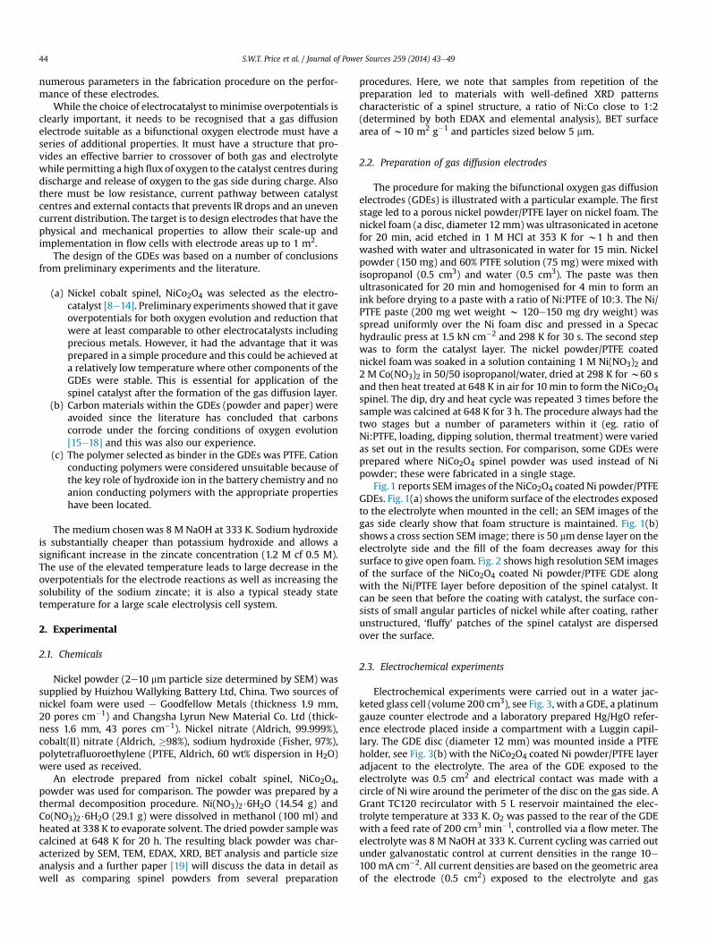
Fig. 1 reports SEM images of the NiCo2O4 coated Ni powder/PTFEGDEs. Fig. 1(a) shows the uniform surface of the electrodes exposedto the electrolyte when mounted in the cell; an SEM images of thegas side clearly show that foam structure is maintained. Fig. 1(b)shows a cross section SEM image; there is 50 mmdense layer on theelectrolyte side and the fill of the foam decreases away for thissurface to give open foam. Fig. 2 shows high resolution SEM imagesof the surface of the NiCo2O4 coated Ni powder/PTFE GDE alongwith the Ni/PTFE layer before deposition of the spinel catalyst. Itcan be seen that before the coating with catalyst, the surface con-sists of small angular particles of nickel while after coating, ratherunstructured, ‘fluffy’ patches of the spinel catalyst are dispersedover the surface.
2.3. Electrochemical experiments
Electrochemical experiments were carried out in a water jac-keted glass cell (volume 200 cm3), see Fig. 3, with a GDE, a platinumgauze counter electrode and a laboratory prepared Hg/HgO refer-ence electrode placed inside a compartment with a Luggin capil-lary. The GDE disc (diameter 12 mm) was mounted inside a PTFEholder, see Fig. 3(b) with the NiCo2O4 coated Ni powder/PTFE layeradjacent to the electrolyte. The area of the GDE exposed to theelectrolyte was 0.5 cm2 and electrical contact was made with acircle of Ni wire around the perimeter of the disc on the gas side. AGrant TC120 recirculator with 5 L reservoir maintained the elec-trolyte temperature at 333 K. O2 was passed to the rear of the GDEwith a feed rate of 200 cm3 min�1, controlled via a flow meter. Theelectrolyte was 8 M NaOH at 333 K. Current cycling was carried outunder galvanostatic control at current densities in the range 10e100 mA cm�2. All current densities are based on the geometric areaof the electrode (0.5 cm2) exposed to the electrolyte and gas
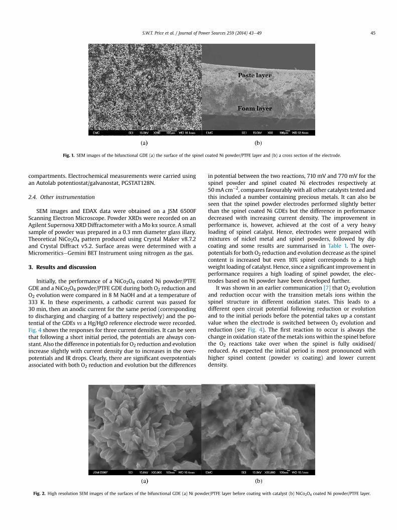
Fig. 1. SEM images of the bifunctional GDE (a) the surface of the spinel coated Ni powder/PTFE layer and (b) a cross section of the electrode.
S.W.T. Price et al. / Journal of Power Sources 259 (2014) 43e49 45
compartments. Electrochemical measurements were carried usingan Autolab potentiostat/galvanostat, PGSTAT128N.
2.4. Other instrumentation
SEM images and EDAX data were obtained on a JSM 6500FScanning Electron Microscope. Powder XRDs were recorded on anAgilent Supernova XRD Diffractometerwith aMo ka source. A smallsample of powder was prepared in a 0.3 mm diameter glass illary.Theoretical NiCo2O4 pattern produced using Crystal Maker v8.7.2and Crystal Diffract v5.2. Surface areas were determined with aMicromeriticseGemini BET Instrument using nitrogen as the gas.
3. Results and discussion
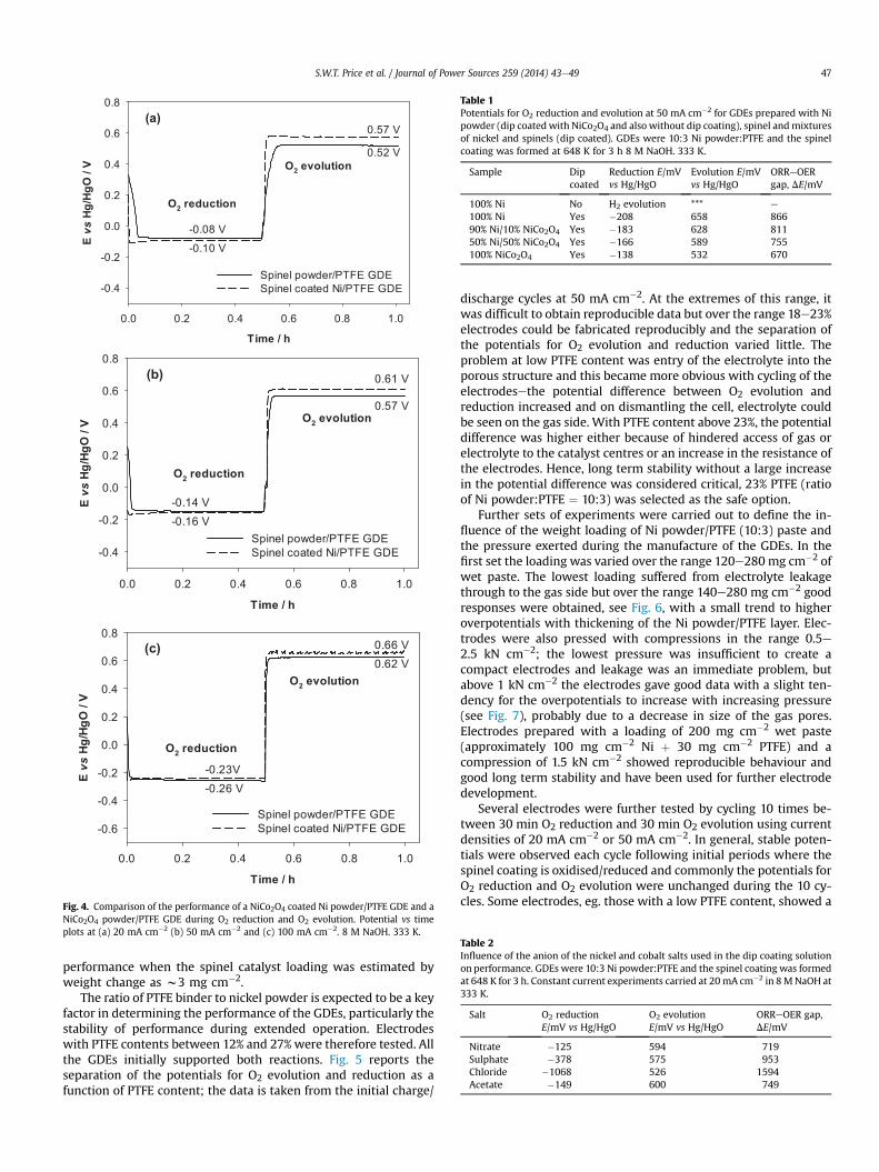
Initially, the performance of a NiCo2O4 coated Ni powder/PTFEGDE and a NiCo2O4 powder/PTFE GDE during both O2 reduction andO2 evolution were compared in 8 M NaOH and at a temperature of333 K. In these experiments, a cathodic current was passed for30 min, then an anodic current for the same period (correspondingto discharging and charging of a battery respectively) and the po-tential of the GDEs vs a Hg/HgO reference electrode were recorded.Fig. 4 shows the responses for three current densities. It can be seenthat following a short initial period, the potentials are always con-stant. Also the difference in potentials for O2 reduction and evolutionincrease slightly with current density due to increases in the over-potentials and IR drops. Clearly, there are significant overpotentialsassociated with both O2 reduction and evolution but the differences
Fig. 2. High resolution SEM images of the surfaces of the bifunctional GDE (a) Ni powde
in potential between the two reactions, 710 mV and 770 mV for thespinel powder and spinel coated Ni electrodes respectively at50mA cm�2, compares favourably with all other catalysts tested andthis included a number containing precious metals. It can also beseen that the spinel powder electrodes performed slightly betterthan the spinel coated Ni GDEs but the difference in performancedecreased with increasing current density. The improvement inperformance is, however, achieved at the cost of a very heavyloading of spinel catalyst. Hence, electrodes were prepared withmixtures of nickel metal and spinel powders, followed by dipcoating and some results are summarised in Table 1. The over-potentials for both O2 reduction and evolution decrease as the spinelcontent is increased but even 10% spinel corresponds to a highweight loading of catalyst. Hence, since a significant improvement inperformance requires a high loading of spinel powder, the elec-trodes based on Ni powder have been developed further.
It was shown in an earlier communication [7] that O2 evolutionand reduction occur with the transition metals ions within thespinel structure in different oxidation states. This leads to adifferent open circuit potential following reduction or evolutionand to the initial periods before the potential takes up a constantvalue when the electrode is switched between O2 evolution andreduction (see Fig. 4). The first reaction to occur is always thechange in oxidation state of themetals ionswithin the spinel beforethe O2 reactions take over when the spinel is fully oxidised/reduced. As expected the initial period is most pronounced withhigher spinel content (powder vs coating) and lower currentdensity.
r/PTFE layer before coating with catalyst (b) NiCo2O4 coated Ni powder/PTFE layer.
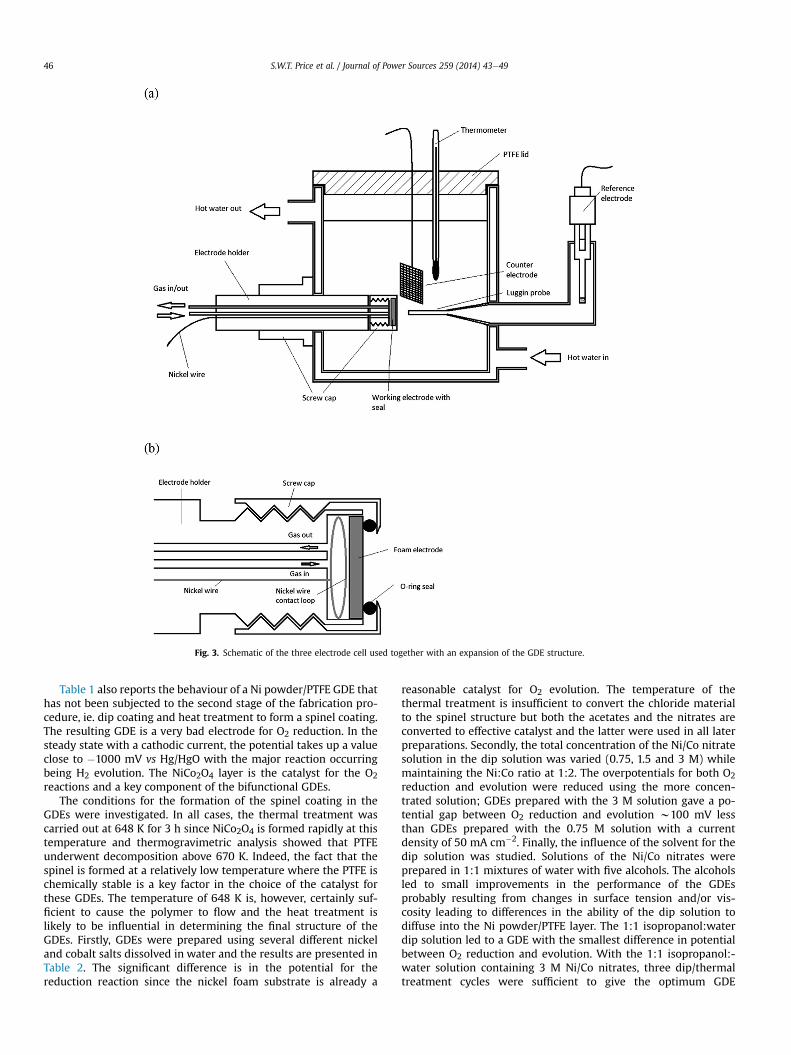
Fig. 3. Schematic of the three electrode cell used together with an expansion of the GDE structure.
S.W.T. Price et al. / Journal of Power Sources 259 (2014) 43e4946
Table 1 also reports the behaviour of a Ni powder/PTFE GDE thathas not been subjected to the second stage of the fabrication pro-cedure, ie. dip coating and heat treatment to form a spinel coating.The resulting GDE is a very bad electrode for O2 reduction. In thesteady state with a cathodic current, the potential takes up a valueclose to �1000 mV vs Hg/HgO with the major reaction occurringbeing H2 evolution. The NiCo2O4 layer is the catalyst for the O2reactions and a key component of the bifunctional GDEs.
The conditions for the formation of the spinel coating in theGDEs were investigated. In all cases, the thermal treatment wascarried out at 648 K for 3 h since NiCo2O4 is formed rapidly at thistemperature and thermogravimetric analysis showed that PTFEunderwent decomposition above 670 K. Indeed, the fact that thespinel is formed at a relatively low temperature where the PTFE ischemically stable is a key factor in the choice of the catalyst forthese GDEs. The temperature of 648 K is, however, certainly suf-ficient to cause the polymer to flow and the heat treatment islikely to be influential in determining the final structure of theGDEs. Firstly, GDEs were prepared using several different nickeland cobalt salts dissolved in water and the results are presented inTable 2. The significant difference is in the potential for thereduction reaction since the nickel foam substrate is already a
reasonable catalyst for O2 evolution. The temperature of thethermal treatment is insufficient to convert the chloride materialto the spinel structure but both the acetates and the nitrates areconverted to effective catalyst and the latter were used in all laterpreparations. Secondly, the total concentration of the Ni/Co nitratesolution in the dip solution was varied (0.75, 1.5 and 3 M) whilemaintaining the Ni:Co ratio at 1:2. The overpotentials for both O2reduction and evolution were reduced using the more concen-trated solution; GDEs prepared with the 3 M solution gave a po-tential gap between O2 reduction and evolution w100 mV lessthan GDEs prepared with the 0.75 M solution with a currentdensity of 50 mA cm�2. Finally, the influence of the solvent for thedip solution was studied. Solutions of the Ni/Co nitrates wereprepared in 1:1 mixtures of water with five alcohols. The alcoholsled to small improvements in the performance of the GDEsprobably resulting from changes in surface tension and/or vis-cosity leading to differences in the ability of the dip solution todiffuse into the Ni powder/PTFE layer. The 1:1 isopropanol:waterdip solution led to a GDE with the smallest difference in potentialbetween O2 reduction and evolution. With the 1:1 isopropanol:-water solution containing 3 M Ni/Co nitrates, three dip/thermaltreatment cycles were sufficient to give the optimum GDE
Time / h
0.0 0.2 0.4 0.6 0.8 1.0
E vs
Hg/H
gO /
V
-0.4
-0.2
0.0
0.2
0.4
0.6
0.8
Spinel powder/PTFE GDESpinel coated Ni/PTFE GDE
0.57 V
0.52 V
-0.08 V
-0.10 V
O2 reduction
O2 evolution
(a)
Time / h
0.0 0.2 0.4 0.6 0.8 1.0
E vs
Hg/
HgO
/ V
-0.4
-0.2
0.0
0.2
0.4
0.6
0.8
Spinel powder/PTFE GDESpinel coated Ni/PTFE GDE
0.61 V
0.57 V
-0.14 V-0.16 V
O2 reduction
O2 evolution
(b)
Time / h
0.0 0.2 0.4 0.6 0.8 1.0
E vs
Hg/
HgO
/ V
-0.6
-0.4
-0.2
0.0
0.2
0.4
0.6
0.8
Spinel powder/PTFE GDESpinel coated Ni/PTFE GDE
0.66 V0.62 V
-0.23V-0.26 V
O2 evolution
O2 reduction
(c)
Fig. 4. Comparison of the performance of a NiCo2O4 coated Ni powder/PTFE GDE and aNiCo2O4 powder/PTFE GDE during O2 reduction and O2 evolution. Potential vs timeplots at (a) 20 mA cm�2 (b) 50 mA cm�2 and (c) 100 mA cm�2. 8 M NaOH. 333 K.
Table 1Potentials for O2 reduction and evolution at 50 mA cm�2 for GDEs prepared with Nipowder (dip coatedwith NiCo2O4 and also without dip coating), spinel andmixturesof nickel and spinels (dip coated). GDEs were 10:3 Ni powder:PTFE and the spinelcoating was formed at 648 K for 3 h 8 M NaOH. 333 K.
Sample Dipcoated
Reduction E/mVvs Hg/HgO
Evolution E/mVvs Hg/HgO
ORReOERgap, DE/mV
100% Ni No H2 evolution *** e
100% Ni Yes �208 658 86690% Ni/10% NiCo2O4 Yes �183 628 81150% Ni/50% NiCo2O4 Yes �166 589 755100% NiCo2O4 Yes �138 532 670
Table 2Influence of the anion of the nickel and cobalt salts used in the dip coating solutionon performance. GDEs were 10:3 Ni powder:PTFE and the spinel coating was formedat 648 K for 3 h. Constant current experiments carried at 20mA cm�2 in 8MNaOH at333 K.
Salt O2 reductionE/mV vs Hg/HgO
O2 evolutionE/mV vs Hg/HgO
ORReOER gap,DE/mV
Nitrate �125 594 719Sulphate �378 575 953Chloride �1068 526 1594Acetate �149 600 749
S.W.T. Price et al. / Journal of Power Sources 259 (2014) 43e49 47
performance when the spinel catalyst loading was estimated byweight change as w3 mg cm�2.
The ratio of PTFE binder to nickel powder is expected to be a keyfactor in determining the performance of the GDEs, particularly thestability of performance during extended operation. Electrodeswith PTFE contents between 12% and 27% were therefore tested. Allthe GDEs initially supported both reactions. Fig. 5 reports theseparation of the potentials for O2 evolution and reduction as afunction of PTFE content; the data is taken from the initial charge/
discharge cycles at 50 mA cm�2. At the extremes of this range, itwas difficult to obtain reproducible data but over the range 18e23%electrodes could be fabricated reproducibly and the separation ofthe potentials for O2 evolution and reduction varied little. Theproblem at low PTFE content was entry of the electrolyte into theporous structure and this became more obvious with cycling of theelectrodesethe potential difference between O2 evolution andreduction increased and on dismantling the cell, electrolyte couldbe seen on the gas side. With PTFE content above 23%, the potentialdifference was higher either because of hindered access of gas orelectrolyte to the catalyst centres or an increase in the resistance ofthe electrodes. Hence, long term stability without a large increasein the potential difference was considered critical, 23% PTFE (ratioof Ni powder:PTFE ¼ 10:3) was selected as the safe option.
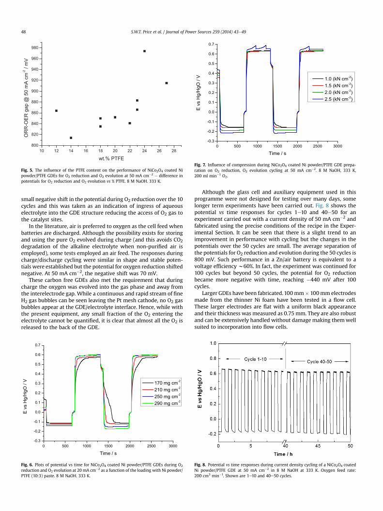
Further sets of experiments were carried out to define the in-fluence of the weight loading of Ni powder/PTFE (10:3) paste andthe pressure exerted during the manufacture of the GDEs. In thefirst set the loading was varied over the range 120e280 mg cm�2 ofwet paste. The lowest loading suffered from electrolyte leakagethrough to the gas side but over the range 140e280 mg cm�2 goodresponses were obtained, see Fig. 6, with a small trend to higheroverpotentials with thickening of the Ni powder/PTFE layer. Elec-trodes were also pressed with compressions in the range 0.5e2.5 kN cm�2; the lowest pressure was insufficient to create acompact electrodes and leakage was an immediate problem, butabove 1 kN cm�2 the electrodes gave good data with a slight ten-dency for the overpotentials to increase with increasing pressure(see Fig. 7), probably due to a decrease in size of the gas pores.Electrodes prepared with a loading of 200 mg cm�2 wet paste(approximately 100 mg cm�2 Ni þ 30 mg cm�2 PTFE) and acompression of 1.5 kN cm�2 showed reproducible behaviour andgood long term stability and have been used for further electrodedevelopment.
Several electrodes were further tested by cycling 10 times be-tween 30 min O2 reduction and 30 min O2 evolution using currentdensities of 20 mA cm�2 or 50 mA cm�2. In general, stable poten-tials were observed each cycle following initial periods where thespinel coating is oxidised/reduced and commonly the potentials forO2 reduction and O2 evolution were unchanged during the 10 cy-cles. Some electrodes, eg. those with a low PTFE content, showed a
0 500 1000 1500 2000 2500 3000-0.3
-0.2
-0.1
0.0
0.1
0.2
0.3
0.4
0.5
0.6
0.7
E v
s H
g/H
gO /
V
Time / s
1.0 (kN cm-2) 1.5 (kN cm-2) 2.0 (kN cm-2) 2.5 (kN cm-2)
Fig. 7. Influence of compression during NiCo2O4 coated Ni powder/PTFE GDE prepa-ration on O2 reduction, O2 evolution cycling at 50 mA cm�2. 8 M NaOH, 333 K,200 ml min�1 O2.
10 12 14 16 18 20 22 24 26 28800
820
840
860
880
900
920
940
960
980
OR
R-O
ER
gap
@ 5
0 m
A c
m-2 /
mV
wt.% PTFE
Fig. 5. The influence of the PTFE content on the performance of NiCo2O4 coated Nipowder/PTFE GDEs for O2 reduction and O2 evolution at 50 mA cm�2 e difference inpotentials for O2 reduction and O2 evolution vs % PTFE. 8 M NaOH. 333 K.
S.W.T. Price et al. / Journal of Power Sources 259 (2014) 43e4948
small negative shift in the potential during O2 reduction over the 10cycles and this was taken as an indication of ingress of aqueouselectrolyte into the GDE structure reducing the access of O2 gas tothe catalyst sites.
In the literature, air is preferred to oxygen as the cell feed whenbatteries are discharged. Although the possibility exists for storingand using the pure O2 evolved during charge (and this avoids CO2
degradation of the alkaline electrolyte when non-purified air isemployed), some tests employed an air feed. The responses duringcharge/discharge cycling were similar in shape and stable poten-tials were established but the potential for oxygen reduction shiftednegative. At 50 mA cm�2, the negative shift was 70 mV.
These carbon free GDEs also met the requirement that duringcharge the oxygen was evolved into the gas phase and away fromthe interelectrode gap. While a continuous and rapid stream of fineH2 gas bubbles can be seen leaving the Pt mesh cathode, no O2 gasbubbles appear at the GDE/electrolyte interface. Hence, while withthe present equipment, any small fraction of the O2 entering theelectrolyte cannot be quantified, it is clear that almost all the O2 isreleased to the back of the GDE.
0 500 1000 1500 2000 2500 3000-0.3
-0.2
-0.1
0.0
0.1
0.2
0.3
0.4
0.5
0.6
0.7
E v
s H
g/H
gO /
V
Time / s
170 mg cm-2
210 mg cm-2
250 mg cm-2
290 mg cm-2
Fig. 6. Plots of potential vs time for NiCo2O4 coated Ni powder/PTFE GDEs during O2
reduction and O2 evolution at 20 mA cm�2 as a function of the loading with Ni powder/PTFE (10:3) paste. 8 M NaOH. 333 K.
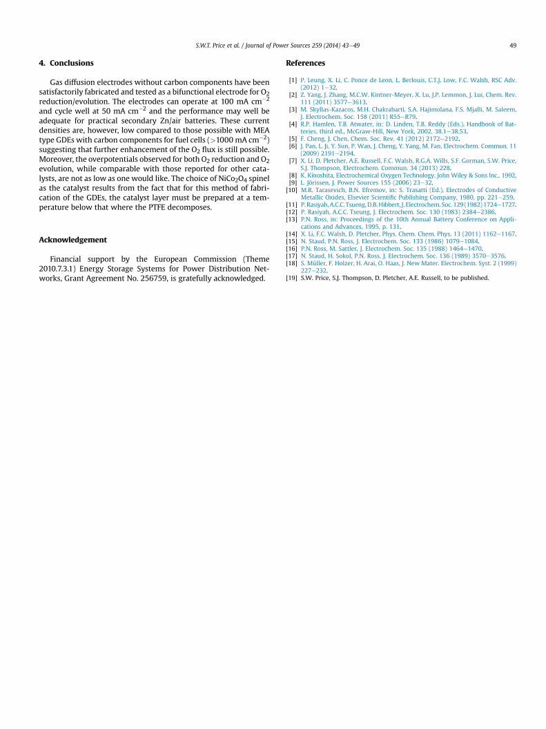
Although the glass cell and auxiliary equipment used in thisprogramme were not designed for testing over many days, somelonger term experiments have been carried out. Fig. 8 shows thepotential vs time responses for cycles 1e10 and 40e50 for anexperiment carried out with a current density of 50 mA cm�2 andfabricated using the precise conditions of the recipe in the Exper-imental Section. It can be seen that there is a slight trend to animprovement in performance with cycling but the changes in thepotentials over the 50 cycles are small. The average separation ofthe potentials for O2 reduction and evolution during the 50 cycles is800 mV. Such performance in a Zn/air battery is equivalent to avoltage efficiency w60%. In fact, the experiment was continued for100 cycles but beyond 50 cycles, the potential for O2 reductionbecame more negative with time, reaching �440 mV after 100cycles.
Larger GDEs have been fabricated.100mm� 100mm electrodesmade from the thinner Ni foam have been tested in a flow cell.These larger electrodes are flat with a uniform black appearanceand their thickness was measured as 0.75 mm. They are also robustand can be extensively handled without damage making themwellsuited to incorporation into flow cells.
Fig. 8. Potential vs time responses during current density cycling of a NiCo2O4 coatedNi powder/PTFE GDE at 50 mA cm�2 in 8 M NaOH at 333 K. Oxygen feed rate:200 cm3 min�1. Shown are 1e10 and 40e50 cycles.
S.W.T. Price et al. / Journal of Power Sources 259 (2014) 43e49 49
4. Conclusions
Gas diffusion electrodes without carbon components have beensatisfactorily fabricated and tested as a bifunctional electrode for O2reduction/evolution. The electrodes can operate at 100 mA cm�2
and cycle well at 50 mA cm�2 and the performance may well beadequate for practical secondary Zn/air batteries. These currentdensities are, however, low compared to those possible with MEAtype GDEs with carbon components for fuel cells (>1000 mA cm�2)suggesting that further enhancement of the O2 flux is still possible.Moreover, the overpotentials observed for both O2 reduction and O2evolution, while comparable with those reported for other cata-lysts, are not as low as one would like. The choice of NiCo2O4 spinelas the catalyst results from the fact that for this method of fabri-cation of the GDEs, the catalyst layer must be prepared at a tem-perature below that where the PTFE decomposes.
Acknowledgement
Financial support by the European Commission (Theme2010.7.3.1) Energy Storage Systems for Power Distribution Net-works, Grant Agreement No. 256759, is gratefully acknowledged.
References
[1] P. Leung, X. Li, C. Ponce de Leon, L. Berlouis, C.T.J. Low, F.C. Walsh, RSC Adv.(2012) 1e32.
[2] Z. Yang, J. Zhang, M.C.W. Kintner-Meyer, X. Lu, J.P. Lemmon, J. Lui, Chem. Rev.111 (2011) 3577e3613.
[3] M. Skyllas-Kazacos, M.H. Chakrabarti, S.A. Hajimolana, F.S. Mjalli, M. Saleem,J. Electrochem. Soc. 158 (2011) R55eR79.
[4] R.P. Hamlen, T.B. Atwater, in: D. Linden, T.B. Reddy (Eds.), Handbook of Bat-teries, third ed., McGraw-Hill, New York, 2002, 38.1e38.53.
[5] F. Cheng, J. Chen, Chem. Soc. Rev. 41 (2012) 2172e2192.[6] J. Pan, L. Ji, Y. Sun, P. Wan, J. Cheng, Y. Yang, M. Fan, Electrochem. Commun. 11
(2009) 2191e2194.[7] X. Li, D. Pletcher, A.E. Russell, F.C. Walsh, R.G.A. Wills, S.F. Gorman, S.W. Price,
S.J. Thompson, Electrochem. Commun. 34 (2013) 228.[8] K. Kinoshita, Electrochemical Oxygen Technology, John Wiley & Sons Inc., 1992.[9] L. Jörissen, J. Power Sources 155 (2006) 23e32.
[10] M.R. Tarasevich, B.N. Efremov, in: S. Trasatti (Ed.), Electrodes of ConductiveMetallic Oxides, Elsevier Scientific Publishing Company, 1980, pp. 221e259.
[11] P.Rasiyah,A.C.C. Tsueng,D.B.Hibbert, J. Electrochem. Soc. 129 (1982) 1724e1727.[12] P. Rasiyah, A.C.C. Tseung, J. Electrochem. Soc. 130 (1983) 2384e2386.[13] P.N. Ross, in: Proceedings of the 10th Annual Battery Conference on Appli-
cations and Advances, 1995, p. 131.[14] X. Li, F.C. Walsh, D. Pletcher, Phys. Chem. Chem. Phys. 13 (2011) 1162e1167.[15] N. Staud, P.N. Ross, J. Electrochem. Soc. 133 (1986) 1079e1084.[16] P.N. Ross, M. Sattler, J. Electrochem. Soc. 135 (1988) 1464e1470.[17] N. Staud, H. Sokol, P.N. Ross, J. Electrochem. Soc. 136 (1989) 3570e3576.[18] S. M}uller, F. Holzer, H. Arai, O. Haas, J. New Mater. Electrochem. Syst. 2 (1999)
227e232.[19] S.W. Price, S.J. Thompson, D. Pletcher, A.E. Russell, to be published.
Related Documents