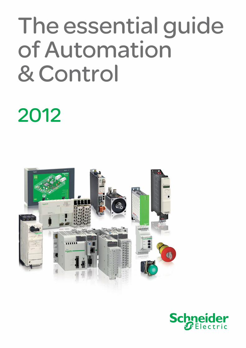
2012 The essential guide of Automation & Control

Welcome message from author
This document is posted to help you gain knowledge. Please leave a comment to let me know what you think about it! Share it to your friends and learn new things together.
Transcript
2012
The essential guideof Automation& Control

The go to guidefor the most efficient selection
Make the most of your energy
Operator dialog p Control and signalling unitsp Human/Machine Interfacesp Dialog operator for Explosive atmospheres
Automation p Relaysp Controllers for commercial and industrial machinesp Programmable Automation Controllers (PACs)p Configuration software
Motion and Drivesp Soft starters and variable speed drivesp Controllers, drives, motors and linear motion axes
Motor controlp Motor control componentsp Components for power control applications
Power suppliesp Power suppliesp Transformersp Connection
Interfaces and I/Op Distributed Inputs/Outputsp Distributed I/O with embedded controlp Interfacesp Accessories and Cabling
Networks connectivity and Web serversp ConneXium cabling systemp AS-Interface cabling systemp Servers and Gateways
Machine safetyp Safety solutions provide maximum protection in all the safety functions of your automation system
Contents
2
1
3
4
5
6
7
9
10
8
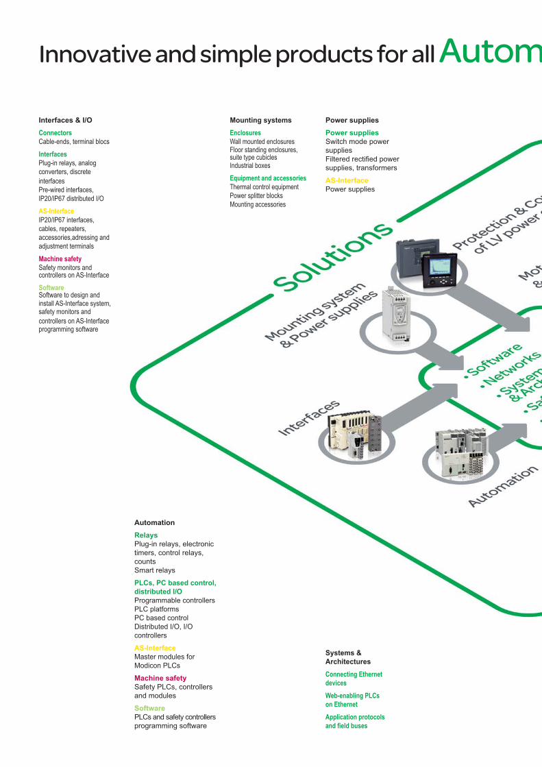
Innovative and simple products for all Autom
Interfaces & I/OConnectors Cable-ends, terminal blocs Interfaces Plug-in relays, analog converters, discrete interfaces Pre-wired interfaces, IP20/IP67 distributed I/OAS-Interface IP20/IP67 interfaces, cables, repeaters, accessories,adressing and adjustment terminalsMachine safety Safety monitors and controllers on AS-InterfaceSoftware Software to design and install AS-Interface system, safety monitors and controllers on AS-Interface programming software
Systems & ArchitecturesConnecting Ethernet devices Web-enabling PLCs on Ethernet Application protocols and field buses
Mounting systemsEnclosures Wall mounted enclosures Floor standing enclosures, suite type cubicles Industrial boxes Equipment and accessories Thermal control equipment Power splitter blocks Mounting accessories
AutomationRelays Plug-in relays, electronic timers, control relays, counts Smart relays
PLCs, PC based control, distributed I/O Programmable controllers PLC platforms PC based control Distributed I/O, I/O controllers
AS-Interface Master modules for Modicon PLCs
Machine safety Safety PLCs, controllers and modules
Software PLCs and safety controllers programming software
Power suppliesPower supplies Switch mode power supplies Filtered rectified power supplies, transformers
AS-Interface Power supplies
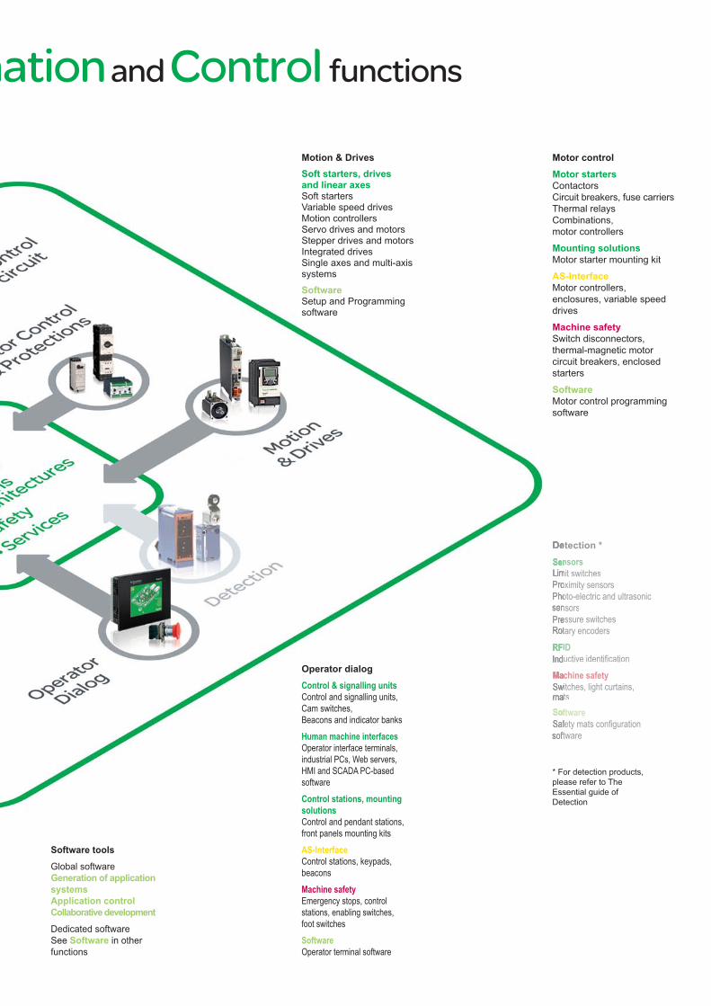
mation and Control functions
Motion & DrivesSoft starters, drives and linear axesSoft startersVariable speed drivesMotion controllersServo drives and motorsStepper drives and motorsIntegrated drivesSingle axes and multi-axis systems
SoftwareSetup and Programming software
Motor controlMotor startersContactorsCircuit breakers, fuse carriersThermal relaysCombinations, motor controllers
Mounting solutionsMotor starter mounting kit
AS-InterfaceMotor controllers, enclosures, variable speed drives
Machine safetySwitch disconnectors, thermal-magnetic motor circuit breakers, enclosed starters
SoftwareMotor control programming software
Operator dialogControl & signalling unitsControl and signalling units, Cam switches,Beacons and indicator banksHuman machine interfacesOperator interface terminals, industrial PCs, Web servers, HMI and SCADA PC-based software Control stations, mounting solutionsControl and pendant stations, front panels mounting kits AS-InterfaceControl stations, keypads, beaconsMachine safetyEmergency stops, control stations, enabling switches, foot switchesSoftwareOperator terminal software
etection *nsors
mit switchesoximity sensorsoto-electric and ultrasonic nsorsessure switchestary encodersIDuctive identifi cationchine safetyitches, light curtains, ts ftwarefety mats confi guration tware
Software toolsGlobal softwareGeneration of application systemsApplication control Collaborative developmentDedicated softwareSee Software in other functions
* For detection products, please refer to The Essential guide of Detection

From the humble pushbutton to the most complex operator dialogue terminal, Schneider Electric is the world’s leading supplier of human-machine interface components. Open-ended and highly innovative, the Harmony and Magelis ranges are synonymous with seamless integration and effective configuration solutions in dialogue applications.
HMI MagelisA comprehensive, rugged, open-ended interface and industrial PC offer to meet your requirements in a wide variety of applications. With its extensive capabilities, Magelis ensures the dependability of your installations.
Harmony Harmony control and signalling products are characterised by their extreme ruggedness, ergonomic design and ease of use, all of which have contributed to their successful application worldwide. The unrivalled depth of the Harmony range provides solutions to meet the diverse needs of your applications.
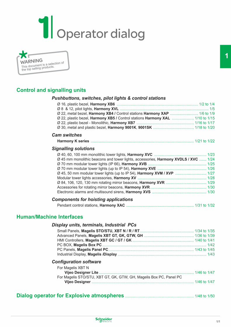
Operator dialog
This document is a selection of
the top selling products.
1/1
2
1
3
4
5
6
7
8
9
10
Control and signalling units Pushbuttons, switches, pilot lights & control stations Ø 16, plastic bezel, Harmony XB6 .............................................................................. 1/2 to 1/4 Ø 8 & 12, pilot lights, Harmony XVL ..................................................................................... 1/5 Ø 22, metal bezel, Harmony XB4 / Control stations Harmony XAP ........................... 1/6 to 1/9 Ø 22, plastic bezel, Harmony XB5 / Control stations Harmony XAL ..................... 1/10 to 1/15 Ø 22, plastic bezel - Monolithic, Harmony XB7 ....................................................... 1/16 to 1/17 Ø 30, metal and plastic bezel, Harmony 9001K, 9001SK ....................................... 1/18 to 1/20
Cam switches Harmony K series ................................................................................................... 1/21 to 1/22
Signalling solutions Ø 40, 60, 100 mm monolithic tower lights, Harmony XVC .................................................. 1/23 Ø 45 mm monolithic beacons and tower lights, accessories, Harmony XVDLS / XVC ....... 1/24 Ø 70 mm modular tower lights (IP 66), Harmony XVB ........................................................ 1/25 Ø 70 mm modular tower lights (up to IP 54), Harmony XVE ............................................... 1/26 Ø 45, 50 mm modular tower lights (up to IP 54), Harmony XVM / XVP .............................. 1/27 Modular tower lights accessories, Harmony XV .................................................................. 1/28 Ø 84, 106, 120, 130 mm rotating mirror beacons, Harmony XVR ....................................... 1/29 Accessories for rotating mirror beacons, Harmony XVR ...................................................... 1/30 Electronic alarms and multisound sirens, Harmony XVS .................................................... 1/30
Components for hoisting applications Pendant control stations, Harmony XAC ................................................................. 1/31 to 1/32
Human/Machine Interfaces Display units, terminals, Industrial PCs Small Panels, Magelis STO/STU, XBT N / R / RT .................................................... 1/34 to 1/35 Advanced Panels, Magelis XBT GT, GK, GTW, GH ................................................ 1/36 to 1/39 HMI Controllers, Magelis XBT GC / GT / GK ........................................................... 1/40 to 1/41 PC BOX, Magelis Box PC .................................................................................................... 1/42 PC Panels, Magelis Panel PC .................................................................................. 1/43 to 1/45 Industrial Display, Magelis iDisplay ..................................................................................... 1/43
Configuration software For Magelis XBT N Vijeo Designer Lite ........................................................................................... 1/46 to 1/47 For Magelis STO/STU, XBT GT, GK, GTW, GH, Magelis Box PC, Panel PC Vijeo Designer .................................................................................................. 1/46 to 1/47
Dialog operator for Explosive atmospheres .................................................................. 1/48 to 1/50
Other versions: please consult our Customer Care Centre.
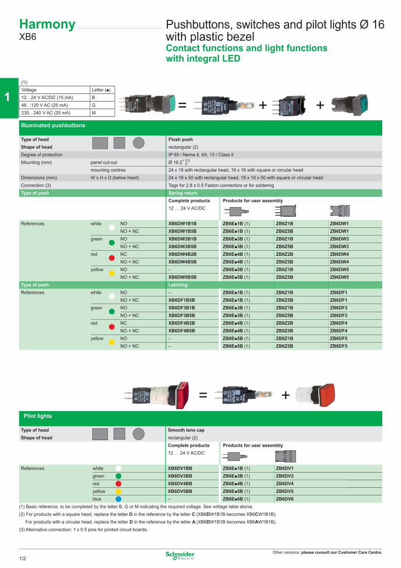
Illuminated pushbuttons
Type of head Flush pushShape of head rectangular (2)Degree of protection IP 65 / Nema 4, 4X, 13 / Class IIMounting (mm) panel cut-out Ø 16.2
mounting centres 24 x 18 with rectangular head, 18 x 18 with square or circular headDimensions (mm) W x H x D (below head) 24 x 18 x 50 with rectangular head, 18 x 18 x 50 with square or circular head Connection (3) Tags for 2.8 x 0.5 Faston connectors or for solderingType of push Spring return
Complete products12 … 24 V AC/DC
Products for user assembly
References white NO XB6DW1B1B ZB6Ep1B (1) ZB6Z1B ZB6DW1NO + NC XB6DW1B5B ZB6Ep1B (1) ZB6Z5B ZB6DW1
green NO XB6DW3B1B ZB6Ep3B (1) ZB6Z1B ZB6DW3NO + NC XB6DW3B5B ZB6Ep3B (1) ZB6Z5B ZB6DW3
red NC XB6DW4B2B ZB6Ep4B (1) ZB6Z2B ZB6DW4NO + NC XB6DW4B5B ZB6Ep4B (1) ZB6Z5B ZB6DW4
yellow NO – ZB6Ep5B (1) ZB6Z1B ZB6DW5NO + NC XB6DW5B5B ZB6Ep5B (1) ZB6Z5B ZB6DW5
Type of push LatchingReferences white NO – ZB6Ep1B (1) ZB6Z1B ZB6DF1
NO + NC XB6DF1B5B ZB6Ep1B (1) ZB6Z5B ZB6DF1green NO XB6DF3B1B ZB6Ep3B (1) ZB6Z1B ZB6DF3
NO + NC XB6DF3B5B ZB6Ep3B (1) ZB6Z5B ZB6DF3red NC XB6DF4B2B ZB6Ep4B (1) ZB6Z2B ZB6DF4
NO + NC XB6DF4B5B ZB6Ep4B (1) ZB6Z5B ZB6DF4yellow NO – ZB6Ep5B (1) ZB6Z1B ZB6DF5
NO + NC – ZB6Ep5B (1) ZB6Z5B ZB6DF5
Pilot lights
Type of head Smooth lens capShape of head rectangular (2)
Complete products Products for user assembly12 … 24 V AC/DC
References white XB6DV1BB ZB6Ep1B (1) ZB6DV1green XB6DV3BB ZB6Ep3B (1) ZB6DV3red XB6DV4BB ZB6Ep4B (1) ZB6DV4yellow XB6DV5BB ZB6Ep5B (1) ZB6DV5blue – ZB6Ep6B (1) ZB6DV6
(1) Basic reference, to be completed by the letter B, G or M indicating the required voltage. See voltage table above.(2) For products with a square head, replace the letter D in the reference by the letter C (XB6DW1B1B becomes XB6CW1B1B). For products with a circular head, replace the letter D in the reference by the letter A (XB6DW1B1B becomes XB6AW1B1B).(3) Alternative connection: 1 x 0.5 pins for printed circuit boards.
Pushbuttons, switches and pilot lights Ø 16 with plastic bezelContact functions and light functions with integral LED
(1):Voltage Letter (p)12…24 V AC/DC (15 mA) B48…120 V AC (25 mA) G230…240 V AC (25 mA) M
+ 0.2 0
HarmonyXB6
= + +
= +
1/2
2
1
3
4
5
6
7
8
9
10
Other versions: please consult our Customer Care Centre.
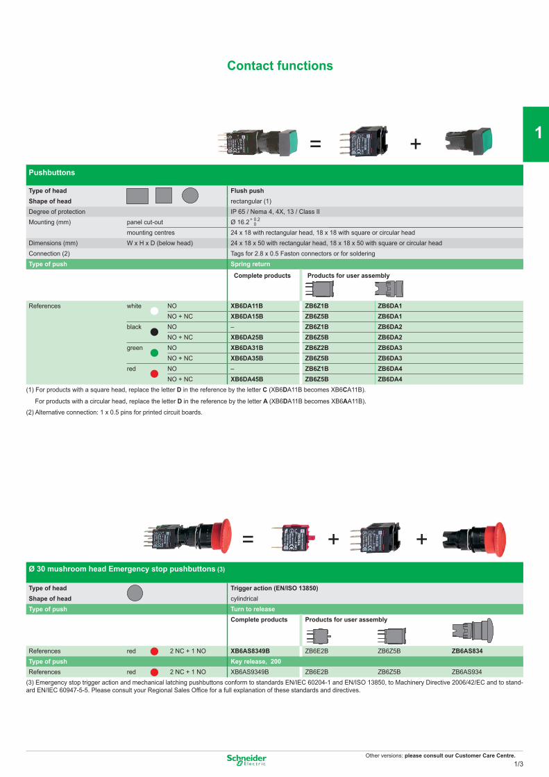
Pushbuttons
Type of head Flush pushShape of head rectangular (1)Degree of protection IP 65 / Nema 4, 4X, 13 / Class IIMounting (mm) panel cut-out Ø 16.2
mounting centres 24 x 18 with rectangular head, 18 x 18 with square or circular headDimensions (mm) W x H x D (below head) 24 x 18 x 50 with rectangular head, 18 x 18 x 50 with square or circular headConnection (2) Tags for 2.8 x 0.5 Faston connectors or for solderingType of push Spring return
Complete products Products for user assembly
References white NO XB6DA11B ZB6Z1B ZB6DA1NO + NC XB6DA15B ZB6Z5B ZB6DA1
black NO – ZB6Z1B ZB6DA2NO + NC XB6DA25B ZB6Z5B ZB6DA2
green NO XB6DA31B ZB6Z2B ZB6DA3NO + NC XB6DA35B ZB6Z5B ZB6DA3
red NO – ZB6Z1B ZB6DA4NO + NC XB6DA45B ZB6Z5B ZB6DA4
(1) For products with a square head, replace the letter D in the reference by the letter C (XB6DA11B becomes XB6CA11B).
For products with a circular head, replace the letter D in the reference by the letter A (XB6DA11B becomes XB6AA11B).
(2) Alternative connection: 1 x 0.5 pins for printed circuit boards.
Ø 30 mushroom head Emergency stop pushbuttons (3)
Type of head Trigger action (EN/ISO 13850)Shape of head cylindricalType of push Turn to release
Complete products Products for user assembly
References red 2 NC + 1 NO XB6AS8349B ZB6E2B ZB6Z5B ZB6AS834Type of push Key release, 200References red 2 NC + 1 NO XB6AS9349B ZB6E2B ZB6Z5B ZB6AS934
(3) Emergency stop trigger action and mechanical latching pushbuttons conform to standards EN/IEC 60204-1 and EN/ISO 13850, to Machinery Directive 2006/42/EC and to stand-ard EN/IEC 60947-5-5. Please consult your Regional Sales Office for a full explanation of these standards and directives.
+ 0.2 0
Contact functions
= +
= + +
1/3
2
1
3
4
5
6
7
8
9
10
Other versions: please consult our Customer Care Centre.
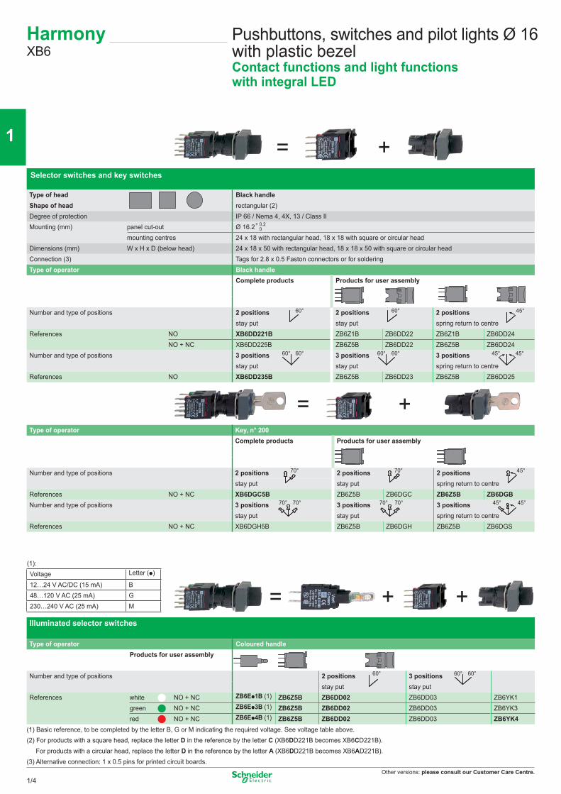
Selector switches and key switches
Type of head Black handleShape of head rectangular (2)Degree of protection IP 66 / Nema 4, 4X, 13 / Class IIMounting (mm) panel cut-out Ø 16.2
mounting centres 24 x 18 with rectangular head, 18 x 18 with square or circular headDimensions (mm) W x H x D (below head) 24 x 18 x 50 with rectangular head, 18 x 18 x 50 with square or circular headConnection (3) Tags for 2.8 x 0.5 Faston connectors or for solderingType of operator Black handle
Complete products Products for user assembly
Number and type of positions 2 positions 2 positions 2 positionsstay put stay put spring return to centre
References NO XB6DD221B ZB6Z1B ZB6DD22 ZB6Z1B ZB6DD24NO + NC XB6DD225B ZB6Z5B ZB6DD22 ZB6Z5B ZB6DD24
Number and type of positions 3 positions 3 positions 3 positionsstay put stay put spring return to centre
References NO XB6DD235B ZB6Z5B ZB6DD23 ZB6Z5B ZB6DD25
Type of operator Key, n° 200Complete products Products for user assembly
Number and type of positions 2 positions 2 positions 2 positionsstay put stay put spring return to centre
References NO + NC XB6DGC5B ZB6Z5B ZB6DGC ZB6Z5B ZB6DGBNumber and type of positions 3 positions 3 positions 3 positions
stay put stay put spring return to centreReferences NO + NC XB6DGH5B ZB6Z5B ZB6DGH ZB6Z5B ZB6DGS
Illuminated selector switches
Type of operator Coloured handleProducts for user assembly
Number and type of positions 2 positions 3 positionsstay put stay put
References white NO + NC ZB6Ep1B (1) ZB6Z5B ZB6DD02 ZB6DD03 ZB6YK1green NO + NC ZB6Ep3B (1) ZB6Z5B ZB6DD02 ZB6DD03 ZB6YK3red NO + NC ZB6Ep4B (1) ZB6Z5B ZB6DD02 ZB6DD03 ZB6YK4
(1) Basic reference, to be completed by the letter B, G or M indicating the required voltage. See voltage table above.(2) For products with a square head, replace the letter D in the reference by the letter C (XB6DD221B becomes XB6CD221B). For products with a circular head, replace the letter D in the reference by the letter A (XB6DD221B becomes XB6AD221B).(3) Alternative connection: 1 x 0.5 pins for printed circuit boards.
(1):Voltage Letter (p)
12…24 V AC/DC (15 mA) B48…120 V AC (25 mA) G230…240 V AC (25 mA) M
+ 0.2 0
HarmonyXB6
60° 45°60°
60° 45°60°60° 45°60°
70° 45°70°
70° 45°70°70° 45°70°
60° 60° 60°
Pushbuttons, switches and pilot lights Ø 16 with plastic bezelContact functions and light functions with integral LED
= +
= +
= + +
1/4
2
1
3
4
5
6
7
8
9
10
Other versions: please consult our Customer Care Centre.
LED pilot lights With black bezel With integral lens cap
Type of head Protruding LED, Ø 8 mm Covered LED, Ø 8 mm Covered LED, Ø 12 mm
Degree of protection IP 40, IP 65 with seal (2)Mounting (mm) panel cut-out Ø 8.2 mm Ø 8.2 mm Ø 12.2 mm
mounting centres 12.5 x 12.5 mm 10.5 x 10.5 mm 16.5 x 16.5 mmDimensions (mm) Ø x Depth (below head) Ø 12 x 32 Ø 10 x 34 Ø 16 x 45 Connection Tags (3) Tags (3) Threaded connectorsReferences (1) green XVLA1p3 XVLA2p3 XVLA3p3
red XVLA1p4 XVLA2p4 XVLA3p4yellow XVLA1p5 XVLA2p5 XVLA3p5
Tightening key For Ø 8 mm pilot lights For Ø 12 mm pilot lightsReferences XVLX08 XVLX12
(1) Basic reference, to be completed by the number 1, 2, 3 or 4 indicating the required voltage. See voltage table above.(2) For an IP 65 degree of protection, include the seals: XVLZ911 for pilot lights XVLA1pp and XVLA2pp; XVLZ912 for pilot lights XVLA3pp.(3) Tags for 2.8 x 0.5 Faston connectors or for soldering.
Sub-assemblies & accessories for Ø 16 plastic bezel control and signalling units
Sub-assemblies Bodies for pushbuttons and selector switches
Bodies for pilot lights
Rated operational characteristics, AC-15: Ue = 240 V and Ie = 1.5 A or Ue = 120 V and Ie = 3 A ConsumptionPositive operation of contacts conforming to IEC/EN 60947-5-1: NC contacts with positive opening operation, 15 mA 12…24 V AC/DCpositive opening force 20 N 25 mA 48…120 V AC
25 mA 230…240 V ACType of Fixing collar Contacts Pilot light 12 … 24 V 48 … 120 V 230 … 240 Vcontact + contacts bodies
References NO ZB6Z1B ZB6E1B White ZB6EB1B ZB6EG1B ZB6EM1BNC ZB6Z2B ZB6E2B Green ZB6EB3B ZB6EG3B ZB6EM3B2 NO ZB6Z3B – Red ZB6EB4B ZB6EG4B ZB6EM4B2 NC ZB6Z4B – Yellow ZB6EB5B ZB6EG5B ZB6EM5BNO + NC ZB6Z5B – Blue ZB6EB6B ZB6EG6B ZB6EM6B
LED pilot lights Ø 8 and 12
(1):
Voltage Number (p)5 V (25 mA) 112 V (18 mA) 224 V (18 mA) 348 V (10 mA) 4
Accessories
Legend holders 24 x 28 mm (8 x 21 mm legend) 24 x 36 mm (16 x 21 mm legend)Blank legend Background colour without legend yellow or white black or red without legend yellow or white black or redReferences (10)* ZB6YD20 ZB6YD21 ZB6YD22 ZB6YD30 ZB6YD31 ZB6YD32Blank legends for legend holders 8 x 21 mm (24 x 28 mm legend holder) 16 x 21 mm (24 x 36 mm legend holder)
Background colour – yellow or white black or red – yellow or white black or redReferences (20)* – ZB6Y1001 ZB6Y2001 – ZB6Y4001 ZB6Y3001Ø 45 mm yellow legend for mushroom head Emergency stop pushbutton
Marking Blank, for engraving EMERGENCY STOP ARRET D’URGENCEReferences ZB6Y7001 ZB6Y7330 ZB6Y7130
Body/fixing collar Plate Tightening tool Dismantling toolanti-rotation and slackening, for fixing nut for removal of contact blocks
References ZB6Y009 (10)* ZB6Y003 (10)* ZB6Y905 (2)* ZB6Y018 (5)*Protective shutter for pushbuttons and switches Connector Blanking plug
for rectangular heads for circular and square heads Faston, female IP 65References ZB6YD001 ZB6YA001 ZB6Y004 (100)* ZB6Y005 (10)*
* sold in lots of
HarmonyXVL
1/5
2
1
3
4
5
6
7
8
9
10
Other versions: please consult our Customer Care Centre.
Pushbuttons, spring return
Type of head Chromium plated circular bezel
Degree of protection IP 66 / Nema 4X, 13 / Class IMounting (mm) panel cut-out Ø 22.5 (22.4 recommended)
mounting centres 30 (horizontal) x 40 (vertical)Depth (mm) below head 43Connection (1) Screw clamp terminalsType of push Flush Flush, bootedUnmarked Products Complete For user assembly Complete For user assembly
References black NO XB4BA21 ZB4BZ101 ZB4BA2 XB4BP21 ZB4BZ101 ZB4BP2green NO XB4BA31 ZB4BZ101 ZB4BA3 XB4BP31 ZB4BZ101 ZB4BP3red NC XB4BA42 ZB4BZ102 ZB4BA4 XB4BP42 ZB4BZ102 ZB4BP4yellow NO XB4BA51 ZB4BZ101 ZB4BA5 XB4BP51 ZB4BZ101 ZB4BP5blue NO XB4BA61 ZB4BZ101 ZB4BA6 XB4BP61 ZB4BZ101 ZB4BP6
Type of push FlushWith international marking Products Complete For user assemblyReferences green NO XB4BA3311 ZB4BZ101 ZB4BA331 – – –
red NC XB4BA4322 ZB4BZ102 ZB4BA432 – – –white NO XB4BA3341 ZB4BZ101 ZB4BA334 – – –black NO XB4BA3351 ZB4BZ101 ZB4BA335 _ _ _
Type of push Projecting Mushroom head, Ø 40 mmUnmarked Products Complete For user assembly Complete For user assembly
References black NO – – – XB4BC21 ZB4BZ101 ZB4BC2red NC XB4BL42 ZB4BZ102 ZB4BL4 – – –
Type of push Double-headed pushbuttons Triple-headed pushbuttonsDegree of protection IP 66 - IP 69K IP 66 - IP 69KWith international marking Products Complete For user assembly Complete For user assembly
(A) (B)
References (A) NO + NC XB4BL73415 ZB4BZ105 ZB4BL7341 – – –(B) NO + NC + NO – – – XB4BA711237 ZB4BZ103 +
ZBE102ZB4BA71123
(1) Alternative connections: plug-in connector, Faston connectors (6.35 and 2 x 2.8).
Ø 40 mm mushroom head Emergency stop pushbuttons (2)Trigger action (EN/ISO 13850)
Type of push Push-pull NO + NCUnmarked Products Complete For user assembly
References red NO + NC XB4BT845 ZB4BZ105 ZB4BT84Type of push Turn to release NO + NCReferences red NO + NC XB4BS8445 ZB4BZ105 ZB4BS844Type of push Key release NO + NCReferences red NO + NC XB4BS9445 ZB4BZ105 ZB4BS944
(2) Emergency stop trigger action and mechanical latching pushbuttons conform to standards EN/IEC 60204-1 and EN/ISO 13850, to Machinery Directive 2006/42/EC and to stand-ard EN/IEC 60947-5-5. Please consult your Regional Sales Office for a full explanation of these standards and directives.
HarmonyXB4
+ 0.4 0
Pushbuttons, switches and pilot lights Ø 22 with metal bezelContact functions
+
= +
= +
1/6
2
1
3
4
5
6
7
8
9
10
Other versions: please consult our Customer Care Centre.
Contact functions
Selector switches and key switches
Type of head Chromium plated circular bezel
Degree of protection IP 66 / Nema 4X, 13 / Class IMounting (mm) panel cut-out Ø 22.5 (22.4 recommended)
mounting centres 30 (horizontal) x 40 (vertical)Depth (mm) below head 43Connection (1) Screw clamp terminals
Type of operator Key, n° 455Products Complete For user assembly Complete For user assembly
Number and type of positions (2) 2 positions 2 positions 2 positions 2 positionsstay put stay put stay put stay put
References black NO XB4BG21 ZB4BZ101 ZB4BG2 XB4BG41 ZB4BZ101 ZB4BG4Number and type of positions 2 positions 2 positions 3 positions 3 positions
spring return to left spring return to left stay put stay put
Referencesblack NO XB4BG61 ZB4BZ101 ZB4BG6 – – –black NO + NO – – – XB4BG33 ZB4BZ103 ZB4BG3
+ 0.4 0
Type of operator HandleProducts Complete For user assembly Complete For user assembly
Number and type of positions 2 positions 2 positions 2 positions 2 positionsstay put stay put spring return to left spring return to left
References black NO XB4BD21 ZB4BZ101 ZB4BD2 XB4BD41 ZB4BZ101 ZB4BD4Number and type of positions 3 positions 3 positions 3 positions 3 positions
stay put stay put spring return to centre spring return to centreReferences black NO + NO XB4BD33 ZB4BZ103 ZB4BD3 XB4BD53 ZB4BZ103 ZB4BD5
= +
= +
1/7
2
1
3
4
5
6
7
8
9
10
Other versions: please consult our Customer Care Centre.
Type Double-headed pushbuttons with LED pilot light Illuminated selector switches(1 flush green push, 1 projecting red push) (2 position stay put)
Degree of protection IP 66 - IP 69K IP 66Light source Integral LED Integral LED
Products Complete CompleteSupply voltage 24 V AC/DC 110…120 V AC 230…240 V AC 24 V AC/DC 110…120 V AC 230…240 V ACReferences green NO + NC – – – XB4BK123B5 XB4BK123G5 XB4BK123M5
red NO + NC – – – XB4BK124B5 XB4BK124G5 XB4BK124M5orange NO + NC – – – XB4BK125B5 XB4BK125G5 XB4BK125M5White NO + NC XB4BW73731B5 XB4BW73731G5 XB4BW73731M5 – – –
(1) Alternative connections: plug-in connector, Faston connectors (6.35 and 2 x 2.8), spring clamp terminal.
HarmonyXB4
Pushbuttons, switches and pilot lights Ø 22 with metal bezelLight functions
Pilot lights
Type of head Circular bezelSmooth lens cap
Degree of protection IP 66 / Nema 4X, 13 / Class IMounting (mm) panel cut-out Ø 22.5 (22.4 recommended)
mounting centres 30 (horizontal) x 40 (vertical)Depth below head 43Connection (1) Screw clamp terminalsLight source Integral LED Direct supply for BA 9s bulb (not included)
Products Complete Complete For user assembly
Supply voltage 24 V AC/DC 110…120 V AC 230…240 V AC 250 V max., 2.4 W max.References white XB4BVB1 XB4BVG1 XB4BVM1 XB4BV61 ZB4BV6 ZB4BV01
green XB4BVB3 XB4BVG3 XB4BVM3 XB4BV63 ZB4BV6 ZB4BV03red XB4BVB4 XB4BVG4 XB4BVM4 XB4BV64 ZB4BV6 ZB4BV04yellow XB4BVB5 XB4BVG5 XB4BVM5 XB4BV65 ZB4BV6 ZB4BV05blue XB4BVB6 XB4BVG6 XB4BVM6 – – –
+ 0.4 0
Illuminated pushbuttons and selector switches
Type Flush push, spring return, illuminated pushbuttonsLight source Integral LED Direct supply for BA 9s bulb (not included)
Products Complete Complete For user assembly
Supply voltage 24 V AC/DC 110…120 V AC 230…240 V AC 250 V max., 2.4 W max.References white NO + NC XB4BW31B5 XB4BW31G5 XB4BW31M5 XB4BW3165 ZB4BW065 ZB4BW31
green NO + NC XB4BW33B5 XB4BW33G5 XB4BW33M5 XB4BW3365 ZB4BW065 ZB4BW33red NO + NC XB4BW34B5 XB4BW34G5 XB4BW34M5 XB4BW3465 ZB4BW065 ZB4BW34orange NO + NC XB4BW35B5 XB4BW35G5 XB4BW35M5 XB4BW3565 ZB4BW065 ZB4BW35blue NO + NC XB4BW36B5 XB4BW36G5 XB4BW36M5 – – –
= +
= +
1/8
2
1
3
4
5
6
7
8
9
10
Other versions: please consult our Customer Care Centre.
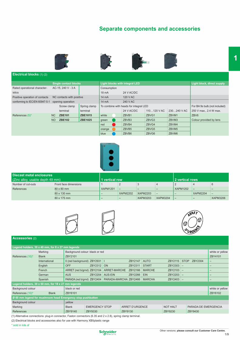
Separate components and accessories
Electrical blocks (1) (2)
Single contact blocks Light blocks with integral LED Light block, direct supplyRated operational character-istics
AC-15, 240 V - 3 A Consumption18 mA 24 V AC/DC
Positive operation of contacts NC contacts with positiveopening operation
14 mA 120 V ACconforming to IEC/EN 60947-5-1 14 mA 240 V AC
Screw clamp terminal
Spring clamp terminal
To combine with heads for integral LED For BA 9s bulb (not included)24 V AC/DC 110…120 V AC 230…240 V AC 250 V max., 2.4 W max.
References (5)* NC ZBE101 ZBE1015 white ZBVB1 ZBVG1 ZBVM1 ZBV6NO ZBE102 ZBE1025 green ZBVB3 ZBVG3 ZBVM3 Colour provided by lens
red ZBVB4 ZBVG4 ZBVM4orange ZBVB5 ZBVG5 ZBVM5blue ZBVB6 ZBVG6 ZBVM6
Diecast metal enclosures(Zinc alloy, usable depth 49 mm) 1 vertical row 2 vertical rowsNumber of cut-outs Front face dimensions 1 2 3 4 2 4 6References 80 x 80 mm XAPM1201 – – – XAPM1202 – –
80 x 130 mm – XAPM2202 XAPM2203 – – XAPM2204 –80 x 175 mm – – XAPM3203 XAPM3204 – – XAPM3206
Accessories (2)
Legend holders, 30 x 40 mm, for 8 x 27 mm legendsMarking Background colour: black or red white or yellow
References (10)* Blank ZBY2101 ZBY4101International 0 (red background) ZBY2931 I ZBY2147 AUTO ZBY2115 STOP ZBY2304 –English OFF ZBY2312 ON ZBY2311 START ZBY2303 – –French ARRET (red b/grnd) ZBY2104 ARRET-MARCHE ZBY2166 MARCHE ZBY2103 – –German AUS ZBY2204 AUS-EIN ZBY2266 EIN ZBY2203 – –Spanish PARADA (red b/grnd) ZBY2404 PARADA-MARCHA ZBY2466 MARCHA ZBY2403 – –
Legend holders, 30 x 50 mm, for 18 x 27 mm legendsBackground colour black or red white or yellowReferences (10)* Blank ZBY6101 ZBY6102Ø 60 mm legend for mushroom head Emergency stop pushbuttonBackground colour yellowMarking Blank EMERGENCY STOP ARRET D’URGENCE NOT HALT PARADA DE EMERGENCIAReferences ZBY9140 ZBY9330 ZBY9130 ZBY9230 ZBY9430
(1) Alternative connections: plug-in connector, Faston connectors (6.35 and 2 x 2.8), spring clamp terminal.(2) Electrical blocks and accessories also for use with Harmony XB5plastic range* sold in lots of
1/9
2
1
3
4
5
6
7
8
9
10
Other versions: please consult our Customer Care Centre.
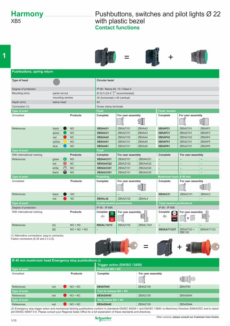
Type of push Double-headed pushbuttons Triple-headed pushbuttonsDegree of protection IP 66 - IP 69K IP 66 - IP 69KWith international marking Products Complete
(A)For user assembly Complete
(B)For user assembly
References (A) NO + NC XB5AL73415 ZB5AZ105 ZB5AL7341 – – –(B) NO + NC + NO – – – XB5AA711237 ZB5AZ103 +
ZBE102ZB5AA71123
(1) Alternative connections: plug-in connector, Faston connectors (6.35 and 2 x 2.8).
HarmonyXB5
Pushbuttons, switches and pilot lights Ø 22 with plastic bezelContact functions
Pushbuttons, spring return
Type of head Circular bezel
Degree of protection IP 66 / Nema 4X, 13 / Class IIMounting (mm) panel cut-out Ø 22.5 (22.4 recommended)
mounting centres 30 (horizontal) x 40 (vertical)Depth (mm) below head 43Connection (1) Screw clamp terminals
+ 0.4 0
Type of push Flush Flush, bootedUnmarked Products Complete For user assembly Complete For user assembly
References black NO XB5AA21 ZB5AZ101 ZB5AA2 XB5AP21 ZB5AZ101 ZB5AP2green NO XB5AA31 ZB5AZ101 ZB5AA3 XB5AP31 ZB5AZ101 ZB5AP3red NC XB5AA42 ZB5AZ102 ZB5AA4 XB5AP42 ZB5AZ102 ZB5AP4yellow NO XB5AA51 ZB5AZ101 ZB5AA5 XB5AP51 ZB5AZ101 ZB5AP5blue NO XB5AA61 ZB5AZ101 ZB5AA6 XB5AP61 ZB5AZ101 ZB5AP6
Type of push FlushWith international marking Products Complete For user assembly Complete For user assemblyReferences green NO XB5AA3311 ZB5AZ101 ZB5AA331 – – –
red NC XB5AA4322 ZB5AZ102 ZB5AA432 – – –white NO XB5AA3341 ZB5AZ101 ZB5AA334 – – –black NO XB5AA3351 ZB5AZ101 ZB5AA335 – – –
Type of push Projecting Mushroom head, Ø 40 mmUnmarked Products Complete For user assembly Complete For user assembly
References black NO – – – XB5AC21 ZB5AZ101 ZB5AC2red NC XB5AL42 ZB5AZ102 ZB5AL4 – – –
Ø 40 mm mushroom head Emergency stop pushbuttons (2)Trigger action (EN/ISO 13850)
Type of push Push-pull NO + NCUnmarked Products Complete For user assembly
References red NO + NC XB5AT845 ZB5AZ105 ZB5AT84Type of push Turn to release NO + NCReferences red NO + NC XB5AS8445 ZB5AZ105 ZB5AS844Type of push Key release NO + NCReferences red NO + NC XB5AS9445 ZB5AZ105 ZB5AS944
(2) Emergency stop trigger action and mechanical latching pushbuttons conform to standards EN/IEC 60204-1 and EN/ISO 13850: to Machinery Directive 2006/42/EC and to stand-ard EN/IEC 60947-5-5. Please consult your Regional Sales Office for a full explanation of these standards and directives.
+
= +
= +
1/10
2
1
3
4
5
6
7
8
9
10
Other versions: please consult our Customer Care Centre.
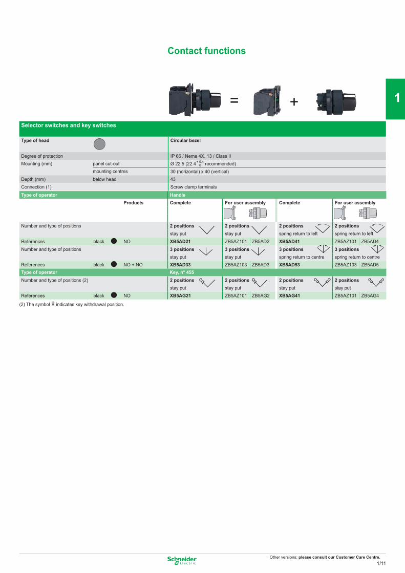
Contact functions
Selector switches and key switches
Type of head Circular bezel
Degree of protection IP 66 / Nema 4X, 13 / Class IIMounting (mm) panel cut-out Ø 22.5 (22.4 recommended)
mounting centres 30 (horizontal) x 40 (vertical)Depth (mm) below head 43Connection (1) Screw clamp terminals
Type of operator HandleProducts Complete For user assembly Complete For user assembly
Number and type of positions 2 positions 2 positions 2 positions 2 positionsstay put stay put spring return to left spring return to left
References black NO XB5AD21 ZB5AZ101 ZB5AD2 XB5AD41 ZB5AZ101 ZB5AD4Number and type of positions 3 positions 3 positions 3 positions 3 positions
stay put stay put spring return to centre spring return to centreReferences black NO + NO XB5AD33 ZB5AZ103 ZB5AD3 XB5AD53 ZB5AZ103 ZB5AD5Type of operator Key, n° 455Number and type of positions (2) 2 positions 2 positions 2 positions 2 positions
stay put stay put stay put stay putReferences black NO XB5AG21 ZB5AZ101 ZB5AG2 XB5AG41 ZB5AZ101 ZB5AG4
(2) The symbol indicates key withdrawal position.
+ 0.4 0
= +
1/11
2
1
3
4
5
6
7
8
9
10
Other versions: please consult our Customer Care Centre.
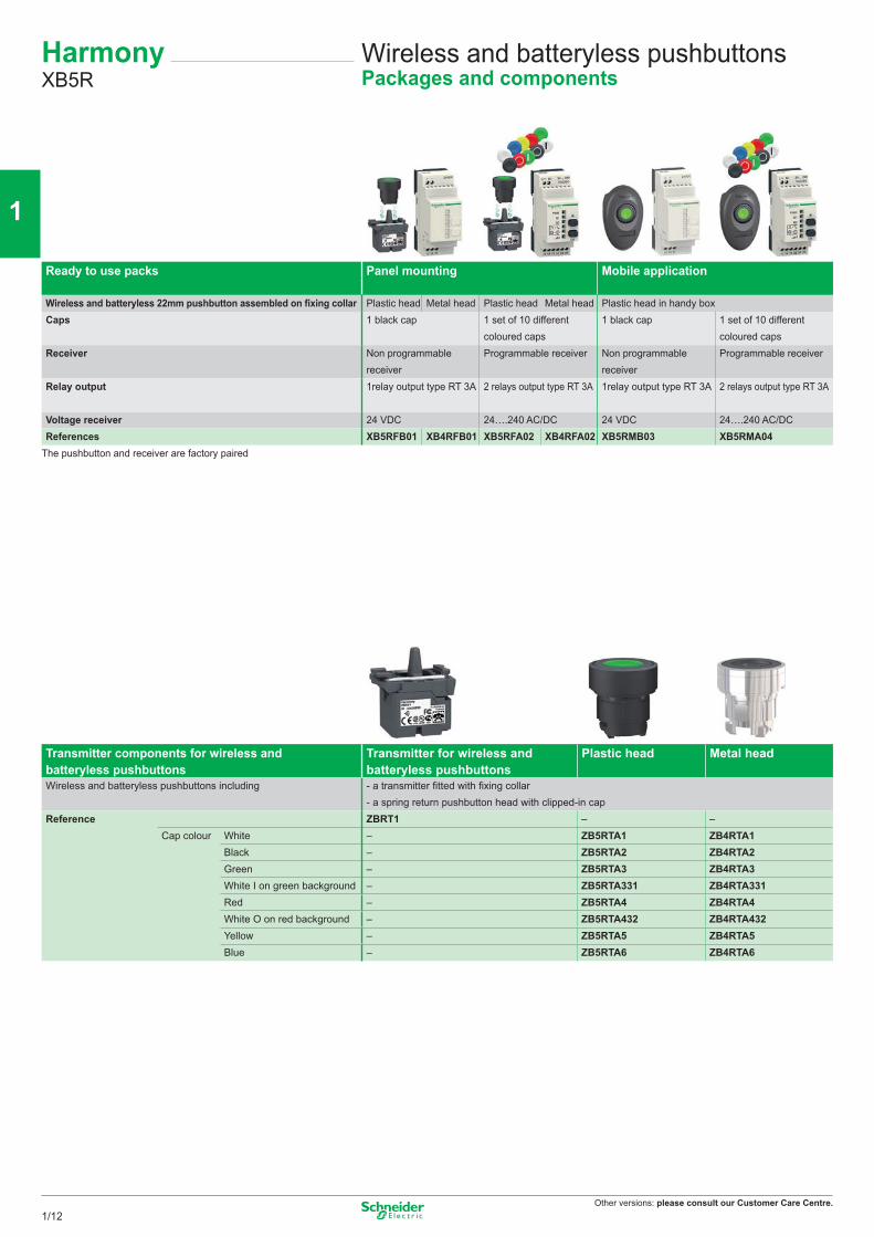
HarmonyXB5R
Wireless and batteryless pushbuttonsPackages and components
Ready to use packs Panel mounting Mobile application
Wireless and batteryless 22mm pushbutton assembled on fixing collar Plastic head Metal head Plastic head Metal head Plastic head in handy boxCaps 1 black cap 1 set of 10 different
coloured caps1 black cap 1 set of 10 different
coloured capsReceiver Non programmable
receiverProgrammable receiver Non programmable
receiverProgrammable receiver
Relay output 1relay output type RT 3A 2 relays output type RT 3A 1relay output type RT 3A 2 relays output type RT 3A
Voltage receiver 24 VDC 24….240 AC/DC 24 VDC 24….240 AC/DCReferences XB5RFB01 XB4RFB01 XB5RFA02 XB4RFA02 XB5RMB03 XB5RMA04
The pushbutton and receiver are factory paired
Transmitter components for wireless and batteryless pushbuttons
Transmitter for wireless and batteryless pushbuttons
Plastic head Metal head
Wireless and batteryless pushbuttons including - a transmitter fitted with fixing collar - a spring return pushbutton head with clipped-in cap
Reference ZBRT1 – –Cap colour White – ZB5RTA1 ZB4RTA1
Black – ZB5RTA2 ZB4RTA2Green – ZB5RTA3 ZB4RTA3White I on green background – ZB5RTA331 ZB4RTA331Red – ZB5RTA4 ZB4RTA4White O on red background – ZB5RTA432 ZB4RTA432Yellow – ZB5RTA5 ZB4RTA5Blue – ZB5RTA6 ZB4RTA6
1/12
2
1
3
4
5
6
7
8
9
10
Other versions: please consult our Customer Care Centre.
Programmable receivers
Programmable receivers equipped with - 2 buttons (learn, parameter setting) - 6 indicating LEDs (power ON, outputs, signal strenght)
Output type 4 PNP outputs 200 mA / 24V 2 relay outputs type RT 3AReceiver voltage 24 VDC 24….240 AC/DCReferences ZBRRC ZBRRA
Relay antenna
The relay antenna is placed between transmitter and receiver Used to increase the distance and/or get round obstacles - 5m cable - 1 power-ON LED - 2 LEDs reception / transmission - Relay antenna voltage : 24….240 AC/DC
Reference ZBRA1
Empty boxes Handy box, plastic, empty Empty plastic boxes1 cut-out 1 cut-out 2 cut-outs
References ZBRM01 XALD01 XALD02
1/13
2
1
3
4
5
6
7
8
9
10
Other versions: please consult our Customer Care Centre.
HarmonyXB5
Pushbuttons, switches and pilot lights Ø 22 with plastic bezelLight functions
Pilot lights
Type of head Circular bezelSmooth lens cap
Degree of protection IP 66 / Nema 4X, 13 / Class IIMounting (mm) panel cut-out Ø 22.5 (22.4 recommended)
mounting centres 30 (horizontal) x 40 (vertical)Depth below head 43Connection (1) Screw clamp terminalsLight source Integral LED Direct supply for BA 9s bulb (not included)
Products Complete Complete For user assembly
Supply voltage 24 V AC/DC 110…120 V AC 230…240 V AC 250 V max., 2.4 W max.References white XB5AVB1 XB5AVG1 XB5AVM1 XB5AV61 ZB5AV6 ZB5AV01
green XB5AVB3 XB5AVG3 XB5AVM3 XB5AV63 ZB5AV6 ZB5AV03red XB5AVB4 XB5AVG4 XB5AVM4 XB5AV64 ZB5AV6 ZB5AV04orange XB5AVB5 XB5AVG5 XB5AVM5 XB5AV65 ZB5AV6 ZB5AV05blue XB5AVB6 XB5AVG6 XB5AVM6 – – –
Illuminated pushbuttons and selector switches
Type Flush push, spring return, illuminated pushbuttonsLight source Integral LED Direct supply for BA 9s bulb (not included)
Products Complete Complete For user assembly
Supply voltage 24 V AC/DC 110…120 V AC 230…240 V AC 250 V max., 2.4 W max.References white NO + NC XB5AW31B5 XB5AW31G5 XB5AW31M5 XB5AW3165 ZB5AW065 ZB5AW31
green NO + NC XB5AW33B5 XB5AW33G5 XB5AW33M5 XB5AW3365 ZB5AW065 ZB5AW33red NO + NC XB5AW34B5 XB5AW34G5 XB5AW34M5 XB5AW3465 ZB5AW065 ZB5AW34orange NO + NC XB5AW35B5 XB5AW35G5 XB5AW35M5 XB5AW3565 ZB5AW065 ZB5AW35blue NO + NC XB5AW36B5 XB5AW36G5 XB5AW36M5 – – –
Type Double-headed pushbuttons with LED pilot light Illuminated selector switches(1 flush green push, 1 projecting red push) (2 position stay put)
Degree of protection IP 66 - IP 69K IP 66Light source Integral LED Integral LED
Products Complete CompleteSupply voltage 24 V AC/DC 110…120 V AC 230…240 V AC 24 V AC/DC 110…120 V AC 230…240 V ACReferences green NO + NC – – – XB5AK123B5 XB5AK123G5 XB5AK123M5
red NO + NC – – – XB5AK124B5 XB5AK124G5 XB5AK124M5orange NO + NC – – – XB5AK125B5 XB5AK125G5 XB5AK125M5white NO + NC XB5AW73731B5 XB5AW73731G5 XB5AW73731M5 – – –
(1) Alternative connections: plug-in connector, Faston connectors (6.35 and 2 x 2.8), spring clamp terminal.Separate components and accessories: see previous page.
+ 0.4 0
= +
= +
1/14
2
1
3
4
5
6
7
8
9
10
Other versions: please consult our Customer Care Centre.
Control stationsFor XB5pushbuttons, switches and pilot lights Ø 22 with plastic bezel
HarmonyXAL
(1) Empty enclosures:Basic reference: XALK0p, replace the p by the number of cut-outs required (see cut-out table above)
(1):Number of cut-outs Number (p)1 12 23 34 45 5
Complete stations with 1 pushbutton, selector switch or key switch(light grey RAL 7035 base with dark grey RAL 7016 lid)Degree of protection IP 65 / Nema 4X and 13 / Class IIDimensions (mm) W x H x D 68 x 68 x 113 max. (with key release Ø 40 mushroom head pushbutton)Fixing (mm) 2 x Ø 4.3 on 54 mm centresFunction 1 Start or Stop function 1 Start-Stop function
Marking On spring return push On legend holder and legend below headNumber and type of pushbutton/selector switch/key switch 1 flush green p/b 1 flush red p/b 1 projecting red p/b 1 2 position stay put selector switch or key switch
Black handle Key n° 455 (key withdrawal LH pos.)References NO I XALD102 – – – –
Start XALD103 – – – –O - I – – – XALD134 XALD144O – XALD112 XALD115 – –
Function Emergency stop (2) (light grey RAL 7035 base with yellow RAL 1012 lid)Number and type of mushroom head pushbutton 1 red Ø 40 head, turn to release 1 red Ø 40 head, key releaseLatching mechanism Trigger action (EN/ISO 13850) Trigger action (EN/ISO 13850)References NC XALK178 XALK188
NC + NC XALK178F XALK188FNO + NC XALK178E XALK188ENC + NC + NO XALK178G XALK188G
(2) Emergency stop trigger action and mechanical latching pushbuttons conform to standards EN/IEC 60204-1 and EN/ISO 13850, to Machinery Directive 2006/42/EC and to stand-ard EN/IEC 60947-5-5. Please consult your Regional Sales Office for a full explanation of these standards and directives.
(1) Empty enclosures:Basic reference: XALD0p, replace the p by the number of cut-outs required (see cut-out table above)
Complete stations with 2 and 3 pushbuttons or 2 pushbuttons + 1 pilot light(light grey RAL 7035 base with dark grey RAL 7016 lid)Dimensions (mm) W x H x D 2-way control stations: 68 x 106 x 62; 3-way control stations: 68 x 136 x 87Fixing (mm) 2-way control stations: 2 x Ø 4.3 on 54 x 68 centres; 3-way control stations: 2 x Ø 4.3 on 54 x 98 centresFunction Start-Stop functions 2 functions 3 functions
Marking On spring return pushNumber and type of pushbutton/pilot light 1 flush green p/b 1 flush green pushbutton 1 flush white p/b 1 flush white p/b 1 flush white p/b
1 flush red p/b 1 flush red pushbutton 1 flush black p/b 1 flush red p/b 1 Ø 30 red mush-1 red pilot light with integral LED 1 flush black p/b room head p/b
1 flush black p/b24 V AC/DC 230 V AC
References NO + NC I - O XALD213 XALD363B XALD363M – – –Start - Stop XALD215 – – – – –
NO + NO – – – XALD222 – –NO + NC + NO – – – – XALD324 XALD328
Accessories Standard contact blocks Light blocks with integral LED, colour redDescription NO contact NC contact 24 V AC/DC 230 V ACReferences ZENL1111 ZENL1121 ZALVB4 ZALVM4
1/15
2
1
3
4
5
6
7
8
9
10
Other versions: please consult our Customer Care Centre.
Pushbuttons
Type of head Flush or projecting pushcircular
Degree of protection IP 65, class IIMounting (mm) panel cut-out Ø 22.4 (0 +0.1)
mounting centres 30 (horizontal) x 40 (vertical)Dimensions (mm) Ø x Depth (below head) Ø 29 x 41.5 (Ø 40 x 41.5 for Emergency stop)Connection Screw clamp terminals, 1 x 0.34 mm2 to 1 x 1.5 mm2
Type of push Flush, spring return Flush, push and latchingReferences (10)* white NO XB7NA11 –
NO + NC XB7NA15 –black NO XB7NA21 XB7NH21
NO + NC XB7NA25 XB7NH25green NO XB7NA31 XB7NH31
NO + NC XB7NA35 XB7NH35red NC XB7NA42 –
NO + NC XB7NA45 –yellow NO XB7NA81 –
Type of push Flush, spring return Projecting, spring returnReferences green NO XB7NA3131 –
red NC – XB7NL4232white NO XB7NA11341 –black NO XB7NA21341 –
NO + NC XB7NA25341 –
Selector switches and key switches
Type of operator Black handle Key, n° 455Number andtype of positions
2 positions 3 positions 2 positions 3 positionsstay put stay put stay put stay put
References (10*) NO XB7ND21 – XB7NG21 –NO + NC XB7ND25 – – –2 NO – XB7ND33 – XB7NG33
Ø 40mm Emmergency Stop trigger action and mechanical latching pushbuttons
Type of push Turn to release Push, Pull Key release (n° 455)References* red NC XB7 NS8442 XB7 NT842 -
red NO + NC XB7 NS8445 XB7 NT845 XB7 NS9445 red 2NC XB7 NS8444 XB7 NT844 XB7 NS9444
* sold in lots of 10
HarmonyXB7
Pushbuttons, switches and pilot lights Ø 22 with plastic bezel - MonolithicContact functions
1/16
2
1
3
4
5
6
7
8
9
10
Other versions: please consult our Customer Care Centre.
Illuminated pushbuttons
Type of head Projecting pushcircular
Degree of protection IP 65, class IIMounting (mm) panel cut-out Ø 22.4 (0 +0.1)
mounting centres 30 (horizontal) x 40 (vertical)Dimensions (mm) Ø x Depth (below head) Ø 29 x 41.5, (Ø 40 x 41.5 for Emergency stop)Connection Screw clamp terminals, 1 x 0.34 mm2 to 1 x 1.5 mm2
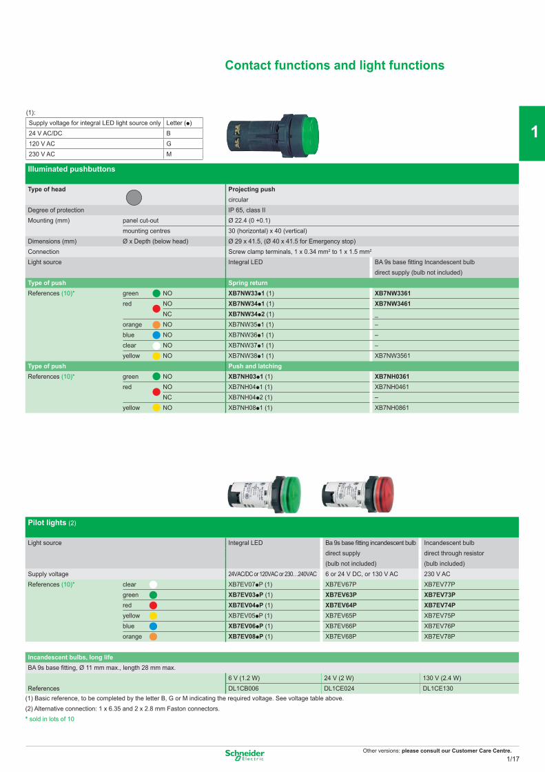
Light source Integral LED BA 9s base fitting Incandescent bulbdirect supply (bulb not included)
Type of push Spring returnReferences (10)* green NO XB7NW33p1 (1) XB7NW3361
red NO XB7NW34p1 (1) XB7NW3461NC XB7NW34p2 (1) _
orange NO XB7NW35p1 (1) –blue NO XB7NW36p1 (1) –clear NO XB7NW37p1 (1) –yellow NO XB7NW38p1 (1) XB7NW3561
Type of push Push and latchingReferences (10)* green NO XB7NH03p1 (1) XB7NH0361
red NO XB7NH04p1 (1) XB7NH0461NC XB7NH04p2 (1) –
yellow NO XB7NH08p1 (1) XB7NH0861
Pilot lights (2)
Light source Integral LED Ba 9s base fitting incandescent bulb Incandescent bulbdirect supply direct through resistor(bulb not included) (bulb included)
Supply voltage 24VAC/DC or 120VAC or 230…240VAC 6 or 24 V DC, or 130 V AC 230 V ACReferences (10)* clear XB7EV07pP (1) XB7EV67P XB7EV77P
green XB7EV03pP (1) XB7EV63P XB7EV73Pred XB7EV04pP (1) XB7EV64P XB7EV74Pyellow XB7EV05pP (1) XB7EV65P XB7EV75Pblue XB7EV06pP (1) XB7EV66P XB7EV76Porange XB7EV08pP (1) XB7EV68P XB7EV78P
Incandescent bulbs, long lifeBA 9s base fitting, Ø 11 mm max., length 28 mm max.
6 V (1.2 W) 24 V (2 W) 130 V (2.4 W)References DL1CB006 DL1CE024 DL1CE130
(1) Basic reference, to be completed by the letter B, G or M indicating the required voltage. See voltage table above.(2) Alternative connection: 1 x 6.35 and 2 x 2.8 mm Faston connectors.* sold in lots of 10
Contact functions and light functions
(1):Supply voltage for integral LED light source only Letter (p)24 V AC/DC B120 V AC G230 V AC M
1/17
2
1
3
4
5
6
7
8
9
10
Other versions: please consult our Customer Care Centre.
Pushbuttons, spring return
Type of push Flush Projecting Projecting (high guard)Colour of push Multi-colour (set of 7 clip-in coloured caps)Degree of protection IP 66 / Nema 1, 2, 3, 3R, 4, 6, 12 and 13 / Class IIMounting (mm) panel cut-out Ø 31
mounting centres 57.2 x 44.5 (with legend 9001KN2pp), 57.2 x 50.8 (with legend 9001KN3pp)Depth below head (mm) 42Connection Screw clamp terminalsReferences CO 9001KR1UH13 9001KR3UH13 9001KR2UH13
NO 9001KR1UH5 9001KR3UH5 9001KR2UH5
Mushroom head pushbuttons, latching (1) Emergency switching off Emergency stop
Type of push Push-pull Turn-to-Release, trigger actionØ 41 mushroom head Ø 35 mushroom head Ø 40 red mushroom head
Degree of protection IP 66 / Nema 1, 2, 3, 3R, 4, 6, 12 and 13 / Class II IP 66 / Nema 1, 2, 3, 3R, 4, 6, 12 and 13 / Class IIIMounting (mm) panel cut-out Ø 31
mounting centres 57.2 x 44.5 (with legend 9001KN2pp), 57.2 x 50.8 (with legend 9001KN3pp)
57,2 x 44,5 (without legend plate), 100 x 100 ((with legend plate 9001KN8330) (2)
Depth below head (mm) 42 60Connection Screw clamp terminalsReferences – – – 9001KR16
CO 9001KR9R94H13 9001KR9R20H13 –NC 9001KR9RH6 9001KR9R20H6 –2NO + 2NC – – 9001KR16H2NO – – 9001KR16H13
(1) Mushroom head switching off mechanical latching pushbuttons conform to standard IEC 60364-5-53 and EN/IEC 60947-5-5. Mushroom trigger action and mechanical latching head Emergency stop pushbuttons conforming to standard EN/IEC 60204-1 and EN/ISO 13850, to Machinery directive 2006/42/EC and standard EN/IEC 60947-5-5.(2) For yellow circular Emergency Stop legend plates: see page 2/19
Selector switches and key switches
Type of operator Long black handle Key, n° 455positions (2) 3 - spring return 2 - stay put 2 - spring return 3 - stay put 2 - stay put
Number and typeof positionsDegree of protection IP 66 / Nema 1, 2, 3, 3R, 4, 6, 12 and 13 / Class IIMounting (mm) panel cut-out Ø 31
mounting centres 57.2 x 44.5 (with legend 9001KN2pp), 57.2 x 50.8 (with legend 9001KN3pp)Depth below head (mm) 42Connection Screw clamp terminalsReferences NO – 9001KS11FBH5 9001KS34FBH5 – –
CO 9001KS53FBH1 – – 9001KS43FBH1 9001KS11K1RH1(2) The symbol indicates key withdrawal position.
Harmony9001K/SK
Pushbuttons, switches and pilot lights Ø 30 with metal bezelContact functions
1/18
2
1
3
4
5
6
7
8
9
10
Other versions: please consult our Customer Care Centre.
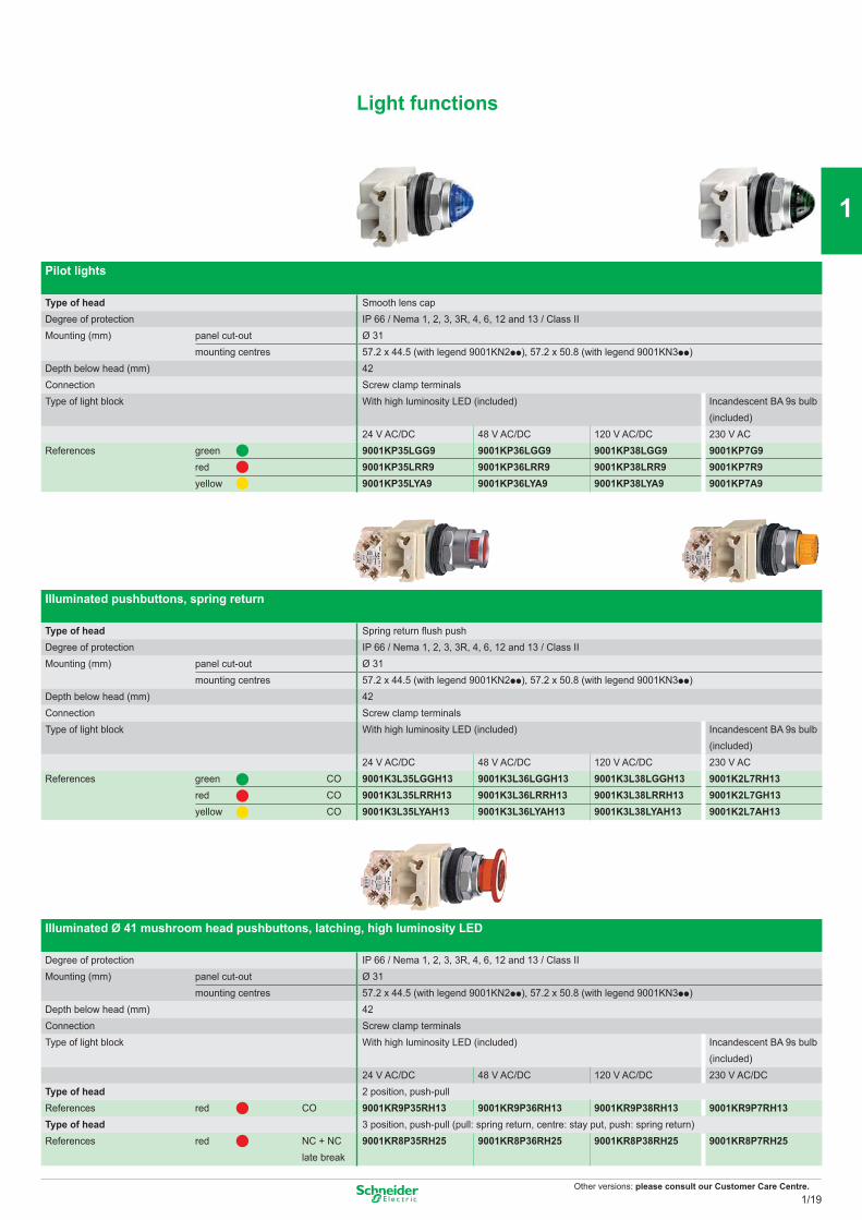
Pilot lights
Type of head Smooth lens capDegree of protection IP 66 / Nema 1, 2, 3, 3R, 4, 6, 12 and 13 / Class IIMounting (mm) panel cut-out Ø 31
mounting centres 57.2 x 44.5 (with legend 9001KN2pp), 57.2 x 50.8 (with legend 9001KN3pp)Depth below head (mm) 42Connection Screw clamp terminalsType of light block With high luminosity LED (included) Incandescent BA 9s bulb
(included)24 V AC/DC 48 V AC/DC 120 V AC/DC 230 V AC
References green 9001KP35LGG9 9001KP36LGG9 9001KP38LGG9 9001KP7G9red 9001KP35LRR9 9001KP36LRR9 9001KP38LRR9 9001KP7R9yellow 9001KP35LYA9 9001KP36LYA9 9001KP38LYA9 9001KP7A9
Illuminated pushbuttons, spring return
Type of head Spring return flush pushDegree of protection IP 66 / Nema 1, 2, 3, 3R, 4, 6, 12 and 13 / Class IIMounting (mm) panel cut-out Ø 31
mounting centres 57.2 x 44.5 (with legend 9001KN2pp), 57.2 x 50.8 (with legend 9001KN3pp)Depth below head (mm) 42Connection Screw clamp terminalsType of light block With high luminosity LED (included) Incandescent BA 9s bulb
(included)24 V AC/DC 48 V AC/DC 120 V AC/DC 230 V AC
References green CO 9001K3L35LGGH13 9001K3L36LGGH13 9001K3L38LGGH13 9001K2L7RH13red CO 9001K3L35LRRH13 9001K3L36LRRH13 9001K3L38LRRH13 9001K2L7GH13yellow CO 9001K3L35LYAH13 9001K3L36LYAH13 9001K3L38LYAH13 9001K2L7AH13
Illuminated Ø 41 mushroom head pushbuttons, latching, high luminosity LED
Degree of protection IP 66 / Nema 1, 2, 3, 3R, 4, 6, 12 and 13 / Class IIMounting (mm) panel cut-out Ø 31
mounting centres 57.2 x 44.5 (with legend 9001KN2pp), 57.2 x 50.8 (with legend 9001KN3pp)Depth below head (mm) 42Connection Screw clamp terminalsType of light block With high luminosity LED (included) Incandescent BA 9s bulb
(included)24 V AC/DC 48 V AC/DC 120 V AC/DC 230 V AC/DC
Type of head 2 position, push-pullReferences red CO 9001KR9P35RH13 9001KR9P36RH13 9001KR9P38RH13 9001KR9P7RH13Type of head 3 position, push-pull (pull: spring return, centre: stay put, push: spring return)References red NC + NC
late break9001KR8P35RH25 9001KR8P36RH25 9001KR8P38RH25 9001KR8P7RH25
Light functions
1/19
2
1
3
4
5
6
7
8
9
10
Other versions: please consult our Customer Care Centre.
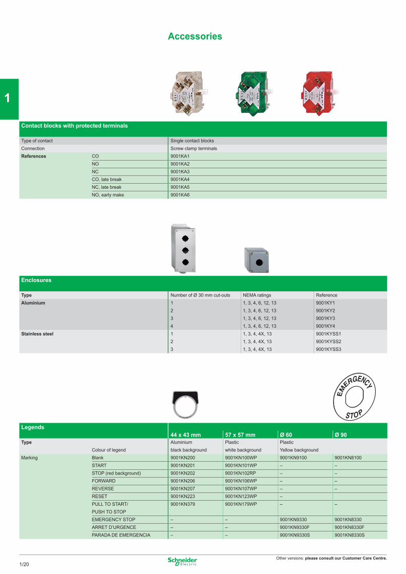
Contact blocks with protected terminals
Type of contact Single contact blocksConnection Screw clamp terminalsReferences CO 9001KA1
NO 9001KA2NC 9001KA3CO, late break 9001KA4NC, late break 9001KA5NO, early make 9001KA6
Enclosures
Type Number of Ø 30 mm cut-outs NEMA ratings ReferenceAluminium 1 1, 3, 4, 6, 12, 13 9001KY1
2 1, 3, 4, 6, 12, 13 9001KY23 1, 3, 4, 6, 12, 13 9001KY34 1, 3, 4, 6, 12, 13 9001KY4
Stainless steel 1 1, 3, 4, 4X, 13 9001KYSS12 1, 3, 4, 4X, 13 9001KYSS23 1, 3, 4, 4X, 13 9001KYSS3
Legends 44 x 43 mm 57 x 57 mm Ø 60 Ø 90
Type Aluminium Plastic PlasticColour of legend black background white background Yellow background
Marking Blank 9001KN200 9001KN100WP 9001KN9100 9001KN8100START 9001KN201 9001KN101WP – –STOP (red background) 9001KN202 9001KN102RP – –FORWARD 9001KN206 9001KN106WP – –REVERSE 9001KN207 9001KN107WP – –RESET 9001KN223 9001KN123WP –PULL TO START/ 9001KN379 9001KN179WP – –PUSH TO STOPEMERGENCY STOP – – 9001KN9330 9001KN8330ARRET D’URGENCE – – 9001KN9330F 9001KN8330FPARADA DE EMERGENCIA – – 9001KN9330S 9001KN8330S
Accessories
1/20
2
1
3
4
5
6
7
8
9
10
Other versions: please consult our Customer Care Centre.
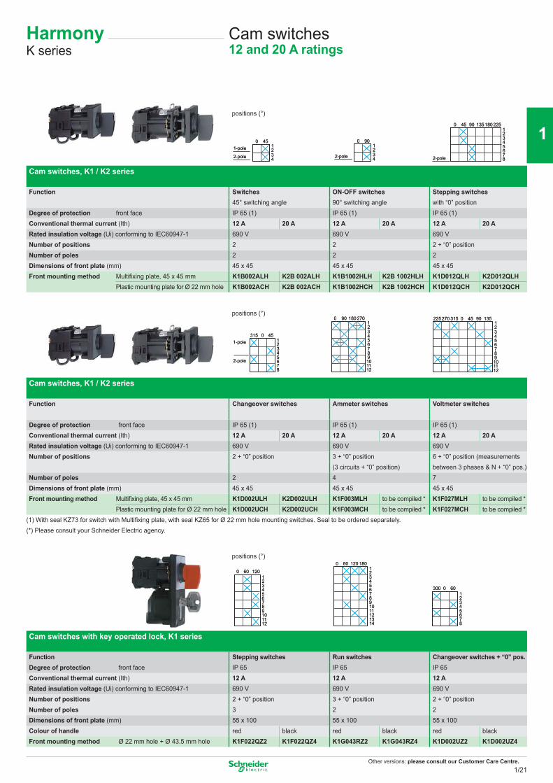
Cam switches12 and 20 A ratings
HarmonyK series
positions (°)
Cam switches, K1 / K2 series
Function Switches ON-OFF switches Stepping switches45° switching angle 90° switching angle with “0” position
Degree of protection front face IP 65 (1) IP 65 (1) IP 65 (1)Conventional thermal current (Ith) 12 A 20 A 12 A 20 A 12 A 20 ARated insulation voltage (Ui) conforming to IEC60947-1 690 V 690 V 690 VNumber of positions 2 2 2 + “0” positionNumber of poles 2 2 2Dimensions of front plate (mm) 45 x 45 45 x 45 45 x 45Front mounting method Multifixing plate, 45 x 45 mm K1B002ALH K2B 002ALH K1B1002HLH K2B 1002HLH K1D012QLH K2D012QLH
Plastic mounting plate for Ø 22 mm hole K1B002ACH K2B 002ACH K1B1002HCH K2B 1002HCH K1D012QCH K2D012QCH
positions (°)
Cam switches, K1 / K2 series
Function Changeover switches Ammeter switches Voltmeter switches
Degree of protection front face IP 65 (1) IP 65 (1) IP 65 (1)Conventional thermal current (Ith) 12 A 20 A 12 A 20 A 12 A 20 ARated insulation voltage (Ui) conforming to IEC60947-1 690 V 690 V 690 VNumber of positions 2 + “0” position 3 + “0” position 6 + “0” position (measurements
(3 circuits + “0” position) between 3 phases & N + “0” pos.)Number of poles 2 4 7Dimensions of front plate (mm) 45 x 45 45 x 45 45 x 45Front mounting method Multifixing plate, 45 x 45 mm K1D002ULH K2D002ULH K1F003MLH to be compiled * K1F027MLH to be compiled *
Plastic mounting plate for Ø 22 mm hole K1D002UCH K2D002UCH K1F003MCH to be compiled * K1F027MCH to be compiled *(1) With seal KZ73 for switch with Multifixing plate, with seal KZ65 for Ø 22 mm hole mounting switches. Seal to be ordered separately.(*) Please consult your Schneider Electric agency.
positions (°)
Cam switches with key operated lock, K1 series
Function Stepping switches Run switches Changeover switches + “0” pos.Degree of protection front face IP 65 IP 65 IP 65Conventional thermal current (Ith) 12 A 12 A 12 ARated insulation voltage (Ui) conforming to IEC60947-1 690 V 690 V 690 VNumber of positions 2 + “0” position 3 + “0” position 2 + “0” positionNumber of poles 3 2 2Dimensions of front plate (mm) 55 x 100 55 x 100 55 x 100Colour of handle red black red black red blackFront mounting method Ø 22 mm hole + Ø 43.5 mm hole K1F022QZ2 K1F022QZ4 K1G043RZ2 K1G043RZ4 K1D002UZ2 K1D002UZ4
12
450
34
1-pole
2-pole
12
450
34
1-pole
2-pole
12
900
342-pole
12
900
342-pole
901
450
2345678
135 180 225
2-pole
901
450
2345678
135 180 225
2-pole
451
0315
2345678
1-pole
2-pole
451
0315
2345678
1-pole
2-pole
1801234
900 270
56789101112
1801234
900 270
56789101112
01234
315270
5678
225
910
45 90
1112
13501234
315270
5678
225
910
45 90
1112
135
0123456789101112
60 1200123456789101112
60 120 1234567891011121314
120 1800 601234567891011121314
120 1800 60
30012345678
0 6030012345678
0 60
1/21
2
1
3
4
5
6
7
8
9
10
Other versions: please consult our Customer Care Centre.
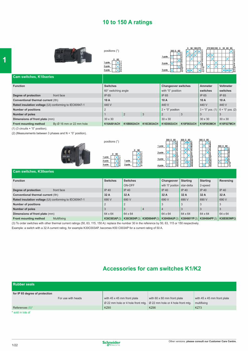
10 to 150 A ratings
positions (°)
Cam switches, K10series
Function Switches Changeover switches Ammeter Voltmeter60° switching angle with “0” position switches switches
Degree of protection front face IP 65 IP 65 IP 65 IP 65Conventional thermal current (Ith) 10 A 10 A 10 A 10 ARated insulation voltage (Ui) conforming to IEC60947-1 440 V 440 V 440 V 440 VNumber of positions 2 2 + “0” position 3 + “0” pos. (1) 6 + “0” pos. (2)Number of poles 1 2 3 2 3 3 3Dimensions of front plate (mm) 30 x 30 30 x 30 30 x 30 30 x 30Front mounting method By Ø 16 mm or 22 mm hole K10A001ACH K10B002ACH K10C003ACH K10D002UCH K10F003UCH K10F003MCH K10F027MCH
(1) (3 circuits + “0” position).(2) (Measurements between 3 phases and N + “0” position).
positions (°)
Cam switches, K30series
Function Switches Switches Changeover Starting Starting ReversingON-OFF with “0” position star-delta 2-speed
Degree of protection front face IP 40 IP 40 IP 40 IP 40 IP 40 IP 40Conventional thermal current (Ith) 32 A 32 A 32 A 32 A 32 A 32 ARated insulation voltage (Ui) conforming to IEC60947-1 690 V 690 V 690 V 690 V 690 V 690 VNumber of positions 2 2 3 3 3 3Number of poles 3 3 4 4 3 3 3Dimensions of front plate (mm) 64 x 64 64 x 64 64 x 64 64 x 64 64 x 64 64 x 64Front mounting method Multifixing K30C003AP (3) K30C003HP (3) K30D004HP (3) K30H004UP (3) K30H001YP (3) K30H004PP (3) K30E003WP(3)
(3) To order switches with other thermal current ratings (50, 63, 115, 150 A): replace the number 30 in the reference by 50, 63, 115 or 150 respectively. Example: a switch with a 32 A current rating, for example K30C003AP, becomes K50 C003AP for a current rating of 50 A.
Accessories for cam switches K1/K2
Rubber seals
for IP 65 degree of protectionFor use with heads with 45 x 45 mm front plate with 60 x 60 mm front plate with 45 x 45 mm front plate
Ø 22 mm hole or 4 hole front mtg. Ø 22 mm hole or 4 hole front mtg. multifixingReferences (5)* KZ65 KZ66 KZ73
* sold in lots of
0123456
601-pole
2-pole
3-pole
0123456
601-pole
2-pole
3-pole
012
60
34
300
56789101112
1-pole
2-pole
3-pole
012
60
34
300
56789101112
1-pole
2-pole
3-pole
9012
180
34
0 270
56789101112
9012
180
34
0 270
56789101112
30012
330
34
270 0 30 60 90
56789101112
30012
330
34
270 0 30 60 90
56789101112
0123456
601-pole
2-pole
3-pole
0123456
601-pole
2-pole
3-pole
012345678
90
1-pole
2-pole
012345678
90
1-pole
2-pole
012
60
34
1234
300
5678910111213141516
1-pole
2-pole
3-pole
4-pole
012
60
34
1234
300
5678910111213141516
1-pole
2-pole
3-pole
4-pole
012
60
34
1234
300
5678910111213141516
012
60
34
1234
300
5678910111213141516
012
60
34
1234
300
5678910111213141516
012
60
34
1234
300
5678910111213141516
012
60
34
1234
300
56789101112
012
60
34
1234
300
56789101112
1/22
2
1
3
4
5
6
7
8
9
10
Other versions: please consult our Customer Care Centre.
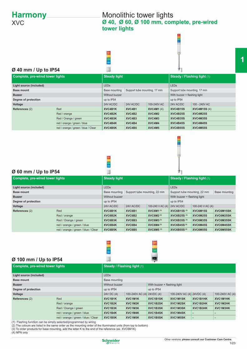
Monolithic tower lightsØ 40, Ø 60, Ø 100 mm, complete, pre-wired tower lights
HarmonyXVC
Ø 40 mm / Up to IP54Complete, pre-wired tower lights Steady light Steady / Flashing light (1)
Light source (included) LEDs LEDsBase mount Base mounting Support tube mounting, 17 mm Support tube mounting, 17 mmBuzzer Without buzzer With buzzer + flashing lightDegree of protection up to IP54 up to IP54Voltage 24V AC/DC 24V AC/DC 100-240V AC 24V AC/DC 100 - 240V ACReferences (2) Red XVC4B1K XVC4B1 XVC4M1 (4) XVC4B15S XVC4M15S (4)
Red / orange XVC4B2K XVC4B2 XVC4M2 XVC4B25S XVC4M25SRed / Orange / green XVC4B3K XVC4B3 XVC4M3 XVC4B35S XVC4M35Sred / orange / green / blue XVC4B4K XVC4B4 XVC4M4 XVC4B45S XVC4M45Sred / orange / green / blue / Clear XVC4B5K XVC4B5 XVC4M5 XVC4B55S XVC4M55S
Ø 60 mm / Up to IP54Complete, pre-wired tower lights Steady light Steady / Flashing light (1)
Light source (included) LEDs LEDsBase mount Base mounting Support tube mounting, 22 mm Support tube mounting, 22 mm Base mountingBuzzer Without buzzer With buzzer + flashing lightDegree of protection up to IP54 up to IP54Voltage 24V AC/DC 24V AC/DC 100-240 V AC (4) 24V AC/DC 100-240 V AC (4)References (2) Red XVC6B1K XVC6B1 XVC6M1 (3) XVC6B15S (3) XVC6M15S XVC6M15SK
Red / orange XVC6B2K XVC6B2 XVC6M2 (3) XVC6B25S (3) XVC6M25S XVC6M25SKRed / Orange / green XVC6B3K XVC6B3 XVC6M3 (3) XVC6B35S (3) XVC6M35S XVC6M35SKred / orange / green / blue XVC6B4K XVC6B4 XVC6M4 (3) XVC6B45S (3) XVC6M45S XVC6M45SKred / orange / green / blue / Clear XVC6B5K XVC6B5 XVC6M5 (3) XVC6B55S (3) XVC6M55S XVC6M55SK
Ø 100 mm / Up to IP54Complete, pre-wired tower lights Steady / Flashing light (1)
Light source (included) LEDsBase mount Base mountingBuzzer Without buzzer With buzzer + flashing lightDegree of protection up to IP54 up to IP54Voltage 24V DC (4) 100-240V AC (4) 24VDC (4) 100-240V AC (4) 24VDC (4) 100-240V AC (4)References (2) Red XVC1B1K XVC1M1K XVC1B1SK XVC1M1SK XVC1B1HK XVC1M1HK
Red / orange XVC1B2K XVC1M2K XVC1B2SK XVC1M2SK XVC1B2HK XVC1M2HKRed / Orange / green XVC1B3K XVC1M3K XVC1B3SK XVC1M3SK XVC1B3HK XVC1M3HKred / orange / green / blue XVC1B4K XVC1M4K XVC1B4SK XVC1M4SK - -red / orange / green / blue / Clear XVC1B5K XVC1M5K XVC1B5SK XVC1M5SK - -
(1) Flashing function can be simply selected/programmed by wiring(2) The colours are listed in the same order as the mounting order of the illuminated units (from top to bottom)(3) To order products for base mounting, add the letter K to the end of the reference (ex. XVC6M1K)(4) NPN only
1/23
2
1
3
4
5
6
7
8
9
10
Other versions: please consult our Customer Care Centre.
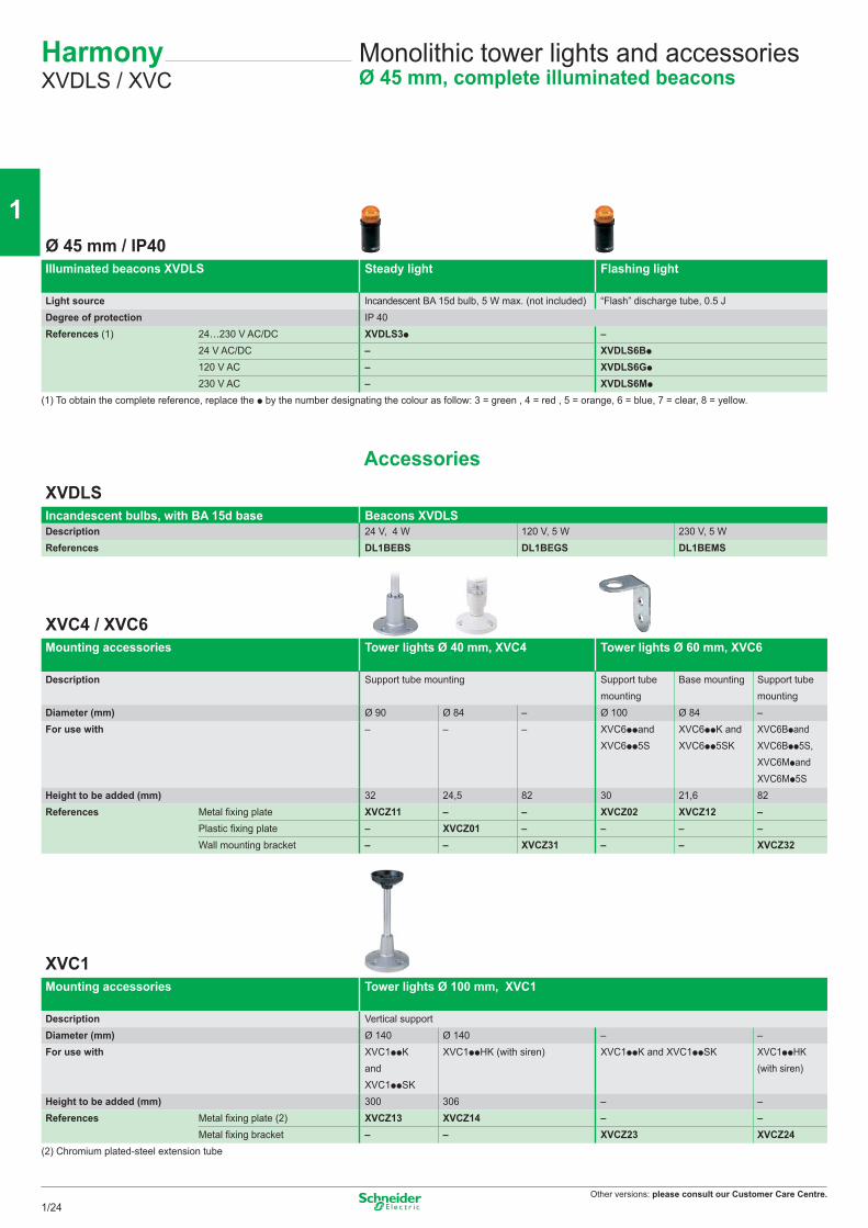
Monolithic tower lights and accessoriesØ 45 mm, complete illuminated beacons
HarmonyXVDLS / XVC
Ø 45 mm / IP40Illuminated beacons XVDLS Steady light Flashing light
Light source Incandescent BA 15d bulb, 5 W max. (not included) “Flash” discharge tube, 0.5 JDegree of protection IP 40References (1) 24…230 V AC/DC XVDLS3p –
24 V AC/DC – XVDLS6Bp
120 V AC – XVDLS6Gp
230 V AC – XVDLS6Mp
(1) To obtain the complete reference, replace the p by the number designating the colour as follow: 3 = green , 4 = red , 5 = orange, 6 = blue, 7 = clear, 8 = yellow.
AccessoriesXVDLSIncandescent bulbs, with BA 15d base Beacons XVDLSDescription 24 V, 4 W 120 V, 5 W 230 V, 5 WReferences DL1BEBS DL1BEGS DL1BEMS
XVC4 / XVC6Mounting accessories Tower lights Ø 40 mm, XVC4 Tower lights Ø 60 mm, XVC6
Description Support tube mounting Support tube mounting
Base mounting Support tube mounting
Diameter (mm) Ø 90 Ø 84 – Ø 100 Ø 84 –For use with – – – XVC6ppand
XVC6pp5SXVC6ppK and XVC6pp5SK
XVC6Bpand XVC6Bpp5S, XVC6Mpand XVC6Mp5S
Height to be added (mm) 32 24,5 82 30 21,6 82References Metal fixing plate XVCZ11 – – XVCZ02 XVCZ12 –
Plastic fixing plate – XVCZ01 – – – –Wall mounting bracket – – XVCZ31 – – XVCZ32
XVC1Mounting accessories Tower lights Ø 100 mm, XVC1
Description Vertical supportDiameter (mm) Ø 140 Ø 140 – –For use with XVC1ppK
and XVC1ppSK
XVC1ppHK (with siren) XVC1ppK and XVC1ppSK XVC1ppHK (with siren)
Height to be added (mm) 300 306 – –References Metal fixing plate (2) XVCZ13 XVCZ14 – –
Metal fixing bracket – – XVCZ23 XVCZ24(2) Chromium plated-steel extension tube
1/24
2
1
3
4
5
6
7
8
9
10
Other versions: please consult our Customer Care Centre.
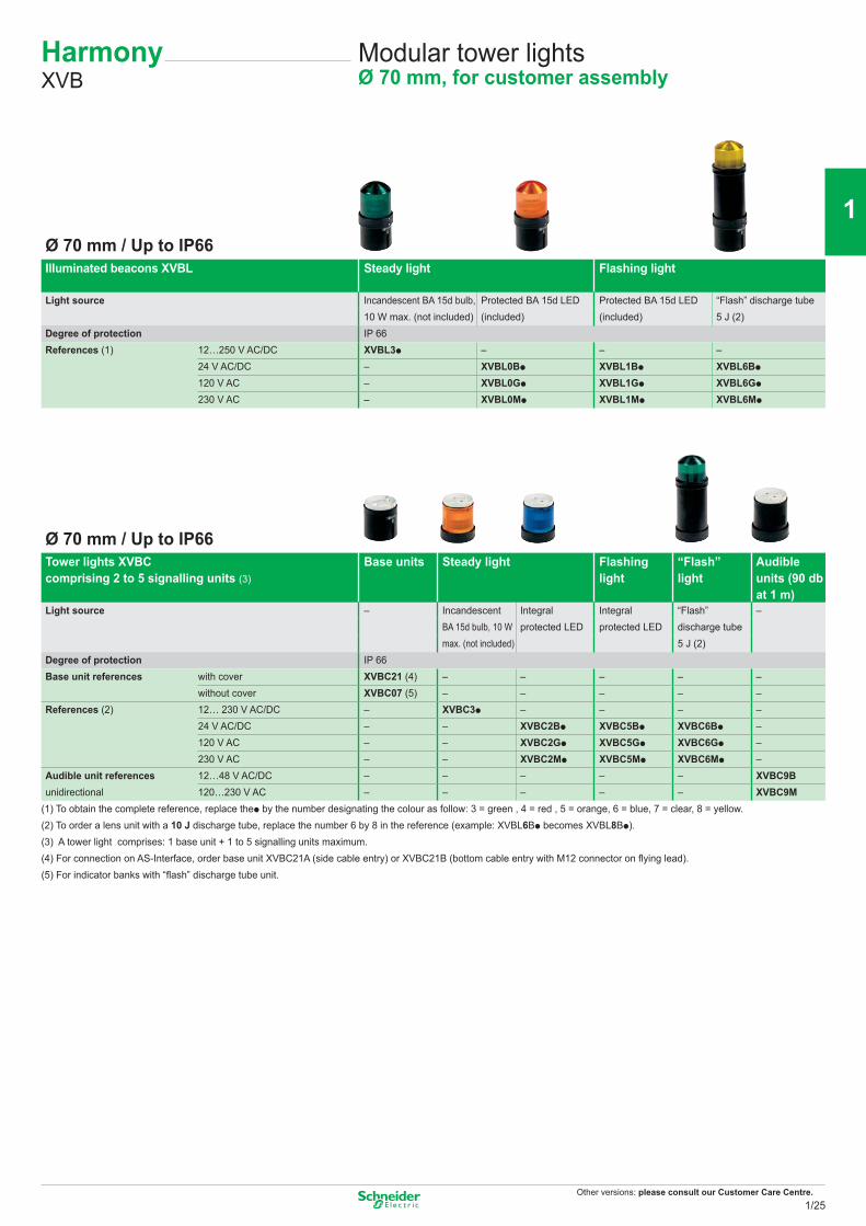
Modular tower lightsØ 70 mm, for customer assembly
HarmonyXVB
Ø 70 mm / Up to IP66Illuminated beacons XVBL Steady light Flashing light
Light source Incandescent BA 15d bulb, Protected BA 15d LED Protected BA 15d LED “Flash” discharge tube10 W max. (not included) (included) (included) 5 J (2)
Degree of protection IP 66References (1) 12…250 V AC/DC XVBL3p – – –
24 V AC/DC – XVBL0Bp XVBL1Bp XVBL6Bp
120 V AC – XVBL0Gp XVBL1Gp XVBL6Gp
230 V AC – XVBL0Mp XVBL1Mp XVBL6Mp
Ø 70 mm / Up to IP66Tower lights XVBCcomprising 2 to 5 signalling units (3)
Base units Steady light Flashinglight
“Flash”light
Audibleunits (90 dbat 1 m)
Light source – Incandescent Integral Integral “Flash” –BA 15d bulb, 10 W protected LED protected LED discharge tubemax. (not included) 5 J (2)
Degree of protection IP 66Base unit references with cover XVBC21 (4) – – – – –
without cover XVBC07 (5) – – – – –References (2) 12… 230 V AC/DC – XVBC3p – – – –
24 V AC/DC – – XVBC2Bp XVBC5Bp XVBC6Bp –120 V AC – – XVBC2Gp XVBC5Gp XVBC6Gp –230 V AC – – XVBC2Mp XVBC5Mp XVBC6Mp –
Audible unit references 12…48 V AC/DC – – – – – XVBC9Bunidirectional 120…230 V AC – – – – – XVBC9M
(1) To obtain the complete reference, replace thep by the number designating the colour as follow: 3 = green , 4 = red , 5 = orange, 6 = blue, 7 = clear, 8 = yellow.(2) To order a lens unit with a 10 J discharge tube, replace the number 6 by 8 in the reference (example: XVBL6Bp becomes XVBL8Bp).(3) A tower light comprises: 1 base unit + 1 to 5 signalling units maximum.(4) For connection on AS-Interface, order base unit XVBC21A (side cable entry) or XVBC21B (bottom cable entry with M12 connector on flying lead).(5) For indicator banks with “flash” discharge tube unit.
1/25
2
1
3
4
5
6
7
8
9
10
Other versions: please consult our Customer Care Centre.
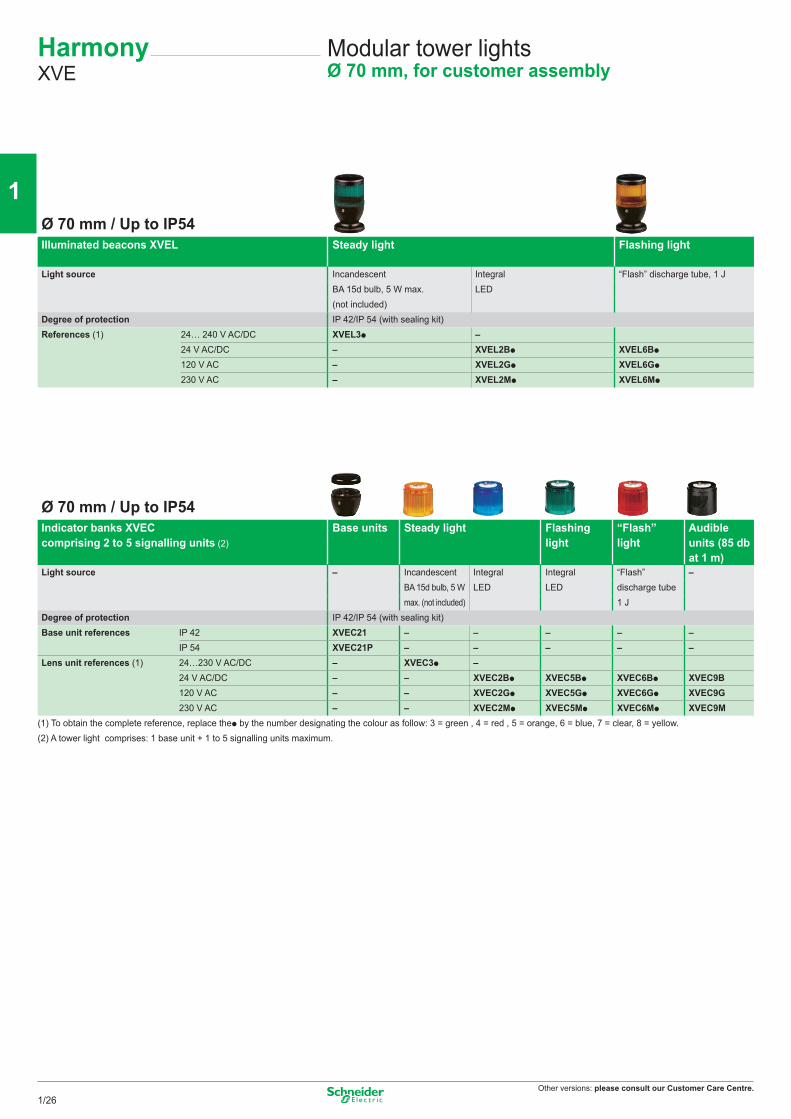
Modular tower lightsØ 70 mm, for customer assembly
HarmonyXVE
Ø 70 mm / Up to IP54Illuminated beacons XVEL Steady light Flashing light
Light source Incandescent Integral “Flash” discharge tube, 1 JBA 15d bulb, 5 W max. LED(not included)
Degree of protection IP 42/IP 54 (with sealing kit)References (1) 24… 240 V AC/DC XVEL3p –
24 V AC/DC – XVEL2Bp XVEL6Bp
120 V AC – XVEL2Gp XVEL6Gp
230 V AC – XVEL2Mp XVEL6Mp
Ø 70 mm / Up to IP54Indicator banks XVECcomprising 2 to 5 signalling units (2)
Base units Steady light Flashinglight
“Flash”light
Audibleunits (85 dbat 1 m)
Light source – Incandescent Integral Integral “Flash” –BA 15d bulb, 5 W LED LED discharge tubemax. (not included) 1 J
Degree of protection IP 42/IP 54 (with sealing kit)Base unit references IP 42 XVEC21 – – – – –
IP 54 XVEC21P – – – – –Lens unit references (1) 24…230 V AC/DC – XVEC3p –
24 V AC/DC – – XVEC2Bp XVEC5Bp XVEC6Bp XVEC9B120 V AC – – XVEC2Gp XVEC5Gp XVEC6Gp XVEC9G230 V AC – – XVEC2Mp XVEC5Mp XVEC6Mp XVEC9M
(1) To obtain the complete reference, replace thep by the number designating the colour as follow: 3 = green , 4 = red , 5 = orange, 6 = blue, 7 = clear, 8 = yellow.(2) A tower light comprises: 1 base unit + 1 to 5 signalling units maximum.
1/26
2
1
3
4
5
6
7
8
9
10
Other versions: please consult our Customer Care Centre.
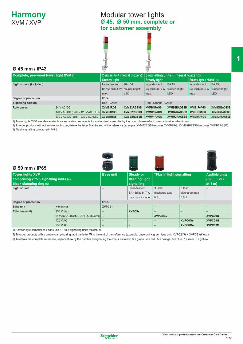
Modular tower lightsØ 45, Ø 50 mm, complete or for customer assembly
HarmonyXVM / XVP
Ø 45 mm / IP42Complete, pre-wired tower light XVM (1) 2 sig. units + integral buzzer (2)
Steady light3 signalling units + integral buzzer (2)Steady light Steady light + “flash” (3)
Light source (included) Incandescent BA 15d Incandescent BA 15d Incandescent BA 15dBA 15d bulb, 5 W “Super bright”
LEDBA 15d bulb, 5 W “Super bright”
LEDBA 15d bulb, 5 W “Super bright”
LEDmax. max. max.Degree of protection IP 54Signalling colours Red - Green Red - Orange - GreenReferences 24 V AC/DC XVMB1RGS XVMB2RGSSB XVMB1RAGS XVMB2RAGSSB XVMB1R6AGS XVMB2R6AGSSB
120 V AC/DC (bulb) - 120 V AC (LED) XVMG1RGS XVMG2RGSSB XVMG1RAGS XVMG2RAGSSB XVMG1R6AGS XVMG2R6AGSSB230 V AC/DC (bulb) - 230 V AC (LED) XVMM1RGS XVMM2RGSSB XVMM1RAGS XVMM2RAGSSB XVMM1RA6GS XVMM2R6AGSSB
(1) Tower lights XVM are also available as separate components for customised assembly by the user: please refer to www.schneider-electric.com.(2) To order products without an integral buzzer, delete the letter S at the end of the reference (example: XVMB2RGS becomes XVMB2RG, XVMB2RGSSB becomes XVMB2RGSB).(3) Flash signalling colour: red - 0.8 J.
Ø 50 mm / IP65Tower lights XVP comprising 2 to 5 signalling units (4), black clamping ring (5)
Base unit Steady or flashing light signalling
“Flash” light signalling Audible units (55…85 dB at 1 m)
Light source – Incandescent “Flash” “Flash” –BA 15d bulb, 7 W discharge tube discharge tubemax. (not included) 0.3 J 0.6 J
Degree of protection IP 65Base unit with cover XVPC21 – – – –References (6) 250 V max. – XVPC3p – – –
24 V AC/DC (flash) - 24 V DC (buzzer) – – XVPC6Bp – XVPC09B120 V AC – – – XVPC6Gp XVPC09G230 V AC – – – XVPC6Mp XVPC09M
(4) A tower light comprises: 1 base unit + 1 to 5 signalling units maximum.(5) To order products with a cream clamping ring, add the letter W to the end of the reference (example: base unit + green lens unit: XVPC21W + XVPC33W etc.).(6) To obtain the complete reference, replace thep by the number designating the colour as follow: 3 = green , 4 = red , 5 = orange, 6 = blue, 7 = clear, 8 = yellow.
1/27
2
1
3
4
5
6
7
8
9
10
Other versions: please consult our Customer Care Centre.
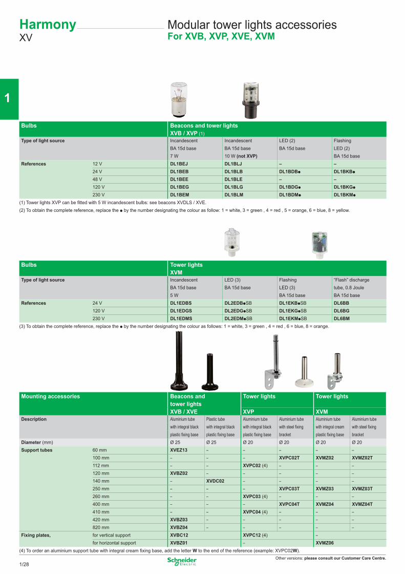
Bulbs Beacons and tower lightsXVB / XVP (1)
Type of light source Incandescent Incandescent LED (2) FlashingBA 15d base BA 15d base BA 15d base LED (2)7 W 10 W (not XVP) BA 15d base
References 12 V DL1BEJ DL1BLJ – –24 V DL1BEB DL1BLB DL1BDBp DL1BKBp
48 V DL1BEE DL1BLE – –120 V DL1BEG DL1BLG DL1BDGp DL1BKGp
230 V DL1BEM DL1BLM DL1BDMp DL1BKMp
(1) Tower lights XVP can be fitted with 5 W incandescent bulbs: see beacons XVDLS / XVE.(2) To obtain the complete reference, replace the p by the number designating the colour as follow: 1 = white, 3 = green , 4 = red , 5 = orange, 6 = blue, 8 = yellow.
Bulbs Tower lightsXVM
Type of light source Incandescent LED (3) Flashing “Flash” dischargeBA 15d base BA 15d base LED (3) tube, 0.8 Joule5 W BA 15d base BA 15d base
References 24 V DL1EDBS DL2EDBpSB DL1EKBpSB DL6BB120 V DL1EDGS DL2EDGpSB DL1EKGpSB DL6BG230 V DL1EDMS DL2EDMpSB DL1EKMpSB DL6BM
(3) To obtain the complete reference, replace the p by the number designating the colour as follows: 1 = white, 3 = green , 4 = red , 6 = blue, 8 = orange.
Mounting accessories Beacons and tower lights XVB / XVE
Tower lights Tower lights
XVP XVMDescription Aluminium tube Plastic tube Aluminium tube Aluminium tube Aluminium tube Aluminium tube
with integral black with integral black with integral black with steel fixing with integral cream with steel fixingplastic fixing base plastic fixing base plastic fixing base bracket plastic fixing base bracket
Diameter (mm) Ø 25 Ø 25 Ø 20 Ø 20 Ø 20 Ø 20Support tubes 60 mm XVEZ13 – – – – –
100 mm – – – XVPC02T XVMZ02 XVMZ02T112 mm – – XVPC02 (4) – – –120 mm XVBZ02 – – – – –140 mm – XVDC02 – – – –250 mm – – – XVPC03T XVMZ03 XVMZ03T260 mm – – XVPC03 (4) – – –400 mm – – – XVPC04T XVMZ04 XVMZ04T410 mm – – XVPC04 (4) – – –420 mm XVBZ03 – – – – –820 mm XVBZ04 – – – – –
Fixing plates, for vertical support XVBC12 XVPC12 (4) –for horizontal support XVBZ01 – XVMZ06
(4) To order an aluminium support tube with integral cream fixing base, add the letter W to the end of the reference (example: XVPC02W).
Modular tower lights accessoriesFor XVB, XVP, XVE, XVM
HarmonyXV
1/28
2
1
3
4
5
6
7
8
9
10
Other versions: please consult our Customer Care Centre.
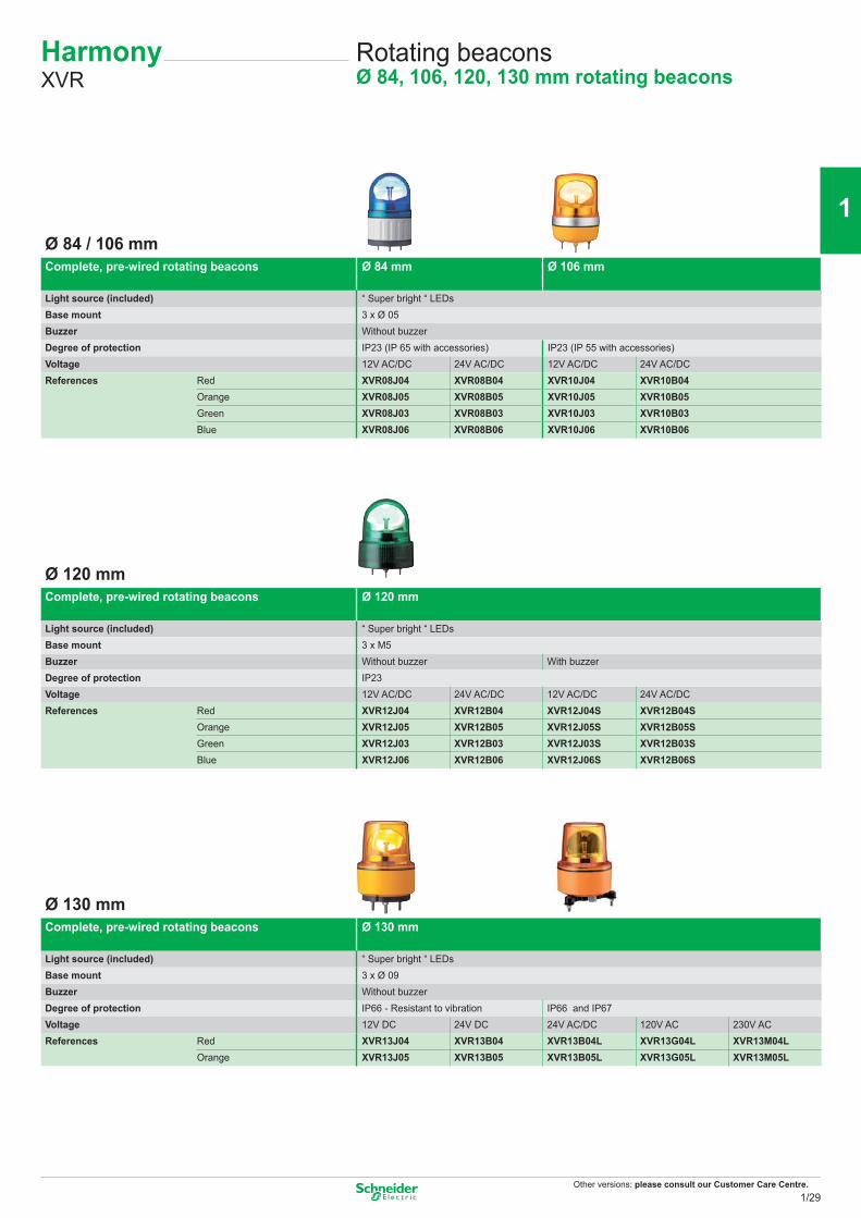
Rotating beaconsØ 84, 106, 120, 130 mm rotating beacons
HarmonyXVR
Ø 84 / 106 mmComplete, pre-wired rotating beacons Ø 84 mm Ø 106 mm
Light source (included) “ Super bright “ LEDsBase mount 3 x Ø 05Buzzer Without buzzerDegree of protection IP23 (IP 65 with accessories) IP23 (IP 55 with accessories)Voltage 12V AC/DC 24V AC/DC 12V AC/DC 24V AC/DCReferences Red XVR08J04 XVR08B04 XVR10J04 XVR10B04
Orange XVR08J05 XVR08B05 XVR10J05 XVR10B05Green XVR08J03 XVR08B03 XVR10J03 XVR10B03Blue XVR08J06 XVR08B06 XVR10J06 XVR10B06
Ø 120 mmComplete, pre-wired rotating beacons Ø 120 mm
Light source (included) “ Super bright “ LEDsBase mount 3 x M5Buzzer Without buzzer With buzzerDegree of protection IP23Voltage 12V AC/DC 24V AC/DC 12V AC/DC 24V AC/DCReferences Red XVR12J04 XVR12B04 XVR12J04S XVR12B04S
Orange XVR12J05 XVR12B05 XVR12J05S XVR12B05SGreen XVR12J03 XVR12B03 XVR12J03S XVR12B03SBlue XVR12J06 XVR12B06 XVR12J06S XVR12B06S
Ø 130 mmComplete, pre-wired rotating beacons Ø 130 mm
Light source (included) “ Super bright “ LEDsBase mount 3 x Ø 09Buzzer Without buzzerDegree of protection IP66 - Resistant to vibration IP66 and IP67Voltage 12V DC 24V DC 24V AC/DC 120V AC 230V ACReferences Red XVR13J04 XVR13B04 XVR13B04L XVR13G04L XVR13M04L
Orange XVR13J05 XVR13B05 XVR13B05L XVR13G05L XVR13M05L
1/29
2
1
3
4
5
6
7
8
9
10
Other versions: please consult our Customer Care Centre.
Accesories for rotating mirrors Reflecting prism Rubber base Metal angle bracket
Metal fixing plate
To be used for/with – Increasing the IP degree Horizontal support Horizontal supportHeight (mm) – – – 300References Ø 84 mm XVRZR1 XVRZ081 XVCZ23 –
Ø 106 mm XVRZR2 XVRZ082 XVCZ23 XVCZ13Ø 120 mm XVRZR3 – XVCZ23 XVCZ13Ø 130 mm XVRZR3 – XVR012L –
Electronic alarms and multisound sirens
Sirens and electronic alarms Sirens Multisound sirens pre-wired
Electronic alarms Panel Mount DIN72
Electronic alarms Panel Mount DIN96
Sound level 106 dB 105 dB 90 dB 96 dBTones 2 43 16 16Channels – 8 4 4Degree of protection IP 53 IP53 IP 54 IP 54Colors White White Black White Black WhiteReferences 12/24V AC/DC XVS10BMW – XVS72BMBp (1) XVS72BMWp (1) XVS96BMBp (1) XVS96BMWp (1)
12/24V DC – XVS14BMW – – – –120V AC XVS10GMW XVS14GMW – – – –230V AC XVS10MMW XVS14MMW – – – –
(1) To obtain a complete reference, replace the p by the letter as follow: P = PNP, N = NPN (ex. XVS72BMBP)
Rotating beacons accessories and sound solutionsAccessories for rotating beacons
HarmonyXVR / XVS
1/30
2
1
3
4
5
6
7
8
9
10
Other versions: please consult our Customer Care Centre.
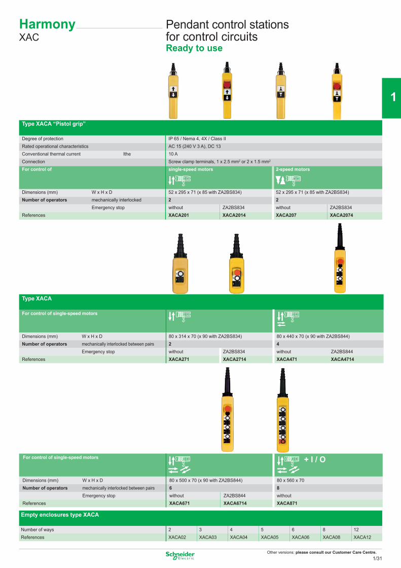
Type XACA “Pistol grip”
Degree of protection IP 65 / Nema 4, 4X / Class IIRated operational characteristics AC 15 (240 V 3 A), DC 13Conventional thermal current Ithe 10 AConnection Screw clamp terminals, 1 x 2.5 mm2 or 2 x 1.5 mm2
For control of single-speed motors 2-speed motors
Dimensions (mm) W x H x D 52 x 295 x 71 (x 85 with ZA2BS834) 52 x 295 x 71 (x 85 with ZA2BS834)Number of operators mechanically interlocked 2 2
Emergency stop without ZA2BS834 without ZA2BS834References XACA201 XACA2014 XACA207 XACA2074
Type XACA
For control of single-speed motors
Dimensions (mm) W x H x D 80 x 314 x 70 (x 90 with ZA2BS834) 80 x 440 x 70 (x 90 with ZA2BS844)Number of operators mechanically interlocked between pairs 2 4
Emergency stop without ZA2BS834 without ZA2BS844References XACA271 XACA2714 XACA471 XACA4714
For control of single-speed motors + I / O
Dimensions (mm) W x H x D 80 x 500 x 70 (x 90 with ZA2BS844) 80 x 560 x 70Number of operators mechanically interlocked between pairs 6 8
Emergency stop without ZA2BS844 withoutReferences XACA671 XACA6714 XACA871
Empty enclosures type XACA
Number of ways 2 3 4 5 6 8 12References XACA02 XACA03 XACA04 XACA05 XACA06 XACA08 XACA12
Pendant control stations for control circuitsReady to use
HarmonyXAC
1/31
2
1
3
4
5
6
7
8
9
10
Other versions: please consult our Customer Care Centre.
(1) Trigger action mechanically latching Emergency stop pushbuttons conform to standards EN/IEC 60204-32, EN/ISO 13850, Machinery directive 2006/42/EC and standard EN/IEC 60947-5-5.
Legends, 30 x 40 mm With symbols conforming to NF E 52-124 With text
References ZB2BY4901 ZB2BY4903 ZB2BY4907 ZB2BY4909 ZB2BY4913 ZB2BY4915 ZB2BY4930 ZB2BY2303 ZB2BY2304
References ZB2BY2904 ZB2BY2906 ZB2BY2910 ZB2BY2912 ZB2BY2916 ZB2BY2918 ZB2BY2931 ZB2BY1W140
blankwhite or yellowbackground
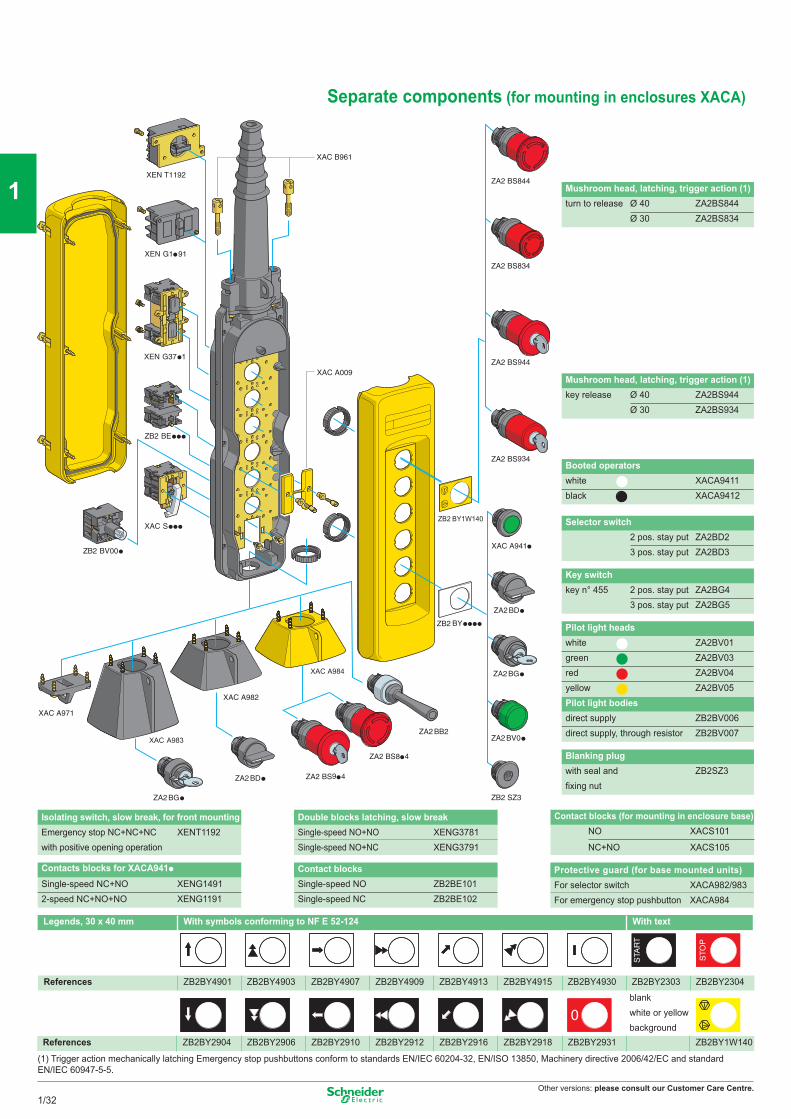
Separate components (for mounting in enclosures XACA)
Booted operatorswhite XACA9411black XACA9412
Mushroom head, latching, trigger action (1)turn to release Ø 40 ZA2BS844
Ø 30 ZA2BS834
Mushroom head, latching, trigger action (1)key release Ø 40 ZA2BS944
Ø 30 ZA2BS934
Selector switch2 pos. stay put ZA2BD23 pos. stay put ZA2BD3
Key switchkey n° 455 2 pos. stay put ZA2BG4
3 pos. stay put ZA2BG5
Blanking plugwith seal and ZB2SZ3fixing nut
Pilot light headswhite ZA2BV01green ZA2BV03red ZA2BV04yellow ZA2BV05Pilot light bodiesdirect supply ZB2BV006direct supply, through resistor ZB2BV007
Protective guard (for base mounted units)For selector switch XACA982/983For emergency stop pushbutton XACA984
Contact blocks Single-speed NO ZB2BE101Single-speed NC ZB2BE102
Contacts blocks for XACA941p
Single-speed NC+NO XENG14912-speed NC+NO+NO XENG1191
Contact blocks (for mounting in enclosure base)NO XACS101
NC+NO XACS105
Isolating switch, slow break, for front mountingEmergency stop NC+NC+NC with positive opening operation
XENT1192Double blocks latching, slow breakSingle-speed NO+NO XENG3781Single-speed NO+NC XENG3791
1/32
2
1
3
4
5
6
7
8
9
10

Other versions: please consult our Customer Care Centre.
Notes
1/33
2
1
3
4
5
6
7
8
9
10
Other versions: please consult our Customer Care Centre.
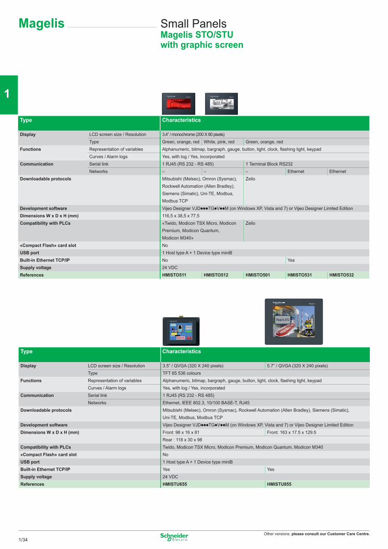
Magelis Small PanelsMagelis STO/STUwith graphic screen
Type Characteristics
Display LCD screen size / Resolution 3.4” / monochrome (200 X 80 pixels)Type Green, orange, red White, pink, red Green, orange, red
Functions Representation of variables Alphanumeric, bitmap, bargraph, gauge, button, light, clock, fl ashing light, keypadCurves / Alarm logs Yes, with log / Yes, incorporated
Communication Serial link 1 RJ45 (RS 232 - RS 485) 1 Terminal Block RS232Networks – – – Ethernet Ethernet
Downloadable protocols Mitsubishi (Melsec), Omron (Sysmac), Rockwell Automation (Allen Bradley), Siemens (Simatic), Uni-TE, Modbus, Modbus TCP
Zelio
Development software Vijeo Designer VJDpppTGpVppM (on Windows XP, Vista and 7) or Vijeo Designer Limited EditionDimensions W x D x H (mm) 116,5 x 38,5 x 77,5Compatibility with PLCs «Twido, Modicon TSX Micro, Modicon
Premium, Modicon Quantum, Modicon M340»
Zelio
«Compact Flash» card slot NoUSB port 1 Host type A + 1 Device type miniBBuilt-in Ethernet TCP/IP No YesSupply voltage 24 VDCReferences HMISTO511 HMISTO512 HMISTO501 HMISTO531 HMISTO532
Type Characteristics
Display LCD screen size / Resolution 3.5” / QVGA (320 X 240 pixels) 5.7” / QVGA (320 X 240 pixels)Type TFT 65 536 colours
Functions Representation of variables Alphanumeric, bitmap, bargraph, gauge, button, light, clock, fl ashing light, keypadCurves / Alarm logs Yes, with log / Yes, incorporated
Communication Serial link 1 RJ45 (RS 232 - RS 485)Networks Ethernet, IEEE 802.3, 10/100 BASE-T, RJ45
Downloadable protocols Mitsubishi (Melsec), Omron (Sysmac), Rockwell Automation (Allen Bradley), Siemens (Simatic), Uni-TE, Modbus, Modbus TCP
Development software Vijeo Designer VJDpppTGpVppM (on Windows XP, Vista and 7) or Vijeo Designer Limited EditionDimensions W x D x H (mm) Front: 98 x 16 x 81 Front: 163 x 17.5 x 129.5
Rear : 118 x 30 x 98Compatibility with PLCs Twido, Modicon TSX Micro, Modicon Premium, Modicon Quantum, Modicon M340«Compact Flash» card slot NoUSB port 1 Host type A + 1 Device type miniBBuilt-in Ethernet TCP/IP Yes YesSupply voltage 24 VDCReferences HMISTU655 HMISTU855
1/34
2
1
3
4
5
6
7
8
9
10
Other versions: please consult our Customer Care Centre.
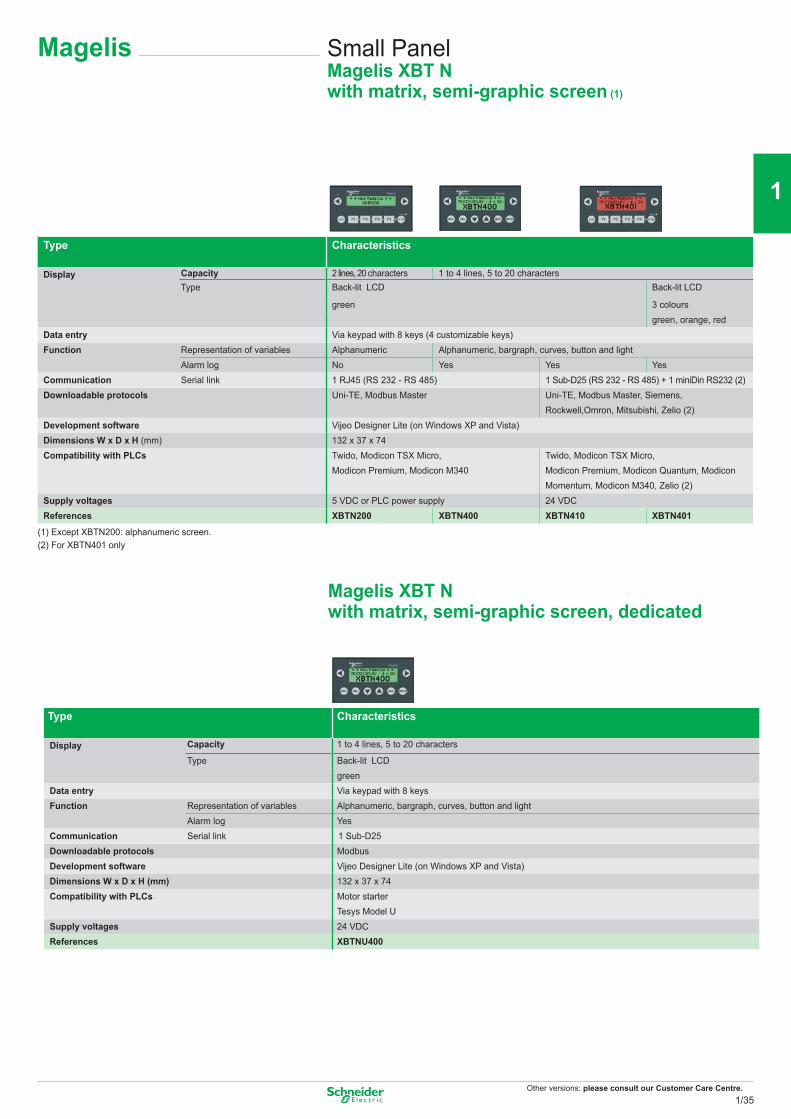
Magelis Small PanelMagelis XBT Nwith matrix, semi-graphic screen (1)
Type Characteristics
Display Capacity 2 lines, 20 characters 1 to 4 lines, 5 to 20 charactersType Back-lit LCD Back-lit LCD
green 3 coloursgreen, orange, red
Data entry Via keypad with 8 keys (4 customizable keys)Function Representation of variables Alphanumeric Alphanumeric, bargraph, curves, button and light
Alarm log No Yes Yes YesCommunication Serial link 1 RJ45 (RS 232 - RS 485) 1 Sub-D25 (RS 232 - RS 485) + 1 miniDin RS232 (2)Downloadable protocols Uni-TE, Modbus Master Uni-TE, Modbus Master, Siemens,
Rockwell,Omron, Mitsubishi, Zelio (2)Development software Vijeo Designer Lite (on Windows XP and Vista)Dimensions W x D x H (mm) 132 x 37 x 74Compatibility with PLCs Twido, Modicon TSX Micro,
Modicon Premium, Modicon M340Twido, Modicon TSX Micro, Modicon Premium, Modicon Quantum, Modicon Momentum, Modicon M340, Zelio (2)
Supply voltages 5 VDC or PLC power supply 24 VDCReferences XBTN200 XBTN400 XBTN410 XBTN401
(1) Except XBTN200: alphanumeric screen.(2) For XBTN401 only
Type Characteristics
Display Capacity 1 to 4 lines, 5 to 20 characters
Type Back-lit LCDgreen
Data entry Via keypad with 8 keysFunction Representation of variables Alphanumeric, bargraph, curves, button and light
Alarm log YesCommunication Serial link 1 Sub-D25Downloadable protocols ModbusDevelopment software Vijeo Designer Lite (on Windows XP and Vista)Dimensions W x D x H (mm) 132 x 37 x 74Compatibility with PLCs Motor starter
Tesys Model USupply voltages 24 VDCReferences XBTNU400
Magelis XBT N with matrix, semi-graphic screen, dedicated
1/35
2
1
3
4
5
6
7
8
9
10
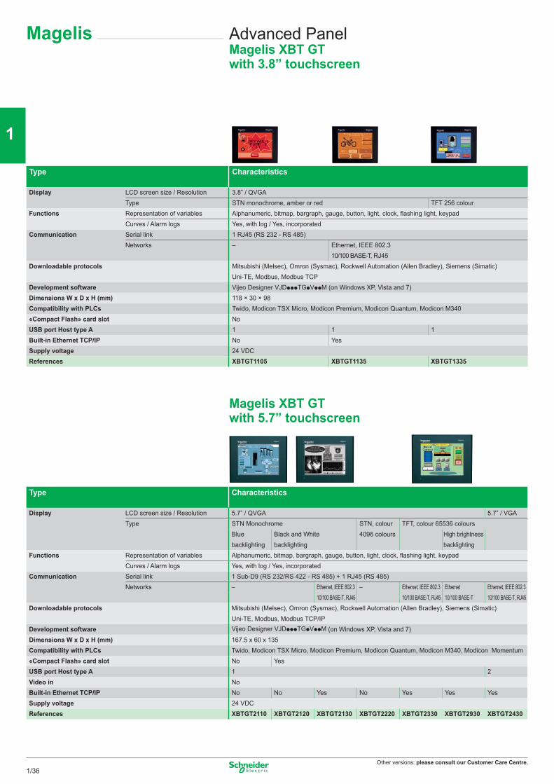
Other versions: please consult our Customer Care Centre.
Magelis Advanced PanelMagelis XBT GT with 3.8” touchscreen
Type Characteristics
Display LCD screen size / Resolution 3.8” / QVGAType STN monochrome, amber or red TFT 256 colour
Functions Representation of variables Alphanumeric, bitmap, bargraph, gauge, button, light, clock, flashing light, keypadCurves / Alarm logs Yes, with log / Yes, incorporated
Communication Serial link 1 RJ45 (RS 232 - RS 485)Networks – Ethernet, IEEE 802.3
10/100 BASE-T, RJ45Downloadable protocols Mitsubishi (Melsec), Omron (Sysmac), Rockwell Automation (Allen Bradley), Siemens (Simatic)
Uni-TE, Modbus, Modbus TCPDevelopment software Vijeo Designer VJDpppTGpVppM (on Windows XP, Vista and 7)Dimensions W x D x H (mm) 118 × 30 × 98Compatibility with PLCs Twido, Modicon TSX Micro, Modicon Premium, Modicon Quantum, Modicon M340«Compact Flash» card slot NoUSB port Host type A 1 1 1Built-in Ethernet TCP/IP No YesSupply voltage 24 VDCReferences XBTGT1105 XBTGT1135 XBTGT1335
Magelis XBT GT with 5.7” touchscreen
Type Type Characteristics
Display LCD screen size / Resolution 5.7” / QVGA 5.7” / VGAType STN Monochrome STN, colour TFT, colour 65536 colours
Blue backlighting
Black and White backlighting
4096 colours High brightness backlighting
Functions Representation of variables Alphanumeric, bitmap, bargraph, gauge, button, light, clock, flashing light, keypadCurves / Alarm logs Yes, with log / Yes, incorporated
Communication Serial link 1 Sub-D9 (RS 232/RS 422 - RS 485) + 1 RJ45 (RS 485)Networks – Ethernet, IEEE 802.3 – Ethernet, IEEE 802.3 Ethernet Ethernet, IEEE 802.3
10/100 BASE-T, RJ45 10/100 BASE-T, RJ45 10/100 BASE-T 10/100 BASE-T, RJ45Downloadable protocols Mitsubishi (Melsec), Omron (Sysmac), Rockwell Automation (Allen Bradley), Siemens (Simatic)
Uni-TE, Modbus, Modbus TCP/IPDevelopment software Vijeo Designer VJDpppTGpVppM (on Windows XP, Vista and 7)Dimensions W x D x H (mm) 167.5 x 60 x 135Compatibility with PLCs Twido, Modicon TSX Micro, Modicon Premium, Modicon Quantum, Modicon M340, Modicon Momentum«Compact Flash» card slot No YesUSB port Host type A 1 2Video in NoBuilt-in Ethernet TCP/IP No No Yes No Yes Yes YesSupply voltage 24 VDCReferences XBTGT2110 XBTGT2120 XBTGT2130 XBTGT2220 XBTGT2330 XBTGT2930 XBTGT2430
1/36
2
1
3
4
5
6
7
8
9
10
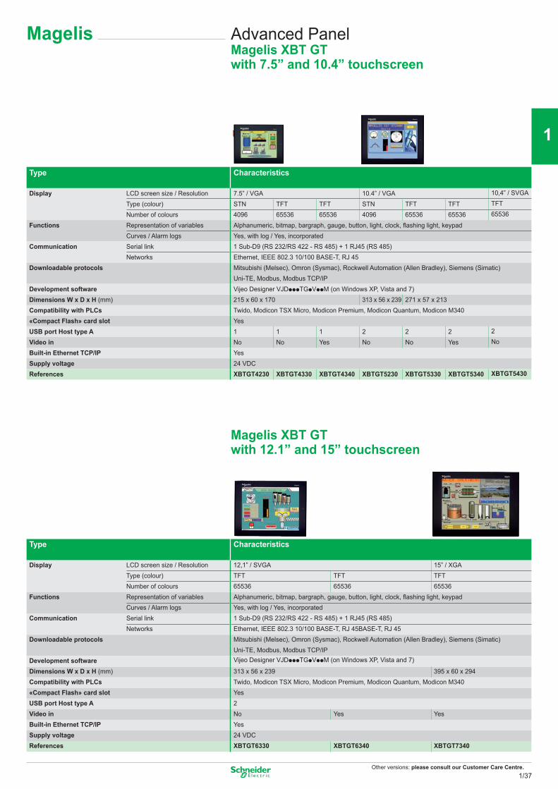
Other versions: please consult our Customer Care Centre.
Magelis Advanced PanelMagelis XBT GTwith 7.5” and 10.4” touchscreen
Type Characteristics
Display LCD screen size / Resolution 7.5” / VGA 10.4” / VGA 10,4” / SVGA
Type (colour) STN TFT TFT STN TFT TFT TFT
Number of colours 4096 65536 65536 4096 65536 65536 65536
Functions Representation of variables Alphanumeric, bitmap, bargraph, gauge, button, light, clock, flashing light, keypadCurves / Alarm logs Yes, with log / Yes, incorporated
Communication Serial link 1 Sub-D9 (RS 232/RS 422 - RS 485) + 1 RJ45 (RS 485)Networks Ethernet, IEEE 802.3 10/100 BASE-T, RJ 45
Downloadable protocols Mitsubishi (Melsec), Omron (Sysmac), Rockwell Automation (Allen Bradley), Siemens (Simatic)Uni-TE, Modbus, Modbus TCP/IP
Development software Vijeo Designer VJDpppTGpVppM (on Windows XP, Vista and 7)Dimensions W x D x H (mm) 215 x 60 x 170 313 x 56 x 239 271 x 57 x 213Compatibility with PLCs Twido, Modicon TSX Micro, Modicon Premium, Modicon Quantum, Modicon M340«Compact Flash» card slot YesUSB port Host type A 1 1 1 2 2 2 2
Video in No No Yes No No Yes No
Built-in Ethernet TCP/IP YesSupply voltage 24 VDCReferences XBTGT4230 XBTGT4330 XBTGT4340 XBTGT5230 XBTGT5330 XBTGT5340 XBTGT5430
Magelis XBT GTwith 12.1” and 15” touchscreen
Type Characteristics
Display LCD screen size / Resolution 12,1” / SVGA 15” / XGAType (colour) TFT TFT TFTNumber of colours 65536 65536 65536
Functions Representation of variables Alphanumeric, bitmap, bargraph, gauge, button, light, clock, flashing light, keypadCurves / Alarm logs Yes, with log / Yes, incorporated
Communication Serial link 1 Sub-D9 (RS 232/RS 422 - RS 485) + 1 RJ45 (RS 485)Networks Ethernet, IEEE 802.3 10/100 BASE-T, RJ 45BASE-T, RJ 45
Downloadable protocols Mitsubishi (Melsec), Omron (Sysmac), Rockwell Automation (Allen Bradley), Siemens (Simatic)Uni-TE, Modbus, Modbus TCP/IP
Development software Vijeo Designer VJDpppTGpVppM (on Windows XP, Vista and 7)
Dimensions W x D x H (mm) 313 x 56 x 239 395 x 60 x 294Compatibility with PLCs Twido, Modicon TSX Micro, Modicon Premium, Modicon Quantum, Modicon M340«Compact Flash» card slot YesUSB port Host type A 2Video in No Yes YesBuilt-in Ethernet TCP/IP YesSupply voltage 24 VDCReferences XBTGT6330 XBTGT6340 XBTGT7340
1/37
2
1
3
4
5
6
7
8
9
10
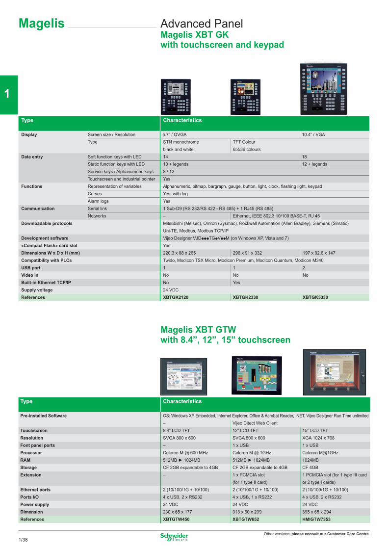
Other versions: please consult our Customer Care Centre.
Magelis
Type Characteristics
Pre-installed Software OS: Windows XP Embedded, Internet Explorer, Office & Acrobat Reader, .NET, Vijeo Designer Run Time unlimited– Vijeo Citect Web Client
Touchscreen 8.4” LCD TFT 12” LCD TFT 15” LCD TFT Resolution SVGA 800 x 600 SVGA 800 x 600 XGA 1024 x 768Font panel ports – 1 x USB 1 x USBProcessor Celeron M @ 600 MHz Celeron M @ 1GHz Celeron M@1GHzRAM 512MB ► 1024MB 512MB ► 1024MB 1024MBStorage CF 2GB expandable to 4GB CF 2GB expandable to 4GB CF 4GBExtension – 1 x PCMCIA slot
(for 1 type II card)1 PCMCIA slot (for 1 type III card or 2 type I cards)
Ethernet ports 2 (10/100/1G + 10/100) 2 (10/100/1G + 10/100) 2 (10/100/1G + 10/100)Ports I/O 4 x USB, 2 x RS232 4 x USB, 1 x RS232 4 x USB, 2 x RS232Power supply 24 VDC 24 VDC 24 VDCDimension 230 x 65 x 177 313 x 60 x 239 395 x 65 x 294References XBTGTW450 XBTGTW652 HMIGTW7353
Advanced PanelMagelis XBT GK with touchscreen and keypad
Magelis XBT GTWwith 8.4”, 12”, 15” touchscreen
Type Characteristics
Display Screen size / Resolution 5.7” / QVGA 10.4” / VGAType STN monochrome
black and whiteTFT Colour 65536 colours
Data entry Soft function keys with LED 14 18Static function keys with LED 10 + legends 12 + legendsService keys / Alphanumeric keys 8 / 12Touchscreen and industrial pointer Yes
Functions Representation of variables Alphanumeric, bitmap, bargraph, gauge, button, light, clock, flashing light, keypadCurves Yes, with logAlarm logs Yes
Communication Serial link 1 Sub-D9 (RS 232/RS 422 - RS 485) + 1 RJ45 (RS 485)Networks – Ethernet, IEEE 802.3 10/100 BASE-T, RJ 45
Downloadable protocols Mitsubishi (Melsec), Omron (Sysmac), Rockwell Automation (Allen Bradley), Siemens (Simatic)Uni-TE, Modbus, Modbus TCP/IP
Development software Vijeo Designer VJDpppTGpVppM (on Windows XP, Vista and 7)«Compact Flash» card slot YesDimensions W x D x H (mm) 220.3 x 88 x 265 296 x 91 x 332 197 x 92.6 x 147Compatibility with PLCs Twido, Modicon TSX Micro, Modicon Premium, Modicon Quantum, Modicon M340USB port 1 1 2Video in No No NoBuilt-in Ethernet TCP/IP No YesSupply voltage 24 VDCReferences XBTGK2120 XBTGK2330 XBTGK5330
1/38
2
1
3
4
5
6
7
8
9
10
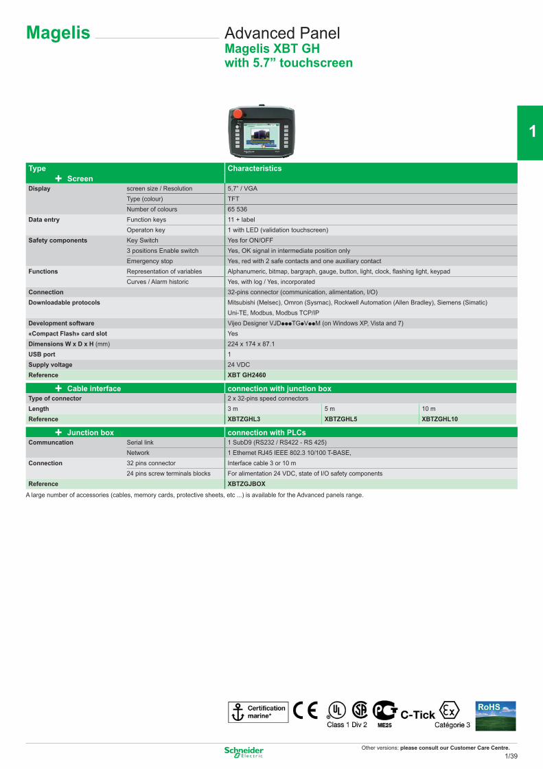
Other versions: please consult our Customer Care Centre.
Magelis
Type Characteristics+ Screen
Display screen size / Resolution 5,7” / VGAType (colour) TFTNumber of colours 65 536
Data entry Function keys 11 + labelOperaton key 1 with LED (validation touchscreen)
Safety components Key Switch Yes for ON/OFF3 positions Enable switch Yes, OK signal in intermediate position onlyEmergency stop Yes, red with 2 safe contacts and one auxiliary contact
Functions Representation of variables Alphanumeric, bitmap, bargraph, gauge, button, light, clock, fl ashing light, keypadCurves / Alarm historic Yes, with log / Yes, incorporated
Connection 32-pins connector (communication, alimentation, I/O)Downloadable protocols Mitsubishi (Melsec), Omron (Sysmac), Rockwell Automation (Allen Bradley), Siemens (Simatic)
Uni-TE, Modbus, Modbus TCP/IPDevelopment software Vijeo Designer VJDpppTGpVppM (on Windows XP, Vista and 7)«Compact Flash» card slot YesDimensions W x D x H (mm) 224 x 174 x 87.1USB port 1Supply voltage 24 VDCReference XBT GH2460
+ Cable interface connection with junction boxType of connector 2 x 32-pins speed connectorsLength 3 m 5 m 10 mReference XBTZGHL3 XBTZGHL5 XBTZGHL10
+ Junction box connection with PLCsCommuncation Serial link 1 SubD9 (RS232 / RS422 - RS 425)
Network 1 Ethernet RJ45 IEEE 802.3 10/100 T-BASE,Connection 32 pins connector Interface cable 3 or 10 m
24 pins screw terminals blocks For alimentation 24 VDC, state of I/O safety components Reference XBTZGJBOX
A large number of accessories (cables, memory cards, protective sheets, etc ...) is available for the Advanced panels range.
Advanced PanelMagelis XBT GHwith 5.7” touchscreen
1/39
2
1
3
4
5
6
7
8
9
10
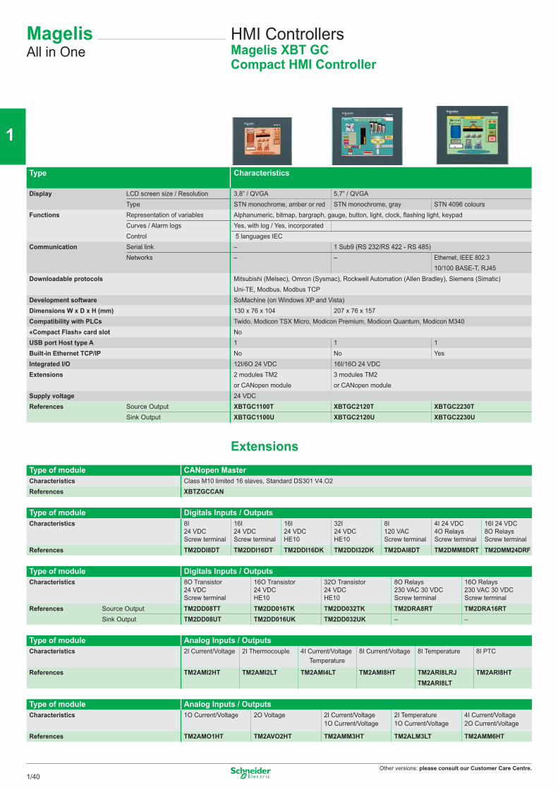
Other versions: please consult our Customer Care Centre.
MagelisAll in One
HMI Controllers Magelis XBT GC Compact HMI Controller
Type Characteristics
Display LCD screen size / Resolution 3,8” / QVGA 5,7” / QVGAType STN monochrome, amber or red STN monochrome, gray STN 4096 colours
Functions Representation of variables Alphanumeric, bitmap, bargraph, gauge, button, light, clock, flashing light, keypadCurves / Alarm logs Yes, with log / Yes, incorporatedControl 5 languages IEC
Communication Serial link – 1 Sub9 (RS 232/RS 422 - RS 485)Networks – – Ethernet, IEEE 802.3
10/100 BASE-T, RJ45Downloadable protocols Mitsubishi (Melsec), Omron (Sysmac), Rockwell Automation (Allen Bradley), Siemens (Simatic)
Uni-TE, Modbus, Modbus TCPDevelopment software SoMachine (on Windows XP and Vista)Dimensions W x D x H (mm) 130 x 76 x 104 207 x 76 x 157Compatibility with PLCs Twido, Modicon TSX Micro, Modicon Premium, Modicon Quantum, Modicon M340«Compact Flash» card slot NoUSB port Host type A 1 1 1Built-in Ethernet TCP/IP No No YesIntegrated I/O 12I/6O 24 VDC 16I/16O 24 VDCExtensions 2 modules TM2
or CANopen module3 modules TM2or CANopen module
Supply voltage 24 VDCReferences Source Output XBTGC1100T XBTGC2120T XBTGC2230T
Sink Output XBTGC1100U XBTGC2120U XBTGC2230U
ExtensionsType of module CANopen MasterCharacteristics Class M10 limited 16 slaves, Standard DS301 V4.O2References XBTZGCCAN
Type of module Digitals Inputs / OutputsCharacteristics 8I
24 VDCScrew terminal
16I 24 VDCScrew terminal
16I24 VDCHE10
32I24 VDCHE10
8I120 VACScrew terminal
4I 24 VDC4O RelaysScrew terminal
16I 24 VDC8O RelaysScrew terminal
References TM2DDI8DT TM2DDI16DT TM2DDI16DK TM2DDI32DK TM2DAI8DT TM2DMM8DRT TM2DMM24DRF
Type of module Digitals Inputs / OutputsCharacteristics 8O Transistor
24 VDCScrew terminal
16O Transistor24 VDCHE10
32O Transistor24 VDCHE10
8O Relays230 VAC 30 VDCScrew terminal
16O Relays230 VAC 30 VDCScrew terminal
References Source Output TM2DD08TT TM2DD016TK TM2DD032TK TM2DRA8RT TM2DRA16RTSink Output TM2DD08UT TM2DD016UK TM2DD032UK – –
Type of module Analog Inputs / OutputsCharacteristics 2I Current/Voltage 2I Thermocouple 4I Current/Voltage
Temperature8I Current/Voltage 8I Temperature 8I PTC
References TM2AMI2HT TM2AMI2LT TM2AMI4LT TM2AMI8HT TM2ARI8LRJTM2ARI8LT
TM2ARI8HT
Type of module Analog Inputs / OutputsCharacteristics 1O Current/Voltage 2O Voltage 2I Current/Voltage
1O Current/Voltage2I Temperature1O Current/Voltage
4I Current/Voltage2O Current/Voltage
References TM2AMO1HT TM2AVO2HT TM2AMM3HT TM2ALM3LT TM2AMM6HT
1/40
2
1
3
4
5
6
7
8
9
10
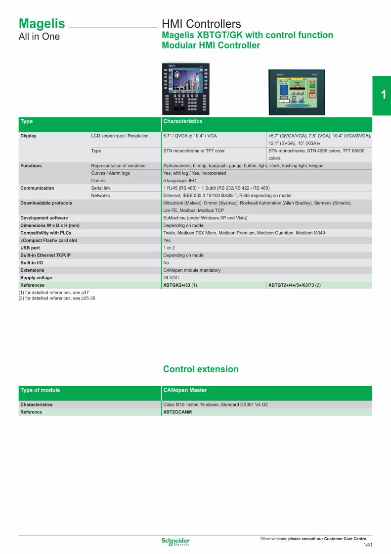
Other versions: please consult our Customer Care Centre.
MagelisAll in One
HMI Controllers Magelis XBTGT/GK with control functionModular HMI Controller
Type Characteristics
Display LCD screen size / Resolution 5.7” / QVGA to 10,4” / VGA «5.7” (QVGA/VGA), 7.5” (VGA), 10.4” (VGA/SVGA), 12.1” (SVGA), 15” (XGA)»
Type STN monochrome or TFT color STN monochrome, STN 4096 colors, TFT 65000 colors
Functions Representation of variables Alphanumeric, bitmap, bargraph, gauge, button, light, clock, fl ashing light, keypadCurves / Alarm logs Yes, with log / Yes, incorporatedControl 5 languages IEC
Communication Serial link 1 RJ45 (RS 485) + 1 Sub9 (RS 232/RS 422 - RS 485) Networks Ethernet, IEEE 802.3 10/100 BASE-T, RJ45 depending on modelDownloadable protocols Mitsubishi (Melsec), Omron (Sysmac), Rockwell Automation (Allen Bradley), Siemens (Simatic),
Uni-TE, Modbus, Modbus TCPDevelopment software SoMachine (under Windows XP and Vista)Dimensions W x D x H (mm) Depending on modelCompatibility with PLCs Twido, Modicon TSX Micro, Modicon Premium, Modicon Quantum, Modicon M340«Compact Flash» card slot YesUSB port 1 or 2Built-in Ethernet TCP/IP Depending on modelBuilt-in I/O NoExtensions CANopen module mandatorySupply voltage 24 VDCReferences XBTGK2●/53 (1) XBTGT2●/4●/5●/63/73 (2)
(1) for detailled references, see p37(2) for detailled references, see p35-36
Control extension
Type of module CANopen Master
Characteristics Class M10 limited 16 slaves, Standard DS301 V4.O2Reference XBTZGCANM
1/41
2
1
3
4
5
6
7
8
9
10
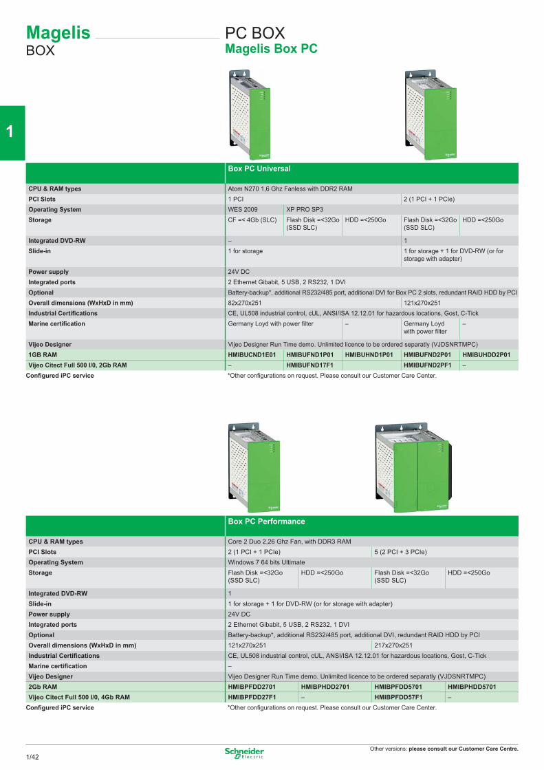
Other versions: please consult our Customer Care Centre.
MagelisBOX
PC BOXMagelis Box PC
Box PC Universal
CPU & RAM types Atom N270 1,6 Ghz Fanless with DDR2 RAMPCI Slots 1 PCI 2 (1 PCI + 1 PCIe)Operating System WES 2009 XP PRO SP3Storage CF =< 4Gb (SLC) Flash Disk =<32Go
(SSD SLC)HDD =<250Go Flash Disk =<32Go
(SSD SLC)HDD =<250Go
Integrated DVD-RW – 1Slide-in 1 for storage 1 for storage + 1 for DVD-RW (or for
storage with adapter)
Power supply 24V DCIntegrated ports 2 Ethernet Gibabit, 5 USB, 2 RS232, 1 DVIOptional Battery-backup*, additional RS232/485 port, additional DVI for Box PC 2 slots, redundant RAID HDD by PCIOverall dimensions (WxHxD in mm) 82x270x251 121x270x251Industrial Certifications CE, UL508 industrial control, cUL, ANSI/ISA 12.12.01 for hazardous locations, Gost, C-TickMarine certification Germany Loyd with power filter – Germany Loyd
with power filter–
Vijeo Designer Vijeo Designer Run Time demo. Unlimited licence to be ordered separatly (VJDSNRTMPC)1GB RAM HMIBUCND1E01 HMIBUFND1P01 HMIBUHND1P01 HMIBUFND2P01 HMIBUHDD2P01Vijeo Citect Full 500 I/0, 2Gb RAM – HMIBUFND17F1 HMIBUFND2PF1 –
Configured iPC service *Other configurations on request. Please consult our Customer Care Center.
Box PC Performance
CPU & RAM types Core 2 Duo 2,26 Ghz Fan, with DDR3 RAMPCI Slots 2 (1 PCI + 1 PCIe) 5 (2 PCI + 3 PCIe)Operating System Windows 7 64 bits UltimateStorage Flash Disk =<32Go
(SSD SLC)HDD =<250Go Flash Disk =<32Go
(SSD SLC)HDD =<250Go
Integrated DVD-RW 1Slide-in 1 for storage + 1 for DVD-RW (or for storage with adapter)Power supply 24V DCIntegrated ports 2 Ethernet Gibabit, 5 USB, 2 RS232, 1 DVIOptional Battery-backup*, additional RS232/485 port, additional DVI, redundant RAID HDD by PCIOverall dimensions (WxHxD in mm) 121x270x251 217x270x251Industrial Certifications CE, UL508 industrial control, cUL, ANSI/ISA 12.12.01 for hazardous locations, Gost, C-TickMarine certification –Vijeo Designer Vijeo Designer Run Time demo. Unlimited licence to be ordered separatly (VJDSNRTMPC)2Gb RAM HMIBPFDD2701 HMIBPHDD2701 HMIBPFDD5701 HMIBPHDD5701Vijeo Citect Full 500 I/0, 4Gb RAM HMIBPFDD27F1 – HMIBPFDD57F1 –
Configured iPC service *Other configurations on request. Please consult our Customer Care Center.
1/42
2
1
3
4
5
6
7
8
9
10
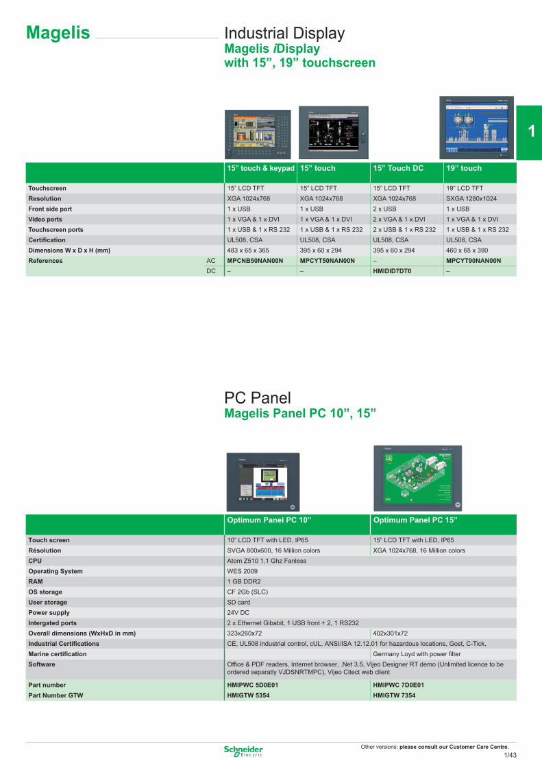
Other versions: please consult our Customer Care Centre.
Magelis Industrial DisplayMagelis iDisplaywith 15”, 19” touchscreen
15” touch & keypad 15” touch 15” Touch DC 19” touch
Touchscreen 15” LCD TFT 15” LCD TFT 15” LCD TFT 19” LCD TFTResolution XGA 1024x768 XGA 1024x768 XGA 1024x768 SXGA 1280x1024Front side port 1 x USB 1 x USB 2 x USB 1 x USBVideo ports 1 x VGA & 1 x DVI 1 x VGA & 1 x DVI 2 x VGA & 1 x DVI 1 x VGA & 1 x DVITouchscreen ports 1 x USB & 1 x RS 232 1 x USB & 1 x RS 232 2 x USB & 1 x RS 232 1 x USB & 1 x RS 232Certifi cation UL508, CSA UL508, CSA UL508, CSA UL508, CSADimensions W x D x H (mm) 483 x 65 x 365 395 x 60 x 294 395 x 60 x 294 460 x 65 x 390References AC MPCNB50NAN00N MPCYT50NAN00N – MPCYT90NAN00N
DC – – HMIDID7DT0 –
PC PanelMagelis Panel PC 10”, 15”
Optimum Panel PC 10” Optimum Panel PC 15”
Touch screen 10” LCD TFT with LED, IP65 15” LCD TFT with LED, IP65Résolution SVGA 800x600, 16 Million colors XGA 1024x768, 16 Million colorsCPU Atom Z510 1,1 Ghz FanlessOperating System WES 2009RAM 1 GB DDR2OS storage CF 2Gb (SLC)User storage SD cardPower supply 24V DCIntergated ports 2 x Ethernet Gibabit, 1 USB front + 2, 1 RS232Overall dimensions (WxHxD in mm) 323x260x72 402x301x72Industrial Certifi cations CE, UL508 industrial control, cUL, ANSI/ISA 12.12.01 for hazardous locations, Gost, C-Tick, Marine certifi cation Germany Loyd with power fi lterSoftware Offi ce & PDF readers, Internet browser, .Net 3.5, Vijeo Designer RT demo (Unlimited licence to be
ordered separatly VJDSNRTMPC), Vijeo Citect web client
Part number HMIPWC 5D0E01 HMIPWC 7D0E01Part Number GTW HMIGTW 5354 HMIGTW 7354
1/43
2
1
3
4
5
6
7
8
9
10
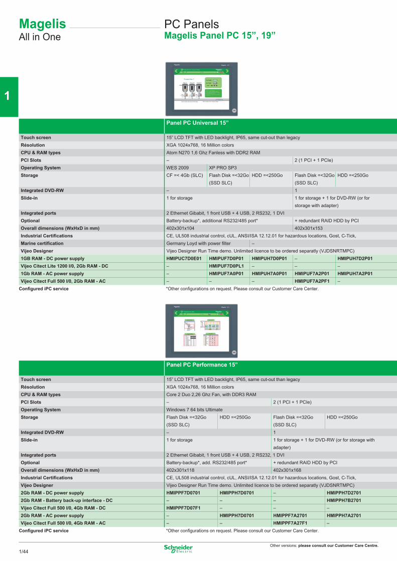
Other versions: please consult our Customer Care Centre.
Panel PC Performance 15”
Touch screen 15” LCD TFT with LED backlight, IP65, same cut-out than legacyRésolution XGA 1024x768, 16 Million colorsCPU & RAM types Core 2 Duo 2,26 Ghz Fan, with DDR3 RAMPCI Slots – 2 (1 PCI + 1 PCIe)Operating System Windows 7 64 bits UltimateStorage Flash Disk =<32Go
(SSD SLC)HDD =<250Go Flash Disk =<32Go
(SSD SLC)HDD =<250Go
Integrated DVD-RW – 1Slide-in 1 for storage 1 for storage + 1 for DVD-RW (or for storage with
adapter)Integrated ports 2 Ethernet Gibabit, 1 front USB + 4 USB, 2 RS232, 1 DVIOptional Battery-backup*, add. RS232/485 port* + redundant RAID HDD by PCIOverall dimensions (WxHxD in mm) 402x301x118 402x301x168Industrial Certifi cations CE, UL508 industrial control, cUL, ANSI/ISA 12.12.01 for hazardous locations, Gost, C-Tick, Vijeo Designer Vijeo Designer Run Time demo. Unlimited licence to be ordered separatly (VJDSNRTMPC)2Gb RAM - DC power supply HMIPPF7D0701 HMIPPH7D0701 – HMIPPH7D27012Gb RAM - Battery back-up interface - DC – – – HMIPPH7B2701Vijeo Citect Full 500 I/0, 4Gb RAM - DC HMIPPF7D07F1 – – –2Gb RAM - AC power supply – HMIPPH7D0701 HMIPPF7A2701 HMIPPH7A2701Vijeo Citect Full 500 I/0, 4Gb RAM - AC – – HMIPPF7A27F1 –
Confi gured iPC service *Other confi gurations on request. Please consult our Customer Care Center.
Panel PC Universal 15”
Touch screen 15” LCD TFT with LED backlight, IP65, same cut-out than legacyRésolution XGA 1024x768, 16 Million colorsCPU & RAM types Atom N270 1,6 Ghz Fanless with DDR2 RAMPCI Slots – 2 (1 PCI + 1 PCIe)Operating System WES 2009 XP PRO SP3Storage CF =< 4Gb (SLC) Flash Disk =<32Go
(SSD SLC)HDD =<250Go Flash Disk =<32Go
(SSD SLC)HDD =<250Go
Integrated DVD-RW – 1Slide-in 1 for storage 1 for storage + 1 for DVD-RW (or for
storage with adapter)Integrated ports 2 Ethernet Gibabit, 1 front USB + 4 USB, 2 RS232, 1 DVIOptional Battery-backup*, additional RS232/485 port* + redundant RAID HDD by PCIOverall dimensions (WxHxD in mm) 402x301x104 402x301x153Industrial Certifi cations CE, UL508 industrial control, cUL, ANSI/ISA 12.12.01 for hazardous locations, Gost, C-Tick, Marine certifi cation Germany Loyd with power fi lter –Vijeo Designer Vijeo Designer Run Time demo. Unlimited licence to be ordered separatly (VJDSNRTMPC)1GB RAM - DC power supply HMIPUC7D0E01 HMIPUF7D0P01 HMIPUH7D0P01 – HMIPUH7D2P01Vijeo Citect Lite 1200 I/0, 2Gb RAM - DC – HMIPUF7D0PL1 – – –1Gb RAM - AC power supply – HMIPUF7A0P01 HMIPUH7A0P01 HMIPUF7A2P01 HMIPUH7A2P01Vijeo Citect Full 500 I/0, 2Gb RAM - AC – – – HMIPUF7A2PF1 –
Confi gured iPC service *Other confi gurations on request. Please consult our Customer Care Center.
MagelisAll in One
PC Panels Magelis Panel PC 15”, 19”
1/44
2
1
3
4
5
6
7
8
9
10
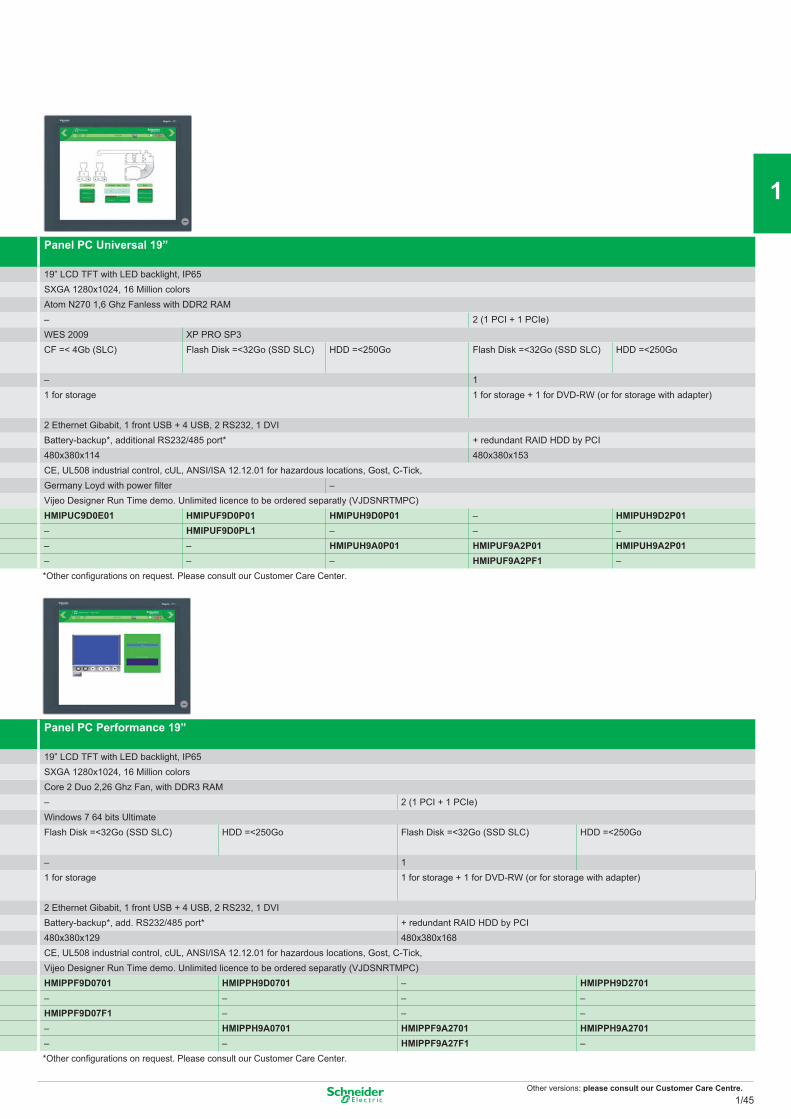
Other versions: please consult our Customer Care Centre.
Panel PC Performance 19”
19” LCD TFT with LED backlight, IP65SXGA 1280x1024, 16 Million colorsCore 2 Duo 2,26 Ghz Fan, with DDR3 RAM– 2 (1 PCI + 1 PCIe)Windows 7 64 bits UltimateFlash Disk =<32Go (SSD SLC) HDD =<250Go Flash Disk =<32Go (SSD SLC) HDD =<250Go
– 11 for storage 1 for storage + 1 for DVD-RW (or for storage with adapter)
2 Ethernet Gibabit, 1 front USB + 4 USB, 2 RS232, 1 DVIBattery-backup*, add. RS232/485 port* + redundant RAID HDD by PCI480x380x129 480x380x168CE, UL508 industrial control, cUL, ANSI/ISA 12.12.01 for hazardous locations, Gost, C-Tick, Vijeo Designer Run Time demo. Unlimited licence to be ordered separatly (VJDSNRTMPC)HMIPPF9D0701 HMIPPH9D0701 – HMIPPH9D2701– – – –HMIPPF9D07F1 – – –– HMIPPH9A0701 HMIPPF9A2701 HMIPPH9A2701– – HMIPPF9A27F1 –*Other confi gurations on request. Please consult our Customer Care Center.
Panel PC Universal 19”
19” LCD TFT with LED backlight, IP65SXGA 1280x1024, 16 Million colorsAtom N270 1,6 Ghz Fanless with DDR2 RAM– 2 (1 PCI + 1 PCIe)WES 2009 XP PRO SP3CF =< 4Gb (SLC) Flash Disk =<32Go (SSD SLC) HDD =<250Go Flash Disk =<32Go (SSD SLC) HDD =<250Go
– 11 for storage 1 for storage + 1 for DVD-RW (or for storage with adapter)
2 Ethernet Gibabit, 1 front USB + 4 USB, 2 RS232, 1 DVIBattery-backup*, additional RS232/485 port* + redundant RAID HDD by PCI480x380x114 480x380x153CE, UL508 industrial control, cUL, ANSI/ISA 12.12.01 for hazardous locations, Gost, C-Tick,Germany Loyd with power fi lter –Vijeo Designer Run Time demo. Unlimited licence to be ordered separatly (VJDSNRTMPC)HMIPUC9D0E01 HMIPUF9D0P01 HMIPUH9D0P01 – HMIPUH9D2P01– HMIPUF9D0PL1 – – –– – HMIPUH9A0P01 HMIPUF9A2P01 HMIPUH9A2P01– – – HMIPUF9A2PF1 –*Other confi gurations on request. Please consult our Customer Care Center.
1/45
2
1
3
4
5
6
7
8
9
10
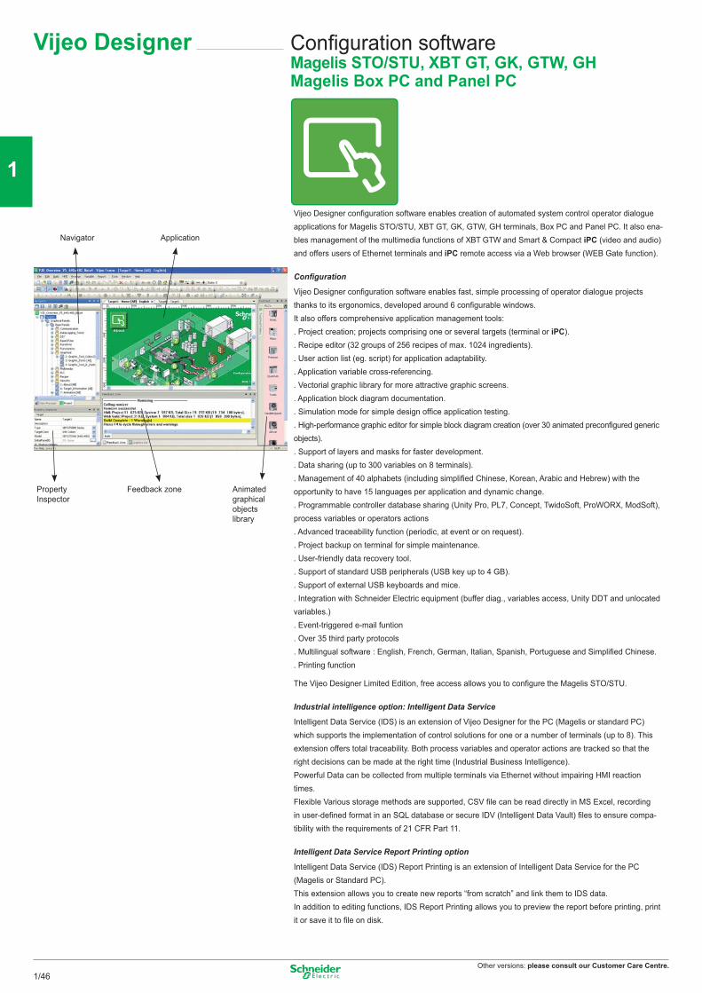
Other versions: please consult our Customer Care Centre.
Configuration softwareMagelis STO/STU, XBT GT, GK, GTW, GHMagelis Box PC and Panel PC
Vijeo Designer
Vijeo Designer configuration software enables creation of automated system control operator dialogue applications for Magelis STO/STU, XBT GT, GK, GTW, GH terminals, Box PC and Panel PC. It also ena-bles management of the multimedia functions of XBT GTW and Smart & Compact iPC (video and audio) and offers users of Ethernet terminals and iPC remote access via a Web browser (WEB Gate function).
Configuration
Vijeo Designer configuration software enables fast, simple processing of operator dialogue projects thanks to its ergonomics, developed around 6 configurable windows.It also offers comprehensive application management tools:. Project creation; projects comprising one or several targets (terminal or iPC).. Recipe editor (32 groups of 256 recipes of max. 1024 ingredients).. User action list (eg. script) for application adaptability.. Application variable cross-referencing.. Vectorial graphic library for more attractive graphic screens.. Application block diagram documentation.. Simulation mode for simple design office application testing.. High-performance graphic editor for simple block diagram creation (over 30 animated preconfigured generic objects).. Support of layers and masks for faster development.. Data sharing (up to 300 variables on 8 terminals).. Management of 40 alphabets (including simplified Chinese, Korean, Arabic and Hebrew) with the opportunity to have 15 languages per application and dynamic change.. Programmable controller database sharing (Unity Pro, PL7, Concept, TwidoSoft, ProWORX, ModSoft), process variables or operators actions. Advanced traceability function (periodic, at event or on request).. Project backup on terminal for simple maintenance.. User-friendly data recovery tool.. Support of standard USB peripherals (USB key up to 4 GB).. Support of external USB keyboards and mice.. Integration with Schneider Electric equipment (buffer diag., variables access, Unity DDT and unlocated variables.). Event-triggered e-mail funtion. Over 35 third party protocols. Multilingual software : English, French, German, Italian, Spanish, Portuguese and Simplified Chinese.. Printing function
The Vijeo Designer Limited Edition, free access allows you to configure the Magelis STO/STU.
Industrial intelligence option: Intelligent Data Service
Intelligent Data Service (IDS) is an extension of Vijeo Designer for the PC (Magelis or standard PC) which supports the implementation of control solutions for one or a number of terminals (up to 8). This extension offers total traceability. Both process variables and operator actions are tracked so that the right decisions can be made at the right time (Industrial Business Intelligence).Powerful Data can be collected from multiple terminals via Ethernet without impairing HMI reaction times.Flexible Various storage methods are supported, CSV file can be read directly in MS Excel, recording in user-defined format in an SQL database or secure IDV (Intelligent Data Vault) files to ensure compa- tibility with the requirements of 21 CFR Part 11.
Intelligent Data Service Report Printing option
Intelligent Data Service (IDS) Report Printing is an extension of Intelligent Data Service for the PC (Magelis or Standard PC).This extension allows you to create new reports “from scratch” and link them to IDS data. In addition to editing functions, IDS Report Printing allows you to preview the report before printing, print it or save it to file on disk.
Navigator Application
Property Inspector
Feedback zone Animated graphical objects library
1/46
2
1
3
4
5
6
7
8
9
10
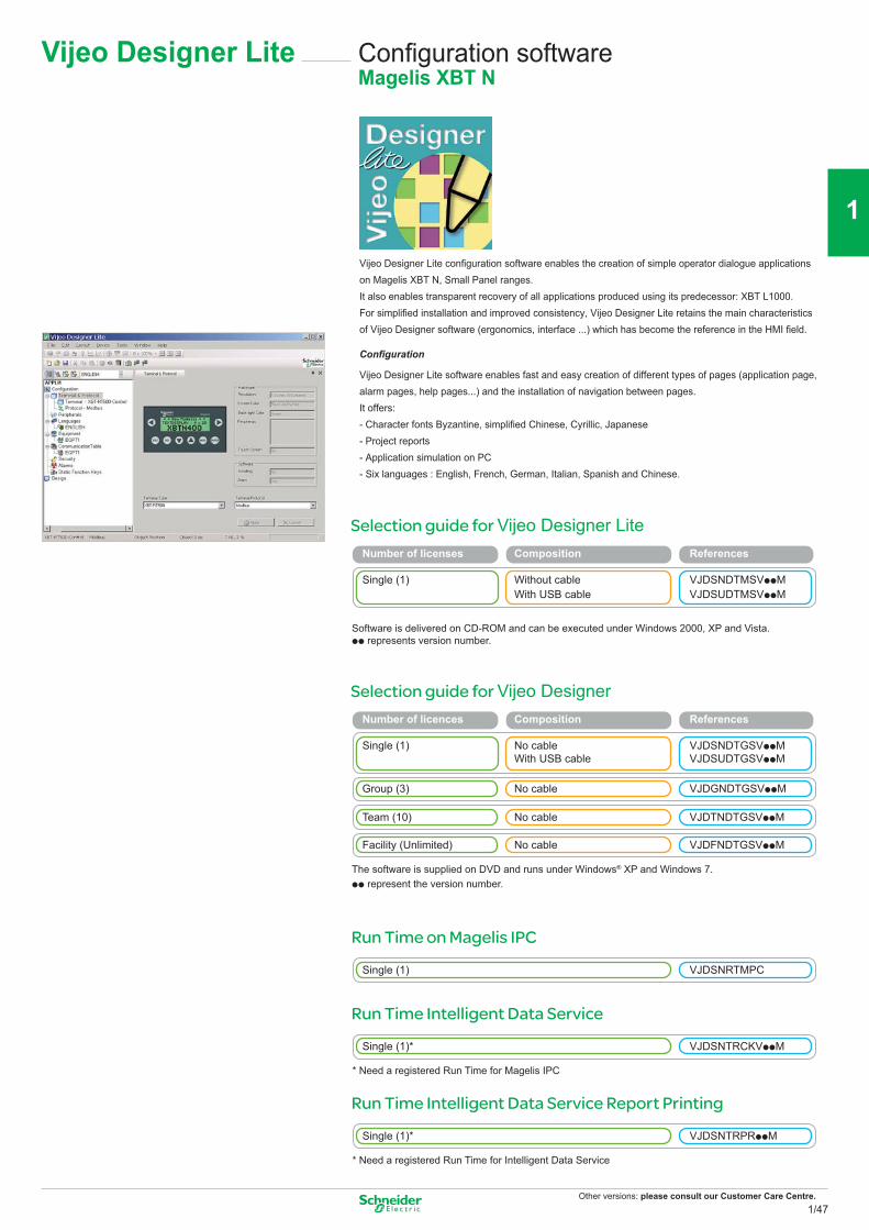
Other versions: please consult our Customer Care Centre.
Selection guide for Vijeo Designer
The software is supplied on DVD and runs under Windows® XP and Windows 7.pp represent the version number.
Number of licences Composition References Single (1) No cable VJDSNDTGSVppM With USB cable VJDSUDTGSVppM
Group (3) No cable VJDGNDTGSVppM
Team (10) No cable VJDTNDTGSVppM
Facility (Unlimited) No cable VJDFNDTGSVppM
Vijeo Designer Lite Configuration softwareMagelis XBT N
Vijeo Designer Lite configuration software enables the creation of simple operator dialogue applications on Magelis XBT N, Small Panel ranges. It also enables transparent recovery of all applications produced using its predecessor: XBT L1000.For simplified installation and improved consistency, Vijeo Designer Lite retains the main characteristics of Vijeo Designer software (ergonomics, interface ...) which has become the reference in the HMI field.
Configuration
Vijeo Designer Lite software enables fast and easy creation of different types of pages (application page, alarm pages, help pages...) and the installation of navigation between pages.It offers:- Character fonts Byzantine, simplified Chinese, Cyrillic, Japanese- Project reports- Application simulation on PC- Six languages : English, French, German, Italian, Spanish and Chinese.
Run Time on Magelis IPC
Single (1) VJDSNRTMPC
Run Time Intelligent Data Service
Single (1)* VJDSNTRCKVppM
* Need a registered Run Time for Magelis IPC
Run Time Intelligent Data Service Report Printing
Single (1)* VJDSNTRPRppM
* Need a registered Run Time for Intelligent Data Service
Selection guide for Vijeo Designer Lite Number of licenses Composition References Single (1) Without cable VJDSNDTMSVppM With USB cable VJDSUDTMSVppM
Software is delivered on CD-ROM and can be executed under Windows 2000, XP and Vista.pp represents version number.
1/47
2
1
3
4
5
6
7
8
9
10
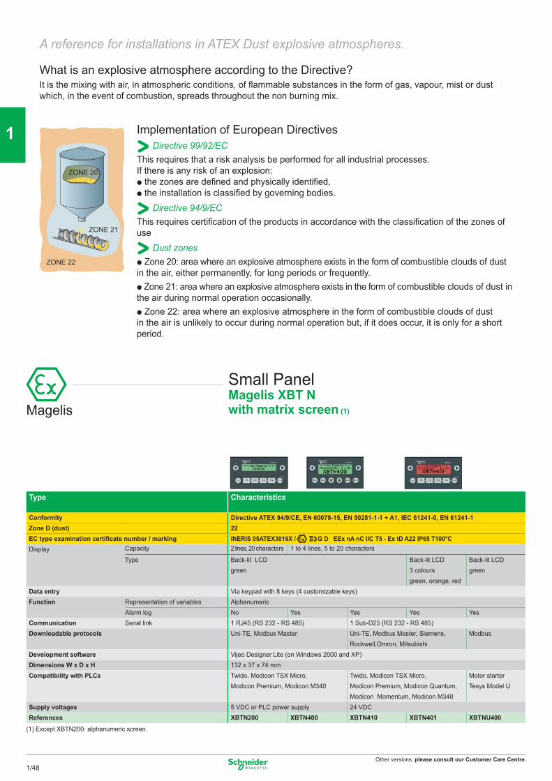
Other versions: please consult our Customer Care Centre.
ZONE 20
ZONE 22
ZONE 21
Implementation of European DirectivesDirective 99/92/EC
This requires that a risk analysis be performed for all industrial processes. If there is any risk of an explosion: p the zones are defined and physically identified, p the installation is classified by governing bodies.
Directive 94/9/ECThis requires certification of the products in accordance with the classification of the zones of use
Dust zones p Zone 20: area where an explosive atmosphere exists in the form of combustible clouds of dust in the air, either permanently, for long periods or frequently. p Zone 21: area where an explosive atmosphere exists in the form of combustible clouds of dust in the air during normal operation occasionally. p Zone 22: area where an explosive atmosphere in the form of combustible clouds of dust in the air is unlikely to occur during normal operation but, if it does occur, it is only for a short period.
A reference for installations in ATEX Dust explosive atmospheres.
What is an explosive atmosphere according to the Directive?It is the mixing with air, in atmospheric conditions, of flammable substances in the form of gas, vapour, mist or dust which, in the event of combustion, spreads throughout the non burning mix.
Type Characteristics
Conformity Directive ATEX 94/9/CE, EN 60079-15, EN 50281-1-1 + A1, IEC 61241-0, EN 61241-1Zone D (dust) 22EC type examination certificate number / marking INERIS 05ATEX3016X / G D EEx nA nC IIC T5 - Ex tD A22 IP65 T100°CDisplay Capacity 2 lines, 20 characters 1 to 4 lines, 5 to 20 characters
Type Back-lit LCD Back-lit LCD Back-lit LCDgreen 3 colours green
green, orange, redData entry Via keypad with 8 keys (4 customizable keys)Function Representation of variables Alphanumeric
Alarm log No Yes Yes Yes YesCommunication Serial link 1 RJ45 (RS 232 - RS 485) 1 Sub-D25 (RS 232 - RS 485)Downloadable protocols Uni-TE, Modbus Master Uni-TE, Modbus Master, Siemens,
Rockwell,Omron, MitsubishiModbus
Development software Vijeo Designer Lite (on Windows 2000 and XP)Dimensions W x D x H 132 x 37 x 74 mmCompatibility with PLCs Twido, Modicon TSX Micro,
Modicon Premium, Modicon M340Twido, Modicon TSX Micro, Modicon Premium, Modicon Quantum, Modicon Momentum, Modicon M340
Motor starter Tesys Model U
Supply voltages 5 VDC or PLC power supply 24 VDCReferences XBTN200 XBTN400 XBTN410 XBTN401 XBTNU400
(1) Except XBTN200: alphanumeric screen.
Magelis
Small PanelMagelis XBT Nwith matrix screen (1)
1/48
2
1
3
4
5
6
7
8
9
10
Other versions: please consult our Customer Care Centre.
Type Characteristics
Conformity Directive ATEX 94/9/CE, EN 60079-15, EN 61241-0, EN 61241-1, EN 60079-0 (1)Zone D (dust) 22EC type examination certificate number / marking INERIS 06ATEX3024X / INERIS 08ATEX3024X / INERIS 06ATEX3024X / INERIS 08ATEX3024X / INERIS 08ATEX3024X /
G D EEx nA nC IIC T4 - Ex tD A22 IP64 T135°CDisplay LCD screen size 3.8”
Type STN monochrome, amber or red TFT colourFunctions Representation of variables Alphanumeric, bitmap, bargraph, gauge, button, light, clock, flashing light, keypad
Curves / Alarm logs Yes, with log / Yes, incorporatedCommunication Serial link 1 RJ45 (RS 232 - RS 485)
Networks – Ethernet, IEEE 802.3 10 BASE-T, RJ45
Ethernet, IEEE 802.3 10/100 BASE-T, RJ45
Downloadable protocols Mitsubishi (Melsec), Omron (Sysmac), Rockwell Automation (Allen Bradley), Siemens (Simatic)Uni-TE, Modbus, Modbus TCP
Development software Vijeo Designer VJDpppTGpVppM (on Windows Vista, XP and 2000)Dimensions W x D x H 130x41x104mmCompatibility with PLCs Twido, Modicon TSX Micro, Modicon Premium, Modicon Quantum, Modicon M340«Compact Flash» card slot NoUSB port – 1 – 1 1Built-in Ethernet TCP/IP No YesSupply voltage 24 VDCReferences XBTGT1100 XBTGT1105 XBTGT1130 XBTGT1135 XBTGT1335
(1) Does not take effect for XBTG1100 and XBTG1130
Magelis XBT GT with 5.7” touchscreen
Type Type Characteristics
Conformity Directive ATEX 94/9/CE, EN 60079-15, EN 61241-0, EN 61241-1Zone D (dust) 22EC type examination certificate number / marking INERIS 06ATEX3024X / G D EEx nA nC IIB T3 - Ex tD A22 IP64 T200°CDisplay LCD screen size 5.7”
Type Back-lit STN, monochrome STN, colour TFT, colourblue black and white 4096 colours 65536 colours
Functions Representation of variables Alphanumeric, bitmap, bargraph, gauge, button, light, clock, flashing light, keypadCurves / Alarm logs Yes, with log / Yes, incorporated
Communication Serial link 1 Sub-D9 (RS 232/RS 422 - RS 485) + 1 RJ45 (RS 485)Networks – Ethernet, IEEE 802.3 – Ethernet, IEEE 802.3
10/100 BASE-T, RJ45 10/100 BASE-T, RJ45Downloadable protocols Mitsubishi (Melsec), Omron (Sysmac), Rockwell Automation (Allen Bradley), Siemens (Simatic)
Uni-TE, Modbus, Modbus TCP/IPDevelopment soft ware Vijeo Designer VJDpppTGpVppM (on Windows Vista, XP and 2000)
Dimensions W x D x H 167.5x60x135mmCompatibility with PLCs Twido, Modicon TSX Micro, Modicon Premium, Modicon Quantum, Modicon M340, Modicon Momentum«Compact Flash» card slot No YesUSB port 1Video in NoBuilt-in Ethernet TCP/IP No No Yes No YesSupply voltage 24 VDCReferences XBTGT2110 XBTGT2120 XBTGT2130 XBTGT2220 XBTGT2330
Magelis
Advanced PanelMagelis XBT GT with 3.8” touchscreen
1/49
2
1
3
4
5
6
7
8
9
10
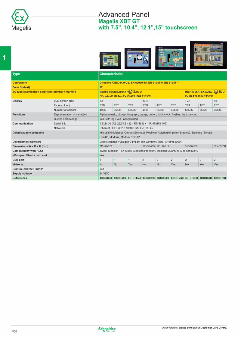
Other versions: please consult our Customer Care Centre.
Type Characteristics
Conformity Directive ATEX 94/9/CE, EN 60079-15, EN 61241-0, EN 61241-1Zone D (dust) 22EC type examination certificate number / marking INERIS 06ATEX3024X / G D
EEx nA nC IIB T4 - Ex tD A22 IP64 T135°CINERIS 06ATEX3024X / D Ex tD A22 IP64 T135°C
Display LCD screen size 7.5” 10.4” 12.1” 15”Type (colour) STN TFT TFT STN TFT TFT TFT TFT TFTNumber of colours 4096 65536 65536 4096 65536 65536 65536 65536 65536
Functions Representation of variables Alphanumeric, bitmap, bargraph, gauge, button, light, clock, flashing light, keypadCurves / Alarm logs Yes, with log / Yes, incorporated
Communication Serial link 1 Sub-D9 (RS 232/RS 422 - RS 485) + 1 RJ45 (RS 485)Networks Ethernet, IEEE 802.3 10/100 BASE-T, RJ 45
Downloadable protocols Mitsubishi (Melsec), Omron (Sysmac), Rockwell Automation (Allen Bradley), Siemens (Simatic)Uni-TE, Modbus, Modbus TCP/IP
Development software Vijeo Designer VJDpppTGpVppM (on Windows Vista, XP and 2000)Dimensions W x D x H (mm) 215x60x170 313x56x239 271x57x213 313x56x239 395x60x294Compatibility with PLCs Twido, Modicon TSX Micro, Modicon Premium, Modicon Quantum, Modicon M340«Compact Flash» card slot YesUSB port 1 1 1 2 2 2 2 2 2Video in No No Yes No No Yes No Yes YesBuilt-in Ethernet TCP/IP YesSupply voltage 24 VDCReferences XBTGT4230 XBTGT4330 XBTGT4340 XBTGT5230 XBTGT5330 XBTGT5340 XBTGT6330 XBTGT6340 XBTGT7340
Advanced PanelMagelis XBT GTwith 7.5”, 10.4”, 12.1”,15” touchscreenMagelis
1/50
2
1
3
4
5
6
7
8
9
10

Other versions: please consult our Customer Care Centre.
Notes
1/51
2
1
3
4
5
6
7
8
9
10
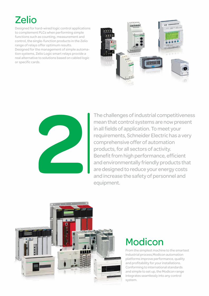
The challenges of industrial competitiveness mean that control systems are now present in all fields of application. To meet your requirements, Schneider Electric has a very comprehensive offer of automation products, for all sectors of activity. Benefit from high performance, efficient and environmentally friendly products that are designed to reduce your energy costs and increase the safety of personnel and equipment.
Zelio Designed for hard-wired logic control applications to complement PLCs when performing simple functions such as counting, measurement and control, the single-function products in the Zelio range of relays offer optimum results. Designed for the management of simple automa-tion systems, Zelio Logic smart relays provide a real alternative to solutions based on cabled logic or specific cards.
ModiconFrom the simplest machine to the smartest industrial process,Modicon automation platforms improve performance, quality and profitability for your installations. Conforming to international standards and simple to set up, the Modicon range integrates seamlessly into any control system.
Automation
This document is a selection of
the top selling products.
2/1
2
1
3
4
5
6
7
8
9
10
Relays Electromechanical plug-in relays, Zelio Relay .................................................................................................. 2/2 to 2/4 Solid-state relays, Zelio Relay .................................................................................................................................... 2/5 Control and measurement relays, Zelio Control ............................................................................................ 2/6 to 2/10 Counters, Zelio Count ...............................................................................................................................................2/11 Timing relays, Zelio Time ............................................................................................................................. 2/12 to 2/13 Analog interface, Zelio Analog ..................................................................................................................... 2/14 to 2/15
Controllers (PLC) for commercial machines Smart relays, Zelio Logic: 10 to 40 I/O ....................................................................................................... 2/16 to 2/17 Programmable controllers, Twido: 10 to 100 I/O 1μs per Instruction ........................................................... 2/18 to 2/19
Controllers (PLC & PAC) for industrial machines Logic controllers, Modicon M238 : 20 to 248 I/O, 0.3 μs per Instruction ...................................................... 2/20 to 2/21 Logic controllers, Modicon M258 : 42 to 2400 I/O, 0.022 μs per Instruction ................................................ 2/22 to 2/23 Motion controllers, Modicon LMC058 : 42 to 2400 I/O, 4 synchronized Axis in 2ms ............................................... 2/24 HMI controllers, Magelis XBTGC : 18 to 96 I/O ........................................................................................................ 2/25 Drive controller, Altivar IMC : 1000 instructions in 942 μs Web Server, CANopen, PLCopen ................................. 2/26
Programmable Automation Controllers (PACs) Mid range PLC Modicon M340 : for industrial process and infrastructure ................................................... 2/28 to 2/37 Large PLC Modicon Premium : for discrete or process applications and high availability solutions ........... 2/38 to 2/45 Large PLC Modicon Quantum : for process applications & high availability solutions ................................ 2/46 to 2/53
Software Programming software, Zelio Soft 2 ......................................................................................................................... 2/17 Programming software, Twido Suite ........................................................................................................................ 2/19 Machine programming software, SoMachine ........................................................................................................... 2/27 Configuration software, Unity Pro ................................................................................................................ 2/54 to 2/55 Programming software, PL7, Concept, ProWORX32 .................................................................................. 2/56 to 2/57 SCADA software, Vijeo Citect .................................................................................................................................. 2/58 Reporting software, Vijeo Historian ......................................................................................................................... 2/59
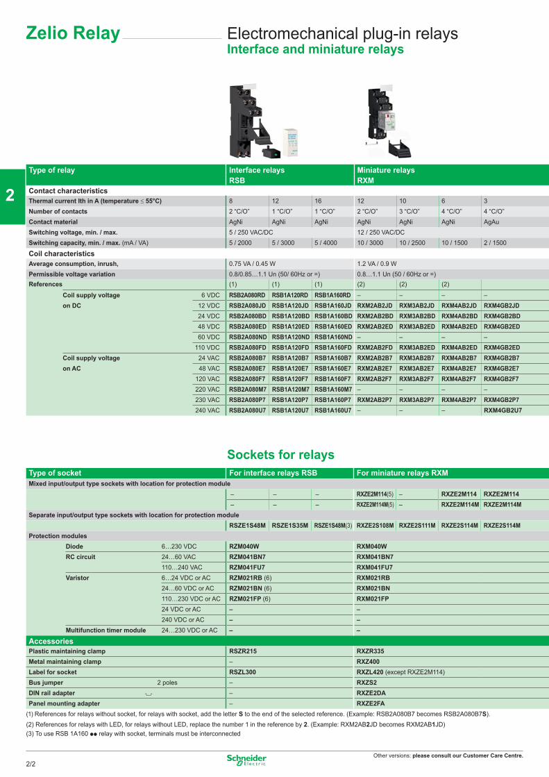
Other versions: please consult our Customer Care Centre.
Electromechanical plug-in relaysInterface and miniature relays
Type of relay Interface relays Miniature relays RSB RXM
Contact characteristicsThermal current Ith in A (temperature ≤ 55°C) 8 12 16 12 10 6 3Number of contacts 2 “C/O” 1 “C/O” 1 “C/O” 2 “C/O” 3 “C/O” 4 “C/O” 4 “C/O”Contact material AgNi AgNi AgNi AgNi AgNi AgNi AgAuSwitching voltage, min. / max. 5 / 250 VAC/DC 12 / 250 VAC/DCSwitching capacity, min. / max. (mA / VA) 5 / 2000 5 / 3000 5 / 4000 10 / 3000 10 / 2500 10 / 1500 2 / 1500
Coil characteristicsAverage consumption, inrush, 0.75 VA / 0.45 W 1.2 VA / 0.9 WPermissible voltage variation 0.8/0.85…1.1 Un (50/ 60Hz or =) 0.8…1.1 Un (50 / 60Hz or =)References (1) (1) (1) (2) (2) (2)
Coil supply voltage 6 VDC RSB2A080RD RSB1A120RD RSB1A160RD – – – –on DC 12 VDC RSB2A080JD RSB1A120JD RSB1A160JD RXM2AB2JD RXM3AB2JD RXM4AB2JD RXM4GB2JD
24 VDC RSB2A080BD RSB1A120BD RSB1A160BD RXM2AB2BD RXM3AB2BD RXM4AB2BD RXM4GB2BD48 VDC RSB2A080ED RSB1A120ED RSB1A160ED RXM2AB2ED RXM3AB2ED RXM4AB2ED RXM4GB2ED60 VDC RSB2A080ND RSB1A120ND RSB1A160ND – – – –
110 VDC RSB2A080FD RSB1A120FD RSB1A160FD RXM2AB2FD RXM3AB2ED RXM4AB2ED RXM4GB2EDCoil supply voltage 24 VAC RSB2A080B7 RSB1A120B7 RSB1A160B7 RXM2AB2B7 RXM3AB2B7 RXM4AB2B7 RXM4GB2B7on AC 48 VAC RSB2A080E7 RSB1A120E7 RSB1A160E7 RXM2AB2E7 RXM3AB2E7 RXM4AB2E7 RXM4GB2E7
120 VAC RSB2A080F7 RSB1A120F7 RSB1A160F7 RXM2AB2F7 RXM3AB2F7 RXM4AB2F7 RXM4GB2F7 220 VAC RSB2A080M7 RSB1A120M7 RSB1A160M7 – – – – 230 VAC RSB2A080P7 RSB1A120P7 RSB1A160P7 RXM2AB2P7 RXM3AB2P7 RXM4AB2P7 RXM4GB2P7 240 VAC RSB2A080U7 RSB1A120U7 RSB1A160U7 – – – RXM4GB2U7
Sockets for relaysType of socket For interface relays RSB For miniature relays RXMMixed input/output type sockets with location for protection module
– – – RXZE2M114(5) – RXZE2M114 RXZE2M114– – – RXZE2M114M(5) – RXZE2M114M RXZE2M114M
Separate input/output type sockets with location for protection module RSZE1S48M RSZE1S35M RSZE1S48M(3) RXZE2S108M RXZE2S111M RXZE2S114M RXZE2S114M
Protection modulesDiode 6…230 VDC RZM040W RXM040WRC circuit 24…60 VAC RZM041BN7 RXM041BN7
110…240 VAC RZM041FU7 RXM041FU7Varistor 6…24 VDC or AC RZM021RB (6) RXM021RB
24…60 VDC or AC RZM021BN (6) RXM021BN110…230 VDC or AC RZM021FP (6) RXM021FP24 VDC or AC – –240 VDC or AC – –
Multifunction timer module 24…230 VDC or AC – –
AccessoriesPlastic maintaining clamp RSZR215 RXZR335Metal maintaining clamp – RXZ400Label for socket RSZL300 RXZL420 (except RXZE2M114)Bus jumper 2 poles – RXZS2DIN rail adapter – RXZE2DAPanel mounting adapter – RXZE2FA
(1) References for relays without socket, for relays with socket, add the letter S to the end of the selected reference. (Example: RSB2A080B7 becomes RSB2A080B7S).(2) References for relays with LED, for relays without LED, replace the number 1 in the reference by 2. (Example: RXM2AB2JD becomes RXM2AB1JD)(3) To use RSB 1A160 pp relay with socket, terminals must be interconnected
Zelio Relay
2/2
2
1
3
4
5
6
7
8
9
10
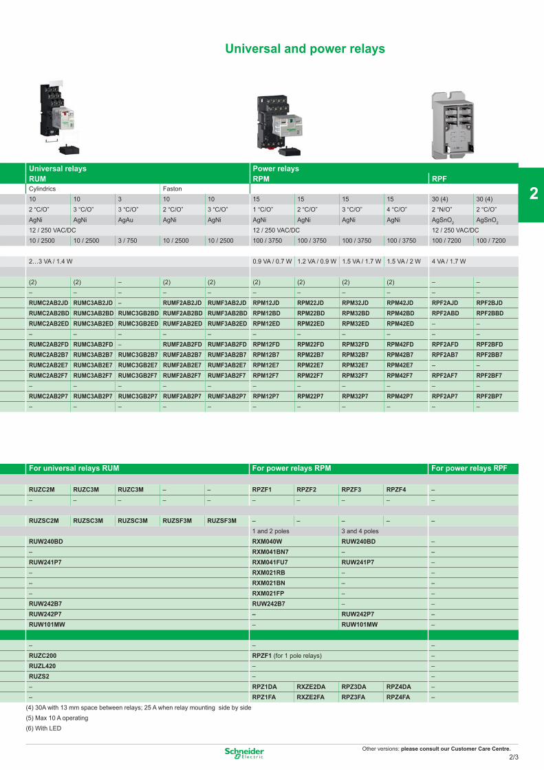
Other versions: please consult our Customer Care Centre.
Universal and power relays
Universal relays Power relaysRUM RPM RPFCylindrics Faston10 10 3 10 10 15 15 15 15 30 (4) 30 (4)2 “C/O” 3 “C/O” 3 “C/O” 2 “C/O” 3 “C/O” 1 “C/O” 2 “C/O” 3 “C/O” 4 “C/O” 2 “N/O” 2 “C/O”AgNi AgNi AgAu AgNi AgNi AgNi AgNi AgNi AgNi AgSnO2 AgSnO2
12 / 250 VAC/DC 12 / 250 VAC/DC 12 / 250 VAC/DC10 / 2500 10 / 2500 3 / 750 10 / 2500 10 / 2500 100 / 3750 100 / 3750 100 / 3750 100 / 3750 100 / 7200 100 / 7200
2…3 VA / 1.4 W 0.9 VA / 0.7 W 1.2 VA / 0.9 W 1.5 VA / 1.7 W 1.5 VA / 2 W 4 VA / 1.7 W
(2) (2) – (2) (2) (2) (2) (2) (2) – –– – – – – – – – – – –RUMC2AB2JD RUMC3AB2JD – RUMF2AB2JD RUMF3AB2JD RPM12JD RPM22JD RPM32JD RPM42JD RPF2AJD RPF2BJDRUMC2AB2BD RUMC3AB2BD RUMC3GB2BD RUMF2AB2BD RUMF3AB2BD RPM12BD RPM22BD RPM32BD RPM42BD RPF2ABD RPF2BBDRUMC2AB2ED RUMC3AB2ED RUMC3GB2ED RUMF2AB2ED RUMF3AB2ED RPM12ED RPM22ED RPM32ED RPM42ED – –– – – – – – – – – – –RUMC2AB2FD RUMC3AB2FD – RUMF2AB2FD RUMF3AB2FD RPM12FD RPM22FD RPM32FD RPM42FD RPF2AFD RPF2BFDRUMC2AB2B7 RUMC3AB2B7 RUMC3GB2B7 RUMF2AB2B7 RUMF3AB2B7 RPM12B7 RPM22B7 RPM32B7 RPM42B7 RPF2AB7 RPF2BB7RUMC2AB2E7 RUMC3AB2E7 RUMC3GB2E7 RUMF2AB2E7 RUMF3AB2E7 RPM12E7 RPM22E7 RPM32E7 RPM42E7 – –RUMC2AB2F7 RUMC3AB2F7 RUMC3GB2F7 RUMF2AB2F7 RUMF3AB2F7 RPM12F7 RPM22F7 RPM32F7 RPM42F7 RPF2AF7 RPF2BF7– – – – – – – – – – –RUMC2AB2P7 RUMC3AB2P7 RUMC3GB2P7 RUMF2AB2P7 RUMF3AB2P7 RPM12P7 RPM22P7 RPM32P7 RPM42P7 RPF2AP7 RPF2BP7– – – – – – – – – – –
For universal relays RUM For power relays RPM For power relays RPF
RUZC2M RUZC3M RUZC3M – – RPZF1 RPZF2 RPZF3 RPZF4 –– – – – – – – – – –
RUZSC2M RUZSC3M RUZSC3M RUZSF3M RUZSF3M – – – – –1 and 2 poles 3 and 4 poles
RUW240BD RXM040W RUW240BD –– RXM041BN7 – –RUW241P7 RXM041FU7 RUW241P7 –– RXM021RB – –– RXM021BN – –– RXM021FP – –RUW242B7 RUW242B7 – –RUW242P7 – RUW242P7 –RUW101MW – RUW101MW –
– – –RUZC200 RPZF1 (for 1 pole relays) –RUZL420 – –RUZS2 – –– RPZ1DA RXZE2DA RPZ3DA RPZ4DA –– RPZ1FA RXZE2FA RPZ3FA RPZ4FA –
(4) 30A with 13 mm space between relays; 25 A when relay mounting side by side(5) Max 10 A operating(6) With LED
2/3
2
1
3
4
5
6
7
8
9
10
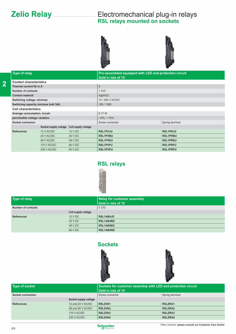
Other versions: please consult our Customer Care Centre.
Electromechanical plug-in relaysRSL relays mounted on sockets
Zelio Relay
Type of relay Pre-assembled equipped with LED and protection circuitSold in lots of 10
Contact characteristicsThermal current Ith in A 6Number of contacts 1 C/OContact material AgSnO2Switching voltage, min/max 12 / 300 V AC/DCSwitching capacity min/max (mA /VA) 100 / 1500
Coil characteristicsAverage consumption, inrush 0.17 Wpermissible voltage variation -10% / +15%Socket connexion Screw connector Spring terminal Socket supply voltage Coil supply voltageReferences 12 V AC/DC 12 V DC RSL1PVJU RSL1PRJU
24 V AC/DC 24 V DC RSL1PVBU RSL1PRBU48 V AC/DC 48 V DC RSL1PVEU RSL1PREU110 V AC/DC 60 V DC RSL1PVFU RSL1PRFU230 V AC/DC 60 V DC RSL1PVPU RSL1PRPU
RSL relays
Type of relay Relay for customer assemblySold in lots of 10
Number of contacts 1 C/O Coil supply voltageReferences 12 V DC RSL1AB4JD
24 V DC RSL1AB4BD48 V DC RSL1AB4ED60 V DC RSL1AB4ND
Sockets
Type of socket Sockets for customer assembly with LED and protection circuit Sold in lots of 10
Socket connection Screw connector Spring terminal Socket supply voltageReferences 12 and 24 V AC/DC RSLZVA1 RSLZRA1
48 and 60 V AC/DC RSLZVA2 RSLZRA2110 V AC/DC RSLZVA3 RSLZRA3230 V AC/DC RSLZVA4 RSLZRA4
2/4
2
1
3
4
5
6
7
8
9
10
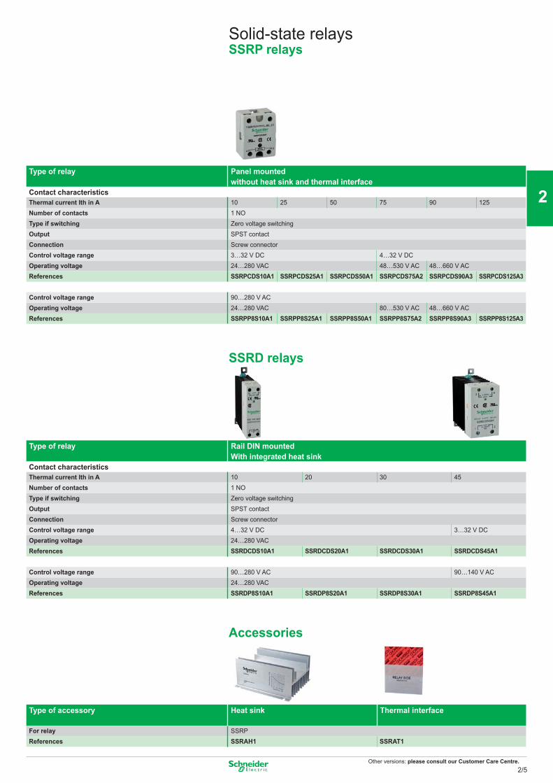
Other versions: please consult our Customer Care Centre.
Solid-state relaysSSRP relays
Type of relay Panel mounted without heat sink and thermal interface
Contact characteristicsThermal current Ith in A 10 25 50 75 90 125Number of contacts 1 NOType if switching Zero voltage switchingOutput SPST contactConnection Screw connectorControl voltage range 3…32 V DC 4…32 V DCOperating voltage 24…280 VAC 48…530 V AC 48…660 V ACReferences SSRPCDS10A1 SSRPCDS25A1 SSRPCDS50A1 SSRPCDS75A2 SSRPCDS90A3 SSRPCDS125A3
Control voltage range 90…280 V ACOperating voltage 24…280 VAC 80…530 V AC 48…660 V ACReferences SSRPP8S10A1 SSRPP8S25A1 SSRPP8S50A1 SSRPP8S75A2 SSRPP8S90A3 SSRPP8S125A3
SSRD relays
Type of relay Rail DIN mountedWith integrated heat sink
Contact characteristicsThermal current Ith in A 10 20 30 45Number of contacts 1 NOType if switching Zero voltage switchingOutput SPST contactConnection Screw connectorControl voltage range 4…32 V DC 3…32 V DCOperating voltage 24…280 VACReferences SSRDCDS10A1 SSRDCDS20A1 SSRDCDS30A1 SSRDCDS45A1
Control voltage range 90…280 V AC 90…140 V ACOperating voltage 24…280 VACReferences SSRDP8S10A1 SSRDP8S20A1 SSRDP8S30A1 SSRDP8S45A1
Accessories
Type of accessory Heat sink Thermal interface
For relay SSRPReferences SSRAH1 SSRAT1
2/5
2
1
3
4
5
6
7
8
9
10
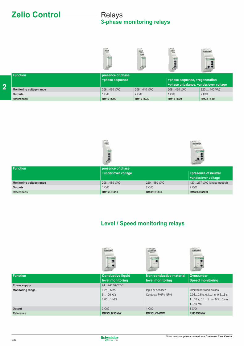
Other versions: please consult our Customer Care Centre.
Relays3-phase monitoring relays
Zelio Control
Function presence of phase+phase sequence +phase sequence, +regeneration
+phase unbalance, +under/over voltageMonitoring voltage range 208…480 VAC 208…440 VAC 208…480 VAC 220 … 440 VACOutputs 1 C/O 2 C/O 1 C/O 2 C/OReferences RM17TG00 RM17TG20 RM17TE00 RM35TF30
Function presence of phase+under/over voltage +presence of neutral
+under/over voltageMonitoring voltage range 208…480 VAC 220…480 VAC 120…277 VAC (phase-neutral)Outputs 1 C/O 2 C/O 2 C/OReferences RM17UB310 RM35UB330 RM35UB3N30
Level / Speed monitoring relays
Function Conductive liquid Non-conductive material Over/underlevel monitoring level monitoring Speed monitoring
Power supply 24…240 VAC/DCMonitoring range 0,25…5 KΩ Input of sensor : Interval between pulses:
5…100 KΩ Contact / PNP / NPN 0.05…0.5 s, 0.1…1 s, 0.5…5 s0,05…1 MΩ 1…10 s, 0.1…1 mn, 0.5…5 mn
1…10 mnOutput 2 C/O 1 C/O 1 C/OReference RM35LM33MW RM35LV14MW RM35S0MW
2/6
2
1
3
4
5
6
7
8
9
10
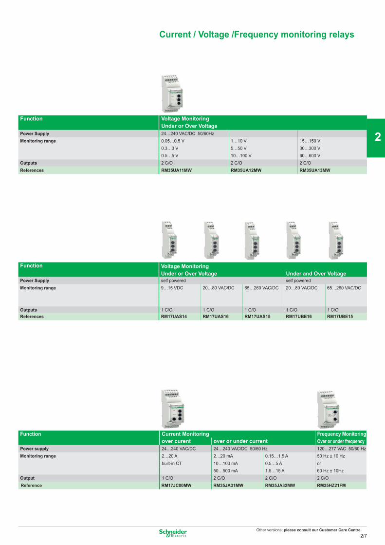
Other versions: please consult our Customer Care Centre.
Function Voltage MonitoringUnder or Over Voltage
Power Supply 24…240 VAC/DC 50/60HzMonitoring range 0.05…0.5 V 1…10 V 15…150 V
0.3…3 V 5…50 V 30…300 V0.5…5 V 10…100 V 60…600 V
Outputs 2 C/O 2 C/O 2 C/OReferences RM35UA11MW RM35UA12MW RM35UA13MW
Function Voltage Monitoring Under or Over Voltage Under and Over Voltage
Power Supply self powered self poweredMonitoring range 9…15 VDC 20…80 VAC/DC 65…260 VAC/DC 20…80 VAC/DC 65…260 VAC/DC
Outputs 1 C/O 1 C/O 1 C/O 1 C/O 1 C/OReferences RM17UAS14 RM17UAS16 RM17UAS15 RM17UBE16 RM17UBE15
Function Current Monitoring Frequency MonitoringOver or under frequencyover curent over or under current
Power supply 24…240 VAC/DC 24…240 VAC/DC 50/60 Hz 120…277 VAC 50/60 HzMonitoring range 2…20 A 2…20 mA 0.15…1.5 A 50 Hz ± 10 Hz
built-in CT 10…100 mA 0.5…5 A or50…500 mA 1.5…15 A 60 Hz ± 10Hz
Output 1 C/O 2 C/O 2 C/O 2 C/O Reference RM17JC00MW RM35JA31MW RM35JA32MW RM35HZ21FM
Current / Voltage /Frequency monitoring relays
2/7
2
1
3
4
5
6
7
8
9
10
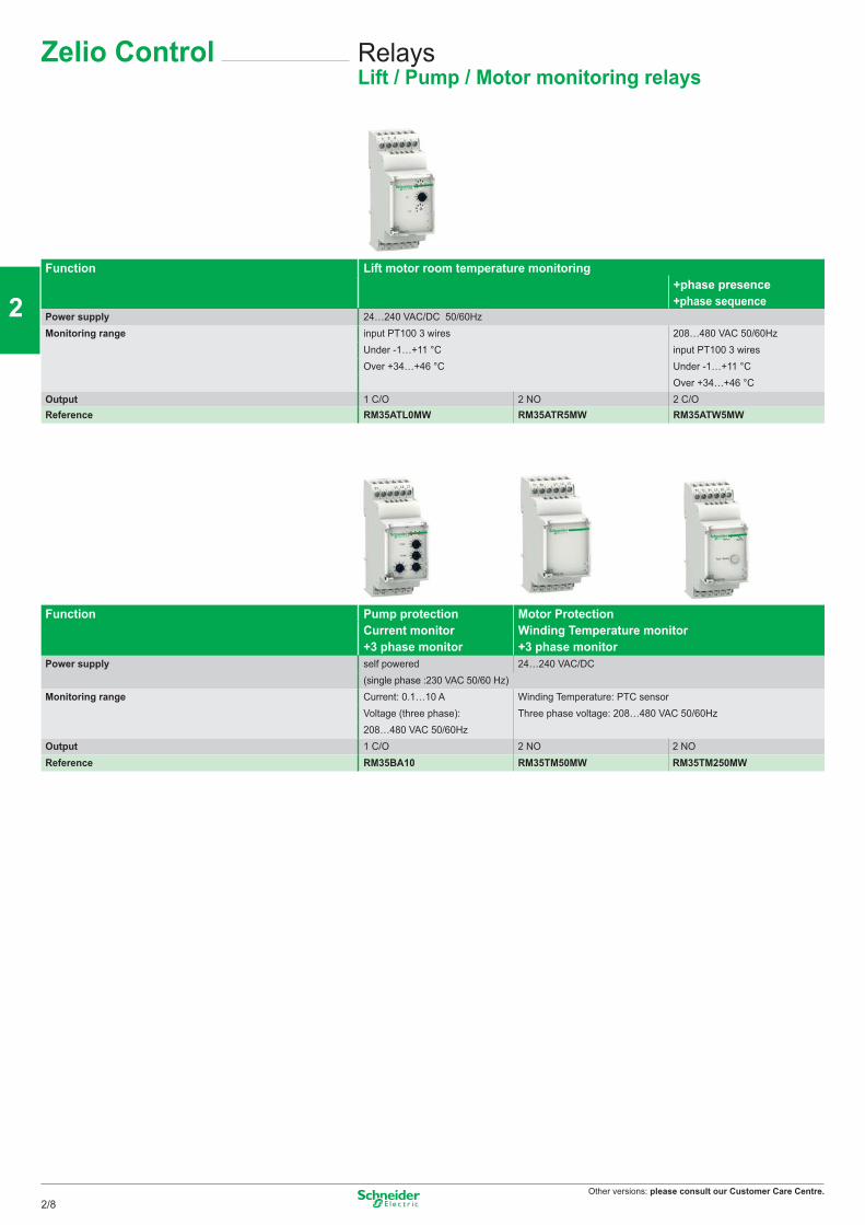
Other versions: please consult our Customer Care Centre.
RelaysLift / Pump / Motor monitoring relays
Zelio Control
Function Lift motor room temperature monitoring+phase presence+phase sequence
Power supply 24…240 VAC/DC 50/60HzMonitoring range input PT100 3 wires 208…480 VAC 50/60Hz
Under -1…+11 °C input PT100 3 wiresOver +34…+46 °C Under -1…+11 °C
Over +34…+46 °COutput 1 C/O 2 NO 2 C/OReference RM35ATL0MW RM35ATR5MW RM35ATW5MW
Function Pump protection Motor Protection Winding Temperature monitor+3 phase monitor
Current monitor +3 phase monitor
Power supply self powered 24…240 VAC/DC(single phase :230 VAC 50/60 Hz)
Monitoring range Current: 0.1…10 A Winding Temperature: PTC sensorVoltage (three phase): Three phase voltage: 208…480 VAC 50/60Hz208…480 VAC 50/60Hz
Output 1 C/O 2 NO 2 NOReference RM35BA10 RM35TM50MW RM35TM250MW
2/8
2
1
3
4
5
6
7
8
9
10
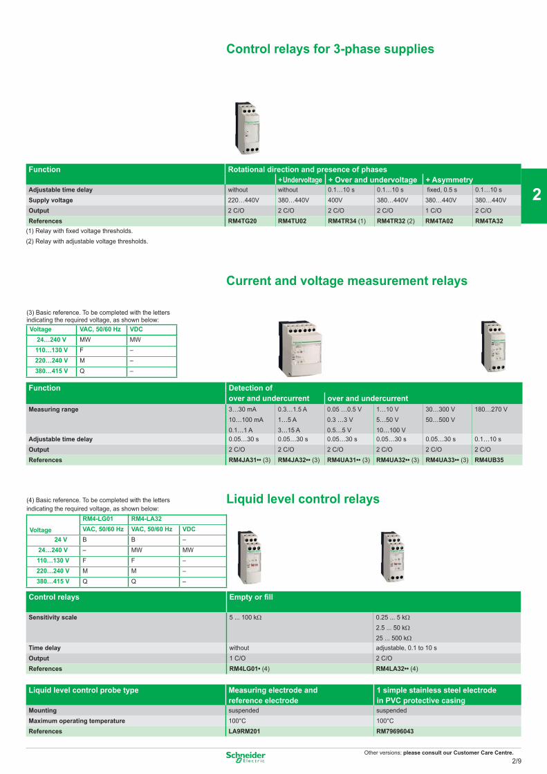
Other versions: please consult our Customer Care Centre.
Control relays for 3-phase supplies
Function Rotational direction and presence of phases + Undervoltage + Over and undervoltage + Asymmetry
Adjustable time delay without without 0.1…10 s 0.1…10 s fixed, 0.5 s 0.1…10 sSupply voltage 220…440V 380…440V 400V 380…440V 380…440V 380…440VOutput 2 C/O 2 C/O 2 C/O 2 C/O 1 C/O 2 C/OReferences RM4TG20 RM4TU02 RM4TR34 (1) RM4TR32 (2) RM4TA02 RM4TA32
(1) Relay with fixed voltage thresholds. (2) Relay with adjustable voltage thresholds.
Current and voltage measurement relays
Function Detection ofover and undercurrent over and undercurrent
Measuring range 3…30 mA 0.3…1.5 A 0.05 …0.5 V 1…10 V 30…300 V 180…270 V 10…100 mA 1…5 A 0.3 …3 V 5…50 V 50…500 V0.1…1 A 3…15 A 0.5…5 V 10…100 V
Adjustable time delay 0.05…30 s 0.05…30 s 0.05…30 s 0.05…30 s 0.05…30 s 0.1…10 sOutput 2 C/O 2 C/O 2 C/O 2 C/O 2 C/O 2 C/OReferences RM4JA31•• (3) RM4JA32•• (3) RM4UA31•• (3) RM4UA32•• (3) RM4UA33•• (3) RM4UB35
Liquid level control relays
Control relays Empty or fill
Sensitivity scale 5 ... 100 kΩ 0.25 ... 5 kΩ
2.5 ... 50 kΩ
25 ... 500 kΩ Time delay without adjustable, 0.1 to 10 sOutput 1 C/O 2 C/OReferences RM4LG01• (4) RM4LA32•• (4)
Liquid level control probe type Measuring electrode andreference electrode
1 simple stainless steel electrodein PVC protective casing
Mounting suspended suspendedMaximum operating temperature 100°C 100°CReferences LA9RM201 RM79696043
(4) Basic reference. To be completed with the letters indicating the required voltage, as shown below:
RM4-LG01 RM4-LA32
Voltage VAC, 50/60 Hz VAC, 50/60 Hz VDC 24 V B B –24…240 V – MW MW110…130 V F F –220…240 V M M –380…415 V Q Q –
(3) Basic reference. To be completed with the lettersindicating the required voltage, as shown below:Voltage VAC, 50/60 Hz VDC
24…240 V MW MW110…130 V F –220…240 V M –380…415 V Q –
2/9
2
1
3
4
5
6
7
8
9
10
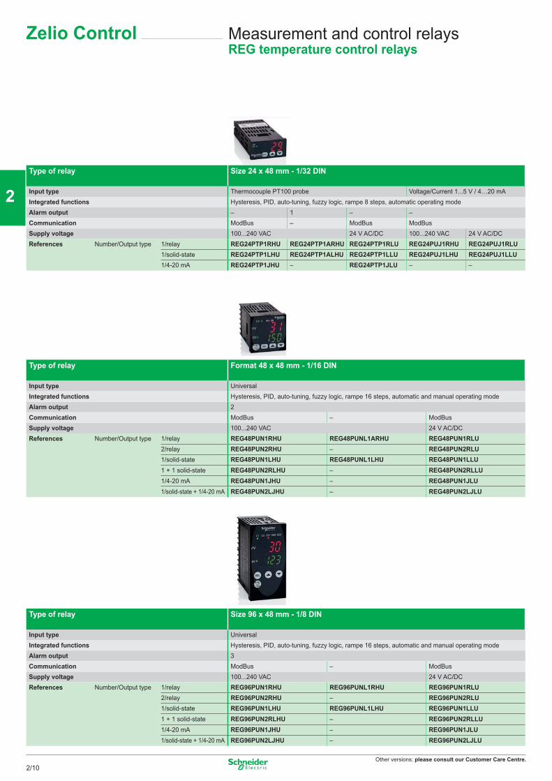
Other versions: please consult our Customer Care Centre.
Measurement and control relaysREG temperature control relays
Zelio Control
Type of relay Size 24 x 48 mm - 1/32 DIN
Input type Thermocouple PT100 probe Voltage/Current 1...5 V / 4…20 mAIntegrated functions Hysteresis, PID, auto-tuning, fuzzy logic, rampe 8 steps, automatic operating modeAlarm output – 1 – –Communication ModBus – ModBus ModBusSupply voltage 100...240 VAC 24 V AC/DC 100...240 VAC 24 V AC/DCReferences Number/Output type 1/relay REG24PTP1RHU REG24PTP1ARHU REG24PTP1RLU REG24PUJ1RHU REG24PUJ1RLU
1/solid-state REG24PTP1LHU REG24PTP1ALHU REG24PTP1LLU REG24PUJ1LHU REG24PUJ1LLU1/4-20 mA REG24PTP1JHU – REG24PTP1JLU – –
Type of relay Format 48 x 48 mm - 1/16 DIN
Input type UniversalIntegrated functions Hysteresis, PID, auto-tuning, fuzzy logic, rampe 16 steps, automatic and manual operating modeAlarm output 2Communication ModBus – ModBusSupply voltage 100...240 VAC 24 V AC/DCReferences Number/Output type 1/relay REG48PUN1RHU REG48PUNL1ARHU REG48PUN1RLU
2/relay REG48PUN2RHU – REG48PUN2RLU1/solid-state REG48PUN1LHU REG48PUNL1LHU REG48PUN1LLU1 + 1 solid-state REG48PUN2RLHU – REG48PUN2RLLU1/4-20 mA REG48PUN1JHU – REG48PUN1JLU1/solid-state + 1/4-20 mA REG48PUN2LJHU – REG48PUN2LJLU
Type of relay Size 96 x 48 mm - 1/8 DIN
Input type UniversalIntegrated functions Hysteresis, PID, auto-tuning, fuzzy logic, rampe 16 steps, automatic and manual operating modeAlarm output 3Communication ModBus – ModBusSupply voltage 100...240 VAC 24 V AC/DCReferences Number/Output type 1/relay REG96PUN1RHU REG96PUNL1RHU REG96PUN1RLU
2/relay REG96PUN2RHU – REG96PUN2RLU1/solid-state REG96PUN1LHU REG96PUNL1LHU REG96PUN1LLU1 + 1 solid-state REG96PUN2RLHU – REG96PUN2RLLU1/4-20 mA REG96PUN1JHU – REG96PUN1JLU1/solid-state + 1/4-20 mA REG96PUN2LJHU – REG96PUN2LJLU
2/10
2
1
3
4
5
6
7
8
9
10
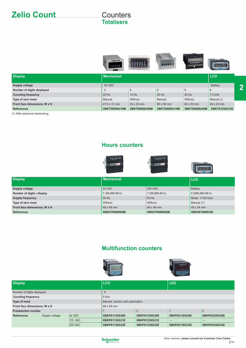
Other versions: please consult our Customer Care Centre.
Display Mechanical
LCD
Supply voltage 24 VDC BatteryNumber of digits displayed 5 6 6 8 8Counting frequency 20 Hz 10 Hz 25 Hz 25 Hz 7.5 kHzType of zero reset Manual Without Manual Without Manual (1) Front face dimensions, W x H 41.5 x 31 mm 30 x 20 mm 60 x 50 mm 60 x 50 mm 48 x 24 mmReferences XBKT50000U10M XBKT60000U00M XBKT60000U10M XBKT80000U00M XBKT81030U33E
(1) With electrical interlocking.
Hours counters
Display Mechanical LCD
Supply voltage 24 VAC 230 VAC BatteryNumber of digits / display 7 (99,999.99 h) 7 (99,999.99 h) 8 (999,999.99 h)Supply frequency 50 Hz 50 Hz Mode: 1/100 hourType of zero reset Without Without Manual (1)Front face dimensions, W x H 48 x 48 mm 48 x 48 mm 48 x 24 mmReferences XBKH70000004M XBKH70000002M XBKH81000033E
Multifunction counters
Display LCD LED
Number of digits displayed 6Counting frequency 5 kHzType of reset Manual, electric and automaticnFront face dimensions, W x H 48 x 48 mmPreselection number 1 2 1 2References Supply voltage 24 VDC XBKP61130G30E XBKP61230G30E XBKP62130G30E XBKP62230G30E
115 VAC XBKP61130G31E XBKP61230G31E – –230 VAC XBKP61130G32E XBKP61230G32E XBKP62130G32E XBKP62230G32E
CountersTotalisers
Zelio Count
2/11
2
1
3
4
5
6
7
8
9
10
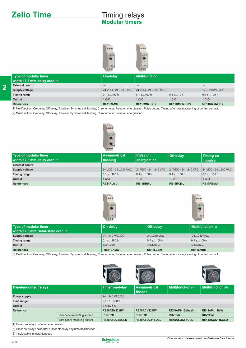
Other versions: please consult our Customer Care Centre.
Type of modular timer width 17.5 mm, relay output
On-delay Multifunction
External control no – – Supply voltage 24 VDC - 24 ...240 VAC 24 VDC - 24 ...240 VAC 12 ... 240VAC/DC Timing range 0.1 s…100 h 0.1 s…100 h 0.1 s…10 h 0.1 s…100 hOutput 1 C/O 1 C/O 1 C/O 1 C/OReferences RE11RAMU RE11RMMU (1) RE11RMEMU (2) RE11RMMW (1)
(1) Multifunction: On-delay, Off-delay, Totaliser, Symmetrical flashing, Chronometer, Pulse on energisation, Pulse output, Timing after closing/opening of control contact.(2) Multifunction: On-delay, Off-delay, Totaliser, Symmetrical flashing, Chronometer, Pulse on energisation.
Type of modular timer width 17.5 mm, relay output
Asymmetrical flashing
Pulse on energisation
Off delay Timing on impulse
External control – – – –Supply voltage 24 VDC - 24…240 VAC 24 VDC - 24…240 VAC 24 VDC - 24…240 VAC 24 VDC - 24…240 VACTiming range 0.1 s…100 h 0.1 s…100 h 0.1 s…100 h 0.1 s…100 hOutput 1 C/O 1 C/O 1 C/O 1 C/OReferences RE11RLMU RE11RHMU RE11RCMU RE11RBMU
Type of modular timer width 17.5 mm, solid-state output
On-delay Off-delay Multifunction (3)
Supply voltage 24…240 VAC/DC 24…240 VAC 24…240 VAC Timing range 0.1 s…100 h 0.1 s…100 h 0.1 s…100 hOutput solid-state solid-state solid-stateReferences RE11LAMW RE11LCBM RE11LMBM
(3) Multifunction: On-delay, Off-delay, Totaliser, Symmetrical flashing, Chronometer, Pulse on energisation, Pulse output, Timing after closing/opening of control contact.
Panel-mounted relays Timer on-delay Asymmetrical flasher
Multifunction (4) Multifunction (5)
Power supply 24…240 VAC/DC Time range 0,02 s…300 hOutput 2 relay 5 A Reference RE48ATM12MW RE48ACV12MW RE48AMH13MW (6) RE48AML12MW
Back panel mounting socket RUZC2M RUZC3M RUZC2M RUZC3MFront panel mounting socket RE48ASOC8SOLD RE48ASOC11SOLD RE48ASOC8SOLD RE48ASOC11SOLD
(4) Timer on-delay / pulse on energization(5) Timer on-delay / calibrator / timer off-delay / symmetrical flasher(6) 1 selectable in instantaneous
Timing relaysModular timers
Zelio Time
2/12
2
1
3
4
5
6
7
8
9
10
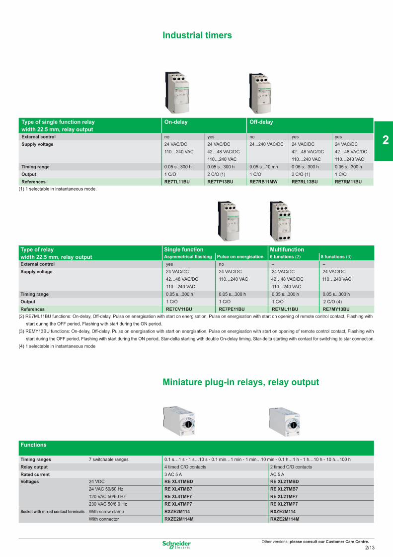
Other versions: please consult our Customer Care Centre.
Industrial timers
Type of single function relay width 22.5 mm, relay output
On-delay
Off-delay
External control no yes no yes yesSupply voltage 24 VAC/DC 24 VAC/DC 24...240 VAC/DC 24 VAC/DC 24 VAC/DC
110…240 VAC 42…48 VAC/DC 42…48 VAC/DC 42…48 VAC/DC110…240 VAC 110…240 VAC 110…240 VAC
Timing range 0.05 s...300 h 0.05 s...300 h 0.05 s...10 mn 0.05 s...300 h 0.05 s...300 hOutput 1 C/O 2 C/O (1) 1 C/O 2 C/O (1) 1 C/OReferences RE7TL11BU RE7TP13BU RE7RB11MW RE7RL13BU RE7RM11BU
(1) 1 selectable in instantaneous mode.
Type of relay width 22.5 mm, relay output
Single function Multifunction Asymmetrical flashing Pulse on energisation 6 functions (2) 8 functions (3)
External control yes no – – Supply voltage 24 VAC/DC 24 VAC/DC 24 VAC/DC 24 VAC/DC
42…48 VAC/DC 110…240 VAC 42…48 VAC/DC 110…240 VAC110…240 VAC 110…240 VAC
Timing range 0.05 s...300 h 0.05 s...300 h 0.05 s...300 h 0.05 s...300 hOutput 1 C/O 1 C/O 1 C/O 2 C/O (4)References RE7CV11BU RE7PE11BU RE7ML11BU RE7MY13BU
(2) RE7ML11BU functions: On-delay, Off-delay, Pulse on energisation with start on energisation, Pulse on energisation with start on opening of remote control contact, Flashing with start during the OFF period, Flashing with start during the ON period.(3) REMY13BU functions: On-delay, Off-delay, Pulse on energisation with start on energisation, Pulse on energisation with start on opening of remote control contact, Flashing with start during the OFF period, Flashing with start during the ON period, Star-delta starting with double On-delay timing, Star-delta starting with contact for switching to star connection.(4) 1 selectable in instantaneous mode
Miniature plug-in relays, relay output
Functions
Timing ranges 7 switchable ranges 0.1 s…1 s - 1 s…10 s - 0.1 min…1 min - 1 min…10 min - 0.1 h…1 h - 1 h…10 h - 10 h…100 hRelay output 4 timed C/O contacts 2 timed C/O contactsRated current 3 AC 5 A AC 5 AVoltages 24 VDC RE XL4TMBD RE XL2TMBD
24 VAC 50/60 Hz RE XL4TMB7 RE XL2TMB7120 VAC 50/60 Hz RE XL4TMF7 RE XL2TMF7230 VAC 50/6 0 Hz RE XL4TMP7 RE XL2TMP7
Socket with mixed contact terminals With screw clamp RXZE2M114 RXZE2M114With connector RXZE2M114M RXZE2M114M
2/13
2
1
3
4
5
6
7
8
9
10
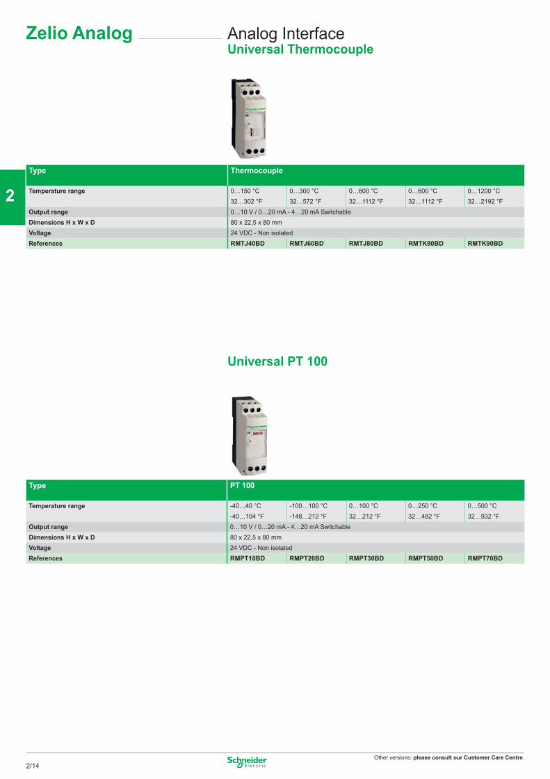
Other versions: please consult our Customer Care Centre.
Analog InterfaceUniversal Thermocouple
Type Thermocouple
Temperature range 0…150 °C 0…300 °C 0…600 °C 0…600 °C 0…1200 °C32…302 °F 32…572 °F 32…1112 °F 32…1112 °F 32…2192 °F
Output range 0…10 V / 0…20 mA - 4…20 mA SwitchableDimensions H x W x D 80 x 22,5 x 80 mmVoltage 24 VDC - Non isolatedReferences RMTJ40BD RMTJ60BD RMTJ80BD RMTK80BD RMTK90BD
Universal PT 100
Type PT 100
Temperature range -40…40 °C -100…100 °C 0…100 °C 0…250 °C 0…500 °C-40…104 °F -148…212 °F 32…212 °F 32…482 °F 32…932 °F
Output range 0…10 V / 0…20 mA - 4…20 mA SwitchableDimensions H x W x D 80 x 22,5 x 80 mmVoltage 24 VDC - Non isolatedReferences RMPT10BD RMPT20BD RMPT30BD RMPT50BD RMPT70BD
Zelio Analog
2/14
2
1
3
4
5
6
7
8
9
10
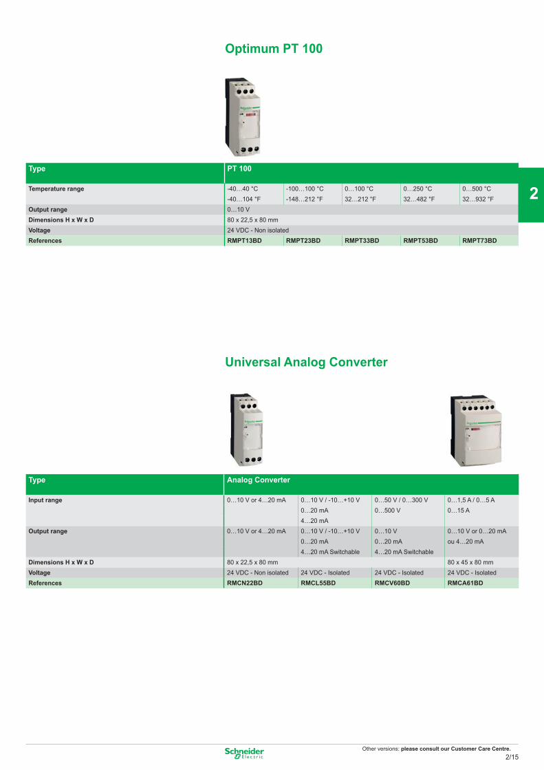
Other versions: please consult our Customer Care Centre.
Type PT 100
Temperature range -40…40 °C -100…100 °C 0…100 °C 0…250 °C 0…500 °C-40…104 °F -148…212 °F 32…212 °F 32…482 °F 32…932 °F
Output range 0…10 VDimensions H x W x D 80 x 22,5 x 80 mmVoltage 24 VDC - Non isolatedReferences RMPT13BD RMPT23BD RMPT33BD RMPT53BD RMPT73BD
Universal Analog Converter
Type Analog Converter
Input range 0…10 V or 4…20 mA 0…10 V / -10…+10 V 0…50 V / 0…300 V 0…1,5 A / 0…5 A0…20 mA 0…500 V 0…15 A4…20 mA
Output range 0…10 V or 4…20 mA 0…10 V / -10…+10 V 0…10 V 0…10 V or 0…20 mA0…20 mA 0…20 mA ou 4…20 mA 4…20 mA Switchable 4…20 mA Switchable
Dimensions H x W x D 80 x 22,5 x 80 mm 80 x 45 x 80 mmVoltage 24 VDC - Non isolated 24 VDC - Isolated 24 VDC - Isolated 24 VDC - IsolatedReferences RMCN22BD RMCL55BD RMCV60BD RMCA61BD
Optimum PT 100
2/15
2
1
3
4
5
6
7
8
9
10
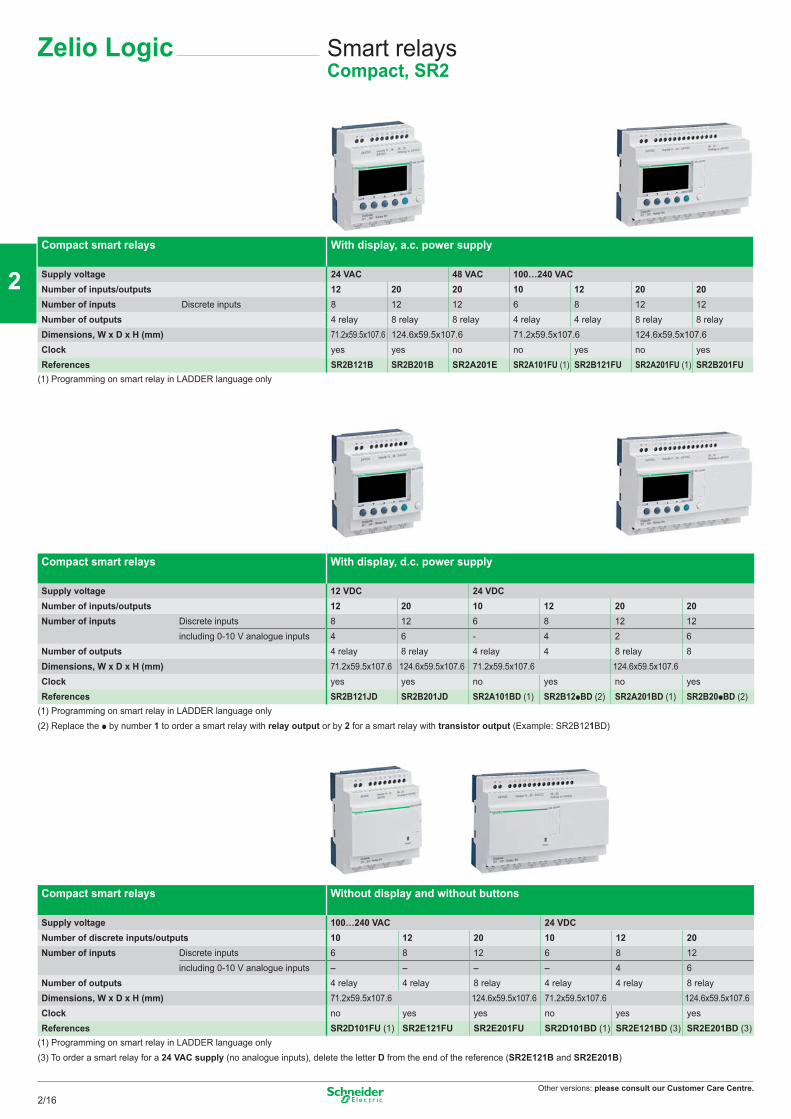
Other versions: please consult our Customer Care Centre.
Smart relaysCompact, SR2
Compact smart relays With display, a.c. power supply
Supply voltage 24 VAC 48 VAC 100…240 VACNumber of inputs/outputs 12 20 20 10 12 20 20Number of inputs Discrete inputs 8 12 12 6 8 12 12Number of outputs 4 relay 8 relay 8 relay 4 relay 4 relay 8 relay 8 relayDimensions, W x D x H (mm) 71.2x59.5x107.6 124.6x59.5x107.6 71.2x59.5x107.6 124.6x59.5x107.6Clock yes yes no no yes no yesReferences SR2B121B SR2B201B SR2A201E SR2A101FU (1) SR2B121FU SR2A201FU (1) SR2B201FU
(1) Programming on smart relay in LADDER language only
Compact smart relays With display, d.c. power supply
Supply voltage 12 VDC 24 VDCNumber of inputs/outputs 12 20 10 12 20 20Number of inputs Discrete inputs 8 12 6 8 12 12
including 0-10 V analogue inputs 4 6 - 4 2 6Number of outputs 4 relay 8 relay 4 relay 4 8 relay 8Dimensions, W x D x H (mm) 71.2x59.5x107.6 124.6x59.5x107.6 71.2x59.5x107.6 124.6x59.5x107.6Clock yes yes no yes no yesReferences SR2B121JD SR2B201JD SR2A101BD (1) SR2B12pBD (2) SR2A201BD (1) SR2B20pBD (2)
(1) Programming on smart relay in LADDER language only(2) Replace the p by number 1 to order a smart relay with relay output or by 2 for a smart relay with transistor output (Example: SR2B121BD)
Compact smart relays Without display and without buttons
Supply voltage 100…240 VAC 24 VDCNumber of discrete inputs/outputs 10 12 20 10 12 20Number of inputs Discrete inputs 6 8 12 6 8 12
including 0-10 V analogue inputs – – – – 4 6Number of outputs 4 relay 4 relay 8 relay 4 relay 4 relay 8 relayDimensions, W x D x H (mm) 71.2x59.5x107.6 124.6x59.5x107.6 71.2x59.5x107.6 124.6x59.5x107.6Clock no yes yes no yes yesReferences SR2D101FU (1) SR2E121FU SR2E201FU SR2D101BD (1) SR2E121BD (3) SR2E201BD (3)
(1) Programming on smart relay in LADDER language only(3) To order a smart relay for a 24 VAC supply (no analogue inputs), delete the letter D from the end of the reference (SR2E121B and SR2E201B)
Zelio Logic
2/16
2
1
3
4
5
6
7
8
9
10
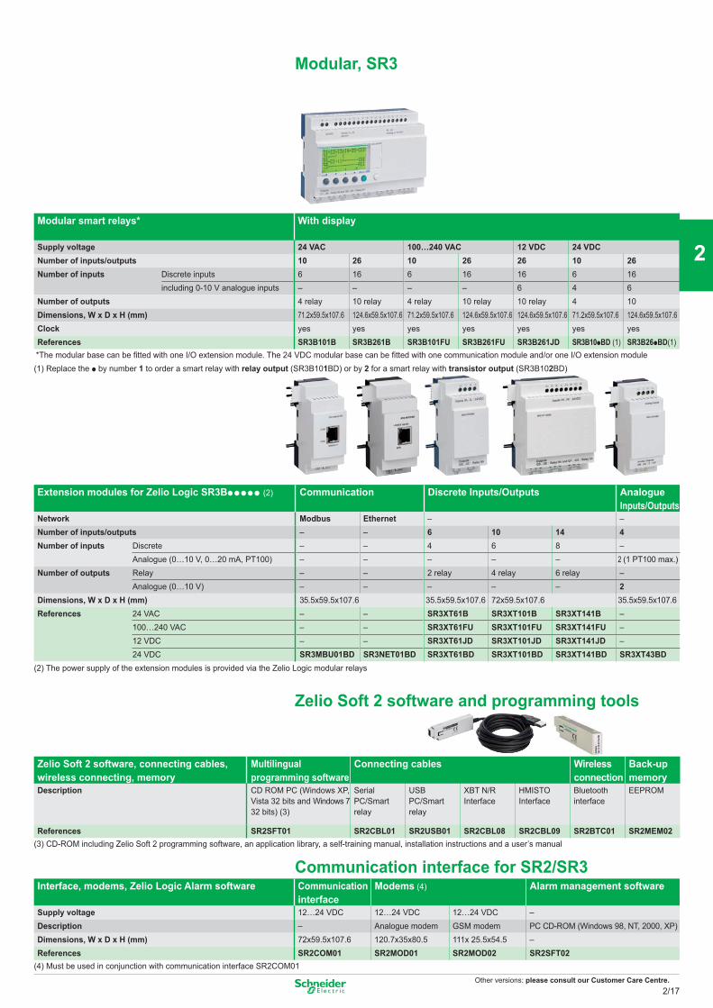
Other versions: please consult our Customer Care Centre.
Modular, SR3
Modular smart relays* With display
Supply voltage 24 VAC 100…240 VAC 12 VDC 24 VDCNumber of inputs/outputs 10 26 10 26 26 10 26Number of inputs Discrete inputs 6 16 6 16 16 6 16
including 0-10 V analogue inputs – – – – 6 4 6Number of outputs 4 relay 10 relay 4 relay 10 relay 10 relay 4 10Dimensions, W x D x H (mm) 71.2x59.5x107.6 124.6x59.5x107.6 71.2x59.5x107.6 124.6x59.5x107.6 124.6x59.5x107.6 71.2x59.5x107.6 124.6x59.5x107.6Clock yes yes yes yes yes yes yesReferences SR3B101B SR3B261B SR3B101FU SR3B261FU SR3B261JD SR3B10pBD (1) SR3B26pBD(1)
*The modular base can be fitted with one I/O extension module. The 24 VDC modular base can be fitted with one communication module and/or one I/O extension module(1) Replace the p by number 1 to order a smart relay with relay output (SR3B101BD) or by 2 for a smart relay with transistor output (SR3B102BD)
Extension modules for Zelio Logic SR3Bppppp (2) Communication
Discrete Inputs/Outputs Analogue Inputs/Outputs
Network Modbus Ethernet – –Number of inputs/outputs – – 6 10 14 4Number of inputs Discrete – – 4 6 8 –
Analogue (0…10 V, 0…20 mA, PT100) – – – – – 2 (1 PT100 max.)Number of outputs Relay – – 2 relay 4 relay 6 relay –
Analogue (0…10 V) – – – – – 2Dimensions, W x D x H (mm) 35.5x59.5x107.6 35.5x59.5x107.6 72x59.5x107.6 35.5x59.5x107.6References 24 VAC – – SR3XT61B SR3XT101B SR3XT141B –
100…240 VAC – – SR3XT61FU SR3XT101FU SR3XT141FU –12 VDC – – SR3XT61JD SR3XT101JD SR3XT141JD –24 VDC SR3MBU01BD SR3NET01BD SR3XT61BD SR3XT101BD SR3XT141BD SR3XT43BD
(2) The power supply of the extension modules is provided via the Zelio Logic modular relays
Zelio Soft 2 software and programming tools
Zelio Soft 2 software, connecting cables, wireless connecting, memory
Multilingual programming software
Connecting cables Wireless connection
Back-up memory
Description CD ROM PC (Windows XP, Vista 32 bits and Windows 7 32 bits) (3)
Serial PC/Smart relay
USB PC/Smart relay
XBT N/R Interface
HMISTOInterface
Bluetoothinterface
EEPROM
References SR2SFT01 SR2CBL01 SR2USB01 SR2CBL08 SR2CBL09 SR2BTC01 SR2MEM02(3) CD-ROM including Zelio Soft 2 programming software, an application library, a self-training manual, installation instructions and a user’s manual
Communication interface for SR2/SR3Interface, modems, Zelio Logic Alarm software Communication
interfaceModems (4) Alarm management software
Supply voltage 12…24 VDC 12…24 VDC 12…24 VDC –Description – Analogue modem GSM modem PC CD-ROM (Windows 98, NT, 2000, XP)Dimensions, W x D x H (mm) 72x59.5x107.6 120.7x35x80.5 111x 25.5x54.5 –References SR2COM01 SR2MOD01 SR2MOD02 SR2SFT02
(4) Must be used in conjunction with communication interface SR2COM01
2/17
2
1
3
4
5
6
7
8
9
10
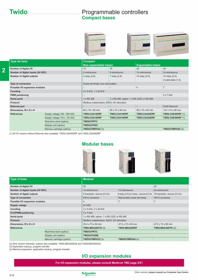
Other versions: please consult our Customer Care Centre.
Programmable controllersCompact bases
Twido
Type de base CompactNon expandable bases Expandable bases
Number of digital i/O 10 16 24 40Number of digital inputs (24 VDC) 6 sink/source 9 sink/source 14 sink/source 24 sink/sourceNumber of digital outputs 4 relay (2 A) 7 relay (2 A) 10 relay (2 A) 14 relay (2 A),
2 solid-state (1 A)Type of connection Screw terminals (non removable)Possible I/O expansion modules – – 4 7Counting 3 x 5 kHz, 1 x 20 kHzPWM positioning – 2 x 7 kHzSerial ports 1 x RS 485 1 x RS 485; option: 1 x RS 232C or RS 485Protocol Modbus master/slave, ASCII, I/O relocationEthernet port – – – RJ45 EthernetDimensions, W x D x H 80 x 70 x 90 mm 80 x 70 x 90 mm 95 x 70 x 90 mm 157 x 70 x 90 mmReferences Supply voltage 100…240 VAC TWDLCAA10DRF TWDLCAA16DRF TWDLCAA24DRF TWDLCAE40DRF (1)
Supply voltage 19.2…30 VDC TWDLCDA10DRF TWDLCDA16DRF TWDLCDA24DRF TWDLCDE40DRF (1)Real-time clock (option) TWDXCPRTCDisplay unit (option) TWDXCPODCMemory cartridge (option) TWDXCPMFK32 (3) TWDXCPMFK64 (4)
(1) 40 I/O version without Ethernet also available: TWDLCAA40DRF and TWDLCDA40DRF
Modular bases
Type of base Modular
Number of digital i/O 20 40Number of digital inputs (24 VDC) 12 sink/source 12 sink/source 24 sink/sourceNumber of digital outputs 8 transistor, source (0.3 A) 6 relay (2 A) & 2 trans., source (0.3 A) 16 transistor, source (0.3 A)Type of connection HE10 connector Removable screw terminals HE10 connectorPossible I/O expansion modules 4 7 7Supply voltage 24 VDCCounting 2 x 5 kHz, 2 x 20 kHzPLS/PWM positioning 2 x 7 kHzSerial ports 1 x RS 485; option: 1 x RS 232C or RS 485Protocol Modbus master/slave, ASCII, I/O relocationDimensions, W x D x H 35.4 x 70 x 90 mm 47.5 x 70 x 90 mm 47.5 x 70 x 90 mmReferences TWDLMDA20DTK (2) TWDLMDA20DRT TWDLMDA40DTK (2)
Real-time clock (option) TWDXCPRTCDisplay unit (option) TWDXCPODMMemory cartridge (option) TWDXCPMFK32 (3) TWDXCPMFK64 (4)
(2) Sink version transistor outputs also available: TWDLMDA20DUK and TWDLMDA40DUK(3) Application backup, program transfer(4) Memory expansion, application backup, program transfer
I/O expansion modulesFor I/O expansion modules, please consult Modicon TM2 page 2/21
2/18
2
1
3
4
5
6
7
8
9
10
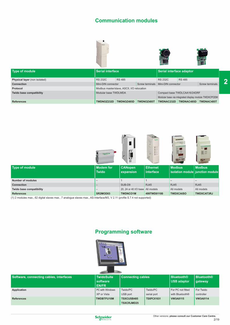
Other versions: please consult our Customer Care Centre.
Type of module Serial interface Serial interface adaptor
Physical layer (non isolated) RS 232C RS 485 RS 232C RS 485Connection Mini-DIN connector Screw terminals Mini-DIN connector Screw terminalsProtocol Modbus master/slave, ASCII, I/O relocationTwido base compatibility Modular base TWDLMDA Compact base TWDLCAA16/24DRF
Modular base via integrated display module TWDXCPODMReferences TWDNOZ232D TWDNOZ485D TWDNOZ485T TWDNAC232D TWDNAC485D TWDNAC485T
Type of module Modem for Twido
CANopenexpansion
Ethernetinterface
Modbus isolation module
Modbus junction module
Number of modules – 1 1 – –Connection – SUB-D9 RJ45 RJ45 RJ45Twido base compatibility – 20, 24 or 40 I/O base All models All models All modelsReferences SR2MOD03 TWDNCO1M 499TWD01100 TWDXCAISO TWDXCAT3RJ
(1) 2 modules max., 62 digital slaves max., 7 analogue slaves max., AS-Interface/M3, V 2.11 (profile S.7.4 not supported)
Programming software
Software, connecting cables, interfaces TwidoSuitesoftwareEN/FR
Connecting cables Bluetooth®USB adaptor
Bluetooth®gateway
Application PC with WindowsXP or Vista
Twido/PCUSB port
Twido/PCserial port
For PC not fitted with Bluetooth®
For Twidocontroller
References TWDBTFU10M TSXCUSB485 TSXCRJMD25
TSXPCX1031 VW3A8115 VW3A8114
Communication modules
2/19
2
1
3
4
5
6
7
8
9
10
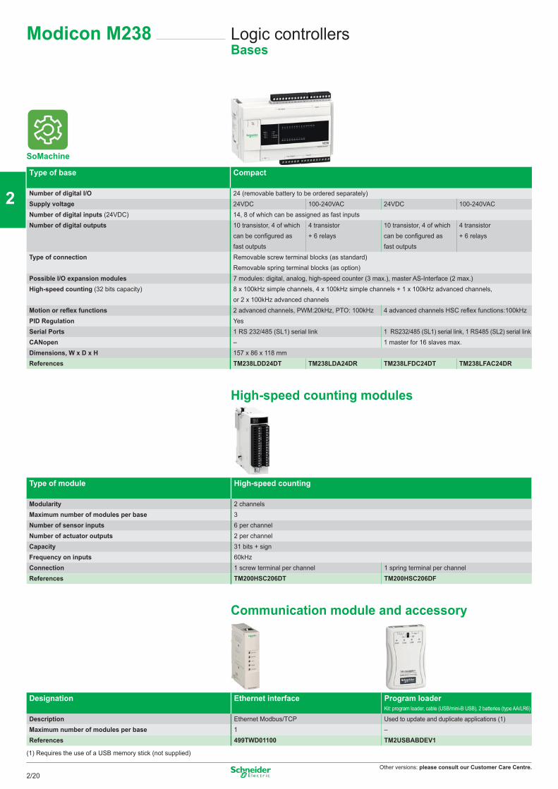
Other versions: please consult our Customer Care Centre.
Logic controllersBases
Modicon M238
Type of base Compact
Number of digital I/O 24 (removable battery to be ordered separately)Supply voltage 24VDC 100-240VAC 24VDC 100-240VACNumber of digital inputs (24VDC) 14, 8 of which can be assigned as fast inputsNumber of digital outputs 10 transistor, 4 of which
can be configured as fast outputs
4 transistor + 6 relays
10 transistor, 4 of which can be configured as fast outputs
4 transistor + 6 relays
Type of connection Removable screw terminal blocks (as standard) Removable spring terminal blocks (as option)
Possible I/O expansion modules 7 modules: digital, analog, high-speed counter (3 max.), master AS-Interface (2 max.)High-speed counting (32 bits capacity) 8 x 100kHz simple channels, 4 x 100kHz simple channels + 1 x 100kHz advanced channels,
or 2 x 100kHz advanced channelsMotion or reflex functions 2 advanced channels, PWM:20kHz, PTO: 100kHz 4 advanced channels HSC reflex functions:100kHzPID Regulation YesSerial Ports 1 RS 232/485 (SL1) serial link 1 RS232/485 (SL1) serial link, 1 RS485 (SL2) serial linkCANopen – 1 master for 16 slaves max.Dimensions, W x D x H 157 x 86 x 118 mmReferences TM238LDD24DT TM238LDA24DR TM238LFDC24DT TM238LFAC24DR
High-speed counting modules
Type of module High-speed counting
Modularity 2 channelsMaximum number of modules per base 3Number of sensor inputs 6 per channelNumber of actuator outputs 2 per channelCapacity 31 bits + signFrequency on inputs 60kHzConnection 1 screw terminal per channel 1 spring terminal per channelReferences TM200HSC206DT TM200HSC206DF
Communication module and accessory
Designation Ethernet interface Program loaderKit: program loader, cable (USB/mini-B USB), 2 batteries (type AA/LR6)
Description Ethernet Modbus/TCP Used to update and duplicate applications (1)Maximum number of modules per base 1 –References 499TWD01100 TM2USBABDEV1
(1) Requires the use of a USB memory stick (not supplied)
SoMachine
2/20
2
1
3
4
5
6
7
8
9
10
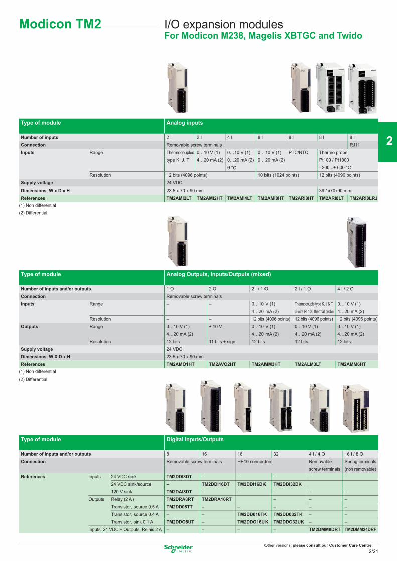
Other versions: please consult our Customer Care Centre.
I/O expansion modulesFor Modicon M238, Magelis XBTGC and Twido
Type of module Analog inputs
Number of inputs 2 I 2 I 4 I 8 I 8 I 8 I 8 IConnection Removable screw terminals RJ11Inputs Range Thermocouples 0…10 V (1) 0…10 V (1) 0…10 V (1) PTC/NTC Thermo probe
Pt100 / Pt1000- 200...+ 600 °C
type K, J, T 4…20 mA (2) 0…20 mA (2) 0…20 mA (2)
θ °CResolution 12 bits (4096 points) 10 bits (1024 points) 12 bits (4096 points)
Supply voltage 24 VDCDimensions, W x D x H 23.5 x 70 x 90 mm 39.1x70x90 mmReferences TM2AMI2LT TM2AMI2HT TM2AMI4LT TM2AMI8HT TM2ARI8HT TM2ARI8LT TM2ARI8LRJ
(1) Non differential(2) Differential
Type of module Analog Outputs, Inputs/Outputs (mixed)
Number of inputs and/or outputs 1 O 2 O 2 I / 1 O 2 I / 1 O 4 I / 2 OConnection Removable screw terminalsInputs Range – – 0…10 V (1) Thermocouple type K, J & T 0…10 V (1)
4…20 mA (2) 3-wire Pt 100 thermal probe 4…20 mA (2)Resolution – – 12 bits (4096 points) 12 bits (4096 points) 12 bits (4096 points)
Outputs Range 0…10 V (1) ± 10 V 0…10 V (1) 0…10 V (1) 0…10 V (1)4…20 mA (2) 4…20 mA (2) 4…20 mA (2) 4…20 mA (2)
Resolution 12 bits 11 bits + sign 12 bits 12 bits 12 bitsSupply voltage 24 VDCDimensions, W X D x H 23.5 x 70 x 90 mmReferences TM2AMO1HT TM2AVO2HT TM2AMM3HT TM2ALM3LT TM2AMM6HT
(1) Non differential(2) Differential
Type of module Digital Inputs/Outputs
Number of inputs and/or outputs 8 16 16 32 4 I / 4 O 16 I / 8 OConnection Removable screw terminals HE10 connectors Removable Spring terminals
screw terminals (non removable)References Inputs 24 VDC sink TM2DDI8DT – – – – –
24 VDC sink/source – TM2DDI16DT TM2DDI16DK TM2DDI32DK120 V sink TM2DAI8DT – – – – –
Outputs Relay (2 A) TM2DRA8RT TM2DRA16RT – – –Transistor, source 0.5 A TM2DD08TT – – – – –Transistor, source 0.4 A – – TM2DD016TK TM2DD032TK – –Transistor, sink 0.1 A TM2DDO8UT – TM2DDO16UK TM2DDO32UK – –
Inputs, 24 VDC + Outputs, Relais 2 A – – – – TM2DMM8DRT TM2DMM24DRF
Modicon TM2
2/21
2
1
3
4
5
6
7
8
9
10
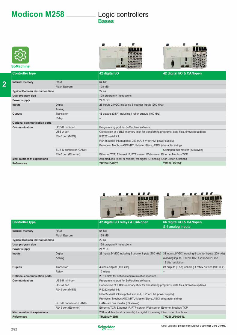
Other versions: please consult our Customer Care Centre.
Logic controllersBases
Modicon M258
Controller type 42 digital I/O 42 digital I/O & CANopen
Internal memory RAM 64 MBFlash Eeprom 128 MB
Typical Boolean instruction time 22 nsUser program size 128 program K instructionsPower supply 24 V DCInputs Digital 26 inputs 24VDC including 8 counter inputs (200 kHz)
Analog –Ouputs Transistor 16 outputs (0,5A) including 4 reflex outputs (100 kHz)
Relay –Optional communication ports –Communication USB-B mini-port Programming port for SoMachine software
USB-A port Connection of a USB memory stick for transferring programs, data files, firmware updatesRJ45 port (MBS) RS232 serial link
RS485 serial link (supplies 250 mA, 5 V for HMI power supply) Protocols: Modbus ASCII/RTU Master/Slave, ASCII (character string)
SUB-D connector (CAN0) – CANopen bus master (63 slaves)RJ45 port (Ethernet) Ethernet TCP, Ethernet IP, FTP server, Web server, Ethernet Modbus TCP
Max. number of expansions 250 modules (local or remote) for digital IO, analog IO or Expert functionsReferences TM258LD42DT TM258LF42DT
Controller type 42 digital I/O relays & CANopen 66 digital I/O & CANopen & 4 analog inputs
Internal memory RAM 64 MBFlash Eeprom 128 MB
Typical Boolean instruction time 22 nsUser program size 128 program K instructionsPower supply 24 V DCInputs Digital 26 inputs 24VDC including 8 counter inputs (200 kHz) 38 inputs 24VDC including 8 counter inputs (200 kHz)
Analog – 4 analog inputs +10 V/-10V, 4-20mA/0-20 mA 12 bits resolution
Ouputs Transistor 4 reflex outputs (100 kHz) 28 outputs (0,5A) including 4 reflex outputs (100 kHz)Relay 12 relays –
Optional communication ports 2 PCI slots for optional communication modulesCommunication USB-B mini-port Programming port for SoMachine software
USB-A port Connection of a USB memory stick for transferring programs, data files, firmware updatesRJ45 port (MBS) RS232 serial link
RS485 serial link (supplies 250 mA, 5 V for HMI power supply) Protocols: Modbus ASCII/RTU Master/Slave, ASCII (character string)
SUB-D connector (CAN0) CANopen bus master (63 slaves)RJ45 port (Ethernet) Ethernet TCP, Ethernet IP, FTP server, Web server, Ethernet Modbus TCP
Max. number of expansions 250 modules (local or remote) for digital IO, analog IO or Expert functionsReferences TM258LF42DR TM258LF66DT4L
SoMachine
2/22
2
1
3
4
5
6
7
8
9
10
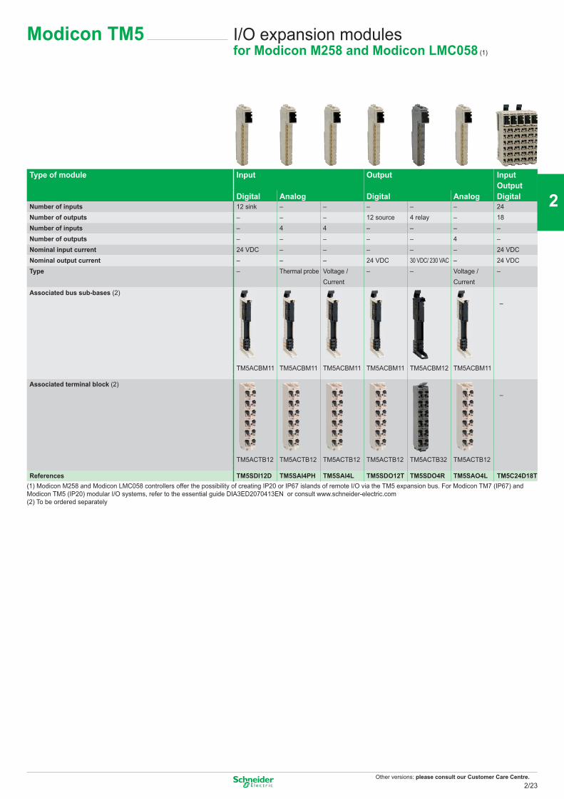
Other versions: please consult our Customer Care Centre.
I/O expansion modulesfor Modicon M258 and Modicon LMC058 (1)
Type of module Input Output InputOutput
Digital Analog Digital Analog DigitalNumber of inputs 12 sink – – – – – 24Number of outputs – – – 12 source 4 relay – 18Number of inputs – 4 4 – – – –Number of outputs – – – – – 4 –Nominal input current 24 VDC – – – – – 24 VDCNominal output current – – – 24 VDC 30 VDC/ 230 VAC – 24 VDCType – Thermal probe Voltage /
Current– – Voltage /
Current–
Associated bus sub-bases (2)–
TM5ACBM11 TM5ACBM11 TM5ACBM11 TM5ACBM11 TM5ACBM12 TM5ACBM11
Associated terminal block (2)–
TM5ACTB12 TM5ACTB12 TM5ACTB12 TM5ACTB12 TM5ACTB32 TM5ACTB12
References TM5SDI12D TM5SAI4PH TM5SAI4L TM5SDO12T TM5SDO4R TM5SAO4L TM5C24D18T(1) Modicon M258 and Modicon LMC058 controllers offer the possibility of creating IP20 or IP67 islands of remote I/O via the TM5 expansion bus. For Modicon TM7 (IP67) and Modicon TM5 (IP20) modular I/O systems, refer to the essential guide DIA3ED2070413EN or consult www.schneider-electric.com(2) To be ordered separately
Modicon TM5
2/23
2
1
3
4
5
6
7
8
9
10

Other versions: please consult our Customer Care Centre.
Motion ControllersBases
Modicon LMC058
Controller type 42 digital I/O 42 digital I/O + 4 analog inputs
CANmotion Drive synchronisation Up to 4 axes 2 msUp to 8 axes 4 ms
Internal memory RAM 64 MBFlash Eeprom 128 MB
Typical Boolean instruction time 22 nsExpert application Relative and Absolute positioning Yes
Velocity control YesHoming YesCNC visual editor YesCAM profiles YesElectronic gear YesInterpolation YesShift Compensation Yes
Embedded number of digital inputs 26 including 8 high speed counterEmbedded number of digital ouputs 16 outputs transistor (0.5 A) including 4 reflex outputsEmbedded number of analog inputs – 4Optional communication ports – 2 PCI slots for optional communication modulesCommunication USB-B mini-port Programming port for SoMachine software
USB-A port Connection of a USB memory stick for transferring programs, data files, firmware updatesRJ45 port (MBS) RS232 serial link
RS485 serial link (supplies 250 mA, 5 V for HMI power supply) Protocols: Modbus ASCII/RTU Master/Slave, ASCII (character string)
SUB-D connector (CAN0) CANopen bus master (63 slaves)SUB-D connector (CAN1) CANmotion bus master (63 slaves)SUB-D connector (Encoder) Encoder input (incremental or SSI)RJ45 port (Ethernet) Ethernet IP device
Ethernet TCP Modbus SoMachine protocol FTP server embedded Web server embedded
Max. number of expansions 250References LMC058LF42 LMC058LF424
I/O expansion modules
For I/O expansion modules, please consult Modicon TM5 page 2/23
SoMachine
2/24
2
1
3
4
5
6
7
8
9
10
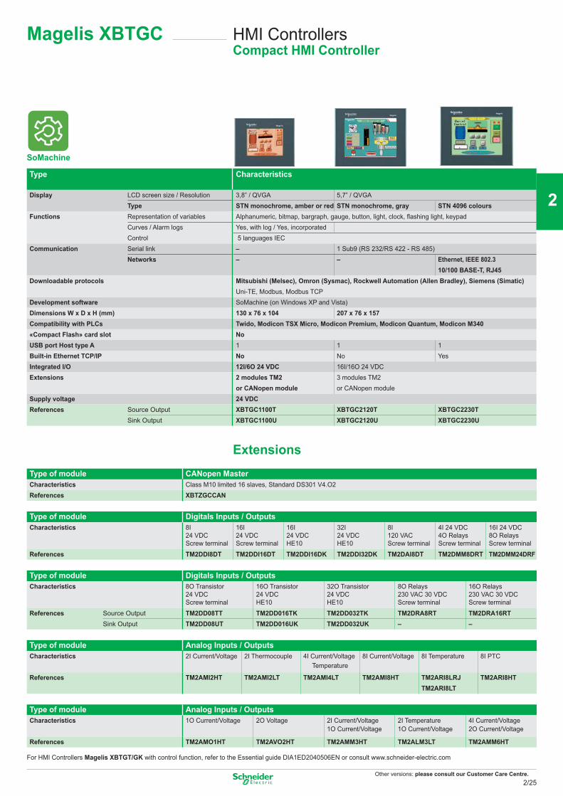
Other versions: please consult our Customer Care Centre.
Magelis XBTGC HMI Controllers Compact HMI Controller
Type Characteristics
Display LCD screen size / Resolution 3,8” / QVGA 5,7” / QVGAType STN monochrome, amber or red STN monochrome, gray STN 4096 colours
Functions Representation of variables Alphanumeric, bitmap, bargraph, gauge, button, light, clock, flashing light, keypadCurves / Alarm logs Yes, with log / Yes, incorporatedControl 5 languages IEC
Communication Serial link – 1 Sub9 (RS 232/RS 422 - RS 485)Networks – – Ethernet, IEEE 802.3
10/100 BASE-T, RJ45Downloadable protocols Mitsubishi (Melsec), Omron (Sysmac), Rockwell Automation (Allen Bradley), Siemens (Simatic)
Uni-TE, Modbus, Modbus TCPDevelopment software SoMachine (on Windows XP and Vista)Dimensions W x D x H (mm) 130 x 76 x 104 207 x 76 x 157Compatibility with PLCs Twido, Modicon TSX Micro, Modicon Premium, Modicon Quantum, Modicon M340«Compact Flash» card slot NoUSB port Host type A 1 1 1Built-in Ethernet TCP/IP No No YesIntegrated I/O 12I/6O 24 VDC 16I/16O 24 VDCExtensions 2 modules TM2
or CANopen module3 modules TM2or CANopen module
Supply voltage 24 VDCReferences Source Output XBTGC1100T XBTGC2120T XBTGC2230T
Sink Output XBTGC1100U XBTGC2120U XBTGC2230U
ExtensionsType of module CANopen MasterCharacteristics Class M10 limited 16 slaves, Standard DS301 V4.O2References XBTZGCCAN
Type of module Digitals Inputs / OutputsCharacteristics 8I
24 VDCScrew terminal
16I 24 VDCScrew terminal
16I24 VDCHE10
32I24 VDCHE10
8I120 VACScrew terminal
4I 24 VDC4O RelaysScrew terminal
16I 24 VDC8O RelaysScrew terminal
References TM2DDI8DT TM2DDI16DT TM2DDI16DK TM2DDI32DK TM2DAI8DT TM2DMM8DRT TM2DMM24DRF
Type of module Digitals Inputs / OutputsCharacteristics 8O Transistor
24 VDCScrew terminal
16O Transistor24 VDCHE10
32O Transistor24 VDCHE10
8O Relays230 VAC 30 VDCScrew terminal
16O Relays230 VAC 30 VDCScrew terminal
References Source Output TM2DD08TT TM2DD016TK TM2DD032TK TM2DRA8RT TM2DRA16RTSink Output TM2DD08UT TM2DD016UK TM2DD032UK – –
Type of module Analog Inputs / OutputsCharacteristics 2I Current/Voltage 2I Thermocouple 4I Current/Voltage
Temperature8I Current/Voltage 8I Temperature 8I PTC
References TM2AMI2HT TM2AMI2LT TM2AMI4LT TM2AMI8HT TM2ARI8LRJTM2ARI8LT
TM2ARI8HT
Type of module Analog Inputs / OutputsCharacteristics 1O Current/Voltage 2O Voltage 2I Current/Voltage
1O Current/Voltage2I Temperature1O Current/Voltage
4I Current/Voltage2O Current/Voltage
References TM2AMO1HT TM2AVO2HT TM2AMM3HT TM2ALM3LT TM2AMM6HT
For HMI Controllers Magelis XBTGT/GK with control function, refer to the Essential guide DIA1ED2040506EN or consult www.schneider-electric.com
SoMachine
2/25
2
1
3
4
5
6
7
8
9
10
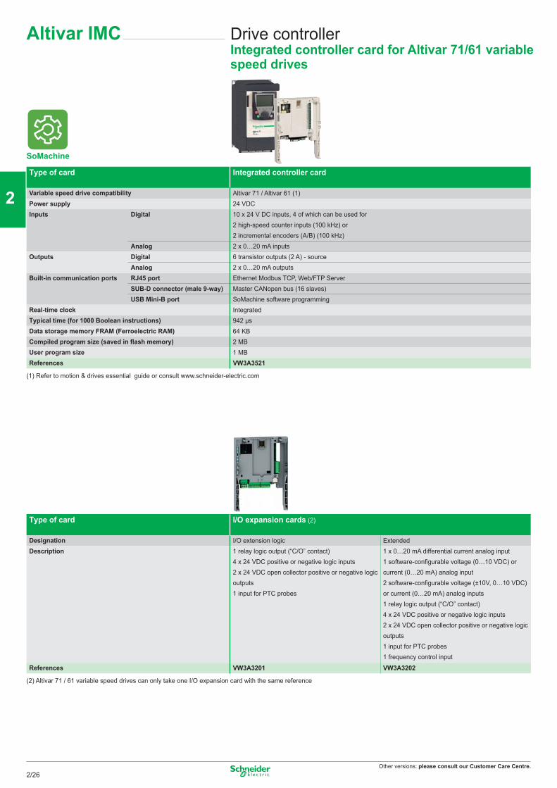
Other versions: please consult our Customer Care Centre.
Drive controllerIntegrated controller card for Altivar 71/61 variable speed drives
Altivar IMC
SoMachine
Type of card Integrated controller card
Variable speed drive compatibility Altivar 71 / Altivar 61 (1)Power supply 24 VDCInputs Digital 10 x 24 V DC inputs, 4 of which can be used for
2 high-speed counter inputs (100 kHz) or 2 incremental encoders (A/B) (100 kHz)
Analog 2 x 0…20 mA inputsOutputs Digital 6 transistor outputs (2 A) - source
Analog 2 x 0…20 mA outputsBuilt-in communication ports RJ45 port Ethernet Modbus TCP, Web/FTP Server
SUB-D connector (male 9-way) Master CANopen bus (16 slaves)USB Mini-B port SoMachine software programming
Real-time clock IntegratedTypical time (for 1000 Boolean instructions) 942 μsData storage memory FRAM (Ferroelectric RAM) 64 KBCompiled program size (saved in flash memory) 2 MBUser program size 1 MBReferences VW3A3521
(1) Refer to motion & drives essential guide or consult www.schneider-electric.com
Type of card I/O expansion cards (2)
Designation I/O extension logic ExtendedDescription 1 relay logic output (“C/O” contact)
4 x 24 VDC positive or negative logic inputs2 x 24 VDC open collector positive or negative logicoutputs1 input for PTC probes
1 x 0…20 mA differential current analog input1 software-configurable voltage (0…10 VDC) orcurrent (0…20 mA) analog input2 software-configurable voltage (±10V, 0…10 VDC)or current (0…20 mA) analog inputs1 relay logic output (“C/O” contact)4 x 24 VDC positive or negative logic inputs2 x 24 VDC open collector positive or negative logic outputs1 input for PTC probes1 frequency control input
References VW3A3201 VW3A3202
(2) Altivar 71 / 61 variable speed drives can only take one I/O expansion card with the same reference
2/26
2
1
3
4
5
6
7
8
9
10
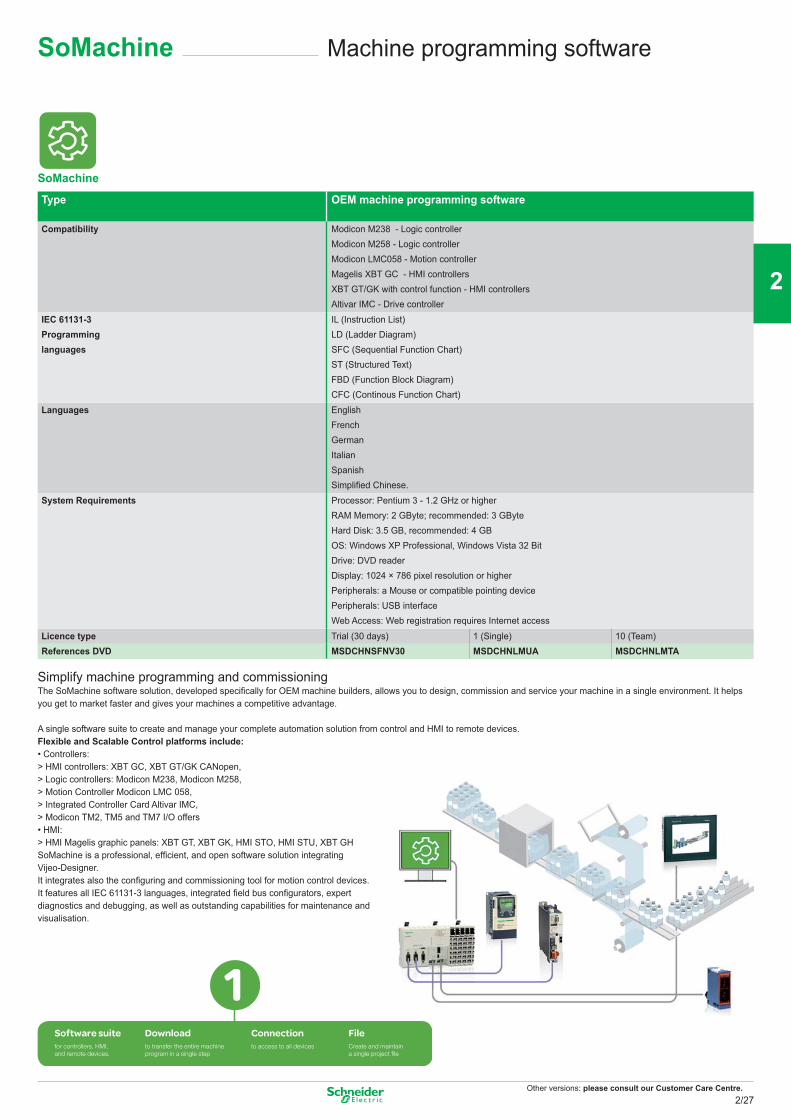
Other versions: please consult our Customer Care Centre.
SoMachine Machine programming software
Type OEM machine programming software
Compatibility Modicon M238 - Logic controllerModicon M258 - Logic controllerModicon LMC058 - Motion controllerMagelis XBT GC - HMI controllersXBT GT/GK with control function - HMI controllersAltivar IMC - Drive controller
IEC 61131-3 Programming languages
IL (Instruction List) LD (Ladder Diagram) SFC (Sequential Function Chart) ST (Structured Text) FBD (Function Block Diagram) CFC (Continous Function Chart)
Languages English FrenchGermanItalianSpanishSimplifi ed Chinese.
System Requirements Processor: Pentium 3 - 1.2 GHz or higherRAM Memory: 2 GByte; recommended: 3 GByteHard Disk: 3.5 GB, recommended: 4 GBOS: Windows XP Professional, Windows Vista 32 BitDrive: DVD readerDisplay: 1024 × 786 pixel resolution or higherPeripherals: a Mouse or compatible pointing devicePeripherals: USB interfaceWeb Access: Web registration requires Internet access
Licence type Trial (30 days) 1 (Single) 10 (Team)References DVD MSDCHNSFNV30 MSDCHNLMUA MSDCHNLMTA
Simplify machine programming and commissioningThe SoMachine software solution, developed specifi cally for OEM machine builders, allows you to design, commission and service your machine in a single environment. It helps you get to market faster and gives your machines a competitive advantage.
A single software suite to create and manage your complete automation solution from control and HMI to remote devices.Flexible and Scalable Control platforms include:• Controllers:> HMI controllers: XBT GC, XBT GT/GK CANopen,> Logic controllers: Modicon M238, Modicon M258,> Motion Controller Modicon LMC 058,> Integrated Controller Card Altivar IMC,> Modicon TM2, TM5 and TM7 I/O offers• HMI:> HMI Magelis graphic panels: XBT GT, XBT GK, HMI STO, HMI STU, XBT GHSoMachine is a professional, effi cient, and open software solution integratingVijeo-Designer.It integrates also the confi guring and commissioning tool for motion control devices.It features all IEC 61131-3 languages, integrated fi eld bus confi gurators, expertdiagnostics and debugging, as well as outstanding capabilities for maintenance andvisualisation.
for controllers, HMI,and remote devices.
to transfer the entire machineprogram in a single step
to access to all devices Create and maintaina single project file
SoMachine
2/27
2
1
3
4
5
6
7
8
9
10
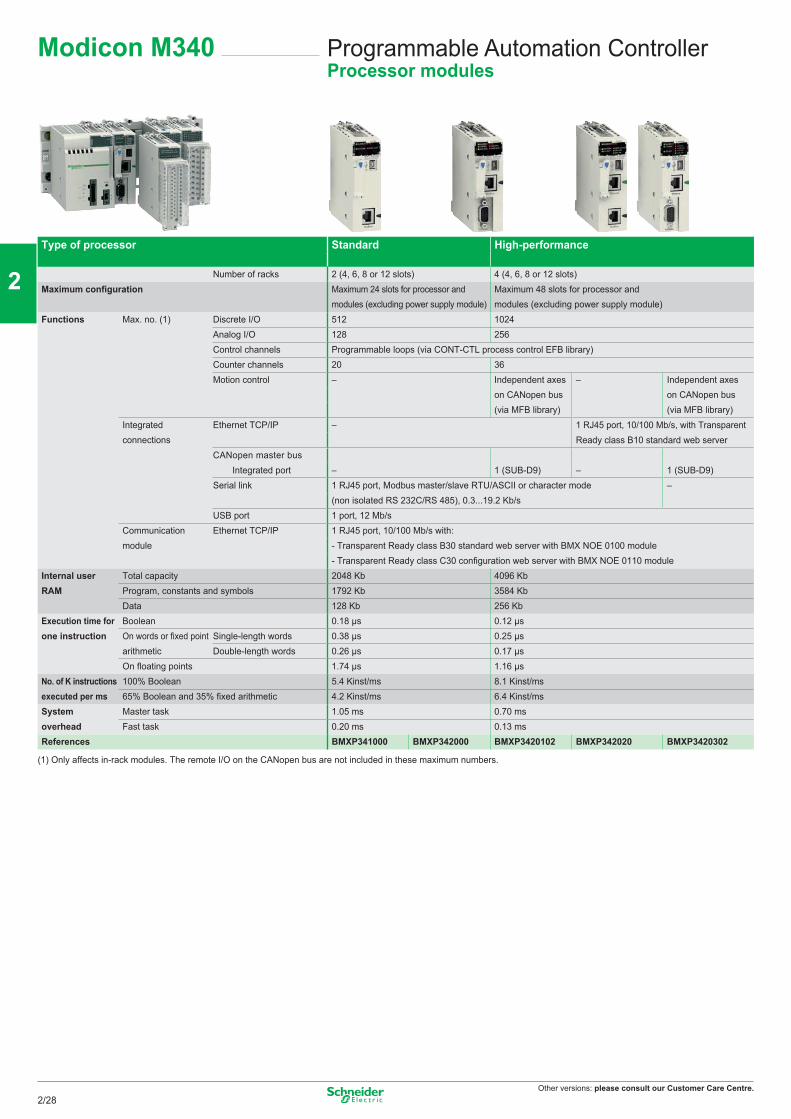
Other versions: please consult our Customer Care Centre.
Programmable Automation ControllerProcessor modules
Modicon M340
Type of processor Standard High-performance
Number of racks 2 (4, 6, 8 or 12 slots) 4 (4, 6, 8 or 12 slots)Maximum confi guration Maximum 24 slots for processor and
modules (excluding power supply module)Maximum 48 slots for processor and modules (excluding power supply module)
Functions Max. no. (1) Discrete I/O 512 1024Analog I/O 128 256Control channels Programmable loops (via CONT-CTL process control EFB library)Counter channels 20 36Motion control – Independent axes
on CANopen bus (via MFB library)
– Independent axes on CANopen bus (via MFB library)
Integratedconnections
Ethernet TCP/IP – 1 RJ45 port, 10/100 Mb/s, with TransparentReady class B10 standard web server
CANopen master busIntegrated port – 1 (SUB-D9) – 1 (SUB-D9)
Serial link 1 RJ45 port, Modbus master/slave RTU/ASCII or character mode –(non isolated RS 232C/RS 485), 0.3...19.2 Kb/s
USB port 1 port, 12 Mb/sCommunication Ethernet TCP/IP 1 RJ45 port, 10/100 Mb/s with:module - Transparent Ready class B30 standard web server with BMX NOE 0100 module
- Transparent Ready class C30 confi guration web server with BMX NOE 0110 moduleInternal user Total capacity 2048 Kb 4096 KbRAM Program, constants and symbols 1792 Kb 3584 Kb
Data 128 Kb 256 KbExecution time for Boolean 0.18 μs 0.12 μsone instruction On words or fi xed point Single-length words 0.38 μs 0.25 μs
arithmetic Double-length words 0.26 μs 0.17 μsOn fl oating points 1.74 μs 1.16 μs
No. of K instructions 100% Boolean 5.4 Kinst/ms 8.1 Kinst/msexecuted per ms 65% Boolean and 35% fi xed arithmetic 4.2 Kinst/ms 6.4 Kinst/msSystem Master task 1.05 ms 0.70 msoverhead Fast task 0.20 ms 0.13 msReferences BMXP341000 BMXP342000 BMXP3420102 BMXP342020 BMXP3420302
(1) Only affects in-rack modules. The remote I/O on the CANopen bus are not included in these maximum numbers.
2/28
2
1
3
4
5
6
7
8
9
10
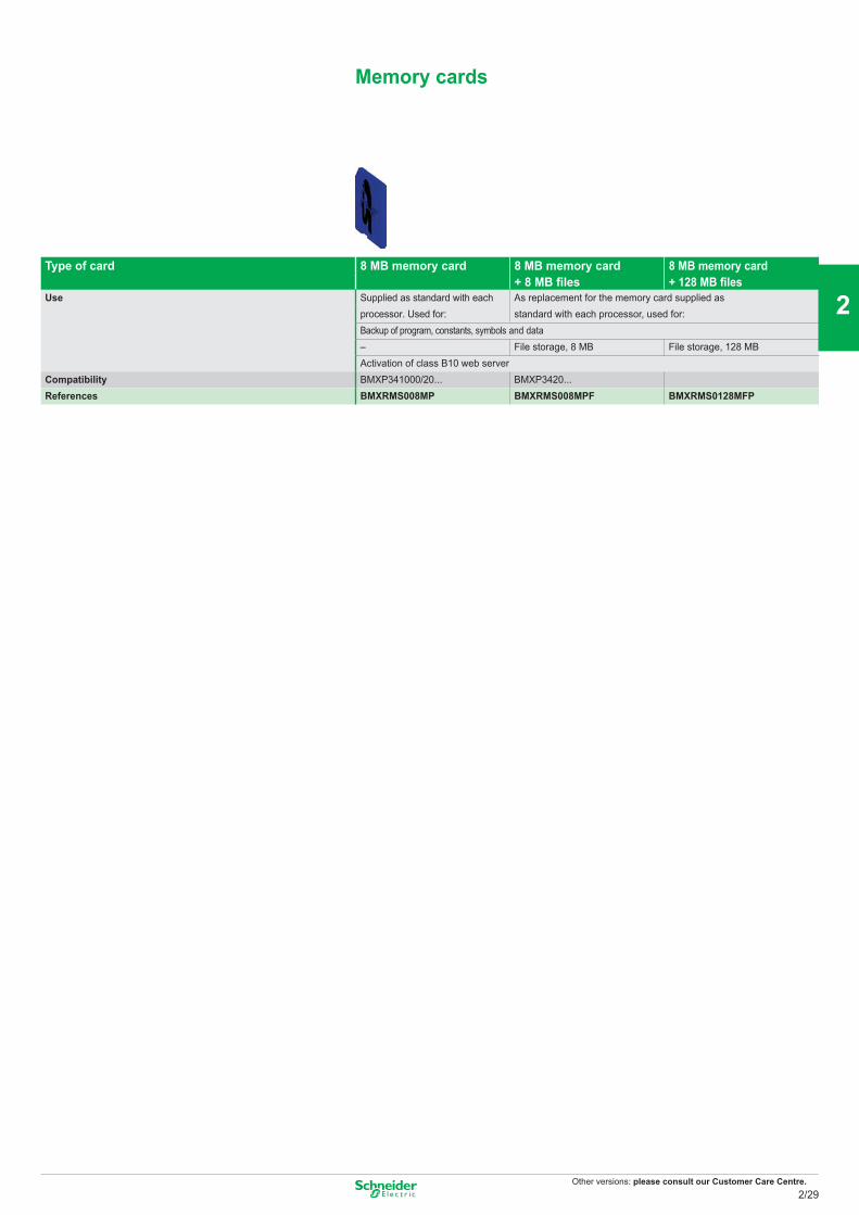
Other versions: please consult our Customer Care Centre.
Type of card 8 MB memory card 8 MB memory card + 8 MB files
8 MB memory card + 128 MB files
Use Supplied as standard with each processor. Used for:
As replacement for the memory card supplied asstandard with each processor, used for:
Backup of program, constants, symbols and data– File storage, 8 MB File storage, 128 MBActivation of class B10 web server
Compatibility BMXP341000/20... BMXP3420...References BMXRMS008MP BMXRMS008MPF BMXRMS0128MFP
Memory cards
2/29
2
1
3
4
5
6
7
8
9
10
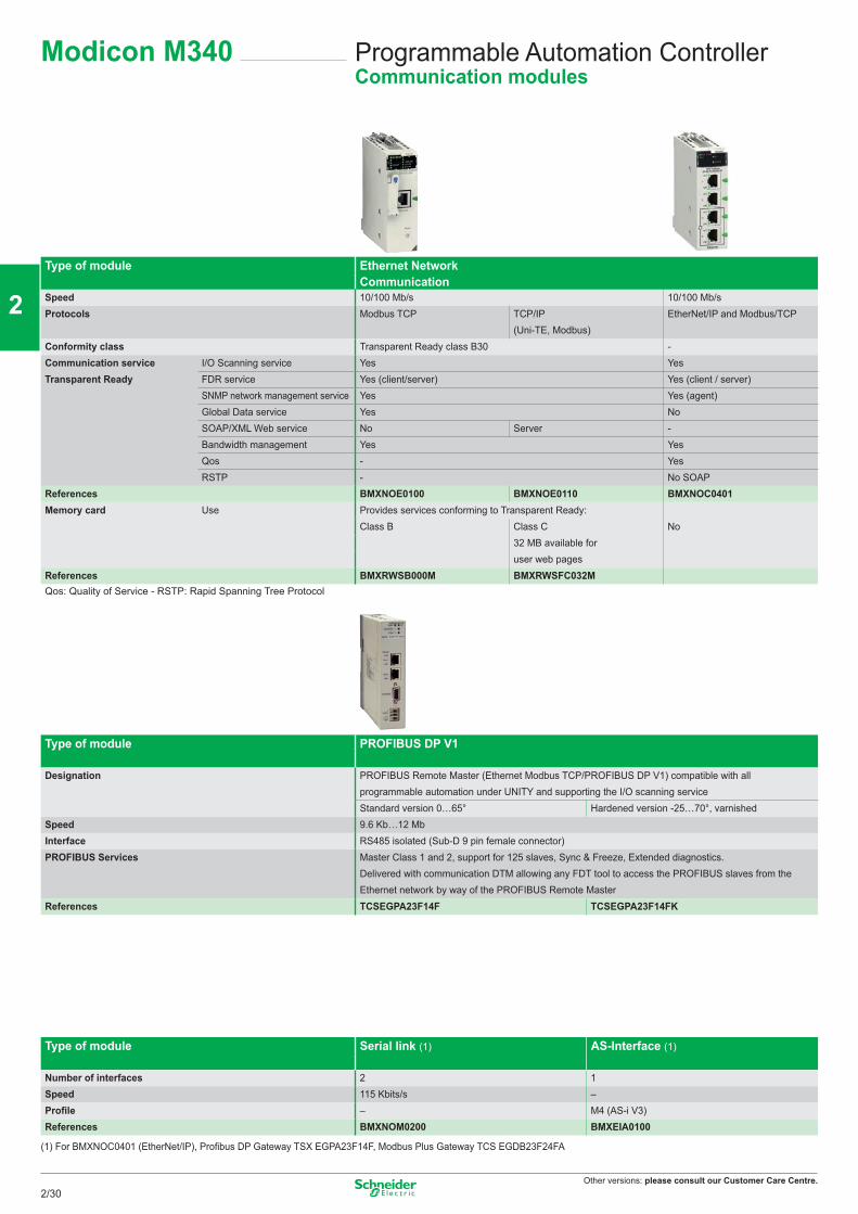
Other versions: please consult our Customer Care Centre.
Programmable Automation ControllerCommunication modules
Modicon M340
Type of module Ethernet Network Communication
Speed 10/100 Mb/s 10/100 Mb/sProtocols Modbus TCP TCP/IP
(Uni-TE, Modbus)EtherNet/IP and Modbus/TCP
Conformity class Transparent Ready class B30 -Communication service I/O Scanning service Yes YesTransparent Ready FDR service Yes (client/server) Yes (client / server)
SNMP network management service Yes Yes (agent)Global Data service Yes NoSOAP/XML Web service No Server -Bandwidth management Yes YesQos - YesRSTP - No SOAP
References BMXNOE0100 BMXNOE0110 BMXNOC0401Memory card Use Provides services conforming to Transparent Ready:
Class B Class C No32 MB available for user web pages
References BMXRWSB000M BMXRWSFC032MQos: Quality of Service - RSTP: Rapid Spanning Tree Protocol
Type of module PROFIBUS DP V1
Designation PROFIBUS Remote Master (Ethernet Modbus TCP/PROFIBUS DP V1) compatible with all programmable automation under UNITY and supporting the I/O scanning serviceStandard version 0…65° Hardened version -25…70°, varnished
Speed 9.6 Kb…12 MbInterface RS485 isolated (Sub-D 9 pin female connector) PROFIBUS Services Master Class 1 and 2, support for 125 slaves, Sync & Freeze, Extended diagnostics.
Delivered with communication DTM allowing any FDT tool to access the PROFIBUS slaves from the Ethernet network by way of the PROFIBUS Remote Master
References TCSEGPA23F14F TCSEGPA23F14FK
Type of module Serial link (1) AS-Interface (1)
Number of interfaces 2 1Speed 115 Kbits/s –Profile – M4 (AS-i V3)References BMXNOM0200 BMXEIA0100
(1) For BMXNOC0401 (EtherNet/IP), Profibus DP Gateway TSX EGPA23F14F, Modbus Plus Gateway TCS EGDB23F24FA
2/30
2
1
3
4
5
6
7
8
9
10
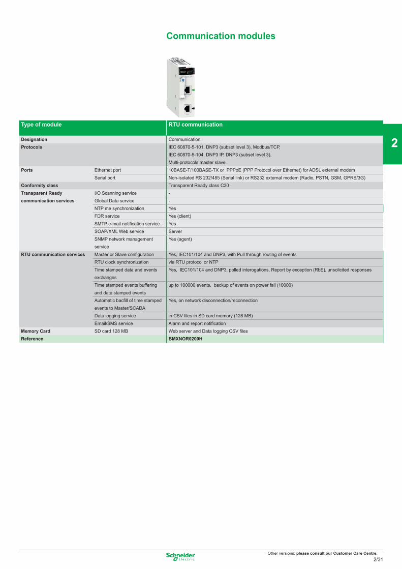
Other versions: please consult our Customer Care Centre.
Type of module RTU communication
Designation CommunicationProtocols IEC 60870-5-101, DNP3 (subset level 3), Modbus/TCP,
IEC 60870-5-104, DNP3 IP, DNP3 (subset level 3),Multi-protocols master slave
Ports Ethernet port 10BASE-T/100BASE-TX or PPPoE (PPP Protocol over Ethernet) for ADSL external modemSerial port Non-isolated RS 232/485 (Serial link) or RS232 external modem (Radio, PSTN, GSM, GPRS/3G)
Conformity class Transparent Ready class C30Transparent Ready communication services
I/O Scanning service -Global Data service -NTP me synchronization YesFDR service Yes (client)SMTP e-mail notification service YesSOAP/XML Web service ServerSNMP network management service
Yes (agent)
RTU communication services Master or Slave configuration Yes, IEC101/104 and DNP3, with Pull through routing of eventsRTU clock synchronization via RTU protocol or NTPTime stamped data and events exchanges
Yes, IEC101/104 and DNP3, polled interogations, Report by exception (RbE), unsolicited responses
Time stamped events buffering and date stamped events
up to 100000 events, backup of events on power fail (10000)
Automatic bacfill of time stamped events to Master/SCADA
Yes, on network disconnection/reconnection
Data logging service in CSV files in SD card memory (128 MB)Email/SMS service Alarm and report notification
Memory Card SD card 128 MB Web server and Data logging CSV filesReference BMXNOR0200H
Communication modules
2/31
2
1
3
4
5
6
7
8
9
10
Other versions: please consult our Customer Care Centre.
Programmable Automation ControllerPower supply modules
Modicon M340
Type of module Power supply modules
Voltage 24 VDC isolated 24…48 VDC isolated 100…240 VACNominal input current 1A at 24 VDC 1.65 A at 24 VDC 0.61 A at 115 VAC 1.04 A at 0.52 A 100...150 VDC
0.83 A at 48 VDC 0.31 A at 220 VDCMicro-break duration ≤ 1
Integrated protection Via internal fuse (not accessible)Max. useful power 17W 32 W 20 W 36 WMax. dissipated power 8.5 WRemovable connectors(set of 2)
supplied as standard BMXXTSCPS10 (cage clamp)to be ordered separately BMXXTSCPS20 (spring-type)
References BMXCPS2010 BMXCPS3020 BMXCPS2000 BMXCPS3500 BMXCPS3504 (1)
Racks
Designation Racks
Type of modules to be installed BMX CPS power supply, BMX P34 processor, I/O modules and application-specifi c modules (counter, communication)
No. of slots 4 6 8 12References BMXXBP0400 BMXXBP0600 BMXXBP0800 BMXXBP1200
Rack extensions
Designation Rack extension module Kit for rack extension
Standard module to interconnect rack A complete assembly kit for to racks distant from 0.8 m or less
References BMXXBE1000 BMXXBE2005
2/32
2
1
3
4
5
6
7
8
9
10
Other versions: please consult our Customer Care Centre.
Programmable Automation ControllerDiscrete I/O modules
Type of module DC input modules
Number of inputs 16 16 32 64 16 16Connection Screw or spring-type 1 connector 2 connectors Screw or spring-type
20-way removableterminal block
20-way removable 40-way 40-wayterminal block
Nominal input values Voltage 24 V 48 V 24 V 125 VDCCurrent 3.5 mA 2.5 mA 1 mA 3 mALogic Positive (sink) Negative (source)
Input limit values At state 1 Voltage ≥11 V ≥34 V ≥11 V ≥15 V ≥14 VCurrent > 2 mA > 2 mA > 2 mA > 1 mA > 2 mA
(for U ≥11 V) (for U ≥34 V) (for U ≥11 V) (for U ≥5 V) (for U ≥15 V)At state 0 Voltage < 5 V < 10 V < 5 V
Current ≥1.5 mA ≥0.5 mA ≥1.5 mA ≥0.5 mAReferences BMXDDI1602 BMXDDI1603 BMXDDI3202K BMXDDI6402K BMXDAI1602 BMXDDI1604 (1)
Type of module AC input modules
Number of inputs 16 8Connection Screw or spring-type 20-way removable terminal blockNominal input values Voltage 24 VAC 48 AC 100…120 VAC 200...240 VAC
Current 3 mA 10.4 mAFrequency 50/60 Hz
Input limit values At state 1 Voltage ≥15 V ≥34 V ≥74 V ≥159 VCurrent ≥2 mA ≥2.5 mA ≥6 mA
At state 0 Voltage ≤5 V ≤10 V ≤20 V ≤40 VCurrent ≤1 mA ≤4 mA
References BMXDAI1602 BMXDAI1603 BMXDAI1604 BMXDAI0805 (2)
Type of module DC solid state output modules
Number of inputs 16 16 32 64Connection Screw or spring-type 20-way removable terminal block One 40-way connector Two 40-way connectorsNominal output values Voltage 24 VDC
Current 0.5 V 0.1 VLogic Positive (source) Negative (sink) Positive (source)
Output limit values Voltage (ripple included) 19…30 (possible up to 34 V, limited to 1 hour in every 24 hours)Current per channel 0.625 A 0.125 ACurrent per module
Maximum dissipated power 4 2.26 3.6 6.85References BMXDDO1602 BMXDDO1612 BMXDDO3202K BMXDDO6402K
Modicon M340
2/33
2
1
3
4
5
6
7
8
9
10
Other versions: please consult our Customer Care Centre.
Programmable Automation ControllerDiscrete I/O modules
Type of module Triac output modules
Number of inputs 16Connection Screw or spring-type 20-way removable terminal blockOperating voltage Nominal 100…240 VAC
Limit 85…288 VACCurrents Maximum 0.6 per channel, 2.4 per common, 4.8 for all 4 commons.
Minimum 25 mA at 100 V a, 25 mA at 240 V a.Maximum inrush current ≤ 20/cycleReference BMXDAO1605
Type of module Relay output modules
Number of inputs 8 16 8Connection Screw or spring-type 20-way removable terminal blockMax. operating voltage DC 10…34 VDC 24…125 VDC (resistive load)
AC 10…264 VAC 200…264 VAC (Cosϕ = 1) 100...150 VDCResponse time Activation < 10 ms
Deactivation < 8 ms < 12 msDissipated power 2.7 W max 3 WReferences BMXDRA0805 BMXDRA1605 BMXDRA0804 (1)
Type of module 24 VDC mixed I/O modulesInputs Solid state outputs Inputs Solid state outputs
Number of I/O 8 8 16 16Connection Screw or spring-type 20-way removable terminal block One 40-way connectorInput limit values At state 1 Voltage ≥11V ≥11V
Current ≥3 mA (for U ≥11) ≥2 mA (for U ≥11)At state 0 Voltage 5 V 5 V
Current ≤1.5 mA ≤1.5 mASensor power supply (ripple included) 19…30 V (possible up to 30 V, limited to 1 hour in every 24 hours)
Output limit values Voltage (ripple included) 19…30 (possible up to 30 V, limited to 1 hour in every 24 hours)Current per channel 0.625 A 0.125 A per module 5 A 3.2 A
Maximum dissipated power 3.7 W 4 WReferences BMXDDM16022 BMXDDM3202K
Modicon M340
2/34
2
1
3
4
5
6
7
8
9
10
Other versions: please consult our Customer Care Centre.
Type of module Mixed input/relay output modules24 VDC inputs 24 VDC or 24…240 VAC relay outputs
Number of I/O 8 8Connection Screw or spring-type 20-way removable terminal blockNominal values Inputs Voltage 24 VDC (positive logic)
Current 3.5 mAOutputs DC voltage 24 VDC
DC 2 (resistive load)AC voltage 220 VAC, Cosϕ = 1
AC 2 AInput limit values At state 1 Voltage ≥11V
Current ≥2 mA (for U ≥ 11 V)At state 0 Voltage 5 V
Current ≤1.5 mASensor power supply (ripple included) 19…30 V (possible up to 30 V, limited to 1 hour in every 24 hours)
Maximum dissipated power 3.1 WReference BMXDDM16025
Discrete I/O modules
2/35
2
1
3
4
5
6
7
8
9
10
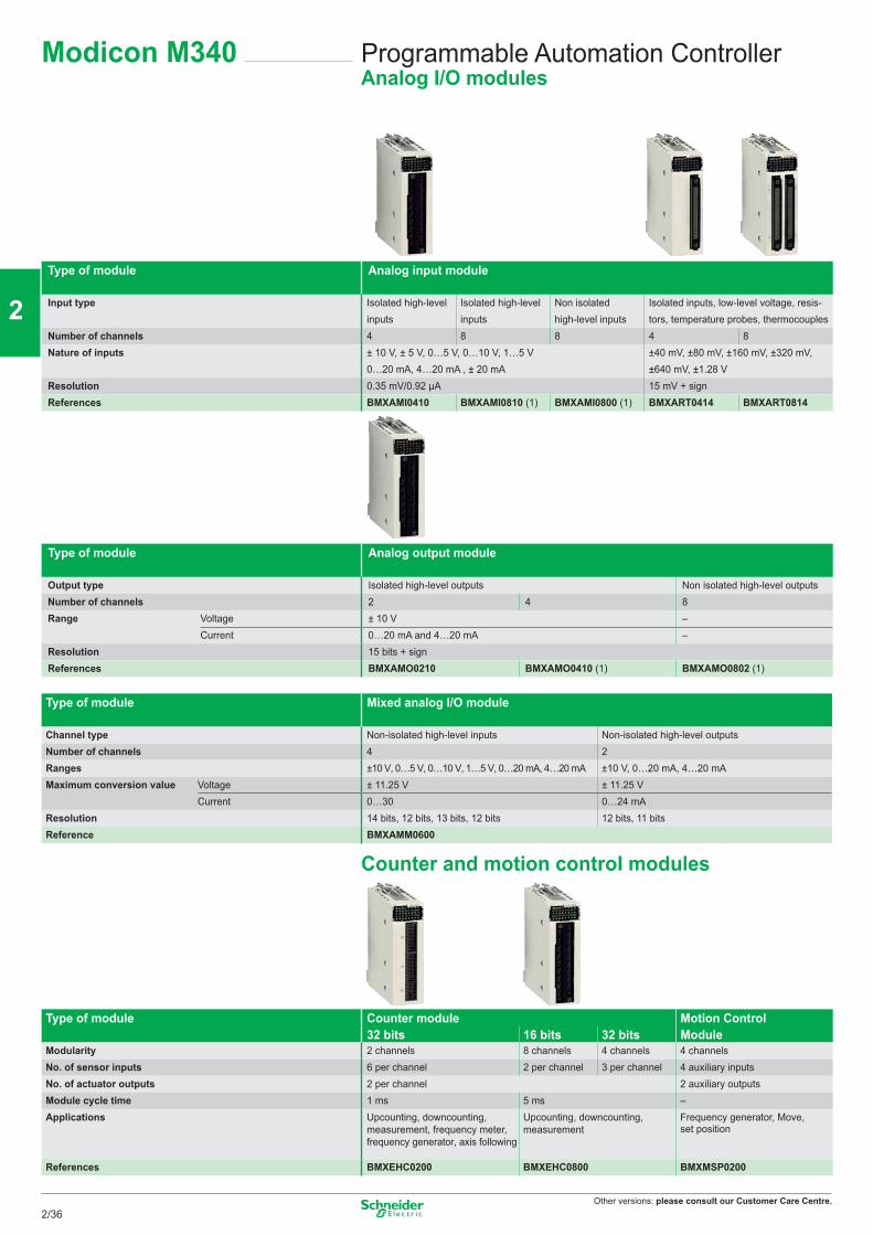
Other versions: please consult our Customer Care Centre.
Programmable Automation ControllerAnalog I/O modules
Type of module Analog input module
Input type Isolated high-level inputs
Isolated high-level inputs
Non isolated high-level inputs
Isolated inputs, low-level voltage, resis-tors, temperature probes, thermocouples
Number of channels 4 8 8 4 8Nature of inputs ± 10 V, ± 5 V, 0…5 V, 0…10 V, 1…5 V
0…20 mA, 4…20 mA , ± 20 mA±40 mV, ±80 mV, ±160 mV, ±320 mV, ±640 mV, ±1.28 V
Resolution 0.35 mV/0.92 μA 15 mV + signReferences BMXAMI0410 BMXAMI0810 (1) BMXAMI0800 (1) BMXART0414 BMXART0814
Type of module Analog output module
Output type Isolated high-level outputs Non isolated high-level outputsNumber of channels 2 4 8Range Voltage ± 10 V –
Current 0…20 mA and 4…20 mA –Resolution 15 bits + signReferences BMXAMO0210 BMXAMO0410 (1) BMXAMO0802 (1)
Type of module Mixed analog I/O module
Channel type Non-isolated high-level inputs Non-isolated high-level outputsNumber of channels 4 2Ranges ±10 V, 0…5 V, 0…10 V, 1…5 V, 0…20 mA, 4…20 mA ±10 V, 0…20 mA, 4…20 mAMaximum conversion value Voltage ± 11.25 V ± 11.25 V
Current 0…30 0…24 mAResolution 14 bits, 12 bits, 13 bits, 12 bits 12 bits, 11 bitsReference BMXAMM0600
Counter and motion control modules
Type of module Counter module Motion Control Module32 bits 16 bits 32 bits
Modularity 2 channels 8 channels 4 channels 4 channelsNo. of sensor inputs 6 per channel 2 per channel 3 per channel 4 auxiliary inputsNo. of actuator outputs 2 per channel 2 auxiliary outputsModule cycle time 1 ms 5 ms –Applications Upcounting, downcounting,
measurement, frequency meter, frequency generator, axis following
Upcounting, downcounting, measurement
Frequency generator, Move, set position
References BMXEHC0200 BMXEHC0800 BMXMSP0200
Modicon M340
2/36
2
1
3
4
5
6
7
8
9
10
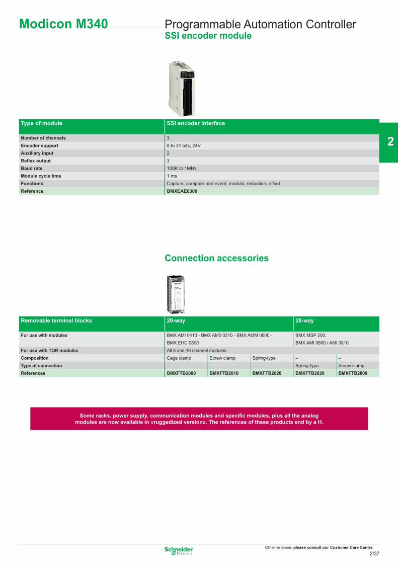
Other versions: please consult our Customer Care Centre.
Programmable Automation ControllerSSI encoder module
Modicon M340
Removable terminal blocks 20-way 28-way
For use with modules BMX AMI 0410 - BMX AM0 0210 - BMX AMM 0600 - BMX EHC 0800
BMX MSP 200, BMX AMI 0800 / AMI 0810
For use with TOR modules All 8 and 16 channel modulesComposition Cage clamp Screw clamp Spring-type – –Type of connection – – – Spring-type Screw clampReferences BMXFTB2000 BMXFTB2010 BMXFTB2020 BMXFTB2820 BMXFTB2800
Some racks, power supply, communication modules and specific modules, plus all the analogmodules are now available in «ruggedized version». The references of these products end by a H.
Connection accessories
Type of module SSI encoder interface
Number of channels 3Encoder support 8 to 31 bits, 24VAuxiliary input 2Reflex output 3Baud rate 100K to 1MHzModule cycle time 1 msFunctions Capture, compare and event, modulo, reduction, offsetReference BMXEAE0300
2/37
2
1
3
4
5
6
7
8
9
10
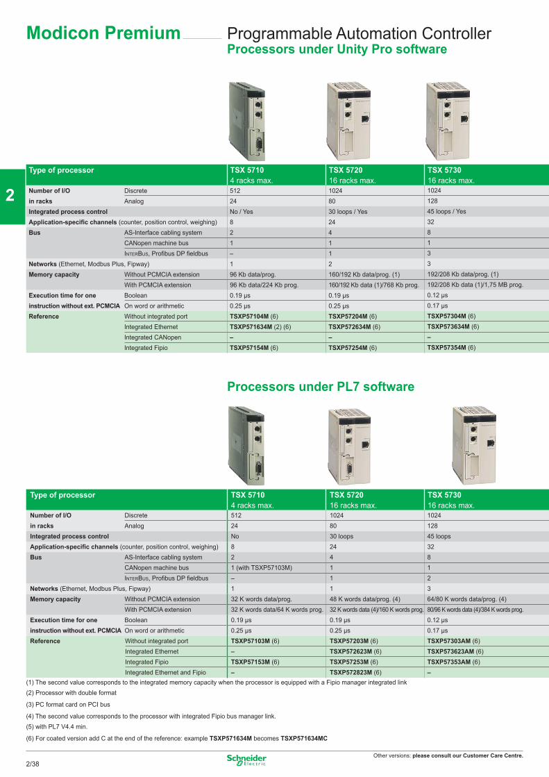
Other versions: please consult our Customer Care Centre.
Programmable Automation ControllerProcessors under Unity Pro software
Type of processor TSX 5710 4 racks max.
TSX 5720 16 racks max.
TSX 5730 16 racks max.
Number of I/O Discrete 512 1024 1024in racks Analog 24 80 128Integrated process control No / Yes 30 loops / Yes 45 loops / YesApplication-specific channels (counter, position control, weighing) 8 24 32Bus AS-Interface cabling system 2 4 8
CANopen machine bus 1 1 1INTERBUS, Profibus DP fieldbus – 1 3
Networks (Ethernet, Modbus Plus, Fipway) 1 2 3Memory capacity Without PCMCIA extension 96 Kb data/prog. 160/192 Kb data/prog. (1) 192/208 Kb data/prog. (1)
With PCMCIA extension 96 Kb data/224 Kb prog. 160/192 Kb data (1)/768 Kb prog. 192/208 Kb data (1)/1,75 MB prog.Execution time for one Boolean 0.19 μs 0.19 μs 0.12 μsinstruction without ext. PCMCIA On word or arithmetic 0.25 μs 0.25 μs 0.17 μsReference Without integrated port TSXP57104M (6) TSXP57204M (6) TSXP57304M (6)
Integrated Ethernet TSXP571634M (2) (6) TSXP572634M (6) TSXP573634M (6)Integrated CANopen – – –Integrated Fipio TSXP57154M (6) TSXP57254M (6) TSXP57354M (6)
Processors under PL7 software
Type of processor TSX 5710 4 racks max.
TSX 5720 16 racks max.
TSX 5730 16 racks max.
Number of I/O Discrete 512 1024 1024in racks Analog 24 80 128Integrated process control No 30 loops 45 loopsApplication-specific channels (counter, position control, weighing) 8 24 32Bus AS-Interface cabling system 2 4 8
CANopen machine bus 1 (with TSXP57103M) 1 1INTERBUS, Profibus DP fieldbus – 1 2
Networks (Ethernet, Modbus Plus, Fipway) 1 1 3Memory capacity Without PCMCIA extension 32 K words data/prog. 48 K words data/prog. (4) 64/80 K words data/prog. (4)
With PCMCIA extension 32 K words data/64 K words prog. 32 K words data (4)/160 K words prog. 80/96 K words data (4)/384 K words prog.Execution time for one Boolean 0.19 μs 0.19 μs 0.12 μsinstruction without ext. PCMCIA On word or arithmetic 0.25 μs 0.25 μs 0.17 μsReference Without integrated port TSXP57103M (6) TSXP57203M (6) TSXP57303AM (6)
Integrated Ethernet – TSXP572623M (6) TSXP573623AM (6)Integrated Fipio TSXP57153M (6) TSXP57253M (6) TSXP57353AM (6)Integrated Ethernet and Fipio – TSXP572823M (6) –
(1) The second value corresponds to the integrated memory capacity when the processor is equipped with a Fipio manager integrated link(2) Processor with double format
(3) PC format card on PCI bus
(4) The second value corresponds to the processor with integrated Fipio bus manager link. (5) with PL7 V4.4 min.
(6) For coated version add C at the end of the reference: example TSXP571634M becomes TSXP571634MC
Modicon Premium
2/38
2
1
3
4
5
6
7
8
9
10
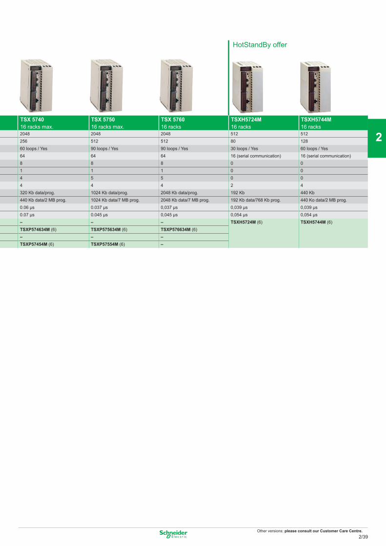
Other versions: please consult our Customer Care Centre.
TSX 5740 16 racks max.
TSX 5750 16 racks max.
TSX 5760 16 racks
TSXH5724M 16 racks
TSXH5744M 16 racks
2048 2048 2048 512 512256 512 512 80 12860 loops / Yes 90 loops / Yes 90 loops / Yes 30 loops / Yes 60 loops / Yes64 64 64 16 (serial communication) 16 (serial communication)8 8 8 0 01 1 1 0 04 5 5 0 04 4 4 2 4320 Kb data/prog. 1024 Kb data/prog. 2048 Kb data/prog. 192 Kb 440 Kb440 Kb data/2 MB prog. 1024 Kb data/7 MB prog. 2048 Kb data/7 MB prog. 192 Kb data/768 Kb prog. 440 Ko data/2 MB prog.0.06 μs 0.037 μs 0,037 μs 0,039 μs 0,039 μs0.07 μs 0.045 μs 0,045 μs 0,054 μs 0,054 μs– – – TSXH5724M (6) TSXH5744M (6)TSXP574634M (6) TSXP575634M (6) TSXP576634M (6)– – –TSXP57454M (6) TSXP57554M (6) –
HotStandBy offer
2/39
2
1
3
4
5
6
7
8
9
10
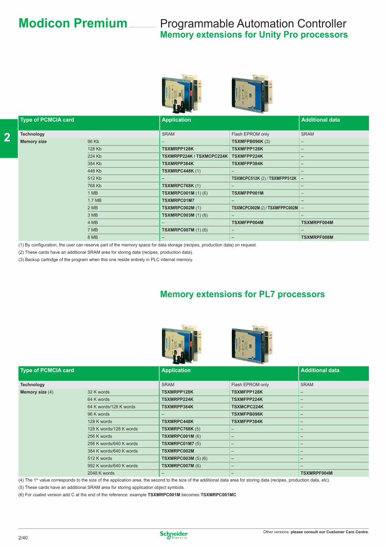
Other versions: please consult our Customer Care Centre.
Programmable Automation ControllerMemory extensions for Unity Pro processors
Type of PCMCIA card Application Additional data
Technology SRAM Flash EPROM only SRAMMemory size 96 Kb – TSXMFPB096K (3) –
128 Kb TSXMRPP128K TSXMFPP128K –224 Kb TSXMRPP224K / TSXMCPC224K TSXMFPP224K –384 Kb TSXMRPP384K TSXMFPP384K –448 Kb TSXMRPC448K (1) – –512 Kb – TSXMCPC512K (2) / TSXMFPP512K –768 Kb TSXMRPC768K (1) – –1 MB TSXMRPC001M (1) (6) TSXMFPP001M –1.7 MB TSXMRPC01M7 – –2 MB TSXMRPC002M (1) TSXMCPC002M (2) / TSXMFPPC002M –3 MB TSXMRPC003M (1) (6) – –4 MB – TSXMFPP004M TSXMRPF004M7 MB TSXMRPC007M (1) (6) – –8 MB – – TSXMRPF008M
(1) By configuration, the user can reserve part of the memory space for data storage (recipes, production data) on request.(2) These cards have an additional SRAM area for storing data (recipes, production data).(3) Backup cartridge of the program when this one reside entirely in PLC internal memory.
Memory extensions for PL7 processors
Type of PCMCIA card Application Additional data
Technology SRAM Flash EPROM only SRAMMemory size (4) 32 K words TSXMRPP128K TSXMFPP128K –
64 K words TSXMRPP224K TSXMFPP224K –64 K words/128 K words TSXMRPP384K TSXMCPC224K –96 K words – TSXMFPB096K –128 K words TSXMRPC448K TSXMFPP384K –128 K words/128 K words TSXMRPC768K (5) – –256 K words TSXMRPC001M (6) – –256 K words/640 K words TSXMRPC01M7 (5) – –384 K words/640 K words TSXMRPC002M – –512 K words TSXMRPC003M (5) (6) – –992 K words/640 K words TSXMRPC007M (6) – –2048 K words – – TSXMRPF004M
(4) The 1st value corresponds to the size of the application area, the second to the size of the additional data area for storing data (recipes, production data, etc).(5) These cards have an additional SRAM area for storing application object symbols.(6) For coated version add C at the end of the reference: example TSXMRPC001M becomes TSXMRPC001MC
Modicon Premium
2/40
2
1
3
4
5
6
7
8
9
10
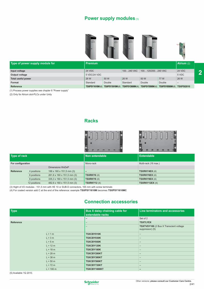
Other versions: please consult our Customer Care Centre.
Power supply modules (1)
Type of power supply module for Premium
Atrium (2)
Input voltage 24 VDC 100…240 VAC 100…120/200…240 VAC 24 VDCOutput voltage 5 VDC/24 VDC 5 VDCTotal useful power 26 W 50 W 26 W 50 W 77 W 26 WFormat Standard Double Standard Double Double –Reference TSXPSY1610M (4) TSXPSY3610M (4) TSXPSY2600M (4) TSXPSY5500M (4) TSXPSY8500M (4) TSXPSI2010
(1) Process power supplies see chapter 6 “Power supply”(2) Only for Atrium slot-PLCs under Unity
Racks
Type of rack Non extendable
Extendable
For configuration Mono-rack Multi-rack (16 max.) Dimensions WxDxP
Reference 4 positions 188 x 160 x 151,5 mm (3) – TSXRKY4EX (4) 6 positions 261,6 x 160 x 151,5 mm (3) TSXRKY6 (4) TSXRKY6EX (4) 8 positions 335,3 x 160 x 151,5 mm (3) TSXRKY8 (4) TSXRKY8EX (4) 12 positions 482,6 x 160 x 151,5 mm (3) TSXRKY12 (4) TSXRKY12EX (4)
(3) Hight of I/O modules : 151,5 mm with HE 10 or SUB-D connectors, 165 mm with screw terminals(4) For coated version add C at the end of the reference: example TSXPSY1610M becomes TSXPSY1610MC
Connection accessories
Type Bus X daisy chaining cable for extendable racks
Line terminators and accessories
– Set of 2Reference – TSXTLYEX
– TSXTVSY100 (2 Bus X Transcient voltage suppressor) (5)
L = 1 m TSXCBY010K –L = 3 m TSXCBY030K –L = 5 m TSXCBY050K –L = 12 m TSXCBY120K –L = 18 m TSXCBY180K –L = 28 m TSXCBY280KT –L = 38 m TSXCBY380KT –L = 50 m TSXCBY500KT –L = 72 m TSXCBY720KT –L = 100 m TSXCBY1000KT –
(5) Available 1Q 2010.
2/41
2
1
3
4
5
6
7
8
9
10
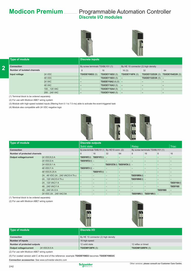
Other versions: please consult our Customer Care Centre.
Programmable Automation ControllerDiscrete I/O modules
Type of module Discrete inputs
Connection By screw terminals TSXBLY01 (1) By HE 10 connector (2) high densityNumber of isolated channels 8 16 16 (3) 32 64
Input voltage 24 VDC TSXDEY08D2 (5) TSXDEY16D2 (5) TSXDEY16FK (5) TSXDEY32D2K (5) TSXDEY64D2K (5)48 VDC – TSXDEY16D3 (5) – TSXDEY32D3K (5) –24 VAC – TSXDEY16A2 (4) (5) – – –48 VAC – TSXDEY16A3 (5) – – –100…120 VAC – TSXDEY16A4 (5) – – –200…240 VAC – TSXDEY16A5 (5) – – –
(1) Terminal block to be ordered separately(2) For use with Modicon ABE7 wiring system(3) Module with high-speed isolated inputs (filtering from 0.1 to 7.5 ms) able to activate the event-triggered task(4) Module also compatible with 24 VDC negative logic
Type of module Discrete outputs Solid state Relay Triac
Connection By screw terminals TSXBLY01 (1) By HE10 conn. (2) By screw terminals TSXBLY01 (1)Number of protected channels 8 16 32 64 8 16 8 16Output voltage/current 24 VDC/0,5 A TSXDSY08T2 (5) TSXDSY16T2 (5) – – – – – –
24 VDC/2 A TSXDSY08T22 (5) – – – – – – –24 VDC/0.1 A – – TSXDSY32T2K (5) TSXDSY64T2K (5) – – – –48 VDC/1 A TSXDSY08T31 (5) – – – – – – –48 VDC/0.25 A – TSXDSY16T3 (5) – – – – – –24…48 VDC-24…240 VAC/5 A Th.c – – – – TSXDSY08R5A (5) – – –24…120 VAC/5 A Th.c – – – – TSXDSY08R4D (5) – – –24…120 VAC/1 A – – – – – – – TSXDSY16S4 (5)48…240 VAC/1 A – – – – – – – TSXDSY16S548…240 VA /2 A – – – – – – TSXDSY08S5 –24 VDC-24…240 VAC/3A – – – – TSXDSY08R5 (5) TSXDSY16R5 (5) – –
(1) Terminal block to be ordered separately(2) For use with Modicon ABE7 wiring system
Type of module Discrete I/O
Connection By HE 10 connector (2) high densityNumber of inputs 16 high-speedNumber of protected outputs 12 solid state 12 reflex or timedOutput voltage/current 24 VDC/0.5 A TSXDMY28FK (5) TSXDMY28RFK (5)
(2) For use with Modicon ABE7 wiring system
(5) For coated version add C at the end of the reference: example TSXDEY08D2 becomes TSXDEY08D2C
Connection accessories: See www.schneider-electric.com
Modicon Premium
2/42
2
1
3
4
5
6
7
8
9
10
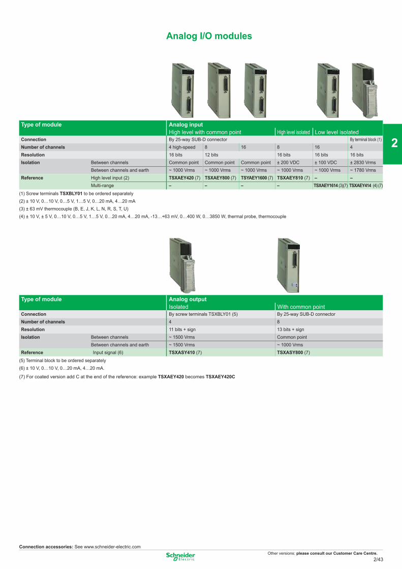
Other versions: please consult our Customer Care Centre.
Analog I/O modules
Type of module Analog input High level with common point High level isolated Low level isolated
Connection By 25-way SUB-D connector By terminal block (1)Number of channels 4 high-speed 8 16 8 16 4Resolution 16 bits 12 bits 16 bits 16 bits 16 bitsIsolation Between channels Common point Common point Common point ± 200 VDC ± 100 VDC ± 2830 Vrms
Between channels and earth ~ 1000 Vrms ~ 1000 Vrms ~ 1000 Vrms ~ 1000 Vrms ~ 1000 Vrms ~ 1780 VrmsReference High level input (2) TSXAEY420 (7) TSXAEY800 (7) TSYAEY1600 (7) TSXAEY810 (7) – –
Multi-range – – – – TSXAEY1614 (3)(7) TSXAEY414 (4) (7)
(1) Screw terminals TSXBLY01 to be ordered separately(2) ± 10 V, 0…10 V, 0…5 V, 1…5 V, 0…20 mA, 4…20 mA(3) ± 63 mV thermocouple (B, E, J, K, L, N, R, S, T, U)(4) ± 10 V, ± 5 V, 0…10 V, 0…5 V, 1…5 V, 0…20 mA, 4…20 mA, -13…+63 mV, 0…400 W, 0…3850 W, thermal probe, thermocouple
Type of module Analog output Isolated With common point
Connection By screw terminals TSXBLY01 (5) By 25-way SUB-D connectorNumber of channels 4 8Resolution 11 bits + sign 13 bits + signIsolation Between channels ~ 1500 Vrms Common point
Between channels and earth ~ 1500 Vrms ~ 1000 VrmsReference Input signal (6) TSXASY410 (7) TSXASY800 (7)
(5) Terminal block to be ordered separately(6) ± 10 V, 0…10 V, 0…20 mA, 4…20 mA.
(7) For coated version add C at the end of the reference: example TSXAEY420 becomes TSXAEY420C
Connection accessories: See www.schneider-electric.com
2/43
2
1
3
4
5
6
7
8
9
10
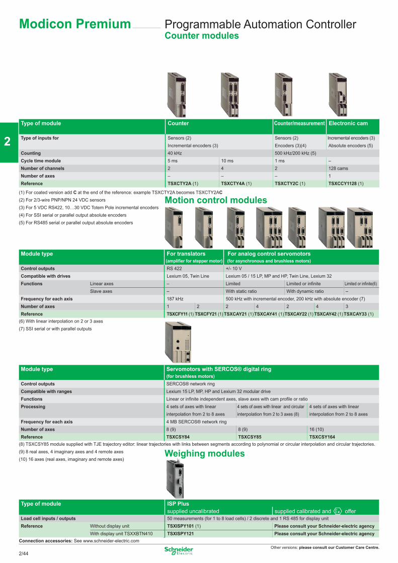
Other versions: please consult our Customer Care Centre.
Programmable Automation ControllerCounter modules
Type of module Counter Counter/measurement Electronic cam
Type of inputs for Sensors (2) Sensors (2) Incremental encoders (3)Incremental encoders (3) Encoders (3)(4) Absolute encoders (5)
Counting 40 kHz 500 kHz/200 kHz (5)Cycle time module 5 ms 10 ms 1 ms –Number of channels 2 4 2 128 camsNumber of axes – – – 1Reference TSXCTY2A (1) TSXCTY4A (1) TSXCTY2C (1) TSXCCY1128 (1)
(1) For coated version add C at the end of the reference: example TSXCTY2A becomes TSXCTY2AC(2) For 2/3-wire PNP/NPN 24 VDC sensors(3) For 5 VDC RS422, 10…30 VDC Totem Pole incremental encoders(4) For SSI serial or parallel output absolute encoders(5) For RS485 serial or parallel output absolute encoders
Module type For translators For analog control servomotors(amplifier for stepper motor) (for asynchronous and brushless motors)
Control outputs RS 422 +/- 10 VCompatible with drives Lexium 05, Twin Line Lexium 05 / 15 LP, MP and HP, Twin Line, Lexium 32Functions Linear axes – Limited Limited or infinite Limited or infinite(6)
Slave axes – With static ratio With dynamic ratio –Frequency for each axis 187 kHz 500 kHz with incremental encoder, 200 kHz with absolute encoder (7)Number of axes 1 2 2 4 2 4 3Reference TSXCFY11 (1) TSXCFY21 (1) TSXCAY21 (1)TSXCAY41 (1)TSXCAY22 (1) TSXCAY42 (1) TSXCAY33 (1)
(6) With linear interpolation on 2 or 3 axes(7) SSI serial or with parallel outputs
Module type Servomotors with SERCOS® digital ring(for brushless motors)
Control outputs SERCOS® network ringCompatible with ranges Lexium 15 LP, MP, HP and Lexium 32 modular driveFunctions Linear or infinite independent axes, slave axes with cam profile or ratioProcessing 4 sets of axes with linear
interpolation from 2 to 8 axes4 sets of axes with linear and circular interpolation from 2 to 3 axes (8)
4 sets of axes with linear interpolation from 2 to 8 axes
Frequency for each axis 4 MB SERCOS® network ring Number of axes 8 (9) 8 (9) 16 (10)Reference TSXCSY84 TSXCSY85 TSXCSY164
(8) TSXCSY85 module supplied with TJE trajectory editor: linear trajectories with links between segments according to polynomial or circular interpolation and circular trajectories.(9) 8 real axes, 4 imaginary axes and 4 remote axes(10) 16 axes (real axes, imaginary and remote axes)
Type of module ISP Plus supplied uncalibrated supplied calibrated and offer
Load cell inputs / outputs 50 measurements (for 1 to 8 load cells) / 2 discrete and 1 RS 485 for display unitReference Without display unit TSXISPY101 (1) Please consult your Schneider-electric agency
With display unit TSXXBTN410 TSXISPY121 Please consult your Schneider-electric agencyConnection accessories: See www.schneider-electric.com
Modicon Premium
Weighing modules
Motion control modules
2/44
2
1
3
4
5
6
7
8
9
10
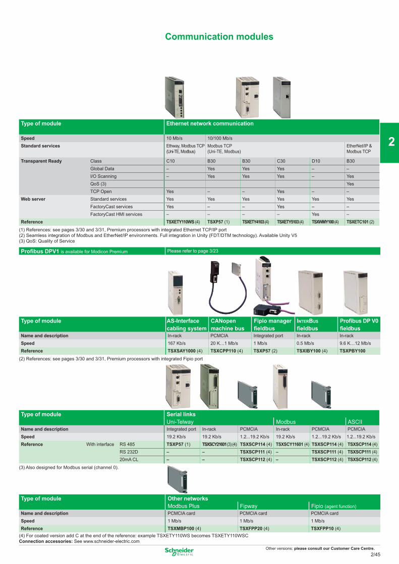
Other versions: please consult our Customer Care Centre.
Communication modules
Type of module Ethernet network communication
Speed 10 Mb/s 10/100 Mb/sStandard services Ethway, Modbus TCP
(Uni-TE, Modbus)Modbus TCP (Uni-TE, Modbus)
EtherNet/IP & Modbus TCP
Transparent Ready Class C10 B30 B30 C30 D10 B30Global Data – Yes Yes Yes – –I/O Scanning – Yes Yes Yes – YesQoS (3) YesTCP Open Yes – – Yes – –
Web server Standard services Yes Yes Yes Yes Yes YesFactoryCast services Yes – – Yes – –FactoryCast HMI services – – – – Yes –
Reference TSXETY110WS (4) TSXP57 (1) TSXETY4103 (4) TSXETY5103 (4) TSXWMY100 (4) TSXETC101 (2)
(1) References: see pages 3/30 and 3/31, Premium processors with integrated Ethernet TCP/IP port(2) Seamless integration of Modbus and EtherNet/IP environments. Full integration in Unity (FDT/DTM technology). Available Unity V5(3) QoS: Quality of Service
Profibus DPV1 is available for Modicon Premium Please refer to page 3/23
Type of module AS-Interface cabling system
CANopen machine bus
Fipio manager fieldbus
INTERBUS fieldbus
Profibus DP V0 fieldbus
Name and description In-rack PCMCIA Integrated port In-rack In-rackSpeed 167 Kb/s 20 K…1 Mb/s 1 Mb/s 0.5 Mb/s 9.6 K…12 Mb/sReference TSXSAY1000 (4) TSXCPP110 (4) TSXP57 (2) TSXIBY100 (4) TSXPBY100
(2) References: see pages 3/30 and 3/31, Premium processors with integrated Fipio port
Type of module Serial links Uni-Telway Modbus ASCII
Name and description Integrated port In-rack PCMCIA In-rack PCMCIA PCMCIASpeed 19.2 Kb/s 19.2 Kb/s 1.2...19.2 Kb/s 19.2 Kb/s 1.2...19.2 Kb/s 1.2...19.2 Kb/sReference With interface RS 485 TSXP57 (1) TSXSCY21601 (3) (4) TSXSCP114 (4) TSXSCY11601 (4) TSXSCP114 (4) TSXSCP114 (4)
RS 232D – – TSXSCP111 (4) – TSXSCP111 (4) TSXSCP111 (4)20mA CL – – TSXSCP112 (4) – TSXSCP112 (4) TSXSCP112 (4)
(3) Also designed for Modbus serial (channel 0).
Type of module Other networks Modbus Plus Fipway Fipio (agent function)
Name and description PCMCIA card PCMCIA card PCMCIA cardSpeed 1 Mb/s 1 Mb/s 1 Mb/sReference TSXMBP100 (4) TSXFPP20 (4) TSXFPP10 (4)
(4) For coated version add C at the end of the reference: example TSXETY110WS becomes TSXETY110WSCConnection accessories: See www.schneider-electric.com
2/45
2
1
3
4
5
6
7
8
9
10
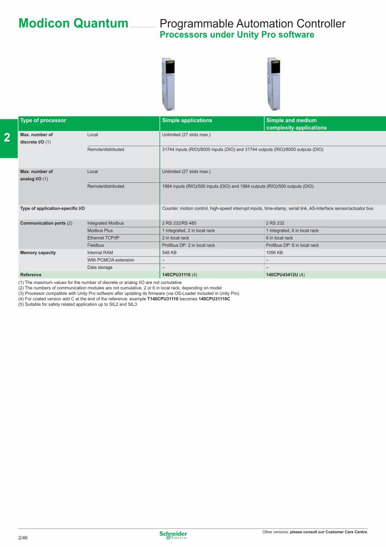
Other versions: please consult our Customer Care Centre.
Programmable Automation ControllerProcessors under Unity Pro software
Type of processor Simple applications Simple and mediumcomplexity applications
Max. number of discrete I/O (1)
Local Unlimited (27 slots max.)
Remote/distributed 31744 inputs (RIO)/8000 inputs (DIO) and 31744 outputs (RIO)/8000 outputs (DIO)
Max. number of analog I/O (1)
Local Unlimited (27 slots max.)
Remote/distributed 1984 inputs (RIO)/500 inputs (DIO) and 1984 outputs (RIO)/500 outputs (DIO)
Type of application-specific I/O Counter, motion control, high-speed interrupt inputs, time-stamp, serial link, AS-Interface sensor/actuator bus
Communication ports (2) Integrated Modbus 2 RS 232/RS 485 2 RS 232Modbus Plus 1 integrated, 2 in local rack 1 integrated, 6 in local rackEthernet TCP/IP 2 in local rack 6 in local rackFieldbus Profibus DP: 2 in local rack Profibus DP: 6 in local rack
Memory capacity Internal RAM 548 KB 1056 KBWith PCMCIA extension – –Data storage – –
Reference 140CPU31110 (4) 140CPU43412U (4)
(1) The maximum values for the number of discrete or analog I/O are not cumulative(2) The numbers of communication modules are not cumulative, 2 or 6 in local rack, depending on model(3) Processor compatible with Unity Pro software after updating its firmware (via OS-Loader included in Unity Pro)(4) For coated version add C at the end of the reference: example T140CPU31110 becomes 140CPU31110C(5) Suitable for safety related application up to SIL2 and SIL3
Modicon Quantum
2/46
2
1
3
4
5
6
7
8
9
10
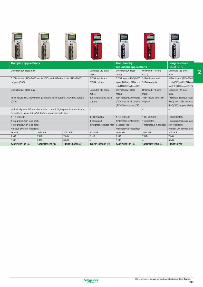
Other versions: please consult our Customer Care Centre.
Complex applications Hot Standby redundant applications
Long distance HSBY CPU
Unlimited (26 slots max.) Unlimited (13 slots max.)
Unlimited (26 slots max.)
Unlimited (13 slots max.)
Unlimited (26 slots max.)
31744 inputs (RIO)/8000 inputs (DIO) and 31744 outputs (RIO)/8000 outputs (DIO)
31744 inputs and 31744 outputs
31744 inputs (RIO)/8000 inputs (DIO) and 31744 out-puts (RIO)/8000 outputs (DIO)
31744 inputs and 31744 outputs
31744 inputs (RIO)/8000 inputs (DIO) and 31744 out-puts (RIO)/8000 outputs (DIO)
Unlimited (27 slots max.) Unlimited (13 slots max.)
Unlimited (27 slots max.)
Unlimited (13 slots max.)
Unlimited (27 slots max.)
1984 inputs (RIO)/500 inputs (DIO) and 1984 outputs (RIO)/500 outputs (DIO)
1984 inputs and 1984 outputs
1984 inputs (RIO)/500 inputs (DIO) and 1984 outputs (RIO)/500 outputs (DIO)
1984 inputs and 1984 outputs
1984 inputs (RIO)/500 inputs (DIO) and 1984 outputs (RIO)/500 outputs (DIO)
Intrinsically safe I/O, counter, motion control, high-speed interrupt inputs, time-stamp, serial link, AS-Interface sensor/actuator bus
– – –
1 RS 232/485 1 RS 232/485 1 RS 232/485 1 RS 232/485 1 RS 232/4851 integrated, 6 in local rack 1 integrated 1 integrated, 6 in local rack 1 integrated 1 integrated, 6 in local rack1 integrated, 6 in local rack 1 integrated, 6 in local rack 6 in local rack 1 integrated, 6 in local rack 6 in local rackProfibus DP: 6 in local rack – Profibus DP: 6 in local rack – Profibus DP: 6 in local rack768 KB 1024 KB 3072 KB 1024 KB 1024 KB 1024 MB 3072 KB7 MB 7 MB 7 MB 7 MB 7 MB 7 MB 7 MB8 MB 8 MB 8 MB – 8 MB – 8 MB140CPU65150 (4) 140CPU65160 (4) 140CPU65260 (4) 140CPU65160S (5) 140CPU67160 (4) 140CPU67160S (5) 140CPU67261
2/47
2
1
3
4
5
6
7
8
9
10
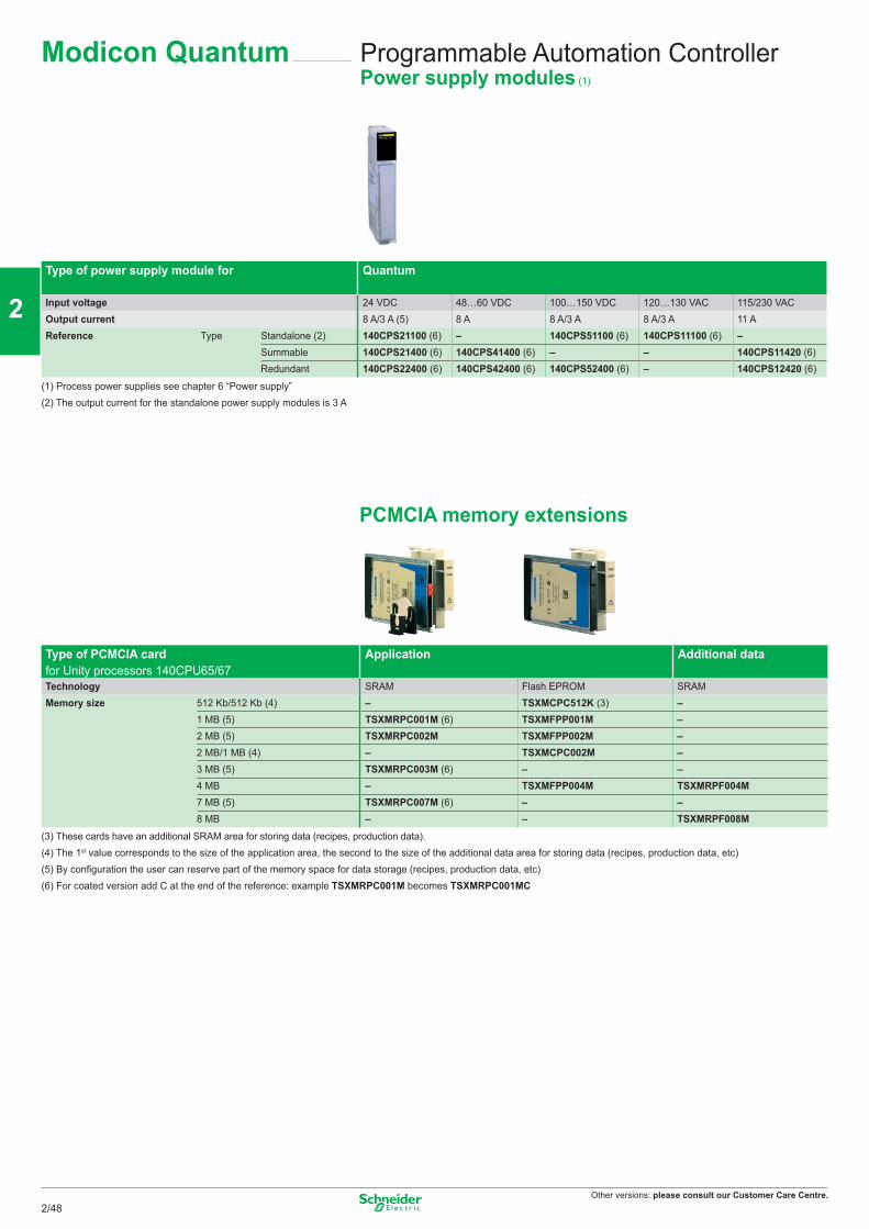
Other versions: please consult our Customer Care Centre.
Programmable Automation ControllerPower supply modules (1)
Type of power supply module for Quantum
Input voltage 24 VDC 48…60 VDC 100…150 VDC 120…130 VAC 115/230 VACOutput current 8 A/3 A (5) 8 A 8 A/3 A 8 A/3 A 11 AReference Type Standalone (2) 140CPS21100 (6) – 140CPS51100 (6) 140CPS11100 (6) –
Summable 140CPS21400 (6) 140CPS41400 (6) – – 140CPS11420 (6)Redundant 140CPS22400 (6) 140CPS42400 (6) 140CPS52400 (6) – 140CPS12420 (6)
(1) Process power supplies see chapter 6 “Power supply”(2) The output current for the standalone power supply modules is 3 A
PCMCIA memory extensions
Type of PCMCIA card for Unity processors 140CPU65/67
Application Additional data
Technology SRAM Flash EPROM SRAMMemory size 512 Kb/512 Kb (4) – TSXMCPC512K (3) –
1 MB (5) TSXMRPC001M (6) TSXMFPP001M –2 MB (5) TSXMRPC002M TSXMFPP002M –2 MB/1 MB (4) – TSXMCPC002M –3 MB (5) TSXMRPC003M (6) – –4 MB – TSXMFPP004M TSXMRPF004M7 MB (5) TSXMRPC007M (6) – –8 MB – – TSXMRPF008M
(3) These cards have an additional SRAM area for storing data (recipes, production data). (4) The 1st value corresponds to the size of the application area, the second to the size of the additional data area for storing data (recipes, production data, etc)(5) By configuration the user can reserve part of the memory space for data storage (recipes, production data, etc)(6) For coated version add C at the end of the reference: example TSXMRPC001M becomes TSXMRPC001MC
Modicon Quantum
2/48
2
1
3
4
5
6
7
8
9
10
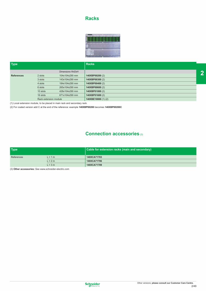
Other versions: please consult our Customer Care Centre.
Type Racks
Dimensions WxDxH References 2 slots 104x104x290 mm 140XBP00200 (2)
3 slots 143x104x290 mm 140XBP00300 (2)4 slots 184x104x290 mm 140XBP00400 (2)6 slots 265x104x290 mm 140XBP00600 (2)10 slots 428x104x290 mm 140XBP01000 (2)16 slots 671x104x290 mm 140XBP01600 (2)Rack extension module 140XBE10000 (1) (2)
(1) Local extension module, to be placed in main rack and secondary rack.(2) For coated version add C at the end of the reference: example 140XBP00200 becomes 140XBP00200C
Connection accessories (3)
Type Cable for extension racks (main and secondary)
References L = 1 m 140XCA71703L = 2 m 140XCA71706L = 3 m 140XCA71709
(3) Other accessories: See www.schneider-electric.com
Racks
2/49
2
1
3
4
5
6
7
8
9
10
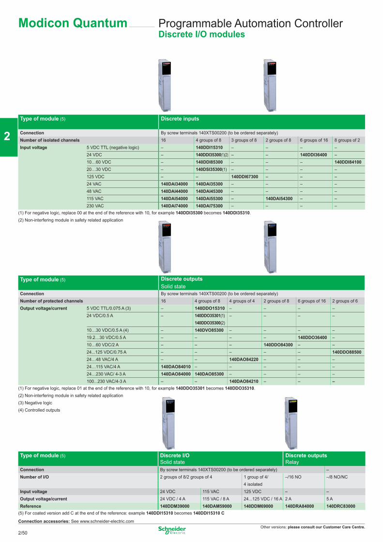
Other versions: please consult our Customer Care Centre.
Programmable Automation ControllerDiscrete I/O modules
Modicon Quantum
Type of module (5) Discrete inputs
Connection By screw terminals 140XTS00200 (to be ordered separately)Number of isolated channels 16 4 groups of 8 3 groups of 8 2 groups of 8 6 groups of 16 8 groups of 2Input voltage 5 VDC TTL (negative logic) – 140DDI15310 – – – –
24 VDC – 140DDI35300(1)(2) – – 140DDI36400 –10…60 VDC – 140DDI85300 – – – 140DDI8410020…30 VDC – 140DSI35300(1) – – – –125 VDC – – 140DDI67300 – – –24 VAC 140DAI34000 140DAI35300 – – – –48 VAC 140DAI44000 140DAI45300 – – – –115 VAC 140DAI54000 140DAI55300 – 140DAI54300 – –230 VAC 140DAI74000 140DAI75300 – – – –
(1) For negative logic, replace 00 at the end of the reference with 10, for example 140DDI35300 becomes 140DDI35310.(2) Non-interfering module in safety related application
Type of module (5) Discrete outputsSolid state
Connection By screw terminals 140XTS00200 (to be ordered separately)Number of protected channels 16 4 groups of 8 4 groups of 4 2 groups of 8 6 groups of 16 2 groups of 6Output voltage/current 5 VDC TTL/0.075 A (3) – 140DDO15310 – – – –
24 VDC/0.5 A – 140DDO35301(1) 140DDO35300(2)
– – – –
10…30 VDC/0.5 A (4) – 140DVO85300 – – – –19.2…30 VDC/0.5 A – – – – 140DDO36400 –10…60 VDC/2 A – – – 140DDO84300 – –24...125 VDC/0.75 A – – – – – 140DDO8850024…48 VAC/4 A – – 140DAO84220 – – –24…115 VAC/4 A 140DAO84010 – – – – –24…230 VAC/ 4-3 A 140DAO84000 140DAO85300 – – – –100...230 VAC/4-3 A – – 140DAO84210 – – –
(1) For negative logic, replace 01 at the end of the reference with 10, for example 140DDO35301 becomes 140DDO35310.(2) Non-interfering module in safety related application(3) Negative logic(4) Controlled outputs
Type of module (5) Discrete I/O Discrete outputs Solid state Relay
Connection By screw terminals 140XTS00200 (to be ordered separately) –Number of I/O 2 groups of 8/2 groups of 4 1 group of 4/
4 isolated–/16 NO –/8 NO/NC
Input voltage 24 VDC 115 VAC 125 VDC – –Output voltage/current 24 VDC / 4 A 115 VAC / 8 A 24...125 VDC / 16 A 2 A 5 AReference 140DDM39000 140DAM59000 140DDM69000 140DRA84000 140DRC83000
(5) For coated version add C at the end of the reference: example 140DDI15310 becomes 140DDI15310 C
Connection accessories: See www.schneider-electric.com
2/50
2
1
3
4
5
6
7
8
9
10
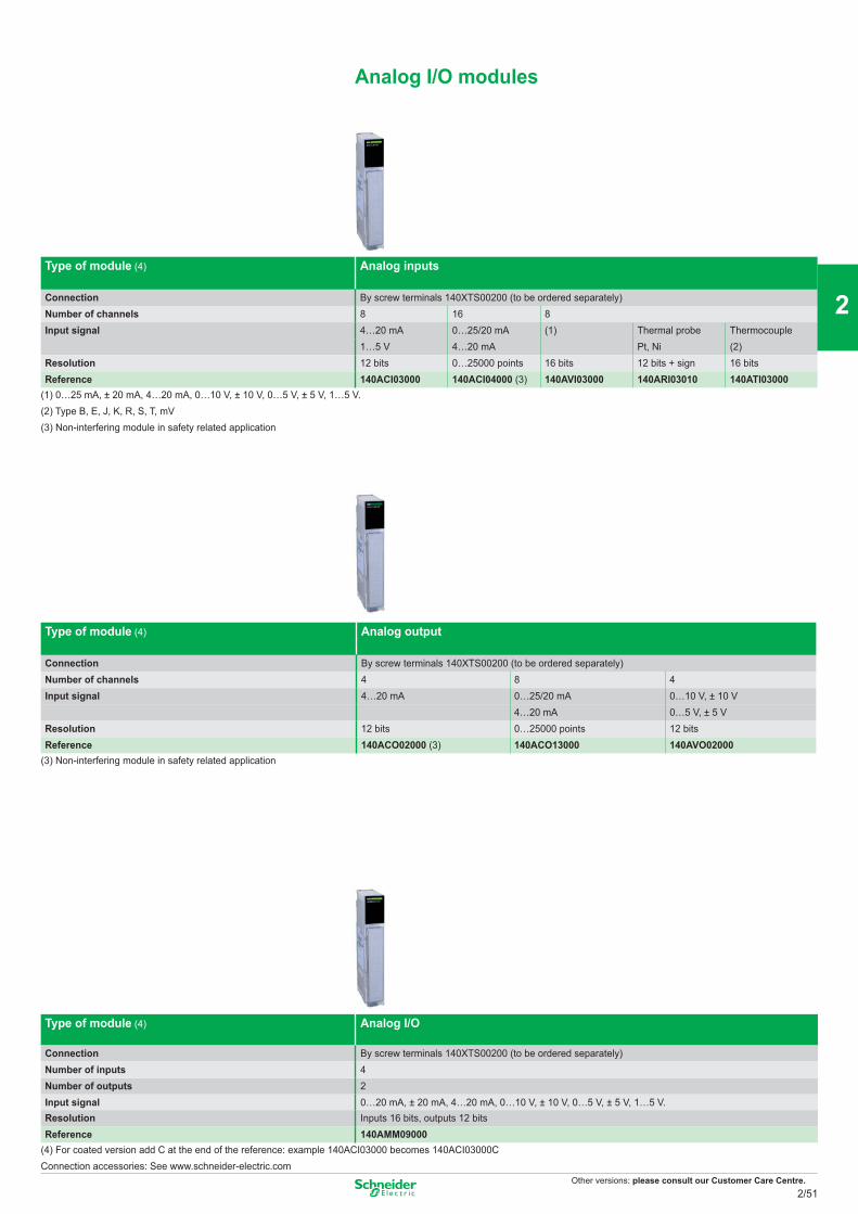
Other versions: please consult our Customer Care Centre.
Analog I/O modules
Type of module (4) Analog inputs
Connection By screw terminals 140XTS00200 (to be ordered separately)Number of channels 8 16 8Input signal 4…20 mA 0…25/20 mA (1) Thermal probe Thermocouple
1…5 V 4…20 mA Pt, Ni (2)Resolution 12 bits 0…25000 points 16 bits 12 bits + sign 16 bitsReference 140ACI03000 140ACI04000 (3) 140AVI03000 140ARI03010 140ATI03000
(1) 0…25 mA, ± 20 mA, 4…20 mA, 0…10 V, ± 10 V, 0…5 V, ± 5 V, 1…5 V.(2) Type B, E, J, K, R, S, T, mV(3) Non-interfering module in safety related application
Type of module (4) Analog output
Connection By screw terminals 140XTS00200 (to be ordered separately)Number of channels 4 8 4Input signal 4…20 mA 0…25/20 mA 0…10 V, ± 10 V
4…20 mA 0…5 V, ± 5 VResolution 12 bits 0…25000 points 12 bitsReference 140ACO02000 (3) 140ACO13000 140AVO02000
(3) Non-interfering module in safety related application
Type of module (4) Analog I/O
Connection By screw terminals 140XTS00200 (to be ordered separately)Number of inputs 4Number of outputs 2Input signal 0…20 mA, ± 20 mA, 4…20 mA, 0…10 V, ± 10 V, 0…5 V, ± 5 V, 1…5 V.Resolution Inputs 16 bits, outputs 12 bitsReference 140AMM09000
(4) For coated version add C at the end of the reference: example 140ACI03000 becomes 140ACI03000CConnection accessories: See www.schneider-electric.com
2/51
2
1
3
4
5
6
7
8
9
10
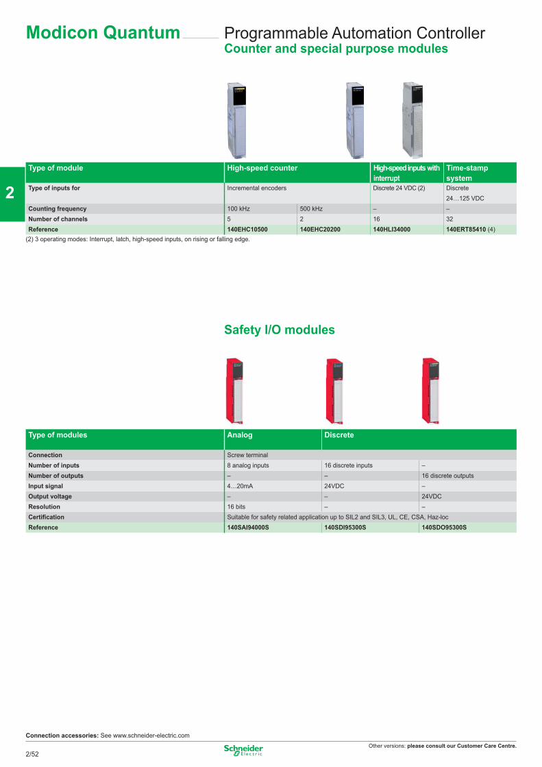
Other versions: please consult our Customer Care Centre.
Programmable Automation ControllerCounter and special purpose modules
Type of module High-speed counter High-speed inputs with interrupt
Time-stamp system
Type of inputs for Incremental encoders Discrete 24 VDC (2) Discrete24…125 VDC
Counting frequency 100 kHz 500 kHz – –Number of channels 5 2 16 32Reference 140EHC10500 140EHC20200 140HLI34000 140ERT85410 (4)
(2) 3 operating modes: Interrupt, latch, high-speed inputs, on rising or falling edge.
Safety I/O modules
Type of modules Analog Discrete
Connection Screw terminalNumber of inputs 8 analog inputs 16 discrete inputs –Number of outputs – – 16 discrete outputsInput signal 4…20mA 24VDC –Output voltage – – 24VDCResolution 16 bits – –Certification Suitable for safety related application up to SIL2 and SIL3, UL, CE, CSA, Haz-loc Reference 140SAI94000S 140SDI95300S 140SDO95300S
Connection accessories: See www.schneider-electric.com
Modicon Quantum
2/52
2
1
3
4
5
6
7
8
9
10
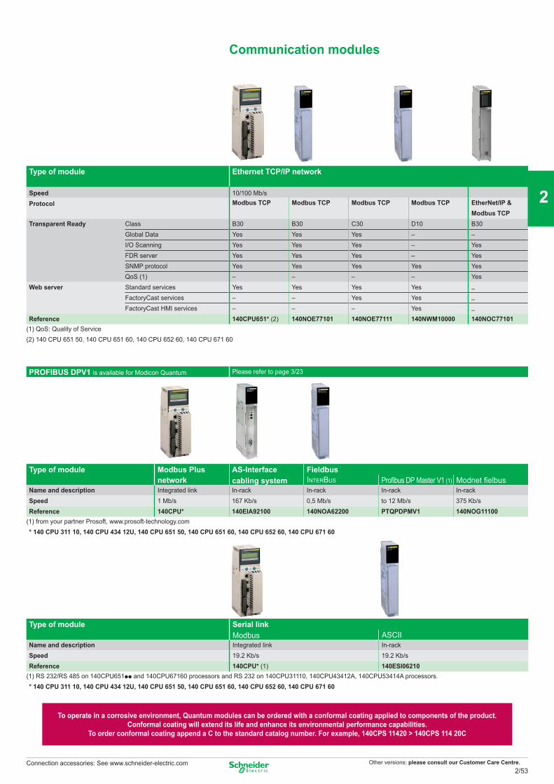
Other versions: please consult our Customer Care Centre.
Communication modules
Type of module Ethernet TCP/IP network
Speed 10/100 Mb/sProtocol Modbus TCP Modbus TCP Modbus TCP Modbus TCP EtherNet/IP &
Modbus TCPTransparent Ready Class B30 B30 C30 D10 B30
Global Data Yes Yes Yes – –I/O Scanning Yes Yes Yes – YesFDR server Yes Yes Yes – YesSNMP protocol Yes Yes Yes Yes YesQoS (1) – – – – Yes
Web server Standard services Yes Yes Yes Yes –FactoryCast services – – Yes Yes –FactoryCast HMI services – – – Yes –
Reference 140CPU651* (2) 140NOE77101 140NOE77111 140NWM10000 140NOC77101(1) QoS: Quality of Service(2) 140 CPU 651 50, 140 CPU 651 60, 140 CPU 652 60, 140 CPU 671 60
PROFIBUS DPV1 is available for Modicon Quantum Please refer to page 3/23
Type of module Modbus Plus network
AS-Interfacecabling system
FieldbusINTERBUS Profibus DP Master V1 (1) Modnet fielbus
Name and description Integrated link In-rack In-rack In-rack In-rackSpeed 1 Mb/s 167 Kb/s 0,5 Mb/s to 12 Mb/s 375 Kb/sReference 140CPU* 140EIA92100 140NOA62200 PTQPDPMV1 140NOG11100
(1) from your partner Prosoft, www.prosoft-technology.com* 140 CPU 311 10, 140 CPU 434 12U, 140 CPU 651 50, 140 CPU 651 60, 140 CPU 652 60, 140 CPU 671 60
Type of module Serial link Modbus ASCII
Name and description Integrated link In-rackSpeed 19.2 Kb/s 19.2 Kb/sReference 140CPU* (1) 140ESI06210
(1) RS 232/RS 485 on 140CPU651pp and 140CPU67160 processors and RS 232 on 140CPU31110, 140CPU43412A, 140CPU53414A processors.* 140 CPU 311 10, 140 CPU 434 12U, 140 CPU 651 50, 140 CPU 651 60, 140 CPU 652 60, 140 CPU 671 60
To operate in a corrosive environment, Quantum modules can be ordered with a conformal coating applied to components of the product. Conformal coating will extend its life and enhance its environmental performance capabilities.
To order conformal coating append a C to the standard catalog number. For example, 140CPS 11420 > 140CPS 114 20C
Connection accessories: See www.schneider-electric.com2/53
2
1
3
4
5
6
7
8
9
10
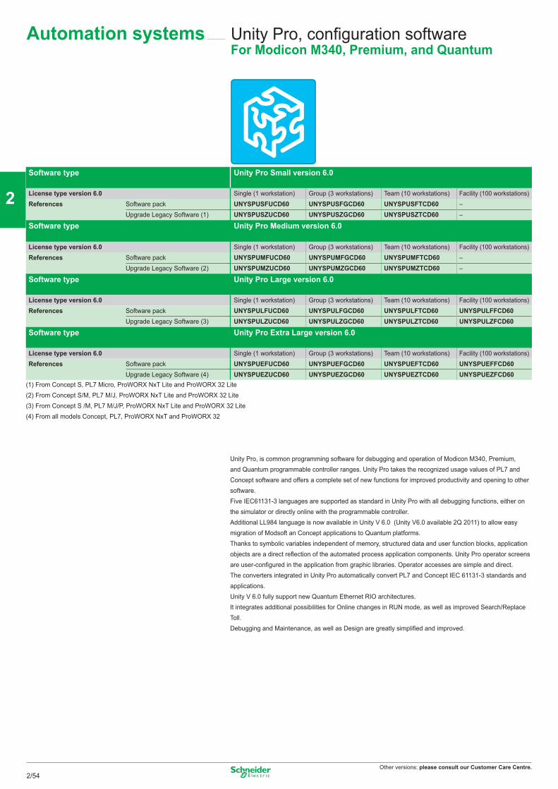
Other versions: please consult our Customer Care Centre.
Unity Pro, configuration softwareFor Modicon M340, Premium, and Quantum
Software type Unity Pro Small version 6.0
License type version 6.0 Single (1 workstation) Group (3 workstations) Team (10 workstations) Facility (100 workstations)References Software pack UNYSPUSFUCD60 UNYSPUSFGCD60 UNYSPUSFTCD60 –
Upgrade Legacy Software (1) UNYSPUSZUCD60 UNYSPUSZGCD60 UNYSPUSZTCD60 –
Software type Unity Pro Medium version 6.0
License type version 6.0 Single (1 workstation) Group (3 workstations) Team (10 workstations) Facility (100 workstations)References Software pack UNYSPUMFUCD60 UNYSPUMFGCD60 UNYSPUMFTCD60 –
Upgrade Legacy Software (2) UNYSPUMZUCD60 UNYSPUMZGCD60 UNYSPUMZTCD60 –
Software type Unity Pro Large version 6.0
License type version 6.0 Single (1 workstation) Group (3 workstations) Team (10 workstations) Facility (100 workstations)References Software pack UNYSPULFUCD60 UNYSPULFGCD60 UNYSPULFTCD60 UNYSPULFFCD60
Upgrade Legacy Software (3) UNYSPULZUCD60 UNYSPULZGCD60 UNYSPULZTCD60 UNYSPULZFCD60
Software type Unity Pro Extra Large version 6.0
License type version 6.0 Single (1 workstation) Group (3 workstations) Team (10 workstations) Facility (100 workstations)References Software pack UNYSPUEFUCD60 UNYSPUEFGCD60 UNYSPUEFTCD60 UNYSPUEFFCD60
Upgrade Legacy Software (4) UNYSPUEZUCD60 UNYSPUEZGCD60 UNYSPUEZTCD60 UNYSPUEZFCD60(1) From Concept S, PL7 Micro, ProWORX NxT Lite and ProWORX 32 Lite(2) From Concept S/M, PL7 M/J, ProWORX NxT Lite and ProWORX 32 Lite (3) From Concept S /M, PL7 M/J/P, ProWORX NxT Lite and ProWORX 32 Lite(4) From all models Concept, PL7, ProWORX NxT and ProWORX 32
Unity Pro, is common programming software for debugging and operation of Modicon M340, Premium, and Quantum programmable controller ranges. Unity Pro takes the recognized usage values of PL7 and Concept software and offers a complete set of new functions for improved productivity and opening to other software.Five IEC61131-3 languages are supported as standard in Unity Pro with all debugging functions, either on the simulator or directly online with the programmable controller.Additional LL984 language is now available in Unity V 6.0 (Unity V6.0 available 2Q 2011) to allow easy migration of Modsoft an Concept applications to Quantum platforms.Thanks to symbolic variables independent of memory, structured data and user function blocks, application objects are a direct reflection of the automated process application components. Unity Pro operator screens are user-configured in the application from graphic libraries. Operator accesses are simple and direct.The converters integrated in Unity Pro automatically convert PL7 and Concept IEC 61131-3 standards and applications.Unity V 6.0 fully support new Quantum Ethernet RIO architectures.It integrates additional possibilities for Online changes in RUN mode, as well as improved Search/Replace Toll.Debugging and Maintenance, as well as Design are greatly simplified and improved.
Automation systems
2/54
2
1
3
4
5
6
7
8
9
10
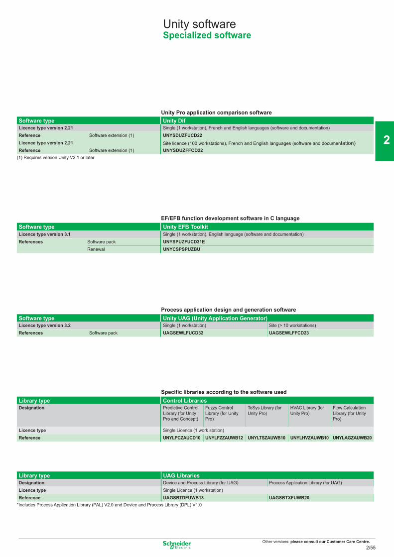
Other versions: please consult our Customer Care Centre.
Unity softwareSpecialized software
Unity Pro application comparison softwareSoftware type Unity DifLicence type version 2.21 Single (1 workstation), French and English languages (software and documentation)Reference Software extension (1) UNYSDUZFUCD22Licence type version 2.21 Site licence (100 workstations), French and English languages (software and documentation)Reference Software extension (1) UNYSDUZFFCD22
(1) Requires version Unity V2.1 or later
EF/EFB function development software in C languageSoftware type Unity EFB ToolkitLicence type version 3.1 Single (1 workstation), English language (software and documentation)References Software pack UNYSPUZFUCD31E
Renewal UNYCSPSPUZBU
Process application design and generation software Software type Unity UAG (Unity Application Generator)Licence type version 3.2 Single (1 workstation) Site (> 10 workstations)References Software pack UAGSEWLFUCD32 UAGSEWLFFCD23
Specific libraries according to the software usedLibrary type Control LibrariesDesignation Predictive Control
Library (for Unity Pro and Concept)
Fuzzy Control Library (for Unity Pro)
TeSys Library (for Unity Pro)
HVAC Library (for Unity Pro)
Flow Calculation Library (for Unity Pro)
Licence type Single Licence (1 work station)Reference UNYLPCZAUCD10 UNYLFZZAUWB12 UNYLTSZAUWB10 UNYLHVZAUWB10 UNYLAGZAUWB20
Library type UAG LibrariesDesignation Device and Process Library (for UAG) Process Application Library (for UAG)Licence type Single Licence (1 workstation)Reference UAGSBTDFUWB13 UAGSBTXFUWB20
*Includes Process Application Library (PAL) V2.0 and Device and Process Library (DPL) V1.0
2/55
2
1
3
4
5
6
7
8
9
10
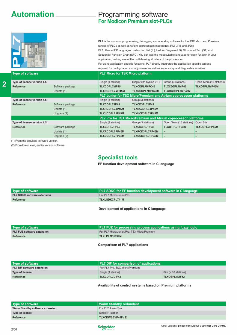
Other versions: please consult our Customer Care Centre.
Programming softwareFor Modicon Premium slot-PLCs
PL7 is the common programming, debugging and operating software for the TSX Micro and Premium ranges of PLCs as well as Atrium coprocessors (see pages 3/12, 3/18 and 3/26).PL7 offers 4 IEC languages: Instruction List (IL), Ladder Diagram (LD), Structured Text (ST) and Sequential Function Chart (SFC). You can use the most suitable language for each function in your application, making use of the multi-tasking structure of the processors.For using application-specific functions, PL7 directly integrates the application-specific screens required for configuration and adjustment as well as supervisory and diagnostics activities.
Type of software PL7 Micro for TSX Micro platform
Type of license version 4.5 Single (1 station) Single with SyCon V2.8 Group (3 stations) Open Team (10 stations)Reference Software package TLXCDPL7MP45 TLXCDPL7MPC45 TLXCD3PL7MP45 TLXOTPL7MP45M
Update (1) TLXRCDPL7MP45M TLXRCDPL7MPC45M TLXRCD3PL7MP45M –PL7 Junior for TSX Micro/Premium and Atrium coprocessor platforms
Type of license version 4.5 Single (1 station) Group (3 stations)Reference Software package TLXCDPL7JP45 TLXCD3PL7JP45
Update (1) TLXRCDPL7JP45M TLXRC3DPL7JP45MUpgrade (2) TLXUCDPL7JP45M TLXUCD3PL7JP45M
PL7 Pro for TSX Micro/Premium and Atrium coprocessor platforms Type of license version 4.5 Single (1 station) Group (3 stations) Open Team (10 stations) Open SiteReference Software package TLXCDPL7PP45 TLXCD3PL7PP45 TLXOTPL7PP45M TLXOSPL7PP45M
Update (1) TLXRCDPL7PP45M TLXRCD3PL7PP45M – –Upgrade (2) TLXUCDPL7PP45M TLXUCD3PL7PP45M – –
(1) From the previous software version.(2) From lower level, earlier version software.
Specialist toolsEF function development software in C language
Type of software PL7 SDKC for EF function development software in C languagePL7 SDKC software extension For PL7 Micro/Junior/ProReference TLXLSDKCPL741M
Development of applications in C language
Type of software PL7 FUZ for processing process applications using fuzzy logicPL7 FUZ software extension For PL7 Micro/Junior/Pro, TSX Micro/PremiumReference TLXLPL7FUZ34M
Comparison of PL7 applications
Type of software PL7 DIF for comparison of applicationsPL7 DIF software extension For PL7 Pro, TSX Micro/PremiumType of license Single (1 station) Site (> 10 stations)Reference TLXCDPL7DIF42 TLXOSPL7DIF42
Availability of control systems based on Premium platforms
Type of software Warm Standby redundantWarm Standby software extension For PL7 Junior/ProType of license Single (1 station)Reference TLXCDWSBYP40F / E
Automation
2/56
2
1
3
4
5
6
7
8
9
10
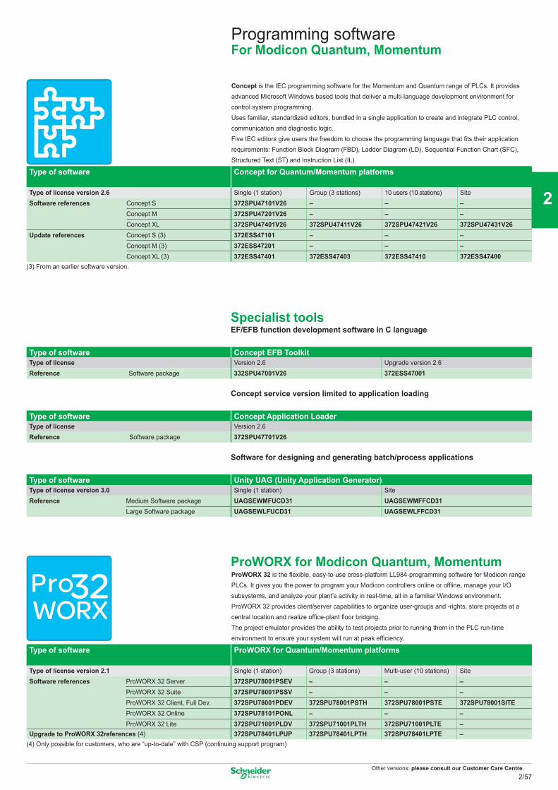
Other versions: please consult our Customer Care Centre.
Programming softwareFor Modicon Quantum, Momentum
Concept is the IEC programming software for the Momentum and Quantum range of PLCs. It provides advanced Microsoft Windows based tools that deliver a multi-language development environment for control system programming.Uses familiar, standardized editors, bundled in a single application to create and integrate PLC control, communication and diagnostic logic.Five IEC editors give users the freedom to choose the programming language that fits their application requirements: Function Block Diagram (FBD), Ladder Diagram (LD), Sequential Function Chart (SFC), Structured Text (ST) and Instruction List (IL).
Type of software Concept for Quantum/Momentum platforms
Type of license version 2.6 Single (1 station) Group (3 stations) 10 users (10 stations) SiteSoftware references Concept S 372SPU47101V26 – – –
Concept M 372SPU47201V26 – – –Concept XL 372SPU47401V26 372SPU47411V26 372SPU47421V26 372SPU47431V26
Update references Concept S (3) 372ESS47101 – – –Concept M (3) 372ESS47201 – – –Concept XL (3) 372ESS47401 372ESS47403 372ESS47410 372ESS47400
(3) From an earlier software version.
Specialist toolsEF/EFB function development software in C language
Type of software Concept EFB ToolkitType of license Version 2.6 Upgrade version 2.6Reference Software package 332SPU47001V26 372ESS47001
Concept service version limited to application loading
Type of software Concept Application LoaderType of license Version 2.6Reference Software package 372SPU47701V26
Software for designing and generating batch/process applications
Type of software Unity UAG (Unity Application Generator)Type of license version 3.0 Single (1 station) SiteReference Medium Software package UAGSEWMFUCD31 UAGSEWMFFCD31
Large Software package UAGSEWLFUCD31 UAGSEWLFFCD31
ProWORX for Modicon Quantum, MomentumProWORX 32 is the flexible, easy-to-use cross-platform LL984-programming software for Modicon range PLCs. It gives you the power to program your Modicon controllers online or offline, manage your I/O subsystems, and analyze your plant’s activity in real-time, all in a familiar Windows environment.ProWORX 32 provides client/server capabilities to organize user-groups and -rights, store projects at a central location and realize office-plant floor bridging.The project emulator provides the ability to test projects prior to running them in the PLC run-time environment to ensure your system will run at peak efficiency.
Type of software ProWORX for Quantum/Momentum platforms
Type of license version 2.1 Single (1 station) Group (3 stations) Multi-user (10 stations) Site Software references ProWORX 32 Server 372SPU78001PSEV – – –
ProWORX 32 Suite 372SPU78001PSSV – – –ProWORX 32 Client, Full Dev. 372SPU78001PDEV 372SPU78001PSTH 372SPU78001PSTE 372SPU78001SITEProWORX 32 Online 372SPU78101PONL – – –ProWORX 32 Lite 372SPU71001PLDV 372SPU71001PLTH 372SPU71001PLTE –
Upgrade to ProWORX 32references (4) 372SPU78401LPUP 372SPU78401LPTH 372SPU78401LPTE –(4) Only possible for customers, who are “up-to-date” with CSP (continuing support program)
2/57
2
1
3
4
5
6
7
8
9
10
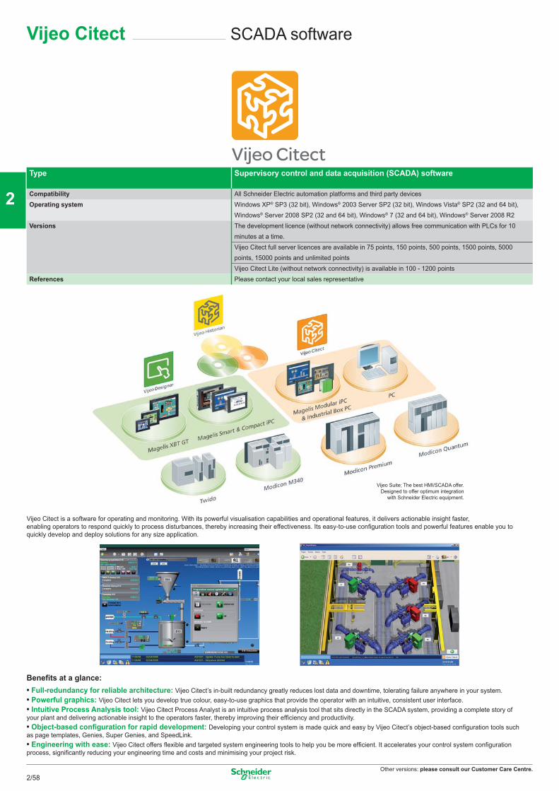
Other versions: please consult our Customer Care Centre.
SCADA softwareVijeo Citect
Type Supervisory control and data acquisition (SCADA) software
Compatibility All Schneider Electric automation platforms and third party devicesOperating system Windows XP® SP3 (32 bit), Windows® 2003 Server SP2 (32 bit), Windows Vista® SP2 (32 and 64 bit),
Windows® Server 2008 SP2 (32 and 64 bit), Windows® 7 (32 and 64 bit), Windows® Server 2008 R2Versions The development licence (without network connectivity) allows free communication with PLCs for 10
minutes at a time.Vijeo Citect full server licences are available in 75 points, 150 points, 500 points, 1500 points, 5000 points, 15000 points and unlimited pointsVijeo Citect Lite (without network connectivity) is available in 100 - 1200 points
References Please contact your local sales representative
Vijeo Citect is a software for operating and monitoring. With its powerful visualisation capabilities and operational features, it delivers actionable insight faster, enabling operators to respond quickly to process disturbances, thereby increasing their effectiveness. Its easy-to-use configuration tools and powerful features enable you to quickly develop and deploy solutions for any size application.
Benefits at a glance:• Full-redundancy for reliable architecture: Vijeo Citect’s in-built redundancy greatly reduces lost data and downtime, tolerating failure anywhere in your system.• Powerful graphics: Vijeo Citect lets you develop true colour, easy-to-use graphics that provide the operator with an intuitive, consistent user interface.• Intuitive Process Analysis tool: Vijeo Citect Process Analyst is an intuitive process analysis tool that sits directly in the SCADA system, providing a complete story of your plant and delivering actionable insight to the operators faster, thereby improving their efficiency and productivity.• Object-based configuration for rapid development: Developing your control system is made quick and easy by Vijeo Citect’s object-based configuration tools such as page templates, Genies, Super Genies, and SpeedLink. • Engineering with ease: Vijeo Citect offers flexible and targeted system engineering tools to help you be more efficient. It accelerates your control system configuration process, significantly reducing your engineering time and costs and minimising your project risk.
Vijeo Suite; The best HMI/SCADA offer. Designed to offer optimum integration
with Schneider Electric equipment.
2/58
2
1
3
4
5
6
7
8
9
10
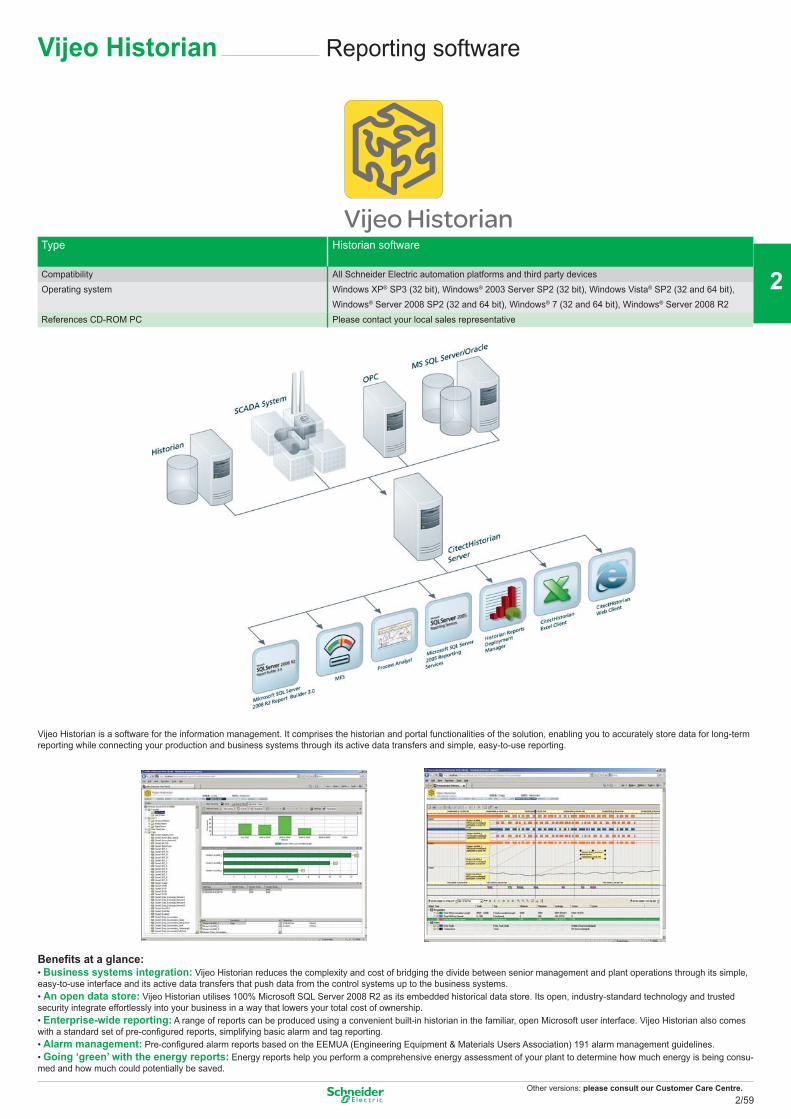
Other versions: please consult our Customer Care Centre.
Vijeo Historian Reporting software
Type Historian software
Compatibility All Schneider Electric automation platforms and third party devicesOperating system Windows XP® SP3 (32 bit), Windows® 2003 Server SP2 (32 bit), Windows Vista® SP2 (32 and 64 bit),
Windows® Server 2008 SP2 (32 and 64 bit), Windows® 7 (32 and 64 bit), Windows® Server 2008 R2References CD-ROM PC Please contact your local sales representative
Vijeo Historian is a software for the information management. It comprises the historian and portal functionalities of the solution, enabling you to accurately store data for long-term reporting while connecting your production and business systems through its active data transfers and simple, easy-to-use reporting.
Benefits at a glance:• Business systems integration: Vijeo Historian reduces the complexity and cost of bridging the divide between senior management and plant operations through its simple, easy-to-use interface and its active data transfers that push data from the control systems up to the business systems.• An open data store: Vijeo Historian utilises 100% Microsoft SQL Server 2008 R2 as its embedded historical data store. Its open, industry-standard technology and trusted security integrate effortlessly into your business in a way that lowers your total cost of ownership.• Enterprise-wide reporting: A range of reports can be produced using a convenient built-in historian in the familiar, open Microsoft user interface. Vijeo Historian also comes with a standard set of pre-configured reports, simplifying basic alarm and tag reporting.• Alarm management: Pre-configured alarm reports based on the EEMUA (Engineering Equipment & Materials Users Association) 191 alarm management guidelines. • Going ‘green’ with the energy reports: Energy reports help you perform a comprehensive energy assessment of your plant to determine how much energy is being consu-med and how much could potentially be saved.
2/59
2
1
3
4
5
6
7
8
9
10
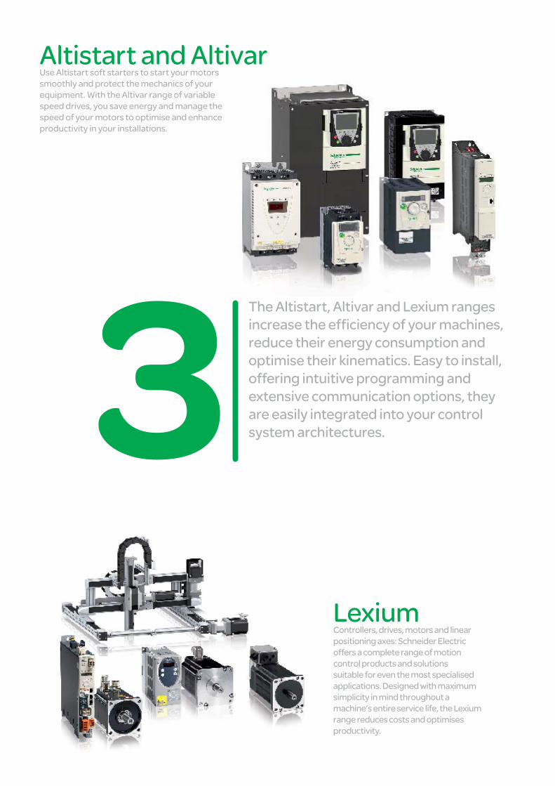
The Altistart, Altivar and Lexium ranges increase the effi ciency of your machines, reduce their energy consumption and optimise their kinematics. Easy to install, offering intuitive programming and extensive communication options, they are easily integrated into your control system architectures.
Altistart and AltivarUse Altistart soft starters to start your motors smoothly and protect the mechanics of your equipment. With the Altivar range of variable speed drives, you save energy and manage the speed of your motors to optimise and enhance productivity in your installations.
LexiumControllers, drives, motors and linear positioning axes: Schneider Electric offers a complete range of motion control products and solutions suitable for even the most specialised applications. Designed with maximum simplicity in mind throughout a machine’s entire service life, the Lexium range reduces costs and optimises productivity.
Motion control
This document is a selection of
the top selling products.
3/1
2
1
3
4
5
6
7
8
9
10
Soft starters and variable speed drives
Selection guide ............................................................................................................ 3/3 to 3/7
Starters Altistart 01 ..................................................................................................................... 3/8 to 3/9 Altistart 22 ..................................................................................................................3/10 to 3/11 Altistart 48 ................................................................................................................. 3/12 to 3/13
Drives Altivar 12 ............................................................................................................................... 3/14 Altivar 212 ............................................................................................................................. 3/15 Altivar 312 ............................................................................................................................. 3/16 Altivar 31C ............................................................................................................................. 3/17 Altivar 32 ............................................................................................................................... 3/18 Altivar 61, 61Q, 61 Plus, 61 Plus-LH ......................................................................... 3/20 to 3/27 Specific cards and extension for pumping and ventilation machines ........................ 3/28 to 3/29 Altivar 71, 71Q, 71 Plus ............................................................................................. 3/30 to 3/36 Altivar LIFT ............................................................................................................................ 3/37 Specific cards and extension for complex and high power machines ....................... 3/38 to 3/39
Accessories and options (Altistart et Altivar) ............................................ 3/40 to 3/41
Controllers, drives, motors and linear motion axes
Selection Guide ....................................................................................................... 3/42 to 3/43
Servo drives, servo motors Lexium 32 and accessories ....................... 3/44 to 3/51 Lexium 32 servo drives Lexium BMH and Lexium BSH servo motors
Stepper Drives and Stepper Motors Lexium SD .................................................... 3/52 Lexium SD2/Lexium SD3 stepper drives Lexium BRS2/Lexium BRS3 stepper motors
Integrated Drives Lexium IL ............................................................................... 3/53 to 3/55 Lexium ILA/ILE/ILS/ILT/ILP
Single axes and multi-axis Systems Linear Motion ................................. 3/56 to 3/57 Lexium PAS/CAS/TAS/MAX
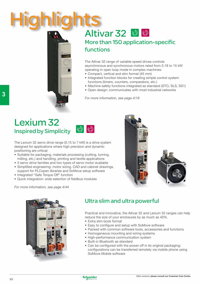
Other versions: please consult our Customer Care Centre.
HighlightsAltivar 32 More than 150 application-specifi c functions
Lexium 32 Inspired by Simplicity
The Altivar 32 range of variable speed drives controls asynchronous and synchronous motors rated from 0.18 to 15 kW operating in open loop mode in complex machines:• Compact, vertical and slim format (45 mm) • Integrated function blocks for creating simple control system
functions (timers, counters, comparators, etc.)• Machine safety functions integrated as standard (STO, SLS, SS1) • Open design: communicates with most industrial networks
For more information, see page 4/18
Ultra slim and ultra powerful
Practical and innovative, the Altivar 32 and Lexium 32 ranges can help reduce the size of your enclosures by as much as 40%. • Extra slim book format • Easy to confi gure and setup with SoMove software • Packed with common software tools, accessories and functions • Homogeneous mounting and wiring systems • High-performance communication system • Built-in Bluetooth as standard • Can be confi gured with the power off in its original packaging: confi gurations can be transferred remotely via mobile phone using
SoMove Mobile software
The Lexium 32 servo drive range (0.15 to 7 kW) is a drive system designed for applications where high precision and dynamic positioning are critical:• Suitable for packaging, materials processing (cutting, turning,
milling, etc.) and handling, printing and textile applications• 3 servo drive families and two types of servo motor available• Simplifi ed engineering: motor sizing, CAD and cabinet drawings,
support for PLCopen libraries and SoMove setup software• Integrated “Safe Torque Off” function• Quick integration: wide selection of fi eldbus modules
For more information, see page 4/44
3/2
2
1
3
4
5
6
7
8
9
10
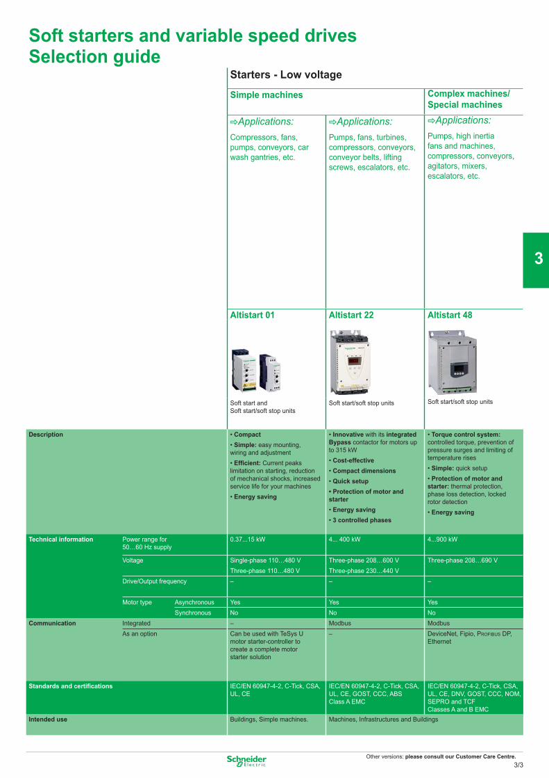
Other versions: please consult our Customer Care Centre.
Soft starters and variable speed drivesSelection guide
Starters - Low voltage
Simple machines Complex machines/ Special machines
CApplications:Compressors, fans, pumps, conveyors, car wash gantries, etc.
CApplications:Pumps, fans, turbines, compressors, conveyors, conveyor belts, lifting screws, escalators, etc.
CApplications:Pumps, high inertia fans and machines, compressors, conveyors, agitators, mixers, escalators, etc.
Altistart 01 Altistart 22 Altistart 48
Soft start and Soft start/soft stop units
Soft start/soft stop units Soft start/soft stop units
Description • Compact • Simple: easy mounting, wiring and adjustment• Effi cient: Current peaks limitation on starting, reduction of mechanical shocks, increased service life for your machines• Energy saving
• Innovative with its integrated Bypass contactor for motors up to 315 kW• Cost-effective• Compact dimensions • Quick setup• Protection of motor and starter• Energy saving• 3 controlled phases
• Torque control system: controlled torque, prevention of pressure surges and limiting of temperature rises• Simple: quick setup• Protection of motor and starter: thermal protection, phase loss detection, locked rotor detection• Energy saving
Technical information Power range for 50…60 Hz supply
0.37...15 kW 4... 400 kW 4...900 kW
Voltage Single-phase 110…480 V Three-phase 208…600 V Three-phase 208…690 VThree-phase 110…480 V Three-phase 230…440 V
Drive/Output frequency – – –
Motor type Asynchronous Yes Yes YesSynchronous No No No
Communication Integrated – Modbus ModbusAs an option Can be used with TeSys U
motor starter-controller to create a complete motor starter solution
– DeviceNet, Fipio, PROFIBUS DP, Ethernet
Standards and certifi cations IEC/EN 60947-4-2, C-Tick, CSA, UL, CE
IEC/EN 60947-4-2, C-Tick, CSA, UL, CE, GOST, CCC, ABSClass A EMC
IEC/EN 60947-4-2, C-Tick, CSA, UL, CE, DNV, GOST, CCC, NOM, SEPRO and TCF Classes A and B EMC
Intended use Buildings, Simple machines. Machines, Infrastructures and Buildings
3/3
2
1
3
4
5
6
7
8
9
10
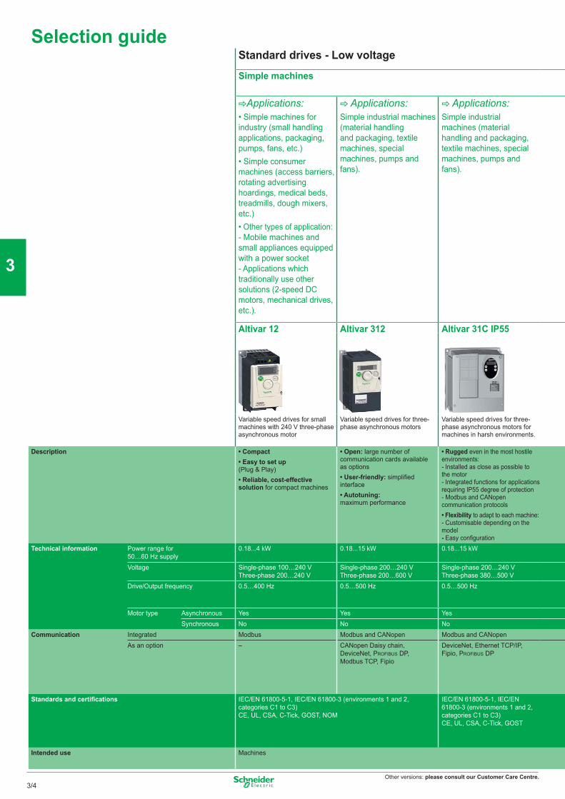
Other versions: please consult our Customer Care Centre.
Selection guideStandard drives - Low voltage
Simple machines
CApplications:• Simple machines for industry (small handling applications, packaging, pumps, fans, etc.)• Simple consumer machines (access barriers, rotating advertising hoardings, medical beds, treadmills, dough mixers, etc.)• Other types of application:- Mobile machines and small appliances equipped with a power socket- Applications which traditionally use other solutions (2-speed DC motors, mechanical drives, etc.).
C Applications:Simple industrial machines (material handling and packaging, textile machines, special machines, pumps and fans).
C Applications:Simple industrial machines (material handling and packaging, textile machines, special machines, pumps and fans).
Altivar 12 Altivar 312 Altivar 31C IP55
Variable speed drives for small machines with 240 V three-phase asynchronous motor
Variable speed drives for three-phase asynchronous motors
Variable speed drives for three-phase asynchronous motors for machines in harsh environments.
Description • Compact• Easy to set up (Plug & Play)• Reliable, cost-effective solution for compact machines
• Open: large number of communication cards available as options• User-friendly: simplified interface• Autotuning: maximum performance
• Rugged even in the most hostile environments:- Installed as close as possible to the motor- Integrated functions for applications requiring IP55 degree of protection- Modbus and CANopen communication protocols• Flexibility to adapt to each machine:- Customisable depending on the model- Easy configuration
Technical information Power range for 50…60 Hz supply
0.18...4 kW 0.18...15 kW 0.18...15 kW
Voltage Single-phase 100…240 VThree-phase 200…240 V
Single-phase 200…240 VThree-phase 200…600 V
Single-phase 200…240 VThree-phase 380…500 V
Drive/Output frequency 0.5…400 Hz 0.5…500 Hz 0.5…500 Hz
Motor type Asynchronous Yes Yes YesSynchronous No No No
Communication Integrated Modbus Modbus and CANopen Modbus and CANopenAs an option – CANopen Daisy chain,
DeviceNet, PROFIBUS DP,Modbus TCP, Fipio
DeviceNet, Ethernet TCP/IP, Fipio, PROFIBUS DP
Standards and certifications IEC/EN 61800-5-1, IEC/EN 61800-3 (environments 1 and 2, categories C1 to C3)CE, UL, CSA, C-Tick, GOST, NOM
IEC/EN 61800-5-1, IEC/EN 61800-3 (environments 1 and 2, categories C1 to C3)CE, UL, CSA, C-Tick, GOST
Intended use Machines
3/4
2
1
3
4
5
6
7
8
9
10
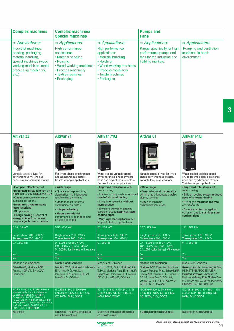
Other versions: please consult our Customer Care Centre.
Complex machines Complex machines/Special machines
Pumps and Fans
C Applications:Industrial machines: hoisting, packaging, material handling, special machines (wood-working machines, metal processing machinery, etc.).
C Applications:High performance applications:• Material handling • Hoisting • Wood-working machines • Process machinery • Textile machines • Packaging
C Applications:High performance applications:• Material handling • Hoisting • Wood-working machines • Process machinery • Textile machines • Packaging
C Applications:Range specifi cally for high performance pumps and fans for the industrial and building markets.
C Applications: Pumping and ventilation machines in harsh environment
Altivar 32 Altivar 71 Altivar 71Q Altivar 61 Altivar 61Q
Variable speed drives for asynchronous motors and open-loop synchronous motors
For three-phase synchronous and asynchronous motors. Constant torque applications.
Water-cooled variable speed drives for three-phase synchro-nous and asynchronous motors.Constant torque applications.
Variable speed drives for three-phase asynchronous motors. Variable torque applications.
Water-cooled variable speed drives for three-phase asynchro-nous and synchronous motors.Variable torque applications
• Compact: "Book" format• Integrated Safety function com-pliant to IEC 61508 SIL3 and PL-e• Open: communication cards available as options • Integrated programmable logic functions• Simple setup· Energy saving : Control of energy effi cient permanent magnet synchronous motors
• Wide range• Quick start-up and easy diagnostics: multi-language graphic display terminal• Open to most industrial communication buses• Integrated safety • Motor control: high-performance in open-loop and closed loop mode
• Improved robustness with water cooling• Effi cient cooling system reduced need of air conditioning• Long time operation without maintenance• Excellent protection against corrosion due to stainless steel cooling pipes• Very high starting torque for frequent start-up applications
• Wide range• Easy setup and diagnostics with the multi-language graphic display terminal• Open to the main communication buses
• Improved robustness with water cooling• Effi cient cooling system reduced need of air conditioning• Prolonged maintenance-free operational life• Excellent protection against corrosion due to stainless steel cooling pipes
0.18...15 kW 0.37...630 kW 90...630 kW 0.37...800 kW 110…800 kW
Single-phase 200…240 VThree-phase 380…480 V
Single-phase 200…240 VThree-phase 200…690 V
Three-phase 380...480 VThree-phase 500…690 V
Single-phase 200…240 VThree-phase 200…690 V
Three-phase 380...480 VThree-phase 500…690 V
0.1…599 Hz 0…599 Hz up to 37 kW / 200…240V and 380…480V0…500 Hz for the rest of the range
0…500 Hz 0.1…599 Hz up to 37 kW / 200…240V and 380…480V0.1…500 Hz for the rest of the range
0.1…500 Hz
Yes Yes Yes Yes YesYes Yes Yes Yes YesModbus and CANopen Modbus and CANopen Modbus et CANopen Modbus and CANopen Modbus et CANopenEtherNet/IP, Modbus TCP, PROFIBUS DP V1, EtherCAT, Devicenet
Modbus TCP, Modbus/Uni-Telway, EtherNet/IP, DeviceNet, PROFIBUS DP, PROFIBUS DP V1, INTERBUS S, CC-Link,
Modbus TCP, Fipio, Modbus/Uni-Telway, Modbus Plus, EtherNet/IP, DeviceNet, PROFIBUS DP, PROFIBUS DP V1, INTERBUS S, CC-Link,
Modbus TCP, Fipio, Modbus/Uni-Telway, Modbus Plus, EtherNet/IP, DeviceNet, PROFIBUS DP, PROFIBUS DP V1, INTERBUS S, CC-Link, Lonworks, METASYS N2, APO-GEE FLN P1, BACnet
HVAC protocols : LonWorks, BACnet, METASYS N2,APOGEE FLN P1Industrial protocols: Modbus TCP, Modbus/Uni-Telway, Fipio, Modbus Plus, PROFIBUS DP, PROFIBUS DP V1, DeviceNet, Ethernet IP, CC-Link, INTERBUS
IEC/EN 61800-5-1, IEC/EN 61800-3 (environments 1 and 2, Categories C2 and C3), UL508C, EN 954-1 Category 3, ISO/EN 13849-1/- 2 Category 3 (PLd), IEC 61800-5-2, IEC 61508 (parts 1&2) level SIL1 SIL2 SIL3, draft standard EN 50495E, CE, UL, CSA, C-Tick, GOST, NOM.
IEC/EN 61800-3, EN 55011, EN 55022, CSA, UL, C-TICK, CE, NOM, DNV, GOST
IEC/EN 61800-3, EN 55011, EN 55022, CSA, UL, C-TICK, CE, NOM, DNV, GOST
IEC/EN 61800-3, EN 55011, EN 55022, CSA, UL, C-TICK, CE, NOM, DNV, GOST
IEC/EN 61800-3, EN 55011, EN 55022, CSA, UL, C-TICK, CE, NOM, DNV, GOST
Machines Machines, industrial processes and infrastructures
Machines, industrial processes or infrastructures
Buildings and infrastructures Building or infrastructures
3/5
2
1
3
4
5
6
7
8
9
10
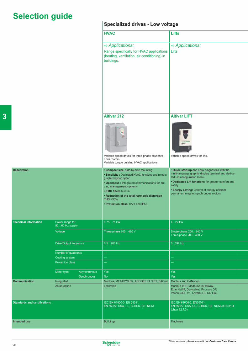
Other versions: please consult our Customer Care Centre.
Selection guideSpecialized drives - Low voltage
HVAC Lifts
C Applications:Range specifically for HVAC applications (heating, ventilation, air conditioning) in buildings.
C Applications:Lifts
Altivar 212 Altivar LIFT
Variable speed drives for three-phase asynchro-nous motors. Variable torque building HVAC applications.
Variable speed drives for lifts.
Description • Compact size: side-by-side mounting• Simplicity : Dedicated HVAC functions and remote graphic keypad option• Openness : Integrated communications for buil-ding management systems• EMC filters built-in• Reduction of the total harmonic distortion THDI<30%• Protection class: IP21 and IP55
• Quick start-up and easy diagnostics with the multi-language graphic display terminal and dedica-ted Lift configuration menu.• Dedicated Lift functions for greater comfort and safety• Energy saving: Control of energy efficient permanent magnet synchronous motors
Technical information Power range for 50…60 Hz supply
0.75…75 kW 4…22 kW
Voltage Three-phase 200…480 V Single-phase 200…240 VThree-phase 200…480 V
Drive/Output frequency 0.5…200 Hz 0...599 Hz
Number of quadrants — —Cooling system — —Protection class — —
Motor type Asynchronous Yes YesSynchronous No Yes
Communication Integrated Modbus, METASYS N2, APOGEE FLN P1, BACnet Modbus and CANopenAs an option Lonworks Modbus TCP, Modbus/Uni-Telway,
EtherNet/IP, DeviceNet, PROFIBUS DP, PROFIBUS DP V1, INTERBUS S, CC-Link
Standards and certifications IEC/EN 61800-3, EN 55011, EN 55022, CSA, UL, C-TICK, CE, NOM
IEC/EN 61800-3, EN55011, EN 55022, CSA, UL, C-TICK, CE, NOM et EN81-1 (chap 12.7.3)
Intended use Buildings Machines
3/6
2
1
3
4
5
6
7
8
9
10
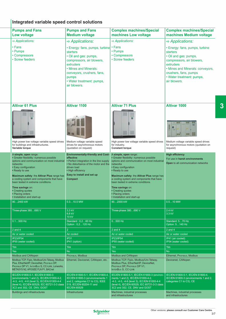
Other versions: please consult our Customer Care Centre.
Integrated variable speed control solutions
Pumps and FansLow voltage
Pumps and FansMedium voltage
Complex machines/Special machines Low voltage
Complex machines/Special machines Medium voltage
C Applications:
• Fans • Pumps• Compressors• Screw feeders
C Applications:• Energy: fans, pumps, turbine starters • Oil and gas: pumps, compressors, air blowers, extruders • Mines and Minerals: conveyors, crushers, fans, pumps • Water treatment: pumps, air blowers.
C Applications:
• Fans • Pumps• Compressors• Screw feeders
C Applications:• Energy: fans, pumps, turbine starters • Oil and gas: pumps, compressors, air blowers, extruders • Mines and Minerals: conveyors, crushers, fans, pumps • Water treatment: pumps, air blowers.
Altivar 61 Plus Altivar 1100 Altivar 71 Plus Altivar 1000
High power low voltage variable speed drives for buildings and infrastructures.Variable torque
Medium voltage variable speed drives for asynchronous motors (quotation on request)
High power low voltage variable speed drives for industry.Constant torque
Medium voltage variable speed drives for asynchronous motors (quotation on request)
A simple, open range:• Greater fl exibility: numerous possible options and communication on most industrial networks• Easy confi guration• Ready to use
Maximum safety: the Altivar Plus range has a cooling system and components that have been tested in extreme conditions.
Time savings on:• Creating quotes• Placing orders• Installation and start-up
Environmentally-friendly and Cost-effective: • Perfect integration in the line supply• No disturbance of the motor and the driven load• High effi ciencyEasy to install and set upCompact
A simple, open range:• Greater fl exibility: numerous possible options and communication on most industrial networks• Easy confi guration• Ready to use
Maximum safety: the Altivar Plus range has a cooling system and components that have been tested in extreme conditions.
Time savings on:• Creating quotes• Placing orders• Installation and start-up
High effi ciency For use in harsh environmentsOpen to all communication networks
90…2400 kW 0.3…10.5 MW 90…2000 kW 0.5…10 MW
Three-phase 380…690 V 3,3 kV6,6 kV10 kV
Three-phase 380…690 V 2.4 kV3.3 kV
0.1…500 Hz Standard : 0,2…60 HzOption : 0,2…120 Hz
0…500 Hz Standard: 5…70 HzOption: 5…140 Hz
2 and 4 2 2 and 4 2 and 4Air or water cooled Air cooled Air or water cooled Air or water cooledIP23/IP54IP55 (water cooled)
IP31IP41 (option)
IP23/IP54IP55 (water cooled)
IP41 (air cooled)IP54 (water cooled)
Yes Yes Yes YesYes No Yes NoModbus and CANopen PROFIBUS, Modbus Modbus and CANopen Ethernet, PROFIBUS, ModbusModbus TCP, Fipio, Modbus/Uni-Telway, Modbus Plus, EtherNet/IP, DeviceNet, PROFIBUS DP, PROFIBUS DP V1, INTERBUS S, CC-Link, Lonworks, METASYS N2, APOGEE FLN P1, BACnet
Ethernet, Devicenet, CANopen, etc. Modbus TCP, Fipio, Modbus/Uni-Telway, Modbus Plus, EtherNet/IP, DeviceNet, PROFIBUS DP, PROFIBUS DP V1, INTERBUS S, CC-Link
Devicenet, CANopen
IEC/EN 61800-5-1, IEC/EN 61800-3 (environments 1 and 2), IEC/EN 61000-4-2, -4-3, -4-5, -4-6 (level 3), IEC/EN 61000-4-4 (level 4), IEC/EN 60529, IEC 60721-3-3 class 3C2 and 3S2, CE. DNV, GOST
IEC/EN 61800-5-1, IEC/EN 61800-4, IEC/EN 61800-3 (environnements 1 and 2, catégories C1 to C3), IEEE 519, IEC/EN 60204-11 and IEC/EN 60529
IEC/EN 61800-5-1, IEC/EN 61800-3 (environ-ments 1 and 2), IEC/EN 61000-4-2, -4-3, -4-5, -4-6 (level 3), IEC/EN 61000-4-4 (level 4), IEC/EN 60529, IEC 60721-3-3 class 3C2 and 3S2, CE. DNV and GOST
IEC/EN 61800-5-1, IEC/EN 61800-4, IEC/EN 61800-3 (environments 1 and 2, categories C1 to C3), CE
Buildings and infrastructures Infrastructures Machines, industrial processes and infrastructures
Machines, industrial processes and infrastructures
3/7
2
1
3
4
5
6
7
8
9
10
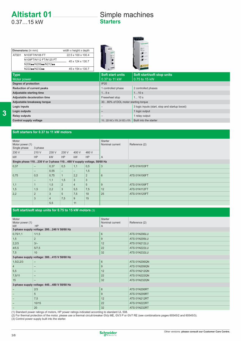
Other versions: please consult our Customer Care Centre.
Type Soft start units Soft start/soft stop unitsMotor power 0.37 to 11 kW 0.75 to 15 kWDegree of protection IP20Reduction of current peaks 1 controlled phase 2 controlled phasesAdjustable starting time 1…5 s 1…10 sAdjustable deceleration time Freewheel stop 1... 10 sAdjustable breakaway torque 30…80% of DOL motor starting torqueLogic inputs – 3 logic inputs (start, stop and startup boost)Logic outputs – 1 logic outputRelay outputs – 1 relay outputControl supply voltage 110... 220 VAC ± 10%, 24 VDC ± 10% Built into the starter
Soft starters for 0.37 to 11 kW motors
Motor StarterMotor power (1) Nominal current Reference (2)Single phase 3-phase230 V 210 V 230 V 230 V 400 V 460 V kW HP kW HP kW HP ASingle phase 110…230 V or 3-phase 110…480 V supply voltage, 50/60 Hz0,37 – 0,37 0,5 1,1 0,5 3 ATS 01N103FT
– 0,55 – – 1,5 0,75 0,5 0,75 1 2,2 2 6 ATS 01N106FT
– 1,1 1,5 3 31,1 1 1,5 2 4 5 9 ATS 01N109FT 1,5 1,5 2,2 3 5,5 7,5 12 ATS 01N112FT 2,2 2 3 5 7,5 10 25 ATS 01N125FT
3 4 7,5 9 15 5,5 11
Soft start/soft stop units for 0.75 to 15 kW motors (3)
Motor StarterMotor power (1) Nominal current Reference (2)kW HP A3-phase supply voltage: 200…240 V 50/60 Hz0,75/1,1 1/1,5 6 ATS 01N206LU
1,5 2 9 ATS 01N209LU 2,2/3 3/– 12 ATS 01N212LU 4/5,5 5/7,5 22 ATS 01N222LU 7,5 10 32 ATS 01N232LU 3-phase supply voltage: 380…415 V 50/60 Hz1,5/2,2/3 – 6 ATS 01N206QN 4 – 9 ATS 01N209QN 5,5 – 12 ATS 01N212QN 7,5/11 – 22 ATS 01N222QN 15 – 32 ATS 01N232QN3-phase supply voltage: 440…480 V 50/60 Hz– 2/3 6 ATS 01N206RT – 5 9 ATS 01N209RT – 7,5 12 ATS 01N212RT – 10/15 22 ATS 01N222RT – 20 32 ATS 01N232RT
(1) Standard power ratings of motors, HP power ratings indicated according to standard UL 508.(2) For thermal protection of the motor, please use a thermal circuit-breaker GVp ME, GV3 P or GV7 RE (see combinations pages 60545/2 and 60545/3).(3) Control power supply built into the starter.
Altistart 010.37…15 kW
Simple machinesStarters
Dimensions (in mm) width x height x depthATS01 N103FT/N106 FT 22.5 x 100 x 100.4
N109FT/N112 FT/N125 FT 45 x 124 x 130.7N206pp/N209pp/N212pp
N222pp/N232pp 45 x 154 x 130.7
3/8
2
1
3
4
5
6
7
8
9
10
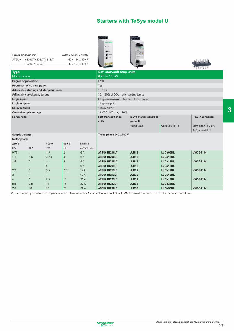
Other versions: please consult our Customer Care Centre.
Starters with TeSys model U
Type Soft start/soft stop unitsMotor power 0.75 to 15 kWDegree of protection IP20Reduction of current peaks YesAdjustable starting and stopping times 1…10 sAdjustable breakaway torque 30.... 80% of DOL motor starting torqueLogic inputs 3 logic inputs (start, stop and startup boost)Logic outputs 1 logic outputRelay outputs 1 relay outputControl supply voltage 24 VDC, 100 mA, ± 10%References Soft start/soft stop
units TeSys starter-controller Power connector
model UPower base Control unit (1) between ATSU and
TeSys model USupply voltage Three-phase 200…480 VMotor power230 V 400 V 460 V Nominal
current (IcL)kW HP kW HP0.75 1 1.5 2 6 A ATSU01N206LT LUB12 LUCp05BL VW3G41041.1 1.5 2.2/3 3 6 A ATSU01N206LT LUB12 LUCp12BL1.5 2 – 5 9 A ATSU01N209LT LUB12 LUCp12BL VW3G4104– – 4 – 9 A ATSU01N209LT LUB12 LUCp12BL2.2 3 5.5 7.5 12 A ATSU01N212LT LUB12 LUCp12BL VW3G41043 – – – 12 A ATSU01N212LT LUB32 LUCp18BL4 5 7.5 10 22 A ATSU01N222LT LUB32 LUCp18BL VW3G41045.5 7.5 11 15 22 A ATSU01N222LT LUB32 LUCp32BL7.5 10 15 20 32 A ATSU01N232LT LUB32 LUCp32BL VW3G4104
(1) To compose your reference, replace p in the reference with: «A» for a standard control unit, «M» for a multifunction unit and «B» for an advanced unit.
Dimensions (in mm) width x height x depthATSU01 N206LT/N209LT/N212LT 45 x 124 x 130.7
N222LT/N232LT 45 x 154 x 130.7
3/9
2
1
3
4
5
6
7
8
9
10
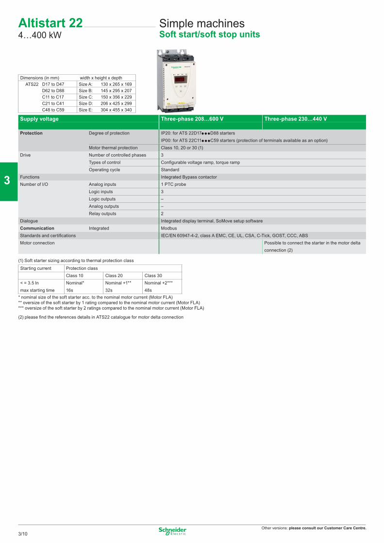
Other versions: please consult our Customer Care Centre.
Altistart 224…400 kW
Simple machinesSoft start/soft stop units
Supply voltage Three-phase 208…600 V Three-phase 230…440 V
Protection Degree of protection IP20: for ATS 22D17pppD88 startersIP00: for ATS 22C11pppC59 starters (protection of terminals available as an option)
Motor thermal protection Class 10, 20 or 30 (1)Drive Number of controlled phases 3
Types of control Confi gurable voltage ramp, torque rampOperating cycle Standard
Functions Integrated Bypass contactorNumber of I/O Analog inputs 1 PTC probe
Logic inputs 3Logic outputs –Analog outputs –Relay outputs 2
Dialogue Integrated display terminal, SoMove setup softwareCommunication Integrated ModbusStandards and certifi cations IEC/EN 60947-4-2, class A EMC, CE, UL, CSA, C-Tick, GOST, CCC, ABSMotor connection Possible to connect the starter in the motor delta
connection (2)
(1) Soft starter sizing according to thermal protection class
Starting current Protection classClass 10 Class 20 Class 30
< = 3.5 ln Nominal* Nominal +1** Nominal +2***max starting time 16s 32s 48s
* nominal size of the soft starter acc. to the nominal motor current (Motor FLA)** oversize of the soft starter by 1 rating compared to the nominal motor current (Motor FLA)*** oversize of the soft starter by 2 ratings compared to the nominal motor current (Motor FLA)
(2) please fi nd the references details in ATS22 catalogue for motor delta connection
Dimensions (in mm) width x height x depthATS22 D17 to D47 Size A: 130 x 265 x 169
D62 to D88 Size B: 145 x 295 x 207C11 to C17 Size C: 150 x 356 x 229C21 to C41 Size D: 206 x 425 x 299C48 to C59 Size E: 304 x 455 x 340
3/10
2
1
3
4
5
6
7
8
9
10
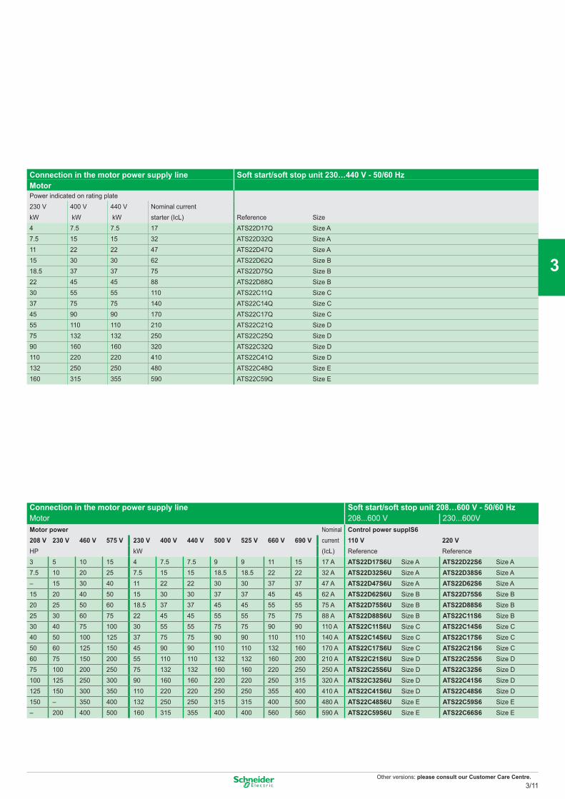
Other versions: please consult our Customer Care Centre.
Connection in the motor power supply line Soft start/soft stop unit 230…440 V - 50/60 HzMotor Power indicated on rating plate230 V 400 V 440 V Nominal currentkW kW kW starter (IcL) Reference Size4 7.5 7.5 17 ATS22D17Q Size A7.5 15 15 32 ATS22D32Q Size A11 22 22 47 ATS22D47Q Size A15 30 30 62 ATS22D62Q Size B18.5 37 37 75 ATS22D75Q Size B22 45 45 88 ATS22D88Q Size B30 55 55 110 ATS22C11Q Size C37 75 75 140 ATS22C14Q Size C45 90 90 170 ATS22C17Q Size C55 110 110 210 ATS22C21Q Size D75 132 132 250 ATS22C25Q Size D90 160 160 320 ATS22C32Q Size D110 220 220 410 ATS22C41Q Size D132 250 250 480 ATS22C48Q Size E160 315 355 590 ATS22C59Q Size E
Connection in the motor power supply line Soft start/soft stop unit 208…600 V - 50/60 HzMotor 208...600 V 230...600VMotor power Nominal
current(IcL)
Control power supplS6208 V 230 V 460 V 575 V 230 V 400 V 440 V 500 V 525 V 660 V 690 V 110 V 220 VHP kW Reference Reference3 5 10 15 4 7.5 7.5 9 9 11 15 17 A ATS22D17S6U Size A ATS22D22S6 Size A7.5 10 20 25 7.5 15 15 18.5 18.5 22 22 32 A ATS22D32S6U Size A ATS22D38S6 Size A– 15 30 40 11 22 22 30 30 37 37 47 A ATS22D47S6U Size A ATS22D62S6 Size A15 20 40 50 15 30 30 37 37 45 45 62 A ATS22D62S6U Size B ATS22D75S6 Size B20 25 50 60 18.5 37 37 45 45 55 55 75 A ATS22D75S6U Size B ATS22D88S6 Size B25 30 60 75 22 45 45 55 55 75 75 88 A ATS22D88S6U Size B ATS22C11S6 Size B30 40 75 100 30 55 55 75 75 90 90 110 A ATS22C11S6U Size C ATS22C14S6 Size C40 50 100 125 37 75 75 90 90 110 110 140 A ATS22C14S6U Size C ATS22C17S6 Size C50 60 125 150 45 90 90 110 110 132 160 170 A ATS22C17S6U Size C ATS22C21S6 Size C60 75 150 200 55 110 110 132 132 160 200 210 A ATS22C21S6U Size D ATS22C25S6 Size D75 100 200 250 75 132 132 160 160 220 250 250 A ATS22C25S6U Size D ATS22C32S6 Size D100 125 250 300 90 160 160 220 220 250 315 320 A ATS22C32S6U Size D ATS22C41S6 Size D125 150 300 350 110 220 220 250 250 355 400 410 A ATS22C41S6U Size D ATS22C48S6 Size D150 – 350 400 132 250 250 315 315 400 500 480 A ATS22C48S6U Size E ATS22C59S6 Size E– 200 400 500 160 315 355 400 400 560 560 590 A ATS22C59S6U Size E ATS22C66S6 Size E
3/11
2
1
3
4
5
6
7
8
9
10
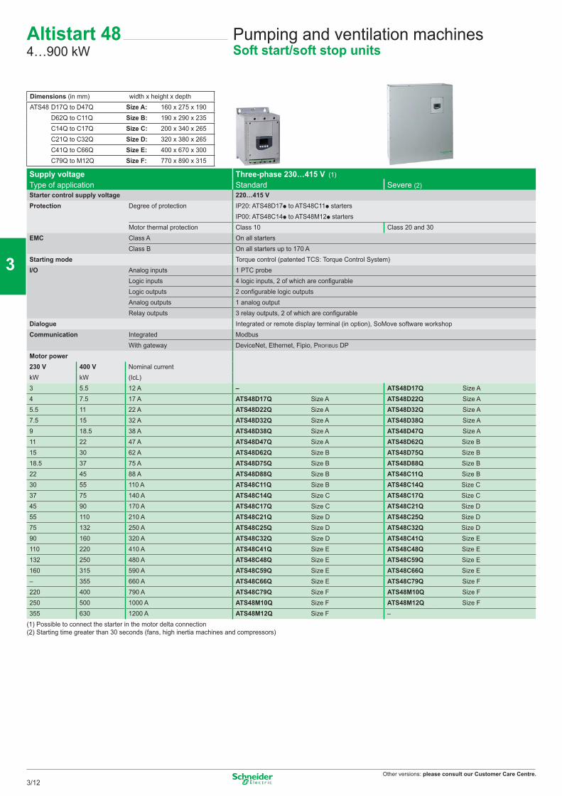
Other versions: please consult our Customer Care Centre.
Altistart 484…900 kW
Pumping and ventilation machinesSoft start/soft stop units
Supply voltage Three-phase 230…415 V (1)Type of application Standard Severe (2)Starter control supply voltage 220…415 VProtection Degree of protection IP20: ATS48D17p to ATS48C11p starters
IP00: ATS48C14p to ATS48M12p startersMotor thermal protection Class 10 Class 20 and 30
EMC Class A On all startersClass B On all starters up to 170 A
Starting mode Torque control (patented TCS: Torque Control System)I/O Analog inputs 1 PTC probe
Logic inputs 4 logic inputs, 2 of which are configurableLogic outputs 2 configurable logic outputsAnalog outputs 1 analog outputRelay outputs 3 relay outputs, 2 of which are configurable
Dialogue Integrated or remote display terminal (in option), SoMove software workshopCommunication Integrated Modbus
With gateway DeviceNet, Ethernet, Fipio, PROFIBUS DPMotor power230 V 400 V Nominal currentkW kW (IcL)3 5.5 12 A – ATS48D17Q Size A4 7.5 17 A ATS48D17Q Size A ATS48D22Q Size A5.5 11 22 A ATS48D22Q Size A ATS48D32Q Size A7.5 15 32 A ATS48D32Q Size A ATS48D38Q Size A9 18.5 38 A ATS48D38Q Size A ATS48D47Q Size A11 22 47 A ATS48D47Q Size A ATS48D62Q Size B15 30 62 A ATS48D62Q Size B ATS48D75Q Size B18.5 37 75 A ATS48D75Q Size B ATS48D88Q Size B22 45 88 A ATS48D88Q Size B ATS48C11Q Size B30 55 110 A ATS48C11Q Size B ATS48C14Q Size C37 75 140 A ATS48C14Q Size C ATS48C17Q Size C45 90 170 A ATS48C17Q Size C ATS48C21Q Size D55 110 210 A ATS48C21Q Size D ATS48C25Q Size D75 132 250 A ATS48C25Q Size D ATS48C32Q Size D90 160 320 A ATS48C32Q Size D ATS48C41Q Size E110 220 410 A ATS48C41Q Size E ATS48C48Q Size E132 250 480 A ATS48C48Q Size E ATS48C59Q Size E160 315 590 A ATS48C59Q Size E ATS48C66Q Size E– 355 660 A ATS48C66Q Size E ATS48C79Q Size F220 400 790 A ATS48C79Q Size F ATS48M10Q Size F250 500 1000 A ATS48M10Q Size F ATS48M12Q Size F355 630 1200 A ATS48M12Q Size F –
(1) Possible to connect the starter in the motor delta connection(2) Starting time greater than 30 seconds (fans, high inertia machines and compressors)
Dimensions (in mm) width x height x depthATS48 D17Q to D47Q Size A: 160 x 275 x 190
D62Q to C11Q Size B: 190 x 290 x 235C14Q to C17Q Size C: 200 x 340 x 265C21Q to C32Q Size D: 320 x 380 x 265C41Q to C66Q Size E: 400 x 670 x 300C79Q to M12Q Size F: 770 x 890 x 315
3/12
2
1
3
4
5
6
7
8
9
10
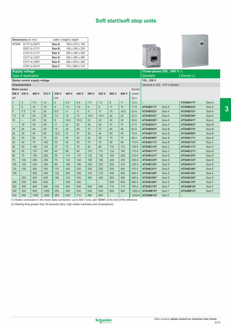
Other versions: please consult our Customer Care Centre.
Soft start/soft stop units
Supply voltage Three-phase 208…690 V (1)Type of application Standard Severe (2)
Starter control supply voltage 110…230 VCharacteristics Identical to 230…415 V startersMotor power Nominal
current(IcL)
208 V 230 V 460 V 575 V 230 V 400 V 440 V 500 V 525 V 660 V 690 VHP kW2 3 7.5 10 3 5.5 5.5 7.5 7.5 9 11 12 A – ATS48D17Y Size A3 5 10 15 4 7.5 7.5 9 9 11 15 17 A ATS48D17Y Size A ATS48D22Y Size A5 7.5 15 20 5.5 11 11 11 11 15 18.5 22 A ATS48D22Y Size A ATS48D32Y Size A7.5 10 20 25 7.5 15 15 18.5 18.5 22 22 32 A ATS48D32Y Size A ATS48D38Y Size A10 – 25 30 9 18.5 18.5 22 22 30 30 38 A ATS48D38Y Size A ATS48D47Y Size A– 15 30 40 11 22 22 30 30 37 37 47 A ATS48D47Y Size A ATS48D62Y Size B15 20 40 50 15 30 30 37 37 45 45 62 A ATS48D62Y Size B ATS48D75Y Size B20 25 50 60 18.5 37 37 45 45 55 55 75 A ATS48D75Y Size B ATS48D88Y Size B25 30 60 75 22 45 45 55 55 75 75 88 A ATS48D88Y Size B ATS48C11Y Size B30 40 75 100 30 55 55 75 75 90 90 110 A ATS48C11Y Size B ATS48C14Y Size C40 50 100 125 37 75 75 90 90 110 110 140 A ATS48C14Y Size C ATS48C17Y Size C50 60 125 150 45 90 90 110 110 132 160 170 A ATS48C17Y Size C ATS48C21Y Size D60 75 150 200 55 110 110 132 132 160 200 210 A ATS48C21Y Size D ATS48C25Y Size D75 100 200 250 75 132 132 160 160 220 250 250 A ATS48C25Y Size D ATS48C32Y Size D100 125 250 300 90 160 160 220 220 250 315 320 A ATS48C32Y Size D ATS48C41Y Size E125 150 300 350 110 220 220 250 250 355 400 410 A ATS48C41Y Size E ATS48C48Y Size E150 – 350 400 132 250 250 315 315 400 500 480 A ATS48C48Y Size E ATS48C59Y Size E– 200 400 500 160 315 355 400 400 560 560 590 A ATS48C59Y Size E ATS48C66Y Size E200 250 500 600 – 355 400 – – 630 630 660 A ATS48C66Y Size E ATS48C79Y Size F250 300 600 800 220 400 500 500 500 710 710 790 A ATS48C79Y Size F ATS48M10Y Size F350 350 800 1000 250 500 630 630 630 900 900 1000 A ATS48M10Y Size F ATS48M12Y Size F400 450 1000 1200 355 630 710 800 800 – – 1200 A ATS48M12Y Size F –
(1) Starter connection in the motor delta connection: up to 500 V only, add "S316" at the end of the reference(2) Starting time greater than 30 seconds (fans, high inertia machines and compressors)
Dimensions (in mm) width x height x depthATS48 D17Y to D47Y Size A: 160 x 275 x 190
D62Y to C11Y Size B: 190 x 290 x 235C14Y to C17Y Size C: 200 x 340 x 265C21Y to C32Y Size D: 320 x 380 x 265C41Y to C66Y Size E: 400 x 670 x 300C79Y to M12Y Size F: 770 x 890 x 315
3/13
2
1
3
4
5
6
7
8
9
10
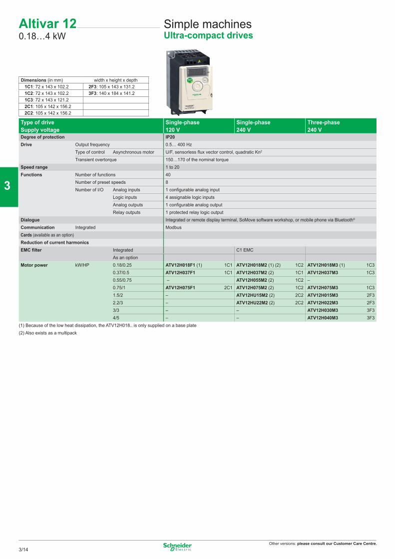
Other versions: please consult our Customer Care Centre.
Altivar 120.18…4 kW
Simple machinesUltra-compact drives
Type of drive Single-phase Single-phase Three-phaseSupply voltage 120 V 240 V 240 VDegree of protection IP20Drive Output frequency 0.5… 400 Hz
Type of control Asynchronous motor U/F, sensorless flux vector control, quadratic Kn2
Transient overtorque 150…170 of the nominal torqueSpeed range 1 to 20Functions Number of functions 40
Number of preset speeds 8Number of I/O Analog inputs 1 configurable analog input
Logic inputs 4 assignable logic inputsAnalog outputs 1 configurable analog outputRelay outputs 1 protected relay logic output
Dialogue Integrated or remote display terminal, SoMove software workshop, or mobile phone via Bluetooth©
Communication Integrated Modbus Cards (available as an option) Reduction of current harmonicsEMC filter Integrated C1 EMC
As an optionMotor power kW/HP 0.18/0.25 ATV12H018F1 (1) 1C1 ATV12H018M2 (1) (2) 1C2 ATV12H018M3 (1) 1C3
0.37/0.5 ATV12H037F1 1C1 ATV12H037M2 (2) 1C1 ATV12H037M3 1C30.55/0.75 – ATV12H055M2 (2) 1C2 –0.75/1 ATV12H075F1 2C1 ATV12H075M2 (2) 1C2 ATV12H075M3 1C31.5/2 – ATV12HU15M2 (2) 2C2 ATV12H015M3 2F32.2/3 – ATV12HU22M2 (2) 2C2 ATV12H022M3 2F33/3 – – ATV12H030M3 3F34/5 – – ATV12H040M3 3F3
(1) Because of the low heat dissipation, the ATV12H018.. is only supplied on a base plate(2) Also exists as a multipack
Dimensions (in mm) width x height x depth1C1: 72 x 143 x 102.2 2F3: 105 x 143 x 131.21C2: 72 x 143 x 102.2 3F3: 140 x 184 x 141.21C3: 72 x 143 x 121.22C1: 105 x 142 x 156.22C2: 105 x 142 x 156.2
3/14
2
1
3
4
5
6
7
8
9
10
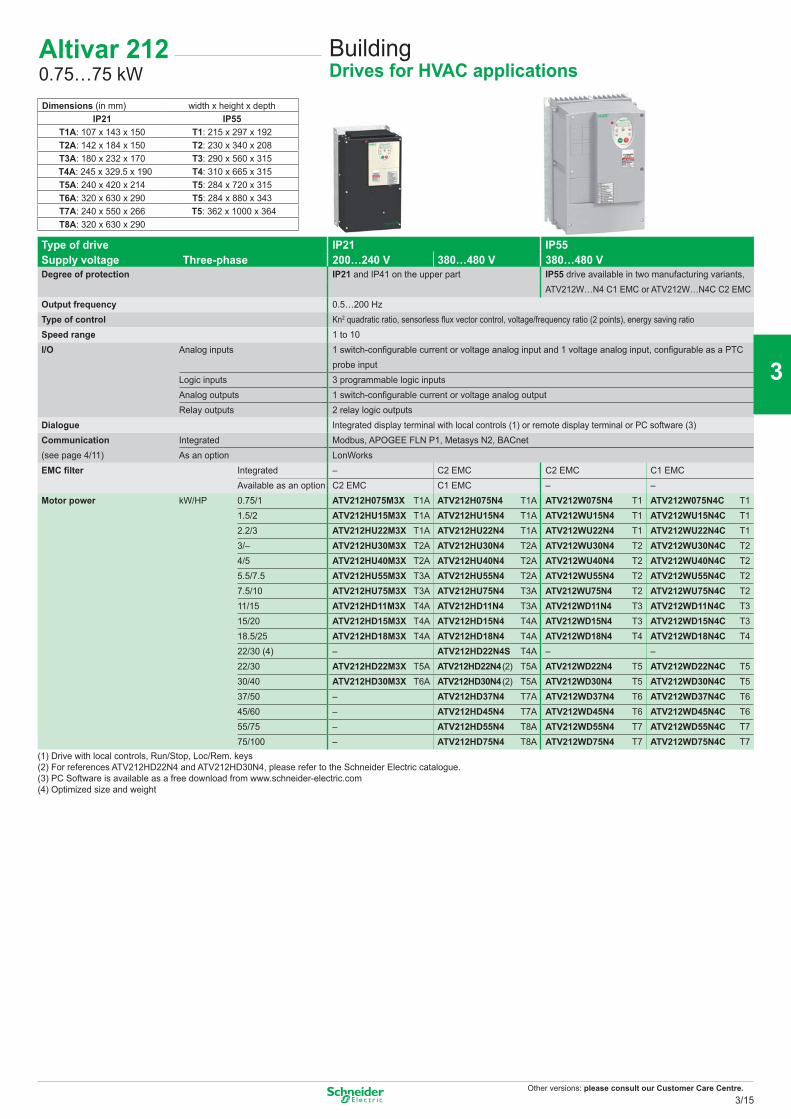
Other versions: please consult our Customer Care Centre.
Altivar 2120.75…75 kW
BuildingDrives for HVAC applications
Type of drive IP21 IP55380…480 VSupply voltage Three-phase 200…240 V 380…480 V
Degree of protection IP21 and IP41 on the upper part IP55 drive available in two manufacturing variants,ATV212W…N4 C1 EMC or ATV212W…N4C C2 EMC
Output frequency 0.5…200 HzType of control Kn2 quadratic ratio, sensorless fl ux vector control, voltage/frequency ratio (2 points), energy saving ratioSpeed range 1 to 10I/O Analog inputs 1 switch-confi gurable current or voltage analog input and 1 voltage analog input, confi gurable as a PTC
probe inputLogic inputs 3 programmable logic inputsAnalog outputs 1 switch-confi gurable current or voltage analog outputRelay outputs 2 relay logic outputs
Dialogue Integrated display terminal with local controls (1) or remote display terminal or PC software (3)Communication(see page 4/11)
Integrated Modbus, APOGEE FLN P1, Metasys N2, BACnetAs an option LonWorks
EMC fi lter Integrated – C2 EMC C2 EMC C1 EMCAvailable as an option C2 EMC C1 EMC – –
Motor power kW/HP 0.75/1 ATV212H075M3X T1A ATV212H075N4 T1A ATV212W075N4 T1 ATV212W075N4C T11.5/2 ATV212HU15M3X T1A ATV212HU15N4 T1A ATV212WU15N4 T1 ATV212WU15N4C T12.2/3 ATV212HU22M3X T1A ATV212HU22N4 T1A ATV212WU22N4 T1 ATV212WU22N4C T13/– ATV212HU30M3X T2A ATV212HU30N4 T2A ATV212WU30N4 T2 ATV212WU30N4C T24/5 ATV212HU40M3X T2A ATV212HU40N4 T2A ATV212WU40N4 T2 ATV212WU40N4C T25.5/7.5 ATV212HU55M3X T3A ATV212HU55N4 T2A ATV212WU55N4 T2 ATV212WU55N4C T27.5/10 ATV212HU75M3X T3A ATV212HU75N4 T3A ATV212WU75N4 T2 ATV212WU75N4C T211/15 ATV212HD11M3X T4A ATV212HD11N4 T3A ATV212WD11N4 T3 ATV212WD11N4C T315/20 ATV212HD15M3X T4A ATV212HD15N4 T4A ATV212WD15N4 T3 ATV212WD15N4C T318.5/25 ATV212HD18M3X T4A ATV212HD18N4 T4A ATV212WD18N4 T4 ATV212WD18N4C T422/30 (4) – ATV212HD22N4S T4A – –22/30 ATV212HD22M3X T5A ATV212HD22N4 (2) T5A ATV212WD22N4 T5 ATV212WD22N4C T530/40 ATV212HD30M3X T6A ATV212HD30N4 (2) T5A ATV212WD30N4 T5 ATV212WD30N4C T537/50 – ATV212HD37N4 T7A ATV212WD37N4 T6 ATV212WD37N4C T645/60 – ATV212HD45N4 T7A ATV212WD45N4 T6 ATV212WD45N4C T655/75 – ATV212HD55N4 T8A ATV212WD55N4 T7 ATV212WD55N4C T775/100 – ATV212HD75N4 T8A ATV212WD75N4 T7 ATV212WD75N4C T7
(1) Drive with local controls, Run/Stop, Loc/Rem. keys(2) For references ATV212HD22N4 and ATV212HD30N4, please refer to the Schneider Electric catalogue.(3) PC Software is available as a free download from www.schneider-electric.com(4) Optimized size and weight
Dimensions (in mm) width x height x depthIP21 IP55
T1A: 107 x 143 x 150 T1: 215 x 297 x 192T2A: 142 x 184 x 150 T2: 230 x 340 x 208T3A: 180 x 232 x 170 T3: 290 x 560 x 315
T4A: 245 x 329.5 x 190 T4: 310 x 665 x 315T5A: 240 x 420 x 214 T5: 284 x 720 x 315T6A: 320 x 630 x 290 T5: 284 x 880 x 343T7A: 240 x 550 x 266 T5: 362 x 1000 x 364T8A: 320 x 630 x 290
3/15
2
1
3
4
5
6
7
8
9
10
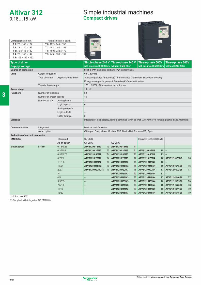
Other versions: please consult our Customer Care Centre.
Altivar 3120.18…15 kW
Simple industrial machinesCompact drives
Dimensions (in mm) width x height x depthT 1: 72 X 145 X 122 T 6: 107 X 143 X 152T 2: 72 X 145 X 132 T 7: 142 X 184 X 152T 3: 72 X 145 X 132 T 8: 180 X 232 X 172T 4: 72 X 145 X 142 T 9: 245 X 330 X 192T 5: 105 X 143 X 132
Type of drive Single-phase 240 V Three-phase 240 V Three-phase 500V Three-phase 600VSupply voltage with integrated EMC filters without EMC filter with integrated EMC filters without EMC filterDegree of protection IP31 & IP41 on upper part and IP21 on terminalsDrive Output frequency 0.5…500 Hz
Type of control Asynchronous motor Standard (voltage / frequency) - Performance (sensorless flux vector control) Energy saving ratio, pump & Fan ratio (Kn² quadratic ratio)
Transient overtorque 170 ... 200% of the nominal motor torqueSpeed range 1 to 50Functions Number of functions 50
Number of preset speeds 16Number of I/O Analog inputs 3
Logic inputs 6Analog outputs 1Logic outputs –Relay outputs 2
Dialogue Integrated 4-digit display, remote terminals (IP54 or IP65), Altivar 61/71 remote graphic display terminal
Communication Integrated Modbus and CANopenAs an option CANopen Daisy chain, Modbus TCP, DeviceNet, PROFIBUS DP, Fipio
Reduction of current harmonicsEMC filter Integrated C2 EMC Integrated C2(1) or C3 EMC
As an option C1 EMC C2 EMC – –Motor power kW/HP 0.18/0.25 ATV312H018M2 T3 ATV312H018M3 T1 – –
0.37/0.5 ATV312H037M2 T3 ATV312H037M3 T1 ATV312H037N4 T5 –0.55/0.75 ATV312H055M2 T4 ATV312H055M3 T2 ATV312H055N4 T5 –0.75/1 ATV312H075M2 T4 ATV312H075M3 T2 ATV312H075N4 T6 ATV312H075S6 T61.1/1.5 ATV312HU11M2 T6 ATV312HU11M3 T5 ATV312HU11N4 T6 –1.5/2 ATV312HU15M2 T6 ATV312HU15M3 T5 ATV312HU15N4 T6 ATV312HU15S6 T62.2/3 ATV312HU22M2 (2) T7 ATV312HU22M3 T6 ATV312HU22N4 T7 ATV312HU22S6 T73/- – ATV312HU30M3 T7 ATV312HU30N4 T7 –4/5 – ATV312HU40M3 T7 ATV312HU40N4 T7 ATV312HU40S6 T75.5/7.5 – ATV312HU55M3 T8 ATV312HU55N4 T8 ATV312HU55S6 T87.5/10 – ATV312HU75M3 T8 ATV312HU75N4 T8 ATV312HU75S6 T811/15 – ATV312HD11M3 T9 ATV312HD11N4 T9 ATV312HD11S6 T915/20 – ATV312HD15M3 T9 ATV312HD15N4 T9 ATV312HD15S6 T9
(1) C2 up to 4 kW(2) Supplied with integrated C3 EMC filter
3/16
2
1
3
4
5
6
7
8
9
10
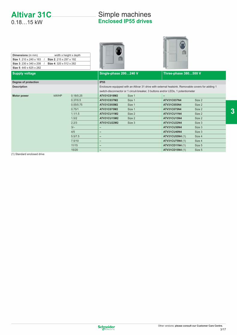
Other versions: please consult our Customer Care Centre.
Supply voltage Single-phase 200…240 V Three-phase 380…500 V
Degree of protection IP55Description Enclosure equipped with an Altivar 31 drive with external heatsink. Removable covers for adding 1
switch-disconnector or 1 circuit-breaker, 3 buttons and/or LEDs, 1 potentiometerMotor power kW/HP 0.18/0.25 ATV31C018M2 Size 1 –
0.37/0.5 ATV31C037M2 Size 1 ATV31C037N4 Size 20.55/0.75 ATV31C055M2 Size 1 ATV31C055N4 Size 20.75/1 ATV31C075M2 Size 1 ATV31C075N4 Size 21.1/1.5 ATV31CU11M2 Size 2 ATV31CU11N4 Size 21.5/2 ATV31CU15M2 Size 2 ATV31CU15N4 Size 22.2/3 ATV31CU22M2 Size 3 ATV31CU22N4 Size 33/– – ATV31CU30N4 Size 34/5 – ATV31CU40N4 Size 35.5/7.5 – ATV31CU55N4 (1) Size 47.5/10 – ATV31CU75N4 (1) Size 411/15 – ATV31CD11N4 (1) Size 515/20 – ATV31CD15N4 (1) Size 5
(1) Standard enclosed drive
Dimensions (in mm) width x height x depthSize 1: 210 x 240 x 163 / Size 2: 215 x 297 x 192Size 3: 230 x 340 x 208 / Size 4: 320 x 512 x 282Size 5: 440 x 625 x 282
Altivar 31C0.18…15 kW
Simple machinesEnclosed IP55 drives
3/17
2
1
3
4
5
6
7
8
9
10
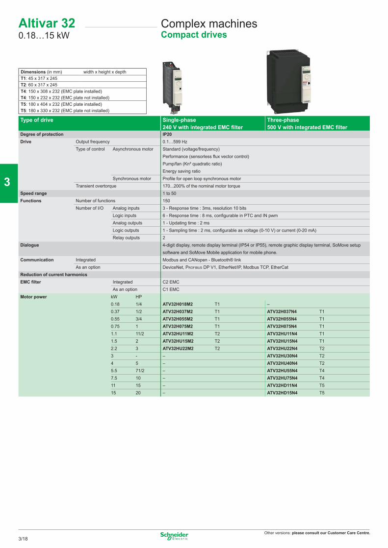
Other versions: please consult our Customer Care Centre.
Type of drive Single-phase Three-phase240 V with integrated EMC fi lter 500 V with integrated EMC fi lter
Degree of protection IP20Drive Output frequency 0.1…599 Hz
Type of control Asynchronous motor Standard (voltage/frequency)Performance (sensorless fl ux vector control)Pump/fan (Kn² quadratic ratio)Energy saving ratio
Synchronous motor Profi le for open loop synchronous motorTransient overtorque 170...200% of the nominal motor torque
Speed range 1 to 50Functions Number of functions 150
Number of I/O Analog inputs 3 - Response time : 3ms, resolution 10 bitsLogic inputs 6 - Response time : 8 ms, confi gurable in PTC and IN pwmAnalog outputs 1 - Updating time : 2 msLogic outputs 1 - Sampling time : 2 ms, confi gurable as voltage (0-10 V) or current (0-20 mA)Relay outputs 2
Dialogue 4-digit display, remote display terminal (IP54 or IP55), remote graphic display terminal, SoMove setup software and SoMove Mobile application for mobile phone.
Communication Integrated Modbus and CANopen - Bluetooth® linkAs an option DeviceNet, PROFIBUS DP V1, EtherNet/IP, Modbus TCP, EtherCat
Reduction of current harmonicsEMC fi lter Integrated C2 EMC
As an option C1 EMCMotor power kW HP
0.18 1/4 ATV32H018M2 T1 –0.37 1/2 ATV32H037M2 T1 ATV32H037N4 T10.55 3/4 ATV32H055M2 T1 ATV32H055N4 T10.75 1 ATV32H075M2 T1 ATV32H075N4 T11.1 11/2 ATV32HU11M2 T2 ATV32HU11N4 T11.5 2 ATV32HU15M2 T2 ATV32HU15N4 T12.2 3 ATV32HU22M2 T2 ATV32HU22N4 T23 - – ATV32HU30N4 T24 5 – ATV32HU40N4 T25.5 71/2 – ATV32HU55N4 T47.5 10 – ATV32HU75N4 T411 15 – ATV32HD11N4 T515 20 – ATV32HD15N4 T5
Dimensions (in mm) width x height x depthT1: 45 x 317 x 245T2: 60 x 317 x 245T4: 150 x 308 x 232 (EMC plate installed)T4: 150 x 232 x 232 (EMC plate not installed)T5: 180 x 404 x 232 (EMC plate installed)T5: 180 x 330 x 232 (EMC plate not installed)
Altivar 320.18…15 kW
Complex machinesCompact drives
3/18
2
1
3
4
5
6
7
8
9
10

Other versions: please consult our Customer Care Centre.
Notes
3/19
2
1
3
4
5
6
7
8
9
10
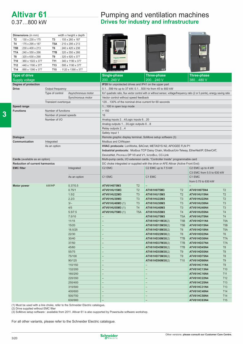
Other versions: please consult our Customer Care Centre.
Pumping and ventilation machinesDrives for industry and infrastructure
Altivar 610.37…800 kW
Type of driveSupply voltage
Single-phase200…240 V
Three-phase200…240 V
Three-phase380…480 V
Degree of protection IP20 for unprotected drives and IP41 on the upper partDrive Output frequency 0.1…599 Hz up to 37 kW; 0.1…500 Hz from 45 to 800 kW
Type of control Asynchronous motor Kn2 quadratic ratio, fl ux vector control with or without sensor, voltage/frequency ratio (2 or 5 points), energy saving ratioSynchronous motor Vector control without speed feedback
Transient overtorque 120…130% of the nominal drive current for 60 secondsSpeed range 1…100 in open loop modeFunctions Number of functions > 150
Number of preset speeds 16Number of I/O Analog inputs 2…4/Logic inputs 6…20
Analog outputs 1…3/Logic outputs 0…8Relay outputs 2…4Safety input 1
Dialogue Remote graphic display terminal, SoMove setup software (3)Communication Integrated Modbus and CANopen
As an option HVAC protocols: LonWorks, BACnet, METASYS N2, APOGEE FLN P1Industrial protocols: Modbus TCP Daisy Chain, Modbus/Uni-Telway, EtherNet/IP, EtherCAT, DeviceNet, PROFIBUS DP V0 and V1, INTERBUS, CC-Link
Cards (available as an option) Multi-pump cards, I/O extension cards, “Controller Inside” programmable cardReduction of current harmonics DC choke integrated or supplied with the drive or AFE Altivar (Active Front End)EMC fi lter Integrated C2 EMC C2 EMC up to 7.5 kW C2 EMC up to 4 kW
C3 EMC from 5.5 to 630 kWAs an option C1 EMC C1 EMC C1 EMC
from 0.75 to 630 kWMotor power kW/HP 0.37/0.5 ATV61H075M3 T2 – –
0.75/1 ATV61HU15M3 T2 ATV61H075M3 T2 ATV61H075N4 T21.5/2 ATV61HU22M3 T3 ATV61HU15M3 T2 ATV61HU15N4 T22.2/3 ATV61HU30M3 T3 ATV61HU22M3 T3 ATV61HU22N4 T23/– ATV61HU40M3 (1) T3 ATV61HU30M3 T3 ATV61HU30N4 T34/5 ATV61HU55M3 (1) T4 ATV61HU40M3 T3 ATV61HU40N4 T35.5/7.5 ATV61HU75M3 (1) T5A ATV61HU55M3 T4 ATV61HU55N4 T47.5/10 – ATV61HU75M3 T5A ATV61HU75N4 T411/15 – ATV61HD11M3X(2) T5B ATV61HD11N4 T5A15/20 – ATV61HD15M3X(2) T5B ATV61HD15N4 T5B18.5/25 – ATV61HD18M3X(2) T6 ATV61HD18N4 T5A22/30 – ATV61HD22M3X(2) T6 ATV61HD22N4 T630/40 – ATV61HD30M3X(2) T7B ATV61HD30N4 T7A37/50 – ATV61HD37M3X(2) T7B ATV61HD37N4 T7A45/60 – ATV61HD45M3X(2) T7B ATV61HD45N4 T855/75 – ATV61HD55M3X(2) T9 ATV61HD55N4 T875/100 – ATV61HD75M3X(2) T9 ATV61HD75N4 T890/125 – ATV61HD90M3X(2) T10 ATV61HD90N4 T9110/150 – – ATV61HC11N4 T9132/200 – – ATV61HC13N4 T10160/250 – – ATV61HC16N4 T11220/350 – – ATV61HC22N4 T12250/400 – – ATV61HC25N4 T13315/500 – – ATV61HC31N4 T13400/600 – – ATV61HC40N4 T14500/700 – – ATV61HC50N4 T14630/900 – – ATV61HC63N4 T15
(1) Must be used with a line choke, refer to the Schneider Electric catalogue.(2) Drive supplied without EMC fi lter(3) SoMove setup software : available from 2011. Altivar 61 is also supported by Powersuite software workshop.
For all other variants, please refer to the Schneider Electric catalogue.
Dimensions (in mm) width x height x depthT2 : 130 x 230 x 175 T3 : 155 x 260 x 187T4 : 175 x 295 x 187 T5A : 210 x 295 x 213T5B : 230 x 400 x 213 T6 : 240 x 420 x 236T7A : 240 x 550 x 266 T7B : 320 x 550 x 266T8 : 320 x 630 x 290 T9 : 320 x 920 x 377T10 : 360 x 1022 x 377 T11 : 340 x 1190 x 377T12 : 440 x 1190 x 377 T13 : 595 x 1190 x 377T14 : 890 x 1390 x 377 T15 : 1120 x 1390 x 377
3/20
2
1
3
4
5
6
7
8
9
10
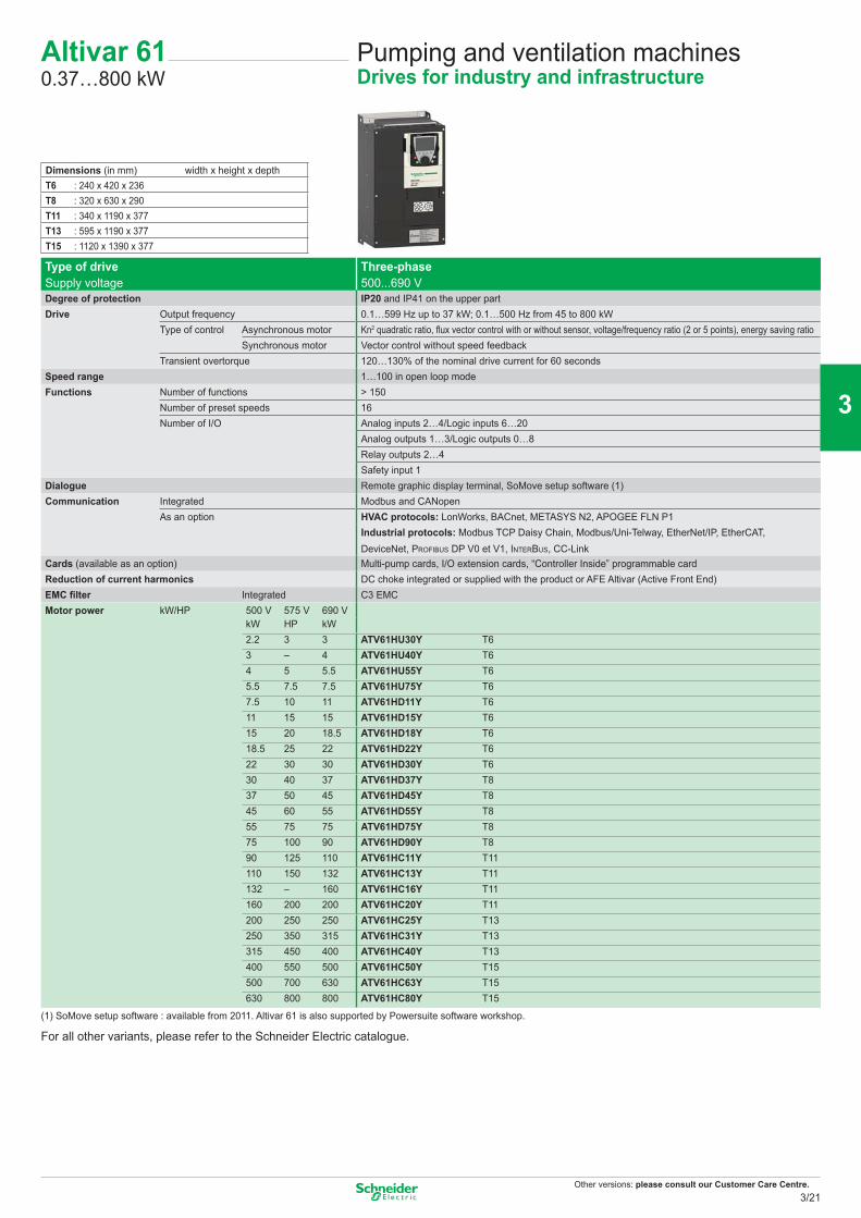
Other versions: please consult our Customer Care Centre.
Pumping and ventilation machinesDrives for industry and infrastructure
Altivar 610.37…800 kW
Type of driveSupply voltage
Three-phase500...690 V
Degree of protection IP20 and IP41 on the upper partDrive Output frequency 0.1…599 Hz up to 37 kW; 0.1…500 Hz from 45 to 800 kW
Type of control Asynchronous motor Kn2 quadratic ratio, fl ux vector control with or without sensor, voltage/frequency ratio (2 or 5 points), energy saving ratioSynchronous motor Vector control without speed feedback
Transient overtorque 120…130% of the nominal drive current for 60 secondsSpeed range 1…100 in open loop modeFunctions Number of functions > 150
Number of preset speeds 16Number of I/O Analog inputs 2…4/Logic inputs 6…20
Analog outputs 1…3/Logic outputs 0…8Relay outputs 2…4Safety input 1
Dialogue Remote graphic display terminal, SoMove setup software (1)Communication Integrated Modbus and CANopen
As an option HVAC protocols: LonWorks, BACnet, METASYS N2, APOGEE FLN P1Industrial protocols: Modbus TCP Daisy Chain, Modbus/Uni-Telway, EtherNet/IP, EtherCAT, DeviceNet, PROFIBUS DP V0 et V1, INTERBUS, CC-Link
Cards (available as an option) Multi-pump cards, I/O extension cards, “Controller Inside” programmable cardReduction of current harmonics DC choke integrated or supplied with the product or AFE Altivar (Active Front End)EMC fi lter Integrated C3 EMCMotor power kW/HP 500 V 575 V 690 V
kW HP kW 2.2 3 3 ATV61HU30Y T63 – 4 ATV61HU40Y T64 5 5.5 ATV61HU55Y T65.5 7.5 7.5 ATV61HU75Y T67.5 10 11 ATV61HD11Y T611 15 15 ATV61HD15Y T615 20 18.5 ATV61HD18Y T618.5 25 22 ATV61HD22Y T622 30 30 ATV61HD30Y T630 40 37 ATV61HD37Y T837 50 45 ATV61HD45Y T845 60 55 ATV61HD55Y T855 75 75 ATV61HD75Y T875 100 90 ATV61HD90Y T890 125 110 ATV61HC11Y T11110 150 132 ATV61HC13Y T11132 – 160 ATV61HC16Y T11160 200 200 ATV61HC20Y T11200 250 250 ATV61HC25Y T13250 350 315 ATV61HC31Y T13315 450 400 ATV61HC40Y T13400 550 500 ATV61HC50Y T15500 700 630 ATV61HC63Y T15630 800 800 ATV61HC80Y T15
(1) SoMove setup software : available from 2011. Altivar 61 is also supported by Powersuite software workshop.
For all other variants, please refer to the Schneider Electric catalogue.
Dimensions (in mm) width x height x depthT6 : 240 x 420 x 236T8 : 320 x 630 x 290T11 : 340 x 1190 x 377T13 : 595 x 1190 x 377T15 : 1120 x 1390 x 377
3/21
2
1
3
4
5
6
7
8
9
10
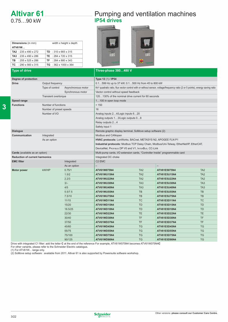
Other versions: please consult our Customer Care Centre.
Type of drive Three-phase 380…480 V
Degree of protection Type 12 (1) / IP54Drive Output frequency 0.1…599 Hz up to 37 kW; 0.1…500 Hz from 45 to 800 kW
Type of control Asynchronous motor Kn2 quadratic ratio, fl ux vector control with or without sensor, voltage/frequency ratio (2 or 5 points), energy saving ratioSynchronous motor Vector control without speed feedback
Transient overtorque 120…130% of the nominal drive current for 60 secondsSpeed range 1…100 in open loop modeFunctions Number of functions > 150
Number of preset speeds 16Number of I/O Analog inputs 2…4/Logic inputs 6…20
Analog outputs 1…3/Logic outputs 0…8Relay outputs 2…4Safety input 1
Dialogue Remote graphic display terminal, SoMove setup software (2)Communication Integrated Modbus and CANopen
As an option HVAC protocols: LonWorks, BACnet, METASYS N2, APOGEE FLN P1Industrial protocols: Modbus TCP Daisy Chain, Modbus/Uni-Telway, EtherNet/IP, EtherCAT, DeviceNet, PROFIBUS DP V0 and V1, INTERBUS, CC-Link
Cards (available as an option) Multi-pump cards, I/O extension cards, “Controller Inside” programmable cardReduction of current harmonics Integrated DC chokeEMC fi lter Integrated C2 EMC
As an option – –Motor power kW/HP 0.75/1 ATV61W075N4 TA2 ATV61E5075N4 TA2
1.5/2 ATV61WU15N4 TA2 ATV61E5U15N4 TA22.2/3 ATV61WU22N4 TA2 ATV61E5U22N4 TA23/– ATV61WU30N4 TA3 ATV61E5U30N4 TA34/5 ATV61WU40N4 TA3 ATV61E5U40N4 TA35.5/7.5 ATV61WU55N4 TB ATV61E5U55N4 TB7.5/10 ATV61WU75N4 TB ATV61E5U75N4 TB11/15 ATV61WD11N4 TC ATV61E5D11N4 TC15/20 ATV61WD15N4 TD ATV61E5D15N4 TD18.5/25 ATV61WD18N4 TD ATV61E5D18N4 TD22/30 ATV61WD22N4 TE ATV61E5D22N4 TE30/40 ATV61WD30N4 TF ATV61E5D30N4 TF37/50 ATV61WD37N4 TF ATV61E5D37N4 TF45/60 ATV61WD45N4 TG ATV61E5D45N4 TG55/75 ATV61WD55N4 TG ATV61E5D55N4 TG75/100 ATV61WD75N4 TG ATV61E5D75N4 TG90/125 ATV61WD90N4 TG ATV61E5D90N4 TG
Drive with integrated C1 fi lter: add the letter C at the end of the reference For example, ATV61W075N4 becomes ATV61W075N4CFor other variants, please refer to the Schneider Electric catalogue.(1) For ATV61W... range only.(2) SoMove setup software : available from 2011. Altivar 61 is also supported by Powersuite software workshop.
Dimensions (in mm) width x height x depthATV61W…TA2 : 235 x 490 x 272 TD : 310 x 665 x 315TA3 : 235 x 490 x 286 TE : 284 x 720 x 315TB : 255 x 525 x 286 TF : 284 x 880 x 343TC : 290 x 560 x 315 TG : 362 x 1000 x 364
Pumping and ventilation machinesIP54 drives
Altivar 610.75…90 kW
3/22
2
1
3
4
5
6
7
8
9
10
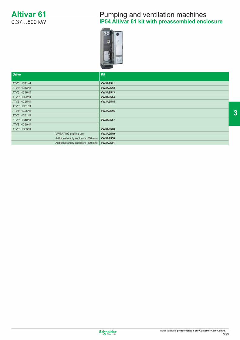
Other versions: please consult our Customer Care Centre.
Pumping and ventilation machinesIP54 Altivar 61 kit with preassembled enclosure
Altivar 610.37…800 kW
Drive Kit
ATV61HC11N4 VW3A9541ATV61HC13N4 VW3A9542ATV61HC16N4 VW3A9543ATV61HC22N4 VW3A9544ATV61HC25N4 VW3A9545ATV61HC31N4ATV61HC25N4 VW3A9546ATV61HC31N4ATV61HC40N4 VW3A9547ATV61HC50N4ATV61HC63N4 VW3A9548
VW3A7102 braking unit VW3A9549Additional empty enclosure (600 mm) VW3A9550Additional empty enclosure (800 mm) VW3A9551
3/23
2
1
3
4
5
6
7
8
9
10
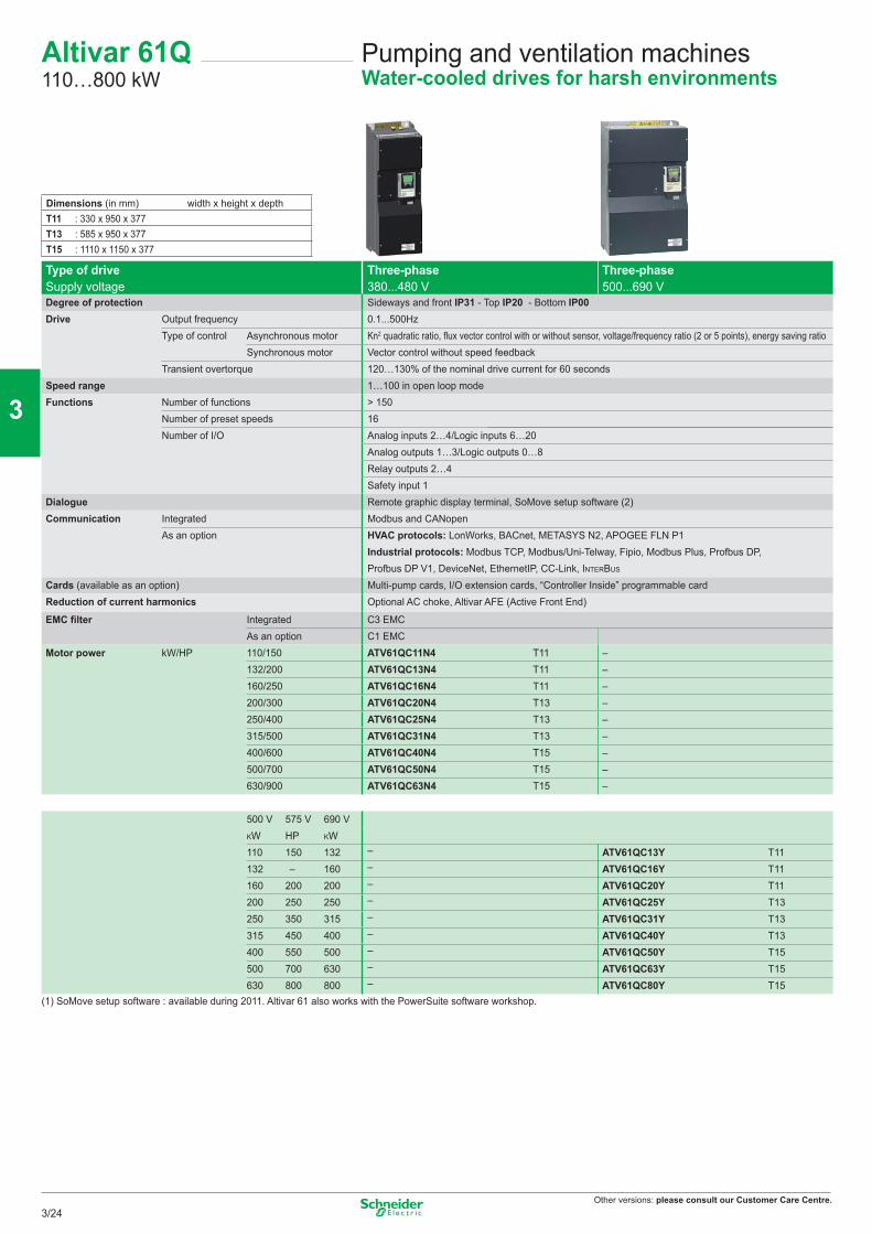
Other versions: please consult our Customer Care Centre.
Pumping and ventilation machinesWater-cooled drives for harsh environments
Altivar 61Q110…800 kW
Dimensions (in mm) width x height x depthT11 : 330 x 950 x 377T13 : 585 x 950 x 377T15 : 1110 x 1150 x 377
Type of driveSupply voltage
Three-phase380...480 V
Three-phase500...690 V
Degree of protection Sideways and front IP31 - Top IP20 - Bottom IP00Drive Output frequency 0.1...500Hz
Type of control Asynchronous motor Kn2 quadratic ratio, flux vector control with or without sensor, voltage/frequency ratio (2 or 5 points), energy saving ratioSynchronous motor Vector control without speed feedback
Transient overtorque 120…130% of the nominal drive current for 60 secondsSpeed range 1…100 in open loop modeFunctions Number of functions > 150
Number of preset speeds 16Number of I/O Analog inputs 2…4/Logic inputs 6…20
Analog outputs 1…3/Logic outputs 0…8Relay outputs 2…4Safety input 1
Dialogue Remote graphic display terminal, SoMove setup software (2)Communication Integrated Modbus and CANopen
As an option HVAC protocols: LonWorks, BACnet, METASYS N2, APOGEE FLN P1Industrial protocols: Modbus TCP, Modbus/Uni-Telway, Fipio, Modbus Plus, Profbus DP, Profbus DP V1, DeviceNet, EthernetIP, CC-Link, INTERBUS
Cards (available as an option) Multi-pump cards, I/O extension cards, “Controller Inside” programmable cardReduction of current harmonics Optional AC choke, Altivar AFE (Active Front End)
EMC filter Integrated C3 EMCAs an option C1 EMC
Motor power kW/HP 110/150 ATV61QC11N4 T11 –132/200 ATV61QC13N4 T11 –160/250 ATV61QC16N4 T11 –200/300 ATV61QC20N4 T13 –250/400 ATV61QC25N4 T13 –315/500 ATV61QC31N4 T13 –400/600 ATV61QC40N4 T15 –500/700 ATV61QC50N4 T15 –630/900 ATV61QC63N4 T15 –
500 V 575 V 690 VKW HP KW110 150 132 – ATV61QC13Y T11132 – 160 – ATV61QC16Y T11160 200 200 – ATV61QC20Y T11200 250 250 – ATV61QC25Y T13250 350 315 – ATV61QC31Y T13315 450 400 – ATV61QC40Y T13400 550 500 – ATV61QC50Y T15500 700 630 – ATV61QC63Y T15630 800 800 – ATV61QC80Y T15
(1) SoMove setup software : available during 2011. Altivar 61 also works with the PowerSuite software workshop.
3/24
2
1
3
4
5
6
7
8
9
10
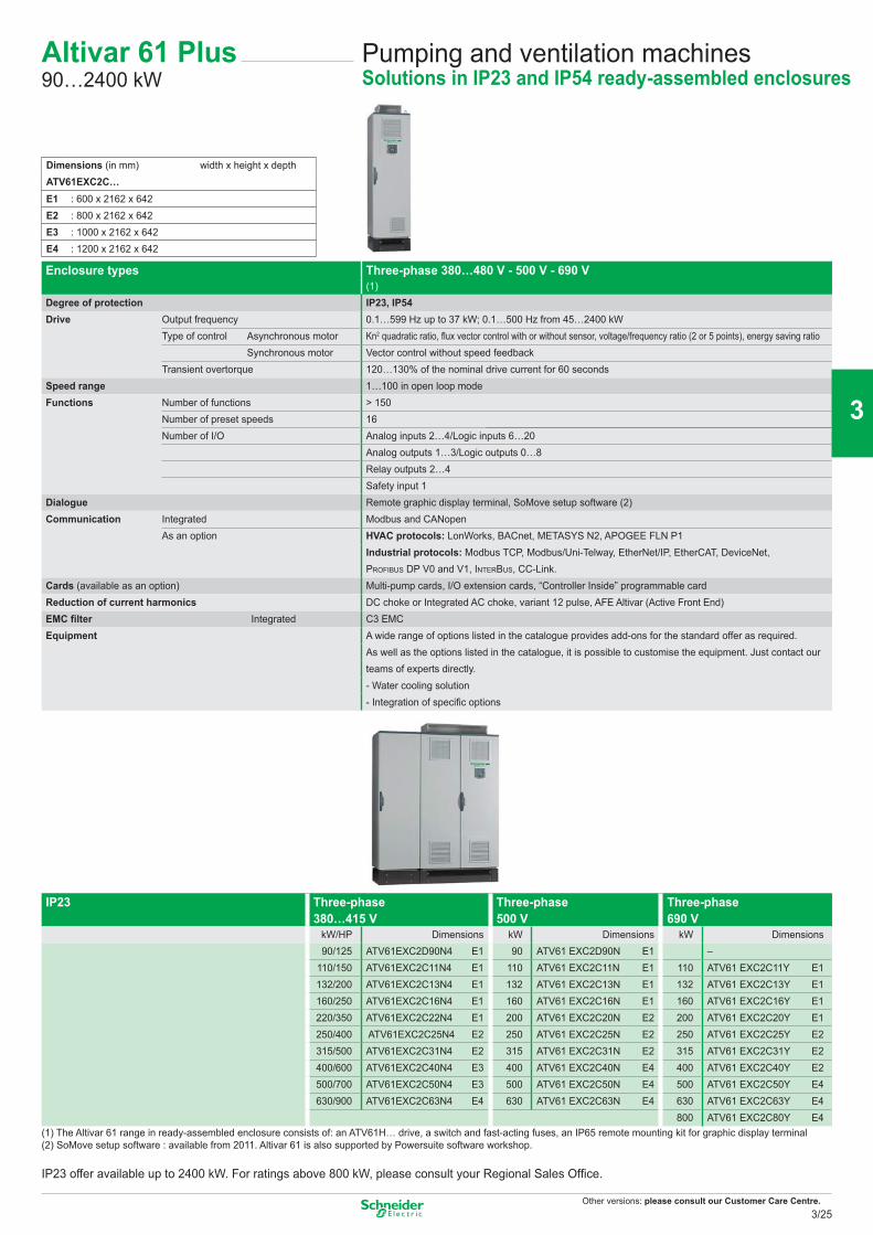
Other versions: please consult our Customer Care Centre.
Enclosure types Three-phase 380…480 V - 500 V - 690 V(1)
Degree of protection IP23, IP54Drive Output frequency 0.1…599 Hz up to 37 kW; 0.1…500 Hz from 45…2400 kW
Type of control Asynchronous motor Kn2 quadratic ratio, fl ux vector control with or without sensor, voltage/frequency ratio (2 or 5 points), energy saving ratioSynchronous motor Vector control without speed feedback
Transient overtorque 120…130% of the nominal drive current for 60 secondsSpeed range 1…100 in open loop modeFunctions Number of functions > 150
Number of preset speeds 16Number of I/O Analog inputs 2…4/Logic inputs 6…20
Analog outputs 1…3/Logic outputs 0…8Relay outputs 2…4Safety input 1
Dialogue Remote graphic display terminal, SoMove setup software (2)Communication Integrated Modbus and CANopen
As an option HVAC protocols: LonWorks, BACnet, METASYS N2, APOGEE FLN P1Industrial protocols: Modbus TCP, Modbus/Uni-Telway, EtherNet/IP, EtherCAT, DeviceNet, PROFIBUS DP V0 and V1, INTERBUS, CC-Link.
Cards (available as an option) Multi-pump cards, I/O extension cards, “Controller Inside” programmable cardReduction of current harmonics DC choke or Integrated AC choke, variant 12 pulse, AFE Altivar (Active Front End)EMC fi lter Integrated C3 EMCEquipment A wide range of options listed in the catalogue provides add-ons for the standard offer as required.
As well as the options listed in the catalogue, it is possible to customise the equipment. Just contact our teams of experts directly.- Water cooling solution- Integration of specifi c options
IP23 Three-phase 380…415 V
Three-phase 500 V
Three-phase690 V
kW/HP Dimensions kW Dimensions kW Dimensions90/125 ATV61EXC2D90N4 E1 90 ATV61 EXC2D90N E1 –
110/150 ATV61EXC2C11N4 E1 110 ATV61 EXC2C11N E1 110 ATV61 EXC2C11Y E1132/200 ATV61EXC2C13N4 E1 132 ATV61 EXC2C13N E1 132 ATV61 EXC2C13Y E1160/250 ATV61EXC2C16N4 E1 160 ATV61 EXC2C16N E1 160 ATV61 EXC2C16Y E1220/350 ATV61EXC2C22N4 E1 200 ATV61 EXC2C20N E2 200 ATV61 EXC2C20Y E1250/400 ATV61EXC2C25N4 E2 250 ATV61 EXC2C25N E2 250 ATV61 EXC2C25Y E2315/500 ATV61EXC2C31N4 E2 315 ATV61 EXC2C31N E2 315 ATV61 EXC2C31Y E2400/600 ATV61EXC2C40N4 E3 400 ATV61 EXC2C40N E4 400 ATV61 EXC2C40Y E2500/700 ATV61EXC2C50N4 E3 500 ATV61 EXC2C50N E4 500 ATV61 EXC2C50Y E4630/900 ATV61EXC2C63N4 E4 630 ATV61 EXC2C63N E4 630 ATV61 EXC2C63Y E4
800 ATV61 EXC2C80Y E4(1) The Altivar 61 range in ready-assembled enclosure consists of: an ATV61H… drive, a switch and fast-acting fuses, an IP65 remote mounting kit for graphic display terminal(2) SoMove setup software : available from 2011. Altivar 61 is also supported by Powersuite software workshop.
IP23 offer available up to 2400 kW. For ratings above 800 kW, please consult your Regional Sales Offi ce.
Dimensions (in mm) width x height x depthATV61EXC2C…E1 : 600 x 2162 x 642E2 : 800 x 2162 x 642E3 : 1000 x 2162 x 642E4 : 1200 x 2162 x 642
Pumping and ventilation machinesSolutions in IP23 and IP54 ready-assembled enclosures
Altivar 61 Plus90…2400 kW
3/25
2
1
3
4
5
6
7
8
9
10
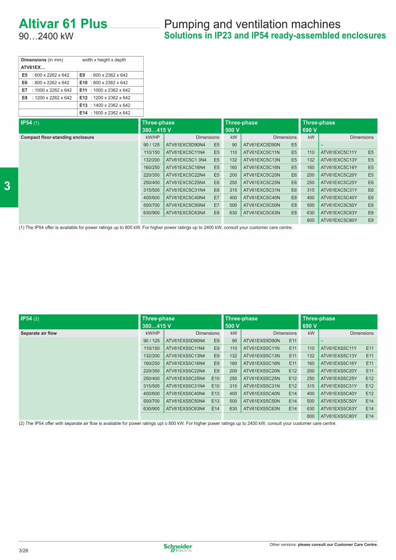
Other versions: please consult our Customer Care Centre.
IP54 (1) Three-phase 380…415 V
Three-phase 500 V
Three-phase 690 V
Compact floor-standing enclosure kW/HP Dimensions kW Dimensions kW Dimensions90 / 125 ATV61EXC5D90N4 E5 90 ATV61EXC5D90N E5 –110/150 ATV61EXC5C11N4 E5 110 ATV61EXC5C11N E5 110 ATV61EXC5C11Y E5132/200 ATV61EXC5C1 3N4 E5 132 ATV61EXC5C13N E5 132 ATV61EXC5C13Y E5160/250 ATV61EXC5C16N4 E5 160 ATV61EXC5C16N E5 160 ATV61EXC5C16Y E5220/350 ATV61EXC5C22N4 E5 200 ATV61EXC5C20N E6 200 ATV61EXC5C20Y E5250/400 ATV61EXC5C25N4 E6 250 ATV61EXC5C25N E6 250 ATV61EXC5C25Y E6315/500 ATV61EXC5C31N4 E6 315 ATV61EXC5C31N E6 315 ATV61EXC5C31Y E6400/600 ATV61EXC5C40N4 E7 400 ATV61EXC5C40N E8 400 ATV61EXC5C40Y E6500/700 ATV61EXC5C50N4 E7 500 ATV61EXC5C50N E8 500 ATV61EXC5C50Y E8630/900 ATV61EXC5C63N4 E8 630 ATV61EXC5C63N E8 630 ATV61EXC5C63Y E8
800 ATV61EXC5C80Y E8(1) The IP54 offer is available for power ratings up to 800 kW. For higher power ratings up to 2400 kW, consult your customer care centre.
IP54 (2) Three-phase 380…415 V
Three-phase 500 V
Three-phase 690 V
Separate air flow kW/HP Dimensions kW Dimensions kW Dimensions90 / 125 ATV61EXS5D90N4 E9 90 ATV61EXS5D90N E11 –110/150 ATV61EXS5C11N4 E9 110 ATV61EXS5C11N E11 110 ATV61EXS5C11Y E11132/200 ATV61EXS5C13N4 E9 132 ATV61EXS5C13N E11 132 ATV61EXS5C13Y E11160/250 ATV61EXS5C16N4 E9 160 ATV61EXS5C16N E11 160 ATV61EXS5C16Y E11220/350 ATV61EXS5C22N4 E9 200 ATV61EXS5C20N E12 200 ATV61EXS5C20Y E11250/400 ATV61EXS5C25N4 E10 250 ATV61EXS5C25N E12 250 ATV61EXS5C25Y E12315/500 ATV61EXS5C31N4 E10 315 ATV61EXS5C31N E12 315 ATV61EXS5C31Y E12400/600 ATV61EXS5C40N4 E13 400 ATV61EXS5C40N E14 400 ATV61EXS5C40Y E12500/700 ATV61EXS5C50N4 E13 500 ATV61EXS5C50N E14 500 ATV61EXS5C50Y E14630/900 ATV61EXS5C63N4 E14 630 ATV61EXS5C63N E14 630 ATV61EXS5C63Y E14
800 ATV61EXS5C80Y E14(2) The IP54 offer with separate air flow is available for power ratings upt o 800 kW. For higher power ratings up to 2400 kW, consult your customer care centre.
Dimensions (in mm) width x height x depthATV61EX…E5 : 600 x 2262 x 642 E9 : 600 x 2362 x 642E6 : 800 x 2262 x 642 E10 : 800 x 2362 x 642E7 : 1000 x 2262 x 642 E11 : 1000 x 2362 x 642E8 : 1200 x 2262 x 642 E12 : 1200 x 2362 x 642
E13 : 1400 x 2362 x 642E14 : 1600 x 2362 x 642
Pumping and ventilation machinesSolutions in IP23 and IP54 ready-assembled enclosures
Altivar 61 Plus90…2400 kW
3/26
2
1
3
4
5
6
7
8
9
10
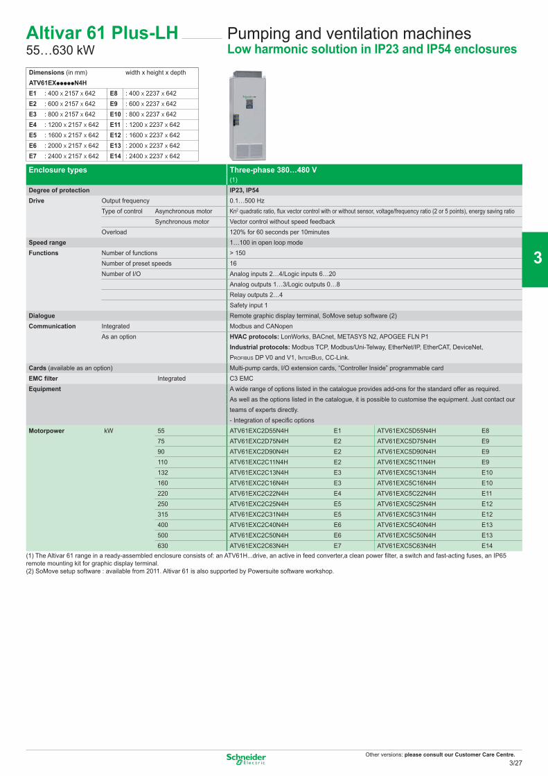
Other versions: please consult our Customer Care Centre.
Pumping and ventilation machinesLow harmonic solution in IP23 and IP54 enclosures
Altivar 61 Plus-LH55…630 kW
Enclosure types Three-phase 380…480 V(1)
Degree of protection IP23, IP54Drive Output frequency 0.1…500 Hz
Type of control Asynchronous motor Kn2 quadratic ratio, fl ux vector control with or without sensor, voltage/frequency ratio (2 or 5 points), energy saving ratioSynchronous motor Vector control without speed feedback
Overload 120% for 60 seconds per 10minutesSpeed range 1…100 in open loop modeFunctions Number of functions > 150
Number of preset speeds 16Number of I/O Analog inputs 2…4/Logic inputs 6…20
Analog outputs 1…3/Logic outputs 0…8Relay outputs 2…4Safety input 1
Dialogue Remote graphic display terminal, SoMove setup software (2)Communication Integrated Modbus and CANopen
As an option HVAC protocols: LonWorks, BACnet, METASYS N2, APOGEE FLN P1Industrial protocols: Modbus TCP, Modbus/Uni-Telway, EtherNet/IP, EtherCAT, DeviceNet, PROFIBUS DP V0 and V1, INTERBUS, CC-Link.
Cards (available as an option) Multi-pump cards, I/O extension cards, “Controller Inside” programmable cardEMC fi lter Integrated C3 EMCEquipment A wide range of options listed in the catalogue provides add-ons for the standard offer as required.
As well as the options listed in the catalogue, it is possible to customise the equipment. Just contact our teams of experts directly.- Integration of specifi c options
Motorpower kW 55 ATV61EXC2D55N4H E1 ATV61EXC5D55N4H E875 ATV61EXC2D75N4H E2 ATV61EXC5D75N4H E990 ATV61EXC2D90N4H E2 ATV61EXC5D90N4H E9110 ATV61EXC2C11N4H E2 ATV61EXC5C11N4H E9132 ATV61EXC2C13N4H E3 ATV61EXC5C13N4H E10160 ATV61EXC2C16N4H E3 ATV61EXC5C16N4H E10220 ATV61EXC2C22N4H E4 ATV61EXC5C22N4H E11250 ATV61EXC2C25N4H E5 ATV61EXC5C25N4H E12315 ATV61EXC2C31N4H E5 ATV61EXC5C31N4H E12400 ATV61EXC2C40N4H E6 ATV61EXC5C40N4H E13500 ATV61EXC2C50N4H E6 ATV61EXC5C50N4H E13630 ATV61EXC2C63N4H E7 ATV61EXC5C63N4H E14
(1) The Altivar 61 range in a ready-assembled enclosure consists of: an ATV61H...drive, an active in feed converter,a clean power fi lter, a switch and fast-acting fuses, an IP65 remote mounting kit for graphic display terminal. (2) SoMove setup software : available from 2011. Altivar 61 is also supported by Powersuite software workshop.
Dimensions (in mm) width x height x depthATV61EXpppppN4H E1 : 400 X 2157 X 642 E8 : 400 X 2237 X 642E2 : 600 X 2157 X 642 E9 : 600 X 2237 X 642E3 : 800 X 2157 X 642 E10 : 800 X 2237 X 642E4 : 1200 X 2157 X 642 E11 : 1200 X 2237 X 642E5 : 1600 X 2157 X 642 E12 : 1600 X 2237 X 642E6 : 2000 X 2157 X 642 E13 : 2000 X 2237 X 642E7 : 2400 X 2157 X 642 E14 : 2400 X 2237 X 642
3/27
2
1
3
4
5
6
7
8
9
10
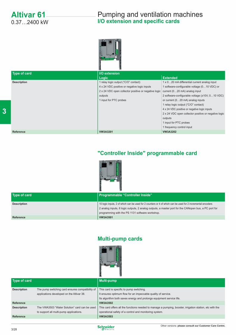
Other versions: please consult our Customer Care Centre.
Altivar 610.37…2400 kW
Pumping and ventilation machinesI/O extension and specific cards
Type of card I/O extensionLogic Extended
Description 1 relay logic output (“C/O” contact)4 x 24 VDC positive or negative logic inputs2 x 24 VDC open collector positive or negative logic outputs1 input for PTC probes
1 x 0…20 mA differential current analog input1 software-configurable voltage (0…10 VDC) or current (0…20 mA) analog input2 software-configurable voltage (±10V, 0…10 VDC) or current (0…20 mA) analog inputs1 relay logic output (“C/O” contact)4 x 24 VDC positive or negative logic inputs2 x 24 VDC open collector positive or negative logic outputs1 input for PTC probes1 frequency control input
Reference VW3A3201 VW3A3202
"Controller Inside" programmable card
Type of card Programmable “Controller Inside”
Description 10 logic inputs, 2 of which can be used for 2 counters or 4 of which can be used for 2 incremental encoders2 analog inputs, 6 logic outputs, 2 analog outputs, a master port for the CANopen bus, a PC port for programming with the PS 1131 software workshop.
Reference VW3A3501
Multi-pump cards
Type of card Multi-pump
Description The pump switching card ensures compatibility of applications developed on the Altivar 38.
This card is specific to pump switching.It ensures optimum flow for an impeccable quality of service.Its algorithm both saves energy and prolongs equipment service life.
Reference VW3A3502Description The VWA3503 “Water Solution” card can be used
to support all multi-pump applications.This card offers all the functions needed to manage a pumping, booster, irrigation station, etc with the operational safety of a control and monitoring system.
Reference VW3A3503
3/28
2
1
3
4
5
6
7
8
9
10
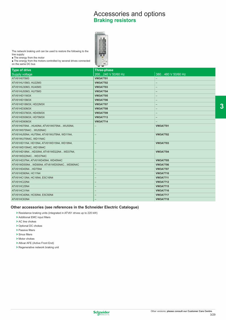
Other versions: please consult our Customer Care Centre.
Accessories and optionsBraking resistors
The network braking unit can be used to restore the following to the line supply:p The energy from the motor p The energy from the motors controlled by several drives connected on the same DC bus
Type of drive Three-phaseSupply voltage 200…240 V 50/60 Hz 380…480 V 50/60 HzATV61H075M3 VW3A7701 –ATV61HU15M3, HU22M3 VW3A7702 –ATV61HU30M3, HU40M3 VW3A7703 –ATV61HU55M3, HU75M3 VW3A7704 –ATV61HD11M3X VW3A7705 –ATV61HD15M3X VW3A7706 –ATV61HD18M3X, HD22M3X VW3A7707 –ATV61HD30M3X VW3A7708 –ATV61HD37M3X, HD45M3X VW3A7709 –ATV61HD55M3X, HD75M3X VW3A7713 –ATV61HD90M3X VW3A7714 –ATV61H075N4…HU40N4, ATV61W075N4…WU55N4, – VW3A7701ATV61W075N4C…WU55N4CATV61HU55N4, HU75N4, ATV61WU75N4, WD11N4, – VW3A7702ATV61WU75N4C, WD11N4CATV61HD11N4, HD15N4, ATV61WD15N4, WD18N4, – VW3A7703ATV61WD15N4C, WD18N4CATV61HD18N4…HD30N4, ATV61WD22N4…WD37N4, – VW3A7704ATV61WD22N4C…WD37N4CATV61HD37N4, ATV61WD45N4, WD45N4C – VW3A7705ATV61WD55N4…WD90N4, ATV61WD55N4C…WD90N4C – VW3A7706ATV61HD45N4…HD75N4 – VW3A7707ATV61HD90N4, HC11N4 – VW3A7710ATV61HC13N4, HC16N4, E5C16N4 – VW3A7711ATV61HC22N4 – VW3A7712ATV61HC25N4 – VW3A7715ATV61HC31N4 – VW3A7716ATV61HC40N4, HC50N4, E5C50N4 – VW3A7717ATV61HC63N4 – VW3A7718
Other accessories (see references in the Schneider Electric Catalogue)> Resistance braking units (integrated in ATV61 drives up to 220 kW)> Additional EMC input filters> AC line chokes> Optional DC chokes> Passive filters> Sinus filters> Motor chokes> Altivar AFE (Active Front End)> Regenerative network braking unit
3/29
2
1
3
4
5
6
7
8
9
10
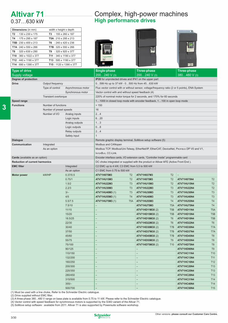
Other versions: please consult our Customer Care Centre.
Complex, high-power machinesHigh performance drives
Type of drive Single-phase Three-phase Three-phaseSupply voltage 200…240 V (3) 200…240 V (3) 380…480 V (3)Degree of protection IP20 for unprotected drives and IP41 on the upper partDrive Output frequency 0…599 Hz up to 37 kW - 0…500 Hz from 45…630 kW
Type of control Asynchronous motor Flux vector control with or without sensor, voltage/frequency ratio (2 or 5 points), ENA SystemSynchronous motor Vector control with and without speed feedback (4)
Transient overtorque 220% of nominal motor torque for 2 seconds, and 170% for 60 secondsSpeed range 1…1000 in closed loop mode with encoder feedback, 1…100 in open loop modeFunctions Number of functions > 150
Number of preset speeds 16Number of I/O Analog inputs 2…4
Logic inputs 6…20Analog outputs 1…3Logic outputs 0…8Relay outputs 2…4Safety input 1
Dialogue Remote graphic display terminal, SoMove setup software (5)Communication Integrated Modbus and CANopen
As an option Modbus TCP, Modbus/Uni-Telway, EtherNet/IP, EtherCAT, DeviceNet, PROFIBUS DP V0 and V1,INTERBUS, CC-Link.
Cards (available as an option) Encoder interface cards, I/O extension cards, “Controller Inside” programmable cardReduction of current harmonics DC choke integrated or supplied with the product or Altivar AFE (Active Front End ).EMC fi lter Integrated C2 EMC up to 4 kW, C3 EMC from 5,5 to 500 kW
As an option C1 EMC from 0.75 to 500 kWMotor power kW/HP 0.37/0.5 ATV71H075M3 T2 ATV71H037M3 T2 –
0.75/1 ATV71HU15M3 T2 ATV71H075M3 T2 ATV71H075N4 T21.5/2 ATV71HU22M3 T3 ATV71HU15M3 T2 ATV71HU15N4 T22.2/3 ATV71HU30M3 T3 ATV71HU22M3 T3 ATV71HU22N4 T23/– ATV71HU40M3 (1) T3 ATV71HU30M3 T3 ATV71HU30N4 T34/5 ATV71HU55M3 (1) T4 ATV71HU40M3 T3 ATV71HU40N4 T35.5/7.5 ATV71HU75M3 (1) T5A ATV71HU55M3 T4 ATV71HU55N4 T47.5/10 – ATV71HU75M3 T5A ATV71HU75N4 T411/15 – ATV71HD11M3X (2) T5B ATV71HD11N4 T5A15/20 – ATV71HD15M3X (2) T5B ATV71HD15N4 T5B18.5/25 – ATV71HD18M3X (2) T6 ATV71HD18N4 T5B22/30 – ATV71HD22M3X (2) T6 ATV71HD22N4 T630/40 – ATV71HD30M3X (2) T7B ATV71HD30N4 T7A37/50 – ATV71HD37M3X (2) T7B ATV71HD37N4 T7A45/60 – ATV71HD45M3X (2) T7B ATV71HD45N4 T855/75 – ATV71HD55M3X (2) T9 ATV71HD55N4 T875/100 – ATV71HD75M3X (2) T10 ATV71HD75N4 T890/125 – – ATV71HD90N4 T9110/150 – – ATV71HC11N4 T10132/200 – – ATV71HC13N4 T11160/250 – – ATV71HC16N4 T12200/300 – – ATV71HC20N4 T13220/350 – – ATV71HC25N4 T13280/450 – – ATV71HC28N4 T13315/500 – – ATV71HC31N4 T14355/– – – ATV71HC40N4 T14500/700 – – ATV71HC50N4 T15
(1) Must be used with a line choke, Refer to the Schneider Electric catalogue.(2) Drive supplied without EMC fi lter.(3) A three-phase 380...480 V range on base plate is available from 0.75 to 11 kW. Please refer to the Schneider Electric catalogue.(4) Vector control with speed feedback for synchronous motors is supported by the S383 variant of the Altivar 71.(5) SoMove setup software : available from 2011. Altivar 71 is also supported by Powersuite software workshop.
Dimensions (in mm) width x height x depthT2 : 130 x 230 x 175 T3 : 155 x 260 x 187T4 : 175 x 295 x 187 T5A : 210 x 295 x 213T5B : 230 x 400 x 213 T6 : 240 x 420 x 236T7A : 240 x 550 x 266 T7B : 320 x 550 x 266T8 : 320 x 630 x 290 T9 : 320 x 920 x 377T10 : 360 x 1022 x 377 T11 : 340 x 1190 x 377T12 : 440 x 1190 x 377 T13 : 595 x 1190 x 377T14 : 890 x 1390 x 377 T15 : 1120 x 1390 x 377
Altivar 710.37…630 kW
3/30
2
1
3
4
5
6
7
8
9
10
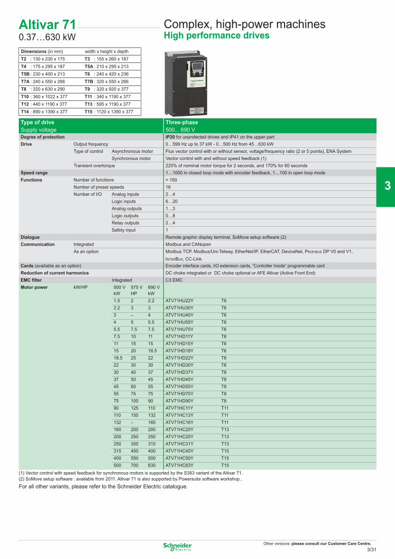
Other versions: please consult our Customer Care Centre.
Complex, high-power machinesHigh performance drives
Type of drive Three-phaseSupply voltage 500... 690 VDegree of protection IP20 for unprotected drives and IP41 on the upper partDrive Output frequency 0…599 Hz up to 37 kW - 0…500 Hz from 45…630 kW
Type of control Asynchronous motor Flux vector control with or without sensor, voltage/frequency ratio (2 or 5 points), ENA SystemSynchronous motor Vector control with and without speed feedback (1)
Transient overtorque 220% of nominal motor torque for 2 seconds, and 170% for 60 secondsSpeed range 1…1000 in closed loop mode with encoder feedback, 1…100 in open loop modeFunctions Number of functions > 150
Number of preset speeds 16Number of I/O Analog inputs 2…4
Logic inputs 6…20Analog outputs 1…3Logic outputs 0…8Relay outputs 2…4Safety input 1
Dialogue Remote graphic display terminal, SoMove setup software (2)Communication Integrated Modbus and CANopen
As an option Modbus TCP, Modbus/Uni-Telway, EtherNet/IP, EtherCAT, DeviceNet, PROFIBUS DP V0 and V1, INTERBUS, CC-Link.
Cards (available as an option) Encoder interface cards, I/O extension cards, “Controller Inside” programmable cardReduction of current harmonics DC choke integrated or DC choke optional or AFE Altivar (Active Front End)EMC fi lter Integrated C3 EMCMotor power kW/HP 500 V 575 V 690 V
kW HP kW 1.5 2 2.2 ATV71HU22Y T62.2 3 3 ATV71HU30Y T63 – 4 ATV71HU40Y T64 5 5.5 ATV71HU55Y T65.5 7.5 7.5 ATV71HU75Y T67.5 10 11 ATV71HD11Y T611 15 15 ATV71HD15Y T615 20 18.5 ATV71HD18Y T618.5 25 22 ATV71HD22Y T622 30 30 ATV71HD30Y T630 40 37 ATV71HD37Y T837 50 45 ATV71HD45Y T845 60 55 ATV71HD55Y T855 75 75 ATV71HD75Y T875 100 90 ATV71HD90Y T890 125 110 ATV71HC11Y T11110 150 132 ATV71HC13Y T11132 – 160 ATV71HC16Y T11160 200 200 ATV71HC20Y T13200 250 250 ATV71HC25Y T13250 350 315 ATV71HC31Y T13315 450 400 ATV71HC40Y T15400 550 500 ATV71HC50Y T15500 700 630 ATV71HC63Y T15
(1) Vector control with speed feedback for synchronous motors is supported by the S383 variant of the Altivar 71.(2) SoMove setup software : available from 2011. Altivar 71 is also supported by Powersuite software workshop..
For all other variants, please refer to the Schneider Electric catalogue.
Dimensions (in mm) width x height x depthT2 : 130 x 230 x 175 T3 : 155 x 260 x 187T4 : 175 x 295 x 187 T5A : 210 x 295 x 213T5B : 230 x 400 x 213 T6 : 240 x 420 x 236T7A : 240 x 550 x 266 T7B : 320 x 550 x 266T8 : 320 x 630 x 290 T9 : 320 x 920 x 377T10 : 360 x 1022 x 377 T11 : 340 x 1190 x 377T12 : 440 x 1190 x 377 T13 : 595 x 1190 x 377T14 : 890 x 1390 x 377 T15 : 1120 x 1390 x 377
Altivar 710.37…630 kW
3/31
2
1
3
4
5
6
7
8
9
10
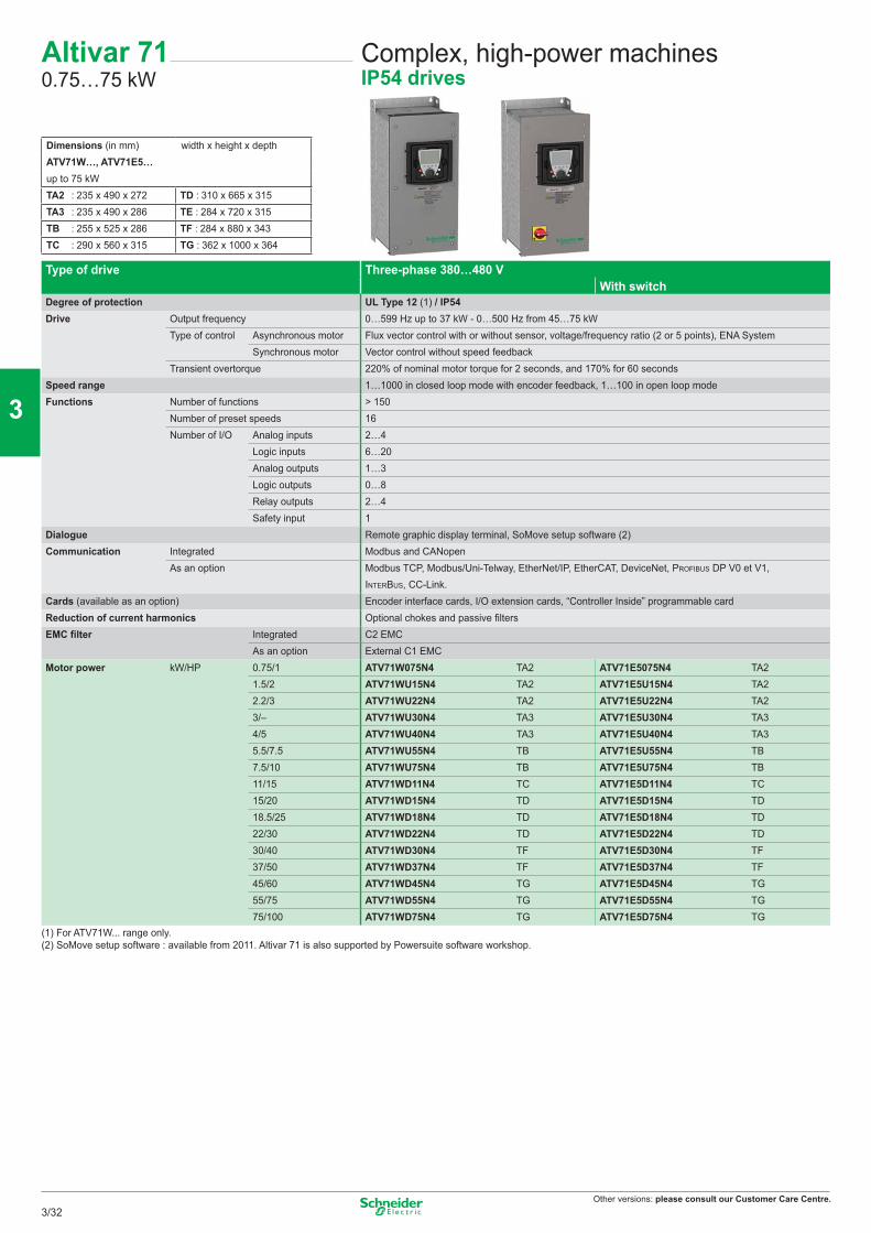
Other versions: please consult our Customer Care Centre.
Type of drive Three-phase 380…480 VWith switch
Degree of protection UL Type 12 (1) / IP54Drive Output frequency 0…599 Hz up to 37 kW - 0…500 Hz from 45…75 kW
Type of control Asynchronous motor Flux vector control with or without sensor, voltage/frequency ratio (2 or 5 points), ENA SystemSynchronous motor Vector control without speed feedback
Transient overtorque 220% of nominal motor torque for 2 seconds, and 170% for 60 secondsSpeed range 1…1000 in closed loop mode with encoder feedback, 1…100 in open loop modeFunctions Number of functions > 150
Number of preset speeds 16Number of I/O Analog inputs 2…4
Logic inputs 6…20Analog outputs 1…3Logic outputs 0…8Relay outputs 2…4Safety input 1
Dialogue Remote graphic display terminal, SoMove setup software (2)Communication Integrated Modbus and CANopen
As an option Modbus TCP, Modbus/Uni-Telway, EtherNet/IP, EtherCAT, DeviceNet, PROFIBUS DP V0 et V1, INTERBUS, CC-Link.
Cards (available as an option) Encoder interface cards, I/O extension cards, “Controller Inside” programmable cardReduction of current harmonics Optional chokes and passive fi ltersEMC fi lter Integrated C2 EMC
As an option External C1 EMCMotor power kW/HP 0.75/1 ATV71W075N4 TA2 ATV71E5075N4 TA2
1.5/2 ATV71WU15N4 TA2 ATV71E5U15N4 TA22.2/3 ATV71WU22N4 TA2 ATV71E5U22N4 TA23/– ATV71WU30N4 TA3 ATV71E5U30N4 TA34/5 ATV71WU40N4 TA3 ATV71E5U40N4 TA35.5/7.5 ATV71WU55N4 TB ATV71E5U55N4 TB7.5/10 ATV71WU75N4 TB ATV71E5U75N4 TB11/15 ATV71WD11N4 TC ATV71E5D11N4 TC15/20 ATV71WD15N4 TD ATV71E5D15N4 TD18.5/25 ATV71WD18N4 TD ATV71E5D18N4 TD22/30 ATV71WD22N4 TD ATV71E5D22N4 TD30/40 ATV71WD30N4 TF ATV71E5D30N4 TF37/50 ATV71WD37N4 TF ATV71E5D37N4 TF45/60 ATV71WD45N4 TG ATV71E5D45N4 TG55/75 ATV71WD55N4 TG ATV71E5D55N4 TG75/100 ATV71WD75N4 TG ATV71E5D75N4 TG
(1) For ATV71W... range only.(2) SoMove setup software : available from 2011. Altivar 71 is also supported by Powersuite software workshop.
Dimensions (in mm) width x height x depthATV71W…, ATV71E5…up to 75 kWTA2 : 235 x 490 x 272 TD : 310 x 665 x 315TA3 : 235 x 490 x 286 TE : 284 x 720 x 315TB : 255 x 525 x 286 TF : 284 x 880 x 343TC : 290 x 560 x 315 TG : 362 x 1000 x 364
Complex, high-power machinesIP54 drives
Altivar 710.75…75 kW
3/32
2
1
3
4
5
6
7
8
9
10
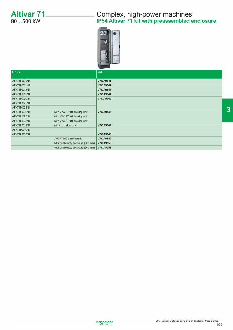
Other versions: please consult our Customer Care Centre.
Complex, high-power machinesIP54 Altivar 71 kit with preassembled enclosure
Altivar 7190…500 kW
Drive Kit
ATV71HD90N4 VW3A9541ATV71HC11N4 VW3A9542ATV71HC13N4 VW3A9543ATV71HC16N4 VW3A9544ATV71HC20N4 VW3A9545ATV71HC25N4ATV71HC28N4ATV71HC20N4 With VW3A7101 braking unit VW3A9546ATV71HC25N4 With VW3A7101 braking unitATV71HC28N4 With VW3A7101 braking unitATV71HC31N4 Without braking unit VW3A9547ATV71HC40N4ATV71HC50N4 VW3A9548
VW3A7102 braking unit VW3A9549Additional empty enclosure (600 mm) VW3A9550Additional empty enclosure (800 mm) VW3A9551
3/33
2
1
3
4
5
6
7
8
9
10
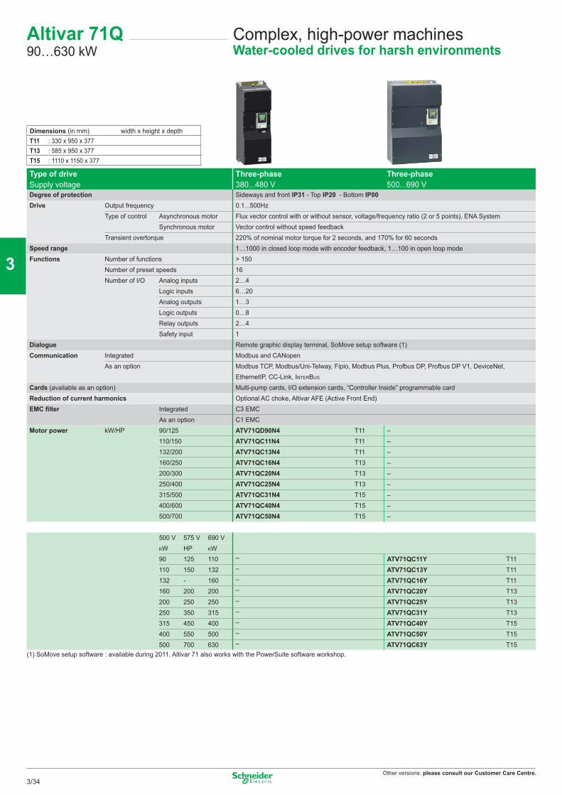
Other versions: please consult our Customer Care Centre.
Complex, high-power machinesWater-cooled drives for harsh environments
Altivar 71Q90…630 kW
Dimensions (in mm) width x height x depthT11 : 330 x 950 x 377T13 : 585 x 950 x 377T15 : 1110 x 1150 x 377
Type of drive Three-phase 380...480 V
Three-phase500...690 VSupply voltage
Degree of protection Sideways and front IP31 - Top IP20 - Bottom IP00Drive Output frequency 0.1...500Hz
Type of control Asynchronous motor Flux vector control with or without sensor, voltage/frequency ratio (2 or 5 points), ENA SystemSynchronous motor Vector control without speed feedback
Transient overtorque 220% of nominal motor torque for 2 seconds, and 170% for 60 secondsSpeed range 1…1000 in closed loop mode with encoder feedback, 1…100 in open loop modeFunctions Number of functions > 150
Number of preset speeds 16Number of I/O Analog inputs 2…4
Logic inputs 6…20Analog outputs 1…3Logic outputs 0…8Relay outputs 2…4Safety input 1
Dialogue Remote graphic display terminal, SoMove setup software (1)Communication Integrated Modbus and CANopen
As an option Modbus TCP, Modbus/Uni-Telway, Fipio, Modbus Plus, Profbus DP, Profbus DP V1, DeviceNet, EthernetIP, CC-Link, INTERBUS
Cards (available as an option) Multi-pump cards, I/O extension cards, “Controller Inside” programmable cardReduction of current harmonics Optional AC choke, Altivar AFE (Active Front End)EMC filter Integrated C3 EMC
As an option C1 EMCMotor power kW/HP 90/125 ATV71QD90N4 T11 –
110/150 ATV71QC11N4 T11 –132/200 ATV71QC13N4 T11 –160/250 ATV71QC16N4 T13 –200/300 ATV71QC20N4 T13 –250/400 ATV71QC25N4 T13 –315/500 ATV71QC31N4 T15 –400/600 ATV71QC40N4 T15 –500/700 ATV71QC50N4 T15 –
500 V 575 V 690 VKW HP KW90 125 110 – ATV71QC11Y T11110 150 132 – ATV71QC13Y T11132 - 160 – ATV71QC16Y T11160 200 200 – ATV71QC20Y T13200 250 250 – ATV71QC25Y T13250 350 315 – ATV71QC31Y T13315 450 400 – ATV71QC40Y T15400 550 500 – ATV71QC50Y T15500 700 630 – ATV71QC63Y T15
(1) SoMove setup software : available during 2011. Altivar 71 also works with the PowerSuite software workshop.
3/34
2
1
3
4
5
6
7
8
9
10
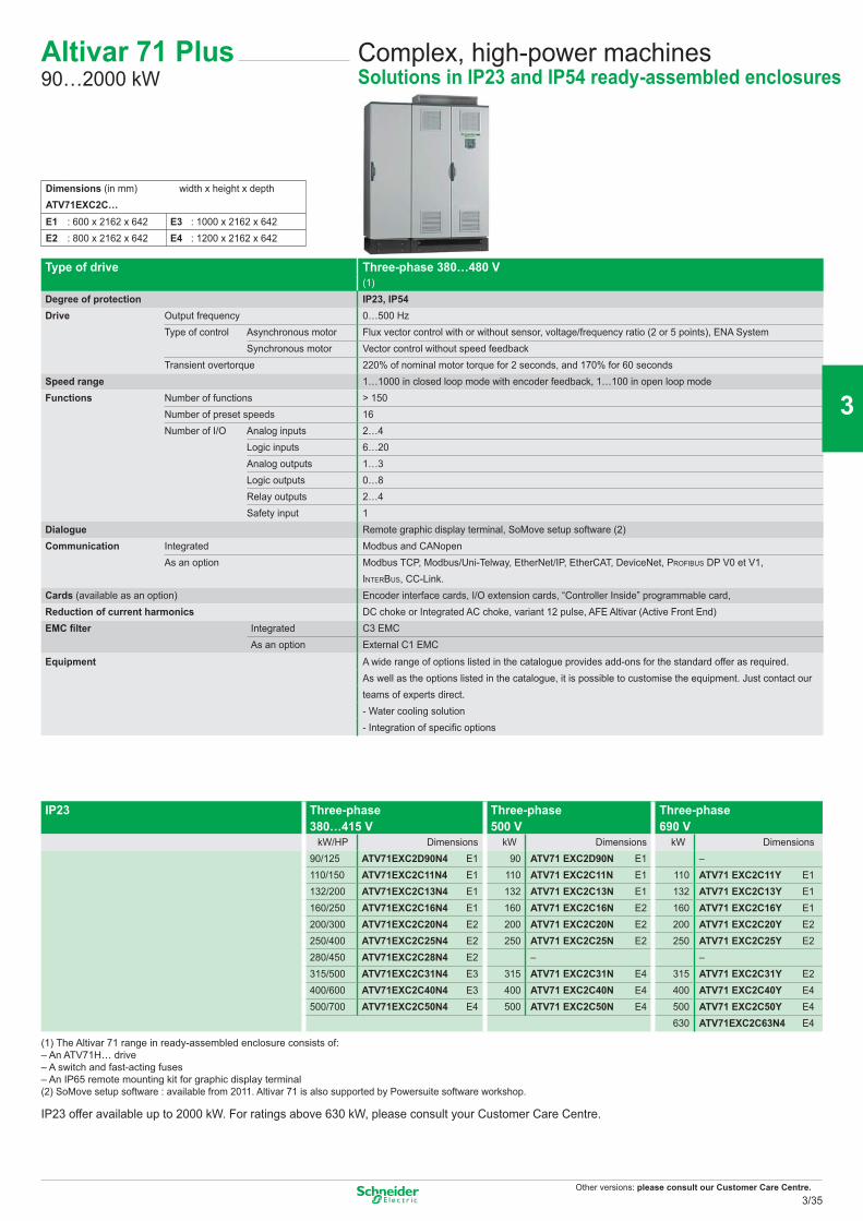
Other versions: please consult our Customer Care Centre.
Type of drive Three-phase 380…480 V (1)
Degree of protection IP23, IP54Drive Output frequency 0…500 Hz
Type of control Asynchronous motor Flux vector control with or without sensor, voltage/frequency ratio (2 or 5 points), ENA SystemSynchronous motor Vector control without speed feedback
Transient overtorque 220% of nominal motor torque for 2 seconds, and 170% for 60 secondsSpeed range 1…1000 in closed loop mode with encoder feedback, 1…100 in open loop modeFunctions Number of functions > 150
Number of preset speeds 16Number of I/O Analog inputs 2…4
Logic inputs 6…20Analog outputs 1…3Logic outputs 0…8Relay outputs 2…4Safety input 1
Dialogue Remote graphic display terminal, SoMove setup software (2)Communication Integrated Modbus and CANopen
As an option Modbus TCP, Modbus/Uni-Telway, EtherNet/IP, EtherCAT, DeviceNet, PROFIBUS DP V0 et V1, INTERBUS, CC-Link.
Cards (available as an option) Encoder interface cards, I/O extension cards, “Controller Inside” programmable card,Reduction of current harmonics DC choke or Integrated AC choke, variant 12 pulse, AFE Altivar (Active Front End)EMC filter Integrated C3 EMC
As an option External C1 EMC
Equipment A wide range of options listed in the catalogue provides add-ons for the standard offer as required.As well as the options listed in the catalogue, it is possible to customise the equipment. Just contact our teams of experts direct.- Water cooling solution- Integration of specific options
IP23 Three-phase 380…415 V
Three-phase 500 V
Three-phase 690 V
kW/HP Dimensions kW Dimensions kW Dimensions90/125 ATV71EXC2D90N4 E1 90 ATV71 EXC2D90N E1 –110/150 ATV71EXC2C11N4 E1 110 ATV71 EXC2C11N E1 110 ATV71 EXC2C11Y E1132/200 ATV71EXC2C13N4 E1 132 ATV71 EXC2C13N E1 132 ATV71 EXC2C13Y E1160/250 ATV71EXC2C16N4 E1 160 ATV71 EXC2C16N E2 160 ATV71 EXC2C16Y E1200/300 ATV71EXC2C20N4 E2 200 ATV71 EXC2C20N E2 200 ATV71 EXC2C20Y E2250/400 ATV71EXC2C25N4 E2 250 ATV71 EXC2C25N E2 250 ATV71 EXC2C25Y E2280/450 ATV71EXC2C28N4 E2 – –315/500 ATV71EXC2C31N4 E3 315 ATV71 EXC2C31N E4 315 ATV71 EXC2C31Y E2400/600 ATV71EXC2C40N4 E3 400 ATV71 EXC2C40N E4 400 ATV71 EXC2C40Y E4500/700 ATV71EXC2C50N4 E4 500 ATV71 EXC2C50N E4 500 ATV71 EXC2C50Y E4
630 ATV71EXC2C63N4 E4
(1) The Altivar 71 range in ready-assembled enclosure consists of: – An ATV71H… drive– A switch and fast-acting fuses – An IP65 remote mounting kit for graphic display terminal (2) SoMove setup software : available from 2011. Altivar 71 is also supported by Powersuite software workshop.
IP23 offer available up to 2000 kW. For ratings above 630 kW, please consult your Customer Care Centre.
Complex, high-power machinesSolutions in IP23 and IP54 ready-assembled enclosures
Altivar 71 Plus90…2000 kW
Dimensions (in mm) width x height x depthATV71EXC2C…E1 : 600 x 2162 x 642 E3 : 1000 x 2162 x 642E2 : 800 x 2162 x 642 E4 : 1200 x 2162 x 642
3/35
2
1
3
4
5
6
7
8
9
10
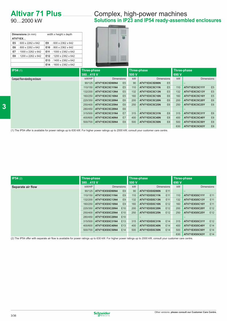
Other versions: please consult our Customer Care Centre.
Complex, high-power machinesSolutions in IP23 and IP54 ready-assembled enclosures
Altivar 71 Plus90…2000 kW
IP54 (1) Three-phase 380…415 V
Three-phase 500 V
Three-phase 690 V
Compact floor-standing enclosure kW/HP Dimensions kW Dimensions kW Dimensions90/125 ATV71EXC5D90N4 E5 90 ATV71EXC5D90N E5 –
110/150 ATV71EXC5C11N4 E5 110 ATV71EXC5C11N E5 110 ATV71EXC5C11Y E5132/200 ATV71EXC5C13N4 E5 132 ATV71EXC5C13N E5 132 ATV71EXC5C13Y E5160/250 ATV71EXC5C16N4 E5 160 ATV71EXC5C16N E6 160 ATV71EXC5C16Y E5220/350 ATV71EXC5C20N4 E6 200 ATV71EXC5C20N E6 200 ATV71EXC5C20Y E6250/400 ATV71EXC5C25N4 E6 250 ATV71EXC5C25N E6 250 ATV71EXC5C25Y E6280/450 ATV71EXC5C28N4 E6 – –315/500 ATV71EXC5C31N4 E7 315 ATV71EXC5C31N E8 315 ATV71EXC5C31Y E6400/600 ATV71EXC5C40N4 E7 400 ATV71EXC5C40N E8 400 ATV71EXC5C40Y E8500/700 ATV71EXC5C50N4 E8 500 ATV71EXC5C50N E8 500 ATV71EXC5C50Y E8
630 ATV71EXC5C63Y E8(1) The IP54 offer is available for power ratings up to 630 kW. For higher power ratings up to 2000 kW, consult your customer care centre.
IP54 (2) Three-phase 380…415 V
Three-phase 500 V
Three-phase 690 V
Separate air flow kW/HP Dimensions kW Dimensions kW Dimensions90/125 ATV71EXS5D90N4 E9 90 ATV71EXS5D90N E11 –
110/150 ATV71EXS5C11N4 E9 110 ATV71EXS5C11N E11 110 ATV71EXS5C11Y E11132/200 ATV71EXS5C13N4 E9 132 ATV71EXS5C13N E11 132 ATV71EXS5C13Y E11160/250 ATV71EXS5C16N4 E9 160 ATV71EXS5C16N E12 160 ATV71EXS5C16Y E11220/350 ATV71EXS5C20N4 E10 200 ATV71EXS5C20N E12 200 ATV71EXS5C20Y E12250/400 ATV71EXS5C25N4 E10 250 ATV71EXS5C25N E12 250 ATV71EXS5C25Y E12280/450 ATV71EXS5C28N4 E10 – –315/500 ATV71EXS5C31N4 E13 315 ATV71EXS5C31N E14 315 ATV71EXS5C31Y E12400/600 ATV71EXS5C40N4 E13 400 ATV71EXS5C40N E14 400 ATV71EXS5C40Y E14500/700 ATV71EXS5C50N4 E14 500 ATV71EXS5C50N E14 500 ATV71EXS5C50Y E14
630 ATV71EXS5C63Y E14(2) The IP54 offer with separate air flow is available for power ratings up to 630 kW. For higher power ratings up to 2000 kW, consult your customer care centre.
Dimensions (in mm) width x height x depthATV71EX…E5 : 600 x 2262 x 642 E9 : 600 x 2362 x 642E6 : 800 x 2262 x 642 E10 : 800 x 2362 x 642E7 : 1000 x 2262 x 642 E11 : 1000 x 2362 x 642E8 : 1200 x 2262 x 642 E12 : 1200 x 2362 x 642
E13 : 1400 x 2362 x 642E14 : 1600 x 2362 x 642
3/36
2
1
3
4
5
6
7
8
9
10
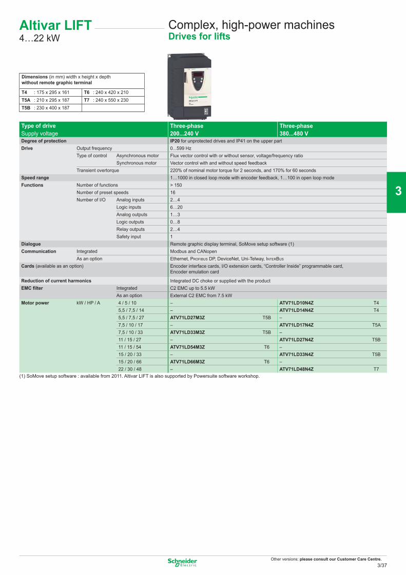
Other versions: please consult our Customer Care Centre.
Complex, high-power machinesDrives for lifts
Type of drive Three-phase200...240 V
Three-phase380...480 VSupply voltage
Degree of protection IP20 for unprotected drives and IP41 on the upper partDrive Output frequency 0...599 Hz
Type of control Asynchronous motor Flux vector control with or without sensor, voltage/frequency ratioSynchronous motor Vector control with and without speed feedback
Transient overtorque 220% of nominal motor torque for 2 seconds, and 170% for 60 secondsSpeed range 1…1000 in closed loop mode with encoder feedback, 1…100 in open loop modeFunctions Number of functions > 150
Number of preset speeds 16Number of I/O Analog inputs 2…4
Logic inputs 6…20Analog outputs 1…3Logic outputs 0…8Relay outputs 2…4Safety input 1
Dialogue Remote graphic display terminal, SoMove setup software (1)Communication Integrated Modbus and CANopen
As an option Ethernet, PROFIBUS DP, DeviceNet, Uni-Telway, INTERBUS
Cards (available as an option) Encoder interface cards, I/O extension cards, “Controller Inside” programmable card, Encoder emulation card
Reduction of current harmonics Integrated DC choke or supplied with the productEMC filter Integrated C2 EMC up to 5.5 kW
As an option External C2 EMC from 7.5 kWMotor power kW / HP / A 4 / 5 / 10 – ATV71LD10N4Z T4
5,5 / 7,5 / 14 – ATV71LD14N4Z T45,5 / 7,5 / 27 ATV71LD27M3Z T5B –7,5 / 10 / 17 – ATV71LD17N4Z T5A7,5 / 10 / 33 ATV71LD33M3Z T5B –11 / 15 / 27 – ATV71LD27N4Z T5B11 / 15 / 54 ATV71LD54M3Z T6 –15 / 20 / 33 – ATV71LD33N4Z T5B15 / 20 / 66 ATV71LD66M3Z T6 –22 / 30 / 48 – ATV71LD48N4Z T7
(1) SoMove setup software : available from 2011. Altivar LIFT is also supported by Powersuite software workshop.
Dimensions (in mm) width x height x depthwithout remote graphic terminal
T4 : 175 x 295 x 161 T6 : 240 x 420 x 210T5A : 210 x 295 x 187 T7 : 240 x 550 x 230T5B : 230 x 400 x 187
Altivar LIFT4…22 kW
3/37
2
1
3
4
5
6
7
8
9
10
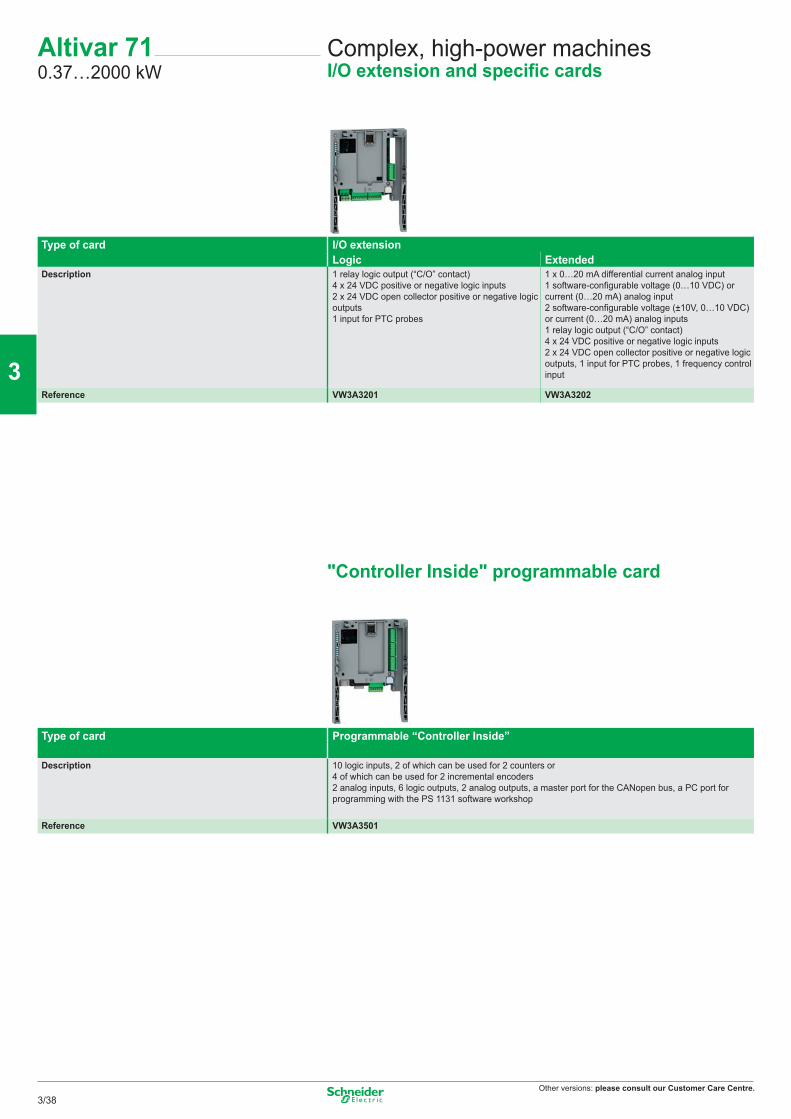
Other versions: please consult our Customer Care Centre.
Altivar 710.37…2000 kW
Complex, high-power machinesI/O extension and specific cards
Type of card I/O extensionLogic Extended
Description 1 relay logic output (“C/O” contact)4 x 24 VDC positive or negative logic inputs2 x 24 VDC open collector positive or negative logic outputs1 input for PTC probes
1 x 0…20 mA differential current analog input1 software-configurable voltage (0…10 VDC) or current (0…20 mA) analog input2 software-configurable voltage (±10V, 0…10 VDC) or current (0…20 mA) analog inputs1 relay logic output (“C/O” contact)4 x 24 VDC positive or negative logic inputs2 x 24 VDC open collector positive or negative logic outputs, 1 input for PTC probes, 1 frequency control input
Reference VW3A3201 VW3A3202
"Controller Inside" programmable card
Type of card Programmable “Controller Inside”
Description 10 logic inputs, 2 of which can be used for 2 counters or4 of which can be used for 2 incremental encoders2 analog inputs, 6 logic outputs, 2 analog outputs, a master port for the CANopen bus, a PC port for programming with the PS 1131 software workshop
Reference VW3A3501
3/38
2
1
3
4
5
6
7
8
9
10
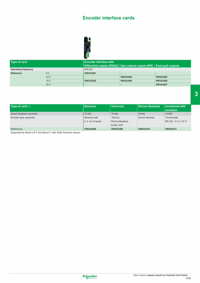
Other versions: please consult our Customer Care Centre.
Encoder interface cards
Type of card Encoder interface withDifferential outputs (RS422) Open collector outputs (NPN) Push-pull outputs
Operating frequency 300 kHzReference 5 V VW3A3401 – –
12 V – VW3A3403 VW3A340515 V VW3A3402 VW3A3404 VW3A340624 V – – VW3A3407
Type of card (1) Resolver Universal Sincos Absolute Incremental with emulation
Speed feedback resolution 12 bits 16 bits 16 bits 10,000Encoder type supported Resolver with
2, 4, 6 or 8 poles"SinCos, SinCosHiperfaceEnDat, SSI"
Sincos Absolute "Incremental RS 422 - 5 V or 15 V"
References VW3A3408 VW3A3409 VW3A3410 VW3A3411 Supported by Altivar LIFT and Altivar71 with S383 firmware version
3/39
2
1
3
4
5
6
7
8
9
10
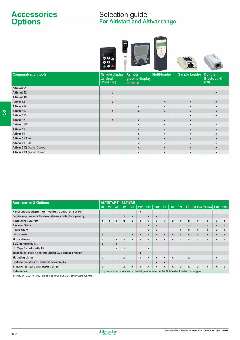
Other versions: please consult our Customer Care Centre.
Selection guideFor Altistart and Altivar range
Accessories Options
Communication tools Remote display terminal (IP54 & IP65)
Remote graphic display terminal
Multi-loader Simple Loader Dongle Bluetooth® (TM)
Altistart 01Altistart 22 x xAltistart 48 xAltivar 12 x x x xAltivar 212 x x x x xAltivar 312 x x x x xAltivar 31C x x xAltivar 32 x x x xAltivar LIFT x x x xAltivar 61 x x x xAltivar 71 x x x xAltivar 61 Plus x x x xAltivar 71 Plus x x x xAltivar 61Q (Water Cooled) x x x xAltivar 71Q (Water Cooled) x x x x
Accessories & Options ALTISTART ALTIVAR01 22 48 12 21 212 312 31C 32 61 71 LIFT 61 Plus 71 Plus 61Q 71Q
Panel cut-out adaptor for mounting control unit at 90° xFerrite suppressors for downstream contactor opening x x x xAdditional EMC filter x x x x x x x x x x x x x x x xPassive filters x x x x x x x xSinus filters x x x x x x x xLine choke x x x x x x x x x x x x xMotor chokes x x x x x x x x x x x x x x xEMC conformity kit x xUL Type 1 conformity kit x x xMechanical base kit for mounting GV2 circuit-breaker xMounting plates x x x x x x x x xBraking resistors for vertical movements x xBraking resistors and braking units x x x x x x x x x x x x x xReferences If options or accessories not listed, please refer to the Schneider Electric catalogue.
For Altivar 1000 or 1100, please consult our Customer Care Centre.
3/40
2
1
3
4
5
6
7
8
9
10
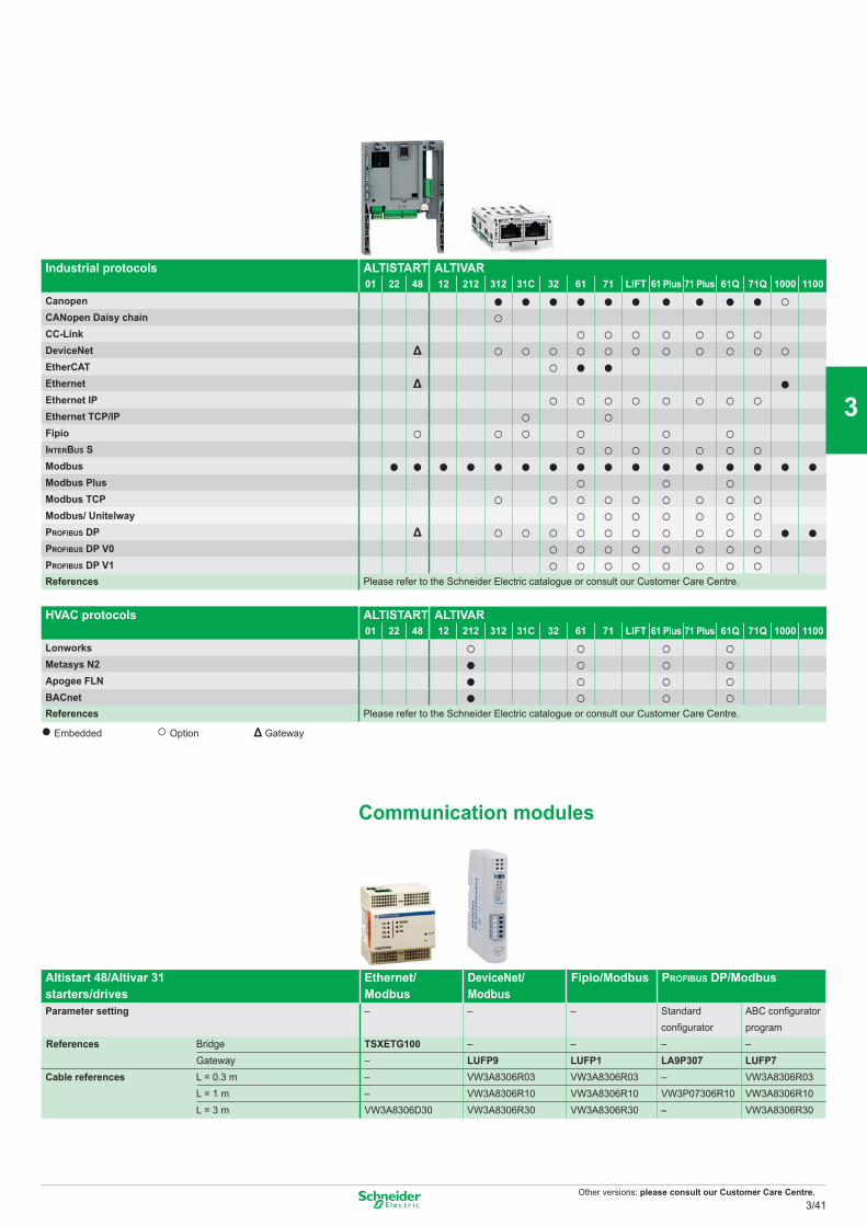
Other versions: please consult our Customer Care Centre.
Altistart 48/Altivar 31 starters/drives
Ethernet/ Modbus
DeviceNet/ Modbus
Fipio/Modbus PROFIBUS DP/Modbus
Parameter setting – – – Standard configurator
ABC configurator program
References Bridge TSXETG100 – – – –Gateway – LUFP9 LUFP1 LA9P307 LUFP7
Cable references L = 0.3 m – VW3A8306R03 VW3A8306R03 – VW3A8306R03L = 1 m – VW3A8306R10 VW3A8306R10 VW3P07306R10 VW3A8306R10L = 3 m VW3A8306D30 VW3A8306R30 VW3A8306R30 – VW3A8306R30
Communication modules
Industrial protocols ALTISTART ALTIVAR01 22 48 12 212 312 31C 32 61 71 LIFT 61 Plus 71 Plus 61Q 71Q 1000 1100
Canopen ● ● ● ● ● ● ● ● ● ● ○CANopen Daisy chain ○CC-Link ○ ○ ○ ○ ○ ○ ○DeviceNet Δ ○ ○ ○ ○ ○ ○ ○ ○ ○ ○ ○EtherCAT ○ ● ●Ethernet Δ ●Ethernet IP ○ ○ ○ ○ ○ ○ ○ ○Ethernet TCP/IP ○ ○Fipio ○ ○ ○ ○ ○ ○INTERBUS S ○ ○ ○ ○ ○ ○ ○Modbus ● ● ● ● ● ● ● ● ● ● ● ● ● ● ● ●Modbus Plus ○ ○ ○Modbus TCP ○ ○ ○ ○ ○ ○ ○ ○ ○Modbus/ Unitelway ○ ○ ○ ○ ○ ○ ○PROFIBUS DP Δ ○ ○ ○ ○ ○ ○ ○ ○ ○ ○ ● ●PROFIBUS DP V0 ○ ○ ○ ○ ○ ○ ○ ○PROFIBUS DP V1 ○ ○ ○ ○ ○ ○ ○ ○References Please refer to the Schneider Electric catalogue or consult our Customer Care Centre.
HVAC protocols ALTISTART ALTIVAR01 22 48 12 212 312 31C 32 61 71 LIFT 61 Plus 71 Plus 61Q 71Q 1000 1100
Lonworks ○ ○ ○ ○Metasys N2 ● ○ ○ ○Apogee FLN ● ○ ○ ○BACnet ● ○ ○ ○References Please refer to the Schneider Electric catalogue or consult our Customer Care Centre.
● Embedded ○ Option Δ Gateway
3/41
2
1
3
4
5
6
7
8
9
10
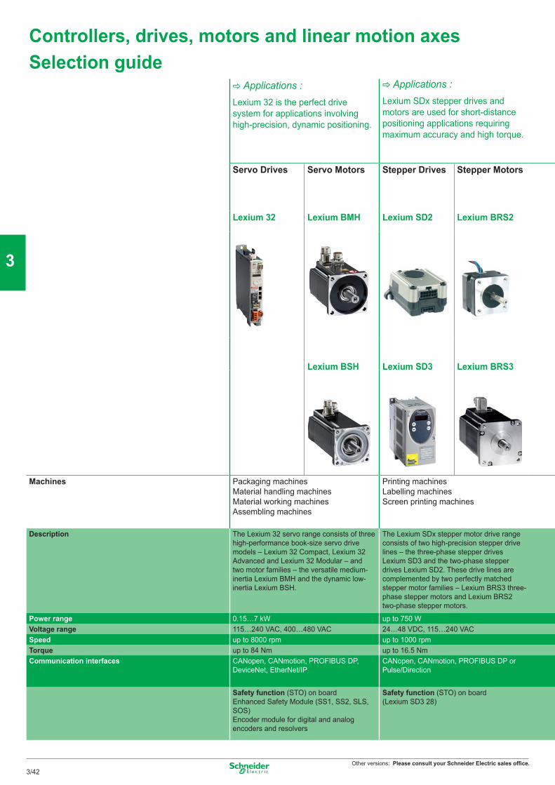
Other versions: Please consult your Schneider Electric sales offi ce.
Controllers, drives, motors and linear motion axesSelection guide
C Applications :Lexium 32 is the perfect drive system for applications involving high-precision, dynamic positioning.
C Applications :Lexium SDx stepper drives and motors are used for short-distance positioning applications requiring maximum accuracy and high torque.
Servo Drives Servo Motors Stepper Drives Stepper Motors
Lexium 32 Lexium BMH Lexium SD2 Lexium BRS2
Lexium BSH Lexium SD3 Lexium BRS3
Machines Packaging machinesMaterial handling machinesMaterial working machinesAssembling machines
Printing machinesLabelling machinesScreen printing machines
Description The Lexium 32 servo range consists of three high-performance book-size servo drive models – Lexium 32 Compact, Lexium 32 Advanced and Lexium 32 Modular – and two motor families – the versatile medium-inertia Lexium BMH and the dynamic low-inertia Lexium BSH.
The Lexium SDx stepper motor drive range consists of two high-precision stepper drive lines – the three-phase stepper drives Lexium SD3 and the two-phase stepper drives Lexium SD2. These drive lines are complemented by two perfectly matched stepper motor families – Lexium BRS3 three-phase stepper motors and Lexium BRS2 two-phase stepper motors.
Power range 0.15…7 kW up to 750 WVoltage range 115…240 VAC, 400…480 VAC 24…48 VDC, 115…240 VACSpeed up to 8000 rpm up to 1000 rpmTorque up to 84 Nm up to 16.5 NmCommunication interfaces CANopen, CANmotion, PROFIBUS DP,
DeviceNet, EtherNet/IPCANopen, CANmotion, PROFIBUS DP or Pulse/Direction
Safety function (STO) on boardEnhanced Safety Module (SS1, SS2, SLS, SOS)Encoder module for digital and analog encoders and resolvers
Safety function (STO) on board(Lexium SD3 28)
3/42
3
4
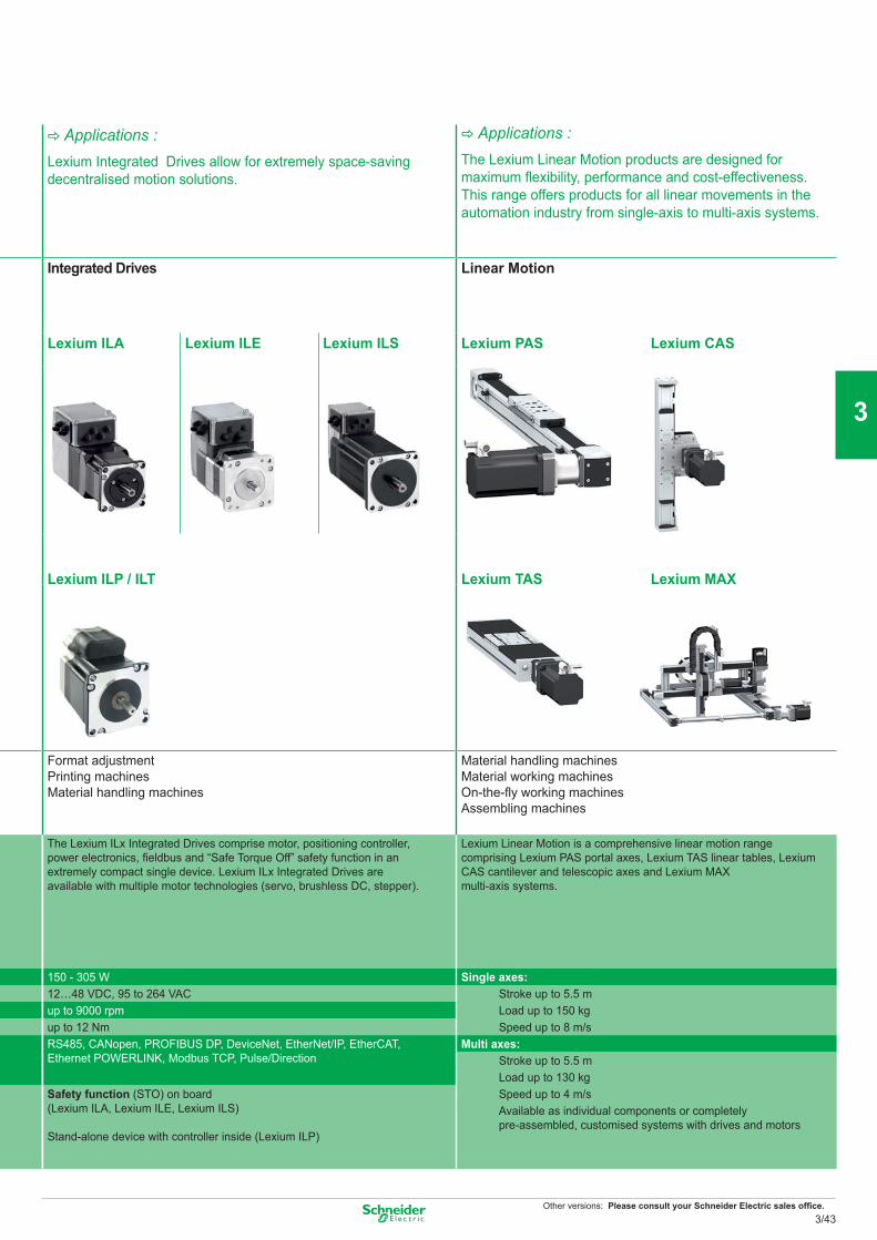
Other versions: Please consult your Schneider Electric sales offi ce.
C Applications :Lexium Integrated Drives allow for extremely space-saving decentralised motion solutions.
C Applications :The Lexium Linear Motion products are designed for maximum fl exibility, performance and cost-effectiveness. This range offers products for all linear movements in the automation industry from single-axis to multi-axis systems.
Integrated Drives Linear Motion
Lexium ILA Lexium ILE Lexium ILS Lexium PAS Lexium CAS
Lexium ILP / ILT Lexium TAS Lexium MAX
Format adjustmentPrinting machinesMaterial handling machines
Material handling machinesMaterial working machinesOn-the-fl y working machinesAssembling machines
The Lexium ILx Integrated Drives comprise motor, positioning controller, power electronics, fi eldbus and “Safe Torque Off” safety function in an extremely compact single device. Lexium ILx Integrated Drives are available with multiple motor technologies (servo, brushless DC, stepper).
Lexium Linear Motion is a comprehensive linear motion range comprising Lexium PAS portal axes, Lexium TAS linear tables, Lexium CAS cantilever and telescopic axes and Lexium MAX multi-axis systems.
150 - 305 W Single axes:12…48 VDC, 95 to 264 VAC Stroke up to 5.5 mup to 9000 rpm Load up to 150 kgup to 12 Nm Speed up to 8 m/sRS485, CANopen, PROFIBUS DP, DeviceNet, EtherNet/IP, EtherCAT, Ethernet POWERLINK, Modbus TCP, Pulse/Direction
Multi axes:Stroke up to 5.5 mLoad up to 130 kg
Safety function (STO) on board(Lexium ILA, Lexium ILE, Lexium ILS)
Stand-alone device with controller inside (Lexium ILP)
Speed up to 4 m/sAvailable as individual components or completely pre-assembled, customised systems with drives and motors
3/43
3
4
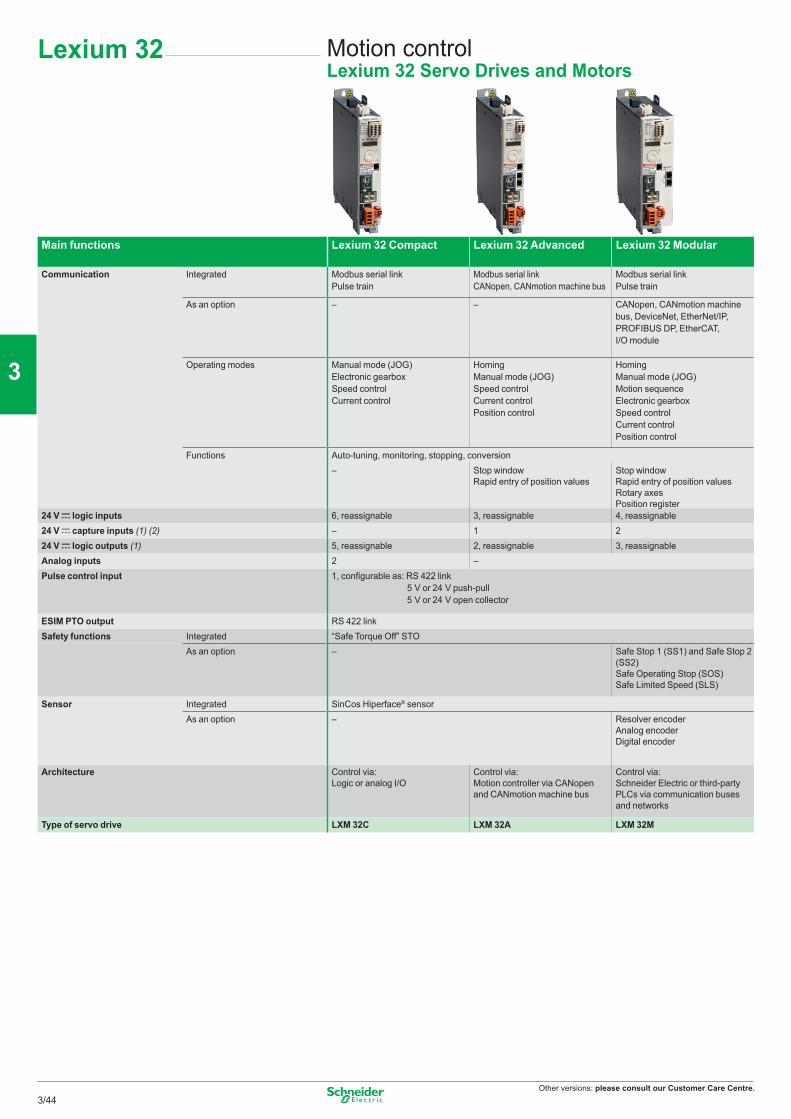
Other versions: please consult our Customer Care Centre.
Lexium 32 Motion controlLexium 32 Servo Drives and Motors
Main functions Lexium 32 Compact Lexium 32 Advanced Lexium 32 Modular
Communication Integrated Modbus serial link Pulse train
Modbus serial link CANopen, CANmotion machine bus
Modbus serial link Pulse train
As an option – – CANopen, CANmotion machine bus, DeviceNet, EtherNet/IP, PROFIBUS DP, EtherCAT, I/O module
Operating modes Manual mode (JOG)Electronic gearboxSpeed controlCurrent control
Homing Manual mode (JOG)Speed controlCurrent controlPosition control
Homing Manual mode (JOG)Motion sequenceElectronic gearboxSpeed controlCurrent controlPosition control
Functions Auto-tuning, monitoring, stopping, conversion– Stop window
Rapid entry of position valuesStop window Rapid entry of position valuesRotary axesPosition register
24 V c logic inputs 6, reassignable 3, reassignable 4, reassignable24 V c capture inputs (1) (2) – 1 224 V c logic outputs (1) 5, reassignable 2, reassignable 3, reassignableAnalog inputs 2 –Pulse control input 1, configurable as: RS 422 link
5 V or 24 V push-pull5 V or 24 V open collector
ESIM PTO output RS 422 linkSafety functions Integrated “Safe Torque Off” STO
As an option – Safe Stop 1 (SS1) and Safe Stop 2 (SS2) Safe Operating Stop (SOS)Safe Limited Speed (SLS)
Sensor Integrated SinCos Hiperface® sensor As an option – Resolver encoder
Analog encoderDigital encoder
Architecture Control via:Logic or analog I/O
Control via:Motion controller via CANopen and CANmotion machine bus
Control via:Schneider Electric or third-party PLCs via communication buses and networks
Type of servo drive LXM 32C LXM 32A LXM 32M
3/44
2
1
3
4
5
6
7
8
9
10
Other versions: please consult our Customer Care Centre.
Main functions
Application type High load, With robust adjustment of the movement High dynamic range, Power densityFlange size 70, 100, 140 and 190 mm 55, 70, 100 and 140 mmContinuous stall torque 1.2 to 84 Nm 0.5 to 33.4 NmEncoder type Single turn SinCos: 32,768 points/turn
and 131,072 points/turnMultiturn SinCos: 32,768 points/turn x 4096 turns and 131,072 points/turn x 4096 turns
Single turn SinCos: 131,072 points/turnMultiturn SinCos: 131,072 points/turn x 4096 turns
Degree of protection Casing IP 65 (IP 67 conformity kit as an option)Shaft end IP 50 or IP 65 (IP 67 conformity kit as an option)
Type of servo motor Lexium BMH Lexium BSH
3/45
2
1
3
4
5
6
7
8
9
10
Other versions: please consult our Customer Care Centre.
Lexium 32 servo drive/BMH or BSH servo motor combinations
Servo motors Lexium 32C, 32A and 32M servo drives200…240 V single-phase supply voltage with integrated EMC filter
BMH (IP50, IP65 or IP67)
BSH (IP 50, IP65 or IP67)
LXM 32pU45M2Continuous output current: 1.5 A rmsNominal operating point Stall torques
Type of servo motor
Rotor inertia
Type of servo motor
Rotor inertia
Nominal torque
Nominal speed
Nominal power
M0/Mmax
kgcm2 kgcm2 Nm rpm W Nm/Nm
BSH 0551T 0.06 0.45 6000 300 0.5/1.4BSH 0552T 0.10BSH 0553T 0.13BSH 0701T 0.25
BMH 0701T 0.59BSH 0702T 0.41BSH 0703T 0.58
BMH 0702T 1.13BSH 1001T 1.40
BMH 0703T 1.67BMH 1001T 3.2
BSH 1002T 2.31BMH 1002T 6.3BMH 1003T 9.4BMH 1401P 16.5
Lexium 32 servo drive/BMH or BSH servo motor combinations
Servo motors Lexium 32C, 32A and 32M servo drives100…120 V single-phase supply voltage with integrated EMC filter
BMH (IP50, IP65 or IP67)
BSH (IP50, IP65 or IP67)
LXM 32pU90M2Continuous output current: 3 A rmsNominal operating point Stall torques
Type of servo motor
Rotor inertia
Type of servo motor
Rotor inertia
Nominal torque
Nominal speed
Nominal power
M0/Mmax
kgcm2 kgcm2 Nm rpm W Nm/NmBSH 0551T 0.06 0.49 3000 150 0.5/1.5 BSH 0552T 0.10 0.77 3000 250 0.8/1.9BSH 0553T 0.13
BMH 0701T 0.59BSH 0701T 0.25BSH 0702T 0.41
BMH 0702T 1.13BMH 0703T 1.67
BSH 1001T 1.40BMH1001T 3.2BMH1002T 6.3
Lexium 32 Lexium 32 motion controlServo drive/servo motor combinations
3/46
2
1
3
4
5
6
7
8
9
10
Other versions: please consult our Customer Care Centre.
LXM 32pU18M2Continuous output current: 6 A rms
LXM 32pD30M2Continuous output current: 10 A rms
Nominal operating point Stall torques Nominal operating point Stall torquesNominal torque
Nominal speed
Nominal power
M0/Mmax Nominal torque
Nominal speed
Nominal power
M0/Mmax
Nm rpm W Nm/Nm Nm rpm W Nm/Nm
1.14 3000 350 1.2/3.31.35 2500 350 1.4/4.21.36 2500 350 1.4/3.5
2.07 2500 550 2.2/6.12.3 2500 600 2.5/6.43.1 2000 650 3.4/8.72.75 2500 700 3.3/6.33.3 2000 700 3.4/8.93.5 2000 750 6/10.3
LXM 32pU90 M2Continuous output current: 3 A rms
LXM 32pD18M2Continuous output current: 6 A rms
LXM 32pD30M2Continuous output current: 10 A rms
Nominal operating point Stall torques Nominal operating point Stall torques Nominal operating point Stall torquesNominal torque
Nominal speed
Nominal power
M0/Mmax Nominal torque
Nominal speed
Nominal power
M0/Mmax Nominal torque
Nominal speed
Nominal power
M0/Mmax
Nm rpm W Nm/Nm Nm rpm W Nm/Nm Nm rpm W Nm/Nm
0.74 6000 450 0.8/2.50.84 6000 550 1.2/30.94 5000 500 1.3/3.51.1 4000 450 1.4/4
1.8 5000 950 2.2/7.22.1 4000 900 2.6/7.42.1 4000 900 2.5/7.42.2 4000 900 2.7/7.52.9 3000 900 3.4/10.22.8 3000 900 3.4/10.2
3.7 4000 1500 5.8/16.44.6 3000 1450 6/18.45.6 2500 1450 8.2/22.86.9 2000 1450 10.3/30.8
3/47
2
1
3
4
5
6
7
8
9
10
Other versions: please consult our Customer Care Centre.
Lexium 32 servo drive/BMH or BSH servo motor combinations
Servo motors Lexium 32C, 32A and 32M servo drives380…480 V three-phase supply voltage with integrated EMC filter
BMH (IP50, IP65 or IP67)
BSH (IP50, IP 65 or IP67)
LXM 32pU60N4Continuous output current: 1.5 A rms
LXM 32pD12N4Continuous output current: 3 A rms
Nominal operating point Stall torques Nominal operating point Stall torquesType of servo motor
Rotor inertia
Type of servo motor
Rotor inertia
Nominal torque
Nominal speed
Nominal power
M0/Mmax Nominal torque
Nominal speed
Nominal power
M0/Mmax
kgcm2 kgcm2 Nm rpm W Nm/Nm Nm rpm W Nm/NmBSH 0551P 0.06 0.48 6000 300 0.5/1.5BSH 0552P 0.10 0.65 6000 400 0.8/2.5BSH 0553P 0.13 0.65 6000 400 1.05/3.5
BMH 0701P 0.59 1.1 3000 350 1.2/4.2BMH 0701P 0.59 1.3 5000 700 1.4/4.2
BSH 0701P 0.25 1.32 5000 700 1.4/3.5BSH 0702P 0.41 1.64 5000 850 2.2/7.6
BMH 1001P 3.2 1.9 4000 800 3.3/10.8BMH 0702P 1.13 2.2 3000 700 2.5/7.4BMH 0703P 1.67
BSH 0703P 0.58BSH 1001P 1.40
BMH 1001P 3.2BMH 1002P 6.3
BSH 1002P 2.31BMH 1003P 9.4
BSH 1003P 3.2BMH 1401P 16.5
BSH 1004P 4.2BSH 1401P 7.4
BMH 1402P 32.0BSH 1402T 12.7BSH 1403T 17.9
BMH 1403P 47.5BSH 1404P 23.7
BMH 1901P 67.7BMH 1902P 130BMH 1903P 194
Lexium 32 Lexium 32 motion controlServo drive/servo motor combinations
3/48
2
1
3
4
5
6
7
8
9
10
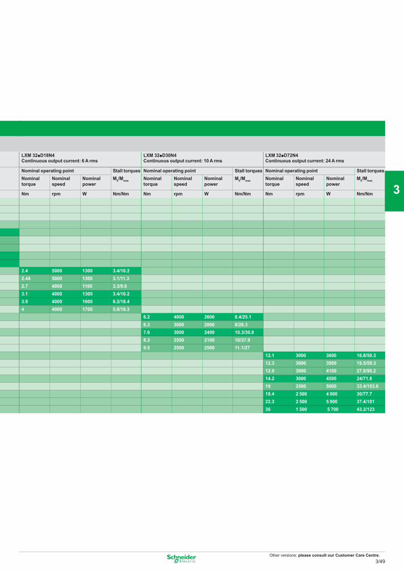
Other versions: please consult our Customer Care Centre.
LXM 32pD18N4 Continuous output current: 6 A rms
LXM 32pD30N4Continuous output current: 10 A rms
LXM 32pD72N4Continuous output current: 24 A rms
Nominal operating point Stall torques Nominal operating point Stall torques Nominal operating point Stall torquesNominal torque
Nominal speed
Nominal power
M0/Mmax Nominal torque
Nominal speed
Nominal power
M0/Mmax Nominal torque
Nominal speed
Nominal power
M0/Mmax
Nm rpm W Nm/Nm Nm rpm W Nm/Nm Nm rpm W Nm/Nm
2.4 5000 1300 3.4/10.22.44 5000 1300 3.1/11.32.7 4000 1100 3.3/9.63.1 4000 1300 3.4/10.23.9 4000 1600 6.2/18.44 4000 1700 5.8/18.3
6.2 4000 2600 8.4/25.16.3 3000 2000 8/28.37.6 3000 2400 10.3/30.88.3 2500 2100 10/37.99.5 2500 2500 11.1/27
12.1 3000 3800 16.8/50.312.3 3000 3900 19.5/59.312.9 3000 4100 27.8/90.214.2 3000 4500 24/71.819 2500 5000 33.4/103.618.4 2 500 4 800 30/77.722.3 2 500 5 900 37.4/10136 1 500 5 700 43.2/123
3/49
2
1
3
4
5
6
7
8
9
10
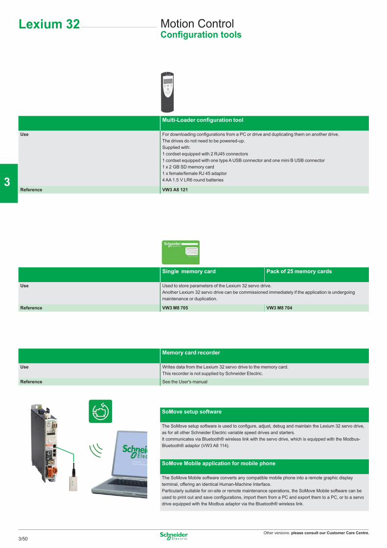
Other versions: please consult our Customer Care Centre.
Multi-Loader configuration tool
Use For downloading configurations from a PC or drive and duplicating them on another drive.The drives do not need to be powered-up.Supplied with:1 cordset equipped with 2 RJ45 connectors1 cordset equipped with one type A USB connector and one mini B USB connector1 x 2 GB SD memory card1 x female/female RJ 45 adaptor4 AA 1.5 V LR6 round batteries
Reference VW3 A8 121
Single memory card Pack of 25 memory cards
Use Used to store parameters of the Lexium 32 servo drive.Another Lexium 32 servo drive can be commissioned immediately if the application is undergoing maintenance or duplication.
Reference VW3 M8 705 VW3 M8 704
Memory card recorder
Use Writes data from the Lexium 32 servo drive to the memory card.This recorder is not supplied by Schneider Electric.
Reference See the User's manual
SoMove setup software
The SoMove setup software is used to configure, adjust, debug and maintain the Lexium 32 servo drive, as for all other Schneider Electric variable speed drives and starters.It communicates via Bluetooth® wireless link with the servo drive, which is equipped with the Modbus- Bluetooth® adaptor (VW3 A8 114).
SoMove Mobile application for mobile phone
The SoMove Mobile software converts any compatible mobile phone into a remote graphic display terminal, offering an identical Human-Machine Interface.Particularly suitable for on-site or remote maintenance operations, the SoMove Mobile software can be used to print out and save configurations, import them from a PC and export them to a PC, or to a servo drive equipped with the Modbus adaptor via the Bluetooth® wireless link.
Motion ControlConfiguration tools
Lexium 32
3/50
2
1
3
4
5
6
7
8
9
10
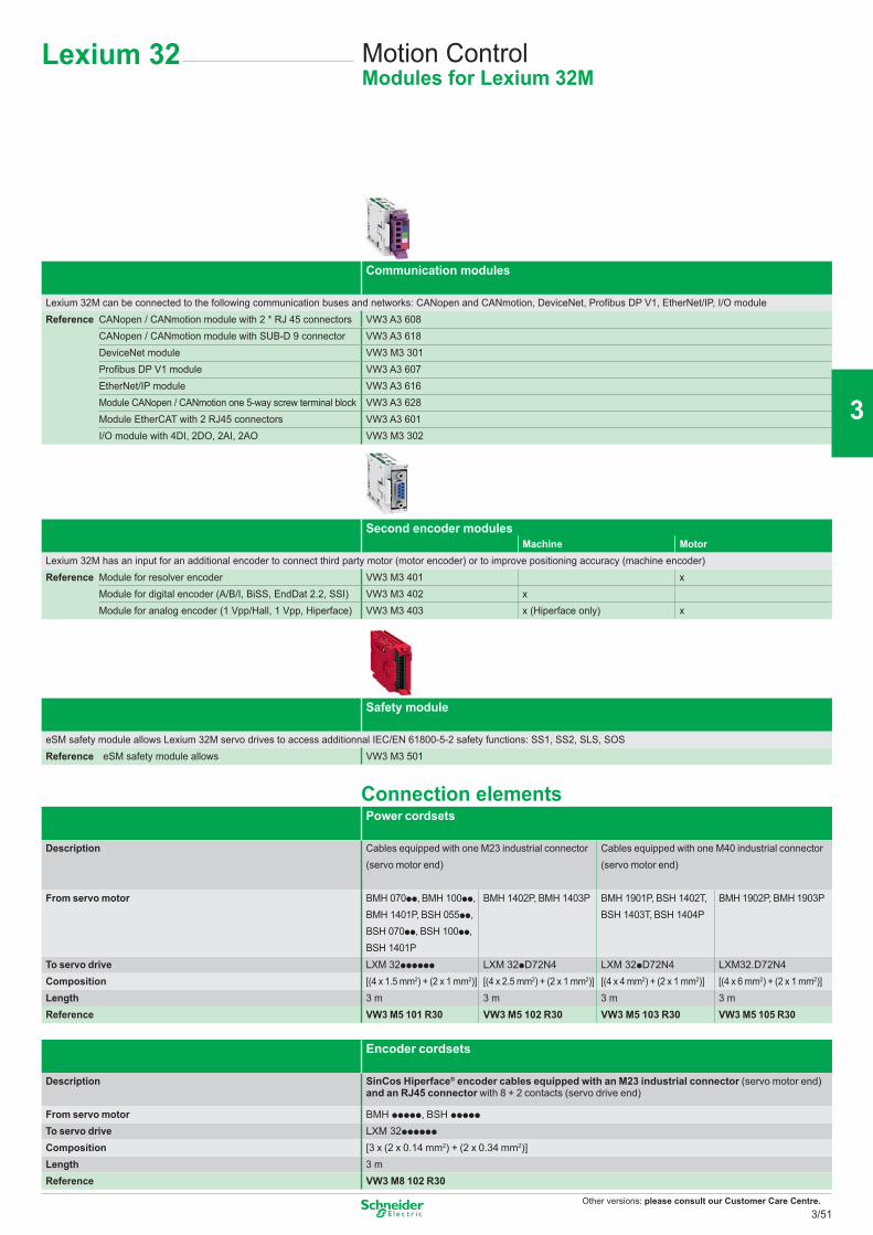
Other versions: please consult our Customer Care Centre.
Communication modules
Lexium 32M can be connected to the following communication buses and networks: CANopen and CANmotion, DeviceNet, Profi bus DP V1, EtherNet/IP, I/O moduleReference CANopen / CANmotion module with 2 * RJ 45 connectors VW3 A3 608
CANopen / CANmotion module with SUB-D 9 connector VW3 A3 618DeviceNet module VW3 M3 301Profi bus DP V1 module VW3 A3 607EtherNet/IP module VW3 A3 616Module CANopen / CANmotion one 5-way screw terminal block VW3 A3 628Module EtherCAT with 2 RJ45 connectors VW3 A3 601I/O module with 4DI, 2DO, 2AI, 2AO VW3 M3 302
Second encoder modulesMachine Motor
Lexium 32M has an input for an additional encoder to connect third party motor (motor encoder) or to improve positioning accuracy (machine encoder)Reference Module for resolver encoder VW3 M3 401 x
Module for digital encoder (A/B/I, BiSS, EndDat 2.2, SSI) VW3 M3 402 xModule for analog encoder (1 Vpp/Hall, 1 Vpp, Hiperface) VW3 M3 403 x (Hiperface only) x
Safety module
eSM safety module allows Lexium 32M servo drives to access additionnal IEC/EN 61800-5-2 safety functions: SS1, SS2, SLS, SOSReference eSM safety module allows VW3 M3 501
Connection elementsPower cordsets
Description Cables equipped with one M23 industrial connector (servo motor end)
Cables equipped with one M40 industrial connector (servo motor end)
From servo motor BMH 070pp, BMH 100pp, BMH 1401P, BSH 055pp, BSH 070pp, BSH 100pp, BSH 1401P
BMH 1402P, BMH 1403P BMH 1901P, BSH 1402T, BSH 1403T, BSH 1404P
BMH 1902P, BMH 1903P
To servo drive LXM 32pppppp LXM 32pD72N4 LXM 32pD72N4 LXM32.D72N4Composition [(4 x 1.5 mm2) + (2 x 1 mm2)] [(4 x 2.5 mm2) + (2 x 1 mm2)] [(4 x 4 mm2) + (2 x 1 mm2)] [(4 x 6 mm2) + (2 x 1 mm2)]Length 3 m 3 m 3 m 3 mReference VW3 M5 101 R30 VW3 M5 102 R30 VW3 M5 103 R30 VW3 M5 105 R30
Encoder cordsets
Description SinCos Hiperface® encoder cables equipped with an M23 industrial connector (servo motor end) and an RJ45 connector with 8 + 2 contacts (servo drive end)
From servo motor BMH ppppp, BSH ppppp
To servo drive LXM 32pppppp
Composition [3 x (2 x 0.14 mm2) + (2 x 0.34 mm2)]Length 3 mReference VW3 M8 102 R30
Motion ControlModules for Lexium 32M
Lexium 32
3/51
2
1
3
4
5
6
7
8
9
10
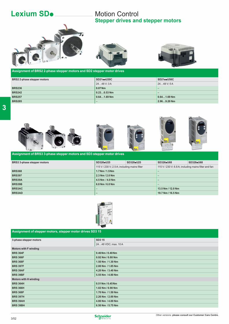
Other versions: please consult our Customer Care Centre.
Assignment of BRS3 3-phase stepper motors and SD3 stepper motor drives
BRS3 3-phase stepper motors SD326pU25 SD328pU25 SD326pU68 SD328pU68115 V / 230 V; 2.5 A; including mains fi lter 115 V / 230 V; 6.8 A; including mains fi lter and fan
BRS368 1.7 Nm / 1.5 Nm –BRS397 2.3 Nm / 2.0 Nm –BRS39A 4.5 Nm / 4.0 Nm –BRS39B 6.8 Nm / 6.0 Nm –BRS3AC – 13.5 Nm / 12.0 NmBRS3AD – 19.7 Nm / 16.5 Nm
Lexium SDp Motion ControlStepper drives and stepper motors
Assignment of BRS2 2-phase stepper motors and SD2 stepper motor drives
BRS2 2-phase stepper motors SD21ppU20C SD21ppU50C24…48 V; 3 A 24…48 V; 5 A
BRS236 0.07 Nm –BRS242 0.23…0.53 Nm –BRS257 0.64…1.69 Nm 0.64…1.69 NmBRS285 – 2.96…9.20 Nm
Assignment of stepper motors, stepper motor drives SD3 15
3-phase stepper motors SD3 1524…48 VDC; max. 10 A
Motors with F windingBRS 364F 0.46 Nm / 0.40 NmBRS 366F 0.92 Nm / 0.80 NmBRS 368F 1.50 Nm / 1.30 NmBRS 397F 2.00 Nm / 1.85 NmBRS 39AF 4.20 Nm / 3.40 NmBRS 39BF 5.55 Nm / 4.80 NmMotors with H windingBRS 364H 0.51 Nm / 0.45 NmBRS 366H 1.02 Nm / 0.90 NmBRS 368F 1.70 Nm / 1.50 NmBRS 397H 2.26 Nm / 2.00 NmBRS 39AH 4.80 Nm / 4.00 NmBRS 39BH 6.50 Nm / 5.75 Nm
3/52
2
1
3
4
5
6
7
8
9
10
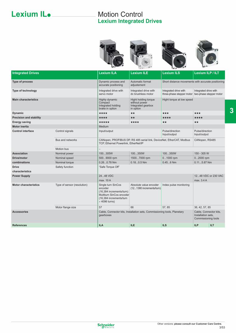
Other versions: please consult our Customer Care Centre.
Integrated Drives Lexium ILA Lexium ILE Lexium ILS Lexium ILP / ILT
Type of process Dynamic process and accurate positioning
Automatic format adjustement
Short distance movements with accurate positioning
Type of technology Integrated drive with servo motor
Integrated drive with dc brushless motor
Integrated drive with three-phase stepper motor
Integrated drive with two-phase stepper motor
Main characteristics Highly dynamic CompactIntegrated holding brake in option
Hight holding torque without powerIntegrated gearbox in option
Hight torque at low speed
Dynamic gggg gg ggg gggPrecision and stability gggg gg gggg ggggEnergy saving ggggg gggg gg ggMotor inertia MediumControl interface Control signals Input/output Pulse/direction
Input/outputPulse/directionInput/output
Bus and networks CANopen, PROFIBUS DP, RS 485 serial link, DeviceNet, EtherCAT, Modbus TCP, Ethernet Powerlink, EtherNet/IP
CANopen, RS485
Motion bus –AssociationDrive/motorcombinations
Nominal power 150...305W 100...350W 100...350W 150 - 305 WNominal speed 500...9000 rpm 1500...7000 rpm 0...1000 rpm 0...2000 rpmNominal torque 0.26...0.78 Nm 0.18...0.5 Nm 0.45...6 Nm 0.11...5.87 Nm
Drive characteristics
Safety function “Safe Torque Off”
Power Supply 24...48 VDC max. 10 A
12...48 VDC or 230 VACmax. 3.4 A
Motor characteristics Type of sensor (resolution) Single turn SinCos encoder (16,384 increments/turn)Multiturn SinCos encoder(16,384 increments/turn × 4096 turns)
Absolute value encoder(12...1380 increments/turn)
Index pulse monitoring
Motor flange size 57 66 57, 85 36, 42, 57, 85Accessories Cable, Connector kits, Installation sets, Commissioning tools, Planetary
gearboxesCable, Connector kits, Installation sets, Commissioning tools
References ILA ILE ILS ILP ILT
Lexium ILp Motion ControlLexium Integrated Drives
3/53
2
1
3
4
5
6
7
8
9
10
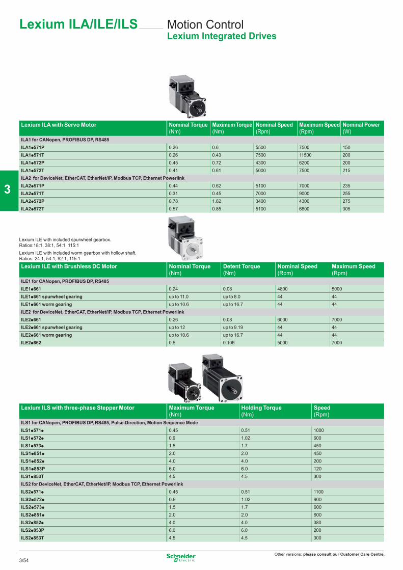
Other versions: please consult our Customer Care Centre.
Lexium ILA/ILE/ILS Motion ControlLexium Integrated Drives
Lexium ILA with Servo Motor Nominal Torque (Nm)
Maximum Torque (Nm)
Nominal Speed (Rpm)
Maximum Speed (Rpm)
Nominal Power (W)
ILA1 for CANopen, PROFIBUS DP, RS485ILA1p571P 0.26 0.6 5500 7500 150ILA1p571T 0.26 0.43 7500 11500 200ILA1p572P 0.45 0.72 4300 6200 200ILA1p572T 0.41 0.61 5000 7500 215ILA2 for DeviceNet, EtherCAT, EtherNet/IP, Modbus TCP, Ethernet PowerlinkILA2p571P 0.44 0.62 5100 7000 235ILA2p571T 0.31 0.45 7000 9000 255ILA2p572P 0.78 1.62 3400 4300 275ILA2p572T 0.57 0.85 5100 6800 305
Lexium ILE with included spurwheel gearbox. Ratios:18:1, 38:1, 54:1, 115:1Lexium ILE with included worm gearbox with hollow shaft.Ratios: 24:1, 54:1, 92:1, 115:1
Lexium ILE with Brushless DC Motor Nominal Torque (Nm)
Detent Torque (Nm)
Nominal Speed (Rpm)
Maximum Speed (Rpm)
ILE1 for CANopen, PROFIBUS DP, RS485ILE1p661 0.24 0.08 4800 5000ILE1p661 spurwheel gearing up to 11.0 up to 8.0 44 44ILE1p661 worm gearing up to 10.6 up to 16.7 44 44ILE2 for DeviceNet, EtherCAT, EtherNet/IP, Modbus TCP, Ethernet PowerlinkILE2p661 0.26 0.08 6000 7000ILE2p661 spurwheel gearing up to 12 up to 9.19 44 44ILE2p661 worm gearing up to 10.6 up to 16.7 44 44ILE2p662 0.5 0.106 5000 7000
Lexium ILS with three-phase Stepper Motor Maximum Torque (Nm)
Holding Torque (Nm)
Speed (Rpm)
ILS1 for CANopen, PROFIBUS DP, RS485, Pulse-Direction, Motion Sequence ModeILS1p571p 0.45 0.51 1000ILS1p572p 0.9 1.02 600ILS1p573p 1.5 1.7 450ILS1p851p 2.0 2.0 450ILS1p852p 4.0 4.0 200ILS1p853P 6.0 6.0 120ILS1p853T 4.5 4.5 300ILS2 for DeviceNet, EtherCAT, EtherNet/IP, Modbus TCP, Ethernet PowerlinkILS2p571p 0.45 0.51 1100ILS2p572p 0.9 1.02 900ILS2p573p 1.5 1.7 600ILS2p851p 2.0 2.0 600ILS2p852p 4.0 4.0 380ILS2p853P 6.0 6.0 200ILS2p853T 4.5 4.5 300
3/54
2
1
3
4
5
6
7
8
9
10
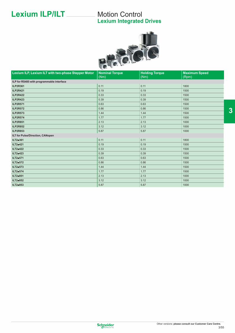
Other versions: please consult our Customer Care Centre.
Lexium ILP/ILT Motion ControlLexium Integrated Drives
Lexium ILP, Lexium ILT with two-phase Stepper Motor Nominal Torque (Nm)
Holding Torque (Nm)
Maximum Speed (Rpm)
ILP for RS485 with programmable interfaceILP2R361 0.11 0.11 1800ILP2R421 0.19 0.19 1500ILP2R422 0.33 0.33 1500ILP2R423 0.39 0.39 1500ILP2R571 0.63 0.63 1500ILP2R572 0.86 0.86 1500ILP2R573 1.44 1.44 1500ILP2R574 1.77 1.77 1500ILP2R851 2.13 2.13 1000ILP2R852 3.12 3.12 1000ILP2R853 5.87 5.87 1000ILT for Pulse/Direction, CANopenILT2p361 0.11 0.11 1800ILT2p421 0.19 0.19 1500ILT2p422 0.33 0.33 1500ILT2p423 0.39 0.39 1500ILT2p571 0.63 0.63 1500ILT2p572 0.86 0.86 1500ILT2p573 1.44 1.44 1500ILT2p574 1.77 1.77 1500ILT2p851 2.13 2.13 1000ILT2p852 3.12 3.12 1000ILT2p853 5.87 5.87 1000
3/55
2
1
3
4
5
6
7
8
9
10
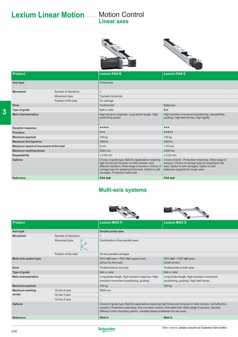
Other versions: please consult our Customer Care Centre.
Lexium Linear Motion Motion ControlLinear axes
Product Lexium PAS B Lexium PAS S
Axis type Portal axes
Movement Number of directions 1Movement type Typically horizontalPosition of the load On carriage
Drive Toothed belt BallscrewType of guide Ball or roller BallMain characteristics High dynamic response, Long stroke length, High
positioning speedHigh precision movement (positioning, repeatability, guiding), High feed forces, High rigidity
Dynamic response ggggg ggg
Precision ggg ggggg
Maximum payload 100 kg 100 kgMaximum driving force 2600 N 4520 NMaximum speed of movement of the load 8 m/s 1.25 m/sMaximum working stroke 5500 mm 3000 mmRepeatability ± 0.05 mm ± 0.02 mmOptions Choice of guide type: Ball (for applications requiring
high forces and torques) or roller (simple, cost-effective solution), Wide range of sensors, Choice of carriage type for adapting to the load, Option to add carriages, Protective metal strip.
Choice of pitch , Protective metal strip, Wide range of sensors, Choice of carriage type for adapting to the load, Option to add carriages, Option to add ballscrew supports for longer axes
Reference PAS 4pB PAS 4pS
Multi-axis systems
Product Lexium MAX H Lexium MAX S
Axis type Double portal axesMovement Number of directions 1
Movement type Combination of two parallel axes
Position of the load On two parallel carriagesMulti-axis system type PAS 4pB axes + PAS 4pH support axis
(driven by the load)PAS 4pB + PAS 4pB axes(shaft-driven)
Drive Toothed belt on one axis Toothed belt on both axesType of guide Ball or roller Ball or rollerMain characteristics Long stroke length, High dynamic response, High
precision movement (positioning, guiding)Long stroke length, High precision movement (positioning, guiding), High feed forces
Maximum payload 250 kg 300 kgMaximum working stroke
On the X-axis 5500 mmOn the Y-axis –On the Z-axis –
Options Choice of guide type: Ball (for applications requiring high forces and torques) or roller (simple, cost-effective solution), Protective metal strip, Anti-corrosion version, Anti-static belt, Wide range of sensors, Several different motor mounting options, Variable distance between the two axes
Reference MAX H MAX S
Z
X
Y
3/56
2
1
3
4
5
6
7
8
9
10
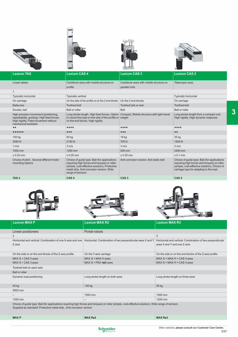
Other versions: please consult our Customer Care Centre.
Lexium TAS Lexium CAS 4 Lexium CAS 3 Lexium CAS 2
Linear tables Cantilever axes with mobile structure on profile
Cantilever axes with mobile structure on parallel rods
Telescopic axes
1Typically horizontal Typically vertical Typically horizontalOn carriage On the side of the profile or on the 2 end blocks On the 2 end blocks On carriageBallscrew Toothed belt Toothed belt or rack Toothed beltDouble, ball Ball or roller Ball Ball or rollerHigh precision movement (positioning, repeatability, guiding), High feed forces, High rigidity, Feed movement without mechanical backlash
Long stroke length, High feed forces, Option to mount the load on the side of the profile or on the end blocks, High rigidity
Compact, Mobile structure with light travel weight
Long stroke length from a compact unit, High rigidity, High dynamic response
gg gggg gggg gggg
gggggg ggg ggg gg
150 kg 50 kg 18 kg 35 kg2580 N 2150 N 705 N 1500 N1 m/s 3 m/s 3 m/s 3 m/s1500 mm 1200 mm 500 mm 2400 mm± 0.02 mm ± 0.05 mm ± 0.05 mm ± 0.1 mmChoice of pitch , Several different motor mounting options
Choice of guide type: Ball (for applications requiring high forces and torques) or roller (simple, cost-effective solution), Protective metal strip, Anti-corrosion version, Wide range of sensors
Anti-corrosion version, Anti-static belt Choice of guide type: Ball (for applications requiring high forces and torques) or roller (simple, cost-effective solution), Choice of carriage type for adapting to the load
TAS 4 CAS 4 CAS 3 CAS 2
Lexium MAX P Lexium MAX R2 Lexium MAX R3
Linear positioners Portal robots2 3Horizontal and vertical: Combination of one X-axis and one Z-axis
Horizontal: Combination of two perpendicular axes X and Y Horizontal and vertical: Combination of two perpendicular axes X and Y and one Z-axis
On the side or on the end blocks of the Z-axis profile On the Y-axis carriage On the side or on the end blocks of the Z-axis profileMAX S + CAS 4 axesMAX S + CAS 3 axes
MAX S + MAX H axesMAX S + PAS 4pB axes
MAX S + MAX H + CAS 4 axesMAX S + MAX H + CAS 3 axes
Toothed belt on each axisBall or rollerDynamic load positioning Long stroke length on both axes Long stroke length on three axes
50 kg 130 kg 50 kg5500 mm– 1500 mm 1500 mm1200 mm – 1200 mmChoice of guide type: Ball (for applications requiring high forces and torques) or roller (simple, cost-effective solution), Wide range of sensors Supplied as standard: Protective metal strip , Anti-corrosion version
MAX P MAX Rp2 MAX Rp3
3/57
2
1
3
4
5
6
7
8
9
10
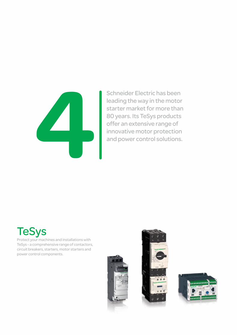
Schneider Electric has been leading the way in the motor starter market for more than 80 years. Its TeSys products offer an extensive range of innovative motor protection and power control solutions.
TeSys Protect your machines and installations with TeSys - a comprehensive range of contactors, circuit breakers, starters, motor starters and power control components.
Motor control
This document is a selection of
the top selling products.
4/1
2
1
3
4
5
6
7
8
9
10
Motor control components TeSys contactors ......................................................................................................4/2 to 4/11 Contactors, TeSys K, D, F, B Variable composition contactors, TeSys CV
TeSys protection components ......................................................................... 4/12 to 4/33 Thermal-magnetic circuit-breakers Magnetic circuit-breakers Fuse carriers, switch-disconnector-fuses Thermal overload relays Electronic thermal overload relays Electronic overload relays Starter-controller, TeSys T Multifunction protection relays Switch disconnectors Mini Vario and Vario
TeSys starters ......................................................................................................... 4/34 to 4/41 Combination motor starters Starter-controller, TeSys U Controller, TeSys U Enclosed motor starters
TeSys installation system .................................................................................. 4/42 to 4/43 For motor starter components with spring terminals, TeSys Quickfit technology
Components for power control applications ................................................................ 4/44 to 4/50
Lighting, capacitor switching, heating and changeover contactor pairs
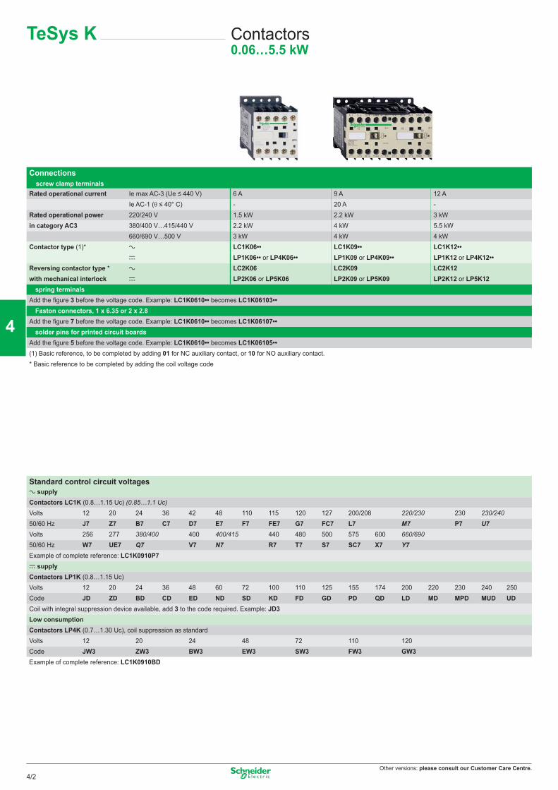
Other versions: please consult our Customer Care Centre.
Connections screw clamp terminals
Rated operational current Ie max AC-3 (Ue ≤ 440 V) 6 A 9 A 12 AIe AC-1 (θ ≤ 40° C) - 20 A -
Rated operational power 220/240 V 1.5 kW 2.2 kW 3 kWin category AC3 380/400 V…415/440 V 2.2 kW 4 kW 5.5 kW
660/690 V…500 V 3 kW 4 kW 4 kWContactor type (1)* a LC1K06•• LC1K09•• LC1K12••
c LP1K06•• or LP4K06•• LP1K09 or LP4K09•• LP1K12 or LP4K12••Reversing contactor type * a LC2K06 LC2K09 LC2K12with mechanical interlock c LP2K06 or LP5K06 LP2K09 or LP5K09 LP2K12 or LP5K12b spring terminalsAdd the figure 3 before the voltage code. Example: LC1K0610•• becomes LC1K06103••b Faston connectors, 1 x 6.35 or 2 x 2.8Add the figure 7 before the voltage code. Example: LC1K0610•• becomes LC1K06107••b solder pins for printed circuit boardsAdd the figure 5 before the voltage code. Example: LC1K0610•• becomes LC1K06105••(1) Basic reference, to be completed by adding 01 for NC auxiliary contact, or 10 for NO auxiliary contact.* Basic reference to be completed by adding the coil voltage code
Standard control circuit voltagesa supply Contactors LC1K (0.8…1.15 Uc) (0.85…1.1 Uc)Volts 12 20 24 36 42 48 110 115 120 127 200/208 220/230 230 230/24050/60 Hz J7 Z7 B7 C7 D7 E7 F7 FE7 G7 FC7 L7 M7 P7 U7Volts 256 277 380/400 400 400/415 440 480 500 575 600 660/69050/60 Hz W7 UE7 Q7 V7 N7 R7 T7 S7 SC7 X7 Y7Example of complete reference: LC1K0910P7c supply Contactors LP1K (0.8…1.15 Uc)Volts 12 20 24 36 48 60 72 100 110 125 155 174 200 220 230 240 250Code JD ZD BD CD ED ND SD KD FD GD PD QD LD MD MPD MUD UDCoil with integral suppression device available, add 3 to the code required. Example: JD3Low consumptionContactors LP4K (0.7…1.30 Uc), coil suppression as standardVolts 12 20 24 48 72 110 120Code JW3 ZW3 BW3 EW3 SW3 FW3 GW3Example of complete reference: LC1K0910BD
TeSys K Contactors0.06…5.5 kW
4/2
2
1
3
4
5
6
7
8
9
10
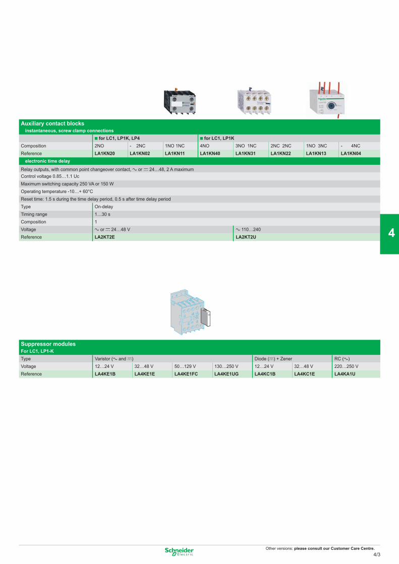
Other versions: please consult our Customer Care Centre.
Auxiliary contact blocks instantaneous, screw clamp connections
for LC1, LP1K, LP4 for LC1, LP1KComposition 2NO - 2NC 1NO 1NC 4NO 3NO 1NC 2NC 2NC 1NO 3NC - 4NCReference LA1KN20 LA1KN02 LA1KN11 LA1KN40 LA1KN31 LA1KN22 LA1KN13 LA1KN04
electronic time delay
Relay outputs, with common point changeover contact, a or c 24…48, 2 A maximumControl voltage 0.85…1.1 UcMaximum switching capacity 250 VA or 150 WOperating temperature -10…+ 60°CReset time: 1.5 s during the time delay period, 0.5 s after time delay periodType On-delayTiming range 1…30 sComposition 1 Voltage a or c 24…48 V a 110…240Reference LA2KT2E LA2KT2U
Suppressor modulesFor LC1, LP1-KType Varistor (a and c) Diode (c) + Zener RC (a)Voltage 12…24 V 32…48 V 50…129 V 130…250 V 12…24 V 32…48 V 220…250 VReference LA4KE1B LA4KE1E LA4KE1FC LA4KE1UG LA4KC1B LA4KC1E LA4KA1U
4/3
2
1
3
4
5
6
7
8
9
10
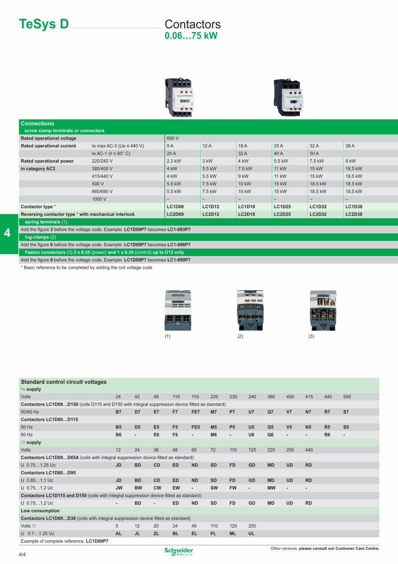
Other versions: please consult our Customer Care Centre.
Connections ■ screw clamp terminals or connectorsRated operational voltage 690 VRated operational current Ie max AC-3 (Ue ≤ 440 V) 9 A 12 A 18 A 25 A 32 A 38 A
Ie AC-1 (θ ≤ 60° C) 25 A 32 A 40 A 50 ARated operational power 220/240 V 2.2 kW 3 kW 4 kW 5.5 kW 7.5 kW 9 kWin category AC3 380/400 V 4 kW 5.5 kW 7.5 kW 11 kW 15 kW 18.5 kW
415/440 V 4 kW 5.5 kW 9 kW 11 kW 15 kW 18.5 kW500 V 5.5 kW 7.5 kW 10 kW 15 kW 18.5 kW 18.5 kW660/690 V 5.5 kW 7.5 kW 10 kW 15 kW 18.5 kW 18.5 kW1000 V – – – – – –
Contactor type * LC1D09 LC1D12 LC1D18 LC1D25 LC1D32 LC1D38Reversing contactor type * with mechanical interlock LC2D09 LC2D12 LC2D18 LC2D25 LC2D32 LC2D38
spring terminals (1)Add the figure 3 before the voltage code. Example: LC1D09P7 becomes LC1-093P7
lug-clamps (2)Add the figure 6 before the voltage code. Example: LC1D09P7 becomes LC1-096P7
Faston connectors (3) 2 x 6.35 (power) and 1 x 6.35 (control) up to D12 onlyAdd the figure 9 before the voltage code. Example: LC1D09P7 becomes LC1-099P7* Basic reference to be completed by adding the coil voltage code
Standard control circuit voltagesa supply Volts 24 42 48 110 115 220 230 240 380 400 415 440 500Contactors LC1D09…D150 (coils D115 and D150 with integral suppression device fitted as standard)50/60 Hz B7 D7 E7 F7 FE7 M7 P7 U7 Q7 V7 N7 R7 S7Contactors LC1D80…D11550 Hz B5 D5 E5 F5 FE5 M5 P5 U5 Q5 V5 N5 R5 S560 Hz B6 - E6 F6 - M6 - U6 Q6 - - R6 -c supply Volts 12 24 36 48 60 72 110 125 220 250 440Contactors LC1D09…D65A (coils with integral suppression device fitted as standard)U 0.75…1.25 Uc JD BD CD ED ND SD FD GD MD UD RDContactors LC1D80…D95U 0.85…1.1 Uc JD BD CD ED ND SD FD GD MD UD RD U 0.75…1.2 Uc JW BW CW EW - SW FW - MW - -Contactors LC1D115 and D150 (coils with integral suppression device fitted as standard)U 0.75…1.2 Uc - BD - ED ND SD FD GD MD UD RDLow consumptionContactors LC1D09…D38 (coils with integral suppression device fitted as standard)Volts c 5 12 20 24 48 110 120 250U 0.7…1.25 Uc AL JL ZL BL EL FL ML ULExample of complete reference: LC1D09P7
TeSys D Contactors0.06…75 kW
(1) (3)(2)
4/4
2
1
3
4
5
6
7
8
9
10
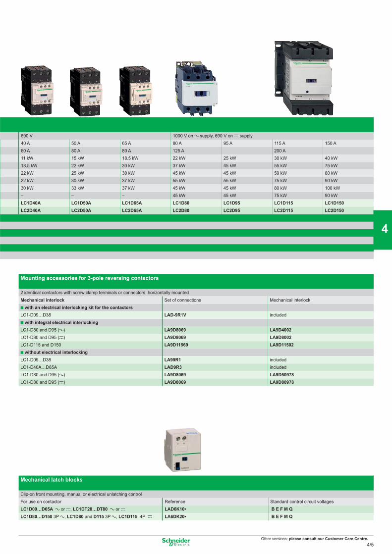
Other versions: please consult our Customer Care Centre.
Mounting accessories for 3-pole reversing contactors
2 identical contactors with screw clamp terminals or connectors, horizontally mountedMechanical interlock Set of connections Mechanical interlock
with an electrical interlocking kit for the contactors LC1-D09…D38 LAD-9R1V included
with integral electrical interlockingLC1-D80 and D95 (a) LA9D8069 LA9D4002LC1-D80 and D95 (c) LA9D8069 LA9D8002LC1-D115 and D150 LA9D11569 LA9D11502
without electrical interlocking LC1-D09…D38 LA99R1 includedLC1-D40A…D65A LAD9R3 includedLC1-D80 and D95 (a) LA9D8069 LA9D50978LC1-D80 and D95 (c) LA9D8069 LA9D80978
Mechanical latch blocks
Clip-on front mounting, manual or electrical unlatching controlFor use on contactor Reference Standard control circuit voltagesLC1D09…D65A a or c, LC1DT20…DT80 a or c LAD6K10• B E F M QLC1D80…D150 3P a, LC1D80 and D115 3P a, LC1D115 4P c LA6DK20• B E F M Q
690 V 1000 V on a supply, 690 V on c supply40 A 50 A 65 A 80 A 95 A 115 A 150 A60 A 80 A 80 A 125 A 200 A11 kW 15 kW 18.5 kW 22 kW 25 kW 30 kW 40 kW18.5 kW 22 kW 30 kW 37 kW 45 kW 55 kW 75 kW22 kW 25 kW 30 kW 45 kW 45 kW 59 kW 80 kW22 kW 30 kW 37 kW 55 kW 55 kW 75 kW 90 kW30 kW 33 kW 37 kW 45 kW 45 kW 80 kW 100 kW– – – 45 kW 45 kW 75 kW 90 kWLC1D40A LC1D50A LC1D65A LC1D80 LC1D95 LC1D115 LC1D150LC2D40A LC2D50A LC2D65A LC2D80 LC2D95 LC2D115 LC2D150
4/5
2
1
3
4
5
6
7
8
9
10
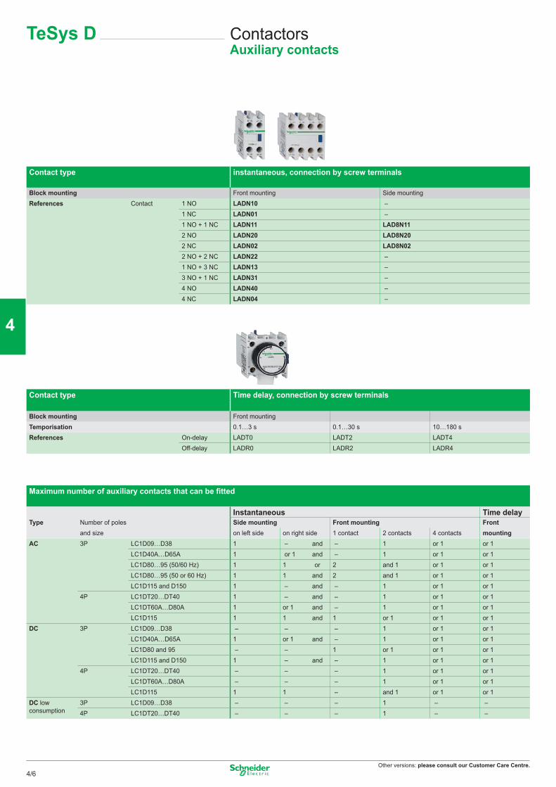
Other versions: please consult our Customer Care Centre.
TeSys D ContactorsAuxiliary contacts
Contact type instantaneous, connection by screw terminals
Block mounting Front mounting Side mountingReferences Contact 1 NO LADN10 –
1 NC LADN01 –1 NO + 1 NC LADN11 LAD8N112 NO LADN20 LAD8N202 NC LADN02 LAD8N022 NO + 2 NC LADN22 –1 NO + 3 NC LADN13 –3 NO + 1 NC LADN31 –4 NO LADN40 –4 NC LADN04 –
Contact type Time delay, connection by screw terminals
Block mounting Front mountingTemporisation 0.1…3 s 0.1…30 s 10…180 sReferences On-delay LADT0 LADT2 LADT4
Off-delay LADR0 LADR2 LADR4
Maximum number of auxiliary contacts that can be fitted
Instantaneous Time delayType Number of poles Side mounting Front mounting Front
and size on left side on right side 1 contact 2 contacts 4 contacts mountingAC 3P LC1D09…D38 1 – and – 1 or 1 or 1
LC1D40A…D65A 1 or 1 and – 1 or 1 or 1LC1D80…95 (50/60 Hz) 1 1 or 2 and 1 or 1 or 1LC1D80…95 (50 or 60 Hz) 1 1 and 2 and 1 or 1 or 1LC1D115 and D150 1 – and – 1 or 1 or 1
4P LC1DT20…DT40 1 – and – 1 or 1 or 1LC1DT60A…D80A 1 or 1 and – 1 or 1 or 1LC1D115 1 1 and 1 or 1 or 1 or 1
DC 3P LC1D09…D38 – – – 1 or 1 or 1LC1D40A…D65A 1 or 1 and – 1 or 1 or 1LC1D80 and 95 – – 1 or 1 or 1 or 1LC1D115 and D150 1 – and – 1 or 1 or 1
4P LC1DT20…DT40 – – – 1 or 1 or 1LC1DT60A…D80A – – – 1 or 1 or 1LC1D115 1 1 – and 1 or 1 or 1
DC lowconsumption
3P LC1D09…D38 – – – 1 – –4P LC1DT20…DT40 – – – 1 – –
4/6
2
1
3
4
5
6
7
8
9
10
Other versions: please consult our Customer Care Centre.
Type of module RC circuits (Resistor-Capacitor)
Mounting Side clip-on Front clip-on Screw fixing
For use with contactor D09…D38(3P) DT20…DT40(4P) D40A…D65A(3P) DT60A…DT80A(4P) D80…D150(3P) D40…D115(4P)
References Voltage 24…48 VAC LAD4RCE LAD4RC3E LA4DA2E50…127 VAC LAD4RCG LAD4RC3G LA4DA2G110…240 VAC LAD4RCU LAD4RC3U LA4DA2U380…415 VAC – LAD4RC3N LA4DA2N
Type of module Varistors (peak limiting)
Mounting Side clip-on Front clip-on Screw fixing
For use with contactor D09…D38(3P) DT20…DT40(4P) D40A…D65A(3P) DT60A…DT80A(4P) D80…D150(3P) D40…D115(4P)
References Voltage 24…48 VAC LAD4VE LAD4V3E LA4DE2E50…127 VAC LAD4VG LAD4V3G LA4DE2G110…240 VAC LAD4VU LAD4V3U LA4DE2U24…48 VDC – – LAD4DE3E (AC and DC)
50…127 VDC – – LAD4DE3G (AC and DC)
110…240 VDC – – LAD4DE3U (AC and DC)
Type of module Flywheel diodes
Mounting Side clip-on Front clip-on Screw fixing
For use with contactor D09…D38(3P) DT20…DT40(4P) D40A…D65A(3P) DT60A…DT80A(4P) D80…D150(3P) D40…D115(4P)
References Voltage 24…250 VDC LAD4DDL LAD4D3U LAD4DC3U
Type of module Bidirectional peak limiting diode
Mounting Side clip-on Front clip-on Screw fixing
For use with contactor D09…D38(3P) DT20…DT40(4P) D40A…D65A(3P) DT60A…DT80A(4P) D80…D150(3P) D40…D115(4P)
References Voltage 24 VAC LAD4TB LAD4T3B LA4DB2B24 VDC LAD4TBDL LAD4T3B LA4DB2S72 VAC LAD4TS LAD4T3S LA4DB3B72 VDC LAD4TSDL LAD4T3S LA4DB3S125 VDC LAD4TGDL LAD4T3G (AC and DC) –
250 VDC LAD4TUDL LAD4T3U (AC and DC) –
600 VDC LAD4TXDL LAD4T3R (AC and DC) –
TeSys D ContactorsSuppressor modules
4/7
2
1
3
4
5
6
7
8
9
10
Other versions: please consult our Customer Care Centre.
Rated operational current Ie max AC-3 (Ue ≤ 440 V) 185 A 225 A 265 A 330 AIe AC-1 (θ ≤ 40° C) 275 A 315 V 350 A 400 A
Rated operational voltage 1 000 V 1 000 V 1 000 V 1 000 VNumber of poles 3 or 4 3 or 4 3 or 4 3 or 4Rated operational power 220/240 V 55 kW 63 kW 75 kW 100 kWin category AC3 380/400 V 90 kW 110 kW 132 kW 160 kW
415 V 100 kW 110 kW 140 kW 180 kW440 V 100 kW 110 kW 140 kW 200 kW500 V 110 kW 129 kW 160 kW 200 kW660/690 V 110 kW 129 kW 160 kW 220 kW1000 V 100 kW 100 kW 147 kW 160 kW
Contactor type* LC1F185 LC1F225 LC1F265 LC1F330Reversing contactor type* LC2F185 LC2F225 LC2F265
* Basic reference to be completed by adding the coil voltage code
Standard control circuit voltagesa supply Volts 24 48 110 115 120 208 220 230 240 380 400 415 440Contactors LC1F115…F225 (0.85…1.1 Uc)50 Hz (coil LX1) B5 E5 F5 FE5 - - M5 P5 U5 Q5 V5 N5 -60 Hz (coil LX1) - E6 F6 - G6 L6 M6 - U6 Q6 - - R6U740…400 Hz (coil LX9) - E7 F7 FE7 G7 L7 M7 P7 U7 Q7 V7 N7 R7Contactors LC1F265…F330U740…400 Hz (coil LX1) B7 E7 F7 FE7 G7 L7 M7 P7 U7 Q7 V7 N7 R7Contactors LC1F400…F630U740…400 Hz (coil LX1) - E7 F7 FE7 G7 (1) L7 M7 P7 U7 Q7 V7 N7 R7Contactor LC1F780U740…400 Hz (coil LX1) - - F7 FE7 F7 L7 M7 P7 U7 Q7 V7 N7 R7Contactor LC1F800U740…400 Hz (coil LX1) - - FE7 FE7 FE7 - P7 P7 P7 V7 V7 V7 V7Y7c supply Volts 24 48 110 125 220 230 250 400 440Contactors LC1F115…F330 (0.85…1.1 Uc)(coil LX4-F) BD ED FD GD MD MD UD - RDContactors LC1F400…F630 (0.85…1.1 Uc)(coil LX4-F) - ED FD GD MD - UD - RDContactor LC1F780 (0.85…1.1 Uc)(coil LX4-F) - - FD GD MD - UD - RDContactor LC1F800 (0.85…1.1 Uc)(coil LX4-F) - - FW FW MW MW - QW -Contactor LC1F1250(coil LX4F) - ED FD - MD - UD - - - - - -Contactor LC1F1400(coil LX4F) - - FD GD MD - UD - RD - - - -Example: For a 630 A contactor with a 110 V a coil, order LC1F630F7
(1) F7 for LC1-F630
TeSys F Contactors90…450 kW
4/8
2
1
3
4
5
6
7
8
9
10
Other versions: please consult our Customer Care Centre.
Auxiliary contact blocks instantaneous dust & damp protected contacts time delay 1 NO + 1 NC
Composition Reference Composition Reference Composition Reference Composition Reference Type Range ReferenceNO NC NO NC NO NC NO NC1 - LADN10 1 1 LADN11 2 2 LADN22 2 - - - LA1DX20 On-delay 0.1…3 s LADT0- 1 LADN01 2 - LADN20 1 3 LADN13 2 2 - - LA1DY20 0.1…30 s LADT2
- 2 LADN02 4 - LADN40 2 - 2 - LA1DZ40 10…180 s LADT4- 4 LADN04 2 - 1 1 LA1DZ31 1…30 s LADS23 1 LADN31 Off-delay 0.1…3 s LADR02 2 LADC22 0.1…30 s LADR2
10…180 s LADR4
Mounting accessories for 3-pole reversing contactors for motor control
2 identical contactors, horizontally mountedMechanical interlock with an electrical interlocking kit for the contactors Contactor type Set of connections Mechanical interlockLC1F115 LA9FF976 LA9FF970LC1F150 LA9F15076 LA9FF970LC1F185 LA9FG976 LA9FG970LC1F225 LA9F22576 LA9FG970LC1F265 LA9FH976 LA9FJ970LC1F330 LA9FJ976 LA9FJ970LC1F400 LA9FJ976 LA9FJ970LC1F500 LA9FK976 LA9FJ970LC1F630 or LC1F800 LA9FL976 LA9FL970LCIF1250 - -LCIF1400 - -
400 A 500 A 630 A 780 A 800 A - -500 A 700 A 1 000 A 1 600 A 1 000 A 1260 14001 000 V 1 000 V 1 000 V 1 000 V 1 000 V 1000 10002, 3 or 4 2, 3 or 4 2, 3 or 4 3 or 4 3 3 3110 kW 147 kW 200 kW 220 kW 250 kW Sans objets Sans objets200 kW 250 kW 335 kW 400 kW 450 kW en AC1 en AC1220 kW 280 kW 375 kW 425 kW 450 kW - -250 kW 295 kW 400 kW 425 kW 450 kW - -257 kW 355 kW 400 kW 450 kW 450 kW - -280 kW 335 kW 450 kW 475 kW 475 kW - -185 kW 335 kW 450 kW 450 kW 450 kW - -LC1F400 LC1F500 LC1F630 LC1F780 LC1F800 LC1F1250 LC1F1400
For customer assembly - -
4/9
2
1
3
4
5
6
7
8
9
10
Other versions: please consult our Customer Care Centre.
Standard control circuit voltages (for other voltages, please consult your Regional Sales Office)Volts 48 110 125 127 220 230 240 380 400 415 440 500a 50…400 Hz - F - G M P U Q V N R Sc ED FD GD - MD - - - - - RD -
Example: To order a 1500 A contactor with 127 V c coil with 3 NO + 1 NC, select LC1BP33G31
Mounting accessories
Description For contactor ReferenceBar support bracket LC1BL to BR LA9B103for mounting on 120 or 150 mm centresMechanical interlock and locking device components LC1B EZ2LB0601
Rated operational current Ie max AC-3 (Ue ≤ 440 V) 750 A 1000 A 1500 A 1800 AIe AC-1 (θ ≤ 40° C) 800 A 1250 V 2000 A 2750 A
Rated operational voltage 1 000 V 1 000 V 1 000 V 1 000 VNumber of poles 1 to 4 1 to 4 1 to 4 1 to 4Rated operational power 220/240 V 220 kW 280 kW 425 kW 500 kWin category AC3 380/400 V 400 kW 500 kW 750 kW 900 kW
415 V 425 kW 530 kW 800 kW 900 kW440 V 450 kW 560 kW 800 kW 900 kW500 V 500 kW 600 kW 700 kW 900 kW660/690 V 560 kW 670 kW 750 kW 900 kW1000 V 530 kW 530 kW 670 kW 750 kW
4 instantaneous contact configurations 2 NC + 2 NO, 3 NO + 1 NC, 1 NO + 3 NC or 4 NOContactor type* LC1BL LC1BM LC1BP LC1BR
* Basic reference to be completed by adding the coil voltage code, followed by the instantaneous contact configuration.
TeSys B Contactors400…900 kW
4/10
2
1
3
4
5
6
7
8
9
10
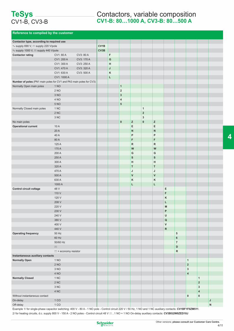
Other versions: please consult our Customer Care Centre.
Reference to compiled by the customer
Contactor type, according to required usea supply 690 V, c supply 220 V/pole CV1Ba supply 1000 V, c supply 440 V/pole CV3BContactor rating CV1: 80 A CV3: 80 A F
CV1: 200 A CV3: 170 A GCV1: 300 A CV3: 250 A HCV1: 470 A CV3: 320 A JCV1: 630 A CV3: 500 A KCV1: 1000 A L
Number of poles (PN1 main poles for CV1 and PA3 main poles for CV3)Normally Open main poles 1 NO 1
2 NO 23 NO 34 NO 45 NO 5
Normally Closed main poles 1 NC 12 NC 23 NC 3
No main poles 0 Z 0 ZOperational current 10 A E E
20 A N N40 A P P80 A F F125 A R R170 A W W200 A G G250 A S S300 A H H320 A T T470 A J J500 A V V630 A K K1000 A L L
Control circuit voltage 48 V E110 V F120 V K208 V L220 V M 230 V P240 V U380 V Q400 V V440 V R
Operating frequency 50 Hz 560 Hz 650/60 Hz 7c Dc + economy resistor R
Instantaneous auxiliary contactsNormally Open 1 NO 1
2 NO 23 NO 34 NO 4
Normally Closed 1 NC 12 NC 23 NC 34 NC 4
Without instantaneous contact 0 0On-delay 1 CO JOff-delay 1 CO NExample 1/ for single-phase capacitor switching: 400 V - 80 A - 1 NO pole - Control circuit 220 V / 50 Hz, 1 NO and 1 NC auxiliary contacts: CV1BF1F0ZM511.2/ for heating circuits, d.c. supply 800 V - 150 A - 2 NO poles - Control circuit 48 V c , 1 NO + 1 NO On-delay auxiliary contacts: CV3BG2W0ZED10J
TeSys CV1-B, CV3-B
Contactors, variable compositionCV1-B: 80…1000 A, CV3-B: 80…500 A
4/11
2
1
3
4
5
6
7
8
9
10
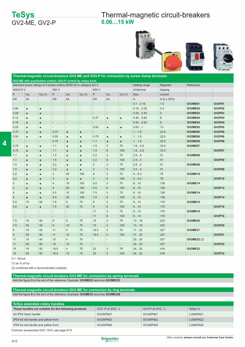
Other versions: please consult our Customer Care Centre.
Thermal-magnetic circuit-breakers GV2-ME and GV2-P for connection by screw clamp terminalsGV2-ME with pushbutton control, GV2-P control by rotary knobStandard power ratings of 3-phase motors 50/60 Hz in category AC-3 Setting range Magnetic Reference400/415 V 500 V 690 V of thermal trippingP Icu Ics (1) P Icu Ics (1) P Icu Ics (1) trips currentkW kA kW kA kW kA A A (d ± 20%)- - - - - - - - - 0.1…0.16 1.5 GV2ME01 GV2P010.06 - - - - - - 0.16…0.25 2.4 GV2ME02 GV2P020.09 - - - - - - 0.25…0.40 5 GV2ME03 GV2P030.12 - - - 0.37 0.40…0.63 8 GV2ME04 GV2P040.18 - - - - - - 0.40…0.63 8 GV2ME04 GV2P040.25 - - - 0.55 - 0.63…1 13 GV2ME05 GV2P050.37 0.37 - - - 1…1.6 22.5 GV2ME06 GV2P060.55 0.55 0.75 1…1.6 22.5 GV2ME06 GV2P06- - - 0.75 1.1 1…1.6 22.5 GV2ME06 GV2P060.75 1.1 1.5 3 75 1.6…2.5 33.5 GV2ME070.75 1.1 1.5 8 100 1.6…2.5 33.5 GV2P071.1 1.5 2.2 3 75 2.5…4 51 GV2ME081.1 1.5 2.2 8 100 2.5…4 51 GV2P081.5 2.2 3 3 75 2.5…4 51 GV2ME081.5 2.2 3 3 100 2.5…4 51 GV2P082.2 3 50 100 4 3 75 4…6.3 78 GV2ME102.2 3 4 6 100 4…6.3 78 GV2P103 4 10 100 5.5 3 75 6…10 138 GV2ME143 4 50 100 5.5 6 100 6…10 138 GV2P144 5.5 10 100 7.5 3 75 6…10 138 GV2ME144 5.5 50 100 7.5 6 100 6…10 138 GV2P145.5 15 50 7.5 6 75 9 3 75 9…14 170 GV2ME165.5 7.5 42 75 9 6 100 9…14 170 GV2P16- - - - - - 11 3 75 9…14 170 GV2ME16- - - - - - 11 6 100 9…14 170 GV2P167.5 15 50 9 6 75 15 3 75 13…18 223 GV2ME207.5 50 50 9 10 75 15 4 100 13…18 223 GV2P209 15 40 11 4 75 18.5 3 75 17…23 327 GV2ME219 50 50 11 10 75 18.5 4 100 17…23 327 GV2P2111 15 40 15 4 75 - - - 20…25 327 GV2ME22 (2)11 50 50 15 10 75 - - - 20…25 327 GV2P2215 10 50 18.5 4 75 22 3 75 24…32 416 GV2ME3215 50 50 18.5 10 75 22 4 100 24…32 416 GV2P32
H > 100 kA(1) as % of Icu(2) combined with a recommended contactor
Thermal-magnetic circuit-breakers GV2-ME for connection by spring terminalsAdd the figure 3 to the end of the reference. Example: GV2ME22 becomes GV2ME223
Thermal-magnetic circuit-breakers GV2-ME for connection by ring terminalsAdd the figure 6 to the end of the reference. Example: GV2ME32 becomes GV2ME326
TeSys extended rotary handlesThese handles are suitable for the following products GV2 -P et GV2 - L GV3-P et GV3 - L TeSys U
Kit IP54 black handle GV2APN01 GV3APN01 LU9APN21
IP54 kit red handle and yellow front GV2APN02 GV3APN02 LU9APN22
IP65 kit red handle and yellow front GV2APN04 GV3APN04 LU9APN24
Common accessories GV2 / GV3, see page 5/15
TeSys GV2-ME, GV2-P
Thermal-magnetic circuit-breakers0.06…15 kW
4/12
2
1
3
4
5
6
7
8
9
10
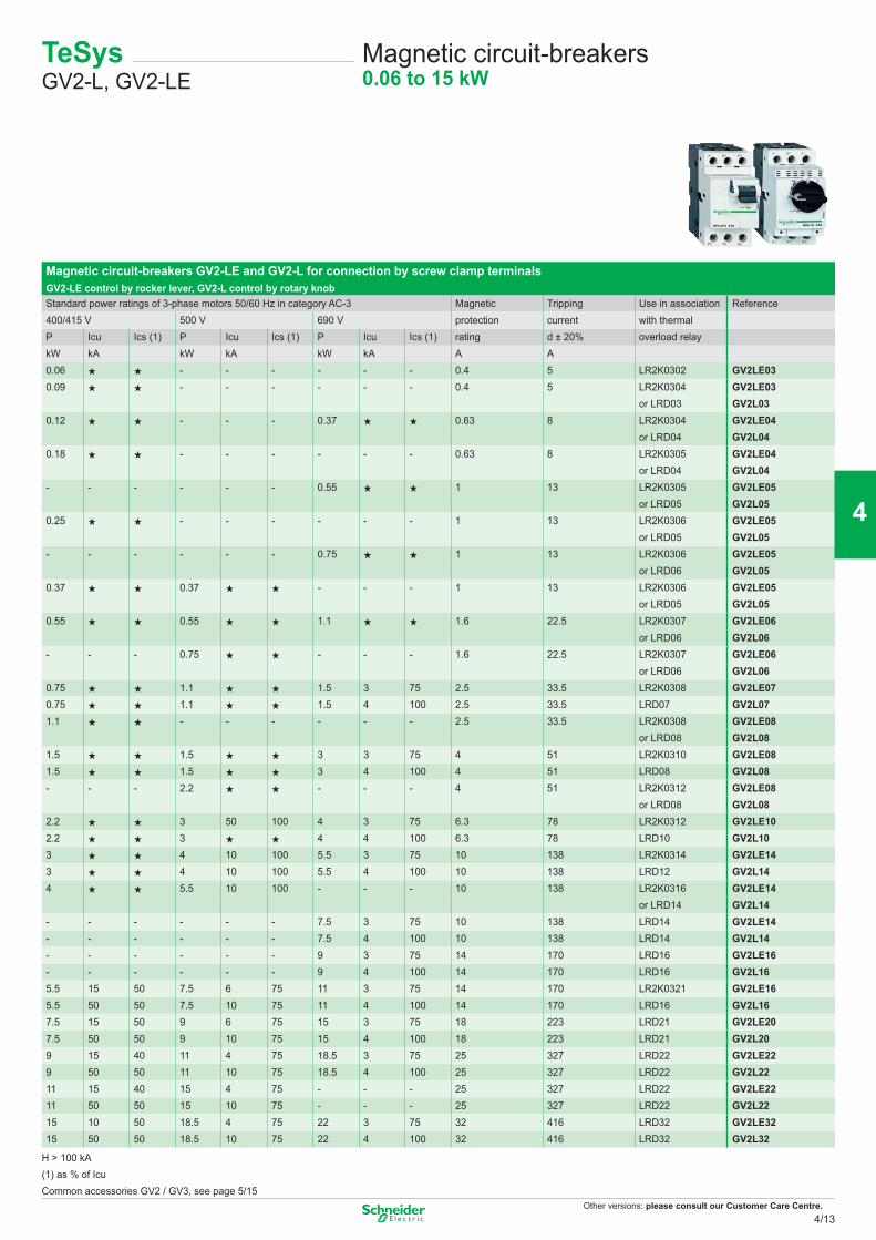
Other versions: please consult our Customer Care Centre.
Magnetic circuit-breakers GV2-LE and GV2-L for connection by screw clamp terminalsGV2-LE control by rocker lever, GV2-L control by rotary knobStandard power ratings of 3-phase motors 50/60 Hz in category AC-3 Magnetic Tripping Use in association Reference400/415 V 500 V 690 V protection current with thermalP Icu Ics (1) P Icu Ics (1) P Icu Ics (1) rating d ± 20% overload relaykW kA kW kA kW kA A A0.06 - - - - - - 0.4 5 LR2K0302 GV2LE030.09 - - - - - - 0.4 5 LR2K0304 GV2LE03
or LRD03 GV2L030.12 - - - 0.37 0.63 8 LR2K0304 GV2LE04
or LRD04 GV2L040.18 - - - - - - 0.63 8 LR2K0305 GV2LE04
or LRD04 GV2L04- - - - - - 0.55 1 13 LR2K0305 GV2LE05
or LRD05 GV2L050.25 - - - - - - 1 13 LR2K0306 GV2LE05
or LRD05 GV2L05- - - - - - 0.75 1 13 LR2K0306 GV2LE05
or LRD06 GV2L050.37 0.37 - - - 1 13 LR2K0306 GV2LE05
or LRD05 GV2L050.55 0.55 1.1 1.6 22.5 LR2K0307 GV2LE06
or LRD06 GV2L06- - - 0.75 - - - 1.6 22.5 LR2K0307 GV2LE06
or LRD06 GV2L060.75 1.1 1.5 3 75 2.5 33.5 LR2K0308 GV2LE070.75 1.1 1.5 4 100 2.5 33.5 LRD07 GV2L071.1 - - - - - - 2.5 33.5 LR2K0308 GV2LE08
or LRD08 GV2L081.5 1.5 3 3 75 4 51 LR2K0310 GV2LE081.5 1.5 3 4 100 4 51 LRD08 GV2L08- - - 2.2 - - - 4 51 LR2K0312 GV2LE08
or LRD08 GV2L082.2 3 50 100 4 3 75 6.3 78 LR2K0312 GV2LE102.2 3 4 4 100 6.3 78 LRD10 GV2L103 4 10 100 5.5 3 75 10 138 LR2K0314 GV2LE143 4 10 100 5.5 4 100 10 138 LRD12 GV2L144 5.5 10 100 - - - 10 138 LR2K0316 GV2LE14
or LRD14 GV2L14- - - - - - 7.5 3 75 10 138 LRD14 GV2LE14- - - - - - 7.5 4 100 10 138 LRD14 GV2L14- - - - - - 9 3 75 14 170 LRD16 GV2LE16- - - - - - 9 4 100 14 170 LRD16 GV2L165.5 15 50 7.5 6 75 11 3 75 14 170 LR2K0321 GV2LE165.5 50 50 7.5 10 75 11 4 100 14 170 LRD16 GV2L167.5 15 50 9 6 75 15 3 75 18 223 LRD21 GV2LE207.5 50 50 9 10 75 15 4 100 18 223 LRD21 GV2L209 15 40 11 4 75 18.5 3 75 25 327 LRD22 GV2LE229 50 50 11 10 75 18.5 4 100 25 327 LRD22 GV2L2211 15 40 15 4 75 - - - 25 327 LRD22 GV2LE2211 50 50 15 10 75 - - - 25 327 LRD22 GV2L2215 10 50 18.5 4 75 22 3 75 32 416 LRD32 GV2LE3215 50 50 18.5 10 75 22 4 100 32 416 LRD32 GV2L32
H > 100 kA(1) as % of IcuCommon accessories GV2 / GV3, see page 5/15
TeSys GV2-L, GV2-LE
Magnetic circuit-breakers0.06 to 15 kW
4/13
2
1
3
4
5
6
7
8
9
10
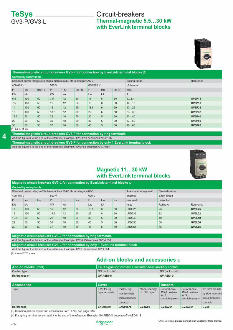
Other versions: please consult our Customer Care Centre.
Thermal-magnetic circuit-breakers GV3-P for connection by EverLink terminal blocks (2)Control by rotary knobStandard power ratings of 3-phase motors 50/60 Hz in category AC-3 Setting range Reference400/415 V 500 V 660/690 V of thermalP Icu Ics (1) P Icu Ics (1) P Icu Ics (1) tripskW kA kW kA kW kA A5.5 100 50 7.5 12 50 11 6 50 9…13 GV3P137.5 100 50 11 12 50 15 6 50 12…18 GV3P1811 100 50 15 12 50 18.5 6 50 17…25 GV3P2515 100 50 18.5 12 50 22 6 50 23…32 GV3P3218.5 50 50 22 10 50 30 5 60 30…40 GV3P4022 50 50 30 10 50 37 5 60 37…50 GV3P5030 50 50 37 10 50 45 5 60 48…65 GV3P65
(1) as % of lcu
Thermal-magnetic circuit-breakers GV3-P for connection by ring terminalsAdd the fi gure 6 to the end of the reference. Example: GV3-P13 becomes GV3-P136Thermal-magnetic circuit-breakers GV3-P for connection by only 1 EverLink terminal blockAdd the fi gure 1 to the end of the reference. Example: GV3P65 becomes GV3P651
Magnetic 11…30 kWwith EverLink terminal blocks
Magnetic circuit-breakers GV3-L for connection by EverLink terminal blocks (2)Control by rotary knobStandard power ratings of 3-phase motors 50/60 Hz in category AC-3 Associated equipment Circuit-breaker400/415 V 500 V 690 V Thermal Short-circuitP Icu Ics P Icu Ics P Icu Ics overload protectionkW kA kW kA kW kA relay Rating A Reference11 100 50 15 12 50 18.5 6 50 LRD325 25 GV3L2515 100 50 18.5 12 50 22 6 50 LRD332 32 GV3L3218.5 50 50 22 10 50 30 5 60 LRD340 40 GV3L4022 50 50 30 10 50 45 5 60 LRD350 50 GV3L5030 50 50 37 10 50 45 5 60 LRD365 65 GV3L65
Magnetic circuit-breakers GV3-L for connection by ring terminalsAdd the fi gure 6 to the end of the reference. Example: GV3-L25 becomes GV3-L256
Magnetic circuit-breakers GV3-L for connection by only 1 EverLink terminal blockAdd the fi gure 1 to the end of the reference. Example: GV3L65 becomes GV3L651
(2) 4 mm BTR screw
Add-on blocks and accessories (3)
Add-on blocks (front) Fault signalling contact + instantaneous auxiliary contactContact type NO (fault) + NC NO (fault) + NOReferences (4) GV-AED011 GV-AED101
Accessories Cover BusbarsType IP20 for lug
type terminalsIP20 for lug type terminals when used with contactor
“Wide spacing” UL 508 type E
Set of 3-pole 115 A busbars for 2 circuit-breakers
Set of 3-pole 115 A busbars for 3 circuit-breakers
“S” form for side by side mounted circuit-breaker/contactor
References LAD96570 LAD96575 GV3G66 GV3G264 GV3G364 GV3S(3) Common add-on blocks and accessories GV2 / GV3, see page 5/15(4) For spring terminal version add 3 to the end of the reference. Example: GV-AED011 becomes GV-AED0113
TeSys GV3-P/GV3-L
Circuit-breakersThermal-magnetic 5.5…30 kWwith EverLink terminal blocks
4/14
2
1
3
4
5
6
7
8
9
10
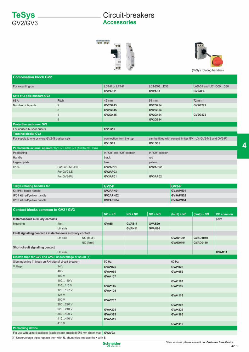
Other versions: please consult our Customer Care Centre.
Combination block GV2
For mounting on LC1-K or LP1-K LC1-D09…D38 LAD-31 and LC1-D09…D38GV2AF01 GV2AF3 GV2AF4
Sets of 3-pole busbars GV263 A Pitch 45 mm 54 mm 72 mmNumber of tap-offs 2 GV2G245 GV2G254 GV2G272
3 GV2G345 GV2G354 4 GV2G445 GV2G454 GV2G472 5 GV2G554Protective end cover GV2For unused busbar outlets GV1G10Terminal blocks GV2For supply to one or more GV2-G busbar sets connection from the top can be fitted with current limiter GV1-L3 (GV2-ME and GV2-P)
GV1G09 GV1G05Padlockable external operator for GV2 and GV3 (150 to 290 mm)Padlocking In “On” and “Off” position In “Off” position Handle black redLegend plate blue yellowIP 54 For GV2-ME/P/L GV2AP01 GV2AP02
For GV2-LE GV2AP03 –For GV3-P/L GV3AP01 GV3AP02
Contact blocks common to GV2 / GV3NO + NC NO + NC NO + NO (fault) + NC (fault) + NO CO common
Instantaneous auxiliary contacts pointMounting front GVAE1 GVAE11 GVAE20
LH side GVAN11 GVAN20Fault signalling contact + instantaneous auxiliary contact
LH side NO (fault) GVAD1001 GVAD1010 NC (fault) GVAD0101 GVAD0110
Short-circuit signalling contactLH side GVAM11
Electric trips for GV2 and GV3 : undervoltage or shunt (1)Side mounting (1 block on RH side of circuit-breaker) 50 Hz 60 HzVoltage 24 V GVA•025 GVA•026
48 V GVA•055 GVA•056100 V GVA•107100…110 V GVA•107110…115 V GVA•115 GVA•116120…127 V GVA•125127 V GVA•115200 V GVA•207200…220 V GVA•207220…240 V GVA•225 GVA•226380…400 V GVA•385 GVA•386415…440 V GVA•415415 V GVA•416
Padlocking deviceFor use with up to 4 padlocks (padlocks not supplied) Ø 6 mm shank max GV2V03
(1) Undervoltage trips: replace the • with U, shunt trips: replace the • with S
TeSys GV2/GV3
Circuit-breakersAccessories
TeSys rotating handles for GV2-P GV3-PKit IP54 black handle GV2APN01 GV3APN01IP54 kit red/yellow handle GV2APN02 GV3APN02IP65 kit red/yellow handle GV2APN04 GV3APN04
(TeSys rotating handles)
4/15
2
1
3
4
5
6
7
8
9
10
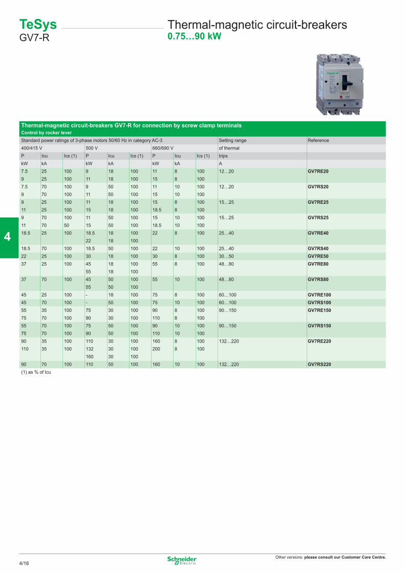
Other versions: please consult our Customer Care Centre.
TeSys GV7-R
Thermal-magnetic circuit-breakers0.75…90 kW
Thermal-magnetic circuit-breakers GV7-R for connection by screw clamp terminalsControl by rocker leverStandard power ratings of 3-phase motors 50/60 Hz in category AC-3 Setting range Reference400/415 V 500 V 660/690 V of thermalP Icu Ics (1) P Icu Ics (1) P Icu Ics (1) tripskW kA kW kA kW kA A7.5 25 100 9 18 100 11 8 100 12…20 GV7RE209 25 100 11 18 100 15 8 1007.5 70 100 9 50 100 11 10 100 12…20 GV7RS209 70 100 11 50 100 15 10 1009 25 100 11 18 100 15 8 100 15…25 GV7RE2511 25 100 15 18 100 18.5 8 1009 70 100 11 50 100 15 10 100 15…25 GV7RS2511 70 50 15 50 100 18.5 10 10018.5 25 100 18.5 18 100 22 8 100 25…40 GV7RE40
22 18 10018.5 70 100 18.5 50 100 22 10 100 25…40 GV7RS4022 25 100 30 18 100 30 8 100 30…50 GV7RE5037 25 100 45 18 100 55 8 100 48…80 GV7RE80
55 18 10037 70 100 45 50 100 55 10 100 48…80 GV7RS80
55 50 10045 25 100 - 18 100 75 8 100 60…100 GV7RE10045 70 100 - 50 100 75 10 100 60…100 GV7RS10055 35 100 75 30 100 90 8 100 90…150 GV7RE15075 70 100 90 30 100 110 8 10055 70 100 75 50 100 90 10 100 90…150 GV7RS15075 70 100 90 50 100 110 10 10090 35 100 110 30 100 160 8 100 132…220 GV7RE220110 35 100 132 30 100 200 8 100
160 30 10090 70 100 110 50 100 160 10 100 132…220 GV7RS220(1) as % of Icu
4/16
2
1
3
4
5
6
7
8
9
10
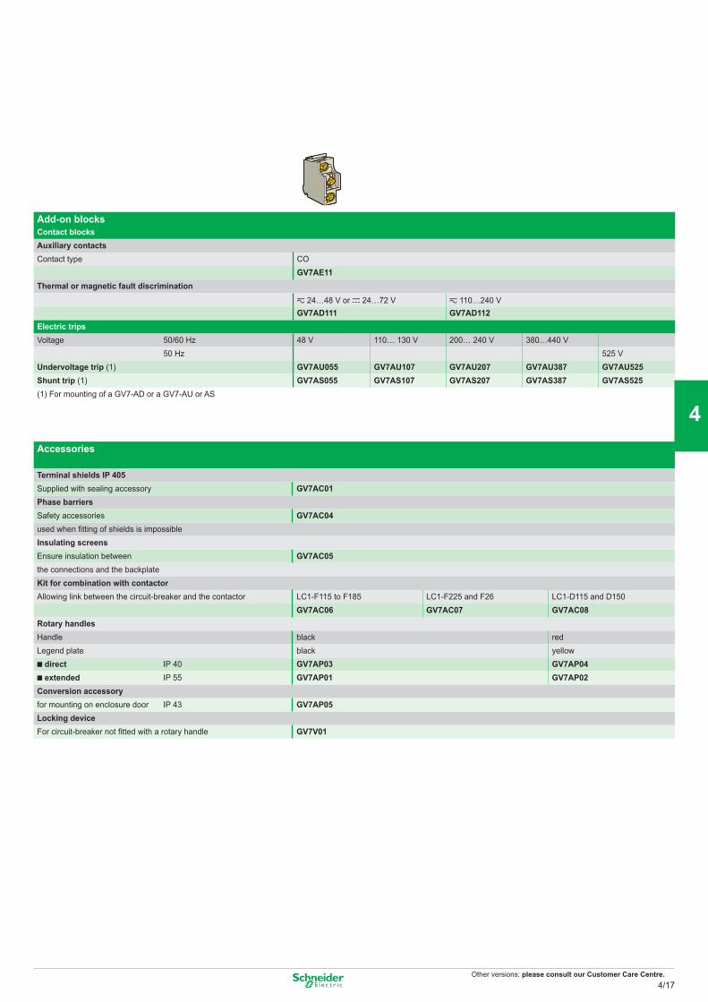
Other versions: please consult our Customer Care Centre.
Add-on blocksContact blocksAuxiliary contactsContact type CO
GV7AE11Thermal or magnetic fault discrimination
z 24…48 V or c 24…72 V z 110…240 VGV7AD111 GV7AD112
Electric tripsVoltage 50/60 Hz 48 V 110… 130 V 200… 240 V 380…440 V
50 Hz 525 VUndervoltage trip (1) GV7AU055 GV7AU107 GV7AU207 GV7AU387 GV7AU525Shunt trip (1) GV7AS055 GV7AS107 GV7AS207 GV7AS387 GV7AS525(1) For mounting of a GV7-AD or a GV7-AU or AS
Accessories
Terminal shields IP 405Supplied with sealing accessory GV7AC01Phase barriersSafety accessories GV7AC04used when fitting of shields is impossibleInsulating screensEnsure insulation between GV7AC05the connections and the backplateKit for combination with contactorAllowing link between the circuit-breaker and the contactor LC1-F115 to F185 LC1-F225 and F26 LC1-D115 and D150
GV7AC06 GV7AC07 GV7AC08Rotary handlesHandle black redLegend plate black yellow
direct IP 40 GV7AP03 GV7AP04 extended IP 55 GV7AP01 GV7AP02
Conversion accessoryfor mounting on enclosure door IP 43 GV7AP05Locking deviceFor circuit-breaker not fitted with a rotary handle GV7V01
4/17
2
1
3
4
5
6
7
8
9
10
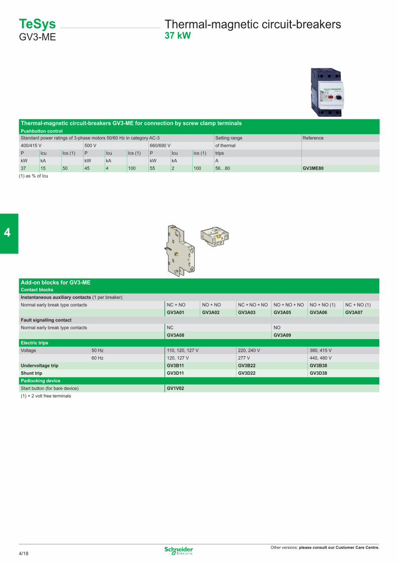
Other versions: please consult our Customer Care Centre.
TeSys GV3-ME
Thermal-magnetic circuit-breakers37 kW
Thermal-magnetic circuit-breakers GV3-ME for connection by screw clamp terminalsPushbutton controlStandard power ratings of 3-phase motors 50/60 Hz in category AC-3 Setting range Reference400/415 V 500 V 660/690 V of thermalP Icu Ics (1) P Icu Ics (1) P Icu Ics (1) tripskW kA kW kA kW kA A37 15 50 45 4 100 55 2 100 56…80 GV3ME80
(1) as % of Icu
Add-on blocks for GV3-MEContact blocksInstantaneous auxiliary contacts (1 per breaker)Normal early break type contacts NC + NO NO + NO NC + NO + NO NO + NO + NO NO + NO (1) NC + NO (1)
GV3A01 GV3A02 GV3A03 GV3A05 GV3A06 GV3A07Fault signalling contactNormal early break type contacts NC NO
GV3A08 GV3A09Electric tripsVoltage 50 Hz 110, 120, 127 V 220, 240 V 380, 415 V
60 Hz 120, 127 V 277 V 440, 480 VUndervoltage trip GV3B11 GV3B22 GV3B38Shunt trip GV3D11 GV3D22 GV3D38Padlocking deviceStart button (for bare device) GV1V02(1) + 2 volt free terminals
4/18
2
1
3
4
5
6
7
8
9
10
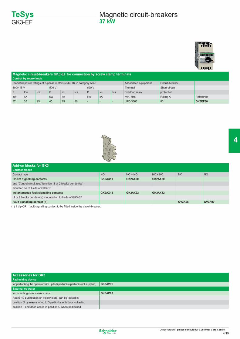
Other versions: please consult our Customer Care Centre.
TeSys GK3-EF
Magnetic circuit-breakers37 kW
Magnetic circuit-breakers GK3-EF for connection by screw clamp terminalsControl by rotary knobStandard power ratings of 3-phase motors 50/60 Hz in category AC-3 Associated equipment Circuit-breaker400/415 V 500 V 690 V Thermal Short-circuitP Icu Ics P Icu Ics P Icu Ics overload relay protectionkW kA kW kA kW kA min. size Rating A Reference37 35 25 45 15 30 - - - LRD-3363 80 GK3EF80
Add-on blocks for GK3Contact blocksContact type NO NO + NO NC + NO NC NOOn-Off signalling contacts GK2AX10 GK2AX20 GK2AX50and “Control circuit test” function (1 or 2 blocks per device)mounted on RH side of GK3-EFInstantaneous fault signalling contacts GK2AX12 GK2AX22 GK2AX52(1 or 2 blocks per device) mounted on LH side of GK3-EFFault signalling contact (1) GV3A08 GV3A09
(1) 1 trip OR 1 fault signalling contact to be fitted inside the circuit-breaker.
Accessories for GK3Padlocking devicefor padlocking the operator with up to 3 padlocks (padlocks not supplied) GK3AV01External operatorfor mounting on enclosure door. GK3AP03Red Ø 40 pushbutton on yellow plate, can be locked inposition O by means of up to 3 padlocks with door locked in position I, and door locked in position O when padlocked
4/19
2
1
3
4
5
6
7
8
9
10
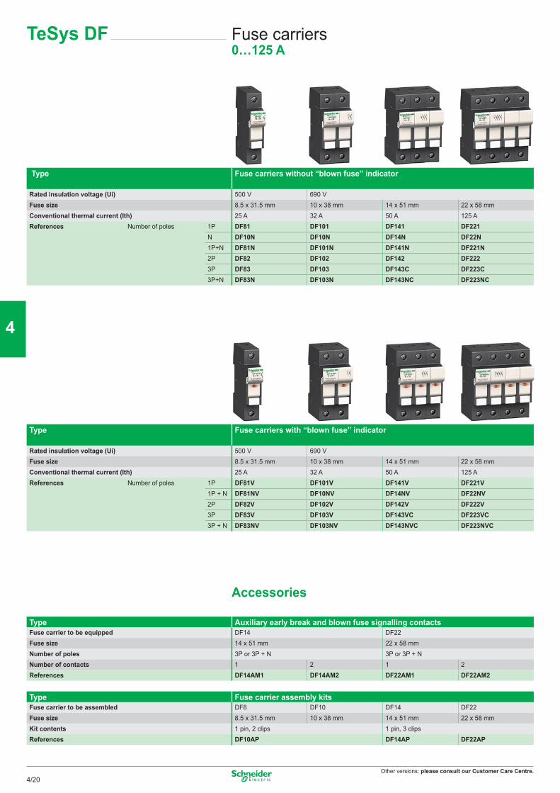
Other versions: please consult our Customer Care Centre.
TeSys DF Fuse carriers0…125 A
Type Fuse carriers without “blown fuse” indicator
Rated insulation voltage (Ui) 500 V 690 VFuse size 8.5 x 31.5 mm 10 x 38 mm 14 x 51 mm 22 x 58 mmConventional thermal current (Ith) 25 A 32 A 50 A 125 AReferences Number of poles 1P DF81 DF101 DF141 DF221
N DF10N DF10N DF14N DF22N1P+N DF81N DF101N DF141N DF221N2P DF82 DF102 DF142 DF2223P DF83 DF103 DF143C DF223C3P+N DF83N DF103N DF143NC DF223NC
Type Fuse carriers with “blown fuse” indicator
Rated insulation voltage (Ui) 500 V 690 VFuse size 8.5 x 31.5 mm 10 x 38 mm 14 x 51 mm 22 x 58 mmConventional thermal current (Ith) 25 A 32 A 50 A 125 AReferences Number of poles 1P DF81V DF101V DF141V DF221V
1P + N DF81NV DF10NV DF14NV DF22NV2P DF82V DF102V DF142V DF222V3P DF83V DF103V DF143VC DF223VC3P + N DF83NV DF103NV DF143NVC DF223NVC
Accessories
Type Auxiliary early break and blown fuse signalling contactsFuse carrier to be equipped DF14 DF22Fuse size 14 x 51 mm 22 x 58 mmNumber of poles 3P or 3P + N 3P or 3P + NNumber of contacts 1 2 1 2References DF14AM1 DF14AM2 DF22AM1 DF22AM2
Type Fuse carrier assembly kitsFuse carrier to be assembled DF8 DF10 DF14 DF22Fuse size 8.5 x 31.5 mm 10 x 38 mm 14 x 51 mm 22 x 58 mmKit contents 1 pin, 2 clips 1 pin, 3 clipsReferences DF10AP DF14AP DF22AP
4/20
2
1
3
4
5
6
7
8
9
10
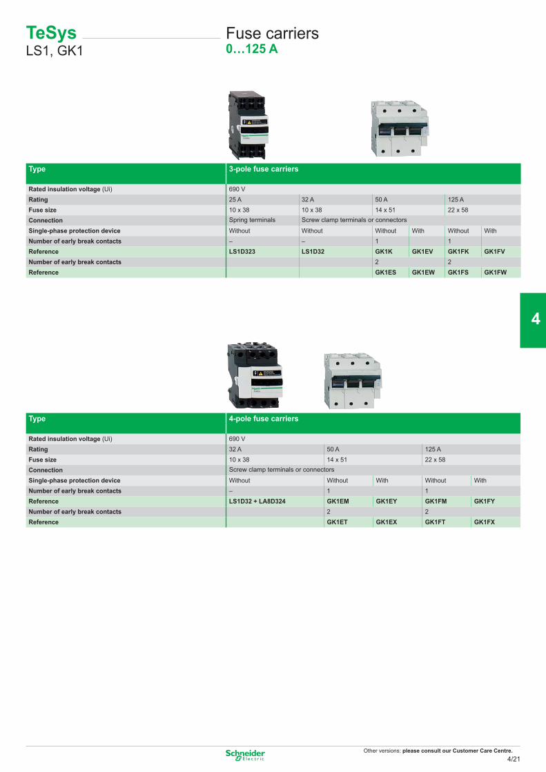
Other versions: please consult our Customer Care Centre.
TeSys LS1, GK1
Fuse carriers0…125 A
Type 3-pole fuse carriers
Rated insulation voltage (Ui) 690 VRating 25 A 32 A 50 A 125 AFuse size 10 x 38 10 x 38 14 x 51 22 x 58Connection Spring terminals Screw clamp terminals or connectors
Single-phase protection device Without Without Without With Without WithNumber of early break contacts – – 1 1Reference LS1D323 LS1D32 GK1K GK1EV GK1FK GK1FVNumber of early break contacts 2 2Reference GK1ES GK1EW GK1FS GK1FW
Type 4-pole fuse carriers
Rated insulation voltage (Ui) 690 VRating 32 A 50 A 125 AFuse size 10 x 38 14 x 51 22 x 58Connection Screw clamp terminals or connectors
Single-phase protection device Without Without With Without WithNumber of early break contacts – 1 1Reference LS1D32 + LA8D324 GK1EM GK1EY GK1FM GK1FYNumber of early break contacts 2 2Reference GK1ET GK1EX GK1FT GK1FX
4/21
2
1
3
4
5
6
7
8
9
10
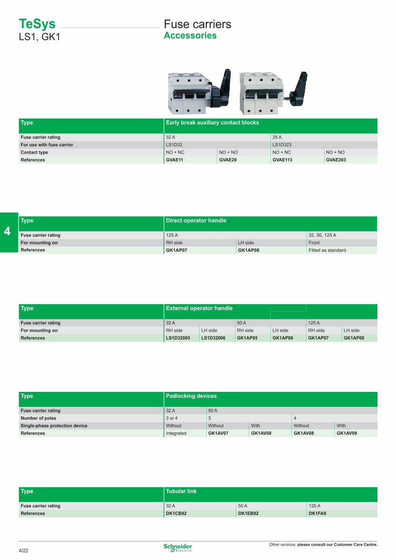
Other versions: please consult our Customer Care Centre.
TeSys LS1, GK1
Fuse carriersAccessories
Type Early break auxiliary contact blocks
Fuse carrier rating 32 A 25 AFor use with fuse carrier LS1D32 LS1D323Contact type NO + NC NO + NO NO + NC NO + NOReferences GVAE11 GVAE20 GVAE113 GVAE203
Type Direct operator handle
Fuse carrier rating 125 A 32, 50, 125 AFor mounting on RH side LH side FrontReferences GK1AP07 GK1AP08 Fitted as standard
Type External operator handle
Fuse carrier rating 32 A 50 A 125 AFor mounting on RH side LH side RH side LH side RH side LH sideReferences LS1D32005 LS1D32006 GK1AP05 GK1AP06 GK1AP07 GK1AP08
Type Padlocking devices
Fuse carrier rating 32 A 50 ANumber of poles 3 or 4 3 4Single-phase protection device Without Without With Without WithReferences Integrated GK1AV07 GK1AV08 GK1AV08 GK1AV09
Type Tubular link
Fuse carrier rating 32 A 50 A 125 AReferences DK1CB92 DK1EB92 DK1FA9
4/22
2
1
3
4
5
6
7
8
9
10
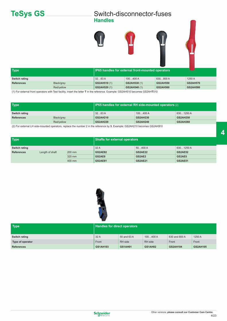
Other versions: please consult our Customer Care Centre.
TeSys GS Switch-disconnector-fusesHandles
Type IP65 handles for external front-mounted operators
Switch rating 32…63 A 100…400 A 630…800 A 1250 AReferences Black/grey GS2AH510 (1) GS2AH530 (1) GS2AH550 GS2AH570
Red/yellow GS2AH520 (1) GS2AH540 (1) GS2AH560 GS2AH580(1) For external front operators with Test facility, insert the letter T in the reference. Example: GS2AH510 becomes GS2AHT510
Type IP65 handles for external RH side-mounted operators (2)
Switch rating 32…63 A 100…400 A 630…1250 AReferences Black/grey GS2AH210 GS2AH230 GS2AH250
Red/yellow GS2AH220 GS2AH240 GS2AH260(2) For external LH side-mounted operators, replace the number 2 in the reference by 3. Example: GS2AH210 becomes GS2AH310
Type Shafts for external operators
Switch rating 32 A 50…400 A 630…1250 AReferences Length of shaft 200 mm GS2AE82 GS2AE22 GS2AE52
320 mm GS2AE8 GS2AE2 GS2AE5400 mm GS2AE81 GS2AE21 GS2AE51
Type Handles for direct operators
Switch rating 32 A 50 and 63 A 100…400 A 630 and 800 A 1250 A
Type of operator Front RH side RH side Front Front
References GS1AH103 GS1AH01 GS1AH02 GS2AH104 GS2AH105
4/23
2
1
3
4
5
6
7
8
9
10
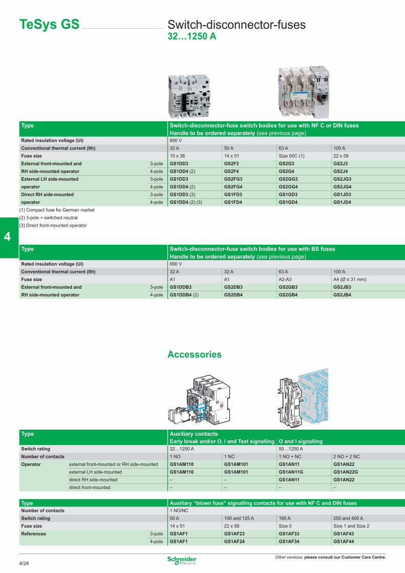
Other versions: please consult our Customer Care Centre.
TeSys GS Switch-disconnector-fuses32…1250 A
Type Switch-disconnector-fuse switch bodies for use with NF C or DIN fusesHandle to be ordered separately (see previous page)
Rated insulation voltage (Ui) 690 VConventional thermal current (Ith) 32 A 50 A 63 A 100 AFuse size 10 x 38 14 x 51 Size 00C (1) 22 x 58External front-mounted and 3-pole GS1DD3 GS2F3 GS2G3 GS2J3RH side-mounted operator 4-pole GS1DD4 (2) GS2F4 GS2G4 GS2J4External LH side-mounted 3-pole GS1DD3 GS2FG3 GS2GG3 GS2JG3operator 4-pole GS1DD4 (2) GS2FG4 GS2GG4 GS2JG4Direct RH side-mounted 3-pole GS1DD3 (3) GS1FD3 GS1GD3 GS1JD3operator 4-pole GS1DD4 (2) (3) GS1FD4 GS1GD4 GS1JD4
(1) Compact fuse for German market(2) 3-pole + switched neutral(3) Direct front-mounted operator
Type Switch-disconnector-fuse switch bodies for use with BS fusesHandle to be ordered separately (see previous page)
Rated insulation voltage (Ui) 690 VConventional thermal current (Ith) 32 A 32 A 63 A 100 AFuse size A1 A1 A2-A3 A4 (Ø ≤ 31 mm)External front-mounted and 3-pole GS1DDB3 GS2DB3 GS2GB3 GS2JB3RH side-mounted operator 4-pole GS1DDB4 (2) GS2DB4 GS2GB4 GS2JB4
Accessories
Type Auxiliary contactsEarly break and/or O, I and Test signalling O and I signalling
Switch rating 32…1250 A 50…1250 ANumber of contacts 1 NO 1 NC 1 NO + NC 2 NO + 2 NCOperator external front-mounted or RH side-mounted GS1AM110 GS1AM101 GS1AN11 GS1AN22
external LH side-mounted GS1AM110 GS1AM101 GS1AN11G GS1AN22Gdirect RH side-mounted – – GS1AN11 GS1AN22direct front-mounted – – – –
Type Auxiliary “blown fuse” signalling contacts for use with NF C and DIN fusesNumber of contacts 1 NO/NCSwitch rating 50 A 100 and 125 A 160 A 250 and 400 AFuse size 14 x 51 22 x 58 Size 0 Size 1 and Size 2References 3-pole GS1AF1 GS1AF23 GS1AF33 GS1AF43
4-pole GS1AF1 GS1AF24 GS1AF34 GS1AF44
4/24
2
1
3
4
5
6
7
8
9
10
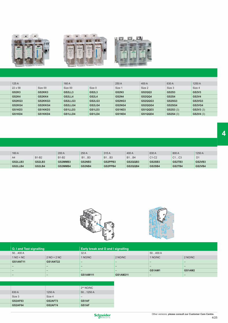
Other versions: please consult our Customer Care Centre.
125 A 160 A 250 A 400 A 630 A 1250 A22 x 58 Size 00 Size 00 Size 0 Size 1 Size 2 Size 3 Size 4GS2K3 GS2KK3 GS2LL3 GS2L3 GS2N3 GS2QQ3 GS2S3 GS2V3GS2K4 GS2KK4 GS2LL4 GS2L4 GS2N4 GS2QQ4 GS2S4 GS2V4GS2KG3 GS2KKG3 GS2LLG3 GS2LG3 GS2NG3 GS2QQG3 GS2SG3 GS2VG3GS2KG4 GS2KKG4 GS2LLG4 GS2LG4 GS2NG4 GS2QQG4 GS2SG4 GS2VG4GS1KD3 GS1KKD3 GS1LLD3 GS1LD3 GS1ND3 GS1QQD3 GS2S3 (3) GS2V3 (3)GS1KD4 GS1KKD4 GS1LLD4 GS1LD4 GS1ND4 GS1QQD4 GS2S4 (3) GS2V4 (3)
160 A 200 A 250 A 315 A 400 A 630 A 800 A 1250 AA4 B1-B2 B1-B2 B1…B3 B1…B3 B1…B4 C1-C2 C1…C3 D1GS2LLB3 GS2LB3 GS2MMB3 GS2NB3 GS2PPB3 GS2QQB3 GS2SB3 GS2TB3 GS2VB3GS2LLB4 GS2LB4 GS2MMB4 GS2NB4 GS2PPB4 GS2QQB4 GS2SB4 GS2TB4 GS2VB4
O, I and Test signalling Early break and O and I signalling50…400 A 32 A 50…400 A1 NO + NC 2 NO + 2 NC 1 NO/NC 2 NO/NC 1 NO/NC 2 NO/NCGS1ANT11 GS1ANT22 – – – –– – – – – –– – – – GS1AM1 GS1AM2– – GS1AM111 GS1AM211 – –
2nd NO/NC630 A 1250 A 50…1250 ASize 3 Size 4 –GS2AF63 GS2AF73 GS1AFGS2AF64 GS2AF74 GS1AF
4/25
2
1
3
4
5
6
7
8
9
10
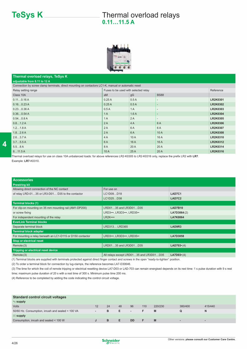
Other versions: please consult our Customer Care Centre.
Thermal overload relays, TeSys K adjustable from 0.11 to 12 AConnection by screw clamp terminals, direct mounting on contactors LC1-K, manual or automatic resetRelay setting range Fuses to be used with selected relay ReferenceClass 10A aM gG BS880.11…0.16 A 0.25 A 0.5 A - LR2K03010.16…0.23 A 0.25 A 0.5 A - LR2K03020.23…0.36 A 0.5 A 1 A - LR2K03030.36…0.54 A 1 A 1.6 A - LR2K03040.54…0.8 A 1 A 2 A - LR2K03050.8…1.2 A 2 A 4 A 6 A LR2K03061.2…1.8 A 2 A 6 A 6 A LR2K03071.8…2.6 A 2 A 6 A 10 A LR2K03082.6…3.7 A 4 A 10 A 16 A LR2K03103.7…5.5 A 6 A 16 A 16 A LR2K03125.5…8 A 8 A 20 A 20 A LR2K03148…11.5 A 10 A 25 A 20 A LR2K0316
Thermal overload relays for use on class 10A unbalanced loads: for above references LR2-K0305 to LR2-K0316 only, replace the prefix LR2 with LR7. Example: LR7-K0310.
Accessories Prewiring kitAllowing direct connection of the NC contact For use onof relay LRD-01…35 or LR3-D01… D35 to the contactor LC1D09…D18 LAD7C1
LC1D25…D38 LAD7C2Terminal blocks (1)For clip-on mounting on 35 mm mounting rail (AM1-DP200) LRD01…35 and LR3D01…D35 LAD7B10or screw fixing LRD3•••, LR3D3•••, LRD35•• LA7D3064 (2)For independent mounting of the relay LR2K•••• LA7K0064EverLink Terminal blocksSeparate terminal block LRD313… LRD365 LAD9R3Terminal block adapterFor mounting a relay beneath an LC1-D115 or D150 contactor LRD3•••, LR3D3•••, LRD35•• LA7D3058Stop or electrical reset Remote (3) LRD01…35 and LR3D01…D35 LAD703• (4)Tripping or electrical reset device Remote (3) All relays except LRD01…35 and LR3D01…D35 LA7D03• (4)
(1) Terminal blocks are supplied with terminals protected against direct finger contact and screws in the open “ready-to-tighten” position.(2) To order a terminal block for connection by lug-clamps, the reference becomes LA7-D30646.(3) The time for which the coil of remote tripping or electrical resetting device LA7-D03 or LAD-703 can remain energised depends on its rest time: 1 s pulse duration with 9 s rest time; maximum pulse duration of 20 s with a rest time of 300 s. Minimum pulse time 200 ms.(4) Reference to be completed by adding the code indicating the control circuit voltage.
Standard control circuit voltagesa supplyVolts 12 24 48 96 110 220/230 380/400 415/44050/60 Hz. Consumption, inrush and sealed < 100 VA - B E - F M Q Nc supplyConsumption, inrush and sealed < 100 W J B E DD F M - -
TeSys K Thermal overload relays0.11…11.5 A
4/26
2
1
3
4
5
6
7
8
9
10
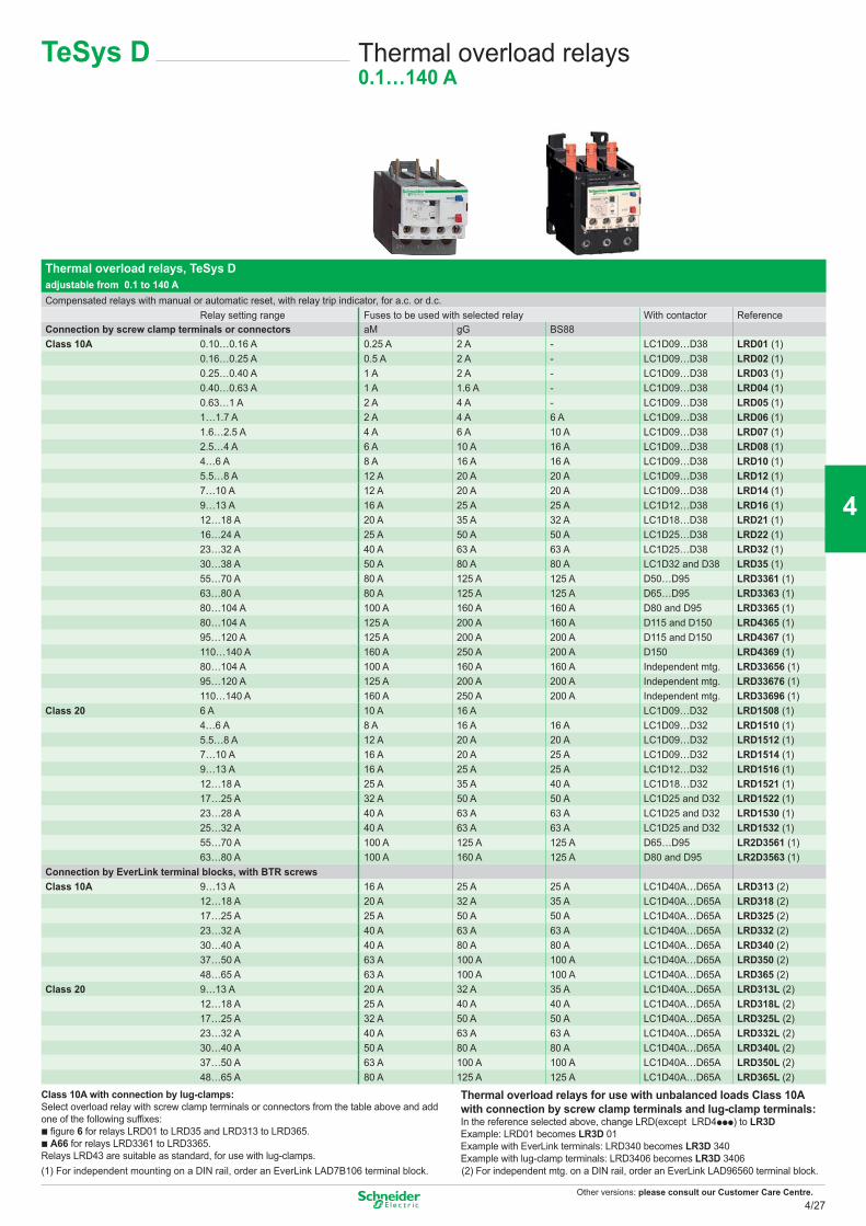
Other versions: please consult our Customer Care Centre.
TeSys D Thermal overload relays0.1…140 A
Thermal overload relays, TeSys D adjustable from 0.1 to 140 ACompensated relays with manual or automatic reset, with relay trip indicator, for a.c. or d.c.
Relay setting range Fuses to be used with selected relay With contactor ReferenceConnection by screw clamp terminals or connectors aM gG BS88Class 10A 0.10…0.16 A 0.25 A 2 A - LC1D09…D38 LRD01 (1)
0.16…0.25 A 0.5 A 2 A - LC1D09…D38 LRD02 (1)0.25…0.40 A 1 A 2 A - LC1D09…D38 LRD03 (1)0.40…0.63 A 1 A 1.6 A - LC1D09…D38 LRD04 (1)0.63…1 A 2 A 4 A - LC1D09…D38 LRD05 (1)1…1.7 A 2 A 4 A 6 A LC1D09…D38 LRD06 (1)1.6…2.5 A 4 A 6 A 10 A LC1D09…D38 LRD07 (1)2.5…4 A 6 A 10 A 16 A LC1D09…D38 LRD08 (1)4…6 A 8 A 16 A 16 A LC1D09…D38 LRD10 (1)5.5…8 A 12 A 20 A 20 A LC1D09…D38 LRD12 (1)7…10 A 12 A 20 A 20 A LC1D09…D38 LRD14 (1)9…13 A 16 A 25 A 25 A LC1D12…D38 LRD16 (1)12…18 A 20 A 35 A 32 A LC1D18…D38 LRD21 (1)16…24 A 25 A 50 A 50 A LC1D25…D38 LRD22 (1)23…32 A 40 A 63 A 63 A LC1D25…D38 LRD32 (1)30…38 A 50 A 80 A 80 A LC1D32 and D38 LRD35 (1)55…70 A 80 A 125 A 125 A D50…D95 LRD3361 (1)63…80 A 80 A 125 A 125 A D65…D95 LRD3363 (1)80…104 A 100 A 160 A 160 A D80 and D95 LRD3365 (1)80…104 A 125 A 200 A 160 A D115 and D150 LRD4365 (1)95…120 A 125 A 200 A 200 A D115 and D150 LRD4367 (1)110…140 A 160 A 250 A 200 A D150 LRD4369 (1)80…104 A 100 A 160 A 160 A Independent mtg. LRD33656 (1)95…120 A 125 A 200 A 200 A Independent mtg. LRD33676 (1)110…140 A 160 A 250 A 200 A Independent mtg. LRD33696 (1)
Class 20 6 A 10 A 16 A LC1D09…D32 LRD1508 (1)4…6 A 8 A 16 A 16 A LC1D09…D32 LRD1510 (1)5.5…8 A 12 A 20 A 20 A LC1D09…D32 LRD1512 (1)7…10 A 16 A 20 A 25 A LC1D09…D32 LRD1514 (1)9…13 A 16 A 25 A 25 A LC1D12…D32 LRD1516 (1)12…18 A 25 A 35 A 40 A LC1D18…D32 LRD1521 (1)17…25 A 32 A 50 A 50 A LC1D25 and D32 LRD1522 (1)23…28 A 40 A 63 A 63 A LC1D25 and D32 LRD1530 (1)25…32 A 40 A 63 A 63 A LC1D25 and D32 LRD1532 (1)55…70 A 100 A 125 A 125 A D65…D95 LR2D3561 (1)63…80 A 100 A 160 A 125 A D80 and D95 LR2D3563 (1)
Connection by EverLink terminal blocks, with BTR screwsClass 10A 9…13 A 16 A 25 A 25 A LC1D40A…D65A LRD313 (2)
12…18 A 20 A 32 A 35 A LC1D40A…D65A LRD318 (2)17…25 A 25 A 50 A 50 A LC1D40A…D65A LRD325 (2)23…32 A 40 A 63 A 63 A LC1D40A…D65A LRD332 (2)30…40 A 40 A 80 A 80 A LC1D40A…D65A LRD340 (2)37…50 A 63 A 100 A 100 A LC1D40A…D65A LRD350 (2)48…65 A 63 A 100 A 100 A LC1D40A…D65A LRD365 (2)
Class 20 9…13 A 20 A 32 A 35 A LC1D40A…D65A LRD313L (2)12…18 A 25 A 40 A 40 A LC1D40A…D65A LRD318L (2)17…25 A 32 A 50 A 50 A LC1D40A…D65A LRD325L (2)23…32 A 40 A 63 A 63 A LC1D40A…D65A LRD332L (2)30…40 A 50 A 80 A 80 A LC1D40A…D65A LRD340L (2)37…50 A 63 A 100 A 100 A LC1D40A…D65A LRD350L (2)48…65 A 80 A 125 A 125 A LC1D40A…D65A LRD365L (2)
Class 10A with connection by lug-clamps: Select overload relay with screw clamp terminals or connectors from the table above and add one of the following suffixes:b figure 6 for relays LRD01 to LRD35 and LRD313 to LRD365.b A66 for relays LRD3361 to LRD3365.Relays LRD43 are suitable as standard, for use with lug-clamps.
Thermal overload relays for use with unbalanced loads Class 10A with connection by screw clamp terminals and lug-clamp terminals:In the reference selected above, change LRD(except LRD4ppp) to LR3DExample: LRD01 becomes LR3D 01Example with EverLink terminals: LRD340 becomes LR3D 340Example with lug-clamp terminals: LRD3406 becomes LR3D 3406
(1) For independent mounting on a DIN rail, order an EverLink LAD7B106 terminal block. (2) For independent mtg. on a DIN rail, order an EverLink LAD96560 terminal block.
4/27
2
1
3
4
5
6
7
8
9
10
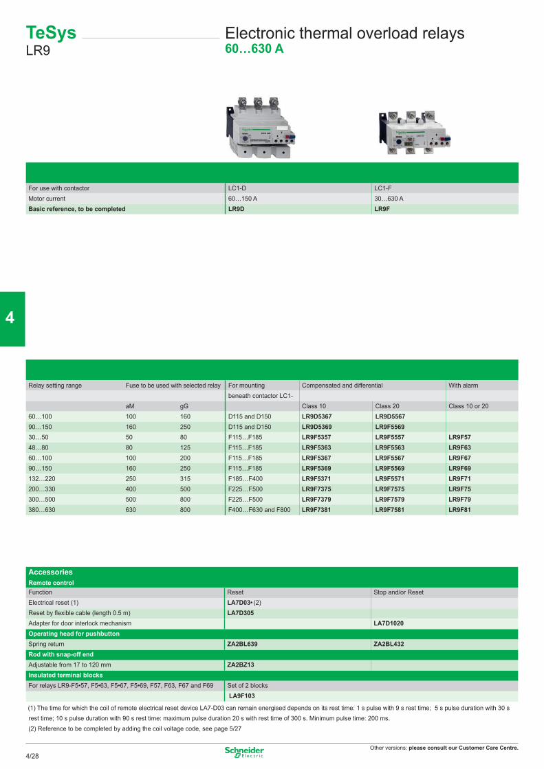
Other versions: please consult our Customer Care Centre.
For use with contactor LC1-D LC1-FMotor current 60…150 A 30…630 ABasic reference, to be completed LR9D LR9F
Relay setting range Fuse to be used with selected relay For mounting Compensated and differential With alarmbeneath contactor LC1-
aM gG Class 10 Class 20 Class 10 or 2060…100 100 160 D115 and D150 LR9D5367 LR9D556790…150 160 250 D115 and D150 LR9D5369 LR9F556930…50 50 80 F115…F185 LR9F5357 LR9F5557 LR9F5748…80 80 125 F115…F185 LR9F5363 LR9F5563 LR9F6360…100 100 200 F115…F185 LR9F5367 LR9F5567 LR9F6790…150 160 250 F115…F185 LR9F5369 LR9F5569 LR9F69132…220 250 315 F185…F400 LR9F5371 LR9F5571 LR9F71200…330 400 500 F225…F500 LR9F7375 LR9F7575 LR9F75300…500 500 800 F225…F500 LR9F7379 LR9F7579 LR9F79380…630 630 800 F400…F630 and F800 LR9F7381 LR9F7581 LR9F81
Accessories Remote controlFunction Reset Stop and/or ResetElectrical reset (1) LA7D03• (2)Reset by flexible cable (length 0.5 m) LA7D305Adapter for door interlock mechanism LA7D1020Operating head for pushbutton Spring return ZA2BL639 ZA2BL432Rod with snap-off endAdjustable from 17 to 120 mm ZA2BZ13Insulated terminal blocksFor relays LR9-F5•57, F5•63, F5•67, F5•69, F57, F63, F67 and F69 Set of 2 blocks
LA9F103
(1) The time for which the coil of remote electrical reset device LA7-D03 can remain energised depends on its rest time: 1 s pulse with 9 s rest time; 5 s pulse duration with 30 s rest time; 10 s pulse duration with 90 s rest time: maximum pulse duration 20 s with rest time of 300 s. Minimum pulse time: 200 ms.(2) Reference to be completed by adding the coil voltage code, see page 5/27
TeSys LR9
Electronic thermal overload relays60…630 A
4/28
2
1
3
4
5
6
7
8
9
10
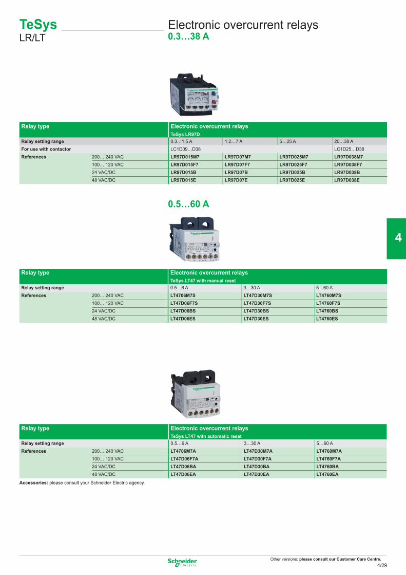
Other versions: please consult our Customer Care Centre.
Relay type Electronic overcurrent relays TeSys LR97D
Relay setting range 0.3…1.5 A 1.2…7 A 5…25 A 20…38 AFor use with contactor LC1D09…D38 LC1D25…D38References 200… 240 VAC LR97D015M7 LR97D07M7 LR97D025M7 LR97D038M7
100… 120 VAC LR97D015F7 LR97D07F7 LR97D025F7 LR97D038F724 VAC/DC LR97D015B LR97D07B LR97D025B LR97D038B48 VAC/DC LR97D015E LR97D07E LR97D025E LR97D038E
0.5…60 A
Relay type Electronic overcurrent relays TeSys LT47 with manual reset
Relay setting range 0.5…6 A 3…30 A 5…60 AReferences 200… 240 VAC LT4706M7S LT47D30M7S LT4760M7S
100… 120 VAC LT47D06F7S LT47D30F7S LT4760F7S24 VAC/DC LT47D06BS LT47D30BS LT4760BS48 VAC/DC LT47D06ES LT47D30ES LT4760ES
Relay type Electronic overcurrent relays TeSys LT47 with automatic reset
Relay setting range 0.5…6 A 3…30 A 5…60 AReferences 200… 240 VAC LT4706M7A LT47D30M7A LT4760M7A
100… 120 VAC LT47D06F7A LT47D30F7A LT4760F7A24 VAC/DC LT47D06BA LT47D30BA LT4760BA48 VAC/DC LT47D06EA LT47D30EA LT4760EA
Accessories: please consult your Schneider Electric agency.
TeSysLR/LT
Electronic overcurrent relays0.3…38 A
4/29
2
1
3
4
5
6
7
8
9
10
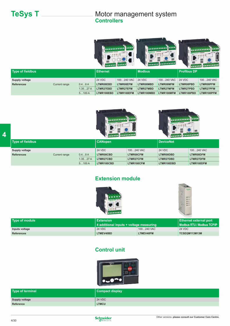
Other versions: please consult our Customer Care Centre.
Type of fieldbus Ethernet Modbus Profibus DP
Supply voltage 24 VDC 100…240 VAC 24 VDC 100…240 VAC 24 VDC 100…240 VACReferences Current range 0.4…8 A LTMR08EBD LTMR08EFM LTMR08MBD LTMR08MFM LTMR08PBD LTMR08PFM
1.35…27 A LTMR27EBD LTMR27EFM LTMR27MBD LTMR27MFM LTMR27PBD LTMR27PFM5…100 A LTMR100EBD LTMR100EFM LTMR100MBD LTMR100MFM LTMR100PBD LTMR100PFM
Type of fieldbus CANopen DeviceNet
Supply voltage 24 VDC 100…240 VAC 24 VDC 100…240 VACReferences Current range 0.4…8 A LTMR08CBD LTMR08CFM LTMR08DBD LTMR08DFM
1.35…27 A LTMR27CBD LTMR27CFM LTMR27DBD LTMR27DFM5…100 A LTMR100CBD LTMR100CFM LTMR100DBD LTMR100DFM
Extension module
Type of module Extension 4 additional inputs + voltage measuring
Ethernet external port Modbus RTU / Modbus TCP/IP
Inputs voltage 24 VDC 100…240 VAC 24 VDCReferences LTMEV40BD LTMEV40FM TCSEQM113M13M
Control unit
Type of terminal Compact display
Supply voltage 24 VDCReference LTMCU
Motor management systemControllers
TeSys T
4/30
2
1
3
4
5
6
7
8
9
10
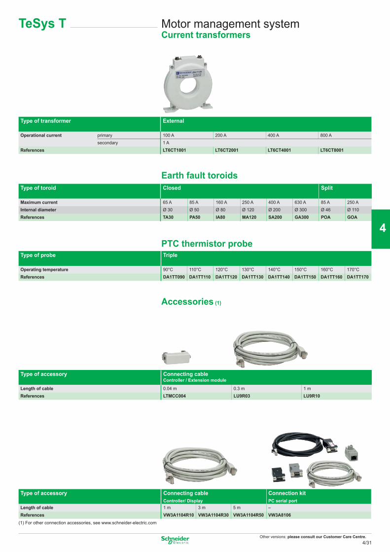
Other versions: please consult our Customer Care Centre.
Type of transformer External
Operational current primary 100 A 200 A 400 A 800 Asecondary 1 A
References LT6CT1001 LT6CT2001 LT6CT4001 LT6CT8001
Earth fault toroidsType of toroid Closed Split
Maximum current 65 A 85 A 160 A 250 A 400 A 630 A 85 A 250 AInternal diameter Ø 30 Ø 50 Ø 80 Ø 120 Ø 200 Ø 300 Ø 46 Ø 110References TA30 PA50 IA80 MA120 SA200 GA300 POA GOA
PTC thermistor probeType of probe Triple
Operating temperature 90°C 110°C 120°C 130°C 140°C 150°C 160°C 170°CReferences DA1TT090 DA1TT110 DA1TT120 DA1TT130 DA1TT140 DA1TT150 DA1TT160 DA1TT170
Accessories (1)
Type of accessory Connecting cable Controller / Extension module
Length of cable 0.04 m 0.3 m 1 mReferences LTMCC004 LU9R03 LU9R10
Type of accessory Connecting cable Controller/ Display
Connection kit PC serial port
Length of cable 1 m 3 m 5 m –References VW3A1104R10 VW3A1104R30 VW3A1104R50 VW3A8106
(1) For other connection accessories, see www.schneider-electric.com
Motor management systemCurrent transformers
TeSys T
4/31
2
1
3
4
5
6
7
8
9
10
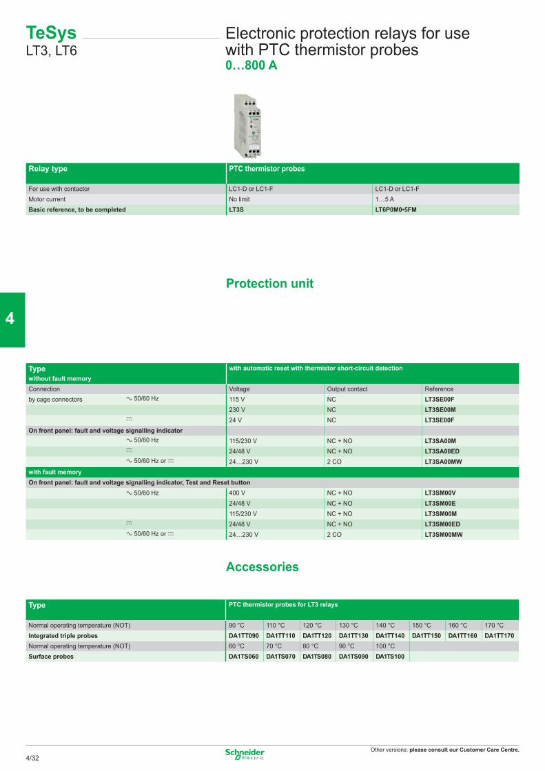
Other versions: please consult our Customer Care Centre.
TeSys LT3, LT6
Electronic protection relays for use with PTC thermistor probes0…800 A
Relay type PTC thermistor probes
For use with contactor LC1-D or LC1-F LC1-D or LC1-FMotor current No limit 1…5 ABasic reference, to be completed LT3S LT6P0M0•5FM
Protection unit
Type with automatic reset with thermistor short-circuit detectionwithout fault memoryConnection Voltage Output contact Referenceby cage connectors a 50/60 Hz 115 V NC LT3SE00F
230 V NC LT3SE00Mc 24 V NC LT3SE00F
On front panel: fault and voltage signalling indicatora 50/60 Hz 115/230 V NC + NO LT3SA00Mc 24/48 V NC + NO LT3SA00EDa 50/60 Hz or c 24…230 V 2 CO LT3SA00MW
with fault memoryOn front panel: fault and voltage signalling indicator, Test and Reset button
a 50/60 Hz 400 V NC + NO LT3SM00V24/48 V NC + NO LT3SM00E115/230 V NC + NO LT3SM00M
c 24/48 V NC + NO LT3SM00EDa 50/60 Hz or c 24…230 V 2 CO LT3SM00MW
Accessories
Type PTC thermistor probes for LT3 relays
Normal operating temperature (NOT) 90 °C 110 °C 120 °C 130 °C 140 °C 150 °C 160 °C 170 °CIntegrated triple probes DA1TT090 DA1TT110 DA1TT120 DA1TT130 DA1TT140 DA1TT150 DA1TT160 DA1TT170Normal operating temperature (NOT) 60 °C 70 °C 80 °C 90 °C 100 °CSurface probes DA1TS060 DA1TS070 DA1TS080 DA1TS090 DA1TS100
4/32
2
1
3
4
5
6
7
8
9
10
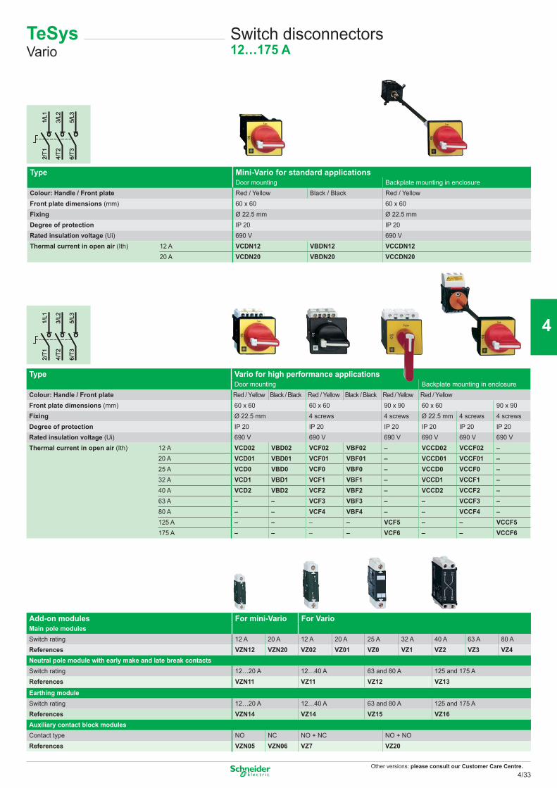
Other versions: please consult our Customer Care Centre.
1/L1
2/T1
3/L2
4/T2
5/L3
6/T3
1/L1
2/T1
3/L2
4/T2
5/L3
6/T3
1/L1
2/T1
3/L2
4/T2
5/L3
6/T3
1/L1
2/T1
3/L2
4/T2
5/L3
6/T3
Switch disconnectors12…175 A
Type Mini-Vario for standard applicationsDoor mounting Backplate mounting in enclosure
Colour: Handle / Front plate Red / Yellow Black / Black Red / YellowFront plate dimensions (mm) 60 x 60 60 x 60Fixing Ø 22.5 mm Ø 22.5 mmDegree of protection IP 20 IP 20Rated insulation voltage (Ui) 690 V 690 VThermal current in open air (Ith) 12 A VCDN12 VBDN12 VCCDN12
20 A VCDN20 VBDN20 VCCDN20
Type Vario for high performance applicationsDoor mounting Backplate mounting in enclosure
Colour: Handle / Front plate Red / Yellow Black / Black Red / Yellow Black / Black Red / Yellow Red / YellowFront plate dimensions (mm) 60 x 60 60 x 60 90 x 90 60 x 60 90 x 90Fixing Ø 22.5 mm 4 screws 4 screws Ø 22.5 mm 4 screws 4 screwsDegree of protection IP 20 IP 20 IP 20 IP 20 IP 20 IP 20Rated insulation voltage (Ui) 690 V 690 V 690 V 690 V 690 V 690 VThermal current in open air (Ith) 12 A VCD02 VBD02 VCF02 VBF02 – VCCD02 VCCF02 –
20 A VCD01 VBD01 VCF01 VBF01 – VCCD01 VCCF01 –25 A VCD0 VBD0 VCF0 VBF0 – VCCD0 VCCF0 –32 A VCD1 VBD1 VCF1 VBF1 – VCCD1 VCCF1 –40 A VCD2 VBD2 VCF2 VBF2 – VCCD2 VCCF2 –63 A – – VCF3 VBF3 – – VCCF3 –80 A – – VCF4 VBF4 – – VCCF4 –125 A – – – – VCF5 – – VCCF5175 A – – – – VCF6 – – VCCF6
Add-on modules For mini-Vario For VarioMain pole modulesSwitch rating 12 A 20 A 12 A 20 A 25 A 32 A 40 A 63 A 80 AReferences VZN12 VZN20 VZ02 VZ01 VZ0 VZ1 VZ2 VZ3 VZ4Neutral pole module with early make and late break contactsSwitch rating 12…20 A 12…40 A 63 and 80 A 125 and 175 AReferences VZN11 VZ11 VZ12 VZ13Earthing moduleSwitch rating 12…20 A 12…40 A 63 and 80 A 125 and 175 AReferences VZN14 VZ14 VZ15 VZ16Auxiliary contact block modulesContact type NO NC NO + NC NO + NOReferences VZN05 VZN06 VZ7 VZ20
TeSysVario
4/33
2
1
3
4
5
6
7
8
9
10
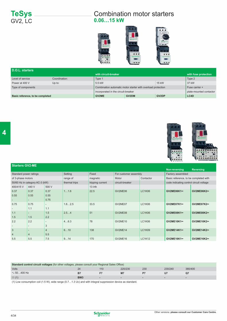
Other versions: please consult our Customer Care Centre.
Starters GV2-MENon-reversing Reversing
Standard power ratings Setting Fixed For customer assembly Factory assembledof 3-phase motors range of magnetic Motor Contactor Basic reference, to be completed with50/60 Hz in category AC-3 (kW) thermal trips tripping current circuit-breaker code indicating control circuit voltage400/415 V 440 V 500 V 13 Irth0.37 0.37 0.37 1…1.6 22.5 GV2ME06 LC1K06 GV2ME06K1•• GV2ME06K2••0.55 0.55 0.55- - 0.750.75 0.75 - 1.6…2.5 33.5 GV2ME07 LC1K06 GV2ME07K1•• GV2ME07K2••- 1.1 1.11.1 - 1.5 2.5…4 51 GV2ME08 LC1K06 GV2ME08K1•• GV2ME08K2••1.5 1.5 2.22.2 2.2 - 4…6.3 78 GV2ME10 LC1K06 GV2ME10K1•• GV2ME10K2••- - 33 - 4 6…10 138 GV2ME14 LC1K09 GV2ME14K1•• GV2ME14K2••4 4 5.55.5 5.5 7.5 9…14 170 GV2ME16 LC1K12 GV2ME16K1•• GV2ME16K2••
TeSys GV2, LC
Combination motor starters0.06…15 kW
D.O.L. starterswith circuit-breaker with fuse protection
Level of service Coordination: Type 1 Type 2Power at 400 V Up to: 5.5 kW 15 kW 37 kWType of components Combination automatic motor starter with overload protection Fuse carrier +
incorporated in the circuit-breaker plate-mounted contactorBasic reference, to be completed GV2ME GV2DM GV2DP LC4D
Standard control circuit voltages (for other voltages, please consult your Regional Sales Office)Volts 24 110 220/230 230 230/240 380/400a 50…400 Hz B7 F7 M7 P7 U7 Q7c (1) BW3 - - - - -(1) Low consumption coil (1.5 W), wide range (0.7…1.3 Uc) and with integral suppression device as standard.
4/34
2
1
3
4
5
6
7
8
9
10
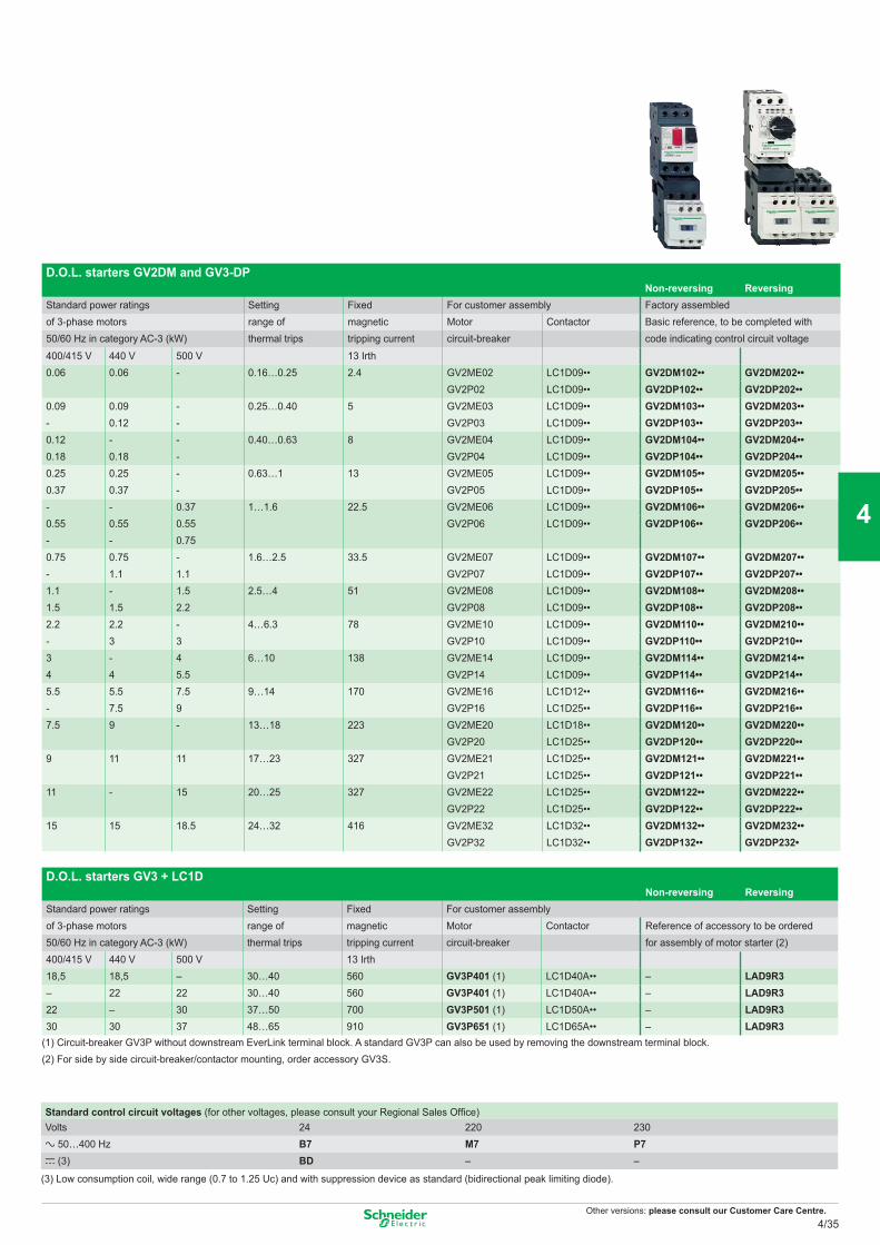
Other versions: please consult our Customer Care Centre.
D.O.L. starters GV2DM and GV3-DPNon-reversing Reversing
Standard power ratings Setting Fixed For customer assembly Factory assembledof 3-phase motors range of magnetic Motor Contactor Basic reference, to be completed with50/60 Hz in category AC-3 (kW) thermal trips tripping current circuit-breaker code indicating control circuit voltage
400/415 V 440 V 500 V 13 Irth0.06 0.06 - 0.16…0.25 2.4 GV2ME02 LC1D09•• GV2DM102•• GV2DM202••
GV2P02 LC1D09•• GV2DP102•• GV2DP202••0.09 0.09 - 0.25…0.40 5 GV2ME03 LC1D09•• GV2DM103•• GV2DM203••- 0.12 - GV2P03 LC1D09•• GV2DP103•• GV2DP203••0.12 - - 0.40…0.63 8 GV2ME04 LC1D09•• GV2DM104•• GV2DM204••0.18 0.18 - GV2P04 LC1D09•• GV2DP104•• GV2DP204••0.25 0.25 - 0.63…1 13 GV2ME05 LC1D09•• GV2DM105•• GV2DM205••0.37 0.37 - GV2P05 LC1D09•• GV2DP105•• GV2DP205••- - 0.37 1…1.6 22.5 GV2ME06 LC1D09•• GV2DM106•• GV2DM206••0.55 0.55 0.55 GV2P06 LC1D09•• GV2DP106•• GV2DP206••- - 0.750.75 0.75 - 1.6…2.5 33.5 GV2ME07 LC1D09•• GV2DM107•• GV2DM207••- 1.1 1.1 GV2P07 LC1D09•• GV2DP107•• GV2DP207••1.1 - 1.5 2.5…4 51 GV2ME08 LC1D09•• GV2DM108•• GV2DM208••1.5 1.5 2.2 GV2P08 LC1D09•• GV2DP108•• GV2DP208••2.2 2.2 - 4…6.3 78 GV2ME10 LC1D09•• GV2DM110•• GV2DM210••- 3 3 GV2P10 LC1D09•• GV2DP110•• GV2DP210••3 - 4 6…10 138 GV2ME14 LC1D09•• GV2DM114•• GV2DM214••4 4 5.5 GV2P14 LC1D09•• GV2DP114•• GV2DP214••5.5 5.5 7.5 9…14 170 GV2ME16 LC1D12•• GV2DM116•• GV2DM216••- 7.5 9 GV2P16 LC1D25•• GV2DP116•• GV2DP216••7.5 9 - 13…18 223 GV2ME20 LC1D18•• GV2DM120•• GV2DM220••
GV2P20 LC1D25•• GV2DP120•• GV2DP220••9 11 11 17…23 327 GV2ME21 LC1D25•• GV2DM121•• GV2DM221••
GV2P21 LC1D25•• GV2DP121•• GV2DP221••11 - 15 20…25 327 GV2ME22 LC1D25•• GV2DM122•• GV2DM222••
GV2P22 LC1D25•• GV2DP122•• GV2DP222••15 15 18.5 24…32 416 GV2ME32 LC1D32•• GV2DM132•• GV2DM232••
GV2P32 LC1D32•• GV2DP132•• GV2DP232•
Standard control circuit voltages (for other voltages, please consult your Regional Sales Office)Volts 24 220 230a 50…400 Hz B7 M7 P7c (3) BD – –
(3) Low consumption coil, wide range (0.7 to 1.25 Uc) and with suppression device as standard (bidirectional peak limiting diode).
D.O.L. starters GV3 + LC1DNon-reversing Reversing
Standard power ratings Setting Fixed For customer assemblyof 3-phase motors range of magnetic Motor Contactor Reference of accessory to be ordered50/60 Hz in category AC-3 (kW) thermal trips tripping current circuit-breaker for assembly of motor starter (2)400/415 V 440 V 500 V 13 Irth18,5 18,5 – 30…40 560 GV3P401 (1) LC1D40A•• – LAD9R3– 22 22 30…40 560 GV3P401 (1) LC1D40A•• – LAD9R322 – 30 37…50 700 GV3P501 (1) LC1D50A•• – LAD9R330 30 37 48…65 910 GV3P651 (1) LC1D65A•• – LAD9R3
(1) Circuit-breaker GV3P without downstream EverLink terminal block. A standard GV3P can also be used by removing the downstream terminal block.(2) For side by side circuit-breaker/contactor mounting, order accessory GV3S.
4/35
2
1
3
4
5
6
7
8
9
10
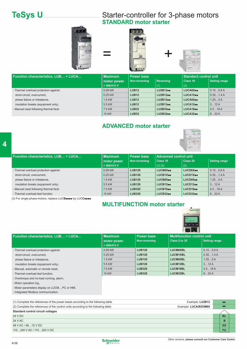
Other versions: please consult our Customer Care Centre.
= +
ADVANCED motor starter
MULTIFUNCTION motor starter
TeSys U Starter-controller for 3-phase motorsSTANDARD motor starter
Function characteristics, LUB… + LUCA… Maximum Power base Standard control unitmotor power Non-reversing Reversing Class 10 Setting range< 400/415 V (1) (2)
- Thermal overload protection against: 0.09 kW LUB12 LU2B12pp LUCA6Xpp 0.15…0.6 Ashort-circuit, overcurrent, 0.25 kW LUB12 LU2B12pp LUCA1Xpp 0.35…1.4 A
phase failure or imbalance, 1.5 kW LUB12 LU2B12pp LUCA05pp 1.25…5 Ainsulation breaks (equipment only). 5.5 kW LUB12 LU2B12pp LUCA12pp 3…12 A
- Manual reset following thermal fault. 7.5 kW LUB32 LU2B32pp LUCA18pp 4.5…18 A15 kW LUB32 LU2B32pp LUCA32pp 8…32 A
Function characteristics, LUB… + LUCA… Maximum Power base Advanced control unitmotor power Non-reversing Class 10 Class 20 Setting range< 400/415 V (2) (3) (2)
- Thermal overload protection against: 0.09 kW LUB120 LUCB6Xpp LUCD6Xpp 0.15…0.6 A short-circuit, overcurrent, 0.25 kW LUB120 LUCB1Xpp LUCD1Xpp 0.35…1.4 A
phase failure or imbalance, 1.5 kW LUB120 LUCB05pp LUCD05pp 1.25…5 Ainsulation breaks (equipment only). 5.5 kW LUB120 LUCB12pp LUCD12pp 3…12 A
- Manual reset following thermal fault. 7.5 kW LUB320 LUCB18pp LUCD18pp 4.5…18 A- Thermal overload test function. 15 kW LUB320 LUCB32pp LUCD32pp 8…32 A
(3) For single-phase-motors, replace LUCBpppp by LUCCpppp.
Function characteristics, LUB… + LUCA…
- Thermal overload protection against:short-circuit, overcurrent,phase failure or imbalance,
insulation breaks (equipment only).- Manual, automatic or remote reset, - Thermal overload test function, - Overtorque and no-load running, alarm, - Motor operation log, - Motor parameters display on LUCM.., PC or HMI,- Integrated Modbus communication.
Maximum Power base Multifunction control unitmotor power Non-reversing Class 5 to 30 Setting range < 400/415 V0.09 kW LUB120 LUCM6XBL 0.15…0.6 A0.25 kW LUB120 LUCM1XBL 0.35…1.4 A1.5 kW LUB120 LUCM05BL 1.25…5 A5.5 kW LUB120 LUCM12BL 3…12 A7.5 kW LUB320 LUCM18BL 4.5…18 A15 kW LUB320 LUCM32BL 8…32 A
(1) Complete the references of the power bases according to the following table. Example: LU2B12 pp
(2) Complete the references of the control units according to the following table. Example: LUCA/B/D/M6X pp
Standard control circuit voltages24 V DC BL24 V AC B48 V AC / 48…72 V DC ES110…240 V AC / 110…220 V DC FU
4/36
2
1
3
4
5
6
7
8
9
10
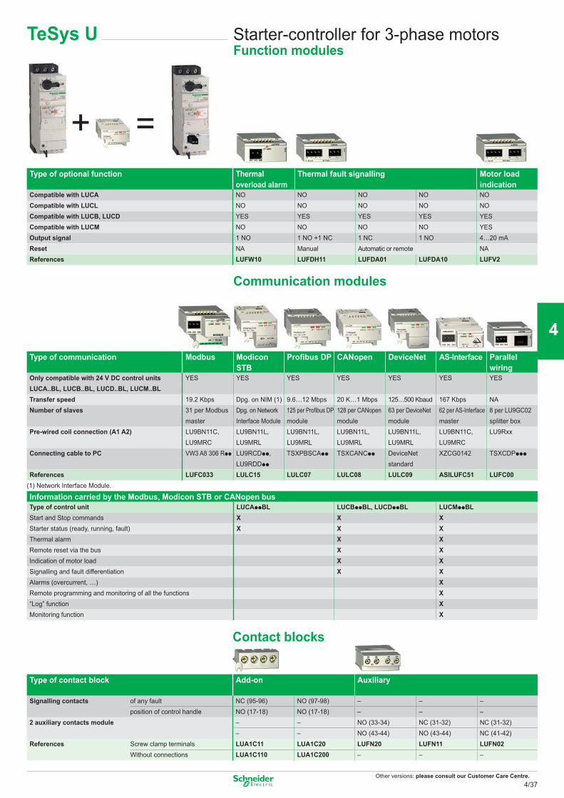
Other versions: please consult our Customer Care Centre.
=+
Communication modules
Contact blocks
TeSys U Starter-controller for 3-phase motorsFunction modules
Type of optional function Thermal Thermal fault signalling Motor loadoverload alarm indication
Compatible with LUCA NO NO NO NO NOCompatible with LUCL NO NO NO NO NOCompatible with LUCB, LUCD YES YES YES YES YESCompatible with LUCM NO NO NO NO YESOutput signal 1 NO 1 NO +1 NC 1 NC 1 NO 4…20 mAReset NA Manual Automatic or remote NAReferences LUFW10 LUFDH11 LUFDA01 LUFDA10 LUFV2
Type of communication Modbus Modicon Profibus DP CANopen DeviceNet AS-Interface ParallelSTB wiring
Only compatible with 24 V DC control units YES YES YES YES YES YES YESLUCA..BL, LUCB..BL, LUCD..BL, LUCM..BLTransfer speed 19.2 Kbps Dpg. on NIM (1) 9.6…12 Mbps 20 K…1 Mbps 125…500 Kbaud 167 Kbps NANumber of slaves 31 per Modbus Dpg. on Network 125 per Profibus DP 128 per CANopen 63 per DeviceNet 62 per AS-Interface 8 per LU9GC02
master Interface Module module module module master splitter boxPre-wired coil connection (A1 A2) LU9BN11C, LU9BN11L, LU9BN11L, LU9BN11L, LU9BN11L, LU9BN11C, LU9Rxx
LU9MRC LU9MRL LU9MRL LU9MRL LU9MRL LU9MRCConnecting cable to PC VW3 A8 306 Rpp LU9RCDpp, TSXPBSCApp TSXCANCpp DeviceNet XZCG0142 TSXCDPppp
LU9RDDpp standardReferences LUFC033 LULC15 LULC07 LULC08 LULC09 ASILUFC51 LUFC00
(1) Network Interface Module.
Information carried by the Modbus, Modicon STB or CANopen busType of control unit LUCAppBL LUCBppBL, LUCDppBL LUCMppBLStart and Stop commands X X XStarter status (ready, running, fault) X X XThermal alarm X XRemote reset via the bus X XIndication of motor load X XSignalling and fault differentiation X XAlarms (overcurrent, …) XRemote programming and monitoring of all the functions X“Log” function XMonitoring function X
Type of contact block Add-on Auxiliary
Signalling contacts of any fault NC (95-96) NO (97-98) – – –position of control handle NO (17-18) NO (17-18) – – –
2 auxiliary contacts module – – NO (33-34) NC (31-32) NC (31-32)– – NO (43-44) NO (43-44) NC (41-42)
References Screw clamp terminals LUA1C11 LUA1C20 LUFN20 LUFN11 LUFN02Without connections LUA1C110 LUA1C200 – – –
4/37
2
1
3
4
5
6
7
8
9
10
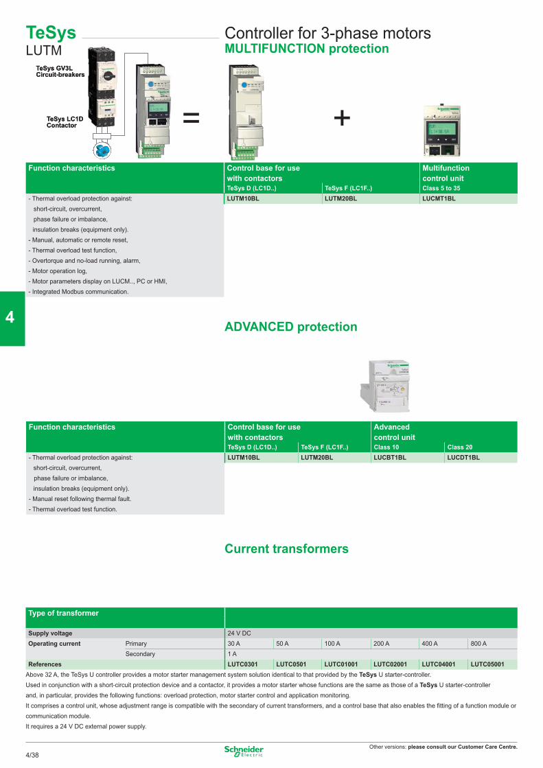
Other versions: please consult our Customer Care Centre.
= +
TeSys GV3L
TeSys LC1DContactor
Circuit-breakersTeSys GV3L
TeSys LC1DContactor
Circuit-breakers
ADVANCED protection
Current transformers
TeSys LUTM
Controller for 3-phase motorsMULTIFUNCTION protection
Function characteristics Control base for use Multifunctionwith contactors control unitTeSys D (LC1D..) TeSys F (LC1F..) Class 5 to 35
- Thermal overload protection against: LUTM10BL LUTM20BL LUCMT1BL short-circuit, overcurrent,
phase failure or imbalance, insulation breaks (equipment only).
- Manual, automatic or remote reset,- Thermal overload test function,- Overtorque and no-load running, alarm,- Motor operation log,- Motor parameters display on LUCM.., PC or HMI,- Integrated Modbus communication.
Function characteristics Control base for use Advancedwith contactors control unitTeSys D (LC1D..) TeSys F (LC1F..) Class 10 Class 20
- Thermal overload protection against: LUTM10BL LUTM20BL LUCBT1BL LUCDT1BL short-circuit, overcurrent,
phase failure or imbalance, insulation breaks (equipment only).- Manual reset following thermal fault.- Thermal overload test function.
Type of transformer
Supply voltage 24 V DCOperating current Primary 30 A 50 A 100 A 200 A 400 A 800 A
Secondary 1 AReferences LUTC0301 LUTC0501 LUTC01001 LUTC02001 LUTC04001 LUTC05001
Above 32 A, the TeSys U controller provides a motor starter management system solution identical to that provided by the TeSys U starter-controller.Used in conjunction with a short-circuit protection device and a contactor, it provides a motor starter whose functions are the same as those of a TeSys U starter-controllerand, in particular, provides the following functions: overload protection, motor starter control and application monitoring.It comprises a control unit, whose adjustment range is compatible with the secondary of current transformers, and a control base that also enables the fitting of a function module orcommunication module.It requires a 24 V DC external power supply.
4/38
2
1
3
4
5
6
7
8
9
10
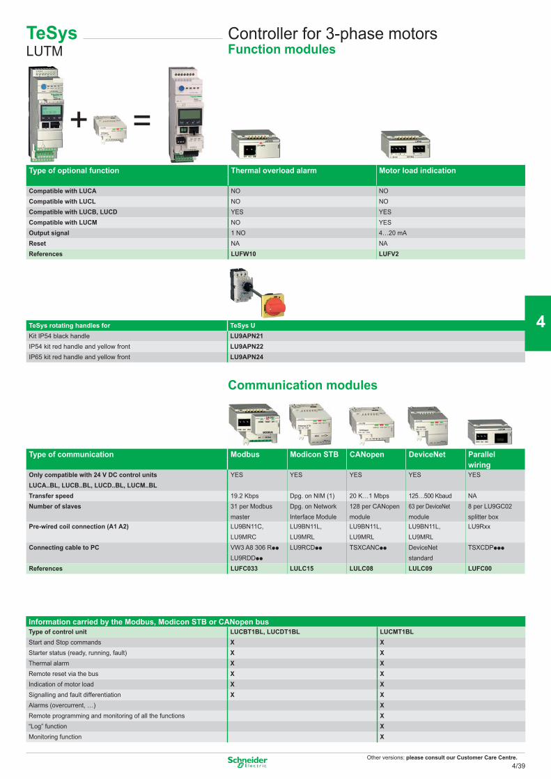
Other versions: please consult our Customer Care Centre.
=+
Communication modules
TeSys rotating handles for TeSys UKit IP54 black handle LU9APN21IP54 kit red handle and yellow front LU9APN22IP65 kit red handle and yellow front LU9APN24
TeSys LUTM
Controller for 3-phase motorsFunction modules
Type of optional function Thermal overload alarm Motor load indication
Compatible with LUCA NO NOCompatible with LUCL NO NOCompatible with LUCB, LUCD YES YESCompatible with LUCM NO YESOutput signal 1 NO 4…20 mAReset NA NAReferences LUFW10 LUFV2
Type of communication Modbus Modicon STB CANopen DeviceNet Parallelwiring
Only compatible with 24 V DC control units YES YES YES YES YESLUCA..BL, LUCB..BL, LUCD..BL, LUCM..BLTransfer speed 19.2 Kbps Dpg. on NIM (1) 20 K…1 Mbps 125…500 Kbaud NANumber of slaves 31 per Modbus Dpg. on Network 128 per CANopen 63 per DeviceNet 8 per LU9GC02
master Interface Module module module splitter boxPre-wired coil connection (A1 A2) LU9BN11C, LU9BN11L, LU9BN11L, LU9BN11L, LU9Rxx
LU9MRC LU9MRL LU9MRL LU9MRLConnecting cable to PC VW3 A8 306 Rpp LU9RCDpp TSXCANCpp DeviceNet TSXCDPppp
LU9RDDpp standardReferences LUFC033 LULC15 LULC08 LULC09 LUFC00
Information carried by the Modbus, Modicon STB or CANopen busType of control unit LUCBT1BL, LUCDT1BL LUCMT1BLStart and Stop commands X XStarter status (ready, running, fault) X XThermal alarm X XRemote reset via the bus X XIndication of motor load X XSignalling and fault differentiation X XAlarms (overcurrent, …) XRemote programming and monitoring of all the functions X“Log” function XMonitoring function X
4/39
2
1
3
4
5
6
7
8
9
10
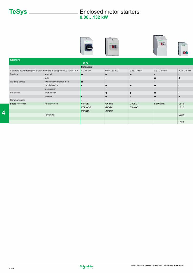
Other versions: please consult our Customer Care Centre.
Starters D.O.L. standard
Standard power ratings of 3-phase motors in category AC3 400/415 V 4…37 kW 0.06…37 kW 0.55…30 kW 0.37…5.5 kW 0.25…45 kWStarters manual - -
auto - - -Isolating device switch-disconnector-fuse - - - -
circuit-breaker - -fuse carrier - - - - -
Protection short-circuit - -overload - -
Communication - - - - -Basic reference Non-reversing V•F•GE GV2ME GV2LC LE1GVME LE1M
VCFN•GE GV3PC GV-NGC LE1DV•FXGE• GV3CE
Reversing LE2K
LE2D
TeSys Enclosed motor starters0.06…132 kW
4/40
2
1
3
4
5
6
7
8
9
10
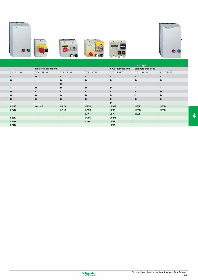
Other versions: please consult our Customer Care Centre.
■ 2 stage safety applications AS-Interface bus standard star-delta
2.2…45 kW 0.06…11 kW 0.06…9 kW 0.06…9 kW 0.06…5.5 kW 5.5…132 kW 7.5…75 kW- - - - - -
-- - - - - -- - -
- - - - --
- - - - - -LE4K GV2ME LG1K LG7K LF3M LE3K LE6DLE4D LG1D LG7D LF3P LE3D LE3D
LJ7K LF7P LE3FLE8K LG8K LF4MLE8D LJ8K LF4PLE2D LF8P
4/41
2
1
3
4
5
6
7
8
9
10
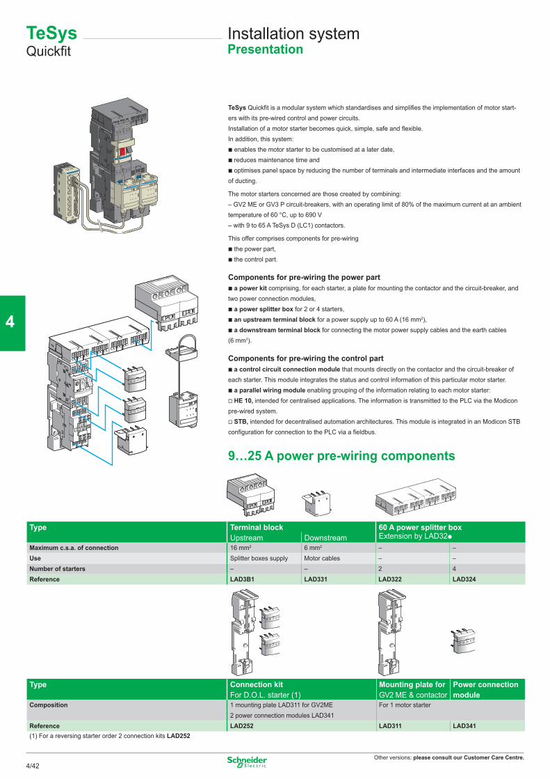
Other versions: please consult our Customer Care Centre.
TeSysQuickfit
Installation systemPresentation
TeSys Quickfit is a modular system which standardises and simplifies the implementation of motor start-ers with its pre-wired control and power circuits.Installation of a motor starter becomes quick, simple, safe and flexible.In addition, this system:b enables the motor starter to be customised at a later date,b reduces maintenance time andb optimises panel space by reducing the number of terminals and intermediate interfaces and the amount of ducting.
The motor starters concerned are those created by combining:– GV2 ME or GV3 P circuit-breakers, with an operating limit of 80% of the maximum current at an ambient temperature of 60 °C, up to 690 V– with 9 to 65 A TeSys D (LC1) contactors.
This offer comprises components for pre-wiringb the power part,b the control part.
Components for pre-wiring the power partb a power kit comprising, for each starter, a plate for mounting the contactor and the circuit-breaker, and two power connection modules,b a power splitter box for 2 or 4 starters,b an upstream terminal block for a power supply up to 60 A (16 mm2),b a downstream terminal block for connecting the motor power supply cables and the earth cables (6 mm2).
Components for pre-wiring the control partb a control circuit connection module that mounts directly on the contactor and the circuit-breaker of each starter. This module integrates the status and control information of this particular motor starter.b a parallel wiring module enabling grouping of the information relating to each motor starter:v HE 10, intended for centralised applications. The information is transmitted to the PLC via the Modicon pre-wired system.v STB, intended for decentralised automation architectures. This module is integrated in an Modicon STB configuration for connection to the PLC via a fieldbus.
9…25 A power pre-wiring components
Type Terminal block 60 A power splitter boxUpstream Downstream Extension by LAD32p
Maximum c.s.a. of connection 16 mm2 6 mm2 – –Use Splitter boxes supply Motor cables – –Number of starters – – 2 4Reference LAD3B1 LAD331 LAD322 LAD324
Type Connection kit Mounting plate for Power connectionFor D.O.L. starter (1) GV2 ME & contactor module
Composition 1 mounting plate LAD311 for GV2ME For 1 motor starter2 power connection modules LAD341
Reference LAD252 LAD311 LAD341(1) For a reversing starter order 2 connection kits LAD252
4/42
2
1
3
4
5
6
7
8
9
10
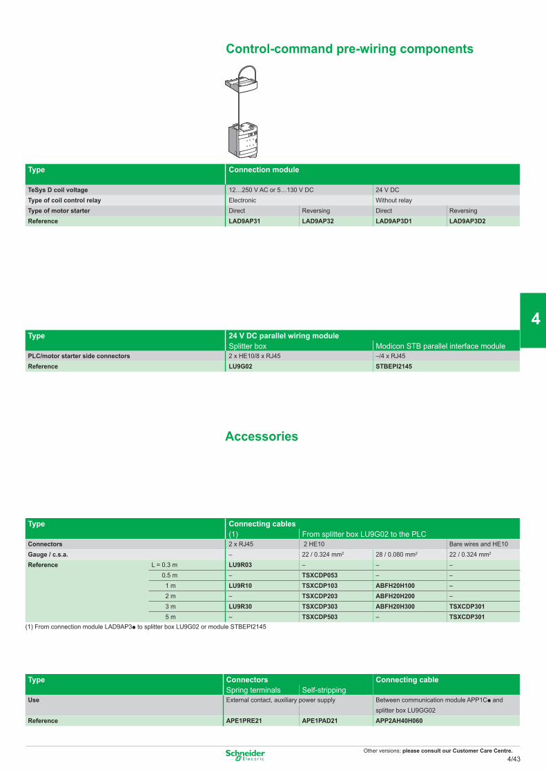
Other versions: please consult our Customer Care Centre.
Type Connection module
TeSys D coil voltage 12…250 V AC or 5…130 V DC 24 V DCType of coil control relay Electronic Without relayType of motor starter Direct Reversing Direct ReversingReference LAD9AP31 LAD9AP32 LAD9AP3D1 LAD9AP3D2
Type 24 V DC parallel wiring moduleSplitter box Modicon STB parallel interface module
PLC/motor starter side connectors 2 x HE10/8 x RJ45 –/4 x RJ45Reference LU9G02 STBEPI2145
Accessories
Type Connecting cables(1) From splitter box LU9G02 to the PLC
Connectors 2 x RJ45 2 HE10 Bare wires and HE10Gauge / c.s.a. – 22 / 0.324 mm2 28 / 0.080 mm2 22 / 0.324 mm2
Reference L = 0.3 m LU9R03 – – – 0.5 m – TSXCDP053 – – 1 m LU9R10 TSXCDP103 ABFH20H100 – 2 m – TSXCDP203 ABFH20H200 – 3 m LU9R30 TSXCDP303 ABFH20H300 TSXCDP301 5 m – TSXCDP503 – TSXCDP301
(1) From connection module LAD9AP3p to splitter box LU9G02 or module STBEPI2145
Type Connectors Connecting cableSpring terminals Self-stripping
Use External contact, auxiliary power supply Between communication module APP1Cp andsplitter box LU9GG02
Reference APE1PRE21 APE1PAD21 APP2AH40H060
Control-command pre-wiring components
4/43
2
1
3
4
5
6
7
8
9
10
Other versions: please consult our Customer Care Centre.
Sodium vapour lamps low pressure
Non-corrected With parallel compensationP (W) 3- 55 90 135 150 180 200 35 55 90 135 150 180 200IB (A) 1.2 1.6 2.4 3.1 3.2 3.3 3.4 0.3 0.4 0.6 0.9 1 1.2 1.3C (μF) - - - - - - - 17 17 25 36 36 36 36 LC1-Max. number of lamps 6 5 3 2 2 2 2 - - - - - - - K09according to P (W), per contactor 10 7 5 3 3 3 3 40 30 - - - - - D09, D12
12 9 6 4 4 4 4 50 37 25 - - - - D1815 11 7 6 5 5 5 63 47 31 21 19 15 14 D2521 16 10 8 8 7 7 86 65 43 28 26 21 20 D32, D3827 20 13 10 10 10 9 110 82 55 36 33 27 25 D40A35 26 17 13 13 12 12 140 105 70 46 42 35 32 D50A, D65A50 37 25 19 18 18 17 200 150 100 66 60 50 46 D80, D95100 75 50 38 36 36 34 400 300 200 132 120 100 92 D115, D150140 104 70 54 52 50 48 560 420 280 186 168 140 128 F185152 114 76 58 56 54 54 606 454 302 202 182 152 140 F225174 130 88 68 66 64 62 700 524 350 232 210 174 162 F265198 148 98 76 74 72 70 792 594 396 264 238 198 182 F330250 188 124 96 94 90 88 1002 752 502 334 300 250 252 F400338 254 168 130 126 122 118 1352 1014 676 450 406 338 312 F500496 372 248 192 186 180 174 1982 1488 992 660 594 496 458 F600, F800
high pressureP (W) 150 250 400 700 1000 150 250 400 700 1000IB (A) 1.9 3.2 5 8.8 12.4 0.84 1.4 2.2 3.9 5.5C (μF) - - - - - 20 32 48 96 120 LC1-Max. number of lamps 4 2 1 - - - - - - - K09according to P (W), per contactor 6 3 2 1 - - - - - - D09, D12
7 4 3 1 1 17 - - - - D1810 5 3 2 1 22 13 8 - - D2513 8 5 2 2 30 18 11 6 - D32, D3817 10 6 3 2 39 23 15 8 6 D40A22 13 8 4 3 50 30 19 10 7 D50A, D65A31 18 12 6 4 71 42 27 15 10 D80, D9562 36 24 12 8 142 84 54 30 20 D115, D15088 52 34 18 14 200 120 76 42 30 F18596 56 36 20 16 216 130 82 46 32 F225110 66 42 24 18 250 150 94 54 38 F265124 74 48 26 20 282 170 108 60 42 F330158 94 60 34 24 358 214 136 76 54 F400214 126 80 46 32 482 290 184 104 74 F500312 186 118 68 48 708 424 270 152 108 F630, F800
Metal iodine vapour lamps
P (W) 250 400 1000 2000 250 400 1000 2000IB (A) 2.5 3.6 9.5 20 1.4 2 5.3 11.2C (μF) - - - - 32 32 64 140 LC1-Max. number of lamps 3 2 - - - - - - K09according to P (W), per contactor 4 3 1 - - - - - D09, D12
6 4 1 - - - - - D187 5 2 - 13 9 - - D2510 7 2 1 18 13 4 - D32, D3813 9 3 1 23 16 6 - D40A16 11 4 2 30 21 7 - D50A, D65A24 16 6 3 42 30 11 5 D80, D9548 32 12 6 84 60 22 10 D115, D15066 46 18 8 120 84 32 14 F18572 50 20 10 130 90 34 16 F22584 58 22 12 150 104 40 18 F26594 66 24 14 170 118 44 20 F330120 84 32 16 214 150 56 26 F400162 112 42 20 290 202 76 36 F500238 164 62 30 424 298 112 52 F630, F800
Components Lighting applications (AC5)
4/44
2
1
3
4
5
6
7
8
9
10
Other versions: please consult our Customer Care Centre.
Incandescent and halogen lamps
P (W) 60 75 100 150 200 300 500 750 1000IB (A) 0.27 0.34 0.45 0.68 0.91 1.40 2.30 3.40 4.60 LC1-Max. number of lamps 35 28 21 14 10 6 4 2 2 K09according to P (W), per contactor 59 47 35 23 17 11 7 4 3 D09, D12
77 61 46 30 23 15 9 6 4 D1892 73 55 36 27 18 11 7 5 D25129 103 77 51 38 25 15 10 7 D32, D38163 129 97 64 48 31 19 13 9 D40A207 164 124 82 62 40 24 16 12 D50A, D65A296 235 177 117 88 57 34 23 17 D80, D95430 340 256 170 126 82 50 34 24 D115466 370 280 184 138 90 54 36 26 D150710 564 426 282 210 136 82 56 40 F185770 610 462 304 228 148 90 60 44 F225888 704 532 352 262 170 104 70 52 F2651006 800 604 400 298 194 118 80 58 F3301274 1010 764 504 378 244 148 100 74 F4001718 1364 1030 682 508 330 200 136 100 F5002328 1850 1396 924 690 448 272 184 136 F6002776 2204 1666 1102 824 534 326 220 162 F800
Fluorescent lamps with starter single fitting
Non-corrected With parallel correctionP (W) 20 40 65 80 110 20 40 65 80 110IB (A) 0.39 0.45 0.70 0.80 1.2 0.17 0.26 0.42 0.52 0.72C (μF) - - - - - 5 5 7 7 16 LC1-Max. number of lamps 24 21 13 12 8 56 36 22 18 - K09according to P (W), per contactor 41 35 22 20 13 94 61 38 30 22 D09, D12
53 46 30 26 17 123 80 50 40 29 D1866 57 37 32 21 152 100 61 50 36 D2589 77 50 43 29 205 134 83 67 48 D32, D38112 97 62 55 36 258 169 104 84 61 D40A143 124 80 70 46 329 215 133 107 77 D50A, D65A205 177 114 100 66 470 367 190 153 111 D80, D95410 354 228 200 132 940 614 380 306 222 D115, D150492 426 274 240 160 1128 738 456 368 266 F185532 462 296 260 172 1224 800 490 400 288 F225614 532 342 300 200 1412 922 570 462 332 F265696 604 388 340 226 1600 1046 648 522 378 F330882 764 490 430 286 2024 1322 818 662 478 F4001190 1030 662 580 386 2728 1724 1104 892 644 F5001612 1398 698 786 524 3700 2418 1498 1210 874 F630, F800
■ twin fittingP (W) 2x20 2x40 2x65 2x80 2x110 2x20 2x40 2x65 2x80 2x110IB (A) 2x0.22 2x0.41 2x0.67 2x0.82 2x1.1 2x0.13 2x0.24 2x0.39 2x0.48 2x0.65 LC1-Max. number of lamps 2x21 2x11 2x7 2x5 2x4 2x36 2x20 2x12 2x10 2x7 K09according to P (W), per contactor 2x36 2x18 2x10 2x8 2x6 2x60 2x32 2x20 2x16 2x12 D09, D12
2x46 2x24 2x14 2x12 2x8 2x80 2x42 2x26 2x20 2x16 D182x58 2x30 2x18 2x14 2x10 2x100 2x54 2x32 2x26 2x20 D252x78 2x42 2x26 2x20 2x14 2x134 2x72 2x44 2x36 2x26 D32, D382x100 2x52 2x32 2x26 2x18 2x168 2x90 2x56 2x44 2x32 D40A2x126 2x68 2x40 2x34 2x24 2x214 2x116 2x70 2x58 2x42 D50A, D65A2x180 2x96 2x58 2x48 2x36 2x306 2x166 2x10² 2x82 2x60 D80, D952x360 2x194 2x118 2x96 2x72 2x614 2x332 2x204 2x166 2x122 D115, D1502x436 2x234 2x142 2x116 2x86 2x738 2x400 2x246 2x200 2x148 F1852x472 2x254 2x154 2x126 2x94 2x800 2x432 2x266 2x216 2x160 F2252x544 2x292 2x178 2x146 2x10⁸ 2x922 2x500 2x308 2x250 2x184 F2652x618 2x332 2x202 2x166 2x124 2x1046 2x566 2x348 2x282 2x208 F3302x782 2x420 2x256 2x210 2x156 2x1322 2x716 2x440 2x358 2x264 F4002x1054 2x566 2x346 2x282 2x210 2x1784 2x966 2x594 2x482 2x356 F5002x1430 2x766 2x468 2x384 2x286 2x2418 2x1310 2x806 2x654 2x484 F630, F800
4/45
2
1
3
4
5
6
7
8
9
10
Other versions: please consult our Customer Care Centre.
On-load capacitor switching for bar-mounted contactors, a.c. control circuit
Without damping resistor With damping resistorRated operational voltage (V) Number of poles Max. operational Basic reference, Number of poles Max. operational Basic reference,
current (A) to be completed current (A) to be completed50 Hz 180 Hz 50 Hz 180 Hz
1300 1 80 60 CE5FB11•11 1 + 1 staggered pole 80 60 CE6FB12•11160 125 CE5GB11•11 160 125 CE6GB12•11240 190 CE5HB11•11 240 190 CE6HB12•11
2 80x2 60x2 CE5FB21•11160x2 125x2 CE5GB21•11240x2 190x2 CE5HB21•11 2 + 2 staggered poles 240x2 190x2 CE6HB22•11
3 80x3 60x3 CE5FB31•11160x3 125x3 CE5GB31•11240x3 190x3 CE5HB31•11 1 + 2 staggered poles
1500 2 poles in series 160 125 CE5GB12•11 160 125 CE6GB13•11280 220 CE5HB12•11 280 220 CE6HB13•11
2 x 2 poles in series 280x2 220x2 CE5HB22•112000 2 poles in series 240 190 CS5HB12•11 1 + 2 staggered poles 240 190 CS6HB13•11
2 x 2 poles in series 240x2 190x2 CS5HB22•113000 3 poles in series 280 220 CS5HB13•11 1 + 3 staggered poles 280 220 CS6HB14•11
Components Capacitor switching0…1000 kVAR
Standard control circuit voltagesa supplyVolts 110 125 127 200 220 240 250 380 415 440 50050 Hz (coil LX1) F - G L M U - Q N R S
4/46
2
1
3
4
5
6
7
8
9
10
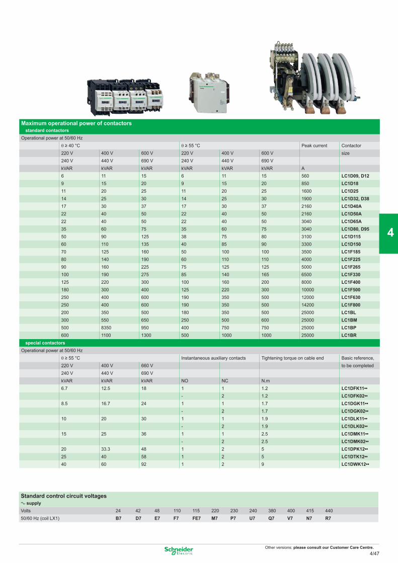
Other versions: please consult our Customer Care Centre.
Maximum operational power of contactors standard contactors
Operational power at 50/60 Hz θ ≥ 40 °C θ ≥ 55 °C Peak current Contactor220 V 400 V 600 V 220 V 400 V 600 V size240 V 440 V 690 V 240 V 440 V 690 VkVAR kVAR kVAR kVAR kVAR kVAR A6 11 15 6 11 15 560 LC1D09, D129 15 20 9 15 20 850 LC1D1811 20 25 11 20 25 1600 LC1D2514 25 30 14 25 30 1900 LC1D32, D3817 30 37 17 30 37 2160 LC1D40A22 40 50 22 40 50 2160 LC1D50A22 40 50 22 40 50 3040 LC1D65A35 60 75 35 60 75 3040 LC1D80, D9550 90 125 38 75 80 3100 LC1D11560 110 135 40 85 90 3300 LC1D15070 125 160 50 100 100 3500 LC1F18580 140 190 60 110 110 4000 LC1F22590 160 225 75 125 125 5000 LC1F265100 190 275 85 140 165 6500 LC1F330125 220 300 100 160 200 8000 LC1F400180 300 400 125 220 300 10000 LC1F500250 400 600 190 350 500 12000 LC1F630250 400 600 190 350 500 14200 LC1F800200 350 500 180 350 500 25000 LC1BL300 550 650 250 500 600 25000 LC1BM500 8350 950 400 750 750 25000 LC1BP600 1100 1300 500 1000 1000 25000 LC1BR
special contactorsOperational power at 50/60 Hz
θ ≥ 55 °C Instantaneous auxiliary contacts Tightening torque on cable end Basic reference,220 V 400 V 660 V to be completed240 V 440 V 690 VkVAR kVAR kVAR NO NC N.m6.7 12.5 18 1 1 1.2 LC1DFK11••
- 2 1.2 LC1DFK02••8.5 16.7 24 1 1 1.7 LC1DGK11••
- 2 1.7 LC1DGK02••10 20 30 1 1 1.9 LC1DLK11••
- 2 1.9 LC1DLK02••15 25 36 1 1 2.5 LC1DMK11••
- 2 2.5 LC1DMK02••20 33.3 48 1 2 5 LC1DPK12••25 40 58 1 2 5 LC1DTK12••40 60 92 1 2 9 LC1DWK12••
Standard control circuit voltagesa supplyVolts 24 42 48 110 115 220 230 240 380 400 415 44050/60 Hz (coil LX1) B7 D7 E7 F7 FE7 M7 P7 U7 Q7 V7 N7 R7
4/47
2
1
3
4
5
6
7
8
9
10
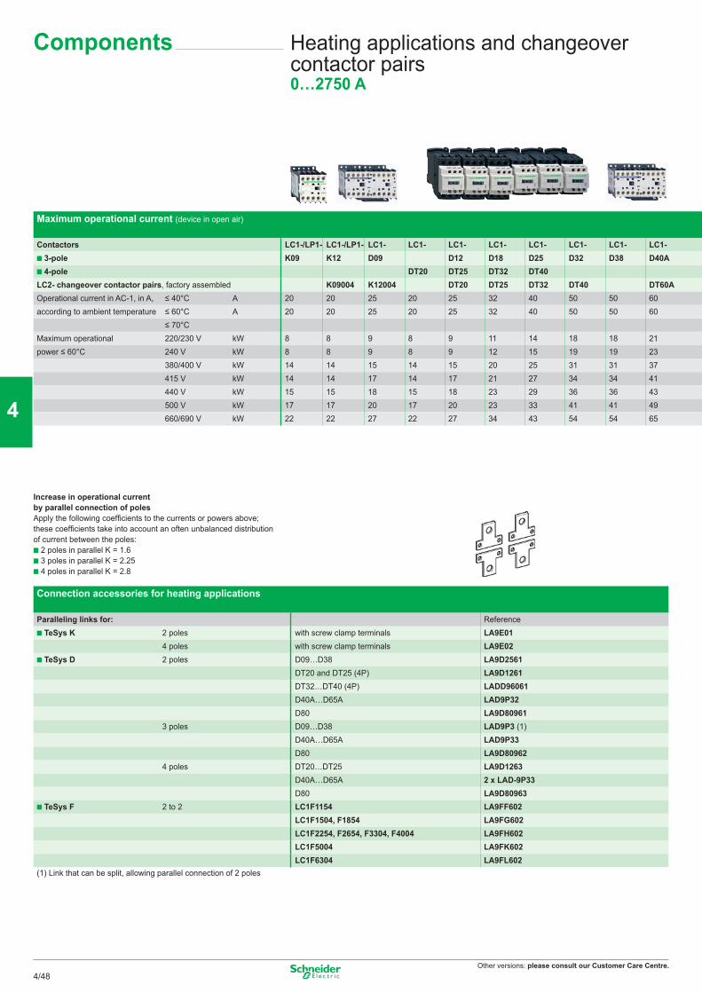
Other versions: please consult our Customer Care Centre.
Maximum operational current (device in open air)
Contactors LC1-/LP1- LC1-/LP1- LC1- LC1- LC1- LC1- LC1- LC1- LC1- LC1- 3-pole K09 K12 D09 D12 D18 D25 D32 D38 D40A 4-pole DT20 DT25 DT32 DT40
LC2- changeover contactor pairs, factory assembled K09004 K12004 DT20 DT25 DT32 DT40 DT60AOperational current in AC-1, in A, ≤ 40°C A 20 20 25 20 25 32 40 50 50 60according to ambient temperature ≤ 60°C A 20 20 25 20 25 32 40 50 50 60
≤ 70°CMaximum operational 220/230 V kW 8 8 9 8 9 11 14 18 18 21power ≤ 60°C 240 V kW 8 8 9 8 9 12 15 19 19 23
380/400 V kW 14 14 15 14 15 20 25 31 31 37415 V kW 14 14 17 14 17 21 27 34 34 41440 V kW 15 15 18 15 18 23 29 36 36 43500 V kW 17 17 20 17 20 23 33 41 41 49660/690 V kW 22 22 27 22 27 34 43 54 54 65
Increase in operational current by parallel connection of polesApply the following coefficients to the currents or powers above; these coefficients take into account an often unbalanced distribution of current between the poles:
2 poles in parallel K = 1.6 3 poles in parallel K = 2.25 4 poles in parallel K = 2.8
Connection accessories for heating applications
Paralleling links for: Reference TeSys K 2 poles with screw clamp terminals LA9E01
4 poles with screw clamp terminals LA9E02 TeSys D 2 poles D09…D38 LA9D2561
DT20 and DT25 (4P) LA9D1261DT32…DT40 (4P) LADD96061D40A…D65A LAD9P32D80 LA9D80961
3 poles D09…D38 LAD9P3 (1)D40A…D65A LAD9P33D80 LA9D80962
4 poles DT20…DT25 LA9D1263D40A…D65A 2 x LAD-9P33
D80 LA9D80963 TeSys F 2 to 2 LC1F1154 LA9FF602
LC1F1504, F1854 LA9FG602LC1F2254, F2654, F3304, F4004 LA9FH602LC1F5004 LA9FK602LC1F6304 LA9FL602
(1) Link that can be split, allowing parallel connection of 2 poles
Heating applications and changeover contactor pairs0…2750 A
Components
4/48
2
1
3
4
5
6
7
8
9
10
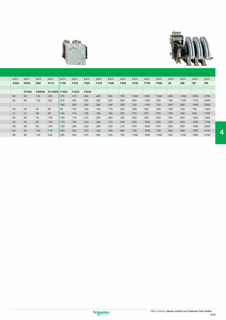
Other versions: please consult our Customer Care Centre.
LC1- LC1- LC1- LC1- LC1- LC1- LC1- LC1- LC1- LC1- LC1- LC1- LC1- LC1- LC1- LC1- LC1-D50A D65A D80 D115 F185 F225 F265 F330 F400 F500 F630 F780 F800 BL BM BP BR
DT80A D80004 D115004 F1854 F2254 F265480 80 125 250 275 315 350 400 500 700 1000 1600 1000 800 1250 2000 275080 80 125 200 275 280 300 360 430 580 850 1350 850 700 1100 1750 2400
180 200 250 290 340 500 700 1100 700 600 900 1500 200029 29 45 80 90 100 120 145 170 240 350 550 350 300 425 700 100031 31 49 83 100 110 125 160 180 255 370 570 370 330 450 800 110050 50 78 135 165 175 210 250 300 430 600 950 600 500 800 1200 160054 54 85 140 170 185 220 260 310 445 630 1000 630 525 825 1250 170058 58 90 150 180 200 230 290 330 370 670 1050 670 550 850 1400 200065 65 102 170 200 220 270 320 380 660 750 1200 750 600 900 1500 210086 86 135 235 280 300 370 400 530 740 1000 1650 1000 800 1100 1900 2700
4/49
2
1
3
4
5
6
7
8
9
10
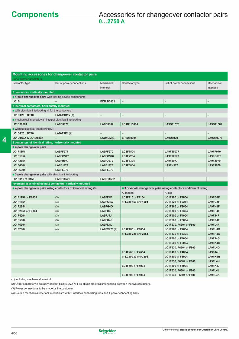
Other versions: please consult our Customer Care Centre.
Accessories for changeover contactor pairs0…2750 A
Components
Mounting accessories for changeover contactor pairs (for customer assembly)Contactor type Set of power connections Mechanical Contactor type Set of power connections Mechanical
interlock interlock2 contactors, vertically mounted
4-pole changeover pairs with locking device componentsLC1B – EZ2LB0601 – – –2 identical contactors, horizontally mounted
with electrical interlocking kit for the contactorsLC1DT20…DT40 LAD-T9R1V (1) – – – –
mechanical interlock with integral electrical interlockingLP1D80004 LA9D8070 LA9D8002 LC1D115004 LA9D11570 LA9D11502
without electrical interlocking (2)LC1DT20…DT40 LAD-T9R1 (2) – – – –LC1DT60A & LC1DT80A – LAD4CM (3) LP1D80004 LA9D8070 LA9D809782 contactors of identical rating, horizontally mounted
4-pole changeover pairsLC1F1154 LA9FF977 LA9FF970 LC1F1504 LA9F15077 LA9FF970LC1F1854 LA9FG977 LA9FG970 LC1F2254 LA9F22577 LA9FG970LC1F2654 LA9FH977 LA9FJ970 LC1F3304 LA9FJ977 LA9FJ970LC1F4004 LA9FJ977 LA9FJ970 LC1F5004 LA9FK977 LA9FJ970LC1F6304 LA9FL977 LA9FL970 – – –
3-pole changeover pairs with electrical interlockingLC1D115 et D150 LA9D11571 LA9D11502 – – –reversers assembled using 2 contactors, vertically mounted
4-pole changeover pairs using contactors of identical rating (3) 3 or 4-pole changeover pairs using contactors of different ratingAt bottom At top
LC1F1154 or F1505 (3) LA9FF4F LC1F115 or F1154 LC1F185 or F1854 LA9FG4FLC1F1854 (3) LA9FG4G or LC1F150 or F1504 LC1F225 or F2254 LA9FG4FLC1F2254 (3) LA9FG4G LC1F265 or F2654 LA9FH4FLC1F2654 or F3304 (3) LA9FH4H LC1F300 or F3304 LA9FH4FLC1F4004 (3) LA9FJ4J LC1F400 or F4004 LA9FJ4FLC1F5004 (3) LA9FK4K LC1F500 or F5004 LA9FK4FLC1F6304 (3) LA9FL4L LC1F630, F6304 or F800 LA9FL4FLC1F7804 (4) LA9FX971 (4) LC1F185 or F1854 LC1F265 or F2654 LA9FH4G
or LC1F225 or F2254 LC1F330 or F3304 LA9FH4GLC1F400 or F4004 LA9FJ4GLC1F500 or F5004 LA9FK4GLC1F630, F6304 or F800 LA9FL4G
LC1F265 or F2654 LC1F400 or F4004 LA9FJ4Hor LC1F330 or F3304 LC1F500 or F5004 LA9FK4H
LC1F630, F6304 or F800 LA9FL4HLC1F400 or F4004 LC1F500 or F5004 LA9FK4J
LC1F630, F6304 or F800 LA9FL4JLC1F500 or F5004 LC1F630, F6304 or F800 LA9FL4K
(1) Including mechanical interlock.(2) Order separately 2 auxiliary contact blocks LAD-N•1 t o obtain electrical interlocking between the two contactors.(3) Power connections to be made by the customer.(4) Double mechanical interlock mechanism with 2 interlock connecting rods and 4 power connecting links.
4/50
2
1
3
4
5
6
7
8
9
10
Other versions: please consult our Customer Care Centre.
TeSys Notes
4/51
2
1
3
4
5
6
7
8
9
10
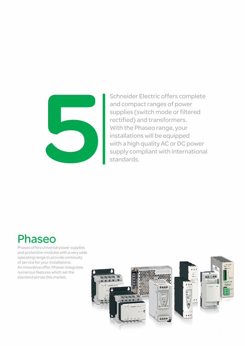
Schneider Electric offers complete and compact ranges of power supplies (switch mode or fi ltered rectifi ed) and transformers. With the Phaseo range, your installations will be equipped with a high quality AC or DC power supply compliant with international standards.
Phaseo Phaseo offers universal power supplies and protection modules with a very wide operating range to provide continuity of service for your installations. An innovative offer, Phaseo integrates numerous features which set the standard across this market.
Power Supplies
This document is a selection of
the top selling products.
5/1
2
1
3
4
5
6
7
8
9
10
Power supplies Regulated switch mode, filtered rectified power supplies Accessories Phaseo ABL8, ABL4, ABL1 ......................................................................................... 5/2 to 5/5
Transformers Phaseo ABL6, ABT7 .................................................................................................................. 5/6
Connection Terminal blocks AB1 ........................................................................................................................................ 5/8 Cable ends DZ5/AZ5 ................................................................................................................................. 5/9
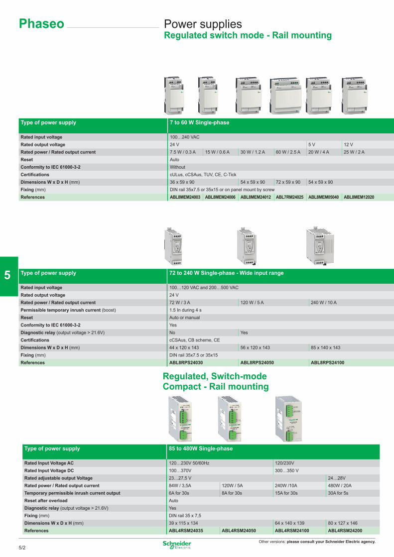
Other versions: please consult your Schneider Electric agency.
Phaseo Power suppliesRegulated switch mode - Rail mounting
Type of power supply 7 to 60 W Single-phase
Rated input voltage 100…240 VACRated output voltage 24 V 5 V 12 VRated power / Rated output current 7.5 W / 0.3 A 15 W / 0.6 A 30 W / 1.2 A 60 W / 2.5 A 20 W / 4 A 25 W / 2 AReset AutoConformity to IEC 61000-3-2 WithoutCertifications cULus, cCSAus, TUV, CE, C-TickDimensions W x D x H (mm) 36 x 59 x 90 54 x 59 x 90 72 x 59 x 90 54 x 59 x 90Fixing (mm) DIN rail 35x7.5 or 35x15 or on panel mount by screwReferences ABL8MEM24003 ABL8MEM24006 ABL8MEM24012 ABL7RM24025 ABL8MEM05040 ABL8MEM12020
Type of power supply 72 to 240 W Single-phase - Wide input range
Rated input voltage 100…120 VAC and 200…500 VACRated output voltage 24 VRated power / Rated output current 72 W / 3 A 120 W / 5 A 240 W / 10 APermissible temporary inrush current (boost) 1.5 In during 4 sReset Auto or manualConformity to IEC 61000-3-2 YesDiagnostic relay (output voltage > 21.6V) No YesCertifications cCSAus, CB scheme, CEDimensions W x D x H (mm) 44 x 120 x 143 56 x 120 x 143 85 x 140 x 143Fixing (mm) DIN rail 35x7.5 or 35x15References ABL8RPS24030 ABL8RPS24050 ABL8RPS24100
Type of power supply 85 to 480W Single-phase
Rated Input Voltage AC 120…230V 50/60Hz 120/230VRated Input Voltage DC 100…370V 300…350 VRated adjustable output Voltage 23…27,5 V 24…28VRated power / Rated output current 84W / 3,5A 120W / 5A 240W /10A 480W / 20ATemporary permissible inrush current output 6A for 30s 8A for 30s 15A for 30s 30A for 5sReset after overload AutoDiagnostic relay (output voltage > 21.6V) YesFixing (mm) DIN rail 35 x 7,5Dimensions W x D x H (mm) 39 x 115 x 134 64 x 140 x 139 80 x 127 x 146References ABL4RSM24035 ABL4RSM24050 ABL4RSM24100 ABL4RSM24200
Regulated, Switch-mode Compact - Rail mounting
5/2
2
1
3
4
5
6
7
8
9
10
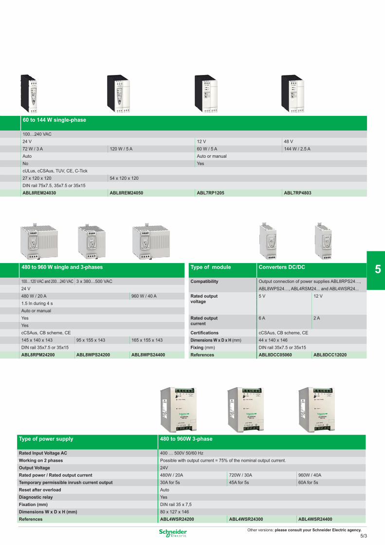
Other versions: please consult your Schneider Electric agency.
60 to 144 W single-phase
100…240 VAC24 V 12 V 48 V72 W / 3 A 120 W / 5 A 60 W / 5 A 144 W / 2.5 AAuto Auto or manualNo YescULus, cCSAus, TUV, CE, C-Tick27 x 120 x 120 54 x 120 x 120DIN rail 75x7.5, 35x7.5 or 35x15ABL8REM24030 ABL8REM24050 ABL7RP1205 ABL7RP4803
480 to 960 W single and 3-phases
100…120 VAC and 200…240 VAC 3 x 380…500 VAC24 V480 W / 20 A 960 W / 40 A1.5 In during 4 sAuto or manualYesYescCSAus, CB scheme, CE145 x 140 x 143 95 x 155 x 143 165 x 155 x 143DIN rail 35x7.5 or 35x15ABL8RPM24200 ABL8WPS24200 ABL8WPS24400
Type of power supply 480 to 960W 3-phase
Rated Input Voltage AC 400 … 500V 50/60 HzWorking on 2 phases Possible with output current = 75% of the nominal output current.Output Voltage 24VRated power / Rated output current 480W / 20A 720W / 30A 960W / 40ATemporary permissible inrush current output 30A for 5s 45A for 5s 60A for 5sReset after overload AutoDiagnostic relay YesFixation (mm) DIN rail 35 x 7,5Dimensions W x D x H (mm) 80 x 127 x 146References ABL4WSR24200 ABL4WSR24300 ABL4WSR24400
Type of module Converters DC/DC
Compatibility Output connection of power supplies ABL8RPS24…, ABL8WPS24…, ABL4RSM24... and ABL4WSR24...
Rated outputvoltage
5 V 12 V
Rated outputcurrent
6 A 2 A
Certifications cCSAus, CB scheme, CEDimensions W x D x H (mm) 44 x 140 x 146Fixing (mm) DIN rail 35x7.5 or 35x15References ABL8DCC05060 ABL8DCC12020
5/3
2
1
3
4
5
6
7
8
9
10
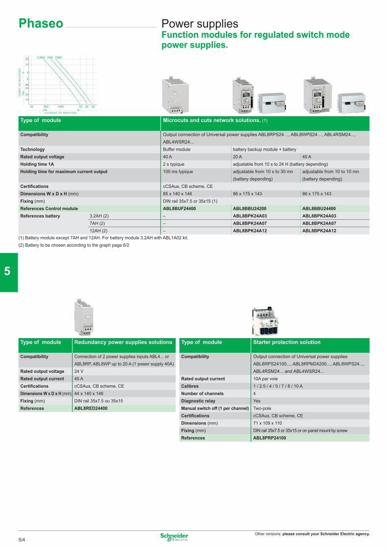
Other versions: please consult your Schneider Electric agency.
1000 10 20 40200mA
40
10
20
4060
2
4
10
20 3,2AH 7AH 12AH
COURANT DE MAINTIEN
TE
MP
S D
E M
AIN
TIE
Nm
nh
A
Power suppliesFunction modules for regulated switch mode power supplies.
Phaseo
Type of module Microcuts and cuts network solutions. (1)
Compatibility Output connection of Universal power supplies ABL8RPS24…, ABL8WPS24…, ABL4RSM24..., ABL4WSR24...
Technology Buffer module battery backup module + batteryRated output voltage 40 A 20 A 40 AHolding time 1A 2 s typique adjustable from 10 s to 24 H (battery depending)Holding time for maximum current output 100 ms typique adjustable from 10 s to 30 mn
(battery depending)adjustable from 10 to 10 mn (battery depending)
Certifications cCSAus, CB scheme, CEDimensions W x D x H (mm) 85 x 140 x 146 86 x 175 x 143 86 x 175 x 143Fixing (mm) DIN rail 35x7.5 or 35x15 (1)References Control module ABL8BUF24400 ABL8BBU24200 ABL8BBU24400References battery 3,2AH (2) – ABL8BPK24A03 ABL8BPK24A03
7AH (2) – ABL8BPK24A07 ABL8BPK24A0712AH (2) – ABL8BPK24A12 ABL8BPK24A12
(1) Battery module except 7AH and 12AH. For battery module 3.2AH with ABL1A02 kit.(2) Battery to be chosen according to the graph page 6/2
Type of module Redundancy power supplies solutions
Compatibility Connection of 2 power supplies inputs ABL4... or ABL8RP, ABL8WP up to 20 A (1 power supply 40A)
Rated output voltage 24 VRated output current 40 ACertifications cCSAus, CB scheme, CEDimensions W x D x H (mm) 44 x 140 x 146Fixing (mm) DIN rail 35x7.5 ou 35x15References ABL8RED24400
Type of module Starter protection solution
Compatibility Output connection of Universal power supplies ABL8RPS24100..., ABL8RPM24200..., ABL8WPS24..., ABL4RSM24... and ABL4WSR24...
Rated output current 10A par voieCalibres 1 / 2.5 / 4 / 5 / 7 / 8 / 10 ANumber of channels 4Diagnostic relay YesManual switch off (1 per channel) Two-poleCertifications cCSAus, CB scheme, CEDimensions (mm) 71 x 109 x 110Fixing (mm) DIN rail 35x7.5 or 35x15 or on panel mount by screwReferences ABL8PRP24100
5/4
2
1
3
4
5
6
7
8
9
10
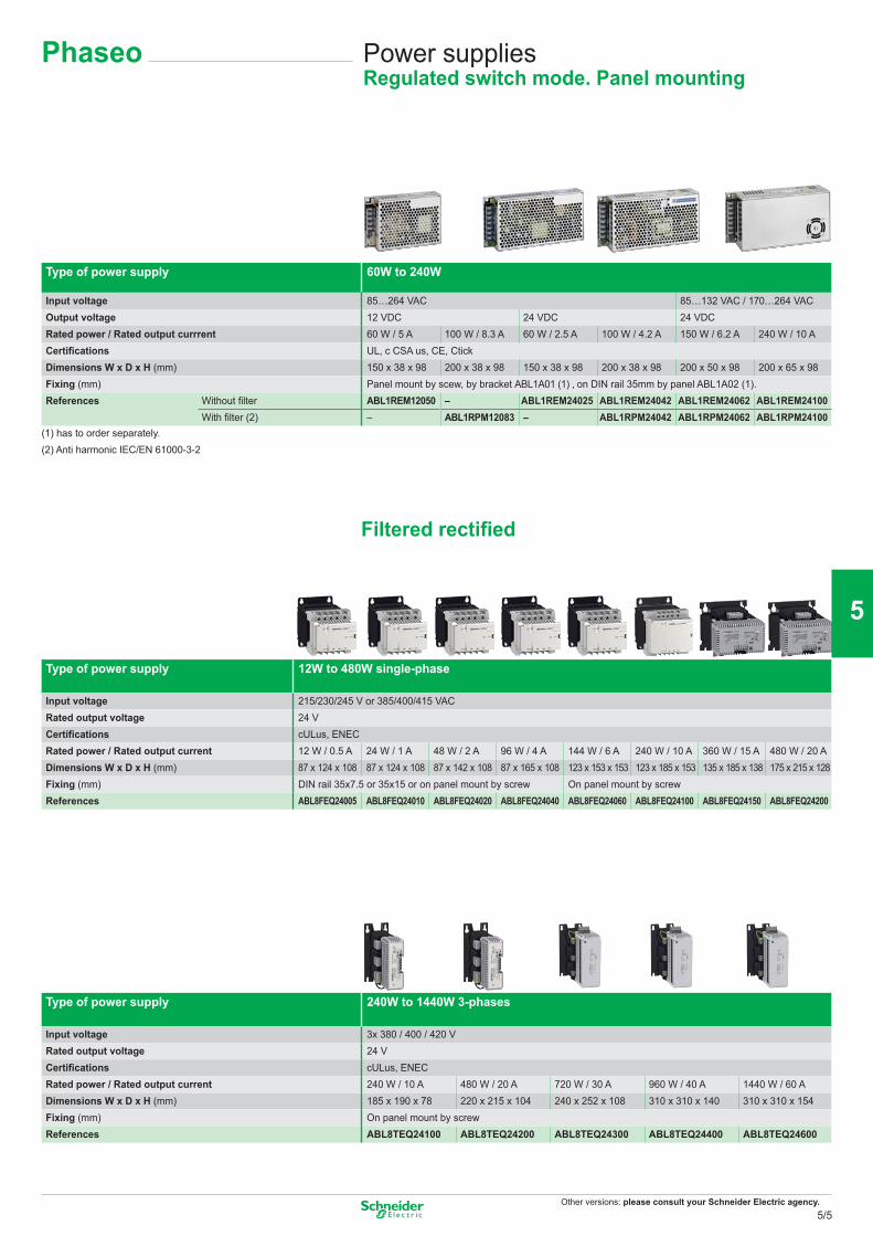
Other versions: please consult your Schneider Electric agency.
Phaseo Power suppliesRegulated switch mode. Panel mounting
Type of power supply 60W to 240W
Input voltage 85…264 VAC 85…132 VAC / 170…264 VACOutput voltage 12 VDC 24 VDC 24 VDCRated power / Rated output currrent 60 W / 5 A 100 W / 8.3 A 60 W / 2.5 A 100 W / 4.2 A 150 W / 6.2 A 240 W / 10 ACertifications UL, c CSA us, CE, CtickDimensions W x D x H (mm) 150 x 38 x 98 200 x 38 x 98 150 x 38 x 98 200 x 38 x 98 200 x 50 x 98 200 x 65 x 98Fixing (mm) Panel mount by scew, by bracket ABL1A01 (1) , on DIN rail 35mm by panel ABL1A02 (1).References Without filter ABL1REM12050 – ABL1REM24025 ABL1REM24042 ABL1REM24062 ABL1REM24100
With filter (2) – ABL1RPM12083 – ABL1RPM24042 ABL1RPM24062 ABL1RPM24100(1) has to order separately.(2) Anti harmonic IEC/EN 61000-3-2
Filtered rectified
Type of power supply 12W to 480W single-phase
Input voltage 215/230/245 V or 385/400/415 VACRated output voltage 24 VCertifications cULus, ENECRated power / Rated output current 12 W / 0.5 A 24 W / 1 A 48 W / 2 A 96 W / 4 A 144 W / 6 A 240 W / 10 A 360 W / 15 A 480 W / 20 ADimensions W x D x H (mm) 87 x 124 x 108 87 x 124 x 108 87 x 142 x 108 87 x 165 x 108 123 x 153 x 153 123 x 185 x 153 135 x 185 x 138 175 x 215 x 128Fixing (mm) DIN rail 35x7.5 or 35x15 or on panel mount by screw On panel mount by screwReferences ABL8FEQ24005 ABL8FEQ24010 ABL8FEQ24020 ABL8FEQ24040 ABL8FEQ24060 ABL8FEQ24100 ABL8FEQ24150 ABL8FEQ24200
Type of power supply 240W to 1440W 3-phases
Input voltage 3x 380 / 400 / 420 VRated output voltage 24 VCertifications cULus, ENECRated power / Rated output current 240 W / 10 A 480 W / 20 A 720 W / 30 A 960 W / 40 A 1440 W / 60 ADimensions W x D x H (mm) 185 x 190 x 78 220 x 215 x 104 240 x 252 x 108 310 x 310 x 140 310 x 310 x 154Fixing (mm) On panel mount by screwReferences ABL8TEQ24100 ABL8TEQ24200 ABL8TEQ24300 ABL8TEQ24400 ABL8TEQ24600
5/5
2
1
3
4
5
6
7
8
9
10
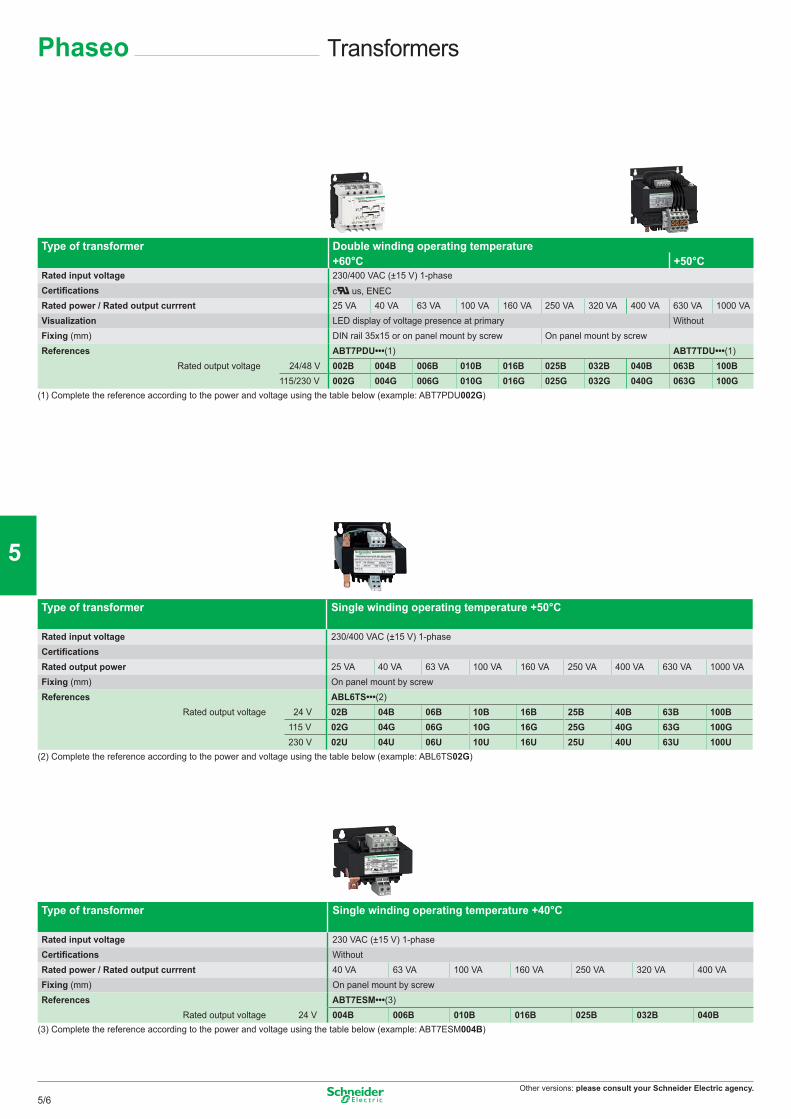
Other versions: please consult your Schneider Electric agency.
Type of transformer Double winding operating temperature+60°C +50°C
Rated input voltage 230/400 VAC (±15 V) 1-phaseCertifications c us, ENECRated power / Rated output currrent 25 VA 40 VA 63 VA 100 VA 160 VA 250 VA 320 VA 400 VA 630 VA 1000 VAVisualization LED display of voltage presence at primary WithoutFixing (mm) DIN rail 35x15 or on panel mount by screw On panel mount by screwReferences ABT7PDU•••(1) ABT7TDU•••(1)
Rated output voltage 24/48 V 002B 004B 006B 010B 016B 025B 032B 040B 063B 100B115/230 V 002G 004G 006G 010G 016G 025G 032G 040G 063G 100G
(1) Complete the reference according to the power and voltage using the table below (example: ABT7PDU002G)
Type of transformer Single winding operating temperature +50°C
Rated input voltage 230/400 VAC (±15 V) 1-phaseCertificationsRated output power 25 VA 40 VA 63 VA 100 VA 160 VA 250 VA 400 VA 630 VA 1000 VAFixing (mm) On panel mount by screwReferences
ABL6TS•••(2)Rated output voltage
24 V 02B 04B 06B 10B 16B 25B 40B 63B 100B115 V 02G 04G 06G 10G 16G 25G 40G 63G 100G230 V 02U 04U 06U 10U 16U 25U 40U 63U 100U
(2) Complete the reference according to the power and voltage using the table below (example: ABL6TS02G)
Type of transformer Single winding operating temperature +40°C
Rated input voltage 230 VAC (±15 V) 1-phaseCertifications WithoutRated power / Rated output currrent 40 VA 63 VA 100 VA 160 VA 250 VA 320 VA 400 VAFixing (mm) On panel mount by screwReferences ABT7ESM•••(3)
Rated output voltage 24 V 004B 006B 010B 016B 025B 032B 040B(3) Complete the reference according to the power and voltage using the table below (example: ABT7ESM004B)
TransformersPhaseo
5/6
2
1
3
4
5
6
7
8
9
10

Other versions: please consult your Schneider Electric agency.
Phaseo Notes
5/7
2
1
3
4
5
6
7
8
9
10
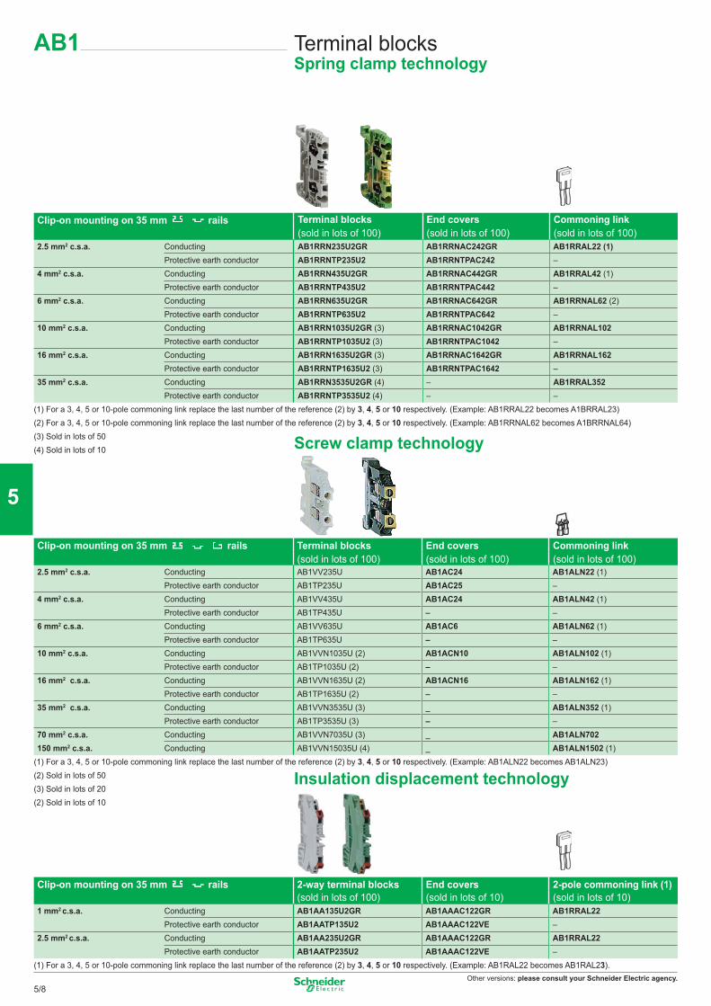
Other versions: please consult your Schneider Electric agency.
Terminal blocksSpring clamp technology
AB1
Clip-on mounting on 35 mm rails Terminal blocks(sold in lots of 100)
End covers(sold in lots of 100)
Commoning link (sold in lots of 100)
2.5 mm2 c.s.a. Conducting AB1RRN235U2GR AB1RRNAC242GR AB1RRAL22 (1)Protective earth conductor AB1RRNTP235U2 AB1RRNTPAC242 –
4 mm2 c.s.a. Conducting AB1RRN435U2GR AB1RRNAC442GR AB1RRAL42 (1)Protective earth conductor AB1RRNTP435U2 AB1RRNTPAC442 –
6 mm2 c.s.a. Conducting AB1RRN635U2GR AB1RRNAC642GR AB1RRNAL62 (2)Protective earth conductor AB1RRNTP635U2 AB1RRNTPAC642 –
10 mm2 c.s.a. Conducting AB1RRN1035U2GR (3) AB1RRNAC1042GR AB1RRNAL102 Protective earth conductor AB1RRNTP1035U2 (3) AB1RRNTPAC1042 –
16 mm2 c.s.a. Conducting AB1RRN1635U2GR (3) AB1RRNAC1642GR AB1RRNAL162 Protective earth conductor AB1RRNTP1635U2 (3) AB1RRNTPAC1642 –
35 mm2 c.s.a. Conducting AB1RRN3535U2GR (4) – AB1RRAL352Protective earth conductor AB1RRNTP3535U2 (4) – –
(1) For a 3, 4, 5 or 10-pole commoning link replace the last number of the reference (2) by 3, 4, 5 or 10 respectively. (Example: AB1RRAL22 becomes A1BRRAL23)(2) For a 3, 4, 5 or 10-pole commoning link replace the last number of the reference (2) by 3, 4, 5 or 10 respectively. (Example: AB1RRNAL62 becomes A1BRRNAL64)(3) Sold in lots of 50(4) Sold in lots of 10
Clip-on mounting on 35 mm rails Terminal blocks End covers Commoning link (sold in lots of 100) (sold in lots of 100) (sold in lots of 100)
2.5 mm2 c.s.a. Conducting AB1VV235U AB1AC24 AB1ALN22 (1)Protective earth conductor AB1TP235U AB1AC25 –
4 mm2 c.s.a. Conducting AB1VV435U AB1AC24 AB1ALN42 (1)Protective earth conductor AB1TP435U – –
6 mm2 c.s.a. Conducting AB1VV635U AB1AC6 AB1ALN62 (1)Protective earth conductor AB1TP635U – –
10 mm2 c.s.a. Conducting AB1VVN1035U (2) AB1ACN10 AB1ALN102 (1)Protective earth conductor AB1TP1035U (2) – –
16 mm2 c.s.a. Conducting AB1VVN1635U (2) AB1ACN16 AB1ALN162 (1)Protective earth conductor AB1TP1635U (2) – –
35 mm2 c.s.a. Conducting AB1VVN3535U (3) _ AB1ALN352 (1)Protective earth conductor AB1TP3535U (3) – –
70 mm2 c.s.a. Conducting AB1VVN7035U (3) _ AB1ALN702150 mm2 c.s.a. Conducting AB1VVN15035U (4) _ AB1ALN1502 (1)
(1) For a 3, 4, 5 or 10-pole commoning link replace the last number of the reference (2) by 3, 4, 5 or 10 respectively. (Example: AB1ALN22 becomes AB1ALN23)(2) Sold in lots of 50(3) Sold in lots of 20(2) Sold in lots of 10
Clip-on mounting on 35 mm rails 2-way terminal blocks End covers 2-pole commoning link (1) (sold in lots of 100) (sold in lots of 10) (sold in lots of 10)
1 mm2 c.s.a. Conducting AB1AA135U2GR AB1AAAC122GR AB1RRAL22Protective earth conductor AB1AATP135U2 AB1AAAC122VE –
2.5 mm2 c.s.a. Conducting AB1AA235U2GR AB1AAAC122GR AB1RRAL22Protective earth conductor AB1AATP235U2 AB1AAAC122VE –
(1) For a 3, 4, 5 or 10-pole commoning link replace the last number of the reference (2) by 3, 4, 5 or 10 respectively. (Example: AB1RAL22 becomes AB1RAL23).
Screw clamp technology
Insulation displacement technology
5/8
2
1
3
4
5
6
7
8
9
10
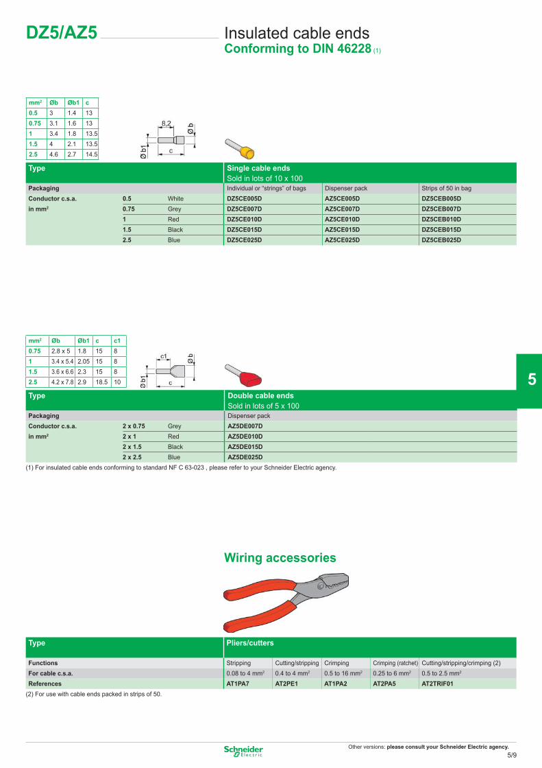
Other versions: please consult your Schneider Electric agency.
Insulated cable endsConforming to DIN 46228 (1)
mm2 Øb Øb1 c c10.75 2.8 x 5 1.8 15 81 3.4 x 5.4 2.05 15 81.5 3.6 x 6.6 2.3 15 82.5 4.2 x 7.8 2.9 18.5 10
mm2 Øb Øb1 c0.5 3 1.4 130.75 3.1 1.6 131 3.4 1.8 13.51.5 4 2.1 13.52.5 4.6 2.7 14.5
DZ5/AZ5
Type Single cable ends Sold in lots of 10 x 100
Packaging Individual or “strings” of bags Dispenser pack Strips of 50 in bagConductor c.s.a. 0.5 White DZ5CE005D AZ5CE005D DZ5CEB005Din mm2 0.75 Grey DZ5CE007D AZ5CE007D DZ5CEB007D
1 Red DZ5CE010D AZ5CE010D DZ5CEB010D1.5 Black DZ5CE015D AZ5CE015D DZ5CEB015D2.5 Blue DZ5CE025D AZ5CE025D DZ5CEB025D
Type Double cable ends Sold in lots of 5 x 100
Packaging Dispenser packConductor c.s.a. 2 x 0.75 Grey AZ5DE007Din mm2 2 x 1 Red AZ5DE010D
2 x 1.5 Black AZ5DE015D2 x 2.5 Blue AZ5DE025D
(1) For insulated cable ends conforming to standard NF C 63-023 , please refer to your Schneider Electric agency.
Wiring accessories
Type Pliers/cutters
Functions Stripping Cutting/stripping Crimping Crimping (ratchet) Cutting/stripping/crimping (2)For cable c.s.a. 0.08 to 4 mm2 0.4 to 4 mm2 0.5 to 16 mm2 0.25 to 6 mm2 0.5 to 2.5 mm2
References AT1PA7 AT2PE1 AT1PA2 AT2PA5 AT2TRIF01(2) For use with cable ends packed in strips of 50.
5/9
2
1
3
4
5
6
7
8
9
10
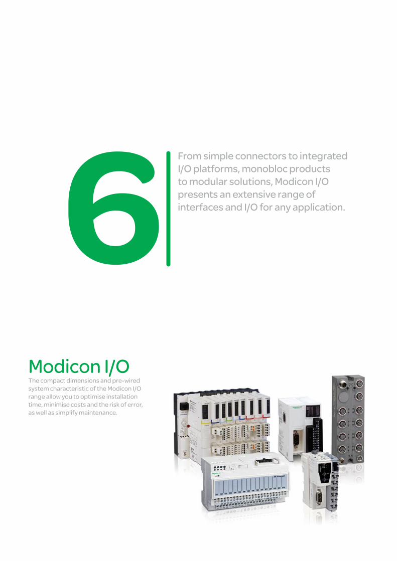
From simple connectors to integrated I/O platforms, monobloc products to modular solutions, Modicon I/O presents an extensive range of interfaces and I/O for any application.
Modicon I/OThe compact dimensions and pre-wired system characteristic of the Modicon I/O range allow you to optimise installation time, minimise costs and the risk of error, as well as simplify maintenance.
Interfaces and I/O
This document is a selection of
the top selling products.
6/1
2
1
3
4
5
6
7
8
9
10
Distributed I/O IP20 Optimum modular I/O system, for simple machines, Modicon OTB ..................................... 6/2 Modular I/O system for complexes machines or installations, Modicon TM5 ........................ 6/3 Modular I/O with device integration capabilities, Modicon STB .................................. 6/4 to 6/7 IP67 Modular I/O system for machines or installations in harsh environment, Modicon TM7 ....... 6/8
Distributed I/O with embedded control IP20 Block I/O, Modicon Momentum ................................................................................ 6/9 to 6/12
Pre-wired interfaces IP20 Sub-bases, Modicon ABE7 ..................................................................................... 6/13 to 6/15 IP67 Passive splitter boxes, Modicon ABE9 ............................................................................... 6/16
Accessories and Cabling Connection cables and jumper cables ................................................................................. 6/17
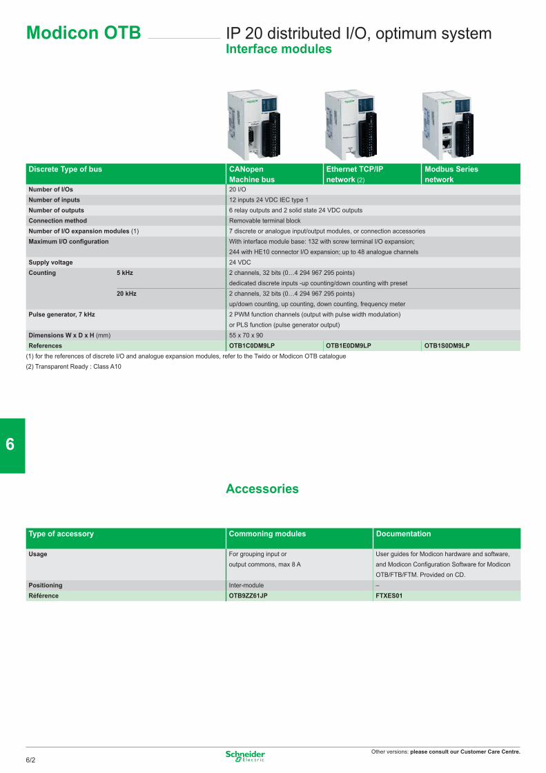
Other versions: please consult our Customer Care Centre.
IP 20 distributed I/O, optimum systemInterface modules
Modicon OTB
Discrete Type of bus CANopen Ethernet TCP/IP Modbus SeriesMachine bus network (2) network
Number of I/Os 20 I/ONumber of inputs 12 inputs 24 VDC IEC type 1Number of outputs 6 relay outputs and 2 solid state 24 VDC outputsConnection method Removable terminal blockNumber of I/O expansion modules (1) 7 discrete or analogue input/output modules, or connection accessoriesMaximum I/O configuration With interface module base: 132 with screw terminal I/O expansion;
244 with HE10 connector I/O expansion; up to 48 analogue channelsSupply voltage 24 VDCCounting 5 kHz 2 channels, 32 bits (0…4 294 967 295 points)
dedicated discrete inputs -up counting/down counting with preset20 kHz 2 channels, 32 bits (0…4 294 967 295 points)
up/down counting, up counting, down counting, frequency meterPulse generator, 7 kHz 2 PWM function channels (output with pulse width modulation)
or PLS function (pulse generator output)Dimensions W x D x H (mm) 55 x 70 x 90 References OTB1C0DM9LP OTB1E0DM9LP OTB1S0DM9LP
(1) for the references of discrete I/O and analogue expansion modules, refer to the Twido or Modicon OTB catalogue(2) Transparent Ready : Class A10
Accessories
Type of accessory Commoning modules Documentation
Usage For grouping input or output commons, max 8 A
User guides for Modicon hardware and software, and Modicon Configuration Software for Modicon OTB/FTB/FTM. Provided on CD.
Positioning Inter-module –Référence OTB9ZZ61JP FTXES01
6/2
2
1
3
4
5
6
7
8
9
10
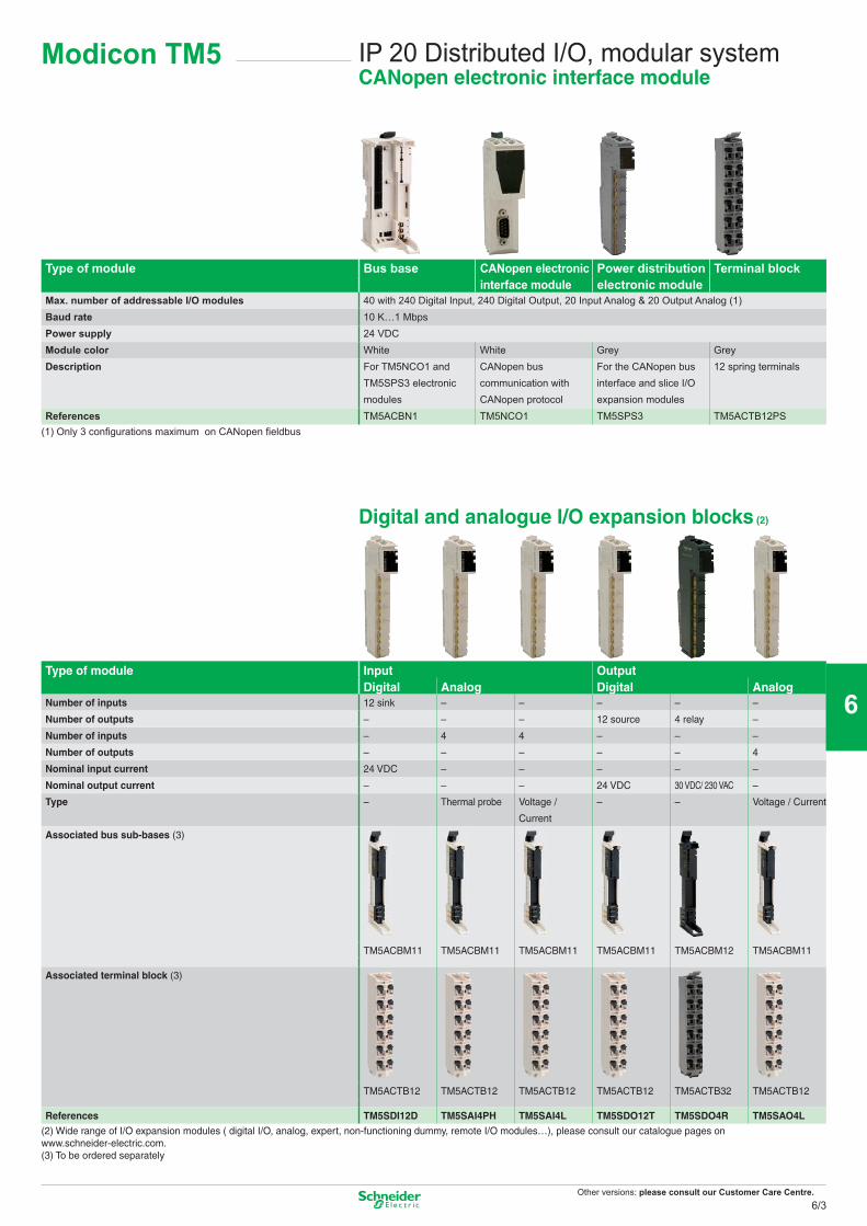
Other versions: please consult our Customer Care Centre.
IP 20 Distributed I/O, modular systemCANopen electronic interface module
Modicon TM5
Type of module Bus base CANopen electronic interface module
Power distribution electronic module
Terminal block
Max. number of addressable I/O modules 40 with 240 Digital Input, 240 Digital Output, 20 Input Analog & 20 Output Analog (1)Baud rate 10 K…1 MbpsPower supply 24 VDCModule color White White Grey GreyDescription For TM5NCO1 and
TM5SPS3 electronic modules
CANopen bus communication with CANopen protocol
For the CANopen bus interface and slice I/O expansion modules
12 spring terminals
References TM5ACBN1 TM5NCO1 TM5SPS3 TM5ACTB12PS(1) Only 3 confi gurations maximum on CANopen fi eldbus
Digital and analogue I/O expansion blocks (2)
Type of module Input OutputDigital Analog Digital Analog
Number of inputs 12 sink – – – – –
Number of outputs – – – 12 source 4 relay –
Number of inputs – 4 4 – – –
Number of outputs – – – – – 4
Nominal input current 24 VDC – – – – –
Nominal output current – – – 24 VDC 30 VDC/ 230 VAC –
Type – Thermal probe Voltage /
Current
– – Voltage / Current
Associated bus sub-bases (3)
TM5ACBM11 TM5ACBM11 TM5ACBM11 TM5ACBM11 TM5ACBM12 TM5ACBM11
Associated terminal block (3)
TM5ACTB12 TM5ACTB12 TM5ACTB12 TM5ACTB12 TM5ACTB32 TM5ACTB12
References TM5SDI12D TM5SAI4PH TM5SAI4L TM5SDO12T TM5SDO4R TM5SAO4L(2) Wide range of I/O expansion modules ( digital I/O, analog, expert, non-functioning dummy, remote I/O modules…), please consult our catalogue pages on www.schneider-electric.com.(3) To be ordered separately
6/3
2
1
3
4
5
6
7
8
9
10
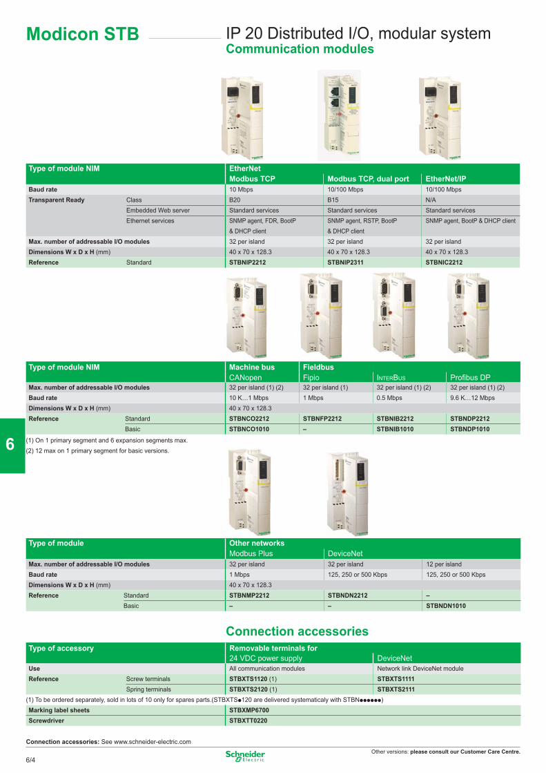
Other versions: please consult our Customer Care Centre.
IP 20 Distributed I/O, modular systemCommunication modules
Type of module NIM EtherNetModbus TCP Modbus TCP, dual port EtherNet/IP
Baud rate 10 Mbps 10/100 Mbps 10/100 MbpsTransparent Ready Class B20 B15 N/A
Embedded Web server Standard services Standard services Standard servicesEthernet services SNMP agent, FDR, BootP
& DHCP clientSNMP agent, RSTP, BootP & DHCP client
SNMP agent, BootP & DHCP client
Max. number of addressable I/O modules 32 per island 32 per island 32 per islandDimensions W x D x H (mm) 40 x 70 x 128.3 40 x 70 x 128.3 40 x 70 x 128.3 Reference Standard STBNIP2212 STBNIP2311 STBNIC2212
Type of module NIM Machine bus Fieldbus CANopen Fipio INTERBUS Profibus DP
Max. number of addressable I/O modules 32 per island (1) (2) 32 per island (1) 32 per island (1) (2) 32 per island (1) (2)Baud rate 10 K…1 Mbps 1 Mbps 0.5 Mbps 9.6 K…12 MbpsDimensions W x D x H (mm) 40 x 70 x 128.3 Reference Standard STBNCO2212 STBNFP2212 STBNIB2212 STBNDP2212
Basic STBNCO1010 – STBNIB1010 STBNDP1010
(1) On 1 primary segment and 6 expansion segments max.(2) 12 max on 1 primary segment for basic versions.
Type of module Other networks Modbus Plus DeviceNet
Max. number of addressable I/O modules 32 per island 32 per island 12 per islandBaud rate 1 Mbps 125, 250 or 500 Kbps 125, 250 or 500 KbpsDimensions W x D x H (mm) 40 x 70 x 128.3 Reference Standard STBNMP2212 STBNDN2212 –
Basic – – STBNDN1010
Connection accessoriesType of accessory Removable terminals for
24 VDC power supply DeviceNetUse All communication modules Network link DeviceNet moduleReference Screw terminals STBXTS1120 (1) STBXTS1111
Spring terminals STBXTS2120 (1) STBXTS2111(1) To be ordered separately, sold in lots of 10 only for spares parts.(STBXTSp120 are delivered systematicaly with STBNpppppp)Marking label sheets STBXMP6700Screwdriver STBXTT0220
Connection accessories: See www.schneider-electric.com
Modicon STB
6/4
2
1
3
4
5
6
7
8
9
10
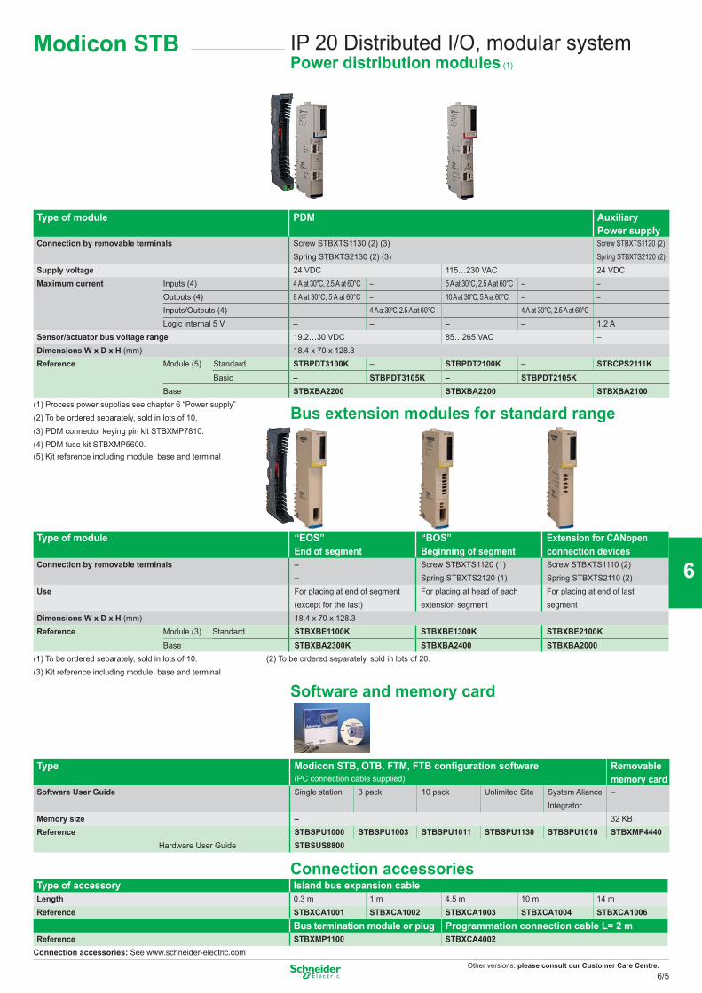
Other versions: please consult our Customer Care Centre.
Type of module PDM Auxiliary Power supply
Connection by removable terminals Screw STBXTS1130 (2) (3) Screw STBXTS1120 (2)Spring STBXTS2130 (2) (3) Spring STBXTS2120 (2)
Supply voltage 24 VDC 115…230 VAC 24 VDCMaximum current Inputs (4) 4 A at 30°C, 2.5 A at 60°C – 5 A at 30°C, 2.5 A at 60°C – –
Outputs (4) 8 A at 30°C, 5 A at 60°C – 10 A at 30°C, 5 A at 60°C – –Inputs/Outputs (4) – 4 A at 30°C, 2.5 A at 60°C – 4 A at 30°C, 2.5 A at 60°C –Logic internal 5 V – – – – 1.2 A
Sensor/actuator bus voltage range 19.2…30 VDC 85…265 VAC –Dimensions W x D x H (mm) 18.4 x 70 x 128.3 Reference Module (5) Standard STBPDT3100K – STBPDT2100K – STBCPS2111K
Basic – STBPDT3105K – STBPDT2105KBase STBXBA2200 STBXBA2200 STBXBA2100
(1) Process power supplies see chapter 6 “Power supply”(2) To be ordered separately, sold in lots of 10.(3) PDM connector keying pin kit STBXMP7810.(4) PDM fuse kit STBXMP5600.(5) Kit reference including module, base and terminal
Type of module “EOS” “BOS” Extension for CANopen End of segment Beginning of segment connection devices
Connection by removable terminals – Screw STBXTS1120 (1) Screw STBXTS1110 (2)– Spring STBXTS2120 (1) Spring STBXTS2110 (2)
Use For placing at end of segment For placing at head of each For placing at end of last(except for the last) extension segment segment
Dimensions W x D x H (mm) 18.4 x 70 x 128.3 Reference Module (3) Standard STBXBE1100K STBXBE1300K STBXBE2100K
Base STBXBA2300K STBXBA2400 STBXBA2000(1) To be ordered separately, sold in lots of 10. (2) To be ordered separately, sold in lots of 20.(3) Kit reference including module, base and terminal
Software and memory card
Type Modicon STB, OTB, FTM, FTB configuration software Removable(PC connection cable supplied) memory card
Software User Guide Single station 3 pack 10 pack Unlimited Site System Aliance –Integrator
Memory size – 32 KBReference STBSPU1000 STBSPU1003 STBSPU1011 STBSPU1130 STBSPU1010 STBXMP4440
Hardware User Guide STBSUS8800
Connection accessoriesType of accessory Island bus expansion cableLength 0.3 m 1 m 4.5 m 10 m 14 mReference STBXCA1001 STBXCA1002 STBXCA1003 STBXCA1004 STBXCA1006
Bus termination module or plug Programmation connection cable L= 2 mReference STBXMP1100 STBXCA4002
Connection accessories: See www.schneider-electric.com
Bus extension modules for standard range
IP 20 Distributed I/O, modular systemPower distribution modules (1)
Modicon STB
6/5
2
1
3
4
5
6
7
8
9
10
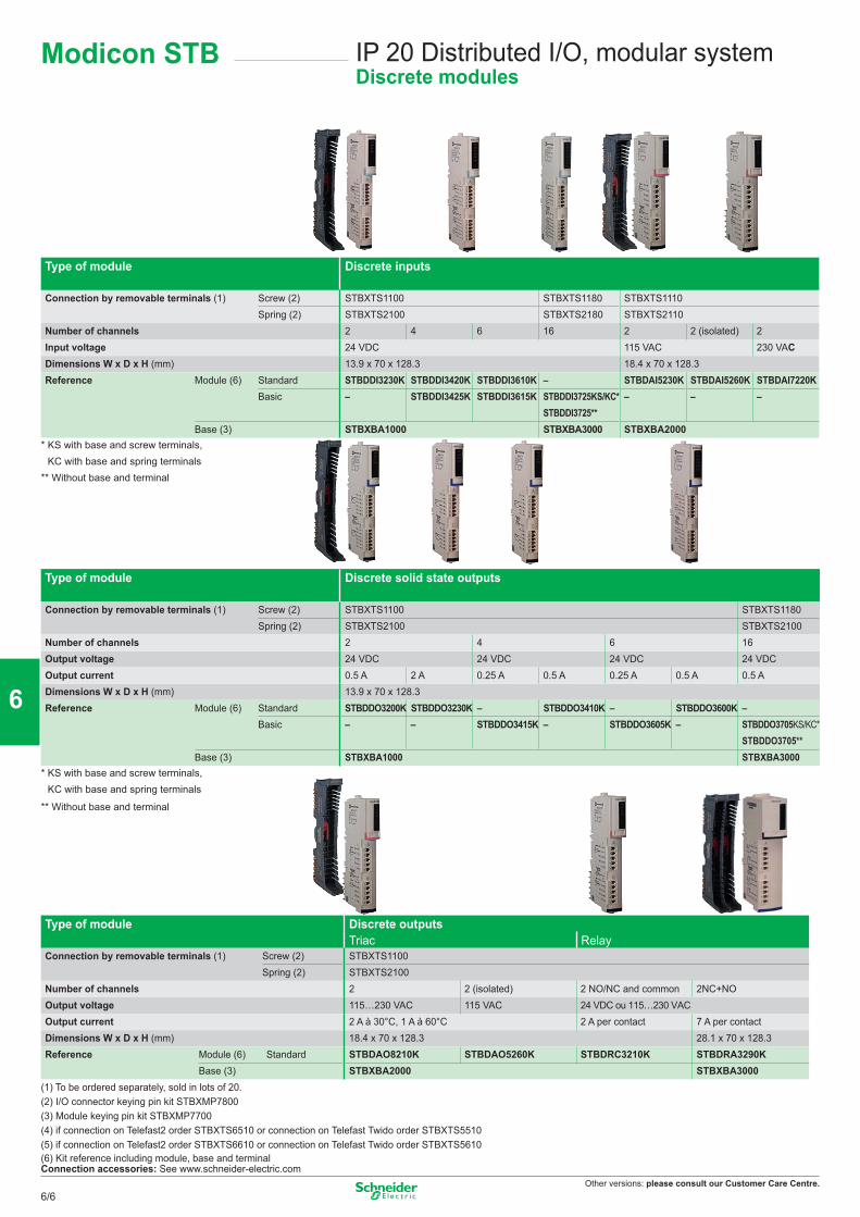
Other versions: please consult our Customer Care Centre.
Type of module Discrete inputs
Connection by removable terminals (1) Screw (2) STBXTS1100 STBXTS1180 STBXTS1110Spring (2) STBXTS2100 STBXTS2180 STBXTS2110
Number of channels 2 4 6 16 2 2 (isolated) 2Input voltage 24 VDC 115 VAC 230 VACDimensions W x D x H (mm) 13.9 x 70 x 128.3 18.4 x 70 x 128.3 Reference Module (6) Standard STBDDI3230K STBDDI3420K STBDDI3610K – STBDAI5230K STBDAI5260K STBDAI7220K
Basic – STBDDI3425K STBDDI3615K STBDDI3725KS/KC*STBDDI3725**
– – –
Base (3) STBXBA1000 STBXBA3000 STBXBA2000* KS with base and screw terminals,
KC with base and spring terminals** Without base and terminal
Type of module Discrete solid state outputs
Connection by removable terminals (1) Screw (2) STBXTS1100 STBXTS1180Spring (2) STBXTS2100 STBXTS2100
Number of channels 2 4 6 16Output voltage 24 VDC 24 VDC 24 VDC 24 VDCOutput current 0.5 A 2 A 0.25 A 0.5 A 0.25 A 0.5 A 0.5 ADimensions W x D x H (mm) 13.9 x 70 x 128.3 Reference Module (6) Standard STBDDO3200K STBDDO3230K – STBDDO3410K – STBDDO3600K –
Basic – – STBDDO3415K – STBDDO3605K – STBDDO3705KS/KC*STBDDO3705**
Base (3) STBXBA1000 STBXBA3000* KS with base and screw terminals,
KC with base and spring terminals
** Without base and terminal
Type of module Discrete outputs Triac Relay
Connection by removable terminals (1) Screw (2) STBXTS1100 Spring (2) STBXTS2100
Number of channels 2 2 (isolated) 2 NO/NC and common 2NC+NOOutput voltage 115…230 VAC 115 VAC 24 VDC ou 115…230 VACOutput current 2 A à 30°C, 1 A à 60°C 2 A per contact 7 A per contactDimensions W x D x H (mm) 18.4 x 70 x 128.3 28.1 x 70 x 128.3 Reference Module (6) Standard STBDAO8210K STBDAO5260K STBDRC3210K STBDRA3290K
Base (3) STBXBA2000 STBXBA3000(1) To be ordered separately, sold in lots of 20.(2) I/O connector keying pin kit STBXMP7800(3) Module keying pin kit STBXMP7700(4) if connection on Telefast2 order STBXTS6510 or connection on Telefast Twido order STBXTS5510(5) if connection on Telefast2 order STBXTS6610 or connection on Telefast Twido order STBXTS5610(6) Kit reference including module, base and terminalConnection accessories: See www.schneider-electric.com
IP 20 Distributed I/O, modular systemDiscrete modules
Modicon STB
6/6
2
1
3
4
5
6
7
8
9
10
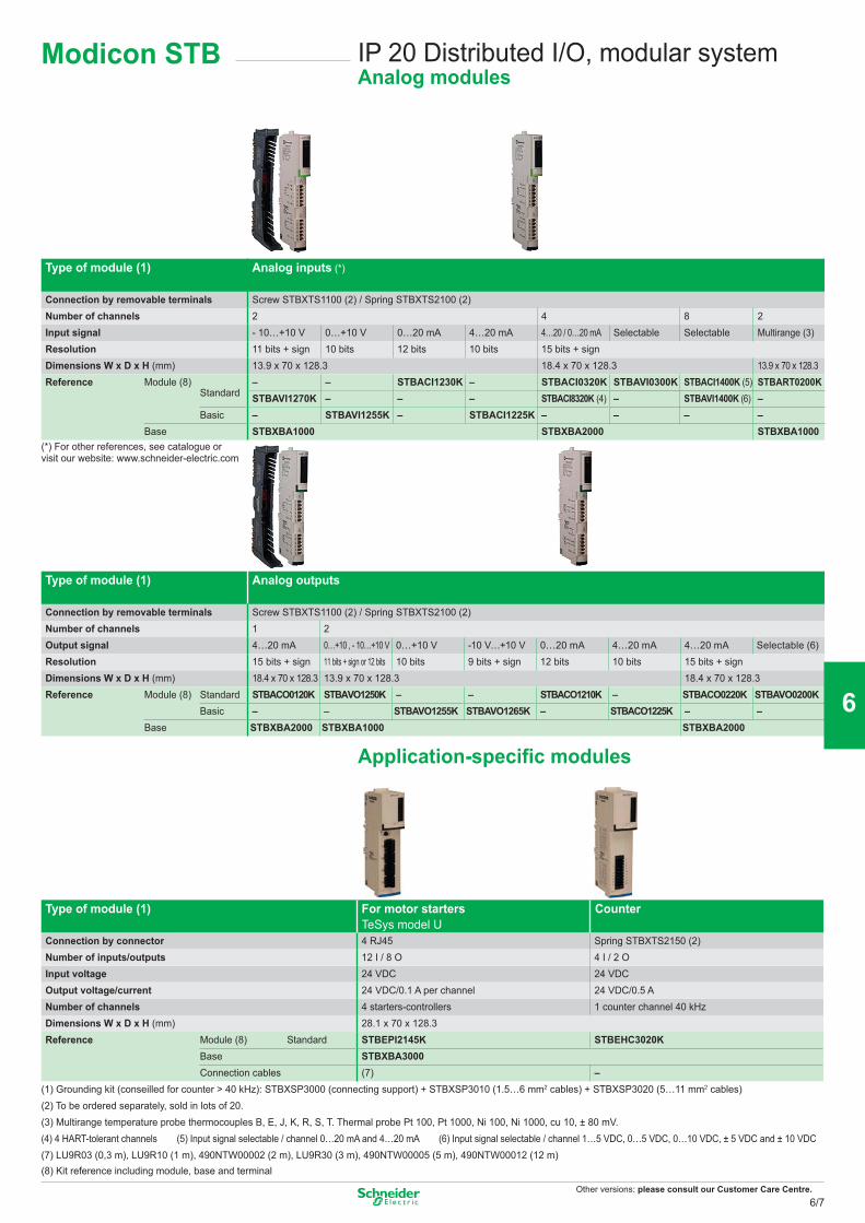
Other versions: please consult our Customer Care Centre.
Type of module (1) Analog inputs (*)
Connection by removable terminals Screw STBXTS1100 (2) / Spring STBXTS2100 (2)Number of channels 2 4 8 2Input signal - 10…+10 V 0…+10 V 0…20 mA 4…20 mA 4…20 / 0…20 mA Selectable Selectable Multirange (3)Resolution 11 bits + sign 10 bits 12 bits 10 bits 15 bits + signDimensions W x D x H (mm) 13.9 x 70 x 128.3 18.4 x 70 x 128.3 13.9 x 70 x 128.3Reference Module (8)
Standard– – STBACI1230K – STBACI0320K STBAVI0300K STBACI1400K (5) STBART0200KSTBAVI1270K – – – STBACI8320K (4) – STBAVI1400K (6) –
Basic – STBAVI1255K – STBACI1225K – – – –Base STBXBA1000 STBXBA2000 STBXBA1000
(*) For other references, see catalogue or visit our website: www.schneider-electric.com
Type of module (1) Analog outputs
Connection by removable terminals Screw STBXTS1100 (2) / Spring STBXTS2100 (2)Number of channels 1 2Output signal 4…20 mA 0…+10 , - 10…+10 V 0…+10 V -10 V…+10 V 0…20 mA 4…20 mA 4…20 mA Selectable (6)Resolution 15 bits + sign 11 bits + sign or 12 bits 10 bits 9 bits + sign 12 bits 10 bits 15 bits + signDimensions W x D x H (mm) 18.4 x 70 x 128.3 13.9 x 70 x 128.3 18.4 x 70 x 128.3Reference Module (8) Standard STBACO0120K STBAVO1250K – – STBACO1210K – STBACO0220K STBAVO0200K
Basic – – STBAVO1255K STBAVO1265K – STBACO1225K – –Base STBXBA2000 STBXBA1000 STBXBA2000
Application-specific modules
Type of module (1) For motor startersTeSys model U
Counter
Connection by connector 4 RJ45 Spring STBXTS2150 (2)Number of inputs/outputs 12 I / 8 O 4 I / 2 OInput voltage 24 VDC 24 VDCOutput voltage/current 24 VDC/0.1 A per channel 24 VDC/0.5 ANumber of channels 4 starters-controllers 1 counter channel 40 kHzDimensions W x D x H (mm) 28.1 x 70 x 128.3Reference Module (8) Standard STBEPI2145K STBEHC3020K
Base STBXBA3000Connection cables (7) –
(1) Grounding kit (conseilled for counter > 40 kHz): STBXSP3000 (connecting support) + STBXSP3010 (1.5…6 mm2 cables) + STBXSP3020 (5…11 mm2 cables) (2) To be ordered separately, sold in lots of 20.(3) Multirange temperature probe thermocouples B, E, J, K, R, S, T. Thermal probe Pt 100, Pt 1000, Ni 100, Ni 1000, cu 10, ± 80 mV.(4) 4 HART-tolerant channels (5) Input signal selectable / channel 0…20 mA and 4…20 mA (6) Input signal selectable / channel 1…5 VDC, 0…5 VDC, 0…10 VDC, ± 5 VDC and ± 10 VDC(7) LU9R03 (0,3 m), LU9R10 (1 m), 490NTW00002 (2 m), LU9R30 (3 m), 490NTW00005 (5 m), 490NTW00012 (12 m)(8) Kit reference including module, base and terminal
IP 20 Distributed I/O, modular systemAnalog modules
Modicon STB
6/7
2
1
3
4
5
6
7
8
9
10
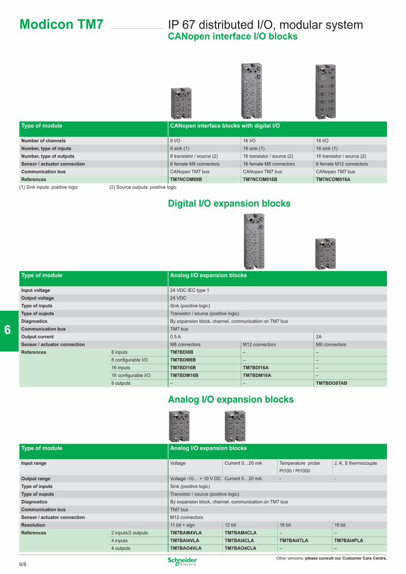
Other versions: please consult our Customer Care Centre.
IP 67 distributed I/O, modular systemCANopen interface I/O blocks
Modicon TM7
Type of module CANopen interface blocks with digital I/O
Number of channels 8 I/O 16 I/O 16 I/ONumber, type of inputs 8 sink (1) 16 sink (1) 16 sink (1)Number, type of outputs 8 transistor / source (2) 16 transistor / source (2) 16 transistor / source (2)Sensor / actuator connection 8 female M8 connectors 16 female M8 connectors 8 female M12 connectorsCommunication bus CANopen TM7 bus CANopen TM7 bus CANopen TM7 busReferences TM7NCOM08B TM7NCOM016B TM7NCOM016A
(1) Sink inputs: positive logic (2) Source outputs: positive logic
Digital I/O expansion blocks
Type of module Analog I/O expansion blocks
Input voltage 24 VDC IEC type 1Output voltage 24 VDCType of inputs Sink (positive logic)Type of ouputs Transistor / source (positive logic)Diagnostics By expansion block, channel, communication on TM7 busCommunication bus TM7 busOutput current 0.5 A 2ASensor / actuator connection M8 connectors M12 connectors M8 connectorsReferences 8 inputs TM7BDI8B – –
8 configurable I/O TM7BDM8B – –16 inputs TM7BDI16B TM7BDI16A –16 configurable I/O TM7BDM16B TM7BDM16A –8 outputs – – TM7BDO8TAB
Analog I/O expansion blocks
Type of module Analog I/O expansion blocks
Input range Voltage Current 0…20 mA Temperature probe Pt100 / Pt1000
J, K, S thermocouple
Output range Voltage -10… + 10 V DC Current 0…20 mA - -Type of inputs Sink (positive logic)Type of ouputs Transistor / source (positive logic)Diagnostics By expansion block, channel, communication on TM7 busCommunication bus TM7 busSensor / actuator connection M12 connectorsResolution 11 bit + sign 12 bit 16 bit 16 bitReferences 2 inputs/2 outputs TM7BAM4VLA TM7BAM4CLA – –
4 inputs TM7BAI4VLA TM7BAI4CLA TM7BAI4TLA TM7BAI4PLA4 outputs TM7BAO4VLA TM7BAO4CLA – –
6/8
2
1
3
4
5
6
7
8
9
10
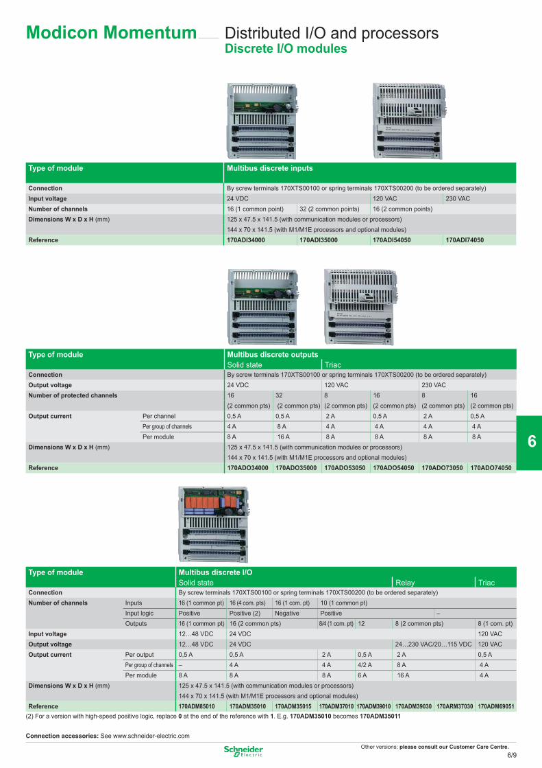
Other versions: please consult our Customer Care Centre.
Distributed I/O and processorsDiscrete I/O modules
Type of module Multibus discrete inputs
Connection By screw terminals 170XTS00100 or spring terminals 170XTS00200 (to be ordered separately)Input voltage 24 VDC 120 VAC 230 VACNumber of channels 16 (1 common point) 32 (2 common points) 16 (2 common points)Dimensions W x D x H (mm) 125 x 47.5 x 141.5 (with communication modules or processors)
144 x 70 x 141.5 (with M1/M1E processors and optional modules)Reference 170ADI34000 170ADI35000 170ADI54050 170ADI74050
Type of module Multibus discrete outputs Solid state Triac
Connection By screw terminals 170XTS00100 or spring terminals 170XTS00200 (to be ordered separately)Output voltage 24 VDC 120 VAC 230 VACNumber of protected channels 16 32 8 16 8 16
(2 common pts) (2 common pts) (2 common pts) (2 common pts) (2 common pts) (2 common pts)Output current Per channel 0,5 A 0,5 A 2 A 0,5 A 2 A 0,5 A
Per group of channels 4 A 8 A 4 A 4 A 4 A 4 APer module 8 A 16 A 8 A 8 A 8 A 8 A
Dimensions W x D x H (mm) 125 x 47.5 x 141.5 (with communication modules or processors)144 x 70 x 141.5 (with M1/M1E processors and optional modules)
Reference 170ADO34000 170ADO35000 170ADO53050 170ADO54050 170ADO73050 170ADO74050
Type of module Multibus discrete I/O Solid state Relay Triac
Connection By screw terminals 170XTS00100 or spring terminals 170XTS00200 (to be ordered separately)Number of channels Inputs 16 (1 common pt) 16 (4 com. pts) 16 (1 com. pt) 10 (1 common pt)
Input logic Positive Positive (2) Negative Positive – Outputs 16 (1 common pt) 16 (2 common pts) 8/4 (1 com. pt) 12 8 (2 common pts) 8 (1 com. pt)
Input voltage 12…48 VDC 24 VDC 120 VACOutput voltage 12…48 VDC 24 VDC 24…230 VAC/20…115 VDC 120 VACOutput current Per output 0,5 A 0,5 A 2 A 0,5 A 2 A 0,5 A
Per group of channels – 4 A 4 A 4/2 A 8 A 4 APer module 8 A 8 A 8 A 6 A 16 A 4 A
Dimensions W x D x H (mm) 125 x 47.5 x 141.5 (with communication modules or processors)144 x 70 x 141.5 (with M1/M1E processors and optional modules)
Reference 170ADM85010 170ADM35010 170ADM35015 170ADM37010 170ADM39010 170ADM39030 170ARM37030 170ADM69051(2) For a version with high-speed positive logic, replace 0 at the end of the reference with 1. E.g. 170ADM35010 becomes 170ADM35011
Connection accessories: See www.schneider-electric.com
Modicon Momentum
6/9
2
1
3
4
5
6
7
8
9
10
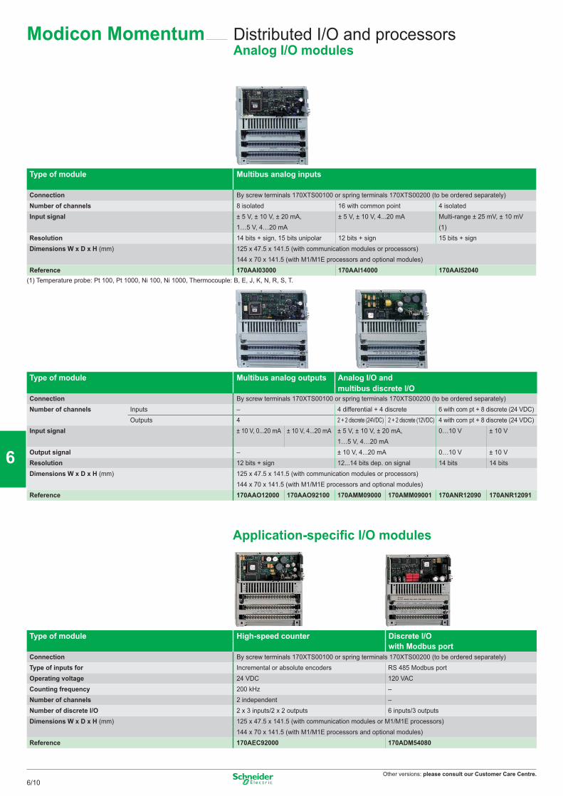
Other versions: please consult our Customer Care Centre.
Type of module Multibus analog inputs
Connection By screw terminals 170XTS00100 or spring terminals 170XTS00200 (to be ordered separately)Number of channels 8 isolated 16 with common point 4 isolatedInput signal ± 5 V, ± 10 V, ± 20 mA, ± 5 V, ± 10 V, 4...20 mA Multi-range ± 25 mV, ± 10 mV
1…5 V, 4…20 mA (1)Resolution 14 bits + sign, 15 bits unipolar 12 bits + sign 15 bits + signDimensions W x D x H (mm) 125 x 47.5 x 141.5 (with communication modules or processors)
144 x 70 x 141.5 (with M1/M1E processors and optional modules)Reference 170AAI03000 170AAI14000 170AAI52040
(1) Temperature probe: Pt 100, Pt 1000, Ni 100, Ni 1000, Thermocouple: B, E, J, K, N, R, S, T.
Type of module Multibus analog outputs
Analog I/O and multibus discrete I/O
Connection By screw terminals 170XTS00100 or spring terminals 170XTS00200 (to be ordered separately)Number of channels Inputs – 4 differential + 4 discrete 6 with com pt + 8 discrete (24 VDC)
Outputs 4 2 + 2 discrete (24VDC) 2 + 2 discrete (12VDC) 4 with com pt + 8 discrete (24 VDC)Input signal ± 10 V, 0...20 mA ± 10 V, 4...20 mA ± 5 V, ± 10 V, ± 20 mA,
1…5 V, 4…20 mA0…10 V ± 10 V
Output signal – ± 10 V, 4...20 mA 0…10 V ± 10 VResolution 12 bits + sign 12...14 bits dep. on signal 14 bits 14 bitsDimensions W x D x H (mm) 125 x 47.5 x 141.5 (with communication modules or processors)
144 x 70 x 141.5 (with M1/M1E processors and optional modules)Reference 170AAO12000 170AAO92100 170AMM09000 170AMM09001 170ANR12090 170ANR12091
Application-specific I/O modules
Type of module High-speed counter Discrete I/Owith Modbus port
Connection By screw terminals 170XTS00100 or spring terminals 170XTS00200 (to be ordered separately)Type of inputs for Incremental or absolute encoders RS 485 Modbus portOperating voltage 24 VDC 120 VACCounting frequency 200 kHz –Number of channels 2 independent –Number of discrete I/O 2 x 3 inputs/2 x 2 outputs 6 inputs/3 outputsDimensions W x D x H (mm) 125 x 47.5 x 141.5 (with communication modules or M1/M1E processors)
144 x 70 x 141.5 (with M1/M1E processors and optional modules)Reference 170AEC92000 170ADM54080
Distributed I/O and processorsAnalog I/O modules
Modicon Momentum
6/10
2
1
3
4
5
6
7
8
9
10
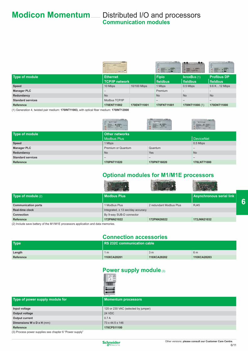
Other versions: please consult our Customer Care Centre.
Distributed I/O and processorsCommunication modules
Type of module Ethernet Fipio INTERBUS (1) Profibus DP TCP/IP network fieldbus fieldbus fieldbus
Speed 10 Mbps 10/100 Mbps 1 Mbps 0.5 Mbps 9.6 K…12 MbpsManager PLC – Premium - -Redundancy No No No NoStandard services Modbus TCP/IP – – –Reference 170ENT11002 170ENT11001 170FNT11001 170INT11000 (1) 170DNT11000
(1) Generation 4, twisted pair medium: 170INT11003, with optical fiber medium: 170INT12000
Type of module Other networksModbus Plus DeviceNet
Speed 1 Mbps 0.5 MbpsManager PLC Premium or Quantum Quantum –Redundancy No Yes NoStandard services – – –Reference 170PNT11020 170PNT16020 170LNT71000
Optional modules for M1/M1E processors
Type of module (2) Modbus Plus Asynchronous serial link
Communication ports 1 Modbus Plus 2 redundant Modbus Plus RJ45Real-time clock Integrated, ± 13 sec/day accuracyConnection By 9-way SUB-D connectorReference 172PNN21022 172PNN26022 172JNN21032
(2) Include save battery of the M1/M1E processors application and data memories.
Connection accessoriesType RS 232C communication cable
Length 1 m 3 m 6 mReference 110XCA28201 110XCA28202 110XCA28203
Power supply module (3)
Type of power supply module for
Momentum processors
Input voltage 120 or 230 VAC (selected by jumper)Output voltage 24 VDCOutput current 0.7 ADimensions W x D x H (mm) 73 x 44.5 x 146 Reference 170CPS11100
(3) Process power supplies see chapter 6 “Power supply”
Modicon Momentum
6/11
2
1
3
4
5
6
7
8
9
10
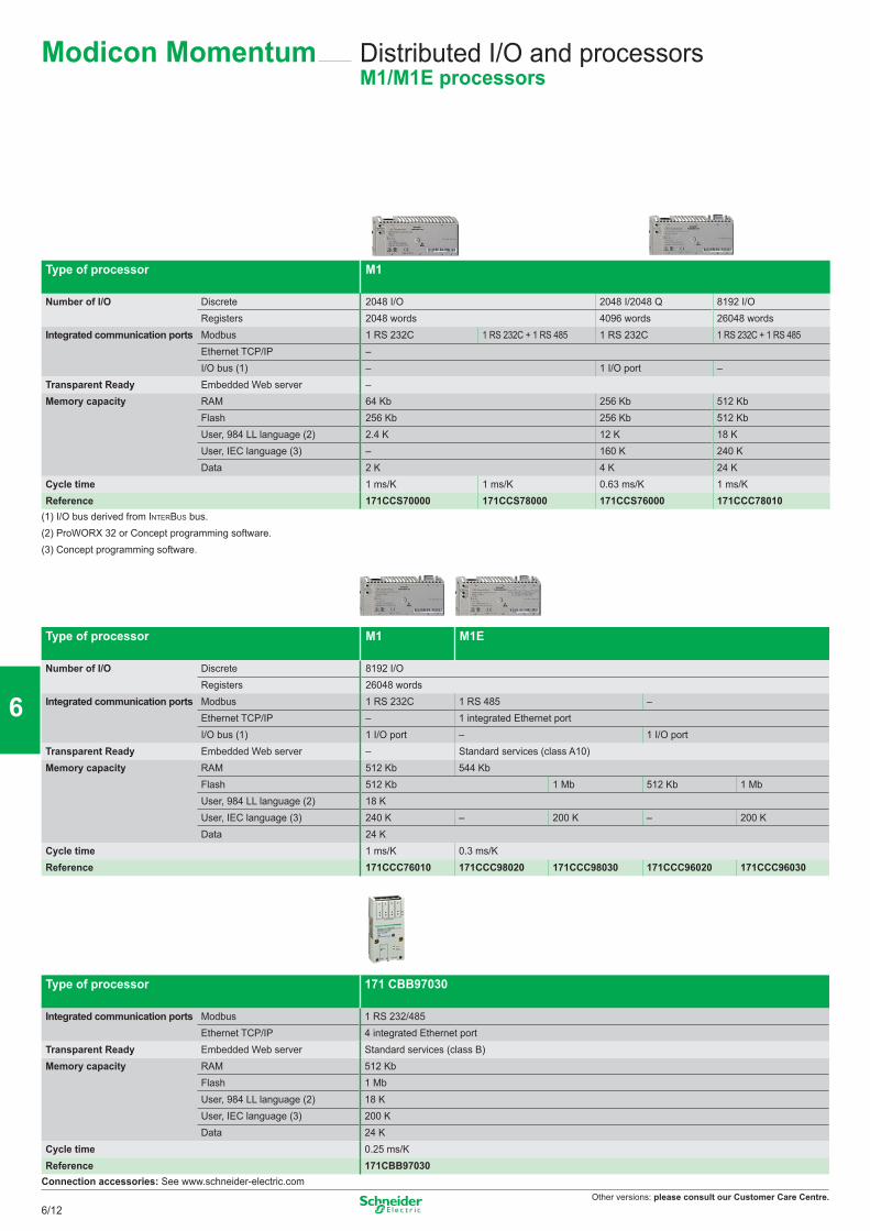
Other versions: please consult our Customer Care Centre.
Type of processor M1
Number of I/O Discrete 2048 I/O 2048 I/2048 Q 8192 I/ORegisters 2048 words 4096 words 26048 words
Integrated communication ports Modbus 1 RS 232C 1 RS 232C + 1 RS 485 1 RS 232C 1 RS 232C + 1 RS 485Ethernet TCP/IP –I/O bus (1) – 1 I/O port –
Transparent Ready Embedded Web server –Memory capacity RAM 64 Kb 256 Kb 512 Kb
Flash 256 Kb 256 Kb 512 KbUser, 984 LL language (2) 2.4 K 12 K 18 KUser, IEC language (3) – 160 K 240 KData 2 K 4 K 24 K
Cycle time 1 ms/K 1 ms/K 0.63 ms/K 1 ms/KReference 171CCS70000 171CCS78000 171CCS76000 171CCC78010
(1) I/O bus derived from INTERBUS bus.(2) ProWORX 32 or Concept programming software.(3) Concept programming software.
Type of processor M1 M1E
Number of I/O Discrete 8192 I/ORegisters 26048 words
Integrated communication ports Modbus 1 RS 232C 1 RS 485 –Ethernet TCP/IP – 1 integrated Ethernet portI/O bus (1) 1 I/O port – 1 I/O port
Transparent Ready Embedded Web server – Standard services (class A10)Memory capacity RAM 512 Kb 544 Kb
Flash 512 Kb 1 Mb 512 Kb 1 MbUser, 984 LL language (2) 18 KUser, IEC language (3) 240 K – 200 K – 200 KData 24 K
Cycle time 1 ms/K 0.3 ms/KReference 171CCC76010 171CCC98020 171CCC98030 171CCC96020 171CCC96030
Type of processor 171 CBB97030
Integrated communication ports Modbus 1 RS 232/485Ethernet TCP/IP 4 integrated Ethernet port
Transparent Ready Embedded Web server Standard services (class B)Memory capacity RAM 512 Kb
Flash 1 MbUser, 984 LL language (2) 18 KUser, IEC language (3) 200 KData 24 K
Cycle time 0.25 ms/KReference 171CBB97030
Connection accessories: See www.schneider-electric.com
Distributed I/O and processorsM1/M1E processors
Modicon Momentum
6/12
2
1
3
4
5
6
7
8
9
10
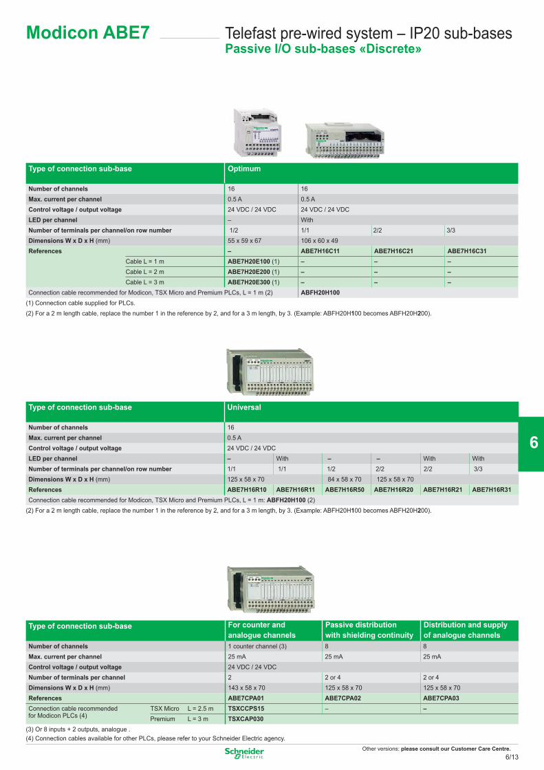
Other versions: please consult our Customer Care Centre.
Telefast pre-wired system – IP20 sub-basesPassive I/O sub-bases «Discrete»
Type of connection sub-base Optimum
Number of channels 16 16Max. current per channel 0.5 A 0.5 AControl voltage / output voltage 24 VDC / 24 VDC 24 VDC / 24 VDCLED per channel – WithNumber of terminals per channel/on row number 1/2 1/1 2/2 3/3Dimensions W x D x H (mm) 55 x 59 x 67 106 x 60 x 49 References – ABE7H16C11 ABE7H16C21 ABE7H16C31
Cable L = 1 m ABE7H20E100 (1) – – –Cable L = 2 m ABE7H20E200 (1) – – –Cable L = 3 m ABE7H20E300 (1) – – –
Connection cable recommended for Modicon, TSX Micro and Premium PLCs, L = 1 m (2) ABFH20H100(1) Connection cable supplied for PLCs.(2) For a 2 m length cable, replace the number 1 in the reference by 2, and for a 3 m length, by 3. (Example: ABFH20H100 becomes ABFH20H200).
Type of connection sub-base Universal
Number of channels 16Max. current per channel 0.5 AControl voltage / output voltage 24 VDC / 24 VDCLED per channel – With – – With WithNumber of terminals per channel/on row number 1/1 1/1 1/2 2/2 2/2 3/3Dimensions W x D x H (mm) 125 x 58 x 70 84 x 58 x 70 125 x 58 x 70 References ABE7H16R10 ABE7H16R11 ABE7H16R50 ABE7H16R20 ABE7H16R21 ABE7H16R31Connection cable recommended for Modicon, TSX Micro and Premium PLCs, L = 1 m: ABFH20H100 (2)
(2) For a 2 m length cable, replace the number 1 in the reference by 2, and for a 3 m length, by 3. (Example: ABFH20H100 becomes ABFH20H200).
Type of connection sub-base For counter and Passive distribution Distribution and supply analogue channels with shielding continuity of analogue channels
Number of channels 1 counter channel (3) 8 8Max. current per channel 25 mA 25 mA 25 mAControl voltage / output voltage 24 VDC / 24 VDCNumber of terminals per channel 2 2 or 4 2 or 4Dimensions W x D x H (mm) 143 x 58 x 70 125 x 58 x 70 125 x 58 x 70 References ABE7CPA01 ABE7CPA02 ABE7CPA03Connection cable recommendedfor Modicon PLCs (4)
TSX Micro L = 2.5 m TSXCCPS15 – –Premium L = 3 m TSXCAP030
(3) Or 8 inputs + 2 outputs, analogue .(4) Connection cables available for other PLCs, please refer to your Schneider Electric agency.
Modicon ABE7
6/13
2
1
3
4
5
6
7
8
9
10
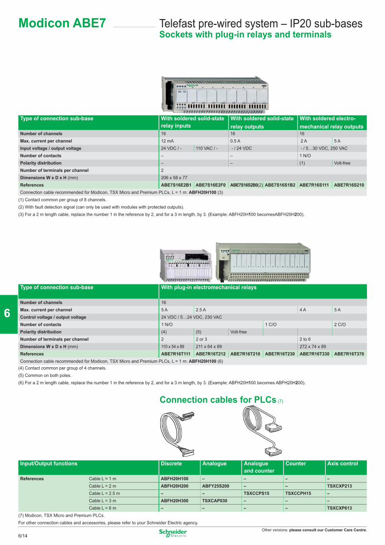
Other versions: please consult our Customer Care Centre.
Type of connection sub-base With soldered solid-staterelay inputs
With soldered solid-state With soldered electro- relay outputs mechanical relay outputs
Number of channels 16 16 16Max. current per channel 12 mA 0.5 A 2 A 5 AInput voltage / output voltage 24 VDC / - 110 VAC / - - / 24 VDC - / 5…30 VDC, 250 VACNumber of contacts – – 1 N/OPolarity distribution – – (1) Volt-freeNumber of terminals per channel 2Dimensions W x D x H (mm) 206 x 58 x 77 References ABE7S16E2B1 ABE7S16E2F0 ABE7S16S2B0(2) ABE7S16S1B2 ABE7R16S111 ABE7R16S210Connection cable recommended for Modicon, TSX Micro and Premium PLCs, L = 1 m: ABFH20H100 (3)
(1) Contact common per group of 8 channels.(2) With fault detection signal (can only be used with modules with protected outputs). (3) For a 2 m length cable, replace the number 1 in the reference by 2, and for a 3 m length, by 3. (Example: ABFH20H100 becomesABFH20H200).
Type of connection sub-base With plug-in electromechanical relays
Number of channels 16Max. current per channel 5 A 2.5 A 4 A 5 AControl voltage / output voltage 24 VDC / 5…24 VDC, 230 VACNumber of contacts 1 N/O 1 C/O 2 C/OPolarity distribution (4) (5) Volt-freeNumber of terminals per channel 2 2 or 3 2 to 6Dimensions W x D x H (mm) 110 x 54 x 89 211 x 64 x 89 272 x 74 x 89 References ABE7R16T111 ABE7R16T212 ABE7R16T210 ABE7R16T230 ABE7R16T330 ABE7R16T370Connection cable recommended for Modicon, TSX Micro and Premium PLCs, L = 1 m: ABFH20H100 (6)
(4) Contact common per group of 4 channels.(5) Common on both poles.(6) For a 2 m length cable, replace the number 1 in the reference by 2, and for a 3 m length, by 3. (Example: ABFH20H100 becomes ABFH20H200).
Connection cables for PLCs (7)
Input/Output functions Discrete Analogue Analogueand counter
Counter Axis control
References Cable L = 1 m ABFH20H100 – – – –Cable L = 2 m ABFH20H200 ABFY25S200 – – TSXCXP213Cable L = 2.5 m – – TSXCCPS15 TSXCCPH15 –Cable L = 3 m ABFH20H300 TSXCAP030 – – –Cable L = 6 m – – – – TSXCXP613
(7) Modicon, TSX Micro and Premium PLCs.For other connection cables and accessories, please refer to your Schneider Electric agency.
Telefast pre-wired system – IP20 sub-basesSockets with plug-in relays and terminals
Modicon ABE7
6/14
2
1
3
4
5
6
7
8
9
10
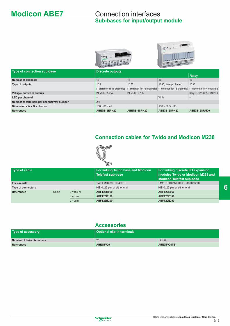
Other versions: please consult our Customer Care Centre.
Connection interfacesSub-bases for input/output module
Modicon ABE7
Type of connection sub-base Discrete outputsRelay
Number of channels 16 16 16 16Type of outputs 16 I 16 O 16 O, fuse protected 16 O
(1 common for 16 channels) (1 common for 16 channels) (1 common for 16 channels) (1 common for 4 channels)Voltage / current of outputs 24 VDC / 5 mA 24 VDC / 0.1 A Relay: 5…30 VDC, 250 VAC / 3 ALED per channel – With –Number of terminals per channel/row number 2/2Dimensions W x D x H (mm) 106 x 60 x 49 130 x 62.5 x 83 References ABE7E16EPN20 ABE7E16SPN20 ABE7E16SPN22 ABE7E16SRM20
Connection cables for Twido and Modicon M238
Type of cable For linking Twido base and Modicon Telefast sub-base
For linking discrete I/O expansion modules Twido or Modicon M238 and Modicon Telefast sub-base
For use with TWDLMDA20DTK/40DTK TM2DI16DK/32DK/DDO16TK/32TKType of connectors HE10, 26-pin, at either end HE10, 20-pin, at either endReferences Cable L = 0.5 m ABFT26B050 ABFT20E050
L = 1 m ABFT26B100 ABFT20E100L = 2 m ABFT26B200 ABFT20E200
AccessoriesType of accessory Optional clip-in terminals
Number of linked terminals 20 12 + 8References ABE7BV20 ABE7BV20TB
6/15
2
1
3
4
5
6
7
8
9
10
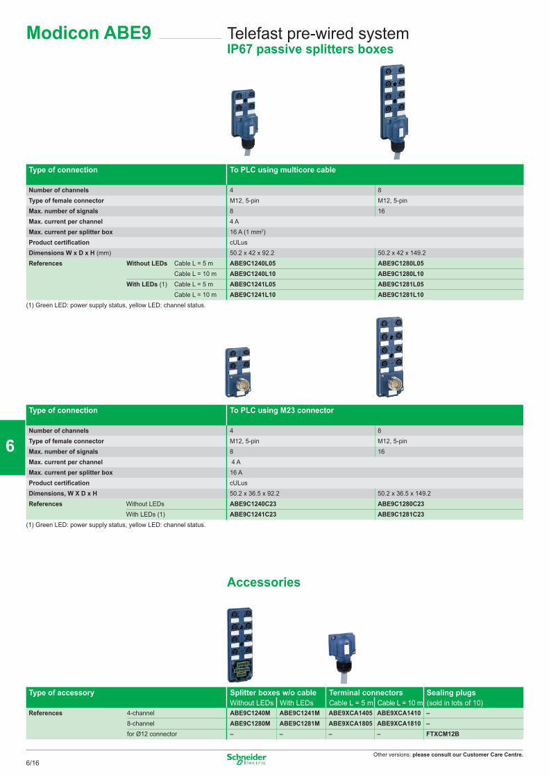
Other versions: please consult our Customer Care Centre.
Telefast pre-wired system IP67 passive splitters boxes
Modicon ABE9
Type of connection To PLC using multicore cable
Number of channels 4 8Type of female connector M12, 5-pin M12, 5-pinMax. number of signals 8 16Max. current per channel 4 A Max. current per splitter box 16 A (1 mm2) Product certification cULus Dimensions W x D x H (mm) 50.2 x 42 x 92.2 50.2 x 42 x 149.2 References Without LEDs Cable L = 5 m ABE9C1240L05 ABE9C1280L05
Cable L = 10 m ABE9C1240L10 ABE9C1280L10With LEDs (1) Cable L = 5 m ABE9C1241L05 ABE9C1281L05
Cable L = 10 m ABE9C1241L10 ABE9C1281L10(1) Green LED: power supply status, yellow LED: channel status.
Type of connection To PLC using M23 connector
Number of channels 4 8Type of female connector M12, 5-pin M12, 5-pinMax. number of signals 8 16Max. current per channel 4 A Max. current per splitter box 16 AProduct certification cULus Dimensions, W X D x H 50.2 x 36.5 x 92.2 50.2 x 36.5 x 149.2 References Without LEDs ABE9C1240C23 ABE9C1280C23
With LEDs (1) ABE9C1241C23 ABE9C1281C23(1) Green LED: power supply status, yellow LED: channel status.
Accessories
Type of accessory Splitter boxes w/o cable Terminal connectors Sealing plugsWithout LEDs With LEDs Cable L = 5 m Cable L = 10 m (sold in lots of 10)
References 4-channel ABE9C1240M ABE9C1241M ABE9XCA1405 ABE9XCA1410 –8-channel ABE9C1280M ABE9C1281M ABE9XCA1805 ABE9XCA1810 –for Ø12 connector – – – – FTXCM12B
6/16
2
1
3
4
5
6
7
8
9
10
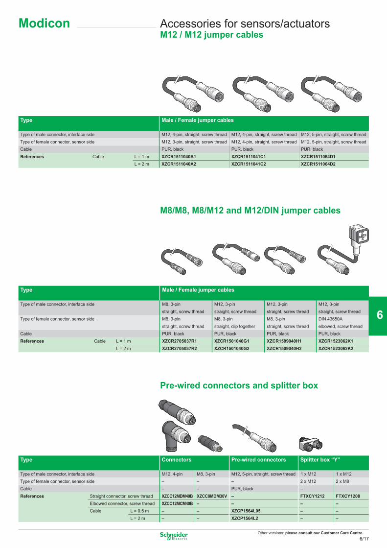
Other versions: please consult our Customer Care Centre.
Accessories for sensors/actuatorsM12 / M12 jumper cables
Type Male / Female jumper cables
Type of male connector, interface side M12, 4-pin, straight, screw thread M12, 4-pin, straight, screw thread M12, 5-pin, straight, screw threadType of female connector, sensor side M12, 3-pin, straight, screw thread M12, 4-pin, straight, screw thread M12, 5-pin, straight, screw threadCable PUR, black PUR, black PUR, blackReferences Cable L = 1 m XZCR1511040A1 XZCR1511041C1 XZCR1511064D1
L = 2 m XZCR1511040A2 XZCR1511041C2 XZCR1511064D2 M8/M8, M8/M12 and M12/DIN jumper cables
M8/M8, M8/M12 and M12/DIN jumper cables
Type Male / Female jumper cables
Type of male connector, interface side M8, 3-pin M12, 3-pin M12, 3-pin M12, 3-pinstraight, screw thread straight, screw thread straight, screw thread straight, screw thread
Type of female connector, sensor side M8, 3-pin M8, 3-pin M8, 3-pin DIN 43650Astraight, screw thread straight, clip together straight, screw thread elbowed, screw thread
Cable PUR, black PUR, black PUR, black PUR, blackReferences Cable L = 1 m XZCR2705037R1 XZCR1501040G1 XZCR1509040H1 XZCR1523062K1
L = 2 m XZCR2705037R2 XZCR1501040G2 XZCR1509040H2 XZCR1523062K2
Pre-wired connectors and splitter box
Type Connectors Pre-wired connectors Splitter box “Y”
Type of male connector, interface side M12, 4-pin M8, 3-pin M12, 5-pin, straight, screw thread 1 x M12 1 x M12Type of female connector, sensor side – – – 2 x M12 2 x M8Cable – – PUR, black –References Straight connector, screw thread XZCC12MDM40B XZCC8MDM30V – FTXCY1212 FTXCY1208
Elbowed connector, screw thread XZCC12MCM40B – – – –Cable L = 0.5 m – – XZCP1564L05 – –
L = 2 m – – XZCP1564L2 – –
Modicon
6/17
2
1
3
4
5
6
7
8
9
10
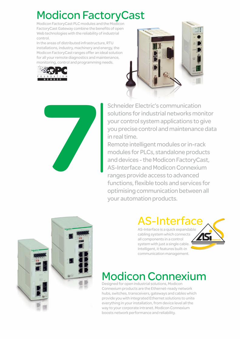
Schneider Electric’s communication solutions for industrial networks monitor your control system applications to give you precise control and maintenance data in real time.Remote intelligent modules or in-rack modules for PLCs, standalone products and devices - the Modicon FactoryCast, AS-Interface and Modicon Connexium ranges provide access to advanced functions, flexible tools and services for optimising communication between all your automation products.
Modicon FactoryCastModicon FactoryCast PLC modules and the Modicon FactoryCast Gateway combine the benefits of open Web technologies with the reliability of industrial control. In the areas of distributed infrastructure, RTU installations, industry, machinery and energy, the Modicon FactoryCast ranges offer an ideal solution for all your remote diagnostics and maintenance, monitoring, control and programming needs.
AS-InterfaceAS-Interface is a quick expandable cabling system which connects all components in a control system with just a single cable. Intelligent, it features built-in communication management.
Modicon ConnexiumDesigned for open industrial solutions, Modicon Connexium products are the Ethernet-ready network hubs, switches, transceivers, gateways and cables which provide you with integrated Ethernet solutions to unite everything in your installation, from device level all the way to your corporate intranet. Modicon Connexium boosts network performance and reliability.
Networks connectivity and Web servers
This document is a selection of
the top selling products.
7/1
2
1
3
4
5
6
7
8
9
10
ConneXium cabling system Hub, IP 67 Switch ................................................................................................................... 7/2 Switches ....................................................................................................................... 7/3 to 7/7 Gateways & Converters ......................................................................................................... 7/8 Cables & Connectors ............................................................................................................. 7/9 WiFi products ........................................................................................................................ 7/10
AS-Interface cabling system Modicon interfaces for generic products .................................................... 7/12 to 7/13 IP20 interfaces IP67 interfaces
Dedicated components ....................................................................................... 7/14 to 7/15 For control For dialogue
Installation system ................................................................................................ 7/16 to 7/18 Master modules, power supply units Cables, repeaters Accessories
Tools ....................................................................................................................................... 7/19 Adjustment and addressing terminals
Safety solutions Safety monitors Safety interfaces see Chapter 8 “Machine safety”
Servers and Gateways Data server software, OPC Factory Server ................................................................................................................. 7/20 Others server and gateways, FactoryCast .................................................................................................................. 7/21 to 7/23
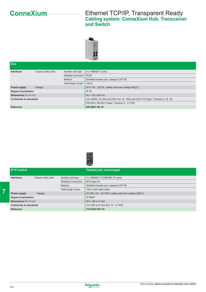
Other versions: please consult our Customer Care Centre.
Ethernet TCP/IP, Transparent ReadyCabling system: ConneXium Hub, Transceiver and Switch
Hub
Interfaces Copper cable ports Number and type 4 x 10BASE-T portsShielded connectors RJ45Medium Shielded twisted pair, category CAT 5ETotal length of pair 100 m
Power supply Voltage 24 V (18…32) DC, safety extra low voltage (SELV)Degree of protection IP 30Dimensions W x H x D 40 x 125 x 80 mmConformity to standards cUL 60950, UL 508 and CSA 142, UL 1604 and CSA 213 Class 1 Division 2, e, GL
FM 3810, FM 3611 Class 1 Division 2 , C-TICKReference 499 NEH 104 10
IP 67 switch Twisted pair, unmanaged
Interfaces Copper cable ports Number and type 5 x 10BASE-T/100BASE-TX portsShielded connectors M12 (type D)Medium Shielded twisted pair, category CAT 5ETotal length of pair 100 m with rated cable
Power supply Voltage 24 VDC (18…32 VDC), safety extra low voltage (SELV)Degree of protection IP 65/67Dimensions W x H x D 60 x 126 x 31 mmConformity to standards cUL 508 and CSA 22.2 14 , C-TICKReference TCS ESU 051 F0
ConneXium
7/2
2
1
3
4
5
6
7
8
9
10
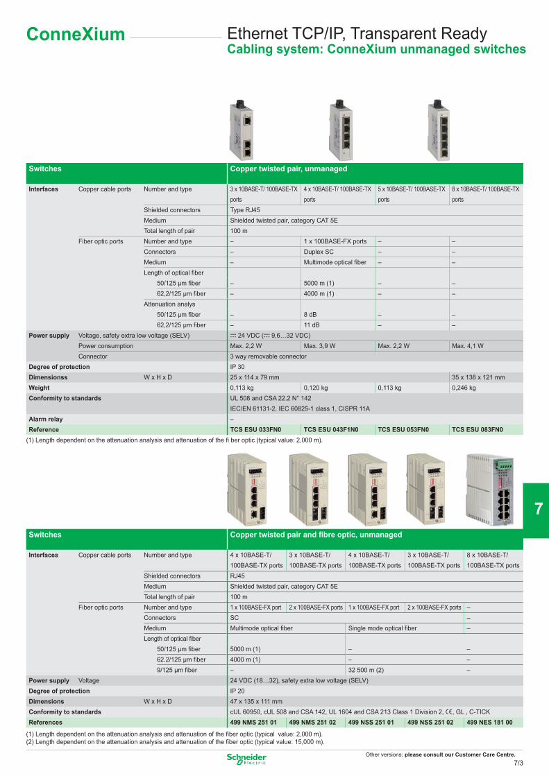
Other versions: please consult our Customer Care Centre.
Ethernet TCP/IP, Transparent ReadyCabling system: ConneXium unmanaged switches
ConneXium
Switches Copper twisted pair, unmanaged
Interfaces Copper cable ports Number and type 3 x 10BASE-T/ 100BASE-TX ports
4 x 10BASE-T/ 100BASE-TX ports
5 x 10BASE-T/ 100BASE-TX ports
8 x 10BASE-T/ 100BASE-TX ports
Shielded connectors Type RJ45Medium Shielded twisted pair, category CAT 5ETotal length of pair 100 m
Fiber optic ports Number and type – 1 x 100BASE-FX ports – –Connectors – Duplex SC – –Medium – Multimode optical fiber – –Length of optical fiber
50/125 μm fiber – 5000 m (1) – –62,2/125 μm fiber – 4000 m (1) – –
Attenuation analys50/125 μm fiber – 8 dB – –62,2/125 μm fiber – 11 dB – –
Power supply Voltage, safety extra low voltage (SELV) c 24 VDC (c 9,6…32 VDC)Power consumption Max. 2,2 W Max. 3,9 W Max. 2,2 W Max. 4,1 WConnector 3 way removable connector
Degree of protection IP 30Dimensionss W x H x D 25 x 114 x 79 mm 35 x 138 x 121 mmWeight 0,113 kg 0,120 kg 0,113 kg 0,246 kgConformity to standards UL 508 and CSA 22.2 N° 142
IEC/EN 61131-2, IEC 60825-1 class 1, CISPR 11AAlarm relay –Reference TCS ESU 033FN0 TCS ESU 043F1N0 TCS ESU 053FN0 TCS ESU 083FN0
(1) Length dependent on the attenuation analysis and attenuation of the fi ber optic (typical value: 2,000 m).
Switches Copper twisted pair and fibre optic, unmanaged
Interfaces Copper cable ports Number and type 4 x 10BASE-T/100BASE-TX ports
3 x 10BASE-T/100BASE-TX ports
4 x 10BASE-T/100BASE-TX ports
3 x 10BASE-T/100BASE-TX ports
8 x 10BASE-T/100BASE-TX ports
Shielded connectors RJ45Medium Shielded twisted pair, category CAT 5ETotal length of pair 100 m
Fiber optic ports Number and type 1 x 100BASE-FX port 2 x 100BASE-FX ports 1 x 100BASE-FX port 2 x 100BASE-FX ports –Connectors SC –Medium Multimode optical fiber Single mode optical fiber –Length of optical fiber
5000 m (1) – –50/125 μm fiber
62.2/125 μm fiber 4000 m (1) – –9/125 μm fiber – 32 500 m (2) –
Power supply Voltage 24 VDC (18…32), safety extra low voltage (SELV)Degree of protection IP 20Dimensions W x H x D 47 x 135 x 111 mmConformity to standards cUL 60950, cUL 508 and CSA 142, UL 1604 and CSA 213 Class 1 Division 2, e, GL , C-TICKReferences 499 NMS 251 01 499 NMS 251 02 499 NSS 251 01 499 NSS 251 02 499 NES 181 00
(1) Length dependent on the attenuation analysis and attenuation of the fiber optic (typical value: 2,000 m).(2) Length dependent on the attenuation analysis and attenuation of the fiber optic (typical value: 15,000 m).
7/3
2
1
3
4
5
6
7
8
9
10
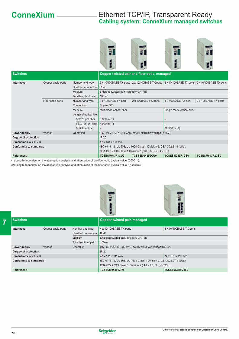
Other versions: please consult our Customer Care Centre.
Ethernet TCP/IP, Transparent ReadyCabling system: ConneXium managed switches
ConneXium
Switches Copper twisted pair and fiber optic, managed
Interfaces Copper cable ports Number and type 3 x 10/100BASE-TX ports 2 x 10/100BASE-TX ports 3 x 10/100BASE-TX ports 2 x 10/100BASE-TX portsShielded connectors RJ45Medium Shielded twisted pair, category CAT 5ETotal length of pair 100 m
Fiber optic ports Number and type 1 x 100BASE-FX port 2 x 100BASE-FX ports 1 x 100BASE-FX port 2 x 100BASE-FX portsConnectors Duplex SCMedium Multimode optical fiber Single mode optical fiberLength of optical fiber
50/125 μm fiber 5,000 m (1) –62.2/125 μm fiber 4,000 m (1) –9/125 μm fiber – 32,500 m (2)
Power supply Voltage Operation 9.6...60 VDC/18…30 VAC, safety extra low voltage (SELV)Degree of protection IP 20Dimensions W x H x D 47 x 131 x 111 mmConformity to standards IEC 61131-2, UL 508, UL 1604 Class 1 Division 2, CSA C22.2 14 (cUL),
CSA C22.2 213 Class 1 Division 2 (cUL), e, GL , C-TICKReferences TCSESM043F1CU0 TCSESM043F2CU0 TCSESM043F1CS0 TCSESM043F2CS0
(1) Length dependent on the attenuation analysis and attenuation of the fiber optic (typical value: 2,000 m).(2) Length dependent on the attenuation analysis and attenuation of the fiber optic (typical value: 15,000 m).
Switches Copper twisted pair, managed
Interfaces Copper cable ports Number and type 4 x 10/100BASE-TX ports 8 x 10/100BASE-TX portsShielded connectors RJ45Medium Shielded twisted pair, category CAT 5ETotal length of pair 100 m
Power supply Voltage Operation 9.6...60 VDC/18…30 VAC, safety extra low voltage (SELV)Degree of protection IP 20Dimensions W x H x D 47 x 131 x 111 mm 74 x 131 x 111 mmConformity to standards IEC 61131-2, UL 508, UL 1604 Class 1 Division 2, CSA C22.2 14 (cUL),
CSA C22.2 213 Class 1 Division 2 (cUL), e, GL , C-TICKReferences TCSESM043F23F0 TCSESM083F23F0
7/4
2
1
3
4
5
6
7
8
9
10
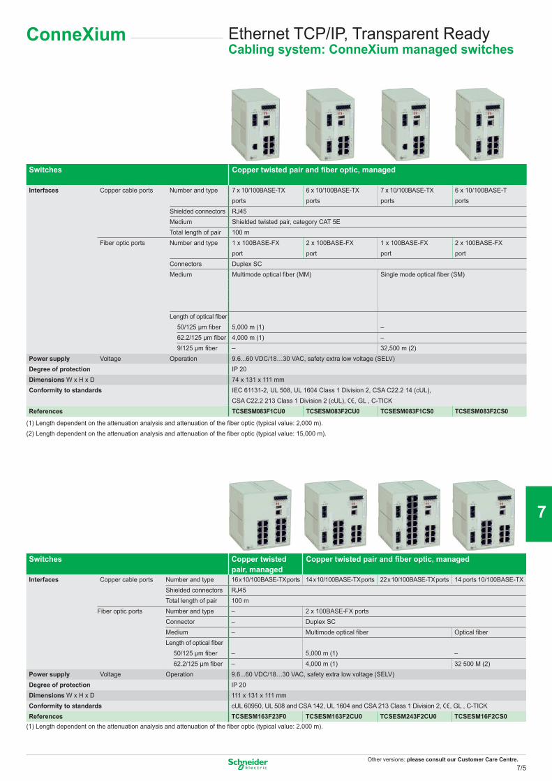
Other versions: please consult our Customer Care Centre.
Ethernet TCP/IP, Transparent ReadyCabling system: ConneXium managed switches
ConneXium
Switches Copper twisted pair and fiber optic, managed
Interfaces Copper cable ports Number and type 7 x 10/100BASE-TXports
6 x 10/100BASE-TXports
7 x 10/100BASE-TXports
6 x 10/100BASE-Tports
Shielded connectors RJ45Medium Shielded twisted pair, category CAT 5ETotal length of pair 100 m
Fiber optic ports Number and type 1 x 100BASE-FX 2 x 100BASE-FX 1 x 100BASE-FX 2 x 100BASE-FXport port port port
Connectors Duplex SCMedium Multimode optical fiber (MM) Single mode optical fiber (SM)
Length of optical fiber 5,000 m (1)
–50/125 μm fiber
62.2/125 μm fiber 4,000 m (1) –9/125 μm fiber – 32,500 m (2)
Power supply Voltage Operation 9.6...60 VDC/18…30 VAC, safety extra low voltage (SELV)Degree of protection IP 20Dimensions W x H x D 74 x 131 x 111 mmConformity to standards IEC 61131-2, UL 508, UL 1604 Class 1 Division 2, CSA C22.2 14 (cUL),
CSA C22.2 213 Class 1 Division 2 (cUL), e, GL , C-TICKReferences TCSESM083F1CU0 TCSESM083F2CU0 TCSESM083F1CS0 TCSESM083F2CS0
(1) Length dependent on the attenuation analysis and attenuation of the fiber optic (typical value: 2,000 m).(2) Length dependent on the attenuation analysis and attenuation of the fiber optic (typical value: 15,000 m).
Switches Copper twisted pair, managed
Copper twisted pair and fiber optic, managed
Interfaces Copper cable ports Number and type 16 x 10/100BASE-TX ports 14 x 10/100BASE-TX ports 22 x 10/100BASE-TX ports 14 ports 10/100BASE-TXShielded connectors RJ45Total length of pair 100 m
Fiber optic ports Number and type – 2 x 100BASE-FX portsConnector – Duplex SCMedium – Multimode optical fiber Optical fiberLength of optical fiber
– 5,000 m (1)50/125 μm fiber –
62.2/125 μm fiber – 4,000 m (1) 32 500 M (2)Power supply Voltage Operation 9.6...60 VDC/18…30 VAC, safety extra low voltage (SELV)Degree of protection IP 20Dimensions W x H x D 111 x 131 x 111 mmConformity to standards cUL 60950, UL 508 and CSA 142, UL 1604 and CSA 213 Class 1 Division 2, e, GL , C-TICKReferences TCSESM163F23F0 TCSESM163F2CU0 TCSESM243F2CU0 TCSESM16F2CS0
(1) Length dependent on the attenuation analysis and attenuation of the fiber optic (typical value: 2,000 m).
7/5
2
1
3
4
5
6
7
8
9
10
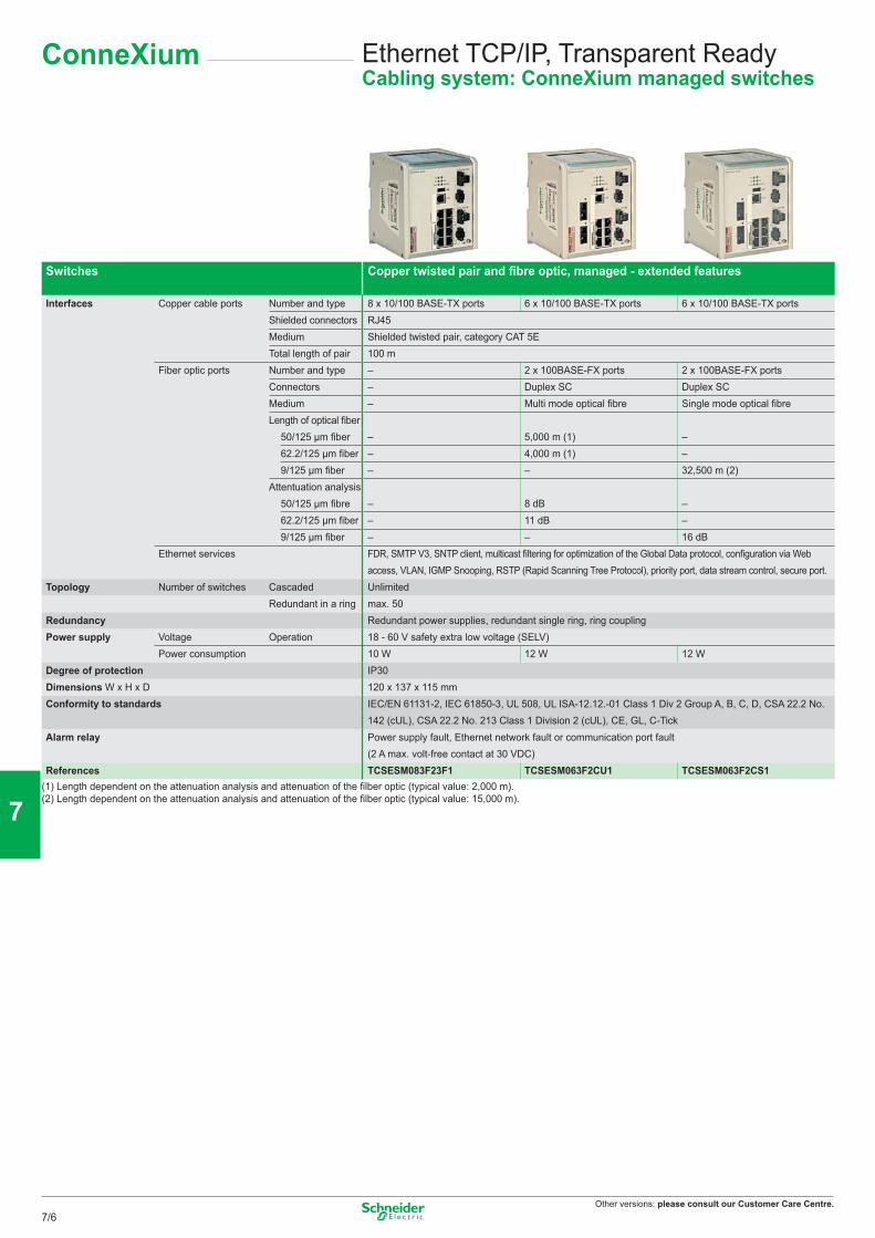
Other versions: please consult our Customer Care Centre.
Ethernet TCP/IP, Transparent ReadyCabling system: ConneXium managed switches
ConneXium
Switches Copper twisted pair and fi bre optic, managed - extended features
Interfaces Copper cable ports Number and type 8 x 10/100 BASE-TX ports 6 x 10/100 BASE-TX ports 6 x 10/100 BASE-TX portsShielded connectors RJ45Medium Shielded twisted pair, category CAT 5ETotal length of pair 100 m
Fiber optic ports Number and type – 2 x 100BASE-FX ports 2 x 100BASE-FX portsConnectors – Duplex SC Duplex SCMedium – Multi mode optical fi bre Single mode optical fi breLength of optical fi ber
– 5,000 m (1) –50/125 μm fi ber62.2/125 μm fi ber – 4,000 m (1) –9/125 μm fi ber – – 32,500 m (2)
Attentuation analysis– 8 dB –50/125 μm fi bre
62.2/125 μm fi ber – 11 dB –9/125 μm fi ber – – 16 dB
Ethernet services FDR, SMTP V3, SNTP client, multicast fi ltering for optimization of the Global Data protocol, confi guration via Web access, VLAN, IGMP Snooping, RSTP (Rapid Scanning Tree Protocol), priority port, data stream control, secure port.
Topology Number of switches Cascaded UnlimitedRedundant in a ring max. 50
Redundancy Redundant power supplies, redundant single ring, ring couplingPower supply Voltage Operation 18 - 60 V safety extra low voltage (SELV)
Power consumption 10 W 12 W 12 WDegree of protection IP30Dimensions W x H x D 120 x 137 x 115 mm Conformity to standards IEC/EN 61131-2, IEC 61850-3, UL 508, UL ISA-12.12.-01 Class 1 Div 2 Group A, B, C, D, CSA 22.2 No.
142 (cUL), CSA 22.2 No. 213 Class 1 Division 2 (cUL), CE, GL, C-TickAlarm relay Power supply fault, Ethernet network fault or communication port fault
(2 A max. volt-free contact at 30 VDC)References TCSESM083F23F1 TCSESM063F2CU1 TCSESM063F2CS1
(1) Length dependent on the attenuation analysis and attenuation of the fi lber optic (typical value: 2,000 m).(2) Length dependent on the attenuation analysis and attenuation of the fi lber optic (typical value: 15,000 m).
7/6
2
1
3
4
5
6
7
8
9
10
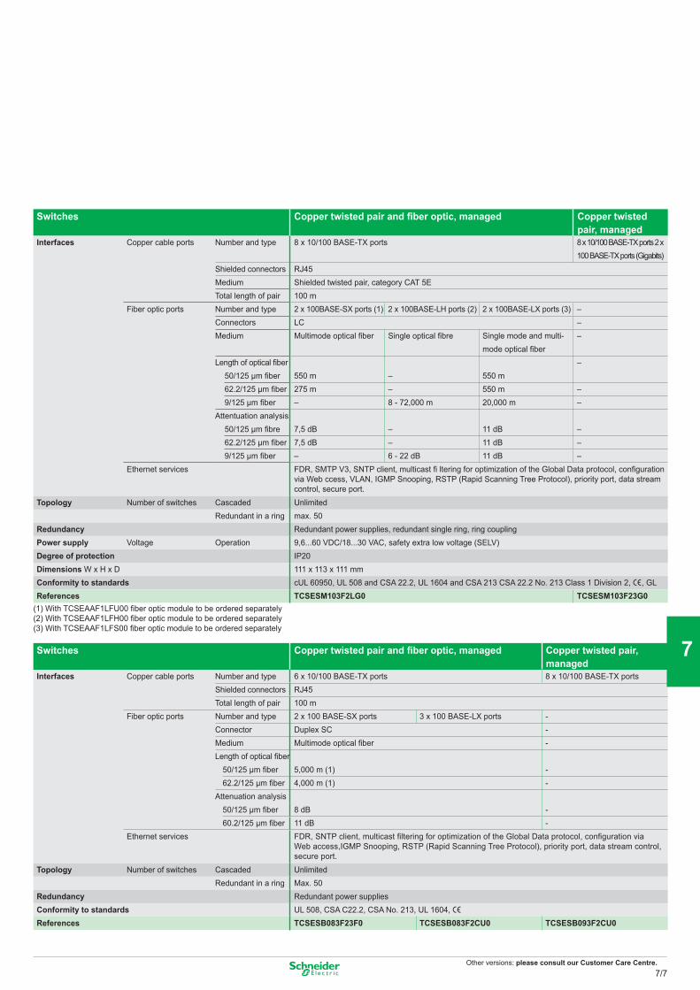
Other versions: please consult our Customer Care Centre.
Switches Copper twisted pair and fiber optic, managed Copper twisted pair, managed
Interfaces Copper cable ports Number and type 8 x 10/100 BASE-TX ports 8 x 10/100 BASE-TX ports 2 x 100 BASE-TX ports (Gigabits)
Shielded connectors RJ45Medium Shielded twisted pair, category CAT 5ETotal length of pair 100 m
Fiber optic ports Number and type 2 x 100BASE-SX ports (1) 2 x 100BASE-LH ports (2) 2 x 100BASE-LX ports (3) –Connectors LC –Medium Multimode optical fiber Single optical fibre Single mode and multi-
mode optical fiber–
Length of optical fiber 550 m –
550 m
–50/125 μm fiber62.2/125 μm fiber 275 m – 550 m –9/125 μm fiber – 8 - 72,000 m 20,000 m –
Attentuation analysis 7,5 dB –
11 dB –50/125 μm fibre
62.2/125 μm fiber 7,5 dB – 11 dB –9/125 μm fiber – 6 - 22 dB 11 dB –
Ethernet services FDR, SMTP V3, SNTP client, multicast fi ltering for optimization of the Global Data protocol, configuration via Web ccess, VLAN, IGMP Snooping, RSTP (Rapid Scanning Tree Protocol), priority port, data stream control, secure port.
Topology Number of switches Cascaded UnlimitedRedundant in a ring max. 50
Redundancy Redundant power supplies, redundant single ring, ring couplingPower supply Voltage Operation 9,6...60 VDC/18...30 VAC, safety extra low voltage (SELV)Degree of protection IP20Dimensions W x H x D 111 x 113 x 111 mm Conformity to standards cUL 60950, UL 508 and CSA 22.2, UL 1604 and CSA 213 CSA 22.2 No. 213 Class 1 Division 2, e, GLReferences TCSESM103F2LG0 TCSESM103F23G0
(1) With TCSEAAF1LFU00 fiber optic module to be ordered separately(2) With TCSEAAF1LFH00 fiber optic module to be ordered separately(3) With TCSEAAF1LFS00 fiber optic module to be ordered separately
Switches Copper twisted pair and fiber optic, managed Copper twisted pair, managed
Interfaces Copper cable ports Number and type 6 x 10/100 BASE-TX ports 8 x 10/100 BASE-TX portsShielded connectors RJ45Total length of pair 100 m
Fiber optic ports Number and type 2 x 100 BASE-SX ports 3 x 100 BASE-LX ports -Connector Duplex SC -Medium Multimode optical fiber -Length of optical fiber
50/125 μm fiber 5,000 m (1) -62.2/125 μm fiber 4,000 m (1) -
Attenuation analysis50/125 μm fiber 8 dB -60.2/125 μm fiber 11 dB -
Ethernet services FDR, SNTP client, multicast filtering for optimization of the Global Data protocol, configuration via Web access,IGMP Snooping, RSTP (Rapid Scanning Tree Protocol), priority port, data stream control, secure port.
Topology Number of switches Cascaded UnlimitedRedundant in a ring Max. 50
Redundancy Redundant power suppliesConformity to standards UL 508, CSA C22.2, CSA No. 213, UL 1604, eReferences TCSESB083F23F0 TCSESB083F2CU0 TCSESB093F2CU0
7/7
2
1
3
4
5
6
7
8
9
10
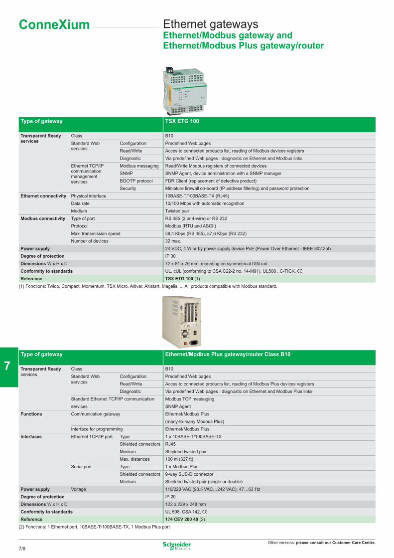
Other versions: please consult our Customer Care Centre.
Ethernet gatewaysEthernet/Modbus gateway and Ethernet/Modbus Plus gateway/router
ConneXium
Type of gateway TSX ETG 100
Transparent Readyservices
Class B10Standard Webservices
Configuration Predefined Web pagesRead/Write Acces to connected products list, reading of Modbus devices registersDiagnostic Via predefined Web pages : diagnostic on Ethernet and Modbus links
Ethernet TCP/IPcommunicationmanagementservices
Modbus messaging Read/Write Modbus registers of connected devicesSNMP SNMP Agent, device administration with a SNMP managerBOOTP protocol FDR Client (replacement of defective product)Security Miniature firewall on-board (IP address filtering) and password protection
Ethernet connectivity Physical interface 10BASE-T/100BASE-TX (RJ45)Data rate 10/100 Mbps with automatic recognitionMedium Twisted pair
Modbus connectivity Type of port RS 485 (2 or 4-wire) or RS 232Protocol Modbus (RTU and ASCII)Maxi transmission speed 38,4 Kbps (RS 485), 57,6 Kbps (RS 232)Number of devices 32 max.
Power supply 24 VDC, 4 W or by power supply device PoE (Power Over Ethernet - IEEE 802.3af)Degree of protection IP 30Dimensions W x H x D 72 x 81 x 76 mm, mounting on symmetrical DIN railConformity to standards UL, cUL (conforming to CSA C22-2 no. 14-M91), UL508 , C-TICK, eReference TSX ETG 100 (1)
(1) Fonctions: Twido, Compact, Momentum, TSX Micro, Altivar, Altistart, Magelis, ... All products compatible with Modbus standard.
Type of gateway Ethernet/Modbus Plus gateway/router Class B10
Transparent Readyservices
Class B10Standard Webservices
Configuration Predefined Web pagesRead/Write Acces to connected products list, reading of Modbus Plus devices registersDiagnostic Via predefined Web pages : diagnostic on Ethernet and Modbus Plus links
Standard Ethernet TCP/IP communication Modbus TCP messagingservices SNMP Agent
Functions Communication gateway Ethernet/Modbus Plus(many-to-many Modbus Plus)
Interface for programming Ethernet/Modbus PlusInterfaces Ethernet TCP/IP port Type 1 x 10BASE-T/100BASE-TX
Shielded connectors RJ45Medium Shielded twisted pairMax. distances 100 m (327 ft)
Serial port Type 1 x Modbus PlusShielded connectors 9-way SUB-D connectorMedium Shielded twisted pair (single or double)
Power supply Voltage 110/220 VAC (93.5 VAC…242 VAC), 47…63 HzDegree of protection IP 20Dimensions W x H x D 122 x 229 x 248 mmConformity to standards UL 508, CSA 142, eReference 174 CEV 200 40 (2)
(2) Fonctions: 1 Ethernet port, 10BASE-T/100BASE-TX, 1 Modbus Plus port
7/8
2
1
3
4
5
6
7
8
9
10
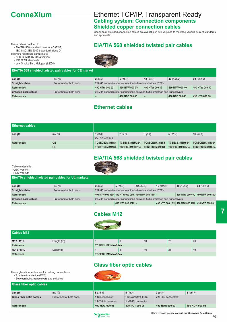
Other versions: please consult our Customer Care Centre.
Ethernet TCP/IP, Transparent ReadyCabling system: Connection components Shielded copper connection cablesConneXium shielded connection cables are available in two versions to meet the various current standards and approvals:
ConneXium
These cables conform to: - EIA/TIA-568 standard, category CAT 5E, - IEC 11801/EN 50173 standard, class D.Their fire resistance conforms to: - NFC 32070# C2 classification - IEC 322/1 standards - Low Smoke Zero Halogen (LSZH).
EIA/TIA 568 shielded twisted pair cables
EIA/TIA 568 shielded twisted pair cables for CE market
Length m / (ft) 2 (6.6) 5 (16.4) 12 (39.4) 40 (131.2) 80 (262.5)Straight cables Preformed at both ends 2 RJ45 connectors for connection to terminal devices (DTE)References 490 NTW 000 02 490 NTW 000 05 490 NTW 000 12 490 NTW 000 40 490 NTW 000 80Crossed cord cables Preformed at both ends 2 RJ45 connectors for connections between hubs, switches and transceiversReferences – 490 NTC 000 05 – 490 NTC 000 40 490 NTC 000 80
Ethernet cables
Ethernet cables
Length m / (ft) 1 (3.3) 2 (6.6) 3 (9.8) 5 (16.4) 10 (32.8)Cat 5E w/RJ45
References CE TCSECE3M3M1S4 TCSECE3M3M2S4 TCSECE3M3M3S4 TCSECE3M3M5S4 TCSECE3M3M10S4UL TCSECU3M3M1S4 TCSECU3M3M2S4 TCSECU3M3M3S4 TCSECU3M3M5S4 TCSECU3M3M10S4
EIA/TIA 568 shielded twisted pair cablesCable material is :- CEC type FT-1- NEC type CM
EIA/TIA shielded twisted pair cables for UL markets
Length m / (ft) 2 (6.6) 5 (16.4) 12 (39.4) 15 (49.2) 40 (131.2) 80 (262.5)Straight cables Preformed at both ends 2 RJ45 connectors for connection to terminal devices (DTE)References 490 NTW 000 02U 490 NTW 000 05U 490 NTW 000 12U – 490 NTW 000 40U 490 NTW 000 80UCrossed cord cables Preformed at both ends 2 RJ45 connectors for connections between hubs, switches and transceiversReferences – 490 NTC 000 05U – 490 NTC 000 12U 490 NTC 000 40U 490 NTC 000 80U
Cables M12
Cables M12
M12 / M12 Length (m) 1 3 10 25 40Reference TCSECL1M1MppS2pp
RJ45 / M12 Length(m) 1 3 10 25 40Reference TCSECL1M3MppS2pp
Glass fiber optic cablesThese glass fiber optics are for making connections: - To a terminal device (DTE) - Between hubs, transceivers and switches
Glass fiber optic cables
Length m / (ft) 5 (16.4) 5 (16.4) 3 (9.8) 5 (16.4)Glass fiber optic cables Preformed at both ends 1 SC connector 1 ST connector (BFOC) 2 MT-RJ connectors
1 MT-RJ connector 1 MT-RJ connectorReferences 490 NOC 000 05 490 NOT 000 05 490 NOR 000 03 490 NOR 000 05
7/9
2
1
3
4
5
6
7
8
9
10
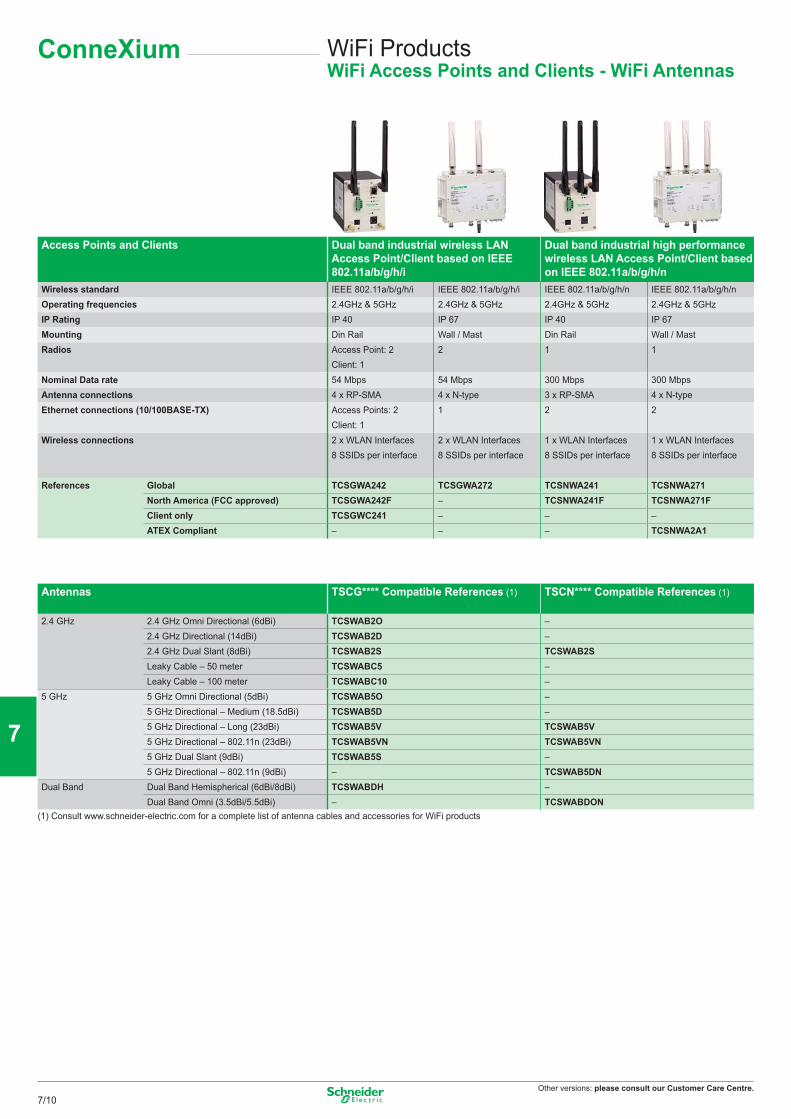
Other versions: please consult our Customer Care Centre.
WiFi ProductsWiFi Access Points and Clients - WiFi Antennas
ConneXium
Access Points and Clients Dual band industrial wireless LAN Access Point/Client based on IEEE 802.11a/b/g/h/i
Dual band industrial high performance wireless LAN Access Point/Client based on IEEE 802.11a/b/g/h/n
Wireless standard IEEE 802.11a/b/g/h/i IEEE 802.11a/b/g/h/i IEEE 802.11a/b/g/h/n IEEE 802.11a/b/g/h/nOperating frequencies 2.4GHz & 5GHz 2.4GHz & 5GHz 2.4GHz & 5GHz 2.4GHz & 5GHzIP Rating IP 40 IP 67 IP 40 IP 67Mounting Din Rail Wall / Mast Din Rail Wall / MastRadios Access Point: 2
Client: 12 1 1
Nominal Data rate 54 Mbps 54 Mbps 300 Mbps 300 MbpsAntenna connections 4 x RP-SMA 4 x N-type 3 x RP-SMA 4 x N-typeEthernet connections (10/100BASE-TX) Access Points: 2
Client: 11 2 2
Wireless connections 2 x WLAN Interfaces 8 SSIDs per interface
2 x WLAN Interfaces 8 SSIDs per interface
1 x WLAN Interfaces 8 SSIDs per interface
1 x WLAN Interfaces 8 SSIDs per interface
References Global TCSGWA242 TCSGWA272 TCSNWA241 TCSNWA271North America (FCC approved) TCSGWA242F – TCSNWA241F TCSNWA271FClient only TCSGWC241 – – –ATEX Compliant – – – TCSNWA2A1
Antennas TSCG**** Compatible References (1) TSCN**** Compatible References (1)
2.4 GHz 2.4 GHz Omni Directional (6dBi) TCSWAB2O –2.4 GHz Directional (14dBi) TCSWAB2D –2.4 GHz Dual Slant (8dBi) TCSWAB2S TCSWAB2SLeaky Cable – 50 meter TCSWABC5 –Leaky Cable – 100 meter TCSWABC10 –
5 GHz 5 GHz Omni Directional (5dBi) TCSWAB5O –5 GHz Directional – Medium (18.5dBi) TCSWAB5D –5 GHz Directional – Long (23dBi) TCSWAB5V TCSWAB5V5 GHz Directional – 802.11n (23dBi) TCSWAB5VN TCSWAB5VN5 GHz Dual Slant (9dBi) TCSWAB5S –5 GHz Directional – 802.11n (9dBi) – TCSWAB5DN
Dual Band Dual Band Hemispherical (6dBi/8dBi) TCSWABDH –Dual Band Omni (3.5dBi/5.5dBi) – TCSWABDON
(1) Consult www.schneider-electric.com for a complete list of antenna cables and accessories for WiFi products
7/10
2
1
3
4
5
6
7
8
9
10
Other versions: please consult our Customer Care Centre.
NotesConneXium
7/11
2
1
3
4
5
6
7
8
9
10
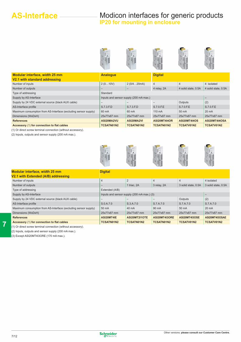
Other versions: please consult our Customer Care Centre.
AS-Interface Modicon interfaces for generic productsIP20 for mounting in enclosure
Modular interface, width 25 mm Analogue DigitalV2.1 with standard addressingNumber of inputs 2 (0…10V) 2 (0/4…20mA) 4 4 4 isolatedNumber of outputs – – 4 relay, 2A 4 solid state, 0.5A 4 solid state, 0.5AType of addressing StandardSupply by AS-Interface Inputs and sensor supply (200 mA max.) –Supply by 24 VDC external source (black AUX cable) – – – Outputs (2)AS-Interface profile S.7.3.F.D S.7.3.F.D S.7.0.F.E S.7.0.F.E S.7.0.F.EMaximum consumption from AS-Interface (excluding sensor supply) 60 mA 60 mA 110 mA 50 mA 20 mADimensions (WxDxH) 25x77x87 mm 25x77x87 mm 25x77x87 mm 25x77x87 mm 25x77x87 mmReferences ASI20MA2VU ASI20MA2VI ASI20MT4I4OR ASI20MT4I4OS ASI20MT4I4OSAAccessory (1) for connection to flat cables TCSATN01N2 TCSATN01N2 TCSATN01N2 TCSATV01N2 TCSATV01N2
(1) Or direct screw terminal connection (without accessory).(2) Inputs, outputs and sensor supply (200 mA max.).
Modular interface, width 25 mm DigitalV2.1 with Extended (A/B) addressingNumber of inputs 4 2 4 4 4 isolatedNumber of outputs – 1 triac, 2A 3 relay, 2A 3 solid state, 0.5A 3 solid state, 0.5AType of addressing Extended (A/B)Supply by AS-Interface Inputs and sensor supply (200 mA max.) (3) –Supply by 24 VDC external source (black AUX cable) – – – Outputs (2)AS-Interface profile S.0.A.7.0 S.3.A.7.0 S.7.A.7.0 S.7.A.7.0 S.7.A.7.0Maximum consumption from AS-Interface (excluding sensor supply) 50 mA 40 mA 90 mA 50 mA 20 mADimensions (WxDxH) 25x77x87 mm 25x77x87 mm 25x77x87 mm 25x77x87 mm 25x77x87 mmReferences ASI20MT4IE ASI20MT2I1OTE ASI20MT4I3ORE ASI20MT4I3OSE ASI20MT4I3OSAEAccessory (1) for connection to flat cables TCSATN01N2 TCSATN01N2 TCSATN01N2 TCSATV01N2 TCSATV01N2
(1) Or direct screw terminal connection (without accessory).(2) Inputs, outputs and sensor supply (200 mA max.).(3) Except ASI20MT4I3ORE (170 mA max.).
7/12
2
1
3
4
5
6
7
8
9
10
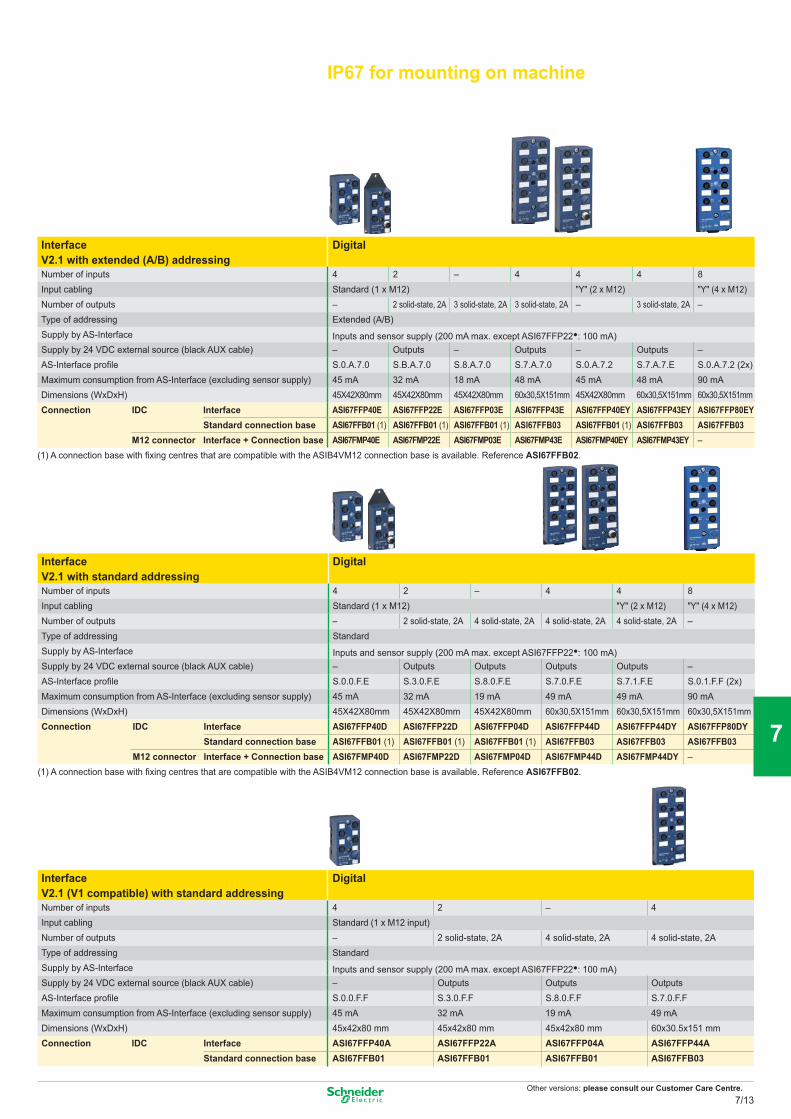
Other versions: please consult our Customer Care Centre.
IP67 for mounting on machine
Interface DigitalV2.1 with extended (A/B) addressingNumber of inputs 4 2 – 4 4 4 8Input cabling Standard (1 x M12) "Y" (2 x M12) "Y" (4 x M12)Number of outputs – 2 solid-state, 2A 3 solid-state, 2A 3 solid-state, 2A – 3 solid-state, 2A –Type of addressing Extended (A/B) Supply by AS-Interface Inputs and sensor supply (200 mA max. except ASI67FFP22•: 100 mA) Supply by 24 VDC external source (black AUX cable) – Outputs – Outputs – Outputs –AS-Interface profile S.0.A.7.0 S.B.A.7.0 S.8.A.7.0 S.7.A.7.0 S.0.A.7.2 S.7.A.7.E S.0.A.7.2 (2x)Maximum consumption from AS-Interface (excluding sensor supply) 45 mA 32 mA 18 mA 48 mA 45 mA 48 mA 90 mADimensions (WxDxH) 45X42X80mm 45X42X80mm 45X42X80mm 60x30,5X151mm 45X42X80mm 60x30,5X151mm 60x30,5X151mmConnection IDC Interface ASI67FFP40E ASI67FFP22E ASI67FFP03E ASI67FFP43E ASI67FFP40EY ASI67FFP43EY ASI67FFP80EY
Standard connection base ASI67FFB01 (1) ASI67FFB01 (1) ASI67FFB01 (1) ASI67FFB03 ASI67FFB01 (1) ASI67FFB03 ASI67FFB03M12 connector Interface + Connection base ASI67FMP40E ASI67FMP22E ASI67FMP03E ASI67FMP43E ASI67FMP40EY ASI67FMP43EY –
(1) A connection base with fixing centres that are compatible with the ASIB4VM12 connection base is available. Reference ASI67FFB02.
Interface DigitalV2.1 with standard addressingNumber of inputs 4 2 – 4 4 8Input cabling Standard (1 x M12) "Y" (2 x M12) "Y" (4 x M12)Number of outputs – 2 solid-state, 2A 4 solid-state, 2A 4 solid-state, 2A 4 solid-state, 2A –Type of addressing StandardSupply by AS-Interface Inputs and sensor supply (200 mA max. except ASI67FFP22•: 100 mA)Supply by 24 VDC external source (black AUX cable) – Outputs Outputs Outputs Outputs –AS-Interface profile S.0.0.F.E S.3.0.F.E S.8.0.F.E S.7.0.F.E S.7.1.F.E S.0.1.F.F (2x)Maximum consumption from AS-Interface (excluding sensor supply) 45 mA 32 mA 19 mA 49 mA 49 mA 90 mADimensions (WxDxH) 45X42X80mm 45X42X80mm 45X42X80mm 60x30,5X151mm 60x30,5X151mm 60x30,5X151mmConnection IDC Interface ASI67FFP40D ASI67FFP22D ASI67FFP04D ASI67FFP44D ASI67FFP44DY ASI67FFP80DY
Standard connection base ASI67FFB01 (1) ASI67FFB01 (1) ASI67FFB01 (1) ASI67FFB03 ASI67FFB03 ASI67FFB03M12 connector Interface + Connection base ASI67FMP40D ASI67FMP22D ASI67FMP04D ASI67FMP44D ASI67FMP44DY –
(1) A connection base with fixing centres that are compatible with the ASIB4VM12 connection base is available. Reference ASI67FFB02.
Interface DigitalV2.1 (V1 compatible) with standard addressingNumber of inputs 4 2 – 4Input cabling Standard (1 x M12 input)Number of outputs – 2 solid-state, 2A 4 solid-state, 2A 4 solid-state, 2AType of addressing StandardSupply by AS-Interface Inputs and sensor supply (200 mA max. except ASI67FFP22•: 100 mA)Supply by 24 VDC external source (black AUX cable) – Outputs Outputs OutputsAS-Interface profile S.0.0.F.F S.3.0.F.F S.8.0.F.F S.7.0.F.FMaximum consumption from AS-Interface (excluding sensor supply) 45 mA 32 mA 19 mA 49 mADimensions (WxDxH) 45x42x80 mm 45x42x80 mm 45x42x80 mm 60x30.5x151 mmConnection IDC Interface ASI67FFP40A ASI67FFP22A ASI67FFP04A ASI67FFP44A
Standard connection base ASI67FFB01 ASI67FFB01 ASI67FFB01 ASI67FFB03
7/13
2
1
3
4
5
6
7
8
9
10
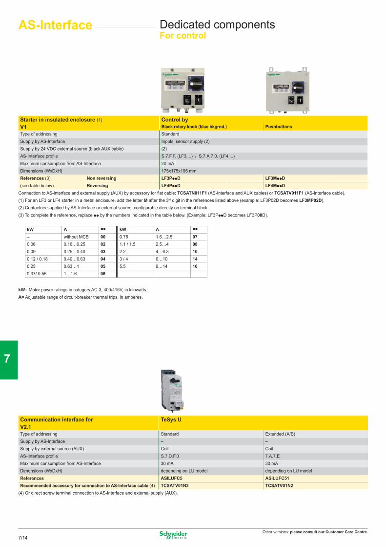
Other versions: please consult our Customer Care Centre.
AS-Interface Dedicated componentsFor control
Starter in insulated enclosure (1) Control byV1 Black rotary knob (blue bkgrnd.) PushbuttonsType of addressing StandardSupply by AS-Interface Inputs, sensor supply (2)Supply by 24 VDC external source (black AUX cable) (2)AS-Interface profi le S.7.F.F. (LF3....) / S.7.A.7.0. (LF4....)Maximum consumption from AS-Interface 20 mADimensions (WxDxH) 175x175x195 mmReferences (3) Non reversing LF3PppD LF3MppD(see table below) Reversing LF4PppD LF4MppD
Connection to AS-Interface and external supply (AUX) by accessory for fl at cable: TCSATN011F1 (AS-Interface and AUX cables) or TCSATV011F1 (AS-Interface cable).(1) For an LF3 or LF4 starter in a metal enclosure, add the letter M after the 3rd digit in the references listed above (example: LF3P02D becomes LF3MP02D).(2) Contactors supplied by AS-Interface or external source, confi gurable directly on terminal block.(3) To complete the reference, replace pp by the numbers indicated in the table below. (Example: LF3PppD becomes LF3P00D).
kW= Motor power ratings in category AC-3, 400/415V, in kilowatts.A= Adjustable range of circuit-breaker thermal trips, in amperes.
Communication interface for TeSys UV2.1Type of addressing Standard Extended (A/B)Supply by AS-Interface – –Supply by external source (AUX) Coil CoilAS-Interface profi le S.7.D.F.0 7.A.7.EMaximum consumption from AS-Interface 30 mA 30 mADimensions (WxDxH) depending on LU model depending on LU modelReferences ASILUFC5 ASILUFC51Recommended accessory for connection to AS-Interface cable (4) TCSATV01N2 TCSATV01N2
(4) Or direct screw terminal connection to AS-Interface and external supply (AUX).
kW A pp kW A pp
– without MCB 00 0.75 1.6…2.5 070.06 0.16…0.25 02 1.1 / 1.5 2.5…4 080.09 0.25…0.40 03 2.2 4…6.3 100.12 / 0.18 0.40…0.63 04 3 / 4 6…10 140.25 0.63…1 05 5.5 9…14 160.37/ 0.55 1…1.6 06
7/14
2
1
3
4
5
6
7
8
9
10
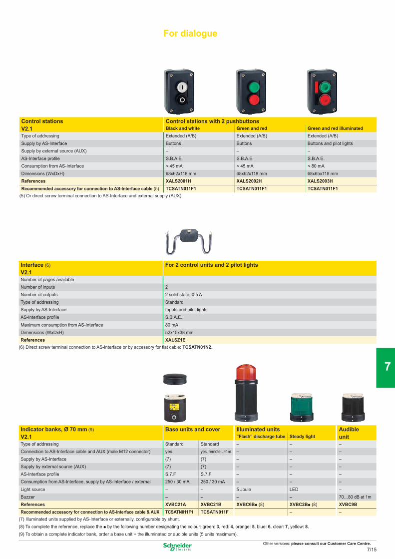
Other versions: please consult our Customer Care Centre.
For dialogue
–
Control stations Control stations with 2 pushbuttonsV2.1 Black and white Green and red Green and red illuminatedType of addressing Extended (A/B) Extended (A/B) Extended (A/B)Supply by AS-Interface Buttons Buttons Buttons and pilot lightsSupply by external source (AUX) – – –AS-Interface profile S.B.A.E. S.B.A.E. S.B.A.E.Consumption from AS-Interface < 45 mA < 45 mA < 80 mADimensions (WxDxH) 68x62x118 mm 68x62x118 mm 68x65x118 mmReferences XALS2001H XALS2002H XALS2003HRecommended accessory for connection to AS-Interface cable (5) TCSATN011F1 TCSATN011F1 TCSATN011F1
(5) Or direct screw terminal connection to AS-Interface and external supply (AUX).
Interface (6) For 2 control units and 2 pilot lightsV2.1Number of pages available –Number of inputs 2Number of outputs 2 solid state, 0.5 AType of addressing StandardSupply by AS-Interface Inputs and pilot lightsAS-Interface profile S.B.A.E.Maximum consumption from AS-Interface 80 mADimensions (WxDxH) 52x15x38 mmReferences XALSZ1E
(6) Direct screw terminal connection to AS-Interface or by accessory for flat cable: TCSATN01N2.
Indicator banks, Ø 70 mm (9) Base units and cover Illuminated units AudibleV2.1 “Flash” discharge tube Steady light unitType of addressing Standard Standard – – –Connection to AS-Interface cable and AUX (male M12 connector) yes yes, remote L=1m – – –Supply by AS-Interface (7) (7) – – –Supply by external source (AUX) (7) (7) – – –AS-Interface profile S.7.F S.7.F – – –Consumption from AS-Interface, supply by AS-Interface / external 250 / 30 mA 250 / 30 mA – – –Light source – – 5 Joule LED –Buzzer – – – – 70…80 dB at 1mReferences XVBC21A XVBC21B XVBC6Bp (8) XVBC2Bp (8) XVBC9BRecommended accessory for connection to AS-Interface cable & AUX TCSATN011F1 TCSATN011F – –
(7) Illuminated units supplied by AS-Interface or externally, configurable by shunt. (8) To complete the reference, replace the p by the following number designating the colour: green: 3, red: 4, orange: 5, blue: 6, clear: 7, yellow: 8. (9) To obtain a complete indicator bank, order a base unit + the illuminated or audible units (5 units maximum).
7/15
2
1
3
4
5
6
7
8
9
10
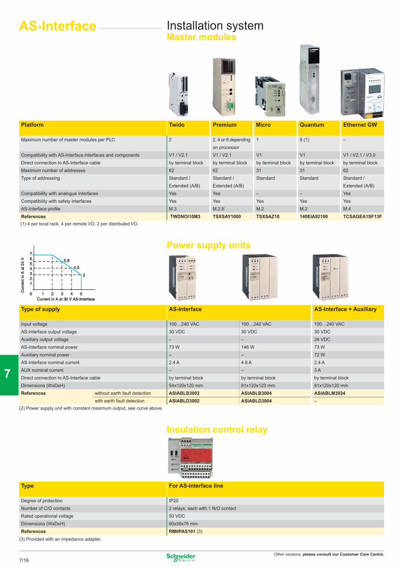
Other versions: please consult our Customer Care Centre.
1Current in A at 30 V AS-Interface
Cur
rent
in A
at 2
4 V
0
123456 5,8
4,5
3
7
2 3 4 51Current in A at 30 V AS-Interface
Cur
rent
in A
at 2
4 V
0
123456 5,8
4,5
3
7
2 3 4 5
AS-Interface Installation systemMaster modules
Type of supply AS-Interface AS-Interface + Auxiliary
Input voltage 100…240 VAC 100…240 VAC 100…240 VACAS-Interface output voltage 30 VDC 30 VDC 30 VDCAuxiliary output voltage – – 24 VDCAS-Interface nominal power 73 W 146 W 73 WAuxiliary nominal power – – 72 WAS-Interface nominal current 2.4 A 4.8 A 2.4 AAUX nominal current – – 3 ADirect connection to AS-Interface cable by terminal block by terminal block by terminal blockDimensions (WxDxH) 54x120x120 mm 81x120x120 mm 81x120x120 mmReferences without earth fault detection ASIABLB3002 ASIABLB3004 ASIABLM3024
with earth fault detection ASIABLD3002 ASIABLD3004 –(2) Power supply unit with constant maximum output, see curve above.
Insulation control relay
Platform Twido Premium Micro Quantum Ethernet GW
Maximum number of master modules per PLC 2 2, 4 or 8 depending 1 8 (1) –on processor
Compatibility with AS-Interface interfaces and components V1 / V2.1 V1 / V2.1 V1 V1 V1 / V2.1 / V3.0Direct connection to AS-Interface cable by terminal block by terminal block by terminal block by terminal block by terminal blockMaximum number of addresses 62 62 31 31 62Type of addressing Standard / Standard / Standard Standard Standard /
Extended (A/B) Extended (A/B) Extended (A/B)Compatibility with analogue interfaces Yes Yes – – YesCompatibility with safety interfaces Yes Yes Yes Yes YesAS-Interface profi le M.3 M.2.E M.2 M.2 M.4References TWDNOI10M3 TSXSAY1000 TSXSAZ10 140EIA92100 TCSAGEA1SF13F
(1) 4 per local rack, 4 per remote I/O, 2 per distributed I/O.
Power supply units
Type For AS-Interface line
Degree of protection IP20Number of C/O contacts 2 relays, each with 1 N/O contactRated operational voltage 50 VDCDimensions (WxDxH) 90x58x76 mmReferences RM0PAS101 (3)
(3) Provided with an impedance adapter.
7/16
2
1
3
4
5
6
7
8
9
10
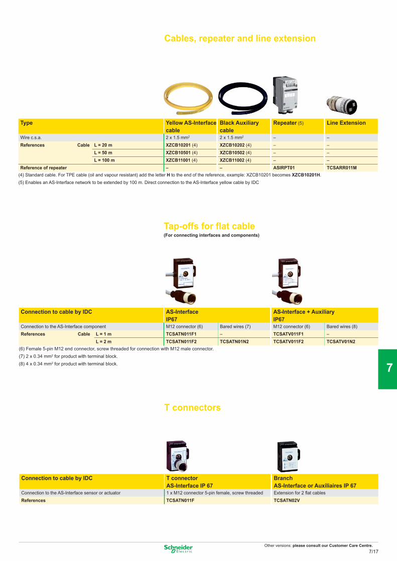
Other versions: please consult our Customer Care Centre.
Cables, repeater and line extension
Type Yellow AS-Interface cable
Black Auxiliary cable
Repeater (5) Line Extension
Wire c.s.a. 2 x 1.5 mm2 2 x 1.5 mm2 – –References Cable L = 20 m XZCB10201 (4) XZCB10202 (4) – –
L = 50 m XZCB10501 (4) XZCB10502 (4) – –L = 100 m XZCB11001 (4) XZCB11002 (4) – –
Reference of repeater – – ASIRPT01 TCSARR011M(4) Standard cable. For TPE cable (oil and vapour resistant) add the letter H to the end of the reference, example: XZCB10201 becomes XZCB10201H. (5) Enables an AS-Interface network to be extended by 100 m. Direct connection to the AS-Interface yellow cable by IDC
Tap-offs for flat cable(For connecting interfaces and components)
Connection to cable by IDC AS-Interface AS-Interface + AuxiliaryIP67 IP67
Connection to the AS-Interface component M12 connector (6) Bared wires (7) M12 connector (6) Bared wires (8)References Cable L = 1 m TCSATN011F1 – TCSATV011F1 –
L = 2 m TCSATN011F2 TCSATN01N2 TCSATV011F2 TCSATV01N2(6) Female 5-pin M12 end connector, screw threaded for connection with M12 male connector. (7) 2 x 0.34 mm2 for product with terminal block. (8) 4 x 0.34 mm2 for product with terminal block.
T connectors
Connection to cable by IDC T connector Branch AS-Interface or Auxiliaires IP 67AS-Interface IP 67
Connection to the AS-Interface sensor or actuator 1 x M12 connector 5-pin female, screw threaded Extension for 2 flat cablesReferences TCSATN011F TCSATN02V
7/17
2
1
3
4
5
6
7
8
9
10
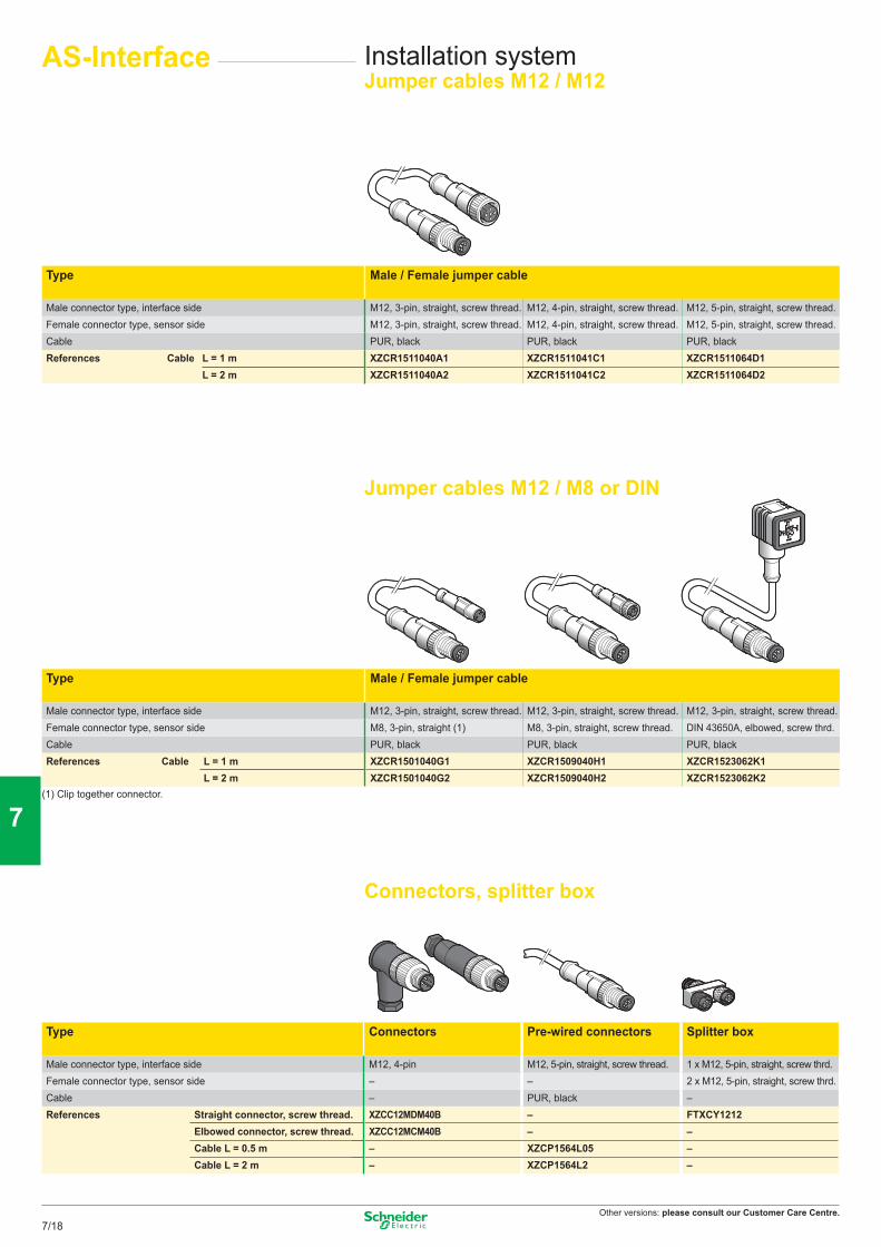
Other versions: please consult our Customer Care Centre.
AS-Interface Installation systemJumper cables M12 / M12
Type Male / Female jumper cable
Male connector type, interface side M12, 3-pin, straight, screw thread. M12, 4-pin, straight, screw thread. M12, 5-pin, straight, screw thread. Female connector type, sensor side M12, 3-pin, straight, screw thread. M12, 4-pin, straight, screw thread. M12, 5-pin, straight, screw thread.Cable PUR, black PUR, black PUR, blackReferences Cable L = 1 m XZCR1511040A1 XZCR1511041C1 XZCR1511064D1
L = 2 m XZCR1511040A2 XZCR1511041C2 XZCR1511064D2
Jumper cables M12 / M8 or DIN
Type Male / Female jumper cable
Male connector type, interface side M12, 3-pin, straight, screw thread. M12, 3-pin, straight, screw thread. M12, 3-pin, straight, screw thread. Female connector type, sensor side M8, 3-pin, straight (1) M8, 3-pin, straight, screw thread. DIN 43650A, elbowed, screw thrd.Cable PUR, black PUR, black PUR, blackReferences Cable L = 1 m XZCR1501040G1 XZCR1509040H1 XZCR1523062K1
L = 2 m XZCR1501040G2 XZCR1509040H2 XZCR1523062K2(1) Clip together connector.
Connectors, splitter box
Type Connectors Pre-wired connectors Splitter box
Male connector type, interface side M12, 4-pin M12, 5-pin, straight, screw thread. 1 x M12, 5-pin, straight, screw thrd. Female connector type, sensor side – – 2 x M12, 5-pin, straight, screw thrd. Cable – PUR, black –References Straight connector, screw thread. XZCC12MDM40B – FTXCY1212
Elbowed connector, screw thread. XZCC12MCM40B – –Cable L = 0.5 m – XZCP1564L05 –Cable L = 2 m – XZCP1564L2 –
7/18
2
1
3
4
5
6
7
8
9
10
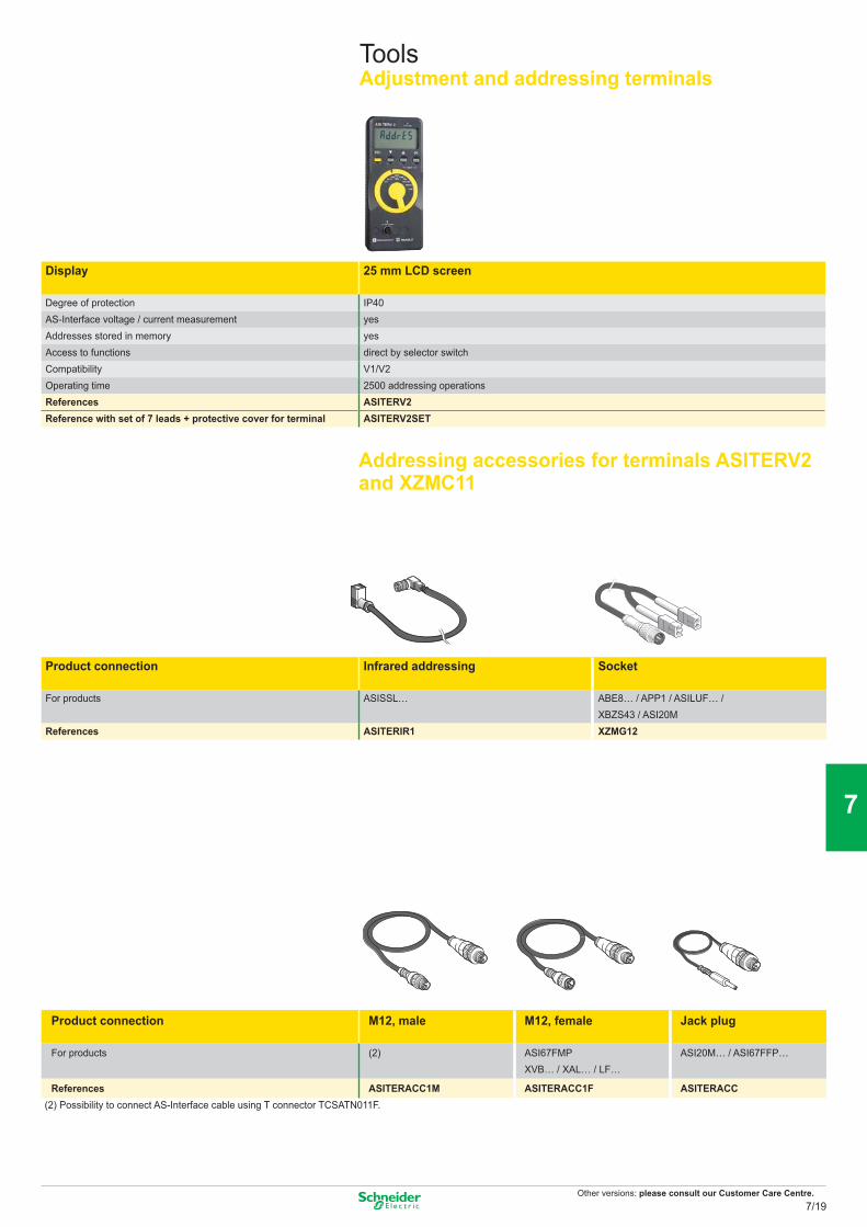
Other versions: please consult our Customer Care Centre.
ToolsAdjustment and addressing terminals
Display 25 mm LCD screen
Degree of protection IP40AS-Interface voltage / current measurement yesAddresses stored in memory yesAccess to functions direct by selector switchCompatibility V1/V2Operating time 2500 addressing operationsReferences ASITERV2Reference with set of 7 leads + protective cover for terminal ASITERV2SET
Addressing accessories for terminals ASITERV2 and XZMC11
Product connection Infrared addressing Socket
For products ASISSL… ABE8… / APP1 / ASILUF… / XBZS43 / ASI20M
References ASITERIR1 XZMG12
Product connection M12, male M12, female Jack plug
For products (2) ASI67FMP XVB… / XAL… / LF…
ASI20M… / ASI67FFP…
References ASITERACC1M ASITERACC1F ASITERACC (2) Possibility to connect AS-Interface cable using T connector TCSATN011F.
7/19
2
1
3
4
5
6
7
8
9
10
Other versions: please consult our Customer Care Centre.
Type OPC data server OFS Small OFS Large
Items number 1000 items UnlimitedOPC protocols OPC DA OPC DA, OPC XML DA, References Single station li cence TLX CD SU OFS 33 TLX CD LU OFS
10 stations licence TLX CD ST OFS 33 TLX CD LT OFS 33200 stations licence – TLX CD LF OFS 33
Description:Based on the OPC protocols, Schneider-Electric’s OFS software (OPC Factory Server) enables local or remote OPC client applications such as SCADA, supervisors or custom interfaces, to access Schneider devices and PLCs data in real time.
OFS software is a multi-device data server which provides simultaneous use of various communication protocols, and allows client applications to access control data via physical addresses or via symbols
Supported devices :p Modicon Quantum, Premium, Micro, Compact and Momentum PLCsp TSX Series 7 and April Series 1000 Schneider-Electric PLCsp Serial Modbus or Uni-Telway devices connected via Schneider-Electric and Merlin Gerin gateways TSX ETG 10xx, EGX xxx ranges etc.
Supported networks and protocols :p Modbus: Serial Modbus, Modbus Plus, Modbus TCP/IP.p XWAY/UNI-TE: Uni-Telway, FIPWAY, ETHWAY, ISAWAY, PCIWAY.
Openess: OFS V3.3, integrates the most recent specifications of the OPC Foundation:p OPC-DA (OPC Data Access)p .NET API interfacep OPC XML-DA V1.0 (OPC XML Data Access)
The development of specialized interfaces is even more easy and open. Developers and System integrators can develop custom applications (in Visual Basic, VBA for Excel, C++, etc) requiring access to Schneider Electric control devices. The OPC XML-DA V1.0 interface is designed to provide an interface for Windows and non-Windows client applications and remote access via the Internet through firewalls.
OPC data server softwareOFS
Remote client application program
DCOM ou HTTP OFS station
Local client application program
Ethernet TCP/IP network
Data symbol (Concept, PL 7 or Unity pro
X-Way networkModbus network
Quantum
Momentum Premium TSX Micro
7/20
2
1
3
4
5
6
7
8
9
10
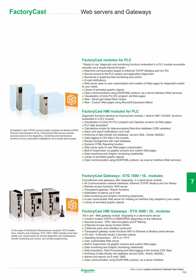
Other versions: please consult our Customer Care Centre.
Web servers and GatewaysFactoryCast
FactoryCast modules for PLC“ Ready to use” diagnostic and monitoring functions embedded in a PLC module accessible remotely via a simple Internet browser:b Real-time communication based on Ethernet TCP/IP (Modbus and Uni-TE)b Secure access to the PLC system and application diagnosticsb Numerical or graphical data monitoring and controlb E-mail notificationsb Web server open to user customization and creation of Web pages for diagnostics suited to your needsb Library of animated graphic objectsb Open communications using SOAP/XML protocol as a server interface (Web services)b Visualization of Unity Pro IEC program via Web pagesb New - SilverLight based Rack Viewer b New - Custom Web pages using Microsoft Expression Blend
FactoryCast HMI modules for PLCDiagnostic functions Identical as FactoryCast modules + Built-in HMI / SCADA functions embedded in a PLC module:b Visualization of Unity Pro PLC program and Operator screens via Web pages b PLC data acquisition b Calculations scripts for data-processing Real-time database (1000 variables)b Alarm and report notifications via E-mailb Archiving of data directly into database servers (SQL, Oracle, MySQL)b Data logging in CSV files in the module. b Recipe management with read Database b Dynamic HTML Reporting function b Web server open to user Web pages customizationb Built-in Supervision via graphic screens and custom Web pages b Data monitoring and Graphic monitoring (read/write)b Library of animated graphic objectsb Open communication using SOAP/XML protocol as a server interface (Web services)
Embedded in the TCP/IP communication modules for Modicon M340, Premium and Quantum PLCs, FactoryCast Web servers provide secured access to the diagnotics, monitoring and maintenance functions of your automation installations via a simple web browser.
FactoryCast Gateways - ETG 1000 / 10.. modulesCost-effective web gateways offer integrating in a stand-alone module:b All Communications network interfaces: Ethernet TCP/IP, Modbus and Uni-Telwayb Remote access functions, RAS server, b Transparent gateway / Router functionsb Notification of alarms via E-mailb Data monitoring and Graphic monitoring (read/write)b A user customizable Web server for creating an interface fully adapted to your needsb Library of animated graphic objects
FactoryCast HMI Gateways - ETG 3000 / 30.. modules“All in one” Web gateway module integrating in a stand-alone device:b a built-in modem (PSTN or GSM/GPRS) depending on the referenceb Secured access : VPN, data encryption and IP filtering.b A Remote Access server function (RAS)b 2 Ethernet ports and a Modbus serial portb Transparent gateway router functions NAT to Ethernet or Modbus serial devicesb I/O card : 6 discrete inputs/ 2 discrete outputs b Operating temperature : -25°C to +75°Cb User customizable Web server b Built-in Supervision via graphic screens and custom Web pages b Data monitoring and Graphic monitoring (read/write)b Data Acquisition, Data Processing and Data logging in the module (CSV files) b Archiving of data directly into database servers (SQL, Oracle, MySQL)b Alarms and reports via E-mail / SMS b Open communication using SOAP/XML protocol as a server interface
In the areas of distributed infrastructures, transport, RTU installa-tions, industry and machines, ETG 1000 / 3000 modules more than satisfy your requirements for remote diagnotics and maintenance, remote monitoring and control, and remote programming.
7/21
2
1
3
4
5
6
7
8
9
10
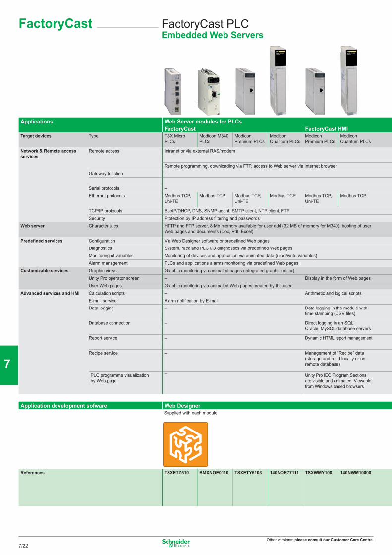
Other versions: please consult our Customer Care Centre.
FactoryCast PLCEmbedded Web Servers
FactoryCast
Applications Web Server modules for PLCsFactoryCast FactoryCast HMI
Target devices Type TSX Micro PLCs
Modicon M340 PLCs
Modicon Premium PLCs
Modicon Quantum PLCs
Modicon Premium PLCs
Modicon Quantum PLCs
Network & Remote access services
Remote access Intranet or via external RAS/modem
Remote programming, downloading via FTP, access to Web server via Internet browserGateway function –
Serial protocols –Ethernet protocols Modbus TCP,
Uni-TEModbus TCP Modbus TCP,
Uni-TEModbus TCP Modbus TCP,
Uni-TEModbus TCP
TCP/IP protocols BootP/DHCP, DNS, SNMP agent, SMTP client, NTP client, FTPSecurity Protection by IP address filtering and passwords
Web server Characteristics HTTP and FTP server, 8 Mb memory available for user add (32 MB of memory for M340), hosting of user Web pages and documents (Doc, Pdf, Excel)
Predefined services Configuration Via Web Designer software or predefined Web pagesDiagnostics System, rack and PLC I/O diagnostics via predefined Web pagesMonitoring of variables Monitoring of devices and application via animated data (read/write variables)Alarm management PLCs and applications alarms monitoring via predefined Web pages
Customizable services Graphic views Graphic monitoring via animated pages (integrated graphic editor)Unity Pro operator screen – Display in the form of Web pagesUser Web pages Graphic monitoring via animated Web pages created by the user
Advanced services and HMI Calculation scripts – Arithmetic and logical scriptsE-mail service Alarm notification by E-mailData logging – Data logging in the module with
time stamping (CSV files)
Database connection – Direct logging in an SQL, Oracle, MySQL database servers
Report service – Dynamic HTML report management
Recipe service – Management of “Recipe” data (storage and read locally or on remote database)
PLC programme visualization by Web page
– Unity Pro IEC Program Sections are visible and animated. Viewable from Windows based browsers
Application development sofware Web DesignerSupplied with each module
References TSXETZ510 BMXNOE0110 TSXETY5103 140NOE77111 TSXWMY100 140NWM10000
7/22
2
1
3
4
5
6
7
8
9
10
Other versions: please consult our Customer Care Centre.
FactoryCast GatewayWeb Gateways for Remote control
Standalone Gateway, Web Server for Remote Access FactoryCast Gateway ETG 10p0 FactoryCast HMI Gateway ETG30pp All equipment supporting Modbus
All equipment supporting Uni-Telway
All Modicon PLCs and third-party equipment supporting Modbus
Intranet or via external Modem, integrated RAS function Intranet or Modem External modem, integrated RAS
Intranet or ModemIntegrated PSTN/RTC/GSM modem and RAS modem, NAT
Remote programming, downloading via FTP, access to Web server via Internet browserEthernet to Modbus serialModem to Modbus serial and Ethernet
Ethernet to Uni-Telway serialModem to Uni-Telway and Ethernet
Ethernet to Modbus serialModem to Modbus serial and Ethernet (Modbus, UNITE)
Modbus (Master) Uni-Telway (Slave) Modbus (Master) Modbus TCP Modbus TCP, Uni-TE (Modicon
Premium, Modicon TSX Micro)Modbus TCP Uni-TE TCP
BootP/DHCP, SNMP agent, SMTP client, NTP client, FTP DHCP, DNS, SNMP agent, SMTP client, NTP client, FTPProtection by IP address fi ltering and password Protection by IP address filtering and password + Tunnels VPN & encryption of the datas.HTTP and FTP server, 8 Mb memory available for user, hosting of user Web pages and documents (Doc, Pdf, Excel)
HTTP and FTP server, 32 Mb memory available for user Web pages, memory extension using Compact Flash cards 1 Gb max., hosting of user Web pages and documents (Doc, Pdf, Excel)
Via Web Designer software or predefined Web pages Diagnostics of serial devices via predefined Web pages Network diagnostics, diagnostics of serial devices and Ethernet via predefined Web pagesMonitoring of devices and application via data tables (read/write variables)
Via E-mail Via E-mail/SMSGraphic monitoring via animated views (integrated graphic editor)– Graphic monitoring via animated Web pages created by the user– Arithmetic and logical scriptsAlarm notification by E-mail Alarm notification by E-mail/SMS– Data logging in the module with time stamping (CSV files)
– Direct recording in SQL, Oracle, MySQL database servers
– Dynamic HTML report management
– Management of “Recipe” data (storage and revad locally or on remote database)
– –
Web DesignerSupplied with each module
TSXETG1000 TSXETG1010 TSXETG3000 TSXETG3010 (Modem RTC) TSXETG3021 Modem GSM/GPRS(Bands 900/1800MHz)TSXETG3022 Modem GSM/GPRS(Bands 850/1900 MHz)
7/23
2
1
3
4
5
6
7
8
9
10

Yourmachine
Riskassesment
analysis
Implemen-tation &
Certifi cation
Conception& Design
Maintennance /
Inspection& Audit
In addition to moral obligation and economic consequences, the law requires that machinery is safe in the interests of accident prevention. Preventa offers an extensive range of safety products, compliant with international standards, designed to provide the most comprehensive protection for personnel and equipment.
Preventa, the safety attitude around your machine life cycle
PreventaThe Preventa range enhances safety throughout a machine’s entire life cycle from design, manufacture, installation, adjustment, operation and servicing right through to decommissioning.
> New machines - the Machinery DirectiveThe Machinery Directive 98/37/EC is to compel manufacturers to guarantee a minimum safety level for machinery and equip-ment sold within the European Union.
From 29 December 2009, the new European Machinery Directive 2006/42/EC is effective. Machines have to comply with the Essential Health and Safety Requirements (EHSRs) listed in Annex I of the Directive, thus setting a common minimum level of protection across the EEA (European Economic Area).
Machine manufacturers, or their authorised representatives within the EU, must ensure that the machine is compliant, the Technical File can be made available to the enforcing authorities on request, the CE marking is affixed, and a Declaration of Conformity has been signed, before the machine may be placed on the market within the EU.
This document is a selection
of the top selling products.
For detection products please refer
to The Essential Guide of Detection
Machine safety
8/1
2
1
3
4
5
6
7
8
9
10
Safety standards ................................................................................................................................... 8/2 to 8/7
Automation ............................................................................................................................................. 8/8 to 8/12
Safety PLCs Safety controllers and modules
AS-Interface Safety at work ...................................................................................................... 8/13 to 8/14
Safety monitors and interfaces
Operator dialogue ........................................................................................................................... 8/15 to 8/18
Emergency stops Foot switches Control units
Motor control .................................................................................................................................. 8/19 to 8/21
Switch disconnectors Motor starters

Why safety?
Human life is the most importantvalue in a company!
Schneider Electric protect people and improve your productivity.

Functional safety
«Helping you to reach easily your safety machinery and standard level required»
Thanks to directives and standards as guidelines.
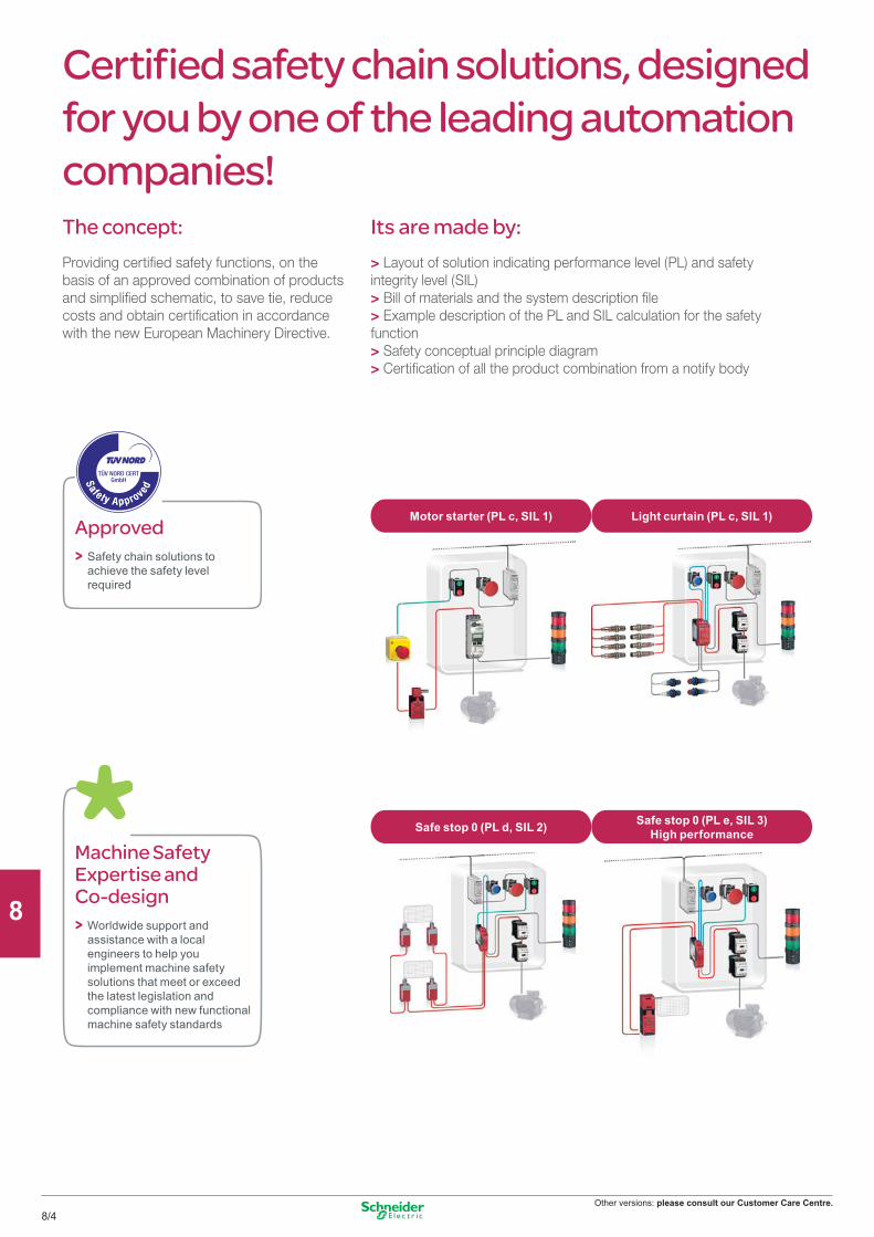
Other versions: please consult our Customer Care Centre.
Its are made by:> Layout of solution indicating performance level (PL) and safety integrity level (SIL)> Bill of materials and the system description file> Example description of the PL and SIL calculation for the safety function> Safety conceptual principle diagram> Certification of all the product combination from a notify body
Certified safety chain solutions, designed for you by one of the leading automation companies!The concept:Providing certified safety functions, on the basis of an approved combination of products and simplified schematic, to save tie, reduce costs and obtain certification in accordance with the new European Machinery Directive.
Motor starter (PL c, SIL 1) Light curtain (PL c, SIL 1)
Safe stop 0 (PL d, SIL 2) Safe stop 0 (PL e, SIL 3) High performance
ApprovedSafety chain solutions to achieve the safety level required
>
Machine Safety Expertise and Co-design
Worldwide support and assistance with a local engineers to help you implement machine safety solutions that meet or exceed the latest legislation and compliance with new functional machine safety standards
>
8/4
2
1
3
4
5
6
7
8
9
10
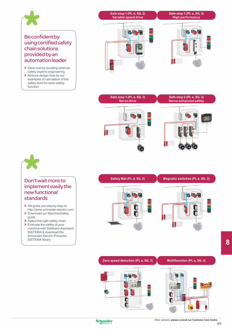
Other versions: please consult our Customer Care Centre.
Don’t wait more to implement easily the new functional standards
We guide you step by step on http://www.schneider-electric.comDownload our MachineSafety guideSelect the right safety chainEvaluate the safety of your machine with Software-Assistant SISTEMA & download the Schneider Electric Preventa SISTEMA library
>>>>
Safe stop 1 (PL d, SIL 2) Variable speed drive
Safe stop 1 (PL e, SIL 3) High performance
Safe stop 1 (PL e, SIL 3) Servo drive
Safe stop 2 (PL e, SIL 3) Servo-enhanced safety
Safety Mat (PL d, SIL 2) Magnetic switches (PL e, SIL 3)
Zero speed detection (PL e, SIL 3) Multifunction (PL e, SIL 3)
Be confident by using certified safety chain solutions provided by an automation leader
Save cost by avoiding external safety experts engineeringReduce design time by our examples of calculation of the safety level for each safety function
>>
8/5
2
1
3
4
5
6
7
8
9
10
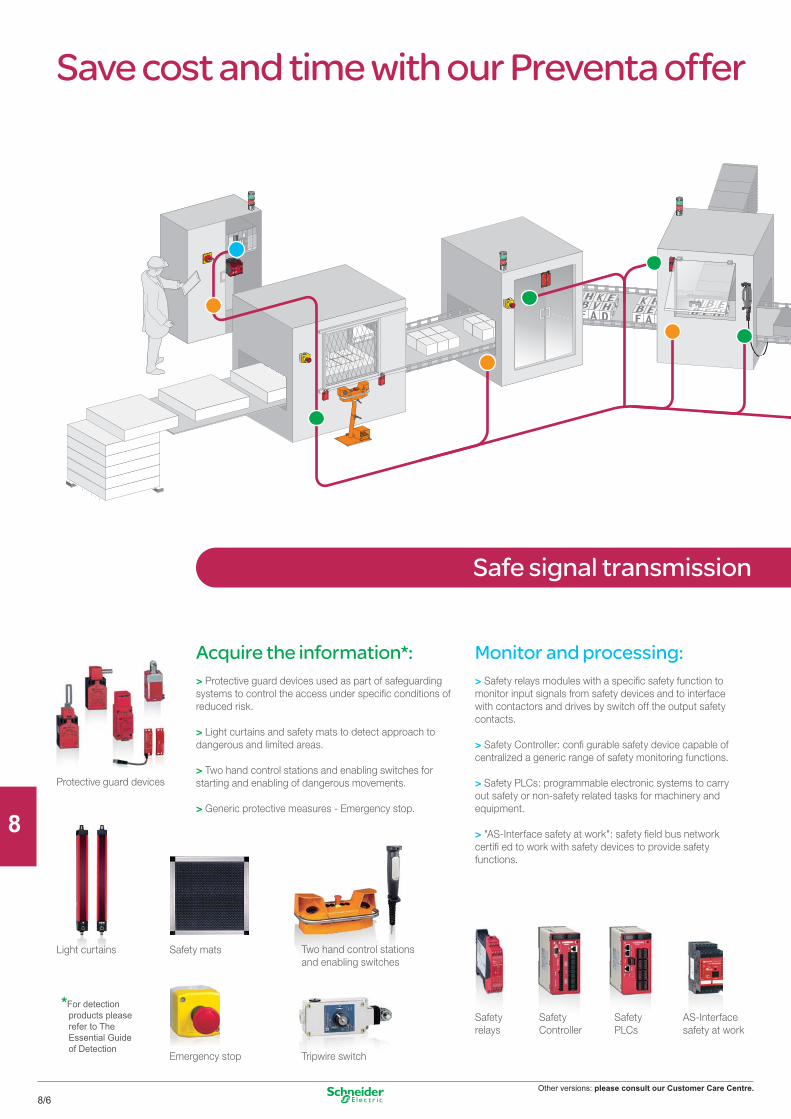
Other versions: please consult our Customer Care Centre.
Safe signal transmission
Save cost and time with our Preventa offer
Safetyrelays
SafetyController
SafetyPLCs
AS-Interface safety at work
Safety mats Two hand control stationsand enabling switches
Emergency stop Tripwire switch
Light curtains
Acquire the information*:> Protective guard devices used as part of safeguarding systems to control the access under specific conditions of reduced risk.
> Light curtains and safety mats to detect approach to dangerous and limited areas.
> Two hand control stations and enabling switches for starting and enabling of dangerous movements.
> Generic protective measures - Emergency stop.
Monitor and processing:> Safety relays modules with a specific safety function to monitor input signals from safety devices and to interface with contactors and drives by switch off the output safety contacts.
> Safety Controller: confi gurable safety device capable of centralized a generic range of safety monitoring functions.
> Safety PLCs: programmable electronic systems to carry out safety or non-safety related tasks for machinery and equipment.
> "AS-Interface safety at work": safety field bus network certifi ed to work with safety devices to provide safety functions.
Protective guard devices
*For detection products please refer to The Essential Guide of Detection
8/6
2
1
3
4
5
6
7
8
9
10
Other versions: please consult our Customer Care Centre.
Up to 50%of spaceoptimizationIncrease the compactness by reducing size.
Save upto 30%on installationtimeReduce installation time by easy and quick wiring.
Stop the machine:> Contactors to cut-off the electrical power supply to the motors with mechanically linked mirror auxiliary contacts integrated for the feedback loop diagnosis of safety modules.
> Variable speed drives and servo drives controlled stopping of the dangerous movement by safety functions integrated.
> Rotary switch disconnectors: for equipment isolation from the electrical supply andfor emergency stop by direct interruption of the power supply.
VariableSpeed Drives
Rotary switchdisconnectors
Contactors
1 Complete& upgradedsafety offer:Improve safety levelrequired
Servodrives
8/7
2
1
3
4
5
6
7
8
9
10
Other versions: please consult our Customer Care Centre.
Safety PLC type Compact
Number of inputs/outputs Digital (configurable with XPSMFWIN software) 24Pulsed (1) 2x4
Memory capacity Application 250 Kb Data 250 Kb
Supply External 24 VDC supply (with separate protection conforming to IEC 61131-2)Communication On Ethernet network with safe Ethernet protocol Integrated (2xRJ45) Integrated (2xRJ45) Integrated (2xRJ45) Integrated (2xRJ45) Integrated (2xRJ45) Integrated (2xRJ45)
On Modbus TCP/IP – Integrated (2xRJ45) – Integrated (2xRJ45) – Integrated (2xRJ45)On Modbus (Serial link) – – Integrated (1xRJ45) Integrated (1xRJ45) – –On Profibus DP – – – – Integrated (SUB-D9) Integrated (SUB-D9)
Input/output connections Removable screw terminal blocks or removable cage clamp terminal blocks coded with locating deviceReferences XPSMF4000 XPSMF4002 XPSMF4020 XPSMF4022 XPSMF4040 XPSMF4042
(1) They outputs are not safety outputs.
Compact
Safety PLC type Compact
Number of inputs Digital 20 20 24 24 24Analogue – – 8 8 8Counting – – 2 2 2
Number of outputs Digital 8 8 8 8 8Analogue – – – – –Relay – – – – –
Memory capacity Application 250 Kb Data 250 Kb
Supply External 24 VDC supply (with separate protection conforming to IEC 61131-2)Communication On Ethernet network (Modbus TCP/IP) Integrated (4xRJ45) Integrated (4xRJ45) Integrated (4xRJ45) Integrated (4xRJ45) Integrated (4xRJ45)
On Modbus (Serial link) Integrated (SUB-D9) – – Integrated (SUB-D9) –On Profibus DP – – – – Integrated (SUB-D9)
Input/output connections Removable screw terminal blocks, coded with locating deviceReferences (2) XPSMF3022 XPSMF31222 XPSMF3502 XPSMF3522 XPSMF3542
(2) Products referenced XPSMF30/MF31/MF35 are marked Himatrix F30, F31 and F35.
Safety PLCsCompact
PreventaAutomation
For all XPSMF PLCs p Maximum category of the solution ..................................Category 4
(EN 954-1)p Max performance level for the solution ..........................PL e
(EN ISO 13849-1)p Max safety integrity level for the solution ........................SIL 3
(EN IEC 62061)
8/8
2
1
3
4
5
6
7
8
9
10
Other versions: please consult our Customer Care Centre.
Type CPU Power supply module
Rack with 6 slots
Software
Memory capacity Application 500 Kb – – For XPSMF PLCsData 500 Kb – –
Supply – External 24 VDC, integrated –Communication On Ethernet network (Modbus TCP/IP) Integrated (4xRJ45) – – Complete version
On Modbus bus (Serial link) Integrated (SUB-D9) – – SSV1XPSMFWINPower connections Screw terminal blocks Screw terminal blocks – (1)Dimensions W x D x H – – 257 x 239 x 310 mm Update versionReferences XPSMFCPU22 XPSMFPS01 XPSMFGEH01 SSVXPSMFWINUP
I/O module type For modular safety PLCAnalogue Digital Relay
Number of inputs Digital – – – 24 32 24 –Analogue 8 – – – – – –Counting – – 2 – – – –
Number of outputs Digital – – 4 – – 16 –Analogue – 8 – – – – –Relay – – – – – – 8
Supply Removable screw terminal blocks, coded with locating deviceReferences XPSMFAI801 XPSMFAO801 XPSMFCIO2401 XPSMFDI2401 XPSMFDI3201 XPSMFDIO241601 XPSMFDO801
Decentralised safety I/O modules
Module type Inputs/OuputsDigital
Number of inputs Digital 16 8+2 16 20Number of outputs Digital – 8 8 8
Pulsed 4 2 2 –Supply External 24 VDC supply (with separate protection conforming to IEC 61131-2)Communication On Safe Ethernet network (Modbus TCP/IP) Integrated (2xRJ45)Input/output connections Removable screw terminal blocks, coded with locating deviceReferences (2) XPSMF1DI1601 XPSMF3DIO8801 XPSMF3DIO16801 XPSMF3DIO20802
I/O module type Inputs/OutputsAnalogue
OutputsDigital Relay
Number of inputs Analogue 8 – – – –Number of outputs Digital – 4 16 – –
Analogue (not safety) 4 – – – –Relay – – – 8 16
Supply External 24 VDC supply (with separate protection conforming to IEC 61131-2)Communication On Safe Ethernet network (Modbus TCP/IP) Integrated (2xRJ45)Input/output connections Removable screw terminal blocks, coded with locating deviceReferences (2) XPSMF3AIO8401 XPSMF2DO401 XPSMF2DO1601 XPSMF2DO801 XPSMF2DO1602
(1) To be ordered only if the previous version of have been already installed.(2) Products referenced XPSMF1/MF2/MF3 are marked Himatrix F1, F2 and F3.
For all XPSMF PLCs p Maximum category of the solution ..................................Category 4
(EN 954-1)p Max performance level for the solution ..........................PL e
(EN ISO 13849-1)p Max safety integrity level for the solution ........................SIL 3
(EN IEC 62061)
8/9
2
1
3
4
5
6
7
8
9
10
Other versions: please consult our Customer Care Centre.
Universal
Universal
Universal
PreventaAutomation
Safety controllers for monitoringemergency stops and limit switches
Maximum safety level of the solution attained (EN ISO 13849-1, EN/IEC 62061)
PL e / Cat. 4, SILCL 3
Number of circuits Safety 2 x 2N/O + 6 solid-state 2 x 3N/O per functionAdditional – 3 solid-state
Display (number of LEDs) 30 12Width of housing 74 mm 45 mmCommunication interface Modbus Modbus, CANopen Modbus, Profibus DP –
Universal solutions: safety controllers (for monitoring several safety functions simultaneously)Supply voltage 24 VDC XPSMC32Z (1) (2) XPSMC32ZC (1) (2) XPSMC32ZP (1) (2) XPSMP11123P (3)
coded magnetic switchesenabling switch
Maximum safety level of the solution attained (EN ISO 13849-1, EN/IEC 62061)
PL e / Cat. 4, SILCL 3
For monitoring magnetic switches and enabling switchNumber of circuits Safety 2 x 2N/O + 6 solid-state 2 x 3N/O per function
Additional – 3 solid-stateDisplay (number of LEDs) 30 12Width of housing 74 mm 45 mmCommunication interface Modbus Modbus, CANopen Modbus, Profibus DP –
Universal solutions: safety controllers (for monitoring several safety functions simultaneously)Supply voltage 24 VDC XPSMC32Z (1)(2) XPSMC32ZC (1)(2) XPSMC32ZP (1)(2) XPSMP11123P (3)
safety mats and edging
Maximum safety level of the solution attained (EN ISO 13849-1, EN/IEC 62061)
PL d / Cat. 3, SILCL 2
Number of circuits Safety 2 x 2N/O + 6 solid-state 2 x 3N/O per functionAdditional – 3 solid-state
Display (number of LEDs) 30 12Width of housing 74 mm 45 mmCommunication interface Modbus Modbus, CANopen Modbus, Profibus DP –
Universal solutions: safety controllers (for monitoring several safety functions simultaneously)Supply voltage 24 VDC XPSMC32Z (1)(2) XPSMC32ZC (1)(2) XPSMC32ZP (1)(2) XPSMP11123P (3)
(1) Version with 32 inputs. For version with 16 inputs, replace 32 in the reference by 16 (example: XPSMC32Z becomes XPSMC16Z).(2) Configuration software XPSMCWIN (complete version) or SSVXPSMCWINUP (update version), connecting cable, adaptor and set of screw terminal plug-in connectors XPSMCTS16 and XPSMCTS32 or set of spring clip terminal plug-in connectors XPSMCTC16 and XPSMCTC32 to be ordered separately.(3) For fixed connector version, delete the letter P from the end of the reference (example: XPSMP11123P becomes XPSMP11123).
8/10
2
1
3
4
5
6
7
8
9
10
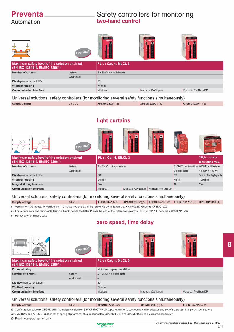
Other versions: please consult our Customer Care Centre.
0,0
0,2
0,4
0,6
0,8
1,0
0,0
0,2
0,4
0,6
0,8
1,0
Universal
Universal
Universal
PreventaAutomation
Safety controllers for monitoringtwo-hand control
Maximum safety level of the solution attained (EN ISO 13849-1, EN/IEC 62061)
PL e / Cat. 4, SILCL 3
Number of circuits Safety 2 x 2N/O + 6 solid-stateAdditional –
Display (number of LEDs) 30Width of housing 74 mmCommunication interface Modbus Modbus, CANopen Modbus, Profibus DP
Universal solutions: safety controllers (for monitoring several safety functions simultaneously)Supply voltage 24 VDC XPSMC32Z (1)(2) XPSMC32ZC (1)(2) XPSMC32ZP (1)(2)
light curtains
Maximum safety level of the solution attained (EN ISO 13849-1, EN/IEC 62061)
PL e / Cat. 4, SILCL 3 2 light curtainsmonitoring max.
Number of circuits Safety 2 x 2N/O + 6 solid-state 2x3N/O per function 6 PNP solid-stateAdditional – 3 solid-state 1 PNP + 1 NPN
Display (number of LEDs) 30 12 14 + double display unitsWidth of housing 74 mm 45 mm 100 mmIntegral Muting function Yes No YesCommunication interface Modbus Modbus, CANopen Modbus, Profibus DP – –
Universal solutions: safety controllers (for monitoring several safety functions simultaneously)Supply voltage 24 VDC XPSMC32Z(1)(2) XPSMC32ZC(1)(2) XPSMC32ZP(1)(2) XPSMP11123P (3) XPSLCM1150 (4)
(1) Version with 32 inputs, for version with 16 inputs, replace 32 in the reference by 16 (example: XPSMC32Z becomes XPSMC16Z).(3) For version with non removable terminal block, delete the letter P from the end of the reference (example: XPSMP11123P becomes XPSMP11123).(4) Removable terminal blocks
zero speed, time delay
Maximum safety level of the solution attained (EN ISO 13849-1, EN/IEC 62061)
PL e / Cat. 4, SILCL 3
For monitoring Motor zero speed conditionNumber of circuits Safety 2 x 2N/O + 6 solid-state
Additional –Display (number of LEDs) 30Width of housing 74 mmCommunication interface Modbus Modbus, CANopen Modbus, Profibus DP
Universal solutions: safety controllers (for monitoring several safety functions simultaneously)Supply voltage 24 VDC XPSMC32Z (5) (2) XPSMC32ZC (5) (2) XPSMC32ZP (5) (2)
(2) Configuration software XPSMCWIN (complete version) or SSVXPSMCWINUP (update version), connecting cable, adaptor and set of screw terminal plug-in connectors XPSMCTS16 and XPSMCTS32 or set of spring clip terminal plug-in connectors XPSMCTC16 and XPSMCTC32 to be ordered separately.(5) Plug-in connector version only.
8/11
2
1
3
4
5
6
7
8
9
10
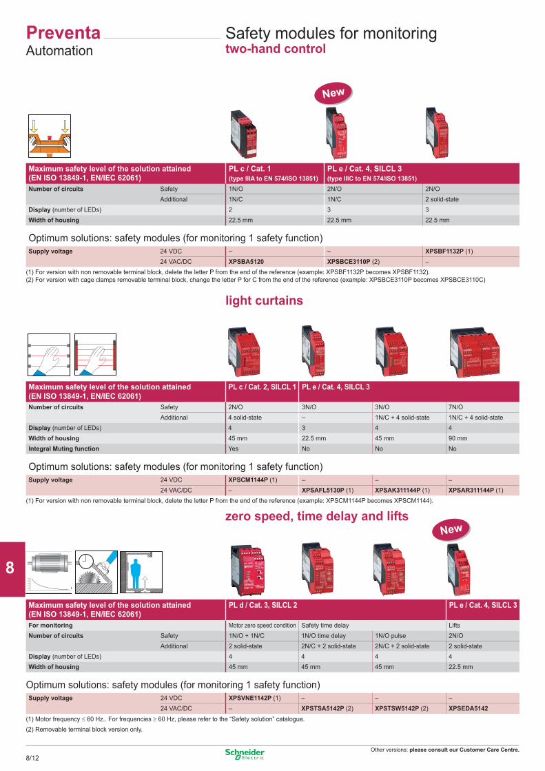
Other versions: please consult our Customer Care Centre.
0,0
0,2
0,4
0,6
0,8
1,0
Safety modules for monitoringtwo-hand control
Maximum safety level of the solution attained (EN ISO 13849-1, EN/IEC 62061)
PL c / Cat. 1 PL e / Cat. 4, SILCL 3(type IIIA to EN 574/ISO 13851) (type IIIC to EN 574/ISO 13851)
Number of circuits Safety 1N/O 2N/O 2N/OAdditional 1N/C 1N/C 2 solid-state
Display (number of LEDs) 2 3 3Width of housing 22.5 mm 22.5 mm 22.5 mm
Optimum solutions: safety modules (for monitoring 1 safety function)Supply voltage 24 VDC – – XPSBF1132P (1)
24 VAC/DC XPSBA5120 XPSBCE3110P (2) –(1) For version with non removable terminal block, delete the letter P from the end of the reference (example: XPSBF1132P becomes XPSBF1132).(2) For version with cage clamps removable terminal block, change the letter P for C from the end of the reference (example: XPSBCE3110P becomes XPSBCE3110C)
light curtains
Maximum safety level of the solution attained (EN ISO 13849-1, EN/IEC 62061)
PL c / Cat. 2, SILCL 1 PL e / Cat. 4, SILCL 3
Number of circuits Safety 2N/O 3N/O 3N/O 7N/OAdditional 4 solid-state – 1N/C + 4 solid-state 1N/C + 4 solid-state
Display (number of LEDs) 4 3 4 4Width of housing 45 mm 22.5 mm 45 mm 90 mmIntegral Muting function Yes No No No
Optimum solutions: safety modules (for monitoring 1 safety function)Supply voltage 24 VDC XPSCM1144P (1) – – –
24 VAC/DC – XPSAFL5130P (1) XPSAK311144P (1) XPSAR311144P (1)(1) For version with non removable terminal block, delete the letter P from the end of the reference (example: XPSCM1144P becomes XPSCM1144).
zero speed, time delay and lifts
Maximum safety level of the solution attained (EN ISO 13849-1, EN/IEC 62061)
PL d / Cat. 3, SILCL 2 PL e / Cat. 4, SILCL 3
For monitoring Motor zero speed condition Safety time delay LiftsNumber of circuits Safety 1N/O + 1N/C 1N/O time delay 1N/O pulse 2N/O
Additional 2 solid-state 2N/C + 2 solid-state 2N/C + 2 solid-state 2 solid-stateDisplay (number of LEDs) 4 4 4 4Width of housing 45 mm 45 mm 45 mm 22.5 mm
Optimum solutions: safety modules (for monitoring 1 safety function)Supply voltage 24 VDC XPSVNE1142P (1) – – –
24 VAC/DC – XPSTSA5142P (2) XPSTSW5142P (2) XPSEDA5142(1) Motor frequency ≤ 60 Hz.. For frequencies ≥ 60 Hz, please refer to the “Safety solution” catalogue.(2) Removable terminal block version only.
New
New
PreventaAutomation
8/12
2
1
3
4
5
6
7
8
9
10
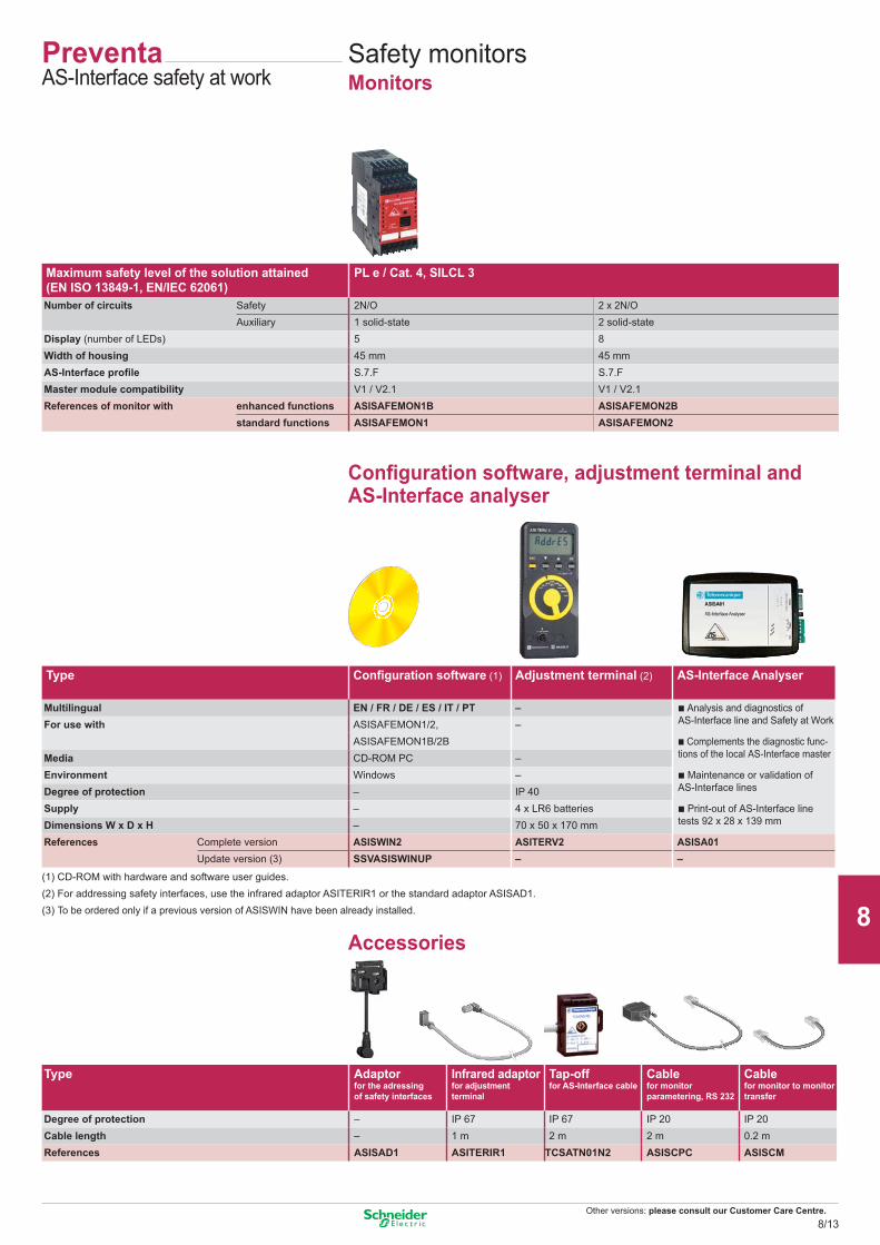
Other versions: please consult our Customer Care Centre.
PreventaAS-Interface safety at work
Safety monitorsMonitors
Configuration software, adjustment terminal and AS-Interface analyser
Maximum safety level of the solution attained (EN ISO 13849-1, EN/IEC 62061)
PL e / Cat. 4, SILCL 3
Number of circuits Safety 2N/O 2 x 2N/OAuxiliary 1 solid-state 2 solid-state
Display (number of LEDs) 5 8Width of housing 45 mm 45 mmAS-Interface profile S.7.F S.7.FMaster module compatibility V1 / V2.1 V1 / V2.1References of monitor with enhanced functions ASISAFEMON1B ASISAFEMON2B
standard functions ASISAFEMON1 ASISAFEMON2
(1) CD-ROM with hardware and software user guides.(2) For addressing safety interfaces, use the infrared adaptor ASITERIR1 or the standard adaptor ASISAD1.(3) To be ordered only if a previous version of ASISWIN have been already installed.
Accessories
Type
Adaptorfor the adressing of safety interfaces
Infrared adaptorfor adjustment terminal
Tap-offfor AS-Interface cable
Cablefor monitor parametering, RS 232
Cablefor monitor to monitor transfer
Degree of protection – IP 67 IP 67 IP 20 IP 20Cable length – 1 m 2 m 2 m 0.2 mReferences ASISAD1 ASITERIR1 TCSATN01N2 ASISCPC ASISCM
Type Configuration software (1) Adjustment terminal (2) AS-Interface Analyser
Multilingual EN / FR / DE / ES / IT / PT – b Analysis and diagnostics of AS-Interface line and Safety at WorkFor use with ASISAFEMON1/2, –
ASISAFEMON1B/2B b Complements the diagnostic func-tions of the local AS-Interface masterMedia CD-ROM PC –
Environment Windows – b Maintenance or validation of AS-Interface lines Degree of protection – IP 40
Supply – 4 x LR6 batteries b Print-out of AS-Interface line tests 92 x 28 x 139 mmDimensions W x D x H – 70 x 50 x 170 mm
References Complete version ASISWIN2 ASITERV2 ASISA01Update version (3) SSVASISWINUP – –
8/13
2
1
3
4
5
6
7
8
9
10
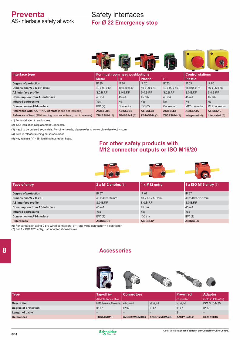
Other versions: please consult our Customer Care Centre.
Accessories
(6) For connection using 2 pre-wired connectors, or 1 pre-wired connector + 1 connector.(7) For 1 x ISO M20 entry, use adaptor shown below.
Type of entry 2 x M12 entries (6) 1 x M12 entry 1 x ISO M16 entry (7)
Degree of protection IP 67 IP 67 IP 67Dimensions W x D x H 40 x 40 x 58 mm 40 x 40 x 58 mm 40 x 40 x 57.5 mmAS-Interface profile S.0.B.F.F S.0.B.F.F S.0.B.F.FConsumption from AS-Interface 45 mA 45 mA 45 mAInfrared addressing Yes Yes YesConnection on AS-Interface IDC (1) IDC (1) IDC (1)References ASISSLC2 ASISSLC1 ASISSLLS
Safety interfacesFor Ø 22 Emergency stop
Interface type For mushroom head pushbuttons Control stationsMetal (1) Plastic (1) Plastic
Degree of protection IP 20 IP 20 IP 20 IP 20 IP 65 IP 65Dimensions W x D x H (mm) 40 x 90 x 68 40 x 80 x 40 40 x 90 x 64 40 x 90 x 40 66 x 95 x 78 66 x 95 x 78AS-Interface profile S.0.B.F.F S.0.B.F.F S.0.B.F.F S.0.B.F.F S.0.B.F.F S.0.B.F.FConsumption from AS-Interface 45 mA 45 mA 45 mA 45 mA 45 mA 45 mAInfrared addressing Yes No Yes No No NoConnection on AS-Interface IDC (2) Connector IDC (2) Connector M12 connector M12 connectorReference with N/C + N/C contact (head not included) ASISSLB4 ASISSLE4 ASISSLB5 ASISSLE5 ASISEA1C ASISEK1CReference of head (Ø40 latching mushroom head, turn to release) ZB4BS844 (3) ZB4BS844 (3) ZB4AS844 (3) ZB5AS844 (3) Integrated (4) Integrated (5)
(1) For installation in enclosures.(2) IDC: Insulation Displacement Connector.(3) Head to be ordered separately. For other heads, please refer to www.schneider-electric.com.(4) Turn to release latching mushroom head.(5) Key release (n° 455) latching mushroom head.
For other safety products with M12 connector outputs or ISO M16/20
Type Tap-off for AS-Interface cable
Connectors Pre-wired connector
Adaptor (sold in lots of 5)
Description M12 female, threaded elbowed straight straight ISO M16/M20Degree of protection IP 67 IP 67 IP 67 IP 67 IP 67Length of cable – – – 2 m –References TCSATN011F XZCC12MCM40B XZCC12MDM40B XZCP1541L2 DE9RI2016
PreventaAS-Interface safety at work
8/14
2
1
3
4
5
6
7
8
9
10
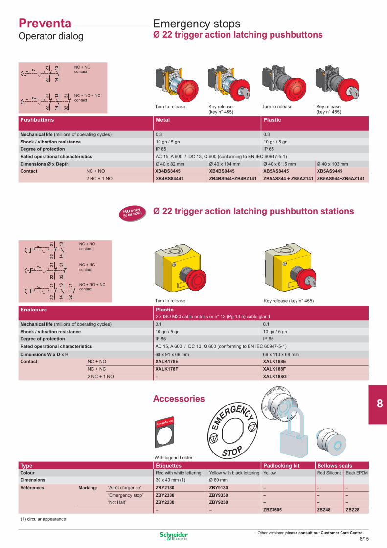
Other versions: please consult our Customer Care Centre.
131422
21
131422
21
3231
131422
21
131422
21
3231
131422
2122
21
3231
131422
21
3231
131422
2122
21
3231
131422
21
3231
ISO entry(to EN 50262)
Key release(key n° 455)
PreventaOperator dialog
Emergency stopsØ 22 trigger action latching pushbuttons
Turn to release Turn to releaseKey release(key n° 455)
NC + NO contact
NC + NO + NCcontact
Key release (key n° 455)Turn to release
Ø 22 trigger action latching pushbutton stations
NC + NO contact
NC + NC contact
NC + NO + NC contact
Pushbuttons Metal Plastic
Mechanical life (millions of operating cycles) 0.3 0.3Shock / vibration resistance 10 gn / 5 gn 10 gn / 5 gnDegree of protection IP 65 IP 65Rated operational characteristics AC 15, A 600 / DC 13, Q 600 (conforming to EN IEC 60947-5-1)Dimensions Ø x Depth Ø 40 x 82 mm Ø 40 x 104 mm Ø 40 x 81.5 mm Ø 40 x 103 mmContact NC + NO XB4BS8445 XB4BS9445 XB5AS8445 XB5AS9445
2 NC + 1 NO XB4BS84441 ZB4BS944+ZB4BZ141 ZB5AS844 + ZB5AZ141 ZB5AS944+ZB5AZ141
Enclosure Plastic2 x ISO M20 cable entries or n° 13 (Pg 13.5) cable gland
Mechanical life (millions of operating cycles) 0.1 0.1Shock / vibration resistance 10 gn / 5 gn 10 gn / 5 gnDegree of protection IP 65 IP 65Rated operational characteristics AC 15, A 600 / DC 13, Q 600 (conforming to EN IEC 60947-5-1)
Dimensions W x D x H 68 x 91 x 68 mm 68 x 113 x 68 mmContact NC + NO XALK178E XALK188E NC + NC XALK178F XALK188F
2 NC + 1 NO – XALK188G
Accessories
Type Étiquettes Padlocking kit Bellows sealsColour Red with white lettering Yellow with black lettering Yellow Red Silicone Black EPDMDimensions 30 x 40 mm (1) Ø 60 mm
Références Marking: “Arrêt d'urgence” ZBY2130 ZBY9130 – – –“Emergency stop” ZBY2330 ZBY9330 – – –“Not Halt” ZBY2230 ZBY9230 – – –
– – ZBZ3605 ZBZ48 ZBZ28
(1) circular appearance
With legend holder
8/15
2
1
3
4
5
6
7
8
9
10
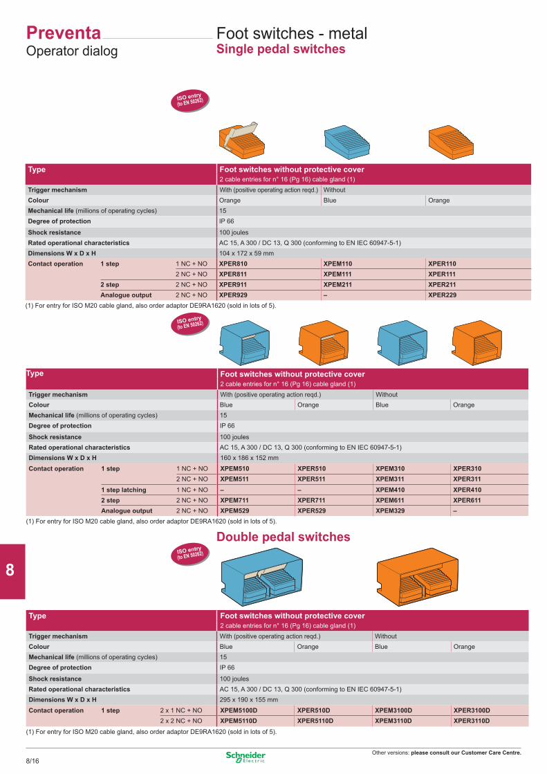
Other versions: please consult our Customer Care Centre.
ISO entry(to EN 50262)
ISO entry(to EN 50262)
ISO entry(to EN 50262)
Foot switches - metalSingle pedal switches
PreventaOperator dialog
Double pedal switches
Type Foot switches without protective cover2 cable entries for n° 16 (Pg 16) cable gland (1)
Trigger mechanism With (positive operating action reqd.) WithoutColour Orange Blue OrangeMechanical life (millions of operating cycles) 15Degree of protection IP 66
Shock resistance 100 joulesRated operational characteristics AC 15, A 300 / DC 13, Q 300 (conforming to EN IEC 60947-5-1)Dimensions W x D x H 104 x 172 x 59 mmContact operation 1 step 1 NC + NO XPER810 XPEM110 XPER110
2 NC + NO XPER811 XPEM111 XPER1112 step 2 NC + NO XPER911 XPEM211 XPER211Analogue output 2 NC + NO XPER929 – XPER229
(1) For entry for ISO M20 cable gland, also order adaptor DE9RA1620 (sold in lots of 5).
Type Foot switches without protective cover2 cable entries for n° 16 (Pg 16) cable gland (1)
Trigger mechanism With (positive operating action reqd.) WithoutColour Blue Orange Blue OrangeMechanical life (millions of operating cycles) 15Degree of protection IP 66
Shock resistance 100 joulesRated operational characteristics AC 15, A 300 / DC 13, Q 300 (conforming to EN IEC 60947-5-1)Dimensions W x D x H 160 x 186 x 152 mm
Contact operation 1 step 1 NC + NO XPEM510 XPER510 XPEM310 XPER3102 NC + NO XPEM511 XPER511 XPEM311 XPER311
1 step latching 1 NC + NO – – XPEM410 XPER4102 step 2 NC + NO XPEM711 XPER711 XPEM611 XPER611Analogue output 2 NC + NO XPEM529 XPER529 XPEM329 –
(1) For entry for ISO M20 cable gland, also order adaptor DE9RA1620 (sold in lots of 5).
Type Foot switches without protective cover2 cable entries for n° 16 (Pg 16) cable gland (1)
Trigger mechanism With (positive operating action reqd.) WithoutColour Blue Orange Blue OrangeMechanical life (millions of operating cycles) 15Degree of protection IP 66
Shock resistance 100 joulesRated operational characteristics AC 15, A 300 / DC 13, Q 300 (conforming to EN IEC 60947-5-1)Dimensions W x D x H 295 x 190 x 155 mm
Contact operation 1 step 2 x 1 NC + NO XPEM5100D XPER510D XPEM3100D XPER3100D2 x 2 NC + NO XPEM5110D XPER5110D XPEM3110D XPER3110D
(1) For entry for ISO M20 cable gland, also order adaptor DE9RA1620 (sold in lots of 5).
8/16
2
1
3
4
5
6
7
8
9
10
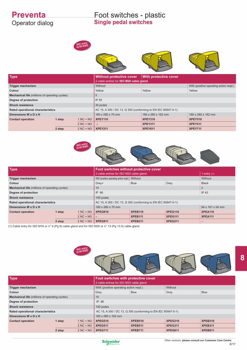
Other versions: please consult our Customer Care Centre.
ISO entry(to EN 50262)
ISO entry(to EN 50262)
ISO entry(to EN 50262)
Foot switches - plasticSingle pedal switches
Type Without protective cover With protective cover2 cable entries for ISO M20 cable gland
Trigger mechanism Without With (positive operating action reqd.)Colour Yellow Yellow YellowMechanical life (millions of operating cycles) 5Degree of protection IP 55
Shock resistance 30 joulesRated operational characteristics AC 15, A 300 / DC 13, Q 300 (conforming to EN IEC 60947-5-1)Dimensions W x D x H 160 x 280 x 70 mm 160 x 280 x 162 mm 160 x 280 x 162 mmContact operation 1 step 1 NC + NO XPEY110 XPEY310 XPEY510
2 NC + NO – XPEY311 XPEY5112 step 2 NC + NO XPEY211 XPEY611 XPEY711
Type Foot switches without protective cover2 cable entries for ISO M20 cable gland 1 entry (1)
Trigger mechanism With (positive operating action reqd.) Without WithoutColour Grey+ Blue Grey BlackMechanical life (millions of operating cycles) 10 2Degree of protection IP 66 IP 43
Shock resistance 100 joulesRated operational characteristics AC 15, A 300 / DC 13, Q 300 (conforming to EN IEC 60947-5-1)Dimensions W x D x H 160 x 280 x 70 mm 94 x 161 x 54 mmContact operation 1 step 1 NC + NO XPEG810 XPEB110 XPEG110 XPEA110
2 NC + NO – XPEB111 XPEG111 XPEA1112 step 2 NC + NO XPEG911 XPEB211 XPEG211 –
(1) Cable entry for ISO M16 or n° 9 (Pg 9) cable gland and for ISO M20 or n° 13 (Pg 13.5) cable gland.
Type Foot switches with protective cover2 cable entries for ISO M20 cable gland
Trigger mechanism With (positive operating action reqd.) WithoutColour Grey Blue Grey BlueMechanical life (millions of operating cycles) 10Degree of protection IP 66
Shock resistance 100 joulesRated operational characteristics AC 15, A 300 / DC 13, Q 300 (conforming to EN IEC 60947-5-1)Dimensions W x D x H 180 x 280 x 162 mmContact operation 1 step 1 NC + NO XPEG510 XPEB510 XPEG310 XPEB310
2 NC + NO XPEG511 XPEB511 XPEG311 XPEB3112 step 2 NC + NO XPEG711 XPEB711 XPEG611 XPEB611
PreventaOperator dialog
8/17
2
1
3
4
5
6
7
8
9
10
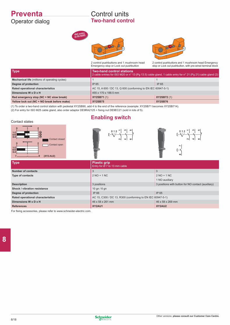
Other versions: please consult our Customer Care Centre.
ISO entry(to EN 50262)
0 1 2
1-25-63-4
0 1 2
7 8 (XY2-AU2)
1-25-63-4
0 1 2
1-25-63-4
0 1 2
7 8 (XY2-AU2)
1-25-63-4
20 12
1 34 6
520 12
1 34 6
5 20 12
1 34 6
5
78
20 12
1 34 6
5
78
PreventaOperator dialog
Control unitsTwo-hand control
Type Two-hand control stations 2 cable entries for ISO M20 or n° 13 (Pg 13.5) cable gland, 1 cable entry for n° 21 (Pg 21) cable gland (2)
Mechanical life (millions of operating cycles) 1 1Degree of protection IP 65 IP 65Rated operational characteristics AC 15, A 600 / DC 13, Q 600 (conforming to EN IEC 60947-5-1)Dimensions W x D x H 455 x 170 x 188.5 mmRed emergency stop (NC + NC slow break) XY2SB71 (1) XY2SB72 (1)Yellow lock out (NC + NO break before make) XY2SB75 XY2SB76
2 control pushbuttons and 1 mushroom headEmergency stop or Lock out pushbutton
(1) To order a two-hand control station with pedestal XY2SB90, add 4 to the end of the reference (example: XY2SB71 becomes XY2SB714).
2 control pushbuttons and 1 mushroom head Emergencystop or Lock out pushbutton, with pre-wired terminal block
Enabling switchContact states
(2) For entry for ISO M25 cable gland, also order adaptor DE9RA2125 + fixing nut DE9EC21 (sold in lots of 5).
For fixing accessories, please refer to www.schneider-electric.com.
Contact closed
Contact open
Type Plastic grip Entry for Ø 7 to 13 mm cable
Number of contacts 3 3Type of contacts 2 NO + 1 NC 2 NO + 1 NC
1 NO auxiliaryDescription 3 positions 3 positions with button for NO contact (auxiliary)Shock / vibration resistance 10 gn / 6 gnDegree of protection IP 66 IP 65Rated operational characteristics AC 15, C300 / DC 13, R300 (conforming to EN IEC 60947-5-1)Dimensions W x D x H 46 x 58 x 261 mm 46 x 58 x 269 mmReferences XY2AU1 XY2AU2
8/18
2
1
3
4
5
6
7
8
9
10
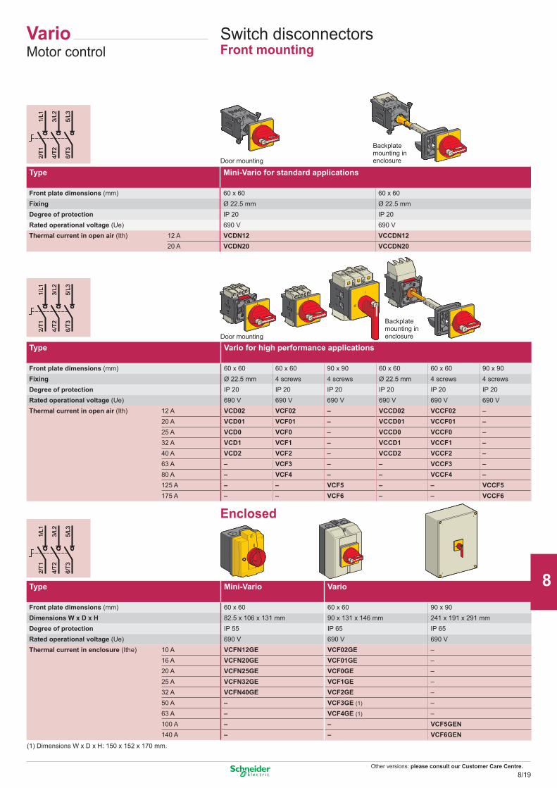
Other versions: please consult our Customer Care Centre.
1/L1
2/T1
3/L2
4/T2
5/L3
6/T3
1/L1
2/T1
3/L2
4/T2
5/L3
6/T3
1/L1
2/T1
3/L2
4/T2
5/L3
6/T3
1/L1
2/T1
3/L2
4/T2
5/L3
6/T3
1/L1
2/T1
3/L2
4/T2
5/L3
6/T3
1/L1
2/T1
3/L2
4/T2
5/L3
6/T3
VarioMotor control
Switch disconnectorsFront mounting
Door mounting
Door mounting
Backplate mounting in enclosure
(1) Dimensions W x D x H: 150 x 152 x 170 mm.
Enclosed
Backplate mounting in enclosure
Type Mini-Vario for standard applications
Front plate dimensions (mm) 60 x 60 60 x 60Fixing Ø 22.5 mm Ø 22.5 mmDegree of protection IP 20 IP 20Rated operational voltage (Ue) 690 V 690 VThermal current in open air (Ith) 12 A VCDN12 VCCDN12 20 A VCDN20 VCCDN20
Type Vario for high performance applications
Front plate dimensions (mm) 60 x 60 60 x 60 90 x 90 60 x 60 60 x 60 90 x 90Fixing Ø 22.5 mm 4 screws 4 screws Ø 22.5 mm 4 screws 4 screwsDegree of protection IP 20 IP 20 IP 20 IP 20 IP 20 IP 20Rated operational voltage (Ue) 690 V 690 V 690 V 690 V 690 V 690 VThermal current in open air (Ith) 12 A VCD02 VCF02 – VCCD02 VCCF02 – 20 A VCD01 VCF01 – VCCD01 VCCF01 –
25 A VCD0 VCF0 – VCCD0 VCCF0 –32 A VCD1 VCF1 – VCCD1 VCCF1 –40 A VCD2 VCF2 – VCCD2 VCCF2 –63 A – VCF3 – – VCCF3 –80 A – VCF4 – – VCCF4 –125 A – – VCF5 – – VCCF5175 A – – VCF6 – – VCCF6
Type Mini-Vario Vario
Front plate dimensions (mm) 60 x 60 60 x 60 90 x 90Dimensions W x D x H 82.5 x 106 x 131 mm 90 x 131 x 146 mm 241 x 191 x 291 mmDegree of protection IP 55 IP 65 IP 65Rated operational voltage (Ue) 690 V 690 V 690 VThermal current in enclosure (Ithe) 10 A VCFN12GE VCF02GE – 16 A VCFN20GE VCF01GE –
20 A VCFN25GE VCF0GE –25 A VCFN32GE VCF1GE –32 A VCFN40GE VCF2GE –50 A – VCF3GE (1) –63 A – VCF4GE (1) –100 A – – VCF5GEN140 A – – VCF6GEN
8/19
2
1
3
4
5
6
7
8
9
10
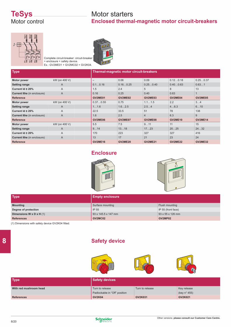
Other versions: please consult our Customer Care Centre.
T1 T2 T3
1/L1
3/L2
5/L3
T1 T2 T3
1/L1
3/L2
5/L3
Motor startersEnclosed thermal-magnetic motor circuit-breakers
Complete circuit-breaker: circuit-breaker + enclosure + safety device.Ex.: GV2ME01 + GV2MC02 + GV2K04.
(1) Dimensions with safety device GV2K04 fitted.
Enclosure
Safety device
TeSysMotor control
Type Thermal-magnetic motor circuit-breakers
Motor power kW (on 400 V) – 0.06 0.09 0.12…0.18 0.25…0.37Setting range A 0.1…0.16 0.16…0.25 0.25…0.40 0.40…0.63 0.63…1Current Id ± 20% A 1.5 2.4 5 8 13Current Ithe (in enclosure) A 0.16 0.25 0.40 0.63 1Reference GV2ME01 GV2ME02 GV2ME03 GV2ME04 GV2ME05Motor power kW (on 400 V) 0.37…0.55 0.75 1.1…1.5 2.2 3…4Setting range A 1…1.6 1.6…2.5 2.5…4 4…6.3 6…10Current Id ± 20% A 22.5 33.5 51 78 138Current Ithe (in enclosure) A 1.6 2.5 4 6.3 9Reference GV2ME06 GV2ME07 GV2ME08 GV2ME10 GV2ME14Motor power kW (on 400 V) 5.5 7.5 9…11 11 15Setting range A 9…14 13…18 17…23 20…25 24…32Current Id ± 20% A 170 223 327 327 416Current Ithe (in enclosure) A 13 17 21 23 24Reference GV2ME16 GV2ME20 GV2ME21 GV2ME22 GV2ME32
Type Empty enclosure
Mounting Surface mounting Flush mountingDegree of protection IP 55 IP 55 (front face)Dimensions W x D x H (1) 93 x 145.5 x 147 mm 93 x 55 x 126 mmReferences GV2MC02 GV2MP02
Type Safety devices
With red mushroom head Turn to release Turn to release Key releasePadlockable in “Off” position (key n° 455)
References GV2K04 GV2K031 GV2K021
8/20
2
1
3
4
5
6
7
8
9
10
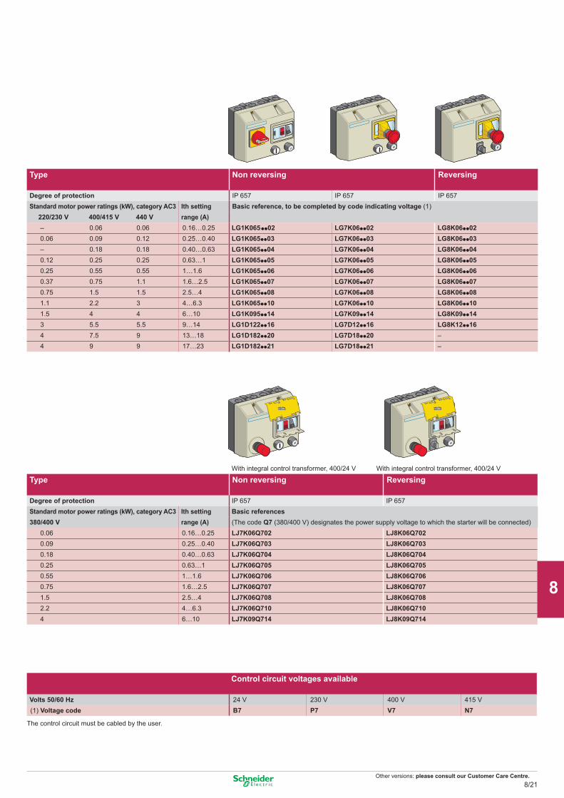
Other versions: please consult our Customer Care Centre.
With integral control transformer, 400/24 V With integral control transformer, 400/24 V
The control circuit must be cabled by the user.
Type Non reversing Reversing
Degree of protection IP 657 IP 657 IP 657Standard motor power ratings (kW), category AC3 Ith setting Basic reference, to be completed by code indicating voltage (1)
220/230 V 400/415 V 440 V range (A)– 0.06 0.06 0.16…0.25 LG1K065pp02 LG7K06pp02 LG8K06pp020.06 0.09 0.12 0.25…0.40 LG1K065pp03 LG7K06pp03 LG8K06pp03– 0.18 0.18 0.40…0.63 LG1K065pp04 LG7K06pp04 LG8K06pp040.12 0.25 0.25 0.63…1 LG1K065pp05 LG7K06pp05 LG8K06pp050.25 0.55 0.55 1…1.6 LG1K065pp06 LG7K06pp06 LG8K06pp060.37 0.75 1.1 1.6…2.5 LG1K065pp07 LG7K06pp07 LG8K06pp070.75 1.5 1.5 2.5…4 LG1K065pp08 LG7K06pp08 LG8K06pp081.1 2.2 3 4…6.3 LG1K065pp10 LG7K06pp10 LG8K06pp101.5 4 4 6…10 LG1K095pp14 LG7K09pp14 LG8K09pp143 5.5 5.5 9…14 LG1D122pp16 LG7D12pp16 LG8K12pp164 7.5 9 13…18 LG1D182pp20 LG7D18pp20 –4 9 9 17…23 LG1D182pp21 LG7D18pp21 –
Type Non reversing Reversing
Degree of protection IP 657 IP 657Standard motor power ratings (kW), category AC3 Ith setting Basic references380/400 V range (A) (The code Q7 (380/400 V) designates the power supply voltage to which the starter will be connected)
0.06 0.16…0.25 LJ7K06Q702 LJ8K06Q7020.09 0.25…0.40 LJ7K06Q703 LJ8K06Q7030.18 0.40…0.63 LJ7K06Q704 LJ8K06Q7040.25 0.63…1 LJ7K06Q705 LJ8K06Q7050.55 1…1.6 LJ7K06Q706 LJ8K06Q7060.75 1.6…2.5 LJ7K06Q707 LJ8K06Q7071.5 2.5…4 LJ7K06Q708 LJ8K06Q7082.2 4…6.3 LJ7K06Q710 LJ8K06Q7104 6…10 LJ7K09Q714 LJ8K09Q714
Control circuit voltages available
Volts 50/60 Hz 24 V 230 V 400 V 415 V(1) Voltage code B7 P7 V7 N7
8/21
2
1
3
4
5
6
7
8
9
10

01/2012 - V9.0ART. 960015
DIA
1ED
2040
506E
N
Head Office35, rue Joseph Monier - CS 30323F92500 Rueil-Malmaison CedexFrance
www.schneider-electric.com
The information provided in this documentation contains general descriptions and/or technical characteristics of the performance of the products contained herein. This documentation is not intended as a substitute for and is not to be used for determining suitability or reliability of these products for specific user applications. It is the duty of any such user or integrator to perform the appropriate and complete risk analysis, evaluation and testing of the products with respect to the relevant specific application or use thereof. Neither Schneider Electric nor any of its affiliates or subsidiaries shall be responsible or liable for misuse of the information contained herein.
Design : IGS-CPPhotos : Schneider ElectricPrint :
Schneider Electric Industries SAS
Related Documents