The ESA Lunar Robotics Challenge: Simulating Operations at the Lunar South Pole • • • • • • • • • • • • • • • • • • • • • • • • • • • • • • • • • • • • Felipe A. W. Belo Interdepartmental Center “E. Piaggio,” Universit´ a di Pisa, Pisa, Italy e-mail: [email protected] Andreas Birk Jacobs University, Bremen, Germany e-mail: [email protected] Christopher Brunskill Surrey Space Centre, University of Surrey, Surrey, United Kingdom e-mail: [email protected] Frank Kirchner DFKI, University of Bremen, Bremen, Germany e-mail: [email protected] Vaios Lappas Surrey Space Centre, University of Surrey, Surrey, United Kingdom e-mail: [email protected] C. David Remy Autonomous Systems Lab, Eidgen¨ ossische Technische Hochschule Z¨ urich, Z ¨ urich, Switzerland e-mail: [email protected] Stefano Roccella Scuola Superiore Sant’Anna, Pisa, Italy e-mail: [email protected] Claudio Rossi Centre for Automation and Robotics, Universidad Politecnica de Adrid, Madrid, Spain e-mail: [email protected] Antti Tikanm ¨ aki University of Oulu, Oulu, Finland e-mail: [email protected].fi Gianfranco Visentin European Space Technology Centre, European Space Agency, Noordwijk, The Netherlands e-mail: [email protected] Received 7 January 2011; accepted 21 September 2011 In 2008, the European Space Agency (ESA) challenged universities to design, develop, and test teleoperated robotic systems for a soil-sampling mission in a simulated lunar-crater-like environment. Eight teams partic- ipated and developed a wide range of engineering solutions that addressed the various technical and oper- ational challenges posed by the unfavorable terrain and harsh environment. The robotic concepts developed by the teams are presented and evaluated in this paper. We highlight operational and technical issues that the teams experienced during an intensive 8-day field campaign, report on design solutions that were adopted to assist in operating a robotic system in a lunar environment, and describe the lesson learned through participa- tion in this field-testing event. C 2012 Wiley Periodicals, Inc. 1. INTRODUCTION Earth’s Moon is the main objective of many exploration plans proposed by space agencies, as it offers many ad- vantages as a permanent base for planetary exploration. It could, for example, be used as a stepping stone for a manned mission to Mars. One of the crucial questions to be answered in order to conceive such a lunar base is the exis- tence of water. This question was the starting point for the Journal of Field Robotics, 1–26 C 2012 Wiley Periodicals, Inc. View this article online at wileyonlinelibrary.com • DOI: 10.1002/rob.20429

Welcome message from author
This document is posted to help you gain knowledge. Please leave a comment to let me know what you think about it! Share it to your friends and learn new things together.
Transcript

The ESA Lunar Robotics Challenge:Simulating Operations at the Lunar South Pole
• • • • • • • • • • • • • • • • • • • • • • • • • • • • • • • • • • • •
Felipe A. W. BeloInterdepartmental Center “E. Piaggio,” Universita di Pisa, Pisa, Italye-mail: [email protected] BirkJacobs University, Bremen, Germanye-mail: [email protected] BrunskillSurrey Space Centre, University of Surrey, Surrey, United Kingdome-mail: [email protected] KirchnerDFKI, University of Bremen, Bremen, Germanye-mail: [email protected] LappasSurrey Space Centre, University of Surrey, Surrey, United Kingdome-mail: [email protected]. David RemyAutonomous Systems Lab, Eidgenossische Technische Hochschule Zurich, Zurich, Switzerlande-mail: [email protected] RoccellaScuola Superiore Sant’Anna, Pisa, Italye-mail: [email protected] RossiCentre for Automation and Robotics, Universidad Politecnica de Adrid, Madrid, Spaine-mail: [email protected] TikanmakiUniversity of Oulu, Oulu, Finlande-mail: [email protected] VisentinEuropean Space Technology Centre, European Space Agency, Noordwijk, The Netherlandse-mail: [email protected]
Received 7 January 2011; accepted 21 September 2011
In 2008, the European Space Agency (ESA) challenged universities to design, develop, and test teleoperatedrobotic systems for a soil-sampling mission in a simulated lunar-crater-like environment. Eight teams partic-ipated and developed a wide range of engineering solutions that addressed the various technical and oper-ational challenges posed by the unfavorable terrain and harsh environment. The robotic concepts developedby the teams are presented and evaluated in this paper. We highlight operational and technical issues that theteams experienced during an intensive 8-day field campaign, report on design solutions that were adopted toassist in operating a robotic system in a lunar environment, and describe the lesson learned through participa-tion in this field-testing event. C© 2012 Wiley Periodicals, Inc.
1. INTRODUCTIONEarth’s Moon is the main objective of many explorationplans proposed by space agencies, as it offers many ad-vantages as a permanent base for planetary exploration.
It could, for example, be used as a stepping stone for amanned mission to Mars. One of the crucial questions to beanswered in order to conceive such a lunar base is the exis-tence of water. This question was the starting point for the
Journal of Field Robotics, 1–26 C© 2012 Wiley Periodicals, Inc.View this article online at wileyonlinelibrary.com • DOI: 10.1002/rob.20429
2 • Journal of Field Robotics—2012
European Space Agency (ESA)’s Lunar Robotic Challenge(LRC).
At the time the LRC was conceived, the question ofwhether there is water on the Moon was still waiting fora definitive answer. Data from many missions suggestedthere might be water trapped, frozen solid, in the perma-nent shadows of deep, cold craters near the Moon’s poles.Definitive proof could come from retrieving samples fromone such crater.
Landing directly in a crater poses risks for the safetyof the lander and for the preservation of the resources,which might be contaminated or destroyed by the hot ex-haust of the landing rockets. Scientists believed that a bet-ter option would be to land near the crater (or on the craterrim, for large craters) and descend into the crater with arobotics device. The harshness of the surface features (steepslopes, boulders, terraces), the extremes of the thermal en-vironment (cold temperature), and the complications ofoperation (limited lighting) and weak communication (noguaranteed line of sight) demanded solutions to key tech-nological problems.
Engineers have proposed a wide variety of roboticmeans (e.g., walking/hopping/rolling rovers, cable ways,tethered tumbleweeds, harpoons) (Ellery, Patel, Richter,Bertrand, & Dalcomo, 2005; McCloskey, 2007; Patel, Scott,& Ellery, 2004; Tadakuma, Matsumoto, & Hirose, 2006),which, despite their different basic working principles,have one characteristic in common: insufficient experimen-tal proof of concept. The ESA LRC was conceived as ameans to spark interest in robotic exploration, stimulate thediscovery of new innovative ideas, and investigate, severalof these concepts in a practical way, at the same time1.
The LRC, organized by the ESA, aimed at setting upand running a European competition for university teams.In this activity each team had to design and build a robotthat would compete to complete the task of descending intoa terrestrial analogue of a lunar crater, to perform soil androck sampling and return the collected samples back out ofthe crater. The competition focused on the challenges im-posed by locomotion in the extremely harsh environmentof craters at the lunar poles, where water ice is suspected toexist in the permanently shadowed regions of such craters,e.g., the Shackleton crater. Furthermore, teleoperation andcommunication without direct line of sight issues should beaddressed.
The LRC invited engineering students and researchersto tackle these problems and test their rover concepts in arepresentative environment.
ESA selected a field test location in Tenerife, in a vol-canic environment simulating a crater at the Lunar southpole, where the teams were required to teleoperate theirrobotic vehicles to find, collect, and return a premarked
1From the Statement of Work of the Lunar Robotics Challenge, Is-sue: 1, Revision 2 Appendix 1 to AO 1-5515/08/NL/HE.
soil sample. The LRC also represented an opportunity togain experience in the implementation of such multiteamfield events and the challenges of organization and techni-cal support.
The rest of this section summarizes the mission sce-nario object of the competition, the technical requirementsimposed on the teams, and the field tests arena, as well asthe technological challenges the teams had to face. Section 2describes the concepts proposed by each team and how thetechnical challenges were tackled. Section 3 reports the ex-perience and the lessons learned for each of the teams dur-ing the field tests campaign and the official trials. Finally,Section 4 summarizes and discusses the outcomes of thecampaign.
1.1. The Challenge
1.1.1. Mission Scenario
The challenge assumed the following hypothetical missionscenario:
1. A lunar lander touches down in proximity to the rim ofa target lunar crater. The lunar lander is equipped withsome robotic means that allows collection of soil sam-ples from the crater floor, a lunar ascent vehicle that per-mits returning to Earth with the samples, and telecomequipment that allows continuous, high-bandwidth di-rect communication with Earth.
2. The robotic means, capable of deployment to maneu-ver from the lander, is used to overcome the crater rim,reach the bottom of the crater, search for and collect in-teresting soil samples, and return the samples to the lu-nar lander.
3. Automated retrieval of the samples from the roboticmeans by the lander and stowage into the lunar ascentvehicle are attained.
4. The lunar ascent vehicle returns to Earth.
The team’s work was focused on point 2 of the mission.The field operations site chosen by ESA was the Minas
de San Jose in the national park of Teide, Tenerife Island,Spain (28◦15’56.22”N, 16◦35’25.77”W). The site, depictedin Fig. 1, has a series of artificial craters and depressions,which, although not the result of an impact or volcaniccrater, provide locomotion challenges similar to the onesexpected on lunar craters. In particular, the soil forming thecraters/depressions is madeup of highly fractured pumice.This soil is madeup of jagged particles of variable size upto a few centimeters across, it is very abrasive and exhibitsflow-like behavior on the slopes of the crater (Fig. 2).
1.1.2. Mission Requirements and Restrictions
The teams had to design a vehicle capable of retrieving soilsamples from a crater and an associated remote-operationworkstation. The vehicles were required to weigh no morethan 100 kg, consume no more than 2 kW of power, and
Journal of Field Robotics DOI 10.1002/rob

Belo et al.: The ESA Lunar Robotics Challenge • 3
Base camp
Remote control station
Lander
Main crater
Rover's pathto rim
~30 m
Secondary cratersfor free trials
Figure 1. The LRC camp setup overview (left) and a pictorial representation of the main crater’s access corridors (right). Maincrater’s dimensions are approximately 46 × 86 m.
Figure 2. The LRC crater (left). Note its similarities to a real lunar crater (right, “Shorty” crater, picture taken during the Apollo17 mission).
occupy a volume of no more than 0.5 m3 with deployableappendages stowed.2
The robot’s test mission included a number of objec-tives:
2Weight and volume restrictions were set to approximately matchactual payload restrictions of real launchers.
• move from a “landing site” to the rim of a lunar-likecrater;
• descend into the crater, negotiating an incline of up to40◦;
• reach the bottom of the 15-m-deep crater;• locate and retrieve at least 0.1 kg of selected, visually dis-
tinctive soil samples from the bottom of the crater;• return to the crater’s rim and then to the “landing site.”
Journal of Field Robotics DOI 10.1002/rob

4 • Journal of Field Robotics—2012
The systems had to operate in sunlight on the craterrim and in the dark interior of the crater. The maximum al-lowed time was 2 h. Three “corridors” with different slopeswere set up (cf. Fig. 1, right): the nominal (green) corridor,with a slope of up to 40◦, and two alternative easier cor-ridors of approximately 30◦ (yellow) and 20◦ (red) slope.Scores were assigned to the teams according to the corri-dors they choose for descending into and ascending fromthe crater.
The vehicles were to be remotely operated by a work-station placed outside the crater and with no direct visi-bility of the crater or rim. Representative conditions weresimulated by conducting the tests at night and by using aset of ground-level floodlights to illuminate the crater rim,while the interior remained completely dark.
1.2. Technology Challenges
The engineering challenges posed by the LRC related to lo-comotion, soil sampling, communications, and situationalawareness.
1. Locomotion in steep slopes with unconsolidated material. Asmentioned earlier, various means of planetary surfacelocomotion have been proposed in the literature. ESA, inpast activities, has evaluated several concepts based ontracks, wheels, and legs. Table I shows that none of theseprinciples, applied to a planetary environment (with re-lated space environment limitations), is a clear winner.The LRC team proposals covered an entire spectrum ofsolutions, including tracks, wheels, legs, and combina-tions of multiple methods, all of which came in a varietyof interesting designs. The LRC allowed the ESA to in-vestigate how each team developed its locomotion solu-
tion in such a way that its benefits could be fully utilizedand its shortcomings minimized.
2. Soil sampling. Soil sampling, the primary objective of themission, has to cope with unknown soil material proper-ties (such as cohesiveness, adherence, and particle size),while sampling it (i.e., detaching the right quantity ofmaterial from its source location), transporting it (avoid-ing the loss of material due to mechanical vibration),and releasing it into its target location (potentially diffi-cult with sticky material) (Bar-Cohen and Zacny, 2009).In the LRC various devices were proposed based on theprinciples of scooping and grasping.
3. Communication persistence. The LRC rovers were re-quired to be teleoperated from a remote station linkeddirectly to the landing station. Persistence of commu-nication from the landing station to the sampling robothad to be secured despite the changing position of thelatter and the unavoidable absence of line-of-sight vis-ibility. In the LRC the communications link technolo-gies investigated included direct, bounced, wired, andrelayed signals.
4. Localization. The ability to determine the robot’s spatialposition with respect to a reference is a difficult prob-lem for any planetary robot. The LRC, with its uniquecombination of strong illumination and darkness, pro-vided new challenges and also opportunities for newlocalization means. The main challenge was in findinga method suitable for darkness. Darkness allows a veryshort viewing range (only that which can be illumi-nated) and very dark and deep shadows that affect theinterpretation of the scene. At the same time, any arti-ficial light can easily be detected in darkness and thusprovides for a good opportunity for referencing. The
Table I. Comparison of locomotion systems.
Tracked rovers Wheeled rovers Legged rovers
Locomotion ratio power/weight Medium High Lowin rugged terrains
Stability Poor for rigid frame; Poor for rigid frame; Excellentgood for flexible frame good for flexible frame
Computing power for motion Low Low Medium for discontinuousand wave gaits;high for free gaits
Terrain adaptability Poor for rigid frame; Bad for rigid frame; Excellentgood for articulated frame good for articulated frame
Mechanical complexity and High Low Highsensitivity to mechanical failure
Slippage Low High NormalEnvironmental damage Very high High Very smallPerformance to overcome Poor for rigid frame; Poor for rigid frame; Excellent
obstacles good for articulated frame good for articulated frame
Journal of Field Robotics DOI 10.1002/rob
Belo et al.: The ESA Lunar Robotics Challenge • 5
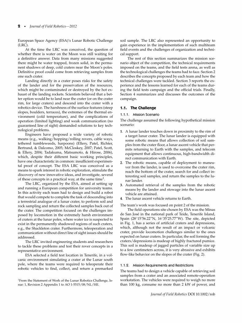
Table II. Comparison of the main concepts’ characteristics.
Envelope (stowed)Concept Locomotion means Weight (kg) L × W × H, cm. Communication means
CESAR Hybrid 13.3 98 × 82 × 50 Low band 868 Mhz data link repeater2 wheels/legs deployed on crater’s rim; analog video
DAVID 6 wheels 80 110 × 85 × 50 802.11b/g repeater deployed oncrater’s rim
ALoF/CRABli 4-legged 15 57 × 39 × 17 802.11b/g relay robot on crater’s rim6 wheels 13 59 × 47 × 29
Jacobs Deployable tracks 21 + 21 50 × 50 × 50 802.11b/g between descending roverand partner on crater’s rim
Moon Hound 4 wheels 50 120 × 100 × 60 802.11b/g repeater deployed oncrater’s rim
Morri 6 wheels/Tracks 60 100 × 60 × 60 Satel 3Asd radio modem (869,4125MHz)and analog video link w/ 5w amplifier
Pesapod 6-legged 42 110 × 100 × 90 802.11b/g mesh multiple nodes deployedalong the path
SELENE Deployable tracks 35 50 × 40 × 50 802.11b/g secondary nanorover deployedat crater’s rim
LRC provided the opportunity to investigate the self,beacon-based, and observed localization principles.
5. Situational awareness. Situational awareness is what al-lows an operator to understand the risks of a robot facesbecause of its own physical status, its surrounding en-vironment, and the interaction of the two. The robot, itsmonitoring equipment, and its control station must al-low the operator to continuously evaluate the risks therover faces, as well as to investigate risks or problemsthrough dedicated investigation activities at any time. Inthe LRC, several situation awareness approaches wereimplemented by different means.
The LRC teams were selected on the basis of the varietyand complementarity of solutions.
2. THE TEAMS AND THEIR CONCEPTS
The eight teams participating to the LRC were (in al-phabetical order) CESAR, developed by the Universityof Bremen (Germany); DAVID, developed by the Uni-versity of Pisa (Italy); ETH ALoF/CRABli, developed bythe Autonomous Systems Lab, ETH Zurich (Switzerland);Jacobs Lunar Robots, developed by the Jacobs University(Germany); MoonHound, developed by the UniversidadPolitecnica de Madrid (Spain); Morri, developed by theUniversity of Oulu (Finland); pESApod, developed by theScuola Superiore Sant’Anna, Pisa (Italy); and SELENE, de-veloped by the Surrey Space Centre, University of Surrey(UK).
A comparison between the eight concepts is summa-rized in Table II, presenting the main characteristics andtechnical choices. In the following sections each team’s con-cepts are presented.
2.1. CESAR: Crater Exploration and Sample Return,University of Bremen, Germany
2.1.1. Proposed Solutions and System Architecture
To meet the LRC requirements and be buildable the withinthe limited time frame, the CESAR system was designedwith simplicity and robustness in mind. The system con-sists of three modules (see Figure 3): the lander module, therepeater, and the rover. For the rover design, the team optedfor a lightweight construction with a hybrid wheel/leg lo-comotion concept (Martin-Alvarez et al., 1996), which com-bines the simplicity of wheel designs with the increasedterrain negotiation capabilities of legged systems. Prelim-inary tests with a similar system (Eich, Grimminger, Bosse,Spenneberg, & Kirchner, 2008) showed promising resultsfor loose soil with varying degrees of granularity. The de-sign was further simplified by reducing the number ofmain drives to two and introducing a lever arm, similar tothat of the Axel Rover from JPL (Nesnas, Abad-Manterola,Edlund, & Burdick, 2008).
2.1.2. Locomotion
The wheel/leg hybrid consists of a central plate cut outof 15-mm polyoxymethylene (DELRIN) board, to whichfive spokes are attached individually. The spokes are of thesame material, and designed to be flexible in both radial
Journal of Field Robotics DOI 10.1002/rob

6 • Journal of Field Robotics—2012
Figure 3. The CESAR system consists of a 13.3-kg hybrid leg/wheel rover, a repeater module for video and control signal relay,and a lander module for communication to Ground Station.
and tangential directions. The feet are a fiberglass and alu-minium sandwich construction and were inspired by howlizards use their feet on loose sand. The wheel constructionis driven by a motor module, which incorporates an addi-tional flexible coupling. A passive lever arm proved to pro-vide too much ground friction, which increased with ter-rain elevation. For this reason, an active paddle wheel wasdeveloped, resembling the shape of a star fruit. Its geome-try provides a large contact surface for traction, but is ableto slide sideways with very low ground resistance. This fea-ture proved to be important for turning the robot.
2.1.3. Soil Sampling
As the lever arm has very low ground clearance, a simpleservo-actuated hatch is used for the collection and storageof soil samples. Once the hatch is opened, and contact withthe ground has been made, the hatch can be filled with asoil sample by moving the robot forward.
2.1.4. Communications
The CESAR system was designed for robust teleopera-tion. There are separate communication channels for videoand control signals. The video signals from the camera aretransmitted as analog signals for less degradation of per-formance. The 2.4-GHz video signal provides poor perfor-mance for non-line-of-sight operation. For this purpose, therepeater is dropped at the crater rim and provides a relayfor video transmission to the lander module (at 5.8 GHz).The release mechanism of the repeater uses the same actu-ator as the sample collection unit. Control signals from thesimulated ground station are transmitted on the 868-MHzISM band and are also relayed by the repeater.
2.1.5. Localization
The CESAR system used only the onboard camera for local-ization. An artificial landmark, integrated into the repeater,
used an array of LEDs as a navigation aid, similar in prin-ciple to a lighthouse.
2.1.6. Situational Awareness
The CESAR robot is entirely teleoperated. A single wide-angle camera attached to the camera mast can be activelyswiveled to provide either a forward-facing view or a wayto inspect the robot and the sample collection process. Thecamera is sensitive in the IR spectrum and has an integratedinfrared LED array for illumination. Two additional LEDarrays, which emit white light, are attached to the mainbody to provide short-range color vision.
2.2. DAVID: A Rough-Terrain Casting Robot fromthe Universita di Pisa, Italy
2.2.1. Proposed Solutions and System Architecture
The two main foci of attention in design were the develop-ment of effective locomotion and sample acquisition sys-tems. Accordingly, the University of Pisa developed a six-wheeled, high-traction rover with an innovative approachto soil sample acquisition.
To reduce the energy effort for accomplishing the mis-sion, the team decided to employ an end effector castingand retrieving system. Casting manipulation is a techniquein which the end effector is thrown, the sample materialis acquired, and the end effector is retrieved using a lighttether that acts as a “fishing line.” The casting manipulatordeveloped for DAVID uses an innovative sling-like tech-nique, capable of obtaining longer and more precise caststhan previous oscillating versions (Fagiolini, Arisumi, &Bicchi, 2005).
2.2.2. Locomotion
The development of a traction system for unstructured en-vironments is a trade-off of traction, maneuverability, ob-stacle negotiation, and reliability. On the basis of the chal-lenge specifications, the solution adopted is composed of
Journal of Field Robotics DOI 10.1002/rob

Belo et al.: The ESA Lunar Robotics Challenge • 7
Figure 4. The DAVID rover (left) and a 3D view of its casting manipulator (right) with details of its components (1. hub, 2. hollowshaft, 3. arm, 4 counterbalancing bar, 5. counterweight, 6. second link’s motor, 7. tilt motor, 8. reel’s motor, 9. electromagnetic clutch,10. reel, 11. optical encoder, 12. driving gear, 13. driven gear, 14. cable, 15. pulleys, 16. rover’s platform.
a rigid frame and six independently actuated rigid wheelswith lugs. The rigid frame simplifies the structure, improv-ing its reliability, and also providing stable support for thecasting system. The six wheels, three on each side of thevehicle, allow the rover to overcome obstacles of dimen-sions comparable to the rocks inside the crater and enhanceclimbing performance.
Based on rough behavior modeling (Bekker, 1969) ofthe different design possibilities, five different wheels oftwo main types (small rims with long lugs or large rimswith short lugs) were chosen to build prototypes and theirperformance was tested for conditions similar to the com-petition. Numerous experiments were done to test the effec-tiveness of different proposed locomotion systems. Basedon these experimental results, the final robot was equippedwith the wheels shown in Figure 4 (left).
This structure allows low energy consumption on softslopes, good obstacle negotiation capacity, and good pres-sure distribution on slopes of higher inclination.
2.2.3. Soil Sampling
For dealing with sample acquisition, a casting manipulator[Figure 4, (right)] was proposed, consisting of a robotic armconnected to an end effector through a retractable tether ca-ble. The system is composed of a support frame, a hollowvertical shaft, and a counterbalanced rigid arm, represent-ing the first and second links. The arm is integral with thevertical shaft. The first link is used to lift the arm from itsrest/travel position to a chosen launch angle. The secondlink, with unbounded rotating capabilities, is used to accel-
erate the end effector, providing it with the right amount ofkinetic energy. The cable is wound around a reel, mountedon an electromagnetic clutch, and keyed on a motor usedfor rewind. The cable passes inside the shaft, driven by pul-leys to reduce friction, and reaches the end of the rigid arm,where it is linked to the end effector.
The working procedure is composed of three mainphases. Startup phase: The structure is lifted to the desiredlaunch angle and the end effector is accelerated until thedesired velocity is reached and stabilized. Casting phase:Whenever the second link reaches the desired throwing di-rection angle, the clutch is disengaged and the end effectoris thrown, at a tangent to its previous rotation. Retrievingphase: At landing the clutch is reengaged and the end effec-tor is dredged in order to collect and retain sample material.Finally, the end effector is retrieved rewinding the cable.
To solve the end-effector flight trajectory, its initial stateis determined by the differential kinematics of the manipu-lator during the startup phase. Ballistic flight is completelydescribed by the end-effector dynamics equations duringthe casting phase, based on the assumption that the cableis subject to constant tension. The designed end effector letour system reach distances of about 10 m with precisionlosses less than the target area size.
2.2.4. Communications
Given that WiFi communication was unavailable insidethe crater, the communication between robot and base sta-tion was achieved through a two-step wireless 802.11b/gbridge. The repeater was released on the crater rim using
Journal of Field Robotics DOI 10.1002/rob

8 • Journal of Field Robotics—2012
a simple hook actuated through a servomotor. Moreover,router and repeater were both equipped with high-gainomnidirectional antennas.
2.2.5. Localization
The DAVID rover used the onboard camera for localization,and the communication relay as a visual landmark for find-ing the way back from the crater.
2.2.6. Situational Awareness
The software architecture was composed of a user in-terface application, running on a host computer (groundsoftware), and some onboard applications. Data communi-cation between ground and onboard applications was com-posed of rover commands, sensor measurements, and thethree cameras’ video stream. Communication was achievedthrough extensive use of the “shared variables” protocolprovided by Labview. Given that network bandwidth sta-bility was not guaranteed, flexibility was an important fac-tor, and data communication should be adjusted accord-ingly. Hence, the system permitted run-time activation anddeactivation of each shared variable’s transmission andconfiguration of several video streaming parameters, in-cluding jpeg video streaming resolution, triggering rate,compression ratio, and image quality.
To improve the overall system reliability, a networkcommunication watchdog timer is implemented as protec-tion in case of communication fault. In such a case, mostof the network-shared variables are shut down (in orderto lower bandwidth), the rover movement is stopped, andwheel motors are blocked until a stable communication linkis reestablished. Finally, each subsystem, e.g., motors andreal-time controller, can be remotely reset to permit recov-ery from faulty conditions.
2.3. Tethered Climbing, Autonomous Systems Lab,ETH Zurich
2.3.1. Proposed Solutions and System Architecture
The team of ETH Zurich implemented three collaborat-ing robots. The main task of descending into the crater,collecting the sample, and returning it to the lander wasperformed by a quadrupedal walking/crawling platform(Hoepflinger, Remy, Hutter, & Siegwart, 2010; Remy et al.,2011). During the entire mission, this robot was attachedto a safety cable, which was deployed from a second sta-tionary robot at the landing module. The cable was usedto passively stabilize the robot on the slope, to enhanceits climbing capabilities, and to supply energy. The last al-lowed significant reduction of the mass of the quadruped,which is especially important for a walking robot thatneeds to support its own weight actively. The third robot,a six wheeled rover equipped with a CRAB suspensionsystem (Thueer, Krebs, Siegwart, & Lamon, 2007; Thueer,Lamon, Krebs, & Siegwar, 2006), served as relay station forcommunication and to enhance the perception of the oper-ator for navigation.
2.3.2. Locomotion
The quadrupedal robot was designed so that it could uti-lize its legs both for upright walking and for flat crawl-ing (Figure 5). The necessary range of motion at the jointswas achieved by a differential drive design of the hip joint.In highly unfavorable terrain, such as on the slopes of thecrater, the robot would lower itself onto its main body andswitch from a regular static walking gait to a crawling orsliding motion. This allows the robot to inch itself up ordown the crater, even on extremely steep slopes. In thismode, the body weight was supported either by all fourlegs at once (when moving forward) or by the main body(when retracting the legs), thereby increasing the overallarea of support (Remy et al., 2011). By equipping the roboton the bottoms of its main body and shanks with scaled
Figure 5. The main task of sample return was solved by ETH Zurich with a quadrupedal robot that was able to walk and crawlwhile being suspended from the ground station by a tether cable.
Journal of Field Robotics DOI 10.1002/rob

Belo et al.: The ESA Lunar Robotics Challenge • 9
plates, further measures against slipping, sliding, or cavingin were introduced.
Using a legged robot also provided intrinsic robust-ness, resulting from the large number of degrees of freedomin its legs. The robot was able to stand up after tipping over,was less likely to get stuck on an obstacle, and might evenbe able to free itself after being partly covered by sand orgravel. These abilities make it possible to recover from lo-comotive disasters that may occur when the robot falls, oris involved in a major landslide on the edge of the crater.As no continuously rotating parts exist, it was possible tocover the entire robot in sealed fabric (akin to a jumpsuit),to protect the sensitive mechanics and electronics from dustand small rocks. This only slightly impeded the motion ofthe legs.
2.3.3. Soil Sampling
The large range of motion was also used in the soil sam-pling process: A small flap/shovel was opened at the frontend of the robot and an adapted crawling motion was per-formed to push the robot forward while it rested on theground. In the process the shovel was filled with the spec-imen. By opening the shovel in a kneeling position at thelander module, the sample could be released.
2.3.4. Communications
The communication and navigation system was in manyways similar to the solutions of other teams, i.e., a two-stepwireless 802.11g bridge relayed from the landing platformto the quadrupedal robot via the wheeled rover.
2.3.5. Localization
Having three collaborating robots greatly facilitated nav-igation and orientation. All robots were equipped withstrong illumination and cameras, which made mutual lo-calization possible. As the camera and the beacon lighton the tether station were stationary, they could alwaysbe used as an absolute reference for navigation. This wasclearly superior to navigation based solely on passively il-luminated and thus hardly distinguishable landmarks.
2.3.6. Situational Awareness
The main sensory inputs in this system were providedby the six-wheeled robot, equipped with a high-resolution(20×) pan–tilt–zoom (PTZ) camera. This robot provided abirds-eye view of the crater area. Odometry measures werealso used for the quadruped’s control.
2.4. Two Cooperative Robots with OnboardIntelligence, Jacobs University
2.4.1. Proposed Solutions and System Architecture
The Jacobs University Robotics Group decided to addressthe challenge by building two robots: one working as proberobot that descends into the crater, and one both for com-munication relay and to support the search of the proberobot by providing an overview of the scenario from therim. Due to the limited time for the preparation of the chal-lenge, the core design of the Jacobs LRC robots is basedon the “rugbot”—short for rugged robot—type of system(Birk, Pathak, Schwertfeger, & Chonnaparamutt, 2006) thatthe group developed previously for Safety, Security andRescue Robotics (SSRR) (Birk, & Carpin, 2006). The imple-mentation is based on the CubeSystem, a collection of hard-ware and software components for fast robot prototyping(Birk, 2004; Birk, Kenn, & Walle, 2000). The standard rug-bot design is already quite lightweight; the SSRR versionsrange from about 35 kg down to about 27 kg. This weightwas further reduced for the two ESA LRC robots to about21 kg for each robot. This was mainly done by using smallerbattery packs that provide sufficient power for the chal-lenge and some slight modifications to trade weight againstreduced robustness, especially with respect to a reducedmaximum drop height. Reduced weight was considered tobe beneficial for moving uphill on loose ground; this wasalso supported by anecdotal evidence during the ESA LRC.
2.4.2. Locomotion
Rugbots are tracked vehicles. The team experimented withgrouser plates of different lengths to improve traction inloose soil. Though working well in sand, especially in drydunes, the grouser plates were not helpful with the chal-lenge itself. The robots were hence operated without them,as traction was always sufficient. The robots are very ag-ile and fast in unstructured environments, and they alsoperform well on open and slippery terrain. The robots arequite compact, with a small footprint of approximately 50× 50 cm and less than 50 cm overall height. A special fea-ture of the rugbot design is an active shape-shifting mech-anism, also known as a “flipper,” that can negotiate, forexample, rubble piles and stairs. The Jacobs flipper has aspecial design, which needs an order of magnitude lessforce than comparable designs and which is particularly ro-bust against shocks (Chonnaparamutt, & Birk, 2007; 2008).Shape-shifting mechanisms have several important proper-ties: they can be used to (a) adapt the footprint of the robotand hence the traction, (b) change the center of gravity ofthe robot to improve its balance, and (c) push the robot ontoor over obstacles.
2.4.3. Soil Sampling
The team experimented with different options for thesampling mechanism, up to complex options such as a
Journal of Field Robotics DOI 10.1002/rob

10 • Journal of Field Robotics—2012
Figure 6. The rugbot (left). The digging mechanism is integrated into a flipper that is mounted in the front of the robot to ease thehandling (right). The digging can be supervised using a dedicated camera that is integrated into the mechanism.
full-fledged robot arm. A simple solution was chosen tosupport easy handling by the operator, which is inher-ently less error-prone because of minimal electromechan-ical complexity. The mechanism consists of an actuatedbucket scoop that is integrated into the existing flippermechanism [Figure 6 (left)]. Hence, it needs only one ad-ditional degree of freedom, powered by a servo. The mech-anism is supplemented by a dedicated camera with lightthat is integrated into the flipper so that it provides an idealview of the bucket scoop.
2.4.4. Communications
Communication was provided by a relay robot to the RF-link from the lander to the probe robot when it is in thecrater and out of direct RF contact. For this purpose, therelay robot was positioned on the rim of the crater.
2.4.5. Localization
The probe robot was equipped with an onboard camera.Moreover, the relay robot supported the search of the proberobot, providing an overview of the scenario from the rim,and provided a landmark for navigation.
2.4.6. Situational Awareness
Rugbots have significant computational power, in the formof an onboard PC, and can be equipped with a large varietyof sensors to support intelligent autonomous functions. Therobots are equipped with (a) intelligent control functions toassist the human operator in the motion control, e.g., au-tonomous balancing functions using the flippers to shiftthe center of gravity or to autonomously optimize tractionby adjusting the robot’s footprint to the terrain, (b) supportfor cooperation between two robots to increase robustnessthrough redundancy as well as to achieve better situationawareness, and (c) three-dimensional (3D) perception andmodeling capabilities. The relay robot is equipped with anactuated laser range finder (aLRF). The team uses an off-
the-shelf SICK S300 2D-LRF combined with a simple servofor pitching motion. The S300 has a horizontal field of viewof 270◦ with 541 beams. The servo allows a maximum ro-tation of ±90◦ with a maximum resolution of 0.5◦, leadingto a 3D point-cloud of total size 541 × 361 = 195,301 persample. As it is an active sensor, it is—in contrast to, for ex-ample, stereo vision—not affected by the light conditionsof the LRC. The maximum range of the aLRF is about 20 m,only marginally less than required for the purpose of theLRC. The time to take one full scan of maximum resolutionis about Tscan ≈ 32 s. The use of the aLRF and in particularthe related data processing within the LRC demonstratesthe proof of concept. An important point is that the raw 3Dpoint-cloud data are well suited neither for onboard pro-cessing for autonomous motion control or path planning,nor for transmission to the operator station due to its size.Based on previous work (Pathak, Vaskevicius, & Birk, 2009;Poppinga, Vaskevicius, Birk, & Pathak, 2008), we can fitlarge planar surface patches into the point clouds, in realtime, which reduces the data by several orders of magni-tude. The surface representation is transmitted to the oper-ator station, where it can be inspected in 3D (Vaskevicius,Birk, Pathak, Schwertfeger, & Rathnam, 2010).
2.5. MoonHound: The Lunar Rover of theUniversidad Politecnica de Madrid, Spain
2.5.1. Proposed Solutions and System Architecture
The MoonHound rover is a four-wheel-drive, differentialwheels-turning vehicle. The main idea of the rover is theuse of very large wheels, with a radius of 30 cm and a widthof 40 cm. As a consequence of this design choice, and in or-der to comply with volume restrictions, the space left forall the onboard equipment was very limited. Thus, most ofthe equipment had to be put inside the wheels. The originalconcept consisted of a cylindrical chamber, around whichthe wheel turns [see Figure 7 (right)]. This chamber pro-tects the electronics from dust and other hazards such asradiation. To reduce the total weight and to provide easieraccess to the equipment, the chamber was later reduced to a
Journal of Field Robotics DOI 10.1002/rob

Belo et al.: The ESA Lunar Robotics Challenge • 11
Figure 7. The MoonHound rover and a detail of the sample collection mechanism (left). The central passive joint decoupling thefront and rear wheels provides high flexibility when passing over an obstacle. MoonHound wheels (right): all onboard equipmentis stored inside the wheels. Note the position of the batteries, which provide an extremely low center of gravity.
dish closing the inner part of the wheel. The location of theequipment at the bottom of the wheel makes the center ofgravity extremely low. Therefore, overturning the rover isextremely difficult. Our simulations showed that the over-turning point was close to 90◦. A key feature of the Moon-Hound is a 1-DoF (degree of freedom) passive joint con-necting the two axes. Such a joint provides the rover withthe ability to twist along the longitudinal direction. In thisway, shocks are damped, and high flexibility when pass-ing over obstacles is achieved, guaranteeing that the fourwheels remain in contact with the surface at all times (cf.Figure 7). A turret and a soil-sampling arm are stowed inthe space between the wheels during launch.
2.5.2. Locomotion
The choice to use large wheels was motivated by the needto improve the wheels’ soil contact area and hence to re-duce slip. In fact, a wide contact surface and the reducedrotation speed (for a given linear speed) reduces slip. Inthis sense, such wheels can be likened to rigid tracks. Also,larger wheels make it possible to negotiate bigger obstaclessuch as the stone and rocks expected to be present on thesurface. The outer wheel, 3 mm thick, was made of a com-posite aluminum/glass fiber material, with a helicoidal de-sign of the grooves, which can be seen in Fig. 7. Such a pat-tern of the grooves allows a very high maneuverability, es-pecially for on-the-spot turning maneuvers. Moreover, thisdesign should allow lateral and diagonal movement of therover. Such types of movement can be achieved on hardsurfaces with omnidirectional wheels (Ilon, 1973) and havealso been tested recently on soft terrain (Ransom, Kromer,& Luckemeieri, 2008).
2.5.3. Soil Sampling
A 4-DoF manipulator for both collecting and storing soilsamples is stowed in the space between the wheels duringlaunch. It unfolds to a working configuration providing asimple excavator-like gripper capable of collecting uncon-solidated material and storing it for safe transportation.
2.5.4. Communications
In the MoonHound system, the communication betweenthe teleoperation station and the rover was provided bycommercial WiFi 802.11g routers. Both UDP and TCP pro-tocols were used for different purposes: TCP for sendingteleoperation commands and receiving telemetry data, andUDP for video streaming. Clearly, the most demanding ser-vice in terms of bandwidth is the video streaming. Prelim-inary tests proved that the bandwidth provided was ade-quate for the cameras’ video streams and command andcontrol purposes. To provide signal coverage inside thecrater, a communication relay was dropped at the crater rimbefore descending.
2.5.5. Localization
The camera mounted on top of the foldable turret was capa-ble of working in the infrared spectrum and provided clearblack and white images with almost no light. This choicewas motivated by the fact that artificial lighting of the fielddid not provide a wide enough field of view, either for thesearch for the samples on for global orientation.
To aid navigation inside the crater and find the wayback to the lander, the relay provided two supplementaryfunctions. First, it was provided with a flashing light, usedas a reference for orientation, and second, it carried a thirdpan–tilt camera whose purpose was to provide a view of
Journal of Field Robotics DOI 10.1002/rob

12 • Journal of Field Robotics—2012
the crater’s base. The rover was provided with flashinggreen/red lights to help detect its orientation.
2.5.6. Situational Awareness
The main sensory input for the MoonHound rover wasprovided by an IP pan–tilt–zoom camera mounted on topof the foldable turret. A dedicated IP channel for imagestreaming provided the necessary bandwidth for smoothvideo streaming of (640 × 480)-pixel frames. A secondarycamera mounted at the end of the manipulator was usedfor a close view of the collection operation, and could serveas a backup system in case of failure of the main camera.This was a commercial webcam working at a resolution of320 × 240 pixels. The status sensory input of the rover wasprovided by an IMU, used to estimate the rover’s pose anddetect the crater rim and base (only accelerometers and gy-roscopes were used; the magnetic compass was disabled).
The teleoperation station consisted of two laptop com-puters, one for the pilot, running teleoperation softwareand receiving the main camera’s video streaming, and onefor the navigator, used for internal status and inertial mea-surements unit (IMU) parameter visualization and videostreaming. The secondary camera was switched on only forclose inspection or during manipulation. The pilot used ajoystick for controlling the rover and a mouse for control-ling the PTZ camera. The same joystick served to controlthe arm movements. This configuration was motivated bypast experience in teleoperation. One input device for roverand arm control, as it is extremely difficult to move therover and the arm at the same time, and only one video
stream at a time for the pilot, since he/she is better toconcentrate on one image. In the configuration used, thepilot is in charge of controlling the rover/arm, while thenavigator is responsible for situation awareness, localisa-tion/orientation and path planning.
2.6. Morri, the University of Oulu, Finland
2.6.1. Proposed Solutions and System Architecture
Team Oulu participated in the LRC competition with arobot called Morri, a mixed wheels–tracks rover. The blockdiagram of the robot’s main parts is shown in Figure 8(left). The robot was one of the heaviest in the competition,weighing about 60 kg. It is powered by two brushless mo-tors and two DC (windshield wiper) motors for operatingthe sampling arm. The sampling arm has a hatch for releas-ing the samples to the lander receptacle in the last phase ofthe mission. The robot’s body consists of two (100 × 100)-mm standard aluminum profiles 600 mm long, which con-tain the motor controller, BLDC motor drivers, LiPo batter-ies, motors, and chain gear. This solution is cheap, easy tomanufacture, easy to protect, and also easy to repair underfield conditions.
The Morri’s electronics contained two Atmel AVR 8-bit microcontrollers, one for controlling the base movementand one for controlling the arm. MCU was chosen to pro-vide a simple solution, but also to be as close as possible toreal components for use in space conditions.
Figure 8. Top, location of the robot parts (left) and sampling arm mechanism (right). Bottom: the Morri rover.
Journal of Field Robotics DOI 10.1002/rob

Belo et al.: The ESA Lunar Robotics Challenge • 13
2.6.2. Locomotion
The robot is a differential-driven, six-wheeled robot withtracks on both sides for better operation in dusty sand.Tracks give a large contact area, lower the center of grav-ity, and make the robot’s movement on rough and bumpyterrain much smoother. Another design issue was to makethe robot long enough so that driving in rough terrain andon steep slopes is smoother and easier.
2.6.3. Soil Sampling
The custom-made sampler is also designed to be as sim-ple as possible, although providing the capability to collectsamples of up to several kilograms. The sampler arm’s op-eration is shown in Figure 8 (right). The sampler arm canturn from the top of the robot (C) to the front to take sam-ples (A). In the sample release phase (B), a hatch is openedon top of the landing platform.
2.6.4. Communications
The communication between a human operator and therobot was provided by a Satel 3Asd radio modem(869.4125 MHz) and an analog video link with a 5-W am-plifier. The advantage of this communication link is almostreal-time control, which provides much easier remote op-eration in comparison to web camera, PC, WLAN, andvideo-player-based systems. A very simple protocol wasimplemented for sending driving commands and controlsignals for the arm, lights, and video multiplexer. A simplebranched RS-232 cable was used to deliver the commandsfrom the radio to the sampler control board and the robot’sbase control board. The sampler controller also operates thevideo multiplexer relays.
2.6.5. Localization
Morri used only the onboard camera for localization. Thethermal camera gave the advantage of observing long dis-tances in darkness as well as in direct light. Switching be-tween these modes provided a method of enhancing thevisual ability.
2.6.6. Situational Awareness
As the robot was fully teleoperated in the competition, theuse of additional sensors was minimized. Instead, stronglights and a thermal camera were used to provide themaximum possible visibility for the operator. The robot isequipped with three cameras: two CCD color cameras andone FLIR thermal camera. One CCD and FLIR give videofrom a front view of the robot, whereas a second CCD isconnected to the arm to provide a view of the sampling pro-cess. The robot also has several LED flashlights to aid op-erations in complete darkness. Cameras are connected to a
video transmitter through relays, which are used to changethe current camera.
The teleoperation station consists of a laptop, a USBanalog video capture device, and standard a Linux videoplayer (MPlayer) that can also save images and video. Ahuman operator uses a custom-made 4-axis joystick to con-trol the robot (self-centering axis) and sampler movements(non-centering potentiometers for arm and hatch angle). Alaptop keyboard is used for operating camera selection. Theoperator can adjust the sampler state separately to certainorientations in parallel to driving the robot. This configu-ration was motivated by previous experience in teleopera-tion. The operator may get confused easily when the samedevice is used to operate different devices (i.e., one joystickfor driving, turning the head unit, and operating the sam-pler). Nonturning cameras were selected to prevent confu-sion in the camera pointing direction. These solutions pro-vide an easy-to-use system for a single operator.
2.7. pESApod: The Hexapod Robot from theScuola Superiore Sant’Anna, Pisa, Italy
2.7.1. Proposed Solutions and System Architecture
The team from the Scuola Superiore Sant’Anna pro-posed, designed, and developed a hexapod robot, namedpESApod. The complex mechatronic system, having 23 ac-tuators, was specifically conceived and completely devel-oped in 5 months to cope with the task presented by theESA LRC. System dimensioning was performed by model-based design using computer dynamic simulations. Fullyequipped, the robot has a total weight of 42 kg and opera-tional dimensions of 110 × 100 × 90 cm (L × W × H). Thecross-shaped frame and the leg links were built from car-bon fiber. Each DoF was actuated by a 60-W DC brushedmotor driven by analog servos and equipped with opticalincremental encoders. To meet the torque requirements andto avoid excessive stress on actuators, the power was trans-mitted through a multiple-stage planetary gearhead in se-ries with a belt transmission. The overall reduction ratio ex-ceeded 250:1.
To achieve maximum flexibility, a distributed controlarchitecture was developed and implemented on three on-board FGPA modules and a PC, communicating via an Eth-ernet link. The PC ran custom-made video-encoding soft-ware and the wireless communication routine. The pat-tern generator translated the high-level commands intojoint trajectories, which were received by the two low-levelboards. These boards computed motor currents on the basisof encoder data and angular references. All FPGA boardsran instances of dedicated hardware modules and soft-core processors. The distributed architecture allowed fasterdevelopment times and easy implementation of differentkinds of gait. A tripod or pentapod gait could be selected.Both translational and rotational movements were permit-ted, with maximum increments of about 20 cm and 10◦ per
Journal of Field Robotics DOI 10.1002/rob

14 • Journal of Field Robotics—2012
step, respectively. Ground clearance could also be adjustedin the field. Additionally, manual control of single jointswas possible for sample retrieval, fault recovery, and ob-stacle avoidance.
2.7.2. Locomotion
The ascent issue drove the choice toward a multileggedplatform. This kind of solution has demonstrated capabil-ities in obstacle climbing and adaptation to steep terrain(Kennedy et al., 2005), at the expense of overall complexity(Yumaryanto, Ana, & Lee, 2006). Moreover, this approachavoided the necessity of an additional manipulator for sam-ple retrieval, allowing an end effector to be housed in thedistal sections of the legs. The central legs are wider andplaced closer to the rear ones in order to maximize sta-bility. This feature required pESApod to move backwardwhile descending a slope. Each leg had three degrees offreedom: two for hip abduction–adduction and flexion–extension movements, and one for knee flexion–extension.
The front and rear feet were conceived to maximizecontact surface while providing sufficient traction and werecomposed of a aluminum discs and removable spikes to beused in cases of very high slope and friable terrain. The feetwere connected to the legs by passive spherical joints andrubber dampers.
2.7.3. Soil Sampling
The collection of samples was performed by clamshellbuckets (end effectors) located on both middle legs anddriven by the movement of the legs themselves. The buck-ets could be closed by an actuated lid in order to retainthe sample. Because the end effectors replaced middle feet,they were designed to be robust and large enough to sus-tain the robot during movement.
2.7.4. Communications
The team designed and developed a multihop wirelesscommunication system for the pESApod robot. As therover was required to operate in a challenging unstructuredenvironment, ensuring reliable remote control and moni-toring was not trivial. The communication system had torelay different sensor data (cameras, joint angle encoders)to the teleoperation station and reliably carry commandsfrom the human operator. The whole system was requiredto be able to communicate over a long distance with lowpower drain.
The developed network linked portable nodes thatcould be dropped during the mission by a vending-machine-like coil on the robot’s rear, forming a path fromthe base station to the rover. Node deployment was re-motely triggered by the human operator to achieve thedesired redundancy and communication radius. Customfirmware implementing the B.A.T.M.A.N. wireless mesh
Figure 9. The pESApod legged rover. The insets show somemechanical details: a. head, b. vending-machine-like coil fordeploying Wi-Fi nodes, c. leg assembly, d. front and rear legfoot, e. clamshell bucket for collecting soil samples, f. cross-shaped frame.
protocol was used. The network automatically chooses theoptimal route, adapting to link conditions, working aroundfailed nodes, and exploiting redundancy. The nodes oper-ate in the unlicensed 2.4-GHz band, using standard 802.11protocols. This approach guarantees a bandwidth of sev-eral Mbit/s even in the presence of obstacles and challeng-ing operating conditions. Commands and sensor data weretreated with high priority and reliability, whereas the videostream was delivered on a best-effort basis. Video encodingand command relay were performed on the onboard PC.Commands and sensor data were relayed to and from mid-level and low-level FPGA controllers via onboard Ethernet.
2.7.5. Localization
The pEASpod legged robot used the onboard camera forlocalization and the deployed nodes as navigation land-marks.
2.7.6. Situational Awareness
A motorized 2-degree of freedom head was mounted ontop of a carbon-fiber mast and was equipped with a stereocamera for navigation and high-efficiency white LEDs forlighting the environment when in complete darkness. Thesoftware running on the teleoperation station aggregatedreceived data and showed a 3D view of the rover by meansof a custom GUI. Graphs were provided showing both thedesired joint trajectory and the actual encoder readings. TheGUI included also dedicated commands for sending high-level instructions to the robot such as the execution of astep, the gait parameters, and the motion of the head or ofthe manipulators, as well as manual control of single jointsfor fault recovery and obstacle avoidance.
Journal of Field Robotics DOI 10.1002/rob

Belo et al.: The ESA Lunar Robotics Challenge • 15
Figure 10. SELENE subsystems: 1. ultra-bright white LEDheadlights, 2. stereo camera system, 3. deployed track module,4. 5-DoF manipulator, 5. secondary nanorover.
2.8. Selene: A Tracked Rover from the Universityof Surrey
2.8.1. Proposed Solutions and System Architecture
The Surrey Space Centre (SSC) has a strong record of uti-lizing commercial off-the-shelf equipment to allow quickapplication of modern technology to space applications, re-ducing cost and complexity. The Mobile Robots Pioneer 3All-Terrain (P3-AT) rover was selected as a base for the SSCmicrorover. Mobile Robots provides a C++ API library toallow direct program access to the rover’s microcontrollerand accessories. Additional rover sensors include a laserrange finder, stereoscopic camera, and IMU. This equip-ment range and the simplicity of a well-supported soft-ware interface confirmed the P3-AT as a suitable producton which to base the microrover.
The SELENE microrover was equipped with fourcustom-built tracked “flipper” modules, the pitch of whichis controlled by a deployment mechanism. The standardwet-cell batteries were replaced with a single lithium-ionbattery, 50% lighter and 33% smaller although providingthe same power. It was mounted at the base of the chassis,to lower the center of gravity. The drive and flipper motorswere mounted above the battery, and the internal belt drivesystem was replaced with a rerouted chain design. Theinternal electronics, including the microcontroller and on-board computer (OBC), were mounted on a grating abovethe motors, providing EM shielding. Externally, the naviga-tion camera and robotic manipulator used for sample col-lection were mounted on the vehicle casing and interfaceddirectly to the microrover OBC. A secondary nanorover iscarried on board for deployment at the crater edge, pro-viding a communications relay and navigational assistance.The complete dual-rover system is shown in Figure 10.
2.8.2. Locomotion
The standard P3-AT is equipped with a locomotion systemconsisting of four powered wheels. Unencumbered, it hasthe ability to climb rigid slopes of up to 35◦. However, SSCresearch into terramechanics and its application to smallwheeled rovers on lunar-type regolith suggested that poorperformance should be expected on sandy, sloped terrains.The predictions indicated that a standard P3-AT would beincapable of climbing slopes of more than a few degrees in-clination. An equivalent tracked system would be expectedto produce significantly better results. Modeling of the per-formance determined on increase of estimated maximumachievable incline from approximately 6◦ for the wheels, toover 36◦ for tracks of a similar size. The addition of grousersfurther improved this estimate.
A number of tracked locomotion designs were devisedto explore the option of converting the existing wheel hubsto support sprockets driving a track belt. These designswere enhanced, extending the tracks past the drive wheelsby adding idler sprockets. This better performing but morecomplicated design incorporated deployable track “flip-pers.” The benefits of the extended track system were off-set somewhat by the requirement for a complicated trackdeployment mechanism and reorganization of the inter-nal subsystems. However, although the simplicity of thesmaller tracked option was advantageous, it was felt thatcertain factors, including the high center of gravity and lim-ited track surface contact area, presented a weaker designoverall. The final flipper locomotion system concept pro-vided the option of raising the chassis to give better groundclearance without compromising tractive ability. A customtrack belt was built using a treadmill belt and aluminumbar grousers.
2.8.3. Soil Sampling
The sample collection system comprised a standard MobileRobots 5-D.F robotic manipulator mounted on top of themicrorover casing. The arm was selected for this task be-cause it provided a versatile platform for sample collectiononce the rover was in the correct location. The preconfig-ured controller and software control provided a compre-hensive and quick solution to the sample collection require-ment, allowing the actuators to be manually controlled viaa serial link to the Selene OBC. Minor modifications weremade to the end effector to incorporate a passive samplecollection and storage system. This utilizes a scoop designincorporating a deep container hinged close to the openend, thus allowing the sample to act as a counterweight andrest safely at the scoop base while being transported backto the lander site.
2.8.4. Communication
The OBC of the P3-AT is a standard ×86 PC running DebianLinux. It is equipped with an 802.11b/g wireless Ethernet
Journal of Field Robotics DOI 10.1002/rob
16 • Journal of Field Robotics—2012
card, which formed the basis of the communication sys-tem. The anticipated nature of the environment raised twoissues with using standard Wi-Fi technology. First, the ex-pected environment boundaries were on the threshold ofthe technology’s range, approximately 100 m. This con-cern was rectified with the addition of high-gain omnidi-rectional antennae to all wireless equipment. Second, be-cause of the position of the lander relative to the crater, themicrorover would be out of view once over the crater rim.Despite the improved antennae, it was predicted that thesolid rock terrain would absorb or deflect most of the signalpower. This led to the enrolment of a secondary nanorover,carried by the primary rover and deployed at the crater rim.Carrying a wireless Ethernet repeater, its task was to act asa mobile relay point for communications inside the crater.
2.8.5. Localization
The navigation system comprised two complementaryparts, the on-board camera to provide the primary videolink and also a simple orientation tool, developed in houseat the SSC to use the communications relay nanorover. Thissystem used bright lights of different colors attached to thefront and back of the primary rover. The nanorover’s built-in camera used these markers to provide a rudimentary op-tical compass system. By identifying the relative positionsof the lights in relation to the nanorover it was possible todetermine the orientation of SELENE, once it was in thecrater. This allowed the operators to quickly ascertain thecorrect direction to follow when exiting the crater basin.
2.8.6. Situational Awareness
Imagery of the crater was achieved through the use of aBumblebee stereoscopic camera, equipped with two ultra-bright LED headlights for use once inside the dark crater.This was also mounted on the microrover casing on a 3-DoF pan–tilt unit (PTU), used to direct the field of viewand positioned close to the robotic arm to aid in samplecollection. The video feed is transmitted via the Wi-Fi linkto the lander and back to the operator station. In additionto this feed, the microrover heading and velocity, wheelodometry, and power level measurements were all con-
trolled and monitored using the MobileEyes software tool,another off-the-shelf product provided with the P3-AT mi-crorover. This provided a GUI displaying these data, theroute track, and is estimated rover position and allowedmovement to be controlled via a computer keyboard or joy-stick. Other equipment, including the bespoke stepper mo-tor controllers for the track “flippers” and the camera PTUinterfaced to the OBC via serial links, were controlled us-ing a terminal application with a custom GUI, developed toremotely operate these systems. A simple complementarycontrol application was created to operate the nanoroverand display the optical compass.
3. ROVING AT THE LUNAR POLES
The campaign took place during eight days between 20 and27 October 2008. The first five days were dedicated to freefield tests. The official competition trials took place duringthe last two nights. The site was a remote location far awayfrom any artificial source of light, at 2,300 m of altitude.No moonlight was present during the trials. At the trials’location, temperature fell below zero at night. Indeed, theterrain, weather, and light conditions were considered ex-treme for all the rovers. The opportunity to work on theproject was an invaluable educational experience, whichhas had a lasting effect on the participants and their respec-tive academic institutions.
Figure 12 shows the score table used for recording theperformances of the rovers during the trials. The missionwas divided into several steps, from deployment from thelander (beginning of the mission) to sample deposit (end ofthe mission). Each step was allocated a number of points,other bonuses, and penalties that were awarded accordingto its accomplishment, elapsed time, and other factors suchas the request for human intervention to resolve a criti-cal situation (e.g., manual abortion of the mission to pre-vent a hazardous situation). Also, penalties were assignedfor damaging the lander and descending/ascending us-ing alternative, easier, corridors (cf. Figure 1, right). Notethat mission time did not play a key role. This was in-tentional, as the variety of locomotion means used wouldhave rendered a comparison based mainly on time unfair.Moreover, in space missions, actually accomplishing the
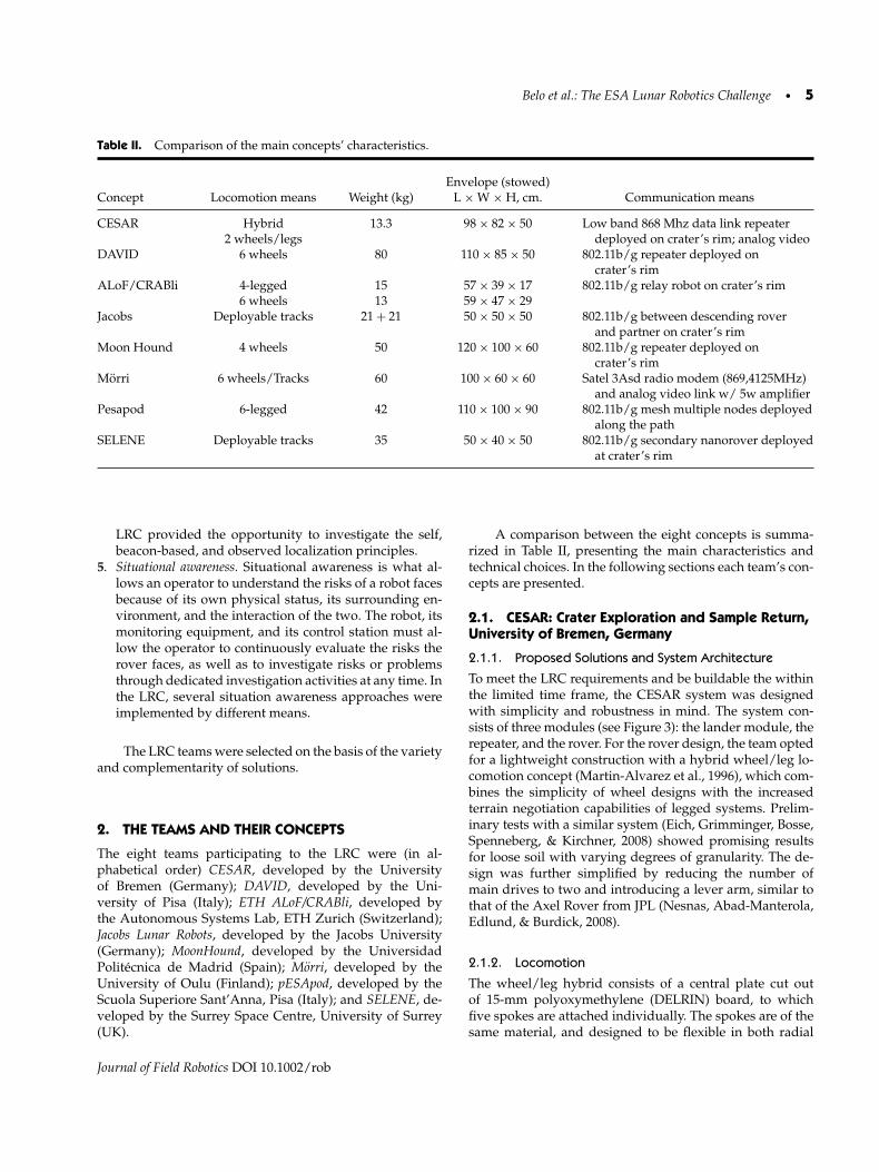
Figure 11. A panoramic view of base camp.
Journal of Field Robotics DOI 10.1002/rob

Belo et al.: The ESA Lunar Robotics Challenge • 17
Figure 12. Score table for the challenge (example). Points were assigned according to mission stages accomplished and penaltiesaccounted for mission time, corridors taken, human intervention, and quantity of sample retrieved.
mission’s objectives (in the time frame allotted) is more im-portant than absolute speed.
Tables III and IV summarize the results of the officialtrials. It can be seen that only one team managed to com-plete the mission. One team abandoned the mission with-out actually reaching the crater, and one could not partici-pate because of a mechanical failure during the free practicetrials. The majority of the teams, five out of eight, achievedsimilar performances, managing to actually reach and de-scend into the crater, and roving inside it in search for thesample. Of these, only one managed to collect the samplebefore a mechanical failure forced them to abandon the mis-sion. It is interesting to notice that the mechanical failuresof three of the teams can be directly related to a faulty situ-ational awareness.
Figure 13 reports a summary of the penalties assignedto the teams during the trials. Such penalties provide goodinsight into what happened during the trials. In summary,penalties were mainly assigned to the request for human in-tervention to manually help the robot to recover from a fail-ure (resetting the robot or one of its components, or physi-cally moving it).
During the trials, only two teams needed to man-ually abort the mission in order to prevent damage totheir rovers, whereas the majority of the teams (five outof seven—SELENE did not compete) needed human inter-vention to manually help the robot to continue the mis-sion. The reasons were different: in one cases the robotflipped over during the descent (JACOBS) and needed tobe repositioned; in one case the relay deploying mechanism
Table III. Official trial results (accomplished steps).
Deploy Reach Descend Search, find and Sample Return to Reach DepositConcept from lander crater’s rim crater reach sample collected rim (ascend) lander sample
CESAR√ √ √ √ √ √ √ √
DAVID√ √ √ √ √
ALoF/CRABli√ √ √
JACOBS√ √ √ √
MOON HOUND√ √ √
MORRI√ √ √
PESAPOD√
SELENE
Journal of Field Robotics DOI 10.1002/rob

18 • Journal of Field Robotics—2012
Table IV. Official trial results: cumulative time of accomplished steps, outcome, and final score.
Concept Time (min) Mission result Final score
CESAR 80 Successful 940DAVID 69 Locomotion failure (robot got stuck) 655ALoF/CRABli 85 Mechanical failure (stuck tether) 210Jacobs 110 Operator failure (robot dug in) 295MoonHound 82 Faulty situation awareness induced by mechanical failure 393Morri 15 Electric system failure (blown fuse) 520pESApod 35 Abandoned 155SELENE N/A Mechanical (motor) failure during free trials 0
Figure 13. Summary of the penalties assigned to the teams during the official trials.
did not work properly (CESAR); the winch mechanism ofALoF/CRABli got stuck and had to be operated manu-ally, causing three penalties; the pan–tilt mechanism of theMoonHound’s camera had to be reset because of a softwarefailure; and pESApod had to be manually carried to thecrater’s rim in order to test the descent. Also, many teamsentered the alternative yellow corridor to reach the crater’srim, although it must be pointed out that this was mainlyunintentional: after deployment all rovers pointed straightto the rim, and exiting the main (green) corridor was due toundetected lateral shift of the rovers. All rovers that man-aged to descend into the crater did it by the steepest slope(40◦), except one (pESApod). Once at the crater’s bottom,navigating to find the sample did not cause any penalties,indicating good performance of the rovers and their pilots,before a failure of the system eventually led to abandoningthe mission. DAVID needed two trials to successfully col-lect the sample before the rover got stuck and, because ofthis, broke a motor. Note that DAVID and pESApod per-formed their official trials during the daytime because ofadverse meteorological conditions on the night they were
supposed to compete. This fact was not considered rele-vant for the final classification by the organizers, becausethe major technical difficulties were not affected. As men-tioned earlier, unfortunately the SELENE team had a majormechanical failure (broken motor) during the free trials andcould not participate in the official competition.
In the following sections, we present the experienceand lessons learned by the teams during the campaign.
3.1. CESAR: Crater Exploration and Sample Return,University of Bremen, Germany
The operator team, which was located at the simulatedground station (GS), consisted of two drivers and a nav-igator. A graphical user interface and two joysticks pro-vided the means to control the three main drives as wellas the servos for the sample collection unit and the cam-era mast. During the challenge run, the approach proved tobe adequate to give the operating team a sufficient percep-tion of the environment. A minor intervention was requiredwhen the repeater module was dropped at a position on the
Journal of Field Robotics DOI 10.1002/rob

Belo et al.: The ESA Lunar Robotics Challenge • 19
Figure 14. The CESAR rover releasing the sample at thelander.
crater rim, which was too steep for the release mechanism.An inclinometer, which was not included because of timeconstraints, could have prevented this issue. The team wasable to navigate down to the crater’s dark interior, find themarked sample, return to the brightly illuminated landingsite, and successfully drop the 100-g soil sample into thedeposit box. Because the Ethernet link was the only con-nection between the simulated GS and the CESAR system,operations could have been performed from any locationwith an adequate network connection. The CESAR systemthus showed a successful crater sample return mission un-der relevant environmental and operational conditions seeFigure 14.
3.2. DAVID: The University of Pisa rover, Italy
During the challenge and trials, the locomotion systemshowed its effectiveness: the vehicle was able to negotiate
Figure 15. The DAVID rover during the trials.
inclines of up to 40◦ during both descending and ascend-ing tasks. Inside the crater, the vehicle showed low slipand good maneuverability, being able to deal with obsta-cles with dimensions around 30 cm. The Wi-Fi bridge alsoworked properly. Finally, during the mission, the robot suc-cessfully achieved the majority of the proposed tasks, in-cluding descend into the crater; negotiation of the craterobstacles; finding the selected samples; and collecting partof the sample material see Figure 15.
3.3. Autonomous Systems Lab, ETH Zurich
Three collaborating robots were used by the team: Thequadrupedal walking/crawling robot ALoF for sample col-lection and return, the six-wheeled rover CRABli utilizedas communication bridge and navigation assistant, and theautomated cable winch spaghetti-bot, which deployed thetether cable that was used for energy supply and climbingassistance of the quadruped (Figure 16).
The quadrupedal walking/crawling concept per-formed exceptionally well in the demanding environmentof the challenge. Scaled plates under the main body andshank segments dug deep into the loose soil and stably sup-ported the robot, even on the steep slopes of the simulatedcrater. When moving, the robot was shifted forward, usingall four legs at once, and rested on its main body duringthe retraction of the legs. The only issue not fully satisfac-torily solved was lateral motion. The scales were optimizedfor forward motion and created little resistance when em-ployed laterally. This led to unwanted drifting when therobot crawled on lateral slopes and reduced the angularmotion when turning. The drift also corrupted odometry, asthe robot was turning downhill when commanded to movestraight ahead.
Unfortunately, the team’s other two robots did not per-form as well in the challenge. The tether cable got twistedand knotted and blocked the winch in the spaghetti-bot.The cable had to be untangled and completely deployedmanually. However, in the remainder of the challenge, itbecame apparent that the crawling quadruped did not re-quire a tethered support at all, not even on the slopes of
Journal of Field Robotics DOI 10.1002/rob

20 • Journal of Field Robotics—2012
Figure 16. The two collaborating robots ALoF (left) and CRABli (right) at the challenge site.
the crater. In retrospect, the tethered solution was an un-necessary complication. Although the rover CRABli wassuccessfully tested on the soil of the challenge site in thedays prior to the challenge, it got stuck completely duringthe actual event. The soil at the simulated crater side wasstirred up and loosened by the footsteps of the spectators,which made the rover completely lose its grip. The obvioussolution to this problem would be the use of a larger vehi-cle, paricularly as the robot was less than half the allowablesize.
Throughout the challenge, navigation was made ex-tremely difficult by the complete absence of ambient light,the low point of view on the individual robots, and the lowresolution and frame rates of the on-board cameras. Addi-tionally, odometric measures were unreliable because of thesubstantial drift and slippage on the loose soil. The cameraand the beacon light on the spaghetti-bot could be used asabsolute reference for the relative localization of the robotswith respect to each other. When hardware and software is-sues led to the abortion of the mission, the position of therobots was still known in the mission control center.
3.4. The Jacobs Lunar Robots
A single operator controlled both Jacobs robots (Figure 17).Though this is interesting from a scientific viewpoint, espe-cially to demonstrate intelligent autonomous functions, itwas not beneficial for completing the task at hand. Missioncontrol may have been improved by distributing tasks overmultiple operators. Overall, both robots performed well.The relay robot reached the rim of the crater as intendedand served as communication bridge. The probe robot de-scended into the crater and found the marked soil aftersome searching. Though the operator managed to get veryclose, he did not succeed in picking up a sample. The proberobot had approached the soil from a steep incline thatmade fine motion control to pick up the sample too chal-lenging. In the repeated attempt to pick up the soil whileon the steep incline, the operator “dug in” the robot, so thatfurther operation became unfeasible. Using multiple oper-
Figure 17. The JACOBS system approaching the crater’s rimduring the trial.
ators for mission control might have improved the overallperformance, particularly as the competition offered only asingle opportunity for executing the mission.
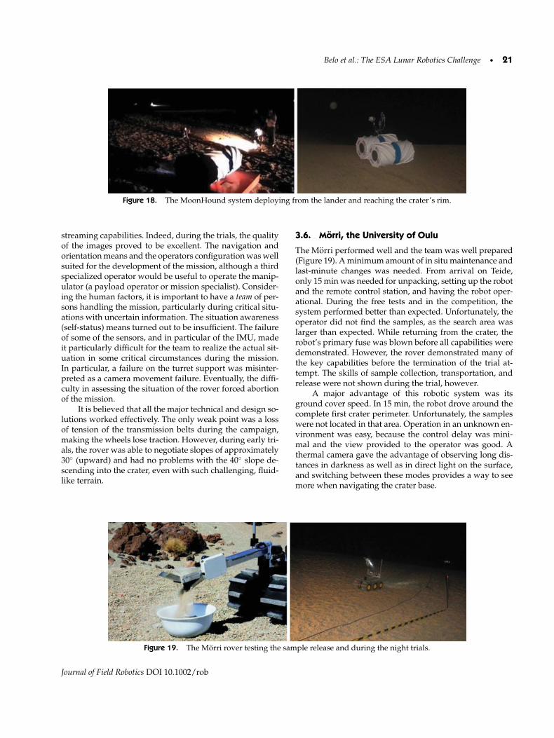
3.5. MoonHound: The Lunar Rover of theUniversidad Politecnica de Madrid, Spain
The experience gained during the field campaign allowsus to draw the following conclusions about MoonHound(Figure 18). The communication architecture and meansprovided the necessary bandwidth and coverage to al-low smooth control of the vehicle and the necessary video
Journal of Field Robotics DOI 10.1002/rob
Belo et al.: The ESA Lunar Robotics Challenge • 21
Figure 18. The MoonHound system deploying from the lander and reaching the crater’s rim.
streaming capabilities. Indeed, during the trials, the qualityof the images proved to be excellent. The navigation andorientation means and the operators configuration was wellsuited for the development of the mission, although a thirdspecialized operator would be useful to operate the manip-ulator (a payload operator or mission specialist). Consider-ing the human factors, it is important to have a team of per-sons handling the mission, particularly during critical situ-ations with uncertain information. The situation awareness(self-status) means turned out to be insufficient. The failureof some of the sensors, and in particular of the IMU, madeit particularly difficult for the team to realize the actual sit-uation in some critical circumstances during the mission.In particular, a failure on the turret support was misinter-preted as a camera movement failure. Eventually, the diffi-culty in assessing the situation of the rover forced abortionof the mission.
It is believed that all the major technical and design so-lutions worked effectively. The only weak point was a lossof tension of the transmission belts during the campaign,making the wheels lose traction. However, during early tri-als, the rover was able to negotiate slopes of approximately30◦ (upward) and had no problems with the 40◦ slope de-scending into the crater, even with such challenging, fluid-like terrain.
3.6. Morri, the University of Oulu
The Morri performed well and the team was well prepared(Figure 19). A minimum amount of in situ maintenance andlast-minute changes was needed. From arrival on Teide,only 15 min was needed for unpacking, setting up the robotand the remote control station, and having the robot oper-ational. During the free tests and in the competition, thesystem performed better than expected. Unfortunately, theoperator did not find the samples, as the search area waslarger than expected. While returning from the crater, therobot’s primary fuse was blown before all capabilities weredemonstrated. However, the rover demonstrated many ofthe key capabilities before the termination of the trial at-tempt. The skills of sample collection, transportation, andrelease were not shown during the trial, however.
A major advantage of this robotic system was itsground cover speed. In 15 min, the robot drove around thecomplete first crater perimeter. Unfortunately, the sampleswere not located in that area. Operation in an unknown en-vironment was easy, because the control delay was mini-mal and the view provided to the operator was good. Athermal camera gave the advantage of observing long dis-tances in darkness as well as in direct light on the surface,and switching between these modes provides a way to seemore when navigating the crater base.
Figure 19. The Morri rover testing the sample release and during the night trials.
Journal of Field Robotics DOI 10.1002/rob

22 • Journal of Field Robotics—2012
Figure 20. The PESAPOD legged rover approaching thecrater’s rim.
3.7. pESApod: The Hexapod Robot from ScuolaSuperiore Sant’Anna, Pisa, Italy
During field tests at the LRC site, the design of pESApod(Figure 19) was revealed to be almost adequate with re-spect to the terrain conditions, being able to ascend anddescend slopes up to about 25◦. The implemented teleoper-ation solution ensured excellent performances even underextreme testing conditions (no line of sight, dust, humidity,rain, long distances) and the lighting and vision systemswere satisfactory for the operators remotely controlling therobot. Major problems occurred with the power electronicsduring the official field test because of high levels of hu-midity and sudden rain. Even if rain cannot occur on theMoon, it will be a good practice for future improvementsof the pESApod to enclose most of the robot components ina shell in order to achieve a water- and dustproof systemfor both the electronic and mechanical subsystems. More-over, another concern was related to the transmission belts,which sometimes slipped during temporary imbalances ofloads between the legs of the robot. This caused loss of theabsolute reference of the joint angular measurements, re-quiring recalibration of the system. This last issue will beaddressed by means of different concurrent strategies: im-plementation of smarter control laws for motion patternsgeneration and feet-soil contact detection, redesign of themechanism to enhance robustness and reliability, and an-gular sensorization of each rotating joint after the transmis-sion instead of before, as done in the current version. Thislast action, despite having drawbacks in terms of overallangular resolution reduction, will ensure benefits also interms of mitigation of backlash effects.
3.8. SELENE: A Tracked Rover from the Universityof Surrey
The use of an existing microrover product provided a headstart in the development of the various subsystems neces-
Figure 21. The SELENE rover during the trials.
sary in preparing SELENE for use in the challenge. Rebuild-ing the mobility system was a time-consuming and compli-cated process. However, while the new chassis and tracksfor Selene were being built, an unmodified P3-AT was usedfor the parallel development of the software and peripheralsetup and testing. This secondary rover was able to repli-cate all the operational functionality in the laboratory fortesting.
After the challenge, the SSC debrief raised the follow-ing points. The modifications to the Pioneer resulted incompromises to the structural integrity of the rover, whichultimately resulted in the failure of the mobility system. Re-duced stiffness in the chassis allowed twisting in the struc-ture when moving over obstacles. The bearing housingssupporting the motor drive shafts failed catastrophically asa result of these additional forces. Furthermore, limiting as-sumptions in the design methodology were also identifiedin the expectation that the terrain would comprise mostlyof loose sand. A thorough understanding of the terrain iscrucial to operational performance, as the gravel and dustmaterial was found to have contributed to the excessivestresses on SELENE’s mobility systems. Future track mod-ule designs give more comprehensive consideration to theeffects of ingestion of foreign objects, as the larger pieces ofregolith were easily trapped in the flipper modules, causingfrequent motor stalls.
4. DISCUSSION AND CONCLUSION
As shown in Tables III and IV, the mission was ex-tremely challenging for the robotic means; in fact, the ma-jority of them could not complete the mission. In viewof the extremely demanding challenge, ESA did not de-mand specific technical solutions, but it actually selectedsubstantially different technical solutions to maximize thepossibility that at least one means would succeed. Con-sequentially the LRC teams had, by design, very diverse
Journal of Field Robotics DOI 10.1002/rob
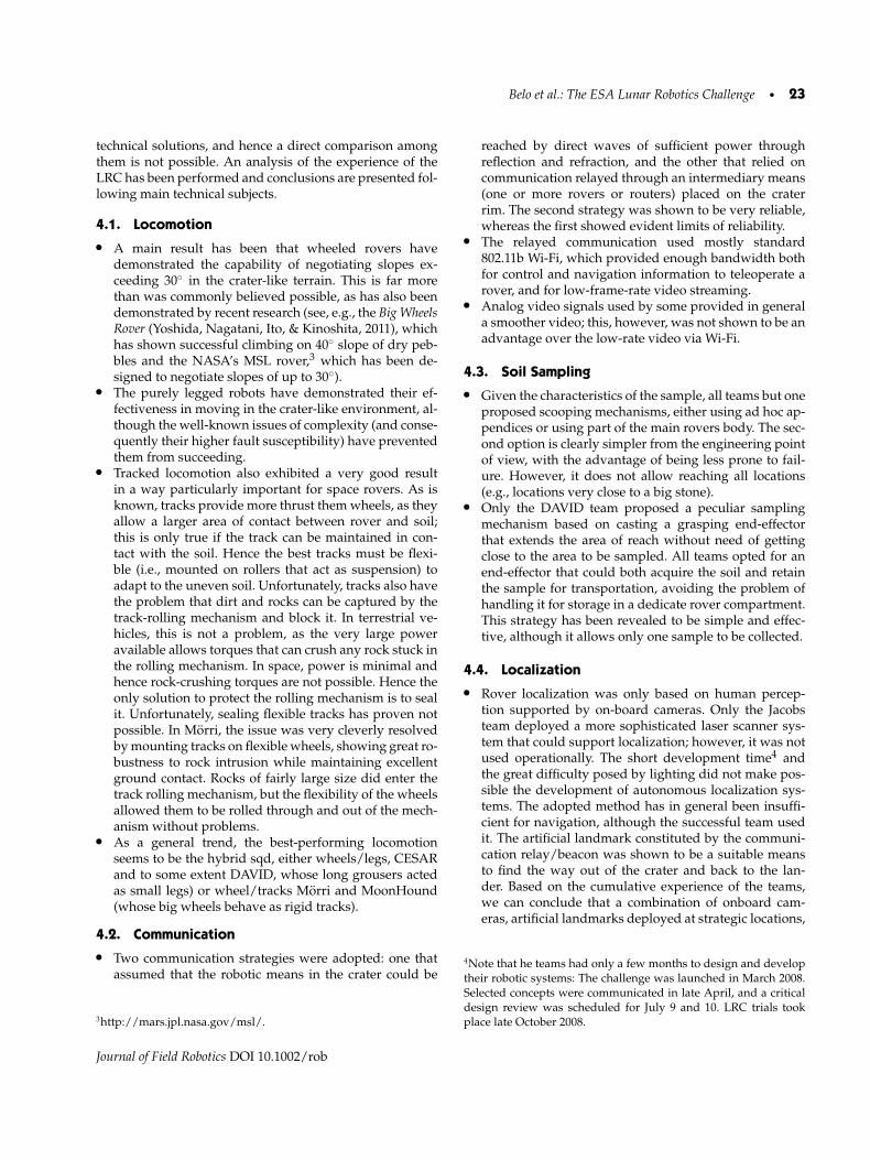
Belo et al.: The ESA Lunar Robotics Challenge • 23
technical solutions, and hence a direct comparison amongthem is not possible. An analysis of the experience of theLRC has been performed and conclusions are presented fol-lowing main technical subjects.
4.1. Locomotion• A main result has been that wheeled rovers have
demonstrated the capability of negotiating slopes ex-ceeding 30◦ in the crater-like terrain. This is far morethan was commonly believed possible, as has also beendemonstrated by recent research (see, e.g., the Big WheelsRover (Yoshida, Nagatani, Ito, & Kinoshita, 2011), whichhas shown successful climbing on 40◦ slope of dry peb-bles and the NASA’s MSL rover,3 which has been de-signed to negotiate slopes of up to 30◦).
• The purely legged robots have demonstrated their ef-fectiveness in moving in the crater-like environment, al-though the well-known issues of complexity (and conse-quently their higher fault susceptibility) have preventedthem from succeeding.
• Tracked locomotion also exhibited a very good resultin a way particularly important for space rovers. As isknown, tracks provide more thrust them wheels, as theyallow a larger area of contact between rover and soil;this is only true if the track can be maintained in con-tact with the soil. Hence the best tracks must be flexi-ble (i.e., mounted on rollers that act as suspension) toadapt to the uneven soil. Unfortunately, tracks also havethe problem that dirt and rocks can be captured by thetrack-rolling mechanism and block it. In terrestrial ve-hicles, this is not a problem, as the very large poweravailable allows torques that can crush any rock stuck inthe rolling mechanism. In space, power is minimal andhence rock-crushing torques are not possible. Hence theonly solution to protect the rolling mechanism is to sealit. Unfortunately, sealing flexible tracks has proven notpossible. In Morri, the issue was very cleverly resolvedby mounting tracks on flexible wheels, showing great ro-bustness to rock intrusion while maintaining excellentground contact. Rocks of fairly large size did enter thetrack rolling mechanism, but the flexibility of the wheelsallowed them to be rolled through and out of the mech-anism without problems.
• As a general trend, the best-performing locomotionseems to be the hybrid sqd, either wheels/legs, CESARand to some extent DAVID, whose long grousers actedas small legs) or wheel/tracks Morri and MoonHound(whose big wheels behave as rigid tracks).
4.2. Communication• Two communication strategies were adopted: one that
assumed that the robotic means in the crater could be
3http://mars.jpl.nasa.gov/msl/.
reached by direct waves of sufficient power throughreflection and refraction, and the other that relied oncommunication relayed through an intermediary means(one or more rovers or routers) placed on the craterrim. The second strategy was shown to be very reliable,whereas the first showed evident limits of reliability.
• The relayed communication used mostly standard802.11b Wi-Fi, which provided enough bandwidth bothfor control and navigation information to teleoperate arover, and for low-frame-rate video streaming.
• Analog video signals used by some provided in generala smoother video; this, however, was not shown to be anadvantage over the low-rate video via Wi-Fi.
4.3. Soil Sampling• Given the characteristics of the sample, all teams but one
proposed scooping mechanisms, either using ad hoc ap-pendices or using part of the main rovers body. The sec-ond option is clearly simpler from the engineering pointof view, with the advantage of being less prone to fail-ure. However, it does not allow reaching all locations(e.g., locations very close to a big stone).
• Only the DAVID team proposed a peculiar samplingmechanism based on casting a grasping end-effectorthat extends the area of reach without need of gettingclose to the area to be sampled. All teams opted for anend-effector that could both acquire the soil and retainthe sample for transportation, avoiding the problem ofhandling it for storage in a dedicate rover compartment.This strategy has been revealed to be simple and effec-tive, although it allows only one sample to be collected.
4.4. Localization• Rover localization was only based on human percep-
tion supported by on-board cameras. Only the Jacobsteam deployed a more sophisticated laser scanner sys-tem that could support localization; however, it was notused operationally. The short development time4 andthe great difficulty posed by lighting did not make pos-sible the development of autonomous localization sys-tems. The adopted method has in general been insuffi-cient for navigation, although the successful team usedit. The artificial landmark constituted by the communi-cation relay/beacon was shown to be a suitable meansto find the way out of the crater and back to the lan-der. Based on the cumulative experience of the teams,we can conclude that a combination of onboard cam-eras, artificial landmarks deployed at strategic locations,
4Note that he teams had only a few months to design and developtheir robotic systems: The challenge was launched in March 2008.Selected concepts were communicated in late April, and a criticaldesign review was scheduled for July 9 and 10. LRC trials tookplace late October 2008.
Journal of Field Robotics DOI 10.1002/rob

24 • Journal of Field Robotics—2012
and observed localization by means of cameras placedon the craters’ rim would provide the key to a successfulmission.
4.5. Situation Awareness• Understanding of rover internal status and external in-
teraction with the environment was generally found tobe inadequate. Telemetry of critical subsystems was notimplemented thoroughly and external visual supervi-sion was inadequate. Most of the teams had rather so-phisticated sets of cameras ideally designed to imageall of the rover and its surroundings. However, in allcases, there were blind spots. Faults or locomotion im-pediments always happened in the blind spots. The lackof objective localization means also created disorienta-tion within the crater. In the particular setting of the LRCthe lack of attitude sensors was particularly critical. Infact, the detection of reaching the craters rim (changeof terrain inclination) turned out to be indispensable,especially since at this location a crucial action had tobe performed, the deployment of the communicationsrelay. The causes that forced the teams to abandon themission were (1) mechanical failure or degradation (SE-LENE, MoonHound, ETHZ, Morri, pEASpod) and (2)irresolvable collision with the environment (DAVID, Ja-cobs). In the cases of MoonHound, ETHZ, DAVID, andJacobs, insufficient situational awareness led to the in-surgence or lack of resolution of the stopping problem.
• It must be noted that real space missions do approachsituational awareness with a more holistic and thoroughprocess that produces the best situational awarenessmeans possible. However, there is always the possibility,through accident/ faults/ degradation of performance,that situational awareness degrades to the levels imple-mented in the LRC means. It is therefore particularly en-couraging to see that even with such minimalist situa-tional awareness the challenge could be completed by atleast one team.
4.6. Human Factors• A final remark concerns the human factors. Vehicle tele-
operation needs task distribution over multiple opera-tors with clearly defined roles (Murphy, & Burke, 2008).In the LRC teams that performed best, a skilled pi-lot/operator was responsible for rover steering, whereasa navigator/mission specialist was responsible for tak-ing decisions on the steps to be performed, such asdirection to interesting locations, path planning, andmaintaining orientation by tracking artificial and nat-ural landmarks inside the operation zone. This splitof responsibilities is of crucial importance, especiallyin critical situations such as disorientation and poorlyunderstood rover status, when restoring correct situa-tion awareness may benefit from multiple viewpoints. A
third specialized payload operator, operating the samplecollection means, was found to be beneficial.
The range of technical solutions implemented in theLRC reflects the many technological options that exist andthat must be properly understood in preparing for futurelunar exploration. Issues regarding communicating with arover inside a crater, negotiating unstable slopes, and keep-ing track of position and orientation in a dark and chaoticlandscape are just a few of the challenges encountered inthe LRC that can be expected in an actual lunar mission.Addressing the various engineering challenges requires arobust approach to design, development, and testing, whilemaintaining the flexibility to include new and innovativesolutions. The LRC participants have demonstrated the ap-plication of this process to the relatively new challenges as-sociated with operating rovers in such a unique environ-ment.
The LRC has successfully demonstrated some of theissues in the teleoperation of robotic vehicles at the Lunarsouth pole. Identifying key features such as the crater rimand the direction of slope posed particular challenges forthe teams with low inclination illumination and limitationsin image quality. Disorientation once inside the dark crateralso proved to be a problem, with the operators experienc-ing difficulties in identifying landmarks by which to nav-igate. Terrain understanding is critical to design suitablerobotic means, whereas other factors that were thought tobe critical, such as slope inclination, turned out to be lessimportant, as most of the rovers could negotiate them rela-tively well.
Finally, as an educational tool, the LRC has also shownthe immense value of providing students and researcherswith an opportunity to experience the challenges of operat-ing their technical concepts in a realistic environment, andthe demands placed on technology, planning, organization,and teamwork. The commitment and dedication of the par-ticipating teams, as well as the LRC support crew, havebeen a major contributor to its success, and hopefully thefoundation for future LRC events.
ACKNOWLEDGMENTS
The authors would like to thank the ESA, and in particu-lar Mr. Richard Fisackerly, for organizing the LRC event.We would also like to thank the local crew from ActiveConnect for their logistic and technical support. Finally, wewould like to mention all the students and researcherswho formed the teams: CESAR team: Jakob Schwend-ner, Felix Grimminger, Sebastian Bartsch, Thilo Kaupisch,Joel Bessekon Akpo, Andreas Bresser, Mehmed Yuksel,Alexander Dieterle, Janosch Machowinski, Steffen Schmidt,Michael K.-G. Seydel, and Frank Kirchner. DAVID team:Riccardo Schiavi, Giorgio Grioli, Felipe Belo, Manuel Cata-lano, Simone Alicino, Fabio Bonomo, Adriano Fagiolini,Andrea di Basco, Michael Catanzaro, Rino LEpiscopia,
Journal of Field Robotics DOI 10.1002/rob
Belo et al.: The ESA Lunar Robotics Challenge • 25
Fabrizio Flacco, Manolo Garabini, Nicola Di Lecce, Gae-tano Lorefice, Federico Puccinelli, Fabrizio Vivaldi, andAntonio Bicchi. ALoF/CRABli team: Oliver Baur, Mar-tin Latta, Andreas Lauber, Fabian Seitz, C. David Remy,Cedric Pradalier, and Roland Siegwart; JACOBS team:Soren Schwertfeger, Jann Poppinga, Heiko Bulow, AdrianCostache, Ishan Basyal, and Andreas Birk. MoonHoundteam: Jose Carlo Fernandez, Christian Fiederling, Jose LuisMora, Juan Padilla, Ricardo Picadoste, Jose Emilio Tor-res, Claudio Rossi, Antonio Barrientos, Manuel Merino,and Miguel Hernando. Morri team: Antti Tikanmaki, MattiTikanmaki, Ari Pitkanen, Aku Pietikainen, Sauli Sarkka,and Juha Roning. pESApod team: Calogero M. Oddo,Nicola Vitiello, Alessandro Pignotti, Jacopo Corbetta, Ste-fano M.M. De Rossi, Roberto Farolfi, Massimo Grava,Marco Cempini, Dario Cazzaro, Luca Invernizzi, JacopoRigosa, Stefano Mintchev, Gerardo De Pasquale, LucaCeccanti, Paolo Dario, Maria Chiara Carrozza, and Ste-fano Roccella. SELENE team: Christopher Brunskill, Beat-rice Smith, Samian Humphrey, Michel Makhlouta, ShakeelBaig, Gareth Merion-Griffith, Akhmer Ahmed, and VaiosLappas.
REFERENCES
Bar-Cohen, Y., & Zacny, K., editors (2009). Drilling in extremeenvironments: penetration and sampling on earth andother planets. Weinheim, Germany: John Wiley & Sons.
Bekker, M. (1969). Introduction to terrain-vehicle systems. AnnArbor, MI: University of Michigan Press.
Birk, A. (2004). Fast robot prototyping with the cubesystem. InProceedings of the International Conference on Roboticsand Automation, New Orleans, LA (pp. 5177–5182).
Birk, A., & Carpin, S. (2006). Rescue robotics—A crucial mile-stone on the road to autonomous systems. AdvancedRobotics Journal, 20(5), 595–695.
Birk, A., Kenn, H., & Walle, T. (2000). On-board control in theRoboCup small robots league. Advanced Robotics Jour-nal, 14(1), 27–36.
Birk, A., Pathak, K., Schwertfeger, S., & Chonnaparamutt, W.(2006). The IUB rugbot: An intelligent, rugged mobilerobot for search and rescue operations. In IEEE Interna-tional Workshop on Safety, Security, and Rescue Robotics(SSRR).
Chonnaparamutt, W., & Birk, A. (2007). A new mechatroniccomponent for adjusting the footprint of tracked res-cue robots. In G. Lakemeyer, E. Sklar, D. Sorrenti, & T.Takahashi, (Eds.), RoboCup 2006: Robot WorldCup X, Lec-ture Notes in Artificial Intelligence (LNAI) (Vol. 4434,pp. 450–457). Berlin Heidelberg: Springer-Verlag.
Chonnaparamutt, W., & Birk, A. (2008). A fuzzy controller forautonomous negotiation of stairs by a mobile robot withadjustable tracks. In U. Visser, F. Ribeiro, T. Ohashi, & F.Dellaert (Eds.), RoboCup 2007: Robot WorldCup XI, Lec-ture Notes in Artificial Intelligence (LNAI) (pp. 196–207).Berlin Heidelberg: Springer-Verlag.
Eich, M., Grimminger, F., Bosse, S., Spenneberg, D., & Kirch-ner, F. (2008, January 7–8). Asguard: A hybrid leggedwheel security and SAR-robot using bio-inspired lo-comotion for rough terrain. In Online Proceedings,IARP/EURON Workshop on Robotics for Risky Interven-tions and Enviromental Surveillance (IARP/EURON-08),Benicassim, Spain. Retrieved December 18, 2011 fromhttp://www.robot.uji.es/documents/rise08/reports/Eich.pdf.
Ellery, A., Patel, N., Richter, L., Bertrand, R., & Dalcomo, J.(2005). EXOMARS rover chassis analysis and design. InB. Battrick (Ed.), i-SAIRAS 2005’—The 8th InternationalSymposium on Artificial Intelligence, Robotics and Au-tomation in Space. ESA SP-603 (p. 17.1). Noordwijk, TheNetherlands: European Space Agency [CD-ROM].
Fagiolini, A., Arisumi, H., & Bicchi, A. (2005). Visual-basedfeedback control of casting manipulation. In Proceedingsof the 2005 International Conference on Robotics and Au-tomation, Barcelona, Spain (pp. 2203–2208).
Hoepflinger, M., Remy, C., Hutter, M., & Siegwart, R. (2010).The quadruped ALoF and a step towards real world hap-tic terrain classifications. In Proceedings 12th Mechatron-ics Forum Biennial International Conference (Mechatron-ics’10), Zurich (pp. 173–180).
Ilon, B. (1973). Directionally stable self-propelled vehicle. U.S.Patent 3,746,112, filed 2 December 1971, patented 17 July1973. First patented in Sweden, 14 December 1970.
Kennedy, B., Okon, A., Aghazarian, H., Badescu, M., Bao, X.,Bar-Cohen, Y., Chang, Z., Dabiri, B., Garrett, M., Magnone,L., & Sherrit, S. (2005). Lemur IIB: A robotic system forsteep terrain access. In Proceedings 8th International Con-ference on Climbing and Walking Robots (CLAWAR’05),London (pp. 595–695).
Martin-Alvarez, A., de Peuter, W., Hillebrand, J., Putz, P.,Matthyssen, A., & de Weerd, J. (1996, May 27–30). Walk-ing robots for planetary exploration missions. Paperpresented at the WAC’96, Second World AutomationCongress, Montpellier, France (p. 2730).
McCloskey, S. (2007). Development of legged, wheeled, andhybrid rover mobility models to facilitate planetary sur-face exploration mission analysis. Master’s thesis, Mas-sachusetts Institute of Technology.
Murphy, R., & Burke, J. (2008). From remote tool to sharedroles. IEEE Robotics & Automation Magazine, 15(4), 39–49.
Nesnas, I., Abad-Manterola, P., Edlund, J., & Burdick, J. (2008).Axel mobility platform for steep terrain excursions andsampling on planetary surfaces. In 2008 IEEE AerospaceConference, Big Sky, MT (pp. 1–11).
Patel, N., Scott, G., & Ellery, A. (2004). Application ofBekker theory for planetary exploration through wheeled,tracked and legged vehicle locomotion. In Space 2004Conference and Exhibit, San Diego, CA (pp. 1–8).
Pathak, K., Vaskevicius, N., & Birk, A. (2009). Revisiting un-certainty analysis for optimum planes extracted from 3drange sensor point-clouds. In International Conference onRobotics and Automation (ICRA), Kobe, Japan (pp. 1631–1636).
Journal of Field Robotics DOI 10.1002/rob

26 • Journal of Field Robotics—2012
Poppinga, J., Vaskevicius, N., Birk, A., & Pathak, K. (2008).Fast plane detection and polygonalization in noisy 3drange images. In International Conference on IntelligentRobots and Systems (IROS), Nice, France (pp. 3378–3383).
Ransom, S., Kromer, O., & Luckemeieri, M. (2008). Planetaryrovers with mecanum wheels. In Proceedings ASTRA2008, Noordwijk, The Netherlands, Retrieved Decem-ber 18, 2011, from http://robotics.estec.esa.int/ASTRA/ASTRA2008.
Remy, C., Baur, O., Latta, M. Lauber, A., Hutter, M.,Hoepflinger, M., Pradalier, C., & Siegwart, R. (2011). Walk-ing and crawling with ALoF—A robot for autonomous lo-comotion on four legs. Industrial Robot: An InternationalJournal, 38(3), 264–268.
Tadakuma, K., Matsumoto, M., & Hirose, S. (2006). “Tri-star3”; Horizontal polyarticular arm equipped 3-wheeledexpandable rover. In 2006 IEEE/RSJ InternationalConference on Intelligent Robots and Systems, Beijing,China (p. 5).
Thueer, T., Krebs, A., Siegwart, R., & Lamon, P. (2007). Perfor-mance comparison of rough-terrain robots—Simulationand hardware. Journal of Field Robotics, 24(3), 251–271.
Thueer, T., Lamon, P., Krebs, A., & Siegwart, R. (2006). Crab—Exploration rover with advanced obstacle negotiation ca-pabilities. In Proceedings 9th ESA Workshop on Ad-vanced Space Technology for Robotics and Automation(ASTRA’06), Noordwijk, The Netherlands (pp. 501–508).
Vaskevicius, N., Birk, A., Pathak, K., Schwertfeger, S., & Rath-nam, R. (2010). Efficient representation in 3D environmentmodeling for planetary robotic exploration. AdvancedRobotics, 24(8–9), 1169–1197.
Yoshida, K., Nagatani, K., Ito, T., & Kinoshita, H. (2011, May).Wheels, tracks and reciprocal walking: Challenges toloose and steep slopes. Paper presented at the ICRA11Space Robotics Workshop, Shanghai, China.
Yumaryanto, A., Ana, J. & Lee, S. (2006). A cockroach-inspiredhexapod robot actuated by LIPCA. In Proceedings of IEEEConference on Robotics, Automation and Mechatronics,Bangkok (pp. 1–6).
Journal of Field Robotics DOI 10.1002/rob
Related Documents