ROAD SAFETY RESEARCH GRANT 2009–005 The effects of Electronic Stability Control interventions on rural road crashes in Australia: Simulation of real world crashes October 2009

Welcome message from author
This document is posted to help you gain knowledge. Please leave a comment to let me know what you think about it! Share it to your friends and learn new things together.
Transcript

ROAD SAFETY RESEARCH GRANT 2009–005
The effects of Electronic Stability Control interventions on rural road crashes in Australia: Simulation of
real world crashes
October 2009

ROAD SAFETY GRANT REPORT 2009-005
The effects of Electronic Stability Control interventions on rural road crashes in Australia:
Simulation of real world crashes
Jamie Mackenzie Robert Anderson
Centre for Automotive Safety Research
October 2009

Published by: Department of Infrastructure, Transport, Regional Development and Local Government
Postal address: GPO Box 594, Canberra, ACT, 2601 Office location: 111 Alinga Street, Canberra City, ACT Telephone: 1800 026 349; from overseas + 61 2 6274 7111 Facsimile: 02 6274 7608; from overseas + 61 2 6274 7608 E-mail: roadsafety @infrastructure.gov.au Internet: www.infrastructure.gov.au/roads/safety
© Centre for Automotive Safety Research 2009
To encourage the dissemination of this publication, it may be copied, downloaded, displayed, printed, reproduced, and distributed in unaltered form (retaining this notice). Subject to the provisions of the Copyright Act 1968, no other use of the material in this publication may be made without the authorisation of the Centre for Automotive Safety Research.

DOCUMENT RETRIEVAL INFORMATION
Report No. RSRG 2009-005
Publication date October 2009
No. of pages 120
ISBN 978-1-921659-05-8
Publication title The effects of Electronic Stability Control interventions on rural road crashes in Australia: Simulation of real world crashes
Authors Mackenzie JRR; Anderson RWG
Organisation that prepared this document Centre for Automotive Safety Research The University of Adelaide, SA, 5005, AUSTRALIA
Sponsor [Available from] Department of Infrastructure, Transport, Regional Development and Local Government GPO Box 594 CANBERRA ACT 2601
www.infrastructure.gov.au
Reference No. October 2009/INFRA09104
Acknowledgements Software and assistance for this study was supplied by Robert Bosch (Australia) Pty. Ltd. Their support was greatly appreciated.
Abstract About 60 per cent of all fatal road crashes in Australia occur on rural roads. While advances have been made in reducing the number of fatal crashes on metropolitan roads, the number of fatal crashes on rural roads remains relatively steady. Electronic Stability Control (ESC) is an active safety system which has shown potential in preventing crashes on high speed rural roads. The ESC system can detect when a vehicle is about to skid and apply braking interventions to individual wheels to prevent the skid from occurring. Previous studies have shown that vehicles equipped with ESC have a significantly reduced crash rate compared with vehicles not equipped with ESC. However the way that the ESC system intervenes to prevent or lower the severity of crashes on rural roads has not been elucidated. Twenty crash scenarios were developed based on actual rural road crashes obtained from an in-depth crash database. With the assistance of Robert Bosch (Australia) Pty. Ltd., 12 of the scenarios were simulated using a vehicle model with and without ESC fitted. The simulations produced detailed plots that displayed the timing and magnitude of the ESC system’s interventions. In two of the scenarios, no simulation was necessary as the driver made no attempt to avoid a collision. In six scenarios, the attempt at simulation was unsuccessful. For the 12 successful simulations, ESC was found to prevent a collision in 10 cases and reduce the severity of a collision in the other two.
Notes (1) The Department’s reports are disseminated in the interest of information exchange. (2) The views expressed are those of the author(s) and do not necessarily represent those of the
Australian Government or the Department.
ii The effects of Electronic Stability Control interventions on rural road crashes in Australia: Simulation of real world crashes
CONTENTS
Executive summary .......................................................................................................................... v
Acknowledgements .......................................................................................................................... vi
Abbreviations .................................................................................................................................. vii
1 Introduction .............................................................................................................................. 1
2 Method ....................................................................................................................................... 2
2.1 Rural crash database ...................................................................................................... 2
2.2 Selection of crashes ....................................................................................................... 2
2.3 Simulation software ....................................................................................................... 4
2.4 Simulation setup ............................................................................................................ 4
3 Basic ESC Principles ................................................................................................................ 9
3.1 Wheel Slip ................................................................................................................... 10
3.2 Traction Circle ............................................................................................................. 11
3.3 Skidding Scenarios ...................................................................................................... 14
4 Results ...................................................................................................................................... 19
4.1 Organisation of Results ................................................................................................ 19
4.2 Case 01 ........................................................................................................................ 21
4.3 Case 02 ........................................................................................................................ 27
4.4 Case 03 ........................................................................................................................ 33
4.5 Case 04 ........................................................................................................................ 39
4.6 Case 05 ........................................................................................................................ 45
4.7 Case 06 ........................................................................................................................ 51
4.8 Case 07 ........................................................................................................................ 57
4.9 Case 08 ........................................................................................................................ 63
4.10 Case 09 ........................................................................................................................ 69
4.11 Case 10 ........................................................................................................................ 75
4.12 Case 11 ........................................................................................................................ 81
4.13 Case 12 ........................................................................................................................ 87
4.14 Case 13 ........................................................................................................................ 93
4.15 Case 14 ........................................................................................................................ 95
4.16 Case 15 ........................................................................................................................ 97
4.17 Case 16 ........................................................................................................................ 99
The effects of Electronic Stability Control interventions on rural road crashes in Australia: Simulation of real world crashes iii

iv The effects of Electronic Stability Control interventions on rural road crashes in Australia: Simulation of real world crashes
4.18 Case 17 ...................................................................................................................... 101
4.19 Case 18 ...................................................................................................................... 103
4.20 Case 19 ...................................................................................................................... 105
4.21 Case 20 ...................................................................................................................... 107
5 Discussion .............................................................................................................................. 109
5.1 Limitations ................................................................................................................. 109
5.2 Recommendations ...................................................................................................... 110
5.3 Future work ................................................................................................................ 110
6 References ............................................................................................................................. 111

EXECUTIVE SUMMARY
It is well documented that, in Australia, the number of people who die as a result of a motor vehicle crash is greater on rural roads than it is on metropolitan roads. This is especially true on high speed rural roads. Several studies have compared the crash rate of vehicles equipped with Electronic Stability Control (ESC) to those not equipped with ESC. All conclude that vehicles equipped with ESC experience a lower crash rate than vehicles not equipped with ESC. This effect was found to be especially prominent for crashes on high speed rural roads. The basic principles behind the way in which ESC systems utilise braking interventions to keep a vehicle stable are well known and understood. However no studies to date have investigated how these interventions operate specifically during the events of actual crashes. Therefore, while it is known that ESC lowers crash rates, how the system’s interventions achieve this, across a wide range of crash types and unique situations is not clear.
In this study 20 rural road crash scenarios were developed to compare the dynamics of a vehicle equipped with ESC to the dynamics of a vehicle not equipped with ESC. The scenarios were based on actual crashes from a database of South Australian rural road crashes. The database contained enough information about each crash to reconstruct the events of the crash. The crashes involved exclusively passenger cars or derivatives, were sensitive to the effects of ESC and did not involve a driver who was dead, asleep, or passed out. Ninety-six crashes were suitable and, from these, 20 were chosen at random.
Computer simulations of each crash scenario were used to analyse the effect that the addition of an ESC system to a vehicle would have had on the crash outcome. In addition, the timing and magnitude of any ESC interventions were documented to explain how the ESC system might have affected the crash outcome. Robert Bosch (Australia) Pty. Ltd. advised on the selection of appropriate simulation software and supplied vehicle models which had the ability to simulate a vehicle either equipped or not equipped with ESC. The simulation software generated data which allowed a comparison of the trajectory of the vehicle equipped with ESC to the vehicle not equipped with ESC. Additionally all interventions made by the ESC system were plotted.
Twelve of the scenarios were simulated successfully and the results are presented herein. Each crash scenario is described and the setup of the simulation for that scenario is detailed. A diagram showing the difference in the vehicle trajectory is presented for the ESC/no-ESC simulation and how the crash outcome would have been affected by ESC is discussed. Finally, a plot of the interventions made by the ESC system is presented, accompanied by an explanation of how the interventions affected the vehicle trajectory.
In 10 of the successful simulations, the addition of ESC to the vehicle prevented a collision from occurring at all. In the other two, the addition of ESC to the vehicle reduced the severity of the collision. In a further two scenarios, no simulation was required as the driver made no attempt to avoid a collision and thus would not have benefited from the presence of ESC. The final six scenarios could not be simulated successfully.
The results show that ESC systems are able to significantly benefit vehicle dynamics in real-world crash scenarios. ESC systems aid drivers in avoiding a loss of control during an emergency manoeuvre. An increase in the number of vehicles in Australia equipped with ESC would therefore be expected to reduce the number of high speed, loss of control crashes. The effectiveness of the system can be maximised by continuing to: seal roadside shoulders; maintain and upgrade road surfaces; increase the width of clear zones; install roadside and median crash barriers; set appropriate speed limits; and educate drivers about the dangers of driving recklessly, at high speeds, while fatigued or while under the influence of alcohol/drugs.
The effects of Electronic Stability Control interventions on rural road crashes in Australia: Simulation of real world crashes v

ACKNOWLEDGEMENTS
The authors acknowledge the funding support provided by the Australian Government, through the Department of Infrastructure, Transport, Regional Development and Local Government’s Road Safety Research Grants Program.
The authors would also like to acknowledge the assistance provided by the following people:
Centre for Automotive Safety Research • Paul Hutchinson • Craig Kloeden • Jaime Royals
University of Adelaide • James Deed • Kristeen Soon
Robert Bosch Australia • Walter My • John Nicolopoulos • Chris Woods
Department of Infrastructure, Transport, Regional Development and Local Government • John Collis • Andrew McCall • John Goldsworthy
vi The effects of Electronic Stability Control interventions on rural road crashes in Australia: Simulation of real world crashes
The effects of Electronic Stability Control interventions on rural road crashes in Australia: Simulation of real world crashes vii
ABBREVIATIONS
TARS Traffic Accident Reporting System
CASR Centre for Automotive Safety Research
ESC Electronic Stability Control
ESP Electronic Stability Program
DTEI Department for Transportation, Energy and Infrastructure

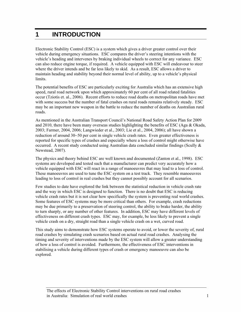
1 INTRODUCTION
Electronic Stability Control (ESC) is a system which gives a driver greater control over their vehicle during emergency situations. ESC compares the driver’s steering intentions with the vehicle’s heading and intervenes by braking individual wheels to correct for any variance. ESC can also reduce engine torque, if required. A vehicle equipped with ESC will endeavour to steer where the driver intends and be far less likely to skid. As a result, ESC allows a driver to maintain heading and stability beyond their normal level of ability, up to a vehicle’s physical limits.
The potential benefits of ESC are particularly exciting for Australia which has an extensive high speed, rural road network upon which approximately 60 per cent of all road related fatalities occur (Tziotis et. al., 2006). Recent efforts to reduce road deaths on metropolitan roads have met with some success but the number of fatal crashes on rural roads remains relatively steady. ESC may be an important new weapon in the battle to reduce the number of deaths on Australian rural roads.
As mentioned in the Australian Transport Council’s National Road Safety Action Plan for 2009 and 2010, there have been many overseas studies highlighting the benefits of ESC (Aga & Okada, 2003; Farmer, 2004, 2006; Langwieder et al., 2003; Lie et al., 2004, 2006); all have shown a reduction of around 30−50 per cent in single vehicle crash rates. Even greater effectiveness is reported for specific types of crashes and especially where a loss of control might otherwise have occurred. A recent study conducted using Australian data concluded similar findings (Scully & Newstead, 2007).
The physics and theory behind ESC are well known and documented (Zanton et al., 1998). ESC systems are developed and tested such that a manufacturer can predict very accurately how a vehicle equipped with ESC will react in a range of manoeuvres that may lead to a loss of control. These manoeuvres are used to tune the ESC system on a test track. They resemble manoeuvres leading to loss of control in real crashes but they cannot possibly account for all scenarios.
Few studies to date have explored the link between the statistical reduction in vehicle crash rate and the way in which ESC is designed to function. There is no doubt that ESC is reducing vehicle crash rates but it is not clear how specifically the system is preventing real world crashes. Some features of ESC systems may be more critical than others. For example, crash reductions may be due primarily to a preservation of steering control, the ability to brake harder, the ability to turn sharply, or any number of other features. In addition, ESC may have different levels of effectiveness on different crash types. ESC may, for example, be less likely to prevent a single vehicle crash on a dry, straight road than a single vehicle crash on a wet, curved road.
This study aims to demonstrate how ESC systems operate to avoid, or lower the severity of, rural road crashes by simulating crash scenarios based on actual rural road crashes. Analysing the timing and severity of interventions made by the ESC system will allow a greater understanding of how a loss of control is avoided. Furthermore, the effectiveness of ESC interventions in stabilising a vehicle during different types of crash or emergency manoeuvre can also be explored.
The effects of Electronic Stability Control interventions on rural road crashes in Australia: Simulation of real world crashes 1

2 METHOD
The crashes used in this study were taken from a database of South Australian rural road crashes which is described in the ‘Rural crash database’ section. Twenty crashes were selected from the database using the method described in the ‘Selection of crashes’ section.
The accurate simulation of a real crash is a difficult process and has many limitations. The vehicle, environment and driver each play a crucial role during a crash event. They should therefore, all be accounted for in the simulation of any crash. Unfortunately, when reconstructing a crash it is usually not possible to know the driver’s actions or intentions, the exact condition of the vehicle or specific details about the environment. For this reason, it is impossible to produce a simulation that precisely reconstructs a real crash in every detail. As such, the crashes selected for this study were used as a guide to develop scenarios representative of real crashes.
Each crash scenario was used to create a simulation using specialised commercial vehicle dynamics software which is described in the ‘Simulation software’ section. The way in which each simulation was set up is discussed in the ‘Simulation setup’ section.
2.1 Rural crash database Between March 1998 and February 2000, the Centre for Automotive Safety Research (CASR) investigated 236 rural road crashes to which an ambulance was called, within 100 km of Adelaide (Baldock et al, 2008). Each crash scene was investigated by CASR personnel where a large amount of data was recorded. The crash site was mapped and photographed. The final positions and damage sustained by any crash-involved vehicle was noted. Post-crash interviews were also conducted with drivers, passengers and witnesses who were willing to participate. The data collected from each crash was placed into the CASR rural crash database along with any additional, relevant files, including police reports and coroners’ reports. The amount of data collected from each crash scene was, in most cases, sufficient to provide an understanding of the crash events and enable a reconstruction of the crash to be made.
2.2 Selection of crashes No ESC systems exist for motorcycles; and while ESC systems do exist for trucks and buses, they are complex and beyond the scope of this study. This study was consequently only concerned with crashes by passenger cars and their derivatives (hatchbacks, station wagons, utilities, etc).
ESC systems correct for sideways skidding. Rear end, side swipe and other straight line or non-loss-of-control type crashes are therefore not sensitive to the effects of ESC. It is unlikely that any ESC interventions would occur during a non-ESC-sensitive crash. In order to ensure results, this study was only concerned with crashes which were ESC-sensitive.
From the initial pool of 236 rural road crashes, 43crashes involving exclusively vehicles other than passenger cars or derivatives, and 78 crashes which were not ESC-sensitive were removed.
The ESC system reacts to a driver’s steering actions. The system therefore relies on a conscious driver making rational steering actions. A further 19 crashes were removed as the driver was
2 The effects of Electronic Stability Control interventions on rural road crashes in Australia: Simulation of real world crashes
either dead, asleep, passed out or there was suspicion of suicide. Crashes involving drivers who were affected by alcohol or fatigued, but still capable of making rational steering decisions, were retained in the sample.
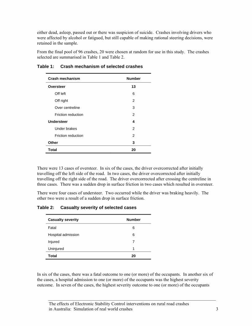
From the final pool of 96 crashes, 20 were chosen at random for use in this study. The crashes selected are summarised in Table 1 and Table 2.
Table 1: Crash mechanism of selected crashes
Crash mechanism Number
Oversteer 13
Off left 6
Off right 2
Over centreline 3
Friction reduction 2
Understeer 4
Under brakes 2
Friction reduction 2
Other 3
Total 20
There were 13 cases of oversteer. In six of the cases, the driver overcorrected after initially travelling off the left side of the road. In two cases, the driver overcorrected after initially travelling off the right side of the road. The driver overcorrected after crossing the centreline in three cases. There was a sudden drop in surface friction in two cases which resulted in oversteer.
There were four cases of understeer. Two occurred while the driver was braking heavily. The other two were a result of a sudden drop in surface friction.
Table 2: Casualty severity of selected cases
Casualty severity Number
Fatal 6
Hospital admission 6
Injured 7
Uninjured 1
Total 20
In six of the cases, there was a fatal outcome to one (or more) of the occupants. In another six of the cases, a hospital admission to one (or more) of the occupants was the highest severity outcome. In seven of the cases, the highest severity outcome to one (or more) of the occupants
The effects of Electronic Stability Control interventions on rural road crashes in Australia: Simulation of real world crashes 3

was an injury treated at either a hospital or a local doctor. In only one case were there no injuries to any of the occupants involved. Overall these cases represent higher severity crashes.
A summary of each case is given in the Results chapter. However, the injury details associated with each individual crash cannot be given for privacy and ethical reasons.
2.3 Simulation software ESC technology is relatively new and complex and there was no standard vehicle dynamics simulation software package which included it as a feature. Robert Bosch (Australia) Pty. Ltd. agreed to provide assistance to this study by supplying software which could integrate with a vehicle dynamics software package to facilitate the simulation of an ESC-equipped vehicle. Bosch Australia recommended a vehicle dynamics simulation package called CarSim, developed by Mechanical Simulation Corporation.
CarSim is able to accurately map the path of a vehicle based upon: characteristics of the vehicle, the environment and the driver’s actions. CarSim uses detailed vehicle and tyre models and generates comprehensive plots of vehicle properties over the course of the simulation. CarSim is not a crash simulator and has no facilities for simulating any type of collision between vehicles or roadside objects.
The software used to simulate the response of an ESC system is a proprietary simulation package, called CSsim, developed by Bosch. CSsim is able to interface with CarSim and calculate the interventions an ESC system would make, based upon a vehicle’s current situation. If the CSsim software is not used, a vehicle not equipped with ESC can be simulated. By turning on the CSsim software, an identical vehicle, this time equipped with ESC, can be simulated within CarSim.
There are several names given to ESC systems by different manufacturers. The system produced by Bosch Australia is called Electronic Stability Program (ESP). The CSsim software simulates the effects of equipping a vehicle with ESP. Therefore when discussing the role of ESC in the crash simulations later in this report, the stability control system will be referred to as ESP.
2.4 Simulation setup
Each simulation was set up according to a set protocol. The CarSim software requires three components of input data for every simulation. These components are vehicle data, events data and environment data. The three components of input data are described below.
Figure 1 shows how the input data is supplied to CarSim, which then communicates with CSsim to produce the outputs. The outputs consist of a three dimensional animation of the vehicle path and graphical plots of various vehicle parameters.
4 The effects of Electronic Stability Control interventions on rural road crashes in Australia: Simulation of real world crashes
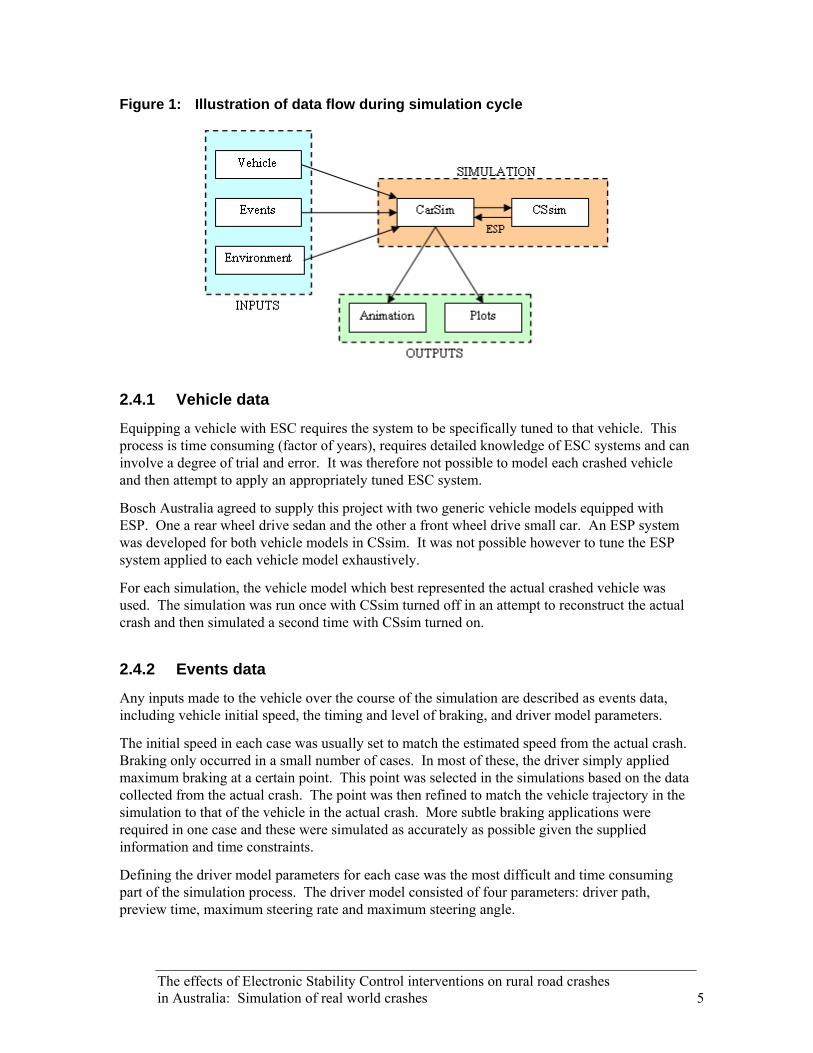
Figure 1: Illustration of data flow during simulation cycle
2.4.1 Vehicle data
Equipping a vehicle with ESC requires the system to be specifically tuned to that vehicle. This process is time consuming (factor of years), requires detailed knowledge of ESC systems and can involve a degree of trial and error. It was therefore not possible to model each crashed vehicle and then attempt to apply an appropriately tuned ESC system.
Bosch Australia agreed to supply this project with two generic vehicle models equipped with ESP. One a rear wheel drive sedan and the other a front wheel drive small car. An ESP system was developed for both vehicle models in CSsim. It was not possible however to tune the ESP system applied to each vehicle model exhaustively.
For each simulation, the vehicle model which best represented the actual crashed vehicle was used. The simulation was run once with CSsim turned off in an attempt to reconstruct the actual crash and then simulated a second time with CSsim turned on.
2.4.2 Events data
Any inputs made to the vehicle over the course of the simulation are described as events data, including vehicle initial speed, the timing and level of braking, and driver model parameters.
The initial speed in each case was usually set to match the estimated speed from the actual crash. Braking only occurred in a small number of cases. In most of these, the driver simply applied maximum braking at a certain point. This point was selected in the simulations based on the data collected from the actual crash. The point was then refined to match the vehicle trajectory in the simulation to that of the vehicle in the actual crash. More subtle braking applications were required in one case and these were simulated as accurately as possible given the supplied information and time constraints.
Defining the driver model parameters for each case was the most difficult and time consuming part of the simulation process. The driver model consisted of four parameters: driver path, preview time, maximum steering rate and maximum steering angle.
The effects of Electronic Stability Control interventions on rural road crashes in Australia: Simulation of real world crashes 5
The maximum steering angle defines the amount of travel (in degrees) in the steering wheel between the full lock positions in either direction. This was set to 360 degrees in all cases.
The maximum steering rate defines the speed at which the driver model is able to turn the steering wheel (in degrees per second). This variable is used in each case to control how quickly the driver model is able to respond to a change in the driver path. If a quick response is required, a high steering rate is used. Conversely, if a slow response is required, a low steering rate is used. In this study, the value of the maximum steering rate ranged between 120 degrees per second and 600 degrees per second.
The preview time defines how far ahead the driver model ‘looks’ in anticipation of a change in the driver path (in seconds). This variable is used in each case to control how the driver model responds to the driver path. If a surprised response to a change in the driver path is required, a small preview time is used. Conversely, if a slow, controlled response to change in the driver path is required, a large preview time is used. In this study, the values ranged between 0.60 seconds and 0.95 seconds.
The driver path informs the driver model when and where to steer the vehicle. The path is defined as a guide to where the vehicle should be positioned, which the driver model attempts to achieve by steering the vehicle. As explained, the driver model will react to the path in different ways depending on the selected preview time and maximum steering rate.
The trajectory of the simulated vehicle depends on all of the driver model parameters (not just the driver path). In each case the driver model parameters were chosen and refined based on the circumstances of the actual crash, with the objective of matching the trajectory of the simulated vehicle with that of the vehicle in the actual crash.
2.4.3 Environment data
The environment data set consists of road section and road profile information as well as the friction values across the surface of the road and shoulders.
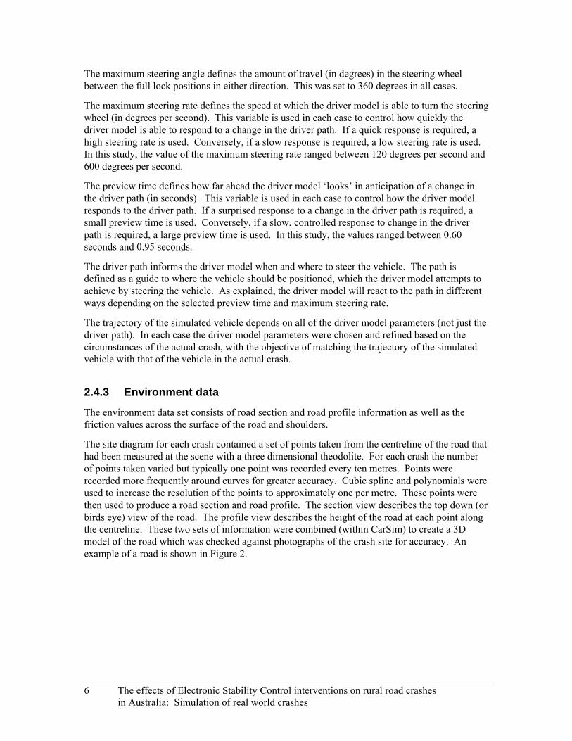
The site diagram for each crash contained a set of points taken from the centreline of the road that had been measured at the scene with a three dimensional theodolite. For each crash the number of points taken varied but typically one point was recorded every ten metres. Points were recorded more frequently around curves for greater accuracy. Cubic spline and polynomials were used to increase the resolution of the points to approximately one per metre. These points were then used to produce a road section and road profile. The section view describes the top down (or birds eye) view of the road. The profile view describes the height of the road at each point along the centreline. These two sets of information were combined (within CarSim) to create a 3D model of the road which was checked against photographs of the crash site for accuracy. An example of a road is shown in Figure 2.
6 The effects of Electronic Stability Control interventions on rural road crashes in Australia: Simulation of real world crashes
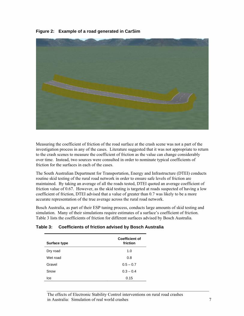
Figure 2: Example of a road generated in CarSim
Measuring the coefficient of friction of the road surface at the crash scene was not a part of the investigation process in any of the cases. Literature suggested that it was not appropriate to return to the crash scenes to measure the coefficient of friction as the value can change considerably over time. Instead, two sources were consulted in order to nominate typical coefficients of friction for the surfaces in each of the cases.
The South Australian Department for Transportation, Energy and Infrastructure (DTEI) conducts routine skid testing of the rural road network in order to ensure safe levels of friction are maintained. By taking an average of all the roads tested, DTEI quoted an average coefficient of friction value of 0.67. However, as the skid testing is targeted at roads suspected of having a low coefficient of friction, DTEI advised that a value of greater than 0.7 was likely to be a more accurate representation of the true average across the rural road network.
Bosch Australia, as part of their ESP tuning process, conducts large amounts of skid testing and simulation. Many of their simulations require estimates of a surface’s coefficient of friction. Table 3 lists the coefficients of friction for different surfaces advised by Bosch Australia.
Table 3: Coefficients of friction advised by Bosch Australia
Surface type Coefficient of
friction
Dry road 1.0
Wet road 0.8
Gravel 0.5 – 0.7
Snow 0.3 – 0.4
Ice 0.15
The effects of Electronic Stability Control interventions on rural road crashes in Australia: Simulation of real world crashes 7

It was decided that, based on the advice from DTEI, a more conservative estimate of the coefficient of friction than that supplied by Bosch Australia would be chosen. Table 4 lists the coefficients of friction used for different surface types in this study. In areas where a vehicle was said to have aquaplaned or skidded on black ice, the coefficient of friction was set to a very low 0.1.
Table 4: Coefficients of friction for various surface types used in this study
Surface type Coefficient of
friction
Dry sealed road 0.85
Wet sealed road 0.75
Dry unsealed road 0.70
Dry shoulder 0.60
Wet shoulder 0.50
Loose gravel road 0.50
Hail and sleet on sealed road 0.50
8 The effects of Electronic Stability Control interventions on rural road crashes in Australia: Simulation of real world crashes
3 BASIC ESC PRINCIPLES
The purpose of ESC is to produce a vehicle which has greater stability. A stable vehicle is one which is able to respond quickly and adequately to a driver’s requests. During emergency manoeuvres a vehicle can experience severe steering requests and large amounts of weight shift from side to side. When this occurs a vehicle can become unstable. A vehicle which is unstable can quickly become unresponsive to driver inputs and begin to skid or yaw.
ESC’s key purpose is to maintain stability during cornering, but it also integrates the functions of both ABS (stability during braking) and traction control systems (stability during acceleration). The ESC system includes the following major components which detect both the driver’s intentions and the vehicle’s response:
Driver Intention • Steering angle sensor • Brake sensor • Throttle sensor
Vehicle Response • Wheel speed sensors • Yaw rate sensor • Lateral acceleration sensor
The critical feature of ESC is its ability to brake individual wheels independently. This enables the system to produce a torque through the vehicle’s vertical axis at its centre of gravity. The ESC system can therefore either increase or decrease the torque and, hence, the rate of yaw which a vehicle experiences. This ability is explained to a greater extent in the following sections.
As a vehicle travels, the ESC system monitors the driver’s intentions and the vehicle’s response. It compares the two and decides whether the vehicle is responding correctly to the driver’s intentions. If the vehicle is not responding correctly, the ESC system will intervene and affect the yaw by braking one or more wheels to keep the vehicle stable.
Each ESC system is specifically designed and tuned to the vehicle in which it is installed. Within the system is a vehicle model which can predict when a vehicle is about to become unstable by calculating how the vehicle will respond to the drivers intentions based on current readings from the ESC sensors. This is important as ESC does not wait for a vehicle to become unstable before it intervenes. Rather it attempts to prevent the vehicle from becoming unstable in the first place.
The sections below provide a quick explanation of the concepts required to understand the results of simulations presented in later sections. In addition, how these vehicle dynamics concepts relate to the way in which the ESC system operates is explained.
Two vehicle dynamics concepts are important when trying to understand the basic principles of ESC operation. The first is wheel slip, which describes the interaction between the tyre and the road on a wheel that is braking. The second is the traction circle (or circle of forces), which is useful in visualising how the braking forces at each wheel manipulate the direction or heading of a vehicle.
The effects of Electronic Stability Control interventions on rural road crashes in Australia: Simulation of real world crashes 9

The explanation of these concepts is only intended to provide an understanding of the results presented in this report and help describe how the ESC system operates. They have been deliberately simplified to make understanding easier. A more complete and comprehensive description of the concepts can be found by reading vehicle dynamics publications such as Gillespie (1992) or Milliken & Milliken (1995).
3.1 Wheel Slip When a wheel is braking (or accelerating) the tyre stretches and deforms at the contact patch with the road. This is due to the elastic properties of the rubber elements in the tyre. Because of the stretching and deforming, the elements on the circumference of the tyre have a smaller forward velocity than that of the vehicle itself. Figure 3 illustrates this where Vc is the forward velocity of the circumference of the tyre and Vf is the forward velocity of the vehicle. This difference is described as ‘wheel slip’ and is defined, non-dimensionally, as a percentage.
Figure 3: Difference in tyre forward velocity
Vf
Vc
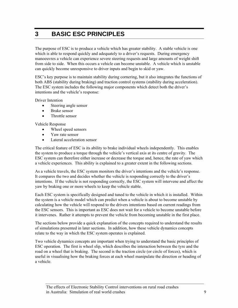
Figure 4 shows the relationship between wheel slip and braking coefficient, which is a measure of the braking force relative to the vertical force on the tyre. A wheel with zero per cent slip is free rolling, while a wheel with 100 per cent slip is skidding (or locked).
There are three phases of wheel slip as shown in Figure 4. The first is the linear phase (0−20 per cent slip), where the braking coefficient increases linearly with slip. The second phase (around 20 per cent slip) is the transitional phase, where the braking coefficient reaches its maximum. The last phase is the unstable phase (20−100 per cent slip), where the braking coefficient begins to decrease as slip increases.
10 The effects of Electronic Stability Control interventions on rural road crashes in Australia: Simulation of real world crashes
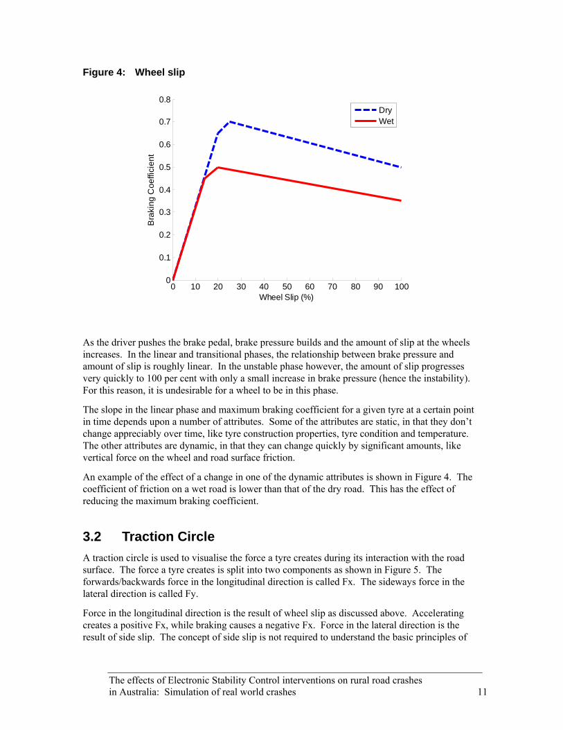
Figure 4: Wheel slip
0 10 20 30 40 50 60 70 80 90 1000
0.1
0.2
0.3
0.4
0.5
0.6
0.7
0.8
Wheel Slip (%)
Bra
king
Coe
ffici
ent
DryWet
As the driver pushes the brake pedal, brake pressure builds and the amount of slip at the wheels increases. In the linear and transitional phases, the relationship between brake pressure and amount of slip is roughly linear. In the unstable phase however, the amount of slip progresses very quickly to 100 per cent with only a small increase in brake pressure (hence the instability). For this reason, it is undesirable for a wheel to be in this phase.
The slope in the linear phase and maximum braking coefficient for a given tyre at a certain point in time depends upon a number of attributes. Some of the attributes are static, in that they don’t change appreciably over time, like tyre construction properties, tyre condition and temperature. The other attributes are dynamic, in that they can change quickly by significant amounts, like vertical force on the wheel and road surface friction.
An example of the effect of a change in one of the dynamic attributes is shown in Figure 4. The coefficient of friction on a wet road is lower than that of the dry road. This has the effect of reducing the maximum braking coefficient.
3.2 Traction Circle A traction circle is used to visualise the force a tyre creates during its interaction with the road surface. The force a tyre creates is split into two components as shown in Figure 5. The forwards/backwards force in the longitudinal direction is called Fx. The sideways force in the lateral direction is called Fy.
Force in the longitudinal direction is the result of wheel slip as discussed above. Accelerating creates a positive Fx, while braking causes a negative Fx. Force in the lateral direction is the result of side slip. The concept of side slip is not required to understand the basic principles of
The effects of Electronic Stability Control interventions on rural road crashes in Australia: Simulation of real world crashes 11
ESC operation and so will not be discussed, other than to say that as a wheel is turned, the tyre creates a sideways force, Fy. Turning the wheel to the right causes a positive Fy, while turning the wheel to the left causes a negative Fy.
Figure 5: Direction of forces, looking down on a tyre
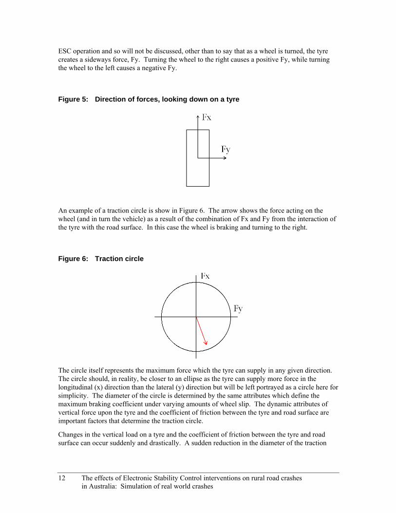
An example of a traction circle is show in Figure 6. The arrow shows the force acting on the wheel (and in turn the vehicle) as a result of the combination of Fx and Fy from the interaction of the tyre with the road surface. In this case the wheel is braking and turning to the right.
Figure 6: Traction circle
The circle itself represents the maximum force which the tyre can supply in any given direction. The circle should, in reality, be closer to an ellipse as the tyre can supply more force in the longitudinal (x) direction than the lateral (y) direction but will be left portrayed as a circle here for simplicity. The diameter of the circle is determined by the same attributes which define the maximum braking coefficient under varying amounts of wheel slip. The dynamic attributes of vertical force upon the tyre and the coefficient of friction between the tyre and road surface are important factors that determine the traction circle.
Changes in the vertical load on a tyre and the coefficient of friction between the tyre and road surface can occur suddenly and drastically. A sudden reduction in the diameter of the traction
12 The effects of Electronic Stability Control interventions on rural road crashes in Australia: Simulation of real world crashes
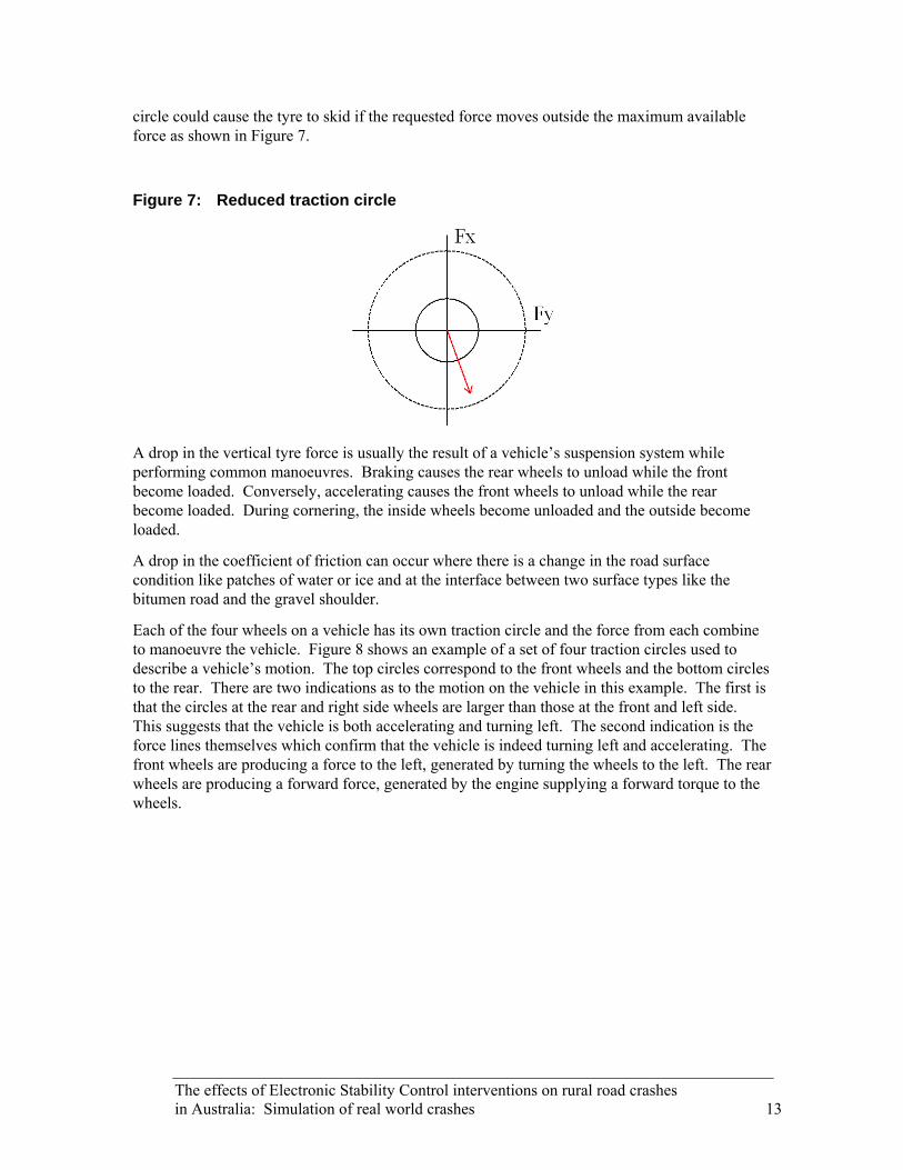
circle could cause the tyre to skid if the requested force moves outside the maximum available force as shown in Figure 7.
Figure 7: Reduced traction circle
A drop in the vertical tyre force is usually the result of a vehicle’s suspension system while performing common manoeuvres. Braking causes the rear wheels to unload while the front become loaded. Conversely, accelerating causes the front wheels to unload while the rear become loaded. During cornering, the inside wheels become unloaded and the outside become loaded.
A drop in the coefficient of friction can occur where there is a change in the road surface condition like patches of water or ice and at the interface between two surface types like the bitumen road and the gravel shoulder.
Each of the four wheels on a vehicle has its own traction circle and the force from each combine to manoeuvre the vehicle. Figure 8 shows an example of a set of four traction circles used to describe a vehicle’s motion. The top circles correspond to the front wheels and the bottom circles to the rear. There are two indications as to the motion on the vehicle in this example. The first is that the circles at the rear and right side wheels are larger than those at the front and left side. This suggests that the vehicle is both accelerating and turning left. The second indication is the force lines themselves which confirm that the vehicle is indeed turning left and accelerating. The front wheels are producing a force to the left, generated by turning the wheels to the left. The rear wheels are producing a forward force, generated by the engine supplying a forward torque to the wheels.
The effects of Electronic Stability Control interventions on rural road crashes in Australia: Simulation of real world crashes 13

Figure 8: Example of a set of traction circles
3.3 Skidding Scenarios There are three general scenarios that can cause a vehicle to lose stability and skid. These scenarios are understeer, oversteer and split mu (or split friction). The type of scenario encountered depends on which wheels are skidding. The ESC system reacts to each of the scenarios in a different way and with varying levels of effectiveness.
It should be mentioned here that ESC is able to determine the type of surface a vehicle is travelling on. It does this by very slightly braking a single wheel and sensing the change in braking coefficient. This change is then compared to a set of wheel slip curves which the system has stored in memory. When the system finds a match (or an approximation) it is then able to accurately predict the response of the vehicle to stronger braking interventions.
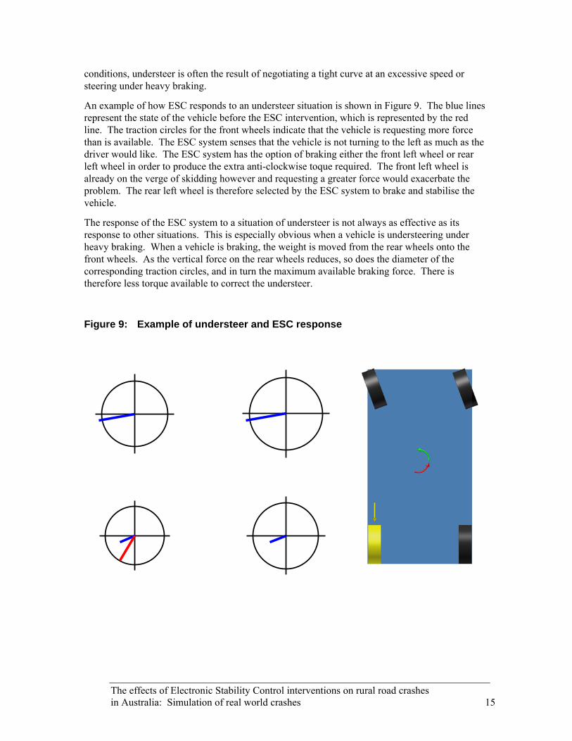
B 3.3.1 Understeer A An understeer situation can occur when one or both of the
front wheels are skidding. The vehicle responds slowly or not at all to the drivers steering inputs and begins to ‘plough’ straight ahead. An example of understeer is shown to the right. The vehicle is turning left in an attempt to end up in position A but instead understeers, skids forwards and finishes in position B.
Manoeuvres which unload or cause a large amount of wheel slip on the front wheels can cause understeer. Under real
14 The effects of Electronic Stability Control interventions on rural road crashes in Australia: Simulation of real world crashes
conditions, understeer is often the result of negotiating a tight curve at an excessive speed or steering under heavy braking.
An example of how ESC responds to an understeer situation is shown in Figure 9. The blue lines represent the state of the vehicle before the ESC intervention, which is represented by the red line. The traction circles for the front wheels indicate that the vehicle is requesting more force than is available. The ESC system senses that the vehicle is not turning to the left as much as the driver would like. The ESC system has the option of braking either the front left wheel or rear left wheel in order to produce the extra anti-clockwise toque required. The front left wheel is already on the verge of skidding however and requesting a greater force would exacerbate the problem. The rear left wheel is therefore selected by the ESC system to brake and stabilise the vehicle.
The response of the ESC system to a situation of understeer is not always as effective as its response to other situations. This is especially obvious when a vehicle is understeering under heavy braking. When a vehicle is braking, the weight is moved from the rear wheels onto the front wheels. As the vertical force on the rear wheels reduces, so does the diameter of the corresponding traction circles, and in turn the maximum available braking force. There is therefore less torque available to correct the understeer.
Figure 9: Example of understeer and ESC response
The effects of Electronic Stability Control interventions on rural road crashes in Australia: Simulation of real world crashes 15

3.3.2 Oversteer
An oversteer situation can occur when one or more of the rear wheels are skidding. The back end of the vehicle flicks out and the heading of the vehicle becomes difficult for the driver to control. An example of oversteer is shown to the right. The vehicle is turning left in an attempt to end up in position A but instead oversteers, spins out and finishes in position B.
Manoeuvres which unload or cause a large amount of wheel slip on the rear wheels can cause oversteer. Under real conditions, oversteer is often the result of sudden weight shift due to rapid counter steering or hard acceleration during sharp cornering in a rear wheel drive vehicle.
An example of how ESC responds to an oversteer is shown in Figure 10. The blue lines represent the state of the vehicle before the ESC intervention, which is represented by the red line. The traction circles for the rear wheels indicate that the vehicle is requesting more force than is available. The ESC system senses that the vehicle is turning to the left more than the driver would like. The ESC system has the option of braking either the right front or right rear wheels in order to produce the counteracting clockwise torque required. The rear right wheel is already on the verge of skidding however and requesting a greater force would exacerbate the problem. The front right wheel is therefore selected by the ESC system to brake and stabilise the vehicle.
B A
Figure 10: Example of oversteer and ESC response
16 The effects of Electronic Stability Control interventions on rural road crashes in Australia: Simulation of real world crashes
The response of the ESC system to a situation of oversteer is usually quite effective. This is because, as a vehicle is braking, the weight is moved from the rear wheels onto the front wheels. As the vertical force on the front wheels increases, so does the diameter of the corresponding traction circles and, in turn, the maximum available braking force. There is therefore more torque available to correct the oversteer.
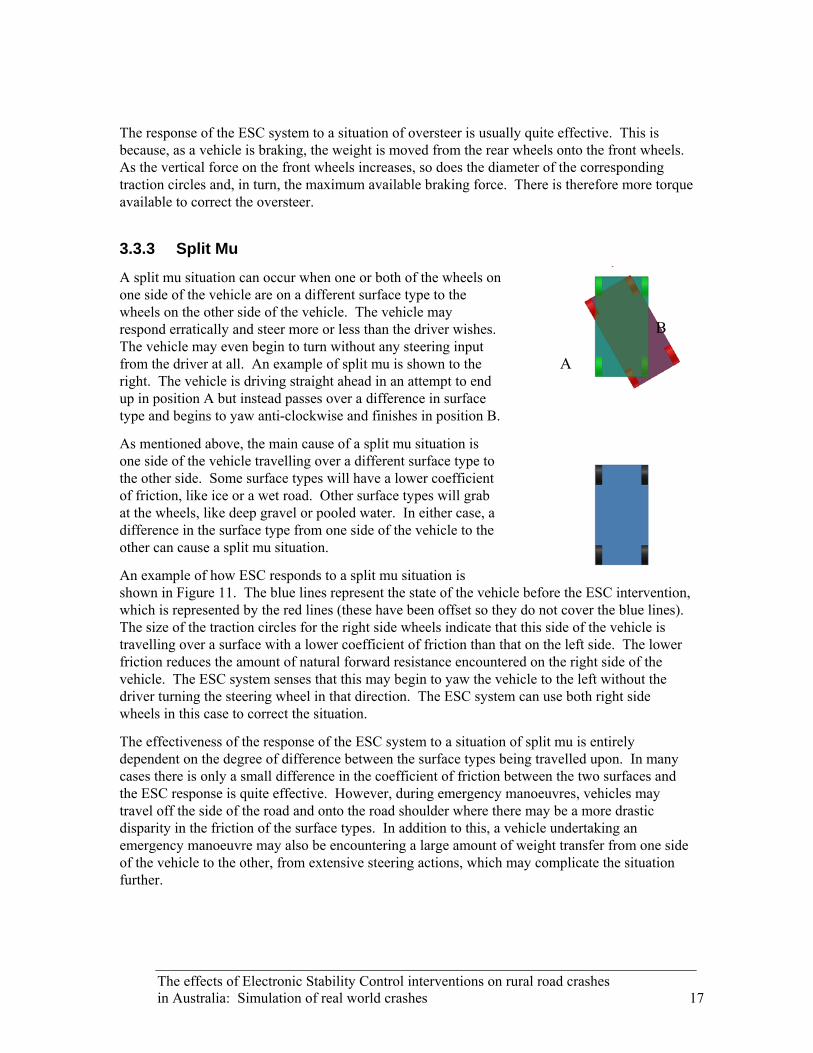
3.3.3 Split Mu
A split mu situation can occur when one or both of the wheels on one side of the vehicle are on a different surface type to the wheels on the other side of the vehicle. The vehicle may respond erratically and steer more or less than the driver wishes. The vehicle may even begin to turn without any steering input from the driver at all. An example of split mu is shown to the right. The vehicle is driving straight ahead in an attempt to end up in position A but instead passes over a difference in surface type and begins to yaw anti-clockwise and finishes in position B.
As mentioned above, the main cause of a split mu situation is one side of the vehicle travelling over a different surface type to the other side. Some surface types will have a lower coefficient of friction, like ice or a wet road. Other surface types will grab at the wheels, like deep gravel or pooled water. In either case, a difference in the surface type from one side of the vehicle to the other can cause a split mu situation.
An example of how ESC responds to a split mu situation is shown in Figure 11. The blue lines represent the state of the vehicle before the ESC intervention, which is represented by the red lines (these have been offset so they do not cover the blue lines). The size of the traction circles for the right side wheels indicate that this side of the vehicle is travelling over a surface with a lower coefficient of friction than that on the left side. The lower friction reduces the amount of natural forward resistance encountered on the right side of the vehicle. The ESC system senses that this may begin to yaw the vehicle to the left without the driver turning the steering wheel in that direction. The ESC system can use both right side wheels in this case to correct the situation.
B
A
The effectiveness of the response of the ESC system to a situation of split mu is entirely dependent on the degree of difference between the surface types being travelled upon. In many cases there is only a small difference in the coefficient of friction between the two surfaces and the ESC response is quite effective. However, during emergency manoeuvres, vehicles may travel off the side of the road and onto the road shoulder where there may be a more drastic disparity in the friction of the surface types. In addition to this, a vehicle undertaking an emergency manoeuvre may also be encountering a large amount of weight transfer from one side of the vehicle to the other, from extensive steering actions, which may complicate the situation further.
The effects of Electronic Stability Control interventions on rural road crashes in Australia: Simulation of real world crashes 17

Figure 11: Example of split mu and ESC response
18 The effects of Electronic Stability Control interventions on rural road crashes in Australia: Simulation of real world crashes
4 RESULTS
The results of each of the 20 cases are presented here individually. Not all cases could be simulated successfully. In two cases (13, 14) there was no simulation required as the driver made no apparent attempt to avoid a collision. In these cases, the ESP system would have done little to avoid a collision. The reasons why the driver made no avoidance manoeuvre are discussed. In another six cases (15, 16, 17, 18, 19, 20) the crash could not be sufficiently reproduced in the simulation to give a conclusive result. This was mainly due to the limitations of the front wheel drive vehicle model. The front wheel drive vehicle model was based upon a modern upmarket vehicle. This vehicle and thus the vehicle model is particularly stable during cornering and showed little propensity to yaw upon a single steering manoeuvre. The authors had no ability to alter this behaviour as the model was provided by Bosch Australia. The effect which ESP may have had upon the un-simulated crashes is discussed.
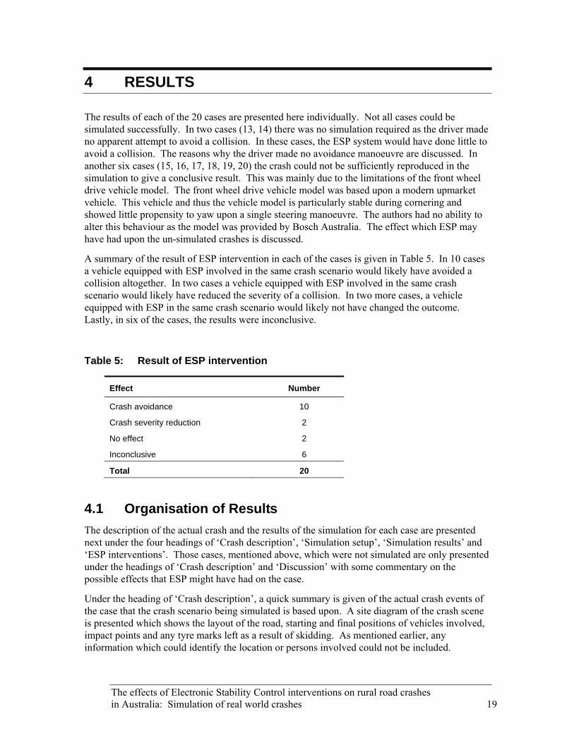
A summary of the result of ESP intervention in each of the cases is given in Table 5. In 10 cases a vehicle equipped with ESP involved in the same crash scenario would likely have avoided a collision altogether. In two cases a vehicle equipped with ESP involved in the same crash scenario would likely have reduced the severity of a collision. In two more cases, a vehicle equipped with ESP in the same crash scenario would likely not have changed the outcome. Lastly, in six of the cases, the results were inconclusive.
Table 5: Result of ESP intervention
Effect Number
Crash avoidance 10
Crash severity reduction 2
No effect 2
Inconclusive 6
Total 20
4.1 Organisation of Results The description of the actual crash and the results of the simulation for each case are presented next under the four headings of ‘Crash description’, ‘Simulation setup’, ‘Simulation results’ and ‘ESP interventions’. Those cases, mentioned above, which were not simulated are only presented under the headings of ‘Crash description’ and ‘Discussion’ with some commentary on the possible effects that ESP might have had on the case.
Under the heading of ‘Crash description’, a quick summary is given of the actual crash events of the case that the crash scenario being simulated is based upon. A site diagram of the crash scene is presented which shows the layout of the road, starting and final positions of vehicles involved, impact points and any tyre marks left as a result of skidding. As mentioned earlier, any information which could identify the location or persons involved could not be included.
The effects of Electronic Stability Control interventions on rural road crashes in Australia: Simulation of real world crashes 19

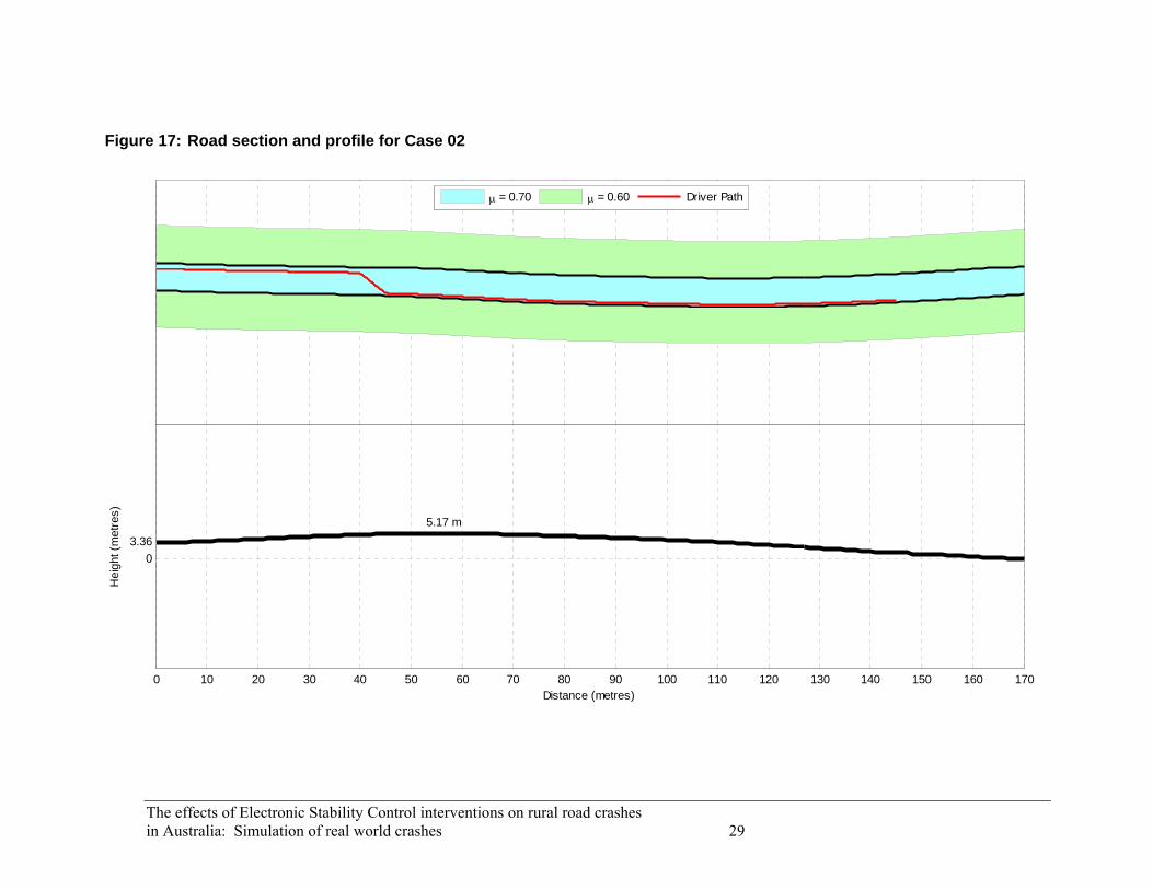
In the ‘Simulation setup’ section, details of how the case was setup in the CarSim program are given. The variables selected for the case are listed in a table. The selection of these variables is explained and justified. A diagram is presented which shows the road section and road profile. This diagram also shows the coefficient of friction on different parts of the road and the driver path used by the driver model. The driver path is then explained and justified.
In the ‘Simulation results’ section, a summary of the simulation output is given. A figure showing the simulated vehicle trajectories for the vehicle with and without ESP equipped is presented. This figure is taken directly from the CarSim animation of each case and shows where the ESP intervention had an effect. The vehicle equipped with ESP is shown in red and the vehicle not equipped with ESP is shown in blue. Any major difference between the trajectories of the simulated vehicle not equipped with ESP and the vehicle in the actual crash are highlighted and discussed. The vehicle trajectories of the two simulated vehicles are then compared and discussed. Any likely change in the result of the crash as a result of the presence of ESP is also considered here.
The final section, ‘ESP interventions’, details how the vehicle equipped with ESP achieves the different trajectory, shown under the ‘Simulation results’ section. The simulation outputs are summarised in four graphs which share a common x-axis (distance). In all graphs, a blue line refers to the vehicle not equipped with ESP and a red line refers to the vehicle equipped with ESP.
The top graph describes the lateral offset of the vehicle relative to the centre of the left lane of the road. A positive lateral offset is to the left and a negative lateral offset is to the right. A thin black line displays the driver path.
The second graph describes the yaw angle of the vehicle relative to the centre of the road. This can be thought of as the angle at which the vehicle is pointing, relative to the centre line of the road. A positive yaw is a clockwise angle and a negative yaw is an anti-clockwise angle. A thin black line displays the zero point at which a vehicle is angled exactly down the centre of the road.
The third and fourth graphs describe the wheel slip in the front and rear tyres respectively. The left tyre is shown as a solid line and the right tyre as a dotted line. On these graphs the y-axis (wheel slip) can vary between cases as some display a small amount of wheel slip while others display a locked wheel condition. The y-axis will always be the same scale for both graphs in a given case.
These four graphs, especially the bottom two, are used to explain how the vehicle equipped with ESP achieves a different trajectory to the vehicle not equipped with ESP.
20 The effects of Electronic Stability Control interventions on rural road crashes in Australia: Simulation of real world crashes

The effects of Electronic Stability Control interventions on rural road crashes in Australia: Simulation of real world crashes 21
4.2 Case 01
4.2.1 Crash Description
On a Thursday at approximately 5:00 pm, a car was negotiating a blind right bend at a self-reported speed of between 60 and 65 km/h, when the driver was confronted with an oncoming vehicle straddling the centre line. The driver veered to the left to avoid a head-on collision causing the left wheels of the vehicle to pass onto the unsealed shoulder. The driver overcorrected to the right, narrowly missing a guide post upon re-entering the sealed carriageway. The vehicle yawed in a clockwise direction across both lanes of the carriageway and across the far shoulder and the grassed verge. The left rear of the vehicle collided with a tree 2.5 metres from the edge of the carriageway. The prevailing environmental conditions at the crash site are given in Table 6. The site diagram for the crash is shown in Figure 12.
Table 6: Environmental conditions prevalent in Case 01
Condition Status
Weather Fine
Lighting Daylight
Road type Rural highway, sealed, two way, dry
Speed limit 100 km/h
4.2.2 Simulation Setup
The parameters used for the simulation of this case are shown in Table 7. An initial speed of 80 km/h was used, which was higher than that reported in the actual crash. This was mainly to compensate for the front wheel drive model which was stable at lower speeds. The higher speed caused the front wheel drive model to yaw in the same way as a less stable vehicle travelling at a lower speed. A preview time of 0.6 seconds and maximum steer rate of 600 degrees per second gave the driver model a surprised and panicked response to the oncoming vehicle.
The driver path for this case, shown in Figure 13, was developed based on the crash description and tyre marks at the crash scene. The driver path was designed to model the following sequence of events: The path begins in the middle of the left lane. As the driver is confronted with the oncoming vehicle, the path suddenly pulls to the left. The driver then panics as the vehicle travels onto the unsealed shoulder. The path pulls suddenly back to the right and returns quickly to the middle of the left lane.

Figure 12: Site diagram for Case 01
22 The effects of Electronic Stability Control interventions on rural road crashes in Australia: Simulation of real world crashes

The effects of Electronic Stability Control interventions on rural road crashes in Australia: Simulation of real world crashes 23
Figure 13: Road section and profile for Case 01
μ = 0.85 μ = 0.60 Driver Path
0 10 20 30 40 50 60 70 80 90 100 110
0
3.573.74 m
Distance (metres)
Hei
ght (
met
res)

Table 7: Simulation parameters for Case 01
Parameter Value Units
Vehicle
Vehicle model Front wheel drive
Events and procedures
Initial speed 80 km/h
Driver model:
Preview time 0.6 seconds
Max. steering wheel angle 360 degrees
Max. steering wheel angle rate 600 degrees per second
Environment
Road width 6.00 metres
Road length 120 metres
Surface type Sealed
Surface friction:
Road 0.85
Shoulder 0.60
4.2.3 Simulation Results
The simulation of the vehicle not equipped with ESP showed only a small resemblance to the events of the actual crash. In the simulation, the vehicle veers to the left suddenly, overcorrects upon returning to the road and then yaws in an anti-clockwise direction across both lanes. This was quite different to the events of the actual crash in which the vehicle yawed in a clockwise direction upon steering back onto the road.
The simulation of the vehicle equipped with ESP produces a significantly different vehicle path. As soon as the vehicle begins the emergency manoeuvre, the ESP system attempts to slow and stabilise the vehicle. Upon returning to the road, the vehicle overshoots the middle of the left lane and crosses the centreline a small distance. Despite this, the ESP system keeps the vehicle stable which enables it to easily return to the middle of the left lane and continue following the road.
Equipping the vehicle with ESP enabled it to remain stable throughout the entire emergency manoeuvre. While the vehicle path did show that the vehicle equipped with ESP crossed the centreline, it did not yaw at any point and quickly re-entered the left lane. Based on this, it is likely that a vehicle equipped with ESP, involved in the same crash scenario, would have avoided the loss of control that led to the collision in the actual crash.
24 The effects of Electronic Stability Control interventions on rural road crashes in Australia: Simulation of real world crashes

Figure 14: Simulation animation for Case 01
4.2.4 ESP Interventions
The ESP interventions for this case are shown in Figure 15. There are two main points of interest, labelled A and B.
As the driver model initially steers the vehicle to the left (prior to point A), the ESP system slightly brakes both the left side wheels. This has the double effect of pulling the vehicle to the left more quickly and reducing the vehicle speed a little.
When the driver model steers the vehicle back to the right (point A), there is a possibility of oversteer occurring. The ESP system brakes the front left wheel very sharply and to a lesser extent, the rear left wheel also. This counteracts the potential oversteer situation by the method shown in Figure 10.
The driver model then steers again to direct the vehicle back into the left lane (point B). As the weight of the vehicle shifts from one side to the other, there is again a possibility of oversteer occurring; this time in the other direction. The ESP system again reacts and brakes the front right wheel sharply and the rear right slightly.
As the driver model returns the vehicle to the left lane and continues down the road (past point B), the ESP system makes its final interventions. The braking at the front right wheel is held for a time and the rear right is braked again. This settles the vehicle back into a stable path down the middle of the left lane.
The effects of Electronic Stability Control interventions on rural road crashes in Australia: Simulation of real world crashes 25

Figure 15: Simulation output for Case 01
-10-8-6-4-202468
10La
tera
l Offs
et (m
etre
s)ESP offESP on
-90-75-60-45-30-15
0153045607590
Yaw
(deg
rees
)
0
10
20
30
40
50
Fron
t Whe
el S
lip (%
)
LeftRight
0 30 A 60 B 900
10
20
30
40
50
Distance (metres)
Rea
r Whe
el S
lip (%
)
LeftRight
26 The effects of Electronic Stability Control interventions on rural road crashes in Australia: Simulation of real world crashes
The effects of Electronic Stability Control interventions on rural road crashes in Australia: Simulation of real world crashes 27
4.3 Case 02
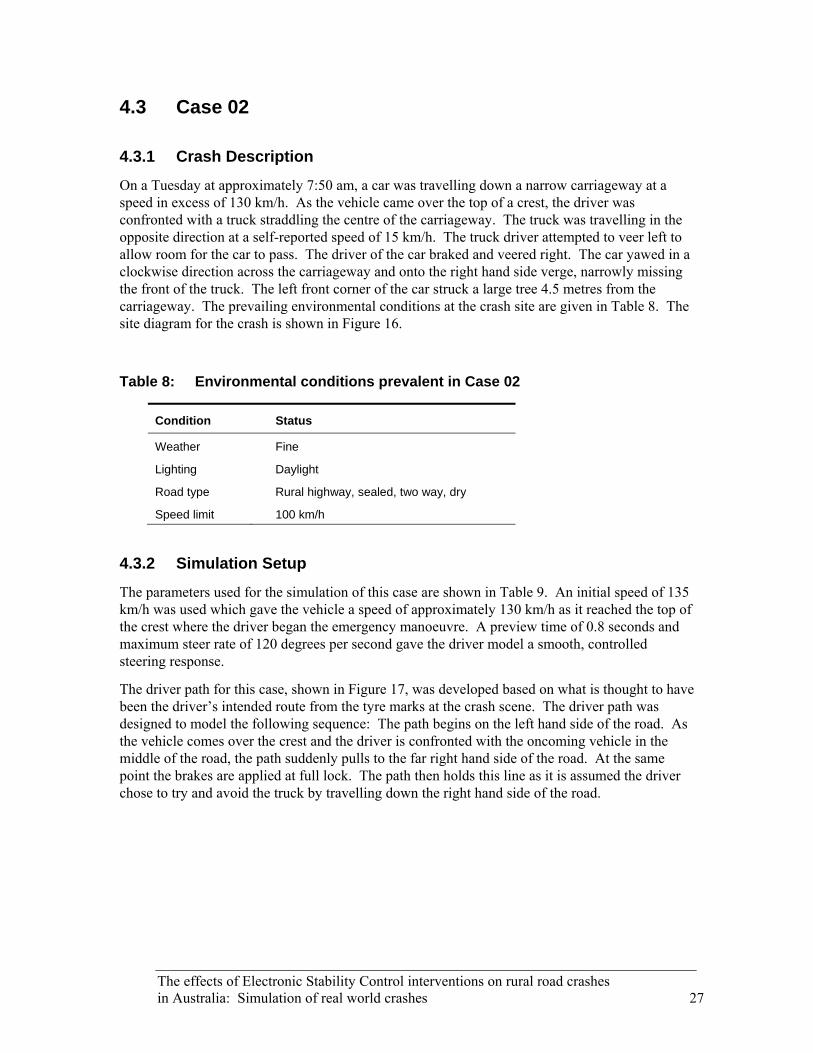
4.3.1 Crash Description
On a Tuesday at approximately 7:50 am, a car was travelling down a narrow carriageway at a speed in excess of 130 km/h. As the vehicle came over the top of a crest, the driver was confronted with a truck straddling the centre of the carriageway. The truck was travelling in the opposite direction at a self-reported speed of 15 km/h. The truck driver attempted to veer left to allow room for the car to pass. The driver of the car braked and veered right. The car yawed in a clockwise direction across the carriageway and onto the right hand side verge, narrowly missing the front of the truck. The left front corner of the car struck a large tree 4.5 metres from the carriageway. The prevailing environmental conditions at the crash site are given in Table 8. The site diagram for the crash is shown in Figure 16.
Table 8: Environmental conditions prevalent in Case 02
Condition Status
Weather Fine
Lighting Daylight
Road type Rural highway, sealed, two way, dry
Speed limit 100 km/h
4.3.2 Simulation Setup
The parameters used for the simulation of this case are shown in Table 9. An initial speed of 135 km/h was used which gave the vehicle a speed of approximately 130 km/h as it reached the top of the crest where the driver began the emergency manoeuvre. A preview time of 0.8 seconds and maximum steer rate of 120 degrees per second gave the driver model a smooth, controlled steering response.
The driver path for this case, shown in Figure 17, was developed based on what is thought to have been the driver’s intended route from the tyre marks at the crash scene. The driver path was designed to model the following sequence: The path begins on the left hand side of the road. As the vehicle comes over the crest and the driver is confronted with the oncoming vehicle in the middle of the road, the path suddenly pulls to the far right hand side of the road. At the same point the brakes are applied at full lock. The path then holds this line as it is assumed the driver chose to try and avoid the truck by travelling down the right hand side of the road.
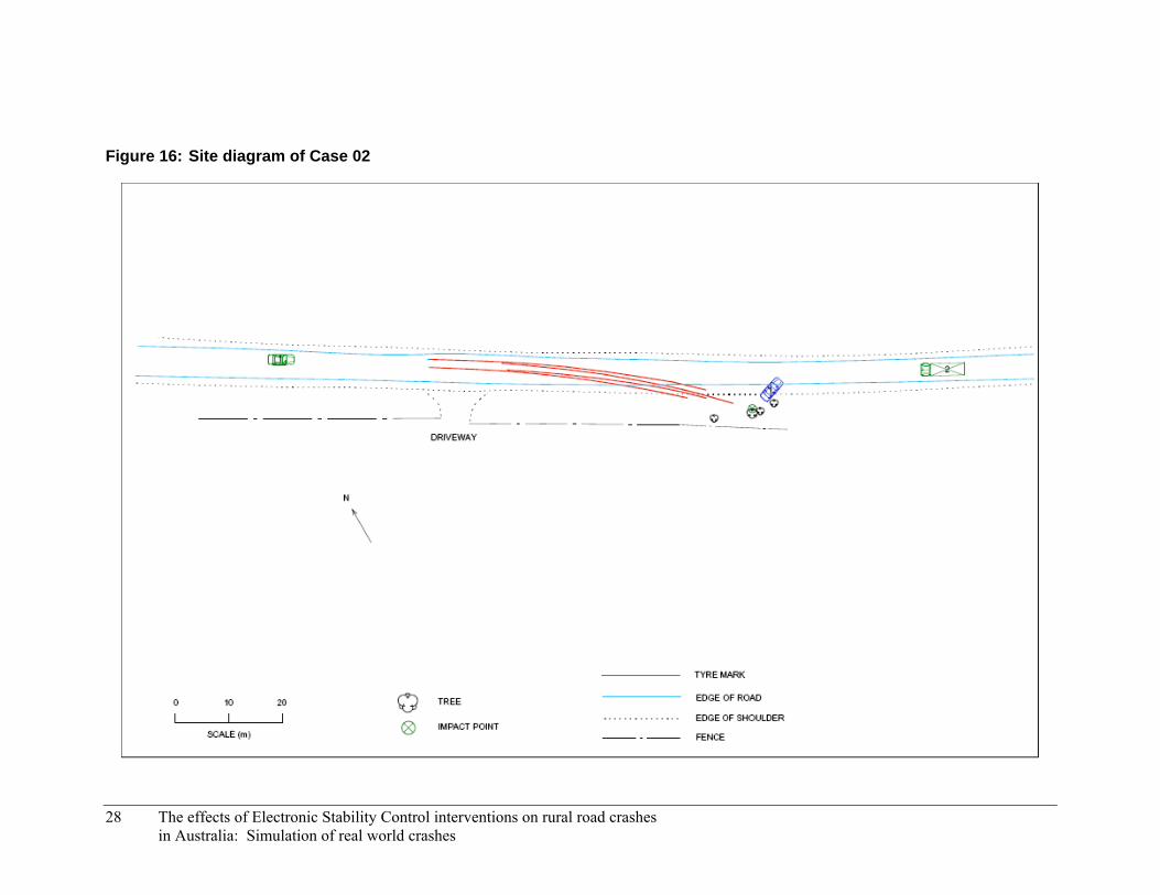
Figure 16: Site diagram of Case 02
28 The effects of Electronic Stability Control interventions on rural road crashes in Australia: Simulation of real world crashes
The effects of Electronic Stability Control interventions on rural road crashes
μ = 0.70 μ = 0.60 Driver Path
0 10 20 30 40 50 60 70 80 90 100 110 120 130 140 150 160 170
03.36
5.17 m
Distance (metres)
Hei
ght (
met
res)
in Australia: Simulation of real world crashes 29
Figure 17: Road section and profile for Case 02

Table 9: Simulation parameters for Case 02
Parameter Value Units
Vehicle
Vehicle model Rear wheel drive
Events and procedures
Initial speed 135 km/h
Driver model:
Preview time 0.8 seconds
Max. steering wheel angle 360 degrees
Max. steering wheel angle rate 120 degrees per second
Environment
Road width 5.54 metres
Road length 120 metres
Surface type Unsealed
Surface friction:
Road 0.70
Shoulder 0.60
4.3.3 Simulation Results
The simulation of the vehicle not equipped with ESP showed a good resemblance to the events of the actual crash. In the simulation, as the vehicle came over the crest, braked and steered to the right, it entered an understeer and yawed in a clockwise direction. The vehicle continued to understeer and yaw across the width of the road into the area where it would have collided with a tree.
The simulation of the vehicle equipped with ESP showed a more controlled vehicle path. As the vehicle comes over the crest and the brakes are applied, the vehicle pulls to the right sharply and then straightens. The vehicle then returns to the road by pulling sharply to the left this time and again straightening.
Equipping the vehicle with ESP enabled it to remain responsive throughout the entire emergency manoeuvre. The vehicle did not yaw at any point and was able to steer sharply away from the obstacle and then back onto the road. However, given the small clear zone adjacent to the road it is likely there would still have been some kind of collision between the vehicle and a roadside object. The orientation of the vehicle means that this collision would have been either a frontal impact or side swipe. This may have resulted in a more favourable result compared with a side impact, which negates the safety benefits of features like airbags and seatbelts.
30 The effects of Electronic Stability Control interventions on rural road crashes in Australia: Simulation of real world crashes
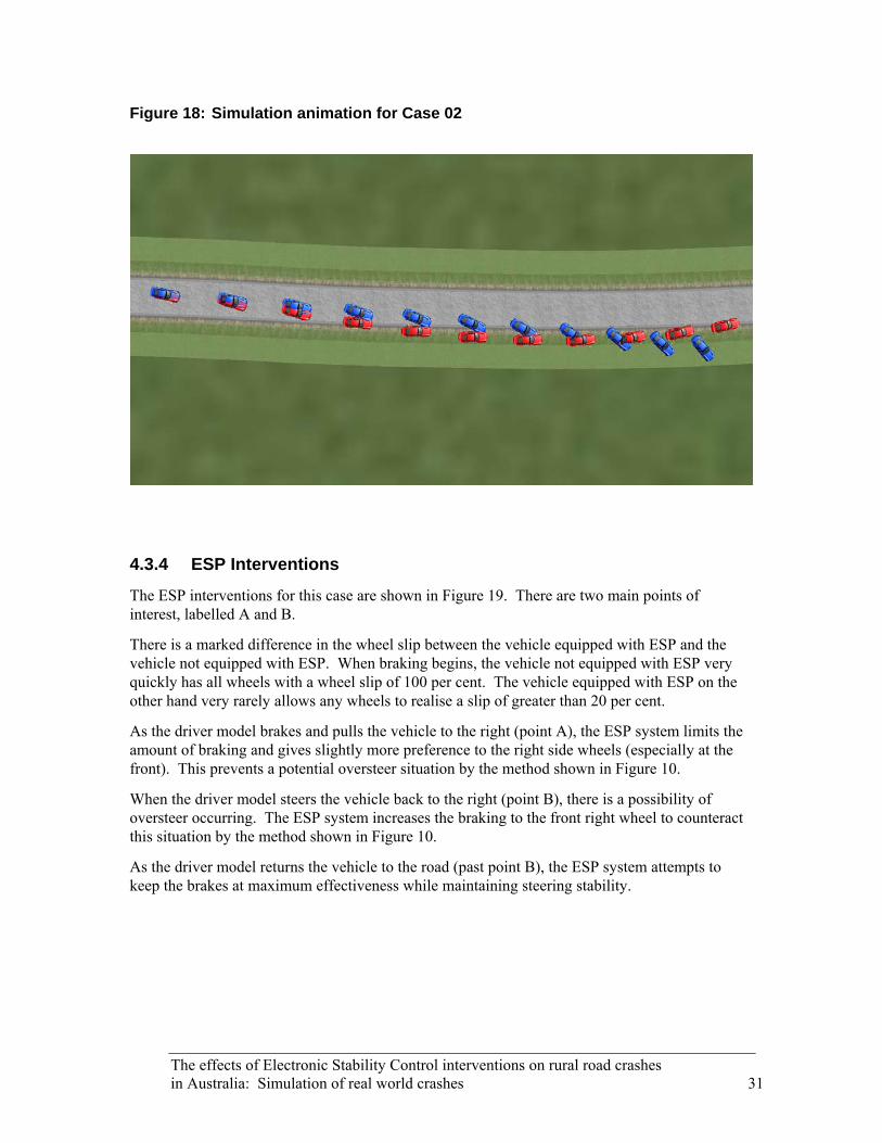
Figure 18: Simulation animation for Case 02
4.3.4 ESP Interventions
The ESP interventions for this case are shown in Figure 19. There are two main points of interest, labelled A and B.
There is a marked difference in the wheel slip between the vehicle equipped with ESP and the vehicle not equipped with ESP. When braking begins, the vehicle not equipped with ESP very quickly has all wheels with a wheel slip of 100 per cent. The vehicle equipped with ESP on the other hand very rarely allows any wheels to realise a slip of greater than 20 per cent.
As the driver model brakes and pulls the vehicle to the right (point A), the ESP system limits the amount of braking and gives slightly more preference to the right side wheels (especially at the front). This prevents a potential oversteer situation by the method shown in Figure 10.
When the driver model steers the vehicle back to the right (point B), there is a possibility of oversteer occurring. The ESP system increases the braking to the front right wheel to counteract this situation by the method shown in Figure 10.
As the driver model returns the vehicle to the road (past point B), the ESP system attempts to keep the brakes at maximum effectiveness while maintaining steering stability.
The effects of Electronic Stability Control interventions on rural road crashes in Australia: Simulation of real world crashes 31

Figure 19: Simulation output for Case 02
-10-8-6-4-202468
10La
tera
l Offs
et (m
etre
s)ESP offESP on
-90-75-60-45-30-15
0153045607590
Yaw
(deg
rees
)
0
20
40
60
80
100
Fron
t Whe
el S
lip (%
)
LeftRight
0 30 A 60 B 90 120 1500
20
40
60
80
100
Distance (metres)
Rea
r Whe
el S
lip (%
)
LeftRight
32 The effects of Electronic Stability Control interventions on rural road crashes in Australia: Simulation of real world crashes

The effects of Electronic Stability Control interventions on rural road crashes in Australia: Simulation of real world crashes 33
4.4 Case 03
4.4.1 Crash Description
On a Wednesday at approximately 2:10 pm, a car was negotiating a sharp left bend at a self-reported speed of 40 km/h. It had been raining and the road was wet. As the vehicle came into the apex of the corner the driver felt the vehicle sliding towards the incorrect side of the carriageway. The driver attempted to correct the vehicle to the left and applied the brakes. The vehicle continued to slide across the centre line on the wet surface, coming into the path of another car, travelling in the opposite direction. The driver of the second car pulled their vehicle onto the left sealed shoulder in an attempt to avoid the collision but was restricted by the guard rail bordering the bend. The front of the first car collided with the right front corner of the second car which was pushed sideways into the guard rail on impact. The prevailing environmental conditions at the crash site are given in Table 10. The site diagram for the crash is shown in Figure 20.
Table 10: Environmental conditions prevalent in Case 03
Condition Status
Weather Raining
Lighting Daylight
Road type Rural highway, sealed, two way, wet
Speed limit 100 km/h (35 km/h advisory)
4.4.2 Simulation Setup
The parameters used for the simulation of this case are shown in Table 11. An initial speed of 40 km/h was used which matched the speed reported in the actual crash. A preview time of 0.8 seconds and a maximum steer rate of 360 degrees per second gave the driver model a fairly normal response to changes in the driver path.
The driver path for this case, shown in Figure 21, was developed to reflect a vehicle negotiating the bend normally. The path was designed to model the following sequence of events: The path begins in the middle of the left lane and as the vehicle approaches the bend the path moves slowly to the right side of the lane and a small amount of braking is applied. This braking equates to a wheel slip value of approximately three per cent. As the vehicle moves into the bend, full lock braking is applied as the driver realises the vehicle is travelling too quickly. After passing the apex of the bend the path returns slowly to the middle of the left lane.
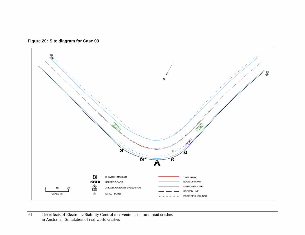
Figure 20: Site diagram for Case 03
34 The effects of Electronic Stability Control interventions on rural road crashes in Australia: Simulation of real world crashes

The effects of Electronic Stability Control interventions on rural road crashes
μ = 0.75 μ = 0.50 Driver Path
0 10 20 30 40 50 60 70 80 90 100 110
0
15.21
Distance (metres)
Hei
ght (
met
res)
in Australia: Simulation of real world crashes 35
Figure 21: Road section and profile for Case 03
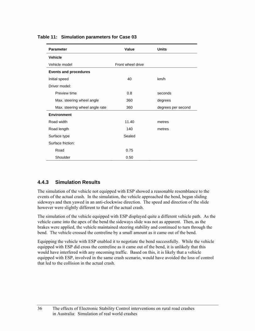
Table 11: Simulation parameters for Case 03
Parameter Value Units
Vehicle
Vehicle model Front wheel drive
Events and procedures
Initial speed 40 km/h
Driver model:
Preview time 0.8 seconds
Max. steering wheel angle 360 degrees
Max. steering wheel angle rate 360 degrees per second
Environment
Road width 11.40 metres
Road length 140 metres
Surface type Sealed
Surface friction:
Road 0.75
Shoulder 0.50
4.4.3 Simulation Results
The simulation of the vehicle not equipped with ESP showed a reasonable resemblance to the events of the actual crash. In the simulation, the vehicle approached the bend, began sliding sideways and then yawed in an anti-clockwise direction. The speed and direction of the slide however were slightly different to that of the actual crash.
The simulation of the vehicle equipped with ESP displayed quite a different vehicle path. As the vehicle came into the apex of the bend the sideways slide was not as apparent. Then, as the brakes were applied, the vehicle maintained steering stability and continued to turn through the bend. The vehicle crossed the centreline by a small amount as it came out of the bend.
Equipping the vehicle with ESP enabled it to negotiate the bend successfully. While the vehicle equipped with ESP did cross the centreline as it came out of the bend, it is unlikely that this would have interfered with any oncoming traffic. Based on this, it is likely that a vehicle equipped with ESP, involved in the same crash scenario, would have avoided the loss of control that led to the collision in the actual crash.
36 The effects of Electronic Stability Control interventions on rural road crashes in Australia: Simulation of real world crashes
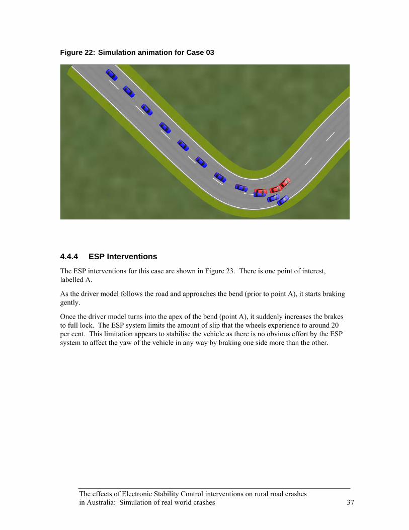
Figure 22: Simulation animation for Case 03
4.4.4 ESP Interventions
The ESP interventions for this case are shown in Figure 23. There is one point of interest, labelled A.
As the driver model follows the road and approaches the bend (prior to point A), it starts braking gently.
Once the driver model turns into the apex of the bend (point A), it suddenly increases the brakes to full lock. The ESP system limits the amount of slip that the wheels experience to around 20 per cent. This limitation appears to stabilise the vehicle as there is no obvious effort by the ESP system to affect the yaw of the vehicle in any way by braking one side more than the other.
The effects of Electronic Stability Control interventions on rural road crashes in Australia: Simulation of real world crashes 37

Figure 23: Simulation output for Case 03
-10-8-6-4-202468
10La
tera
l Offs
et (m
etre
s)ESP offESP on
-90-75-60-45-30-15
0153045607590
Yaw
(deg
rees
)
0
20
40
60
80
100
Fron
t Whe
el S
lip (%
)
LeftRight
0 20 40 60 A 800
20
40
60
80
100
Distance (metres)
Rea
r Whe
el S
lip (%
)
LeftRight
38 The effects of Electronic Stability Control interventions on rural road crashes in Australia: Simulation of real world crashes
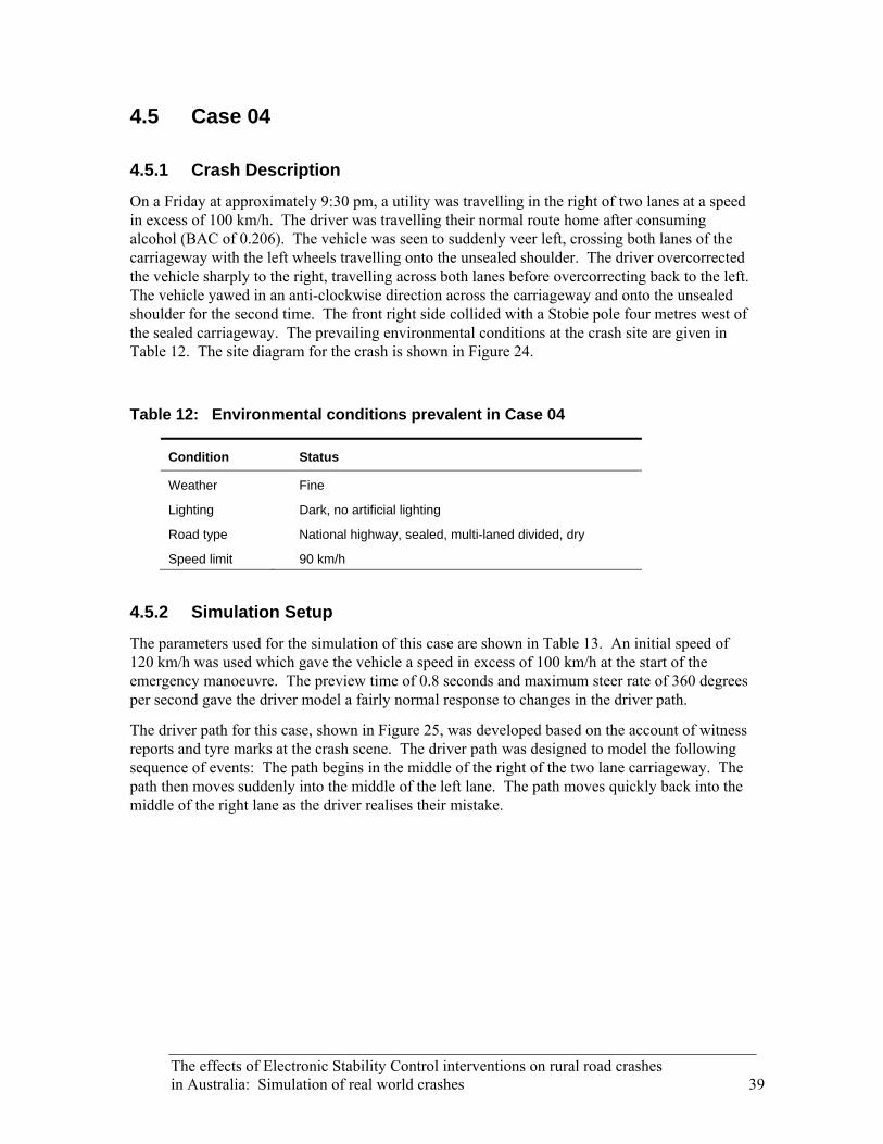
The effects of Electronic Stability Control interventions on rural road crashes in Australia: Simulation of real world crashes 39
4.5 Case 04
4.5.1 Crash Description
On a Friday at approximately 9:30 pm, a utility was travelling in the right of two lanes at a speed in excess of 100 km/h. The driver was travelling their normal route home after consuming alcohol (BAC of 0.206). The vehicle was seen to suddenly veer left, crossing both lanes of the carriageway with the left wheels travelling onto the unsealed shoulder. The driver overcorrected the vehicle sharply to the right, travelling across both lanes before overcorrecting back to the left. The vehicle yawed in an anti-clockwise direction across the carriageway and onto the unsealed shoulder for the second time. The front right side collided with a Stobie pole four metres west of the sealed carriageway. The prevailing environmental conditions at the crash site are given in Table 12. The site diagram for the crash is shown in Figure 24.
Table 12: Environmental conditions prevalent in Case 04
Condition Status
Weather Fine
Lighting Dark, no artificial lighting
Road type National highway, sealed, multi-laned divided, dry
Speed limit 90 km/h
4.5.2 Simulation Setup
The parameters used for the simulation of this case are shown in Table 13. An initial speed of 120 km/h was used which gave the vehicle a speed in excess of 100 km/h at the start of the emergency manoeuvre. The preview time of 0.8 seconds and maximum steer rate of 360 degrees per second gave the driver model a fairly normal response to changes in the driver path.
The driver path for this case, shown in Figure 25, was developed based on the account of witness reports and tyre marks at the crash scene. The driver path was designed to model the following sequence of events: The path begins in the middle of the right of the two lane carriageway. The path then moves suddenly into the middle of the left lane. The path moves quickly back into the middle of the right lane as the driver realises their mistake.

Figure 24: Site diagram for Case 04
40 The effects of Electronic Stability Control interventions on rural road crashes in Australia: Simulation of real world crashes

The effects of Electronic Stability Control interventions on rural road crashes
μ = 0.85 μ = 0.60 Driver Path
0 10 20 30 40 50 60 70 80 90 100 110 120 130 140 150 160 170 180 190 200 210
0
Distance (metres)
Hei
ght (
met
res)
in Australia: Simulation of real world crashes 41
Figure 25: Road section and profile for Case 04
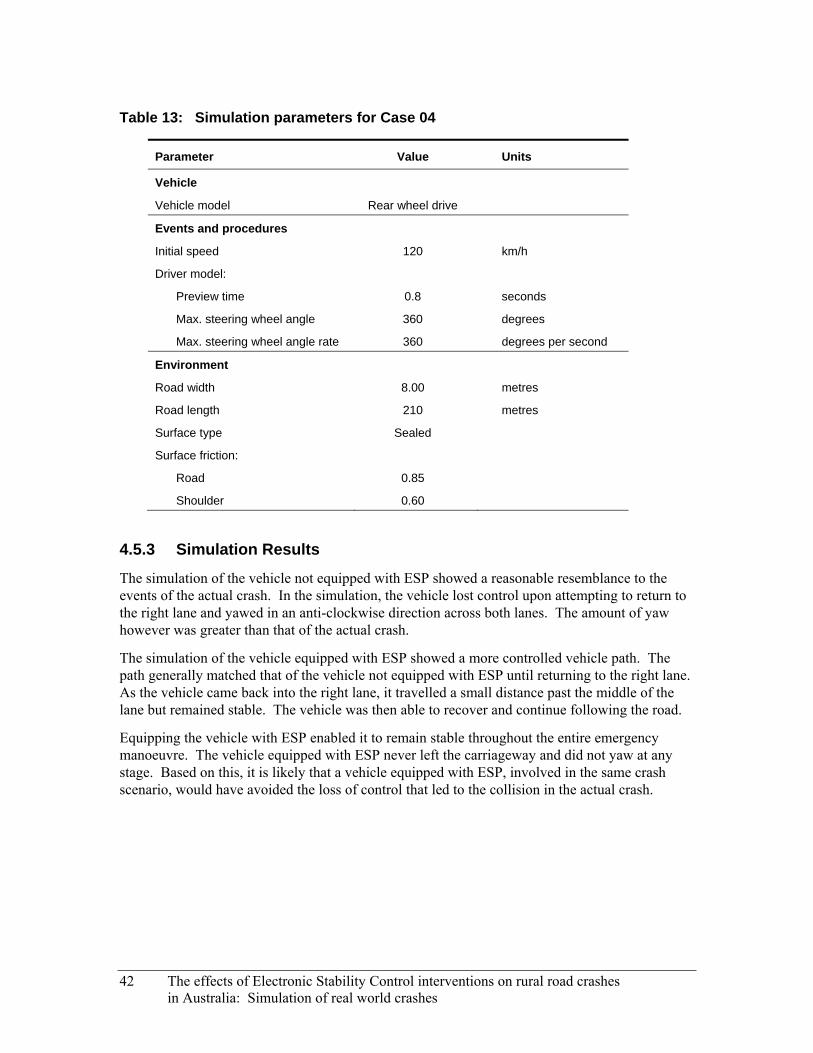
Table 13: Simulation parameters for Case 04
Parameter Value Units
Vehicle
Vehicle model Rear wheel drive
Events and procedures
Initial speed 120 km/h
Driver model:
Preview time 0.8 seconds
Max. steering wheel angle 360 degrees
Max. steering wheel angle rate 360 degrees per second
Environment
Road width 8.00 metres
Road length 210 metres
Surface type Sealed
Surface friction:
Road 0.85
Shoulder 0.60
4.5.3 Simulation Results
The simulation of the vehicle not equipped with ESP showed a reasonable resemblance to the events of the actual crash. In the simulation, the vehicle lost control upon attempting to return to the right lane and yawed in an anti-clockwise direction across both lanes. The amount of yaw however was greater than that of the actual crash.
The simulation of the vehicle equipped with ESP showed a more controlled vehicle path. The path generally matched that of the vehicle not equipped with ESP until returning to the right lane. As the vehicle came back into the right lane, it travelled a small distance past the middle of the lane but remained stable. The vehicle was then able to recover and continue following the road.
Equipping the vehicle with ESP enabled it to remain stable throughout the entire emergency manoeuvre. The vehicle equipped with ESP never left the carriageway and did not yaw at any stage. Based on this, it is likely that a vehicle equipped with ESP, involved in the same crash scenario, would have avoided the loss of control that led to the collision in the actual crash.
42 The effects of Electronic Stability Control interventions on rural road crashes in Australia: Simulation of real world crashes

Figure 26: Simulation animation for Case 04
4.5.4 ESP Interventions
The ESP interventions for this case are shown in Figure 27. There are three points of interest, labelled A, B and C.
As the driver model initially pulls the vehicle to the left (prior to point A), there is little intervention from the ESP system.
When the driver model corrects to straighten the vehicle after pulling left (point A), there is a possibility of oversteer occurring. The ESP system brakes the left side wheels gently. This counteracts the potential oversteer situation by the method shown in Figure 10.
The ESP system brakes the left front wheel a second time as the driver model continues to pull the vehicle back to the right (point B). There is also a small intervention in the front right wheel as the driver model straightens the vehicle to point towards the right lane.
As the driver model steers again to pull the vehicle into the right lane (point C), there is again a possibility of oversteer occurring as the weight of the vehicle shifts. The ESP system brakes the right side wheels gently. This counteracts the potential oversteer situation by the method shown in Figure 10.
The ESP system makes its final interventions as the driver model aligns the vehicle with the centre of the right lane (past point C). By braking the right side wheels one last time, any potential for oversteer is negated.
The effects of Electronic Stability Control interventions on rural road crashes in Australia: Simulation of real world crashes 43
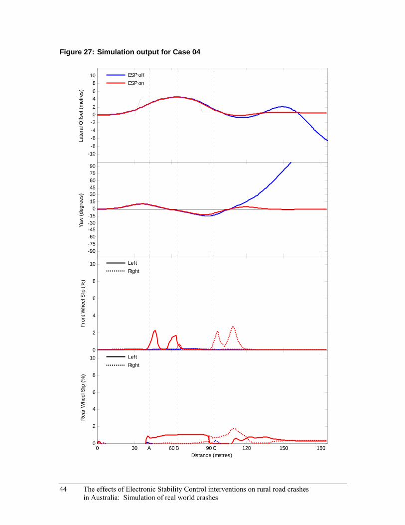
Figure 27: Simulation output for Case 04
-10-8-6-4-202468
10La
tera
l Offs
et (m
etre
s)ESP offESP on
-90-75-60-45-30-15
0153045607590
Yaw
(deg
rees
)
0
2
4
6
8
10
Fron
t Whe
el S
lip (%
)
LeftRight
0 30 A 60 B 90 C 120 150 1800
2
4
6
8
10
Distance (metres)
Rea
r Whe
el S
lip (%
)
LeftRight
44 The effects of Electronic Stability Control interventions on rural road crashes in Australia: Simulation of real world crashes

The effects of Electronic Stability Control interventions on rural road crashes in Australia: Simulation of real world crashes 45
4.6 Case 05
4.6.1 Crash Description
On a Thursday at approximately 3:00 pm, a car was travelling at an estimated speed of 85 km/h, negotiating a left bend with an advisory speed of 55 km/h. While negotiating the bend, the right hand wheels of the vehicle travelled over the double centre lines. The driver overcorrected the vehicle to the left to avoid a collision with an oncoming vehicle. The vehicle yawed in an anti-clockwise direction across the left lane and onto the unsealed shoulder where the left front corner of the car clipped a large tree three metres south of the carriageway. The prevailing environmental conditions at the crash site are given in Table 14. The site diagram for the crash is shown in Figure 28.
Table 14: Environmental conditions prevalent in Case 05
Condition Status
Weather Fine
Lighting Daylight
Road type Rural highway, sealed, two way, dry
Speed limit 80 km/h (55 km/h advisory)
4.6.2 Simulation Setup
The parameters used for the simulation of this case are shown in Table 15. An initial speed of 85 km/h was used to match the speed of the vehicle in the actual crash. A preview time of 0.6 seconds and a maximum steer rate of 360 degrees per second gave the driver model a surprised but somewhat controlled reaction to the oncoming vehicle.
The driver path for this case, shown in Figure 29, was developed based on the crash description and tyre marks at the crash scene. The driver path was designed to model the following sequence of events: The path begins in the middle of the left lane and moves to the right of the lane as the vehicle approaches the apex of the bend. The path moves suddenly back to the middle of the left lane as the driver is confronted with the oncoming vehicle.

Figure 28: Site diagram for Case 05
46 The effects of Electronic Stability Control interventions on rural road crashes in Australia: Simulation of real world crashes
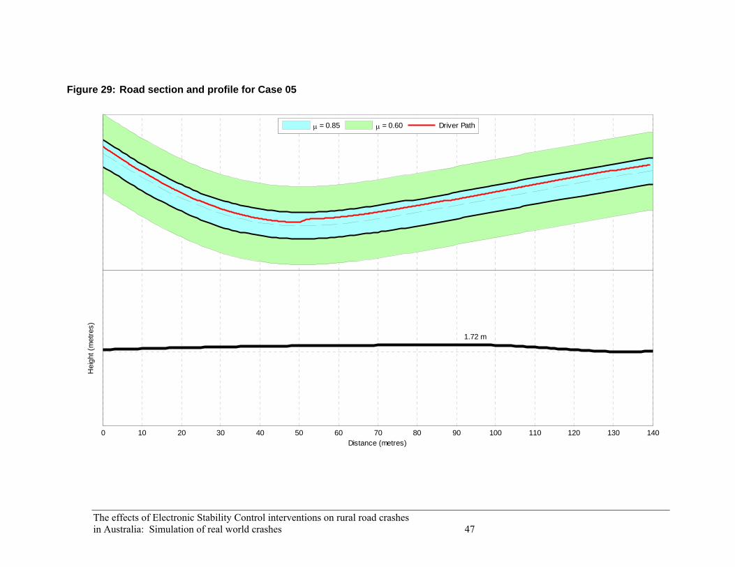
The effects of Electronic Stability Control interventions on rural road crashes
μ = 0.85 μ = 0.60 Driver Path
0 10 20 30 40 50 60 70 80 90 100 110 120 130 140
1.72 m
Distance (metres)
Hei
ght (
met
res)
in Australia: Simulation of real world crashes 47
Figure 29: Road section and profile for Case 05

Table 15: Simulation parameters for Case 05
Parameter Value Units
Vehicle
Vehicle model Rear wheel drive
Events and procedures
Initial speed 85 km/h
Driver model:
Preview time 0.6 seconds
Max. steering wheel angle 360 degrees
Max. steering wheel angle rate 360 degrees per second
Environment
Road width 6.80 metres
Road length 145 metres
Surface type Sealed
Surface friction:
Road 0.85
Shoulder 0.60
4.6.3 Simulation Results
The simulation of the vehicle not equipped with ESP showed only a small resemblance to the events of the actual crash. In the simulation, the vehicle overcorrected as it returned to the middle of the left lane and then overcorrected again back to the right. As the vehicle steered back to the left it began to yaw in an anti-clockwise direction across the left side shoulder. This is quite different to the actual crash however, in which the vehicle began to yaw after only the initial steer to the left.
The simulation of the vehicle equipped with ESP showed a more stable vehicle path. The vehicle overcorrects twice but remains stable and returns to the middle of the left lane to continue to following the road.
Equipping the vehicle with ESP enabled it to remain stable throughout the entire emergency manoeuvre. While the vehicle equipped with ESP did still overcorrect twice across the width of the lane, it did not yaw at any point and quickly re-aligned itself with the middle of the lane. Based on this, it is likely that a vehicle equipped with ESP, involved in the same crash scenario, would have avoided the loss of control that led to the collision in the actual crash.
48 The effects of Electronic Stability Control interventions on rural road crashes in Australia: Simulation of real world crashes

Figure 30: Simulation animation for Case 05
4.6.4 ESP Interventions
The ESP interventions for this case are shown in Figure 31. There are two points of interest, labelled A and B.
As the driver model pulls the vehicle to the left in an attempt to re-align the vehicle with the middle of the lane (point A), there is a possibility of oversteer occurring. The ESP system brakes the front right wheel and, to a lesser extent, the rear right wheel. This counteracts the potential oversteer situation by the method shown in Figure 10.
When the driver model pulls the vehicle back to the right again (point B), there is a possibility of oversteer occurring in the other direction. The ESP system brakes the front left wheel and, to a lesser extent, the rear left wheel. This again counteracts the potential oversteer situation.
As the driver model makes the final minor adjustments to return the vehicle to the middle of the lane (past point B), the ESP system brakes the rear right, then rear left wheels slightly, to settle the vehicle back into a stable path down the middle of the left lane.
The effects of Electronic Stability Control interventions on rural road crashes in Australia: Simulation of real world crashes 49

Figure 31: Simulation output for Case 05
-10-8-6-4-202468
10La
tera
l Offs
et (m
etre
s)ESP offESP on
-90-75-60-45-30-15
0153045607590
Yaw
(deg
rees
)
0
2
4
6
8
10
Fron
t Whe
el S
lip (%
)
LeftRight
0 30 A 60 B 90 1200
2
4
6
8
10
Distance (metres)
Rea
r Whe
el S
lip (%
)
LeftRight
50 The effects of Electronic Stability Control interventions on rural road crashes in Australia: Simulation of real world crashes
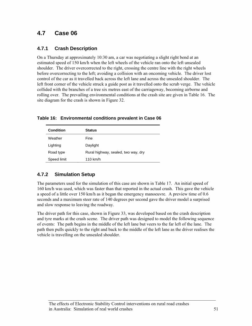
The effects of Electronic Stability Control interventions on rural road crashes in Australia: Simulation of real world crashes 51
4.7 Case 06
4.7.1 Crash Description
On a Thursday at approximately 10:30 am, a car was negotiating a slight right bend at an estimated speed of 150 km/h when the left wheels of the vehicle ran onto the left unsealed shoulder. The driver overcorrected to the right, crossing the centre line with the right wheels before overcorrecting to the left; avoiding a collision with an oncoming vehicle. The driver lost control of the car as it travelled back across the left lane and across the unsealed shoulder. The left front corner of the vehicle struck a guide post as it travelled onto the scrub verge. The vehicle collided with the branches of a tree six metres east of the carriageway, becoming airborne and rolling over. The prevailing environmental conditions at the crash site are given in Table 16. The site diagram for the crash is shown in Figure 32.
Table 16: Environmental conditions prevalent in Case 06
Condition Status
Weather Fine
Lighting Daylight
Road type Rural highway, sealed, two way, dry
Speed limit 110 km/h
4.7.2 Simulation Setup
The parameters used for the simulation of this case are shown in Table 17. An initial speed of 160 km/h was used, which was faster than that reported in the actual crash. This gave the vehicle a speed of a little over 150 km/h as it began the emergency manoeuvre. A preview time of 0.6 seconds and a maximum steer rate of 140 degrees per second gave the driver model a surprised and slow response to leaving the roadway.
The driver path for this case, shown in Figure 33, was developed based on the crash description and tyre marks at the crash scene. The driver path was designed to model the following sequence of events: The path begins in the middle of the left lane but veers to the far left of the lane. The path then pulls quickly to the right and back to the middle of the left lane as the driver realises the vehicle is travelling on the unsealed shoulder.

Figure 32: Site diagram for Case 06
52 The effects of Electronic Stability Control interventions on rural road crashes in Australia: Simulation of real world crashes

The effects of Electronic Stability Control interventions on rural road crashes
μ = 0.85 μ = 0.60 Driver Path
0 10 20 30 40 50 60 70 80 90 100 110 120 130 140 150 160
01.66
Distance (metres)
Hei
ght (
met
res)
in Australia: Simulation of real world crashes 53
Figure 33: Road section and profile for Case 06

Table 17: Simulation parameters for Case 06
Parameter Value Units
Vehicle
Vehicle model Front wheel drive
Events and procedures
Initial speed 160 km/h
Driver model:
Preview time 0.6 seconds
Max. steering wheel angle 360 degrees
Max. steering wheel angle rate 140 degrees per second
Environment
Road width 6.20 metres
Road length 160 metres
Surface type Sealed
Surface friction:
Road 0.85
Shoulder 0.60
4.7.3 Simulation Results
The simulation of the vehicle not equipped with ESP showed a reasonable resemblance to the events of the actual crash. In the simulation, the vehicle overcorrects to the right after the initial excursion off the side of the road onto the unsealed shoulder. As the vehicle comes back onto the road, the vehicle overcorrects back to the left and finally yaws in a clockwise direction off the left side of the road. The rate of yaw however was slightly different to that of the actual crash.
The simulation of the vehicle equipped with ESP showed a quite different vehicle path. The vehicle steers easily to the right and re-enters the left lane to continue following the road.
Equipping the vehicle with ESP enabled it to remain stable throughout the entire emergency manoeuvre. The vehicle equipped with ESP is able to quickly re-align with the middle of the left lane without yawing at any point. Based on this, it is likely that a vehicle equipped with ESP, involved in the same crash scenario, would have avoided the loss of control that led to the collision in the actual crash.
54 The effects of Electronic Stability Control interventions on rural road crashes in Australia: Simulation of real world crashes

Figure 34: Simulation animation for Case 06
4.7.4 ESP Interventions
The ESP interventions for this case are shown in Figure 35. There is one point of interest, labelled A.
As the driver model pulls the vehicle hard to the right in order to bring it back into the middle of the lane (point A), there is a possibility of oversteer occurring. The ESP system brakes the front left wheel sharply and, to a lesser extent, the rear left wheel. This counteracts the potential oversteer situation by the method shown in Figure 10.
The vehicle model then corrects back to the left to re-align the vehicle with the middle of the lane with no ESP intervention and continues following the road.
The effects of Electronic Stability Control interventions on rural road crashes in Australia: Simulation of real world crashes 55

Figure 35: Simulation output for Case 06
-10-8-6-4-202468
10La
tera
l Offs
et (m
etre
s)ESP offESP on
-90-75-60-45-30-15
0153045607590
Yaw
(deg
rees
)
0
5
10
15
20
25
Fron
t Whe
el S
lip (%
)
LeftRight
0 30 A 60 90 120 1500
5
10
15
20
25
Distance (metres)
Rea
r Whe
el S
lip (%
)
LeftRight
56 The effects of Electronic Stability Control interventions on rural road crashes in Australia: Simulation of real world crashes
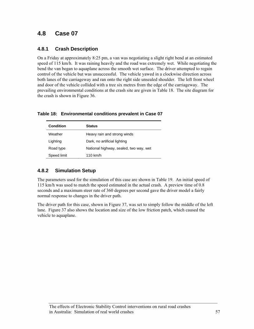
The effects of Electronic Stability Control interventions on rural road crashes in Australia: Simulation of real world crashes 57
4.8 Case 07
4.8.1 Crash Description
On a Friday at approximately 8:25 pm, a van was negotiating a slight right bend at an estimated speed of 115 km/h. It was raining heavily and the road was extremely wet. While negotiating the bend the van began to aquaplane across the smooth wet surface. The driver attempted to regain control of the vehicle but was unsuccessful. The vehicle yawed in a clockwise direction across both lanes of the carriageway and ran onto the right side unsealed shoulder. The left front wheel and door of the vehicle collided with a tree six metres from the edge of the carriageway. The prevailing environmental conditions at the crash site are given in Table 18. The site diagram for the crash is shown in Figure 36.
Table 18: Environmental conditions prevalent in Case 07
Condition Status
Weather Heavy rain and strong winds
Lighting Dark, no artificial lighting
Road type National highway, sealed, two way, wet
Speed limit 110 km/h
4.8.2 Simulation Setup
The parameters used for the simulation of this case are shown in Table 19. An initial speed of 115 km/h was used to match the speed estimated in the actual crash. A preview time of 0.8 seconds and a maximum steer rate of 360 degrees per second gave the driver model a fairly normal response to changes in the driver path.
The driver path for this case, shown in Figure 37, was set to simply follow the middle of the left lane. Figure 37 also shows the location and size of the low friction patch, which caused the vehicle to aquaplane.

Figure 36: Site diagram for Case 07
58 The effects of Electronic Stability Control interventions on rural road crashes in Australia: Simulation of real world crashes

The effects of Electronic Stability Control interventions on rural road crashes
μ = 0.75 μ = 0.50 μ = 0.10 Driver Path
0 10 20 30 40 50 60 70 80 90 100 110 120 130 140 150 160 170 180 190 200 210
0
5.94
Distance (metres)
Hei
ght (
met
res)
in Australia: Simulation of real world crashes 59
Figure 37: Road section and profile for Case 07

Table 19: Simulation parameters for Case 07
Parameter Value Units
Vehicle
Vehicle model Rear wheel drive
Events and procedures
Initial speed 115 km/h
Driver model:
Preview time 0.8 seconds
Max. steering wheel angle 360 degrees
Max. steering wheel angle rate 360 degrees per second
Environment
Road width 6.80 metres
Road length 215 metres
Surface type Sealed
Surface friction:
Road 0.75
Shoulder 0.50
Patch 0.10
4.8.3 Simulation Results
The simulation of the vehicle not equipped with ESP showed a reasonable resemblance to the events of the actual crash. In the simulation, the vehicle travelled down the middle of the left lane and then suddenly began to yaw in a clockwise direction as it passed over the patch of low friction. This yaw continued as the vehicle travelled across the right lane and off the side of the road. The amount of yaw however was greater than that of the actual crash.
The simulation of the vehicle equipped with ESP showed a vastly different vehicle path. There was virtually no reaction from the vehicle as it passed over the patch of low friction.
Equipping the vehicle with ESP enabled it to remain stable throughout the entire simulation. The vehicle equipped with ESP did not yaw at any stage and showed no effects from passing over the patch of low friction. Based on this, it is likely that a vehicle equipped with ESP, involved in the same crash scenario, would have avoided the loss of control that led to the collision in the actual crash.
60 The effects of Electronic Stability Control interventions on rural road crashes in Australia: Simulation of real world crashes

Figure 38: Simulation animation for Case 07
4.8.4 ESP Interventions
The ESP interventions for this case are shown in Figure 39. There are two points of interest, labelled A and B.
The driver model in this case does not make any drastic steering manoeuvres and instead attempts to keep the vehicle travelling down the middle of the left lane for the entire simulation.
As the vehicle travels over the patch of low friction (point A), there is a tendency for the vehicle to yaw to the right. This is due to the slight orientation of the wheels to the right just before entering the patch of low friction. There is also a small difference in the amount of friction available at the right and left wheels which creates a split mu situation. This situation is the inverse of an understeer. Instead of the driver steering and the vehicle not yawing, the driver is not steering but the vehicle is beginning to yaw. The ESP system very gently brakes the rear wheels, with a little more emphasis on the left wheel. This counteracts the situation in the same way as an understeer by the method shown in Figure 9.
The vehicle responds to the interventions of the ESP system at point A by remaining aligned with the lane but, because the friction is still very low, the vehicle may now begin veering to the left.
The ESP system responds to this effect a short time later (point B) by swapping the emphasis of the rear brakes from the left wheel to the right wheel.
As the vehicle continues to travel along the road (past point B), the ESP system lowers the amount of braking on the rear wheels and makes a final swap of the emphasis back to the left wheel.
The effects of Electronic Stability Control interventions on rural road crashes in Australia: Simulation of real world crashes 61
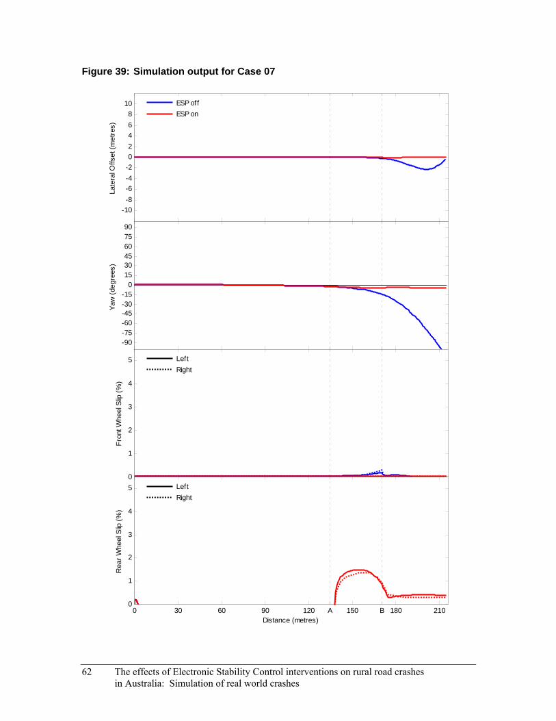
Figure 39: Simulation output for Case 07
-10-8-6-4-202468
10La
tera
l Offs
et (m
etre
s)ESP offESP on
-90-75-60-45-30-15
0153045607590
Yaw
(deg
rees
)
0
1
2
3
4
5
Fron
t Whe
el S
lip (%
)
LeftRight
0 30 60 90 120 A 150 B 180 2100
1
2
3
4
5
Distance (metres)
Rea
r Whe
el S
lip (%
)
LeftRight
62 The effects of Electronic Stability Control interventions on rural road crashes in Australia: Simulation of real world crashes

The effects of Electronic Stability Control interventions on rural road crashes in Australia: Simulation of real world crashes 63
4.9 Case 08
4.9.1 Crash Description
On a Saturday at approximately 7:10 am, a car was travelling south east on a straight carriageway. The driver reported having consumed a moderate quantity of alcohol the previous night and having less than four hours of sleep before commencing the journey an hour before the crash. The driver overtook a slower vehicle at an estimated speed of 120 km/h. When returning to the left lane, the driver overcorrected with the car yawing 35 metres across the lane. The vehicle continued onto the unsealed shoulder, careered into shrubs and trees 10−15 metres east of the road surface and rolled onto its right side. The prevailing environmental conditions at the crash site are given in Table 20. The site diagram for the crash is shown in Figure 40.
Table 20: Environmental conditions prevalent in Case 08
Condition Status
Weather Fine
Lighting Daylight
Road type Rural highway, sealed, two way, dry
Speed limit 110 km/h
4.9.2 Simulation Setup
The parameters used for the simulation of this case are shown in Table 21. An initial speed of 125 km/h was used, which gave the vehicle a speed of approximately 120 km/h as it began moving from the right lane, back into the left lane. A preview time of 0.6 seconds and a maximum steer rate of 540 degrees per second gave the driver model a quick, jerking response to changes in the driver path.
The driver path for this case, show in Figure 41, was developed based on what was thought to be the driver’s intention. The driver path was designed to model the following sequence of events: The path begins in the middle of the right lane where the vehicle is overtaking a slower moving vehicle. The path then pulls quickly to the left into the middle of the left lane.

Figure 40: Site diagram for Case 08
64 The effects of Electronic Stability Control interventions on rural road crashes in Australia: Simulation of real world crashes

The effects of Electronic Stability Control interventions on rural road crashes
μ = 0.85 μ = 0.60 Driver Path
0 10 20 30 40 50 60 70 80 90 100 110 120
0
Distance (metres)
Hei
ght (
met
res)
in Australia: Simulation of real world crashes 65
Figure 41: Road section and profile for Case 08

Table 21: Simulation parameters for Case 08
Parameter Value Units
Vehicle
Vehicle model Front wheel drive
Events and procedures
Initial speed 125 km/h
Driver model:
Preview time 0.6 seconds
Max. steering wheel angle 360 degrees
Max. steering wheel angle rate 540 degrees per second
Environment
Road width 7.20 metres
Road length 125 metres
Surface type Sealed
Surface friction:
Road 0.85
Shoulder 0.60
4.9.3 Simulation Results
The simulation of the vehicle not equipped with ESP showed a small resemblance to the events of the actual crash. In the simulation, the vehicle lost control when returning to the left lane. The vehicle overshot the middle of the left lane and then overcorrected back to the right and began to yaw in a clockwise direction across both lanes. In the actual crash the vehicle began to yaw anti-clockwise upon attempting to return to the left lane.
The simulation of the vehicle equipped with ESP showed a more controlled vehicle path. Upon returning to the left lane the vehicle travelled a little way onto the unsealed shoulder. The vehicle then steered easily back to the middle of the lane and continued following the road.
Equipping the vehicle with ESP enabled it to remain stable throughout the entire emergency manoeuvre. While the vehicle equipped with ESP did overshoot the middle of the left lane and travelled a small way onto the unsealed shoulder, it remained stable and did not yaw at any stage. It was then able to quickly re-enter the middle of the lane. Based on this, it is likely that a vehicle equipped with ESP, involved in the same crash scenario, would have avoided the loss of control that led to the collision in the actual crash.
66 The effects of Electronic Stability Control interventions on rural road crashes in Australia: Simulation of real world crashes
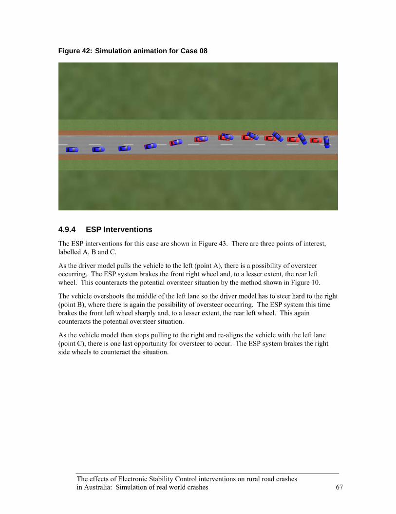
Figure 42: Simulation animation for Case 08
4.9.4 ESP Interventions
The ESP interventions for this case are shown in Figure 43. There are three points of interest, labelled A, B and C.
As the driver model pulls the vehicle to the left (point A), there is a possibility of oversteer occurring. The ESP system brakes the front right wheel and, to a lesser extent, the rear left wheel. This counteracts the potential oversteer situation by the method shown in Figure 10.
The vehicle overshoots the middle of the left lane so the driver model has to steer hard to the right (point B), where there is again the possibility of oversteer occurring. The ESP system this time brakes the front left wheel sharply and, to a lesser extent, the rear left wheel. This again counteracts the potential oversteer situation.
As the vehicle model then stops pulling to the right and re-aligns the vehicle with the left lane (point C), there is one last opportunity for oversteer to occur. The ESP system brakes the right side wheels to counteract the situation.
The effects of Electronic Stability Control interventions on rural road crashes in Australia: Simulation of real world crashes 67

Figure 43: Simulation output for Case 08
-10-8-6-4-202468
10La
tera
l Offs
et (m
etre
s)ESP offESP on
-90-75-60-45-30-15
0153045607590
Yaw
(deg
rees
)
0
10
20
30
40
50
Fron
t Whe
el S
lip (%
)
LeftRight
0 30 A 60 B 90 C 1200
10
20
30
40
50
Distance (metres)
Rea
r Whe
el S
lip (%
)
LeftRight
68 The effects of Electronic Stability Control interventions on rural road crashes in Australia: Simulation of real world crashes
The effects of Electronic Stability Control interventions on rural road crashes in Australia: Simulation of real world crashes 69
4.10 Case 09
4.10.1 Crash Description
On a Thursday at approximately 7:35 am, a 4WD was negotiating a sweeping left bend at an estimated speed of 70 km/h. As the 4WD came over a crest the left front wheel ran onto the unsealed left shoulder. The driver overcorrected the 4WD to the right, crossing the centre line before overcorrecting back to the left. The 4WD yawed in an anti-clockwise direction across the carriageway and an unsealed driveway. The right rear of the 4WD collided with a large tree located four metres from the carriageway. The prevailing environmental conditions at the crash site are given in Table 22. The site diagram for the crash is shown in Figure 44.
Table 22: Environmental conditions prevalent in Case 09
Condition Status
Weather Fine
Lighting Daylight
Road type Sealed, two way, dry
Speed limit 100 km/h
4.10.2 Simulation Setup
The parameters used for the simulation of this case are shown in Table 23. An initial speed of 80 km/h was used, which was higher than that reported in the actual crash. This gave the vehicle (which was travelling up an incline) a speed of a little over 70 km/h as it began the emergency manoeuvre. A preview time of 0.6 seconds and a maximum steer rate of 400 degrees per second gave the driver model a surprised and jerking response to travelling off the side of the road.
The driver path for this case, shown in Figure 45, was developed based on the crash description and the tyre marks at the crash scene. The driver path was designed to model the following sequence of events: The path begins in the middle of the left lane. As the vehicle comes over the small crest and through the apex of the bend, the path moves to the far left of the lane. The path then suddenly pulls to the right and back into the middle of the left lane as the driver realises the left wheels of the vehicle have left the road.

Figure 44: Site diagram for Case 09
70 The effects of Electronic Stability Control interventions on rural road crashes in Australia: Simulation of real world crashes

The effects of Electronic Stability Control interventions on rural road crashes
μ = 0.85 μ = 0.60 Driver Path
0 10 20 30 40 50 60 70 80 90 100 110 120 130 140 150 160
0.014.69
5.38 m
Distance (metres)
Hei
ght (
met
res)
in Australia: Simulation of real world crashes 71
Figure 45: Road section and profile for Case 09
Table 23: Simulation parameters for Case 09
Parameter Value Units
Vehicle
Vehicle model Rear wheel drive
Events and procedures
Initial speed 80 km/h
Driver model:
Preview time 0.6 seconds
Max. steering wheel angle 360 degrees
Max. steering wheel angle rate 400 degrees per second
Environment
Road width 6.40 metres
Road length 185 metres
Surface type Sealed
Surface friction:
Road 0.85
Shoulder 0.60
4.10.3 Simulation Results
The simulation of the vehicle not equipped with ESP showed a reasonable resemblance to the events of the actual crash. In the simulation, the vehicle travelled a small distance off the left side of the road as it came through the apex of the bend. The vehicle then pulled sharply to the right before overcorrecting back to the left. This overcorrection caused the vehicle to yaw in an anti-clockwise direction off the left side of the road and unsealed shoulder. The amount of yaw and the path taken, however, were slightly different to those of the actual crash.
The simulation of the vehicle equipped with ESP showed a more stable vehicle path. As the vehicle pulled to the right it overshot the middle of the left lane and travelled slightly over the centreline a small distance. The vehicle was able to easily steer back into the middle of the left lane and continue following the road.
Equipping the vehicle with ESP enabled it to remain stable throughout the entire emergency manoeuvre. The vehicle equipped with ESP overcorrected to the right when attempting to return to the middle of the left lane and crossed the centreline a small distance. Despite this, it did not yaw at any stage and was able to quickly correct and re-align with the middle of the left lane. Based on this, it is likely that a vehicle equipped with ESP, involved in the same crash scenario, would have avoided the loss of control that led to the collision in the actual crash.
72 The effects of Electronic Stability Control interventions on rural road crashes in Australia: Simulation of real world crashes

Figure 46: Simulation result for Case 09
4.10.4 ESP Interventions
The ESP interventions for this case are shown in Figure 47. There are two points of interest, labelled A and B.
As the driver model turns left, into the corner (point A), the ESP system brakes the right side wheels. The driver model then pulls the vehicle to the right which gives rise to the possibility of oversteer occurring. The ESP system brakes the front left wheel slightly. This counteracts the potential oversteer situation by the method shown in Figure 10.
The driver model then steers back to the left (point B) which again gives rise to the possibility of oversteer as the weight of the vehicle shifts from one side to the other. The ESP system brakes the front right wheel sharply. This counteracts the potential oversteer situation and allows the vehicle to continue following the road.
The effects of Electronic Stability Control interventions on rural road crashes in Australia: Simulation of real world crashes 73
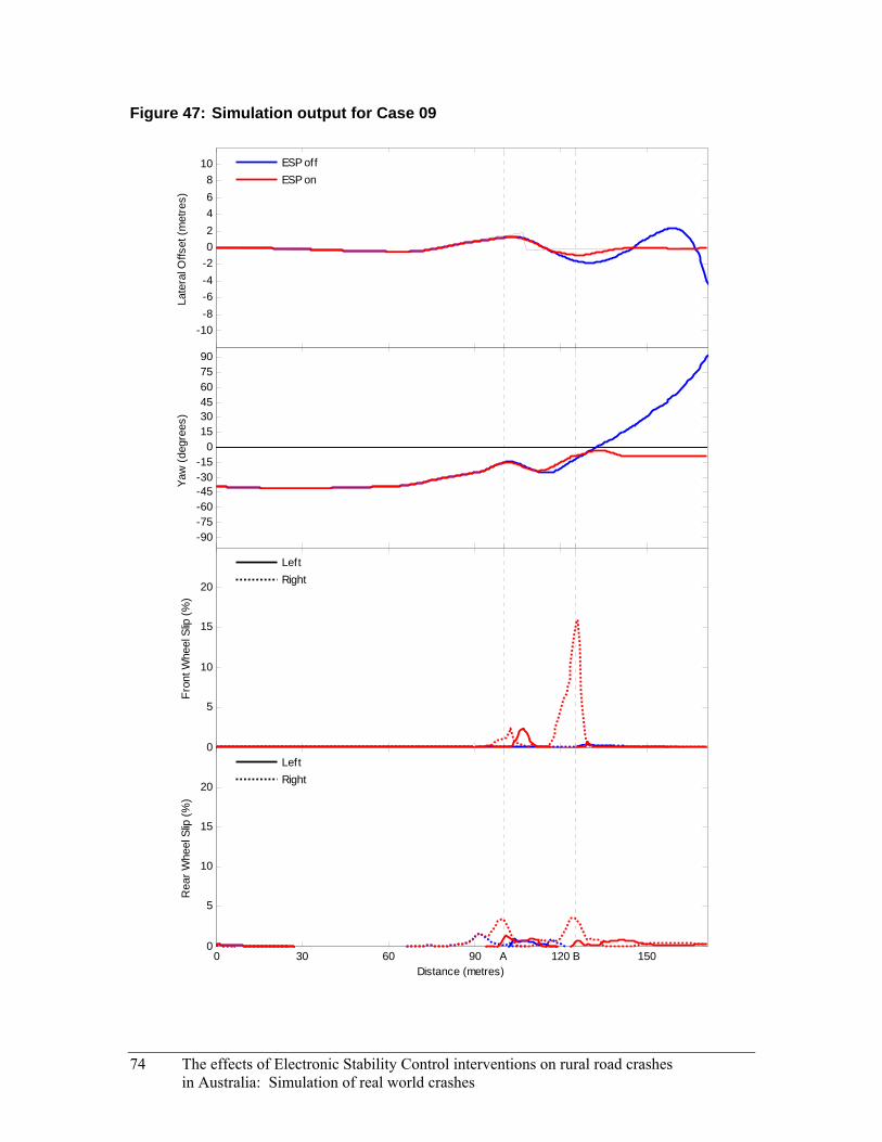
Figure 47: Simulation output for Case 09
-10-8-6-4-202468
10La
tera
l Offs
et (m
etre
s)
ESP offESP on
-90-75-60-45-30-15
0153045607590
Yaw
(deg
rees
)
0
5
10
15
20
Fron
t Whe
el S
lip (%
)
LeftRight
0 30 60 90 A 120 B 1500
5
10
15
20
Distance (metres)
Rea
r Whe
el S
lip (%
)
LeftRight
74 The effects of Electronic Stability Control interventions on rural road crashes in Australia: Simulation of real world crashes
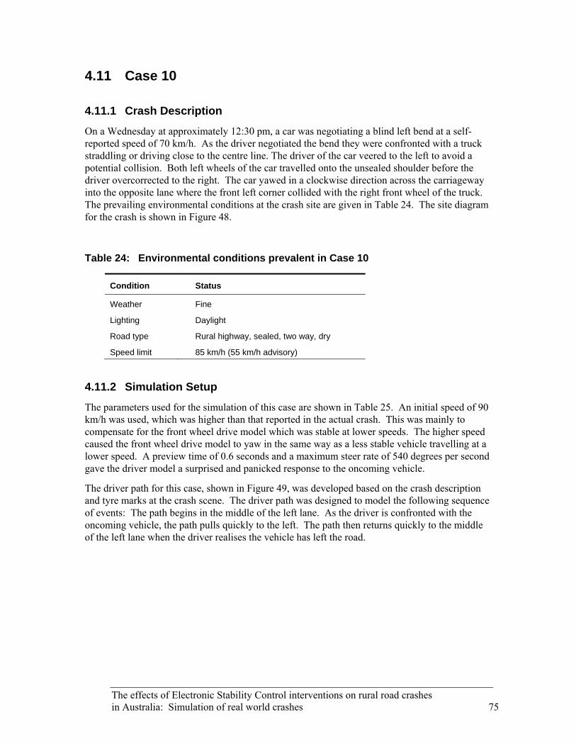
The effects of Electronic Stability Control interventions on rural road crashes in Australia: Simulation of real world crashes 75
4.11 Case 10
4.11.1 Crash Description
On a Wednesday at approximately 12:30 pm, a car was negotiating a blind left bend at a self-reported speed of 70 km/h. As the driver negotiated the bend they were confronted with a truck straddling or driving close to the centre line. The driver of the car veered to the left to avoid a potential collision. Both left wheels of the car travelled onto the unsealed shoulder before the driver overcorrected to the right. The car yawed in a clockwise direction across the carriageway into the opposite lane where the front left corner collided with the right front wheel of the truck. The prevailing environmental conditions at the crash site are given in Table 24. The site diagram for the crash is shown in Figure 48.
Table 24: Environmental conditions prevalent in Case 10
Condition Status
Weather Fine
Lighting Daylight
Road type Rural highway, sealed, two way, dry
Speed limit 85 km/h (55 km/h advisory)
4.11.2 Simulation Setup
The parameters used for the simulation of this case are shown in Table 25. An initial speed of 90 km/h was used, which was higher than that reported in the actual crash. This was mainly to compensate for the front wheel drive model which was stable at lower speeds. The higher speed caused the front wheel drive model to yaw in the same way as a less stable vehicle travelling at a lower speed. A preview time of 0.6 seconds and a maximum steer rate of 540 degrees per second gave the driver model a surprised and panicked response to the oncoming vehicle.
The driver path for this case, shown in Figure 49, was developed based on the crash description and tyre marks at the crash scene. The driver path was designed to model the following sequence of events: The path begins in the middle of the left lane. As the driver is confronted with the oncoming vehicle, the path pulls quickly to the left. The path then returns quickly to the middle of the left lane when the driver realises the vehicle has left the road.

Figure 48: Site diagram for Case 10
76 The effects of Electronic Stability Control interventions on rural road crashes in Australia: Simulation of real world crashes

The effects of Electronic Stability Control interventions on rural road crashes
μ = 0.85 μ = 0.60 Driver Path
0 10 20 30 40 50 60 70 80 90
0.35 m
Distance (metres)
Hei
ght (
met
res)
in Australia: Simulation of real world crashes 77
Figure 49: Road section and profile for Case 10
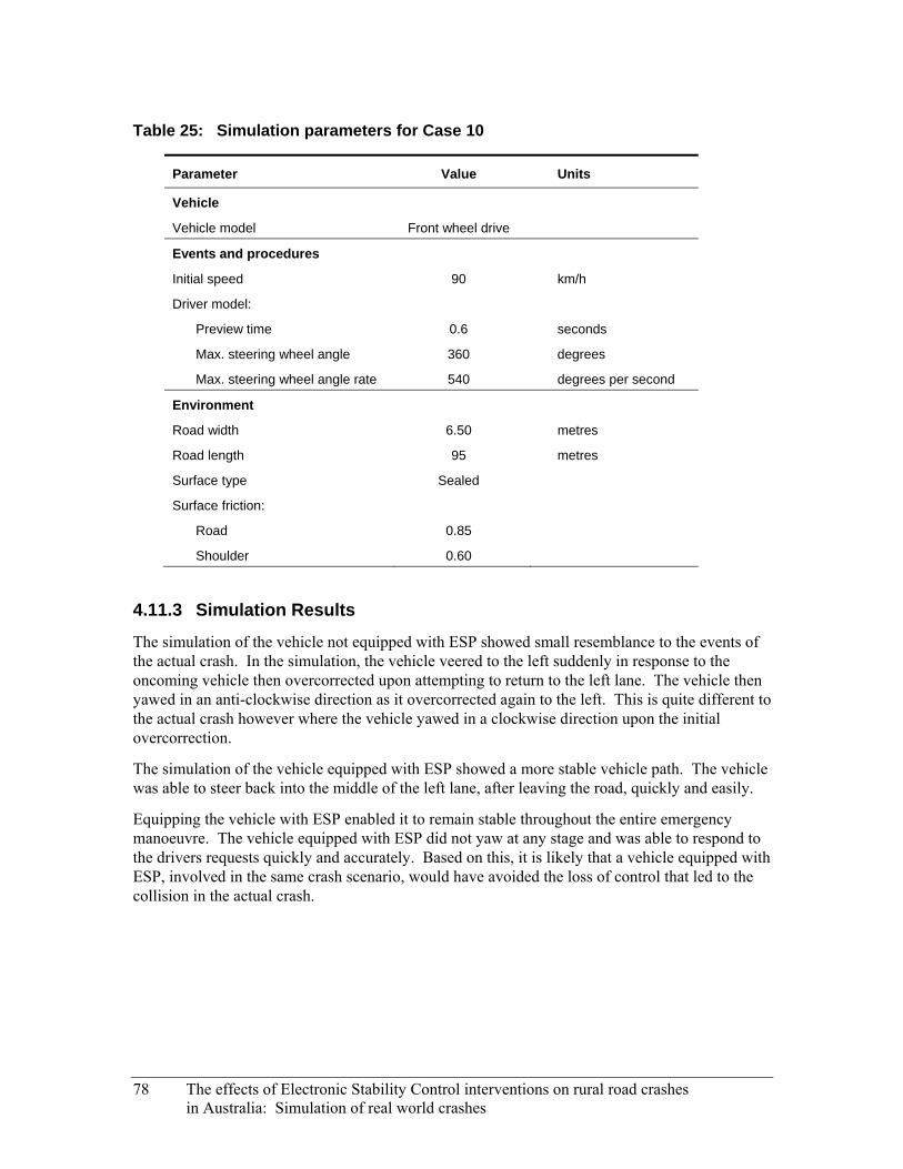
Table 25: Simulation parameters for Case 10
Parameter Value Units
Vehicle
Vehicle model Front wheel drive
Events and procedures
Initial speed 90 km/h
Driver model:
Preview time 0.6 seconds
Max. steering wheel angle 360 degrees
Max. steering wheel angle rate 540 degrees per second
Environment
Road width 6.50 metres
Road length 95 metres
Surface type Sealed
Surface friction:
Road 0.85
Shoulder 0.60
4.11.3 Simulation Results
The simulation of the vehicle not equipped with ESP showed small resemblance to the events of the actual crash. In the simulation, the vehicle veered to the left suddenly in response to the oncoming vehicle then overcorrected upon attempting to return to the left lane. The vehicle then yawed in an anti-clockwise direction as it overcorrected again to the left. This is quite different to the actual crash however where the vehicle yawed in a clockwise direction upon the initial overcorrection.
The simulation of the vehicle equipped with ESP showed a more stable vehicle path. The vehicle was able to steer back into the middle of the left lane, after leaving the road, quickly and easily.
Equipping the vehicle with ESP enabled it to remain stable throughout the entire emergency manoeuvre. The vehicle equipped with ESP did not yaw at any stage and was able to respond to the drivers requests quickly and accurately. Based on this, it is likely that a vehicle equipped with ESP, involved in the same crash scenario, would have avoided the loss of control that led to the collision in the actual crash.
78 The effects of Electronic Stability Control interventions on rural road crashes in Australia: Simulation of real world crashes
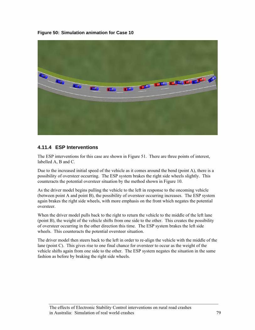
Figure 50: Simulation animation for Case 10
4.11.4 ESP Interventions
The ESP interventions for this case are shown in Figure 51. There are three points of interest, labelled A, B and C.
Due to the increased initial speed of the vehicle as it comes around the bend (point A), there is a possibility of oversteer occurring. The ESP system brakes the right side wheels slightly. This counteracts the potential oversteer situation by the method shown in Figure 10.
As the driver model begins pulling the vehicle to the left in response to the oncoming vehicle (between point A and point B), the possibility of oversteer occurring increases. The ESP system again brakes the right side wheels, with more emphasis on the front which negates the potential oversteer.
When the driver model pulls back to the right to return the vehicle to the middle of the left lane (point B), the weight of the vehicle shifts from one side to the other. This creates the possibility of oversteer occurring in the other direction this time. The ESP system brakes the left side wheels. This counteracts the potential oversteer situation.
The driver model then steers back to the left in order to re-align the vehicle with the middle of the lane (point C). This gives rise to one final chance for oversteer to occur as the weight of the vehicle shifts again from one side to the other. The ESP system negates the situation in the same fashion as before by braking the right side wheels.
The effects of Electronic Stability Control interventions on rural road crashes in Australia: Simulation of real world crashes 79
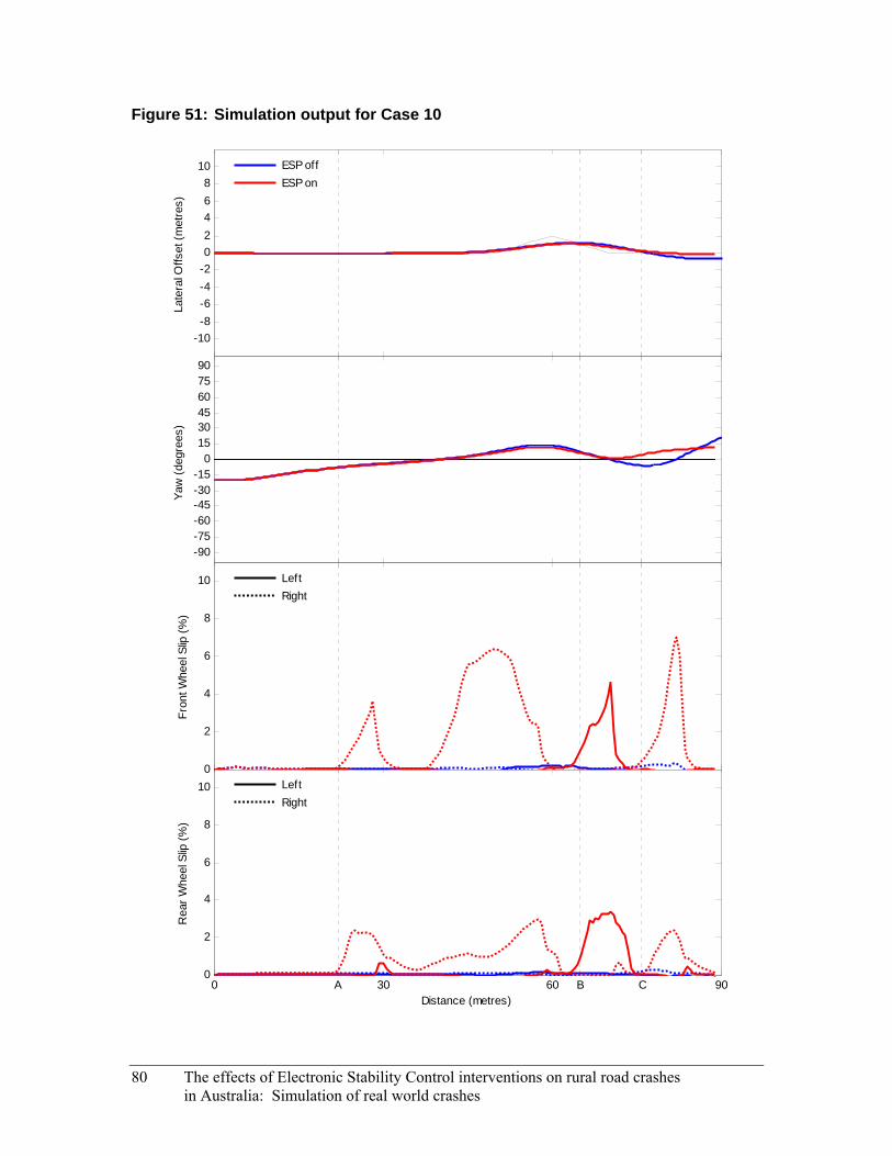
Figure 51: Simulation output for Case 10
-10-8-6-4-202468
10La
tera
l Offs
et (m
etre
s)ESP offESP on
-90-75-60-45-30-15
0153045607590
Yaw
(deg
rees
)
0
2
4
6
8
10
Fron
t Whe
el S
lip (%
)
LeftRight
0 A 30 60 B C 900
2
4
6
8
10
Distance (metres)
Rea
r Whe
el S
lip (%
)
LeftRight
80 The effects of Electronic Stability Control interventions on rural road crashes in Australia: Simulation of real world crashes
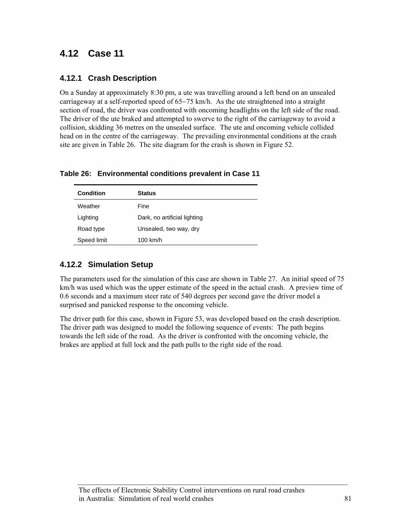
The effects of Electronic Stability Control interventions on rural road crashes in Australia: Simulation of real world crashes 81
4.12 Case 11
4.12.1 Crash Description
On a Sunday at approximately 8:30 pm, a ute was travelling around a left bend on an unsealed carriageway at a self-reported speed of 65−75 km/h. As the ute straightened into a straight section of road, the driver was confronted with oncoming headlights on the left side of the road. The driver of the ute braked and attempted to swerve to the right of the carriageway to avoid a collision, skidding 36 metres on the unsealed surface. The ute and oncoming vehicle collided head on in the centre of the carriageway. The prevailing environmental conditions at the crash site are given in Table 26. The site diagram for the crash is shown in Figure 52.
Table 26: Environmental conditions prevalent in Case 11
Condition Status
Weather Fine
Lighting Dark, no artificial lighting
Road type Unsealed, two way, dry
Speed limit 100 km/h
4.12.2 Simulation Setup
The parameters used for the simulation of this case are shown in Table 27. An initial speed of 75 km/h was used which was the upper estimate of the speed in the actual crash. A preview time of 0.6 seconds and a maximum steer rate of 540 degrees per second gave the driver model a surprised and panicked response to the oncoming vehicle.
The driver path for this case, shown in Figure 53, was developed based on the crash description. The driver path was designed to model the following sequence of events: The path begins towards the left side of the road. As the driver is confronted with the oncoming vehicle, the brakes are applied at full lock and the path pulls to the right side of the road.
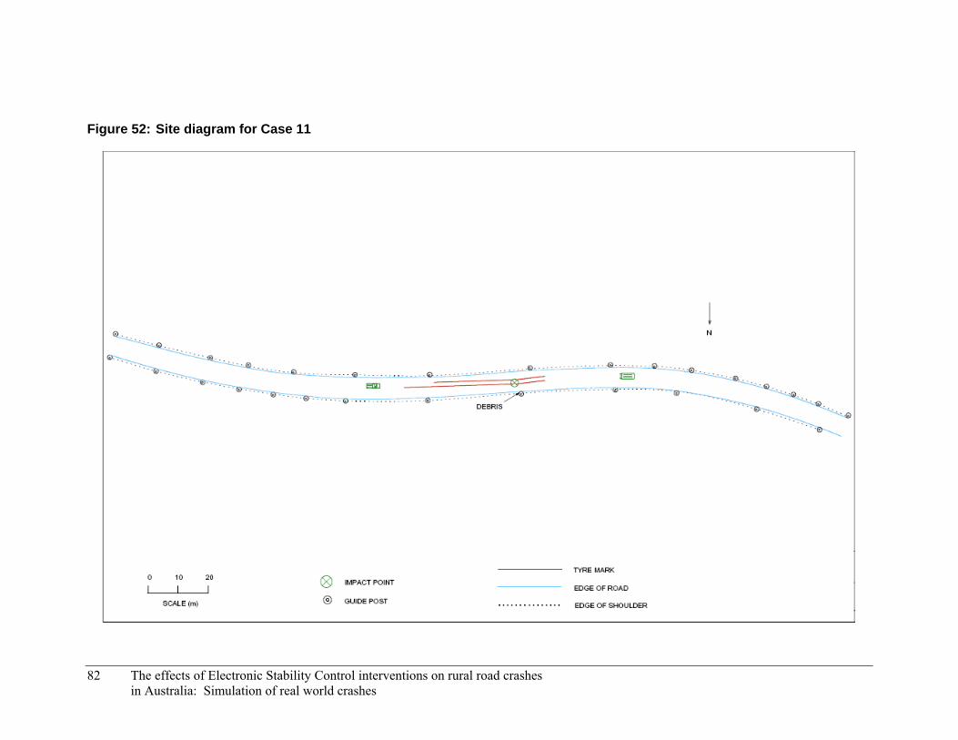
Figure 52: Site diagram for Case 11
82 The effects of Electronic Stability Control interventions on rural road crashes in Australia: Simulation of real world crashes
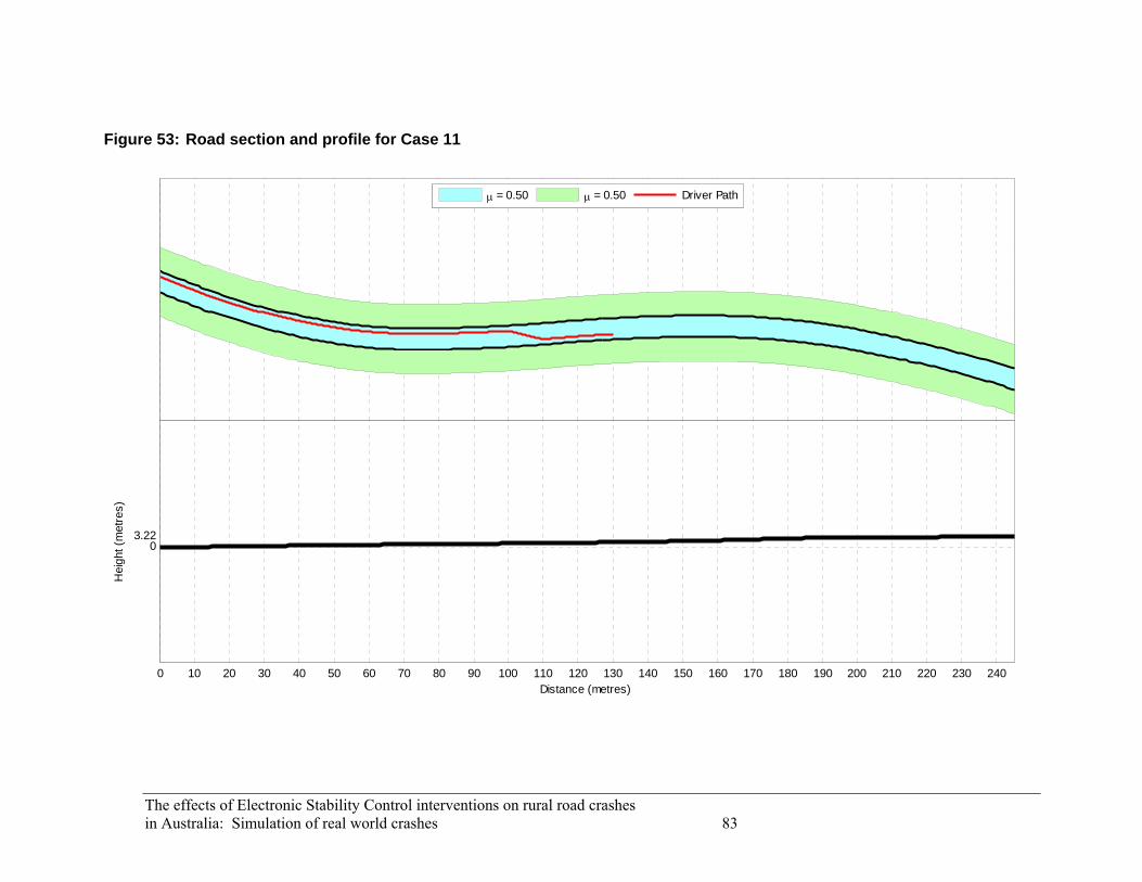
The effects of Electronic Stability Control interventions on rural road crashes
μ = 0.50 μ = 0.50 Driver Path
0 10 20 30 40 50 60 70 80 90 100 110 120 130 140 150 160 170 180 190 200 210 220 230 240
03.22
Distance (metres)
Hei
ght (
met
res)
in Australia: Simulation of real world crashes 83
Figure 53: Road section and profile for Case 11

Table 27: Simulation parameters for Case 11
Parameter Value Units
Vehicle
Vehicle model Rear wheel drive
Events and procedures
Initial speed 75 km/h
Driver model:
Preview time 0.6 seconds
Max. steering wheel angle 360 degrees
Max. steering wheel angle rate 540 degrees per second
Environment
Road width 6.00 metres
Road length 250 metres
Surface type Unsealed
Surface friction:
Road 0.50
Shoulder 0.50
4.12.3 Simulation Results
The simulation of the vehicle not equipped with ESP showed a good resemblance to the events of the actual crash. In the simulation, the vehicle travelled around the bend and applied the brakes at full lock. This caused the vehicle to skid forwards while drifting to the right.
The simulation of the vehicle equipped with ESP showed a more responsive vehicle path. The vehicle was able to steer to the right as it braked and slowed.
Equipping the vehicle with ESP enabled it to remain stable throughout the entire emergency manoeuvre. The vehicle equipped with ESP was able to respond to the driver’s request to veer right. Unfortunately due to both drivers electing to steer in the same direction it is likely there would still have been some kind of collision. The collision would have been either an offset frontal impact or a glancing side swipe. The two vehicles would have impacted on their front left corners. This can be a more favourable result compared with the full frontal impact experienced by the vehicle in the actual crash. This is because the driver sits on the right side of the vehicle and would have been further from the impact point. A front seat passenger however would have been closer to the impact point.
84 The effects of Electronic Stability Control interventions on rural road crashes in Australia: Simulation of real world crashes
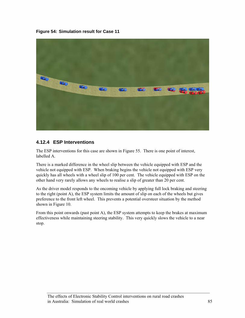
Figure 54: Simulation result for Case 11
4.12.4 ESP Interventions
The ESP interventions for this case are shown in Figure 55. There is one point of interest, labelled A.
There is a marked difference in the wheel slip between the vehicle equipped with ESP and the vehicle not equipped with ESP. When braking begins the vehicle not equipped with ESP very quickly has all wheels with a wheel slip of 100 per cent. The vehicle equipped with ESP on the other hand very rarely allows any wheels to realise a slip of greater than 20 per cent.
As the driver model responds to the oncoming vehicle by applying full lock braking and steering to the right (point A), the ESP system limits the amount of slip on each of the wheels but gives preference to the front left wheel. This prevents a potential oversteer situation by the method shown in Figure 10.
From this point onwards (past point A), the ESP system attempts to keep the brakes at maximum effectiveness while maintaining steering stability. This very quickly slows the vehicle to a near stop.
The effects of Electronic Stability Control interventions on rural road crashes in Australia: Simulation of real world crashes 85

Figure 55: Simulation output for Case 11
-10-8-6-4-202468
10La
tera
l Offs
et (m
etre
s)ESP offESP on
-90-75-60-45-30-15
0153045607590
Yaw
(deg
rees
)
0
20
40
60
80
100
Fron
t Whe
el S
lip (%
)
LeftRight
0 30 60 A 90 1200
20
40
60
80
100
Distance (metres)
Rea
r Whe
el S
lip (%
)
LeftRight
86 The effects of Electronic Stability Control interventions on rural road crashes in Australia: Simulation of real world crashes

The effects of Electronic Stability Control interventions on rural road crashes in Australia: Simulation of real world crashes 87
4.13 Case 12
4.13.1 Crash Description
On a Tuesday at approximately 11:45 am, a station wagon was negotiating a left hand bend through a cutting. There were steep 45 degree embankments on both sides of the carriageway that consisted of deeply embedded rock to a maximum height of eight metres. The weather conditions were severe (hail and sleet) and the driver was travelling cautiously at a self-reported speed of 40−50 km/h. As the station wagon entered the cutting it ran onto black ice on the surface and the driver lost control. The station wagon left the carriageway to the left and mounted the embankment to a height of approximately two metres before rolling over back onto the road surface, landing on its roof. The prevailing environmental conditions at the crash site are given in Table 28. The site diagram for the crash is shown in Figure 56.
Table 28: Environmental conditions prevalent in Case 12
Condition Status
Weather Hail and sleet
Lighting Daylight
Road type Rural highway, sealed, two way, hail and sleet on surface
Speed limit 110 km/h
4.13.2 Simulation Setup
The parameters used for the simulation of this case are shown in Table 29. An initial speed of 65 km/h was used. This gave the vehicle (which was travelling up an incline) a speed of approximately 55 km/h as it began to aquaplane. A preview time of 0.95 seconds and a maximum steer rate of 120 degrees per second gave the driver model a normal but slowed reaction to changes in the driver path.
The driver path for this case, shown in Figure 57, was set to simply follow the middle of the left lane. Figure 59 also shows the location and size of the low friction patch, which caused the vehicle to aquaplane.
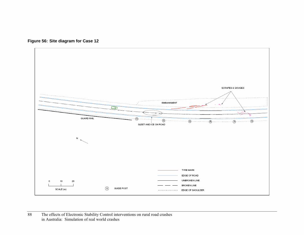
Figure 56: Site diagram for Case 12
88 The effects of Electronic Stability Control interventions on rural road crashes in Australia: Simulation of real world crashes

The effects of Electronic Stability Control interventions on rural road crashes
μ = 0.50 μ = 0.50 μ = 0.10 Driver Path
0 10 20 30 40 50 60 70 80 90 100 110 120 130 140 150 160 170 180 190
0
6.366.41 m
Distance (metres)
Hei
ght (
met
res)
in Australia: Simulation of real world crashes 89
Figure 57: Road section and profile for Case 12
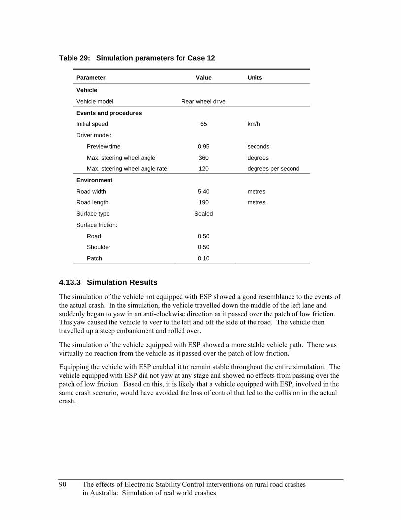
Table 29: Simulation parameters for Case 12
Parameter Value Units
Vehicle
Vehicle model Rear wheel drive
Events and procedures
Initial speed 65 km/h
Driver model:
Preview time 0.95 seconds
Max. steering wheel angle 360 degrees
Max. steering wheel angle rate 120 degrees per second
Environment
Road width 5.40 metres
Road length 190 metres
Surface type Sealed
Surface friction:
Road 0.50
Shoulder 0.50
Patch 0.10
4.13.3 Simulation Results
The simulation of the vehicle not equipped with ESP showed a good resemblance to the events of the actual crash. In the simulation, the vehicle travelled down the middle of the left lane and suddenly began to yaw in an anti-clockwise direction as it passed over the patch of low friction. This yaw caused the vehicle to veer to the left and off the side of the road. The vehicle then travelled up a steep embankment and rolled over.
The simulation of the vehicle equipped with ESP showed a more stable vehicle path. There was virtually no reaction from the vehicle as it passed over the patch of low friction.
Equipping the vehicle with ESP enabled it to remain stable throughout the entire simulation. The vehicle equipped with ESP did not yaw at any stage and showed no effects from passing over the patch of low friction. Based on this, it is likely that a vehicle equipped with ESP, involved in the same crash scenario, would have avoided the loss of control that led to the collision in the actual crash.
90 The effects of Electronic Stability Control interventions on rural road crashes in Australia: Simulation of real world crashes
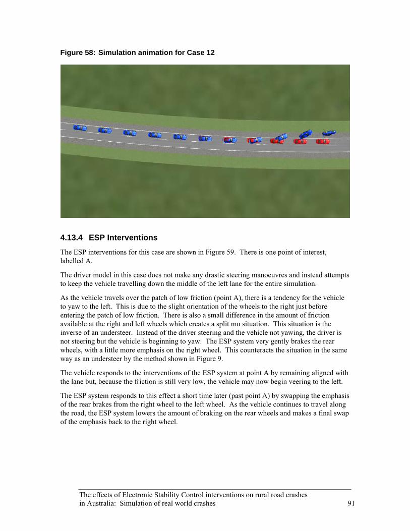
Figure 58: Simulation animation for Case 12
4.13.4 ESP Interventions
The ESP interventions for this case are shown in Figure 59. There is one point of interest, labelled A.
The driver model in this case does not make any drastic steering manoeuvres and instead attempts to keep the vehicle travelling down the middle of the left lane for the entire simulation.
As the vehicle travels over the patch of low friction (point A), there is a tendency for the vehicle to yaw to the left. This is due to the slight orientation of the wheels to the right just before entering the patch of low friction. There is also a small difference in the amount of friction available at the right and left wheels which creates a split mu situation. This situation is the inverse of an understeer. Instead of the driver steering and the vehicle not yawing, the driver is not steering but the vehicle is beginning to yaw. The ESP system very gently brakes the rear wheels, with a little more emphasis on the right wheel. This counteracts the situation in the same way as an understeer by the method shown in Figure 9.
The vehicle responds to the interventions of the ESP system at point A by remaining aligned with the lane but, because the friction is still very low, the vehicle may now begin veering to the left.
The ESP system responds to this effect a short time later (past point A) by swapping the emphasis of the rear brakes from the right wheel to the left wheel. As the vehicle continues to travel along the road, the ESP system lowers the amount of braking on the rear wheels and makes a final swap of the emphasis back to the right wheel.
The effects of Electronic Stability Control interventions on rural road crashes in Australia: Simulation of real world crashes 91
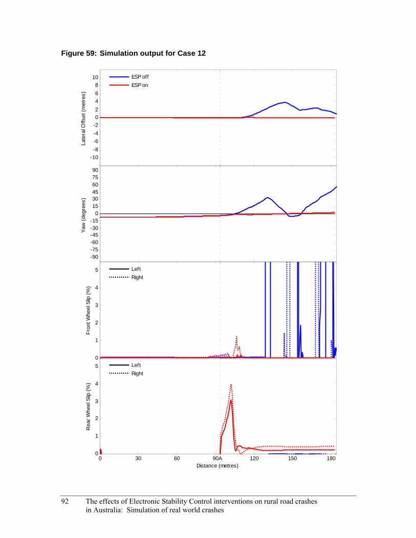
Figure 59: Simulation output for Case 12
-10-8-6-4-202468
10La
tera
l Offs
et (m
etre
s)ESP offESP on
-90-75-60-45-30-15
0153045607590
Yaw
(deg
rees
)
0
1
2
3
4
5
Fron
t Whe
el S
lip (%
)
LeftRight
0 30 60 90A 120 150 1800
1
2
3
4
5
Distance (metres)
Rea
r Whe
el S
lip (%
)
LeftRight
92 The effects of Electronic Stability Control interventions on rural road crashes in Australia: Simulation of real world crashes

The effects of Electronic Stability Control interventions on rural road crashes in Australia: Simulation of real world crashes 93
4.14 Case 13
4.14.1 Crash Description
On a Saturday at approximately 9:45 am, a car was negotiating a left bend at an estimated speed of 100 to 110 km/h. While negotiating the bend the car travelled across the centre line and into the opposite lane. A second car was travelling in the opposite direction at an estimated speed of 80 km/h when the driver was confronted with the first car travelling towards them. The driver of the second car veered to the left but was unable to avoid a collision. The prevailing environmental conditions at the crash site are given in Table 30. The site diagram for the crash is shown in Figure 60.
Table 30: Environmental conditions prevalent in Case 13
Condition Status
Weather Fine
Lighting Daylight
Road type Rural highway, sealed, two way, dry
Speed limit 100 km/h
4.14.2 Discussion
In this case the driver did not make any appreciable avoidance manoeuvre. The reasons for this are unknown but can be speculated upon. Perhaps the driver was conscious of their high speed and did not wish to risk oversteering the vehicle by suddenly steering left. Perhaps the driver believed a near miss would occur, rather than a collision.
Regardless of why the driver made no avoidance attempt, having the vehicle equipped with ESP would not have helped to prevent the collision. After the initial collision however, the vehicle swerved dangerously across both lanes and came to rest on the shoulder of the opposite side of the road. Had the vehicle been equipped with ESP, and had the system not been damaged during the collision, the post-crash vehicle trajectory may have been different. The ESP system would have attempted to stabilise the vehicle, which may have enabled it to continue in the left lane without crossing the centreline.

Figure 60: Site diagram for Case 13
94 The effects of Electronic Stability Control interventions on rural road crashes in Australia: Simulation of real world crashes

4.15 Case 14
4.15.1 Crash Description
On a Friday at approximately 12:05 pm, a car was travelling through a left bend when the right side of the vehicle travelled over the double centre line and into the path of a truck travelling in the opposite direction at an estimated speed of 40 km/h. The driver of the truck veered left but was unable to avoid a collision. The right side of the car collided with the right front corner of the truck’s overhanging tray top. The prevailing environmental conditions at the crash site are given in Table 31. The site diagram for the crash is shown in Figure 61.
Table 31: Environmental conditions prevalent in Case 14
Condition Status
Weather Overcast
Lighting Daylight
Road type Rural highway, sealed, two way, dry
Speed limit 100 km/h (35 km/h advisory)
4.15.2 Discussion
In this case the driver did not make any appreciable avoidance manoeuvre. The reasons for this are unknown but can be speculated upon. Perhaps the driver was not aware of the vehicle travelling in the other direction due to the configuration of the bend. Perhaps the driver believed a near miss would occur, rather than a collision.
Regardless of why the driver made no avoidance attempt, having the vehicle equipped with ESP would not have helped to prevent the collision.
The effects of Electronic Stability Control interventions on rural road crashes in Australia: Simulation of real world crashes 95
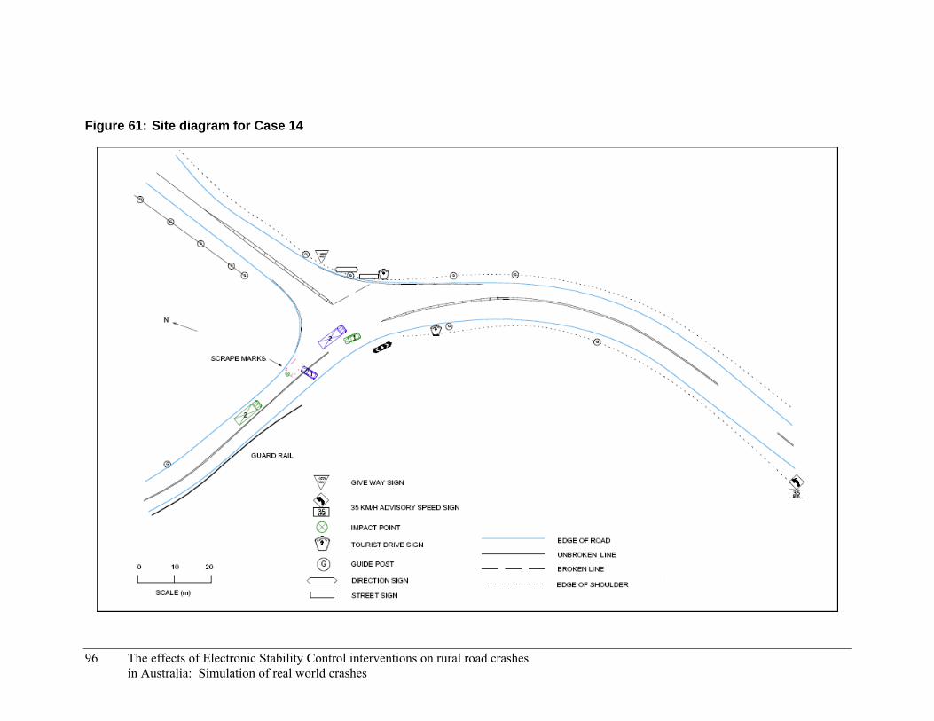
Figure 61: Site diagram for Case 14
96 The effects of Electronic Stability Control interventions on rural road crashes in Australia: Simulation of real world crashes

4.16 Case 15
4.16.1 Crash Description
On a Thursday at approximately 7:40 am, a car was negotiating a right bend at an estimated speed of 68 km/h. The driver was travelling their normal route to work and was familiar with the carriageway. It was reported that the driver lost control of the vehicle when it travelled over loose gravel that had been brought onto the road surface following recent road works. The car yawed in a clockwise direction across the centre line and into the path of a truck, travelling in the opposite direction. The driver of the truck braked but was unable to avoid a collision. The front of the truck, which was fitted with a bull bar, collided with the left side of the car within the truck’s lane. The prevailing environmental conditions at the crash site are given in Table 32. The site diagram for the crash is shown in Figure 62.
Table 32: Environmental conditions prevalent in Case 15
Condition Status
Weather Fine
Lighting Daylight
Road type Rural highway, sealed, two way, dry
Speed limit 80 km/h
4.16.2 Discussion
This is a case of oversteer by a front wheel drive vehicle. Multiple attempts at simulation were unable to replicate the results of the crash scenario in any way. This may be due to the inherent stability of the front wheel drive vehicle model or there may have been some other factors that contributed to the crash which were not discovered.
If the cause of the oversteer was the result of the friction drop due to the loose gravel, the ESP system would have attempted to stabilise the vehicle. There may have been an overall friction drop across all the wheels or only the right side wheels, resulting in a split mu situation. For the ESP system’s response to an oversteer situation, see Figure 10. For the ESP system’s response to a split mu situation, see Figure 11.
The effects of Electronic Stability Control interventions on rural road crashes in Australia: Simulation of real world crashes 97
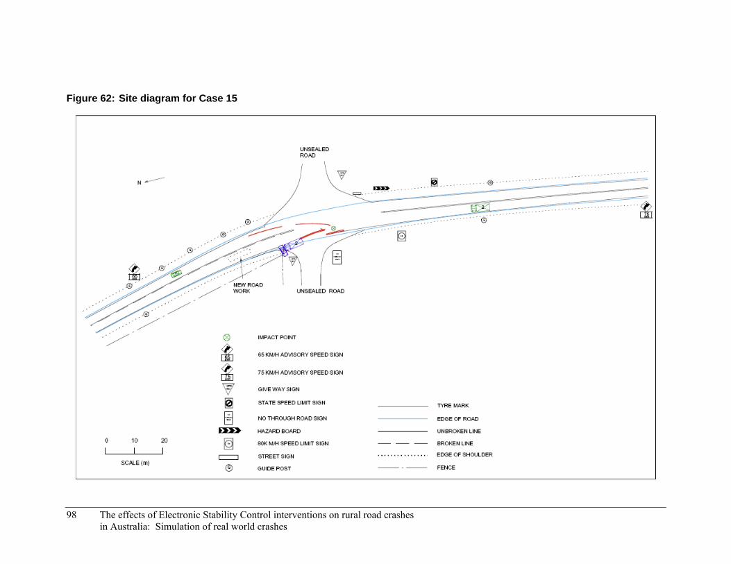
Figure 62: Site diagram for Case 15
98 The effects of Electronic Stability Control interventions on rural road crashes in Australia: Simulation of real world crashes

4.17 Case 16
4.17.1 Crash Description
On a Friday at approximately 3:05 am, a car was negotiating a slight left bend at an excessive but unknown speed. The driver of the car was fatigued and had consumed a considerable quantity of alcohol (BAC of 0.206). The vehicle failed to negotiate the bend and travelled across both lanes of the carriageway onto the outside unsealed shoulder. The driver overcorrected the vehicle to the left, causing it to yaw in an anti-clockwise direction across both lanes before running onto the opposite unsealed shoulder. The driver’s door and A-pillar of the vehicle collided with a tree three metres south of the carriageway. The prevailing environmental conditions at the crash site are given in Table 33. The site diagram for the crash is shown in Figure 63.
Table 33: Environmental conditions prevalent in Case 16
Condition Status
Weather Fine
Lighting Dusk, no artificial lighting
Road type Rural highway, sealed, two way, dry
Speed limit 110 km/h (75 km/h advisory)
4.17.2 Discussion
This is a case of oversteer by a front wheel drive vehicle. Multiple attempts at simulation were unable to replicate the results of the crash scenario in any way. The lack of a verifiable initial speed, along with the driver’s impairment, compounded the issue of using a highly stable front wheel drive vehicle model.
The ESP system’s response to an oversteer situation is shown in Figure 10. There is some uncertainty however over the driver’s ability to provide suitable steering inputs, given their impaired state.
The effects of Electronic Stability Control interventions on rural road crashes in Australia: Simulation of real world crashes 99
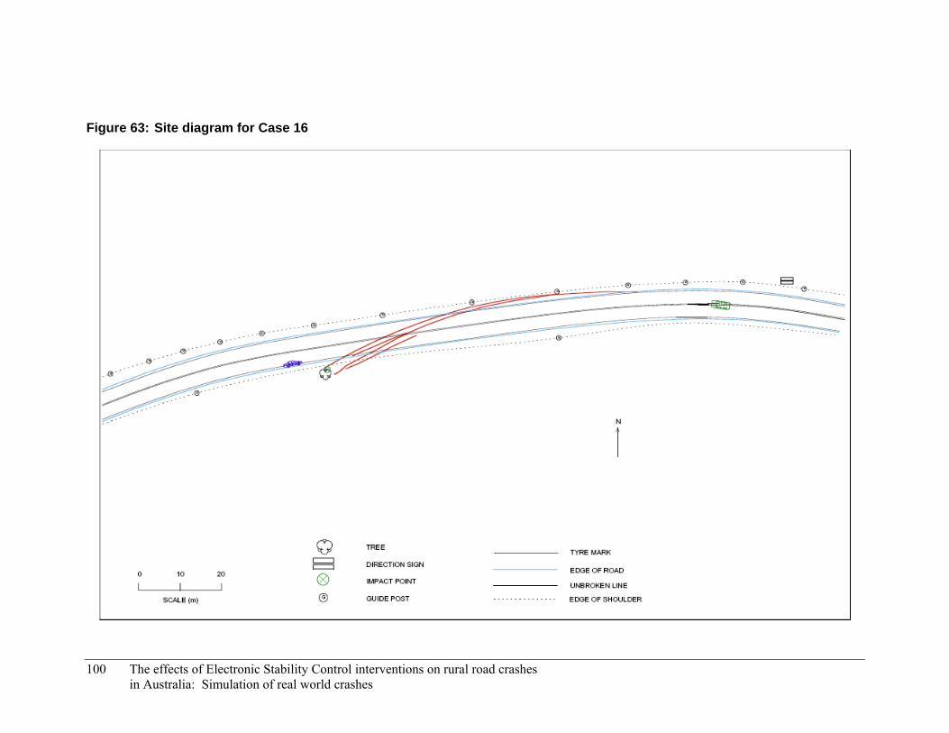
Figure 63: Site diagram for Case 16
100 The effects of Electronic Stability Control interventions on rural road crashes in Australia: Simulation of real world crashes

4.18 Case 17
4.18.1 Crash Description
On a Monday at approximately 11:10 am, a car was travelling in the right of a two lane road while negotiating a left bend. The winding carriageway was characterised by a steep descent. The driver was travelling at a self-reported speed between 60 and 70 km/h and was very familiar with the carriageway. As the vehicle was negotiating the bend the right wheels travelled across the edge line to the right and onto the unsealed shoulder. The driver overcorrected to the left and the vehicle yawed anti-clockwise across both lanes. The front left corner of the vehicle collided with a guard rail on the side of the carriageway. The prevailing environmental conditions at the crash site are given in Table 34. The site diagram for the crash is shown in Figure 64.
Table 34: Environmental conditions prevalent in Case 17
Condition Status
Weather Fine
Lighting Daylight
Road type National highway, sealed, divided, dry
Speed limit 70 km/h
4.18.2 Discussion
This is a case of oversteer by a front wheel drive vehicle. Multiple attempts at simulation were unable to replicate the results of the crash scenario in any way. This was due to the inherent stability of the front wheel drive vehicle model.
The cause of the oversteer may have been the result of the driver’s excessive overcorrection to the left or may have been the result of the split mu effect as the right side wheels entered the unsealed shoulder. For the ESP system’s response to an oversteer situation, see Figure 10. For the ESP system’s response to a split mu situation, see Figure 11.
The effects of Electronic Stability Control interventions on rural road crashes in Australia: Simulation of real world crashes 101

Figure 64: Site diagram for Case 17
102 The effects of Electronic Stability Control interventions on rural road crashes in Australia: Simulation of real world crashes

4.19 Case 18
4.19.1 Crash Description
On a Monday at approximately 12:05 pm, a car was travelling at an estimated speed of 80 km/h when the driver was distracted by a bug on the windscreen. The car veered to the left of the carriageway with all four wheels travelling onto the unsealed shoulder. The centre front of the car collided with a guide post before the driver overcorrected the vehicle to the right. The car yawed in a clockwise direction across both lanes of the carriageway and onto the far shoulder and verge. The left front wheel and A-pillar of the vehicle collided with a tree six metres from the carriageway. The prevailing environmental conditions at the crash site are given in Table 35. The site diagram for the crash is shown in Figure 65.
Table 35: Environmental conditions prevalent in Case 18
Condition Status
Weather Fine
Lighting Daylight
Road type Rural highway, sealed, two way, dry
Speed limit 110 km/h
4.19.2 Discussion
This is a case of oversteer by a front wheel drive vehicle. Multiple attempts at simulation were unable to replicate the results of the crash scenario in any way. This was due to the inherent stability of the front wheel drive vehicle model.
The cause of the oversteer may have been the result of the driver’s excessive overcorrection to the left or may have been the result of the split mu effect as the left side wheels entered the unsealed shoulder. For the ESP system’s response to an oversteer situation, see Figure 10. For the ESP system’s response to a split mu situation, see Figure 11.
The effects of Electronic Stability Control interventions on rural road crashes in Australia: Simulation of real world crashes 103
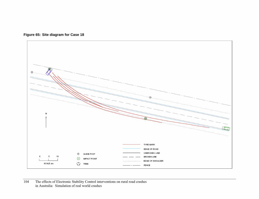
Figure 65: Site diagram for Case 18
104 The effects of Electronic Stability Control interventions on rural road crashes in Australia: Simulation of real world crashes

4.20 Case 19
4.20.1 Crash Description
On a Friday at approximately 10:30 pm, a 4WD was travelling in the left of two lanes at an estimated speed of 110 km/h. The 4WD veered to the right, yawing in a clockwise direction across both lanes and ran onto the grassed median. The 4WD rolled several times on entering the median, narrowly missing several large trees. The prevailing environmental conditions at the crash site are given in Table 36. The site diagram for the crash is shown in Figure 66.
Table 36: Environmental conditions prevalent in Case 19
Condition Status
Weather Raining
Lighting Dark, no artificial lighting
Road type National highway, sealed, multi-laned, wet
Speed limit 110 km/h
4.20.2 Discussion
This is a case of oversteer by a front wheel drive vehicle. Multiple attempts at simulation were unable to replicate the results of the crash scenario in any way. This was due to the inherent stability of the front wheel drive vehicle model.
The cause of the oversteer in this case is unknown but can be speculated upon. Perhaps the driver was attempting to avoid an object on the road (e.g. an animal). Perhaps there was a series of events which caused the steering wheel to become stuck pointing to the right.
Regardless of the cause of the oversteer, the ESP system would have attempted to stabilise the vehicle. For the ESP system’s response to an oversteer situation, see Figure 10.
The effects of Electronic Stability Control interventions on rural road crashes in Australia: Simulation of real world crashes 105

Figure 66: Site diagram for Case 19
106 The effects of Electronic Stability Control interventions on rural road crashes in Australia: Simulation of real world crashes

4.21 Case 20
4.21.1 Crash Description
On a Saturday at approximately 3:50 pm, a car was negotiating a left bend at an estimated speed between 90 and 95 km/h; an advisory speed of 55 km/h was posted for this corner. As the car entered the bend the right hand wheels travelled across the centre line and into the right lane. The driver overcorrected the car to the left then right and yawed in a clockwise direction across the left lane and unsealed shoulder. The right front corner of the car collided with a guide post and the end of a guard rail two metres from the carriageway. The prevailing environmental conditions at the crash site are given in Table 37. The site diagram for the crash is shown in Figure 67.
Table 37: Environmental conditions prevalent in Case 20
Condition Status
Weather Fine
Lighting Daylight
Road type Rural highway, sealed, two way, dry
Speed limit 100 km/h (55 km/h advisory)
4.21.2 Discussion
This is a case of oversteer by a front wheel drive vehicle. Multiple attempts at simulation were unable to replicate the results of the crash scenario in any way. This was due to the inherent stability of the front wheel drive vehicle model.
The cause of the oversteer is likely to have been a result of the driver’s excessive overcorrection to the left at high speed. For the ESP system’s response to an oversteer situation, see Figure 10.
The effects of Electronic Stability Control interventions on rural road crashes in Australia: Simulation of real world crashes 107

Figure 67: Site diagram for Case 20
108 The effects of Electronic Stability Control interventions on rural road crashes in Australia: Simulation of real world crashes

5 DISCUSSION
The aim of this study was to demonstrate how ESC systems intervene to avoid, or lower the severity of, real-world rural road crashes. Crash scenarios were developed from actual rural road crashes taken from an in-depth crash database. The crashes were selected from the database using specific criteria to isolate those which involved exclusively passenger vehicles or derivatives and which were sensitive to the effects of ESC. Computer models of vehicles, supplied by Bosch Australia, allowed the crash scenarios to be simulated with and without ESC active. The results are a simulation of the actions of the Bosch ESP system in response to the selected crash scenarios. The results show the timing and magnitude of the ESP system’s interventions, and provide a link between the general theory of ESC operation and the reported reductions in crash rates for vehicles equipped with ESC.
Not all of the selected crash scenarios were able to be satisfactorily simulated for reasons detailed in the results chapter. However the plots showing the ESC interventions during each of the successful simulations confirmed that the systems would have prevented a loss of steering control in these crash scenarios (assuming that the simulations are a reasonable representation of reality) and this would have allowed the driver to navigate their vehicle out of danger in most cases. It may therefore be concluded that the majority of the cases examined here would have benefited from the addition of an ESC system to the vehicle involved in the crash scenario. In 10 cases the addition of the ESC system helped to avoid the loss of control which led to a collision. In a further two cases, the addition of the ESC system lowered the severity of a collision. In two more cases, it may be concluded that the addition of the ESC system would have had no effect upon the crash scenario outcome, due to driver inaction.
Because of the limitations of the study, which are discussed below, the results that have been presented should be interpreted with some caution and should be regarded as preliminary. The timing and magnitude of the interventions for each simulation, taken individually, may not be an accurate representation of the interventions which would have been made by an actual ESC system. Taken as a whole however, the results give an indication of how ESC systems can alter the outcome of a set of crash scenarios in a positive way. The recommendations that have been made below are based on the way in which the addition of ESC to each crash scenario affected vehicle trajectory and crash outcomes.
Future work is planned to eliminate or mitigate the effects of these limitations, with a view to increasing the accuracy and credibility of the results. This work is outlined below.
5.1 Limitations There are three major limitations in this study that weaken the accuracy of the results. It was difficult to determine which of the limitations had a greater effect on the simulation accuracy. It is likely that the combination of all three contributed to the inability to produce an accurate simulation for six of the crash scenarios and lowered the confidence in the scenarios which were able to be simulated.
The first is that the vehicles in the crash scenarios could not be accurately modelled for simulation. Only two vehicle models were available and these were based on modern vehicles which differed to the vehicles in the crash scenarios in terms of tyre condition, suspension setup and braking power, resulting in dissimilar vehicle dynamics. These vehicle models, in some cases, did not respond in the same manner as the vehicles in the crash scenarios.
The second limitation is that many of the simulation variables were estimated or based on unreliable
The effects of Electronic Stability Control interventions on rural road crashes in Australia: Simulation of real world crashes 109

accounts. For each simulation, a set of variables was chosen to produce an output that was similar to the events of the crash scenario on which it was based. However, it was possible that a different set of variables would also produce an output that was similar to the events of the crash scenario. Knowing which set of variables was more plausible than the rest was difficult to determine.
The final limitation is that the ESC system was poorly tuned to the vehicle models. This was especially evident in the small number of the simulations in which the ESC system appeared to be reacting to a situation of understeer; i.e. braking one of the rear wheels in order to turn a vehicle which is threatening to ‘plough’ forward.
5.2 Recommendations Previous studies have already highlighted the benefits of ESC to road safety and the results presented in this study give further indication of this by showing how an ESC system can alter the outcome of a set of crash scenarios in a positive way. Efforts should continue to be made to increase the number of vehicles equipped with ESC on Australian roads.
The advantage of this study over others is that the altered trajectory of a vehicle equipped with ESC could be simulated. By looking at this, it was possible to note that in some cases, even though a loss of control crash was avoided, the vehicle still made a dangerous manoeuvre – i.e. crossed the centreline a short distance or entered the unsealed shoulder momentarily. Efforts should be made to mitigate and allow for these dangerous manoeuvres. This can be achieved by giving the ESC system the time, space and friction it requires to be effective. Continuing efforts to maintain and upgrade road surfaces and road shoulders will ensure higher levels of friction. Increasing the width of clear zones and roadside shoulders will increase the time and space available to the ESC system and would allow for some margin of error. For areas where this is not appropriate, roadside and median crash barriers can be utilised. It may also be appropriate to review the speed limits (and advisory limits) on rural roads and, particularly, to lower the limits on high-risk sections where infrastructure remedies are not an option.
This study was also able to highlight the critical role played by the driver in steering the vehicle away from danger. Only by analysing the driver’s inputs can an ESC system make appropriate interventions which enable the vehicle to remain stable during emergency manoeuvres. It is therefore important that drivers remain conscious and make rational steering/driving decisions. Efforts should continue to be made to reduce the number of drivers impaired by alcohol/drugs or fatigue, as well as the number of drivers who drive recklessly (i.e. not to the conditions) or above the posted speed limit.
5.3 Future work This study will be the basis for future work which will address the limitations with a view to producing greater simulation accuracy and more reliable results. The main focus of the future work will be to select, with confidence, a suitable set of simulation variables. In addition, more suitable vehicle models may be sought, along with a more precisely tuned ESC system. It may also be appropriate to develop new crash scenarios which involve newer vehicles that have similar features to the vehicle models being used. Finally, a more customisable driver model will be sought to supply more appropriate driver inputs.
110 The effects of Electronic Stability Control interventions on rural road crashes in Australia: Simulation of real world crashes

The effects of Electronic Stability Control interventions on rural road crashes in Australia: Simulation of real world crashes 111
6 REFERENCES
M. Aga, A. Okada, “Analysis of vehicle stability control (VSC)’s effectiveness from accident data,” in Proc. 18th International Technical Conference on the Enhanced Safety of Vehicles, Nagoya, 2003, pp. 19–22.
M. Tziotis, P. Roper, C. Edmonston, M. Sheehan, “Guide to Road Safety Part 5: Rural Safety in Rural and Remote Areas,” Austroads, AGRS05/06, Sydney, NSW, 2006.
M. Baldock, C. Kloeden, J. McLean, “In-depth research into rural road crashes,” CASR report series, CASR057, Adelaide, SA, 2008.
C. Farmer, “Effect of electronic stability control on automobile crash risk,” Traffic Injury Prevention, vol. 5, pp. 317–325, 2004.
C. Farmer, “Effects of electronic stability control: an update,” Traffic Injury Prevention, vol. 7, pp. 319–324, 2006.
T. Gillespie, “Fundamentals of Vehicle Dynamics,” SAE International, USA, 1992.
K. Langwieder, J. Gwehenberger, T. Hummel, J. Bende, “Benefit potential of ESP in real accident situations involving cars and trucks,” in: Proc. 18th International Technical Conference on the Enhanced Safety of Vehicles, Nagoya, 2003.
A. Lie, C. Tingvall, M. Krafft, A. Kullgren, “The effectiveness of ESP (electronic stability program) in reducing real life accidents,” Traffic Injury Prevention, vol. 5, pp. 37–41, 2004.
A. Lie, C. Tingvall, M. Krafft, A. Kullgren, “The effectiveness of electronic stability control (ESC) in reducing real life crashes and injuries,” Traffic Injury Prevention, vol. 7, pp. 38–43, 2006.
W. Milliken, D. Milliken, “Race Car Vehicle Dynamics,” SAE International, USA, 1995.
J. Scully, S. Newstead, “Preliminary evaluation of Electronic Stability Control effectiveness in Australia,” Monash University Accident Research Centre, Report 271, 2007.
A. van Zanton, R. Erhardt, G. Pfaff, H. Wiss, “ESP Electronic Stability Program,” BOSCH, Stuttgart, 1998.
Related Documents