1 The Effect of Type of Transient Voltage Suppressor on the Signal Response of a Coupling Circuit for Power Line Communications M. Hove † , T.O. Sanya †† , A. J. Snyders †† , I.R Jandrell ††† and H.C. Ferreira †† †† Department of Electrical and Electronic Engineering Technology University of Johannesburg, Doornfontein Campus P.O. Box 17011, Doornfontein, 2028, Johannesburg, South Africa E-mail: [email protected] † Department of Electrical and Electronic Engineering Science University of Johannesburg Auckland Park Campus P.O. Box 524, Auckland Park, 2006, Johannesburg, South Africa Email: {tosanya, hcferreira, asnyders}@uj.ac.za Abstract: The effect of the type of transient voltage suppressor (TVS) used in coupling circuits for surge protecting PLC equipment on the signal response has been studied. The study was focused at TVS devices used in both differential and common mode surge protection. It is found that the gas discharge tube (GDT) has no effect on the communication signal, whilst TVSs that operate on avalanche breakdown attenuate the signal and they also render signal dropout at a particular frequency. Metal Oxide Varistors (MOVs) behave similarly. Key Words: TVS, PLC, MOVs, coupling circuit, surge protection, surge protection devices I. INTRODUCTION With the advent of the smart grid, Power Line Communication (PLC) is an indispensable mode of communication. PLC can be used to manage and control power usage by consumers. It can also be used for remote power metering as well for power prepayment [1]. Attractive as it is, unfortunately the communication medium is prone to a varia of electrical surges. For this reason it is imperative that the modems that are used to transmit, process and receive the ††† School of Electrical and Information Engineering, University of Witwatersrand, Bag 3, Wits2050, Phone +27-11-717 7204, Fax +27-11- 403 1929 E-mail: [email protected] communication signals be protected against these electrical surges. TVS devices are often used to surge protect circuits that are used in PLC. One such circuit is the PLC coupling circuit. Often the surge protection afforded to such circuits is against differential mode surges only [2], [3] and none against common mode surges to the best knowledge of the authors. In as much as surge protection of the said modems and circuits is needed, the effect of type of such protective devices on the communication signal does not seem to be available. Iwao et al [4] have carried out a similar exercise but focused only on the MOV. In their work, they found that using a MOV as a surge protecting device (spd) results in PLC modem rate degradations. This is a problem in that one is not assured of receiving an un-attenuated, non – corrupted communication signal or receiving it at all for that matter. That is, not only is there risk of information loss, but reliability is compromised as well. Surges do corrupt the transmitted information signal. The power line itself is a dissipative medium and will attenuate the signal. Hence the need to understand the effect of the type of a spd has on the communication signal is crucial. This paper addresses this issue. The findings are that the mode of breakdown and hence the type of TVS used for surge protecting PLC equipment that is used to transmit, process and receive the communication signals affect the communication signal differently. The gas discharge tube (GDT) is found not to affect the signal at all; in fact it boosts the signal. IEEE Africon 2011 - The Falls Resort and Conference Centre, Livingstone, Zambia, 13 - 15 September 2011 978-1-61284-993-5/11/$26.00 ©2011 IEEE

Welcome message from author
This document is posted to help you gain knowledge. Please leave a comment to let me know what you think about it! Share it to your friends and learn new things together.
Transcript

1
The Effect of Type of Transient Voltage Suppressor on the Signal Response of a Coupling Circuit for Power Line Communications
M. Hove†, T.O. Sanya††, A. J. Snyders††, I.R Jandrell††† and H.C. Ferreira††
††Department of Electrical and Electronic Engineering Technology University of Johannesburg, Doornfontein Campus P.O. Box 17011, Doornfontein, 2028, Johannesburg, South Africa E-mail: [email protected]
†Department of Electrical and Electronic Engineering Science University of Johannesburg Auckland Park Campus P.O. Box 524, Auckland Park, 2006, Johannesburg, South Africa Email: {tosanya, hcferreira, asnyders}@uj.ac.za
Abstract: The effect of the type of transient voltage suppressor (TVS) used in coupling circuits for surge protecting PLC equipment on the signal response has been studied. The study was focused at TVS devices used in both differential and common mode surge protection. It is found that the gas discharge tube (GDT) has no effect on the communication signal, whilst TVSs that operate on avalanche breakdown attenuate the signal and they also render signal dropout at a particular frequency. Metal Oxide Varistors (MOVs) behave similarly.
Key Words: TVS, PLC, MOVs, coupling circuit, surge protection, surge protection devices
I. INTRODUCTION
With the advent of the smart grid, Power Line Communication (PLC) is an indispensable mode of communication. PLC can be used to manage and control power usage by consumers. It can also be used for remote power metering as well for power prepayment [1]. Attractive as it is, unfortunately the communication medium is prone to a varia of electrical surges. For this reason it is imperative that the modems that are used to transmit, process and receive the
†††School of Electrical and Information Engineering, University of Witwatersrand, Bag 3, Wits2050, Phone +27-11-717 7204, Fax +27-11- 403 1929 E-mail: [email protected]
communication signals be protected against these electrical surges. TVS devices are often used to surge protect circuits that are used in PLC. One such circuit is the PLC coupling circuit. Often the surge protection afforded to such circuits is against differential mode surges only [2], [3] and none against common mode surges to the best knowledge of the authors. In as much as surge protection of the said modems and circuits is needed, the effect of type of such protective devices on the communication signal does not seem to be available. Iwao et al [4] have carried out a similar exercise but focused only on the MOV. In their work, they found that using a MOV as a surge protecting device (spd) results in PLC modem rate degradations. This is a problem in that one is not assured of receiving an un-attenuated, non – corrupted communication signal or receiving it at all for that matter. That is, not only is there risk of information loss, but reliability is compromised as well. Surges do corrupt the transmitted information signal. The power line itself is a dissipative medium and will attenuate the signal. Hence the need to understand the effect of the type of a spd has on the communication signal is crucial. This paper addresses this issue. The findings are that the mode of breakdown and hence the type of TVS used for surge protecting PLC equipment that is used to transmit, process and receive the communication signals affect the communication signal differently. The gas discharge tube (GDT) is found not to affect the signal at all; in fact it boosts the signal.
IEEE Africon 2011 - The Falls Resort and Conference Centre, Livingstone, Zambia, 13 - 15 September 2011
978-1-61284-993-5/11/$26.00 ©2011 IEEE
2
Avalanche based TVS’s are found not only to attenuate the signal, but they also render a signal dropout at a particular frequency that is device dependent. MOVs are found to behave similarly.
II. EXPERIMENTAL
Prototype coupling circuits for signal transmission and reception of Power Line Communications (PLC) were designed. TVS devices that are different in their breakdown modes were used as surge protection devices. The surge protection scheme employed catered for both differential (normal) mode as well common mode surges. The devices were 1N5344B, 1N5908, 1.5KE 8.2A, 14 V MOV and a 90 V GDT. The coupling circuits were then tested for signal reception with the surge protection devices connected for both differential (normal) mode as well common mode surges. The parameters used for evaluation were signal quality in terms of noise level, signal distortion, signal bandwidth and attenuation.
A 20 MHz Pulse/Function generator (Etabor Electronics) was used as the communication signal source. The frequency bandwidth used was 3 KHz - 2 MHz. The bandwidth for PLC as set out by standards such as CENELEC is 3KHz – 35 MHz and the signal levels used for the investigation were 1.0 Vpp, 3.0 Vpp and 6.0 Vpp. The frequency range was later extended to 7.0 MHz to investigate signal integrity beyond the 2.0 MHz limit in view of signal drop out experienced at certain frequencies that were TVS type dependent. The received signal was captured by a digital storage oscilloscope.
Figure 1 shows a circuit that formed the basis for this investigation [5].
Figure 1: Typical coupling circuit for PLC
III. RESULTS
Because of the similarities obtained for the 3 signal input levels, only the results for the 6.0 Vpp input signal are presented. The signal response of the coupling circuit when
incorporating each type of the aforementioned TVS devices and connected for both common and differential mode surge protection are respectively shown in figures 2 - 6 below.
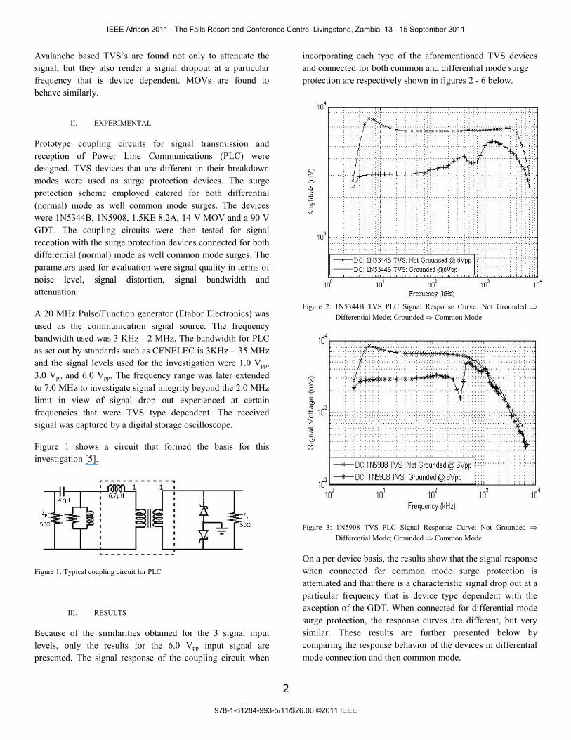
Figure 2: 1N5344B TVS PLC Signal Response Curve: Not Grounded ⇒
Differential Mode; Grounded ⇒ Common Mode
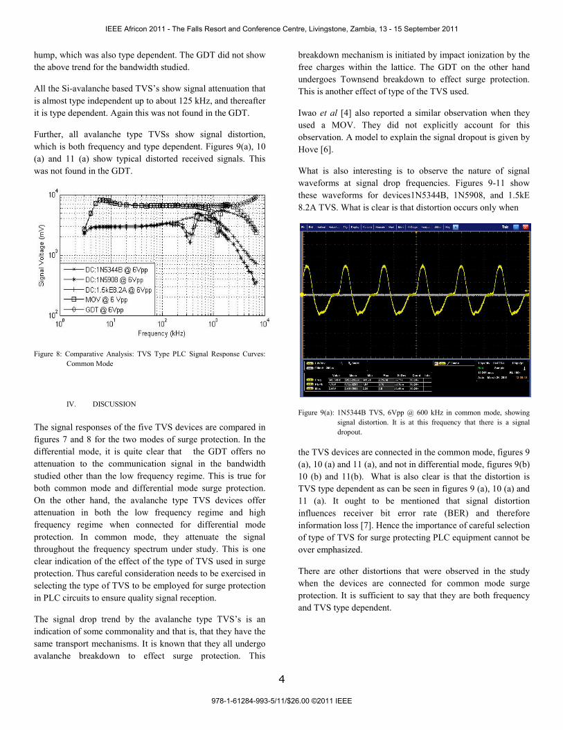
Figure 3: 1N5908 TVS PLC Signal Response Curve: Not Grounded ⇒ Differential Mode; Grounded ⇒ Common Mode
On a per device basis, the results show that the signal response when connected for common mode surge protection is attenuated and that there is a characteristic signal drop out at a particular frequency that is device type dependent with the exception of the GDT. When connected for differential mode surge protection, the response curves are different, but very similar. These results are further presented below by comparing the response behavior of the devices in differential mode connection and then common mode.
IEEE Africon 2011 - The Falls Resort and Conference Centre, Livingstone, Zambia, 13 - 15 September 2011
978-1-61284-993-5/11/$26.00 ©2011 IEEE

3
Figure 4: 1.5KE8.2A TVS PLC Signal Response Curve: Not Grounded ⇒ Differential Mode; Grounded ⇒ Common Mode
Figure 5: 14 V MOV PLC Signal Response Curve: Not Grounded ⇒ Differential Mode; Grounded ⇒ Common Mode
Figure 6: GDT PLC Signal Response Curve: Not Grounded ⇒ Differential Mode; Grounded ⇒ Common Mode
A. Differential Mode Protection
Figure 7 compares the response curves of the five TVS devices in differential mode protection. The five TVS devices show very similar signal response curves with the exception of the GDT. The latter showed no signal attenuation, no noise on the received signal. The bandwidth for which no signal attenuation was experienced was well beyond that studied and there was no signal distortion either. The avalanche - based TVS devices differ from the GDT in that they start to attenuate the signal (Vout/Vin<1) more severely around 1.0 MHz. Typically, 1N5344B starts at about 600 kHz, 1N5908 at about 300 kHz, 1.5 kHz at about 3 MHz, and the MOV at about 1.5MHz. The GDT on the other hand boosts the signal. That is, Vout/Vin >1. It starts to show increased signal amplification from 2.0MHz. Although the avalanche based TVS devices attenuated the PLC signal at higher frequencies, the signal was not distorted, and it was relatively noise free.
Figure 7: Comparative Analysis: TVS Type PLC Signal Response Curves: Differential Mode
B. Common Mode Surge Protection
Figure 8 compares the response curves of the five TVS devices in common mode protection. The avalanche type TVS devices 1N5344B, 1N5908, 1.5kE8.2A and the MOV all exhibit a very similar signal response curves that are characterized by a signal drop at a particular frequency. This was not expected for the MOV. For TVS 1N5344B, this was at 600 kHz. For TVS 1N5908, it was at 350 kHz. For TVS 1.5KE 8.2A, it was 400 kHz. For the MOV it was at 1.25 MHz. The signal drop level seems also to be manufacturer dependent. The GDT did not show this drop.
The signal drop was also found to be dependent on the magnitude of the input signal. The higher it is the lower the drop. Further, the signal drop was accompanied by a signal
IEEE Africon 2011 - The Falls Resort and Conference Centre, Livingstone, Zambia, 13 - 15 September 2011
978-1-61284-993-5/11/$26.00 ©2011 IEEE
4
hump, which was also type dependent. The GDT did not show the above trend for the bandwidth studied.
All the Si-avalanche based TVS’s show signal attenuation that is almost type independent up to about 125 kHz, and thereafter it is type dependent. Again this was not found in the GDT.
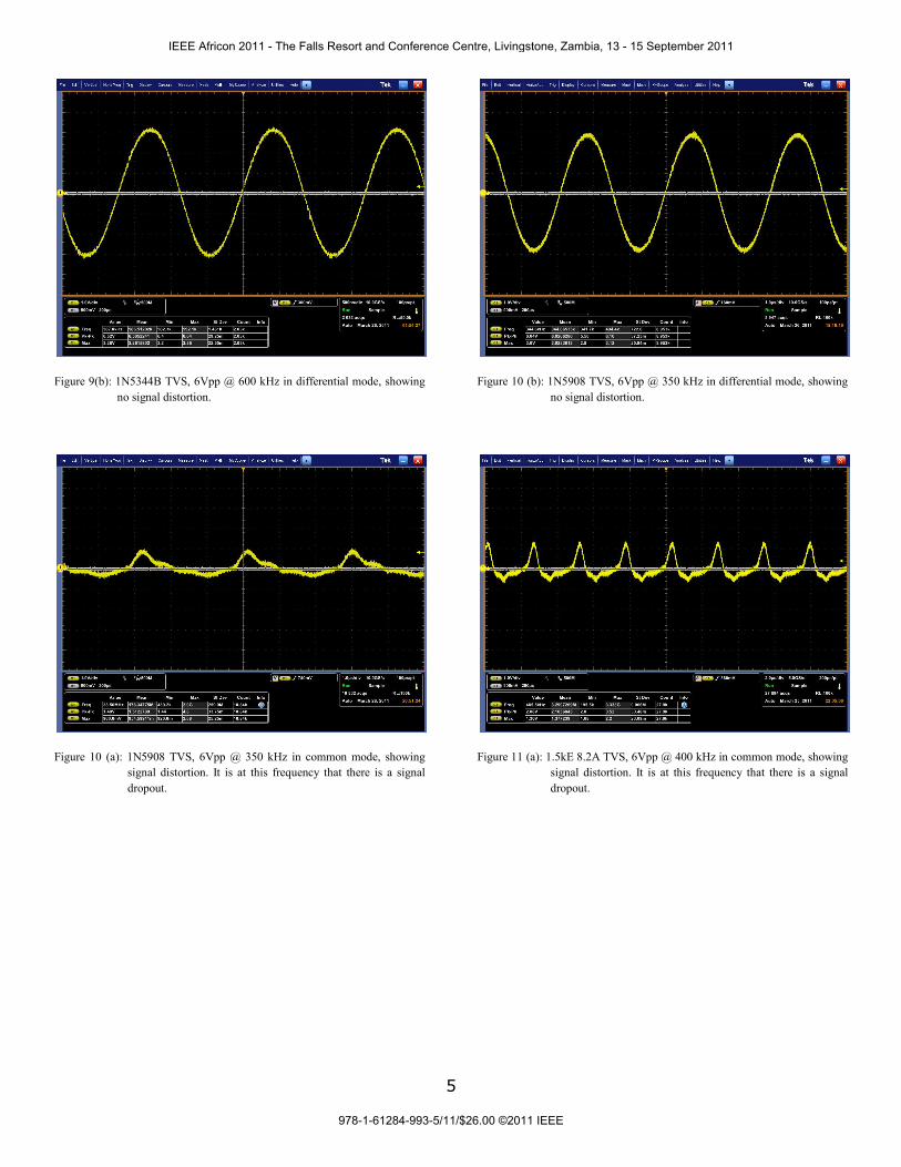
Further, all avalanche type TVSs show signal distortion, which is both frequency and type dependent. Figures 9(a), 10 (a) and 11 (a) show typical distorted received signals. This was not found in the GDT.
Figure 8: Comparative Analysis: TVS Type PLC Signal Response Curves: Common Mode
IV. DISCUSSION The signal responses of the five TVS devices are compared in figures 7 and 8 for the two modes of surge protection. In the differential mode, it is quite clear that the GDT offers no attenuation to the communication signal in the bandwidth studied other than the low frequency regime. This is true for both common mode and differential mode surge protection. On the other hand, the avalanche type TVS devices offer attenuation in both the low frequency regime and high frequency regime when connected for differential mode protection. In common mode, they attenuate the signal throughout the frequency spectrum under study. This is one clear indication of the effect of the type of TVS used in surge protection. Thus careful consideration needs to be exercised in selecting the type of TVS to be employed for surge protection in PLC circuits to ensure quality signal reception.
The signal drop trend by the avalanche type TVS’s is an indication of some commonality and that is, that they have the same transport mechanisms. It is known that they all undergo avalanche breakdown to effect surge protection. This
breakdown mechanism is initiated by impact ionization by the free charges within the lattice. The GDT on the other hand undergoes Townsend breakdown to effect surge protection. This is another effect of type of the TVS used.
Iwao et al [4] also reported a similar observation when they used a MOV. They did not explicitly account for this observation. A model to explain the signal dropout is given by Hove [6].
What is also interesting is to observe the nature of signal waveforms at signal drop frequencies. Figures 9-11 show these waveforms for devices1N5344B, 1N5908, and 1.5kE 8.2A TVS. What is clear is that distortion occurs only when
Figure 9(a): 1N5344B TVS, 6Vpp @ 600 kHz in common mode, showing signal distortion. It is at this frequency that there is a signal dropout.
the TVS devices are connected in the common mode, figures 9 (a), 10 (a) and 11 (a), and not in differential mode, figures 9(b) 10 (b) and 11(b). What is also clear is that the distortion is TVS type dependent as can be seen in figures 9 (a), 10 (a) and 11 (a). It ought to be mentioned that signal distortion influences receiver bit error rate (BER) and therefore information loss [7]. Hence the importance of careful selection of type of TVS for surge protecting PLC equipment cannot be over emphasized.
There are other distortions that were observed in the study when the devices are connected for common mode surge protection. It is sufficient to say that they are both frequency and TVS type dependent.
IEEE Africon 2011 - The Falls Resort and Conference Centre, Livingstone, Zambia, 13 - 15 September 2011
978-1-61284-993-5/11/$26.00 ©2011 IEEE
5
Figure 9(b): 1N5344B TVS, 6Vpp @ 600 kHz in differential mode, showing no signal distortion.
Figure 10 (a): 1N5908 TVS, 6Vpp @ 350 kHz in common mode, showing signal distortion. It is at this frequency that there is a signal dropout.
Figure 10 (b): 1N5908 TVS, 6Vpp @ 350 kHz in differential mode, showing no signal distortion.
Figure 11 (a): 1.5kE 8.2A TVS, 6Vpp @ 400 kHz in common mode, showing signal distortion. It is at this frequency that there is a signal dropout.
IEEE Africon 2011 - The Falls Resort and Conference Centre, Livingstone, Zambia, 13 - 15 September 2011
978-1-61284-993-5/11/$26.00 ©2011 IEEE

6
Figure 11 (b): 1.5kE 8.2A TVS, 6Vpp @ 400 kHz in differential mode, showing no signal distortion.
V. RECOMMENDATIONS
In view of the above findings, a comprehensive surge protection scheme for PLC that will cater for both high and low energy surges, differential and common mode surges is as shown in figure 12. What is gained is that the upfront GDT will cater for high energy, direct and indirect surges in both common and differential modes. The Si-avalanche with their limited energy handling capabilities, but very tight surge voltage clamping capabilities will look at low energy differential mode surges. This will not only assure safety of the PLC equipment, but also corrupt-free, distortion -free and attenuation-free PLC signal.
Figure 12: Typical surge protection scheme for PLC applications.
CONCLUSION
The effect of the type of transient voltage suppressor (TVS) used in coupling circuits for surge protecting PLC equipment on the signal response has been studied. Avalanche type TVS’s connected in differential mode are found to attenuate and distort the PLC signal, with the exception of the MOV. Signal distortion is both frequency and TVS type dependent. They also render signal drop at frequencies that is type dependent. These effects are not observed when connected in the differential mode. The GDT is found to have no effect to the PLC signal in both common and differential modes. It is crucial for any surge protection scheme for PLC applications to critically examine what type of spd to employ to maintain signal integrity.
ACKNOWLEDGEMENTS
The authors thank the University of Johannesburg for funding the project under its PLC Research Group.
REFERENCES
[1] A. Hosemann, “PLC Applications in Low Voltage Distribution Networks’, International Symposium on PLC and its Applications , Essen, April 2-4, 1997.
[2] O.G.Hooijen, “A Channel Model for Low Voltage Power Line Channel; Measurement and Simulation Results”, IEEE X-Plore
[3] P.A. Janse van Rensburg, H.C Ferreira, “Coupling Circuitry: Understanding the Functions of Different Components,” Proc. 7th Int. Symp. Power-Line Comm., 2003
[4] H. Iwao, H. Kijima, and K.Takato, “An Influence on Transmission Characteristics of Power Line Communication when using Surge Protective Devices”, ISPLC 2008 IEEE International Symposium on 200, pp 218 - 221
[5] T.O. Sanya, M. Hove, A. J. Snyders, and H.C. Ferreira (2011): Surge Protection of Communication Equipments for Power Line Communication: Effects on Communication Signal, IEEE Region 8 AFRICON 2011
[6] Hove, M: A Model to Explain Signal Drop out for TVS Surge Protected PLC Coupling Circuits, [To Be Published].
[7] http://en.wikipedia.org/wiki/File:Diffenc_BPSK_BER_curves.svg
IEEE Africon 2011 - The Falls Resort and Conference Centre, Livingstone, Zambia, 13 - 15 September 2011
978-1-61284-993-5/11/$26.00 ©2011 IEEE
Related Documents


![PTVSxS1UR series 400 W Transient Voltage Suppressor · PTVSxS1UR series 400 W Transient Voltage Suppressor ... In accordance with IEC 61643-321 (10/1000 μs current waveform). [2]](https://static.cupdf.com/doc/110x72/5b4a2d007f8b9ada3a8c032a/ptvsxs1ur-series-400-w-transient-voltage-suppressor-ptvsxs1ur-series-400-w-transient.jpg)


