Manufacturing and Materials Processing Journal of Article The Effect of Switchback Parameters on Root Pass Formation of Butt Welds with Variable Gap Hélio Antônio Lameira de Almeida 1 , Felipe Ribeiro Teixeira 2 , Carlos Alberto Mendes da Mota 2 and Américo Scotti 3,4, * 1 Center of Mechanics, Federal Institute of Education, Science and Technology of Pará, Belém-PA 66093-020, Brazil 2 Department of Mechanical Engineering, Federal University of Pará, Belém-PA 66075-110, Brazil 3 Laprosolda (Center for Research and Development of Welding Processes), Federal University of Uberlandia, Uberlândia-MG 38400-902, Brazil 4 Department of Engineering Science, University of West, S-461 32 Trollhättan, Sweden * Correspondence: [email protected] Received: 17 June 2019; Accepted: 1 July 2019; Published: 5 July 2019 Abstract: Root pass manufacturing in automated welding is still a challenge when the backing plate is not feasible. Using the concept of bead formation in an original way, the GMAW (Gas Metal Arc Welding) switchback technique was assessed against linear movement as a means of facing this challenge. Experimental work was applied, keeping the process parametrization and joint configuration, so that only the switchback parameters were modified, i.e., the stroke lengths and speeds. Thermography was used to estimate the effect of the switchback parameters on bead formation. The results showed the potential of the switchback technique as a means of favoring weld pool control. Surprisingly, the operational gap range is not necessarily larger when switchback is applied. The strong influence of stroke lengths and speeds on the process performance was characterized. In general, the results showed that linear movement leads to larger pools and deeper penetrations, more adequate for gaps with no clearances. Shorter stroke lengths and slower stroke speeds (intermediate pool size) better suit root gaps that are not too wide, while longer stroke lengths and faster stroke speeds (smaller pool size, more easily sustainable) are applicable to larger root gaps. Keywords: GMAW; switchback; root pass; thermography 1. Introduction The root pass consists of the first weld bead deposited in a groove. Deposition of a root pass requires a greater ability of the welder, since it must guarantee penetration, consistently and without perforations. The aspect and quality of a root pass are dependent of the forces that act directly on the weld pool. When there are no backing strips, the weld pool is supported by the shear stress induced by the surface tension gradient, which causes the liquid metal to flow from the center of the pool surface towards the joint edges. Considering the flat position, the weld pool is pressed down by the force induced by the plasma jet, the Lorentz force, and the gravity force. In this way, the welding current and the size of the weld pool tend to govern the stability of the root pass. However, conceptually, the formation of a root pass happens at two continuous yet distinct stages. At the first stage, the arc is over the pool, heating and melting the metal (groove metal and filler). In the case of flat position welding, the arc jet and the gravitational and electromagnetic forces, the last one to a lesser extent, act pressing down the pool (although the arc jet avoids the pool collapse in the case of overhead position). The pool itself is sustained inside the groove by surface tension, which demands less free surface energy between the surrounding non-molten metal and the pool J. Manuf. Mater. Process. 2019, 3, 54; doi:10.3390/jmmp3030054 www.mdpi.com/journal/jmmp

Welcome message from author
This document is posted to help you gain knowledge. Please leave a comment to let me know what you think about it! Share it to your friends and learn new things together.
Transcript

Manufacturing andMaterials Processing
Journal of
Article
The Effect of Switchback Parameters on Root PassFormation of Butt Welds with Variable Gap
Hélio Antônio Lameira de Almeida 1, Felipe Ribeiro Teixeira 2 ,Carlos Alberto Mendes da Mota 2 and Américo Scotti 3,4,*
1 Center of Mechanics, Federal Institute of Education, Science and Technology of Pará, Belém-PA 66093-020,Brazil
2 Department of Mechanical Engineering, Federal University of Pará, Belém-PA 66075-110, Brazil3 Laprosolda (Center for Research and Development of Welding Processes), Federal University of Uberlandia,
Uberlândia-MG 38400-902, Brazil4 Department of Engineering Science, University of West, S-461 32 Trollhättan, Sweden* Correspondence: [email protected]
Received: 17 June 2019; Accepted: 1 July 2019; Published: 5 July 2019�����������������
Abstract: Root pass manufacturing in automated welding is still a challenge when the backingplate is not feasible. Using the concept of bead formation in an original way, the GMAW (GasMetal Arc Welding) switchback technique was assessed against linear movement as a means offacing this challenge. Experimental work was applied, keeping the process parametrization andjoint configuration, so that only the switchback parameters were modified, i.e., the stroke lengthsand speeds. Thermography was used to estimate the effect of the switchback parameters on beadformation. The results showed the potential of the switchback technique as a means of favoringweld pool control. Surprisingly, the operational gap range is not necessarily larger when switchbackis applied. The strong influence of stroke lengths and speeds on the process performance wascharacterized. In general, the results showed that linear movement leads to larger pools and deeperpenetrations, more adequate for gaps with no clearances. Shorter stroke lengths and slower strokespeeds (intermediate pool size) better suit root gaps that are not too wide, while longer stroke lengthsand faster stroke speeds (smaller pool size, more easily sustainable) are applicable to larger root gaps.
Keywords: GMAW; switchback; root pass; thermography
1. Introduction
The root pass consists of the first weld bead deposited in a groove. Deposition of a root passrequires a greater ability of the welder, since it must guarantee penetration, consistently and withoutperforations. The aspect and quality of a root pass are dependent of the forces that act directly on theweld pool. When there are no backing strips, the weld pool is supported by the shear stress induced bythe surface tension gradient, which causes the liquid metal to flow from the center of the pool surfacetowards the joint edges. Considering the flat position, the weld pool is pressed down by the forceinduced by the plasma jet, the Lorentz force, and the gravity force. In this way, the welding currentand the size of the weld pool tend to govern the stability of the root pass. However, conceptually, theformation of a root pass happens at two continuous yet distinct stages.
At the first stage, the arc is over the pool, heating and melting the metal (groove metal and filler).In the case of flat position welding, the arc jet and the gravitational and electromagnetic forces, thelast one to a lesser extent, act pressing down the pool (although the arc jet avoids the pool collapsein the case of overhead position). The pool itself is sustained inside the groove by surface tension,which demands less free surface energy between the surrounding non-molten metal and the pool
J. Manuf. Mater. Process. 2019, 3, 54; doi:10.3390/jmmp3030054 www.mdpi.com/journal/jmmp

J. Manuf. Mater. Process. 2019, 3, 54 2 of 18
than between the environment and the pool. Therefore, in the flat position, small size pools (lowergravitational force), a lower number of slags (which reduces the free surface energy between theenvironment and the pool), and low currents (less arc force pushing down the pool) favor the formationof a stable pool during the first stage.
It is worth noting two characteristics of this first stage. Although gravitational force can beassumed to depend only upon the molten metal mass, the action of the gravitational force is morepronounced in the overhead welding position, since there is a wider molten area on the lower surfaceof the pool than in the flat position. In the flat position, there is a more permanent backrest (joint faces)to the pool. Therefore, the positive effect of the arc jet towards sustaining the pool in the overheadwelding position is counterbalanced by a higher negative effect of the gravitational force, and root passin the overhead welding position is even more difficult. It is important to clarify that root faces with nogap demand a higher current to melt the metal at the groove root, also making more difficult (higherarc jet/electrical magnetic forces and larger molten metal volume) the formation of sound root passes.Too wide gaps, on the other hand, demand more molten metal to fill the volume, increasing the gravityforce, yet requiring less current, since there is no need to melt the whole root face neighborhood.
A second characteristic is related to the mentioned reached pool stability at the end of the firststage. In fact, it would be more precise to say a pseudo-stable pool, since the molten metal is fluidand it would sag down eventually if the second stage of root pass formation would not take place.Regarding the second stage, as long as the arc is moving forward, the pool starts to cool down. Then,the molten metal viscosity increases, preventing the pool collapse before the full solidification (thereader must realize that viscosity is a dynamic property of a fluid, different from surface tension).Excessively fluid weld metal is not desirable for root pass in this concern, making the molten metalspillage faster (before full solidification). Therefore, small and deeply penetrated pools, as well as areduced number of slags (all leading to faster solidification) favor the formation of sound root beads atthe end of the second stage.
Considering all the above, the manual process with shielded metal arc welding (SMAW) is themost commonly used for root pass welding, especially with cellulose coating. The possibility of usingtransverse oscillation, relatively low currents and a short arc (low plasma jet) facilitates the controlof the weld pool. Another widely used process for making a root pass is gas tungsten arc welding(GTAW), which, because of its independence between the material feed and the heat source, provides askilled welder with the possibility of balancing the heat and the wire feeding, thereby controlling theweld pool. In these processes, the root pass can be made in different positions, but with relatively lowwelding speeds and deposition rates (slightly higher with SMAW) compared to other processes andwelding techniques, generating limitations in terms of production. Finally, new versions of the gasmetal arc welding (GMAW) process, using a controlled waveform format, brought new perspectivesto build root passes, as demonstrated by Martikainen and Kah [1], in an interesting study whichcomparatively evaluated the quality and productivity of GMAW, SMAW, and GTAW root pass weldingunder different fit-up gaps. In a similar study, Adi et al. [2] demonstrated the ability to increase up tothree times the travel speed of root pass with a version of a waveform-controlled process in comparisonto SMAW or GTAW processes, with weld quality similar to GTAW process.
Nowadays, the reduction in the availability of skilled manual welders, an essential condition tobuild up root passes, has forced the use of automation. However, unlike manual welding, automationdoes not rely on the ability of the welder to control the weld pool. In order to get around this problem,one solution is to emulate the manual welder in automated operations, for tasks which are not sosimple. Another solution would be to work on the concept of the root pass formation as summarizedabove. In this sense, the potentiality of the switchback technique with the GMAW process is presented.
The switchback technique consists of the periodic oscillation of the torch, a consequence of thearc (heat source), along the longitudinal direction of the groove during the welding operation. Asillustrated in Figure 1, the arc cyclically moves forward with the weld pool along the joint by acertain linear amplitude, forming a first layer, so that it returns with a lesser length than that of the
J. Manuf. Mater. Process. 2019, 3, 54 3 of 18
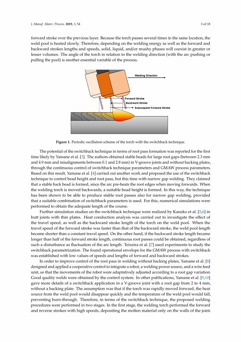
forward stroke over the previous layer. Because the torch passes several times in the same location, theweld pool is heated slowly. Therefore, depending on the welding energy as well as the forward andbackward strokes lengths and speeds, solid, liquid, and/or mushy phases will coexist in greater orlesser volumes. The angle of the torch in relation to the welding direction (with the arc pushing orpulling the pool) is another essential variable of the process.
J. Manuf. Mater. Process. 2019, 3, x FOR PEER REVIEW 3 of 19
The switchback technique consists of the periodic oscillation of the torch, a consequence of the
arc (heat source), along the longitudinal direction of the groove during the welding operation. As
illustrated in Figure 1, the arc cyclically moves forward with the weld pool along the joint by a certain
linear amplitude, forming a first layer, so that it returns with a lesser length than that of the forward
stroke over the previous layer. Because the torch passes several times in the same location, the weld
pool is heated slowly. Therefore, depending on the welding energy as well as the forward and
backward strokes lengths and speeds, solid, liquid, and/or mushy phases will coexist in greater or
lesser volumes. The angle of the torch in relation to the welding direction (with the arc pushing or
pulling the pool) is another essential variable of the process.
Figure 1. Periodic oscillation scheme of the torch with the switchback technique.
The potential of the switchback technique in terms of root pass formation was reported for the
first time likely by Yamane et al. [3]. The authors obtained stable beads for large root gaps (between
2.3 mm and 4.9 mm and misalignments between 0.1 and 2.8 mm) in V-groove joints and without
backing plates, through the continuous control of switchback technique parameters and GMAW
process parameters. Based on this result, Yamane et al. [4] carried out another work and proposed
the use of the switchback technique to control bead height and root pass, but this time with narrow
gap welding. They claimed that a stable back bead is formed, since the arc pre-heats the root edges
when moving forwards. When the welding torch is moved backwards, a suitable bead height is
formed. In this way, the technique has been shown to be able to produce stable root passes also for
narrow gap welding, provided that a suitable combination of switchback parameters is used. For this,
numerical simulations were performed to obtain the adequate length of the course.
Further simulation studies on the switchback technique were realized by Kaneko et al. [5,6] in
butt joints with thin plates. Heat conduction analysis was carried out to investigate the effect of the
travel speed, as well as the backward stroke length of the torch on the weld pool. When the travel
speed of the forward stroke was faster than that of the backward stroke, the weld pool length became
shorter than a constant travel speed. On the other hand, if the backward stroke length became longer
than half of the forward stroke length, continuous root passes could be obtained, regardless of such
a disturbance as fluctuation of the arc length. Teixeira et al. [7] used experiments to study the
switchback parametrization. The found operational envelope for the GMAW process with
switchback was established with low values of speeds and lengths of forward and backward strokes.
In order to improve control of the root pass in welding without backing plates, Yamane et al. [8]
designed and applied a cooperative control to integrate a robot, a welding power source, and a
wire feed unit, so that the movements of the robot were adaptatively adjusted according to a root gap
variation. Good quality welds were obtained by the control system. In other publications,
Yamane et al. [9,10] gave more details of a switchback application in a V-groove joint with a root gap
from 2 to 4 mm, without a backing plate. The assumption was that if the torch was rapidly moved
forward, the heat source from the weld pool would disappear quickly and the temperature of the
Figure 1. Periodic oscillation scheme of the torch with the switchback technique.
The potential of the switchback technique in terms of root pass formation was reported for the firsttime likely by Yamane et al. [3]. The authors obtained stable beads for large root gaps (between 2.3 mmand 4.9 mm and misalignments between 0.1 and 2.8 mm) in V-groove joints and without backing plates,through the continuous control of switchback technique parameters and GMAW process parameters.Based on this result, Yamane et al. [4] carried out another work and proposed the use of the switchbacktechnique to control bead height and root pass, but this time with narrow gap welding. They claimedthat a stable back bead is formed, since the arc pre-heats the root edges when moving forwards. Whenthe welding torch is moved backwards, a suitable bead height is formed. In this way, the techniquehas been shown to be able to produce stable root passes also for narrow gap welding, providedthat a suitable combination of switchback parameters is used. For this, numerical simulations wereperformed to obtain the adequate length of the course.
Further simulation studies on the switchback technique were realized by Kaneko et al. [5,6] inbutt joints with thin plates. Heat conduction analysis was carried out to investigate the effect ofthe travel speed, as well as the backward stroke length of the torch on the weld pool. When thetravel speed of the forward stroke was faster than that of the backward stroke, the weld pool lengthbecame shorter than a constant travel speed. On the other hand, if the backward stroke length becamelonger than half of the forward stroke length, continuous root passes could be obtained, regardless ofsuch a disturbance as fluctuation of the arc length. Teixeira et al. [7] used experiments to study theswitchback parametrization. The found operational envelope for the GMAW process with switchbackwas established with low values of speeds and lengths of forward and backward strokes.
In order to improve control of the root pass in welding without backing plates, Yamane et al. [8]designed and applied a cooperative control to integrate a robot, a welding power source, and a wire feedunit, so that the movements of the robot were adaptatively adjusted according to a root gap variation.Good quality welds were obtained by the control system. In other publications, Yamane et al. [9,10]gave more details of a switchback application in a V-groove joint with a root gap from 2 to 4 mm,without a backing plate. The assumption was that if the torch was rapidly moved forward, the heatsource from the weld pool would disappear quickly and the temperature of the weld pool would fall,preventing burn-through. Therefore, in terms of the switchback technique, the proposed weldingprocedures were performed in two stages. In the first stage, the welding torch performed the forwardand reverse strokes with high speeds, depositing the molten material only on the walls of the joint.
J. Manuf. Mater. Process. 2019, 3, 54 4 of 18
Thereafter, a new forward stroke was performed with the same prior length, however, with a reducedspeed capable of merging and joining the previously deposited material on the walls of the joint.Thus, due to successfully combining the switchback technique with a transverse oscillation and apulsed current GMAW, a good root pass could be obtained by setting an appropriate amplitude for thetorch oscillation.
In order to improve control of the weld pool, Scotti et al. [11] registered a patent for a switchbackwelding device using the GMAW process. In this device, the weld pool control is performed bychanging the operational mode of the process (polarity and/or metallic transfer) in synchrony with theposition of the torch in the joint. However, unlike Yamane et al. [9,10], in which the torch oscillatedtransversely at the same time as the switchback movement, this device causes the torch to first travelone side of the groove face during the forward movement, changing to the other side in a backwardmovement, and concluding the cycle at the center of the groove with another forward movement.In this control device, the forward and backward lengths were the same. During displacement onthe groove sides, the device makes the power supply impose a higher arc energy, while during thedisplacement over the center of the groove (root centerline), the control changes the operational modeto a lower energy. In this way, the device contributed to a greater heat distribution and control of theviscosity of the weld pool, avoiding the collapse of the same in different geometric tolerances in theroot gap, either by misalignment or unevenness.
The possibility of increasing the limit travel speed in fillet welds (overspeed leads to a humpingformation) has been also appointed as a beneficial characteristic of switchback. Aiming to use GMAWswitchback to increase production with quality, Bonacorso et al. [12] compared linear conventional andswitchback trajectories (forward speed four times faster than the backward and with pool pushingmovement). However, the results showed a non-significant increase in the production with theswitchback technique (limit increase of only 5%). This result contrasts with that mentioned in thereview by Almeida et al. [13], where an increase of up to 60% in the limit travel speed was observedin the welding of a 3 mm thick steel overlap joint. Applying switchback to GTAW at high currents,Schwedersky et al. [14] showed that the incidence of humping-like discontinuities, typical of GTAWwith high currents, was reduced. This improvement was clearer when the backward stroke length wasmore than half of the forward stroke length. Using thermography on the back of the plate, the authorssuggested that the heat tends to penetrate into the plate less when switchback is applied, following thesame trend observed in the simulations of Kaneko et al. [5,6].
As seen above, despite the fact that GMAW switchback has been acknowledged for some years,there is not much information in current literature about this technique and its application is unknownin the industrial environment. One reason for this fact would be the lack of robust information onparametrization, for example, about the reliability of the technique to manufacture root passes inbutt joints with a variable root gap. Therefore, the objective of this work was to experimentallydetermine the potential gain in root gap tolerances (operational gap range) when switchback replacesthe conventional linear progression welding (a typical application of GMAW), with the view of poolformation at the root pass.
2. Materials and Methods
2.1. Experimental Planning to Evaluate the Effect of Stroke Lengths and Speeds on the Operational Gap RangeLimits
The methodology to reach the objective of this work was to comparatively weld butt welds (I joint)with a progressively increased root gap, using either switchback or the conventional linear movementtechniques. During welding, switchback parameters were changed in order to optimize the weld poolcontrol, as proposed and fundamentally explained in the introduction section. The criterion was todetermine and compare the range size of the gap that each technique could perform without losingroot pass quality, i.e., the root gap tolerance. In addition, a thermal analysis of each technique wasimplemented as a support to explain the results.

J. Manuf. Mater. Process. 2019, 3, 54 5 of 18
A robotic system moved the torch in both conditions, i.e., with switchback and with linearmovements. All the welds were carried out by using the GMAW process, with the pulsed current at alow average value (145 A), to make root pass feasible. Table 1 presents the pulsed current parametersapplied in this study. An AWS (American Welding Society) ER70S-6 wire (1.2 mm) was used asthe filler metal. The arc was shielded by a gas blend of 95% Ar + 5% O2, at a flow rate of 15 l/min.The angle of the torch in relation to the welding direction was 15◦ (pushing the pool), assuring aCTWD (contact tip to workpiece distance) of 18 mm, measured along the wire inclination. Therefore,during the switchback mode, the torch was pushing during the forward stroke and pulling duringthe backward stroke. The travel speed (TS) was kept constant at 4.2 mm/s. However, to establishcomparisons with the conventional condition, the concept of equivalent travel speed (TSeq), whichis the combination of the forward and backward stroke speeds to deposit a bead with same lengthand time as the conventional condition, was applied to the switchback technique. The remainingparameters and variables were kept constant.
Table 1. Pulsed parametrization for the gas metal arc welding (GMAW) process.
WFS (m/min) Im (A) Ip (A) Ib (A) tp (ms) tb (ms)
4.0 145 510 75 1.7 9.4
Note: WFS stands for wire feed speed; Im for mean current; Ip for pulse current; Ib for base current; tp for pulse time;tb for base time.
The test coupons were composed of two plain carbon steel (AISI 1020) bars, 140 mm × 50 mm ×3.3 mm thick (no machining on the bar lateral surfaces), as illustrated in Figure 2. Each bar was sandblasted and tack welded at the ends to get different gap ranges, nominally starting from an initialnarrow root gap (f1) and increasing to a final larger root gap (f2). Due to the tack welds at the testcoupon ends, the effective variation of the root gap happened in a test coupon length of 100 mm. If inthat range of root gap a bead without irregularities was obtained, new test coupons would be weldedfrom a gap slightly narrower (to verify repeatability) than the final root gap in which an acceptedroot was observed. For analysis of the test coupons, two parameters were evaluated: a minimumoperational opening (Fmin), which corresponded to the root gap value from which a total penetrationwas reached; and a maximum operational opening (Fmax), which corresponded to the maximum rootgap value achieved without any surface irregularities or burn throughs becoming apparent.
J. Manuf. Mater. Process. 2019, 3, x FOR PEER REVIEW 5 of 19
without losing root pass quality, i.e., the root gap tolerance. In addition, a thermal analysis of each
technique was implemented as a support to explain the results.
A robotic system moved the torch in both conditions, i.e., with switchback and with linear
movements. All the welds were carried out by using the GMAW process, with the pulsed current at
a low average value (145 A), to make root pass feasible. Table 1 presents the pulsed current
parameters applied in this study. An AWS (American Welding Society) ER70S-6 wire (1.2 mm) was
used as the filler metal. The arc was shielded by a gas blend of 95% Ar + 5% O2, at a flow rate of
15 l/min. The angle of the torch in relation to the welding direction was 15° (pushing the pool),
assuring a CTWD (contact tip to workpiece distance) of 18 mm, measured along the wire inclination.
Therefore, during the switchback mode, the torch was pushing during the forward stroke and pulling
during the backward stroke. The travel speed (TS) was kept constant at 4.2 mm/s. However, to
establish comparisons with the conventional condition, the concept of equivalent travel speed (TSeq),
which is the combination of the forward and backward stroke speeds to deposit a bead with same
length and time as the conventional condition, was applied to the switchback technique. The
remaining parameters and variables were kept constant.
Table 1. Pulsed parametrization for the gas metal arc welding (GMAW) process.
WFS (m/min) Im (A) Ip (A) Ib (A) tp (ms) tb (ms)
4.0 145 510 75 1.7 9.4
Note: WFS stands for wire feed speed; Im for mean current; Ip for pulse current; Ib for base current; tp for pulse
time; tb for base time.
The test coupons were composed of two plain carbon steel (AISI 1020) bars, 140 mm × 50 mm ×
3.3 mm thick (no machining on the bar lateral surfaces), as illustrated in Figure 2. Each bar was sand
blasted and tack welded at the ends to get different gap ranges, nominally starting from an initial
narrow root gap (f1) and increasing to a final larger root gap (f2). Due to the tack welds at the test
coupon ends, the effective variation of the root gap happened in a test coupon length of 100 mm. If
in that range of root gap a bead without irregularities was obtained, new test coupons would be
welded from a gap slightly narrower (to verify repeatability) than the final root gap in which an
accepted root was observed. For analysis of the test coupons, two parameters were evaluated: a
minimum operational opening (Fmin), which corresponded to the root gap value from which a total
penetration was reached; and a maximum operational opening (Fmax), which corresponded to the
maximum root gap value achieved without any surface irregularities or burn throughs becoming
apparent.
Figure 2. Test coupon showing the groove with an opening root gap: (a) schematic; and (b) in a fixture.
In order to evaluate the effect of the switchback technique on the weld pool control, an
experimental plan was elaborated (Table 2). In this planning, the experiments were coded as follows:
“L” for linear movement (no switchback) and “SB” for switchback movement. As indicated in
Table 2, the linear condition was taken as the reference (conventional operational method). In this
Figure 2. Test coupon showing the groove with an opening root gap: (a) schematic; and (b) in a fixture.
In order to evaluate the effect of the switchback technique on the weld pool control, an experimentalplan was elaborated (Table 2). In this planning, the experiments were coded as follows: “L” for linearmovement (no switchback) and “SB” for switchback movement. As indicated in Table 2, the linearcondition was taken as the reference (conventional operational method). In this way, the forward andbackward travel speeds (TSF and TSB, respectively) were adjusted to make the equivalent travel speedof the switchback experiments with the same value as the linear movement. The experiment 1SB was

J. Manuf. Mater. Process. 2019, 3, 54 6 of 18
set with a longer forward stroke length (F) than backward stroke length (B), 30 mm and 20 mm (F = 1.5B), respectively, yet keeping the same forward and backward stroke speeds (TSF = TSB). In the otherexperiments (2SB to 6SB), the forward and backward stroke lengths were kept constant, but with Ftwice as long as B, and the variables under study were TSF and TSB. The variations in TSF and TSB
were evaluated at three distinct modes, i.e., when the forward stroke speed was equal to the backwardstroke speed (experiments 1SB and 2SB), when the forward stroke speed was less than the backwardstroke speed (experiments 3SB and 4SB), and when the forward stroke speed was greater than thebackward stroke speed (experiments 5SB and 6SB).
Table 2. Experimental planning (pulsed GMAW, 1.2 mm ER70S-6, CTWD of 18 mm, Ar + 5% O2 andIm = 145 A).
Exp. TS (or TSeq) (mm/s) F (mm) B (mm) TSF (mm/s) TSB (mm/s)
1L 4.2 – – – –1SB 4.2 30 20 18.3 18.32SB 4.2 10 5 11.7 11.73SB 4.2 10 5 9.2 30.84SB 4.2 10 5 8.7 66.75SB 4.2 10 5 15.7 7.86SB 4.2 10 5 19.5 6.5
Note: TS stands for Travel Speed, F for forward stroke length, and B for backward stroke length.
2.2. Experimental Planning to Evaluate the Effect of Stroke Lengths and Speeds on the Size of the Weld Pool
In order to better understand the weld pool formation phenomenon when the switchback techniqueis present, video-thermography was applied. An FLIR (Forward Looking Infrared Radar) T440 camerawas used, with an acquisition rate of 30 fps. The data compilation through the equipment softwarewas carried out at the range of 200 ◦C to 1300 ◦C. The methodology was based on the comparisonof thermal profile images and the maximum temperature from the back surface of the test couponswhen the bead-on-plate depositions were welded, with or without switchback. With this approach,the effect of switchback parameters was qualitatively estimated by the size and shape of hottest areaon the plate backside, assumed hereafter to be proportional (not the same) to the weld pool volume.This assumption is based on the fact that the arc energy was the same and test coupons had the samedimensions, consequently undergoing a similar heat flux. Furthermore, the maximum temperaturewas assessed as a means of quantifying the influence of the switchback parameters. It was also assumedthat a larger pool volume would carry a higher heat content and that the distance from the pool bottomto the backside of the plate would turn shorter. Consequently, the temperature reached on the backsidewould also be higher.
The test coupons for this experimental phase were carbon steel plates (AISI 1020). The dimensionsof the substrate were 200 × 50 × 4.6 mm. The reason for not working with gaps and a thinner plate, asdone in Section 2, was based on the objective of this work stage. The use of gaps and/or a thinner platewould make the heat flux into the plate to be predominantly 2D, whereas a thicker plate would makethe temperature at the plate backside very low. Both cases would lead the experimental condition to benot sensitive enough to stress out the effect of the switchback parameters.
GMA welding was carried out over the surface of the test coupons (bead-on-plate) by using apulsed current, at a travel speed of 4.2 mm/s. The torch was positioned at an angle of 15◦, pushing thepool in the forward direction (and pulling during the backward stroke), keeping a CTWD (contacttip to work distance) of 18 mm, measured along the wire (1.2 mm AWS ER70S-6) inclination. The arcwas shielded by a gas blend of 98% Ar + 2% O2, at a flow rate of 15 l/min. Table 3 presents the pulsedcurrent parameters applied in this study.

J. Manuf. Mater. Process. 2019, 3, 54 7 of 18
Table 3. Pulsed parametrization for the GMAW process.
WFS (m/min) Im (A) Ip (A) Ib (A) tp (ms) tb (ms)
4.0 145 400 50 3 8
Note: TS stands for travel speed, F for forward stroke length, and B for backward stroke length.
Only two typical switchback conditions were selected for the thermographic assessment, both withTSF > TSB, as presented in Table 4. The switchback comparison was established between the long strokelengths (T1SB) and short stroke lengths (T2SB). A condition with linear movement (no switchback)was also used as a reference (T1L). In addition, similar to Section 2, the travel and equivalent speedstook the same value, that is, 4.2 mm/s.
Table 4. Experimental planning (pulsed GMAW, 1.2 mm ER70S-6, CTWD of 18 mm, Ar + 5% O2 andIm = 145 A).
Exp. TS (or TSeq) (mm/s) F (mm) B (mm) TSF (mm/s) TSB (mm/s)
T1L 4.2 – – – –T1SB 4.2 30 20 24.2 15.8T2SB 4.2 10 5 16.2 7.8
Note: WFS stands for wire feed speed; Im for mean current; Ip for pulse current; Ib for base current; tp for pulse time;tb for base time.
3. Results and Discussion
3.1. Effect of Stroke Lengths and Speeds on the Operational Gap Range Limits
Figure 3 presents the welded joints for the experiment without switchback technique (1L). In thiscondition, the root gaps varied from 0 to 2.5 mm, reached accumulatively after using three different testcoupons. Based on this figure, full penetration happened from a minimum operational opening (Fmin)of 0.3 mm and remained stable up to a maximum operational opening (Fmax) of 1.7 mm. Therefore, theroot gap tolerance was 1.4 mm (from 0.3 mm to 1.7 mm) for the process with linear movement.J. Manuf. Mater. Process. 2019, 3, x FOR PEER REVIEW 8 of 19
Figure 3. Quantification of the operational gap range for the experiment 1L (linear torch movement).
Figures 4 and 5 present the welded joints for the switchback experiments with forward stroke
speed equal to the backward stroke speed (TSF = TSB). It is important to note that the bead appearance
with switchback resembles a string of beads with overlap parts, as stated by Kaneko et al. [5]. For
experiment 1SB (Figure 4), which presented longer forward and backward stroke lengths, full
penetration happened from a minimum operational opening (Fmin) of 1.7 mm and remained stable up
to a maximum operational opening (Fmax) of 3.0 mm. For root gaps narrower than 1.7 mm, there was
a lack of penetration, while for values above 3.0 mm, there was perforation. Thus, the condition with
switchback 1SB provided a root gap tolerance of 1.3 mm (from 1.7 mm to 3.0 mm), which is
approximately the same as the experiment 1L (1.4 mm). However, the condition with linear
movement (1L) was operational for narrower gaps (from 0.3 mm to 1.7 mm), while the condition with
switchback movement and longer strokes (1SB) showed to be operational for wider gaps (from 1.7
mm to 3.0 mm). It is understood in this switchback condition the first stroke is colder than when
linear movement is carried out, contributing to the stability of the root pass in wider gaps, where
penetration is facilitated.
Figure 4. Quantification of the operational gap range for the experiment 1SB (switchback torch
movement).
Figure 3. Quantification of the operational gap range for the experiment 1L (linear torch movement).
J. Manuf. Mater. Process. 2019, 3, 54 8 of 18
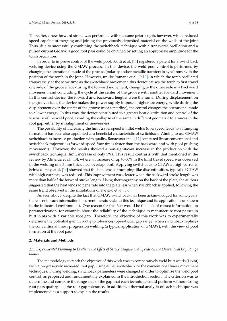
Figures 4 and 5 present the welded joints for the switchback experiments with forward strokespeed equal to the backward stroke speed (TSF = TSB). It is important to note that the bead appearancewith switchback resembles a string of beads with overlap parts, as stated by Kaneko et al. [5].For experiment 1SB (Figure 4), which presented longer forward and backward stroke lengths, fullpenetration happened from a minimum operational opening (Fmin) of 1.7 mm and remained stableup to a maximum operational opening (Fmax) of 3.0 mm. For root gaps narrower than 1.7 mm, therewas a lack of penetration, while for values above 3.0 mm, there was perforation. Thus, the conditionwith switchback 1SB provided a root gap tolerance of 1.3 mm (from 1.7 mm to 3.0 mm), which isapproximately the same as the experiment 1L (1.4 mm). However, the condition with linear movement(1L) was operational for narrower gaps (from 0.3 mm to 1.7 mm), while the condition with switchbackmovement and longer strokes (1SB) showed to be operational for wider gaps (from 1.7 mm to 3.0 mm).It is understood in this switchback condition the first stroke is colder than when linear movement iscarried out, contributing to the stability of the root pass in wider gaps, where penetration is facilitated.
J. Manuf. Mater. Process. 2019, 3, x FOR PEER REVIEW 8 of 19
Figure 3. Quantification of the operational gap range for the experiment 1L (linear torch movement).
Figures 4 and 5 present the welded joints for the switchback experiments with forward stroke
speed equal to the backward stroke speed (TSF = TSB). It is important to note that the bead appearance
with switchback resembles a string of beads with overlap parts, as stated by Kaneko et al. [5]. For
experiment 1SB (Figure 4), which presented longer forward and backward stroke lengths, full
penetration happened from a minimum operational opening (Fmin) of 1.7 mm and remained stable up
to a maximum operational opening (Fmax) of 3.0 mm. For root gaps narrower than 1.7 mm, there was
a lack of penetration, while for values above 3.0 mm, there was perforation. Thus, the condition with
switchback 1SB provided a root gap tolerance of 1.3 mm (from 1.7 mm to 3.0 mm), which is
approximately the same as the experiment 1L (1.4 mm). However, the condition with linear
movement (1L) was operational for narrower gaps (from 0.3 mm to 1.7 mm), while the condition with
switchback movement and longer strokes (1SB) showed to be operational for wider gaps (from 1.7
mm to 3.0 mm). It is understood in this switchback condition the first stroke is colder than when
linear movement is carried out, contributing to the stability of the root pass in wider gaps, where
penetration is facilitated.
Figure 4. Quantification of the operational gap range for the experiment 1SB (switchback torch
movement).
Figure 4. Quantification of the operational gap range for the experiment 1SB (switchback torchmovement).
In the case of experiment 2SB (Figure 5), when the forward and backward stroke lengths weresignificantly reduced and the condition TSF = TSB was maintained, full penetration happened from aroot gap of 1.0 mm to 3.0 mm. Contrasting to experiment 1SB, there was also penetration for narrowergaps (<2.0 mm). Smaller stroke lengths resulted in a weld pool that was less elongated, and, therefore,hotter than condition 1SB, justifying the observed behavior. In addition, as well as experiment 1SB,experiment 2SB had a greater maximum operational opening than experiment 1L. However, it is worthnoting that this condition presented a lack of penetration in some isolated points with root gaps lessthan 2.0 mm. Therefore, from a robustness point of view, Fmin was assumed for experiment 2SB to be2.0 mm, with a root gap tolerance of 1.0 mm and Fmax of 3.0 mm.
The results up to now suggest that the switchback movement influences the quality of the rootpass and the parameters of the technique play an important role in this phenomenon. This is thereason for planning the second and third experimental modes, i.e., with TSF < TSB (experiments 3SBand 4SB) and with TSF > TSB (experiments 5SB and 6SB). Figure 6 shows the welded joints fromexperiments 3SB and 4SB. The minimum and maximum operational openings were very similar (Fmin
= 1.1 mm and Fmax = 2.5 mm), although the weld root was more regular for 4SB. Thus, the rootgap tolerance was assumed to have reached 1.4 mm when the condition TSF < TSB was used. Thisvalue was approximately the same as that achieved by experiments 1L and 1SB (1.4 mm and 1.3 mm,respectively) and greater than that obtained with experiment 2SB (which was 1.0 mm). This means

J. Manuf. Mater. Process. 2019, 3, 54 9 of 18
that, within the parameters evaluated, the conditions with TSF < TSB did not improve the performanceof the technique in relation to the formation of the root pass.J. Manuf. Mater. Process. 2019, 3, x FOR PEER REVIEW 9 of 19
Figure 5. Quantification of the operational gap range for the experiment 2SB (switchback torch
movement).
In the case of experiment 2SB (Figure 5), when the forward and backward stroke lengths were
significantly reduced and the condition TSF = TSB was maintained, full penetration happened from a
root gap of 1.0 mm to 3.0 mm. Contrasting to experiment 1SB, there was also penetration for narrower
gaps (<2.0 mm). Smaller stroke lengths resulted in a weld pool that was less elongated, and, therefore,
hotter than condition 1SB, justifying the observed behavior. In addition, as well as experiment 1SB,
experiment 2SB had a greater maximum operational opening than experiment 1L. However, it is
worth noting that this condition presented a lack of penetration in some isolated points with root
gaps less than 2.0 mm. Therefore, from a robustness point of view, Fmin was assumed for experiment
2SB to be 2.0 mm, with a root gap tolerance of 1.0 mm and Fmax of 3.0 mm.
The results up to now suggest that the switchback movement influences the quality of the root
pass and the parameters of the technique play an important role in this phenomenon. This is the
reason for planning the second and third experimental modes, i.e., with TSF ˂ TSB (experiments 3SB
and 4SB) and with TSF > TSB (experiments 5SB and 6SB). Figure 6 are shown the welded joints from
experiments 3SB and 4SB. The minimum and maximum operational openings were very similar
(Fmin = 1.1 mm and Fmax = 2.5 mm), although the weld root was more regular for 4SB. Thus, the root
gap tolerance was assumed to have reached 1.4 mm when the condition TSF ˂ TSB was used. This
value was approximately the same as that achieved by experiments 1L and 1SB (1.4 mm and 1.3 mm,
respectively) and greater than that obtained with experiment 2SB (which was 1.0 mm). This means
that, within the parameters evaluated, the conditions with TSF ˂ TSB did not improve the performance
of the technique in relation to the formation of the root pass.
Figure 5. Quantification of the operational gap range for the experiment 2SB (switchback torchmovement).J. Manuf. Mater. Process. 2019, 3, x FOR PEER REVIEW 10 of 19
Figure 6. Quantification of the operational gap range for experiments 3SB and 4SB (switchback torch
movement), where TSF ˂ TSB.
Figure 7, in turn, shows the experiments in which forward stroke speeds were faster than the
backward stroke speeds (experiments 5SB and 6SB). For this setting, it was observed that Fmin = 1.7
mm and Fmax = 2.5 mm, resulting in a root gap tolerance of 0.8 mm. This tolerance is shorter than that
obtained for the experiments with TSF < TSB (3SB and 4SB), with TSF = TSB (1SB and 2SB), and with
linear movement (1L). In this way, within the parameters evaluated, the conditions with TSF > TSB
did not improve the performance of the technique in relation to the formation of the root pass.
Figure 7. Quantification of the operational gap range for experiments 5SB and 6SB (switchback torch
movement), where TSF > TSB.
Table 5 displays a summary of the root gap ranges with full penetration for each tested
condition. As seen in the mentioned table, in terms of root gap tolerance for the switchback
conditions, the welded joints with a forward stroke speed lower than the backward stroke speed (3SB
and 4SB) were those that presented root passes which were more stable, yet at the same level as one
of the conditions with forward stroke speed equal to the backward stroke speed (1SB) and the
condition with without application of the switchback (1L). On the other hand, based on results from
elsewhere, improvements could be made through slight adjustments of the switchback parameters.
According to the simulations carried out by Kaneko et al. [5,6], also in thin plate butt welding, and
the results obtained by Schwedersky et al. [14], using GTAW at high currents, if the backward stroke
length became longer than half of the forward stroke length (B > F/2), continuous root passes could
Figure 6. Quantification of the operational gap range for experiments 3SB and 4SB (switchback torchmovement), where TSF < TSB.
Figure 7, in turn, shows the experiments in which forward stroke speeds were faster than thebackward stroke speeds (experiments 5SB and 6SB). For this setting, it was observed that Fmin = 1.7mm and Fmax = 2.5 mm, resulting in a root gap tolerance of 0.8 mm. This tolerance is shorter than that

J. Manuf. Mater. Process. 2019, 3, 54 10 of 18
obtained for the experiments with TSF < TSB (3SB and 4SB), with TSF = TSB (1SB and 2SB), and withlinear movement (1L). In this way, within the parameters evaluated, the conditions with TSF > TSB didnot improve the performance of the technique in relation to the formation of the root pass.
J. Manuf. Mater. Process. 2019, 3, x FOR PEER REVIEW 10 of 19
Figure 6. Quantification of the operational gap range for experiments 3SB and 4SB (switchback torch
movement), where TSF ˂ TSB.
Figure 7, in turn, shows the experiments in which forward stroke speeds were faster than the
backward stroke speeds (experiments 5SB and 6SB). For this setting, it was observed that Fmin = 1.7
mm and Fmax = 2.5 mm, resulting in a root gap tolerance of 0.8 mm. This tolerance is shorter than that
obtained for the experiments with TSF < TSB (3SB and 4SB), with TSF = TSB (1SB and 2SB), and with
linear movement (1L). In this way, within the parameters evaluated, the conditions with TSF > TSB
did not improve the performance of the technique in relation to the formation of the root pass.
Figure 7. Quantification of the operational gap range for experiments 5SB and 6SB (switchback torch
movement), where TSF > TSB.
Table 5 displays a summary of the root gap ranges with full penetration for each tested
condition. As seen in the mentioned table, in terms of root gap tolerance for the switchback
conditions, the welded joints with a forward stroke speed lower than the backward stroke speed (3SB
and 4SB) were those that presented root passes which were more stable, yet at the same level as one
of the conditions with forward stroke speed equal to the backward stroke speed (1SB) and the
condition with without application of the switchback (1L). On the other hand, based on results from
elsewhere, improvements could be made through slight adjustments of the switchback parameters.
According to the simulations carried out by Kaneko et al. [5,6], also in thin plate butt welding, and
the results obtained by Schwedersky et al. [14], using GTAW at high currents, if the backward stroke
length became longer than half of the forward stroke length (B > F/2), continuous root passes could
Figure 7. Quantification of the operational gap range for experiments 5SB and 6SB (switchback torchmovement), where TSF > TSB.
Table 5 displays a summary of the root gap ranges with full penetration for each tested condition.As seen in the mentioned table, in terms of root gap tolerance for the switchback conditions, thewelded joints with a forward stroke speed lower than the backward stroke speed (3SB and 4SB)were those that presented root passes which were more stable, yet at the same level as one of theconditions with forward stroke speed equal to the backward stroke speed (1SB) and the conditionwith without application of the switchback (1L). On the other hand, based on results from elsewhere,improvements could be made through slight adjustments of the switchback parameters. Accordingto the simulations carried out by Kaneko et al. [5,6], also in thin plate butt welding, and the resultsobtained by Schwedersky et al. [14], using GTAW at high currents, if the backward stroke length becamelonger than half of the forward stroke length (B > F/2), continuous root passes could be obtained. Inthe present cases, the only condition that fulfilled this setting (B > F/2) was the 1SB experiment. If 1SBis compared with 2SB (also with TSF = TSB, yet with B = F/2), there is an operational gap enlargement.
Table 5. Summary of the outputs of the experiments, as planned in Table 2.
Exp. Switchback Conditions Fmin (mm) Fmax (mm) Operational Gap Range (mm)
1L – – – 0.3 1.7 1.41SB TSF = TSB F = 30 B = 20 1.7 3.0 1.32SB TSF = TSB F = 10 B = 5 2.0 3.0 1.03SB TSF < TSB F = 10 B = 5 1.1 2.5 1.44SB TSF < TSB F = 10 B = 5 1.0 2.5 1.55SB TSF > TSB F = 10 B = 5 1.7 2.5 0.86SB TSF > TSB F = 10 B = 5 1.7 2.5 0.8
Note: Pulsed GMAW (AWS ER70S-6, Ar + 5% O2 and CTWD of 18 mm, Im = 145 A and TSeq = 4.2 mm/s); F forforward stroke length (mm), B for backward stroke length (mm), Fmin for the root gap value from which a totalpenetration was reached, and Fmax for the maximum root gap value achieved without any surface irregularities orburn throughs becoming apparent.
Still based on Table 5, comparing switchback (SB) and linear movement (1L) experiments, thereis a considerable difference between the welded joints. The switchback, for same arc energy, is notable to reach full penetration when the root gap is too narrow. The reason for this behavior would be

J. Manuf. Mater. Process. 2019, 3, 54 11 of 18
related to the high forward and backward stroke speeds used in relation to the travel speed of the linearmovement experiment. A lower heat input in the first stroke (forward) decreases the digging power ofthe weld pool in the substrate and, consequently, the penetration. According to Kaneko et al. [5,6],this phenomenon also affects the shape of the pool—mainly the length. It is important to mentionthat in the present work, similar welding conditions to those used by Kaneko et al. [5] (Im, TSeq, WireFeed Speed (WFS), stroke lengths and plate material) were applied, the differences being that the platewas slightly thicker and there were lower peak and base currents, as well as shorter peak and basedurations. However, Kaneko et al. [5] stated that a higher root stability was observed for the conditionof forward speeds faster than backward speeds (TSF > TSB). These conditions are more similar to thoseof 5SB and 6SB, for which the operational gap ranges were the smallest. Nevertheless, Kaneko et al. [5]did not determine the operational gap range, which suggests that the relationship between TSF and TSB
is not the governing parameter, at least not alone (the stroke lengths F and B must also be considered).
3.2. Effect of Stroke Lengths and Speeds on the Size of the Weld Pool
Figure 8 illustrates the superficial aspects of the three bead-on-plate depositions performed atthis stage of the work. The superficial aspect of the beads using switchback are uniformly scaled, incontrast to the bead using linear movement, which presents a smooth aspect (typical of pulsed GMAW).However, they are regular along the whole length, with the space between each scale proportional tothe stroke lengths (T1SB is more spaced than T2SB). These characteristics support the assumption thatstable weldments were performed using the three conditions of Table 4.J. Manuf. Mater. Process. 2019, 3, x FOR PEER REVIEW 12 of 19
Figure 8. Superficial aspects of the beads deposited on plates (same WFS and TS) for thermographic
assessment: (a) T1L (linear); (b) T1SB (switchback with F = 30 mm and B = 20 mm); (c) T2SB
(switchback with F = 10 mm and B = 5 mm).
Figures 9–11, in turn, indicate the thermal profile on the backside of the plates for each
deposition (T1L, T1SB, and T2SB, respectively) at three different welding positions (beginning,
middle, and end of the bead), emphasizing the temporal progression of the welding torch. The hottest
areas (rich red) were around 800 °C, surrounded by decrescent isotherms up to 200 °C (magenta). In
general, the red and yellow areas of each condition remained the same size regardless the heat source
position, showing that the weld reached the steady state from the beginning. However, the farther
the heat source was from the welding starting point, the more elongated and enlarged were the
isotherms related to lower temperatures (from heavy green towards light cyan, bright blue, and
magenta), showing, as expected, a longer time to converge to an equilibrium final temperature of the
plate. As explained in the first paragraph of Section 3.1, the rich red isotherm was proportional to the
weld pool size. Thereafter, the thermal profile analysis was concentrated in this area.
Figure 8. Superficial aspects of the beads deposited on plates (same WFS and TS) for thermographicassessment: (a) T1L (linear); (b) T1SB (switchback with F = 30 mm and B = 20 mm); (c) T2SB (switchbackwith F = 10 mm and B = 5 mm).
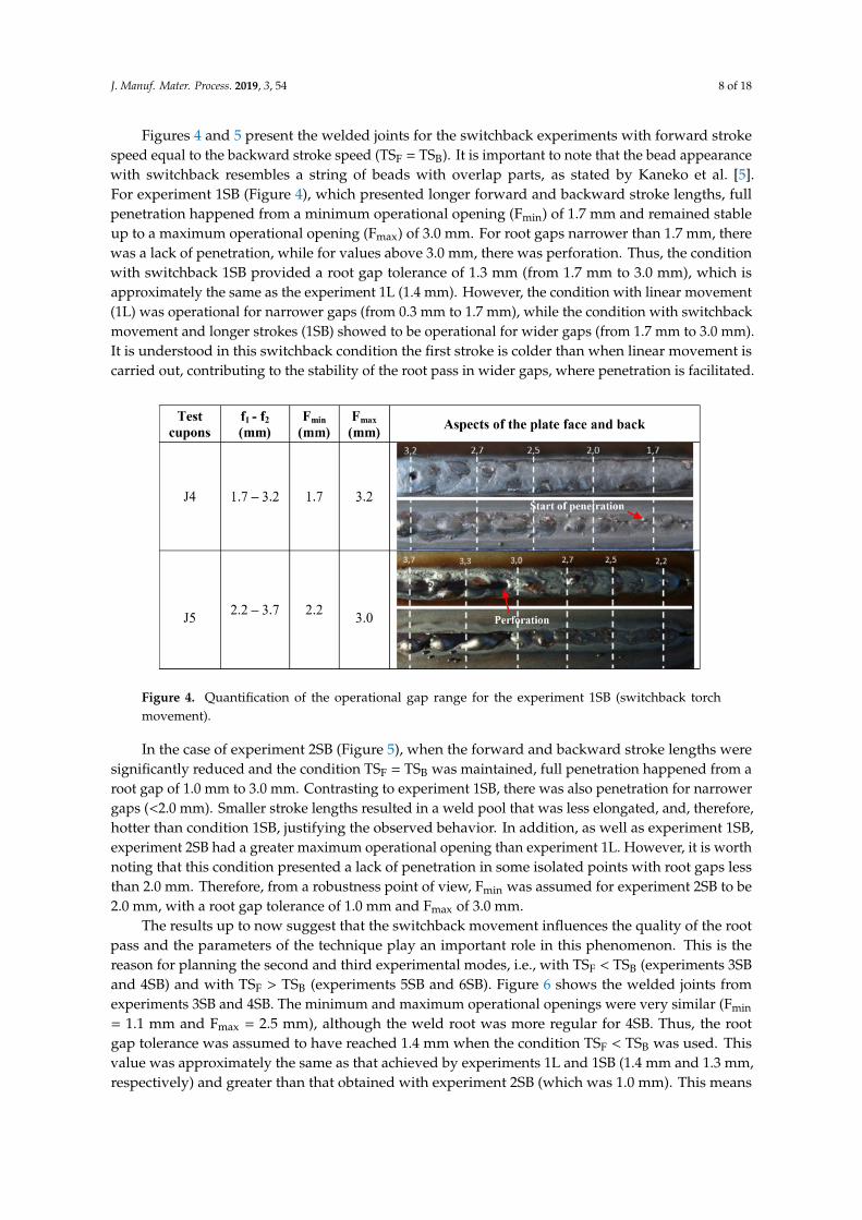
Figures 9–11, in turn, indicate the thermal profile on the backside of the plates for each deposition(T1L, T1SB, and T2SB, respectively) at three different welding positions (beginning, middle, and end ofthe bead), emphasizing the temporal progression of the welding torch. The hottest areas (rich red) werearound 800 ◦C, surrounded by decrescent isotherms up to 200 ◦C (magenta). In general, the red and

J. Manuf. Mater. Process. 2019, 3, 54 12 of 18
yellow areas of each condition remained the same size regardless the heat source position, showingthat the weld reached the steady state from the beginning. However, the farther the heat source wasfrom the welding starting point, the more elongated and enlarged were the isotherms related to lowertemperatures (from heavy green towards light cyan, bright blue, and magenta), showing, as expected,a longer time to converge to an equilibrium final temperature of the plate. As explained in the firstparagraph of Section 3.1, the rich red isotherm was proportional to the weld pool size. Thereafter, thethermal profile analysis was concentrated in this area.J. Manuf. Mater. Process. 2019, 3, x FOR PEER REVIEW 13 of 19
Figure 9. Thermal profile at the plate backside from the deposition T1L (linear) at different welding
times (progressively advancing the torch position).
Figure 9. Thermal profile at the plate backside from the deposition T1L (linear) at different weldingtimes (progressively advancing the torch position).
J. Manuf. Mater. Process. 2019, 3, 54 13 of 18
J. Manuf. Mater. Process. 2019, 3, x FOR PEER REVIEW 14 of 19
Figure 10. Thermal profile at the plate backside from the deposition T1SB (switchback with F = 30 mm
and B = 20 mm) at different welding times (progressively advancing the torch position).
Figure 10. Thermal profile at the plate backside from the deposition T1SB (switchback with F = 30 mmand B = 20 mm) at different welding times (progressively advancing the torch position).

J. Manuf. Mater. Process. 2019, 3, 54 14 of 18J. Manuf. Mater. Process. 2019, 3, x FOR PEER REVIEW 15 of 19
Figure 11. Thermal profile at the plate backside from the deposition T2SB (switchback with F = 10 mm
and B = 5 mm) at different welding times (progressively advancing the torch position).
After evaluating the isotherm format of the red areas, it is clear that the pool from the linear
movement was larger than in the plates in which switchback was applied (although the bead volume
was the same). The larger the stroke lengths and the faster stroke speeds (T1SB in relation to T2SB),
the smaller the weld pool. For a better comparison, Figure 12 presents the area values corresponding
to the red isotherm as the arc progressed with the welding torch under the conditions T1L, T1SB, and
T2SB, where the suffixes F and B for switchback conditions indicate the measurements at the end of
the forward and backward strokes, respectively.
Figure 11. Thermal profile at the plate backside from the deposition T2SB (switchback with F = 10 mmand B = 5 mm) at different welding times (progressively advancing the torch position).
After evaluating the isotherm format of the red areas, it is clear that the pool from the linearmovement was larger than in the plates in which switchback was applied (although the bead volumewas the same). The larger the stroke lengths and the faster stroke speeds (T1SB in relation to T2SB), thesmaller the weld pool. For a better comparison, Figure 12 presents the area values corresponding tothe red isotherm as the arc progressed with the welding torch under the conditions T1L, T1SB, andT2SB, where the suffixes F and B for switchback conditions indicate the measurements at the end of theforward and backward strokes, respectively.

J. Manuf. Mater. Process. 2019, 3, 54 15 of 18
J. Manuf. Mater. Process. 2019, 3, x FOR PEER REVIEW 16 of 19
Figure 12. Areas of the hottest points at the plate backside, defined by the red isotherms, at different
torch positions (progressively advancing): T1L (linear); T1SB (switchback with F = 30 mm and B = 20
mm); T2SB (switchback with F = 10 mm and B = 5 mm).
Another way to see the effect of lengths and speeds on the bead formation is based on the
maximum temperatures within the red isotherms. Figure 13 presents the behavior of these
temperatures along the time. As seen, a higher and slightly more uniform maximum temperature
range was identified for the linear deposition in relation to switchback depositions. Deposits T1SB
(switchback with F = 30 mm and B = 20 mm) and T2SB (switchback with F = 10 mm and B = 5 mm),
in turn, had temperature variations in the form of ramps, which were associated with the switchback
movements exerted by the welding torch (clearer for T1SB, lower backward stroke frequency). It
should be noted that these values, although following a logical trend, are very close to each other.
However, it should also be noted that these temperatures were measured on the plate underside.
Thus, the heat had to cross more than half thickness of the plate to heat up that backside, distributing
to a certain level before reaching the opposite face. In this way, it is envisaged that these differences
would be greater if the temperature measurements were made on the top of the plates, although other
sources of errors would appear. The same average temperatures, now discretized and plotted in
Figure 14, make clear not only the difference between the linear and switchback conditions, but also
between long (T1SB) and shorter (T2SB) strokes.
Figure 12. Areas of the hottest points at the plate backside, defined by the red isotherms, at differenttorch positions (progressively advancing): T1L (linear); T1SB (switchback with F = 30 mm and B = 20mm); T2SB (switchback with F = 10 mm and B = 5 mm).
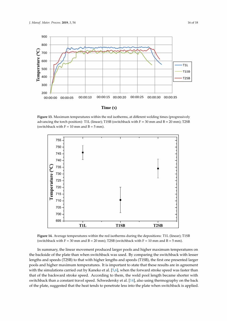
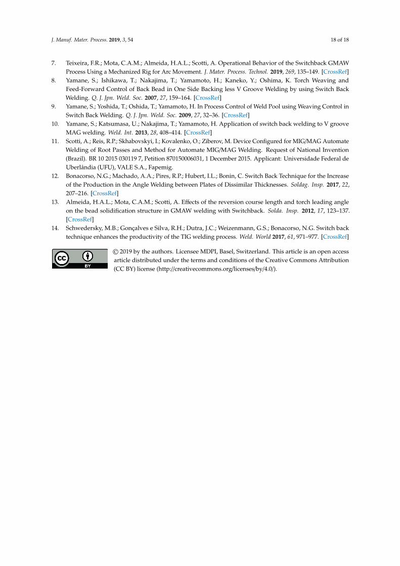
Another way to see the effect of lengths and speeds on the bead formation is based on the maximumtemperatures within the red isotherms. Figure 13 presents the behavior of these temperatures alongthe time. As seen, a higher and slightly more uniform maximum temperature range was identified forthe linear deposition in relation to switchback depositions. Deposits T1SB (switchback with F = 30mm and B = 20 mm) and T2SB (switchback with F = 10 mm and B = 5 mm), in turn, had temperaturevariations in the form of ramps, which were associated with the switchback movements exerted bythe welding torch (clearer for T1SB, lower backward stroke frequency). It should be noted that thesevalues, although following a logical trend, are very close to each other. However, it should also benoted that these temperatures were measured on the plate underside. Thus, the heat had to cross morethan half thickness of the plate to heat up that backside, distributing to a certain level before reachingthe opposite face. In this way, it is envisaged that these differences would be greater if the temperaturemeasurements were made on the top of the plates, although other sources of errors would appear.The same average temperatures, now discretized and plotted in Figure 14, make clear not only thedifference between the linear and switchback conditions, but also between long (T1SB) and shorter(T2SB) strokes.
J. Manuf. Mater. Process. 2019, 3, 54 16 of 18J. Manuf. Mater. Process. 2019, 3, x FOR PEER REVIEW 17 of 19
Figure 13. Maximum temperatures within the red isotherms, at different welding times (progressively
advancing the torch position): T1L (linear); T1SB (switchback with F = 30 mm and B = 20 mm); T2SB
(switchback with F = 10 mm and B = 5 mm).
Figure 14. Average temperatures within the red isotherms during the depositions: T1L (linear); T1SB
(switchback with F = 30 mm and B = 20 mm); T2SB (switchback with F = 10 mm and B = 5 mm).
In summary, the linear movement produced larger pools and higher maximum temperatures on
the backside of the plate than when switchback was used. By comparing the switchback with lesser
lengths and speeds (T2SB) to that with higher lengths and speeds (T1SB), the first one presented
larger pools and higher maximum temperatures. It is important to state that these results are in
agreement with the simulations carried out by Kaneko et al. [5,6], when the forward stroke speed was
faster than that of the backward stroke speed. According to them, the weld pool length became
shorter with switchback than a constant travel speed. Schwedersky et al. [14], also using
thermography on the back of the plate, suggested that the heat tends to penetrate less into the plate
when switchback is applied.
Figure 13. Maximum temperatures within the red isotherms, at different welding times (progressivelyadvancing the torch position): T1L (linear); T1SB (switchback with F = 30 mm and B = 20 mm); T2SB(switchback with F = 10 mm and B = 5 mm).
J. Manuf. Mater. Process. 2019, 3, x FOR PEER REVIEW 17 of 19
Figure 13. Maximum temperatures within the red isotherms, at different welding times (progressively
advancing the torch position): T1L (linear); T1SB (switchback with F = 30 mm and B = 20 mm); T2SB
(switchback with F = 10 mm and B = 5 mm).
Figure 14. Average temperatures within the red isotherms during the depositions: T1L (linear); T1SB
(switchback with F = 30 mm and B = 20 mm); T2SB (switchback with F = 10 mm and B = 5 mm).
In summary, the linear movement produced larger pools and higher maximum temperatures on
the backside of the plate than when switchback was used. By comparing the switchback with lesser
lengths and speeds (T2SB) to that with higher lengths and speeds (T1SB), the first one presented
larger pools and higher maximum temperatures. It is important to state that these results are in
agreement with the simulations carried out by Kaneko et al. [5,6], when the forward stroke speed was
faster than that of the backward stroke speed. According to them, the weld pool length became
shorter with switchback than a constant travel speed. Schwedersky et al. [14], also using
thermography on the back of the plate, suggested that the heat tends to penetrate less into the plate
when switchback is applied.
Figure 14. Average temperatures within the red isotherms during the depositions: T1L (linear); T1SB(switchback with F = 30 mm and B = 20 mm); T2SB (switchback with F = 10 mm and B = 5 mm).
In summary, the linear movement produced larger pools and higher maximum temperatures onthe backside of the plate than when switchback was used. By comparing the switchback with lesserlengths and speeds (T2SB) to that with higher lengths and speeds (T1SB), the first one presented largerpools and higher maximum temperatures. It is important to state that these results are in agreementwith the simulations carried out by Kaneko et al. [5,6], when the forward stroke speed was faster thanthat of the backward stroke speed. According to them, the weld pool length became shorter withswitchback than a constant travel speed. Schwedersky et al. [14], also using thermography on the backof the plate, suggested that the heat tends to penetrate less into the plate when switchback is applied.

J. Manuf. Mater. Process. 2019, 3, 54 17 of 18
One can assume that hotter and larger weld pools would lead to slower cooling rates. Slowercooling rates at a high temperature, in turn, would keep a lower molten metal viscosity for a longertime, a fact that, along with a higher molten volume (higher gravity force), favors the pool collapsebefore solidification and makes it difficult to sustain it with wider gaps. This reasoning could explainthe results of Section 2, in which the conditions with switchback reached wider root gaps (see Table 3).The higher temperature of the linear movement would justify the possibility of reaching full penetrationwith a very low gap opening. However, this reasoning by itself would not explain the variation inoperational gap ranges for different switchback parameters. For instance, in terms of the switchbackparameters, the condition of T2SB (Section 3) is very similar to condition 5SB (Section 2) which reacheswider root gaps, but also a gap range narrower than that with linear movement and other conditionsin which TSF is smaller or equal to TSB. Thus, it becomes clear that there is a dependence between thestroke lengths and the stroke speeds in the influence of the switchback parameterization.
4. Conclusions
The results showed that the switchback technique can be successfully used to sustain the pool inthe root of the joint with wider root gaps, although the operational gap range is not necessarily largerwhen switchback is applied. There is a strong influence and interaction of the values of the strokelengths and stroke speeds on the process performance.
Nevertheless, in general, the results showed that for very narrow root gaps, the use of switchbackdoes not seem to be the best option (linear movement leads to a larger weld pool to guarantee thetotal penetration). For intermediary root gaps, the best switchback conditions seem to be with shorterstroke lengths and slower stroke speeds (intermediate pool size), while for larger root gaps, the bestswitchback conditions seem to be with longer stroke lengths and faster stroke speeds (smaller poolsize, more easily sustainable).
Based on these trends, an ideal welding system for butt welds with variable root gaps can berealized, in which a sensor would measure the gap ahead of the heat source, in order to have movementand parameters adaptively changed according to the root gap value.
Author Contributions: Conceptualization, H.A.L.d.A. and A.S.; Methodology, H.A.L.d.A., A.S., F.R.T. andC.A.M.d.M.; Validation, H.A.L.d.A., A.S., F.R.T.; Formal analysis, F.R.T.; Investigation, H.A.L.d.A. and F.R.T.;Writing—original draft preparation, H.A.L.d.A., F.R.T. and C.A.M.d.M.; Writing—review and editing, F.R.T. andA.S.; Project administration, A.S.; Funding acquisition, A.S. and C.A.M.d.M.
Funding: This research was funded by CAPES, grant number 001, National Council for Scientific and TechnologicalDevelopment—CNPq, grant numbers 302863/2016-8 and 01.10.0723.00, PETROBRAS/CENPES and REMULT(Nucleus of Union and Coating of Materials).
Conflicts of Interest: The authors declare no conflict of interest. The funders had no role in the design of thestudy; in the collection, analyses, or interpretation of data; in the writing of the manuscript, or in the decision topublish the results.
References
1. Martikainen, J.; Kah, P. Modified Short Arc GMAW Techniques for Welding a Root Pass. In Proceedings ofthe 14th International Conference Mechanika, Kaunas, Lithuania, 2–3 April 2009; pp. 259–263. [CrossRef]
2. Adi, P.; Ismar, H.; Petar, T. Advantages of MAG-STT Welding Process for Root Pass Welding in the Oil andGas Industry. TEM J. 2016, 5, 76–79. [CrossRef]
3. Yamane, S.; Yamamoto, H.; Ishihara, T.; Kubota, T.; Eguchi, K.; Oshima, K. Adaptive control of back bead inV groove welding without backing plate. Sci. Technol. Weld. Join. 2004, 9, 138–148. [CrossRef]
4. Yamane, S.; Sharif, L.H.; Zeniya, S.; Oshima, K. Feed forward control of back bead and bead height in narrowgap robotic welding. Sci. Technol. Weld. Join. 2005, 10, 23–26. [CrossRef]
5. Kaneko, Y.; Yamane, S.; Oshima, K. Numerical simulation of MIG weld pool in switchback welding.Weld. World 2009, 53, R333–R341. [CrossRef]
6. Kaneko, Y.; Maekawa, Y.; Yamane, S.; Oshima, K. Numerical simulation of MIG weld pool in switch backwelding. Q. J. Jpn. Weld. Soc. 2007, 25, 372–380. [CrossRef]
J. Manuf. Mater. Process. 2019, 3, 54 18 of 18
7. Teixeira, F.R.; Mota, C.A.M.; Almeida, H.A.L.; Scotti, A. Operational Behavior of the Switchback GMAWProcess Using a Mechanized Rig for Arc Movement. J. Mater. Process. Technol. 2019, 269, 135–149. [CrossRef]
8. Yamane, S.; Ishikawa, T.; Nakajima, T.; Yamamoto, H.; Kaneko, Y.; Oshima, K. Torch Weaving andFeed-Forward Control of Back Bead in One Side Backing less V Groove Welding by using Switch BackWelding. Q. J. Jpn. Weld. Soc. 2007, 27, 159–164. [CrossRef]
9. Yamane, S.; Yoshida, T.; Oshida, T.; Yamamoto, H. In Process Control of Weld Pool using Weaving Control inSwitch Back Welding. Q. J. Jpn. Weld. Soc. 2009, 27, 32–36. [CrossRef]
10. Yamane, S.; Katsumasa, U.; Nakajima, T.; Yamamoto, H. Application of switch back welding to V grooveMAG welding. Weld. Int. 2013, 28, 408–414. [CrossRef]
11. Scotti, A.; Reis, R.P.; Skhabovskyi, I.; Kovalenko, O.; Ziberov, M. Device Configured for MIG/MAG AutomateWelding of Root Passes and Method for Automate MIG/MAG Welding. Request of National Invention(Brazil). BR 10 2015 030119 7, Petition 870150006031, 1 December 2015. Applicant: Universidade Federal deUberlândia (UFU), VALE S.A., Fapemig.
12. Bonacorso, N.G.; Machado, A.A.; Pires, R.P.; Hubert, I.L.; Bonin, C. Switch Back Technique for the Increaseof the Production in the Angle Welding between Plates of Dissimilar Thicknesses. Soldag. Insp. 2017, 22,207–216. [CrossRef]
13. Almeida, H.A.L.; Mota, C.A.M.; Scotti, A. Effects of the reversion course length and torch leading angleon the bead solidification structure in GMAW welding with Switchback. Solda. Insp. 2012, 17, 123–137.[CrossRef]
14. Schwedersky, M.B.; Gonçalves e Silva, R.H.; Dutra, J.C.; Weizenmann, G.S.; Bonacorso, N.G. Switch backtechnique enhances the productivity of the TIG welding process. Weld. World 2017, 61, 971–977. [CrossRef]
© 2019 by the authors. Licensee MDPI, Basel, Switzerland. This article is an open accessarticle distributed under the terms and conditions of the Creative Commons Attribution(CC BY) license (http://creativecommons.org/licenses/by/4.0/).
Related Documents