Arab Journal of Nuclear Sciences and Applications, 45(2)407-418(2012) -407- The effect of FSW tool geometry on AA6061-T6 weldments M. A. Abdelrahman *, M. M. Ghoneim *, M. E. Abdelazim *, M M. R. El-Kouss **, N. A. Abdelraheem ** * Metallurgy Department, Nuclear Research Center, Atomic Energy Authority, Cairo, Egypt. ** Metallurgy Department, Faculty of Engineering, Cairo University, Giza, Egypt. ABSTRACT The geometry of the FSW tool plays a major role in deciding the weld quality. In this study several FSW tools (differ from each other in pin angle, shoulder diameter, and shoulder concavity) have been used to fabricate a number of joints in order to obtain a tool with which a sound weld can be produced. It was found that the FSW tool with tapered cone pin, concave shoulder, and shoulder diameter equal to four times the welded plate thickness is suitable to produce a sound weld. INTRODUCTION Although Al–Mg–Si alloys are readily weldable, they suffer from severe softening in the heat affected zone (HAZ) because of the dissolution of Mg 2 Si precipitates during weld thermal cycle. This type of mechanical impairment presents a major problem in engineering design. It will be more appropriate to overcome or minimize the HAZ softening to improve mechanical properties of weldments [1]. In addition, the poor solidification microstructure and porosity in the fusion zone should also be overcome. Compared to many of the fusion welding processes that are routinely used for joining structural alloys, friction stir welding (FSW) is an emerging solid state joining process in which the material that is being welded does not melt and recast. This is a solid-state process based on plastic deformation. A rotating tool made of a pin and a shoulder, travels along the abutting edges of plates that have to be joined. The joint is produced thanks to the plastic flow of the material induced by the friction between the tool and the workpiece [2]. The tool geometry plays a critical role in material flow, so it governs the parameters at which FSW can be conducted. Fujii et al [3] studied the FSW of 6061-T6 AA using FSW tools differ in pin shape (columnar pin without threads, threaded columnar pin, and triangular pin). They reached to the conclusion that the tool shape does not significantly affect the microstructures and mechanical properties of the joints. There is little work concerning the effect of tool shape on the characteristics of FSW 6061-T6 weldments. We will study the role of tool geometry on producing a sound weld. EXPRIMENTAL Extruded 6061-T6 AA plates were used as the base material. The FSW tool was made of H13 steel. Four different FSW tools were used. The details of these tools are given in Table 1 and their shapes are shown in Fig 1. The first three tools were used to weld plates of 11mm thickness and the fourth tool was used to weld 5.3mm thickness plates. The details of the FSW joints produced in this work are given in Table 2. The microstructure of the weldments was examined by optical microscope. Figure. 2 shows schematic representation of transverse and longitudinal tensile test specimens with respect to the welding direction. The transverse tensile test specimen covers all the zones within the joint. The Longitudinal tensile test specimens were cut from the welded joint at the weld center and at several points on both the advancing and retreating sides of the welded joint.

Welcome message from author
This document is posted to help you gain knowledge. Please leave a comment to let me know what you think about it! Share it to your friends and learn new things together.
Transcript
Arab Journal of Nuclear Sciences and Applications, 45(2)407-418(2012)
-407-
The effect of FSW tool geometry on AA6061-T6 weldments
M. A. Abdelrahman *, M. M. Ghoneim *, M. E. Abdelazim *, M M. R. El-Kouss **,N. A. Abdelraheem **
* Metallurgy Department, Nuclear Research Center, Atomic Energy Authority, Cairo, Egypt.** Metallurgy Department, Faculty of Engineering, Cairo University, Giza, Egypt.
ABSTRACT
The geometry of the FSW tool plays a major role in deciding the weld quality.In this study several FSW tools (differ from each other in pin angle, shoulderdiameter, and shoulder concavity) have been used to fabricate a number of jointsin order to obtain a tool with which a sound weld can be produced. It was foundthat the FSW tool with tapered cone pin, concave shoulder, and shoulderdiameter equal to four times the welded plate thickness is suitable to produce asound weld.
INTRODUCTION
Although Al–Mg–Si alloys are readily weldable, they suffer from severe softening in theheat affected zone (HAZ) because of the dissolution of Mg2Si precipitates during weld thermalcycle. This type of mechanical impairment presents a major problem in engineering design. Itwill be more appropriate to overcome or minimize the HAZ softening to improve mechanicalproperties of weldments [1]. In addition, the poor solidification microstructure and porosity inthe fusion zone should also be overcome.
Compared to many of the fusion welding processes that are routinely used for joiningstructural alloys, friction stir welding (FSW) is an emerging solid state joining process inwhich the material that is being welded does not melt and recast. This is a solid-state processbased on plastic deformation. A rotating tool made of a pin and a shoulder, travels along theabutting edges of plates that have to be joined. The joint is produced thanks to the plastic flowof the material induced by the friction between the tool and the workpiece [2].
The tool geometry plays a critical role in material flow, so it governs the parameters atwhich FSW can be conducted. Fujii et al [3] studied the FSW of 6061-T6 AA using FSW toolsdiffer in pin shape (columnar pin without threads, threaded columnar pin, and triangular pin).They reached to the conclusion that the tool shape does not significantly affect themicrostructures and mechanical properties of the joints. There is little work concerning theeffect of tool shape on the characteristics of FSW 6061-T6 weldments. We will study the roleof tool geometry on producing a sound weld.
EXPRIMENTAL
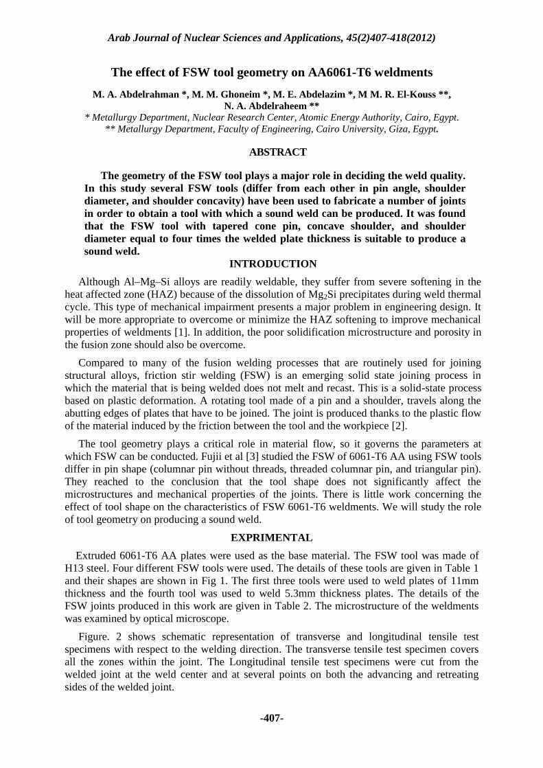
Extruded 6061-T6 AA plates were used as the base material. The FSW tool was made ofH13 steel. Four different FSW tools were used. The details of these tools are given in Table 1and their shapes are shown in Fig 1. The first three tools were used to weld plates of 11mmthickness and the fourth tool was used to weld 5.3mm thickness plates. The details of theFSW joints produced in this work are given in Table 2. The microstructure of the weldmentswas examined by optical microscope.
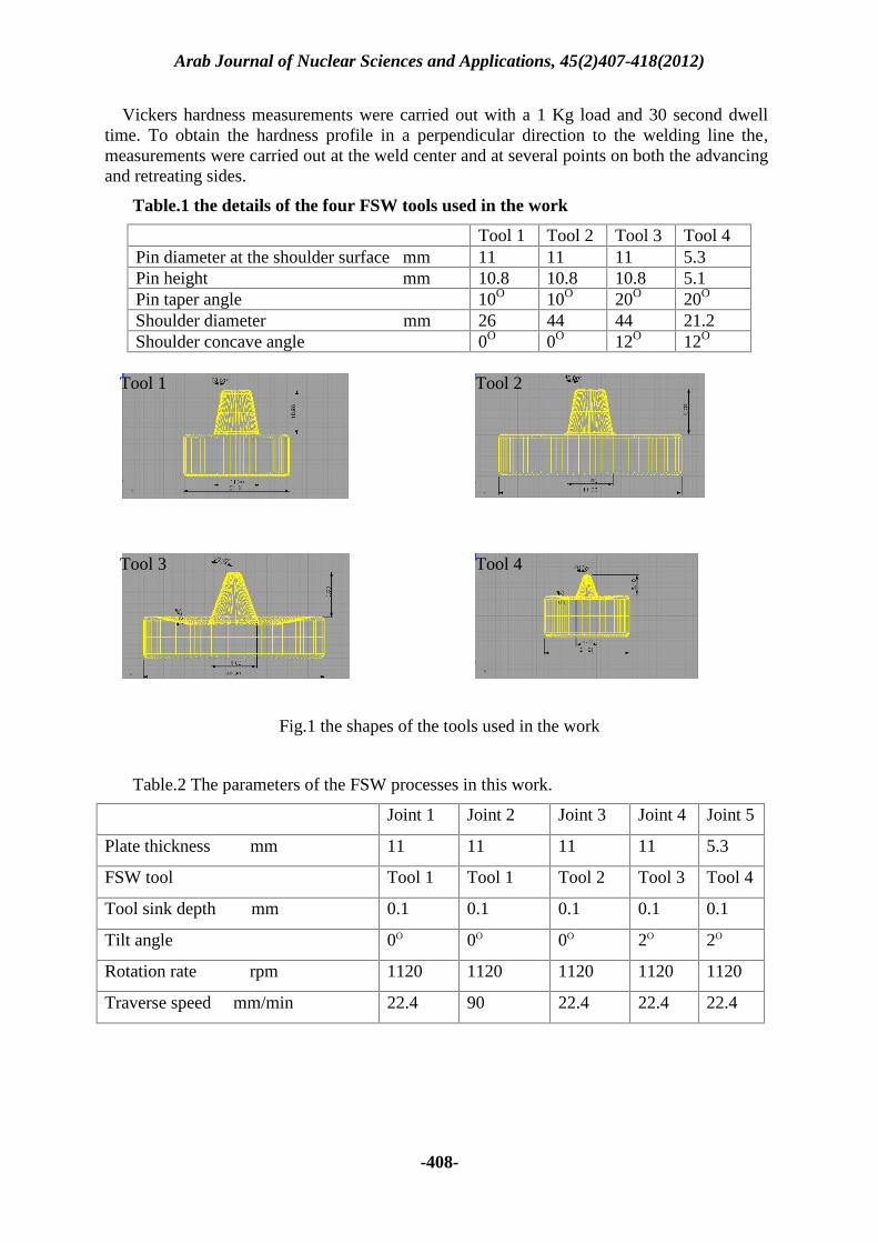
Figure. 2 shows schematic representation of transverse and longitudinal tensile testspecimens with respect to the welding direction. The transverse tensile test specimen coversall the zones within the joint. The Longitudinal tensile test specimens were cut from thewelded joint at the weld center and at several points on both the advancing and retreatingsides of the welded joint.
Arab Journal of Nuclear Sciences and Applications, 45(2)407-418(2012)
-408-
Vickers hardness measurements were carried out with a 1 Kg load and 30 second dwelltime. To obtain the hardness profile in a perpendicular direction to the welding line the,measurements were carried out at the weld center and at several points on both the advancingand retreating sides.
Table.1 the details of the four FSW tools used in the work
Tool 1 Tool 2 Tool 3 Tool 4Pin diameter at the shoulder surface mm 11 11 11 5.3Pin height mm 10.8 10.8 10.8 5.1Pin taper angle 10O 10O 20O 20O
Shoulder diameter mm 26 44 44 21.2Shoulder concave angle 0O 0O 12O 12O
Tool 1 Tool 2
Tool 3 Tool 4
Fig.1 the shapes of the tools used in the work
Table.2 The parameters of the FSW processes in this work.
Joint 1 Joint 2 Joint 3 Joint 4 Joint 5
Plate thickness mm 11 11 11 11 5.3
FSW tool Tool 1 Tool 1 Tool 2 Tool 3 Tool 4
Tool sink depth mm 0.1 0.1 0.1 0.1 0.1
Tilt angle 0O 0O 0O 2O 2O
Rotation rate rpm 1120 1120 1120 1120 1120
Traverse speed mm/min 22.4 90 22.4 22.4 22.4
Arab Journal of Nuclear Sciences and Applications, 45(2)407-418(2012)
-409-
Fig.2 Schematic representation of transverse and longitudinal tensile test specimenswith respect to the welding direction
RESULTSVisual observations
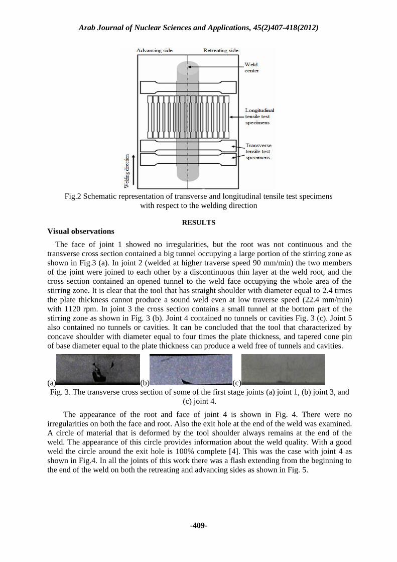
The face of joint 1 showed no irregularities, but the root was not continuous and thetransverse cross section contained a big tunnel occupying a large portion of the stirring zone asshown in Fig.3 (a). In joint 2 (welded at higher traverse speed 90 mm/min) the two membersof the joint were joined to each other by a discontinuous thin layer at the weld root, and thecross section contained an opened tunnel to the weld face occupying the whole area of thestirring zone. It is clear that the tool that has straight shoulder with diameter equal to 2.4 timesthe plate thickness cannot produce a sound weld even at low traverse speed (22.4 mm/min)with 1120 rpm. In joint 3 the cross section contains a small tunnel at the bottom part of thestirring zone as shown in Fig. 3 (b). Joint 4 contained no tunnels or cavities Fig. 3 (c). Joint 5also contained no tunnels or cavities. It can be concluded that the tool that characterized byconcave shoulder with diameter equal to four times the plate thickness, and tapered cone pinof base diameter equal to the plate thickness can produce a weld free of tunnels and cavities.
(a) (b) (c)Fig. 3. The transverse cross section of some of the first stage joints (a) joint 1, (b) joint 3, and
(c) joint 4.
The appearance of the root and face of joint 4 is shown in Fig. 4. There were noirregularities on both the face and root. Also the exit hole at the end of the weld was examined.A circle of material that is deformed by the tool shoulder always remains at the end of theweld. The appearance of this circle provides information about the weld quality. With a goodweld the circle around the exit hole is 100% complete [4]. This was the case with joint 4 asshown in Fig.4. In all the joints of this work there was a flash extending from the beginning tothe end of the weld on both the retreating and advancing sides as shown in Fig. 5.
Arab Journal of Nuclear Sciences and Applications, 45(2)407-418(2012)
-410-
Fig.4 the face and root of joint 4.
Fig. 5. The flash exists on both the advancing side and the retreating side (joint 4).
Microstructure observations
The appearance of the zigzag line
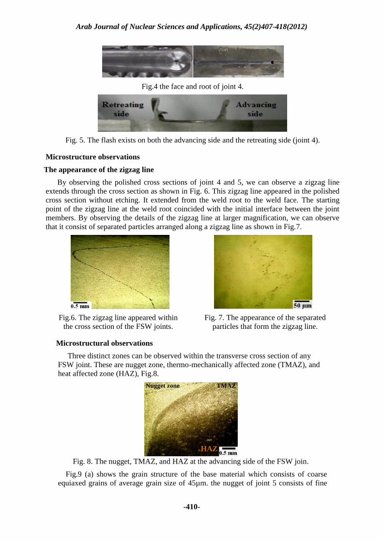
By observing the polished cross sections of joint 4 and 5, we can observe a zigzag lineextends through the cross section as shown in Fig. 6. This zigzag line appeared in the polishedcross section without etching. It extended from the weld root to the weld face. The startingpoint of the zigzag line at the weld root coincided with the initial interface between the jointmembers. By observing the details of the zigzag line at larger magnification, we can observethat it consist of separated particles arranged along a zigzag line as shown in Fig.7.
Fig. 7. The appearance of the separatedparticles that form the zigzag line.
Fig.6. The zigzag line appeared withinthe cross section of the FSW joints.
Microstructural observations
Three distinct zones can be observed within the transverse cross section of anyFSW joint. These are nugget zone, thermo-mechanically affected zone (TMAZ), andheat affected zone (HAZ), Fig.8.
Nugget zone TMAZ
HAZ
Fig. 8. The nugget, TMAZ, and HAZ at the advancing side of the FSW join.
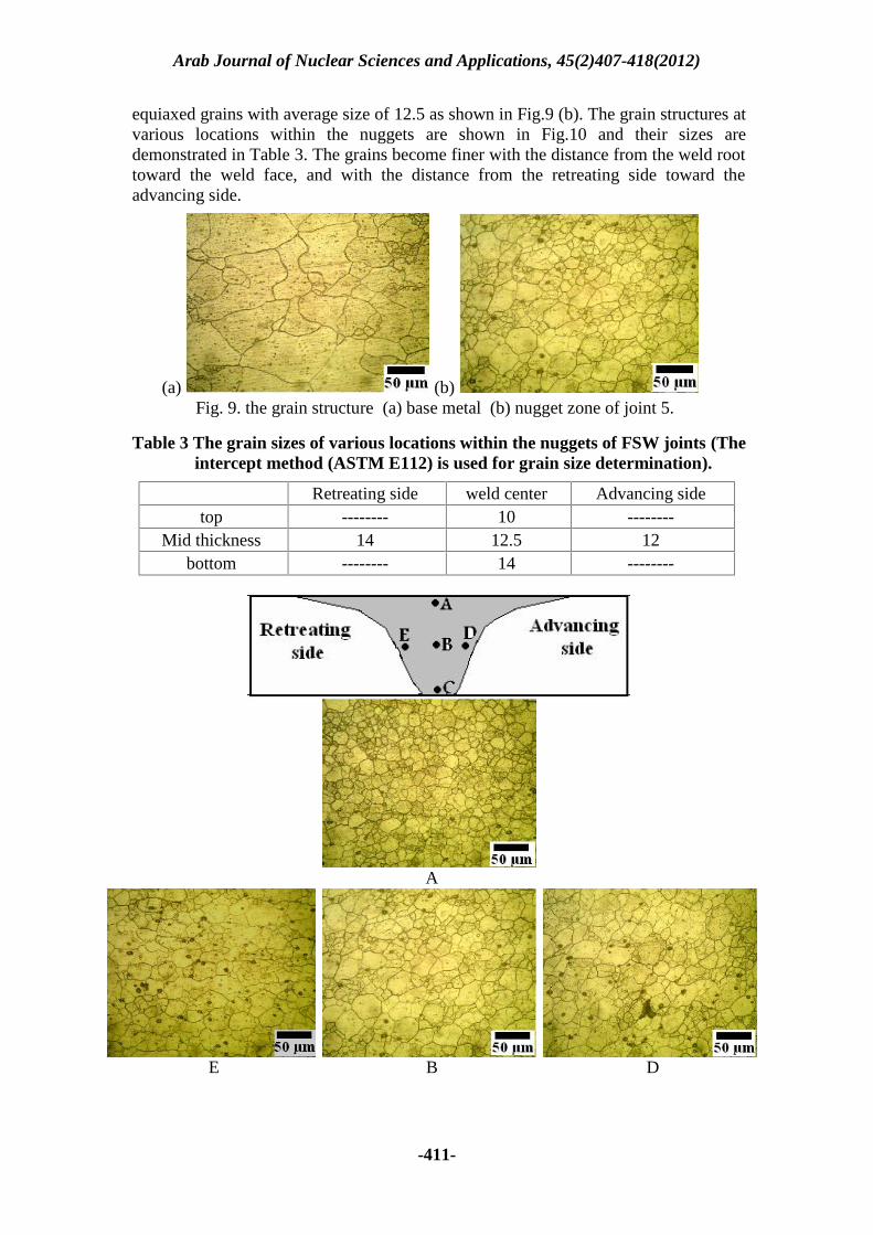
Fig.9 (a) shows the grain structure of the base material which consists of coarseequiaxed grains of average grain size of 45µm. the nugget of joint 5 consists of fine
Arab Journal of Nuclear Sciences and Applications, 45(2)407-418(2012)
-411-
equiaxed grains with average size of 12.5 as shown in Fig.9 (b). The grain structures atvarious locations within the nuggets are shown in Fig.10 and their sizes aredemonstrated in Table 3. The grains become finer with the distance from the weld roottoward the weld face, and with the distance from the retreating side toward theadvancing side.
(b)(a)Fig. 9. the grain structure (a) base metal (b) nugget zone of joint 5.
Table 3 The grain sizes of various locations within the nuggets of FSW joints (Theintercept method (ASTM E112) is used for grain size determination).
Retreating side weld center Advancing sidetop -------- 10 --------
Mid thickness 14 12.5 12bottom -------- 14 --------
A
E B D
Arab Journal of Nuclear Sciences and Applications, 45(2)407-418(2012)
-412-
CFig.10 The variation of grain size at different portions within the nugget
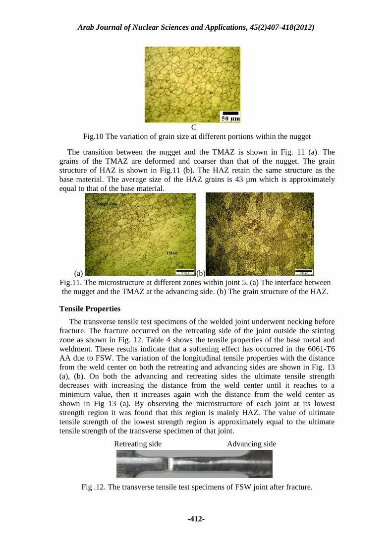
The transition between the nugget and the TMAZ is shown in Fig. 11 (a). Thegrains of the TMAZ are deformed and coarser than that of the nugget. The grainstructure of HAZ is shown in Fig.11 (b). The HAZ retain the same structure as thebase material. The average size of the HAZ grains is 43 µm which is approximatelyequal to that of the base material.
(a) (b)Fig.11. The microstructure at different zones within joint 5. (a) The interface betweenthe nugget and the TMAZ at the advancing side. (b) The grain structure of the HAZ.
Tensile Properties
The transverse tensile test specimens of the welded joint underwent necking beforefracture. The fracture occurred on the retreating side of the joint outside the stirringzone as shown in Fig. 12. Table 4 shows the tensile properties of the base metal andweldment. These results indicate that a softening effect has occurred in the 6061-T6AA due to FSW. The variation of the longitudinal tensile properties with the distancefrom the weld center on both the retreating and advancing sides are shown in Fig. 13(a), (b). On both the advancing and retreating sides the ultimate tensile strengthdecreases with increasing the distance from the weld center until it reaches to aminimum value, then it increases again with the distance from the weld center asshown in Fig 13 (a). By observing the microstructure of each joint at its loweststrength region it was found that this region is mainly HAZ. The value of ultimatetensile strength of the lowest strength region is approximately equal to the ultimatetensile strength of the transverse specimen of that joint.
Retreating side Advancing side
Fig .12. The transverse tensile test specimens of FSW joint after fracture.
Arab Journal of Nuclear Sciences and Applications, 45(2)407-418(2012)
-413-
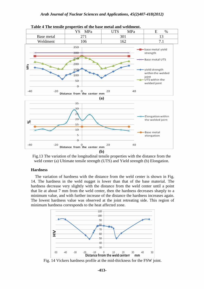
Table 4 The tensile properties of the base metal and weldment.YS MPa UTS MPa E %
Base metal 271 301 13Weldment 106 162 7.1
(a)
(b)Fig.13 The variation of the longitudinal tensile properties with the distance from theweld center (a) Ultimate tensile strength (UTS) and Yield strength (b) Elongation.
Hardness
The variation of hardness with the distance from the weld center is shown in Fig.14. The hardness in the weld nugget is lower than that of the base material. Thehardness decrease very slightly with the distance from the weld center until a pointthat lie at about 7 mm from the weld center, then the hardness decreases sharply to aminimum value, and with further increase of the distance the hardness increases again.The lowest hardness value was observed at the joint retreating side. This region ofminimum hardness corresponds to the heat affected zone.
Fig. 14 Vickers hardness profile at the mid-thickness for the FSW joint.
Arab Journal of Nuclear Sciences and Applications, 45(2)407-418(2012)
-414-
DISCUSSION
Visual observations of the FSW joints
During the FSW process, joining is achieved through frictional heating between thetool and the workpiece, plasticizing, mixing, and extrusion action of a rotating pin-shoulder tool that moves between two parts being joined in addition to the forgingaction of the shoulder trailing part. The ultimate requirement for a FSW process is tocreate a certain amount of friction heat, which can keep the welding material in a wellplasticized state with a suitable temperature, and to generate a high hydrostaticpressure along the joint line so that a sound weld can be generated. The heatgeneration is in direct proportion to deformation and frictional energy created duringthe stirring process. The latter depends on the friction area between the tool shoulderand workpiece surface, as well on the rotation speed of the welding tool and thepressure applied to the welding tool head shoulder [5].
In Joint 2 (see Table 2), the material in front of the tool, instead of being plasticallyflowed with the tool from the front and being consolidated at the trailing side, is cut bythe rotating pin and left behind the pin in the form of small segments occupying thegroove produced by the traverse motion of the pin. The cause may be that the materialwas not softened enough by the friction heating. In order to increase the frictionalheating the traverse speed was reduced to 22.4 mm/min as in Joint 1. At such speed,the amount of friction heating increases, so the upper part of the transverse crosssection of the joint appears to be joined. The heating effect didn’t extend sufficientlyto the middle or lower parts, so the material wasn’t well plasticized and didn’t flowsufficiently with the rotating pin. Insufficient material came back to the advancingside, so a big tunnel occupying a large portion of the stirring zone was formed alongthe joint (Fig.3 (a)). Therefore it is concluded that Tool 1, that had a straight shoulderof diameter equal to 2.4 times the plate thickness, provided insufficient heating tomake the material plasticized enough, so it failed to produce a sound weld even at lowtraverse speed of 22.4 mm/min.
The heat generation in FSW is in direct proportion to deformation and frictionalenergy generated in the welding. The latter depends on the friction area between thetool shoulder and workpiece surface as well on the rotation speed of the welding headpin [6]. In order to increase the frictional heating, Tool 2 was made with largershoulder than tool 1(see table 1). The larger shoulder results in higher heat generationand the material becomes more plasticized and flow with the pin. The tunnel that existnear the root of joint 3 (see Fig.1 (b)) means that the material didn’t flow sufficientlyand insufficient material came back to the advancing side. This showed therequirement to make a tool that provides suitable combination of heat generation andmaterial flow.
Tool 3 has a concave shoulder in order to improve the heat generation and thematerial flow. The concave shoulder forms a compressed annular ring of workpiecematerial around the pin and prevents material expulsion. The combination of tool tiltangle and shoulder cavity inclination establishes a material flow toward the pin [4].The contact area between the concave shoulder and the workpiece is larger than thatbetween the straight shoulder and the workpiece, so tool 3 provides higher heatgeneration. The pin angle was increased from 10O in tool 1 and 2 to 20O in tool 3.Increasing the pin angle improves both the heat generation and material flow. As thepin angle increases the friction heating and deformation energy increases, and thetemperature distribution along the thickness direction of the workpiece becomes more
Arab Journal of Nuclear Sciences and Applications, 45(2)407-418(2012)
-415-
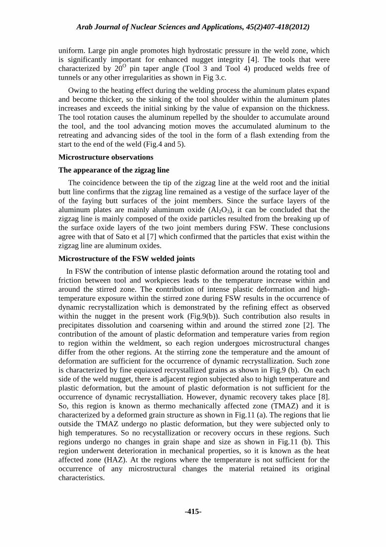
uniform. Large pin angle promotes high hydrostatic pressure in the weld zone, whichis significantly important for enhanced nugget integrity [4]. The tools that werecharacterized by 20O pin taper angle (Tool 3 and Tool 4) produced welds free oftunnels or any other irregularities as shown in Fig 3.c.
Owing to the heating effect during the welding process the aluminum plates expandand become thicker, so the sinking of the tool shoulder within the aluminum platesincreases and exceeds the initial sinking by the value of expansion on the thickness.The tool rotation causes the aluminum repelled by the shoulder to accumulate aroundthe tool, and the tool advancing motion moves the accumulated aluminum to theretreating and advancing sides of the tool in the form of a flash extending from thestart to the end of the weld (Fig.4 and 5).
Microstructure observations
The appearance of the zigzag line
The coincidence between the tip of the zigzag line at the weld root and the initialbutt line confirms that the zigzag line remained as a vestige of the surface layer of theof the faying butt surfaces of the joint members. Since the surface layers of thealuminum plates are mainly aluminum oxide (Al2O3), it can be concluded that thezigzag line is mainly composed of the oxide particles resulted from the breaking up ofthe surface oxide layers of the two joint members during FSW. These conclusionsagree with that of Sato et al [7] which confirmed that the particles that exist within thezigzag line are aluminum oxides.
Microstructure of the FSW welded joints
In FSW the contribution of intense plastic deformation around the rotating tool andfriction between tool and workpieces leads to the temperature increase within andaround the stirred zone. The contribution of intense plastic deformation and high-temperature exposure within the stirred zone during FSW results in the occurrence ofdynamic recrystallization which is demonstrated by the refining effect as observedwithin the nugget in the present work (Fig.9(b)). Such contribution also results inprecipitates dissolution and coarsening within and around the stirred zone [2]. Thecontribution of the amount of plastic deformation and temperature varies from regionto region within the weldment, so each region undergoes microstructural changesdiffer from the other regions. At the stirring zone the temperature and the amount ofdeformation are sufficient for the occurrence of dynamic recrystallization. Such zoneis characterized by fine equiaxed recrystallized grains as shown in Fig.9 (b). On eachside of the weld nugget, there is adjacent region subjected also to high temperature andplastic deformation, but the amount of plastic deformation is not sufficient for theoccurrence of dynamic recrystalliation. However, dynamic recovery takes place [8].So, this region is known as thermo mechanically affected zone (TMAZ) and it ischaracterized by a deformed grain structure as shown in Fig.11 (a). The regions that lieoutside the TMAZ undergo no plastic deformation, but they were subjected only tohigh temperatures. So no recystallization or recovery occurs in these regions. Suchregions undergo no changes in grain shape and size as shown in Fig.11 (b). Thisregion underwent deterioration in mechanical properties, so it is known as the heataffected zone (HAZ). At the regions where the temperature is not sufficient for theoccurrence of any microstructural changes the material retained its originalcharacteristics.
Arab Journal of Nuclear Sciences and Applications, 45(2)407-418(2012)
-416-
According to the general principles of recrystallization the main factors that affectthe size of the recrystallized grains are the temperature and the amount of deformation.The size of the recrystallized grains becomes larger with increasing temperature and/orwith lowering the amount of deformation and vice versa. The amount of deformationat the bottom of the nugget is lower than that at the top because the conical shape ofthe rotating pin. The amount of deformation at the top of the nugget is furtherincreased because that the material near the top surface is not only stirred by thewelding pin but also by the welding shoulder [9, 10]. This explains why the size of therecrystallized grains decreases with the distance from the bottom to the upper part ofthe stirred zone as shown in Fig. 10.
It is reported [4, 5, 10, and 11] that the strain distribution is not symmetric aboutthe weld line and maximum strains are on the material advancing side where a“positive” combination of the tool feed rate and of the peripheral tool velocity isobserved. The temperature distribution at each side of the weld line is nearlysymmetric, so there is no significant difference in temperature between the retreatingside and the advancing side of the nugget [4, 5]. The higher amount of strain at theadvancing side than that at the retreating side demonstrates why the advancing sidehas grains of smaller size than that of the retreating side as shown in Fig.10.
Tensile and hardness Properties
The main controlling factor of the mechanical properties at different zones withinthe FSW welded Al joints is the nature of the strengthening precipitates. In order todiscuss the variation of the tensile properties and hardness with the distance across thefriction stir welded joints the effect of the welding thermal cycle on the strengtheningprecipitates within the different zones ( nugget, TMAZ, and HAZ) of the welded jointshould be discussed first.
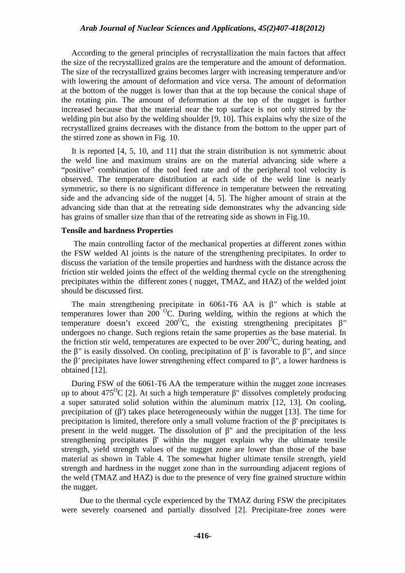
The main strengthening precipitate in 6061-T6 AA is β" which is stable attemperatures lower than 200 OC. During welding, within the regions at which thetemperature doesn’t exceed 200OC, the existing strengthening precipitates β"undergoes no change. Such regions retain the same properties as the base material. Inthe friction stir weld, temperatures are expected to be over 200OC, during heating, andthe β" is easily dissolved. On cooling, precipitation of β' is favorable to β", and sincethe β' precipitates have lower strengthening effect compared to β", a lower hardness isobtained [12].
During FSW of the 6061-T6 AA the temperature within the nugget zone increasesup to about 475OC [2]. At such a high temperature β" dissolves completely producinga super saturated solid solution within the aluminum matrix [12, 13]. On cooling,precipitation of (β') takes place heterogeneously within the nugget [13]. The time forprecipitation is limited, therefore only a small volume fraction of the β' precipitates ispresent in the weld nugget. The dissolution of β" and the precipitation of the lessstrengthening precipitates β' within the nugget explain why the ultimate tensilestrength, yield strength values of the nugget zone are lower than those of the basematerial as shown in Table 4. The somewhat higher ultimate tensile strength, yieldstrength and hardness in the nugget zone than in the surrounding adjacent regions ofthe weld (TMAZ and HAZ) is due to the presence of very fine grained structure withinthe nugget.
Due to the thermal cycle experienced by the TMAZ during FSW the precipitateswere severely coarsened and partially dissolved [2]. Precipitate-free zones were
Arab Journal of Nuclear Sciences and Applications, 45(2)407-418(2012)
-417-
observed around many of the larger precipitates and around all of the grain boundaryprecipitates [8, 14].
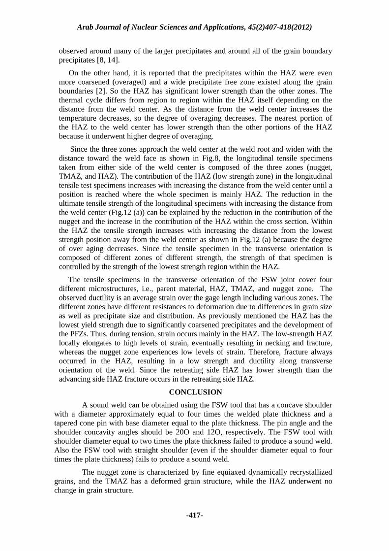
On the other hand, it is reported that the precipitates within the HAZ were evenmore coarsened (overaged) and a wide precipitate free zone existed along the grainboundaries [2]. So the HAZ has significant lower strength than the other zones. Thethermal cycle differs from region to region within the HAZ itself depending on thedistance from the weld center. As the distance from the weld center increases thetemperature decreases, so the degree of overaging decreases. The nearest portion ofthe HAZ to the weld center has lower strength than the other portions of the HAZbecause it underwent higher degree of overaging.
Since the three zones approach the weld center at the weld root and widen with thedistance toward the weld face as shown in Fig.8, the longitudinal tensile specimenstaken from either side of the weld center is composed of the three zones (nugget,TMAZ, and HAZ). The contribution of the HAZ (low strength zone) in the longitudinaltensile test specimens increases with increasing the distance from the weld center until aposition is reached where the whole specimen is mainly HAZ. The reduction in theultimate tensile strength of the longitudinal specimens with increasing the distance fromthe weld center (Fig.12 (a)) can be explained by the reduction in the contribution of thenugget and the increase in the contribution of the HAZ within the cross section. Withinthe HAZ the tensile strength increases with increasing the distance from the loweststrength position away from the weld center as shown in Fig.12 (a) because the degreeof over aging decreases. Since the tensile specimen in the transverse orientation iscomposed of different zones of different strength, the strength of that specimen iscontrolled by the strength of the lowest strength region within the HAZ.
The tensile specimens in the transverse orientation of the FSW joint cover fourdifferent microstructures, i.e., parent material, HAZ, TMAZ, and nugget zone. Theobserved ductility is an average strain over the gage length including various zones. Thedifferent zones have different resistances to deformation due to differences in grain sizeas well as precipitate size and distribution. As previously mentioned the HAZ has thelowest yield strength due to significantly coarsened precipitates and the development ofthe PFZs. Thus, during tension, strain occurs mainly in the HAZ. The low-strength HAZlocally elongates to high levels of strain, eventually resulting in necking and fracture,whereas the nugget zone experiences low levels of strain. Therefore, fracture alwaysoccurred in the HAZ, resulting in a low strength and ductility along transverseorientation of the weld. Since the retreating side HAZ has lower strength than theadvancing side HAZ fracture occurs in the retreating side HAZ.
CONCLUSION
A sound weld can be obtained using the FSW tool that has a concave shoulderwith a diameter approximately equal to four times the welded plate thickness and atapered cone pin with base diameter equal to the plate thickness. The pin angle and theshoulder concavity angles should be 20O and 12O, respectively. The FSW tool withshoulder diameter equal to two times the plate thickness failed to produce a sound weld.Also the FSW tool with straight shoulder (even if the shoulder diameter equal to fourtimes the plate thickness) fails to produce a sound weld.
The nugget zone is characterized by fine equiaxed dynamically recrystallizedgrains, and the TMAZ has a deformed grain structure, while the HAZ underwent nochange in grain structure.
Arab Journal of Nuclear Sciences and Applications, 45(2)407-418(2012)
-418-
Within the nugget zone of the FSW joint the grain size differs from portion toother portion. The grain size decreases with the distance from the retreating side to theadvancing side. Also, the grain size decreases with the distance from the weld root tothe weld face.
The tensile properties (yield strength, ultimate tensile strength, and elongation)of all the FSW joints are lower than that of the base material 6061-T6 AA. These resultsindicate that a softening effect has occurred in the 6061-T6 AA due to FSW
The nearest region within the welded joint to the weld center at which the crosssection is composed mainly of the HAZ has lower ultimate tensile strength than anyother region within the welded joint. The ultimate tensile strength of such region isapproximately the same as the overall ultimate tensile strength of the FSW joint.
In the FSW joints, the hardness at the weld nugget is much lower than that ofthe base material. The hardness values are approximately equal at all the measuredpoints within the nugget zone.
The lowest hardness values were obtained at the HAZ.
REFERENCES
[1] K. Elangovan, V. Balasubramanian, Materials & Design, Volume 29, Issue2, (2008), PP 362-373.
[2] R.S. Mishra, Z.Y. Ma, Materials Science and Engineering: R, Volume 50, Issues1-2, (2005), PP 1-78.
[3] H. Fujii, L. Cui, M. Maeda, K. Nogi, Materials Science and Engineering:A, Volume 419, Issues1-2, (2006), PP 25-31.
[4] A. Scialpi, L. Filippis, P. Cavaliere, Materials & Design, Volume 28, Issue4, 2007, PP 1124-1129.
[5] G. Buffa, J. Hua, R. Shivpuri, L. Fratini, Materials Science and Engineering:A, Volume 419, Issues 1-2, (2006), PP 389-396.
[6] G. Buffa, J. Hua, R. Shivpuri, L. Fratini, Materials Science and Engineering: A,Volume419, Issues1-2, (2006), PP 381-388
[7] Y. Sato, F. Yamashita, Y. Sugiura, S. Hwan, C. Park, H. Kokawa, ScriptaMaterialia, Volume 50, Issue 3, (2004), PP 365-369.
[8] J. Su, T. Nelson, R. Mishra, M. Mahoney, Acta Materialia, Volume 51, Issue3, (2003), PP 713-729.
[9] Z. Zhang, H. Zhang. Materials and Design, Volume 30, (2009), PP 900–907.[10] Z. Zhang, H. Zhang. Journal of materials processing technology, Volume209, (2009), PP 241–270.
[11] H. Zhang, Z. Zhang, J. Chen, Journal of Materials Processing Technology,volume 183, Issue 1, (2007), PP 62-70.
[12] P. Moreira, T. Santos, S. Tavares , Materials and Design, Volume 30, (2009), PP180–187.
[13] X. Sauvage, A. Dédé, A. Muñoz, B. Huneau, Materials Science and Engineering:A, Volume 491, Issues 1-2, (2008), PP 364-371.
[14] C. Rhodes, M. Mahoney, W. Bingel, R. Spurling, C. Bampton, ScriptaMaterialia, Volume 36, Issue 1, (1997), PP 69-75.
Related Documents


![Ceramic coating [tio2 zro2] on aluminium 6061 t6 for anti](https://static.cupdf.com/doc/110x72/556da50cd8b42a875d8b4901/ceramic-coating-tio2-zro2-on-aluminium-6061-t6-for-anti.jpg)