International Journal of Civil and Structural Engineering Research ISSN 2348-7607 (Online) Vol. 2, Issue 2, pp: (101-112), Month: October 2014 - March 2015, Available at: www.researchpublish.com Page | 101 Research Publish Journals The Effect of Change in the Seismic Stability of Tall RC Buildings by Changing the Position of Shear Walls WASEEM RAJA GANAI Abstract: The vast majority of existing RC structures have not been designed according to modern seismic codes. These structures are very likely to experience brittle types of shear failure with grave consequences during a major seismic event. Therefore, a complete and reliable seismic assessment of these structures needs to be carried out. It is only after the seismic assessment of buildings that effective earthquake resistant parameters can be suggested expected future earthquakes. In other words knowing the extent of expected structural damage reliable measures could be suggested. Moreover, it is well known that shear walls are very important in providing resistance and stiffness against the horizontal loading induced by earthquake motions. Many buildings have been able to withstand severe earthquakes successfully due to the contribution of shear walls. To account for this, the effect of shear walls on the damage indices and hence on the degree of damage is also quantified. Furthermore, the location of shear walls in a building is said to considerably affect their effectiveness and hence the needs to be addressed. Program consisted of testing of eight 8-STOREY frames using IDARC software. Frames were designed considering two parameters: reinforcement detailing and the presence of SHEAR walls. Frames were subjected to inelastic dynamic analysis with increasing intensity of ground acceleration. The study is conducted on the same frame by organizing the SHEAR walls at different positions. 1. INTRODUCTION Assessment of damage of RCC buildings refers to the quantification of degree of damage in components and as well as in the whole building using certain damage indices for an analytical structural model of the building. The damage is dependent on both permanent deformations and the energy absorbed in hysteretic cycles leading often to low cycle fatigue. The damage is quantified at different PGAs with and without shear walls using the time-history response of some previous earthquake. Drawing the comparison between the two, retrofit measures can be suggested easily and effectively. Even the effectiveness of position/location of shear walls is in a building is known. There are various software programs for quantifying seismic damage of a building. The methods actually calculate damage indices and response collapse times. Some of these software’s are: IDARC-2D DRAIN-2D 2. OBJECTIVES OF THE STUDY The main objectives of the project are “Seismic Behavior of RC Structural Frame with and without Shear Walls”. The sub-objectives of the project are: (i) Analyze an eight storey building-its analytical model using Moment Distribution Method. (ii) Design the building as per codal provisions and get the input parameters required for input file of IDARC-2D. (iii) Make two input files-one without shear walls and another with shear walls.

Welcome message from author
This document is posted to help you gain knowledge. Please leave a comment to let me know what you think about it! Share it to your friends and learn new things together.
Transcript

International Journal of Civil and Structural Engineering Research ISSN 2348-7607 (Online) Vol. 2, Issue 2, pp: (101-112), Month: October 2014 - March 2015, Available at: www.researchpublish.com
Page | 101 Research Publish Journals
The Effect of Change in the Seismic Stability of
Tall RC Buildings by Changing the Position of
Shear Walls
WASEEM RAJA GANAI
Abstract: The vast majority of existing RC structures have not been designed according to modern seismic codes.
These structures are very likely to experience brittle types of shear failure with grave consequences during a major
seismic event. Therefore, a complete and reliable seismic assessment of these structures needs to be carried out. It
is only after the seismic assessment of buildings that effective earthquake resistant parameters can be suggested
expected future earthquakes. In other words knowing the extent of expected structural damage reliable measures
could be suggested.
Moreover, it is well known that shear walls are very important in providing resistance and stiffness against the
horizontal loading induced by earthquake motions. Many buildings have been able to withstand severe
earthquakes successfully due to the contribution of shear walls. To account for this, the effect of shear walls on the
damage indices and hence on the degree of damage is also quantified. Furthermore, the location of shear walls in a
building is said to considerably affect their effectiveness and hence the needs to be addressed.
Program consisted of testing of eight 8-STOREY frames using IDARC software. Frames were designed
considering two parameters: reinforcement detailing and the presence of SHEAR walls. Frames were subjected to
inelastic dynamic analysis with increasing intensity of ground acceleration. The study is conducted on the same
frame by organizing the SHEAR walls at different positions.
1. INTRODUCTION
Assessment of damage of RCC buildings refers to the quantification of degree of damage in components and as well as in
the whole building using certain damage indices for an analytical structural model of the building. The damage is
dependent on both permanent deformations and the energy absorbed in hysteretic cycles leading often to low cycle
fatigue. The damage is quantified at different PGAs with and without shear walls using the time-history response of some
previous earthquake. Drawing the comparison between the two, retrofit measures can be suggested easily and effectively.
Even the effectiveness of position/location of shear walls is in a building is known.
There are various software programs for quantifying seismic damage of a building. The methods actually calculate
damage indices and response collapse times. Some of these software’s are:
IDARC-2D
DRAIN-2D
2. OBJECTIVES OF THE STUDY
The main objectives of the project are “Seismic Behavior of RC Structural Frame with and without Shear Walls”.
The sub-objectives of the project are:
(i) Analyze an eight storey building-its analytical model using Moment Distribution Method.
(ii) Design the building as per codal provisions and get the input parameters required for input file of IDARC-2D.
(iii) Make two input files-one without shear walls and another with shear walls.
International Journal of Civil and Structural Engineering Research ISSN 2348-7607 (Online) Vol. 2, Issue 2, pp: (101-112), Month: October 2014 - March 2015, Available at: www.researchpublish.com
Page | 102 Research Publish Journals
(iv) Feed the software IDARC-2D with the two input files and carry out seismic damage analysis.
(v) Compare and contrast the damage indices with and without shear walls.
(vi) Draw conclusions and recommendations based on conclusions.
3. METHODOLOGY
The whole project work was carried out in the following phases:
Phase 1: Select eight storey tall building with and without shear walls.
The proposed 8-storey building in Kashmir is chosen as model in this study. The building is symmetric in plan
(rectangular).
Phase 2: Compute sizes of structural members and loads manually using “IS CODE”
Phase 3: Compute damage indices of selected frame (critical one) without shear walls by IDARC-2D using the modified
ELCENTRO1940 design spectra
Phase 4: Compute damage indices of a selected frame (critical one) with shear walls at different positions by IDARC-2D
using the modified ELCENTRO (1940) design spectra
Phase 5: Comparison study and discussion of results
What Is a Tall Building?
There is no absolute definition of what a tall building constitutes. It is a building that exhibits some elements of tallness in
one/more of the following categories:
a) Height relative to context: An 8 storey building in New Delhi may not be considered as a tall building while, the
same 8 storey building will be considered as a tall building in Srinagar.
b) Proportion: A tall building is not only about height but also about proportion. Some buildings may not be high but
slender enough to make them behave as tall buildings. In the figure 2.1- (i) and (ii) despite being of same height have
different structural behaviors. (ii) Behaves as tall building due to its slenderness.
(i) (ii)
Fig 1: Slender Building.
c) Tall building technologies: If a building contains technologies which may be attached as being a product of “tall” e.g.
specific vertical transport technologies, lateral braces as a product of height, then this classified as a tall building.
Why We Study Tall Building?
Tall buildings are the most complex built structures since there are many conflicting requirements and complex building
systems to integrate.
Today’s tall buildings are more slender leading to more sways than earlier buildings. Thus, the modern tall buildings need
to be strengthened appropriately to ensure their better performance in wind and earthquake loads.With improved structural
forms such as shear walls, tube structures and improved material properties the height of concrete structures can be soared
more with higher safety.
Shear Wall & Shear Wall Building:
Shear walls are vertical elements of the horizontal force resisting system. They are typically Wood frame stud walls
covered with a structural sheathing material like plywood. These are solid walls which usually extend over the full height
of the building. Shear walls are also frequently placed along the transverse direction of a building either as exterior façade
walls or as interior walls. They have considerable depth in the direction of lateral loads, they resist loads by bending.
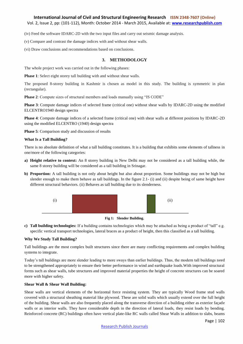
Reinforced concrete (RC) buildings often have vertical plate-like RC walls called Shear Walls in addition to slabs, beams
International Journal of Civil and Structural Engineering Research ISSN 2348-7607 (Online) Vol. 2, Issue 2, pp: (101-112), Month: October 2014 - March 2015, Available at: www.researchpublish.com
Page | 103 Research Publish Journals
and columns. These walls generally start at foundation level and are continuous throughout the building height. Their
thickness can be as low as 150mm, or as high as 400mm in high rise buildings. Shear walls are usually provided along
both length and width of buildings. Shear walls are like vertically-oriented wide beams that carry earthquake loads
downwards to the foundation.
Fig.2: Reinforced Concrete Shear Walls In Buildings-An Excellent Structural System for Earthquake Resistance
Advantages of Shear Walls in RC Buildings:
Properly designed and detailed buildings with shear walls have shown very good performance in past earthquakes. The
overwhelming success of buildings with shear walls in resisting strong earthquakes is summarized in the quote:
“We cannot afford to build concrete buildings meant to resist severe earthquakes without shear walls.” Mark Fintel, a
noted consulting engineer in USA
Shear walls in high seismic regions require special detailing. However, in past earthquakes, even buildings with sufficient
amount of walls that were not specially detailed for seismic performance (but had enough well-distributed reinforcement)
were saved from collapse. Shear wall buildings are a popular choice in many earthquake prone countries, like Chile, New
Zealand and USA. Shear walls are easy to construct, because reinforcement detailing of walls is relatively straight-
forward and therefore easily implemented at site. Shear walls are efficient, both in terms of construction cost and
effectiveness in minimizing earthquake damage in structural and non structural elements (like glass windows and building
contents).
Architectural Aspects of Shear Walls:
Most RC buildings with shear walls also have columns; these columns primarily carry gravity loads (i.e., those due to
self-weight and contents of building).Shear walls provide large strength and stiffness to buildings in the direction of their
orientation, which significantly reduces lateral sway of the building and thereby reduces damage to structure and its
contents. Since shear walls carry large horizontal earthquake forces, the overturning effects on them are large. Thus,
design of their foundations requires special attention. Shear walls should be provided along preferably both length and
width. However, if they are provided along only one direction, a proper grid of beams and columns in the vertical plane
(called a moment-resistant frame) must be provided along the other direction to resist strong earthquake effects.
Door or window openings can be provided in shear walls, but their size must be small to ensure least interruption to force
flow through walls. Moreover, openings should be symmetrically located. Special design checks are required to ensure
that the net cross-sectional area of a wall at an opening is sufficient to carry the horizontal earthquake force. Shear walls
in buildings must be symmetrically located in plan to reduce ill-effects of twist in buildings (Figure 2.3). They could be
placed symmetrically along one or both directions in plan. Shear walls are more effective when located along exterior
perimeter of the building – such a layout increases resistance of the building to twisting.

International Journal of Civil and Structural Engineering Research ISSN 2348-7607 (Online) Vol. 2, Issue 2, pp: (101-112), Month: October 2014 - March 2015, Available at: www.researchpublish.com
Page | 104 Research Publish Journals
Fig 3: Shear walls must be symmetric in plan layout – twist in buildings can be avoided
Ductile Design of Shear Walls: Just like reinforced concrete (RC) beams and columns, RC shear walls also perform
much better if designed to be ductile. Overall geometric proportions of the wall, types and amount of reinforcement, and
connection with remaining elements in the building help in improving the ductility of walls. The Indian Standard Ductile
Detailing Code for RC members (IS: 13920-1993) provides special design guidelines for ductile detailing of shear wall.
Overall Geometry of Walls: Shear walls are oblong in cross-section, i.e., one dimension of the Cross-section is much
larger than the other. While rectangular cross-section is common, L- and U-shaped sections are also used (Figure 2.4).
Thin-walled hollow RC shafts around the elevator core of buildings also act as shear walls, and should be taken advantage
of to resist earthquake forces.
Fig 4: Shear walls in RC Buildings – different geometries are possible
Reinforcement Bars in RC Walls:
Steel reinforcing bars are to be provided in walls in regularly spaced vertical and horizontal grids (Figure5). The vertical
and horizontal reinforcement in the wall can be placed in one or two parallel layers called curtains. Horizontal
reinforcement needs to be anchored at the ends of walls. The minimum area of reinforcing steel to be provided is 0.0025
times the cross-sectional area, along each of the horizontal and vertical directions. This vertical reinforcement should be
distributed uniformly across the wall cross-section.
Fig 5: Reinforcement in RC shear walls

International Journal of Civil and Structural Engineering Research ISSN 2348-7607 (Online) Vol. 2, Issue 2, pp: (101-112), Month: October 2014 - March 2015, Available at: www.researchpublish.com
Page | 105 Research Publish Journals
Boundary Elements:
Under the large overturning effects caused by horizontal earthquake forces, edges of shear walls experience high
compressive and tensile stresses. To ensure that shear walls behave in a ductile way, concrete in the wall end regions must
be reinforced in a special manner to sustain these load reversals without losing strength (Figure 6). End regions of a wall
with increased confinement are called boundary elements. This special confining transverse reinforcement in boundary
elements is similar to that provided in columns of RC frames sometimes the thickness of the shear wall in these boundary
elements is also increased. RC walls with boundary elements have substantially higher bending strength and horizontal
shear force carrying capacity, and are therefore less susceptible to earthquake damage than walls without boundary
elements.
Fig 6: Reinforcement details in boundary elements in shear wall
Where Shear Walls Should Be Located?
Shear walls should be located on each level of the structure including the crawl space. To form an effective box structure,
equal length shear walls should be placed symmetrically on all four exterior walls of the building. Shear walls should be
added to the building interior when the exterior walls cannot provide sufficient strength and stiffness or when the
allowable span-width ratio for the floor or roof diaphragm is exceeded. For subfloors with conventional diagonal
sheathing, the span-width ratio is 3:1. Shear walls are most efficient when they align vertically and are supported on
foundation walls or footings. When shear walls do not align, other parts of the building will need additional strengthening.
Fig 7: Horizontal alignment of shear wall

International Journal of Civil and Structural Engineering Research ISSN 2348-7607 (Online) Vol. 2, Issue 2, pp: (101-112), Month: October 2014 - March 2015, Available at: www.researchpublish.com
Page | 106 Research Publish Journals
Fig 8: Even Distribution of Shear walls
What Type Of Forces Do Shear Walls Resist?
Shear walls resist two types of forces: shear forces and uplift forces. Connections to the structure above transfer horizontal
forces to the shear wall. This transfer creates shear forces throughout the height of the wall between the top and bottom
shear wall connections. The strength of the lumber, sheathing and fasteners must resist these shear forces or the wall will
tear or “shear” apart. Uplift forces exist on shear walls because the horizontal forces are applied to the top of the wall.
These uplift forces try to lift up one end of the wall and push the other end down. In some cases, the uplift force is large
enough to tip the wall over. Uplift forces are greater on tall short walls and less on low long walls. Bearing walls have less
uplift than non-bearing walls because gravity loads on shear walls help them resist uplift. Shear walls need hold own
devices at each end when the gravity loads cannot resist all of the uplift. The holdown device then provides the necessary
uplift resistance.
What Are The Functions of a Shear Walls?
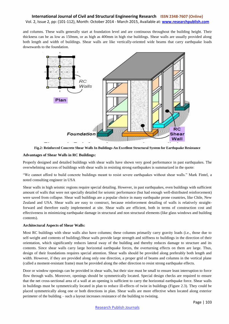
Shear walls must provide the necessary lateral strength to resist horizontal earthquake forces. When shear walls are strong
enough, they will transfer these horizontal forces to the next element in the load path below them. These other
components in the load path may be other shear walls, floors, foundation walls, slabs or footings.
Shear walls also provide lateral stiffness to prevent the roof or floor above from excessive side-sway. When shear walls
are stiff enough, they will prevent floor and roof framing members from moving off their supports. Also, buildings that
are sufficiently stiff will usually suffer less nonstructural damage.
Shear walls cannot be used as gravity and seismic bracing systems, in fact very tight criteria’s should be satisfied. A
seismic bracing system conceptually should have a level of ductility such that the decrements of the bracing system under
axial loading should be considered in the conceptual design.
The various walls and coexisting frames in a building are linked at the different floor levels by means of a floor system
which distributes loads to these systems appropriately. The interaction between frames and shear walls is an advantage in
that the shear walls restrain the frame deformation in the lower storeys and the frames restrain the shear wall deformation
in the top storeys.
Even distribution
of shear walls
International Journal of Civil and Structural Engineering Research ISSN 2348-7607 (Online) Vol. 2, Issue 2, pp: (101-112), Month: October 2014 - March 2015, Available at: www.researchpublish.com
Page | 107 Research Publish Journals
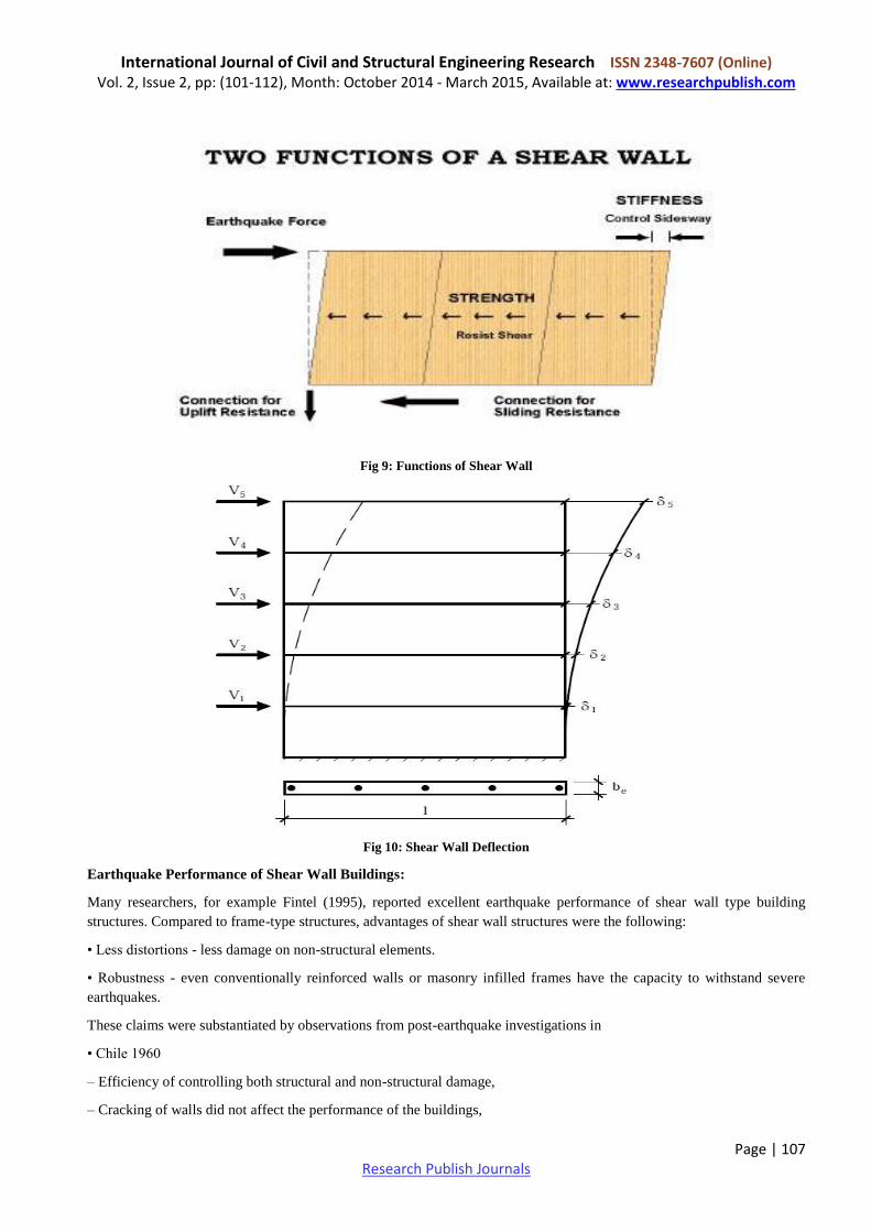
Fig 9: Functions of Shear Wall
Fig 10: Shear Wall Deflection
Earthquake Performance of Shear Wall Buildings:
Many researchers, for example Fintel (1995), reported excellent earthquake performance of shear wall type building
structures. Compared to frame-type structures, advantages of shear wall structures were the following:
• Less distortions - less damage on non-structural elements.
• Robustness - even conventionally reinforced walls or masonry infilled frames have the capacity to withstand severe
earthquakes.
These claims were substantiated by observations from post-earthquake investigations in
• Chile 1960
– Efficiency of controlling both structural and non-structural damage,
– Cracking of walls did not affect the performance of the buildings,
International Journal of Civil and Structural Engineering Research ISSN 2348-7607 (Online) Vol. 2, Issue 2, pp: (101-112), Month: October 2014 - March 2015, Available at: www.researchpublish.com
Page | 108 Research Publish Journals
– Walls continued to function after occurrence of damage,
– Amounts of steel less than code specifications.
• Skopje 1963
– Plain concrete walls helped to reduce damage of frame systems (wall-frame interaction).
– Unreinforced concrete cores behaved well.
– Interaction of monolithic stairs with cores and frames (stairs = vertical truss).
• Caracas 1967
– Better performance achieved by shear walls than frames,
– Low strength brittle partitions in flexible frames caused costly damage,
– Short columns and beam failed in shear independent of the amount of reinforcement.
• San Fernando 1971
– Soft storey - invitation for trouble - because of restricted restoring force,
– Shear wall structures showed superior performance because of limited interstorey drifts.
• Romania 1977
– Minor damage of precast concrete panel buildings,
– Period of those buildings was between 0.6 and 0.7s while periods near to 1.5s dominated the earthquake motion.
• Mexico City 1985
– Non-ductile frame buildings failed in severe earthquakes,
– Flate-plate structures without stiffened walls were revealed to be not suitable for seismic action.
• Chile 1985 - minor damage due to extensive use of non-ductile shear walls.
Wyllie, Abrahamson, Bolt, Castro & Durkin (1986) reported following damage of rectangular shear walls:
– Sliding in construction joints,
– Spalling and degradation of concrete at the extremities near to the wall base,
– Buckling of longitudinal rebars near to the boundaries.
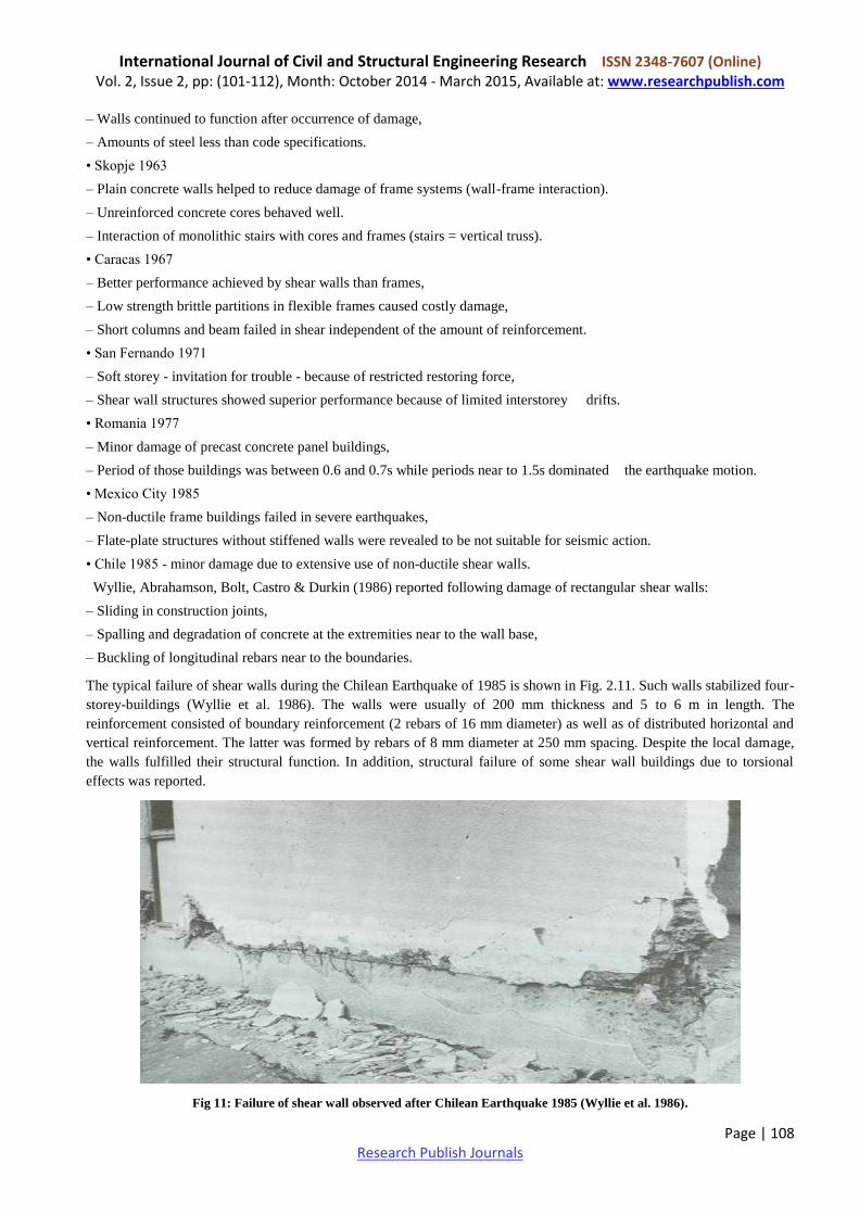
The typical failure of shear walls during the Chilean Earthquake of 1985 is shown in Fig. 2.11. Such walls stabilized four-
storey-buildings (Wyllie et al. 1986). The walls were usually of 200 mm thickness and 5 to 6 m in length. The
reinforcement consisted of boundary reinforcement (2 rebars of 16 mm diameter) as well as of distributed horizontal and
vertical reinforcement. The latter was formed by rebars of 8 mm diameter at 250 mm spacing. Despite the local damage,
the walls fulfilled their structural function. In addition, structural failure of some shear wall buildings due to torsional
effects was reported.
Fig 11: Failure of shear wall observed after Chilean Earthquake 1985 (Wyllie et al. 1986).
International Journal of Civil and Structural Engineering Research ISSN 2348-7607 (Online) Vol. 2, Issue 2, pp: (101-112), Month: October 2014 - March 2015, Available at: www.researchpublish.com
Page | 109 Research Publish Journals
FAILURE MODES:
Low Rise Shear Walls:
Failure modes describe the physical reason for the rupture of a structural element. Because of the different material
properties of reinforcing steel and concrete, a number of failure modes can occur depending on parameters such as type of
cross-section, reinforcement detailing and quantities, properties of reinforcing steel, concrete compressive strength, and
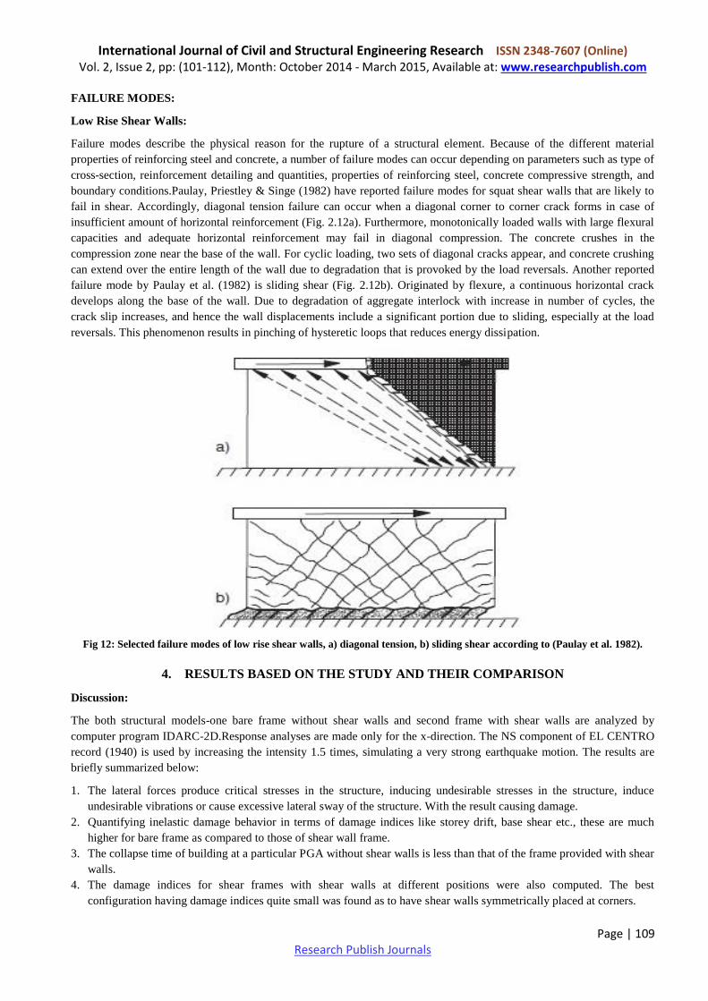
boundary conditions.Paulay, Priestley & Singe (1982) have reported failure modes for squat shear walls that are likely to
fail in shear. Accordingly, diagonal tension failure can occur when a diagonal corner to corner crack forms in case of
insufficient amount of horizontal reinforcement (Fig. 2.12a). Furthermore, monotonically loaded walls with large flexural
capacities and adequate horizontal reinforcement may fail in diagonal compression. The concrete crushes in the
compression zone near the base of the wall. For cyclic loading, two sets of diagonal cracks appear, and concrete crushing
can extend over the entire length of the wall due to degradation that is provoked by the load reversals. Another reported
failure mode by Paulay et al. (1982) is sliding shear (Fig. 2.12b). Originated by flexure, a continuous horizontal crack
develops along the base of the wall. Due to degradation of aggregate interlock with increase in number of cycles, the
crack slip increases, and hence the wall displacements include a significant portion due to sliding, especially at the load
reversals. This phenomenon results in pinching of hysteretic loops that reduces energy dissipation.
Fig 12: Selected failure modes of low rise shear walls, a) diagonal tension, b) sliding shear according to (Paulay et al. 1982).
4. RESULTS BASED ON THE STUDY AND THEIR COMPARISON
Discussion:
The both structural models-one bare frame without shear walls and second frame with shear walls are analyzed by
computer program IDARC-2D.Response analyses are made only for the x-direction. The NS component of EL CENTRO
record (1940) is used by increasing the intensity 1.5 times, simulating a very strong earthquake motion. The results are
briefly summarized below:
1. The lateral forces produce critical stresses in the structure, inducing undesirable stresses in the structure, induce
undesirable vibrations or cause excessive lateral sway of the structure. With the result causing damage.
2. Quantifying inelastic damage behavior in terms of damage indices like storey drift, base shear etc., these are much
higher for bare frame as compared to those of shear wall frame.
3. The collapse time of building at a particular PGA without shear walls is less than that of the frame provided with shear
walls.
4. The damage indices for shear frames with shear walls at different positions were also computed. The best
configuration having damage indices quite small was found as to have shear walls symmetrically placed at corners.
International Journal of Civil and Structural Engineering Research ISSN 2348-7607 (Online) Vol. 2, Issue 2, pp: (101-112), Month: October 2014 - March 2015, Available at: www.researchpublish.com
Page | 110 Research Publish Journals
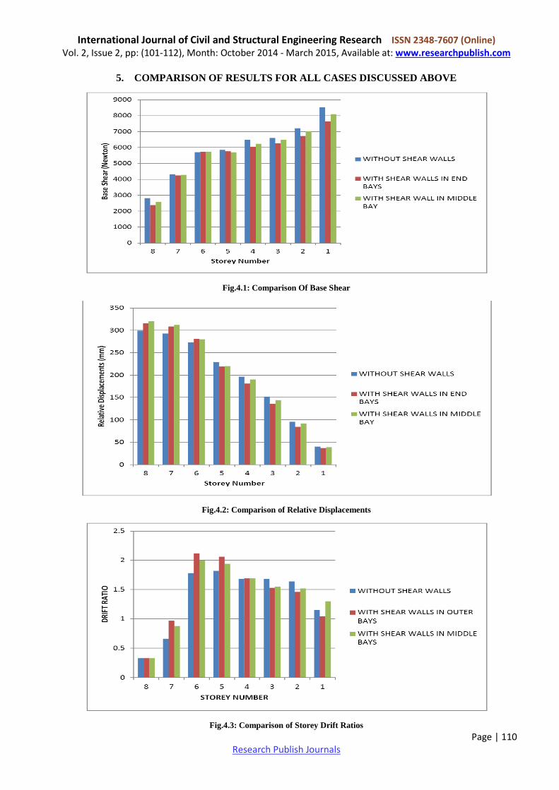
5. COMPARISON OF RESULTS FOR ALL CASES DISCUSSED ABOVE
Fig.4.1: Comparison Of Base Shear
Fig.4.2: Comparison of Relative Displacements
Fig.4.3: Comparison of Storey Drift Ratios
International Journal of Civil and Structural Engineering Research ISSN 2348-7607 (Online) Vol. 2, Issue 2, pp: (101-112), Month: October 2014 - March 2015, Available at: www.researchpublish.com
Page | 111 Research Publish Journals
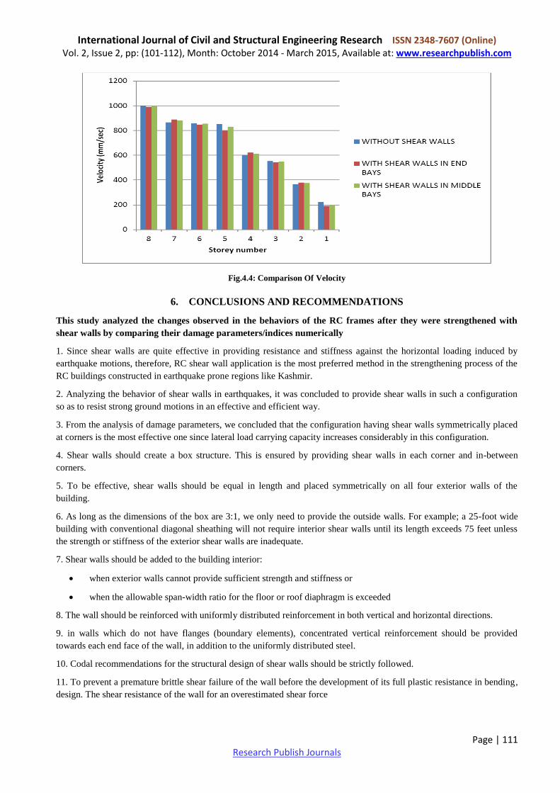
Fig.4.4: Comparison Of Velocity
6. CONCLUSIONS AND RECOMMENDATIONS
This study analyzed the changes observed in the behaviors of the RC frames after they were strengthened with
shear walls by comparing their damage parameters/indices numerically
1. Since shear walls are quite effective in providing resistance and stiffness against the horizontal loading induced by
earthquake motions, therefore, RC shear wall application is the most preferred method in the strengthening process of the
RC buildings constructed in earthquake prone regions like Kashmir.
2. Analyzing the behavior of shear walls in earthquakes, it was concluded to provide shear walls in such a configuration
so as to resist strong ground motions in an effective and efficient way.
3. From the analysis of damage parameters, we concluded that the configuration having shear walls symmetrically placed
at corners is the most effective one since lateral load carrying capacity increases considerably in this configuration.
4. Shear walls should create a box structure. This is ensured by providing shear walls in each corner and in-between
corners.
5. To be effective, shear walls should be equal in length and placed symmetrically on all four exterior walls of the
building.
6. As long as the dimensions of the box are 3:1, we only need to provide the outside walls. For example; a 25-foot wide
building with conventional diagonal sheathing will not require interior shear walls until its length exceeds 75 feet unless
the strength or stiffness of the exterior shear walls are inadequate.
7. Shear walls should be added to the building interior:
when exterior walls cannot provide sufficient strength and stiffness or
when the allowable span-width ratio for the floor or roof diaphragm is exceeded
8. The wall should be reinforced with uniformly distributed reinforcement in both vertical and horizontal directions.
9. in walls which do not have flanges (boundary elements), concentrated vertical reinforcement should be provided
towards each end face of the wall, in addition to the uniformly distributed steel.
10. Codal recommendations for the structural design of shear walls should be strictly followed.
11. To prevent a premature brittle shear failure of the wall before the development of its full plastic resistance in bending,
design. The shear resistance of the wall for an overestimated shear force
International Journal of Civil and Structural Engineering Research ISSN 2348-7607 (Online) Vol. 2, Issue 2, pp: (101-112), Month: October 2014 - March 2015, Available at: www.researchpublish.com
Page | 112 Research Publish Journals
REFERENCES
[1] Bachmann, H.: Influence of Shear and Bond on Rotational Capacity of Reinforced Concrete Beams, Publications
of the International Association for Bridge and Structural Engineering 30(2) (1970)pp. 12–27.
[2] Duggal S. K.(2010), “ Earthquake Resistant Design Structures”. Oxford University press YMCA library building,
Jai Singh road, New Delhi
[3] IIT Kanpur EQ Tip 2010
[4] IS Codes :IS 456,IS 13920,IS 875 parts I-V
[5] Internet:Google and Wikipedia
[6] Manoj S., Medhekar Sudhir K. Jain, “Seismic behavior design and detailing of RC shear walls, Part1:- Behavior
and Strength”. Indian Concrete Journal July 1993.
[7] Pillai/.Menon(Third Edition),”Reinforced Concrete Design “.Tata McGraw-Hill Private Limited,NEW DELHI
Related Documents