ÓCopyright 2019 ABB. All rights reserved. Based on Document kind Acceptance record Prepared Title 2020-02-25 Max Contributer test32 Approved 2020-02-25 Max Contributer Resp. (division/department) Document id. Rev. Lang. Page ABB Power Grids, GA Products 1ABB0000000907 A en 1/14 File: 3024661_8.docx; 7 Saved Date: 2020-02-25 11:55; Template: 1MRK3-490_AFL TEST SPECIFICATION.DOTX Sensitivity: Internal & Restricted The document describes the tests that will be performed for the application function PowerSwingDet_se95_B, ZMRPSB. All tests will be carried out using RTDS (Real Time Digital Simulator) to evaluate the performance of application under dynamic system conditions. Document Review Summary Reviewer Role Reviewer Name Organization Review Date Review Status Peer Review Bjorn Westman SEAPR 2019-05-xx No remarks To be revised Peer Review Sachin Srivastava IDC/PGGAP 2019-05-xx No remarks To be revised Product Application Specialist Zoran Gajic SEAPR 2019-05-xx No remarks To be revised Product Application Specialist Hamdy Faramawy SEAPR 2019-05-xx No remarks To be revised Product Application Specialist Marco Kovacic SEAPR 2019-05-xx No remarks To be revised Product Manager Patrick Cost SEAPR 2019-05-xx No remarks To be revised Review comments are in Appendix Document Review comments

Welcome message from author
This document is posted to help you gain knowledge. Please leave a comment to let me know what you think about it! Share it to your friends and learn new things together.
Transcript

ÓCopyright 2019 ABB. All rights reserved.
Based on Document kind
Acceptance recordPrepared Title
2020-02-25 Max Contributer test32
Approved
2020-02-25 Max Contributer
Resp. (division/department) Document id. Rev. Lang. Page
ABB Power Grids, GA Products 1ABB0000000907 A en 1/14
File: 3024661_8.docx; 7 Saved Date: 2020-02-25 11:55; Template: 1MRK3-490_AFL TEST SPECIFICATION.DOTX
Sensitivity: Internal & Restricted
The document describes the tests that will be performed for the application functionPowerSwingDet_se95_B, ZMRPSB. All tests will be carried out using RTDS (Real Time DigitalSimulator) to evaluate the performance of application under dynamic system conditions.
Document Review Summary
Reviewer Role Reviewer Name Organization Review Date Review Status
Peer Review Bjorn Westman SEAPR 2019-05-xx No remarks
To be revised
Peer Review Sachin Srivastava IDC/PGGAP 2019-05-xx No remarks
To be revised
Product Application Specialist
Zoran Gajic SEAPR 2019-05-xx No remarks
To be revised
Product Application Specialist
Hamdy Faramawy SEAPR 2019-05-xx No remarks
To be revised
Product Application Specialist
Marco Kovacic SEAPR 2019-05-xx No remarks
To be revised
Product Manager Patrick Cost SEAPR 2019-05-xx No remarks
To be revised
Review comments are in Appendix Document Review comments
Title Document kind
test32 Acceptance recordResp. (division/department) Document id. Rev. Lang. Page
ABB Power Grids, GA Products 1ABB0000000907 A en 2/14
Sensitivity: Internal & Restricted
TABLE OF CONTENTS
1 Function introduction .............................................................................................. 3
1.1 Function name ............................................................................................. 31.2 Reference documents .................................................................................. 31.3 Abbreviations and definitions ........................................................................ 3
2 Function interfaces .................................................................................................. 3
2.1 Extra interface descriptions for test .............................................................. 4
3 Tests to be included in RTDS .................................................................................. 5
3.1 PLN Indonesia Network ................................................................................ 53.1.1 Testing of power swing unblocking with single transmission line model ........ 63.1.2 Testing of power swing unblocking with double transmission line model ...... 63.2 IEC 60255 – 121 power network .................................................................. 73.3 Special cases ............................................................................................. 11
4 Test SETUP ............................................................................................................ 11
4.1 System for test ........................................................................................... 114.2 Information of product to be used for test ................................................... 11
Appendix ........................................................................................................................ 11
A. Document Review comments ............................................................................... 11
TABLES
Table 1 - Function name ................................................................................................... 3Table 2 - Reference documents ........................................................................................ 3Table 3 - Abbreviations and definitions .............................................................................. 3Table 4 – Extra interface descriptions ............................................................................... 4Table 5 - Common parameters and settings .................................................................... 11
Title Document kind
test32 Acceptance recordResp. (division/department) Document id. Rev. Lang. Page
ABB Power Grids, GA Products 1ABB0000000907 A en 3/14
Sensitivity: Internal & Restricted
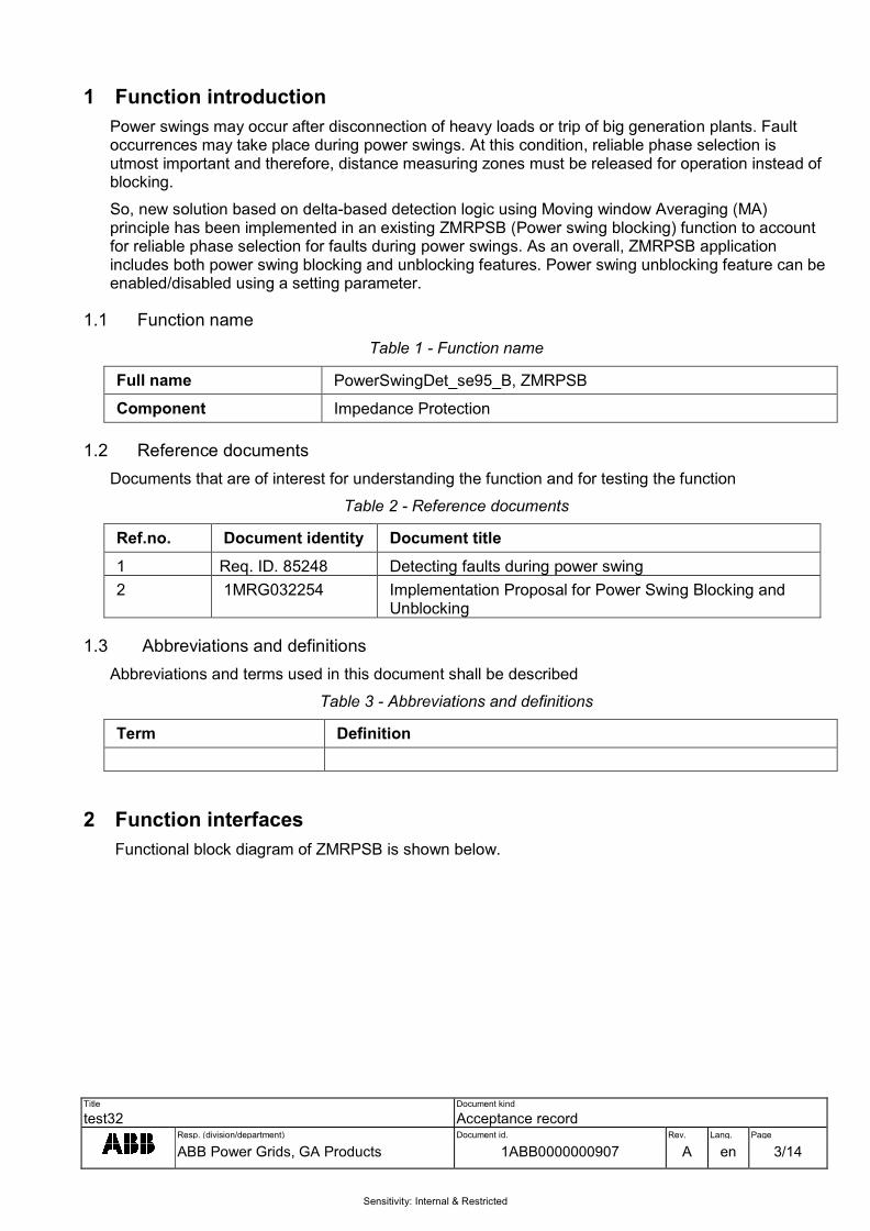
1 Function introduction
Power swings may occur after disconnection of heavy loads or trip of big generation plants. Faultoccurrences may take place during power swings. At this condition, reliable phase selection isutmost important and therefore, distance measuring zones must be released for operation instead ofblocking.
So, new solution based on delta-based detection logic using Moving window Averaging (MA)principle has been implemented in an existing ZMRPSB (Power swing blocking) function to accountfor reliable phase selection for faults during power swings. As an overall, ZMRPSB applicationincludes both power swing blocking and unblocking features. Power swing unblocking feature can beenabled/disabled using a setting parameter.
1.1 Function name
Table 1 - Function name
Full name PowerSwingDet_se95_B, ZMRPSB
Component Impedance Protection
1.2 Reference documents
Documents that are of interest for understanding the function and for testing the function
Table 2 - Reference documents
Ref.no. Document identity Document title
1 Req. ID. 85248 Detecting faults during power swing
2 1MRG032254 Implementation Proposal for Power Swing Blocking andUnblocking
1.3 Abbreviations and definitions
Abbreviations and terms used in this document shall be described
Table 3 - Abbreviations and definitions
Term Definition
2 Function interfaces
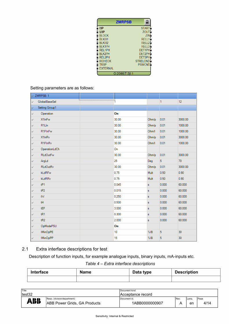
Functional block diagram of ZMRPSB is shown below.
Title Document kind
test32 Acceptance recordResp. (division/department) Document id. Rev. Lang. Page
ABB Power Grids, GA Products 1ABB0000000907 A en 4/14
Sensitivity: Internal & Restricted
Setting parameters are as follows:
2.1 Extra interface descriptions for test
Description of function inputs, for example analogue inputs, binary inputs, mA-inputs etc.
Table 4 – Extra interface descriptions
Interface Name Data type Description
Title Document kind
test32 Acceptance recordResp. (division/department) Document id. Rev. Lang. Page
ABB Power Grids, GA Products 1ABB0000000907 A en 5/14
Sensitivity: Internal & Restricted
Interface Name Data type Description
3 Tests to be included in RTDS
The following tests should be run in RTDS.
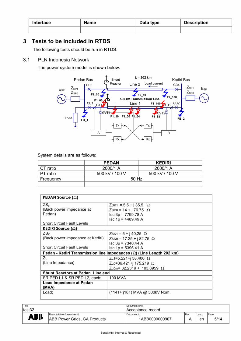
3.1 PLN Indonesia Network
The power system model is shown below.
Pedan Bus Kediri Bus
ESPZSP1 ESK
ZSP0
Line 1
ZSK1
ZSK0
Line 2
A B
CB1 CB2
CB3 CB4
CT1
CVT1 CVT2
CT2
Load
500 kV Transmission Line
Load current
Shunt
Reactor
Tx Tx
Rx Rx
FB_2FB_1
F2_00 F2_50F2_100
F1_00
F1_10 F1_50 F1_64 F1_88
F1_100
L = 202 km
System details are as follows:
PEDAN KEDIRICT ratio 2000/1 A 2000/1 APT ratio 500 kV / 100 V 500 kV / 100 VFrequency 50 Hz
PEDAN Source (W)
ZSp
(Back power impedance at Pedan) Short Circuit Fault Levels
ZSP1 = 5.5 + j 35.5 WZSP0 = 14 + j 76.75 WIsc 3p = 7799.78 AIsc 1p = 4489.49 A
KEDIRI Source (W)ZS K (Back power impedance at Kediri) Short Circuit Fault Levels
ZSK1 = 5 + j 40.25 WZSK0 = 17.25 + j 82.75 WIsc 3p = 7340.44 AIsc 1p = 5396.41 A
Pedan - Kediri Transmission line impedances (W) (Line Length 202 km)
ZL (Line Impedance)
ZL1=5.221+j 58.406 W ZL0=36.421+j 175.219 WZL0m= 32.2319 +j 103.8959 W
Shunt Reactors at Pedan Line end
SR PED L1 & SR PED L2, each: 100 MVALoad Impedance at Pedan(MVA)
Load: (1141+ j181) MVA @ 500kV Nom.
Title Document kind
test32 Acceptance recordResp. (division/department) Document id. Rev. Lang. Page
ABB Power Grids, GA Products 1ABB0000000907 A en 6/14
Sensitivity: Internal & Restricted
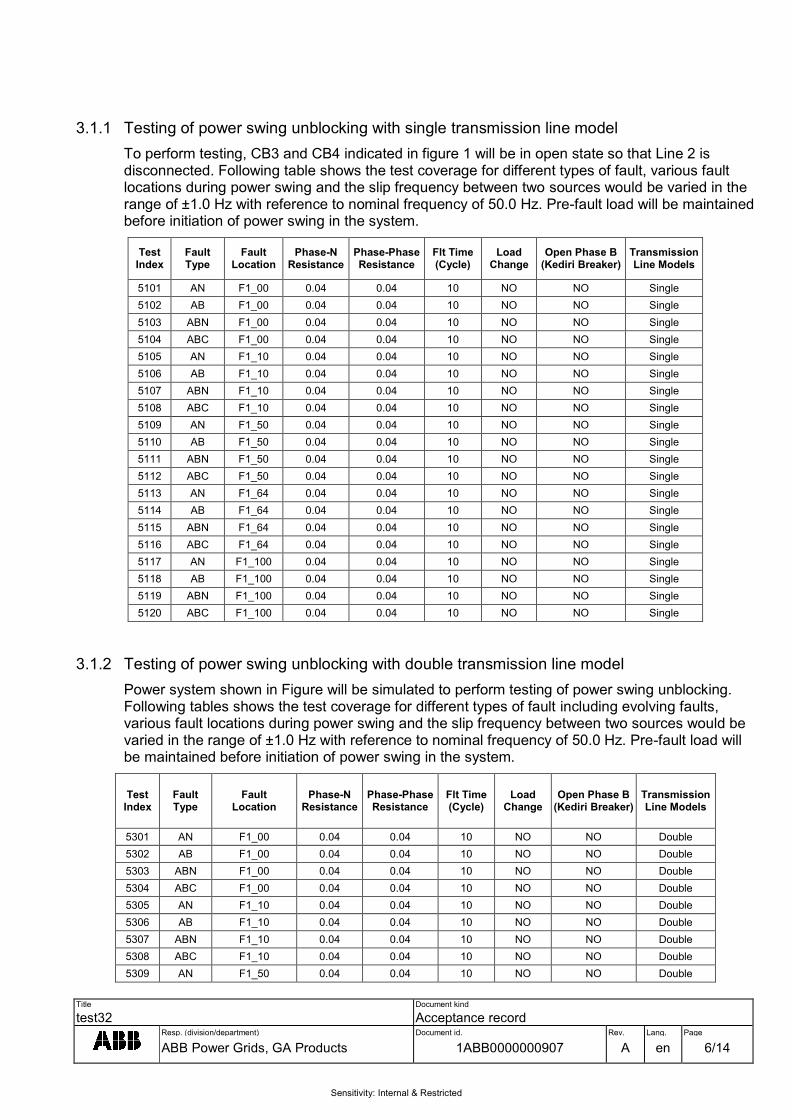
3.1.1 Testing of power swing unblocking with single transmission line model
To perform testing, CB3 and CB4 indicated in figure 1 will be in open state so that Line 2 isdisconnected. Following table shows the test coverage for different types of fault, various faultlocations during power swing and the slip frequency between two sources would be varied in therange of ±1.0 Hz with reference to nominal frequency of 50.0 Hz. Pre-fault load will be maintainedbefore initiation of power swing in the system.
Test Index
Fault Type
Fault Location
Phase-N Resistance
Phase-PhaseResistance
Flt Time (Cycle)
Load Change
Open Phase B (Kediri Breaker)
TransmissionLine Models
5101 AN F1_00 0.04 0.04 10 NO NO Single
5102 AB F1_00 0.04 0.04 10 NO NO Single
5103 ABN F1_00 0.04 0.04 10 NO NO Single
5104 ABC F1_00 0.04 0.04 10 NO NO Single
5105 AN F1_10 0.04 0.04 10 NO NO Single
5106 AB F1_10 0.04 0.04 10 NO NO Single
5107 ABN F1_10 0.04 0.04 10 NO NO Single
5108 ABC F1_10 0.04 0.04 10 NO NO Single
5109 AN F1_50 0.04 0.04 10 NO NO Single
5110 AB F1_50 0.04 0.04 10 NO NO Single
5111 ABN F1_50 0.04 0.04 10 NO NO Single
5112 ABC F1_50 0.04 0.04 10 NO NO Single
5113 AN F1_64 0.04 0.04 10 NO NO Single
5114 AB F1_64 0.04 0.04 10 NO NO Single
5115 ABN F1_64 0.04 0.04 10 NO NO Single
5116 ABC F1_64 0.04 0.04 10 NO NO Single
5117 AN F1_100 0.04 0.04 10 NO NO Single
5118 AB F1_100 0.04 0.04 10 NO NO Single
5119 ABN F1_100 0.04 0.04 10 NO NO Single
5120 ABC F1_100 0.04 0.04 10 NO NO Single
3.1.2 Testing of power swing unblocking with double transmission line model
Power system shown in Figure will be simulated to perform testing of power swing unblocking.Following tables shows the test coverage for different types of fault including evolving faults,various fault locations during power swing and the slip frequency between two sources would bevaried in the range of ±1.0 Hz with reference to nominal frequency of 50.0 Hz. Pre-fault load willbe maintained before initiation of power swing in the system.
TestIndex
Fault Type
Fault Location
Phase-N Resistance
Phase-Phase Resistance
Flt Time (Cycle)
Load Change
Open Phase B (Kediri Breaker)
TransmissionLine Models
5301 AN F1_00 0.04 0.04 10 NO NO Double
5302 AB F1_00 0.04 0.04 10 NO NO Double
5303 ABN F1_00 0.04 0.04 10 NO NO Double
5304 ABC F1_00 0.04 0.04 10 NO NO Double
5305 AN F1_10 0.04 0.04 10 NO NO Double
5306 AB F1_10 0.04 0.04 10 NO NO Double
5307 ABN F1_10 0.04 0.04 10 NO NO Double
5308 ABC F1_10 0.04 0.04 10 NO NO Double
5309 AN F1_50 0.04 0.04 10 NO NO Double
Title Document kind
test32 Acceptance recordResp. (division/department) Document id. Rev. Lang. Page
ABB Power Grids, GA Products 1ABB0000000907 A en 7/14
Sensitivity: Internal & Restricted
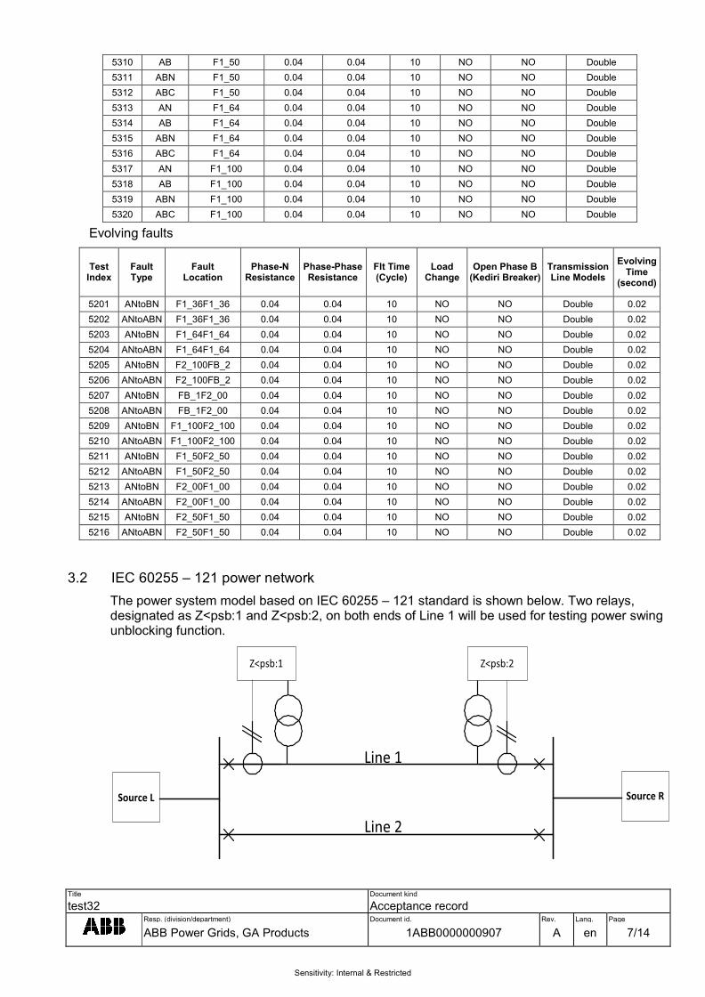
Evolving faults
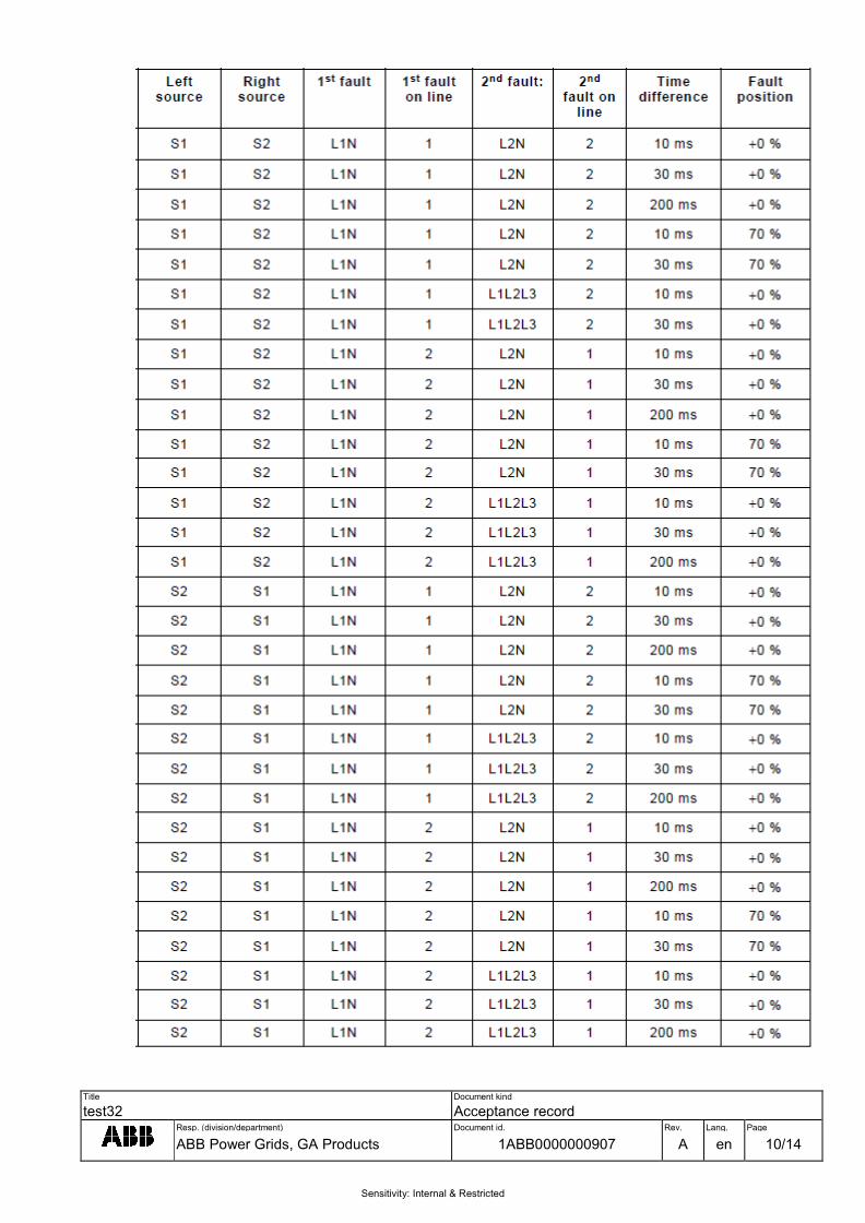
3.2 IEC 60255 – 121 power network
The power system model based on IEC 60255 – 121 standard is shown below. Two relays,designated as Z<psb:1 and Z<psb:2, on both ends of Line 1 will be used for testing power swingunblocking function.
Source L Source R
Line 1
Line 2
Z<psb:1 Z<psb:2
5310 AB F1_50 0.04 0.04 10 NO NO Double
5311 ABN F1_50 0.04 0.04 10 NO NO Double
5312 ABC F1_50 0.04 0.04 10 NO NO Double
5313 AN F1_64 0.04 0.04 10 NO NO Double
5314 AB F1_64 0.04 0.04 10 NO NO Double
5315 ABN F1_64 0.04 0.04 10 NO NO Double
5316 ABC F1_64 0.04 0.04 10 NO NO Double
5317 AN F1_100 0.04 0.04 10 NO NO Double
5318 AB F1_100 0.04 0.04 10 NO NO Double
5319 ABN F1_100 0.04 0.04 10 NO NO Double
5320 ABC F1_100 0.04 0.04 10 NO NO Double
TestIndex
Fault Type
Fault Location
Phase-N Resistance
Phase-Phase Resistance
Flt Time (Cycle)
Load Change
Open Phase B (Kediri Breaker)
TransmissionLine Models
EvolvingTime
(second)
5201 ANtoBN F1_36F1_36 0.04 0.04 10 NO NO Double 0.02
5202 ANtoABN F1_36F1_36 0.04 0.04 10 NO NO Double 0.02
5203 ANtoBN F1_64F1_64 0.04 0.04 10 NO NO Double 0.02
5204 ANtoABN F1_64F1_64 0.04 0.04 10 NO NO Double 0.02
5205 ANtoBN F2_100FB_2 0.04 0.04 10 NO NO Double 0.02
5206 ANtoABN F2_100FB_2 0.04 0.04 10 NO NO Double 0.02
5207 ANtoBN FB_1F2_00 0.04 0.04 10 NO NO Double 0.02
5208 ANtoABN FB_1F2_00 0.04 0.04 10 NO NO Double 0.02
5209 ANtoBN F1_100F2_100 0.04 0.04 10 NO NO Double 0.02
5210 ANtoABN F1_100F2_100 0.04 0.04 10 NO NO Double 0.02
5211 ANtoBN F1_50F2_50 0.04 0.04 10 NO NO Double 0.02
5212 ANtoABN F1_50F2_50 0.04 0.04 10 NO NO Double 0.02
5213 ANtoBN F2_00F1_00 0.04 0.04 10 NO NO Double 0.02
5214 ANtoABN F2_00F1_00 0.04 0.04 10 NO NO Double 0.02
5215 ANtoBN F2_50F1_50 0.04 0.04 10 NO NO Double 0.02
5216 ANtoABN F2_50F1_50 0.04 0.04 10 NO NO Double 0.02
Title Document kind
test32 Acceptance recordResp. (division/department) Document id. Rev. Lang. Page
ABB Power Grids, GA Products 1ABB0000000907 A en 8/14
Sensitivity: Internal & Restricted
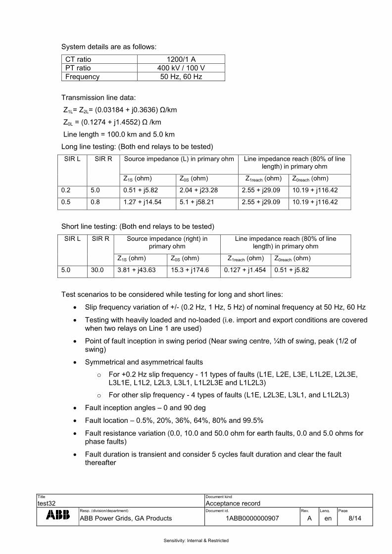
System details are as follows:
CT ratio 1200/1 APT ratio 400 kV / 100 VFrequency 50 Hz, 60 Hz
Transmission line data:
Z1L= Z2L= (0.03184 + j0.3636) Ω/km
Z0L = (0.1274 + j1.4552) Ω /km
Line length = 100.0 km and 5.0 km
Long line testing: (Both end relays to be tested)
SIR L SIR R Source impedance (L) in primary ohm Line impedance reach (80% of linelength) in primary ohm
Z1S (ohm) Z0S (ohm) Z1reach (ohm) Z0reach (ohm)
0.2 5.0 0.51 + j5.82 2.04 + j23.28 2.55 + j29.09 10.19 + j116.42
0.5 0.8 1.27 + j14.54 5.1 + j58.21 2.55 + j29.09 10.19 + j116.42
Short line testing: (Both end relays to be tested)
SIR L SIR R Source impedance (right) in primary ohm
Line impedance reach (80% of linelength) in primary ohm
Z1S (ohm) Z0S (ohm) Z1reach (ohm) Z0reach (ohm)
5.0 30.0 3.81 + j43.63 15.3 + j174.6 0.127 + j1.454 0.51 + j5.82
Test scenarios to be considered while testing for long and short lines:
· Slip frequency variation of +/- (0.2 Hz, 1 Hz, 5 Hz) of nominal frequency at 50 Hz, 60 Hz
· Testing with heavily loaded and no-loaded (i.e. import and export conditions are coveredwhen two relays on Line 1 are used)
· Point of fault inception in swing period (Near swing centre, ¼th of swing, peak (1/2 ofswing)
· Symmetrical and asymmetrical faults
o For +0.2 Hz slip frequency - 11 types of faults (L1E, L2E, L3E, L1L2E, L2L3E,L3L1E, L1L2, L2L3, L3L1, L1L2L3E and L1L2L3)
o For other slip frequency - 4 types of faults (L1E, L2L3E, L3L1, and L1L2L3)
· Fault inception angles – 0 and 90 deg
· Fault location – 0.5%, 20%, 36%, 64%, 80% and 99.5%
· Fault resistance variation (0.0, 10.0 and 50.0 ohm for earth faults, 0.0 and 5.0 ohms forphase faults)
· Fault duration is transient and consider 5 cycles fault duration and clear the faultthereafter
Title Document kind
test32 Acceptance recordResp. (division/department) Document id. Rev. Lang. Page
ABB Power Grids, GA Products 1ABB0000000907 A en 9/14
Sensitivity: Internal & Restricted
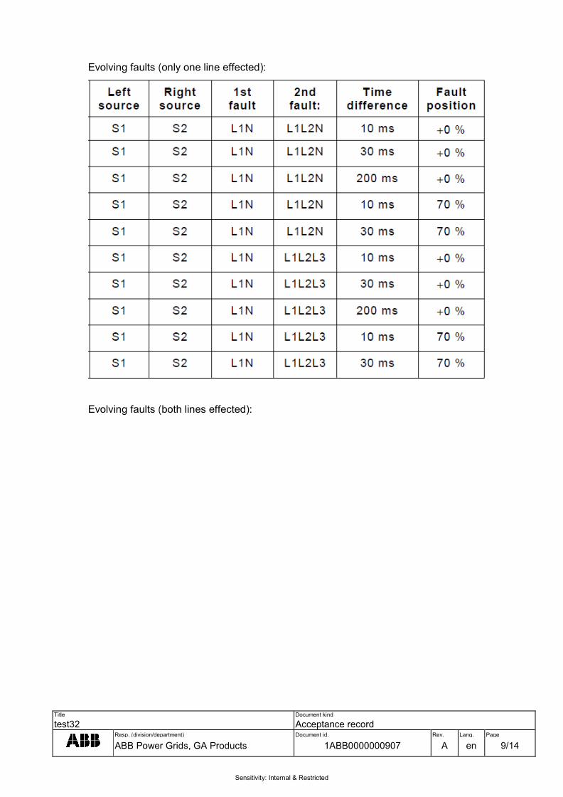
Evolving faults (only one line effected):
Evolving faults (both lines effected):
Title Document kind
test32 Acceptance recordResp. (division/department) Document id. Rev. Lang. Page
ABB Power Grids, GA Products 1ABB0000000907 A en 10/14
Sensitivity: Internal & Restricted

Title Document kind
test32 Acceptance recordResp. (division/department) Document id. Rev. Lang. Page
ABB Power Grids, GA Products 1ABB0000000907 A en 11/14
Sensitivity: Internal & Restricted
3.3 Special cases
In IEC network,
· protected line L2 is switched off from the network after power swing period and thenswitches onto fault
· When protected line is opened due to phase-to-earth fault, create a fault in other twophases during 1-pole auto-reclosing period
4 Test SETUP
4.1 System for test
It will be specified in RTDS test report document.
4.2 Information of product to be used for test
ProductVer: 2.2.3.300
Product Variant: REL670
4.2.1 Parameters common to all tests
Table 5 - Common parameters and settings
Appendix
A. Document Review comments
Rev. ind.
Page (P)Chapt (C) Description Issuer C
lassification
Decision
A Page 5 Chapt. 3.1.1, 3.1.2
Consider slip frequency of 1.0 Hz onlyfor PLN network and no need to test inthe range of +5 Hz to -10 Hz slipfrequency.
HF,SS
I Ok. Slip frequency of 1.0 Hz will onlybe considered for PLN network whileperforming RTDS testing.
A Page 7 Chapt. 3.2
Consider short line length as 5.0 kminstead of 20.0 km.
HF,SS
I Ok.
A Page 7 Chapt. 3.2
For long line, limit SIRs to 0.2 and 5.0and for short line, limit SIRs to 5.0 and30.0
HF,SS,HJ
I Ok.
A Page 7 Chapt. 3.2
For long line, consider (SIRA, SIRB)à (0.2, 5.0), (5, 0.2) and (0.5 and 0.8)instead of (0.1, 1.0), (1.0,1.0),(5.0,1.0)
HF,SS,HJ
I Ok.
A Page 7Chapt.3.2
For short line, consider (SIRA, SIRB)à (5, 30.0), and (30 and 5)
HF,SS,HJ
I Ok.
Title Document kind
test32 Acceptance recordResp. (division/department) Document id. Rev. Lang. Page
ABB Power Grids, GA Products 1ABB0000000907 A en 12/14
Sensitivity: Internal & Restricted
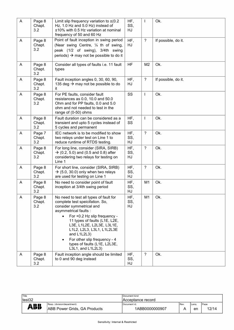
A Page 8Chapt.3.2
Limit slip frequency variation to ±(0.2Hz, 1.0 Hz and 5.0 Hz) instead of±10% with 0.5 Hz variation at nominalfrequency of 50 and 60 Hz
HF,SS,HJ
I Ok.
A Page 8Chapt.3.2
Point of fault inception in swing period(Near swing Centre, ¼ th of swing,peak (1/2 of swing), 3/4th swingperiods) à may not be possible to do it
HF,HJ
? If possible, do it.
A Page 8Chapt.3.2
Consider all types of faults i.e. 11 faulttypes
HF M2 Ok.
A Page 8Chapt.3.2
Fault inception angles 0, 30, 60, 90,135 deg à may not be possible to doit
HF,HJ
? If possible, do it.
A Page 8Chapt.3.2
For PE faults, consider faultresistances as 0.0, 10.0 and 50.0Ohm and for PP faults, 0.0 and 5.0ohm and not needed to test in therange of (0-50) ohms
SS I Ok.
A Page 8Chapt.3.2
Fault duration can be considered as atransient and upto 5 cycles instead of5 cycles and permanent
HF,SS
I Ok.
A Page 7Chapt.3.2
IEC network is to be modified to showtwo relays under test on Line 1 toreduce runtime of RTDS testing.
HF,SS,HJ
? Ok.
A Page 8Chapt.3.2
For long line, consider (SIRA, SIRB)à (0.2, 5.0) and (0.5 and 0.8) afterconsidering two relays for testing onLine 1
HF,SS,HJ
? Ok.
A Page 8Chapt.3.2
For short line, consider (SIRA, SIRB)à (5.0, 30.0) only when two relaysare used for testing on Line 1
HF,SS,HJ
? Ok.
A Page 8Chapt.3.2
No need to consider point of faultinception at 3/4th swing period
HF,SS,HJ
M1 Ok.
A Page 8Chapt.3.2
No need to test all types of fault forcomplete test speicifation. So,consider symmetrical andasymmetrical faults :
· For +0.2 Hz slip frequency -11 types of faults (L1E, L2E,L3E, L1L2E, L2L3E, L3L1E,L1L2, L2L3, L3L1, L1L2L3Eand L1L2L3)
· For other slip frequency - 4types of faults (L1E, L2L3E,L3L1, and L1L2L3)
HF,SS,HJ
M1 Ok.
A Page 8Chapt.3.2
Fault inception angle should be limitedto 0 and 90 deg instead
HF,SS,HJ
? Ok.

Title Document kind
test32 Acceptance recordResp. (division/department) Document id. Rev. Lang. Page
ABB Power Grids, GA Products 1ABB0000000907 A en 13/14
Sensitivity: Internal & Restricted
A Page 8Chapt.3.2
Consider fault location – 0.5%, 20%,36%, 64%, 80% and 99.5% instead of0.5%, 20%, 50%, 64%, 80% and 95%.So, performance of two relays can beevaluated.
HF,SS,HJ
M1 Ok.
Classification:· N = New
· M1 = Major remark
· M2 = Minor remark
· I = Improvement, suggestion
· ? = Question
Decision:· NA = No action

Title Document kind
test32 Acceptance recordResp. (division/department) Document id. Rev. Lang. Page
ABB Power Grids, GA Products 1ABB0000000907 A en 14/14
Sensitivity: Internal & Restricted
REVISION
Rev.ind. Page (P)
Chapt. (C)
Description
Date
Dept./Name
A All Initial Document 2019/05/09IDC/PGGAP/SureshMaturu
A Page 7 and 8 Chapt. 3.2
1st round review comments updated and captured in review table
2019/05/17IDC/PGGAP/SureshMaturu
A
Page 7 and 8 Chapt. 3.2
2 nd round review comments updated 2019/05/27IDC/PGGAP/SureshMaturu
Related Documents


