G. A. Berry British Gas Corporation, School of Engineering, Harvey Combe, Killingworth, Newcastle upon Tyne, NE99 1 LH, England The Division of Frictional Heat-A Guide to the Nature of Sliding Contact J.R. Barber University of Newcastle upon Tyne, Newcastle upon Tyne, NE1 7RU, England; Now, University of Michigan, Ann Arbor, MI 48109 The work vf Jaeger [l] and Barber [2] indicates that the division of frictional heat between sliding solids should be sensitive to the interfacial boundary conditions. Thus it should provide a guide to the nature of asperity interactions and a more accurate statement of the boundary conditions for any subsequent analysis. Measurement of the division of heat in a symmetric "cylinder on cylinder" system was frustrated by the widespread occurrence of thermoelastic instability. An alternative specimen geometry has been developed which has permitted the division of heat between sliding solids of various materials to be investigated experimentally. The characteristics of the microscopic thermal resistance at the surface of a sliding solid have been investigated theoretically for several types of asperity interaction. An approximate method has been employed to estimate the thermal resistance of an oxidized surface. The observed division of heat is interpreted with reference to the characteristic behavior associated with the various types of asperity interaction. It is shown that in the mild wear regime oxide films have an appreciable effect on the microscopic thermal resistance and hence, on the thermal behavior of the sliding solids, particularly the division of heat between them. 1 Introduction When solids are in sliding contact, frictional heating causes a significant rise in temperature of all but the most lightly loaded, low speed systems. This temperature increase has an important influence on friction and wear. It may modify the mechanical and metallurgical properties of the sliding solids and control the oxidation of their surface. It is not surprising therefore that there have been numerous attempts to determine the temperature of sliding surfaces. Some experimenters, e.g., Bowden and Ridler [3] and Fury [4] have employed dynamic thermocouple measurements. However, in addition to doubts concerning the effect of mechanical working on the thermoelectric junctions formed by the surfaces of the sliding pair, it is most improbable that this technique will detect the rapid transients or "flash temperatures" at the real contact areas. Temperature flashes arise due to frictional heating at the real contact areas. These are small; typically 10- 2 mm, (Rabinowicz [5]) of variable but short duration, and their location within the apparent contact area is continually changing. Thus direct measurement of the flash temperature is virtually impossible. Parker and Marshall [6] identified contacts of macroscopic size and using a low temperature radiation pyrometer, measured their temperature immediately after contact ceased. Contributed by the Tribology Division for publication in the JOURNAL OF TRIBOLOGY. Manuscript received by the Tribology Division, September I, 1981. Journal of Tribology It is almost certain that these contacts were a consequence of thermoelastic instability. The work of Blok [7], Jaeger [1], and Barber [2] would permit calculation of the real contact temperatures if the boundary conditions, i.e., size, relative motion of contacts, and location of heat generation could be accurately specified. Unfortunately, these boundary conditions are particularly ill defined. However, the above authors show that the division of frictional heat between sliding solids is sensitive to the boundary conditions. Further, the division of heat, and the bulk surface temperature (i.e., that of the apparent or nominal contact area) are comparatively easy to measure. This suggests an alternative to either direct measurement or purely analytical determination of the flash temperature. Measuring the division of heat for a wide range of sliding conditions should allow the nature of the surface interactions to be deduced, permitting a more precise statement of the boundary conditions for any subsequent thermal analysis; for example estimates of flash temperature. A similar approach has been adopted by Grosberg and Molgaard [8] using a pin and disk machine. Quinn [9] ex- tended this work, again using the pin and disk geometry. However, because the bulk thermal resistance of the pin is large compared with that of the disk, little of the frictional heat (approximately 1 to 4 percent) flows into the pin. This limits observation of the response of the division of heat to changes at the sliding interface. In the current work, efforts have been made to develop a geometry which will permit more extensive control of the division of heat. JULY 1984, Vol. 106/405 Copyright © 1984 by ASME Downloaded From: http://tribology.asmedigitalcollection.asme.org/ on 01/14/2015 Terms of Use: http://asme.org/terms

Welcome message from author
This document is posted to help you gain knowledge. Please leave a comment to let me know what you think about it! Share it to your friends and learn new things together.
Transcript
G. A. Berry British Gas Corporation, School of Engineering,
Harvey Combe, Killingworth,
Newcastle upon Tyne, NE99 1 LH, England
The Division of Frictional Heat-A Guide to the Nature of Sliding Contact
J.R. Barber University of Newcastle upon Tyne,
Newcastle upon Tyne, NE1 7RU, England;
Now, University of Michigan, Ann Arbor, MI 48109
The work vf Jaeger [l] and Barber [2] indicates that the division of frictional heat between sliding solids should be sensitive to the interfacial boundary conditions. Thus it should provide a guide to the nature of asperity interactions and a more accurate statement of the boundary conditions for any subsequent analysis. Measurement of the division of heat in a symmetric "cylinder on cylinder" system was frustrated by the widespread occurrence of thermoelastic instability. An alternative specimen geometry has been developed which has permitted the division of heat between sliding solids of various materials to be investigated experimentally. The characteristics of the microscopic thermal resistance at the surface of a sliding solid have been investigated theoretically for several types of asperity interaction. An approximate method has been employed to estimate the thermal resistance of an oxidized surface. The observed division of heat is interpreted with reference to the characteristic behavior associated with the various types of asperity interaction. It is shown that in the mild wear regime oxide films have an appreciable effect on the microscopic thermal resistance and hence, on the thermal behavior of the sliding solids, particularly the division of heat between them.
1 Introduction
When solids are in sliding contact, frictional heating causes a significant rise in temperature of all but the most lightly loaded, low speed systems. This temperature increase has an important influence on friction and wear. It may modify the mechanical and metallurgical properties of the sliding solids and control the oxidation of their surface.
It is not surprising therefore that there have been numerous attempts to determine the temperature of sliding surfaces. Some experimenters, e.g., Bowden and Ridler [3] and Fury [4] have employed dynamic thermocouple measurements. However, in addition to doubts concerning the effect of mechanical working on the thermoelectric junctions formed by the surfaces of the sliding pair, it is most improbable that this technique will detect the rapid transients or "flash temperatures" at the real contact areas.
Temperature flashes arise due to frictional heating at the real contact areas. These are small; typically 10- 2 mm, (Rabinowicz [5]) of variable but short duration, and their location within the apparent contact area is continually changing. Thus direct measurement of the flash temperature is virtually impossible.
Parker and Marshall [6] identified contacts of macroscopic size and using a low temperature radiation pyrometer, measured their temperature immediately after contact ceased.
Contributed by the Tribology Division for publication in the JOURNAL OF
TRIBOLOGY. Manuscript received by the Tribology Division, September I, 1981.
Journal of Tribology
It is almost certain that these contacts were a consequence of thermoelastic instability.
The work of Blok [7], Jaeger [1], and Barber [2] would permit calculation of the real contact temperatures if the boundary conditions, i.e., size, relative motion of contacts, and location of heat generation could be accurately specified. Unfortunately, these boundary conditions are particularly ill defined. However, the above authors show that the division of frictional heat between sliding solids is sensitive to the boundary conditions. Further, the division of heat, and the bulk surface temperature (i.e., that of the apparent or nominal contact area) are comparatively easy to measure. This suggests an alternative to either direct measurement or purely analytical determination of the flash temperature. Measuring the division of heat for a wide range of sliding conditions should allow the nature of the surface interactions to be deduced, permitting a more precise statement of the boundary conditions for any subsequent thermal analysis; for example estimates of flash temperature.
A similar approach has been adopted by Grosberg and Molgaard [8] using a pin and disk machine. Quinn [9] extended this work, again using the pin and disk geometry. However, because the bulk thermal resistance of the pin is large compared with that of the disk, little of the frictional heat (approximately 1 to 4 percent) flows into the pin. This limits observation of the response of the division of heat to changes at the sliding interface. In the current work, efforts have been made to develop a geometry which will permit more extensive control of the division of heat.
JULY 1984, Vol. 106/405 Copyright © 1984 by ASME
Downloaded From: http://tribology.asmedigitalcollection.asme.org/ on 01/14/2015 Terms of Use: http://asme.org/terms
TORQUE RESTRAINT
.SPEED MEASUre>£NT
SUP-RTN6S FOR THERMOCOUPLES
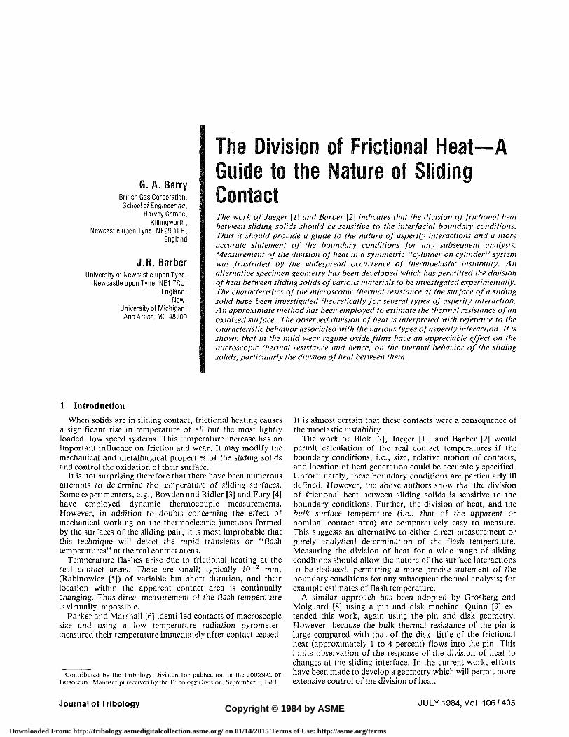
Fig. 1 Mechanical arrangement
2 Some Preliminary Experimental Observations and Their Influence on the Development of the Specimen Geometry
For changes in the thermal resistance at the real contact areas to significantly affect the division of heat, it is necessary to select a sliding system in which their magnitude is comparable with the bulk resistance of the sliding solids. Further, it was decided to use a system in which the large scale
Fig. 2 Subsurface temperature of cylindrical specimens (EN 24 v. EN24) Load 30 kg: speed 2, 6 m/s
geometry is symmetrical in the belief that this might yield a symmetrical division of heat or that any observed asymmetry could be attributed to differences between the microscopic contact resistance associated with the real contact areas.
Accordingly an apparatus (Fig. 1) was developed in which two hollow cylinders are rotated relative to each other with their plain annular ends in contact and loaded by a dead weight system. The apparatus has facilities for heating or cooling the base of the specimens. Provision is made for measuring rotational speed, axial wear rate, friction torque and most importantly with regard to the present work, the temperature at various locations in the sliding solids. These measurements were made using thermocouples accurately positioned in the specimens and were recorded on a chart recorder.
Thermocouples were installed two millimetres below the annular contact area of each specimen and equally spaced (every 90 deg) around the circumference. At this distance below the surface the thermocouples are not able to detect the "flash temperature," which is confined to a volume of material whose linear dimensions are similar to those of the real contact area, i.e., approximately .01 mm. Therefore the symmetry of the system suggests that the circumferential temperature distribution will be uniform. This was not the case. During a test each thermocouple records the close proximity of a hot area indicating localization of load transfer between the surfaces (Fig. 2). This is not attributable to
N o m e n c l a t u r e
A a
b =
c = h = K = n = Q =
QT =
R = Rh =
dimensionless speed (Va/ln) characteristic dimension of a contact (i.e., radius or half length of side) radius of nominal contact area specific heat flow pressure thermal conductivity number of real contact areas heat flow per unit time t o t a l f r i c t i o n a l h e a t generation per unit time heat input per unit time at a real contact thermal resistance of solid bulk component of thermal resistance
Rm = microscopic component of vj = thermal resistance
r = thermal resistance of a single contact on a semi-infinite Z = solid (vflq) z =
''nom = thermal resistance of semi-infinite solid (heat input 5 = distributed over nominal contact area) K =
V = velocity of frictional heat p = source relative to a sliding gQiy Subscipts
v = temperature at remote 1 = boundary of solid 2 =
vb = bulk surface temperature, 3B = i.e., average temperature of nominal contact area 24 =
vf = flash temperature, i.e.,
average temperature at a real contact area temperature jump, i.e., difference between bulk temperatures of sliding solids dimensionless depth ( VZ/2K) distance below (normal) to sliding surface thermal boundary layer thickness thermal diffusivity (K/pc) density of sliding solid
parameter of solid 1 parameter of solid 2 parameter of solid of EN3B steel parameter of solid of EN24 steel
406 /Vol. 106, JULY 1984 Transactions of the ASME
Downloaded From: http://tribology.asmedigitalcollection.asme.org/ on 01/14/2015 Terms of Use: http://asme.org/terms
misalignment which would simply cause concentration of load into one particular area of the stationary specimen. Further, the specimens were "run in" to conformity, at low speed, before commencing each test.
Localized heating on a macroscopic scale has been reported by Parker and Marshall [6] and Barber [10]. Barber conducted an extensive investigation of the phenomenon and showed it to be a consequence of a thermoelastic instability, such that any slight nonuniformity of load transfer between the surfaces causes increased frictional heating at more highly loaded regions which become hotter, expand, and relieve the surrounding surface of load. Ultimately the load may be concentrated into a few, or even one small area of the surface.
To pursue the objective of the work, it was necessary to develop a specimen geometry which would prevent movement of the thermoelastic contact relative to the thermocouples used to measure heat flow. This was achieved by relieving the surface of one cylinder by approximately three millimetres to leave only a small block or "p ip" of material in contact with the counterface. While the heat flow is no longer one dimensional, this geometry imposes the minimum increase in bulk thermal resistance, thus retaining maximum control of the bulk temperature and division of heat.
The pip size required to suppress movement was determined by gradually reducing its width and monitoring the temperature on the central axis of the pip and at 10° to either side. As the pip width was gradually reduced, from 15 to 6 mm an increase in order was observed, ultimately yielding a temperature profile symmetrical about the central axis, as would be expected for a uniform stationary heat source located on the surface of the pip. This suggests that the linear dimensions of a thermoelastic contact are approximately 6 mm which is in good agreement with the independent estimate of 7 mm obtained by Barber [10].
3 Surface Boundary Conditions and the Division of Heat
Plastic deformation and frictional energy loss occur in the regions of the real contact areas, which are very small. Because of the large constriction resistance which results, "flash" temperatures occur which are considerably in excess of the "bulk" or average temperature of the apparent contact area. Collectively these microscopic thermal resistances constitute a thermal resistance at each sliding surface which may significantly affect the division of heat. The nature and magnitude of these microscopic resistances depend on the number and type of asperity interactions and on the complex role played by insulating films, principally oxides, which form on the sliding surfaces.
3.1 The Division of Heat Between Sliding Solids. The division of heat during sliding and the magnitude of the flash temperatures have been investigated theoretically by Blok [7] and Jaeger [1]. Because real contacts are very small they approximate the sliding pair by semi-infinite solids with zero temperature at infinity. Barber [2] observes that in real systems heat transfer at the remote boundary causes a temperature rise there which significantly affects the division of heat. Superposing the heat flow caused by the nonzero temperatures at "infinity" (v] and v2 for solids 1 and 2, respectively) he obtains the heat flow into each solid resulting from total frictional heat input QT.
Q>- R^R2 Q l ' R^R~2
( 1 )
Ri and R2 are the thermal resistances of the actual sliding solids. They may be obtained by modifying the semi-infinite solid solutions of Jaeger. Essentially the "bulk" component
of Jaeger's semi-infinite solid resistance (/•) is replaced by that of the actual large scale geometry by subtracting the thermal resistance of the nominal contact if it were located on a semi-infinite solid (rnom) and adding the actual bulk resistance (Rb). The latter is relatively easily determined either analytically, or by numerical methods. For a single real contact this yields:
R = r-rmm+Rb=Rm+R„ (2)
All resistances define the average temperature of the area to which they relate. The validity of the approximate method of equating the average temperature of the real contacts on each solid to determine the division of heat, is confirmed by the work of Cameron, Gordon, and Symm [11] and is discussed in Barber [2]. Thus the microscopic resistance (/?,„) describes the difference between the interface, i.e., flash temperature and the bulk temperature per unit heat flow, and is equal to r — rnam for a single contact.
These two scales of resistance are responsible for the "temperature jump" i.e., the differing bulk surface temperatures of the solids observed by Ling and Simpkins, [12] and in the present work. Ling [13] proposes an explanation based on subsurface heat generation but this is refuted by Barber [2]. A simple model with a heat input at the interface between the solids, each represented by a microscopic resistance (R,„) in series with bulk resistance (Rt,), shows that:
Vlb-V2b= r^r^l ^ Z Z i _ (3 ) l+Rlb/Rlm \+R\b/R\m
where Vj is the flash temperature, which must be common to both solids to satisfy continuity of temperature at the interface.
Evidently a temperature jump will occur whenever the terms of equation (3) are unequal. For equal temperatures at the remote boundaries (i>, = v2) this will occur whenever the ratio of the bulk and microscopic resistances differ, i.e., whenever:
R\b/R\m ^Rib/Rim
3.2 Multiple Contacts. Usually contact between sliding solids occurs at numerous real contact areas, which are the source of frictional heat generation. If the contacts are well separated, so that interaction of their temperature fields is negligible, the heat flow into each solid is simply the sum of the heat inputs for each individual contact treated separately. However, if the contacts are closely packed, a heat input at one will cause a significant rise in temperature at the others. In this case we may use an approximate method which is fully described by Barber [2]. Briefly it is argued that only in the region of a contact is its temperature affected by its size. Therefore, the remaining {n - 1) contacts, of radius a, are approximated by equal sources uniformly distributed over circles of radius bl^fn centered on the actual contacts, where b is the radius of the nominal contact area. Hence the temperature at a given contact (/th) is given by the superposition of:
(i) A heat input of q at the /th contact of radius a. (ii) A heat input of nq uniformly distributed over the
nominal contact area, (iii) A heat output q uniformly distributed over a circle,
radius b/yfn centered on the /th contact.
where terms (ii) and (iii) approximate the temperature at the /th contact due to the other (n - 1) contacts. Term (iii) is usually interpreted as the alleviation in constriction resistance of a single contact due to the finite size of the nominal contact area. For a large number of widely spaced contacts it is comparatively small and as a first approximation may be neglected. Thus the principal effect of interaction between the
Journal of Tribology JULY 1984, Vol. 106/407
Downloaded From: http://tribology.asmedigitalcollection.asme.org/ on 01/14/2015 Terms of Use: http://asme.org/terms
temperature fields of the contacts is the introduction of term (ii) representing the thermal resistance of the nominal contact area on the semi-infinite solid. As previously this is replaced by the bulk resistance of the actual large scale geometry. For identical contacts the heat flow into solid 1 is:
QT{r2/n+R2b)-{vx~v2) y ' (ri/n+Rlb+r2/n + R2b)
In this case the microscopic thermal resistance Rin = r/n, i.e., the resistance of the individual contacts in parallel, as might be expected.
3.3 Microscopic Surface Boundary Conditions. The work of Blok [7], Jaeger [1], and Barber [2] indicate that the microscopic resistance is influenced by the location, relative velocity and duration of a frictional heat source.
If deformation and hence heat generation is by symmetrical interfacial shearing of junctions, as may be expected for materials of similar hardness, the usual assumption of a surface heat input at each real contact is reasonable, however, model junction studies [15-16] indicate that deformation may extend into the surfaces. (Note, the problem of sub-surface heat generation has been analyzed by Barber [2].)
For solids of appreciably different hardnesses, asperities on the harder solid will "plough" the softer one in which most of the heat generation will therefore occur. This is particularly important if conduction through the interface is reduced, for example by oxide films. Also contact areas will be stationary relative to the harder solid. Jaeger [1] shows that for a low speed contact (i.e., A = Ka/2x<0.1) the influence of the relative velocity of the contact is negligible, the division of heat, for equal bulk temperatures, being determined only by the thermal conductivities of the solids, i.e.,
Ql/QT=Kl/(Kl+K2) (5)
However, for a high speed contact (A >5) the heat flow into the solid accommodating the moving contacts is
Ql/QT = KI^A/(KI^ +0.795 K2) (6)
and the relative motion of the contacts is crucial. Even for the lowest speed (A = 5) in the high speed range 74 percent of the frictional heat will flow into the softer of two solids of equal conductivity, since it would accommodate the moving contacts.
A*. In the transition range (0.1 <^4 <5.0) there is no analytic solution but Jaeger [1] has obtained a numerical solution.
For surfaces of similar hardness with symmetrical shearing of contacts the base of each asperity will be stationary with respect to its supporting surface. Alternatively the harder asperities of each surface may plough the softer regions of the opposing surface. In both cases the division of heat, for equal bulk temperatures, should be symmetrical.
Symmetrical asperity distortion also limits the duration of contact since the displacement which can be sustained is very small, approximately twice the linear dimensions of the contact. Consequently a steady thermal state is not attained, the division of heat varying throughout the life of the contact. This precludes the "steady state" analysis of Blok or Jaeger, but, Barber [17] has obtained an approximate solution.
For a ploughing type interaction termination of contact is usually due to wear, unless the nominal contact is very small. Nevertheless the displacement is usually many times the real contact size permitting the attainment of a steady state early in the contacts life.
3.4 Role of Oxide Films. In unlubricated sliding two types of wear are distinguished; mild and severe. Mild wear is characterized by oxidized contacts and since many oxides, in
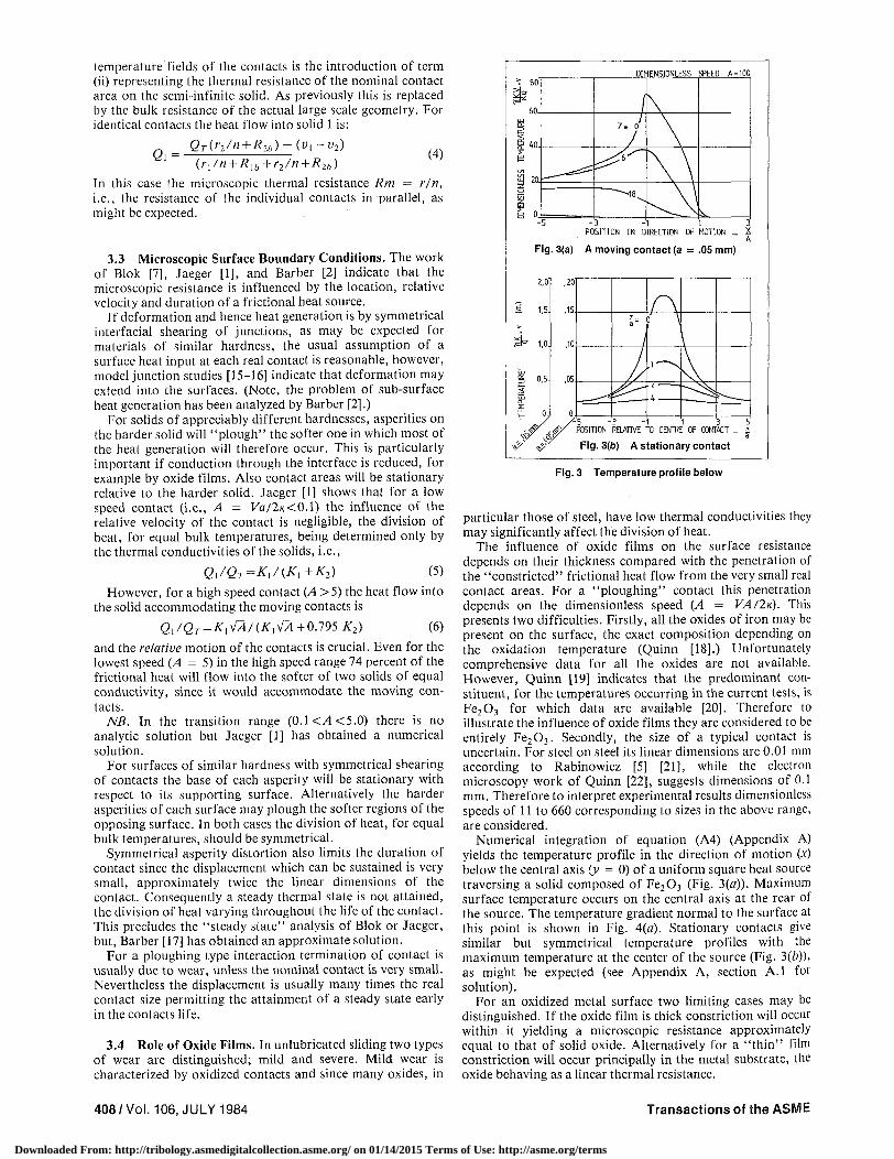
Fig. 3 Temperature profile below
particular those of steel, have low thermal conductivities they may significantly affect the division of heat.
The influence of oxide films on the surface resistance depends on their thickness compared with the penetration of the "constricted" frictional heat flow from the very small real contact areas. For a "ploughing" contact this penetration depends on the dimensionless speed {A = VA/2K). This presents two difficulties. Firstly, all the oxides of iron may be present on the surface, the exact composition depending on the oxidation temperature (Quinn [18].) Unfortunately comprehensive data for all the oxides are not available. However, Quinn [19] indicates that the predominant constituent, for the temperatures occurring in the current tests, is Fe 2 0 3 for which data are available [20], Therefore to illustrate the influence of oxide films they are considered to be entirely Fe 2 0 3 . Secondly, the size of a typical contact is uncertain. For steel on steel its linear dimensions are 0.01 mm according to Rabinowicz [5] [21], while the electron microscopy work of Quinn [22], suggests dimensions of 0.1 mm. Therefore to interpret experimental results dimensionless speeds of 11 to 660 corresponding to sizes in the above range, are considered.
Numerical integration of equation (A4) (Appendix A) yields the temperature profile in the direction of motion (x) below the central axis (y = 0) of a uniform square heat source traversing a solid composed of Fe 2 0 3 (Fig. 3(«)). Maximum surface temperature occurs on the central axis at the rear of the source. The temperature gradient normal to the surface at this point is shown in Fig. 4(a). Stationary contacts give similar but symmetrical temperature profiles with the maximum temperature at the center of the source (Fig. 3(b)), as might be expected (see Appendix A, section A.l for solution).
For an oxidized metal surface two limiting cases may be distinguished. If the oxide film is thick constriction will occur within it yielding a microscopic resistance approximately equal to that of solid oxide. Alternatively for a "thin" film constriction will occur principally in the metal substrate, the oxide behaving as a linear thermal resistance.
408/Vol. 106, JULY 1984 Transactions of the ASME
Downloaded From: http://tribology.asmedigitalcollection.asme.org/ on 01/14/2015 Terms of Use: http://asme.org/terms
sV TE
MPE
RAT
UR
E D
IME
NS
ION
LES
S
I
£k
, /
~T5o"
125
100.
75,
50
25
0
\ *̂ ff
\2Cf l
\ I P~C ;̂
\ 6 0 -A
0 10 20 '30 40 '50 60
DIMENSIONLESS DEPTH _ Z
Fig. 4(a) For a moving contact
15 15
m
0,5
n
/
10
,05
0. 0 2 4 6 '8 10
DEPTH _ z / a
Fig. 4(b) For a stationary contact
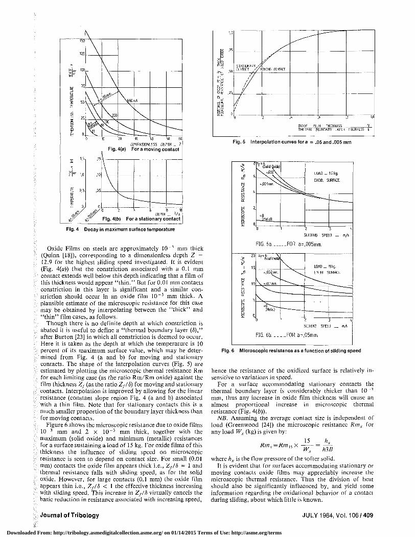
Fig. 4 Decay in maximum surface temperature
Oxide Films on steels are approximately 10 ~3 mm thick (Quinn [18]), corresponding to a dimensionless depth Z = 12.9 for the highest sliding speed investigated. It is evident (Fig. 4(a)) that the constriction associated with a 0.1 mm contact extends well below this depth indicating that a film of this thickness would appear " thin." But for 0.01 mm contacts constriction in this layer is significant and a similar constriction should occur in an oxide film 10 ~3 mm thick. A plausible estimate of the microscopic resistance for this case may be obtained by interpolating between the "thick" and "thin" film cases, as follows.
Though there is no definite depth at which constriction is abated it is useful to define a "thermal boundary layer (5)," after Burton [23] in which all constriction is deemed to occur. Here it is taken as the depth at which the temperature is 10 percent of its maximum surface value, which may be determined from Fig. 4 (a and b) for moving and stationary contacts. The shape of the interpolation curves (Fig. 5) are estimated by plotting the microscopic thermal resistance Rm for each limiting case (as the ratio Rm/Rra oxide) against the film thickness Zj (as the ratio Zf/S) for moving and stationary contacts. Interpolation is improved by allowing for the linear resistance (constant slope region Fig. 4 (a and b) associated with a thin film. Note that for stationary contacts this is a much smaller proportion of the boundary layer thickness than for moving contacts.
Figure 6 shows the microscopic resistance due to oxide films 10~3 mm and 2 x 10 - 3 mm thick, together with the maximum (solid oxide) and minimum (metallic) resistances for a surface sustaining a load of 15 kg. For oxide films of this thickness the influence of sliding speed on microscopic resistance is seen to depend on contact size. For small (0.01 mm) contacts the oxide film appears thick i.e., Zf/S ~ 1 and thermal resistance falls with sliding speed, as for the solid oxide. However, for large contacts (0.1 mm) the oxide film appears thin i.e., Zf/S < 1 the effective thickness increasing with sliding speed. This increase in Zf/S virtually cancels the basic reduction in resistance associated with increasing speed,
1,0
S . " R o
Fa
L/l
rd£
§ B ,25
M D
trbt
'/ STATIONARY /X CONTACT /y
/M0VING CONTACT
/ / / / / / 1 /
1/
/i I
I
0 ,2 4 6 B 1,0
0XI0E FILM THICKNESS zf THERMAL 30UNDARY LAYER THICKNESS I
Fig. 5 Interpolation curves for a = .05 and .005 mm
2 3 4
SLIDING SPEED _ m/s
FIG. 6a FOR a=.005mm.
3 4
SLIDING SPEED _ m/6
FIG. 6b FORa=,05mm.
Fig. 6 Microscopic resistance as a function of sliding speed
hence the resistance of the oxidized surface is relatively insensitive to variations in speed.
For a surface accommodating stationary contacts the thermal boundary layer is considerably thicker than 10 ~3
mm, thus any increase in oxide film thickness will cause an almost proportional increase in microscopic thermal resistance (Fig. 4(b)).
NB. Assuming the average contact size is independent of load (Greenwood [24]) the microscopic resistance Rmx for any load Wx (kg) is given by:
Rm..=Rm,< x = —— 5 Wx hlB
where hx is the flow pressure of the softer solid. It is evident that for surfaces accommodating stationary or
moving contacts oxide films may appreciably increase the microscopic thermal resistance. Thus the division of heat should also be significantly influenced by, and yield some information regarding the oxidational behavior of a contact during sliding, about which little is known.
Journal of Tribology JULY 1984, Vol. 106/409
Downloaded From: http://tribology.asmedigitalcollection.asme.org/ on 01/14/2015 Terms of Use: http://asme.org/terms
t.
Si ,55
?
AT
TO
E
N
O
F
i 8 ,35
2,6
>*"+
/+
EN 24
^ rz; EN3B
LOAD 15kg 8 1
, + /
iv-^^
,
/' 1,2
1,95 m V -
;,
/
^
A
^^
/
1,3m*/
" , , /
/
"
1,4 1,6 '1,8
*
°c/V
2
I.. 1 I '2
1 °
CYUNDER
PIP i f
/ / / D'
®
/
4 T~~:--
1 T5
c
0
A
UN2LI EN3B
P(P V
rcu+EN24"l L _ T - r - - i
! EN3B !
IflAD 15kg SPEED 1,3ms
@\CYUrt tR
ON.
300
1 3 §
5 h 1.5 2 - " X s
lv b24-v b3Bj/oT °C/w
Fig. 7 Division of frictional heal Fig. 8 Division of frictional heat and bulk surface temperature
4 Experimental Results
Using solutions for the temperature in the bulk of the specimens due to a given heat input at the nominal contact area the division of heat has been determined from temperature measurements made by thermocouples accurately positioned in each specimen. The average or bulk surface temperature of the nominal contact is also obtained. These solutions were obtained by a suitable integration and superposition of the instantaneous point source solution [1]. For the cylindrical specimen the solution due to a uniform heat flow along its axis with a heat loss from its outer surface was also employed (Carslaw and Jaeger - [25]).
In sections 4.1 to 4.3 below the measured division of heat, for various material combinations and sliding conditions, is interpreted with respect to the behavior to be expected for the boundary conditions discussed in sections 3.3 and 3.4.
4.1 Constant Microscopic Resistance Hypothesis. The division of heat may be expressed in terms of the microscopic resistance R„, and the bulk temperature jump Vj by superposing the heat flow into solid 1. {QrtRim/ (R\m+ Rim)) f ° r
equal bulk temperatures and the heat flow into solid 1 from 2 ((v2b~v\i>)/(Rim+R2m)) due to any difference in their bulk temperature.
Gi = QT,Rlm+(V2b-Vlb)
-vxb)
(7)
expressing in terms of the temperature jump Vj (= v2b-and rearranging
-Q—(Rim+R2,n)-R2m=Vj/QT
If the resistances R,„ are due principally to constriction at metallic contacts it is reasonable to suppose they will be constant for a given load and speed. Thus we should expect a linear relationship between (Qx /QT and Vj/QT,) the intercepts (QI/QT = 0, 1) yielding the values of Rm2 and Rml, respectively.
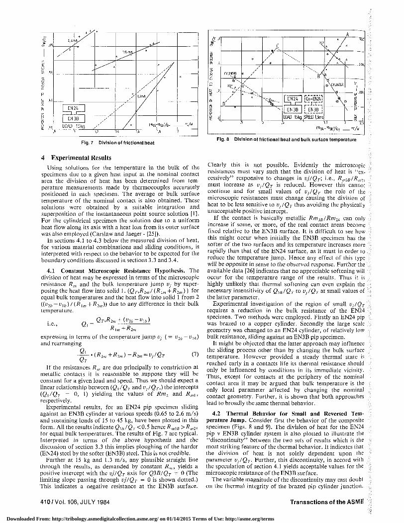
Experimental results, for an EN24 pip specimen sliding against an EN3B cylinder at various speeds (0.65 to 2.6 m/s) and sustaining loads of 15 to 45 kg, have been plotted in this form. All the results indicate Q3a /6 r<0 .5 hence RmiB >R„M for equal bulk temperatures. The results of Fig. 7 are typical. Interpreted in terms of the above hypothesis and the discussion of section 3.3 this implies ploughing of the harder (EN24) steel by the softer (EN3B) steel. This is not credible.
Further at 15 kg and 1.3 m/s, any plausible straight line through the results, as demanded by constant Rm, yields a positive intercept with the vj/QT axis for Q3B/QT = 0 (The limiting slope passing through vj/QT = 0 is shown dotted.) This indicates a negative resistance at the EN3B surface.
Clearly this is not possible. Evidently the microscopic resistances must vary such that the division of heat is "excessively" responsive to changes in vj/QT; i.e., RmlB/R„a4
must increase as Vj/QT is reduced. However this cannot continue and for small values of Vj/QT the role of the microscopic resistances must change causing the division of heat to be less sensitive to Vj/QT thus avoiding the physically unacceptable positive intercept.
If the contact is basically metallic RmJB/Rm2^ can only increase if some, or more, of the real contact areas become fixed relative to the EN3B surface. It is difficult to see how this might occur when initially the EN3B specimen has the softer of the two surfaces and its temperature increases more rapidly than that of the EN24 surface, as it must in order to reduce the temperature jump. Hence any effect of this type will be opposite in sense to the observed response. Further the available data [26] indicates that no appreciable softening will occur for the temperature range of the results. Thus it is highly unlikely that thermal softening can even explain the necessary insensitivity of Q3B/QT to Vj/QT at small values of the latter parameter.
Experimental investigation of the region of small Vj/QT
requires a reduction in the bulk resistance of the EN24 specimen. Two methods were employed. Firstly an EN24 pip was brazed to a copper cylinder. Secondly the large scale geometry was changed to an EN24 cylinder, of relatively low bulk resistance, sliding against an EN3B pip specimen.
It might be objected that the latter approach may influence the sliding process other than by changing the bulk surface temperature. However provided a steady thermal state is reached early in a contacts life its thermal resistance should only be influenced by conditions in its immediate vicinity. Thus, except for contacts at the periphery of the nominal contact area it may be argued that bulk temperature is the only local parameter affected by changing the nominal contact geometry. Further, it is shown that both approaches lead to broadly the same thermal behavior.
4.2 Thermal Behavior for Small and Reversed Temperature Jump. Consider first the behavior of the composite specimen (Figs. 8 and 9). The division of heat for the EN24 pip v EN3B cylinder system is also plotted to illustrate the "discontinuity" between the two sets of results which is the most striking feature of the thermal behavior. It indicates that the division of heat is not solely dependent upon the parameter Vj/QT. Further, this discontinuity, in accord with the speculation of section 4.1 yields acceptable values for the microscopic resistance of the EN3B surface.
The variable magnitude of the discontinuity may cast doubt on the thermal integrity of the brazed pip cylinder junction.
410/Vol. 106, JULY 1984 Transactions of the ASME
Downloaded From: http://tribology.asmedigitalcollection.asme.org/ on 01/14/2015 Terms of Use: http://asme.org/terms
,6 t—
Q> ,4 o
,2
UN24J
| EN 3B |
JOTETIUI
X-
LOAD -15 kg SPEED =565nyfe
( ^ 2 4 - ^ 3 3 ^ . ° C / W
8
6
4
2
MATERIALS >AS A3WE
8
a ,"'
- a
8 0
l^" l 8
-30kg -,65m/S
8 1,6
8
6
4
2
MATERIALS AS ABOVE
/ / -5
* ®
ay / 8 ' /
®
0
^ " • • - ^
5
/ . ~~~-S
- 3 0 kg -1,3nyS
1 1,5
Fig. 9 Division of frictional heat
However if this interface were the cause of any additional thermal resistance the bulk temperature of the EN24 surface, for a given division of heat, would be greater than that calculated and Vj/QT would be increased, which is opposite in sense to the observed behavior. Further, measurements of bulk temperature immediately below (= 1.5 mm) the EN24 surface confirm the accuracy of the extrapolation of bulk temperature.
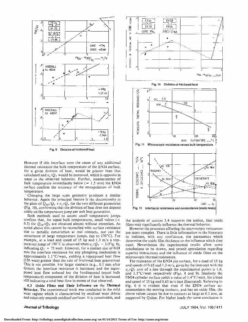
Changing the large scale geometry produces a similar behavior. Again the principal feature is the discontinuity in the plots of QIB/QT V VJ/QT f ° r the two different geometries (Fig. 10), confirming that the division of heat does not depend solely on the temperature jump per unit heat generation.
Both methods used to secure small temperature jumps confirm that, for equal bulk temperatures, small values (< 0.5) for Q^BIQT a r e obtained almost without exception. As noted above this cannot be reconciled with surface resistance due to metallic constriction at real contacts, nor can the occurrence of large temperature jumps, (up to 270°C). For example, at a load and speed of 15 kg and 1.3 m/s a temperature jump of 150°C is observed when Vj/QT = 2 (Fig. 8), indicating QT = 75 watt. However, for a contact size of 0.01 mm the interface resistance for any ploughing mechanism is approximately l . l°C/watt , yielding a superposed heat flow (136 watt) greater than the rate of frictional heat generation! This is not possible. For larger contacts (e.g., 0.1 mm after Quinn) the interface resistance is increased and the superposed heat flow reduced but the fundamental (equal bulk temperature) component of the division of heat is increased still indicating a total heat flow in excess of that observed.
4.3 Oxide Films and Their Influence on the Thermal Behavior. The experimental work was conducted in the mild wear regime which is characterized by oxidized wear debris and relatively smooth oxidized surfaces. It is conceivable, and
I" P .5.
i
J E N 2 4 1 1 i '
EN3B |
LOAD 15kg.
© - "
"* '
2
[ EN~3rB ]
r:_"l_r.V-. I EN24 i
SPED t3nvs.
6
®
1
"---^
^
V /
7 /
' " - - - /
0 1 2
'V-^Bl /Qy ?C/W
Fig. 10 Division of frictional heat
'100 200 300
BULK TEMPERATURE ° C
Fig. 11 Microscopic resistance versus bulk temperature
60 90
LOAD _ kg
Fig. 12 Interfacial resistance and conductance (static tests)
the analysis of section 3.4 supports the notion, that oxide films may significantly influence the thermal behavior.
However the processes affecting the microscopic resistances are more complex. There is little information in the literature to indicate, with any confidence, the parameters which determine the oxide film thickness or the influence which they exert. Nevertheless the experimental results allow some conclusions to be drawn, and permit speculation regarding asperity interactions and the influence of oxide films on the microscopic thermal resistances.
The resistance of the EN24 pip surface, for a load of 15 kg and speeds of 0.65 and 1.3 m/s, given by the intercept with the VJ/QT a x is of a line through the experimental points is 1.6, and 1.3°C/watt respectively (Figs. 8 and 9). Similarly the EN24 cylinder surface yields a value of 1.4°C/watt, for a load and speed of 15 kg and 0.65 m/s (not illustrated). Referring to Fig. 6 it is evident that even if the EN24 surface accommodates the moving contacts, and has no oxide film, the above values cannot be due to contacts as large as 0.1 mm, as suggested by Quinn. For higher loads the same conclusion is
Journal of Tribology JULY 1984, Vol. 106/411
Downloaded From: http://tribology.asmedigitalcollection.asme.org/ on 01/14/2015 Terms of Use: http://asme.org/terms
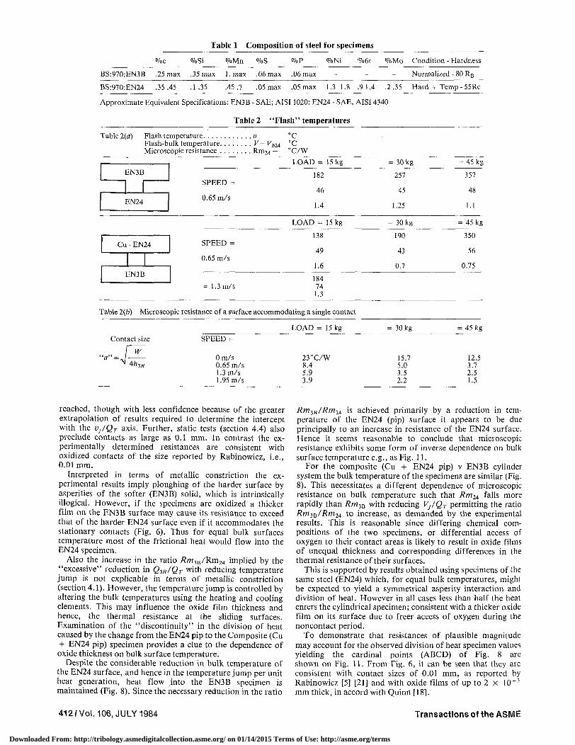
Table 1 Composition of steel for specimens
%c %Si %Mn %S %P %Ni °7o6r °7oMo Condition - Hardness
BS:970:EN3B .25 max .35 max l .max .06 max .06 max Normalized - 80 RB
BS:970:EN24 .35 .45 .1 .35 .45.7 .05 max .05 max 1.3 1.8 .9 1.4 .2.35 Hard + Temp - 55Rc
Approximate Equivalent Specifications: EN3B - SAE; AISI 1020: EN24 - SAE, AISI 4340
Table 2 "Flash" temperatures
Table 2(a)
EN3B
EN24
Cu - EN24
EN3B
SPEED =
0.65 m/s
SPEED =
0.65 m/s
= 1.3 m/s
V-Rm 24 _
"C °c "C/W
LOAD = 15 kg
182
46
1.4
LOAD = 15 kg
138
49
1.6
184 74
1.3
Table 2(6) Microscopic resistance of a surface accommodating a single contact
Cont
• • * - , /
act si
W
4h3B
ze SPEED =
Om/s 0.65 m/s 1.3 m/s 1.95 m/s
LOAD = 15 kg
23°C/W 8.4 5.9 3.9
= 30 kg
257
45
1.25
= 30 kg
190
43
0.7
= 30 kg
15.7 5.0 3.5 2.2
- 45 kg
357
48
1.1
= 45 kg
350
56
0.75
= 45 kg
12.5 3.7 2.5 1.5
reached, though with less confidence because of the greater extrapolation of results required to determine the intercept with the VjlQT axis. Further, static tests (section 4.4) also preclude contacts as large as 0.1 mm. In contrast the experimentally determined resistances are consistent with oxidized contacts of the size reported by Rabinowicz, i.e., 0.01 mm.
Interpreted in terms of metallic constriction the experimental results imply ploughing of the harder surface by asperities of the softer (EN3B) solid, which is intrinsically illogical. However, if the specimens are oxidized a thicker film on the EN3B surface may cause its resistance to exceed that of the harder EN24 surface even if it accommodates the stationary contacts (Fig. 6). Thus for equal bulk surfaces temperature most of the frictional heat would flow into the EN24 specimen.
Also the increase in the ratio SmjB /Rm2 4 implied by the "excessive" reduction in Q-$B/QT w i t n reducing temperature jump is not explicable in terms of metallic constriction (section 4.1). However, the temperature jump is controlled by altering the bulk temperatures using the heating and cooling elements. This may influence the oxide film thickness and hence, the thermal resistance at the sliding surfaces. Examination of the "discontinuity" in the division of heat caused by the change from the EN24 pip to the Composite (Cu + EN24 pip) specimen provides a clue to the dependence of oxide thickness on bulk surface temperature.
Despite the considerable reduction in bulk temperature of the EN24 surface, and hence in the temperature jump per unit heat generation, heat flow into the EN3B specimen is maintained (Fig. 8). Since the necessary reduction in the ratio
RmlB/Rm24 is achieved primarily by a reduction in temperature of the EN24 (pip) surface it appears to be due principally to an increase in resistance of the EN24 surface. Hence it seems reasonable to conclude that microscopic resistance exhibits some form of inverse dependence on bulk surface temperature e.g., as Fig. 11.
For the composite (Cu + EN24 pip) v EN3B cylinder system the bulk temperature of the specimens are similar (Fig. 8). This necessitates a different dependence of microscopic resistance on bulk temperature such that Rm24 falls more rapidly than RmiB with reducing Vj/QT permitting the ratio Rm3B/Rm24 to increase, as demanded by the experimental results. This is reasonable since differing chemical compositions of the two specimens, or differential access of oxygen to their contact areas is likely to result in oxide films of unequal thickness and corresponding differences in the thermal resistance of their surfaces.
This is supported by results obtained using specimens of the same steel (EN24) which, for equal bulk temperatures, might be expected to yield a symmetrical asperity interaction and division of heat. However in all cases less than half the heat enters the cylindrical specimen; consistent with a thicker oxide film on its surface due to freer access of oxygen during the noncontact period.
To demonstrate that resistances of plausible magnitude may account for the observed division of heat specimen values yielding the cardinal points (ABCD) of Fig. 8 are shown on Fig. 11. From Fig. 6, it can be seen that they are consistent with contact sizes of 0.01 mm, as reported by Rabinowicz [5] [21] and with oxide films of up to 2 x 10 ~3
mm thick, in accord with Quinn [18].
412/Vol. 106, JULY 1984 Transactions of the ASME
Downloaded From: http://tribology.asmedigitalcollection.asme.org/ on 01/14/2015 Terms of Use: http://asme.org/terms
Further, changing the large scale geometry also causes a behavior entirely consistent with the above hypothesis. Again the primary effect.is to reduce the temperature of the EN24 surface. Accordingly we should expect a reduction in the ratio RmiB/Rm24 and a discontinuity such that for a given temperature jump heat flow to the EN3B specimen is increased; as observed (e.g., Fig. 10).
Grosberg and Molgaard [8] also deduce a similar dependence of oxide thickness on temperature. However this supporting evidence should be viewed with some caution since changes in bulk temperature were accomplished by varying the load, which may influence oxide thicknesses other than via changes in bulk temperature.
4.4 Static Tests. The presence of oxide films on the worn surfaces is easily observed by the naked eye and by optical microscopy but this gives no direct evidence of any significant increase in microscopic thermal resistance; a necessary requirement for the above hypothesis. To obtain such evidence specimens in the "as prepared" condition and after running (at 15 kg; 0.65 m/s) have been loaded together, statically, and the interface resistance determined by causing a heat flow through the interface using the heating and cooling facilities of the apparatus.
The results (Fig. 12) show that there is a marked difference between the thermal resistance of the two interfaces confirming the significant effect of the oxide films on the surface of the "as run" specimens. Further, the resistance of the "as prepared" interface (= 1.5°C/watt @ 15 kg) is in good agreement with that to be expected for metallic contacts of the size reported by Rabinowicz (i.e., 1.2°C/watt @ 15 kg). However, the resistance of the "as run" interface indicates oxide thicknesses of less than 10~3 mm, probably because sliding was terminated with the specimens in contact, hence some oxide may have been detached. This procedure was adopted since it was thought to be less vulnerable to the criticism that any oxide subsequently detected in static tests had grown after the specimens had been separated but while they were still hot.
Finally, the linear dependence on load of the conductance of each interface also supports Greenwood's assertion that the size of the real contacts are independent of load; increase in which only serves to cause a proportional increase in their number.
4.5 Flash Temperatures. The experimental results imply that the microscopic surface resistance exhibits some form of inverse dependence on the bulk temperature. Thus for a given heat input to a solid its flash temperature (ly = Q.Rm + Vb) will depend on the effect of the bulk temperature on microscopic resistance (R,„), as well as its direct contribution to the flash temperature. Because of this inverse dependence (of Rm on Vb) the influence of bulk temperature on the flash temperature; and the division of heat, should be diminished. This affect has been observed.
Further any estimate of flash temperature will only be valid for prescribed sliding conditions. Nevertheless, where flash temperatures can be estimated (for zero heat flow into one of the solids), they should be reasonably typical for that particular load and speed. For the EN24 v EN3B system, typical values are shown in Table 2. Also shown are the microscopic resistance of the EN24 system (for Q3B = 0) and the difference between the flash and bulk temperatures (vf — vb), both of which are quite modest. This is attributable to the occurrence of a relatively large number of small contacts rather than a few large contacts.
Comparing the thermal resistance (Table 2(b)) for the case of a single contact, either stationary or moving, with those measured (Table 2(a)) shows that even the resistance of an
oxide free contact is much higher than those observed. It follows that estimates of typical flash temperatures based on Archards' [27] limiting assumption of a single contact will be significantly in error.
5 Conclusions
The thermal behavior of sliding solids is often analyzed assuming surface films have a negligible effect on the microscopic resistance of their surfaces. It is shown (section 4) that the observed division of heat, at least for the systems investigated here, is incompatible with this assumption and that in the mild wear regime the influence of oxide films must be considered. An approximate method of analysis has been used to estimate the additional resistance due to oxide films. Although only approximate thermal data could be obtained for only one particular iron oxide, the indications are that for films of the thickness reported by Quinn [18] i.e., 10 - 3 mm the microscopic resistance may be increased by as much as 10 or 15 fold for moving or stationary contacts, respectively.
Static tests confirm that oxides cause an appreciable increase in resistance though this was not as large (approximately three fold) as that which appears possible as indicated above. These tests also support the notion that the average real contact size is approximately 0.01 mm and independent of load.
The temperature jump reported by Ling and Simkins [12] has also been observed and magnitudes up to 270°C have been recorded. It is shown (section 3.1) that a temperature jump will occur whenever the ratio between the bulk and microscopic thermal resistances for each surface differ and is not necessarily a consequence of sub-surface heat generation as suggested by Ling [13].
For some cases, generally lower loads and speeds, it was possible to estimate typical flash temperatures (Table 2). At higher loads and speeds (e.g., 60 kg: 1.3 m/s) flash temperatures could not be determined but obviously must exceed the bulk temperature (670°C) of the hotter solid.
Although the approximate analysis of section 3.4 indicates that oxide films are an important feature of the thermal behavior of sliding solids, application of the method is limited by the increased complexity of the boundary conditions for oxidized contacts. The experimental results suggest that the oxide film thickness reduces as bulk temperature increases. However further investigation of this or any other parameter influencing oxide film thickness, composition or structure is necessary prelude to an improved knowledge of the thermal behavior. There is also a paucity of comprehensive thermal data (K, K, C) for the oxides of iron. This indicates another area in which a useful contribution could be made.
Finally fullest use of new information regarding boundary conditions, or thermal properties of oxides will require a more precise analysis of the conduction of heat into a sliding solid with an oxidized contact surface.
References 1 Jaeger, J. C , "Moving Sources of Heat and the Temperature of Sliding
Contacts," J. Proc. Roy. Soc. N.S. W., Vol. 76, 1942, pp. 203-224. 2 Barber, J. R., "The Conduction of Heat from Sliding Solids," Int. J.
Heat & Mass Transfer, Vol. 13, 1970, pp. 857-869. 3 Bowden, F. P., and Ridler, K. E. W., "Physical Properties of Surfaces,"
Proc. Roy. Soc, Vol. A154, 1936, p. 640. 4 Furey, M. J., "Surface Temperatures at Unlubricated Sliding Contacts,"
A.S.L.E. Trans., Vol. 7, 1964, p. 133. 5 Rabinowicz, E., "The Intrinsic Variables Affecting the Stick-Slip
Process," Proc. Phys. Soc. (London), Vol. 71, 1958, pp. 668-675. 6 Parker, R. C , and Marshall, P. R., "The Measurement of the Tem
perature of Sliding Surfaces with Particular Reference to Railway Brake Blocks," Proc. Inst. Mech. Engs., Vol. 158, 1948, pp. 209-229.
7 Blok, H., "Theoretical Study of Temperature Rise at Surfaces of Actual Contact under Oiliness Conditions," 7ns;. Mech. Eng. General Discussion of Lubrication, Vol. 2, 1937, pp. 222-235.
Journal of Tribology JULY 1984, Vol. 106/413
Downloaded From: http://tribology.asmedigitalcollection.asme.org/ on 01/14/2015 Terms of Use: http://asme.org/terms
8 Grasberg, P. , and Moigaard, J., "Aspects of the Wear of Spinning Travellers: The Division of Heat at Rubbing Surfaces," Proc. Inst. Mech. Eng., Vol. 181, Part 3L, 1966/1967, pp. 16-23.
9 Quinn, T. J. F., "The Division of Heat and Surface Temperatures at Sliding Steel Interfaces and their Relation to Oxidational Wear," Paper Presented at ASLE/ASME Lubrication Conference in Boston, Mass, Oct. 5-7, 1976.
10 Barber, J. R., "Therraoelastic Instabilities in the Sliding of Conforming Solids,"Proc. Roy. Soc, Vol. A132, 1969, pp. 381-394.
11 Cameron, A., Gordon, A. N.,andSymm, G. T., "Contact Temperatures in Rolling/Sliding Surfaces," Proc. Roy. Soc , Vol. A286,1965, pp. 45-61.
12 Ling, F. F., and Simkins, T. E., "Measurement of Pointwise Juncture Condition of Temperature at the Interface of Two Bodies in Sliding Contact," ASME Journal of Basic Engineering, Vol. 85,1963, pp. 481-487.
13 Ling, F. F., "Surface Interactions in Sliding. N.A.S.A. Symposium on Interdisciplinary Approach to Friction and Wear," 1967.
14 Green, A. P., "Friction Between Unlubricated Metals-. A Theoretical Analysis of the Junction Model," Proc. Roy. Soc, Vol. A228, 1955, pp. 191-204.
15 Greenwood, J. A., and Tabor, D., "The Properties of Model Friction Junctions," Inst. Mech. Engs. Proc. of Conference on Lubrication and Wear, 1957, paper 92, pp. 314-317.
16 Brockley.C. A., and Fleming, G.K., "A Model Junction Study of Severe Metallic Friction," Wear, Vol. 8, 1965, pp. 374-380.
17 Barber, J. R., "Distribution of Heat between Sliding Surfaces," J. Mech. Eng. Sci., Vol. 9-5, 1967, pp. 351-354.
18 Quinn, T. F. J., "Dry Wear of Steel as Revealed by Electron Microscopy and X-ray Diffraction," Proc. Inst. Mech. Engs. Convention on Tribology, Vol. 182, Part 3N, 1968, pp. 201-213.
19 Quinn, T. F. J., "The Effect of Hot Spot Temperatures on the Unlubricated Wear of Steel," A.S.L.E. Trans., Vol. 10, 1967, pp. 158-168.
20 International Critical Tables, McGraw-Hill, New York, 1926. 21 Rabinowicz, E., "The Nature of Static and Kinetic Coefficients of
Friction," J. Apply Phys., Vol. 22,1951, pp. 1373-1379. 22 Quinn, T. F. J., "Some Microscopic Aspects of the Mild Wear of Steel,"
/ . of Microscopy, Vol. 94, Part 2,1971, pp. 125-137. 23 Burton, R. A., "The Role of Insulating Surface Films in Frictionally
Excited Thermoelastic Instabilities," Wear, Vol. 24, 1973, pp. 189-198. 24 Greenwood, J. A., "On the Area of Contact between a Rough Surface
andaFla t , " ASME Journal of Lubrication Technology, Vol. 1,1967, p. 81. 25 Carslaw, H., and Jaeger, J. C , The Conduction of Heat in Solids (2nd
Ed.), Clarendon Press - Oxford, 1959. 26 U.S. Dept. of Commerce Circular - C447, "Mechanical Properties of
Metals and Alloys," U.S. Dept. of Commerce: National Bureau of Standards. 27 Archard, F. J., "The Temperature of Rubbing Surfaces," Wear, Vol. 2,
1959, pp.438-455.
A P P E N D I X A
Uniform Square Source Solutions
A.l Stationary Source. The temperature at time t at any point (xyz) in a semi-infinite solid, due to a stationary square source of side (2a) and heat input (q) per unit time per unit area may be obtained by integrating the "point source" solution of Jaeger (1942) i.e.,
Vxyz=-—,Q . , , , \ ., ,<s3 /2 dx'\ dy' exp ApciirnY'2 Jo (t-t'Y11 J -a J -a 4pc(trK)s/1 Jo (t-t'f
(x-x')2+(y-y')2+z2
AK(t-t')
Allowing t — oo, steady state temperature is given by:
Vxyz=—— [ dx'\ dy'{{x-x')2
ZTTKpC J -a J - a
+ (y-y'?+z2]Vl
Integrating with respect toy ' yields: Vxyz = ^r-7} arcsinh - = = = = = = -
"-- '• 'J-a ^(x-x'f+z2
y-a
(Al)
2-KK.
- arcsinh -J(x-x')2+z2
dx'
and finally with respect to x' gives the required temp at the point (xyz) i.e.,
2-wKv r . , y + a = a i a arcsinh
t- sj(x-a)2+z2
• u y~a • u y + a
- arcsinh . = = + arcsinh
- arcsinh
^T(x-a)2+~z2 ' ^I(x + a)2+z2
y-
V (x+a)1 +z )2+z2>
-{(y+a){ arcsinh (x-a)
J(y+a)2+z2
(x + a) - arcsinh
(y-a)[ arcsinh
^(y + aV+z2
(x + a)
- arcsinh
J(y^a)2+z2
(x-a) }}
- « [ • arctg (x-a) (y-a)
- arctg
+ arctg
Z-J(x-a)2+(y-a)2+z2
(x+a) (y-a)
Zsl(x-a)2~+(yZa)1+z1
(x+a) (y + a)
Z\l(x + a)2 + (y + a)2 +z2
(x-a) (y-a) (x-a) (y-a) ) - arctg —, *==
Z-4(x-a)2 + (y + a)2+z2)
z <-
x r ^J(x-a)2 + (y-a)2+z2- (y-a) ln-
z (- \l(x-a)2 +(y-aj2Tz2 +(y-a)
- I n
sf(x+a)2 + (y-aj2rTz1 - (y-a)
\/(x + a)2+Jy-a)2+z2 + (y-a)
JJx+a)2 + (y + a)2Tz? -~(y + a)
4(x+a)2 +(y + a)2~+rz2 + (y + a)
-JJx^a)2 + (y + a)2 +z2 - (y + a)
*4~(x-
-In
+ ln
a)l + (y + a)z+z - (y + a) -\ 7a)2 + (y + a)2+z2+(y + a) ->''
(A2)
For the purposes of calculation it is convenient to put this result in an alternative "log" form, which for the case of y = 0 discussed in section 3 is given by:
2-KKV , A+a , B + a B+x + a = (a—x)m (- (a+x)ln^ i-2mn
A-a B-a
r a(x+a) a(x-a)} 2 z) arctg arctg —
v xB zA J
B+x-a
(A3) xB zA
where A = ->T(x—a)2 +z2 +a2 and B = -4 (x+a)2 +z2 +a2
A.2 Moving Source. Consider a source identical to that above but which moves with a velocity (V) parallel to the x axis on the surface of a semi-infinite solid. At time (t) after
414/Vol. 106, JULY 1984 Transactions of the ASME
Downloaded From: http://tribology.asmedigitalcollection.asme.org/ on 01/14/2015 Terms of Use: http://asme.org/terms
heating commences the temperature at the point (xyz) when q CX+A J. Y+A e x p [ _ ^2 + ^ 2 + z2)Yl} the source is at the origin is: vxyz = ~^c j X_A
e "drl) Y „ A (^TpTz^ ( A 4 )
vxyz = • [ ' \" dx'\" dy' Jaeger 1942 JO f - r ' ) 3 / 2 J - o J -a 4pc(7TK)3/2 Jo ( f - / ' ) 3 / 2 . . » ,, . , . , . ,
Kv Ky Kz K<? where x = ; y = ; Z = ; A =
( (x-x'-V(t-t'))2+(y-y[)2+ 2li 2K 2K 2K
exp ;
4/c( / - / ) Equation (A4) has been integrated numerically to yield the Integrating with respect to /, and allowing t — oo, given the temperature distribution below a moving heat source (see steady state temperature. section 3 and Fig. 3(a)).
Journal of Tribology JULY 1984, Vol. 106/415
Downloaded From: http://tribology.asmedigitalcollection.asme.org/ on 01/14/2015 Terms of Use: http://asme.org/terms
Related Documents