FINAL REPORT VOLUME 2 THE DEVELOPMENT OF QUALIFICATION STANDARDS FOR CAST DUPLEX STAINLESS STEEL SUBMITTED TO U. S. DEPARTMENT OF ENERGY Award Number - DE-FC36-00 ID13975 OCTOBER 1, 2000 – SEPTEMBER 30, 2005 STEVEN W. RUSSELL CARL D. LUNDIN MATERIALS JOINING GROUP MATERIALS SCIENCE AND ENGINEERING THE UNIVERSITY OF TENNESSEE, KNOXVILLE

Welcome message from author
This document is posted to help you gain knowledge. Please leave a comment to let me know what you think about it! Share it to your friends and learn new things together.
Transcript

FINAL REPORT
VOLUME 2
THE DEVELOPMENT OF
QUALIFICATION STANDARDS FOR
CAST DUPLEX STAINLESS STEEL
SUBMITTED TO U. S. DEPARTMENT OF ENERGY Award Number - DE-FC36-00 ID13975
OCTOBER 1, 2000 – SEPTEMBER 30, 2005
STEVEN W. RUSSELL CARL D. LUNDIN
MATERIALS JOINING GROUP MATERIALS SCIENCE AND ENGINEERING
THE UNIVERSITY OF TENNESSEE, KNOXVILLE

ii
CARL D. LUNDIN PROFESSOR OF METALLURGY
MATERIALS JOINING GROUP
MATERIALS SCIENCE AND ENGINEERING THE UNIVERSITY OF TENNESSEE
KNOXVILLE 37996-2200
TELEPHONE (865) 974-5310 FAX (865) 974-0880
This is Volume 2 of 5 of the final report for The Department of Energy
Grant # DE-FC36-00 ID13975 entitled “Behavior of Duplex Stainless Steel Castings.”

iii
FOREWARD
The final report for the DOE Grant DE-FC36-00 IDI13975 consists of five volumes. The
volumes provide in depth information on Cast Duplex and Cast Super Duplex Stainless Steels.
Volume 1 is entitled “Metallurgical Evaluation of Cast Duplex Stainless Steels and their
Weldments” involves comparison of selected grades of Duplex Stainless Steels and their welds
with their wrought counterparts regarding corrosion performance, mechanical properties and
weldability. Volume 2 entitled “The Development of Qualification Standards for Cast Duplex
Stainless Steel” involves inter-laboratory testing and Volume 3 “The Development of
Qualification Standards for Cast Super Duplex Stainless Steel” provides information on the
testing of Super Duplex Stainless Steels to ASTM A923. Volume 4 is the “Guidance Document
for the Evaluation of Super Duplex Stainless Steel” and involves the applicability of ASTM
A923 to the Cast Super Duplex materials. Volume 5 is the data package for the incorporation of
ASTM A890-5A material into the ASTM A923.
In volume 1 selected grades of Duplex Stainless Steel castings and their welds, in
comparison with their wrought counterparts, were evaluated, regarding corrosion performance,
mechanical properties and weldability. Multiple heats of cast duplex stainless steel were
evaluated in the as-cast, solution annealed static cast and solution annealed centrifugal cast
conditions, while their wrought counterparts were characterized in the solution annealed
condition and in the form of as-rolled plate. Welding, including extensive assessment of
autogenous welds and a preliminary study of composite welds, Shielded Metal Arc Weld
(SMAW), was performed. The evaluations included Critical Pitting Temperature (CPT) testing,
Intergranular Corrosion (IGC) testing, ASTM A923 (Methods A, B and C), Charpy impact
testing, weldability testing (ASTM A494), ferrite measurement and microstructural evaluations.
Volume 2 deals with the Development of Qualification Standards for Cast Duplex
Stainless Steel (A890-4A) which is equivalent to wrought 2205. This volume involves testing of
cast Duplex Stainless Steel to several ASTM specifications, formulating and conducting industry
round robin tests and studying the reproducibility of the results. ASTM E562 (Standard Test
Method for Determining Volume Fraction by Systematic manual Point Count) and ASTM A923
(Standard Test Methods for Detecting Detrimental Intermetallic Phase in Wrought Duplex

iv
Austenitic/Ferritic Stainless Steels) were the specifications utilized in conducting this work. An
ASTM E562 industry round robin, ASTM A923 applicability study, ASTM A923 industry round
robin, and an ASTM A923 study of the effectiveness of existing foundry solution annealing
procedures for producing cast Duplex Stainless Steel without intermetallic phases were
implemented.
Volume 3 comprises of the Development of Qualification Standards for Cast Super
Duplex Stainless Steel (A890-5A) which is equivalent to wrought 2507. The objective of this
work was to determine the suitability of ASTM A923 “Standard Test methods for Detecting
Detrimental Intermetallic Phase in Duplex Austenitic-Ferritic Stainless Steels” for 25 Cr Cast
Super Duplex Stainless Steels (ASTM A890-5A). The various tests which were carried out were
ASTM A923 Test Method A, B and C (Sodium Hydroxide Etch Test, Charpy Impact Test and
Ferric Chloride Corrosion Test), ferrite measurement using Feritscope®, ASTM E562 Manual
Point Count Method and X-Ray Diffraction, hardness measurement using Rockwell B and C and
microstructural analysis using SEM and EDS.
Volume 4 is the guidance document for the evaluation of cast Super Duplex Stainless
Steel which deals with the various evaluation methods which were defined and used for the work
on volume 3 for the “Development of Qualification Standards for Cast Super Duplex Stainless
Steel alloy A890-5A (2507 Wrought Equivalent)”. The document explains in detail each test
which was conducted. It also includes some of the results which were acquired during this work.
Volume 5 is the Data Package for the evaluation of Super Duplex Stainless Steel
Castings prepared at the end of work comprised in volumes 3 and 4. The document deals with
the various evaluation methods used in the work documented in volume 3 and 4. This document
covers materials regarding evaluation of the A890-5A material in terms of inclusion in ASTM
A923. The various tests which were conducted on the A890-5A material are included in this
document.

v
Abstract
The scope of testing cast Duplex Stainless Steel (DSS) required testing to several
ASTM specifications, while formulating and conducting industry round robin tests to
verify and study the reproducibility of the results. ASTM E562 (Standard Test Method
for Determining Volume Fraction by Systematic manual Point Count) and ASTM A923
(Standard Test Methods for Detecting Detrimental Intermetallic Phase in Wrought
Duplex Austenitic/Ferritic Stainless Steels) were the specifications utilized in conducting
this work. An ASTM E562 industry round robin, ASTM A923 applicability study,
ASTM A923 industry round robin, and an ASTM A923 study of the effectiveness of
existing foundry solution annealing procedures for producing cast DSS without
intermetallic phases were implemented.
In the ASTM E562 study, 5 samples were extracted from various cast austenitic and
DSS in order to have varying amounts of ferrite. Each sample was metallographically
prepared by UT and sent to each of 8 participants for volume fraction of ferrite
measurements. Volume fraction of ferrite was measured using manual point count per
ASTM E562. FN was measured from the Feritescope® and converted to volume fraction
of ferrite. Results indicate that ASTM E562 is applicable to DSS and the results have
excellent lab-to-lab reproducibility. Also, volume fraction of ferrite conversions from the
FN measured by the Feritescope® were similar to volume fraction of ferrite measured per
ASTM E562.
In the ASTM A923 applicability to cast DSS study, 8 different heat treatments
were performed on 3 lots of ASTM A890-4A (CD3MN) castings and 1 lot of 2205
vi
wrought DSS. The heat treatments were selected to produce a wide range of cooling
rates and hold times in order to study the suitability of ASTM A923 to the response of
varying amounts on intermetallic phases [117]. The test parameters were identical to
those used to develop ASTM A923 for wrought DSS. Charpy V-notch impact samples
were extracted from the castings and wrought DSS and tested per ASTM A923 method B
(Charpy impact test). Method A (sodium hydroxide etch test) was performed on one half
of a fractured Charpy V-notch impact sample and Method C (ferric chloride corrosion
weight loss test) was performed on another half. Test results for the three cast lots and
one wrought lot indicate that ASTM A923 is relevant for detecting intermetallic phases in
cast DSS.
In the ASTM A923 round robin study, five laboratories conducted ASTM A923
Methods A & C on cast DSS material and the lab-to-lab reproducibility of the data was
determined. Two groups of samples were sent to the participants. Group 1 samples were
tested per ASTM A923 Method A, group 2 samples were tested by ASTM A923 Method
C. Testing procedures for this round robin study were identical to those used in the
ASTM A923 applicability study. Results from this round robin indicate that there is
excellent lab-to-lab reproducibility of ASTM A923 with respect to cast DSS and that
ASTM A923 could be expanded to cover both wrought and cast DSS.
In the ASTM A923 study of the effectiveness of existing foundry solution annealing
procedures for producing cast DSS without intermetallic phases, Ten heats of ASTM
A890-4A (CD3MN) in the foundry solution annealed condition were tested per ASTM
A923 Methods A, B, & C. Testing of these materials per ASTM A923 was used to

vii
determine if the foundry solution anneal procedures were adequate to completely
eliminate any intermetallic phases, which may have precipitated during the casting and
subsequent heat treatment processes. All heats showed no sign of intermetallic phase per
Method A, passed minimum Charpy impact energy requirements per Method B (> 40 ft-
lbs @ -40°C (-40°F)), and showed negligible weight loss per Method C (< 10 mdd).
These results indicate that the solution annealing procedure used by foundries is adequate
to produce a product free from intermetallic phases.

viii
Table of Contents
Heading Page
I. Program Introduction 1 II. Project Goals 2 III. Literature Review 3
Introduction 3 Metallurgy of DSS 4
Secondary Phases 4 Sigma (σ) Phase 4 Chi (χ) Phase 9 R-Phase 9 π-Phase 11 Secondary Austenite (γ2) 11 Cr2N 12 Carbides M23C6 and M7C3 12 Cu-rich epsilon (ε) Phase 13
Microstructural Investigation Techniques 13 Alloying Elements 16
Chromium (Cr) 16 Molybdenum (Mo) 16 Nickel (Ni) 16 Nitrogen (N) 17 Manganese (Mn) 17 Copper (Cu) 17 Tungsten (W) 17
Effect of Solution Heat Treating 18 Effect of Heat Treatment Temperature 18 Effect of Other Heat Treatment Variables 20
Corrosion Behavior of Duplex Stainless Steels 22 Pitting Corrosion 22 Intergranular Corrosion 25
Toughness 25 Welding of DSS 26
Welding Metallurgy 26 Heat Affected Zone (HAZ) 27 Weld Fusion Zone 35
Ferrite Prediction and Measurement 36 WRC-1992 Diagram 38 The Schoeffer Diagram 40 Ferrite Measurement 42
Point Count 43 Magne-Gage: Magnetic Adhesion Method 44

ix
Eddy Current Method: Magnetic Induction Method 46 Ferrite Number vs. Ferrite Percent 48
Weldability 48 Fusion Zone Solidification Cracking 49
Heat Affected Zone Liquation Cracking 50 Hydrogen Assisted Cold Cracking 50 Welding Procedures 51 Welding Processes 52
SMAW 54 GTAW 55 Other Welding Processes 57
Filler Metal 57 Shielding and Backing Gases 59 Other Welding Related Issues 61
Casting Related Issues 62 Casting Production 63
IV. Experimental Procedures 64 ASTM E562 Ferrite Measurement Round Robin Study 64
Materials 64 Testing Method 64
The Suitability of ASTM A923 for Detecting the Presence of 69 Intermetallic Phases in Duplex Stainless Steel Castings
Materials 69 Heat Treatments 70 Testing Methods 70
Test Method B 70 Test Method A 74 Test Method C 77
ASTM A923 Method A & C Round Robin Study 79 Materials 79 Testing Methods 80
ASTM A923 Study of the Effectiveness of Existing Foundry 80 Solution Annealing Procedures for Producing Cast DSS Without Intermetallic Phases
Materials 80 Heat Treatment 80 Test Methods 82
V. Results and Discussion 83 ASTM E562 Ferrite Measurement Round Robin Study 83 The Suitability of ASTM A923 for Detecting the Presence of 86 Intermetallic Phases in Duplex Stainless Steel Castings
Test Method B 86 Test Method A 86 Test Method C 86
x
ASTM A923 Method A & C Round Robin Study 109 Test Method A 109 Test Method C 109
ASTM A923 Study of the Effectiveness of Existing Foundry 133 Solution Annealing Procedures for Producing Cast DSS Without Intermetallic Phases
Test Method A 133 Test Method B 133 Test Method C 133
VI. Conclusions 145 References 148 Appendix: Specifications 165

xi
List of Tables
Table Page
Table 1 Crystallographic Data for Various Phases 8
Table 2 Five Step Contemporary Automated Preparation Practice 14
Table 3 Heat Treatment Requirements by ASTM A 890-4A 19
Table 4 Welding Process Characteristics 53
Table 5 Round Robin Sample Set 64
Table 6 Chemical Composition of Tested Materials 69
Table 7 Heat Treatment Schedule 71
Table 8 Chemical Composition of Foundry Solution 81
Annealed Materials
Table 9 Foundry Solution Anneal Heat Treatment Schedule 81
Table 10 Volume Percent Ferrite 81
Table 11 ASTM E562 Results 84
Table 12 Charpy Impact Toughness at -40°C (-40°F) 87
Table 13 Classification of Etch Structure 89
Table 14 Corrosion Rates for ASTM A923 Study 106
Table 15 Classification of Etch Structure 110
Table 16 Corrosion Rates for ASTM A923 Round Robin Study 131
Table 17 Classification of Etch Structure for Foundry 136
Solution Anneal Study
Table 18 Charpy Impact Toughness at -40°C (-40°F) for Foundry 142
Solution Anneal Study
Table 19 Corrosion Rates for Foundry Solution Anneal Study 143

xii
List of Figures
Figure Page
Figure 1. Possible Precipitates in DSS 5
Figure 2. Micrographs Showing Different Morphologies of σ-phase 7
Figure 3. BSEM Micrograph Showing Contrast Difference for 10 χ-phase and σ-phase Due to Difference in Chemical Composition
Figure 4. Effect of Solution Annealing Temperature on Ferrite 21 and Austenite Content
Figure 5. Effect of Solution Annealing Temperature on the 23 Relative Amounts of the Ferrite and Austenite Phases
Figure 6. Modified Ternary Section of the Fe-Cr-Ni Phase Diagram 30 Plotted Using the WRC-1992 Equivalent Relationships
Figure 7. Micrographs Showing Microstructures of SAF 2205 and 31 2507 After Gleeble Simulation at ∆t = 93.0s
Figure 8. Schematic Showing HAZs Experience Different Thermal 33 Cycles
Figure 9. Schematic Diagram Illustrating the Relative Positions of 34
the Different Thermal Cycles in a Two Pass Weld Deposit
Figure 10. The Schaeffler's Diagram 37
Figure 11. The WRC-1992 Diagram 39
Figure 12. The Schoeffer Diagram 41
Figure 13. Photograph of a Standard Mage-Gage 45
Figure 14. Schematic of the Magnetic Induction Method 47
Figure 15. Effect of Welding on Impact Toughness 56
Figure 16. Effect of Shielding Gas Compositions on Pitting Corrosion 60
Resistance of Duplex Stainless Steels

xiii
Figure 17. Microstructure of Round Robin Sample "A", NaOH, 100x 65
Figure 18. Microstructure of Round Robin Sample "E", NaOH, 100x 65
Figure 19. Microstructure of Round Robin Sample "F", NaOH, 100x 66
Figure 20. Microstructure of Round Robin Sample "J", NaOH, 100x 66
Figure 21. Microstructure of Round Robin Sample "K", NaOH, 1 00x 67
Figure 22. Actual Thermal History for Various Heat Treatments 71
Figure 23. Charpy Impact Sample Extraction Location 72
Figure 24. Charpy Impact Notch Geometry 72
Figure 25. Charpy Impact Test Apparatus 73
Figure 26. Unaffected Structure from ASTM A923 76
Figure 27. Possibly Affected Structure from ASTM A923 76
Figure 28. Affected Structure from ASTM A923 76
Figure 29. Centerline Structure from ASTM A923 76
Figure 30. Temperature Controlled Water Bath 78
Figure 31. Comparison of Volume Fraction of Ferrite per 85 Feritescope® and ASTM E562 Manual Point Count
Figure 32. Charpy Impact Toughness at -40°C (-40°F) 88
Figure 33. Microstructure of 2205-A-3, NaOH, 400x 90
Figure 34. Microstructure of 41NCC-A-1, NaOH, 400x 90
Figure 3 5. Microstructure of 42RA-1, NaOH, 400x 91
Figure 36. Microstructure of CD3-A-2, NaOH, 400x 91
Figure 37. Microstructure of 2205-B-2, NaOH, 400x 92
Figure 38. Microstructure of 41NCC-B-2, NaOH, 400x 92

xiv
Figure 39. Microstructure of 42R-B-1, NaOH, 400x 93
Figure 40. Microstructure of CD3-B-1, NaOH, 400x 93
Figure 41. Microstructure of 2205-C-1, NaOH, 400x 94
Figure 42. Microstructure of 41NCC-C-1, NaOH, 400x 94
Figure 43. Microstructure of 42R-C-1, NaOH, 400x 95
Figure 44. Microstructure of CD3-C-2, NaOH, 400x 95
Figure 45. Microstructure of 2205-D-1, NaOH, 400x 96
Figure 46. Microstructure of 41NCC-D-2, NaOH, 400x 96
Figure 47. Microstructure of 42R-D-1, NaOH, 400x 97
Figure 48. Microstructure of CD3-D-2, NaOH, 400x 97
Figure 49. Microstructure of 2205-E-1, NaOH, 400x 98
Figure 50. Microstructure of 41NCC-E-1, NaOH, 400x 98
Figure 51. Microstructure of 42R-E-1, NaOH, 400x 99
Figure 52. Microstructure of CD3-E-3, NaOH, 400x 99
Figure 53. Microstructure of 2205-F-3, NaOH, 400x 100
Figure 54. Microstructure of 41NCC-F-2, NaOH, 400x 100
Figure 55. Microstructure of 42R-F-3, NaOH, 400x 101
Figure 56. Microstructure of CD3-F-2, NaOH, 400x 101
Figure 57. Microstructure of 2205-G-2, NaOH, 400x 102
Figure 58. Microstructure of 41NCC-G-3, NaOH, 400x 102
Figure 59. Microstructure of 42R-G-2, NaOH, 400x 103
Figure 60. Microstructure of CD3-G-2, NaOH, 400x 103
xv
Figure 61. Microstructure of 2205-H-2, NaOH, 400x 104
Figure 62. Microstructure of 41N-H-3, NaOH, 400x 104
Figure 63. Microstructure of 42R-H-1, NaOH, 400x 105
Figure 64. Microstructure of CD3-H-1, NaOH, 400x 105
Figure 65. Corrosion Rates for ASTM A923 Study 107
Figure 66. Microstructure of 41NCC-A-1, NaOH, 400x, Participant 1 111
Figure 67. Microstructure of 41NCC-A-1, NaOH, 400x, Participant 2 111
Figure 68. Microstructure of 41NCC-A-1, NaOH, 500x, Participant 3 112
Figure 69. Microstructure of 41NCC-A-1, NaOH, 500x, Participant 4 112
Figure 70. Microstructure of 41NCC-A-1, NaOH, 400x, Participant 5 113
Figure 71. Microstructure of 41NCC-B-3, NaOH, 400x, Participant 1 113
Figure 72. Microstructure of 41NCC-B-3, NaOH, 400x, Participant 2 114
Figure 73. Microstructure of 41NCC-B-3, NaOH, 500x, Participant 3 114
Figure 74. Microstructure of 41NCC-B-3, NaOH, 500x, Participant 4 115
Figure 75. Microstructure of 41NCC-B-3, NaOH, 400x, Participant 5 115
Figure 76. Microstructure of 41NCC-C-2, NaOH, 400x, Participant 1 116
Figure 77. Microstructure of 41NCC-C-2, NaOH, 400x, Participant 2 116
Figure 78. Microstructure of 41NCC-C-2, NaOH, 500x, Participant 3 117
Figure 79. Microstructure of 41NCC-C-2, NaOH, 500x, Participant 4 117
Figure 80. Microstructure of 41NCC-C-2, NaOH, 400x, Participant 5 118
Figure 81. Microstructure of 41NCC-D-1, NaOH, 400x, Participant 1 118
Figure 82. Microstructure of 41NCC-D-1, NaOH, 400x, Participant 2 119

xvi
Figure 83. Microstructure of 41NCC-D-1, NaOH, 500x, Participant 3 119
Figure 84. Microstructure of 41NCC-D-1, NaOH, 500x, Participant 4 120
Figure 85. Microstructure of 41NCC-D-1, NaOH, 400x, Participant 5 120
Figure 86. Microstructure of 41NCC-E-2, NaOH, 400x, Participant 1 121
Figure 87. Microstructure of 41NCC-E-2, NaOH, 400x, Participant 2 121
Figure 88. Microstructure of 41NCC-E-2, NaOH, 500x, Participant 3 122
Figure 89. Microstructure of 41NCC-E-2, NaOH, 500x, Participant 4 122
Figure 90. Microstructure of 41NCC-E-2, NaOH, 400x, Participant 5 123
Figure 91. Microstructure of 41NCC-F-1, NaOH, 400x, Participant 1 123
Figure 92. Microstructure of 41NCC-F-1, NaOH, 400x, Participant 2 124
Figure 93. Microstructure of 41NCC-F-1, NaOH, 500x, Participant 3 124
Figure 94. Microstructure of 41NCC-F-1, NaOH, 500x, Participant 4 125
Figure 95. Microstructure of 41NCC-F-1, NaOH, 400x, Participant 5 125
Figure 96. Microstructure of 41NCC-G-1, NaOH, 400x, Participant 1 126
Figure 97. Microstructure of 41NCC-G-1, NaOH, 400x, Participant 2 126
Figure 98. Microstructure of 41NCC-G-1, NaOH, 500x, Participant 3 127
Figure 99. Microstructure of 41NCC-G-1, NaOH, 500x, Participant 4 127
Figure 100. Microstructure of 41NCC-G-1, NaOH, 400x, Participant 5 128
Figure 101. Microstructure of 41NCC-H-1, NaOH, 400x, Participant 1 128
Figure 102. Microstructure of 41NCC-H-1, NaOH, 400x, Participant 2 129
Figure 103. Microstructure of 41NCC-H-1, NaOH, 500x, Participant 3 129
Figure 104. Microstructure of 41NCC-H-1, NaOH, 500x, Participant 4 130
xvii
Figure 105. Microstructure of 41NCC-H-1, NaOH, 400x, Participant 5 130
Figure 106. Unaffected Structure, No Evidence of Intermetallic Phase, 134 NaOH, 400x
Figure 107. Possibly Affected Structure, Interphase Boundaries Show 134 Fine Waviness, NaOH, 400x
Figure 108. Affected Structure 1, Intermetallic Phase is Evident, 135 NaOH 400x
Figure 109. Affected Structure 2, Intermetallic Phase is Evident, 135 NaOH, 400x
Figure 110. Microstructure of 4A-SA-1, NaOH, 400x 136
Figure 111. Microstructure of 4A-SA-2, NaOH, 400x 137
Figure 112. Microstructure of 4A-SA-3, NaOH, 400x 137
Figure 113. Microstructure of 4A-SA-4, NaOH, 400x 138
Figure 114. Microstructure of 4A-SA-6, NaOH, 400x 138
Figure 115. Microstructure of 4A-SA-7, NaOH, 400x 139
Figure 116. Microstructure of 4A-SA-8, NaOH, 400x 139
Figure 117. Microstructure of 4A-SA-9, NaOH, 400x 140
Figure 118. Microstructure of 4A-SA-10, NaOH, 400x 140
Figure 119. Microstructure of 4A-SA-11, NaOH, 400x 141
Figure 120. Charpy Impact Toughness at -40°C (-40°F) for Foundry 143 Solution Anneal Study

1
I. Program Introduction
Duplex stainless steels (DSS), which were originally developed in Europe during the
1930s, have been gaining popularity in the U.S. in recent years. At one time, DSS were
considered an exotic alloy but now are considered industrial steel thanks to its
widespread use in the paper, chemical, and off-shore petroleum industry.
Wrought DSS has been enjoying rapid growth in the U.S. market while its cast
counterpart has had limited use due to very few qualification standards being available.
This program was designed to develop a database of information for developing cast DSS
practices and standards from the existing wrought DSS practices and standards. Two of
the main factors which cause cast DSS to perform at less than desirable levels is an
inappropriate austenite/ferrite balance and the precipitation of detrimental intermetallic
phases during the casting or subsequent welding process. This program will address the
applicability ASTM E562 (Standard Test Method for Determining Volume Fraction by
Systematic Manual Point Count) for determining ferrite content in DSS and will also
address the applicability of ASTM A923 (Standard Test Methods for Detecting
Detrimental Intermetallic Phase in Wrought Duplex Austenitic/Ferritic Stainless Steels)
to cast DSS. The data can then be used in further development of cast DSS specifications
which may increase the use of cast DSS in U.S. industry.
2
II. Project Goals
The following project goals have been established for this program:
1. Establish the lab-to-lab reproducibility of ASTM E562 "Standard Test Method
for Determining Volume Fraction by Systematic Manual Point Count" with
respect to ferrite volume fraction measurement in DSS.
2. Compare ASTM E562 round robin results to Feritescope® measurement results
with respect to ferrite volume fraction measurement in DSS.
3. Determine the suitability of ASTM A923 “Standard Test Methods for Detecting
Detrimental Intermetallic Phase in Wrought Duplex Austenitic/Ferritic Stainless
Steels" for ASTM A890-4A cast DSS.
4. Determine the lab-to-lab reproducibility of ASTM A923 Method A (Sodium
Hydroxide Etch Test for Classification of Etch Structures of Duplex Stainless
Steels) and Method C (Ferric Chloride Corrosion Test for Classification of
Structures of Duplex Stainless Steels" for ASTM A890-4A cast DSS.

3
III. Literature Review Introduction
DSS was developed in Europe in the early 1930's. Development of DSS
progressed slowly until the early 1950's, when the first generation alloys
were first produced. These early alloys were found to have a poor balance of
austenite and ferrite, thus producing poor mechanical properties and
corrosion resistance. In a second generation of these alloys, the austenite
and ferrite balance was more stringently controlled, which led to increased
performance. DSS has been gaining popularity in the United States due to
its excellent resistance to stress corrosion cracking along with its
combination of strength and pitting and corrosion resistance.
DSS has been enjoying widespread use in European industry while just
recently being applied to industrial use in the United States. DSS is
commonly used in the pulp and paper industry, chemical industry, and in
corrosive chemical containment pressure vessels [130].
Although few standards exist it has been recognized that these
metallurgically complex alloys require high processing controls to ensure
that they can be produced economically and with desirable properties.
Standards for wrought DSS have been established and research dedicated to
the establishment of suitable cast DSS standards is currently being conducted.
4
Metallurgy of DSS
Duplex defines a stainless steel that contains both austenite and
ferrite. The simultaneous presence of both phases makes DSS show
excellent resistance to stress corrosion cracking (SCC). While the
optimum austenite/ferrite ratio is 50%, the austenite/ferrite balance
generally depends on the chemical composition of the alloy.
The presence of ferrite is beneficial in reducing hot cracking tendency
during casting and welding. However, the presence of ferrite also raises the
risk of secondary phase precipitation, which can be detrimental to
mechanical properties and corrosion resistance.
Secondary Phases
Secondary phases describe the different precipitates that have been found
in DSS. Each of the following phases vary with respect to their formation
mechanisms, appearance, and effect on properties but all have been found to
be detrimental in some way. Figure 1 [1] shows the possible secondary
phases in DSS.
Sigma (σ) Phase
The deleterious Cr, Mo rich σ-phase is a hard embrittling precipitate,
which forms between 650 and 1000°C often associated with a reduction in
both impact properties and corrosion resistance [1]. The detrimental effects
to corrosion can be attributed to the high Cr and Mo content in σ-phase,
typically Fe-30Cr-4Ni and 4-7 Mo [3], depleting the surrounding ferrite

5
Figure 1. Possible Precipitates in DSS [1]
6
matrix of these elements, which are necessary for corrosion resistance.
Sigma phase has been found to nucleate preferentially at ferrite/ferrite/austenite
triple points and growth occurs along ferrite/ferrite boundaries [13, 41]. Atamert and
King [43] suggested that sigma phase preferentially grows into ferrite because the ferrite
phase is thermodynamically metastable at temperatures where sigma phase precipitates.
Therefore, formation of sigma is simply the transformation of ferrite phase from a
metastable state to an equilibrium state.
Sigma phase has different morphologies depending on whether it precipitates at
ferrite/austenite of ferrite/ferrite interfaces or if it co-precipitates with secondary
austenite. Figure 2 [22] illustrates the different morphologies of sigma phase.
Sigma phase is distinguishable by SEM-EDS. This technique defines the ratio of
iron-chromium-molybdenum and is often used to determine whether the precipitates are
sigma phase or some other secondary phase.
The removal of sigma phase from cast or as-rolled materials is usually performed
through a solution annealing heat treatment. The solution annealing heat treatment
reaches a high enough temperature to completely dissolve sigma and the steel is then
rapid cooled to ensure that sigma does not reform. High solution annealing temperatures
tend to increase the volume fraction of ferrite, which consequently is diluted with respect
to ferrite forming elements; therefore, sigma formation is suppressed [8].
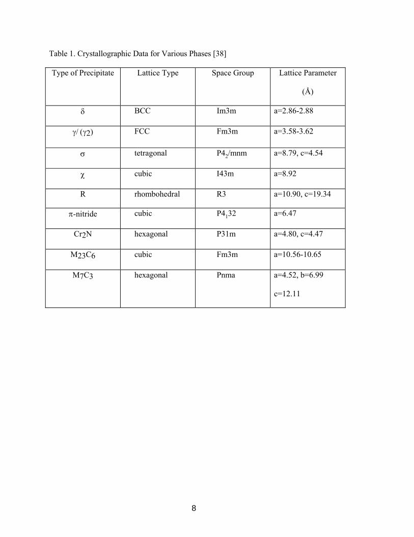
Identification of sigma phase by chemical composition is not always definitive. The
identification of precipitates should be combined with crystallography determinations.
Table 1 [38] shows the crystallographic data for the types of precipitates that occur in
DSS.

Figure 2. Micrographs Showing Different Morphologies of σ-phase [22]
7
8
Table 1. Crystallographic Data for Various Phases [38] Type of Precipitate Lattice Type Space Group Lattice Parameter
(Å)
δ BCC Im3m a=2.86-2.88
γ/ (γ2) FCC Fm3m a=3.58-3.62
σ tetragonal P42/mnm a=8.79, c=4.54
χ cubic I43m a=8.92
R rhombohedral R3 a=10.90, c=19.34
π-nitride cubic P4132 a=6.47
Cr2N hexagonal P31m a=4.80, c=4.47
M23C6 cubic Fm3m a=10.56-10.65
M7C3 hexagonal Pnma a=4.52, b=6.99
c=12.11

9
Chi (χ) Phase
χ-phase forms between 700 and 900°C and has similar Cr content and much
higher Mo content than σ-phase. χ-phase usually exists in much smaller quantities than
σ-phase[10], and also is associated with a reduction in both impact properties and
corrosion resistance [133]. However, χ-phase and σ-phase usually exist simultaneously,
thus it is difficult to study their individual effect on impact properties and corrosion
resistance [1]. Also, it has been indicated that χ-phase precipitates faster in the range of
800 to 850°C and upon long-term aging, χ-phase will convert into σ-phase [11].
χ-phase usually forms at the δ/γ interface and grows into the ferrite, but unlike σ-
phase, χ-phase is not distinguishable by optical light microscopy (OLM) and must be
studied using either TEM or backscattered (BS) SEM [11]. χ -phase can be distinguished
from σ-phase by TEM due the difference in crystallographic structure, as shown in Table
1, and by BS SEM because of the brighter contrast of χ-phase compared to σ-phase.
Figure 3 [12], illustrates the difference between the two phase using BS SEM.
R-Phase
R-phase forms between 550 and 800°C and is a Mo rich intermetallic compound
having a rhombohedral crystal structure, as shown in Table 1. R-phase, like other
intermetallic compounds, reduces impact properties and corrosion resistance. R-phase
forms rapidly from 550 to 650°C and at higher temperatures converts to σ-phase with
relatively short aging time.
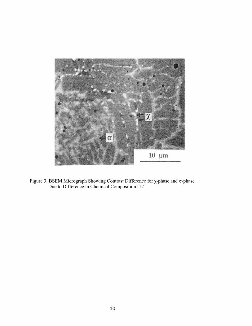
Figure 3. BSEM Micrograph Showing Contrast Difference for χ-phase and σ-phase Due to Difference in Chemical Composition [12]
10

11
R-phase is not distinguishable by OLM and is difficult to identify even with
advanced techniques such as TEM or SEM. Combinations of TEM and SEM/EDS are
usually employed for the identification of R-phase.
π-Phase
π-Phase has been identified as a nitride and is found at intragranular sites in DSS
after isothermal heat treatment at 600°C for several hours. Because of its Cr and Mo
enriched composition, π-phase has sometimes been confused with σ-phase. Similar to
other intermetallic precipitates, π-phase is also detrimental to toughness and pitting
corrosion resistance [13]. π-phase is also not distinguishable by OLM techniques. TEM
is normally used for identification [11].
Secondary Austenite (γ2)
Secondary Austenite (γ2) is termed as such because it has a FCC crystal structure,
which is the same crystallographic structure as primary austenite. γ2 is usually found at
austenite/ferrite boundaries or inside ferrite grains [12]. γ2 forms relatively quickly and
by different mechanisms as a function of temperature.
Below 650°C, γ2 is similar in composition to the surrounding ferrite, suggesting a
diffusionless transformation, with characteristics similar to martensite formation [14].
The orientation relationship is found to obey the Nishiyama-Wasserman (N-W)
relationship [11].
12
At a temperature range between 650 and 800°C, where diffusion is rapid,
Widmanstätten austenite can form [15]. In this temperature range, γ2 obeys the
Kurdjumov-Sachs relationship, its formation involves diffusion as it is enriched in Ni
compared to the ferrite matrix [16]. Also, in this temperature range, the composition of
γ2, with respect to Cr and N, is substantially lower than that of primary austenite. In the temperature range between 700 and 900°C, an eutectoid reaction of γ2 + σ-
phase can form. In this reaction the Cr and Mo rich σ-phase is surrounded by γ2, which
absorbs Ni and becomes depleted of Cr and Mo.
Cr2N
Cr2N is formed after a high temperature solution annealing heat treatment and
rapid cooling. This formation is caused by the supersaturation of nitrogen in the ferrite
matrix during the rapid cool, thus the amount of Cr2N present is a function of the
amount of nitrogen present. Formation occurs in the ferrite matrix between 700 and
900°C and takes the form of intragranularly precipitated elongated particles or
intergranularly precipitated globular particles.
Carbides M23C6 and M7C3
M23C6 carbides precipitate rapidly between 650 and 950°C and require less than
one minute to form at 800°C. M7C3 carbides precipitate between 950 and 1050°C and,
like M23C6, are predominantly located at austenite/ferrite boundaries.

13
Cu-rich epsilon (ε) Phase
Cu-rich ε-Phase occurs only in DSS alloys containing Cu. ε-phase precipitates after
100 hours at 500°C because of the supersaturation of ferrite due to the decrease in
solubility at lower temperatures. ε-phase has shown the ability to refine microstructure
but the effect on toughness and corrosion properties has not been well documented.
Microstructural Investigation Techniques
Vander Voort [39] stated in general, preparing DSS is not difficult, at least to a level
where the true structure can be seen. However, to remove all scratches can be more of a
challenge. As some of the precipitates that can form are harder than either matrix phase,
relief may occur. A contemporary method has been described for preparing DSS
specimens. This procedure, shown in Table 2, produces better, more consistent surfaces
where the true microstructure can be revealed clearly and sharply with good contrast.
Microstructural evaluation of DSS must be performed with the proper etching
techniques in order to use OLM or SEM. Numerous etchants and electro-chemical
etching techniques have been identified for revelation of the microstructures in DSS.
The following is a list of various etching techniques and the types of microstructure
they reveal:
1) 10% KOH electrolytical etchant, 5 V. Ferrite is stained yellow, austenite is
unattacked, σ-phase is stained reddish brown, and carbides are stained black [17].
2) A two-step electrolytical etching technique was developed by Nilson et al. [12] to
reveal the contrast of intermetallic phase. Step 1 uses dilute HNO3 to reveal

14
Table 2. Five Step Contemporary Automated Preparation Practice [39]
Step Surface/Abrasive Rpm Direction Load (lbs)
Time (minutes)
1 240-grit SiC 240-300 Head and plate rotating in same
direction
6 Remove All Cutting Damage
2 9-µm diamond on UltraPol™ Cloth
120-150 Head and plate rotating in same
direction
6 5
3-µm diamond on Texmet 1000®
Cloth
120-150 Head and plate rotating in same
direction
6 3
4 l-µm diamond on Trident™ Cloth
120-150 Head and plate rotating in same
direction
6 2
5 Masterprep™ alumina suspension on a Chemomet®
Cloth
120-150 Head and plate rotating in opposite direction
6 1.5-2
15
phase boundaries. Step 2 uses saturated KOH to enhance precipitate contrast. The
use of 2.2g (NH4)HF2, 0.2g K2S2O5, 18 ml HCl, 100 ml distilled H2O, known as
Beraha etchant, produces as-welded microstructures with high contrast secondary
austenite when etched for 10 to 20 seconds. This technique also colors ferrite blue
while austenite remains uncolored.
3) Cheng et al. [18] used a heated solution of 50 g K3Fe(CN)6, 30 g KOH, and 100
ml distilled H2O for DSS etching.
4) 1.5g CuCl2, 33 ml HCl, 33 ml alcohol, and 33 ml distilled H2O, known as
Kallings reagent, is an acid chloride solution that does not require electrolytical
techniques or heating. Kallings reagent stains ferrite dark and austenite light [19].
5) 10% Oxalic, 40% NaOH, and Glyceregia electrolytical etching are the most
common etchants used on DSS.
OLM techniques are used for the revelation of ferrite and austenite microstructure as
well as for the revelation of σ-phase, but this technique is not sufficient for the
identification of other secondary phases. Also, SEM/EDS is not sufficient due to the
similar chemical compositions of many of the secondary phases. TEM is time-
consuming and sometimes costly but it is the most effective way of revealing and
identifying secondary phases. TEM requires a sample thinning solution of 20% perchloric
acid, 10% glycerol, and 70% ethyl alcohol, which is performed at 0°C and 25 to 45V on a
twin jet polishing unit [20].

16
Alloying Elements
Alloying elements affect properties and microstructure of DSS in various ways, thus
each must be understood in order to maximize the effectiveness and to prevent the
alloying element from becoming harmful instead of beneficial to the complex
metallurgical system.
Chromium (Cr)
Cr is a strong ferrite former and is the essential element for the excellent corrosion
resistance of stainless steels. However, there is a limit to the level of Cr that can be
added, as the beneficial effect of ever higher levels is negated by the enhanced
precipitation of intermetallic phases such as σ-phase, as shown in Figure 1 [1].
Molybdenum (Mo)
Mo has a similar effect on ferrite stability as Cr and increases crevice corrosion and
pitting resistance. The mechanism by which Mo increases the pitting resistance has been
found to be the suppression of active sites via formation of an oxy-hydroxide or
molybdate ion [2].
Nickel (Ni)
Ni is a strong austenite former and is added to maintain the ferrite/austenite balance
in DSS. Excessive Ni can enhance the precipitation of σ-phase by promoting greater
concentrations of ferrite stabilizers such as Cr and Mo in the ferrite matrix.

17
Nitrogen (N)
N, like Ni, is a strong austenite former and can often be used in place of Ni for
austenite stabilization. N also effectively increases strength without the risk of
sensitization, increases localized corrosion performance, and critical pitting temperature
(CPT).
Manganese (Mn)
Mn increases abrasion, wear resistance, and tensile properties without a loss in
ductility [4]. However, Mn additions in excess of 3% and 6%, for nitrogen levels of
0.1% and 0.23% respectively, significantly decrease the CPT due to the increased
likelihood of MnS inclusions, which can act as initiation sites for pits [5].
Copper (Cu)
Cu plays a minor role in DSS but can increase the corrosion resistance when added
not in excess of 2%. However, additions of Cu can cause the supersaturation of ferrite
due to the decrease in solubility at lower temperatures, which can lead to the precipitation
of extremely fine Cu-rich ε-phase particles after 100 hours at 500°C [6]. This can
severely limit the service performance of DSS at temperatures near or in excess of 500°C.
Tungsten (W)
W additions of up to 2% in DSS improves the pitting resistance and crevice
corrosion resistance [7]. W is known to encourage the formation of intermetallics in the

18
700 to 1000°C temperature range, as shown previously in Figure 1 [1], and encourages
secondary austenite [8]. Also, W has been shown to form chi phase more rapidly than
otherwise similar chemical compositions without the W addition [9].
Effect of Solution Heat Treating
Slow cooling of DSS from the solution annealing temperature has been found to lead
to precipitation of detrimental intermetallic phases. DSS is normally water quenched
from elevated temperatures but even this type of cooling can be slow enough at the center
of heavy sections to allow formation of intermetallic phases. Proper solution annealing
heat treatments are employed to dissolve intermetallic phases and restore mechanical
properties and corrosion resistance to cast and wrought DSS.
The influences of certain elements play a role in defining the correct solution
annealing temperatures. Ni stabilizes sigma phase and Cr and Mo promote the formation
of sigma and other detrimental phases. Table 3 shows the correct solution annealing
temperature for cast DSS as defined by ASTM A 890-94a.
Effect of Heat Treatment Temperature
A maximum solution annealing temperature must be specified because too high of a
temperature can result in an increase of ferrite [22]. The modified ternary section of the
Fe-Cr-Ni phase diagram illustrates this increase in ferrite with respect to high solution
annealing temperatures. Higher ferrite content is not the only effect of high solution
annealing temperatures; these high temperatures can also:

19
Table 3. Heat Treatment Requirements by ASTM A890-94a
Grade Heat Treatment
4A Heat to 1120°C for sufficient time to heat casting uniformly to
temperature and water quench, or the casting may be furnace cooled to
1010°C minimum, hold for 15 minutes minimum and then water quench. A
rapid cool by other means may be employed in lieu of water quench. 5A
Heat to 1120°C minimum, hold for sufficient time to heat casting to
temperature, furnace cool to 1045°C minimum, quench in water or rapid
cool by other means. 6A
Heat to 1100°C minimum, hold for sufficient time to heat casting
uniformly to temperature, quench in water or cool rapidly by other means. 7A
Heat to 1040°C minimum, hold for sufficient time to heat casting
uniformly, quench in water or rapid cool by other means.

20
1) Lower the portioning coefficients [23]. This makes DSS less susceptible to
intermetallic phase transformations but more sensitive to secondary austenite and
Cr2N formation [34].
2) Decrease chromium content and increase nickel content in the ferrite as shown in
Figure 4 [22]. Consequently, Lai et al. [22] also demonstrated that this effect
dramatically slows the formation of sigma phase.
3) Change the morphology of austenite and ferrite. Radenkovic et al. [21] observed
that the morphology of the austenite changes from a relatively discontinuous
network to grain boundary morphology. Grain boundaries also become smoother
than their previous irregular shape as solution annealing temperature increases.
An increase in grain size has also been observed with an increase in peak
temperature [24].
Solution annealing temperatures should be chosen, as a function of specific heat
chemistry instead of selecting a temperature from the ASTM required minimum. High
solution annealing temperatures are required to dissolve sigma phase and obtain a
required ferrite content but the temperature must be controlled as not to increase the
ferrite to an abnormally high level, which can cause a decrease in impact toughness,
ductility, and corrosion resistance.
Effect of Other Heat Treatment Variables
As discussed in the previous section, heat treatment at excessively high temperatures
is undesirable but other variables in the heat treatment of DSS also need to be stringently

21
Figure 4. Effect of Solution Annealing Temperature on Ferrite and
Austenite Content [22]

22
controlled. Figure 5 [22], shows the effect of annealing temperature on the relative
amounts ferrite and austenite. Excessively high heat treatment temperature can cause
heat treatment time to have an even greater effect on ferrite content.
Step annealing/cooling heat treatment procedures for SAF 2205 and Ferralium 255
weld metals were analyzed by Kotecki [25]; no particular advantages or disadvantaged
were observed.
Corrosion Behavior of Duplex Stainless Steels
It is well known that DSS has a high resistance to stress corrosion cracking (SCC)
due to its ferrite/austenite microstructure. SCC is not in the scope of this research so it
will not be discussed in this review. However, DSS is affected by two other corrosion
mechanisms known as pitting corrosion and intergranular corrosion.
Pitting Corrosion
The pitting resistance of DSS in a chloride environment has been related
essentially to Cr, Mo, and Ni. The pitting resistance equivalent number, PREN, was
developed to relate the amount of these elements present to the corrosion potential of the
alloy. However, numerous researchers [19, 26-29] have determined that this equation
can be misleading when calculated from the bulk alloy composition because DSS alloys
contain austenite and ferrite, which have different compositions. Ferrite is enriched in
Cr and Mo, while austenite is enriched in N. In general, austenite has a lower PREN
than ferrite in the base material, but austenite has higher PREN than ferrite in the weld
metal.

23
Figure 5. Effect of Solution Annealing Temperature on the Relative Amounts of the Ferrite and Austenite Phases [22]
24
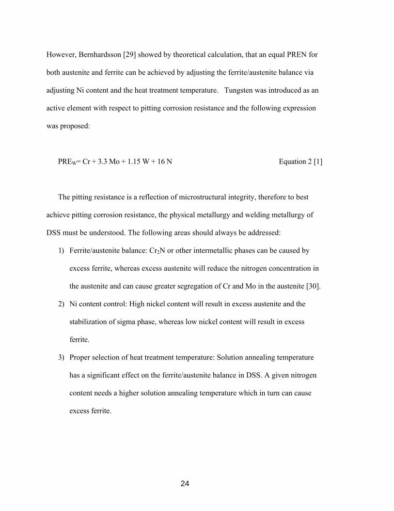
However, Bernhardsson [29] showed by theoretical calculation, that an equal PREN for
both austenite and ferrite can be achieved by adjusting the ferrite/austenite balance via
adjusting Ni content and the heat treatment temperature. Tungsten was introduced as an
active element with respect to pitting corrosion resistance and the following expression
was proposed:
PREW= Cr + 3.3 Mo + 1.15 W + 16 N Equation 2 [1]
The pitting resistance is a reflection of microstructural integrity, therefore to best
achieve pitting corrosion resistance, the physical metallurgy and welding metallurgy of
DSS must be understood. The following areas should always be addressed:
1) Ferrite/austenite balance: Cr2N or other intermetallic phases can be caused by
excess ferrite, whereas excess austenite will reduce the nitrogen concentration in
the austenite and can cause greater segregation of Cr and Mo in the austenite [30].
2) Ni content control: High nickel content will result in excess austenite and the
stabilization of sigma phase, whereas low nickel content will result in excess
ferrite.
3) Proper selection of heat treatment temperature: Solution annealing temperature
has a significant effect on the ferrite/austenite balance in DSS. A given nitrogen
content needs a higher solution annealing temperature which in turn can cause
excess ferrite.

25
4) Proper selection of welding procedures: Welding parameters, joint geometry, heat
input, filler metal, and shielding/backing gases should always be carefully
considered. Excessive dilution and extremely rapid or slow cooling rates must be
avoided.
Intergranular Corrosion
If a DSS is properly solution annealed and cooled, which dissolves intermetallic
compounds and chromium carbides, it is immune to intergranular corrosion [17, 31-35].
However, it was found that a high Mo content in oxidizing environments would result in
higher general corrosion rates [36].
Phase balance plays a crucial role in the intergranular corrosion resistance of DSS.
Gooch [30] showed that excess ferrite in weld HAZ's causes decreased resistance to
intergranular corrosion. However, if enough austenite is formed along with the ferrite the
HAZ is nearly immune to intergranular corrosion, therefore, microstructural control is
again proven to be of great importance.
Toughness
The Charpy Impact test is a supplementary requirement for DSS castings specified to
ASTM A890-4A. Druce et al. [118] determined that the V-notch specified by ASTM
was the best geometry for the impact toughness testing of cast DSS.
26
This literature review mentions, in detail, the factors that can lead to reduced impact
toughness in DSS, therefore, no further discussion of these factors will be included in this
section of the review.
Welding of DSS
Welding Metallurgy
Farrar [40] noted that the transformation of delta-ferrite and the formation of
intermetallic phases is controlled by the local microsegregation of chromium and
molybdenum, not the bulk concentration. It was also shown by Farrar, that the delta-
ferrite to austenite transformation is accompanied by significant diffusion of both Cr and
Mo across the austenite/ferrite boundary to the delta-ferrite and that the enrichment
strongly influences the formation of intermetallic phase.
Elemental partitioning of Cr, Mo, Ni, and N was studied by Atamart and King [41].
Mo was found to partition preferentially to ferrite as temperature decreased. With
increasing temperature, the partitioning of Ni to austenite was determined to decrease
gradually. It was also determined that N has the most profound effect on the
austenite/ferrite phase balance. The volume fraction of austenite is extremely sensitive to
small N additions, which suggests that the phase balance after welding can be controlled
by the N content.
Similar studies by Ogawa and Koseki [27] showed that the microsegregation of Ni is
more pronounced than Mo, which is more pronounced than that of Cr. The authors also
noted that the partitioning of Cr, Mo, and Ni during ferrite solidification is not as

27
pronounced as during austenite segregation. Also, the partitioning of Cr, Mo, and Ni
between austenite and ferrite was not significant. However, by increasing the austenite
transformation temperature with the addition of Ni and/or N, partitioning was promoted.
Heat Affected Zone (HAZ)
The HAZ in welds experiences a range of thermal histories with peak temperatures
reaching solidus adjacent to the weld and falling to ambient at greater distances from the
weld. The total thermal cycle at a specific point in the HAZ is often very complicated to
determine due to the rapid heating and cooling, and in multipass welds, the repeated
exposure to high temperatures. The thermal history of the HAZ must be understood in
order to identify potential metallurgical consequences in terms of austenite/ferrite phase
balance, intermetallic phase precipitation, grain growth, and the HAZ width, which all
effect mechanical properties and corrosion performance of DSS.
Austenite/ferrite phase balance control in the HAZ is important from a corrosion
standpoint, in that the intergranular corrosion resistance, which is the major advantage of
DSS over fully austenitic stainless steels, deteriorates with high ferrite contents. Also,
austenite/ferrite content is important from a fracture toughness standpoint. As the ferrite
content of DSS increases, impact toughness decreases. Therefore, proper balance of
ferrite and austenite must be maintained.
For a given plate thickness, the cooling rate decreases as the heat input is increased.
Also, for a given heat input, the cooling rate decreases as the plate thickness decreases.
For these reasons, the welding heat input cannot be considered alone. However, for the

28
following discussion, the plate thickness and joint configuration is assumed to be the
same.
Ferrite content in DSS is a function of heat input and cooling rate. The lower the
heat input, the higher the ferrite content and the lower the impact toughness [42-53].
Draugelates et al. [48] explained that the higher cooling rates suppress the diffusion-
controlled processes in austenite reformation, hence, the original phase ratio of ferrite to
austenite is shifted towards higher ferrite content.
Secondary phase precipitation is also significantly effected by high cooling rates.
Lippold et al. [51] ad Kirieva and Hanerz [52] explained that the presence of chromium-
rich nitrides (Cr2N) is observed over a wide range of cooling rates and the effect is
particularly evident for microstructures with a high ferrite content (usually the result of a
fast cooling rate). These chromium rich nitrides also significantly decrease the impact
toughness and pitting corrosion resistance. A risk of chromium nitride formation in
ferrite is also noticed with an increase in ferrite and increased nitrogen levels due to the
lower solubility of nitrogen in ferrite. However, high cooling rates do reduce σ-phase
and χ-phase precipitation.
It has been determined, however, that excessively high heat input may not be
beneficial due to the risk of intermetallic phase precipitation and grain growth, both of
which reduce impact toughness [40, 52-56].
Studies have also been conducted to compare the sensitivity with respect to cooling
rate for different grades of DSS. As previously discussed, alloying elements, such as
nickel and nitrogen, can increase the temperature range at which ferrite to austenite

29
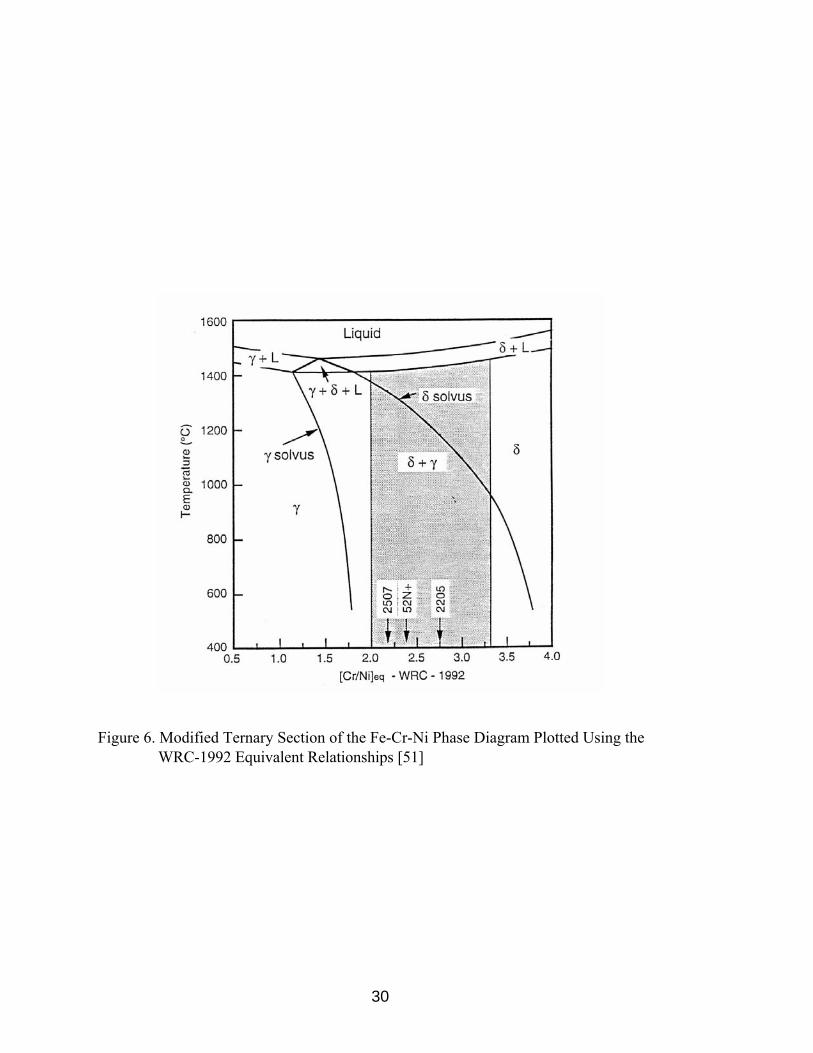
transformation begins. Lippold et al. [51] investigated alloys SAF 2205, SAF 2507,
and 52 N+. Alloy 2507 was found to be less sensitive to HAZ microstructural
degradation than Alloy 2205 over a wide range of cooling rates and heat inputs. It was
suggested by the authors that the highly ferritic HAZ of Alloy 2507 is due to the greater
temperature range between solidus and ferrite solvus temperature for Alloy 2205.
Figure 6, from Lippold et al., shows the ferrite solvus temperature, A4, is approximately
1180°C for Alloy 2205 and increases to approximately 1350°C for Alloy 2507 due to
the higher content of nickel and nitrogen. Kivinera and Hanerz [52] showed that at a
similar cooling rate, more ferrite was found in SAF 2205 HAZ than in SAF 2507 HAZ.
Figure 7, illustrates these findings.
The effect of cooling rate on Alloy SAF 2205 and Ferralium 255 was compared by
Lippold et al. For cooling rates from 2 C°/min. to 50 C°/min, the HAZ ferrite content
for both alloys is nearly the same. Due to the chemistries of each alloy, this study
showed that nickel and nitrogen are dominant elements in ferrite content control.
The effect of varying nitrogen content in super duplex stainless steel was
investigated by Hoffmeister and Lothongkum [53]. It was determined that the A4
temperature was increased and the ferrite to austenite transformation was accelerated as
nitrogen content increased. However, a medium nitrogen content of approximately
0.10% was determined to be detrimental due to precipitation of Cr2N when the cooling
rate is high.
30
Figure 6. Modified Ternary Section of the Fe-Cr-Ni Phase Diagram Plotted Using the WRC-1992 Equivalent Relationships [51]

Microstructure of SAF 2205 after Gleeble simulation ∆t12/8 = 93.0s
Microstructure of SAF 2507 after Gleeble simulation ∆t12/8 = 93.5 s
Figure 7. Micrographs Showing Microstructures of SAF 2205 and 2507 after Gleeble Simulation at ∆t = 93.0 s [52]
31

32
Generally, for a given cooling rate, the higher the peak temperature, the higher the
ferrite content. Heating rate and base metal structure can also affect the final amount of
ferrite. It was shown by Lippold et al [51] that fast heating rates can retard the
dissolution of austenite therefore preventing a high ferrite content in the HAZ.
Grain growth can also be a problem in the HAZ. High peak temperatures may cause
excessive grain growth, which can lower impact toughness [40, 52-56]. Atamert and
King [42] showed that when the spacing between austenite particles is large, grain growth
can be excessive.
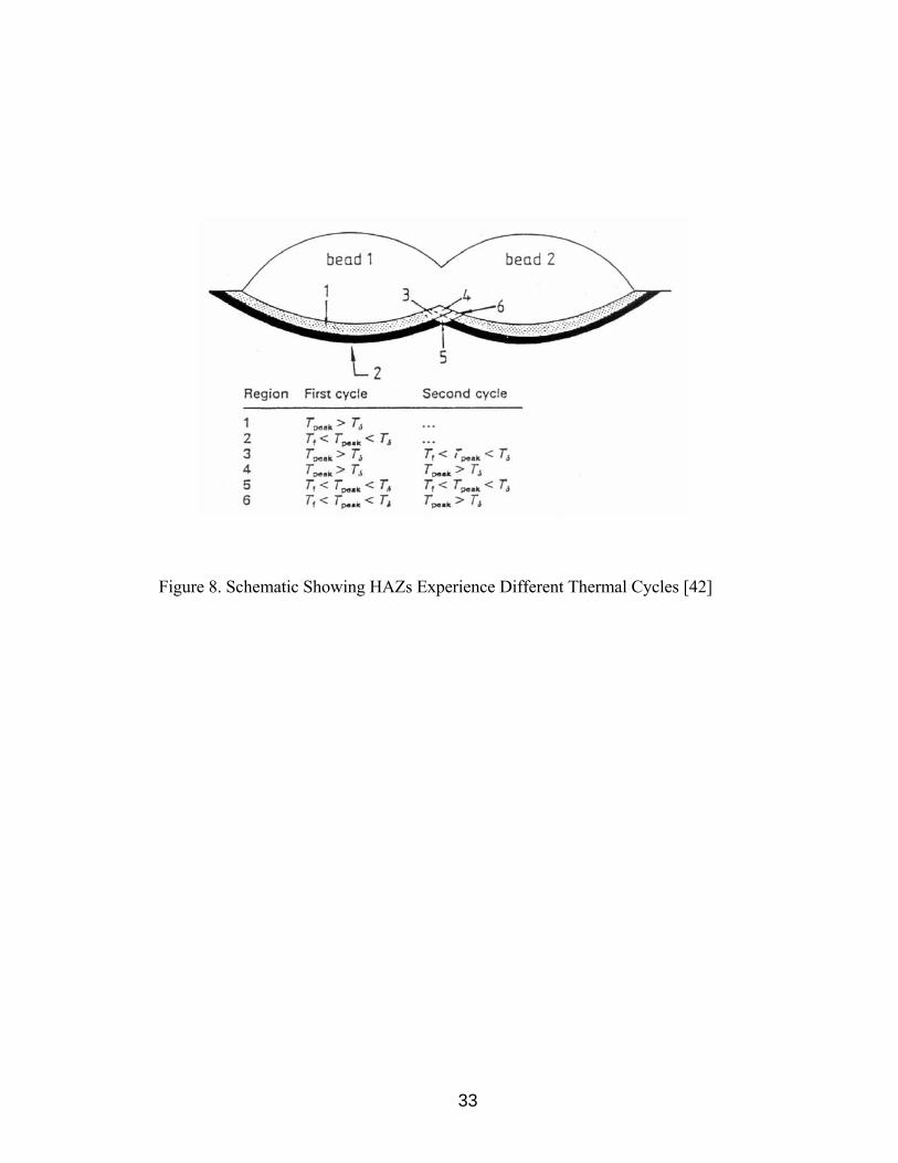
The prior discussions of the HAZ are limited to single pass welding. However, it is
important to consider multipass welding since it is normally used in industrial practice.
During multipass welding the HAZ is reheated during subsequent weld passes, to a
degree dependent on the position of the HAZ relative to the heat source. Figure 8 [42],
shows the effect of multipass welding on the HAZ. Regions of the HAZ that are affected
by the second pass may experience significant microstructural change.
In multipass welds, underlying weld metal is also reheated by the deposition of each
subsequent pass. Figure 9 [57], shows another schematic of multipass effects on the
HAZ.
A maximum interpass temperature of 150°C is normally recommended for multipass
welding of DSS. [58,59]. However, Sandvik Steel [134] specifies a maximum interpass
temperature of 150°C for SAF 2507 and 250°C for SAF 2304 and SAF 2205.
33
Figure 8. Schematic Showing HAZs Experience Different Thermal Cycles [42]
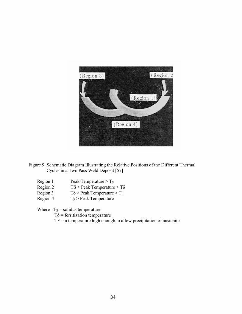
Figure 9. Schematic Diagram Illustrating the Relative Positions of the Different Thermal Cycles in a Two Pass Weld Deposit [57]
Region 1 Peak Temperature > TS
Region 2 TS > Peak Temperature > Tδ Region 3 Tδ > Peak Temperature > TFRegion 4 TF > Peak Temperature
Where TS = solidus temperature Tδ = ferritization temperature TF = a temperature high enough to allow precipitation of austenite
34
35
Weld Fusion Zone
The weld fusion zone is similar to a casting in that segregation of alloying elements
occurs. DSS weld metal solidifies mainly as ferrite, which leads to less segregation of
chromium and molybdenum. Also, diffusion rates are at high temperatures just below the
melting point, so homogenization of alloy elements in the ferrite can occur [30].
Heat input is of major concern when welding DSS. At low heat input, the
ferrite/austenite transformation is controlled by nitrogen, so there may be little difference
between the substitutional element contents of the two phases upon cooling to room
temperature, although nitrogen will be enriched in the austenite. At high heat input, there
is sufficient time for diffusion of Cr, Mo, and Ni to occur, therefore, there will be
significant differences in the final alloy content between the two phases [30].
Autogenous welding of DSS is generally not recommended unless a post weld
solution annealing heat treatment will be employed, due to the fact that a high ferrite
content will be produced and a brittle weld metal can exist [39]. DSS is generally welded
with filler metals containing at least 2% higher nickel content than the base metal.
However, if the filler metal composition is biased to austenite by adding nickel, an
adverse weldment performance may result due to the following reasons:
1.) Increasing the nickel content promotes austenite formation and dilution of
nitrogen content in the austenite and thus lowers the corrosion resistance of the
austenite and the weld metal in general.
2.) High Ni promotes austenite formation but also promotes a greater concentration of
ferrite stabilizing elements (Cr, Mo) in the remaining ferrite, therefore, more

36
susceptibility to the precipitation of sigma. Consequently, higher post weld
solution heat treatment temperatures (1100 to 1150°C) must be utilized to
dissolve all sigma phases [6].
3.) If the dilution from the parent steel is low, ferrite levels can be too low to even
satisfy the weld metal strength requirements.
Ferrite Prediction and Measurement
It is essential for DSS to have appropriate ferrite content in order to achieve a
desirable combination of strength, toughness, and corrosion resistance. Also, appropriate
ferrite content helps to reduce the susceptibility of DSS to hot cracking and
microfissuring. Excessively low levels of ferrite in DSS will cause low strength, poor
intergranular corrosion resistance, and susceptibility to hot cracking. On the other hand,
excessively high levels of ferrite in DSS will cause low toughness, poor intergranular and
pitting corrosion resistance, and susceptibility to cold cracking embrittlement problems.
From this, it is obvious that appropriate levels of ferrite must be maintained and accurate
ferrite measurement techniques must be used in DSS castings and welds so that ferrite
content can be achieved through chemical composition adjustment.
In 1949, Schaeffler [65] began some of the earliest work on ferrite prediction in weld
metals. Delong [66] expanded on this work, as did Kotecki [62-64], who also
accomplished significant research on ferrite measurement.
The Schaeffler diagram, Figure 10, first developed in 1949, contains phase fields and
isoferrite lines that predict weld metal structure as a function of composition.

12 14 16 18 20 22 24 26 28 30 32 34 36 38
Figure 10. The Schaeffler's Diagram [65]
37
38
A "chromium equivalent" (Creq) and a "nickel equivalent" (Nieq) are calculated for each
base metal and filler metal. The equivalents are then plotted on the Schaeffler diagram
and tie lines are drawn through the plotted points, proportioned according to expected
dilution, to obtain a weld metal ferrite content estimation.
Based on the Schaeffler diagram, the WRC-1992 diagram was developed. Due to the
fact that the Schaeffler diagram was replaced by the WRC-1992 diagram in codes such
as ASME Boiler and Pressure Vessel Code [86], this review focuses on the WRC-1992
diagram and the on-going debate over possible modifications. Also, the Schoefer diagram,
which was developed similarly to the Schaeffler diagram, has been a standard for
stainless steel castings and will also be addressed in this review.
WRC-1992 Diagram
Figure 11, shows the WRC-1992 diagram. Creq and Nieq for the WRC-1992 diagram
are calculated as:
Creq = Cr + Mo + 0.7 Nb Equation 3
Nieq = Ni + 35C + 20N + 0.25 Cu Equation 4
The significant addition in developing the WRC-1992 diagram was the recognition
that a coefficient of Cu needed to be added to the Nieq. Kotecki [62] stated that the
importance of the effect of Cu on ferrite content has long been recognized and various
coefficients have been proposed. Lake [67] developed data specifically for evaluation of
the effect of Cu. The data was developed by determining the effect of Cu through the

Figure 11. The WRC-1992 Diagram [62]
39

40
addition of 0 - 4% Cu. Building on Lake's research, Kotecki [68] proposed a coefficient
of 0.25 for Cu and demonstrated the validity. Kotecki [62] also noted that the predictions
of the WRC-1992 diagram are only valid over limited Creq and Nieq ranges, 17-31 and 9-8,
respectively. However demonstrations were made that proved lower ranges of Creq and
Nieq could be valid.
The Schoeffer Diagram
Figure 12 shows the Schoeffer diagram, which was adopted by ASTM and used in
Specification A 800. As with similar diagrams, the Schoeffer diagram requires that Creq
and Nieq be calculated but the calculations for the Schoeffer diagram are vastly different
than calculations for other diagrams. The calculation for Creq and Nieq are shown below:
Creq = Cr + 1.5 Si + 1.4 Mo + Nb - 4.99 Equation 5
Nieq = Ni + 30 C + 0.5 Mn + 26 (N-0.02) + 2.77 Equation 6
where the elemental concentrations are given in weight percent.
It must be noted that the WRC-1992 diagram bases ferrite content in Ferrite
Number (FN), which is based on magnetic response. In the Schoeffer diagram, the
ferrite content is based on volume fraction. A comparison between FN and ferrite
percent will be addressed later in this review.
ASTM A 800-91 states that the Schoeffer diagram is applicable to alloys containing
elements in the following ranges:

41
Figure 12. The Schoeffer Diagram (from ASTM A 800-91)
42
Carbon 0.20 max
Manganese 2.00 max
Silicon 2.00 max
Chromium 17.0-28.0
Nickel 4.0-13.0
Molybdenum 4.00 max
Columbium 1.00 max
Nitrogen 0.20 max
By examining the elemental content of DSS, nitrogen, which is a strong austenite
former and Mo, which is a strong ferrite promoter, can easily exceed the Schoeffer
diagram elemental limitations, which produces concerns for the accuracy of estimations
produced by this method for DSS ferrite prediction. However, presently there are no
alternate "quick" methods for ferrite prediction in DSS.
Ferrite Measurement
Discussions on ferrite prediction have shown that no one method is completely
accurate for DSS. Therefore, it is imperative that accurate ferrite measurement
techniques be established in order to ensure that an appropriate balance of ferrite and
austenite in DSS castings and weld metal is achieved.
43
The following sections will address advantages and disadvantages of the current
ferrite measurement techniques that have been established, with some being standardized
and others not.
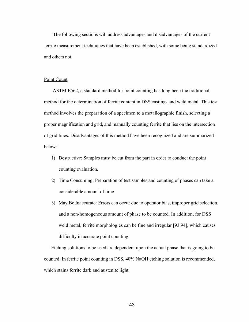
Point Count
ASTM E562, a standard method for point counting has long been the traditional
method for the determination of ferrite content in DSS castings and weld metal. This test
method involves the preparation of a specimen to a metallographic finish, selecting a
proper magnification and grid, and manually counting ferrite that lies on the intersection
of grid lines. Disadvantages of this method have been recognized and are summarized
below:
1) Destructive: Samples must be cut from the part in order to conduct the point
counting evaluation.
2) Time Consuming: Preparation of test samples and counting of phases can take a
considerable amount of time.
3) May Be Inaccurate: Errors can occur due to operator bias, improper grid selection,
and a non-homogeneous amount of phase to be counted. In addition, for DSS
weld metal, ferrite morphologies can be fine and irregular [93,94], which causes
difficulty in accurate point counting.
Etching solutions to be used are dependent upon the actual phase that is going to be
counted. In ferrite point counting in DSS, 40% NaOH etching solution is recommended,
which stains ferrite dark and austenite light.

44
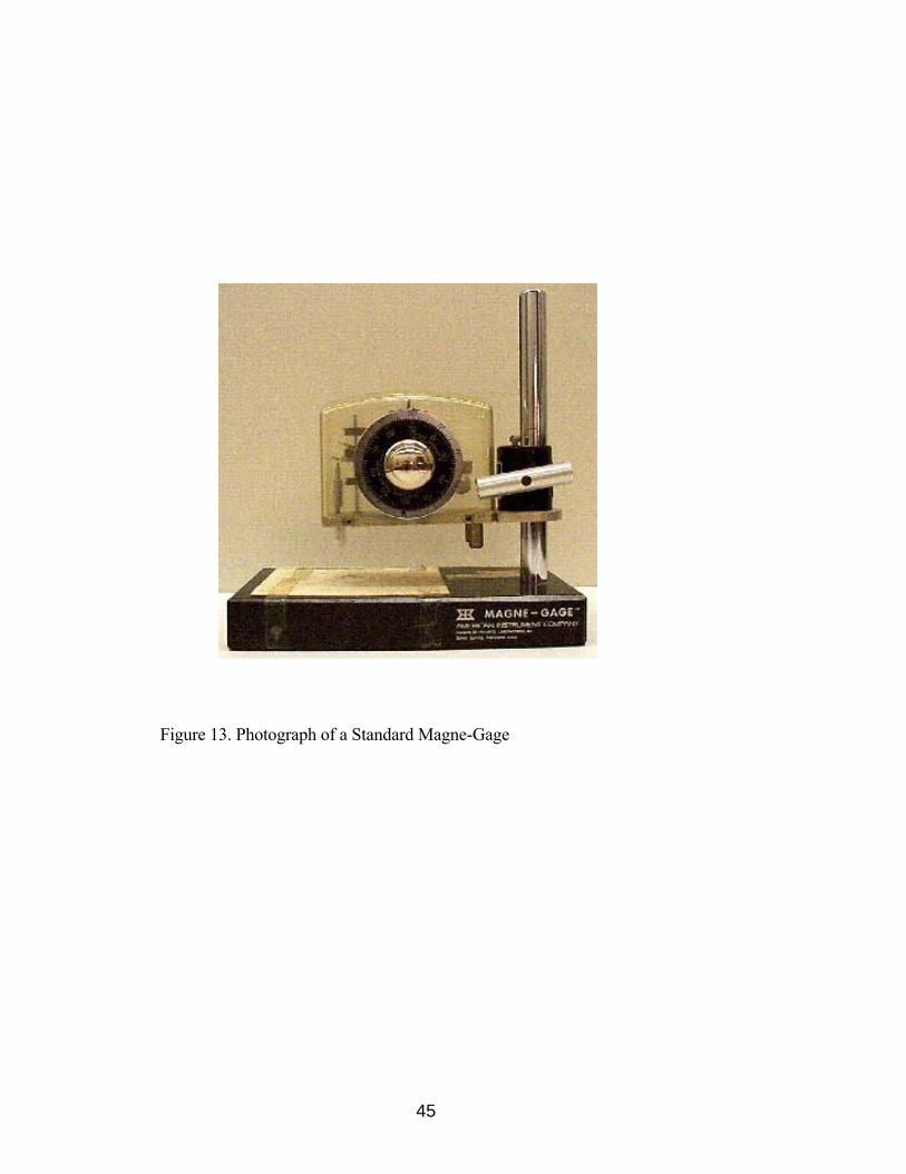
Magne-Gage: Magnetic Adhesion Method
The ferromagnetic property of ferrite has been used in many instruments, to
determine the ferrite content in DSS castings and weld metal. The Magne-Gage is one of
the most widely applied instruments, which uses the ferromagnetic property of ferrite to
make measurements.
Figure 13 [69] shows a standard version of the Magne-Gage. The white dial (WD)
scale measures the range of 0-28 FN with a #3 magnet. The white dial readings decrease
as the FN increases, therefore 0 FN usually corresponds to a WD greater than 100. The
range in measurement of 0-28 F for the Magne-Gage is certainly a major limitation, but
this problem can be solved using the Extended ferrite Number (EFN) system.
It is imperative to recognize the advantages of using FN in place of volume % ferrite.
The arbitrary FN scale was first adopted in the U.S. as ASI/AWS A4.2-74 [70]. FN has
been found to be very reproducible, which is the main advantage for its use and
standardization. However, FN has been found to appreciable overstate the volume %
ferrite in weld metal [70].
Calibration of the Magne-Gage must be performed in order to accurately develop the
EFN as a function of WD. Primary and secondary standards are specified, in ANSI/AWS
A4.2-91 [71] ad ASTM A 799-92, for the calibration. Primary standards are available
from the U.S. National Institute of Standards and Technology (NIST), formerly known as
the National Bureau of Standards (NBS), and consist of a non-magnetic coating over a
carbon steel substrate. Secondary standards are cast stainless steel or DSS weld metals
whose ferrite percent has been determined "in house" by a primary instrument. Detailed
45
Figure 13. Photograph of a Standard Magne-Gage

46
calibration procedures are described in ANSI/AWS A4.2-91 and ASTM A 799-92.
Readers are referred to Kotecki [86,88,96] for details on the lengthy procedures for
developing EFN as a function of WD.
Measurements taken from the Magne-Gage are very reproducible, however, the
Magne-gage is not well suited for field use. Also, the Magne-Gage is not well suited for
measuring ferrite content of specimens with smaller contact surfaces than the contact
surface of the magnet used in the gage.
Eddy Current Method: Magnetic Induction Method
Instrumentation for the eddy current method usually includes a display and control
unit and a hand-held eddy current probe, which makes this method particularly well
suited for field measurements of ferrite content.
Figure 14, shows a schematic of the magnetic induction measurement method. The
method utilizes a low frequency alternating current through the field coil, generating an
alternating magnetic field that penetrates the specimen. The interaction between the field
and specimen produces an alternating voltage in the detection coil that is proportional to
the ferrite content in the volume of the measurement, which means this method
determines ferrite in terms of volume %.
The Feritscope® is a commercially available instrument that incorporates this
measurement technique. The accuracy of the Feritscope® is affected by the
electromagnetic properties of the ferrite and morphology of the ferrite [72].
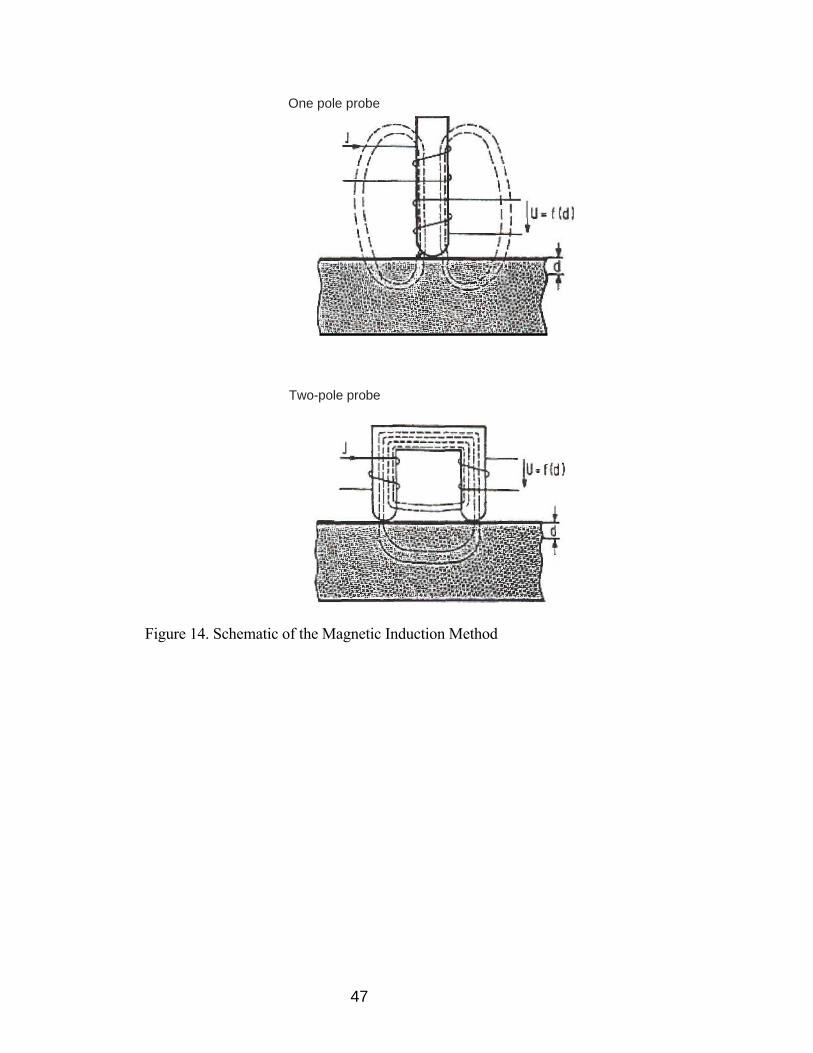
One pole probe
Two-pole probe
Figure 14. Schematic of the Magnetic Induction Method
47

48
Distance between the probe and the surface of the specimen and the curvature of the
specimen can also affect the accuracy.
Ferrite Number vs. Ferrite Percent
Point Counting and the Feritscope® measure ferrite content in ferrite %, whereas the
Magne-Gage measures ferrite content in FN. There is not a simple relationship between
FN and ferrite % mainly because the relationship depends upon the composition of the
ferrite [73]. FN is clearly preferable to ferrite % for the determination of ferrite in duplex
stainless steel weld metal [74]. However, Kotecki [73] indicated that such is not the case
with cast alloy, in which the ferrite is much coarser and more regularly shaped than in the
weld metal. Taylor [75] suggested a relationship between FN and ferrite %:
% Ferrite = 0.55(Extended Ferrite Number) + 10.6 Equation 7
Since EFN is used in this equation, FN in the range of 0-28 is not applicable for this
equation.
Weldability
Weldability defines the ease of producing a defect-free weld with adequate
mechanical properties and corrosion resistance. Hot cracks in the fusion zone or HAZ
and hydrogen assisted cold cracking are the defects of interest in DSS. The following
49
sections will address proper welding procedures, to avoid these types of defects and to
achieve adequate mechanical properties and corrosion resistance.
Fusion Zone Solidification Cracking
Weld solidification cracking is caused by a crack-susceptible microstructure which
forms at the final stage of the solidification process due to the low melting impurities
enriched in the final liquid films. A Creq/Nieq ratio of less than 1.5 causes DSS welds to
solidify in a primary austenite mode causing severe partitioning of impurities such as S
and P, which form liquid films which can wet austenite/austenite grain boundaries and
lead to solidification cracking. A Creq/Nieq ratio of 1.5 - 2.0 has been determined as the
optimum level for resistance to hot cracking in DSS. A Creq/Nieq ratio above 2.0 has been
shown to have a highly ferritic solidification, which also produces cracking tendencies.
Little research on DSS fusion zone solidification cracking exists. Fabrication
experience with a number of commercial DSS has suggested that weld solidification
cracking is not a significant problem [76]. DSS alloys solidify with ferrite as the primary
phase, which causes these alloys to be less susceptible to solidification cracking than
those that solidify with austenite as the primary phase. The difference in cracking
susceptibility as a function of primary solidification product is generally ascribed to the
greater affinity of the ferrite phase for the impurity elements such as sulfur and
phosphorus and the reduced tendency for liquid films to wet ferrite/ferrite boundaries
[99].

50
Heat Affected Zone Liquation Cracking
Lippold et al. [77] concluded that the susceptibility of DSS to liquation-related HAZ
cracking is negligible. It was noted that ferritic microstructures are generally resistant to
grain boundary liquation because of the high diffusivity of impurities at high
temperatures and because DSS generally contain low amounts of impurities.
Hydrogen Assisted Cold Cracking
Cold cracking, also known as hydrogen assisted cracking, susceptibility is
determined by three factors: susceptible microstructure, the presence of hydrogen, and
restraint. Although ferrite in DSS helps to eliminate hot cracking problems, it increases
the risk of cold cracking.
Highly ferritic microstructures are considered susceptible because they have high
strength, low toughness, and high diffusivity for hydrogen.
Hydrogen can be introduced into welds in many ways but most commonly through
the use of electrodes that have absorbed moisture or from the atmosphere, which is not
properly shielded during welding. Ar-5% H2 has been used as a common shielding gas
when joining DSS using the gas tungsten arc welding process [59, 61,, 78-84]. Research
[78-84] has shown that cold cracking susceptibility of DSS increases as ferrite content
increases; therefore, it is necessary to have a properly controlled ferrite/austenite balance.
The work of Ogawa and Miura [79] showed that by increasing austenite formation,
by increasing the N2 and Ni content, cold cracking problems will be reduced. The reason
for this is that the diffusivity of hydrogen in austenite is significantly lower than in ferrite.

51
Therefore, for a given hydrogen level in the weld, the lower the amount of ferrite, the
lower the tendency for cold cracking. Hoffmeister et al. [81] showed that an interaction
between nitrogen and hydrogen occurs during welding. When welding DSS containing
N2, the loss of N2 is more severe when H2 bearing Ar is used. For this reason, Hoffmeister
et al. suggested that H2 needs to be mixed with Ar, N2 should also be mixed, mainly
because N2 and H2 loss in the weld metal is reduced. Shinozaki et al. [78], warned that
adding Nitrogen may not be beneficial depending on whether nitrogen is indeed
dissolved in austenite. If this happens, the higher nitrogen content causes a higher amount
of Cr2N precipitation, which can increase the risk of cold cracking. Preheating the
material at 100 - 200°C is viable to decrease the cooling rate [79].
Postweld solution heat treatment immediately after welding is another suggested
method for eliminating hydrogen cracking [79]. However, section size limitations and
material chemistry may make preheating or postweld heat treatment difficult. Therefore,
the most viable option for eliminating cold cracking is the elimination of H2 from the
welding process.
Readers interested in cold cracking susceptibility tests are referred to Shinozaki et al.
[78], Ogawa and Miura [79], Lundin et al. [84], and Walker and Gooch [85].
Welding Procedures
Good welding practice must be appreciated and implemented when fabricating DSS.
The details of, for example, the welding energy input must be related to the grade and
thickness being welded [121]. Welding procedures must be correctly designed as an aid
52
to the welder, not simply as a document for the owner and authorities [121]. Balanced
welding and distortion control techniques have positive implications on the technical and
economic success of duplex fabrication [121].
Welding Processes
The following welding process have been determined as viable methods for DSS [86-
94]:
1) SMAW Shielded Metal Arc Welding (stick electrode welding)
2) GTAW Gas Tungsten Arc Welding
3) GMAW Gas Metal Arc Welding
4) FCAW Flux Cored Arc Welding
5) SAW Submerged Arc Welding
6) PAW Plasma Arc Welding
Table 4 gives a brief summary of the characteristics of the welding processes listed
above. Resistance welding (RW), laser welding (LW), electron beam welding (EBW)
and friction welding (FW) are considered immature processes for DSS [94]. These
processes are considered immature due to the fact that rapid cooling rates are generally
produced, which often leads to high ferrite content in DSS weld metals and HAZ.
Similarly, electroslag welding (ESW) is not recommended because it requires high
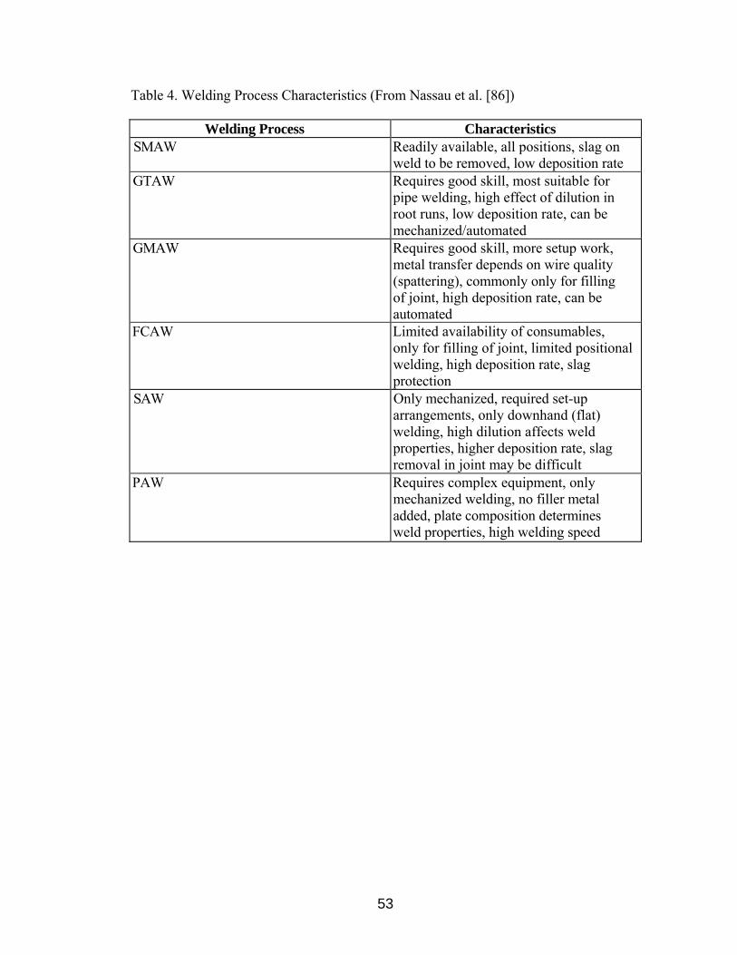
53
Table 4. Welding Process Characteristics (From Nassau et al. [86])
Welding Process Characteristics SMAW Readily available, all positions, slag on
weld to be removed, low deposition rate GTAW Requires good skill, most suitable for
pipe welding, high effect of dilution in root runs, low deposition rate, can be mechanized/automated
GMAW Requires good skill, more setup work, metal transfer depends on wire quality (spattering), commonly only for filling of joint, high deposition rate, can be automated
FCAW Limited availability of consumables, only for filling of joint, limited positional welding, high deposition rate, slag protection
SAW Only mechanized, required set-up arrangements, only downhand (flat) welding, high dilution affects weld properties, higher deposition rate, slag removal in joint may be difficult
PAW Requires complex equipment, only mechanized welding, no filler metal added, plate composition determines weld properties, high welding speed
54
heat inputs and can produce extremely slow cooling rates, which can lead to intermetallic
phase precipitation in DSS.
SMAW and GTAW are the most used processes for the welding of DSS, therefore
the focus of this review will be these processes.
SMAW
Table 4 shows that SMAW is a versatile welding process, which can be used in
all welding positions. For the repair welding of castings and other structures, SMAW is
usually selected [86]. Basic SMAW electrodes usually result in poor cosmetic
appearance of the weld and difficulty in removing slag, therefore rutile coated electrodes
are normally the electrode of choice. However, basic electrodes show good low
temperature impact values because of their lower oxygen and silicon content deposited in
the weld.
The control of moisture is important to eliminate cold cracking problems and
porosity [87, 89, 91, 95]. A method for moisture control in SMAW electrodes is to bake
for approximately two hours at 250 - 305°C before welding. Extra-moisture-resistant
(EMR) electrodes, which have a manufacturer's guarantee of low moisture content, are
also an excellent option for control of cold cracking.
SMAW relies on gases and slag from the electrode to protect the pool during
welding. Holmberg [91] recommended that an arc as short as possible should be
maintained in order to offer the best protection of the weld pool. Oxides, porosity,

55
reduced mechanical properties, and excessive heat input can be produced if the arc is
long.
Heat input in DSS welding is of major importance. Low heat inputs result in fast
cooling rates causing high ferrite content and Cr2N precipitates, which in turn, causes
brittleness in the weld. High heat inputs result in slow cooling rates, which can lead to
the precipitation of detrimental intermetallic phases in DSS. A range of heat inputs for a
broad range of thicknesses was recommended by Holmberg [91], 0.2 -1.5 KJ/mm for
alloy SAF 2507 and 0.5 - 2.5 KJ/mm for 22Cr DSS. Readers are encouraged to consult
the material producers for detailed welding parameter information.
GTAW
GTAW is a slow process but it can be ideal for certain welding situations. GTAW is
the process of choice for high-quality root passes in piping because, with proper backing,
it prevents slag, spatter, and oxidation on the inside root pass. Also, automated GTAW
shows great weld to weld repeatability.
Figure 15 shows the impact toughness characteristics of GTAW as opposed to
various other welding processes. GTAW exhibits better impact toughness because of the
absence of slag and oxidation.
Root pass dilution can be severe in GTAW therefore filler metal must be added to
control this phenomenon. Autogenous GTAW is generally not recommended unless a
PWHT is to be performed [87, 89, 91].

Figure 15. Effect of Welding Process on Impact Toughness (From Noble and Gunn [88])
56

57
Nitrogen is known to promote austenite formation in DSS and a loss of nitrogen can
lead to high ferrite content. GTAW is known to be susceptible to nitrogen dilution,
therefore N2 addition to the shielding gas is generally recommended. A common
shielding gas used in GTAW is the addition of 5% N2 into Ar. 100% N2 backing gas is
recommended for welding the root pas [11]. Shielding and backing gas will be discussed,
in greater detail, later in this review.
GTAW heat input ranges are similar to SMAW therefore refer to recommended
ranges for SMAW.
Other Welding Processes
The major concern for using GMAW and FCAW is to have proper shielding gas
[96] or flux so that oxygen in the weld metal is kept to a minimum. Dilution is a major
concern for SAW and PAW. SAW dilution can be controlled through proper weld
preparation and heat input [98] and proper control of interpass temperature. PAW should
employ nickel-based filler metal along with a postweld heat treatment. Stringer beads
should be used for these processes for accurate control of the heat input.
Filler Metal
The selection of a proper filler metal is critical in the welding of DSS in order to
achieve the desired ferrite balance. The use of a matching filler metal does not work well
with DSS unless a postweld solution anneal is employed to restore the chemistry balance
that is upset by the dilution effect [75, 100]. Overmatching consumables are now

58
considered to be a viable option, which can give improved mechanical properties and
corrosion resistance provided the correct welding procedures and heat treatments are
applied [122].
Overmatched filler metals are generally the rule of thumb for DSS welding. Weld
metal ferrite contents show very modest reductions after solution annealing, there is no
evidence to support the concern that has been sometimes expressed that overmatching
weld metals would contain insufficient ferrite [122]. The filler metal chemistry is
modified to provide comparable mechanical properties and improved corrosion resistance
to allow for the loss of particular elements in the arc [75]. For this reason, DSS filler
metals normally contain nitrogen and have high levels of nickel. N2 is added to control
ferrite content and increase pitting corrosion resistance, while Ni is added for ferrite
content control only.
Covered electrodes high in silicon, such as rutile electrodes, also produce high
oxygen content in the weld metal. It has been documented that weld metal toughness is
affected by ferrite content and oxygen content, therefore basic covered electrodes may
produce better properties due to the lower silicon and oxygen levels they contain [100].
Increased corrosion resistance can be achieved through the use of Ni-base filler
metals. However, Holmberg [100] concluded that the combination of Ni-base fillers in
the root and duplex fillers in the intermediate passes and cap passes may result in brittle
microstructures. It was concluded by Ödegärd and Fager [101] that welding super DSS
using high Ni filler metal produced Cr2N in the reheated regions and resulted in lower
toughness. Electrode OK 92.95, was recommended by Karlsson et al. [101], to solve

59
these problems. It was shown that weld metal deposited with electrode OK 92.95 has an
impact toughness value of > 50 J at 196°C.
The development of welding filler electrodes and wires for DSS has been rapid but
the standardization of welding consumables is limited [86]. It was stated, by van Nassau
et al. [86], that covered electrodes can only be made to the following drafts of national
and international standards or working documents:
1) AWS A 5.4-92
2) AWS A 5.9-93
3) CEN(TC121PREN.)
4) IIW (Subcommittee IIE. Doc. II-E-118-91)
Shielding and Backing Gases
The role of welding gases in the fabrication of DSS has been of interest, especially
for GTAW [102-106]. Pitting corrosion resistance, for welds made with nitrogen
additions in shielding and backing gases, has been shown to significantly improve over
normal pure argon shielding and backing gases. The effect of various shielding gases on
critical pitting resistance (CPT) of DSS is shown in Figure 16 [102]. While backing
gases are encouraged to be 100% N2 [102-106], the nitrogen content in shielding gas has
been limited to a maximum of 5% due to weldability problems. More than 5% N2 can
cause detrimental effects on the weldability of DSS, namely, tungsten electrode
contamination, unstable arc conditions, weld pool turbulence, spatter, and weld metal
porosity. Helium and hydrogen can also be added to argon in shielding gas, the additions

60
Figure 16. Effect of Shielding Gas Compositions on Pitting Corrosion Resistance of Duplex Stainless Steels (From Urmston et al. [102])

61
can lead to better weld penetration. However, as stated before, the addition of hydrogen
can lead to cold cracking if ferrite levels are not controlled. Also, H2 enhances nitrogen
loss in the weld pool [81].
Shielding and backing gases in GMAW also require special attention when welding
DSS [107-108]. Carbon dioxide and oxygen are additions commonly used to stabilize the
arc. However, oxygen has been shown to lower weld metal toughness for DSS. Stenbacka
et al. [107] concluded that standard gases such as Ar + 2 vol.% O2 and Ar + 2 vol.% CO2
are not suitable for GMAW of 2205 and 2507 DSS. Arcal 129 (Ar, 5% He, 2% CO2 and
2% N2) has been shown to produce good results and has not shown carbon pickup [108].
Other Welding Related Issues
The welding of DSS is a complex issue due to the fact that small variations in heat
input may cause microstructural variation, which can cause changes in mechanical
properties and corrosion resistance that cannot be defined by normal non-destructive tests
[109-110]. A lack of specifications for DSS was pointed out by Warburton et al [110], it
is suggested that Charpy impact tests, corrosion tests per ASTM G48, and microstructural
examinations be conducted.
Energy input control is appropriate, the energy level and extent of control must be
related to the alloy being welded and to the section thickness [123]. Fusari and Bertoni
[109] stress the importance of informing personnel involved in DSS fabrication that

62
welding procedures must be followed. For example, an arc strike by the operator can
cause very rapid cooling, which will produce localized microstructural problems [134].
Improper joint design has been shown to cause severe dilution, which can affect
ferrite content and toughness, along with corrosion resistance [90]. As a general rule, the
root gap and joint angle for DSS should be wider than for austenitic stainless steel [134].
For more information, readers should refer to manufacturer's guidelines and references
for welding [95, 112-116, 134].
Cleaning of DSS joints before and after welding should follow the same practices
documented for austenitic stainless steel. Use of a rotating brush for cleaning should be
avoided because it may cause micro-crevices and decrease the corrosion resistance [134].
Casting Related Issues
There are a number of differences, listed by Niederau and Overbeck [119],
between cast DSS and wrought DSS:
1.) The grain size in the casting is coarser than in a mechanically deformed wrought
structure. Micro segregation, due to processing differences, is also well
pronounced in the cast structure with attendant differences in corrosion
behavior.
2.) It is more difficult to avoid the formation of intermetallic phases in castings as
opposed to wrought products because castings may have a larger section size,
which produces slower cooling rates in the center of the section.

63
3.) Nitrogen solubility in castings may be limited. Nitrogen amounts in excess of
0.28% can cause gas defects in the castings [75].
Casting Production
DSS is usually melted in electric arc of induction furnaces [75]. Control of the
chemistry is of major importance during the production of DSS. Argon-Oxygen-
Decarburization (AOD) refining is highly recommended [11]. Titanium, Zirconium , and
aluminum have a strong affinity for nitrogen, for this reason, these elements should not
be employed in deoxidation processes [75].
DSS is produced in both static and centrifugally casting [75]. Pouring temperature
must be controlled to minimize grain size but the final decision on temperature depends
on mold complexity and section size [120]. Casting technology and method design of
cast components imposes that the primary grain size is already fixed after the end of
solidification. Consequently, a grain refinement treatment or inoculation is for the
foundry is of great interest [124]. It is known that the yield and ultimate tensile strengths
increase with decreasing grain size according to the Hall-Petch relation [124]. Whenever
possible a solution treatment after shakeout should be employed [75]. This treatment
reduces the likelihood for cracking during subsequent processing [11].

64
IV. Experimental Procedures
ASTM E562 Ferrite Measurement Round Robin Study
Materials
A sample set of 5 samples was extracted from cast austenitic and DSS in order to
have varying amounts of ferrite to be measured. Table 5correlates the sample code with
the alloy type. Figures 17-21 show the microstructure of each of the samples.
Testing Method
Each sample was prepared on the measurement face by metallographic polishing and
etching. The metallography was performed by UT to ensure that each participant
received suitably polished and etched samples and to eliminate bias. Figures 17-21 show
the microstructure of each sample used in the study, the darker phase is ferrite and the
lighter phase is austenite. A circle was scribed on the measurement face and no
measurements were to be taken outside of the cycle. This was to ensure that all
participants measured the same areas on the samples.
Table 5. Round Robin Sample Set
Code Alloy Type A CF8 E ASTM A890-4A F ASTM A890-4A* J CD7MCuN* K CD7MCuN
* Indicates that the material was centrifugally cast as opposed to static cast
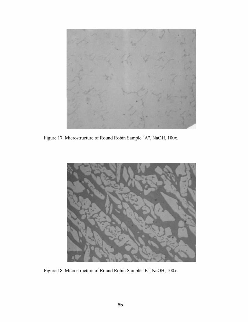
Figure 17. Microstructure of Round Robin Sample "A", NaOH, 100x.
Figure 18. Microstructure of Round Robin Sample "E", NaOH, 100x.
65

Figure 19. Microstructure of Round Robin Sample "F", NaOH, 100x.
Figure 20. Microstructure of Round Robin Sample "J", NaOH, 100x.
66
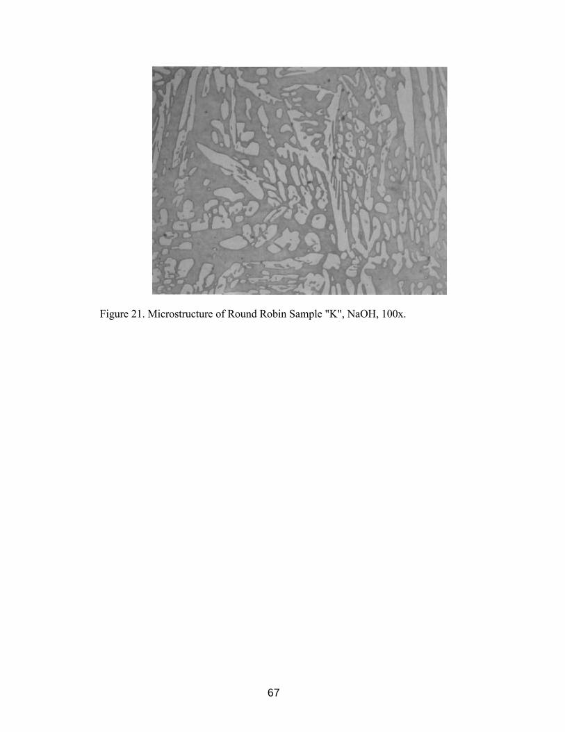
Figure 21. Microstructure of Round Robin Sample "K", NaOH, 100x.
67

68
Participants were asked to determine the ferrite content (volume fraction) on the
sample set provided using manual point counting per ASTM E562. For the point
counting, the procedure in ASTM E562 Annex 1 was to be followed. A visual estimate
of area percent ferrite was determined. Using ASTM E562 Table 3, a grid size, PT was
selected based on a required relative accuracy of 20%. The grid was then superimposed
upon the microscope viewing screen and magnification was selected such that the size of
the ferrite pools was approximately one half of the spacing between grid points. Using
ASTM E526 Table 3, the number of fields was determined based on 20% relative
accuracy. The spacing between fields was determined in order to form a systematic
(equally spaced) array covering a majority of the sample area (inside the scribed circle)
without overlap. The number of turns required on the microscope stage translation knobs
to move the stage from one field position to the next was determined. The image was not
observed while translating in order to avoid bias in positioning the grid. The number of
points, Pi, falling within the ferrite was then counted. Any points falling completely
within the ferrite were counted as one. Any points falling on a phase boundary or any
that were deemed questionable were counted as one half. Data was recorded and
returned to UT, where results were tabulated. A sample data sheet is found in Appendix
B, where:
PT = total number of points in the test grid
Pi = point count to the ith field
PP (i) = Pi / PT x 100 = percentage of grid points in the ferrite on the ith field
n = number of fields counted
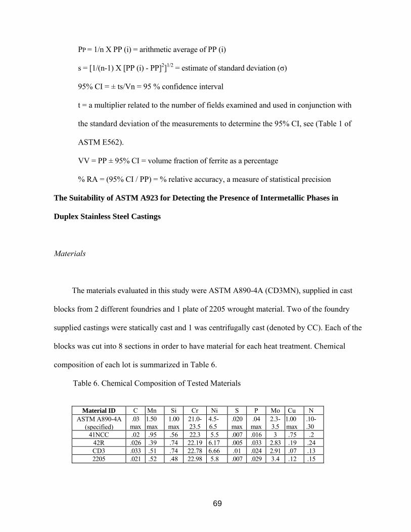
69
PP = 1/n X PP (i) = arithmetic average of PP (i)
s = [1/(n-1) X [PP (i) - PP]2]1/2 = estimate of standard deviation (σ)
95% CI = ± ts/Vn = 95 % confidence interval
t = a multiplier related to the number of fields examined and used in conjunction with
the standard deviation of the measurements to determine the 95% CI, see (Table 1 of
ASTM E562).
VV = PP ± 95% CI = volume fraction of ferrite as a percentage
% RA = (95% CI / PP) = % relative accuracy, a measure of statistical precision
The Suitability of ASTM A923 for Detecting the Presence of Intermetallic Phases in
Duplex Stainless Steel Castings
Materials
The materials evaluated in this study were ASTM A890-4A (CD3MN), supplied in cast
blocks from 2 different foundries and 1 plate of 2205 wrought material. Two of the foundry
supplied castings were statically cast and 1 was centrifugally cast (denoted by CC). Each of the
blocks was cut into 8 sections in order to have material for each heat treatment. Chemical
composition of each lot is summarized in Table 6.
Table 6. Chemical Composition of Tested Materials
Material ID C Mn Si Cr Ni S P Mo Cu N ASTM A890-4A
(specified) .03
max 1.50 max
1.00 max
21.0- 23.5
4.5-6.5
.020 max
.04 max
2.3-3.5
1.00 max
.10-
.30 41NCC .02 .95 .56 22.3 5.5 .007 .016 3 .75 .2
42R .026 .39 .74 22.19 6.17 .005 .033 2.83 .19 .24 CD3 .033 .51 .74 22.78 6.66 .01 .024 2.91 .07 .13 2205 .021 .52 .48 22.98 5.8 .007 .029 3.4 .12 .15

70
Heat Treatments
The heat treatment schedules were derived from the testing of wrought DSS to
establish the A923 specification [117]. 8 heat treatment schedules were selected in order
to produce a wide range of intermetallic phase precipitation, these heat treatments are
shown in Table 7. The solution annealing temperature of 1950°F is lower than that
utilized for cast DSS but it duplicates that used to establish A923. Thermocouples were
welded to each section prior to heat treatment so that actual thermal history could be
recorded. The time / temperature cycles are shown in Figure 22.
Testing Methods
Test Method B
This test method requires Charpy impact testing at -40°C as a method for the
detection of intermetallic phases in DSS. Acceptance criteria for this test is a minimum
of 40 ft-lbs @ -40°C for 2205 wrought base metal. The same acceptance criteria were
used for the cast material.
2 - 3 Charpy impact samples were extracted from the material sections and notched
in the orientation shown in Figure 23. Notch Geometry for the Charpy impact samples
per ASTM A370 is shown in Figure 24. The Charpy impact test apparatus is shown in
Figure 25. This apparatus is a pendulum type of rigid construction that is capable of
providing enough impact energy to break a notched sample in one blow.
The samples were then tested as follows per ASTM E23. The samples were placed
in an alcohol bath cooled with liquid nitrogen to maintain a temperature of -40°C for a

71
Table 7. Heat Treatment Schedule
Heat Treatment Stage 1 Stage 2 A Heat Sample to 1950°F, Hold 30
min., Water Quench
B Heat Sample to 1950°F, Hold 30 min., Water Quench
Heat sample to 1550°F, Water Quench
C Heat Sample to 1950°F, Hold 30 min., Water Quench
Heat sample to 1550°F, Hold 5 min., Water
Quench D Heat Sample to 1950°F, Hold 30
min., Water Quench Heat sample to 1550°F, Hold 10 min., Water
Quench E Heat Sample to 1950°F, Hold 30
min., Water Quench Heat sample to 1550°F, Hold 15 min., Water
Quench F Heat Sample to 1950°F, Hold 30
min., Water Quench Heat sample to 1550°F, Hold 20 min., Water
Quench G Heat Sample to 1950°F, Hold 30
min., Air Cool
H Heat Sample to 1950°F, Hold 30 min., Slow Cool
Figure 22. Actual Thermal History for Various Heat Treatments.

72
Figure 23. Charpy Impact Sample Extraction Location
Figure 24. Charpy Impact Notch Geometry

73
Figure 25. Charpy Impact Test Apparatus

74
sufficient time to normalize the bars at temperature. Self-centering tongs were used to
remove the samples from the liquid nitrogen bath. The sample was placed in the proper
orientation in the Charpy impact test apparatus and the pendulum was then released.
(This step must take no longer than 5 seconds to perform due to the low temperature that
is being used). After impact the broken specimen was placed in a room temperature
acetone bath. Data was collected and the fractured samples were placed in individual
packages for future examinations that may be required.
Test Method A
After completion of Method B, one half of a fractured Charpy sample from each
lot and heat treatment was tested per Method A (sodium hydroxide etch test). The
sodium hydroxide etch test may be used for the acceptance of material but not for
rejection. This test method may be used with other evaluation tests to provide a rapid
method for identifying those specimens that are free of detrimental intermetallic phases as
measured in these tests.
On all samples, cross-sectional surfaces were prepared to a metallographic finish
suitable for examination at 400x after etching. The etching solution was prepared by
adding 40g reagent grade sodium hydroxide (NaOH) to 100g of distilled water. Samples
were then electrolytically etched at 3 V dc for 15 seconds. Following etching, the
specimens were rinsed thoroughly in hot water and in acetone, followed by air drying.
The etched surfaces were examined at 400x and classified according to ASTM A923,
which supplies photomicrographs of wrought material in order to classify the structure.
75
The cast material classification had to be determined from the wrought material
photomicrographs supplied in A923, with the exception of the centerline structure
classification, which would only be applicable to wrought material, see Figures 26-29.
ASTM A923 requires that any material showing other than an unaffected structure must
be Charpy impact tested per Method B. The following is used to define classify each
microstructure:
1. Unaffected Structure (Figure 26) - The sample has been etched and the
microstructure is without the revelation of any intermetallic phase. The
austenite-ferrite boundaries are smooth.
2. Possibly Affected Structure (Figure 27) - The sample has been etched and
isolated indications of possible intermetallic phase are noted. The austenite-
ferrite boundaries show a fine waviness.
3. Affected Structure (Figure 28) - The indication of an intermetallic phase is
readily revealed upon etching.
4. Centerline Structure (Figure 29) - The intermetallic phase is observed as a
continuous or semi-continuous phase in the mid-thickness region of the
sample, with or without the affected structure outside of the mid-thickness
region, indicative of segregation. This structure is only applicable to
wrought materials.
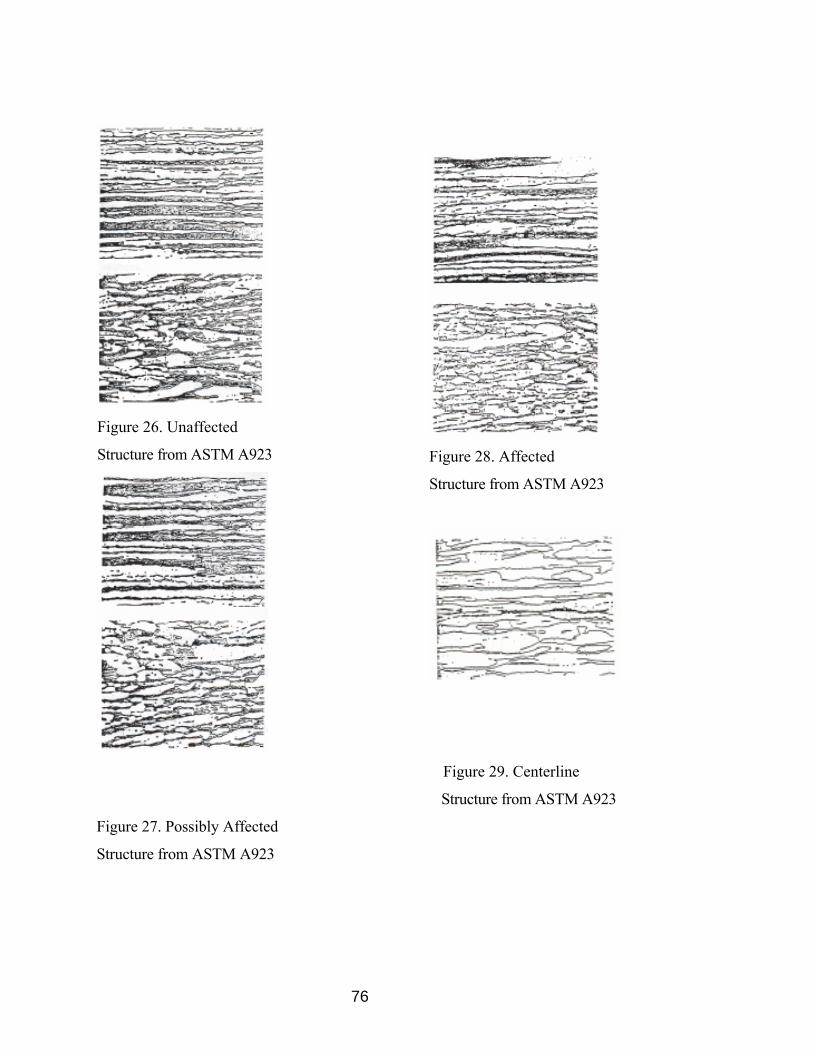
76
Figure 26. Unaffected
Structure from ASTM A923
Figure 28. Affected
Structure from ASTM A923
Figure 29. Centerline
Structure from ASTM A923
Figure 27. Possibly Affected
Structure from ASTM A923
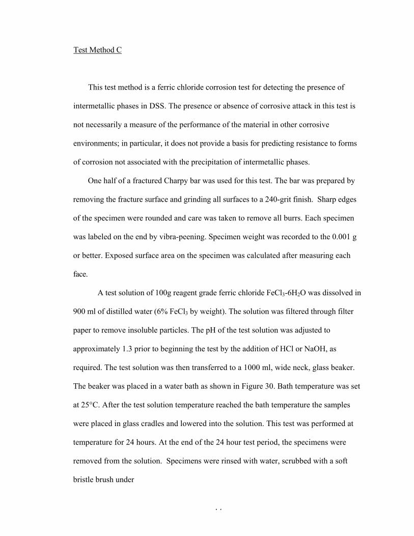
77
Test Method C
This test method is a ferric chloride corrosion test for detecting the presence of
intermetallic phases in DSS. The presence or absence of corrosive attack in this test is
not necessarily a measure of the performance of the material in other corrosive
environments; in particular, it does not provide a basis for predicting resistance to forms
of corrosion not associated with the precipitation of intermetallic phases.
One half of a fractured Charpy bar was used for this test. The bar was prepared by
removing the fracture surface and grinding all surfaces to a 240-grit finish. Sharp edges
of the specimen were rounded and care was taken to remove all burrs. Each specimen
was labeled on the end by vibra-peening. Specimen weight was recorded to the 0.001 g
or better. Exposed surface area on the specimen was calculated after measuring each
face.
A test solution of 100g reagent grade ferric chloride FeCl3-6H2O was dissolved in
900 ml of distilled water (6% FeCl3 by weight). The solution was filtered through filter
paper to remove insoluble particles. The pH of the test solution was adjusted to
approximately 1.3 prior to beginning the test by the addition of HCl or NaOH, as
required. The test solution was then transferred to a 1000 ml, wide neck, glass beaker.
The beaker was placed in a water bath as shown in Figure 30. Bath temperature was set
at 25°C. After the test solution temperature reached the bath temperature the samples
were placed in glass cradles and lowered into the solution. This test was performed at
temperature for 24 hours. At the end of the 24 hour test period, the specimens were
removed from the solution. Specimens were rinsed with water, scrubbed with a soft
bristle brush under
78
Figure 30. Temperature Controlled Water Bath
79
running water to remove corrosive products, dipped in acetone, and then dried in air.
Specimens were then re-weighed to 0.001g or better. The acceptance criterion for this
test is that no specimen shall show a weight loss of more than 10
milligrams/decimeter/day (10 mdd), as calculated by:
Corrosion rate = weight loss (mg)/[specimen area (dm2) x time (days)] Equation 8
ASTM A923 Method A & C Round Robin Study
This round robin study was used to correlate the data obtained from "The Suitability
of ASTM A923 for Detecting the Presence of Intermetallic Phases in Duplex Stainless
Steel Castings" and the data obtained from numerous different laboratories.
Materials
One half of a fractured Charpy sample from each lot and heat treatment used in "The
Suitability of ASTM A923 for Detecting the Presence of Intermetallic Phases in Duplex
Stainless Steel Castings" was tested per ASTM A923 Method A and the other half of the
Charpy sample was tested per ASTM A923 Method C.
Method A samples were mounted in epoxy and ground to120-grit finish.
Identification was vibra-peened on the side of the mount.
Method C samples were prepared by removing the Charpy fracture surface and
grinding all surfaces to a 240-grit finish. Sharp edges of the specimen were rounded and
care was taken to remove all burrs. Each specimen was labeled on the end by vibra-
peening.
80
Testing Methods
Both groups of samples were shipped to the first laboratory in the previously
described condition. Testing procedures for the laboratory were identical to those used in
"The Suitability of ASTM A923 for Detecting the Presence of Intermetallic Phases in
Duplex Stainless Steel Castings". After testing, the samples were returned to UT,
restored to their previous untested condition, and shipped to the next participant.
ASTM A923 Study of the Effectiveness of Existing Foundry Solution Annealing
Procedures for Producing Cast DSS Without Intermetallic Phases
Materials
The materials evaluated in this study were 10 heats of ASTM A890-4A (CD3MN)
cast keel blocks all supplied from the same foundry. Table 8 summarizes the chemical
composition of each heat.
Heat Treatment
All 10 heats of material for this study were solution annealed by the same schedule.
Table 9 shows the foundry solution anneal schedule. Table 10 shows the volume percent
ferrite values for each heat treatment, calculated using Equation 1, from the measured
extended ferrite numbers (EFN) using the Feritscope®.
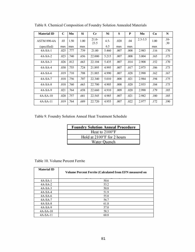
81
Table 8. Chemical Composition of Foundry Solution Annealed Materials
Material ID C Mn Si Cr Ni S P Mo Cu N
ASTM 890-4A
(specified)
.03
max
1.50
max
1.00
max
21.0- 23.5
4.5-
6.5
.020
max
.04
max
2.3-3.5 1.00
max
.10- .30
4A-SA-1 .025 .777 .739 21.00 5.460 .007 .008 2.983 .116 .170
4A-SA-2 .023 .740 .656 22.000 5.215 .007 .008 3.004 .165 .173
4A-SA-3 .026 .812 .663 22.104 5.435 .007 .014 2.908 .152 .170
4A-SA-4 .030 .755 .724 21.895 4.995 .007 .017 2.975 .186 .173
4A-SA-6 .019 .710 .708 21.885 4.990 .007 .028 2.990 .162 .167
4A-SA-7 .018 .756 .707 22.340 5.010 .008 .021 2.984 .194 .175
4A-SA-8 .018 .760 .663 22.700 4.905 .008 .020 2.935 .184 .175
4A-SA-9 .021 .764 .658 22.660 4.910 .009 .020 2.990 .179 .185
4A-SA-10 .020 .757 .681 22.545 4.985 .007 .021 2.982 .180 .185
4A-SA-11 .019 .764 .689 22.720 4.955 .007 .022 2.977 .172 .190
Table 9. Foundry Solution Anneal Heat Treatment Schedule
Table 10. Volume Percent Ferrite
Material ID Volume Percent Ferrite (Calculated from EFN measured on
F i ® i E i 1)4A-SA-1 50.64A-SA-2 53.24A-SA-3 50.84A-SA-4 51.94A-SA-6 55.84A-SA-7 56.74A-SA-8 61.84A-SA-9 57.0
4A-SA-10 58.34A-SA-11 60.8

82
Test Methods
Testing procedures for this study were identical to those used in "The Suitability of
ASTM A923 for Detecting the Presence of Intermetallic Phases in Duplex Stainless Steel
Castings".

83
V. Results and Discussion
ASTM E562 Ferrite Measurement Round Robin Study
Table 11 shows the average volume fraction of ferrite in the cast DSS samples, as
determined per ASTM E562, ranges from 6.2 - 54.7. Figure 31 shows the comparison
between volume fraction of ferrite from the Feritescope® (Equation 7) and volume
fraction of ferrite per ASTM E562. Volume fraction of ferrite measurements, converted
from FN measured by the Feritscope® (Equation 7), fall within the 95% confidence
limits for volume fraction of ferrite measurements per ASTM E562,except for sample A,
where the Feritscope® measurement falls below the limit.
Ruprecht [135] identified a standard deviation of less than 14% as being sufficient
interlaboratory reproducibility for cast DSS ferrite measurement using the Feritscope®.
The standard deviation for the cast DSS samples measured per ASTM E562 ranges from
2.2% - 5.5%, which indicates that ferrite measurement per ASTM E562, in cast DSS, is
more reproducible that measurements using the Feritscope®.
Several factors that can affect the accuracy of ASTM E562 with respect to ferrite
determination in DSS castings are as follows:
1.) Specimen preparation: Surfaces defects or abnormalities due polishing or etching
can lead to difficulty in distinguishing between phases. Also the sample must be
properly etched so that there is a definitive difference between phases to be
counted.
2.) Grid preparation: Thicknesses of grid lines can cause difficulty in determining if
a phase actually lies at the intersection or not.

84
Table 11. ASTM E562 Results

85
Figure 31. Comparison of Volume Fraction of Ferrite per Feritescope® and
ASTM E562 Manual Point Count

86
3.) Operator bias
It can be concluded from the results that either method of ferrite determination would
produce similar results but ASTM E562 would be the most reliable method. However,
the Feritescope® would be the preferred method for ferrite determination since it is non-
destructive, much faster, and can eliminate operator bias with respect to ASTM E562 and
ASTM E562 Manual Point Count
The Suitability of ASTM A923 for Detecting the Presence of Intermetallic Phases in Duplex Stainless Steel Castings
Test Method B
Table 12 shows the Charpy impact energy of each sample tested. Figure 32 shows a
graphical view of the average Charpy impact toughness for each lot and heat treatment.
Test Method A
Table 13 summarizes the classification of the etch structure as determined from
Method A. Figures 33-64 show the microstructure for each material.
Test Method C
Table 14 summarizes the corrosion rates of each lot and heat treatment per Method C.
Figure 65 shows a graphical view of the results.
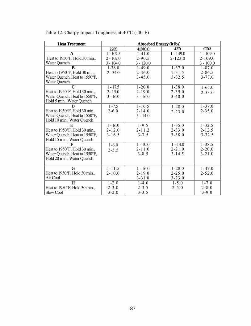
87
Table 12. Charpy Impact Toughness at-40°C (-40°F)
Heat Treatment Absorbed Energy (ft lbs) 2205 41NCC 42R CD3
A Heat to 1950°F, Hold 30 min., Water Quench
1 - 107.5 2 - 102.0 3 - 104.0
1-41.0 2-90.5 3 - 120.0
1 - 149.0 2-123.0
1 - 109.0 2-109.0 3 - 100.0
B Heat to 1950°F, Hold 30 min., Water Quench, Heat to 1550°F, Water Quench
1-38.0 2 - 34.0
1-49.0 2-46.0 3-45.0
1-37.0 2-31.5 3-32.5
1-87.0 2-86.5 3-77.0
C Heat to 1950°F, Hold 30 min., Water Quench, Heat to 1550°F, Hold 5 min., Water Quench
1 - 17.5 2- 15.0 3 - 16.0
1-20.0 2-19.0 3 - 16.0
1-38.0 2-39.0 3-40.0
1-65.0 2-53.0
D Heat to 1950°F, Hold 30 min., Water Quench, Heat to 1550°F, Hold 10 min., Water Quench
1 -7.5 2-6.0
1-16.5 2-14.0 3 - 14.0
1-28.0 2-23.0
1-37.0 2-35.0
E Heat to 1950°F, Hold 30 min., Water Quench, Heat to 1550°F, Hold 15 min., Water Quench
1 - 16.0 2-12.0 3-16.5
1-9.5 2-11.2 3-7.5
1-35.0 2-33.0 3-38.0
1-32.5 2-12.5 3-32.5
F Heat to 1950°F, Hold 30 min., Water Quench, Heat to 1550°F, Hold 20 min., Water Quench
1-6.0 2-5.5
1 - 10.0 2-11.0 3-8.5
1 - 14.0 2-21.0 3-14.5
1-38.5 2-20.0 3-21.0
G Heat to 1950°F, Hold 30 min., Air Cool
1-11.5 2-10.0
1 - 16.0 2-19.0 3-31.0
1-28.0 2-25.0 3-23.0
1-47.0 2-52.0
H Heat to 1950°F, Hold 30 min., Slow Cool
1-2.0 2-3.0 3-2.0
1-4.0 2-3.5 3-3.5
1-5.0 2-5.0
1-7.0 2-8.0 3-9.0
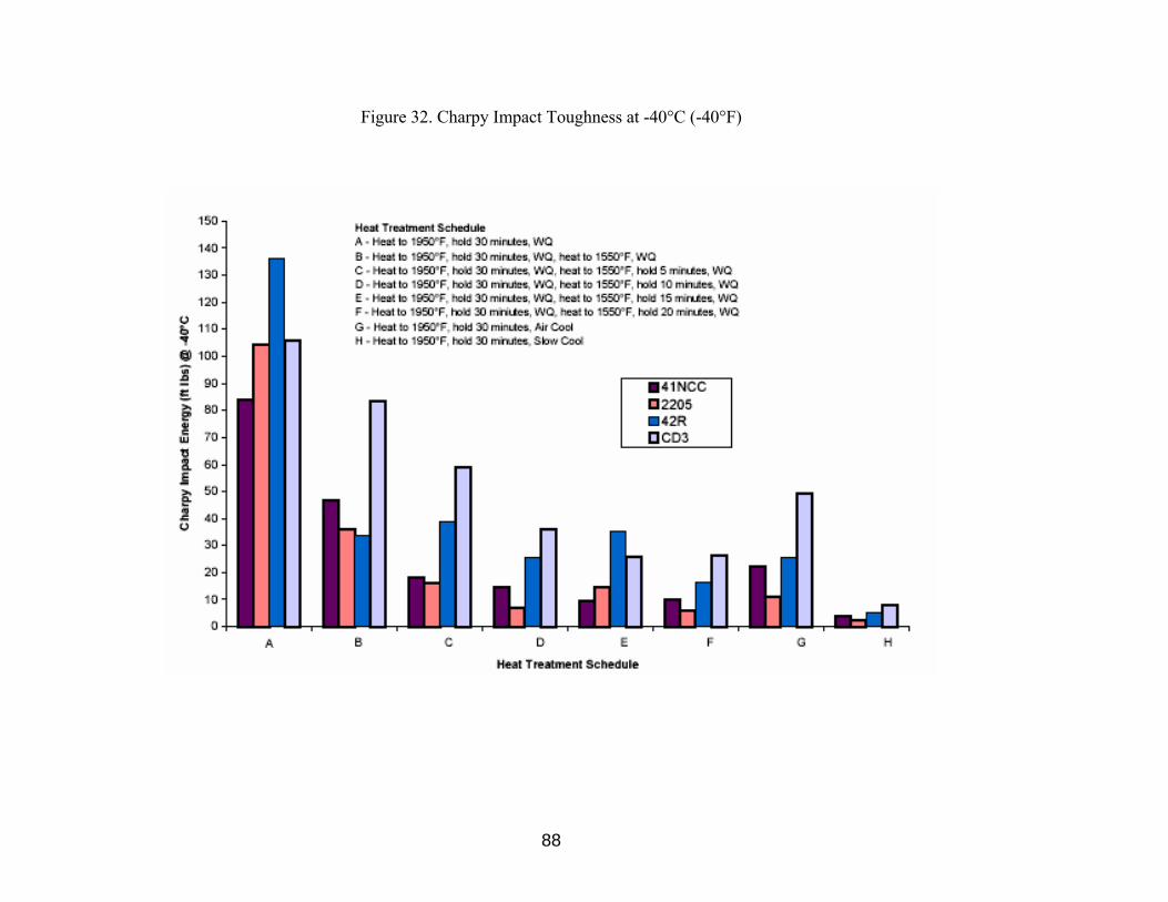
88
Figure 32. Charpy Impact Toughness at -40°C (-40°F)

Table 13. Classification of Etch Structure
89

Figure 33. Microstructure of 2205-A-3, NaOH, 400x
Figure 34. Microstructure of 41NCC-A-1, NaOH, 400x
90

Figure 35. Microstructure of 42R-A-1, NaOH, 400x
Figure 36. Microstructure of CD3-A-2, NaOH, 400x
91

Figure 37. Microstructure of 2205-B-2, NaOH, 400x
Figure 38. Microstructure of 41NCC-B-2, NaOH, 400x
92

Figure 39. Microstructure of 42R-B-1, NaOH, 400x
Figure 40. Microstructure of CD3-B-1, NaOH, 400x
93
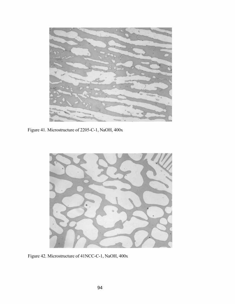
Figure 41. Microstructure of 2205-C-1, NaOH, 400x
Figure 42. Microstructure of 41NCC-C-1, NaOH, 400x
94

Figure 43. Microstructure of 42R-C-1, NaOH, 400x
Figure 44. Microstructure of CD3-C-2, NaOH, 400x
95
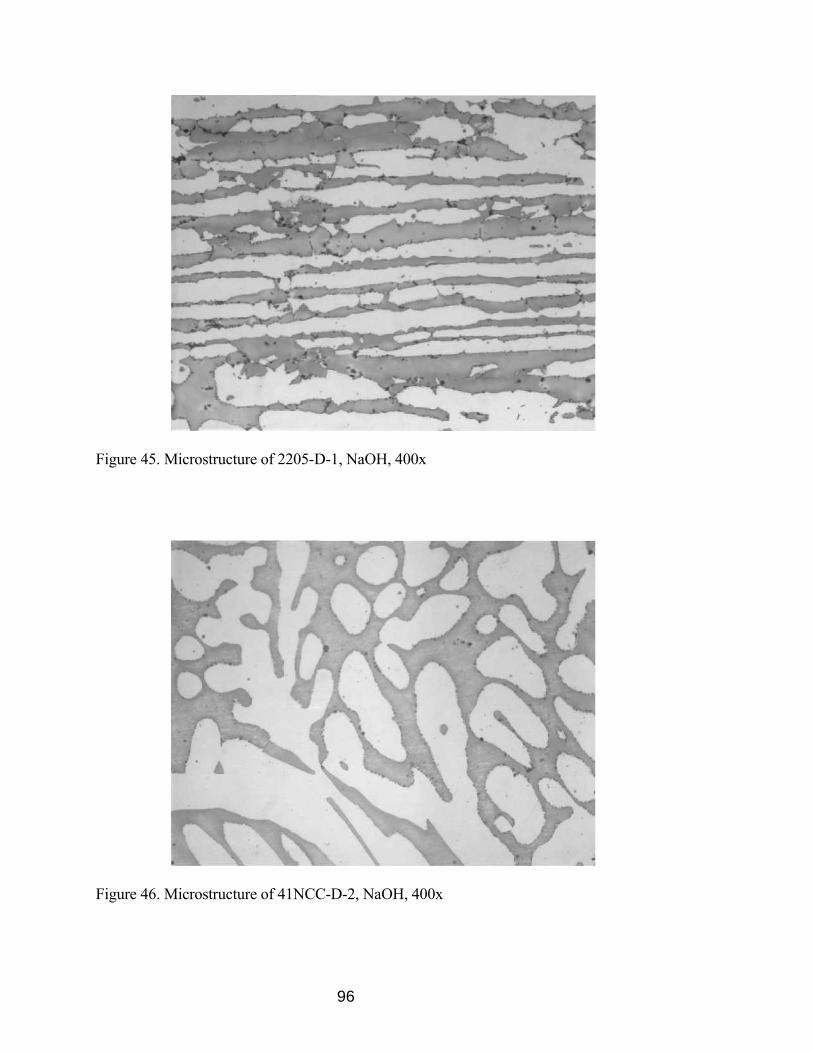
Figure 45. Microstructure of 2205-D-1, NaOH, 400x
Figure 46. Microstructure of 41NCC-D-2, NaOH, 400x
96

97
Figure 48. Microstructure of CD3-D-2, NaOH, 400x
Figure 47. Microstructure of 42R-D-1, NaOH, 400x
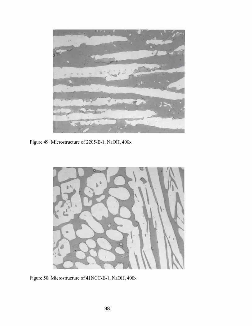
Figure 49. Microstructure of 2205-E-1, NaOH, 400x
Figure 50. Microstructure of 41NCC-E-1, NaOH, 400x
98
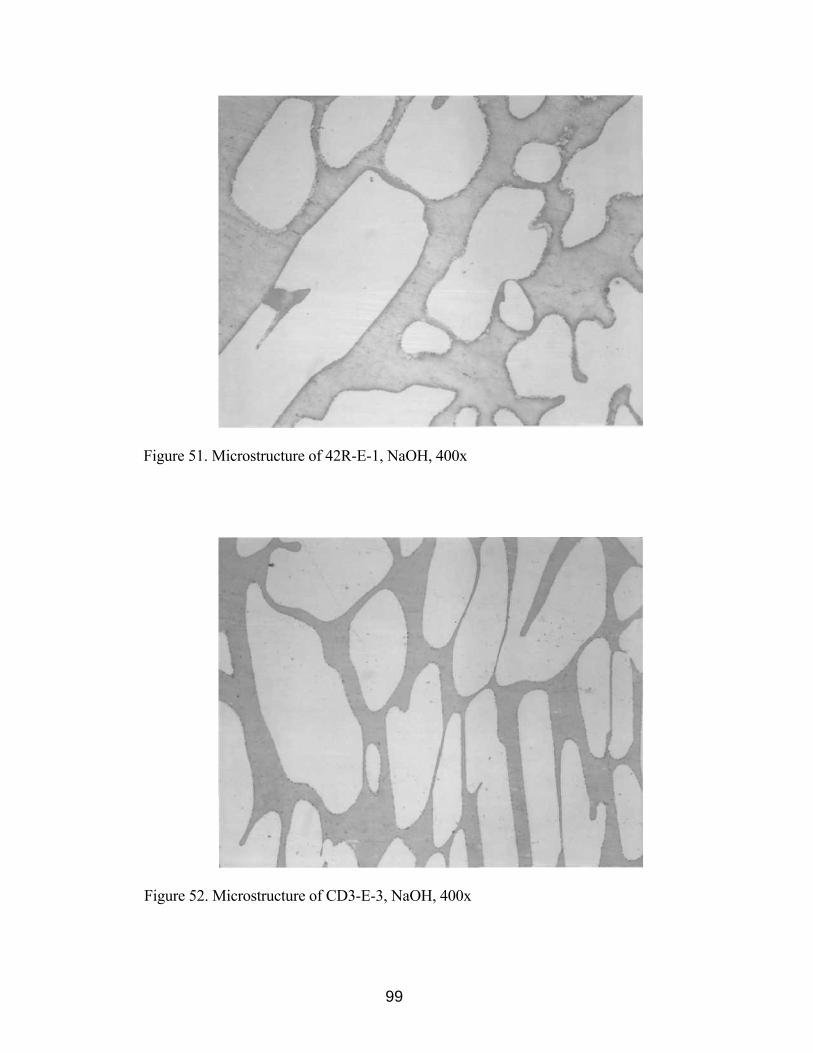
Figure 51. Microstructure of 42R-E-1, NaOH, 400x
Figure 52. Microstructure of CD3-E-3, NaOH, 400x
99

Figure 53. Microstructure of 2205-F-3, NaOH, 400x
Figure 54. Microstructure of 41NCC-F-2, NaOH, 400x
100

Figure 55. Microstructure of 42R-F-3, NaOH, 400x
Figure 56. Microstructure of CD3-F-2, NaOH, 400x
101

Figure 57. Microstructure of 2205-G-2, NaOH, 400x
Figure 58. Microstructure of 41NCC-G-3, NaOH, 400x
102

Figure 59. Microstructure of 42R-G-2, NaOH, 400x
Figure 60. Microstructure of CD3-G-2, NaOH, 400x
103

Figure 61. Microstructure of 2205-H-2, NaOH, 400x
Figure 62. Microstructure of 41N-H-3, NaOH, 400x
104

Figure 63. Microstructure of 42R-H-1, NaOH, 400x
Figure 64. Microstructure of CD3-H-1, NaOH, 400x
105

106
Table 14. Corrosion Rates for ASTM A923 Study
Corrosion Rates (mdd) Heat Treatment 2205 41NCC 42R CD3
A Heat to 1950°F, Hold 30 min., Water Quench
0.0 0.0 0.0 1.9
B Heat to 1950°F, Hold 30 min., Water Quench, Heat to 1550°F, Water Quench
10.0 0.0 4.0 15.2
C Heat to 1950°F, Hold 30 min., Water Quench, Heat to 1550°F, Hold 5 min., Water Quench
6.5 0.0 0.0 7.2
D Heat to 1950°F, Hold 30 min., Water Quench, Heat to 1550°F, Hold 10 min., Water Quench
30.4 8.5 3.8 2.6
E Heat to 1950°F, Hold 30 min., Water Quench, Heat to 1550°F, Hold 15 min., Water Quench
5.9 23.7 2.0 45.8
F Heat to 1950°F, Hold 30 min., Water Quench, Heat to 1550°F, Hold 20 min., Water Quench
39.5 58.8 3.9 28.2
G Heat to 1950°F, Hold 30 min., Air Cool
1.0 6.9 0.0 5.1
H Heat to 1950°F, Hold 30 min., Slow Cool
3510.5 1438.5 176.9 566.5
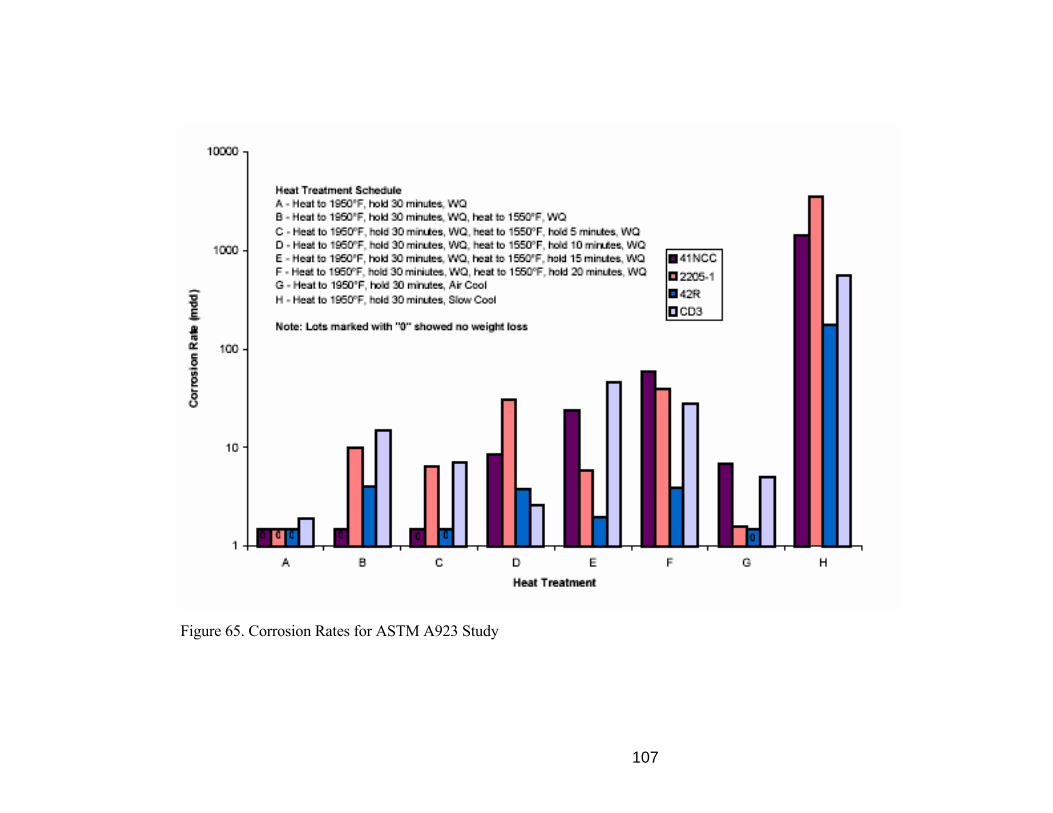
107
Figure 65. Corrosion Rates for ASTM A923 Study

108
The impact toughness of cast and wrought DSS materials subjected to the 2-stage
heat treatments (solution anneal @ 1950°F + hold @ 1550°F) and other than rapid
quenching (air cool & slow cool from 1950°F) was dramatically reduced. The 2-stage
heat treatment, "B" (figures 8-11), shows a very fine waviness along the austenite/ferrite
boundaries, which is identified as a possibly affected structure. The toughness of the
material subjected to this heat treatment shows a sharp drop in impact toughness. This
indicates that toughness of the material is affected even with the slightest amount of
intermetallic phase precipitation. Figures 8-27, for the 2 stage heat treatments, show that
the intermetallic phase precipitation increases as a function of hold time at 1550°F, which
leads to further decrease in impact toughness of the materials. From the results it can be
concluded that ASTM A923 Method B impact testing is the most sensitive of the 3
ASTM A923 methods for detecting the presence of intermetallic phases. Method B is
readily reproducible within the accuracy required for the detection of intermetallic phases
[1], however it is the most costly and time-consuming method to perform due to the
precise machining required for impact test specimens.
ASTM A923 Method A etch testing is adequate for detection of the presence of
intermetallic phases, however this method introduces operator bias as it requires greater
skill to interpret the results. Method A etch testing does not easily distinguish between an
unaffected structure (no intermetallic phases present) and a partially affected structure
(slight traces of intermetallic phases present), whereas Method B impact testing detects
the slightest formation of intermetallic phases with a marked decrease in impact
toughness. As intermetallic phase precipitation increased, there was not a predictable
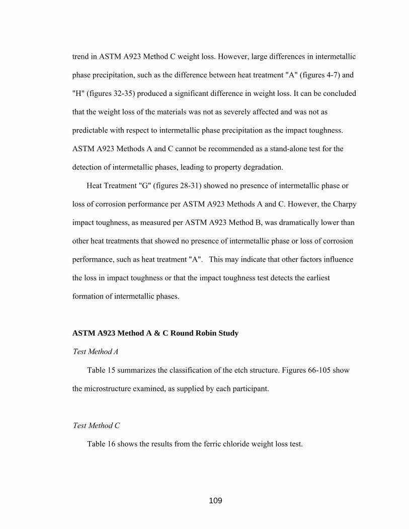
109
trend in ASTM A923 Method C weight loss. However, large differences in intermetallic
phase precipitation, such as the difference between heat treatment "A" (figures 4-7) and
"H" (figures 32-35) produced a significant difference in weight loss. It can be concluded
that the weight loss of the materials was not as severely affected and was not as
predictable with respect to intermetallic phase precipitation as the impact toughness.
ASTM A923 Methods A and C cannot be recommended as a stand-alone test for the
detection of intermetallic phases, leading to property degradation.
Heat Treatment "G" (figures 28-31) showed no presence of intermetallic phase or
loss of corrosion performance per ASTM A923 Methods A and C. However, the Charpy
impact toughness, as measured per ASTM A923 Method B, was dramatically lower than
other heat treatments that showed no presence of intermetallic phase or loss of corrosion
performance, such as heat treatment "A". This may indicate that other factors influence
the loss in impact toughness or that the impact toughness test detects the earliest
formation of intermetallic phases.
ASTM A923 Method A & C Round Robin Study
Test Method A
Table 15 summarizes the classification of the etch structure. Figures 66-105 show
the microstructure examined, as supplied by each participant.
Test Method C
Table 16 shows the results from the ferric chloride weight loss test.
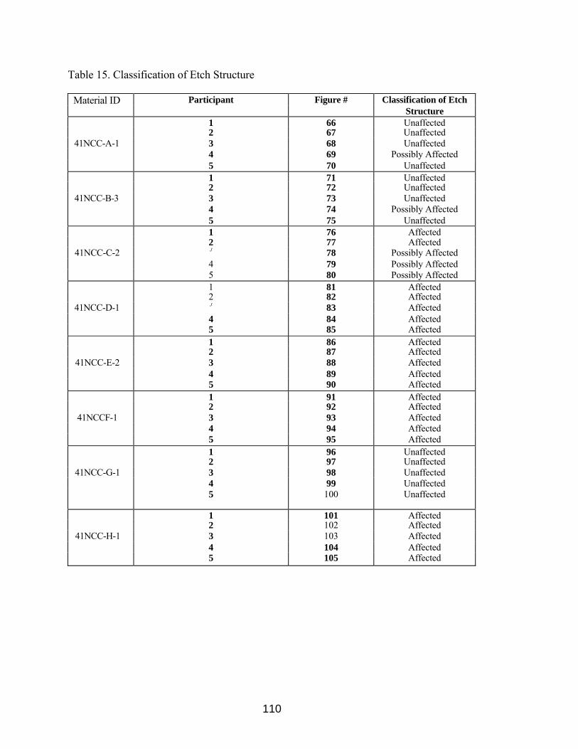
110
Table 15. Classification of Etch Structure
Material ID Participant Figure # Classification of Etch Structure 1 66 Unaffected 2 67 Unaffected 41NCC-A-1 3 68 Unaffected
4 69 Possibly Affected 5 70 Unaffected 1 71 Unaffected 2 72 Unaffected
41NCC-B-3 3 73 Unaffected 4 74 Possibly Affected 5 75 Unaffected 1 76 Affected 2 77 Affected
41NCC-C-2 J 78 Possibly Affected 4 79 Possibly Affected 5 80 Possibly Affected 1 81 Affected 2 82 Affected
41NCC-D-1 J 83 Affected 4 84 Affected 5 85 Affected 1 86 Affected 2 87 Affected
41NCC-E-2 3 88 Affected 4 89 Affected 5 90 Affected 1 91 Affected 2 92 Affected
41NCCF-1 3 93 Affected 4 94 Affected 5 95 Affected 1 96 Unaffected 2 97 Unaffected
41NCC-G-1 3 98 Unaffected 4 99 Unaffected 5 100 Unaffected
1 101 Affected 2 102 Affected
41NCC-H-1 3 103 Affected 4 104 Affected 5 105 Affected

Figure 66. Microstructure of 41NCC-A-1, NaOH, 400x, Participant 1
Figure 67. Microstructure of 41NCC-A-1, NaOH, 400x, Participant 2
111

112
Figure 68. Microstructure of 41NCC-A-1, NaOH, 500x, Participant 3
Figure 69. Microstructure of 41NCC-A-1, NaOH, 500x, Participant 4

Figure 70. Microstructure of 41NCC-A-1, NaOH, 400x, Participant 5
Figure 71. Microstructure of 41NCC-B-3, NaOH, 400x, Participant 1
113

Figure 72. Microstructure of 41NCC-B-3, NaOH, 400x, Participant 2
Figure 73. Microstructure of 41NCC-B-3, NaOH, 500x, Participant 3
114
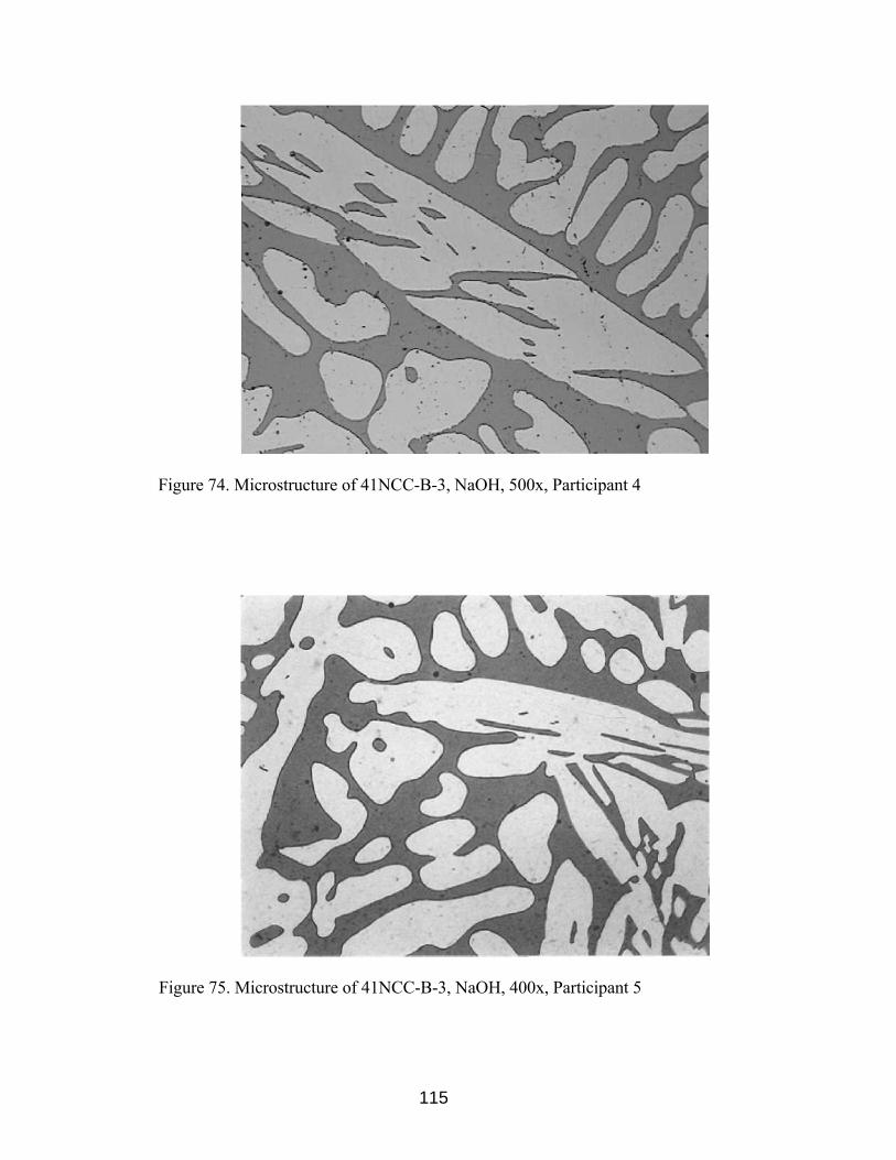
Figure 74. Microstructure of 41NCC-B-3, NaOH, 500x, Participant 4
Figure 75. Microstructure of 41NCC-B-3, NaOH, 400x, Participant 5
115

Figure 76. Microstructure of 41NCC-C-2, NaOH, 400x, Participant 1
Figure 77. Microstructure of 41NCC-C-2, NaOH, 400x, Participant 2
116

117
Figure 78. Microstructure of 41NCC-C-2, NaOH, 500x, Participant 3
Figure 79. Microstructure of 41NCC-C-2, NaOH, 500x, Participant 4

Figure 80. Microstructure of 41NCC-C-2, NaOH, 400x, Participant 5
Figure 81. Microstructure of 41NCC-D-1, NaOH, 400x, Participant 1
118

Figure 82. Microstructure of 41NCC-D-1, NaOH, 400x, Participant 2
Figure 83. Microstructure of 41NCC-D-1, NaOH, 500x, Participant 3
119
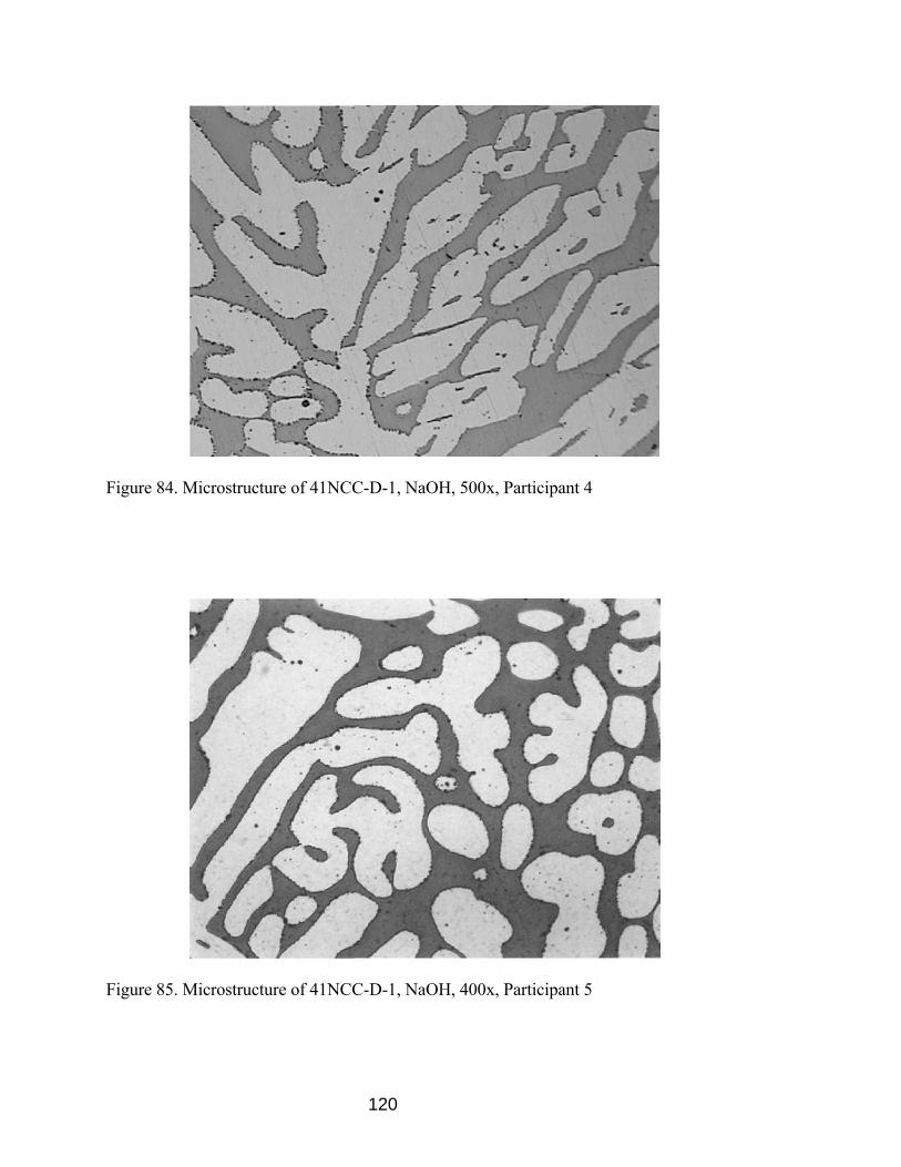
Figure 84. Microstructure of 41NCC-D-1, NaOH, 500x, Participant 4
Figure 85. Microstructure of 41NCC-D-1, NaOH, 400x, Participant 5
120

Figure 86. Microstructure of 41NCC-E-2, NaOH, 400x, Participant 1
Figure 87. Microstructure of 41NCC-E-2, NaOH, 400x, Participant 2
121

Figure 88. Microstructure of 41NCC-E-2, NaOH, 500x, Participant 3
Figure 89. Microstructure of 41NCC-E-2, NaOH, 500x, Participant 4
122
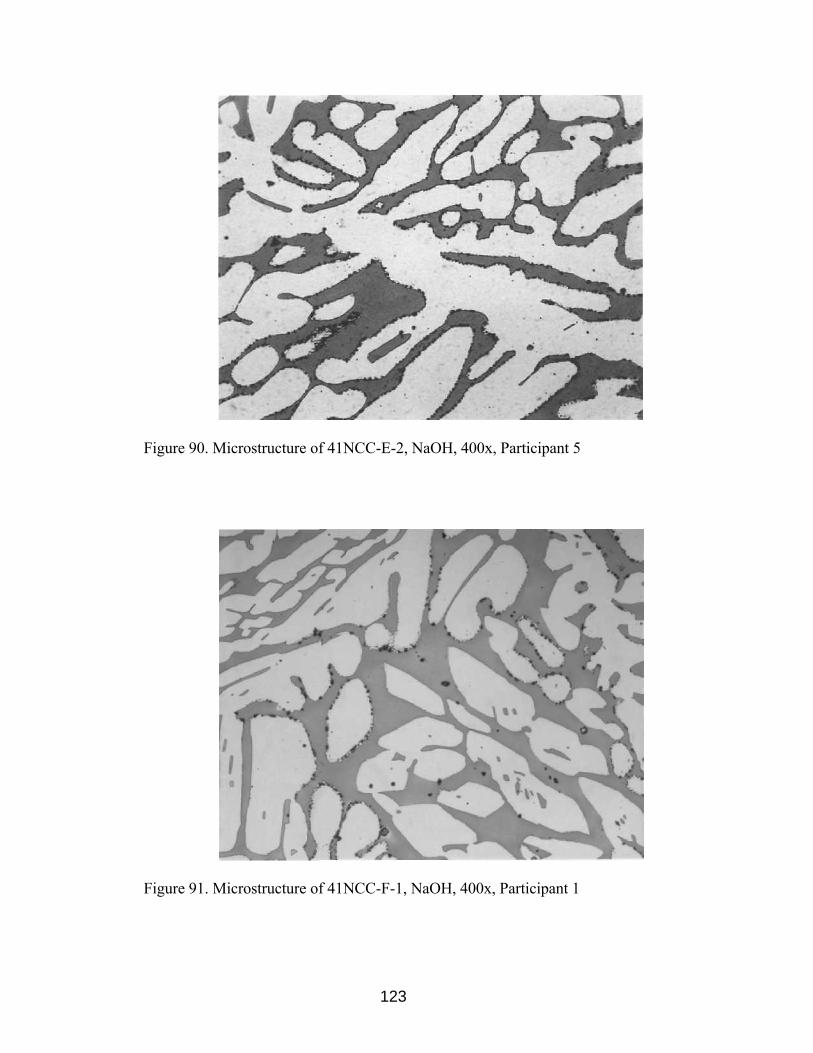
Figure 90. Microstructure of 41NCC-E-2, NaOH, 400x, Participant 5
Figure 91. Microstructure of 41NCC-F-1, NaOH, 400x, Participant 1
123
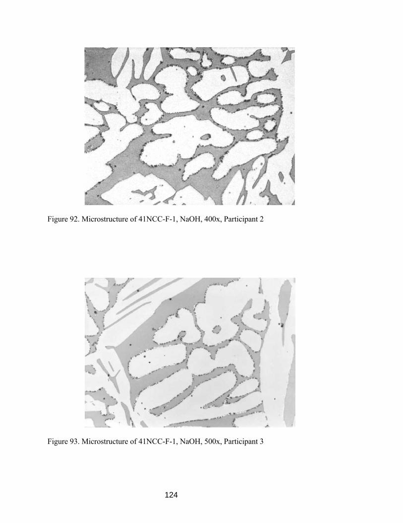
Figure 92. Microstructure of 41NCC-F-1, NaOH, 400x, Participant 2
Figure 93. Microstructure of 41NCC-F-1, NaOH, 500x, Participant 3
124

Figure 94. Microstructure of 41NCC-F-1, NaOH, 500x, Participant 4
Figure 95. Microstructure of 41NCC-F-1, NaOH, 400x, Participant 5
125

Figure 96. Microstructure of 41NCC-G-1, NaOH, 400x, Participant 1
Figure 97. Microstructure of 41NCC-G-1, NaOH, 400x, Participant 2
126

127
Figure 98. Microstructure of 41NCC-G-1, NaOH, 500x, Participant 3
Figure 99. Microstructure of 41NCC-G-1, NaOH, 500x, Participant 4

Figure 100. Microstructure of 41NCC-G-1, NaOH, 400x, Participant 5
Figure 101. Microstructure of 41NCC-H-1, NaOH, 400x, Participant 1
128

Figure 102. Microstructure of 41NCC-H-1, NaOH, 400x, Participant 2
Figure 103. Microstructure of 41NCC-H-1, NaOH, 500x, Participant 3
129

130
Figure 104. Microstructure of 41NCC-H-1, NaOH, 500x, Participant 4
Figure 105. Microstructure of 41NCC-H-1, NaOH, 400x, Participant 5

131
Table 16. Corrosion Rates for ASTM A923 Round Robin Study
Material ID Participant Corrosion Standard 95% Pass/Fail Rate Deviation Confidence per ASTM A923 (mdd) Limit Criteria
41NCC-A 1 4.28 Pass 2 0.00 Pass 3 1.04 1.84 0.00-3.87 Pass 4 0.00 Pass 5 2.60 Pass
41NCC-B 1 1.06 Pass 2 0.00 Pass 3 0.00 1.79 0.00-3.66 Pass 4 4.34 Pass 5 1.77 Pass
41NCC-C 1 0.00 Pass 2 1.03 Pass 3 1.45 1.48 0.00-3.05 Pass 4 0.00 Pass 5 3.60 Pass
41NCC-D 1 4.13 Pass 2 1.01 Pass 3 2.02 1.53 0.00-3.68 Pass 4 0.00 Pass 5 1.77 Pass
41NCC-E 1 1.05 Pass 2 3.07 Pass 3 2.06 .737 1.01-2.84 Pass 4 1.71 Pass 5 1.74 Pass
41NCC-F 1 20.78 Fail 2 18.17 Fail 3 9.24 4.30 10.46-21.13 Pass 4 15.21 Fail 5 15.58 Fail
41NCC-G 1 0.00 Pass 2 0.00 Pass 3 2.05 .904 0.00-1.71 Pass 4 0.00 Pass 5 0.89 Pass
41NCC-H 1 541.54 Fail 2 1055.72 Fail 3 10.36 389 0.00-954.3 Fail 4 259.48 Fail 5 491.74 Fail

132
All participants identified the microstructure of 41NCC-A-1 and 41NCC-B-3 as
"unaffected" except for participant 4 who identified the microstructure as "possibly
affected". The microstructure 41NCC-C-2 was identified, by participants 1 and 2, as
"affected", participants 3, 4, and 5 identified the microstructure as "possibly affected".
The microstructures of 41NCC-D-1, 41NCC-E-2, 41NCC-F-1, and 41NCC-H-1 were
identified by all participants as "affected". The microstructure of 41NCC-G-1 was
identified by all participants as "unaffected". All materials identified as "possibly
affected" or "affected" would have to pass ASTM A923 method B and method C in order
to be qualified as acceptable. There is difficulty in determining the difference between an
"unaffected" structure and "possibly affected" structure in cast DSS. However, it is no
more difficult than distinguishing between an "unaffected" structure and "possibly
affected" structure in wrought DSS.
41NCC-A, 41NCC-B, 41NCC-C, 41NCC-D, 41NCC-E, and 41NCC-G passed
ASTM A923 method C per each participant. Participants 1, 2, 4, and 5 reported failure
per method C for 41NCC-F, and passing per participant 3. All participants reported
failure per method C for 41NCC-H. The standard deviation of less than 6% of the mean
for each material by 5 participants shows that lab-to-lab results are predictable unless
"high" amounts of intermetallic phases are present, such as in heat treatment H. ASTM
A923 is sufficient for predicting corrosion performance of cast DSS because all
microstructures listed as "unaffected" passed method C testing.
The results of this round robin study indicate that lab-to-lab reproducibility of cast
DSS etch structures and corrosion performance is possible. ASTM A923 is sufficient to

133
detect the presence of detrimental intermetallic phases in cast DSS. The following
photomicrographs, Figures 106-109 are recommended for addition to ASTM A923
Method A for the classification of etch structures in cast DSS.
ASTM A923 Study of the Effectiveness of Existing Foundry Solution Annealing Procedures for Producing Cast DSS Without Intermetallic Phases
Test Method A
Table 17 summarizes the classification of the etch structure as determined from
Method A. Figures 110-119 shows the microstructure for each lot.
Test Method B
Results of the impact toughness for a number of Charpy bars from heat of the
foundry solution annealed castings are shown in Table 18 and average impact toughness
for each heat is shown in Figure 120.
Test Method C
The corrosion rates per Method C are summarized in Table 19.

Fig. 106 Unaffected Structure, No Evidence of Intermetallic Phase, NaOH, 400x
Fig. 107 Possibly Affected Structure, Interphase Boundaries Show Fine Waviness, NaOH, 400x
134
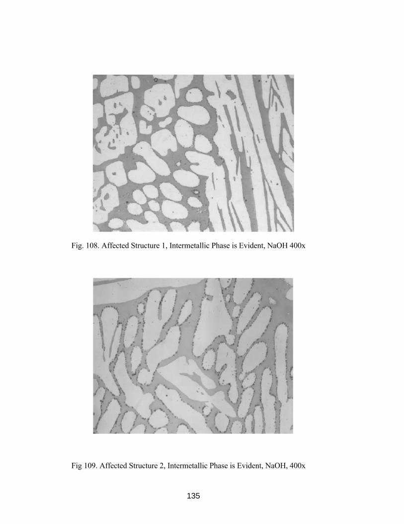
Fig. 108. Affected Structure 1, Intermetallic Phase is Evident, NaOH 400x
Fig 109. Affected Structure 2, Intermetallic Phase is Evident, NaOH, 400x
135

136
Table 17. Classification of Etch Structure for Foundry Solution Anneal Study
Material ID Classification of Etch Structure 4A-SA-1 Unaffected Structure4A-SA-2 Unaffected Structure4A-SA-3 Unaffected Structure4A-SA-4 Unaffected Structure4A-SA-6 Unaffected Structure4A-SA-7 Unaffected Structure4A-SA-8 Unaffected Structure4A-SA-9 Unaffected Structure4A-SA-10 Unaffected Structure4A-SA-11 Unaffected Structure
Figure 110. Microstructure of 4A-SA-1, NaOH, 400x

Figure 111. Microstructure of 4A-SA-2, NaOH, 400x
Figure 112. Microstructure of 4A-SA-3, NaOH, 400x
137
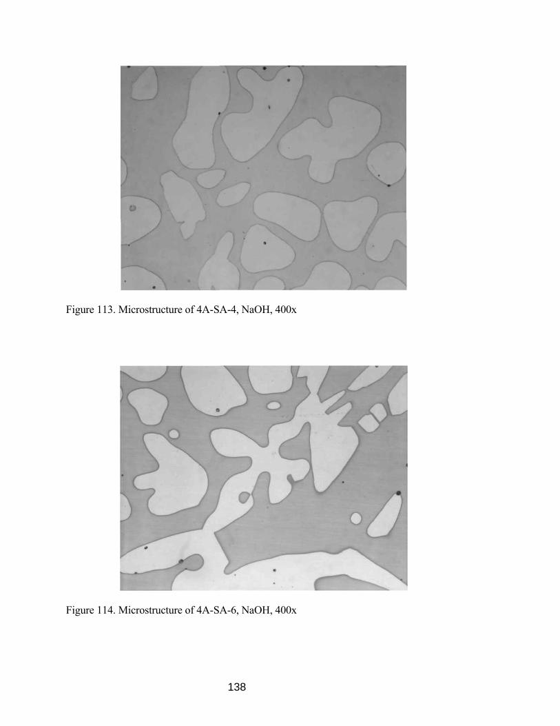
Figure 113. Microstructure of 4A-SA-4, NaOH, 400x
Figure 114. Microstructure of 4A-SA-6, NaOH, 400x
138
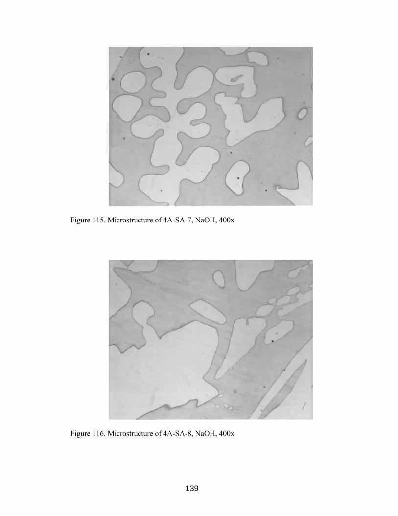
Figure 115. Microstructure of 4A-SA-7, NaOH, 400x
Figure 116. Microstructure of 4A-SA-8, NaOH, 400x
139

Figure 117. Microstructure of 4A-SA-9, NaOH, 400x
Figure 118. Microstructure of 4A-SA-10, NaOH, 400x
140
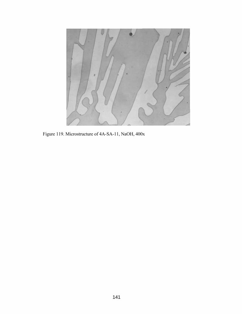
Figure 119. Microstructure of 4A-SA-11, NaOH, 400x
141
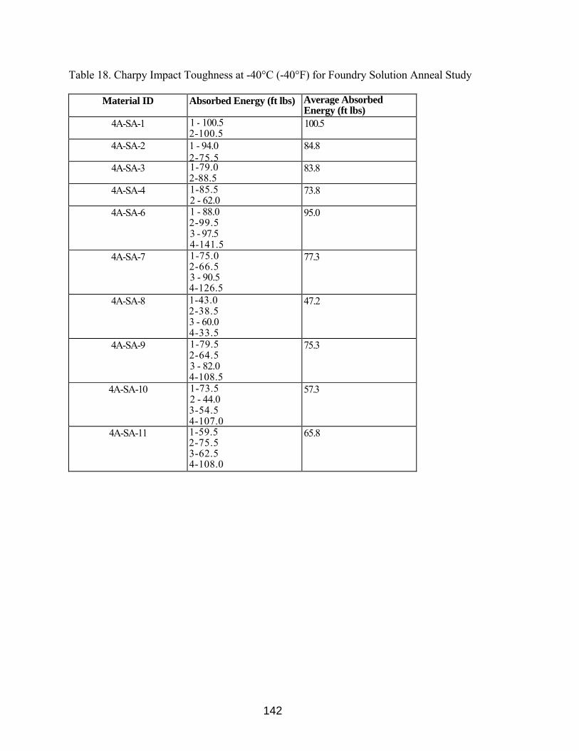
142
Table 18. Charpy Impact Toughness at -40°C (-40°F) for Foundry Solution Anneal Study
Material ID Absorbed Energy (ft lbs) Average Absorbed Energy (ft lbs)
4A-SA-1 1 - 100.5 2-100.5
100.5
4A-SA-2 1 - 94.0 2-75.5
84.8
4A-SA-3 1-79.0 2-88.5
83.8
4A-SA-4 1-85.5 2 - 62.0
73.8
4A-SA-6 1 - 88.0 2-99.5 3 - 97.5 4-141.5
95.0
4A-SA-7 1-75.0 2-66.5 3 - 90.5 4-126.5
77.3
4A-SA-8 1-43.0 2-38.5 3 - 60.0 4-33.5
47.2
4A-SA-9 1-79.5 2-64.5 3 - 82.0 4-108.5
75.3
4A-SA-10 1-73.5 2 - 44.0 3-54.5 4-107.0
57.3
4A-SA-11 1-59.5 2-75.5 3-62.5 4-108.0
65.8
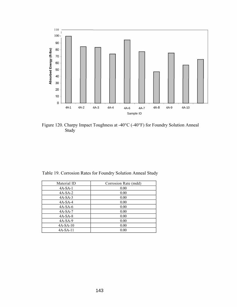
110
4A-6 4A-7
143
Sample ID
Figure 120. Charpy Impact Toughness at -40°C (-40°F) for Foundry Solution Anneal Study
Table 19. Corrosion Rates for Foundry Solution Anneal Study
Material ID Corrosion Rate (mdd) 4A-SA-1 0.004A-SA-2 0.004A-SA-3 0.004A-SA-4 0.004A-SA-6 0.004A-SA-7 0.004A-SA-8 0.004A-SA-9 0.004A-SA-10 0.004A-SA-11 0.00
4A-1 4A-2 4A-3 4A-4 4A-9 4A-10
100 -

144
All foundry solution annealed castings passed ASTM A923 requirements. No
intermetallic phases were evident in any of the samples per ASTM A923 method A
(Figures 37-46). All samples showed average Charpy impact energies greater than 40 ft-
lbs at -40°C per ASTM A923 method B (Figure 36). No weight loss was evident in any
of the samples when exposed to a ferric chloride test solution per ASTM A923 method C
(Table 10). Testing of the 10 heats of A890-4A (CD3MN) after a foundry solution
annealing heat treatment shows that the specified foundry solution anneal was adequate
to produce castings free from intermetallic phases.

145
VI. Conclusions
1. Lab-to-lab reproducibility of ASTM E562 is excellent for determining the
amount of ferrite in cast DSS.
2. Both ASTM E562 and the Feritescope® are viable methods for determining the
amount of ferrite present in DSS with ASTM E562 being more accurate.
However, the Feritescope® is quicker and is also non-destructive.
3. Several factors such as operator bias, grid spacing, and specimen metallography
can affect the accuracy of ferrite determination per ASTM E562.
4. ASTM A923 Methods adequately identify the presence of detrimental
intermetallic precipitates in both wrought and cast DSS.
5. Cast DSS material gave results similar to those of wrought DSS in all three
ASTM A923 methods.
6. The presence of detrimental intermetallic precipitates, per ASTM A923 Method
A, is easier to identify in cast DSS than in wrought DSS.
7. The micrographs obtained in this study (Figures 106 - 109) can be used when
incorporating A890-4A (CD3MN) cast materials into ASTM A923.
8. ASTM A923 Method B impact toughness testing in cast and wrought DSS is the
most sensitive of the 3 methods for detecting the presence of intermetallic
phases. Method A etch testing is adequate for detecting the presence of
intermetallic phases but this method introduces operator bias as it requires greater
skills to interpret the results. Method C corrosion weight loss testing is the least
sensitive for detecting intermetallic phases.

146
9. Isothermal holds at 1550°C showed a steady progression in the formation of
secondary phases.
10. "H" heat treatment (furnace cooled) was the most egregious thermal treatment as
samples failed all ASTM A923 tests.
11. All "G" heat treatment (air cooled) samples passed Method A and Method C
testing but showed low impact toughness per Method B.
12. Lab-to-lab reproducibility of microstructure classification per ASTM A923
method A is excellent for ASTM A890-4A cast DSS.
13. Lab-to-lab reproducibility of corrosion performance per ASTM A923 method C
is excellent for ASTM A890-4A cast DSS unless there are "high" amounts of
intermetallic phases present.
14. ASTM A923 is a viable standard for detecting the presence of detrimental
intermetallic phase in ASTM A890-4A cast DSS.
15. The data obtained in this study suggests that ASTM A923 can be expanded to
include the cast duplex materials ASTM A890-4A (CD3MN).
16. All foundry solution annealed castings passed ASTM A923 requirements. No
intermetallic phases were evident in any of the samples per ASTM A923 method
A (Figures 37-46). All samples showed Charpy impact energies greater than 40
ft-lbs at -40°C per ASTM A923 method B (Figure 36). No weight loss was
evident in any of the samples when exposed to a ferric chloride test solution per
ASTM A923 method C (Table 10).

147
17. Testing of the 10 heats of A890-4A (CD3MN) after a foundry solution annealing heat
treatment shows that the specified foundry solution anneal was adequate to produce
castings free from intermetallic phases.

148
References

149
1. Gunn, R., ed. Duplex Stainless Steels - Microstructure, Properties, and
Applications. 1997, Abington Publishing: Cambridge England.
2. Soulignac P, Dupoiron F: Stainless Steel Europe, June 1990, 18-21.
3. Chung, H.M., Chopra, O.K., "Characterization of Duplex Stainless Steels by
TEM, SANS, and APFIM Techniques," Characterization of Advanced Materials,
Edited by W. Altergott and E. Henneke, Plenum Press, New York, 1991, pp. 123-
147.
4. Roscoe C.V., Gradwell KJ, Lorimer GW: Goteborg '84, Vide ref 6, 563-577.
5. Sedriks AJ: International Metal Reviews 28,1983,295.
6. Charles J.: Proc conf Duplex Stainless Steels '94, Glasgow, TWI, 1994, Vol. 1,
paper KI.
7. OkamotoH.: Conf proc Applications of Stainless Steel '92, Stockholm,
Jernkontoret, 1992, Vol 1, 360-369.
8. Nilsson J.-O, Jonsson P, Wilson A: Glasgow '94, vide ref. 1, Vol. 2, paper 39.
9. Hertzman S., Nilsson M., Jargelius-Pettersson R.: Glasgow '94, vide ref. 1, Vol.
1, paper 1.
10. Nilsson J.-O.: Materials Science and Technology 8, 1992, 685-700.
11. Lundin, C.D., Wen, S., Zhou, G., Ruprecht, W., W. Liu, G. Lu, "Duplex Stainless
Steels, A State-of-the Art Literature Review," Steel Founders' Society of America
Report Special Report No. 31, March 2001.
12. Nilsson, J.-O., Wilson, A., Huhtala, T., Karlsson, L., Jonsson, P., "Structural
Stability of Super Duplex Stainless Weld Metals and Its Dependence on Tungsten

150
and Copper," Metallurgical and Materials Transactions A, 27A (8), Aug. 1996,
pp. 2196-2208.
13. Josefsson, B., Nilsson, J.-O., Wilson, A., "Phase Transformation in Duplex Steels
and the Relation Between Continuous Cooling and Isothermal Heat Treatment,"
Duplex Stainless Steels '91, Vol. 1, pp. 67-78.
14. Southwick P.D., Honeycombe RWK: Metal Science 14(7), 1980, p. 253.
15. Hochman J. et al: MC 50-1, 1974/5.
16. Josefsson B., Nilsson J.-O., Wilson A.: Beaune '91, vide ref. 2, Vol. 1, 67-78.
17. Ravindranath, K., Malhotra, S.N., "Influence of Aging on Intergranular Corrosion
of a 25%Cr-5%Ni Duplex Stainless Steel," Corrosion, 50(4), 1994, pp. 318-328.
18. Cheng, T.P., Tsai, W.T., Lee, J.T., "Electrochemical and Corrosion Behavior of
Duplex Stainless Steels in Hank's Solution," Journal of Materials Science,
25(2A), Feb. 1990, pp. 936-943.
19. Sriram, R., Thomas, D., "Pitting Corrosion of Duplex Stainless Steels,"
Corrosion, 45(10), Oct., 1989, pp. 804-810.
20. Machado, I.F., Padilha, A.F., "Precipitation Behavior of 25% Cr - 5.5% Ni
Austenitic Stainless Steel Containing 0.87% Nitrogen," Steel Research, 67(7),
July 1996, pp. 285-290.
21. Radenkovic, G., Cvijovic, Z., Mihajlovic, D., "Effect of Quenching Temperature
on the Microstructure and Properties of Cast Duplex Stainless Steel," Acta
Stereol, 13(2), 1994, pp. 439-444.

151
22. Lai, J.K.L., Wong, K.W., Li, D.J., "Effect of Solution Treatment on the
Transformation Behavior of Cold-Rolled Duplex Stainless Steels," Materials
Science and Engineering A, 203(1-2), Nov. 1995, pp.356-364.
23. Charles, J., "Composition and Properties of Duplex Stainless Steels," Welding in
the World, Vol. 36, 1995, pp. 43-55.
24. Kuroda, T., Matsuda, F., "Role of Secondary Austenite on Corrosion and Stress
Corrosion Cracking of Sensitized Duplex Stainless Steel Weldments,"
Transactions of JWRI, 23(2), 1994, pp. 205-211.
25. Kotecki, D.J.a.S., T.A., "Heat Treatment of Duplex Stainless Steel Weld Metals,"
Welding Journal, 1989. 68(11): pp. 431s-441s.
26. Nilsson, J.-O., "Overview: Super Duplex Stainless Steels," Materials Science and
Technology, 1992. 8(8): pp. 686-700.
27. Ogawa, T.a.K., T., "Effect of Composition Profiles on Metallurgy and Corrosion
Behavior of Duplex Stainless Steel Weld Metals," Welding Journal, 1998. 68(5):
pp. 181s-191s.
28. Miura, M., Koso, M., Hudo, T., Tsuge, H., "The Effects of Nickel and Nitrogen
on the Microstructure and Corrosion Resistance of Duplex Stainless Steel
Weldments," Welding International, 1990. 4(3): pp. 200-206.
29. Bernhardsson, S., "The Corrosion Resistance of Duplex Stainless Steels," Duplex
Stainless Steels 91,1991.
30. Gooch, T.G., "Corrosion Resistance of Welds in Duplex Stainless Steels," Duplex
Stainless Steel 9 L 1991.

152
31. Karlsson, L.a.P., S., "Influence of Intermetallic Phases on the Corrosion
Properties of Duplex Stainless Steel Weld Metals," Welding International, 1995.
9(7): pp. 554-562.
32. Adhe, K.N., Kain, V., Madangopal, K., Gadiyar, H.S., "Influence of Sigma-Phase
Formation on the Localized Corrosion Behavior of a Duplex Stainless Steel,"
Journal of Materials Engineering and Performance, 1996. 5(4): pp. 500-506.
33. Ravindranath, K.a.M., S.N., "The Influence of Aging on the Intergranular
Corrosion of 22 Chromium - 5 Nickel Duplex Stainless Steel," Corrosion
Science, 1995. 37(1): pp. 121-132.
34. Otero, E., Merino, C., Fosca, C., Fernandez, P., "Electrochemical
Characterization of Secondary Phases in Duplex Stainless Steel by EPR Test,"
Duplex Stainless Steels, 94. 1994.
35. Merino, P., Novoa, X.R., Pena, G., Porto, E., Espada, L., "Intergranular Corrosion
Susceptibility of Austenitic-Ferritic Duplex Stainless Steels: Application of
Potentiokinetic Reactivation Tests," Materials Science and Technology, 1993.
9(2): pp. 168-171.
36. Nicholls, J.M., "Corrosion Properties of Duplex Stainless Steels: General
Corrosion, Pitting and Crevice Corrosion," Duplex Stainless Steels 94. 1994.
37. Charles, J. "Super Duplex Stainless Steel: Structure and Properties," Duplex
Stainless Steels. 1991.
38. Charles, J. "Structure and Mechanical Properties of Duplex Stainless Steels,"
Duplex Stainless Steels 94. 1994.

153
39. Vander Voort, G.F., "Metallographic Techniques for Duplex Stainless Steels,"
Duplex 6th World Conference & Expo, 2000.
40. Farrar, R.A., "The Importance of Microstructural Transformations for Welding
and the Stability of Long Term Service Properties," Welding in the World, Vol.
36, 1995, pp. 143-151.
41. Atamert, S., King, J.E., "Elemental Partitioning and Microstructural Development
in Duplex Stainless Steel Weld Metal," Acta. Metall. Mater., 39(3), 1991, pp.
273-285.
42. Atamert, S., King, J.E., "Super Duplex Stainless Steels Part I: Heat Affected
Microstructures," Materials Science and Technology, 7(2), pp. 137-145.
43. Bonnefois, B., Charles J., Dupoiron, F., Soulignac, P., "How to Predict Welding
Properties of Duplex Stainless Steels," Duplex Stainless Steel '91, Vol.1, 1991,
pp. 347-361.
44. Cao, H.L., Hertzman, S., "The Relationship between Impact Properties and
Welding Simulated Microstructures in Three Duplex Stainless Steels," Duplex
Stainless Steel '91, Vol. 1, 1991, pp. 363-372.
45. Lindbolm, B.E.S., Hannerz, N., "Austenite Reformation in HAZ of Ferritic
Austenitic Steels," Duplex Stainless Steels '91, Vol. 2, 1991, pp. 951-958.
46. Dufrance, J. J., "Heat Affected Zone Simulation of Super Duplex Stainless Steel
UNS S 32760 - Zeron 100," Duplex Stainless Steel '91, Vol. 2, 1991, pp. 967-
975.

154
47. Draugelates, U., Schram, A., Boppert, C., Liu, J., "Investigation on the Effect of
the Peak Temperature and Cooling Time on the Heat Affected Zone in Duplex
Cast Steel," Duplex Stainless Steel '91, Vol. 2, 1991, pp. 977-984.
48. Draugelates, U., Schram, A., Boppert, C., "Effect of the Thermal Welding Process
Conditions on the Structure and Properties in the Heat Affected Zone of Duplex
Cast Steel," Duplex Stainless Steel '91, Vol. 2, 1991, pp. 985-992.
49. Roberti, R., Nicodemi, W., La Vecchia, G.M., Basha, Sh., "Fracture Toughness of
Simulated Duplex Stainless Steel Heat Affected Zones," Duplex Stainless Steel
91, Vol. 2, 1991, pp. 993-1000.
50. Boppert, C., Draugelates, U., "Mechanical Properties and Corrosion Resistance of
Welded Superduplex Cast Alloys," Duplex Stainless Steel '94, Vol. 3, Paper 73.
51. Lippold, J.C., Lin, W., Brandi, S., Varol, I., Baeslack III, W.A., "Heat Affected
Zone Microstructure and Properties in Commercial Duplex Stainless Steels,"
Duplex Stainless Steel '94, Vol. 1, 1994, Paper 116.
52. Kivineva, E.I., Hannerz, N.E., "The Properties of Gleeble Simulated Heat
Affected Zone of SAF 2205 and SAF 2507 Duplex Stainless Steels," Duplex
Stainless Steel '94, Vol. 1, 1994, Paper 7.
53. Hoffmeister, H. Lothongkum, G., "Quantitative Effects of Nitrogen Contents and
Cooling Rates on δ-γ transformation, Chromium Nitride Precipitation and Pitting
Corrosion after Weld Simulation of Duplex Stainless Steels," Duplex Stainless
Steel '94, Vol. 1, 1994, Paper 55.

155
54. Jana, S.,"Effect of Heat Input on the HAZ Properties of Two Duplex Stainless
Steels," Journal of Materials Processing Technology, Vol. 33, 1992, pp. 247-261.
55. Ferreira, P.J., Hertzman, S., "δ-Ferrite Grain Growth in Simulated High
Temperature HAZ of Three Duplex Stainless Steels," Duplex Stainless Steel '91,
Vol. 2, Edited by J. Charles, S. Bernhardsson, pp. 959-966.
56. Lindblom, B.E.S., Lundvist, B., Hannerz, N.E., "Grain Growth in HAZ of Duplex
Stainless Steels," Duplex Stainless Steel '91, Vol. 1, Edited by J. Charles, S.
Bernhardsson, pp. 373-381.
57. Atamert, S., Reed, R.C., King, J.E., "Modeling of Multipass Duplex Stainless
Steel Weld Deposit Microstructures," Duplex Stainless Steel '91, Vol. 1, Edited
by J. Charles, S. Bernhardsson, pp. 393-402.
58. Walker, R.A., Noble, D.N., "Effect of Welding Conditions on Corrosion
Resistance of Duplex Stainless Steels," Proceedings: Weldability of Materials,
Edited by R.A., Patterson, K.W., Mahin, Oct. 1990, pp. 117-125.
59. Lundvist, B., Norberg, P., "Weldability Aspects and Weld Joint Properties of
Duplex Stainless Steels," Welding Journal, 67(7), July 1988, pp. 45-51.
60. Karlsson, L., "Welding Super Duplex Stainless Steels," Anti-Corrosion Methods
and Materials, 42(6), 1995, pp. 30-35.
61. Varol, I., Lippold, J.C., Baeslack III, W.A., "Welding of Duplex Stainless Steels,"
Key Engineering Materials, Vol. 69 & 70, 1992, pp. 217-252.

156
62. Kotecki, D.J., Siewert, T.A., "WRC-1992 Constitution Diagram for Stainless
Steel Weld Metals: A Modification of the WRC-1988 Diagram," Welding
Journal, 71(5), 1992, pp. 171s-178s.
63. Kotecki, D.J., "Ferrite Control in Duplex Stainless Steel Weld Metal," Welding
Journal, 65(10), 1986, pp. 352s-361s.
64. Kotecki, D.J., "Extension of the WRC Ferrite Number System," Welding Journal,
61(11), 1982, pp. 352-361.
65. Schaeffler, A., "Constitution Diagram for Stainless Steel Weld Metal," Metal
Progress, 56(5), 1949, pp. 680, 680B.
66. Delong, W.T., "Ferrite in Austenitic Stainless Steel Weld Metal," Welding
Journal, 53(7), 1974, pp. 273s-286s.
67. Lake, F.B., "Effect of Cu on Stainless Steel Weld Metal Ferrite Content, " Paper
Presented at AWS Annual Meeting, 1990.
68. Kotecki, D.J., "Ferrite Measurement and Control in Duplex Stainless Steel
Welds," Proceedings of Weldability of Materials, ASM International, Oct. 1990,
pp. 127-133.
69. Kotecki, D.J., "Duplex Alloy Weld Ferrite Content: Measurement and
Mechanical Property effects," ASM Metal/Materials Technology Series, 8201-
021, Oct. 1982.
70. Lefebvre, J., "Guidance on Specifications of Ferrite in Stainless Steel Weld
Metal," Welding in the World, 31(6), Nov./Dec. 1993, pp. 390-406.
157
71. "Standard Procedures for Calibrating Magnetic Instruments to Measure the Delta
Ferrite Content of Austenitic and Duplex Austenitic-Ferritic Stainless Steel Weld
Metal," ANSI/AWSA4.2-91, American Welding Society, February 1991.
72. Neumaier, P. "ON-site Eddy Current Measurement of Ferrite Content in
Austenitic and Duplex Steel Components," Materials Evaluation, 48(9), Sept.
1990, pp. 1065-1072.
73. Kotecki, D.J., "Ferrite Determination in Stainless Steel Welds - Advances Since
1974," Welding Journal, 76(1), 1997, pp. 24s-37s.
74. Brantsma, L.H., Nijhof, P., "Ferrite Measurements: An Evaluation of Methods
and Experiences." Duplex Stainless Steel '86, Netherlands, 1986, Paper 45.
75. Taylor, R., "Duplex Stainless Steel Production," SFSA T&O Conference, 1994.
76. Nelson, D.E., Baselack III, W.A, Lippold, J.C., "An Investigation of Weld Hot
Cracking in Duplex Stainless Steels," Welding Journal, 66(8), 1987, pp. 241s-
250s.
77. Lippold, J.C., Baeslack III, W.A., Varol, I., "Heat Affected Zone Liquation
Cracking in Austenitic and Duplex Stainless Steels," Welding Journal, 71(11),
1992, pp. 387s-396s.
78. Shinozaki, K., Ke, L., North, T.H., "Hydrogen Cracking in Duplex Stainless Steel
Weld Metal," Welding Journal, 71(11), 1992, pp. 387s-396s.
79. Ogawa, K., Miura, M., "Hydrogen Cracking in Duplex Stainless Steel
Weldments," Welding International, 5(9), 1991, pp. 691-696.

158
80. Kotecki, D.J., "Phase Transformations and Weldability of Duplex Stainless
Steels," Proceedings: The First United States - Japan Symposium on Advances in
Welding Metallurgy, June 1990, pp. 251-263.
81. Hoffmeister, H., Volden, L., Grong, O., "Hydrogen Induced Weld Cracking of
Duplex Stainless Steels as Affected by Shielding Gas Composition with TIG
Welding," Duplex Stainless Steels '94, Vol. 1, Part III, 1994, Paper 54.
82. van der Mee, V., Meelker, H., van Nassau, L., "How to Avoid Hydrogen
Cracking in (Super) Duplex Stainless Steel Weldments," Duplex Stainless Steels
'94, Vol. 1, Part III, 1994, Paper 119.
83. Fang, P.J., Kirkwood, D., Power, L.J., Baxter, C.F.G., "The Resistance of Super
Duplex Stainless Steel to Hydrogen Cracking," Duplex Stainless Steels '94, Vol.
1, Part III, 1994, Paper 51.
84. Lundin, C.D. et al, "Measurement of Diffusible Hydrogen and Hydrogen Effects
on the Weldability of 2205/2209 Duplex Stainless Steel."
85. Walker, R.A., Gooch, T.G., "Hydrogen Cracking of Welds in Duplex Stainless
Steel," Duplex Stainless Steels '91, Vol. 2, 1991, pp. 1053-1063.
86. van Nassau, Meelker, H., Hilkes, J., "Welding Duplex and Super Duplex Stainless
Steels," Welding in the World, 31(5), Sept./Oct. 1993, pp. 322-343.
87. Bekkers, K., "Practice in Welding Duplex and Super Duplex Stainless Steel
Worldwide," Welding in the World, Vol. 36, 1995, pp. 111-123.
88. Noble, D.N., Gunn, R.N., "Welding of Duplex Stainless Steel - A Reader's
Digest: Part 1," Stainless Steel Europe.
159
89. Fager, S. -A. Odegard, L., "Influence of Different Welding Conditions on
Mechanical Properties and Corrosion Resistance of Sandvik SAF 2507,"
Corrosion Review, 11(3-4), 1993, pp.83-100.
90. Hilkes, J., Bekkers, K., "Welding Duplex Stainless Steel," Welding Journal,
74(11), Nov. 1995, pp. 51-54.
91. Holmberg, B., "Welding of Super Duplex Steel Avesta 2507," Welding Review
International, 11(1), 1992, pp. 22-27.
92. Doyen, R., Niset, M., "Welding of Duplex and Super Duplex Stainless Steels,"
Duplex Stainless Steels '91, Vol. 2, 1991, pp. 1043-1051.
93. Karlsson, L., Pak, S., "Welding of Duplex Stainless Steels - Properties of
SMAW-, FCAW-, and SAW- Welded Joints," Duplex Stainless Steels '91, Vol. 1,
1991, pp. 413-420.
94. Kotecki, D.J., Hilkes, J., "Welding Process for Duplex Stainless steels," Duplex
Stainless Steels '94, Vol. 2, 1994, Keynote Paper KVI.
95. "Guidelines for Welding Zeron 100 Super Duplex Stainless Steel," Weir
Materials, Ltd.
96. Geipl, H., "Gas Mixture MAG (GMA) Welding of Corrosion Resistant Duplex
Steels - Effect of Shielding Gas and Process Variations," Duplex Stainless Steels
'91, Vol. 2, 1991, pp 1027-1034.
97. Gouch, P.C., Farrar, J.C.M., "Factors Affecting Weld Root Run Corrosion
Performance in Duplex and Super Duplex Pipework," Duplex Stainless Steels '91,
Vol. 2, 1991, pp. 1009-1025.
160
98. Bjorkman, G., Odegard, L., Fager, S.A., "Submerged Arc Welding of Sandvik
2507 with Different Heat Inputs. Mechanical Properties and Corrosion
Resistance," Duplex Stainless Steels '91, Vol. 2, 1991, pp. 1035-1042.
99. Suutala, N., Takalo, T., Moisio, T., "Ferritic-Austenitic Solidification Mode in
Austenitic Stainless Steel Welds," Metallurgical Transaction, 11 A, 1980, pp.
717-725.
100. Homberg, B., "Filler Metal Selection for Optimum Duplex Weldment Properties
in Steel UNS 31803," Duplex Stainless Steels '94, Vol. 1, Part II, 1994, Paper 93.
101. Karlsson, L., Andersson, S.L., Huhtala, T., "New Ni-base Consumables for
Welding of Duplex and Super Duplex Stainless Steels," Duplex Stainless Steels
'94, Vol. 1, Part II, 1994, Paper 42.
102. Urmstom, S.A., Creffield, G.K., Cole, M.A., Huang, W., "Effect of Nitrogen
Containing Shielding Gases on the Weldability and Corrosion Performance of
Duplex Stainless Steels," Duplex Stainless Steels '94, Vol. 2, 1994, Paper 27.
103. Gunn, R.N., Anderson, P.C.J., "Development of Special Ar-He-N2 Gases for TIG
Welding of Duplex and Superduplex Stainless Steels," Duplex Stainless Steels
'94, Vol. 2, 1994, Paper 30.
104. Rabensteiner, G. Tosch, J., "The Specific Effect of Nitrogen in the Fabrication of
a Super Duplex Stainless Steel Weld," Duplex Stainless Steel '94, Vol. 2, 1994,
Paper 44.

161
105. Bradshaw, R., Cottis, R.A., "The Effect of Nitrogen Additions to Argon Shielding
Gases on the properties of Duplex Stainless Steel GTA Welds," Duplex Stainless
Steels '94, Vol. 2, 1994, Paper 31.
106. Bonnefois, B., Soulignac, P., Charles J., "Some Aspects of Nitrogen Introduction
in the Duplex Weld Pool, " Duplex Stainless Steels '91, Vol. 1, 1991, pp. 469-
478.
107. Stenbacka, N., Persson, K.A., Runnerstam, O., "Shielding Gas Technology when
Ordinary and High Alloyed Stainless Steels," Welding in the World, Vol. 36,
1995, pp. 83-90.
108. Bonnet, C., Linden, G., Rouault, P., "A Shielding Gas for the Gas Metal Arc
Welding of Duplex and Superduplex Stainless Steels," Duplex Stainless Steels
'94, Vol. 2, 1994, Paper 102.
109. Fusari, F., Bertoni, A., "Welding of Duplex Stainless Steels: Easy or Difficult?"
Duplex Stainless Steels '94, Vol. 3, Part II, 1994, Paper 57.
110. Warburton, G.R., Spence, M.A., Healiss, T., "Fabrication and Qualification
Experiences with Duplex, Super Duplex, and Super Austenitic Alloys," Duplex
Stainless Steels '94, Paper 24.
111. Odegard, L., "Welding of Stainless Steels Corrosion in Welds. Effect of Oxides,
Slag, and Weld Defects on the Pitting Resistance," Welding in the World, Vol. 36,
1995, pp. 153-160.
112. Holmberg, B., "How to Weld Avesta SAF 2507," Information 9168, Avesta
Welding.

162
113. Homerg, B., "How to Weld Avesta 2205."
114. Krysiak, K.F., Bhadha, P.M., "Shielding Gas Purification Improves Weld
Quality," Welding Journal, 69(11), 1990, pp. 47-49.
115. "How to Weld Avesta 2205 Code Plus Two® Duplex Stainless Steel," Avesta
Stainless Inc., June 1992.
116. "Your Guide to Easy Welding of Duplex Stainless Steel," Sandvik Steel Co.,
March 1992.
117. Davidson, R., Redmond, J., "Development of Qualification Tests for Duplex
Stainless Steel Mill Products," Corrosion 9, 302, 1991.
118. Druce, S.G., Gage, G., Popkiss, E., "Effects of Notch Geometry on the Impact
Fracture Behavior of a Cast Duplex Stainless Steel," The International Journal of
Pressure Vessels and Piping, 33(1), 1988, pp. 59-81.
119. Niederau, H.J., Overbeck, G.W., "high Quality Castings from Duplex and Super-
Duplex Stainless Steels for FGD and Off-shore Applications," Duplex Stainless
Steels '94, Vol. 1, Part III, 1994, Keynote Paper 99.
120. SCRATA Materials Fact Sheets on Duplex Cr-Ni Steels, Section D, Apr. 1991.
121. Baxter, C., Young, M., "The Practicalities of Welding Duplex Stainless Steel
Process Plant," Duplex 6th World Conference & Expo, 2000.
122. Holloway, G.B., Farrar, J.C.M., "Welding Consumables for Duplex and
Superduplex Stainless Steels - Optimizing Properties After Heat Treatment,"
Duplex 6th World Conference & Expo, 2000.
163
123. Baxter, C., Laren, M., "Energy Input Control Nomographs for Welding Duplex
and Super Duplex Stainless Steel," Duplex 6th World Conference & Expo, 2000.
124. dos Santos, R., Hofmann, E., "On the Control of the Microstructural Development
During Solidification of Superduplex Steel Castings," Duplex 6th World
Conference & Expo, 2000.
125. Charles, J., Verneau, M., "How to Improve Duplex Stainless Steel Properties with
Copper Additions," Duplex 6th World Conference & Expo, 2000.
126. Salvago, G., Carucci, L., Gariboldi, E., Lecis, N., "Phase Distribution and
Electrochemical Behavior of Centrifugally Cast Duplex Stainless Steel Pipe,"
Duplex 6th World Conference & Expo, 2000.
127. Suk, J., Soo, J., Kim K., "The Effect of W Modification of Duplex Stainless Steel
on the Behavior of Precipitation of Secondary Phases and Stress Corrosion
Cracking," Duplex 6th World Conference & Expo, 2000.
128. Wessman, S., Pettersson, J., "Hydrogen Cracking of Cathodically Polarized
Duplex Stainless Steels and Weld Metals," Duplex 6th World Conference & Expo,
2000.
129. Bonnet, C., Lethuiller, L., Rouault, P., "Comparison Between Different Ways of
Ferrite Measurements in Duplex Welds and Influence on Control Reliability
During Construction," Duplex 6th World Conference & Expo, 2000.
130. Farina, C., Grassini, U., "Experiences and NDT Controls with Duplex Stainless
Steels in Chemical and Refinery Plants," Duplex 6th World Conference & Expo,
2000.
164
131. Karlsson, L., Rigdal, S., Pak, S., "Effects of Elemental Distribution on
Precipitation Behavior and Properties of Duplex Stainless Steel Weldments,"
Duplex 6th World Conference & Expo, 2000.
132. Jimenez, J.A., Ruano, O.A., Allende, R., Torralba, M., Carsi, M., "Effect of
Composition on the Mechanical Properties of Two Duplex Stainless Steels,"
Duplex 6th World Conference & Expo, 2000.
133. Lee, C.S., Ahn, J.S., Lee, A., Kim, K.T., Park, C.G., Kim, K.Y., "Effect of χ-
phase Precipitation on the Mechanical Properties of Duplex Stainless Steels,"
Duplex 6th World Conference & Expo, 2000.
134. "Your Guide to Easy Welding of Duplex Stainless Steel," Sandvik Steel, March
1992.
135. "Ferrite Measurement in Austenitic and Duplex Stainless Steel Castings,"
Ruprecht, W.J., December 1999.
136. "Fabrication and Service Performance of Welded Duplex Stainless Steels,"
Newman, V.

165
Appendix: Specifications

166
1. ASTM A890-94: "Standard Specification for Castings, Iron-Chromium-Nickel-
Molybdenum Corrosion Resistant, Duplex (Austenitic/Ferritic) for General
Application"
2. ASTM E562-01: "Standard Test Method for Determining Volume Fraction by
Systematic Manual point Count"
3. ASTM A923-94: "Standard Test Methods for Detecting Detrimental Intermetallic
Phase in Wrought Duplex Austenitic/Ferritic Stainless Steels"
4. ASTM A370: "Standard Methods and Definitions for mechanical Testing of Steel
Products"
5. ASTM E23: "Standard Method for Notch Bar Impact Testing of Metallic Materials"
6. ASTM A799/A 799M-91: "Standard Practice for Stainless Steel Castings,
Instrument Calibration, for Estimating Ferrite Content"
Related Documents