Journal of Mechanical Science and Technology 24 (2010) 189~195 www.springerlink.com/content/1738-494x DOI 10.1007/s12206-009-1155-0 [Invited Paper] The Development of gearless reducers with rolling balls † Hidetsugu Terada * Graduate school of Medical and Engineering, Department of Mechanical System Engineering, University of Yamanashi, Takeda 4-3-11, Kofu, Yamanashi 400-8511, Japan (Manuscript Received May 1, 2009; Revised November 10, 2009; Accepted November 16, 2009) ---------------------------------------------------------------------------------------------------------------------------------------------------------------------------------------------------------------------------------------------------------------------------------------------- Abstract To satisfy the various demands such as no-backlash characteristic and so on, we have newly developed three types of no-backlash re- ducers: the cycloid ball reducer, the precession ball reducer and the reciprocating motion input type ball reducer. Especially, these reduc- ers are developed for the robot joints. Also, these reducers are a kind of the constant velocity cam mechanisms with rolling balls; their inputs use eccentric motion, precession motion and reciprocating motion. The motion principle and the profile calculation method of each reducer are proposed, using the vector analysis. Keywords: Ball reducer; No-backlash; Eccentric motion; Precession motion; Reciprocating motion ---------------------------------------------------------------------------------------------------------------------------------------------------------------------------------------------------------------------------------------------------------------------------------------------- 1. Introduction The characteristic of a no-backlash transmission is the most important performance for industrial robots. To satisfy that performance, many varieties of the no-backlash reducers have been developed [1-3]. However, the conventional no-backlash reducers have a limited reduction ratio. So, we cannot select an arbitrary reduction ratio. Also, these reducers cannot often be used to the robot wrist joint; that size is limited strictly. And the conventional orthogonal axis output type reducers cannot eliminate the backlash. To solve these problems, it is difficult to develop only one type of reducer. Therefore, we have paid attention as follows: (1) The planetary motion can generate the reduced rotation with high reduction ratio. (2) The cam mechanism is designed using motion loci; that is, no-backlash in theoretical calculation. (3) The simplest rolling element is the ball shape. Considering these points, we have developed three input motion type reducers which are a kind of the constant velocity cam mechanisms with rolling balls; they have eccentric mo- tion, precession motion and reciprocating motion. The eccen- tric input type is useful for the co-axial output type reducer. And the precession motion input type is useful to generate the reduced orthogonal axis output rotation. Also, the reciprocat- ing motion input type is suitable for the hollow shape and the large diameter of the reducer elements. In this report, an overview of the developed reducers is shown. And the motion principle and the profile calculation method are shown, using the some developed reducers. 2. Development of the eccentric motion input type ball reducer 2.1 Single stage type cycloid ball reducer The single stage type cycloid ball reducer [4] consists of two sections: the reduction section and the motion transmit- ting section with many circular grooves, shown in Fig. 1. The reduction section is driven by the eccentric input shaft shown in Fig. 1 as 1. To eliminate the excitation which is caused by eccentric motion, a counter weight is needed as 2. The reduc- tion section consists of a fixed disc 4 with an epi-trochoidal Fig. 1. Fundamental structure of a single stage type cycloid ball reducer. † This paper was presented at the ICMDT 2009, Jeju, Korea, June 2009. This paper was recommended for publication in revised form by Guest Editors Sung-Lim Ko, Keiichi Watanuki. * Corresponding author. Tel.: +81 55 220 8452, Fax.: +81 55 220 8452 E-mail address: [email protected] © KSME & Springer 2010

Welcome message from author
This document is posted to help you gain knowledge. Please leave a comment to let me know what you think about it! Share it to your friends and learn new things together.
Transcript

Journal of Mechanical Science and Technology 24 (2010) 189~195
www.springerlink.com/content/1738-494x DOI 10.1007/s12206-009-1155-0
[Invited Paper] The Development of gearless reducers with rolling balls†
Hidetsugu Terada* Graduate school of Medical and Engineering, Department of Mechanical System Engineering,
University of Yamanashi, Takeda 4-3-11, Kofu, Yamanashi 400-8511, Japan
(Manuscript Received May 1, 2009; Revised November 10, 2009; Accepted November 16, 2009)
----------------------------------------------------------------------------------------------------------------------------------------------------------------------------------------------------------------------------------------------------------------------------------------------
Abstract To satisfy the various demands such as no-backlash characteristic and so on, we have newly developed three types of no-backlash re-
ducers: the cycloid ball reducer, the precession ball reducer and the reciprocating motion input type ball reducer. Especially, these reduc-ers are developed for the robot joints. Also, these reducers are a kind of the constant velocity cam mechanisms with rolling balls; their inputs use eccentric motion, precession motion and reciprocating motion. The motion principle and the profile calculation method of each reducer are proposed, using the vector analysis.
Keywords: Ball reducer; No-backlash; Eccentric motion; Precession motion; Reciprocating motion ---------------------------------------------------------------------------------------------------------------------------------------------------------------------------------------------------------------------------------------------------------------------------------------------- 1. Introduction
The characteristic of a no-backlash transmission is the most important performance for industrial robots. To satisfy that performance, many varieties of the no-backlash reducers have been developed [1-3]. However, the conventional no-backlash reducers have a limited reduction ratio. So, we cannot select an arbitrary reduction ratio. Also, these reducers cannot often be used to the robot wrist joint; that size is limited strictly. And the conventional orthogonal axis output type reducers cannot eliminate the backlash. To solve these problems, it is difficult to develop only one type of reducer. Therefore, we have paid attention as follows: (1) The planetary motion can generate the reduced rotation
with high reduction ratio. (2) The cam mechanism is designed using motion loci; that is,
no-backlash in theoretical calculation. (3) The simplest rolling element is the ball shape.
Considering these points, we have developed three input motion type reducers which are a kind of the constant velocity cam mechanisms with rolling balls; they have eccentric mo-tion, precession motion and reciprocating motion. The eccen-tric input type is useful for the co-axial output type reducer. And the precession motion input type is useful to generate the reduced orthogonal axis output rotation. Also, the reciprocat-ing motion input type is suitable for the hollow shape and the large diameter of the reducer elements.
In this report, an overview of the developed reducers is shown. And the motion principle and the profile calculation method are shown, using the some developed reducers.
2. Development of the eccentric motion input type
ball reducer
2.1 Single stage type cycloid ball reducer
The single stage type cycloid ball reducer [4] consists of two sections: the reduction section and the motion transmit-ting section with many circular grooves, shown in Fig. 1. The reduction section is driven by the eccentric input shaft shown in Fig. 1 as 1. To eliminate the excitation which is caused by eccentric motion, a counter weight is needed as 2. The reduc-tion section consists of a fixed disc 4 with an epi-trochoidal
Fig. 1. Fundamental structure of a single stage type cycloid ball reducer.
† This paper was presented at the ICMDT 2009, Jeju, Korea, June 2009. This paperwas recommended for publication in revised form by Guest Editors Sung-Lim Ko, Keiichi Watanuki.
*Corresponding author. Tel.: +81 55 220 8452, Fax.: +81 55 220 8452 E-mail address: [email protected]
© KSME & Springer 2010
190 H. Terada / Journal of Mechanical Science and Technology 24 (2010) 189~195
First stage reduction section
Second stage reduction section
Motion transmitting section
Input rotation
Output rotation
Hypo-trochoidalwave on a fixed disc
Hypo-trochoidalwave on an eccentric motion disc
Epi-trochoidalwave on an eccentric motion disc
Epi-trochoidalwave on a Output disc
Z1
Z2
Z5
Z6
Many circular grooves
Fig. 2. Equivalent model of a two stage type cycloid ball reducer.
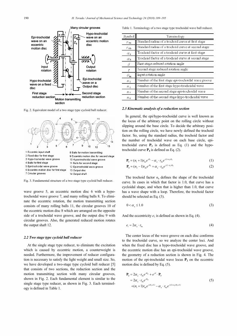
Fig. 3. Fundamental structure of a two stage type cycloid ball reducer.
wave groove 5, an eccentric motion disc 6 with a hypo-trochoidal wave groove 7, and many rolling balls 8. To elimi-nate the eccentric rotation, the motion transmitting section consists of many rolling balls 11, the circular grooves 10 of the eccentric motion disc 8 which are arranged on the opposite side of a trochoidal wave groove, and the output disc 9 with circular grooves. Also, the generated reduced motion rotates the output shaft 12.
2.2 Two stage type cycloid ball reducer
At the single stage type reducer, to eliminate the excitation which is caused by eccentric motion, a counterweight is needed. Furthermore, the improvement of reducer configura-tion is necessary to satisfy the light weight and small size. So, we have developed a two-stage type cycloid ball reducer [5] that consists of two sections, the reduction section and the motion transmitting section with many circular grooves, shown in Fig. 2. Each fundamental element is similar to the single stage type reducer, as shown in Fig. 3. Each terminol-ogy is defined in Table 1.
Table 1. Terminology of a two stage type trochoidal wave ball reducer.
2.3 Kinematic analysis of a reduction section
In general, the epi/hypo-trochoidal curve is well known as the locus of the arbitrary point on the rolling circle without slipping around the base circle. To decide the arbitrary posi-tion on the rolling circle, we have newly defined the trochoid factor. So, using the standard radius, the trochoid factor and the number of trochoidal wave on each base circle, epi-trochoidal curve P3 is defined as Eq. (1) and the hypo-trochoidal curve P4 is defined as Eq. (2).
3 1 3(1 )
1 0a a 0a( 1) j j nn r e r eθ θα += + − ⋅3P (1) 4 2 4(1 )
2 0a a 0a( 1) j j nn r e r eθ θα −= − + ⋅4P (2) The trochoid factor αa defines the shape of the trochoidal
curve. In cases in which that factor is 1.0, that curve has a cycloidal shape, and when that is higher than 1.0, that curve has a wave shape with a loop. Therefore, the trochoid factor should be selected as Eq. (3).
a0 1.0α< ≤ (3)
And the eccentricity e1 is defined as shown in Eq. (4).
1 a 0a2e rα= ⋅ (4) The center locus of the wave groove on each disc conforms
to the trochoidal curve, so we analyze the center loci. And when the fixed disc has a hypo-trochoidal wave groove, and the eccentric motion disc has an epi-trochoidal wave groove, the geometry of a reduction section is shown in Fig. 4. The motion of the epi-trochoidal wave locus P2 on the eccentric motion disc is defined by Eq. (5).
in
in
3 1 3
a 0a
a 0a
( ) {(1 ) }1 0a a 0a
22( 1)
j j
j
j j n
r e er e
n r e r e
θ δ
θ
θ δ θ δ
α
α
α+ + +
= ⋅ + ⋅
= ⋅
+ + − ⋅
2 3P P (5)
H. Terada / Journal of Mechanical Science and Technology 24 (2010) 189~195 191
Epi-trochoidal curve
Hypo-trochoidal curve
Base circle of a hypo-trochoidal curve
Base circle of an epi-trochoidalcurve
Pitch circle of rolling balls allocation
Eccentricity
O3
P2
Rolling circle of a hypo-trochoidal curve
Rolling circle of an epi-trochoidal curve
Meshed points with balls
O4
Epi-trochoidal curve
Hypo-trochoidal curve
Base circle of a hypo-trochoidal curve
Base circle of an epi-trochoidalcurve
Pitch circle of rolling balls allocation
Eccentricity
O3
P2
Rolling circle of a hypo-trochoidal curve
Rolling circle of an epi-trochoidal curve
Meshed points with balls
O4
Fig. 4. Geometry of an epi-trochoidal wave and a hypo-trochoidal wave meshing.
In this equation, the δ shows the reduced rotation angle
around the first stage eccentric shaft. On the other hand, the hypo-trochoidal wave groove on the fixed disc conforms to Eq. (2). When these grooves are meshed across many balls, as shown in Fig. 4, the first stage design conditions are needed as follows.
2 1
in1
13 in
1 1
4 in1
22
2( 1)1
1
n n
nn
n n
n
δ θ
θ θ
θ θ
− =⎧⎪⎪ = −⎪⎪
+⎨ =⎪ +⎪⎪ −
=⎪ +⎩
(6)
The motion of the epi-trochoidal wave locus P2 is shown in
Eq. (7). This equation is satisfied on the arbitrary rotation.
in1 in
1 ( 2 )1
1 0a a 0a( 1)j m
n jn r e r eθ π
θα⎧ ⎫⎪ ⎪− +⎨ ⎬
+⎪ ⎪⎩ ⎭= + + ⋅2P
1( 0,1,2, , )m n= L (7) In cases in which all meshed points with balls conform to
the points on tangents of the epi-trochoidal curve and the hy-po-trochoidal curve, all balls are arranged to the equivalent pitch. The number of balls is n1+1.
At the second stage section, the motion analysis is similar to the first stage section. However, to rotate with a constant ve-locity, the f1 must be an integer which shows the design condi-tion parameter of wave numbers, as Eq. (8).
1 5
11
2 ( 2)n nfn
+ ⋅ += (8)
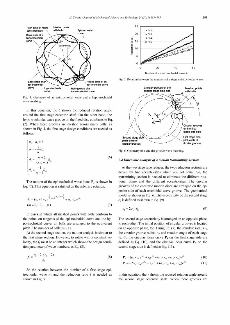
So the relation between the number of a first stage epi-
trochoidal wave n5 and the reduction ratio i is needed as shown in Fig. 5.
0
5
10
15
20
25
0 20 40 60
Number of an epi-trochoidal wave n 5
Redu
ction r
atio i
f1:2
f1:3
f1:4
f1:5
Fig. 5. Relation between the numbers of a stage epi-trochoidal wave.
δa
θin
O8O9
θ9
θ8
Meshed points with balls
Circular grooves on the first stage side disc
δa
Circular grooves on the second stage side disc
First stage side pitch circle of circular grooves
Second stage side pitch circle of circular grooves
δa
θin
O8O9
θ9
θ8
Meshed points with balls
Circular grooves on the first stage side disc
δa
Circular grooves on the second stage side disc
First stage side pitch circle of circular grooves
Second stage side pitch circle of circular grooves
Fig. 6. Geometry of a circular groove wave meshing.
2.4 Kinematic analysis of a motion transmitting section
At the two stage type reducer, the two reduction sections are driven by two eccentricities which are not equal. So, the transmitting section is needed to eliminate the different rota-tional phase and the different eccentricities. The circular grooves of the eccentric motion discs are arranged on the op-posite side of each trochoidal wave groove. The geometrical model is shown in Fig. 6. The eccentricity of the second stage e2 is defined as shown in Eq. (9).
2 b 0b2e rα= ⋅ (9)
The second stage eccentricity is arranged on an opposite phase to each other. The initial position of circular grooves is located on an opposite phase, too. Using Eq. (7), the standard radius r8, the circular groove radius r7, and rotation angle of each stage θ8, θ7, the circular locus curve P8 on the first stage side are defined as Eq. (10), and the circular locus curve P7 on the second stage side is defined as Eq. (11).
8in
a 0a 8 a 0a b 0b2 ( ) jj jr e r e r r e θθ δα α α= ⋅ + + ⋅ + ⋅8P (10) 7in
b 0b 7 a 0a b 0b2 ( ) jj jr e r e r r e θθ γα α α= − ⋅ + + ⋅ + ⋅7P (11)
In this equation, the γ shows the reduced rotation angle around the second stage eccentric shaft. When these grooves are

192 H. Terada / Journal of Mechanical Science and Technology 24 (2010) 189~195
meshed across many balls, the design conditions are needed as Eq. (12).
8 7
in2
7 in
8 in
2r r
nδ γ θ
θ θθ θ π
=⎧⎪⎪ = = −⎪⎨⎪ =⎪⎪ = +⎩
(12)
3. Development of the precession motion input type
ball reducer
3.1 Co-axial output type precession ball reducer
The co-axial type precession ball reducer [6] consists of an inclined input shaft 1, a precession motion rotor 2 which ro-tates around the input shaft freely, many rolling balls on the rotor 3, a fixed ring 4 with spatial circular grooves 5 of an inside surface and an output ring 6 with the trochoidal wave groove 7 of an inside surface, as shown Fig. 7. The output ring has a coaxial output to the input shaft. Many balls which are arranged on the rotor are meshing with the spatial circular grooves 5, to generate a precession motion of pre-cession rotor. The spatial cycloidal or trochoidal wave groove 7, which is based on a precession motion, generates the reduced rotating motion. That spatial wave groove is the locus of a precession motion with the reduced rotating motion, which generates using the relative motion of a precession rotor and an output ring. On both sides of the pre-cession rotor, many rotating balls are arranged in a uniform angular pitch. For each ball, the rotating phase which is caused by an inclined input shaft is different.
3.2 Orthogonal-axis output type precession ball reducer
The orthogonal-axis output type precession ball reducer [7] consists of many parts as shown in Fig. 8. The generating section of precession motion consists of an inclined input shaft 1 with the inclined shaft 2 which rotates freely, a precession motion rotor 3 which rotates around the input shaft freely, many rolling balls 4 for precession motion and a fixed ring 5 with the spatial circular grooves 6 of an inside surface. These spatial circular grooves make the precession motion. The con-verting section of the precession motion direction consists of a converting rotor 7 and many rolling balls 9, 11 and 13 on that rotor. The precession rotor has many grooves 8 for converting that motion direction. And many circular grooves 10 are as-signed around that rotor, to generate precession motion around the output axis. Also, the section of reduced output motion consists of an output rotor with the spatial trochoidal-wave groove 12 of an inside surface. This groove is generated from the arbitrary required reduction ratio. The generated reduced motion rotates the output shaft 14 which is the orthogonal direction of the input shaft.
Fig. 7. Fundamental structure of a co-axial type precession ball reducer.
Fig. 8. Fundamental structure of an orthogonal axial type precession ball reducer.
3.3 Kinematic analysis of spatial circular grooves on the
fixed ring
In general, the precession motion is well known as the rotat-ing motion of a cone without slipping. This motion can be modeled to the motion of a disc rotating around the equivalent circle in which the rotating axis coincides with the i-axis on the Cartesian space. When a precession motion is generated, it is necessary to limit the arbitrary spatial motion. So, spatial circular grooves on fixed ring are needed. Also, the reduced rotating motion is generated from the precession motion for the precession rotor. The reaction torque for reduced rotating motion acts on the precession rotor. So the mechanism which holds a reaction torque is needed as well as the general plane-tary gearing system, at this proposed reducer. Therefore, the circular spatial grooves on a fixed ring are investigated.
H. Terada / Journal of Mechanical Science and Technology 24 (2010) 189~195 193
The section generating the precession motion is shown in Fig. 9. The axis of the input shaft intersects with the inclined shaft at the origin point Op. Then the pitch radius of balls lo-cated is defined as r0. All balls are located on the arbitrary position on a precession rotor, so the number of located balls is defined as n. Each ball is located around the rotating axis w1 at the initial angle λn. That is separated at the initial angle τn around j-axis. Also the inclined angle is defined as α1 that rotor which rotates freely is assembled to the inclined shaft.
When the inclined input shaft rotates as θ, the precession ro-tor rotates without slipping on the equivalent disc as φ1. So the position of the ball center P1 is defined as Eq. (13) [13].
1 1 1 n 1 n 1 1w w j j wi iφ λ α τ φθ θ= ⋅ = ⋅1 0 0P Ε Ε E E E R Ε Ε P
bn(0,1,2, , 1)n Z= ⋅ ⋅ ⋅⋅ − (13)
In this equation, each ball is numbered as the n-th. Also, the
initial position is defined as Eq. (14).
0(0,0, )Tr= −0R (14)
The rotating matrix around the w1 axis is defined as Eq. (15).
1 1
21 1
1 1
1 1
1 1 1 12
1 1 1 12
1 1 1 1
cos (1 cos )(1 cos ) sin(1 cos ) sin
(1 cos ) sin (1 cos ) sincos (1 cos ) (1 cos ) sin
(1 cos ) sin cos (1 cos )
wφ
φ λ φλµ φ υ φυλ φ µ φ
λµ φ υ φ υλ φ µ φφ µ φ µυ φ λ φ
µυ φ λ φ φ υ φ
⎡ + −⎢Ε = − +⎢⎢ − −⎣
− − − + ⎤⎥+ − − − ⎥⎥− + + − ⎦
(15)
At this equation, the λ, µ and ν are defined as the directional
cosine of a unit vector at the w1-axis. Based on these vector analyses, the end-mill cutter gener-
ates circular grooves the diameter of which is the same as the ball. When these grooves are generated, that cutter pose has to conform to the direction of P1.
Fig. 9. Geometry of a precession motion and circular groove vector.
3.4 Kinematic analysis of the special circular grooves on a
converting rotor
The precession motion generated from an input rotating is shown as Eq. (13). However, the axis of output rotating is located on orthogonal direction to the axis of input rotating. So, it is different from the required precession motion which ro-tates around output axis as shown Eq. (16).
2 2w kφ θ′ ′= Ε Ε1 0P P (16)
Each ball on the converting rotor rotates around axis w2.
That is separated at the initial angle τ1 around j-axis. Also the inclined angle of output side is defined as α2. The pitch radius of balls on the converting rotor is defined as Eq. (17).
0( ,0,0)Tr′ =0R (17)
The position of each ball is defined as Eq. (18).
2 n 2 1w j jk λ α τε′ ′= Ε Ε Ε Ε0 0P R
bn(0,1,2, , 1)n Z= ⋅ ⋅ ⋅⋅ − (18) In this equation, each ball is numbered as the n-th. Also, the
arbitrary initial pose of a converting rotor is defined as the offset angle ε.
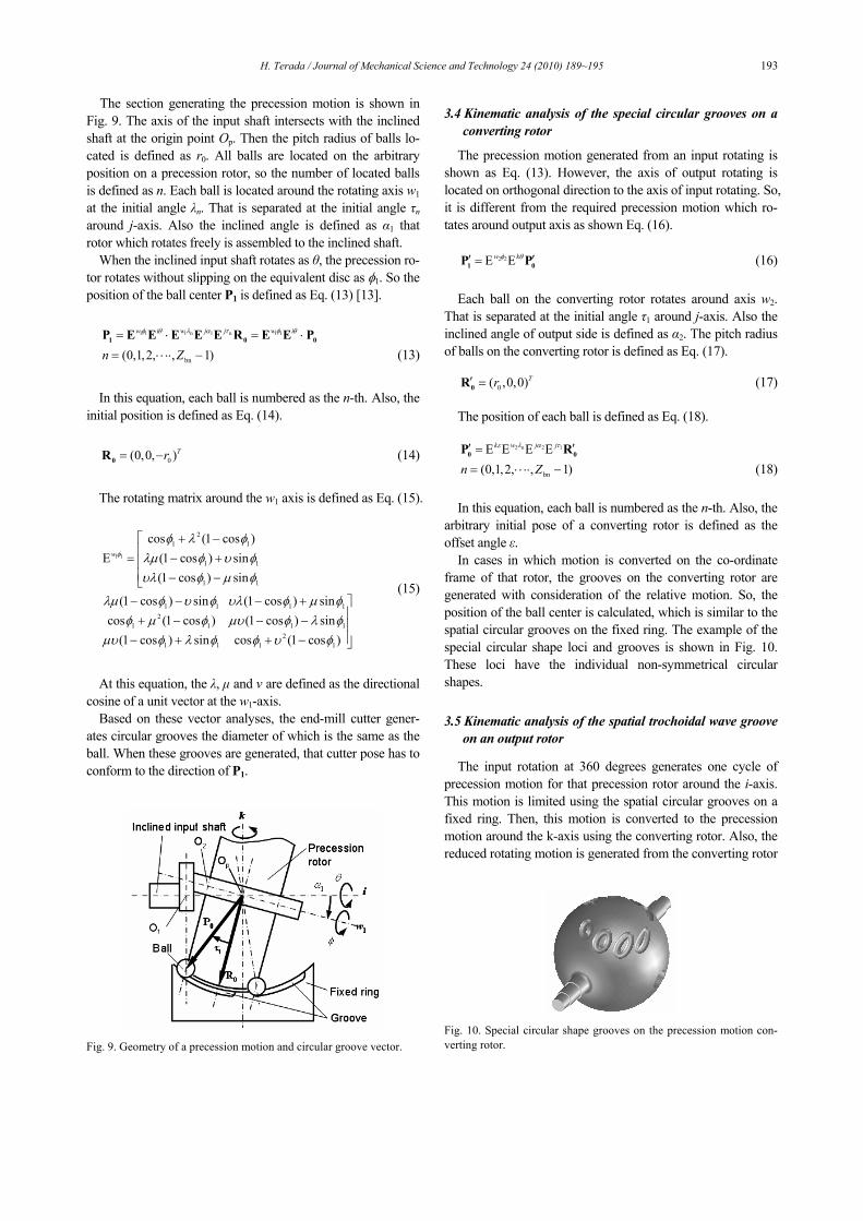
In cases in which motion is converted on the co-ordinate frame of that rotor, the grooves on the converting rotor are generated with consideration of the relative motion. So, the position of the ball center is calculated, which is similar to the spatial circular grooves on the fixed ring. The example of the special circular shape loci and grooves is shown in Fig. 10. These loci have the individual non-symmetrical circular shapes.
3.5 Kinematic analysis of the spatial trochoidal wave groove
on an output rotor
The input rotation at 360 degrees generates one cycle of precession motion for that precession rotor around the i-axis. This motion is limited using the spatial circular grooves on a fixed ring. Then, this motion is converted to the precession motion around the k-axis using the converting rotor. Also, the reduced rotating motion is generated from the converting rotor
Fig. 10. Special circular shape grooves on the precession motion con-verting rotor.

194 H. Terada / Journal of Mechanical Science and Technology 24 (2010) 189~195
Op
P1
iw1
k
Precession motionconverting rotor
w2
α2
φ2
τ3
θ
Circular Grooves
Fixed ring
Output ring Wave groove
τ2
R1R2
Q1
Op
P1
iw1
k
Precession motionconverting rotor
w2
α2
φ2
τ3
θ
Circular Grooves
Fixed ring
Output ring Wave groove
τ2
R1R2
Q1
Fig. 11. Geometry of a reduced output motion.
Fig. 12. Trochoidal wave groove on an output ring. motion. The reaction torque of reduced rotating motion around the k-axis acts on that converting rotor. So, this section consists of the part which limits spatial motion around the k-axis, and the generating part of a reduced motion. This gener-ating section of reduced output motion is shown in Fig. 11. The spatial trochoidal wave groove is shown in Fig. 12. With this type of reducer, the rolling balls are arranged in a uniform angular pitch on the rotor converting the precession motion. Therefore, each ball does not separate from that locus at these loop points and rotates smoothly. In other words, the loops on the trochoidal wave groove can be used.
4. Development of the precession motion input type
ball reducer
The reciprocating motion type ball reducer [8] consists of the reciprocating motion generating section and the reduced motion generating section. Each element is an input rotor 1, a fixed rotor 2, a reduced motion rotor 3, many reciprocating motion sliders 4 and many rolling balls 5 and 6, as shown in Fig. 13. These sliders are located between the fixed rotor and each input/reduced rotor to hold the rolling balls. Each rotor meshes with balls by use of the outside groove on themselves. Also, the fixed rotor has internal linear grooves 7, which gen-erate the reciprocating motion by ball rolling.
At the reciprocating motion generating section, to generate the doubling reciprocating cycle motion using the constant velocity input rotation, the input rotor has a special circulate groove 8, just like a "8" character, which is on the rotor out-side surface. The meshing with the ball located on that slider and the groove generates the half speed reciprocating motion.
Fig. 13. Structure of a reciprocating motion ball reducer.
That ball meshes with fixed rotor simultaneously. The motion direction is translated by use of the component of the recipro-cating motion direction. It is similar to a grooved cam mecha-nism which has a converting follower. Also, at this section, many reciprocating motion sliders which have different mo-tion phase each other are assigned on the uniform angular pitch.
On the other hand, at the reduced motion generating section, the reduced rotation is generated by use of the meshing with balls and the reduced groove. These balls are located on the reciprocating motion slider. That groove has a wave groove just like a "trochoidal-wave" 9 on that rotor outside surface. At this section, these reciprocating sliders drive a reduced motion rotor which is different from the general cam mechanism.
5. Conclusions
In this report, an overview of reducers which were devel-oped to satisfy the various demands is given. Using the two stage type cycloid ball reducer and the orthogonal-axis output type precession ball reducer, the motion principle and the pro-file calculation method are shown.
In future work, to realize higher performances for the robot joint, we'll improve the structures of reducers.
References
[1] W. G. Molyneux, The follower tooth reduction gear, Mechanisms 1972, I. Mech. E., London, G.B., (1973) 15-23.
[2] Cyclo Reducer catalog, Sumitomo Heavy Industry Ltd., Tokyo, Japan, (1999) F0101-2.
[3] Harmonic Drive CSF-3 Series Technical Data, Harmonic Drive systems Inc., Tokyo, Japan, (2008) 0710-2R-TCSF3.
[4] H. Terada, K. Imase and H. Makino, Fundamental analysis of a cycloid ball reducer, (1st report) Motion principle, J. Japan Soc. for Precision Engineering 54(11) (1988) 2101-2106.
[5] H. Terada and K. Imase, Motion analysis of a multi-stage type trochoidal wave ball reducer, Proc. of the 10th Int. Conf.

H. Terada / Journal of Mechanical Science and Technology 24 (2010) 189~195 195
on the Theory of Machines and Mechanisms, Liberec, Czech Republic, (2008) 629-636.
[6] H. Terada, T. Fukazawa and R. Irie, Motion analysis of a coaxial output type precession motion ball reducer, Proc. of the 11th World Congress in Mechanism and Machine Sci-ence, Tianjin, China, (2004) 877-881.
[7] H. Terada and R. Irie, Motion analysis of an orthogonal output type precession motion ball reducer, Proc. of the 9th Int. Conf. on the Theory of Machines and Mechanisms, Liberec, Czech Republic, (2004) 753-762.
[8] H. Terada, T. Masuda and S. Yoshida, Motion analysis of a reciprocating motion type ball reducer, Proc. of the 12th World Congress in Mechanism and Machine Science, Be-sancon, France, (2007) Lc4-418.
Hidetsugu Terada received his Ba-chelor and Master degrees in Me-chanical Engineering from the Uni-versity of Yamanashi, Japan, in 1986 and 1988, respectively. He then received his Doctorate from the Tokyo Institute of Technology in 1993. Dr. Terada is currently an Associate Professor at the
Graduate School of Medical and Engineering Science at the University of Yamanashi in Kofu, Japan. He serves as the IFToMM Technical Committee member of the “Linkage and cams.” His research interests include gear-less reducers, robotics, and micro-machining.
Related Documents