The Design and Evaluation of Hydraulic and Hydrologic Systems in Tafila Area Mohmd K. SArireh Civil Engineering Department, Engineering Faculty, Tafila Technical University, Tafila, Jordan Email: [email protected], [email protected] Abstract—Jordan Hydraulic and Hydrologic infrastructures (ex. Culverts) specially in Tafila age with increase of failure. The inadequate capacity, blockages, and the non planned construction and maintenance are arising as the major problems that engineers and governors should focus across Tafila area and the whole of country. Culverts' systems are facing many challenges in Tafila area such as the extreme topography with high slopes that make the surface water flow all the time turbulent and critical, transferring large sizes of stones and soil in wet seasons. Also the failure in culverts' systems is the main reason for road failure and damage, as these systems are not suitable for the quality and capacity of the seasonal extreme flow. For these reasons, the cost for rehabilitation, construction, and maintenance will be very high as the governmental agencies (The Municipality of the city, The Ministry of Public Works) are working on emergency basis, in addition, citizens, people and private sector are not affecting the process of construction, maintenance, and rehabilitation positively and they are not motoring government agencies for extra effective work. Also, the reconstruction cost and ineffectiveness in the implementation program (delay and cost overrun) are not considered in cost cycle for the culvert projects or systems. It is recommended to inventor culverts' systems by the responsible governmental agencies mainly the ministry of municipality and the ministry of public works. Index Terms—pipe culverts, box culverts, hydraulic structures, hydrologic structures I. INTRODUCTION A culvert is a conduit under an embankment that transports storm water from one side of the embankment to the other through hydraulic inlet, outlet, or barrel control to convey surface water. The control of flow in a culvert can shift dramatically and unpredictably between inlet control, barrel control, and outlet control, causing relatively sudden rises in headwater [1]. And the following factors should be considered in culvert design: flood frequency, velocity limitations, buoyancy protection, length and slope, debris and siltation control, culvert barrel bends, ice buildup, headwater limitations, tail water conditions, and storage [2]. Many of channels' and culverts sections have failure in Tafila area (erosion, blockage, cracks, and partial demolition and/or full collapse. This put safety of users at risk and delay and interrupt the traffic for many hours or Manuscript received August 17, 2015; revised January 7, 2016. days in some cases, that push responsible agencies to work in emergent conditions considering emergent costs [3]. The purpose of this research is to quantify the design elements and cost of hydraulic and hydrologic structures (culverts), explore the needs for failure safety and cost calculation. All of the sections detected and visited are made from hydraulic cement concrete for culverts (pipe and box culverts). And it was noticed that there are no records for these projects or infrastructure elements in the formal boards or governmental agencies. And there are no records for the expected life of the structures, and the work for repair and replacement is based on emergency basis and depending on reported sudden failure. All sections of culverts are rigid section made of reinforced concrete in the shape of pipe or box (single and multi opens) that bore the load directly and specifically as they are rigid structure [4]. Meanwhile the scope of the work has specific objective and clear items, but there is no clear cost for installation of the sections (specially for pipe culvert section), and the price of contract if contracted comes too high and un predictable, so the pipe culverts are most of the time repaired and constructed using the home-in resources of workers and labors of the governmental agency monitoring and responsible for these sections (ministry of municipality and the public works). The high cost of repair and construction is because of the keeping of machine resources (Loader, truck, and compactor) all the time close to the workers and labors compared to the reasonable cost of materials and sections themselves and to the time of the proposed work or project (one day mostly) as the project is critical for the interrupting of traffic. Construction planning and cost estimation are short-term decision for such these projects as the repair and/or construction is needed urgent to stop delay in traffic interruption and in transportation of goods and services. The important question is: what are the procedures and practices and criteria that are employed and implemented by the responsible agencies (municipality and public works ministries) in repair and construction decisions for tracking and monitoring of the inventory and for the selection of the materials, dimensions, shapes and capacity? II. LITERATURE REVIEW There is no specific assumption in cost estimation for pipe culvert during the life cycle. This is true because the International Journal of Structural and Civil Engineering Research Vol. 5, No. 2, May 2016 © 2016 Int. J. Struct. Civ. Eng. Res. 140 doi: 10.18178/ijscer.5.2.140-146

Welcome message from author
This document is posted to help you gain knowledge. Please leave a comment to let me know what you think about it! Share it to your friends and learn new things together.
Transcript
The Design and Evaluation of Hydraulic and
Hydrologic Systems in Tafila Area
Mohmd K. SArireh Civil Engineering Department, Engineering Faculty, Tafila Technical University, Tafila, Jordan
Email: [email protected], [email protected]
Abstract—Jordan Hydraulic and Hydrologic infrastructures
(ex. Culverts) specially in Tafila age with increase of failure.
The inadequate capacity, blockages, and the non planned
construction and maintenance are arising as the major
problems that engineers and governors should focus across
Tafila area and the whole of country. Culverts' systems are
facing many challenges in Tafila area such as the extreme
topography with high slopes that make the surface water
flow all the time turbulent and critical, transferring large
sizes of stones and soil in wet seasons. Also the failure in
culverts' systems is the main reason for road failure and
damage, as these systems are not suitable for the quality and
capacity of the seasonal extreme flow. For these reasons, the
cost for rehabilitation, construction, and maintenance will
be very high as the governmental agencies (The
Municipality of the city, The Ministry of Public Works) are
working on emergency basis, in addition, citizens, people
and private sector are not affecting the process of
construction, maintenance, and rehabilitation positively and
they are not motoring government agencies for extra
effective work. Also, the reconstruction cost and
ineffectiveness in the implementation program (delay and
cost overrun) are not considered in cost cycle for the culvert
projects or systems. It is recommended to inventor culverts'
systems by the responsible governmental agencies mainly
the ministry of municipality and the ministry of public
works.
Index Terms—pipe culverts, box culverts, hydraulic
structures, hydrologic structures
I. INTRODUCTION
A culvert is a conduit under an embankment that
transports storm water from one side of the embankment
to the other through hydraulic inlet, outlet, or barrel
control to convey surface water. The control of flow in a
culvert can shift dramatically and unpredictably between
inlet control, barrel control, and outlet control, causing
relatively sudden rises in headwater [1]. And the
following factors should be considered in culvert design:
flood frequency, velocity limitations, buoyancy
protection, length and slope, debris and siltation control,
culvert barrel bends, ice buildup, headwater limitations,
tail water conditions, and storage [2].
Many of channels' and culverts sections have failure in
Tafila area (erosion, blockage, cracks, and partial
demolition and/or full collapse. This put safety of users at
risk and delay and interrupt the traffic for many hours or
Manuscript received August 17, 2015; revised January 7, 2016.
days in some cases, that push responsible agencies to
work in emergent conditions considering emergent costs
[3]. The purpose of this research is to quantify the design
elements and cost of hydraulic and hydrologic structures
(culverts), explore the needs for failure safety and cost
calculation.
All of the sections detected and visited are made from
hydraulic cement concrete for culverts (pipe and box
culverts). And it was noticed that there are no records for
these projects or infrastructure elements in the formal
boards or governmental agencies. And there are no
records for the expected life of the structures, and the
work for repair and replacement is based on emergency
basis and depending on reported sudden failure.
All sections of culverts are rigid section made of
reinforced concrete in the shape of pipe or box (single
and multi opens) that bore the load directly and
specifically as they are rigid structure [4]. Meanwhile the
scope of the work has specific objective and clear items,
but there is no clear cost for installation of the sections
(specially for pipe culvert section), and the price of
contract if contracted comes too high and un predictable,
so the pipe culverts are most of the time repaired and
constructed using the home-in resources of workers and
labors of the governmental agency monitoring and
responsible for these sections (ministry of municipality
and the public works). The high cost of repair and
construction is because of the keeping of machine
resources (Loader, truck, and compactor) all the time
close to the workers and labors compared to the
reasonable cost of materials and sections themselves and
to the time of the proposed work or project (one day
mostly) as the project is critical for the interrupting of
traffic. Construction planning and cost estimation are
short-term decision for such these projects as the repair
and/or construction is needed urgent to stop delay in
traffic interruption and in transportation of goods and
services. The important question is: what are the
procedures and practices and criteria that are employed
and implemented by the responsible agencies
(municipality and public works ministries) in repair and
construction decisions for tracking and monitoring of the
inventory and for the selection of the materials,
dimensions, shapes and capacity?
II. LITERATURE REVIEW
There is no specific assumption in cost estimation for
pipe culvert during the life cycle. This is true because the
International Journal of Structural and Civil Engineering Research Vol. 5, No. 2, May 2016
© 2016 Int. J. Struct. Civ. Eng. Res. 140doi: 10.18178/ijscer.5.2.140-146

proposed design life for pipe culvert or channel sections
is not expected or defined truly. Meanwhile, the design of
culvert and channel sections including physical minimum
dimensions, materials, and expected design life [5]. After
visual inspection, 60% of pipe and box culverts need
repair and maintenance, while 40% need reconstruction
and replacement. In order to satisfy the design life of
infrastructure of 100 years, and the design life of concrete
structure of 70-100 years or minimum to 50 years,
defined, specific, and serious periodic program for
maintenance and repair should be very well planned and
implemented without any delay in time or constraints on
budget.
In Tafila, and in whole Jordan steel pipes are not used
as culverts because they are not suitable for corrosion by
soil and at invert and exterior, and with the proper applied
coating, the design life may be extended to 50 years. Also,
aluminum pipes are not suitable for use because of the
high effect of soil corrosion rather than the existence of
invert and exterior corrosion, and the design life is not
expected to be more than 50 years because of the
expected performance rather than the short experience
and history with aluminum pipes. Plastic pipes are similar
to aluminum pipes, they are not familiar to be used in
culvert sections in any shape. Another factor to be
considered in the design to have the height of soil
embankment above the culvert to the height of culvert
concrete ratio (h/Hc), that if increased will make
reduction of compression stresses on culvert system [6]
as represented in Fig. 1. And the other theory presented
by [7] considering the rigid reinforced concrete culvert as
two beams supported by elastic springs for developing a
simplified design procedure for the culvert system of 1.2
m in diameter and 4 layers of compacted materials each
0.3 m in height and two points of loading at 1.8 m apart
of 16 Kips (71 KN) factored by 1.2. and the optimization
of section design is considered by [8] and [9].
Figure 1. Load reduction on culvert vs. H/Hc ratio [6]
Any work plan for the maintenance, repair, and/or
construction and/or replacement should define the cost in
terms of: material selection with relation to design service
life, considering the design hazards for traffic and people
in region, documentation and records for the
infrastructures (culverts and channels) should be kept for
the use by the responsible or governor agency,
considering all costs not only the least or minimum cost,
all considerations and constraints should presented and
fulfilled in the design, structural and hydraulic
considerations should be covered in culvert design for
first and repeated cost, failure and damage of surrounding
property, safety of traffic and people, environmental
considerations, aesthetic considerations, familiar and
relevant to existence land use. Also, the delay and hazard
(risk) should be evaluated in term of cost and tested by
field measurements and readings. So, there is a need for
tracking of channels and culverts systems as inventories
that should be tracked, examined, and documented in
term of existent or current conditions and type and level
of failure. And for simplicity, only installation
(construction or replacement) and/or maintenance costs
are considered.
In the design process, it is necessary to find the case
where Hw/L has relation value with discharge coefficient
Cr in low Hw/L < 0.15), moderate (Hw/L > 0.15), and
submerged conditions (Ht/Hw > 0.6) as it is represented in
Fig. 2. Where Hw is the height of water at inlet, and L is
the length of section, and Ht is the height of water at
outlet, depending on overtopping, soil type, and section
slope (constant by design or as in nature for severe slope)
[1]. And it is required by the [10] and [11] that the culvert
location, length, the waterway area are primary elements
in the design process. And it should be avoided to have
concentrated stresses on culvert, and it is preferable to
have uniform distributed load on culverts' base. [12]
stated that the design of culvert and drainage systems is
from point of view a key issue in road construction and
improvement of road projects.
Figure 2. Design parameters a) discharge coeff. For Hw/L > 0.15, b) discharge coeff. For Hw/L < 0.15, c) submergence factor [1]
And the procedure for the hydraulic design of culvert
can be summarized by the following steps according to
Ref. [1]:
1) Get the design data and parameters that include Q
(discharge, cfs), L (culvert length, ft), S (culvert
slope, ft/ft), Ke (inlet loss coefficient), V (velocity,
ft/s), TW (tailwater depth, ft), HW (allowable
headwater depth for the design storm, ft).
2) Determine trial culvert size by assuming a trial
velocity 3-5 ft/s and computing the culvert area, A
= Q/V. Determine the culvert diameter (inches).
3) Find the actual HW for the trial-size culvert for
inlet and outlet control. Also the critical depth can
be found from Fig. 3, Fig. 4, and Fig. 5 for pipe
International Journal of Structural and Civil Engineering Research Vol. 5, No. 2, May 2016
© 2016 Int. J. Struct. Civ. Eng. Res. 141

culvert considering the discharge volume and the
selected diameter of the pipe culvert, and from Fig.
6, and Fig. 7.
For inlet control, enter inlet-control nomograph with D
and Q and find HW/D for the proper entrance type [13]
and [14]. Compute HW, and, if too large or too small, try
another culvert size before computing HW for outlet
control. For outlet control, enter the outlet-control
nomograph with the culvert length, entrance loss
coefficient, and trial culvert diameter. To compute HW,
connect the length of the scale for the type of entrance
condition and culvert diameter scale with a straight line,
pivot on the turning line, and draw a straight line from the
design discharge through the turning point to the head
loss scale H. Compute the headwater elevation HW from
the following equation: HW = H + ho – LS, where ho = ½
(critical depth + D), or tailwater depth, whichever is
greater. Fig. 3 represents the design for pipe culvert
considering critical depth (ft) [15] and discharge of the
range of 0-100 cfs. And the designed diameter selected
will be in the range of 1-4 ft, and the critical depth ratio
will be of 0.4-0.9 of selected diameter.
Figure 3. Critical depth, Circular Pipe Discharge = 0 - 100 cfs [1]
Fig. 4 represents the design for pipe culvert
considering critical depth (ft) and discharge comes in two
sets of ranges; one of 0-500 cfs, and the second of 500-
600 cfs. And the designed diameter selected will be in the
range of 4-7 ft and 7-9 ft respectively, and the critical
depth ratio will be of 0.4-0.9 of selected diameter, also.
Figure 4. Critical depth, circular pipe, Discharge = 0 - 1000 cfs [1]
Figure 5. Critical depth, circular pipe, Discharge = 0 - 4000 cfs [1]
Fig. 5 represents the design for pipe culvert
considering critical depth (ft) and discharge of the range
of 0-4,000 cfs. And the designed diameter selected will
be in the range of 9-15 ft, and the critical depth ratio will
be of 0.4-0.9 of selected diameter.
Fig. 6 represents the design for Box culvert
considering critical depth (ft) and discharge to width ratio
of the range of 0-60 cfs/m. And the critical depth will be
in the range of 1-5 ft, so the depth of box culvert should
be greater than or exceeding critical depth found.
Figure 6. Critical depth, box culvert, Q/B = 0 60 cfs [1]
Figure 7. Critical depth, box culvert, Q/B = 50 - 350 cfs [1]
Figure 8. Inlet control nomograph, Q = 1-10,000 cfs [1]
International Journal of Structural and Civil Engineering Research Vol. 5, No. 2, May 2016
© 2016 Int. J. Struct. Civ. Eng. Res. 142
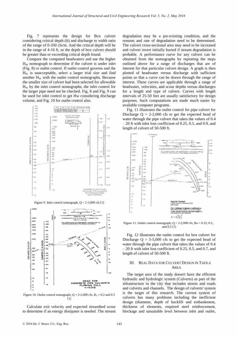
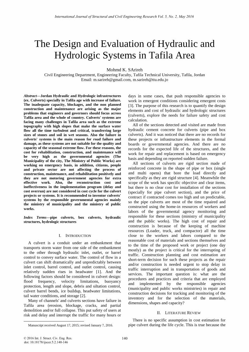
Fig. 7 represents the design for Box culvert
considering critical depth (ft) and discharge to width ratio
of the range of 0-350 cfs/m. And the critical depth will be
in the range of 4-16 ft, so the depth of box culvert should
be greater than or exceeding critical depth found.
Compare the computed headwaters and use the higher
HW nomograph to determine if the culvert is under inlet
(Fig. 8) or outlet control. If outlet control governs and the
HW is unacceptable, select a larger trial size and find
another HW with the outlet control nomographs. Because
the smaller size of culvert had been selected for allowable
HW by the inlet control nomographs, the inlet control for
the larger pipe need not be checked. Fig. 8 and Fig. 9 can
be used for inlet control to get Hw considering discharge
volume, and Fig. 10 for outlet control also.
Figure 9. Inlet control nomograph, Q = 1-3,000 cfs [1]
Figure 10. Outlet control nomograph, Q = 2-2,000 cfs, Ke = 0.2 and 0.5
[1]
Calculate exit velocity and expected streambed scour
to determine if an energy dissipater is needed. The stream
degradation may be a pre-existing condition, and the
reasons and rate of degradation need to be determined.
The culvert cross-sectional area may need to be increased
and culvert invert initially buried if stream degradation is
probable. A performance curve for any culvert can be
obtained from the nomographs by repeating the steps
outlined above for a range of discharges that are of
interest for that particular culvert design. A graph is then
plotted of headwater versus discharge with sufficient
points so that a curve can be drawn through the range of
interest. These curves are applicable through a range of
headwater, velocities, and scour depths versus discharges
for a length and type of culvert. Curves with length
intervals of 25-50 feet are usually satisfactory for design
purposes. Such computations are made much easier by
available computer programs.
Fig. 11 illustrates the outlet control for pipe culvert for
Discharge Q = 2-2,000 cfs to get the expected head of
water through the pipe culvert that takes the values of 0.4
– 20 ft with inlet loss coefficient of 0.25, 0.5, and 0.9, and
length of culvert of 50-500 ft.
Figure 11. Outlet control nomograph, Q = 2-2,000 cfs, Ke = 0.25, 0.5, and 0.5 [1]
Fig. 12 illustrates the outlet control for box culvert for
Discharge Q = 5-5,000 cfs to get the expected head of
water through the pipe culvert that takes the values of 0.4
– 20 ft with inlet loss coefficient of 0.25, 0.5, and 0.7, and
length of culvert of 50-500 ft.
III. REAL DATA FOR CULVERT DESIGN IN TAFILA
AREA
The target area of the study doesn't have the efficient
hydraulic and hydrologic system (Culverts) as part of the
infrastructure in the city that includes streets and roads
and culverts and channels. The design of culverts' system
is the target of this research. The current system of
culverts has many problems including the inefficient
design (diameter, depth of backfill and embankment,
thickness of elements, required steel reinforcement,
blockage and unsuitable level between inlet and outlet,
International Journal of Structural and Civil Engineering Research Vol. 5, No. 2, May 2016
© 2016 Int. J. Struct. Civ. Eng. Res. 143
and unsuitable level for the streets and channels) [16].
Table I illustrates the designed pipe and box culverts
from the sections 1 to 10 considering discharge rate,
length, critical depth and water depth.
Figure 12. Outlet control nomograph, Q = 5-5,000, Ke = 0.2, 0.5, and 0.7 [1]
TABLE I. THE DESIGN PARAMETERS FOR CULVERT SYSTEM IN TAFILA AREA
Sec #
Discharge (cfs)
Length (ft)
Velocity ft/s
Diameter or Height
(ft)
Critical Depth
(ft)
Hw (ft)
Hw (ft)
Culvert Type
1 5.9 50 5 3 1 0.1 1 Pipe
2 26.62 75 5 3 1.8 0.75 2.8 Pipe
3 101.5 75 5 4 3 2.8 2.6 Pipe
4 143.17 100 5 4 3.4 1.7 3 Pipe
5 219.8 125 5 6 3.4 0.95 1.4 Box
6 370.24 160 5 6 4.8 1.4 1.8 Box
7 499.84 180 5 8 4.8 0.92 0.8 Box
8 558.71 210 5 8 5.4 1.05 0.9 Box
9 597.913 240 5 8 5.6 1.2 1 Box
1
0
818.03 240 5 8 6.8 1.5 1.2 Box
In details, Table II illustrates the design (dimensions of
working area at each section) for pipe culverts, and the
required items for work construction that includes
excavation, number of elements required in each section,
lining, shoulders of culvert required to protect inlet and
outlet and the floor areas of inlet and outlet required
before and after section. Prices for items of work were
obtained considering the home-in resources and prices
considered by the directory of public works and housing
in Tafila governorate. The total cost of pipe culvert
projects is JD16,940, and the cost per foot is JD59.44/ft.
TABLE II. PIPE CULVERT DESIGN AND ESTIMATION OF COST OF CONSTRUCTION
Section Type Dimension
(ft) Excavati
on (Yrd3) Piece Lining
Shoulder (ft2)
Inlet / Out (ft2)
1
Pipe
60 7 8 124.5 20
250
106.7 170
2 75 7 8 155.6 24 128.0 223
3 75 8 8 155.6 24 128.0 223
4 75 8 8 436 24 362.7 616
Unit Cost (JD) 3 75 1.5 1.5
Sub Total (JD) 1744 5100 910 1232 11
Backfill Cost (Thousands JD) .55
Subbase Cost (Thousands JD) 0.84
Base Coarse (Thousands JD) 1.26
Prime Coat Cost (Thousands JD) 0.32
HMA Cost (Thousands JD) 2.94
Total (Thousands JD) 16.9
International Journal of Structural and Civil Engineering Research Vol. 5, No. 2, May 2016
© 2016 Int. J. Struct. Civ. Eng. Res. 144

Table III illustrates the design of working area,
estimation of construction cost for box culverts' systems
in Tafila area, the total cost for the project is JD184,066
the cost per linear ft is 395.84 JD/ft.
TABLE III. THE ESTIMATION FOR THE COST OF CONSTRUCTION OF BOX CULVERT
Section Type Dimensions Excav. (Yrd3) Concrete Lining Shoulders (ft2) Inlet / Outlet (ft2) Steel
5
Box
60 10 10 222 54
150 40
94
5
6 60 12 12 320 69 240 80
7 75 12 12 400 74 240 80
8 90 12 12 480 91 240 80
9 90 12 12 480 104 240 80
10 90 12 12 480 104 240 80
Unit Cost (JD) 3 90 1.5 1.5
Sub Total 1 (Thousands JD) 7.15 44.64 0.4 2.025 0.66 54.9
Backfill Cost (JD) 6.7
Subbase Cost ( Thousands JD) 5.6
Base Coarse Cost (Thousands JD) 7.5
Prime Coat Cost (Thousands JD) 1.4
HMA Cost (Thousands JD) 14
Sub Total 2 (Thousands JD) 91
Total (Thousands JD) 184
IV. DISCUSSION AND RECOMMENDATION
Infrastructures such as the hydrologic and hydraulic
structures (culvers as examples) need for complete,
continuous, planned monitoring program for inspection
and repairs. The program will be useful for avoiding the
failure of culvert system as transfering and safety
structure. The failure may have the level of cracks,
blockage, overflow, and/or collapse.
The studied ssystems (culverts) are all under public
roads, that needs reasonable monitoring and inspection
program to avoid failure in the form of collapse or
overflow in wet seasons that will interrupt traffic systems
and put safety of public and properties at critical
siyuation.
The current study investigated the redesign and
reconstruction of 4 sites for pipe culverts, and 6 sites for
box culver, in addition to the calculation of cost. The
design included the required diameter or dimension of
culvert, the critical depth of culvert, the expected or
allowed hieght of water in culvert, also the hieght of
water at inlet and outlet control nomographs.
The expected total cost for the studied pipe culverts is
JD16,940, and the rate cost is JD59.44 per feet. While the
expected total cost for the box culvert system is
JD184,066, at the rate cost JD395.84 per feet.
It is recommended that responsible agencies
(Municipality of city, and directorate of public works)
should share the responsibility and take actions on plan-
basis and not on emergent-basis. The monitoring and
inspection program will help in avoiding sudden collapse
and failure, and wil help in reduction of maintenance and
repair cost in future.
V. LIMITATIONS ON RESEARCH
The current research focused on the adjacent sections
for pipe and box culvert, but not all sections in the
governorate of Tafila city and other villages belong to the
directorate of the city because of transportation dificulties
and lack of support for the reserach. The lack of local and
international studies on the subject is other difficulty that
faced the research conduction. Future studies are required
to widden the study area and to have the chance to have
different sections design and aspects for design of flow in
valleyes in the country areas in the city.
ACKNOWLEDGMENT
The authors wish to thank The Colleagues in Civil
Engineering Department and in Faculty. Also the great
thanks for the deanship of academic research and the
presidency office of Tafila Technical University for their
support. Great thanks for the organizing committee of the
conference.
REFERENCES
[1] October 28, 2009.
[2] Florida Department of Transportation FDOT, Drainage Handbook
Culvert Design, Office of Design, Drainage Section, Tallahassee,
Florida, 2004. [3] J. J. Perrin and C. S. Jhaveri, “The economic costs of culvert
failures,” Civil Engineering Dept., University of Utah, prepared
for Transportation Research Board, 2004.
[4] B. G. Chen, J. J. Zheng, and J. Han, “Experimental study on
concrete box culverts in trenches,” Front. Archit. Civ. Eng. China,
vol. 3, no. 1, pp. 73-80, 2009. [5] G. V. Loganathan, “Optimal design of parabolic canals,” Journal
of Irrigation and Drainage Engineering, vol. 117, pp. 716–735,
1991. [6] K. Kim and C. H. Yoo, “Design loading for deeply buried box
culverts,” Highway Research Center, Auburn University, AL,
2002. [7] AASHTO LRFD Bridge, Design Specifications, 2012.
[8] V. T. Chow, Open-Channel Hydraulics, McGraw-Hill Book
Company, New York, 1959. [9] C. Guo and W. Hughes, “Optimal channel cross section with
freeboard,” Journal of Irrigation and Drainage Engineering, vol.
110, pp. 304–314, 1984. [10] I. D. Moore, D. B. García, H. Sezen, and T. Sheldon, “Structural
design of culvert joints,” Contractor’s Final Report for NCHRP Project 15-38, National Cooperative Highway Research Program,
2012.
[11] P. Monadjemi, “General formulation of best hydraulic channel section,” Journal of Irrigation and Drainage Engineering, vol.
120, pp. 27–35, 1994.
International Journal of Structural and Civil Engineering Research Vol. 5, No. 2, May 2016
© 2016 Int. J. Struct. Civ. Eng. Res. 145
Iowa Storm water Management Manual (ISMM) 2009 , Version 3,

[12] A. R. A. Mateus, C. Grilo, and M. Santos-Ries, “Surveying drainage culverts by carnivores: Sampling design and cost-benefit
analyzes of track pads vs. Video surveillance method,”
Environment Monit. Assess., vol. 181, no. 1-4, pp. 101-109, 2011. [13] P. K. Swamee, “Optimal irrigation canal sections,” Journal of
Irrigation and Drainage Engineering, vol. 121, pp. 467–469, 1995.
[14] D. C. Froehlich, “Width and depth-constrained best trapezoidal section,” Journal of Irrigation and Drainage Engineering, vol.
120, pp. 828–835, 1994.
[15] A. Jain, R. K. Bhattacharjya, and S. Sanaga, “Optimal design of composite channels using genetic algorithm,” Journal of
Irrigation and Drainage Engineering, vol. 130, pp. 286–295, 2004.
[16] P. K. Swamee, G. C. Mishra, and B. R. Chahar, “Minimum cost design of lined canal sections,” Journal of Water Resources
Management, vol. 14, pp. 1–12, 2000.
Mohmd Kh. Sarireh is an assistant professor in Civil Engineering Department, Tafila
Technical University. He received his B.Sc. in
civil engineering from Mu’ta University, Jordan, and he received his M.Sc. in Civil
Engineering from The University of Jordan,
Jordan. He got his Ph.D. in Construction Engineering from Civil Engineering
Department at The University of Texas at
Arlington in August 2011, Arlington, Texas, USA. His Ph.D. Thesis was in modeling of productivity for horizontal
directional drilling and factors affecting HDD productivity. The author
had published his researches and papers in the HDD Productivity and Analysis and Market Statistics, Usage, and Applications and affecting
Factors. Also, in concrete mixes, and Project Safety, and Deterioration
of Pavement on Highways in Jordan. Another interest is in the volcanic tuff aggregate for block construction for slabs and walls for its
properties. Other researches are under revision in cost overrun, HDD
time of drilling, and the application of solar and wind energy in Kuwait, and administration of wind energy also, and in high strength concrete.
International Journal of Structural and Civil Engineering Research Vol. 5, No. 2, May 2016
© 2016 Int. J. Struct. Civ. Eng. Res. 146
Related Documents