THE DESIGN AND ANALYSIS OF A HA/PLA PEDICLE SCREW FOR SPINAL FUSION A thesis presented to the Faculty of the Graduate school University of Missouri In Partial Fulfillment Of the Requirements for the Degree Master of Science Mechanical Engineering By JONATHAN SCHOTTLER Dr. Hao Li, Thesis Supervisor DECEMBER 2011

Welcome message from author
This document is posted to help you gain knowledge. Please leave a comment to let me know what you think about it! Share it to your friends and learn new things together.
Transcript

THE DESIGN AND ANALYSIS OF A HA/PLA PEDICLE SCREW
FOR SPINAL FUSION
A thesis presented to the Faculty of the Graduate school
University of Missouri
In Partial Fulfillment
Of the Requirements for the Degree
Master of Science Mechanical Engineering
By
JONATHAN SCHOTTLER
Dr. Hao Li, Thesis Supervisor
DECEMBER 2011

© Copyright by Jonathan Schottler 2011
All Rights Reserved

UNIVERSITY OF MISSOURI - COLUMBIA
This is to certify that I have examined this copy of a Master’s thesis by
Jonathan Christian Schottler
and have found that it is complete and satisfactory in all respects, and that any and all revisions required by the final
examining committee have been made.
Dr. Hao Li Dr. Douglas E. Smith . Name of Faculty Advisor Name of Faculty Co-Advisor _______________________________ _________________________________ Signature of Faculty Advisor Signature of Faculty Co-Advisor Dr. Craig A. Kuhns . Name of Committee Member _______________________________ Signature of Committee Member ______________________________________________________________________
Date
12/08/11
GRADUATE SCHOOL
DEDICATIONS
This thesis is dedicated to my mother, Suzanne McHale, late father and step-
father, Jon Schottler and Joseph McHale, respectively, for their encouragement,
motivation and love.

ii
ACKNOWLEDGEMENTS
I would first like to thank Dr. Hao Li for initiating my interest in graduate school.
It was Dr. Li and the Nanomaterials course I took during my undergraduate degree that
sparked an interest in continuing my education and focusing on the quickly growing field
of nanomaterials. He took me under his wing and gracefully put me in to his research
group and continued to help and guide me through my Master’s degree. Without
personal interest and encouragement I most likely would have never considered
pursuing my education beyond my Bachelor degree, and for that I am thankful.
I would like to thank my colleagues, Mr. Richard Lebens, Mr. Adam Blumhagen,
Chris Mr. Nasaeu, Dr. Liang Chen, Mrs. Wen Ritts, and Dr. Andrew Ritts. Without their
assistance and contribution throughout my coursework and research I would have
surely not been able to do what I’ve accomplished.
I would like to express my gratitude to all the committee members in my thesis
committee, Dr. Hao Li, Dr. Craig Kuhns, and Dr. Douglas Smith for their valuable and
supportive suggestions. I would also like to thank Dr. Douglas Smith and Dr. Kenneth
Lambert for gracefully spending their own time to assist in my understanding of the
related material and contributing their vast knowledge and experience on the subjects.
I am most thankful for an incredibly supportive and encouraging family. Without
their continued support, I may have not made it through the extra school, let alone my
Bachelor degree. I would like to thank my Mom, Suzanne Mchale, and my siblings, Kelly
Schottler, Melissa Bodine, Travis Graf, Joe McHale, and Stephanie McHale. Finally, I
would like to thank and dedicate this thesis to my late father and step-father, Jon
iii
Schottler and Joseph McHale, respectively, for everything I was taught through my
childhood and young adulthood on how to work hard for what you want and never give
up, “You can do, handle, and become anything you set your mind to.”
iv
TABLE OF CONTENTS
ACKNOWLEDGEMENTS..………………………………………………..………………………………………………ii.
LIST OF ILLUSTRATIONS..……………………………………….…………………………..………………………..vii.
ABSTRACT.……………………………………………………………………..………………………..……..…………….x.
Chapter
1. INTRODUCTION…………………………………………………………………………………..…….………………1.
1.1 Nanocomposites………………………………………………………………………………………………1.
1.1.1 Background of nanocomposites……………………………………………………………..…1.
1.2 Pedicle bone screws……………………………..…………………………………………………………1.
1.2.1 Summary of the spine and vertebrae………………………….……………………………5.
1.2.2 Introduction to bone and the healing process……………….………………………..7.
1.2.3 Lumbar fusion……………………………………………………………………………………….10.
1.2.4 Pedicle screw failure………………………………………………………..…………………..11.
1.2.5 Research objective………………………………………………………………………………..16.
1.3 References…………………………………………………………….……………………………………..17.
2. PLA/HA COMPOSITES………………………………………………………..……………………..……………..18.
2.1 Introduction………………………….………………………………………………………………………18.
2.2 PLA/HA composites preparation and characterization…………………..……………..19.
2.2.1 Injection molding……………………………………………….………………………………..19.
2.2.2 Bending test…………………………………………………….………………………………….22.
2.2.3 Tensile test……………………………………………………….…………………………………23.
2.3 Results and discussion…………………………………………………..………………………………25.

v
2.3.1 Bending strength and elastic modulus…………….….………………………………..25.
2.3.2 Tensile strength………………………………………………….……………………………….27.
2.4 Conclusion……………………………………………………………………..…….……………………….28.
2.5 References……………………………….…………………………………………………………………..29.
3. THE DESIGN AND ANALYSIS OF A PLA/HA PEDICLE SCREW….………………………….……….30.
3.1 Introduction……………………………………………………….…………………………………………30.
3.2 Materials and methods…………………...…………………………………………………………..32.
3.2.1 3-D model setup…………………………………………………………………………………32.
3.2.2 Material properties…………………………………………………………………………….34.
3.2.3 Finite element analysis……………………………………………………………………….35.
3.2.4 Objective values……………………………………………………………..………………….39.
3.2.5 Taguchi robust design methods………………………………………………………….39.
3.2.6 Artificial neural network (ANN) ………………………………………..……………….40.
3.3 Results and Discussion…………………………………………………………………………………43.
3.3.1 3-D model setup…………………………………………………………………………………43.
3.3.2 Taguchi robust design methods………………………………………………………….45.
3.3.3 Artificial neural network…………………………………………………………………….46.
3.3.4 Finite Element Analysis………………………………………………………………………49.
3.4 Conclusion…………………………………………………………………………………………………..64.
3.5 References…………………………………………………………………………………………..……..65.
4. CONCLUSION AND FUTURE WORK….…………………………………………………………..………….68.
4.1 Summary and conclusion……………………………………………………………………………..68.
vi
4.1.1 Fabrication, modification, and evaluation of HA nanofibers and associated PLA/Ha composites………………………………………………………………………………68.
4.1.2 The design and analysis of a PLA/HA pedicle screw.….…………………………69.
4.2 Recommendation and future work………………………………………………………………70.
4.2.1 Pull-Out Test……………………………………………………………………………………….71.
4.2.2 Bend Test……………………………………………………………………………………………72.
4.2.3 Analysis of strength in relation to saturation time………………………………75.
4.2.4. Further investigation to improve rigidity……………………………………………75.
4.2.5 Improvement in ANN………………………………………………………………………….75.
4.3 References…………………………………………………………………………………………………..76.
vii
LIST OF ILLUSTRATIONS
Figure Page
1.1. A selection of current commercial metallic pedicle screws………………………………...3
1.2. Pedicle screw assembly………………………………………………………………………………………3
1.3. The X-ray image of pedicle screws inserted into two spinal segments………………..4
1.4. Pedicle screw insertion…………………………………………………………………………………..…..5
1.5. Spinal column………………………………………………………………………………………………….….6
1.6. Lumbar vertebrae. (a) superior view. Posterior view is up, anterior is down. (b) Right lateral view. (c) Posterior View………………………….………………………………….….7
1.7. Illustration of a general bone cross section displaying the cortical and cancellous layer of bone……………………………………………………………………………………..……………….9
1.8. (a) Anterior lumbar interbody fusion. (b) Posterolateral lumbar fusion…………...12
1.9. SEM image indicating tearing and fatigue striations………………………………………...13
1.10. SEM image indicating (A) & (B) beach marks (20x), (C) fatigue striations (800x).14 1.11. SEM image of broken screw fracture surface. (A) Regions of dimples and profuse
tear, (B) Close-up view of dimples (90x), (C) Evidence of crack propagation……..15 2.1. (a) Takiron Co Ltd, FIXSORB anterior cervical fusion bioabsorbable screws,
HA/PLLA, (b) Stryker BIOSTEON wedge interference screw, HA/PLLA……....……..19
2.2. Digital camera image of Mini-Jector used for injection molding. Machinery Corporation, Newbury Ohio………………………………………………………………………………21
2.3. Digital camera image of CNC created injection molds (bend test) placed in holding mold holding shell………………………………………..………………………………….…..21
2.4. Digital camera image of HMW injection molded bend sample………….…………..….22 2.5. ASTM specified setup for 3-point bend testing………………………………………………...23 2.6. Instron 3367 testing machine…………………………………………………………………………...24

viii
2.7. Average ultimate bending strength of HMW PLA/HA composites filled with
different mass fraction of HA nanofibers fabricated by injection molding method….…………………………………………………………………………………………………….…..25
2.8. Elastic modulus of HMW HA/PLA via injection molding and 3-point bending..….27 2.9. Tensile strength of HMW PLA/HA composites filled with different mass fraction
HA nanofibers fabricated by injection molding method…………………………..……….28 3.1. Image depicting geometry and location of a lumbar vertebrae segment………….33 3.2. Cross section image of the pedicle/screw model. (a) Cross-section of
modeled vertebrae and screw segment displaying cortical shell (red), CPC (green), and pedicle screw (blue.) (b) Opposite side of (a), displaying the geometry difference of the vertebrae body, traverse, and traverse process. (c) Cross-section similar to that of (a) displaying the cylindrical geometry of the analyzed spinal segment……………………………………………………………………………….….34
3.3. Cross section image of pedicle defining sections………………………………………….…..35 3.4. Model cross section with constraints. ………………………………………………………..…….36 3.5. Visualization of 10 node second-order tetrahedron surface………………………..……38 3.6. Artificial neural network structure………………………………………………………………..….42 3.7. Various screw profiles with corresponding pull-out strength……………………………44 3.8. Depiction of screw geometry…………………………………………………………………………...44 3.9. 3D models of optimum screw……………………………………………………………………………48 3.10. FEA and ANN result of screw surface stress. Taguchi L18 models, additional model (A1), and optimum (Opt1.)……….…………………………………………………………...48 3.11. FEA result of the bone surface stress………………………………………………………………..49 3.12. (a) Optimum design stress distribution, HA/PLA. (b) Nominal design. (c) Stainless steel with optimum polymer geometry……………………………………..….……52 3.13. Optimum design. (a) Separation at proximal end. (b) General max VMS stress location. (c) Detailed max VMS location……………..……………………………………….……54

ix
3.14. Optimum Design. (a) General stress reactions of screw in CPC. (b) Detailed location of maximum CPC VMS………………………………………………………………..……….55 3.15. Nominal design. (a) General location of max screw VMS. (b) Detailed location of max VMS………………………………………………………………………………………………………56 3.16. Nominal Design. (a) General location of maximum CPC stress. (b) Detailed area of maximal VMS………………………………………………………..………………………………………57 3.17. Stainless steel with optimum geometry. (a) No separation in CPC. (b) Max VMS location, tension………………………………………………………………………..……………………..58 3.18. Stainless steel with optimum geometry. (a) Maximum VMS in CPC location. (b) Detailed max VMS location…………………………………………………………….………………..59 3.19. FEA result of screw head deflections…………………………………………………………………60 3.20. Optimum polymer design, 0.676 mm deflection……………………………………….……..60 3.21. Nominal polymer design, 0.6825 mm deflection……………………………………….……..61 3.22. Optimum design with 316L stainless steel, 0.154 mm deflection………………………61 3.23. Cross section image showing stress distribution within screw……………………….…62 3.24. Optimal screw cross section path with x-y plot…………………………………………………63 3.25. Nominal screw cross section with x-y plot……..…………………………………………………63 4.1. ASTM F2502-05 pull-out test for bioabsorbable screws……………………………………72 4.2. Suggested bend test apparatus…….…………………………………………………………………..74 Table 3.1. Taguchi robust design method L18 orthogonal array (L1-L18), additional model
(A1), and optimum (Opt1) model……………………………………………………………………..46

x
ABSTRACT
Metallic pedicle screws have been widely used in the orthopaedic field to treat
spinal diseases. Although spinal screws have improved over the last few decades, there
is still sometimes a need for a second painful surgery to remove the instrumentation
due to late-onset pain or discomfort due to breakage or infection. Polylactic acid has
been heavily studied recently and is emerging as a viable absorbing material for bone
fixation devices with good biological response; however there have been no
optimization studies for its use and practicality as a lumbar pedicle screw. In addition to
the lack of pedicle applications for the material, there are no FEA studies analyzing the
objective values of simultaneous bending and pull-out of a pedicle screw or a pedicle
screw augmented with calcium phosphate bone cement. Finite element analysis,
Taguchi method, and an artificial neural network were used as the optimization
methodology. Three-dimensional finite element method was used to create an arranged
L18 orthogonal array of a model simultaneously applying a bend and pull-out test. These
simulations were used to calculate two objective values for analysis. Artificial neural
networks were used to estimate an optimum design which had the lowest surface stress
in the screw. The obtained design was used for experimental testing to verify
computational results and analyze practicality of clinical use. The optimal screw was
shown to have a maximum surface stress of 81.83 MPa. The reaction in the CPC was
shown to have a surface stress of 43.69 MPa. The screw and CPC stresses are below
their yield strengths, which should result in non-failure. However, the biggest concern is
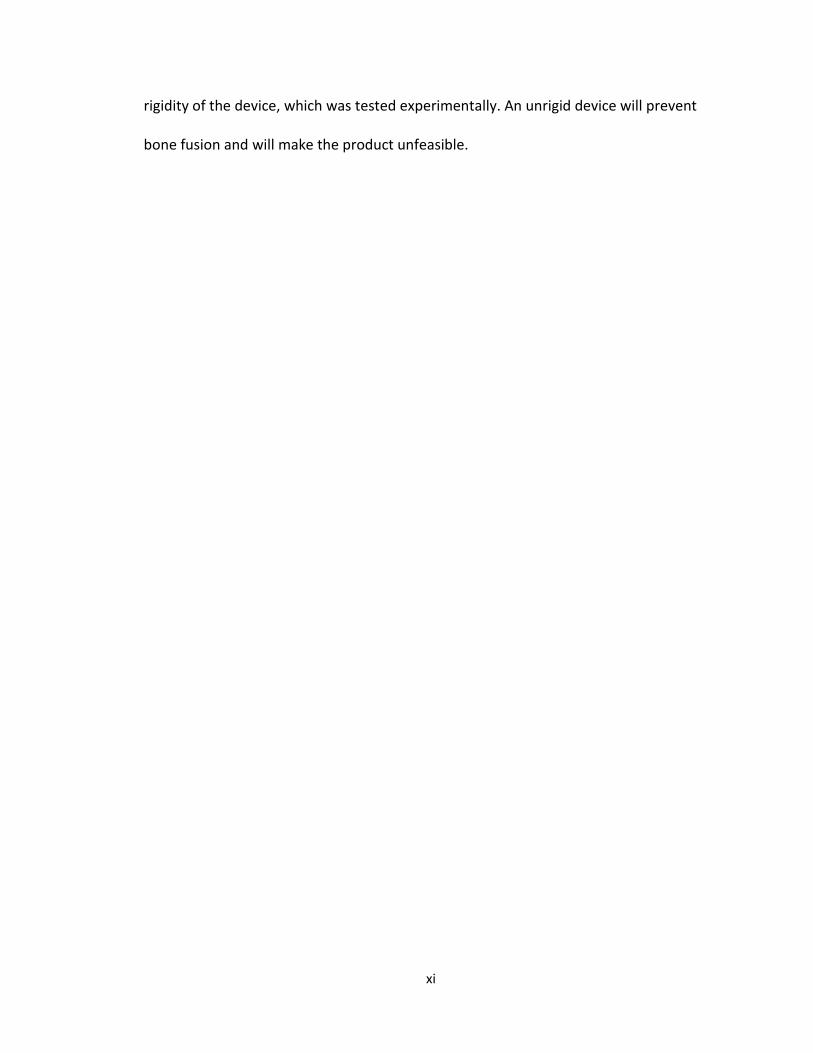
xi
rigidity of the device, which was tested experimentally. An unrigid device will prevent
bone fusion and will make the product unfeasible.
1
Chapter 1: Introduction
1.1 Nanocomposites
1.1.1 Background of nanocomposites
A nanocomposite can be defined as a multiphase solid material in which one to
three dimensions are less than 100 nanometers, or one tenth of a micrometer [2].
Nanocomposites are commonly found in nature, such as abalone shell and bone. These
extremely small composites often differ from conventional composites due to the high
surface to volume ratio for the reinforcing phase and/or its high aspect ratio. These
nanosized reinforcing materials are often made up as particles, sheets, or fibers.
1.2 Pedicle bone screws
According to the FDA [3], the pedicle screw spinal system is a multiple
component device. Screw spinal systems are made from a variety of materials, including
alloys such as 316LVM stainless steel, 316L stainless steel, 22Cr13Ni-5Mn stainless steel,
Ti-6Al-4V, and unalloyed titanium. Combined components allow the surgeon to build an
implant system to fit the patient’s anatomical and physiological requirements. These
components are often comprised of the following: Anchors (bolts, hooks, and/or
screws); interconnection mechanisms incorporating nuts, screws, sleeves, or bolts;
longitudinal members (plates, rods, and/or plate/rod combinations); and/or transverse
connectors. Combination of these components are intended to provide immobilization
and stabilization of spinal segments in skeletally mature patients as an adjunct to fusion
in the treatment of specific conditions. The conditions intended for treatment are acute
and chronic instabilities or deformities of the thoracic, lumbar, and sacral spine:

2
degenerative spondylolisthesis with objective evidence of neurologic impairment,
fracture, dislocation, scoliosis, kyphosis, spinal tumor, and failed previous fusion
(pseudarthrosis).
As required by the FDA, pedicle screw systems must comply with the following
special controls: (i) Compliance with material standards, (ii) Compliance with mechanical
testing standards, (iii) Compliance with biocompatibility standards, and (iv) Labeling
which contains these two statements in addition to other appropriate labeling
information: ``Warning: The safety and effectiveness of pedicle screw spinal systems
have been established only for spinal conditions with significant mechanical instability
or deformity requiring fusion with instrumentation. These conditions are significant
mechanical instability or deformity of the thoracic, lumbar, and sacral spine secondary
to degenerative spondylolisthesis with objective evidence of neurologic impairment,
fracture, dislocation, scoliosis, kyphosis, spinal tumor, and failed previous fusion
(pseudarthrosis). The safety and effectiveness of these devices for any other conditions
are unknown.'' ``Precaution: The implantation of pedicle screw spinal systems should be
performed only by experienced spinal surgeons with specific training in the use of this
pedicle screw spinal system because this is a technically demanding procedure
presenting a risk of serious injury to the patient [3].''
Commercial metallic pedicle screws will generally have consistent geometry
characteristics. For the most part, these pedicle screws will have a tapered minor
diameter, constant major diameter, constant thread pitch, and sometimes have a

3
varying thread width. A few metallic commercial screws and a pedicle assembly can be
seen in Fig. 1.1 and 1.2, respectively.
Fig. 1.1. A selection of current commercial metallic pedicle screws.
Fig. 1.2. Pedicle screw assembly.

4
A pedicle screw is used to provide a means of gripping a spinal segment,
sometimes used as an adjacent to spinal fusion surgery. The screws act as anchor points
that can be connected with a rod, instead of fixating the spinal segment themselves. The
use of pedicle screws in posterolateral gutter fusion has improved spinal fusion rates
from approximately 60 to 90%. Surgeons believe pedicle screws enhance patient
recovery due to the fact they provide immediate stability for the spine and early
mobilization for the patient. The screws are often inserted into two or three spinal
segments, followed by connecting them with a small rod. This method prevents motion
at the segments being fused. A X-ray image of this can be seen in Fig. 1. Once the bone
graft in the spinal fusion grows, the screws and rods can be removed. This removal
requires a secondary back surgery and is not recommended, unless the patient is
experiencing discomfort (5% to 10% of cases.)[4]
Pedicle screw installation has been shown to have steep learning curve, and is
usually only done by surgeons with plenty of experience in the technique. An image
description of how a pedicle screw is inserted can be seen in Fig. 1.3 and 1.4. [4]
Fig. 1.3 The X-ray image of pedicle screws inserted into two spinal segments .[4]

5
(a)
(b)
Fig. 1.4(a,b). Pedicle screw insertion.[4]
1.2.1 Summary of the spine and vertebrae
The spine, also commonly referred to as a spinal column, vertebral column or
backbone, consists of intervertebral discs, ligaments, joints, and bone. The spine serves
as an attachment point for numerous muscles as well as surrounding and protecting the
spinal cord and nerve roots. The human spine consists of 33 vertebrae; 7 cervical
vertebrae (C1-C7), thoracic vertebrae (T1-T12), lumbar vertebrae (L1-L5), sacral
vertebrae, and the coccygeal vertebrae, which can be seen in Fig. 1.5.[5]

6
Fig. 1.5. Spinal column. [5]
All vertebrae have the same parts, but will vary in shape and proportion
depending on level of the spine. A lumbar vertebrae can be seen in Fig. 1.6. The parts of
a vertebrae consist of the vertebral body, pedicles, transverse processes, laminas,
superior and inferior facets, and spinous processes. [5]

7
(c)
Fig. 1.6(a,b,c) Lumbar vertebrae. (a) superior view. Posterior view is up, anterior is down. (b) Right lateral view. (c) Posterior View. [5] 1.2.2 Summary of bone and the healing process
Bone is categorized as two different types of tissue, or density; Cortical
(compact), and cancellous (spongy). Cortical bone, the most dense and outermost layer
of the bone, will take the majority of the load applied, and will generally range in
thickness. This thickness will depend on bone section, stress applied, and the age of the
patient. In the process of bone remodeling, three different types of cells contribute to
bone homeostasis, which is the process of bone remodeling. The first of these cells
(a) (b)
8
including bone-forming cells (osteoblasts), cells for breakdown and resorbing
(osteoclasts), and mature bone cells (osteocytes) contribute to the bone homeostasis.
Bone tissue will naturally be maintained by finding a medium between the osteoclasts
and osteoblasts. This bone remodeling process, bone will be laid down or resorbed
based on axial loading experienced in the bone section. An illustration showing the
compact and spongy bone tissue can be seen in Fig. 1.7.
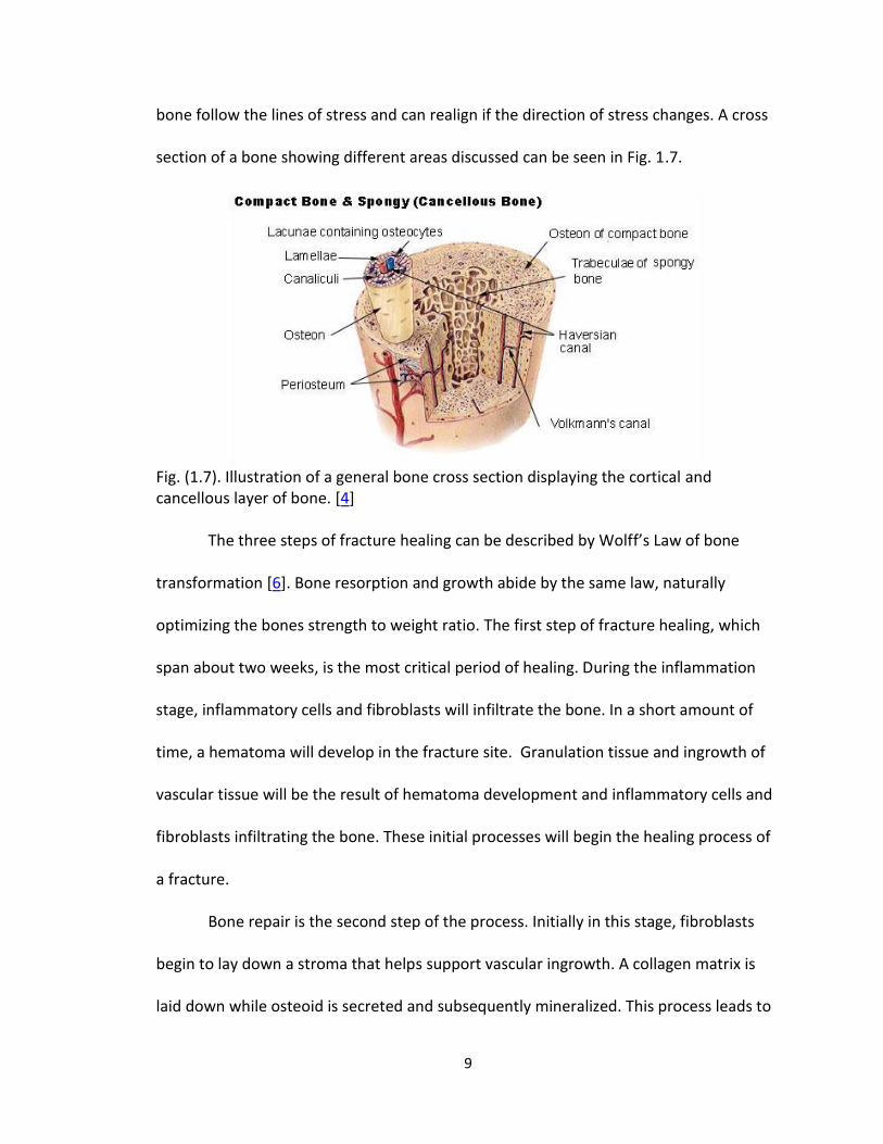
Cortical bone gets its density from closely packed osteon systems. This system
consists of an osteonic canal, which is the central canal of the bone. This is surrounded
by concentric rings of matrix, which is then filled will osteocytes (mature bone cells.)
This area between the rings which is filled with osteocytes is called lacunae. Channels
from this area radiate to the osteonic canal, which provide passageways through the
hard matrix. For cortical bone, these osteon systems are packed very tightly together,
providing the high density. Osteonic canals provide blood flow parallel to the long bone
axis, which are interconnected by perforating canals, with vessels on the surface of the
bone.
Cancellous bone on the other hand, is the inner most section of the bone. This
section is a sponge-like marrow of the bone, providing little structural support. This
section of bone consists of trabeculae and bars adjacent to small, irregular cavaties that
contain red bone barrow. Canaliculi are connected to the adjacent cavaties instead of
the osteonic canals like cortical bone, to receive their blood supply. Trabeculae appear
to be arranged in a random order, but are positioned in such a way that maximum
strength is provided, which are used to support a building. The trabeculae of spongy
9
bone follow the lines of stress and can realign if the direction of stress changes. A cross
section of a bone showing different areas discussed can be seen in Fig. 1.7.
Fig. (1.7). Illustration of a general bone cross section displaying the cortical and cancellous layer of bone. [4]
The three steps of fracture healing can be described by Wolff’s Law of bone
transformation [6]. Bone resorption and growth abide by the same law, naturally
optimizing the bones strength to weight ratio. The first step of fracture healing, which
span about two weeks, is the most critical period of healing. During the inflammation
stage, inflammatory cells and fibroblasts will infiltrate the bone. In a short amount of
time, a hematoma will develop in the fracture site. Granulation tissue and ingrowth of
vascular tissue will be the result of hematoma development and inflammatory cells and
fibroblasts infiltrating the bone. These initial processes will begin the healing process of
a fracture.
Bone repair is the second step of the process. Initially in this stage, fibroblasts
begin to lay down a stroma that helps support vascular ingrowth. A collagen matrix is
laid down while osteoid is secreted and subsequently mineralized. This process leads to
10
the formation of soft callus around the repair site. This newly created callus is very weak
during first 4-6 weeks and will require adequate protection from either bracing or
internal fixation. Micromotion of the fracture site can cause failure of the developed
callus, inevitably leading to a longer healing period for the patient.
The final step in the repair process is bone remodeling. During this process, bone
will be laid down or resorbed where needed based on axial loading experienced in the
bone section. Eventually, the repaired bone is returned to the original shape and regains
its original mechanical strength. Adequate strength is generally achieved in 3 to 6
months.
1.2.3 Lumbar fusion
The region between the superior and inferior articular facts is called the pars
interarticularis (pars.) Spondylolysis is a fracture of the bilateral pars, and causes a
separation between the pedicles/vertebral body/superior articular facts and the
lamina/spinous process/inferior facts, and is a cause of spondylolisthesis. This is a
common type of fracture resulting in the need for lumbar spinal fusion [5]. Other spinal
problems resulting in lumbar fusion are degenerative disc disease, and spinal stenosis
(arthritis) [7].
Lumbar spinal fusion is an operation that will conclude in the fusion of multiple
vertebrae to reduce pain, numbness, tingling, weakness, and nerve damage. A bone
spur, resulting from fracture, can put pressure on the nerves of the spine. This bone
spur is removed to reduce pain and the possibility of nerve damage. Lumbar fusion can
be performed in the front or rear of the spine and are referred to as anterior lumbar

11
fusion (ALIF) and posterior lumbar interbody fusion (PLIF) or posterior lumbar fusion
(PLF), respectively [7].
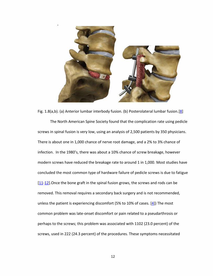
Anterior lumbar fusion results in the removal of the intervertebral disc
(interbody fusion) which is replaced with a bone graft or a metal or plastic cage. The
bone graft will eventually fuse to the surrounding vertebrae to stop abnormal motion.
Posterior lumbar fusion uses a different method to fuse vertebrae. In this case, a bone
graft is applied to the sides of the vertebrae where it will grow together to stop
abnormal motion (PLF) or also replace the intervertebral disc (PLIF) similar to ALIF. In
either case, the two vertebrae are fused together with pedicle screw instrumentation
(screws and rods.) [7] An image of both ALIF and PLF can be seen in Fig. 1.8.
1.2.4 Pedicle screw failure
The consequence of corrosion of implant metals is usually disastrous because it
not only causes implant device failure, but it also induces various toxic effects on the
human body due to metal ion release through corrosion reactions. The metal ion
release, particularly nickel and chromium into the tissues surrounding the implants, may
cause local irritations, toxicity, hypersensitivity, or systemic effects over time and in
some cases removal of the implants is necessary (re-operation). The excessive Ni ion
release due to corrosion of Ni alloys, such as nitinol (TiNi alloy) and 316L stainless steel,
under biological environment exhibits high carcinogenic and toxic potential in vivo [9-
10].
12
Fig. 1.8(a,b). (a) Anterior lumbar interbody fusion. (b) Posterolateral lumbar fusion.[8]
The North American Spine Society found that the complication rate using pedicle
screws in spinal fusion is very low, using an analysis of 2,500 patients by 350 physicians.
There is about one in 1,000 chance of nerve root damage, and a 2% to 3% chance of
infection. In the 1980’s, there was about a 10% chance of screw breakage, however
modern screws have reduced the breakage rate to around 1 in 1,000. Most studies have
concluded the most common type of hardware failure of pedicle screws is due to fatigue
[11-12].Once the bone graft in the spinal fusion grows, the screws and rods can be
removed. This removal requires a secondary back surgery and is not recommended,
unless the patient is experiencing discomfort (5% to 10% of cases. [4]) The most
common problem was late-onset discomfort or pain related to a pseudarthrosis or
perhaps to the screws; this problem was associated with 1102 (23.0 percent) of the
screws, used in 222 (24.3 percent) of the procedures. These symptoms necessitated
13
removal of the instrumentation with or without repair of the pseudarthrosis (non-union)
[13]. Pedicle screw failure has been commonly associated to fatigue fracture
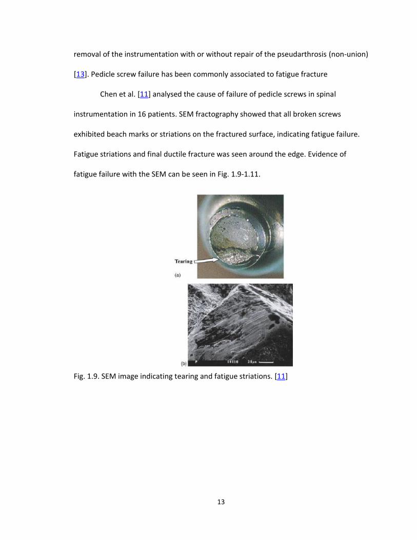
Chen et al. [11] analysed the cause of failure of pedicle screws in spinal
instrumentation in 16 patients. SEM fractography showed that all broken screws
exhibited beach marks or striations on the fractured surface, indicating fatigue failure.
Fatigue striations and final ductile fracture was seen around the edge. Evidence of
fatigue failure with the SEM can be seen in Fig. 1.9-1.11.
Fig. 1.9. SEM image indicating tearing and fatigue striations. [11]

14
Fig. 1.10. SEM image indicating (A) & (B) beach marks (20x), (C) fatigue striations (800x). [11]

15
Fig. 1.11. SEM image of broken screw fracture surface. (A) Regions of dimples and profuse tear, (B) Close-up view of dimples (90x), (C) Evidence of crack propagation. [11]

16
1.2.5 Research objective
The current aim of this research is to study the viability of a polymer resorbable
pedicle screw for use in lumbar spinal fusion. After synthesizing a hyroxyapatite
polylactic acid nanocomposite that is suitable for the application, a pedicle screw will be
designed, analyzed, and optimized using finite element analysis. In order to optimize
both the pull-out strength and bending strength, a parametric study of varying
geometries will be tested using the taguchi method. These will be used to train an
artificial neural network and an optimum screw geometry will be predicted. This will be
done iteratively until a satisfactorily optimum screw is found. This is a very similar
strategy to optimize a pedicle screw as Chao et al. [14].
17
1.3 References
1. Claes, L. and A. Ignatius, [Development of new, biodegradable implants]. Der Chirurg; Zeitschrift fur alle Gebiete der operativen Medizen, 2002. 73(10): p. 990-6.
2. http://en.wikipedia.org/wiki/Nanocomposite. 3. CFR part 888 Authority: 21 U.S.C. 351, 360c, 360e, 360j, 371. 4. Peter F. Ullrich, J., MD. Pedicle Screws for Spine Fusion. 1999 [cited 2010 12/16]; Available from:
http://www.spine-health.com/treatment/spinal-fusion/pedicle-screws-spine-fusion. 5. Specialists, N.a.S. Anatomy and Terminology of the Spine. 2010 [cited 2011 6/1]; Available from:
http://www.neurosurgeryandspinemd.com/Anatomy%20and%20Terminology%20of%20the%20Spine.pdf.
6. Focus, N., Principles of Bone Healing: Bone Healing Process. American Association of Neurological Surgeons, 2001.
7. Todd Albert, M. Understanding Lumbar Fusion Surgery. 2010 02/01/10 [cited 2011 6/14]; Available from: http://www.spineuniverse.com/treatments/surgery/lumbar/understanding-lumbar-fusion-surgery.
8. Spineuniverse. Reports and Clinical Data. 2010 01/28/10; Available from: http://www.spineuniverse.com/professional/resource-center/vitoss/reports-clinical-data.
9. Takamura, K., et al., Evaluation of carcinogenicity and chronic toxicity associated with orthopedic implants in mice. Journal of Biomedical Materials Research, 1994. 28(5): p. 583-589.
10. Shih, C.-C., et al., The cytotoxicity of corrosion products of nitinol stent wire on cultured smooth muscle cells. Journal of Biomedical Materials Research, 2000. 52(2): p. 395-403.
11. Chen, C.-S., et al., Failure analysis of broken pedicle screws on spinal instrumentation. Medical engineering & physics, 2005. 27(6): p. 487-496.
12. Villarraga, M.L., et al., Wear and Corrosion in Retrieved Thoracolumbar Posterior Internal Fixation. Spine, 2006. 31(21): p. 2454-2462 10.1097/01.brs.0000239132.16484.be.
13. Lonstein, J.E., et al., Complications associated with pedicle screws. The Journal of bone and joint surgery. American volume, 1999. 81(11): p. 1519-28.
14. Chao, C.-K., et al., A Neurogenetic Approach to a Multiobjective Design Optimization of Spinal Pedicle Screws. Journal of Biomechanical Engineering, 2010. 132(9): p. 091006.

18
CHAPTER 2:
FABRICATION, MODIFICATION, AND EVALUATION OF HA NANOFIBERS AND
ASSOCIATED PLA/HA COMPOSITES
2.1 Introduction
PLA and PLA based copolymers are leading the way of bioabsorbable polymers
for orthopaedic application in terms of good mechanical properties and
biocompatibility[1]. Its degradation rate is also appropriate to maintain adequate
mechanical strength and material structure during the healing process of the fracture
site [2]. However, it also has weakness such as the modulus that is much lower than that
of cortical bone. In order to improve the modulus and ultimate strength of PLA devices,
hydroxyapatite (HA), which is the main inorganic component of natural bone with
excellent biocompatibility and bioactivity, has been used as a reinforcing material [3, 4].
Kasuga, T. et al. [5] was able to achieve a modulus of 5-10GPa by hot pressing a mixture
of PLA and HA fiber (20-60 wt%), creating a stiffness equal to that of cortical bone.
Combining HA with a biodegradable PLA implant should allow the material to dissolve
harmlessly in the body while increasing the rate of bone growth and improving
biological response [2, 4, 6, 7]. For a high molecular weight (HMW) PLA sample, it has
been shown through experimentation that a 35% increase in bending strength can be
achieved. The improvements in the mechanical properties are a notable step forward
towards eventual use in orthopaedic surgical applications. Currently, PLA screws are
commercial available as locking screws and anterior cervical fusion applications [8-11].
An example of these screw types can be seen in Fig. 2.1.

19
Fig. 2.1(a,b) (a) Takiron Co Ltd, FIXSORB anterior cervical fusion bioabsorbable screws, HA/PLLA.[8, 9] (b) Stryker BIOSTEON wedge interference screw, HA/PLLA.[10, 11]
2.2 HA/PLA composites preparation and characterization
2.2.1 Injection Molding
For testing, 0, 1, 2, and 5 wt% (0, 2, 4, and 10 grams) HA nanofibers are used
with 20 grams of HMW PLA. HA nanofiber and PLA are ground together in a mortar and
pestle for 1 minute, a process that is used to help mix the materials together and is
effective in removing the HA from the walls of the pestle. Once this process is
completed, the mixture is placed in a K-Tec Blendtec blender on high for 50 seconds.
This will turn the PLA pellets and HA fiber into a finely mixed powder.
Tensile dog bone specimens were injection molded using a Mini-Jector (Machine
Corporation, Newbury Ohio) according to ASTM standard D638, as shown in Fig. 2.2. The
mold was designed using aluminum insert mold on a family mold, creating 3 specimens
20
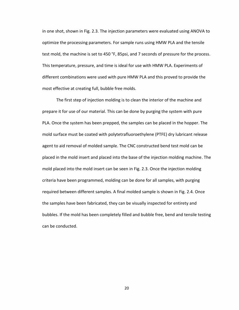
in one shot, shown in Fig. 2.3. The injection parameters were evaluated using ANOVA to
optimize the processing parameters. For sample runs using HMW PLA and the tensile
test mold, the machine is set to 450 °F, 85psi, and 7 seconds of pressure for the process.
This temperature, pressure, and time is ideal for use with HMW PLA. Experiments of
different combinations were used with pure HMW PLA and this proved to provide the
most effective at creating full, bubble free molds.
The first step of injection molding is to clean the interior of the machine and
prepare it for use of our material. This can be done by purging the system with pure
PLA. Once the system has been prepped, the samples can be placed in the hopper. The
mold surface must be coated with polytetrafluoroethylene (PTFE) dry lubricant release
agent to aid removal of molded sample. The CNC constructed bend test mold can be
placed in the mold insert and placed into the base of the injection molding machine. The
mold placed into the mold insert can be seen in Fig. 2.3. Once the injection molding
criteria have been programmed, molding can be done for all samples, with purging
required between different samples. A final molded sample is shown in Fig. 2.4. Once
the samples have been fabricated, they can be visually inspected for entirety and
bubbles. If the mold has been completely filled and bubble free, bend and tensile testing
can be conducted.

21
Fig. 2.2. Digital camera image of Mini-Jector used for injection molding. Machinery Corporation, Newbury Ohio.
Fig. 2.3. Digital camera image of CNC created injection molds (bend test) placed in holding mold holding shell.
22
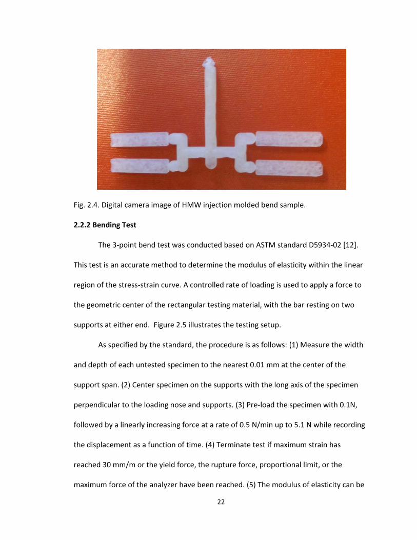
Fig. 2.4. Digital camera image of HMW injection molded bend sample.
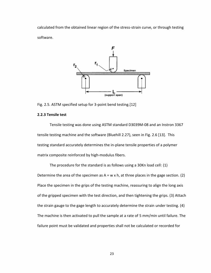
2.2.2 Bending Test
The 3-point bend test was conducted based on ASTM standard D5934-02 [12].
This test is an accurate method to determine the modulus of elasticity within the linear
region of the stress-strain curve. A controlled rate of loading is used to apply a force to
the geometric center of the rectangular testing material, with the bar resting on two
supports at either end. Figure 2.5 illustrates the testing setup.
As specified by the standard, the procedure is as follows: (1) Measure the width
and depth of each untested specimen to the nearest 0.01 mm at the center of the
support span. (2) Center specimen on the supports with the long axis of the specimen
perpendicular to the loading nose and supports. (3) Pre-load the specimen with 0.1N,
followed by a linearly increasing force at a rate of 0.5 N/min up to 5.1 N while recording
the displacement as a function of time. (4) Terminate test if maximum strain has
reached 30 mm/m or the yield force, the rupture force, proportional limit, or the
maximum force of the analyzer have been reached. (5) The modulus of elasticity can be
23
calculated from the obtained linear region of the stress-strain curve, or through testing
software.
Fig. 2.5. ASTM specified setup for 3-point bend testing.[12]
2.2.3 Tensile test
Tensile testing was done using ASTM standard D3039M-08 and an Instron 3367
tensile testing machine and the software (Bluehill 2.27), seen in Fig. 2.6 [13]. This
testing standard accurately determines the in-plane tensile properties of a polymer
matrix composite reinforced by high-modulus fibers.
The procedure for the standard is as follows using a 30Kn load cell: (1)
Determine the area of the specimen as A = w x h, at three places in the gage section. (2)
Place the specimen in the grips of the testing machine, reassuring to align the long axis
of the gripped specimen with the test direction, and then tightening the grips. (3) Attach
the strain gauge to the gage length to accurately determine the strain under testing. (4)
The machine is then activated to pull the sample at a rate of 5 mm/min until failure. The
failure point must be validated and properties shall not be calculated or recorded for

24
any specimen that broke at an obvious flow. (5) Desired results including the elastic
modulus and ultimate tensile strength are then calculated by the software.
Fig. 2.6. Instron 3367 testing machine.

25
2.3 Results and discussion
2.3.1 Bending strength and elastic modulus
Ultimate bending strength test results for different HA filler can be seen in Fig.
2.7. UBS was determined at the point of highest stress before failure, which was shown
to be nearly the same as the yield strength. It can be shown in the results that 5 wt% HA
filler had the highest ultimate bending strength at 140.7 MPa, about 30% increase over
pure PLA and similar to other filler percentages. It can be concluded that the addition of
HA nanofibers into PLA matrix have significantly increased the mechanical strength as
hypothesis.
Fig. 2.7. Average ultimate bending strength of HMW PLA/HA composites filled with different mass fraction of HA nanofibers fabricated by injection molding method.
97.9916
132.9380375 131.82576
140.6781575
0
20
40
60
80
100
120
140
160
Be
nd
Str
ess
(MP
a)
Bend Test HMW PLA
Pure
1% HA
2% HA
5% HA

26
Stress and strain of the 3-point bend test can be automatically calculated with
testing software, or with Eq. 1 and Eq. 2,
(1)
(2)
where F is the applied force, D is the deflection, d is the depth of the beam tested, b is
the width of the beam tested, L is the support span, and E is the modulus of elasticity in
bending. The elastic modulus can be determined by the linear portion of the stress
strain curve.
Figure 2.8 represents the calculated elastic modulus for different fiber
percentages. As seen in Fig. 2.8, the addition of HA fibers have increased the elastic
modulus of the HMW PLA, with 5% filler being the highest at 4.41 MPa, a 21% increase.
An explanation for the increase in modulus and UTS could be due to alignment of the
fibers due to flash freezing, which can be a result of not preheating the molds when
injection molding. Similar to that of the tensile strength, the increase in bending
modulus is related to the addition of HA fibers. An increase in modulus is an
advantageous result in bioabsorbable products experiencing high bending loads, helping
limit deflection.

27
Fig. 2.8. Elastic modulus of HMW HA/PLA via injection molding and 3-point bending. 2.3.2 Tensile strength
Figure 2.9 represents the stress strain curve of varying fiber filler percentages,
which was automatically calculated through the testing software. It can be seen that the
highest UTS came from 2 wt% HA filler at 70.2 MPa, a 30.7% increase over pure PLA
which had an UTS of only 48.6 MPa. It is also interesting to note how the addition of HA
fibers has created a more pliable material. The tests with an increase in fiber filler
continued to strain beyond the UTS while pure PLA failed at the UTS. This property could
be beneficial to reducing the initial failure in devices.
3.478763333
4.3261525 4.1454275 4.4076625
0
1
2
3
4
5
6Pure
1%HA
2%HA
5%HA
Flexural Modulus (3 point bending)
Mo
du
lus

28
Fig. 2.9. Tensile strength of HMW PLA/HA composites filled with different mass fraction HA nanofibers fabricated by injection molding method.
2.4 Conclusion
PLA/HA nanocomposites were successfully fabricated by injection molding
process and the addition of HA nanofibers could substantially improve the mechanical
strength and modulus. In addition, considering the biodegradability and excellent
bioactivity, the incorporation of HA nanofibers can also be beneficial to the
biocompatibility of resulting PLA/HA composites.
0
10
20
30
40
50
60
70
80
0 1 2 3 4
Ten
sile
Str
ess
(M
Pa)
ε(%)
Stress/Strain HMW PLA
Pure
1% HA
2% HA
5% HA

29
2.5 References
1. Pang, X., et al., Polylactic acid (PLA): research, development and industrialization. Biotechnology journal, 2010. 5(11): p. 1125-36.
2. Lee, M.J., et al., Effect of hydroxyapatite on bone integration in a rabbit tibial defect model. Clinics in orthopedic surgery, 2010. 2(2): p. 90-7.
3. http://www.medterms.com/script/main/art.asp?articlekey=7368. 4. Hunt, J.A. and J.T. Callaghan, Polymer-hydroxyapatite composite versus polymer
interference screws in anterior cruciate ligament reconstruction in a large animal model. Knee surgery, sports traumatology, arthroscopy : official journal of the ESSKA, 2008. 16(7): p. 655-60.
5. Kasuga, T., et al., Preparation and mechanical properties of polylactic acid composites containing hydroxyapatite fibers. Biomaterials, 2001. 22(1): p. 19-23.
6. Douglas, T., et al., Porous polymer/hydroxyapatite scaffolds: characterization and biocompatibility investigations. Journal of materials science. Materials in medicine, 2009. 20(9): p. 1909-15.
7. Ylinen, P., et al., Use of hydroxylapatite/ polymer-composite in facial bone augmentation. An experimental study. International journal of oral and maxillofacial surgery, 2002. 31(4): p. 405-9.
8. Kim, K., et al., Utility of new bioabsorptive screws in cervical anterior fusion. Surgical Neurology, 2007. 68(3): p. 264-268.
9. Keiichiro Koyama, M.D., Takiron Co., Ltd. A New Generation Bioresorbable Bone Conductive Devices Acquires 510(k) Approval from the US FDA. 2007.
10. Stryker. Biosteon ACL Screws. Available from: http://www.europe.stryker.com/st_pag_detailed-product-info/st_pag_endo-sports-med/st_pag_redirect-endo-biosteon-screws/st_pag_endo-biosteon-screw-prod-res.htm.
11. Ltd., U.S.F.a.D.A.-B., 510(K) Summary of Safety and Effectiveness, U.S.F.a.D. Administration, Editor 2001.
12. ASTM, Standard Test Method for Determination of Modulus of Elasticity for Rigid and Semi-Rigid Plastic Specimens by Controlled Rate of Loading Using Three-Point Bending, in D5934-022002.
13. ASTM, Standard Test Method for Tensile Properties of Polymer Matrix Composite Materials, in D 3039/D 3039M - 082008.

30
Chapter 3:
The design and analysis of a HA/PLA pedicle screw
Neural Genetic Optimization of a Hydroxyapatite Reinforced Polylactic Acid Spinal
Pedicle Screw Augmented with Calcium Phosphate Bone Cement
3.1 Introduction
Metallic screws are currently dominating the market for permanent lumbar
vertebrae fusion applications. Wolff’s law states that bone shielded from carrying a load
will adapt by reducing its mass. This results in loosening of the screw over time [1].
Clinically available metal screws have a large elastic modulus, i.e., around 100-230 GPa,
while the adjacent bone modulus is at most 12 GPa [1]. The great difference in moduli
results in stress shielding, resorbing the surrounding bone. Most studies have concluded
the most common type of hardware failure of pedicle screws is due to fatigue, and
appears in about 1 of every 1,000 screws and generally result in late-onset discomfort
and pain related to pseudarthrosis (non-union)[1-4]. These symptoms necessitate
removal of the instrumentation with or without repair of the pseudarthrosis [5].
Resorbale polymers for orthopedic application have drawn a great deal of interest in
this field [6-14]. However, very few applications in the area of the lumbar spine have
been developed using this technology.
The lack of research in PLA devices located in the lower spine are due to the
lower elastic modulus, ultimate bending, and tensile strengths compared to that of
metalic screws. Polylactic acid, a strong polymer commonly used in medical
interference screw applications, can provide a similar fixation stiffness compared to
31
titanium screws, but PLA with hydroxapatite nanofibers has a bending strength of at
most ~280 MPa, while titanium has a bending strength over 1000 MPa [15, 16]. PLA
interference screws have been found to have similar pull-out strengths compared to
titanium screws [16]. PLA has been used in fusion of the cervical spine and was found to
be safe and easy [7]. PLA has a modulus closer to that of bone and so stress shielding is
lowered. Hasemi et al. [17], determined that pedicle screws augmented with calcium
phosphate bone cement (CPC) increases a screws pull-out strength. CPC has an elastic
modulus much greater than the cancellous bone it is replacing, 1 GPa compared to 100
MPa. So, it is also believed to make the device more rigid.
The current aim of this research is to study the viability of a polymer resorbable
pedicle screw for use in lumbar spinal fusion. In addition to the pull-out the strength,
the materials higher elastic modulus is closer to that of PLA than cancellous bone [18].
In this research, screw pull-out test and bending test will be conducted to judge screw
performance. In order to optimize both the pull-out strength and bending strength,
multiple FEA simulations varying the geometries will be tested using the taguchi method
to determine the corresponding stress. These will be used to train an artificial neural
network and an optimum screw geometry will be predicted. The results will be
confirmed with FEA and the results entered into the ANN. This will be done iteratively
until a satisfactorily optimum screw is found. This is a very similar strategy to optimize a
pedicle screw as Chao et al. [19].

32
3.2 Materials and Methods
3.2.1 3-D Model Setup
SOLIDWORKS 2010 (SolidWorks Corporation, Concord, MA) was used to create
the pedicle screw models. ABAQUS (Dessault Systemes) was used to create and section
the vertebrae model. Initially, a screw with specified thread geometry was sketched. To
do this, the SolidWorks helical sweep protrusion function was used, which allows
sketching of the thread profile perpendicular to the central axis. This helical sweep was
modeled with a specific pitch over a distance. To model the varying thread width, a
second helical sweep protrusion with varying pitch resulting in 0.1 mm total thread
height increase was used. Once the screw has been swept to the specified length, the
ends were cut flush by simply extrude cutting the ends. To obtain a conical minor
diameter, the geometry was simply be revolved about the central axis. And finally, fillets
were added. Once the thread profile was created, a cylinder and square head was added
to the proximal end, providing an area to apply the displacements during simulation.
The tapered distal tip of the screw was ignored for the analysis.
A bone model depicted a generic lumbar pedicle which included the vertebral
body and transverse process. This model was sectioned to have replaced the cancellous
bone with CPC in the vertebral body and transverse process/pedicle section, with a
1mm thick uniform outer shell (cortical bone) [20]. An image depicting a vertebrae with
nomenclature can be seen in Fig. 3.1. The screw model was cut from the central axis of
the bone and then re-inserted, providing a perfect fit for the analysis. To cut down on

33
simulation resource requirements and time, the models were cut in half. The sectioned
and cut bone model can be seen in Fig. 3.2
Fig. 3.1. Image depicting geometry and location of a lumbar vertebrae segment. [21]
(a)
(b)
34
(c)
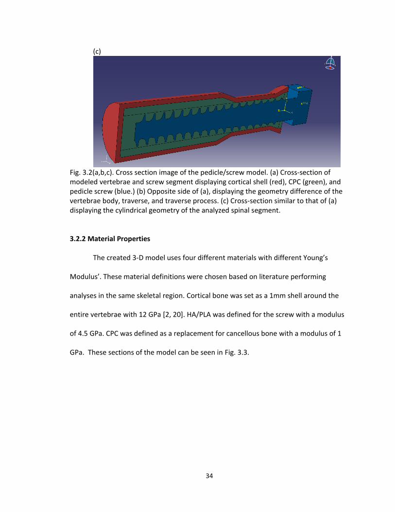
Fig. 3.2(a,b,c). Cross section image of the pedicle/screw model. (a) Cross-section of modeled vertebrae and screw segment displaying cortical shell (red), CPC (green), and pedicle screw (blue.) (b) Opposite side of (a), displaying the geometry difference of the vertebrae body, traverse, and traverse process. (c) Cross-section similar to that of (a) displaying the cylindrical geometry of the analyzed spinal segment.
3.2.2 Material Properties
The created 3-D model uses four different materials with different Young’s
Modulus’. These material definitions were chosen based on literature performing
analyses in the same skeletal region. Cortical bone was set as a 1mm shell around the
entire vertebrae with 12 GPa [2, 20]. HA/PLA was defined for the screw with a modulus
of 4.5 GPa. CPC was defined as a replacement for cancellous bone with a modulus of 1
GPa. These sections of the model can be seen in Fig. 3.3.

35
Fig. 3.3. Cross section image of pedicle defining sections. 3.2.3 Finite Element Analysis
ABAQUS (Dessault Systemes) is used for the finite element analysis evaluation of
HA/PLA pedicle screw in a vertebrae. The Solidworks pedicle screw models were
imported in to ABAQUS as a .VDA file.
Once the parts and materials have been defined, they must be meshed and
constrained with applied boundary condition displacements. For all models, 4-node
standard linear free tetrahedron elements are used, with mapped tri meshing disabled.
An edge mesh ranging from 0.14 to 0.75 are used within the bone model, creating a
dense mesh along the contact area. The screw is meshed with global and edge seeds
ranging from 0.10-0.25. The mesh must be dense enough to limit the warnings of
distorted elements while minimizing the amount of elements to reduce computation
time. Based on previous analysis attempts, it was established that the maximum stress
for a polymer pedicle screw in this vertebrae model is at the proximal end within the
first two threads. Therefore, a fine, 0.10 edge mesh was applied to this region to obtain
a more accurate result. The mesh must be checked to confirm no errors and minimize
36
the warnings for deformed elements. The complete model creates an average of 1.2
million elements.
The bone and screw were set up with surface to surface contact with slave
adjustments only to remove over closure, and finite sliding (frictionless). The outside
surface of the vertebrae body was constrained as encastre, preventing rotation and
displacement in all directions. The screw cross-section was constrained from rotation
along the central z-axis. The entire cross section of the screw and vertebrae was
constrained against displacement in the horizontal x-axis. The constraints for the model
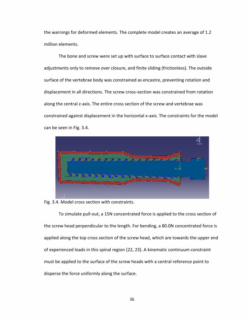
can be seen in Fig. 3.4.
Fig. 3.4. Model cross section with constraints. To simulate pull-out, a 15N concentrated force is applied to the cross section of
the screw head perpendicular to the length. For bending, a 80.0N concentrated force is
applied along the top cross section of the screw head, which are towards the upper end
of experienced loads in this spinal region [22, 23]. A kinematic continuum constraint
must be applied to the surface of the screw heads with a central reference point to
disperse the force uniformly along the surface.

37
Element selection is important to create an accurate simulation with any finite
element analysis program. For a brief background on elements, there are tetrahedron,
hexahedron, and wedge. Hex elements will provide the quickest convergence and most
accurate results, however due to the shape, they cannot be used with complex
geometries. For our case, a tetrahedron element is the only viable option. There are two
distinct types of these tetrahedron elements, and those are first-order (4-node linear)
and second-order (10-node quadratic). For “smooth” problems that do not involve
complex contact or impact, second order elements are the ideal choice, however
require much more computational power and time. These elements possess nodes
midway along the edges, in addition to the corners, like the first-order elements. This
allows these elements to deform easier and give a more accurate result. 4-node linear
elements can still be used, however there must be a dense mesh at the stress
concentration area. For this simulation, both first and second-order elements were
experimented with. Upon job submission, an error commonly stated; “The volume of ()
elements is zero, small, or negative. Check coordinates or node numbering, or modify
the mesh seed. In the case of a tetrahedron this error may indicate that all nodes are
located very nearly in a plane.” This error ended the simulation and was easily
repairable with a 4-node element by simply ignoring parallel lines along the surface,
which were created very small elements. However, the 10-node elements when put at
the same density resulted in random error elements. When important the screw to
ABAQUS, a warning states that the model contains imprecise geometry and quadratic
elements cannot be used. Therefore, the 10-node elements display an unsmooth and
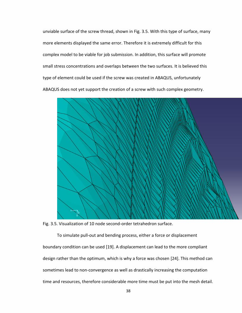
38
unviable surface of the screw thread, shown in Fig. 3.5. With this type of surface, many
more elements displayed the same error. Therefore it is extremely difficult for this
complex model to be viable for job submission. In addition, this surface will promote
small stress concentrations and overlaps between the two surfaces. It is believed this
type of element could be used if the screw was created in ABAQUS, unfortunately
ABAQUS does not yet support the creation of a screw with such complex geometry.
Fig. 3.5. Visualization of 10 node second-order tetrahedron surface.
To simulate pull-out and bending process, either a force or displacement
boundary condition can be used [19]. A displacement can lead to the more compliant
design rather than the optimum, which is why a force was chosen [24]. This method can
sometimes lead to non-convergence as well as drastically increasing the computation
time and resources, therefore considerable more time must be put into the mesh detail.

39
3.2.4 Objective Values
The results that were analyzed as the objective values are the surface stress of
the screw. Maximum von Mises stress was chosen as the value to minimize in this
analysis since it is used to predict yielding of materials under multiaxial loading
conditions. Materials are said to start yielding when its von Mises stress reaches a
critical value, the yield strength. Similarly, once the compressive strength of a material
has been reached, it will irreversibly plastically deform and eventually fracture. PLA will
plastically deform in tension and compression (ductile behavior), and will irreversibly
‘pull-apart’ instead of cracking. CPC on the other hand is a brittle material and will not
experience the same deformation, it will fracture and fail. Minimizing VMS in a
simulation or experimental test should create a design that will be less likely to fail by
yielding under a given loading condition. To do this with ABAQUS, two field output
requests for the maximum VMS were defined to specific nodal sections. Nodal sections
were setup to include the contact areas of the screw and bone surface. The screw
surface was set as the objective value for the analysis while the bone surface was
analyzed to predict failure. An optimized design will be generated by analyzing the
patterns of the maximum VMS in the screw. Stresses below the surface will also be
analyzed to confirm no higher stresses are within the screw.
3.2.5 Taguchi Robust Design Methods
Taguchi robust design method is a widely used method in engineering field
which can effectively reduce the number of models to be created and fairly arrange the
design variables [25-29]. With the Taguchi method, six different design variables of a
40
pedicle screw including minor radius (IR), proximal half angle (HAp), proximal root radius
(RRp), initial position of conical angle (IP), thread width (TW), and the pitch (P) were
considered. With these variables, an L18 orthogonal array was selected, which included
6 parameters and 3 levels. The remaining screw variables were kept constant: length
(40mm), major diameter (6.5mm-conical), distal half angle (15°), distal root radius
(1.0mm), proximal minor diameter (5.5mm), rate of increasing thread width
(0.1mm/length), and thread width fillet (0.15mm radius). This method lead to the
creation of 18 different models to be analyzed in the FEA simulation.
3.2.6 Artificial Neural Network (ANN)
Hsu et al. [30] and Chao et al. [19] have used a neural genetic approach to
effectively analyze and optimize orthopaedic bone screws. Much like a biological
network, an artificial neural network utilizes a network of neurons to perform a specific
function or task. However, in an artificial neural network, the functions of artificial
neurons are created to perform this function or task and estimate a cost [31], which is a
measure of how far away a particular solution is from the optimal. The learning
algorithm will search through the solution space to find a function that has the smallest
possible cost. In this research ANN was used to gain the understanding of a polymer
pedicle screw geometric design to avoid creating an enormous amount of models. In
addition, this ANN also dramatically reduced time on developing models and
computation. In order to utilize the benefits of an ANN, the program must be taught. In
learning, the program can find connections which minimize the cost of each variable
change. In this research, supervised learning was utilized because we had a relatively

41
large data set sample from the Taguchi orthogonal array. Back propagation method is a
form of supervised learning where the cost of a function is known or can be calculated.
In this method, the ANN was taught using a normalized set of information in this
research, which included the initial position of conical angle, inner diameter, root radius,
pitch, half angle, and thread width. The cost or outputs which were used as learning are
the outputs from each of the models for maximum von Mises stress (VMS) for the
surface, calculated by finite element analysis. In this method, the weights of each
connection were updated at each iteration of the training set to more accurately
predicting the cost of each function set.
A three layer architecture, which had six input neurons, three hidden neurons,
and one output neuron, was used for our program, as shown in Fig. 3.6. The hidden
layer had 3 neurons where a hyperbolic tangent function was used as an activation
function [32]. The number of learning iterations used was 2000 and learning rate was
0.5 to control the learning of our ANN to reduce to probability for our program to be
over trained or to be stuck in a local minimal or maximal. Momentum for learning of
our ANN was set to 0.5, this can provide faster convergence in training set [19]. The
ANN was validated by removing two of our eighteen function sets with cost and testing
the ANN with this data a changing the number of iterations until the predicted values
were closest to actual values. Next, nine additional designs were created which were
used to further validate our ANN and were also used for further training. From our 28
sets, an optimal design was generated and a random search was employed which
minimized the maximum von Mises stress on the surface of the screw. The ANN was

42
coded using python 2.7 and modified from an existing module program [33]. 27
different geometries were used to train the neural network. These geometries were
obtained via using the largest and smallest values of current commercially available
pedicle screws [5].
The artificial neural network employed in this study allows many sets of variable
values to be entered and a corresponding objective function, i.e., maximum von Mises
stress of surface and below surface, is predicted. To optimize the screw, the maximum
von Mises stress
in the bone sets are minimized by randomly trying 1000 different values for each
variable. The values were then changed iteratively and the optimum was found using a
gradient search. The optimums for each objective function were found separately.
Fig. 3.6 Artificial neural network structure [19].

43
3.3 Results and discussion
3.3.1 3-D model setup
Kim et al. [34] has been shown that the pull-out strength of constant major
diameters is greater than that of conical major diameters due to a greater screw
purchase, therefore a constant major diameter will be used, this plot can be seen in Fig.
3.7. Tapering the minor diameter is very common in this screw application due to the
large loads experienced, this will improve the bending strength of the screw at the
proximal end while providing an adequate screw purchase in the distal end and
increasing the insertion torque [34-38]. However, there are no commercially available or
well-studied polymer pedicle screws which could be used as a common screw geometry
to improve. Therefore, a set of three commercially available metallic screws including
Cotrel-Dubousset (Medtronic Sofamor-Danek, Memphis, TN), Texas Scottish Rite
Hospital (Danek, Memphis, TN), and Moss Miami (DePuy Spine, Raynham, MA) [19]
were chosen and modified. A previous optimization using the exact geometries gave us
the nominal values to study while creating new bounds based on these values. An image
depicting the screw geometry can be seen in Fig. 3.8.

44
Fig. 3.7. Various screw profiles with corresponding pull-out strength. [34]
Fig. 3.8. Depiction of screw geometry [19].

45
A design aspect that was considered which was not verified in the simulation is
the increasing thread width, due to the fact that the fit between the screw and bone is
perfect. The increasing thread width will provide a higher compression fit for the
proximal thread sections, as well as constantly providing good contact with the thread
and surrounding bone since the trabecular or bone cement may become damaged while
threading the screw in. Stresses could be evaluated in the models by providing a
thermal expansion coefficient to either the bone or the screw, which would expand or
contract either part.
During the installation of the pedicle screw, it is not common to tap threads for
installation. Pfeiffer et al. [39] determined that tapping a pilot hole degraded the
material and did not increase the pull-out strength. However, a self-tapping screw could
invoke isolated stresses in the polymer screw threads, which cannot be shown in the
FEA.
3.3.2 Taguchi robust design methods
The L18 orthogonal array used to train the ANN can be seen in Table 3.1. 18
different models were initially created. An additional model (A1) was created and run,
which was the first result of the ANN. An optimized final result (Opt1) from the ANN was
also created. The maximum von Mises stress of the screw surface nodeset was used as
the objective value.
46
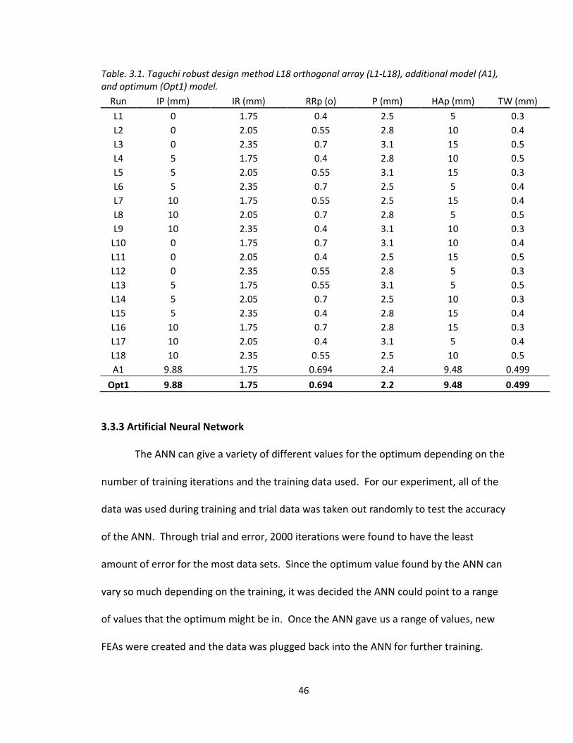
Table. 3.1. Taguchi robust design method L18 orthogonal array (L1-L18), additional model (A1), and optimum (Opt1) model.
Run IP (mm) IR (mm) RRp (o) P (mm) HAp (mm) TW (mm)
L1 0 1.75 0.4 2.5 5 0.3
L2 0 2.05 0.55 2.8 10 0.4
L3 0 2.35 0.7 3.1 15 0.5
L4 5 1.75 0.4 2.8 10 0.5
L5 5 2.05 0.55 3.1 15 0.3
L6 5 2.35 0.7 2.5 5 0.4
L7 10 1.75 0.55 2.5 15 0.4
L8 10 2.05 0.7 2.8 5 0.5
L9 10 2.35 0.4 3.1 10 0.3
L10 0 1.75 0.7 3.1 10 0.4
L11 0 2.05 0.4 2.5 15 0.5
L12 0 2.35 0.55 2.8 5 0.3
L13 5 1.75 0.55 3.1 5 0.5
L14 5 2.05 0.7 2.5 10 0.3
L15 5 2.35 0.4 2.8 15 0.4
L16 10 1.75 0.7 2.8 15 0.3
L17 10 2.05 0.4 3.1 5 0.4
L18 10 2.35 0.55 2.5 10 0.5
A1 9.88 1.75 0.694 2.4 9.48 0.499
Opt1 9.88 1.75 0.694 2.2 9.48 0.499
3.3.3 Artificial Neural Network
The ANN can give a variety of different values for the optimum depending on the
number of training iterations and the training data used. For our experiment, all of the
data was used during training and trial data was taken out randomly to test the accuracy
of the ANN. Through trial and error, 2000 iterations were found to have the least
amount of error for the most data sets. Since the optimum value found by the ANN can
vary so much depending on the training, it was decided the ANN could point to a range
of values that the optimum might be in. Once the ANN gave us a range of values, new
FEAs were created and the data was plugged back into the ANN for further training.

47
This was performed until a good screw design was found. The error in the training data
set is inside an acceptable range at 2.12%. In addition to closely matching the neural
network training data, the optimal screw geometry was found. The 3D model of the
optimum screw can be seen in Fig. 3.9.
The initial optimization attempt lead to a result at the bounds of our analysis,
which resulted in a minimum value approximately the same as our L18 minimum.
Analyzing the results lead to a conclusion that the smaller the thread pitch, the lower
the VMS. If there is more material to absorb the deflection and contact stress at the
proximal end, it will be more evenly distributed. Therefore, the pitch bound was
lowered to a value at the limit of our machinability with a proximal radius at the low
bound, 2.2 threads per inch. This resulted in the same geometry suggestion with the
minimum bound selected. It can be seen that the VMS in the screw is at a minimum
while maintaining an acceptable stress in the CPC. With our constraints, loading,
material definitions, and sectioned model, the optimum screw stress was shown to have
a maximum von Mises stress of 81.83 MPa in the screw surface and 43.69 MPa in the
bone surface. The resulting experimental and predicted values of the screw surface
stress can be seen in Fig. 10. Corresponding surface stress of the CPC can be seen in Fig.
11.

48
Fig. 3.9. 3D models of optimum screw.
Fig. 3.10. FEA and ANN result of screw surface stress. Taguchi L18 models, additional model (A1), and optimum (Opt1.)
0
20
40
60
80
100
120
140
L1 L2 L3 L4 L5 L6 L7 L8 L9
L10
L11
L12
L13
L14
L15
L16
L17
L18
A1
Op
t1Max
imu
m V
MS
(MP
a)
Trial Number
Screw Surface Stress
FEA Result
ANN Prediction

49
Fig. 3.11. FEA result of the bone surface stress.
3.3.4 Finite Element Analysis
ABAQUS, a Dessault Systemes brand, offers advanced and realistic simulation
modeling, specifically with ABAQUS. ABAQUS FEA offers unparalled assistance in
understanding the detailed behavior of new materials, component interactions, and a
seemingly endless amount of geometric possibilities.
The simulation setup was created for all different screw geometries seen in the
initial matrix. The jobs were submitted on a Intel Xeon X5650 @2.67GHz (2 processors)
with 24 gigabytes of ram on 64 bit Windows 7 OS, running 12 cores per simulation.
Computation time varied between 1-2 hours per simulation, depending on number of
elements and conversion rate. Total computation time was 30.54 hours at 90% memory
allocation. It is assumed that the large number of elements in the analysis required
more memory, resulting in the computer resorting to swap space for analysis. More
memory would cut down computation time considerably.
0
10
20
30
40
50
60
70
80
L1 L2 L3 L4 L5 L6 L7 L8 L9
L10
L11
L12
L13
L14
L15
L16
L17
L18
A1
Op
t1Max
imu
m V
MS
(MP
a)
Trial Number
Bone Surface Stress
FEA Result

50
For reference, our tested 5% wt. HA/PLA has a tensile and bending
ultimate/yield strength of ~75 MPa and ~150MPa, respectively. Compressive strength of
our HA/PLA has not been tested, however has been published to be up to 6.5 GPa [40].
Ideally, the strengths and modulus of the bending and tensile tests should be the same.
The reason for strength differences is due to inhomogeneities in the polymer composite
makeup. In a bending test, the stress distribution is not consistent throughout the body
of the sample, with the surfaces absorbing a higher load, due to the injection molding
process. In a tensile test, the load is more evenly distributed through the sample. Plastic
deformation will occur in this screw model once the bending yield strength has been
met (ductile failure), due to the bending loads placed in the model and the elastic
behavior of HA/PLA. CPC is commonly measured for its compressive strength and was
tested to be 54 MPa. Once the CPC compressive strength has been met, fracture will
occur (brittle failure.)
Stress distribution for the FEA result of the optimal, nominal, and stainless steel
pedicle screw can be seen in Fig. 3.12. All FEA images are set with a contour limit
automatically calculated with the maximum stress in the model. Every model exhibited
a similar stress distribution with a maximum stress at the first top proximal thread at the
base of the proximal radius. The L18 models resulted in a maximum VMS of 115.868,
minimum of 84.363, and an average of 93.79 MPa. The interaction in the CPC had a
maximum VMS of 67.59, minimum of 41.98, and an average of 51.01 MPa. For
comparison of the stress regions, the optimum polymer geometry was run with the
elastic modulus of 316L stainless steel, 230 GPa [41]. It is very interesting to see the

51
drastic difference in the location and value of the stress as compared to the polymer
screw. The maximum stress, with the same loading and boundary conditions as the
polymer screw, is 261 MPa, located at the upper center of the screw at the minor
diameter, where the vertebral body encastre boundary condition begins. This stress is in
tension and similar to the stress level at the bottom of the screw (compression.) 261
MPa is well above the yield strength of 316L stainless steel, 170 MPa [41]. This result
could reinforce the fact that failure is possible in the low cycle range, generally before 6
months. Low cycle fatigue will occur with ongoing stress near the yield strength. It is
also interesting to note that there is much lower stress in the CPC than with the polymer
screw, 20.08 MPa, due to the higher modulus steel absorbing the bending loads. With
these loads and constraints, a 316L stainless steel screw may fatigue and fail in the low
cycle range before HA/PLA.
(a)

52
(b)
(c)
Fig. 3.12. (a) Optimum design stress distribution, HA/PLA. (b) Nominal design. (c) Stainless steel with optimum polymer geometry.
Now that the general stress regions of the polymer and metallic screw have been
observed, the specific locations and types of stress within the optimum, nominal, and
stainless steel screws can be discussed. All polymer screw simulations had a similar
reaction to the loading and had the same maximum stress location. Due to the low
modulus, the screws bend, elastically deform, and separate from the CPC contact
regions at the proximal end. This results in an isolated compressive stress in the CPC
region and a tensile stress along the proximal half angle/radius. This tensile region

53
towards the base of the proximal radius is the maximum stress of the screw. It should
also be noted that there is still a compressive stress along the top of the screw thread
where it is in contact with the CPC region. Much differently, the SS screw simulation
shows no separation between the screw surface and the CPC contact. This results in a
very well distributed stress across the majority of the screw region.
The contact discussed between the polymer and metallic screws showed a
distinct different reaction in the bone. The polymer screws all showed a separation
between the screw and the CPC. This separation leads to a compressive stress in a
localized region of the polymer screw thread, which resulted in a tensile stress along the
proximal half angle/radius. These stresses and locations can be seen in Fig. 3.13.
Separation and deflection of the polymer screw showed a compressive stress in the
lower region of the CPC in the threads and along the farthest proximal area, shown in
Fig. 3.14. The nominal screw design, just like all others analyzed, showed a very similar
reaction to the loading, shown in Fig. 3.15 and 3.16. It is also important to note that the
transition of the traverse process/pedicle to the fully constrained vertebral body
showed a high stress, 149 MPa in cortical bone (optimum geometry,) which could be
influenced by the vertebrae model geometry, and therefore will not be included in the
analysis, as seen in Fig. 3.12. This will need to be analyzed experimentally in a cadaver
vertebra. The metallic screws did not show any separation from the CPC, had a different
max VMS location with a considerably higher value, and had a much lower compressive
stress in the CPC and surrounding bone. These locations and stress can be seen in Fig.
3.17 and 3.18.
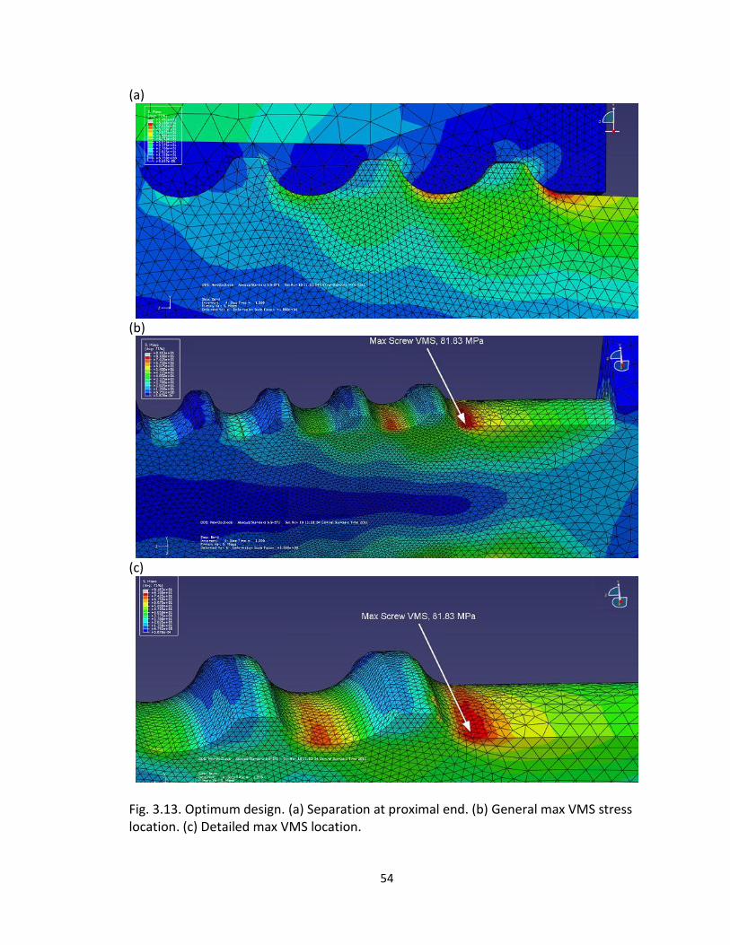
54
(a)
(b)
(c)
Fig. 3.13. Optimum design. (a) Separation at proximal end. (b) General max VMS stress location. (c) Detailed max VMS location.

55
(a)
(b)
Fig. 3.14. Optimum Design. (a) General stress reactions of screw in CPC. (b) Detailed location of maximum CPC VMS.

56
(a)
(b)
Fig. 3.15. Nominal design. (a) General location of max screw VMS. (b) Detailed location of max VMS.

57
(a)
(b)
Fig. 3.16. Nominal Design. (a) General location of maximum CPC stress. (b) Detailed area of maximal VMS.
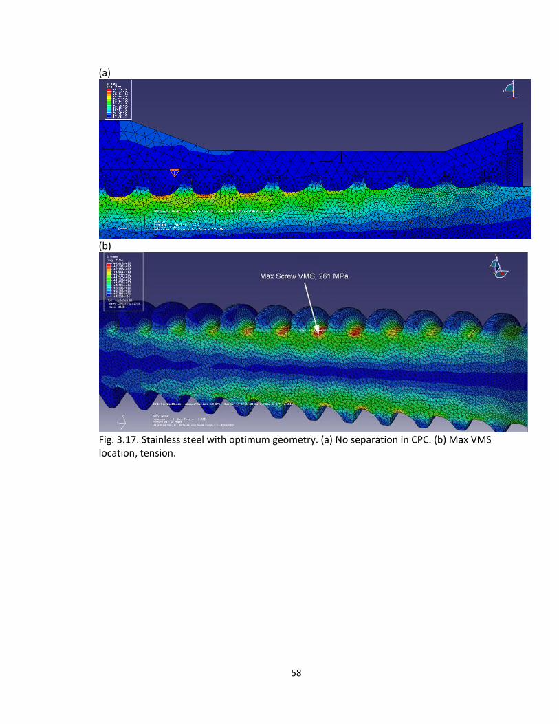
58
(a)
(b)
Fig. 3.17. Stainless steel with optimum geometry. (a) No separation in CPC. (b) Max VMS location, tension.

59
(a)
(b)
Fig. 3.18. Stainless steel with optimum geometry. (a) Maximum VMS in CPC location. (b) Detailed max VMS location.
An important criterion to study the viability of this device is the deflection of the
screw at the proximal end, or the head. To be a viable device, the device must be rigid
to provide fusion of the bone graft and vertebrae. The deflection of farthest corner
node of the optimal, nominal, and stainless steel models have been analyzed. For a
result, the optimum and nominal design deflected 0.676 and 0.683mm, respectively.
Interestingly though, the SS model resulted in a deflection of 0.154mm, which shows to
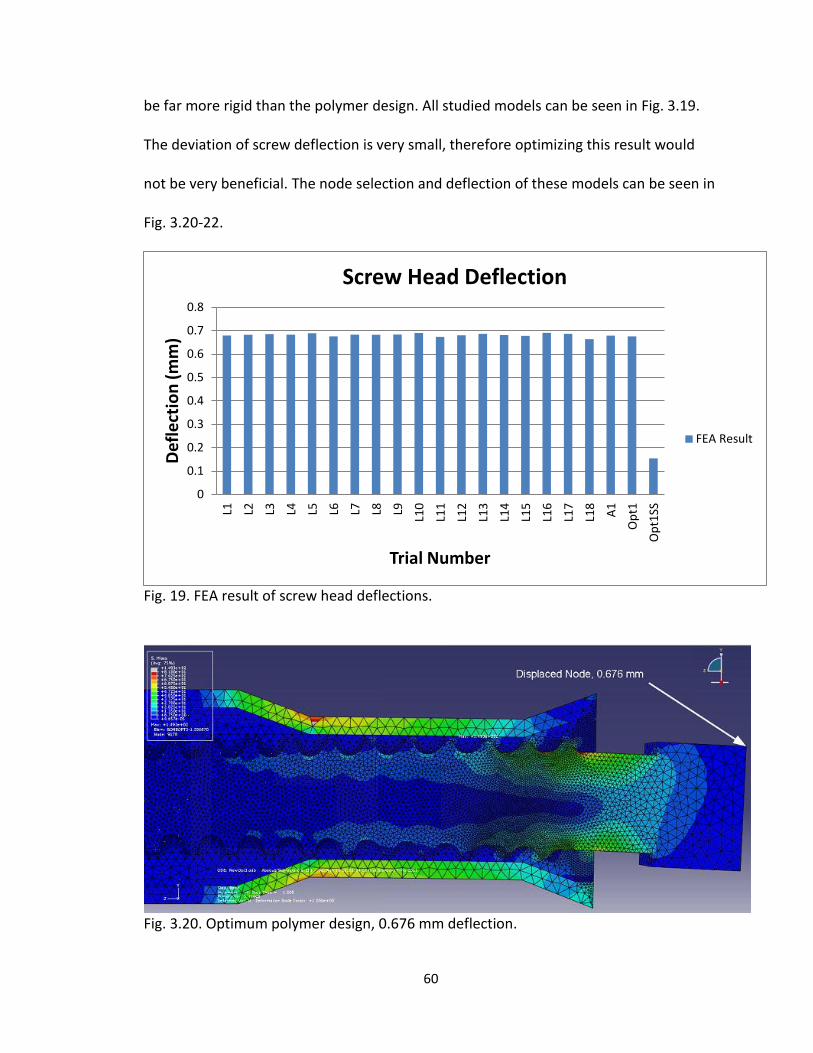
60
be far more rigid than the polymer design. All studied models can be seen in Fig. 3.19.
The deviation of screw deflection is very small, therefore optimizing this result would
not be very beneficial. The node selection and deflection of these models can be seen in
Fig. 3.20-22.
Fig. 19. FEA result of screw head deflections.
Fig. 3.20. Optimum polymer design, 0.676 mm deflection.
0
0.1
0.2
0.3
0.4
0.5
0.6
0.7
0.8
L1 L2 L3 L4 L5 L6 L7 L8 L9
L10
L11
L12
L13
L14
L15
L16
L17
L18
A1
Op
t1
Op
t1SS
Def
lect
ion
(m
m)
Trial Number
Screw Head Deflection
FEA Result

61
Fig. 3.21. Nominal polymer design, 0.6825 mm deflection.
Fig. 3.22. Optimum design with 316L stainless steel, 0.154 mm deflection.
To further analyze the stress distribution in these screw models, a vertical line
was drawn from the top of the first thread to the minor diameter on the opposite side
using nearly identical nodal locations in respect to the screw geometry. Beam theory
shows there should be a tensile stress on the top and compressive on the bottom with a
stress of zero at the center. The 15N pull-out force is not significant, however it will
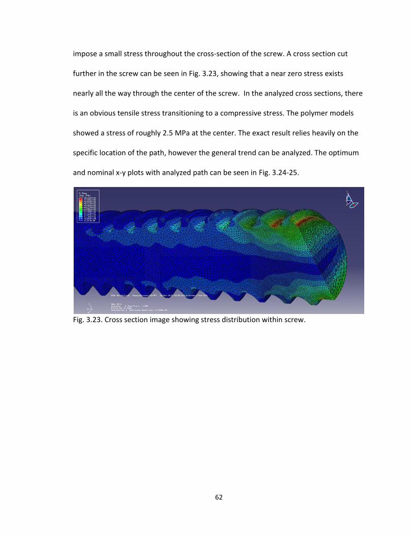
62
impose a small stress throughout the cross-section of the screw. A cross section cut
further in the screw can be seen in Fig. 3.23, showing that a near zero stress exists
nearly all the way through the center of the screw. In the analyzed cross sections, there
is an obvious tensile stress transitioning to a compressive stress. The polymer models
showed a stress of roughly 2.5 MPa at the center. The exact result relies heavily on the
specific location of the path, however the general trend can be analyzed. The optimum
and nominal x-y plots with analyzed path can be seen in Fig. 3.24-25.
Fig. 3.23. Cross section image showing stress distribution within screw.
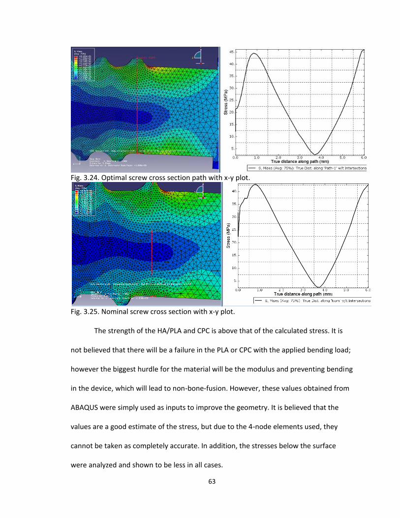
63
Fig. 3.24. Optimal screw cross section path with x-y plot.
Fig. 3.25. Nominal screw cross section with x-y plot.
The strength of the HA/PLA and CPC is above that of the calculated stress. It is
not believed that there will be a failure in the PLA or CPC with the applied bending load;
however the biggest hurdle for the material will be the modulus and preventing bending
in the device, which will lead to non-bone-fusion. However, these values obtained from
ABAQUS were simply used as inputs to improve the geometry. It is believed that the
values are a good estimate of the stress, but due to the 4-node elements used, they
cannot be taken as completely accurate. In addition, the stresses below the surface
were analyzed and shown to be less in all cases.

64
3.4 Conclusion
A high performing, i.e., near optimum PLA bone screw was found using finite
element analysis and with the assistance of an artificial neural network. It is believed
that the HA/PLA screw and the CPC will not fail under the given loading and model
setup. Mechanical testing will need to be conducted to both verify the computational
results, failure mode, failure strength, and deflection of the device. Failure of the
HA/PLA screw will occur by yielding and deforming plastically (ductile failure), while CPC
will fail in compression by fracture (brittle failure.) If there is no failure under this
loading in the bone, bone cement, or HA/PLA screw, the biggest hurdle for the material
will be the modulus and preventing bending in the device, which will lead to non-bone-
fusion. If this device shows to be rigid enough through experimental testing, fatigue
testing must be implemented to determine cycles to failure. According to the
simulations, a 316L stainless steel screw with this optimum polymer geometry may fail
due to fatigue (ductile failure) in the low cycle range. Based on these results, the
optimum geometry for a polymer and metal pedicle screw could be very different.

65
3.5 References
1. Gefen, A., Computational simulations of stress shielding and bone resorption around existing and computer-designed orthopaedic screws. Medical and Biological Engineering and Computing, 2002. 40(3): p. 311-322.
2. Chen, C.-S., et al., Failure analysis of broken pedicle screws on spinal instrumentation. Medical engineering & physics, 2005. 27(6): p. 487-496.
3. Villarraga, M.L., et al., Wear and Corrosion in Retrieved Thoracolumbar Posterior Internal Fixation. Spine, 2006. 31(21): p. 2454-2462 10.1097/01.brs.0000239132.16484.be.
4. Peter F. Ullrich, J., MD. Pedicle Screws for Spine Fusion. 1999 [cited 2010 12/16]; Available from: http://www.spine-health.com/treatment/spinal-fusion/pedicle-screws-spine-fusion.
5. Lonstein, J.E., et al., Complications associated with pedicle screws. The Journal of bone and joint surgery. American volume, 1999. 81(11): p. 1519-28.
6. Vaccaro, A.R., et al., The use of bioabsorbable implants in the spine. The Spine Journal. 3(3): p. 227-237.
7. Kim, K., et al., Utility of new bioabsorptive screws in cervical anterior fusion. Surgical Neurology, 2007. 68(3): p. 264-268.
8. Pietrzak W S, P.o.d.a.u.o.a.i.f., Tis. Engin. (2000);6(4), pp. and 425–433. 9. Athanasiou, K.A., et al., Orthopaedic applications for PLA-PGA biodegradable polymers.
Arthroscopy: The Journal of Arthroscopic & Related Surgery, 1998. 14(7): p. 726-737. 10. Kotani, Y., et al., Two-year observation of artificial intervertebral disc replacement:
results after supplemental ultra-high strength bioresorbable spinal stabilization. Journal of neurosurgery, 2004. 100(4 Suppl Spine): p. 337-42.
11. Pietrzak, W.S., Principles of development and use of absorbable internal fixation. Tissue engineering, 2000. 6(4): p. 425-33.
12. Pietrzak, W.S., Critical concepts of absorbable internal fixation. The Journal of craniofacial surgery, 2000. 11(4): p. 335-41.
13. Pietrzak, W.S. and B.L. Eppley, Resorbable polymer fixation for craniomaxillofacial surgery: development and engineering paradigms. The Journal of craniofacial surgery, 2000. 11(6): p. 575-85.
14. Rikli, D.A., et al., The potential of bioresorbable plates and screws in distal radius fracture fixation. Injury, 2002. 33 Suppl 2: p. B77-83.
15. Ho, W.-F., et al., Mechanical properties and deformation behavior of cast binary Ti-Cr alloys. Journal of Alloys and Compounds, 2009. 468(1-2): p. 533-538.
16. Weiler, A., et al., Biodegradable Interference Screw Fixation Exhibits Pull-Out Force and Stiffness Similar to Titanium Screws. The American Journal of Sports Medicine, 1998. 26(1): p. 119-128.
17. Hashemi, A., D. Bednar, and S. Ziada, Pullout strength of pedicle screws augmented with particulate calcium phosphate: An experimental study. The Spine Journal, 2009. 9(5): p. 404-410.
18. Bai, B., F.J. Kummer, and J. Spivak, Augmentation of anterior vertebral body screw fixation by an injectable, biodegradable calcium phosphate bone substitute. Spine, 2001. 26(24): p. 2679-83.
19. Chao, C.-K., et al., A Neurogenetic Approach to a Multiobjective Design Optimization of Spinal Pedicle Screws. Journal of Biomechanical Engineering, 2010. 132(9): p. 091006.
20. Pfeiffer, D., Discussion of vertebrae modeling and analysis, R. Lebens, Editor 2011: Columbia, MO.

66
21. Specialists, N.a.S. Anatomy and Terminology of the Spine. 2010 [cited 2011 6/1]; Available from: http://www.neurosurgeryandspinemd.com/Anatomy%20and%20Terminology%20of%20the%20Spine.pdf.
22. McKinley, T.O., et al., Characteristics of Pedicle Screw Loading: Effect of Surgical Technique on Intravertebral and Intrapedicular Bending Moments. Spine, 1999. 24(1): p. 18-24.
23. Tsai, W.-C., et al., Comparison and prediction of pullout strength of conical and cylindrical pedicle screws within synthetic bone. BMC Musculoskeletal Disorders, 2009. 10(1): p. 44.
24. Smith, D.D., HA/PLA Pedicle Screw Design Discussion, J. Schottler, Editor 2011: Columbia, MO.
25. Fowlkes, W.Y., and Creveling, C.M, Engineering Methods for Robust
Product Design Using Taguchi Methods in Technology and Product Development1995, Reading, MA: Addison-Wesley.
26. Hou, S.-M., et al., Mechanical tests and finite element models for bone holding power of tibial locking screws. Clinical Biomechanics, 2004. 19(7): p. 738-745.
27. Hsu, C.C., et al., Multiobjective optimization of tibial locking screw design using a genetic algorithm: Evaluation of mechanical performance. Journal of orthopaedic research : official publication of the Orthopaedic Research Society, 2006. 24(5): p. 908-16.
28. Lin, C.L., et al., Evaluation of contributions of orthodontic mini-screw design factors based on FE analysis and the Taguchi method. Journal of biomechanics, 2010. 43(11): p. 2174-81.
29. Chao, C.K., et al., Increasing bending strength of tibial locking screws: mechanical tests and finite element analyses. Clinical Biomechanics, 2007. 22(1): p. 59-66.
30. Hsu, C.C., J. Lin, and C.K. Chao, Comparison of multiple linear regression and artificial neural network in developing the objective functions of the orthopaedic screws. Computer methods and programs in biomedicine, 2010.
31. Michalski. The Machine Learning Dictionary. 2011 2011 [cited 2011 5/10]; Available from: http://www.cse.unsw.edu.au
32. Cybenko, G., Approximation by superpositions of a sigmoidal function. Mathematics of Control, Signals, and Systems (MCSS), 1989. 2(4): p. 303-314.
33. Schemenauer, N. Python Stuff. 2004 [cited 2011 5/24]; Available from: http://arctrix.com/nas/.
34. Kim, D.H., Spinal Instrumentation: Surgical Techniques. Silhouette Surgical Technique, ed. S.A. Webb2005, New York: Thieme. 1330.
35. Kim, D.H., Spinal Instrumentation: Surgical Techniques. Zimmer ST360 Spinal Instrumentation, ed. J.C. Dick2005, New York: Thieme. 1330.
36. Kim, D.H., Spinal Instrumentation: Surgical Techniques. InCompass Thoracolumbar Fixation System, ed. R.P.J.a.A.C. McManus2005, New York: Thieme. 1330.
37. Kim, D.H., Spinal Instrumentation: Surgical Techniques. Global Spinal Fixation System: Instrumentation Technique, ed. J.S.P.a.H.S. An2005, New York: Thieme. 1330.
38. Hsu, C.-C., et al., Increase of pullout strength of spinal pedicle screws with conical core: Biomechanical tests and finite element analyses. Journal of Orthopaedic Research, 2005. 23(4): p. 788-794.

67
39. Pfeiffer, F.M., D.L. Abernathie, and D.E. Smith, A comparison of pullout strength for pedicle screws of different designs: a study using tapped and untapped pilot holes. Spine, 2006. 31(23): p. E867-70.
40. Shikinami, Y. and M. Okuno, Bioresorbable devices made of forged composites of hydroxyapatite (HA) particles and poly l-lactide (PLLA). Part II: practical properties of miniscrews and miniplates. Biomaterials, 2001. 22(23): p. 3197-3211.
41. Metals, U.P. 316 / 316L Stainless Steel Sheet & Coil. 2006 [cited 2011 11/20]; Available from: http://www.upmet.com/316-mechanical.shtml.

68
Chapter 4-Conclusion and future work
4.1 Summary and conclusion
4.1.1 Fabrication, modification, and evaluation of HA nanofibers and associated
PLA/HA composites
Hydroxyapatite nanofibers were successfully incorporated into the PLA matrix
through injection molding process. Different mass fractions of HA nanofibers (1, 2, and 5
wt% ) were impregnated in 20 grams of HMW PLA through an injection molding process
to fabricate samples to be tested in both bending and tensile tests.
The ASTM standard D5934-02 was used for bend testing, which accurately
determined the modulus of elasticity of our rigid rectangular testing samples. Bending
test results showed that the incorporation of 5wt% HA nanofiber into PLA matrix could
reach the maximum value (140.7 MPa) on ultimate bending strength and lead to a 30%
increase in comparison with pure PLA. The addition of 1 wt% or 2 wt% HA nanofiber
could result in similar reinforcing effects as 5wt% HA impregnation. Moreover, the
addition of fibers also increased the elastic modulus by as much as 21% to 4.41 MPa,
from 3.48 MPa of pure PLA.
The ASTM standard D3039M-08 was used for tensile testing, which accurately
determined the in-plane tensile properties of the polymer matrix composite reinforced
by high-modulus fibers. It was shown that the highest UTS came from 2% HA filler at
70.2 MPa, a 30.7% increase over pure PLA. Pure PLA had an UTS of only 48.6 MPa. It is
also interesting to note how the addition of HA fibers has created a more pliable
material.

69
Overall, the addition of HA nanofibers could not only improve the biological
properties but also increased the UTS and modulus of the material. This increase in
strength and modulus is ideal for our pedicle screw device, which experiencing a
relatively large bending load. The increases could be due to flash freezing, which is what
happens when the molds are not preheated before injection molding. The fibers and
PLA may suddenly freeze to the surface, orienting the fibers in such a way that the
bending strength and rigidity was improved. It is hypothesized that this process may
carry over to injection molding a HA/PLA pedicle screw.
4.1.2 The design and analysis of a PLA/HA pedicle screw
A high performing, i.e., near optimum PLA bone screw was found using finite
element analysis and with the assistance of an artificial neural network. With our
constraints, loading, material definitions, and sectioned model, the highest stress shown
in our analyzed sections were shown to have a maximum von mises stress of 122 MPa in
the bone surface, 113 for the bone bearing stress, 87 at the screw surface, and 63 MPa
as the screw bearing stress. The yield strength and UTS of HA/PLA is 140 MPa.
Therefore, the strength of the HA/PLA is not below that of the calculated stress, which
should not result in failure. CPC bone cement is not a heavily studied material and is
typically characterized by compressive strength, which is 54 MPa, below the maximum
VMS of the measured model. It is believed that portions of the bone cement will fail
under loading, displacing the load to other areas of the model. It is not believed that the
failure will be in the screw design itself. Mechanical testing will need to be conducted to
both verify the computational results and analyze the type of failure. If there is no

70
failure in the bone, bone cement, or HA/PLA screw, the biggest hurdle for the material
will be the modulus and preventing bending in the device, which will lead to non-bone-
fusion.
A concern, which was not addressed in the analysis, was the ignored small
section of cortical bone at the proximal end of the bone model. Due to the inconsistent
and small amount of thread in a much stronger and smaller section of bone, high stress
concentrations arise. Therefore, this section of bone was not included in the nodesets
analyzing the maximum VMS. The maximum VMS in this small section with the optimum
screw model is about 505 MPa, well beyond the yield strength of any material in the
model. It is believed that a section of the bone or screw will either fracture or fail,
however the load will be transferred to another part of the model. However, this
section of contact may not be included in a realistic setting due to pre-drilling the
pedicle for the impregnation of bone cement. Furthermore, research can be conducted
to improve the interaction of the screw at the surface of the bone.
4.2 Recommendation and future work
Computational modeling and simulations are effective ways of determining the
reaction between design variables and isolating high stress areas of designs, as well as
accurately comparing numerous different models with identical constraints and loads.
Unfortunately, not all design aspects can accurately be tested. Therefore, it is important
to analyze and verify the final design experimentally.
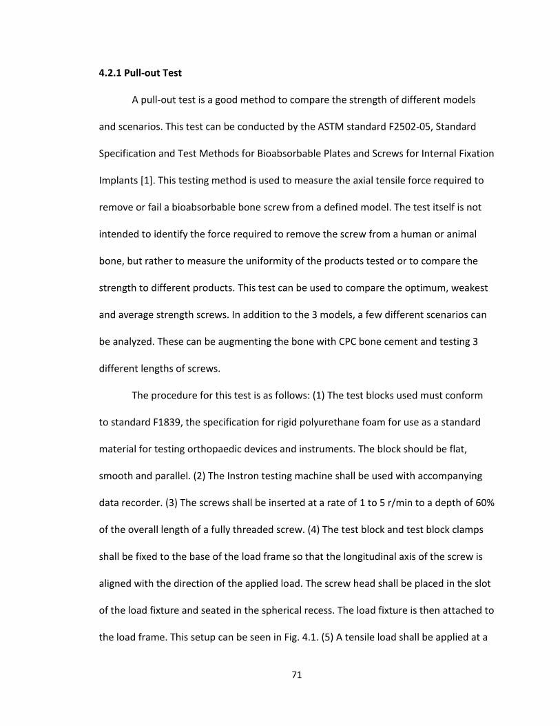
71
4.2.1 Pull-out Test
A pull-out test is a good method to compare the strength of different models
and scenarios. This test can be conducted by the ASTM standard F2502-05, Standard
Specification and Test Methods for Bioabsorbable Plates and Screws for Internal Fixation
Implants [1]. This testing method is used to measure the axial tensile force required to
remove or fail a bioabsorbable bone screw from a defined model. The test itself is not
intended to identify the force required to remove the screw from a human or animal
bone, but rather to measure the uniformity of the products tested or to compare the
strength to different products. This test can be used to compare the optimum, weakest
and average strength screws. In addition to the 3 models, a few different scenarios can
be analyzed. These can be augmenting the bone with CPC bone cement and testing 3
different lengths of screws.
The procedure for this test is as follows: (1) The test blocks used must conform
to standard F1839, the specification for rigid polyurethane foam for use as a standard
material for testing orthopaedic devices and instruments. The block should be flat,
smooth and parallel. (2) The Instron testing machine shall be used with accompanying
data recorder. (3) The screws shall be inserted at a rate of 1 to 5 r/min to a depth of 60%
of the overall length of a fully threaded screw. (4) The test block and test block clamps
shall be fixed to the base of the load frame so that the longitudinal axis of the screw is
aligned with the direction of the applied load. The screw head shall be placed in the slot
of the load fixture and seated in the spherical recess. The load fixture is then attached to
the load frame. This setup can be seen in Fig. 4.1. (5) A tensile load shall be applied at a
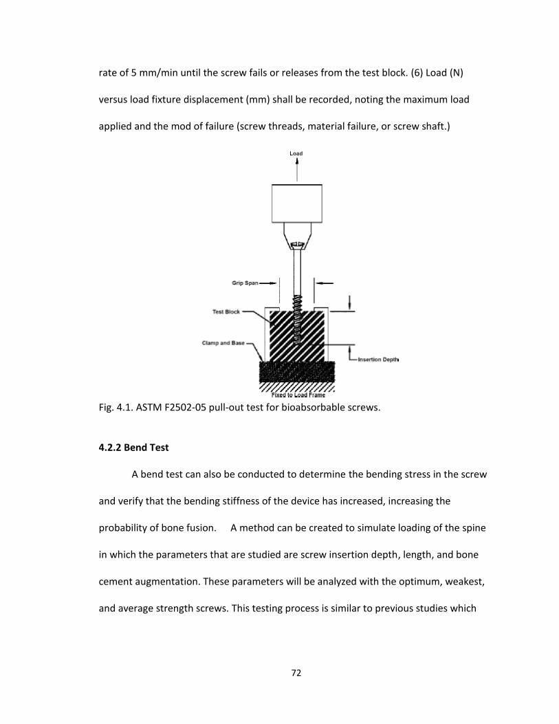
72
rate of 5 mm/min until the screw fails or releases from the test block. (6) Load (N)
versus load fixture displacement (mm) shall be recorded, noting the maximum load
applied and the mod of failure (screw threads, material failure, or screw shaft.)
Fig. 4.1. ASTM F2502-05 pull-out test for bioabsorbable screws.
4.2.2 Bend Test
A bend test can also be conducted to determine the bending stress in the screw
and verify that the bending stiffness of the device has increased, increasing the
probability of bone fusion. A method can be created to simulate loading of the spine
in which the parameters that are studied are screw insertion depth, length, and bone
cement augmentation. These parameters will be analyzed with the optimum, weakest,
and average strength screws. This testing process is similar to previous studies which

73
were sufficient in demonstrating significant differences in measured moment between
metallic screw models [2-4].
Vertebral models can be used instead of cadaver vertebrae due to consistency
in the material. The high strength open cellular foam has a modulus of elasticity similar
to that of cancellous vertebral material at 500 MPa can be used. These single section
vertebral models can be drilled and augmented with CPC bone cement before insertion
of screw models, along with models without bone cement. A possible experimental
setup can be seen in Fig. 4.2.
Axial strain gauges can be applied to the inside of the screw at predetermined
positions along the length of the screw. The strain gauges will record the bending
moments within the pedicle. These strain gauges can be placed at positions to analyze
the bending moment at different areas of interest.
A pilot hole of the inner diameter and equal in length can be drilled before
threading in the screw into the pedicle segment. If augmenting with bone cement, a
6.5mm pilot hole will be drilled and bone cement will be inserted. After insertion, the
vertebral analogue can be rigidly mounted in an aluminum testing frame with set screws
to secure the pedicle screws. Load can be applied to the superior endplate of the
vertebra analogue through an aluminum loading block equaling the cross section of the
vertebrae segment, reassuring adequate dispersement of the force. Load can be applied
with an instron testing machine.

74
Fig. 4.2 Suggested bend test apparatus. [4]
Loading can be done with 200N, about twice that of the FEA analysis, with a
constant cross-head displacement rate of 10.0 mm/min. To help eliminate stresses
which were applied during insertion, two cycles should be performed, followed by two
load/unload cycles in which the bending moments are recorded.
The results of this bend test should confirm that the bending modulus was
improved with the optimized screw design while limiting the stresses applied to the
screw thread profile and bone, reducing the risk of failure and showing feasibility of
clinical use. If failure occurs, the reason can be analyzed and recorded.
The variance in screw length can also be analyzed. The models were originally
created based on the geometry of commercially available metallic pedicle screws of
40mm. Due to the significantly lower modulus of HA/PLA, it can be analyzed whether or
not this type of length is required. Analyzing the different stresses applied to the screw
based on the amount of material (threads) exposed out of the bone, it can be

75
determined whether or not it’s feasible for such a scenario to allow for bone fusion. It
will be important to analyze the difference in performance of the models augmented
with bone cement and verify whether or not it played a role in failure.
4.2.3. Analysis of strength in relation to saturation time
HA/PLA must maintain adequate mechanical strength and material structure
during the healing process of the fracture site. To verify that the design will provide
adequate stability throughout the fusion process, the design can be tested in vitro. Pull-
out and bend tests can be conducted at specific time intervals while the design is placed
in an aqueous environment similar to that of vertebrae segment.
4.2.4 Further investigation to improve rigidity
It has been discussed that the material and design may be strong enough to
prevent failure, however the biggest concern is rigidity. Further research could be
conducted on improving the rigidity of the device. Possibly improvements could be to
enhance the proximal end of the device to resist bending. This could be done by
inserting a rod of hydroxyapatite within the core of the pedicle screw.
4.2.5 Improvement in the ANN
Further work can be put in to improving the artificial neural network. Although
the program effectively resulted in an ideal design and geometry, improved models can
still be created. The optimized and created screw is simply the initial design
consideration for mechanical testing and an improved ANN could more effectively
generate superior geometry considerations.
76
4.3 References
1. ASTM, Standard Specification and Test Methods for Bioabsorbable Plates and Screws for Internal Fixation Implants, in F2502-052005.
2. McKinley, T.O., et al., Characteristics of Pedicle Screw Loading: Effect of Surgical Technique on Intravertebral and Intrapedicular Bending Moments. Spine, 1999. 24(1): p. 18-24.
3. McKinley, T.O., et al., The effect of pedicle morphometry on pedicle screw loading. A synthetic model. Spine, 1997. 22(3): p. 246-52.
4. McLain, R.F., et al., The effect of bone quality on pedicle screw loading in axial instability. A synthetic model. Spine, 1997. 22(13): p. 1454-60.
Related Documents