Ice Class Vessels, 28-29 April 2015, London, UK © 2015: The Royal Institution of Naval Architects THE CONVERSION OF VESSELS TO MEET HIGHER ICE CLASS REQUIREMENTS USING SPS OVERLAY M. Brooking and Dr. O. Sukovoy, Intelligent Engineering (UK) Ltd. UK SUMMARY Intelligent Engineering has designed an SPS Overlay solution to upgrade vessels to meet higher Ice Class requirements enabling them to operate in ice conditions. Ship owners wishing to upgrade their vessels to satisfy new Ice Class operational requirements have previously faced undertaking major modifications to existing hull structures such as increased shell plate thickness and additional frames and stringers. By using SPS Overlay on the external surface of the shell plating in the ice belt region, higher Ice Class strengthening requirements can be met without major disruption to the hull structure. The use of SPS Overlay eliminates conventional crop-and-replace of the existing shell. The inherent local stiffness of SPS Overlay ensures effective distribution of any localised peaks in the ice pressure loads. In addition to providing increased plate strength, SPS Overlay increases the section modulus of the framing plate/stiffener combination thus minimizing changes to the existing frames. SPS Overlay’s ability to absorb high impact loads makes it ideal for this application. The system uses t he existing hull as one side of a steel composite panel formed by a new top plate and an elastomer core, greatly reducing the complexity of the conversion, time out of service and total repair costs. This paper describes the technical work carried out to design and achieve DNV-GL class approval, and install the SPS upgrades. 1. INTRODUCTION SPS (Sandwich Plate System) is a structural composite material comprising two metal face plates permanently bonded to a polyurethane elastomer core, which can be used as an alternative to conventional steel construction and repairs. The compact elastomer core provides continuous support to the face plates prevents local buckling and in many cases removes the need for secondary stiffeners. SPS was initially developed to provide impact resistant plating for offshore structures and ice islands operating in harsh ice conditions of the Canadian Beaufort Sea. Research and development focused on material characterisation, structural behaviour and performance, design principles, energy absorption design philosophies and the development of connection details specific to sandwich plate structures. Physical properties, design parameters and production techniques have been established through extensive analytical, experimental and prototype work. SPS has been used widely in the marine industry since 1999; and has an established track record in ship repair and construction. To date more than 300 projects have been completed on a wide range of ship types. SPS is approved by all major classification societies and regulatory authorities for use in newbuilds and rehabilitation of ships and offshore units. Lloyd’s Register published provisional ship construction rules in 2006 [1]; and more recently DNV-GL published Class Note 30.11 [2] describing the classification requirements. Figure 1 –Offshore Supply Vessel (OSV) Intelligent Engineering (IE) was requested to prepare a design to strengthen the hull structure of an offshore supply vessel (OSV), illustrated in Figure 1, using SPS in order to upgrade the Ice Class of the vessel to DNV’s ICE-1C. The hull needed strengthening to satisfy new operational requirements. IE has undertaken detailed design work to confirm that ice strengthening requirements according to classification standards can be met using SPS. Following review for compliance with the applicable Rules and Regulations, DNV-GL granted the approval to the proposed SPS Overlay design.

Welcome message from author
This document is posted to help you gain knowledge. Please leave a comment to let me know what you think about it! Share it to your friends and learn new things together.
Transcript

Ice Class Vessels, 28-29 April 2015, London, UK
© 2015: The Royal Institution of Naval Architects
THE CONVERSION OF VESSELS TO MEET HIGHER ICE CLASS REQUIREMENTS
USING SPS OVERLAY
M. Brooking and Dr. O. Sukovoy, Intelligent Engineering (UK) Ltd. UK
SUMMARY
Intelligent Engineering has designed an SPS Overlay solution to upgrade vessels to meet higher Ice Class requirements
enabling them to operate in ice conditions.
Ship owners wishing to upgrade their vessels to satisfy new Ice Class operational requirements have previously faced
undertaking major modifications to existing hull structures such as increased shell plate thickness and additional frames
and stringers.
By using SPS Overlay on the external surface of the shell plating in the ice belt region, higher Ice Class strengthening
requirements can be met without major disruption to the hull structure. The use of SPS Overlay eliminates conventional
crop-and-replace of the existing shell. The inherent local stiffness of SPS Overlay ensures effective distribution of any
localised peaks in the ice pressure loads. In addition to providing increased plate strength, SPS Overlay increases the
section modulus of the framing plate/stiffener combination thus minimizing changes to the existing frames. SPS
Overlay’s ability to absorb high impact loads makes it ideal for this application. The system uses the existing hull as one
side of a steel composite panel formed by a new top plate and an elastomer core, greatly reducing the complexity of the
conversion, time out of service and total repair costs.
This paper describes the technical work carried out to design and achieve DNV-GL class approval, and install the SPS
upgrades.
1. INTRODUCTION
SPS (Sandwich Plate System) is a structural composite
material comprising two metal face plates permanently
bonded to a polyurethane elastomer core, which can be
used as an alternative to conventional steel construction
and repairs. The compact elastomer core provides
continuous support to the face plates prevents local
buckling and in many cases removes the need for
secondary stiffeners.
SPS was initially developed to provide impact resistant
plating for offshore structures and ice islands operating
in harsh ice conditions of the Canadian Beaufort Sea.
Research and development focused on material
characterisation, structural behaviour and performance,
design principles, energy absorption design philosophies
and the development of connection details specific to
sandwich plate structures. Physical properties, design
parameters and production techniques have been
established through extensive analytical, experimental
and prototype work.
SPS has been used widely in the marine industry since
1999; and has an established track record in ship repair
and construction. To date more than 300 projects have
been completed on a wide range of ship types. SPS is
approved by all major classification societies and
regulatory authorities for use in newbuilds and
rehabilitation of ships and offshore units. Lloyd’s
Register published provisional ship construction rules in
2006 [1]; and more recently DNV-GL published Class
Note 30.11 [2] describing the classification requirements.
Figure 1 –Offshore Supply Vessel (OSV)
Intelligent Engineering (IE) was requested to prepare a
design to strengthen the hull structure of an offshore
supply vessel (OSV), illustrated in Figure 1, using SPS in
order to upgrade the Ice Class of the vessel to DNV’s
ICE-1C. The hull needed strengthening to satisfy new
operational requirements. IE has undertaken detailed
design work to confirm that ice strengthening
requirements according to classification standards can be
met using SPS. Following review for compliance with
the applicable Rules and Regulations, DNV-GL granted
the approval to the proposed SPS Overlay design.

Design & Operation of Wind Farm Support Vessels, 28-29 January 2015, London, UK
© 2015: The Royal Institution of Naval Architects
2. DESIGN
2.1 DESIGN SUMMARY
Built in 2002 the vessel is classed with Det Norske
Veritas, (Class Notation: 1A1 ICE-C Tug Supply Vessel
Fire Fighter) and has principal particulars as listed in
Table 1.
Length overall 80.00 m
Length between
perpendiculars 69.30 m
Rule length 73.10 m
Breadth moulded 18.00 m
Depth Main Deck 8.00 m
Scantling draught 6.60 m
CB 0.7655
Speed 16 knots
Engine output 12000 kW
Table 1 – Principal Particulars
The vessel was built in compliance with the requirements
for the class notation ICE-C, that relate to the hull
strengthening only in the bow region of the vessel. ICE-
C is intended for a vessel which operates in light first-
year ice conditions and calls into ports which
occasionally experience ice. Finnish and Swedish
Transport authorities do not recognise ICE-C as an ice
class, and vessels with this notation are treated as open
water vessels. To satisfy new operational requirements
for areas with potentially heavier ice conditions, the OSV
had to be upgraded to ICE-1C ice class.
The existing structure of the OSV in the ice belt region
was evaluated to determine the extent of strengthening
required to meet DNV ICE-1C class requirements. The
comparison of the required and existing as-built
scantlings for the ice belt regions of the hull revealed that
the existing shell plating and most of the frames in the
area of the forward ice belt are below the minimum Class
requirements for ICE-1C. The shell strakes in way of
(iwo) ice strengthening area should also be of higher
grade steel. Conventional conversion would have
involved replacing existing shell plating with thicker
steel of a higher material grade, replacing or
reinforcement of the existing frames to heavier scantlings
and adding new intermediate ice-frames. This would
have taken the vessel out of service for a long period and
resulted in a higher repair cost. IE developed an SPS
Overlay solution that significantly simplified the
conversion and reduced the project schedule.
The alternative solution proposed was to apply an SPS
Overlay (approximately 900 m2 total) 15-25-E to the
outer shell iwo ice belt in the bow region and 10-20-E
iwo the ice belt midbody and stern regions to strengthen
the OSV hull. For specific areas of existing hull framing
that did not meet the requirements, a small number of
additional web frames and ice stringers were proposed to
reduce the spans and strengthen existing frames in the
forward ice belt region.
The design of ice strengthened structure was then
evaluated using the routine rule based calculations,
supported by Finite Element Analysis.
2.2 STRUCTURAL REQUIREMENTS FOR ICE
STRENGTHENING
To ensure efficient operation and safe navigation in ice
without incurring any damage to vessel and surrounding
environment, a vessel is typically to be designed to a
relevant ice class and shall comply with regulations.
Classification rules require a minimum level of ice
strengthening of the hull structures to be sufficient to
withstand ice loads for normal operations in the ice
conditions associated with the ice class.
The requirements with which the OSV vessel shall
comply when assigning a new class notation ICE-1C and
recommendations related to this alteration using SPS are
specified in:
DNV Rules for Ships Part 5, Chapter 1, “Ships for
Navigation in Ice”, January 2012.
DNV Classification Notes No.8, “Conversion of
Ships”, April 2013.
DNV Classification Notes No.30.11, “Steel
Sandwich Panel Construction”, April 2012.
As per DNV Rules for Ships Part 5, Chapter 1, Section 3
“Ice Strengthening for the Northern Baltic” the
requirements for strengthening the ice belt for ICE-1C
are accepted as equivalent to the Finnish-Swedish ice
class IC requirements given in the “Finnish-Swedish Ice
Class Rules 2010”.
Extent of Ice Strengthening
The extent of the ice strengthening is determined from
the Upper Ice Water Line (UIWL) to the Lower Ice
Water Line (LIWL), which defines the extreme draughts.
For the OSV the UIWL and the LIWL were assumed at
6.60 m and 4.40 m aBL respectively. The ice belt was
divided longitudinally into three regions, i.e. the bow,
midbody and stern regions, as required by DNV Rules
and indicated in Figure 2. Vertical extension of the ice
strengthening for plating and framing was also
determined in accordance with the Rules.

Ice Class Vessels, 28-29 April 2015, London, UK
© 2015: The Royal Institution of Naval Architects
Figure 2 – Ice belt regions
2.3 SPS OVERLAY DESIGN EVALUATION
The results of the design assessment calculations
according to the class ICE-1C requirements are
summarised briefly below.
Shell Plating
The existing hull plating does not meet the ICE-1C class
requirements. To strengthen the hull an SPS Overlay 15-
25-E iwo ice belt bow region and 10-20-E iwo ice belt
midbody and stern regions was proposed. In addition to
providing increased plate strength, the SPS Overlay
increases the section modulus of the framing
plate/stiffener combination thus minimizing changes to
the existing frames.
The proposed SPS Overlay design scantlings are a 15
mm top plate and a 25 mm elastomer core for SPS
Overlay 15-25-E in the bow region of ice belt, and 10
mm top plate and 20 mm core for the SPS 10-20-E in
other two regions of the ice belt. This includes an
additional 2mm on the top plate to withstand the abrasion
of ice.
The steel grade of the SPS Overlay iwo ice strengthening
area shall be minimum grade B/AH as per Pt.5 Ch.1 Sec.
2 E101 of DNV Rules for Ships.
The local plate strengthening is readily achieved, since
the local plate modulus of the SPS Overlay structure is
greater than that of the conventional plating thickness
required by the DNV Rules. The shell plating has been
evaluated by calculating the section modulus of 100mm
wide strips of plate for the conventional design and
proposed SPS Overlay 15-25-E and 10-20-E design.
This evaluation has been extended to demonstrate the
acceptability of the proposed SPS Overlay plating when
future wastage is applied (see Table 2). 20% diminution
of the existing shell plating was assumed for the current
evaluation of the corroded structure, which represents a
conservative assumption. It would be normal practice for
the local Class surveyor to verify the condition of the
existing structure prior to commencing work.
Table 2 – Properties of Shell Plating iwo Ice Belt
Table 2 demonstrates that the section modulus of the
plating, and therefore the local strength of the existing
shell plating strengthened by SPS Overlay, is
considerably greater than that required for the all-steel
solution, even when future wastage is considered.
Therefore all SPS plating scantlings shown in Table 2
provide adequate strength.
In addition to the above, direct calculations by finite
element analysis (FEA) were used to evaluate stresses
and demonstrate adequacy of SPS Overlay plating. Two
finite element models of the SPS Overlay structure for
bow and midbody regions with distinct structural
arrangement have been created. Details of this FEA and a
summary of the results are presented in section 2.4.
Midbody Region
Stern Region
Bow Region

Design & Operation of Wind Farm Support Vessels, 28-29 January 2015, London, UK
© 2015: The Royal Institution of Naval Architects
The chemical bond at the interface between the core and
faceplates is required to transfer shear under operational
loads for the full range of operating temperatures. Bond
strength is governed by the surface profile and
cleanliness. Using grit blasting for surface preparation
(see Table 5, Step 1) typically results in interface bond
capacities in the range of 10 to 12 MPa. Recognising that
variations can occur with the surface preparation, the
bond partial safety factor of 1.8 and design value of 7.5
MPa as the allowable bond shear stress, were used for
this application as given in DNV CN No.30.11 Sec.3,
3.5.2.9. The stress distribution at the interface between
the elastomer core and faceplates was analysed with a
finite element model of a section of the side shell
strengthened with 13-25-Existing SPS Overlay (net
scantlings) and 8.8mm existing plating (assumed 20%
deducted for corrosion for 11.0mm as-built plate). The
FE model has been loaded with uniformly distributed
pressure of 3.26 MPa applied over a 220mm×800mm
strip at various locations. The applied load includes a 1.8
safety factor as per Pt.3 Ch.1 Sec.3 A204 of DNV Rules.
In all cases the maximum core shear stresses and stresses
at the core interface were less than the allowable stresses
and therefore the proposed SPS design fully meets the
requirements. Similar calculations were carried out for
the FE model with SPS 8-20-E.
Framing Members
The SPS Overlay works in combination with the framing
members to increase the section modulus of the
plate/stiffener combination. However, additional ice
stringers were required in the bow region between frames
54 and 93 in locations as shown in Figure 3(a). These
additional stringers reduce the span of the transverse
frames. One new stringer is to be fitted between Main
Deck and Tween Deck and the existing ice stringer
1400mm below Tween Deck is to be modified. These
additional stringers reduce the span of the existing
transverse frames. Also additional web frames are to be
installed at Frames 70 and 82, see Figure 3(c), to reduce
the span of the ice stringers and thereby reduce the
required section modulus for these stringers.
The hull framing was assessed in accordance with the
DNV Rules. Table 3 summarises the revised frames
(with reduced span, as illustrated in Figure 3) section
moduli and effective shear areas required in the bow ice
belt region. It also provides the calculated section moduli
of the sandwich plate with transverse frames. The
effective section moduli of the frames have been
calculated in assuming an attached load bearing plating
taken equal to the stiffener spacing as per Pt.3 Ch.2 Sec.
3 of DNV Rules for Ships. The results indicate that the
proposed SPS Overlay design will exceed the minimum
required values and thereby satisfy Class requirements.
Table 3 – Properties of Frames
Table 4 summarises the comparison of the required and
proposed scantlings of the additional transverse web
frames to be installed at Frames 70 and 82. The proposed
arrangement of additional steel to be fitted on top of the
existing frames to form new web frames is illustrated in
Figure 3(c). The web plates of the new web frames are to
be stiffened as per Rules for Ships Pt.3 Ch.2 Sec.3 C 602
with stiffeners positioned 600mm from each end of the
web span and maximum spacing of 900mm elsewhere.
Table 4 – Properties of Web Frames
The required shear area and section modulus for new Ice
Stringers (Figure 3a) for various regions were calculated
in accordance with the Rules (the results are not shown
here).
With the existing arrangement of the stem in the region
below 3240mm aBL, where the supporting elements
were spaced at 520mm, the shell plating thickness should
be increased to 23.0mm. The proposed stem
reinforcement in this region is to install additional
brackets (breasthooks) as indicated in Figure 3(b) with
red lines.

Ice Class Vessels, 28-29 April 2015, London, UK
© 2015: The Royal Institution of Naval Architects
Figure 3 – Framing modifications required in bow region
NEW ICE STRINGER (6400 aBL)
NEW WEB FRAME #70
NEW WEB FRAME #82
EXISTING ICE STRINGER TO BE MODIFIED
PL300X10
PL.10BKT
BK
T
BK
T
BK
T
BK
T
BK
T
BK
T
BK
T
BK
T
BK
T
BK
T
BK
T
BK
TBK
T
~10~
FL75X10
W:570x10FL75X10
FL75X10
W:740x10FL90X10
W400X9FL75X10
BREASTHOOK
SPS 15-25-EXISTING
SPS 15-25-EXISTING
BHD56
BHD60
BHD66
BHD54
BHD58
~10~( )*
~10~( )*
~10~( )*
( )*
( )*
( )*
( )*
( )*
( )*
( )*
( )*
( )*
( )*( )*
( )*
( )*
( )*
( )*
( )*
( )*
( )*
( )*
( )*
( )*
( )*( )*
( )*
( )*
( )*
( )*
W:400x10FL75X10
( )*W:400x10FL75X10
( )*W:400x10FL75X10
( )*1400 1400 1400
3500 42012114
1426
42022836
3633
742
4579
4690
2121
1094
BHD58
#90
#70
#85
#90
#80
W:490x10FL75X10
W:650x10
W:740x10FL90X10
#55 #60 #65
#70
#75
#80
#85
#90
BHD56
BHD60
BHD66
BHD54
ICE STRINGER 6400 A/BL
W400X9FL75X10W:490x10
FL75X10W:650x10
W:740x10FL90X10
W:740x10FL90X10
FL75X10W:490x10
#92#90#85#80#75#70#65#60#55
#60 #65
#75
#55
(a) Proposed new Ice Stringer at 6400 aBL
(c) Proposed new web frames at Fr.70 and Fr.82
FB.100x8
DET "D"
600
EXISTING BKT
REMOVED
( )*
( )*
( )*( )*
( )*
( ) *( ) *
( )*( )*
( )*( )*
PL 7,0
600
700
SCALE 1:50
HP.160X8
SPS 15-25-EXISTING
EXISTING BKT
REMOVED
DET "B"
SWL 6.6m
BWL 4.4m
ICE STR.3400 A/BL
ICE STR.6400 A/BL
SPS 15-25-EXISTING
FB.100x8
FB.100x8
1640 A/BL
4800 A/BL
8000 A/BL
SECTION @ FRAME 70
PL 7,0
W:9
60X
10F
B.1
00X
15
300X10
HP240X10
8.5
HP240X10
8.5
TWEEN DECK
MAIN DECK
TANKTOP
ICE STR.3400 A/BL
ICE STR.6400 A/BL
HP 220x10
250X250X9
HP
.260
X10
HP200X9
HP.160X8
100X8FB
HP 220x10
75X
8FB
PL.8.0
75X
8FB
100X8FB
100X8FB
HP 220x10
HP220X10
75X
8FB
PL.8.0
75X
8FB
100X8FB
BKT.
FB.100x8
( )*
( )*
( )*
( )*
( )*
( )*
( )*
( )*
( )*
( )*( )*
( )*
( )*( )*
( )*( )*
( )*( )*
940
940
( ) *( ) *
( ) *( ) *
( )*
W:1200X
10
FB.100X
15
SCALE 1:50
W:1200X
10
FB
.100X15
HP
260X10
HP
260X10
SPS 15-25-EXISTING
SPS 15-25-EXISTING
DET "B"
SWL 6.6m
BWL 4.4m
ICE STR.3400 A/BL
ICE STR.6400 A/BL
DET "D"
EXISTING BKT
REMOVED
EXISTING BKT
REMOVED
EXISTING BKT
REMOVED
FB.100x8
FB.100x8
FB.100x8
600
600
600
FB.100x8
600
FB.100x8
FB.100x8
FB.100x8
FB.100x8
FB.100x8
FB.100x8
584
200X200X8
8000 A/BL
4800 A/BL
1640 A/BL
SECTION @ FRAME 82
250X250X12
250X250X9
HP
240X
10
HP180X8
500X500X15
300X300X10
300X300X10
ICE STR.3400 A/BL
ICE STR.6400 A/BL
250X250X9
HP
260X
10
HP
240X
10
HP200X9
HP180X8
200X200X8
HP260X10
500X500X15
200X200X8
W:1
200X
10
200X200X8
FB.1
00X
15
HP
260X
10
300X300X10
W:1
200X
10F
B.1
00X
15
TWEEN DECK
MAIN DECK
TANKTOP
300X300X10
FB.150X20
TYPICAL ADDITIONAL BREASTHOOK
#93
12.0
PERIMETER BARSIM TO DET "C"
30°
WELD TO BE FINISHED FULL& GROUND SMOOTH
FB.150X20
FB.200X20
FB.200X10( )*
( )*
150
SECTION 3240 AB. BL.
5120 AB. BL.
6400 AB. BL.
7680 AB. BL.
SECTION 550-1060 AB. BL.
(b) Proposed stem reinforcement

Design & Operation of Wind Farm Support Vessels, 28-29 January 2015, London, UK
© 2015: The Royal Institution of Naval Architects
2.4 FINITE ELEMENT ANALYSIS
Direct calculations have been carried out in order to
evaluate the proposed modifications to the side shell
structure. The objective of the calculations was to verify
that the stress levels of an SPS Overlay plating structure,
under applied loads, are within acceptable limits. The
calculations of the vessel’s structural response were
based on a three-dimensional finite element analysis
(FEA) using ANSYS v13.0. FE models were created for
SPS Overlay plating for two representative locations in
the bow and stern regions. In addition, a local detailed
FE model was also used to evaluate the design of the
bow ice belt region.
FEA for Bow Ice Belt Region
Figure 4 illustrates one of the FE models, representing a
portion of the side shell strengthened with an SPS 15-25-
E Overlay between Frames 76 to 82 and between the
Tween Deck and Main Deck developed to verify that it
satisfies DNV’s requirements. The model was built using
shell elements (SHELL 181) for the structural members
(web frame, bulkhead, decks at elevations 4800 and 8000
above baseline, stiffeners etc.), the existing 8.8mm side
shell plate (2.2mm deducted from the 11.0mm as-built
plate, representing assumed 20% diminution), and the
new 13.0 mm thick SPS top faceplate (with the margin
for abrasion and corrosion of 2mm deducted from 15.0
mm plate). The 25mm elastomer core of the SPS
Overlay was modeled using solid elements (SOLID 185)
with 4 elements through the depth to capture the flexural
behaviour.
Figure 4 – Finite element model of bow region
Figure 4 illustrates the finite element model along with
the material properties and boundary conditions used in
the calculations.
The FE model has been loaded with the factored patch
load, i.e. uniformly distributed pressure of 3.26 MPa
applied along a narrow horizontal strip (800mm ×
220mm) as illustrated in Figure 5. The magnification
factor of 1.8 increases the design patch load above the ice
pressure of 1.811 MPa determined according to the Rules
Sec.3 B201. Four different load cases were considered
for the analysis of the SPS Overlay with the centroid of
the patch load positioned in the following locations:
1. directly over the frame at mid-span between the
Tween Deck and the ice stringer;
2. between frames at mid-span between the Tween
Deck and the ice stringer;
3. directly over the ice stringer at its mid-span;
4. directly over the web frame at its mid-span.
In accordance with the Rules the allowable stress in the
steel faceplates governing the design of the SPS 13-25-
Existing Overlay was taken as the yield strength of mild
steel, 235 MPa. The results indicated that the stress in
some locations in way of the frames exceed yield point
for two load cases. The von Mises contour plots
presented in Figure 5 show some plasticity in the existing
shell plate in the elements directly connected to the web
frame (stresses above the 235 MPa yield strength are
illustrated with a grey coloured contour). These stresses
are highly localized and in large part caused by the
geometric hard point in the model where the web of the
HP260×10 frame is connected to the SPS Overlay panel.
This joint location was modeled more accurately and
with higher order elements using local FE model (see
Figure 6) indicating significant reduction of this stress
concentration.
Figure 5 – Load Case 1: von Mises Stresses (MPa)
For the rest of the SPS Overlay, the normal and von
Mises stresses in the steel faceplates did not exceed the
allowable stress limit. Since the high stresses in both
load cases were highly localized and the majority of the
Bow Region
(a) SPS Top plate
800×220 patch load 3.26 MPa
(b) Existing plate
800×220 patch load 3.26 MPa

Ice Class Vessels, 28-29 April 2015, London, UK
© 2015: The Royal Institution of Naval Architects
steel faceplates around the loaded area remains below the
allowable stress limit, the design scantlings selected for
the SPS Overlay were found to be satisfactory.
Local FE Model
A local three-dimensional FE model was created to
represent the behaviour of the side shell structure when
subjected to ice load. A portion of the side shell structure
measuring 2400mm × 2400mm, extending longitudinally
between web frames Fr.60 and Fr.62 and between ice
stringer and Tween Deck in vertical direction has been
modelled as illustrated in Figure 6. The SPS Overlay
component thicknesses used in the analysis were the
same as in FE model illustrated in Figure 4. Solid
elements SOLSH190 have been used and material non-
linearity has been specified in the model. The element
size selected was approximately 25 mm x 25 mm. Full
fixity has been applied at the deck and ice stringer levels
of the model and Y-constraints have been applied to the
free edges fore and aft to create continuous boundary
conditions.
The model was loaded with uniformly distributed
pressure of 3.26 MPa applied along a narrow horizontal
220mm × 800mm strip centred between the ice stringer
and deck. The applied load includes a 1.8 safety factor
as per DNV Rules for direct analyses; the design ice
pressure determined for this location is 1.811 MPa. The
non-linear analysis has been carried out for evaluation of
the strength of the side shell considering two load cases:
LC1 - with the load patch positioned directly above
frame FR.61
LC2 – with the load patch positioned between
frames FR.60 and FR.61.
Figure 6 – Local FE model for bow region
The results indicate that the stresses exceed yield in some
locations. Yielding occurs only at the plate surface
extremities and is highly localised. The small localised
plastification on the extreme fibre of the side shell plate
is insignificant in the global response as the majority of
the shell plating remains fully elastic.
Figure 7 – Von Mises Stresses in the SPS Overlay top
plate and existing shell plate (LC1).
For the LC1 the peak von Mises stress of 249 MPa is at
the surface of the 8.8mm existing shell plate and 256
MPa at the surface of the 13 mm SPS top face plate
(Figure 7); the contour plots with stresses in the cross-

Design & Operation of Wind Farm Support Vessels, 28-29 January 2015, London, UK
© 2015: The Royal Institution of Naval Architects
sections through the shell plating are also illustrated,
indicating that the localised yielding does not extend
through the thickness of the plates rendering the response
mostly elastic. Figure 8 illustrates the interface shear
stress contour plot with a maximum interface shear stress
value of 4.7 MPa.
Figure 7 – Interface Shear Stresses in Elastomer Core
(LC1).
For the LC2 the peak von Mises stress of 249 MPa was
at the surface of the 8.8mm existing shell plate and 216
MPa on the surface of the 13 mm SPS top face plate; a
maximum interface shear stress was 6.2 MPa.
2.5 DESIGN REVIEW AND APPROVAL
IE’s drawings illustrating the strengthening of the
offshore supply vessel through SPS Overlay being
applied to the surface of the external shell plating in the
ice belt region along with the proposed side framing
modifications and supporting design calculations and
structural analyses were examined by DNV-GL.
Following their review for compliance with the
applicable Rules and Regulations, approval was granted
for the use of SPS Overlay for ice strengthening of an
OSV hull to DNV Ice Class ICE-1C.
It should be noted that the SPS Overlay strengthening
design approval is limited only to the hull’s structure.
Other requirements that address the capability of a vessel
to meet ICE-1C class include:
Stern frame and rudder
Engine Power
Propeller, shafts and gears
Prevention of ballast tank or fresh water tank
freezing
Sea inlet and cooling water systems
Protection from freezing and icing on decks and
deck equipment.
These were outside the scope of this study and the ship’s
owner was aware of the additional requirements to be
satisfied to achieve the ICE-1C notation.
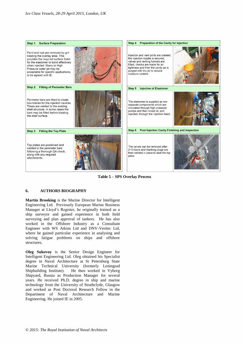
3. INSTALLATION OF SPS OVERLAY
STRENGTHENING
The methodology for installing SPS Overlay uses a
combination of conventional steel fabrication practice
and SPS technology.
The SPS Overlay application is carried out in accordance
with IE’s standard installation procedures under the
supervision of the attending DNV-GL surveyor. Table 5
outlines the key steps for a vertical SPS Overlay
installation.
The advantages of using SPS Overlay instead of a
conventional solution to strengthen the OSV’s hull are as
follows:
SPS will provide improved lifetime performance,
better resistance to abrasions and indentations from
impacts; and significant potential for reduced
maintenance, repair and downtime costs.
SPS improves the resistance against impact loads
associated with operating in ice conditions;
SPS Overlay is simpler, quicker and less disruptive
to install.
4. CONCLUSIONS
Intelligent Engineering has undertaken detailed design
work to confirm that DNV ICE-1C Ice Strengthening can
be achieved using SPS Overlay and minimal framing
modifications.
The design was examined and verified for compliance
with the applicable Rules and approved by DNV-GL.
Its ability to absorb high impact loads makes SPS
Overlay ideal for this application. Use of SPS Overlay
eliminates conventional crop-and-replace. By minimising
the work required on the inboard side shell, SPS Overlay
offers the potential to significantly reduce the complexity
of the conversion work and reduce the overall conversion
schedule.
5. REFERENCES
1. Lloyd’s Register, ‘Provisional Rules for the
Application of Sandwich Panel Construction to
Ship Structure’, April 2006.
2. DNV-GL., ‘Steel Sandwich Panel
Construction’, Classification Notes No.30.11,
April 2012.
2. DNV, ‘Ships for Navigation in Ice’, Rules for
Classification of Ships Part 5 Chapter 1, July
2013.
Ice Class Vessels, 28-29 April 2015, London, UK
© 2015: The Royal Institution of Naval Architects
Table 5 – SPS Overlay Process
6. AUTHORS BIOGRAPHY
Martin Brooking is the Marine Director for Intelligent
Engineering Ltd. Previously European Marine Business
Manager at Lloyd’s Register, he originally trained as a
ship surveyor and gained experience in both field
surveying and plan approval of tankers. He has also
worked in the Offshore Industry as a Consultant
Engineer with WS Atkins Ltd and DNV-Veritec Ltd,
where he gained particular experience in analysing and
solving fatigue problems on ships and offshore
structures.
Oleg Sukovoy is the Senior Design Engineer for
Intelligent Engineering Ltd. Oleg obtained his Specialist
degree in Naval Architecture at St Petersburg State
Marine Technical University (formerly Leningrad
Shipbuilding Institute). He then worked in Vyborg
Shipyard, Russia as Production Manager for several
years. He received Ph.D. degree in ship and marine
technology from the University of Strathclyde, Glasgow
and worked as Post Doctoral Research Fellow in the
Department of Naval Architecture and Marine
Engineering. He joined IE in 2005.
Related Documents