2004 Connecticut Stormwater Quality Manual by The Connecticut Department of Environmental Protection 79 Elm Street • Hartford, Connecticut 06106 Printed on recycled paper, 30% post consumer content.

Welcome message from author
This document is posted to help you gain knowledge. Please leave a comment to let me know what you think about it! Share it to your friends and learn new things together.
Transcript

2004 Connecticut Stormwater Quality Manual
byThe Connecticut Department of Environmental Protection
79 Elm Street • Hartford, Connecticut 06106
Printed on recycled paper, 30% post consumer content.
The Honorable M. Jodi Rell, GovernorState of Connecticut
Arthur J. Rocque, Jr., CommissionerConnecticut Department of Environmental Protection
Book designed by Adell DonaghueAdell Donaghue Design
Edited by Jane A. Rothchild
Project Coordination by Cheryl A. Chase, P.E.Connecticut Department of Environmental Protection
Project Management by Erik Mas, P.E.Fuss & O’Neill, Inc.
Illustrations by Clay Crow and Tom Ouellette
Book Production: Adell Donaghue and Michele Holcomb
Book Production by the DEP Bureau of Water Management, Inland Water Resources Division
The Connecticut Stormwater Quality Manual is available on-line inAdobe Acrobat (pdf) format.
http://dep.state.ct.us
© 2004 by the Connecticut Department of Environmental Protection
Funded in part by the CT DEP through aUS EPA Clean Water Act section 319 grant
administered by the CT DEP.
The Department of Environmental Protection is an affirmative action/equal opportunity employer, providing programs and services ina fair and impartial manner. In conformance with the Americans with Disabilities Act, DEP makes every effort to provide equallyeffective services for persons with disabilities. Individuals with disabilities needing auxiliary aids or services should call (860) 424-3019or for more information by voice or TTY/TDD call (860) 424-3000.
Acknowledgements
Project Initiation
Sharon Yurasevecz, Connecticut Department of Environmental Protection
Steering Committee
Bob Bartholemew, A-N Consulting Engineers, Inc.Jeff Caiola, Connecticut Department of Environmental Protection
Paul Corrente, Connecticut Department of TransportationJohn Deering, John W. Deering, Inc.
John Gaucher, Connecticut Department of Environmental ProtectionLaurie Giannotti, Executive Director, Pomperaug River Watershed Coalition, Inc.
Mary-Beth Hart, Connecticut Department of Environmental ProtectionRob Hust, Connecticut Department of Environmental Protection
Bob Jontos, Land-Tech Consultants, Inc.Tyler Kleykamp, Connecticut Department of Public Health
Chris Malik, Connecticut Department of Environmental ProtectionLori Mathieu, Connecticut Department of Public Health
Joe Polulech, President, JEP Consulting CompanySally Snyder, Connecticut Department of Environmental Protection Chris Stone, Connecticut Department of Environmental Protection
Tom Torgersen, University of Connecticut
Provided comments, support and assistance
Peter Aarrestad, Connecticut Department of Environmental ProtectionLarry Bradley, Town of Greenwich
Bob Brinton, Town Engineer, Town of BloomfieldMarla Butts, Connecticut Department of Environmental Protection
Tim Coon, J.R. Russo and AssociatesJohn Clausen, University of Connecticut
Mel Cote, US Environmental Protection AgencyNaomi Davidson, Connecticut Department of Environmental Protection
Virginia deLima, US Geological SurveyMatt Fritz, Connecticut Department of Environmental Protection
Terrance Gallagher, BL CompaniesKillingly Department of Planning and Development
Dr. Michael KlemensLisa Krall, Natural Resource Conservation Commission
Ann Kuzyk, Connecticut Department of Environmental ProtectionMike Masayda, Connecticut Department of Transportation
Eric Ott, Connecticut Department of Environmental ProtectionElsie Patton, Connecticut Department of Environmental Protection
John Pindot, Norwalk River Harbor CommissionDenise Ruzicka, Connecticut Department of Environmental Protection
Carl Salsedo, University of ConnecticutJo-Ann Smith, Connecticut Department of Environmental Protection
Steve Winnett, US Environmental Protection AgencyRoger Wolfe, Connecticut Department of Environmental Protection
Jennifer Zmiejewski, Connecticut Department of Environmental Protection
Project Team at Fuss & O’Neill, Inc.
Dean Audet, P.E.Michael Gagnon, P.E.
Diane Mas, M.S.E.Phil Moreschi, P.E.Charlie Murphy
2004 The Connecticut Stormwater Quality Manual i
Chapter 1 Introduction
Chapter 2 Why Stormwater Matters:The Impacts of Urbanization
Table of Contents
1.1 Purpose of the Manual ...............................................................................1-2
1.2 Users of the Manual.....................................................................................1-2
1.3 Organization of the Manual........................................................................1-2
1.4 Regulatory Basis and Use of the Manual.................................................1-4
1.5 Relationship of the Manual to Federal, State, andLocal Programs .............................................................................................1-4
1.5.1 Federal Programs ......................................................................1-4
1.5.2 State Programs...........................................................................1-5
1.5.3 Local Programs........................................................................1-10
2.1 What is Urban Stormwater Runoff?.........................................................2-2
2.2 Hydrologic Impacts.......................................................................................2-6
2.3 Stream Channel and Floodplain Impacts.................................................2-6
2.4 Water Quality Impacts.................................................................................2-6
2.5 Habitat and Ecological Impacts.................................................................2-11
2.6 Impacts on Other Receiving Environments ..........................................2-11
Volume 1: Background
3.1 Introduction ...................................................................................................3-2
3.2 Guiding Stormwater Management Principles.........................................3-2
3.3 Site Planning and Design .............................................................................3-3
3.4 Source Control Practices and Pollution Prevention.............................3-4
3.5 Construction Erosion and Sedimentation Control ..............................3-4
3.6 Stormwater Treatment Practices ..............................................................3-4
3.7 Stormwater Quantity Control ..................................................................3-6
3.8 Watershed Management..............................................................................3-7
4.1 Introduction ...................................................................................................4-2
4.2 Site Planning and Design Concepts ..........................................................4-2
4.3 Alternative Site Design ................................................................................4-4
4.3.1 Streets and Parking Lots .........................................................4-6
4.3.2 Lot Development.....................................................................4-11
4.4 Low Impact Development Management Practices .............................4-13
4.4.1 Vegetated Swales, Buffers, and Filter Strips .......................4-13
4.4.2 Bioretention/Rain Gardens...................................................4-13
4.4.3 Dry Wells/Leaching Trenches ...............................................4-15
4.4.4 Rainwater Harvesting ............................................................4-15
4.4.5 Vegetated Roof Covers..........................................................4-17
Chapter 3 Preventing and MitigatingStormwater Impacts
Chapter 4 Site Planning and Design
2004 The Connecticut Stormwater Quality Manuali i
5.1 Introduction ...................................................................................................5-2
5.2 Municipal Practices .......................................................................................5-2
5.2.1 Street and Parking Lot Sweeping ..........................................5-2
5.2.2 Roadway Deicing/Salt Storage................................................5-4
5.2.3 Storm Drainage System Maintenance ..................................5-7
5.2.4 Other Road, Highway, and Bridge Maintenance.................5-7
5.2.5 Illicit Discharge Detection and Elimination.........................5-8
5.3 Industrial and Commercial Practices .......................................................5-9
5.3.1 Stormwater Pollution Prevention Plans...............................5-9
5.4 Lawn Care and Landscaping Practices...................................................5-10
5.4.1 Xeriscaping and General Landscape Management..........5-10
5.4.2 Fertilizer and Pesticide Management..................................5-12
5.4.3 Animal Waste Management...................................................5-12
5.5 Model Stormwater Ordinances ..............................................................5-14
5.6 Public Education and Outreach...............................................................5-14
6.1 Introduction ...................................................................................................6-2
6.2 Primary Stormwater Treatment Practices ..............................................6-2
6.3 Secondary Stormwater Treatment Practices..........................................6-3
6.3.1 Conventional Practices ............................................................6-4
6.3.2 Innovative/Emerging Technologies .........................................6-4
6.4 Stormwater Treatment Train ......................................................................6-8
6.5 Maintenance ...................................................................................................6-8
2004 The Connecticut Stormwater Quality Manual i i i
Chapter 5 Source Control Practices andPollution Prevention
Chapter 6 Introduction to StormwaterTreatment Practices
Volume 1I: Design
2004 The Connecticut Stormwater Quality Manuali v
7.1 Introduction .................................................................................................7-2
7.2 Criteria Applicability....................................................................................7-2
7.3 Criteria Summary .........................................................................................7-4
7.4 Pollutant Reduction.....................................................................................7-4
7.4.1 Water Quality Volume (WQV)..............................................7-4
7.4.2 Water Quality Flow (WQF)...................................................7-5
7.5 Groundwater Recharge and RunoffVolume Reduction .......................................................................................7-5
7.5.1 Groundwater Recharge Volume (GRV) ...............................7-6
7.5.2 Runoff Capture Volume (RCV) ..............................................7-7
7.6 Peak Flow Control .......................................................................................7-8
7.6.1 Stream Channel Protection....................................................7-8
7.6.2 Conveyance Protection ...........................................................7-9
7.6.3 Peak Runoff Attenuation .........................................................7-9
7.6.4 Emergency Outlet Sizing.......................................................7-10
7.6.5 Downstream Analysis.............................................................7-10
7.7 Sizing Example .............................................................................................7-10
Chapter 7 Hydrologic Sizing Criteria for Stormwater Treatment Practices
8.1 Stormwater Management Effectiveness .................................................8-2
8.2 Land Use Factors .........................................................................................8-3
8.3 Physical/Site Feasibility Factors .................................................................8-5
8.4 Downstream Resources .............................................................................8-6
8.5 Maintenance Factors .................................................................................8-10
8.6 Winter Operation......................................................................................8-10
8.7 Nuisance Insects and Vectors ..................................................................8-11
8.8 Natural Wetlands and Vernal Pools ........................................................8-13
Chapter 8 Selection Criteria for Stormwater Treatment Practices
2004 The Connecticut Stormwater Quality Manual v
9.1 Plan Development ......................................................................................9-2
9.2 Plan Content .................................................................................................9-2
9.2.1 Applicant/Site Information.......................................................9-3
9.2.2 Project Narrative ......................................................................9-3
9.2.3 Calcualtions ................................................................................9-4
9.2.4 Design Drawings and Specifications .....................................9-6
9.2.5 Construction Erosion and Sedimentation Controls.........9-7
9.2.6 Supporting Documents and Studies .....................................9-7
9.2.7 Other Required Permits..........................................................9-7
9.2.8 Operation and Maintenance...................................................9-7
Chapter 9 Developing a Site Stormwater Management Plan
10.1 Introduction .................................................................................................10-2
10.2 Objectives and Benefits of Stormwater Retrofits..............................10-2
10.3 When is Retrofitting Appropriate? .........................................................10-2
10.4 Stormwater Retrofit Options..................................................................10-2
10.4.1 Stormwater Drainage Systems...........................................10-3
10.4.2 Stormwater Management Facilities ...................................10-4
10.4.3 Storm Drain Outfalls.............................................................10-6
10.4.4 Highway Rights-of-Way.........................................................10-6
10.4.5 Parking Lots .............................................................................10-9
10.4.6 In-stream practices in Drainage Channels.......................10-9
10.4.7 Wetland Creation and Restoration ...................................10-9
Chapter 10 Stormwater Retrofits
2004 The Connecticut Stormwater Quality Manualv i
Chapter 11 Stormwater Treatment Practice Design Guidance
Primary Treatment Practices.............................................................................11-2
Secondary Treatment Practices........................................................................11-3
Primary (P) Treatment Practices
11-P1 Stormwater Ponds................................................................11-P1-1
11-P2 Stormwater Wetlands ..........................................................11-P2-1
11-P3 Infiltration Practices .............................................................11-P3-1
11-P4 Filtering Practices..................................................................11-P4-1
11-P5 Water Quality Swales..........................................................11-P5-1
Secondary (S) Treatment Practices
Conventional Practices
11-S1 Dry Detention Pond ............................................................11-S1-1
11-S2 Underground Detention Facilities ...................................11-S2-1
11-S3 Deep Sump Catch Basins ...................................................11-S3-1
11-S4 Oil/Particle Separators .......................................................11-S4-1
11-S5 Dry Wells ...............................................................................11-S5-1
11-S6 Permeable Pavement ............................................................11-S6-1
11-S7 Vegetated Filter Strips/Level Spreaders ...........................11-S7-1
11-S8 Grass Drainage Channels ..................................................11-S8-1
Innovative/Emerging Technologies
11-S9 Catch Basin Inserts...............................................................11-S9-1
11-S10 Hydrodynamic Separators.................................................11-S10-1
11-S11 Media Filters .........................................................................11-S11-1
11-S12 Underground Infiltration Systems ...................................11-S12-1
11-S13 Alum Injection......................................................................11-S13-1

2004 The Connecticut Stormwater Quality Manual v i i
Appendix A: Plant List ........................................................................................A-1
Appendix B: Water Quality Flow and Flow Diversion Guidance ...........B-1
Appendix C: Model Ordinances......................................................................C-1
Appendix D: Site Stormwater Management Plan Checklist .....................D-1
Appendix E: Maintenance Inspection Checklist ............................................E-1
Appendix F: Glossary ..........................................................................................F-1
Appendices
Chapter 1Introduction to the Stormwater Quality Manual
Chapter 1 Introduction
1.1 Purpose of the Manual ..............................................................................1-2
1.2 Users of the Manual....................................................................................1-2
1.3 Organization of the Manual ......................................................................1-2
1.4 Regulatory Basis and Use of the Manual ...............................................1-4
1.5 Relationship of the Manual to Federal, State,and Local Programs.....................................................................................1-4
1.5.1 Federal Programs......................................................................1-4
1.5.2 State Programs ..........................................................................1-5
1.5.3 Local Programs ........................................................................1-10
Volume 1: Background
2004 Connecticut Stormwater Quality Manual 1-1
2004 Connecticut Stormwater Quality Manual1-2
1.1 Purpose of the Manual
The purpose of this Manual
is to provide guidance on
the measures necessary to
protect the waters of the
State of Connecticut from
the adverse impacts of post-
construction stormwater
runoff. The guidance provided
in this Manual is applicable
to new development,
redevelopment, and upgrades
to existing development.
The Manual focuses on site
planning, source control and
pollution prevention, and
stormwater treatment
practices. Related topics
such as erosion and sediment
control, stormwater drainage
design and flood control, and
watershed management are
addressed in the Manual as
secondary considerations.
The Manual does not address
agricultural runoff. Additional
information on these topics
can be found in other related
guidance documents listed
at the end of this chapter.
1.2 Users of the ManualThe Connecticut Department of Environmental Protection intends thisManual for use as a planning tool and design guidance document by theregulated and regulatory communities involved in stormwater qualitymanagement in the State of Connecticut. The Manual provides uniformguidance for developers and engineers on the selection, design, andproper application of stormwater Best Management Practices (BMPs).The Manual will also assist local and state government officials (i.e., townengineers, planners, Planning and Zoning Commissions, ConservationCommissions, Inland Wetlands Commissions, and Connecticut Stateagencies) design and review projects in a technically sound andconsistent manner.
The information and recommendations in this Manual are provided forguidance and are intended to augment, rather than replace, professionaljudgement. The design practices described in this Manual should be imple-mented by individuals with a demonstrated level of professionalcompetence, such as professional engineers licensed to practice in theState of Connecticut. Design engineers, as well as those responsible foroperation and maintenance, are ultimately responsible for the long-termperformance and success of these practices. However, the use of thisManual is not restricted to engineers or technical professionals. It is alsointended to be used by other individuals involved in stormwater andland use management for reviewing and recommending practices con-tained in the Manual.
1.3 Organization of the ManualThe Manual is organized into two volumes, both contained in a single,comprehensive document. The organization of the Manual generally follows the recommended stormwater management planning process,which emphasizes preventive measures such as site planning and alterna-tive site design, source controls, and pollution prevention over end-of-pipestructural controls.
Volume I provides an overview of the stormwater problem, approachesfor preventing and mitigating stormwater impacts, and a description of site planning and source control practices for pollution prevention. Thesubsequent chapters in Volume I include:
Chapter Two – Why Stormwater Matters: The Impacts ofUrbanizationThis chapter introduces the concept of urban stormwater runoff and its impact on watershed hydrology, water quality, and ecology. ChapterTwo summarizes why stormwater management measures are necessary toprotect receiving waters from the adverse impacts of uncontrolledstormwater runoff.
Chapter Three – Approaches for Preventing and MitigatingStormwater ImpactsChapter Three presents an overview of approaches for preventing and mitigating stormwater impacts through site planning and pollution preven-tion, stormwater quantity controls, construction erosion and sedimentationcontrols, and post-construction stormwater quality management.
2004 Connecticut Stormwater Quality Manual 1-3
Chapter Four – Site Planning and DesignChapter Four addresses site planning concepts suchas alternative site design and Low ImpactDevelopment. These techniques can be incorporatedinto the design of new projects to reduce or discon-nect impervious surfaces and retain and infiltratestormwater on-site, thereby eliminating or reducingthe need for structural stormwater quality controls.
Chapter Five – Source Control Practices andPollution PreventionChapter Five describes source control and pollutionprevention practices to limit the generation ofstormwater pollutants at their source. This chapterfocuses on common municipal, residential, commer-cial, and industrial practices applicable to new andexisting development, such as street and parking lotsweeping, roadway deicing and salt storage, stormdrainage system maintenance, illicit discharge detec-tion and elimination, commercial and industrialpollution prevention, and lawn care and landscap-ing practices.
Volume II provides technical guidance on theselection, design, construction, and maintenanceof structural stormwater treatment practices.Volume II also addresses procedures for develop-ing a site stormwater management plan, anddesign issues associated with stormwater retrofitsfor existing development. Volume II includes thefollowing chapters:
Chapter Six – Introduction to StormwaterTreatment PracticesChapter Six introduces structural stormwater treat-ment practices that can be used alone as primarytreatment, as pretreatment or supplemental treatmentpractices, or in combination (i.e., treatment trainapproach). This chapter also describes general cate-gories of recently developed, emerging, and potentialfuture stormwater treatment devices and technologies,as well as criteria for evaluating the performance andapplicability of new treatment practices.
Chapter Seven – Hydrologic Sizing Criteria forStormwater Treatment PracticesChapter Seven explains the procedures and applica-bility of sizing criteria for structural stormwatertreatment practices to meet pollutant reduction,groundwater recharge and runoff volume reduction,and peak flow control requirements. This chapter alsoincludes guidance on the design of stormwater bypassstructures and sizing examples for various types ofstormwater treatment practices.
Chapter Eight – Selection Criteria forStormwater Treatment PracticesChapter Eight provides guidance on selecting appro-priate structural stormwater treatment practices for adevelopment site based on the requirements andneeds of the site. This chapter includes a recom-mended selection process and selection criteria.
Chapter Nine – Developing a Site StormwaterManagement PlanChapter Nine describes how to prepare a sitestormwater management plan for review by local and state regulatory agencies. The chapter includes a rec-ommended plan format and contents, and acompleteness checklist for use by the plan preparerand reviewer.
Chapter Ten – Stormwater RetrofitsChapter Ten describes techniques for retrofitting exist-ing developed sites to improve or enhance the waterquality mitigation functions of the sites. Chapter Tenalso discusses the conditions for which stormwaterretrofits are appropriate and the potential benefits ofstormwater retrofits.
Chapter Eleven – Design Guidance forStormwater Treatment PracticesChapter Eleven provides detailed technical designguidance for each of the stormwater treatment prac-tices introduced in Chapter Six. This chapter includesguidance on the design, construction, and mainte-nance of these practices, as well as summaryinformation on selection and sizing criteria addressedin previous chapters.
AppendicesAppendices containing supplemental information onthe design, construction, and maintenance of struc-tural stormwater management practices are includedat the end of Volume II. A glossary of terms used inthe Manual is also provided in Appendix F.
While providing detailed guidance on a number ofrecommended stormwater management practices andrelated topics, this Manual is not an exhaustive refer-ence on each topic and does not address all aspects ofstormwater management. Additional technical guid-ance can be found in numerous other documents,many of which are referenced in this Manual.References and recommended additional sources ofinformation are listed at the end of each chapter.
2004 Connecticut Stormwater Quality Manual1- 4
1.4 Regulatory Basis and Use of theManual
This Manual is intended for use as a guidance docu-ment to assist developers and the regulatedcommunity in complying with existing local, state,and federal laws and regulations. The Manual itselfhas no independent regulatory authority. Rather, itestablishes guidelines that are implemented through aframework of existing laws and regulations. Althoughthis Manual is non-regulatory in scope, it provides thetechnical basis for a comprehensive, statewidestormwater quality management strategy, includingthe consistent application of stormwater managementpractices throughout the state.
1.5 Relationship of the Manual to Federal, State, and LocalPrograms
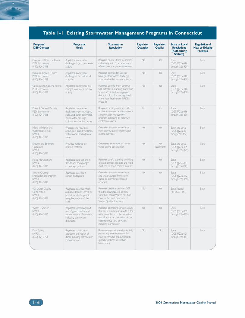
The Connecticut Department of EnvironmentalProtection (DEP) historically has been a nationalleader in developing and implementing water qualityprotection programs and policies. A number of fed-eral and state regulatory programs are currently inplace for stormwater quality management and waterresource protection in the state. Consistent with along-established tradition of home-rule-style govern-ment exerted by municipal authorities, many of theseprograms are implemented at the local level throughlocal zoning, subdivision, and inland wetlands andwatercourses regulations and ordinances. In addition,the State of Connecticut has been delegated authorityfrom the federal government to implement federalregulations that pertain to water resources protection.Table 1-1 summarizes existing regulatory programsthat address management of stormwater discharges inConnecticut. Descriptions of these programs and theirrelationship to this Manual are found in Section 1.5.2.
1.5.1 Federal ProgramsClean Water ActThe Federal Water Pollution Control Act of 1948, thefirst major federal legislation governing pollution ofthe nation’s surface waters (33 U.S.C. 1251-1387),was significantly amended in 1972 (P.L. 92-500) andthen again in 1977 when it became commonlyknown as the Clean Water Act (CWA) of 1977 (P.L.95-217). The CWA was subsequently amendedunder the Water Quality Act of 1987 (P.L. 100-4).There are four primary sections of the CWA thatrelate to stormwater discharges:
❍ Section 303 – Water Quality Standards andImplementation Plans
❍ Section 319 – Nonpoint Source Management Program
❍ Section 401 – Water Quality Certification
❍ Section 402 – National Pollutant DischargeElimination System (NPDES)
Under Section 303 of the CWA, states arerequired to adopt surface water quality standards,subject to review and approval by the U.S. EPA, andidentify surface waters that do not meet these waterquality standards following the installation of mini-mum required pollution control technology for pointsources discharging to surface water bodies. Theseimpaired water bodies must be ranked by the statesand a Total Maximum Daily Load (TMDL) must beestablished for the pollutant(s) that exceed the waterquality standards. A TMDL both specifies a maxi-mum amount of pollutant that the surface waterbody can receive and allocates that amount, or load,among point and nonpoint sources, includingstormwater discharges.
The Nonpoint Source Management Program wasestablished under Section 319 of the CWA of 1987.Section 319 addresses the need for federal guidanceand assistance to state and local programs for con-trolling nonpoint sources of pollution, includingstormwater runoff. Under Section 319, states, territo-ries and Indian Tribes receive federal grant money tosupport various activities that address nonpointsource pollution control. These activities include tech-nical and direct financial assistance, education,training, technology transfer, demonstration projects,and monitoring to assess the effectiveness of specificnonpoint source implementation projects.
Section 401 of the CWA requires applicants for afederal license or permit to obtain a certification orwaiver from the state water pollution control agency(DEP, or EPA for Indian reservation lands) for anyactivity which may result in a discharge into naviga-ble waters of the state, including wetlands,watercourses, and natural and man-made ponds.This waiver certifies that the discharge will complywith the applicable provisions of the CWA andConnecticut’s Water Quality Standards. Examples offederal licenses and permits for which water qualitycertification is required include U.S. Army Corps ofEngineers Section 404 dredge and fill permits, CoastGuard bridge permits, and Federal EnergyRegulatory Commission permits for hydropower andgas transmission facilities.
The NPDES program was established underSection 402 of the CWA and specifically targets pointsource discharges by industries, municipalities, andother facilities that discharge directly into surfacewaters. Stormwater discharges are addressed underthe NPDES Stormwater Program. This two-phasednational program targets non-agricultural sources ofstormwater discharges that may adversely affect sur-
2004 Connecticut Stormwater Quality Manual 1-5
face water quality. The NPDES permitting programis administered in Connecticut by DEP through aseries of permits as outlined in Table 1-1. Phase Iof the NPDES Stormwater Program was developedunder the 1987 amendments to the CWA and regu-lates stormwater discharges from:
❍ “Medium” and “large” municipal separate stormsewer systems (MS4s) located in incorporatedplaces or counties with populations of 100,000or more; and
❍ Eleven categories of industrial activity, one ofwhich is construction activity that disturbs fiveor more acres of land.
Phase II of the program expands the scope of theregulated discharges to include:
❍ Certain regulated “small” MS4s; and
❍ Construction activity disturbing between oneand five acres of land (i.e., small constructionactivities).
The Phase II Final Rule was published inDecember 1999. DEP issued a General Permit in 2004 to address small municipalities. At the timeof writing, DEP was in the process of developing aGeneral Permit for the Connecticut Department ofTransportation and other state and federal facilitieswith significant drainage systems and stormwaterdischarges. Stormwater discharges associated withconstruction activities between one and five acresare regulated by DEP through a coordinated effortwith municipalities under the Connecticut Erosionand Sedimentation Control Act.
Coastal Zone Act Reauthorization AmendmentsSection 6217 of the Coastal Zone ActReauthorization Amendments (CZARA) of 1990 (16U.S.C. §1455b) is designed to address the problemof nonpoint source pollution in coastal waters.Under Section 6217, states and territories withapproved Coastal Zone Management Programs,including Connecticut, are required to developCoastal Nonpoint Source Pollution ControlPrograms or face funding sanctions in both theircoastal programs and their nonpoint programsestablished under Section 319 of the Clean WaterAct. The program must describe how the state orterritory will implement management measures toreduce or eliminate nonpoint source pollution,including stormwater runoff, to coastal waters.These management measures must conform tothose described in the U.S. EPA publicationGuidance Specifying Management Measures forSources of Nonpoint Pollution in Coastal Waters.
1.5.2 State ProgramsConnecticut Clean Water ActThe Connecticut Clean Water Act (CCWA) of 1967(P.A. 67-57) launched Connecticut’s modern waterpollution control program. Under the CCWA, asamended, DEP has the regulatory authority to:
❍ Abate, prevent or minimize all sources of waterpollution, including nonpoint sources
❍ Develop state water quality standards
❍ Permit discharges, including stormwater discharges, to waters of the state
❍ Establish enforcement tools for pollution abatement and prevention
This statute (Chapter 446k of the ConnecticutGeneral Statutes (CGS)) forms the authority for theDEP Bureau of Water Management’s Permitting andEnforcement Division (PED) to regulate dischargesto surface waters, ground waters, and PubliclyOwned Treatment Works (POTWs). Discharges tosurface waters are regulated by DEP under both theCCWA and the federal NPDES Program, becauseConnecticut has been delegated authority to imple-ment the federal NPDES Program. Consequently,stormwater discharges are regulated under a seriesof general permits based on the type of activitygenerating the discharge. The general permit pro-gram is authorized under CGS §22a-430b and is designed to authorize similar minor stormwater discharges by one or more applicants. The regulatedsources are divided into four major categories:
Commercial Activities: This general permit appliesto discharges from any conveyance which is used forcollecting and conveying stormwater and which isdirectly related to retail, commercial, and/or officeservices whose facilities occupy 5 acres or more ofcontiguous impervious surface and which aredescribed in the SIC Codes 50’s and 70’s.
Industrial Activities: This general permit applies todischarges from any conveyance which is used for col-lecting and conveying stormwater and which is directlyrelated to manufacturing, processing or material storageareas at designated categories of industrial facilities.
Construction Activities: This general permitapplies to discharges of stormwater and dewateringwastewaters from construction activities whichinclude, but are not limited to, clearing, grading, andexcavating and which result in the disturbance of 5or more acres of total land area on a site. Asdescribed above, under Phase II of the NPDESStormwater Program, construction activities disturb-
2004 Connecticut Stormwater Quality Manual1- 6
Program/ Programs Stormwater Regulates Regulates State or Local Regulation ofDEP Contact Goals Regulation Quantity Quality Regulations New or Existing
(Authorizing Facilities1
Statute)
Commercial General Permit PED Stormwater (860) 424-3018
Industrial General PermitPED Stormwater (860) 424-3018
Construction General PermitPED Stormwater (860) 424-3018
Phase II General PermitsPED Stormwater (860) 424-3018
Inland Wetlands andWatercourses Act IWRD (860) 424-3019
Erosion and SedimentGuidelinesIWRD (860) 424-3019
Flood ManagementIWRD (860) 424-3019
Stream ChannelEncroachment program IWRD (860) 424-3019
401 Water QualityCertificationIWRD(860) 424-3019
Water DiversionIWRD(860) 424-3019
Dam SafetyIWRD(860) 424-3706
Regulates stormwater discharges from commercialactivity
Regulates stormwater discharges from industrialactivities
Regulates stormwater dis-charges from constructionactivity
Regulates stormwater discharges from municipal,state, and other designatedstormwater drainage systems in urbanized areas
Protects and regulates activities in inland wetlands,watercourse, and adjacentareas
Provides guidance on erosion controls
Regulates state actions infloodplains and changes in drainage patterns
Regulates activities in certain floodplains
Regulates activities whichrequire a federal license orpermit for discharge intonavigable waters of thestate
Regulates withdrawal anduse of groundwater andsurface waters of the state,including stormwater diversions
Regulates construction,alteration, and repair ofdams, including stormwaterimpoundments
Requires permits from a commer-cial activity with 5 or more acresof contiguous impervious surfaces
Requires permits for facilities having a stormwater dischargeassociated with industrial activity
Requires permits from construc-tion activities disturbing more than5 total acres land area (projectsdisturbing 1 to 5 acres regulated at the local level under NPDESPhase II)
Requires municipalities and otherentities to develop and implementa stormwater management program consisting of minimumcontrol measures
Considers impacts to wetlandsfrom stormwater or stormwater-related activities
Guidelines for control of storm-water during construction
Requires careful planning and sitingof development projects and mod-ifications to flood control facilities
Considers impacts to wetlands and watercourses from stormwater or stormwater-related activities
Requires certification from DEPthat the discharge will comply with the Federal Water PollutionControl Act and ConnecticutWater Quality Standards
Requires permitting for any activitythat causes, allows, or results in thewithdrawal from or the alteration,modification, or diminution of theinstantaneous flow of water,including stormwater
Requires registration and potentiallypermit approval/inspection for new stormwater impoundments(ponds, wetlands, infiltration basins, etc.)
State(CGS §§22a-416through 22a-438)
State(CGS §§22a-416through 22a-438)
State(CGS §§22a-416through 22a-438)
State(CGS §§22a-416through 22a-438)
State and Local(CGS §§22a-36though 22a-45a)
State and Local(CGS §§22a-325through 22a-329)
State (CGS §§25-68bthrough 25-68h)
State(CGS §§22a-342through 22a-349a)
State/Federal(33 USC 1341)
State(CGS §§22a-365through 22a-379a)
State(CGS §§22a-401through 22a-411)
No
No
No
Yes
Yes
Yes
Yes
Yes
No
Yes
No
Yes
Yes
Yes
Yes
Yes
Yes (sediment)
Yes
Yes
Yes
Yes
No
Both
Both
Both
Both
Both
New
Both
Both
Both
Both
Both
Table 1-1 Existing Stormwater Management Programs in Connecticut
2004 Connecticut Stormwater Quality Manual 1-7
Program/ Programs Stormwater Regulates Regulates State or Local Regulation ofDEP Contact Goals Regulation Quantity Quality Regulations New or Existing
(Authorizing Facilities1
Statute)
Coastal Management ActOLISP (860) 424-3034
Tidal Wetlands ActOLISP (860) 424-3034
Structures Dredging and FillActOLISP (860) 424-3034
Nonpoint SourceManagement ProgramPSD(860) 424-3020
Aquifer Protection Program PSD(860) 424-3020
Source Water AssessmentProgramBWM/DPH(860) 424-3704
Underground InjectionControl ProgramBWM(860) 424-3018
Public Health Code –Sanitation of WatershedsDPH
Municipal Planning andZoning Authorities
Protects coastal resourcesand supports water-dependent uses
Requires permits for dredg-ing, draining, or filling withintidal wetlands
Requires permits for struc-tures, dredging, or fill intidal, coastal, or navigablewaters
Coordinates statewideefforts to prevent and man-age nonpoint sourcepollution
Addresses potential ground-water contaminationthrough various programsto ensure safe drinkingwater supplies
Assessment and protectionof public drinking watersupply sources
Prohibits the use of Class Vwells and limits the use ofUIC drywells in existing orpotential groundwaterdrinking supply areas
Protects public water supplysources
Reviews site developmentplans and protects environ-mental resources
Regulates development thatimpacts coastal water andresources
Discourages direct stormwater dis-charges
Discourages direct stormwater dis-charges
Relies on existing regulations inplace at federal, state, and locallevel
Management plans may includestormwater controls
Requires assessment of delineatedprotection areas of potentialsources of contamination. Reliesprimarily on existing regulations.
Requires safeguards for infiltrationof stormwater in areas with highpotential for spills and groundwa-ter drinking supply areas
Regulates stormwater dischargeswithin 100 feet of an establishedwatercourse within public watersupply watersheds or groundwateraquifer recharge areas
Considers impacts to receivingwaters
State and Local(CGS §§22a-90through 22a-112)
State(CGS §§22a-28through 22a-35)
State(CGS §§22a-359through 22a-363f)
State
State and Local(CGS §§22a-354athrough 22a-354b)
State and Federal
State and Federal
PHC 19-13-B32i
Local
Yes
Yes
Yes
No
No
No
No
Optional
Optional
Yes
Yes
Yes
No
Yes
No
Yes
Yes
Optional
Both
Both
Both
Both
Both
Both
Both
New
Both
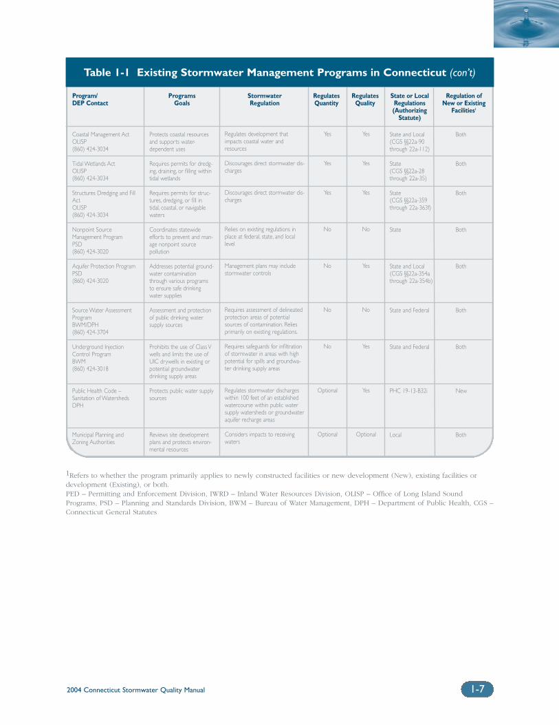
Table 1-1 Existing Stormwater Management Programs in Connecticut (con’t)
1Refers to whether the program primarily applies to newly constructed facilities or new development (New), existing facilities ordevelopment (Existing), or both. PED – Permitting and Enforcement Division, IWRD – Inland Water Resources Division, OLISP – Office of Long Island SoundPrograms, PSD – Planning and Standards Division, BWM – Bureau of Water Management, DPH – Department of Public Health, CGS –Connecticut General Statutes
2004 Connecticut Stormwater Quality Manual1-8
ing between one and five acres are also regulated byDEP through a coordinated effort with municipalitiesunder the Connecticut Erosion and SedimentationControl Act.
Municipal Separate Storm Sewer Systems (MS4s):This general permit regulates discharges of stormwa-ter from small MS4s and other similar facilities locatedin urbanized areas. Separate general permits addressstormwater discharges from small municipalities andother state and public facilities, as well as theConnecticut Department of Transportation.
Inland Wetlands and Watercourses ActThe Inland Wetlands and Watercourses Act of 1972,as amended, establishes authority for DEP andmunicipalities to adopt programs regulating con-struction and other activities affecting inlandwetlands and watercourses, including impacts due tostormwater or stormwater-related activities. TheWetlands Management Section of the DEP InlandWater Resources Division (IWRD) has responsibilityfor overseeing implementation of the Act anddirectly regulates the activities of Connecticut stateagencies that are located in, or may affect, inlandwetlands and watercourses. As discussed in moredetail below, local inland wetland agencies areresponsible for regulating private and municipalwork located in, or affecting, wetlands or water-courses within each Connecticut municipality.
Soil Erosion and Sediment Control ActThe Soil Erosion and Sediment Control Act (CGS§§22a- 325 to 22a-329, inclusive) requires that theCouncil on Soil and Water Conservation developguidelines for soil erosion and sediment control onland being developed. The latest version of theseguidelines was released in April of 2002. The goal ofthe guidelines is to reduce soil erosion from storm-water runoff, minimize nonpoint sediment pollutionfrom land being developed, and conserve and protectthe land, water, air and other environmental resourcesof the state.
Flood Management CertificationUnder CGS §§25-68b through 25-68h, inclusive, anystate agency proposing an activity within or affectinga floodplain or impacting natural or man-made stormdrainage facilities must submit a flood managementcertification application to DEP.
Stream Channel EncroachmentStream channel encroachment lines have been estab-lished for approximately 270 linear miles of riverinefloodplain throughout Connecticut. Under CGS §§22a-342 through 22a-349a, DEP IWRD regulates theplacement of encroachments and obstructions river-ward of these encroachment lines. Any activity that
permanently alters the character of the floodplain orwatercourse within these areas, including activitiesgenerating stormwater discharges, is subject toapproval by DEP.
401 Water Quality CertificationApplicants for a federal license or permit for activitiesthat may result in a discharge into navigable waters of the state, including stormwater discharges, mustsubmit a water quality certification application to DEP.
Water Diversion Policy ActThe Water Division Policy Act of 1982 (P.A. 82-402, asamended) grants the DEP IWRD limited authority toregulate the withdrawal and use of groundwater andsurface waters of the state, including stormwaterdiversions. Under CGS §§22a-365 through 22a-379a,permitting is required for any activity that causes,allows, or results in the withdrawal from, or the alteration, modification, or diminution of, the instan-taneous flow of water. Diversions must be consistentwith other state policies that deal with long-rangeplanning, management and use of the water resourcesof the state, including the State Plan for Conservationand Development, Water Quality Standards, FloodManagement Act, Water Supply Planning Process,Inland Wetlands and Watercourses Act, AquiferProtection Act, and Endangered Species Act.
Dam Safety ProgramThe Dam Safety Section of the DEP IWRD is respon-sible for administration and enforcement ofConnecticut’s dam safety laws under CGS §§22a-401through 22a-411, inclusive. The Dam Safety Sectionregulates the construction, alteration, repair, andremoval of dams, including stormwater impound-ments through the use of embankments such asstormwater retention/detention ponds, stormwaterwetlands, and infiltration basins. Registration with theDam Safety Section is required for all new storm-water impoundments. A dam construction permit mayalso be required if the structure may endanger life orproperty in the event of failure or breaking away.Structures that pose a significant or high hazard to lifeor property are also subject to periodic inspections by DEP.
Connecticut Coastal Management ActThe Connecticut Coastal Management Act (CGS §§22a-90 through 22a-112, inclusive) establishes goals andpolicies for the protection of coastal resources. UnderCGS §22a-98, the Commissioner of DEP must coordi-nate all regulatory programs under his jurisdictionwith permitting authorities in the coastal area, includ-ing those related to wetlands and watercourses,stream channel encroachment, and the erection of structures or placement of fill in tidal, coastal, ornavigable waters, to ensure that permits issued under
2004 Connecticut Stormwater Quality Manual 1-9
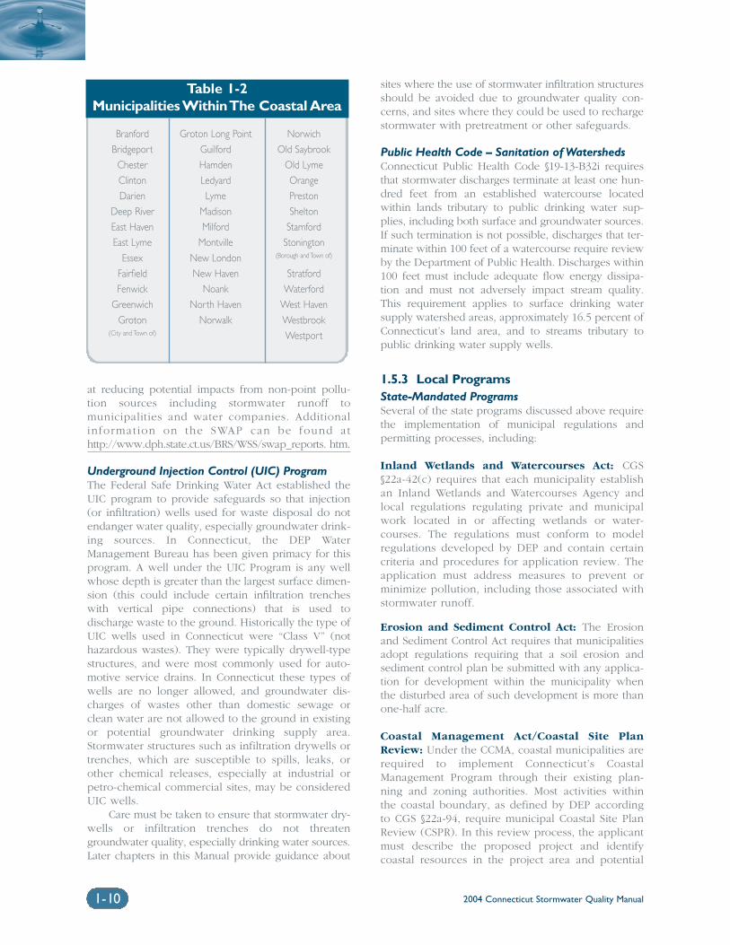
such regulatory authority are consistent with coastalmanagement goals and policies. The coastal area isdefined by statute (CGS §22a-94(a)) and encompassesthe municipalities listed in Table 1-2. In addition, pursuant to CGS §22a-100(b), each state department,institution, or agency responsible for the primary recommendation or initiation of actions within the coastal boundary which may significantly affect theenvironment must also ensure that such actions are consistent with coastal management goals andpolicies and incorporate all reasonable measures mitigating any adverse impacts on coastal resources.The coastal boundary is defined by statute (CGS §22a-94(b)). Adverse impacts on coastal resources are alsostatutorily defined (CGS §22a-93(15)) and includedegrading water quality through the significant intro-duction into either coastal waters or groundwatersupplies of suspended solids, nutrients, toxics, heavymetals, or pathogens, all of which can be containedin stormwater. In addition, degrading water qualitythrough the significant alteration of temperature, pH,dissolved oxygen, or salinity is also included in thestatutory definition of adverse impacts, and theseimpacts can also result from stormwater runoff.Coastal permitting and assistance to municipalities isadministered through the DEP Office of Long IslandSound Programs (OLISP).
Tidal Wetlands ActThe Tidal Wetlands Act of 1969 (CGS §§22a-28 through22a-35, inclusive) gives DEP authority to regulate activ-ities in tidal wetlands. The permitting programadministered by OLISP requires that the applicantaddress possible impacts to coastal resources, includingthose associated with stormwater runoff, and discour-ages direct stormwater discharges to tidal wetlands.
Structures, Dredging and Fill ActThe Structures, Dredging, and Fill Act (CGS §§22a-359through 22a-363f, inclusive) gives DEP the authority toregulate dredging, the erection of structures, and theplacement of fill in tidal, coastal or navigable waters ofthe state waterward of the high tide line. The permit-ting program administered by OLISP requires that theapplicant address possible impacts to coastal resources,including those associated with stormwater runoff, anddiscourages direct untreated stormwater discharges totidal, coastal, or navigable waters.
Nonpoint Source Management Programs (pursuant to CWA Section 319 and CZARASection 6217)The Connecticut Nonpoint Source Management (NPS)Program is administered by the DEP Bureau of WaterManagement (BWM) Planning and Standards Division(PSD) and is a network of several federal, state, andlocal programs. The NPS Program includes all of thecomponents required under Section 319 of the
Federal Clean Water Act. It establishes long- andshort-term goals for the prevention and managementof nonpoint sources of pollution, including thoseassociated with urban runoff and stormwater. EPAdefines NPS pollution as that which is “caused by diffuse sources that are not regulated as point sourcesand are normally associated with precipitation and runoff from the land or percolation.” EPAapproved Connecticut’s upgraded Nonpoint SourceManagement Program in November 1999 (seeNonpoint Source Management Program athttp://www.dep.state.ct.us/wtr/nps/npsmgtpl.pdf).
As described in the discussion of federal pro-grams above, Section 6217 of the 1990 CZARArequires the development of a Coastal NonpointPollution Control Program (CNPCP) to implementmanagement measures to reduce or eliminate non-point source pollution within the coastal boundary.The CNPCP is a networked program administered byOLISP with assistance from BWM and relies on otherregulatory programs described in this section includ-ing state and local permitting authorities.
Aquifer Protection Area ActThe Aquifer Protection Area Act of 1989 requires thedevelopment of aquifer protection land use regula-tions applicable within DEP-approved aquiferprotection areas (areas recharging large public watersupply wells). As part of the regulations, issued in2004, municipalities containing aquifer protectionareas are required to adopt regulations, subject toapproval by DEP, requiring permitting for all regu-lated activities within aquifer protection areas. Inaddition, regulated activities within an aquifer protec-tion area may require a stormwater management planto assure that stormwater runoff generated by the pro-posed activity is managed in a manner to preventpollution of ground water.
Source Water Assessment Program (SWAP)The Connecticut Source Water Assessment Program(SWAP) was initiated in 1997 in response to the 1996Amendments to the Federal Safe Drinking Water Act.The Connecticut Department of Public Health (DPH),in partnership with DEP, is responsible for the devel-opment of the SWAP, which is designed to assess andprotect public drinking water supply sources in thestate. The SWAP completes its work based upon anEPA-approved Work Plan dated September 1999. TheSWAP includes the delineation of a protection areasurrounding the drinking water source, the identifica-tion of potential pollution sources within and aroundthe protection area, and the determination of a watersupply’s susceptibility to contamination. The SWAPwill build on existing surface water and wellhead pro-tection programs administered by DPH and DEP. As part of the program, DEP and DPH will recom-mend a variety of source protection strategies aimed
2004 Connecticut Stormwater Quality Manual1-10
at reducing potential impacts from non-point pollu-tion sources including stormwater runoff tomunicipalities and water companies. Additionalinformation on the SWAP can be found athttp://www.dph.state.ct.us/BRS/WSS/swap_reports. htm.
Underground Injection Control (UIC) ProgramThe Federal Safe Drinking Water Act established theUIC program to provide safeguards so that injection(or infiltration) wells used for waste disposal do notendanger water quality, especially groundwater drink-ing sources. In Connecticut, the DEP WaterManagement Bureau has been given primacy for thisprogram. A well under the UIC Program is any wellwhose depth is greater than the largest surface dimen-sion (this could include certain infiltration trencheswith vertical pipe connections) that is used to discharge waste to the ground. Historically the type ofUIC wells used in Connecticut were “Class V” (nothazardous wastes). They were typically drywell-typestructures, and were most commonly used for auto-motive service drains. In Connecticut these types ofwells are no longer allowed, and groundwater dis-charges of wastes other than domestic sewage orclean water are not allowed to the ground in existingor potential groundwater drinking supply area.Stormwater structures such as infiltration drywells ortrenches, which are susceptible to spills, leaks, orother chemical releases, especially at industrial orpetro-chemical commercial sites, may be consideredUIC wells.
Care must be taken to ensure that stormwater dry-wells or infiltration trenches do not threatengroundwater quality, especially drinking water sources.Later chapters in this Manual provide guidance about
sites where the use of stormwater infiltration structuresshould be avoided due to groundwater quality con-cerns, and sites where they could be used to rechargestormwater with pretreatment or other safeguards.
Public Health Code – Sanitation of WatershedsConnecticut Public Health Code §19-13-B32i requiresthat stormwater discharges terminate at least one hun-dred feet from an established watercourse locatedwithin lands tributary to public drinking water sup-plies, including both surface and groundwater sources.If such termination is not possible, discharges that ter-minate within 100 feet of a watercourse require reviewby the Department of Public Health. Discharges within100 feet must include adequate flow energy dissipa-tion and must not adversely impact stream quality.This requirement applies to surface drinking watersupply watershed areas, approximately 16.5 percent ofConnecticut’s land area, and to streams tributary topublic drinking water supply wells.
1.5.3 Local ProgramsState-Mandated ProgramsSeveral of the state programs discussed above requirethe implementation of municipal regulations and permitting processes, including:
Inland Wetlands and Watercourses Act: CGS§22a-42(c) requires that each municipality establishan Inland Wetlands and Watercourses Agency andlocal regulations regulating private and municipalwork located in or affecting wetlands or water-courses. The regulations must conform to modelregulations developed by DEP and contain certaincriteria and procedures for application review. Theapplication must address measures to prevent orminimize pollution, including those associated withstormwater runoff.
Erosion and Sediment Control Act: The Erosionand Sediment Control Act requires that municipalitiesadopt regulations requiring that a soil erosion andsediment control plan be submitted with any applica-tion for development within the municipality whenthe disturbed area of such development is more thanone-half acre.
Coastal Management Act/Coastal Site PlanReview: Under the CCMA, coastal municipalities arerequired to implement Connecticut’s CoastalManagement Program through their existing plan-ning and zoning authorities. Most activities withinthe coastal boundary, as defined by DEP accordingto CGS §22a-94, require municipal Coastal Site PlanReview (CSPR). In this review process, the applicantmust describe the proposed project and identifycoastal resources in the project area and potential
Table 1-2Municipalities Within The Coastal Area
Branford Groton Long Point Norwich
Bridgeport Guilford Old Saybrook
Chester Hamden Old Lyme
Clinton Ledyard Orange
Darien Lyme Preston
Deep River Madison Shelton
East Haven Milford Stamford
East Lyme Montville Stonington
Essex New London (Borough and Town of)
Fairfield New Haven Stratford
Fenwick Noank Waterford
Greenwich North Haven West Haven
Groton Norwalk Westbrook(City and Town of) Westport
2004 Connecticut Stormwater Quality Manual 1-11
impacts to those resources. Local planning and zon-ing authorities must decide whether potential adverseimpacts to water quality or other coastal resources areacceptable. A description of stormwater managementmeasures may be required depending on the size ofa project and the municipality concerned. CGS §22a-101 allows coastal municipalities to developMunicipal Coastal Programs, which are revisions toplans of conservation and development and zoningregulations to focus on the coastal resources andcoastal management issues unique to each town.
Municipal Planning/Zoning: Public Act 91-170(codified in CGS §8-2(b) and CGS §8-35a) and PublicAct 91-395 (codified in CGS §8-23(a)) require that thezoning regulations and plans of conservation anddevelopment for any municipality contiguous to LongIsland Sound, and the regional plans of developmentof each region contiguous to Long Island Sound, bemade with reasonable consideration for the restora-tion and protection of the ecosystem and habitat ofLong Island Sound. These documents must also con-tain recommendations and practices to reducehypoxia, pathogens, toxic contaminants, and floatabledebris in Long Island Sound.
Aquifer Protection Act: Under the aquifer protectionland use regulations, issued in 2004, municipalitiescontaining aquifer protection areas are directed toadopt regulations requiring local permitting for allregulated activities within aquifer protection areas. Inaddition, regulated activities within an aquifer protec-tion area may require a stormwater management planto ensure that stormwater runoff generated by theproposed activity is managed in a manner to preventpollution of ground water.
Municipal Planning/Zoning Development projects and other activities subject toapproval by municipal planning and zoning authori-ties are typically subject to review for potentialimpacts to environmental resources. Depending uponthe local regulations, stormwater quantity and/orquality may be regulated. In addition, some munici-palities have developed or are consideringdeveloping local stormwater quality ordinances.
Additional Information Sources
Watershed Management
Center for Watershed Protection. 2000. The Practiceof Watershed Protection, Ellicott City, Maryland.
Davenport, T.E. 2002. The Watershed ProjectManagement Guide. Lewis Publishers/CRC Press.
U.S. Environmental Protection Agency, Office ofWater. 2001. Protecting and Restoring America’sWatersheds: Status, Trends, and Initiatives inWatershed Management. EPA-840-R-00-001.
Agricultural Runoff
Connecticut Department of Environmental Protectionand U.S. Department of Agriculture, NaturalResources Conservation Service. 1993. Guidelines for Protecting Connecticut’s Water Resources.
U.S. Environmental Protection Agency, Office ofWater. 1993. Guidance Specifying ManagementMeasures for Sources of Nonpoint Pollution inCoastal Waters.
U.S. Department of Agriculture, Natural ResourceConservation Service. National Handbook ofConservation Practices.
Drainage Design and Flood Control
Connecticut Department of Transportation (DOT).2000. Connecticut Department of TransportationDrainage Manual.
Natural Resource Conservation Service (formerly SoilConservation Service). 1986. Urban Hydrology forSmall Watersheds, TR-55.
Water Environment Federation (WEF) and AmericanSociety of Civil Engineers (ASCE). 1992. Design andConstruction of Urban Stormwater ManagementSystems (Urban Runoff Quality Management (WEFManual of Practice FD-20 and ASCE Manual andReport on Engineering Practice No. 77).
Erosion and Sediment Control
Connecticut Council on Soil and Water Conservationand the Connecticut Department of EnvironmentalProtection. 2002. 2002 Connecticut Guidelines forSoil Erosion and Sediment Control, DEP Bulletin 34.
Chapter 2Why Stormwater Matters:
The Impacts of Urbanization
Chapter 2 Why Stormwater Matters:The Impacts of Urbanization
2.1 What is Urban Stormwater Runoff? .....................................................2-2
2.2 Hydrologic Impacts .....................................................................................2-6
2.3 Stream Channel and Floodplain Impacts................................................2-6
2.4 Water Quality Impacts...............................................................................2-6
2.5 Habitat and Ecological Impacts...............................................................2-11
2.6 Impacts of Other Receiving Environments..........................................2-11
Volume 1: Background
2004 Connecticut Stormwater Quality Manual 2-1
2004 Connecticut Stormwater Quality Manual2-2
2.1 What is Urban Stormwater Runoff?
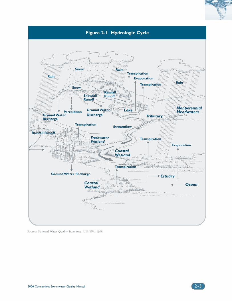
Stormwater runoff is a natural
part of the hydrological cycle,
which is the distribution and
movement of water between
the earth’s atmosphere, land,
and water bodies. Rainfall,
snowfall, and other frozen
precipitation send water to
the earth’s surfaces.
Stormwater runoff is surface
flow from precipitation that
accumulates in and flows
through natural or man-made
conveyance systems during
and immediately after a storm
event or upon snowmelt.
Stormwater runoff eventually
travels to surface water bod-
ies as diffuse overland flow, a
point discharge, or as ground-
water flow.Water that seeps
into the ground eventually
replenishes groundwater
aquifers and surface waters
such as lakes, streams, and the
oceans. Groundwater
recharge also helps maintain
water flow in streams and
wetland moisture levels dur-
ing dry weather.Water is
returned to the atmosphere
through evaporation and tran-
spiration to complete the
cycle. A schematic of the
hydrologic cycle is shown in
Figure 2-1.
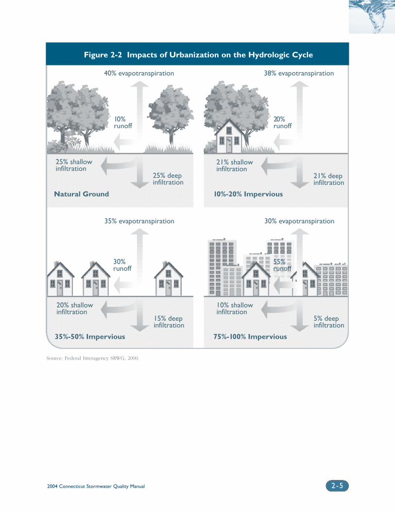
Traditional development of the landscape with impervious surfaces such asbuildings, roads, and parking lots, as well as storm sewer systems andother man-made features, alters the hydrology of a watershed and has thepotential to adversely affect water quality and aquatic habitat. As a resultof development, vegetated and forested land that consists of pervious sur-faces is largely replaced by land uses with impervious surfaces. Thistransformation increases the amount of stormwater runoff from a site,decreases infiltration and groundwater recharge, and alters naturaldrainage patterns. This effect is shown schematically in Figure 2-2.In addition, natural pollutant removal mechanisms provided by on-sitevegetation and soils have less opportunity to remove pollutants fromstormwater runoff in developed areas. During construction, soils areexposed to rainfall, which increases the potential for erosion and sedi-mentation. Development can also introduce new sources of pollutantsfrom everyday activities associated with residential, commercial, and indus-trial land uses. The development process is known as “urbanization.”Stormwater runoff from developed areas is commonly referred to as “urbanstormwater runoff.”
Urban stormwater runoff can be considered both a point source anda nonpoint source of pollution. Stormwater runoff that flows into a conveyance system and is discharged through a pipe, ditch, channel, orother structure is considered a point source discharge under EPA’s NationalPollutant Discharge Elimination System (NPDES) permit program, asadministered by DEP. Stormwater runoff that flows over the land surfaceand is not concentrated in a defined channel is considered nonpoint sourcepollution. In most cases stormwater runoff begins as a nonpoint sourceand becomes a point source discharge (MADEP, 1997). Both point andnonpoint sources of urban stormwater runoff have been shown to be significant causes of water quality impairment (EPA, 2000).
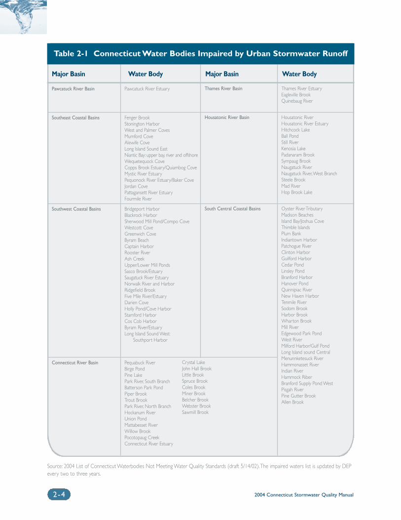
According to the draft 2004 Connecticut list of impaired waters(“303(d)”) list prepared pursuant to Section 303(d) of the Federal CleanWater Act), urban runoff and stormwater discharges were a significantcause of aquatic life and contact recreation (e.g. swimming and boating)impairment to approximately one-quarter of the state’s 893 miles of majorrivers and streams. Urban runoff is also reported as a contributor to exces-sive nutrient enrichment in numerous lakes and ponds throughout thestate, as well as a continued threat to estuarine waters and Long IslandSound (EPA, 2001). Table 2-1 summarizes impaired Connecticut water bodies (i.e., those not meeting water quality standards) for which urbanrunoff, stormwater discharges, or other wet-weather sources are suspectedcauses of impairment (DEP, 2004 draft). This list does not include waterbodies impaired as a result of other related causes such as combined seweroverflows (CSOs) and agricultural runoff or unknown sources.
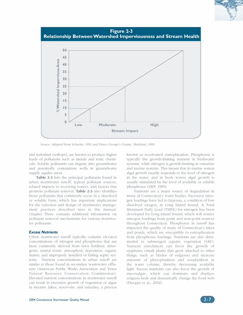
Impervious cover has emerged as a measurable, integrating conceptused to describe the overall health of a watershed. Numerous studies havedocumented the cumulative effects of urbanization on stream and water-shed ecology (See, e.g., Schueler et al., 1992; Schueler, 1994; Schueler,1995; Booth and Reinelt, 1993, Arnold and Gibbons, 1996; Brant, 1999;Shaver and Maxted, 1996). Research has shown that when imperviouscover in a watershed reaches between 10 and 25 percent, ecological stressbecomes clearly apparent. Beyond 25 percent, stream stability is reduced,habitat is lost, water quality becomes degraded, and biological diversitydecreases (NRDC, May 1999). Figure 2-3 illustrates this effect.
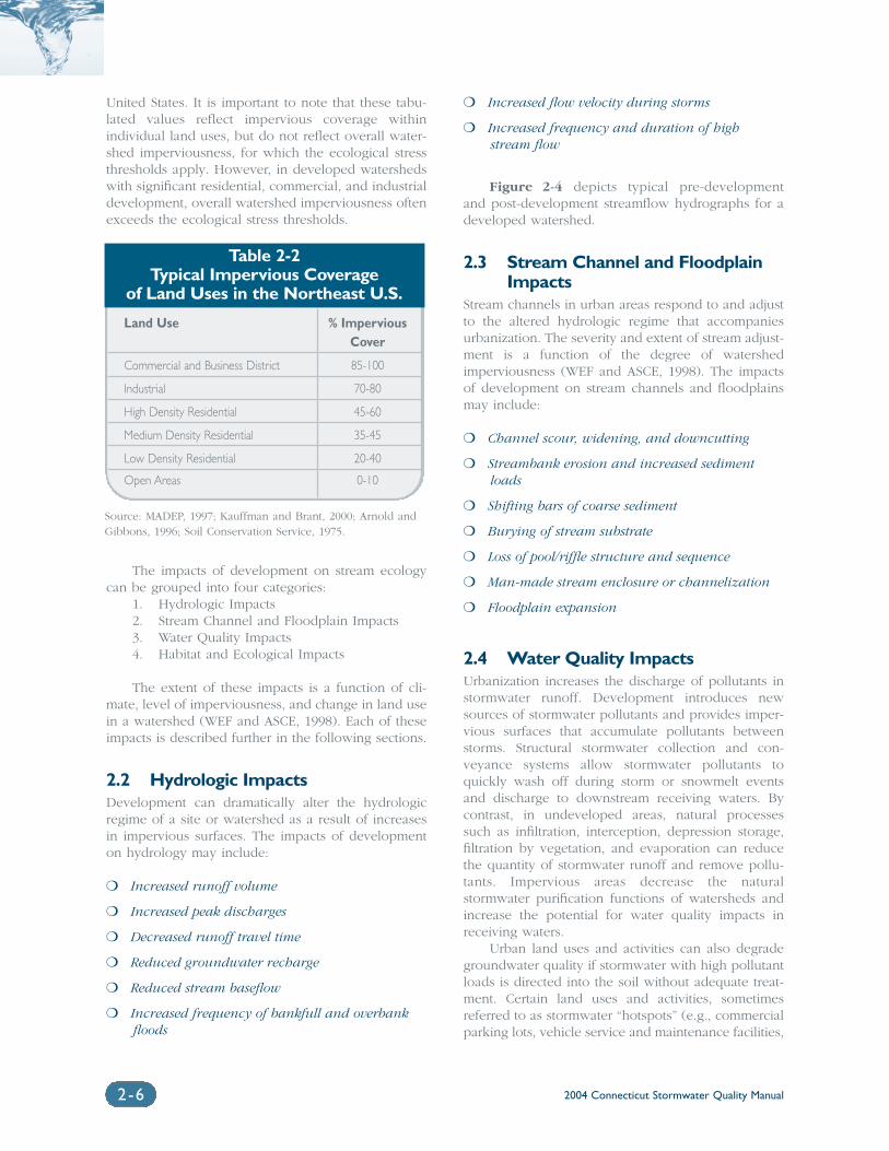
To put these thresholds into perspective, typical total imperviousnessin medium density, single-family home residential areas ranges from 25 tonearly 60 percent (Schueler, 1995). Table 2-2 indicates typical percentagesof impervious cover for various land uses in Connecticut and the Northeast
2004 Connecticut Stormwater Quality Manual 2-3
Figure 2-1 Hydrologic Cycle
Source: National Water Quality Inventory, U.S. EPA, 1998.
Snow
LakeTributary
Streamflow
Snow
Rain
Rain
Transpiration
Transpiration
Transpiration
Transpiration
Ocean
Estuary
Evaporation
Evaporation
CoastalWetland
CoastalWetland
Ground Water Recharge
Freshwater Wetland
Transpiration
NonperennialHeadwatersPercolation
Ground WaterRecharge
SnowfallRunoff
Ground WaterDischarge
RainfallRunoff
Rainfall Runoff
Rain
2004 Connecticut Stormwater Quality Manual2-4
Major Basin Water Body Major Basin Water Body
Pawcatuck River Basin
Southeast Coastal Basins
Southwest Coastal Basins
Connecticut River Basin
Pawcatuck River Estuary
Fenger BrookStonington HarborWest and Palmer CovesMumford CoveAlewife CoveLong Island Sound EastNiantic Bay: upper bay, river and offshoreWequetequock CoveCopps Brook Estuary/Quiambog CoveMystic River EstuaryPequonock River Estuary/Baker CoveJordan CovePattagansett River EstuaryFourmile River
Bridgeport HarborBlackrock HarborSherwood Mill Pond/Compo CoveWestcott CoveGreenwich CoveByram BeachCaptain HarborRooster RiverAsh CreekUpper/Lower Mill PondsSasco Brook/EstuarySaugatuck River EstuaryNorwalk River and HarborRidgefield BrookFive Mile River/EstuaryDarien CoveHolly Pond/Cove HarborStamford HarborCos Cob HarborByram River/EstuaryLong Island Sound West:
Southport Harbor
Pequabuck RiverBirge PondPine LakePark River, South BranchBatterson Park PondPiper BrookTrout BrookPark River, North BranchHockanum RiverUnion PondMattabesset RiverWillow BrookPocotopaug CreekConnecticut River Estuary
Thames River Basin
Housatonic River Basin
South Central Coastal Basins
Thames River EstuaryEagleville BrookQuinebaug River
Housatonic RiverHousatonic River EstuaryHitchcock LakeBall PondStill RiverKenosia LakePadanaram BrookSympaug BrookNaugatuck RiverNaugatuck River,West BranchSteele BrookMad RiverHop Brook Lake
Oyster River TributaryMadison BeachesIsland Bay/Joshua CoveThimble IslandsPlum BankIndiantown HarborPatchogue RiverClinton HarborGuilford HarborCedar PondLinsley PondBranford HarborHanover PondQuinnipiac RiverNew Haven HarborTenmile RiverSodom BrookHarbor BrookWharton BrookMill RiverEdgewood Park PondWest RiverMilford Harbor/Gulf PondLong Island sound CentralMenunnketesuck RiverHammonasset RiverIndian RiverHammock RiberBranford Supply Pond WestPisgah RiverPine Gutter BrookAllen Brook
Table 2-1 Connecticut Water Bodies Impaired by Urban Stormwater Runoff
Source: 2004 List of Connecticut Waterbodies Not Meeting Water Quality Standards (draft 5/14/02).The impaired waters list is updated by DEPevery two to three years.
Crystal LakeJohn Hall BrookLittle BrookSpruce BrookColes BrookMiner BrookBelcher BrookWebster BrookSawmill Brook
2004 Connecticut Stormwater Quality Manual 2-5
Source: Federal Interagency SRWG, 2000.
40% evapotranspiration 38% evapotranspiration
10%runoff
20%runoff
25% shallowinfiltration
25% deepinfiltration
21% shallowinfiltration
21% deepinfiltration
30% evapotranspiration
55%runoff
10% shallowinfiltration
5% deepinfiltration
35% evapotranspiration
30%runoff
20% shallowinfiltration
15% deepinfiltration
Natural Ground
75%-100% Impervious
10%-20% Impervious
35%-50% Impervious
Figure 2-2 Impacts of Urbanization on the Hydrologic Cycle
2004 Connecticut Stormwater Quality Manual2-6
United States. It is important to note that these tabu-lated values reflect impervious coverage withinindividual land uses, but do not reflect overall water-shed imperviousness, for which the ecological stressthresholds apply. However, in developed watershedswith significant residential, commercial, and industrialdevelopment, overall watershed imperviousness oftenexceeds the ecological stress thresholds.
The impacts of development on stream ecologycan be grouped into four categories:
1. Hydrologic Impacts2. Stream Channel and Floodplain Impacts3. Water Quality Impacts4. Habitat and Ecological Impacts
The extent of these impacts is a function of cli-mate, level of imperviousness, and change in land usein a watershed (WEF and ASCE, 1998). Each of theseimpacts is described further in the following sections.
2.2 Hydrologic ImpactsDevelopment can dramatically alter the hydrologicregime of a site or watershed as a result of increasesin impervious surfaces. The impacts of developmenton hydrology may include:
❍ Increased runoff volume
❍ Increased peak discharges
❍ Decreased runoff travel time
❍ Reduced groundwater recharge
❍ Reduced stream baseflow
❍ Increased frequency of bankfull and overbankfloods
❍ Increased flow velocity during storms
❍ Increased frequency and duration of highstream flow
Figure 2-4 depicts typical pre-development and post-development streamflow hydrographs for adeveloped watershed.
2.3 Stream Channel and FloodplainImpacts
Stream channels in urban areas respond to and adjustto the altered hydrologic regime that accompaniesurbanization. The severity and extent of stream adjust-ment is a function of the degree of watershedimperviousness (WEF and ASCE, 1998). The impactsof development on stream channels and floodplainsmay include:
❍ Channel scour, widening, and downcutting
❍ Streambank erosion and increased sedimentloads
❍ Shifting bars of coarse sediment
❍ Burying of stream substrate
❍ Loss of pool/riffle structure and sequence
❍ Man-made stream enclosure or channelization
❍ Floodplain expansion
2.4 Water Quality ImpactsUrbanization increases the discharge of pollutants instormwater runoff. Development introduces newsources of stormwater pollutants and provides imper-vious surfaces that accumulate pollutants betweenstorms. Structural stormwater collection and con-veyance systems allow stormwater pollutants toquickly wash off during storm or snowmelt eventsand discharge to downstream receiving waters. Bycontrast, in undeveloped areas, natural processessuch as infiltration, interception, depression storage,filtration by vegetation, and evaporation can reducethe quantity of stormwater runoff and remove pollu-tants. Impervious areas decrease the naturalstormwater purification functions of watersheds andincrease the potential for water quality impacts inreceiving waters.
Urban land uses and activities can also degradegroundwater quality if stormwater with high pollutantloads is directed into the soil without adequate treat-ment. Certain land uses and activities, sometimesreferred to as stormwater “hotspots” (e.g., commercialparking lots, vehicle service and maintenance facilities,
Table 2-2Typical Impervious Coverage
of Land Uses in the Northeast U.S.
Land Use % Impervious Cover
Commercial and Business District 85-100
Industrial 70-80
High Density Residential 45-60
Medium Density Residential 35-45
Low Density Residential 20-40
Open Areas 0-10
Source: MADEP, 1997; Kauffman and Brant, 2000; Arnold andGibbons, 1996; Soil Conservation Service, 1975.
2004 Connecticut Stormwater Quality Manual 2-7
and industrial rooftops), are known to produce higherloads of pollutants such as metals and toxic chemi-cals. Soluble pollutants can migrate into groundwaterand potentially contaminate wells in groundwatersupply aquifer areas.
Table 2-3 lists the principal pollutants found inurban stormwater runoff, typical pollutant sources,related impacts to receiving waters, and factors thatpromote pollutant removal. Table 2-3 also identifiesthose pollutants that commonly occur in a dissolvedor soluble form, which has important implications for the selection and design of stormwater manage-ment practices described later in this manual.Chapter Three contains additional information onpollutant removal mechanisms for various stormwa-ter pollutants.
Excess NutrientsUrban stormwater runoff typically contains elevatedconcentrations of nitrogen and phosphorus that aremost commonly derived from lawn fertilizer, deter-gents, animal waste, atmospheric deposition, organicmatter, and improperly installed or failing septic sys-tems. Nutrient concentrations in urban runoff aresimilar to those found in secondary wastewater efflu-ents (American Public Works Association and TexasNatural Resource Conservation Commission).Elevated nutrient concentrations in stormwater runoffcan result in excessive growth of vegetation or algaein streams, lakes, reservoirs, and estuaries, a process
known as accelerated eutrophication. Phosphorus istypically the growth-limiting nutrient in freshwatersystems, while nitrogen is growth-limiting in estuarineand marine systems. This means that in marine watersalgal growth usually responds to the level of nitrogenin the water, and in fresh waters algal growth is usually stimulated by the level of available or solublephosphorus (DEP, 1995).
Nutrients are a major source of degradation inmany of Connecticut’s water bodies. Excessive nitro-gen loadings have led to hypoxia, a condition of lowdissolved oxygen, in Long Island Sound. A TotalMaximum Daily Load (TMDL) for nitrogen has beendeveloped for Long Island Sound, which will restrictnitrogen loadings from point and non-point sourcesthroughout Connecticut. Phosphorus in runoff hasimpacted the quality of many of Connecticut’s lakesand ponds, which are susceptible to eutrophicationfrom phosphorus loadings. Nutrients are also detri-mental to submerged aquatic vegetation (SAV).Nutrient enrichment can favor the growth of epiphytes (small plants that grow attached to otherthings, such as blades of eelgrass) and increaseamounts of phytoplankton and zooplankton in the water column, thereby decreasing available light. Excess nutrients can also favor the growth ofmacroalgae, which can dominate and displace eelgrass beds and dramatically change the food web(Deegan et al., 2002).
Source: Adapted from Schueler, 1992 and Prince George’s County, Maryland, 1999.
Figure 2-3Relationship Between Watershed Imperviousness and Stream Health
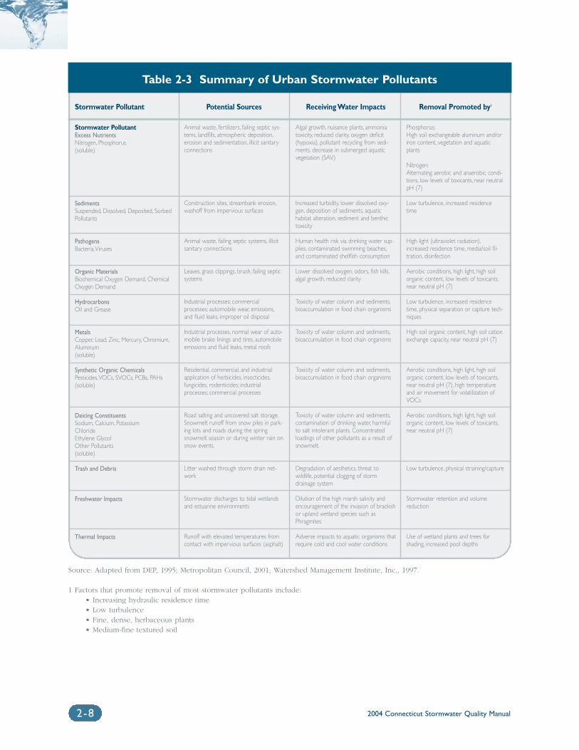
2004 Connecticut Stormwater Quality Manual2-8
Stormwater Pollutant Potential Sources Receiving Water Impacts Removal Promoted by1
Stormwater PollutantExcess NutrientsNitrogen, Phosphorus(soluble)
SedimentsSuspended, Dissolved, Deposited, SorbedPollutants
PathogensBacteria,Viruses
Organic MaterialsBiochemical Oxygen Demand, ChemicalOxygen Demand
HydrocarbonsOil and Grease
MetalsCopper, Lead, Zinc, Mercury, Chromium,Aluminum(soluble)
Synthetic Organic ChemicalsPesticides,VOCs, SVOCs, PCBs, PAHs(soluble)
Deicing ConstituentsSodium, Calcium, PotassiumChlorideEthylene GlycolOther Pollutants(soluble)
Trash and Debris
Freshwater Impacts
Thermal Impacts
Animal waste, fertilizers, failing septic sys-tems, landfills, atmospheric deposition,erosion and sedimentation, illicit sanitaryconnections
Construction sites, streambank erosion,washoff from impervious surfaces
Animal waste, failing septic systems, illicitsanitary connections
Leaves, grass clippings, brush, failing septicsystems
Industrial processes; commercialprocesses; automobile wear, emissions,and fluid leaks; improper oil disposal
Industrial processes, normal wear of auto-mobile brake linings and tires, automobileemissions and fluid leaks, metal roofs
Residential, commercial, and industrialapplication of herbicides, insecticides,fungicides, rodenticides; industrialprocesses; commercial processes
Road salting and uncovered salt storage.Snowmelt runoff from snow piles in park-ing lots and roads during the springsnowmelt season or during winter rain onsnow events.
Litter washed through storm drain net-work
Stormwater discharges to tidal wetlandsand estuarine environments
Runoff with elevated temperatures fromcontact with impervious surfaces (asphalt)
Algal growth, nuisance plants, ammoniatoxicity, reduced clarity, oxygen deficit(hypoxia), pollutant recycling from sedi-ments, decrease in submerged aquaticvegetation (SAV)
Increased turbidity, lower dissolved oxy-gen, deposition of sediments, aquatichabitat alteration, sediment and benthictoxicity
Human health risk via drinking water sup-plies, contaminated swimming beaches,and contaminated shellfish consumption
Lower dissolved oxygen, odors, fish kills,algal growth, reduced clarity
Toxicity of water column and sediments,bioaccumulation in food chain organisms
Toxicity of water column and sediments,bioaccumulation in food chain organisms
Toxicity of water column and sediments,bioaccumulation in food chain organisms
Toxicity of water column and sediments,contamination of drinking water, harmfulto salt intolerant plants. Concentratedloadings of other pollutants as a result ofsnowmelt.
Degradation of aesthetics, threat towildlife, potential clogging of stormdrainage system
Dilution of the high marsh salinity andencouragement of the invasion of brackishor upland wetland species such asPhragmites
Adverse impacts to aquatic organisms thatrequire cold and cool water conditions
Phosphorus:High soil exchangeable aluminum and/oriron content, vegetation and aquaticplants
Nitrogen:Alternating aerobic and anaerobic condi-tions, low levels of toxicants, near neutralpH (7)
Low turbulence, increased residencetime
High light (ultraviolet radiation),increased residence time, media/soil fil-tration, disinfection
Aerobic conditions, high light, high soilorganic content, low levels of toxicants,near neutral pH (7)
Low turbulence, increased residencetime, physical separation or capture tech-niques
High soil organic content, high soil cationexchange capacity, near neutral pH (7)
Aerobic conditions, high light, high soilorganic content, low levels of toxicants,near neutral pH (7), high temperatureand air movement for volatilization ofVOCs
Aerobic conditions, high light, high soilorganic content, low levels of toxicants,near neutral pH (7)
Low turbulence, physical straining/capture
Stormwater retention and volumereduction
Use of wetland plants and trees forshading, increased pool depths
Table 2-3 Summary of Urban Stormwater Pollutants
Source: Adapted from DEP, 1995; Metropolitan Council, 2001; Watershed Management Institute, Inc., 1997.
1 Factors that promote removal of most stormwater pollutants include:• Increasing hydraulic residence time• Low turbulence• Fine, dense, herbaceous plants• Medium-fine textured soil
2004 Connecticut Stormwater Quality Manual 2-9
SedimentsSediment loading to water bodies occurs fromwashoff of particles that are deposited on impervioussurfaces such as roads and parking lots, soil erosionassociated with construction activities, and stream-bank erosion. Although some erosion andsedimentation is natural, excessive sediment loadscan be detrimental to aquatic life including phyto-plankton, algae, benthic invertebrates, and fish, byinterfering with photosynthesis, respiration, growth,and reproduction. Solids can either remain in suspen-sion or settle to the bottom of the water body.Suspended solids can make the water cloudy or turbid,detract from the aesthetic and recreational value of awater body, and harm SAV, finfish, and shellfish.Sediment transported in stormwater runoff can bedeposited in a stream or other water body or wetlandand can adversely impact fish and wildlife habitat bysmothering bottom dwelling aquatic life and changingthe bottom substrate. Sediment deposition in waterbodies can result in the loss of deep-water habitat andcan affect navigation, often necessitating dredging.Sediment transported in stormwater runoff can alsocarry other pollutants such as nutrients, metals,pathogens, and hydrocarbons.
PathogensPathogens are bacteria, protozoa, and viruses that cancause disease in humans. The presence of bacteriasuch as fecal coliform or enterococci is used as anindicator of pathogens and of potential risk to humanhealth (DEP, 1995). Pathogen concentrations in urbanrunoff routinely exceed public health standards forwater contact recreation and shellfishing. Sources ofpathogens in stormwater runoff include animal wastefrom pets, wildlife, and waterfowl; combined sewers;failing septic systems; and illegal sanitary sewer cross-connections. High levels of indicator bacteria instormwater have commonly led to the closure ofbeaches and shellfishing beds along coastal areas of Connecticut.
Organic MaterialsOxygen-demanding organic substances such as grassclippings, leaves, animal waste, and street litter arecommonly found in stormwater. The decompositionof such substances in water bodies can deplete oxy-gen from the water, thereby causing similar effects tothose caused by nutrient loading. Organic matter is ofprimary concern in water bodies where oxygen is not easily replenished, such as slower movingstreams, lakes, and estuaries. An additional concernfor unfiltered water supplies is the formation of trihalomethane (THM), a carcinogenic disinfectionbyproduct generated by the mixing of chlorine withwater high in organic carbon (NYDEC, 2001).
HydrocarbonsUrban stormwater runoff contains a wide array ofhydrocarbon compounds, some of which are toxic toaquatic organisms at low concentrations (Woodward-Clyde, 1990). The primary sources of hydrocarbons in urban runoff are automotive. Source areas withhigher concentrations of hydrocarbons in stormwaterrunoff include roads, parking lots, gas stations, vehicleservice stations, residential parking areas, and bulkpetroleum storage facilities.
MetalsMetals such as copper, lead, zinc, mercury, and cad-mium are commonly found in urban stormwaterrunoff. Chromium and nickel are also frequentlypresent (USEPA, 1983). The primary sources of thesemetals in stormwater runoff are vehicular exhaustresidue, fossil fuel combustion, corrosion of galva-nized and chrome-plated products, roof runoff,stormwater runoff from industrial sites, and theapplication of deicing agents. Architectural copperassociated with building roofs, flashing, gutters, anddownspouts has been shown to be a source of cop-per in stormwater runoff in Connecticut and otherareas of the country (Barron, 2000; Tobiason, 2001).Marinas have also been identified as a source of cop-per and aquatic toxicity to inland and marine waters(Sailer Environmental, Inc. 2000). Washing or sand-blasting of boat hulls to remove salt and barnaclesalso removes some of the bottom paint, which con-tains copper and zinc additives to protect hulls fromdeterioration.
In Connecticut, discharge of metals to surfacewaters is of particular concern. Metals can be toxic toaquatic organisms, can bioaccumulate, and have thepotential to contaminate drinking water supplies.Many major rivers in Connecticut have copper levelsthat exceed Connecticut’s Copper Water QualityCriteria. Although metals generally attach themselvesto the solids in stormwater runoff or receiving waters,recent studies have demonstrated that dissolved met-als, particularly copper and zinc, are the primarytoxicants in stormwater runoff from industrial facilitiesthroughout Connecticut (Mas et al., 2001; NewEngland Bioassay, Inc., 2001). Additionally, stormwa-ter runoff can contribute to elevated metals in aquaticsediments. The metals can become bioavailablewhere the bottom sediment is anaerobic (withoutoxygen) such as in a lake or estuary. Metal accumu-lation in sediments has resulted in impaired aquatichabitat and more difficult maintenance dredging oper-ations in estuaries because of the special handlingrequirements for contaminated sediments.
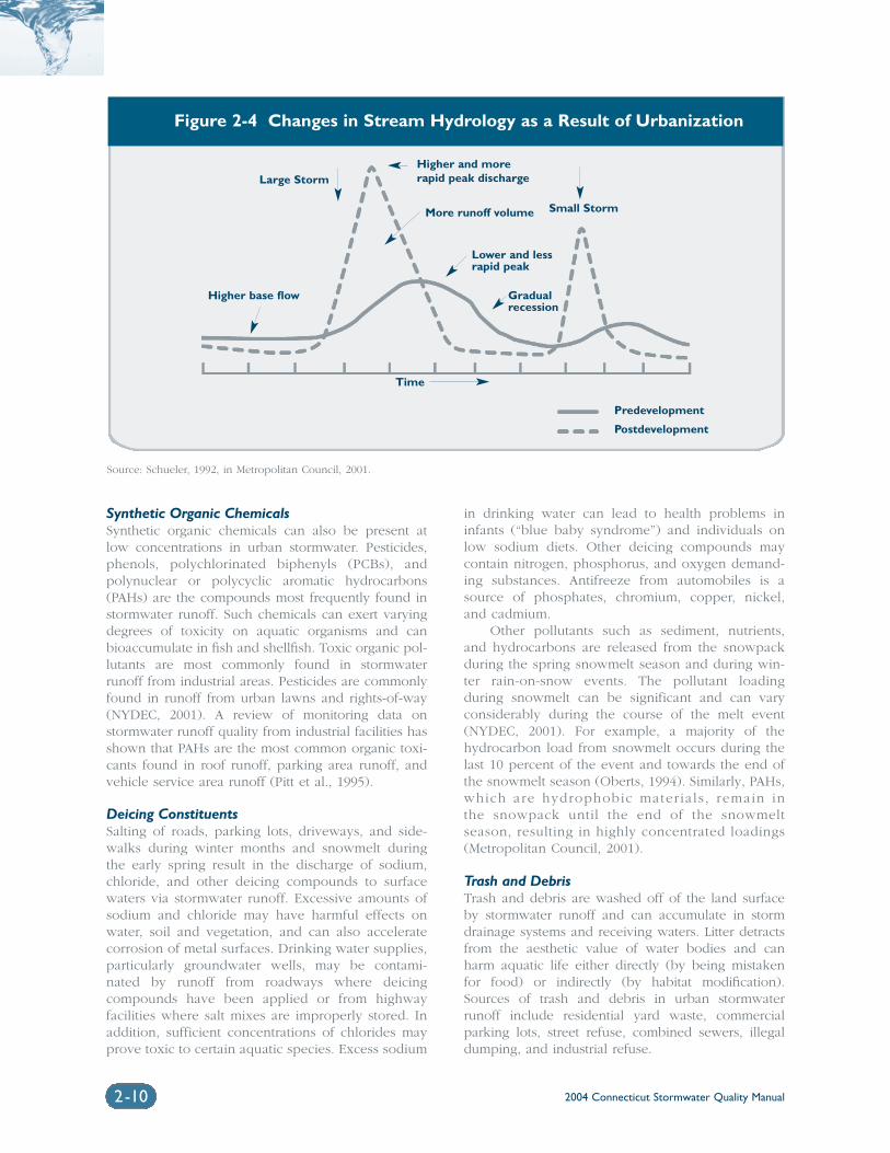
2004 Connecticut Stormwater Quality Manual2-10
Synthetic Organic ChemicalsSynthetic organic chemicals can also be present at low concentrations in urban stormwater. Pesticides,phenols, polychlorinated biphenyls (PCBs), andpolynuclear or polycyclic aromatic hydrocarbons(PAHs) are the compounds most frequently found instormwater runoff. Such chemicals can exert varyingdegrees of toxicity on aquatic organisms and canbioaccumulate in fish and shellfish. Toxic organic pol-lutants are most commonly found in stormwaterrunoff from industrial areas. Pesticides are commonlyfound in runoff from urban lawns and rights-of-way(NYDEC, 2001). A review of monitoring data onstormwater runoff quality from industrial facilities hasshown that PAHs are the most common organic toxi-cants found in roof runoff, parking area runoff, andvehicle service area runoff (Pitt et al., 1995).
Deicing ConstituentsSalting of roads, parking lots, driveways, and side-walks during winter months and snowmelt duringthe early spring result in the discharge of sodium,chloride, and other deicing compounds to surfacewaters via stormwater runoff. Excessive amounts ofsodium and chloride may have harmful effects onwater, soil and vegetation, and can also acceleratecorrosion of metal surfaces. Drinking water supplies,particularly groundwater wells, may be contami-nated by runoff from roadways where deicingcompounds have been applied or from highwayfacilities where salt mixes are improperly stored. Inaddition, sufficient concentrations of chlorides mayprove toxic to certain aquatic species. Excess sodium
in drinking water can lead to health problems ininfants (“blue baby syndrome”) and individuals onlow sodium diets. Other deicing compounds maycontain nitrogen, phosphorus, and oxygen demand-ing substances. Antifreeze from automobiles is asource of phosphates, chromium, copper, nickel,and cadmium.
Other pollutants such as sediment, nutrients,and hydrocarbons are released from the snowpackduring the spring snowmelt season and during win-ter rain-on-snow events. The pollutant loadingduring snowmelt can be significant and can varyconsiderably during the course of the melt event(NYDEC, 2001). For example, a majority of thehydrocarbon load from snowmelt occurs during thelast 10 percent of the event and towards the end ofthe snowmelt season (Oberts, 1994). Similarly, PAHs,which are hydrophobic mater ia ls , remain inthe snowpack until the end of the snowmeltseason, resulting in highly concentrated loadings(Metropolitan Council, 2001).
Trash and DebrisTrash and debris are washed off of the land surfaceby stormwater runoff and can accumulate in stormdrainage systems and receiving waters. Litter detractsfrom the aesthetic value of water bodies and canharm aquatic life either directly (by being mistakenfor food) or indirectly (by habitat modification).Sources of trash and debris in urban stormwaterrunoff include residential yard waste, commercialparking lots, street refuse, combined sewers, illegaldumping, and industrial refuse.
Source: Schueler, 1992, in Metropolitan Council, 2001.
Figure 2-4 Changes in Stream Hydrology as a Result of Urbanization
Large StormHigher and morerapid peak discharge
Predevelopment
Postdevelopment
More runoff volume
Lower and lessrapid peak
Gradualrecession
Small Storm
Higher base flow
Time
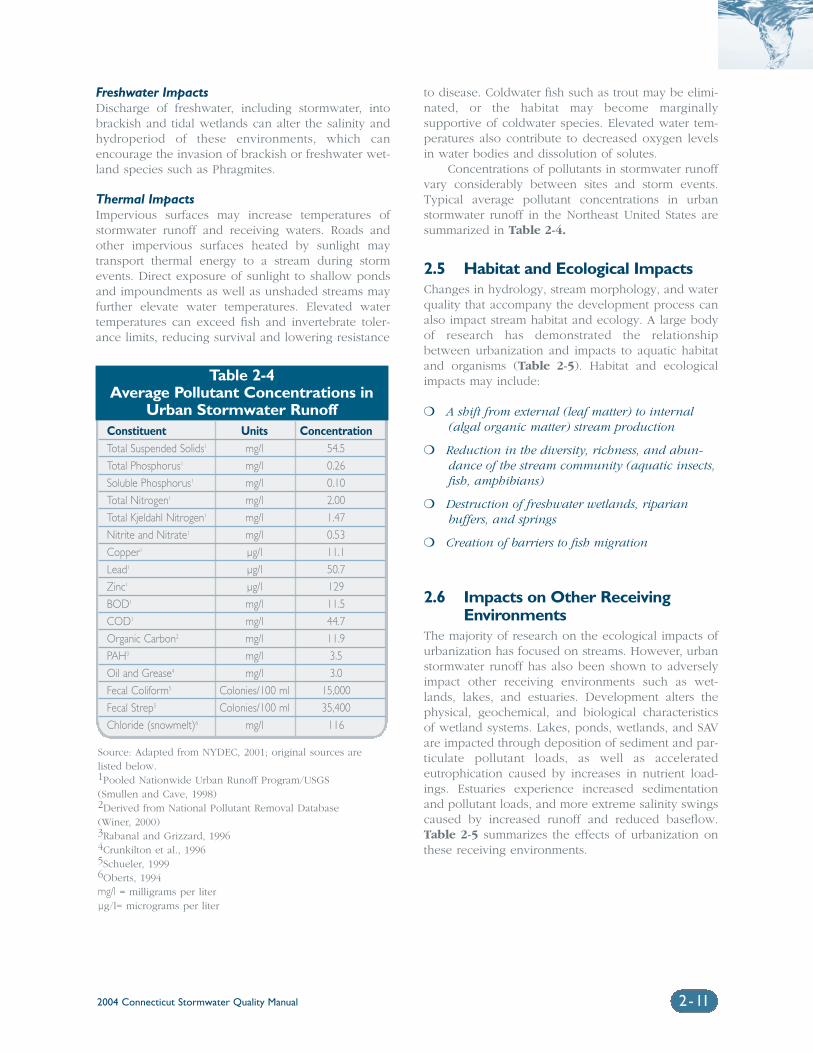
2004 Connecticut Stormwater Quality Manual 2-11
Freshwater ImpactsDischarge of freshwater, including stormwater, intobrackish and tidal wetlands can alter the salinity andhydroperiod of these environments, which canencourage the invasion of brackish or freshwater wet-land species such as Phragmites.
Thermal ImpactsImpervious surfaces may increase temperatures ofstormwater runoff and receiving waters. Roads andother impervious surfaces heated by sunlight maytransport thermal energy to a stream during stormevents. Direct exposure of sunlight to shallow pondsand impoundments as well as unshaded streams mayfurther elevate water temperatures. Elevated watertemperatures can exceed fish and invertebrate toler-ance limits, reducing survival and lowering resistance
to disease. Coldwater fish such as trout may be elimi-nated, or the habitat may become marginallysupportive of coldwater species. Elevated water tem-peratures also contribute to decreased oxygen levelsin water bodies and dissolution of solutes.
Concentrations of pollutants in stormwater runoffvary considerably between sites and storm events.Typical average pollutant concentrations in urbanstormwater runoff in the Northeast United States aresummarized in Table 2-4.
2.5 Habitat and Ecological ImpactsChanges in hydrology, stream morphology, and waterquality that accompany the development process canalso impact stream habitat and ecology. A large bodyof research has demonstrated the relationshipbetween urbanization and impacts to aquatic habitatand organisms (Table 2-5). Habitat and ecologicalimpacts may include:
❍ A shift from external (leaf matter) to internal(algal organic matter) stream production
❍ Reduction in the diversity, richness, and abun-dance of the stream community (aquatic insects,fish, amphibians)
❍ Destruction of freshwater wetlands, riparianbuffers, and springs
❍ Creation of barriers to fish migration
2.6 Impacts on Other ReceivingEnvironments
The majority of research on the ecological impacts ofurbanization has focused on streams. However, urbanstormwater runoff has also been shown to adverselyimpact other receiving environments such as wet-lands, lakes, and estuaries. Development alters thephysical, geochemical, and biological characteristicsof wetland systems. Lakes, ponds, wetlands, and SAVare impacted through deposition of sediment and par-ticulate pollutant loads, as well as acceleratedeutrophication caused by increases in nutrient load-ings. Estuaries experience increased sedimentationand pollutant loads, and more extreme salinity swingscaused by increased runoff and reduced baseflow.Table 2-5 summarizes the effects of urbanization onthese receiving environments.
Table 2-4Average Pollutant Concentrations in
Urban Stormwater RunoffConstituent Units ConcentrationTotal Suspended Solids1 mg/l 54.5
Total Phosphorus1 mg/l 0.26
Soluble Phosphorus1 mg/l 0.10
Total Nitrogen1 mg/l 2.00
Total Kjeldahl Nitrogen1 mg/l 1.47
Nitrite and Nitrate1 mg/l 0.53
Copper1 µg/l 11.1
Lead1 µg/l 50.7
Zinc1 µg/l 129
BOD1 mg/l 11.5
COD1 mg/l 44.7
Organic Carbon2 mg/l 11.9
PAH3 mg/l 3.5
Oil and Grease4 mg/l 3.0
Fecal Coliform5 Colonies/100 ml 15,000
Fecal Strep5 Colonies/100 ml 35,400
Chloride (snowmelt)6 mg/l 116
Source: Adapted from NYDEC, 2001; original sources arelisted below.1Pooled Nationwide Urban Runoff Program/USGS (Smullen and Cave, 1998)2Derived from National Pollutant Removal Database (Winer, 2000)3Rabanal and Grizzard, 19964Crunkilton et al., 19965Schueler, 19996Oberts, 1994mg/l = milligrams per literµg/l= micrograms per liter
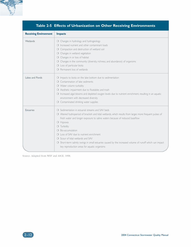
2004 Connecticut Stormwater Quality Manual2-12
Table 2-5 Effects of Urbanization on Other Receiving Environments
Receiving Environment Impacts
Wetlands ❍ Changes in hydrology and hydrogeology
❍ Increased nutrient and other contaminant loads
❍ Compaction and destruction of wetland soil
❍ Changes in wetland vegetation
❍ Changes in or loss of habitat
❍ Changes in the community (diversity, richness, and abundance) of organisms
❍ Loss of particular biota
❍ Permanent loss of wetlands
Lakes and Ponds ❍ Impacts to biota on the lake bottom due to sedimentation
❍ Contamination of lake sediments
❍ Water column turbidity
❍ Aesthetic impairment due to floatables and trash
❍ Increased algal blooms and depleted oxygen levels due to nutrient enrichment, resulting in an aquatic
environment with decreased diversity
❍ Contaminated drinking water supplies
Estuaries ❍ Sedimentation in estuarial streams and SAV beds
❍ Altered hydroperiod of brackish and tidal wetlands, which results from larger, more frequent pulses of
fresh water and longer exposure to saline waters because of reduced baseflow
❍ Hypoxia
❍ Turbidity
❍ Bio-accumulation
❍ Loss of SAV due to nutrient enrichment
❍ Scour of tidal wetlands and SAV
❍ Short-term salinity swings in small estuaries caused by the increased volume of runoff which can impact
key reproduction areas for aquatic organisms
Source: Adapted from WEF and ASCE, 1998.
2004 Connecticut Stormwater Quality Manual 2-13
References
Arnold, C.L., Jr., and C.J. Gibbons. 1996. “ImperviousSurface Coverage: The Emergence of a KeyEnvironmental Indicator”. Journal of the AmericanPlanning Association. Vol. 62, No. 2.
Barron, T. 2000. Architectural Uses of Copper: AnEvaluation of Stormwater Pollution Loads and BestManagement Practices. Prepared for the Palo AltoRegional Water Quality Control Plant.
Booth, D.B. and L.E. Reinelt. 1993. “Consequences ofUrbanization on Aquatic Systems - Measured Effects,Degradation Thresholds, and Corrective Strategies”,in Proceedings of the Watershed ‘93 Conference.Alexandria, Virginia.
Brant, T.R. 1999. “Community Perceptions of WaterQuality and Management Measures in the NaamansCreek Watershed”. Masters Thesis for the Degree ofMaster of Marine Policy.
Center for Watershed Protection. 2003. Impacts ofImpervious Cover on Aquatic Systems. WatershedProtection Research Monograph No. 1. March 2003.
Connecticut Department of Environmental Protection(DEP). 1995. Assessment of Nonpoint Sources ofPollution in Urbanized Watersheds: A GuidanceDocument for Municipal Officials, DEP Bulletin #22.Bureau of Water Management, Planning andStandards Division, Hartford, Connecticut.
Connecticut Department of Environmental Protection(DEP). 2004 draft. 2004 List of ConnecticutWaterbodies Not Meeting Water Quality Standards.
Crunkilton, R. et al. 1996. “Assessment of theResponse of Aquatic Organisms to Long-term InsituExposures of Urban Runoff”, in Effects of WatershedDevelopment and Management on AquaticEcosystems Proceedings of an EngineeringFoundation Conference. Snowbird, Utah.
Deegan, L., A. A. Wright, S. G. Ayvazian, J. T. Finn,H. Golden, R. R. Merson, and J. Harrison. “Nitrogenloading alters seagrass ecosystem structure and sup-port of higher trophic levels.” Aquatic Conservation.12(2): p. 193-212. March-April, 2002.
Mas, D.M.L., Curtis, M.D., and E.V. Mas. 2001.“Investigation of Toxicity Relationships in IndustrialStormwater Discharges”, presented at New EnglandWater Environment Association 2001 AnnualConference, Boston, MA.
Massachusetts Department of EnvironmentalProtection (MADEP) and the Massachusetts Office ofCoastal Zone Management. 1997. StormwaterManagement, Volume Two: Stormwater TechnicalHandbook. Boston, Massachusetts.
Metropolitan Council. 2001. Minnesota Urban SmallSites BMP Manual: Stormwater Best ManagementPractices for Cold Climates, prepared by BarrEngineering Company, St. Paul, Minnesota.
Natural Resources Defense Council (NRDC). 1999.Stormwater Strategies: Community Responses toRunoff Pollution.
New England Bioassay, Inc. 2001. Final Report onStormwater Toxicity Identification Evaluations (TIE)at Industrial Sites. Prepared for the ConnecticutDepartment of Environmental Protection.
New York State Department of EnvironmentalConservation (NYDEC). 2001. New York StateStormwater Management Design Manual. Preparedby Center for Watershed Protection, Albany, New York.
Oberts, G. 1994. “Influence of Snowmelt Dynamicson Stormwater Runoff Quality”. Watershed ProtectionTechniques. Vol. 1, No. 2.
Pitt, R., Field, R., Lalor, M., and M. Brown. 1995.“Urban Stormwater Toxic Pollutants: Assessment,Sources, and Treatability”. Water EnvironmentResearch. Vol. 67, No. 3.
Prince George’s County, Maryland. 1999. Low-ImpactDevelopment Design Strategies: An Integrated DesignApproach. Prince George’s County Department ofEnvironmental Resources Programs and PlanningDivision.
Rabanal, F. and T. Grizzard. 1995. “Concentrations ofSelected Constituents in Runoff from ImperviousSurfaces in Four Urban Land Use Catchments ofDifferent Land Use”, Proceedings of the 4th BiennialStormwater Research Conference, Clearwater, Florida.
Sailer Environmental, Inc. 2000. Final Report on theAlternative Stormwater Sampling for CMTA Members.Prepared for Connecticut Marine Trades Association.
Schueler, T.R. 1994. “The Importance of Impervious-ness”. Watershed Protection Techniques. Vol. 1, No. 3.
2004 Connecticut Stormwater Quality Manual2-14
Schueler, T.R. 1995. Site Planning for Urban StreamProtection. Metropolitan Washington Council ofGovernments, Washington, D.C.
Schueler, T.R. 1999. “Microbes and UrbanWatersheds”. Watershed Protection Techniques, Vol.3, No. 1.
Schueler, T.R., Kumble, P.A., and M.A. Heraty. 1992.A Current Assessment of Urban Best ManagementPractices: Techniques for Reducing Non-Point SourcePollution in the Coastal Zone. Department ofEnvironmental Programs, Metropolitan WashingtonCouncil of Governments.
Shaver, E.J. and J.R. Maxted. 1996. “Technical Note72 Habitat and Biological Monitoring RevealsHeadwater Stream Impairment in Delaware’sPiedmont”. Watershed Protection Techniques. Vol. 2,No. 2.
Smullen, J. and K. Cave. 1998. “Updating the U.S.Nationwide Urban Runoff Quality Database”. 3rdInternational Conference on Diffuse Pollution,August 31 – September 4, 1998. ScottishEnvironmental Protection Agency, Edinburgh,Scotland.
Soil Conservation Service. 1975. Urban Hydrology forSmall Watersheds, USDA Soil Conservation ServiceTechnical Release No. 55. Washington, D.C.
Tobiason, S. 2001. “Trickle Down Effect”. IndustrialWastewater. Water Environment Federation. Vol. 9,No. 6.
United States Environmental Protection Agency(EPA). 1983. Results of the Nationwide Urban RunoffProgram, Volume 1, Final Report. Water PlanningDivision, Washington, D.C. NTIS No. PB 84-185 552.
United States Environmental Protection Agency(EPA). 2000. National Coastal Condition Report.EPA841-R-00-001. Office of Water, Washington, D.C.
United States Environmental Protection Agency(EPA). 2001. National Water Quality Inventory: 1998Report to Congress. EPA620-R-01-005. Office of Water,Washington, D.C.
Water Environment Federation (WEF) and AmericanSociety of Civil Engineers (ASCE). 1998. UrbanRunoff Quality Management (WEF Manual ofPractice No. 23 and ASCE Manual and Report onEngineering Practice No. 87).
Watershed Management Institute, Inc. 1997.Operation, Maintenance, and Management ofStormwater Management Systems. In cooperationwith U.S. Environmental Protection Agency, Office ofWater, Washington, D.C.
Winer, R. 2000. National Pollutant Removal Databasefor Stormwater Treatment Practices, 2nd Edition.Center for Watershed Protection, Ellicott City,Maryland.
Woodward-Clyde Consultants. 1990. Urban targetingand BMP Selection: An Information and GuidanceManual for State NPS Program Staff Engineers andManagers, Final Report.
Chapter 3Preventing and Mitigating Stormwater Impacts
Chapter 3 Preventing and MitigatingStormwater Impacts
3.1 Introduction .................................................................................................3-2
3.2 Guiding Stormwater Management Principles .......................................3-2
3.3 Site Planning and Design............................................................................3-3
3.4 Source Control Practices and Pollution Prevention ...........................3-4
3.5 Construction Erosion and Sedimentation Control .............................3-4
3.6 Stormwater Treatment Practices .............................................................3-4
3.7 Stormwater Quantity Control .................................................................3-6
3.8 Watershed Management............................................................................3-7
Volume 1: Background
2004 Connecticut Stormwater Quality Manual 3-1
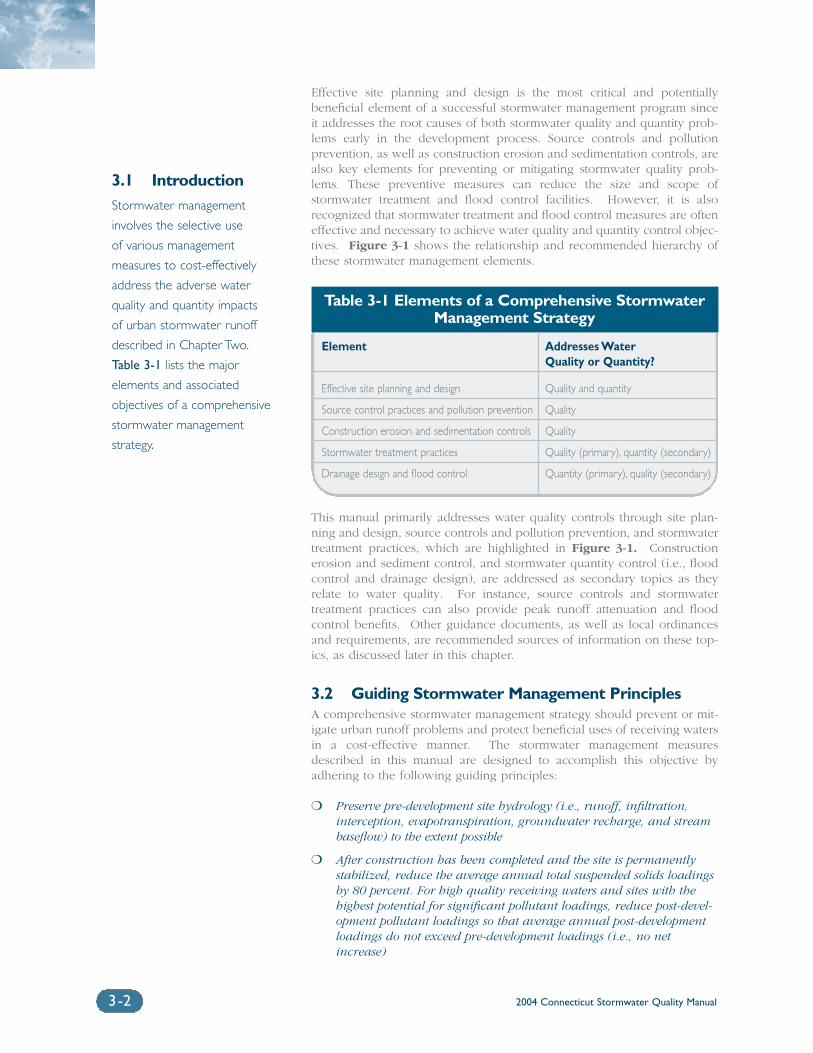
Effective site planning and design is the most critical and potentially beneficial element of a successful stormwater management program sinceit addresses the root causes of both stormwater quality and quantity prob-lems early in the development process. Source controls and pollutionprevention, as well as construction erosion and sedimentation controls, arealso key elements for preventing or mitigating stormwater quality prob-lems. These preventive measures can reduce the size and scope ofstormwater treatment and flood control facilities. However, it is also recognized that stormwater treatment and flood control measures are ofteneffective and necessary to achieve water quality and quantity control objec-tives. Figure 3-1 shows the relationship and recommended hierarchy ofthese stormwater management elements.
This manual primarily addresses water quality controls through site plan-ning and design, source controls and pollution prevention, and stormwatertreatment practices, which are highlighted in Figure 3-1. Constructionerosion and sediment control, and stormwater quantity control (i.e., floodcontrol and drainage design), are addressed as secondary topics as theyrelate to water quality. For instance, source controls and stormwatertreatment practices can also provide peak runoff attenuation and floodcontrol benefits. Other guidance documents, as well as local ordinancesand requirements, are recommended sources of information on these top-ics, as discussed later in this chapter.
3.2 Guiding Stormwater Management PrinciplesA comprehensive stormwater management strategy should prevent or mit-igate urban runoff problems and protect beneficial uses of receiving watersin a cost-effective manner. The stormwater management measuresdescribed in this manual are designed to accomplish this objective byadhering to the following guiding principles:
❍ Preserve pre-development site hydrology (i.e., runoff, infiltration,interception, evapotranspiration, groundwater recharge, and streambaseflow) to the extent possible
❍ After construction has been completed and the site is permanentlystabilized, reduce the average annual total suspended solids loadingsby 80 percent. For high quality receiving waters and sites with thehighest potential for significant pollutant loadings, reduce post-devel-opment pollutant loadings so that average annual post-developmentloadings do not exceed pre-development loadings (i.e., no netincrease)
Element Addresses Water Quality or Quantity?
Effective site planning and design Quality and quantity
Source control practices and pollution prevention Quality
Construction erosion and sedimentation controls Quality
Stormwater treatment practices Quality (primary), quantity (secondary)
Drainage design and flood control Quantity (primary), quality (secondary)
2004 Connecticut Stormwater Quality Manual3-2
3.1 IntroductionStormwater management
involves the selective use
of various management
measures to cost-effectively
address the adverse water
quality and quantity impacts
of urban stormwater runoff
described in Chapter Two.
Table 3-1 lists the major
elements and associated
objectives of a comprehensive
stormwater management
strategy.
Table 3-1 Elements of a Comprehensive StormwaterManagement Strategy
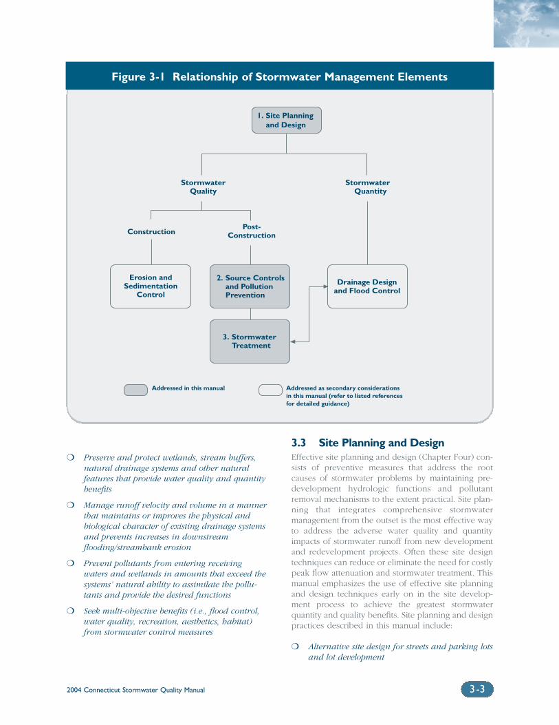
2004 Connecticut Stormwater Quality Manual 3-3
❍ Preserve and protect wetlands, stream buffers,natural drainage systems and other natural features that provide water quality and quantitybenefits
❍ Manage runoff velocity and volume in a mannerthat maintains or improves the physical and biological character of existing drainage systemsand prevents increases in downstreamflooding/streambank erosion
❍ Prevent pollutants from entering receivingwaters and wetlands in amounts that exceed thesystems’ natural ability to assimilate the pollu-tants and provide the desired functions
❍ Seek multi-objective benefits (i.e., flood control,water quality, recreation, aesthetics, habitat)from stormwater control measures
3.3 Site Planning and DesignEffective site planning and design (Chapter Four) con-sists of preventive measures that address the rootcauses of stormwater problems by maintaining pre-development hydrologic functions and pollutantremoval mechanisms to the extent practical. Site plan-ning that integrates comprehensive stormwatermanagement from the outset is the most effective wayto address the adverse water quality and quantityimpacts of stormwater runoff from new developmentand redevelopment projects. Often these site designtechniques can reduce or eliminate the need for costlypeak flow attenuation and stormwater treatment. Thismanual emphasizes the use of effective site planningand design techniques early on in the site develop-ment process to achieve the greatest stormwaterquantity and quality benefits. Site planning and designpractices described in this manual include:
❍ Alternative site design for streets and parking lotsand lot development
3. StormwaterTreatment
StormwaterQuality
Post-Construction
StormwaterQuantity
Construction
Erosion andSedimentation
Control
Drainage Designand Flood Control
2. Source Controlsand PollutionPrevention
1. Site Planning and Design
Addressed in this manual Addressed as secondary considerationsin this manual (refer to listed referencesfor detailed guidance)
Figure 3-1 Relationship of Stormwater Management Elements
2004 Connecticut Stormwater Quality Manual3- 4
❍ Low Impact Development (LID) managementpractices
❍ Watershed planning
3.4 Source Control Practices andPollution Prevention
Source control practices and pollution prevention(Chapter Five) are operational practices that canreduce the types and concentrations of pollutants instormwater runoff by limiting the generation of pollu-tants at their source. The guiding principle behindthese techniques is to minimize contact of stormwaterwith potential pollutants, thereby reducing pollutantloads and the size and cost of stormwater treatment.This manual emphasizes the use of source controlpractices and pollution prevention, in conjunctionwith effective site planning and design, to reduce theneed for and scope of stormwater treatment. Sourcecontrol practices commonly implemented at residen-tial, commercial, and industrial sites are discussed inthis manual, including:
❍ Street and Parking Lot Sweeping
❍ Roadway Deicing/Salt Storage
❍ Storm Drainage System Maintenance
❍ Other Road, Highway, and Bridge Maintenance
❍ Illicit Discharge Detection and Elimination
❍ Commercial and Industrial Pollution Prevention Plans
❍ Animal Waste Management
❍ Lawn Care and Landscaping Practices
❍ Model Stormwater Ordinances
❍ Public Education
3.5 Construction Erosion andSedimentation Control
As described in Chapter One, soil erosion and sedi-mentation control is addressed by the Soil Erosionand Sediment Control Act (CGS §§22a-325 through22a-335, inclusive). The primary goal of the Act is toreduce soil erosion from stormwater runoff and nonpoint sediment pollution from land being devel-oped. Controlling soil erosion and sedimentationduring construction is addressed through a combina-tion of measures that are described in a site-specificErosion and Sediment Control (E&SC) Plan. The basicprinciples of effective soil erosion and sediment control include:
❍ Use effective site planning to avoid sensitiveareas such as wetlands and watercourses
❍ Keep land disturbance to a minimum
❍ Stabilize disturbed areas
❍ Phase land disturbance on larger projects, start-ing subsequent phases after disturbed areas arestabilized
❍ Keep runoff velocities low
❍ Protect disturbed areas from stormwater runoff
❍ Properly install perimeter control practices
❍ Limit construction during months when runoffrates are higher due to decreased infiltration orextreme rainfall events
❍ Implement a thorough maintenance and follow-up program
❍ Assign responsibility for the maintenance program
As shown in Figure 3-1, soil erosion and sedi-ment control is a key component of any stormwatermanagement strategy in order to reduce the impactsof stormwater runoff during construction activities.Although many of the vegetative, filtration, and infil-tration stormwater management practices containedin this manual are based on the above principles, thismanual does not address construction soil erosionand sediment control practices. Municipal ordinancescontain specific soil erosion and sediment controlrequirements for developments disturbing more thanone-half acre. Additionally, the 2002 revision of theConnecticut Guidelines for Soil Erosion and SedimentControl, DEP Bulletin 34 (Connecticut Council on Soiland Water Conservation and the ConnecticutDepartment of Environmental Protection, 2002) con-tains detailed technical guidance on specific erosionand sediment control practices and recommendedprocedures for developing an effective E&SC Plan.Copies of this guidance manual have been issued toeach local Planning, Zoning, and Inland Wetlands andWatercourses Office.
3.6 Stormwater Treatment PracticesStormwater treatment practices, which are the focusof the second half of this Manual, are primarilydesigned to remove pollutants from stormwaterrunoff. In addition to water quality treatment, thesepractices can also provide groundwater recharge,stream channel protection, and peak runoff attenua-tion. As described above, stormwater treatmentpractices should be selected and designed only afterconsideration of effective site planning/design and
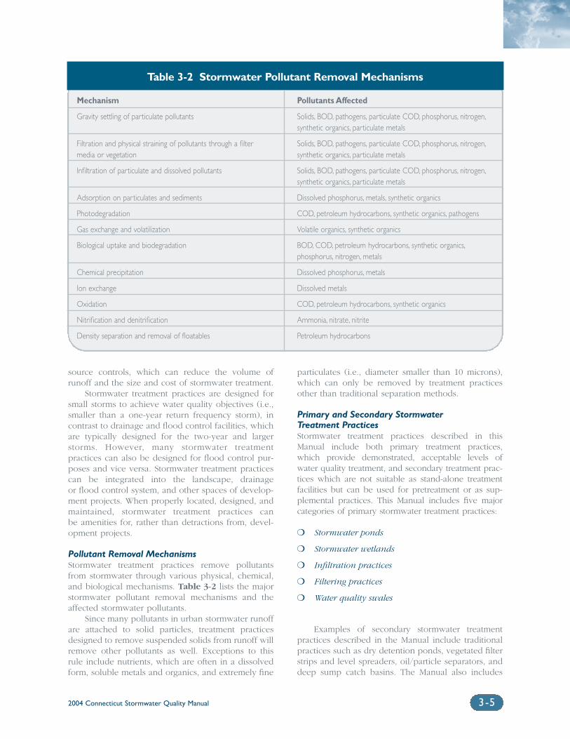
Mechanism
Gravity settling of particulate pollutants
Filtration and physical straining of pollutants through a filter media or vegetation
Infiltration of particulate and dissolved pollutants
Adsorption on particulates and sediments
Photodegradation
Gas exchange and volatilization
Biological uptake and biodegradation
Chemical precipitation
Ion exchange
Oxidation
Nitrification and denitrification
Density separation and removal of floatables
Pollutants Affected
Solids, BOD, pathogens, particulate COD, phosphorus, nitrogen,synthetic organics, particulate metals
Solids, BOD, pathogens, particulate COD, phosphorus, nitrogen,synthetic organics, particulate metals
Solids, BOD, pathogens, particulate COD, phosphorus, nitrogen,synthetic organics, particulate metals
Dissolved phosphorus, metals, synthetic organics
COD, petroleum hydrocarbons, synthetic organics, pathogens
Volatile organics, synthetic organics
BOD, COD, petroleum hydrocarbons, synthetic organics,phosphorus, nitrogen, metals
Dissolved phosphorus, metals
Dissolved metals
COD, petroleum hydrocarbons, synthetic organics
Ammonia, nitrate, nitrite
Petroleum hydrocarbons
2004 Connecticut Stormwater Quality Manual 3-5
source controls, which can reduce the volume ofrunoff and the size and cost of stormwater treatment.
Stormwater treatment practices are designed forsmall storms to achieve water quality objectives (i.e.,smaller than a one-year return frequency storm), incontrast to drainage and flood control facilities, whichare typically designed for the two-year and largerstorms. However, many stormwater treatment practices can also be designed for flood control pur-poses and vice versa. Stormwater treatment practicescan be integrated into the landscape, drainage or flood control system, and other spaces of develop-ment projects. When properly located, designed, and maintained, stormwater treatment practices can be amenities for, rather than detractions from, devel-opment projects.
Pollutant Removal MechanismsStormwater treatment practices remove pollutantsfrom stormwater through various physical, chemical,and biological mechanisms. Table 3-2 lists the majorstormwater pollutant removal mechanisms and theaffected stormwater pollutants.
Since many pollutants in urban stormwater runoffare attached to solid particles, treatment practicesdesigned to remove suspended solids from runoff willremove other pollutants as well. Exceptions to thisrule include nutrients, which are often in a dissolvedform, soluble metals and organics, and extremely fine
particulates (i.e., diameter smaller than 10 microns),which can only be removed by treatment practicesother than traditional separation methods.
Primary and Secondary Stormwater Treatment PracticesStormwater treatment practices described in thisManual include both primary treatment practices,which provide demonstrated, acceptable levels ofwater quality treatment, and secondary treatment prac-tices which are not suitable as stand-alone treatmentfacilities but can be used for pretreatment or as sup-plemental practices. This Manual includes five majorcategories of primary stormwater treatment practices:
❍ Stormwater ponds
❍ Stormwater wetlands
❍ Infiltration practices
❍ Filtering practices
❍ Water quality swales
Examples of secondary stormwater treatmentpractices described in the Manual include traditionalpractices such as dry detention ponds, vegetated filterstrips and level spreaders, oil/particle separators, anddeep sump catch basins. The Manual also includes
Table 3-2 Stormwater Pollutant Removal Mechanisms
2004 Connecticut Stormwater Quality Manual3-6
innovative and emerging technologies as secondarytreatment practices. These technologies are designedto remove a variety of stormwater pollutants, but havenot been evaluated in sufficient detail to demonstratethe capability to meet established performance stan-dards. Sizing and selection criteria for stormwatertreatment practices are addressed in Chapter Sevenand Chapter Eight, respectively.
New Development Versus RetrofitsStormwater treatment practices can be implementedfor new development projects as well as existing,developed sites. Retrofitting existing developmentscan improve water quality mitigation functions ofolder, poorly designed, or poorly maintainedstormwater management systems. Incorporatingstormwater retrofits into developed sites is typicallymore difficult than implementing treatment practicesfor new development due to the numerous site con-straints associated with developed areas such assubsurface utilities, buildings, conflicting land uses,and maintenance access. Chapter Ten describes com-mon stormwater retrofit options for existingdevelopment and redevelopment projects, including:
❍ Stormwater collection system retrofits
❍ Stormwater management facility retrofits
❍ New stormwater controls at storm drain outfalls
❍ In-stream practices in existing drainage channels
❍ Parking lot stormwater retrofits
❍ Wetland creation and restoration
3.7 Stormwater Quantity ControlStormwater quantity controls include drainage andflood control. As shown in Figure 3-1, stormwaterquantity and quality controls are related and com-plementary elements of an effective stormwatermanagement strategy. Stormwater drainage systemscan be designed to reduce the potential erosive velocity of stormwater runoff and maintain pre-devel-opment hydrology through infiltration and the use ofvegetated conveyances, thereby preserving the waterquality mitigation functions of a site. Similarly,stormwater treatment practices such as stormwaterponds and wetlands can provide dual flood controland water quality treatment benefits.
This Manual addresses the topics of drainagedesign and flood control as they relate to stormwaterquality management. The Manual identifies storm-water treatment practices that also provide peakrunoff attenuation and channel protection functions.However, this document is not intended to serve as a
drainage or flood control design manual. Other rec-ommended guidance documents and manuals onthese topics include:
❍ 2000 Connecticut Department of TransportationDrainage Manual, October 2000
❍ Connecticut Department of EnvironmentalProtection, Model Hydraulic Analysis, revisedFebruary 13, 2002
❍ Urban Hydrology for Small Watersheds, TR-55,Natural Resource Conservation Service (formerlySoil Conservation Service), June 1986
In addition, municipal ordinances, as well assome DEP regulatory programs, contain specificstormwater quantity control requirements for landdevelopment projects, as described in Chapter One.
Drainage Design and Flood Control Principles for Water QualityThe traditional approach to drainage design has beento collect and remove runoff from the site as quicklyas possible through the use of curbs, gutters, catchbasins, and storm sewers, often resulting in the dis-charge of polluted runoff directly to receiving waters.While this approach effectively removes runoff from asite, it does not address water quality or downstreamflooding and erosion issues. Similarly, the traditionalapproach to flood control has been to attenuate peakrunoff to pre-development levels through the use ofdetention and retention ponds. While stormwaterdetention or retention facilities can effectively reducepeak discharge rates, they also typically prolong the duration of elevated flows and do not reducerunoff volumes unless infiltration is incorporated into their design. Historically, these facilities have not adequately addressed problems associated with water quality, runoff volume, and downstreamchannel erosion.
Drainage and flood control facilities should bedesigned according to the following principles toaddress water quality objectives:
❍ Identify and assess existing stormwater runoffrates and volumes at the site, as well as down-stream flooding and erosion concerns.
❍ Preserve pre-development hydrologic conditions,including peak discharge, runoff volume,groundwater recharge, and natural drainage paths.
❍ Reduce the potential for increases in runoffquantity by minimizing impervious surfacesand maximizing infiltration of stormwaterrunoff. Eliminate curbs where possible andencourage sheet flow from paved areas. If
2004 Connecticut Stormwater Quality Manual 3-7
curbing is required, use Cape Cod curbing orother similar curbing, which allows amphibiansto climb.
❍ Encourage infiltration of stormwater through theuse of vegetated depressions, swales, rain gar-dens and bioretention, and other vegetateddrainageways to convey and hold stormwaterand provide for a slow recharge to groundwater,where soils permit. Special care must be taken inareas of sensitive groundwater resources such asaquifer protection areas and groundwater sup-ply wells in order to prevent their contamination.In addition, in areas with soil or groundwatercontamination, the potential for infiltratedstormwater to mobilize contaminants must alsobe considered.
❍ Control increases in stormwater runoff volumeand peak flows through properly designed andlocated stormwater management facilities.Manage stormwater so that both the volume andpeak rate of runoff from the site after develop-ment does not exceed the volume and peak rateof runoff from the site prior to development.
❍ Encourage the development of watershed-based stormwater management strategies toeffectively control the cumulative effects ofincreases in runoff volume and peak flows atcritical locations throughout the watershed.Coordinate the timing of detention basin outflows to avoid increases in peak flows indownstream watercourses.
❍ Use adequate outlet protection at drainage out-falls to reduce discharge velocities, disperse flow,and prevent or reduce downstream erosion.
❍ Coordinate construction erosion and sedimentcontrol measures with post-constructionstormwater management measures. For example,a sediment basin designed to trap sediment dur-ing the construction phase of a project maysometimes be converted to a detention basin orstormwater treatment facility to meet peakrunoff attenuation or water quality mitigationobjectives following construction.
❍ Retain on-site the volume of runoff generated bythe first inch of rainfall from areas adjacent toor within 500 feet of tidal salt marshes and estuarine waters. Excessive quantities of freshwater can be a pollutant to tidal wetlands andcause a decrease in vegetative diversity and wetland productivity.
❍ Protect wetland and watercourse resources fromstormwater discharges. Do not drain stormwaterdirectly to a wetland or watercourse or to a
municipal storm drainage system that drainsdirectly to a wetland or watercourse withoutadequate stormwater treatment. Protect wetlands, watercourses, and submerged aquatic vegetation from scour.
3.8 Watershed ManagementStormwater management is most effectively under-taken in the context of a watershed managementplan. A watershed management plan is a comprehen-sive framework for applying management tools in amanner that achieves the water resources goals forthe watershed as a whole (CWP, 1998). Typically,watershed management plans are developed fromwatershed studies undertaken by one or more munic-ipalities located within the watershed. The watershedapproach has emerged over the past decade as therecommended approach for addressing nonpointsource pollution problems, including pollutedstormwater runoff. Watershed planning offers the bestmeans to:
❍ Address cumulative impacts derived from anumber of new land development projects
❍ Plan for mitigation to address cumulativeimpacts from existing developments
❍ Focus efforts and resources on identified priority water bodies and pollutant sources in a watershed
❍ Achieve noticeable improvements to impairedwaters or waters threatened with impairment
The watershed approach is built on three mainprinciples. First, the target watersheds should be thosewhere stormwater impacts pose the greatest risk tohuman health, ecological resources, desirable uses ofthe water, or a combination of these. Second, partieswith a stake in the specific local situation (i.e., stake-holders) should participate in the analysis of problemsand the creation of solutions. Third, the actions under-taken should draw on the full range of methods andtools available, integrating them into a coordinated,multi-organization attack on the problems. The water-shed approach has the following significant advantagesover traditional piecemeal approaches to stormwatermanagement that require individual land developmentsto provide on-site stormwater management facilities(adapted from Aldrich, 1988):
Lower capital and O&M cost: Typically, water-shed management plans yield fewer and largerstormwater management facilities. Economies ofscale are achievable in capital costs and especially
2004 Connecticut Stormwater Quality Manual3-8
in O&M. Strategic placement of regional facilities per-mits concentrating funds on areas where potentialbenefits are greatest. Cost sharing arrangements signifi-cantly reduce the net cost of stormwater management tothe community as a whole.
Increased effectiveness on a watershed-widebasis: Often different portions of watersheds requiredifferent types of stormwater controls. Watershedplanning permits the siting of a variety of on-site andregional facilities in locations where the greatest benefits are achieved.
Greater use of nonstructural measures: Often themost practical stormwater controls involve nonstructuralmeasures such as land acquisition, floodplain zoning,subdivision drainage ordinances, and land use controls.Watershed planning provides a coordinated, compre-hensive framework and decision-making process toallow the effective implementation of these measures.
Less risk of negative “spillover” effects: The piece-meal approach may adequately solve localizeddrainage problems, but seldom addresses downstreamimpacts. Thus, dynamic interactions betweenupstream drainage improvements may actuallyincrease downstream flooding. An objective of water-shed planning is to account for these upstreaminteractions and achieve solutions to both localizedand regional stormwater management concerns.
Watershed management plans should include rec-ommended criteria for stormwater source controls andtreatment practices in the watershed. These criteria arebased on watershed-specific factors such as physicalattributes, land use, pollution sources, and sensitivereceptors, and are the basis for selecting and locatingstormwater controls in the watershed. At a minimum, awatershed management plan should contain the elements listed in Table 3-3 to address stormwater-related issues.
The watershed management plan should addressintegrating flood control and stormwater managementcontrols with community needs, including openspace, aesthetics, and other environmental objectivessuch as habitat or river restoration. This synchroniza-tion with other programs can create better fundingopportunities and enhance the overall benefit of thestormwater management practices in the watershed.
On-Site Versus Regional ApproachesWatershed management plans can identify conditionsand locations in the watershed where regionalstormwater management facilities may be moreappropriate or effective than on-site controls. On-siteand regional stormwater management approaches areillustrated schematically in Figure 3-2. Theseapproaches apply to both stormwater quality andquantity controls.
In the on-site approach, land developers have responsi-bility for deploying treatment practices and runoffcontrols at individual development sites. Developers areresponsible for constructing on-site stormwater manage-ment facilities to control stormwater pollutant loadingsand runoff from the site. The local government is respon-sible for reviewing the design of stormwater managementfacilities relative to specified design criteria, for inspectingthe constructed facilities to ensure conformance with thedesign, and for ensuring that operation and maintenanceplans are implemented for the facilities (Novotny, 1995).
The regional approach involves strategically sitingstormwater management facilities to control stormwaterrunoff from multiple development projects or largedrainage areas. Local or regional governments assumethe capital costs for constructing the regional facilities.Capital costs are typically recovered from upstreamdevelopers as development occurs. Individual regionalfacilities are often sited and phased in as developmentoccurs according to a comprehensive watershed man-agement plan. Municipalities generally assumeresponsibility for operation and maintenance of regionalstormwater facilities (Novotny, 1995).
Both approaches have a number of advantages anddisadvantages, which are summarized in Table 3-4. Mostof the advantages of the regional approach can be attrib-uted to the need for fewer stormwater managementfacilities that are strategically located throughout the water-shed (Novotny, 1995). However, the on-site approachaddresses stormwater pollution close to its source, offersgreater opportunities to preserve pre-development hydro-logic conditions, and reduces the overall volume ofstormwater runoff. Historically the on-site approach tostormwater management has been more common inConnecticut. The major drawbacks that have limited thewidespread use of the regional approach include signifi-cant required advanced planning, financing, and landacquisition. Local governments must finance, design, andconstruct regional stormwater facilities before the majorityof the watershed is developed, with reimbursement bydevelopers over build-out periods of many years (WEFand ASCE, 1992). Due to these limitations, the regionalapproach generally is more appropriate for:
❍ Highly developed watersheds with severe waterquality and flooding impacts, where stormwatercontrols for new development alone cannot ade-quately address the impacts in these areas
❍ Watersheds where the timing of peak runoff mayincrease downstream flooding if on-site peakrunoff attenuation criteria are applied uniformlythroughout the watershed
(Pennsylvania Association of Conservation Districts et al.,1998). In most watersheds, a mix of regional and on-sitecontrols is desirable and has the greatest potential forsuccess when implemented as part of a comprehensivewatershed management plan. (DEP, 1995).
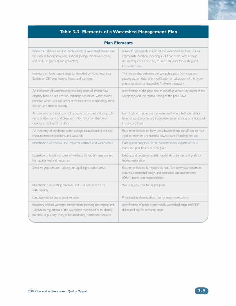
2004 Connecticut Stormwater Quality Manual 3-9
Plan Elements
Table 3-3 Elements of a Watershed Management Plan
Watershed delineation and identification of watershed characteris-
tics such as topography, soils, surficial geology, impervious cover,
and land use (current and projected)
Inventory of flood hazard areas as identified by Flood Insurance
Studies or DEP, plus historic floods and damages
An evaluation of watercourses, including areas of limited flow
capacity, bank or bed erosion, sediment deposition, water quality,
principle water uses and users, recreation areas, morphology classi-
fication, and channel stability
An inventory and evaluation of hydraulic structures, including cul-
verts, bridges, dams and dikes with information on their flow
capacity and physical condition
An inventory of significant water storage areas, including principal
impoundments, floodplains, and wetlands
Identification of sensitive and impaired wetlands and waterbodies
Evaluation of functional value of wetlands to identify sensitive and
high quality wetland resources
Sensitive groundwater recharge or aquifer protection areas
Identification of existing problem land uses and impacts on
water quality
Land use restrictions in sensitive areas
Inventory of local wetlands, conservation, planning and zoning, and
subdivision regulations of the watershed municipalities to identify
potential regulatory changes for addressing stormwater impacts
A runoff hydrograph analysis of the watershed for floods of an
appropriate duration, including a 24 hour event, with average
return frequencies of 2, 10, 25, and 100 years for existing and
future land uses
The relationship between the computed peak flow rates and
gauging station data, with modification or calibration of the hydro-
graphs to obtain a reasonable fit where necessary
Identification of the peak rate of runoff at various key points in the
watershed, and the relative timing of the peak flows
Identification of points in the watershed where hydraulic struc-
tures or watercourses are inadequate under existing or anticipated
future conditions
Recommendations on how the subwatershed’s runoff can be man-
aged to minimize any harmful downstream (flooding) impacts
Existing and projected future pollutant loads, impacts of these
loads, and pollution reduction goals
Existing and projected aquatic habitat disturbances and goals for
habitat restoration
Recommendations for watershed-specific stormwater treatment
controls, conceptual design, and operation and maintenance
(O&M) needs and responsibilities
Water quality monitoring program
Prioritized implementation plan for recommendations
Identification of public water supply watershed areas and DEP-
delineated aquifer recharge areas.
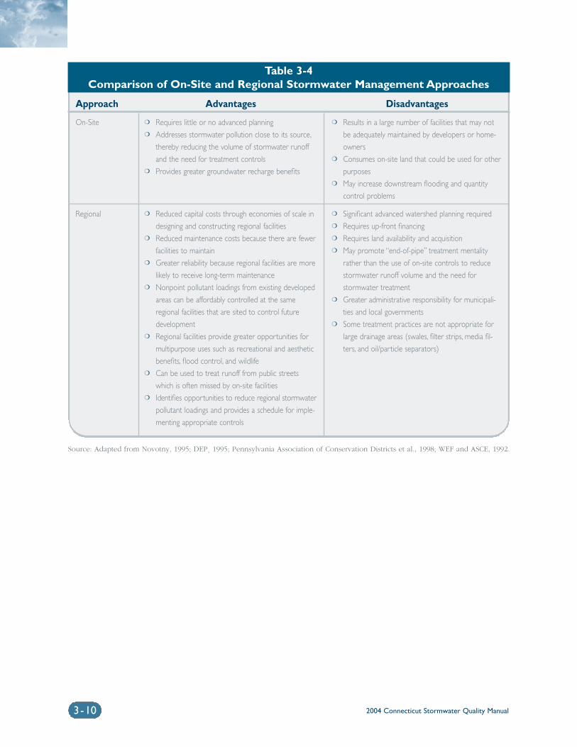
2004 Connecticut Stormwater Quality Manual3-10
Source: Adapted from Novotny, 1995; DEP¸ 1995; Pennsylvania Association of Conservation Districts et al., 1998; WEF and ASCE, 1992.
Table 3-4Comparison of On-Site and Regional Stormwater Management Approaches
Approach
On-Site
Regional
Advantages
❍ Requires little or no advanced planning❍ Addresses stormwater pollution close to its source,
thereby reducing the volume of stormwater runoff
and the need for treatment controls❍ Provides greater groundwater recharge benefits
❍ Reduced capital costs through economies of scale in
designing and constructing regional facilities❍ Reduced maintenance costs because there are fewer
facilities to maintain❍ Greater reliability because regional facilities are more
likely to receive long-term maintenance❍ Nonpoint pollutant loadings from existing developed
areas can be affordably controlled at the same
regional facilities that are sited to control future
development❍ Regional facilities provide greater opportunities for
multipurpose uses such as recreational and aesthetic
benefits, flood control, and wildlife❍ Can be used to treat runoff from public streets
which is often missed by on-site facilities❍ Identifies opportunities to reduce regional stormwater
pollutant loadings and provides a schedule for imple-
menting appropriate controls
Disadvantages
❍ Results in a large number of facilities that may not
be adequately maintained by developers or home-
owners❍ Consumes on-site land that could be used for other
purposes❍ May increase downstream flooding and quantity
control problems
❍ Significant advanced watershed planning required❍ Requires up-front financing❍ Requires land availability and acquisition❍ May promote “end-of-pipe” treatment mentality
rather than the use of on-site controls to reduce
stormwater runoff volume and the need for
stormwater treatment❍ Greater administrative responsibility for municipali-
ties and local governments❍ Some treatment practices are not appropriate for
large drainage areas (swales, filter strips, media fil-
ters, and oil/particle separators)
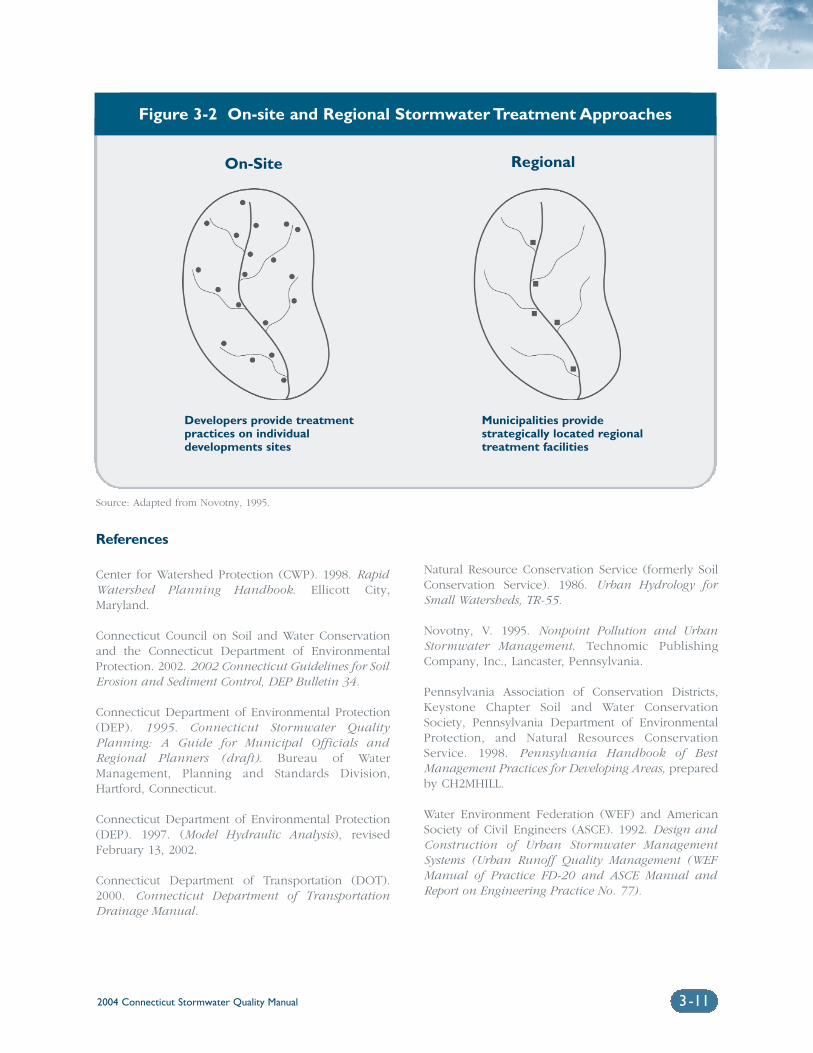
References
Center for Watershed Protection (CWP). 1998. RapidWatershed Planning Handbook. Ellicott City,Maryland.
Connecticut Council on Soil and Water Conservationand the Connecticut Department of EnvironmentalProtection. 2002. 2002 Connecticut Guidelines for SoilErosion and Sediment Control, DEP Bulletin 34.
Connecticut Department of Environmental Protection(DEP). 1995. Connecticut Stormwater QualityPlanning: A Guide for Municipal Officials andRegional Planners (draft). Bureau of WaterManagement, Planning and Standards Division,Hartford, Connecticut.
Connecticut Department of Environmental Protection(DEP). 1997. (Model Hydraulic Analysis), revisedFebruary 13, 2002.
Connecticut Department of Transportation (DOT).2000. Connecticut Department of TransportationDrainage Manual.
Natural Resource Conservation Service (formerly SoilConservation Service). 1986. Urban Hydrology forSmall Watersheds, TR-55.
Novotny, V. 1995. Nonpoint Pollution and UrbanStormwater Management. Technomic PublishingCompany, Inc., Lancaster, Pennsylvania.
Pennsylvania Association of Conservation Districts,Keystone Chapter Soil and Water ConservationSociety, Pennsylvania Department of EnvironmentalProtection, and Natural Resources ConservationService. 1998. Pennsylvania Handbook of BestManagement Practices for Developing Areas, preparedby CH2MHILL.
Water Environment Federation (WEF) and AmericanSociety of Civil Engineers (ASCE). 1992. Design andConstruction of Urban Stormwater ManagementSystems (Urban Runoff Quality Management (WEFManual of Practice FD-20 and ASCE Manual andReport on Engineering Practice No. 77).
2004 Connecticut Stormwater Quality Manual 3-11
Figure 3-2 On-site and Regional Stormwater Treatment Approaches
On-Site
Developers provide treatmentpractices on individual developments sites
Municipalities providestrategically located regionaltreatment facilities
Regional
Source: Adapted from Novotny, 1995.

Chapter 4Site Planning and Design
Chapter 4 Site Planning and Design
4.1 Introduction...................................................................................................4-2
4.2 Site Planning and Design Concepts..........................................................4-2
4.3 Alternative Site Design................................................................................4-4
4.3.1 Streets and Parking Lots .........................................................4-6
4.3.2 Lot Development ....................................................................4-11
4.4 Low Impact Development Management Practices.............................4-13
4.4.1 Vegetated Swales, Buffers, and Filter Strips ......................4-13
4.4.2 Bioretention/Rain Gardens ..................................................4-13
4.4.3 Dry Wells/Leaching Trenches...............................................4-15
4.4.4 Rainwater Harvesting............................................................4-15
4.4.5 Vegetated Roof Covers .........................................................4-17
Volume 1: Background
2004 Connecticut Stormwater Quality Manual 4-1
Site planning and design is a complex process involving a variety ofconsiderations such as zoning regulations (e.g. setbacks, Floor Area Ratioallowances, allowable building density, and height restrictions) andimpacts to traffic, wetlands, and the environment. Site planning is under-taken by the developer or project proponent in conjunction with localand/or state review agencies, typically local Planning, Zoning, and InlandWetlands Commissions and, in some instances, the ConnecticutDepartment of Environmental Protection (DEP) or federal agencies such asthe U.S. Army Corps of Engineers. Due to the complexities of site planningand design, the most effective site planning process occurs through a col-laborative effort between developers and the review agencies before andthroughout the review process.
This chapter addresses recommended site planning concepts and prac-tices that can be incorporated into the design of new projects to providewater quality and quantity benefits and reduce the need for or size of struc-tural stormwater controls. This chapter does not address comprehensiveland use planning (master planning, zoning, open space, conservationeasements, etc.) which is beyond the scope of this Manual. However, thesite planning concepts and practices presented in this chapter should beimplemented through existing local land use ordinances and state regula-tions and programs. Local and state review agencies should encourage theimplementation of these practices through the site plan review process. Inmany instances, communities may need to re-evaluate local codes andordinances to effectively promote the use of the practices described in thischapter. These design concepts are encouraged by DEP, as well as by theConnecticut Department of Public Health (DPH) for protection of watersupplies in public drinking water supply watershed areas.
4.2 Site Planning and Design ConceptsThe concepts presented in this section are central to effective site planningand design for stormwater management and environmental resource pro-tection. Each of these concepts is based on the fundamental objective ofpreserving a site’s natural hydrologic conditions. As discussed in ChapterTwo, the hydrologic conditions and pollutant removal functions of a sitecan be altered significantly as a result of development. The traditionalapproach to site drainage has been to remove runoff from the site asquickly and efficiently as possible through the use of storm sewers andstructural stormwater conveyances, and to provide detention facilities tomanage increases in peak flows. This approach severely reduces the natu-ral hydrologic and water quality functions of the site and contributes to theadverse environmental impacts discussed in Chapter Two.
A guiding principle of effective site planning is to preserve pre-devel-opment hydrologic conditions such as:
❍ Runoff volume and rate
❍ Groundwater recharge
❍ Stream baseflow
❍ Runoff water quality
This can be accomplished through a number of techniques that shouldbe integrated into the site planning and design process wherever possible.These techniques are described in the following sections of this chapter. Incollaboration with DEP’s NPS Program, the University of ConnecticutCooperative Extension System’s Nonpoint Education for Municipal Officials(NEMO) Project offers assistance to Connecticut municipalities in imple-
2004 Connecticut Stormwater Quality Manual4-2
4.1 IntroductionCareful site planning at the out-
set of a project is the most
effective approach for prevent-
ing or reducing the potential
adverse impacts from develop-
ment. Site planning is a
preventive measure that
addresses the root causes of
stormwater problems. Effective
site layouts and designs that
preserve natural features as
well as natural hydrologic and
water quality functions can limit
water quality impacts and the
need for costly structural
stormwater controls, thereby
reducing the costs of develop-
ment. Other potential benefits
of effective site planning include
preservation of open space,
enhanced aesthetic and recre-
ational value, reduced
downstream flooding, and
enhanced land values.
2004 Connecticut Stormwater Quality Manual 4-3
menting these site planning and design strategies.(See Additional Information Sources at the end of thischapter or visit http://www.nemo.uconn.edu).
Designing the Development to Fit the TerrainDevelopments that are designed to “fit the terrain” ofthe site require significantly less grading and soil dis-turbance than those that are designed without regardfor the existing topography. Road patterns shouldmatch the landform by placing roadways parallel tocontour lines where possible. In doing so, naturaldrainageways can be constructed along street rights-of-way, thereby reducing the need for storm pipes.Open space development, allowable in many munic-ipalities, can help preserve large natural areas andopen space as well as make it possible to designaround topographical constraints.
Limiting Land Disturbance ActivitiesLand disturbance activities such as clearing and grub-bing, excavation, and grading result in erosion ofexposed soils, increased sediment loadings, as well asincreased volumes of runoff from a site. Limiting theland area disturbed by development can only beaddressed comprehensively at the site planning level(Schueler, 1995). Land disturbance activities should belimited to only those areas absolutely necessary forconstruction purposes, in keeping with the naturalfeatures of the site, and should be clearly delineatedin the field prior to construction. Land disturbanceactivities in proximity to wetlands, watercourses,steep slopes, and other sensitive resource areasshould be avoided, or minimized if they cannot beavoided. Areas outside the disturbed zone shouldretain natural vegetation. This approach is more suc-cessful on larger lots where large areas ofundeveloped land can be preserved. The successfulapplication of this approach is more difficult and lesspractical on small lots in heavily developed areas(NJDEP, 2000).
Reducing or Disconnecting Impervious AreasReducing and disconnecting impervious surfaces areeffective methods for preserving pre-developmenthydrology. Reducing impervious coverage on a sitedirectly limits the adverse impacts associated withimpervious coverage. On a watershed basis, reduc-tions in impervious coverage contribute directly to theecological health of streams and receiving waters, asdescribed in Chapter Two. Impervious surfaces thatare not directly connected to the drainage collectionsystem contribute less runoff and smaller pollutantloads than hydraulically connected impervious sur-faces. Isolating impervious surfaces also promotesinfiltration of stormwater runoff. Specific techniquesfor reducing or disconnecting impervious areas forroad and lot development are described in Section 4.3 Alternative Site Design.
Preserving and Utilizing Natural Drainage SystemsThe goal of traditional drainage design, to collect andconvey stormwater runoff from the site as efficientlyas possible, is in direct conflict with the objectives ofwater quality design, which is to slow down andattenuate runoff to allow filtration, infiltration, biolog-ical uptake, and settling of pollutants. Naturaldrainage features such as vegetated swales and chan-nels and natural micro-pools or depressions shouldbe preserved or incorporated into the design of a siteto take advantage of their ability to infiltrate andattenuate flows and filter pollutants. The use of natu-ral overland drainage features such as stabilizedswales, where soil and hydraulic conditions allow,and the discharge of stormwater in a diffuse mannerfrom level spreaders should be encouraged as analternative to traditional storm sewer systems.Consistent with this approach is to design roads andparking areas at higher elevations in the landscapeand locate existing swales along back lot lines withindrainage easements (Pennsylvania Association ofConservation Districts et al., 1998). Natural low areasor depressions in the landscape should be preservedwhere possible to maintain infiltration of runoff inthese areas similar to pre-development conditions.
Providing Setbacks and Vegetated BuffersSetbacks and vegetated buffers provide protection ofadjacent natural resources from areas of intensivedevelopment. A setback is the regulated area betweenthe development and a protected area such as a wet-land. A vegetated buffer is an area or strip of land ofpermanent undisturbed vegetation adjacent to a waterbody or other resource. Buffers protect resourcesfrom adjacent development during construction andafter development by filtering pollutants in runoff,protecting water quality and temperature, providingwildlife habitat, screening structures and enhancingaesthetics, and providing access for recreation.Characteristics such as width, target vegetation, andallowable uses within buffers are managed to ensurethat the goals designated for the buffer are achieved(Center for Watershed Protection, 1998b). Buffersalong watercourses also serve to function as green-ways that provide for connectivity of open spaceareas, allowing the movement of wildlife and theopportunity for passive recreation. The dual benefitsthat buffers provide for the protection of water qual-ity from stormwater runoff and the creation ofgreenways are extremely important and complemen-tary. Table 4-1 summarizes the benefits that can beachieved by buffer systems.
As a general rule, one hundred feet of undis-turbed upland along a wetland boundary or on eitherside of a watercourse is recommended as a minimumbuffer width depending on the slope and sensitivity ofthe wetland or watercourse. A conceptual three-zone
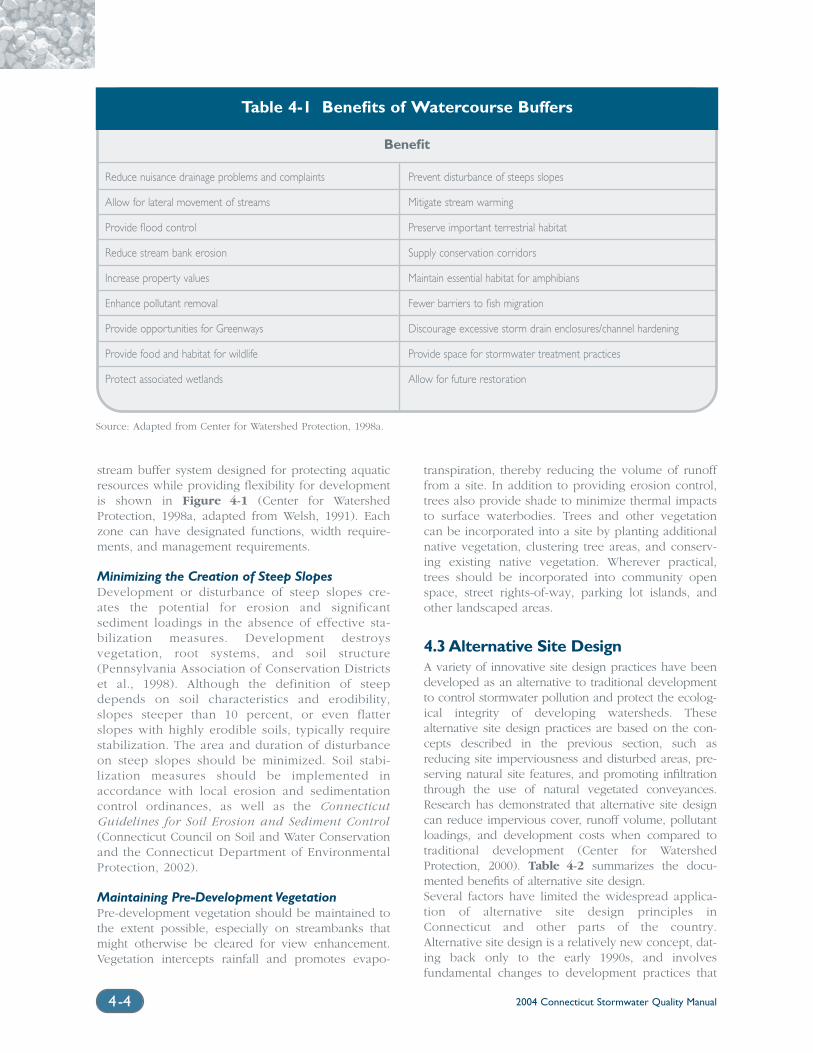
2004 Connecticut Stormwater Quality Manual4-4
stream buffer system designed for protecting aquaticresources while providing flexibility for developmentis shown in Figure 4-1 (Center for WatershedProtection, 1998a, adapted from Welsh, 1991). Eachzone can have designated functions, width require-ments, and management requirements.
Minimizing the Creation of Steep SlopesDevelopment or disturbance of steep slopes cre-ates the potential for erosion and significantsediment loadings in the absence of effective sta-bilization measures. Development destroysvegetation, root systems, and soil structure(Pennsylvania Association of Conservation Districtset al., 1998). Although the definition of steepdepends on soil characteristics and erodibility,slopes steeper than 10 percent, or even flatterslopes with highly erodible soils, typically requirestabilization. The area and duration of disturbanceon steep slopes should be minimized. Soil stabi-lization measures should be implemented inaccordance with local erosion and sedimentationcontrol ordinances, as well as the ConnecticutGuidelines for Soil Erosion and Sediment Control(Connecticut Council on Soil and Water Conservationand the Connecticut Department of EnvironmentalProtection, 2002).
Maintaining Pre-Development VegetationPre-development vegetation should be maintained tothe extent possible, especially on streambanks thatmight otherwise be cleared for view enhancement.Vegetation intercepts rainfall and promotes evapo-
transpiration, thereby reducing the volume of runofffrom a site. In addition to providing erosion control,trees also provide shade to minimize thermal impactsto surface waterbodies. Trees and other vegetationcan be incorporated into a site by planting additionalnative vegetation, clustering tree areas, and conserv-ing existing native vegetation. Wherever practical,trees should be incorporated into community openspace, street rights-of-way, parking lot islands, andother landscaped areas.
4.3 Alternative Site DesignA variety of innovative site design practices have beendeveloped as an alternative to traditional developmentto control stormwater pollution and protect the ecolog-ical integrity of developing watersheds. Thesealternative site design practices are based on the con-cepts described in the previous section, such asreducing site imperviousness and disturbed areas, pre-serving natural site features, and promoting infiltrationthrough the use of natural vegetated conveyances.Research has demonstrated that alternative site designcan reduce impervious cover, runoff volume, pollutantloadings, and development costs when compared totraditional development (Center for WatershedProtection, 2000). Table 4-2 summarizes the docu-mented benefits of alternative site design. Several factors have limited the widespread applica-tion of alternative site design principles inConnecticut and other parts of the country.Alternative site design is a relatively new concept, dat-ing back only to the early 1990s, and involvesfundamental changes to development practices that
Source: Adapted from Center for Watershed Protection, 1998a.
Table 4-1 Benefits of Watercourse Buffers
Benefit
Reduce nuisance drainage problems and complaints Prevent disturbance of steeps slopes
Allow for lateral movement of streams Mitigate stream warming
Provide flood control Preserve important terrestrial habitat
Reduce stream bank erosion Supply conservation corridors
Increase property values Maintain essential habitat for amphibians
Enhance pollutant removal Fewer barriers to fish migration
Provide opportunities for Greenways Discourage excessive storm drain enclosures/channel hardening
Provide food and habitat for wildlife Provide space for stormwater treatment practices
Protect associated wetlands Allow for future restoration
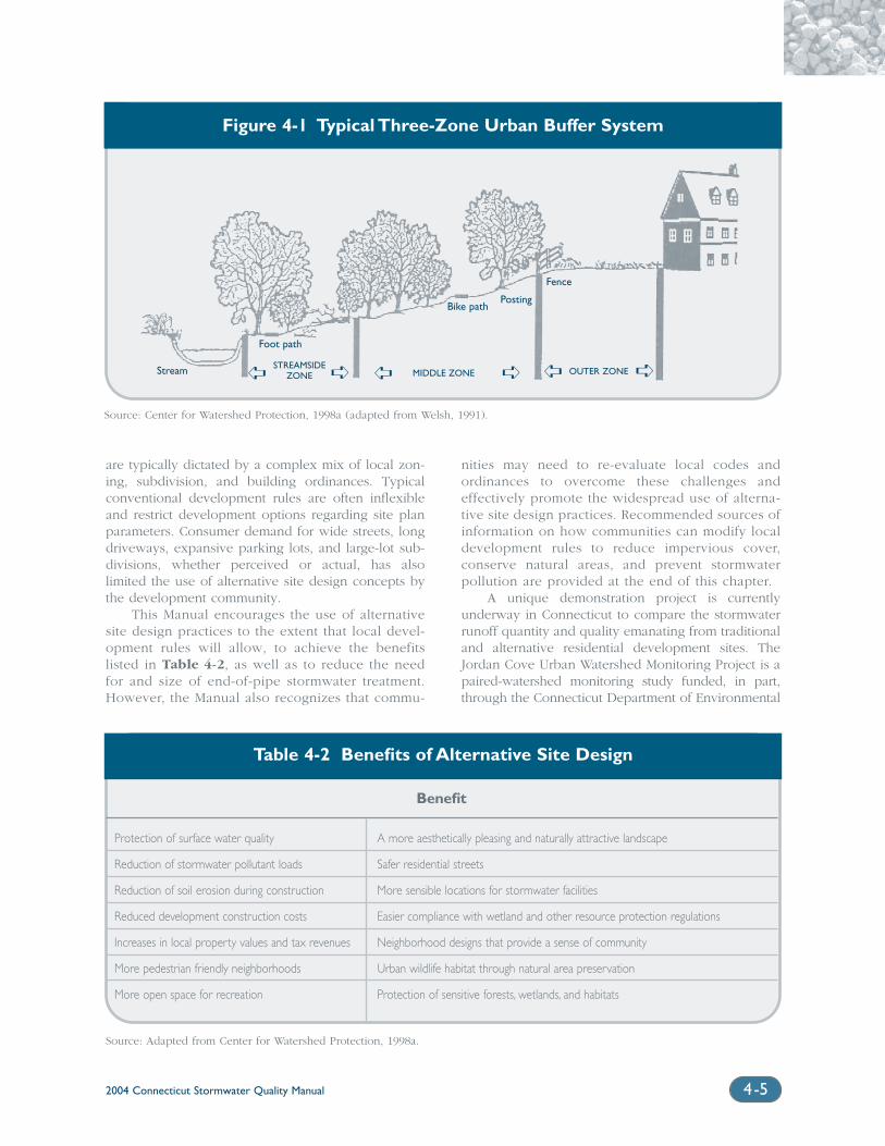
2004 Connecticut Stormwater Quality Manual 4-5
are typically dictated by a complex mix of local zon-ing, subdivision, and building ordinances. Typicalconventional development rules are often inflexibleand restrict development options regarding site planparameters. Consumer demand for wide streets, longdriveways, expansive parking lots, and large-lot sub-divisions, whether perceived or actual, has alsolimited the use of alternative site design concepts bythe development community.
This Manual encourages the use of alternativesite design practices to the extent that local devel-opment rules will allow, to achieve the benefitslisted in Table 4-2, as well as to reduce the needfor and size of end-of-pipe stormwater treatment.However, the Manual also recognizes that commu-
nities may need to re-evaluate local codes andordinances to overcome these challenges andeffectively promote the widespread use of alterna-tive site design practices. Recommended sources ofinformation on how communities can modify localdevelopment rules to reduce impervious cover,conserve natural areas, and prevent stormwaterpollution are provided at the end of this chapter.
A unique demonstration project is currentlyunderway in Connecticut to compare the stormwaterrunoff quantity and quality emanating from traditionaland alternative residential development sites. TheJordan Cove Urban Watershed Monitoring Project is apaired-watershed monitoring study funded, in part,through the Connecticut Department of Environmental
Figure 4-1 Typical Three-Zone Urban Buffer System
STREAMSIDEZONE MIDDLE ZONE OUTER ZONE
Fence
PostingBike path
Foot path
Stream
Source: Center for Watershed Protection, 1998a (adapted from Welsh, 1991).
Table 4-2 Benefits of Alternative Site Design
Benefit
Protection of surface water quality A more aesthetically pleasing and naturally attractive landscape
Reduction of stormwater pollutant loads Safer residential streets
Reduction of soil erosion during construction More sensible locations for stormwater facilities
Reduced development construction costs Easier compliance with wetland and other resource protection regulations
Increases in local property values and tax revenues Neighborhood designs that provide a sense of community
More pedestrian friendly neighborhoods Urban wildlife habitat through natural area preservation
More open space for recreation Protection of sensitive forests, wetlands, and habitats
Source: Adapted from Center for Watershed Protection, 1998a.
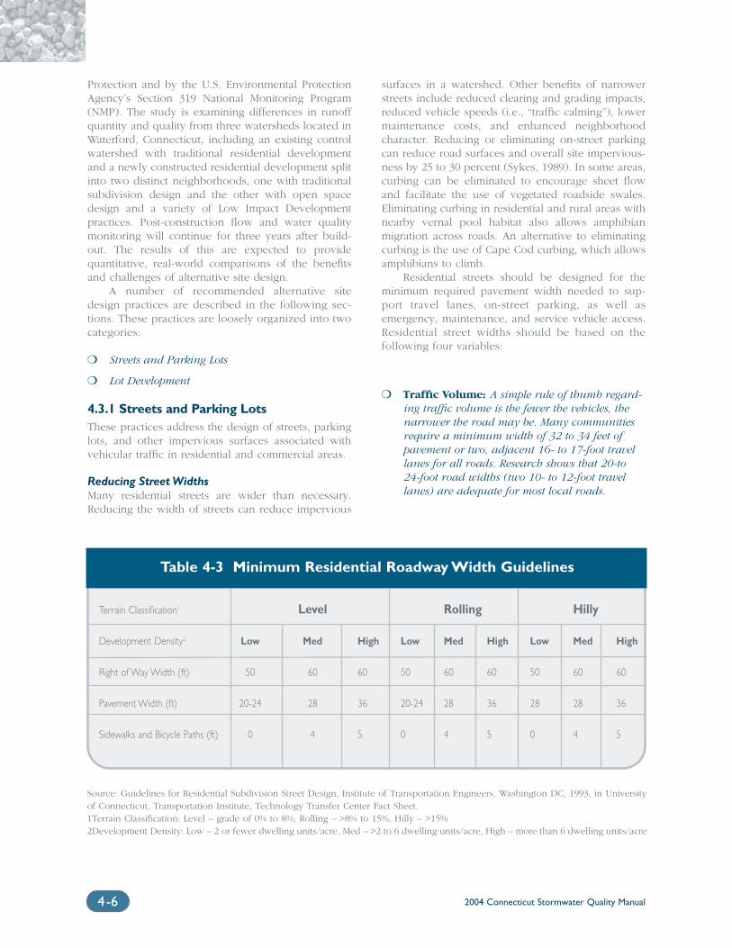
Terrain Classification1 Level Rolling Hilly
Development Density2 Low Med High Low Med High Low Med High
Right of Way Width (ft) 50 60 60 50 60 60 50 60 60
Pavement Width (ft) 20-24 28 36 20-24 28 36 28 28 36
Sidewalks and Bicycle Paths (ft) 0 4 5 0 4 5 0 4 5
2004 Connecticut Stormwater Quality Manual4-6
Protection and by the U.S. Environmental ProtectionAgency’s Section 319 National Monitoring Program(NMP). The study is examining differences in runoffquantity and quality from three watersheds located inWaterford, Connecticut, including an existing controlwatershed with traditional residential developmentand a newly constructed residential development splitinto two distinct neighborhoods, one with traditionalsubdivision design and the other with open spacedesign and a variety of Low Impact Developmentpractices. Post-construction flow and water qualitymonitoring will continue for three years after build-out. The results of this are expected to providequantitative, real-world comparisons of the benefitsand challenges of alternative site design.
A number of recommended alternative sitedesign practices are described in the following sec-tions. These practices are loosely organized into twocategories:
❍ Streets and Parking Lots
❍ Lot Development
4.3.1 Streets and Parking LotsThese practices address the design of streets, parkinglots, and other impervious surfaces associated withvehicular traffic in residential and commercial areas.
Reducing Street WidthsMany residential streets are wider than necessary.Reducing the width of streets can reduce impervious
surfaces in a watershed. Other benefits of narrowerstreets include reduced clearing and grading impacts,reduced vehicle speeds (i.e., “traffic calming”), lowermaintenance costs, and enhanced neighborhoodcharacter. Reducing or eliminating on-street parkingcan reduce road surfaces and overall site impervious-ness by 25 to 30 percent (Sykes, 1989). In some areas,curbing can be eliminated to encourage sheet flowand facilitate the use of vegetated roadside swales.Eliminating curbing in residential and rural areas withnearby vernal pool habitat also allows amphibianmigration across roads. An alternative to eliminatingcurbing is the use of Cape Cod curbing, which allowsamphibians to climb.
Residential streets should be designed for theminimum required pavement width needed to sup-port travel lanes, on-street parking, as well asemergency, maintenance, and service vehicle access.Residential street widths should be based on thefollowing four variables:
❍ Traffic Volume: A simple rule of thumb regard-ing traffic volume is the fewer the vehicles, thenarrower the road may be. Many communitiesrequire a minimum width of 32 to 34 feet ofpavement or two, adjacent 16- to 17-foot travellanes for all roads. Research shows that 20-to24-foot road widths (two 10- to 12-foot travellanes) are adequate for most local roads.
Source: Guidelines for Residential Subdivision Street Design, Institute of Transportation Engineers, Washington DC, 1993, in Universityof Connecticut, Transportation Institute, Technology Transfer Center Fact Sheet.1Terrain Classification: Level – grade of 0% to 8%, Rolling – >8% to 15%, Hilly – >15%2Development Density: Low – 2 or fewer dwelling units/acre, Med – >2 to 6 dwelling units/acre, High – more than 6 dwelling units/acre
Table 4-3 Minimum Residential Roadway Width Guidelines
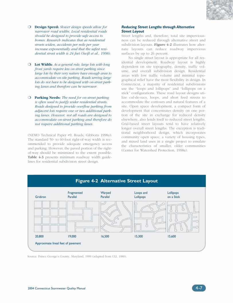
2004 Connecticut Stormwater Quality Manual 4-7
❍ Design Speed: Slower design speeds allow fornarrower road widths. Local residential roadsshould be designed to provide safe access tohomes. Research indicates that as residentialstreets widen, accidents per mile per yearincrease exponentially and that the safest resi-dential street width is 24 feet (Swift et al., 1998).
❍ Lot Width: As a general rule, large lots with longfront yards require less on-street parking sincelarge lots by their very nature have enough area toaccommodate on-site parking. Roads serving largelots do not have to be designed with on-street park-ing lanes and therefore can be narrower.
❍ Parking Needs: The need for on-street parkingis often used to justify wider residential streets.Roads designed to provide overflow parking fromadjacent lots require one or two additional park-ing lanes. However, not all roads are designed toaccommodate on-street parking and therefore donot require additional parking lanes.
(NEMO Technical Paper #9, Roads, Gibbons 1998a):The standard 50- to 60-foot right-of-way width is rec-ommended to provide adequate emergency accessand parking. However, the paved portion of the right-of-way should be minimized to the extent possible.Table 4-3 presents minimum roadway width guide-lines for residential subdivision street design.
Reducing Street Lengths through AlternativeStreet LayoutStreet lengths and, therefore, total site impervious-ness can be reduced through alternative street andsubdivision layouts. Figure 4-2 illustrates how alter-nate layouts can reduce roadway impervioussurfaces by up to 26 percent.
No single street layout is appropriate for all res-idential development. Roadway layout is highlydependent on site topography, density, traffic vol-ume, and overall subdivision design. Residentialareas with low traffic volume and minimal topo-graphical relief have the most flexibility in design. InConnecticut, a majority of residential subdivisionsuse the “loops and lollipops” and “lollipops on astick” configurations. These road layout designs uti-lize cul-de-sacs, loops, and short feed streets toaccommodate the contours and natural features of asite. Open space development, a compact form ofdevelopment that concentrates density on one por-tion of the site in exchange for reduced densityelsewhere, also lends itself to reduced street lengths.Grid-based street layouts tend to have relativelylonger overall street lengths. The exception is tradi-tional neighborhood design, which incorporatescommunity open space, a variety of housing types,and mixed land uses in a single project to emulatethe characteristics of smaller, older communities(Center for Watershed Protection, 1998a).
Figure 4-2 Alternative Street Layout
Source: Prince George’s County, Maryland, 1999 (adapted from ULI, 1980).
Fragmented Warped Loops and LollipopsGridiron Parallel Parallel Lollipops on a Stick
20,800 19,000 16,500 15,300 15,600
Approximate lineal feet of pavement
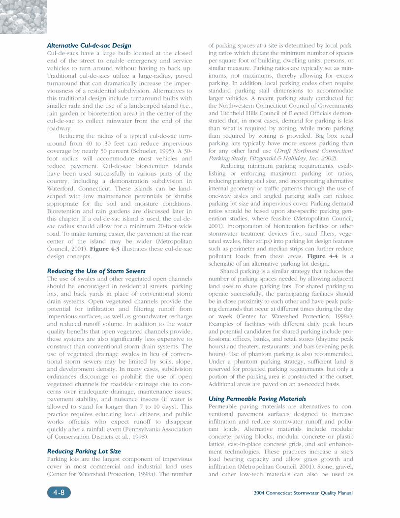
2004 Connecticut Stormwater Quality Manual4-8
Alternative Cul-de-sac DesignCul-de-sacs have a large bulb located at the closedend of the street to enable emergency and servicevehicles to turn around without having to back up.Traditional cul-de-sacs utilize a large-radius, pavedturnaround that can dramatically increase the imper-viousness of a residential subdivision. Alternatives tothis traditional design include turnaround bulbs withsmaller radii and the use of a landscaped island (i.e.,rain garden or bioretention area) in the center of thecul-de-sac to collect rainwater from the end of theroadway.
Reducing the radius of a typical cul-de-sac turn-around from 40 to 30 feet can reduce imperviouscoverage by nearly 50 percent (Schueler, 1995). A 30-foot radius will accommodate most vehicles andreduce pavement. Cul-de-sac bioretention islandshave been used successfully in various parts of thecountry, including a demonstration subdivision inWaterford, Connecticut. These islands can be land-scaped with low maintenance perennials or shrubsappropriate for the soil and moisture conditions.Bioretention and rain gardens are discussed later inthis chapter. If a cul-de-sac island is used, the cul-de-sac radius should allow for a minimum 20-foot wideroad. To make turning easier, the pavement at the rearcenter of the island may be wider (MetropolitanCouncil, 2001). Figure 4-3 illustrates these cul-de-sacdesign concepts.
Reducing the Use of Storm SewersThe use of swales and other vegetated open channelsshould be encouraged in residential streets, parkinglots, and back yards in place of conventional stormdrain systems. Open vegetated channels provide thepotential for infiltration and filtering runoff fromimpervious surfaces, as well as groundwater rechargeand reduced runoff volume. In addition to the waterquality benefits that open vegetated channels provide,these systems are also significantly less expensive toconstruct than conventional storm drain systems. Theuse of vegetated drainage swales in lieu of conven-tional storm sewers may be limited by soils, slope,and development density. In many cases, subdivisionordinances discourage or prohibit the use of openvegetated channels for roadside drainage due to con-cerns over inadequate drainage, maintenance issues,pavement stability, and nuisance insects (if water isallowed to stand for longer than 7 to 10 days). Thispractice requires educating local citizens and publicworks officials who expect runoff to disappearquickly after a rainfall event (Pennsylvania Associationof Conservation Districts et al., 1998).
Reducing Parking Lot SizeParking lots are the largest component of imperviouscover in most commercial and industrial land uses(Center for Watershed Protection, 1998a). The number
of parking spaces at a site is determined by local park-ing ratios which dictate the minimum number of spacesper square foot of building, dwelling units, persons, orsimilar measure. Parking ratios are typically set as min-imums, not maximums, thereby allowing for excessparking. In addition, local parking codes often requirestandard parking stall dimensions to accommodatelarger vehicles. A recent parking study conducted forthe Northwestern Connecticut Council of Governmentsand Litchfield Hills Council of Elected Officials demon-strated that, in most cases, demand for parking is lessthan what is required by zoning, while more parkingthan required by zoning is provided. Big box retailparking lots typically have more excess parking thanfor any other land use (Draft Northwest ConnecticutParking Study, Fitzgerald & Halliday, Inc. 2002).
Reducing minimum parking requirements, estab-lishing or enforcing maximum parking lot ratios,reducing parking stall size, and incorporating alternativeinternal geometry or traffic patterns through the use ofone-way aisles and angled parking stalls can reduceparking lot size and impervious cover. Parking demandratios should be based upon site-specific parking gen-eration studies, where feasible (Metropolitan Council,2001). Incorporation of bioretention facilities or otherstormwater treatment devices (i.e., sand filters, vege-tated swales, filter strips) into parking lot design featuressuch as perimeter and median strips can further reducepollutant loads from these areas. Figure 4-4 is aschematic of an alternative parking lot design.
Shared parking is a similar strategy that reduces thenumber of parking spaces needed by allowing adjacentland uses to share parking lots. For shared parking tooperate successfully, the participating facilities shouldbe in close proximity to each other and have peak park-ing demands that occur at different times during the dayor week (Center for Watershed Protection, 1998a).Examples of facilities with different daily peak hoursand potential candidates for shared parking include pro-fessional offices, banks, and retail stores (daytime peakhours) and theaters, restaurants, and bars (evening peakhours). Use of phantom parking is also recommended.Under a phantom parking strategy, sufficient land isreserved for projected parking requirements, but only aportion of the parking area is constructed at the outset.Additional areas are paved on an as-needed basis.
Using Permeable Paving MaterialsPermeable paving materials are alternatives to con-ventional pavement surfaces designed to increaseinfiltration and reduce stormwater runoff and pollu-tant loads. Alternative materials include modularconcrete paving blocks, modular concrete or plasticlattice, cast-in-place concrete grids, and soil enhance-ment technologies. These practices increase a site’sload bearing capacity and allow grass growth andinfiltration (Metropolitan Council, 2001). Stone, gravel,and other low-tech materials can also be used as
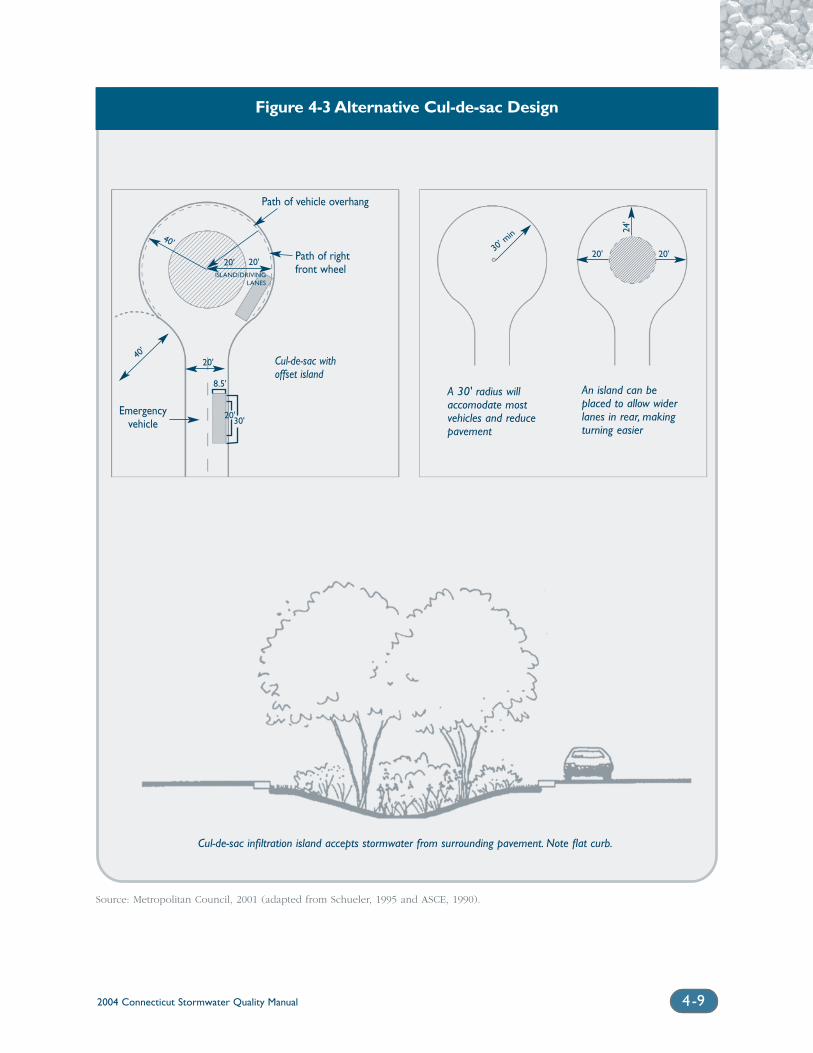
2004 Connecticut Stormwater Quality Manual 4-9
FigureFigure 4-3 Alternative Cul-de-sac Design
Path of vehicle overhang
Path of rightfront wheel
Emergencyvehicle
40'
Cul-de-sac withoffset island
A 30' radius willaccomodate mostvehicles and reducepavement
An island can beplaced to allow widerlanes in rear, makingturning easier
Cul-de-sac infiltration island accepts stormwater from surrounding pavement. Note flat curb.
Source: Metropolitan Council, 2001 (adapted from Schueler, 1995 and ASCE, 1990).
30' m
in
20' 20'
24'
40'
20' 20'ISLAND/DRIVING
LANES
20'
8.5'
20'30'
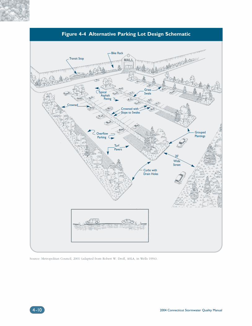
2004 Connecticut Stormwater Quality Manual4-10
Figure 4-4 Alternative Parking Lot Design Schematic
Transit Stop
Bike Rack
GrassSwale
Crowned withSlope to Swales
TypicalAsphalt
Paving
TurfPavers
OverflowParking
Crowned
Source: Metropolitan Council, 2001 (adapted from Robert W. Droll, ASLA, in Wells 1994).
Curbs withDrain Holes
20'
WideStreet
GroupedPlantings
alternatives for low traffic applications such as drive-ways, haul roads, and access roads.
Porous asphalt or concrete, also known as porouspavement, is similar to conventional asphalt but for-mulated to have more void space for greater waterpassage through the material. Traditionally, porouspavement has had limited application in cold climatessuch as Connecticut due to the potential for cloggingas a result of sand application. Porous pavement hasbeen successfully used for some parking lot applica-tions in New England where the underlying soils aresufficiently permeable. One example is a parkinglot demonstration project at Walden Pond StateReservation in eastern Massachusetts.
While permeable paving materials can makesense in many parking lot designs, site-specific factorssuch as accessibility, soils, maintenance, and long-termperformance must be carefully considered. Permeablepaving materials are most appropriate in areas of lowtraffic volume (e.g., generally less than 500 averagedaily trips or ADT) such as roadside rights-of-way,emergency access lanes, delivery access routes, resi-dential driveways, and overflow parking. ChapterEleven of this Manual contains additional siting anddesign guidance for permeable pavement materials.
4.3.2 Lot DevelopmentThese alternative design practices address thesize, shape, density, and appearance of residen-tial development.
Maintaining Pre-Development VegetationPre-development vegetation should be maintained tothe extent possible. Vegetation intercepts rainfall andpromotes evapotranspiration, thereby reducing thevolume of runoff from a site. Trees and other vegeta-tion can be incorporated into a site by plantingadditional vegetation, clustering tree areas, and con-serving native vegetation. Wherever practical, treesshould be incorporated into community open space,street rights-of-way, parking lot islands, bioretentionareas, and other landscaped areas.
Open Space DevelopmentOpen space development, also known as conserva-tion or cluster development, can reduce the amount ofimpervious area for a given number of lots. Openspace development is a compact form of developmentthat concentrates density in one portion of the site inexchange for reduced density elsewhere (Center forWatershed Protection, 1998a). Planners have advo-cated open space development for many years forcommunity design, preservation of rural character, orcreation of affordable housing. However, it has onlyrecently been identified as a site planning practice forreducing imperviousness and for environmental pro-tection. Open space design is most effective for
reducing impervious cover when used in conjunctionwith narrower streets and other alternative site designpractices. Studies have shown that open space designscan reduce impervious cover from 15 to 50 percentwhen compared to conventional subdivision designs,particularly if narrow streets are utilized (NEMO,1999). Open space designs can generally achieve sig-nificant reductions in impervious cover for mostresidential zones, although only minor reductionsoccur in areas with 1/8-acre lots and smaller (Centerfor Watershed Protection, 1998a).
The benefits of open space development aresummarized in Table 4-4. In particular, this Manualencourages the use of open space development as analternative to conventional subdivision layout to:
❍ Reduce overall site imperviousness and associ-ated stormwater impacts
❍ Avoid development in sensitive areas of a site
❍ Locate stormwater treatment facilities within theopen space
Historically, there have been several barriers tothe widespread use of open space development inConnecticut, primarily due to poorly worded “clusterzoning” adopted by many communities in the 1960sand 1970s. Smaller lot sizes and compact developmentcan be perceived as less marketable, and prospectivehomebuyers may have concerns over management ofcommunity open space. Other common obstacleshave included opposition from adjacent residents dueto concerns about density, traffic congestion, andproperty values. More recent studies have demon-strated that many of these concerns can be addressedthrough thoughtful site design and clear local ordi-nances (Center for Watershed Protection, 1998a).Conservation subdivisions have also been shown tohave marketing and sales advantages, as buyers pre-fer lots close to or facing protected open space.Conservation subdivisions have also been shown toappreciate faster than counterparts in conventionaldevelopments (NEMO, 1999). The Jordan CoveUrban Watershed Monitoring Project in Waterford,Connecticut is expected to provide additional insightinto the benefits of open space development.Recommended sources of additional information onopen space and conservation development are listedat the end of this chapter.
Reducing Building SetbacksReducing building setbacks can reduce imperviouscover. Reducing front yard setbacks results in shorterdriveways. Narrower side yard setbacks may result innarrower lots and shorter road lengths, provided thatnarrower lots do not result in greater overall densityof development. Flexible setbacks and frontage
2004 Connecticut Stormwater Quality Manual 4-11
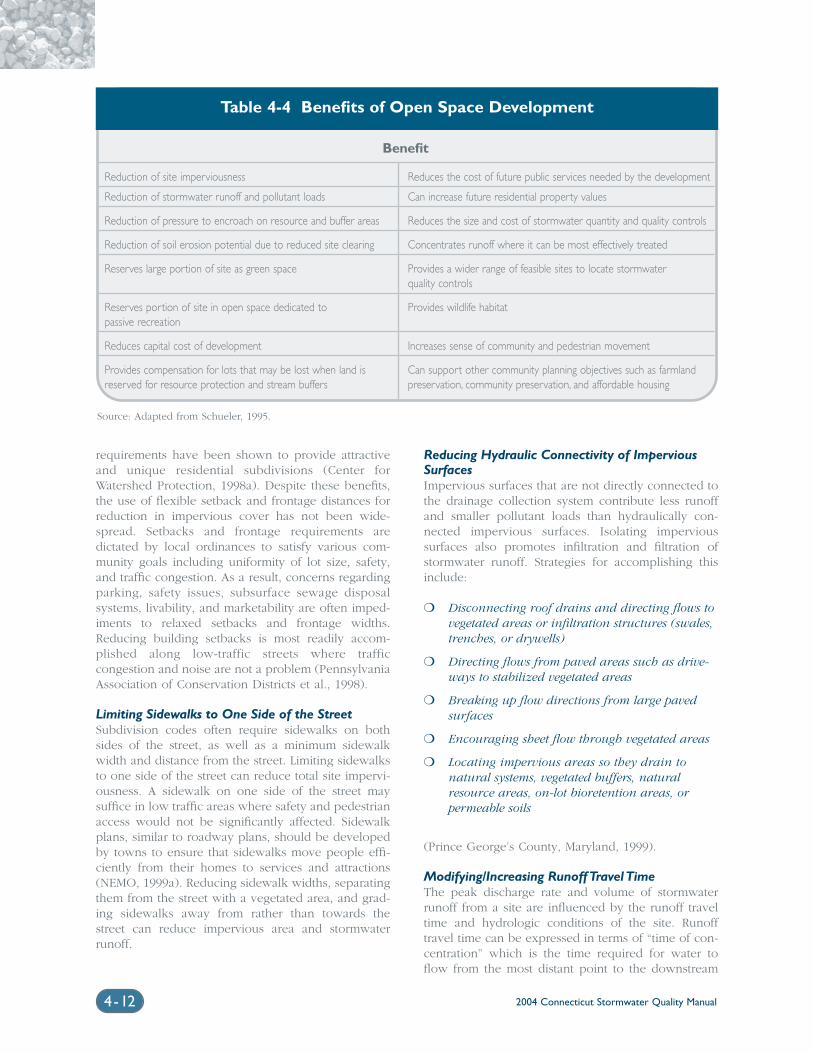
2004 Connecticut Stormwater Quality Manual4-12
requirements have been shown to provide attractiveand unique residential subdivisions (Center forWatershed Protection, 1998a). Despite these benefits,the use of flexible setback and frontage distances forreduction in impervious cover has not been wide-spread. Setbacks and frontage requirements aredictated by local ordinances to satisfy various com-munity goals including uniformity of lot size, safety,and traffic congestion. As a result, concerns regardingparking, safety issues, subsurface sewage disposalsystems, livability, and marketability are often imped-iments to relaxed setbacks and frontage widths.Reducing building setbacks is most readily accom-plished along low-traffic streets where trafficcongestion and noise are not a problem (PennsylvaniaAssociation of Conservation Districts et al., 1998).
Limiting Sidewalks to One Side of the StreetSubdivision codes often require sidewalks on bothsides of the street, as well as a minimum sidewalkwidth and distance from the street. Limiting sidewalksto one side of the street can reduce total site impervi-ousness. A sidewalk on one side of the street maysuffice in low traffic areas where safety and pedestrianaccess would not be significantly affected. Sidewalkplans, similar to roadway plans, should be developedby towns to ensure that sidewalks move people effi-ciently from their homes to services and attractions(NEMO, 1999a). Reducing sidewalk widths, separatingthem from the street with a vegetated area, and grad-ing sidewalks away from rather than towards thestreet can reduce impervious area and stormwaterrunoff.
Reducing Hydraulic Connectivity of ImperviousSurfacesImpervious surfaces that are not directly connected tothe drainage collection system contribute less runoffand smaller pollutant loads than hydraulically con-nected impervious surfaces. Isolating impervioussurfaces also promotes infiltration and filtration ofstormwater runoff. Strategies for accomplishing thisinclude:
❍ Disconnecting roof drains and directing flows tovegetated areas or infiltration structures (swales,trenches, or drywells)
❍ Directing flows from paved areas such as drive-ways to stabilized vegetated areas
❍ Breaking up flow directions from large pavedsurfaces
❍ Encouraging sheet flow through vegetated areas
❍ Locating impervious areas so they drain to natural systems, vegetated buffers, naturalresource areas, on-lot bioretention areas, or permeable soils
(Prince George’s County, Maryland, 1999).
Modifying/Increasing Runoff Travel TimeThe peak discharge rate and volume of stormwaterrunoff from a site are influenced by the runoff traveltime and hydrologic conditions of the site. Runofftravel time can be expressed in terms of “time of con-centration” which is the time required for water toflow from the most distant point to the downstream
Table 4-4 Benefits of Open Space Development
Benefit
Reduction of site imperviousness Reduces the cost of future public services needed by the development
Reduction of stormwater runoff and pollutant loads Can increase future residential property values
Reduction of pressure to encroach on resource and buffer areas Reduces the size and cost of stormwater quantity and quality controls
Reduction of soil erosion potential due to reduced site clearing Concentrates runoff where it can be most effectively treated
Reserves large portion of site as green space Provides a wider range of feasible sites to locate stormwater quality controls
Reserves portion of site in open space dedicated to Provides wildlife habitatpassive recreation
Reduces capital cost of development Increases sense of community and pedestrian movement
Provides compensation for lots that may be lost when land is Can support other community planning objectives such as farmlandreserved for resource protection and stream buffers preservation, community preservation, and affordable housing
Source: Adapted from Schueler, 1995.
2004 Connecticut Stormwater Quality Manual 4-13
outlet of a site. Runoff flow paths, ground surfaceslope and roughness, and channel characteristicsaffect the time of concentration. Site design tech-niques that can modify or increase the runoff traveltime and time of concentration include:
❍ Maximizing overland sheet flow
❍ Increasing and lengthening drainage flow paths
❍ Lengthening and flattening site and lot slopes(although may conflict with goal of minimizinggrading and disturbance)
❍ Maximizing use of vegetated swales
(Prince George’s County, Maryland, 1999).
4.4 Low Impact DevelopmentManagement Practices
Low Impact Development (LID), a relatively new con-cept in stormwater management pioneered by PrinceGeorge’s County, Maryland and several other areas ofthe country, is a site design strategy that employsmany of the concepts and practices already describedin this chapter. The goal of LID is to maintain or repli-cate predevelopment hydrology through the use ofsmall-scale controls integrated throughout the site(U.S. EPA, 2000). Site design techniques such as thosedescribed above are one component of the LIDapproach. The other major component of the LIDapproach is the use of micro-scale integrated man-agement practices to manage runoff as close to itssource as possible. This involves strategic placementof lot-level controls to reduce runoff volume and pol-lutant loads through infiltration, evapotranspiration,and reuse of stormwater runoff.
The appropriateness of LID practices is highlydependent on site conditions. Soil permeability, slope,and depth to water table and bedrock are physicalconstraints that may limit the use of LID practices at asite. Community perception and local developmentrules may also present obstacles to the implementa-tion of LID practices, as described previously in thischapter. Although alternative site design and LID prac-tices may not replace the need for conventionalstormwater controls, the economical and environmen-tal benefits of LID practices are well documented (U.S.EPA, 2000). LID practices described in the followingsections include:
❍ Vegetated Swales, Buffers, and Filter Strips
❍ Bioretention/Rain Gardens
❍ Dry Wells/Leaching Trenches
❍ Rainwater Harvesting
❍ Vegetated Roof Covers (Green Roofs)
The main feature that distinguishes these practicesfrom conventional structural stormwater controls isscale. These small systems are typically designed asoff-line systems that accept runoff from a single resi-dential lot or portions of a lot, as opposed to largemultiple-lot or end-of-pipe controls. The followingsections contain summary descriptions of these small-scale LID practices. The design sections of this Manualcontain more detailed guidance for similar,larger-scale stormwater treatment practices such asbioretention, infiltration, and filtration systems.
4.4.1 Vegetated Swales, Buffers, and FilterStrips
Vegetated swales, buffers, and filter strips are vegeta-tive practices that can be incorporated into a site tomaintain predevelopment hydrology. These practicesare adaptable to a variety of site conditions, are flexi-ble in design and layout, and are relativelyinexpensive (U.S. EPA, 2000). Vegetated swales canprovide both water quantity and quality control byfacilitating stormwater infiltration, filtration, andadsorption. Vegetated buffers are strips of vegetation(natural or planted) around sensitive areas such aswetlands, watercourses, or highly erodible soils(Prince George’s County, Maryland, 1999). Similarly,filter strips are typically grass or close-growing vege-tation planted between pollutant source areas anddownstream receiving waters or wetlands. Filter stripsare commonly located downgradient of stormwateroutfalls and level spreaders to reduce flow velocitiesand promote infiltration/filtration. Chapter Eleven pro-vides additional design guidance on these vegetativepractices.
4.4.2 Bioretention/Rain Gardens
Bioretention is a practice to manage and treat stormwa-ter runoff by using a specially designed planting soilbed and planting materials to filter runoff stored in ashallow depression (Prince George’s County, Maryland,1999). Bioretention areas are composed of a mix offunctional elements, each designed to perform differentfunctions in the removal of pollutants and attenuationof stormwater runoff. Bioretention removes stormwa-ter pollutants through physical and biologicalprocesses, including adsorption, filtration, plantuptake, microbial activity, decomposition, sedimenta-tion, and volatilization (U.S. EPA, 2000). The majorcomponents of a bioretention system include:
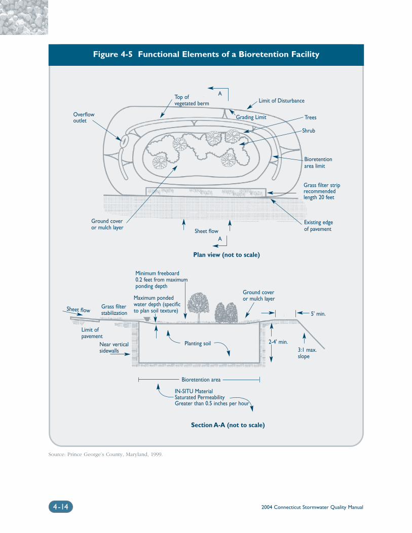
2004 Connecticut Stormwater Quality Manual4-14
Figure 4-5 Functional Elements of a Bioretention Facility
Source: Prince George’s County, Maryland, 1999.
Overflowoutlet
Top ofvegetated berm Limit of Disturbance
Sheet flow
Trees
Shrub
Bioretentionarea limit
Grass filter striprecommendedlength 20 feet
Existing edgeof pavement
Grading Limit
A
Ground coveror mulch layer
Plan view (not to scale)
Section A-A (not to scale)
Ground coveror mulch layer
Minimum freeboard0.2 feet from maximumponding depth
Maximum pondedwater depth (specificto plan soil texture)
Grass filterstabilization
Sheet flow
Limit ofpavement
Near verticalsidewalls
Planting soil
Bioretention area
IN-SITU MaterialSaturated PermeabilityGreater than 0.5 inches per hour
2-4' min.
5' min.
3:1 max.slope
A
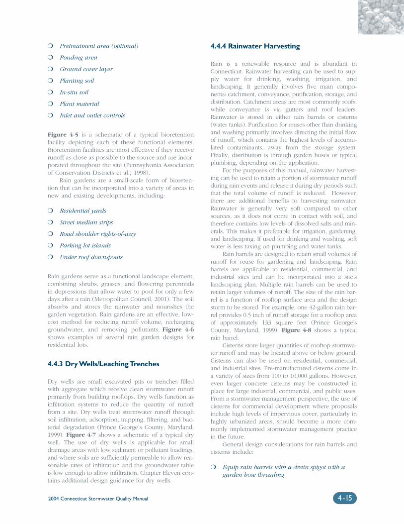
2004 Connecticut Stormwater Quality Manual 4-15
❍ Pretreatment area (optional)
❍ Ponding area
❍ Ground cover layer
❍ Planting soil
❍ In-situ soil
❍ Plant material
❍ Inlet and outlet controls
Figure 4-5 is a schematic of a typical bioretentionfacility depicting each of these functional elements.Bioretention facilities are most effective if they receiverunoff as close as possible to the source and are incor-porated throughout the site (Pennsylvania Associationof Conservation Districts et al., 1998).
Rain gardens are a small-scale form of bioreten-tion that can be incorporated into a variety of areas innew and existing developments, including:
❍ Residential yards
❍ Street median strips
❍ Road shoulder rights-of-way
❍ Parking lot islands
❍ Under roof downspouts
Rain gardens serve as a functional landscape element,combining shrubs, grasses, and flowering perennialsin depressions that allow water to pool for only a fewdays after a rain (Metropolitan Council, 2001). The soilabsorbs and stores the rainwater and nourishes thegarden vegetation. Rain gardens are an effective, low-cost method for reducing runoff volume, recharginggroundwater, and removing pollutants. Figure 4-6shows examples of several rain garden designs forresidential lots.
4.4.3 Dry Wells/Leaching Trenches
Dry wells are small excavated pits or trenches filledwith aggregate which receive clean stormwater runoffprimarily from building rooftops. Dry wells function asinfiltration systems to reduce the quantity of runofffrom a site. Dry wells treat stormwater runoff throughsoil infiltration, adsorption, trapping, filtering, and bac-terial degradation (Prince George’s County, Maryland,1999). Figure 4-7 shows a schematic of a typical drywell. The use of dry wells is applicable for smalldrainage areas with low sediment or pollutant loadings,and where soils are sufficiently permeable to allow rea-sonable rates of infiltration and the groundwater tableis low enough to allow infiltration. Chapter Eleven con-tains additional design guidance for dry wells.
4.4.4 Rainwater Harvesting
Rain is a renewable resource and is abundant inConnecticut. Rainwater harvesting can be used to sup-ply water for drinking, washing, irrigation, andlandscaping. It generally involves five main compo-nents: catchment, conveyance, purification, storage, anddistribution. Catchment areas are most commonly roofs,while conveyance is via gutters and roof leaders.Rainwater is stored in either rain barrels or cisterns(water tanks). Purification for reuses other than drinkingand washing primarily involves directing the initial flowof runoff, which contains the highest levels of accumu-lated contaminants, away from the storage system.Finally, distribution is through garden hoses or typicalplumbing, depending on the application.
For the purposes of this manual, rainwater harvest-ing can be used to retain a portion of stormwater runoffduring rain events and release it during dry periods suchthat the total volume of runoff is reduced. However,there are additional benefits to harvesting rainwater.Rainwater is generally very soft compared to othersources, as it does not come in contact with soil, andtherefore contains low levels of dissolved salts and min-erals. This makes it preferable for irrigation, gardening,and landscaping. If used for drinking and washing, softwater is less taxing on plumbing and water tanks.
Rain barrels are designed to retain small volumes ofrunoff for reuse for gardening and landscaping. Rainbarrels are applicable to residential, commercial, andindustrial sites and can be incorporated into a site’slandscaping plan. Multiple rain barrels can be used toretain larger volumes of runoff. The size of the rain bar-rel is a function of rooftop surface area and the designstorm to be stored. For example, one 42-gallon rain bar-rel provides 0.5 inch of runoff storage for a rooftop areaof approximately 133 square feet (Prince George’sCounty, Maryland, 1999). Figure 4-8 shows a typicalrain barrel.
Cisterns store larger quantities of rooftop stormwa-ter runoff and may be located above or below ground.Cisterns can also be used on residential, commercial,and industrial sites. Pre-manufactured cisterns come ina variety of sizes from 100 to 10,000 gallons. However,even larger concrete cisterns may be constructed inplace for large industrial, commercial, and public uses.From a stormwater management perspective, the use ofcisterns for commercial development where proposalsinclude high levels of impervious cover, particularly inhighly urbanized areas, should become a more com-monly implemented stormwater management practicein the future.
General design considerations for rain barrels andcisterns include:
❍ Equip rain barrels with a drain spigot with agarden hose threading
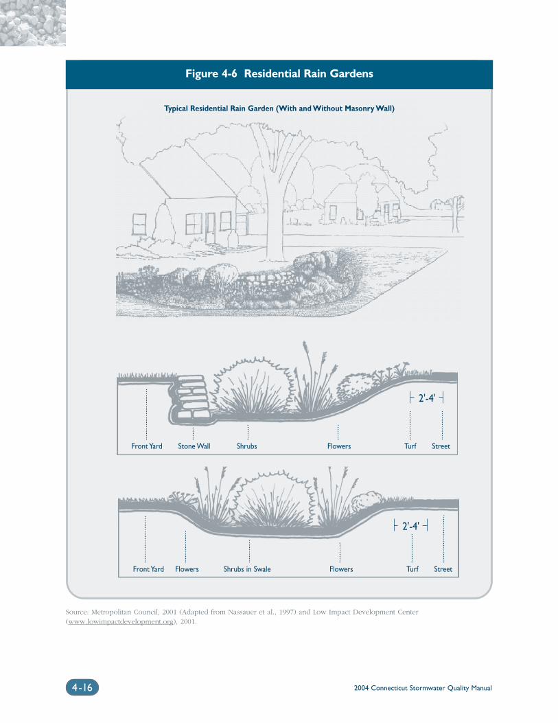
2004 Connecticut Stormwater Quality Manual4-16
Figure 4-6 Residential Rain Gardens
Typical Residential Rain Garden (With and Without Masonry Wall)
Source: Metropolitan Council, 2001 (Adapted from Nassauer et al., 1997) and Low Impact Development Center (www.lowimpactdevelopment.org), 2001.
Front Yard Stone Wall Shrubs Flowers Turf Street
2'-4'
2'-4'
Front Yard Flowers Shrubs in Swale Flowers Turf Street
2004 Connecticut Stormwater Quality Manual 4-17
Figure 4-7 Schematic of Typical Dry Well
Source: Adapted from NYDEC, 2001.
BuildingFoundation
Sump(OPTIONAL)
Mesh Screen
FilterFabric
FootPlate
CleanWashedStone
Observation Well
Cap with Screw Top Lid
12"
Roof Leader
Surcharge Pipe
Splash Block
Access Lid
❍ Use a tight-fitting, light-blocking lid to keep chil-dren and animals out of the water, stop thedevelopment of algae, and limit access to stand-ing water by mosquitoes and other nuisanceinsects. Alternatively, a small mesh screen couldbe used over the hole in the barrel/cistern to limitmosquito-breeding potential
❍ Use a roof washer (collection and disposal of thefirst flush of water from a roof) to catch accu-mulated debris and divert the first flush of runoffaway from rain barrels or cisterns
❍ Use an overflow device to direct excess wateraway from a building’s foundation when thetank is full
❍ Monitor cistern intakes and overflows for blockage
❍ Locate cisterns as close to supply and demand aspossible
❍ Size storage volume based on seasonal rainfalldata and anticipated water requirements
❍ For drinking water supply, purification usingultraviolet light, ozonation, chlorination, reverseosmosis, and carbon filters can be used
4.4.5 Vegetated Roof Covers
Vegetated roof covers, also referred to as “greenroofs”, are layers of vegetation installed on buildingrooftops. Green roofs are an effective means forreducing urban stormwater runoff by replacing imper-meable rooftops with permeable, vegetated surfaces.Rainwater is either intercepted by vegetation andevaporated to the atmosphere or retained in the sub-strate before being returned to the atmospherethrough transpiration and evaporation. Several exam-ples of vegetated roof installations are shown inFigure 4-9.
The green roof is a multilayered, constructed roofsystem consisting of a vegetative layer, media, a geo-textile layer, and a synthetic drain layer. Green roofshave been used extensively in Europe and are becom-ing more common in the United States. A variety ofgreen roof designs exist. The simplest consists of alight system of drainage and filtering components anda thin soil layer, which is installed and planted withdrought-resistant herbaceous vegetation (MetropolitanCouncil, 2001). This type of system is called an exten-sive system. More complex green roof systems such asroof gardens built to accommodate trees, shrubs, andrecreational access are called intensive systems.Figure 4-10 is a schematic of the functional compo-nents of the simpler extensive vegetated roof system.
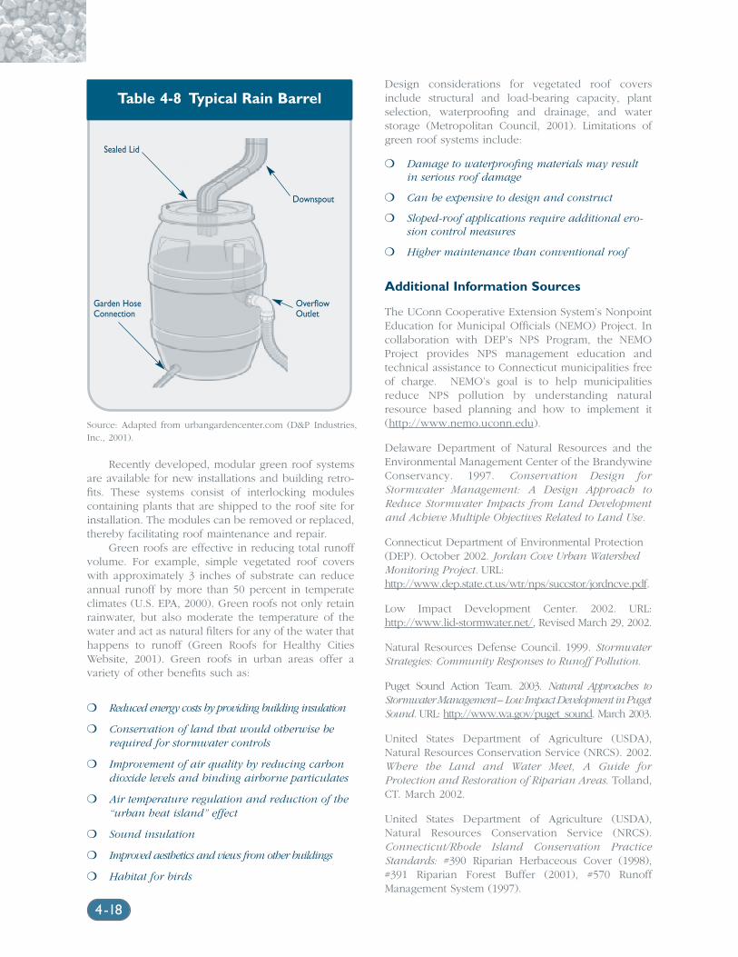
Recently developed, modular green roof systemsare available for new installations and building retro-fits. These systems consist of interlocking modulescontaining plants that are shipped to the roof site forinstallation. The modules can be removed or replaced,thereby facilitating roof maintenance and repair.
Green roofs are effective in reducing total runoffvolume. For example, simple vegetated roof coverswith approximately 3 inches of substrate can reduceannual runoff by more than 50 percent in temperateclimates (U.S. EPA, 2000). Green roofs not only retainrainwater, but also moderate the temperature of thewater and act as natural filters for any of the water thathappens to runoff (Green Roofs for Healthy CitiesWebsite, 2001). Green roofs in urban areas offer avariety of other benefits such as:
❍ Reduced energy costs by providing building insulation
❍ Conservation of land that would otherwise berequired for stormwater controls
❍ Improvement of air quality by reducing carbondioxide levels and binding airborne particulates
❍ Air temperature regulation and reduction of the“urban heat island” effect
❍ Sound insulation
❍ Improved aesthetics and views from other buildings
❍ Habitat for birds
Design considerations for vegetated roof coversinclude structural and load-bearing capacity, plantselection, waterproofing and drainage, and waterstorage (Metropolitan Council, 2001). Limitations ofgreen roof systems include:
❍ Damage to waterproofing materials may resultin serious roof damage
❍ Can be expensive to design and construct
❍ Sloped-roof applications require additional ero-sion control measures
❍ Higher maintenance than conventional roof
Additional Information Sources
The UConn Cooperative Extension System’s NonpointEducation for Municipal Officials (NEMO) Project. Incollaboration with DEP’s NPS Program, the NEMOProject provides NPS management education andtechnical assistance to Connecticut municipalities freeof charge. NEMO’s goal is to help municipalitiesreduce NPS pollution by understanding naturalresource based planning and how to implement it(http://www.nemo.uconn.edu).
Delaware Department of Natural Resources and theEnvironmental Management Center of the BrandywineConservancy. 1997. Conservation Design forStormwater Management: A Design Approach toReduce Stormwater Impacts from Land Developmentand Achieve Multiple Objectives Related to Land Use.
Connecticut Department of Environmental Protection(DEP). October 2002. Jordan Cove Urban WatershedMonitoring Project. URL:http://www.dep.state.ct.us/wtr/nps/succstor/jordncve.pdf.
Low Impact Development Center. 2002. URL:http://www.lid-stormwater.net/, Revised March 29, 2002.
Natural Resources Defense Council. 1999. StormwaterStrategies: Community Responses to Runoff Pollution.
Puget Sound Action Team. 2003. Natural Approaches toStormwater Management – Low Impact Development in PugetSound. URL: http://www.wa.gov/puget_sound. March 2003.
United States Department of Agriculture (USDA),Natural Resources Conservation Service (NRCS). 2002.Where the Land and Water Meet, A Guide forProtection and Restoration of Riparian Areas. Tolland,CT. March 2002.
United States Department of Agriculture (USDA),Natural Resources Conservation Service (NRCS).Connecticut/Rhode Island Conservation PracticeStandards: #390 Riparian Herbaceous Cover (1998),#391 Riparian Forest Buffer (2001), #570 RunoffManagement System (1997).
Table 4-8 Typical Rain Barrel
Source: Adapted from urbangardencenter.com (D&P Industries,Inc., 2001).
Sealed Lid
Downspout
OverflowOutlet
Garden HoseConnection
4-18
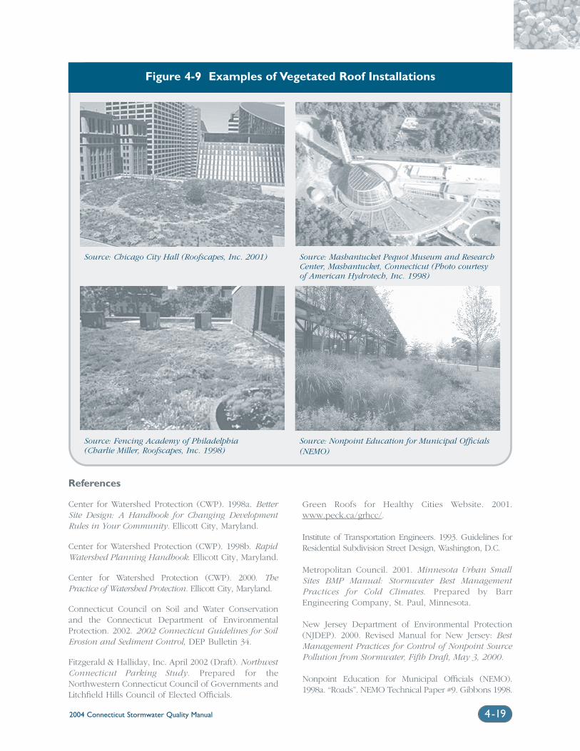
2004 Connecticut Stormwater Quality Manual 4-19
References
Center for Watershed Protection (CWP). 1998a. BetterSite Design: A Handbook for Changing DevelopmentRules in Your Community. Ellicott City, Maryland.
Center for Watershed Protection (CWP). 1998b. RapidWatershed Planning Handbook. Ellicott City, Maryland.
Center for Watershed Protection (CWP). 2000. ThePractice of Watershed Protection. Ellicott City, Maryland.
Connecticut Council on Soil and Water Conservationand the Connecticut Department of EnvironmentalProtection. 2002. 2002 Connecticut Guidelines for SoilErosion and Sediment Control, DEP Bulletin 34.
Fitzgerald & Halliday, Inc. April 2002 (Draft). NorthwestConnecticut Parking Study. Prepared for theNorthwestern Connecticut Council of Governments andLitchfield Hills Council of Elected Officials.
Green Roofs for Healthy Cities Website. 2001.www.peck.ca/grhcc/.
Institute of Transportation Engineers. 1993. Guidelines forResidential Subdivision Street Design, Washington, D.C.
Metropolitan Council. 2001. Minnesota Urban SmallSites BMP Manual: Stormwater Best ManagementPractices for Cold Climates. Prepared by BarrEngineering Company, St. Paul, Minnesota.
New Jersey Department of Environmental Protection(NJDEP). 2000. Revised Manual for New Jersey: BestManagement Practices for Control of Nonpoint SourcePollution from Stormwater, Fifth Draft, May 3, 2000.
Nonpoint Education for Municipal Officials (NEMO).1998a. “Roads”. NEMO Technical Paper #9. Gibbons 1998.
Figure 4-9 Examples of Vegetated Roof Installations
Source: Chicago City Hall (Roofscapes, Inc. 2001) Source: Mashantucket Pequot Museum and ResearchCenter, Mashantucket, Connecticut (Photo courtesyof American Hydrotech, Inc. 1998)
Source: Fencing Academy of Philadelphia(Charlie Miller, Roofscapes, Inc. 1998)
Source: Nonpoint Education for Municipal Officials(NEMO)
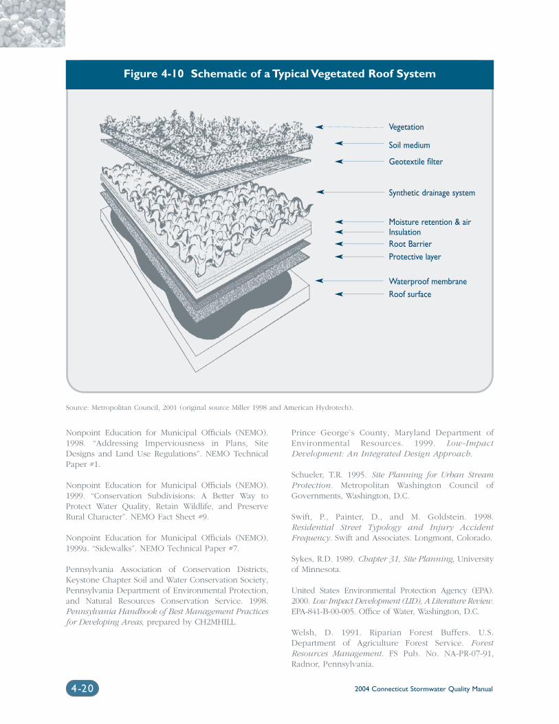
2004 Connecticut Stormwater Quality Manual4-20
Nonpoint Education for Municipal Officials (NEMO).1998. “Addressing Imperviousness in Plans, SiteDesigns and Land Use Regulations”. NEMO TechnicalPaper #1.
Nonpoint Education for Municipal Officials (NEMO).1999. “Conservation Subdivisions: A Better Way toProtect Water Quality, Retain Wildlife, and PreserveRural Character”. NEMO Fact Sheet #9.
Nonpoint Education for Municipal Officials (NEMO).1999a. “Sidewalks”. NEMO Technical Paper #7.
Pennsylvania Association of Conservation Districts,Keystone Chapter Soil and Water Conservation Society,Pennsylvania Department of Environmental Protection,and Natural Resources Conservation Service. 1998.Pennsylvania Handbook of Best Management Practicesfor Developing Areas, prepared by CH2MHILL.
Prince George’s County, Maryland Department ofEnvironmental Resources. 1999. Low-ImpactDevelopment: An Integrated Design Approach.
Schueler, T.R. 1995. Site Planning for Urban StreamProtection. Metropolitan Washington Council ofGovernments, Washington, D.C.
Swift, P., Painter, D., and M. Goldstein. 1998.Residential Street Typology and Injury AccidentFrequency. Swift and Associates. Longmont, Colorado.
Sykes, R.D. 1989. Chapter 31, Site Planning, Universityof Minnesota.
United States Environmental Protection Agency (EPA).2000. Low Impact Development (LID), A Literature Review.EPA-841-B-00-005. Office of Water, Washington, D.C.
Welsh, D. 1991. Riparian Forest Buffers. U.S.Department of Agriculture Forest Service. ForestResources Management. FS Pub. No. NA-PR-07-91,Radnor, Pennsylvania.
Figure 4-10 Schematic of a Typical Vegetated Roof System
Source: Metropolitan Council, 2001 (original source Miller 1998 and American Hydrotech).
Vegetation
Soil medium
Geotextile filter
Synthetic drainage system
Moisture retention & airInsulationRoot BarrierProtective layer
Waterproof membraneRoof surface
Chapter 5Source Control Practices
and Pollution Prevention
Chapter 5 Source Control Practices and Pollution Prevention
5.1 Introduction...................................................................................................5-2
5.2 Municipal Practices.......................................................................................5-2
5.2.1 Street and Parking Lot Sweeping..........................................5-2
5.2.2 Roadway Deicing/Salt Storage ...............................................5-4
5.2.3 Storm Drainage System Maintenance..................................5-7
5.2.4 Other Road, Highway, and Bridge Maintenance ................5-7
5.2.5 Illicit Discharge Detection and Elimination ........................5-8
5.3 Industrial and Commercial Practices.......................................................5-9
5.3.1 Stormwater Pollution Prevention Plans ..............................5-9
5.4 Lawn Care and Landscaping Practices ..................................................5-10
5.4.1 Xeriscaping and General Landscape Management .........5-10
5.4.2 Fertilizer and Pesticide Management.................................5-12
5.4.3 Animal Waste Management..................................................5-12
5.5 Model Stormwater Ordinances..............................................................5-14
5.6 Public Education and Outreach..............................................................5-14
Volume 1: Background
2004 Connecticut Stormwater Quality Manual 5-1
2004 Connecticut Stormwater Quality Manual5-2
5.1 IntroductionControlling the sources of
pollution and preventing
pollutant exposure to
stormwater are important
management techniques
that can reduce the amount
of pollutants in stormwater
and the need for stormwater
treatment. Source control
practices and pollution
prevention can include a
wide variety of management
techniques that address
stormwater and other
nonpoint sources of
pollution. Most are typically
non-structural, require
minimal or no land area,
and can be implemented
with moderate cost and
effort as compared to
structural treatment
practices. In addition to
management actions, source
control and pollution preven-
tion also include education
and outreach.
Developing awareness of potential sources of pollution and ways to mod-ify behavior in order to reduce both the amount of available pollutant andthe volume of stormwater runoff are key elements in this approach tostormwater management. This chapter discusses the following source control and pollution prevention practices that are commonly applied inmunicipal, industrial, commercial and residential settings:
❍ Street and Parking Lot Sweeping
❍ Roadway Deicing/Salt Storage
❍ Storm Drainage System Maintenance
❍ Other Road, Highway, and Bridge Maintenance
❍ Illicit Discharge Detection and Elimination
❍ Commercial and Industrial Pollution Prevention Plans
❍ Animal Waste Management
❍ Lawn Care and Landscaping Practices
❍ Model Stormwater Ordinances
❍ Public Education
5.2 Municipal Practices
5.2.1 Street and Parking Lot SweepingRemoval and proper disposal of sediment and debris from paved surfaces reduces the exposure of these materials to stormwater washoff andsubsequent pollutant export to receiving waters. The reported effectivenessof street sweeping varies considerably among sources (e.g., EPA, 1983; Bannerman, 1999) and is particularly dependent upon the type ofsweeper used.
Sweeper TypeMechanical Broom Sweepers: These are the oldest and most commontype of sweeper used for municipal roadway cleaning. They work like abroom and dustpan to pick of particles and only remove large debris.Mechanical broom sweepers are relatively ineffective at removing particlessmaller than 60 microns. In addition, the broom action may actually breaklarger particles into smaller ones, which are more difficult to pick up(Schwarze Industries, Inc., 2001).
Vacuum Sweepers: Vacuum sweepers work in a manner comparable to household vacuum cleaners. Typically, a broom head pushes debris toward a suction inlet or vacuum. Traditional vacuum sweepersuse a water-based dust suppression system, but still exhaust a high levelof particulates into the atmosphere while in operation (SchwarzeIndustries, Inc., 2001).
Regenerative Air Sweepers: Regenerative air sweepers use a closed-loop,cyclonic effect to clean. Air is constantly recirculated or regenerated in theunit. It is blasted onto the pavement on one side of the sweeper head,picks up debris as it travels across the width of the head, and is suctionedup on the vacuum inlet on the other side of the sweeper head.Regenerative air sweepers use water for dust suppression and exhaustsome particulates into the atmosphere during operation.
2004 Connecticut Stormwater Quality Manual 5-3
Dry Vacuum Sweepers: Unlike water-assisted vacuum sweepers, dry vacuum sweepers use a filtra-tion system and require no water for dustsuppression. Consequently, this type of sweeper canalso be used in colder weather, since freezing condi-tions are not an issue for operation. The internalfiltration system also results in less fine-grained par-ticulate exhaust to the atmosphere compared to themechanical sweepers discussed above.
Sweeper EffectivenessThe improvements in sweeper technology over thepast 20 years have considerably improved the capa-bility of sweepers to pick up the fine-grainedsediment particles that carry a substantial portion ofthe stormwater pollutant load (EPA, 2002). A study byTerrene Institute in 1998 has shown that mechanicalbroom sweepers and water-assisted vacuum sweepersreduce nonpoint source pollution by 5-30 percent andnutrient content by 0-15 percent. However, dry vac-uum sweepers are reported to reduce non-pointsource pollution by 35-80 percent and nutrients by15-40 percent. Bannerman (1999) estimates that,depending upon sweeping frequency, dry vacuumsweepers could achieve a 50-80 percent overallreduction in the annual sediment load for a residen-tial street.
The effectiveness of pavement sweeping inreducing nonpoint source pollution in a particulararea is a function of several variables including:
Street Condition: Regular pavement repair andmaintenance will encourage a smooth pavement con-dition and texture which will reduce the amount of particulates shaken from vehicles, increase the ease of street sweeping, and reduce the amount ofparticulates generated from the deteriorating streetsurface itself.
Geographic Location: The frequency of precipita-tion events capable of removing particulates from thepaved surface will influence the effectiveness of asweeping program.
Sweeper Operator’s Skill: Optimum pollutantremoval is a function of operator control over sweeperspeed, brush adjustment and rotation rate, sweepingpattern, and maneuvering around parked vehicles.
Presence of Parked Vehicles: On-street parking ofvehicles during sweeping reduces overall effectiveness.
Amount of Impervious Area Devoted to Rooftop(as compared to pavement): Sweeping is obviouslymore effective in areas where paved surfaces are the major contributor to impervious surfaces in a watershed.
Frequency of Sweeping: More frequent sweepingshould improve overall sediment load reductions, andis particularly important for streets or other pavedareas with high pollutant loadings.
Type of Mechanical Sweeper Used: As discussedabove, dry vacuum and regenerative air sweepers arepreferable to mechanical broom and traditional water-assisted vacuum sweepers. State, municipal, commer-cial, and industrial facilities with street sweepersshould consider upgrading to the latest sweepingtechnology when new equipment is purchased. A 10-year equipment replacement cycle is recommended.(EPA, 2002). In colder climates such as Connecticut,street sweeping can be effectively used during thespring snowmelt to reduce pollutant loads from roadsalt (see section on deicing for further information)and sand export to receiving waters. In Connecticut,the recommended minimum frequency for streetsweeping is once per year as soon as possible aftersnowmelt and, when possible, before spring rainfallevents. In urbanized areas and other areas withhigher potential pollutant loadings, streets mayrequire sweeping more than once per year.
Because of the initial capital cost and operationand maintenance costs associated with a street sweep-ing program, municipalities should prioritize streetsweeping activities to achieve the most effective pol-lution prevention. In general, street sweeping is mosteffective in urban areas and pollutant removal ratesare typically higher on residential roads than for arte-rial roadways (EPA, 2002). When developing a streetsweeping program, more sophisticated sweepers suchas dry vacuum sweepers should be used in areas ofhigher pollutant loading, and these areas should alsobe considered for more frequent sweeping.Municipalities can also improve the effectiveness ofstreet sweeping programs by enforcing constructionsite erosion controls, especially the use of anti-track-ing pads to minimize excess sediment on pavedsurfaces; and developing and enforcing regulationsfor alternate side parking during cleaning operations,litter control, and trash and refuse storage and disposal, especially yard debris.
Disposal of SweepingsStreet sweepings may contain low levels of chemicalcompounds associated with stormwater runoff suchas lead, sodium and compounds associated withasphalt and motor oils. Street sweepings are alsolikely to contain debris such as leaves, broken glass,and small pieces of metal.
Temporary Storage of Street Sweepings:Temporary storage of street sweepings prior to reuseor disposal should be located in an area where thesweepings will not wash into wetlands or water-courses. Acceptable temporary storage sites include:
2004 Connecticut Stormwater Quality Manual5-4
❍ an empty salt storage shed
❍ a municipal site where sand and salt are nor-mally handled
❍ a paved area that is more than 100 feet from awetland or watercourse
Street sweepings should not be combined with sandand debris collected from catch basins. Materialremoved from catch basins may have higher concen-trations of pollutants. Prior to reuse, materials such astrash, leaves and debris should be removed from thestreet sweepings by screening or other appropriatemethod and such materials should either be disposedof at a permitted solid waste facility, recycled (e.g.aluminum cans) or composted (e.g. leaves).
Limitations on Reuse of Street Sweepings withoutTesting: It is acceptable to reuse street sweepingswithout analyzing the concentration of chemical com-pounds in the following ways:
❍ as fill in road construction projects where thesweepings are used below the paved surface orin the median strip of a divided highway
❍ as aggregate in concrete or asphalt
❍ as daily cover on a permitted landfill
Limitations on Reuse of Street Sweepings withTesting: Properly tested street sweepings may beused for fill material on an industrial or commercialproperty, provided the testing for both heavy met-als and semivolatile organic compounds, at afrequency of approximately one sample per 500cubic yards of street sweepings, shows concentra-tions below the residential direct exposurestandards established in the Remediation StandardRegulations found in Appendix A to Sections 22a-133k-1 through 22a-133k-3 in the Regulations ofConnecticut State Agencies (“RCSA”). Alternatively,properly tested street sweepings may be reused atother sites in accordance with the regulations forreuse of polluted soil pursuant to Section 22a-133k-2(h) RCSA.
No Use on Residential Property: Street sweepings,regardless of testing status, are not recommended foruse on residential property because they may containbroken glass or other sharp debris.
Disposal at Permitted Solid Waste Facility: Streetsweepings that are not used in the manner describedabove should be disposed of at a permitted solidwaste facility.
5.2.2 Roadway Deicing/Salt Storage Salts, sand, gravel and other materials are applied toroadways during the winter months in Connecticut.The salts and other deicing materials discussed belowlower the melting point of ice and are applied toreduce icing on roadways. Sand and gravel areapplied to roadways to increase traction during andafter adverse winter weather conditions.
Common DeicersSodium Chloride: Also called rock salt, this is themost commonly used deicing product due to its lowcost and effectiveness. Sodium chloride will work attemperatures as low as –7°F, but is most effective at10-15°F.
Calcium Chloride: This salt is a more expensivedeicing agent than sodium chloride. However, itworks at temperatures as low as -60°F, but is mosteffective at approximately -25°F.
Calcium Magnesium Acetate (CMA): CMA is a fre-quently used alternative to sodium chloride. It ismade from dolomitic limestone treated with aceticacid. It is reported to work at temperatures as low as-5°F, but is most effective at approximately 20-25°F(Ohrel, 2000).
Blended Products: These new deicing materials con-sist of various combinations of sodium, calcium,magnesium, and chloride, as well as other con-stituents, but typically are lower in sodium chloride(Lucas, 1994).
Environmental concerns related to roadway deic-ing materials include:
❍ Damage to vegetation growing adjacent to road-ways receiving salt application (See plant list inAppendix A for a list of more salt-resistant vege-tation for roadway plantings)
❍ Residues of chloride ions on the roadway surfacethat may contaminate groundwater resources
❍ Other substances in deicing chemicals that act toprevent caking (i.e., sodium ferrocyanide) orprevent corrosion may be toxic to human, ani-mal, and fish life (FWHA, 1999)
Table 5-1 compares the environmental effects of sev-eral common roadway deicers as reported in a 1993study by the Michigan Department of Transportationand cited by Ohrel (2000). Other potential environ-mental impacts associated specifically with sodiumchloride include temporary reductions in soil microbes,sensitivity of certain deciduous trees, and secondarycomponents (3-5 percent of road salt composition)
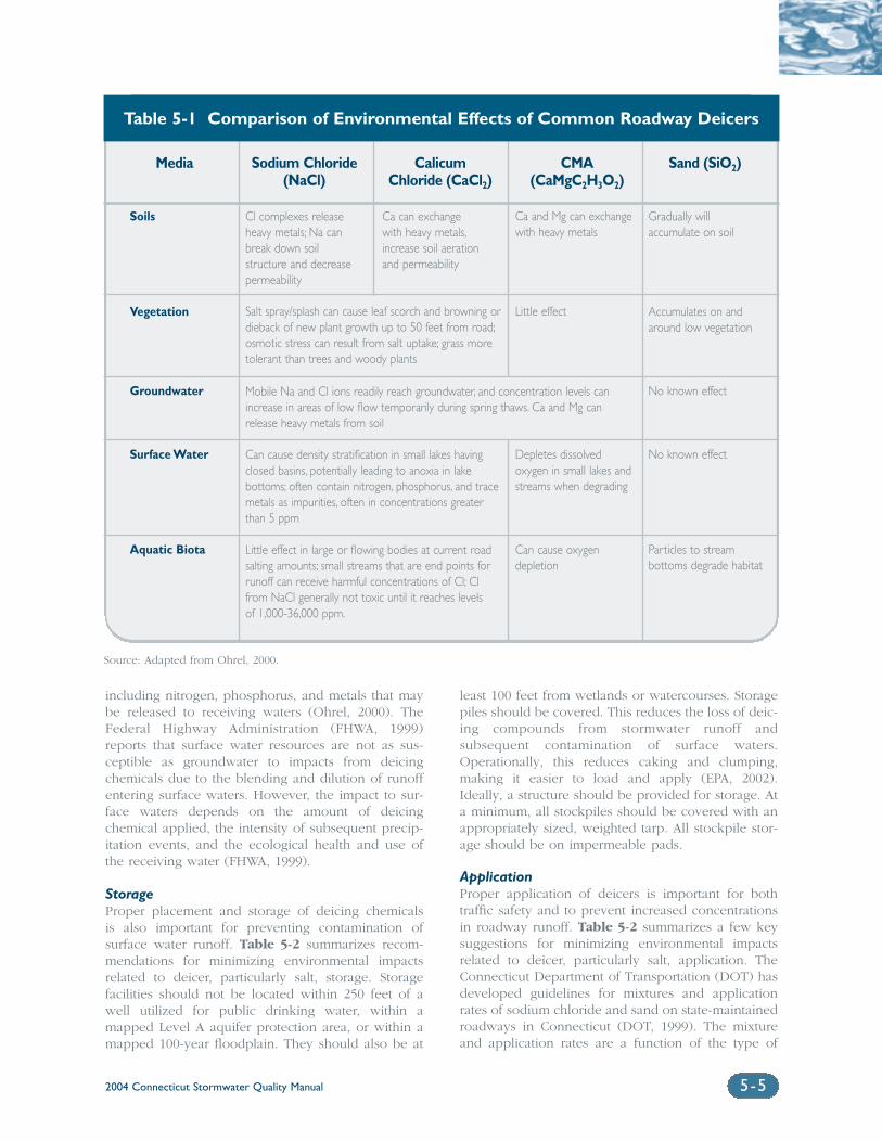
2004 Connecticut Stormwater Quality Manual 5-5
including nitrogen, phosphorus, and metals that maybe released to receiving waters (Ohrel, 2000). TheFederal Highway Administration (FHWA, 1999)reports that surface water resources are not as sus-ceptible as groundwater to impacts from deicingchemicals due to the blending and dilution of runoffentering surface waters. However, the impact to sur-face waters depends on the amount of deicingchemical applied, the intensity of subsequent precip-itation events, and the ecological health and use ofthe receiving water (FHWA, 1999).
StorageProper placement and storage of deicing chemicals is also important for preventing contamination ofsurface water runoff. Table 5-2 summarizes recom-mendations for minimizing environmental impactsrelated to deicer, particularly salt, storage. Storagefacilities should not be located within 250 feet of awell utilized for public drinking water, within amapped Level A aquifer protection area, or within amapped 100-year floodplain. They should also be at
least 100 feet from wetlands or watercourses. Storagepiles should be covered. This reduces the loss of deic-ing compounds from stormwater runoff andsubsequent contamination of surface waters.Operationally, this reduces caking and clumping,making it easier to load and apply (EPA, 2002).Ideally, a structure should be provided for storage. Ata minimum, all stockpiles should be covered with anappropriately sized, weighted tarp. All stockpile stor-age should be on impermeable pads.
ApplicationProper application of deicers is important for bothtraffic safety and to prevent increased concentrationsin roadway runoff. Table 5-2 summarizes a few keysuggestions for minimizing environmental impactsrelated to deicer, particularly salt, application. TheConnecticut Department of Transportation (DOT) hasdeveloped guidelines for mixtures and applicationrates of sodium chloride and sand on state-maintainedroadways in Connecticut (DOT, 1999). The mixtureand application rates are a function of the type of
Soils
Vegetation
Groundwater
Surface Water
Aquatic Biota
Ca can exchange with heavy metals,increase soil aeration and permeability
Ca and Mg can exchangewith heavy metals
Little effect
Depletes dissolved oxygen in small lakes andstreams when degrading
Can cause oxygendepletion
Gradually will accumulate on soil
Accumulates on andaround low vegetation
No known effect
No known effect
Particles to stream bottoms degrade habitat
Cl complexes releaseheavy metals; Na canbreak down soil structure and decreasepermeability
Salt spray/splash can cause leaf scorch and browning ordieback of new plant growth up to 50 feet from road;osmotic stress can result from salt uptake; grass moretolerant than trees and woody plants
Mobile Na and Cl ions readily reach groundwater, and concentration levels canincrease in areas of low flow temporarily during spring thaws. Ca and Mg canrelease heavy metals from soil
Can cause density stratification in small lakes havingclosed basins, potentially leading to anoxia in lake bottoms; often contain nitrogen, phosphorus, and tracemetals as impurities, often in concentrations greaterthan 5 ppm
Little effect in large or flowing bodies at current roadsalting amounts; small streams that are end points forrunoff can receive harmful concentrations of Cl; Clfrom NaCl generally not toxic until it reaches levelsof 1,000-36,000 ppm.
Source: Adapted from Ohrel, 2000.
Media Sodium Chloride Calicum CMA Sand (SiO2)(NaCl) Chloride (CaCl2) (CaMgC2H3O2)
Table 5-1 Comparison of Environmental Effects of Common Roadway Deicers
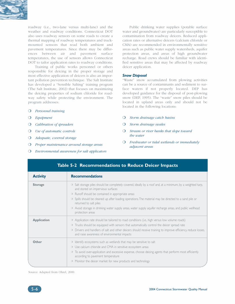
2004 Connecticut Stormwater Quality Manual5-6
roadway (i.e., two-lane versus multi-lane) and theweather and roadway conditions. Connecticut DOTalso uses roadway sensors on some roads to create athermal mapping of roadway temperatures and truck-mounted sensors that read both ambient andpavement temperatures. Since there may be differ-ences between air and pavement surfacetemperatures, the use of sensors allows ConnecticutDOT to tailor application rates to roadway conditions.
Training of public works personnel or othersresponsible for deicing in the proper storage andmost effective application of deicers is also an impor-tant pollution prevention technique. The Salt Institutehas developed a “Sensible Salting” training program(The Salt Institute, 2002) that focuses on maximizingthe deicing properties of sodium chloride for road-way safety while protecting the environment. Theprogram addresses:
❍ Personnel training
❍ Equipment
❍ Calibration of spreaders
❍ Use of automatic controls
❍ Adequate, covered storage
❍ Proper maintenance around storage areas
❍ Environmental awareness for salt applicators
Public drinking water supplies (potable surfacewater and groundwater) are particularly susceptible tocontamination from roadway deicers. Reduced appli-cation rates or alternative deicers (calcium chloride orCMA) are recommended in environmentally sensitiveareas such as public water supply watersheds, aquiferprotection areas, and areas of high groundwaterrecharge. Road crews should be familiar with identi-fied sensitive areas that may be affected by roadwaydeicer application.
Snow Disposal“Waste” snow accumulated from plowing activitiescan be a source of contaminants and sediment to sur-face waters if not properly located. DEP hasdeveloped guidance for the disposal of post-plowingsnow (DEP, 1995). The “waste” snow piles should belocated in upland areas only and should not belocated in the following locations:
❍ Storm drainage catch basins
❍ Storm drainage swales
❍ Stream or river banks that slope toward the water
❍ Freshwater or tidal wetlands or immediatelyadjacent areas
Table 5-2 Recommendations to Reduce Deicer Impacts
Activity Recommendations
Storage ❍ Salt storage piles should be completely covered, ideally by a roof and, at a minimum, by a weighted tarp,and stored on impervious surfaces
❍ Runoff should be contained in appropriate areas❍ Spills should be cleaned up after loading operations.The material may be directed to a sand pile or
returned to salt piles❍ Avoid storage in drinking water supply areas, water supply aquifer recharge areas, and public wellhead
protection areas
Application ❍ Application rate should be tailored to road conditions (i.e., high versus low volume roads)❍ Trucks should be equipped with sensors that automatically control the deicer spread rate❍ Drivers and handlers of salt and other deicers should receive training to improve efficiency, reduce losses,
and raise awareness of environmental impacts
Other ❍ Identify ecosystems such as wetlands that may be sensitive to salt❍ Use calcium chloride and CMA in sensitive ecosystem areas❍ To avoid over-application and excessive expense, choose deicing agents that perform most efficiently
according to pavement temperature❍ Monitor the deicer market for new products and technology
Source: Adapted from Ohrel, 2000.
2004 Connecticut Stormwater Quality Manual 5-7
❍ Within 100 feet of private drinking water supply wells
❍ Within 500 feet of public drinking water supply wells
❍ Public drinking water supply watershed areas
5.2.3 Storm Drainage System MaintenanceIn order to maintain their intended function, stormwa-ter drainage and treatment systems should beinspected at least annually. Deterioration of any partof the system that threatens the structural integrity ofthe facility should be immediately repaired.Inspection and cleaning of catch basins and stormwa-ter inlets preserves the sediment-trapping function ofthese devices and also prevents sediment, trash, andother pollutants present in the storm drain systemfrom reaching receiving waters. Removal of sedimentand decaying debris from catch basin sumps yieldsaesthetic and water quality benefits including reduc-tion of foul odors, suspended solids, bacteria, and theload of oxygen demanding substances (EPA, 1999;EPA, 2002). Pitt (1979, 1984) found that cleaning catchbasins in urban areas twice a year reduced the loadsof total solids and lead in urban runoff by 10 percentand 25 percent, respectively. This maintenance sched-ule also reduced loads of chemical oxygen demand(COD), total Kjeldahl nitrogen, total phosphorus, andzinc by 5 percent to 10 percent (WisconsinDepartment of Natural Resources, 1994).
Catch basins and other stormwater structuresthat accumulate sediment should be cleaned at leastannually. The cleaning should include both removalof sediment from the sump and removal of any trashor debris from the grate. Additional maintenance isrecommended in the fall to remove trash, leaves,and other debris. In rural areas and areas that expe-rience significant accumulation of leaves, therecommended fall maintenance should be per-formed after leaf fall and before the first snowfall. Inaddition, areas with higher pollutant loadings or dis-charging to sensitive water bodies should also becleaned more frequently (WEF and ASCE, 1998).More frequent cleaning of drainage systems may alsobe needed in areas with relatively flat grades or lowflows since they may rarely achieve sufficiently highflows for self-flushing (Ferguson et al., 1997).Deviations from these recommended frequenciesmay be warranted based on field evaluation of actualsediment and debris accumulation rates, includingidentification and prioritization of structures thatmay require more or less frequent cleaning.
In addition to catch basin cleaning, stormdrainage system maintenance should include removalof debris from surface basins used for stormwatermanagement (Washington, 2000). The design sectionsof this Manual contain additional guidance on main-tenance of stormwater treatment practices.
Polluted water or sediment removed from thestorm drainage system must be disposed of properly.Before disposal, a detailed chemical analysis of thematerial should be performed to determine propermethods for storage and disposal (EPA, 1999).
Stormwater drainage systems located on privateproperty, but subject to regulatory review and permitting,should be required to have similar operation andmaintenance plans to protect receiving waters.
5.2.4 Other Road, Highway, and BridgeMaintenance
The following operation and maintenance practicesfor roads, highways, and bridges can further reducestormwater pollutant loadings:
❍ Develop an overall inspection program to ensurethat general maintenance is performed onurban runoff and nonpoint source pollutioncontrol facilities.
❍ The use of chemicals such as soil stabilizers, dust palliatives, sterilants, and growth inhibitorsshould be limited to the best estimate of optimumapplication rates. All feasible measures should be taken to avoid excess application and consequent intrusion of such chemicals into surface runoff.
❍ Use techniques such as suspended tarps, vacuums,or booms to reduce, to the extent practicable, thedelivery to surface waters of pollutants used orgenerated during bridge maintenance (e.g.,paint, solvents, scrapings).
❍ Maintain retaining walls and pavements to minimize cracks and leakage.
❍ Repair potholes.
❍ Inspect silt fences and replace deteriorated fabrics and wire connections. Properly dispose of deteriorated materials.
❍ Renew riprap areas and reapply supplementalrock as necessary.
❍ Repair/replace check dams and brush barriers;replace or stabilize straw bales as needed.
❍ Regrade and shape berms and drainage ditchesto ensure that runoff is properly channeled.
❍ Seed and fertilize, seed and mulch, and/or soddamaged vegetated areas and slopes.
❍ Apply seed and mulch where bare spots appear,and replace matting material if deteriorated.
❍ Ensure that culverts and inlets are protectedfrom siltation.
2004 Connecticut Stormwater Quality Manual5-8
❍ Inspect all permanent erosion and sedimentcontrols on a scheduled, programmed basis.
❍ Ensure that energy dissipators and velocity controls to minimize runoff velocity and erosionare maintained.
5.2.5 Illicit Discharge Detection andElimination
Illicit discharges are non-stormwater flows that dis-charge into the stormwater drainage system. Failingseptic systems, wastewater connections to the stormdrain system, and illegal dumping are among thetypes of illicit discharges that can occur. Depending onthe source, an illicit discharge may contain a variety of pollutants that can impact both human healthand the aquatic environment. Identifying and eliminatingthese discharges is an important means of pollutionsource control in a stormwater drainage system.
This section provides a brief description of sev-eral common types of illicit discharges, techniques forillicit discharge detection, and public education andregulatory measures for preventing illicit discharges.
Failing Septic SystemsSeptic systems are on-site wastewater disposal sys-tems that provide a means of treating domesticwastewater in areas where public sanitary sewers arenot available. After separating the solids from thewastewater stream, the septic system discharges theeffluent into the ground. A failing septic system dis-charges effluent into the ground at concentrations thatexceed water quality standards. Systems can fail for anumber of reasons including unsuitable soil condi-tions, lack of or improper maintenance, or improperdesign and installation (EPA, 2002). Failing systems, as well as properly functioning septic systems in some instances, can be significant sources of nutri-ents, especially nitrogen, and microbial pathogens toboth surface water and groundwater. Effluent thatpools on the ground surface can be transported by runoff and enter nearby storm drainage systems andsurface waters.
Detection of individual failing septic systems typ-ically requires detailed on-site inspection. However,the presence of odors and isolated areas of very greengrass or pooling on the ground surface are typicalindicators of a failing system. Detection of opticalbrighteners and the use of color infrared (CIR) aerialphotography are two field screening techniques thatcan be used (EPA, 2002). Optical brighteners are flu-orescent white dyes that are used as additives inlaundry soaps and detergents and are commonlyfound in domestic wastewater. The presence of opti-cal brighteners can be detected by placing cottonpads in storm drains, pipes, or surface waters andthen exposing them to ultraviolet light (Sargent andCastonguay, 1998). CIR is a relatively quick and cost-
effective method that uses variations in vegetationgrowth or stress patterns to determine potentially failing septic systems (EPA, 2002).
Prevention of discharges from failing septic sys-tems relies heavily on public education to informhomeowners about the need for routine septic systemmaintenance. Local health departments have educa-tional materials available to assist with publiceducation on this issue. In some cases, municipalitieshave instituted local ordinances with advanced designstandards, mandatory pump-out schedules, requiredreporting of pump-out activities by private vendors,and inspection of septic systems upon propertytransfer (EPA, 2002).
Wastewater ConnectionsUntreated wastewater (e.g., process wastewater, washwaters, and sanitary wastewater) from business orcommercial establishments that is discharged to thestorm drainage system can introduce heavy metals, oiland grease, solids, sewage, detergents, nutrients,ammonia, chlorine and potassium (EPA, 2002). Thesecontaminants can result in a variety of impacts tohuman health and the aquatic environment, includingeutrophication, aquatic toxicity, reduced oxygen levels, and bacterial contamination (EPA, 2001).
Illicit wastewater discharges may be the result ofinadvertent cross-connections between sanitary sewerand storm drainage systems. Floor drains, wash sinks,sump pumps, and solvent sinks are examples ofdrains that may be inadvertently connected to thestorm drainage system as the result of poor mappingon internal facility pumping systems or incorrectsewer mapping (EPA, 2002). In some cases, untreatedwastewater may be intentionally discharged to thestorm drainage system as an inexpensive or conven-ient alternative to proper wastewater disposal andtreatment (EPA, 2002).
Detection of illicit discharges for commercial andindustrial sites can occur during both the designphase and during facility operation. During construc-tion, inspection and verification of facility piping canavoid the need for later detection and evaluation. Forfacilities in operation, the use of the field screeningtechniques, source testing protocols, and the visualinspection methods described below can identifyimproper connections.
Illegal DumpingThe disposal of solid wastes in an unpermitted area,the pouring of liquid wastes or placement of trash intoa storm drainage system, and blowing or sweeping oflandscape debris into a public right of way or a stormdrainage system are common methods of illegaldumping. Runoff from areas of illegal solid waste dis-posal can enter the stormwater drainage system andpollute receiving waters. Liquids or solids depositeddirectly into the storm drainage system are also
2004 Connecticut Stormwater Quality Manual 5-9
sources of potential contamination. The extent andtype of pollution generated by illegal dumping andthe subsequent water quality impairment dependsupon the characteristics of the illicit discharge.
Most municipalities have ordinances that prohibitillegal dumping and include penalties such as fines,jail time, or community service. However, detection ofillegal dumping activities requires public educationand awareness to encourage reporting of suspectedillegal dumping activities.
Methods of Illicit Discharge IdentificationMethods for identifying illicit discharges can varywidely in the level of effort and cost required forimplementation. The following field-based methodsare often used to identify illicit discharges in stormdrainage systems:
Testing of Dry Weather Discharges: Flows fromstormwater outfalls during dry weather may indicatean illicit discharge. A combination of visual inspectionand chemical analysis of dry weather discharges canaid in identifying potential discharge sources.
Visual Inspection: Examination of piping connec-tions by either physical examination or closed-circuit camera can be used to identify possible illicitconnections.
Review of Piping Schematics: Examination of archi-tectural plans and plumbing details can revealpotential sites of improper connections.
Smoke Testing: Injection of a non-toxic vapor(smoke) into the facility plumbing system and followingits path of travel can be used to locate connections.
Dye Testing: In this method, appropriate coloreddyes are added into the drain water of suspect piping.Appearance of the dyed water in the storm drainagesystem indicates an illicit discharge. As mentioned inthe discussion of septic system discharges, testing foroptical brighteners can provide an indication of thepresence of domestic wastewater flows.
Infrared, Aerial, and Thermal Photography: Useof aerial, infrared, and thermal photography to locatepatterns of stream temperature, land surface moisture,and vegetative growth are emerging techniques to identify potential illicit discharges to stormwatersystems.
(EPA, 1999; 2002). In addition to these field methods,building and plumbing codes can help to preventpotential cross-connections between storm drainageand sanitary sewer systems. Municipalities can alsoprioritize illicit discharge detection efforts based onbuilding age and/or operation type. Older buildings
are more likely to have cross connections or otherinappropriate discharges. A possible priority systemfor detecting illicit discharges from businesses is as follows:
1. Automobile-relatedbusinesses/facilities and heavy manufacturing
2. Printers, dry cleaners/laundries, photo processors, utilities, paint stores, chemical laboratories, construction companies, and medium to light manufacturing
3. Institutional facilities, private service agencies, retail establishments, and schools
(EPA, 2002).
5.3 Industrial and CommercialPractices
5.3.1 Stormwater Pollution Prevention Plans
Commercial and industrial facilities, including institu-tional facilities, can potentially contribute point ornonpoint pollution to stormwater through activitiesassociated with operations, maintenance, and storage.DEP provides general pollution prevention informa-tion applicable to a wide variety of industries as wellas pollution prevention fact sheets for the followingspecific industries:
❍ Aerospace
❍ Chemical Manufacturers
❍ Coating
❍ Dry Cleaning Businesses
❍ Fabricated Metal
❍ Fiberglass-Reinforced Composite Plastics
❍ Marine Maintenance and Repair
❍ Metal Casting
❍ Metal Manufacturing/Finishing
❍ Metal Parts Cleaning
❍ Paint Manufacturers
❍ Pesticide Applicators
❍ Pesticide Formulating
❍ Pharmaceutical
❍ Photoprocessing
❍ Radiator Service
❍ Printed Circuit Board
❍ Printing
❍ Research and Educational Institutions
❍ Steel
2004 Connecticut Stormwater Quality Manual5-10
(DEP, 2002). Stormwater Pollution Prevention Plans(SWPPPs) are one facet of a facility-wide approach topollution prevention activities. SWPPPs identifypotential sources of pollution and outline specificmanagement activities designed to minimize the intro-duction of pollutants into stormwater. In Connecticut,commercial and industrial facilities required to regis-ter under the General Permit for the Discharge ofStormwater Associated with Commercial Activities orthe General Permit for the Discharge of StormwaterAssociated with Industrial Activities have specificSWPPP requirements. (See Chapter One for a discus-sion of stormwater regulatory programs) Althougheach SWPPP must be tailored to an individual facility,as well as any regulatory requirements, the followingelements are typically included:
Description of Potential Pollutant Sources: Thissection of the plan describes potential sources of pol-lutants that may reasonably be expected to affectstormwater quality at the site or that may result in thedischarge of pollutants from the site during dryweather. Activities (e.g., fueling, vehicle and equip-ment maintenance and cleaning, and loading andunloading) and materials that may be sources ofstormwater pollution should be identified. This sec-tion of the SWPPP may also include a description ofthe site drainage showing the direction of stormwaterflow, an inventory of materials exposed to precipita-tion, a list of spills and leaks, and a description of anymonitoring done at the site.
Stormwater Management Measures and Controls:This section of the plan describes stormwater man-agement measures and controls for the facility and aschedule for their implementation. Typical elementsdiscussed in this section of the SWPPP include goodhousekeeping practices, vehicle or equipment wash-ing, sediment and erosion control, preventivemaintenance, sweeping, spill prevention andresponse, outside storage, employee training, non-stormwater discharges, facility inspection, andstormwater runoff management and treatment.
Comprehensive Site Compliance Evaluation:A qualified individual knowledgeable about theGeneral Permit requirements and the objectives andcontents of the SWPPP should conduct an evaluationof the site for compliance with the provisions of theSWPPP on a regular basis. The frequency of the eval-uation depends on specific permitting requirements,but typically is at least annually for commercial sitesand twice per year for industrial facilities inConnecticut. The evaluation should include a visualinspection of potential pollutant sources identified inthe plan to determine evidence of, or potential for,pollution entering the stormwater system; an evalua-
tion of the management measures identified in theplan to assure that they are in place and operatingcorrectly; and visual inspection of equipment (e.g.,spill response equipment) needed to implement theplan. If possible, inspections should be conductedduring rainfall events and a written report of theinspection and its findings should be prepared andretained with the SWPPP.
Pollution Prevention Team: A pollution preventionteam, consisting of one or more individuals, shouldbe identified in the plan. The team will be responsi-ble for developing, implementing, maintaining, andrevising the plan.
Record Keeping: Record keeping elements in theplan should include inspections and evaluations ofthe site, a list of the pollution prevention team mem-bers and their assigned responsibilities, spill controland response plans, training schedules, and stormwa-ter-related maintenance schedules (e.g., structurecleaning, sweeping, etc.), as well as stormwater qual-ity monitoring results.
Certification: If the SWPPP is a regulatory require-ment, the plan will also require certification by aprofessional engineer, licensed to practice inConnecticut, stating that the SWPPP meets therequirements of the General Permit.
5.4 Lawn Care and LandscapingPractices
Source control and pollution prevention techniquesrelated to landscaping and gardening activities relyon public education and awareness. The use of alter-native landscaping techniques and judicious use offertilizers and pesticides in landscaping and garden-ing require voluntary cooperation from the public,business owners, and landscaping professionals.While municipalities can establish landscaping prac-tices for their public works or other departments thatperform landscaping functions, public education isthe primary method for encouraging private home-owners to adopt more environmentally friendlylandscape and gardening practices. The UConnCooperative Extension System’s Residential WaterQuality Program has educational workshops andmaterials to assist with this public education(http://www.nemo.uconn.edu).
5.4.1 Xeriscaping and General LandscapeManagement
Xeriscaping is landscaping to minimize water usage(“xeri” is the Greek prefix meaning “dry”) and incor-porates two essential components:
2004 Connecticut Stormwater Quality Manual 5-11
❍ Using native plants that are adapted toConnecticut’s climate and that require minimalwatering, fertilizer, and pesticide application
❍ Improving soils by adding soil amendments orusing mulches to reduce the need for wateringby increasing the moisture retained in the soil
(Salsedo and Crawford, 2000). In addition to promot-ing water conservation, minimizing water use andwater loss will reduce the transport of pollutants intodownstream surface waters. Because xeriscaping typ-ically results in a reduced need for pesticides andfertilizers as part of landscape maintenance, thisapproach to lawn and turf management also reducesnutrient and pesticide contamination in stormwaterrunoff.
Residential and commercial property owners, aswell as municipalities and other government agenciesresponsible for maintaining large vegetated areas, canuse Xeriscaping. Xeriscaping incorporates seven basicprinciples that are also generally applicable to lawnand turf management:
Planning and Design: Appropriate and thoughtfulplanning and design is critical for the long-term suc-cess of the xeriscaped landscape. Landscape planningshould consider soil and topographic characteristics,light conditions, drainage, existing plantings to be pre-served, and owner preferences such as the desiredlevel of maintenance, budget constraints and plantand color preferences (NYCDEP, 2002).
Soil Improvements: Improving soil conditions willhelp to retain water in the soil. Soil should be ana-lyzed to determine current conditions and needed soilamendments. Addition of organic matter such as com-post or peat moss to the soil will improve soilmoisture retaining capabilities. The soil below the sur-face layer should be examined to identify limitationssuch as compaction.
Practical Turf Areas: Because of the water require-ments of many turf grasses, limit or reduce theamount of turf areas (EPA, 2002), or convert existingturf areas to the alternatives described below.Groundcovers, planting beds or permeable surfaceslike wood decks and brick-on-sand walkways areoptions for reducing turf areas (Salsedo andCrawford, 2000). Turf areas should be designed inrounded, compact shapes to water and mow moreefficiently and appropriate turf varieties should beselected for the site. See the plant list in Appendix Afor suggestions.
Appropriate Plant Selection: Selecting trees, shrubs,flowers, grasses, and groundcovers that are eithernative to the region or are non-invasive, non-nativeadapted species will reduce the amount of wateringneeded. These plants are adapted to the soil and rain-fall conditions in Connecticut and in many cases willrequire minimal or no watering after an establishmentperiod. Choosing a variety of plants will avoid amonoculture, which may be more susceptible to pestor insect problems than more stable and diverse plantpopulations (Greenbuilder, 2001). Native plants arealso less susceptible to pests or disease (DEP, 1999b).In addition, it is advisable to select plants from reputable nurseries since these plants are often more viable. A partial list of native species is pro-vided in Appendix A. For additional information on native species selection and availability, refer tothe Additional Information Sources at the end of this chapter.
Efficient Irrigation: Irrigation techniques can beused to reduce overall water use. Encouraging thegrowth of deep roots enables plants to reach deeperinto the soil for moisture. Watering only whenneeded and allowing the water to penetrate deeperinto the soil will encourage deeper root growth (EPA,2002). A soil moisture sensor can also be used todetermine when watering is necessary. Using asoaker hose or drip irrigation system will targetwatering and result in less evaporation than occurswith sprinkler systems. Watering in the early morn-ing and evening will also reduce evaporation losses.Collection of residential roof runoff in a rain barrel orcistern can provide a reservoir for landscape wateringwith high quality water (Salsedo and Crawford, 2000).In addition to these irrigation techniques, plantsshould also be grouped by water needs to reduceoverall water usage.
Effective Use of Mulches: Use of mulch helps tomaintain soil moisture, reduce weed growth, and pre-vent erosion (EPA, 2002). Organic mulches such aspeat moss, compost, wood chips, shredded bark orbark nuggets, pine needles, cocoa bean shells, leaves,and sawdust retain soil moisture and provide nutrientsto the soil for plant growth. Inorganic mulches such assheeting, stone, or gravel will also reduce moistureloss, but will not provide nutrients and are recom-mended only for unplanted areas. Mulch typicallyshould be placed in layers three to four inches thickand should be set back a few inches from shrub stems or tree trunks to avoid possible rodent damageto the bark.
2004 Connecticut Stormwater Quality Manual5-12
Appropriate Regular Maintenance: Properly timedmaintenance such as pruning, liming and fertilizing(only when indicated by soil testing), weeding, pestcontrol and mowing will encourage the long-term via-bility of the xeriscaped landscape (NYCDEP, 2002). Acomposting area for yard and household waste willprovide mulch and reduce solid waste disposal.Alternatively, designation of several smaller plantingbeds or areas in the landscape where grass clippings,pine needles or leaves can be recycled as mulch candecrease overall maintenance and create convenientlylocated supplies of organic mulch (Salsedo andCrawford, 2000). Mowing turf areas high and oftenlowers the stress on grasses and reduces wateringneeds. By setting mower blades at three inches andmowing when the lawn is at approximately fourinches, clippings are less likely to mat and will pro-vide nutrients for the lawn (DFWELE, 2001).
In addition to the xeriscaping concepts describedabove, no landscaping debris (grass clippings, leaves,brush, prunings, mulch, soil, etc.) should bedeposited, dumped, blown, or swept directly into awatercourse, wetland, storm drainage system, or pub-lic right of way.
5.4.2 Fertilizer and Pesticide ManagementLandscaping and gardening activities can result incontamination of stormwater through fertilizer andpesticide runoff. Over-application or mis-applicationof fertilizers can be a significant source of nutrientssuch as phosphorus and nitrogen in stormwaterrunoff. Pesticides in stormwater runoff may be toxic toaquatic organisms. The selection, rate, and timing ofapplication of both fertilizers and pesticides are keyfor minimizing possible runoff contamination. Thesesource control measures can be implemented by citi-zens, businesses, municipalities, and governmentagencies to minimize stormwater contamination.
Soil testing should be done prior to fertilizerapplication to ensure that appropriate fertilizers areselected and that the rate of fertilizer application issuitable for the soil conditions. Soil often containsadequate levels of phosphorous, and most fertilizermixes contain significantly more phosphorous thannecessary. Therefore, low-phosphorous fertilizers maybe appropriate under most conditions. Phosphorousapplication is typically most critical when seeding.Slow-release organic fertilizers are recommended, asthey are potentially less toxic than other types of com-mercial fertilizers and are less likely to enterstormwater runoff (EPA, 2002).
Fertilization should be timed so that it is mostbeneficial to the target species. For example, warmseason grasses such as Creeping Red Fescue (Festucarubra), Big Bluestem (Andropogon gerardii), or LittleBluestem (Schizachyrium scoparius) should be fertil-ized in small frequent doses in the summer while cool
season grasses such as Kentucky bluegrass (Poapratensis) benefit from fall fertilization (EPA, 2002).Research has shown that there is little or no benefit toapplying fertilizers to turf after mid-September inConnecticut since nitrogen is leached into the soilwith minimal or no benefit to the vegetation. In addi-tion, to minimize mobilization of fertilizer into surfacewater runoff, fertilizer should not be applied on awindy day or immediately before a heavy rain.
Pesticides, which include herbicides, insecticides,fungicides, and rodenticides, should only be utilizedwhen absolutely necessary and should be selected tospecifically target the pests of concern. Potential pests,which may be weeds, diseases, insects, or rodents,should be positively identified in order to determine ifthey pose an actual threat to the landscape and toenable the targeted selection of pesticides. If possible,the use of chemical pesticides should be avoided.When chemical pesticide use is unavoidable, the leasttoxic pesticide that targets the pest of concern shouldbe selected. This approach to pesticide usage is for-malized in a management technique called IntegratedPest Management (IPM). IPM developed in the turf-grass management field to produce high qualityornamental turfgrass with the most judicious use ofpesticides. The principals of IPM are applicable to anylandscape. IPM combines monitoring, pest trapping,establishment of action thresholds, use of resistantvarieties and cultivars, cultural, physical, and biologi-cal controls, and precise timing and application ofpesticide treatments (DEP, 1999b).
As discussed in the section on xeriscaping, nativeplant species are typically better adapted to the localenvironment and require less fertilization and are lesssusceptible to pests and disease.
5.4.3 Animal Waste ManagementThe fecal matter of domestic pets and waterfowl canbe carried by stormwater runoff into nearby water-bodies or storm drainage systems. In addition tocontributing solids to stormwater, animal fecal matteris a source of nutrients and pathogens, such as bacte-ria and viruses, in stormwater runoff (EPA, 2002).Nutrients can contribute to eutrophication of water-bodies, which together with the oxygen consumptioncaused by decaying fecal matter, can encourage oxygen-depleting conditions in water bodies.
Recommended methods for proper disposal ofdomestic pet waste include:
❍ Bagging the waste and disposing of it in house-hold trash (EPA, 2002)
❍ Burying it in at least 5 inches of soil away fromvegetable gardens and water supplies (Universityof Wisconsin – Extension, 1999)

2004 Connecticut Stormwater Quality Manual 5-13
Source control and pollution prevention tech-niques for pet waste management rely on modificationof the behavior of pet owners and typically involvethe combined use of public education campaigns andlocal ordinances. Many people are not aware of thepotential pollution caused by their pets. Informationon both the pollution effects of pet waste and theproper methods for collection and disposal of thewaste can be distributed to pet owners through directmailings or municipal utility/tax bill enclosures, localveterinarians, local pet stores, and as part of a munic-ipal dog or pet licensing process.
Creating an environment that encourages properpet waste disposal in areas such as public parkswhere pet waste is likely to be found is an additionalmethod of pollution prevention. Signage requestingthat owners pick up and dispose of pet waste as wellas the availability of plastic bags, scoops, and disposalreceptacles are common techniques used. Local ordinances mandating pet waste removal and disposalare an additional tool. Such “pooper-scooper” lawstypically require pet owners to remove and dispose ofany waste generated by their pet at a location otherthan the owner’s property and may include fines. Inareas of sensitive water resources, such as bathingbeaches, public water supplies or shellfish areas, prohibition of domestic pets is an additional sourcecontrol mechanism.
In addition to domestic pets, waterfowl can be asignificant source of nutrient and pathogen loadingto surface waters. Canada geese are Connecticut’slargest native waterfowl population and, along withgulls, are the primary sources of waterfowl-relatedwater quality impacts. Since the 1950s, the “resident”population of Canada geese has grown dramatically.Unlike migrant populations that travel south in thewinter, resident geese are well adapted to suburbanhabitat and live year-round in areas that provide acombination of open water, cover, and grazing areas.Park ponds, reservoirs, and golf courses are exam-ples of areas that typically provide a combination ofthese habitat features. (DEP, 1999c).
Lethal methods of waterfowl control, such ashunting, are among the most effective, but are typi-cally not feasible in the suburban and urban areaswhere waterfowl management is of greatest concern(DEP, 1999c). Other control methods for waterfowl,especially geese, consist of:
Habitat Modification: This method focuses onchanges in the vegetation available for grazingand/or the alteration of the relationship betweenopen water and grazing habitat. Geese are especiallyattracted to ponds and lakes that have graduallysloping banks and lawn or other similar vegetation,allowing them to easily walk between open waterand land. Planting unpalatable species such as
pachysandra or allowing vegetation to grow tall inareas adjacent to water bodies will make these areasunattractive for grazing. Planting of species that alsocreate a visual and physical barrier (see below)between land and open water will also make thehabitat less conducive to geese populations. In addi-tion, it is important that people do not artificiallyfeed geese (i.e., bread or grain), which can be a par-ticularly prevalent problem in public parks.
Barriers and Exclusion: Barriers for goose controlshould be at least 3-feet high. Effective barriers canconsist of either vegetation or structural materials.Dense shrub plantings or mixed-vegetation bufferzones 20 to 100-feet wide along a shoreline are possible vegetative barriers. Wooden snow fence,soft or hard nylon fencing, or chicken wire or weld wire fences are artificial barriers that can be effective,although not aesthetically pleasing, for excludinggeese from freely crossing between open water and grazing areas (DEP, 1999c; Metropolitan Council, 2001).
Non-Toxic Repellants: Repellants that eitherchange the reflective property of the grass and makeit look unnatural to geese or irritate the throats of thegeese can be sprayed on feeding areas.
Frightening Methods: In order to be effective,frightening methods need to be employed beforegeese establish a feeding pattern at a particular loca-tion because they may become accustomed torepetitious frightening methods once they realizethat there is no real danger (DEP, 1999c). Typically,frightening methods are most effective when theycoincide with feeding times, typically sunrise andsunset. Frightening techniques can consist ofpyrotechnics that create loud noises. Visual methodssuch as helium balloons, flags, and scarecrows areoften effective because geese are uncomfortable withmoving objects overhead. Mylar plastic flash tape,strung like a string fence at one to two feet above theground is another visual frightening method. Wherefeasible, free-ranging dogs trained to chase geese oreven tethered dogs that are allowed extensive move-ment can be effective.
Mute swans are also an increasing problem innatural and constructed ponds/wetlands. These exoticbirds are very territorial and chase away native water-fowl. In addition to increased loadings of fecal matter,these birds can damage planted and established veg-etation and can uproot submerged plants. Mute swanshave been identified as a significant cause of eelgrassbed decline in Long Island Sound.
2004 Connecticut Stormwater Quality Manual5-14
5.5 Model Stormwater OrdinancesMunicipal ordinances provide the legal authority forresource protection on the local level. Although ordi-nances need to be specific to the particular conditionsof a community, stormwater-related ordinances typi-cally contain the following basic elements:
Finding of Fact/Purpose and Objectives: This sec-tion addresses why the ordinance is necessary andwhat its objective and purpose is.
Authority/Jurisdiction: This section describes theauthority for the adoption of the ordinance and thejurisdiction covered under the ordinance.
Definitions: Key terms used in the ordinance areclearly defined in this section.
Requirements and Standards: These elements mayvary considerably depending upon the topic of theordinance and the content of other ordinances alreadyin place. These sections describe the actual elementsof resource protection.
Enforcement: This section describes violations of theordinance, notices of violations, and penalties.
Appeals and Variances: These sections describe themechanism and requirements for appeals and vari-ances under the ordinance.
(Wisconsin Department of Natural Resources, 1994;EPA, 2000). As described in prior sections of this chap-ter, municipal ordinances provide an enforceablemethod of instituting the following pollution preven-tion and source control measures:
Illicit Discharges: An illicit discharge ordinance reg-ulates non-stormwater discharges to municipalstormwater drainage systems. A critical element ofillicit discharge ordinances is a guaranteed “right ofentry” to private property, giving the authority toinspect properties suspected of releasing contami-nated discharges into the stormwater drainage system(CWP, 2002a). Appendix C contains a model illicitdischarge detection and elimination ordinance developed by DEP in conjunction with the StormwaterPhase II Municipal Separate Storm Sewer System(MS4) General Permit.
Post-Construction Stormwater Controls: Ordinancesfor post-construction stormwater controls are usefulfor communities that have no existing ordinancesaddressing stormwater management. Typically a post-construction stormwater control ordinance willinclude language referring to the latest version of astormwater guidance manual so that the ordinance
itself will not need to be updated to reflect techno-logical advances or changes in stormwatermanagement techniques. The ordinance should alsorequire a post-construction stormwater managementplan, including plan contents and operation and main-tenance requirements (CWP, 2002b).
To ensure that new and redevelopment projectsinclude stormwater management plans, municipalplanning and zoning commissions should review andrevise their site and subdivision plan submissionrequirements to require such plans. Chapter Ninedescribes how to develop a site stormwater manage-ment plan.
Stormwater Operation and Maintenance: For com-munities with existing ordinances that addressstormwater management, but do not include provi-sions for post-construction operations andmaintenance, a stormwater operation and mainte-nance ordinance can augment existing localstormwater management ordinances. Like the modelordinance in Appendix C, a stormwater operationand maintenance ordinance should specify require-ments for an operation and maintenance plan, theentity responsible for long-term maintenance, andthe frequency of inspections (CWP, 2002c).
The Center for Watershed Protection (www.cwp.org)and the U.S. Environmental Protection Agency Office ofWater (www.epa.gov/nps/ordinance/index.htm) provideinformation on local stormwater-related ordinances,including model ordinances and examples of localordinances from communities across the United States.
The model ordinances in Appendix C of thisManual are provided for informational purposes onlyand should not be adopted as a legal requirementwithout modification to fit the specific needs of themunicipality and the local water resource conditions.
5.6 Public Education and OutreachNearly all source control and pollution preventiontechniques rely on some level and form of public edu-cation. In some cases, education efforts must betargeted at municipal officials and public works employees (e.g., stormwater ordinances, roadwaydeicing application, storm drainage system mainte-nance). The general public, including businessowners and operators, plays an important role inalmost all of the source control and pollution preven-tion measures described in this chapter. Often, thepublic is not aware of the critical role they have inprotecting water resources. Public education is animportant part of an overall pollution prevention andsource control program because it raises awareness ofboth personal responsibilities and the responsibilitiesof others relative to environmental protection, andteaches people what individual actions they can take
2004 Connecticut Stormwater Quality Manual 5-15
to prevent pollution. This increased understandinghas the additional benefit of fostering support forother stormwater management efforts.
This section describes some common generaltechniques for public education that can be used in addition to the specific methods described in earlier sections.
Public Education MaterialsPublic education campaigns can consist of a variety ofelements including:
❍ Educational displays, pamphlets, booklets, andutility stuffers
❍ Use of the media (newspapers, television, radio)
❍ Promotional giveaways (hats, t-shirts, bumperstickers, etc.)
❍ Stormwater educational materials
❍ Classroom education
The choice of outreach materials is dependentupon the resources available and the target audience.A variety of general educational materials onstormwater and pollution prevention are availablefrom state and federal government agencies, as wellas education and industry groups (see referencesbelow for a partial list of such contacts).
BusinessesBecause many commercial activities can potentiallycontribute to stormwater pollution, businesses are acommon target for public education. Public outreachactivities should be targeted to the specific businessaudience, i.e., automotive-related, dry cleaners, etc.Materials can include posters, calendars, flyers,brochures, handbooks, and best management prac-tice (BMP) fact sheets targeted to the specificindustry. Because of the wide variety of businesses,public education and outreach programs should pri-oritize efforts on business types that might have themost potential to contribute to stormwater pollutionor might be most receptive to outreach.
Municipal OfficialsBecause of their involvement in establishing and imple-menting local source control and pollution preventionmeasures, municipal officials are an important targetaudience for education related to stormwater manage-ment and pollution prevention. The NonpointEducation for Municipal Officials (NEMO) Project(http://www.nemo.uconn.edu) is an educational pro-gram for Connecticut local land use officials thataddresses the relationship between land use and naturalresource protection. NEMO is a collaboration betweenthree branches of the University of Connecticut: the
Cooperative Extension System, the Natural ResourcesManagement and Engineering Department, and theConnecticut Sea Grant College Program. NEMO’s educa-tional programs are available to communities free ofcharge. In addition, the program provides educationalpublications and in some cases, maps, web-based infor-mation, and individual consultation. The materials covera range of topics from open space planning to site planreview for stormwater management.
In addition to the information and assistanceavailable through NEMO, DEP and other governmentand non-profit agencies provide a variety of outreachprograms and materials focused on educating localdecision-makers about stormwater management andpollution prevention.
Additional Information Sources
Connecticut Department of Environmental Protection(DEP). No date. Connecticut Native Tree and ShrubAvailability List.URL: http://www.conncoll.edu/ccrec/greennet/arbo/treeavailability.pdf.
Connecticut Department of Environmental Protection(DEP). 2002. Pollution Prevention for Business. URL: http://www.dep.state.ct.us/wst/p2/industry/ p2industryhome.htm.
Connecticut Department of Environmental Protection(DEP). 1998. Guidance Document StormwaterPollution Prevention Plan for Industrial Activities.
Connecticut Department of Environmental Protection(DEP). 1995a. Stormwater Management Plan for theGeneral Permit for the Discharge of StormwaterAssociated with Commercial Activity.
Mehrhoff, L.J., K.J. Metzler, and E.E. Corrigan. 2001.Non-native and Potentially Invasive Vascular Plantsin Connecticut. Center for Conservation andBiodiversity, University of Connecticut, Storrs, CT.
United States Environmental Protection Agency(EPA). 2002. Stormwater Pollution Prevention, URL: http://www.epa.gov/reg3wapd/stormwater.
2004 Connecticut Stormwater Quality Manual5-16
References
Bannerman, R. 1999. “Sweeping Water Clean”.American Sweeper Magazine. Vol. 7, No. 1.
Center for Watershed Protection (CWP). 2002a. Illicit Discharge Detection and Elimination. URL http://www.stormwatercenter.net.
Center for Watershed Protection (CWP). 2002b. Post-Construction Runoff Controls.URL http://www.stormwatercenter.net.
Center for Watershed Protection (CWP). 2002c.Operation and Maintenance.URL http://www.stormwatercenter.net.
Connecticut Department of Environmental Protection(DEP). 1995b. Best Management Practices forDisposal of Post-Plowing Snow Accumulations fromRoadways and Parking Lots.
Connecticut Department of Environmental Protection(DEP). 1995c. General Permit for the Discharge ofStormwater Associated with Commercial Activity.
Connecticut Department of Environmental Protection(DEP). 1997. General Permit for the Discharge ofStormwater Associated with Industrial Activity.
Connecticut Department of Environmental Protection(DEP). 1999a. Municipal Management Practices forthe Reuse of Road Sand Sweepings. Bureau of WaterManagement, Hartford, Connecticut.
Connecticut Department of Environmental Protection(DEP). 1999b. Pollution Prevention Fact Sheet -Integrated Pest Management: What Is It?URL: http://dep.state.ct.us/wst/p2/ipm/IPM.htm.
Connecticut Department of Environmental Protection(DEP). 1999c. Wildlife in Connecticut InformationalSeries: Canada Goose. Wildlife Division.
Connecticut Department of Environmental Protection(DEP). 2002. Pollution Prevention Options forIndustry. URL: http://www.dep.state.ct.us/wst/p2/industry/optindex.htm.
Connecticut Department of Transportation (DOT).1999. 1999/2000 Snow and Ice Policy Manual.Bureau of Engineering and Highway Operations,Office of Maintenance.
Federal Highway Administration (FHWA). 1999. “Is Highway Runoff a Serious Problem?”, FederalHighway Technology Brief. Office of InfrastructureResearch and Development. McLean, VA. URL: http://www.tfhrc.gov/hnr20/runoff/runoff.htm.
Ferguson, T., R. Gignac, M. Stoffan, A. Ibrahim, andH. Aldrich. 1997. Rouge River National Wet WeatherDemonstration Project Cost Estimating Guidelines:Best Management Practices and Engineered Controls.Rouge River National Wet Weather DemonstrationProject. Wayne County, MI.
Greenbuilder. 2001. Sustainable Building Sourcebook – Xeriscaping Guidelines.URL: http://www.greenbuilder.com/sourcebook.
Lucas, N. 1994. “De-Icing Technology”. AmericanSweeper. Vol. 3, No. 3.
Massachusetts Department of Fisheries Wildlife and Environmental Law Enforcement (DFWELE).2001. “Advocating for Better River Flows”. Stream Advocate.
Metropolitan Council. 2001. Minnesota Urban SmallSites BMP Manual: Stormwater Best ManagementPractices for Cold Climates. Prepared by BarrEngineering Company, St. Paul, Minnesota.
New York City Department of EnvironmentalProtection (NYCDEP). 2002. Seven Steps to a WaterSaving Garden.URL: http://www.nyc.gov/html/dep/html/xeris.html.
Ohrel, R. 2000. “Rating Deicing Agents: Road SaltStands Firm” in The Practice of Watershed Protection.ed. T.R. Schueler and H.K. Holland. Center forWatershed Protection, Ellicott City, MD.
Pitt, R. 1979. Demonstration of Nonpoint PollutionAbatement Through Improved Street CleaningPractices. EPA-600/2-79-161. U.S. EnvironmentalProtection Agency, Cincinnati, Ohio.
Pitt, R. 1984. Characterization, Sources, and Controlof Urban Runoff by Street and Sewerage Cleaning.Contract No. R-80597012, U.S. EnvironmentalProtection Agency and the City of Bellevue (WA),Cincinnati, Ohio.
Salsedo, C.A. and H.M. Crawford. 2000. Fact Sheet 5:Conservation Landscaping for Water Quality.URL: http://www.seagrant.uconn.edu. Availablefrom: Connecticut Sea Grant, 1084 Shennecossett Rd.,Groton, CT 06340.
2004 Connecticut Stormwater Quality Manual 5-17
Sargent, D and W. Castonguay. 1998. An Optical Brightener Handbook.URL: http://www.thecompass.org/8TB/pages/SamplingContents.html.
Schwarze Industries, Inc. No date. An Overview ofSweeping Equipment Technology.URL: http://www.americansweeper.com/topics/overviewofsweepers.html.
The Salt Institute. 2002. Highway Deicing and Anti-Icing for Safety and Mobility.URL: http://www.saltinstitute.org/30.html.
The Terrene Institute (Terrene Institute). 1998. “A CleanSweep Now Possible”. Runoff Report. Vol. 6, No. 4.
University of Wisconsin – Extension. 1999. Pet Waste and Water Quality.
United States Environmental Protection Agency(EPA). 2000. Model Ordinances to Protect LocalResources – Preface. URL:http://www.epa.gov/owow/nps/ordinance/ preface.htm.
United States Environmental Protection Agency(EPA). 1999. Storm Water O&M Fact Sheet: CatchBasin Cleaning. EPA 832-F-99-011. Washington, D.C.
United States Environmental Protection Agency(EPA). 1999. Storm Water Management Fact Sheet:Non-Storm Water Discharges to Storm Sewers. EPA832-F-99-022. Office of Water, Washington, D.C.
Washington State Department of Ecology(Washington). 2000. Stormwater ManagementManual for Western Washington, Final Draft.Olympia, Washington.
Wisconsin Department of Natural Resources. 1994.The Wisconsin Stormwater Manual. PublicationNumber WR-349-94.
Chapter 6Introduction to Stormwater Treatment Practices
Chapter 6 Introduction to StormwaterTreatment Practices
6.1 Introduction ...................................................................................................6-2
6.2 Primary Stormwater Treatment Practices ..............................................6-2
6.3 Secondary Stormwater Treatment Practices..........................................6-3
6.3.1 Conventional Practices ............................................................6-4
6.3.2 Innovative/Emerging Technologies .........................................6-4
6.4 Stormwater Treatment Train ......................................................................6-8
6.5 Maintenance ...................................................................................................6-8
Volume 1I: Design
2004 Connecticut Stormwater Quality Manual 6-1
2004 Connecticut Stormwater Quality Manual6-2
6.1 Introduction
Stormwater treatment prac-
tices are structural controls
primarily designed to remove
pollutants from stormwater
runoff, but they also can pro-
vide other benefits including
groundwater recharge, peak
runoff attenuation, and stream
channel protection. As
described in Chapter Three of
this Manual, stormwater treat-
ment practices are one
element of a comprehensive
stormwater management
strategy, and should be
selected and designed only
after consideration of effective
site planning/design and
source controls that can
reduce the volume of runoff
and the size and cost of
stormwater treatment.
This chapter introduces stormwater treatment practices that are acceptablefor water quality treatment in Connecticut, either alone or in combinationwith source controls and other treatment practices. The following sectionsdescribe three categories of stormwater treatment practices:
❍ Primary Stormwater Treatment Practices
❍ Secondary Stormwater Treatment Practices
❍ Stormwater Treatment Train
This chapter also provides general information on maintenance considera-tions and performance monitoring for stormwater treatment practices.
6.2 Primary Stormwater Treatment PracticesThe stormwater treatment practices listed in this section, referred to as pri-mary stormwater treatment practices, are capable of providing high levelsof water quality treatment as stand-alone devices. A growing body ofresearch on stormwater treatment practices throughout the United States,as well as field experience in Connecticut and other northeastern states,has demonstrated that these practices are capable of:
❍ Capturing and treating the design water quality volume (WQV) ordesign water quality flow (WQF) (see Chapter Seven)
❍ Removing at least 80 percent of the average annual total suspendedsolids (TSS) load
❍ Removing at least 80 percent of floatable debris, including oil andpetroleum products, for all flow rates up to the design water qualityflow, either alone or in combination with pretreatment
❍ Acceptable performance or operational longevity in the field
(NYDEC, 2001; MDE, 2000). The above performance standards assume thatthese stormwater treatment practices are properly selected, sited, designed,constructed, and maintained in accordance with the guidelines containedin this Manual.
The State of Connecticut has adopted the 80 percent TSS removal goalbased on EPA guidance and its widespread use as a target stormwater qual-ity performance standard. TSS is considered a suitable target pollutantconstituent for a removal standard because of its widespread impact onwater quality and aquatic habitat degradation, because many other pollu-tants including heavy metals, bacteria, and organic chemicals adsorb tosediment particles, and because it has been the most frequently and con-sistently sampled stormwater constituent (MADEP, 1997).
Primary stormwater treatment practices can be grouped into five majorcategories:
Stormwater Ponds: Stormwater ponds maintain either a permanent poolof water or a combination of a permanent pool and extended detention.The permanent pool of water in these systems enhances pollutant removalthrough mechanisms such as sedimentation, biological uptake, microbialbreakdown, gas exchange, volatilization, and decomposition. This categoryof stormwater ponds does not include traditional dry detention ponds ordry flood control basins, which do not provide significant water quality
2004 Connecticut Stormwater Quality Manual 6-3
treatment functions (see the Secondary TreatmentPractices described in this chapter). Treatment prac-tices in this category include:
❍ Wet pond
❍ Micropool extended detention pond
❍ Wet extended detention pond
❍ Multiple pond system
Stormwater Wetlands: Stormwater wetlands are con-structed wetland systems designed to treat pollutedstormwater runoff by several mechanisms, includingsedimentation, adsorption, biological uptake, pho-todegradation, and microbial breakdown. Stormwaterwetlands typically include sediment forebays, shallowand deep pool areas, meandering flow paths, and veg-etative measures to enhance pollutant removal.Stormwater wetlands are engineered specifically forpollutant removal and flood control purposes. Theytypically do not have the full range of ecological func-tions of natural wetlands or wetlands constructed forcompensatory storage or wetland mitigation.Stormwater wetland practices in this category include:
❍ Shallow wetland
❍ Extended detention wetland
❍ Pond/wetland system
Infiltration Practices: Infiltration practices aredesigned to capture, temporarily store, and infiltratestormwater into porous soils. Pollutant removaloccurs through adsorption of pollutants onto soil par-ticles, and subsequent biological and chemicalconversion in the soil. Infiltration practices aid in recharging groundwater but must be carefullydesigned and maintained to prevent clogging and system failure. Infiltration practices in this categoryinclude:
❍ Infiltration trench
❍ Infiltration basin
Filtering Practices: Filtering practices treat stormwa-ter runoff by capturing, temporarily storing, andfiltering stormwater through sand, soil, organic mate-rial, or other porous media. As the water flowsthrough the filter media, sediment particles andattached pollutants, as well as some soluble pollu-tants, are removed through physical straining and
adsorption. Pretreatment is generally required toremove debris and floatables, and prolong the life ofthe filter. Filtering practices in this category include:
❍ Surface sand filter
❍ Underground sand filter
❍ Perimeter sand filter
❍ Bioretention
Water Quality Swales: Water quality swales reducethe velocity of and temporarily store stormwaterrunoff and promote infiltration. Pollutant removalmechanisms in water quality swales are similar toconstructed wetlands and include sedimentation,adsorption, biological uptake, and microbial break-down. These practices differ from conventional grasschannels and ditches that are primarily designed forconveyance, as they provide higher levels of pollutantremoval. Practices in this category include:
❍ Dry swale
❍ Wet swale
The above practices generally have the highestremoval efficiencies for pollutants such as nutrientsand metals, in addition to TSS. Pollutant removal sum-mary data for stormwater treatment practices areincluded in Chapter Eight.
Other stormwater treatment practices not listedabove, such as the secondary treatment practicesdescribed in the following section, may be classifiedas primary practices at the discretion of the localreview authority and/or DEP. In order to be consid-ered a primary stormwater treatment practice, apractice must demonstrate the ability to treat thedesign water quality volume or an equivalent designwater quality flow, meet the 80 percent TSS and float-ables criteria, and have proven operational longevity.It is conceivable that as treatment systems age, theymay lose their effectiveness and may further be con-sidered a pollutant source. The following sectionsdescribe criteria for acceptance of new technologiesas primary treatment practices.
6.3 Secondary StormwaterTreatment Practices
A number of stormwater treatment practices may notbe suitable as stand-alone treatment because theyeither are not capable of meeting the water qualitytreatment performance criteria described in the previ-ous section or have not yet received the thorough
2004 Connecticut Stormwater Quality Manual6- 4
evaluation needed to demonstrate the capabilities formeeting the performance criteria. These practices,termed secondary stormwater treatment practices,generally fall into either of the following categories:
❍ Conventional Practices
❍ Innovative/Emerging Technologies
Table 6-1 summarizes the rationale for the lim-ited use of these practices for water quality control, aswell as applications suitable for their use, such as pre-treatment or use in a treatment train to achievemultiple stormwater management objectives and tosatisfy the design criteria in Chapter Seven (seeSection 6.4 below). Chapter Eleven contains limiteddesign guidance for these secondary practices.
6.3.1 Conventional PracticesConventional or “public-domain” (as opposed to pro-prietary) secondary treatment practices are practicesthat have traditionally been used to provide somewater quality benefits, but that do not provide thesame level of treatment or broad water quality func-tions as primary stormwater treatment practices.Consequently, their application is limited to use aspretreatment or supplemental treatment practices inconjunction with primary practices (i.e., a treatmenttrain), or to achieve other objectives such as ground-water recharge, channel protection, and peak runoffattenuation. Conventional secondary treatment prac-tices addressed in this Manual include:
❍ Dry Detention Ponds
❍ Underground Detention Facilities
❍ Deep Sump Catch Basins
❍ Conventional Oil/Particle Separators
❍ Dry Wells
❍ Permeable Pavement
❍ Vegetated Filter Strips and Level Spreaders
❍ Grass Drainage Channels
6.3.2 Innovative/Emerging TechnologiesThe other category of secondary treatment practicesaddressed in this Manual includes innovative andemerging technologies, which are typically propri-etary systems. Stormwater treatment practices arecontinually evolving in response to advances in treat-ment technology, availability and affordability of new
technology, and recognition of new treatment needs.These innovative and emerging technologies arethose for which preliminary performance data indi-cate that they may provide a valuable stormwatertreatment function. However, unlike the primarystormwater treatment practices described previouslyin this chapter, these technologies have not been eval-uated in sufficient detail to demonstrate provencapabilities for meeting established performance stan-dards, including pollutant removal and field longevity(see Table 6-1).
The following section provides examples ofrecently developed innovative and emerging tech-nologies for stormwater treatment. Chapter Elevenalso provides limited design guidance for these tech-nologies. As secondary treatment practices, innovativeand emerging technologies are suitable for pretreat-ment or for use in a treatment train approach.Emerging technologies generally are also good candi-dates for stormwater retrofits and where land isunavailable for larger systems. Their use as stand-alone treatment devices (i.e., primary treatmentpractices) should be evaluated using consistent andtechnically rigorous protocols. This section describesrecommended criteria for evaluating new or emergingstormwater treatment technologies. New or emergingtechnologies that meet these criteria may be accept-able as primary treatment practices.
Examples of Innovative and EmergingTechnologiesMost innovative or emerging technologies are propri-etary devices developed by various manufacturersand vendors. System designs vary considerably,although most currently available technologies gener-ally can be grouped into one of the followingcategories:
Catch Basin Inserts: As the name implies, catchbasin inserts are placed directly inside of existingcatch basins to remove pollutants from stormwater.Stormwater flows into the catch basin and is treatedas it passes through the structure. The insert consistsof a structure, such as a tray, basket, or bag that typ-ically contains a pollutant removal medium (i.e., filtermedia) and a method for suspending the structure inthe catch basin (Lee, 2001). Although filter media iscommonly used, basket-type inserts constructed ofwire mesh and fabric bag-type inserts are also usedwithout filter media for removing gross particles (i.e.,trash and debris). Although they have the potential toremove total suspended solids, organics, and metals,the removal capabilities depend on the pollutant load-ing characteristics of the stormwater and the choice offilter medium. Because these devices are limited bythe size of the catch basin, there is a relatively shortcontact time between stormwater and the media for
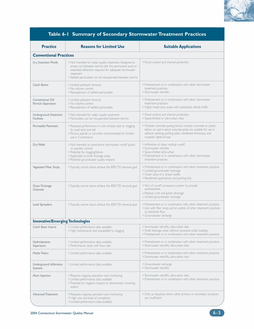
Practice Reasons for Limited Use Suitable Applications
Conventional Practices
Dry Detention Ponds
Catch Basins
Conventional Oil/Particle Separators
Underground DetentionFacilities
Permeable Pavement
Dry Wells
Vegetated Filter Strips
Grass DrainageChannels
Level Spreaders
Catch Basin Inserts
Hydrodynamic Separators
Media Filters
Underground InfiltrationSystems
Alum Injection
Advanced Treatment
❍ Not intended for water quality treatment. Designed toempty out between storms; lack the permanent pool orextended detention required for adequate stormwatertreatment
❍ Settled particulates can be resuspended between storms
❍ Limited pollutant removal❍ No volume control❍ Resuspension of settled particulates
❍ Limited pollutant removal❍ No volume control❍ Resuspension of settled particulates
❍ Not intended for water quality treatment❍ Particulates can be resuspended between storms
❍ Reduced performance in cold climates due to cloggingby road sand and salt
❍ Porous asphalt or concrete recommended for limiteduse in Connecticut
❍ Not intended as stand-alone stormwater runoff qualityor quantity control
❍ Potential for clogging/failure❍ Applicable to small drainage areas❍ Potential groundwater quality impacts
❍ Typically, cannot alone achieve the 80% TSS removal goal
❍ Typically, cannot alone achieve the 80% TSS removal goal
❍ Typically, cannot alone achieve the 80% TSS removal goal
❍ Limited performance data available❍ High maintenance and susceptible to clogging
❍ Limited performance data available❍ Performance varies with flow rate
❍ Limited performance data available
❍ Limited performance data available
❍ Requires ongoing operation and monitoring❍ Limited performance data available❍ Potential for negative impacts to downstream receiving
waters
❍ Requires ongoing operation and monitoring❍ High cost and level of complexity❍ Limited performance data available
❍ Flood control and channel protection
❍ Pretreatment or in combination with other stormwater treatment practices
❍ Stormwater retrofits
❍ Pretreatment or in combination with other stormwater treatment practices
❍ Highly impervious areas with substantial vehicle traffic
❍ Flood control and channel protection❍ Space-limited or ultra-urban sites
❍ Modular concrete paving blocks, modular concrete or plasticlattice, or cast-in-place concrete grids are suitable for use inspillover parking, parking aisles, residential driveways, and roadside rights-of-way
❍ Infiltration of clean rooftop runoff❍ Stormwater retrofits❍ Space-limited ultra-urban❍ Pretreatment or in combination with other stormwater
treatment practices
❍ Pretreatment or in combination with other treatment practices❍ Limited groundwater recharge❍ Outer zone of a stream buffer❍ Residential applications and parking lots
❍ Part of runoff conveyance system to provide pretreatment
❍ Replace curb and gutter drainage❍ Limited groundwater recharge
❍ Pretreatment or in combination with other treatment practices❍ Use with filter strips and at outlets of other treatment practices
to distribute flow❍ Groundwater recharge
❍ Stormwater retrofits, ultra-urban sites❍ Small drainage areas without excessive solids loadings❍ Pretreatment or in combination with other treatment practices
❍ Pretreatment or in combination with other treatment practices❍ Stormwater retrofits, ultra-urban sites
❍ Pretreatment or in combination with other treatment practices❍ Stormwater retrofits, ultra-urban sites
❍ Groundwater recharge❍ Stormwater retrofits
❍ Stormwater retrofits, ultra-urban sites❍ Pretreatment or in combination with other treatment practices
❍ Only as required, where other primary or secondary practicesare insufficient
Table 6-1 Summary of Secondary Stormwater Treatment Practices
2004 Connecticut Stormwater Quality Manual 6-5
Innovative/Emerging Technologies
2004 Connecticut Stormwater Quality Manual6-6
pollutant removal and little storage area for thematerial that is removed. Consequently, frequentmaintenance is typically required to avoid clogging ofthe insert and there is the possibility of re-suspensionof filtered pollutants (Washington, 2000).
Hydrodynamic Separators: This group of stormwa-ter treatment technologies is designed to remove largeparticle total suspended solids and large oil droplets.They consist primarily of cylindrical-shaped devicesthat are designed to fit in or adjacent to existingstormwater drainage systems (Washington, 2000). Themost common mechanism used in these devices isvortex-enhanced sedimentation, also called swirl con-centration. In these structures, often called swirlconcentrators, stormwater enters as tangential inletflow into the side of the cylindrical structure. As thestormwater spirals through the chamber, the swirlingmotion causes the sediments to settle by gravity,removing them from the stormwater (EPA, 2002).Some devices also have compartments or chambers totrap oil and other floatables.
Although swirl concentration is the technologyemployed by most hydrodynamic separators, somesystems use circular screening systems or engi-neered cylindrical sedimentation. Circular screenedsystems use a combination of screens, baffles, andinlet and outlet structures to remove debris, largeparticle total suspended solids, and large oildroplets. Structures using engineered cylindricalsedimentation use an arrangement of internal baf-fles and an oil and sediment storage compartment.Other proprietary technologies incorporate an inter-nal high flow bypass with a baffle system in arectangular structure to simulate plug flow opera-tion. When properly engineered and tested, thesesystems can also be an improvement over conven-tional oil/particle separators and offer removalefficiencies similar to swirl chamber technologies.Absorbent materials can also be added to thesestructures to increase removal efficiency of oil andhydrocarbons (Washington, 2000).
Media Filters: In this type of treatment practice,media is placed within filter cartridges that are typi-cally enclosed in concrete vaults. Stormwater ispassed through the media, which traps particulatesand/or soluble pollutants. Various materials can beused as filter media including pleated fabric, activatedcharcoal, perlite, amended sand and perlite mixes,and zeolite. Selection of filter media is a function ofthe pollutants targeted for removal. Pretreatment priorto the filter media is typically necessary for stormwa-ter with high total suspended solids, hydrocarbon,and debris loadings that may cause clogging and pre-mature filter failure (Washington, 2000).
Underground Infiltration Systems: Various typesof underground infiltration structures, such as pre-manufactured pipes, vaults, and modular structures,have been developed as alternatives to infiltrationtrenches and basins for space-limited sites andstormwater retrofit applications. Similar to traditionalinfiltration trenches and basins, these systems aredesigned to capture, temporarily store, and infiltratethe design water quality volume over several days.Performance of underground infiltration structuresvaries by manufacturer and system design. These sys-tems are currently considered secondary treatmentpractices due to limited field performance data,although pollutant removal efficiency is anticipated tobe similar to that of infiltration trenches and basins.
Advanced Treatment: The pollutant removal tech-niques utilized in drinking water treatment processesare potential advanced treatment options forstormwater (Lee, 2001). Alum has been used exten-sively as a coagulant in pond and lake managementapplications. Alum injection has also been used morerecently in stormwater applications for reducing con-centrations of fine sediment and phosphorus instormwater discharges to eutrophic water bodies.Water-soluble anionic polyacrylamide (PAM) has alsobeen used as a coagulant in drinking water treatmentand pond dredging operations to enhance settling ofsolids. PAM has also been land applied as an erosionand sedimentation control measure. Recently, the useof PAM in pre-formed shapes such as logs in ditchesor open swales has been introduced to enhanceremoval of fine sediment in stormwater runoff.However, the practicability of methods such as ionexchange, reverse osmosis, disinfection, and ultrafil-tration is undocumented for stormwater treatment.The success of these methods in drinking water treat-ment suggests that they may have potentialapplications in areas where conventional stormwatertreatment methods are unable to meet stringentstormwater quality standards or established wasteload allocations. However, these technologies arebeyond the scope of this Manual.
Criteria for Evaluating New PracticesNew and emerging stormwater treatment practicesmay be acceptable as primary treatment practices ifthey demonstrate the ability to achieve treatmentresults consistent with the primary treatment practicesdescribed at the beginning of this chapter, specifically:
❍ Capture and treatment of the design water qual-ity volume (WQV) or design water quality flow(WQF)

2004 Connecticut Stormwater Quality Manual 6-7
❍ Removal of at least 80 percent of the averageannual total suspended solids (TSS) load
❍ Removing at least 80 percent of floatable debris,including oil and petroleum products, for allflow rates up to the design water quality flow(WQF), either alone or in combination with pre-treatment
❍ Acceptable performance or operational longevityin the field
❍ Automatic operation during runoff events (i.e.,no need for manual activation)
These capabilities must be demonstrated throughfield and laboratory testing. Independent validation ofdata that support specific treatment technology per-formance claims is recommended. Field performancedata should come from field studies conducted undera variety of conditions (e.g., flow rates, contaminantloadings, antecedent moisture conditions, rainfall dis-tribution, land use, percent imperviousness,maintenance intervals) (TARP, 2001). Ideally, the fieldstudies should be conducted over a one-year demon-stration period, including cold weather and winterconditions, to capture possible seasonal variations inperformance and performance variations as a functionof rainfall intensity.
Field data is valuable for verifying performanceunder actual field conditions. However, the variabilityof site conditions leads to site-specific performancevalidation that may be difficult to develop into sizingmethodologies. It is recommended that laboratorytesting be conducted to establish performance curvesfor technologies over the full operating range of thesystem. Performance curves based on laboratory datafor various technologies, developed using the sametest criteria, applied to the same rainfall and TSSremoval model, enable direct comparison betweentechnologies. Laboratory testing must be conducted inaccordance with an established protocol for knownparticle sizes in known concentrations. The MaineDepartment of Environmental Protection has estab-lished one such protocol for comparing innovativetechnologies.
Performance claim data sets should be collectedunder a Quality Assurance Project Plan (QAPP) toensure that the data sets meet data quality objectivesand are defensible, and should include flow rates, res-idence times, and rainfall intensity data with which tointerpret these claims. USEPA provides guidance onthe development and minimum requirements for aQAPP. (See USEPA references at the end of this chap-ter.) Standardized test methods and procedures mustbe used in the collection of data. For example, ASTMmethods for flow measurement methods, ASCE
hydraulic flow estimation methods, and EPA testmethods for water quality analysis are typical stan-dardized test methods. (See TARP (2001)) for a listingof standardized methods for flow and water con-stituent analysis).
It is recommended that stormwater quality databe collected in accordance with guidance outlined inthe Technology Acceptance and ReciprocityPartnership (TARP) Stormwater BMP DemonstrationProtocol (2001). The TARP Stormwater BMPDemonstration Protocol has been endorsed by thestates of Massachusetts, New York, New Jersey,Illinois, California, Maryland, Pennsylvania, Texas andVirginia to provide a uniform method for demonstrat-ing stormwater technologies and developing testquality assurance plans for certification or verificationof performance claims. Treatment efficiencies shouldbe calculated using methods outlined in the joint EPAand ASCE technical memorandum DeterminingUrban Stormwater Best Management Practice (BMP)Removal Efficiencies (URS Greiner Woodward Clydeet al., 1999). In addition, to demonstrate that the per-formance claims are reliable, significant, and withinconfidence limits, statistical evaluation of the datamust be performed and made available. Performanceclaims should be given with appropriate confidenceintervals (i.e., removal rate of 85% ± 5% at a 95% con-fidence interval). The EPA Data Quality AssessmentGuidance Manual (EPA, 1998) provides informationon statistical methods for comparison and validationof data sets.
In addition to performance claims and validation,the following specifications for the treatment technol-ogy should be provided:
❍ Description of the underlying scientific andengineering principles
❍ Standard drawings, including a process flowdiagram
❍ Minimum siting and design specifications neces-sary to achieve the stated performance
❍ The full range of operating conditions for thetechnology, including minimum, maximum,and optimal conditions to meet the stated per-formance claims (flow rate, residence time,rainfall intensity, etc.)
❍ Minimum maintenance requirements to sustainthe stated performance
❍ Description of hydraulics and system sizing tomeet the performance claims
❍ Discussion of any pretreatment required to meetthe stated performance claims
2004 Connecticut Stormwater Quality Manual6- 8
❍ Identification of any special licensing or haulingrequirements, safety issues or access require-ments associated with installation and/oroperation and maintenance
❍ Discussion of the generation, handling, removaland disposal of any discharges, emissions, or otherwaste byproducts of the treatment technology
(TARP, 2001). Evaluation protocols and methods sim-ilar to those of the TARP Stormwater BMPDemonstration Protocol have also been developedthrough EPA’s Environmental Technology Verification(ETV) program. With funding from the ETV program,the Civil Engineering Research Foundation estab-lished the Environmental Technology EvaluationCenter (EvTEC), an independent, non-profit verifica-tion center that evaluates environmental technologies.EvTEC is collaborating with the Washington StateDepartment of Transportation to verify performanceof innovative stormwater treatment practices underfield operating conditions. These evaluations areexpected to provide comparable, peer-reviewed per-formance data on these systems (CERF, 2002).
EPA and NSF International, an independent, non-profit testing organization, have developed a testingprotocol under the ETV program to determine the via-bility of runoff treatment technologies and other wetweather flow controls, including urban runoff, com-bined sewer overflows (CSO), and sanitary seweroverflows (SSO). Participants in the study include ven-dors who want to demonstrate the effectiveness oftheir technologies. Results of the pilot will be useful toa variety of stakeholders including municipalities, busi-nesses, vendors, consulting engineers, and regulatoryagencies. Once verification reports have been com-pleted, vendors may use the results in their marketingefforts. Results will be made publicly available throughEPA’s and NSF’s Web sites at http://www.epa.gov/etvand http://www.nsf.org/etv, respectively.
6.4 Stormwater Treatment TrainStormwater treatment practices can be combined inseries to enhance pollutant removal or achieve multi-ple stormwater objectives. The use of a series oftreatment practices, as well as site planning tech-niques and source controls, is referred to as“stormwater treatment trains”. The use of a treatmenttrain approach can:
❍ Increase the level and reliability of pollutantremoval
❍ Accomplish multiple stormwater managementobjectives (pollutant removal, groundwaterrecharge, channel protection, peak runoffattenuation, etc.)
❍ Increase the lifespan of treatment devices bydistributing pollutant removal over multiplepractices or controls
❍ Reduce the potential for resuspension of sedi-ment by reducing flow velocities and increasingflow paths
❍ Allow the use of a wider array of treatmentpractices, including supplemental practices forpretreatment
A treatment train may consist of the followingtypes of practices in series to satisfy the design crite-ria in Chapter Seven:
❍ Multiple primary treatment practices
❍ A combination of primary and secondary treat-ment practices
❍ Multiple secondary treatment practices (at thediscretion of the review authority)
The use of multiple stormwater treatment prac-tices increases the maintenance required topreserve the overall effectiveness of the system. Ingeneral, the least expensive and most easily main-tained components should be placed at the mostupstream point in the treatment train to reduce themaintenance requirements of the downstream com-ponents (Metropolitan Council, 2001). Theindividual treatment practice descriptions inChapter Eleven include guidance on routine andnon-routine maintenance.
6.5 MaintenanceStormwater treatment practices require regularmaintenance to perform successfully. Failure toperform adequate maintenance can lead to reduc-tions in pollutant removal efficiency or actuallyincrease pollutant loadings and aggravate down-stream impacts. Stormwater treatment practicesshould be routinely inspected and maintainedfollowing construction to ensure that the controlsare in proper working condition and operating asdesigned. General maintenance guidelines forstormwater treatment practices are summarizedbelow. Chapter Eleven contains recommendedmaintenance for specific stormwater treatmentpractices. Appendix E contains maintenanceinspection checklists for specific stormwatertreatment practices. Additional information onmaintenance of stormwater treatment practicescan be found in the documents listed at the end ofthis chapter.
2004 Connecticut Stormwater Quality Manual 6-9
General maintenance requirements for stormwa-ter treatment practices include:
Inspections: Inspections should be performed atregular intervals to ensure proper operation ofstormwater treatment practices. Inspections shouldbe conducted at least annually, with additionalinspections following large storms. Inspectionsshould include a comprehensive visual check forevidence of the following (not all items apply toevery treatment practice):
❍ Accumulation of sediment or debris at inlet andoutlet structures
❍ Erosion, settlement, or slope failure
❍ Clogging or buildup of fines on infiltration surfaces
❍ Vegetative stress and appropriate water levels foremergent vegetation
❍ Algae growth, stagnant pools, or noxious odors
❍ Deterioration of pipes or conduits
❍ Seepage at the toe of ponds or wetlands
❍ Deterioration or sedimentation in downstreamchannels and energy dissipators
❍ Evidence of vandalism
❍ Evidence of structural damage by beavers,muskrats, and other wildlife
Routine Maintenance: Routine maintenance shouldbe performed on a regular basis to maintain properoperation and aesthetics. Routine maintenance shouldinclude:
❍ Debris and litter removal
❍ Silt and sediment removal
❍ Terrestrial vegetation maintenance
❍ Aquatic vegetation maintenance
❍ Maintenance of mechanical components (valves,gates, access hatches, locks)
Non-routine Maintenance: Non-routine mainte-nance refers to corrective measures taken to repair orrehabilitate stormwater controls to proper workingcondition. Non-routine maintenance is performed asneeded, typically in response to problems detectedduring routine maintenance and inspections,and can include:
❍ Erosion and structural repair
❍ Sediment removal and disposal
❍ Nuisance control (odors, mosquitoes, weeds,excessive litter)
Stormwater treatment practice operation andmaintenance requirements are an integral part of asite stormwater management plan (see ChapterNine). These requirements should include, at a min-imum, detailed inspection and maintenance tasks,schedules, responsible parties, and financing provi-sions. The owner typically maintains stormwatertreatment practices at commercial, industrial, andrental residential developments. These facilities gen-erally have staff dedicated to maintenance activitiesor contract for such services. Maintenance of non-rental residential installations is typically performedby private landowners or property/homeownersassociations, which in many cases do not have thetechnical expertise, resources, or funds to inspectand maintain their stormwater systems. In somecases, local government may accept responsibilityfor inspecting and maintaining stormwater treatmentpractices. Local governments should require legallybinding maintenance agreements for stormwatertreatment practices to clearly delineate maintenanceresponsibilities. Potential funding mechanismsinclude general tax revenues, stormwater utility fees,inspection or permit fees, and dedicated funds fromland developers. Public education is critical for thesuccess of any stormwater financing program.
Many municipalities consider stormwater treat-ment practices such as ponds, wetlands, and other“wet” treatment systems as regulated wetland areas,and therefore subject to local inland wetlands andwatercourses regulations. Sediment removal andother common maintenance activities may requireapproval from the local Inland Wetlands andWatercourses Commission, which presents a poten-tial regulatory hurdle to consistent maintenance. Tofacilitate this approval process, municipalities couldissue up to a five-year maintenance permit in con-junction with the primary Inland Wetlands andWatercourses permit for the development or rede-velopment project. The permit holder would beresponsible for renewing or requesting reissuance ofthe maintenance permit at five-year intervals.Municipalities should identify all such stormwatermanagement facilities for which they are responsibleand issue a five-year renewable maintenance permit.This type of an approach is analogous to DEP’srenewable five-year maintenance permits issued toDOT and other state-regulated entities for statewidedrainage maintenance activities.
2004 Connecticut Stormwater Quality Manual6-10
6.6 Performance MonitoringCurrently, there are very limited performance data forstormwater treatment practices in the State ofConnecticut. Performance data from the majority ofprevious monitoring studies conducted throughoutthe United States are limited by differences in design,performance goals, site parameters, storm events,flow and pollutant loadings, seasonal variations, mon-itoring methods, efficiency calculation methods orsimply by the lack of or inadequacy of information.Several major initiatives are underway nationally toprovide a more useful set of data on the effectivenessof individual stormwater treatment practices, and tobetter understand the relationship between treatmentpractice design and performance. These include:
❍ The Center for Watershed Protection’s NationalPollutant Removal Performance Database(Winer, 2000)
❍ The American Society of Civil Engineers (ASCE)National Stormwater Best Management Practices(BMP) Database (Urban Water ResourcesResearch Council of ASCE and Wright WaterEngineers, Inc., 2001)
❍ Water Environment Research Foundation(WERF) Critical Assessment of StormwaterControl (BMP) Selection Issues (WERF, inprogress)
These databases contain the results of perform-ance studies for individual stormwater treatmentpractices throughout the United States. While theyprovide a starting point for pollutant removal esti-mates, the usefulness of the data is still extremelylimited for many of the reasons stated above. Thereliability of the data will continue to increase as theresults from additional studies are added.
Very few performance monitoring studies havebeen performed in Connecticut or elsewhere in NewEngland. Performance monitoring is recommendedfor new and existing stormwater treatment practicesin Connecticut to develop a representative and reli-able performance database that is specific to the Stateof Connecticut. Performance monitoring is designedto provide information on the following issues:
❍ What degree of pollution control does the treat-ment practice provide under typical operatingconditions?
❍ How does efficiency vary from pollutant to pollutant?
❍ How does efficiency vary with various input concentrations?
❍ How does efficiency vary with storm characteris-tics such as rainfall amount, rainfall density,antecedent weather conditions?
❍ How do design variables affect performance?
❍ How does efficiency vary with different opera-tional and/or maintenance approaches?
❍ Does efficiency improve, decay, or remain thestable over time?
❍ How does the system’s efficiency, performance,and effectiveness compare relative to otherstormwater treatment practices?
❍ Does the treatment practice reduce toxicity toacceptable levels?
❍ Does the treatment practice cause an improvementor protect in downstream biotic communities?
❍ Does the treatment practice have potential down-stream negative impacts?
(URS Greiner Woodward Clyde et al., 1999).Standardized test methods and procedures should beused for stormwater performance monitoring stud-ies. Performance monitoring should be consistentwith the methods and protocols described previ-ously in this chapter for evaluating new stormwatertreatment technologies and the guidance documentsreferenced therein.
2004 Connecticut Stormwater Quality Manual 6-11
Additional Information Sources
Technology Acceptance and Reciprocity Partnership(TARP), Pennsylvania Department of EnvironmentalProtection,URL: http://www.dep.state.pa.us/dep/deputate/pollprev/techservices/tarp/index.htm.
Water Environment Federation (WEF) and AmericanSociety of Civil Engineers (ASCE). 1998. UrbanRunoff Quality Management (WEF Manual ofPractice No. 23 and ASCE Manual and Report onEngineering Practice No. 87).
Watershed Management Institute, Inc. 1997.Operation, Maintenance, and Management ofStormwater Management Systems. In cooperationwith U.S. Environmental Protection Agency, Office ofWater. Washington, D.C.
United States Environmental Protection Agency (EPA).2001. Environmental Technology Verification (ETV)Program. URL: http://www.epa.gov/etv.NSF International. 2001. Verification Program to testEffectiveness of Wet Weather Flow Technologies. URL: http://www.nsf.org/etv.
References
Civil Engineering Research Foundation (CERF). 2002.Stormwater Best Management Practices (BMP)Verification Program. Fact Sheet Updated February2002. Environmental Technology Evaluation Center(EvTEC) website.URL: http://www.cerf.org/evtec/eval/wsdot2.htm.
Maryland Department of the Environment (MDE). 2000.2000 Maryland Stormwater Design Manual, Volumes Iand II. Baltimore, Maryland. Prepared by Center forWatershed Protection, Ellicott City, Maryland.
Massachusetts Department of EnvironmentalProtection (MADEP) and the Massachusetts Office ofCoastal Zone Management. 1997. StormwaterManagement, Volume Two: Stormwater TechnicalHandbook, Boston, Massachusetts.
Metropolitan Council. 2001. Minnesota Urban SmallSites BMP Manual: Stormwater Best ManagementPractices for Cold Climates. Prepared by BarrEngineering Company, St. Paul, Minnesota.
New York State Department of EnvironmentalConservation (NYDEC). 2001. New York StateStormwater Management Design Manual. Prepared byCenter for Watershed Protection. Albany, New York.
Technology Acceptance and Reciprocity Partnership.2001. Stormwater Best Management PracticeDemonstration Tier II Protocol for InterstateReciprocity Endorsed by California, Massachusetts,New Jersey, Pennsylvania, and Virginia.
United States Environmental Protection Agency(EPA). 1992. NPDES Stormwater Sampling GuidanceDocument. EPA/833-B-92-001. Washington, D.C.
United States Environmental Protection Agency(EPA). 1998a. Data Quality Assessment GuidanceManual. (QA/G-9) EPA/600/R-96/084. Washington, D.C.
United States Environmental Protection Agency(EPA). 1998b. Guidance for Quality AssuranceProject Plans. (QA/G-5) EPA/600/R-98/018.Washington, D.C.
United States Environmental Protection Agency(EPA). 2001. EPA Requirements for QualityAssurance Project Plans. (QA/R-5) EPA/240/B-01/003. Washington, D.C.
United States Environmental Protection Agency(EPA). 2002. National Menu of Best ManagementPractices for Stormwater Phase II. URL:http://www.epa.gov/npdes/menuofbmps/menu.htm,Last Modified January 24, 2002.
Urban Water Resources Research Council of theAmerican Society of Civil Engineers (ASCE) andWright Water Engineers, Inc. 2001. NationalStormwater Best Management Practices (BMP)Database.
URS Greiner Woodward Clyde, Urban Waterresources Research Council of the American Societyof Civil Engineers, U.S. Environmental ProtectionAgency. 1999. Development of PerformanceMeasures, Task 3.1 – Technical Memorandum,Determining Urban Stormwater Best ManagementPractice (BMP) Removal Efficiencies.
Washington State Department of Ecology(Washington). 2000. Stormwater ManagementManual for Western Washington, Final Draft,Olympia, Washington.
Winer, R. 2000. National Pollutant RemovalDatabase for Stormwater Treatment Practices, 2ndEdition. Center for Watershed Protection. EllicottCity, Maryland.
Chapter 7Hydrologic Sizing Criteria
for Stormwater Treatment Practices
Chapter 7 Hydrologic Sizing Criteria for Stormwater Treatment Practices
7.1 Introduction .................................................................................................7-2
7.2 Criteria Applicability ...................................................................................7-2
7.3 Criteria Summary.........................................................................................7-4
7.4 Pollutant Reduction.....................................................................................7-4
7.4.1 Water Quality Volume (WQV)..............................................7-4
7.4.2 Water Quality Flow (WQF)...................................................7-5
7.5 Groundwater Recharge and RunoffVolume Reduction .......................................................................................7-5
7.5.1 Groundwater Recharge Volume (GRV) ...............................7-6
7.5.2 Runoff Capture Volume (RCV)..............................................7-7
7.6 Peak Flow Control .......................................................................................7-8
7.6.1 Stream Channel Protection....................................................7-8
7.6.2 Conveyance Protection...........................................................7-9
7.6.3 Peak Runoff Attenuation .........................................................7-9
7.6.4 Emergency Outlet Sizing ......................................................7-10
7.6.5 Downstream Analysis............................................................7-10
7.7 Sizing Example ............................................................................................7-10
Volume 1I: Design
2004 Connecticut Stormwater Quality Manual 7- 1
2004 Connecticut Stormwater Quality Manual7-2
7.1 IntroductionThis chapter presents a
recommended approach for
sizing stormwater treatment
practices in the State of
Connecticut. Although the
primary focus of this Manual
is on stormwater quality, the
management of stormwater
quantity is an impor tant
related concern.Therefore,
the sizing criteria in this
chapter are designed to
achieve both water quality
and quantity control objec-
tives. The recommended
sizing criteria have been
adapted from the Center
for Watershed Protection’s
Unified Sizing Criteria,
which is one of the more
comprehensive approaches
for s i z ing s tormwater
treatment practices devel-
oped to date.This approach
has been implemented in
several other states including
Maryland, New York,
Vermont, and Georgia.
The sizing approach described in this chapter is intended to manage thefull spectrum of storm flows and their associated water quality and quan-tity impacts. These range from small, frequent storms that are responsiblefor a majority of the annual runoff volume and pollutant loads to large,infrequent events which are responsible for nuisance and catastrophicflooding. Stormwater treatment practices should be designed to accomplishthe following primary objectives:
❍ Pollutant reduction
❍ Runoff volume reduction and groundwater recharge
❍ Stream channel protection and peak flow control
The following sections of this chapter describe criteria and methodsfor sizing stormwater treatment practices to meet these objectives. Thesecriteria are intended to be consistent with local subdivision and planning/zoning ordinances of most municipalities throughout the state, particularlyregarding peak flow control requirements. Some differences may existbetween the criteria presented in this chapter and local requirements. Localrequirements should be consulted in addition to these criteria. However,the criteria presented in this chapter are recommended where local regu-lations are less stringent.
7.2 Criteria ApplicabilityThe design criteria presented in this chapter are generally applicable to the following types of new development and redevelopment projects,including phased developments:
❍ Any development resulting in the disturbance of greater than orequal to one acre of land
❍ Residential development consisting of 5 or more dwelling units
❍ Residential development consisting of fewer than 5 dwelling unitsinvolving construction of a new road or reconstruction of an existingroad
❍ Residential development consisting of fewer than 5 dwelling unitswhere imperviousness of the site after construction exceeds 30 percent
❍ Stormwater discharge to wetlands/watercourses
❍ New stormwater discharges located less than 500 feet from tidal wetlands
❍ Land uses or activities with potential for higher pollutant loadings(see Table 7-5), excluding the groundwater recharge criterion
❍ Industrial and commercial development projects which result in10,000 sq. ft. or greater of impervious surface
❍ New highway, road, and street construction
❍ Modifications to existing storm drainage systems
These and other types of projects not listed above, such as single fam-ily residential development, are encouraged to incorporate alternative sitedesign, low impact development practices, and source controls to reduceimperviousness, runoff volumes, and stormwater pollutant sources.
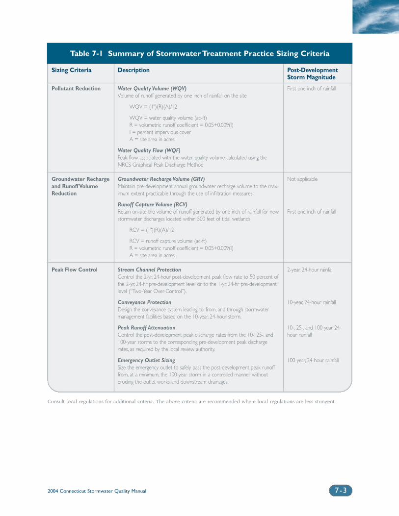
2004 Connecticut Stormwater Quality Manual 7-3
Sizing Criteria
Pollutant Reduction
Groundwater Rechargeand Runoff VolumeReduction
Peak Flow Control
Description
Water Quality Volume (WQV)Volume of runoff generated by one inch of rainfall on the site
WQV = (1")(R)(A)/12
WQV = water quality volume (ac-ft)R = volumetric runoff coefficient = 0.05+0.009(I)I = percent impervious coverA = site area in acres
Water Quality Flow (WQF)Peak flow associated with the water quality volume calculated using theNRCS Graphical Peak Discharge Method
Groundwater Recharge Volume (GRV)Maintain pre-development annual groundwater recharge volume to the max-imum extent practicable through the use of infiltration measures
Runoff Capture Volume (RCV)Retain on-site the volume of runoff generated by one inch of rainfall for newstormwater discharges located within 500 feet of tidal wetlands
RCV = (1")(R)(A)/12
RCV = runoff capture volume (ac-ft)R = volumetric runoff coefficient = 0.05+0.009(I)A = site area in acres
Stream Channel ProtectionControl the 2-yr, 24-hour post-development peak flow rate to 50 percent ofthe 2-yr, 24-hr pre-development level or to the 1-yr, 24-hr pre-developmentlevel (“Two-Year Over-Control”).
Conveyance ProtectionDesign the conveyance system leading to, from, and through stormwatermanagement facilities based on the 10-year, 24-hour storm.
Peak Runoff AttenuationControl the post-development peak discharge rates from the 10-, 25-, and100-year storms to the corresponding pre-development peak dischargerates, as required by the local review authority.
Emergency Outlet SizingSize the emergency outlet to safely pass the post-development peak runofffrom, at a minimum, the 100-year storm in a controlled manner withouteroding the outlet works and downstream drainages.
Post-DevelopmentStorm Magnitude
First one inch of rainfall
Not applicable
First one inch of rainfall
2-year, 24-hour rainfall
10-year, 24-hour rainfall
10-, 25-, and 100-year 24-hour rainfall
100-year, 24-hour rainfall
Table 7-1 Summary of Stormwater Treatment Practice Sizing Criteria
Consult local regulations for additional criteria. The above criteria are recommended where local regulations are less stringent.
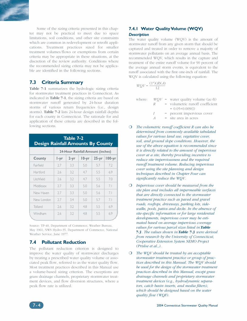
2004 Connecticut Stormwater Quality Manual7- 4
Some of the sizing criteria presented in this chap-ter may not be practical to meet due to spacelimitations, soil conditions, and other site constraintswhich are common in redevelopment or retrofit appli-cations. Treatment practices sized for smallertreatment volumes/flows or exemptions from certaincriteria may be appropriate in these situations, at thediscretion of the review authority. Conditions wherethe recommended sizing criteria may not be applica-ble are identified in the following sections.
7.3 Criteria SummaryTable 7-1 summarizes the hydrologic sizing criteriafor stormwater treatment practices in Connecticut. Asindicated in Table 7-1, the sizing criteria are based onstormwater runoff generated by 24-hour durationstorms of various return frequencies (i.e., designstorms). Table 7-2 lists 24-hour design rainfall depthsfor each county in Connecticut. The rationale for andapplication of these criteria are described in the fol-lowing sections.
7.4 Pollutant ReductionThe pollutant reduction criterion is designed toimprove the water quality of stormwater dischargesby treating a prescribed water quality volume or asso-ciated peak flow, referred to as the water quality flow.Most treatment practices described in this Manual usea volume-based sizing criterion. The exceptions aregrass drainage channels, proprietary stormwater treat-ment devices, and flow diversion structures, where apeak flow rate is utilized.
7.4.1 Water Quality Volume (WQV)DescriptionThe water quality volume (WQV) is the amount ofstormwater runoff from any given storm that should becaptured and treated in order to remove a majority ofstormwater pollutants on an average annual basis. Therecommended WQV, which results in the capture andtreatment of the entire runoff volume for 90 percent ofthe average annual storm events, is equivalent to therunoff associated with the first one-inch of rainfall. TheWQV is calculated using the following equation:
WQV = (1")(R)(A)
12
where: WQV = water quality volume (ac-ft)R = volumetric runoff coefficient
= 0.05+0.009(I)I = percent impervious coverA = site area in acres
❍ The volumetric runoff coefficient R can also bedetermined from commonly available tabulatedvalues for various land use, vegetative cover, soil, and ground slope conditions. However, theuse of the above equation is recommended sinceit is directly related to the amount of imperviouscover at a site, thereby providing incentive toreduce site imperviousness and the requiredrunoff treatment volume. Reducing imperviouscover using the site planning and design techniques described in Chapter Four can significantly reduce the WQV.
❍ Impervious cover should be measured from thesite plan and includes all impermeable surfacesthat are directly connected to the stormwater treatment practice such as paved and gravelroads, rooftops, driveways, parking lots, side-walks, pools, patios and decks. In the absence ofsite-specific information or for large residentialdevelopments, impervious cover may be esti-mated based on average impervious coveragevalues for various parcel sizes listed in Table 7-3. The values shown in Table 7-3 were derivedfrom research by the University of Connecticut,Cooperative Extension System NEMO Project(Prisloe et al.,).
❍ The WQV should be treated by an acceptablestormwater treatment practice or group of prac-tices described in this Manual. The WQV shouldbe used for the design of the stormwater treatmentpractices described in this Manual, except grassdrainage channels and proprietary stormwatertreatment devices (e.g., hydrodynamic separa-tors, catch basin inserts, and media filters),which should be designed based on the waterquality flow (WQF).
Table 7-2Design Rainfall Amounts By County
24-Hour Rainfall Amount (inches)
County 1-yr 2-yr 10-yr 25-yr 100-yr
Fairfield 2.7 3.3 5.0 5.7 7.2
Hartford 2.6 3.2 4.7 5.5 6.9
Litchfield 2.6 3.2 4.7 5.5 7.0
Middlesex 2.7 3.3 5.0 5.6 7.1
New Haven 2.7 3.3 5.0 5.6 7.1
New London 2.7 3.4 5.0 5.7 7.1
Tolland 2.6 3.2 4.8 5.5 6.9
Windham 2.6 3.2 4.8 5.5 6.9
Source: TP-40, Department of Commerce, Weather Bureau, May 1961; NWS Hydro-35, Department of Commerce, National Weather Service, June 1977.
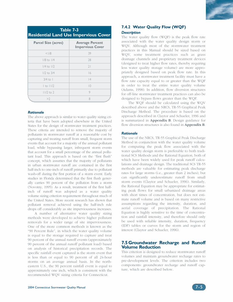
2004 Connecticut Stormwater Quality Manual 7-5
RationaleThe above approach is similar to water quality sizing cri-teria that have been adopted elsewhere in the UnitedStates for the design of stormwater treatment practices.These criteria are intended to remove the majority ofpollutants in stormwater runoff at a reasonable cost bycapturing and treating runoff from small, frequent stormevents that account for a majority of the annual pollutantload, while bypassing larger, infrequent storm eventsthat account for a small percentage of the annual pollu-tant load. This approach is based on the “first flush”concept, which assumes that the majority of pollutantsin urban stormwater runoff are contained in the firsthalf-inch to one-inch of runoff primarily due to pollutantwash-off during the first portion of a storm event. Earlystudies in Florida determined that the first flush gener-ally carries 90 percent of the pollution from a storm(Novotny, 1995). As a result, treatment of the first half-inch of runoff was adopted as a water quality volume sizing criterion requirement throughout much ofthe United States. More recent research has shown thatpollutant removal achieved using the half-inch ruledrops off considerably as site imperviousness increases.
A number of alternative water quality sizingmethods were developed to achieve higher pollutantremovals for a wider range of site imperviousness.One of the more common methods is known as the“90 Percent Rule”, in which the water quality volumeis equal to the storage required to capture and treat90 percent of the annual runoff events (approximately90 percent of the annual runoff pollutant load) basedon analysis of historical precipitation records. Thespecific rainfall event captured is the storm event thatis less than or equal to 90 percent of all 24-hourstorms on an average annual basis. In the north-eastern U.S., the 90 percent rainfall event is equal toapproximately one inch, which is consistent with therecommended WQV sizing criteria for Connecticut.
7.4.2 Water Quality Flow (WQF)DescriptionThe water quality flow (WQF) is the peak flow rateassociated with the water quality design storm orWQV. Although most of the stormwater treatmentpractices in this Manual should be sized based onWQV, some treatment practices such as grassdrainage channels and proprietary treatment devices(designed to treat higher flow rates, thereby requiringless water quality storage volume) are more appro-priately designed based on peak flow rate. In thisapproach, a stormwater treatment facility must have aflow rate capacity equal to or greater than the WQFin order to treat the entire water quality volume(Adams, 1998). In addition, flow diversion structuresfor off-line stormwater treatment practices can also bedesigned to bypass flows greater than the WQF.
The WQF should be calculated using the WQVdescribed above and the NRCS, TR-55 Graphical PeakDischarge Method. The procedure is based on theapproach described in Claytor and Schueler, 1996 andis summarized in Appendix B. Design guidance forflow diversion structures is also found in Appendix B.
RationaleThe use of the NRCS, TR-55 Graphical Peak DischargeMethod in conjunction with the water quality volumefor computing the peak flow associated with thewater quality design storm is preferable to both tradi-tional SCS Methods and the Rational Equation, both ofwhich have been widely used for peak runoff calcu-lations and drainage design. The traditional SCS TR-55methods are valuable for estimating peak dischargerates for large storms (i.e., greater than 2 inches), butcan significantly underestimate runoff from smallstorm events (Claytor and Schueler, 1996). Similarly,the Rational Equation may be appropriate for estimat-ing peak flows for small urbanized drainage areaswith short times of concentration, but does not esti-mate runoff volume and is based on many restrictiveassumptions regarding the intensity, duration, andaerial coverage of precipitation. The RationalEquation is highly sensitive to the time of concentra-tion and rainfall intensity, and therefore should onlybe used with reliable intensity, duration, frequency(IDF) tables or curves for the storm and region ofinterest (Claytor and Schueler, 1996).
7.5Groundwater Recharge and RunoffVolume ReductionThis criterion is designed to reduce stormwater runoffvolumes and maintain groundwater recharge rates topre-development levels. The criterion includes twocomponents: groundwater recharge and runoff cap-ture, which are described below.
Parcel Size (acres) Average Percent Impervious Cover
<1/8 39
1/8 to 1/4 28
1/4 to 1/2 21
1/2 to 3/4 16
3/4 to 1 14
1 to 11/2 10
11/2 to 2 9
>2 8
Table 7-3 Residential Land Use Impervious Cover
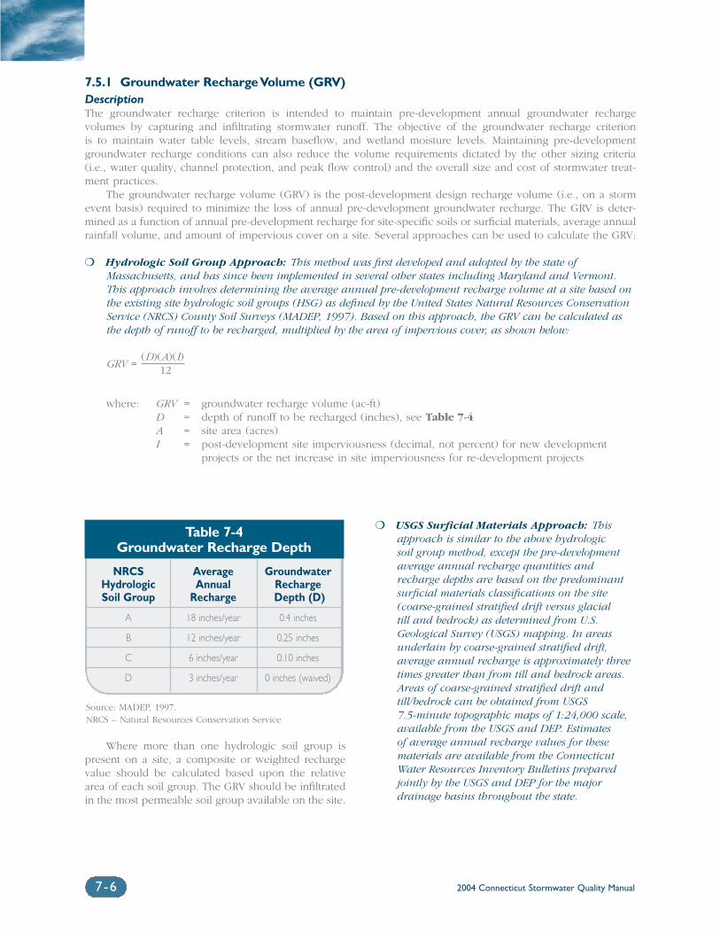
2004 Connecticut Stormwater Quality Manual7-6
7.5.1 Groundwater Recharge Volume (GRV)DescriptionThe groundwater recharge criterion is intended to maintain pre-development annual groundwater recharge volumes by capturing and infiltrating stormwater runoff. The objective of the groundwater recharge criterionis to maintain water table levels, stream baseflow, and wetland moisture levels. Maintaining pre-developmentgroundwater recharge conditions can also reduce the volume requirements dictated by the other sizing criteria(i.e., water quality, channel protection, and peak flow control) and the overall size and cost of stormwater treat-ment practices.
The groundwater recharge volume (GRV) is the post-development design recharge volume (i.e., on a stormevent basis) required to minimize the loss of annual pre-development groundwater recharge. The GRV is deter-mined as a function of annual pre-development recharge for site-specific soils or surficial materials, average annualrainfall volume, and amount of impervious cover on a site. Several approaches can be used to calculate the GRV:
❍ Hydrologic Soil Group Approach: This method was first developed and adopted by the state ofMassachusetts, and has since been implemented in several other states including Maryland and Vermont.This approach involves determining the average annual pre-development recharge volume at a site based onthe existing site hydrologic soil groups (HSG) as defined by the United States Natural Resources ConservationService (NRCS) County Soil Surveys (MADEP, 1997). Based on this approach, the GRV can be calculated asthe depth of runoff to be recharged, multiplied by the area of impervious cover, as shown below:
GRV = (D)(A)(I)
12
where: GRV = groundwater recharge volume (ac-ft)D = depth of runoff to be recharged (inches), see Table 7-4A = site area (acres)I = post-development site imperviousness (decimal, not percent) for new development
projects or the net increase in site imperviousness for re-development projects
Where more than one hydrologic soil group ispresent on a site, a composite or weighted rechargevalue should be calculated based upon the relativearea of each soil group. The GRV should be infiltratedin the most permeable soil group available on the site.
❍ USGS Surficial Materials Approach: Thisapproach is similar to the above hydrologic soil group method, except the pre-developmentaverage annual recharge quantities andrecharge depths are based on the predominantsurficial materials classifications on the site(coarse-grained stratified drift versus glacial till and bedrock) as determined from U.S.Geological Survey (USGS) mapping. In areasunderlain by coarse-grained stratified drift, average annual recharge is approximately threetimes greater than from till and bedrock areas.Areas of coarse-grained stratified drift andtill/bedrock can be obtained from USGS 7.5-minute topographic maps of 1:24,000 scale,available from the USGS and DEP. Estimates of average annual recharge values for thesematerials are available from the ConnecticutWater Resources Inventory Bulletins preparedjointly by the USGS and DEP for the majordrainage basins throughout the state.
Table 7-4Groundwater Recharge Depth
NRCS Average GroundwaterHydrologic Annual RechargeSoil Group Recharge Depth (D)
A 18 inches/year 0.4 inches
B 12 inches/year 0.25 inches
C 6 inches/year 0.10 inches
D 3 inches/year 0 inches (waived)
Source: MADEP, 1997.NRCS – Natural Resources Conservation Service
2004 Connecticut Stormwater Quality Manual 7-7
❍ Other Methods: Pre-development recharge values and the required GRV can also be deter-mined using the results of on-site soil evaluationsor other geologic information provided thatinformation sources and methods are clearlydocumented.
Meeting the recharge requirement can be accom-plished through the use of primary treatment practices(infiltration, bioretention, filtration, and swales), secondary treatment practices (drywells, permeablepavement, level spreaders), and non-structural sitedesign techniques such as disconnection of rooftoprunoff and grading. Stormwater ponds, wetlands, andsediment forebays generally are not suitable forgroundwater recharge since they are either designedwith impermeable bottoms or have significantlyreduced permeability due to accumulation of fine sed-iment. When designing infiltration practices, a factorof safety should be used to account for potential com-paction of soils by construction equipment, which cansignificantly reduce soil infiltration capacity andgroundwater recharge. See the design sections of thisManual for guidance on the design and constructionof infiltration practices to reduce this potential.
The GRV is considered as part of the total waterquality volume (WQV) and therefore can be sub-tracted from the WQV, provided that the proposedinfiltration measures are capable of infiltrating therequired recharge volume. Reducing the WQV (and consequently the size and cost of stormwatertreatment) is an additional incentive for meeting the groundwater recharge criterion. Additionally, both WQV and GRV are a function of site impervi-ousness, providing further incentive to minimize siteimpervious cover.
There are several instances where the ground-water recharge criterion should be waived to protectagainst contamination of drinking water supplies andmobilization of existing subsurface contamination.Infiltration of stormwater is not recommended underthe following site conditions:
❍ Land Uses or Activities with Potential forHigher Pollutant Loads: Infiltration ofstormwater from these land uses or activities(Table 7-5), also referred to as stormwater“hotspots,” can contaminate public and privategroundwater supplies. Infiltration of stormwaterfrom these land uses or activities may be allowed by the review authority with appropriatepretreatment. Pretreatment could consist of oneor a combination of the primary or secondarytreatment practices described in this Manualprovided that the treatment practice is designedto remove the stormwater contaminants of concern.
❍ Subsurface Contamination: Infiltration ofstormwater in areas with soil or groundwatercontamination such as brownfield sites andurban redevelopment areas can mobilize contaminants.
❍ Groundwater Supply Areas: Infiltration ofstormwater can potentially contaminategroundwater drinking water supplies in publicdrinking water aquifer recharge areas andwellhead protection areas.
RationaleThe objective of the groundwater recharge criterionis to mimic the average annual recharge rate for pre-development site conditions. The recommendedapproach for calculating the GRV (i.e., the requiredstormwater infiltration volume) is a function of post-development site imperviousness and the prevailingsurface permeability and infiltration capacity. Thehydrologic soil group approach uses the widelyavailable NRCS Soil Survey maps and estimates ofaverage annual infiltration rates for each hydrologicsoil group. This method has been adopted inMassachusetts and other northeastern states, whichhave humid climates and receive approximately 44 inches of average annual rainfall. The recharge factors developed for this approach are also valid for Connecticut, which has similar rainfall, soils, and climate.
The alternative surficial materials approach maybe less accurate than other soil-specific methods forestimating site-specific infiltration rates. The annualrecharge values for surficial material categories arebased on basin-wide analyses of stratified drift andtill, which may not be applicable to specific sites.However, the approach is believed to be suitable forestimating the required recharge volume and utilizesreadily available, published information from theUSGS and DEP.
7.5.2 Runoff Capture Volume (RCV)DescriptionThe objective of the runoff capture criterion is tocapture stormwater runoff to prevent the discharge of pollutants, including “unpolluted” fresh water, tosensitive coastal receiving waters and wetlands. Therunoff capture criterion applies to new stormwaterdischarges located less than 500 feet from tidalwetlands, which are not fresh-tidal wetlands. Thestormwater runoff volume generated by the firstinch of rainfall must be retained on-site for such discharges. The runoff capture volume is equivalentto the WQV and can be calculated using the fol-lowing equation:
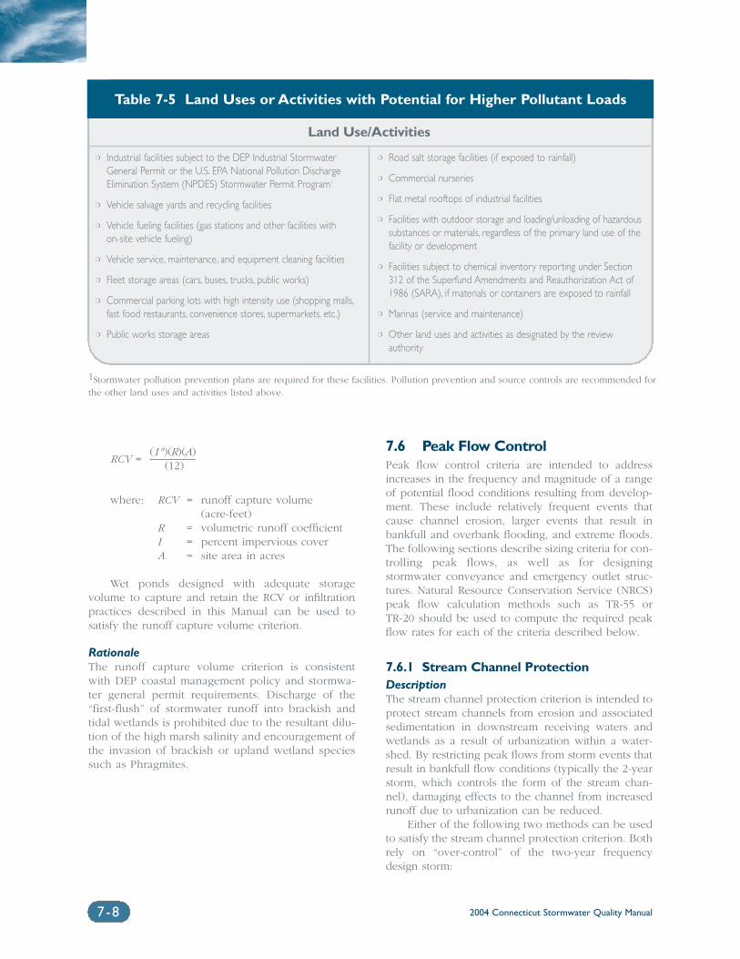
2004 Connecticut Stormwater Quality Manual7-8
RCV = (1")(R)(A)
(12)
where: RCV = runoff capture volume (acre-feet)
R = volumetric runoff coefficientI = percent impervious coverA = site area in acres
Wet ponds designed with adequate storage volume to capture and retain the RCV or infiltrationpractices described in this Manual can be used to satisfy the runoff capture volume criterion.
RationaleThe runoff capture volume criterion is consistentwith DEP coastal management policy and stormwa-ter general permit requirements. Discharge of the“first-flush” of stormwater runoff into brackish andtidal wetlands is prohibited due to the resultant dilu-tion of the high marsh salinity and encouragement ofthe invasion of brackish or upland wetland speciessuch as Phragmites.
7.6 Peak Flow ControlPeak flow control criteria are intended to addressincreases in the frequency and magnitude of a rangeof potential flood conditions resulting from develop-ment. These include relatively frequent events thatcause channel erosion, larger events that result inbankfull and overbank flooding, and extreme floods.The following sections describe sizing criteria for con-trolling peak flows, as well as for designingstormwater conveyance and emergency outlet struc-tures. Natural Resource Conservation Service (NRCS)peak flow calculation methods such as TR-55 or TR-20 should be used to compute the required peakflow rates for each of the criteria described below.
7.6.1 Stream Channel ProtectionDescriptionThe stream channel protection criterion is intended toprotect stream channels from erosion and associatedsedimentation in downstream receiving waters andwetlands as a result of urbanization within a water-shed. By restricting peak flows from storm events thatresult in bankfull flow conditions (typically the 2-yearstorm, which controls the form of the stream chan-nel), damaging effects to the channel from increasedrunoff due to urbanization can be reduced.
Either of the following two methods can be usedto satisfy the stream channel protection criterion. Bothrely on “over-control” of the two-year frequencydesign storm:
Table 7-5 Land Uses or Activities with Potential for Higher Pollutant Loads
Land Use/Activities
❍ Industrial facilities subject to the DEP Industrial StormwaterGeneral Permit or the U.S. EPA National Pollution DischargeElimination System (NPDES) Stormwater Permit Program1
❍ Vehicle salvage yards and recycling facilities
❍ Vehicle fueling facilities (gas stations and other facilities with on-site vehicle fueling)
❍ Vehicle service, maintenance, and equipment cleaning facilities
❍ Fleet storage areas (cars, buses, trucks, public works)
❍ Commercial parking lots with high intensity use (shopping malls,fast food restaurants, convenience stores, supermarkets, etc.)
❍ Public works storage areas
❍ Road salt storage facilities (if exposed to rainfall)
❍ Commercial nurseries
❍ Flat metal rooftops of industrial facilities
❍ Facilities with outdoor storage and loading/unloading of hazardoussubstances or materials, regardless of the primary land use of thefacility or development
❍ Facilities subject to chemical inventory reporting under Section312 of the Superfund Amendments and Reauthorization Act of1986 (SARA), if materials or containers are exposed to rainfall
❍ Marinas (service and maintenance)
❍ Other land uses and activities as designated by the reviewauthority
1Stormwater pollution prevention plans are required for these facilities. Pollution prevention and source controls are recommended forthe other land uses and activities listed above.
2004 Connecticut Stormwater Quality Manual 7-9
❍ Control the 2-year, 24-hour post-developmentpeak flow rate to 50 percent of the 2-year, 24-hour pre-development level or
❍ Control the 2-year, 24-hour post-developmentpeak flow rate to the 1-year, 24-hour pre-development level
There are several practical limitations on theapplication of the stream channel protection criterion.For sites having less than one acre of imperviouscover, the size of the orifice or weir required forextended detention becomes too small (approxi-mately 1 inch in diameter) to effectively operatewithout clogging. In addition, channel protection isgenerally not required where sites discharge to a largereceiving water body (Brown and Caraco, 2001).Therefore, the channel protection criterion does notapply under the following conditions:
❍ The entire channel protection volume isrecharged to groundwater
❍ Sites less than or equal to one acre of impervious cover
❍ The site discharges to a large river (fourth orderor greater), lake, estuary, or tidal water wherethe development area is less than 5 percent of thewatershed area upstream of the development siteunless known water quality problems exist in thereceiving waters. Stream order indicates the rel-ative size of a stream based on Strahler’s (1957)method. Streams with no tributaries are firstorder streams, represented as the start of a solidline on a 1:24,000 USGS Quadrangle Sheet. Asecond order stream is formed at the confluenceof two first order streams, and so on.
RationaleA number of design criteria have been developed forthe purpose of stream channel protection. The earli-est and most common method relied on control ofpost-development peak flows associated with the 2-year, 24-hour storm event to pre-development lev-els based on the assumption that bankfull dischargefor most streams has a recurrence interval of between1 and 2 years (Leopold, et al., 1964 and Leopold,1994). More recent research indicates that this methoddoes not adequately protect stream channels fromdownstream erosion and may actually contribute toerosion since banks are exposed to a longer durationof erosive bankfull and sub-bankfull events (MacRae,1993 and 1996, McCuen and Moglen, 1988).
The two-year “over-control” methods recom-mended above were developed as a modification ofthe original two-year control approach to provide
additional protection. These methods require largerdetention volumes than the traditional two-yearapproach, but reduce the duration of bankfull flows.More recent research has shown that extended deten-tion of the 1-year, 24-hour storm event and a methodreferred to as Distributed Runoff Control (DRC)potentially provide the highest level of stream chan-nel protection. In the extended detention method, therunoff volume generated by the 1-year, 24-hour rain-fall (2.6 to 2.7 inches in Connecticut) is captured andgradually released over a 24-hour period to controlerosive velocities in downstream channels. However,this method results in extremely large detention storage requirements (comparable to the storage vol-ume required for 10-year peak discharge control), andthe incremental benefits of this approach over thetwo-year over-control approach are undocumented.The DRC method involves detailed field assessmentsand hydraulic/hydrologic modeling to determinehydraulic stress and erosion potential of streambanks. This level of detailed, site-specific analysis isnot warranted for use as a general stream channelprotection criterion.
7.6.2 Conveyance ProtectionDescriptionThe conveyance systems to, from, and throughstormwater management facilities should be designedbased on the peak discharge rate for the 10-year, 24-hour storm. This criterion is designed to preventerosive flows within internal and external conveyancesystems associated with stormwater treatment prac-tices such as channels, ditches, berms, overflowchannels, and outfalls. The local review authority mayrequire the use of larger magnitude design storms for conveyance systems associated with stormwatertreatment practices.
RationaleThis criterion is generally consistent with stormdrainage system design in Connecticut, includingdesign requirements of most municipalities and theConnecticut Department of Transportation.
7.6.3 Peak Runoff AttenuationDescriptionThe peak runoff attenuation criterion is designed toaddress increases in the frequency and magnitude offlooding caused by development. This criterion isintended to control a range of flood conditions, fromevents that just exceed the bankfull capacity of thestream channel to catastrophic flooding associatedwith extremely large events. Other objectives includemaintaining the boundaries of the pre-development100-year floodplain and protecting the physicalintegrity of stormwater management facilities.
2004 Connecticut Stormwater Quality Manual7-10
The recommended peak runoff attenuation crite-rion in Connecticut includes control of post-development peak discharge rates from the 10-year, 25-year, and 100-year storms to the corre-sponding pre-development peak discharge rates, asrequired by the local review authority. Attention mustbe given to timing of peak flows. The local reviewauthority may require peak runoff attenuation foradditional design storms such as the 1-year, 2-year, 5-year and 50-year, 24-hour events. The local reviewauthority may waive the peak runoff attenuation criterion for sites that discharge to a large river (fourthorder or greater), lake, estuary, or tidal waters wherethe development area is less than 5 percent of thewatershed area upstream of the development site.
RationaleThis criterion is generally consistent with stormdrainage system design in Connecticut, includingdesign requirements of most municipalities and theConnecticut Department of Transportation.
7.6.4 Emergency Outlet SizingDescriptionThe emergency outlets of stormwater managementfacilities should be designed to safely pass the peakdischarge rate associated with the 100-year storm orlarger. The emergency outlet should be able to pass the 100-year peak runoff rate, at a minimum, ina controlled manner, without eroding outfalls ordownstream conveyances. Emergency outlets con-structed in natural ground are generally preferable toconstructed embankments. This criterion is applicableto all stormwater management facilities that employan emergency outlet.
RationaleThis criterion is generally consistent with stormdrainage system design in Connecticut, includingdesign requirements of most municipalities and theConnecticut Department of Transportation.
7.6.5 Downstream AnalysisPeak runoff control criteria are typically applied at theimmediate downstream boundary of a project area.However, since stormwater management facilitiesmay change the timing of the post-developmenthydrograph, multiple stormwater treatment practicesor detention facilities in a watershed may result inunexpected increases in peak flows at critical down-stream locations such as road culverts and areasprone to flooding. This effect is most pronounced fordetention structures in the middle to lower third of awatershed. The local review authority may require a
downstream analysis to identify potential detrimentaleffects of proposed stormwater treatment practicesand detention facilities on downstream areas.
The downstream analysis should include the following elements:
❍ Routing calculations should proceed down-stream to a confluence point where the sitedrainage area represents 10 percent of the totaldrainage area (i.e., the “10 percent rule”)
❍ Calculation of peak flows, velocities, andhydraulic effects at critical downstream locations(stream confluences, culverts, other channelconstrictions, and flood-prone areas) to the con-fluence point where the 10 percent rule applies
❍ The analysis should use an appropriate hydro-graph routing method, such as TR-20, to routethe pre- and post-development runoff hydro-graphs from the project site to the downstreamcritical locations
The ultimate objective of this analysis is to ensurethat proposed projects do not increase post-develop-ment peak flows and velocities at critical downstreamlocations in the watershed. Increases in flow rates andvelocities at these locations should be limited to lessthan 5 percent of the pre-developed condition(NYDEC, 2001) and should not exceed freeboardclearances or allowable velocities.
7.7 Sizing ExampleThe following example illustrates how the various sizing criteria described in this chapter are applied to determine stormwater treatment requirements(required storage volume and hydraulic capacity) fora hypothetical development project.
Old Town Office Building, New London,ConnecticutAn office building is proposed on a commercial prop-erty in New London, Connecticut. The approximately2-acre site is characterized by Type B soils. The pro-posed development consists of approximately 80 percent impervious area (parking lots and build-ings), with approximately 20 percent as lawn orundisturbed area. Runoff from the impervious areas iscollected and conveyed to a hypothetical stormwatertreatment basin located on the southwest portion ofthe site. Stormwater is discharged from the basin to anadjacent tidal wetland. Figure 7-1 shows a schematiclayout of the proposed development.
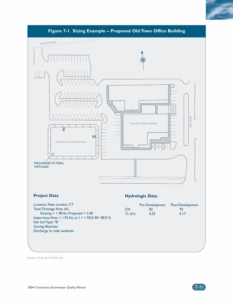
2004 Connecticut Stormwater Quality Manual 7-11
Figure 7-1 Sizing Example – Proposed Old Town Office Building
Project Data
Location: New London, CTTotal Drainage Area (A)
Existing = 1.98 Ac; Proposed = 2.40Impervious Area = 1.92 Ac; or I = 1.92/2.40= 80.0 %Site Soil Type:“B”Zoning: BusinessDischarge to tidal wetlands
Hydrologic Data
Pre-Development Post-DevelopmentCN 82 92Tc (hr) 0.25 0.17
DISCHARGE TO TIDALWETLAND
✵N
North Street
East
Str
eet
Proposed Stormwater Basin
Proposed Office Building
Source: Fuss & O’Neill, Inc.
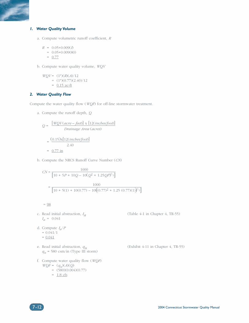
2004 Connecticut Stormwater Quality Manual7-12
1. Water Quality Volume
a. Compute volumetric runoff coefficient, R
R = 0.05+0.009(I)= 0.05+0.009(80)= 0.77
b. Compute water quality volume, WQV
WQV = (1")(R)(A)/12= (1")(0.77)(2.40)/12= 0.15 ac-ft
2. Water Quality Flow
Compute the water quality flow (WQF) for off-line stormwater treatment.
a. Compute the runoff depth, Q
Q =[WQV (acre – feet)] x [12(inches/foot)]
Drainage Area (acres)
=(0.15)x[12(inches/foot)]
2.40
= 0.77 in
b. Compute the NRCS Runoff Curve Number (CN)
CN =1000
[10 + 5P + 10Q – 10(Q2 + 1.25QP)1/2]
=1000
[10 + 5(1) + 10(0.77) – 10((0.77)2 + 1.25 (0.77)(1))1/2]
= 98
c. Read initial abstraction, Ia (Table 4-1 in Chapter 4, TR-55)Ia = 0.041
d. Compute Ia/P= 0.041/1= 0.041
e. Read initial abstraction, qu (Exhibit 4-11 in Chapter 4, TR-55)qu = 580 csm/in (Type III storm)
f. Compute water quality flow (WQF)WQF = (qu)(A)(Q)
= (580)(0.004)(0.77)= 1.8 cfs
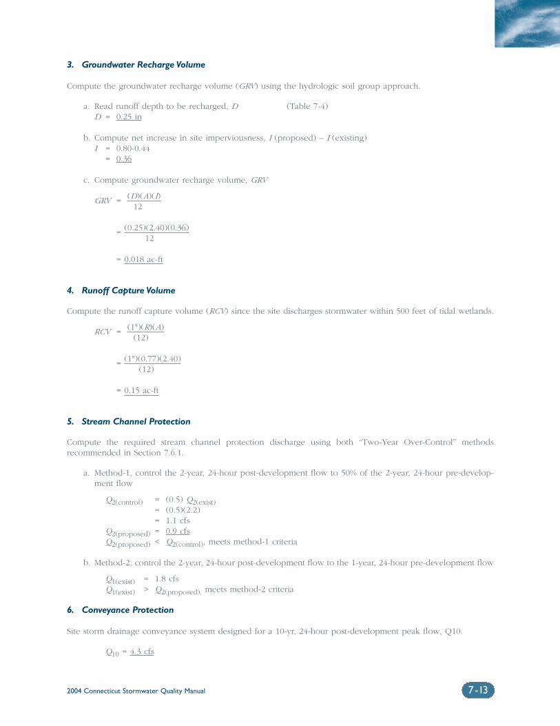
2004 Connecticut Stormwater Quality Manual 7-13
3. Groundwater Recharge Volume
Compute the groundwater recharge volume (GRV) using the hydrologic soil group approach.
a. Read runoff depth to be recharged, D (Table 7-4)D = 0.25 in
b. Compute net increase in site imperviousness, I (proposed) – I (existing)I = 0.80-0.44
= 0.36
c. Compute groundwater recharge volume, GRV
GRV = (D)(A)(I)12
= (0.25)(2.40)(0.36)12
= 0.018 ac-ft
4. Runoff Capture Volume
Compute the runoff capture volume (RCV) since the site discharges stormwater within 500 feet of tidal wetlands.
RCV = (1")(R)(A)(12)
= (1")(0.77)(2.40)(12)
= 0.15 ac-ft
5. Stream Channel Protection
Compute the required stream channel protection discharge using both “Two-Year Over-Control” methods recommended in Section 7.6.1.
a. Method-1, control the 2-year, 24-hour post-development flow to 50% of the 2-year, 24-hour pre-develop-ment flow
Q2(control) = (0.5) Q2(exist)= (0.5)(2.2)= 1.1 cfs
Q2(proposed) = 0.9 cfsQ2(proposed) < Q2(control), meets method-1 criteria
b. Method-2, control the 2-year, 24-hour post-development flow to the 1-year, 24-hour pre-development flow
Q1(exist) = 1.8 cfsQ1(exist) > Q2(proposed), meets method-2 criteria
6. Conveyance Protection
Site storm drainage conveyance system designed for a 10-yr, 24-hour post-development peak flow, Q10.
Q10 = 4.3 cfs
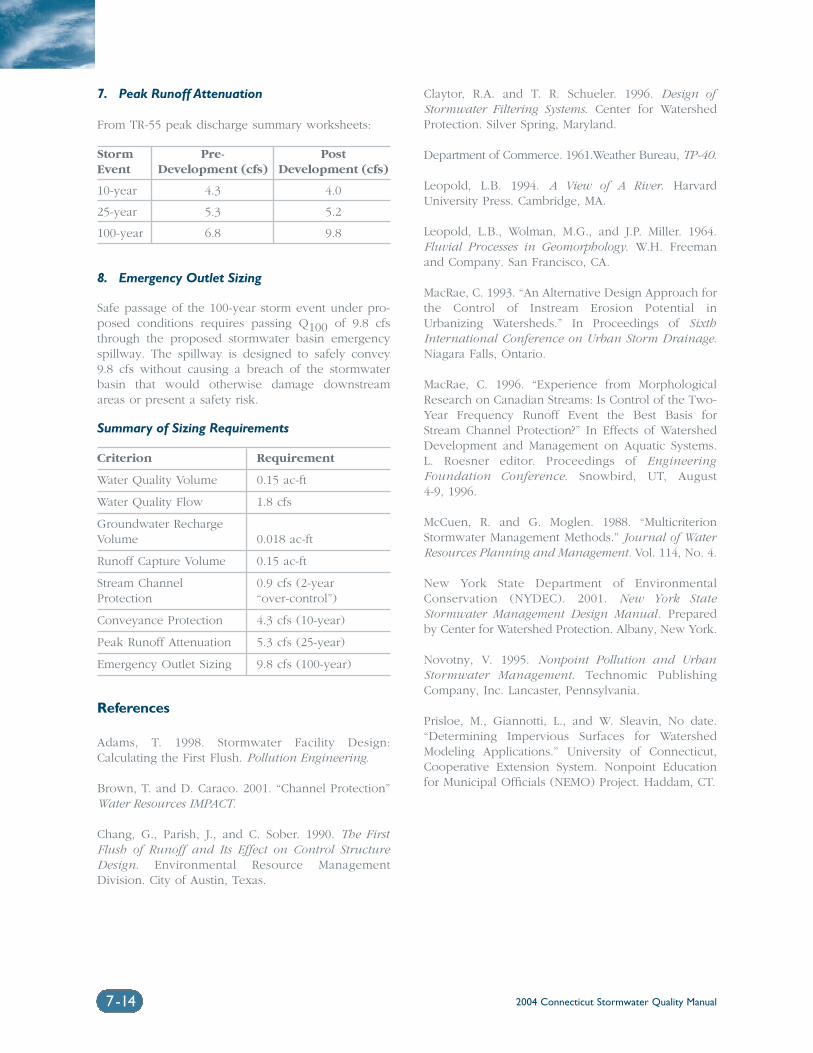
2004 Connecticut Stormwater Quality Manual7-14
7. Peak Runoff Attenuation
From TR-55 peak discharge summary worksheets:
Storm Pre- PostEvent Development (cfs) Development (cfs)
10-year 4.3 4.0
25-year 5.3 5.2
100-year 6.8 9.8
8. Emergency Outlet Sizing
Safe passage of the 100-year storm event under pro-posed conditions requires passing Q100 of 9.8 cfsthrough the proposed stormwater basin emergencyspillway. The spillway is designed to safely convey9.8 cfs without causing a breach of the stormwaterbasin that would otherwise damage downstreamareas or present a safety risk.
Summary of Sizing Requirements
Criterion Requirement
Water Quality Volume 0.15 ac-ft
Water Quality Flow 1.8 cfs
Groundwater Recharge Volume 0.018 ac-ft
Runoff Capture Volume 0.15 ac-ft
Stream Channel 0.9 cfs (2-year Protection “over-control”)
Conveyance Protection 4.3 cfs (10-year)
Peak Runoff Attenuation 5.3 cfs (25-year)
Emergency Outlet Sizing 9.8 cfs (100-year)
References
Adams, T. 1998. Stormwater Facility Design:Calculating the First Flush. Pollution Engineering.
Brown, T. and D. Caraco. 2001. “Channel Protection”Water Resources IMPACT.
Chang, G., Parish, J., and C. Sober. 1990. The FirstFlush of Runoff and Its Effect on Control StructureDesign. Environmental Resource ManagementDivision. City of Austin, Texas.
Claytor, R.A. and T. R. Schueler. 1996. Design ofStormwater Filtering Systems. Center for WatershedProtection. Silver Spring, Maryland.
Department of Commerce. 1961.Weather Bureau, TP-40.
Leopold, L.B. 1994. A View of A River. HarvardUniversity Press. Cambridge, MA.
Leopold, L.B., Wolman, M.G., and J.P. Miller. 1964.Fluvial Processes in Geomorphology. W.H. Freemanand Company. San Francisco, CA.
MacRae, C. 1993. “An Alternative Design Approach forthe Control of Instream Erosion Potential inUrbanizing Watersheds.” In Proceedings of SixthInternational Conference on Urban Storm Drainage.Niagara Falls, Ontario.
MacRae, C. 1996. “Experience from MorphologicalResearch on Canadian Streams: Is Control of the Two-Year Frequency Runoff Event the Best Basis forStream Channel Protection?” In Effects of WatershedDevelopment and Management on Aquatic Systems.L. Roesner editor. Proceedings of EngineeringFoundation Conference. Snowbird, UT, August 4-9, 1996.
McCuen, R. and G. Moglen. 1988. “MulticriterionStormwater Management Methods.” Journal of WaterResources Planning and Management. Vol. 114, No. 4.
New York State Department of EnvironmentalConservation (NYDEC). 2001. New York StateStormwater Management Design Manual. Preparedby Center for Watershed Protection. Albany, New York.
Novotny, V. 1995. Nonpoint Pollution and UrbanStormwater Management. Technomic PublishingCompany, Inc. Lancaster, Pennsylvania.
Prisloe, M., Giannotti, L., and W. Sleavin, No date.“Determining Impervious Surfaces for WatershedModeling Applications.” University of Connecticut,Cooperative Extension System. Nonpoint Educationfor Municipal Officials (NEMO) Project. Haddam, CT.
Chapter 8Selection Criteria for
Stormwater Treatment Practices
Chapter 8 Selection Criteria for Stormwater Treatment Practices
8.1 Stormwater Management Effectiveness ................................................8-2
8.2 Land Use Factors.........................................................................................8-3
8.3 Physical/Site Feasibility Factors .................................................................8-5
8.4 Downstream Resources ............................................................................8-6
8.5 Maintenance Factors.................................................................................8-10
8.6 Winter Operation ......................................................................................8-10
8.7 Nuisance Insects and Vectors...................................................................8-11
8.8 Natural Wetlands and Vernal Pools ........................................................8-13
Volume 1I: Design
2004 Connecticut Stormwater Quality Manual 8-1
2004 Connecticut Stormwater Quality Manual8-2
No single stormwater treat-
ment practice is appropriate
for every site and condition.
The applicability of individual
practices varies depending
upon relatively simple
physical constraints, as well
as more complicated siting
and treatment issues.This
chapter addresses criteria
to consider when selecting
stormwater treatment
practices for a particular site.
8.1 Stormwater Management EffectivenessAs discussed in Chapter Two, land development increases the potential forseveral stormwater related impacts. These impacts are largely a function ofaltering the natural hydrology at a site and increasing exposure to poten-tial pollutants. Common stormwater impacts related to land developmentinclude degraded water quality, increased peak flow rates, increased runoffvolume, stream channel erosion, and reduced groundwater recharge.
As discussed in Chapter Seven, stormwater treatment practices canachieve one or more of the following management objectives:
❍ Pollutant reduction
❍ Groundwater recharge and runoff volume reduction
❍ Stream channel protection and peak flow control
Table 8-1 summarizes the relative effectiveness of each stormwater treat-ment practice in providing these management capabilities. Theeffectiveness ratings provided in the table should only be used to comparethe relative management capabilities of different treatment practices. Theratings should not be used in an absolute sense to quantitatively predictactual field performance.
As described in Chapter Six, there is currently a lack of reliable per-formance data for stormwater treatment practices in the State ofConnecticut. Additionally, the available performance data from past moni-toring studies conducted throughout the United States are limited bydifferences in design, performance goals, site parameters, storm events,flow and pollutant loadings, seasonal variations, monitoring methods, andefficiency calculation methods or simply by the lack of, or inadequate,information. The reliability of pollutant removal efficiencies, which areoften cited in guidance documents, is typically poor due to the largedegree of uncertainty in the data. Additional performance monitoring usingstandardized methods and quality control procedures is recommended fornew and existing stormwater treatment practices (see Chapter Six) inConnecticut to provide a more useful set of data on the effectiveness ofindividual stormwater treatment practices, and to better understand therelationship between treatment practice design and performance.
As shown in Table 8-1, most of these primary treatment practices aresimilarly effective at removing sediment, nutrients, and metals. Removalefficiencies are generally highest for sediment, while nutrient and metalsremoval efficiencies are typically lower. Infiltration systems are generallythe most effective practices for removal of bacteria. Designs that incorpo-rate floatable controls or pretreatment are most effective for removal ofhydrocarbons. Treatment practices that incorporate biological removalmechanisms, such as constructed wetlands, are also more effective inremoving pollutants than systems that strictly rely on gravity or physicalseparation of particles.
Many of these practices also have limited effectiveness in terms ofpeak flow control and groundwater recharge. Open bottom basins and dryswales provide some groundwater recharge, but only practices specificallydesigned as infiltration structures will provide significant levels of ground-water recharge. Many of these practices either have an impermeablebottom or are designed to intercept groundwater and thereby provide lit-tle infiltration. Similarly, attenuation of peak flows requires significantavailable storage capacity to temporarily store runoff as the peak flow isbeing throttled. Many stormwater treatment practices provide limited stor-age capacity or detention time and are inadequate as stand-alone flood
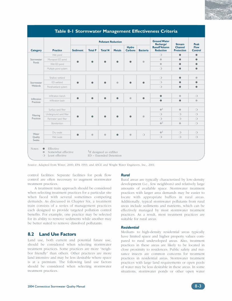
2004 Connecticut Stormwater Quality Manual 8-3
control facilities. Separate facilities for peak flow control are often necessary to augment stormwatertreatment practices.
A treatment train approach should be consideredwhen selecting treatment practices for a particular sitewhen faced with several sometimes competingdemands. As discussed in Chapter Six, a treatmenttrain consists of a series of management practiceseach designed to provide targeted pollution controlbenefits. For example, one practice may be selectedfor its ability to remove sediments while another maybe better suited to remove dissolved pollutants.
8.2 Land Use FactorsLand use, both current and potential future use,should be considered when selecting stormwatertreatment practices. Some practices are more “neigh-bor friendly” than others. Other practices are moreland intensive and may be less desirable where spaceis at a premium. The following land use factorsshould be considered when selecting stormwatertreatment practices.
RuralRural areas are typically characterized by low-densitydevelopment (i.e., few neighbors) and relatively largeamounts of available space. Stormwater treatmentpractices with larger area demands may be easier tolocate with appropriate buffers in rural areas.Additionally, typical stormwater pollutants from ruralareas include sediments and nutrients, which can beeffectively managed by most stormwater treatmentpractices. As a result, most treatment practices aresuitable for rural areas.
ResidentialMedium- to high-density residential areas typicallyhave limited space and higher property values com-pared to rural undeveloped areas. Also, treatmentpractices in these areas are likely to be located inclose proximity to residences. Public safety and nui-sance insects are common concerns for treatmentpractices in residential areas. Stormwater treatmentpractices with large land requirements or open poolsof water may be less desirable in these areas. In somesituations, stormwater ponds or other open water
Category
StormwaterPonds
StormwaterWetlands
InfiltrationPractices
FilteringPractices
Water Quality Swales
Practice
Wet pond
Micropool ED pond
Wet ED pond
Multiple pond system
Shallow wetland
ED wetland
Pond/wetland system
Infiltration trench
Infiltration basin
Surface sand filter
Underground sand filter
Perimeter sand filter
Bioretention
Dry swale
Wet swale
Sediment
�
�
�
�
�
Total P
�
�
�
�
�
Total N
�
�
�
�
�
Metals
�
�
�
�
�
HydroCarbons
�
�
�
�
�
Bacteria
�
�
�
�
❍
Ground WaterRecharge/
Runoff VolumnReduction
❍
�
�
❍
❍
❍
❍
�
�
�1
❍
❍
�1
�1
❍
StreamChannel
Protection
�
�
�
�
�
�
�
�
�
�
❍
❍
�
❍
❍
PeakFlow
Control
�
�
�
�
�
�
�
❍
�
❍
❍
❍
❍
❍
❍
Table 8-1 Stormwater Management Effectiveness Criteria
Pollutant Reduction
Notes: � Effective� Somewhat effective❍ Least effective
Source: Adapted from Winer, 2000; EPA 1993; and ASCE and Wright Water Engineers, Inc., 2001.
1If designed as exfilterED – Extended Detention
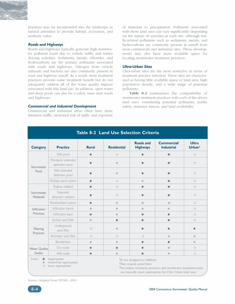
2004 Connecticut Stormwater Quality Manual8-4
practices may be incorporated into the landscape asnatural amenities to provide habitat, recreation, andaesthetic value.
Roads and Highways Roads and highways typically generate high stormwa-ter pollutant loads due to vehicle traffic and winterdeicing activities. Sediments, metals, chlorides, andhydrocarbons are the primary pollutants associatedwith roads and highways. Nitrogen from vehicleexhausts and bacteria are also commonly present inroad and highway runoff. As a result, most treatmentpractices provide some treatment benefit but do notadequately address all of the water quality impactsassociated with this land use. In addition, open waterand deep pools can also be a safety issue near roadsand highways.
Commercial and Industrial DevelopmentCommercial and industrial areas often have moreintensive traffic, increased risk of spills, and exposure
of materials to precipitation. Pollutants associatedwith these land uses can vary significantly dependingon the nature of activities at each site, although traf-fic-related pollutants such as sediments, metals, andhydrocarbons are commonly present in runoff frommost commercial and industrial sites. These develop-ments may also have more available space forlocating stormwater treatment practices.
Ultra-Urban SitesUltra-urban sites are the most restrictive in terms oftreatment practice selection. These sites are character-ized as having little available space or land area, highpopulation density, and a wide range of potential pollutants.
Table 8-2 summarizes the compatibility ofstormwater treatment practices with each of the aboveland uses, considering potential pollutants, publicsafety, nuisance insects, and land availability.
Category
StormwaterPond
StormwaterWetlands
InfiltrationPractices
FilteringPractices
Water QualitySwales
Roads and Commercial/ UltraPractice Rural Residential Highways Industrial Urban3
Wet pond � ❍ � �2 ❍
Micropool extended � � � �2 ❍detention pond
Wet extended � � � �2 ❍detention pond
Multiple pond system � ❍ � �2 ❍
Shallow wetland � ❍ � �2 ❍
Extended � ❍ � �2 ❍detention wetland
Pond/wetland system � � � �2 ❍
Infiltration trench � � � � ❍
Infiltration basin � � � � ❍
Surface sand filter � � � �1 ❍
Underground ❍ � � � �sand filter
Perimeter sand filter ❍ ❍ ❍ � �
Bioretention � � � �1 �
Dry swale � � � �1 ❍
Wet swale � � � � ❍
Table 8-2 Land Use Selection Criteria
Notes: � Appropriate� Somewhat appropriate❍ Least appropriate
1If not designed to infiltrate2May require pond liner3Secondary treatment practices and stormwater treatment trainsare typically more appropriate for Ultra Urban land uses
Source: Adapted from NYDEC, 2001.
2004 Connecticut Stormwater Quality Manual 8-5
8.3 Physical/Site Feasibility FactorsPhysical site constraints can also dictate the feasibilityof specific stormwater treatment practices. Thesephysical constraints can either make the installation ofa particular treatment practice too costly or result in reduced or ineffective operation. While every sitehas its own individual characteristics that need to beevaluated, the five most common physical constraintsthat need to be considered are:
❍ Infiltration capacity
❍ Seasonally high groundwater (water table)
❍ Drainage area
❍ Slope
❍ Required hydraulic head
These factors are discussed in general termsbelow. Chapter Eleven contains additional informa-tion on physical feasibility and siting considerationsfor individual treatment practices.
Infiltration CapacityInfiltration practices are highly dependent on the infil-tration capacity of the underlying soils. Low soilinfiltration capacity requires structures with largerinfiltration surface area and storage capacity toaccount for slower infiltration rates. Higher soil infil-tration rates allow for smaller infiltration structures.Accurate field measurements of infiltration rates arecritical for the successful design and implementationof stormwater treatment practices that rely on infiltra-tion of stormwater to underlying soils.
In Connecticut, the United States Department ofAgriculture (USDA) Natural Resources ConservationService (NRCS) has developed soil suitability rankingsfor various types of stormwater management prac-tices, including infiltration trenches, undergroundinfiltration galleries, stormwater wetlands, andstormwater ponds. The soil suitability designationsare intended to facilitate proper selection and siting ofstormwater controls and are based upon NRCS soilsurvey soil properties and landscape criteria. Theinformation can be used to generate soil suitabilitymaps for a town, watershed, or other designation.Soils are rated for each practice (suitable, fair, orgood), and the specific limitations (slow infiltration,for example) are provided. This tool is intended to beused for initial screening of stormwater treatmentpractices and does not eliminate the need for on-siteevaluation of soil characteristics for design purposes.Additional information on this program can beobtained from the Connecticut USDA NRCS (see Additional Information Sources at the end ofthis chapter).
Water TableAn elevated water table poses several design issues.The primary issue is the loss of storage and retentioncapacity in unlined treatment structures. If seasonallyhigh groundwater exists above the bottom of an unlined pond or basin, groundwater will drain intothe structure and fill or displace volume that mayhave been intended for retention. If a treatment prac-tice is constructed below the seasonally high watertable, the loss of storage capacity should beaccounted for in the design, or engineering controlssuch as liners and/or underdrains should be considered.
An elevated water table may be advantageous forsome treatment practices where a permanent pool ofwater is desired, such as stormwater wetlands.However, small separation between the bottom of atreatment structure and the water table may result ininadequate pollutant attenuation and treatment in theunsaturated zone. The potential for groundwater pol-lution due to stormwater infiltration is an importantconsideration in the design of stormwater treatmentpractices. Engineering controls such as impermeableliners may be required in these circumstances.
Buoyancy of structures installed below the watertable is another issue related to a high water table.Below the water table, buoyancy is calculated as theweight of water displaced (i.e., the volume of thestructure below the water table multiplied by the unitweight of fresh water or 62.4 pounds per cubic foot).The upward buoyant force may be large enough todisplace a structure, sometimes out of the ground.Engineering controls typically consist of anchors, suchas connecting the structure to an appropriately sizedconcrete pad to provide adequate weight to offsetbuoyant forces.
Field determination of seasonally high ground-water is required for the successful design andimplementation of most stormwater treatment practices.
Drainage AreaThe efficiency of most treatment practices decreaseswith increasing drainage area and volume ofstormwater runoff. An increased hydraulic load canincrease velocities and reduce detention time in atreatment structure. The size of some practices can beincreased to address the issues associated with anincreased hydraulic load. Other treatment practicesare better suited to smaller drainage areas and smallerhydraulic loads. One approach to improving the effi-ciency of practices serving larger drainage areas is toconstruct diversion structures for treatment of theWater Quality Volume, while larger flows or volumesare bypassed around the treatment system.
2004 Connecticut Stormwater Quality Manual8-6
SlopeThe ground slope at and immediately adjacent to thelocation of a treatment practice, as well as the slopeof the contributing watershed and drainage flowpaths, are important factors in determining the feasi-bility of treatment controls. Most stormwatertreatment practices are sensitive to the local terrainslope. For example, swales and infiltration basins can-not be used in steep terrain, while others such asstormwater ponds and filtering practices can beadapted to most terrain. The slope of the contributingdrainage area or watershed can influence erosion andsediment loads to the treatment system. Manystormwater treatment practices are not recommendedfor sites with significant sediment loads without suitable pretreatment.
Required HeadSeveral practices, such as stormwater filtering systems,require larger hydraulic head for gravity flow to andthrough the system. For example, if only four feet ofgrade exists on a site between the most hydraulicallyremote point on the site and the invert elevation ofthe discharge, a treatment practice that requires fivefeet of head would not be feasible.
Table 8-3 summarizes the physical feasibility criteria discussed above.
8.4 Downstream ResourcesWhile all sites should provide at least a minimumlevel of protection, stormwater treatment practicesshould be tailored not only to the conditions that existat a particular site, but also to the downstreamresources that could be impacted by stormwater dis-charges from the site. As a result, the followingdownstream resources should be considered in thetreatment practice selection process.
Sensitive WatercoursesStreams, brooks, and rivers that are classified by DEPas Class A (fishable, swimmable, and potential drinkingwater), as well as their tributary watercourses and wet-lands, are high quality resources that warrant a highdegree of protection. Toxic pollutants such as metalsand soluble organics, as well as other contaminantssuch as bacteria, are the primary concern for thesewaterbodies. Sensitive cold water fisheries, includingClass B waters or managed stocked streams, could alsobe adversely impacted by stormwater runoff with ele-vated temperatures. In addition, the rate and volume ofstormwater discharges from new developments areespecially critical to these systems, as they couldimpact the flood carrying capacity of the watercourseand increase the potential for channel erosion.
Water Supply AquifersGroundwater is a major source of drinking water inConnecticut for residences that rely on small privatewells and larger water distributors. This applies toboth water supply aquifers and Class GA and GAAgroundwaters as defined by DEP. In addition, ground-water is the source of dry weather flows (baseflow) inwatercourses, which is critical for maintaining suitablehabitat. As a result, it is important to maintain ground-water recharge, and to maintain a high qualityrecharge to groundwater in water supply aquifers andClass GA and GAA waters.
Lakes and PondsLakes and ponds are especially sensitive to sedimentand nutrient loadings. Excess sediments and nutrientsare the cause of algal blooms in these surface waters,leading to eutrophication and degradation. Theseconditions often result in costly dredging and rehabil-itation projects. In fresh water systems, phosphorus istypically the limiting nutrient, that is, much less phos-phorus is needed compared to other nutrients such asnitrogen to create eutrophic conditions. As a result,treatment practices should focus on nutrient removal,particularly phosphorus, for stormwater discharges tolakes and ponds, and watercourses that feed lakesand ponds. Control of phosphorus is also directlyrelated to the control of iron. Certain iron compoundssuch as ferric iron often have a high scavenging coef-ficient for metals. Thus, control of phosphorus mayhave ancillary benefits in the control of metals.
Surface Water Drinking SuppliesSurface waters that supply drinking water are espe-cially susceptible to contamination by bacteria andother pathogens. Other contaminants-of-concern maybe defined for specific water supply systems by theowner/operator or the State Department of Health.Treatment practices for sites within drinking watersupply watersheds should target these potential con-taminants. The Public Health Code also requires a100-foot separation distance between drainage ortreatment practice outlets and public water supplytributaries. Site designs within public water supplywatersheds are encouraged to maximize absorption ofpollutants by the soil and vegetation.
Estuary/CoastalCoastal or estuary areas are more sensitive to nitrogenloadings than fresh water systems. In salt water systems, nitrogen tends to be the limiting nutrient asopposed to phosphorus. Bacteria are also a concerngiven the sensitivity of public swimming areas andshellfish beds to bacterial loadings.
Table 8-4 summarizes limitations and engineer-ing considerations for stormwater treatment practicesbased on downstream resources and the receivingenvironment.
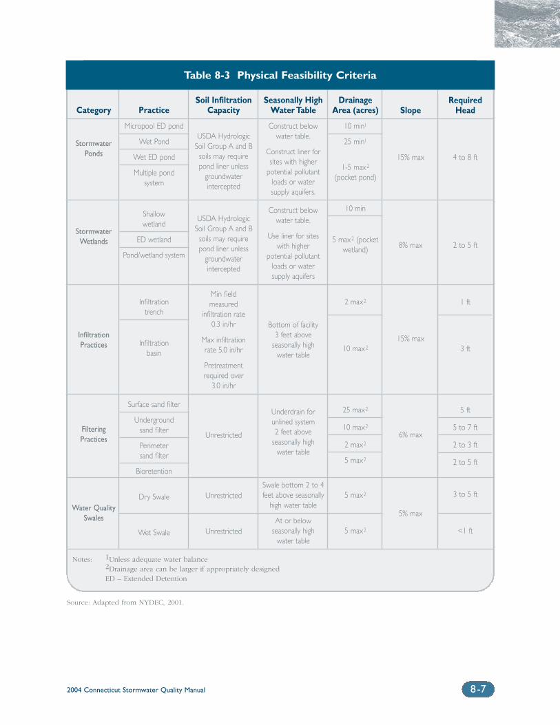
2004 Connecticut Stormwater Quality Manual 8-7
Category
StormwaterPonds
StormwaterWetlands
InfiltrationPractices
FilteringPractices
Water QualitySwales
Practice
Micropool ED pond
Wet Pond
Wet ED pond
Multiple pond system
Shallowwetland
ED wetland
Pond/wetland system
Infiltration trench
Infiltration basin
Surface sand filter
Underground sand filter
Perimeter sand filter
Bioretention
Dry Swale
Wet Swale
Soil Infiltration Capacity
USDA Hydrologic Soil Group A and B
soils may require pond liner unless
groundwater intercepted
USDA Hydrologic Soil Group A and B
soils may require pond liner unless
groundwater intercepted
Min field measured
infiltration rate 0.3 in/hr
Max infiltration rate 5.0 in/hr
Pretreatment required over
3.0 in/hr
Unrestricted
Unrestricted
Unrestricted
Seasonally HighWater Table
Construct below water table.
Construct liner for sites with higher
potential pollutantloads or watersupply aquifers.
Construct below water table.
Use liner for sites with higher
potential pollutantloads or watersupply aquifers
Bottom of facility 3 feet above
seasonally high water table
Underdrain for unlined system2 feet above
seasonally high water table
Swale bottom 2 to 4feet above seasonally
high water table
At or below seasonally high
water table
Drainage Area (acres)
10 min1
25 min1
1-5 max2
(pocket pond)
10 min
5 max2 (pocketwetland)
2 max2
10 max2
25 max2
10 max2
2 max2
5 max2
5 max2
5 max2
Table 8-3 Physical Feasibility Criteria
Source: Adapted from NYDEC, 2001.
Slope
15% max
8% max
15% max
6% max
5% max
RequiredHead
4 to 8 ft
2 to 5 ft
1 ft
3 ft
5 ft
5 to 7 ft
2 to 3 ft
2 to 5 ft
3 to 5 ft
<1 ft
Notes: 1Unless adequate water balance2Drainage area can be larger if appropriately designedED – Extended Detention
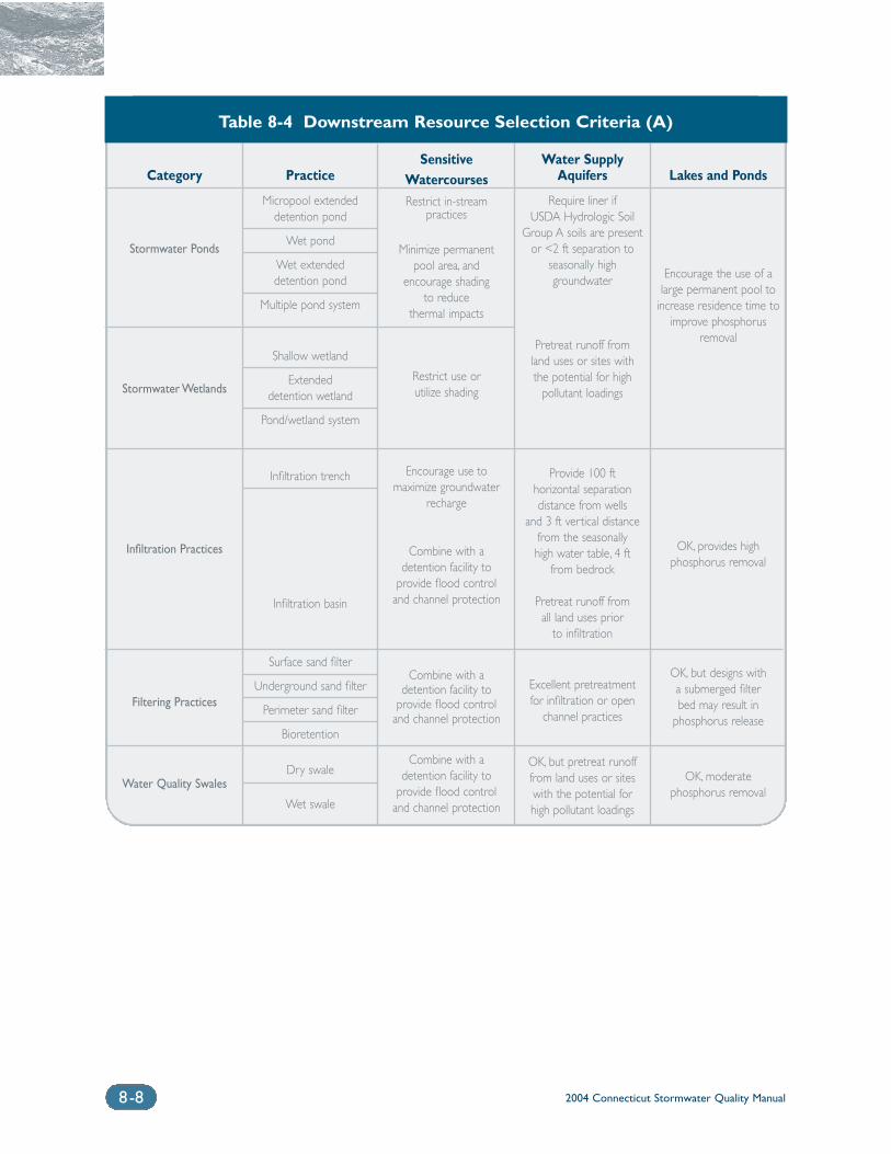
2004 Connecticut Stormwater Quality Manual8-8
Category
Stormwater Ponds
Stormwater Wetlands
Infiltration Practices
Filtering Practices
Water Quality Swales
Practice
Micropool extended detention pond
Wet pond
Wet extended detention pond
Multiple pond system
Shallow wetland
Extended detention wetland
Pond/wetland system
Infiltration trench
Infiltration basin
Surface sand filter
Underground sand filter
Perimeter sand filter
Bioretention
Dry swale
Wet swale
SensitiveWatercoursesRestrict in-stream
practices
Minimize permanent pool area, and
encourage shading to reduce
thermal impacts
Restrict use or utilize shading
Encourage use to maximize groundwater
recharge
Combine with a detention facility to
provide flood control and channel protection
Combine with a detention facility to
provide flood control and channel protection
Combine with a detention facility to
provide flood control and channel protection
Water Supply Aquifers
Require liner if USDA Hydrologic Soil
Group A soils are present or <2 ft separation to
seasonally highgroundwater
Pretreat runoff fromland uses or sites with the potential for high
pollutant loadings
Provide 100 ft horizontal separation distance from wells
and 3 ft vertical distancefrom the seasonally high water table, 4 ft
from bedrock
Pretreat runoff from all land uses prior
to infiltration
Excellent pretreatment for infiltration or open
channel practices
OK, but pretreat runoff from land uses or sites with the potential for high pollutant loadings
Lakes and Ponds
Encourage the use of alarge permanent pool to
increase residence time toimprove phosphorus
removal
OK, provides high phosphorus removal
OK, but designs with a submerged filter bed may result in
phosphorus release
OK, moderate phosphorus removal
Table 8-4 Downstream Resource Selection Criteria (A)
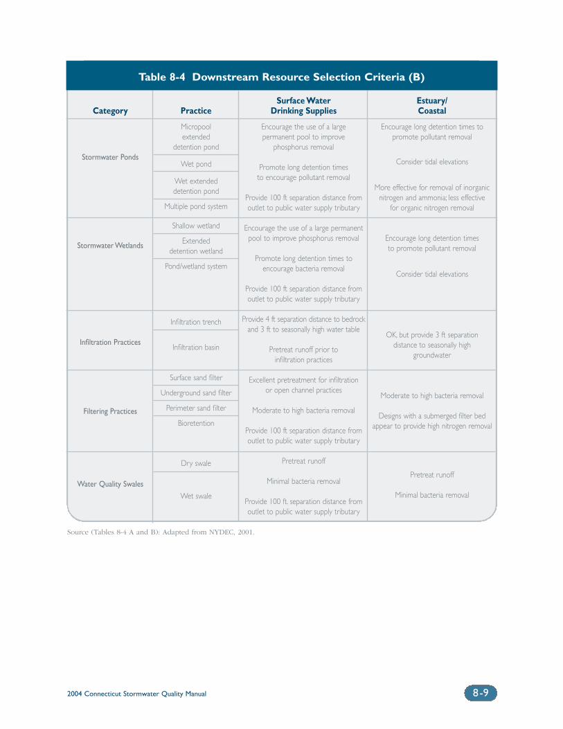
2004 Connecticut Stormwater Quality Manual 8-9
Category
Stormwater Ponds
Stormwater Wetlands
Infiltration Practices
Filtering Practices
Water Quality Swales
Practice
Micropool extended
detention pond
Wet pond
Wet extended detention pond
Multiple pond system
Shallow wetland
Extended detention wetland
Pond/wetland system
Infiltration trench
Infiltration basin
Surface sand filter
Underground sand filter
Perimeter sand filter
Bioretention
Dry swale
Wet swale
Estuary/Coastal
Encourage long detention times topromote pollutant removal
Consider tidal elevations
More effective for removal of inorganicnitrogen and ammonia; less effective
for organic nitrogen removal
Encourage long detention times to promote pollutant removal
Consider tidal elevations
OK, but provide 3 ft separation distance to seasonally high
groundwater
Moderate to high bacteria removal
Designs with a submerged filter bedappear to provide high nitrogen removal
Pretreat runoff
Minimal bacteria removal
Surface Water Drinking Supplies
Encourage the use of a large permanent pool to improve
phosphorus removal
Promote long detention timesto encourage pollutant removal
Provide 100 ft separation distance fromoutlet to public water supply tributary
Encourage the use of a large permanentpool to improve phosphorus removal
Promote long detention times to encourage bacteria removal
Provide 100 ft separation distance fromoutlet to public water supply tributary
Provide 4 ft separation distance to bedrockand 3 ft to seasonally high water table
Pretreat runoff prior to infiltration practices
Excellent pretreatment for infiltration or open channel practices
Moderate to high bacteria removal
Provide 100 ft separation distance fromoutlet to public water supply tributary
Pretreat runoff
Minimal bacteria removal
Provide 100 ft. separation distance fromoutlet to public water supply tributary
Table 8-4 Downstream Resource Selection Criteria (B)
Source (Tables 8-4 A and B): Adapted from NYDEC, 2001.
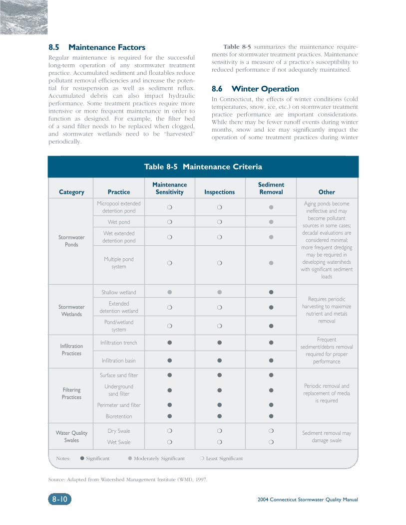
2004 Connecticut Stormwater Quality Manual8-10
8.5 Maintenance FactorsRegular maintenance is required for the successfullong-term operation of any stormwater treatment practice. Accumulated sediment and floatables reducepollutant removal efficiencies and increase the poten-tial for resuspension as well as sediment reflux.Accumulated debris can also impact hydraulic performance. Some treatment practices require moreintensive or more frequent maintenance in order tofunction as designed. For example, the filter bed of a sand filter needs to be replaced when clogged,and stormwater wetlands need to be “harvested” periodically.
Table 8-5 summarizes the maintenance require-ments for stormwater treatment practices. Maintenancesensitivity is a measure of a practice’s susceptibility toreduced performance if not adequately maintained.
8.6 Winter OperationIn Connecticut, the effects of winter conditions (coldtemperatures, snow, ice, etc.) on stormwater treatmentpractice performance are important considerations.While there may be fewer runoff events during wintermonths, snow and ice may significantly impact theoperation of some treatment practices during winter
Category
Stormwater Ponds
StormwaterWetlands
Infiltration Practices
Filtering Practices
Water QualitySwales
Maintenance SedimentPractice Sensitivity Inspections Removal
Micropool extended ❍ ❍ �detention pond
Wet pond ❍ ❍ �
Wet extended ❍ ❍ �detention pond
Multiple pond ❍ ❍ �system
Shallow wetland � � �
Extended ❍ ❍ �detention wetland
Pond/wetland ❍ ❍ �system
Infiltration trench � � �
Infiltration basin � � �
Surface sand filter � � �
Underground � � �sand filter
Perimeter sand filter � � �
Bioretention � � �
Dry Swale ❍ ❍ ❍
Wet Swale ❍ ❍ ❍
Table 8-5 Maintenance Criteria
Other
Aging ponds become ineffective and maybecome pollutant
sources in some cases;decadal evaluations are
considered minimal;more frequent dredging
may be required indeveloping watersheds
with significant sedimentloads
Requires periodic harvesting to maximize
nutrient and metalsremoval
Frequent sediment/debris removal
required for proper performance
Periodic removal andreplacement of media
is required
Sediment removal may damage swale
Notes: � Significant � Moderately Significant ❍ Least Significant
Source: Adapted from Watershed Management Institute (WMI), 1997.
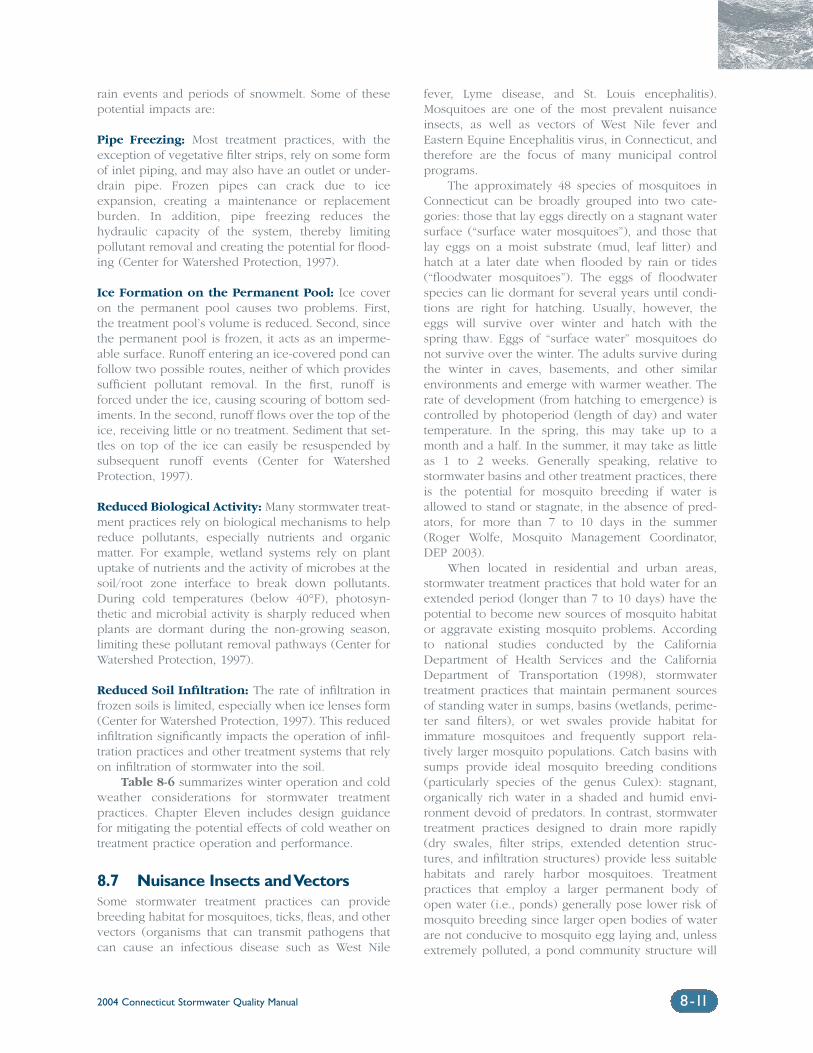
2004 Connecticut Stormwater Quality Manual 8-11
rain events and periods of snowmelt. Some of thesepotential impacts are:
Pipe Freezing: Most treatment practices, with theexception of vegetative filter strips, rely on some formof inlet piping, and may also have an outlet or under-drain pipe. Frozen pipes can crack due to iceexpansion, creating a maintenance or replacementburden. In addition, pipe freezing reduces thehydraulic capacity of the system, thereby limitingpollutant removal and creating the potential for flood-ing (Center for Watershed Protection, 1997).
Ice Formation on the Permanent Pool: Ice coveron the permanent pool causes two problems. First,the treatment pool’s volume is reduced. Second, sincethe permanent pool is frozen, it acts as an imperme-able surface. Runoff entering an ice-covered pond canfollow two possible routes, neither of which providessufficient pollutant removal. In the first, runoff isforced under the ice, causing scouring of bottom sed-iments. In the second, runoff flows over the top of theice, receiving little or no treatment. Sediment that set-tles on top of the ice can easily be resuspended bysubsequent runoff events (Center for WatershedProtection, 1997).
Reduced Biological Activity: Many stormwater treat-ment practices rely on biological mechanisms to helpreduce pollutants, especially nutrients and organicmatter. For example, wetland systems rely on plantuptake of nutrients and the activity of microbes at thesoil/root zone interface to break down pollutants.During cold temperatures (below 40°F), photosyn-thetic and microbial activity is sharply reduced whenplants are dormant during the non-growing season,limiting these pollutant removal pathways (Center forWatershed Protection, 1997).
Reduced Soil Infiltration: The rate of infiltration infrozen soils is limited, especially when ice lenses form(Center for Watershed Protection, 1997). This reducedinfiltration significantly impacts the operation of infil-tration practices and other treatment systems that relyon infiltration of stormwater into the soil.
Table 8-6 summarizes winter operation and coldweather considerations for stormwater treatment practices. Chapter Eleven includes design guidancefor mitigating the potential effects of cold weather ontreatment practice operation and performance.
8.7 Nuisance Insects and VectorsSome stormwater treatment practices can providebreeding habitat for mosquitoes, ticks, fleas, and othervectors (organisms that can transmit pathogens thatcan cause an infectious disease such as West Nile
fever, Lyme disease, and St. Louis encephalitis).Mosquitoes are one of the most prevalent nuisanceinsects, as well as vectors of West Nile fever andEastern Equine Encephalitis virus, in Connecticut, andtherefore are the focus of many municipal controlprograms.
The approximately 48 species of mosquitoes inConnecticut can be broadly grouped into two cate-gories: those that lay eggs directly on a stagnant watersurface (“surface water mosquitoes”), and those thatlay eggs on a moist substrate (mud, leaf litter) andhatch at a later date when flooded by rain or tides(“floodwater mosquitoes”). The eggs of floodwaterspecies can lie dormant for several years until condi-tions are right for hatching. Usually, however, theeggs will survive over winter and hatch with thespring thaw. Eggs of “surface water” mosquitoes donot survive over the winter. The adults survive duringthe winter in caves, basements, and other similarenvironments and emerge with warmer weather. Therate of development (from hatching to emergence) iscontrolled by photoperiod (length of day) and watertemperature. In the spring, this may take up to amonth and a half. In the summer, it may take as littleas 1 to 2 weeks. Generally speaking, relative tostormwater basins and other treatment practices, thereis the potential for mosquito breeding if water isallowed to stand or stagnate, in the absence of pred-ators, for more than 7 to 10 days in the summer(Roger Wolfe, Mosquito Management Coordinator,DEP 2003).
When located in residential and urban areas,stormwater treatment practices that hold water for anextended period (longer than 7 to 10 days) have thepotential to become new sources of mosquito habitator aggravate existing mosquito problems. Accordingto national studies conducted by the CaliforniaDepartment of Health Services and the CaliforniaDepartment of Transportation (1998), stormwatertreatment practices that maintain permanent sourcesof standing water in sumps, basins (wetlands, perime-ter sand filters), or wet swales provide habitat forimmature mosquitoes and frequently support rela-tively larger mosquito populations. Catch basins withsumps provide ideal mosquito breeding conditions(particularly species of the genus Culex): stagnant,organically rich water in a shaded and humid envi-ronment devoid of predators. In contrast, stormwatertreatment practices designed to drain more rapidly(dry swales, filter strips, extended detention struc-tures, and infiltration structures) provide less suitablehabitats and rarely harbor mosquitoes. Treatmentpractices that employ a larger permanent body ofopen water (i.e., ponds) generally pose lower risk ofmosquito breeding since larger open bodies of waterare not conducive to mosquito egg laying and, unlessextremely polluted, a pond community structure will
2004 Connecticut Stormwater Quality Manual8-12
Category
Stormwater Ponds
StormwaterWetlands
Infiltration Practices
Filtering Practices
Water QualitySwales
Pipe Ice Reduced Reduced SoilPractice Freezing Formations Biological Activity Infiltration
Micropool extended � � � ❍detention pond
Wet pond � � � ❍
Wet extended � � � ❍detention pond
Multiple pond � � � ❍system
Shallow wetland � � � ❍
Extended � � � ❍detention wetland
Pond/wetland � � � ❍system
Infiltration trench ❍ ❍ ❍ �
Infiltration basin ❍ ❍ ❍ �
Surface sand filter � � ❍ �
Underground ❍ ❍ ❍ ❍sand filter
Perimeter sand filter � � ❍ ❍
Bioretention � � ❍ �
Dry Swale ❍ ❍ � �
Wet Swale ❍ � � ❍
Table 8-6 Winter and Cold Weather Operation Criteria
Notes: � Significant� Moderately Significant❍ Least Significant
Source: Adapted from Center for Watershed Protection, 1997.
2004 Connecticut Stormwater Quality Manual 8-13
support a natural predator population. Improperlymaintained structures can also result in sediment anddebris accumulation that can contribute to conditionsof prolonged standing water.
Proper siting, design, and maintenance ofstormwater treatment practices are important factorsin minimizing the potential for these structures tobecome mosquito-breeding areas. Stormwater ponds,wetlands, and other treatment practices that maintainstanding water for a prolonged period should be care-fully considered and designed in residential,commercial, and other urban areas where mosquitocontrol is a concern. Key design considerations formosquito control include:
❍ Limiting water retention or draining time to 5 days or less (based on a 7 to 10 day summerbreeding period and a factor of safety).Structures designed with sumps or basins thatretain water permanently or longer than 5 daysshould be sealed completely to prevent entry ofadult mosquitoes.
❍ Maintaining pond and wetland water qualitysufficient to support mosquito-feeding fish andother aquatic predators. Stormwater ponds andwetlands often develop mini-ecosystems wherebirds, frogs, and other insects feed, many ofwhich are natural predators of mosquitoes andother nuisance insects. Ponds can also bestocked with fish native to Connecticut that feedon mosquito larvae such as banded killfish,golden shiners, and pumpkinseed sunfish. TheDEP Inland Fisheries Division should be con-sulted regarding species selection and permittingrequirements. A liberation permit is required tointroduce these and other fish into ponds andother water bodies in Connecticut. Other naturalpredators of mosquitoes such as dragonflynymphs can also be used.
❍ Maintaining permanent pond water depths inexcess of 4 feet to preclude invasive emergentvegetation such as cattails. Dense emergent vegetation provides mosquito larvae with refugefrom predators.
❍ Designing ponds to allow for easy dewatering of the basin when necessary.
❍ Providing sufficient slope on basin floors andswales for adequate drainage.
❍ Ensuring sufficient separation distance to theseasonal high groundwater table for infiltrationstructures.
❍ Sealing potential mosquito entry points inunderground stormwater treatment devices(adult female mosquitoes can use openings assmall as 1/16 inch to access water for egg laying).
Chapter Eleven includes additional design guid-ance to avoid or reduce mosquito-breeding problemsfor individual treatment practice categories.
8.8 Natural Wetlands and Vernal Pools
Careful consideration should be given to the selec-tion, design, and location of stormwater treatmentpractices on or near sites with natural wetlands andvernal pools. Conventional stormwater managementtechniques often have adverse impacts on biodiver-sity. Wildlife species that migrate seasonally betweenforested upland habitats and vernal pools (and othersmall wetlands) are particularly susceptible (Calhounand Klemens 2002). Populations of turtles, snakes,small mammals, frogs, and salamanders often declinein areas with intensive stormwater management measures. Curb and catch-basin systems, particularlyin combination with hydrodynamic separators, canintercept, trap, and kill amphibians and other smallanimals crossing roads. Stormwater wetlands andponds that are placed near vernal pools can alsothreaten pool-breeding amphibian populations.Stormwater ponds and wetlands can serve as “decoy”pools, intercepting amphibians as they migrate inspring to their vernal pool breeding habitats.Amphibians often deposit their eggs in these artificialwetlands. The eggs rarely survive due to sedimentand pollutant loads, which are concentrated in thesestormwater treatment systems. Fluctuations in waterquality, water quantity, and temperature within thesedecoy wetlands can also cause reproductive failure.Many vernal pool species are extremely sensitive tohydroperiod (duration of flooding). Stormwater man-agement can de-water (or shorten the hydroperiod)vernal pools. This impacts species that require longerhydroperiods such as marbled salamanders.Stormwater management can also increase thehydroperiod of vernal pools, impacting species thatrequire shorter hydroperiods (e.g., fairy shrimp). In addition, constructed wetlands tend to supporthighly adaptable, widespread, “weedy” species (e.g., bullfrogs or green frogs), which prey upon, orsuccessfully out-compete, vernal pool-breedingamphibians.
Stormwater ponds and wetlands should belocated at least 750 feet from a vernal pool and shouldnot be sited between vernal pools or in areas that are
2004 Connecticut Stormwater Quality Manual8-14
primary amphibian overland migration routes, ifknown (Calhoun and Klemens 2002). Using naturalwetlands as stormwater treatment practices is alsohighly undesirable. Increases in pollutants, sediments,and “flashiness” of the system degrade the wetlandand result in a reduction habitat complexity, leadingto reductions in biodiversity. In general, stormwaterrunoff to vernal pools should be maintained at pre-construction levels to avoid increases ordecreases in water levels and hydroperiod. Chapter Eleven con-tains additional design guidance to avoid impacts tonatural wetlands and vernal pools.
Additional Information Sources
U.S. Department of Agriculture (USDA). NaturalResources Conservation Service (NRCS). 2002 (draft).Soil Suitability for Stormwater Management Practices.URL: http://www.ct.nrcs.usda.gov. Contact: KipenKolesinskas, State Soil Scientist, 344 Merrow Road,Tolland, CT 06084-3917, (860) 871-4047.
References
Calhoun, A.J.K. and M.W. Klemens. 2002. Best development practices: Conserving pool-breedingamphibians in residential and commercial develop-ments in the northeastern United States. MCATechnical Paper No. 5, Metropolitan ConservationAlliance, Wildlife Conservation Society, Bronx, New York.
Center for Watershed Protection (CWP). 1997.Stormwater BMP Design Supplement for ColdClimates. Ellicot City, Maryland.
New York State Department of EnvironmentalConservation (NYDEC). 2001. New York StateStormwater Management Design Manual. Preparedby Center for Watershed Protection. Albany, New York.
Urban Water Resources Research Council of theAmerican Society of Civil Engineers (ASCE) andWright Water Engineers, Inc. 2001. NationalStormwater Best Management Practices (BMP)Database.
U.S. Environmental Protection Agency (EPA). 1993.Handbook of Urban Runoff Pollution Prevention andControl Planning. EPA 625-R-93-004. Washington, D.C.
Winer, R. 2000. National Pollutant Removal Databasefor Stormwater Treatment Practices, 2nd Edition.Center for Watershed Protection. Ellicott City,Maryland.
Chapter 9Developing a Site
Stormwater Management Plan
Chapter 9 Developing a Site Stormwater Management Plan
9.1 Plan Development ......................................................................................9-2
9.2 Plan Content.................................................................................................9-2
9.2.1 Applicant/Site Information ......................................................9-3
9.2.2 Project Narrative......................................................................9-3
9.2.3 Calculations................................................................................9-4
9.2.4 Design Drawings and Specifications.....................................9-6
9.2.5 Construction Erosion and Sedimentation Controls ........9-7
9.2.6 Supporting Documents and Studies.....................................9-7
9.2.7 Other Required Permits .........................................................9-7
9.2.8 Operation and Maintenance ..................................................9-7
Volume 1I: Design
2004 Connecticut Stormwater Quality Manual 9-1
2004 Connecticut Stormwater Quality Manual9-2
While this Manual describes
the selection and design of a
wide range of stormwater
treatment practices, it is
important that the designer
effectively communicates their
rationale, design, and mainte-
nance requirements to several
audiences including the facility
owner, regulatory reviewers,
and maintenance personnel.
This is critical so that all par-
ties fully understand the need
for and the future operation
of the treatment practices,
and so that the selection of
the specified practice is
appropriate.
A site stormwater manage-
ment plan describes the
potential water quality and
quantity impacts associated
with a development project
both during and after
construction. A stormwater
management plan also identi-
fies selected source controls
and treatment practices to
address those potential
impacts, the engineering
design of the treatment
practices, and maintenance
requirements for proper
performance of the
selected practices.
9.1 Plan DevelopmentStormwater management plans should be developed for all new and rede-velopment projects, including phased developments, that meet any of thefollowing criteria:
❍ Any development resulting in the disturbance of greater than orequal to one acre of land
❍ Residential development consisting of 5 or more dwelling units
❍ Residential development consisting of fewer than 5 dwelling unitsinvolving construction of a new road or reconstruction of an existingroad
❍ Residential development consisting of fewer than 5 dwelling unitswhere imperviousness of the site after construction exceeds 30 percent
❍ Stormwater discharge to wetlands/watercourses
❍ New stormwater discharges located less than 500 feet from tidal wetlands
❍ Land uses or facilities with potential for higher pollutant loadings (see Chapter Seven)
❍ Industrial and commercial development projects which result in10,000 sq. ft. or greater of impervious surface. (Industrial and com-mercial activities requiring authorization under the DEP GeneralPermit for the Discharge of Stormwater Associated with IndustrialActivity or General Permit for the Discharge of StormwaterAssociated with Commercial Activity have specific StormwaterManagement Plan requirements which focus on source controls andpollution prevention.)
❍ New highway, road, and street construction
❍ Modifications to existing storm drainage systems
These types of projects are also subject to the hydrologic sizing criteriadescribed in Chapter Seven of this Manual.
9.2 Plan ContentA stormwater management plan should include source controls for poten-tial sources of stormwater runoff pollution and treatment controls forstormwater discharges. In addition, any supporting documentation, includ-ing calculations, engineering details, or reports, should be provided toillustrate the proposed development’s compliance with applicable federal,state, and local regulations, and the design guidelines of this Manual.Professionals (engineers, surveyors, landscape architects, etc.) must affixtheir seal and dated signature to all plans and documents prepared bythem or under their direct supervision.
The major elements of a stormwater management plan include:
❍ Applicant/Site Information
❍ Project Narrative
❍ Calculations
2004 Connecticut Stormwater Quality Manual 9-3
❍ Design Drawings and Specifications
❍ Construction Erosion and SedimentationControls
❍ Supporting Documents and Studies
❍ Other Required Permits
❍ Operation and Maintenance
Each of these elements is described further in thefollowing sections. Appendix D contains a checklistthat can be used in preparing or reviewing a sitestormwater management plan.
9.2.1 Applicant/Site InformationThe stormwater management plan should include thefollowing information to clearly identify the applicantand site of the proposed activity:
❍ Applicant name, legal address, andtelephone/fax numbers
❍ Common address and legal description of theproposed site
❍ Site location or locus map
9.2.2 Project NarrativeProjects that require a stormwater management planmust include documentation that adequately describesthe proposed improvements or alterations to the site.In particular, it is necessary to describe any alterationsto surface waters, including wetlands and waterways,removal of vegetation, and earth moving operations.The project scope and objective must identify, in sum-mary, the potential water quality impacts to receivingwaters during construction and the post-constructionwater quality and quantity impacts that may occur asa result of the intended use(s) of the property.
In describing the project, alternative designs orconstruction methods should be evaluated to addressthe goal of impact minimization through the use ofsite design practices such as providing “green” park-ing areas, and preserving natural buffers or openspaces. The purpose of evaluating project alternativesis to achieve a final design that allows an appropriate,legal use of the property while minimizing impacts tosurface water quality caused by stormwater runoff.
The project narrative should consist of:
Project Description and Purpose: Provide a generaldescription of the project in adequate detail such thatreviewers will have a sense of the proposed projectand potential impacts. This section should describeexisting and proposed conditions, including:
❍ Natural and manmade features at the siteincluding, at a minimum, wetlands, water-courses, floodplains, and development (roads,buildings, and other structures)
❍ Site topography, drainage patterns, flow paths,and ground cover
❍ Impervious area and runoff coefficient
❍ Site soils as defined by USDA soil surveys includ-ing soil names, map unit, erodibility,permeability, depth, texture, and soil structure
❍ Stormwater discharges, including the quality ofany existing or proposed stormwater dischargesfrom the site and known sources of pollutantsand sediment loadings
❍ Critical areas, buffers, and setbacks establishedby the local, state, and federal regulatory author-ities
❍ Water quality classification of on-site and adja-cent water bodies and identification of anyon-site or adjacent water bodies included on theConnecticut 303(d) list of impaired waters
Potential Stormwater Impacts: Describe the pro-ject’s potential for stormwater impacts affecting waterquality, peak flow, and groundwater recharge. Theelements that should be included in this section are:
❍ Description of all potential pollution sources suchas erosive soils, steep slopes, vehicle fueling, vehi-cle washing, etc.
❍ Identification of the types of anticipatedstormwater pollutants and the relative or calcu-lated load of each pollutant
❍ A summary of calculated pre- and post-develop-ment peak flows
❍ A summary of calculated pre- and post-develop-ment groundwater recharge
2004 Connecticut Stormwater Quality Manual9-4
Critical On-site Resources: Describe and identifythe locations of on-site resources that could poten-tially be impacted by stormwater runoff. Theseresources may include:
❍ Wells
❍ Aquifers
❍ Wetlands
❍ Streams
❍ Ponds
❍ Public drinking water supplies
Critical Off-site Resources: Describe and identifythe locations of off-site resources (typically down-stream of the site) that could potentially be impactedby stormwater runoff. These resources may include:
❍ Neighboring land uses
❍ Wells
❍ Aquifers
❍ Wetlands
❍ Streams
❍ Ponds
❍ Public drinking water supplies
Proposed Stormwater Management Practices:Describe the proposed stormwater management prac-tices and why they were selected for the project.Stormwater management practices that should bedescribed in this section are:
❍ Source controls and pollution prevention
❍ Alternative site planning and design
❍ Stormwater treatment practices
❍ Flood control and peak runoff attenuationmanagement practices
Site Plan: Include a site plan showing, at a minimum,the following existing and proposed features:
❍ Topography, drainage patterns, drainageboundaries, and flow paths
❍ Locations of stormwater discharges
❍ Perennial and intermittent streams
❍ Soil types
❍ Proposed borehole investigations
❍ Vegetation and proposed limits of clearing anddisturbance
❍ Resource protection areas such as wetlands,lakes, ponds, and other setbacks (stream buffers,drinking water well setbacks, septic setbacks,etc.)
❍ Roads, buildings, and other structures
❍ Utilities and easements
❍ Temporary and permanent conveyance systems(grass channels, swales, ditches, storm drains,etc.) including grades, dimensions, and direc-tion of flow
❍ Location of floodplain and floodway limits andrelationship of site to upstream and downstreamproperties and drainage systems
❍ Location, size, maintenance access, and limitsof disturbance of proposed structural stormwatermanagement practices (treatment practices,flood control facilities, stormwater diversionstructures, etc.)
❍ Final landscaping plans for structural stormwa-ter management practices and site revegetation
❍ Locations of source controls
Construction Schedule: Describe the anticipatedconstruction schedule, including the constructionsequence and any proposed phasing of the project.
9.2.3 CalculationsThe stormwater management plan should include cal-culations to demonstrate that the proposed projectsatisfies the stormwater management objectives andtreatment practice sizing criteria described in ChapterSeven of this Manual.
Pollutant ReductionWater Quality Volume (WQV): Calculate the designwater quality volume (WQV) to be treated by the pro-posed stormwater treatment practices using theprocedures described in Chapter Seven. Design cal-culations should demonstrate that the proposedstormwater treatment practices meet the requiredWQV, detention time, and other practice-specificdesign criteria as described in this Manual.
Water Quality Flow (WQF): Calculate the designwater quality flow (WQF), which is the peak flow rateassociated with the WQV. The WQF is used to sizeflow rate-based treatment practices (i.e., manufactured
2004 Connecticut Stormwater Quality Manual 9-5
treatment systems such as catch basin inserts, mediafilters, and hydrodynamic structures), grass drainagechannels, and flow diversion structures for off-linetreatment practices. The WQF should be calculatedusing the procedures described in Appendix B. Thepeak flow rates associated with larger design stormsshould also be evaluated to ensure that stormwatertreatment practices could safely convey large stormevents while providing the minimum rates of pollu-tant removal established in this Manual.
Pollutant Loads: At the discretion of the reviewauthority, estimate pollutant loads found in pre- andpost-development runoff. One method to determinestormwater pollutant loads for urbanized areas is theSimple Method developed by Schueler (MetropolitanWashington Council of Governments, 1987). Thismethod can be used to estimate stormwater pollutantloads for different land uses, but does not provide anestimate of the base flow pollutant load. However, theSimple Method may be used to calculate the pollutantload associated with storm events.
Groundwater RechargeGroundwater Recharge Volume (GRV): Calculatethe required groundwater recharge volume to main-tain pre-development annual groundwater rechargeon the site after the site is developed. The GRV shouldbe calculated using the procedures described inChapter Seven. The GRV calculation should includethe average annual groundwater recharge (i.e.,stormwater infiltration) provided by the proposedstormwater management practices.
Runoff CaptureRunoff Capture Volume (RCV): For new stormwa-ter discharges located less than 500 feet from brackishand tidal wetlands, which are not fresh-tidal wetlands,calculate the volume of runoff generated by the firstinch of rainfall. The design calculations shoulddemonstrate how the proposed stormwater manage-ment system would retain or infiltrate this runoffcapture volume (RCV). The RCV should be calculatedbased on the procedures described in Chapter Seven.
Peak Flow Control (Stormwater Quantity)For new development projects, calculations should beprovided to demonstrate that post-development peakflows do not exceed pre-development peak flows fora range of design storms. For redevelopment projects,the bank condition and sensitivity of receiving watersmay justify a reduction in peak flows and runoff vol-ume from the site. Achieving a reduction in runofffrom a redevelopment project may often be feasiblewith proper planning and implementation of deten-tion or infiltration practices.
A number of methods and models are available to cal-culate peak stormwater discharge rates, and thedesigner must determine the most appropriatemethod for the project. The following informationmust be submitted with all stormwater managementplans:
Hydrologic and Hydraulic Design Calculations:Calculate the pre-development and post-developmentpeak runoff rates, volumes, and velocities at the sitelimits. The calculations shall be based on the follow-ing 24-hour duration design storm events to satisfythe sizing criteria described in Chapter Seven:
❍ Stream Channel Protection: 2-year frequency(“over-control” of 2-year storm)
❍ Conveyance Protection: 10-year frequency
❍ Peak Runoff Attenuation: 10-year, 25-year, and100-year frequency (and other design stormsrequired by the local review authority)
❍ Emergency Outlet Sizing: safely pass the 100-year frequency or larger storm
Provide the following information for each of theabove design storms for pre-development and post-development conditions:
❍ Description of the design storm frequency, inten-sity, and duration
❍ Watershed map with locations of design pointsand watershed area (acres) for runoff calcula-tions
❍ Time of concentration (and associated flowpaths)
❍ Imperviousness of the entire site and each water-shed area
❍ NRCS runoff curve numbers or volumetric runoffcoefficients
❍ Peak runoff rates, volumes, and velocities foreach watershed area
❍ Hydrograph routing calculations
❍ Culvert capacities
❍ Infiltration rates, where applicable
❍ Dam breach analysis, where applicable
❍ Documentation of sources for all computationmethods and field test results
2004 Connecticut Stormwater Quality Manual9-6
Downstream Analysis: Improperly placed or sizeddetention may adversely affect downstream areas bydelaying the timing of the peak flows from the site.Delayed peaks can coincide with the upstream peakflow that naturally occurs later as the discharge travelsfrom the upper portions of the watershed. If the siteis in the middle to lower third of a watershed anddetention is proposed, provide calculations of existingand proposed discharges at any critical downstreampoints using hydrograph analysis. Critical downstreampoints may be currently flooded properties or road-ways, for example. Routing calculations shouldproceed downstream to a confluence point where thesite drainage area represents 10 percent of the totaldrainage area (i.e., the “10 percent rule”). The down-stream analysis should be performed using themethods described in Chapter Seven.
Drainage Systems and Structures: Provide designcalculations for existing and proposed drainage sys-tems and structures at the site. Based on the designstorm for those structures, a hydrograph analysisshould be used to analyze the storage and dischargefor detention structures. Drainage system componentsshould be designed according to the standards out-lined in this Manual, as well as other applicable localstandards or requirements.
9.2.4 Design Drawings and SpecificationsDesign drawings and specifications must be preparedby a professional engineer licensed to practice in theState of Connecticut. The format of site plans anddrawings should conform to the following:
❍ Drawings should be no larger than 24” x 36”and no smaller than 8-1/2” x 11”.
❍ Plans and documents should not be piecedtogether or submitted with handwritten mark-ings. Blue line prints or photocopies of originalplans are acceptable.
❍ A scale should be used that adequately presentsthe detail of the proposed improvements for theproject. A maximum scale of 1” = 40’ is recom-mended, however larger scales up to 1” = 100’may be used to represent overall site developmentplans or for conceptual plans. Profiles and cross-sections should be prepared at a maximum scaleof 1” = 4’ vertical and 1”=40’ horizontal.
❍ Design details including cross-sections, elevationviews, and profiles as necessary to allow theproper depiction of the proposed controls forreview and permitting and ultimately to allowthe proper construction of these controls.
❍ Specifications, which clearly indicate the materialsof construction, the specific stormwater controlproduct designations (if applicable), the methodsof installation, and reference to applicable mate-rial and construction standards.
❍ Plans should contain a title block that includesthe project title, location, owner, assessor’s mapand parcel number of the subject site(s), name ofpreparer, sheet number, date (with revision date,if applicable), and drawing scale.
❍ Legend defining all symbols depicted on the plans.
❍ A cover sheet with a sheet index for plan setsgreater than two sheets. Multiple sheets shouldcontain either match lines or provide an overlapof 1” with information on adjoining plan sheets.
❍ North arrow.
❍ Property boundary of the entire subject propertyand depicting the parcels, or portions thereof, ofabutting land and roadways within one hun-dred feet of the property boundary.
❍ Locus map of the site prepared at a scale of 1” =1,000’ with a north arrow. The map should ade-quately show the subject site relative to majorroads and natural features, if any.
❍ The seal of a licensed professional should beaffixed to all original design plans, calculations,and reports prepared by them or under theirdirect supervision.
2004 Connecticut Stormwater Quality Manual 9-7
❍ Survey plans should be prepared according tothe Minimum Standards for Surveys and Maps inConnecticut with the class of survey representedon the plan, and must be stamped by a profes-sional land surveyor. The survey plan shoulddepict topography at contour intervals of two feet,the referenced or assumed elevation datum, two(2) benchmarks on the site within one hundredfeet of the proposed construction, the outside limits of disturbances, and any plan references.
9.2.5 Construction Erosion andSedimentation Controls
The proposed Erosion and Sedimentation ControlPlan should, at a minimum, demonstrate the methodsand designs to be utilized during construction and stabilization of the site following completion of con-struction activity. All proposed erosion and sedimentcontrol measures must comply with the ConnecticutGuidelines for Soil Erosion and Sediment Control,DEP Bulletin 34 (Connecticut Council on Soil andWater Conservation and the Connecticut Departmentof Environmental Protection, 2002). Erosion and sedi-ment control measures must be included on the planswith sufficient detail to facilitate review of the designby regulatory officials, and proper construction of themeasures.
9.2.6 Supporting Documents and StudiesInformation used in the design of construction andpost-construction stormwater controls for the overallsite development must be included (or referenced, ifappropriate) with reports, plans, or calculations tosupport the designer’s results and conclusion.Pertinent information may include:
❍ Soil maps, borings/test pits
❍ Infiltration test results
❍ Groundwater impacts for proposed infiltrationstructures
❍ Reports on wetlands and other surface waters(including available information such asMaximum Contaminant Levels [MCLs], Total Maximum Daily Loads [TMDLs], 303(d) or 305(b) impaired waters listings, etc.)
❍ Water quality impacts to receiving waters
❍ Impacts on biological populations/ecologicalcommunities including fish, wildlife (vertebratesand invertebrates), and vegetation
❍ Flood study/calculations
9.2.7 Other Required PermitsApproval of a stormwater management plan does notrelieve a property owner of the need to obtain otherpermits or approvals from federal, state, and local reg-ulatory agencies. Stormwater regulatory programs inthe state of Connecticut are summarized in ChapterOne of this Manual. The stormwater managementplan should include evidence of acquisition of allapplicable federal, state, and local permits orapprovals such as copies of DEP permit registrationcertificates, local approval letters, etc.
Where appropriate, a grading or building permitshould not be issued for any parcel or lot unless astormwater management plan has been approved orwaived. If requirements of federal, state, and localofficials vary, the most stringent requirements shouldbe followed.
9.2.8 Operation and MaintenanceStormwater management plans should describe theprocedures, including routine and non-routine main-tenance, that are necessary to maintain treatmentpractices, including vegetation, in good and effectiveoperating conditions. Chapter Eleven of this Manualcontains operation and maintenance guidelines andrecommendations for individual stormwater treatmentpractices. Operation and maintenance elements thatshould be included in the stormwater managementplan include:
❍ Detailed inspection and maintenance require-ments/tasks
❍ Inspection and maintenance schedules
❍ Parties legally responsible for maintenance(name, address, and telephone number)
❍ Provisions for financing of operation and maintenance activities
❍ As-built plans of completed structures
❍ Letter of compliance from the designer
❍ Post-construction documentation to demonstratecompliance with maintenance activities
2004 Connecticut Stormwater Quality Manual9-8
References
Connecticut Council on Soil and Water Conservationand the Connecticut Department of EnvironmentalProtection. 2002. 2002 Connecticut Guidelines for SoilErosion and Sediment Control, DEP Bulletin 34.
Connecticut Department of Environmental Protection(DEP). 1995. General Permit for Stormwater Associatedwith Commercial Activities.
Connecticut Department of Environmental Protection(DEP). 1997. General Permit for StormwaterAssociated with Industrial Activities.
Connecticut Department of Environmental Protection(DEP). 2000. General Permit for the Discharge ofStormwater and Dewatering Wastewaters Associatedwith Construction Activities. Issuance date October 1,1997, modified December 20, 2000.
Schueler, T.R. 1987. Controlling Urban Runoff: APractical Manual for Planning and Designing UrbanBMPs. Metropolitan Washington Council of Govern-ments. Washington, D.C.
Chapter 10Stormwater Retrofits
Chapter 10 Stormwater Retrofits
10.1 Introduction .............................................................................................10-2
10.2 Objectives and Benefits of Stormwater Retrofits ...........................10-2
10.3 When is Retrofitting Appropriate? ......................................................10-2
10.4 Stormwater Retrofit Options...............................................................10-2
10.4.1 Stormwater Drainage Systems ........................................10-3
10.4.2 Stormwater Management Facilities.................................10-4
10.4.3 Storm Drain Outfalls..........................................................10-6
10.4.4 Highway Rights-of-Way......................................................10-6
10.4.5 Parking Lots..........................................................................10-9
10.4.6 In-stream practices in Drainage Channels ....................10-9
10.4.7 Wetland Creation and Restoration.........................................10-9
Volume 1I: Design
2004 Connecticut Stormwater Quality Manual 10-1
2004 Connecticut Stormwater Quality Manual10-2
10.1 IntroductionExisting development can be
modified to incorporate
source controls and structural
stormwater treatment prac-
tices. Such modifications are
commonly referred to as
stormwater retrofits.This
chapter describes opportunities
and techniques for retrofitting
existing, developed sites to
improve or enhance water
quality mitigation functions.
This chapter also identifies
the conditions for which
stormwater retrofits are
appropriate, as well as the
potential benefits and effec-
tiveness of stormwater
retrofits.
10.2 Objectives and Benefits of Stormwater RetrofitsThe objective of stormwater retrofitting is to remedy problems associatedwith, and improve water quality mitigation functions of, older, poorlydesigned or poorly maintained stormwater management systems. InConnecticut prior to the 1970s, site drainage design did not requirestormwater detention for controlling post-development peak flows. As aresult, drainage, flooding, and erosion problems are common in manyolder developed areas of the state. Furthermore, a majority of the storm-water detention facilities throughout the state have been designed tocontrol peak flows, without regard for water quality mitigation. Therefore,many existing stormwater detention basins provide only minimal waterquality benefit.
Incorporating stormwater retrofits into existing developed sites or intoredevelopment projects can reduce the adverse impacts of uncontrolledstormwater runoff. This can be accomplished through reduction in unnec-essary impervious cover, incorporation of small-scale Low ImpactDevelopment (LID) management practices, and construction of new orimproved structural stormwater treatment practices. One of the primarybenefits of stormwater retrofits is the opportunity to combine stormwaterquantity and quality controls. Stormwater retrofits can also remedy localnuisance conditions and maintenance problems in older areas, andimprove the appearance of existing facilities through landscape amenitiesand additional vegetation.
10.3 When is Retrofitting Appropriate?Site constraints commonly encountered in existing, developed areas canlimit the type of stormwater retrofits that are possible for a site and theiroverall effectiveness. Retrofit of an existing stormwater management facil-ity according to the design standards contained in Chapter Eleven of this Manual may not be possible due to site-specific factors such as thelocation of existing utilities, buildings, wetlands, maintenance access, andadjacent land uses. Table 10-1 lists site-specific factors to consider in deter-mining the appropriateness of stormwater retrofits for a particular site.
Retrofitted facilities may not be as effective in reducing pollutant loadsas newly designed and installed facilities. However, in most cases, someimprovements in stormwater quantity and quality control are possible,especially if a new use is planned for an existing development or an exist-ing storm drainage system is upgraded or expanded. Incorporation of anumber of small-scale LID management practices or a treatment trainapproach may be necessary to achieve the desired level of effectiveness. Itshould also be recognized that stormwater quantity frequently creates themost severe impacts to receiving waters and wetlands as a result of chan-nel erosion (Claytor, Center for Watershed Protection, 2000). Therefore,stormwater quantity control functions that existing stormwater manage-ment facilities provide should not be significantly compromised inexchange for pollutant removal effectiveness.
10.4 Stormwater Retrofit OptionsStormwater retrofit options include many of the same source control andstormwater treatment practices for new developments that are described inother chapters of this Manual. Common stormwater retrofit applications forexisting development and redevelopment projects include:
❍ Stormwater drainage system retrofits
❍ Stormwater management facility retrofits
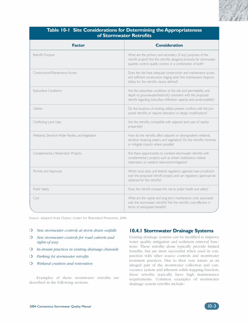
Factor Consideration
Retrofit Purpose
Construction/Maintenance Access
Subsurface Conditions
Utilities
Conflicting Land Uses
Wetlands, Sensitive Water Bodies, and Vegetation
Complementary Restoration Projects
Permits and Approvals
Public Safety
Cost
What are the primary and secondary (if any) purposes of theretrofit project? Are the retrofits designed primarily for stormwaterquantity control, quality control, or a combination of both?
Does the site have adequate construction and maintenance accessand sufficient construction staging area? Are maintenance responsi-bilities for the retrofits clearly defined?
Are the subsurface conditions at the site (soil permeability anddepth to groundwater/bedrock) consistent with the proposedretrofit regarding subsurface infiltration capacity and constructability?
Do the locations of existing utilities present conflicts with the pro-posed retrofits or require relocation or design modifications?
Are the retrofits compatible with adjacent land uses of nearbyproperties?
How do the retrofits affect adjacent or downgradient wetlands,sensitive receiving waters, and vegetation? Do the retrofits minimizeor mitigate impacts where possible?
Are there opportunities to combine stormwater retrofits withcomplementary projects such as stream stabilization, habitatrestoration, or wetland restoration/mitigation?
Which local, state, and federal regulatory agencies have jurisdictionover the proposed retrofit project, and can regulatory approvals beobtained for the retrofits?
Does the retrofit increase the risk to public health and safety?
What are the capital and long-term maintenance costs associatedwith the stormwater retrofits? Are the retrofits cost-effective interms of anticipated benefits?
Table 10-1 Site Considerations for Determining the Appropriatenessof Stormwater Retrofits
2004 Connecticut Stormwater Quality Manual 10-3
❍ New stormwater controls at storm drain outfalls
❍ New stormwater controls for road culverts andrights-of-way
❍ In-stream practices in existing drainage channels
❍ Parking lot stormwater retrofits
❍ Wetland creation and restoration
Examples of these stormwater retrofits aredescribed in the following sections.
10.4.1 Stormwater Drainage SystemsExisting drainage systems can be modified to improvewater quality mitigation and sediment removal func-tions. These retrofits alone typically provide limitedbenefits, but are most successful when used in con-junction with other source controls and stormwatertreatment practices. Due to their very nature as anintegral part of the stormwater collection and con-veyance system and inherent solids trapping function,these retrofits typically have high maintenancerequirements. Common examples of stormwaterdrainage system retrofits include:
Source: Adapted from Claytor, Center for Watershed Protection, 2000.
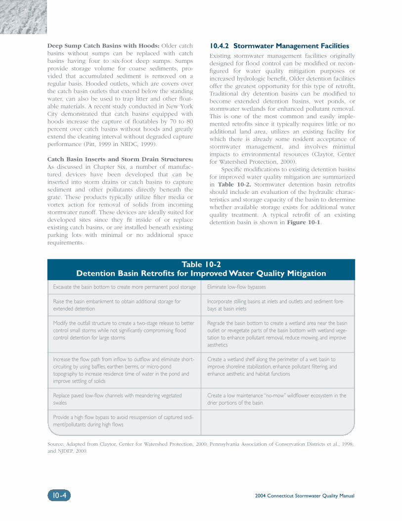
2004 Connecticut Stormwater Quality Manual10-4
Deep Sump Catch Basins with Hoods: Older catchbasins without sumps can be replaced with catchbasins having four to six-foot deep sumps. Sumpsprovide storage volume for coarse sediments, pro-vided that accumulated sediment is removed on aregular basis. Hooded outlets, which are covers overthe catch basin outlets that extend below the standingwater, can also be used to trap litter and other float-able materials. A recent study conducted in New YorkCity demonstrated that catch basins equipped withhoods increase the capture of floatables by 70 to 80percent over catch basins without hoods and greatlyextend the cleaning interval without degraded captureperformance (Pitt, 1999 in NRDC, 1999).
Catch Basin Inserts and Storm Drain Structures:As discussed in Chapter Six, a number of manufac-tured devices have been developed that can beinserted into storm drains or catch basins to capturesediment and other pollutants directly beneath thegrate. These products typically utilize filter media orvortex action for removal of solids from incomingstormwater runoff. These devices are ideally suited fordeveloped sites since they fit inside of or replaceexisting catch basins, or are installed beneath existingparking lots with minimal or no additional spacerequirements.
10.4.2 Stormwater Management FacilitiesExisting stormwater management facilities originallydesigned for flood control can be modified or recon-figured for water quality mitigation purposes orincreased hydrologic benefit. Older detention facilitiesoffer the greatest opportunity for this type of retrofit.Traditional dry detention basins can be modified tobecome extended detention basins, wet ponds, orstormwater wetlands for enhanced pollutant removal.This is one of the most common and easily imple-mented retrofits since it typically requires little or noadditional land area, utilizes an existing facility forwhich there is already some resident acceptance ofstormwater management, and involves minimalimpacts to environmental resources (Claytor, Centerfor Watershed Protection, 2000).
Specific modifications to existing detention basinsfor improved water quality mitigation are summarizedin Table 10-2. Stormwater detention basin retrofitsshould include an evaluation of the hydraulic charac-teristics and storage capacity of the basin to determinewhether available storage exists for additional waterquality treatment. A typical retrofit of an existingdetention basin is shown in Figure 10-1.
Excavate the basin bottom to create more permanent pool storage
Raise the basin embankment to obtain additional storage forextended detention
Modify the outfall structure to create a two-stage release to bettercontrol small storms while not significantly compromising floodcontrol detention for large storms
Increase the flow path from inflow to outflow and eliminate short-circuiting by using baffles, earthen berms, or micro-pondtopography to increase residence time of water in the pond andimprove settling of solids
Replace paved low-flow channels with meandering vegetatedswales
Provide a high flow bypass to avoid resuspension of captured sedi-ment/pollutants during high flows
Eliminate low-flow bypasses
Incorporate stilling basins at inlets and outlets and sediment fore-bays at basin inlets
Regrade the basin bottom to create a wetland area near the basinoutlet or revegetate parts of the basin bottom with wetland vege-tation to enhance pollutant removal, reduce mowing, and improveaesthetics
Create a wetland shelf along the perimeter of a wet basin toimprove shoreline stabilization, enhance pollutant filtering, andenhance aesthetic and habitat functions
Create a low maintenance “no-mow” wildflower ecosystem in thedrier portions of the basin
Table 10-2Detention Basin Retrofits for Improved Water Quality Mitigation
Source: Adapted from Claytor, Center for Watershed Protection, 2000; Pennsylvania Association of Conservation Districts et al., 1998;and NJDEP, 2000.
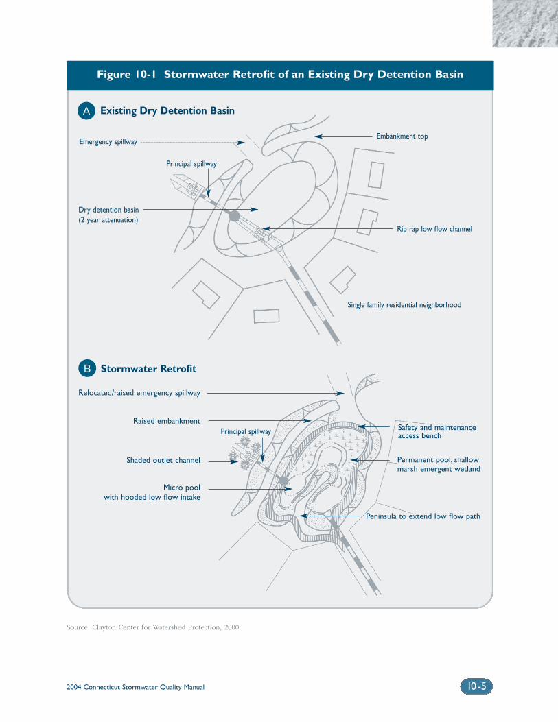
2004 Connecticut Stormwater Quality Manual 10-5
Figure 10-1 Stormwater Retrofit of an Existing Dry Detention Basin
Source: Claytor, Center for Watershed Protection, 2000.
Embankment top
Existing Dry Detention Basin
Stormwater Retrofit
Dry detention basin(2 year attenuation)
Emergency spillway
Single family residential neighborhood
Rip rap low flow channel
Relocated/raised emergency spillway
Raised embankment
Shaded outlet channel
Micro poolwith hooded low flow intake
A
B
Principal spillway
Principal spillway Safety and maintenanceaccess bench
Permanent pool, shallow marsh emergent wetland
Peninsula to extend low flow path
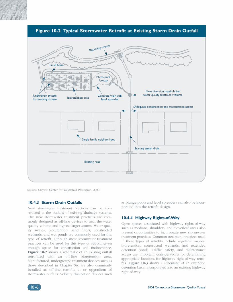
2004 Connecticut Stormwater Quality Manual10-6
10.4.3 Storm Drain OutfallsNew stormwater treatment practices can be con-structed at the outfalls of existing drainage systems.The new stormwater treatment practices are com-monly designed as off-line devices to treat the waterquality volume and bypass larger storms. Water qual-ity swales, bioretention, sand filters, constructedwetlands, and wet ponds are commonly used for thistype of retrofit, although most stormwater treatmentpractices can be used for this type of retrofit givenenough space for construction and maintenance.Figure 10-2 shows a schematic of an existing outfallretrofitted with an off-line bioretention area.Manufactured, underground treatment devices such asthose described in Chapter Six are also commonlyinstalled as off-line retrofits at or upgradient ofstormwater outfalls. Velocity dissipation devices such
as plunge pools and level spreaders can also be incor-porated into the retrofit design.
10.4.4 Highway Rights-of-WayOpen spaces associated with highway rights-of-waysuch as medians, shoulders, and cloverleaf areas alsopresent opportunities to incorporate new stormwatertreatment practices. Common treatment practices usedin these types of retrofits include vegetated swales,bioretention, constructed wetlands, and extendeddetention ponds. Traffic, safety, and maintenanceaccess are important considerations for determiningappropriate locations for highway right-of-way retro-fits. Figure 10-3 shows a schematic of an extendeddetention basin incorporated into an existing highwayright-of-way.
Figure 10-2 Typical Stormwater Retrofit at Existing Storm Drain Outfall
Source: Claytor, Center for Watershed Protection, 2000.
Receiving stream
Adequate construction and maintenance access
Existing road
Single-family neighborhood
New diversion manhole forwater quality treatment volumeConcrete weir wall,
level spreaderBioretention areaUnderdrain systemto receiving stream
Small berm
Micro-poolforebay
Existing storm drain
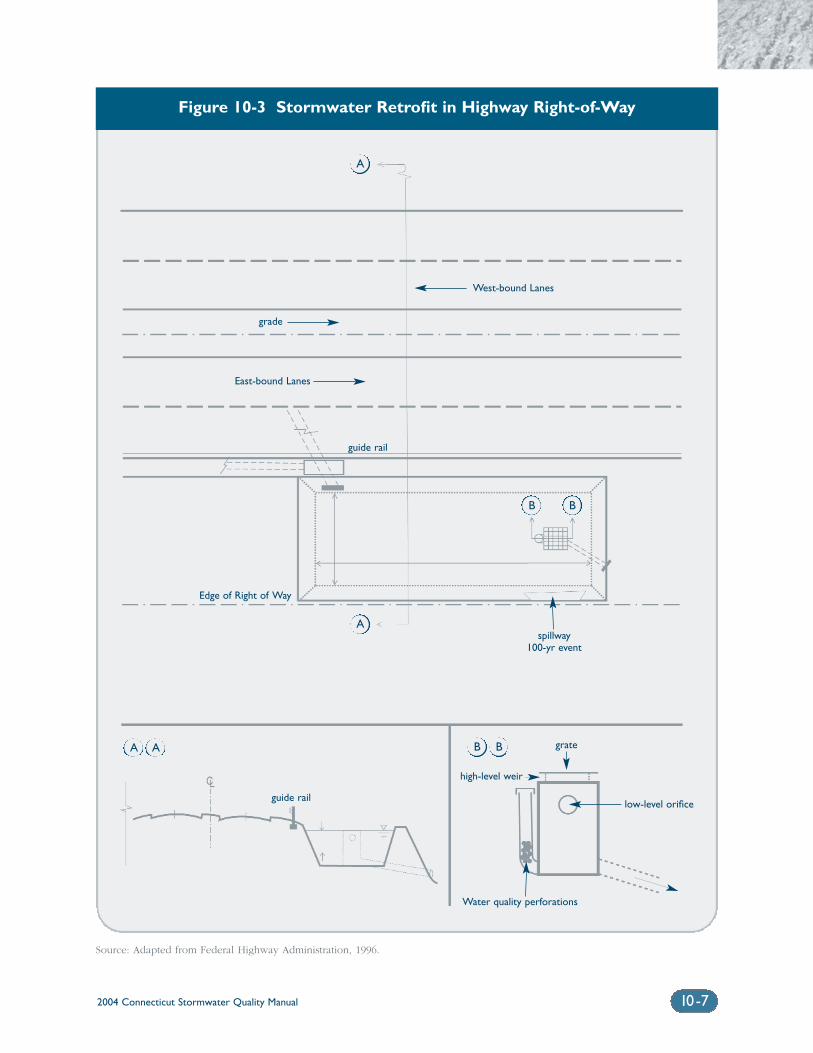
2004 Connecticut Stormwater Quality Manual 10-7
Figure 10-3 Stormwater Retrofit in Highway Right-of-Way
Source: Adapted from Federal Highway Administration, 1996.
West-bound Lanes
grade
guide rail
low-level orifice
Water quality perforations
high-level weir
grate
East-bound Lanes
Edge of Right of Way
spillway100-yr event
guide rail
B B
B B
A A
A
A
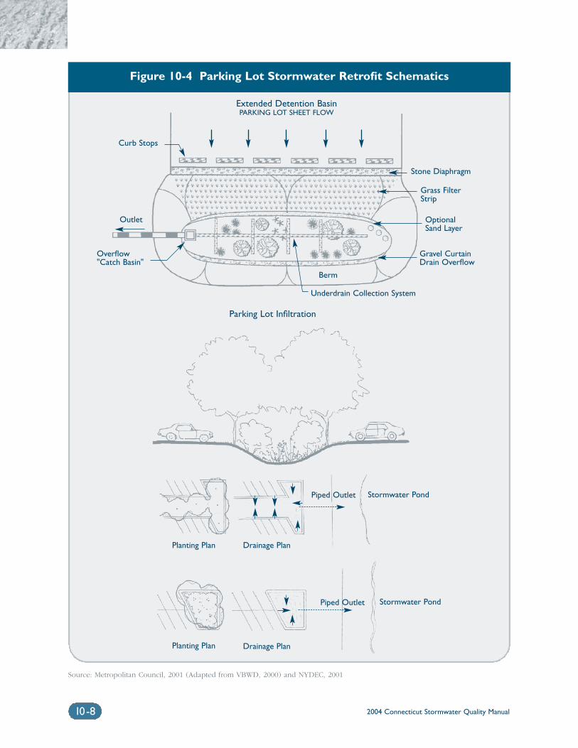
2004 Connecticut Stormwater Quality Manual10-8
Figure 10-4 Parking Lot Stormwater Retrofit Schematics
Source: Metropolitan Council, 2001 (Adapted from VBWD, 2000) and NYDEC, 2001
Extended Detention BasinPARKING LOT SHEET FLOW
Curb Stops
Outlet
Overflow"Catch Basin"
Gravel CurtainDrain Overflow
OptionalSand Layer
Grass FilterStrip
Stone Diaphragm
Parking Lot Infiltration
Piped Outlet
Piped Outlet
Stormwater Pond
Stormwater Pond
Berm
Underdrain Collection System
Drainage Plan
Drainage Plan
Planting Plan
Planting Plan
2004 Connecticut Stormwater Quality Manual 10-9
10.4.5 Parking LotsParking lots can be ideal candidates for a wide rangeof stormwater retrofits. Potentially applicable retrofitsinclude site planning techniques and small-scale management measures to reduce impervious coverageand promote increased infiltration (see Chapter Four),as well as a variety of larger, end-of-pipe treatmentpractices. Redevelopment of older commercial proper-ties, which were often designed with oversized parkinglots and almost 100 percent impervious coverage, isone of the most common and environmentally benefi-cial opportunities for parking lot stormwater retrofits.
Alternative site design and LID managementpractices are well suited to existing developed areasbecause most of these practices use a small amount ofland and are easily integrated into existing parkingareas. Examples of these parking lot stormwater retro-fits include:
Incorporating Bioretention Into Parking LotIslands and Landscaping: Parking lot islands, land-scaped areas, and tree planter boxes can be convertedinto functional bioretention areas and rain gardens toreduce and treat stormwater runoff.
Removing Curbing and Adding Slotted CurbStops: Curbs along the edges of parking lots cansometimes be removed or slotted to re-route runoff tovegetated areas, buffer strips, or bioretention facilities.The capacity of existing swales may need to be eval-uated and expanded as part of this retrofit option.
Infiltrating Clean Roof Runoff From Buildings: Insome instances, building roof drains connected to thestormwater drainage system can be disconnected andre-directed to vegetated areas, buffer strips, bioreten-tion facilities, or infiltration structures (dry wells orinfiltration trenches).
Incorporating New Treatment Practices at theEdges of Parking Lots: New stormwater treatmentpractices such as bioretention, sand filters, and con-structed wetlands can often be incorporated at theedges of large parking lots.
Use of Permeable Paving Materials: Existing imper-meable pavement in overflow parking or otherlow-traffic areas can sometimes be replaced withalternative, permeable materials such as modular con-crete paving blocks, modular concrete or plasticlattice, or cast-in-place concrete grids. Site-specificfactors including traffic volumes, soil permeability,maintenance, sediment loads, and land use must becarefully considered for the successful application ofpermeable paving materials for new development orretrofit applications.
Figure 10-4 depicts some of the parking lotstormwater retrofits described above.
10.4.6 In-stream Practices in DrainageChannels
Existing (man-made) channelized streams anddrainage conveyances such as grass channels can bemodified to reduce flow velocities and enhance pol-lutant removal. Weir walls or riprap check damsplaced across a channel create opportunities forponding, infiltration, and establishment of wetlandvegetation upstream of the retrofit (Claytor, Center forWatershed Protection, 2000). In-stream retrofit prac-tices include stream bank stabilization of eroded areasand placement of habitat improvement structures (i.e.,flow deflectors, boulders, pools/riffles, and low-flowchannels) in impacted natural streams and alongstream banks. In-stream retrofits may require evalua-tion of potential flooding and floodplain impactsresulting from altered channel conveyance, as well aslocal, state, or federal approval for work in wetlandsand watercourses. More comprehensive urban streamand stream corridor restoration practices are beyondthe scope of this Manual. Additional sources of infor-mation on stream restoration practices are included atthe end of this chapter.
10.4.7 Wetland Creation and RestorationWetland creation or restoration can partially substitutefor lost ecological functions of a destroyed ordegraded wetland system in developed areas.Creation or restoration of freshwater or tidal wetlandscan improve the pollutant removal, longevity, adapt-ability, and habitat functions of wetland systems (DEP,1995). Techniques to improve pollutant removal increated or restored wetlands include:
❍ Increasing wetland volume to increase residencetime
❍ Increasing the surface area to volume ratio ofthe wetland
❍ Increasing the flow path through the wetland
❍ Providing energy dissipation and primary sedi-mentation either prior to the wetland or in asediment forebay at the wetland inflow locations
❍ Integrating with other treatment practices suchas extended detention
(Schueler et al., 1992) When wetlands are alteredthrough clearing of vegetation, impoundment ofwater, or dredging, the microhabitats used by manywildlife species are changed or lost. This may resultin unsuitable breeding habitat for many amphibians,including vernal pool species. Similarly, created wet-lands usually lack the structural diversity,microhabitats, and hydrology to support vernal pool
breeding amphibians (Calhoun and Klemens, 2002).Altered and created wetlands often support highlyadaptable, widespread, “weedy” species (e.g., bull-frogs or green frogs) that prey upon, or successfullyout-compete, vernal pool-breeding amphibians,which reduces or locally eliminates populations ofthese habitat specialists. Created wetlands that do nothave the appropriate habitat often attract breedingamphibians, which serve as “decoy” pools and trapbreeding amphibians. Therefore, these wetland cre-ation and restoration techniques should only beimplemented with careful consideration of the effectsto wetland function and hydrology and in conjunctionwith applicable local, state, and federal wetland andwatercourses regulatory agencies.
Additional Information Sources
Riley, A.L. 1998. Restoring Streams in Cities. IslandPress. Washington, D.C.
Federal Interagency Stream Restoration WorkingGroup. 1998. Stream Corridor Restoration-Principles,Processes, and Practices.
References
Calhoun, A.J.K. and M.W. Klemens. 2002. Best devel-opment practices: Conserving pool-breedingamphibians in residential and commercial develop-ments in the northeastern United States. MCATechnical Paper No. 5, Metropolitan ConservationAlliance, Wildlife Conservation Society, Bronx, NewYork.
Center for Watershed Protection (CWP). 2000. ThePractice of Watershed Protection. Ellicott City,Maryland.
Connecticut Department of Environmental Protection(DEP). 1995. Connecticut Stormwater QualityPlanning: A Guide for Municipal Officials andRegional Planners (draft). Bureau of WaterManagement. Planning and Standards Division.Hartford, Connecticut.
Natural Resources Defense Council (NRDC). 1999.Stormwater Strategies: Community Responses toRunoff Pollution.
New Jersey Department of Environmental Protection(NJDEP). 2000. Revised Manual for New Jersey: BestManagement Practices for Control of Nonpoint SourcePollution from Stormwater, Fifth Draft, May 3, 2000.
Pennsylvania Association of Conservation Districts,Keystone Chapter Soil and Water ConservationSociety, Pennsylvania Department of EnvironmentalProtection, and Natural Resources ConservationService. 1998. Pennsylvania Handbook of BestManagement Practices for Developing Areas, preparedby CH2MHILL.
Pitt, R. 1999. Department of Civil and EnvironmentalEngineering, University of Alabama at Birmingham.
Schueler, T.R., Kumble, P.A., and M.A. Heraty. 1992. ACurrent Assessment of Urban Best ManagementPractices: Techniques for Reducing Non-Point SourcePollution in the Coastal Zone. Department ofEnvironmental Programs. Metropolitan WashingtonCouncil of Governments.
2004 Connecticut Stormwater Quality Manual10-10
Chapter 11Stormwater Treatment
Practice Design Guidance
Chapter 11 Stormwater Treatment Practice Design Guidance
Primary Treatment Practices ............................................................................11-2
Secondary Treatment Practices .......................................................................11-3
Primary (P) Treatment Practices
11-P1 Stormwater Ponds ..............................................................11-P1-1
11-P2 Stormwater Wetlands.........................................................11-P2-1
11-P3 Infiltration Practices............................................................11-P3-1
11-P4 Filtering Practices ................................................................11-P4-1
11-P5 Water Quality ......................................................................11-P5-1
Secondary (S) Treatment Practices
Conventional Practices
11-S1 Dry Detention Pond...........................................................11-S1-1
11-S2 Underground Detention Facilities ..................................11-S2-1
11-S3 Deep Sump Catch Basins .................................................11-S3-1
11-S4 Oil/Particle Separators ......................................................11-S4-1
11-S5 Dry Wells .............................................................................11-S5-1
11-S6 Permeable Pavement...........................................................11-S6-1
11-S7 Vegetated Filter Strips/Level Spreaders..........................11-S7-1
11-S8 Grass Drainage Channels .................................................11-S8-1
Innovative/Emerging Technologies
11-S9 Catch Basin Inserts .............................................................11-S9-1
11-S10 Hydrodynamic Separators...............................................11-S10-1
11-S11 Media Filters .......................................................................11-S11-1
11-S12 Underground Infiltration Systems .................................11-S12-1
11-S13 Alum Injection....................................................................11-S13-1
Volume II: Design
2004 Connecticut Stormwater Quality Manual 11-1
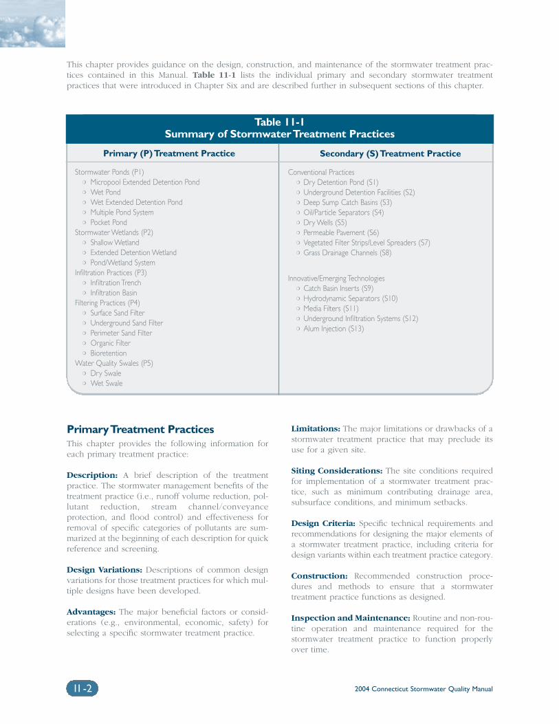
2004 Connecticut Stormwater Quality Manual11-2
This chapter provides guidance on the design, construction, and maintenance of the stormwater treatment prac-tices contained in this Manual. Table 11-1 lists the individual primary and secondary stormwater treatmentpractices that were introduced in Chapter Six and are described further in subsequent sections of this chapter.
Primary Treatment PracticesThis chapter provides the following information foreach primary treatment practice:
Description: A brief description of the treatmentpractice. The stormwater management benefits of thetreatment practice (i.e., runoff volume reduction, pol-lutant reduction, stream channel/conveyanceprotection, and flood control) and effectiveness forremoval of specific categories of pollutants are sum-marized at the beginning of each description for quickreference and screening.
Design Variations: Descriptions of common designvariations for those treatment practices for which mul-tiple designs have been developed.
Advantages: The major beneficial factors or consid-erations (e.g., environmental, economic, safety) forselecting a specific stormwater treatment practice.
Limitations: The major limitations or drawbacks of astormwater treatment practice that may preclude itsuse for a given site.
Siting Considerations: The site conditions requiredfor implementation of a stormwater treatment prac-tice, such as minimum contributing drainage area,subsurface conditions, and minimum setbacks.
Design Criteria: Specific technical requirements andrecommendations for designing the major elements ofa stormwater treatment practice, including criteria fordesign variants within each treatment practice category.
Construction: Recommended construction proce-dures and methods to ensure that a stormwatertreatment practice functions as designed.
Inspection and Maintenance: Routine and non-rou-tine operation and maintenance required for thestormwater treatment practice to function properlyover time.
Table 11-1Summary of Stormwater Treatment Practices
Primary (P) Treatment Practice
Stormwater Ponds (P1)❍ Micropool Extended Detention Pond❍ Wet Pond❍ Wet Extended Detention Pond❍ Multiple Pond System❍ Pocket Pond
Stormwater Wetlands (P2)❍ Shallow Wetland❍ Extended Detention Wetland❍ Pond/Wetland System
Infiltration Practices (P3)❍ Infiltration Trench❍ Infiltration Basin
Filtering Practices (P4)❍ Surface Sand Filter❍ Underground Sand Filter❍ Perimeter Sand Filter❍ Organic Filter❍ Bioretention
Water Quality Swales (P5)❍ Dry Swale❍ Wet Swale
Secondary (S) Treatment Practice
Conventional Practices❍ Dry Detention Pond (S1)❍ Underground Detention Facilities (S2)❍ Deep Sump Catch Basins (S3)❍ Oil/Particle Separators (S4)❍ Dry Wells (S5)❍ Permeable Pavement (S6)❍ Vegetated Filter Strips/Level Spreaders (S7)❍ Grass Drainage Channels (S8)
Innovative/Emerging Technologies❍ Catch Basin Inserts (S9)❍ Hydrodynamic Separators (S10)❍ Media Filters (S11)❍ Underground Infiltration Systems (S12)❍ Alum Injection (S13)
2004 Connecticut Stormwater Quality Manual 11-3
Cost Considerations: Approximate capital costs todesign, construct, and implement the stormwatertreatment practice, as well as approximate annualoperation and maintenance costs, where available.
Secondary Treatment PracticesSecondary treatment practices are described in lessdetail due to their limited applicability for water qual-ity control. The following guidance is provided forthese treatment practices:
Description: A brief description and associatedstormwater management benefits of the treatmentpractice.
Reasons for Limited Use: Rationale for why thepractice generally does not meet the performancestandards required for classification as a primary treat-ment practice.
Suitable Applications: The conditions or applica-tions for which the practice is typically suitable (i.e.,pretreatment, ultra-urban environments, etc.)
Design Considerations: Key factors for siting,designing, and implementing the treatment practice.
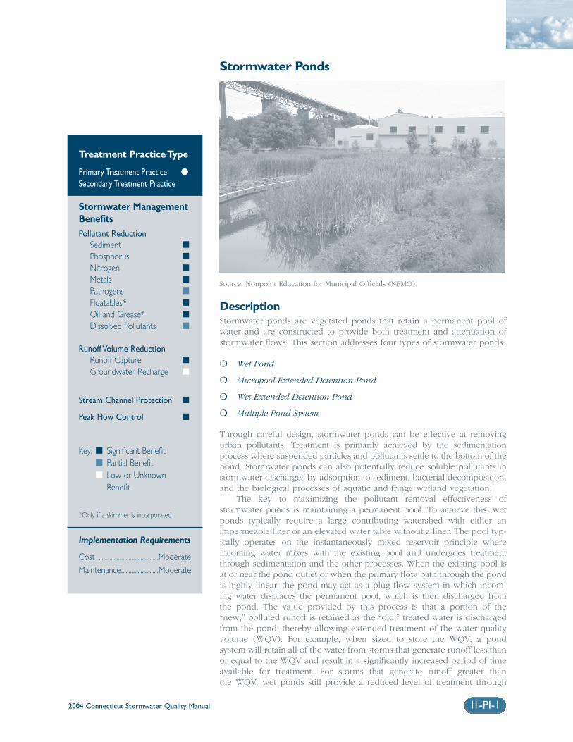
2004 Connecticut Stormwater Quality Manual 11-PI-1
Stormwater Ponds
DescriptionStormwater ponds are vegetated ponds that retain a permanent pool ofwater and are constructed to provide both treatment and attenuation ofstormwater flows. This section addresses four types of stormwater ponds:
❍ Wet Pond
❍ Micropool Extended Detention Pond
❍ Wet Extended Detention Pond
❍ Multiple Pond System
Through careful design, stormwater ponds can be effective at removingurban pollutants. Treatment is primarily achieved by the sedimentationprocess where suspended particles and pollutants settle to the bottom of thepond. Stormwater ponds can also potentially reduce soluble pollutants instormwater discharges by adsorption to sediment, bacterial decomposition,and the biological processes of aquatic and fringe wetland vegetation.
The key to maximizing the pollutant removal effectiveness ofstormwater ponds is maintaining a permanent pool. To achieve this, wetponds typically require a large contributing watershed with either animpermeable liner or an elevated water table without a liner. The pool typ-ically operates on the instantaneously mixed reservoir principle whereincoming water mixes with the existing pool and undergoes treatmentthrough sedimentation and the other processes. When the existing pool isat or near the pond outlet or when the primary flow path through the pondis highly linear, the pond may act as a plug flow system in which incom-ing water displaces the permanent pool, which is then discharged from the pond. The value provided by this process is that a portion of the “new,” polluted runoff is retained as the “old,” treated water is dischargedfrom the pond, thereby allowing extended treatment of the water qualityvolume (WQV). For example, when sized to store the WQV, a pond system will retain all of the water from storms that generate runoff less thanor equal to the WQV and result in a significantly increased period of timeavailable for treatment. For storms that generate runoff greater than the WQV, wet ponds still provide a reduced level of treatment through
Treatment Practice Type
Primary Treatment Practice �
Secondary Treatment Practice
Stormwater ManagementBenefitsPollutant Reduction
Sediment �
Phosphorus �
Nitrogen �
Metals �
Pathogens �
Floatables* �
Oil and Grease* �
Dissolved Pollutants �
Runoff Volume ReductionRunoff Capture �
Groundwater Recharge �
Stream Channel Protection �
Peak Flow Control �
Key: � Significant Benefit� Partial Benefit� Low or Unknown
Benefit
*Only if a skimmer is incorporated
Implementation Requirements
Cost ........................................ModerateMaintenance.........................Moderate
Source: Nonpoint Education for Municipal Officials (NEMO).
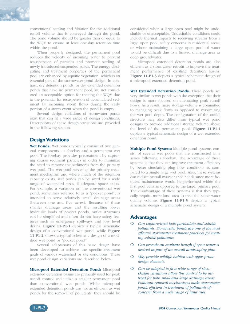
2004 Connecticut Stormwater Quality Manual11-PI-2
conventional settling and filtration for the additionalrunoff volume that is conveyed through the pond.The pond volume should be greater than or equal tothe WQV to ensure at least one-day retention timewithin the pond.
When properly designed, the permanent poolreduces the velocity of incoming water to preventresuspension of particles and promote settling ofnewly introduced suspended solids. The energy dissi-pating and treatment properties of the permanentpool are enhanced by aquatic vegetation, which is anessential part of the stormwater pond design. In con-trast, dry detention ponds, or dry extended detentionponds that have no permanent pool, are not consid-ered an acceptable option for treating the WQV dueto the potential for resuspension of accumulated sed-iment by incoming storm flows during the earlyportion of a storm event when the pond is empty.
Several design variations of stormwater pondsexist that can fit a wide range of design conditions.Descriptions of these design variations are providedin the following section.
Design VariationsWet Ponds: Wet ponds typically consist of two gen-eral components - a forebay and a permanent wetpool. The forebay provides pretreatment by captur-ing coarse sediment particles in order to minimizethe need to remove the sediments from the primarywet pool. The wet pool serves as the primary treat-ment mechanism and where much of the retentioncapacity exists. Wet ponds can be sized for a widerange of watershed sizes, if adequate space exists.For example, a variation on the conventional wetpond, sometimes referred to as a “pocket pond”, isintended to serve relatively small drainage areas(between one and five acres). Because of thesesmaller drainage areas and the resulting lowerhydraulic loads of pocket ponds, outlet structurescan be simplified and often do not have safety fea-tures such as emergency spillways and low leveldrains. Figure 11-P1-1 depicts a typical schematicdesign of a conventional wet pond, while Figure11-P1-2 shows a typical schematic design of a mod-ified wet pond or “pocket pond”.
Several adaptations of this basic design havebeen developed to achieve the specific treatmentgoals of various watershed or site conditions. Thesewet pond design variations are described below.
Micropool Extended Detention Pond: Micropoolextended detention basins are primarily used for peakrunoff control and utilize a smaller permanent poolthan conventional wet ponds. While micropoolextended detention ponds are not as efficient as wetponds for the removal of pollutants, they should be
considered when a large open pool might be unde-sirable or unacceptable. Undesirable conditions couldinclude thermal impacts to receiving streams from alarge open pool, safety concerns in residential areas,or where maintaining a large open pool of waterwould be difficult due to a limited drainage area ordeep groundwater.
Micropool extended detention ponds are alsoefficient as a stormwater retrofit to improve the treat-ment performance of existing detention basins.Figure 11-P1-3 depicts a typical schematic design ofa micropool extended detention pond.
Wet Extended Detention Ponds: These ponds arevery similar to wet ponds with the exception that theirdesign is more focused on attenuating peak runoffflows. As a result, more storage volume is committedto managing peak flows as opposed to maximizingthe wet pool depth. The configuration of the outfallstructure may also differ from typical wet ponddesigns to provide additional storage volume abovethe level of the permanent pool. Figure 11-P1-4depicts a typical schematic design of a wet extendeddetention pond.
Multiple Pond System: Multiple pond systems con-sist of several wet pools that are constructed in aseries following a forebay. The advantage of thesesystems is that they can improve treatment efficiencyby better simulating plug flow conditions as com-pared to a single large wet pool. Also, these systemscan reduce overall maintenance needs since more fre-quent maintenance would be performed within thefirst pool cells as opposed to the large, primary pool.The disadvantage of these systems is that they typi-cally require more land area to treat the same waterquality volume. Figure 11-P1-5 depicts a typicalschematic design of a multiple pond system.
Advantages❍ Can capture/treat both particulate and soluble
pollutants. Stormwater ponds are one of the mosteffective stormwater treatment practices for treat-ing soluble pollutants.
❍ Can provide an aesthetic benefit if open water isdesired as part of an overall landscaping plan.
❍ May provide wildlife habitat with appropriatedesign elements.
❍ Can be adapted to fit a wide range of sites.Design variations allow this control to be uti-lized for both small and large drainage areas.Pollutant removal mechanisms make stormwaterponds efficient in treatment of pollutants-of-concern from a wide range of land uses.
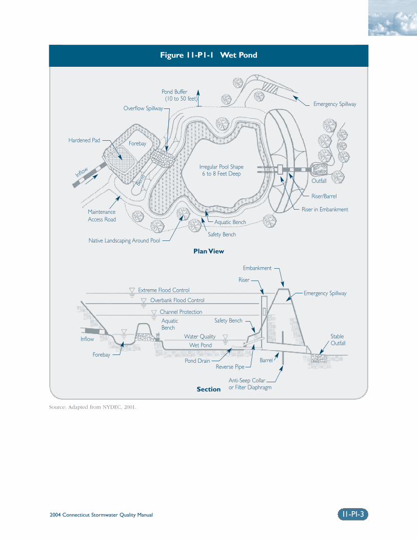
2004 Connecticut Stormwater Quality Manual 11-PI-3
Figure 11-P1-1 Wet Pond
Source: Adapted from NYDEC, 2001.
Pond Buffer(10 to 50 feet)
Hardened Pad
Overflow Spillway
MaintenanceAccess Road
Native Landscaping Around Pool
Aquatic Bench
Safety Bench
Riser in Embankment
Riser/Barrel
Outfall
Emergency Spillway
Irregular Pool Shape6 to 8 Feet Deep
Forebay
Plan View
Section
Embankment
Riser
Emergency Spillway
StableOutfall
Anti-Seep Collar or Filter Diaphragm
BarrelReverse Pipe
Pond Drain
Extreme Flood Control
Overbank Flood Control
Channel ProtectionSafety Bench
Water QualityWet Pond
AquaticBench
Forebay
Inflow
Inflow
Berm
2004 Connecticut Stormwater Quality Manual11-PI-4
Limitations❍ Unlined ponds that intercept groundwater
have potential to impact groundwater quality ifdissolved pollutants are present in the runoff.
❍ Lined ponds typically require a minimumdrainage area in order to maintain a perma-nent pool, which may become difficult duringextended dry periods.
❍ Require a relatively large land area that isdirectly proportional to the size of the areadraining to it.
❍ May cause thermal impacts to receiving watersand thereby are not recommended to dischargedirectly to cold water fish habitats.
❍ Require more storage volume (i.e., above perma-nent pool) to attenuate peak flows.
❍ Potential breeding habitat for mosquitoes, partic-ularly for smaller ponds with stagnant water orisolated pockets of standing water (rather thanlarge open water bodies). Circulating water inthe permanent pool may minimize this problem.This may be a more significant problem forlined basins.
❍ Pollutant removal efficiency can be affected incold climates due to ice formation on the perma-nent pool and longer particle settling timesassociated with higher density water during winter months. However, modifications to apond’s design can help maintain the primarypollutant removal mechanism of sedimentation.
❍ Ponds with steep side slopes and/or deep wetpools may present a safety issue to nearby pedestrians.
❍ Stormwater ponds can serve as decoy wetlands,intercepting breeding amphibians movingtoward vernal pools. If amphibians deposit theireggs in these artificial ponds/wetlands, theyrarely survive due to the sediment and pollutantloads, as well as fluctuations in water quality,quantity, and temperature.
Siting ConsiderationsDrainage Area: Stormwater ponds that utilize a linersystem should have a contributing drainage area thatis adequate to maintain minimum water levels.Typically, minimum contributing watersheds forunlined ponds are twenty-five acres for wet ponds,wet extended detention ponds, and multiple pondsystems; ten acres for micropool extended detentionponds; and one to five acres for pocket ponds.
Groundwater: Unlined basins must intersect thegroundwater table in order to maintain the desiredpermanent pool. In this case, the elevations of thebasin should be established such that the ground-water elevation is equal to the desired permanentpool elevation. Seasonal variations of groundwaterelevations should be considered, which can be verypronounced in low permeability soils.
Land Uses: Land uses will dictate potential pollu-tants-of-concern and potential safety risks. For thoseland uses where there is significant potential for solu-ble pollutants, especially those that are highlysusceptible to groundwater transport, the use of aliner is recommended. An impermeable liner may notbe required depending on risk of downstream con-tamination, but a low permeability liner constructedin till soils may be acceptable. With regard to poten-tial safety issues, adjacent residential land uses posethe greatest risks where mosquito breeding and waterhazards must be considered.
Baseflow: A small amount of baseflow is desirable tomaintain circulation and reduce the potential for lowdissolved oxygen levels during late summer. Thisbaseflow can be provided by groundwater infiltratinginto either the basin or the collection system abovethe pond.
Site Slopes: Steep on-site slopes may result in theneed for a large embankment to be constructed to pro-vide the desired storage volume, which could requirea dam construction permit from the Connecticut DEP.Steep slopes may also present design and construc-tion challenges, and significantly increase the cost ofearthwork.
Receiving Waters: The sensitivity of receiving watersshould be evaluated to determine whether the effectsof the warmer stormwater discharges from the wetpond could be detrimental to cold water fish or othersensitive aquatic species.
Flood Zones: Ponds should not be located in flood-ways, floodplains, or tidal lands, especially those thatrequire construction of an embankment. Floodwaterscould flush out stored pollutants or damage pondembankments.
Natural Wetlands/Vernal Pools: Natural wetlandsand vernal pool depressions should not be used,either temporarily or permanently, as a stormwaterpond or wetland. Stormwater ponds should belocated at least 750 feet from a vernal pool. Theyshould not be sited between vernal pools, or in areasthat are known primary amphibian overland migra-tion routes.
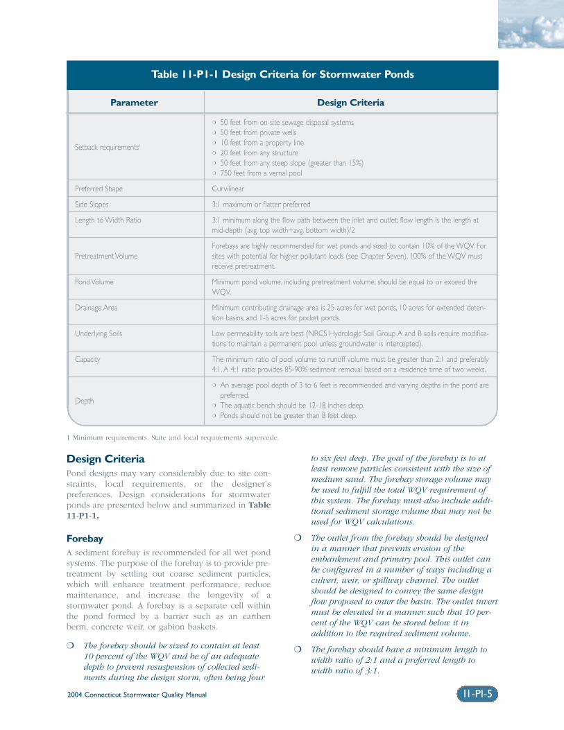
2004 Connecticut Stormwater Quality Manual
Design CriteriaPond designs may vary considerably due to site con-straints, local requirements, or the designer’spreferences. Design considerations for stormwaterponds are presented below and summarized in Table11-P1-1.
ForebayA sediment forebay is recommended for all wet pondsystems. The purpose of the forebay is to provide pre-treatment by settling out coarse sediment particles,which will enhance treatment performance, reducemaintenance, and increase the longevity of astormwater pond. A forebay is a separate cell withinthe pond formed by a barrier such as an earthenberm, concrete weir, or gabion baskets.
❍ The forebay should be sized to contain at least10 percent of the WQV and be of an adequatedepth to prevent resuspension of collected sedi-ments during the design storm, often being four
to six feet deep. The goal of the forebay is to atleast remove particles consistent with the size ofmedium sand. The forebay storage volume maybe used to fulfill the total WQV requirement ofthis system. The forebay must also include addi-tional sediment storage volume that may not beused for WQV calculations.
❍ The outlet from the forebay should be designedin a manner that prevents erosion of theembankment and primary pool. This outlet canbe configured in a number of ways including aculvert, weir, or spillway channel. The outletshould be designed to convey the same designflow proposed to enter the basin. The outlet invertmust be elevated in a manner such that 10 per-cent of the WQV can be stored below it inaddition to the required sediment volume.
❍ The forebay should have a minimum length towidth ratio of 2:1 and a preferred length towidth ratio of 3:1.
11-PI-5
Parameter Design Criteria
Setback requirements1
Preferred Shape
Side Slopes
Length to Width Ratio
Pretreatment Volume
Pond Volume
Drainage Area
Underlying Soils
Capacity
Depth
❍ 50 feet from on-site sewage disposal systems❍ 50 feet from private wells❍ 10 feet from a property line❍ 20 feet from any structure❍ 50 feet from any steep slope (greater than 15%)❍ 750 feet from a vernal pool
Curvilinear
3:1 maximum or flatter preferred
3:1 minimum along the flow path between the inlet and outlet; flow length is the length atmid-depth (avg. top width+avg. bottom width)/2
Forebays are highly recommended for wet ponds and sized to contain 10% of the WQV. Forsites with potential for higher pollutant loads (see Chapter Seven), 100% of the WQV mustreceive pretreatment.
Minimum pond volume, including pretreatment volume, should be equal to or exceed theWQV.
Minimum contributing drainage area is 25 acres for wet ponds, 10 acres for extended deten-tion basins, and 1-5 acres for pocket ponds.
Low permeability soils are best (NRCS Hydrologic Soil Group A and B soils require modifica-tions to maintain a permanent pool unless groundwater is intercepted).
The minimum ratio of pool volume to runoff volume must be greater than 2:1 and preferably4:1. A 4:1 ratio provides 85-90% sediment removal based on a residence time of two weeks.
❍ An average pool depth of 3 to 6 feet is recommended and varying depths in the pond arepreferred.
❍ The aquatic bench should be 12-18 inches deep.❍ Ponds should not be greater than 8 feet deep.
Table 11-P1-1 Design Criteria for Stormwater Ponds
1 Minimum requirements. State and local requirements supercede.
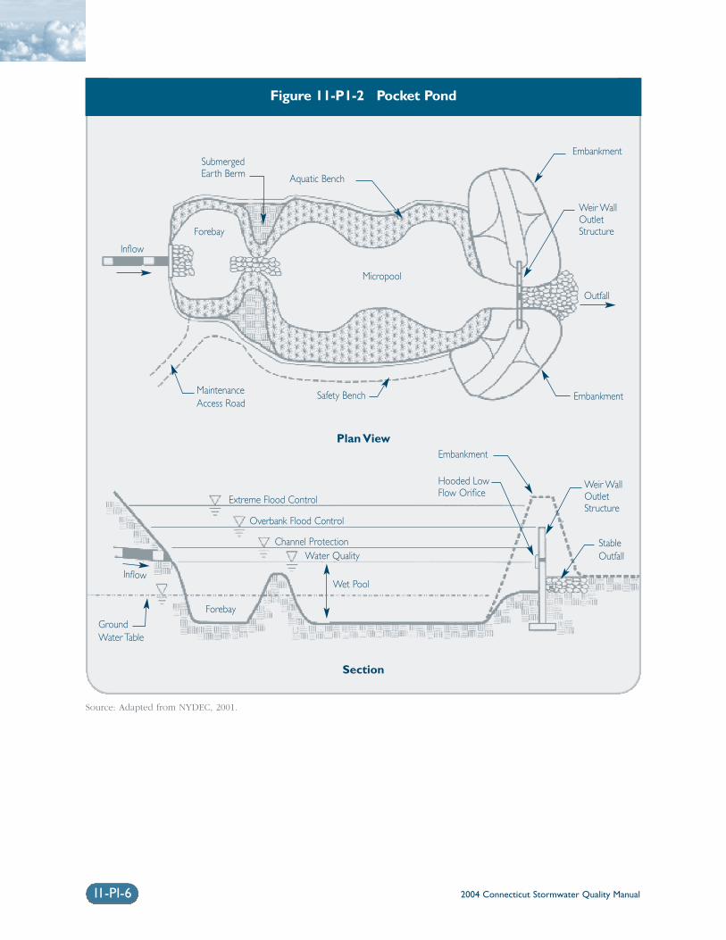
2004 Connecticut Stormwater Quality Manual11-PI-6
Figure 11-P1-2 Pocket Pond
Source: Adapted from NYDEC, 2001.
SubmergedEarth Berm
MaintenanceAccess Road
Safety Bench
Aquatic Bench
Micropool
Embankment
Outfall
Extreme Flood Control
Overbank Flood Control
Channel ProtectionWater Quality
Forebay
Inflow
Plan View
Section
Embankment
Weir WallOutlet Structure
Wet Pool
Forebay
Inflow
GroundWater Table
Weir WallOutlet Structure
Embankment
StableOutfall
Hooded LowFlow Orifice
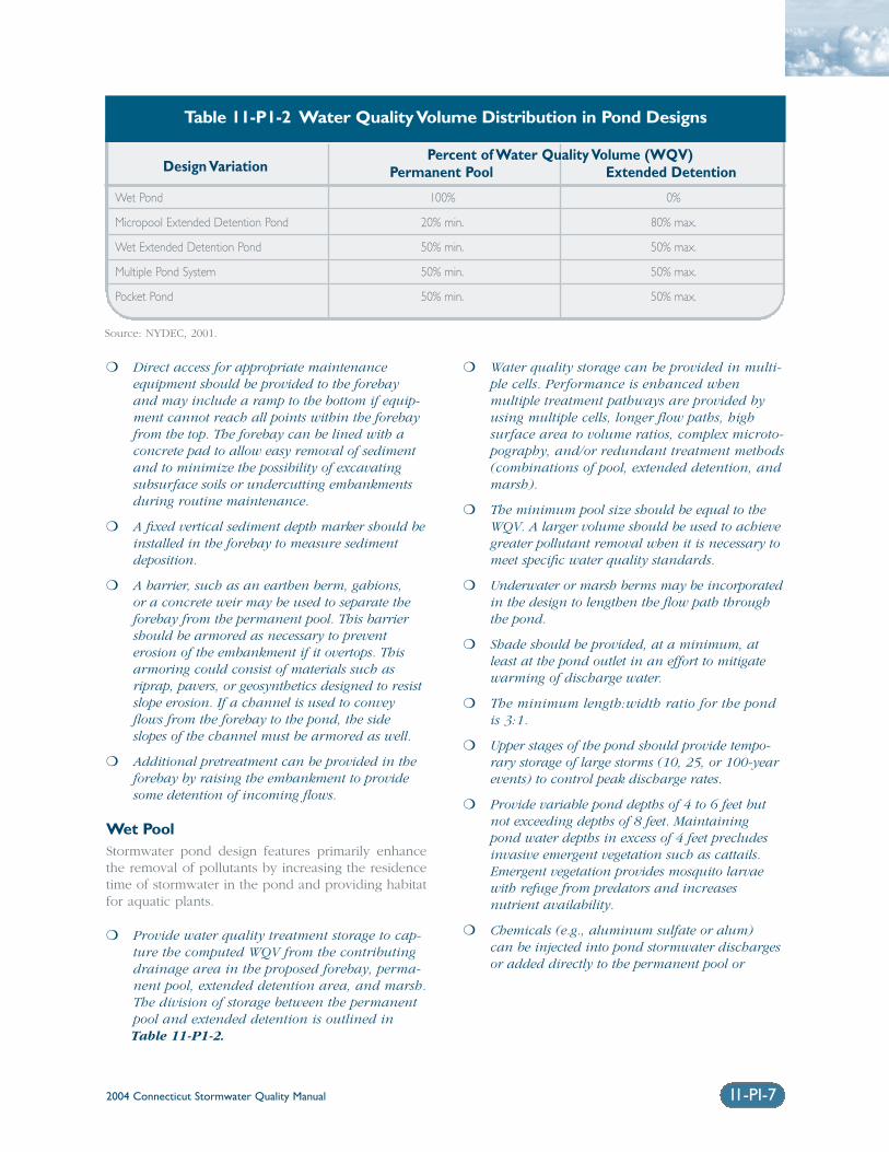
❍ Direct access for appropriate maintenanceequipment should be provided to the forebayand may include a ramp to the bottom if equip-ment cannot reach all points within the forebayfrom the top. The forebay can be lined with aconcrete pad to allow easy removal of sedimentand to minimize the possibility of excavatingsubsurface soils or undercutting embankmentsduring routine maintenance.
❍ A fixed vertical sediment depth marker should beinstalled in the forebay to measure sedimentdeposition.
❍ A barrier, such as an earthen berm, gabions, or a concrete weir may be used to separate theforebay from the permanent pool. This barriershould be armored as necessary to prevent erosion of the embankment if it overtops. Thisarmoring could consist of materials such asriprap, pavers, or geosynthetics designed to resistslope erosion. If a channel is used to conveyflows from the forebay to the pond, the sideslopes of the channel must be armored as well.
❍ Additional pretreatment can be provided in theforebay by raising the embankment to providesome detention of incoming flows.
Wet Pool Stormwater pond design features primarily enhancethe removal of pollutants by increasing the residencetime of stormwater in the pond and providing habitatfor aquatic plants.
❍ Provide water quality treatment storage to cap-ture the computed WQV from the contributingdrainage area in the proposed forebay, perma-nent pool, extended detention area, and marsh.The division of storage between the permanentpool and extended detention is outlined inTable 11-P1-2.
❍ Water quality storage can be provided in multi-ple cells. Performance is enhanced whenmultiple treatment pathways are provided byusing multiple cells, longer flow paths, high surface area to volume ratios, complex microto-pography, and/or redundant treatment methods(combinations of pool, extended detention, andmarsh).
❍ The minimum pool size should be equal to theWQV. A larger volume should be used to achievegreater pollutant removal when it is necessary tomeet specific water quality standards.
❍ Underwater or marsh berms may be incorporatedin the design to lengthen the flow path throughthe pond.
❍ Shade should be provided, at a minimum, atleast at the pond outlet in an effort to mitigatewarming of discharge water.
❍ The minimum length:width ratio for the pondis 3:1.
❍ Upper stages of the pond should provide tempo-rary storage of large storms (10, 25, or 100-yearevents) to control peak discharge rates.
❍ Provide variable pond depths of 4 to 6 feet butnot exceeding depths of 8 feet. Maintainingpond water depths in excess of 4 feet precludesinvasive emergent vegetation such as cattails.Emergent vegetation provides mosquito larvaewith refuge from predators and increases nutrient availability.
❍ Chemicals (e.g., aluminum sulfate or alum) can be injected into pond stormwater dischargesor added directly to the permanent pool or
Design VariationPercent of Water Quality Volume (WQV)
Permanent Pool Extended Detention
Wet Pond 100% 0%
Micropool Extended Detention Pond 20% min. 80% max.
Wet Extended Detention Pond 50% min. 50% max.
Multiple Pond System 50% min. 50% max.
Pocket Pond 50% min. 50% max.
Table 11-P1-2 Water Quality Volume Distribution in Pond Designs
Source: NYDEC, 2001.
2004 Connecticut Stormwater Quality Manual 11-PI-7
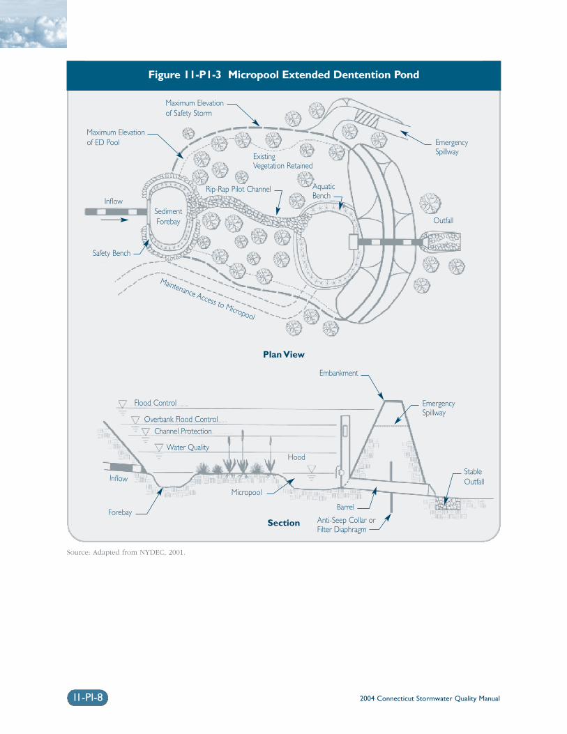
2004 Connecticut Stormwater Quality Manual11-PI-8
Figure 11-P1-3 Micropool Extended Dentention Pond
Source: Adapted from NYDEC, 2001.
ExistingVegetation Retained
Maximum Elevationof Safety Storm
Safety Bench
AquaticBench
Barrel
Outfall
Flood Control
Overbank Flood ControlChannel Protection
Water Quality
SedimentForebay
Inflow
Plan View
Section
Embankment
Micropool
Forebay
InflowStableOutfall
EmergencySpillway
Maintenance Access to Micropool
EmergencySpillway
Maximum Elevationof ED Pool
Hood
Rip-Rap Pilot Channel
Anti-Seep Collar orFilter Diaphragm
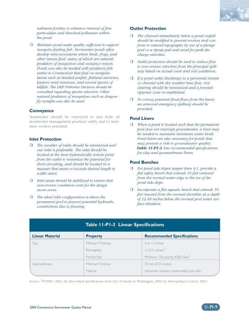
2004 Connecticut Stormwater Quality Manual 11-PI-9
sediment forebay to enhance removal of fineparticulates and dissolved pollutants within the pond.
❍ Maintain pond water quality sufficient to supportmosquito-feeding fish. Stormwater ponds oftendevelop mini-ecosystems where birds, frogs, andother insects feed, many of which are naturalpredators of mosquitoes and nuisance insects.Ponds can also be stocked with predatory fishnative to Connecticut that feed on mosquito larvae such as banded sunfish, flathead minnows,Eastern mud minnows, and several species ofkillfish. The DEP Fisheries Division should beconsulted regarding species selection. Other natural predators of mosquitoes such as dragon-fly nymphs can also be used.
Conveyance Stormwater should be conveyed to and from allstormwater management practices safely and to mini-mize erosion potential.
Inlet Protection❍ The number of inlets should be minimized and
one inlet is preferable. The inlet should belocated at the most hydraulically remote pointfrom the outlet to minimize the potential forshort-circuiting, and should be located in amanner that meets or exceeds desired length towidth ratios.
❍ Inlet areas should be stabilized to ensure thatnon-erosive conditions exist for the design storm event.
❍ The ideal inlet configuration is above the permanent pool to prevent potential hydraulicconstrictions due to freezing.
Outlet Protection
❍ The channel immediately below a pond outfallshould be modified to prevent erosion and con-form to natural topography by use of a plungepool or a riprap pad and sized for peak dis-charge velocities.
❍ Outlet protection should be used to reduce flowto non-erosive velocities from the principal spill-way based on actual cover and soil conditions.
❍ If a pond outlet discharges to a perennial streamor channel with dry weather base flow, treeclearing should be minimized and a forestedriparian zone re-established.
❍ To convey potential flood flows from the basin,an armored emergency spillway should be provided.
Pond Liners❍ When a pond is located such that the permanent
pool does not intercept groundwater, a liner maybe needed to maintain minimum water levels.Pond liners are also necessary for ponds thatmay present a risk to groundwater quality.Table 11-P1-3 lists recommended specificationsfor clay and geomembrane liners.
Pond Benches❍ For pond side slopes steeper than 4:1, provide a
flat safety bench that extends 10 feet outwardfrom the normal water edge to the toe of thepond side slope.
❍ Incorporate a flat aquatic bench that extends 10feet inward from the normal shoreline at a depthof 12-18 inches below the normal pool water sur-face elevation.
Linear Material Property Recommended Specifications
Clay Minimum Thickness 6 to 12 inches
Permeability 1x10⁻⁵ cm/sec1
Particle Size Minimum 15% passing #200 sieve1
Geomembrane Minimum Thickness 30 mils (0.03 inches)
Material Ultraviolet resistant, impermeable poly-liner
Table 11-P1-3 Linear Specifications
Source: 1NYDEC, 2001; all other listed specifications from City of Austin in Washington, 2000 (in Metropolitan Council, 2001).
2004 Connecticut Stormwater Quality Manual11-PI-10
Maintenance Reduction FeaturesIn addition to regular maintenance activities needed tomaintain the function of stormwater practices, somedesign features can be incorporated to ease the main-tenance burden of each practice. In wet ponds,maintenance reduction features include techniques to reduce the amount of maintenance needed, as wellas techniques to make regular maintenance activitieseasier.
❍ Ponds should be designed with non-clogging out-lets, such as a weir, or by incorporating trashracks for culverts and orifice openings.
❍ To prevent clogging from ice or floatables, areverse slope outlet pipe can be used to drawwater from below the permanent pool up to theoutlet structure. The invert of the pipe drawingfrom the pool should be at least 18 inches fromthe bottom to prevent sediment discharge.
❍ No orifice should be less than 6 inches in diameter with a trash rack to prevent clogging.
❍ Ponds should have a manually operated drain to draw down the pond for infrequent mainte-nance or dredging of the main cell of the pond.
❍ Metal components of outlet structures should becorrosion resistant, but not galvanized due to the contribution of zinc to water.
❍ Outlet structures should be resistant to frostheave and ice action in the pond.
Landscaping Constructing landscaped wet ponds can enhance theiraesthetic value. Aquatic plantings around the edge ofthe pond can provide pollutant uptake, stabilize thesoil at the edge of the pond, and improve habitat.Maintaining high vegetation along the edge of thepond (not mowing to the edge) can also deter water-fowl access and filter pollutants.
❍ Wetland plantings should be encouraged in apond design, either along the aquatic bench(fringe wetlands), the safety bench and sideslopes, or within shallow areas of the pool.
❍ The best depth for establishing wetland plants,either through transplantation or volunteer colo-nization, is within approximately six inches ofthe normal pool elevation.
❍ Soils should be modified (e.g., scarified or tilled)to mitigate compaction that occurs during con-struction around the proposed planting sites.
❍ Avoid species that require full shade, are suscep-tible to winterkill, or are prone to wind damage.
❍ Woody vegetation may not be planted or allowedto grow within 25 feet of the toe of the embank-ment and 25 feet from the principal spillwaystructure.
❍ Existing trees should be preserved in the bufferarea during construction. It is desirable to locateforest conservation areas adjacent to ponds. Tohelp discourage resident geese populations, the buffer can be planted with trees, shrubs, andnative ground covers.
❍ Annual mowing of the pond buffer is onlyrequired along maintenance rights-of-way andthe embankment. The remaining buffer can bemanaged as a meadow (mowing every otheryear) or forest.
❍ Plant the pond with salt-tolerant vegetation if thestormwater pond receives road runoff.
Cold Climate Pond Design ConsiderationsThe following design elements should be consideredto minimize potential performance impacts caused bycold weather:
❍ Inlet pipes should not be submerged, since thiscan result in freezing and upstream damage orflooding.
❍ Bury all pipes below the frost line to prevent frostheave and pipe freezing. Bury pipes at the pointfurthest from the pond deeper than the frost lineto minimize the length of pipe exposed.
❍ Increase the slope of inlet pipes to a minimum of1 percent, if site conditions allow, to preventstanding water in the pipe and reduce the poten-tial for ice formation.
❍ If perforated riser pipes are used, the minimumorifice diameter should be 0.5 inches. In addi-tion, the pipe should have a diameter of at least6 inches.
❍ When a standard weir is used, the minimum slotwidth should be 3 inches, especially when the slotis tall.
❍ Baffle weirs can prevent ice formation near theoutlet by preventing surface ice from blockingthe inlet, encouraging the movement of base flowthrough the system.
❍ In cold climates, riser hoods and reverse slopepipes should draw from at least 6 inches belowthe typical ice layer. This design encourages cir-culation in the pond, preventing stratificationand formation of ice at the outlet. Reverse slopepipes should not be used for off-line ponds.
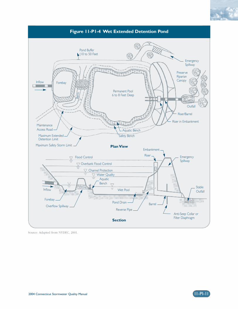
11-PI-11
Figure 11-P1-4 Wet Extended Detention Pond
Source: Adapted from NYDEC, 2001.
Permanent Pool6 to 8 Feet Deep
PreserveRiparianCanopy
Barrel
Outfall
Flood Control
Overbank Flood Control
Channel ProtectionWater Quality
ForebayInflow
Plan View
Section
Embankment
Reverse Pipe
Forebay
InflowStableOutfall
EmergencySpillway
EmergencySpillway
Maximum ExtendedDetention Limit
Riser
Overflow Spillway
Anti-Seep Collar orFilter Diaphragm
MaintenanceAccess Road Aquatic Bench
Safety Bench
Riser in Embankment
Riser/Barrel
Maximum Safety Storm Limit
Berm
Pond Buffer(10 to 50 Feet
Pond Drain
Wet Pool
AquaticBench
2004 Connecticut Stormwater Quality Manual
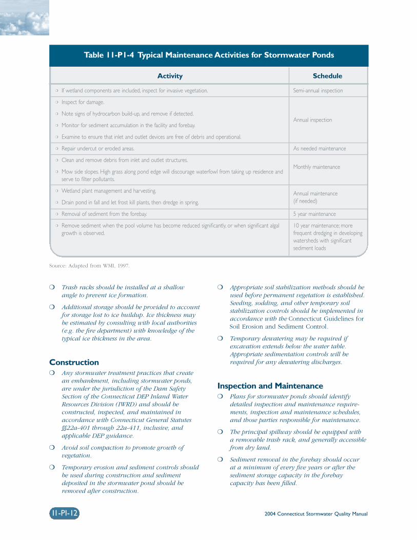
2004 Connecticut Stormwater Quality Manual
❍ Trash racks should be installed at a shallowangle to prevent ice formation.
❍ Additional storage should be provided to accountfor storage lost to ice buildup. Ice thickness maybe estimated by consulting with local authorities(e.g. the fire department) with knowledge of thetypical ice thickness in the area.
Construction❍ Any stormwater treatment practices that create
an embankment, including stormwater ponds,are under the jurisdiction of the Dam SafetySection of the Connecticut DEP Inland WaterResources Division (IWRD) and should be constructed, inspected, and maintained inaccordance with Connecticut General Statutes§§22a-401 through 22a-411, inclusive, andapplicable DEP guidance.
❍ Avoid soil compaction to promote growth of vegetation.
❍ Temporary erosion and sediment controls shouldbe used during construction and sedimentdeposited in the stormwater pond should beremoved after construction.
❍ Appropriate soil stabilization methods should beused before permanent vegetation is established.Seeding, sodding, and other temporary soil stabilization controls should be implemented inaccordance with the Connecticut Guidelines forSoil Erosion and Sediment Control.
❍ Temporary dewatering may be required if excavation extends below the water table.Appropriate sedimentation controls will berequired for any dewatering discharges.
Inspection and Maintenance❍ Plans for stormwater ponds should identify
detailed inspection and maintenance require-ments, inspection and maintenance schedules,and those parties responsible for maintenance.
❍ The principal spillway should be equipped with a removable trash rack, and generally accessiblefrom dry land.
❍ Sediment removal in the forebay should occur at a minimum of every five years or after thesediment storage capacity in the forebay capacity has been filled.
11-PI-12
Activity Schedule
❍ If wetland components are included, inspect for invasive vegetation.
❍ Inspect for damage.
❍ Note signs of hydrocarbon build-up, and remove if detected.
❍ Monitor for sediment accumulation in the facility and forebay.
❍ Examine to ensure that inlet and outlet devices are free of debris and operational.
❍ Repair undercut or eroded areas.
❍ Clean and remove debris from inlet and outlet structures.
❍ Mow side slopes. High grass along pond edge will discourage waterfowl from taking up residence andserve to filter pollutants.
❍ Wetland plant management and harvesting.
❍ Drain pond in fall and let frost kill plants, then dredge in spring.
❍ Removal of sediment from the forebay.
❍ Remove sediment when the pool volume has become reduced significantly, or when significant algalgrowth is observed.
Semi-annual inspection
Annual inspection
As needed maintenance
Monthly maintenance
Annual maintenance(if needed)
5 year maintenance
10 year maintenance; more frequent dredging in developingwatersheds with significant sediment loads
Table 11-P1-4 Typical Maintenance Activities for Stormwater Ponds
Source: Adapted from WMI, 1997.
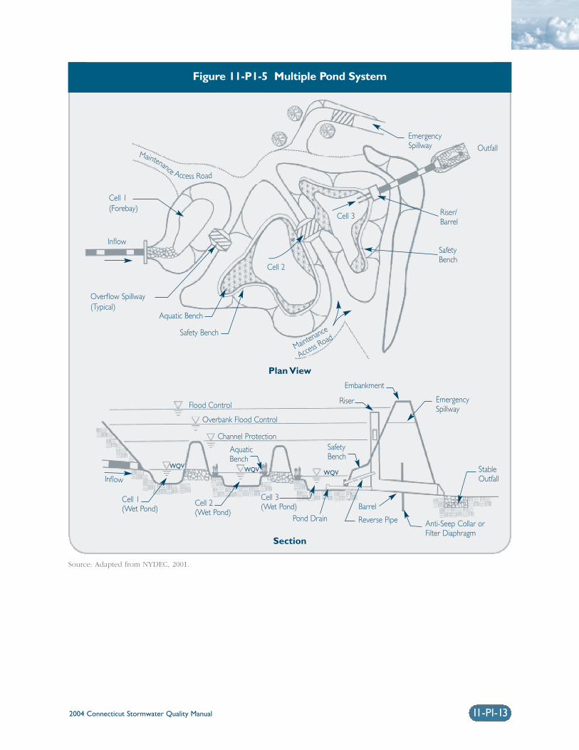
2004 Connecticut Stormwater Quality Manual 11-PI-13
Figure 11-P1-5 Multiple Pond System
Source: Adapted from NYDEC, 2001.
Maintenance
Access Road
Safety Bench
AquaticBench
Riser
Outfall
Flood Control
Overbank Flood Control
Channel Protection
Inflow
Plan View
Section
Embankment
InflowStableOutfall
EmergencySpillway
EmergencySpillway
Anti-Seep Collar orFilter Diaphragm
Reverse PipePond Drain
Cell 3(Wet Pond)
WQV WQV
SafetyBench
Cell 2(Wet Pond)
Cell 1(Wet Pond) Barrel
WQV
Aquatic Bench
Overflow Spillway(Typical)
Cell 1(Forebay)
Maintenance Access Road
Cell 2
Cell 3 Riser/Barrel
SafetyBench
2004 Connecticut Stormwater Quality Manual11-PI-14
❍ Sediment removed from stormwater pondsshould be disposed of according to anapproved comprehensive operation andmaintenance plan.
❍ Recommended maintenance activities forstormwater ponds are summarized in Table 11-P1-4.
Maintenance Access❍ A maintenance right-of-way or easement should
extend to the pond from a public road.
❍ Maintenance access should be at least 12 feetwide, have a maximum slope of no more than15 percent, and be appropriately stabilized towithstand maintenance equipment and vehicles.
❍ The maintenance access should extend to theforebay, safety bench, riser, and outlet and bedesigned to allow vehicles to turn around.
Non-clogging Low Flow Orifice❍ A low flow orifice shall be provided, with the size
of the orifice sufficient to ensure that no cloggingwill occur.
❍ The low flow orifice should be adequately pro-tected from clogging by either an acceptableexternal trash rack (recommended minimumorifice of 6 inches) or by internal orifice protec-tion that may allow for smaller diameters(minimum of 1 inch).
❍ The preferred method is a submerged reverse-slope pipe that extends downward from the riserto an inflow point one foot below the normalpool elevation.
❍ Alternative methods are to employ a broadcrested rectangular, V-notch, or proportionalweir, protected by a half-round pipe that extendsat least 12 inches below the normal pool level.
❍ The use of horizontally extended perforated pipeprotected by geotextile fabric and gravel is notrecommended. Vertical pipes may be used as analternative if a permanent pool is present.
Riser in Embankment❍ The riser must be located within the embank-
ment for maintenance access, safety andaesthetics.
❍ Lockable manhole covers and manhole stepswithin easy reach of valves and other controlsshould provide access to the riser. The principalspillway opening should be “fenced” with pipe at8-inch intervals for safety purposes.
Pond Drain❍ Except where local slopes prohibit this design,
each pond should have a drain pipe that cancompletely or partially drain the pond. Thedrain pipe shall have an elbow or protectedintake within the pond to prevent sediment depo-sition in the pipe, and a diameter capable ofdraining the pond within 24 hours.
❍ Pond retention times can be increased toenhance water quality control during stormevents by maintaining ponds at low levels beforestorms and increasing the available pond volumeduring storms.
❍ Care should be exercised during pond drainingto prevent rapid drawdown and minimizedownstream discharge of sediments or anoxicwater. The approving jurisdiction should be notified before draining a pond.
Adjustable Gate Valve❍ Both the WQV extended detention pipe and the
pond drain may be equipped with an adjustablegate valve, typically a handwheel activated knifegate valve.
❍ Valves should be located inside of the riser at apoint where they will not normally be inundatedand can be operated in a safe manner.
❍ Both the WQV extended detention pipe and thepond drain should be sized one pipe size greaterthan the calculated design diameter.
❍ To prevent vandalism, the handwheel should bechained to a ringbolt, manhole step, or otherfixed object.
2004 Connecticut Stormwater Quality Manual
Safety Features❍ Side slopes to the pond should not exceed 3:1
and should terminate at a safety bench.
❍ The principal spillway opening must not permitaccess by small children, and endwalls abovepipe outfalls greater than 48 inches in diametermust be fenced to prevent a hazard.
❍ Both the safety bench and the aquatic benchmay be landscaped to prevent access to the pool.
❍ Warning signs prohibiting swimming and skatingshould be posted.
❍ Pond fencing is generally not encouraged, butmay be required by some municipalities. Thepreferred method is to grade the pond to elimi-nate dropoffs or other safety hazards.
Cost Considerations Wet ponds are relatively inexpensive stormwater prac-tices, but costs vary widely depending on thecomplexity of the design or difficulty of site con-straints. The costs of stormwater ponds may beestimated using the following equation (Brown andSchueler, 1997):
C = 24.5V 0.705
where: C = Construction, design, and permitting cost. V = Volume in the pond to include the
10-year storm (ft3).
Costs should be adjusted for inflation to reflect currentcosts. The annual cost of routine maintenance is typi-cally estimated at about 3 to 5 percent of theconstruction cost (EPA Wet Pond Fact Sheet,http://www.epa.gov/npdes/menuofbmps/menu.htm).Ponds typically have a design life longer than twentyyears.
ReferencesBrown, W. and Shueler, T. 1997. The Economics ofStormwater BMPs in the Mid-Atlantic Region. Centerfor Watershed Protection. Elliot City, MD.
Galli, F. 1990. Thermal Impacts Associated withUrbanization and Stormwater Best ManagementPractices. Metropolitan Washington Council ofGovernments. Prepared for: Maryland Department ofthe Environment. Baltimore, MD.
Metropolitan Council. 2001. Minnesota Urban SmallSites BMP Manual: Stormwater Best ManagementPractices for Cold Climates. Prepared by BarrEngineering Company. St. Paul, Minnesota.
New York State Department of EnvironmentalConservation (NYDEC). 2001. New York StateStormwater Management Design Manual. Preparedby Center for Watershed Protection. Albany, NewYork.
Oberts, G. 1994. Performance of Stormwater Pondsand Wetlands in Winter. Watershed ProtectionTechniques 1(2): 64-68.
Schueler, T. 1997. Influence of Groundwater onPerformance of Stormwater Ponds in Florida.Watershed Protection Techniques 2(4): 525-528.
United States[E1] Environmental Protection Agency(EPA). 2002. National Menu of Best ManagementPractices for Stormwater Phase II. URL:http://www.epa.gov/npdes/menuofbmps/menu.htm,Last Modified January 24, 2002.
Washington State Department of Ecology(Washington). 2000. Stormwater ManagementManual for Western Washington, Final Draft.Olympia, Washington.
Watershed Management Institute (WMI). 1997.Operation, Maintenance, and Management ofStormwater Management Systems. Prepared for U.S.Environmental Protection Agency. Office of Water.Washington, D.C.
11-PI-15
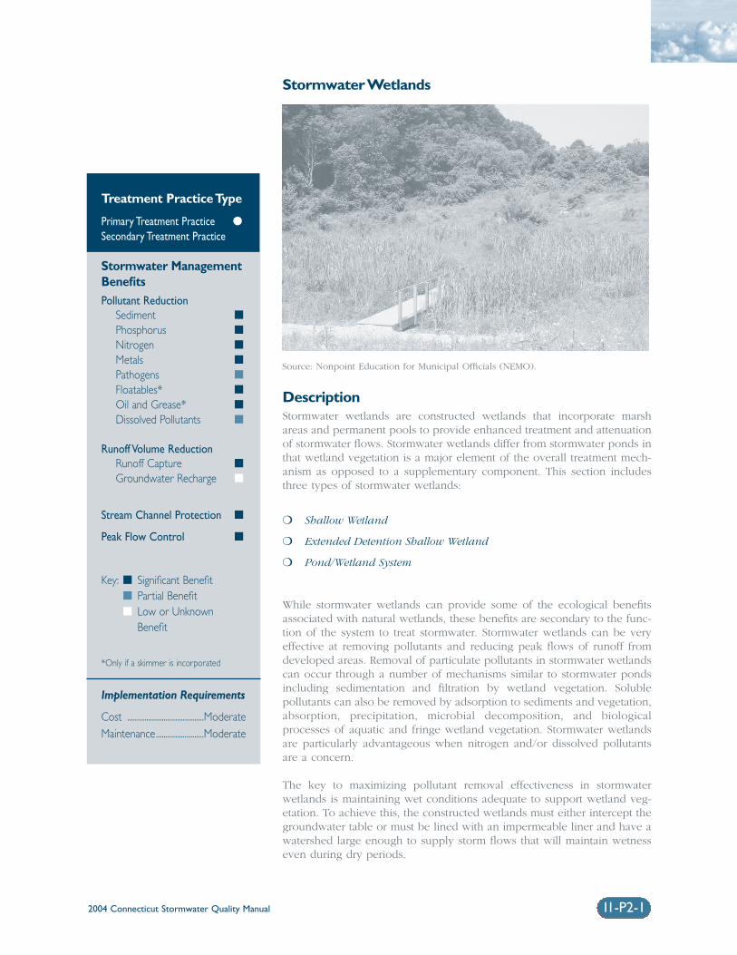
2004 Connecticut Stormwater Quality Manual 11-P2-1
Stormwater Wetlands
DescriptionStormwater wetlands are constructed wetlands that incorporate marshareas and permanent pools to provide enhanced treatment and attenuationof stormwater flows. Stormwater wetlands differ from stormwater ponds inthat wetland vegetation is a major element of the overall treatment mech-anism as opposed to a supplementary component. This section includesthree types of stormwater wetlands:
❍ Shallow Wetland
❍ Extended Detention Shallow Wetland
❍ Pond/Wetland System
While stormwater wetlands can provide some of the ecological benefitsassociated with natural wetlands, these benefits are secondary to the func-tion of the system to treat stormwater. Stormwater wetlands can be veryeffective at removing pollutants and reducing peak flows of runoff fromdeveloped areas. Removal of particulate pollutants in stormwater wetlandscan occur through a number of mechanisms similar to stormwater pondsincluding sedimentation and filtration by wetland vegetation. Soluble pollutants can also be removed by adsorption to sediments and vegetation,absorption, precipitation, microbial decomposition, and biologicalprocesses of aquatic and fringe wetland vegetation. Stormwater wetlandsare particularly advantageous when nitrogen and/or dissolved pollutantsare a concern.
The key to maximizing pollutant removal effectiveness in stormwater wetlands is maintaining wet conditions adequate to support wetland veg-etation. To achieve this, the constructed wetlands must either intercept thegroundwater table or must be lined with an impermeable liner and have awatershed large enough to supply storm flows that will maintain wetnesseven during dry periods.
Treatment Practice Type
Primary Treatment Practice �
Secondary Treatment Practice
Stormwater ManagementBenefitsPollutant Reduction
Sediment �
Phosphorus �
Nitrogen �
Metals �
Pathogens �
Floatables* �
Oil and Grease* �
Dissolved Pollutants �
Runoff Volume ReductionRunoff Capture �
Groundwater Recharge �
Stream Channel Protection �
Peak Flow Control �
Key: � Significant Benefit� Partial Benefit� Low or Unknown
Benefit
*Only if a skimmer is incorporated
Implementation Requirements
Cost ........................................ModerateMaintenance.........................Moderate
Source: Nonpoint Education for Municipal Officials (NEMO).
2004 Connecticut Stormwater Quality Manual11-P2-2
Stormwater wetland systems should be designed tooperate on the plug flow principle where incomingwater displaces the water retained in the system fromthe previous storm event. This is accomplished bymaximizing length versus width ratios and/or by creating distinct cells along the treatment path.Ideally, the wetland system would be designed toretain the water quality volume (WQV) betweenstorm events. As a result, storms that generate runoffless than the WQV would be entirely retained whileonly a percentage of the runoff from storms that gen-erate more than the WQV would be retained. Thevalue provided by this process is that a portion of the“new” polluted runoff is retained, and the “old”treated water is discharged from the wetland, therebyallowing extended treatment of the WQV.
Stormwater wetlands should be equipped with a sediment forebay or similar form of pretreatment tominimize the discharge of sediment to the primarytreatment wetland. High solids loadings to the systemwill degrade system performance and result in morefrequent cleaning, which could result in additionaldisturbance to the wetland vegetation. A micropool orpermanent pool is often included just prior to the discharge for additional solids removal.
Design VariationsThere are several common stormwater wetlanddesign variations. The various designs are character-ized by the volume of the wetland in the deep pool,high marsh, and low marsh zones, and whether thedesign allows for detention of small storms above thepermanent pool.
Shallow Wetland: Most shallow wetland systems,also referred to as shallow marsh wetlands, consist ofaquatic vegetation with a permanent pool rangingfrom 6 to 18 inches during normal conditions.Shallow wetlands are designed such that flow throughthe wetlands is conveyed uniformly across the treat-ment area. While pathways, streams or other variedwater depths could enhance the aesthetic or ecosys-tem value of the wetland, they could also causeshort-circuiting through the wetland thereby reducingthe overall treatment effectiveness. As a result, tomaximize treatment performance, providing a uni-formly sloped system is recommended. In order toenhance plug flow conditions across the wetland,individual wetland cells can be constructed and sepa-rated by weirs. Figure 11-P2-1 depicts a typicalschematic design of a shallow wetland.
Extended Detention Shallow Wetland: Extendeddetention shallow wetlands provide a greater degreeof downstream channel protection as they aredesigned with more vertical storage capacity. The
additional vertical storage volume also provides extrarunoff detention above the normal pool elevations.Water levels in the extended detention shallow wet-land may increase by as much as three feet after astorm event and return gradually to pre-storm eleva-tions within 24 hours of the storm event. The growingarea in extended detention shallow wetlands extendsfrom the normal pool elevation to the maximumwater surface elevation. Wetland plants that tolerateintermittent flooding and dry periods should beselected for the extended detention area above theshallow marsh elevations. Figure 11-P2-2 depicts atypical schematic design of an extended detentionshallow wetland.
Pond/Wetland Systems: Multiple cell systems, suchas pond/wetland systems, utilize at least one pondcomponent in conjunction with a shallow marshcomponent. The first cell is typically a wet pond,which provides pretreatment of the runoff by remov-ing particulate pollutants. The wet pond is also usedto reduce the velocity of the runoff entering the sys-tem. The shallow marsh then polishes the runoff,particularly for soluble pollutants, prior to discharge.These systems require less space than the shallowmarsh systems since more of the water volume isstored in the deep pool which can be designed toreduce peak flows. Because of this system’s ability tosignificantly reduce the velocity and volume ofincoming peak flows (i.e., flow equalization or damp-ening), it can often achieve higher pollutant removalrates than other similarly sized stormwater wetlandsystems. Figure 11-P2-3 depicts a typical schematicdesign of a pond/wetland system.
Advantages❍ Efficient at removing both particulate and solu-
ble pollutants.
❍ Capable of providing aesthetic benefits.
❍ Capable of providing wildlife habitat withappropriate design elements.
❍ Provide ability to attenuate peak runoff flows.
Limitations❍ More costly than extended detention basins.
❍ Require a relatively large land area that isdirectly proportional to the size of the contribut-ing drainage area.
❍ Very sensitive to the ability to maintain wet con-ditions especially during extended dry weatherwhen there may be significant evaporative losses.
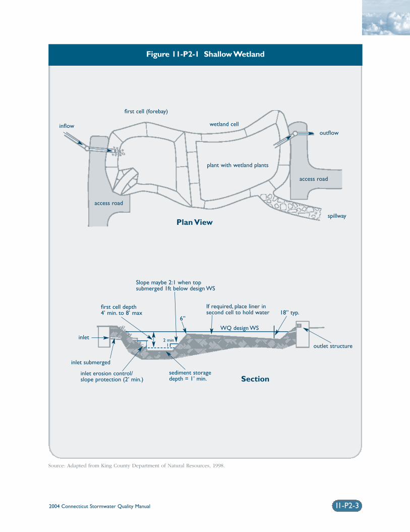
2004 Connecticut Stormwater Quality Manual 11-P2-3
Figure 11-P2-1 Shallow Wetland
Source: Adapted from King County Department of Natural Resources, 1998.
first cell (forebay)
wetland celloutflow
access road
access road
inflow
spillway
inlet submerged
inlet erosion control/slope protection (2’ min.)
sediment storage depth = 1’ min.
Slope maybe 2:1 when top submerged 1ft below design WS
If required, place liner insecond cell to hold water
inlet
first cell depth4’ min. to 8’ max
outlet structure
18” typ.6”
2 min1
WQ design WS
plant with wetland plants
Plan View
Section
2004 Connecticut Stormwater Quality Manual11-P2-4
❍ May cause thermal impacts to receiving watersand thereby should not discharge directly to coldwater fish habitats.
❍ Potential breeding habitat for mosquitoes, particularly for systems with isolated pockets ofstanding water (standing longer than 5 days).Circulating water in the permanent pool mayminimize this problem. This may be a more significant problem for lined systems.
❍ Wetland systems with steep side slopes and/ordeep wet pools may present a safety issue tonearby pedestrians.
❍ Stormwater wetlands can serve as decoy wet-lands, intercepting breeding amphibians movingtoward vernal pools. If amphibians deposit theireggs in these artificial wetlands, they rarely sur-vive due to the sediment and pollutant loads, aswell as fluctuations in water quality, quantity,and temperature.
Siting ConsiderationsDrainage Area: Stormwater wetlands that utilize aliner system to maintain the desired permanent poolshould have a contributing drainage area that is adequate to maintain minimum water levels.Typically, minimum contributing drainage areas aretwenty-five acres, especially for shallow systems. Awater budget for the wetlands should be calculated toensure that evaporation losses do not exceed inflowsduring warm weather months.
Groundwater: Unlined basins must intersect thegroundwater table in order to maintain the desiredpermanent pool. In this case, the elevations of thebasin should be established such that the ground-water elevation is equal to the desired permanentpool elevation. Seasonal variations of groundwaterelevations should be considered, which can be verypronounced in low permeability soils.
Land Uses: Land uses will dictate potential pollutants-of-concern and potential safety risks. For those landuses where there is significant potential for solublepollutants, especially those that are highly susceptibleto groundwater transport, the use of a liner is recommended. An impermeable liner may not berequired, depending on the risk of downgradient con-tamination, but a low permeable liner constructed intill soils may be acceptable. Adjacent residential landuses pose the greatest public safety risks where mos-quito breeding and water hazards must be considered.
Baseflow: A small amount of baseflow is desirable tomaintain circulation and reduce the potential for lowdissolved oxygen levels during late summer, and toreduce mosquito breeding. This baseflow can be pro-vided by groundwater infiltrating into either thewetland or the collection system above the pond.
Site Slopes: Steep on-site slopes may result in theneed for a large embankment to be constructed toprovide the desired storage volume and could requirea dam construction permit from the Connecticut DEP. Steep slopes may also present design and construction challenges, and significantly increase thecost of earthwork.
Receiving Waters: The sensitivity of receiving watersshould be evaluated to determine whether the effectsof the warmer stormwater discharges from the wetland could be detrimental to cold-water fish orother sensitive aquatic species.
Flood Zones: Constructed wetlands should not belocated in floodways, floodplains, or tidal lands, espe-cially those that require construction of anembankment. Floodwaters could flush out stored pol-lutants or damage pond embankments.
Natural Wetlands/Vernal Pools: Natural wetlandsand vernal pool depressions should not be used,either temporarily or permanently, as a stormwaterpond or wetland. Stormwater wetlands should belocated at least 750 feet from a vernal pool. Theyshould not be sited between vernal pools or in areasthat are known primary amphibian overland migrationroutes.
Design CriteriaWetland designs may vary considerably due to siteconstraints, local requirements, or the designer’s pref-erences. The five common design elements thatshould be considered for all stormwater wetlands are:
❍ Pretreatment
❍ Treatment
❍ Conveyance
❍ Maintenance reduction
❍ Landscaping
Design considerations for stormwater wetlands arepresented below and summarized in Table 11-P2-1.
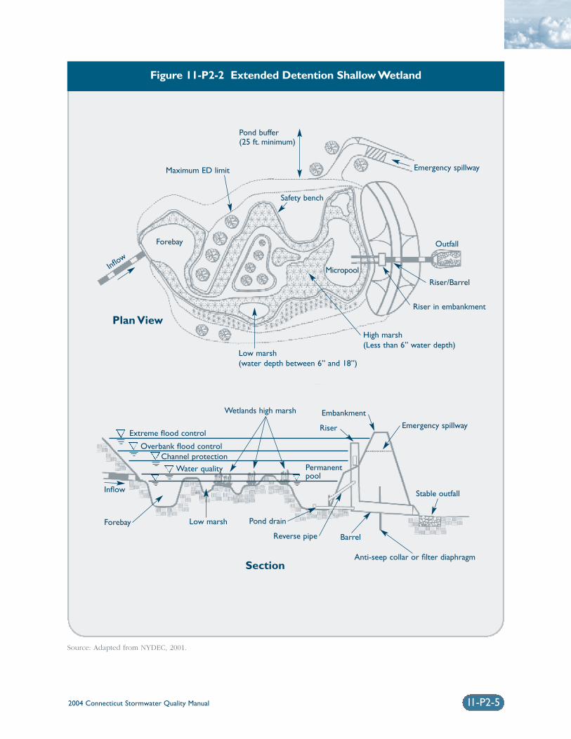
2004 Connecticut Stormwater Quality Manual 11-P2-5
Figure 11-P2-2 Extended Detention Shallow Wetland
Source: Adapted from NYDEC, 2001.
Maximum ED limit
Riser in embankment
Riser/Barrel
Outfall
Emergency spillway
Safety bench
Forebay
MicropoolInflow
Pond buffer (25 ft. minimum)
High marsh(Less than 6” water depth)
Low marsh(water depth between 6” and 18”)
Extreme flood control
Wetlands high marsh
Emergency spillway
Stable outfall
Barrel
Pond drainLow marshForebay
Inflow
Reverse pipe
Embankment
Riser
Overbank flood controlChannel protection
Water quality
Anti-seep collar or filter diaphragm
Permanentpool
Section
Plan View
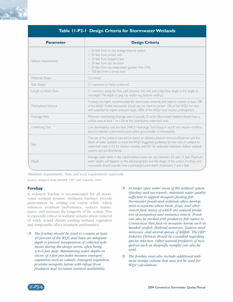
2004 Connecticut Stormwater Quality Manual11-P2-6
ForebayA sediment forebay is recommended for all storm-water wetland systems. Sediment forebays providepretreatment by settling out coarse solids, whichenhances treatment performance, reduces mainte-nance, and increases the longevity of the system. Thisis especially critical in wetland systems where removalof solids would disturb existing wetland vegetationand temporarily affect treatment performance.
❍ The forebay should be sized to contain at least10 percent of the WQV and have an adequatedepth to prevent resuspension of collected sedi-ments during the design storm, often being 4 to 6 feet deep. Maintaining water depths inexcess of 4 feet precludes invasive emergent vegetation such as cattails. Emergent vegetationprovides mosquito larvae with refuge from predators and increases nutrient availability.
❍ In larger open water areas of the wetland system(forebay and micropool), maintain water qualitysufficient to support mosquito-feeding fish.Stormwater ponds and wetlands often developmini-ecosystems where birds, frogs, and otherinsects feed, many of which are natural preda-tors of mosquitoes and nuisance insects. Pondscan also be stocked with predatory fish native toConnecticut that feed on mosquito larvae such asbanded sunfish, flathead minnows, Eastern mudminnows, and several species of killfish. The DEPFisheries Division should be consulted regardingspecies selection. Other natural predators of mos-quitoes such as dragonfly nymphs can also beused.
❍ The forebay must also include additional sedi-ment storage volume that may not be used forWQV calculations.
1Minimum requirements. State and local requirements supercede.
Source: Adapted from MADEP, 1997 and Schueler, 1992.
Parameter Design Criteria
Setback requirements1
Preferred Shape
Side Slopes
Length to Width Ratio
Pretreatment Volume
Drainage Area
Underlying Soils
Size
Depth
❍ 50 feet from on-site sewage disposal system❍ 50 feet from private well❍ 10 feet from property line❍ 20 feet from any structure❍ 50 feet from any steep slope (greater than 15%)❍ 750 feet from a vernal pool
Curvilinear
3:1 maximum or flatter preferred
3:1 minimum along the flow path between the inlet and outlet; flow length is the length atmid-depth. Mid-depth is (avg. top width+avg. bottom width)/2
Forebays are highly recommended for stormwater wetlands and sized to contain at least 10%of the WQV. Outlet micropools should also be sized to contain 10% of the WQV. For siteswith potential for higher pollutant loads, 100% of the WQV must receive pretreatment.
Minimum contributing drainage area is typically 25 acres. Stormwater wetland should have asurface area at least 1 to 1.5% of the contributing watershed area.
Low permeability soils are best (NRCS Hydrologic Soil Group A and B soils require modifica-tions to maintain a permanent pool unless groundwater is intercepted).
The size of the wetland area will be based on desired pollutant removal efficiencies and thedepth of water available to store the WQV. Suggested guidelines for the ratio of wetland towatershed areas is 0.2 for shallow marshes and 0.01 for extended detention shallow wetlandsystems and pond/wetlands.
Average water levels in the marsh/wetland areas can vary between 0.5 and 1.5 feet. Maximumwater depths will depend on the site topography and the design of the system. Forebays andmicropools should typically have a permanent pool depth of between 4 and 6 feet.
Table 11-P2-1 Design Criteria for Stormwater Wetlands
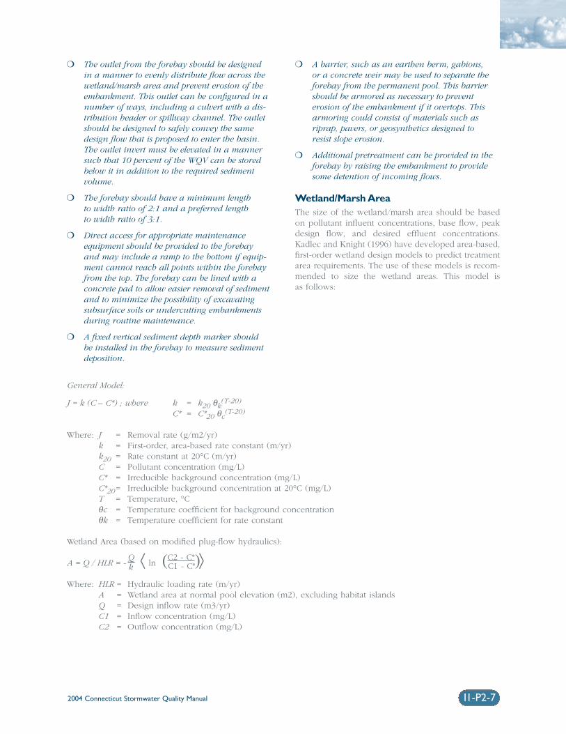
2004 Connecticut Stormwater Quality Manual 11-P2-7
❍ The outlet from the forebay should be designedin a manner to evenly distribute flow across thewetland/marsh area and prevent erosion of theembankment. This outlet can be configured in anumber of ways, including a culvert with a dis-tribution header or spillway channel. The outletshould be designed to safely convey the samedesign flow that is proposed to enter the basin.The outlet invert must be elevated in a mannersuch that 10 percent of the WQV can be storedbelow it in addition to the required sediment volume.
❍ The forebay should have a minimum length to width ratio of 2:1 and a preferred length to width ratio of 3:1.
❍ Direct access for appropriate maintenanceequipment should be provided to the forebayand may include a ramp to the bottom if equip-ment cannot reach all points within the forebayfrom the top. The forebay can be lined with aconcrete pad to allow easier removal of sedimentand to minimize the possibility of excavatingsubsurface soils or undercutting embankmentsduring routine maintenance.
❍ A fixed vertical sediment depth marker should be installed in the forebay to measure sedimentdeposition.
❍ A barrier, such as an earthen berm, gabions, or a concrete weir may be used to separate theforebay from the permanent pool. This barriershould be armored as necessary to prevent erosion of the embankment if it overtops. Thisarmoring could consist of materials such asriprap, pavers, or geosynthetics designed to resist slope erosion.
❍ Additional pretreatment can be provided in theforebay by raising the embankment to providesome detention of incoming flows.
Wetland/Marsh Area The size of the wetland/marsh area should be basedon pollutant influent concentrations, base flow, peakdesign flow, and desired effluent concentrations.Kadlec and Knight (1996) have developed area-based,first-order wetland design models to predict treatmentarea requirements. The use of these models is recom-mended to size the wetland areas. This model is as follows:
J = k (C – C*) ; where k = k20 θk(T-20)
C* = C*20 θc(T-20)
Where: J = Removal rate (g/m2/yr)k = First-order, area-based rate constant (m/yr)k20 = Rate constant at 20°C (m/yr)C = Pollutant concentration (mg/L)C* = Irreducible background concentration (mg/L)C*20= Irreducible background concentration at 20°C (mg/L)T = Temperature, °Cθc = Temperature coefficient for background concentrationθk = Temperature coefficient for rate constant
Wetland Area (based on modified plug-flow hydraulics):
A = Q / HLR = -Q ⟨ ln (C2 - C*)⟩k C1 - C*
Where: HLR = Hydraulic loading rate (m/yr)A = Wetland area at normal pool elevation (m2), excluding habitat islandsQ = Design inflow rate (m3/yr)C1 = Inflow concentration (mg/L)C2 = Outflow concentration (mg/L)
General Model:
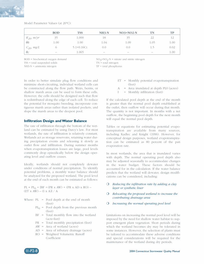
2004 Connecticut Stormwater Quality Manual11-P2-8
In order to better simulate plug flow conditions andminimize short-circuiting, individual wetland cells canbe constructed along the flow path. Weirs, berms, orshallow marsh areas can be used to form these cells.However, the cells should be designed such that flowis redistributed along the edge of each cell. To reducethe potential for mosquito breeding, incorporate con-tiguous marsh areas rather than isolated pockets, andslope the marsh areas to the deepest pool.
Infiltration Design and Water BalanceThe rate of infiltration through the bottom of the wet-land can be estimated by using Darcy’s law. For mostwetlands, the rate of infiltration is relatively constant.Wetlands act as storage reservoirs, retaining water dur-ing precipitation events and releasing it slowly asoutlet flow and infiltration. During summer monthswhen evapotranspiration losses are large, pool levelscommonly drop episodically below the design oper-ating level and outflow ceases.
Ideally, wetlands should not completely dewaterunder conditions of normal precipitation. To identifypotential problems, a monthly water balance shouldbe analyzed for the proposed wetland. The pool levelat the end of each month can be estimated as follows:
PL = PL0 + [BF + (PR x AW) + (PR x AD x RO) – (ET x AW) – (I x A)] / A
Where: PL = Pool depth at the end of month(feet)
PL0 = Pool depth from the previous month(feet)
BF = Total monthly flow into the wetland(acre-feet)
PR = Total monthly precipitation (feet)AW = Area of wetland (acres)AD = Area of tributary drainage (acres)RO = Weighted Volumetric Runoff
Coefficient
ET = Monthly potential evapotranspiration(feet)
A = Area inundated at depth PL0 (acres)I = Monthly infiltration (feet)
If the calculated pool depth at the end of the monthis greater than the normal pool depth established atthe outlet, then outflow will occur during that month.The quantity is not important. In months with a netoutflow, the beginning pool depth for the next monthwill equal the normal pool depth.
Tables or equations for estimating potential evapo-transpiration are available from many sources,including Kadlec and Knight (1996). However, forconceptual design purposes, wetland evapotranspira-tion can be estimated as 80 percent of the panevaporation rate.
In most wetlands, the area that is inundated varieswith depth. The normal operating pool depth alsomay be adjusted seasonally to accommodate changesin the water budget. These factors should beaccounted for in the calculation. If the water balancepredicts that the wetland will dewater, design modifi-cations can be considered, including:
❍ Reducing the infiltration rate by adding a claylayer or synthetic liner
❍ Relocating the proposed wetland to increase thecontributing drainage area
❍ Increasing the normal operating pool level
Limitations on increasing the normal pool level will beimposed by the need for shallow water habitat to sup-port emergent plant vegetation. Short periods duringwhich the wetland becomes dry may be tolerated insome instances. However, the selection of plants mustbe tailored to accommodate these adverse conditionsand special considerations will be required for themaintenance of the wetland during dry periods.
Model Parameter Values (at 20°C):
BOD TSS NH3-N NO3+NO2-N TN TP
K20, m/yr 35 1,000 18 35 22 12
θk 1.00 1.00 1.04 1.09 1.05 1.00
C20, mg/L 6 5.1+0.16C1 0.0 0.0 1.5 0.02
θc – 1.065 – – – 1.00
BOD = biochemical oxygen demand NO3+NO2-N = nitrate and nitrite nitrogenTSS = total suspended solids TN = total nitrogenNH3-N = ammonia nitrogen TP = total phosphorus
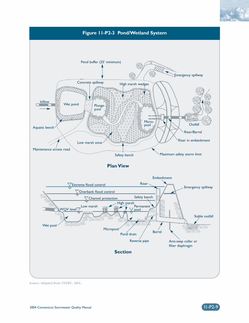
2004 Connecticut Stormwater Quality Manual 11-P2-9
Figure 11-P2-3 Pond/Wetland System
Source: Adapted from NYDEC, 2001.
Plan View
Section
Pond buffer (25’ minimum)
High marsh wedges
Aquatic benchOutfall
Concrete spillway
Low marsh zone
Safety bench
Riser/Barrel
Riser in embankment
Maintenance access roadMaximum safety storm limit
Plungepool
Micro-pool
InflowWet pond
Emergency spillway
Permanentpool
Embankment
Wet poolMicropool
Emergency spillwayExtreme flood control
Overbank flood control
Channel protection Safety bench
Stable outfall
High marsh
WQV levelLow marsh
Anti-seep collar orfilter diaphragm
Pond drain
Reverse pipe
Barrel
Riser
2004 Connecticut Stormwater Quality Manual11-P2-10
Conveyance Stormwater should be conveyed to and from all stormwater management practices safely and tominimize erosion potential.
Inlet Protection❍ The number of inlets should be minimized, and
one inlet is preferable. The inlet should belocated at the most hydraulically remote pointfrom the outlet, but in any case should belocated in a manner that meets or exceedsdesired length to width ratios.
❍ Inlet areas should be stabilized to ensure thatnon-erosive conditions exist for the design stormevent.
❍ The ideal inlet discharge configuration is abovethe permanent pool to prevent potentialhydraulic impacts from freezing.
Oulet Protection❍ The channel immediately below an outfall
should be modified to prevent erosion and conform to natural topography by use of aplunge pool or a riprap pad and sized for peak discharge velocities.
❍ Outlet protection should be used to reduce flow to non-erosive velocities from the principalspillway based on actual cover and soil condi-tions (3.5 to 5.0 ft/s).
❍ If a pond outlet discharges to a perennial streamor channel with dry weather base flow, treeclearing should be minimized and a forestedriparian zone re-established.
❍ To convey potential flood flows from the basin,an armored emergency spillway should beprovided.
Wetland LinersWhen the permanent pool does not intercept ground-water, a liner may be needed to maintain minimumwater levels. Liners are also necessary for wetland sys-tems that may present a risk to groundwater quality.Table 11-P2-2 lists recommended specifications forclay and geomembrane liners.
Pool BenchesThese specifications apply to permanent pools at thesediment forebay and micropool.
❍ For side slopes steeper than 4:1, provide a 10-footwide flat safety bench above the permanent poollevel.
VegetationHigh pollutant removal efficiencies are dependent ona dense cover of emergent plant vegetation. Actualplant species do not appear to be as important asplant growth habitat. In particular, use plants thathave high colonization and growth rates, can establishlarge surface areas that continue through the winterdormant season, have high potential for treating pol-lutants, and are very robust in flooded environments.Appendix A contains planting guidance for storm-water wetlands. Other landscaping criteria include thefollowing:
❍ Soils should be modified to mitigate compactionthat occurs during construction around the proposed planting sites.
❍ Woody vegetation may not be planted or allowedto grow within 25 feet of the toe of the embank-ment and 25 feet from the principal spillwaystructure.
❍ Existing trees should be preserved in the bufferarea during construction. It is desirable to locateforest conservation areas adjacent to ponds andwetlands. To help discourage resident geese pop-ulations, the buffer can be planted with trees,shrubs, and native ground covers.
❍ Annual mowing of the pond/wetland buffer isonly required along maintenance rights-of-wayand the embankment. The remaining buffer canbe managed as a meadow (mowing every otheryear) or forest.
Maintenance Reduction FeaturesIn addition to regular maintenance activities needed tomaintain the function of stormwater practices, somedesign features can be incorporated to ease the main-tenance burden of each practice. In constructedwetlands, maintenance reduction features includetechniques to reduce the amount of required mainte-nance, as well as techniques to make regularmaintenance activities easier.
❍ Outlets should be designed with non-cloggingfeatures, such as a weir, or by incorporatingtrash racks for culverts and orifice openings.
❍ To prevent clogging from ice or floatables, areverse slope outlet pipe can be used to drawwater from below the permanent pool up to theoutlet structure. The invert of the pipe drawingfrom the pool should be at least 18 inches fromthe bottom to prevent sediment discharge.
❍ Orifices should be no smaller than 6 inches in diameter, and have a trash rack to preventclogging.
2004 Connecticut Stormwater Quality Manual 11-P2-11
❍ Pools should have a manually operated drain todraw down the pond for infrequent mainte-nance or dredging of the main cell of the pond.
❍ Metal components of outlet structures should becorrosion resistant, but not galvanized due to thecontribution of zinc to water (Washington,2000).
❍ Outlet structures should be resistant to frostheave and ice action in the pond.
Cold Climate Design ConsiderationsThe following design elements should be consideredto minimize potential performance impacts caused bycold weather:
❍ Inlet pipes should not be submerged, since thiscan result in freezing and upstream damage orflooding.
❍ Bury pipes below the frost line to prevent frostheave and pipe freezing.
❍ To prevent standing water in the pipe and toreduce the potential for ice formation, increasethe slope of inlet pipes to a minimum of 1 per-cent, if site conditions allow.
❍ If perforated riser pipes are used, the minimumorifice diameter should be 0.5 inches. In addi-tion, the pipe should have a diameter of at least6 inches.
❍ When a standard weir is used, the minimum slotwidth should be 3 inches, especially when the slotis tall.
❍ Baffle weirs can prevent ice formation near theoutlet by preventing surface ice from blockingthe inlet, encouraging the movement of base flowthrough the system.
❍ Riser hoods and reverse slope pipes should drawfrom at least 6 inches below the typical ice layer.This design encourages circulation in the pond,preventing stratification and formation of ice atthe outlet. Reverse slope pipes should not be usedfor off-line ponds.
❍ Trash racks should be installed at a shallowangle to prevent ice formation.
❍ Additional storage should be provided to accountfor storage lost to ice buildup, especially in shal-low wetlands where much of the pool becomesfrozen. Ice thickness may be estimated by con-sulting with local authorities (the firedepartment, for example) with knowledge of thetypical ice thickness in the area.
Construction❍ Any stormwater treatment practices that create
an embankment, including stormwater wet-lands, are under the jurisdiction of the DamSafety Section of the Connecticut DEP InlandWater Resources Division (IWRD) and should be constructed, inspected, and maintained in accordance with CGS §§22a-401 through 22a-411, inclusive, and applicable DEP guidance.
❍ Avoid soil compaction to promote growth of vegetation.
❍ Temporary erosion and sediment controls shouldbe used during construction, and sedimentdeposited in the wetlands should be removedafter construction, but preferably before wetlandvegetation is planted.
❍ Temporary dewatering may be required if exca-vation extends below the water table. Appropriatesedimentation controls will be required for anydewatering discharges.
Linear Material Property Recommended Specifications
Clay Minimum Thickness 6 to 12 inches
Permeability 1x10⁻⁵ cm/sec1
Particle Size Minimum 15% passing #200 sieve1
Geomembrane Minimum Thickness 30 mils (0.03 inches)
Material Ultraviolet resistant, impermeable poly-liner
Table 11-P2-2 Stormwater Wetland Liner Specifications
Source: 1NYDEC, 2001; all other listed specifications from City of Austin in Washington, 2000 (in Metropolitan Council, 2001).
2004 Connecticut Stormwater Quality Manual11-P2-12
❍ Establishment of wetland plantings is critical. Asa result, installation should be as directed by abiologist or landscape architect.
Inspection and Maintenance❍ Plans for stormwater wetlands should identify
detailed inspection and maintenance require-ments, inspection and maintenance schedules,and those parties responsible for maintenance.
❍ The principal spillway should be equipped with aremovable trash rack, and generally accessiblefrom dry land.
❍ Sediment removal in the forebay and micropoolshould occur at a minimum of every five yearsor before the sediment storage capacity has beenfilled.
❍ Sediment removed should be disposed of accord-ing to an approved comprehensive operationand maintenance plan.
❍ Inspect twice per year for the first three years toevaluate plant sustainability, water levels, slopestability, and the outlet structure.
❍ Perform maintenance outside of vegetative grow-ing and wildlife seasons.
❍ Harvesting of dead plant material is notrequired except in cases where high pollutantremoval efficiencies, especially for nutrients, arerequired.
Maintenance Access
❍ A maintenance right of way or easement shouldextend to the wetland from a public road.
❍ Maintenance access should be at least 12 feetwide, have a maximum slope of no more than15 percent, and be appropriately stabilized towithstand maintenance equipment and vehicles.
❍ The maintenance access should extend to theforebay, safety bench, riser, and outlet and bedesigned to allow vehicles to turn around.
Non-clogging Low Flow Orifice
❍ A low flow orifice shall be provided, with the sizeof the orifice sufficient to ensure that no cloggingwill occur.
❍ The low flow orifice should be adequately pro-tected from clogging by either an acceptableexternal trash rack (recommended minimumorifice of 6 inches) or by internal orifice protec-tion that may allow for smaller diameters(minimum of 1 inch).
❍ The preferred method is a submerged reverse-slope pipe that extends downward from the riserto an inflow point one foot below the normalpool elevation.
❍ Alternative methods are to employ a broadcrested rectangular, V-notch, or proportionalweir, protected by a half-round pipe that extendsat least 12 inches below the normal pool level.
❍ The use of horizontally extended perforated pipeprotected by geotextile fabric and gravel is notrecommended. Vertical pipes may be used as analternative if a permanent pool is present.
Riser in Embankment
❍ The riser must be located within the embank-ment for maintenance access, safety, andaesthetics.
❍ Lockable manhole covers, and manhole stepswithin easy reach of valves and other controlsshould provide access to the riser. The principalspillway opening should be “fenced” with pipe at8-inch intervals for safety purposes.
Drain
❍ Except where local slopes prohibit this design,each wetland should have a drain pipe that cancompletely or partially drain the wetland. Thedrain pipe shall have an elbow or protectedintake within the pond to prevent sediment depo-sition, and a diameter capable of draining thepond within 24 hours.
❍ Care should be exercised during pond drainingto prevent rapid drawdown and minimizedownstream discharge of sediments or anoxicwater. The approving jurisdiction must be noti-fied before draining a pond.
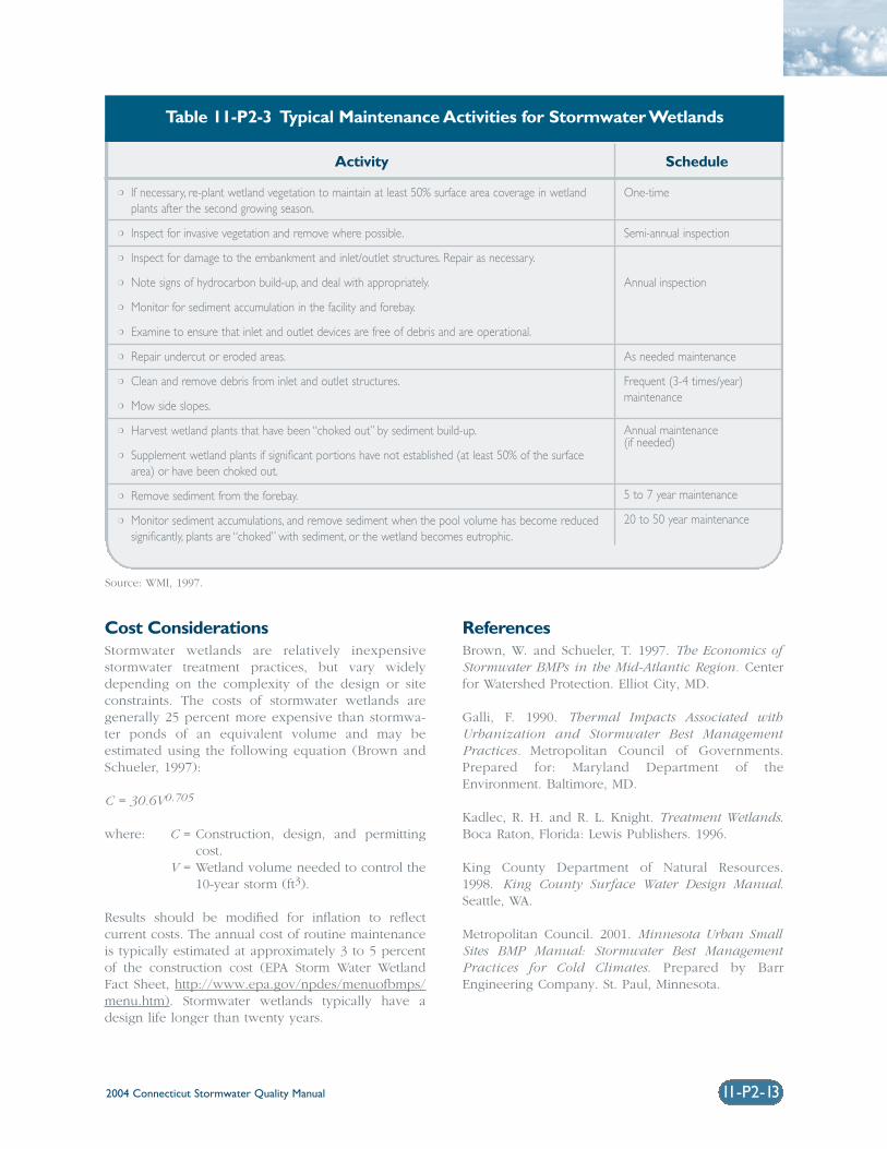
2004 Connecticut Stormwater Quality Manual 11-P2-13
Cost Considerations Stormwater wetlands are relatively inexpensivestormwater treatment practices, but vary widelydepending on the complexity of the design or siteconstraints. The costs of stormwater wetlands aregenerally 25 percent more expensive than stormwa-ter ponds of an equivalent volume and may beestimated using the following equation (Brown andSchueler, 1997):
C = 30.6V0.705
where: C = Construction, design, and permittingcost.
V = Wetland volume needed to control the10-year storm (ft3).
Results should be modified for inflation to reflect current costs. The annual cost of routine maintenanceis typically estimated at approximately 3 to 5 percentof the construction cost (EPA Storm Water WetlandFact Sheet, http://www.epa.gov/npdes/menuofbmps/menu.htm). Stormwater wetlands typically have adesign life longer than twenty years.
ReferencesBrown, W. and Schueler, T. 1997. The Economics ofStormwater BMPs in the Mid-Atlantic Region. Centerfor Watershed Protection. Elliot City, MD.
Galli, F. 1990. Thermal Impacts Associated withUrbanization and Stormwater Best ManagementPractices. Metropolitan Council of Governments.Prepared for: Maryland Department of theEnvironment. Baltimore, MD.
Kadlec, R. H. and R. L. Knight. Treatment Wetlands.Boca Raton, Florida: Lewis Publishers. 1996.
King County Department of Natural Resources. 1998. King County Surface Water Design Manual.Seattle, WA.
Metropolitan Council. 2001. Minnesota Urban SmallSites BMP Manual: Stormwater Best ManagementPractices for Cold Climates. Prepared by BarrEngineering Company. St. Paul, Minnesota.
Activity Schedule
❍ If necessary, re-plant wetland vegetation to maintain at least 50% surface area coverage in wetlandplants after the second growing season.
❍ Inspect for invasive vegetation and remove where possible.
❍ Inspect for damage to the embankment and inlet/outlet structures. Repair as necessary.
❍ Note signs of hydrocarbon build-up, and deal with appropriately.
❍ Monitor for sediment accumulation in the facility and forebay.
❍ Examine to ensure that inlet and outlet devices are free of debris and are operational.
❍ Repair undercut or eroded areas.
❍ Clean and remove debris from inlet and outlet structures.
❍ Mow side slopes.
❍ Harvest wetland plants that have been “choked out” by sediment build-up.
❍ Supplement wetland plants if significant portions have not established (at least 50% of the surfacearea) or have been choked out.
❍ Remove sediment from the forebay.
❍ Monitor sediment accumulations, and remove sediment when the pool volume has become reducedsignificantly, plants are “choked” with sediment, or the wetland becomes eutrophic.
One-time
Semi-annual inspection
Annual inspection
As needed maintenance
Frequent (3-4 times/year) maintenance
Annual maintenance (if needed)
5 to 7 year maintenance
20 to 50 year maintenance
Table 11-P2-3 Typical Maintenance Activities for Stormwater Wetlands
Source: WMI, 1997.
2004 Connecticut Stormwater Quality Manual11-P2-14
New York State Department of EnvironmentalConservation (NYDEC). 2001. New York StateStormwater Management Design Manual. Prepared byCenter for Watershed Protection. Albany, New York.
Oberts, G. 1994. Performance of Stormwater Pondsand Wetlands in Winter. Watershed ProtectionTechniques 1(2): 64-68.
Schueler, T.R. 1992. Design of Stormwater WetlandSystems: Guidelines for Creating Diverse and EffectiveStormwater Wetlands in the Mid-Atlantic Region.Metropolitan Washington Council of Governments.Washington, D.C.
Schueler, T. 1997. Influence of Groundwater onPerformance of Stormwater Ponds in Florida.Watershed Protection Techniques 2(4): 525-528.
United States Environmental Protection Agency (EPA).2002. National Menu of Best Management Practicesfor Stormwater Phase II.URL:http://www.epa.gov/npdes/menuofbmps/menu.htm,Last Modified January 24, 2002.
Washington State Department of Ecology(Washington). 2000. Stormwater ManagementManual for Western Washington, Final Draft.Olympia, Washington.
Watershed Management Institute (WMI). 1997.Operation, Maintenance, and Management ofStormwater Management Systems. Prepared for U.S.Environmental Protection Agency, Office of Water.Washington, DC.
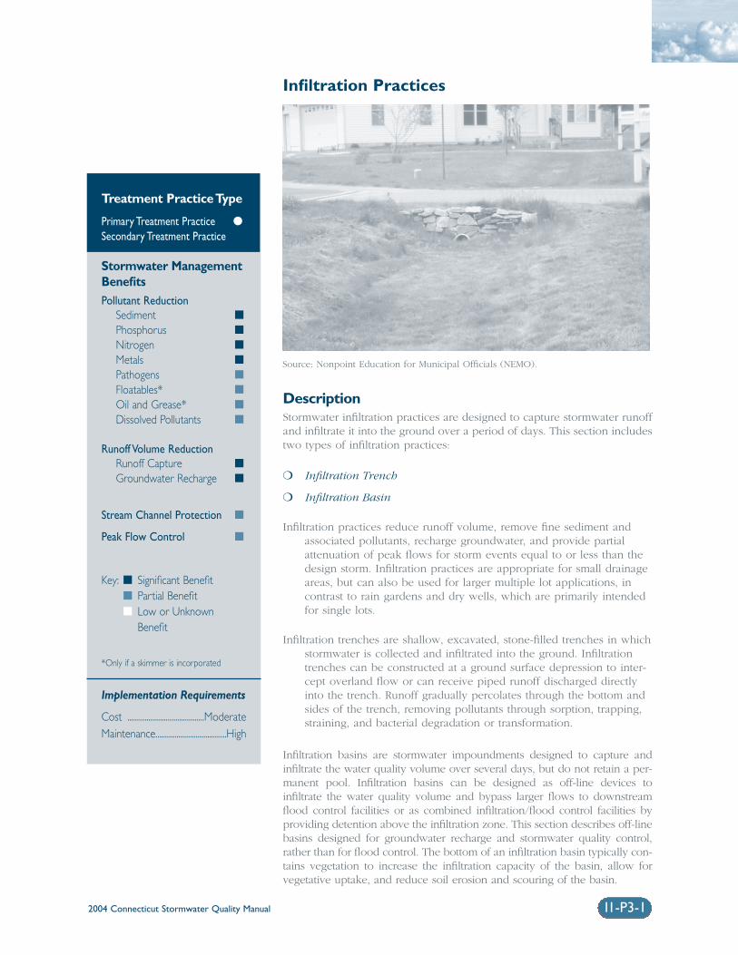
2004 Connecticut Stormwater Quality Manual 11-P3-1
Infiltration Practices
DescriptionStormwater infiltration practices are designed to capture stormwater runoffand infiltrate it into the ground over a period of days. This section includestwo types of infiltration practices:
❍ Infiltration Trench
❍ Infiltration Basin
Infiltration practices reduce runoff volume, remove fine sediment andassociated pollutants, recharge groundwater, and provide partialattenuation of peak flows for storm events equal to or less than thedesign storm. Infiltration practices are appropriate for small drainageareas, but can also be used for larger multiple lot applications, incontrast to rain gardens and dry wells, which are primarily intendedfor single lots.
Infiltration trenches are shallow, excavated, stone-filled trenches in whichstormwater is collected and infiltrated into the ground. Infiltrationtrenches can be constructed at a ground surface depression to inter-cept overland flow or can receive piped runoff discharged directlyinto the trench. Runoff gradually percolates through the bottom andsides of the trench, removing pollutants through sorption, trapping,straining, and bacterial degradation or transformation.
Infiltration basins are stormwater impoundments designed to capture andinfiltrate the water quality volume over several days, but do not retain a per-manent pool. Infiltration basins can be designed as off-line devices toinfiltrate the water quality volume and bypass larger flows to downstreamflood control facilities or as combined infiltration/flood control facilities byproviding detention above the infiltration zone. This section describes off-linebasins designed for groundwater recharge and stormwater quality control,rather than for flood control. The bottom of an infiltration basin typically con-tains vegetation to increase the infiltration capacity of the basin, allow forvegetative uptake, and reduce soil erosion and scouring of the basin.
Treatment Practice Type
Primary Treatment Practice �
Secondary Treatment Practice
Stormwater ManagementBenefitsPollutant Reduction
Sediment �
Phosphorus �
Nitrogen �
Metals �
Pathogens �
Floatables* �
Oil and Grease* �
Dissolved Pollutants �
Runoff Volume ReductionRunoff Capture �
Groundwater Recharge �
Stream Channel Protection �
Peak Flow Control �
Key: � Significant Benefit� Partial Benefit� Low or Unknown
Benefit
*Only if a skimmer is incorporated
Implementation Requirements
Cost ........................................ModerateMaintenance.....................................High
Source: Nonpoint Education for Municipal Officials (NEMO).
2004 Connecticut Stormwater Quality Manual11-P3-2
A number of underground infiltration structures,including premanufactured pipes, vaults, and modularstructures, have been developed in recent years asalternatives to infiltration trenches and basins forspace-limited sites and stormwater retrofit applica-tions. Performance of these systems varies bymanufacturer and system design. These systems arecurrently considered secondary treatment practicesdue to limited field performance data, although pol-lutant removal efficiency is anticipated to be similar tothat of infiltration trenches and basins.
Infiltration practices are susceptible to clogging bysuspended solids in stormwater runoff. Therefore,infiltration trenches and basins require pretreatmentto remove a portion of the solids load before enteringthe infiltration practice. Infiltration trenches andbasins are often preceded by other primary or sec-ondary treatment practices that are effective inremoving coarse solids, as well as oil, grease, andfloatable organic and inorganic material. Infiltrationpractices are not appropriate in areas that contributehigh concentrations of sediment, hydrocarbons, orother floatables without adequate pretreatment.
Because infiltration practices recharge stormwaterdirectly to groundwater, they can potentially contam-inate groundwater supplies with dissolved pollutantscontained in stormwater runoff or mobilized fromsubsurface contamination. Runoff sources that causeparticular problems for infiltration structures includesites with high pesticide levels; manufacturing andindustrial sites, due to potentially high concentrationsof soluble toxicants and heavy metals; and snowmeltrunoff because of salts. Infiltration practices should becarefully sited and designed to minimize the risk ofgroundwater contamination. Runoff from residentialareas (rooftops and lawns) is generally consideredthe least polluted and, therefore, the safest runoff for discharge to infiltration structures (WisconsinDNR, 2000).
Advantages❍ Promote groundwater recharge and baseflow in
nearby streams.
❍ Reduce the volume of runoff, thereby reducingthe size and cost of downstream drainage andstormwater control facilities.
❍ Provide partial attenuation of peak flows,thereby reducing local flooding and maintainingstreambank integrity.
❍ Appropriate for small or space-limited sites.
Limitations❍ Potential failure due to improper siting, design
(including inadequate pretreatment), construc-tion, and maintenance. Infiltration basinsusually fail for one or more of the following reasons (Wisconsin DNR, 2000):
❑ Premature clogging
❑ A design infiltration rate greater than theactual infiltration rate
❑ Because the basin was first used for site construction erosion control
❑ Soil was compacted during construction
❑ The upland soils or basin walls were not stabilized with vegetation, and sediment was delivered to the basin
❍ Potential for mosquito breeding due to standingwater in the event of system failure.
❍ Risk of groundwater contamination dependingon subsurface conditions, land use, and aquifersusceptibility.
❍ Require frequent inspection and maintenance.
❍ Not suitable for stormwater runoff from landuses or activities with the potential for high sedi-ment or pollutant loads without pretreatmentsized to treat the entire water quality volume.
❍ Low removal of dissolved pollutants in verycoarse soils.
❍ Use generally restricted to small drainage areas.
❍ Significantly reduced performance in the winterdue to frozen soils.
❍ Failure is not readily apparent until the system isseverely compromised.
❍ Visual inspection alone may not detect problems.
Siting ConsiderationsDrainage Area: The maximum contributing drainagearea for infiltration trenches should not exceed 5 acres(2 acres is recommended). The maximum contribut-ing drainage area for infiltration basins should notexceed 25 acres (10 acres is recommended). Whiletheoretically feasible, provided soils are sufficientlypermeable, infiltration from larger contributingdrainage areas can lead to problems such as ground-water mounding, clogging, and compaction.
Soils: Underlying soils should have a minimum infil-tration rate of 0.3 inches per hour, as initiallydetermined from NRCS soil textural classifications.
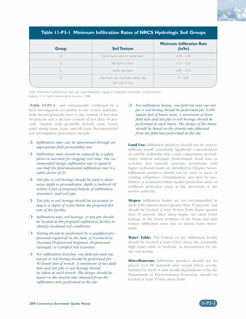
2004 Connecticut Stormwater Quality Manual 11-P3-3
(Table 11-P3-1), and subsequently confirmed by afield investigation acceptable to the review authority.Soils should generally have a clay content of less than30 percent and a silt/clay content of less than 40 per-cent. Suitable soils generally include sand, loamysand, sandy loam, loam, and silt loam. Recommendedsoil investigation procedures include:
❍ Infiltration rates can be determined through anappropriate field permeability test.
❍ Infiltration rates should be reduced by a safetyfactor to account for clogging over time. The rec-ommended design infiltration rate is equal toone-half the field-measured infiltration rate (i.e.,safety factor of 2).
❍ Test pits or soil borings should be used to deter-mine depth to groundwater, depth to bedrock (ifwithin 4 feet of proposed bottom of infiltrationstructure), and soil type.
❍ Test pits or soil borings should be excavated ordug to a depth of 4 feet below the proposed bot-tom of the facility.
❍ Infiltration tests, soil borings, or test pits shouldbe located at the proposed infiltration facility toidentify localized soil conditions.
❍ Testing should be performed by a qualified pro-fessional registered in the State of Connecticut.(licensed Professional Engineer, ProfessionalGeologist, or Certified Soil Scientist).
❍ For infiltration trenches, one field test and onetest pit or soil boring should be performed per 50 linear feet of trench. A minimum of two fieldtests and test pits or soil borings should be taken at each trench. The design should bebased on the slowest rate obtained from the infiltration tests performed at the site.
❍ For infiltration basins, one field test and one testpit or soil boring should be performed per 5,000square feet of basin area. A minimum of threefield tests and test pits or soil borings should beperformed at each basin. The design of the basinshould be based on the slowest rate obtainedfrom the field tests performed at the site.
Land Use: Infiltration practices should not be used toinfiltrate runoff containing significant concentrationsof soluble pollutants that could contaminate ground-water, without adequate pretreatment. Land uses oractivities that typically generate stormwater withhigher pollutant loads are identified in Chapter Seven.Infiltration practices should not be used in areas ofexisting subsurface contamination, and may be pro-hibited or restricted within aquifer protection areas orwellhead protection areas at the discretion of thereview authority.
Slopes: Infiltration basins are not recommended inareas with natural slopes greater than 15 percent, andshould be located at least 50 feet from slopes greaterthan 15 percent, since steep slopes can cause waterleakage in the lower portions of the basin and mayreduce infiltration rates due to lateral water move-ment.
Water Table: The bottom of the infiltration facilityshould be located at least 3 feet above the seasonallyhigh water table or bedrock, as documented by on-site soil testing.
Miscellaneous: Infiltration practices should not beplaced over fill materials and, except where recom-mended by local or state health departments or by theDepartment of Environmental Protection, should belocated at least 75 feet away from:
Minimum Infiltration RateGroup Soil Texture (in/hr)
A Sand, loamy sand, or sandy loam 0.30 – 0.45
B Silt loam or loam 0.15 – 0.30
C Sandy clay loam 0.05 – 0.15
D Clay loam, silty clay loam, sandy clay, 0 – 0.05silty clay, or clay
Table 11-P3-1 Minimum Infiltration Rates of NRCS Hydrologic Soil Groups
Note: Tabulated infiltration rates are approximately equal to saturated hydraulic conductivities.Source: U.S. Soil Conservation Service, 1986.
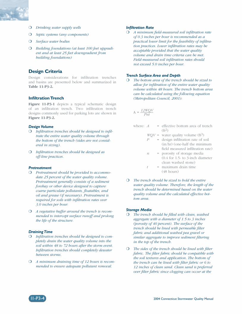
2004 Connecticut Stormwater Quality Manual11-P3-4
❍ Drinking water supply wells
❍ Septic systems (any components)
❍ Surface water bodies
❍ Building foundations (at least 100 feet upgradi-ent and at least 25 feet downgradient frombuilding foundations)
Design CriteriaDesign considerations for infiltration trenches and basins are presented below and summarized inTable 11-P3-2.
Infiltration TrenchFigure 11-P3-1 depicts a typical schematic design of an infiltration trench. Two infiltration trenchdesigns commonly used for parking lots are shown inFigure 11-P3-2.
Design Volume❍ Infiltration trenches should be designed to infil-
trate the entire water quality volume through the bottom of the trench (sides are not consid-ered in sizing).
❍ Infiltration trenches should be designed as off-line practices.
Pretreatment❍ Pretreatment should be provided to accommo-
date 25 percent of the water quality volume.Pretreatment generally consists of a sedimentforebay or other device designed to capturecoarse particulate pollutants, floatables, and oil and grease (if necessary). Pretreatment isrequired for soils with infiltration rates over 3.0 inches per hour.
❍ A vegetative buffer around the trench is recom-mended to intercept surface runoff and prolongthe life of the structure.
Draining Time❍ Infiltration trenches should be designed to com-
pletely drain the water quality volume into thesoil within 48 to 72 hours after the storm event.Infiltration trenches should completely dewaterbetween storms.
❍ A minimum draining time of 12 hours is recom-mended to ensure adequate pollutant removal.
Infiltration Rate❍ A minimum field-measured soil infiltration rate
of 0.3 inches per hour is recommended as apractical lower limit for the feasibility of infiltra-tion practices. Lower infiltration rates may beacceptable provided that the water quality volume and drain time criteria can be met.Field-measured soil infiltration rates should not exceed 5.0 inches per hour.
Trench Surface Area and Depth❍ The bottom area of the trench should be sized to
allow for infiltration of the entire water qualityvolume within 48 hours. The trench bottom areacan be calculated using the following equation(Metropolitan Council, 2001):
A = 12WQVPnt
where: A = effective bottom area of trench(ft2)
WQV = water quality volume (ft3)P = design infiltration rate of soil
(in/hr) (one-half the minimumfield measured infiltration rate)
n = porosity of storage media(0.4 for 1.5- to 3-inch diameterclean washed stone)
t = maximum drain time (48 hours)
❍ The trench should be sized to hold the entirewater quality volume. Therefore, the length of thetrench should be determined based on the waterquality volume and the calculated effective bot-tom area.
Storage Media❍ The trench should be filled with clean, washed
aggregate with a diameter of 1.5 to 3 inches(porosity of 40 percent). The surface of thetrench should be lined with permeable filter fabric and additional washed pea gravel or similar aggregate to improve sediment filtering in the top of the trench.
❍ The sides of the trench should be lined with filterfabric. The filter fabric should be compatible withthe soil textures and application. The bottom ofthe trench can be lined with filter fabric or 6 to12 inches of clean sand. Clean sand is preferredover filter fabric since clogging can occur at the
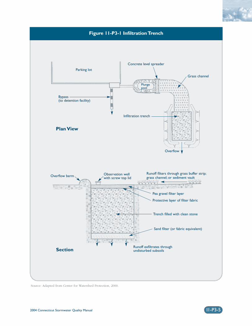
2004 Connecticut Stormwater Quality Manual 11-P3-5
Figure 11-P3-1 Infiltration Trench
Source: Adapted from Center for Watershed Protection, 2000.
Plungepool
Parking lot
Concrete level spreader
Infiltration trench
Overflow berm
Pea gravel filter layer
Protective layer of filter fabric
Trench filled with clean stone
Sand filter (or fabric equivalent)
Runoff exfiltrates through undisturbed subsoils
Overflow
Bypass (to detention facility)
Grass channel
Observation wellwith screw top lid
Runoff filters through grass buffer strip;grass channel; or sediment vault
Plan View
Section
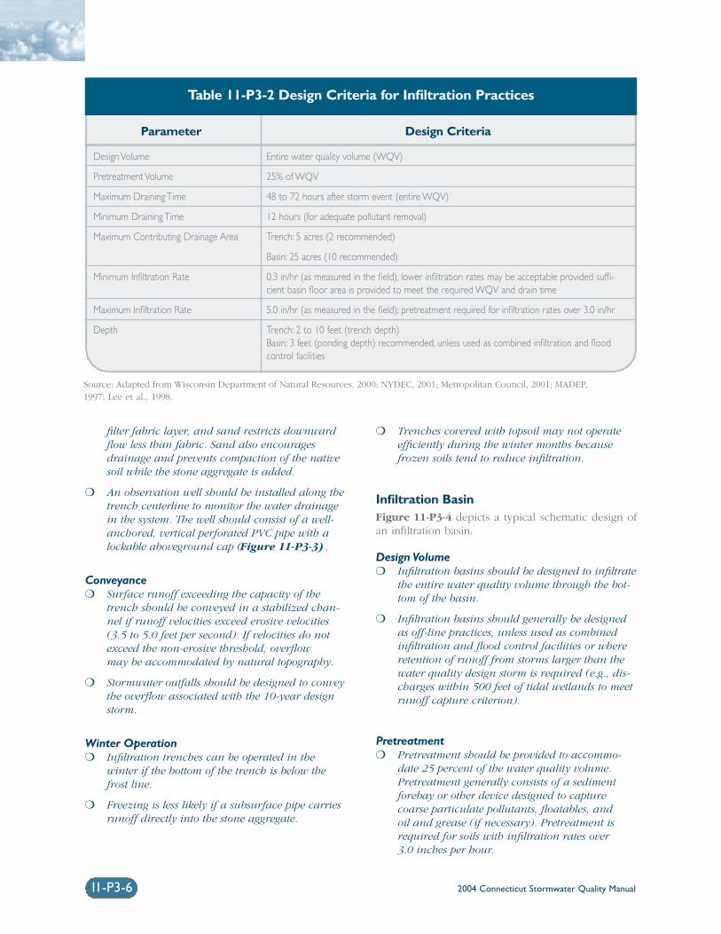
2004 Connecticut Stormwater Quality Manual11-P3-6
filter fabric layer, and sand restricts downwardflow less than fabric. Sand also encouragesdrainage and prevents compaction of the nativesoil while the stone aggregate is added.
❍ An observation well should be installed along thetrench centerline to monitor the water drainagein the system. The well should consist of a well-anchored, vertical perforated PVC pipe with alockable aboveground cap (Figure 11-P3-3).
Conveyance❍ Surface runoff exceeding the capacity of the
trench should be conveyed in a stabilized chan-nel if runoff velocities exceed erosive velocities(3.5 to 5.0 feet per second). If velocities do notexceed the non-erosive threshold, overflow may be accommodated by natural topography.
❍ Stormwater outfalls should be designed to conveythe overflow associated with the 10-year designstorm.
Winter Operation❍ Infiltration trenches can be operated in the
winter if the bottom of the trench is below thefrost line.
❍ Freezing is less likely if a subsurface pipe carriesrunoff directly into the stone aggregate.
❍ Trenches covered with topsoil may not operateefficiently during the winter months becausefrozen soils tend to reduce infiltration.
Infiltration BasinFigure 11-P3-4 depicts a typical schematic design ofan infiltration basin.
Design Volume❍ Infiltration basins should be designed to infiltrate
the entire water quality volume through the bot-tom of the basin.
❍ Infiltration basins should generally be designedas off-line practices, unless used as combinedinfiltration and flood control facilities or whereretention of runoff from storms larger than thewater quality design storm is required (e.g., dis-charges within 500 feet of tidal wetlands to meetrunoff capture criterion).
Pretreatment❍ Pretreatment should be provided to accommo-
date 25 percent of the water quality volume.Pretreatment generally consists of a sedimentforebay or other device designed to capturecoarse particulate pollutants, floatables, and oil and grease (if necessary). Pretreatment isrequired for soils with infiltration rates over 3.0 inches per hour.
Source: Adapted from Wisconsin Department of Natural Resources, 2000; NYDEC, 2001; Metropolitan Council, 2001; MADEP,1997; Lee et al., 1998.
Parameter Design Criteria
Design Volume Entire water quality volume (WQV)
Pretreatment Volume 25% of WQV
Maximum Draining Time 48 to 72 hours after storm event (entire WQV)
Minimum Draining Time 12 hours (for adequate pollutant removal)
Maximum Contributing Drainage Area Trench: 5 acres (2 recommended)
Basin: 25 acres (10 recommended)
Minimum Infiltration Rate 0.3 in/hr (as measured in the field), lower infiltration rates may be acceptable provided suffi-cient basin floor area is provided to meet the required WQV and drain time
Maximum Infiltration Rate 5.0 in/hr (as measured in the field); pretreatment required for infiltration rates over 3.0 in/hr
Depth Trench: 2 to 10 feet (trench depth)Basin: 3 feet (ponding depth) recommended, unless used as combined infiltration and floodcontrol facilities
Table 11-P3-2 Design Criteria for Infiltration Practices
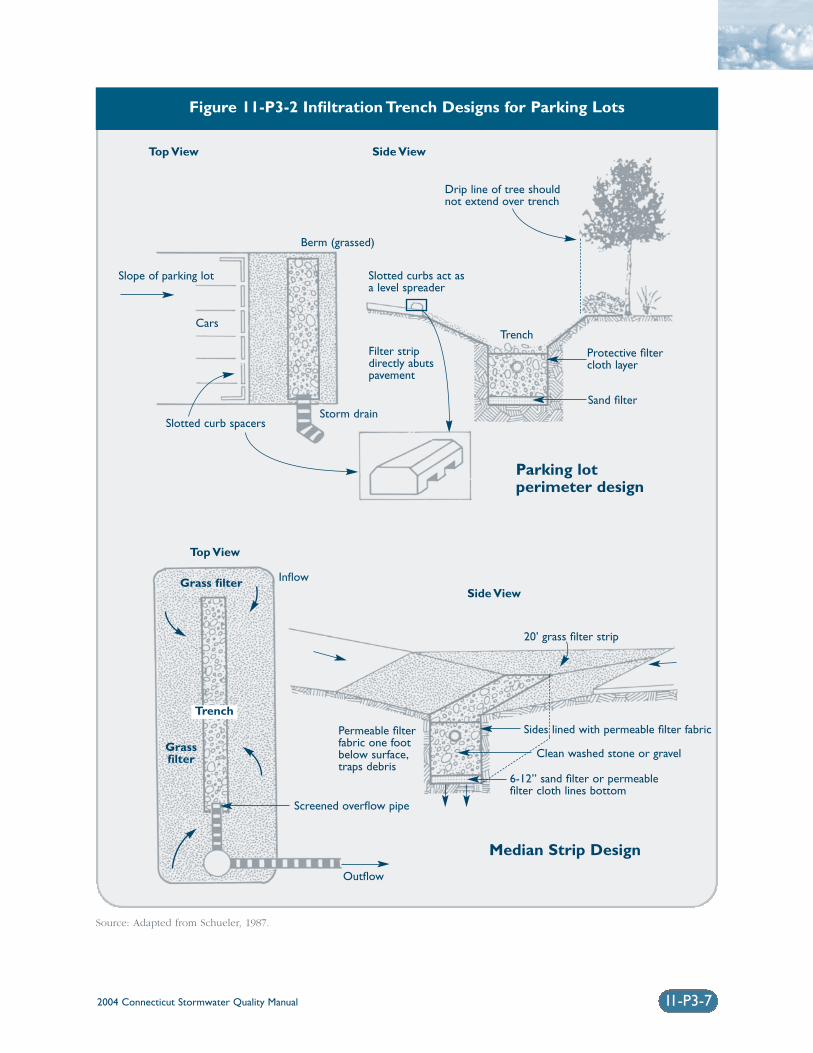
2004 Connecticut Stormwater Quality Manual 11-P3-7
Figure 11-P3-2 Infiltration Trench Designs for Parking Lots
Source: Adapted from Schueler, 1987.
Drip line of tree shouldnot extend over trench
Median Strip Design
Parking lot perimeter design
Top View Side View
Trench
Sand filter
Protective filter cloth layer
Slotted curbs act asa level spreader
Filter stripdirectly abutspavement
Cars
Slotted curb spacers
Slope of parking lot
Storm drain
Berm (grassed)
Top View
InflowSide View
Screened overflow pipe
Outflow
Grass filter
Trench
Grassfilter
20’ grass filter strip
Permeable filter fabric one footbelow surface,traps debris
Sides lined with permeable filter fabric
Clean washed stone or gravel
6-12” sand filter or permeablefilter cloth lines bottom
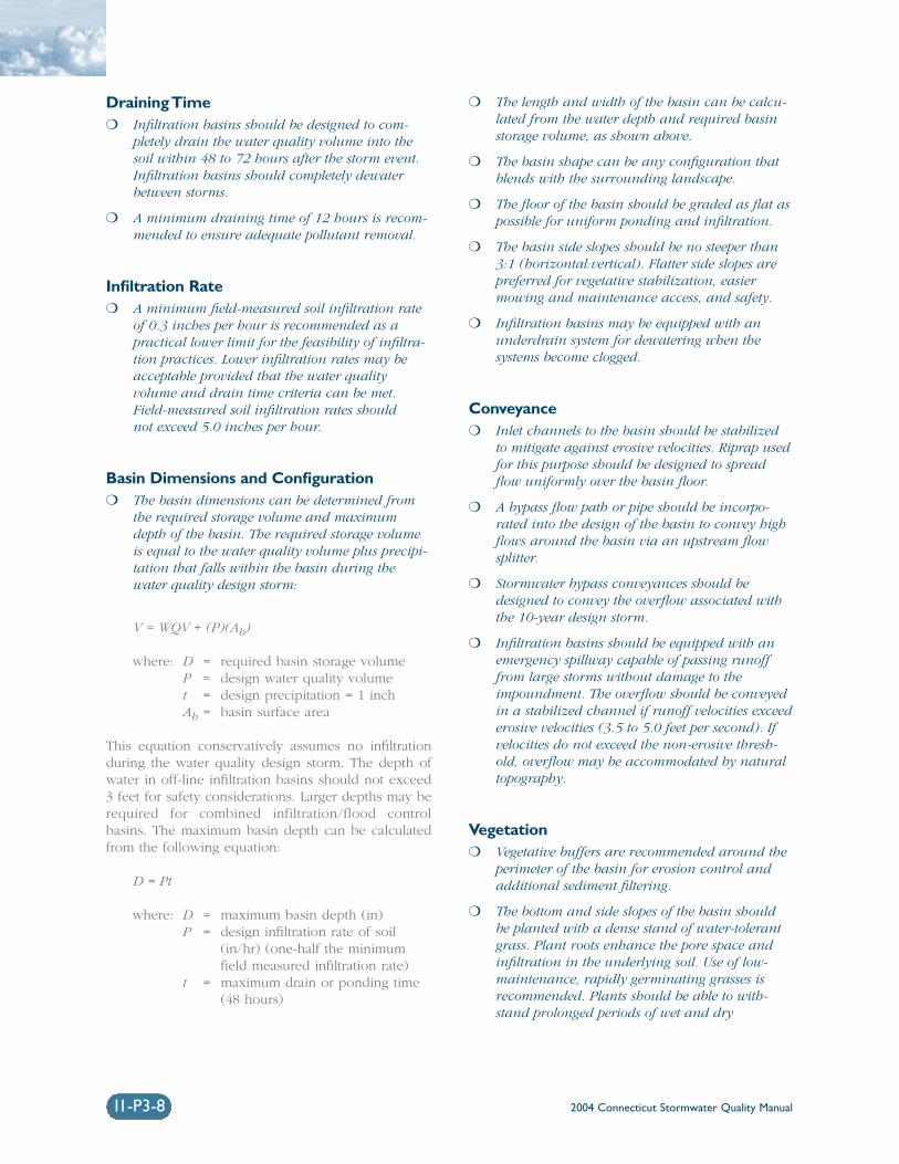
2004 Connecticut Stormwater Quality Manual11-P3-8
Draining Time❍ Infiltration basins should be designed to com-
pletely drain the water quality volume into thesoil within 48 to 72 hours after the storm event.Infiltration basins should completely dewaterbetween storms.
❍ A minimum draining time of 12 hours is recom-mended to ensure adequate pollutant removal.
Infiltration Rate❍ A minimum field-measured soil infiltration rate
of 0.3 inches per hour is recommended as apractical lower limit for the feasibility of infiltra-tion practices. Lower infiltration rates may beacceptable provided that the water quality volume and drain time criteria can be met.Field-measured soil infiltration rates should not exceed 5.0 inches per hour.
Basin Dimensions and Configuration❍ The basin dimensions can be determined from
the required storage volume and maximumdepth of the basin. The required storage volumeis equal to the water quality volume plus precipi-tation that falls within the basin during thewater quality design storm:
V = WQV + (P)(Ab)
where: D = required basin storage volumeP = design water quality volumet = design precipitation = 1 inchAb = basin surface area
This equation conservatively assumes no infiltrationduring the water quality design storm. The depth ofwater in off-line infiltration basins should not exceed3 feet for safety considerations. Larger depths may berequired for combined infiltration/flood controlbasins. The maximum basin depth can be calculatedfrom the following equation:
D = Pt
where: D = maximum basin depth (in)P = design infiltration rate of soil
(in/hr) (one-half the minimumfield measured infiltration rate)
t = maximum drain or ponding time(48 hours)
❍ The length and width of the basin can be calcu-lated from the water depth and required basinstorage volume, as shown above.
❍ The basin shape can be any configuration thatblends with the surrounding landscape.
❍ The floor of the basin should be graded as flat aspossible for uniform ponding and infiltration.
❍ The basin side slopes should be no steeper than3:1 (horizontal:vertical). Flatter side slopes arepreferred for vegetative stabilization, easier mowing and maintenance access, and safety.
❍ Infiltration basins may be equipped with anunderdrain system for dewatering when the systems become clogged.
Conveyance❍ Inlet channels to the basin should be stabilized
to mitigate against erosive velocities. Riprap usedfor this purpose should be designed to spreadflow uniformly over the basin floor.
❍ A bypass flow path or pipe should be incorpo-rated into the design of the basin to convey highflows around the basin via an upstream flowsplitter.
❍ Stormwater bypass conveyances should bedesigned to convey the overflow associated withthe 10-year design storm.
❍ Infiltration basins should be equipped with anemergency spillway capable of passing runofffrom large storms without damage to theimpoundment. The overflow should be conveyedin a stabilized channel if runoff velocities exceederosive velocities (3.5 to 5.0 feet per second). Ifvelocities do not exceed the non-erosive thresh-old, overflow may be accommodated by naturaltopography.
Vegetation❍ Vegetative buffers are recommended around the
perimeter of the basin for erosion control andadditional sediment filtering.
❍ The bottom and side slopes of the basin should be planted with a dense stand of water-tolerantgrass. Plant roots enhance the pore space andinfiltration in the underlying soil. Use of low-maintenance, rapidly germinating grasses isrecommended. Plants should be able to with-stand prolonged periods of wet and dry
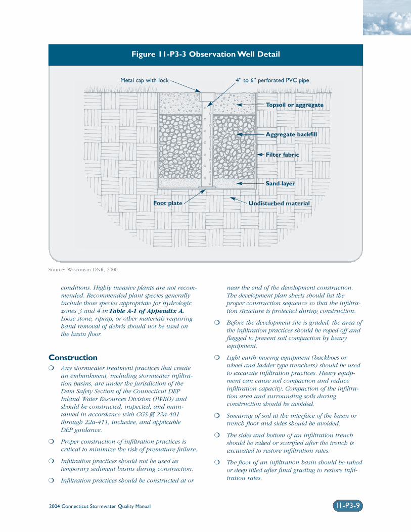
2004 Connecticut Stormwater Quality Manual
conditions. Highly invasive plants are not recom-mended. Recommended plant species generallyinclude those species appropriate for hydrologiczones 3 and 4 in Table A-1 of Appendix A.Loose stone, riprap, or other materials requiringhand removal of debris should not be used onthe basin floor.
Construction❍ Any stormwater treatment practices that create
an embankment, including stormwater infiltra-tion basins, are under the jurisdiction of theDam Safety Section of the Connecticut DEPInland Water Resources Division (IWRD) andshould be constructed, inspected, and main-tained in accordance with CGS §§ 22a-401through 22a-411, inclusive, and applicable DEP guidance.
❍ Proper construction of infiltration practices iscritical to minimize the risk of premature failure.
❍ Infiltration practices should not be used as temporary sediment basins during construction.
❍ Infiltration practices should be constructed at or
near the end of the development construction.The development plan sheets should list theproper construction sequence so that the infiltra-tion structure is protected during construction.
❍ Before the development site is graded, the area ofthe infiltration practices should be roped off andflagged to prevent soil compaction by heavyequipment.
❍ Light earth-moving equipment (backhoes orwheel and ladder type trenchers) should be usedto excavate infiltration practices. Heavy equip-ment can cause soil compaction and reduceinfiltration capacity. Compaction of the infiltra-tion area and surrounding soils duringconstruction should be avoided.
❍ Smearing of soil at the interface of the basin ortrench floor and sides should be avoided.
❍ The sides and bottom of an infiltration trenchshould be raked or scarified after the trench isexcavated to restore infiltration rates.
❍ The floor of an infiltration basin should be rakedor deep tilled after final grading to restore infil-tration rates.
11-P3-9
Figure 11-P3-3 Observation Well Detail
Source: Wisconsin DNR, 2000.
Metal cap with lock 4” to 6” perforated PVC pipe
Topsoil or aggregate
Aggregate backfill
Filter fabric
Sand layer
Undisturbed materialFoot plate
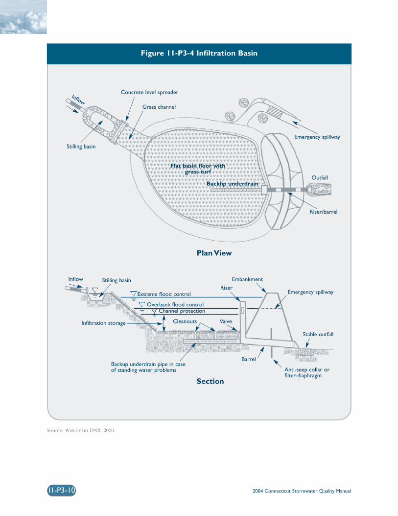
2004 Connecticut Stormwater Quality Manual11-P3-10
Figure 11-P3-4 Infiltration Basin
Source: Wisconsin DNR, 2000.
Concrete level spreader
Flat basin floor withgrass turf
Backlip underdrain
Grass channel
Plan View
Section
Emergency spillway
Emergency spillway
Embankment
Riser
Cleanouts Valve
Outfall
Riser/barrel
Inflow Stilling basin
Extreme flood control
Overbank flood controlChannel protection
Stable outfall
BarrelBackup underdrain pipe in caseof standing water problems Anti-seep collar or
filter-diaphragm
Infiltration storage
Stilling basin
Inflow
2004 Connecticut Stormwater Quality Manual 11-P3-11
❍ Appropriate erosion and sediment controlsshould be utilized during construction, as well asimmediately following construction, to stabilizethe soils in and around the basin.
Inspection and Maintenance❍ Plans for infiltration practices should identify
detailed inspection and maintenance require-ments, inspection and maintenance schedules,and those parties responsible for maintenance.
❍ Pretreatment devices should be inspected andcleaned at least twice a year.
❍ For the first few months after construction, infil-tration trenches and basins should be inspectedafter every major storm. Inspections should focuson the duration of standing water in a basin orin the observation well of a trench after a storm.Ponding water after 48 hours indicates that thebottom of the infiltration structure may beclogged. If the bottom of the trench becomesclogged, all of the stone aggregate and filter fabric must be removed and replaced with newmaterial. The bottom of the trench may need tobe tilled to enhance infiltration. Water ponded at the surface of a trench may indicate only surface clogging.
❍ After the first few months of operation, mainte-nance schedules for infiltration practices shouldbe based on field observations, although inspec-tions should be performed at least twice per year.For infiltration trenches, observations shouldinclude checking for accumulated sediment,leaves and debris in the pretreatment device,clogging of inlet and outlet pipes, and pondedwater inside and on the surface of the trench.For infiltration basins, observations shouldinclude measurement of differential accumula-tion of sediment, erosion of the basin floor,health of the basin vegetation, and condition of riprap.
❍ Grass clippings, leaves, and accumulated sedi-ment should be removed routinely from thesurface of infiltration trenches. The upper layerof stone and filter fabric may need to bereplaced to repair surface clogging.
❍ Sediment should be removed from infiltrationbasins when the sediment is dry (visible cracks)and readily separates from the floor of the basinto minimize smearing the basin floor. Theremaining soil should be tilled and revegetated.
❍ The grass in the basin, side slopes, and bufferareas should be mowed, and grass clippings andaccumulated trash removed at least twice duringthe growing season. Mowing should not be per-formed when the ground is soft to avoid thecreation of ruts and compaction, which canreduce infiltration.
Cost ConsiderationsCosts for implementation of infiltration practices arehighly variable from site to site depending on soilconditions and the required pretreatment. Typicalinstallation costs for infiltration trenches and basinsare approximately $5.00 and $2.00 per cubic foot(adjusted for inflation) of stormwater treated (SWRPC,1999), respectively. The cost per impervious acretreated varies by region and design variant. Infiltrationbasins are relatively cost-effective practices becauselittle infrastructure is needed. Infiltration basins typi-cally consume about 2 to 3 percent of the site drainingto them. Maintenance costs for infiltration basins areestimated at 5 to 10 percent of construction costs,while maintenance costs for infiltration trenches areestimated at 20 percent of construction costs (EPA,2002). Infiltration trenches are more expensive to con-struct than some other treatment practices in terms ofcost per volume of stormwater treated. Because infil-tration practices have high failure rates if improperlydesigned, constructed, and maintained, these prac-tices may require frequent replacement, which wouldreduce their overall cost effectiveness.
2004 Connecticut Stormwater Quality Manual11-P3-12
ReferencesCenter for Watershed Protection (CWP). 2000. TheVermont Stormwater Management HandbookTechnical Support Document – Public Review Draft.Prepared For Vermont Agency of Natural Resources.
Metropolitan Council. 2001. Minnesota Urban SmallSites BMP Manual: Stormwater Best ManagementPractices for Cold Climates. Prepared by BarrEngineering Company. St. Paul, Minnesota.
Wisconsin Department of Natural Resources. 2000.The Wisconsin Stormwater Manual: Infiltration Basinsand Trenches. Publication Number G3691-3.
Schuler, T.R. 1987. Controlling Urban Runoff: APractical Manual for Planning and Designing UrbanBMPs. Metropolitan Washington Council ofGovernments. Washington, D.C.
Soil Conservation Service. 1986. Urban Hydrology forSmall Watersheds, USDA Soil Conservation ServiceTechnical Release No. 55. Washington, D.C.
Southeastern Wisconsin Regional PlanningCommission (SWRPC). 1991. Costs of Urban NonpointSource Water Pollution Control Measures.Southeastern Wisconsin Regional PlanningCommission. Waukesha, WI.
United States Environmental Protection Agency (EPA).2002. National Menu of Best Management Practices for Stormwater Phase II. URL:http://www.epa.gov/npdes/menuofbmps/menu.htm,Last Modified January 24, 2002.
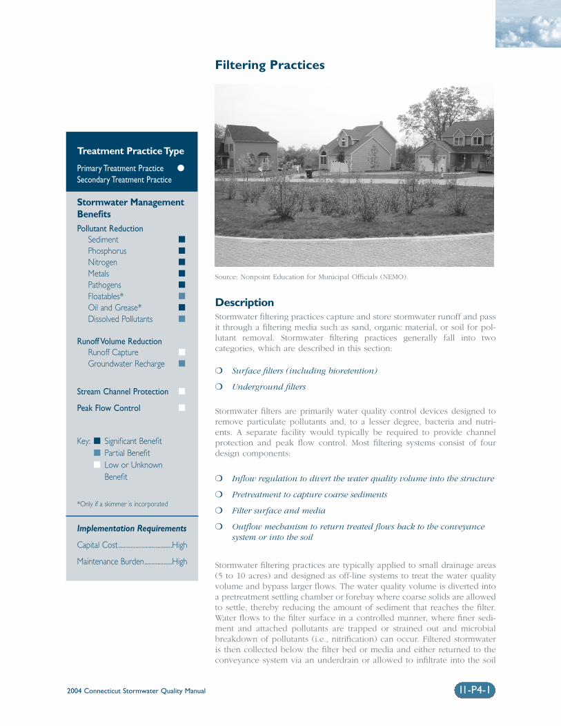
2004 Connecticut Stormwater Quality Manual 11-P4-1
Filtering Practices
DescriptionStormwater filtering practices capture and store stormwater runoff and passit through a filtering media such as sand, organic material, or soil for pol-lutant removal. Stormwater filtering practices generally fall into twocategories, which are described in this section:
❍ Surface filters (including bioretention)
❍ Underground filters
Stormwater filters are primarily water quality control devices designed toremove particulate pollutants and, to a lesser degree, bacteria and nutri-ents. A separate facility would typically be required to provide channelprotection and peak flow control. Most filtering systems consist of fourdesign components:
❍ Inflow regulation to divert the water quality volume into the structure
❍ Pretreatment to capture coarse sediments
❍ Filter surface and media
❍ Outflow mechanism to return treated flows back to the conveyancesystem or into the soil
Stormwater filtering practices are typically applied to small drainage areas(5 to 10 acres) and designed as off-line systems to treat the water qualityvolume and bypass larger flows. The water quality volume is diverted intoa pretreatment settling chamber or forebay where coarse solids are allowedto settle, thereby reducing the amount of sediment that reaches the filter.Water flows to the filter surface in a controlled manner, where finer sedi-ment and attached pollutants are trapped or strained out and microbialbreakdown of pollutants (i.e., nitrification) can occur. Filtered stormwateris then collected below the filter bed or media and either returned to theconveyance system via an underdrain or allowed to infiltrate into the soil
Treatment Practice Type
Primary Treatment Practice �
Secondary Treatment Practice
Stormwater ManagementBenefitsPollutant Reduction
Sediment �
Phosphorus �
Nitrogen �
Metals �
Pathogens �
Floatables* �
Oil and Grease* �
Dissolved Pollutants �
Runoff Volume ReductionRunoff Capture �
Groundwater Recharge �
Stream Channel Protection �
Peak Flow Control �
Key: � Significant Benefit� Partial Benefit� Low or Unknown
Benefit
*Only if a skimmer is incorporated
Implementation Requirements
Capital Cost.....................................High
Maintenance Burden...................High
Source: Nonpoint Education for Municipal Officials (NEMO).
2004 Connecticut Stormwater Quality Manual11-P4-2
(i.e., exfiltration). Due to their similarity to infiltrationbasins, which were discussed in the previous section,exfiltration systems are not addressed in this section.
Stormwater filtering practices are commonly used totreat runoff from small sites such as parking lots andsmall developments; areas with high pollution poten-tial such as industrial sites; or in highly urbanizedareas where space is limited. A number of surface andunderground stormwater filter design variations havebeen developed for these types of applications.Underground filters can be placed under parking lotsand are well suited to highly urbanized areas orspace-limited sites since they consume no surfacespace. As such, stormwater filters are often suitablefor retrofit applications where space is typically lim-ited. Stormwater filtration systems that do notdischarge to the soil (i.e., are contained in a structureor equipped with an impermeable liner) are also suit-able options for treating runoff from industrial areasand other land uses with high pollutant potentialsince the water is not allowed to infiltrate into the soiland potentially contaminate groundwater.
Design Variations
Surface FiltersSurface Sand Filter: The surface sand filter is theoriginal sand filter design, in which both the filter bedand sedimentation chamber are aboveground. Surfacesand filters can consist of excavated, earthen basins oraboveground concrete chambers (i.e., Austin SandFilter). Figure 11-P4-1 and Figure 11-P4-2 depictschematics of two common surface sand filterdesigns.
Organic Filters: Organic filters are similar to surfacesand filters, with the sand medium replaced with orsupplemented by material having a higher organiccontent such as peat or compost. Organic filters aregenerally ineffective during the winter in cold cli-mates because they retain water and consequentlyfreeze solid and become completely impervious.Organic filters are not recommended for use inConnecticut and, therefore, are not addressed in thisManual.
Bioretention: Bioretention systems are shallow land-scaped depressions designed to manage and treatstormwater runoff. Bioretention systems are a varia-tion of a surface sand filter, where the sand filtrationmedia is replaced with a planted soil bed designed toremove pollutants through physical and biologicalprocesses (EPA, 2002). Stormwater flows into thebioretention area, ponds on the surface, and gradually
infiltrates into the soil bed. Treated water is allowedto infiltrate into the surrounding soils or is collectedby an underdrain system and discharged to the stormsewer system or receiving waters. Small-scale biore-tention applications (i.e., residential yards, medianstrips, parking lot islands), commonly referred to asrain gardens, are also described in Chapter Four ofthis Manual as a Low Impact Development designpractice. Figure 11-P4-3 depicts schematic designs ofseveral common types of bioretention facilities.
Underground FiltersD.C. Sand Filter: This underground vaulted filterdesign was developed by the District of Columbia inthe late 1980s. The D.C. Sand Filter includes threechambers. The first chamber and a portion of the sec-ond chamber contain a permanent pool of water,which provides sedimentation and removal of floata-bles and oil and grease. Water flows through asubmerged opening near the dividing wall that con-nects the two chambers, into the second chamber andonto the filter bed. Filtered water is collected by anunderdrain system and flows into the third chamber,which acts like a clearwell and overflow chamber(EPA, 2002). A schematic of the D.C. Sand Filter isshown in Figure 11-P4-4.
Perimeter Sand Filter: The perimeter sand filter isan underground vault sand filter that was originallydeveloped in Delaware (also known as the “DelawareSand Filter”) for use around the perimeter of parkinglots. The system contains two parallel chambers anda clearwell. Overland flow enters the first chamberthrough slotted grates, which acts as a sedimentationchamber. Water then flows over weirs into the secondchamber, which contains the filter media. Filteredwater is collected by an underdrain system and flowsinto a clearwell before discharging to the storm drainsystem. A schematic of a perimeter sand filter isshown in Figure 11-P4-5.
Alexandria Sand Filter: The Alexandria Sand Filter,developed in Alexandria, Virginia, is similar to theD.C. Sand Filter in that it consists of three distinctchambers: a sediment chamber, a filtering chamber,and a clearwell. However, the Alexandria designreplaces the permanent pool oil/water separator witha gabion barrier that filters and dissipates energy. Thisvariation is a dry system designed to drain betweenstorms. Figure 11-P4-6 shows a schematic of anAlexandria Sand Filter.
Proprietary Designs: A number of proprietaryunderground media filter designs have been devel-oped in recent years. These systems consist of the
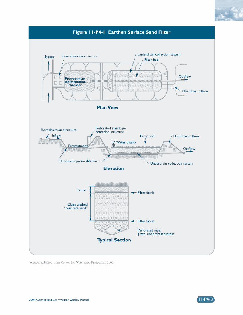
2004 Connecticut Stormwater Quality Manual 11-P4-3
Figure 11-P4-1 Earthen Surface Sand Filter
Source: Adapted from Center for Watershed Protection, 2000.
Flow diversion structure
Flow diversion structure
Underdrain collection system
Underdrain collection system
Filter bed
Outflow
Outflow
Inflow
Pretreatment
Optional impermeable liner
Perforated standpipedetention structure
Water quality
Filter bed
Filter fabricTopsoil
Clean washed“concrete sand”
Filter fabric
Perforated pipe/gravel underdrain system
Overflow spillway
Overflow spillway
Pretreatmentsedimentation
chamber
Bypass
Plan View
Elevation
Typical Section
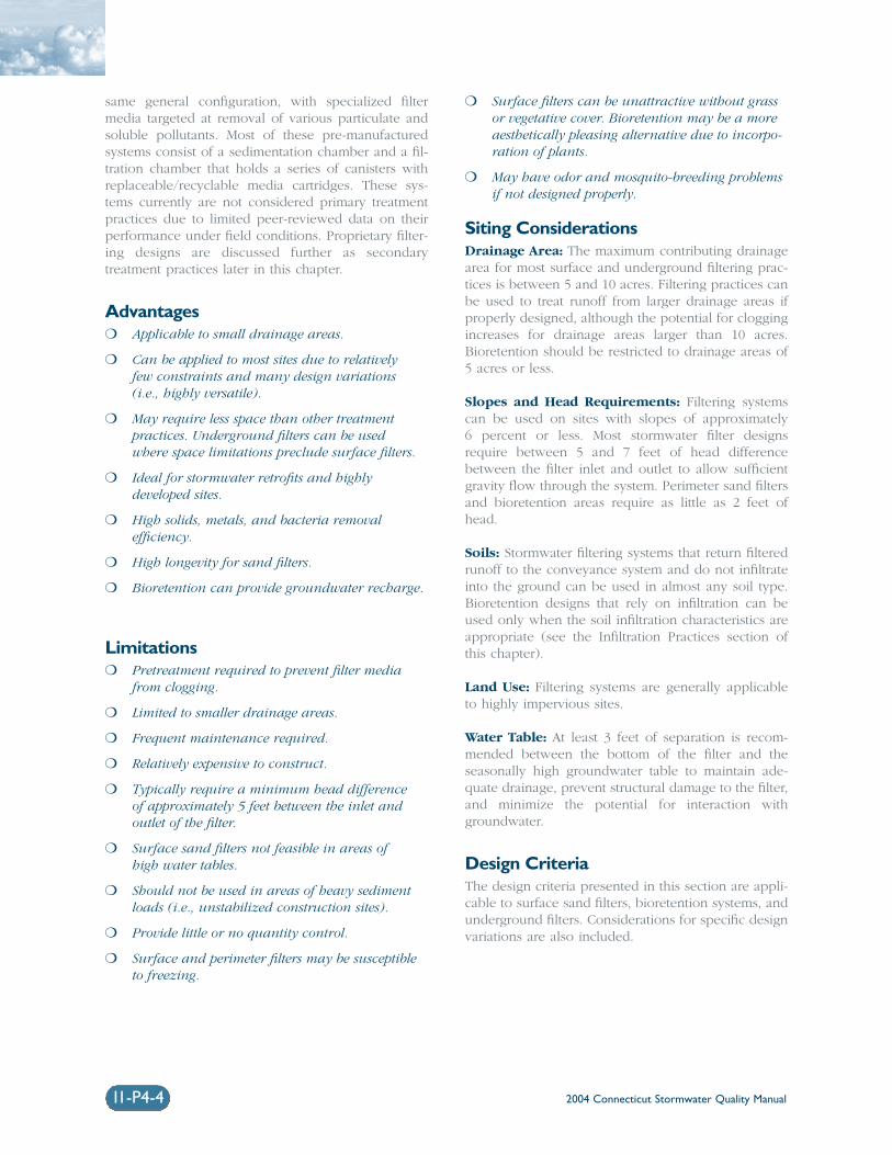
2004 Connecticut Stormwater Quality Manual11-P4-4
same general configuration, with specialized filtermedia targeted at removal of various particulate andsoluble pollutants. Most of these pre-manufacturedsystems consist of a sedimentation chamber and a fil-tration chamber that holds a series of canisters withreplaceable/recyclable media cartridges. These sys-tems currently are not considered primary treatmentpractices due to limited peer-reviewed data on theirperformance under field conditions. Proprietary filter-ing designs are discussed further as secondarytreatment practices later in this chapter.
Advantages❍ Applicable to small drainage areas.
❍ Can be applied to most sites due to relatively few constraints and many design variations (i.e., highly versatile).
❍ May require less space than other treatmentpractices. Underground filters can be used where space limitations preclude surface filters.
❍ Ideal for stormwater retrofits and highly developed sites.
❍ High solids, metals, and bacteria removal efficiency.
❍ High longevity for sand filters.
❍ Bioretention can provide groundwater recharge.
Limitations❍ Pretreatment required to prevent filter media
from clogging.
❍ Limited to smaller drainage areas.
❍ Frequent maintenance required.
❍ Relatively expensive to construct.
❍ Typically require a minimum head difference of approximately 5 feet between the inlet andoutlet of the filter.
❍ Surface sand filters not feasible in areas of high water tables.
❍ Should not be used in areas of heavy sedimentloads (i.e., unstabilized construction sites).
❍ Provide little or no quantity control.
❍ Surface and perimeter filters may be susceptibleto freezing.
❍ Surface filters can be unattractive without grassor vegetative cover. Bioretention may be a moreaesthetically pleasing alternative due to incorpo-ration of plants.
❍ May have odor and mosquito-breeding problemsif not designed properly.
Siting ConsiderationsDrainage Area: The maximum contributing drainagearea for most surface and underground filtering prac-tices is between 5 and 10 acres. Filtering practices canbe used to treat runoff from larger drainage areas ifproperly designed, although the potential for cloggingincreases for drainage areas larger than 10 acres.Bioretention should be restricted to drainage areas of5 acres or less.
Slopes and Head Requirements: Filtering systemscan be used on sites with slopes of approximately 6 percent or less. Most stormwater filter designsrequire between 5 and 7 feet of head differencebetween the filter inlet and outlet to allow sufficientgravity flow through the system. Perimeter sand filtersand bioretention areas require as little as 2 feet ofhead.
Soils: Stormwater filtering systems that return filteredrunoff to the conveyance system and do not infiltrateinto the ground can be used in almost any soil type.Bioretention designs that rely on infiltration can beused only when the soil infiltration characteristics areappropriate (see the Infiltration Practices section ofthis chapter).
Land Use: Filtering systems are generally applicableto highly impervious sites.
Water Table: At least 3 feet of separation is recom-mended between the bottom of the filter and theseasonally high groundwater table to maintain ade-quate drainage, prevent structural damage to the filter,and minimize the potential for interaction withgroundwater.
Design CriteriaThe design criteria presented in this section are appli-cable to surface sand filters, bioretention systems, andunderground filters. Considerations for specific designvariations are also included.
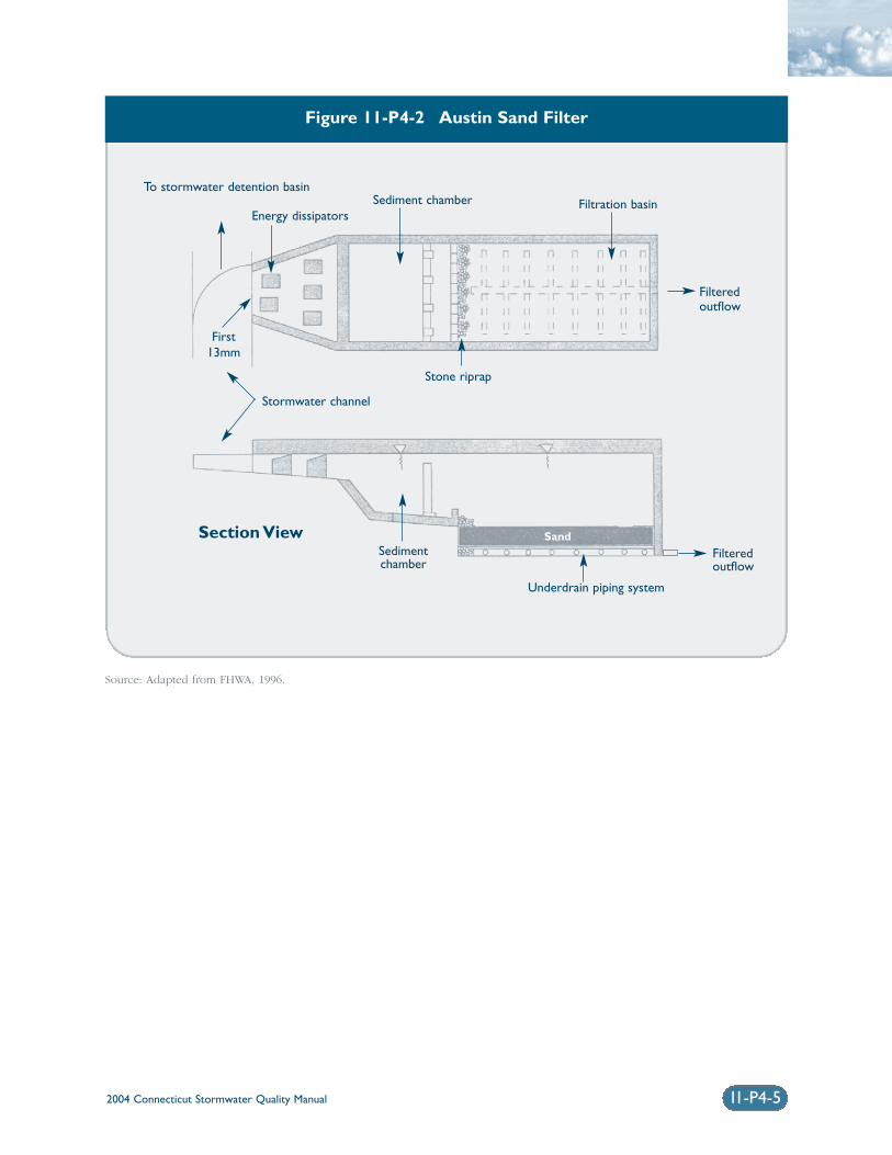
2004 Connecticut Stormwater Quality Manual 11-P4-5
Figure 11-P4-2 Austin Sand Filter
Source: Adapted from FHWA, 1996.
To stormwater detention basinSediment chamber
Underdrain piping system
Filtered outflow
Sedimentchamber
Section View
Filtration basin
Filteredoutflow
Stone riprap
Stormwater channel
First13mm
Energy dissipators
Sand
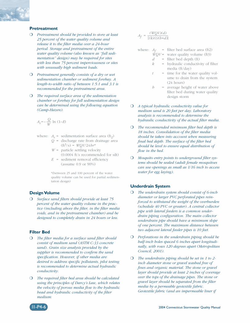
2004 Connecticut Stormwater Quality Manual11-P4-6
Pretreatment❍ Pretreatment should be provided to store at least
25 percent of the water quality volume andrelease it to the filter media over a 24-hourperiod. Storage and pretreatment of the entirewater quality volume (also known as “full sedi-mentation” design) may be required for siteswith less than 75 percent imperviousness or siteswith unusually high sediment loads.
❍ Pretreatment generally consists of a dry or wetsedimentation chamber or sediment forebay. Alength-to-width ratio of between 1.5:1 and 3:1 isrecommended for the pretreatment area.
❍ The required surface area of the sedimentationchamber or forebay for full sedimentation designcan be determined using the following equation(Camp-Hazen):
As= –Q
ln (1–E)W
where: As = sedimentation surface area (ft2)Q = discharge rate from drainage area
(ft3/s) = WQV/24hr*W = particle settling velocity
(0.0004 ft/s recommended for silt)E = sediment removal efficiency
(assume 0.9 or 90%)
*(between 25 and 100 percent of the waterquality volume can be used for partial sedimen-tation design)
Design Volume❍ Surface sand filters should provide at least 75
percent of the water quality volume in the prac-tice (including above the filter, in the filter mediavoids, and in the pretreatment chamber) and bedesigned to completely drain in 24 hours or less.
Filter Bed❍ The filter media for a surface sand filter should
consist of medium sand (ASTM C-33 concretesand). Grain size analysis provided by the supplier is recommended to confirm the sandspecification. However, if other media aredesired to address specific pollutants, pilot testingis recommended to determine actual hydraulicconductivity.
❍ The required filter bed area should be calculatedusing the principles of Darcy’s Law, which relatesthe velocity of porous media flow to the hydraulichead and hydraulic conductivity of the filtermedium:
Af = (WQV)(d)
[(k)(t)(h+d)]
where: Af = filter bed surface area (ft2)WQV = water quality volume (ft3)d = filter bed depth (ft)k = hydraulic conductivity of filter
media (ft/day)t = time for the water quality vol-
ume to drain from the system(24 hours)
h = average height of water abovefilter bed during water qualitydesign storm
❍ A typical hydraulic conductivity value formedium sand is 20 feet per day. Laboratoryanalysis is recommended to determine thehydraulic conductivity of the actual filter media.
❍ The recommended minimum filter bed depth is18 inches. Consolidation of the filter mediashould be taken into account when measuringfinal bed depth. The surface of the filter bedshould be level to ensure equal distribution offlow in the bed.
❍ Mosquito entry points to underground filter sys-tems should be sealed (adult female mosquitoescan use openings as small as 1/16 inch to accesswater for egg laying).
Underdrain System❍ The underdrain system should consist of 6-inch
diameter or larger PVC perforated pipes rein-forced to withstand the weight of the overburden(schedule 40 PVC or greater). A central collectorpipe with lateral feeders is a common under-drain piping configuration. The main collectorunderdrain pipe should have a minimum slopeof one percent. The maximum distance betweentwo adjacent lateral feeder pipes is 10 feet.
❍ Perforations in the underdrain piping should behalf-inch holes spaced 6 inches apart longitudi-nally, with rows 120 degrees apart (MetropolitanCouncil, 2001).
❍ The underdrain piping should be set in 1 to 2-inch diameter stone or gravel washed free offines and organic material. The stone or gravellayer should provide at least 2 inches of coverageover the tops of the drainage pipes. The stone orgravel layer should be separated from the filtermedia by a permeable geotextile fabric.Geotextile fabric (and an impermeable liner if
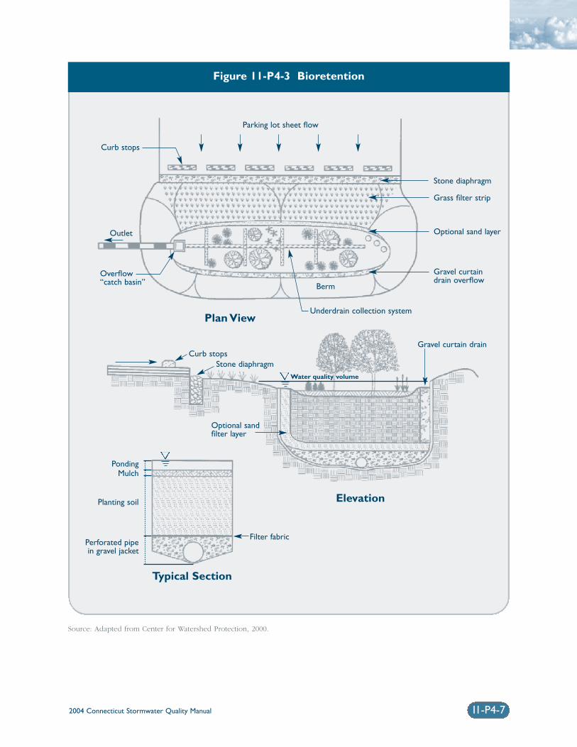
2004 Connecticut Stormwater Quality Manual 11-P4-7
Figure 11-P4-3 Bioretention
Source: Adapted from Center for Watershed Protection, 2000.
Parking lot sheet flow
Plan View
Elevation
Typical Section
Stone diaphragm
Grass filter strip
Optional sand layer
Gravel curtaindrain overflow
Gravel curtain drainCurb stops
Stone diaphragmWater quality volume
Optional sandfilter layer
Filter fabric
PondingMulch
Planting soil
Perforated pipein gravel jacket
Underdrain collection system
Berm
Overflow“catch basin”
Outlet
Curb stops
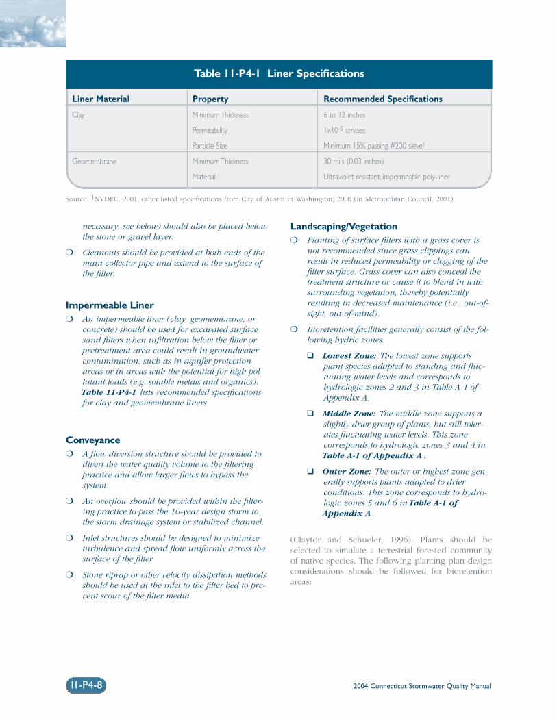
2004 Connecticut Stormwater Quality Manual11-P4-8
necessary, see below) should also be placed belowthe stone or gravel layer.
❍ Cleanouts should be provided at both ends of themain collector pipe and extend to the surface ofthe filter.
Impermeable Liner❍ An impermeable liner (clay, geomembrane, or
concrete) should be used for excavated surfacesand filters when infiltration below the filter orpretreatment area could result in groundwatercontamination, such as in aquifer protectionareas or in areas with the potential for high pol-lutant loads (e.g. soluble metals and organics).Table 11-P4-1 lists recommended specificationsfor clay and geomembrane liners.
Conveyance❍ A flow diversion structure should be provided to
divert the water quality volume to the filteringpractice and allow larger flows to bypass the system.
❍ An overflow should be provided within the filter-ing practice to pass the 10-year design storm tothe storm drainage system or stabilized channel.
❍ Inlet structures should be designed to minimizeturbulence and spread flow uniformly across thesurface of the filter.
❍ Stone riprap or other velocity dissipation methodsshould be used at the inlet to the filter bed to pre-vent scour of the filter media.
Landscaping/Vegetation❍ Planting of surface filters with a grass cover is
not recommended since grass clippings canresult in reduced permeability or clogging of thefilter surface. Grass cover can also conceal thetreatment structure or cause it to blend in withsurrounding vegetation, thereby potentiallyresulting in decreased maintenance (i.e., out-of-sight, out-of-mind).
❍ Bioretention facilities generally consist of the fol-lowing hydric zones:
❑ Lowest Zone: The lowest zone supportsplant species adapted to standing and fluc-tuating water levels and corresponds tohydrologic zones 2 and 3 in Table A-1 ofAppendix A.
❑ Middle Zone: The middle zone supports aslightly drier group of plants, but still toler-ates fluctuating water levels. This zonecorresponds to hydrologic zones 3 and 4 inTable A-1 of Appendix A.
❑ Outer Zone: The outer or highest zone gen-erally supports plants adapted to drierconditions. This zone corresponds to hydro-logic zones 5 and 6 in Table A-1 ofAppendix A.
(Claytor and Schueler, 1996). Plants should beselected to simulate a terrestrial forested communityof native species. The following planting plan designconsiderations should be followed for bioretentionareas:
Liner Material Property Recommended Specifications
Clay Minimum Thickness 6 to 12 inches
Permeability 1x10⁻⁵ cm/sec1
Particle Size Minimum 15% passing #200 sieve1
Geomembrane Minimum Thickness 30 mils (0.03 inches)
Material Ultraviolet resistant, impermeable poly-liner
Table 11-P4-1 Liner Specifications
Source: 1NYDEC, 2001; other listed specifications from City of Austin in Washington, 2000 (in Metropolitan Council, 2001).
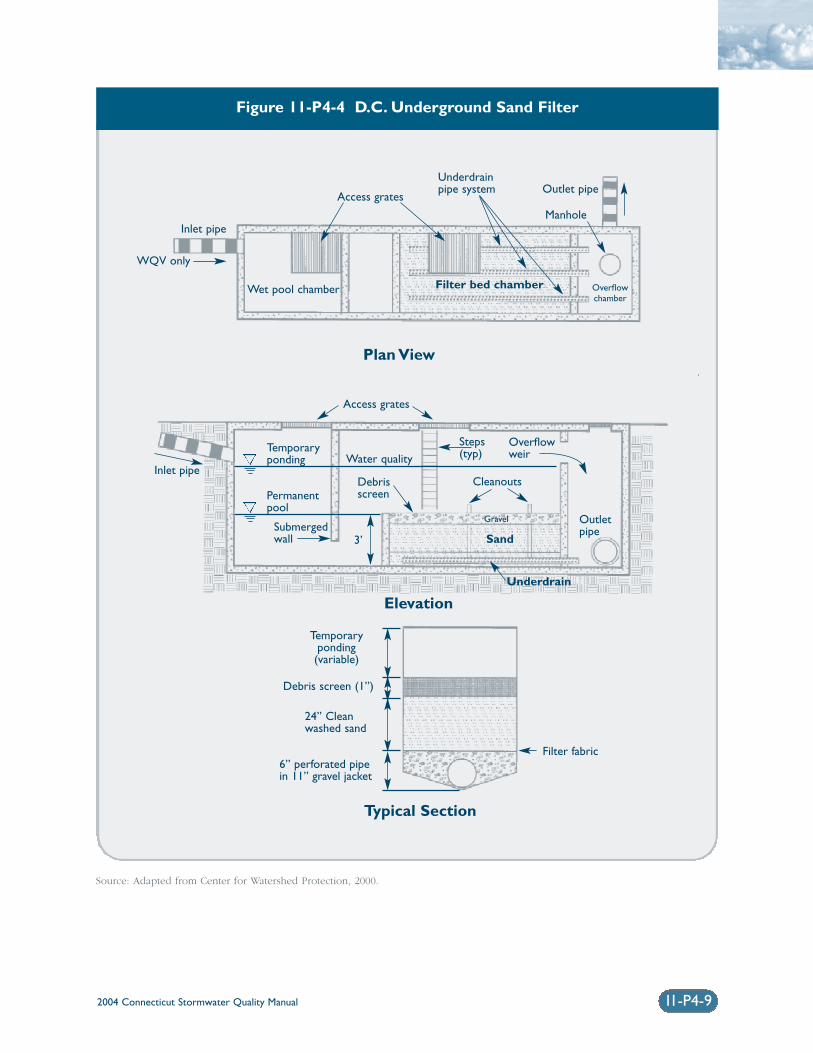
2004 Connecticut Stormwater Quality Manual 11-P4-9
Figure 11-P4-4 D.C. Underground Sand Filter
Source: Adapted from Center for Watershed Protection, 2000.
Plan View
Elevation
Typical Section
Inlet pipe
Inlet pipe
Access grates
Temporaryponding
Permanentpool
Submergedwall
Debrisscreen
Temporaryponding(variable)
Access grates
Water quality
3’
Debris screen (1”)
Filter fabric
24” Cleanwashed sand
6” perforated pipein 11” gravel jacket
Cleanouts
Steps(typ)
Overflowweir
Wet pool chamber Filter bed chamber
Sand
Underdrain
Gravel
Underdrainpipe system Outlet pipe
Outletpipe
Manhole
Overflowchamber
WQV only
2004 Connecticut Stormwater Quality Manual11-P4-10
❑ Use native plant species
❑ Select vegetation based on hydric zones
❑ Plant layout should be random and natural
❑ Establish canopy with an understory ofshrubs and herbaceous plants
❑ Do not use woody vegetation near inflowlocations
❑ Plant trees along the perimeter of the bioretention area
❑ Do not specify noxious weeds
❑ Wind, sun, exposure, insects, disease, aes-thetics, existing utilities, traffic, and safetyissues should be considered for plant selec-tion and location.
(Claytor and Schueler, 1996).
Winter Operation❍ Surface sand filters and perimeter filters can be
ineffective during the winter months due tofreezing of the filter bed.
❍ Where possible, the filter bed should be below thefrost line.
❍ A larger underdrain system (i.e., larger diameterand more frequently spaced underdrain pipesand stone or gravel) may encourage fasterdraining and reduce the potential for freezingduring winter months.
❍ Filters that receive significant road sand shouldbe equipped with a larger pretreatment sedimentchamber or forebay.
Construction❍ Any stormwater treatment practices that create
an embankment, including surface sand filtersor similar stormwater filtration systems, areunder the jurisdiction of the Dam Safety Sectionof the Connecticut DEP Inland Water ResourcesDivision (IWRD) and should be constructed,inspected, and maintained in accordance with Connecticut General Statutes §§22a-401through 22a-411, inclusive, and applicable DEP guidance.
❍ The contributing drainage area should be stabi-lized to the maximum extent practicable anderosion and sediment controls should be in placeduring construction.
❍ Filtering systems should not be used as temporarysediment traps for construction erosion and sedi-ment control.
❍ The filter media should be wetted periodicallyduring construction to allow for consolidation ofthe filter media and proper filter media depth.Sand and other filter media should be carefullyplaced to avoid formation of voids and short-cir-cuiting.
❍ Over-compaction of the filter media should beavoided to preserve filtration capacity.Mechanical compaction of the filter mediashould be avoided. Excavation should be per-formed with backhoes or lightweight equipmentrather than loaders.
❍ The underdrain piping should be reinforced towithstand the weight of the overburden.
Inspection and Maintenance❍ Maintenance is critical for the proper operation
of filtering systems.
❍ Plans for filtering practices should identifydetailed inspection and maintenance require-ments, inspection and maintenance schedules,and those parties responsible for maintenance.
❍ Filtering practices should be inspected after everymajor storm in the first few months followingconstruction. The filter should be inspected atleast every 6 months thereafter. Inspectionsshould focus on:
❑ Checking the filter surface for standingwater or other evidence of clogging, such as discolored or accumulated sediments.
❑ Checking the sedimentation chamber orforebay for sediment accumulation, trash,and debris.
❑ Checking inlets, outlets, and overflow spill-way for blockage, structural integrity, andevidence of erosion.
❍ Sediment should be removed from the sedimenta-tion chamber or forebay when it accumulates toa depth of more than 12 inches or 10 percent ofthe pretreatment volume. The sedimentationchamber or forebay outlet devices should becleaned when drawdown times exceed 36 hours.
❍ Sediment should be removed from the filter bedwhen the accumulation exceeds one inch orwhen there is evidence that the infiltration
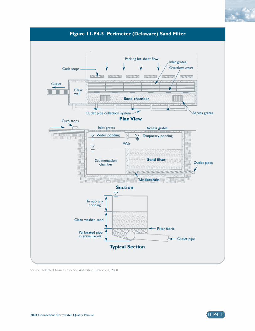
2004 Connecticut Stormwater Quality Manual 11-P4-11
Figure 11-P4-5 Perimeter (Delaware) Sand Filter
Source: Adapted from Center for Watershed Protection, 2000.
Parking lot sheet flow
Outlet pipe collection system Access grates
Outlet pipes
Outlet pipe
Filter fabric
Inlet grates
Overflow weirs
Outlet
Clearwell
Curb stops
Curb stops
Inlet grates Access grates
Temporary pondingWater ponding
Weir
Sedimentation chamber
Sand chamber
Sand filter
Underdrain
Temporaryponding
Clean washed sand
Perforated pipein gravel jacket
Plan View
Section
Typical Section
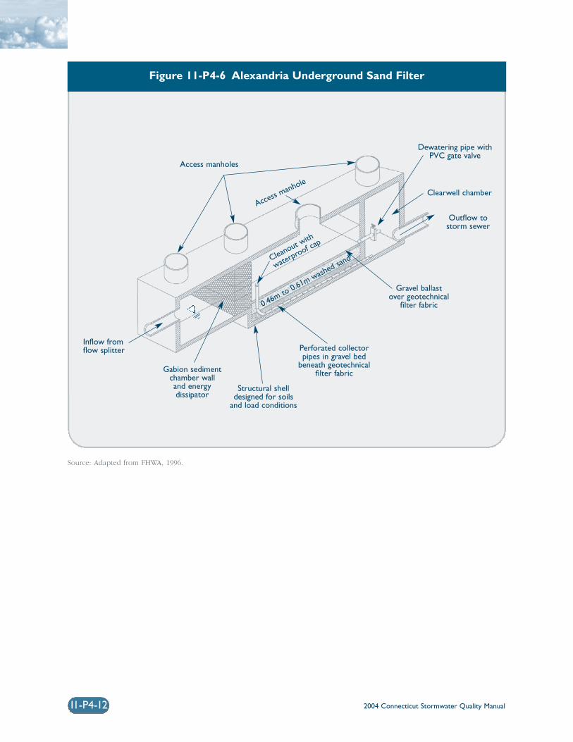
2004 Connecticut Stormwater Quality Manual11-P4-12
Figure 11-P4-6 Alexandria Underground Sand Filter
Source: Adapted from FHWA, 1996.
Access manholes
Inflow fromflow splitter
Gabion sedimentchamber walland energydissipator
Structural shelldesigned for soils
and load conditions
Perforated collectorpipes in gravel bed
beneath geotechnicalfilter fabric
Gravel ballastover geotechnical
filter fabric
Outflow tostorm sewer
Clearwell chamber
Dewatering pipe withPVC gate valve
Access manhole
Cleanout with
waterproof ca
p
0.46m to 0.61m washed san
d
2004 Connecticut Stormwater Quality Manual 11-P4-13
capacity of the filter bed has been significantlyreduced (i.e., observed water level above the filterexceeds the design level or drawdown timeexceeds 36 to 48 hours). As a rule-of-thumb, thetop several inches of the filter bed (typically dis-colored material) should be removed andreplaced annually, or more frequently if neces-sary. The material should be removed with rakeswhere possible rather than heavy constructionequipment to avoid compaction of the filter bed.Heavy equipment could be used if the system isdesigned with dimensions that allow equipmentto be located outside the filter, while a backhoeshovel reaches inside the filter to remove sedi-ment. Removed sediments should be dewatered(if necessary) and disposed of in an acceptablemanner.
❍ Bioretention areas require seasonal landscapingmaintenance, including:
❑ Watering plants as necessary during firstgrowing season
❑ Watering as necessary during dry periods
❑ Re-mulching void areas as necessary
❑ Treating diseased trees and shrubs as neces-sary
❑ Monthly inspection of soil and repairingeroded areas
❑ Monthly removal of litter and debris
❑ Adding mulch annually
(Center for Watershed Protection, 2001).
Cost ConsiderationsCosts for implementation of stormwater filtering prac-tices are generally higher than other stormwatertreatment practices, but vary widely due to many dif-ferent filter designs. A study by Brown and Schueler(1997) found typical installation costs between $3.00and $6.00 per cubic foot of stormwater treated. Thesecosts should be adjusted for inflation to reflect currentcosts. The cost per impervious acre treated varies byregion and design variant. While underground filtersare generally more expensive to construct than sur-face filters, they consume no surface space, whichmakes them relatively cost-effective in ultra-urbanareas where land is at a premium (EPA, 1999).
ReferencesBrown, W., and T. Schueler. 1997. The Economics ofStormwater BMPs in the Mid-Atlantic Region.Prepared for the Chesapeake Research Consortium,Edgewater, MD, by the Center for WatershedProtection. Ellicott City, MD.
Center for Watershed Protection (CWP). 2000. TheVermont Stormwater Management HandbookTechnical Support Document – Public Review Draft.Prepared For Vermont Agency of Natural Resources.
Center for Watershed Protection (CWP). 2001. TheVermont Stormwater Management Manual – PublicReview Draft. Prepared For Vermont Agency ofNatural Resources.
Claytor, R.A. and T.R. Schueler. 1996. Design ofStormwater Filtering Systems. The Center forWatershed Protection. Silver Spring, Maryland.
Federal Highway Administration. 1996. Evaluationand Management of Highway Runoff Water Quality.Publication No. FHWA-PD-96-032.
Metropolitan Council. 2001. Minnesota Urban SmallSites BMP Manual: Stormwater Best ManagementPractices for Cold Climates. Prepared by BarrEngineering Company. St. Paul, Minnesota.
New York State Department of EnvironmentalConservation (NYDEC). 2001. New York StateStormwater Management Design Manual. Prepared byCenter for Watershed Protection. Albany, New York.
United States Environmental Protection Agency (EPA).1999. Preliminary Data Summary of Urban StormWater Best Management Practices. EPA 821-R-99-012.Office of Water. Washington, D.C.
United States Environmental Protection Agency (EPA).2002. National Menu of Best Management Practicesfor Stormwater Phase II. URL: http://www.epa.gov/npdes/menuofbmps/menu.htm,Last Modified January 24, 2002.
Washington State Department of Ecology(Washington). 2000. Stormwater ManagementManual for Western Washington, Final Draft.Olympia, Washington.
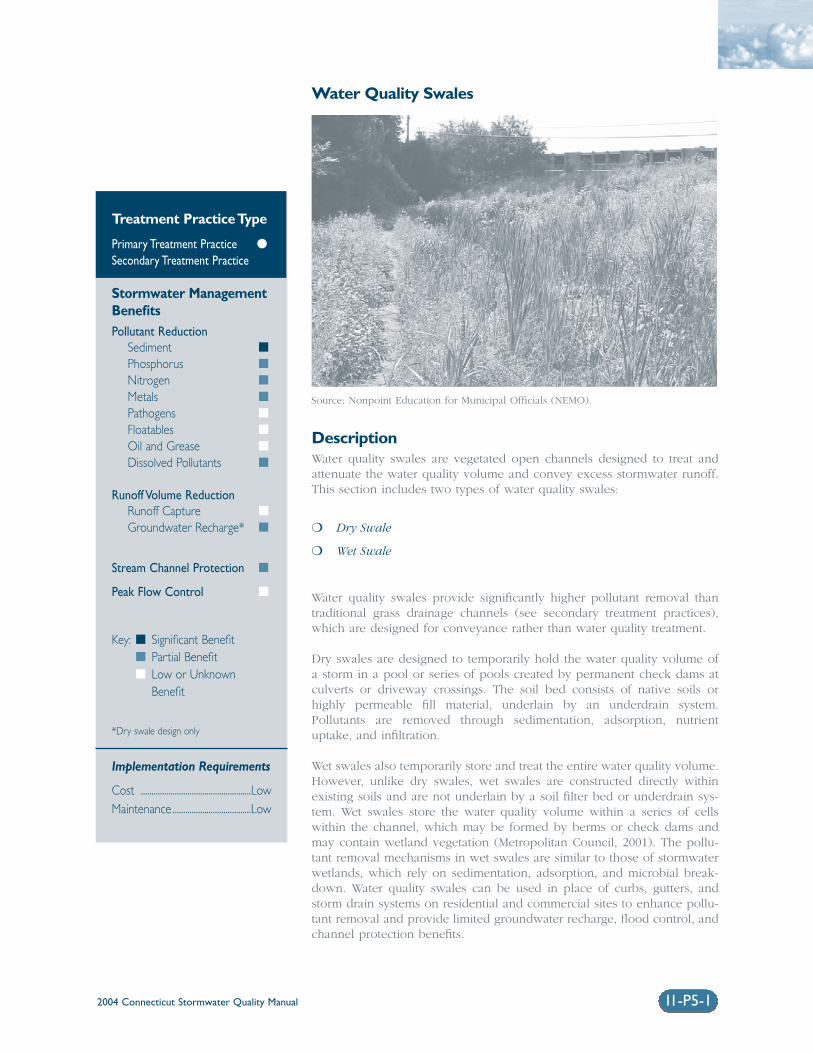
2004 Connecticut Stormwater Quality Manual 11-P5-1
Water Quality Swales
DescriptionWater quality swales are vegetated open channels designed to treat andattenuate the water quality volume and convey excess stormwater runoff.This section includes two types of water quality swales:
❍ Dry Swale
❍ Wet Swale
Water quality swales provide significantly higher pollutant removal thantraditional grass drainage channels (see secondary treatment practices),which are designed for conveyance rather than water quality treatment.
Dry swales are designed to temporarily hold the water quality volume ofa storm in a pool or series of pools created by permanent check dams atculverts or driveway crossings. The soil bed consists of native soils orhighly permeable fill material, underlain by an underdrain system.Pollutants are removed through sedimentation, adsorption, nutrientuptake, and infiltration.
Wet swales also temporarily store and treat the entire water quality volume.However, unlike dry swales, wet swales are constructed directly withinexisting soils and are not underlain by a soil filter bed or underdrain sys-tem. Wet swales store the water quality volume within a series of cellswithin the channel, which may be formed by berms or check dams andmay contain wetland vegetation (Metropolitan Council, 2001). The pollu-tant removal mechanisms in wet swales are similar to those of stormwaterwetlands, which rely on sedimentation, adsorption, and microbial break-down. Water quality swales can be used in place of curbs, gutters, andstorm drain systems on residential and commercial sites to enhance pollu-tant removal and provide limited groundwater recharge, flood control, andchannel protection benefits.
Treatment Practice Type
Primary Treatment Practice �
Secondary Treatment Practice
Stormwater ManagementBenefitsPollutant Reduction
Sediment �
Phosphorus �
Nitrogen �
Metals �
Pathogens �
Floatables �
Oil and Grease �
Dissolved Pollutants �
Runoff Volume ReductionRunoff Capture �
Groundwater Recharge* �
Stream Channel Protection �
Peak Flow Control �
Key: � Significant Benefit� Partial Benefit� Low or Unknown
Benefit
*Dry swale design only
Implementation Requirements
Cost ....................................................LowMaintenance .....................................Low
Source: Nonpoint Education for Municipal Officials (NEMO).
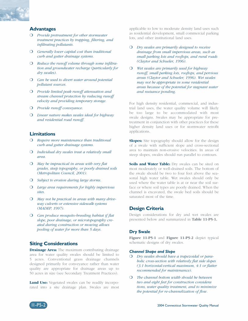
2004 Connecticut Stormwater Quality Manual11-P5-2
Advantages❍ Provide pretreatment for other stormwater
treatment practices by trapping, filtering, andinfiltrating pollutants.
❍ Generally lower capital cost than traditionalcurb and gutter drainage systems.
❍ Reduce the runoff volume through some infiltra-tion and groundwater recharge (particularly fordry swales).
❍ Can be used to divert water around potentialpollutant sources.
❍ Provide limited peak runoff attenuation andstream channel protection by reducing runoffvelocity and providing temporary storage.
❍ Provide runoff conveyance.
❍ Linear nature makes swales ideal for highwayand residential road runoff.
Limitations❍ Require more maintenance than traditional
curb and gutter drainage systems.
❍ Individual dry swales treat a relatively smallarea.
❍ May be impractical in areas with very flatgrades, steep topography, or poorly drained soils(Metropolitan Council, 2001).
❍ Subject to erosion during large storms.
❍ Large area requirements for highly impervioussites.
❍ May not be practical in areas with many drive-way culverts or extensive sidewalk systems(MADEP, 1997).
❍ Can produce mosquito-breeding habitat if flatslope, poor drainage, or microtopography cre-ated during construction or mowing allowspooling of water for more than 5 days.
Siting ConsiderationsDrainage Area: The maximum contributing drainagearea for water quality swales should be limited to 5 acres. Conventional grass drainage channelsdesigned primarily for conveyance rather than waterquality are appropriate for drainage areas up to 50 acres in size (see Secondary Treatment Practices).
Land Use: Vegetated swales can be readily incorpo-rated into a site drainage plan. Swales are most
applicable to low to moderate density land uses suchas residential development, small commercial parkinglots, and other institutional land uses.
❍ Dry swales are primarily designed to receivedrainage from small impervious areas, such assmall parking lots and rooftops, and rural roads(Claytor and Schueler, 1996).
❍ Wet swales are primarily used for highwayrunoff, small parking lots, rooftops, and perviousareas (Claytor and Schueler, 1996). Wet swalesmay not be appropriate in some residentialareas because of the potential for stagnant waterand nuisance ponding.
For high density residential, commercial, and indus-trial land uses, the water quality volume will likely be too large to be accommodated with most swale designs. Swales may be appropriate for pre-treatment in conjunction with other practices for thesehigher density land uses or for stormwater retrofitapplications.
Slopes: Site topography should allow for the designof a swale with sufficient slope and cross-sectionalarea to maintain non-erosive velocities. In areas ofsteep slopes, swales should run parallel to contours.
Soils and Water Table: Dry swales can be sited onmost moderately or well-drained soils. The bottom ofthe swale should be two to four feet above the sea-sonal high water table. Wet swales should only beused where the water table is at or near the soil sur-face or where soil types are poorly drained. When thechannel is excavated, the swale bed soils should besaturated most of the time.
Design CriteriaDesign considerations for dry and wet swales are presented below and summarized in Table 11-P5-1.
Dry SwaleFigure 11-P5-1 and Figure 11-P5-2 depict typicalschematic designs of dry swales.
Channel Shape and Slope❍ Dry swales should have a trapezoidal or para-
bolic cross-section with relatively flat side slopes(3:1 horizontal:vertical maximum, 4:1 or flatterrecommended for maintenance).
❍ The channel bottom width should be betweentwo and eight feet for construction considerations, water quality treatment, and to minimizethe potential for re-channelization of flow.
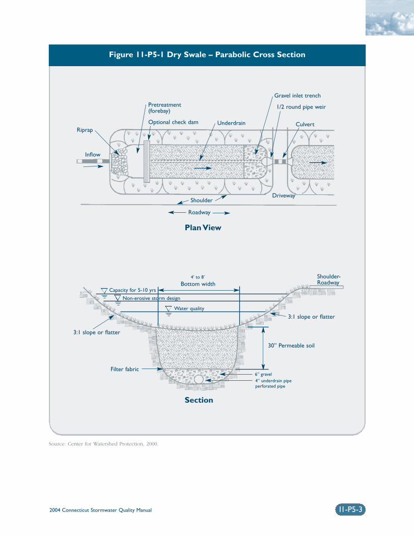
Figure 11-P5-1 Dry Swale – Parabolic Cross Section
Source: Center for Watershed Protection, 2000.
2004 Connecticut Stormwater Quality Manual 11-P5-3
Riprap
Inflow
Pretreatment(forebay)
Optional check dam Underdrain
Gravel inlet trench
1/2 round pipe weir
Culvert
Roadway
Bottom widthCapacity for 5-10 yrs
Non-erosive storm design
Water quality
Shoulder-Roadway
3:1 slope or flatter
30” Permeable soil
Filter fabric
3:1 slope or flatter
6” gravel
4’ to 8’
4” underdrain pipeperforated pipe
Driveway
Plan View
Section
Shoulder
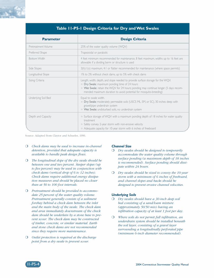
2004 Connecticut Stormwater Quality Manual11-P5-4
❍ Check dams may be used to increase in-channeldetention, provided that adequate capacity isavailable to handle peak design flows.
❍ The longitudinal slope of the dry swale should bebetween one and two percent. Steeper slopes (upto five percent) may be used in conjunction withcheck dams (vertical drop of 6 to 12 inches).Check dams require additional energy dissipa-tion measures and should be placed no closerthan at 50 to 100 foot intervals.
❍ Pretreatment should be provided to accommo-date 25 percent of the water quality volume.Pretreatment generally consists of a sedimentforebay behind a check dam between the inletand the main body of the swale. The check damand area immediately downstream of the checkdam should be underlain by a stone base to pre-vent scour. The check dam may be constructedof timber, concrete, or similar material. Earthand stone check dams are not recommendedsince they require more maintenance.
❍ Outlet protection is required at the dischargepoint from a dry swale to prevent scour.
Channel Size❍ Dry swales should be designed to temporarily
accommodate the water quality volume throughsurface ponding (a maximum depth of 18 inchesis recommended). Surface ponding should dissi-pate within 24 hours.
❍ Dry swales should be sized to convey the 10-yearstorm with a minimum of 6 inches of freeboard,and channel slopes and backs should bedesigned to prevent erosive channel velocities.
Underlying Soils❍ Dry swales should have a 30-inch deep soil
bed consisting of a sand/loam mixture (approximately 50/50 mix) having an infiltration capacity of at least 1 foot per day.
❍ Where soils do not permit full infiltration, anunderdrain system should be installed beneaththe soil layer, consisting of a gravel layer surrounding a longitudinally perforated pipe(minimum 6-inch diameter recommended).
Source: Adapted from Claytor and Schueler, 1996.
Parameter Design Criteria
Pretreatment Volume
Preferred Shape
Bottom Width
Side Slopes
Longitudinal Slope
Sizing Criteria
Underlying Soil Bed
Depth and Capacity
25% of the water quality volume (WQV)
Trapezoidal or parabolic
4 feet minimum recommended for maintenance, 8 feet maximum, widths up to 16 feet areallowable if a dividing berm or structure is used
3(h):1(v) maximum, 4:1 or flatter recommended for maintenance (where space permits)
1% to 2% without check dams, up to 5% with check dams
Length, width, depth, and slope needed to provide surface storage for the WQV.❍ Dry Swale: maximum ponding time of 24 hours❍ Wet Swale: retain the WQV for 24 hours; ponding may continue longer (5 days recom-
mended maximum duration to avoid potential for mosquito-breeding)
Equal to swale width.❍ Dry Swale: moderately permeable soils (USCS ML, SM, or SC), 30 inches deep with
gravel/pipe underdrain system❍ Wet Swale: undisturbed soils, no underdrain system
❍ Surface storage of WQV with a maximum ponding depth of 18 inches for water qualitytreatment
❍ Safely convey 2-year storm with non-erosive velocity❍ Adequate capacity for 10-year storm with 6 inches of freeboard
Table 11-P5-1 Design Criteria for Dry and Wet Swales
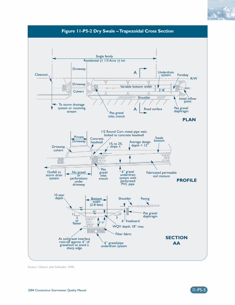
Figure 11-P5-2 Dry Swale – Trapezoidal Cross Section
Source: Claytor and Schueler, 1996.
2004 Connecticut Stormwater Quality Manual 11-P5-5
Driveway
Driveway
PrivateDriveway
Drivewayculvert
Outfall tostorm drain
system
Peagravelinlet
trench
6” gravelunderdrainsystem withperforatedPVC pipe
No gravelor
perforationsunder
driveway
Bottomwidth
(2-8 feet)
10 yeardepth
At soil/gravel interfaceroto-till approx. 6” ofgravel/soil to avoid a
sharp edge
6” gravel/pipeunderdrain system
Filter fabric
WQV depth, 18” max.
6” freeboard
Pea graveldiaphragm
PavingShoulder
3or
flatter
Concreteheadwall 1% to 2%
slope +
SwalebottomAverage design
depth = 12”
Fabricated permeablesoil mixture
Cleanout
Culvert
To storm drainagesystem or receiving
stream Pea gravelinlet, trench
1/2 Round Corr. metal pipe weir,bolted to concrete headwall
Road surface
Shoulder
Variable bottom width
Single familyResidential (> 1/3 Acre +) lot
Underdrainsystem Forebay
R/W
Initial inflowpoint
Pea graveldiaphragm
2’-8’
1
2”-6”
13
A
A
PLAN
PROFILE
SECTIONAA
2004 Connecticut Stormwater Quality Manual11-P5-6
Vegetation❍ Vegetation should be designed for regular
mowing, like a typical lawn, or less frequently(annually or semi-annually).
❍ Native grasses are preferred for enhanced biodi-versity, wildlife habitat, and drought tolerance.Grass species should be sod-forming, resistant tofrequent inundation, rigid and upright in highflows, and salt tolerant if located along a road-way. Wetland species may be used for the bottomof a wet swale. The maximum velocity shouldnot exceed erosive velocities for the soil type andvegetation condition of the channel (seeConnecticut Guidelines for Soil Erosion andSediment Control for maximum permissiblevelocities). The following grasses perform well in an open channel environment:
❑ Red Fescue (Festuca rubra)
❑ Tall Fescue (Festuca arundinacea)
❑ Redtop (Agrostis alba)
❑ Smooth Bromegrass (Bromus inermis)
❑ Reed Canarygrass (Phalaris arundinacea L.)
Wet SwaleFigure 11-P5-3 depicts a typical schematic design ofa wet swale.
Channel Shape and Slope❍ Wet swales should have a trapezoidal or para-
bolic cross-section with relatively flat side slopes(3:1 horizontal:vertical maximum, 4:1 or flatterrecommended for maintenance).
❍ The channel bottom width should be betweenfour and eight feet.
❍ Check dams may be used to increase in-channeldetention, provided that adequate capacity isavailable to handle peak design flows.
❍ The longitudinal slope of the dry swale should bebetween one and two percent. Steeper slopes maybe used in conjunction with check dams (verti-cal drop of 6 to 12 inches). Check dams requireadditional energy dissipation measures andshould be placed no closer than at 50 to 100 footintervals.
❍ Pretreatment should be provided to accommo-date 25 percent of the water quality volume.Pretreatment generally consists of a sedimentforebay behind a check dam between the inletand the main body of the swale. The check damand area immediately downstream of the checkdam should be underlain by a stone base to pre-
vent scour. The check dam may be constructedof timber or concrete, and may incorporate v-notch weirs to direct low flow volumes. Earthand stone check dams are not recommendedsince they require more maintenance.
❍ Outlet protection is required at any dischargepoint from a wet swale to prevent scour at theoutlet.
Channel Size❍ Wet swales should be designed to temporarily
retain the water quality volume for 24 hours, but ponding may continue for longer periodsdepending on the depth and elevation to thewater table (5 days recommended maximumduration to reduce the potential for mosquitobreeding). A maximum ponding depth of 18inches (at the end point of the channel) is rec-ommended for storage of the water qualityvolume.
❍ Wet swales should be sized to convey the 10-yearstorm with a minimum of 6 inches of freeboard,and channel slopes and backs should bedesigned to prevent erosive velocities.
Underlying Soils❍ The soil bed below wet swales should consist of
undisturbed soils. This area may be periodicallyinundated and remain wet for extended periods.
❍ Wet swales should not be constructed in gravellyand coarse sandy soils that cannot easily supportdense vegetation.
Vegetation❍ The permanent channel vegetation should be
suitable for the site and soil conditions.
❍ Native grasses are preferred for enhanced biodi-versity and wildlife habitat. Grass species shouldbe resistant to sustained inundation and/or ahigh water table and salt tolerant if locatedalong a roadway. Wetland species are appropri-ate for the bottom of a wet swale. The maximumvelocity should not exceed erosive velocities forthe soil type and vegetation condition of thechannel (see Connecticut Guidelines for SoilErosion and Sediment Control for maximumpermissible velocities). The following grasses per-form well in an open channel environment:
❑ Red Fescue (Festuca rubra)
❑ Tall Fescue (Festuca arundinacea)
❑ Redtop (Agrostis alba)
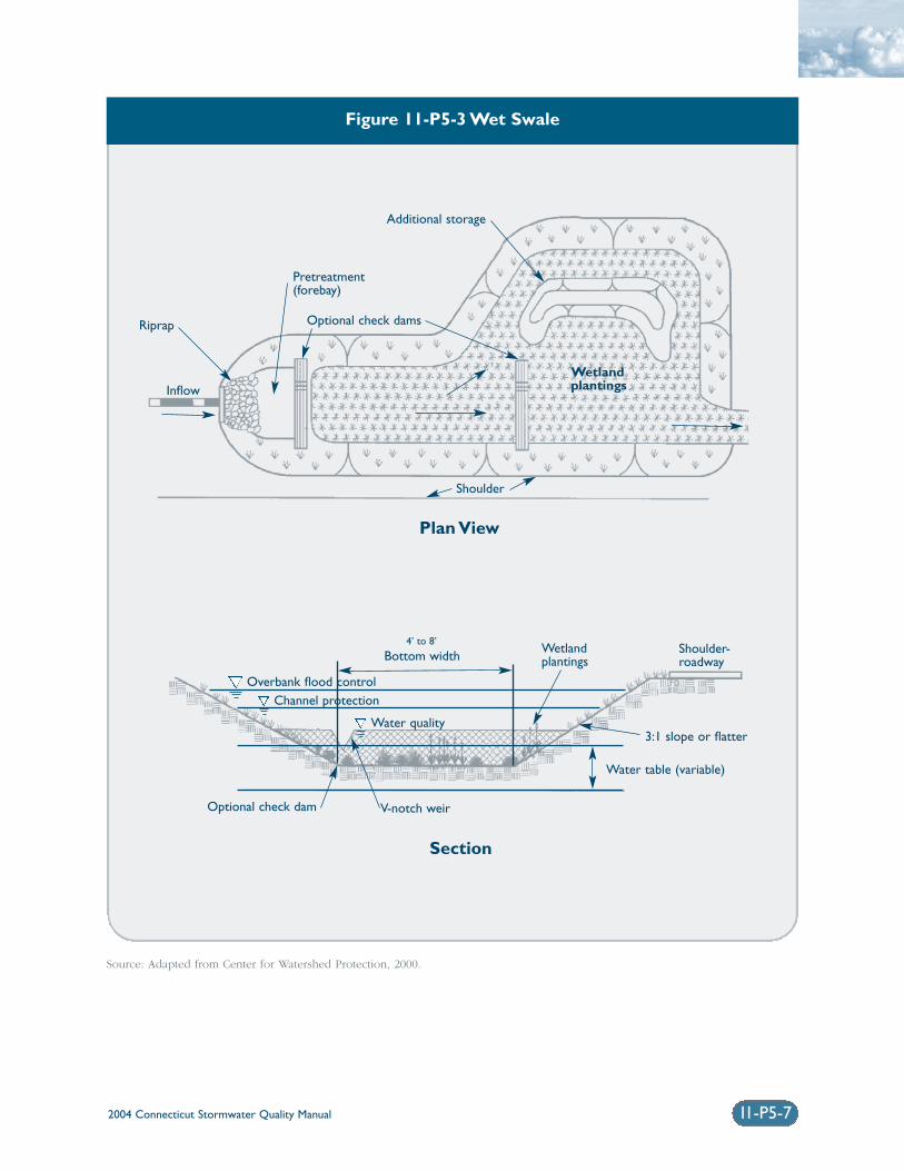
2004 Connecticut Stormwater Quality Manual 11-P5-7
Figure 11-P5-3 Wet Swale
Source: Adapted from Center for Watershed Protection, 2000.
Riprap
Pretreatment(forebay)
Optional check dams
Additional storage
Shoulder
WetlandplantingsInflow
Overbank flood controlChannel protection
Optional check dam V-notch weir
Water quality
Wetlandplantings
Shoulder-roadwayBottom width
3:1 slope or flatter
Water table (variable)
4’ to 8’
Plan View
Section
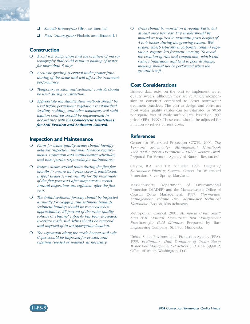
2004 Connecticut Stormwater Quality Manual11-P5-8
❑ Smooth Bromegrass (Bromus inermis)
❑ Reed Canarygrass (Phalaris arundinacea L.)
Construction❍ Avoid soil compaction and the creation of micro-
topography that could result in pooling of waterfor more than 5 days.
❍ Accurate grading is critical to the proper func-tioning of the swale and will affect the treatmentperformance.
❍ Temporary erosion and sediment controls shouldbe used during construction.
❍ Appropriate soil stabilization methods should beused before permanent vegetation is established.Seeding, sodding, and other temporary soil stabi-lization controls should be implemented inaccordance with the Connecticut Guidelinesfor Soil Erosion and Sediment Control.
Inspection and Maintenance❍ Plans for water quality swales should identify
detailed inspection and maintenance require-ments, inspection and maintenance schedules,and those parties responsible for maintenance.
❍ Inspect swales several times during the first fewmonths to ensure that grass cover is established.Inspect swales semi-annually for the remainderof the first year and after major storm events.Annual inspections are sufficient after the firstyear.
❍ The initial sediment forebay should be inspectedannually for clogging and sediment buildup.Sediment buildup should be removed whenapproximately 25 percent of the water qualityvolume or channel capacity has been exceeded.Excessive trash and debris should be removedand disposed of in an appropriate location.
❍ The vegetation along the swale bottom and sideslopes should be inspected for erosion andrepaired (seeded or sodded), as necessary.
❍ Grass should be mowed on a regular basis, butat least once per year. Dry swales should bemowed as required to maintain grass heights of4 to 6 inches during the growing season. Wetswales, which typically incorporate wetland vege-tation, require less frequent mowing. To avoidthe creation of ruts and compaction, which canreduce infiltration and lead to poor drainage,mowing should not be performed when theground is soft..
Cost ConsiderationsLimited data exist on the cost to implement waterquality swales, although they are relatively inexpen-sive to construct compared to other stormwatertreatment practices. The cost to design and constructmost water quality swales can be estimated as $0.50per square foot of swale surface area, based on 1997prices (EPA, 1999). These costs should be adjusted forinflation to reflect current costs.
ReferencesCenter for Watershed Protection (CWP). 2000. TheVermont Stormwater Management HandbookTechnical Support Document – Public Review Draft.Prepared For Vermont Agency of Natural Resources.
Claytor, R.A. and T.R. Schueler. 1996. Design ofStormwater Filtering Systems. Center for WatershedProtection. Silver Spring, Maryland.
Massachusetts Department of EnvironmentalProtection (MADEP) and the Massachusetts Office ofCoastal Zone Management. 1997. StormwaterManagement, Volume Two: Stormwater TechnicalHandbook. Boston, Massachusetts.
Metropolitan Council. 2001. Minnesota Urban SmallSites BMP Manual: Stormwater Best ManagementPractices for Cold Climates. Prepared by BarrEngineering Company. St. Paul, Minnesota.
United States Environmental Protection Agency (EPA).1999. Preliminary Data Summary of Urban StormWater Best Management Practices. EPA 821-R-99-012,Office of Water. Washington, D.C.
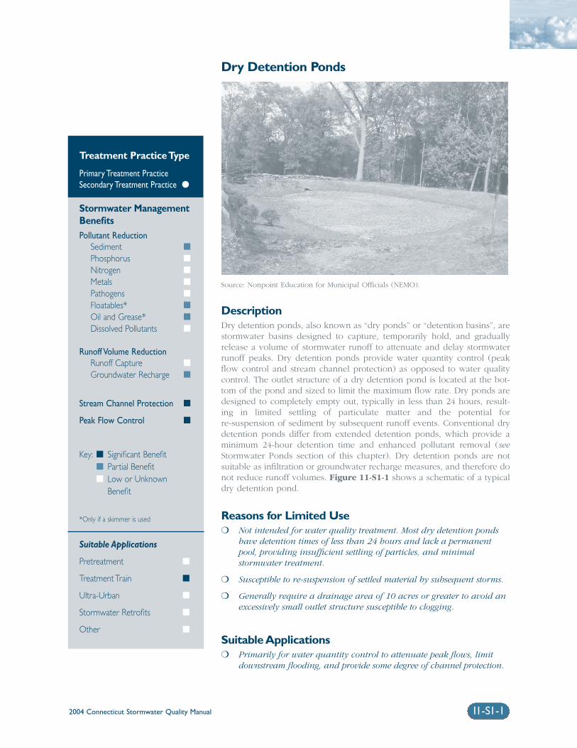
2004 Connecticut Stormwater Quality Manual 11-S1-1
Dry Detention Ponds
DescriptionDry detention ponds, also known as “dry ponds” or “detention basins”, arestormwater basins designed to capture, temporarily hold, and graduallyrelease a volume of stormwater runoff to attenuate and delay stormwaterrunoff peaks. Dry detention ponds provide water quantity control (peakflow control and stream channel protection) as opposed to water qualitycontrol. The outlet structure of a dry detention pond is located at the bot-tom of the pond and sized to limit the maximum flow rate. Dry ponds aredesigned to completely empty out, typically in less than 24 hours, result-ing in limited settling of particulate matter and the potential forre-suspension of sediment by subsequent runoff events. Conventional drydetention ponds differ from extended detention ponds, which provide aminimum 24-hour detention time and enhanced pollutant removal (seeStormwater Ponds section of this chapter). Dry detention ponds are notsuitable as infiltration or groundwater recharge measures, and therefore donot reduce runoff volumes. Figure 11-S1-1 shows a schematic of a typicaldry detention pond.
Reasons for Limited Use❍ Not intended for water quality treatment. Most dry detention ponds
have detention times of less than 24 hours and lack a permanentpool, providing insufficient settling of particles, and minimalstormwater treatment.
❍ Susceptible to re-suspension of settled material by subsequent storms.
❍ Generally require a drainage area of 10 acres or greater to avoid anexcessively small outlet structure susceptible to clogging.
Suitable Applications❍ Primarily for water quantity control to attenuate peak flows, limit
downstream flooding, and provide some degree of channel protection.
Treatment Practice Type
Primary Treatment PracticeSecondary Treatment Practice l
Stormwater ManagementBenefitsPollutant Reduction
Sediment �
Phosphorus �
Nitrogen �
Metals �
Pathogens �
Floatables* �
Oil and Grease* �
Dissolved Pollutants �
Runoff Volume ReductionRunoff Capture �
Groundwater Recharge �
Stream Channel Protection �
Peak Flow Control �
Key: � Significant Benefit� Partial Benefit� Low or Unknown
Benefit
*Only if a skimmer is used
Suitable Applications
Pretreatment �
Treatment Train �
Ultra-Urban �
Stormwater Retrofits �
Other �
Source: Nonpoint Education for Municipal Officials (NEMO).
2004 Connecticut Stormwater Quality Manual11-S1-2
❍ Low-density residential, industrial, and commer-cial developments with adequate space and lowvisibility.
❍ As part of a stormwater treatment train, particu-larly in combination with other primary orsecondary treatment practices that provide pollu-tant reduction, runoff volume reduction, orgroundwater recharge. The size of dry pondscan be reduced substantially by placing them atthe end of the treatment train to take advantageof reduced runoff volume resulting fromupstream practices that employ infiltration.
❍ Less frequently used portions of larger orregional dry detention basins can offer recre-ational, aesthetic, or open space opportunities(e.g., athletic fields, jogging and walking trails,picnic areas).
Design ConsiderationsThe design of detention ponds is dictated by localstormwater quantity control requirements. Local ordi-nances typically require that post-development peakflows be controlled to pre-development levels forstorms ranging from 2-year through 100-year returnperiods. Control of more frequent events may also berequired. The reader should consult the local author-ity for specific quantity control requirements, as wellas the following references for guidance on thedesign and implementation of conventional drydetention ponds for stormwater quantity control:
❍ Connecticut Department of Transportation(ConnDOT), Connecticut Department ofTransportation Drainage Manual, October 2000.
❍ Water Environment Federation (WEF) andAmerican Society of Civil Engineers (ASCE),Design and Construction of Urban StormwaterManagement Systems (Urban Runoff QualityManagement (WEF Manual of Practice FD-20and ASCE Manual and Report on EngineeringPractice No. 77), 1992.
Whenever possible, detention ponds should bedesigned as extended detention ponds or wet ponds,or used in conjunction with other stormwater treat-ment practices to provide water quality benefits.Extended detention ponds, which are considered primary stormwater treatment practices (see theStormwater Ponds section of this chapter), are modi-fied dry detention ponds that incorporate a number of
enhancements for improved water quality function.Older, existing dry ponds are also good candidates forstormwater retrofits by incorporating these recom-mended enhancements (see Chapter Ten), which aresummarized below.
Sediment Forebay: A sediment forebay is an addi-tional storage area near the inlet of the pond thatfacilitates maintenance and improves pollutantremoval by capturing large particles. Sediment fore-bays can be created by berms or baffles constructedof stone, riprap, gabions or similar materials. Theforebay should include a deep permanent pool tominimize the potential for scour and re-suspension(Metropolitan Council, 2001).
Extended Detention Storage: Extended detentionrequires sufficient storage capacity to hold storm-water for at least 24 hours to allow solids to settle out.The additional storage volume is usually provided inthe lower stages of the pond for treatment of smallerstorms associated with the water quality volume,while the upper stages provide storage capacity forlarge, infrequent storms. To reduce the potential formosquito breeding, detention ponds should not bedesigned to hold water for longer than 5 days.
Any stormwater treatment practices that create anembankment, including stormwater detention ponds,are under the jurisdiction of the Dam Safety Section ofthe Connecticut DEP Inland Water Resources Division(IWRD) and should be constructed, inspected, andmaintained in accordance with Connecticut GeneralStatutes §§22a-401 through 22a-411, inclusive, andapplicable DEP guidance.
Outlet Wet Pool: A relatively shallow, permanentpool of water at the pond outlet can provide addi-tional pollutant removal by settling finer sediment andreducing re-suspension. The wet pool or micropoolcan also be planted with wetland species to enhancepollutant removal.
Pond Configuration: The inlet and outlet of thepond should be positioned to minimize short-circuit-ing. Baffles and internal grading can be used tolengthen the flow path within the pond. A minimumlength-to-width ratio of 2:1 is recommended, andirregularly shaped ponds are desirable due to theirmore natural and less engineered appearance.
Low Flow Channels: Low flow channels preventerosion as runoff first enters a dry pond during theinitial period of a storm event, and after a storm, routethe final portion to the pond outlet.
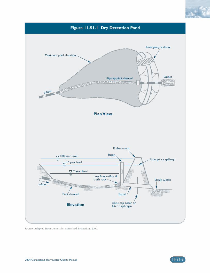
2004 Connecticut Stormwater Quality Manual 11-S1-3
Figure 11-S1-1 Dry Detention Pond
Source: Adapted from Center for Watershed Protection, 2000.
Maximum pool elevation
Inflow
Emergency spillway
Outlet
100 year level
10 year level
2 year level
Riser
Embankment
Pilot channel
Inflow
Barrel
Anti-seep collar orfilter diaphragm
Stable outfall
Emergency spillway
Low flow orifice &trash rack
Rip-rap pilot channel
Plan View
Elevation
2004 Connecticut Stormwater Quality Manual11-S1-4
ReferencesCenter for Watershed Protection (CWP). 2000. TheVermont Stormwater Management HandbookTechnical Support Document – Public Review Draft.Prepared For Vermont Agency of Natural Resources.
Connecticut Department of Transportation (DOT).2000. Connecticut Department of TransportationDrainage Manual.
Metropolitan Council. 2001. Minnesota Urban SmallSites BMP Manual: Stormwater Best ManagementPractices for Cold Climates. Prepared by BarrEngineering Company. St. Paul, Minnesota.
United States Environmental Protection Agency (EPA).2002. National Menu of Best Management Practicesfor Stormwater Phase II. URL: http://www.epa.gov/npdes/menuofbmps/menu.htm,Last Modified January 24, 2002.
Water Environment Federation (WEF) and AmericanSociety of Civil Engineers (ASCE). 1992. Design andConstruction of Urban Stormwater ManagementSystems. WEF Manual of Practice FD-20 and ASCEManual and Report on Engineering Practice No. 77.
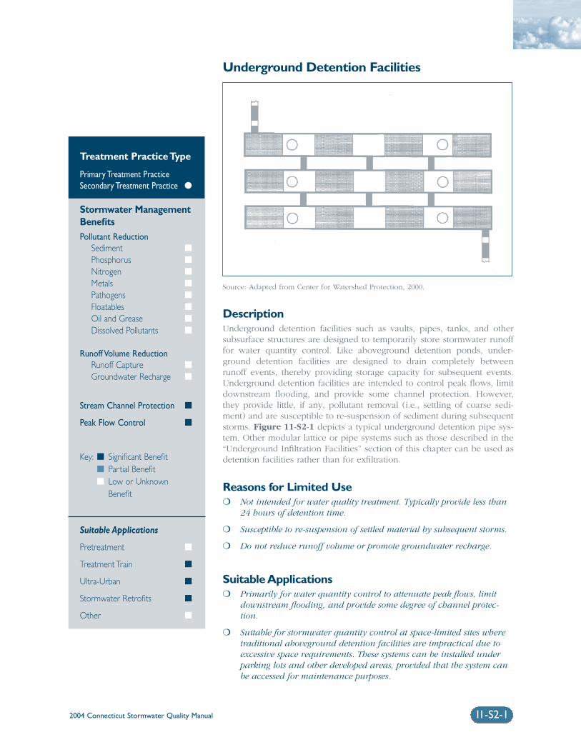
2004 Connecticut Stormwater Quality Manual 11-S2-1
Underground Detention Facilities
DescriptionUnderground detention facilities such as vaults, pipes, tanks, and othersubsurface structures are designed to temporarily store stormwater runofffor water quantity control. Like aboveground detention ponds, under-ground detention facilities are designed to drain completely betweenrunoff events, thereby providing storage capacity for subsequent events.Underground detention facilities are intended to control peak flows, limitdownstream flooding, and provide some channel protection. However,they provide little, if any, pollutant removal (i.e., settling of coarse sedi-ment) and are susceptible to re-suspension of sediment during subsequentstorms. Figure 11-S2-1 depicts a typical underground detention pipe sys-tem. Other modular lattice or pipe systems such as those described in the“Underground Infiltration Facilities” section of this chapter can be used asdetention facilities rather than for exfiltration.
Reasons for Limited Use❍ Not intended for water quality treatment. Typically provide less than
24 hours of detention time.
❍ Susceptible to re-suspension of settled material by subsequent storms.
❍ Do not reduce runoff volume or promote groundwater recharge.
Suitable Applications❍ Primarily for water quantity control to attenuate peak flows, limit
downstream flooding, and provide some degree of channel protec-tion.
❍ Suitable for stormwater quantity control at space-limited sites wheretraditional aboveground detention facilities are impractical due toexcessive space requirements. These systems can be installed underparking lots and other developed areas, provided that the system canbe accessed for maintenance purposes.
Treatment Practice Type
Primary Treatment PracticeSecondary Treatment Practice �
Stormwater ManagementBenefitsPollutant Reduction
Sediment �
Phosphorus �
Nitrogen �
Metals �
Pathogens �
Floatables �
Oil and Grease �
Dissolved Pollutants �
Runoff Volume ReductionRunoff Capture �
Groundwater Recharge �
Stream Channel Protection �
Peak Flow Control �
Key: � Significant Benefit� Partial Benefit� Low or Unknown
Benefit
Suitable Applications
Pretreatment �
Treatment Train �
Ultra-Urban �
Stormwater Retrofits �
Other �
Source: Adapted from Center for Watershed Protection, 2000.
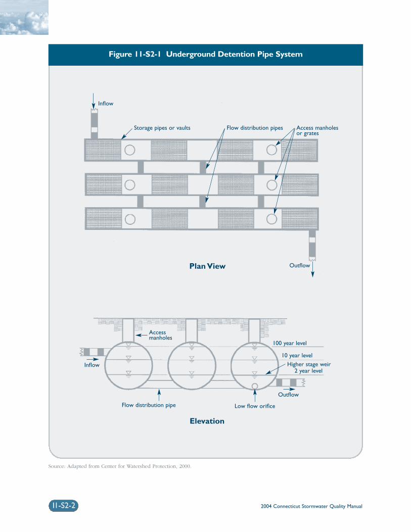
2004 Connecticut Stormwater Quality Manual11-S2-2
Figure 11-S2-1 Underground Detention Pipe System
Source: Adapted from Center for Watershed Protection, 2000.
Inflow
Inflow
Storage pipes or vaults Flow distribution pipes
Low flow orifice
100 year level
10 year level
2 year levelHigher stage weir
Flow distribution pipe
Outflow
Outflow
Plan View
Elevation
Access manholesor grates
Accessmanholes
2004 Connecticut Stormwater Quality Manual 11-S2-3
❍ Useful in stormwater retrofit applications to pro-vide additional temporary storage volume andattenuate peak flows.
❍ As part of a stormwater treatment train, particu-larly in combination with other primary orsecondary treatment practices that provide pollu-tant reduction, runoff volume reduction, orgroundwater recharge.
Design ConsiderationsSiting: Underground detention systems are generallyapplicable to small development sites and should beinstalled in locations that are easily accessible for rou-tine and non-routine maintenance. These systemsshould not be located in areas or below structuresthat cannot be excavated in the event that the systemneeds to be replaced. Access manholes should belocated at upstream, downstream, and intermediatelocations, as appropriate
Pretreatment: Appropriate pretreatment (e.g.,oil/particle separator, hydrodynamic device, catchbasin inserts, or other secondary or primary treatmentpractices) should be provided to minimize the quan-tity of sediment that reaches the detention system.
Inlets, Outlets, and Overflows: Underground sys-tems are typically designed as on-line systems thatcapture frequent runoff events from paved areas.Outlets are sized to restrict maximum flow rates inaccordance with local peak flow control require-ments, such as controlling post-development peakflows to pre-development levels for storms rangingfrom 2-year through 100-year return periods.Emergency surface overflows should be designed toconvey the 100-year runoff in case the outlet becomesclogged. Potential mosquito entry points should besealed (adult female mosquitoes can use openings assmall as 1/16 inch to access water for egg laying).
ReferencesCenter for Watershed Protection (CWP). 2000. TheVermont Stormwater Management HandbookTechnical Support Document – Public Review Draft.Prepared For Vermont Agency of Natural Resources.
United States Environmental Protection Agency (EPA).1999. Storm Water Technology Fact Sheet: InfiltrationDrainfields. EPA 832-F-99-018. Office of Water.Washington, D.C.
United States Environmental Protection Agency (EPA).2002. National Menu of Best Management Practicesfor Stormwater Phase II. URL: http://www.epa.gov/npdes/menuofbmps/menu.htm,
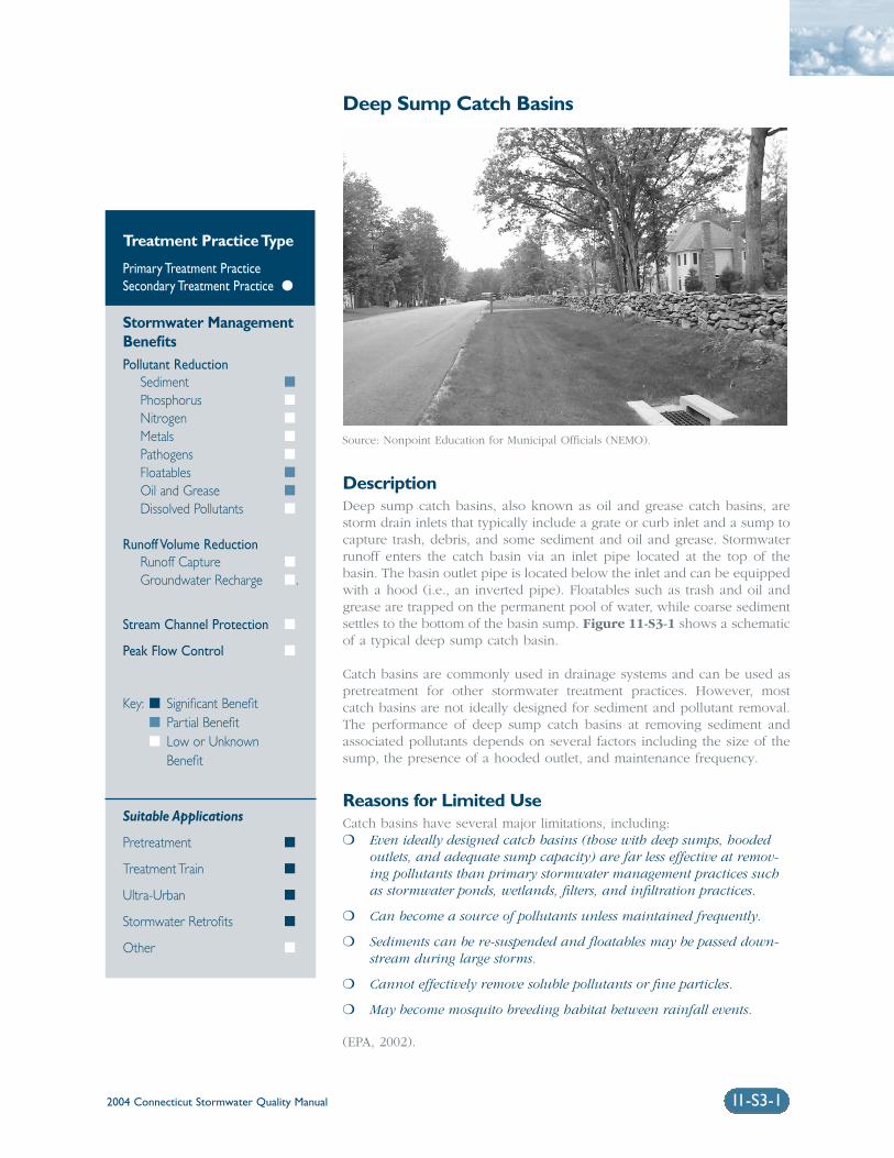
2004 Connecticut Stormwater Quality Manual 11-S3-1
Deep Sump Catch Basins
DescriptionDeep sump catch basins, also known as oil and grease catch basins, arestorm drain inlets that typically include a grate or curb inlet and a sump tocapture trash, debris, and some sediment and oil and grease. Stormwaterrunoff enters the catch basin via an inlet pipe located at the top of thebasin. The basin outlet pipe is located below the inlet and can be equippedwith a hood (i.e., an inverted pipe). Floatables such as trash and oil andgrease are trapped on the permanent pool of water, while coarse sedimentsettles to the bottom of the basin sump. Figure 11-S3-1 shows a schematicof a typical deep sump catch basin.
Catch basins are commonly used in drainage systems and can be used aspretreatment for other stormwater treatment practices. However, mostcatch basins are not ideally designed for sediment and pollutant removal.The performance of deep sump catch basins at removing sediment andassociated pollutants depends on several factors including the size of thesump, the presence of a hooded outlet, and maintenance frequency.
Reasons for Limited UseCatch basins have several major limitations, including:❍ Even ideally designed catch basins (those with deep sumps, hooded
outlets, and adequate sump capacity) are far less effective at remov-ing pollutants than primary stormwater management practices suchas stormwater ponds, wetlands, filters, and infiltration practices.
❍ Can become a source of pollutants unless maintained frequently.
❍ Sediments can be re-suspended and floatables may be passed down-stream during large storms.
❍ Cannot effectively remove soluble pollutants or fine particles.
❍ May become mosquito breeding habitat between rainfall events.
(EPA, 2002).
Treatment Practice Type
Primary Treatment PracticeSecondary Treatment Practice �
Stormwater ManagementBenefitsPollutant Reduction
Sediment �
Phosphorus �
Nitrogen �
Metals �
Pathogens �
Floatables �
Oil and Grease �
Dissolved Pollutants �
Runoff Volume ReductionRunoff Capture �
Groundwater Recharge �.
Stream Channel Protection �
Peak Flow Control �
Key: � Significant Benefit� Partial Benefit� Low or Unknown
Benefit
Suitable Applications
Pretreatment �
Treatment Train �
Ultra-Urban �
Stormwater Retrofits �
Other �
Source: Nonpoint Education for Municipal Officials (NEMO).
2004 Connecticut Stormwater Quality Manual11-S3-2
Suitable Applications❍ For limited removal of trash, debris, oil and
grease, and sediment from stormwater runofffrom relatively small impervious areas (parkinglots, gas stations, and other commercial development).
❍ To provide pretreatment for other stormwatertreatment practices.
❍ For retrofit of existing stormwater drainage systems to provide floatables and limited sedi-ment control. See Chapter Ten for examples of catch basin stormwater retrofits.
Design ConsiderationsDrainage Area: The contributing drainage area toany deep sump catch basin generally should notexceed 1/4 acre of impervious cover.
Design: Catch basin performance is related to thevolume of the sump below the outlet. A recom-mended catch basin sizing criterion relates the catchbasin sump depth to the diameter of the outlet pipe(D), as follows:
❍ The sump depth (distance from the bottom of theoutlet pipe to the bottom of the basin) should beat least 4D and increased if cleaning is infre-quent or if the contributing drainage area hashigh sediment loads.
❍ The diameter of the catch basin should be atleast 4 feet.
❍ The bottom of the outlet pipe should be at least 4 feet from the bottom of the catch basininlet grate.
(Lager et al., 1997). Where high sediment loads areanticipated, the catch basin can be sized to accom-modate the volume of sediment that enters thesystem, with a factor of safety (Pitt et al., 2000).
Where feasible, deep sump catch basins should bedesigned as off-line systems (i.e., collectors or pre-ceded by a flow diversion structure) to minimizere-suspension of sediment during large storms. Thebasic design should also incorporate a hooded outletconsisting of an inverted elbow pipe to prevent float-able materials and trash from entering the stormdrainage system. Hooded outlets may be impractical
for outlet pipes larger than 24 inches in diameter.Catch basin hoods that reduce or eliminate siphoningshould be used. Catch basins should be watertight tomaintain a permanent pool of water and providehigher floatable capture efficiency. Catch basininserts, which are described elsewhere in this chapter,can be used to filter runoff entering the catch basin,although their effectiveness is unproven and theyrequire frequent sediment removal.
Maintenance: Typical maintenance of catch basinsincludes trash removal from the grate (and screen orother debris-capturing device if one is used) andremoval of sediment using a vacuum truck. Studieshave shown that catch basins can capture sedimentsup to approximately 50 percent of the sump volume.Above this volume, catch basins reach steady statedue to re-suspension of sediment (Pitt, 1984).Frequent cleanout maintains available sump volumefor treatment purposes.
Catch basins should be cleaned at least annually, afterthe snow and ice removal season is over and as soonas possible before spring rainfall events. In general, acatch basin should be cleaned if the depth of depositsis greater than or equal to one-half the depth from thebottom of the basin to the invert of the lowest pipe inthe basin (EPA, 1999). If a catch basin significantlyexceeds this one-half depth standard during theannual inspection, then it should be cleaned more frequently.
In addition, areas with higher pollutant loadings ordischarging to sensitive water bodies should also becleaned more frequently (WEF and ASCE, 1998). Morefrequent cleaning of drainage systems may also beneeded in areas with relatively flat grades or lowflows since they may rarely achieve sufficiently highflows for self-flushing (Fergusen et al., 1997).
Plans for catch basins should identify detailed inspec-tion and maintenance requirements, inspection andmaintenance schedules, and those parties responsiblefor maintenance.
Sediment Disposal: Polluted water or sedimentremoved from catch basins should be properly handled and disposed in accordance with local, state,and federal regulations. Before disposal, an appropri-ate chemical analysis of the material should beperformed to determine proper methods for storageand disposal (EPA, 1999).
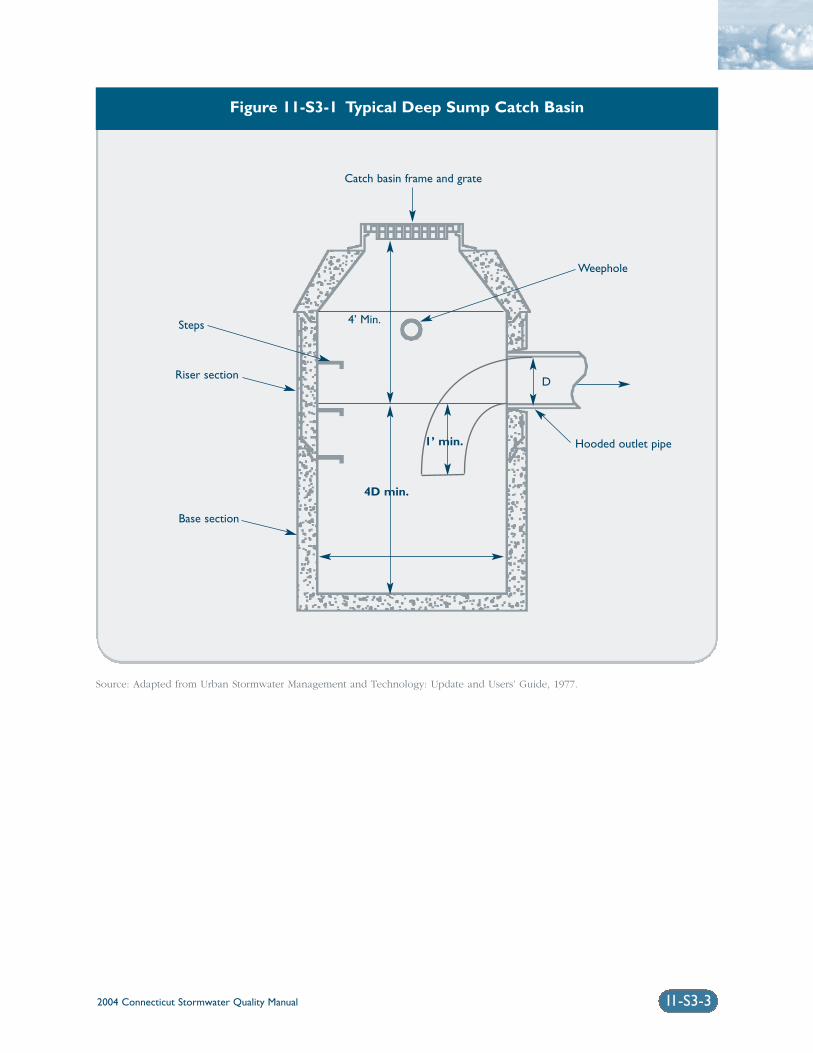
2004 Connecticut Stormwater Quality Manual 11-S3-3
Figure 11-S3-1 Typical Deep Sump Catch Basin
Catch basin frame and grate
Weephole
Hooded outlet pipe
4’ Min.
D
Steps
Riser section
Base section
4D min.
1’ min.
Source: Adapted from Urban Stormwater Management and Technology: Update and Users’ Guide, 1977.
2004 Connecticut Stormwater Quality Manual11-S3-4
ReferencesFerguson, T., Gignac, R., Stoffan, M., Ibrahim, A., andJ. Aldrich. 1997. Rouge River national Wet WeatherDemonstration Project: Cost Estimating Guidelines,Best Management Practices and Engineered Controls.Wayne County, Michigan.
Lager, J., Smith, W., Finn, R., and E. Finnemore. 1997.Urban Stormwater Management and Technology:Update and User’s Guide. Prepared for U.S.Environmental Protection Agency. EPA-600/8-77-014.
Pitt, R. and P. Bissonnette. 1984. Bellevue UrbanRunoff Program Summary Report. U.S. EnvironmentalProtection Agency. Water Planning Division.Washington, D.C..
Pitt, R.M., Nix, S., Durrans, S.R., Burian, S., Voorhees,J., and J. Martinson. 2000. Guidance Manual forIntegrated Wet Weather Flow (WWF) Collection andTreatment Systems for Newly Urbanized Areas (NewWWF Systems). U.S. Environmental ProtectionAgency. Office of Research and Development.Cincinnati, Ohio.
United States Environmental Protection Agency (EPA).1999. Preliminary Data Summary of Urban StormWater Best Management Practices. EPA 821-R99-012.
United States Environmental Protection Agency (EPA).2002. National Menu of Best Management Practicesfor Stormwater Phase II. URL:http://www.epa.gov/npdes/menuofbmps/menu.htm,Last Modified January 24, 2002.
Water Environment Federation (WEF) and AmericanSociety of Civil Engineers (ASCE), Urban RunoffQuality Management. WEF Manual of Practice No. 23and ASCE Manual and Report on Engineering PracticeNo. 87, 1998.
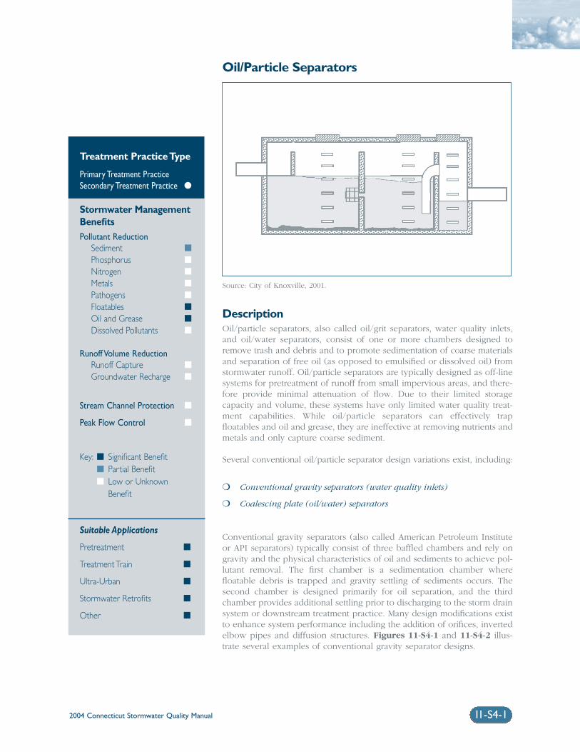
2004 Connecticut Stormwater Quality Manual 11-S4-1
Oil/Particle Separators
DescriptionOil/particle separators, also called oil/grit separators, water quality inlets,and oil/water separators, consist of one or more chambers designed toremove trash and debris and to promote sedimentation of coarse materialsand separation of free oil (as opposed to emulsified or dissolved oil) fromstormwater runoff. Oil/particle separators are typically designed as off-linesystems for pretreatment of runoff from small impervious areas, and there-fore provide minimal attenuation of flow. Due to their limited storagecapacity and volume, these systems have only limited water quality treat-ment capabilities. While oil/particle separators can effectively trapfloatables and oil and grease, they are ineffective at removing nutrients andmetals and only capture coarse sediment.
Several conventional oil/particle separator design variations exist, including:
❍ Conventional gravity separators (water quality inlets)
❍ Coalescing plate (oil/water) separators
Conventional gravity separators (also called American Petroleum Instituteor API separators) typically consist of three baffled chambers and rely ongravity and the physical characteristics of oil and sediments to achieve pol-lutant removal. The first chamber is a sedimentation chamber wherefloatable debris is trapped and gravity settling of sediments occurs. Thesecond chamber is designed primarily for oil separation, and the thirdchamber provides additional settling prior to discharging to the storm drainsystem or downstream treatment practice. Many design modifications existto enhance system performance including the addition of orifices, invertedelbow pipes and diffusion structures. Figures 11-S4-1 and 11-S4-2 illus-trate several examples of conventional gravity separator designs.
Treatment Practice Type
Primary Treatment PracticeSecondary Treatment Practice �
Stormwater ManagementBenefitsPollutant Reduction
Sediment �
Phosphorus �
Nitrogen �
Metals �
Pathogens �
Floatables �
Oil and Grease �
Dissolved Pollutants �
Runoff Volume ReductionRunoff Capture �
Groundwater Recharge �
Stream Channel Protection �
Peak Flow Control �
Key: � Significant Benefit� Partial Benefit� Low or Unknown
Benefit
Suitable Applications
Pretreatment �
Treatment Train �
Ultra-Urban �
Stormwater Retrofits �
Other �
Source: City of Knoxville, 2001.
2004 Connecticut Stormwater Quality Manual11-S4-2
Conventional gravity separators used for stormwatertreatment are similar to wastewater oil/water separa-tors, but have several important differences. Figure11-S4-3 shows a typical oil/water separator designedto treat wastewater discharges from vehicle washingand floor drains. As shown in the figure, wastewaterseparators commonly employ a single chamber withtee or elbow inlet and outlet pipes. The magnitudeand duration of stormwater flows are typically muchmore variable than wastewater flows and, therefore,the single-chamber design does not provide sufficientprotection against re-suspension of sediment duringrunoff events. Single-chamber wastewater oil/waterseparators should not be used for stormwater applications.
The basic gravity separator design can be modified byadding coalescing plates to increase the effectivenessof oil/water separation and reduce the size of therequired unit. A series of coalescing plates, con-structed of oil-attracting materials such aspolypropylene and typically spaced an inch apart,attract small oil droplets which begin to concentrateuntil they are large enough to float to the water sur-face and separate from the stormwater (EPA, 1999).Figure 11-S4-4 shows a typical coalescing plate separator design.
A number of recently developed proprietary separatordesigns also exist. These are addressed in theHydrodynamic Separators section of this chapter.
Reasons for Limited Use❍ Limited pollutant removal. Cannot effectively
remove soluble pollutants or fine particles.
❍ Can become a source of pollutants due to re-suspension of sediment unless maintained frequently. Maintenance often neglected (“out of sight and out of mind”).
❍ Limited to relatively small contributing drainage areas.
Suitable Applications❍ For limited removal of trash, debris, oil and
grease, and sediment from stormwater runofffrom relatively small impervious areas with high traffic volumes or high potential for spillssuch as:
❑ Parking lots
❑ Streets
❑ Truck loading areas
❑ Gas stations
❑ Refueling areas
❑ Automotive repair facilities
❑ Fleet maintenance yards
❑ Commercial vehicle washing facilities
❑ Industrial facilities.
❍ To provide pretreatment for other stormwatertreatment practices.
❍ For retrofit of existing stormwater drainage systems, particularly in highly developed (ultra-urban) areas.
Design ConsiderationsDrainage Area: The contributing drainage area toconventional oil/particle separators generally shouldbe limited to one acre or less of impervious cover.Separators should only be used in an off-line config-uration to treat the design water quality flow (peakflow associated with the design water quality vol-ume). Upstream diversion structures can be used todivert higher flows around the separator. On-lineunits receive higher flows that cause increased turbu-lence and re-suspension of settled material (EPA, 1999).
Sizing/Design: The combined volume of the perma-nent pools in the chambers should be 400 cubic feetper acre of contributing impervious area. The poolsshould be at least 4 feet deep, and the third chambershould also be used as a permanent pool.
A trash rack or screen should be used to cover thedischarge outlet and orifices between chambers. Aninverted elbow pipe should be located between thesecond and third chambers, and the bottom of theelbow pipe should be at least 3 feet below the secondchamber permanent pool. Each chamber should beequipped with manholes and access steps/ladders formaintenance and cleaning. Potential mosquito entrypoints should be sealed (adult female mosquitoes canuse openings as small as 1/16 inch to access water foregg laying).
Maintenance: Maintenance is critical for properoperation of oil/particle separators. Separators thatare not maintained can be significant sources of pol-lution. Separators should be inspected at least
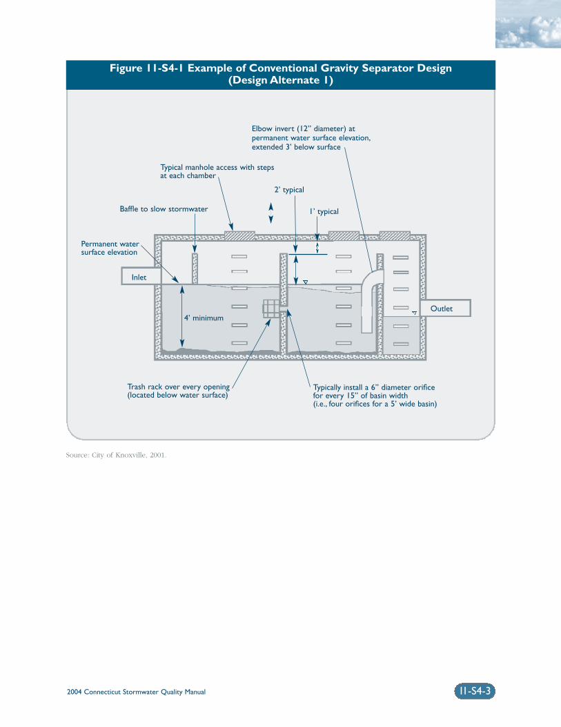
Figure 11-S4-1 Example of Conventional Gravity Separator Design(Design Alternate 1)
2004 Connecticut Stormwater Quality Manual 11-S4-3
Source: City of Knoxville, 2001.
Elbow invert (12” diameter) at permanent water surface elevation,extended 3’ below surface
Typical manhole access with stepsat each chamber
Trash rack over every opening(located below water surface)
4’ minimum
Typically install a 6” diameter orificefor every 15” of basin width(i.e., four orifices for a 5’ wide basin)
Baffle to slow stormwater
2’ typical
1’ typical
Outlet
Inlet
Permanent watersurface elevation
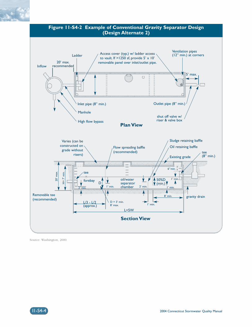
2004 Connecticut Stormwater Quality Manual11-S4-4
Figure 11-S4-2 Example of Conventional Gravity Separator Design(Design Alternate 2)
Source: Washington, 2000.
Access cover (typ.) w/ ladder accessto vault. If >1250 sf, provide 5’ x 10’
removable panel over inlet/outlet pipe.
Ladder
20’ max.recommendedInflow
Inlet pipe (8” min.) Outlet pipe (8” min.)
shut off valve w/riser & valve box
Ventilation pipes(12” min.) at corners
Manhole
5’ max.
High flow bypass
Varies (can beconstructed ongrade without
risers)
Flow spreading baffle(recommended)
Sludge retaining baffle
Oil retaining baffle
Existing grade
gravity drainRemovable tee(recommended)
tee
forebay
L=5W
L/3 - L/2(approx.)
D
tee(8” min.)
50%D(min.)
6”min.
1’ min.
1’ min.
8’ min.
1’ min.
20’ m
ax.
H=
7’ m
in.
2’ min.2’ min. 1’ min.
oil/waterseparatorchamber
D = 3’ min.8’ max.
Plan View
Section View
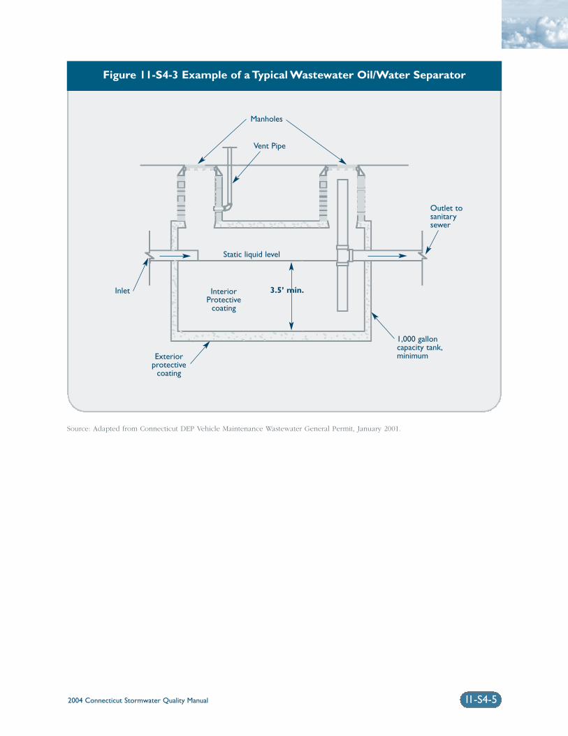
2004 Connecticut Stormwater Quality Manual 11-S4-5
Figure 11-S4-3 Example of a Typical Wastewater Oil/Water Separator
Source: Adapted from Connecticut DEP Vehicle Maintenance Wastewater General Permit, January 2001.
Manholes
Static liquid level
Vent Pipe
Inlet
Outlet tosanitarysewer
1,000 galloncapacity tank,minimum
InteriorProtective
coating
Exteriorprotective
coating
3.5’ min.
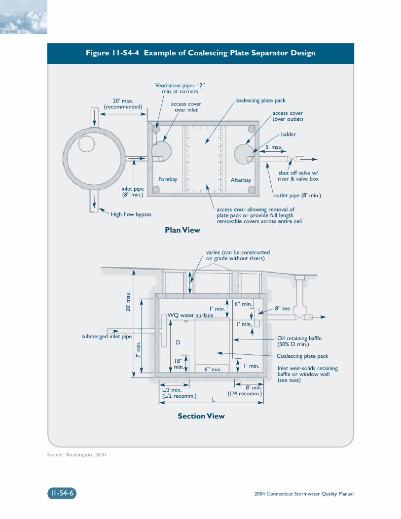
2004 Connecticut Stormwater Quality Manual11-S4-6
Figure 11-S4-4 Example of Coalescing Plate Separator Design
Source: Washington, 2000.
20’ max.(recommended) access cover
over inlet
coalescing plate pack
Ventilation pipes 12”min. at corners
access cover(over outlet)
ladder
5’ max.
shut off valve w/riser & valve box
access door allowing removal ofplate pack or provide full lengthremovable covers across entire cell
varies (can be constructedon grade without risers)
submerged inlet pipe
L/3 min.(L/2 recomm.)
18”min.
D
L
6” min.1’ min.
1’ min.
1’ min.WQ water surface
20’ m
ax.
7’ m
in.
6” min.8” tee
8’ min.(L/4 recomm.)
Coalescing plate pack
Oil retaining baffle(50% D min.)
Inlet weir-solids retaining baffle or window wall (see text)
outlet pipe (8’ min.)
Forebay Afterbay
High flow bypass
inlet pipe(8” min.)
Plan View
Section View
2004 Connecticut Stormwater Quality Manual 11-S4-7
monthly and typically need to be cleaned every oneto six months. Typical maintenance includes removalof accumulated oil and grease, floatables, and sedi-ment using a vacuum truck or other ordinary catchbasin cleaning equipment.
Plans for oil/particle separators should identifydetailed inspection and maintenance requirements,inspection and maintenance schedules, and those par-ties responsible for maintenance.
Sediment Disposal: Polluted water or sedimentremoved from separators should be properly handledand disposed of in accordance with local, state, andfederal regulations. Before disposal, appropriatechemical analysis of the material should be performedto determine proper methods for storage and disposal.
ReferencesConnecticut Department of Environmental Protection(DEP). 2001. General Permit for the Discharge ofVehicle Maintenance Wastewater. Issuance DateJanuary 23, 2001.
City of Knoxville. 2001. Knoxville BMP Manual. City ofKnoxville Engineering Department. Knoxville,Tennessee.
United States Environmental Protection Agency (EPA).2002. National Menu of Best Management Practices forStormwater Phase II. URL: http://www.epa.gov/npdes/menuofbmps/menu.htm,Last Modified January 24, 2002.
United States Environmental Protection Agency (EPA).1999. Storm Water Technology Fact Sheet: WaterQuality Inlets. EPA 832-F-99-029. Office of Water.Washington, D.C.
Washington State Department of Ecology(Washington). 2000. Stormwater Management Manualfor Western Washington, Final Draft. Olympia,Washington.
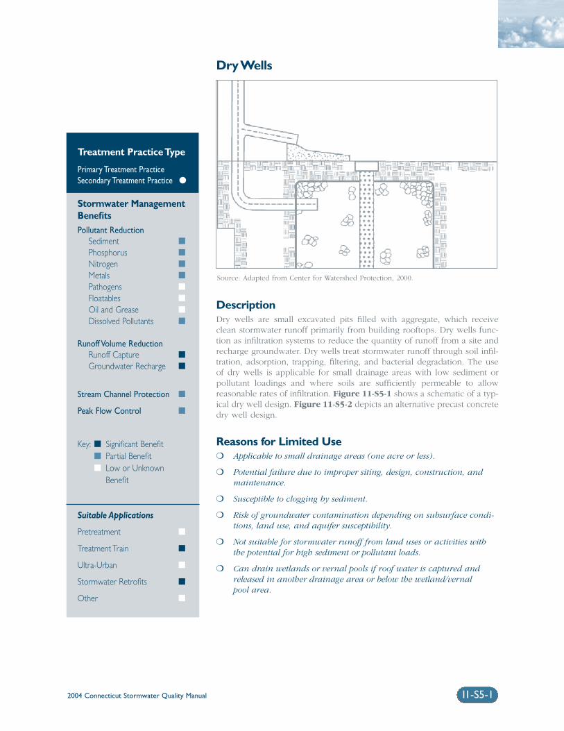
2004 Connecticut Stormwater Quality Manual 11-S5-1
Dry Wells
DescriptionDry wells are small excavated pits filled with aggregate, which receiveclean stormwater runoff primarily from building rooftops. Dry wells func-tion as infiltration systems to reduce the quantity of runoff from a site andrecharge groundwater. Dry wells treat stormwater runoff through soil infil-tration, adsorption, trapping, filtering, and bacterial degradation. The useof dry wells is applicable for small drainage areas with low sediment orpollutant loadings and where soils are sufficiently permeable to allow reasonable rates of infiltration. Figure 11-S5-1 shows a schematic of a typ-ical dry well design. Figure 11-S5-2 depicts an alternative precast concretedry well design.
Reasons for Limited Use❍ Applicable to small drainage areas (one acre or less).
❍ Potential failure due to improper siting, design, construction, andmaintenance.
❍ Susceptible to clogging by sediment.
❍ Risk of groundwater contamination depending on subsurface condi-tions, land use, and aquifer susceptibility.
❍ Not suitable for stormwater runoff from land uses or activities withthe potential for high sediment or pollutant loads.
❍ Can drain wetlands or vernal pools if roof water is captured andreleased in another drainage area or below the wetland/vernal pool area.
Treatment Practice Type
Primary Treatment PracticeSecondary Treatment Practice �
Stormwater ManagementBenefitsPollutant Reduction
Sediment �
Phosphorus �
Nitrogen �
Metals �
Pathogens �
Floatables �
Oil and Grease �
Dissolved Pollutants �
Runoff Volume ReductionRunoff Capture �
Groundwater Recharge �
Stream Channel Protection �
Peak Flow Control �
Key: � Significant Benefit� Partial Benefit� Low or Unknown
Benefit
Suitable Applications
Pretreatment �
Treatment Train �
Ultra-Urban �
Stormwater Retrofits �
Other �
Source: Adapted from Center for Watershed Protection, 2000.
2004 Connecticut Stormwater Quality Manual11-S5-2
Suitable Applications❍ For infiltration of rooftop runoff that is unlikely
to contribute significant loadings of sediment orpollutants (i.e., non-industrial, non-metallicroofs). Dry wells are not recommended for infil-trating parking lot runoff without pretreatmentto remove sediment, hydrocarbons, and otherpollutants.
❍ These systems can be installed under parking lotsand other developed areas, provided that the sys-tem can be accessed for maintenance purposes.
❍ Useful in stormwater retrofit applications wherespace is limited and where additional runoffcontrol is required.
❍ Where storm drains are not available and whereadequate pretreatment is provided.
Design ConsiderationsDry wells are small-scale infiltration systems similar tothe primary treatment infiltration practices describedin previous sections of this chapter. Many of the sit-ing, design, construction, and maintenanceconsiderations for dry wells are similar to those ofinfiltration trenches, which are summarized below.
Soils: Dry wells should only be used with soils hav-ing suitable infiltration capacity (as confirmed throughfield testing). The minimum acceptable field-meas-ured soil infiltration rate is 0.3 inches per hour.Field-measured soil infiltration rates should notexceed 5.0 inches per hour. This generally restrictsapplication to soils of NRCS Hydrologic Soil Group A.Some Group B soils may be suitable if field-measuredinfiltration rates exceed 0.3 inches per hour. Refer tothe Infiltration Practices section of this chapter for rec-ommended field measurement techniques. Oneinfiltration test and test pit or soil boring is recom-mended at the proposed location of the dry well. Anobservation well consisting of a well-anchored, verti-cal perforated PVC pipe with lockable abovegroundcap should be installed to monitor system perform-ance.
Land Use: Dry wells should only be used to infiltraterelatively clean runoff such as rooftop runoff. Drywells should not be used to infiltrate runoff contain-ing significant solids concentrations or concentrationsof soluble pollutants that could contaminate ground-water, without adequate pretreatment. Appropriatepretreatment (e.g., filter strip, oil/particle separator,hydrodynamic device, roof washer for cisterns and
rain barrels, catch basin inserts, or other secondary orprimary treatment practices) should be provided toremove sediment, floatables, and oil and grease.
Drainage Area: The contributing drainage area to adry well should be restricted to one acre or less.
Water Table/Bedrock: The bottom of the dry wellshould be located at least 3 feet above the seasonallyhigh water table as documented by on-site soil testingand should be at least 4 feet above bedrock.
Size/Depth: Dry wells should be designed to com-pletely drain the water quality volume (or largerrunoff volumes for additional groundwater recharge)into the soil within 48 hours after the storm event. Drywells should completely dewater between storms. Aminimum draining time of 6 to 12 hours is recom-mended to ensure adequate pollutant removal. Drywells should be equipped with overflows to handlelarger runoff volumes or flows.
Miscellaneous: Dry wells should not be placed overfill materials, should be located a minimum of 10 feetfrom building foundations and, unless otherwiserequired or recommended by the DEP or the state orlocal health department should be located at least 75feet away from:
❍ Drinking water supply wells
❍ Septic systems (any components)
❍ Surface water bodies
❍ Building foundations (at least 100 feet upgradientand at least 25 feet downgradient from buildingfoundations)
Construction: Refer to the Infiltration Practices section of this chapter for construction recommenda-tions. The dry well should be filled with 1.5 to3.0-inch diameter clean washed stone and bewrapped with filter fabric. The dry well should becovered by a minimum of 12 inches of soil.
Operation and Maintenance: Refer to theInfiltration Practices section of this chapter for opera-tion and maintenance recommendations.
Plans for dry wells should identify detailed inspectionand maintenance requirements, inspection and main-tenance schedules, and those parties responsible formaintenance.
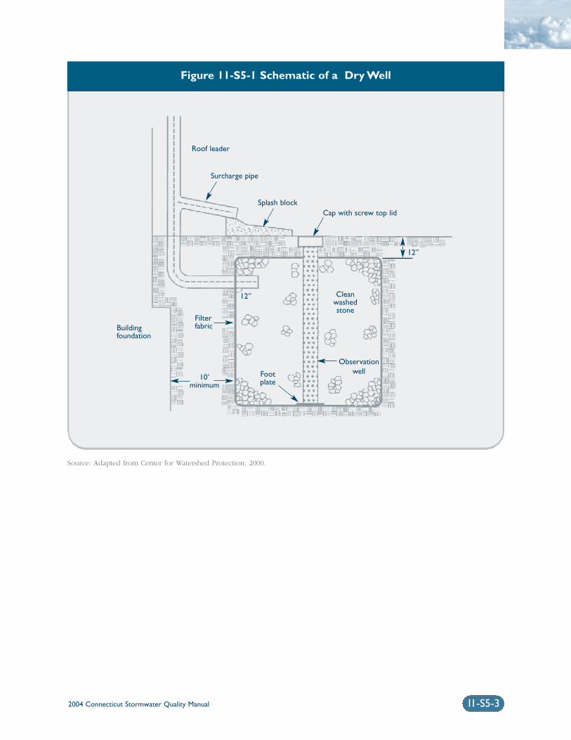
2004 Connecticut Stormwater Quality Manual 11-S5-3
Source: Adapted from Center for Watershed Protection, 2000.
Figure 11-S5-1 Schematic of a Dry Well
Roof leader
Surcharge pipe
Splash blockCap with screw top lid
Observationwell
Buildingfoundation
Cleanwashedstone
Footplate
12”
12”
Filterfabric
10’minimum
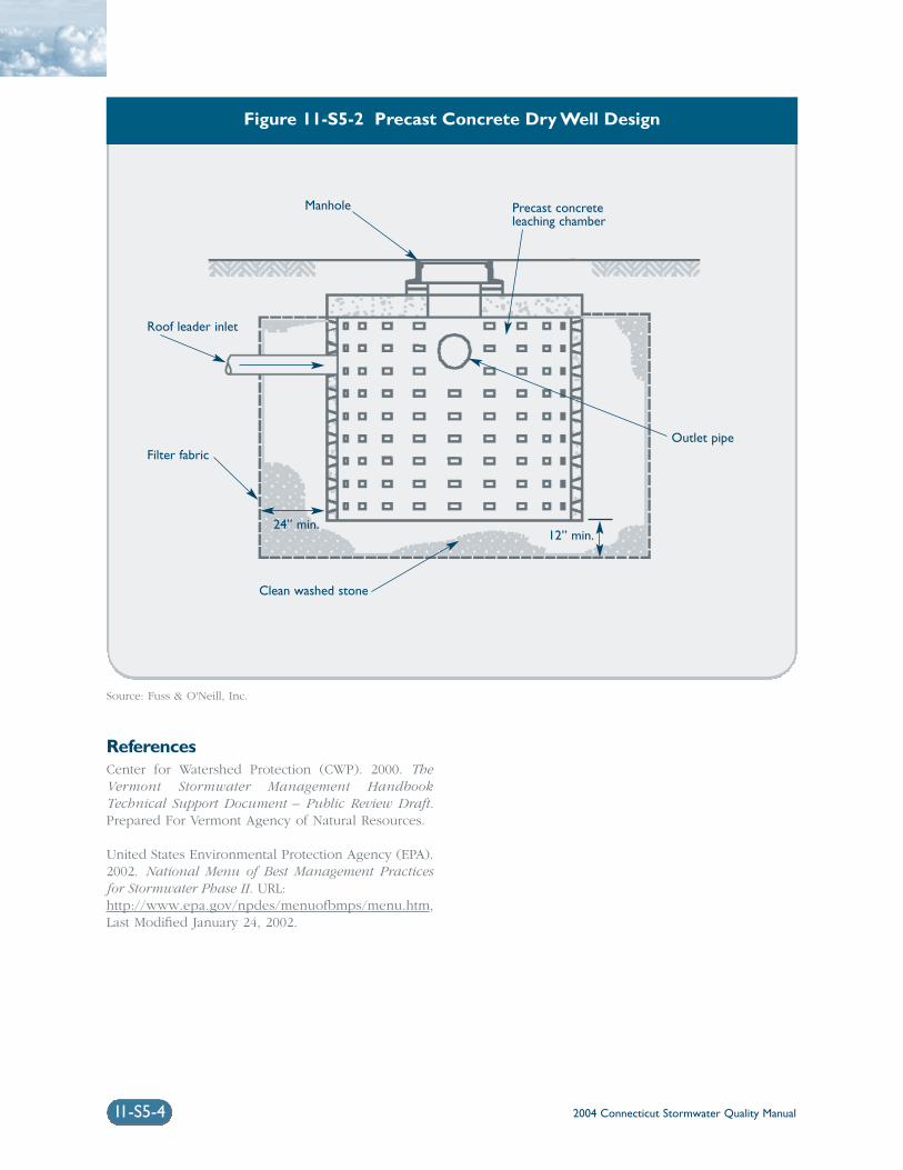
2004 Connecticut Stormwater Quality Manual
ReferencesCenter for Watershed Protection (CWP). 2000. TheVermont Stormwater Management HandbookTechnical Support Document – Public Review Draft.Prepared For Vermont Agency of Natural Resources.
United States Environmental Protection Agency (EPA).2002. National Menu of Best Management Practicesfor Stormwater Phase II. URL:http://www.epa.gov/npdes/menuofbmps/menu.htm,Last Modified January 24, 2002.
11-S5-4
Figure 11-S5-2 Precast Concrete Dry Well Design
Manhole
Roof leader inlet
Filter fabric
Clean washed stone
Outlet pipe
12” min.24” min.
Precast concreteleaching chamber
Source: Fuss & O'Neill, Inc.
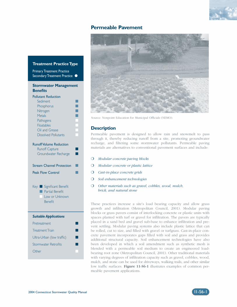
2004 Connecticut Stormwater Quality Manual 11-S6-1
Permeable Pavement
DescriptionPermeable pavement is designed to allow rain and snowmelt to passthrough it, thereby reducing runoff from a site, promoting groundwaterrecharge, and filtering some stormwater pollutants. Permeable pavingmaterials are alternatives to conventional pavement surfaces and include:
❍ Modular concrete paving blocks
❍ Modular concrete or plastic lattice
❍ Cast-in-place concrete grids
❍ Soil enhancement technologies
❍ Other materials such as gravel, cobbles, wood, mulch,brick, and natural stone
These practices increase a site’s load bearing capacity and allow grassgrowth and infiltration (Metropolitan Council, 2001). Modular pavingblocks or grass pavers consist of interlocking concrete or plastic units withspaces planted with turf or gravel for infiltration. The pavers are typicallyplaced in a sand bed and gravel sub-base to enhance infiltration and pre-vent settling. Modular paving systems also include plastic lattice that canbe rolled, cut to size, and filled with gravel or turfgrass. Cast-in-place con-crete pavement incorporates gaps filled with soil and grass and providesadditional structural capacity. Soil enhancement technologies have alsobeen developed in which a soil amendment such as synthetic mesh isblended with a permeable soil medium to create an engineered load-bearing root zone (Metropolitan Council, 2001). Other traditional materialswith varying degrees of infiltration capacity such as gravel, cobbles, wood,mulch, and stone can be used for driveways, walking trails, and other similarlow traffic surfaces. Figure 11-S6-1 illustrates examples of common per-meable pavement applications.
Treatment Practice Type
Primary Treatment PracticeSecondary Treatment Practice �
Stormwater ManagementBenefitsPollutant Reduction
Sediment �
Phosphorus �
Nitrogen �
Metals �
Pathogens �
Floatables �
Oil and Grease �
Dissolved Pollutants �
Runoff Volume ReductionRunoff Capture �
Groundwater Recharge �
Stream Channel Protection �
Peak Flow Control �
Key: � Significant Benefit� Partial Benefit� Low or Unknown
Benefit
Suitable Applications
Pretreatment �
Treatment Train �
Ultra-Urban (low traffic) �
Stormwater Retrofits �
Other �
Source: Nonpoint Education for Municipal Officials (NEMO).
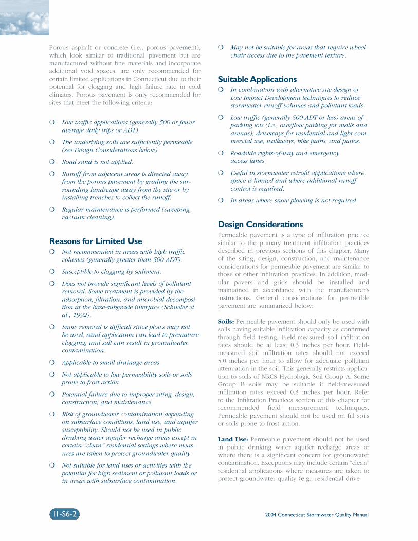
2004 Connecticut Stormwater Quality Manual11-S6-2
Porous asphalt or concrete (i.e., porous pavement),which look similar to traditional pavement but aremanufactured without fine materials and incorporateadditional void spaces, are only recommended forcertain limited applications in Connecticut due to theirpotential for clogging and high failure rate in cold climates. Porous pavement is only recommended forsites that meet the following criteria:
❍ Low traffic applications (generally 500 or feweraverage daily trips or ADT).
❍ The underlying soils are sufficiently permeable(see Design Considerations below).
❍ Road sand is not applied.
❍ Runoff from adjacent areas is directed awayfrom the porous pavement by grading the sur-rounding landscape away from the site or byinstalling trenches to collect the runoff.
❍ Regular maintenance is performed (sweeping,vacuum cleaning).
Reasons for Limited Use❍ Not recommended in areas with high traffic
volumes (generally greater than 500 ADT).
❍ Susceptible to clogging by sediment.
❍ Does not provide significant levels of pollutantremoval. Some treatment is provided by theadsorption, filtration, and microbial decomposi-tion at the base-subgrade interface (Schueler etal., 1992).
❍ Snow removal is difficult since plows may not be used, sand application can lead to prematureclogging, and salt can result in groundwatercontamination.
❍ Applicable to small drainage areas.
❍ Not applicable to low permeability soils or soilsprone to frost action.
❍ Potential failure due to improper siting, design,construction, and maintenance.
❍ Risk of groundwater contamination dependingon subsurface conditions, land use, and aquifersusceptibility. Should not be used in publicdrinking water aquifer recharge areas except incertain “clean” residential settings where meas-ures are taken to protect groundwater quality.
❍ Not suitable for land uses or activities with thepotential for high sediment or pollutant loads orin areas with subsurface contamination.
❍ May not be suitable for areas that require wheel-chair access due to the pavement texture.
Suitable Applications❍ In combination with alternative site design or
Low Impact Development techniques to reducestormwater runoff volumes and pollutant loads.
❍ Low traffic (generally 500 ADT or less) areas ofparking lots (i.e., overflow parking for malls andarenas), driveways for residential and light com-mercial use, walkways, bike paths, and patios.
❍ Roadside rights-of-way and emergency access lanes.
❍ Useful in stormwater retrofit applications wherespace is limited and where additional runoffcontrol is required.
❍ In areas where snow plowing is not required.
Design ConsiderationsPermeable pavement is a type of infiltration practicesimilar to the primary treatment infiltration practicesdescribed in previous sections of this chapter. Many of the siting, design, construction, and maintenanceconsiderations for permeable pavement are similar tothose of other infiltration practices. In addition, mod-ular pavers and grids should be installed andmaintained in accordance with the manufacturer’sinstructions. General considerations for permeablepavement are summarized below:
Soils: Permeable pavement should only be used withsoils having suitable infiltration capacity as confirmedthrough field testing. Field-measured soil infiltrationrates should be at least 0.3 inches per hour. Field-measured soil infiltration rates should not exceed 5.0 inches per hour to allow for adequate pollutantattenuation in the soil. This generally restricts applica-tion to soils of NRCS Hydrologic Soil Group A. SomeGroup B soils may be suitable if field-measured infiltration rates exceed 0.3 inches per hour. Refer to the Infiltration Practices section of this chapter forrecommended field measurement techniques.Permeable pavement should not be used on fill soilsor soils prone to frost action.
Land Use: Permeable pavement should not be usedin public drinking water aquifer recharge areas orwhere there is a significant concern for groundwatercontamination. Exceptions may include certain “clean”residential applications where measures are taken toprotect groundwater quality (e.g., residential drive
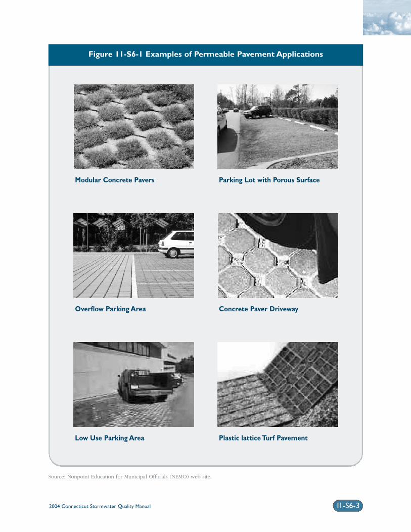
2004 Connecticut Stormwater Quality Manual 11-S6-3
Figure 11-S6-1 Examples of Permeable Pavement Applications
Source: Nonpoint Education for Municipal Officials (NEMO) web site.
Modular Concrete Pavers Parking Lot with Porous Surface
Overflow Parking Area Concrete Paver Driveway
Low Use Parking Area Plastic lattice Turf Pavement
2004 Connecticut Stormwater Quality Manual11-S6-4
ways or walkways graded to drain away from the per-meable pavement). Permeable pavement is notappropriate for land uses where petroleum products,greases, or other chemicals will be used, stored, ortransferred. Except where recommended by local orstate health departments or the Department ofEnvironmental Protection, permeable paving materialsshould not be used in areas that receive significantamounts of sediment or areas that require sand andsalt application for winter deicing.
Slope: Permeable pavement should not be used inareas that are steeply sloped (>15%), such as steepdriveways, as this may lead to erosion of the materialin the voids.
Water Table/Bedrock: The seasonally high watertable as documented by on-site soil testing, should beat least 3 feet below grade. Bedrock should be at least4 feet below grade. Except where recommended bylocal or state health departments or the Department ofEnvironmental Protection, permeable pavement shouldbe located at least 75 feet from drinking water wells.
Construction: Manufacturer’s guidelines should befollowed for installation. Generally, the following pro-cedures are followed for construction of modularpavement systems:
Site Preparation
❍ Site must be excavated and fine graded to the depth required by the base design.
❍ Roller pressure should be applied to compact soils.
❍ Base rock (3” to 6” of 3/4” clean gravel) is then installed and compacted to approxi-mately 95 percent of Standard ProctorDensity.
❍ A 1” sand layer is placed on top of the gravellayer and compacted.
❍ The pavers are then installed according tomanufacturer’s requirements.
Planting
❍ At least 1/8” to 1/4” of the paver must remainabove the soil to bear the traffic load.
❍ Sod or seeding method may be used.
❍ If sod is used, the depth of backfill requiredwill depend on the depth of the sod. Sod islaid over the pavers, watered thoroughly, andthen compressed into the cells of the pavers.
❍ If grass is planted from seed, the appropriatesoil should be placed in the cells, tamped into
the cells, and then watered thoroughly so thatthe appropriate amount of paver is exposed.The soil is then ready for planting with adurable grass seed.
❍ Traffic should be excluded from the area forat least a month to allow for establishment ofgrass.
Operation and Maintenance: Permeable pavementis easiest to maintain in areas where access to thepavement is limited and controlled and where pave-ment maintenance can be incorporated into a routinesite maintenance program, such as commercial park-ing lots, office buildings, and institutional buildings(Pennsylvania Association of Conservation Districts etal., 1998). Turf pavers can be mowed, irrigated, andfertilized like other turf areas. However, fertilizers andother chemicals may adversely affect concrete prod-ucts, and the use of such chemicals should beminimized. Pavers should be inspected once per yearfor deterioration and to determine if soil/vegetationloss has occurred. Soil or vegetation should bereplaced or repaired as necessary. Care must be exer-cised when removing snow to avoid catching thesnow plow on the edges of the pavers. Permeablepavement should be regularly cleared of tracked mudor sediment and leaves.
Plans for permeable pavement should identifydetailed inspection and maintenance requirements,inspection and maintenance schedules, and those par-ties responsible for maintenance.
ReferencesMetropolitan Council. 2001. Minnesota Urban SmallSites BMP Manual: Stormwater Best ManagementPractices for Cold Climates. Prepared by BarrEngineering Company. St. Paul, Minnesota.
Nonpoint Education for Municipal Officials (NEMO)website, URL: http://nemo.uconn.edu.
Pennsylvania Association of Conservation Districts,Keystone Chapter Soil and Water ConservationSociety, Pennsylvania Department of EnvironmentalProtection, and Natural Resources ConservationService. 1998. Pennsylvania Handbook of BestManagement Practices for Developing Areas. Preparedby CH2MHILL.
Schueler, T.R., Kumble, P.A., and M.A. Heraty. 1992. A Current Assessment of Urban Best ManagementPractices: Techniques for Reducing Non-Point SourcePollution in the Coastal Zone. Department ofEnvironmental Programs. Metropolitan WashingtonCouncil of Governments.
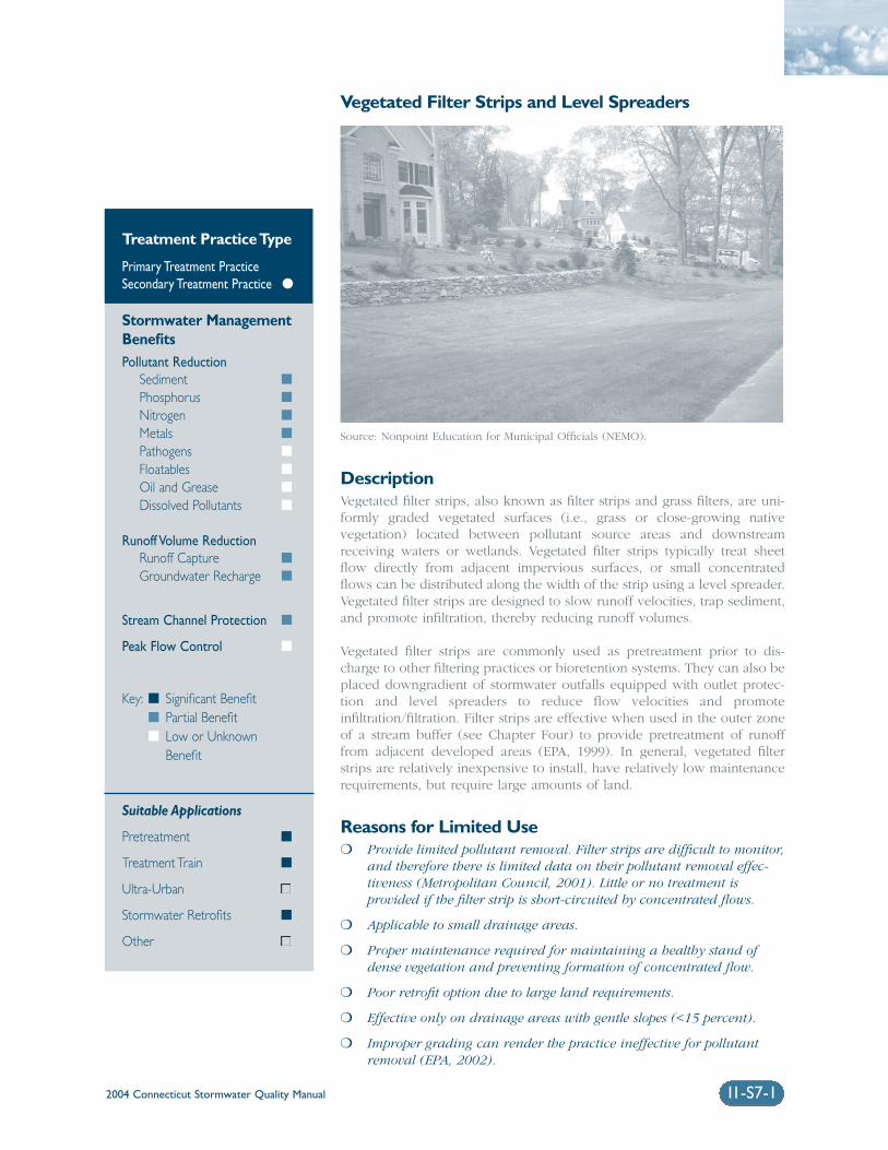
2004 Connecticut Stormwater Quality Manual 11-S7-1
Vegetated Filter Strips and Level Spreaders
DescriptionVegetated filter strips, also known as filter strips and grass filters, are uni-formly graded vegetated surfaces (i.e., grass or close-growing nativevegetation) located between pollutant source areas and downstreamreceiving waters or wetlands. Vegetated filter strips typically treat sheetflow directly from adjacent impervious surfaces, or small concentratedflows can be distributed along the width of the strip using a level spreader.Vegetated filter strips are designed to slow runoff velocities, trap sediment,and promote infiltration, thereby reducing runoff volumes.
Vegetated filter strips are commonly used as pretreatment prior to dis-charge to other filtering practices or bioretention systems. They can also beplaced downgradient of stormwater outfalls equipped with outlet protec-tion and level spreaders to reduce flow velocities and promoteinfiltration/filtration. Filter strips are effective when used in the outer zoneof a stream buffer (see Chapter Four) to provide pretreatment of runofffrom adjacent developed areas (EPA, 1999). In general, vegetated filterstrips are relatively inexpensive to install, have relatively low maintenancerequirements, but require large amounts of land.
Reasons for Limited Use❍ Provide limited pollutant removal. Filter strips are difficult to monitor,
and therefore there is limited data on their pollutant removal effec-tiveness (Metropolitan Council, 2001). Little or no treatment isprovided if the filter strip is short-circuited by concentrated flows.
❍ Applicable to small drainage areas.
❍ Proper maintenance required for maintaining a healthy stand ofdense vegetation and preventing formation of concentrated flow.
❍ Poor retrofit option due to large land requirements.
❍ Effective only on drainage areas with gentle slopes (<15 percent).
❍ Improper grading can render the practice ineffective for pollutantremoval (EPA, 2002).
Treatment Practice Type
Primary Treatment PracticeSecondary Treatment Practice �
Stormwater ManagementBenefitsPollutant Reduction
Sediment �
Phosphorus �
Nitrogen �
Metals �
Pathogens �
Floatables �
Oil and Grease �
Dissolved Pollutants �
Runoff Volume ReductionRunoff Capture �
Groundwater Recharge �
Stream Channel Protection �
Peak Flow Control �
Key: � Significant Benefit� Partial Benefit� Low or Unknown
Benefit
Suitable Applications
Pretreatment �
Treatment Train �
Ultra-Urban
Stormwater Retrofits �
Other
Source: Nonpoint Education for Municipal Officials (NEMO).
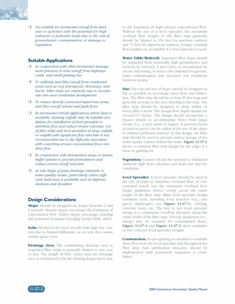
2004 Connecticut Stormwater Quality Manual11-S7-2
❍ Not suitable for stormwater runoff from landuses or activities with the potential for highsediment or pollutant loads due to the risk ofgroundwater contamination or damage tovegetation.
Suitable Applications❍ In conjunction with other stormwater manage-
ment practices to treat runoff from highways,roads, and small parking lots.
❍ To infiltrate and filter runoff from residentialareas such as roof downspouts, driveways, andlawns. Filter strips are relatively easy to incorpo-rate into most residential developments.
❍ To reduce directly connected impervious areas,and thus runoff volume and peak flows.
❍ In stormwater retrofit applications where land isavailable. Existing outfalls may be suitable can-didates for installation of level spreaders todistribute flow and reduce erosive velocities. Useof filter strips and level spreaders at large outfallsor outfalls with significant flow velocities is notrecommended due to the difficulty associatedwith converting erosive concentrated flows intosheet flow.
❍ In conjunction with bioretention areas or streambuffer systems to provide pretreatment andreduce erosive runoff velocities.
❍ As side slopes of grass drainage channels orwater quality swales, particularly where suffi-cient land area is available such as highwaymedians and shoulders.
Design ConsiderationsSlope: Should be designed on slopes between 2 and6 percent. Steeper slopes encourage the formation ofconcentrated flow. Flatter slopes encourage pondingand potential mosquito breeding habitat (EPA, 2002).
Soils: Should not be used on soils with high clay con-tent due to limited infiltration, or on soils that cannotsustain grass cover.
Drainage Area: The contributing drainage area tovegetated filter strips is generally limited to one acreor less. The length of flow, rather than the drainagearea, is considered to be the limiting design factor due
to the formation of high-velocity concentrated flow.Without the use of a level spreader, the maximumoverland flow lengths to the filter strip generallyshould be limited to 150 feet for pervious surfacesand 75 feet for impervious surfaces. Longer overlandflow lengths are acceptable if a level spreader is used.
Water Table/Bedrock: Vegetated filter strips shouldbe separated from seasonally high groundwater andbedrock by between 2 and 4 feet, as documented byon-site soil testing, to reduce the potential for ground-water contamination and saturated soil conditionsbetween storms.
Size: The top and toe of slope should be designed asflat as possible to encourage sheet flow and infiltra-tion. The filter strip should be at least 25 feet long andgenerally as wide as the area draining to the strip. Thefilter strip should be designed to drain within 24hours after a storm. The design flow depth should notexceed 0.5 inches. The design should incorporate abypass system to accommodate flows from largerstorms (i.e., 2 year storm or larger). A pervious bermof sand or gravel can be added at the toe of the slopeto enhance pollutant removal. In this design, the filterstrip should be sized to provide surface storage of thewater quality volume behind the berm. Figure 11-S7-1shows a common filter strip design for the edge of alawn or parking lot.
Vegetation: Grasses should be selected to withstandrelatively high flow velocities and both wet and dryconditions.
Level Spreader: A level spreader should be used atthe top of slope to distribute overland flow or con-centrated runoff (see the maximum overland flowlength guidelines above) evenly across the entirelength of the filter strip. Many level spreader designvariations exist, including level trenches (e.g., peagravel diaphragms, see Figure 11-S7-1), curbing,concrete weirs, etc. The key to any level spreaderdesign is a continuous overflow elevation along theentire width of the filter strip. Velocity dissipation (i.e.,riprap) may be required for concentrated flows.Figure 11-S7-2 and Figure 11-S7-3 show examplesof two concrete level spreader designs.
Construction: Proper grading is essential to establishsheet flow from the level spreader and throughout thefilter strip. Soil stabilization measures should beimplemented until permanent vegetation is estab-lished.
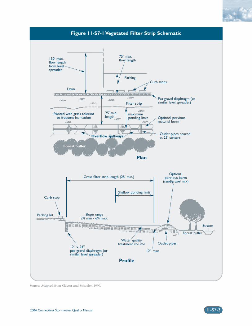
Figure 11-S7-1 Vegetated Filter Strip Schematic
Source: Adapted from Claytor and Schueler, 1996.
2004 Connecticut Stormwater Quality Manual 11-S7-3
Grass filter strip length (25’ min.)
Shallow ponding limit
Outlet pipes
12” max.
Curb stop
Parking lot
Water qualitytreatment volume
Slope range2% min - 6% max.
Optionalpervious berm
(sand/gravel mix)
Stream
Forest buffer
12” x 24”pea gravel diaphragm (orsimilar level spreader)
150’ max.flow lengthfrom levelspreader
Lawn
ParkingCurb stops
Filter stripPea gravel diaphragm (orsimilar level spreader)
Optional perviousmaterial berm
Outlet pipes, spacedat 25’ centers
Planted with grass tolerantto frequent inundation
Overflow spillways
Forest buffer
75’ max.flow length
25’ min.length
maximumponding limit
Profile
Plan
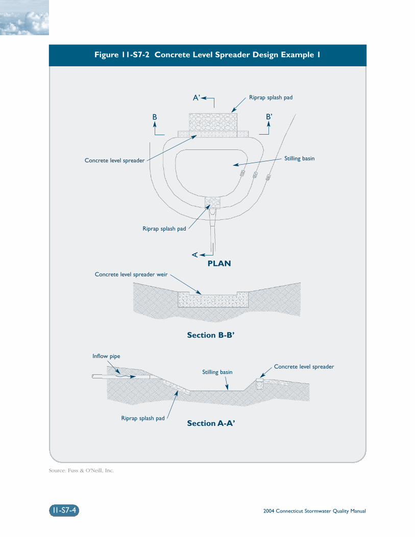
2004 Connecticut Stormwater Quality Manual11-S7-4
Figure 11-S7-2 Concrete Level Spreader Design Example 1
Source: Fuss & O'Neill, Inc.
Riprap splash pad
Riprap splash pad
Inflow pipe
Riprap splash pad
Stilling basin
Stilling basin
Concrete level spreader
Concrete level spreader
Concrete level spreader weir
PLAN
Section B-B’
Section A-A’
A’
A
B B’
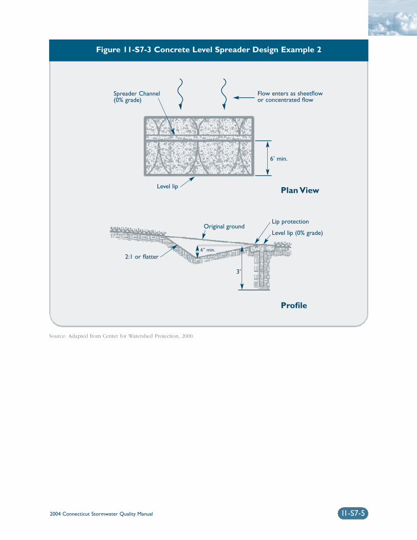
2004 Connecticut Stormwater Quality Manual 11-S7-5
Figure 11-S7-3 Concrete Level Spreader Design Example 2
Source: Adapted from Center for Watershed Protection, 2000.
Spreader Channel(0% grade)
Flow enters as sheetflowor concentrated flow
6’ min.
Level lip
Original groundLip protection
Level lip (0% grade)
2:1 or flatter6” min.
3’
Plan View
Profile
2004 Connecticut Stormwater Quality Manual11-S7-6
Operation and Maintenance: Regular maintenanceis critical for the effectiveness of filter strips, especiallyto ensure that flow does not short-circuit the system.Semi-annual inspections are recommended during thefirst year (and annually thereafter), including inspec-tion of the level spreader for sediment buildup andinspection of the vegetation for erosion, bare spots,and overall health. Regular, frequent mowing of thegrass to a height of 3 to 4 inches is required. Sedimentshould be removed from the toe of slope or levelspreader, and bare spots should be reseeded as nec-essary.
Plans for vegetated filter strips and level spreadersshould identify detailed inspection and maintenancerequirements, inspection and maintenance schedules,and those parties responsible for maintenance.
ReferencesClaytor, R.A. and T.R. Schueler. 1996. Design ofStormwater Filtering Systems. Center for WatershedProtection. Silver Spring, Maryland.
Metropolitan Council. 2001. Minnesota Urban SmallSites BMP Manual: Stormwater Best ManagementPractices for Cold Climates. Prepared by BarrEngineering Company. St. Paul, Minnesota.
New York State Department of EnvironmentalConservation (NYDEC). 2001. New York StateStormwater Management Design Manual. Preparedby Center for Watershed Protection. Albany, NewYork.
United States Environmental Protection Agency (EPA).1999. Preliminary Data Summary of Urban StormWater Best Management Practices. EPA 821-R99-012.
United States Environmental Protection Agency (EPA).2002. National Menu of Best Management Practicesfor Stormwater Phase II. URL: http://www.epa.gov/npdes/menuofbmps/menu.htm,Last Modified January 24, 2002.
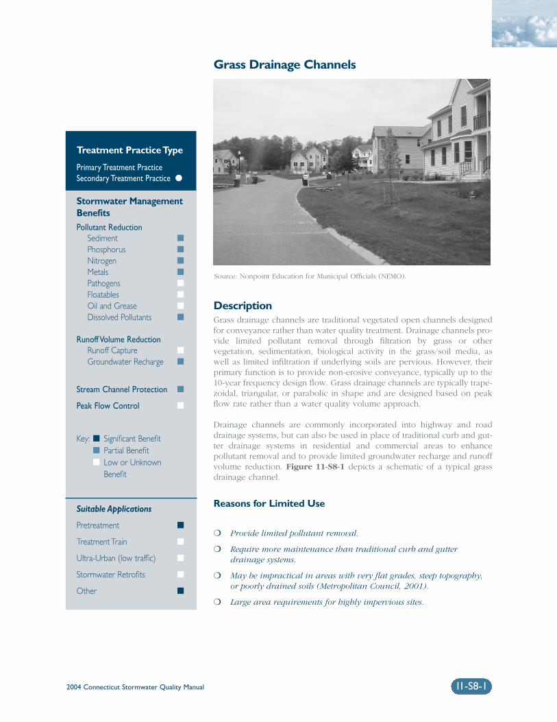
2004 Connecticut Stormwater Quality Manual 11-S8-1
Grass Drainage Channels
DescriptionGrass drainage channels are traditional vegetated open channels designedfor conveyance rather than water quality treatment. Drainage channels pro-vide limited pollutant removal through filtration by grass or othervegetation, sedimentation, biological activity in the grass/soil media, aswell as limited infiltration if underlying soils are pervious. However, theirprimary function is to provide non-erosive conveyance, typically up to the10-year frequency design flow. Grass drainage channels are typically trape-zoidal, triangular, or parabolic in shape and are designed based on peakflow rate rather than a water quality volume approach.
Drainage channels are commonly incorporated into highway and roaddrainage systems, but can also be used in place of traditional curb and gut-ter drainage systems in residential and commercial areas to enhancepollutant removal and to provide limited groundwater recharge and runoffvolume reduction. Figure 11-S8-1 depicts a schematic of a typical grassdrainage channel.
Reasons for Limited Use
❍ Provide limited pollutant removal.
❍ Require more maintenance than traditional curb and gutterdrainage systems.
❍ May be impractical in areas with very flat grades, steep topography,or poorly drained soils (Metropolitan Council, 2001).
❍ Large area requirements for highly impervious sites.
Treatment Practice Type
Primary Treatment PracticeSecondary Treatment Practice �
Stormwater ManagementBenefitsPollutant Reduction
Sediment �
Phosphorus �
Nitrogen �
Metals �
Pathogens �
Floatables �
Oil and Grease �
Dissolved Pollutants �
Runoff Volume ReductionRunoff Capture �
Groundwater Recharge �
Stream Channel Protection �
Peak Flow Control �
Key: � Significant Benefit� Partial Benefit� Low or Unknown
Benefit
Suitable Applications
Pretreatment �
Treatment Train �
Ultra-Urban (low traffic) �
Stormwater Retrofits �
Other �
Source: Nonpoint Education for Municipal Officials (NEMO).
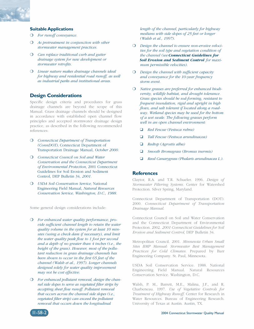
2004 Connecticut Stormwater Quality Manual11-S8-2
Suitable Applications❍ For runoff conveyance.
❍ As pretreatment in conjunction with otherstormwater management practices.
❍ Can replace traditional curb and gutterdrainage system for new development orstormwater retrofits.
❍ Linear nature makes drainage channels idealfor highway and residential road runoff, as wellas industrial parks and institutional areas.
Design ConsiderationsSpecific design criteria and procedures for grassdrainage channels are beyond the scope of thisManual. Grass drainage channels should be designedin accordance with established open channel flowprinciples and accepted stormwater drainage designpractice, as described in the following recommendedreferences:
❍ Connecticut Department of Transportation(ConnDOT), Connecticut Department ofTransportation Drainage Manual, October 2000.
❍ Connecticut Council on Soil and WaterConservation and the Connecticut Departmentof Environmental Protection, 2001 ConnecticutGuidelines for Soil Erosion and SedimentControl, DEP Bulletin 34, 2001.
❍ USDA Soil Conservation Service, NationalEngineering Field Manual, Natural ResourcesConservation Service, Washington, D.C., 1988.
Some general design considerations include:
❍ For enhanced water quality performance, pro-vide sufficient channel length to retain the waterquality volume in the system for at least 10 min-utes (using a check dam if necessary), and limitthe water quality peak flow to 1 foot per secondand a depth of no greater than 4 inches (i.e., theheight of the grass). However, most of the pollu-tant reduction in grass drainage channels hasbeen shown to occur in the first 65 feet of thechannel (Walsh et al., 1997). Longer channelsdesigned solely for water quality improvementmay not be cost effective.
❍ For enhanced pollutant removal, design the chan-nel side slopes to serve as vegetated filter strips byaccepting sheet flow runoff. Pollutant removalthat occurs across the channel side slopes (i.e.,vegetated filter strip) can exceed the pollutantremoval that occurs down the longitudinal
length of the channel, particularly for highwaymedians with side slopes of 25 feet or longer(Walsh et al., 1997).
❍ Design the channel to ensure non-erosive veloci-ties for the soil type and vegetation condition ofthe channel (see Connecticut Guidelines forSoil Erosion and Sediment Control for maxi-mum permissible velocities).
❍ Design the channel with sufficient capacity and conveyance for the 10-year frequency storm event.
❍ Native grasses are preferred for enhanced biodi-versity, wildlife habitat, and drought tolerance.Grass species should be sod-forming, resistant tofrequent inundation, rigid and upright in highflows, and salt tolerant if located along a road-way. Wetland species may be used for the bottomof a wet swale. The following grasses performwell in an open channel environment:
❑ Red Fescue (Festuca rubra)
❑ Tall Fescue (Festuca arundinacea)
❑ Redtop (Agrostis alba)
❑ Smooth Bromegrass (Bromus inermis)
❑ Reed Canarygrass (Phalaris arundinacea L.).
ReferencesClaytor, R.A. and T.R. Schueler. 1996. Design ofStormwater Filtering Systems. Center for WatershedProtection. Silver Spring, Maryland.
Connecticut Department of Transportation (DOT).2000. Connecticut Department of TransportationDrainage Manual.
Connecticut Council on Soil and Water Conservationand the Connecticut Department of EnvironmentalProtection. 2002. 2001 Connecticut Guidelines for SoilErosion and Sediment Control, DEP Bulletin 34.
Metropolitan Council. 2001. Minnesota Urban SmallSites BMP Manual: Stormwater Best ManagementPractices for Cold Climates. Prepared by BarrEngineering Company. St. Paul, Minnesota.
USDA Soil Conservation Service. 1988. NationalEngineering Field Manual. Natural ResourcesConservation Service. Washington, D.C.
Walsh, P. M., Barrett, M.E., Malina, J.F., and R.Charbeneau. 1997. Use of Vegetative Controls forTreatment of Highway Runoff. Center for Research inWater Resources. Bureau of Engineering Research.University of Texas at Austin. Austin, TX.
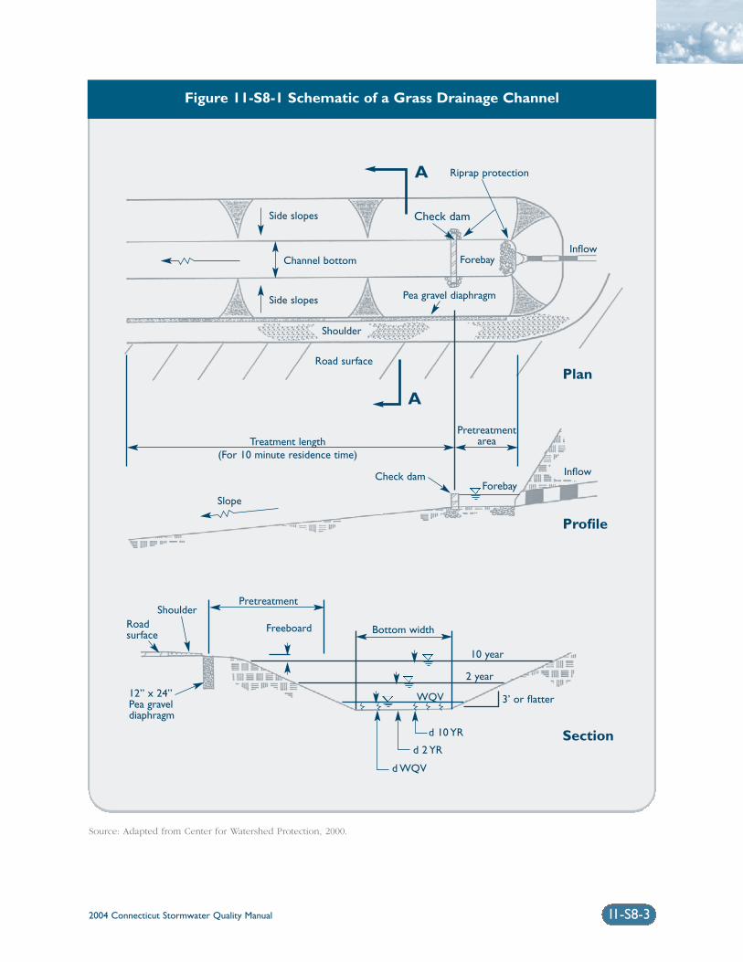
2004 Connecticut Stormwater Quality Manual 11-S8-3
Figure 11-S8-1 Schematic of a Grass Drainage Channel
Source: Adapted from Center for Watershed Protection, 2000.
Riprap protection
Channel bottom
Shoulder
Road surface
Pretreatment
Bottom width
10 year
2 year
3’ or flatter
d 10 YR
d 2 YR
d WQV
WQV
Freeboard
ShoulderRoadsurface
12” x 24”Pea graveldiaphragm
Treatment length(For 10 minute residence time)
Side slopes
Side slopes
Forebay
Pretreatmentarea
Inflow
InflowForebay
Check dam
Slope
Pea gravel diaphragm
Check dam
A
A
Plan
Profile
Section
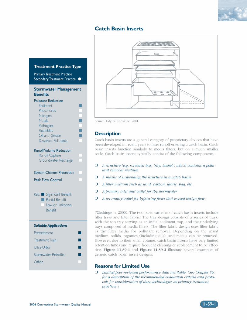
2004 Connecticut Stormwater Quality Manual 11-S9-1
Catch Basin Inserts
DescriptionCatch basin inserts are a general category of proprietary devices that havebeen developed in recent years to filter runoff entering a catch basin. Catchbasin inserts function similarly to media filters, but on a much smallerscale. Catch basin inserts typically consist of the following components:
❍ A structure (e.g. screened box, tray, basket,) which contains a pollu-tant removal medium
❍ A means of suspending the structure in a catch basin
❍ A filter medium such as sand, carbon, fabric, bag, etc.
❍ A primary inlet and outlet for the stormwater
❍ A secondary outlet for bypassing flows that exceed design flow.
(Washington, 2000). The two basic varieties of catch basin inserts includefilter trays and filter fabric. The tray design consists of a series of trays,with the top tray serving as an initial sediment trap, and the underlyingtrays composed of media filters. The filter fabric design uses filter fabricas the filter media for pollutant removal. Depending on the insertmedium, solids, organics (including oils), and metals can be removed.However, due to their small volume, catch basin inserts have very limitedretention times and require frequent cleaning or replacement to be effec-tive. Figure 11-S9-1 and Figure 11-S9-2 illustrate several examples ofgeneric catch basin insert designs.
Reasons for Limited Use❍ Limited peer-reviewed performance data available. (See Chapter Six
for a description of the recommended evaluation criteria and proto-cols for consideration of these technologies as primary treatmentpractices.)
Treatment Practice Type
Primary Treatment PracticeSecondary Treatment Practice �
Stormwater ManagementBenefitsPollutant Reduction
Sediment �
Phosphorus �
Nitrogen �
Metals �
Pathogens �
Floatables �
Oil and Grease �
Dissolved Pollutants �
Runoff Volume ReductionRunoff Capture �
Groundwater Recharge �
Stream Channel Protection �
Peak Flow Control �
Key: � Significant Benefit� Partial Benefit� Low or Unknown
Benefit
Suitable Applications
Pretreatment �
Treatment Train �
Ultra-Urban �
Stormwater Retrofits �
Other �
Source: City of Knoxville, 2001.
2004 Connecticut Stormwater Quality Manual11-S9-2
❍ Require frequent maintenance and replacement.Can become a source of pollutants unless main-tained frequently.
❍ Susceptible to clogging. Can aggravate floodingwhen clogged.
❍ Do not provide peak flow attenuation, runoffvolume reduction, or groundwater recharge.
Suitable Applications❍ To provide pretreatment for other stormwater
treatment practices.
❍ For retrofit of existing conventional catch basinsthat lack sumps or have undersized sumps.
❍ May be considered in specialized small drainageapplications such as industrial sites for specifictarget pollutants where clogging of the mediumwill not be a problem.
❍ As temporary sediment control devices and pre-treatment at construction sites.
❍ For oil control at small sites where the insertmedium has sufficient hydrocarbon loadingcapacity and rate of removal, and the solids anddebris will not prematurely clog the insert.
❍ Can be used in unpaved areas for inlet protec-tion.
Design ConsiderationsDue to the proprietary nature of these products, catchbasin inserts should be designed according to themanufacturer’s recommendations. Some generaldesign considerations for catch basin inserts include:
High Flow Bypass: A high flow bypass or otherdesign feature to allow stormwater runoff into thedrain system in the event of clogging and runoff inexcess of the water quality design flow to bypass thesystem without danger of local flooding.
Maintenance: Should be inspected and maintainedin accordance with manufacturer’s recommendations.Since catch basin inserts require frequent inspectionand maintenance, they should only be used where afull-time maintenance person is on-site.
Plans for catch basin inserts should identify detailedinspection and maintenance requirements, inspectionand maintenance schedules, and those parties respon-sible for maintenance.
Sediment Disposal: Sediment removed from catchbasin inserts should be properly handled and dis-posed in accordance with local, state, and federalregulations. Before disposal, appropriate chemicalanalysis of the material should be performed to deter-mine proper methods for storage and disposal.
ReferencesCity of Knoxville. 2001. Knoxville BMP Manual, Cityof Knoxville Engineering Department. Knoxville,Tennessee.
United States Environmental Protection Agency (EPA).2002. National Menu of Best Management Practicesfor Stormwater Phase II. URL: http://www.epa.gov/npdes/menuofbmps/menu.htm,Last Modified January 24, 2002.
Washington State Department of Ecology(Washington). 2000. Stormwater ManagementManual for Western Washington, Final Draft.Olympia, Washington.
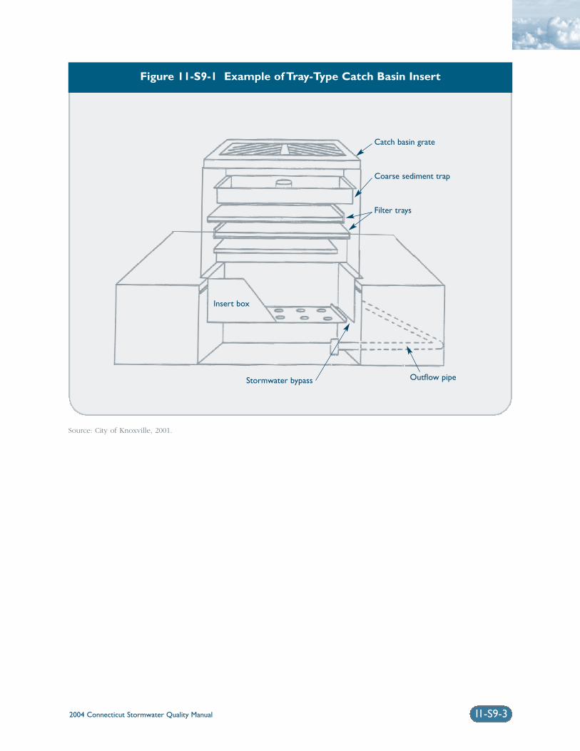
2004 Connecticut Stormwater Quality Manual 11-S9-3
Figure 11-S9-1 Example of Tray-Type Catch Basin Insert
Source: City of Knoxville, 2001.
Catch basin grate
Coarse sediment trap
Filter trays
Insert box
Outflow pipeStormwater bypass
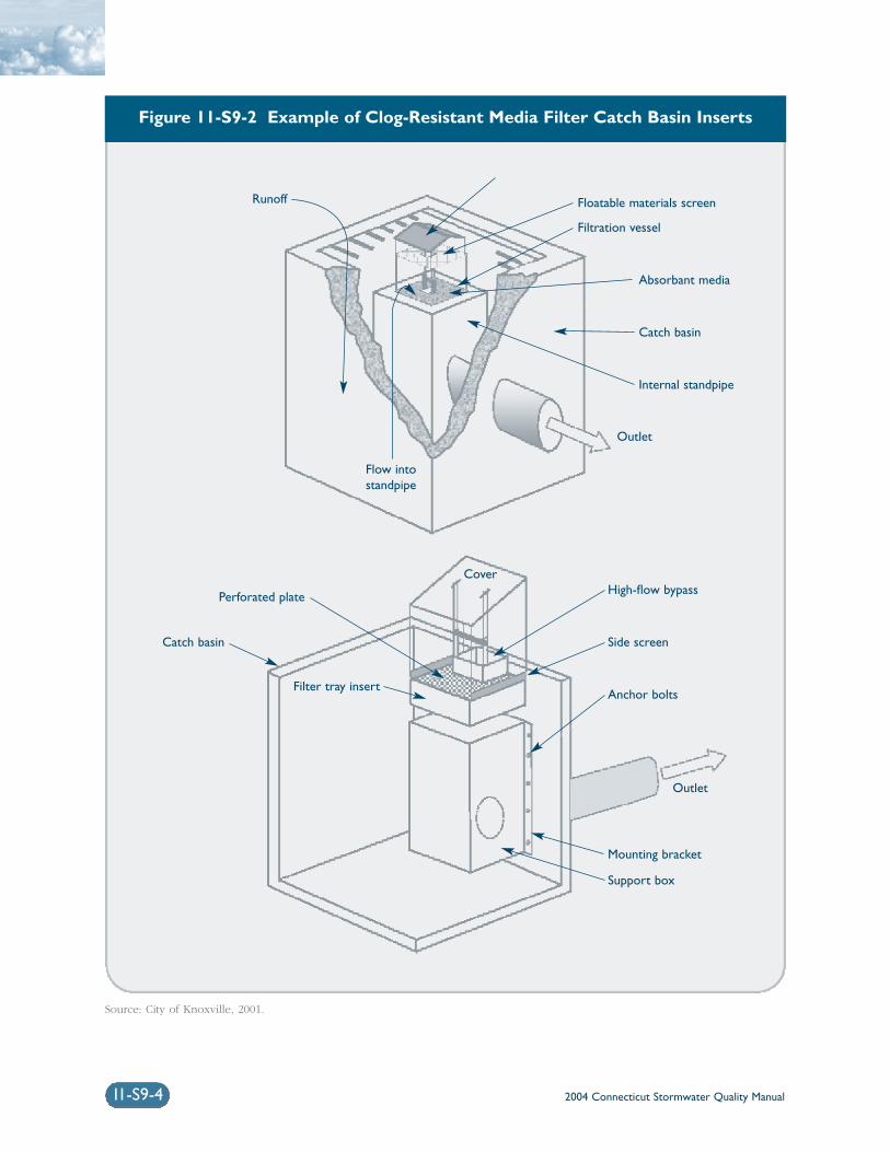
11-S9-4
Figure 11-S9-2 Example of Clog-Resistant Media Filter Catch Basin Inserts
Source: City of Knoxville, 2001.
2004 Connecticut Stormwater Quality Manual
Runoff Floatable materials screen
Filtration vessel
Absorbant media
Catch basin
Internal standpipe
Outlet
High-flow bypass
Side screen
Cover
Outlet
Perforated plate
Catch basin
Filter tray insertAnchor bolts
Mounting bracket
Support box
Flow intostandpipe
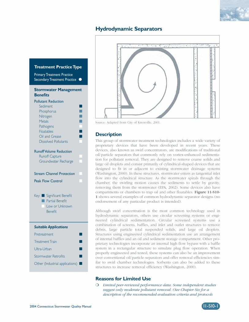
2004 Connecticut Stormwater Quality Manual 11-S10-1
Hydrodynamic Separators
DescriptionThis group of stormwater treatment technologies includes a wide variety ofproprietary devices that have been developed in recent years. Thesedevices, also known as swirl concentrators, are modifications of traditionaloil/particle separators that commonly rely on vortex-enhanced sedimenta-tion for pollutant removal. They are designed to remove coarse solids andlarge oil droplets and consist primarily of cylindrical-shaped devices that aredesigned to fit in or adjacent to existing stormwater drainage systems(Washington, 2000). In these structures, stormwater enters as tangential inletflow into the cylindrical structure. As the stormwater spirals through thechamber, the swirling motion causes the sediments to settle by gravity,removing them from the stormwater (EPA, 2002). Some devices also havecompartments or chambers to trap oil and other floatables. Figure 11-S10-1 shows several examples of common hydrodynamic separator designs (noendorsement of any particular product is intended).
Although swirl concentration is the most common technology used inhydrodynamic separators, others use circular screening systems or engi-neered cylindrical sedimentation. Circular screened systems use acombination of screens, baffles, and inlet and outlet structures to removedebris, large particle total suspended solids, and large oil droplets.Structures using engineered cylindrical sedimentation use an arrangementof internal baffles and an oil and sediment storage compartment. Other pro-prietary technologies incorporate an internal high flow bypass with a bafflesystem in a rectangular structure to simulate plug flow operation. Whenproperly engineered and tested, these systems can also be an improvementover conventional oil/particle separators and offer removal efficiencies sim-ilar to swirl chamber technologies. Sorbents can also be added to thesestructures to increase removal efficiency (Washington, 2000).
Reasons for Limited Use❍ Limited peer-reviewed performance data. Some independent studies
suggest only moderate pollutant removal. (See Chapter Six for adescription of the recommended evaluation criteria and protocols
Treatment Practice Type
Primary Treatment PracticeSecondary Treatment Practice �
Stormwater ManagementBenefitsPollutant Reduction
Sediment �
Phosphorus �
Nitrogen �
Metals �
Pathogens �
Floatables �
Oil and Grease �
Dissolved Pollutants �
Runoff Volume ReductionRunoff Capture �
Groundwater Recharge �
Stream Channel Protection �
Peak Flow Control �
Key: � Significant Benefit� Partial Benefit� Low or Unknown
Benefit
Suitable Applications
Pretreatment �
Treatment Train �
Ultra-Urban �
Stormwater Retrofits �
Other (Industrial applications) �
Source: Adapted from City of Knoxville, 2001.
2004 Connecticut Stormwater Quality Manual11-S10-2
for consideration of these technologies as primarytreatment practices).
❍ Cannot effectively remove soluble pollutants orfine particles.
❍ Can become a source of pollutants due to re-suspension of sediment unless maintainedregularly. Maintenance often neglected (“out of sight and out of mind”).
Suitable Applications❍ Where higher sediment and pollutant removal
efficiencies are required over a range of flowconditions, as compared to conventional oil/particle or oil/grit separators.
❍ For limited removal of trash, debris, oil andgrease, and sediment from stormwater runofffrom relatively small impervious areas with high traffic volumes or high potential for spillssuch as:
❑ Parking lots
❑ Streets
❑ Truck loading areas
❑ Gas stations
❑ Refueling areas
❑ Automotive repair facilities
❑ Fleet maintenance yards
❑ Commercial vehicle washing facilities
❑ Industrial facilities
❍ To provide pretreatment for other stormwater treatment practices.
❍ For retrofit of existing stormwater drainage systems, particularly in highly developed (ultra-urban) areas where larger conventional treatmentpractices are not feasible or where abovegroundtreatment practices are not an option.
Design ConsiderationsDue to the proprietary nature of these products, hydro-dynamic separators should be designed according tothe manufacturer’s recommendations. Some generaldesign considerations for these devices include:
Drainage Area: The recommended maximum con-tributing drainage area to individual devices varies bymanufacturer, model, etc.
Sizing/Design: In most instances, hydrodynamicseparators should be used in an off-line configurationto treat the design water quality flow (peak flow asso-ciated with the design water quality volume).Upstream diversion structures can be used to bypasshigher flows around the device. Sizing based on flowrate allows these devices to provide treatment withina much smaller area than conventional volume-basedstormwater treatment practices such as ponds, wet-lands, and infiltration practices. Potential mosquitoentry points should be sealed (adult female mosqui-toes can use openings as small as 1/16 inch to accesswater for egg laying). To avoid funneling amphibiansinto treatment chambers, where they are killed,Hydrodynamic separators should be used in conjunc-tion with Cape Cod curbing or other similar curbingthat allows amphibians to climb.
Performance: Performance is dependent on manyvariables such as particle size, sediment concentra-tion, water temperature, and flow rate. Hydrodynamicseparators should be sized and compared based onperformance testing of comparable size particles,influent concentrations, and testing protocols.Comparative performance testing that establishes aperformance curve over the full operating range ofthe technology should be considered a prerequisite toany meaningful performance based sizing.
Maintenance: Frequent inspection and cleanout iscritical for proper operation of hydrodynamic separa-tors. Structures that are not maintained can besignificant sources of pollution. Recommended main-tenance requirements and schedules vary withmanufacturer, but in general these devices need to becleaned quarterly. Typical maintenance includesremoval of accumulated oil and grease, floatables,and sediment using a vacuum truck or other ordinarycatch basin cleaning equipment.
Design plans for hydrodynamic separators shouldidentify detailed inspection and maintenance require-ments, inspection and maintenance schedules, andthose parties responsible for maintenance.
Sediment Disposal: Polluted water or sedimentremoved from these devices should be properly handled and disposed in accordance with local, state,and federal regulations. Before disposal, a detailedchemical analysis of the material should be performedto determine proper methods for storage and disposal.
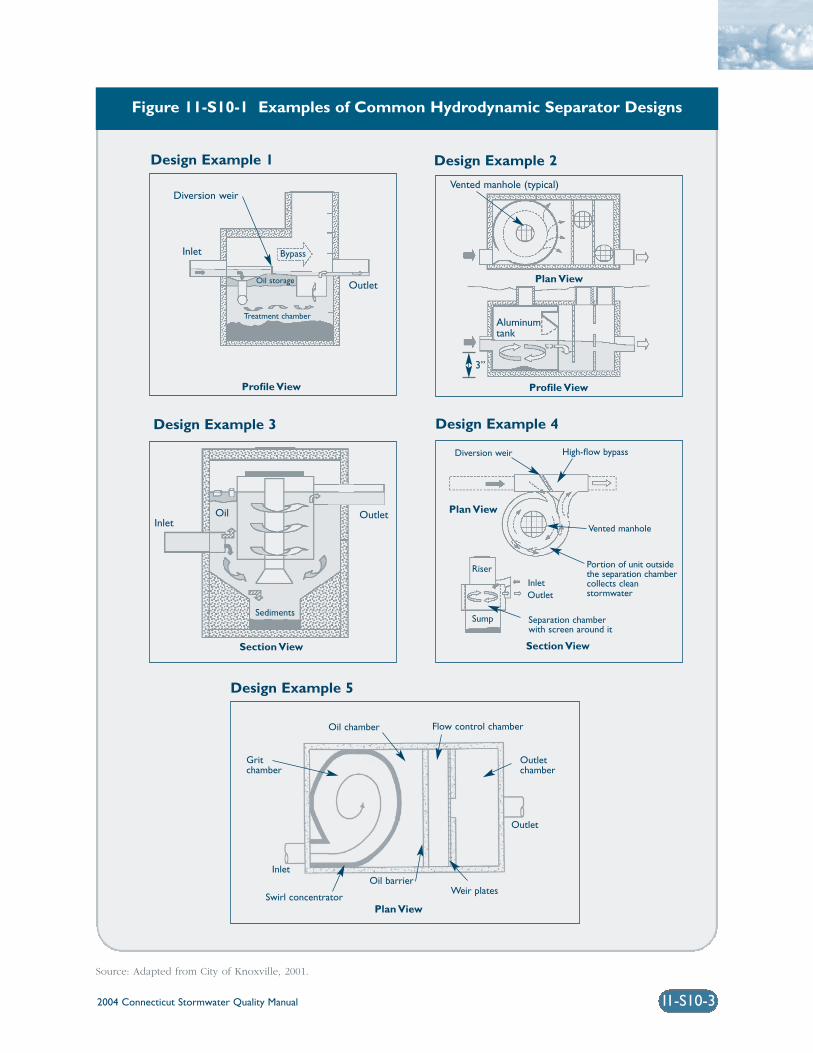
2004 Connecticut Stormwater Quality Manual 11-S10-3
Figure 11-S10-1 Examples of Common Hydrodynamic Separator Designs
Diversion weir
Profile ViewProfile View
Plan View
Section View
Plan View
Section View
Inlet
InletOil
Outlet
Outlet
Outlet
Diversion weir High-flow bypass
Vented manhole
Portion of unit outsidethe separation chambercollects cleanstormwater
Separation chamberwith screen around it
Inlet
Riser
SumpSediments
Vented manhole (typical)
3”
Aluminumtank
Bypass
Oil storage
Treatment chamber
Design Example 1
Design Example 5
Design Example 2
Design Example 3 Design Example 4
Oil chamber
Gritchamber
Inlet
Flow control chamber
Outletchamber
Outlet
Oil barrierWeir plates
Plan ViewSwirl concentrator
Source: Adapted from City of Knoxville, 2001.

2004 Connecticut Stormwater Quality Manual11-S10-4
ReferencesCity of Knoxville. 2001. Knoxville BMP Manual. Cityof Knoxville Engineering Department, Knoxville,Tennessee.
United States Environmental Protection Agency (EPA).2002. National Menu of Best Management Practicesfor Stormwater Phase II. URL: http://www.epa.gov/npdes/menuofbmps/menu.htm,Last Modified January 24, 2002.
Washington State Department of Ecology(Washington). 2000. Stormwater Management Manualfor Western Washington, Final Draft. Olympia,Washington.
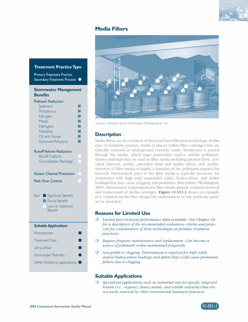
2004 Connecticut Stormwater Quality Manual 11-S11-1
Media Filters
DescriptionMedia filters are an evolution of fixed bed sand filtration technology. In thistype of treatment practice, media is placed within filter cartridges that aretypically enclosed in underground concrete vaults. Stormwater is passedthrough the media, which traps particulates and/or soluble pollutants.Various materials may be used as filter media including pleated fabric, acti-vated charcoal, perlite, amended sand and perlite mixes, and zeolite.Selection of filter media is largely a function of the pollutants targeted forremoval. Pretreatment prior to the filter media is typically necessary forstormwater with high total suspended solids, hydrocarbon, and debrisloadings that may cause clogging and premature filter failure (Washington,2000). Maintenance requirements for filter media include sediment removaland replacement of media cartridges. Figure 11-S11-1 shows an exampleof a common media filter design (no endorsement of any particular prod-uct is intended).
Reasons for Limited Use❍ Limited peer-reviewed performance data available. (See Chapter Six
for a description of the recommended evaluation criteria and proto-cols for consideration of these technologies as primary treatmentpractices).
❍ Require frequent maintenance and replacement. Can become asource of pollutants unless maintained frequently.
❍ Susceptible to clogging. Pretreatment is required for high solidsand/or hydrocarbon loadings and debris that could cause prematurefailure due to clogging.
Suitable Applications❍ Specialized applications such as industrial sites for specific target pol-
lutants (i.e., organics, heavy metals, and soluble nutrients) that arenot easily removed by other conventional treatment practices.
Treatment Practice Type
Primary Treatment PracticeSecondary Treatment Practice �
Stormwater ManagementBenefitsPollutant Reduction
Sediment �
Phosphorus �
Nitrogen �
Metals �
Pathogens �
Floatables �
Oil and Grease �
Dissolved Pollutants �
Runoff Volume ReductionRunoff Capture �
Groundwater Recharge �
Stream Channel Protection �
Peak Flow Control �
Key: � Significant Benefit� Partial Benefit� Low or Unknown
Benefit
Suitable Applications
Pretreatment �
Treatment Train �
Ultra-Urban �
Stormwater Retrofits �
Other (Industrial applications) �
Source: Adapted from Stormwater Management, Inc.
2004 Connecticut Stormwater Quality Manual11-S11-2
❍ For retrofit of existing stormwater drainage sys-tems, particularly in highly developed(ultra-urban) areas where larger conventionaltreatment practices are not feasible or whereaboveground treatment practices are not anoption.
❍ For pretreatment or as part of a stormwatertreatment train in conjunction with otherstormwater management practices.
Design ConsiderationsDue to the proprietary nature of these products,media filters should be designed according to themanufacturer’s recommendations. Some generaldesign considerations for media filters include:
Sizing/Design: Media filters should primarily be usedin an off-line configuration to treat either the designwater quality volume or the design water quality flow(peak flow associated with the design water qualityvolume). Upstream diversion structures or bypass sys-tems built into the unit are used to bypass higherflows around the device. The size and number of fil-ter cartridges are determined based upon theanticipated solids loading rate and design water qual-ity flow. Filter media are selected based on pollutantsof concern. Potential mosquito entry points should besealed (adult female mosquitoes can use openings assmall as 1/16 inch to access water for egg laying).
Maintenance: Frequent inspection and cleanout iscritical for proper operation of media filters. Structuresthat are not maintained can be significant sources ofpollution. Manufacturer’s operation and maintenanceguidelines should be followed to maintain designflows and pollutant removals. Typical maintenanceincludes removal of accumulated oil and grease, float-ables, and sediment from the filter chamber andreplacement of the filter cartridges.
Plans for media filters should identify detailed inspec-tion and maintenance requirements, inspection andmaintenance schedules, and those parties responsiblefor maintenance.
Sediment Disposal: Polluted water or sedimentremoved from these devices should be properly han-dled and disposed in accordance with local, state, andfederal regulations. Before disposal, a detailed chem-ical analysis of the material should be performed todetermine proper methods for storage and disposal.
ReferencesStormwater Management Inc., URL: http://www.stormwatermgt.com/.
United States Environmental Protection Agency (EPA).2002. National Menu of Best Management Practicesfor Stormwater Phase II. URL: http://www.epa.gov/npdes/menuofbmps/menu.htm,Last Modified January 24, 2002.
Washington State Department of Ecology(Washington). 2000. Stormwater ManagementManual for Western Washington, Final Draft.Olympia, Washington.
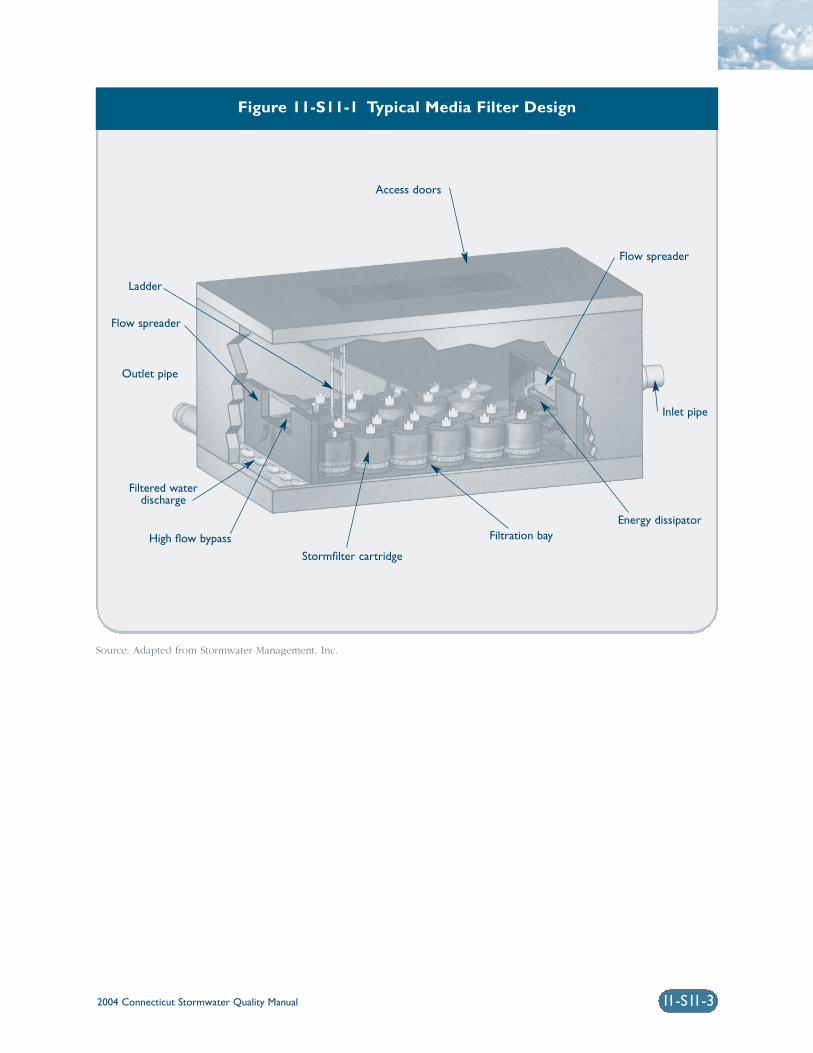
Figure 11-S11-1 Typical Media Filter Design
Source: Adapted from Stormwater Management, Inc.
2004 Connecticut Stormwater Quality Manual 11-S11-3
Access doors
Outlet pipe
Flow spreader
Ladder
Flow spreader
Inlet pipe
Energy dissipatorFiltration bay
Stormfilter cartridge
High flow bypass
Filtered waterdischarge
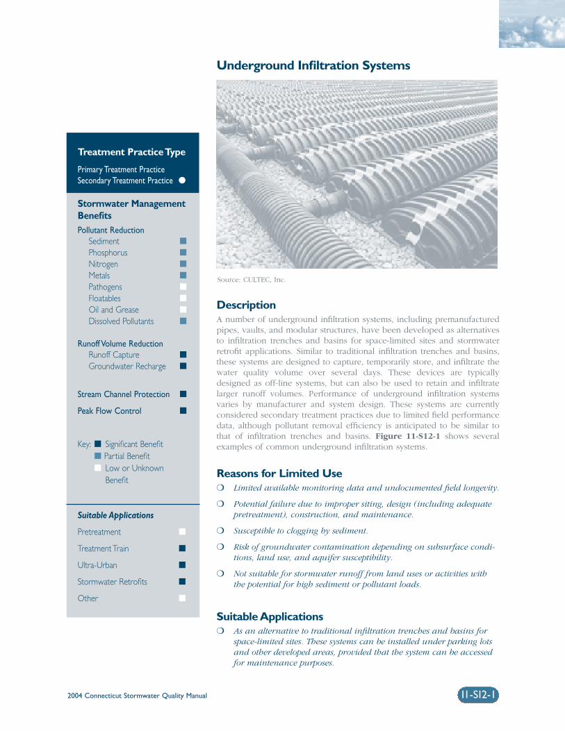
2004 Connecticut Stormwater Quality Manual 11-S12-1
Underground Infiltration Systems
DescriptionA number of underground infiltration systems, including premanufacturedpipes, vaults, and modular structures, have been developed as alternativesto infiltration trenches and basins for space-limited sites and stormwaterretrofit applications. Similar to traditional infiltration trenches and basins,these systems are designed to capture, temporarily store, and infiltrate thewater quality volume over several days. These devices are typicallydesigned as off-line systems, but can also be used to retain and infiltratelarger runoff volumes. Performance of underground infiltration systemsvaries by manufacturer and system design. These systems are currentlyconsidered secondary treatment practices due to limited field performancedata, although pollutant removal efficiency is anticipated to be similar tothat of infiltration trenches and basins. Figure 11-S12-1 shows severalexamples of common underground infiltration systems.
Reasons for Limited Use❍ Limited available monitoring data and undocumented field longevity.
❍ Potential failure due to improper siting, design (including adequatepretreatment), construction, and maintenance.
❍ Susceptible to clogging by sediment.
❍ Risk of groundwater contamination depending on subsurface condi-tions, land use, and aquifer susceptibility.
❍ Not suitable for stormwater runoff from land uses or activities withthe potential for high sediment or pollutant loads.
Suitable Applications❍ As an alternative to traditional infiltration trenches and basins for
space-limited sites. These systems can be installed under parking lotsand other developed areas, provided that the system can be accessedfor maintenance purposes.
Treatment Practice Type
Primary Treatment PracticeSecondary Treatment Practice �
Stormwater ManagementBenefitsPollutant Reduction
Sediment �
Phosphorus �
Nitrogen �
Metals �
Pathogens �
Floatables �
Oil and Grease �
Dissolved Pollutants �
Runoff Volume ReductionRunoff Capture �
Groundwater Recharge �
Stream Channel Protection �
Peak Flow Control �
Key: � Significant Benefit� Partial Benefit� Low or Unknown
Benefit
Suitable Applications
Pretreatment �
Treatment Train �
Ultra-Urban �
Stormwater Retrofits �
Other �
Source: CULTEC, Inc.
2004 Connecticut Stormwater Quality Manual11-S12-2
❍ Useful in stormwater retrofit applications or aspart of a stormwater treatment train to provideadditional groundwater recharge and storagevolume to attenuate peak flows.
Design ConsiderationsThe materials of construction, configuration, and lay-out of underground infiltration systems varyconsiderably depending on the system manufacturer.Specific design criteria and specifications for thesesystems can be obtained from system manufacturersor vendors. General design elements common to mostof these systems are summarized below. The readershould refer to the Infiltration Practices section of thischapter for additional information on siting, design,construction, and maintenance considerations.
Siting: Underground infiltration systems are gener-ally applicable to small development sites (typicallyless than 10 acres) and should be installed in loca-tions that are easily accessible for routine andnon-routine maintenance. These systems should notbe located in areas or below structures that cannotbe excavated in the event that the system needs tobe replaced. Similar to infiltration trenches andbasins, underground infiltration systems should onlybe used with soils having suitable infiltration capac-ity (as confirmed through field testing) and for landuses, activities, or areas that do not pose a risk ofgroundwater contamination.
Pretreatment: Appropriate pretreatment (e.g.,oil/particle separator, hydrodynamic device, catchbasin inserts, or other secondary or primary treatmentpractices) should be provided to remove sediment,floatables, and oil and grease.
Design Volume: Underground infiltration structuresshould be designed as off-line practices to infiltratethe entire water quality volume. A flow bypass struc-ture should be located upgradient of the infiltrationstructure to convey high flows around the structure.
Draining Time: Infiltration structures should bedesigned to completely drain the water quality vol-ume into the soil within 48 hours after the storm eventand completely dewater between storms. A minimumdraining time of 6 hours is recommended to ensureadequate pollutant removal. Standing water for longerthan 5 days can lead to potential mosquito-breedingproblems. Potential mosquito entry points should besealed (adult female mosquitoes can use openings assmall as 1/16 inch to access water for egg laying).
Infiltration Rate: The minimum acceptable field-measured soil infiltration rate is 0.3 inches per hour.Field-measured soil infiltration rates should notexceed 5.0 inches per hour. This generally restrictsapplication to soils of NRCS Hydrologic Soil Group A.Some Group B soils may be suitable if field-measuredinfiltration rates exceed 0.3 inches per hour.
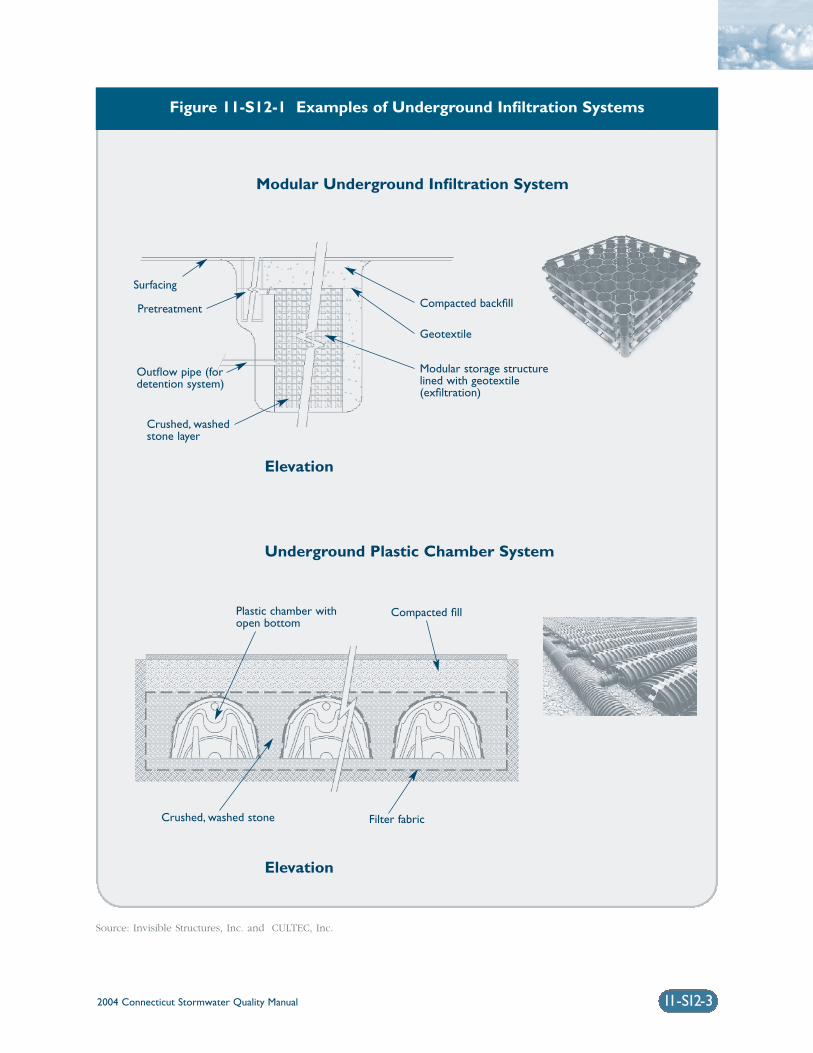
Figure 11-S12-1 Examples of Underground Infiltration Systems
2004 Connecticut Stormwater Quality Manual 11-S12-3
Plastic chamber withopen bottom
Crushed, washed stone Filter fabric
Elevation
Underground Plastic Chamber System
Modular Underground Infiltration System
Compacted fill
Surfacing
Pretreatment
Outflow pipe (fordetention system)
Crushed, washedstone layer
Compacted backfill
Geotextile
Modular storage structurelined with geotextile(exfiltration)
Elevation
Source: Invisible Structures, Inc. and CULTEC, Inc.
2004 Connecticut Stormwater Quality Manual 11-S13-1
Alum Injection
DescriptionAlum injection is the addition of aluminum sulfate (alum) solution tostormwater before discharging to a receiving water body or stormwatertreatment practice. When alum is injected into stormwater it binds withsuspended solids, metals, and phosphorus and forms aluminum phosphateand aluminum hydroxide precipitates. These precipitates settle out of thewater column and are deposited in the bottom sediments in a stable, inac-tive state (referred to as “floc”).
The injection of liquid alum into storm sewers has been used to reduce thewater quality impacts of stormwater runoff to lakes and other receivingwater bodies, particularly to reduce high phosphorus levels and addresseutrophic conditions (EPA, 2002). Alum injection systems are commonlyused in some parts of the country as stormwater retrofits for existing dis-charges to lakes and ponds, but may also be used as pretreatment forstormwater ponds and other treatment practices (ASCE, 2001). Alum addi-tion should be considered only after all other best management practiceshave been implemented.
Reasons for Limited Use❍ Limited long-term performance data.
❍ Requires ongoing operation unlike most other stormwater treatmentpractices.
❍ Improper dosing of chemicals may have negative impacts on down-stream water bodies.
❍ Increases the volume of sediment/floc (and associated pollutant concentrations) that must be disposed of.
❍ Typically not cost effective for drainage areas less than 50 acres.
❍ Alum application may be approved as part of a state stormwater permit or could require an individual state permit. The DEP WaterManagement Bureau should be contacted for further permit guidance.
Treatment Practice Type
Primary Treatment PracticeSecondary Treatment Practice �
Stormwater ManagementBenefitsPollutant Reduction
Sediment �
Phosphorus �
Nitrogen �
Metals �
Pathogens �
Floatables �
Oil and Grease �
Dissolved Pollutants �
Runoff Volume ReductionRunoff Capture �
Groundwater Recharge �
Stream Channel Protection �
Peak Flow Control �
Key: � Significant Benefit� Partial Benefit� Low or Unknown
Benefit
Suitable Applications
Pretreatment �
Treatment Train �
Ultra-Urban �
Stormwater Retrofits �
Other �
Source: Photo courtesy of Adell Donaghue.
2004 Connecticut Stormwater Quality Manual11-S13-2
Suitable Applications❍ Best suited to situations where a large volume
of water is stored in one area.
❍ As part of a stormwater treatment train or pretreatment step to further reduce turbidity and fine suspended solids.
❍ For existing stormwater discharges to existingponds and lakes, particularly in highly devel-oped areas, where new stormwater treatmentpractices or other treatment options are not feasible.
Design ConsiderationsDesign: Alum injection systems typically consist of aflow-weighted dosing system designed to fit inside astorm sewer manhole, remotely located alum storagetanks, and a downstream pond or treatment practicethat allows alum and pollutants to settle out (EPA,2002). Alum dosage rates generally range between 5 and 10 milligrams per liter of alum solution and are determined on a flow-weighted basis duringstorm events. Lime is often added to raise the pH(between 8 and 11) and enhance pollutant settling. Jartesting is recommended to determine alum dosingrates and the need for pH control. Injection points inthe storm drainage system should be approximately100 feet upstream of the discharge point (ASCE,2001). In addition to the settling pond, a separate floccollection pump-out facility is recommended toreduce the chance of resuspension and transport offloc to receiving waters by pumping floc to the sani-tary sewer or onto nearby upland areas (withappropriate local, state, and federal regulatoryapproval, as necessary).
Operation and Maintenance: Typical operation andmaintenance requirements for alum injection systemsinclude maintenance of pump equipment, power,chemical replacement, routine inspections, and
equipment replacement (doser and pump-out facil-ity). A trained operator should be on-site to adjust thechemical dosage and regulate flows, if necessary.Alum injection systems also require continued moni-toring of water quality to detect potential negativeimpacts to receiving waters. The settling basin orpond should be dredged periodically to dispose ofaccumulated floc.
Cost Considerations: Alum injection is a relativelyexpensive and labor-intensive treatment practice.Construction costs depend on watershed size and thenumber of outfalls treated, but construction costs gen-erally range from $135,000 to $400,000. Due to thehigh construction cost, alum injection is not costeffective for drainage areas less than 50 acres.Operation and maintenance costs can vary from$6,500 to $50,000 per year depending on the size ofthe system (Harper and Herr, 1996).
ReferencesAmerican Society of Civil Engineers (ASCE). 2001. AGuide for Best Management Practice (BMP) Selectionin Urban Developed Areas. Urban Water InfrastructureManagement Committee’s Task Committee forEvaluating Best Management Practices. Reston,Virginia.
Harper, H.H. and J.L. Herr. 1996. Alum Treatment ofStormwater Runoff: The First Ten Years.Environmental Research and Design. Orlando,Florida.
United States Environmental Protection Agency (EPA).2002. National Menu of Best Management Practicesfor Stormwater Phase II. URL: http://cfpub.epa.gov/npdes/stormwater/menuofbmps/post_3.cfm, Last Modified August 15, 2002.
Appendix APlant List
2004 Connecticut Stormwater Quality Manual A-1
Appendix A: Plant List
1. Salt-Tolerant PlantsThese plant species are suitable for planting within 80 feet of a roadside that is subject to de-icing andanti-icing application of salts.
TreesWhite Oak (Quercus alba)Red Oak (Quercus rubra)White Poplar (Populus alba)Blue Spruce (Picea pungens)Green Ash (Fraxinus pennsylvanica)Eastern Cottonwood (Populus deltoides)Eastern White Pine (Pinus strobus)Hawthorn (Crataegus spp.)Pitch Pine (Pinus rigida)Honeylocust (Gleditsia triacanthos)
ShrubsForsythia (Forsythia x intermedia)Buttonbush (Cephalanthus occidentalis)Bayberry (Myrica pennsylvanica)Black Chokeberry (Aronia melanocarpa)Red Chokeberry (Aronia arbutifolia)Marsh Elder or High Tide Bush (Iva frutescens)Groundsel (Baccharis halimifolia)
Grasses/HerbsBirdsfoot trefoil (Lotus corniculatus)Perennial ryegrass (Lolium perenne)Switchgrass (Panicum virgatum)Tall Fescue (Festuca arundinacea)Alfalfa (Medicago sativa)Cattails (Typha domingensis)
2. Native Plants/XeriscapingThese plant species are native or adapted to southernNew England. Information on these species and oth-ers that may be suitable for xeriscaping may be foundin the references at the end of this appendix, includ-ing the Connecticut Native Tree and Shrub AvailabilityList (DEP).
TreesEastern Red Cedar (Juniperus virginiana)Flowering Dogwood (Cornus florida)Hackberry (Celtis occidentalis)Hawthorn (Crataegus spp.)Hickories (Carya spp.)Oaks (Quercus spp.)Walnuts (Juglans spp.)Atlantic White Cedar (Chamaecyparis thyoides)
Black Spruce (Picea mariana)White Pine (Pinus strobus)Black Cherry (Prunus serotina)Choke Cherry (Prunus virginiana)
ShrubsFor Dry, Sunny AreasBayberry (Myrica pensylvanica)Lowbush Blueberry (Vaccinium augustifolium)Ground Juniper (Juniperus communis)New Jersey Tea (Ceanothus americanus)Sweet Fern (Comptonia peregrina)
For Shaded AreasHazelnut (Corylus americana, C. cornuta)Mountain Laurel (Kalmia latifolia)Swamp Azalea (Rhododendron viscosum)Viburnums (V. acerfolium, V. cassinoides, V.
alnifolium)
For Moist SitesDogwoods (Cornus spp.)Elderberry (Sambucus canadensis)Highbush Blueberry (Vaccinium corymbosum)Pussy Willow (Salix discolor)Shadbush Serviceberry (Amelanchier canadensis)Spicebush (Lindera benzoin)Spirea (Spirea latifolia)Swamp azalea (Rhododendron viscosum)Sweet Pepperbush (Clethra alnifolia)Viburnums (Viburnum spp.)Winterberry (Ilex verticillata)Witch Hazel (Hamamelis virginiana)
PerennialsWild red columbine (Aquilegia canadensis)Bearberry, kinnickinick (Arctostaphylos uva-ursi)Wild ginger (Asarum canadense)Butterfly weed (Asclepias tuberosa)White wood aster (Aster divaricatus)New England aster (Aster novae-angliae)Marsh marigold (Caltha palustris)Wild geranium (Geranium maculatum)Cardinal flower (Lobelia cardinalis)Solomon’s plume (Maianthemum racemosum, syn.
Smilacina racemosa)Partridgeberry (Mitchella repens)Wild blue phlox (Phlox divaricata)Bloodroot (Sanguinaria canadensis)Foamflower (Tiarella cordifolia)
GrassesBig bluestem (Andropogon gerardii)Switchgrass (Panicum virgatum)Little bluestem (Schizachyrium scoparium, syn.
Andropogon scoparius)
2004 Connecticut Stormwater Quality ManualA-2
3. Stormwater Ponds and Wetlands Plant List
This section contains planting guidance for stormwa-ter ponds and wetlands. The following lists emphasizethe use of plants native to Connecticut and southernNew England and are intended as general guidancefor planning purposes. Local landscape architects andnurseries may provide additional information, includ-ing plant availability, for specific applications.
Plantings for stormwater ponds and wetlands shouldbe selected to be compatible with the various hydro-logic zones within these treatment practices (NYDEC,
2001). The hydrologic zones reflect the degree andduration of inundation by water. Plants recommendedfor a particular zone can generally tolerate the hydro-logic conditions that typically exist within that zone.Table A-1 summarizes recommended plantings(trees/shrubs and herbaceous plants) within eachhydrologic zone. This list is not intended to beexhaustive, but includes a number of recommendednative species that are generally available from com-mercial nurseries. Other plant species may beacceptable if they can be shown to be appropriate forthe intended hydrologic zone.
Trees and ShrubsNot recommended
Herbaceous PlantsCoontail (Ceratophyllumdemersum)Duckweed (Lemma sp.)Pond Weed, Sago (Potamogeton Pectinatus)Waterweed (Elodea canadensis)Wild Celery (Valisneria Americana)
Trees and ShrubsButtonbush (Cepahlanthus occidentalis)
Herbaceous PlantsArrow arum (Peltandra virginica)Arrowhead, Duck Potato (Saggitaria latifolia)Blue Flag Iris (Iris versicolor)Blue Joint (Calamagrotis canadensis)Broomsedge (Andropogon virginicus)Bushy Beardgrass (Andropogon glomeratus) Cattail (Typha sp.)Common Three-Square (Scirpus pungens)Duckweed (Lemma sp.)Giant Burreed (Sparganium eurycarpum)Long-leaved Pond Weed (Potamogeton
nodosus)Marsh Hibiscus (Hibiscus moscheutos) Pickerelweed (Pontederia cordata)Rice Cutgrass (Leersia oryzoides)Sedges (Carex spp.) Soft-stem Bulrush (Scirpus validus)Smartweed (Polygonum spp)Soft Rush (Juncus effusus)Spatterdock (Nuphar luteum)Switchgrass (Panicum virgatum)Sweet Flag (Acorus calamus)Wild Rice (Zizania aquatica)Wool Grass (Scirpus cyperinus)
SubmergentSubmergent/EmergentSubmergentSubmergentSubmergent
Deciduous shrub
EmergentEmergentEmergentEmergentPerimeterEmergentEmergentEmergentSubmergent/EmergentEmergentRooted Submerged
AquaticEmergentEmergentEmergentEmergentEmergentEmergentEmergentEmergentPerimeterHerbaceousEmergentEmergent
Plant Name and Form
❍ 1 to 6 feet deep, permanent pool❍ Submergent plants (if any at all)❍ Not routinely planted due to limited
availability of plants that can survivein this zone and potential clogging ofoutlet structure
❍ Plants reduce resuspension of sediments and improve oxidation/aquatic habitat
❍ 1 foot below the normal pool(aquatic bench in stormwaterponds)
❍ Plants partially submerged❍ Emergent wetland plants❍ Plants reduce resuspension of
sediments, enhance pollutantremoval, and provide aquatic andnonaquatic habitat
Zone Description
Zone 1Deep WaterPool
Zone 2Shallow WaterBench
HydrologicZone
Table A-1 Plant List for Stormwater Ponds and Wetlands
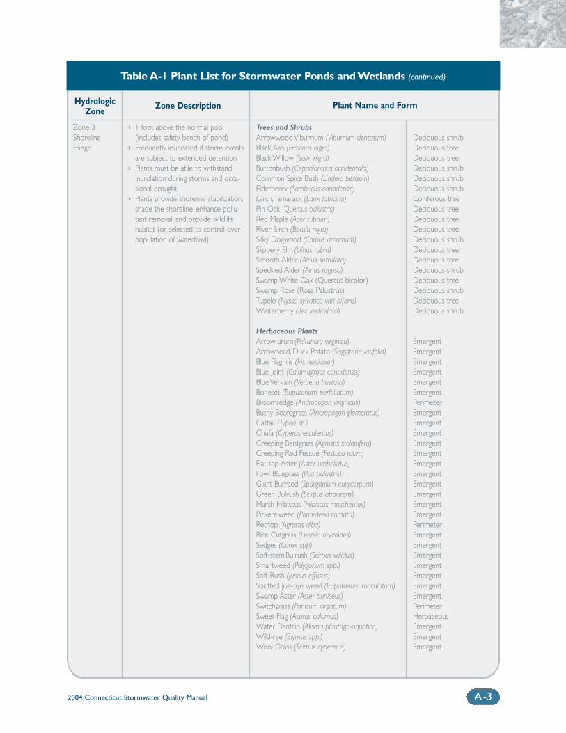
2004 Connecticut Stormwater Quality Manual A-3
Trees and ShrubsArrowwood Viburrium (Viburrium dentatum)Black Ash (Fraxinus nigra)Black Willow (Salix nigra)Buttonbush (Cepahlanthus occidentalis)Common Spice Bush (Lindera benzoin)Elderberry (Sambucus canadensis)Larch,Tamarack (Larix latricina)Pin Oak (Quercus palustris)Red Maple (Acer rubrum)River Birch (Betula nigra)Silky Dogwood (Cornus amomum)Slippery Elm (Ulnus rubra) Smooth Alder (Alnus serrulata)Speckled Alder (Alnus rugosa) Swamp White Oak (Quercus bicolor) Swamp Rose (Rosa Palustrus) Tupelo (Nyssa sylvatica vari biflora)Winterberry (Ilex verticillata)
Herbaceous PlantsArrow arum (Peltandra virginica)Arrowhead, Duck Potato (Saggitaria latifolia) Blue Flag Iris (Iris versicolor)Blue Joint (Calamagrotis canadensis)Blue Vervain (Verbena hastata)Boneset (Eupatorium perfoliatum)Broomsedge (Andropogon virginicus)Bushy Beardgrass (Andropogon glomeratus)Cattail (Typha sp.)Chufa (Cyperus esculentus)Creeping Bentgrass (Agrostis stolonifera)Creeping Red Fescue (Festuca rubra)Flat-top Aster (Aster umbellatus)Fowl Bluegrass (Poa palustris)Giant Burreed (Sparganium eurycarpum)Green Bulrush (Scirpus atrovirens)Marsh Hibiscus (Hibiscus moscheutos)Pickerelweed (Pontederia cordata)Redtop (Agrostis alba)Rice Cutgrass (Leersia oryzoides)Sedges (Carex spp)Soft-stem Bulrush (Scirpus validus)Smartweed (Polygonum spp.)Soft Rush (Juncus effusus) Spotted Joe-pye weed (Eupatorium maculatum)Swamp Aster (Aster puniceus)Switchgrass (Panicum virgatum)Sweet Flag (Acorus calamus)Water Plantain (Alisma plantago-aquatica)Wild-rye (Elymus spp.)Wool Grass (Scirpus cyperinus)
Deciduous shrubDeciduous treeDeciduous treeDeciduous shrubDeciduous shrubDeciduous shrubConiferous treeDeciduous treeDeciduous treeDeciduous treeDeciduous shrubDeciduous treeDeciduous treeDeciduous shrubDeciduous treeDeciduous shrubDeciduous treeDeciduous shrub
EmergentEmergentEmergentEmergentEmergentEmergentPerimeterEmergentEmergentEmergentEmergentEmergentEmergentEmergentEmergentEmergentEmergentEmergentPerimeterEmergentEmergentEmergentEmergentEmergentEmergentEmergentPerimeterHerbaceousEmergentEmergentEmergent
Plant Name and Form
❍ 1 foot above the normal pool(includes safety bench of pond)
❍ Frequently inundated if storm eventsare subject to extended detention
❍ Plants must be able to withstandinundation during storms and occa-sional drought
❍ Plants provide shoreline stabilization,shade the shoreline, enhance pollu-tant removal, and provide wildlifehabitat (or selected to control over-population of waterfowl)
Zone Description
Zone 3ShorelineFringe
HydrologicZone
Table A-1 Plant List for Stormwater Ponds and Wetlands (continued)
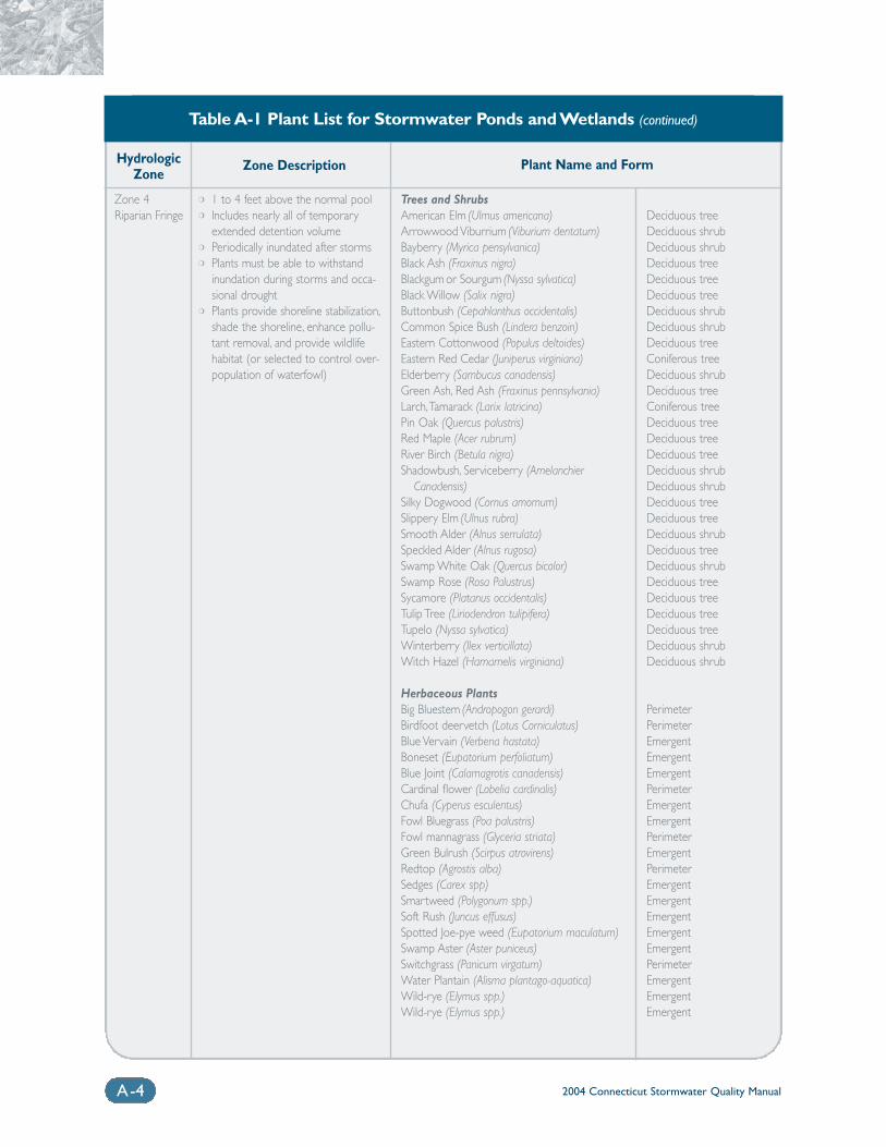
2004 Connecticut Stormwater Quality ManualA-4
Trees and ShrubsAmerican Elm (Ulmus americana)Arrowwood Viburrium (Viburium dentatum)Bayberry (Myrica pensylvanica) Black Ash (Fraxinus nigra)Blackgum or Sourgum (Nyssa sylvatica)Black Willow (Salix nigra)Buttonbush (Cepahlanthus occidentalis)Common Spice Bush (Lindera benzoin)Eastern Cottonwood (Populus deltoides)Eastern Red Cedar (Juniperus virginiana)Elderberry (Sambucus canadensis)Green Ash, Red Ash (Fraxinus pennsylvania)Larch,Tamarack (Larix latricina)Pin Oak (Quercus palustris)Red Maple (Acer rubrum) River Birch (Betula nigra)Shadowbush, Serviceberry (Amelanchier
Canadensis) Silky Dogwood (Cornus amomum)Slippery Elm (Ulnus rubra)Smooth Alder (Alnus serrulata)Speckled Alder (Alnus rugosa) Swamp White Oak (Quercus bicolor)Swamp Rose (Rosa Palustrus)Sycamore (Platanus occidentalis)Tulip Tree (Liriodendron tulipifera)Tupelo (Nyssa sylvatica) Winterberry (Ilex verticillata)Witch Hazel (Hamamelis virginiana)
Herbaceous PlantsBig Bluestem (Andropogon gerardi)Birdfoot deervetch (Lotus Corniculatus)Blue Vervain (Verbena hastata)Boneset (Eupatorium perfoliatum)Blue Joint (Calamagrotis canadensis)Cardinal flower (Lobelia cardinalis)Chufa (Cyperus esculentus)Fowl Bluegrass (Poa palustris)Fowl mannagrass (Glyceria striata) Green Bulrush (Scirpus atrovirens)Redtop (Agrostis alba)Sedges (Carex spp)Smartweed (Polygonum spp.) Soft Rush (Juncus effusus) Spotted Joe-pye weed (Eupatorium maculatum)Swamp Aster (Aster puniceus)Switchgrass (Panicum virgatum)Water Plantain (Alisma plantago-aquatica)Wild-rye (Elymus spp.)Wild-rye (Elymus spp.)
Deciduous treeDeciduous shrubDeciduous shrubDeciduous treeDeciduous treeDeciduous treeDeciduous shrubDeciduous shrubDeciduous treeConiferous treeDeciduous shrubDeciduous treeConiferous treeDeciduous treeDeciduous treeDeciduous treeDeciduous shrubDeciduous shrubDeciduous treeDeciduous treeDeciduous shrubDeciduous treeDeciduous shrubDeciduous treeDeciduous treeDeciduous treeDeciduous treeDeciduous shrubDeciduous shrub
PerimeterPerimeterEmergentEmergentEmergentPerimeterEmergentEmergentPerimeterEmergentPerimeterEmergentEmergentEmergentEmergentEmergentPerimeterEmergentEmergentEmergent
Plant Name and Form
❍ 1 to 4 feet above the normal pool❍ Includes nearly all of temporary
extended detention volume❍ Periodically inundated after storms❍ Plants must be able to withstand
inundation during storms and occa-sional drought
❍ Plants provide shoreline stabilization,shade the shoreline, enhance pollu-tant removal, and provide wildlifehabitat (or selected to control over-population of waterfowl)
Zone Description
Zone 4Riparian Fringe
HydrologicZone
Table A-1 Plant List for Stormwater Ponds and Wetlands (continued)
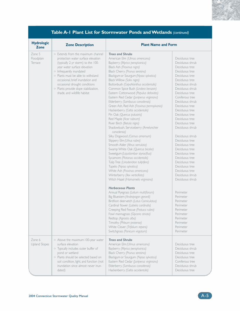
2004 Connecticut Stormwater Quality Manual A-5
Trees and ShrubsAmerican Elm (Ulmus americana) Bayberry (Myrica pensylvanica)Black Ash (Fraxinus nigra)Black Cherry (Prunus serotina)Blackgum or Sourgum (Nyssa sylvatica)Black Willow (Salix nigra)Buttonbush (Cepahlanthus occidentalis)Common Spice Bush (Lindera benzoin)Eastern Cottonwood (Populus deltoides)Eastern Red Cedar (Juniperus virginiana)Elderberry (Sambucus canadensis)Green Ash, Red Ash (Fraxinus pennsylvania)Hackenberry (Celtis occidentalis)Pin Oak (Quercus palustris) Red Maple (Acer rubrum)River Birch (Betula nigra)Shadowbush, Serviceberry (Amelanchier
canadensis)Silky Dogwood (Cornus amomum) Slippery Elm (Ulnus rubra)Smooth Alder (Alnus serrulata)Swamp White Oak (Quercus bicolor)Sweetgum (Liquidambar styraciflua)Sycamore (Platanus occidentalis)Tulip Tree (Liriodendron tulipifera)Tupelo (Nyssa sylvatica) White Ash (Fraxinus americana)Winterberry (Ilex verticillata)Witch Hazel (Hamamelis virginiana)
Herbaceous PlantsAnnual Ryegrass (Lolium multiflorum)Big Bluestem (Andropogon gerardi)Birdfoot deervetch (Lotus Corniculatus)Cardinal flower (Lobelia cardinalis)Creeping Red Fescue (Festuca rubra)Fowl mannagrass (Glyceria striata) Redtop (Agrostis alba)Timothy (Phleum pratense)White Clover (Trifolium repens)Switchgrass (Panicum virgatum)
Trees and ShrubsAmerican Elm (Ulmus americana)Bayberry (Myrica pensylvanica)Black Cherry (Prunus serotina)Blackgum or Sourgum (Nyssa sylvatica)Eastern Red Cedar (Juniperus virginiana)Elderberry (Sambucus canadensis)Hackenberry (Celtis occidentalis)
Deciduous treeDeciduous shrubDeciduous treeDeciduous treeDeciduous treeDeciduous treeDeciduous shrubDeciduous shrubDeciduous treeConiferous treeDeciduous shrubDeciduous treeDeciduous treeDeciduous treeDeciduous treeDeciduous treeDeciduous shrub
Deciduous shrubDeciduous treeDeciduous treeDeciduous treeDeciduous treeDeciduous treeDeciduous treeDeciduous treeDeciduous treeDeciduous shrubDeciduous shrub
PerimeterPerimeterPerimeterPerimeterPerimeterPerimeterPerimeterPerimeterPerimeterPerimeter
Deciduous treeDeciduous shrubDeciduous treeDeciduous treeConiferous treeDeciduous shrubDeciduous tree
Plant Name and Form
❍ Extends from the maximum channelprotection water surface elevation(typically 2-yr storm) to the 100-year water surface elevation
❍ Infrequently inundated❍ Plants must be able to withstand
occasional, brief inundation andoccasional drought conditions
❍ Plants provide slope stabilization,shade, and wildlife habitat
❍ Above the maximum 100-year watersurface elevation
❍ Typically includes outer buffer ofpond or wetland
❍ Plants should be selected based onsoil condition, light, and function (notinundation since almost never inun-dated)
Zone Description
Zone 5FloodplainTerrace
Zone 6Upland Slopes
HydrologicZone
Table A-1 Plant List for Stormwater Ponds and Wetlands (continued)
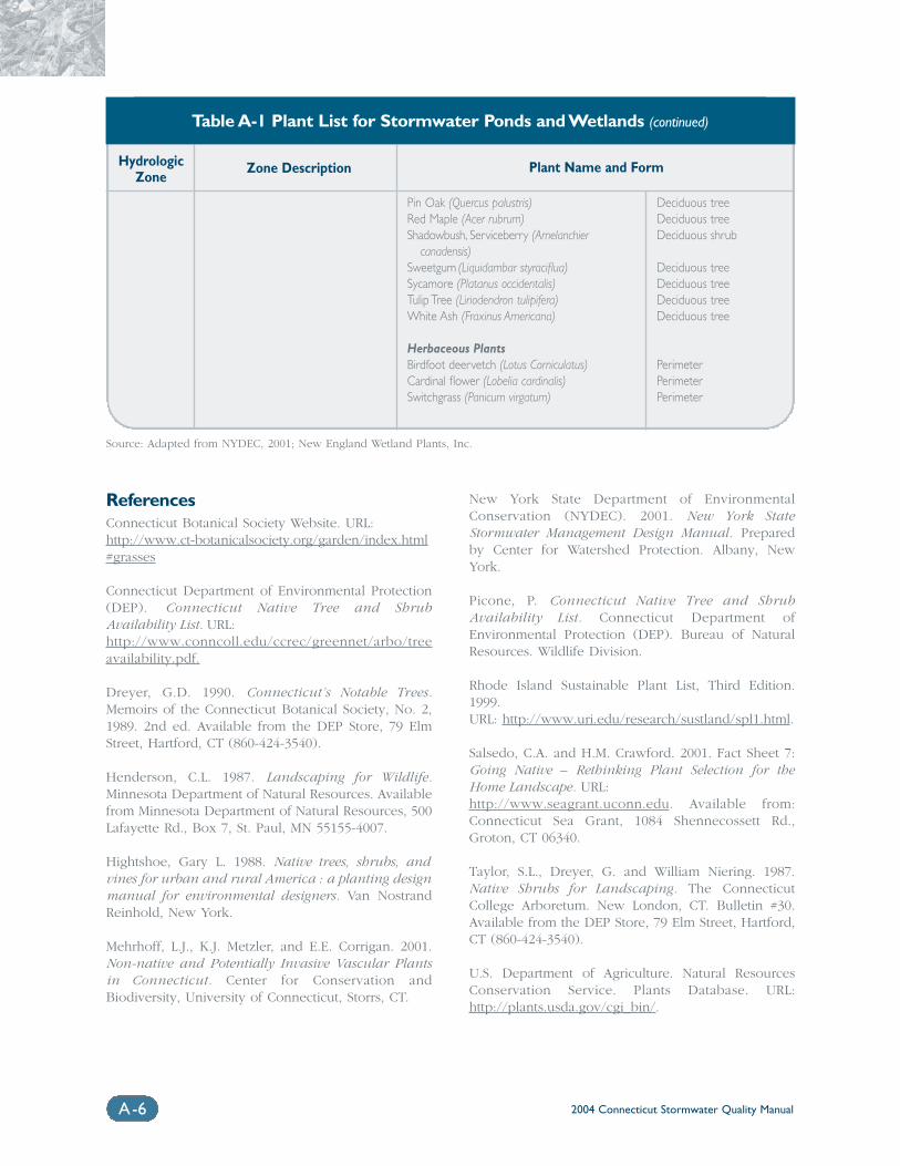
2004 Connecticut Stormwater Quality ManualA-6
ReferencesConnecticut Botanical Society Website. URL: http://www.ct-botanicalsociety.org/garden/index.html#grasses
Connecticut Department of Environmental Protection(DEP). Connecticut Native Tree and ShrubAvailability List. URL: http://www.conncoll.edu/ccrec/greennet/arbo/treeavailability.pdf.
Dreyer, G.D. 1990. Connecticut’s Notable Trees.Memoirs of the Connecticut Botanical Society, No. 2,1989. 2nd ed. Available from the DEP Store, 79 ElmStreet, Hartford, CT (860-424-3540).
Henderson, C.L. 1987. Landscaping for Wildlife.Minnesota Department of Natural Resources. Availablefrom Minnesota Department of Natural Resources, 500Lafayette Rd., Box 7, St. Paul, MN 55155-4007.
Hightshoe, Gary L. 1988. Native trees, shrubs, andvines for urban and rural America : a planting designmanual for environmental designers. Van NostrandReinhold, New York.
Mehrhoff, L.J., K.J. Metzler, and E.E. Corrigan. 2001.Non-native and Potentially Invasive Vascular Plantsin Connecticut. Center for Conservation andBiodiversity, University of Connecticut, Storrs, CT.
New York State Department of EnvironmentalConservation (NYDEC). 2001. New York StateStormwater Management Design Manual. Preparedby Center for Watershed Protection. Albany, NewYork.
Picone, P. Connecticut Native Tree and ShrubAvailability List. Connecticut Department ofEnvironmental Protection (DEP). Bureau of NaturalResources. Wildlife Division.
Rhode Island Sustainable Plant List, Third Edition.1999.URL: http://www.uri.edu/research/sustland/spl1.html.
Salsedo, C.A. and H.M. Crawford. 2001. Fact Sheet 7:Going Native – Rethinking Plant Selection for theHome Landscape. URL: http://www.seagrant.uconn.edu. Available from:Connecticut Sea Grant, 1084 Shennecossett Rd.,Groton, CT 06340.
Taylor, S.L., Dreyer, G. and William Niering. 1987.Native Shrubs for Landscaping. The ConnecticutCollege Arboretum. New London, CT. Bulletin #30.Available from the DEP Store, 79 Elm Street, Hartford,CT (860-424-3540).
U.S. Department of Agriculture. Natural ResourcesConservation Service. Plants Database. URL:http://plants.usda.gov/cgi_bin/.
Pin Oak (Quercus palustris) Red Maple (Acer rubrum)Shadowbush, Serviceberry (Amelanchier
canadensis)Sweetgum (Liquidambar styraciflua)Sycamore (Platanus occidentalis)Tulip Tree (Liriodendron tulipifera)White Ash (Fraxinus Americana)
Herbaceous PlantsBirdfoot deervetch (Lotus Corniculatus)Cardinal flower (Lobelia cardinalis) Switchgrass (Panicum virgatum)
Deciduous treeDeciduous treeDeciduous shrub
Deciduous treeDeciduous treeDeciduous treeDeciduous tree
PerimeterPerimeterPerimeter
Plant Name and FormZone DescriptionHydrologicZone
Table A-1 Plant List for Stormwater Ponds and Wetlands (continued)
Source: Adapted from NYDEC, 2001; New England Wetland Plants, Inc.
Appendix BWater Quality Flow (WQF)
and Flow Diversion Guidance
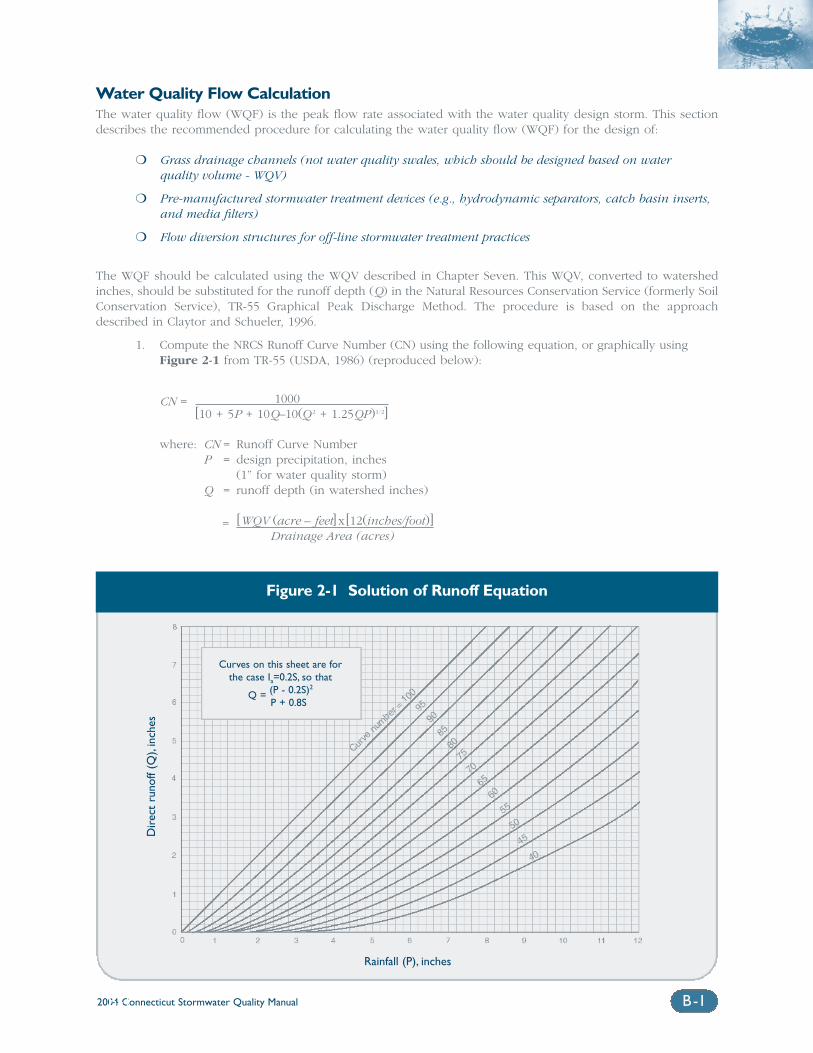
2004 Connecticut Stormwater Quality Manual B-1B-1
Water Quality Flow CalculationThe water quality flow (WQF) is the peak flow rate associated with the water quality design storm. This sectiondescribes the recommended procedure for calculating the water quality flow (WQF) for the design of:
❍ Grass drainage channels (not water quality swales, which should be designed based on water quality volume - WQV)
❍ Pre-manufactured stormwater treatment devices (e.g., hydrodynamic separators, catch basin inserts,and media filters)
❍ Flow diversion structures for off-line stormwater treatment practices
The WQF should be calculated using the WQV described in Chapter Seven. This WQV, converted to watershedinches, should be substituted for the runoff depth (Q) in the Natural Resources Conservation Service (formerly SoilConservation Service), TR-55 Graphical Peak Discharge Method. The procedure is based on the approachdescribed in Claytor and Schueler, 1996.
1. Compute the NRCS Runoff Curve Number (CN) using the following equation, or graphically usingFigure 2-1 from TR-55 (USDA, 1986) (reproduced below):
CN = 1000[10 + 5P + 10Q–10(Q 2 + 1.25QP)1/2]
where: CN = Runoff Curve NumberP = design precipitation, inches
(1” for water quality storm)Q = runoff depth (in watershed inches)
= [WQV (acre – feet] x[12(inches/foot)]Drainage Area (acres)
Figure 2-1 Solution of Runoff Equation
Dir
ect
runo
ff (Q
),in
ches
Rainfall (P), inches
Curves on this sheet are forthe case Ia=0.2S, so that
Q = (P - 0.2S)2
P + 0.8S
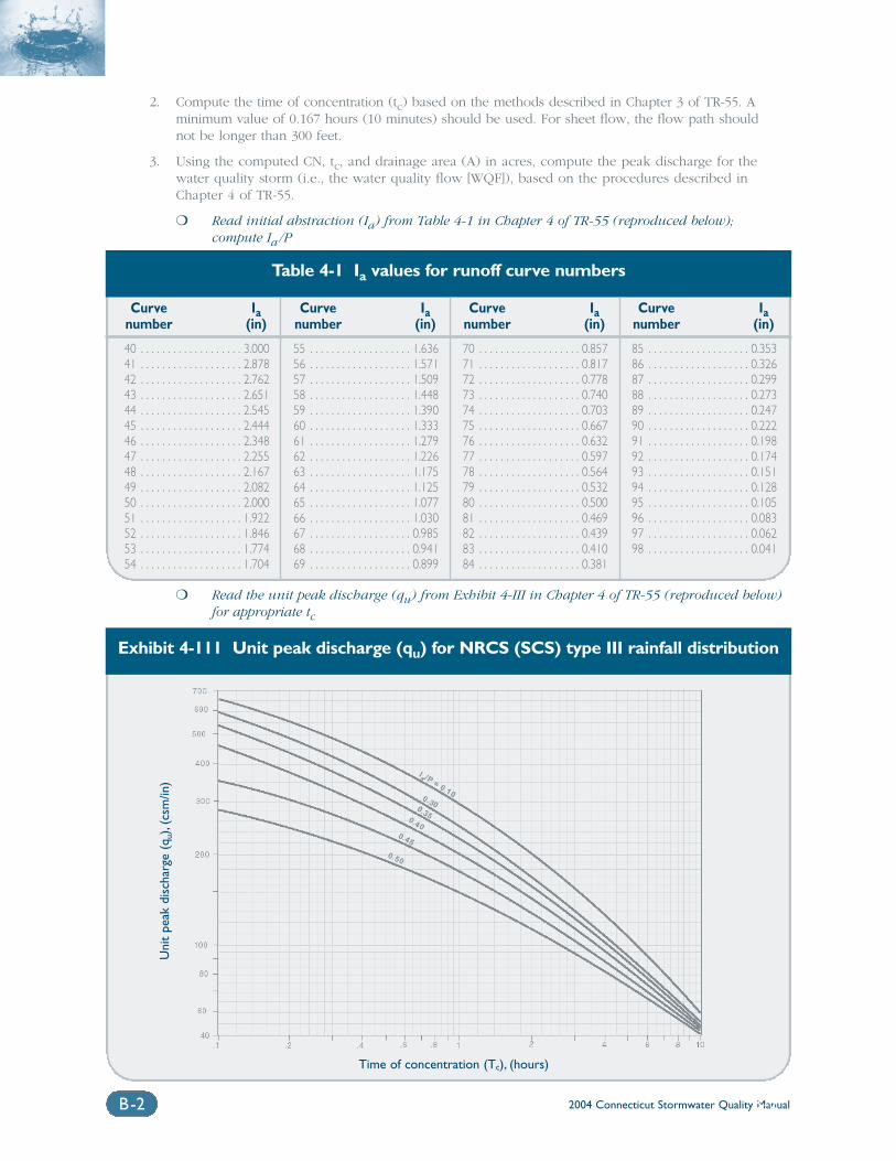
2004 Connecticut Stormwater Quality ManualB-2 B-2
2. Compute the time of concentration (tc) based on the methods described in Chapter 3 of TR-55. A minimum value of 0.167 hours (10 minutes) should be used. For sheet flow, the flow path shouldnot be longer than 300 feet.
3. Using the computed CN, tc, and drainage area (A) in acres, compute the peak discharge for thewater quality storm (i.e., the water quality flow [WQF]), based on the procedures described inChapter 4 of TR-55.
❍ Read initial abstraction (Ia) from Table 4-1 in Chapter 4 of TR-55 (reproduced below); compute Ia /P
Table 4-1 Ia values for runoff curve numbers
Curve Ianumber (in)
40 . . . . . . . . . . . . . . . . . . . 3.00041 . . . . . . . . . . . . . . . . . . . 2.87842 . . . . . . . . . . . . . . . . . . . 2.76243 . . . . . . . . . . . . . . . . . . . 2.65144 . . . . . . . . . . . . . . . . . . . 2.54545 . . . . . . . . . . . . . . . . . . . 2.44446 . . . . . . . . . . . . . . . . . . . 2.34847 . . . . . . . . . . . . . . . . . . . 2.25548 . . . . . . . . . . . . . . . . . . . 2.16749 . . . . . . . . . . . . . . . . . . . 2.08250 . . . . . . . . . . . . . . . . . . . 2.00051 . . . . . . . . . . . . . . . . . . . 1.92252 . . . . . . . . . . . . . . . . . . . 1.84653 . . . . . . . . . . . . . . . . . . . 1.77454 . . . . . . . . . . . . . . . . . . . 1.704
Curve Ianumber (in)
55 . . . . . . . . . . . . . . . . . . . 1.63656 . . . . . . . . . . . . . . . . . . . 1.57157 . . . . . . . . . . . . . . . . . . . 1.50958 . . . . . . . . . . . . . . . . . . . 1.44859 . . . . . . . . . . . . . . . . . . . 1.39060 . . . . . . . . . . . . . . . . . . . 1.33361 . . . . . . . . . . . . . . . . . . . 1.27962 . . . . . . . . . . . . . . . . . . . 1.22663 . . . . . . . . . . . . . . . . . . . 1.17564 . . . . . . . . . . . . . . . . . . . 1.12565 . . . . . . . . . . . . . . . . . . . 1.07766 . . . . . . . . . . . . . . . . . . . 1.03067 . . . . . . . . . . . . . . . . . . . 0.98568 . . . . . . . . . . . . . . . . . . . 0.94169 . . . . . . . . . . . . . . . . . . . 0.899
Curve Ianumber (in)
70 . . . . . . . . . . . . . . . . . . . 0.85771 . . . . . . . . . . . . . . . . . . . 0.81772 . . . . . . . . . . . . . . . . . . . 0.77873 . . . . . . . . . . . . . . . . . . . 0.74074 . . . . . . . . . . . . . . . . . . . 0.70375 . . . . . . . . . . . . . . . . . . . 0.66776 . . . . . . . . . . . . . . . . . . . 0.63277 . . . . . . . . . . . . . . . . . . . 0.59778 . . . . . . . . . . . . . . . . . . . 0.56479 . . . . . . . . . . . . . . . . . . . 0.53280 . . . . . . . . . . . . . . . . . . . 0.50081 . . . . . . . . . . . . . . . . . . . 0.46982 . . . . . . . . . . . . . . . . . . . 0.43983 . . . . . . . . . . . . . . . . . . . 0.41084 . . . . . . . . . . . . . . . . . . . 0.381
Curve Ianumber (in)
85 . . . . . . . . . . . . . . . . . . . 0.35386 . . . . . . . . . . . . . . . . . . . 0.32687 . . . . . . . . . . . . . . . . . . . 0.29988 . . . . . . . . . . . . . . . . . . . 0.27389 . . . . . . . . . . . . . . . . . . . 0.24790 . . . . . . . . . . . . . . . . . . . 0.22291 . . . . . . . . . . . . . . . . . . . 0.19892 . . . . . . . . . . . . . . . . . . . 0.17493 . . . . . . . . . . . . . . . . . . . 0.15194 . . . . . . . . . . . . . . . . . . . 0.12895 . . . . . . . . . . . . . . . . . . . 0.10596 . . . . . . . . . . . . . . . . . . . 0.08397 . . . . . . . . . . . . . . . . . . . 0.06298 . . . . . . . . . . . . . . . . . . . 0.041
Exhibit 4-111 Unit peak discharge (qu) for NRCS (SCS) type III rainfall distribution
❍ Read the unit peak discharge (qu) from Exhibit 4-III in Chapter 4 of TR-55 (reproduced below)for appropriate tc
Uni
t pe
ak d
isch
arge
(q u
),(c
sm/in
)
Time of concentration (Tc), (hours)
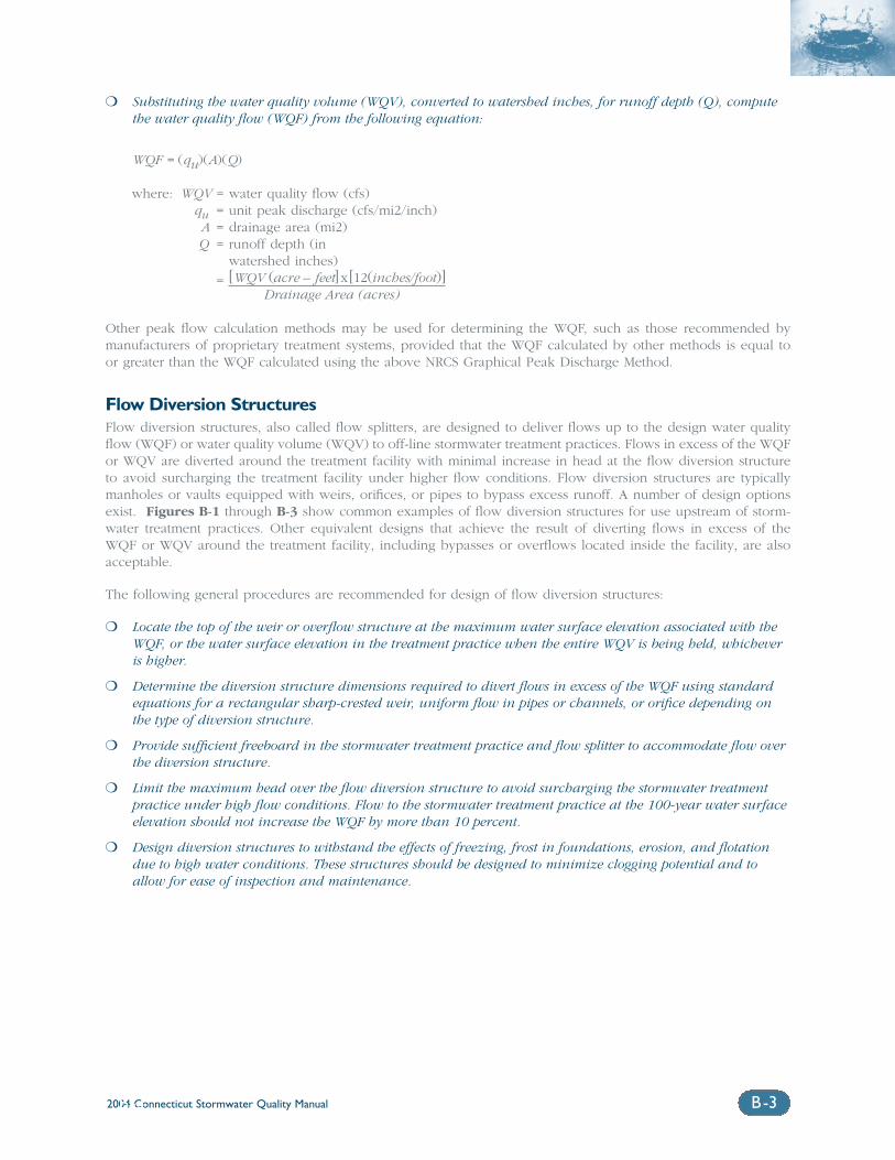
2004 Connecticut Stormwater Quality Manual B-3B-3
❍ Substituting the water quality volume (WQV), converted to watershed inches, for runoff depth (Q), computethe water quality flow (WQF) from the following equation:
WQF = (qu)(A)(Q)
where: WQV = water quality flow (cfs)qu = unit peak discharge (cfs/mi2/inch)A = drainage area (mi2)Q = runoff depth (in
watershed inches)
= [WQV (acre – feet] x[12(inches/foot)]Drainage Area (acres)
Other peak flow calculation methods may be used for determining the WQF, such as those recommended by manufacturers of proprietary treatment systems, provided that the WQF calculated by other methods is equal toor greater than the WQF calculated using the above NRCS Graphical Peak Discharge Method.
Flow Diversion StructuresFlow diversion structures, also called flow splitters, are designed to deliver flows up to the design water qualityflow (WQF) or water quality volume (WQV) to off-line stormwater treatment practices. Flows in excess of the WQFor WQV are diverted around the treatment facility with minimal increase in head at the flow diversion structureto avoid surcharging the treatment facility under higher flow conditions. Flow diversion structures are typicallymanholes or vaults equipped with weirs, orifices, or pipes to bypass excess runoff. A number of design optionsexist. Figures B-1 through B-3 show common examples of flow diversion structures for use upstream of storm-water treatment practices. Other equivalent designs that achieve the result of diverting flows in excess of the WQF or WQV around the treatment facility, including bypasses or overflows located inside the facility, are alsoacceptable.
The following general procedures are recommended for design of flow diversion structures:
❍ Locate the top of the weir or overflow structure at the maximum water surface elevation associated with theWQF, or the water surface elevation in the treatment practice when the entire WQV is being held, whicheveris higher.
❍ Determine the diversion structure dimensions required to divert flows in excess of the WQF using standardequations for a rectangular sharp-crested weir, uniform flow in pipes or channels, or orifice depending onthe type of diversion structure.
❍ Provide sufficient freeboard in the stormwater treatment practice and flow splitter to accommodate flow overthe diversion structure.
❍ Limit the maximum head over the flow diversion structure to avoid surcharging the stormwater treatmentpractice under high flow conditions. Flow to the stormwater treatment practice at the 100-year water surfaceelevation should not increase the WQF by more than 10 percent.
❍ Design diversion structures to withstand the effects of freezing, frost in foundations, erosion, and flotationdue to high water conditions. These structures should be designed to minimize clogging potential and toallow for ease of inspection and maintenance.
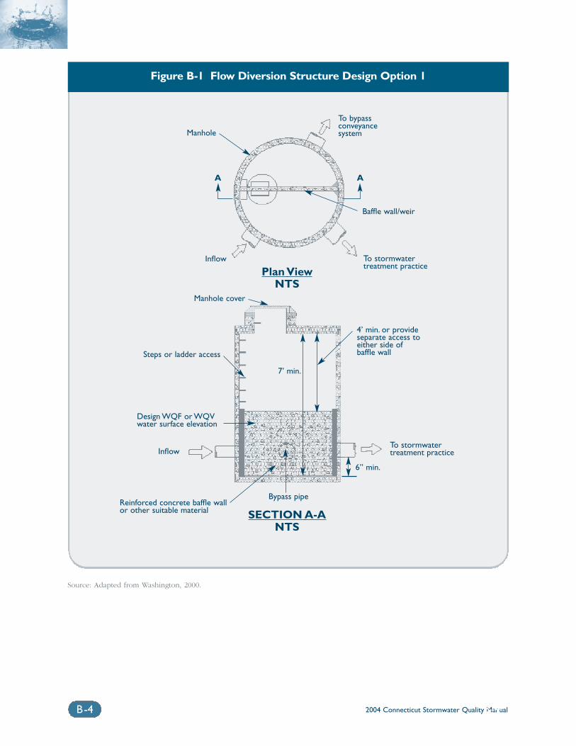
2004 Connecticut Stormwater Quality ManualB-4 B-4
Figure B-1 Flow Diversion Structure Design Option 1
Source: Adapted from Washington, 2000.
Manhole
Inflow
Baffle wall/weir
To stormwatertreatment practice
Steps or ladder access
Design WQF or WQVwater surface elevation
Reinforced concrete baffle wallor other suitable material
4’ min. or provideseparate access toeither side of baffle wall
7’ min.
A A
6” min.
To stormwatertreatment practice
Manhole cover
Inflow
Bypass pipe
To bypassconveyancesystem
Plan ViewNTS
SECTION A-ANTS
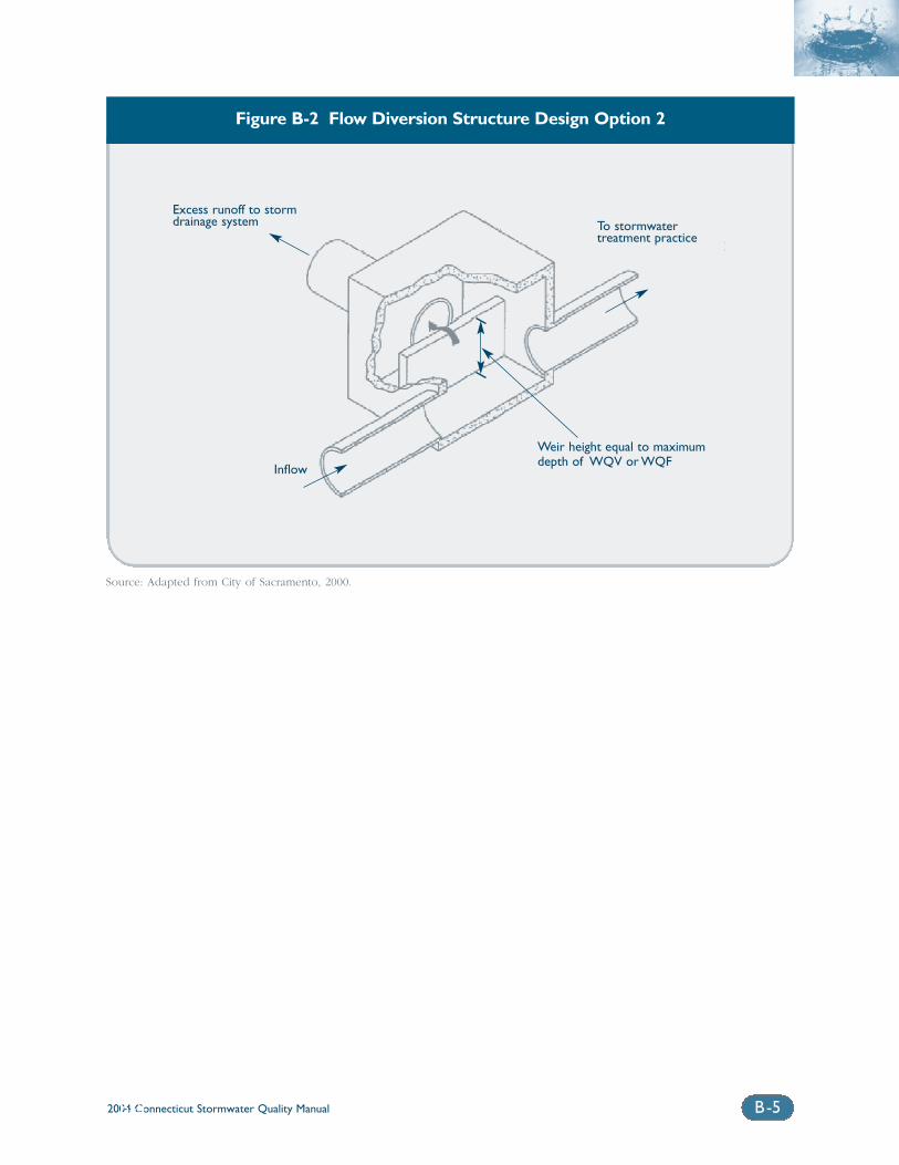
2004 Connecticut Stormwater Quality Manual B-5B-5
Figure B-2 Flow Diversion Structure Design Option 2
Source: Adapted from City of Sacramento, 2000.
Excess runoff to stormdrainage system To stormwater
treatment practice
Inflow
Weir height equal to maximumdepth of WQV or WQF
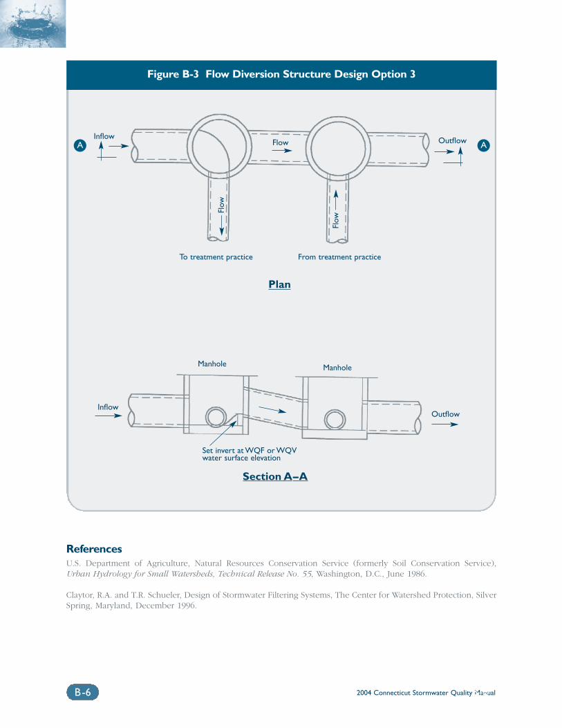
2004 Connecticut Stormwater Quality ManualB-6 B-6
Figure B-3 Flow Diversion Structure Design Option 3
ReferencesU.S. Department of Agriculture, Natural Resources Conservation Service (formerly Soil Conservation Service),Urban Hydrology for Small Watersheds, Technical Release No. 55, Washington, D.C., June 1986.
Claytor, R.A. and T.R. Schueler, Design of Stormwater Filtering Systems, The Center for Watershed Protection, SilverSpring, Maryland, December 1996.
Inflow
Inflow
Outflow
Outflow
To treatment practice
Set invert at WQF or WQVwater surface elevation
Manhole Manhole
From treatment practice
Flow
Flow
Flow
Plan
Section A–A
A A
Appendix CModel Ordinances
2004 Connecticut Stormwater Quality Manual C-1
This Appendix contains model ordinances for:
❍ Illicit Discharge Detection and Elimination(USEPA, 2002)
❍ Stormwater Operation and Maintenance (CWP,2002)
A model ordinance that was developed for protectionof Long Island Sound is included, as well as examplesof specific ordinances or sections of ordinances thathave been adopted by various Connecticut municipal-ities. These model ordinances and examples are notexhaustive and are not necessarily appropriate foradoption in their entirety without modification.
ReferencesCenter for Watershed Protection (CWP). 2002a.Operation and Maintenance. URL http://www.stormwatercenter.net/.
Cromwell, Town of. Zoning Regulations.http://www.cromwellct.com/regs/zregs_03.pdf
Cromwell, Town of. Subdivision Regulations.http://www.cromwellct.com/regs/Subdivision_11_01.pdf
DEP. 1996. Coastal Water Quality Protection: A Guidefor Local Officials.
East Lyme Plan of Conservation and Development1999 http://www.eltownhall.com/newindex1.htm(see link to “Plan of Development”)
Enfield, Town of. Zoning Regulations. http://www.enfield.org/PlanZone/Enfield%20Zoning%20Regs%20On-Line2.pdf
Farmington, Town of. Zoning Regulationshttp://www.farmington-ct.org/government/zoningregulations.pdf
Glastonbury, Town of. Planning and ZoningRegulations http://www.glasct.org/communitydevelopment/commtemplateDIV.htm
South Windsor, Town of. Zoning Regulations.http://www.southwindsor.org/TownHall/ZBA/zoning%20regs.pdf
USEPA. 2002. Model Ordinances to Protect LocalResources: Illicit Discharges. h t tp : / /www.epa .gov/owow/nps/ord inance/discharges.htmWindsor, Town of. Zoning Regulations.http://townofwindsorct.com/Planning/zoning.pdf
Woodbury, Town of. Subdivision Regulations.http://www.woodburyct.org/SubdivisionRegulations041002.pdf
2004 Connecticut Stormwater Quality ManualC-2
Model Illicit Discharge and ConnectionStormwater Ordinance1ORDINANCE NO. ______
Section 1. Purpose/Intent.The purpose of this ordinance is to provide for thehealth, safety, and general welfare of the citizens of( ________________________ ) through the regulation ofnon-storm water discharges to the storm drainage sys-tem to the maximum extent practicable as required byfederal and state law. This ordinance establishesmethods for controlling the introduction of pollutantsinto the municipal separate storm sewer system (MS4)in order to comply with requirements of the NationalPollutant Discharge Elimination System (NPDES) permit process. The objectives of this ordinance are:
(1) To regulate the contribution of pollutants to themunicipal separate storm sewer system (MS4) bystormwater discharges by any user
(2) To prohibit Illicit Connections and Discharges tothe municipal separate storm sewer system
(3) To establish legal authority to carry out all inspec-tion, surveillance and monitoring procedures necessary to ensure compliance with this ordinance
Section 2. Definitions.For the purposes of this ordinance, the following shallmean:
Authorized Enforcement Agency: employees ordesignees of the director of the municipal agency designated to enforce this ordinance.
Best Management Practices (BMPs): schedules ofactivities, prohibitions of practices, general goodhouse keeping practices, pollution prevention andeducational practices, maintenance procedures, andother management practices to prevent or reduce thedischarge of pollutants directly or indirectly tostormwater, receiving waters, or stormwater con-veyance systems. BMPs also include treatmentpractices, operating procedures, and practices to con-trol site runoff, spillage or leaks, sludge or waterdisposal, or drainage from raw materials storage.
Clean Water Act. The federal Water Pollution ControlAct (33 U.S.C. § 1251 et seq.), and any subsequentamendments thereto.
Construction Activity. Activities subject to NPDESConstruction Permits. Currently these include con-struction projects resulting in land disturbance of 1 acre or more. Such activities include but are not limited to clearing and grubbing, grading, excavating,and demolition.
Hazardous Materials. Any material, including anysubstance, waste, or combination thereof, whichbecause of its quantity, concentration, or physical,chemical, or infectious characteristics may cause, orsignificantly contribute to, a substantial present orpotential hazard to human health, safety, property, orthe environment when improperly treated, stored,transported, disposed of, or otherwise managed.
Illegal Discharge. Any direct or indirect non-stormwater discharge to the storm drain system, except asexempted in Section X of this ordinance.
Illicit Connections. An illicit connection is definedas either of the following:
Any drain or conveyance, whether on the surface orsubsurface, which allows an illegal discharge to enterthe storm drain system including but not limited toany conveyances which allow any non-storm waterdischarge including sewage, process wastewater, andwash water to enter the storm drain system and anyconnections to the storm drain system from indoordrains and sinks, regardless of whether said drain orconnection had been previously allowed, permitted,or approved by an authorized enforcement agency or,Any drain or conveyance connected from a commer-cial or industrial land use to the storm drain systemwhich has not been documented in plans, maps, orequivalent records and approved by an authorizedenforcement agency.
Industrial Activity. Activities subject to NPDESIndustrial Permits as defined in 40 CFR, Section 122.26(b)(14).
National Pollutant Discharge Elimination System(NPDES) Storm Water Discharge Permit. means apermit issued by EPA (or by a State under authoritydelegated pursuant to 33 USC § 1342(b)) that author-izes the discharge of pollutants to waters of the UnitedStates, whether the permit is applicable on an indi-vidual, group, or general areawide basis.
Non-Storm Water Discharge. Any discharge to thestorm drain system that is not composed entirely ofstorm water.
Person. means any individual, association, organiza-tion, partnership, firm, corporation or other entityrecognized by law and acting as either the owner oras the owner’s agent.
Pollutant. Anything which causes or contributes topollution. Pollutants may include, but are not limitedto: paints, varnishes, and solvents; oil and other auto-motive fluids; non-hazardous liquid and solid wastesand yard wastes; refuse, rubbish, garbage, litter, orother discarded or abandoned objects, ordinances,and accumulations, so that same may cause or con-tribute to pollution; floatables; pesticides, herbicides,
2004 Connecticut Stormwater Quality Manual C-3
and fertilizers; hazardous substances and wastes;sewage, fecal coliform and pathogens; dissolved andparticulate metals; animal wastes; wastes and residuesthat result from constructing a building or structure;and noxious or offensive matter of any kind.
Premises. Any building, lot, parcel of land, or portionof land whether improved or unimproved includingadjacent sidewalks and parking strips.
Storm Drainage System. Publicly-owned facilitiesby which storm water is collected and/or conveyed,including but not limited to any roads with drainagesystems, municipal streets, gutters, curbs, inlets, pipedstorm drains, pumping facilities, retention and deten-tion basins, natural and human-made or altereddrainage channels, reservoirs, and other drainagestructures.
Storm Water. Any surface flow, runoff, and drainageconsisting entirely of water from any form of naturalprecipitation, and resulting from such precipitation.
Stormwater Pollution Prevention Plan. A docu-ment which describes the Best Management Practicesand activities to be implemented by a person or busi-ness to identify sources of pollution or contaminationat a site and the actions to eliminate or reduce pollu-tant discharges to Stormwater, StormwaterConveyance Systems, and/or Receiving Waters to theMaximum Extent Practicable.
Wastewater means any water or other liquid, otherthan uncontaminated storm water, discharged from afacility.
Section 3. Applicability.This ordinance shall apply to all water entering thestorm drain system generated on any developed andundeveloped lands unless explicitly exempted by anauthorized enforcement agency.
Section 4. Responsibility for Administration.
The ____________________________ [authorized enforce-ment agency] shall administer, implement, andenforce the provisions of this ordinance. Any powersgranted or duties imposed upon the authorizedenforcement agency may be delegated in writing bythe Director of the authorized enforcement agency topersons or entities acting in the beneficial interest ofor in the employ of the agency.
Section 5. Severability.The provisions of this ordinance are hereby declaredto be severable. If any provision, clause, sentence, orparagraph of this Ordinance or the application thereof
to any person, establishment, or circumstances shallbe held invalid, such invalidity shall not affect theother provisions or application of this Ordinance.
Section 6. Ultimate Responsibility.
The standards set forth herein and promulgated pursuant to this ordinance are minimum standards;therefore this ordinance does not intend nor implythat compliance by any person will ensure that therewill be no contamination, pollution, nor unautho-rized discharge of pollutants.
Section 7. Discharge Prohibitions.Prohibition of Illegal Discharges.No person shall discharge or cause to be dischargedinto the municipal storm drain system or watercoursesany materials, including but not limited to pollutantsor waters containing any pollutants that cause or contribute to a violation of applicable water qualitystandards, other than storm water. The commence-ment, conduct or continuance of any illegal dischargeto the storm drain system is prohibited except asdescribed as follows:
(1) The following discharges are exempt from discharge prohibitions established by this ordi-nance: water line flushing or other potable watersources, landscape irrigation or lawn watering,diverted stream flows, rising ground water,ground water infiltration to storm drains, uncont-aminated pumped ground water, foundation orfooting drains (not including active groundwaterdewatering systems), crawl space pumps, air con-ditioning condensation, springs, non-commercialwashing of vehicles, natural riparian habitat orwetland flows, swimming pools (if dechlorinated– typically less than one PPM chlorine), fire fight-ing activities, and any other water source notcontaining Pollutants.
(2) Discharges specified in writing by the authorizedenforcement agency as being necessary to protectpublic health and safety.
(3) Dye testing is an allowable discharge, butrequires a verbal notification to the authorizedenforcement agency prior to the time of the test.
(4) The prohibition shall not apply to any non-stormwater discharge permitted under an NPDES permit, waiver, or waste discharge order issued tothe discharger and administered under theauthority of the Federal Environmental ProtectionAgency, provided that the discharger is in fullcompliance with all requirements of the permit,waiver, or order and other applicable laws andregulations, and provided that written approval
2004 Connecticut Stormwater Quality ManualC-4
has been granted for any discharge to the stormdrain system.
Prohibition of Illicit Connections.(1) The construction, use, maintenance or continued
existence of illicit connections to the storm drainsystem is prohibited.
(2) This prohibition expressly includes, without limi-tation, illicit connections made in the past,regardless of whether the connection was permissible under law or practices applicable orprevailing at the time of connection.
(3) A person is considered to be in violation of thisordinance if the person connects a line conveyingsewage to the MS4, or allows such a connectionto continue.
Section 8. Suspension of MS4 QAccess.Suspension due to Illicit Discharges inEmergency SituationsThe ____________________________ [authorized enforce-ment agency] may, without prior notice, suspend MS4discharge access to a person when such suspension isnecessary to stop an actual or threatened dischargewhich presents or may present imminent and sub-stantial danger to the environment, or to the health orwelfare of persons, or to the MS4 or Waters of theUnited States. If the violator fails to comply with a sus-pension order issued in an emergency, the authorizedenforcement agency may take such steps as deemednecessary to prevent or minimize damage to the MS4or Waters of the United States, or to minimize dangerto persons.
Suspension due to the Detection of IllicitDischargeAny person discharging to the MS4 in violation of thisordinance may have their MS4 access terminatedif such termination would abate or reduce an illicitdischarge. The authorized enforcement agency willnotify a violator of the proposed termination of itsMS4 access. The violator may petition the authorizedenforcement agency for a reconsideration and hearing.
A person commits an offense if the person reinstatesMS4 access to premises terminated pursuant to thisSection, without the prior approval of the authorizedenforcement agency.
Section 9. Industrial or Construction Activity Dischrges.
Any person subject to an industrial or constructionactivity NPDES storm water discharge permit shallcomply with all provisions of such permit. Proof of
compliance with said permit may be required in aform acceptable to the ____________________________[authorized enforcement agency] prior to the allowingof discharges to the MS4.
Section 10. Monitoring of Damages.1. Applicability.
This section applies to all facilities that have stormwater discharges associated with industrial activ-ity, including construction activity.
2. Access to Facilities.
(1) The ____________________________ [authorizedenforcement agency] shall be permitted to enterand inspect facilities subject to regulation underthis ordinance as often as may be necessary todetermine compliance with this ordinance. If adischarger has security measures in force whichrequire proper identification and clearance beforeentry into its premises, the discharger shall makethe necessary arrangements to allow access torepresentatives of the authorized enforcementagency.
(2) Facility operators shall allow the____________________________ [authorized enforce-ment agency] ready access to all parts of thepremises for the purposes of inspection, sam-pling, examination and copying of records thatmust be kept under the conditions of an NPDESpermit to discharge storm water, and the per-formance of any additional duties as defined bystate and federal law.
(3) The ____________________________ [authorizedenforcement agency] shall have the right to set upon any permitted facility such devices as are nec-essary in the opinion of the authorizedenforcement agency to conduct monitoringand/or sampling of the facility’s storm water dis-charge.
(4) The ____________________________ [authorizedenforcement agency] has the right to require thedischarger to install monitoring equipment asnecessary. The facility’s sampling and monitoringequipment shall be maintained at all times in asafe and proper operating condition by the dis-charger at its own expense. All devices used tomeasure stormwater flow and quality shall be cal-ibrated to ensure their accuracy.
(5) Any temporary or permanent obstruction to safeand easy access to the facility to be inspectedand/or sampled shall be promptly removed bythe operator at the written or oral request of the____________________________ [authorized enforce-
2004 Connecticut Stormwater Quality Manual C-5
ment agency] and shall not be replaced. The costsof clearing such access shall be borne by theoperator.
(6) Unreasonable delays in allowing the____________________________ [authorized enforce-ment agency] access to a permitted facility is aviolation of a storm water discharge permit and ofthis ordinance. A person who is the operator of afacility with a NPDES permit to discharge stormwater associated with industrial activity commitsan offense if the person denies the authorizedenforcement agency reasonable access to the per-mitted facility for the purpose of conducting anyactivity authorized or required by this ordinance.
(7) If the ____________________________ [authorizedenforcement agency] has been refused access toany part of the premises from which stormwateris discharged, and he/she is able to demonstrateprobable cause to believe that there may be a vio-lation of this ordinance, or that there is a need toinspect and/or sample as part of a routine inspec-tion and sampling program designed to verifycompliance with this ordinance or any orderissued hereunder, or to protect the overall publichealth, safety, and welfare of the community,then the authorized enforcement agency mayseek issuance of a search warrant from any courtof competent jurisdiction.
Section 11. Requirement to Prevent,Control, and Reduce Storm Water Pollutants by the Use of Best Management.
[Authorized enforcement agency] will adopt require-ments identifying Best Management Practices for anyactivity, operation, or facility which may cause or con-tribute to pollution or contamination of storm water,the storm drain system, or waters of the U.S. Theowner or operator of a commercial or industrial estab-lishment shall provide, at their own expense,reasonable protection from accidental discharge ofprohibited materials or other wastes into the munici-pal storm drain system or watercourses through theuse of these structural and non-structural BMPs.Further, any person responsible for a property orpremise, which is, or may be, the source of an illicitdischarge, may be required to implement, at said per-son’s expense, additional structural and non-structuralBMPs to prevent the further discharge of pollutants tothe municipal separate storm sewer system.Compliance with all terms and conditions of a validNPDES permit authorizing the discharge of stormwater associated with industrial activity, to the extent
practicable, shall be deemed compliance with the pro-visions of this section. These BMPs shall be part of astormwater pollution prevention plan (SWPP) as nec-essary for compliance with requirements of theNPDES permit.
Section 12. Watercourse Protection.Every person owning property through which awatercourse passes, or such person’s lessee, shallkeep and maintain that part of the watercourse withinthe property free of trash, debris, excessive vegeta-tion, and other obstacles that would pollute,contaminate, or significantly retard the flow of waterthrough the watercourse. In addition, the owner orlessee shall maintain existing privately owned struc-tures within or adjacent to a watercourse, so that suchstructures will not become a hazard to the use, func-tion, or physical integrity of the watercourse.
Section 13. Notification of Spills.Notwithstanding other requirements of law, as soon asany person responsible for a facility or operation, orresponsible for emergency response for a facility oroperation has information of any known or suspectedrelease of materials which are resulting or may resultin illegal discharges or pollutants discharging intostorm water, the storm drain system, or water of theU.S. said person shall take all necessary steps toensure the discovery, containment, and cleanup ofsuch release. In the event of such a release of haz-ardous materials said person shall immediately notifyemergency response agencies of the occurrence viaemergency dispatch services. In the event of a releaseof non-hazardous materials, said person shall notifythe authorized enforcement agency in person or byphone or facsimile no later than the next businessday. Notifications in person or by phone shall be con-firmed by written notice addressed and mailed to the____________________________ [authorized enforcementagency] within three business days of the phonenotice. If the discharge of prohibited materialsemanates from a commercial or industrial establish-ment, the owner or operator of such establishmentshall also retain an on-site written record of the dis-charge and the actions taken to prevent its recurrence.Such records shall be retained for at least three years.
Section 14. Enforcement.1. Notice of Violation.
Whenever the ______________________________[authorized enforcement agency] finds that a person has violated a prohibition or failed to meeta requirement of this Ordinance, the authorizedenforcement agency may order compliance by
2004 Connecticut Stormwater Quality ManualC-6
written notice of violation to the responsible per-son. Such notice may require without limitation:
(a) The performance of monitoring, analyses, andreporting;
(b) The elimination of illicit connections or discharges;
(c) That violating discharges, practices, or opera-tions shall cease and desist;
(d) The abatement or remediation of storm waterpollution or contamination hazards and therestoration of any affected property; and
(e) Payment of a fine to cover administrative andremediation costs; and
(f) The implementation of source control or treat-ment BMPs.
If abatement of a violation and/or restoration ofaffected property is required, the notice shall setforth a deadline within which such remediationor restoration must be completed. Said noticeshall further advise that, should the violator fail toremediate or restore within the established dead-line, the work will be done by a designatedgovernmental agency or a contractor and theexpense thereof shall be charged to the violator.
Section 15. Appeal of Notice of Violation.Any person receiving a Notice of Violation mayappeal the determination of the authorized enforce-ment agency. The notice of appeal must be receivedwithin ___ days from the date of the Notice ofViolation. Hearing on the appeal before the appropri-ate authority or his/her designee shall take placewithin 15 days from the date of receipt of the noticeof appeal. The decision of the municipal authority ortheir designee shall be final.
Section 16. Enforcement Measures After Appeal.
If the violation has not been corrected pursuant to therequirements set forth in the Notice of Violation, or ,in the event of an appeal, within ___ days of the deci-sion of the municipal authority upholding the decisionof the authorized enforcement agency, then represen-tatives of the authorized enforcement agency shallenter upon the subject private property and areauthorized to take any and all measures necessary toabate the violation and/or restore the property. It shallbe unlawful for any person, owner, agent or person inpossession of any premises to refuse to allow the gov-ernment agency or designated contractor to enterupon the premises for the purposes set forth above.
Section 17. Cost of Abatement of the Violation.
Within _____ days after abatement of the violation,the owner of the property will be notified of the costof abatement, including administrative costs. Theproperty owner may file a written protest objecting tothe amount of the assessment within _____ days. Ifthe amount due is not paid within a timely manner asdetermined by the decision of the municipal authorityor by the expiration of the time in which to file anappeal, the charges shall become a special assessmentagainst the property and shall constitute a lien on theproperty for the amount of the assessment. Any per-son violating any of the provisions of this article shallbecome liable to the city by reason of such violation.The liability shall be paid in not more than 12 equalpayments. Interest at the rate of _____ percent perannum shall be assessed on the balance beginning onthe _____ st day following discovery of the violation.
Section 18. Injuctive Relief.It shall be unlawful for any person to violate any pro-vision or fail to comply with any of the requirementsof this Ordinance. If a person has violated or contin-ues to violate the provisions of this ordinance, theauthorized enforcement agency may petition for apreliminary or permanent injunction restraining theperson from activities which would create further vio-lations or compelling the person to performabatement or remediation of the violation.
Section 19. Compensatory Actions.In lieu of enforcement proceedings, penalties, andremedies authorized by this Ordinance, the authorizedenforcement agency may impose upon a violatoralternative compensatory actions, such as storm drainstenciling, attendance at compliance workshops,creek cleanup, etc.
Section 20. Violations Deemed a Public Nuisance.
In addition to the enforcement processes and penal-ties provided, any condition caused or permitted toexist in violation of any of the provisions of thisOrdinance is a threat to public health, safety, and wel-fare, and is declared and deemed a nuisance, and maybe summarily abated or restored at the violator’sexpense, and/or a civil action to abate, enjoin, or oth-erwise compel the cessation of such nuisance may betaken.
Section 21. Criminal Prosecution.Any person that has violated or continues to violatethis ordinance shall be liable to criminal prosecutionto the fullest extent of the law, and shall be subject to
2004 Connecticut Stormwater Quality Manual C-7
a criminal penalty of ______ dollars per violation perday and/or imprisonment for a period of time not toexceed _____ days. The authorized enforcementagency may recover all attorney’s fees court costs andother expenses associated with enforcement of thisordinance, including sampling and monitoringexpenses.
Section 22. Remedies Not Exclusive.The remedies listed in this ordinance are not exclusiveof any other remedies available under any applicablefederal, state or local law and it is within the discre-tion of the authorized enforcement agency to seekcumulative remedies.
Section 23. Adoption of Ordinance.This ordinance shall be in full force and effect __ daysafter its final passage and adoption. All prior ordi-nances and parts of ordinances in conflict with thisordinance are hereby repealed.
PASSED AND ADOPTED this ______ day of ___________,20_____ , by the following vote:
Stormwater Operation andMaintenance Model OrdinanceUnlike other model ordinances, the Operation andMaintenance ordinance language is not “stand-alone.” Operation and Maintenance language wouldbe a part of a broader stormwater ordinance.
Section I. DefinitionsStormwater Treatment Practice: Structural device,measure, facility, or activity that helps to achievestormwater management control objectives at a desig-nated site.
Site Stormwater Management Plan: A documentapproved at the site design phase that outlines themeasures and practices used to control stormwaterrunoff at a site.
Section II. Design1. All stormwater BMPs shall be designed in a man-
ner to minimize the need for maintenance andreduce the chances of failure. Design guidelinesare outlined in the most recent version of_________________________ (local or state stormwatermanual).
Rather than incorporate specific stormwaterdesign or maintenance standards into the ordi-nance itself, it is best to reference “the most recentversion” of a stormwater manual. This way, tech-
nical information can remain up-to-date withoutmaking legal changes to the ordinance.
2. Stormwater easements and covenants shall beprovided by the property owner for access forfacility inspections and maintenance. Easementsand covenants shall be recorded with(stormwater agency) prior to the issuance of apermit.
3. Final design shall be approved by(stormwater agency)
Section III. Routine Maintenance1. All stormwater BMPs shall be maintained accord-
ing to the measures outlined in the most recentversion of ______ (local or state stormwa-ter manual), and as approved in the permit.
2. The person(s) or organization(s) responsible formaintenance shall be designated in the plan.Options include
❍ Property owner
❍ Homeowner’s association, provided that pro-visions for financing necessary maintenanceare included in deed restrictions or othercontractual agreements
❍ ____________________ (stormwater managementagency)
3. Maintenance agreements shall specify responsibil-ities for financing maintenance.
Section IV. Nonroutine Maintenance1. Nonroutine maintenance includes maintenance
activities that are expensive but infrequent, suchas pond dredging or major repairs to stormwaterstructures.
2. Nonroutine maintenance shall be performed onan as-needed basis based on information gath-ered during regular inspections.
3. If nonroutine maintenance activities are not com-pleted in a timely manner or as specified in theapproved plan, (stormwater agency)may complete the necessary maintenance at theowner’s/operator’s expense.
Section V. Inspections1. The person(s) or organization(s) responsible for
maintenance shall inspect stormwater BMPs on aregular basis as outlined in the plan.
2004 Connecticut Stormwater Quality ManualC-8
2. Authorized representatives of _________________________ (stormwater agency) may enter at reason-able times to conduct on-site inspections orroutine maintenance.
3. For BMPs maintained by the property owner orhomeowner’s association, inspection and mainte-nance reports shall be filed with_______________________________ (stormwater agency) as provided for in the plan.
4. Authorized representatives of _________________________inspections to confirm the information inthe reports filed under Section V(3).
Model Ordinance for StormwaterManagement1
BackgroundIn 1991, the Connecticut General Assembly passedPublic Acts 91-398 (amending CGS Section 8-23(a))and 91-170 (amending CGS Sections 8-2(b), 8-3b and8-35a). These acts require, in part, that zoning regula-tions and plans of conservation and developmentadopted by coastal municipalities be made with rea-sonable consideration for greater protection of LongIsland Sound water quality. In particular, the Actsrequired municipalities to adopt regulations and planswith reasonable consideration and protection of theecosystem and habitat of Long Island Sound and todesign them to reduce hypoxia, pathogens, toxic con-taminants and floatable debris in Long Island Sound.It is well documented that improperly managedstormwater flows do make significant contributions tocoastal pollution, resulting in hypoxic (low dissolvedoxygen) conditions and increases in pathogens, toxiccontaminants and floatable debris. Therefore,improved stormwater management and treatment willresult in decreases in these pollutants.
In order to assist municipalities in meeting the sub-stantive as well as legal requirements of thislegislation, the Connecticut Department ofEnvironmental Protection’s Office of Long IslandSound Programs developed this Model StormwaterOrdinance for municipal use. The approach of pro-viding a model ordinance as opposed to zoningregulations was selected due to the need for consis-tent approaches to stormwater management in variousmunicipal regulations such as zoning regulations, wet-lands regulations, coastal site plan review and aquiferprotection regulations. Thus, rather than providemodel site plan regulations, which may conflict withexisting municipal regulations, an ordinance providesa more appropriate means of ensuring consistencyamong various municipal regulations.
Depending upon the current format of your regula-tions, portions of this ordinance can be insertedwhere appropriate. Therefore, the first task is to iden-tify appropriate sections. For example, should yourregulations have an environmental section, this maybe the most appropriate place for incorporation; how-ever, you may have a drainage section that would bemore appropriate. Since the system of regulationsvaries from town to town, this model may have to bereorganized in order to match an existing format. Priorto adopting any stormwater regulations, the munici-pality’s corporation counsel should be consulted.
Although this model ordinance was initially devel-oped for use by coastal municipalities in meeting alegislative requirement, it is clear that stormwater mustbe better controlled statewide. Therefore, allConnecticut municipalities can adopt this ordinance,which can also help municipalities meet requirementscontained in state stormwater general permits formunicipal separate stormwater sewer systems. Inreviewing the model ordinance, please note that sug-gested ordinance language is in normal type;explanations or commentary are in italics.
Purpose and AuthorityIn accordance with the provisions of Chapters 98, 124,126, 440, 444, and 446h of the General Statutes of theState of Connecticut, as amended, the Town of____________ hereby adopts the following StormwaterManagement Ordinance for the following purposes:
Increased development without proper considerationof stormwater impacts can be a significant source ofpollution to Long Island Sound, its tributaries, andother waters of the state. The state’s water resourcesare valuable natural, economic, recreational, culturaland aesthetic resources. The protection and preserva-tion of these waters is in the public interest and isessential to the health, welfare and safety of the citi-zens of the state. It is, therefore, the purpose of thisordinance to protect and preserve the waters within(town name) from nonpoint sources of pollutionthrough the proper management of stormwater flowsand minimization of inputs of suspended solid,pathogens, toxic contaminants, nitrogen and floatabledebris to these flows.
1Excertpted from Coastal Water Quality Protection: A Guide forLocal Officials (DEP, 1996).
2004 Connecticut Stormwater Quality Manual C-9
Definitions
aquifer – a geologic formation, group of formationsor part of a formation that contains sufficient satu-rated, permeable materials to yield significantquantities of water to wells and springs
BMPs – best management practices - techniques orstructural devices that are effective practical ways ofpreventing or reducing pollution
“first inch of rain” – the first inch of rainfall duringa single event. The initial runoff from the first inch ofrain contains higher pollutant concentrations than thesubsequent runoff, due to initial washing off of dryweather deposits in significantly higher concentrationsthan those washed off later in a storm. This effect isparticularly pronounced with initial heavy rainfalls.
groundwater – water found beneath the ground sur-face that completely fills the open spaces betweenparticles of sediment and within rock formations
impervious surface – material or structure on, aboveor below the ground that does not allow precipitationor surface water to penetrate directly into the soil
site – a single parcel, together with any adjacentwaters, which is the subject of an application for zon-ing approval, subdivision approval, coastal site planreview, or an inland wetlands permit
sediment – solid material, either mineral or organic,that is in suspension, is transported, or has beenmoved from its site or origin by erosion
trash hood – feature in a catch basin which trapsdebris such as litter and keeps it from being dis-charged from the catch basin
urban stormwater runoff – precipitation that fallsonto the surfaces of roofs, streets, parking lots, roadsand the grounds of developed areas. Urban precipita-tion is not absorbed by the ground or retained in itssurface, but collects and runs off, carrying a wide variety of pollutants such as oil-based contaminants,heavy metals (copper and lead), nutrients and bacteria
Application RequirementsStormwater management plans should be stronglyencouraged for all land use and development projects,even where they are not required. A stormwater man-agement plan shall be included as a part of anyapplication for zoning approval, subdivision approval,coastal site plan review, or an inland wetlands permitwhere:
1. the application pertains to a development or con-struction project disturbing one or more acres oftotal land area on a site; Applicants should bemade aware that any development which calls for
a total disturbance of over 5 acres also requiresthe submission of registration to the ConnecticutDEP under the General Permit for the Dischargeof Stormwater and Dewatering Wastewaters fromConstruction Activities.
2. the application pertains to any site with one acreor more of impervious cover;
3. the application proposes new residential devel-opment of three or more units;
4. the application pertains to any new industrial orcommercial project; or
5. the commission which has jurisdiction over theapplication has required submission of astormwater management plan pursuant to writtenfindings that the activity proposed in the applica-tion has the potential to cause significantnonpoint source pollution to groundwater or surface water drinking supplies, or to Long IslandSound or any other waters of the state. Such find-ings may be based upon a written request by theCommissioner of Environmental Protection.
If the commission determines that the activity pro-posed in an application may result in significantnonpoint source pollution to groundwater or surfacewater drinking supplies, or to Long Island Sound orany other waters of the state, it may refer the applica-tion, including the stormwater management plan, tothe Commissioner of Environmental Protection for adetermination as to whether a discharge permit undersection 22a-430 of the General Statutes, or other stateauthorization, is required.
Contents of stormwater management plan:Where a stormwater management plan is required,such plan shall provide, at a minimum, the followinginformation:
1. Soil characteristics of the site.
2. Location of the closest surface water bodies andwetlands to the site, and the depth to any ground-water or aquifer areas on or adjacent to the site.In the case of tidal waters, provide the mean highwater and high tide elevations.
3. DEP ground and surface water quality classifica-tion of waterbodies on and adjacent to the site.
4. Identification of any waterbodies on and adjacentto the site documented by DEP as not meetingwater quality standards. The list of impairedwaterbodies, documented by DEP pursuant toSection 303(d) of the Federal Clean Water Act,and can be accessed online athttp://www.dep.state.ct.us/wtr/wq/impaired2002.pdf
2004 Connecticut Stormwater Quality ManualC-10
5. Location and description of all proposedstormwater control BMPs for both constructionactivities and post-construction long-termstormwater control.
6. Proposed maintenance and operation manual orschedule for any trash hoods, catchbasins, orother BMP devices used to prevent runoff,encourage sheet flow or infiltration, or treatstormwater.
7. Calculations of stormwater runoff rates, sus-pended solids removal rates, and soil infiltrationrates before and after completion of the activityproposed in the application.
8. A hydrologic study of pre-development site con-ditions. Hydrology studies shall be conducted at alevel of detail commensurate with the probableimpact of the proposed activity and shouldextend downstream to the point where the pro-posed activity causes less than a five percentchange in the peak flow rates.
Standards and Criteria for DecisionIn order to approve any application for which astormwater management plan is required, the com-mission shall find the stormwater management planconsistent with the following criteria. If such applica-tion is also subject to the requirements of an aquiferprotection overlay zone or any other requirements fornonpoint source pollution control, the more stringentrequirements shall control.
1. Direct channeling of untreated surface waterrunoff into adjacent ground and surface watersshall be prohibited.
2. No net increase in urban stormwater runoff fromthe site, to the maximum extent possible, shallresult from the proposed activity.
3. Design and planning for site development shallprovide for minimal disturbance of pre-develop-ment natural hydrologic conditions, and shallreproduce such conditions after completion of theproposed activity, to the maximum extent feasi-ble.
4. Pollutants shall be controlled at their source tothe maximum extent feasible in order to containand minimize contamination. Such an approachis not only cost-effective but more efficient, byreducing the need for extensive restoration efforts.
Methods include but are not limited to sweepingof streets and parking lots, especially in the earlyspring, the use of oil traps and sediment basinsprior to infiltration, the use of pervious surfacesand encouragement of sheet flow to filter strips.
5. Stormwater management systems shall bedesigned and maintained to manage site runoff inorder to eliminate surface and groundwater pollution, prevent flooding and, where required,control peak discharges and provide pollutiontreatment.
6. Stormwater management systems shall bedesigned to collect, retain and treat the first inchof rain on-site, so as to trap floating material, oiland litter. BMP techniques to achieve treatment ofthe first inch of rainfall include oil and grit separators, and trash hoods.
7. On-site storage of stormwater shall be employedto the maximum extent feasible. On-site storagemethods include but are not limited to land-scaped depressions, grass swales, infiltrationtrenches and retention or detention basins.
8. Post-development runoff rates and volumes shallnot exceed pre-development rates and volumes.Stormwater runoff rates and volumes shall becontrolled by slowing runoff velocities andencouraging infiltration. BMP methods for con-trolling runoff and encouraging infiltrationinclude the minimization of impervious surfaces,minimization of curbing and collection, the useof grass or vegetative filter zones, landscapedepressions, slotted curb spacers, perforated pipesfor conveying stormwater, establishment of buffersfrom streams, wetlands and waterbodies, andany combination of methods, where appropriate.
9. Stormwater treatment systems shall be employedwhere necessary to ensure that the averageannual loadings of total suspended solids (TSS)following the completion of the proposed activityat the site are no greater than such loadings priorto the proposed activity. Alternatively, stormwatertreatment systems shall remove 80% of TSS fromthe site on an average annual basis. BMP methodsfor stormwater treatment include infiltrationthrough vegetative strips, grass swales and deten-tion basins.
2004 Connecticut Stormwater Quality Manual C-11
Excerpts from Local RegulationsFrom Cromwell SECTION XI –SPECIAL REGULATIONS11.2 STORMWATER RUNOFF CONTROL REGULATIONa. Stormwater Runoff Control Plans. Site Plans shall
be accompanied by plans providing measures fordetention and controlled release of stormwaterrunoff when proposed developments contain anarea of five (5) acres or more or the imperviousarea is 60.0% or greater. All other developmentsmay be required to provide such measures ifdeemed necessary to protect the public health,safety and well-being by the Planning and Zoning
Commission.
1. When required, measures for the detention andcontrolled release of stormwater runoff shall meetthe following standards:
a. Release rate shall not exceed the rate of runoff forthe same site in its undeveloped state for allintensities and durations of rainfall.
b. Required volume for stormwater detention shallbe calculated on the basis of runoff from a 50-year frequency rainfall, as published by theNational Weather Service or other recognizedagency. The detention volume required shall bethat necessary to handle the runoff of a 50-yearfrequency rainfall, for any and all durations, fromthe proposed development less that volume dis-charged during the same duration at theapproved release rate as specified above.
c. In all cases, runoff shall be computed in accor-dance with Technical Release #55, EngineeringDivision, Soil Conservation Service, USDA,January, 1975, as amended.
2. The ability to retain and maximize the groundwater recharge capacity is encouraged. Design ofthe stormwater runoff control system shall giveconsideration to providing ground waterrecharge.
3. All on-site facilities shall be properly maintainedby the owner such that they do not become nui-sances.
4. All runoff control structures located on privateproperty shall be accessible at all times for Towninspection.
From Cromwell, Section 300 Regulations, j.STORMWATER RUNOFF CONTROL:The use of “best management practices” (BMPs) tominimize nonpoint source pollution shall be consid-ered by the applicant, including but not limited tothoseBMPs discussed in the “Nonpoint SourcePollution Management Plan for the Town ofCromwell” dated October 1992. A written descriptionof this consideration shall be submitted with the appli-cation.
From East Lyme Plan of Conservation andDevelopment, Section Seven - TransportationFrom Parking Recommendations:Promote the use of permeable lot paving materialsthat will reduce surface water runoff into the munici-pal waste water treatment system. Best managementpractices for roads and parking areas should be exam-ined to include minimized use of curbing whereappropriate, minimized disturbance when buildingnew or improving existing roads, minimizing impervi-ous surfaces in new roads and parking areas, regularsweeping of parking areas and roadways and routinecatch basin maintenance.
From Enfield,ARTICLE X SITE DEVELOPMENTREGULATIONSSection 10.10 Off Street Parking and LoadingRegulations10.10.6 Parking Design, Layout, and Location(The standards of this section shall apply to all park-ing areas that serve three (3) or more vehicles or two(2) or more uses.)
All off street parking areas and driveways shall bedesigned, to include drainage design, and constructedto the standards of the Director of Public Works. TheCommission may allow an alternate surface to be usedfor the parking area when such surface is designed tominimize storm water runoff. In such situations, amaintenance plan for the surface must be approvedby the Commission.
From Farmington Zoning Regulations:Article IV,Special RegulationsSection 25. STORMWATER SYSTEMS
A. Stormwater systems designed and installed inconjunction with the development of land mustreceive the approval of the Commission in con-sultation with the Town Engineer.
B. Stormwater systems shall be designed for the fol-lowing objectives:
1. Prevent flooding of onsite or offsite property.
2. Feed and recharge inland wetlands, surface andsubsurface waters.
2004 Connecticut Stormwater Quality ManualC-12
3. Minimize pollutant loads in stormwater runoffinto inland wetlands, surface and subsurfacewaters.
4. Maintain the hydrology of existing sub water-sheds including wetlands and watercourses.
C. The Commission may withhold the approval of astorm water system design if it fails to meet theabove objectives.
D. The maintenance of a private storm water systemis the responsibility of the property owner. TheCommission may require that a maintenance pro-gram be developed and submitted to them forapproval. The Commission may require that abond be posted and/or that periodic reports befiled with the Town to ensure that the requiredmaintenance has been performed.
From Glastonbury, Zoning Regulations 10.0 Streetand Highway StandardsWhere permanent cul-de-sac streets are included in aresidential subdivision, they shall not exceed fifteenhundred (1500) feet in length. A permanent cul-de-sacshall contain a turnaround which has a minimumright-of-way radius of fifty-five (55) feet and a mini-mum outside pavement radius of forty-five (45) feetexcept where a permanent cul-de-sac has classifica-tion “Light Local” or “Limited Local” the Commissionmay permit a turnaround which has a minimum right-of-way radius of fifty (50) feet and a minimum outsidepavement radius of forty-five (45) feet. A twenty-five(25) foot pavement width shall be provided aroundcul-de-sac islands located on “Light Local” or “LimitedLocal” streets. Low maintenance cul-de-sac islandsmay be permitted.
From South Windsor Zoning Regulations:SECTION XIII: OFF-STREET PARKING ANDLOADING13.4.1 Modification of Minimum RequiredParking SpacesA reduction in parking spaces will be allowed whenthe Planning and Zoning Commission deems thereduction to be in the best interest of the Town,according to the following:
a. The changes in topography of the land can beminimized by reducing the number of parkingspaces.
b. The cutting of trees and other desirable plants canbe minimized by reducing the number of parkingspaces.
c. The increase in stormwater run-off rate shall beheld to a minimum by reducing the parkingspaces.
From Windsor Zoning Regulations SECTION V:USE REGULATIONS, COMMERCIAL ZONES,I-291 CORRIDOR DEVELOPMENT ZONE5.9.6 Infrastructure Improvements5.9.6.D Stormwater Management1. Design of the stormwater management system
shall be consistent with the standards of thePublic Improvement Specifications manual. Zeronet increase in stormwater runoff (ZIRO) betweenpre- and post-development conditions is to bemaintained for the 2, 10, 25 and 100 year storms,unless it can be demonstrated that there will beno deleterious downstream effects.
2. The applicant shall employ the best availabletechnology in design of the closed drainage sys-tem, including oil and sediment separationdevices, filtration and discharge techniques.
The Town encourages the use of on-site naturalfiltration functions as a part of currently acceptedBest Management Practices in the reduction ofsediment and pollutants.
3. The applicant shall employ, as appropriate, theextended wet-bottom detention basin techniquefor metering site generated storm runoff prior todischarge to off-site drainage systems.
When accessible, the applicant shall utilize Town-owned lands for construction of the wet basin.Such basins will be ultimately sized to accommo-date more than one user. Where location of adetention facility on Town land is not feasible dueto distance or access problems, the applicant isencouraged to enter into an easement agreementwith adjacent lots to create a shared-use detentionfacility. Consolidated parcels will share a deten-tion facility.
4. Clean Water: Clean water is defined as thatstormwater runoff generated from roof flows col-lected in roof gutter or other pickup systems andtransported via risers to underground pipes andout to a discharge point. These flows may notneed to be attenuated (meet ZIRO requirements)if the volume of runoff can be dissipated by infil-tration into the groundwater table.
5. Dirty Water: Dirty water is defined as that stormrunoff generated from parking and road pave-ments that carry sands, road salts, oils, etc. Theseflows are initially treated at catch basins wheresome heavy particulates are trapped in basinsumps. Prior to discharge, flows will pass througha “water quality inlet” where sediment and oilchambers can provide for secondary separation ofparticulates and oils. Discharges would theneither be directed offsite or into a wet detentionbasin in accordance with ZIRO requirements forthat portion of the site.
2004 Connecticut Stormwater Quality Manual C-13
From Windsor Zoning Regulations SECTION 3.SITE DEVELOPMENT3.4 OFF-STREET PARKING3.4.1 General ProvisionsGThe Commission may, depending on the parkingneeds of a particular use, authorize a phased devel-opment of the off-street parking area in compliancewith the following criteria:
1. The total number of spaces required to be shownon the Site Plan shall be determined in accor-dance with the standards for that particular use.
2. The construction of the parking area and installa-tion of the spaces may be phased according toshort- and long-term needs of a particular use.Not less than 50 percent of the total requiredspaces shall be constructed as part of the shortterm, except that for buildings housing computerequipment and operations, and for wholesale orwarehouse uses, this percentage may be reducedto not less than 30 percent. This approval shallbecome null and void if the use changes.
3. The spaces which are not intended for construc-tion as part of the short term shall be labeled“Reserve Parking” on the plan and shall be prop-erly designed and shown as an integral part of theoverall parking layout and must be located onland suitable for parking area development.
4. If at any time after the Certificate of Use andOccupancy is issued the Zoning EnforcementOfficer determines that additional spaces may beneeded, he shall notify the Commission and theowner of the property concerning his finding.
5. The Commission may, after reviewing the ZoningEnforcement Officer’s report, require that all orany portion of the spaces shown on the approvedSite Plan as “Reserve Parking” be constructed.
From Woodbury Subdivision Regulations,SECTION IV - DESIGN AND CONSTRUCTIONSTANDARDS
4.18 Watershed/Viewshed Regulated Area(Effective 4/1/98)
4.18.1 Intent: The Watershed/Viewshed RegulatedArea is adopted in order to:
a. Promote the goals and objectives of theWoodbury Plan of Conservation andDevelopment.
b. Encourage the most appropriate use of land.
c. Preserve the natural environment of distinctiveridgeline areas as a visual and historic asset forthe benefit of the community.
d. Protect the groundwater recharging function andcapacity of the ridges by minimizing the potentialfor pollution and preserving open areas forgroundwater recharge.
e. Prevent the creation of any safety or health haz-ard including, but not limited to, soil erosion,excessive drainage runoff, and degradation ofwater quality.
f. Minimize the adverse effect of development uponboth the visual and functional role of the naturallandscape to preserve Woodbury’s quality of life.
Appendix DSite Stormwater Management
Plan Checklist
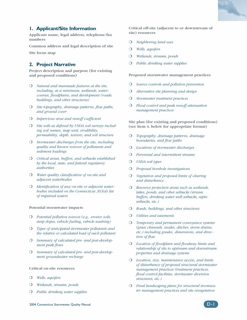
2004 Connecticut Stormwater Quality Manual D-1
1. Applicant/Site InformationApplicant name, legal address, telephone/faxnumbers
Common address and legal description of site
Site locus map
2. Project NarrativeProject description and purpose (for existingand proposed conditions)
❍ Natural and manmade features at the site,including, at a minimum, wetlands, water-courses, floodplains, and development (roads,buildings, and other structures)
❍ Site topography, drainage patterns, flow paths,and ground cover
❍ Impervious area and runoff coefficient
❍ Site soils as defined by USDA soil surveys includ-ing soil names, map unit, erodibility,permeability, depth, texture, and soil structure
❍ Stormwater discharges from the site, includingquality and known sources of pollutants andsediment loadings
❍ Critical areas, buffers, and setbacks establishedby the local, state, and federal regulatory authorities
❍ Water quality classification of on-site and adjacent waterbodies
❍ Identification of any on-site or adjacent water-bodies included on the Connecticut 303(d) list of impaired waters
Potential stormwater impacts
❍ Potential pollution sources (e.g., erosive soils,steep slopes, vehicle fueling, vehicle washing)
❍ Types of anticipated stormwater pollutants andthe relative or calculated load of each pollutant
❍ Summary of calculated pre- and post-develop-ment peak flows
❍ Summary of calculated pre- and post-develop-ment groundwater recharge
Critical on-site resources
❍ Wells, aquifers
❍ Wetlands, streams, ponds
❍ Public drinking water supplies
Critical off-site (adjacent to or downstream ofsite) resources
❍ Neighboring land uses
❍ Wells, aquifers
❍ Wetlands, streams, ponds
❍ Public drinking water supplies
Proposed stormwater management practices
❍ Source controls and pollution prevention
❍ Alternative site planning and design
❍ Stormwater treatment practices
❍ Flood control and peak runoff attenuation management practices
Site plan (for existing and proposed conditions)(see Item 4. below for appropriate format)
❍ Topography, drainage patterns, drainage boundaries, and flow paths
❍ Locations of stormwater discharges
❍ Perennial and intermittent streams
❍ USDA soil types
❍ Proposed borehole investigations
❍ Vegetation and proposed limits of clearing and disturbance
❍ Resource protection areas such as wetlands,lakes, ponds, and other setbacks (stream buffers, drinking water well setbacks, septic setbacks, etc.)
❍ Roads, buildings, and other structures
❍ Utilities and easements
❍ Temporary and permanent conveyance systems(grass channels, swales, ditches, storm drains,etc.) including grades, dimensions, and direc-tion of flow
❍ Location of floodplain and floodway limits andrelationship of site to upstream and downstreamproperties and drainage systems
❍ Location, size, maintenance access, and limits of disturbance of proposed structural stormwatermanagement practices (treatment practices,flood control facilities, stormwater diversionstructures, etc.)
❍ Final landscaping plans for structural stormwa-ter management practices and site revegetation
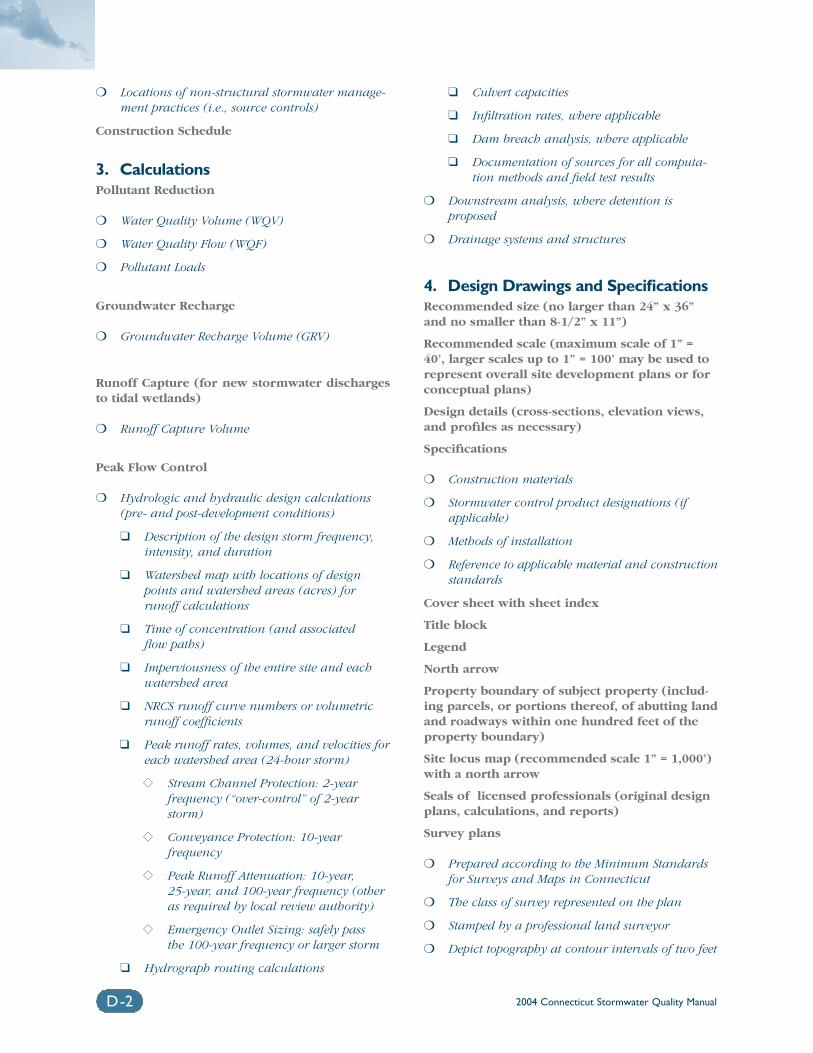
2004 Connecticut Stormwater Quality ManualD-2
❍ Locations of non-structural stormwater manage-ment practices (i.e., source controls)
Construction Schedule
3. CalculationsPollutant Reduction
❍ Water Quality Volume (WQV)
❍ Water Quality Flow (WQF)
❍ Pollutant Loads
Groundwater Recharge
❍ Groundwater Recharge Volume (GRV)
Runoff Capture (for new stormwater dischargesto tidal wetlands)
❍ Runoff Capture Volume
Peak Flow Control
❍ Hydrologic and hydraulic design calculations(pre- and post-development conditions)
❑ Description of the design storm frequency,intensity, and duration
❑ Watershed map with locations of designpoints and watershed areas (acres) forrunoff calculations
❑ Time of concentration (and associated flow paths)
❑ Imperviousness of the entire site and eachwatershed area
❑ NRCS runoff curve numbers or volumetricrunoff coefficients
❑ Peak runoff rates, volumes, and velocities foreach watershed area (24-hour storm)
�� Stream Channel Protection: 2-year frequency (“over-control” of 2-yearstorm)
�� Conveyance Protection: 10-year frequency
�� Peak Runoff Attenuation: 10-year, 25-year, and 100-year frequency (otheras required by local review authority)
�� Emergency Outlet Sizing: safely pass the 100-year frequency or larger storm
❑ Hydrograph routing calculations
❑ Culvert capacities
❑ Infiltration rates, where applicable
❑ Dam breach analysis, where applicable
❑ Documentation of sources for all computa-tion methods and field test results
❍ Downstream analysis, where detention is proposed
❍ Drainage systems and structures
4. Design Drawings and SpecificationsRecommended size (no larger than 24” x 36”and no smaller than 8-1/2” x 11”)
Recommended scale (maximum scale of 1” =40’, larger scales up to 1” = 100’ may be used torepresent overall site development plans or forconceptual plans)
Design details (cross-sections, elevation views,and profiles as necessary)
Specifications
❍ Construction materials
❍ Stormwater control product designations (ifapplicable)
❍ Methods of installation
❍ Reference to applicable material and constructionstandards
Cover sheet with sheet index
Title block
Legend
North arrow
Property boundary of subject property (includ-ing parcels, or portions thereof, of abutting landand roadways within one hundred feet of theproperty boundary)
Site locus map (recommended scale 1” = 1,000’)with a north arrow
Seals of licensed professionals (original designplans, calculations, and reports)
Survey plans
❍ Prepared according to the Minimum Standardsfor Surveys and Maps in Connecticut
❍ The class of survey represented on the plan
❍ Stamped by a professional land surveyor
❍ Depict topography at contour intervals of two feet
2004 Connecticut Stormwater Quality Manual D-3
❍ The referenced or assumed elevation datum
❍ Two (2) benchmarks on the site within one hundred feet of the proposed construction
❍ Outside limits of disturbances
❍ Plan references
5. Construction Erosion and Sediment Controls
Erosion and sediment control plan that com-plies with the requirements of the currentversion of Connecticut Guidelines for SoilErosion and Sediment Control, DEP Bulletin 34.
6. Supporting Documents and StudiesProvide other sources of information used in thedesign of construction and post-constructionstormwater controls for the site development, asapplicable:
Soil maps, borings/test pits
Infiltration test results
Groundwater impacts for proposed infiltrationstructures
Reports on wetlands and other surface waters(including available information such asMaximum Contaminant Levels [MCLs], TotalMaximum Daily Loads [TMDLs], 303(d) or 305(b)listings, etc.)
Water quality impacts to receiving waters andbiological/ecological studies
Flood study/calculations
7. Other Required PermitsEvidence of acquisition of all applicable federal,state, and local permits or approvals (e.g.,copies of DEP permit registration certificates,DEP Dam Safety Registration certificate forstormwater impoundments, DPH approval letterfor stormwater discharges within 100 feet of awatercourse within a public water supply water-shed or aquifer protection area, local approval letters, etc.)
8. Operation and MaintenanceDetailed inspection and maintenance require-ments/tasks
Inspection and maintenance schedules
Parties legally responsible for maintenance(name, address, and telephone number)
Provisions for financing of operation and maintenance activities
As-built plans of completed structures
Letter of compliance from designer
Post-construction documentation to demon-strate compliance with maintenance activities.
Appendix EMaintenance Inspection Checklist
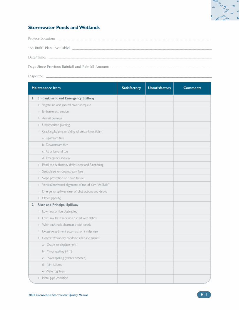
2004 Connecticut Stormwater Quality Manual E-1
Stormwater Ponds and Wetlands
Project/Location: _______________________________________________________________________________________________________________________
“As Built” Plans Available? ___________________________________________________________________________________________________________
Date/Time: _____________________________________________________________________________________________________________________________
Days Since Previous Rainfall and Rainfall Amount: _____________________________________________________________________________
Inspector: _______________________________________________________________________________________________________________________________
Maintenance Item Satisfactory Unsatisfactory Comments
1. Embankment and Emergency Spillway
❍ Vegetation and ground cover adequate
❍ Embankment erosion
❍ Animal burrows
❍ Unauthorized planting
❍ Cracking, bulging, or sliding of embankment/dam
a. Upstream face
b. Downstream face
c. At or beyond toe
d. Emergency spillway
❍ Pond, toe & chimney drains clear and functioning
❍ Seeps/leaks on downstream face
❍ Slope protection or riprap failure
❍ Vertical/horizontal alignment of top of dam “As-Built”
❍ Emergency spillway clear of obstructions and debris
❍ Other (specify)
2. Riser and Principal Spillway
❍ Low flow orifice obstructed
❍ Low flow trash rack obstructed with debris
❍ Weir trash rack obstructed with debris
❍ Excessive sediment accumulation insider riser
❍ Concrete/masonry condition riser and barrels
a. Cracks or displacement
b. Minor spalling (<1”)
c. Major spalling (rebars exposed)
d. Joint failures
e. Water tightness
❍ Metal pipe condition
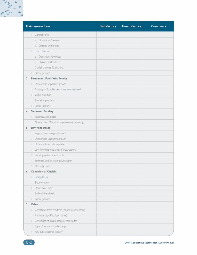
2004 Connecticut Stormwater Quality ManualE-2
Maintenance Item Satisfactory Unsatisfactory Comments
❍ Control valve
a. Operational/exercised
b. Chained and locked
❍ Pond drain valve
a. Operational/exercised
b. Chained and locked
❍ Outfall channels functioning
❍ Other (specify)
3. Permanent Pool (Wet Ponds)
❍ Undesirable vegetative growth
❍ Floating or floatable debris removal required
❍ Visible pollution
❍ Shoreline problem
❍ Other (specify)
4. Sediment Forebay
❍ Sedimentation noted
❍ Greater than 50% of storage volume remaining
5. Dry Pond Areas
❍ Vegetation coverage adequate
❍ Undesirable vegetative growth
❍ Undesirable woody vegetation
❍ Low flow channels clear of obstructions
❍ Standing water or wet spots
❍ Sediment and/or trash accumulation
❍ Other (specify)
6. Condition of Outfalls
❍ Riprap failures
❍ Slope erosion
❍ Storm drain pipes
❍ Endwalls/Headwalls
❍ Other (specify)
7. Other
❍ Complaints from residents (odors, insects, other)
❍ Aesthetics (graffiti, algae, other)
❍ Conditions of maintenance access routes
❍ Signs of hydrocarbon build-up
❍ Any public hazards (specify)
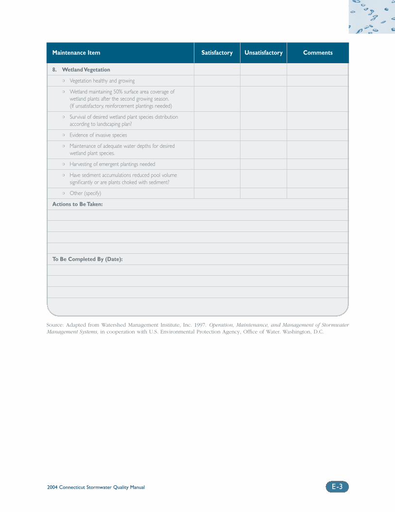
2004 Connecticut Stormwater Quality Manual E-3
Maintenance Item Satisfactory Unsatisfactory Comments
8. Wetland Vegetation
❍ Vegetation healthy and growing
❍ Wetland maintaining 50% surface area coverage of wetland plants after the second growing season.(If unsatisfactory, reinforcement plantings needed)
❍ Survival of desired wetland plant species distribution according to landscaping plan?
❍ Evidence of invasive species
❍ Maintenance of adequate water depths for desired wetland plant species.
❍ Harvesting of emergent plantings needed
❍ Have sediment accumulations reduced pool volume significantly or are plants choked with sediment?
❍ Other (specify)
Actions to Be Taken:
To Be Completed By (Date):
Source: Adapted from Watershed Management Institute, Inc. 1997. Operation, Maintenance, and Management of StormwaterManagement Systems, in cooperation with U.S. Environmental Protection Agency, Office of Water. Washington, D.C.
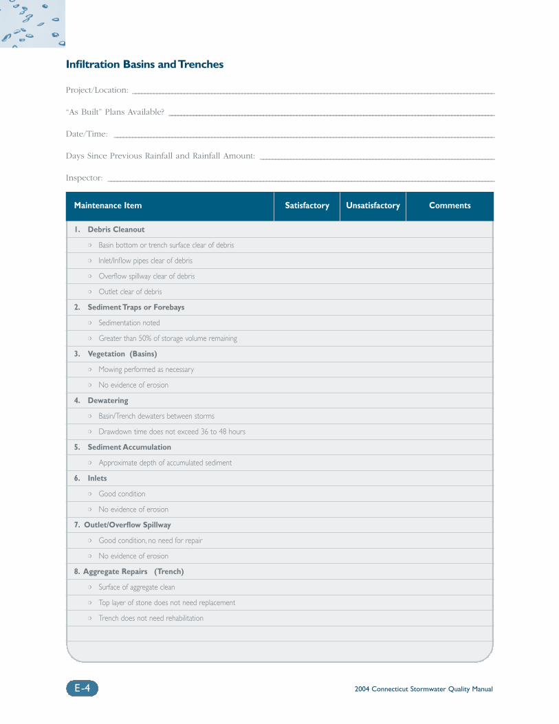
2004 Connecticut Stormwater Quality ManualE-4
Infiltration Basins and Trenches
Project/Location: _______________________________________________________________________________________________________________________
“As Built” Plans Available? ___________________________________________________________________________________________________________
Date/Time: _____________________________________________________________________________________________________________________________
Days Since Previous Rainfall and Rainfall Amount: _____________________________________________________________________________
Inspector: _______________________________________________________________________________________________________________________________
Maintenance Item Satisfactory Unsatisfactory Comments
1. Debris Cleanout
❍ Basin bottom or trench surface clear of debris
❍ Inlet/Inflow pipes clear of debris
❍ Overflow spillway clear of debris
❍ Outlet clear of debris
2. Sediment Traps or Forebays
❍ Sedimentation noted
❍ Greater than 50% of storage volume remaining
3. Vegetation (Basins)
❍ Mowing performed as necessary
❍ No evidence of erosion
4. Dewatering
❍ Basin/Trench dewaters between storms
❍ Drawdown time does not exceed 36 to 48 hours
5. Sediment Accumulation
❍ Approximate depth of accumulated sediment
6. Inlets
❍ Good condition
❍ No evidence of erosion
7. Outlet/Overflow Spillway
❍ Good condition, no need for repair
❍ No evidence of erosion
8. Aggregate Repairs (Trench)
❍ Surface of aggregate clean
❍ Top layer of stone does not need replacement
❍ Trench does not need rehabilitation
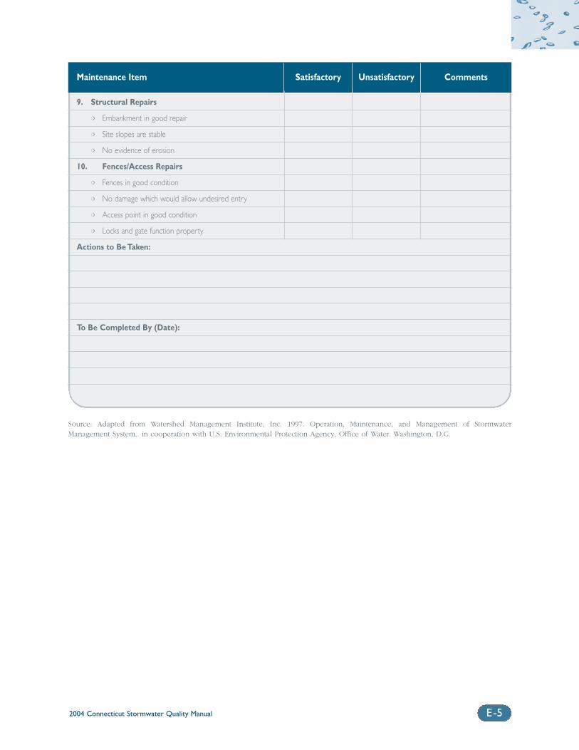
2004 Connecticut Stormwater Quality Manual E-5
Maintenance Item Satisfactory Unsatisfactory Comments
9. Structural Repairs
❍ Embankment in good repair
❍ Site slopes are stable
❍ No evidence of erosion
10. Fences/Access Repairs
❍ Fences in good condition
❍ No damage which would allow undesired entry
❍ Access point in good condition
❍ Locks and gate function property
Actions to Be Taken:
To Be Completed By (Date):
Source: Adapted from Watershed Management Institute, Inc. 1997. Operation, Maintenance, and Management of StormwaterManagement System,. in cooperation with U.S. Environmental Protection Agency, Office of Water. Washington, D.C.
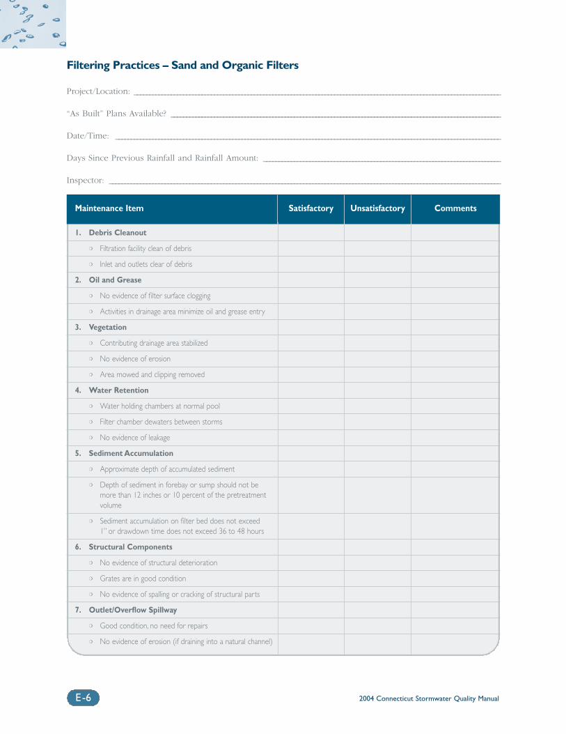
2004 Connecticut Stormwater Quality ManualE-6
Filtering Practices – Sand and Organic Filters
Project/Location: _______________________________________________________________________________________________________________________
“As Built” Plans Available? ___________________________________________________________________________________________________________
Date/Time: _____________________________________________________________________________________________________________________________
Days Since Previous Rainfall and Rainfall Amount: _____________________________________________________________________________
Inspector: _______________________________________________________________________________________________________________________________
Maintenance Item Satisfactory Unsatisfactory Comments
1. Debris Cleanout
❍ Filtration facility clean of debris
❍ Inlet and outlets clear of debris
2. Oil and Grease
❍ No evidence of filter surface clogging
❍ Activities in drainage area minimize oil and grease entry
3. Vegetation
❍ Contributing drainage area stabilized
❍ No evidence of erosion
❍ Area mowed and clipping removed
4. Water Retention
❍ Water holding chambers at normal pool
❍ Filter chamber dewaters between storms
❍ No evidence of leakage
5. Sediment Accumulation
❍ Approximate depth of accumulated sediment
❍ Depth of sediment in forebay or sump should not be more than 12 inches or 10 percent of the pretreatment volume
❍ Sediment accumulation on filter bed does not exceed 1” or drawdown time does not exceed 36 to 48 hours
6. Structural Components
❍ No evidence of structural deterioration
❍ Grates are in good condition
❍ No evidence of spalling or cracking of structural parts
7. Outlet/Overflow Spillway
❍ Good condition, no need for repairs
❍ No evidence of erosion (if draining into a natural channel)
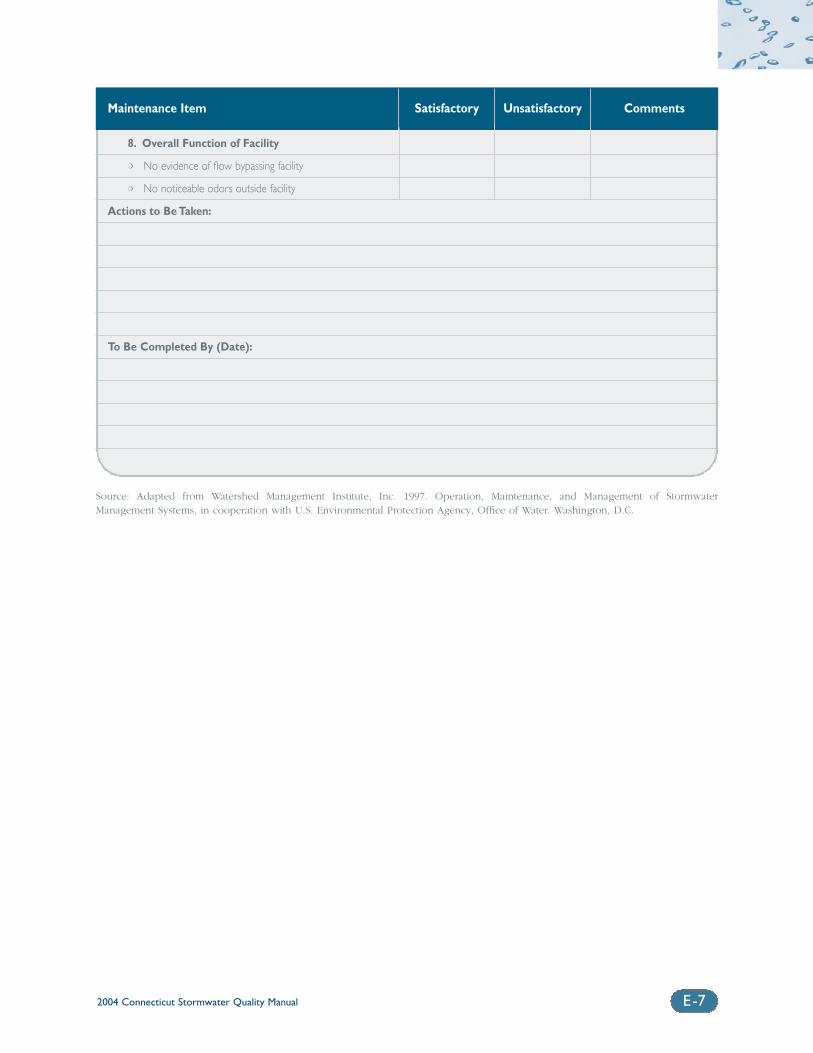
2004 Connecticut Stormwater Quality Manual E-7
Maintenance Item Satisfactory Unsatisfactory Comments
8. Overall Function of Facility
❍ No evidence of flow bypassing facility
❍ No noticeable odors outside facility
Actions to Be Taken:
To Be Completed By (Date):
Source: Adapted from Watershed Management Institute, Inc. 1997. Operation, Maintenance, and Management of StormwaterManagement Systems, in cooperation with U.S. Environmental Protection Agency, Office of Water. Washington, D.C.
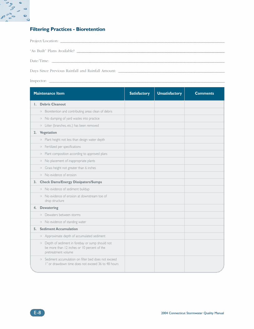
2004 Connecticut Stormwater Quality ManualE-8
Filtering Practices - Bioretention
Project/Location: _______________________________________________________________________________________________________________________
“As Built” Plans Available? ___________________________________________________________________________________________________________
Date/Time: _____________________________________________________________________________________________________________________________
Days Since Previous Rainfall and Rainfall Amount: _____________________________________________________________________________
Inspector: _______________________________________________________________________________________________________________________________
Maintenance Item Satisfactory Unsatisfactory Comments
1. Debris Cleanout
❍ Bioretention and contributing areas clean of debris
❍ No dumping of yard wastes into practice
❍ Litter (branches, etc.) has been removed
2. Vegetation
❍ Plant height not less than design water depth
❍ Fertilized per specifications
❍ Plant composition according to approved plans
❍ No placement of inappropriate plants
❍ Grass height not greater than 6 inches
❍ No evidence of erosion
3. Check Dams/Energy Dissipaters/Sumps
❍ No evidence of sediment buildup
❍ No evidence of erosion at downstream toe of drop structure
4. Dewatering
❍ Dewaters between storms
❍ No evidence of standing water
5. Sediment Accumulation
❍ Approximate depth of accumulated sediment
❍ Depth of sediment in forebay or sump should not be more than 12 inches or 10 percent of the pretreatment volume
❍ Sediment accumulation on filter bed does not exceed 1” or drawdown time does not exceed 36 to 48 hours
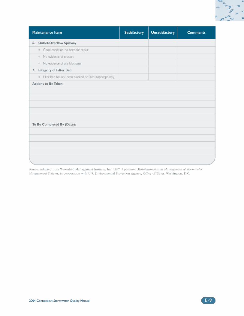
2004 Connecticut Stormwater Quality Manual E-9
Maintenance Item Satisfactory Unsatisfactory Comments
6. Outlet/Overflow Spillway
❍ Good condition, no need for repair
❍ No evidence of erosion
❍ No evidence of any blockages
7. Integrity of Filter Bed
❍ Filter bed has not been blocked or filled inappropriately
Actions to Be Taken:
To Be Completed By (Date):
Source: Adapted from Watershed Management Institute, Inc. 1997. Operation, Maintenance, and Management of StormwaterManagement Systems, in cooperation with U.S. Environmental Protection Agency, Office of Water. Washington, D.C.
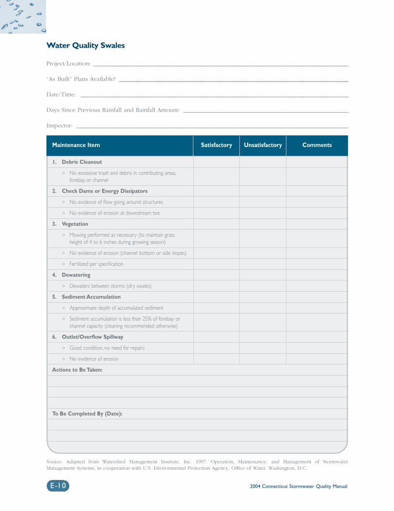
2004 Connecticut Stormwater Quality ManualE-10
Water Quality Swales
Project/Location: _______________________________________________________________________________________________________________________
“As Built” Plans Available? ___________________________________________________________________________________________________________
Date/Time: _____________________________________________________________________________________________________________________________
Days Since Previous Rainfall and Rainfall Amount: _____________________________________________________________________________
Inspector: _______________________________________________________________________________________________________________________________
Maintenance Item Satisfactory Unsatisfactory Comments
1. Debris Cleanout
❍ No excessive trash and debris in contributing areas,forebay, or channel
2. Check Dams or Energy Dissipators
❍ No evidence of flow going around structures
❍ No evidence of erosion at downstream toe
3. Vegetation
❍ Mowing performed as necessary (to maintain grass height of 4 to 6 inches during growing season)
❍ No evidence of erosion (channel bottom or side slopes)
❍ Fertilized per specification
4. Dewatering
❍ Dewaters between storms (dry swales)
5. Sediment Accumulation
❍ Approximate depth of accumulated sediment
❍ Sediment accumulation is less than 25% of forebay or channel capacity (cleaning recommended otherwise)
6. Outlet/Overflow Spillway
❍ Good condition, no need for repairs
❍ No evidence of erosion
Actions to Be Taken:
To Be Completed By (Date):
Source: Adapted from Watershed Management Institute, Inc. 1997. Operation, Maintenance, and Management of StormwaterManagement Systems, in cooperation with U.S. Environmental Protection Agency, Office of Water. Washington, D.C.
Appendix FGlossary
2004 Connecticut Stormwater Quality Manual F-1
Some definitions in this glossary are adapted from definitions in applicable sections of the Connecticut GeneralStatutes and the Regulations of Connecticut State Agencies, as well as related guidance documents such as theConnecticut Guidelines for Soil Erosion and Sediment Control. Refer to these sources for complete definitions.
Advanced Treatment Pollutant removal techniques typically used in drinking water treatmentprocesses but with potential for application as advanced treatmentoptions for stormwater. These treatment techniques include ionexchange, reverse osmosis, disinfection, ultrafiltration, alum injection, anduse of water-soluble anionic polyacrylamide (PAM).
Agricultural Runoff Runoff from land utilized for agricultural practices including growingcrops and raising livestock.
Alternative Site Design Innovative site design practices have been developed as alternatives to traditional development to control stormwater pollution and protect theecological integrity of developing watersheds. Research has demonstratedthat alternative site design can reduce impervious cover, runoff volume,pollutant loadings, and development costs when compared to traditionaldevelopment.
Alum Injection Injection of aluminum phosphate (alum), which has been used exten-sively as a flocculent in pond and lake management applications, forreducing concentrations of fine sediment and phosphorus in stormwaterdischarges to eutrophic water bodies.
Aquatic Bench A ten-foot wide bench located around the inside perimeter of a perma-nent pool that is normally vegetated with aquatic plants to providepollutant removal.
Aquifer A porous water-bearing formation of permeable rock, sand or gravel capable of yielding economically significant quantities of groundwater.
Baseflow The portion of streamflow that is not due to storm runoff but is the resultof groundwater discharge or discharge from lakes or similar permanentimpoundments of water.
Biochemical Oxygen A measure of the quantity of organic material that can be decomposedDemand (BOD) through oxidation by micro-organisms.
Bioretention A practice to manage and treat stormwater runoff by using a speciallydesigned planting soil bed and planting materials to filter runoff stored ina shallow depression. The areas consist of a mix of elements eachdesigned to perform different functions in the removal of pollutants andattenuation of stormwater runoff.
Building Setbacks The distance between a structure and a property boundary (front, rear, orside) of the lot on which the structure is located.
Catch Basin Inserts A structure, such as a tray, basket, or bag, that typically contains a pollu-tant removal medium (i.e., filter media) and a method for suspending thestructure in the catch basin. They are placed directly inside of existingcatch basins where stormwater flows into the catch basin and is treatedas it passes through the structure.
Catch Basin A structure placed below grade to conduct water from a street or otherpaved surface to the storm sewer.
2004 Connecticut Stormwater Quality ManualF-2
Check Dams Small temporary dams constructed across a swale or drainage ditch toreduce the velocity of concentrated stormwater flows.
Chemical Oxygen A measure of the amount of organic material that can be chemically Demand (COD) oxidized.
Cisterns Containers that store larger quantities of rooftop stormwater runoff andmay be located above or below ground. Cisterns can also be used onresidential, commercial, and industrial sites. See also Rain Barrel.
Coagulant A chemical added to wastewater or stormwater that destabilizes the surface charge of fine particles, allowing the particles to come together toform larger particles that can be more easily removed by gravity settlingand other physical treatment processes. Alum is a common coagulantused in lake management applications and sometimes used for storm-water treatment.
Coastal Area As defined in CGS §22a-94(a), land and water within the towns listed inTable 1-2 of this Manual.
Coastal Boundary As defined in CGS §22a-94(b), a region within the coastal area delineatedby the contour elevation of the one hundred year frequency coastal floodzone, as defined and determined by the National Flood Insurance Act; ora one thousand foot linear setback measured from the mean high watermark in coastal waters; or a one thousand foot linear setback measuredfrom the inland boundary of tidal wetlands mapped under C.G.S. §22a-20, whichever is farthest inland.
Combined Sewer Combined sewers collect both stormwater runoff and sanitary wastewater Overflows (CSOs) in a single set of sewer pipes. When combined sewers do not have
enough capacity to carry all the runoff and wastewater or the receivingwater pollution control plant cannot accept all the combined flow, thecombined wastewater overflows from the collection system into the near-est body of water, creating a CSO.
Darcy’s Law An equation stating that the rate of fluid flow through a porous mediumis proportional to the potential energy gradient within the fluid. The constant of proportionality is the hydraulic conductivity, which is a property of both the porous medium and the fluid moving through theporous medium.
Deep Sump Catch Basins Storm drain inlets that typically include a grate or curb inlet and a sumpto capture trash, debris and some sediment and oil and grease. Alsoknown as an oil and grease catch basin.
Deicers Materials applied to reduce icing on paved surfaces. These consist ofsalts and other formulated materials that lower the melting point of ice,including sodium chloride, calcium chloride, calcium magnesium acetate,and blended products consisting of various combinations of sodium, cal-cium, magnesium, chloride, and other constituents.
Deicing Constituents Additives included in deicing materials to prevent caking and inhibit cor-rosion.
Dissolved Pollutants Non-particulate pollutants typically removed through removal mecha-nisms such as adsorption, biological uptake, chemical precipitation or ion exchange.
2004 Connecticut Stormwater Quality Manual F-3
Downstream Analysis Calculation of peak flows, velocities, and hydraulic effects at criticaldownstream locations to ensure that proposed projects do not increasepost-development peak flows and velocities at these locations.
Dry Detention Pond Stormwater basin designed to capture, temporarily hold, and graduallyrelease a volume of stormwater runoff to attenuate and delay stormwaterrunoff peaks. Dry detention ponds provide water quantity control (peakflow control and stream channel protection) as opposed to water qualitycontrol. Also known as “dry ponds” or “detention basins”.
Dry Well Small excavated pits or trenches filled with aggregate that receive cleanstormwater runoff primarily from building rooftops. Dry wells function asinfiltration systems to reduce the quantity of runoff from a site. The useof dry wells is applicable for small drainage areas with low sediment orpollutant loadings and where soils are sufficiently permeable to allowreasonable rates of infiltration.
Emergency Spillway Auxiliary outlet to a water impoundment that transmits floodwaterexceeding the capacity of the primary spillway.
Erosion The wearing away of land surface by running water, wind, ice or othergeological agents, including such processes as gravitational creep.
Erosion and Sediment Control A device placed, constructed on, or applied to the landscape that pre-vents or curbs the detachment of soil, its movement and/or deposition.
Failing Septic System An on-site wastewater disposal system that discharges effluent into theground at concentrations that exceed water quality standards. Failing systems can be significant sources of nutrients, especially nitrogen, andmicrobial pathogens to both surface water and groundwater.
Filter Strip A strip or area of vegetation for removing sediment, organic material,nutrients and chemicals from runoff or wastewater. They are typicallylocated downgradient of stormwater outfalls and level spreaders toreduce flow velocities and promote infiltration/filtration.
Filtering Practices Practices that capture and store stormwater runoff and pass it through a filtering media such as sand, organic material, or soil for pollutantremoval. Stormwater filters are primarily water quality control devicesdesigned to remove particulate pollutants and, to a lesser degree, bacteria and nutrients.
Floodplain Any land susceptible to being inundated by water, usually adjacent to a stream, river or water body and usually associated with a particulardesign flooding frequency (e.g., 100-year floodplain).
Flow Splitter An engineered, hydraulic structure designed to divert a percentage ofstormwater to a treatment practice located outside of the primary channelor to direct stormwater to a parallel pipe system or to bypass a portionof baseflow around a treatment practice.
Fourth Order Stream Stream order indicates the relative size of a stream based on Strahler’s(1957) method. Streams with no tributaries are first order streams, repre-sented as the start of a solid line on a 1:24,000 USGS Quadrangle Sheet.A second order stream is formed at the confluence of two first orderstreams, and so on.
2004 Connecticut Stormwater Quality ManualF-4
Fresh-tidal Wetland A tidal wetland with an annual average salinity of less than 0.5 parts perthousand.
Full Sedimentation Design Stormwater filter system design involving storage and pretreatment of theentire water quality volume.
Grass Drainage Channels Traditional vegetated open channels, typically trapezoidal, triangular, or parabolic in shape, whose primary function is to provide non-erosiveconveyance, typically up to the 10-year frequency design flow. They provide limited pollutant removal through filtration by grass or other vegetation, sedimentation, biological activity in the grass/soil media, aswell as limited infiltration if underlying soils are pervious.
Groundwater Recharge The process by which water that seeps into the ground, eventuallyreplenishing groundwater aquifers and surface waters such as lakes,streams, and the oceans. This process helps maintain water flow instreams and wetlands and preserves water table levels that support drinking water supplies.
Groundwater Recharge The post-development design recharge volume (i.e., on a storm event Volume (GRV) basis) required to minimize the loss of annual pre-development ground-
water recharge. The GRV is determined as a function of annualpre-development recharge for site-specific soils or surficial materials,average annual rainfall volume, and amount of impervious cover on a site.
Heavy Metals Metals such as copper, zinc, barium, cadmium, lead, and mercury, whichare natural constituents of the Earth’s crust. Heavy metals are stable andpersistent environmental contaminants since they cannot be degraded ordestroyed.
Hydraulic Conductivity The rate at which water moves through a saturated porous media undera unit potential-energy gradient. It is a measure of the ease of watermovement in soil and is a function of the fluid as well as the porousmedia through which the fluid is moving.
Hydraulic Head The kinetic or potential energy of a unit weight of water expressed asthe vertical height of water above a reference datum.
Hydrocarbons Inorganic compounds consisting of carbon and hydrogen, includingpetroleum hydrocarbons derived from crude oil, natural gas, and coal.
Hydrodynamic Separators A group of stormwater treatment technologies designed to remove largeparticle total suspended solids and large oil droplets, consisting primarilyof cylindrical-shaped devices that are designed to fit in or adjacent toexisting stormwater drainage systems. The most common mechanismused in these devices is vortex-enhanced sedimentation, where stormwa-ter enters as tangential inlet flow into the side of the cylindrical structure.As the stormwater spirals through the chamber, the swirling motioncauses the sediments to settle by gravity, removing them from thestormwater.
Hydrograph A graph showing the variation in discharge or depth of a stream of waterover time.
Hydrologic Cycle The distribution and movement of water between the earth’s atmosphere,land, and water bodies.
2004 Connecticut Stormwater Quality Manual F-5
Hydrologic Zones Planting zones that reflect the degree and duration of inundation bywater, consisting of a deep water pool, shallow water bench, shorelinefringe, riparian fringe, floodplain terrace, and upland slopes.
Illicit Discharges Unpermitted discharges to waters of the state that do not consist entirelyof stormwater or uncontaminated groundwater except certain dischargesidentified in the DEP Phase II Stormwater General Permit.
Impaired Waters [303(d) List] Those water bodies not meeting water quality standards. This list ofimpaired waters within each state is referred to as the “303(d) List” andis prepared pursuant to Section 303(d) of the Federal Clean Water Act.
Impervious Surfaces Surfaces that cannot infiltrate rainfall, including rooftops, pavement, sidewalks, and driveways.
Infiltration Practices Stormwater treatment practices designed to capture stormwater runoffand infiltrate it into the ground over a period of days, including infiltra-tion trenches and infiltration basins.
Infiltration Rate A soil characteristic determining or describing the maximum rate atwhich water can enter the soil under specific conditions.
Instantaneously Mixed Reservoir A hypothetical model of a natural water body or impoundment in whichthe contents are sufficiently well-mixed as to be uniformly distributed.
Integrated Pest An approach to pesticide usage that combines monitoring; pest trapping; Management (IPM) establishment of action thresholds; use of resistant varieties and cultivars;
cultural, physical, and biological controls; and precise timing and applica-tion of pesticide treatments to avoid the use of chemical pesticides whenpossible and use the least toxic pesticide that targets the pest of concern,when pesticide usage is unavoidable.
Low Flow Orifice Principal outlet of a stormwater treatment practice to convey flows abovethe permanent pool elevation.
Low Impact Development (LID) Low impact development is a site design strategy intended to maintain orreplicate predevelopment hydrology through the use of small-scale con-trols integrated throughout the site to manage runoff as close to itssource as possible.
Media Filters These devices consist of media, such as pleated fabric, activated char-coal, perlite, amended sand and perlite mixes, or zeolite placed withinfilter cartridges that are typically enclosed in concrete vaults. Stormwateris passed through the media, which traps particulates and/or soluble pol-lutants
Micropool A smaller permanent pool that is incorporated into the design of a largerstormwater pond to avoid resuspension of particles.
Municipal Separate Storm Conveyances for stormwater, including, but not limited to, roads with Sewer System (MS4) drainage systems, municipal streets, catch basins, curbs, gutters, ditches,
manmade channels or storm drains owned or operated by any municipality, sewer or sewage district, fire district, State agency or Federalagency and discharging directly to surface waters of the state.
Native Plants Plants that are adapted to the local soil and rainfall conditions and thatrequire minimal watering, fertilizer, and pesticide application.
2004 Connecticut Stormwater Quality ManualF-6
Nitrate One of the forms of nitrogen found in aquatic ecosystems. It is producedduring nitrification and denitrification by bacteria. Nitrate is the mostcompletely oxidized state of nitrogen commonly found in water, and isthe most readily available state utilized for plant growth.
Nitrite A form of nitrogen that is the end product of nitrification, which is produced by Nitrobacter spp. Nitrate is also the initial substrate for denitrification.
Nonpoint Source Pollution Pollution caused by diffuse sources that are not regulated as pointsources and are normally associated with precipitation and runoff fromthe land or percolation.
Non-Routine Maintenance Corrective measures taken to repair or rehabilitate stormwater controls to proper working condition. Non-routine maintenance is performed as needed, typically in response to problems detected during routinemaintenance and inspections.
Non-Structural Controls Pollution control techniques, such as management actions and behaviormodification that do not involve the construction or installation ofdevices.
Oil/Particle Separators Consist of one or more chambers designed to remove trash and debrisand to promote sedimentation of coarse materials and separation of freeoil (as opposed to emulsified or dissolved oil) from stormwater runoff.Oil/particle separators are typically designed as off-line systems for pre-treatment of runoff from small impervious areas, and therefore provideminimal attenuation of flow. Also called oil/grit separators, water qualityinlets, and oil/water separators.
Open Space Development A compact form of development that concentrates density in one portionof the site in exchange for reduced density elsewhere. Also known ascluster or conservation development.
Optical Brighteners Fluorescent white dyes that are additives in laundry soaps and detergentsand are commonly found in domestic wastewater.
Partial Sedimentation Design Stormwater filter system design involving storage and pretreatment of aportion of the water quality volume.
Peak Flow Control Criteria intended to address increases in the frequency and magnitude of a range of potential flood conditions resulting from development andinclude stream channel protection, conveyance protection, peak runoffattenuation, and emergency outlet sizing.
Performance Monitoring Collection of data on the effectiveness of individual stormwater treatmentpractices.
Permanent (Wet) Pool An area of a detention basin or flood control project that has a fixedwater surface elevation due to a manipulation of the outlet structure.
Permeable Paving Materials Materials that are alternatives to conventional pavement surfaces and thatare designed to increase infiltration and reduce stormwater runoff andpollutant loads. Alternative materials include modular concrete pavingblocks, modular concrete or plastic lattice, cast-in-place concrete grids,and soil enhancement technologies. Stone, gravel, and other low-techmaterials can also be used as alternatives for low traffic applications suchas driveways, haul roads, and access roads.
2004 Connecticut Stormwater Quality Manual F-7
Phase II Stormwater The second phase of the NPDES program which specifically targets certain regulated small MS4s and construction activity disturbing betweenone and five acres of land.
Plug Flow A hypothetical model of a natural water body or impoundment in whichadvection dominates (i.e., substances are discharged in the samesequence in which they enter).
Point Source Any discernible, confined and discrete conveyance, including but notlimited to, any pipe, ditch, channel, tunnel, conduit, well, discrete fissure,container, rolling stock, concentrated animal feeding operation, landfillleachate collection system, vessel or other floating craft from which pollutants are or may be discharged.
Porous Pavement Porous pavement is similar to conventional asphalt or concrete but is formulated to have more void space for greater water passage throughthe material.
Pretreatment Techniques used in stormwater management to provide storage andremoval of coarse materials, floatables, or other pollutants before the primary treatment practice.
Primary Stormwater Stormwater treatment practices that are capable of providing high levels Treatment Practice of water quality treatment as stand-alone devices; can be grouped into
five major categories stormwater ponds, stormwater wetlands, infiltrationpractices, filtering practices, and water quality swales.
Principal Spillway The primary pipe or weir that carries baseflow and storage flow throughthe embankment.
Quality Assurance A document describing the planning, implementation, and assessment Project Plan (QAPP) procedures for a particular project, as well as any specific quality assur-
ance and quality control activities. It integrates all the technical andquality assurance and control aspects of the project to provide a compre-hensive plan for obtaining the type and quality of environmental dataand information needed for a specific decision or use.
Rain Barrels Barrels designed to retain small volumes of runoff for reuse for garden-ing and landscaping. They are applicable to residential, commercial, andindustrial sites and can be incorporated into a site’s landscaping plan.The size of the rain barrel is a function of rooftop surface area and thedesign storm to be stored.
Rain Garden Functional landscape elements that combine plantings in depressions thatallow water to pool for only a few days after a rainfall then be slowlyabsorbed by the soil and plantings.
Rainwater Harvesting The collection and conveyance of rainwater from roofs and storage ineither rain barrels or cisterns. Depending on the type and reuse of therainwater, purification may be required prior to distribution of the rain-water for reuse. Harvested rainwater can be used to supply water fordrinking, washing, irrigation, and landscaping.
Rational Equation An equation that may be appropriate for estimating peak flows for smallurbanized drainage areas with short times of concentration, but does notestimate runoff volume and is based on many restrictive assumptionsregarding the intensity, duration, and aerial coverage of precipitation.
2004 Connecticut Stormwater Quality ManualF-8
Retention (or Residence) Time The average length of time that a “parcel” of water spends in a stormwa-ter pond or other water body.
Riser A vertical pipe extending from the bottom of a pond that is used to control the discharge rate for a specified design storm.
Routine Maintenance Maintenance performed on a regular basis to maintain proper operationand aesthetics.
Runoff Capture Volume (RCV) The runoff capture volume is equivalent to the water quality volume(WQV) and is the stormwater runoff volume generated by the first inchof rainfall on the site.
Safety Bench A flat area above the permanent pool and surrounding a stormwaterpond or wetland to provide separation from the pool and adjacentslopes.
Seasonally High The highest elevation of the groundwater table typically observed during Groundwater Table the year.
Secondary Stormwater Stormwater treatment practices that may not be suitable as stand-alone Treatment Practices treatment because they either are not capable of meeting the water
quality treatment performance criteria or have not yet received the thorough evaluation needed to demonstrate the capabilities for meetingthe performance criteria.
Sediment Chamber or Forebay A underground chamber or surface impoundment (i.e., forebay) designedto remove sediment and/or floatables prior to a primary or other second-ary stormwater treatment practice.
Sensitive Watercourse Streams, brooks, and rivers that are classified by DEP as Class A (fish-able, swimmable, and potential drinking water), as well as their tributarywatercourses and wetlands, that are high quality resources that warrant ahigh degree of protection.
Shallow Marsh The portion of a stormwater wetland that consists of aquatic vegetationwithin a permanent pool ranging in depth from 6” to 18” during normalconditions.
Shared Parking A strategy that reduces the number of parking spaces needed by allow-ing adjacent land uses with different peak parking demands to shareparking lots.
Site Planning and Design Techniques of engineering and landscape design that maintaining prede-velopment hydrologic functions and pollutant removal mechanisms to the extent practical.
Site Stormwater Plan describing the potential water quality and quantity impacts associatedManagement Plan with a development project both during and after construction. It also
identifies selected source controls and treatment practices to addressthose potential impacts, the engineering design of the treatment practices,and maintenance requirements for proper performance of the selectedpractices.
Soil Infiltration Capacity The maximum rate at which water can infiltrate into the soil from the surface.
2004 Connecticut Stormwater Quality Manual F-9F-9
Soluble Phosphorus Soluble phosphorus is present predominantly as the ionic speciesorthophosphate and is thought to be the form readily taken up by plants,i.e., “bioavailable.”
Source Controls Practices to limit the generation of stormwater pollutants at their source.
Stormwater Water consisting of precipitation runoff or snowmelt.
Stormwater Hotspots Land uses or activities with potential for higher pollutant loads.
Stormwater Pollution Identifies potential sources of pollution and outlines specific management Prevention Plan (SWPPP) activities designed to minimize the introduction of pollutants into
stormwater.
Stormwater Ponds Vegetated ponds that retain a permanent pool of water and are con-structed to provide both treatment and attenuation of stormwater flows.
Stormwater Retrofits Modifications to existing development to incorporate source controls andstructural stormwater treatment practices to remedy problems associatedwith, and improve water quality mitigation functions of, older, poorlydesigned, or poorly maintained stormwater management systems.
Stormwater Treatment Practices Devices constructed for primary treatment, pretreatment or supplementaltreatment of stormwater.
Stormwater Treatment Train Stormwater treatment practices, as well as site planning techniques andsource controls, combined in series to enhance pollutant removal orachieve multiple stormwater objectives.
Stormwater Wetlands Shallow, constructed pools that capture stormwater and allow for thegrowth of characteristic wetland vegetation.
Street Sweepers Equipment to remove particulate debris from roadways and parking lots,including mechanical broom sweepers, vacuum sweepers, regenerativeair sweepers and dry vacuum sweepers.
Structural Controls Devices constructed for temporary storage and treatment of stormwaterrunoff.
Submerged Aquatic Includes rooted, vascular, flowering plants that live permanently sub-Vegetation (SAV) merged below the water in coastal, tidal and navigable waters.
Synthetic Organic Chemicals Chemicals that contain carbon, but are not naturally occurring.
Technology Acceptance and TARP was formed by the states of California, Illinois, Maryland, Reciprocity Partnership (TARP) Massachusetts, New Jersey, New York, Pennsylvania, and Virginia to
development standard protocols for the collection and evaluation of performance data for new environmental technologies.
Tidal Wetland As defined in CGS §22a-29(2), those areas that border on or lie beneathtidal waters whose surface is at or below an elevation of one foot abovelocal extreme high water and upon which may grow or be capable ofgrowing some, but not necessarily all, of a list of specific plant species.
Time of Concentration The time required for water to flow from the most distant point to thedownstream outlet of a site. Runoff flow paths, ground surface slope androughness, and channel characteristics affect the time of concentration.
2004 Connecticut Stormwater Quality ManualF-10 F-10
Total Kjeldahl Nitrogen (TKN) The sum of the ammonia nitrogen and the organic bounded nitrogen;nitrates and nitrites are not included.
Total Maximum Daily A calculation of the maximum amount of a pollutant that a water body Load (TMDL) can receive and still meet water quality standards, and an allocation of
that amount to the pollutant’s sources, including a margin of safety.
Total Nitrogen The sum of total Kjeldahl nitrogen, nitrate, and nitrite. Nitrogen is typicallythe growth-limiting nutrient is estuarine and marine systems.
Total Organic Carbon A measure of the organic matter content. The amount of organic mattercontent affects biogeochemical processes, nutrient cycling, biologicalavailability, chemical transport and interactions and also has direct impli-cations in the planning of wastewater treatment and drinking watertreatment.
Total Phosphorus Sum of orthophosphate, metaphosphate (or polyphosphate) and organi-cally bound phosphate. Phosphorus is typically the growth-limitingnutrient is freshwater systems.
Total Suspended Solids The total amount of particulate matter that is suspended in the water column.
Technical Release A watershed hydrology model developed by the Soil Conservation Number 55 (TR-55) Service (now Natural Resources Conservation Service) used to calculate
runoff volumes, peak flows, and simplified routing for storm eventsthrough ponds.
Trash Rack A structural device (e.g., screen or grate) used to prevent debris fromentering a spillway, channel, drain, pump or other hydraulic structure.
Underground Detention Facilities Vaults, pipes, tanks, and other subsurface structures designed to tem-porarily store stormwater runoff for water quantity control and to draincompletely between runoff events. They are intended to control peakflows, limit downstream flooding, and provide some channel protection.
Underground Infiltration Systems Structures designed to capture, temporarily store, and infiltrate the waterquality volume over several days, including premanufactured pipes,vaults, and modular structures. Used as alternatives to infiltration trenchesand basins for space-limited sites and stormwater retrofit applications.
Urban Stormwater Runoff Stormwater runoff from developed areas.
Vegetated Buffer An area or strip of land in permanent undisturbed vegetation adjacent toa water body or other resource that is designed to protect resources fromadjacent development during construction and after development by fil-tering pollutants in runoff, protecting water quality and temperature,providing wildlife habitat, screening structures and enhancing aesthetics,and providing access for recreation.
Vegetated Filter Strips Uniformly graded vegetated surfaces (i.e., grass or close-growing native and Level Spreaders vegetation) located between pollutant source areas and downstream
receiving waters or wetlands. A level spreader is usually located at thetop of the slope to distribute overland flow or concentrated runoff (seethe maximum overland flow length guidelines above) evenly across theentire length of the filter strip.
2004 Connecticut Stormwater Quality Manual F-11F-11
Vegetated Roof Covers Multilayered, constructed roof systems consisting of a vegetative layer,media, a geotextile layer, and a synthetic drain layer installed on buildingrooftops. Rainwater is either intercepted by vegetation and evaporated tothe atmosphere or retained in the substrate before being returned to theatmosphere through transpiration and evaporation. Also referred to asgreen roofs.
Water Balance Equation describing the input, output, and storage of water in a water-shed or other hydrologic system.
Water Quality Flow (WQF) The peak flow associated with the water quality volume calculated usingthe NRCS Graphical Peak Discharge Method.
Water Quality Swales Vegetated open channels designed to treat and attenuate the water qualityvolume and convey excess stormwater runoff. Dry swales are primarilydesigned to receive drainage from small impervious areas and ruralroads. Wet swales are primarily used for highway runoff, small parkinglots, rooftops, and pervious areas.
Water Quality Volume (WQV) The volume of runoff generated by one inch of rainfall on a site.
Watershed Management Integrated approach addressing all aspects of water quality and relatednatural resource management, including pollution prevention and sourcecontrol.
Xeriscaping Landscaping to minimize water usage (“xeri” is the Greek prefix meaning”dry”) by using plants that are adapted to the local climate and requireminimal watering, fertilizer, and pesticide application, and improvingsoils by adding soil amendments or using mulches to reduce the needfor watering by increasing the moisture retained in the soil.
Related Documents


![Introduction - University of Connecticut · Web view[TOWN will maintain their own or link to UConn NEMO’s comprehensive online library of stormwater educational material. The [TOWN]](https://static.cupdf.com/doc/110x72/5ea6f73ecf88a145a94a19a0/introduction-university-of-connecticut-web-view-town-will-maintain-their-own.jpg)

