Material Science. Textile and Clothing Technology ________________________________________________________________________________________________ 2014/9 69 The Compliance of 3D Scanned Anthropometric Data with a CAD Grafis Measurement Chart Ausma Vilumsone 1 , Inga Dabolina 2 , 1, 2 Institute of Design Technologies, Riga Technical University Abstract – The designing of clothes includes a row of processes and one of the most time and labor consuming is constructing. The construction displays the layout (pattern) of the surface of the body (garment). In order to exclude routine job from the pattern making process CAD Systems are used. To gain a good construction, exact, proper and accurate human body measurements are needed. Measurements acquired by 3D scanning device should be checked out for compliance with CAD systems for automatized pattern making procedure. Keywords – 3D anthropometry, anthropometric data, CAD systems, pattern making. I. INTRODUCTION The usage of garment designing systems excludes the time consuming manual preparation of patterns, creation of layouts and relocation of written information. Although computer systems significantly facilitate the development of a product, the knowledge and skills of the user are still very important. One of the most important garment creation stages is constructing. The aim of this research is to check out compliance of 3D scanned anthropometric data with a CAD Grafis measurement chart. II. DESCRIPTION OF THE DATA PROCESSING SYSTEMS AND METHODOLOGY USED FOR PATTERNMAKING To conform and check the compliance of 3D scanned anthropometric data with a CAD Grafis measurement chart, it is necessary to create a table in order to construct a sample and to verify measurements obtained and usability of them in CAD Grafis. 3D scanning system VITUS Smart XXL, CAD system Grafis and Pattern making system M. Müller & Sohn are used for this purpose. The methodology of measurement system of M. Müller & Sohn pattern making system is compared with the scanner measurement acquisition methodology. A. 3D Scanning System Anthropometric data can be acquired with different tools. Traditional methods use different manual tools (measuring tape, anthropometer, etc.). As the technologies develop, new tools are created and/or the existent ones are improved. A relatively new tool (approximately since 1980 (1)) in anthropometry is the 3D scanner. Considering the advantages of 3D scanning, the scanning technologies are being developed and improved. Most of the scanners can not only create a 3D image of the human body, but also read the x, y and z coordinates thereby acquiring precise information about the human body and its volumes (2). VITUS Smart XXL used in RTU IDT is a 3D body scanner designed to generate highly precise 3-dimensional images of the human body according to the ISO 20685. This technology can be utilized for a variety of applications in fields as serial measurements and military working clothes. VITUS Smart XXL is based on optical triangulation, currently the most accurate method for touchless 3D imaging (3). B. CAD System Computer aided designing software not only provides the possibility to speed up the process of putting a new model into production and improve the quality of the products, but also to reduce material costs and labor intensity, ensuring an elastic Fig. 1. Measurements used in CAD Grafis M. Müller & Sohn. doi: 10.7250/mstct.2014.011

Welcome message from author
This document is posted to help you gain knowledge. Please leave a comment to let me know what you think about it! Share it to your friends and learn new things together.
Transcript

Material Science. Textile and Clothing Technology
________________________________________________________________________________________________ 2014/9
69
The Compliance of 3D Scanned Anthropometric
Data with a CAD Grafis Measurement Chart
Ausma Vilumsone1, Inga Dabolina2, 1, 2 Institute of Design Technologies, Riga Technical University
Abstract – The designing of clothes includes a row of processes
and one of the most time and labor consuming is constructing.
The construction displays the layout (pattern) of the surface of
the body (garment). In order to exclude routine job from the
pattern making process CAD Systems are used. To gain a good
construction, exact, proper and accurate human body
measurements are needed. Measurements acquired by 3D
scanning device should be checked out for compliance with CAD
systems for automatized pattern making procedure.
Keywords – 3D anthropometry, anthropometric data, CAD
systems, pattern making.
I. INTRODUCTION
The usage of garment designing systems excludes the time
consuming manual preparation of patterns, creation of layouts
and relocation of written information. Although computer
systems significantly facilitate the development of a product,
the knowledge and skills of the user are still very important.
One of the most important garment creation stages is
constructing.
The aim of this research is to check out compliance of 3D
scanned anthropometric data with a CAD Grafis measurement
chart.
II. DESCRIPTION OF THE DATA PROCESSING SYSTEMS AND
METHODOLOGY USED FOR PATTERNMAKING
To conform and check the compliance of 3D scanned
anthropometric data with a CAD Grafis measurement chart, it
is necessary to create a table in order to construct a sample and
to verify measurements obtained and usability of them in CAD
Grafis. 3D scanning system VITUS Smart XXL, CAD system
Grafis and Pattern making system M. Müller & Sohn are used
for this purpose. The methodology of measurement system of
M. Müller & Sohn pattern making system is compared with
the scanner measurement acquisition methodology.
A. 3D Scanning System
Anthropometric data can be acquired with different tools.
Traditional methods use different manual tools (measuring
tape, anthropometer, etc.). As the technologies develop, new
tools are created and/or the existent ones are improved. A
relatively new tool (approximately since 1980 (1)) in
anthropometry is the 3D scanner.
Considering the advantages of 3D scanning, the scanning
technologies are being developed and improved. Most of the
scanners can not only create a 3D image of the human body,
but also read the x, y and z coordinates thereby acquiring
precise information about the human body and its volumes (2).
VITUS Smart XXL used in RTU IDT is a 3D body scanner
designed to generate highly precise 3-dimensional images of
the human body according to the ISO 20685.
This technology can be utilized for a variety of applications
in fields as serial measurements and military working clothes.
VITUS Smart XXL is based on optical triangulation, currently
the most accurate method for touchless 3D imaging (3).
B. CAD System
Computer aided designing software not only provides the
possibility to speed up the process of putting a new model into
production and improve the quality of the products, but also to
reduce material costs and labor intensity, ensuring an elastic
Fig. 1. Measurements used in CAD Grafis M. Müller & Sohn.
doi: 10.7250/mstct.2014.011

Material Science. Textile and Clothing Technology
2014/9 ________________________________________________________________________________________________
70
change of the assortment. Most of the systems are made by the
module principle in which separate garment designing stages
are implemented (4).
GRAFIS is CAD software for pattern design and marker
making. It offers creation and modification of pattern pieces,
grading and output to printers and plotters as well as export of
the finished pattern in several data formats. In addition
GRAFIS contains a marker making software, which enables
the placement of the completed styles and subsequent plotting.
Export to cutters is also possible. GRAFIS is used in industry,
craft and schools.
GRAFIS works with the construction principle as a standard
procedure. Body measurement charts are used to draft basic
blocks which are then modified into styles and production
patterns. These measurement charts can represent standard
sizes and/or individual sizes. The structure of the measurement
charts depends on the measurement system. The interactive
basic blocks delivered with the Grafis software relate to the
measurement charts (5).
C. Pattern System M. Müller & Sohn
The principles of the pattern making system M. Müller &
Sohn are as follows – the pattern system M. Müller & Sohn is
based on the construction system with proportional
calculation. This pattern system takes into account different
figure proportions exactly (6). Modified patterns are created
from basic pattern blocks.
The advantages of the pattern system M. Müller & Sohn
are:
Fit for standard sizes as well as for made-to-measure.
Pattern development in the building block principle:
existing basic patterns can be modified.
Development of design variations from the same basic
pattern.
Variable use of ease additions.
Applicably for CAD-computer aided design.
Pattern system M. Müller & Sohn is integrated into CAD
system Grafis. Fig. 1 shows the example of Measurement
Chart for German system women’s size 38.
III. ANTHROPOMETRIC DATA
There are two types of human body measurement acquiring
methods: manual anthropometry methods (contact methods);
optic anthropometry methods (non-contact methods).
A. Acquiring of the Data
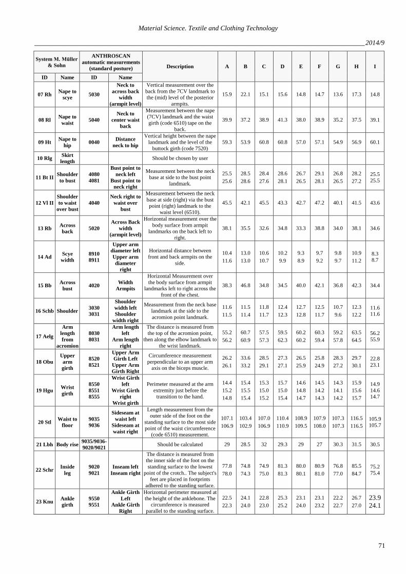
To ascertain the compliance of 3D scanned anthropometric
data with a CAD Grafis measurement chart respondents (nine
women aged 20 – 30) were chosen. The summary of the
necessary measurements, the acquired measures from the
automated scanner and 3D anthropometrics are given in
Table I.
TABLE I
COMPARISON OF BODY MEASUREMENT LIST AND THE RESULT OF 3D SCANNING FOR TARGET GROUP
System M. Müller
& Sohn
ANTHROSCAN
automatic measurements
(standard posture) Description A B C D E F G H I
ID Name ID Name
01 Kh Height 0010 Body Height
Vertical height from standing
surface to the visual top of the head. The vertical distance is
measured between the standing
surface and the top of the head.
169.8 160.8 169.1 173.8 170.6 168.4 161.9 175.2 168.4
02 Bu Bust
girth 4510
Bust/chest
girth
(horizontal)
The circumference of the chest is measured across the bust point
landmarks. The circumference is
measured parallel to the standing surface.
95.0 103.4 93.2 89.8 88.1 97.1 93.4 98.6 86.9
03 Tu Waist
girth 6510 Waist Girth
The circumference of the waist is
measured in the height of the natural waist (if feasible). The
natural waist height is
determined by extracting a contraction point on the side.
The circumference is measured
parallel to the standing surface.
69.8 82.8 70.4 75.9 69.9 70.7 77.0 80.4 64.5
04 Hu Hip girth 7520 Buttock
Girth
The circumference of the buttock is measured in a front-to-back
plane with the tape passing just above the most protruding point
of the buttock. The
circumference is measured parallel to the standing surface.
92.8 112.1 98.3 99.9 96.6 93.1 102.1 106.2 86.7
05 Hsu Base of
neck 1520
Neck at Base-
Girth
Circumference measurement at
the level of the base of the neck,
just on the transition between torso and neck.
36.8 38.7 38.5 40.6 35.3 35.0 39.2 40.6 35.4
06 Hs Neck
width
Determined as proportion from
neck circumference
Material Science. Textile and Clothing Technology
________________________________________________________________________________________________ 2014/9
71
System M. Müller
& Sohn
ANTHROSCAN
automatic measurements
(standard posture) Description A B C D E F G H I
ID Name ID Name
07 Rh Nape to
scye 5030
Neck to
across back
width
(armpit level)
Vertical measurement over the
back from the 7CV landmark to the (mid) level of the posterior
armpits.
15.9 22.1 15.1 15.6 14.8 14.7 13.6 17.3 14.8
08 Rl Nape to
waist 5040
Neck to
center waist
back
Measurement between the nape (7CV) landmark and the waist
girth (code 6510) tape on the
back.
39.9 37.2 38.9 41.3 38.0 38.9 35.2 37.5 39.1
09 Ht Nape to
hip 0040
Distance
neck to hip
Vertical height between the nape landmark and the level of the
buttock girth (code 7520)
59.3 53.9 60.8 60.8 57.0 57.1 54.9 56.9 60.1
10 Rlg Skirt
length Should be chosen by user
11 Bt II Shoulder
to bust
4080
4081
Bust point to
neck left
Bust point to
neck right
Measurement between the neck
base at side to the bust point
landmark.
25.5
25.6
28.5
28.6
28.4
27.6
28.6
28.1
26.7
26.5
29.1
28.1
26.8
26.5
28.2
27.2
25.5
25.5
12 Vl II
Shoulder
to waist
over bust
4040
Neck right to
waist over
bust
Measurement between the neck
base at side (right) via the bust point (right) landmark to the
waist level (6510).
45.5 42.1 45.5 43.3 42.7 47.2 40.1 41.5 43.6
13 Rb Across
back 5020
Across Back
width
(armpit level)
Horizontal measurement over the
body surface from armpit landmarks on the back left to
right.
38.1 35.5 32.6 34.8 33.3 38.8 34.0 38.1 34.6
14 Ad Scye
width
8910
8911
Upper arm
diameter left
Upper arm
diameter
right
Horizontal distance between
front and back armpits on the
side.
10.4
11.6
13.0
13.0
10.6
10.7
10.2
9.9
9.3
8.9
9.7
9.2
9.8
9.7
10.9
11.2
8.3 8.7
15 Bb Across
bust 4020
Width
Armpits
Horizontal Measurement over
the body surface from armpit landmarks left to right across the
front of the chest.
38.3 46.8 34.8 34.5 40.0 42.1 36.8 42.3 34.4
16 Schb Shoulder 3030
3031
Shoulder
width left
Shoulder
width right
Measurement from the neck base
landmark at the side to the
acromion point landmark.
11.6
11.5
11.5
11.4
11.8
11.7
12.4
12.3
12.7
12.8
12.5
11.7
10.7
9.6
12.3
12.2
11.6 11.6
17 Aelg
Arm
length
from
acromion
8030
8031
Arm length
left
Arm length
right
The distance is measured from the top of the acromion point,
then along the elbow landmark to
the wrist landmark.
55.2
56.2
60.7
60.9
57.5
57.3
59.5
62.3
60.2
60.2
60.3
59.4
59.2
57.8
63.5
64.5
56.2
55.9
18 Obu
Upper
arm
girth
8520
8521
Upper Arm
Girth Left
Upper Arm
Girth Right
Circumference measurement
perpendicular to an upper arm axis on the biceps muscle.
26.2
26.1
33.6
33.2
28.5
29.1
27.3
27.1
26.5
25.9
25.8
24.9
28.3
27.2
29.7
30.1
22.8
23.1
19 Hgu Wrist
girth
8550
8551
8555
Wrist Girth
left
Wrist Girth
right
Wrist girth
Perimeter measured at the arm
extremity just before the transition to the hand.
14.4
15.2
14.8
15.4
15.5
15.4
15.3
15.0
15.2
15.7
15.0
15.4
14.6
14.8
14.7
14.5
14.2
14.3
14.3
14.1
14.2
15.9
15.6
15.7
14.9
14.6 14.7
20 Stl Waist to
floor
9035
9036
Sideseam at
waist left
Sideseam at
waist right
Length measurement from the outer side of the foot on the
standing surface to the most side
point of the waist circumference (code 6510) measurement.
107.1
106.9
103.4
102.9
107.0
106.9
110.4
110.9
108.9
109.5
107.9
108.0
107.3
107.3
116.5
116.5
105.9
105.7
21 Lbh Body rise 9035/9036-
9020/9021 Should be calculated 29 28.5 32 29.3 29 27 30.3 31.5 30.5
22 Schr Inside
leg
9020
9021
Inseam left
Inseam right
The distance is measured from the inner side of the foot on the
standing surface to the lowest
point of the crotch.. The subject's feet are placed in footprints
adhered to the standing surface.
77.8
78.0
74.8
74.3
74.9
75.0
81.3
81.3
80.0
80.1
80.9
81.0
76.8
77.0
85.5
84.7
75.2
75.4
23 Knu Ankle
girth
9550
9551
Ankle Girth
Left
Ankle Girth
Right
Horizontal perimeter measured at
the height of the anklebone. The circumference is measured
parallel to the standing surface.
22.5
22.3
24.1
24.0
22.8
23.0
25.3
25.2
23.1
24.0
23.1
23.2
22.2
22.7
26.7
27.0
23.9
24.1

Material Science. Textile and Clothing Technology
2014/9 ________________________________________________________________________________________________
72
3D scanning has several advantages compared to manual
measurements – it is fast, sequential, and has a higher
precision level. Using 3D scanning no professional knowledge
is needed to acquire the measurements – most of the systems
generate the measures of the human body self-dependently.
B. Data Analysis
Before the scanning experiment, measurements were made
manually; by comparing the data, it was concluded that the
deviations are within the acceptable range in accordance with
the standard ISO 20685 if the measured person has no major
defects of posture. Almost all circumferences 3D scan data
while processed are set accurately horizontally (parallel to the
surface of the man standing), but manual measurements only
apply to the horizontal direction. For example, waist
circumference (ID 6510), the circumference is measured in the
height of the natural waist (if feasible) above the pelvic bone.
In the case of pelvic asymmetry this measurement is carried
out manually at an angle, while the automated 3D
measurement system is carried horizontally, thus it is not
possible to determine the appropriate measurement (see
Fig. 2.).
With other important measurements there are similar
problems in the case of asymmetry.
TABLE II
COMPARISON OF THE RESULTS OF MANUAL MEASUREMENTS AND
AUTOMATIC 3D MEASUREMENTS FOR ACROSS FRONT MEASUREMENT
# 15 Bb Across
bust (cm)
4020 Width
Armpits (cm) Difference (cm)
A 28 38.3 10.3
B 38 46.8 8.8
C 34.5 34.8 0.3
D 34 34.5 0.5
E 33 40 7.0
F 38 42.1 4.1
G 37 36.8 −0.2
H 36 42.3 6.3
I 34 34.4 0.4
In some cases a horizontal cross-cutting plane is not an
appropriate measure of the distance measurements, such as the
measurement across the front (4020 Width armpits) is
measured as the Horizontal Measurement over the body
surface from armpit landmarks left to right across the front of
the chest, but compared to manual measurement results the
differences are significant (see Table II).
Across front measurement obtained in 3D scanner is not
usable for tailoring needs, although it is measured from one
armpit to the other armpit (see Fig. 3), the result is not read by
the shortest surface distance, but along the perimeter of the
horizontal plane.
In addition, the study found that the difference is not
dependent on the size of the target group, namely the absence
of a correlation between the human body girth measured
values and ID 4020 with the measurement across bust (see
Table II). However, there is a strong correlation with breast
location and size. Higher placement of breasts sets larger
horizontal measurement, and the difference between manually
and automatically derived measurements is greater (see
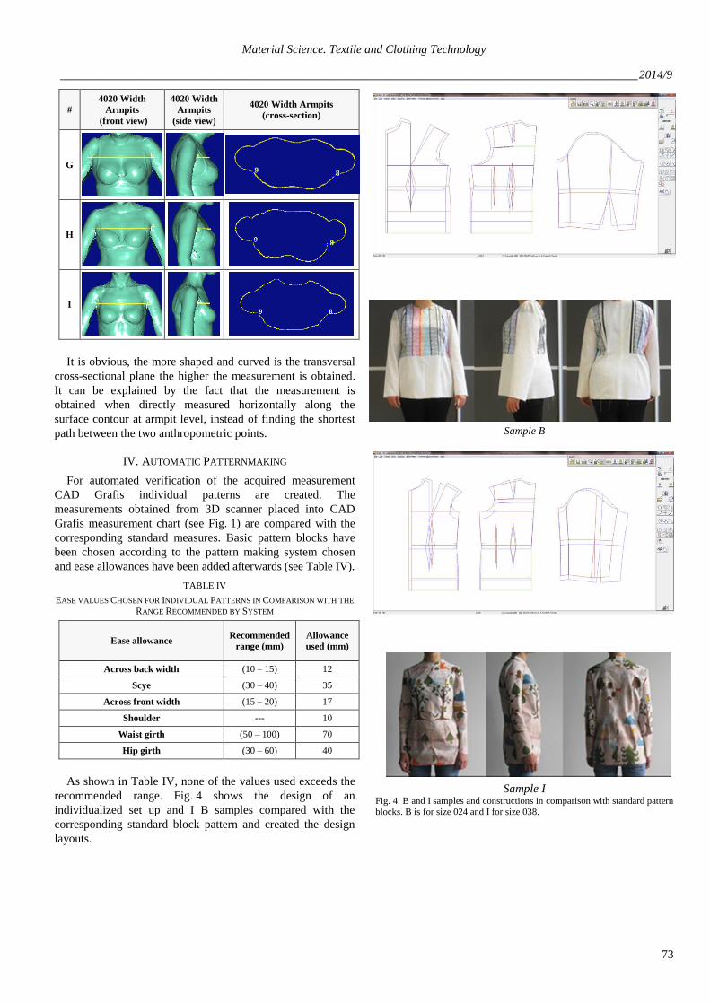
Table III). TABLE III
COMPARISON OF TRANSVERSAL PLANES ON ARMPIT LEVEL
#
4020 Width
Armpits
(front view)
4020 Width
Armpits
(side view)
4020 Width Armpits
(cross-section)
A
B
C
D
E
F
Fig. 2. Sample of scanned body surface with asymmetrical body sides for measurement ID 6510 Waist Girth.
Fig. 3. Example of 3D body measurement ID 4020 Width Armpits.
Material Science. Textile and Clothing Technology
________________________________________________________________________________________________ 2014/9
73
#
4020 Width
Armpits
(front view)
4020 Width
Armpits
(side view)
4020 Width Armpits
(cross-section)
G
H
I
It is obvious, the more shaped and curved is the transversal
cross-sectional plane the higher the measurement is obtained.
It can be explained by the fact that the measurement is
obtained when directly measured horizontally along the
surface contour at armpit level, instead of finding the shortest
path between the two anthropometric points.
IV. AUTOMATIC PATTERNMAKING
For automated verification of the acquired measurement
CAD Grafis individual patterns are created. The
measurements obtained from 3D scanner placed into CAD
Grafis measurement chart (see Fig. 1) are compared with the
corresponding standard measures. Basic pattern blocks have
been chosen according to the pattern making system chosen
and ease allowances have been added afterwards (see Table IV).
TABLE IV
EASE VALUES CHOSEN FOR INDIVIDUAL PATTERNS IN COMPARISON WITH THE
RANGE RECOMMENDED BY SYSTEM
Ease allowance Recommended
range (mm)
Allowance
used (mm)
Across back width (10 – 15) 12
Scye (30 – 40) 35
Across front width (15 – 20) 17
Shoulder --- 10
Waist girth (50 – 100) 70
Hip girth (30 – 60) 40
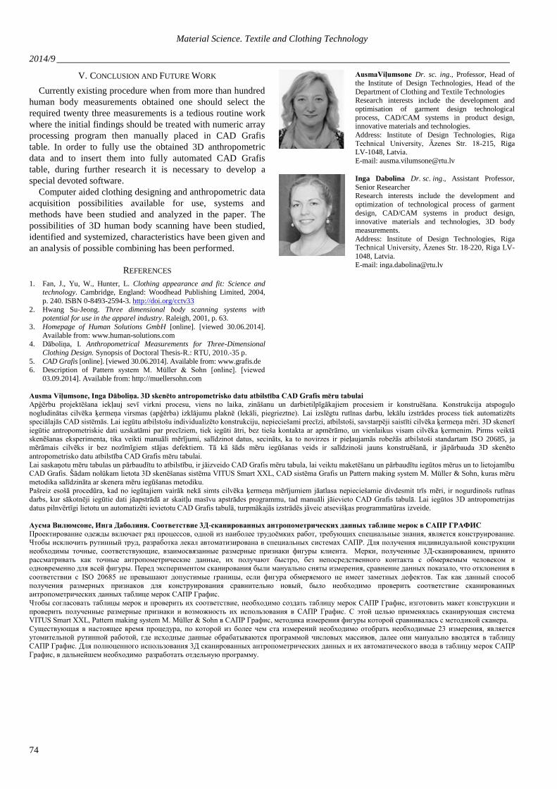
As shown in Table IV, none of the values used exceeds the
recommended range. Fig. 4 shows the design of an
individualized set up and I B samples compared with the
corresponding standard block pattern and created the design
layouts.
Sample B
Sample I Fig. 4. B and I samples and constructions in comparison with standard pattern
blocks. B is for size 024 and I for size 038.
Material Science. Textile and Clothing Technology
2014/9 ________________________________________________________________________________________________
74
V. CONCLUSION AND FUTURE WORK
Currently existing procedure when from more than hundred
human body measurements obtained one should select the
required twenty three measurements is a tedious routine work
where the initial findings should be treated with numeric array
processing program then manually placed in CAD Grafis
table. In order to fully use the obtained 3D anthropometric
data and to insert them into fully automated CAD Grafis
table, during further research it is necessary to develop a
special devoted software.
Computer aided clothing designing and anthropometric data
acquisition possibilities available for use, systems and
methods have been studied and analyzed in the paper. The
possibilities of 3D human body scanning have been studied,
identified and systemized, characteristics have been given and
an analysis of possible combining has been performed.
REFERENCES
1. Fan, J., Yu, W., Hunter, L. Clothing appearance and fit: Science and technology. Cambridge, England: Woodhead Publishing Limited, 2004,
p. 240. ISBN 0-8493-2594-3. http://doi.org/cctv33
2. Hwang Su-Jeong. Three dimensional body scanning systems with potential for use in the apparel industry. Raleigh, 2001, p. 63.
3. Homepage of Human Solutions GmbH [online]. [viewed 30.06.2014].
Available from: www.human-solutions.com 4. Dāboliņa, I. Anthropometrical Measurements for Three-Dimensional
Clothing Design. Synopsis of Doctoral Thesis-R.: RTU, 2010.-35 p.
5. CAD Grafis [online]. [viewed 30.06.2014]. Available from: www.grafis.de 6. Description of Pattern system M. Müller & Sohn [online]. [viewed
03.09.2014]. Available from: http://muellersohn.com
AusmaViļumsone Dr. sc. ing., Professor, Head of
the Institute of Design Technologies, Head of the
Department of Clothing and Textile Technologies Research interests include the development and
optimisation of garment design technological
process, CAD/CAM systems in product design, innovative materials and technologies.
Address: Institute of Design Technologies, Riga
Technical University, Āzenes Str. 18-215, Riga LV-1048, Latvia.
E-mail: [email protected]
Inga Dabolina Dr. sc. ing., Assistant Professor,
Senior Researcher Research interests include the development and
optimization of technological process of garment
design, CAD/CAM systems in product design, innovative materials and technologies, 3D body
measurements.
Address: Institute of Design Technologies, Riga
Technical University, Āzenes Str. 18-220, Riga LV-
1048, Latvia.
E-mail: [email protected]
Ausma Viļumsone, Inga Dāboliņa. 3D skenēto antropometrisko datu atbilstība CAD Grafis mēru tabulai
Apģērbu projektēšana iekļauj sevī virkni procesu, viens no laika, zināšanu un darbietilpīgākajiem procesiem ir konstruēšana. Konstrukcija atspoguļo
nogludinātas cilvēka ķermeņa virsmas (apģērba) izklājumu plaknē (lekāli, piegrieztne). Lai izslēgtu rutīnas darbu, lekālu izstrādes process tiek automatizēts speciālajās CAD sistēmās. Lai iegūtu atbilstošu individualizēto konstrukciju, nepieciešami precīzi, atbilstoši, savstarpēji saistīti cilvēka ķermeņa mēri. 3D skenerī
iegūtie antropometriskie dati uzskatāmi par precīziem, tiek iegūti ātri, bez tieša kontakta ar apmērāmo, un vienlaikus visam cilvēka ķermenim. Pirms veiktā
skenēšanas eksperimenta, tika veikti manuāli mērījumi, salīdzinot datus, secināts, ka to novirzes ir pieļaujamās robežās atbilstoši standartam ISO 20685, ja mērāmais cilvēks ir bez nozīmīgiem stājas defektiem. Tā kā šāds mēru iegūšanas veids ir salīdzinoši jauns konstruēšanā, ir jāpārbauda 3D skenēto
antropometrisko datu atbilstība CAD Grafis mēru tabulai.
Lai saskaņotu mēru tabulas un pārbaudītu to atbilstību, ir jāizveido CAD Grafis mēru tabula, lai veiktu maketēšanu un pārbaudītu iegūtos mērus un to lietojamību CAD Grafis. Šādam nolūkam lietota 3D skenēšanas sistēma VITUS Smart XXL, CAD sistēma Grafis un Pattern making system M. Müller & Sohn, kuras mēru
metodika salīdzināta ar skenera mēru iegūšanas metodiku. Pašreiz esošā procedūra, kad no iegūtajiem vairāk nekā simts cilvēka ķermeņa mērījumiem jāatlasa nepieciešamie divdesmit trīs mēri, ir nogurdinošs rutīnas
darbs, kur sākotnēji iegūtie dati jāapstrādā ar skaitļu masīvu apstrādes programmu, tad manuāli jāievieto CAD Grafis tabulā. Lai iegūtos 3D antropometrijas
datus pilnvērtīgi lietotu un automatizēti ievietotu CAD Grafis tabulā, turpmākajās izstrādēs jāveic atsevišķas programmatūras izveide.
Аусма Вилюмсоне, Инга Даболиня. Соответствие 3Д-сканированных антропометрических данных таблице мерок в САПР ГРАФИС
Проектирование одежды включает ряд процессов, одной из наиболее трудоёмких работ, требующих специальные знания, является конструирование. Чтобы исключить рутинный труд, разработка лекал автоматизирована в специальных системах САПР. Для получения индивидуальной конструкции
необходимы точные, соответствующие, взаимосвязанные размерные признаки фигуры клиента. Мерки, полученные 3Д-сканированием, принято
рассматривать как точные антропометрические данные, их получают быстро, без непосредственного контакта с обмеряемым человеком и одновременно для всей фигуры. Перед экспериментом сканирования были мануально сняты измерения, сравнение данных показало, что отклонения в
соответствии с ISO 20685 не превышают допустимые границы, если фигура обмеряемого не имеет заметных дефектов. Так как данный способ
получения размерных признаков для конструирования сравнительно новый, было необходимо проверить соответствие сканированных антропометрических данных таблице мерок САПР Графис.
Чтобы согласовать таблицы мерок и проверить их соответствие, необходимо создать таблицу мерок САПР Графис, изготовить макет конструкции и
проверить полученные размерные признаки и возможность их использования в САПР Графис. С этой целью применялась сканирующая система VITUS Smart XXL, Pattern making system M. Müller & Sohn в САПР Графис, методика измерения фигуры которой сравнивалась с методикой сканера.
Существующая в настоящее время процедура, по которой из более чем ста измерений необходимо отобрать необходимые 23 измерения, является
утомительной рутинной работой, где исходные данные обрабатываются программой числовых массивов, далее они мануально вводятся в таблицу САПР Графис. Для полноценного использования 3Д сканированных антропометрических данных и их автоматического ввода в таблицу мерок САПР
Графис, в дальнейшем необходимо разработать отдельную программу.
Related Documents