Ci/SfB UDC 628.24 THE COMPLETE TECHNICAL DESIGN GUIDE mpa British Precast Drainage Association

Welcome message from author
This document is posted to help you gain knowledge. Please leave a comment to let me know what you think about it! Share it to your friends and learn new things together.
Transcript

Ci/SfB
UDC628.24
THE COMPLETE TECHNICAL DESIGN GUIDE
mpa British Precast Drainage Association

Sir Joseph Bazalgette (1819 – 1891) As Chief Engineer of London’s Metropolitan Board of Works his major achievement was the creation of a sewer network for central London.
Completed in 1858, it extended 82 miles, required 670,000m³ of concrete and is still in use today.
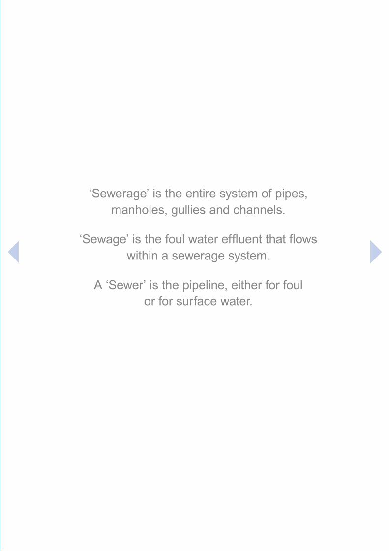
‘Sewerage’ is the entire system of pipes, manholes, gullies and channels.
‘Sewage’ is the foul water effluent that flows within a sewerage system.
A ‘Sewer’ is the pipeline, either for foul or for surface water.

FOREWORD
Precast concrete pipeline systems are the UK’s choice for drainage and sewer solutions. With the inherent
benefits of concrete in terms of cost, strength, inertia and durability, precast systems are the preferred choice
with a design life in excess of 100 years.
Concrete drainage units manufactured in accordance with BS EN 1916 and BS EN 1917 are suitable for slightly
aggressive chemical ground conditions. In the UK, some soils are more aggressive in nature. As a safeguard,
the provision of a concrete suitable for ACEC AC-4 conditions as described in Building Research Establishment
Special Digest 1 2005 is specified. The preferred method to achieve AC-4 for a 100 year intended working life
is the use of a DC-4 concrete with surface carbonation (i.e. precast concrete) without the need for additional
protective measures.
DC-4 concrete is adequate for the vast majority of discharges in normal conditions of use. However, further consideration should be given to suitable additional protective measures in the following cases:-
• where a sewer, drain or other component within the system is liable to carry untreated or corrosive trade effluents
• a rising main discharge
• septic sewage
• inadequate ventilation.
• pipeline systems exposed to the highest level of aggressive conditions (AC-5 family).
In general, the type of surface protection will be specified by the construction designer and will be provided by the site contractor rather than the manufacturer of the pipeline system. Appropriate options are discussed in Section D6.4 of Special Digest 1, Concrete in Aggressive Ground.

CONTENTS
1: SYSTEM DESIGN 06
1.1 Pipeline Hydraulic Design 06
1.2 Pipeline Structural Design 19
1.3 Manhole Design 32
1.4 Box Culvert Design 39
2: INSTALLATION- PIPES 49
2.1 Planning 49
2.2 Handling and Storage 49
2.3 Excavation and Laying 52
2.4 Jointing 54
2.5 Reinstatement 56
2.6 Testing 56
2.7 Jetting 58
3: INSTALLATION – JACKING PIPES 59
3.1 Introduction 59
3.2 Technique and Equipment 59
3.3 Advantages 59
3.4 Products 60
3.5 Further Information 60
4: INSTALLATION - MANHOLES 61
4.1 Planning 61
4.2 Handling and Storage 61
4.3 Construction 61
4.4 Jointing 62
4.5 Reinstatement 63
4.6 Testing 63
5: INSTALLATION - BOX CULVERTS 64
5.1 Planning 64
5.2 Delivery, handling and storage 65
5.3 Construction 66
5.4 References 67
6: REFERENCES AND FURTHER READING 68

1: SYSTEM DESIGN6
1: SYSTEM DESIGN1.1 PIPELINE HYDRAULIC DESIGN
1.1.1 Pipeline Design
Background
There are two main categories of drainage:
1. Surface (or Storm) water systems which generally discharge untreated into rivers or water courses. Surface water includes agricultural, roof or paved areas and highway drainage.
2. Foul water systems that feed into sewage treatment plants. Foul water can be from either domestic or industrial sources.
Up to the early 20th century, the majority of drainage systems were ‘combined’, that is, the foul and surface water fed into the same main sewer. More recent installations opted for separate systems. To further complicate the situation there are partially separate systems where in times of surface water flooding, provision is made for cross-linking of the two systems. Combined systems are still sometimes used, although the government is insisting that they are phased out and replaced by separate systems.
Even today, for some new installations, mis-connections between surface water and foul water systems are a problem. The design of drainage should be integral to the design of a development and follow an holistic approach, working from the whole to the part and not the other way round.
General
The capacity of sewers are selected to meet the design criteria for the hydraulic and environmental performance of the system. Pipes must be selected to:-• transport the required design flows• limit sediment build up• reduce risk of blockage• allow effective maintenance
Design considerations
In the design of a surface water or foul water sewer, similar criteria must be considered:-• average and peak flows and their duration gradient• the position of the sewer within the network and whether flooding can be tolerated• the cover depth of the sewer• any topographical or structural feature (such as a valley, building or embankment)• surface characteristics (road, field or paved area)• access to the sewer for maintenance (frequency, size, spacing and depth of manholes)
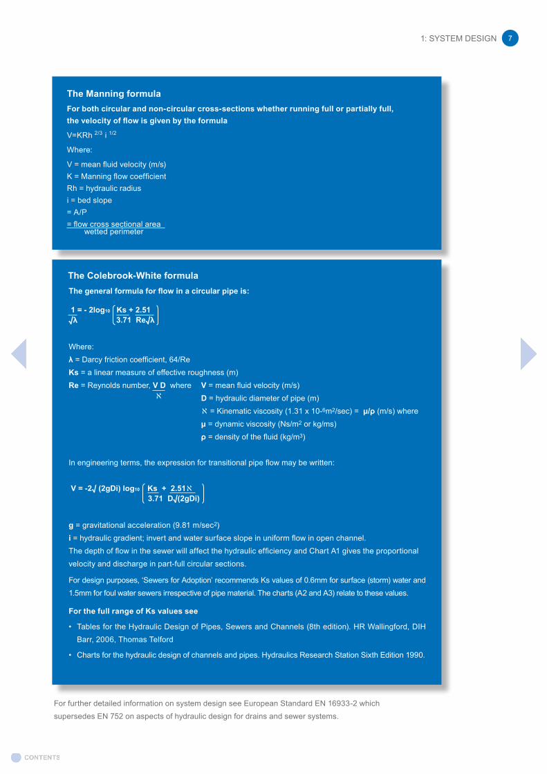
The basis for design is that flows in sewers are turbulent. Two formulae are recommended for calculating turbulent flows in sewers: Manning and Colebrook-White.
Pipe headlosses
When using recommended hydraulic pipeline roughness values, it is necessary to establish whether allowance has been made for local headlosses. The hydraulic pipeline roughness (Ks) or the Manning flow coefficient (K) should allow for headlosses due to pipe material, taking into account other factors including the internal profile of the pipe in its in-service state and biofilms that grow on the pipe surface below water level. The effect of the biofilm can be more significant than any difference in the roughness of the material without the biofilm. A single value regardless of pipe material is therefore often used.
1: SYSTEM DESIGN 7
The Manning formulaFor both circular and non-circular cross-sections whether running full or partially full, the velocity of flow is given by the formula
V=KRh 2/3 i 1/2
Where:
V = mean fluid velocity (m/s)K = Manning flow coefficientRh = hydraulic radiusi = bed slope= A/P= flow cross sectional area wetted perimeter
The general formula for flow in a circular pipe is:
1 = - 2log10 Ks + 2.51 √λ 3.71 Re√λ
Where:λ = Darcy friction coefficient, 64/Re Ks = a linear measure of effective roughness (m)Re = Reynolds number, V D where V = mean fluid velocity (m/s) D = hydraulic diameter of pipe (m) ℵ = Kinematic viscosity (1.31 x 10⁻⁶m2/sec) = μ/ρ (m/s) where μ = dynamic viscosity (Ns/m2 or kg/ms) ρ = density of the fluid (kg/m3)
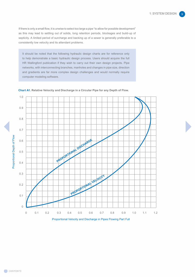
In engineering terms, the expression for transitional pipe flow may be written: V = -2√ (2gDi) log10 Ks + 2.51ℵ 3.71 D√(2gDi) g = gravitational acceleration (9.81 m/sec2)i = hydraulic gradient; invert and water surface slope in uniform flow in open channel.The depth of flow in the sewer will affect the hydraulic efficiency and Chart A1 gives the proportional velocity and discharge in part-full circular sections.
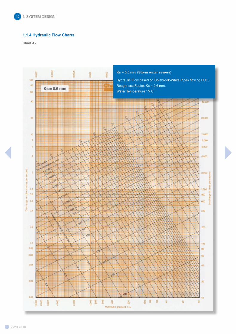
For design purposes, ‘Sewers for Adoption’ recommends Ks values of 0.6mm for surface (storm) water and 1.5mm for foul water sewers irrespective of pipe material. The charts (A2 and A3) relate to these values.
For the full range of Ks values see
• Tables for the Hydraulic Design of Pipes, Sewers and Channels (8th edition). HR Wallingford, DIH Barr, 2006, Thomas Telford
• Charts for the hydraulic design of channels and pipes. Hydraulics Research Station Sixth Edition 1990.
The Colebrook-White formula
For further detailed information on system design see European Standard EN 16933-2 which supersedes EN 752 on aspects of hydraulic design for drains and sewer systems.
ℵ

1: SYSTEM DESIGN8
This section is generally based on the guidance and recommendations within Sewers for Adoption and BS EN16933-2:2017 Drain and sewer systems outside buildings. Design. Hydraulic design.
1.1.2 Hydraulic design of surface water sewers
Surface water runoff from impermeable surfaces, such as roads and car parks must first pass through an interface between the impermeable surface and the drain or sewer system. To minimise the impact of sewer flooding, the flow at this interface must be considered and its capacity to accommodate the flow passing through it.
For smaller schemes, a simple approach is recommended where sewers are usually designed to run full, without surcharge, for relatively frequent design rainfall events on the basis that this will generally provide protection against sewer flooding from more severe rainfall events. Rainfall intensity and duration figures applicable to the area should be used.
For larger schemes, where damage or public health risks are significant, the level of sewer flooding protection should be directly assessed. A sewer flow simulation model based on the Wallingford Procedure should be used to check the level of flood protection against the sewer flooding design criteria and the design adjusted where the required sewer flooding protection is not achieved.
Where storage is provided to control surface water discharges, the designer should demonstrate that:
• the system upstream, including inlets, has sufficient capacity to accommodate the flows to storage
• an overland flood exceedance route is provided that will deliver sufficient capacity
Large (“oversized”) pipes may be used as part of a Sustainable urban Drainage System (SuDS) - see section 1.1.6. In these situations the pipe is sized to accommodate a calculated volume of surface water to store and attenuate flow at the discharge point. For “on-line” attenuation systems a low-flow channel is usually provided within the invert to encourage self-cleansing. If oversized pipes are used off-line from the sewer, self-cleansing velocities are not expected and effective silt removal must be provided upstream of the storage.
1.1.3 Hydraulic design of foul water sewers
For drains and sewers serving small populations, the capacity of the pipe is often established by the minimum pipe size specified by the relevant authority.
In gravity drains and sewers, the ratio between the peak flow and the average dry weather flow reduces as the flow moves downstream.
The peak design flow rate for dwellings may be based on:
• BS EN16933-2:2017 and calculated in accordance with BS EN12056-2:2000 Gravity drainage systems inside buildings Part 2: Sanitary pipework, layout and calculation - System II.
Or
• 4000 litres per dwelling per day (0.05 litres per second per dwelling). This is not a daily average water usage and represents the peak flow rate from a number of appliances. Reducing daily water usage does not necessarily reduce the peak flow rate.
Unless specifically directed by the client, the choice of method is at the discretion of the designer.
For self-cleansing properties, the foul sewer must flow at a minimum of 0.75 m/sec at one third of the design flow, the main governing factors being the pipe diameter, the gradient and the volume of effluent (the larger the pipe and the flatter the gradient, the greater amount of effluent will be required to achieve self-cleansing velocity).
1: SYSTEM DESIGN 9
Chart A1. Relative Velocity and Discharge in a Circular Pipe for any Depth of Flow.
Proportional Velocity and Discharge in Pipes Flowing Part Full
1.0
0.9
0.8
0.7
0.6
0.5
0.4
0.3
0.2
0.1
0
0 0.1 0.2 0.3 0.4 0.5 0.6 0.7 0.8 0.9 1.0 1.1 1.2
Pro
port
iona
l Dep
th o
f Flo
w
PROPORTIONAL DISCHARGE
PROPORTIONAL VELOCITY
It should be noted that the following hydraulic design charts are for reference only to help demonstrate a basic hydraulic design process. Users should acquire the full HR Wallingford publication if they wish to carry out their own design projects. Pipe networks, with interconnecting branches, manholes and changes in pipe size, direction and gradients are far more complex design challenges and would normally require computer modeling software.
If there is only a small flow, it is unwise to select too large a pipe “to allow for possible development” as this may lead to settling out of solids, long retention periods, blockages and build-up of septicity. A limited period of surcharge and backing up of a sewer is generally preferable to a consistently low velocity and its attendant problems.
1: SYSTEM DESIGN10
1.1.2 Hydraulic Flow Charts
Chart A2
Ks = 0.6 mm (Storm water sewers)
Hydraulic Flow based on Colebrook-White Pipes flowing FULL.Roughness Factor, Ks = 0.6 mm.Water Temperature 15ºC
1.1.4 Hydraulic Flow Charts
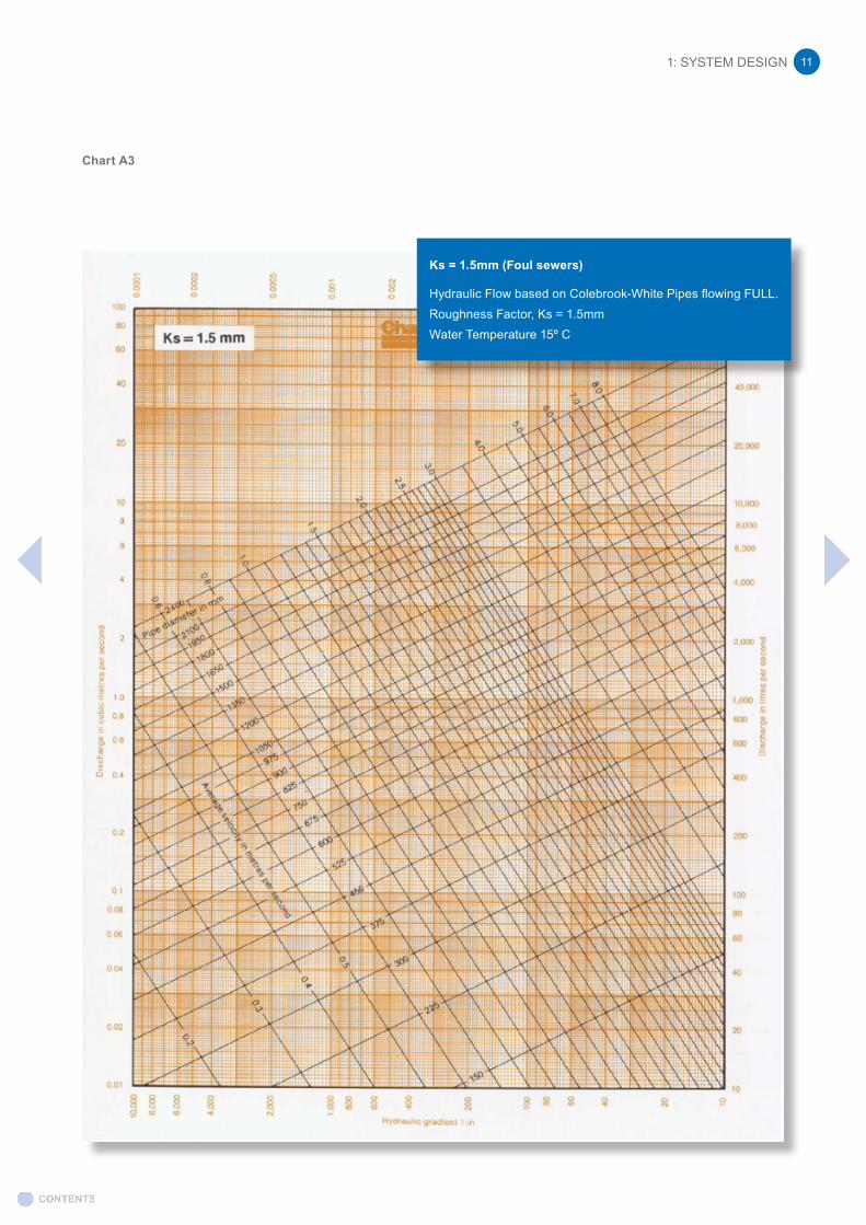
Chart A3
1: SYSTEM DESIGN 11
Ks = 1.5mm (Foul sewers)
Hydraulic Flow based on Colebrook-White Pipes flowing FULL.Roughness Factor, Ks = 1.5mmWater Temperature 15º C
1: SYSTEM DESIGN12
1.1.3 Worked examples
1) Design of surface (storm) water sewer Total length of pipeline = 2300m. Total fall to outlet = 15m. Design discharge = 0.3m3/sDetermine required pipe size for: a) Pipe flowing full b) Pipe flowing quarter full
Example 1(b):
2.14m3/s
Example 1(a):
0.3m3/s
1:153
Ks for storm water sewer = 0.6mmHydraulic gradient = δy/δx = 15m/2300m = 0.0065 = 1:153Example 1a) Pipe flowing fullStep 1: read off discharge = 03.m3/sec on y-axis and project a line horizontally across the chartStep 2: read off hydraulic gradient = 1:153 on x-axis and project a line
vertically across the chartStep 3: at intersection of Steps 1 and 2 project a line parallel to sloping
line for pipe (internal/nominal) diameter lines. The required pipe size is between DN450 and DN525. DN450 is insufficient capacity so select DN525.
1.1.5 Worked examples
1: SYSTEM DESIGN 13
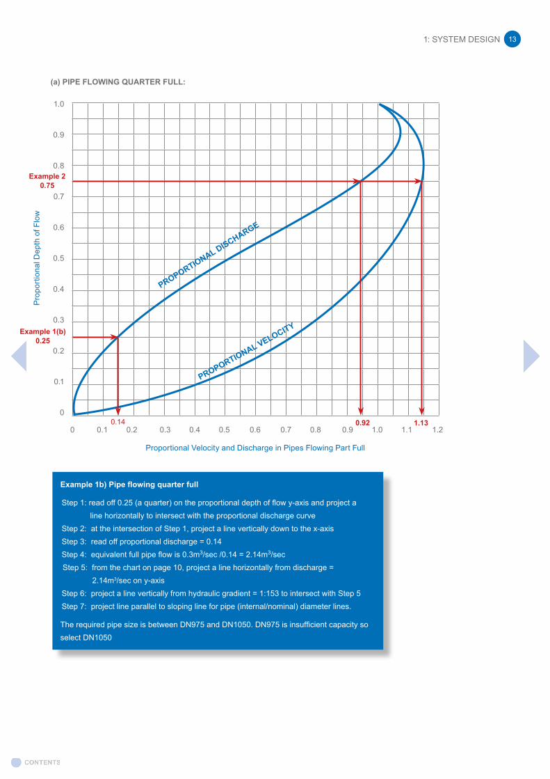
Example 1b) Pipe flowing quarter full
Step 1: read off 0.25 (a quarter) on the proportional depth of flow y-axis and project a line horizontally to intersect with the proportional discharge curveStep 2: at the intersection of Step 1, project a line vertically down to the x-axisStep 3: read off proportional discharge = 0.14Step 4: equivalent full pipe flow is 0.3m3/sec /0.14 = 2.14m3/secStep 5: from the chart on page 10, project a line horizontally from discharge =
2.14m3/sec on y-axisStep 6: project a line vertically from hydraulic gradient = 1:153 to intersect with Step 5Step 7: project line parallel to sloping line for pipe (internal/nominal) diameter lines.
The required pipe size is between DN975 and DN1050. DN975 is insufficient capacity so select DN1050
(a) PIPE FLOWING QUARTER FULL:
1.130.920.14
Example 1(b)0.25
Example 20.75
Proportional Velocity and Discharge in Pipes Flowing Part Full
1.0
0.9
0.8
0.7
0.6
0.5
0.4
0.3
0.2
0.1
0
0 0.1 0.2 0.3 0.4 0.5 0.6 0.7 0.8 0.9 1.0 1.1 1.2
Pro
port
iona
l Dep
th o
f Flo
w
PROPORTIONAL DISCHARGE
PROPORTIONAL VELOCITY
1: SYSTEM DESIGN14
Example 2: 0.11m3/s
0.66m/s
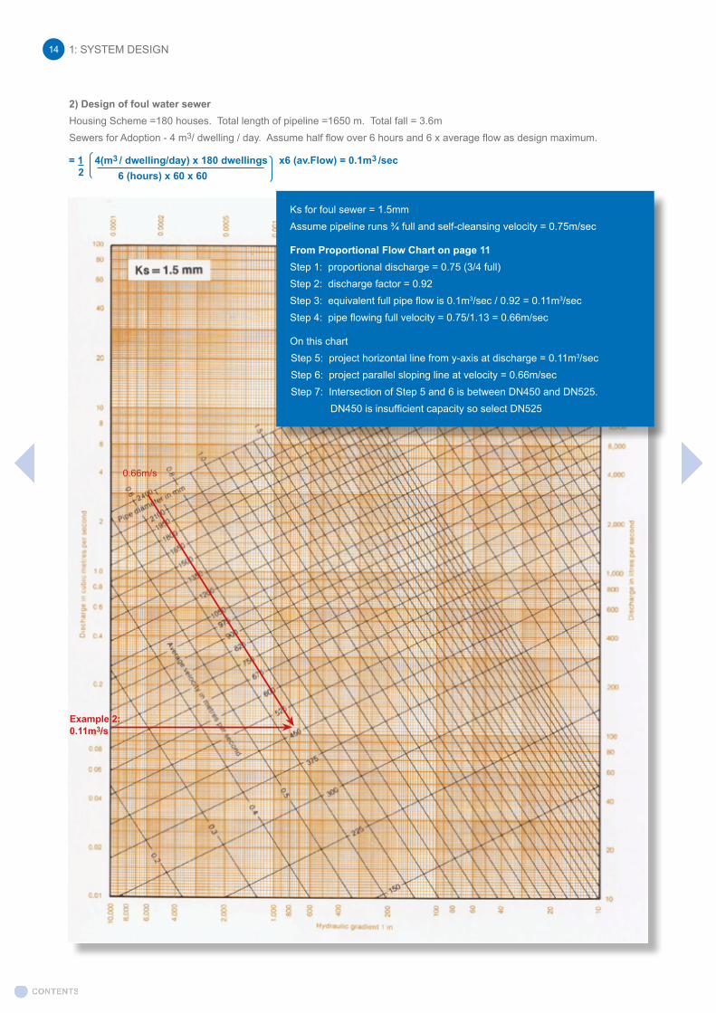
2) Design of foul water sewerHousing Scheme =180 houses. Total length of pipeline =1650 m. Total fall = 3.6mSewers for Adoption - 4 m3/ dwelling / day. Assume half flow over 6 hours and 6 x average flow as design maximum.
Ks for foul sewer = 1.5mmAssume pipeline runs ¾ full and self-cleansing velocity = 0.75m/sec
From Proportional Flow Chart on page 11Step 1: proportional discharge = 0.75 (3/4 full)Step 2: discharge factor = 0.92Step 3: equivalent full pipe flow is 0.1m3/sec / 0.92 = 0.11m3/secStep 4: pipe flowing full velocity = 0.75/1.13 = 0.66m/sec
On this chartStep 5: project horizontal line from y-axis at discharge = 0.11m3/secStep 6: project parallel sloping line at velocity = 0.66m/secStep 7: Intersection of Step 5 and 6 is between DN450 and DN525.
DN450 is insufficient capacity so select DN525
= 1 4(m3 / dwelling/day) x 180 dwellings x6 (av.Flow) = 0.1m3 /sec 2 6 (hours) x 60 x 60

The Management Train can be divided into the following processes:
• Collection • Treatment • Re-use• Infiltration • Attenuation • Conveyance
Management Train
The SuDS philosophy is underpinned by the water “Management Train”. The Management Train applies SuDS techniques in series and is based on:
• Prevention; good housekeeping measures within the development
• Source control; runoff managed as close as possible to where it originates as rain
• Sub-catchments; division into small areas with different drainage characteristics and land use
- Site Control; dealing with runoff within or local to the development
- Regional Control; e.g. SuDS features within amenity space before final outfall
1.1.6 Sustainable Urban Drainage Systems (SuDS)
BPDA Proprietary Sustainable Drainage Systems and Components
The use of sustainable drainage systems, known as SuDS, and best management practices should be an integral part of any development’s surface water management strategy. This should provide a basis for replicating the response of a catchment and its surfaces by mimicking, to some extent, the behaviour of surface water on the developed site as if it had remained undeveloped. Modern sustainable drainage systems should aim to offer improvements to existing surface water runoff, negating any increased risk of flooding by using methods for managing surface water by focusing on three key elements:
• Controlling surface water quantity (reducing off-site low rates)• Improving surface water quality• Providing added amenity value to the development
The successful implementation of a sustainable drainage scheme should consider a combination of natural and proprietary techniques, complemented by traditional drainage methods, where appropriate.
It is essential that planners, designers, installers and operators of SuDS systems take into account the importance of whole life maintenance and the use of suitable components that deliver authentic sustainable drainage performance and longevity.
BDPA Sustainable Drainage Solutions
BDPA members offer a wide variety of proprietary SuDS components and systems suitable for use within a sustainable drainage system.
These are listed in the following table indicating their functions within the Management Train. For specific product information please consult our members.
1: SYSTEM DESIGN 15
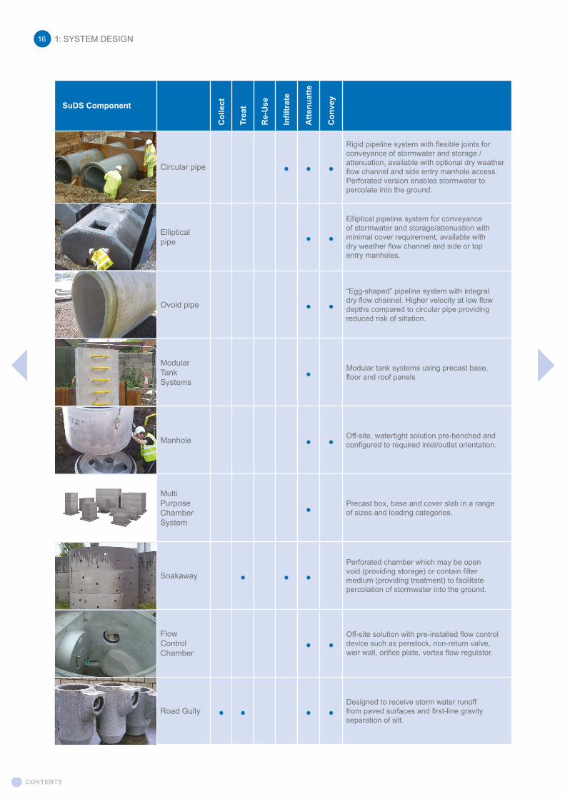
SuDS Component
Col
lect
Trea
t
Re-
Use
Infil
trat
e
Atte
nuat
te
Con
vey
Circular pipe • • •
Rigid pipeline system with flexible joints for conveyance of stormwater and storage /attenuation, available with optional dry weather flow channel and side entry manhole access. Perforated version enables stormwater to percolate into the ground.
Elliptical pipe • •
Elliptical pipeline system for conveyance of stormwater and storage/attenuation with minimal cover requirement, available with dry weather flow channel and side or top entry manholes.
Ovoid pipe • •“Egg-shaped” pipeline system with integral dry flow channel. Higher velocity at low flow depths compared to circular pipe providing reduced risk of siltation.
Modular Tank Systems
• Modular tank systems using precast base, floor and roof panels
Manhole • • Off-site, watertight solution pre-benched and configured to required inlet/outlet orientation.
Multi Purpose Chamber System
• Precast box, base and cover slab in a range of sizes and loading categories.
Soakaway • • •Perforated chamber which may be open void (providing storage) or contain filter medium (providing treatment) to facilitate percolation of stormwater into the ground.
Flow ControlChamber
• •Off-site solution with pre-installed flow control device such as penstock, non-return valve, weir wall, orifice plate, vortex flow regulator.
Road Gully • • • •Designed to receive storm water runoff from paved surfaces and first-line gravity separation of silt.
1: SYSTEM DESIGN16
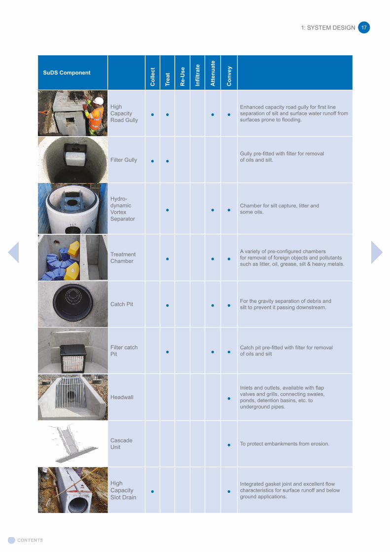
1: SYSTEM DESIGN 17
SuDS Component
Col
lect
Trea
t
Re-
Use
Infil
trat
e
Atte
nuat
e
Con
vey
High Capacity Road Gully
• • • •Enhanced capacity road gully for first line separation of silt and surface water runoff from surfaces prone to flooding.
Filter Gully • •Gully pre-fitted with filter for removal of oils and silt.
Hydro-dynamic Vortex Separator
• • • Chamber for silt capture, litter and some oils.
Treatment Chamber • • •
A variety of pre-configured chambers for removal of foreign objects and pollutants such as litter, oil, grease, silt & heavy metals.
Catch Pit • • • For the gravity separation of debris and silt to prevent it passing downstream.
Filter catch Pit • • • Catch pit pre-fitted with filter for removal
of oils and silt
Headwall •Inlets and outlets, available with flap valves and grills, connecting swales, ponds, detention basins, etc. to underground pipes.
Cascade Unit • To protect embankments from erosion.
High Capacity Slot Drain
• •Integrated gasket joint and excellent flow characteristics for surface runoff and below ground applications.
SuDS References
Information sources to help plan, design and implement sustainable drainage:
1. The community for sustainable drainage. www.susdrain.org
2. CIRIA. The SuDS Manual C753. www.ciria.org
3. Association of SuDS Authorities (ASA). Guidance on SuDS standards: https://www.suds-authority.org.uk/wp-content/uploads/2018/12/non-statutory-technical-standards-guidance.pdf
4. CIRIA. Site Handbook for the Construction of SuDS C698. www.ciria.org
5. BS 8582:2013 Code of practice for surface water management for development sites.
6. CIRIA. Designing for Exceedance in Urban Drainage Good Practice C635. www.ciria.org
7. CIRIA. Sustainable Drainage Systems. Hydraulic, Structural and Water Quality Advice C609. www.ciria.org
8. CIRIA. Infiltration Drainage – Manual of Good Practice R156. www.ciria.org
9. CIRIA. Control of Pollution from Highway Drainage Discharge R142. www.ciria.org
10. British Hydrological Society. Sources of Hydrological Data. http://www.hydrology.org.uk/Data_sources.php
11. WRc. Sewers for Adoption. www.wrcplc.co.uk
12. Local Government Association. Flownet Knowledge Hub. A group for all those interested or involved in flood risk and water management. https://knowledgehub.local.gov.uk/group/flownet
13. National Standards for sustainable drainage systems. Designing, constructing, operating and maintaining drainage for surface runoff. www.defra.gov.uk
14. For information on SuDS legislation, questions on government policy and to register to receive updates. email [email protected]
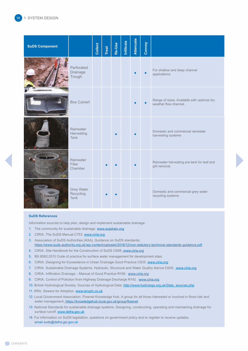
1: SYSTEM DESIGN18
SuDS Component
Col
lect
Trea
t
Re-
Use
Infil
trat
e
Atte
nuat
e
Con
vey
Perforated Drainage Trough
• • For shallow and deep channel applications.
Box Culvert • • Range of sizes. Available with optional dry weather flow channel.
Rainwater Harvesting Tank
• • Domestic and commercial rainwater harvesting systems
Rainwater Filter Chamber
• • • Rainwater harvesting pre-tank for leaf and grit removal.
Grey Water Recycling Tank
• • Domestic and commercial grey water recycling systems

1: SYSTEM DESIGN 19
1.2 PIPELINE STRUCTURAL DESIGN1.2.1 Design Principles
The forces acting on a cross section of pipeline arise from three main sources:
A) Weight of overlying fill, including any local surcharge.
B) Soil pressures transmitted to the pipe from surface loads, i.e. traffic and other transient loads.
C) Supporting reaction below the pipe.
The weight of water within the pipe is only significant for larger diameter pipes.
A: Weight of overlying fill
There are four main conditions in which pipes are installed:
a) “Narrow” trench.
b) “Wide” trench, or on the surface of ground over which an embankment is then built (positive projection condition).
c) Narrow trench over which an embankment is then built (negative projection condition).
d) Tunnel, heading or by jacking.
The load Wc imposed by the backfill on a pipe in a “narrow” trench can be found from Marston’s formula from which the Tables have been compiled in Section 1.2.5.
These Tables are only applicable to rigid pipes laid in “Narrow” trench conditions.
B: Traffic and other transient loads
Measurements have shown that on large civil engineering works pipes may well be subjected to their highest loads during construction. Here, three categories of traffic loading are considered and rigid pipes should normally be designed to withstand the most onerous likely to occur.
If during construction it is clear that excessive site traffic loading will occur, the design should be checked accordingly or special crossing places must be designated.
In assessing the loading category, regard should be paid to the possible future upgrading of a road. Pipes under verges should normally be treated as though under the road, with the possible exception of motorways and trunk roads and should take account of any planned road improvement. For non-public roads such as industrial estate roads or roads within works, an assessment should be made of the heaviest vehicle likely to use the road, and one of the above three loading conditions selected as appropriate.
a) Main road loading is intended to apply to all main traffic routes and to roads liable to be used for the temporary diversion of heavy traffic.
As a guide it may be assumed that such roads carry at least 200 commercial vehicles per day in each direction. HA and HB loading are assumed to use such roads
b) Field loading applies to fields, gardens and lightly trafficked access tracks. This loading is also considered to be adequate to cater for occasional heaps or stacks of materials on the ground surface. Massive heaps or stacks likely to produce a more severe loading should be treated as a special design.

C: Supporting reaction below the pipe
British Standards for concrete pipes give maximum crushing loads for each diameter and strength class of pipe. Loads are applied in a 3 edged loading test described in BS EN 1916 and BS 5911-1. The pipe must not collapse under the maximum load specified.
Proof test loads are also specified. Reinforced pipes must not crack by more than a specified amount under the proof load. The only proof load test for unreinforced pipes is the maximum load.
Pipes of a small diameter (Less than DN 300) may fail as a beam. BS EN 1916 and BS 5911-1 include suitable values of bending moment resistance.
Pipe bedding
This term is used to describe the complete arc of material within the trench, or in the case of Class “C” or Class “D” beddings, a special preparation of the trench bottom. For further information, see Section 1.2.4 “Pipe Bedding”.
Bedding factor
In the standard test on pipes the vertical loading and supporting reactions are line loads and any trench situation in the field is unlikely to produce such an onerous loading condition. The strength of the pipe determined in the crushing test can therefore be multiplied by a bedding factor which represents the amount by which the stresses in the pipe are reduced because of the spreading properties of the bedding for load and reaction.
The value of a bedding factor for a particular method of construction is not a precise figure but is affected by the quality of workmanship. The values given whilst being conservative assume a reasonable standard of workmanship and supervision. If the designer needs a somewhat higher bedding factor than stated a high standard of workmanship and supervision must be specified and guaranteed; alternatively a higher strength pipe may be considered where available. If a higher strength pipe is available adequate time must be allowed for the manufacturer to supply.
Factor of safety
For structural design to BS EN 1295 unreinforced pipes should be designed with a factor of safety (Fse) of 1.25 (generally DN225–DN600 units are unreinforced but some manufacturers may have a different range of such pipes). The factor of safety increases to 1.5 for reinforced pipes. Confirmation should be obtained from the manufacturer or a conservative approach would be to use a 1.5 factor of safety.
1.2.2 Design Assumptions
Surface Conditions
The Tables in Section 1.2.7 are applicable only to a single pipeline laid in its own trench, and have been set out to give the loads on pipes under three surface conditions, Main Roads, Light Roads and Fields.
Alternatively, refer to www.precastdrainage.co.uk/calculators/structural-design where specific designs can be entered (note: for single pipe trench conditions only).
Backfill loads
The Tables are calculated using an equivalent soil density of 19.6 kN/m3 (approximately 2.0 tonnes/m3).
Traffic loads
The loads referred to in the design principles have values as follows:-
1: SYSTEM DESIGN20
1: SYSTEM DESIGN 21
a) Main roads
Static wheel load of 86.5kN and an impact factor of 1.3, giving a Total Static wheel load of 112.5kN; contact pressure 1100kN/m2.
b) Fields
Static wheel load of 30kN and an impact factor of 2.0, giving a Total Static wheel load of 60 kN; contact pressure 400kN/m2.
Superimposed loads
These are not included in the Tables. If however such loads are encountered and are of sufficient magnitude, an allowance should be made.
Water Loads
These are included in the Tables. If the pipe is laid below the ground water table, an allowance for this load is not needed. However, as these loads are small by comparison with other loads on the pipe, it has been considered appropriate to include them only for pipes of DN 600 and over.
Frictional factor K
A value of 0.13 has been used for narrow trench conditions.
Recommended minimum cover over pipe
Cover depths less than the minimum values published in industry specifications and Standards should only be used with the appropriate authority’s permission.
a) It is common practice that pipes laid under roads should have cover over the pipe of not less than 1.2m to avoid conflict with other services. This cover should be maintained for main roads, light roads (which may on occasion carry main road traffic) and for pipes laid under grass verges adjacent to a road. Where pipes have to be laid with less than 1.2m cover special consideration is needed to reduce the risk of damage. For concrete pipes, according to TRL tables, the cover depth under highways can be reduced down to a minimum depth of 0.6m when installed in conjunction with a full granular bed and surround (Bedding Class S).
b) For pipes laid in fields, a minimum cover of 0.6m should be provided. At shallower depths there is a risk of damage from agricultural operations.
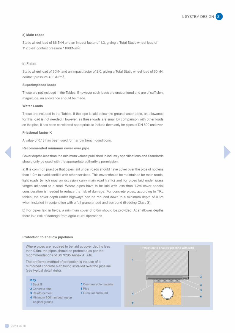
Protection to shallow pipelines
Where pipes are required to be laid at cover depths less than 0.6m, the pipes should be protected as per the recommendations of BS 9295 Annex A, A16.
The preferred method of protection is the use of a reinforced concrete slab being installed over the pipeline (see typical detail right).
Key1 Backfill2 Concrete slab3 Reinforcement4 Minimum 300 mm bearing on
original ground
5 Compressible material6 Pipe7 Granular surround
Ground level
1
2
3
5
6
7
4
Protection to shallow pipeline with slab

It is important that the slab extends sufficient distance beyond the trench and would depend on soil conditions (minimum bearing of 300mm each side advised). A layer of compressible material directly over the pipeline aids in the prevention of the slab loading directly onto the pipeline should settlement occur.
Another method of protection at shallow cover depth is via the use of a concrete surround. It is important in such installations to install compressible material at least every other pipe joint to ensure that the pipeline retains its flexibility.
Special consideration should be given where construction plant has to cross pipelines with shallow cover depth. Where possible, traffic should be routed over dedicated crossing points. Crossing points may consist of heavy steel plates to transfer vehicle loads or temporary additional cover emplaced over the pipeline.
Pipelines under embankments or laid in deep trenches
Where a pipeline is laid under an embankment, or where the pipeline is installed in a deep trench, it can be critical for the trench width and the distance above the crown of the pipe to be kept within the design values. Any slight increase over the designed trench width can greatly increase the pipeline’s loading.
Multiple pipes in trench
For convenience, two or more pipelines may be installed in the same trench and at different levels.
Trenches can be excavated to the maximum depth to accept all pipelines, or they may be stepped in construction where levels of the pipelines are different.
Careful consideration should be undertaken to assess the loading and possible implications of installing multiple pipelines in the same trench.
The horizontal distance between adjacent pipelines will largely be dependent on the type of bedding/backfill material used to surround the pipelines. With rounded gravels it’s possible to achieve minimal spacing between the pipelines (just room to provide access for the gravel to be working in and around the pipes), whereas an angular/cohesive material may require upwards of 400mm or greater (depending on pipe sizes) to enable suitable access for placement and compaction of the materials.
More advice can be found at BS 9295, A.11.
1.2.3 Design Method
The established method for calculation of loads on buried rigid pipes is summarised in BS EN 1295 National Annex A, the principles of which are explained below. For further information, BS9295 has been published as a guide and background to BS EN 1295.
In general pipelines are laid in trenches and the pipes used are designed to carry the backfill, traffic loads and, when the diameter is 600mm or more, some part of the water load under working conditions.
In order to improve the load carrying capacity of the pipe it is laid on one of several classes of bedding (see Table A2). Each type of bedding is allocated a “bedding factor” (Fm) which may be regarded as a multiplier applied to the test load of the pipe.
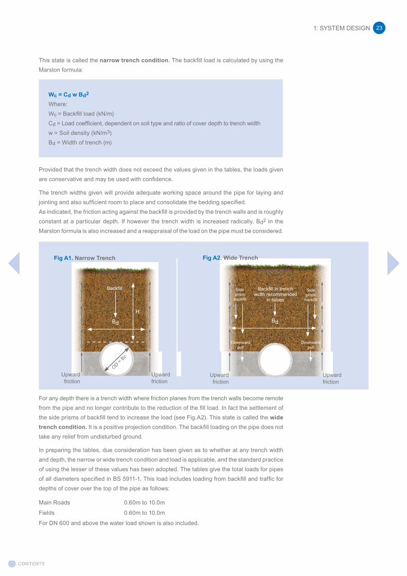
The trench is excavated in the natural soil, the pipe is laid on the selected bedding and the trench backfilled. Load on the pipe due to the backfill develops as the fill material settles. The load on the pipe due to the backfill is therefore the weight of the backfill taken over the full trench width but reduced by the shear force from the trench walls acting upwards (see Fig.A1).
1: SYSTEM DESIGN22
1: SYSTEM DESIGN 23
This state is called the narrow trench condition. The backfill load is calculated by using the Marston formula:
Wc = Cd w Bd2
Where:Wc = Backfill load (kN/m)Cd = Load coefficient, dependent on soil type and ratio of cover depth to trench widthw = Soil density (kN/m3) Bd = Width of trench (m)
Provided that the trench width does not exceed the values given in the tables, the loads given are conservative and may be used with confidence.
The trench widths given will provide adequate working space around the pipe for laying and jointing and also sufficient room to place and consolidate the bedding specified.As indicated, the friction acting against the backfill is provided by the trench walls and is roughly constant at a particular depth. If however the trench width is increased radically, Bd2 in the Marston formula is also increased and a reappraisal of the load on the pipe must be considered.
For any depth there is a trench width where friction planes from the trench walls become remote from the pipe and no longer contribute to the reduction of the fill load. In fact the settlement of the side prisms of backfill tend to increase the load (see Fig.A2). This state is called the wide trench condition. It is a positive projection condition. The backfill loading on the pipe does not take any relief from undisturbed ground.
In preparing the tables, due consideration has been given as to whether at any trench width and depth, the narrow or wide trench condition and load is applicable, and the standard practice of using the lesser of these values has been adopted. The tables give the total loads for pipes of all diameters specified in BS 5911-1. This load includes loading from backfill and traffic for depths of cover over the top of the pipe as follows:
Main Roads 0.60m to 10.0m
Fields 0.60m to 10.0m
For DN 600 and above the water load shown is also included.
Fig A1. Narrow Trench Fig A2. Wide Trench
Bedding BeddingUpwardfriction
Upwardfriction
Upwardfriction
Upwardfriction
Backfill
Ground level Ground level
H
Bd Bd
Backfill in trench width recommended
in tables
Downward pull
Downward pull
Side prism
backfill
Side prism
backfill
OD = Bc
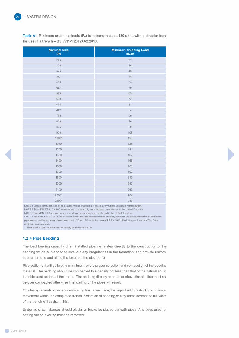
Table A1. Minimum crushing loads (Fn) for strength class 120 units with a circular bore for use in a trench – BS 5911-1:2002+A2:2010.
Nominal SizeDN
Minimum crushing LoadkN/m
225 27
300 36
375 45
400* 48
450 54
500* 60
525 63
600 72
675 81
700* 84
750 90
800 96
825 99
900 108
1000* 120
1050 126
1200 144
1350 162
1400 168
1500 180
1600 192
1800 216
2000 240
2100 252
2200* 264
2400* 288
NOTE 1 Classic sizes, denoted by an asterisk, will be phased out if called for by further European harmonisation.NOTE 2 Sizes DN 225 to DN 600 inclusive are normally only manufactured unreinforced in the United Kingdom.NOTE 3 Sizes DN 1000 and above are normally only manufactured reinforced in the United Kingdom.NOTE 4 Table NA.5 of BS EN 1295-1: recommends that the minimum value of safety factor for the structural design of reinforced pipelines should be increased from the normal 1.25 to 1.5 if, as is the case of BS EN 1916: 2002, the proof load is 67% of the minimum crushing load.* Sizes marked with asterisk are not readily available in the UK
1.2.4 Pipe Bedding
The load bearing capacity of an installed pipeline relates directly to the construction of the bedding which is intended to level out any irregularities in the formation, and provide uniform support around and along the length of the pipe barrel.
Pipe settlement will be kept to a minimum by the proper selection and compaction of the bedding material. The bedding should be compacted to a density not less than that of the natural soil in the sides and bottom of the trench. The bedding directly beneath or above the pipeline must not be over compacted otherwise line loading of the pipes will result.
On steep gradients, or where dewatering has taken place, it is important to restrict ground water movement within the completed trench. Selection of bedding or clay dams across the full width of the trench will assist in this.
Under no circumstances should blocks or bricks be placed beneath pipes. Any pegs used for setting out or levelling must be removed.
1: SYSTEM DESIGN24

1: SYSTEM DESIGN 25
Bedding materials
Any stable soil will act adequately as a bedding material provided that it is placed and compacted around the pipeline. From a practical point of view granular material is compacted more readily and has become widely accepted.
The bedding material should be of similar particle size to that in the trench sides. Where the ground is clay or silt, bedding material must consist of all-in gravels to prevent the trench from becoming a drainage channel and carrying away fines from the trench walls and bedding and causing settlement of the pipes.
Granular bedding material
The ideal is crushed rock or gravel but similar locally available material having an angular or an irregular shape may be used. Rounded single sized material is not recommended as it may not provide a stable bed especially for heavy larger diameter pipes.
Water Research Centre (WRc) Information and Guidance Note (IGN) 4-08-01 provides guidance on the particle size of material relating to pipe diameter.
Sands containing an excess of fine particles are more difficult to place and compact and will require a greater degree of supervision on site to achieve a stable embedment for the pipeline.
Selected bedding and fill material
This should consist of uniform readily compactable material, free from tree roots, vegetable matter, building rubbish and frozen soil. When used as fill, the material should not contain large clay lumps or cobbles. When used as bedding, all clay lumps should be excluded.
“As dug” material may be used provided that it is readily compactable and provides stable embedment.
Classes of bedding and bedding factors
The strength of an installed pipeline depends on a combination of the strength of the pipe and the class of bedding.
The selection of the bedding class is influenced by many factors, which include the nature of the ground, the loads acting on the pipeline in the trench, strength class of pipe, and the local cost and availability of the bedding material.
Taking into account the cost of labour, it is generally more economical to lay the pipes on a bedding of non-cohesive materials, or alternatively scarify the trench bottom rather than hand trim the formation.
Normally loading calculations are made considering the pipeline in complete lengths, between manholes. The calculated installation condition to satisfy the most severe loading condition between each pair of manholes is then used throughout the length.
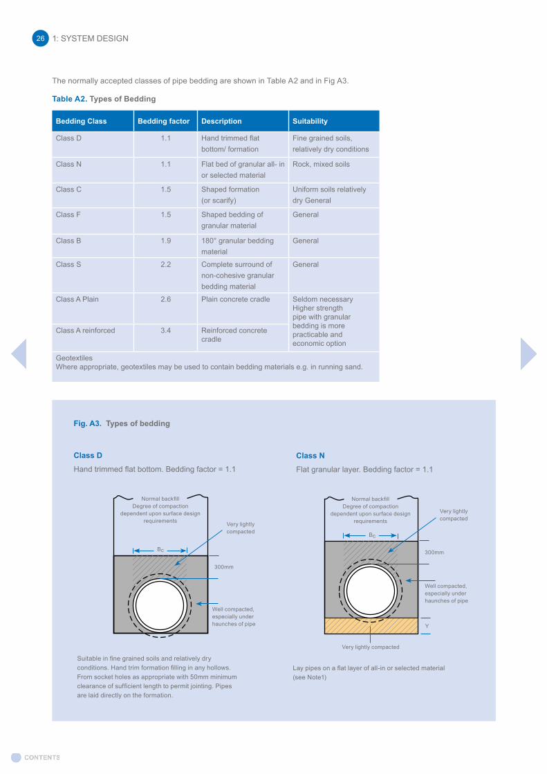
The normally accepted classes of pipe bedding are shown in Table A2 and in Fig A3.
Table A2. Types of Bedding
Bedding Class Bedding factor Description Suitability
Class D 1.1 Hand trimmed flat bottom/ formation
Fine grained soils, relatively dry conditions
Class N 1.1 Flat bed of granular all- in or selected material
Rock, mixed soils
Class C 1.5 Shaped formation (or scarify)
Uniform soils relatively dry General
Class F 1.5 Shaped bedding ofgranular material
General
Class B 1.9 180° granular bedding material
General
Class S 2.2 Complete surround of non-cohesive granular bedding material
General
Class A Plain 2.6 Plain concrete cradle Seldom necessaryHigher strengthpipe with granularbedding is more practicable and economic option
Class A reinforced 3.4 Reinforced concretecradle
GeotextilesWhere appropriate, geotextiles may be used to contain bedding materials e.g. in running sand.
1: SYSTEM DESIGN26
Fig. A3. Types of bedding
Class D
Hand trimmed flat bottom. Bedding factor = 1.1
Class N
Flat granular layer. Bedding factor = 1.1
Suitable in fine grained soils and relatively dry conditions. Hand trim formation filling in any hollows. From socket holes as appropriate with 50mm minimum clearance of sufficient length to permit jointing. Pipes are laid directly on the formation.
Lay pipes on a flat layer of all-in or selected material (see Note1)
Normal backfillDegree of compaction
dependent upon surface design requirements
Normal backfillDegree of compaction
dependent upon surface design requirementsVery lightly
compacted
Very lightly compacted
300mm
300mm
Y
Very lightly compacted
Well compacted, especially under haunches of pipe
Well compacted, especially under haunches of pipe
Bc
Bc
1: SYSTEM DESIGN 27
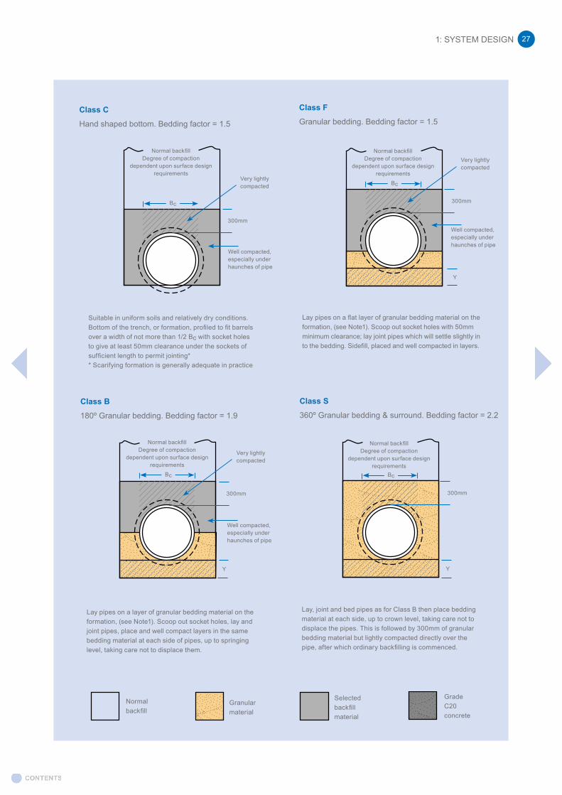
Class C
Hand shaped bottom. Bedding factor = 1.5
Class F
Granular bedding. Bedding factor = 1.5
Class B
180º Granular bedding. Bedding factor = 1.9
Class S
360º Granular bedding & surround. Bedding factor = 2.2
Suitable in uniform soils and relatively dry conditions. Bottom of the trench, or formation, profiled to fit barrels over a width of not more than 1/2 Bc with socket holes to give at least 50mm clearance under the sockets of sufficient length to permit jointing** Scarifying formation is generally adequate in practice
Lay pipes on a flat layer of granular bedding material on the formation, (see Note1). Scoop out socket holes with 50mm minimum clearance; lay joint pipes which will settle slightly in to the bedding. Sidefill, placed and well compacted in layers.
Lay pipes on a layer of granular bedding material on the formation, (see Note1). Scoop out socket holes, lay and joint pipes, place and well compact layers in the same bedding material at each side of pipes, up to springing level, taking care not to displace them.
Lay, joint and bed pipes as for Class B then place bedding material at each side, up to crown level, taking care not to displace the pipes. This is followed by 300mm of granular bedding material but lightly compacted directly over the pipe, after which ordinary backfilling is commenced.
Normal backfillDegree of compaction
dependent upon surface design requirements
Normal backfillDegree of compaction
dependent upon surface design requirements
Normal backfillDegree of compaction
dependent upon surface design requirements
Normal backfillDegree of compaction
dependent upon surface design requirements
Very lightly compacted
Very lightly compacted
Very lightly compacted
300mm
300mm
Well compacted, especially under haunches of pipe
Well compacted, especially under haunches of pipe
Bc
Bc
BcBc
Y
Y Y
300mm 300mm
Well compacted, especially under haunches of pipe
Normal backfill
Granularmaterial
Selectedbackfillmaterial
GradeC20concrete
1.2.5 Design Calculations
The calculated load “We”, which is the total load a concrete pipe in a trench is required to sustain, is used in the design formula as follows:
Fn = We x Fse Fm
where Fn = required BS 5911-1 test strength (kN/m) We = load from Tables A3 or A4 (kN) Fse = factor of safety Fm = bedding factor chosen
Test strength of pipe (Fn)
The test strength of a concrete pipe may be referred to as Fc or Fn
In the UK, standard circular pipes to BS EN 1916 and BS 5911-1 are usually to Class 120. To calculate the test strength apply 120 x pipe nominal diameter in metres e.g. for DN450 pipe, Fn=120 x 0.45=54kN/m (see Table A1).
For a reinforced concrete pipe Fc is the load which the pipe will sustain without developing a crack exceeding 0.30mm in width over a length of 300mm and Wt is the load which the pipe will sustain without collapse, irrespective of crack width. However, to further simplify the procedure it is more straightforward to use the maximum test load Fn and applying the factor of safety of Fse.
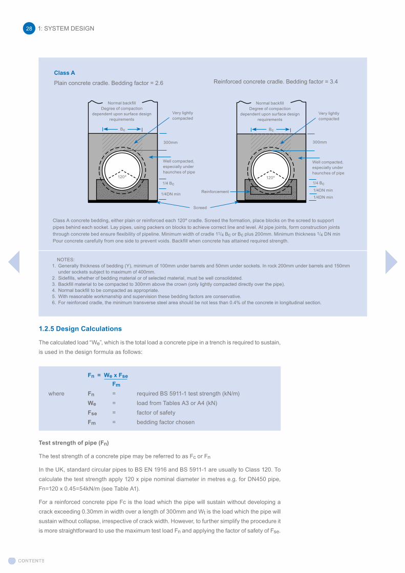
NOTES:1. Generally thickness of bedding (Y), minimum of 100mm under barrels and 50mm under sockets. In rock 200mm under barrels and 150mm
under sockets subject to maximum of 400mm.2. Sidefills, whether of bedding material or of selected material, must be well consolidated.3. Backfill material to be compacted to 300mm above the crown (only lightly compacted directly over the pipe).4. Normal backfill to be compacted as appropriate.5. With reasonable workmanship and supervision these bedding factors are conservative.6. For reinforced cradle, the minimum transverse steel area should be not less than 0.4% of the concrete in longitudinal section.
1: SYSTEM DESIGN28
Class A
Plain concrete cradle. Bedding factor = 2.6 Reinforced concrete cradle. Bedding factor = 3.4
Normal backfillDegree of compaction
dependent upon surface design requirements
Normal backfillDegree of compaction
dependent upon surface design requirements
Very lightly compacted
Very lightly compacted
Bc Bc
300mm 300mm
Well compacted, especially under haunches of pipe
Well compacted, especially under haunches of pipe
120º 120º1/4 Bc
1/4DN min
1/4 Bc
1/4DN min
Class A concrete bedding, either plain or reinforced each 120º cradle. Screed the formation, place blocks on the screed to support pipes behind each socket. Lay pipes, using packers on blocks to achieve correct line and level. At pipe joints, form construction joints through concrete bed ensure flexibility of pipeline. Minimum width of cradle 11/4 Bc or Bc plus 200mm. Minimum thickness 1/4 DN min Pour concrete carefully from one side to prevent voids. Backfill when concrete has attained required strength.
Screed
Reinforcement 1/4DN min
1: SYSTEM DESIGN 29
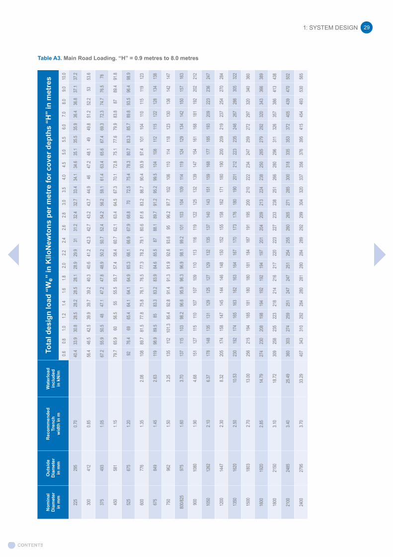
Table A3. Main Road Loading. “H” = 0.9 metres to 8.0 metres
Nom
inal
Dia
met
erin
mm
Out
side
Dia
met
erin
mm
Rec
omm
ende
dTr
ench
wid
th in
m
Wat
erlo
adin
clud
edin
kN
/m
Tota
l des
ign
load
“W
e” in
Kilo
New
tons
per
met
re fo
r cov
er d
epth
s “H
” in
met
res
0.60.8
1.01.2
1.41.6
1.82.0
2.22.4
2.62.8
3.03.5
4.04.5
5.05.5
6.07.0
8.09.0
10.0
225
295
0.70
40.4
33.9
30.8
28.5
28.2
28.5
28.1
28.9
29.9
3131
.232
.432
.733
.434
.134
.635
.135
.535
.936
.436
.837
.137
.2
300
412
0.85
56.4
46.5
42.5
39.9
39.7
39.2
40.3
40.6
41.2
42.3
42.7
43.2
43.7
44.9
4647
.248
.149
49.8
51.2
52.2
5353
.6
375
493
1.05
67.2
55.9
50.5
4847
.147
.247
.848
.950
.250
.752
.454
.256
.259
.161
.463
.465
.667
.469
.372
.374
.776
.578
450
581
1.15
79.7
65.9
6056
.555
55.5
55.7
57.4
58.4
60.7
62.1
63.4
64.5
67.3
70.1
72.8
75.1
77.6
79.9
83.8
8789
.491
.8
525
675
1.20
9276
.469
65.4
64.1
64.1
64.9
65.3
66.1
66.9
67.9
68.8
7072
.575
.478
.380
.783
.385
.789
.893
.596
.498
.9
600
776
1.35
2.08
108
89.7
81.5
77.8
75.8
76.1
76.5
77.3
78.2
79.1
80.6
81.6
83.2
86.7
90.4
93.9
97.4
101
104
110
115
119
123
675
849
1.45
2.63
119
98.9
89.5
8583
.383
.283
.984
.685
.587
88.1
89.7
91.2
95.2
99.5
104
108
112
115
122
128
134
138
750
962
1.50
3.25
135
112
101.3
95.4
92.8
91.4
91.3
91.9
92.6
93.6
9596
.297
.710
210
611
011
411
812
313
013
614
214
7
800/8
2597
51.6
03.7
013
711
510
398
.296
.695
.996
.396
.998
.199
.210
110
310
410
911
411
912
412
913
414
215
015
716
3
900
1080
1.90
4.68
151
127
115
110
107
107
109
110
113
116
119
122
125
132
139
147
154
161
168
181
192
202
212
1050
1262
2.10
6.37
178
148
135
131
129
125
127
129
132
135
137
140
143
151
159
168
177
185
193
209
223
236
247
1200
1447
2.30
8.32
205
174
158
147
145
144
146
148
150
152
155
158
162
171
180
190
200
209
219
237
254
270
284
1350
1620
2.50
10.53
230
192
174
165
163
162
163
164
167
170
173
176
180
190
201
212
223
235
246
267
286
305
322
1500
1803
2.70
13.00
256
215
194
185
181
180
180
181
184
187
191
195
200
210
222
234
247
259
272
297
320
340
360
1600
1920
2.85
14.79
274
230
208
198
194
192
192
194
197
201
204
209
213
224
238
250
265
279
292
320
343
366
389
1800
2150
3.10
18.72
309
258
235
223
218
214
216
217
220
223
227
233
238
251
266
280
296
311
326
357
386
413
438
2100
2485
3.40
25.49
360
303
274
259
251
247
247
251
254
255
260
265
271
285
300
318
335
353
372
405
439
470
502
2400
2795
3.70
33.29
407
343
310
292
284
280
281
280
284
289
292
299
304
320
337
356
376
395
415
454
493
530
565
1: SYSTEM DESIGN30
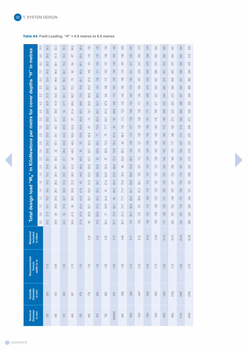
Table A4. Field Loading. “H” = 0.6 metres to 8.0 metres
Nom
inal
D
iam
eter
in m
m
Out
side
D
iam
eter
in m
m
Rec
omm
ende
dTr
ench
wid
th in
m
Wat
erlo
ad in
clud
ed
in k
N/m
Tota
l des
ign
load
“W
e” in
Kilo
New
tons
per
met
re fo
r cov
er d
epth
s “H
” in
met
res
0.60.8
1.01.2
1.41.6
1.82.0
2.22.4
2.62.8
3.03.5
4.04.5
5.05.5
6.07.0
8.09.0
10.0
225
295
0.70
25.5
21.3
19.7
18.2
18.5
19.3
19.3
20.6
22.1
23.6
24.3
25.9
26.5
28.2
29.6
30.8
31.9
32.7
33.4
34.5
35.3
35.8
36.2
300
412
0.85
35.6
2926
.925
.526
.126
.328
.129
.130
.332
33.1
34.1
35.1
37.7
39.8
41.9
43.5
45.1
46.4
48.5
50.1
51.3
52.2
375
493
1.05
42.3
3531
.830
.730
.931
.833
.335
.137
.138
.440
.843
.345
.950
.454
57.1
60.1
62.7
65.2
69.1
72.2
74.5
76.3
450
581
1.15
50.4
41.2
3836
.235
.837
.338
.541
.243
46.2
48.5
50.6
52.4
5761
.465
.468
.772
.175
8084
8789
.8
525
675
1.20
57.9
47.8
43.4
41.8
41.9
4344
.946
.448
.250
5253
.955
.960
.665
.369
.673
.276
.980
.185
.590
.193
.696
.6
600
776
1.35
2.08
6956
.852
.150
.750
.251
.953
.555
.657
.759
.762
.464
.467
7378
.783
.988
.893
.297
.610
511
111
612
0
675
849
1.45
2.63
75.6
62.9
57.3
55.2
55.3
56.7
58.8
60.9
6365
.868
.171
73.6
80.2
86.7
92.7
98.5
104
108
117
124
130
135
750
962
1.50
3.25
86.1
7164
.964
.461
61.4
62.8
62.4
6769
.672
.475
77.7
84.7
91.2
97.6
104
109
115
123
131
138
144
800/8
2597
51.6
03.7
087
.773
.366
.164
64.2
65.4
67.4
69.6
72.3
74.8
78.2
81.2
8492
99.6
106
113
120
126
136
145
153
160
900
1080
1.90
4.68
96.7
81.2
73.7
71.7
71.4
72.9
76.6
8083
.989
.394
98.3
102
113
123
133
142
150
158
174
187
198
208
1050
1262
2.10
6.37
114
94.7
86.9
83.5
84.1
85.8
89.9
93.9
98.5
103
108
113
117
129
140
152
163
173
183
201
217
230
243
1200
1447
2.30
8.32
132
110
101
96.6
97.2
99.1
103
107
112
116
121
126
132
145
158
171
184
196
207
228
247
264
279
1350
1620
2.50
10.53
148
123
113
109
110
112
115
119
124
129
134
140
146
161
177
191
205
219
232
256
278
298
316
1500
1803
2.70
13.00
165
139
126
122
122
124
127
131
136
142
148
155
162
178
195
211
227
242
257
285
310
333
354
1600
1920
2.85
14.79
177
148
135
131
130
132
135
140
146
153
159
166
173
190
209
225
244
260
276
307
333
358
382
1800
2150
3.10
18.72
200
167
153
148
147
147
152
156
164
170
177
186
193
213
233
253
272
290
308
343
375
404
431
2100
2485
3.40
25.49
234
197
179
172
169
170
173
181
187
193
201
210
219
240
263
286
307
329
351
389
426
460
494
2400
2795
3.70
33.29
266
224
204
194
191
193
198
202
210
219
227
237
246
271
295
320
345
369
392
436
478
518
555
Nominal Diameter in mm
Outside Diameter in mm
RecommendedTrench
width in m
Waterload included in kN/m
Total design load “We” in KiloNewtons per metre for cover depths “H” in metres
0.6 0.8 1.0 1.2 1.4 1.6 1.8 2.0 2.2 2.4 2.6 2.8 3.0 3.5 4.0 4.5 5.0 5.5 6.0 7.0 8.0 9.0 10.0
225 295 0.70 25.5 21.3 19.7 18.2 18.5 19.3 19.3 20.6 22.1 23.6 24.3 25.9 26.5 28.2 29.6 30.8 31.9 32.7 33.4 34.5 35.3 35.8 36.2
300 412 0.85 35.6 29 26.9 25.5 26.1 26.3 28.1 29.1 30.3 32 33.1 34.1 35.1 37.7 39.8 41.9 43.5 45.1 46.4 48.5 50.1 51.3 52.2
375 493 1.05 42.3 35 31.8 30.7 30.9 31.8 33.3 35.1 37.1 38.4 40.8 43.3 45.9 50.4 54 57.1 60.1 62.7 65.2 69.1 72.2 74.5 76.3
450 581 1.15 50.4 41.2 38 36.2 35.8 37.3 38.5 41.2 43 46.2 48.5 50.6 52.4 57 61.4 65.4 68.7 72.1 75 80 84 87 89.8
525 675 1.20 57.9 47.8 43.4 41.8 41.9 43 44.9 46.4 48.2 50 52 53.9 55.9 60.6 65.3 69.6 73.2 76.9 80.1 85.5 90.1 93.6 96.6
600 776 1.35 2.08 69 56.8 52.1 50.7 50.2 51.9 53.5 55.6 57.7 59.7 62.4 64.4 67 73 78.7 83.9 88.8 93.2 97.6 105 111 116 120
675 849 1.45 2.63 75.6 62.9 57.3 55.2 55.3 56.7 58.8 60.9 63 65.8 68.1 71 73.6 80.2 86.7 92.7 98.5 104 108 117 124 130 135
750 962 1.50 3.25 86.1 71 64.9 64.4 61 61.4 62.8 62.4 67 69.6 72.4 75 77.7 84.7 91.2 97.6 104 109 115 123 131 138 144
800/825 975 1.60 3.70 87.7 73.3 66.1 64 64.2 65.4 67.4 69.6 72.3 74.8 78.2 81.2 84 92 99.6 106 113 120 126 136 145 153 160
900 1080 1.90 4.68 96.7 81.2 73.7 71.7 71.4 72.9 76.6 80 83.9 89.3 94 98.3 102 113 123 133 142 150 158 174 187 198 208
1050 1262 2.10 6.37 114 94.7 86.9 83.5 84.1 85.8 89.9 93.9 98.5 103 108 113 117 129 140 152 163 173 183 201 217 230 243
1200 1447 2.30 8.32 132 110 101 96.6 97.2 99.1 103 107 112 116 121 126 132 145 158 171 184 196 207 228 247 264 279
1350 1620 2.50 10.53 148 123 113 109 110 112 115 119 124 129 134 140 146 161 177 191 205 219 232 256 278 298 316
1500 1803 2.70 13.00 165 139 126 122 122 124 127 131 136 142 148 155 162 178 195 211 227 242 257 285 310 333 354
1600 1920 2.85 14.79 177 148 135 131 130 132 135 140 146 153 159 166 173 190 209 225 244 260 276 307 333 358 382
1800 2150 3.10 18.72 200 167 153 148 147 147 152 156 164 170 177 186 193 213 233 253 272 290 308 343 375 404 431
2100 2485 3.40 25.49 234 197 179 172 169 170 173 181 187 193 201 210 219 240 263 286 307 329 351 389 426 460 494
2400 2795 3.70 33.29 266 224 204 194 191 193 198 202 210 219 227 237 246 271 295 320 345 369 392 436 478 518 555
NominalDiameter
in mm
OutsideDiameter
in mm
RecommendedTrench
width in m
Waterloadincludedin kN/m
Total design load “We” in KiloNewtons per metre for cover depths “H” in metres
0.6 0.8 1.0 1.2 1.4 1.6 1.8 2.0 2.2 2.4 2.6 2.8 3.0 3.5 4.0 4.5 5.0 5.5 6.0 7.0 8.0 9.0 10.0
225 295 0.70 40.4 33.9 30.8 28.5 28.2 28.5 28.1 28.9 29.9 31 31.2 32.4 32.7 33.4 34.1 34.6 35.1 35.5 35.9 36.4 36.8 37.1 37.2
300 412 0.85 56.4 46.5 42.5 39.9 39.7 39.2 40.3 40.6 41.2 42.3 42.7 43.2 43.7 44.9 46 47.2 48.1 49 49.8 51.2 52.2 53 53.6
375 493 1.05 67.2 55.9 50.5 48 47.1 47.2 47.8 48.9 50.2 50.7 52.4 54.2 56.2 59.1 61.4 63.4 65.6 67.4 69.3 72.3 74.7 76.5 78
450 581 1.15 79.7 65.9 60 56.5 55 55.5 55.7 57.4 58.4 60.7 62.1 63.4 64.5 67.3 70.1 72.8 75.1 77.6 79.9 83.8 87 89.4 91.8
525 675 1.20 92 76.4 69 65.4 64.1 64.1 64.9 65.3 66.1 66.9 67.9 68.8 70 72.5 75.4 78.3 80.7 83.3 85.7 89.8 93.5 96.4 98.9
600 776 1.35 2.08 108 89.7 81.5 77.8 75.8 76.1 76.5 77.3 78.2 79.1 80.6 81.6 83.2 86.7 90.4 93.9 97.4 101 104 110 115 119 123
675 849 1.45 2.63 119 98.9 89.5 85 83.3 83.2 83.9 84.6 85.5 87 88.1 89.7 91.2 95.2 99.5 104 108 112 115 122 128 134 138
750 962 1.50 3.25 135 112 101.3 95.4 92.8 91.4 91.3 91.9 92.6 93.6 95 96.2 97.7 102 106 110 114 118 123 130 136 142 147
800/825 975 1.60 3.70 137 115 103 98.2 96.6 95.9 96.3 96.9 98.1 99.2 101 103 104 109 114 119 124 129 134 142 150 157 163
900 1080 1.90 4.68 151 127 115 110 107 107 109 110 113 116 119 122 125 132 139 147 154 161 168 181 192 202 212
1050 1262 2.10 6.37 178 148 135 131 129 125 127 129 132 135 137 140 143 151 159 168 177 185 193 209 223 236 247
1200 1447 2.30 8.32 205 174 158 147 145 144 146 148 150 152 155 158 162 171 180 190 200 209 219 237 254 270 284
1350 1620 2.50 10.53 230 192 174 165 163 162 163 164 167 170 173 176 180 190 201 212 223 235 246 267 286 305 322
1500 1803 2.70 13.00 256 215 194 185 181 180 180 181 184 187 191 195 200 210 222 234 247 259 272 297 320 340 360
1600 1920 2.85 14.79 274 230 208 198 194 192 192 194 197 201 204 209 213 224 238 250 265 279 292 320 343 366 389
1800 2150 3.10 18.72 309 258 235 223 218 214 216 217 220 223 227 233 238 251 266 280 296 311 326 357 386 413 438
2100 2485 3.40 25.49 360 303 274 259 251 247 247 251 254 255 260 265 271 285 300 318 335 353 372 405 439 470 502
2400 2795 3.70 33.29 407 343 310 292 284 280 281 280 284 289 292 299 304 320 337 356 376 395 415 454 493 530 565
1: SYSTEM DESIGN 31
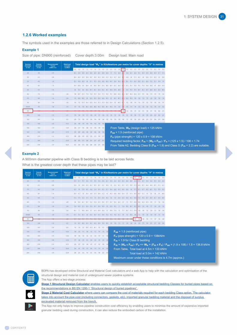
The symbols used in the examples are those referred to in Design Calculations (Section 1.2.5).
Example 1Size of pipe: DN900 (reinforced) Cover depth:3.00m Design load: Main road
Example 2A 900mm diameter pipeline with Class B bedding is to be laid across fields. What is the greatest cover depth that these pipes may be laid?
Fse = 1.5 (reinforced pipe)Fn (pipe strength) = 120 x 0.9 = 108kN/mFm = 1.9 for Class B beddingFm = (We x Fse) / Fn => We = (Fm x Fn) / Fse = (1.9 x 10⁸) / 1.5 = 136.8 kN/m From Table, Total load at 4.5m = 133 kN/m Total load at 5.0m = 142 kN/mMaximum cover under these conditions is 4.7m (approx.)
BDPA has developed online Structural and Material Cost calculators and a web App to help with the calculation and optimisation of the structural design and material cost of underground sewer pipeline systems.The App offers a two-stage process:Stage 1 Structural Design Calculator enables users to quickly establish acceptable structural bedding Classes for buried pipes based on the recommendations in BS EN 1295-1 “Structural design of buried pipelines”. Stage 2 Material Cost Calculator where users can compare the cost of materials required for each bedding Class option. The calculator takes into account the pipe cost (including connectors, gaskets, etc), imported granular bedding material and the disposal of surplus excavated material removed from the trench.The App not only helps to improve pipeline construction cost efficiency by enabling users to minimise the amount of expensive imported granular bedding used during construction, it can also reduce the embodied carbon of the installation.
From Table, We (design load) = 125 kN/mFse = 1.5 (reinforced pipe)Fn (pipe strength) = 120 x 0.9 = 108 kN/mRequired bedding factor, Fm = (We x Fse) / Fn = (125 x 1.5) / 108 = 1.74From Table A2, Bedding Class B (Fm = 1.9) and Class S (Fm = 2.2) are suitable.
1.2.6 Worked examples
1.3 MANHOLE DESIGN
1.3.1 Manhole Positions
Manholes are recommended:
• At intervals of up to 90m, or 200m for man entry pipe runs.• Whenever there is a significant change of direction in a sewer.• Where another sewer is connecting with the main run of a sewer.• Where there is a change of size or gradient of pipeline.• Where there is a change of design loading or bedding design.
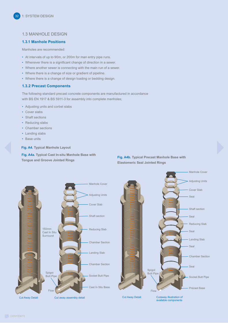
1.3.2 Precast Components
The following standard precast concrete components are manufactured in accordance with BS EN 1917 & BS 5911-3 for assembly into complete manholes;
• Adjusting units and corbel slabs• Cover slabs• Shaft sections• Reducing slabs• Chamber sections• Landing slabs• Base units
Fig. A4. Typical Manhole Layout
Fig. A4a. Typical Cast In-situ Manhole Base with Tongue and Groove Jointed Rings
Fig. A4b. Typical Precast Manhole Base with Elastomeric Seal Jointed Rings
150mm Cast In SituSurround
Spigot Butt Pipe
Spigot Butt Pipe
Manhole Cover
Adjusting Units
Cover Slab
Shaft section
Reducing Slab
Chamber Section
Chamber Section
Socket Butt Pipe
Cast In Situ Base
Manhole Cover
Adjusting Units
Cover Slab
Shaft section
Reducing Slab
Seal
Chamber Section
Seal
Precast BaseFlow Flow
Cut Away Detail Cut Away DetailCut away assembly detail Cutaway illustration of available components
Landing Slab
Seal
Seal
Landing Slab
Seal
Socket Butt Pipe
1: SYSTEM DESIGN32

1: SYSTEM DESIGN 33
Base units can be supplied with circular or semicircular holes (cut-outs or ‘dog kennels’) cut in the chamber walls or with factory made flexible joints to incorporate a sealing ring to connect pipes to the chamber.
1.3.3 Advantages
1.3.4 Types of Manholes
Manholes should be designed and constructed in accordance with BS EN 752. Table NA.22 provides recommendations for dimensions for manholes and manhole shafts for UK applications (with personnel entry) and Sewers for Adoption provides details of manholes suitable for adoption purposes.
Manholes are built on a run of sewer with or without side connections. Where conditions permit, the soffit level of sewers connecting to a manhole should be the same.
Manholes may be constructed with or without a shaft. It is recommended that reducing slabs and shafts are only used for DN1800 manholes and larger. Landing slabs are generally required for manholes 6 metres deep or greater.
Smaller diameter chambers should be constructed up to full height and use a cover slab. There are also inspection chambers which are constructed over a subsidiary drain or sewer of not more than DN 225 to permit inspection and access for rodding. Most manholes are sited symmetrically over the main sewer pipeline. Side-entry manholes which are formed integral to the crown of the pipe are also manufactured. These can be advantageous in terms of installation time and cost savings.
When contemplating the installation of rectangular or square manhole/s, reference should be made to Annex F of BS 5911-3+A1.
The main advantages of manholes using precast concrete components are:
1. Reduced construction time and cost
2. Less operative risk exposure in trench during construction
3. Its self-weight provides natural resistance to flotation
4. Can accommodate new build and retro-fitting of new connections
5. Units are produced in a controlled factory environment to BS EN 1917 & BS 5911-3 to ensure consistent quality and performance.
6. All BPDA member factories are licensed to manufacture ‘Kitemarked’ standard units under BS EN ISO 9001 quality management systems.
7. They are manufactured in a range of standard sizes and depths.
8. They are simple to assemble requiring relatively unskilled labour on site.
9. Units are watertight structures without the need for a concrete surround. Soil backfill is normally sufficient.
10.They can be supplied ready fitted with double steps complying with BS EN 13101.
11. The structure is durable with its own inherent strength.
1: SYSTEM DESIGN34
For more information on precast manhole base systems, refer to BPDA and member product information:
Marshalls CPM http://www.cpm-group.com/products/drainage/sealed-manholes/the-perfect-manholesFP McCann Ltd http://fpmccann.co.uk/easi-base Stanton Bonna http://www.stanton-bonna.co.uk/drainage-systems/watertight-manhole-system/BPDA https://www.precastdrainage.co.uk/page/precast-manhole-design-construction
1) Precast base systems
Inlet(s) and outlet positions are configured to site requirements and delivered with all channels and benching complete. Watertight joints and thicker walls means units do not require a concrete surround, unless specified. A faster, safer, higher quality, lower installed cost and reduced carbon footprint alternative to conventional manholes, (the product’s finish is not subject to the skills of site operatives).
Precast concrete manhole sections and cover slab to be bedded with mortar, plastomericor elastomeric seal conforming toBS EN 1917 and BS 5911-3Chamber wall to be minimum 125 mm
Surface of benching and channel formed monolithically with high-strength concretebase or a proprietary liner
Benching slope to be 1:10 to 1:30
150 mm to underside of channel
2) In-situ manholes
Concrete base, channel/s and benching installed in-situ. With the bottom section of the first manhole ring being built in to the base concrete by a minimum of 75mm. Distance between top of pipe and underside of first manhole ring to be minimum of 50mm to a maximum of 300mm. Generally and in accordance with ‘Sewers For Adoption’ a concrete surround is required with this type of manhole construction.
Precast concrete manhole sections and cover slab to be bedded with mortar, plastomericor elastomeric seal conforming toBS EN 1917 and BS 5911-3
Concrete surround 150 mm thick
The bottom precast section to be built into base concrete minimum 75 mm
Benching slope to be 1:10 to 1:30
Construction joint
225 mm to underside of channel
Distance between top of pipe and underside of precast section to be minimum 50 mm to maximum 300 mm
In-situ concrete to be GEN3(designed to BRE Special Digest 1Concrete in Aggressive Ground)
High-strength concrete topping to be brought up to a dense, smooth face, neatly shaped and finished to all branch connections(minimum thickness 20 mm)
1: SYSTEM DESIGN 35
4) Backdrop manholes
Where one sewer connects with another at a substantially different level, the manhole is built on the lower sewer and incorporates a vertical or ramped drop pipe from the higher sewer. The drop pipe, which may be inside or outside the manhole chamber, has its lower end discharging into the main sewer, and at its upper end has a rodding eye for cleaning through the higher sewer.
Wherever possible, steeper gradients are preferred over the use of backdrops in ‘Sewers For Adoption’.
5) Dual and crossing manholes
Where surface water and foul sewers are laid in the same trench, the surface water being normally above the foul, a normal manhole chamber is built for the foul sewer and the surface water is carried across the chamber in a separate pipe which may have a sealed inspection cover.
1.3.5 Sizes of Manholes
The diameter of the chamber is determined by the number and the diameter of the sewer pipes coming into the manhole and the working space required.
The chamber should be a minimum of DN 1050 and is the smallest size that may be fitted with steps, but are only permitted to be used to a depth of 1.5m. DN 1200 is the smallest size that can be used deeper than 1.5m and to which ladders may be fitted. It should have ample benching at least 225mm wide on one side of the channels. On the other side, the benching should be wide enough to stand on, at least 450mm.
For deep manholes, the chamber should be large enough to provide benching or a landing adequate for two persons to stand upon.
A guide for the minimum chamber diameters required for various sizes of sewer pipes entering the manhole is given in Table A6. When a manhole is sited on a curve, or where additional pipes enter at the sides a larger size may be required.
Table A5. Sizes of pipe and manhole chamber diameters
Maximum size of pipe (DN) through chamber Minimum Chamber diameter (DN)
Less than 375 1200
375 – 450 1350
500 –700 1500
750 – 900 1800
Greater than 900 Pipe diameter + 900
1.3.6 Pipes Adjacent to Manholes
There may be differential settlement between a structure and the pipeline resulting in angular deflection of the joint. This creates no problem for the joint itself but when this movement is “excessive” there is a shear force that can cause structural failure on the pipe, either shear behind the collar or from beam fracture of the pipe barrel.
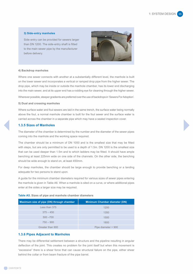
3) Side-entry manholes
Side-entry can be provided for sewers larger than DN 1200. The side-entry shaft is fitted to the main sewer pipe by the manufacturer before delivery.
1: SYSTEM DESIGN36
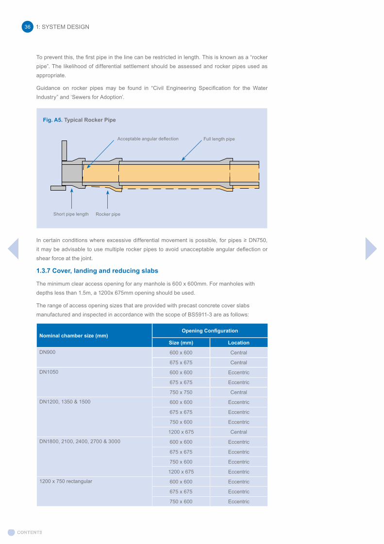
To prevent this, the first pipe in the line can be restricted in length. This is known as a “rocker pipe”. The likelihood of differential settlement should be assessed and rocker pipes used as appropriate.
Guidance on rocker pipes may be found in “Civil Engineering Specification for the Water Industry” and ‘Sewers for Adoption’.
In certain conditions where excessive differential movement is possible, for pipes ≥ DN750, it may be advisable to use multiple rocker pipes to avoid unacceptable angular deflection or shear force at the joint.
1.3.7 Cover, landing and reducing slabs
The minimum clear access opening for any manhole is 600 x 600mm. For manholes with depths less than 1.5m, a 1200x 675mm opening should be used.
The range of access opening sizes that are provided with precast concrete cover slabs manufactured and inspected in accordance with the scope of BS5911-3 are as follows:
Fig. A5. Typical Rocker Pipe
Short pipe length Rocker pipe
Acceptable angular deflection Full length pipe
Nominal chamber size (mm)Opening Configuration
Size (mm) Location
DN900 600 x 600 Central
675 x 675 Central
DN1050 600 x 600 Eccentric
675 x 675 Eccentric
750 x 750 Central
DN1200, 1350 & 1500 600 x 600 Eccentric
675 x 675 Eccentric
750 x 600 Eccentric
1200 x 675 Central
DN1800, 2100, 2400, 2700 & 3000 600 x 600 Eccentric
675 x 675 Eccentric
750 x 600 Eccentric
1200 x 675 Eccentric
1200 x 750 rectangular 600 x 600 Eccentric
675 x 675 Eccentric
750 x 600 Eccentric

1: SYSTEM DESIGN 37
Slabs with other sized accesses/multiple accesses or rebated accesses are quite often required in cases of split wall chambers, pumping stations, where flow control devices are fitted within the chamber etc. (these would be made to order products).
Cover Slabs – CE Marking
Only cover slabs covered by the European Standard (DN900 – DN1200) may be CE Marked.
Slabs covered by the British Standard may be Kite-marked. Thus most Slabs DN900 – DN1200 carry both Kite-mark and a CE Marking whereas most slabs of DN1350 and above would only carry a Kite-mark. Exceptions to this rule exist, for example a DN1200 Slab with a 750x750mm opening carries CE Marking but not a Kite-mark as the opening size is not contained within the British Standard.
Cover Slabs – Loading
EN1917 :2010 is the European standard and together with BS5911-3:2014 as the UK National standard for Manhole Cover Slabs and provides a full product specification. The scope of the standard covers manholes ’intended to be installed in carriageways of roads (including pedestrian streets), hard shoulders and parking areas for all types of road vehicles’.
BS-5911-3:2014 ‘Specification for reinforced and unreinforced manholes’ has been revised such that the test loads for standard slabs covered by BS5911-3 are consistent with Eurocode Loadings.
The standards include test requirements for the cover slabs to ensure suitability for use in all UK Road categories. There is no requirement in BS5911-3 for the slabs to comply with a reinforced concrete design code of practice such as BS EN 1992-1-1.
The cover slabs are subjected to routine batch load testing. The test is deemed a ‘proof load’ test and does not take the slab to ultimate (failure) but requires compliance with a maximum permitted crack width after removal of the test load being 0.15mm. This is therefore comparable with serviceability requirements in a design code of practice where the design considers a service load not ultimate load.
In concluding the above demonstrates that the test loads required to comply with BS5911-3 are at least equivalent to the loading required under BS EN 1991-2 when considering crack width requirements. The principal difference between the cover slab product standard and the Eurocode design standard being slabs to the BS 5911-3 are tested as opposed to a structural design required for compliance with BS EN 1991-2.
Generally, slabs manufactured and inspected in accordance with BS5911-3 are suitable for use in applications where an A15 - D400 rated manhole cover, manufactured and inspected in accordance with BS EN 124, is intended to be used.
In concluding the above demonstrates that the test loads required to comply with BS5911-3 are at least equivalent to the loading required under BS EN 1991-2 when considering crack width requirements. The principal difference between the cover slab product standard and the Eurocode design standard being slabs to the BS 5911-3 are tested as opposed to a structural design required for compliance with BS EN 1991-2.
Consequently, if loads are compared between test loads and design loading it would be as follows.
• BS EN 1917 DN900- DN1200 120kN load applied around the access
• BS 5911-3:2014 Figure 11 ‘Loading arrangements for cover slabs’ DN1350-DN1800 250kN load applied around the access DN2100-DN3000 2 x 250kN at 1.2m centres applied over a 400mm x 400mm
contact area
• BS EN 1991-2 ‘Traffic loads on bridges’ Load Model 1 (Covering most of the effects on normal roads from lorries and cars) 150kN wheel load in lane 1 & 100kN wheel load in lane 2 at 1.0m centres

Generally, slabs manufactured and inspected in accordance with BS5911-3 are suitable for use in applications where an A15 - D400 rated manhole cover, manufactured and inspected in accordance with BS EN 124, is intended to be used.
Slabs that are to be used in differing loading conditions, or with multiple access holes or access hole sizes outside of the scope of BS5911-3, can be manufactured in precast concrete but this will be a bespoke design and manufactured in accordance with the relevant Standards; i.e. they will not be tested.
Landing slabs
Landing slabs are generally required on manholes greater than 6m depth (landing slabs should be installed at minimum of 2 metres and maximum of 6 metres spacing for the depth of the manhole).
Reducing slabs
On large, deep chambers (usually DN1800 or greater), it is common practice to reduce the upper access shaft to a smaller, more economic solution of typically DN1200 size. Where double steps are fitted in the main chamber, the steps alignment is maintained through the reduced shaft section.
Nominal chamber size (mm)Opening Configuration
Size (mm) Location
Landing Slabs
DN1800, 2100, 2400, 2700 & 3000 DN900 Eccentric
Reducing Slabs
DN1800, 2100, 2400, 2700 & 3000 DN900 Eccentric
DN1050 Eccentric
DN1200 Eccentric
Adjusting units and Corbel units
Adjusting units can be installed between the concrete cover slab and the access cover and frame (can be used in replacement of engineering brickwork in most situations).
The access in the concrete cover slab may be reduced in size (typically from 750 x 600 mm to 600 x 600 mm) via the use of corbel units.
In order to meet the maximum distance from cover level to the first step (typically 675mm), it is recommended that no more than three adjusting/corbel units are used in total.
1: SYSTEM DESIGN38
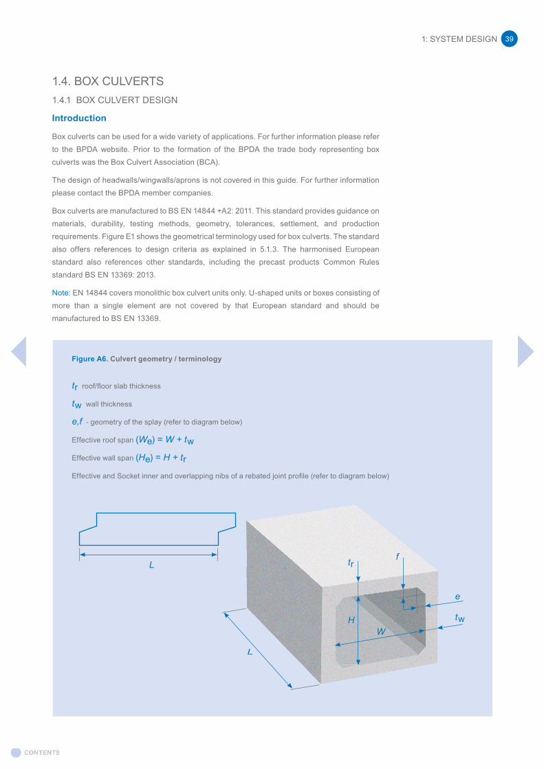
1: SYSTEM DESIGN 39
1.4. BOX CULVERTS1.4.1 BOX CULVERT DESIGN
Introduction
Box culverts can be used for a wide variety of applications. For further information please refer to the BPDA website. Prior to the formation of the BPDA the trade body representing box culverts was the Box Culvert Association (BCA).
The design of headwalls/wingwalls/aprons is not covered in this guide. For further information please contact the BPDA member companies.
Box culverts are manufactured to BS EN 14844 +A2: 2011. This standard provides guidance on materials, durability, testing methods, geometry, tolerances, settlement, and production requirements. Figure E1 shows the geometrical terminology used for box culverts. The standard also offers references to design criteria as explained in 5.1.3. The harmonised European standard also references other standards, including the precast products Common Rules standard BS EN 13369: 2013.
Note: EN 14844 covers monolithic box culvert units only. U-shaped units or boxes consisting of more than a single element are not covered by that European standard and should be manufactured to BS EN 13369.
Figure A6. Culvert geometry / terminology
tr roof/floor slab thickness
tw wall thickness
e,f - geometry of the splay (refer to diagram below)
Effective roof span (We) = W + tw
Effective wall span (He) = H + tr
Effective and Socket inner and overlapping nibs of a rebated joint profile (refer to diagram below)
L
L
HW
trf
e
tw
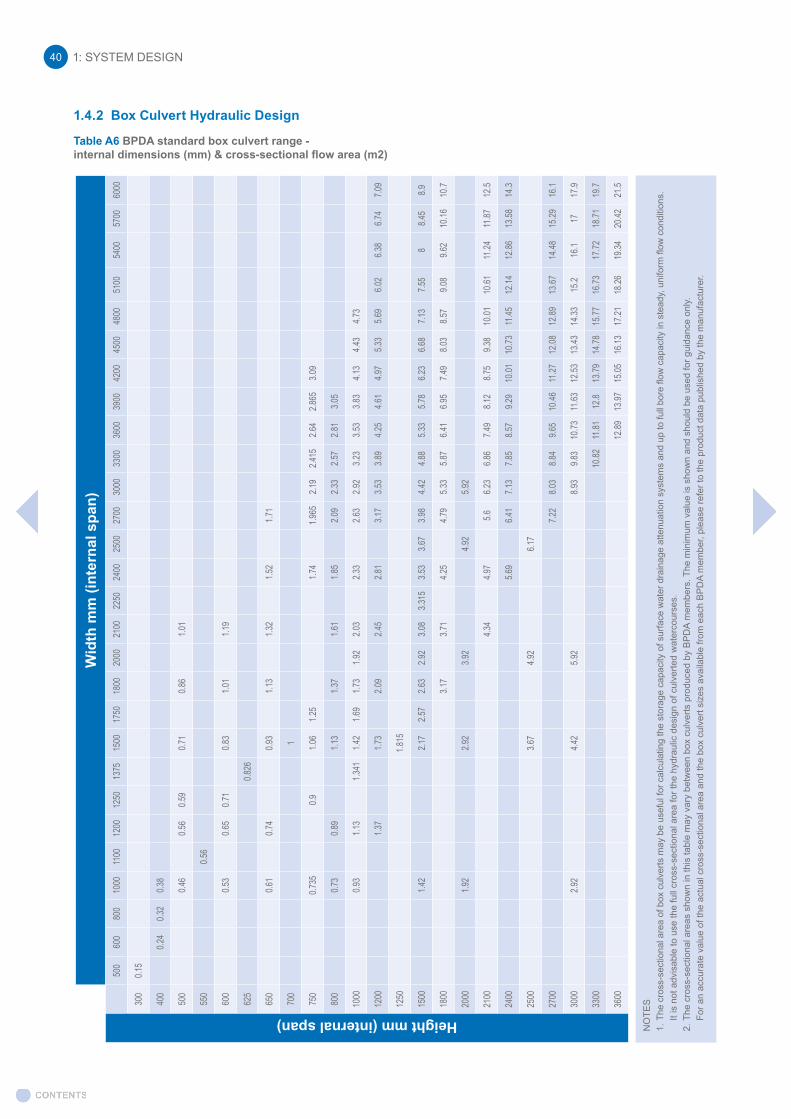
1: SYSTEM DESIGN40
Table A6 BPDA standard box culvert range -internal dimensions (mm) & cross-sectional flow area (m2)
1.4.2 Box Culvert Hydraulic Design
NO
TES
1.
The
cro
ss-s
ectio
nal a
rea
of b
ox c
ulve
rts m
ay b
e us
eful
for c
alcu
latin
g th
e st
orag
e ca
paci
ty o
f sur
face
wat
er d
rain
age
atte
nuat
ion
syst
ems
and
up to
full
bore
flow
cap
acity
in s
tead
y, u
nifo
rm fl
ow c
ondi
tions
.
It is
not
adv
isab
le to
use
the
full
cros
s-se
ctio
nal a
rea
for t
he h
ydra
ulic
des
ign
of c
ulve
rted
wat
erco
urse
s.2.
The
cro
ss-s
ectio
nal a
reas
sho
wn
in th
is ta
ble
may
var
y be
twee
n bo
x cu
lver
ts p
rodu
ced
by B
PD
A m
embe
rs. T
he m
inim
um v
alue
is s
how
n an
d sh
ould
be
used
for g
uida
nce
only.
For a
n ac
cura
te v
alue
of t
he a
ctua
l cro
ss-s
ectio
nal a
rea
and
the
box
culv
ert s
izes
ava
ilabl
e fro
m e
ach
BP
DA
mem
ber,
plea
se re
fer t
o th
e pr
oduc
t dat
a pu
blis
hed
by th
e m
anuf
actu
rer.
Wid
th m
m (i
nter
nal s
pan)
Height mm (internal span)50
060
080
010
0011
0012
0012
5013
7515
0017
5018
0020
0021
0022
5024
0025
0027
0030
0033
0036
0039
0042
0045
0048
0051
0054
0057
0060
00
300
0.15
400
0.24
0.32
0.38
500
0.46
0.56
0.59
0.71
0.86
1.01
550
0.56
600
0.53
0.65
0.71
0.83
1.01
1.19
625
0.826
650
0.61
0.74
0.93
1.13
1.32
1.52
1.71
700
1
750
0.735
0.91.0
61.2
51.7
41.9
652.1
92.4
152.6
42.8
653.0
9
800
0.73
0.89
1.13
1.37
1.61
1.85
2.09
2.33
2.57
2.81
3.05
1000
0.93
1.13
1.341
1.42
1.69
1.73
1.92
2.03
2.33
2.63
2.92
3.23
3.53
3.83
4.13
4.43
4.73
1200
1.37
1.73
2.09
2.45
2.81
3.17
3.53
3.89
4.25
4.61
4.97
5.33
5.69
6.02
6.38
6.74
7.09
1250
1.815
1500
1.42
2.17
2.57
2.63
2.92
3.08
3.315
3.53
3.67
3.98
4.42
4.88
5.33
5.78
6.23
6.68
7.13
7.55
88.4
58.9
1800
3.17
3.71
4.25
4.79
5.33
5.87
6.41
6.95
7.49
8.03
8.57
9.08
9.62
10.16
10.7
2000
1.92
2.92
3.92
4.92
5.92
2100
4.34
4.97
5.66.2
36.8
67.4
98.1
28.7
59.3
810
.0110
.6111
.2411
.8712
.5
2400
5.69
6.41
7.13
7.85
8.57
9.29
10.01
10.73
11.45
12.14
12.86
13.58
14.3
2500
3.67
4.92
6.17
2700
7.22
8.03
8.84
9.65
10.46
11.27
12.08
12.89
13.67
14.48
15.29
16.1
3000
2.92
4.42
5.92
8.93
9.83
10.73
11.63
12.53
13.43
14.33
15.2
16.1
1717
.9
3300
10.82
11.81
12.8
13.79
14.78
15.77
16.73
17.72
18.71
19.7
3600
12.89
13.97
15.05
16.13
17.21
18.26
19.34
20.42
21.5

Design principles
The overall scheme designer is responsible for the hydraulic design of a box culvert, taking into account all parameters relevant to the project.
For example: • conditions upstream and downstream of the culvert (before and after culvert construction)
• inlet and outlet hydraulic energy losses
• compound hydraulic roughness of culvert
• longitudinal flow profiles (such as backwater, headwater and tailwater depths), afflux and freeboard through the culvert during maximum design flows
• cross-section restriction due to sediment deposition
• benching for fish / mammal passage
• low flow channel provision
• safe access and screening requirements
• appropriate maintenance regime to ensure effective performance over asset lifetime
• flood routing in the event of a blockage
Example 5.A
It is proposed to build an access road over a stream using a highway culvert under the road. The culvert is required to carry a design flood of 4.0m3/s under free flow conditions with partial sedimentation. Normal flow conditions may be assumed and there are no hydraulic structures at the culvert site to consider. The bed slope So is gentle at 1:200 (i.e. 0.005m/m).
Design steps
i) Calculate the tailwater depth at the culvert for the design floodii) Check suitability of proposed culvert dimensions
Data references
• BPDA Table of Standard box culvert dimensions (see Table A6)• CIRIA Culvert design and operation guide (C689) Table A1.6 geometrical formulae
Manning’s equation for open channel flow
V = n-1R2/3So1/2
WhereV = mean velocity (m/s)R = hydraulic radius (m) = A/PA = cross-sectional area of flow (m2)P = wetted perimeter (m)So = slope of energy line (bed slope)n = coefficient of roughness (Manning’s n)
BPDA members can provide discharge capacities based on flows through the full cross-section of box culvert units, i.e. full-bore flow. In practice, this is likely to over-estimate the actual capacity of the culvert and may not represent the actual conditions.
The following example, based on CIRIA Culvert design and operation guide (C689) is provided to demonstrate the basic hydraulic design process for culverts. Users should acquire the full publication or seek alternative guidance in order to carry out their own hydraulic design for projects.
1: SYSTEM DESIGN 41
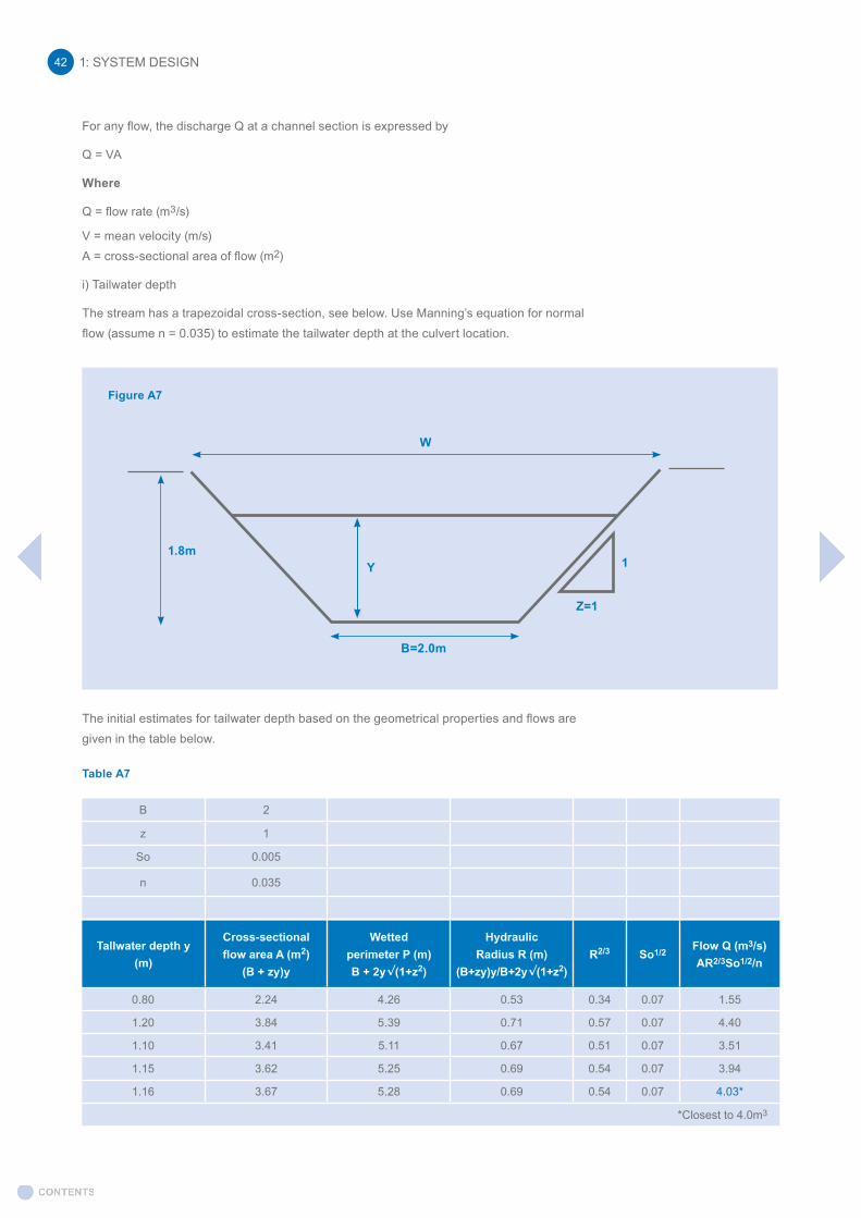
For any flow, the discharge Q at a channel section is expressed by
Q = VA
Where
Q = flow rate (m3/s)
V = mean velocity (m/s)A = cross-sectional area of flow (m2)
i) Tailwater depth
The stream has a trapezoidal cross-section, see below. Use Manning’s equation for normal flow (assume n = 0.035) to estimate the tailwater depth at the culvert location.
The initial estimates for tailwater depth based on the geometrical properties and flows are given in the table below.
Table A7
Tallwater depth y (m)
Cross-sectional flow area A (m2)
(B + zy)y
Wetted perimeter P (m) B + 2y√(1+z2)
Hydraulic Radius R (m)
(B+zy)y/B+2y√(1+z2)R2/3 So1/2 Flow Q (m3/s)
AR2/3So1/2/n
0.80 2.24 4.26 0.53 0.34 0.07 1.55
1.20 3.84 5.39 0.71 0.57 0.07 4.40
1.10 3.41 5.11 0.67 0.51 0.07 3.51
1.15 3.62 5.25 0.69 0.54 0.07 3.94
1.16 3.67 5.28 0.69 0.54 0.07 4.03*
*Closest to 4.0m3
B 2
z 1
So 0.005
n 0.035
1.8m1
W
Y
B=2.0m
Z=1
Figure A7
1: SYSTEM DESIGN42
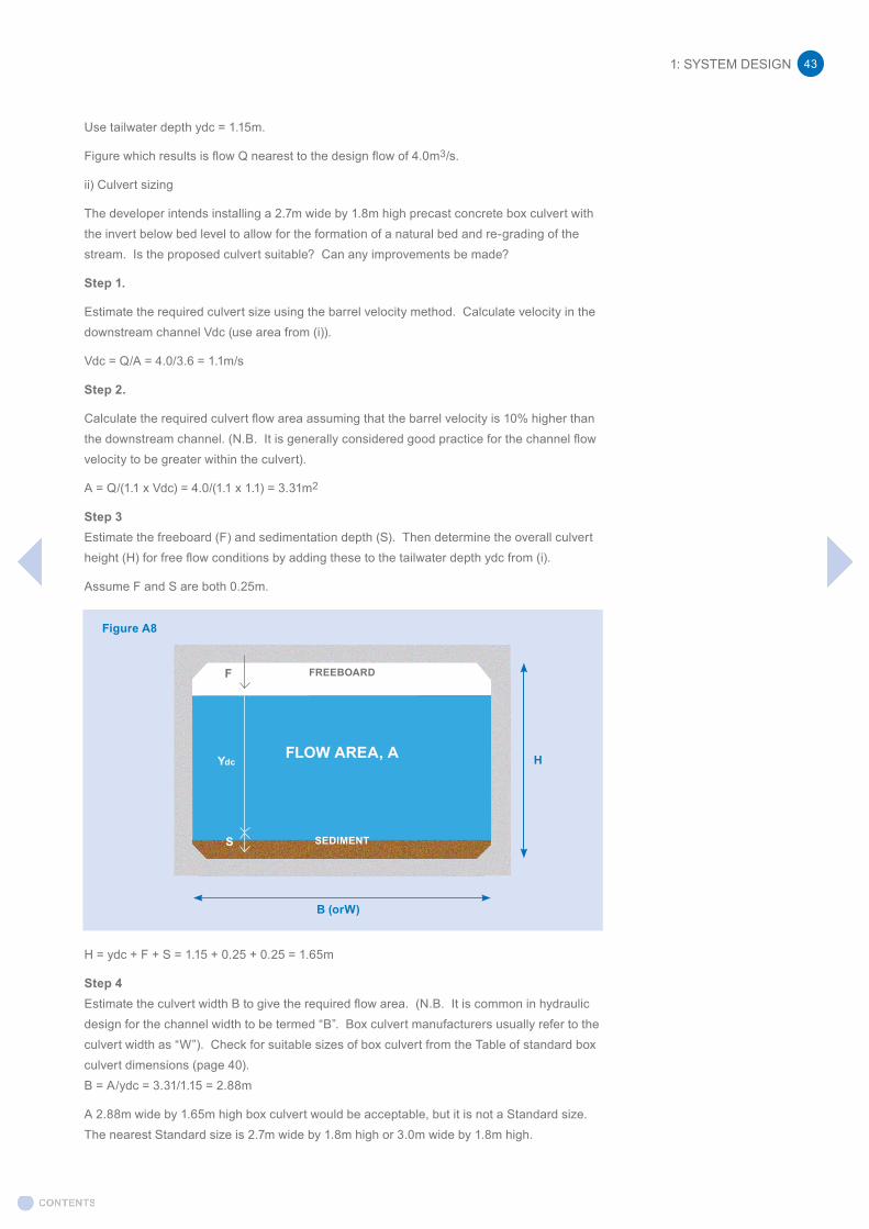
Use tailwater depth ydc = 1.15m.
Figure which results is flow Q nearest to the design flow of 4.0m3/s.
ii) Culvert sizing
The developer intends installing a 2.7m wide by 1.8m high precast concrete box culvert with the invert below bed level to allow for the formation of a natural bed and re-grading of the stream. Is the proposed culvert suitable? Can any improvements be made?
Step 1.
Estimate the required culvert size using the barrel velocity method. Calculate velocity in the downstream channel Vdc (use area from (i)).
Vdc = Q/A = 4.0/3.6 = 1.1m/s
Step 2.
Calculate the required culvert flow area assuming that the barrel velocity is 10% higher than the downstream channel. (N.B. It is generally considered good practice for the channel flow velocity to be greater within the culvert).
A = Q/(1.1 x Vdc) = 4.0/(1.1 x 1.1) = 3.31m2
Step 3Estimate the freeboard (F) and sedimentation depth (S). Then determine the overall culvert height (H) for free flow conditions by adding these to the tailwater depth ydc from (i).
Assume F and S are both 0.25m.
H = ydc + F + S = 1.15 + 0.25 + 0.25 = 1.65m
Step 4Estimate the culvert width B to give the required flow area. (N.B. It is common in hydraulic design for the channel width to be termed “B”. Box culvert manufacturers usually refer to the culvert width as “W”). Check for suitable sizes of box culvert from the Table of standard box culvert dimensions (page 40).B = A/ydc = 3.31/1.15 = 2.88m
A 2.88m wide by 1.65m high box culvert would be acceptable, but it is not a Standard size. The nearest Standard size is 2.7m wide by 1.8m high or 3.0m wide by 1.8m high.
SEDIMENTS
F
Ydc
FREEBOARD
FLOW AREA, A
B (orW)
H
Figure A8
1: SYSTEM DESIGN 43
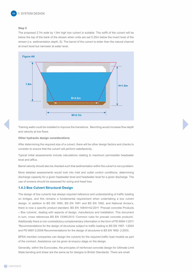
Step 5The proposed 2.7m wide by 1.8m high box culvert is suitable. The soffit of the culvert will be below the top of the bank of the stream when units are set 0.25m below the invert level of the stream (i.e. sedimentation depth, S). The barrel of the culvert is wider than the natural channel at invert level but narrower at water level.
Training walls could be installed to improve the transitions. Benching would increase flow depth and velocity at low flows.
Other hydraulic design considerations
After determining the required size of a culvert, there will be other design factors and checks to consider to ensure that the culvert will perform satisfactorily.
Typical initial assessments include calculations relating to maximum permissible headwater level and afflux.
Barrel velocity should also be checked such that sedimentation within the culvert is not a problem.
More detailed assessments would look into inlet and outlet control conditions, determining discharge capacity for a given headwater level and headwater level for a given discharge. The use of screens should be assessed for sizing and head loss.
1.4.3 Box Culvert Structural Design
The design of box culverts has always required reference and understanding of traffic loading on bridges, and this remains a fundamental requirement when undertaking a box culvert design. In addition to BS EN 1990, BS EN 1991 and BS EN 1992, and National Annex’s, there is now a specific product standard, BS EN 14844+A2:2011 ‘Precast concrete Products – Box culverts’, dealing with aspects of design, manufacture and installation. This document in turn, cross references BS EN 13369:2013 ‘Common rules for precast concrete products’. Additionally there is non-contradictory complementary information in the form of PD 6694-1:2011 ‘Recommendations for the design of structures subject to traffic loading to BS EN 1997- 1:2004 and PD 6687-2:2008 Recommendations for the design of structures to BS EN 1992- 2:2005.
BPDA member companies can design the culverts for the required traffic load models as part of the contract. Assistance can be given at enquiry stage on the design.
Generally, within the Eurocodes, the principles of reinforced concrete design for Ultimate Limit State bending and shear are the same as for designs to British Standards. There are small
W=2.7m
B=2.0m
1.8m H=1.8m
Figure A9
1: SYSTEM DESIGN44

Standard How the standard is used
BS EN 1991-2:2003 Eurocode 1:Actions on Structures - Part 2: Traffic Loads on Bridges
This document sets out the loading classes for road bridges and defines a series of Load Models (LM1-LM3),
• Load Model 1 - Concentrated and Distributed Load
• Load Model 2 - Single axle loads
• Load Model 3 - Loads for Special vehicles which includes types SV80, SV100 and SV196
• Load Model 4 - Crowd Loading (this load model is not used as the UDL value is less than the base UDL used in LM1)
Each Load Model describes a configuration of wheel loading to represent different wheeled vehicles. It is significant that the wheel loads within these models is now 150kN (LM1) and 200kN (LM2) & 165kN (LM3). This is compared to the previous wheel load of 30HB at 75kN.
The design is progressed, generally adopting the worst case effects of these Load Models. The loads are applied to the culvert structure by considering the zones of influence as described in PD 6694 (Fig 11). PD 6694 (Table 7), also defines the horizontal surcharge pressures to be applied to the structure.
Horizontal loads in terms of braking and acceleration forces are defined within the Eurocode, and these are applied in conjunction with the relevant vertical loads.
BS EN 1992-1-1:2004+A1:2014 – Eurocode 2:Design of concrete structures - Part 1-1: General rules and rules for buildings
Having established the appropriate applied loads, and from an analysis to determine the resultant bending moments and shear forces, the detailed concrete design is undertaken, in accordance with this document.
BS 8500-1:2015+A1:2016 – Concrete - Complementary
The performance of the culvert structure and its defined working life will be determined by defining a suitable concrete specification, and by adopting suitable cover to the reinforcement.
British Standard to BS EN 206-1, Part 1: method of specifying and guidance for the specifier
Section 4 of BS EN 1992-1 covers durability and cover requirements. The Exposure Classes are as EN 206-1, but in the UK BS BS8500-1 is adopted, to define a suitable concrete specification, taking account of corrosion due to carbonation (XC), chlorides (XD), sea water (XS), & freeze/thaw (XF). Generally, XD2 is adopted for buried highway structures more than 1.0m below an adjacent carriageway and XD3 for buried highway structures less than 1.0m below the carriageway level. For a structure that is not buried adjacent to a carriageway XD1 is adopted. The required concrete specification for XD3 is described by it’s a strength class C40/50 with an associated minimum cement content of 380kg/m3 and maximum water cement ratio of 0.35 when cement types IIB-V or IIIA are used. In some circumstance a client may request that the internal surface and external face are designed with different exposure classes.
differences in the allowable shear stresses but this does not significantly affect the design of box culvert units. However, the loadings now required by the BS EN 1991-2 are significantly greater than former British Standards. This results in the need to provide a structure with increased structural capacity.
1.4.4 Relevant Standards
There are documents which need to be consulted to achieve an appropriate and compliant design for a box culvert. It is essential that the initial design parameters are clearly defined at an early stage, to ensure the Client is provided with a product which meets their requirements.
1: SYSTEM DESIGN 45
Table A8. Standards used in the design of box culverts
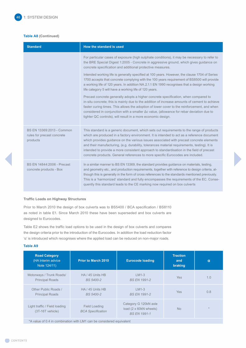
Standard How the standard is used
For particular cases of exposure (high sulphate conditions), it may be necessary to refer to the BRE Special Digest 1:2005 - Concrete in aggressive ground, which gives guidance on concrete specification and additional protective measures.
Intended working life is generally specified at 100 years. However, the clause 1704 of Series 1700 accepts that concrete complying with the 100 years requirement of BS8500 will provide a working life of 120 years. In addition NA.2.1.1 EN 1990 recognises that a design working life category 5 will have a working life of 120 years.
Precast concrete generally adopts a higher concrete specification, when compared to in-situ concrete; this is mainly due to the addition of increase amounts of cement to achieve faster curing times. This allows the adoption of lower cover to the reinforcement, and when considered in conjunction with a smaller Δc value, (allowance for rebar deviation due to tighter QC controls), will result in a more economic design.
BS EN 13369:2013 - Common rules for precast concrete products
This standard is a generic document, which sets out requirements to the range of products which are produced in a factory environment. It is intended to act as a reference document which provides guidance on the various issues associated with precast concrete elements and their manufacturing, (e.g. durability, tolerances material requirements, testing). It is intended to provide a more consistent approach to standardisation in the field of precast concrete products. General references to more specific Eurocodes are included.
BS EN 14844:2006 - Precast concrete products - Box
In a similar manner to BS EN 13369, the standard provides guidance on materials, testing, and geometry etc., and production requirements, together with reference to design criteria, al-though this is generally in the form of cross references to the standards mentioned previously. This is a ‘harmonized’ standard and fully encompasses the requirements of the EC. Conse-quently this standard leads to the CE marking now required on box culverts
Traffic Loads on Highway Structures
Prior to March 2010 the design of box culverts was to BS5400 / BCA specification / BS8110 as noted in table E1. Since March 2010 these have been superseded and box culverts are designed to Eurocodes.
Table E2 shows the traffic load options to be used in the design of box culverts and compares the design criteria prior to the introduction of the Eurocodes. In addition the load reduction factor ‘α’ is introduced which recognises where the applied load can be reduced on non-major roads.
Road Category(HA Interim advice
Note 124/11)Prior to March 2010 Eurocode loading
Traction and
brakingα
Motorways / Trunk Roads/Principal Roads
HA / 45 Units HB BS 5400-2
LM1-3BS EN 1991-2
Yes 1.0
Other Public Roads / Principal Roads
HA / 45 Units HB BS 5400-2
LM1-3BS EN 1991-2
Yes 0.8
Light traffic / Field loading(3T-16T vehicle)
Field LoadingBCA Specification
Category G 120kN axle load (2 x 60kN wheels)
BS EN 1991-1No *
*A value of 0.4 in combination with LM1 can be considered equivalent
1: SYSTEM DESIGN46
Table A8 (Continued)
Table A9
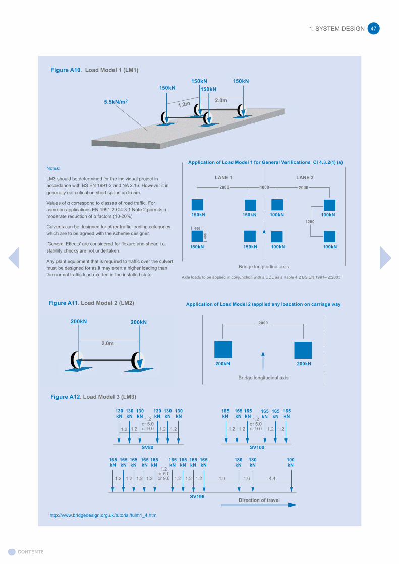
Direction of travelSV196
SV100SV80
Figure A10. Load Model 1 (LM1)
Figure A11. Load Model 2 (LM2)
Figure A12. Load Model 3 (LM3)
http://www.bridgedesign.org.uk/tutorial/tulm1_4.html
150kN
200kN 200kN
5.5kN/m2
150kN
130 kN
165 kN
165 kN
165 kN
165 kN
165 kN
165 kN
165 kN
165 kN
165 kN
180 kN
180 kN
100 kN
130 kN
130 kN
130 kN
130 kN
130 kN
165 kN
165 kN
165 kN
165 kN
165 kN
165 kN
150kN150kN
2.0m
2.0m
1.2 1.2 1.2 1.2 1.2 1.2 1.2 1.2
1.2 1.2 1.2 1.2 1.2 1.2 1.2 4.0
1.2or 5.0or 9.0
1.2or 5.0or 9.0
1.2or 5.0or 9.0 1.6 4.4
1.2m
100kN150kN150kN 100kN
100kN100kN150kN150kN
LANE 2LANE 1
Bridge longitudinal axis
Axle loads to be applied in conjunction with a UDL as a Table 4.2 BS EN 1991– 2:2003
Application of Load Model 1 for General Verifications CI 4.3.2(1) (a)
20002000 1000
1200400
400
200kN 200kN
2000
Bridge longitudinal axis
Application of Load Model 2 (applied any loacation on carriage way
Notes:
LM3 should be determined for the individual project in accordance with BS EN 1991-2 and NA 2.16. However it is generally not critical on short spans up to 5m.
Values of α correspond to classes of road traffic. For common applications EN 1991-2 Cl4.3.1 Note 2 permits a moderate reduction of α factors (10-20%)
Culverts can be designed for other traffic loading categories which are to be agreed with the scheme designer.
‘General Effects’ are considered for flexure and shear, i.e. stability checks are not undertaken.
Any plant equipment that is required to traffic over the culvert must be designed for as it may exert a higher loading than the normal traffic load exerted in the installed state.
1: SYSTEM DESIGN 47
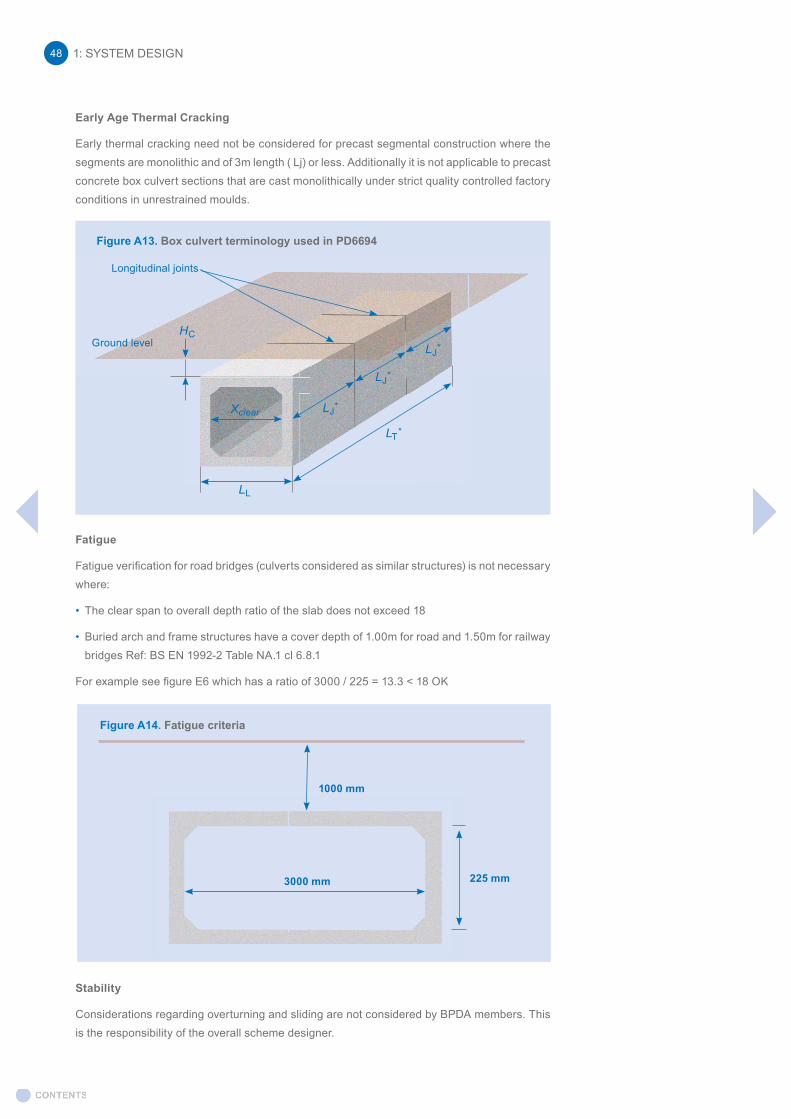
Early Age Thermal Cracking
Early thermal cracking need not be considered for precast segmental construction where the segments are monolithic and of 3m length ( Lj) or less. Additionally it is not applicable to precast concrete box culvert sections that are cast monolithically under strict quality controlled factory conditions in unrestrained moulds.
Fatigue
Fatigue verification for road bridges (culverts considered as similar structures) is not necessary where:
• The clear span to overall depth ratio of the slab does not exceed 18
• Buried arch and frame structures have a cover depth of 1.00m for road and 1.50m for railway bridges Ref: BS EN 1992-2 Table NA.1 cl 6.8.1
For example see figure E6 which has a ratio of 3000 / 225 = 13.3 < 18 OK
Stability
Considerations regarding overturning and sliding are not considered by BPDA members. This is the responsibility of the overall scheme designer.
Figure A14. Fatigue criteria
3000 mm
1000 mm
225 mm
Xclear LJ*
LJ*
LJ*
LL
LT*
HCGround level
Longitudinal joints
Figure A13. Box culvert terminology used in PD6694
1: SYSTEM DESIGN48

2 - INSTALLATION: PIPESThis section describes the recommended procedure for the installation of concrete pipelines in trenches for non-pressure (gravity) applications or when occasional periods of hydraulic surcharge may occur. It covers the types of laying conditions most commonly encountered in practice. In situations beyond these general conditions, the pipeline designer and the site engineer should give suitable instructions to supplement this guidance.
Pipelines laid under embankments require special consideration whilst those installed by pipe jacking require the use of specialised techniques.
2.1 Planning
General
Prior to constructing the pipeline, the contractor will need to organise the work from the contract documents, specification, drawings and bill of quantities.
The line and level of the sewer, any side connections and the positions of the manholes will have been determined at the design stage but some flexibility in construction should be permitted to cater for circumstances such as foundations or buried services not shown on the drawings. An agreed re-siting of a manhole may save time and additional expense.
Sequence of operations
a) Plan and set out the work including location of manholes.
b) Receive, check against specification and store deliveries of materials on site.
c) Excavate trench and install trench support system.
d) Lay bedding material forming socket holes as appropriate.
e) Check for damage, lay and joint pipes, air testing every third or fourth pipe as laying proceeds. Check line and level.
f) Place and compact sidefills with bedding or selected materials.
g) Continue placing and compacting sidefills withdrawing trench sheeting in stages.
h) Place initial backfill above pipe continuing withdrawal of sheeting.
i) Air and/or water test or inspect visually prior to final backfill.
j) Complete backfill, compacting as appropriate.
k) Final acceptance, air and/or water test or inspection.
l) Reinstatement of surface as appropriate
2.2 Handling and storage
Lifting equipment
Time and place of off-loading should be agreed before units arrive on site. The contractor should have suitable equipment for off-loading, stacking and stringing out pipes and other units on site.
All lifting tackle must be of good sound construction and should be regularly tested and certificated.
Off-loading
Whenever possible, pipes and other units should be off-loaded in the reverse order that they were loaded. The vehicle must not be moved if any part of the load is unsecured. Off-loading
2: INSTALLATION - PIPES 49

should take place at the nearest hard standing to the point of installation; all units must be left in a stable position well clear of the edge of the trench.
For further information, refer to the BPDA Health & Safety Off-loading Guide http://www.precastdrainage.co.uk/page/pipe-laying-lifting
BPDA member companies are also available to advise on general handling of products and appropriate lifting equipment. Member companies contact details can be found here: http://www.precastdrainage.co.uk/suppliers
Use of tackle
Where provided, lifting holes, anchors etc. must be used with the correct equipment to lift the units (note - installed lifting points may not necessarily be suitable for the transportation of a product across a site).
Pipes
Pipes should be handled individually using a properly designed “C” hook, beam sling or other purpose-designed system. Small diameter pipes may be slung through the bore providing the sling is sleeved and protected around the joint. This is important in order to avoid damage to jointing surfaces and consequent leakage of the laid pipe. ‘Pipe hooks’ must not be used. Slings may be made of cordage, canvas, or man-made fibres, but not chains.
Many manufacturers offer a combined lifting and jointing system using a three-legged chain and cast-in facilities (larger pipe sizes only). A special concrete pipe lifter is also available providing improved site safety, reduced installation time, labour and cost savings. Further details relating to the concrete pipe lifter and other proprietary lifting devices can be found in the BPDA Site Guide, available at www.precastdrainage.co.uk and directly from BPDA members.
How to Use
• Perform appropriate pre-work checks to ensure all equipment is working properly and has valid operating certificates, where required.
• Connect Pipe Lifter to excavator via quick hitch coupling, ensuring correctly attached and locked in position.
• Fully insert the long lifting arm horizontally into the barrel of the pipe and carefully raise to make contact with the internal crown. When installing pipes, ensure it is lifted from the socket end.
• The clamp arm will slowly press down onto the top of the pipe and hold it in position.
• The pipe may now be lifted and transferred to a suitable storage location or placed into the prepared trench and jointed following the application of an approved joint lubricant to the pipe
The Concrete Pipe Lifter is designed to improve site safety and increase efficiency during the lifting and installation of precast concrete pipes.It is connected to an excavator via a quick hitch attachment.www.concretepipelifter.co.uk
2: INSTALLATION - PIPES50
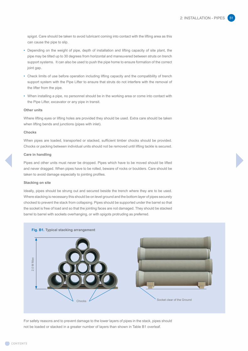
spigot. Care should be taken to avoid lubricant coming into contact with the lifting area as this can cause the pipe to slip.
• Depending on the weight of pipe, depth of installation and lifting capacity of site plant, the pipe may be tilted up to 30 degrees from horizontal and maneuvered between struts on trench support systems. It can also be used to push the pipe home to ensure formation of the correct joint gap.
• Check limits of use before operation including lifting capacity and the compatibility of trench support system with the Pipe Lifter to ensure that struts do not interfere with the removal of the lifter from the pipe.
• When installing a pipe, no personnel should be in the working area or come into contact with the Pipe Lifter, excavator or any pipe in transit.
Other units
Where lifting eyes or lifting holes are provided they should be used. Extra care should be taken when lifting bends and junctions (pipes with inlet).
Chocks
When pipes are loaded, transported or stacked, sufficient timber chocks should be provided. Chocks or packing between individual units should not be removed until lifting tackle is secured.
Care in handling
Pipes and other units must never be dropped. Pipes which have to be moved should be lifted and never dragged. When pipes have to be rolled, beware of rocks or boulders. Care should be taken to avoid damage especially to jointing profiles.
Stacking on site
Ideally, pipes should be strung out and secured beside the trench where they are to be used. Where stacking is necessary this should be on level ground and the bottom layer of pipes securely chocked to prevent the stack from collapsing. Pipes should be supported under the barrel so that the socket is free of load and so that the jointing faces are not damaged. They should be stacked barrel to barrel with sockets overhanging, or with spigots protruding as preferred.
For safety reasons and to prevent damage to the lower layers of pipes in the stack, pipes should not be loaded or stacked in a greater number of layers than shown in Table B1 overleaf.
Fig. B1. Typical stacking arrangement
Socket clear of the GroundChocks
2.0
M M
ax
2: INSTALLATION - PIPES 51
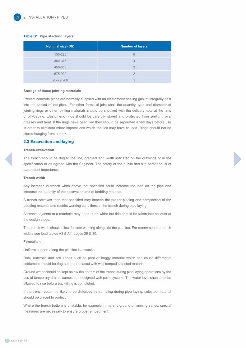
Table B1. Pipe stacking layers
Nominal size (DN) Number of layers
150-225 6
300-375 4
450-600 3
675-900 2
above 900 1
Storage of loose jointing materials
Precast concrete pipes are normally supplied with an elastomeric sealing gasket integrally-cast into the socket of the pipe. For other forms of joint seal, the quantity, type and diameter of jointing rings or other jointing materials should be checked with the delivery note at the time of off-loading. Elastomeric rings should be carefully stored and protected from sunlight, oils, greases and heat. If the rings have been tied they should be separated a few days before use in order to eliminate minor impressions which the ties may have caused. Rings should not be stored hanging from a hook.
2.3 Excavation and laying
Trench excavation
The trench should be dug to the line, gradient and width indicated on the drawings or in the specification or as agreed with the Engineer. The safety of the public and site personnel is of paramount importance.
Trench width
Any increase in trench width above that specified could increase the load on the pipe and increase the quantity of the excavation and of bedding material.
A trench narrower than that specified may impede the proper placing and compaction of the bedding material and restrict working conditions in the trench during pipe laying.
A trench adjacent to a manhole may need to be wider but this should be taken into account at the design stage.
The trench width should allow for safe working alongside the pipeline. For recommended trench widths see load tables A3 & A4, pages 29 & 30.
Formation
Uniform support along the pipeline is essential.
Rock outcrops and soft zones such as peat or boggy material which can cause differential settlement should be dug out and replaced with well tamped selected material.
Ground water should be kept below the bottom of the trench during pipe laying operations by the use of temporary drains, sumps or a designed well-point system. The water level should not be allowed to rise before backfilling is completed.
If the trench bottom is likely to be disturbed by trampling during pipe laying, selected material should be placed to protect it.
Where the trench bottom is unstable, for example in marshy ground or running sands, special measures are necessary to ensure proper embedment.
2: INSTALLATION - PIPES52

A trench excavated in clay should not be kept open any longer than necessary to avoid instability due to change in moisture content.
Pipe laying
Before lowering into the trench, each unit should be inspected carefully for any damage which may have occurred in transit or during handling and storage on site. Pay special attention to jointing surfaces. Units should be lowered carefully into the trench with tackle suitable for their weight and for the depth of the trench.
The contractor should have available, at the required time, all material and equipment necessary for carrying out the work in accordance with the specification and statutory safety requirements.
The contractor must ensure that the size and strength class of pipes or other units conform to the contract specifications and manufacturer’s recommendations. In the case of integrated seals, the joint must be prepared i.e. the application of the correct lubricant and the removal of the seal positioning strip (where present).
Normal gradients
Pipes should be supported by the bedding over the length of their barrels and their weight must never be carried by the sockets or by bricks and rocks in the trench bottom. Bedding under the pipe should be scooped out to accommodate pipe sockets at each joint. The pipes should be laid and assembled in correct alignment.
If, in order to curve the pipeline it is necessary to deflect the pipes at the joints, the deflection should be applied only after the joint has been made in the normal manner and should be limited to 75% of the manufacturer’s recommended limits to allow for any subsequent movement.
Mechanical plant must not be used to press pipes down to their correct level.
Changing direction
Change in direction, either horizontal or vertical, should be made at a manhole or by means of a precast bend unit.
Passing through rigid structures
For a pipeline connection to a manhole or passing through a wall it is essential that the pipeline joint retains its flexibility. This may be achieved by casting a short length of pipe into the wall of the structure and providing a flexible joint adjacent to the wall. Depending on ground conditions, short length pipes (rockers) should be used (see Section 1.3.6).
Unstable ground
In unstable ground an appropriate installation method should be determined. The following possibilities should be taken into account:
• Use of short lengths of pipe.
• Use of continuous support on pile caps/beams.
• Special preparation of trench bottom.
• Trenchless methods of construction such as pipe jacking or heading.
Passing under highways or railways
If disruption of traffic is to be avoided, pipes should be installed by jacking or in heading.
2: INSTALLATION - PIPES 53

2.4 Jointing
A number of different joint designs are manufactured, all of which comply with the performance requirements of BS EN 1916 and BS 5911-1.
The pipe manufacturer’s jointing instructions should be complied with but the basic requirements for jointing concrete pipes are:
• Pipes should always be handled in a way to avoid damage, especially the spigot and socket ends and joint surfaces.
• Prior to jointing, the socket and spigot should be cleaned and inspected to ensure they are in good condition.
• Most standard concrete pipes are supplied with an elastomeric seal integrally cast into the socket of the pipe
For Integrated Seal Joints
• Remove the protective polystyrene strip (where present) by using the tape provided. Grip the tab of the tape and pull firmly towards the centre of the pipe. Residual polystyrene in the rear corner of the socket is acceptable but the area behind the seal must be clear.
• Lubricant should be applied to the spigot end of the pipe, ensuring the radius area and entire length of the spigot is covered. Additional lubrication may be also applied to the seal face to assist jointing.
• Only use lubricant as recommended/supplied by the manufacturer.
• Enter the spigot carefully into the socket, ensuring that the pipes are correctly aligned.
• Always follow the manufacturer’s instructions.
For Spigot Seal Joints (Rolling and Sliding Seals)
• Stretch and position the seal onto the spigot of the pipe ensuring it is not twisted. Even out the stretch by lifting and releasing at several points around the spigot.
• The seal should be located on the spigot in accordance with the manufacturer’s instructions.
• Rolling seal joints do not require lubrication. Most sliding seal are internally pre-lubricated and do not require additional lubrication. If the joint design does require lubrication then follow the manufacturer’s instructions.
• With rolling ring joints, offer up the pipe spigot to the socket, but keep clear of engagement by 25mm so that the joint ring is not disturbed. With sliding ring joints, the joint ring should be just in contact with the socket.
• Enter the spigot carefully into the socket, ensuring that the gasket is correctly positioned and that the pipes are correctly aligned.
• Always follow the manufacturer’s instructions.
• Jointing tackle or chain systems should be used in accordance with the pipe manufacturer’s instructions.
• Fully support the pipe so that it does not exert undue weight on the seal whilst closing the joint to the recommended joint gap.
• Joint the pipes in accordance with the manufacturer’s recommendations, making sure that the pipe moves without excessive slew or misalignment, that extraneous matter does not enter the joint and that the joint is not damaged and correctly positioned. For jointing bends, special procedures may be appropriate.
2: INSTALLATION - PIPES54
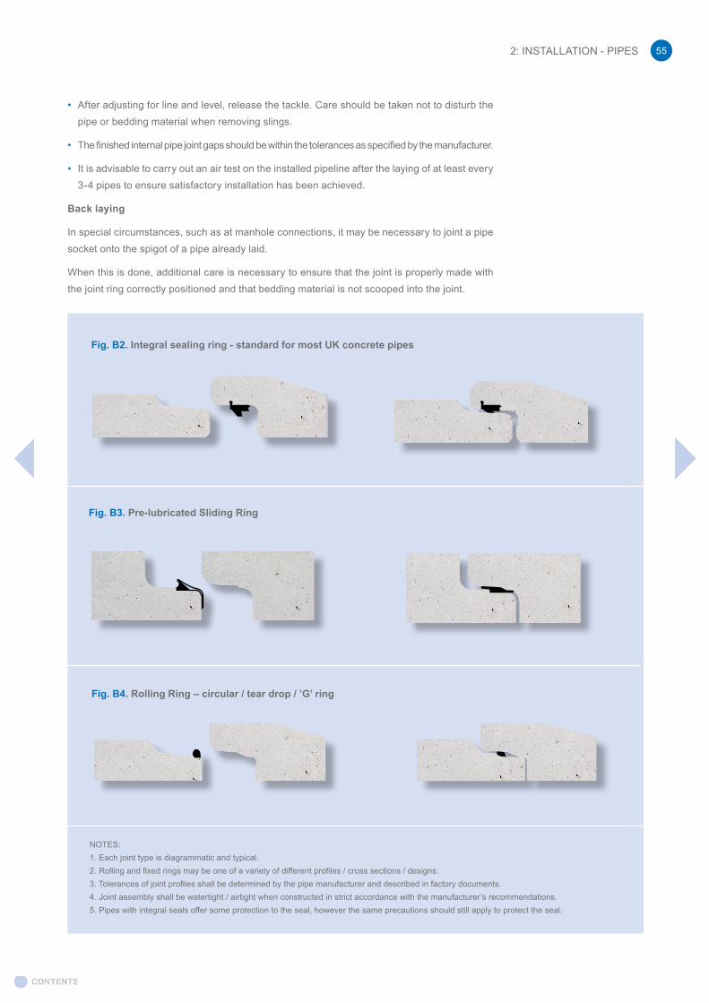
• After adjusting for line and level, release the tackle. Care should be taken not to disturb the pipe or bedding material when removing slings.
• The finished internal pipe joint gaps should be within the tolerances as specified by the manufacturer.
• It is advisable to carry out an air test on the installed pipeline after the laying of at least every 3-4 pipes to ensure satisfactory installation has been achieved.
Back laying
In special circumstances, such as at manhole connections, it may be necessary to joint a pipe socket onto the spigot of a pipe already laid.
When this is done, additional care is necessary to ensure that the joint is properly made with the joint ring correctly positioned and that bedding material is not scooped into the joint.
NOTES: 1. Each joint type is diagrammatic and typical.2. Rolling and fixed rings may be one of a variety of different profiles / cross sections / designs.3. Tolerances of joint profiles shall be determined by the pipe manufacturer and described in factory documents.4. Joint assembly shall be watertight / airtight when constructed in strict accordance with the manufacturer’s recommendations.5. Pipes with integral seals offer some protection to the seal, however the same precautions should still apply to protect the seal.
Fig. B2. Integral sealing ring - standard for most UK concrete pipes
Fig. B3. Pre-lubricated Sliding Ring
Fig. B4. Rolling Ring – circular / tear drop / ’G’ ring
2: INSTALLATION - PIPES 55

2.5 Reinstatement
Trench reinstatementAfter inspection and testing, backfilling should proceed whilst withdrawing trench sheeting in stages where practicable.
The sidefill is of great importance and close attention to its selection, placing and compaction will protect a new pipeline.
Good trenching practice including controlled removal of temporary supports and compaction of backfilling as described above not only protects the pipeline but will also reduce settlement and the risk of damage to adjacent underground services or structures.
The trench should be backfilled as soon as possible after the pipes are laid bearing in mind any specified test and inspection requirements. Compaction of the envelope of material immediately around the pipe is extremely important. In trench installations, as space is limited, mechanical compactors are commonly used but caution should be exercised so as not to damage or displace the pipe. The material should be compacted at near optimum moisture content and should be brought up evenly in layers on both sides of the pipe, withdrawing trench sheeting as backfill proceeds. Backfill material should not be pushed into the trench from the surface nor dropped in bulk directly onto the pipe.
Heavy mechanical equipment should not be allowed to traverse pipelines with limited cover except at prepared crossing places.
Fill material
Material for sidefill, initial and final backfill should be similar in character to the surrounding soil; for example, the use of single size granular material in clay soil will create a natural drainage channel that could cause subsequent settlement.
Sidefill and initial backfill should be free from large stones, heavy lumps of clay, frozen soil, tree roots and other rubbish, and should be readily compactable.
Sidefill
The sidefill should be placed and compacted as soon as possible after laying, or as soon as it is safe to do so without damaging concrete beddings. Compaction should be carried out evenly on each side of the pipe to prevent lateral or vertical displacement.
Initial backfill
This should also be placed as soon as possible in order to provide protective cover of not less than 300mm compacted depth. This should consist of bedding or selected material placed carefully and evenly over the top of the pipe and lightly compacted by hand.
Removal of trench supports
As backfilling proceeds, trench sheeting should be removed as soon as it is both safe and practicable to do so.
Remaining backfill
This should be placed evenly in layers and compacted as appropriate.
2.6 Testing
Acceptance tests on the completed pipeline give an indication of the level of control of workmanship and materials during construction.
2: INSTALLATION - PIPES56

Visual inspection
Man entry sized pipelines can be physically inspected whilst smaller diameters can be visually inspected from manholes or by means of CCTV cameras.
Air and water tests
All lengths of drain and sewer up to DN 750 should be tested for leakage by means of air or water tests.
These tests should be carried out after laying and before backfilling. Some backfill may be placed at the centre of each pipe to prevent movement during testing. Short branch drains connected to a main sewer between manholes should be tested as one system with the main sewer. Long branches should be separately tested.
Air Test
The air test is more convenient than the water test, but the leakage rate cannot be measured accurately. An excessive drop in pressure in the air test may indicate a fault in the line such as a displaced sealing ring or it may be due to faults in the testing apparatus. Therefore, the first check must be on the apparatus, especially the seals of the stop ends and all connections.
The point of a leakage may be difficult to detect but spraying with soap solution could indicate such leakage by the presence of bubbles.
Failure to pass this test is not conclusive. When marginal failure does occur, a water test should be performed and the leakage rate determined before a decision on rejection is made.
Air test requirements are specified in ‘Civil Engineering Specification for the Water Industry’.
It is strongly recommended that inflatable stoppers are used for air testing.
A successful test is achieved if the equipment shows a fall in pressure of no more than 25mm after 5 minutes, having allowed a suitable period for stabilisation.
If the pressure falls sharply and the pipes appear to have failed, check the test equipment is in good condition, that the stoppers are not leaking (use industrial soap around the edge of the stopper to provide an effective seal if necessary) and check the joint rings are correctly located or re-test after allowing temperature to settle.
A video on how to air test concrete pipelines is available at the BPDA channel in Youtube:Link: https://www.youtube.com/watch?v=UdohjdbKP0o
Check for: -
a) Obstructions and debris. c) Joints properly sealed.
b) Structural soundness of pipes. d) Line and level within tolerance.
2: INSTALLATION - PIPES 57

Water Test
A water test is the more conclusive method of testing a completed pipeline but problems of availability and disposal of the quantity of water involved may cause difficulty. Before backfilling, leakage can be clearly located, its amount assessed and where necessary, appropriate remedies applied.
To test the pipeline:
a) Insert plugs in both ends of the drain or sewer and in connections if necessary. Precautions should be taken by strutting or otherwise, to prevent any movement of the drain or sewer during testing.
b) Fill the system with water ensuring all the air has been expelled.
c) Allow at least two hours before test readings are taken to permit conditions to stabilize, adding water to maintain test head.
It may be necessary to extend this period for large diameter pipes, up to twenty-four hours or more before a stable condition is reached.
d) Apply required test head at the upper end by means of a flexible pipe leading from a graduated container or stand pipe.
e) Apply the test pressure of 1.2m head of water above the soffit of the drain or sewer at the high end with a maximum of 6m head at the low end. If this exceeds 6m test the drain or sewer in stages.
f) Measure the loss of water over a period of 30 minutes by adding and metering quantities of water at intervals of 5 minutes to maintain original water level in the standpipe.
Over this 30 minute period, the quantity of water added should not exceed 0.05 litre per 100 linear metres per millimetre of nominal size of the drain or sewer.
Over this 30 minute period, the quantity of water added should not exceed 0.05 litre per 100 linear metres per millimetre of nominal size of the drain or sewer. For example:
For a 150m length of DN 800 pipe the allowable leakage would be:
0.05 X 150 X 800 = 60 litres 100
Should the pipeline not comply with these requirements it will probably be attributable to one of the following:-
a) Leakage from test equipment.
b) Trapped air.
c) Leakage from joints, e.g. displaced ring.
d) Leakage from damaged or defective pipe.
2.7 Jetting
A jetting resistance of 12 MPa (120 bar) using a moving nozzle and/or 28 MPa (280 bar) using a stationary nozzle can be assumed acceptable for use on precast concrete drainage systems.
2: INSTALLATION - PIPES58
3: INSTALLATION - JACKING PIPES3.1 Introduction
The installation of pipelines for drainage purposes has traditionally been carried out using open-cut trenches in both urban and rural locations. However, in recent years an increasing proportion of pipeline construction projects have utilized pipe jacking or the form of the miniaturized tunneling technique known as microtunneling.
The basic pipe jacking method has been used in various forms for centuries but only in the past decades have we seen significant advances in equipment and technology.
This has raised confidence in the technique and numerous successful pipeline engineering schemes have used pipe jacking and microtunneling.
Normally, for pipelines constructed in this manner up to DN 900 the technique is referred to as microtunneling and above this as pipe jacking, but the principle remains the same.
3.2 Technique and equipment
The pipe jacking or microtunneling method consists of the construction of a number of excavated shafts from which a tunneling shield is launched and behind which a succession of smooth-walled concrete pipes are jacked. When the shield reaches the destination or reception shaft, it is either re-launched in a different direction or removed to another location and the process repeated. The excavated drive and reception shafts are usually converted to finished manholes once pipeline installation is complete.
Spoil excavated by the rotating cutting head in the front of the shield is removed by an auger flight or by mixing with water and pumping to the ground surface for treatment and disposal. Some progress has been made with the development of machines which can compact soil to the sides of the shield as it advances. Other equipment types use vacuum systems for the removal of excavated material to the surface.
Particularly high levels of installation accuracy can be achieved with these systems since they use sophisticated steering and guidance methods based on laser technology and optional automatic computer control. Finished bores have frequently been described “like rifle barrels”. Equipment has been developed which can install pipes in small diameters down to DN150 for house connections and lateral drains without the need for a trench.
3.3 Advantages
The advantage of using a trenchless method can be substantial. Any attempt to dig up long trenches within an urban area often results in severe disruption, delays and diversions to traffic, environmental pollution through noise, dust and dirt, loss of profit for local businesses, damage to properties or other buried pipes and cables and so on. These items are usually referred to as social costs and are nearly always absorbed by the community rather than paid as direct engineering costs.
However, when one considers further, other equally serious problems become apparent. Sometimes, the as-dug material excavated from the trench is not suitable for re-use as backfill. This waste spoil must be transported away from the area and disposed at a suitable landfill site. Such sites are becoming more difficult to find and the cost of using them is increasing. Also, new backfill material such as crushed stone has to be imported to the site and these operations usually involve heavy wagons inflicting damage to roads and using fuel which in turn produces more pollution. These environmental costs are compounded by the damage and visual impact to the countryside from landfill and quarrying sites.
3: INSTALLATION - JACKING PIPES 59

Pipe jacking and microtunneling can dramatically reduce many of these social and environmental problems. The technique offers significant benefits in reduced excavation since they only require relatively small launch and reception shafts for the tunneling equipment. Streets and roadways can often be kept open to traffic with little hindrance or disruption. The environment in general benefits from a no-dig approach because far less transportation of trench reinstatement materials is required, normally limited to only the displaced spoil from the pipes and manholes.
Reduced levels of reinstatement lead to cost savings, as much of the cost of a pipeline scheme is in the excavation and subsequent reinstatement. Installation depths of up to 35m have successfully been achieved which would not have been possible with open cut methods.
3.4 Products
The UK concrete pipe manufacturing industry is playing a leading role in the advancement of trenchless techniques. Several BPDA member companies produce jacking and microtunnelling pipes in a range of sizes. These pipes are manufactured to produce accurate joint surfaces with square faces and a strong high density concrete with a smooth surface finish to assist in reducing jacking forces.
Jacking and microtunneling pipes are available in sizes from DN 450 up to DN 2500 and utilise elastomeric seals in a steel banded joint. These pipes are manufactured to comply with the requirements of European Standard EN 1916:2002 and the UK complementary standard BS 5911-1:2002. The external surface of the pipeline is smooth for easy insertion through the ground during installation. For steel banded joints, both mild and stainless steel are available. Jacking pipes can be supplied with grout holes and cast-in lifting sockets as required.
Other products for use with this trenchless method include caisson sections in sizes from DN 2000 to DN4000 complete with base sections fitted with cutting shoe. Also produced are lead pipes which are rebated to accommodate the tunneling shield and interjack pipes (leading and trailing pipes in pairs) for use with intermediate jacking stations.
3.5 Further information
More information on the pipe jacking and microtunnelling method can be found in the publications of the Pipe Jacking Association (PJA) http://www.pipejacking.org/publications.
The United Kingdom Society for Trenchless Technology (UKSTT) is another useful source of information on trenchless techniques including pipe jacking.
3: INSTALLATION - JACKING PIPES60
4: INSTALLATION - MANHOLESManholes may be installed using fresh concrete to construct the base, channels and benching in-situ or by using a precast base system where units are manufactured and delivered to site with predetermined positions for connecting pipework using flexible, watertight elastomeric joints.
4.1 Planning
Sequence of operations
a) Place the bottom unit with either integral precast or in-situ concrete base.
b) Erect the required number of standard components and seal the joints as appropriate in accordance with the design/chosen method of construction.
c) Place a precast reinforced concrete cover slab on top.
d) If required, place a corbel slab then add the appropriate number of adjusting units.
e) Fit the access cover and frame.
4.2 Handling and storage
1) Chamber rings may be supplied with lifting holes for the use with specialist lifting pins and chain/sling sets. Alternatively they may have pins cast into them for use with universal head-links and chain/sling sets.
2) Cover, landing and reducing slabs are usually cast with anchors allowing the use of hook and chain/sling sets.
Note: Apparatus used for lifting, may not necessary be suitable for the transporting of products across a site.
Other lifting methods may be available or available to order – check with manufacture for full details.
All products should be lifted individually.
Chamber rings must not be lifted by attaching lifting equipment to steps.
Chamber rings should be stored ‘chimney’ fashion i.e. not on their side, or rolled.
Chamber rings and all types of slabs should be stacked on level and stable ground and on timbers wherever possible.
4.3 Construction
To ensure that the manhole structure is vertical, accurate levelling of the formation for the precast base unit or the in-situ concrete foundation is essential. The depths of precast manhole components are nominal and therefore subject to manufacturing tolerance; this, along with the formation of joints, should be considered during the setting out process.
Normal considerations should be taken into account when assessing the suitability of the formation. Units should be laid on a prepared level foundation of adequate bearing capacity
The manhole can be built of either;-
-15-20mm graded, 14mm or 20mm single-sized, suitably compacted aggregate to provide a level base with a minimum depth of 150mm, with an additional blinding layer of fine material where required to account for unevenness or any other environmental factors.
- 150mm deep GEN 1(C8/10) concrete. The base unit should be placed whilst concrete is wet so it can be set level. Where the concrete has already cured, a levelling screed with a minimum
4: INSTALLATION - MANHOLES 61
depth of 15mm-50mm sand/cement will be required between the foundation and the unit to prevent point loading.
Note: Normally, a granular bedding is recommended where the safe ground bearing pressure >200kN/m2. In poor or wet ground conditions a concrete pad is advised. The manufacturer of the manholes can advise where required.
Shaft and chamber sections with tongued and grooved joints should be installed with the socket / groove facing upwards, whereas units with ogee joints should have the spigot upwards. Precast cover slabs can be installed onto the shaft or chamber rings (with appropriate mastic, mortar or seal). Suitable cover and frame can then be bedded on adjusting units to achieve the finished level required.
Note that the distance from ground level to the first step in the manhole is usually specified as not to exceed 675mm (where units are fitted with step or ladder system)
Jointing to pipeline
To allow for differential settlement between manhole and pipeline, short “butt” pipes, either spigot or socket, should be built into the wall of manholes constructed with an in-situ concrete base and a flexible joint incorporated as close as possible to the outside of the manhole wall or concrete surround, if used.
Depending on ground conditions, short length pipes (rockers) then connect the butt pipes to the incoming pipe runs. Additional care must be taken to ensure that the joints are properly made.
4.4 Jointing
Precast manhole components are provided with joints formed within the wall section (see typical figures below) and are sealed with proprietary mastic seals, sand / cement mortar, or with elastomeric joints. Precast concrete manhole units, well jointed, provide an adequate seal under normal conditions. Any lifting holes will need to be sealed with sand / cement mortar or a proprietary non-shrink mortar.
Joint strips typically have a thickness of 12mm and are offered in one or two layers as demonstrated in the table below.
Fig. D1. Examples of Manhole Joints
a) Cover, Landing and reducing slab joints
1 or 2 strips
1 or 2 strips
(DN675-1200) (DN 1350-3000)
4: INSTALLATION - MANHOLES62
Fig. D1 cont. Examples of Manhole Joints
Reducing slab, shaft and chamber joint Other joints
b) Tongue and groove
1 or 2 strips
c) Ogee d) Landing platform joint
4.5 Reinstatement
In-situ concrete surround
In-situ concrete surround to precast concrete manholes, except for side-entry manholes, is unnecessary other than for exceptional structural reasons such as embankments, in sloping or unstable ground, where there is a large opening into the manhole, where it is a requirement due to a permanent head of water or where an individual specification requires it i.e. as in some types of adoptable manholes specified in Sewers For Adoption.
Note: Sewers For Adoption includes for the use of thicker walled (minimum 125mm thick) manhole rings without the requirement for a concrete surround.
Side entry manholes should be provided with a suitably designed GEN 3 concrete surround of at least 150mm thick extending the whole length of the pipe in which the manhole is placed.
Fig. D2. Example of Manhole Joint with Elastomeric Seal
Load Distribution Seal
Joint
4: INSTALLATION - MANHOLES 63
Backfilling
As each precast manhole section is placed, backfill should be returned in layers and compacted as for pipelines. Backfill must be brought up evenly around the manhole to prevent displacement. Additionally, care should be taken to avoid damaging the connecting pipelines.
Special consideration should be given where construction plant is working in the vicinity of manholes. Where possible, traffic should be routed away from such structures and may require temporary protection with heavy steel plates or temporary additional cover material.
4.6 Testing
In working conditions manholes are not normally full of water. This only happens under rare conditions of surcharge. Prevention of infiltration is of more relevance than exfiltration and where this occurs, it can be remedied by sealing using an appropriate method.
Where testing of manholes is required, see Sewers For Adoption or Civil Engineering Specification for the Water Industry for suitable method.
5: INSTALLATION - BOX CULVERT
This section provides an overview for all parties engaged in the installation of box culverts. Where site conditions vary, for example, fluctuating ground conditions or vehicle loadings, supplementary instructions may be required. In this case more advice should be sought from the overall scheme engineer.
5.1 Planning
Prior to constructing the culvert run, the contractor will need to organise the work from the contract documents, specification, drawings and bill of quantities. The line and level of the culvert, any side connections and the position of any access openings will have been determined at the design stage.
Sequence of operations:
1. Plan and set out the working including the location of any incoming pipes and access openings
2. Prepare the ground ready to receive the delivery vehicle and act as temporary storage of the units if required
3. If using a crane undertake the required lift plan paying special attention to the ground conditions and that they are suitable for the crane
4. Arrival - Box Culverts arrive onto site in the pre-constructed / designated off-loading point
5. Inspection - items visually checked and identified / cross referenced from drawings
6. Offload - transport strapping released and culverts are off loaded, placing them in a holding location
7. Excavate the trench with a suitable angle of repose or install trench support system
8. Preparation the trench base by laying the granular bedding material (min 200mm thick) or pouring the concrete blinding (min 75mm thick) with 50mm deep granular overlay
9. Prepare the joint of the culvert in the holding area
10. Lift the units into place – checking the level
11. Pull the units together using a proprietary puller
12. Once installed and other connection are made (if any) back filling can commence
5: INSTALLATION - BOX CULVERTS64
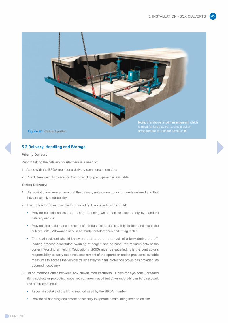
5.2 Delivery, Handling and Storage
Prior to Delivery
Prior to taking the delivery on site there is a need to:
1. Agree with the BPDA member a delivery commencement date
2. Check item weights to ensure the correct lifting equipment is available
Taking Delivery:
1 On receipt of delivery ensure that the delivery note corresponds to goods ordered and that they are checked for quality.
2 The contractor is responsible for off-loading box culverts and should:
• Provide suitable access and a hard standing which can be used safely by standard delivery vehicle
• Provide a suitable crane and plant of adequate capacity to safely off-load and install the culvert units. Allowance should be made for tolerances and lifting tackle.
• The load recipient should be aware that to be on the back of a lorry during the off-loading process constitutes “working at height” and as such, the requirements of the current Working at Height Regulations (2005) must be satisfied. It is the contractor’s responsibility to carry out a risk assessment of the operation and to provide all suitable measures to access the vehicle trailer safely with fall protection provisions provided, as deemed necessary
3 Lifting methods differ between box culvert manufacturers, Holes for eye-bolts, threaded lifting sockets or projecting loops are commonly used but other methods can be employed, The contractor should
• Ascertain details of the lifting method used by the BPDA member
• Provide all handling equipment necessary to operate a safe lifting method on site
Figure E1. Culvert puller
Note: this shows a twin arrangement which is used for large culverts. single puller arrangement is used for small units.
5: INSTALLATION - BOX CULVERTS 65

• Ensure that any non-standard attachment to the lifting point is supplied and that full instruction are given for its use.
• Under all risk assessments in addition to providing all handling equipment necessary to safely operate the lifting method on site
4 Where other methods, such as lifting forks, beams or slings are to be used, the contractor should:
• Consult the BPDA member to ensure that the proposed method is acceptable
• Protect the box culvert and particularly the joining surfaces from damage while lifting
• Ensure complete safety of operatives
5 Generally box culverts are transported as laid, but for safety reasons such as load stability or economy, the box culverts may be transported on end. The contractor should:
• Check with the BPDA member how the box culverts will be delivered
• Where box culverts are delivered on end, establish a safe method of turning the units to the as laid orientation.
• Provide any equipment necessary for the operation
6 The box culverts may be off-loaded into a storage area or they may be placed in line alongside the trench in which they are to be laid. In either situation:
• Before off-loading, visually inspect the units and check the identification label by cross referencing against the layout drawings
• Lower them carefully on to a firm level base away from the edge of the trench
• Box culvert units should be moved by lifting and never by dragging
• In cold weather, protect open lifting sockets from freezing and bursting
5.3 Construction
Trench Preparation
Keeping to the specified line and gradient, the trench should be excavated ideally to a width equal to the box culvert width plus a minimum of 300mm to either side to allow for access to aid installation. However, specific site conditions regarding the excavation and ground stability will prevail. Reference should be made to BD31/01 section 5.0.
In certain circumstances with unstable ground, e.g. clay soils, it may be necessary to undertake additional works to provide stable ground conditions.
Bedding
Bedding is intended to level out any irregularities in the trench bottom and ensure uniform support under the full width and length of the box culvert.
1. Lay granular material over the full width of the trench to a minimum depth of 200mm having first removed any protective layer ensuring that it is sufficiently compacted.
2. Lay the bedding material only a minimum distance ahead of laying the box culverts.
3. Keep off the prepared base so far as practicable. Having achieved a flat, well prepared base, it should not be allowed to deteriorate.
As an alternative to granular bedding, a suitable concrete blinding slab can be used. Lay a flat apron of unreinforced lean-mix concrete, minimum 75mm thick in the prepared trench. On top of the blinding place a 50mm thick layer of granular bedding material.
5: INSTALLATION - BOX CULVERTS66

Jointing
BPDA members employ different methods of joining the culverts together. Please refer to BPDA members for further information.
Reinstatement & Backfilling
Backfilling should commence as soon as possible after the box culverts have been laid.
• Fill the trench to the level of the top of the box culvert working evenly on each side
• Use appropriate backfill material well-compacted in layers not exceeding 200mm
• Do not use heavy vibratory equipment
• Continue filling over the box culvert and compact in layers
• Do not run heavy rollers or construction plant over the box culvert without protection
5.4. References
• BS EN 14844 - 2006 + A2:2011 - Precast Concrete product - Box culverts
• BS EN 13369:2013- Common rules for precast concrete products
• BS EN 1990:2002 Eurocode – basis of structural design (A new version will be published in November 2018)
• BS EN 1992-1-1:2004+A1:2014 – Eurocode 2:Design of concrete structures - Part 1-1: General rules and rules for buildings
• BS EN 1991-2:2003 Eurocode 1:Actions on Structures - Part 2: Traffic Loads on Bridges
• BS EN 1992-2:2005 - Eurocode 2 – Design of concrete structures –Part 2: Concrete bridges – Design and detailing rules
• PD 6687-2:2008 Recommendations for the design of structures to BS EN 1992-2:2005
• BD31/01 The design of buried concrete box and portal frame structures Design Manual for Roads and Bridges: Volume 2, Section 2, Part 12 (2001)
• CIRIA C689 Culvert design and operation guide (2010)
• PD6694-1 (2011): Recommendations for the design of structures subject to traffic loading to BS EN 1997-1:2004
• BS 8500-1:2015+A1:2016 – Concrete - Complementary British Standard to BS EN 206-1, Part 1: method of specifying and guidance for the specifier
Care must be taken if the construction traffic passes over or close to the culvert and imposes loadings greater than those for which the box culvert has been designed for. In such cases protective measures will be required.
5: INSTALLATION - BOX CULVERTS 67

6.1 British Standards
1 BS EN 197-1:2011 Cement. Composition, specifications and conformity criteria for common cements.
2011 BSI
2 BS EN 206:2013 Concrete. Specification, performance, production and conformity.
2013 BSI
3 BS EN 450 (various parts) Fly ash for concrete. 2005-2015
BSI
4 BS EN 681-1:1996 – Elastomeric seals. Material requirements for pipe joint seals used in water and drainage applications. Vulcanised rubber.
1996 BSI
5 BS EN 752:2008 Drain and sewer systems outside buildings. 2008 BSI
6 BS EN 1295-1 Structural design of buried pipelines under various conditions of loading – Part 1: General requirements.
1996 BSI
7 BS 1881 (various parts) Testing Concrete. 1983-2015
BSI
8 BS EN 1916 – Concrete pipes and fittings, unreinforced, steel fibre and reinforced.
2002 BSI
9 BS EN 1917 – concrete manholes and inspection chambers, unreinforced, steel fibre and reinforced.
2002 BSI
10 BS 4449: 2005+A3:2016 Steel for the reinforcement of concrete. Weldable reinforcing steel, Bar, coil and decoiled product. Specification.
2016 BSI
11 BS 4482:2005 Steel wire for the reinforcement of concrete products. Specification.
2005 BSI
12 BS 4483:2005 Steel fabric for the reinforcement of concrete. Specification. 2005 BSI
13 BS 5911 – 1 : 2002 + A2 : 2010 - Specification for unreinforced and reinforced pipes
2002 BSI
14 BS 5911 – 3 : 2010 + A1:2014 - Specification for unreinforced and reinforced manholes and soakaways.
2010 BSI
15 BS 5911 – 4 : 2002 +A2 : 2010 - Specification for unreinforced and reinforced inspection chambers.
2010 BSI
16 BS 5911 – 6 : 2004 + A1 : 2010 - Specification for road gulley and gulley cover slabs.
2010 BSI
17 BS 6031:2009 Code of Practice for earthworks. 2009 BSI
18 BS 8500-1: 2015+A1 Concrete. Complementary British Standard to BS EN 206. Method of specifying and guidance for the specifier.
2016 BSI
19 BS 8500-2: 2015+A1 Concrete. Complementary British Standard to BS EN 206. Specification for constituent materials and concrete.
2016 BSI
20 BS EN ISO 9001:2015 - Quality management systems: Requirements. 2015 BSI
21 BS 9295:2010 Guide to the structural design of buried pipelines. 2010 BSI
22 BS EN 13101:2002 Steps for underground man entry chambers. Requirements, marking, testing and evaluation of conformity.
2002 BSI
6: REFERENCES AND FURTHER READING
- BS EN 16933-2 Drain and sewer systems outside buildings — Design. Part 2: — Hydraulic design (expected in 2017)
- Also see SuDS references on page 16
6: REFERENCES AND FURTHER READING68

6: REFERENCES AND FURTHER READING 69
6.2 Industry References
1 Sewers for Adoption 6th and 7th Editions March 2006 & August 2012
Water UK / WRc
2 Sewers for Adoption 6th Edition – Combined Addendum
March 2006 Water UK / WRc
3 Civil Engineering Specification for the Water Industry (CESWI) 7th edition
March 2011 WRc
4 Simplified Tables of ExternalLoads on Buried Pipelines
1986 TRL HMSO
5 Guide to Design-Loadings for Buried Pipelines (Out of print)
1983 TRL HMSO
6 Tables for the Hydraulic Design of Pipes, Sewers and Channels 8th edition
2005 HR Wallingford and D H Barr
7 Specification for Highway Works 2001 Department of Transport HMSO
8 An introduction to pipe jacking and microtunnelling design
1995 Pipe Jacking As-sociation PJA
9 Guide to Best Practice for the Installation of Pipe Jacks and Microtunnels
1995 Pipe Jacking Association (PJA)
10 Concrete in Aggressive Ground - BRE Special Digest 1 2005 BRE
11 Imported Granular and Selected As-dug Bedding and Side Fill Materials for Buried Pipelines Water Industry Specification 4-08-01
1994 WRc
12 Precast Concrete Pipes - Unreinforced and Reinforced, with Flexible Joints - Water Industry Specification 4-12-01
1991 WRc
13 Specification for Polypropylene Encapsulated Steps for Use in Manholes and Access Chambers - Water Industry Specification 4-33-01
1990 WRc
14 Specification for Flexible Couplings for Gravity Sewage and Drainage Pipes - Water Industry Specification 4-41-01
1993 WRc
Whilst every effort is made to ensure that the information in this Technical Guide is accurate, it is the user’s responsibility to check that any Standard or other material referred to in the Guide is still relevant and is the most current version.
6.3 Relevant Organisations
British PrecastThe Old RectoryMain Street Glenfield LE3 8DG
• Telephone: +44 (0) 116 232 5170 • Fax: +44 (0)116 232 5197• [email protected]• www.britishprecast.org
British WaterVox StudiosUnit V03 1-451 Durham StreetLondon SE11 5JH
• Telephone: 02035670950• [email protected]• www.britishwater.co.uk
BREBuilding Research EstablishmentGarston,Watford WD25 9XX
• Telephone: +44 (0)1923 664000• Fax: +44 (0)1923 664010• [email protected]• www.bre.co.uk
BSI British Standards Institution389 Chiswick High Road London W4 4AL
• Telephone: +44 (0)20 8996 9000• Fax: +44 (0)20 8996 7001• [email protected]• www.bsi-global.com
CIRIA Griffin Court15 Long LaneLondon EC1A 9PN
• Telephone: +44 (0) 20 7549 3300• Fax: +44 (0) 20 7549 3349• [email protected]• www.ciria.org.uk
EA Environment AgencyHead OfficeHorizon House Deanery Road Bristol BS1 5AH
• Telephone: 03708 506 506• [email protected]• www.environment-agency.gov.uk
Highways EnglandBridge House, 1 Walnut Tree Close, Guildford GU1 4LZ
• Telephone: 0300 123 5000• [email protected]• www.highwaysengland.co.uk
Office of Public Sector Information / The Stationery Office (Previously HMSO)TSO Orders/Post Cash DeptPO Box 29Norwich NR3 1GN
• Telephone: +44 (0)870 600 5522• Fax: +44 (0)870 600 5533• [email protected]• www.tso.co.uk
HR Wallingford (Formerly HRS)HR Wallingford Ltd,Howbery ParkWallingfordOxfordshire OX10 8BA
• Telephone: +44 (0) 1491 835381• Fax: +44 (0) 1491 832233• [email protected]• www.hrwallingford.co.uk
PJA Pipe Jacking Association10 Greycoat PlaceLondon SW1P 1SB
• Telephone: +44 (0)845 0705201• Fax: +44 (0)845 0705202• [email protected]• www.pipejacking.org
6: REFERENCES AND FURTHER READING70

TRL Transport Research LaboratoryCrowthorne HouseNine Mile RideWokinghamBerkshire RG40 3GA
• Telephone: +44 (0)1344 773131• Fax: +44 (0)1344 770356• [email protected]• www.trl.co.uk
UKSTTUnited Kingdom Society for Trench-less Technology38 Holly WalkLeamington SpaWarwickshire CV32 4LYUnited Kingdom
• Telephone: +44 (0)1926 330 935• Fax: +44 (0)1926 330 935• [email protected]• www.ukstt.org.uk
UK Water Industry Research LtdBCSC8th Floor50 Broadway, London SW1H 0RG
• Telephone: +44(0)20 7152 4537• [email protected]• www.ukwir.org/
Water UK 3rd Floor36 BroadwayLondon SW1H 0BH
• Telephone: +44 (0)20 7344 1844• [email protected]• www.water.org.uk
WRc plcFrankland RoadBlagroveSwindonWiltshire SN5 8YF
• Telephone: 01793 865000• Fax: 01793 865001• [email protected]• www.wrcplc.co.uk
British Precast Drainage AssociationThe Old Rectory, Main StreetGlenfield, LeicesterLE3 8DGTel: 0116 232 5170 Fax: 0116 232 [email protected] precastdrainage.co.uk
The information in this guide is to the best of our knowledge true and accurate, but all information provided is for guidance only and made without guarantee. Since the conditions of use are beyond their control, the British Precast Drainage Association disclaims any liability for loss or damage resulting from the use of this guide. Furthermore, no liability is accepted if use of any products in accordance with this data or these suggestions infringes any patent. The British Precast Drainage Association reserves the right to change product specifications and references without notice.
For further information contact:
6: REFERENCES AND FURTHER READING 71

TechGuidev6May20191k
Related Documents