The City of Durham, Public Works Department Revised 6/27/16 (R2) Engineering Division – Construction Specifications Soils for Earthwork 31 05 13 - 1 SELECTED LINKS TO SECTIONS WITHIN THIS SPECIFICATION PART 1- GENERAL Excavated & Reuse On/Offsite Soil Topsoil Materials PART 2 – PRODUCTS Select Borrow/Fill Materials Unsatisfactory Subgrade Soils PART 3 – EXECUTION Soil Classifications Borrow Source Quality Control Stockpiling Borrow/Topsoil Criteria for Acceptance of Mat’s Stone Screenings SECTION 31 05 13 SOILS FOR EARTHWORK PART 1 GENERAL 1.1 SUMMARY A. Section Includes: 1. Subgrade soil materials. 2. Fill/Borrow materials 3. Topsoil materials. B. Related Sections: 1. Section 31 05 16 - Aggregates for Earthwork. 2. Section 31 20 00 – Earthmoving. 3. Section 31 22 13 - Rough Grading. 4. Section 31 23 17 - Trenching, Backfilling and Compaction of Utilities. 5. Section 31 23 23 - Fill. 6. Section 32 91 19 - Landscape Grading. 7. Section 33 46 00 - Subdrainage: Filter aggregate. 8. Document: Geotechnical report; bore hole locations and findings of subsurface materials. 1.2 MEASUREMENT AND PAYMENT A. See Section 01 20 01 Measurement & Payment. 1.3 REFERENCES A. Materials and operations shall comply with the latest revision of the Codes and Standards. B. American Society for Testing and Materials (ASTM) 1. ASTM C136 – Standard Test Method for Sieve Analysis of Fine and Coarse Aggregates Sieve Analysis of Fine and Coarse Aggregate 2. ASTM D422 – Standard Test Method for Particle-Size Analysis of Soils (for classification purposes only) 3. ASTM D698 – Test Method for Laboratory Compaction Characteristics of Soil Using Standard Effort (12,400 ft-lbf/ft 3 ) (Standard Proctor).

Welcome message from author
This document is posted to help you gain knowledge. Please leave a comment to let me know what you think about it! Share it to your friends and learn new things together.
Transcript
The City of Durham, Public Works Department Revised 6/27/16 (R2)
Engineering Division – Construction Specifications
Soils for Earthwork
31 05 13 - 1
SELECTED LINKS TO SECTIONS WITHIN THIS SPECIFICATION PART 1- GENERAL Excavated & Reuse On/Offsite Soil Topsoil Materials
PART 2 – PRODUCTS Select Borrow/Fill Materials Unsatisfactory Subgrade Soils
PART 3 – EXECUTION Soil Classifications
Borrow Source Quality Control Stockpiling Borrow/Topsoil
Criteria for Acceptance of Mat’s Stone Screenings
SECTION 31 05 13
SOILS FOR EARTHWORK
PART 1 GENERAL
1.1 SUMMARY
A. Section Includes:
1. Subgrade soil materials.
2. Fill/Borrow materials
3. Topsoil materials.
B. Related Sections:
1. Section 31 05 16 - Aggregates for Earthwork.
2. Section 31 20 00 – Earthmoving.
3. Section 31 22 13 - Rough Grading.
4. Section 31 23 17 - Trenching, Backfilling and Compaction of Utilities.
5. Section 31 23 23 - Fill.
6. Section 32 91 19 - Landscape Grading.
7. Section 33 46 00 - Subdrainage: Filter aggregate.
8. Document: Geotechnical report; bore hole locations and findings of subsurface materials.
1.2 MEASUREMENT AND PAYMENT
A. See Section 01 20 01 Measurement & Payment.
1.3 REFERENCES
A. Materials and operations shall comply with the latest revision of the Codes and Standards.
B. American Society for Testing and Materials (ASTM)
1. ASTM C136 – Standard Test Method for Sieve Analysis of Fine and Coarse Aggregates
Sieve Analysis of Fine and Coarse Aggregate
2. ASTM D422 – Standard Test Method for Particle-Size Analysis of Soils (for
classification purposes only)
3. ASTM D698 – Test Method for Laboratory Compaction Characteristics of Soil Using
Standard Effort (12,400 ft-lbf/ft3) (Standard Proctor).

The City of Durham, Public Works Department Revised 6/27/16 (R2)
Engineering Division – Construction Specifications
Soils for Earthwork
31 05 13 - 2
4. ASTM D1557 – Test Method for Laboratory Compaction Characteristics of Soil Using
Modified Effort (56,000 ft-lbf/ft3) (Modified Proctor)
5. ASTM D1883 – Standard Test Method for CBR (California Bearing Ratio) of
Laboratory-Compacted Soils
6. ASTM D2487 – Standard Classification of Soils for Engineering Purposes (Unified Soil
Classification System).
7. ASTM D2922 – Test Methods for Density of Soil and Soil-Aggregate in Place by
Nuclear Methods (Shallow Depth).
8. ASTM D2937 – Standard Test Method for Density of Soil in Place by the Drive-Cylinder
Method
9. ASTM D3017 - Standard Test Method for Water Content of Soil and Rock in Place by
Nuclear Methods (Shallow Depth).
10. ASTM D4253 – Standard Test Methods for Maximum Index Density and Unit Weight of
Soils Using a Vibratory Table.
11. ASTM D4254 – Test Method for Minimum Index Density and Unit Weight of Soils and
Calculation of Relative Density.
12. ASTM D4318 – Test Method for Liquid Limit, Plastic Limit, and Plasticity Index of
Soils.
13. ASTM D 5268 – Standard Specification for Topsoil Used for Landscaping Purposes.
C. American Association of State Highway & Transportation Officials (AASHTO)
1. AASHTO T11 – Standard Method of Test for Materials Finer Than 75-µm (No. 200)
Sieve in Mineral Aggregates by Washing.
2. AASHTO T27 – Standard Method of Test for Sieve Analysis of Coarse Aggregates.
3. AASHTO T89 – Standard Method of Test for Determining the Liquid Limit of Soils.
4. AASHTO T90 – Standard Method of Test for Determining the Plastic Limit and
Plasticity Index of Soils.
5. AASHTO T99 – The Moisture-Density Relations of Soils using a 5.5-pound Rammer and
a 12-inch drop.
6. AASHTO M145 – The Classification of Soils and Soil-Aggregate Mixtures for Highway
Construction Purposes.
7. AASHTO T180 – The Moisture Density Relations of Soils using a 10-pound Rammer
and an 18-inch drop.
1.4 SUBMITTALS
A. Section 01 33 00 - Submittal Procedures: Requirements for submittals.
B. Materials Source: Submit name of imported fill materials suppliers. For borrow sources that
are currently certified to meet DOT specifications/classifications, submit documentation on
soil classification intended for use as select fill/borrow. For non-certified sources, material is
to be tested and documentation provided to the City showing the origin, soil classification and
optimum moisture content for placement/densification.
C. Material Test Reports: Provide from a qualified testing agency test results and interpretation
for compliance of the following requirements indicated:
1. Classification according ASTM D2487 of each on-site or borrow soil proposed for fill,
unless otherwise directed by the City’s Engineer.

The City of Durham, Public Works Department Revised 6/27/16 (R2)
Engineering Division – Construction Specifications
Soils for Earthwork
31 05 13 - 3
2. Laboratory compaction curve according to ASTM D698 for each on-site or borrow soil
material proposed for fill or backfill.
3. Laboratory testing according to ASTM D4318 for each on-site or borrow soil material for
fill or backfill to determine Liquid Limit, Plastic Limit, and Plasticity Index of Soils.
1.5 QUALITY ASSURANCE
A. Perform work in accordance with City of Durham’s Specifications and Standard Details.
B. Comply with all codes, laws, ordinances, and regulations of governmental authorities having
jurisdiction over this part of the work.
C. Unless approved otherwise by the City’s Engineer, furnish each soil type material from the
same approved borrow source throughout the Work.
D. Geotechnical Testing Agency Qualifications: An independent testing agency qualified
according to ASTM E 329 to conduct soil materials and rock-definition testing as documented
according to ASTM D 3740 and ASTM E 548. Testing Lab to be AMRL (AASHTO
Materials Reference Laboratory) and CCRL (Cement and Concrete Reference Laboratory)
certified.
1. The Testing Laboratory shall be approved by the City’s Engineer and will be responsible
for conducting and interpreting tests. The Testing Laboratory shall state in each report
whether or not the test specimens conform to all requirements of the Contract Documents
and specifically note any deviation.
2. Specific test requirements shall be as specified herein.
PART 2 PRODUCTS
2.1 SOIL CLASSIFICATIONS
A. Select material may be specified for use in:
1. Fill/Embankments
2. Subgrade
3. Backfill in undercut
4. Core material
5. Foundation conditioning
6. Slope and shoulder embankment
7. Material placement over fabric
B. Select Structural Fill/Borrow Material: Nonplastic material, free of organic material, used as
foundation for subbase, shoulder surfacing, fill, backfill, or other specific purposes.
1. NCDOT Class II, Type 1 Select Material: Fine aggregate material consisting of crushed
stone screenings (washed or unwashed) meeting the gradation shown in Table 1016-1 of
the NCDOT Standard Specifications for Roads and Structures.
2. NCDOT Class II, Type 2, Select Material: Granular soil material meeting AASHTO M
145 for soil classifications A-2-4 with a maximum PI of 6 and A-4 soil containing 45%
maximum passing a No. 200 sieve and a maximum PI of 6 (Unified Soil Classification
System: SW, SP, SM, SC; CL, ML subject to conditions stated for A-4 soils above).

The City of Durham, Public Works Department Revised 6/27/16 (R2)
Engineering Division – Construction Specifications
Soils for Earthwork
31 05 13 - 4
3. NCDOT Class III, Type 1: Natural or manufactured fine aggregate (sand) material
meeting the gradation requirements of 2S or 2MS in Table 1005-2 as described in
Sections 1005 and 1006 of the NCDOT Standard Specifications for Roads and
Structures.
4. NCDOT Class III, Type 2: Granular soil meeting AASHTO M 145 for soil classification
A-1 or A-3 (USC: GW, GC, GP, GM, SC, SW, SM).
C. Excavated and Reused Native On-Site or Off-Site Borrow, Prepared subgrade:
1. NCDOT CLASS I: Class I select material is silty or clayey soil material meeting
ASHTO M 145 for soil classification A-4. Soil materials which meet AASHTO M 145
for soil classifications A-2, A-5, A-6 and A-7 are acceptable provided such materials do
not have a LL greater than 50, nor a PI of less than 7 or greater than 20. (USC: SC, SM,
CL, ML).
2. Soils shall be free of lumps, rock or gravel larger than 2 inches in any dimension, debris,
organic matter, waste, frozen materials, muck, roots, vegetation, and other deleterious
matter.
3. Soils shall be subject to the acceptance criteria in Table 1 (paragraph 2.1.D), 2.1.E and
2.1.F, below.
D. Criteria for Acceptance of Select Fill/Borrow Material:
1. Only natural earth material may be used as borrow material. Any other materials are
subject to rejection. See Table 1, below.
2. Soils having a pH of less than 5.5 or an organic content of more than 4.0% may be
rejected.
3. Waste or by-products from industrial processes or mining operations are not acceptable
except by specific written approval.
Table 1
Criteria for Acceptance of Select Fill/Borrow Material
Soil P.I. Remarks
25 or less Acceptable
26 through 35 Acceptable, but not to be used in the top 2 feet
Greater than 35 Not Acceptable
E. When material is to be utilized for placing embankment or backfilling undercut areas that are
excessively wet, the materials shall consist of NCDOT Select Material Class II, III, or IV.
F. Unsatisfactory Subgrade Soils: ASTM D2487 soil classification group (Unified Soil
Classification System) CH and MH soils having a LL of > 50 and a PI of > 30, OH, OL, and
PT; soils which contain rock or gravel larger than 3 inches in any dimension, debris, organic
matter, waste frozen materials, vegetation, and other deleterious matter. Unsatisfactory soils
also include satisfactory soils not maintained within +/- 3% of optimum moisture content at
time of compaction, unless otherwise approved by the City’s Engineer.
2.2 AGGREGATE FILL
A. See Specification Section 31 05 16 Aggregates for Earthwork.

The City of Durham, Public Works Department Revised 6/27/16 (R2)
Engineering Division – Construction Specifications
Soils for Earthwork
31 05 13 - 5
2.3 TOPSOIL MATERIALS
A. Topsoil – General Requirements: Topsoil shall be obtained either from on-site or an off-site
source. Topsoil shall consist of friable clayey or silty loam, free from roots, stones, and other
undesirable material and shall be capable of supporting a good growth of grass. Topsoil shall
be free of material greater than 1-inch in any dimension.
B. On-site or Off-site Excavated/Stripped and Reusable Topsoil:
On-site Topsoil Source: Unclassified organic excavation from project site. Contractor
may supplement on-site source with imported or manufactured topsoil when quantities
are insufficient.
1. Offsite Topsoil Source: Obtain topsoil from naturally well-drained sites where topsoil
occurs at least 4 inches in depth. Do not obtain from swamps or marshes.
Free of roots, lumps, frozen materials, rocks larger than 1/2 inch, subsoil, debris, large
weeds and foreign matter.
a. Screening: Single screened only if City’s Engineer deems necessary. Alternatively,
material may be raked upon placement to remove such material.
2. If approved by the City’s Engineer, material conforming to ASTM D2487 Unified Soil
Classification System OL, OH, and PT.
C. Imported Select Topsoil:
1. Friable loam.
2. Reasonably free of roots, lumps, frozen materials, rocks larger than 1/2 inch, subsoil,
debris, large weeds, and foreign matter.
a. Screening: Single or double screened.
3. Topsoil should comply with ASTM D5268 Standard Specification for Topsoil Used for
Landscaping Purposes.
4. Acidity range (pH) of 5.5 to 7.5.
5. Containing minimum of 4 percent and maximum of 25 percent inorganic matter.
6. If approved by the City’s Engineer, material conforming to ASTM D2487 Unified Soil
Classification System OL, OH, and PT.
7. To minimize nitrogen depletion, limit decaying matter to 5 percent of total content by
volume.
2.4 SOURCE QUALITY CONTROL
A. Section [01 40 00 - Quality Requirements: Testing and Inspection Services] Testing and
analysis of soil material.
B. Testing and Analysis of On-Site or Off-Site Borrow Material: Perform in accordance with
ASTM D698 (AASHTO T99) and ASTM D4318 (AASHTO T11, R27, T89, and T90).
C. Testing and Analysis of Imported Select Topsoil Material: ASTM D5268.
D. When tests indicate materials do not meet specified requirements, change material and retest.
E. Unless approved otherwise by the City’s Engineer, furnish each soil type material from the
same approved borrow source throughout the Work.

The City of Durham, Public Works Department Revised 6/27/16 (R2)
Engineering Division – Construction Specifications
Soils for Earthwork
31 05 13 - 6
PART 3 EXECUTION
3.1 EXCAVATION
A. See Sections 31 23 16 Excavation – Earthwork and 31 20 00 Earthmoving for requirements
associated with excavation.
B. Temporarily stockpile excess excavated material meeting requirements for use as on-site
borrow until material is required to be use.
C. Remove from site excess excavated materials not intended for reuse.
D. Remove excavated materials not meeting requirements as on-site select fill/borrow material or
as acceptable subgrade from site. See paragraph 2.1.F and Table 1 Criteria for Acceptance of
Select Fill/Borrow Material.
3.2 FILLING
A. Place and compact fill material in accordance with the requirements of 31 23 23 Fill,
paragraph 3.7 Field Quality Control.
3.3 STOCKPILING
A. On-Site Borrow Stockpiling: It is preferred that borrow material be delivered directly from its
source and deposited at the project site at the location of its final destination, graded and
compacted in accordance with these contract documents. However, if necessary, the
Contractor may stockpile material on the project site until it is needed subject to the following
conditions/provisions:
1. Stockpile in sufficient quantities to meet Project schedule and requirements.
2. If material is stockpiled adjacent to any dissimilar materials, separate differing materials
with dividers or stockpile apart in such a manner to prevent intermixing of soil type and
minimize segregation.
3. Provide sites for aggregate stockpiles that are cleared, grubbed and cleaned with a firm,
smooth and well drained ground surface. Maintain a cover of at least 3" of aggregate over
the ground surface to avoid the inclusion of soil or foreign material. Operate trucks or
other equipment on a stockpile in an acceptable manner.
4. Do not allow the stockpile to become contaminated with foreign matter or degrade
excessively. Failure of aggregate samples to meet all gradation requirements due to
excessive degradation will be determined by sieve tests of samples taken from any
portion of the stockpile and is cause for discontinuance of such stockpiling procedure.
5. Direct surface water away from stockpile site to prevent erosion or deterioration of
materials.
B. Stockpile Area:
1. The Contractor is responsible for securing a material lay down and stockpile storage area.
As such, the Contractor is responsible for the necessary erosion control measures,
including but not necessarily limited to, a construction entrance, silt fence, protection of
streams/buffers, clean up and restoration of site to the satisfaction of the City and
NCDEQ, Division of Energy, Mineral and Land Resources, Erosion and sedimentation

The City of Durham, Public Works Department Revised 6/27/16 (R2)
Engineering Division – Construction Specifications
Soils for Earthwork
31 05 13 - 7
Control. Stockpile and/or waste areas must be maintained within the limits of the areas
protected by the proposed measures and otherwise temporarily seeded if to be left
stockpiled over 14 days.
2. Unsuitable material that is to be temporarily stockpiled and, if not to be temporarily
seeded/stabilized, are to be covered to prevent erosion and leaching until disposed of
offsite.
3. Stockpile areas shall not encroach into the Public ROW or any public or private utility
easements.
C. Stockpile topsoil:
1. Stockpile height to be no more than 8 feet high unless approved otherwise by the City’s
Engineer.
2. Provide erosion control measures to prevent erosion and off-site deposition of topsoil.
3.4 STOCKPILE CLEANUP
A. Remove stockpile, leave area in clean and neat condition. Grade site surface to prevent free
standing surface water.
B. Remove surplus soil and waste material, unsuitable soil, trash, and debris and legally dispose
of off-site.
END OF SECTION
Back to Top

The City of Durham, Public Works Department Revised 6/27/16 (R2)
Engineering Division – Construction Specifications
Aggregates for Earthwork
31 05 16 - 1
SELECTED LINKS TO SECTIONS WITHIN THIS SPECIFICATION PART 1 - GENERAL Aggregate Base Coarse (ABC) Fine Aggregate Mat’ls (Sand)
PART 2 - PRODUCTS Aggregate Materials Granular Soil Aggregate Materials
PART 3 - EXECUTION Clean Coarse Aggregate Pea Gravel Aggregate
SECTION 31 05 16
AGGREGATES FOR EARTHWORK
PART 1 GENERAL
1.1 SUMMARY
A. Section Includes:
1. Coarse aggregate materials.
2. Fine aggregate materials.
B. Related Sections:
1. Section 31 05 13 - Soils for Earthwork: Fill and grading materials.
2. Section 31 22 13 - Rough Grading.
3. Section 31 23 17 – Trenching, Backfilling and Compaction of Utilities.
4. Section 31 23 23 - Fill.
5. Section 31 37 00 - Riprap.
6. Section 32 11 23 - Aggregate Base Courses.
7. Section 33 11 00 - Public Water Distribution Piping.
8. Section 33 31 00 – Public Sanitary Sewer Piping.
9. Section 33 41 00 – Public Storm Drainage Piping.
10. Section 33 46 00 - Subdrainage: Filter aggregate.
11. Document: Geotechnical report; bore hole locations and findings of subsurface materials.
12. Document: NCDOT Standard Specifications for or Roads and Structures; Section 1016-
3 Classifications.
1.2 MEASUREMENT AND PAYMENT
A. See Section 01 20 01 Measurement & Payment.
1.3 REFERENCES
A. Materials and operations shall comply with the latest revision of the Codes and Standards.
B. ASTM International:
1. ASTM C136 - Standard Test Method for Sieve Analysis of Fine and Coarse Aggregates.
2. ASTM D698 - Standard Test Method for Laboratory Compaction Characteristics of Soil
Using Standard Effort (12,400 ft-lbf/ft3).
3. ASTM D1557 - Standard Test Method for Laboratory Compaction Characteristics of Soil
Using Modified Effort (6,000 ft-lbf/ft3).

The City of Durham, Public Works Department Revised 6/27/16 (R2)
Engineering Division – Construction Specifications
Aggregates for Earthwork
31 05 16 - 2
4. ASTM D2487 - Standard Classification of Soils for Engineering Purposes (Unified Soil
Classification System).
5. ASTM D4253 – Standard Test Methods for Maximum Index Density and Unit Weight of
Soils Using a Vibratory Table.
6. ASTM D4318 - Standard Test Method for Liquid Limit, Plastic Limit, and Plasticity
Index of Soils.
C. American Association of State Highway and Transportation Officials:
1. AASHTO M145 - The Classification of Soils and Soil-Aggregate Mixtures for Highway
Construction Purposes.
2. AASHTO M147 - Standard Specification for Materials for Aggregate and Soil-Aggregate
Subbase, Base and Surface Courses.
3. AASHTO T11 - Standard Method of Test for Materials Finer Than 75-µm (No. 200)
Sieve in Mineral Aggregates by Washing
4. AASHTO T27 - Standard Method of Test for Sieve Analysis of Coarse Aggregates.
5. AASHTO T89 - Standard Method of Test for Determining the Liquid Limit of Soils.
6. AASHTO T99 - The Moisture-Density Relations of Soils using a 5.5-pound Rammer and
a 12-inch drop.
7. AASHTO T104 - Standard Method of Test for Soundness of Aggregate by Use of
Sodium Sulfate or Magnesium Sulfate.
1.4 SUBMITTALS
A. Section 01 33 00 - Submittal Procedures: Requirements for submittals.
B. Materials Source (Quarry/Pit Certificate):
1. Submit name of imported aggregate materials suppliers. For aggregate sources that are
currently certified to meet NCDOT specifications/classifications, submit documentation
on aggregate classification intended for use.
2. For non-certified sources, material is to be tested and documentation provided to the City
showing the origin, aggregate classification and optimum moisture content for
placement/densification.
1.5 QUALITY ASSURANCE
A. Perform work in accordance with City of Durham’s Specifications and Standard Details.
B. Comply with all codes, laws, ordinances, and regulations of governmental authorities having
jurisdiction over this part of the work.
C. Unless approved otherwise by the City’s Engineer, furnish each aggregate type material from
the same single approved aggregate source throughout the Work.
D. Geotechnical Testing Agency Qualifications: An independent testing agency qualified
according to ASTM E 329 to conduct soil materials and rock-definition testing as documented
according to ASTM D 3740 and ASTM E 548. Testing Lab to be AMRL (AASHTO
Materials Reference Laboratory) and CCRL (Cement and Concrete Reference Laboratory)
certified.
The City of Durham, Public Works Department Revised 6/27/16 (R2)
Engineering Division – Construction Specifications
Aggregates for Earthwork
31 05 16 - 3
1. The Testing Laboratory shall be approved by the City’s Engineer and will be responsible
for conducting and interpreting tests. The Testing Laboratory shall state in each report
whether or not the test specimens conform to all requirements of the Contract Documents
and specifically note any deviation.
2. Specific test requirements shall be as specified herein.
E. Maintain one copy of each document/certificate on site.
PART 2 PRODUCTS
2.1 AGGREGATE MATERIALS
A. Aggregate Material may be specified for use in:
1. Pavement base
2. Foundation conditioning
3. Concrete slab-on-grade aggregate base
4. Pipe bedding
5. Subsurface drainage bedding and backfill
6. Excludes aggregate for asphalt pavements and surface treatments.
7. Excludes aggregate for Portland cement concrete.
B. Aggregate Base Coarse Aggregate:
1. Use coarse aggregate consisting of crushed stone, crushed gravel, a mixture of uncrushed
gravel with either crushed stone or crushed gravel or other inert material having similar
characteristics. Provide coarse aggregate composed of clean, tough, durable fragments
free from an excess of flat or elongated pieces and free of organic matter and deleterious
substances.
2. NCDOT Class IV select coarse aggregate material meeting the gradation requirements of
ABC as described in Section 1010 of the NCDOT Standard Specifications for Roads and
Structures. The material passing the No. 40 sieve shall not have a liquid limit of more
than 30 or a plasticity index of more than 6 in accordance with ASTM D4318.
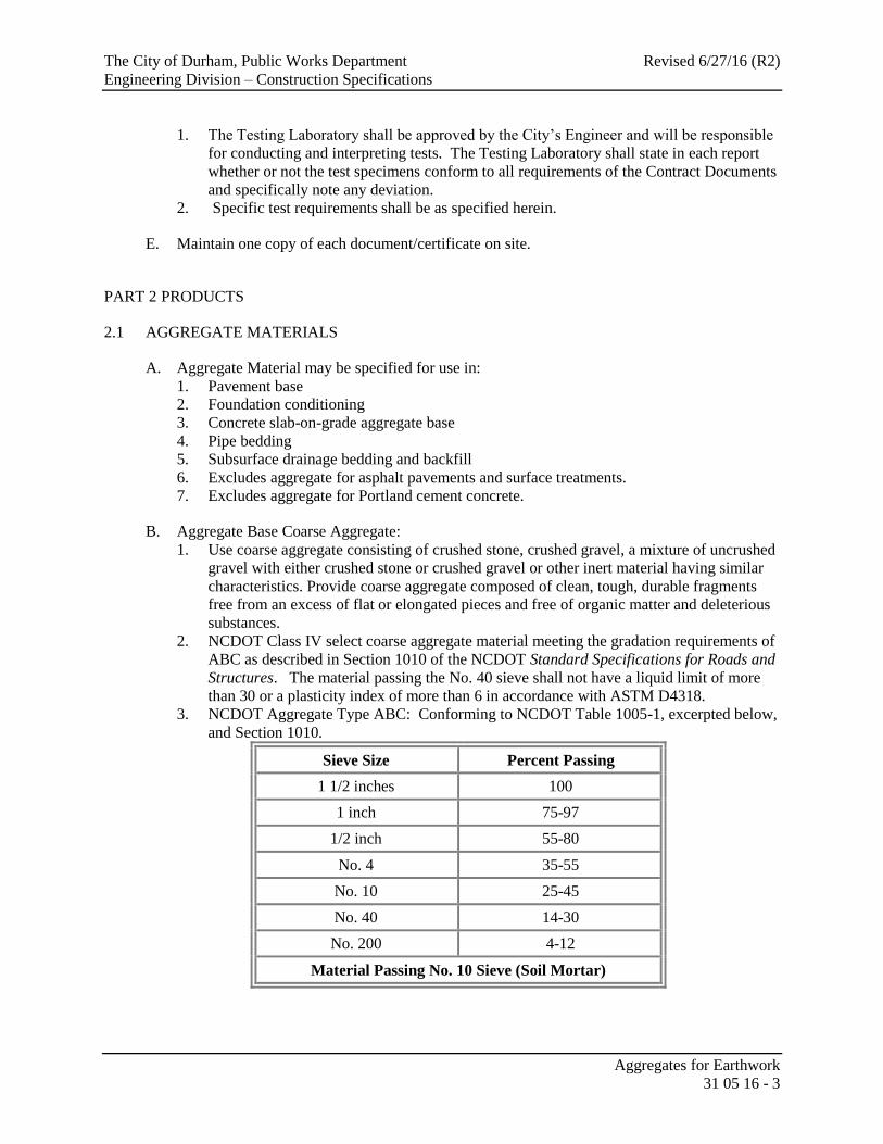
3. NCDOT Aggregate Type ABC: Conforming to NCDOT Table 1005-1, excerpted below,
and Section 1010.
Sieve Size Percent Passing
1 1/2 inches 100
1 inch 75-97
1/2 inch 55-80
No. 4 35-55
No. 10 25-45
No. 40 14-30
No. 200 4-12
Material Passing No. 10 Sieve (Soil Mortar)

The City of Durham, Public Works Department Revised 6/27/16 (R2)
Engineering Division – Construction Specifications
Aggregates for Earthwork
31 05 16 - 4
The gradation requirements for material passing the No. 10
sieve (soil mortar) will be as required by Section 1010 of the
NCDOT Standard Specifications for Roads and Structures,
latest edition.
Material Passing No. 40 Sieve
L.L. 0-30
P.I. 0-6
C. Clean Coarse Aggregate: NCDOT Class VI select material is a coarse aggregate material
meeting the gradation requirements of standard size 57 in Table 1005-1 as described in
Section 1005 and 1006 of the NCDOT Standard Specifications for Roads and Structures.
D. Pea Gravel Aggregate: Natural stone; washed, free of clay or silt, shale, organic matter; graded
in accordance with ASTM C136.
1. ASTM D2487 Unified Soil Classification System Group Symbol GM, GC; to the
following limits:
a. Minimum Size: 1/4 inch.
b. Maximum Size: 5/8 inch.
2. NCDOT Table 1005-1 Standard Size 78M.
E. Granular Soil Aggregate Material: NCDOT Class III, Type 2 coarse stone, angular crushed
gravel or natural stone; free of shale, friable material and debris; graded in accordance with
ASTM C136, and meeting AASHTO M 145 for soil classification A-1 only (ASTM D2487,
USC: GW, GC, GP, GM ).
2.2 FINE AGGREGATE MATERIALS
A. Sand: NCDOT Class III, Type 2 natural river or bank sand; washed; free of silt, clay, loam,
friable or soluble materials, and organic matter; graded in accordance with ASTM C136 and
meeting AASHTO M 145 for soil classification A-3 only (ASTM D2487, USC: SW, SP, SM,
SC).
2.3 SOURCE QUALITY CONTROL
A. Section 01 40 00 - Quality Requirements: Testing and inspection services.
B. Coarse Aggregate Material - Testing and Analysis: Perform in accordance with ASTM C136,
ASTM D698 and ASTM D4318 (AASHTO T11 & T27, AASHTO T89 as modified,
AASHTO T99, and AASHTO T104.
C. Fine Aggregate Material - Testing and Analysis: Perform in accordance with ASTM C136,
ASTM D698 and ASTM D4318; AASHTO T89 and AASHTO T99
D. Provide certification from source that material meets the gradation specified.
E. When field tests indicate materials do not meet specified requirements, change material and
retest.

The City of Durham, Public Works Department Revised 6/27/16 (R2)
Engineering Division – Construction Specifications
Aggregates for Earthwork
31 05 16 - 5
F. Unless approved otherwise by the City’s Engineer, furnish each aggregate type/material from
the same single approved borrow source throughout the Work.
PART 3 EXECUTION
3.1 EXCAVATION
A. See Sections 31 23 16 Excavation – Earthwork and 31 20 00 Earthmoving for requirements
associated with excavation.
B. Excavate aggregate materials from on-site locations indicated in Contract Documents or as
designated by the City’s Engineer as specified in Section 31 22 13 Rough Grading.
C. Stockpile excavated material designated for reuse and meeting these requirements for coarse
aggregate materials and fine aggregate materials.
D. Remove excess excavated coarse aggregate materials and fine aggregate materials from site
not intended for reuse.
E. Remove excavated materials not meeting requirements for coarse aggregate materials and fine
aggregate materials from site.
3.2 FILLING
A. Place and compact fill material in accordance with the requirements of 31 23 23 Fill,
paragraph 3.7 Field Quality Control as well as other applicable sections of 31 23 23.
3.3 STOCKPILING
A. On-Site Aggregate Stockpiling: It is preferred that aggregate material be delivered directly
from its source and deposited at the project site at the location of its final destination, graded
and compacted in accordance with these contract documents. However, if necessary, the
Contractor may stockpile material on the project site until it is needed subject to the following
conditions/provisions:
1. Stockpile in sufficient quantities to meet Project schedule and requirements.
2. If material is stockpiled adjacent to any dissimilar materials, separate differing materials
with dividers or stockpile apart in such a manner to prevent intermixing of aggregate type
and minimize segregation.
3. Provide sites for aggregate stockpiles that are cleared, grubbed and cleaned with a firm,
smooth and well drained ground surface. Maintain a cover of at least 3" of aggregate over
the ground surface to avoid the inclusion of soil or foreign material. Operate trucks or
other equipment on a stockpile in an acceptable manner.
4. Do not allow the stockpile to become contaminated with foreign matter or degrade
excessively. Failure of aggregate samples to meet all gradation requirements due to
excessive degradation will be determined by sieve tests of samples taken from any
portion of the stockpile and is cause for discontinuance of such stockpiling procedure.
5. Direct surface water away from stockpile site to prevent erosion or deterioration of
materials.

The City of Durham, Public Works Department Revised 6/27/16 (R2)
Engineering Division – Construction Specifications
Aggregates for Earthwork
31 05 16 - 6
B. Stockpile Area:
1. The Contractor is responsible for securing an aggregate stockpile storage area. As such,
the Contractor is responsible for the necessary erosion control measures, including but
not necessarily limited to, a construction entrance, silt fence, protection of
streams/buffers, clean up and restoration of site to the satisfaction of the City and the
NCDEQ, Division of Energy, Mineral and Land Resources, Erosion and Sedimentation
Control.
2. Stockpile and/or waste areas must be maintained within the limits of the areas protected
by the proposed measures.
3. Cover stockpiled fine aggregate to prevent erosion or provide a protective silt fence
around stockpile to prevent erosion and/or off-site deposition of fine aggregate.
4. Unsuitable material that is to be temporarily stockpiled and, if not to be temporarily
seeded/stabilized or otherwise protected, is to be covered to prevent erosion and leaching
until disposed of offsite.
5. Stockpile areas shall not encroach into the Public ROW or any public or private utility
easements.
3.4 STOCKPILE CLEANUP
A. Remove stockpile, leave area in clean and neat condition. Grade site surface to prevent free
standing surface water.
B. Remove surplus soil and waste material, unsuitable soil, trash, and debris and legally dispose
of off-site.
END OF SECTION
Back to Top

The City of Durham, Public Works Department Revised 6/27/16 (R2)
Engineering Division – Construction Specifications
Excavation - Earthwork
31 23 16 - 1
SELECTED LINKS TO SECTIONS WITHIN THIS SPECIFICATION PART 1- GENERAL Grading Tolerances Sand Rock
PART 2 – PRODUCTS Heavy Excavator – Def Site Rock
PART 3 – EXECUTION Heavy Ripping Equipment – Def Site Rock Excavation-Def
Common Excavation – Def Pusher Tractor – Def Trap, Granite, Gneiss Rock - Def
Erosion Control, NPDES Rock Classification - Def Unclassified Excavation - Def
Excavation Rock Classification – Engrs Judge’t Wheel Tractor Scraper – Def
SECTION 31 23 16
EXCAVATION - EARTHWORK
PART 1 GENERAL
1.1 SUMMARY
A. Section Includes:
1. Excavating for paving, roads, and parking areas.
2. Excavating for slabs-on-grade.
3. Excavating for landscaping.
B. Related Sections:
1. Section 01 20 01 Measurement & Payment.
2. Section 30 10 00 Construction Survey and Stakeout and As-Builts
3. Section 31 05 13 - Soils for Earthwork: Stockpiling excavated materials.
4. Section 31 05 16 - Aggregates for Earthwork: Stockpiling excavated materials.
5. Section 31 10 00 – Site Clearing
6. Section 31 22 13 - Rough Grading: Topsoil and subsoil removal from site surface.
7. Section 31 23 17 - Trenching, Backfilling & Compaction of Utilities.
8. Section 31 23 18 - Rock Removal
9. Section 31 23 23 - Fill.
10. NCDEQ, Division of Energy, Mineral and Land Resources, Erosion and Sedimentation
Control Planning and Design Manual.
1.2 MEASUREMENT AND PAYMENT
A. See Section 01 20 01 Measurement & Payment.
1.3 REFERENCES
A. Materials and operations shall comply with the latest revision of the Codes and Standards.
B. American Society for Testing and Materials (ASTM)
1. ASTM C33 – Concrete Aggregates
2. ASTM C136 – Standard Test Method for Sieve Analysis of Fine and Coarse Aggregates
Sieve Analysis of Fine and Coarse Aggregate

The City of Durham, Public Works Department Revised 6/27/16 (R2)
Engineering Division – Construction Specifications
Excavation - Earthwork
31 23 16 - 2
3. ASTM D422 – Standard Test Method for Particle-Size Analysis of Soils (for classification
purposes only)
4. ASTM D698 – Test Method for Laboratory Compaction Characteristics of Soil Using
Standard Effort (12,400 ft-lbf/ft3) (Standard Proctor).
5. ASTM D1556 – Standard Method of Test for Density of Soil in Place by the Sand-Cone
Method
6. ASTM D1557 – Test Method for Laboratory Compaction Characteristics of Soil Using
Modified Effort (56,000 ft-lbf/ft3) (Modified Proctor)
7. ASTM D1883 – Standard Test Method for CBR (California Bearing Ratio) of Laboratory-
Compacted Soils
8. ASTM D2049 – Standard Method of Test for Relative Density of Cohesionless Soils
9. ASTM D2167 – Standard Method of Test for Density of Soil in Place by the Rubber-Balloon
Method
10. ASTM D2487 – Standard Classification of Soils for Engineering Purposes (Unified Soil
Classification System).
11. ASTM D2922 – Test Methods for Density of Soil and Soil-Aggregate in Place by Nuclear
Methods (Shallow Depth).
12. ASTM D2937 – Standard Test Method for Density of Soil in Place by the Drive-Cylinder
Method
13. ASTM D4253 – Standard Test Methods for Maximum Index Density and Unit Weight of
Soils Using a Vibratory Table.
14. ASTM D4254 – Test Method for Minimum Index Density and Unit Weight of Soils and
Calculation of Relative Density.
15. ASTM D4318 – Test Method for Liquid Limit, Plastic Limit, and Plasticity Index of Soils.
C. American Association of State Highway & Transportation Officials (AASHTO)
1. AASHTO T99 – The Moisture-Density Relations of Soils using a 5.5-pound Rammer and a
12-inch drop.
2. AASHTO M145 – The Classification of Soils and Soil-Aggregate Mixtures for Highway
Construction Purposes.
3. AASHTO T180 – The Moisture Density Relations of Soils using a 10-pound Rammer and
an 18-inch drop.
4. AASHTO T191 – Density of Soil In-Place by the Sand-Cone Method
5. AASHTO T204 – Density of Soil In-Place by the Drive Cylinder Method
6. AASHTO T205 – Density of Soil In-Place by the Rubber-Balloon Method
1.4 DEFINITIONS
A. Borrow: Borrow shall consist of approved fill material imported from off-site.
B. Excavation is classified as common excavation, trench rock excavation, or unclassified
excavation in accordance with the following definitions.
C. Grubbing: Grubbing shall consist of the removal of roots 1 ½ inch and larger, organic matter,
debris and stumps and the disposal thereof.
D. Site Rock Excavation: Site Rock Excavation is classified as common excavation, rock
excavation, or unclassified excavation in accordance with the following definitions.

The City of Durham, Public Works Department Revised 6/27/16 (R2)
Engineering Division – Construction Specifications
Excavation - Earthwork
31 23 16 - 3
1. Common Excavation is defined as the excavation of all materials that can be excavated,
transported, and unloaded using a heavy excavator, or heavy ripping equipment in
combination with wheel tractor-scrapers with pusher tractors, or lessor equipment,
appropriate to the material type, character, and nature of the materials and excavation being
performed.
2. Site Rock: Solid mineral material with volume in excess of 1 cubic yard or solid material that
cannot be removed with Heavy Excavator or Heavy Ripping Equipment without drilling or
blasting.
3. Rock Excavation is defined as the excavation of all hard, compacted, or cemented materials
that require blasting or the use of ripping and excavating equipment larger than defined for
common excavation. The excavation and removal of isolated boulders or rock fragments
larger than 1 cubic yard encountered in materials otherwise conforming to the definition of
common excavation shall be classified as rock excavation. The presence of isolated
boulders or rock fragments larger than 1 cubic yard is not in itself sufficient cause to change
the classification of the surrounding material.
For the purpose of these classifications, the following equipment definitions shall apply:
a. Heavy Excavator is a boom, stick, bucket and cab on a rotating platform on top of a
track mounted undercarriage. The Heavy Excavator has at least 200 flywheel
horsepower, unless otherwise specified, and is equipped with a bucket specifically for
use in abrasive applications where breakout force and for use in materials such as
tightly compacted mixed dirt and rock. . The Heavy Excavator is typically used for
trench excavation.
b. Heavy Ripping Equipment is a rear-mounted, heavy duty, single-tooth, ripping
attachment mounted on a track type tractor having a power rating of at least 250
flywheel horsepower unless otherwise specified. The Heavy Ripping Equipment is
typically used the in mass (site) grading operations and almost never used for trench
excavation. It is often used in conjunction with Wheel tractor-scrapers (pans) and
Pusher tractors.
c. Wheel tractor-scraper is a self-loading (not elevating) and unloading scraper having a
struck bowl capacity of at least 12 cubic yards.
d. Pusher tractor is a track type tractor having a power rating of at least 250 flywheel
horsepower equipped with appropriate attachments
E. Rock Classification:
1. Any site or trench rock, in the opinion of the City’s Engineer cannot be excavated and
classified as common excavation will be classified by the City’s Engineer as either:
a. Sand rock, or
b. Trap, granite or gneiss rock.
2. Sand rock is classified as that rock consisting of sand, firmly united by a cementing material,
such as silica iron oxide, calcium carbonate, etc. Sand rock varies in color being commonly
red, yellow, brown, gray or white. When excavated, it tends to break into sand granules.
Sand rock will be classified as such when, in the opinion of the City’s Engineer, it becomes
necessary to drill or blast.
3. Trap, granite or gneiss rock is classified as only hard, distinct, solid rock formations which
have a close grained, highly-crystalline content composed mainly of feldspar, quartz, mica or
hornblende. Boulders over 1/4 cubic yard in volume shall be included in this classification.
Trap, granite, or gneiss rock shall be classified as such when; in the opinion of the City’s
Engineer, it becomes necessary to drill, blast, wedge or bar.

The City of Durham, Public Works Department Revised 6/27/16 (R2)
Engineering Division – Construction Specifications
Excavation - Earthwork
31 23 16 - 4
4. Engineer’s Opinion/Classification of Material: The City’s Engineer classification of
material excavated as either common excavation or rock excavation shall be final. The
City’s Engineer classification of excavated rock as either sand rock or as trap, granite, gneiss
rock as set forth in the previous paragraphs, shall be final.
F. Structures: Buildings, footings, foundations, retaining walls, manholes, catch basins, precast
concrete vaults, slabs, tanks, curbs, mechanical and electrical appurtenances, or other man-made
stationary features constructed above or below the ground surface.
G. Subgrade: Surface or elevation remaining after completing the excavation or, the top surface of a
backfill (stone or soil) immediately below a pavement stone base, sidewalk, driveway, as
applicable.
H. Unclassified excavation is defined as the excavation of all materials encountered, including rock
materials, regardless of their nature or the manner in which they are removed.
I. Utility: Any buried or above ground pipe, duct, conduit, or cable.
1.5 SUBMITTALS
A. Section 01 33 00 - Submittal Procedures: Requirements for submittals.
B. Excavation Protection Plan: Describe sheeting, shoring method (passive or active shoring), and
bracing materials and installation required to protect excavations and adjacent structures and
property; and shoring subcontractor. Include structural calculations to support plan if requested
by City’s Engineer.
C. Detour or Pedestrian Protection Plan: Submit layout for review and approval by City’s Engineer.
D. Traffic control
1. A traffic control plan shall be submitted to the City’s Engineer for review and approval prior
to construction.
2. Traffic Control Protection Plan: Submit plan of action to repair/replace traffic signs, signal
loops and pavement markings damaged by trench excavation.
3. The Contractor shall have NCDOT Certified Work Zone Safety personnel on site at all times
whenever traffic control devices or a signal is deployed for the project. The flaggers shall be
certified as such and the site superintendent shall be certified NCDOT Work Zone Safety
Superintendent. All certifications shall be current.
E. For non-DOT certified borrow material, submit documentation on soil classification intended for
use as “select” fill.
F. Material Test Reports: Provide from a qualified testing agency test results and interpretation for
compliance of the following requirements indicated:
1. Classification according ASTM D2487 of each on-site or borrow soil proposed for fill,
unless otherwise directed by the City’s Engineer.
2. Laboratory compaction curve according to ASTM D698 for each on-site or borrow soil
material proposed for fill or backfill.

The City of Durham, Public Works Department Revised 6/27/16 (R2)
Engineering Division – Construction Specifications
Excavation - Earthwork
31 23 16 - 5
G. Product Data:
1. Submit data for geotextile fabric indicating manufacturer, type and product and intended
location of use for construction.
1.6 DELIVERY, STORAGE, AND HANDLING
A. Stockpile topsoil or excavation where indicated on approved Erosion and Sedimentation plan and
protect as required by plan.
B. Geotextile fabric shall be protected from mud, dirt, dust, sunlight, and debris during transport and
storage. Geotextile fabric for subsurface installation shall not be exposed to direct sunlight for
more than 24 hours before or during installation.
1.7 QUALITY ASSURANCE
A. Perform work in accordance with City of Durham’s Specifications and Standard Details.
B. Comply with all codes, laws, ordinances, and regulations of governmental authorities having
jurisdiction over this part of the work.
C. The contractor shall comply with North Carolina Department of Environment and Natural
Resources, Erosion and Sedimentation Control Handbook, latest revisions and the approved
Erosion and Sedimentation Permit; copy to maintained on site at all times.
D. When construction occurs on a NCDOT right-of-way, construction shall comply with the latest
edition/revision of the NCDOT Standard Specifications for Roads and Structures as well as the
NCDOT’s Roadway Standard Drawings.
E. Geotechnical Testing Agency Qualifications: An independent testing agency qualified according
to ASTM E 329 to conduct soil materials and rock-definition testing as documented according to
ASTM D 3740 and ASTM E 548. Testing Lab to be AMRL (AASHTO Materials Reference
Laboratory) and CCRL (Cement and Concrete Reference Laboratory) certified.
1. The Testing Laboratory shall be approved by the City’s Engineer and will be responsible for
conducting and interpreting tests. The Testing Laboratory shall state in each report whether
or not the test specimens conform to all requirements of the Contract Documents and
specifically note any deviation.
2. Specific test and inspection requirements shall be as specified herein.
F. Erosion And Sedimentation Control And NPDES Monitoring, Controls, And Limitations For
Permitted Discharges:
1. The Contractor shall follow all local and state requirements regarding sedimentation and
erosion control. Construction methods shall minimize sedimentation and erosion.
2. It is the Contractor’s responsibility to periodically monitor the Stormwater Discharge Outfall
points at the specified frequency and maintain reports as outlined in the approved permit.
G. Maintain one copy of approved contract documents on site.
The City of Durham, Public Works Department Revised 6/27/16 (R2)
Engineering Division – Construction Specifications
Excavation - Earthwork
31 23 16 - 6
1.8 QUALIFICATIONS
A. Prepare excavation protection plan under direct supervision of Professional Engineer experienced
in design of this Work and licensed in State of North Carolina.
1.9 COORDINATION
A. Section 01 30 00 - Administrative Requirements: Coordination and project conditions.
B. Refer to Section 33 11 13 Public Water Utility Distribution Piping for valve and hydrant
operation requirements and for service interruption notification requirements.
C. See Section 33 31 00 Sanitary Utility Sewerage Piping for bypass pumping requirements and
procedures if applicable.
D. See Section 31 23 17 Trenching, Backfilling and Compaction of Utilities for requirements
pertaining to protection of existing surface and subsurface utilities and structures and for
procedures relating to repair of damaged utilities.
E. When working within or upon a NCDOT right of way, all work shall be coordinated with the
local District Engineers Office.
F. When traffic signals, loops, or their appurtenances are likely to be damaged or interfere with
construction, coordinate temporary operation with the applicable agency having jurisdiction of
the signals. Provide a minimum of one weeks’ notice prior to anticipated disturbance or
interruption. At the discretion of the City’s Engineer, the notice may be required to be published
in the newspaper.
G. Benchmark/Monument Protection: Protect and maintain benchmarks, monuments or other
established reference points and property corners. If disturbed or destroyed, they must be
replaced at Contractor’s own expense by a Licensed Professional Surveyor and to the full
satisfaction of Owner/City of Durham.
H. Traffic Control:
1. Traffic maintenance shall comply with the latest revision of the NCDOT Standard
Specifications for Roads and Structures, Division 9 – Signing and Division 11 – Work Zone
Traffic Control, and the NCDOT Roadway Standard Drawings as applicable.
I. Contractor is to coordinate his activities with the requirement of all permits (environmental,
roadway encroachments, etc) obtained for the project. Contractor to request copy of all permits
and familiarize him/herself with the permit requirements.
J. Contact NC One Call at 811 no less than 2 working days before performing any
construction. Request underground utilities to be located and marked within and
surrounding construction areas.

The City of Durham, Public Works Department Revised 6/27/16 (R2)
Engineering Division – Construction Specifications
Excavation - Earthwork
31 23 16 - 7
PART 2 PRODUCTS
2.1 FILL MATERIALS & CLASSIFICATION
A. Excavation: All excavation material shall be classified as either Rock or Unclassified Earth
Excavation.
PART 3 EXECUTION
3.1 LINES AND GRADES
A. Identify required lines, levels, contours, and datum.
1. City reserves right to make changes in alignment and grade when changes are required for
Project conditions.
2. Establish lines and grade.
3. Structures: Offset stakes set at each manhole, catch basin, or curb inlet shall indicate the line
and grade of the proposed utility line.
4. Prior to making changes in the field, the City’s Engineer shall approve any change in grade
or alignment which deviates from the approved plans.
3.2 PREPARATION
A. Protect bench marks, existing structures, fences, sidewalks, paving, and curbs that are to remain
from excavating equipment and vehicular traffic.
B. The Contractor shall protect all above ground buildings or structures as well as underground
utilities or structures designated to remain. Hand trenching, shoring, or other methods may be
required when working in close proximity to certain structures to avoid damage.
C. All trees, shrubs, hedges, or other ornamental plantings located outside of the construction limits
or public rights-of-way shall be protected by the Contractor. Protect plant life, lawns, rock
outcroppings and other features remaining as portion of final landscaping.
D. Notify applicable utility agency for coordination of removal and/or relocation of existing utilities.
E. Locate, maintain and protect above and below grade utilities indicated to remain. Protect utilities
indicated to remain from damage.
F. Establish temporary traffic control (and detours if applicable) when excavation is performed in a
public right-of-way. Relocate controls and reroute traffic as required during progress of
construction. See paragraph 1.5.D, above.
G. Access and/or Haul Roads: Any grading or excavation required for equipment travel during the
course of construction as well as erosion control, access or haul road construction and removal,
restoration, seeding and ground cover shall be provided at the Contractor’s expense.
H. The Contractor shall obtain written permission from property owners for use of staging areas
and/or access proposed to be located outside public rights-of-way or easements. Written

The City of Durham, Public Works Department Revised 6/27/16 (R2)
Engineering Division – Construction Specifications
Excavation - Earthwork
31 23 16 - 8
permission shall contain conditions for use and restoration agreements between property owner
and Contractor.
3.3 CLEARING AND GRUBBING
A. See Specification Section 31 10 00 Site Clearing.
3.4 EXCAVATION
A. Prior to beginning grading or embankment operations in any area, all necessary clearing and
grubbing in that area shall have been performed and completed.
B. If adjacent structures are to be underpinned or stabilized as part of this project, stabilize before
commencing excavation work.
C. Excavation shall conform to the lines, grades, and typical cross sections shown on the contract
documents, standard details, or as established by the City’s Engineer. The subgrade shall be
finished to a reasonable smooth and uniform surface. Changes in grade shall be accomplished by
smooth curves. Remove loose matter.
D. Slope banks to the slope indicated on the plan or, if not indicated, to no greater than the angle of
repose unless otherwise shored.
E. Do not interfere with the Zone of Building Foundation Influence:
1. The edge of a cut section shall not pass through the zone of influence of a building
foundation. Unless otherwise indicated by the City’s Engineer, the zone of influence is
defined as a line extending down and out from the outside edge of a building footing at a 45
degree angle.
2. This condition shall also extend to retaining walls except that for wall greater than 8 feet tall
or with a surcharge load behind them, the City’s Engineer may require a Structural or
Geotechnical Engineer review and approve any excavation constructed within a horizontal
distance of two times the cut height from the face of the building footing. If either of these
situations arises, contact the City’s Engineer for direction before proceeding with excavation
into these zones.
F. Remove lumped subsoil, boulders, and rock up to 1/3 cubic yard (measured by volume). Remove
larger material as specified in Section 31 23 23 Fill. However, no rock, stone, or rock fragments,
larger than 3 inches in their greatest dimension will be permitted in the top 12 inches of the
subgrade.
G. When solid rock is incurred in the excavation, the rock shall be removed to a minimum depth of
12 inches below the surface of the subgrade, or as otherwise directed by the City’s Engineer.
Material unsatisfactory for subgrade foundation shall be removed to a depth specified to provide a
satisfactory foundation. The portion so excavated shall be refilled with suitable material obtained
from the grading operations or borrow area and thoroughly compacted by rolling. The City’s
Engineer must approve material obtained from on site grading operation.
H. For areas that do not require fill, scarify and compact to a depth of 6 inches.

The City of Durham, Public Works Department Revised 6/27/16 (R2)
Engineering Division – Construction Specifications
Excavation - Earthwork
31 23 16 - 9
I. Notify the City’s Engineer of unexpected subsurface conditions.
J. Any removal, manipulation, aeration, replacement, and re-compaction of suitable materials
necessary to obtain the required density shall be considered as incidental to the construction
operations, and shall be performed by the Contractor at no additional cost to the City.
K. Should the Contractor, through negligence or other fault, excavate below the designated grades,
he shall replace the excavation with approved satisfactory materials, in an approved method, at
his own expense. Correct areas over excavated with structural fill as specified in Section
31 23 23 Fill or as otherwise directed by the City’s Engineer.
L. The Contractor shall satisfy himself as to the character, quantity, and distribution of all materials
to be excavated. No payment will be made for any excavated material that is used for purposes
other than those designated.
M. Remove excess and unsuitable material from site. Where material is intended to be re-used,
stockpile subsoil in area designated on site and protect from erosion.
N. Topsoil shall not be used in embankments but shall be handled and placed as directed.
O. Repair or replace items indicated to remain damaged by excavation.
3.5 FILL
A. See Specification Section 31 23 23 Fill.
3.6 FIELD QUALITY CONTROL
A. Evaluation of Excavated Pavement Subgrade: The City’s Engineer or his representative shall
carefully inspect the exposed subgrade. The Contractor shall then proof roll the exposed
subgrade, in the presence of the City’s Engineer or his representative. The inspection shall
include, but not be limited to, proof rolling the prepared subgrade with a rubber-tired fully loaded
tandem dump truck that has a gross weight at the legal limit of 52,000 pounds. No other method
will be acceptable. Any unsatisfactory materials thus exposed shall be removed and replaced
with satisfactory select material as approved by the City’s Engineer. Provide the necessary
amount of select fill compacted to the density requirements outlined in this specification.
B. Curb and gutter, sidewalks and driveway aprons: The subgrade shall be constructed true to grade
and cross section as may be shown on the drawings or standard details.
1. All subgrade shall be graded and protected as to prevent an accumulation of standing water,
and consequent subgrade saturation, in the event of rain.
C. Confirmation of Initial Geotechnical Report/Design Assumptions: Prior to placement of stone
base over the subgrade, the Geotechnical Engineer or his representative shall confirm the initial
test results and design assumptions by visual classification and hand augur borings. If the visual
findings are at variance with the initial testing and design assumptions, recommendations for
modifications to the subgrade shall be provided to the Grading Contractor and the City’s
Engineer. The City’s Engineer shall approve the proposed recommendations prior to
incorporation of the measures.

The City of Durham, Public Works Department Revised 6/27/16 (R2)
Engineering Division – Construction Specifications
Excavation - Earthwork
31 23 16 - 10
D. Grading tolerances of finished surface:
1. Finish subgrade areas that are to receive topsoil: Bring such areas to within plus or minus
0.10 foot of required subgrade elevations.
2. Under Pavement and Curb and Gutter: Shape subgrade under pavement and curb and gutter
to within ½ inch of required subgrade elevations.
3. Under sidewalks: Shape to line, grade, and cross-section. Subgrade is to be brought to
within plus or minus 0.10 foot of required subgrade elevations.
4. For all other areas, subgrade and finish elevations shall be within 0.10 foot of required
corresponding elevations.
E. See Specification Section 31 23 23 Fill for field quality control of fill/embankments.
F. Section 01 40 00 Quality Requirements and 01 70 00 Execution and Closeout Requirements:
Field inspecting, testing, adjusting, and balancing.
3.7 PROTECTION
A. Prevent displacement or loose soil from falling into excavation; maintain soil stability.
B. Protect bottom of excavations and soil adjacent to and beneath foundation from freezing.
C. Protect structures, utilities and other facilities from damage caused by settlement, lateral
movement, undermining, washout, and other hazards created by earth operations.
D. During the process of excavation, the grade shall be maintained and surface shall be shaped and
rolled so that it will be well drained at all times.
END OF SECTION
Back to Top

The City of Durham, Public Works Department Revised 6/23/16 (R3)
Engineering Division – Construction Specifications
Trenching, Backfilling & Compaction of Utilities
31 23 17 - 1
SELECTED LINKS TO SECTIONS WITHIN THIS SPECIFICATION PART 1- GENERAL Common Trench Backfil-Def Rip Rap Placement
PART 2 – PRODUCTS Compaction – Min Require’ts River & Creek Crossings
PART 3 – EXECUTION Dewatering Rock Classification - Def
Active Shoring Disposal of Unsuitable Mat’l Rock Excavation-Trenches
Bedding Definitions Erosion Control, NPDES Shoring
Bedding for Pipe Flowable Fill Concrete Select Earth Backfill-Def
Classified Excav (undercut) Highway Crossings Select Earth Backfill Place’t
Cleanup & Restoration Horizontal Directional Boring Trench Backfilling
Clearing and Grubbing Minimum Pipe Cover Unclassified Excavation Common Trench Excavation - Def Pavement Repair Warning Tape & Wire
Common Trench Backfill
SECTION 31 23 17
TRENCHING, BACKFILLING & COMPACTION OF UTILITIES
PART 1 GENERAL
1.1 SUMMARY
A. Section Includes:
1. Excavating trenches for utilities.
2. Compacted fill from top of utility bedding to subgrade elevations.
3. Backfilling and compaction.
B. Related Sections:
1. 01 20 01 Measurement & Payment
2. Section 03 30 00 - Cast-In-Place Concrete: Concrete materials.
3. Section 31 05 16 - Aggregates for Earthwork: Aggregates for fill.
4. Section 31 23 16 - Excavation.
5. Section 31 23 18 - Rock Removal: Removal of rock during excavating.
6. Section 31 37 00 - Riprap.
7. Section 32 91 19 - Landscape Grading: Filling of topsoil over backfilled trenches to finish
grade elevation.
8. Section 33 11 13 - Public Water Utility Distribution Piping.
9. Section 33 31 00 - Sanitary Utility Sewerage Piping.
10. Section 33 41 00 - Storm Utility Drainage Piping.
11. See Standard Detail 408.01 – Street Cut Repair Detail Cross Section
1.2 MEASUREMENT AND PAYMENT
A. See Section 01 20 01 Measurement & Payment.
1.3 REFERENCES
A. American Concrete Pipe Association
The City of Durham, Public Works Department Revised 6/23/16 (R3)
Engineering Division – Construction Specifications
Trenching, Backfilling & Compaction of Utilities
31 23 17 - 2
1. Design Data 7 - Transition Width
2. Design Data 9 - Standard Installations and Bedding Factors for the Indirect Design Method.
B. American Association of State Highway and Transportation Officials:
1. AASHTO T99 - The Moisture-Density Relations of Soils using a 5.5-pound Rammer and a 12-
inch drop.
2. AASHTO T180 - Standard Specification for Moisture-Density Relations of Soils Using a 10-
lb Rammer and a 18-in. Drop.
C. ASTM International:
1. ASTM D698 - Standard Test Method for Laboratory Compaction Characteristics of Soil Using
Standard Effort (12,400 ft-lbf/ft3).
2. ASTM D1556 - Standard Test Method for Density and Unit Weight of Soil in Place by the
Sand-Cone Method.
3. ASTM D1557 - Standard Test Methods for Laboratory Compaction Characteristics of Soil
Using Modified Effort (56,000 ft-lbf/ft3
).
4. ASTM D2167 - Standard Test Method for Density and Unit Weight of Soil in Place by the
Rubber Balloon Method.
5. ASTM D2922 - Standard Test Method for Density of Soil and Soil-Aggregate in Place by
Nuclear Methods (Shallow Depth).
6. ASTM D3017 - Standard Test Method for Water Content of Soil and Rock in Place by
Nuclear Methods (Shallow Depth).
7. ASTM D3740 - Standard Practice for Minimum Requirements for Agencies Engaged in
Testing and/or Inspection of Soil and Rock as Used in Engineering Design and Construction
8. ASTM E329 - Standard Specification for Agencies Engaged in Construction Inspection,
Testing, or Special Inspection
9. ASTM E548 - Standard Guide for General Criteria Used for Evaluating Laboratory
Competence
D. American Water Works Association:
1. AWWA C600- Standard for Installation of Ductile-Iron Water Mains and their Appurtenances
2. AWWA C605 - Underground Installation of Polyvinyl Chloride (PVC) Pressure Pipe and
Fittings
E. Ductile Iron Pipe Research Association (http://www.dipra.org/):
1. Design of Ductile Iron Pipe (printed resource)
2. Design of Ductile Iron Pipe Supports (printed resource and software)
3. Thrust Resistant Design for Ductile Iron Pipe (printed resource and software)
4. Truck Loads on Pipe Buried at Shallow Depths (printed resource)
5. Thickness Design of Ductile Iron Pipe (software)
F. NC Administrative Code Title 15A, NC Department of Environmental Quality, Division of Water
Resources:
1. Separation Requirements:
a. Subchapter 02T, Section .0300 Sewer Extensions.
b. 18C, Section .0900 Distribution Systems.
G. OSHA:
1. Standard 29 CFR Part 1926, OSHA Subpart P "Excavation and Trenching,” latest edition.

The City of Durham, Public Works Department Revised 6/23/16 (R3)
Engineering Division – Construction Specifications
Trenching, Backfilling & Compaction of Utilities
31 23 17 - 3
H. US Department of Transportation, Federal Highway Administration
1. Manual on Uniform Traffic Control Devices (MUTCD), latest revision
I. Uni-bell PVC Pipe Association:
1. UNI-PUB-6: Recommended Installation Guide for PVC Solid-Wall Sewer Pipe (4-15 inch)
2. UNI-PUB-9: Installation Guide for PVC Pressure Pipe
3. UNI-PUB-12: Design and Installation Guide: PVC Fittings and Laterals for Solid-Wall PVC
Sewer Pipe.
1.4 DEFINITIONS
A. Backfill: Soil materials used to fill an excavated trench.
B. Carefully Compacted Select Earth Trench Backfill (Initial Backfill): Backfill placed beside and
over the top 12-inches of the pipe in a trench, including haunches to support sides of pipe.
C. Common Trench Backfill (Final Backfill): Backfill placed over the initial backfill to fill a trench.
D. Common Trench Excavation is defined as the excavation of all materials that can be excavated,
transported, and unloaded using a heavy excavator or lessor equipment, appropriate to the material
type, character, and nature of the materials and excavation being performed. See specification
section 31 23 18 Rock Removal, paragraph 1.4.A.3.a for definition of a heavy excavator.
E. Bedding Course: Layer of clean coarse stone placed over the excavated subgrade in a trench to
bring the trench bottom up to grade before laying pipe. When natural materials encountered in
trenches are of fine grains and migration of material into the bedding is possible, use well graded
bedding material without voids (coarse sand; [Unified Soil Classification System] SC, SM).
F. Borrow: Borrow shall consist of approved fill material imported from off-site.
G. Excavation is classified as common excavation, trench rock excavation, or unclassified excavation
in accordance with the following definitions.
H. Trench Rock Excavation:
1. Trench Rock: Solid mineral material with volume in excess of 1 cubic yard or solid material
that cannot be removed with Heavy Excavator without drilling or blasting. See specification
section 31 23 18 Rock Removal, paragraph 1.4.A.3.a for definition of a heavy excavator.
2. This trench rock excavation clause shall apply only to water and sewer or drainage
construction, including manholes and catch basins. In no way shall the rock clause be
misconstrued to include the grading construction.
I. Rock Classification:
1. Any trench rock, in the opinion of the City’s Engineer cannot be excavated and classified as
common excavation will be classified by the City’s Engineer as either:
a. Sand rock, or
b. Trap, granite or gneiss rock.
2. Sand rock is classified as that rock consisting of sand, firmly united by a cementing material,
such as silica iron oxide, calcium carbonate, etc. Sand rock varies in color being commonly
red, yellow, brown, gray or white. When excavated, it tends to break into sand granules. Sand

The City of Durham, Public Works Department Revised 6/23/16 (R3)
Engineering Division – Construction Specifications
Trenching, Backfilling & Compaction of Utilities
31 23 17 - 4
rock will be classified as such when, in the opinion of the City’s Engineer, it becomes
necessary to drill or blast.
3. Trap, granite or gneiss rock is classified as only hard, distinct, solid rock formations which
have a close grained, highly-crystalline content composed mainly of feldspar, quartz, mica or
hornblende. Boulders over 1/4 cubic yard in volume shall be included in this classification.
Trap, granite, or gneiss rock shall be classified as such when; in the opinion of the City’s
Engineer, it becomes necessary to drill, blast, wedge or bar.
4. Engineer’s Opinion/Classification of Material: The City’s Engineer classification of material
excavated as either common excavation or rock excavation shall be final. The City’s Engineer
classification of excavated rock as either sand rock or as trap, granite, gneiss rock as set forth
in the previous paragraphs, shall be final.
J. Foundation Stone: Clean well-graded stone, authorized by the City’s Engineer, used to strengthen
and/or provide support to an otherwise weak subgrade. Foundation stone is placed and the
subgrade improved before bedding stone is placed. Where voids may cause migration of native or
backfill material, use well graded material without voids (coarse sands; [Unified Soil
Classification System] SC, SM).
K. Grubbing: Grubbing shall consist of the removal of roots 1 ½ inch and larger, organic matter,
debris and stumps and the disposal thereof.
L. Haunching: Layer of clean coarse stone placed and compacted up to the springline of the pipe.
Where voids may cause migration of native or backfill material, use well graded material without
voids (screenings or coarse sands; [Unified Soils Classification System] SC, SM).
M. Structures: Buildings, footings, foundations, retaining walls, manholes, catch basins, precast
concrete vaults, slabs, tanks, curbs, mechanical and electrical appurtenances, or other man-made
stationary features constructed above or below the ground surface.
N. Subgrade: Surface or elevation remaining after completing the trench excavation or, the top
surface of a backfill (stone or soil) immediately below the pipe conduit or pipe bedding, as
applicable.
O. Trench Borrow: Trench borrow shall consist of approved material imported from off-site for use as
fill or backfill required to be placed in trenches either as initial carefully controlled select earth
backfill or final common trench backfill. Trench borrow shall not be used until all suitable trench
excavation material has been placed in the trench, unless authorized by the City’s Engineer.
Unless otherwise designated on the plans and in the contract documents, the Contractor shall make
his own arrangements for obtaining borrow and pay all costs involved.
P. Unclassified Excavation is defined as the excavation of all materials encountered, including rock
materials, regardless of their nature or the manner in which they are removed.
Q. Utility: Any buried or aboveground pipe, duct, conduit, or cable.
1.5 SUBMITTALS
A. Section 01 33 00 - Submittal Procedures: Requirements for submittals.

The City of Durham, Public Works Department Revised 6/23/16 (R3)
Engineering Division – Construction Specifications
Trenching, Backfilling & Compaction of Utilities
31 23 17 - 5
B. Excavation Protection Plan: Describe sheeting, shoring method (passive or active shoring), and
bracing materials and installation required to protect excavations and adjacent structures and
property; and shoring subcontractor. Include structural calculations to support plan if requested by
City’s Engineer.
C. Detour or Pedestrian Protection Plan: Submit layout for review and approval by City’s Engineer.
D. Traffic control
1. A traffic control plan shall be submitted to the City’s Engineer for review and approval prior
to construction.
2. Traffic Control Protection Plan: Submit plan of action to repair/replace traffic signs, signal
loops and pavement markings damaged by trench excavation.
3. The Contractor shall have NCDOT Certified Work Zone Safety personnel on site at all times
whenever traffic control devices or a signal is deployed for the project. The flaggers shall be
certified as such and the site superintendent shall be certified NCDOT Work Zone Safety
Superintendent. All certifications shall be current.
E. Product Data: Submit data for geotextile fabric indicating manufacturer, type and product and
intended location of use for construction.
F. For non-DOT certified borrow material, submit documentation on soil classification intended for
use as “select” trench fill.
1.6 DELIVERY, STORAGE, AND HANDLING
A. Stockpile topsoil or excavation where indicated on approved Erosion and Sedimentation plan and
protect as required by plan.
B. Geotextile fabric shall be protected from mud, dirt, dust, sunlight, and debris during transport and
storage. Geotextile fabric for subsurface installation shall not be exposed to direct sunlight for
more than 24 hours before or during installation.
1.7 QUALITY ASSURANCE
A. Perform work in accordance with City of Durham’s Specifications and Standard Details.
B. Comply with all codes, laws, ordinances, and regulations of governmental authorities having
jurisdiction over this part of the work.
C. The contractor shall comply with North Carolina Department of Environment Quality, Division of
Energy, Mineral and Land Resources, Erosion and Sedimentation Control Handbook, latest
revisions and the approved Erosion and Sedimentation Permit; copy to maintained on site at all
times.
D. When construction occurs on a NCDOT right-of-way, construction shall comply with the latest
edition/revision of the NCDOT Standard Specifications for Roads and Structures as well as the
NCDOT’s Roadway Standard Drawings.

The City of Durham, Public Works Department Revised 6/23/16 (R3)
Engineering Division – Construction Specifications
Trenching, Backfilling & Compaction of Utilities
31 23 17 - 6
E. Geotechnical Testing Agency Qualifications: An independent testing agency qualified according
to ASTM E329 to conduct soil materials and rock-definition testing as documented according to
ASTM D3740 and ASTM E548. Testing Lab to be AMRL (AASHTO Materials Reference
Laboratory) and CCRL (Cement and Concrete Reference Laboratory) certified.
1. The testing laboratory shall be approved by the City’s Engineer and will be responsible for
conducting and interpreting tests. The testing laboratory shall state in each report whether or
not the test specimens conform to all requirements of the Contract Documents and specifically
note any deviation.
F. Erosion And Sedimentation Control And NPDES Monitoring, Controls, And Limitations For
Permitted Discharges:
1. The Contractor shall follow all local and state requirements regarding sedimentation and
erosion control. Construction methods shall minimize sedimentation and erosion.
2. It is the Contractor’s responsibility to periodically monitor the Stormwater Discharge Outfall
points at the specified frequency and maintain reports as outlined in the approved permit.
1.8 QUALIFICATIONS
A. Prepare excavation protection plan under direct supervision of Professional Engineer experienced
in design of this Work and licensed in State of North Carolina.
1.9 FIELD MEASUREMENTS
A. Verify field measurements prior to fabrication.
1.10 COORDINATION
A. Section 01 30 00 - Administrative Requirements: Coordination and project conditions.
B. Refer to Section 33 11 13 Public Water Utility Distribution Piping for valve and hydrant operation
requirements and for service interruption notification requirements.
C. At the direction of the City’s Engineer, temporary bypass pumping of sewerage flow may be
required to be provided. See Section 33 31 00 Sanitary Utility Sewerage Piping for bypass
pumping requirements and procedures.
D. When working within or upon a NCDOT right of way, all work shall be coordinated with the local
District Engineers Office.
E. When traffic signals, loops, or their appurtenances are likely to be damaged or interfere with
construction, coordinate temporary operation with the applicable agency having jurisdiction of the
signals. Provide a minimum of one weeks’ notice prior to anticipated disturbance or interruption.
At the discretion of the City’s Engineer, the notice may be required to be published in the
newspaper.
F. Benchmark/Monument Protection: Protect and maintain benchmarks, monuments or other
established reference points and property corners. If disturbed or destroyed, they must be replaced
at Contractor’s own expense by a Licensed Professional Surveyor and to the full satisfaction of
Owner/City of Durham.

The City of Durham, Public Works Department Revised 6/23/16 (R3)
Engineering Division – Construction Specifications
Trenching, Backfilling & Compaction of Utilities
31 23 17 - 7
G. Traffic Control:
1. Traffic maintenance shall comply with the latest revision of the NCDOT Standard
Specifications for Roads and Structures, Division 9 – Signing and Division 11 – Work Zone
Traffic Control, and the NCDOT Roadway Standard Drawings as applicable.
2. Whenever it becomes necessary to leave a section of trench open after completion of the day’s
work, the Contractor shall provide barricades and lights to protect the public. Operate warning
lights during hours from dusk to dawn each day and as otherwise required for inclement
weather and visibility as directed by the Contractor’s Safety Officer and/or the City of
Durham.
H. Contact NC One Call at 811 before digging.
PART 2 PRODUCTS
2.1 FILL MATERIALS & CLASSIFICATION
A. Bedding Material:
1. Storm Drainage Pipe - NCDOT #57 stone or other material meeting the laying condition and
bedding class shown in Standard Detail 631.01.
2. Sanitary Sewer Gravity Pipe – NCDOT #57.
B. Excavation: All excavation material shall be classified as either Rock or Unclassified Earth
Excavation.
C. Flowable Fill Concrete Backfill (Controlled Low Strength Material):
1. Concrete strength shall be liquid enough to flow, be self-leveling, excavatable, and have a
minimum 28-day compressive strength of 30-psi but not more than 100-psi.
a. Excavatable is an application where it may be necessary to remove the flowable fill at a
later date.
2. Non-excavatable flowable fill concrete shall have a minimum 28-day compressive strength of
125-psi but no more than 200-psi (to be excavatable by machine equipment).
a. Non-excavatable is an application where it is not necessary to remove or otherwise
excavate the flowable fill at a later date.
3. Materials shall comply with the recommendations within chapter 3 of ACI 229, latest revision,
which include cement, aggregates, fly ash, water, admixtures, slag and other non standard
materials).
D. Foundation Stone: Foundation/Trench Stabilization Material: #57 stone. For Concrete Pipe
foundation stone, see Standard Detail 631.01.
E. Select Earth Trench Backfill: Select earth backfill shall be free of debris, roots, frozen materials,
organic matter, rock, or gravel larger than 1-inch in any dimension, or other harmful matter and
shall generally meet NCDOT Standard Specifications for Roads and Structures, Section 1016 –
Select Material for properties and gradation, Class II or III unless otherwise approved by the City’s
Engineer. Stone screenings backfill meet Class II, Type 1.
F. Common Trench Backfill: Suitable material from the specific excavations may be used for
backfill or in the construction of required earth fill or rock fill provided the material meets the

The City of Durham, Public Works Department Revised 6/23/16 (R3)
Engineering Division – Construction Specifications
Trenching, Backfilling & Compaction of Utilities
31 23 17 - 8
following criteria. The suitability of material for specific purposes is to be determined by the
City’s Engineer.
1. Satisfactory Soils: ASTM D2487 Standard Practice for Classification of Soils for
Engineering Purposes (Unified Soil Classification System) (USCS), soil classification groups
GW, GP, GM, SW, SP, SM, SC, ML, and CL; or a combination of these group symbols; free
of rock or gravel larger than 3 inches in any dimension, debris, waste frozen materials,
vegetation, and other deleterious matter.
a. NCDOT Standard Specifications for Roads and Structures, Section 1016 – Select
Material Class II and III and some soils in Class 1 (AASHTO M145 classifications A-2,
A-4, A-6 [excluding organic and high plasticity classifications within these classes]) fall
into the satisfactory USCS soil ranges noted above.
2. Unsatisfactory soils: ASTM D 2487 USCS soil classification groups GC, CH, MH, OH, OL
and PT; soils which contain rock or gravel larger than 3 inches in any dimension, debris,
waste frozen materials, vegetation, clumps of clay larger than 3 inches in any dimension, and
other deleterious matter. Unsatisfactory soils also include satisfactory soils not maintained
within +/- 3% of optimum moisture content at time of compaction, unless otherwise approved
by the City’s Engineer.
G. Structures, Backfill Around: Backfill shall be approved by the City’s Engineer and shall be free
from large or frozen lumps, wood, or rocks more than 3 inches in their greatest dimension or other
extraneous material. The top 12 inches are to be free of material greater than 1-inch in their
greatest dimension. Porous backfill shall be either #67 or #57 clean stone.
H. Topsoil: Topsoil shall consist of friable clayey or silty loam, free from roots, stones, and other
undesirable material and shall be capable of supporting a good growth of grass. Topsoil shall be
free of material greater than 1-inch in any dimension. Topsoil shall generally meet the definitions
prescribed in Section 31 05 13 Soils for Earthwork, obtained either from on-site or an off-site
source.
2.2 LAYING CONDITIONS WITH CORRESPONDING PIPE BEDDING DESCRIPTIONS
A. Laying Condition and Pipe Bedding Definitions are based on Figure 1 of DIPRA Design of
Ductile Iron Pipe. Refer to Standard Detail 511.02.
Water and Sewer Pipe Laying Conditions and Bedding
Laying Condition
a Trench Bedding
Factora,b
Typical Applications
Type 1 1.1 DIP Water or Force Main, Water Services
Type 2 1.1 DIP Water or Force Main, Water Services
Type 3c
1.5 DIP Sewer Mains & DIP or PVC Services (RCP Stormc)
Type 4 1.9 DIP Sewer Mains (See Std. Detail 731.01)
Type 5 2.2 PVC Sewer Mains (See Std. Detail 731.01) aLaying Conditions & Bedding Factors based on “Trench Condition” (as opposed to “Embankment
Condition”) bBased on soil being placed with minimum compaction for each standard installation
cSee Standard Detail 631.01 for Storm Drain Pipe Installation. See paragraph 7, below.

The City of Durham, Public Works Department Revised 6/23/16 (R3)
Engineering Division – Construction Specifications
Trenching, Backfilling & Compaction of Utilities
31 23 17 - 9
1. Type 1 Laying Condition:
a. Bedding (Flat Bottom): Type 1 laying condition is that condition that exists when the
ditch is excavated slightly above grade by excavation equipment and cut to finish grade
by hand to undisturbed earth creating a flat bottom. Bell holes are dug, to prevent point
loading the pipe bells, so that pipe bears uniformly upon the trench bottom between bell
holes. Existing soil should be shovel sliced or otherwise compacted under the haunching
of the pipe to provide some uniform support.
b. Backfill: Carefully placed common trench backfill tamped around the pipe to the top of
the pipe. The remainder of the soil to the ground surface is to be compacted common
trench backfill to the density specified in Table 3. In poor soils, either a Type 3 laying
condition should be used or the foundation improved in accordance with Standard Detail
C01.02.
2. Type 2 Laying Condition:
a. Bedding (Flat Bottom trench, backfill lightly consolidated to centerline of pipe): Type 2
laying condition is that condition that exists when the ditch is over-excavated and the
subgrade elevation is restored to create a flat bedding base; cutting or leveling to finish
grade by hand to create a flat bottom. Bell holes are dug, to prevent point loading the
pipe bells, so that pipe bears uniformly upon the trench bottom between bell holes.
Existing soil should be shovel sliced or otherwise compacted under the haunching of the
pipe to provide some uniform support.
b. Backfill: Same as for Type 1 Laying Condition.
3. Type 3 Laying Condition:
a. Bedding with pipe bedded in 4-inch minimum loose soil): Type 3 laying condition is
that condition where the gravity pipe is bedded in a minimum of 4 inches of loose soil or
select earth trench backfill material; slicing the material under the haunches with a
shovel or other suitable tool. Bedding material may also be #57, #67, or 78M clean
crushed stone (NCDOT Standard Specifications for Roads and Structures, Table 1005-
1). In poor soils, improve foundation in accordance with Standard Detail C01.02.
b. Backfill: The remainder of the side fill, to a depth equal to the top of the pipe, consists
of lightly compacted carefully placed select earth trench backfill. The remainder of the
soil to ground surface is to be compacted common trench backfill to the density
specified in Table 3. For lines placed in roadways, at the City’s Engineer’s discretion
and where conditions warrant, the Contractor may be required to backfill with select
earth trench backfill in lieu of common trench backfill.
4. Type 4 Laying Condition:
a. Pipe bedded in sand, gravel, or crushed stone to a depth of 1/8 pipe diameter; 4 inches
minimum: Type 4 laying condition is that condition where the sewer pipe is bedded in a
minimum of 4 inches of carefully compacted granular material between the barrel and
the trench bottom, and covering the full width of the trench. The haunch area of the
sewer pipe must be fully supported to the springline of the pipe with the bedding
material; therefore, the granular material should be shovel sliced or otherwise
consolidated under the pipe haunch to the springline of the pipe carefully bringing fill up
both sides at the same time to avoid uneven pressures and pipe misalignment. Bedding
material may be #57, #67, or #78M clean crushed stone (NCDOT Standard
Specifications for Roads and Structures, Table 1005-1). In poor soils, improve
foundation in accordance with Standard Detail C01.02.
b. Backfill: The initial backfill from the pipe bedding to the top of the pipe shall consist of
carefully placed select earth trench backfill; compacting to no less than 80% of the

The City of Durham, Public Works Department Revised 6/23/16 (R3)
Engineering Division – Construction Specifications
Trenching, Backfilling & Compaction of Utilities
31 23 17 - 10
standard Proctor maximum dry density. The remainder of the soil to the ground surface
is to be common trench backfill compacted to the density specified in Table 3. For lines
placed in roadways, at the City’s Engineer’s discretion and where conditions warrant,
the Contractor may be required to backfill with select earth trench backfill in lieu of
common trench backfill.
5. Type 5 Laying Condition
a. Pipe Bedded to its centerline in compacted granular material, 4 inches under pipe, and
compacted granular or select material to top of pipe: Bedding is the same as that for
Type 4 laying condition except that granular bedding is brought up to the spring line of
the pipe.
b. Backfill: The initial backfill from the spring line to the top of the pipe shall consist of
compacted granular or select earth backfill material to top of pipe; compacting to no less
than 90% of the standard Proctor maximum dry density. The remainder of the soil to the
ground surface is to be common trench backfill compacted to the density specified in
Table 3. For lines placed in roadways, at the City’s Engineer’s discretion and where
conditions warrant, the Contractor may be required to backfill with select earth trench
backfill in lieu of common trench backfill.
6. Gravity Sanitary Sewer Applications: See Standard Detail 731.01. This detail equates to a
Type 5 laying condition.
7. Storm Drainage Pipe Applications: See Standard Detail 631.01 for RCP storm drain pipe
installation. This detail equates to a Type 3 laying condition.
2.3 GEOTEXTILE FABRICS
A. Material shall be inert to commonly encountered chemicals; resistant to mildew, rot, insects, and
rodents; and biologically and thermally stable.
B. Filter Fabric for Rip Rap: Filter Fabric for Rip Rap and Rip Rap Beddings shall conform to
Section 1056 – Geosynthetics of the NCDOT Standard Specifications for Roadways and
Structures, latest revision for Type 2 engineering fabric.
C. Soil Stabilization Fabric: Generally, soil stabilization fabric shall conform to the requirements of
Section 1056 – Geosynthetics of the NCDOT Standard Specifications for Roadways and
Structures, latest revision for Type 4 engineering fabric. However, provide fabric meeting
Geotechnical Engineers recommendations for the application and use intended.
D. Fabric for Subsurface Drains: Non-woven needle-punched fabric shall conform to Section 1056 –
Geosynthetics of the NCDOT Standard Specifications for Roadways and Structures, latest revision
for Type 1 engineering fabric.
E. Silt Fence Fabric: Silt fence fabric shall conform to Section 1056 – Geosynthetics of the NCDOT
Standard Specifications for Roadways and Structures, latest revision for Type 3 engineering fabric,
Class A or B as specified or shown on the plans.
2.4 REINFORCING STEEL, DEFORMED
A. Reinforcing Steel bars shall meet ASTM A615 Standard Specification for Deformed and Plain
Carbon-Steel Bars for Concrete Reinforcement, Grade 60.

The City of Durham, Public Works Department Revised 6/23/16 (R3)
Engineering Division – Construction Specifications
Trenching, Backfilling & Compaction of Utilities
31 23 17 - 11
2.5 STEEL CASING PIPE
A. Pipe shall be unwrapped high strength steel, spiral welded or smooth-wall seamless manufactured
in accordance with ASTM A139 Standard Specification for Electric-Fusion (Arc)-Welded Steel
Pipe (NPS 4 and Over) and ASTM A283/283M Standard Specification for Low and Intermediate
Tensile Strength Carbon Steel Plates, Grade “B” steel with a minimum yield strength of 35,000 psi
or ASTM A252 Standard Specification for Welded and Seamless Steel Pipe Piles, Grade 2 steel
with a minimum yield strength of 35,000 psi. All encasement pipes shall meet the applicable
NCDOT, Municipal, or AREA specifications but shall be no less than 6 inches larger than the
outside diameter of the carrier pipe bell. The steel pipe shall be capable of withstanding the design
load. Unless otherwise shown on the approved drawings, no interior lining and exterior coating
shall be required except that all exposed metal is to be coated with epoxy or asphaltic material.
The pipe shall have welded joints and be in at least 18-foot lengths.
1. Steel Encasement Pipe for Boring Applications: Encasement pipe shall meet applicable
NCDOT and AREA specifications. Casing pipe shall include pipe carriers (spiders) to support
carrier pipe (interior of pipe to be uncoated).
a. Casing Wall Thickness: Refer to Standard Detail C07.01 for standard wall thickness
based on diameter and location (i.e. highway, rail).
b. Steel Casing End Seals: Casing end seals shall be 8-inch thick brick masonry with a 1-
inch diameter weep hole constructed as shown on Standard Detail C07.01.
c. Spiders/Skids for Encasement Pipes: See Pre-Approved Product List for acceptable
spider/skid manufacturers and models.
1) Band and Risers:
a) Band: 14 gauge T-304 Stainless Steel; 8 or 12 inches. Interior surface of
circular stainless steel band.
b) Riser: 10-gauge T-304 Stainless Steel. All risers shall be welded to band by
MIG welding. All welds shall be passivated.
c) Band width requirements to be determined by weight, pipe and fluid and
spacing.
d) Band Spacing, unless otherwise noted on plans: 1 to 2 feet from each end of
bell joint and one placed every 7 to 9 feet thereafter; 3 per pipe 18-foot pipe
joint.
2) Liner – Elastomeric PVC per ASTM D149 or extruded EPDM
3) Skids/Runners: Abrasion resistant runners attached to band. Glass reinforced nylon
or Ultra High Molecular weight (UHMW) polyethylene per ASTM D638. Ends of
Skids/runners to be beveled to facilitate installation over rough weld beads or
welded ends of misaligned or deformed casing pipe.
4) Fasteners: Type 304 stainless steel per ASTM A193.
5) See Standard Detail C07.01 for spacing/location of spiders.
2. Steel Pipe for Aerial Creek Crossings (without encasement and carrier pipe): The outside of
the pipe shall have one coat of zinc chromate primer conforming to Federal Specification TT-
P-1757 and afterwards painted with coal-tar enamel.
3. Rail Applications: Encasement for rail applications, encasement pipe to be coal tar coated,
lined, and wrapped except, if permitted by Rail agency, the interior shall be left unlined to
permit ease of carrier pipe/spider installation.
4. Steel Vent Pipes for Sanitary Sewer Manholes: The vent pipe shall be made from Schedule 40
Stainless Steel. See Standard Detail 732.10.

The City of Durham, Public Works Department Revised 6/23/16 (R3)
Engineering Division – Construction Specifications
Trenching, Backfilling & Compaction of Utilities
31 23 17 - 12
2.6 WELDED WIRE FABRIC
A. Welded wire fabric shall meet ASTM A185 Standard Specification for Steel Welded Wire
Reinforcement, Plain, for Concrete.
2.7 WARNING TAPE & LOCATOR WIRE
A. Manufacturers:
1. See Pre-Approved Product List for acceptable manufacturers and product name.
B. Designed as a three-layer sandwich with a layer of foil encased between two layers of plastic and
designed for direct burial service. Tape is to be a minimum of 3 inches wide with a minimum
overall thickness 5.0 mil (nominal). Tape is to be continuously printed.
C. Minimum tensile strength shall be 22 lbs/inch. Soil tolerance range to be pH 2.5 to pH 11.0.
D. Aluminum foils is to be visible from both sides. Tape is locatable by conductive and inductive
methods and is to be acid and alkali resistant. Tape is to be imprinted with black lettering on a
color coded background in accordance the APWA National Color Code (ANSI Z535.1 Safety
Colors). On one side of the tape, the text shall include the wording repeated along the length of
the tape (e.g. WATER LINE BELOW).
E. Standard color code for tape and wire:
1. Blue: Water Systems
2. Green: Sanitary Sewer Systems and Storm Drainage Systems
F. Tape shall conform as applicable to:
1. ASTM D2103 Standard Specification for Polyethylene Film and Sheeting.
2. ASTM D882 Standard Test Method for Tensile Properties of Thin Plastic Sheeting.
3. ASTM D2578 Standard Test Method for Wetting Tension of Polyethylene and Polypropylene
Films.
G. Locator Wire: Size 12 gauge insulated single-strand solid or multi-strand copper wire shall be
installed above all non-ferrous water services; attached every 5 feet to the water main with zip ties.
Electrical conductivity along the pipe shall be continuous and uninterrupted between main and
valve or meter vaults/boxes. A sufficient excess length of wire shall be left in each box to provide
at least a 6 to 12 inches length of wire above finished grade.
PART 3 EXECUTION
3.1 LINES AND GRADES
A. Lay pipes to lines and grades indicated on Drawings.
1. City reserves right to make changes in lines, grades, and depths of utilities when changes are
required for Project conditions.
2. Use laser-beam instrument with qualified operator to establish lines and grade.
3. Structures: Offset stakes set at each manhole, catch basin, or curb inlet shall indicate the line
and grade of the proposed utility line.

The City of Durham, Public Works Department Revised 6/23/16 (R3)
Engineering Division – Construction Specifications
Trenching, Backfilling & Compaction of Utilities
31 23 17 - 13
4. Prior to making changes in the field, the City’s Engineer shall approve any change in grade or
alignment which deviates from the approved plans.
3.2 PREPARATION
A. Call NC One Call no less than 2 working days before performing any construction.
1. Request underground utilities to be located and marked within and surrounding construction
areas.
B. Protect benchmarks, existing structures, fences, sidewalks, paving, and curbs that are to remain
from excavating equipment and vehicular traffic.
C. Locate, maintain, and protect above and below grade utilities indicated to remain.
D. Establish temporary traffic control (and detours if applicable) when trenching is performed in a
public right-of-way. Relocate controls and reroute traffic as required during progress of
construction along utility alignment. See paragraph 1.6.D, above.
E. Access and/or Haul Roads: Any grading or excavation required for equipment travel during the
course of construction as well as erosion control, access or haul road construction and removal,
restoration, seeding and ground cover shall be provided at the Contractor’s expense.
F. Along the utility line route and/or easement, the Contractor shall protect all above ground
buildings or structures as well as underground utilities or structures designated to remain. Hand
trenching, shoring, or other methods may be required when working in close proximity to certain
structures to avoid damage.
G. All trees, shrubs, hedges, or other ornamental plantings located outside of the construction limits,
easements, or public rights-of-way shall be protected by the Contractor.
H. The Contractor shall obtain written permission from property owners for use of staging areas
and/or access proposed to be located outside public rights-of-way or easements. Written
permission shall contain conditions for use and restoration agreements between property owner
and Contractor.
3.3 CONSTRUCTION LIMITS
A. The construction limits or widths of permitted disturbance shall be as shown on the contract
drawings. The Contractor shall protect all areas outside these construction limits subject to the
conditions stipulated herein.
B. Contractor shall plan construction in such a way as to avoid and/or minimize disturbance to
properties adjacent to the utility lines(s). When unavoidable, written permission from the City’s
Engineer and/or property owner will be required. .
C. The City’s Engineer reserves the right to limit the width of land to be disturbed and to designate on
the drawings or in the field certain areas or items within this width to be protected from damage.
D. Specific requirements applying to developed subdivision/lots

The City of Durham, Public Works Department Revised 6/23/16 (R3)
Engineering Division – Construction Specifications
Trenching, Backfilling & Compaction of Utilities
31 23 17 - 14
1. Except as indicated on the plans or otherwise directed by the City’s Engineer, no “clear
cutting” of timber shall be permitted within the construction limits. Contractor shall make
select cutting of trees, taking smallest trees first that are mandatory for the construction of the
utility line. The decision of the City’s Engineer shall be final on the determination of which
trees are to be cut.
2. Contractor shall limit width of disturbed area through private garden areas to a width
absolutely necessary for construction of utility line.
3. The contractor shall protect septic systems or springs located outside the construction limits.
4. Excavated or blasted rock shall be removed from the site unless otherwise ordered by the
City’s Engineer.
E. Specific requirements applying to undeveloped areas
1. In wooded areas, the clearing shall be limited to the easement or right-of-way limits unless
indicated differently on the City approved construction drawings, in which case, the work shall
be confined to the limits defined on the plans. All permanent easements and rights-of-way
shall be fully cleared as determined by the City’s Engineer. The City’s Engineer reserves the
right to designate certain tree located within the construction limits for protection where
deemed desirable.
2. In areas where livestock and pets are kept, the Contractor shall notify property owner prior to
commencing work and keep owner advised of progress of work. Coordinate protection of
livestock with owner at all times. Fences shall be kept secure at all times and livestock and
pets protected from open ditches, machinery, blasting, and other hazards.
F. See also paragraph 3.6, Protection of Persons and Property.
3.4 PROTECTION OF EXISTING SUBSURFACE UTILITIES AND STRUCTURES
A. Take necessary precautions to protect existing utilities from damage due to
any construction activity. The Contractor shall locate existing utilities,
culverts, and structures (above or below ground), before any excavation
starts and coordinate work with utility companies. The Contractor shall be
responsible for notifying utility companies when working within the
vicinity of the existing utilities. Omission from or inclusion of located
utility items on plans do not constitute non-existent or definite location. Even though for
convenience, the utility may be shown on the plans, the Contractor is responsible for and shall call
for utility location a minimum of 48 hours prior to excavation. Contact underground damage
protection services NC One Call or current locator service. Secure and examine local utility
surveyor records for available location data including building service lines.
B. Unless shown to be removed, protect active utility lines shown on the drawings or otherwise made
known to the Contractor prior to trenching. In excavating, care must be taken not to remove or
injure any subsurface structure. All existing gas pipes, water pipes, steam pipes, telephone lines,
cable TV lines, electrical conduits, poles, sewers, drains, fire hydrants, and other structures which,
in the opinion of the utility company, do not require relocation shall be carefully supported and/or
shored up, the flow maintained if applicable, and the line/main/obstruction protected from damage
by the Contractor. Such sustaining and supporting shall be carefully done by the Contractor and as
required by the Company or party owning the structures or Agency controlling it. If damaged, the
Contractor shall give immediate notice to the proper authorities. The utility shall be restored, at
the Contractor’s expense, by the appropriate utility to original or better condition.

The City of Durham, Public Works Department Revised 6/23/16 (R3)
Engineering Division – Construction Specifications
Trenching, Backfilling & Compaction of Utilities
31 23 17 - 15
C. Where pipes, conduits, or sewers are removed leaving dead ends in the ground, such ends shall be
carefully plugged or bulk-headed by the Contractor at the Contractor’s expense and in accordance
with the requirements of the affected utility agency. Where so required by the City’s Engineer or
designated on the construction documents, lines to be abandoned in place shall be filled
completely with flowable fill.
D. The Contractor shall be responsible for any damage to persons or property caused by such breaks.
This includes water taps and sewer cleanouts installed by a contractor during new construction to
be taken over by the City of Durham.
E. The Contractor shall be responsible for anticipating and locating underground utilities and
obstructions. When construction appears to be in close proximity to existing utilities, the
trench(es) shall be opened a sufficient distance ahead of the work or test pits made to verify the
exact locations and inverts of the utility to allow for changes in line and grade.
F. If active utility lines are encountered, and are not shown on the Drawings or otherwise made
known to the Contractor, promptly take necessary steps to assure that service is not interrupted.
Note on the construction plan the location of the unknown utility by recording the station(s), depth,
line type, size and material.
G. Should it become necessary to relocated any underground structure, when approved by the City’s
Engineer, the Contractor may be required to do such work and shall be paid on a “force account”
basis or on an “extra work” basis.
H. If existing utilities are found to interfere with the permanent facilities being constructed under this
Section, immediately notify the City’s Engineer and secure instructions. Do not proceed with
permanent relocation of utilities until written instructions are received from the City’s Engineer.
3.5 PROTECTION OF EXISTING SURFACE UTILITIES AND STRUCTURES
A. The Contractor shall, at his own expense, sustain in their places and protect from direct or indirect
injury all above ground pipes, poles, conduits, walls, bridges and/or roadways, buildings, and any
other surface structure or utility in the vicinity of his work located. Such sustaining and supporting
shall be carefully done by the Contractor and as required by the Company or party owning the
structures or Agency controlling it. The Contractor shall take all risks attending the presence or
proximity of pipes, poles, conduits, walls, thereof and any costs associated will be deducted from
any monies due the Contractor. Failure of the City’s Engineer or his/her authorized representative
to direct the correction of unsafe conditions or practices shall not relieve the Contractor of his
responsibility hereunder.
B. Whenever the utility line is to be placed in or near a paved street, the Contractor shall provide pads
or take necessary precautions to protect the pavement from damage by the construction equipment.
Pavement damaged by cleated or tracked equipment, or by any other means, shall be repaired by
the Contractor at his expense to the satisfaction of the City’s Engineer.
C. Where a utility line is placed in an existing paved area, the Contractor shall use care to cut in
sharp, neat lines ahead of the excavating/ditching equipment and parallel to the pipe on each side
as may be applicable. If the existing road to be cut is located within NCDOT rights of way, the

The City of Durham, Public Works Department Revised 6/23/16 (R3)
Engineering Division – Construction Specifications
Trenching, Backfilling & Compaction of Utilities
31 23 17 - 16
Contractor is responsible for repairing the pavement in accordance with the Street Cut Repair
Detail Cross Section, Standard Detail 408.01.
D. Avoid overloading or surcharge by keeping equipment and material a sufficient distance back from
edge of excavation to prevent slides or caving. Maintain and trim excavated materials in such
manner to be as little inconvenience as possible to public and adjoining property.
E. Provide full access to public and private premises, to fire hydrants, at street crossings, sidewalks
and other points as designated by the City’s Engineer to prevent serious interruption of travel.
F. Protect and maintain benchmarks, monuments, or other established points and reference points,
and if disturbed or destroyed, items shall be replaced by a Licensed Professional Surveyor to the
full satisfaction of the City’s Engineer and/or the jurisdictional agency.
G. See paragraph 1.11 E, Coordination, regarding traffic signals.
3.6 PROTECTION OF PERSONS AND PROPERTY
A. Barricade open holes and depressions occurring as part of the work and post warning lights on
property adjacent to or within public access ways.
B. Protect structures, utilities, sidewalks, pavements, and other facilities from damage caused by
settlement, lateral movement, washout, and other hazards created by operations under this or other
related sections.
C. Protection and Restoration of Property: The contactor shall not enter upon private property for
any purpose without first obtaining permission. The Contractor shall use every precaution
necessary to prevent damage or injury to any public or private property, trees, fences, monuments,
and underground structures, etc., on and adjacent to the site of the work. The Contractor shall
protect carefully from disturbance or damage all land monuments and property markers until an
authorized agent has witnessed or otherwise referenced their locations, and shall not remove them
until directed.
1. The Contractor shall be responsible for all damage or injury to property of any character
resulting from any act, omission, neglect, or misconduct in his manner or method of executing
said work, from his non-execution of work, or from defective work or materials, and he shall
not be released from said responsibility until the work shall have been completed and
accepted.
2. When or where any direct or indirect damage or injury is done to public or private property by
or on account of any act, omission, neglect, or misconduct in the execution of the work, the
contractor shall restore such property, at his own expense, to a condition equal to or better than
that existing before such damage or injury was done. The contractor shall make good such
damage or injury in an acceptable manner by repairing, rebuilding or otherwise restoring as
directed.
3.7 PROCEDURES FOR REPAIRING DAMAGED UTILITY SERVICES
A. If a located service is interrupted as a result of work under this Section, immediately restore
service by repairing the damaged utility at no additional cost to the City. Notification shall be
made to the Utility owner.

The City of Durham, Public Works Department Revised 6/23/16 (R3)
Engineering Division – Construction Specifications
Trenching, Backfilling & Compaction of Utilities
31 23 17 - 17
B. House services: If a service pipe supplying water, sewer, or gas to an adjoining house is broken,
the Contractor shall repair it at once and at his expense. The City may, at the Contractor’s
expense, repair any such service without prior notice to the Contractor.
C. If damage results from the action of either a public or private party on a newly constructed project
to be accepted by the City of Durham (e.g. water, sanitary sewer, storm sewer, or street),
immediate notification shall be given to the City’s Engineer or City Inspector. All damages or
interruption shall be the responsibility of the party causing the damage.
3.8 CLEARING AND GRUBBING
A. The method of stripping, clearing, and grubbing the site shall be at the discretion of the Contractor.
B. Description: This work shall consist of clearing, grubbing, removing, and disposing of all
vegetation and debris within the limits of construction, as designated on the plans or as required by
the City’s Engineer. Clearing shall consist of cutting, removal, and satisfactory disposal of all
trees, down timber, brush, rocks, projected roots, stumps, rubbish, laps, and other material within
the limits of construction.
C. A preconstruction meeting shall be held with appropriate urban forestry personnel (as may be
applicable) and the City prior to any clearing, if required. The City’s Engineer may require tree
protection fencing in sensitive areas, where specifically identified trees are desired to be protected,
and when required by the landscape ordinance.
D. Trees and shrubs that are to remain within the construction limits will be indicated on the drawings
or conspicuously marked on site. Unless otherwise noted, trees within the construction limits shall
become the property of the Contractor and shall be removed from the site.
E. The area within the limits of construction or as designated shall be cleared and grubbed of all trees,
stumps, roots, brush, undergrowth, hedges, heavy growth of grasses or weeds, debris and rubbish
of any nature that, in the opinion of the City’s Engineer, is unsuitable for foundation material. If
approved by the City’s Engineer, nonperishable items that are not deleterious to the project and
will be a minimum of 5 feet below the finish elevation of the earthwork or slope of the
embankment may be left in place.
F. Carefully and cleanly, cut roots and branches of trees indicated to remain where the roots and
branches obstruct construction of the proposed utility line. If directed by the City’s Engineer, the
Contractor shall provide protection for roots and branches over 1 ½ inches diameter that are cut
during construction operations. Coat the cut faces with emulsified asphalt, or other coating
especially formulated for horticultural use on cut or damaged plant tissues. Temporarily cover all
exposed roots with wet burlap to prevent roots from drying out. Provide earth cover as soon as
possible.
G. All stumps, roots and other debris protruding through the ground surface or in excavated areas
shall be completely removed.
H. If they are damaged by construction operations, trees and vegetation designated to remain shall be
repaired or replaced at Contractor’s expense in a manner acceptable to the City’s Engineer. When
such damage does occur, and the damage does not necessitate vegetation replacement, all rough

The City of Durham, Public Works Department Revised 6/23/16 (R3)
Engineering Division – Construction Specifications
Trenching, Backfilling & Compaction of Utilities
31 23 17 - 18
edges of scarred areas shall be removed and the area repaired in accordance with accepted
horticultural practices. The City’s Engineer may require that the tree and/or vegetation damage be
repaired as directed by a qualified tree surgeon.
I. Marginal Areas: In marginal areas, with the City’s Engineer’s permission, remove trees where the
following conditions exist.
1. Root Cutting: When clearing up to the "clearing limits,” the Contractor shall also remove any
tree which is deemed marginal such that when the roots are cut a tree could be rendered
unstable by the effects of high winds and thus in danger of toppling into either an easement or
right-of-way or onto private property.
2. Slender Bending Trees: Where young, tall, thin trees are left unsupported by the clearing
operation, and are likely to bend over into the easement or right-of-way, the Contractor, during
the clearing operation, shall selectively remove those trees which are located outside and
adjacent to the clearing limits and City right-of-way or easement as well. During the course of
construction and during the one-year warranty period, the Contractor shall remove such young
trees that overhang into the right-of-way or cleared area. Removal outside of a public right-of-
way or easement requires permission from a private property owner. Coordinate owner
contact with the City’s inspector.
J. Stripping of Topsoil:
1. Remove the existing topsoil to a depth of 6 inches or to the depth encountered from all areas in
which excavation will occur. The topsoil shall either be stored in stockpiles separate from the
excavated trench material if the topsoil is to be respread or otherwise disposed of off-site.
Topsoil stockpiles shall be graded to freely drain surface water, and shall have a silt fence
placed around the base of the stockpile and/or other measures required by the Erosion and
Sedimentation Control Plan/Permit.
K. Disposal:
1. All brush, tree tops, stumps, and debris shall be hauled away from site. The contactor shall
clean up debris resulting from clearing operations continuously with the progress of the work
and remove promptly all salvageable material that becomes his property. Such material is not
to be reused in construction. Sale of material at or on the site is prohibited.
2. Stumps of trees cut down outside of the excavation area will be removed. Perishable material
shall not be disposed of at the construction site.
3. Unless removed from site for chipping/shredding and recycling, brush, laps, roots, and stumps
from trees shall be disposed of in a NCDEQ approved and permitted land clearing and inert
debris type landfill. Disposal of cleared material shall be in accordance with all local and state
laws. The Contractor will be responsible for obtaining all applicable permits and paying all
fees for the disposal of excess material.
4. Debris from the site shall be removed in such a manner as to prevent spillage. Keep pavement
and area adjacent to site clean and free from mud, dirt, dust, and debris at all times.
3.9 DEWATERING:
A. Surface or Ground Water in Trenches/Pipe: No pipe shall be constructed in water and, unless
otherwise approved by the City’s Engineer, stormwater shall not be allowed to drain through a new
pipe. Do not allow water to accumulate in excavations. When ground water is encountered, the
contractor shall remove the water that accumulates in the trenches or pits, which would affect the
construction of the lines or their appurtenances, by pumping, bailing, well-pointing, or other

The City of Durham, Public Works Department Revised 6/23/16 (R3)
Engineering Division – Construction Specifications
Trenching, Backfilling & Compaction of Utilities
31 23 17 - 19
approved dewatering method and shall perform all work necessary to keep the trenches or pits
entirely clear from water while bedding is being placed, the pipe is being laid, masonry units are
being placed, and structures are either being set or constructed.
B. Pipe laying and pipe jointing shall be made in the “dry.”
C. All water removed from the trench shall be conveyed in a proper manner to a suitable point of
discharge and shall comply with applicable erosion and sedimentation control laws. The contractor
shall dispose of water from the trenches in such a manner to cause no injury to public health,
public or private property, work completed or in progress, street surfaces, or where such effluent
may cause any interference with the use of the streets. Water, if odorless and stable, may be
discharged into an existing storm drain, channel, or street gutter in a manner approved by the
City’s Engineer. When required by the City’s Engineer, a means shall be provided for de-silting
(filtering) the water before discharge. Under no circumstances shall water be discharged to a
sanitary sewer main or sewer related structure. All dewatering shall comply with the requirements
of the City of Durham Storm Water ordinance.
D. Where underground streams or springs are encountered, provide temporary drainage, well
pointing, or bailing. Notify the City’s Engineer of such conditions.
E. Protect subgrade from softening, undermining, washout, and damage by rain or water
accumulation. Include cost of de-watering in proposal for utility line. No additional remuneration
for this item is permitted.
F. Maintain dewatering systems until dewatering is no longer required.
G. Prevent surface water from ponding on prepared subgrade and from flooding project site and the
surrounding area. Reroute surface water runoff away from or around excavated areas.
H. Do not use excavated trenches as temporary drainage ditches.
I. Backfilling shall not take place when the trench contains water in an amount to create soupy
conditions.
J. The open end of water or sewer pipe shall be kept closed with a watertight plug to prevent washing
of any foreign matter into the line. At the conclusion of the workday, or at any other time when
pipe laying is not in progress, a watertight plug shall be placed in the bell of the last joint of pipe
laid.
K. Storm drainage pipe shall either be plugged and/or an appropriate sediment trap placed at the
upstream end to prevent siltation.
L. Unless otherwise directed by the City’s Engineer or shown in the proposal, the cost of well
pointing and other dewatering devices shall be included in the unit price of each respective item
bid.

The City of Durham, Public Works Department Revised 6/23/16 (R3)
Engineering Division – Construction Specifications
Trenching, Backfilling & Compaction of Utilities
31 23 17 - 20
3.10 TRENCHING
A. General: Where lines transverse public property or are subject to other governmental or utility
company jurisdiction, provide depth, bedding, cover, and other requirements as set forth by the
legally constituted authority having jurisdiction, but in no case less than the depth shown in the
Contract Documents.
B. Classification of Excavated Material: Unless otherwise noted in the bid proposal or contract
documents, all excavated material shall be classified as either unclassified or trench rock
excavation. See bid proposal.
C. All trenching shall be open-cut from the surface. Trenches shall be excavated in straight lines, in
general, following the contour of the ground, and shall be accurately graded in order to establish a
true elevation of the invert of the pipe. Unless otherwise shown on the contract documents, no
tunneling, punching or boring will be allowed without the consent of the City’s Engineer.
1. Trenches for water lines may be curved within the limits of curvature of the pipe as allowed by
AWWA C600. In no case shall the trench alignment exceed the allowable vertical or
horizontal pipe deflection of offset recommended by the pipe manufacturer.
D. Trench Width:
1. General:
a. All trenches shall be excavated according to the alignment shown on the plans.
b. The trench width for water and sewer pipe shall be excavated to conform to Standard
Detail 511.02 and to 731.01 as applicable. The width of the trench at the top of the pipe
shall be a width that will permit the proper construction of joints and compaction of
backfill around the pipe and shall be equal to the largest outside diameter of the pipe
plus 12 inches minimum on each side of the pipe, measured transverse to the pipe at the
spring line of the pipe. Sufficient space shall also be allowed at the joints for the free
use of wrenches for tightening of bolts.
c. The trench for storm drainage pipe shall conform to Standard Detail 631.01. The width
of the trench at the top of the pipe shall be a width that will permit the proper
construction of joints and compaction of backfill around the pipe and shall be equal to
the largest outside diameter of the pipe plus 18 inches on each side of the pipe, measured
transverse to the pipe at the springline of the pipe.
d. Trench widths shall be wide enough to accommodate inspection.
e. When required, trenches shall be wider to permit the placement of shoring and
appurtenances as required.
2. The sides of trench shall be uniform and vertical unless otherwise approved by the City’s
Engineer. Unless otherwise shown in the standard details, vertical walls should project to least
2 feet above the top of the pipeline unless the finished grade fill depth is less than 2 feet.
Slope side walls of excavation starting 2 feet above top of pipe.
a. When side walls cannot be sloped, provide sheeting and shoring to protect excavation as
specified in this section.
b. Lowering trench wall height may necessitate a change in either pipe or bury
classification. Notwithstanding, this section is subject to OSHA guidelines and
regulations regarding trench protection and shoring.
3. Refer to Standard Detail C01.01 for minimum required side clearances in rock excavation.
4. Every effort shall be made to maintain the width of the pipe plus the minimum required side
clearance but trench width must also be wide enough to provide adequate space for laying and

The City of Durham, Public Works Department Revised 6/23/16 (R3)
Engineering Division – Construction Specifications
Trenching, Backfilling & Compaction of Utilities
31 23 17 - 21
connecting pipe and appurtenances as well as to accommodate shoring and compaction
equipment.
5. The minimum overall trench width should generally be no less than 36 inches in order to
accommodate a “Rammax” walk behind or infrared remote controlled trench roller/compactor
(24- to 33-inch drum).
E. Trench Depth
1. General:
a. All trenches shall be excavated to the grades as shown on the plans.
b. The trench depth for water and sewer pipe shall be excavated to conform to Standard
Detail 511.02 and to 731.01 as applicable.
c. The trench for storm drainage pipe shall conform to Standard Detail 631.01.
d. Zone of Building Foundation Influence:
1) The outside bottom of a trench shall not pass through the zone of influence of a
building foundation. Unless otherwise indicated by the City’s Engineer, the zone
of influence is defined as a line extending down and out from the outside edge of a
building footing at a 45-degree angle.
2) This condition shall also extend to retaining walls except that for wall greater than
8 feet tall or with a surcharge load behind them, the City’s Engineer may require a
Structural or Geotechnical Engineer review and approve any trench constructed
within a horizontal distance of two times the trench depth from the face of the
building footing. If either of these situations arise, contact the City’s Engineer for
direction before proceeding with trench excavation into these zones.
3) Where shoring systems are proposed to be placed within the zone of influence, the
surcharge loads imposed by the building or structure shall be taken into
consideration by the shoring system designer. See paragraph 3.11.E Shoring
Systems.
2. Shaping Subgrade: In excavating for the trench, it is essential that the trench bottom be
uniform in grade and remains static during backfilling and under all subsequent trench
conditions. To ensure a uniform depth of stone, the grade of the bottom of the trench shall be
graded to within 0.04 foot (1/2-inch) of the plan specified grade. The stone shall be graded to
the same tolerance.
3. Care shall be taken not to over excavate the trench. All trenches excavated below grade (over
excavated) shall be refilled to grade with clean #57 stone. No extra compensation shall be
allowed for this work unless such excavations are ordered by the City’s Engineer.
4. No extra compensation will be made for stone bedding used to bring the trench up to grade
other than that required in Standard Detail C01.02 where yielding or wet subgrade is
encountered.
5. Refer to Standard Detail C01.01 for bedding and clearances in rock excavation.
6. Refer to Table 1, below for minimum cover required above tope of pipe lines.
F. Minimum Pipe Cover:
1. Provide minimum trench depth indicated below to maintain a minimum cover over the top of
the installed item. Minimum cover on pipe is measured perpendicular from top of pipe or
fittings to original ground or proposed finished grade as applicable and shall be per Table 1,
below. Where the minimum cover is not provided, either use Ductile Iron Pipe or encase the
pipe(s) in concrete as indicated. Provide concrete with a minimum 28-day compressive
strength of 3000 psi. If DIP is used, the pipe cover required in any location shall also take
into account the considerations from the resources of the DIPRA (Ductile Iron Pipe Research

The City of Durham, Public Works Department Revised 6/23/16 (R3)
Engineering Division – Construction Specifications
Trenching, Backfilling & Compaction of Utilities
31 23 17 - 22
Association) with respect to wall thickness and horizontal/vertical restraint required given the
working pressures of the water line anticipated at that location.
2.
Table 1
Minimum Cover Above Top of Main Pipe Lines
Utility
Condition
Subject to vehicular traffic
NOT subject to vehicular traffic
With Concrete Encasement
Sanitary Sewer 60b inches 48
b inches As Designed
Sewer Services At depth shown on plans but no less than 36
b inches
(use DIP if < 36 inches of cover)
At depth shown on plans but no less than 12
b inches
As Designed
Water Distribution 36a inches 36
a inches 24 inches
(encasement, if required, shall
extend to at least 5 feet beyond each side of a ditch or culvert crossing)
Water services 30a inches 30
a inches As Designed
Storm Drainage 18c inches 12 inches
c As Designed
c
aMinimum/Maximum Cover for Water Pipe: The City’s Engineer must approve all installations of
water line. The City Engineer may grant a variance (upon request) for water lines with less than
minimum cover or greater than 72 inches of cover. Lines which have less than 30 inches of cover at
ditch or culvert crossings shall be Ductile Iron and encased in a steel casing. The casing shall extend
through all areas until the depth of cover above the DIP is greater than 30 inches. bMinimum/Maximum Cover for Sewer Pipe: The City’s Engineer must approve all installations of
sewer lines. The City Engineer may grant a variance (upon request) for sewer lines with less than
minimum cover or with greater than 20 feet of cover. Ductile iron pipe is required where depth of
pipe exceeds 20 feet or the line is placed in fill. cMinimum/Maximum Cover for Storm Drainage Pipe: The City’s Engineer must approve all
installations of storm drainage lines. The City Engineer may grant a variance (upon request) for storm
drainage pipe in areas subject to traffic load with less than 18 inches of cover or with greater than 20
feet of cover. The pipe class, trench width, and/or the bedding class shall be modified for the depths
exceeding 12 feet of cover to accommodate the extra depth/loads. Pipe subject to vehicular traffic
shall be reinforced concrete pipe. No plain concrete pipe is permitted in traffic areas. See also
Standard Detail 631.01 for further requirements of minimum bury based on installation type.
G. Cutting Existing Pavement:
1. Where utility lines are in an existing paved area, the edges of the pavement for the utility line
shall be cut in a straight line parallel to the pipe.
2. Where it is necessary to remove existing pavement, prepared road surfaces, sidewalks and
curbs, these structures/surfaces must be replaced by the Contractor.
3. When making a pavement cut, the Contractor shall use care to saw cut in sharp, neat lines
ahead of the excavating/ditching equipment and parallel to the pipe on each side as may be
applicable. If necessary due to damage, edges of existing pavement shall be re-cut and

The City of Durham, Public Works Department Revised 6/23/16 (R3)
Engineering Division – Construction Specifications
Trenching, Backfilling & Compaction of Utilities
31 23 17 - 23
trimmed to square, straight edges after the pipe system has been installed and prior to
placement of the new base and pavement.
4. Paved Street Repair: Refer to the City of Durham Pavement Repair Policy for repair
requirements.
H. Trench Preparation for Pipe
1. Preparation of trenches for Gravity Sewer pipelines: The bottom of the trench for gravity
pipelines shall be excavated to a minimum over depth as shown on Standard Detail 731.01 to
provide for improved pipe bedding material for the entire length of the gravity pipeline,
including sewer lateral connections, except in rock where bedding shall be a minimum of 6
inches deep (see Standard Detail C01.01). The bedding shall be shaped so that the bottom of
the pipe rests on the bed. Bell holes and depressions as required of the joint shall be dug after
the bedding has been graded and shaped, and shall be only of such length, depth, and width as
required for properly making the particular type of joint.
2. Preparation of Trenches for Storm Drainage Pipelines :The bottom of the trench for storm
drainage pipelines shall be excavated to a minimum over depth as shown on the construction
drawings in accordance with the applicable type laying condition specified (as shown on
Standard Detail 631.01) to provide for pipe bedding for the entire length of the gravity
pipeline, except in rock where foundation bedding shall be prepared as specified on Standard
Detail 631.01. Unless otherwise directed by the City’s Engineer, the bedding shall be shaped
to conform to Standard Detail 631.01. Bell holes and depressions as required of the joint shall
be dug after the bedding has been graded and shaped, and shall be only of such length, depth,
and width as required for properly making the particular type of joint. Rock larger than 3
inches shall be removed from the trench bottom and any voids filled with compacted NCDOT
Class II or III material. The trench for storm drainage shall then be backfilled and compacted
as indicated Standard Detail 631.01, Table 2 taking care to compact in no more than 8-inch
lifts with the fill brought up evenly on both sides of the pipe at the same time to avoid
unbalanced pressures. Bedding and backfill requirements vary between different ipe meatiral;
ensure that the bedding being placed is appropriate for the type pipe (i.e. RCP, HDPE, C900,
etc.).
3. Where an unsuitable foundation is encountered, provide a stone foundation with NCDOT Type
4 soil stabilization fabric as shown on Standard Detail 631.01.
4. Preparation of trenches for Water Mains and Force Mains: The trenches for water lines and
sewage force mains shall be graded to avoid local high points. Trenches shall be graded either
level or on a continuous upslope to the high points designated on the drawings. Trenches shall
be of such depth as to provide a minimum cover over the top of the pipe as noted in Table 1.
The trenches shall have 4 inches of loose soil in the bottom before pipe is placed, so pipe is
firmly and continuous in contact with the soil. Pipe shall not bridge any areas. Rock larger
than 3 inches shall be removed from the trench bottom and any voids filled with soil or clean
stone. Bell holes shall be provided at each joint to permit proper joint assembly and proper
pipe support. Rock shall be removed 6 inches below pipe and the void filled with coarse sand
(SC, SM). Unless directed otherwise by the City’s Engineer, DIP water mains and force mains shall have a Type 1 laying condition. Bedding for DIP water mains shall conform to Standard Detail 511.02. (See also paragraph 2.2.A, Bedding Definitions)
I. Trenching in Fill: In areas where trenching for pipe will be in fill (embankment sections), the fill
shall be brought to an elevation of at least 12 inches above the top of the pipe, and then the trench
excavated in the compacted fill, as herein specified for trench excavation.

The City of Durham, Public Works Department Revised 6/23/16 (R3)
Engineering Division – Construction Specifications
Trenching, Backfilling & Compaction of Utilities
31 23 17 - 24
J. Subsurface Drainage: Installation of subsurface drainage systems shall conform to the
requirements of Section 815 – Subsurface Drainage of the NCDOT Standard Specifications for
Roadways and Structures.
K. Excavation for Structures
1. Excavate to provide a minimum of 12 inches of horizontal clearance between outer surface of
structure and trench wall.
2. Where rock is encountered so that a built-in-place manhole, precast structure (such as a
manhole or vault), or other structure will bear over rock, unless otherwise directed by the
City’s Engineer, remove the rock to a minimum of 8 inches below the foundation or footing of
the structure and place an 8 inch cushion of clean #57 stone over the rock.
L. Unsuitable Trench Subgrade/Foundation Improvement: Excavation in Class V (refer to Standard
Detail 511.02 for Class definitions), wet, yielding, unstable, inadequately supporting, or mucky
soils shall be excavated 6 inches or more below the specified grade. The material shall be
removed for the full width of the trench and the excavated area strengthened for foundation
purposes. The over excavated material shall be replaced with thoroughly compacted Class I, II, or
III materials as directed by the City’s Engineer. The trench bottom shall provide a stable and
continuous support for the pipe system with bell holes provided to permit jointing. See Standard
Detail C01.02.
M. Whenever the bottom of the trench is such that it cannot be reasonably stabilized, the City’s
Engineer may require the utility to be laid in a concrete mud mat, concrete encasement, cradles, in
cradles supported on piles, or a combination of these materials. When necessary, the Contractor
shall provide for the temporary diversion of water in order to maintain the pipe foundation in a dry
condition.
Observe the following requirements when unstable trench bottom materials are encountered:
N. Over-excavation: Unauthorized over-excavation consists of removal of material beyond indicated
subgrade elevations or side dimensions, without specific approval of the City’s Engineer. Exercise
care to avoid excavations below established grade where firm earth conditions exist. Where
unauthorized excavations have been carried beyond points required, restore these areas to the
elevations and dimensions shown on the drawings with approved fill material and compact as
specified (as noted in the preceding paragraph). In no case shall the pipe be brought to grade by
blocking under the barrel of the pipe. A uniform support shall be provided for the entire length of
the pipe. Unauthorized excavation shall be replaced at Contractor’s expense.
O. Disposal of Unsuitable Material: See paragraph 3.25, Disposal of Unsuitable Material.
P. Containment of Sediment (solids and mud): The contractor shall at all times so conduct his work
to ensure that all solids and mud are contained within the trench. This containment shall be by the
employment of a brick or block weir at the junction of new construction and the existing City
system in order to trap material for the Contractor’s removal and City’s inspection. The
installation and removal of this dam shall be at the Contractor’s expense and shall be removed
before the line is televised.
Q. Material Deposition/Temporary Stockpiling:
The City of Durham, Public Works Department Revised 6/23/16 (R3)
Engineering Division – Construction Specifications
Trenching, Backfilling & Compaction of Utilities
31 23 17 - 25
1. Excavated material shall be placed in a manner that will not obstruct the work nor endanger
workers or the public nor obstruct sidewalks, driveway, roadways, easements, or other
structures. Excavated material shall be placed in compliance with federal, state and local
regulations.
2. Exercise care when stockpiling excavated material on the bank in order to prevent surcharging
the bank of the trench and potentially rendering the excavation unstable.
3. All excavated material shall be placed on one side of the trench (a minimum of 2 feet from the
edge of excavation but no less that that specified/required by OSHA regulations) away from
the roadway unless permission is given by the City’s representative to place it on both sides.
Excavated materials shall be so placed as not to endanger the work and so that free access may
be had at all times to all parts of the trench and to all fire alarm boxes, fire hydrants and gate
valves on water pipes, which are located in the vicinity. Excavated material shall be placed to
in such a way as to inconvenience the public as little as possible. All fences and walls shall be
protected and, if damaged, shall be repaired or replaced in as good or better condition as
before it was disturbed. Protect shade trees from stockpiling of material.
4. Where topsoil or excess material proposed for reuse is to be stockpiled, stockpile in area
designated on site to and protect from erosion.
R. Open trench exposure:
1. The contractor shall only open as much ditch as he can completely install pipe, backfill,
compact, and cleanup within that working day.
2. Schedule work and order materials so that trenches are not left open for a longer period than is
reasonably necessary.
3. Long stretches of open trench ahead of pipe laying shall be avoided. Unless approved
otherwise by the City’s Engineer, no more than 300 feet of installed pipe shall be open in
ahead of the completed work in any section.
4. Once trench is opened, proceed immediately and with dispatch to place specified materials in
trench, or to otherwise utilize trench for intended purpose. Excavating, pipe laying, and
backfilling must move forward at approximately equal rates of progress.
5. There shall be no trenches left open without proper supervision during working hours or after
work has been completed for day. Any exception to this construction practice must be
approved, in writing, by the City’s Engineer.
6. If the contractor should fail to heed the aforementioned requirement, the City’s Engineer may
refuse payment until these conditions are complied with.
3.11 SHORING
A. A Certified Competent Person designated by the Contractor shall be on-site at all times excavation
or pipe installation is being conducted.
B. Provided there is no indication of a potential cave-in, trench walls may generally have vertical
sides if less than 5 feet in depth (measured from subgrade elevation to existing grade). In excess
of this depth, unless the soil classification permits otherwise, the entire side must be laid back or
either shoring or a trench box, certified for the depths being used, must be used. The contractor
shall be required to furnish, put in place, and maintain such sheeting, bracing, etc. as may be
required to support the sides of the trenches. Brace and sheet trenches in full observation of the
requirements of OSHA Subpart P – Excavations. Trench wall slopes and/or benching shall
conform to the requirements of OSHA based on Soil Classification (Stable Rock, type A, B, or C
type) and account for trench depth, surcharge loads, stored equipment or material, traffic, etc.

The City of Durham, Public Works Department Revised 6/23/16 (R3)
Engineering Division – Construction Specifications
Trenching, Backfilling & Compaction of Utilities
31 23 17 - 26
C. If trench walls are to be sloped or benched, contractor is responsible for determining the proper
and applicable slope based on soil type in order to meet OSHA requirements. Laying back slopes
also applies for areas where the top of the trench box is lower than the top of the bank. Contractor
shall employ the services of a Geotechnical Engineer for direction and guidance if unstable or
difficult soils are encountered. In any event, the Contractor shall hold the City harmless for
injuries and/or damages resulting from failure to properly adhere to trench protection
regulations/requirements in force at the time of a failure or mishap including, but not limited to,
damage to utilities, equipment, structures, paving, etc.
D. When trenches are 4 feet or more in depth, a safe means of egress (stairway, ladder, ramp or other
safe means) from the trench excavations shall be provided. Such egress shall be placed so that no
more than 25 feet of lateral travel by employees is required to the egress.
E. Shoring Systems: Conventional Passive Shoring is permitted. However, active shoring is the
preferred method of shoring for bracing trenches excavated in proximity to buildings, retaining
walls, freestanding columns, etc. or when the allowable and/or permitted depth of free-standing
trench wall, based on site soil classification, is proposed to be exceeded.
1. Conventional Passive Shoring: Provide conventional passive shoring systems such as driven
braced sheet piling systems, trench boxes, or other approved shoring means as required to
protect workman and adjacent structures and utilities.
a. All shoring and form material shall be removed before completing backfilling.
b. Do not remove sheeting until backfilling has progressed to the stage that no damage to
piping, utility service, or conduit will result due to removal of sheeting.
c. When sheeting, bracing, or trench boxes are required, in order to prevent damage to
existing facilities or structures, or as a matter of safety, or as directed by the City’s
Engineer, the costs are to be included in the unit prices as bid for storm drains or
structures as applicable and there shall be no additional cost for these items.
2. Active Shoring: Active or positive shoring may be installed before or during excavation to
proactively prevent soil from moving while protecting workers and adjacent facilities and
structures. Active shoring is the preferred (and more appropriate) method for construction
challenges such as poor soils, groundwater, deep excavations, tights spaces, route-crossing
utilities, and long runs of large-diameter pipelines. Contractor to submit the method proposed
(e.g. the slide rail system) for review and approval.
3. Shoring System Design: All shoring systems proposed for use in City of Durham projects,
whether site built, manufactured trench boxes, or active shoring systems, shall be designed and
sealed by a Licensed NC Professional Engineer.
4. Shoring or sheeting or well-pointing will be used where and as required, in order to prevent
damage to existing facilities or structures, or as a matter of safety, or as directed by the City’s
Engineer. The costs of shoring, sheeting, and well-pointing as required are included in the unit
prices as bid for sanitary sewers, storm drains, water lines or excavation as applicable and
there shall be no additional cost for these items.
5. See also paragraph 3.10.E.1.d for shoring system design considerations for trenches
constructed within a building footing’s zone of influence.
6. Design sheeting and shoring to be removed at completion of excavation, line or structure
placement, and/or backfilling.
7. Shoring Removal:
a. Unless otherwise approved or ordered by the City’s Engineer, all shoring is to be
removed from trench. If left in place, cut off shoring a minimum of 18 inches below
The City of Durham, Public Works Department Revised 6/23/16 (R3)
Engineering Division – Construction Specifications
Trenching, Backfilling & Compaction of Utilities
31 23 17 - 27
finished grade. Annotate on the as-built project plans the stationing of the shoring left in
place as well as the type and the cutoff depth.
b. Do not remove sheeting until backfilling has progressed to the stage that no damage to
piping, utility service, or conduit will result due to removal of sheeting.
8. Repair damage caused by failure of the sheeting, shoring, or bracing and for settlement of
filled excavations or adjacent soil.
9. Unless otherwise directed by the City’s Engineer, the costs of active shoring, sheeting,
bracing, or trench boxes are to be included in the unit prices as bid for the respective utility
line or structures as applicable and there shall be no additional cost for these items.
F. Water Main Bend Blocking installation
1. Excavate area to receive poured-in-place concrete blocking to exact dimensions shown in
Standard Detail 512.01. Blocking is to be placed in undisturbed residual soils. If blocking is
to be placed in areas where boulders or stumps have been removed or in areas of loosely
compacted fills, such as in landscaped areas (outside of pavements or parking lots), contact the
City’s Engineer for directions.
2. Concrete shall be plain concrete with a minimum compressive strength of 2,500 psi at 28 days.
3.12 BEDDING
A. Bedding Definitions: See paragraph 2.1.2, Pipe Bedding Definitions.
B. Minimum bedding requirements (by utility type):
1. Sewer Pipe Bedding: Unless otherwise noted below, provide #57 stone trench bedding
material.
a. Minimum Bedding Allowed DIP Gravity Pipe: Minimum Type 4 Laying Condition
(Standard Detail 511.02). The minimum bedding depth shall be 4 inches under the pipe
with an additional 1 inch depth of cushioning material added for each additional 2 feet of
depth in excess of 16 feet up to a maximum of 12 inches of cushioning material.
Haunching & Backfill of DIP Gravity Pipe: See paragraph 2.2.A.4.b, Type 4 laying
condition. However, when the foundation is determined by the City’s Engineer or his
representative to be unsuitable, the pipe shall be bedded to the spring line of the pipe.
See Standard Detail 511.02, Type 4 laying condition.
b. Minimum Bedding Allowed for DIP Force Mains: Bedding for DIP force mains shall be
Type 1 Laying Condition with excavation of trench bottom for bells as shown on
Standard Detail 511.02.
c. Bedding and Haunching SDR 35 PVC and C900 PVC Gravity Pipe: See Standard
Detail 731.01 for bedding, haunching, and backfill. The minimum bedding depth shall
be 3 to 6 inches under the pipe with an additional 1 inch depth of cushioning material
added for each additional 2 feet of depth in excess of 16 feet up to a maximum of 12
inches of cushioning material.
d. Minimum Bedding Allowed for PVC Services: Bedding for PVC services shall be Type
3 laying Condition as shown on Standard Detail 511.02 except the total trench width
may no less than 24 inches.
2. Bedding Water Pipe and Water Service Pipe: Unless otherwise directed by the City’s
Engineer, do not bed water pipe and water service pipe in stone. DIP water mains to be Type 1
Laying Condition with excavation of trench for bottom of bells as shown on Standard Detail
511.02.

The City of Durham, Public Works Department Revised 6/23/16 (R3)
Engineering Division – Construction Specifications
Trenching, Backfilling & Compaction of Utilities
31 23 17 - 28
3. Bedding in Rock: For rock areas, bed pipe in accordance with paragraph 3.2.5 B Cushioning
pipe in rock and Standard Detail C01.01.
4. Bedding for Storm Drainage Pipe: See paragraph 3.10.H.2, above.
5. Bedding for Structures: The bottom of manhole bases and other precast structures and
appurtenances shall be excavated to minimum over depth of 6 inches, but no less than as
indicated in the applicable standard details, below the bottom of the structure. The structures
shall be placed on clean stone bedding that has been firmly consolidated. Bedding material
shall be shaped, graded, and compacted so that the entire bottom of the structure rests level on
the material for its entire area.
C. Bedding Material Placement
1. Unless otherwise specified, the bottom of the pipe trench for sanitary sewer (gravity and
pressure), and where indicated by the City’s Engineer, storm drainage pipe shall be excavated
to below the bottom of the pipe, to provide for the compacted bedding materials, except as
specified in rock. Bedding material shall be placed, shaped, and compacted so that at least the
bottom of the pipe rests uniformly upon the material for the entire length of the pipe. Bell
holes and depressions required for the jointing of pipe shall be dug after the compacted
bedding material has been graded and shaped and shall be only of the length, depth, and width
required to make the joint properly. Care shall be taken to ensure bedding fills the voids
beneath the pipe haunches, by poking with a shovel or tamper. See Standard Details 511.02,
631.01, and 731.01, as applicable.
D. Bedding in Rock:
1. Rock Excavation: See paragraph 1.5.J, Rock Excavation for Trenches and Pits and paragraph
1.5.K, Rock in Open Excavations for definition of rock excavation.
2. When rock is encountered in the trench, the City’s Engineer must be notified before any rock
is blasted or removed. Do not perform rock excavation work until rock has been cross-
sectioned, classified, and approved for removal by the City’s Engineer. The City’s Engineer
will measure the rock, after which, the rock shall be excavated to a depth 6 inches below the
bottom of the pipe unless otherwise required by Standard Detail 631.01 (as it relates to storm
drainage pipe). See Specification Section 31 23 18 Rock Removal for other requirements
regarding rock excavation.
3. Intermittent drilling, blasting, or ripping performed to increase production and not necessary to
permit excavation of material encountered will be deemed to be unclassified excavation
4. All over-blasted rock which has been loosened must be removed prior to backfilling.
5. Cushioning pipe in rock: Special precautions shall be exercised to prevent any pipe from
resting on rock or any other hard projection that might cause breakage of pipe. At no time
shall the pipe bell or the pipe barrel rest on rock. A minimum of 6 inches of cushioning is
required between the barrel of the pipe and rock. A minimum of 12 inches of clearance is
required between the sides of the pipe and the rock. Thicker cushioning may be required for
deeper pipe on a case-by-case basis. See Standard Detail C01.01 and Standard Detail 631.01
(as it relates to cushioning for Storm Drainage pipe).
6. Disposal of Rock: See paragraph 3.18.C Disposal/Wasting of Unsuitable Material.
3.13 BACKFILLING (MATERIAL AND METHODS)
A. Backfill trenches to contours and elevations shown on contract documents.

The City of Durham, Public Works Department Revised 6/23/16 (R3)
Engineering Division – Construction Specifications
Trenching, Backfilling & Compaction of Utilities
31 23 17 - 29
B. Systematically backfill to allow maximum time for natural settlement. Do not backfill over
porous, wet, frozen, or spongy subgrade surfaces.
C. Maintain optimum moisture content of fill materials to attain required compaction density.
D. Backfilling - General:
1. Materials: See paragraph 2.1 – Fill Materials and Classification for Select Earth Backfill and
Common Trench Backfill classification. In areas of extensive rock excavation, where there is
a shortage of suitable backfill, the contractor shall, at his own expense, haul suitable material
in to be placed over the pipe.
2. Pipe and fittings shall be inspected before backfilling.
3. Except as otherwise specified or directed for special conditions, backfill trenches to the ground
surface with unfrozen Common Trench Backfill material approved by the City’s Engineer.
After the pipe has been brought to grade on a proper foundation, earth fill shall be placed
carefully and equally on both sides of pipe and structures in order to avoid displacement the
pipe or structure. Exercise extreme care in backfilling operations to avoid displacing joints and
appurtenances or causing any horizontal or vertical misalignment, separation, or distortion.
The backfill shall be tamped properly to hold the pipe in position. Pipe shall be removed if
broken or damaged during installation. Repair damages, distortions, or misalignments to the
full satisfaction of the City’s Engineer.
4. Backfill shall closely follow the pipe installation. Unless otherwise directed or permitted by
the City’s Engineer, all pipe laid shall be backfilled during the same day, and prior to the
completion of the day’s work, to provide a firm continuous support and covering for the pipe.
5. Reopen trenches that have been improperly backfilled, to a depth as required for proper
compaction. Refill and compact as specified, or otherwise correct to the approval of the City’s
Engineer.
6. Do not allow or cause any of the work performed or installed to be covered up or enclosed by
work prior to required inspections, tests, and approvals. Should any of the work be so
enclosed or covered up before it has been approved, uncover all such work and, after approvals
have been given, refill and compact as specified, all at no additional cost to the City.
7. Observe specific pipe manufacturer's recommendations regarding methods of backfilling and
compaction.
8. Ensure compaction of each lift to requirements stated in these specifications.
9. All pipe areas shall be graded and maintained in such a condition that erosion or saturation
will not damage the pipe bed or backfill.
10. Heavy equipment shall not be operated over any pipe until it has been properly backfilled and
compacted with a vibratory compaction device (i.e. Rammax walk behind or infrared remote
controlled trench roller/compactor (24- to 33-inch drum), NOT A PLATE TAMP) and has a
minimum cover as required by the plans. Pipe that is misaligned, shows excessive settlement,
or has been otherwise damaged by the Contractor’s operations, shall be removed and replaced
at no cost to the City.
11. Installation of Warning Tape: For all pipe, a metallic warning tape shall be placed 12 to 18
inches directly above the top of the pipe. See paragraph 2.6 Warning Tape for product
specifications. No separate payment will be made for warning tape as it is considered to be
incidental to the cost of construction of the line being installed.
E. Methods: Provide backfill and compaction methods of following types:

The City of Durham, Public Works Department Revised 6/23/16 (R3)
Engineering Division – Construction Specifications
Trenching, Backfilling & Compaction of Utilities
31 23 17 - 30
1. Carefully Compacted Select Earth Backfill: Furnish carefully compacted select earth backfill
where indicated on drawings and specified for compacted backfill conditions up to 12 inches
above top of pipe. See paragraph 2.1 Fill Materials and Classification for definition of Select
Earth Backfill. Comply with the following:
2. Care shall be taken to prevent any disturbance of the pipe or damage to newly made joints.
The filling of the trench shall be carried on simultaneously on both sides of the pipe in such a
manner that injurious side pressures do not occur such that the pipe could be displaced or
dislodged. Do not backfill on muddy or frozen soil.
3. Sheeting and shoring generally should be removed only when the trench below it has become
substantially filled, and every precaution shall be taken to prevent any slides of material from
the sides of the trench onto or against the pipe.
a. Unless otherwise approved by the City’s Engineer, place backfill in lifts not exceeding 6
inches (loose thickness).
b. Hand place, shovel slice, and hand tamp carefully compacted backfill solidly around
pipe. Only hand tamping shall be used to compact earth around the pipeline. When the
backfill has been brought to 12 inches above the top of the barrel, vibratory compaction
devices (i.e. Rammax Trench Compactor walk behind or infrared remote controlled
trench roller/compactor (24- to 33-inch drum), NOT A PLATE TAMP) shall be used to
compact the remainder of the soil.
4. Common Trench (Final) Backfill Perform remaining backfill in accordance with drawings or
as directed by the City’s Engineer. See paragraph 2.1 Fill Materials and Classification for
definition of Common Trench Backfill. Comply with the following:
a. Unless otherwise specified or approved by the City’s Engineer, backfill the remainder of
the trench, from 12 inches above the pipe to grade, with clean earth fill free of stones
larger than 3 inches in diameter. Top 12 inches to be free of material greater than 1 inch.
Material shall be free from all perishable and objectionable materials (organic). Before
placing any backfill, all rubbish, forms, blocks, wires, or other unsuitable material shall
be removed from excavation. The backfilling shall be placed in layers not over 6 inches
thick in the street right of way and 12-inch layers outside of the street right of way. See
Table 4. Final backfill shall be tamped with a vibratory compaction device (i.e.
Rammax Trench Compactor walk behind or infrared remote controlled trench
roller/compactor (24- to 33-inch drum), NOT A PLATE TAMP). See Table.3 below,
for specific density requirements.
b. Surface Protection – Traffic: The contractor shall protect newly graded areas from traffic
and erosion, repair, and re-establish grade in settled, eroded, or rutted areas. Where
compacted areas are disturbed by subsequent construction or adverse weather, the
contractor shall scarify the surface, reshape, and re-compact to the required density.
c. Should the contractor fail to maintain any trench within 2 days after notice from the
City’s Engineer, the City may address/remediate the trench problem and the cost of such
work may be retained from monies due the contractor. In case of emergency, the City’s
Engineer may refill any dangerous trench failures or depressions without prior notice to
the Contractor.
5. Structure Backfill: Backfill placed within 2 feet of manholes and other special structures shall
be of the same quality as that specified for backfill around water, sewer or storm drainage
lines. Take care to prevent wedging action of the backfill against structure by carrying the
material uniformly around the structure so approximately the same elevation is maintained in
each lift. If necessary to prevent damage to structure, provide temporary bracing of structure
walls. Material shall be solidly tamped with a mechanical or pneumatic tamper in such a way

The City of Durham, Public Works Department Revised 6/23/16 (R3)
Engineering Division – Construction Specifications
Trenching, Backfilling & Compaction of Utilities
31 23 17 - 31
as to avoid damaging the structures or producing unequal pressures. The Contractor shall refill
all excavations as rapidly as practical after completion of the structural work therein, or after
the excavations have served their purpose.
3.14 TOLERANCES
A. All areas within the limits designated on the drawings, including adjacent transition areas, shall be
uniformly graded. The contractor shall finish surfaces within the specified tolerances with uniform
levels or slopes between points where elevations or existing grades are shown.
1. Finish subgrade areas that are to receive topsoil: Bring such areas to within plus or minus 0.10
foot of required subgrade elevations.
2. Under sidewalks: Shape to line, grade, and cross-section. Subgrade is to be brought to within
plus or minus 0.10 foot of required subgrade elevations.
3. Under pavement: Shape to line, grade, and cross-section. Subgrade is to be brought to within
plus or minus ½ inch of required subgrade elevations.
4. Finish Surface of General Backfilling: Plus or minus 1-inch from required elevations.
3.15 FIELD QUALITY CONTROL
A. COMPACTION/DENSITY Soil shall be compacted using equipment suitable for the material and the work area location.
1. Testing
a. Testing of backfill shall be performed by an independent laboratory approved by the
City and the Contractor. The Contractor shall be responsible for excavation for testing.
b. Quality Assurance vs. Quality Control:
1) Quality Assurance (QA) testing, and the associated cost, is the responsibility of the
City. Quality Assurance testing by the City is used to confirm that the Contractor
is generally performing his/her work in compliance with these specifications.
2) Quality Control (QC) testing is the necessary and required testing that is to be
performed by the Contractor to assure that he/she is meeting and complying with
the requirements of these specifications. The associated cost for QC testing is the
contractor’s responsibility. The contractor is also responsible for “re-testing” costs
incurred by the City when the City’s test results (tests for Quality Assurance)
results in a “failure.”
2. Quality Assurance (QA):
a. In the course of backfilling trenches for utility installations, the City’s Engineer may
require “Field Density Determinations” or compaction tests. When compaction tests are
called for, the City’s Engineer will determine the location of the tests and the City shall
engage a qualified testing firm to perform the test. A representative of the City will
observe tests and a copy of the test results and inspection report will be submitted by the
testing firm directly to the City’s Engineer. When the tests indicate that the density
failed to meet the requirements of Table 3, the Contractor shall comply with paragraph
3.16.A.7, Failure of Compactive Efforts.
b. Payment for failed QA density tests: For City funded projects, payment for failed in-
place density tests shall be made by the Contractor by deducting the testing cost from the
forthcoming retainage. For other projects in which the City will ultimately assume
ownership and maintenance, the testing costs for failed in-place density tests shall be
billed directly to the Contractor.

The City of Durham, Public Works Department Revised 6/23/16 (R3)
Engineering Division – Construction Specifications
Trenching, Backfilling & Compaction of Utilities
31 23 17 - 32
3. Quality Control (QC): The Contractor shall perform in-field density tests in accordance with
Table 2. Inspection reports shall be submitted by the testing firm directly to the City’s
Engineer. See paragraph 3.16.A.6, Passing Test.
a. All test results shall be provided to the City Engineer as they become available from the
testing agency.
b. The Geotechnical testing firm is to perform laboratory tests (ASTM D698, standard
Proctor) to establish a moisture-density relationship for all materials that are proposed to
be used as fill.
c. Contractor shall give a 24-hour notice to Geotechnical testing firm for subgrade testing,
subgrade confirmation, or inspections.
d. Minimum Compaction Testing Frequency:
e. The following testing frequency shall be employed on both City funded projects and
projects proposed to be turned over to the City for maintenance and/or ownership.
Table 2
Testing Frequency
Location Frequency
Trench areas in road
crossings
1 test groupa per road crossing, and/or
Trench areas 1 test per 200 linear feet per two feet of fill thickness
Exception: Where additional tests are required to determine the extent of unacceptable compaction (having been determined by the initial QA/QC test). In this case, the costs for these additional tests are the responsibility of the Contractor.
aOne test group consists of a compaction test on each layer of backfill material in the trench segment.
4. Site access for testing: Ensure the City, at all times, has immediate access to the site for the
testing of all soils related work. Ensure excavations are in a safe condition for testing
personnel.
5. Minimum Compaction Requirements: Compaction percentages are percentages of maximum
dry density as determined by indicated ASTM Standards. Unless noted otherwise on drawings
or more stringently by other sections of these specifications, place and ensure degree of
compaction of trench backfill and/or borrow material does not fall below the following
percentages of the maximum density at optimum moisture content.
Table 3
Minimum Compaction Limits (Cohesive Soils)
Location Density
Beneath and within 5 feet of buildings
100% of the maximum dry density by ASTM D698 (standard Proctor), AASHTO T-99.
Areas under roadway pavement surfaces, curb and
Top 12 inches 100% of the maximum dry density by ASTM D698 (standard Proctor), AASHTO T-99.

The City of Durham, Public Works Department Revised 6/23/16 (R3)
Engineering Division – Construction Specifications
Trenching, Backfilling & Compaction of Utilities
31 23 17 - 33
gutter, and sidewalks
Up to within 12 inches
95% of the maximum dry density by ASTM D698 (standard Proctor), AASHTO T-99.
Roadway shoulders 95% of the maximum dry density by ASTM D698 (standard Proctor), AASHTO T-99.
Under turf, sodded, planted, or seeded non-traffic areas
90% of the maximum dry density by ASTM D698 (standard Proctor), AASHTO T-99.
6. Passing Test: Average of 3 test results meeting the applicable provisions of Table 3 (above)
with no one test failing by more than -3 percentage points. Moisture content tolerance is to be
within +/- 3 percentage points of the optimum moisture content unless otherwise specified by
the City’s Engineer or Geotechnical Engineer.
7. Failure of compactive efforts: If compaction efforts should fail to provide a stable subgrade in
accordance with the requirements in paragraph 3.16.A.6, Passing Test after subgrade materials
have been shaped and brought to optimum moisture, such unstable materials shall be removed
to the extent directed by the Geotechnical Engineer and/or the City’s Engineer and replaced
and compacted using new material and must pass compaction test prior to proceeding to the
next stage of construction and at no expense to the City.
The costs associated with excavation and re-compaction of areas that have failed will be the Contractors responsibility.
8. Compaction Lifts:
Table 4
Compaction Lift Thickness
Lift Thickness (inches) Location
6 Inside street rights-of-way
12 Outside street rights-of-way
9. In-place testing of soils shall be tested based on the following:
Table 5
In-Place Density Tests
Soil Type/Classification Reference Standard
Crushed Rock ASTM D2049 by percentage of relative density ASTM D1557 or D698 (standard Proctor)
GW, GP, SW and SP ASTM D2049 by percentage of relative density ASTM D1557 or D698 (standard Proctor)
GM, GC, SM, SC, ML, CL ASTM D2167, D1556, D2922, or D2937 by percentage of standard Proctor Density according to ASTM D698 or AASHTO T-99

The City of Durham, Public Works Department Revised 6/23/16 (R3)
Engineering Division – Construction Specifications
Trenching, Backfilling & Compaction of Utilities
31 23 17 - 34
3.16 SERVICE CUTS, DIRECTIONAL BORED OR PUNCHED SERVICES
A. Open trenches: Sewer lateral and water service connections that cross paved streets shall be
installed by saw cutting the pavement and opening the trench. The open trench width shall be no
wider than 36 inches.
1. Lateral connection trenches in non-paved areas shall be buried as specified for gravity sewers
and for water lines, as applicable. See Table 1.
2. Do not bed water service pipe, except when rock is encountered.
B. Directional Boring or Punching: At the direction of the City’s Engineer, service pipes may be
required to be “punched” or “directionally bored” beneath the pavement.
3.17 PAVEMENT REPAIR AND REPLACEMENT
A. Paved Street Repair: Refer to the City of Durham Pavement Repair Policy for repair requirements.
B. Construction in Public Rights of Way: Water, sewer, and storm drainage lines installed in or
across NCDOT roads shall be installed in accordance with, if applicable, the requirements
stipulated in the approved encroachment permit and the latest requirements of both the NCDOT
Standard Specifications for Roads and Structures and the Roadway Standard Drawings. All
water, sewer and storm drainage lines installed in or across City streets shall be in accordance with
these specifications and the applicable standard details.
C. When it is necessary to remove the existing pavements, prepared road surfaces, sidewalks, or
curbing, it shall be the responsibility of the Contractor to replace these surfaces to original or better
condition.
3.18 HIGHWAY CROSSING – DRY BORE & JACKING
A. Pipeline crossing shall be installed in a steel casing pipe installed by the “dry bore and jacking”
method. Length of steel pipe shall be welded to the preceding length installed. The carrier pipe
shall be protected by spiders constructed as shown on Standard Detail C07.01. The ductile iron
carrier pipe shall be as specified for sewer and water pipe and shall be mechanical joint ductile
iron pipe. If, in the opinion of the Contractor, boring and jacking of the highway crossing is not
possible due to rock, he shall test drill, in the presence of the City’s Engineer at the proposed
crossing locations, at least 3 evenly spaced points in the placement along the crossing alignment.
Upon verifying the presence of rock at a depth that would conflict with the boring and jacking
operation, the Contractor shall make application to the City or the NCDOT, as applicable, to allow
open cutting of the crossing. The Contractor shall be responsible for providing all data and shall
pay any fees required for this application. If the trench is allowed to be open cut, casing pipe shall
be provided and the trench shall be backfilled entirely with flowable fill concrete to the bottom of
the pavement base course and the pavement restored within one day of placing the pipe.
B. The steel casing pipe shall be of the thickness as specified in Standard Detail C07.01. Refer to
paragraph 2.5.A & B for casing pipe and band/spider specifications.
C. Band/Spider Spacing: Unless otherwise noted on plans, a minimum of 3 per carrier pipe joint; 1 to
2 feet from each end of bell joint and one placed every 7 to 9 feet thereafter.

The City of Durham, Public Works Department Revised 6/23/16 (R3)
Engineering Division – Construction Specifications
Trenching, Backfilling & Compaction of Utilities
31 23 17 - 35
D. Installation shall be in accordance with AREA.
E. The jacking operation shall be carried on in such a manner that settlement of the ground or the
highway above the pipeline will not occur. The use of water or other fluids in connection with the
boring and jacking operation shall not be allowed. Excavation shall be made by auger or manual
methods, at the Contractor’s option, to suit the conditions encountered. The contractor shall repair
or replace, as directed by the City’s Engineer, at his own expense, casing pipe damaged during the
jacking operation.
F. After installation of the casing pipe, the carrier pipe, if required, shall be installed. The ends of the
casing shall be plugged in accordance with Standard Detail C07.01.
G. All operations of the Contractor shall be subordinate to the free and unobstructed use of the
highway right of way for passage of traffic without delay or danger to life, equipment, or property.
The contractor shall provide all necessary bracing, bulkheads, and shields to ensure complete
safety to all traffic at all times.
3.19 RAILROAD CROSSING/TRACKS
A. Crossing of railroad tracks with water, sewer or storm drainage lines shall be by the method shown
on the contract drawings and approved by the applicable Railroad Company. All water, sewer, and
storm drainage lines installed beneath railroad tracks shall be in accordance with the Railroad
Company’s policies, procedures, and permits requirements. The railroad right of way and track
structure shall be fully restored to its original pre-existing condition and to the full satisfaction of
the Railroad Company. The work shall not interrupt the use of the railroad tracks or in any way
endanger the traffic on them.
3.20 UNDERGROUND RIVER OR CREEK CROSSINGS
A. In accordance with the contract drawings, underground river or creek crossings shall be made
either by horizontal directional drilling (sometimes referred to as bore and jacking), and the water
or sewer pipe shall be encased in an appropriately sized steel carrier pipe (see Standard Detail
C07.01), or constructed in the dry by providing a temporary cofferdam or bulkhead. River or
creek crossings shall be in accordance with the requirements of the City’s Engineer, NCDEQ, The
US Army Corps of Engineers, and all other agencies having jurisdiction.
B. River or creek crossings shall be as near to perpendicular as possible to the stream.
1. Cofferdam Method: The Contractor shall construct the river crossing in the “dry” by
providing a temporary cofferdam or bulkhead of non-erodible material. The cofferdam shall
not obstruct more than one-half of the water surface at any time and shall not extend more than
3 feet above the normal water surface. The Contractor shall not be allowed to operate
construction equipment on the native steam bottom, except during removal of the cofferdam.
The contractor shall be advised that the level in any river or stream can fluctuate rapidly.
a. Non-erodible material shall be defined as heavy coarse aggregate as specified on the
plans. An earth core for the cofferdam may be constructed over the propose
excavations; however, the non-erodible materials shall be in place prior to the placement
of the earth, so that the erodible earth does not come in contact with the flowing water.

The City of Durham, Public Works Department Revised 6/23/16 (R3)
Engineering Division – Construction Specifications
Trenching, Backfilling & Compaction of Utilities
31 23 17 - 36
b. A bulkhead may be constructed in lieu of the cofferdam. The bulkhead shall be made of
wood, steel or some like material suitable to withstand the hydraulic forces to permit
construction in a dry trench.
c. Construct the crossings as indicated. The Contractor shall then remove the cofferdam,
bulkhead, or whatever equipment or material that was used to construct the crossing.
The bottom of the river in the construction area shall be restored to its original cross
section. All disturbed areas on the banks of the river shall be seeded and mulched.
d. Comply with all terms and conditions of all permits issued by the US Army Corps of
Engineers and/or NCDEQ for this work.
e. The pipe and joints of water or sewer main entering or crossing streams shall be tested in
place and shall exhibit zero infiltration. This testing shall be done prior to encasing in
concrete.
2. Horizontal Directional Drilling (Dry Bore & Jack Method):
a. Where required, steel encasement pipe shall meet the length as shown on the plans and
the thickness and diameter as shown on Standard Detail C07.01. Boring across streams
shall be performed by dry boring and jacking a steel encasement pipe under the stream.
The encasement shall be located in an area that is relatively free from material such as
rock and stone that may hamper the boring operation. If requested by the City’s
Engineer, the Contractor shall submit a complete plan and schedule for pipe installation
prior to the commencement of such work. The submission shall include complete details
of the sheeting, shoring and bracing for the protection of the stream and the materials
and equipment pertinent to the boring operation. The Contractor shall not proceed with
the pipe installation until he/she has received approval of the plan and schedule from the
City Engineer.
Construction shall be executed in such a manner as to prevent settlement of the ground
surface above the pipeline. The installation of the pipeline shall follow the heading or
tunneling excavation as closely as possible.
All operations of the Contractor shall be subordinate to the free and unobstructed use of
the stream without delay or danger to life, equipment, or property. Installation shall be
in accordance with the NCDOT Standard Specifications for Roads and Bridges, latest
revision or AREA, as applicable.
The pipe shall be beveled and prepared for field welding at the circumferential joints.
Joining of steel casing pipe shall meet the requirements of AWWA C206, AWWA
Standard for Field Welding of Steel Water Pipe. Field welded joints shall be performed
by ANSI/AWS D1.1 certified welders and shall be full penetration single vee groove,
butt type welds around the entire circumference of the pipe. The pipe shall be in at
least 18-foot lengths. Casing shall be installed by either dry boring and jacking or open
cut, as indicated on the drawings.
Encasement ends shall be enclosed using enclosed using brick and mortar as shown on
Standard Detail C07.01. The steel encasement pipe shall be of leak proof construction.
All exposed metal is to be coated with epoxy or asphaltic material.
All carrier piping shall be mechanical joint ductile iron pipe with restrained joints
supported by spiders.

The City of Durham, Public Works Department Revised 6/23/16 (R3)
Engineering Division – Construction Specifications
Trenching, Backfilling & Compaction of Utilities
31 23 17 - 37
Manufactured Spiders/Skids: The spiders necessary to support the carrier pipe inside of
the steel encasement pipe shall be in accordance with paragraph 2.5.A.1.c,
Spiders/Skids for Encasement Pipes. Unless otherwise shown on the drawings, one
spider shall be placed at each bell end, one at each spigot end, and one centered
between the two pipe ends (3 spiders per joint) of the carrier pipe. See Standard Detail
C07.03 for location of spiders). Spiders are to be bolted together using stainless steel.
3.21 CONCRETE COLLARS ON SEWER MAINS
A. Concrete collars shall be used on sewer lines with slopes 10% or greater. See Standard Detail
736.01. When concrete collars are specified or shown on the drawings, at least one concrete collar
shall be placed before the bell of each joint of pipe. Additional collars may be required by the
City.
3.22 PLACEMENT OF RIP RAP AND RIP RAP BEDDING
A. Placement of Rip Rap and fabric shall conform to Section 876 – Rip Rap of the NCDOT Standard
Specifications for Roadways and Structures, latest revision.
3.23 DUST CONTROL
A. The contractor shall be required to sprinkle with water or to apply dust allaying materials in the
vicinity of dwellings, schools, churches, stores, or other places, where in the opinion of the City’s
Engineer, it is necessary to ensure that dust is held to an absolute minimum. Dust control is
considered incidental and shall be carried out at the Contractor’s expense.
3.24 RESTORATION
A. The Contractor shall be responsible and pay for damage to areas or items designated by the City’s
Engineer to be protected. Repairs to, replacement of, or reparations for areas or items damaged
shall be made to the satisfaction of the City’s Engineer and affected property owners before
acceptance of the completed project.
B. All areas disturbed shall be restored to a condition equal to or better than their original condition
and shall be graded to drain.
C. The Contractor shall replace or repair all damaged or destroyed hedgerows and property corners
using the services of a licensed Professional Surveyor.
D. Any ornamental fences disturbed by the Contractor shall be repaired to a condition equal to or
better than their original condition or to the satisfaction of the City’s Engineer. This may require
the use of new material.
3.25 DISPOSAL/WASTING OF UNSUITABLE MATERIAL:
A. Disposal of Surplus Waste Materials: All surplus or unsuitable excavated materials are
designated as waste and shall include, but are not necessarily limited to, material of an
uncompactable nature, material unsatisfactory for backfill, trash, and excess material. Surplus or

The City of Durham, Public Works Department Revised 6/23/16 (R3)
Engineering Division – Construction Specifications
Trenching, Backfilling & Compaction of Utilities
31 23 17 - 38
unsuitable material shall be removed from project site and shall be disposed of by the contractor at
sites of his own choosing. The disposal shall be in an environmentally acceptable manner that
does not violate state or local rules and regulations.
B. Where removal of unsatisfactory material is due to negligence on the part of the Contractor (i.e.
resulting from inadequate shoring or bracing, failure to dewater, improper material storage
exposing it to rain or flooding, or other failure to meet specified requirements), remedial work
shall be performed at no additional cost to the City of Durham. If additional material is required,
the contractor shall supply same from an approved borrow pit at no additional cost to the City.
C. Rock excavated from the trench shall be hauled off the site at the Contractor’s expense. Borrow
required to replace excavated rock shall be provided by the Contractor and shall be included in the
unit price bid for rock excavation. No rocks or boulders shall be used as backfill in any part of the
trench. Where rock has scattered over adjoining property as a result of blasting, the Contractor
shall remove the rock and restore the area to its original condition at no cost to the City.
END OF SECTION
Back to Top
The City of Durham, Public Works Department Revised 6/22/16 (R2)
Engineering Division – Construction Specifications
Rock Removal
31 23 18 - 1
SELECTED LINKS TO SECTIONS WITHIN THIS SPECIFICATION
PART 1 – GENERAL Pusher Tractor - Definition Site Rock Excavation - Def
PART 2 – PRODUCTS Rock Classification Trench Rock - Definition
PART 3 – EXECUTION Rock Classification – Engrs Judge’t Trap, Granite, Gneiss Rock - Def
Common Excavation - Def Rock Excavation - Definition Wheel Tractor Scarper - Definition
Heavy Excavator Definition Sand Rock - Definition Unclassified Excavation - Definition
Heavy Ripping Equip’t - Def Site Rock - Definition
SECTION 31 23 18
ROCK REMOVAL
PART 1 GENERAL
1.1 SUMMARY
A. Section Includes:
1. Removing identified and discovered rock during excavation.
2. Expansive tools and explosives to assist rock removal.
B. Related Sections:
1. Section 01 20 12 Measurement & Payment.
2. Section 31 23 16 - Excavation
3. Section 31 23 17 - Trenching
4. Section 31 37 00 - Riprap.
1.2 MEASUREMENT AND PAYMENT
A. See Specification Section 01 20 12 Measurement & Payment.
1.3 REFERENCES
A. National Fire Protection Association:
1. NFPA 495 - Explosive Materials Code.
B. North Carolina Department of Transportation Standard Specifications for Roads and
Structures, latest edition.
C. OSHA Standard 29 CFR Part 1910.109
D. NC Department of Transportation Rules and Regulations for Transporting Explosives.
E. NFPA 495: Explosives Material Code, as applicable.
1.4 DEFINITIONS
A. Site Rock Excavation: Site Rock Excavation is classified as common excavation, rock
excavation, or unclassified excavation in accordance with the following definitions.

The City of Durham, Public Works Department Revised 6/22/16 (R2)
Engineering Division – Construction Specifications
Rock Removal
31 23 18 - 2
1. Common Excavation is defined as the excavation of all materials that can be excavated,
transported, and unloaded using a heavy excavator, or heavy ripping equipment in
combination with wheel tractor-scrapers with pusher tractors, or lessor equipment,
appropriate to the material type, character, and nature of the materials and excavation
being performed.
2. Site Rock: Solid mineral material with volume in excess of 1 cubic yard or solid material
that cannot be removed with Heavy Excavator or Heavy Ripping Equipment without
drilling or blasting.
3. Rock Excavation is defined as the excavation of all hard, compacted, or cemented
materials that require blasting or the use of ripping and excavating equipment larger than
defined for common excavation. The excavation and removal of isolated boulders or
rock fragments larger than 1 cubic yard encountered in materials otherwise conforming to
the definition of common excavation shall be classified as rock excavation. The presence
of isolated boulders or rock fragments larger than 1 cubic yard is not in itself sufficient
cause to change the classification of the surrounding material.
For the purpose of these classifications, the following equipment definitions shall apply:
a. Heavy Excavator is a boom, stick, bucket and cab on a rotating platform on top of a
track mounted undercarriage. The Heavy Excavator has at least 200 flywheel
horsepower, unless otherwise specified, and is equipped with a bucket specifically
for use in abrasive applications where breakout force and for use in materials such as
tightly compacted mixed dirt and rock. . The Heavy Excavator is typically used for
trench excavation.
b. Heavy Ripping Equipment is a rear-mounted, heavy duty, single-tooth, ripping
attachment mounted on a track type tractor having a power rating of at least 250
flywheel horsepower unless otherwise specified. The Heavy Ripping Equipment is
typically used the in mass (site) grading operations and almost never used for trench
excavation. It is often used in conjunction with Wheel tractor-scrapers (pans) and
Pusher tractors.
c. Wheel tractor-scraper is a self-loading (not elevating) and unloading scraper having
a struck bowl capacity of at least 12 cubic yards.
d. Pusher tractor is a track type tractor having a power rating of at least 250 flywheel
horsepower equipped with appropriate attachments
B. Trench Rock Excavation:
1. Trench Rock: Solid mineral material with volume in excess of 1 cubic yard or solid
material that cannot be removed with Heavy Excavator without drilling or blasting.
2. This trench rock excavation clause shall apply only to water and sewer or drainage
construction, including manholes and catch basins. In no way shall the rock clause be
misconstrued to include the grading construction.
C. Rock Classification:
1. Any site or trench rock, in the opinion of the City’s Engineer cannot be excavated and
classified as common excavation will be classified by the City’s Engineer as either:
a. Sand rock, or
b. Trap, granite or gneiss rock.
2. Sand rock is classified as that rock consisting of sand, firmly united by a cementing
material, such as silica iron oxide, calcium carbonate, etc. Sand rock varies in color being
commonly red, yellow, brown, gray or white. When excavated, it tends to break into sand
The City of Durham, Public Works Department Revised 6/22/16 (R2)
Engineering Division – Construction Specifications
Rock Removal
31 23 18 - 3
granules. Sand rock will be classified as such when, in the opinion of the City’s Engineer,
it becomes necessary to drill or blast.
3. Trap, granite or gneiss rock is classified as only hard, distinct, solid rock formations
which have a close grained, highly-crystalline content composed mainly of feldspar,
quartz, mica or hornblende. Boulders over 1/4 cubic yard in volume shall be included in
this classification. Trap, granite, or gneiss rock shall be classified as such when; in the
opinion of the City’s Engineer, it becomes necessary to drill, blast, wedge or bar.
4. Engineer’s Opinion/Classification of Material: The City’s Engineer classification of
material excavated as either common excavation or rock excavation shall be final. The
City’s Engineer classification of excavated rock as either sand rock or as trap, granite,
gneiss rock as set forth in the previous paragraphs, shall be final.
D. Unclassified excavation is defined as the excavation of all materials encountered, including
rock materials, regardless of their nature or the manner in which they are removed.
1.5 SUBMITTALS
A. Section 01 33 00 - Submittal Procedures: Submittal procedures.
B. Shop Drawings: Indicate proposed method of blasting, delay pattern, explosive types, type of
blasting mat or cover, and intended rock removal method.
C. Submit type of explosive storage and proposed location.
D. Survey Report: Submit survey report on conditions of buildings near locations of rock
removal.
E. Insurance Certificate naming the City of Durham as “additional Insured.”
1. The minimum insurance coverage for blasting shall be as specified by current NC Fire
Prevention Code or more as determined by the City’s Engineer and Fire Marshall.
2. The coverage shall include explosion and collapse.
3. If blasting occurs within 200 feet of any underground structure or utility, underground
coverage will be required. The owner and the property owners shall be named as
“additional insured.”
F. Qualifications, proposed procedures, and schedule shall be submitted at least 2 weeks prior to
commencing any blasting operations.
G. Permits from local Fire Department and City officials.
H. Blasters shall, at all times, have their license and blasting permits on the job site, and shall
allow examination of same by any official that may have jurisdiction.
I. If required by the City’s Engineer, seismic survey agency report, for record purposes.
1.6 QUALITY ASSURANCE
A. Seismic Survey Firm: Licensed Company specializing in seismic surveys with five years
documented experience.

The City of Durham, Public Works Department Revised 6/22/16 (R2)
Engineering Division – Construction Specifications
Rock Removal
31 23 18 - 4
B. Explosives Firm: Company specializing in explosives for disintegration of rock, with five (5)
years documented experience.
1.7 PROJECT CONDITIONS
A. Conduct survey and document conditions of buildings near locations of rock removal, prior to
blasting, and photograph existing conditions identifying existing irregularities.
B. Preblast and post blast surveys shall be performed by the Contractor. The Contractor may
review this data and supplement it as he sees fit or conduct separate survey after written
permission is obtained from the property Owners. In this event, the written permission shall
be submitted to the City Engineer’s and Fire Marshall prior to entering upon private property.
The preblast and post blast surveys will include all occupied buildings within 250 feet of
blasting areas. The Contractor is strongly encouraged to have a representative present during
these surveys. The preblast and post blast surveys performed by the City or the property
owner in no way relieve the Contractor of his liability.
C. Advise owners of adjacent buildings or structures in writing, prior to executing seismographic
survey. Explain planned blasting and seismic operations.
D. Obtain seismic survey prior to rock excavation to determine maximum charges that can be
used at different locations in area of excavation without damaging adjacent properties or other
work.
E. The use of explosives shall be in accordance with approved methods that safeguard lives and
property. Explosives shall only be handled, placed, and detonated by persons licensed in this
work.
F. Storage: Store explosives in accordance with the Occupational Safety and Health Act and
with other Federal, State and Local ordinances and regulations. The Contractor shall keep
explosive materials that are on the job site in special constructed boxes provided with locks.
These boxes shall be plainly identified as to their contents. Detonators shall be stored
separately from explosives. Failure to comply with this specification shall be grounds for
suspension of blasting operations until full compliance is made. No blasting shall be allowed
unless a galvanometer is employed to check cap circuits.
G. The City’s Engineer may prohibit blasting when the method of detonation or the means of
protection provided is inadequate. Blasting conducted with or without direct supervision of
the City will not relieve the Contractor of the responsibilities stipulated herein.
H. Blasters shall not explode or attempt to explode blasting powder or high explosives unless it is
performed with a suitable electric blasting machine. Electric current from batteries, telephone,
or power lines shall not be used for detonation.
1.8 SCHEDULING
A. Section 01 30 00 - Administrative Requirements: Coordination and project conditions.
B. Schedule Work to avoid disruption to occupied buildings nearby.

The City of Durham, Public Works Department Revised 6/22/16 (R2)
Engineering Division – Construction Specifications
Rock Removal
31 23 18 - 5
C. It is the responsibility of the Contractor to provide proper notification to appropriate parties.
D. Preblast meetings shall be scheduled with the City’s Engineer and Fire Marshall to document
hole depths and spacing, charge weight per delay, shot scheduling, and weather conditions.
E. The Contractor shall notify in writing all property Owners within 250 feet of the proposed
blast at least 1 week prior to the proposed blast and verbally on the day of the scheduled blast.
F. Blasting shall be limited to mid-morning hours on days of clear-to-partly cloudy skies with
increasing surface temperature and light wind. The Contractor shall provide monitoring
equipment to monitor all blasting. A copy of monitor record shall be given to the City daily.
G. The City’s Engineer may fix the hours of blasting if he/she deems it to be necessary.
H. Warning: Loud and sufficient warnings shall be given to all persons in vicinity of blasting
operations. A minimum of 3 minutes prior to the detonation, the blaster shall inform
competent flagmen, equipped with red flags, stationed at reasonable distances from the blast
area at every avenue of approach, to warn all persons. Such operations are to be conducted
only by experienced personnel in accordance with standard procedures. See paragraph
3.4.D.8 for blast warning requirements.
PART 2 PRODUCTS
2.1 MATERIALS
A. Explosives: Type recommended by explosive firm following seismic survey and required by
authorities having jurisdiction.
B. Delay Device: Type recommended by explosives firm.
C. Blast Mat Materials: Type recommended by explosives firm.
D. Mechanical Disintegration Compound: Grout mix of materials that expand on curing.
PART 3 EXECUTION
3.1 EXAMINATION
A. Section 01 30 00 - Administrative Requirements: Coordination and project conditions.
B. Verify site conditions and note subsurface irregularities affecting Work of this section.
3.2 PREPARATION
A. When blasting is involved the Contractor shall secure a permit from the Fire Prevention
Bureau.

The City of Durham, Public Works Department Revised 6/22/16 (R2)
Engineering Division – Construction Specifications
Rock Removal
31 23 18 - 6
B. Identify required lines, levels, contours, and datum.
3.3 ROCK REMOVAL BY MECHANICAL METHOD
A. Excavate and remove rock by mechanical method.
1. Drill holes and use expansive tools, wedges or mechanical disintegration compound to
fracture rock.
B. Cut away rock at bottom of excavation to form level bearing.
C. In water and sewer utility trenches, excavate to 6 inches below pipe bottom and 24inches
wider than pipe outside diameter. See Standard Detail C01.01. In storm drainage trenches,
excavate a minimum of 6 inches below pipe bottom but no less than that required by Standard
Detail 631.01. Minimum side clearance is to be 24 inches plus pipe OD.
D. Remove excavated materials from site.
E. Correct unauthorized rock removal as directed by City’s Engineer.
3.4 ROCK REMOVAL BY EXPLOSIVE METHODS
A. When rock is uncovered requiring explosives method for rock disintegration, notify the City’s
Engineer.
B. Provide seismographic monitoring during progress of blasting operations.
C. Disintegrate rock and remove from excavation.
D. Blasting Procedure:
1. The Contractor shall establish test pits at up to two representative locations along the
alignment and up to three locations adjacent to the site proposed to be blasted to
determine if the rock is “rippable”. If these procedures do not offer reasonable
production for rock excavation, then blasting will be allowed unless otherwise indicated.
2. The Contractor shall obtain accurate measured distances from structures to center of blast
area prior to determining the safe maximum charge-weight per delay and loading blast
holes.
3. The use of unconfined explosives shall be prohibited.
4. Unless otherwise stipulated in Title 13 of the NC Administrative Code, chapter 7, the
maximum allowable peak particle velocity shall be 1.25 inches per second for all
structures located 0 to 300 feet from the blasting site. The maximum allowable peak
particle velocity shall be 1.00 inch per second for all structures located 301 to 5,000 feet
from the blasting site. The maximum allowable peak particle velocity shall be 0.75 inch
per second for all structures located 5,001 feet and beyond from the blasting site.
5. To minimize vibration, minimum scaled distance (SD) of 50 shall be used to determine
maximum explosive weight per delay. A test blast shall be conducted to verify the scaled
distance. The maximum explosive weight per delay shall not exceed the distance from
the blast to the nearest structure divided by 50 squared. Maximum explosive weight per
delay may be revised pending outcome of test blast. The recommendations indicated for
blasting criteria in no way relieves the Contractor of his liability.
The City of Durham, Public Works Department Revised 6/22/16 (R2)
Engineering Division – Construction Specifications
Rock Removal
31 23 18 - 7
6. The peak overpressure of air blast shall not exceed 0.015 pound per square inch or 138
decibels.
7. Immediately after the loading and tamping of the drill hole and before fixing the blast, the
material to be blasted shall be covered on all exposed sides with overburden, blasting
mats, or other approved protective material to minimize flyrock. After the protection has
been applied, the blast shall be fired without unnecessary delay. Any damage caused by
flyrock or excessive vibration will be the responsibility of the Contractor.
8. The Contractor shall provide a blast warning signal system. The blast warning signal
system shall consist of one or more air horns located at the blast site. The air horn(s)
shall be audible a minimum of 1 mile from the blast site. The signals shall be one long
horn five (5) minutes prior to the blast, one short horn one (1) minute prior to the blast,
and one (1) long horn after the blast to signal all clear. The Contractor shall erect two (2)
clear and legible blast warning signal signs at locations determined by the City’s
Engineer and Fire Marshall. The signs shall list the blast warning signal system, the
Contractor Superintendent’s name and telephone number, and the City’s representative’s
name and telephone number.
9. The City reserves the right to monitor production blasting. In this event, the Contractor
shall provide the City’s Engineer and Fire Marshall ample notice of scheduled blasts
(minimum of 24 hours) to allow set-up of monitoring equipment.
E. Remove rock at excavation bottom to form level bearing.
F. In water and sewer utility trenches, excavate to 6 inches below pipe bottom and 24inches
wider than pipe outside diameter. In storm drainage trenches, excavate a minimum of 6 inches
below pipe bottom but no less than that required by Standard Detail 631.01. Minimum side
clearance is to be 24 inches plus pipe OD.
G. Remove excavated material from site.
H. Correct unauthorized rock removal as directed by City’s Engineer.
I. All damage resulting from blasting operations beyond the limits of the trench is to be repaired
or replaced by the contractor at the no cost to the City.
J. Contractor shall bear all costs to temporarily relocate City of Durham water and sewer lines
when blasting may damage existing utilities.
3.5 BEDDING IN ROCK
A. See Specification Section 31 23 17 Trenching, Backfilling and Compaction of Utilities,
paragraph 3.12.D Bedding in Rock.
3.6 DISPOSAL OF ROCK
A. No rocks or boulders shall be used as backfill in any part of the trench.
B. Rock excavated from the trench and remaining on the job site after backfilling shall be hauled
off the site at the Contractor’s expense.

The City of Durham, Public Works Department Revised 6/22/16 (R2)
Engineering Division – Construction Specifications
Rock Removal
31 23 18 - 8
C. Where rock has scattered over adjoining property as a result of blasting, the Contractor shall
remove the rock and restore the area to its original condition at no cost to the City.
D. The disposal shall be in an environmentally acceptable manner that does not violate state or
local rules and regulations.
3.7 FIELD QUALITY CONTROL
A. Section 01 40 00 - Quality Requirements and 01 70 00 - Execution and Closeout
Requirements: Field inspecting, testing, adjusting, and balancing.
B. Request visual inspection of foundation bearing surfaces by City before installing
subsequent work.
END OF SECTION
Back to Top

The City of Durham, Public Works Department Revised 6/23/16 (R1)
Engineering Division – Construction Specifications
Manhole Grade Adjustment
33 01 31 - 1
SELECTED LINKS TO SECTIONS WITHIN THIS SPECIFICATION
PART 1 - GENERAL Installing Iron Riser Rings Replacing MH Rings & Covers
PART 2 - PRODUCTS Installing Precast Grade Rings Precast Conc Grade Rings - Spec
PART 3 - EXECUTION Installing Rubber Grade Rings Rubber Grade Rings - Spec
Iron Riser Rings - Spec
SECTION 33 01 31
MANHOLE GRADE ADJUSTMENT
PART 1 GENERAL
1.1 SUMMARY
A. Section Includes:
1. Raising manhole frames and covers.
2. Replacing manhole frames and covers.
B. Related Sections:
1. Pre-Approved Product List
2. Section 32 12 16 - Asphalt Paving.
3. Section 33 05 14 - Public Manholes and Structures
4. Section 33 31 13 - Public Sanitary Utility Sewerage Piping.
5. Section 33 34 00 - Sanitary Utility Sewerage Force Mains
1.2 UNIT PRICE - MEASUREMENT AND PAYMENT
A. See Section 01 20 01 Measurement & Payment.
1.3 REFERENCES
A. ASTM International:
1. ASTM A48 - Standard Specification for Gray Iron Castings.
2. ASTM A536 - Standard Specification for Ductile Iron Castings.
3. ASTM C32 - Standard Specification for Sewer and Manhole Brick (Made from Clay or
Shale).
4. ASTM C531 -Standard Test Method for Linear Shrinkage and Coefficient Mortars, Grouts,
Monolithic Surfacings, and Polymer Concretes.
5. ASTM C642 - Standard Test Method for Density, Absorption, and Voids in Hardened
Concrete.
6. ASTM C672 - Standard Test Method for Scaling Resistance of Concrete Surfaces Exposed
to Deicing Chemicals.
7. ASTM D395 - Standard Test Method for Rubber Property - Compression Set.
8. ASTM D412 - Standard Test Methods for Vulcanized Rubber and Thermoplastic Rubbers
and Thermoplastic Elastomers -Tension.
9. ASTM D573 - Standard Test Method for Rubber-Deterioration in an Air Oven.

The City of Durham, Public Works Department Revised 6/23/16 (R1)
Engineering Division – Construction Specifications
Manhole Grade Adjustment
33 01 31 - 2
10. ASTM D575 - Standard Test Methods for Rubber Properties in Compression.
11. ASTM D2240 - Standard Test Method for Rubber Property-Durometer Hardness.
12. ASTM F593 - Standard Specification for Stainless Steel Bolts, Hex Cap Screws, and Studs.
13. ASTM F1554 - Standard Specification for Anchor Bolts, Steel, 36, 55, and 105-ksi Yield
Strength.
1.4 SUBMITTALS
A. Section 01 33 00 - Submittal Procedures: Requirements for submittals.
B. Product Data: Unless otherwise shown or indicated on the contract documents, products shall
conform to the City of Durham’s Pre-Approved Product List. Where not covered in the pre-
approved product list, submit manufacturer’s product data sheets and other pertinent data for
review.
C. Manufacturer’s Certificates: Submit Statement of Compliance, supporting data, from materials
suppliers attesting that the materials provided meet or exceed AASHTO/ASTM Standards and
specification requirements.
D. Manufacturer’s Installation Instructions: If recommended by manufacturer, submit special
procedures for structure installation.
1.5 CLOSEOUT SUBMITTALS
A. Section 01 70 00 - Execution and Closeout Requirements: Requirements for submittals.
B. Project Record Documents: Record actual grade adjustment elevation of manhole.
1.6 QUALIFICATIONS
A. Manufacturer: Company specializing in manufacturing Products specified in this section with
minimum three years documented experience.
B. Installer: Company specializing in performing work of this section with minimum 3 years
documented experience in the field of their trade.
1.7 DELIVERY, STORAGE, AND HANDLING
A. Section 01 60 00 - Product Requirements: Requirements for transporting, handling, storing, and
protecting products.
B. Observe manufacturer's directions for delivery and storage of materials and accessories.
C. Protect materials from damage by storage in secure location.
1.8 FIELD MEASUREMENTS
A. Verify field measurements prior to fabrication.

The City of Durham, Public Works Department Revised 6/23/16 (R1)
Engineering Division – Construction Specifications
Manhole Grade Adjustment
33 01 31 - 3
B. Verify field measurements and elevations are as indicated on plans. It is the responsibility of
the Contractor to verify the construction conforms in both vertical and horizontal alignment
with the contract documents.
1.9 COORDINATION
A. See General Conditions for administrative requirements regarding coordination.
B. Coordinate work with NCDOT when utilities are constructed on or within a NCDOT public
right-of-way or easement.
PART 2 PRODUCTS
2.1 MANHOLE FRAMES AND COVERS
A. Iron Frames and Covers: Iron frames and covers shall conform to paragraph 2.5, Frames and
Covers, Section 33 05 14 Public Manholes and Structures.
2.2 RISER RINGS
A. Iron Riser Rings: Iron riser rings shall conform to paragraph 2.5.C, Frames and Covers,
Section 33 05 14 Public Manholes and Structures.
1. See Pre-Approved Product List for a listing of riser heights and manufacturers available for
both manholes and valves. Standard manhole riser ring heights are 1”, 1 ½”, and 2”
maximum. Standard valve box riser ring heights are 1”, 2”, and 3”.
2. Finish: The horizontal seating and vertical facing surfaces common to the ring and cover
shall be machine finished to ensure nonrocking and full bearing for the entire width and
circumference of the bearing surface to permit interchangeability with castings of the same
design. The vertical face common to the ring and cover shall be beveled.
B. Rubber Adjustment Riser Rings: Composite rubber rings shall conform to paragraph 2.5.K,
Frames and Covers, Section 33 05 14 Public Manholes and Structures.
1. Composite rubber rings may be flat or tapered.
2. See Standard Detail C06.02.
C. Brick: ASTM C32, Grade MS solid.
D. Precast Concrete: Precast concrete riser rings shall conform to paragraph 2.1, Manholes and
Structures, Section 33 05 14 Public Manholes and Structures. See also Standard Detail
C01.06.01.
E. Accessories:
1. Joint Sealant: ASTM C990.
2. Bolts: Stainless steel ASTM F593.
2.3 CONCRETE
A. Concrete class (NCDOT) correlation to design compressive strength at 28 days (f’c):

The City of Durham, Public Works Department Revised 6/23/16 (R1)
Engineering Division – Construction Specifications
Manhole Grade Adjustment
33 01 31 - 4
Class 28-day Compressive Strength (f’c) AA 4500 psi A 3000 psi B 2500 psi
B. Ready mixed concrete shall comply with ASTM C94, Standard Specification for Ready-Mixed
Concrete. All exposed concrete shall be air entrained. Concrete strength shall be as specified
on the Standard Details and drawings. Unless otherwise specified, all concrete shall be
minimum class A.
PART 3 EXECUTION
3.1 EXAMINATION
A. Section 01 30 00 - Administrative Requirements: Verification of existing conditions before
starting work.
B. Verify and locate manholes requiring grade adjustment.
3.2 EXISTING WORK
A. Saw cut existing paving to permit adjustment of manhole casting..
B. Excavate.
C. Clean manholes. If present, remove exterior joint sealant band.
D. Remove existing manhole frames and covers.
E. Repair waterproofing.
3.3 RAISING IRON MANHOLE & VALVE BOX COVERS USING IRON RISER RINGS
A. Locate manholes to be adjusted as indicated on Contract Documents.
B. Determine depth of proposed asphalt paving lift and order corresponding machined riser ring.
C. Clean existing frame seat of asphalt, grime, and debris to permit full seating of new riser ring.
D. Install new riser ring and replace cover.
E. If the riser ring is to be exposed to traffic until the street is resurfaced and the ring projects no
more than 1-inch above the existing pavement, spray paint the perimeter of riser ring with a
reflective bright orange paint or as specified by the City’s inspector.
F. Where the ring height exceeds 1-inch, and traffic will be permitted access to the road and the
manhole obstruction, install a temporary annular asphalt feathering ramp at a 12:1 slope up to
The City of Durham, Public Works Department Revised 6/23/16 (R1)
Engineering Division – Construction Specifications
Manhole Grade Adjustment
33 01 31 - 5
the top of the iron riser ring. Remove asphalt feathering ramp prior to resurfacing and tack
both asphalt and riser ring with liquid asphalt.
3.4 RAISING MANHOLE FRAMES AND COVERS WITH RISER RINGS
A. Locate and raise manholes to grade as indicated on Contract Documents.
B. Vertical Adjustments of New or Existing Manholes and Structures:
1. New Manholes: The Contractor shall exercise care in the ordering of structures so that the
use of brick or leveling rings for leveling and adjustments can be minimized. Contractor
shall endeavor to order precast manhole units to correspond to the design height shown on
the Contract Documents; inclusive of iron frame.
2. Where minor adjustments are required to new or existing manholes or structures, unless
otherwise directed by the City’s Engineer, grade rings shall be used. Contractor shall
adjust with the narrowest grade ring possible. ; applying butyl mastic between both the
concrete cone and grade ring and between the grade ring and the iron casting, and between
each successive grade ring, as shown on Standard Detail C06.01 and C06.02.
3. Alternatively, with the approval of the City’s Engineer, adjustment may be made with brick
and mortar meeting these specifications.
C. Grade Rings:
1. Precast Concrete Grade Rings or Brick:
a. The total depth of grade rings shall not exceed 12 inches, measured from the bottom of
the iron casting to the top of the precast concrete cone or flat top section, before
removal of the cone or flat top is necessary for adjustment.
b. If greater than 12 inches of adjustment (excluding iron casting) is needed, remove cone
and replace with a taller cone or flat top.
c. Apply butyl mastic between both the concrete cone and grade ring and between the
grade ring and the iron casting, and between each successive grade ring, as shown on
Standard Detail C06.01.
2. Flat or tapered Grade Rings:
a. The total depth of rubber grade rings shall range from ½” minimum to a maximum of 3
inches, measured from the bottom of the iron casting to the top of the precast cone or
flat top section, before removal of the cone or flat top is necessary for adjustment or a
concrete grade ring is used.
b. The total grade ring depth shall not exceed 3 inches.
c. Rubber grade rings may be flat or tapered to match the surface profile of the pavement.
d. Apply butyl mastic between both the concrete cone and grade ring and between the
grade ring and the iron casting, and between each successive grade ring, as shown on
Standard Detail C06.02
D. Adjust top elevation of existing manholes and structures to finished grades shown on contract
drawings.
E. Reinstall removed manhole frame and cover and seal interior of manhole top in accordance
with Standard Detail 732.11. See paragraph 2.6.J Components, Section 33 05 14 Public
Manholes and Structures for sealant spec.
F. Install concrete base around manhole casting as shown on Standard Detail 732.02.

The City of Durham, Public Works Department Revised 6/23/16 (R1)
Engineering Division – Construction Specifications
Manhole Grade Adjustment
33 01 31 - 6
3.5 REPLACING MANHOLE FRAMES AND COVERS
A. Remove existing manhole frames and covers to enable reuse.
B. Deliver removed manhole frames and covers to the City of Durham as maintenance materials in
accordance with section 01 70 00 - Execution and Closeout Requirements.
C. Install new frames and covers for manholes as indicated on Contract Documents. Adjust to
match finished grade as indicated on Drawings. Seal interior joints between manholes and
manhole frames and install concrete base around manhole casting as shown on Standard Detail
732.02.
3.6 PAVING RESTORATION
A. Restore bituminous paved areas in accordance with NCDOT Specifications for Roads and
structures, latest revision.
3.7 LANDSCAPING RESTORATION
A. Restore grassed areas.
END OF SECTION
Back to Top

The City of Durham, Public Works Department Revised 6/23/16 (R1)
Engineering Division – Construction Specifications
Sewer and Manhole Testing
33 01 32 - 1
SELECTED LINKS TO SECTIONS WITHIN THIS SPECIFICATION
PART 1 - GENERAL Infiltration Test - Mains Table II - Vacuum Test Times MH’s
PART 2 - PRODUCTS Low-Pressure Air Test - Mains Table III - Exfiltration Test Times, MH
PART 3 - EXECUTION Manhole Exfiltration Test Table of Testing Applications
Deflection Test -Mandrel Manhole Vacuum Test TV Inspection of SS Mains
Hydrostatic Test – Force Mains Table I - Air Press Test Times Visual Line Inspection
SECTION 33 01 32
SEWER AND MANHOLE TESTING
PART 1 GENERAL
1.1 SUMMARY
A. Section Includes:
1. Testing Manholes:
a. Vacuum Test.
b. Exfiltration Test.
2. Testing Gravity Sewer Piping:
a. Low-pressure Air Test.
b. Infiltration Test.
3. Hydrostatic Testing Pressure Piping.
4. Deflection Testing Plastic Piping.
5. Television Inspection of sewer Mains.
B. Related Sections:
1. Section 33 01 31 - Manhole Grade Adjustment.
2. Section 33 05 14 – Public Manholes and Structures
3. Section 33 31 00 - Sanitary Utility Sewerage Piping.
4. Section 33 34 00 - Sanitary Utility Sewerage Force Mains.
1.2 REFERENCES
A. ASTM International:
1. ASTM C1244 - Standard Test Method for Concrete Sewer Manholes by the Negative Air
Pressure (Vacuum) Test.
2. ASTM D2122 - Standard Test Method for Determining Dimensions of Thermoplastic Pipe
and Fittings
3. ASTM F1417 - Standard Practice for Installation Acceptance of Plastic Non-pressure
Sewer Lines Using Low-Pressure Air

The City of Durham, Public Works Department Revised 6/23/16 (R1)
Engineering Division – Construction Specifications
Sewer and Manhole Testing
33 01 32 - 2
1.3 SUBMITTALS
A. Section 01 33 00 - Submittal Procedures: Requirements for submittals.
B. Submit the following prior to start of testing:
1. Testing procedures.
2. List of test equipment.
3. Testing sequence schedule.
4. Provisions for disposal of flushing and test water.
5. Certification of test gauge calibration.
6. Deflection mandrel drawings and calculations.
C. Test Reports: Indicate results of manhole and piping tests.
1.4 MAINTENANCE MATERIALS
A. The contractor shall furnish all equipment required to perform the tests that are described
within this document.
PART 2 PRODUCTS
2.1 VACUUM TESTING EQUIPMENT
A. Vacuum pump.
B. Vacuum line.
C. Vacuum tester base with compression band seal and outlet port.
D. Shut-off valve.
E. Stop watch.
F. Plugs.
G. Calibrated Vacuum gauge: 4 inches in diameter with minimum divisions of 0.10 psi and an
accuracy of plus or minus 0.04 psi
2.2 EXFILTRATION TEST EQUIPMENT
A. Plugs.
B. Pump.
C. Measuring device.

The City of Durham, Public Works Department Revised 6/23/16 (R1)
Engineering Division – Construction Specifications
Sewer and Manhole Testing
33 01 32 - 3
2.3 AIR TEST EQUIPMENT
A. Air compressor.
B. Air supply line.
C. Shut-off valves.
D. Pressure regulator.
E. Pressure relief valve.
F. Stop watch.
G. Plugs.
H. Calibrated Pressure gauge: 4 inches in diameter with minimum divisions of 0.10 psi and an
accuracy of plus or minus 0.04 psi
2.4 INFILTRATION TEST EQUIPMENT
A. Weirs.
2.5 HYDROSTATIC TEST EQUIPMENT
A. Hydro pump.
B. Pressure hose.
C. Water meter.
D. Test connections.
E. Pressure relief valve.
F. Pressure gauge: 4 inches in diameter with minimum divisions of 0.10 psi and an accuracy of
plus or minus 0.04 psi
2.6 DEFLECTION TEST EQUIPMENT
A. Go, No-Go mandrels.
B. Pull/retrieval ropes.

The City of Durham, Public Works Department Revised 6/23/16 (R1)
Engineering Division – Construction Specifications
Sewer and Manhole Testing
33 01 32 - 4
PART 3 EXECUTION
3.1 GENERAL
A. Unless otherwise directed by the City’s Engineer, all sanitary sewer pipe shall be tested after
backfilling has been completed and before final acceptance by the City. Upon completion of
entire pipe installation, the City shall inspect the work in part or as a whole and make such tests
as necessary to verify that the work has been carried out in accordance with the plans and
specifications.
B. All manholes shall be of the specified size, shape, and material, and shall have their tops set to
the grade as shown on the approved drawings provided by the designer.
C. The Contractor shall provide all equipment, material, water, labor, etc. needed to perform any
and all tests in accordance with the procedures listed herein. All equipment, materials, etc.
used shall be checked and approved by the City prior to its use. It shall be the responsibility of
the Contractor to ensure pipe to be tested is clean before any tests are made. Frame and covers
shall be tested with manhole tests.
1. Furnish all pumps, gauges, instruments, test equipment, and personnel required for
inspections and testing operations at no additional cost to the City.
2. Provide lights and mirrors and inspect lines in presence of the City’s authorized
representative.
D. Testing and inspection shall promptly follow installation of wastewater pipe including services.
E. The following tests shall apply for the respective pipe materials as required by the following
specifications:
Testing Applications
Material Air Test Vacuum
Test Mandrel
Test TV
Inspection Exfiltration
Test
All PVC pipe X X X All Pipe V
36”
DIP X X All Pipe V
36” Manholes X Optional
3.2 EXAMINATION
A. Section 01 30 00 - Administrative Requirements: Verification of existing conditions before
starting work.
B. Verify that manholes and piping are ready for testing.
C. Contractor is to inspect the system for conformance with line and grade shown on the plans and
provide record drawing measurements on Record Drawings.
D. Verify pressure piping concrete reaction support blocking or mechanical restraint system is
installed.

The City of Durham, Public Works Department Revised 6/23/16 (R1)
Engineering Division – Construction Specifications
Sewer and Manhole Testing
33 01 32 - 5
E. Flushing: Contractor shall flush all sand, dirt, and debris from lines prior to inspection. If
during any of the inspections sewer lines and manholes are found to contain mud and other
debris, the Contractor shall be required to re-flush or clean this material from the system by
whatever means necessary. Mud and other debris shall not be allowed to enter the existing
sanitary sewer system. The Contractor shall be responsible for the cost of water used to flush
the system.
F. Verify trenches are backfilled. Backfill Testing: Testing of backfill shall conform to the
requirements of paragraph 3.15 Field Quality Control, of section 31 23 17 Trenching,
Backfilling and Compaction of Utilities. Quality Control (QC) compaction tests are the
responsibility of the Contractor. The City will perform such additional Quality Assurance
(QA) tests they may deem necessary at their expense.
G. All tests shall be made in the presence of the contractor or his representative and the City
Inspector or Engineer. The costs for these tests shall be included in the unit price for installing
the pipe.
H. Materials and construction methods called for in these specifications are of such nature as to
ensure maximum protection for the sewer line from infiltration. The contractor shall be
responsible for the sewer conforming to the above limits for a period of one year from the date
of final inspection.
I. Sewer lines will be tested by using the water test or the low pressure air test. The test on sewer
lines will be performed on the mains. All plugs should be properly installed to withstand the
test pressure.
3.3 PIPING PREPARATION
A. Lamping:
1. Lamp gravity piping after flushing and cleaning.
2. Sewer lines shall be visually inspected from every manhole by use of mirrors and television
cameras. The lines shall exhibit a fully circular pattern when viewed from one manhole to
the next. Lines, which do not exhibit a true line and grade, have obstruction or structural
defects, shall be corrected to meet these specifications and the sewer barrel left clean for its
entire length
3. Perform lamping operation by shining light at one end of each pipe section between
manholes; observe light at other end; reject pipe not installed with uniform line and grade;
remove and reinstall rejected pipe sections; re-clean and lamp until pipe section achieves
uniform line and grade.
B. Plug outlets, wye-branches and laterals; brace plugs to resist test pressures.
3.4 FIELD QUALITY CONTROL
A. Section 01 70 00 - Execution and Closeout Requirements: Field inspecting, testing, adjusting,
and balancing.
B. Visual Inspection of Sanitary Sewers:

The City of Durham, Public Works Department Revised 6/23/16 (R1)
Engineering Division – Construction Specifications
Sewer and Manhole Testing
33 01 32 - 6
1. Television of Sanitary Sewers: Upon completion of the mandrel test for deflection, the
contractor shall request a final inspection by the City. The City will TV the mainline using
its TV inspection truck and all services inspected using a mini-cam. It is the responsibility
of the contractor to flush all lines and manholes to ensure there is no sediment or debris in
the lines at the time of inspection. The contractor and/or Engineer or their designated
representative shall be present during the TV inspection. All inspections will be placed on
video tape or CD. All debris should be removed.
2. Inspection Criteria:
a. The main lines and wyes will be checked for leaking joints, deformed pipe, cracked
pipe, grade problems, excessive infiltration, and overall appearance.
b. Services will be checked for leaks, cracks, broken, or missing pipe, deformed pipe, and
grade. If defective pipe or conditions are discovered they shall be corrected at no cost
to the City.
3. TV inspections are required following placement and compaction of backfill and
completion of other required testing, but prior to placement of pavement. The City of
Durham will televise all sewer lines for conformance to the project drawings and
specifications. A tape and log of the televising shall be prepared.
4. When the City’s Engineer permits, contractors may TV their lines and deliver the tape or
disk and log to the City for review. The television camera used for the inspection shall be
one specifically designed and constructed for such inspection. Lighting for the camera
shall be suitable to allow a clear picture of the entire periphery of the pipe. The camera
shall be operative in 100% humidity conditions. The camera, television monitor, and other
components of the video system shall be capable of producing picture quality to the
satisfaction of the City; and if unsatisfactory, equipment shall be removed and no payment
will be made for an unsatisfactory inspection. The cost of inspection by television camera
shall be at the Contractor’s expense.
5. The camera shall be moved through the line in either direction at a moderate rate, stopping
when necessary to permit proper documentation of the sewer’s condition. In no case will
the television camera be pulled at a speed greater than 30 feet per minute. Manual winches,
power winches, TV cable, and powered rewinds or other devices that do not obstruct the
camera view or interfere with proper documentation of the sewer conditions shall be used
to move the camera through the sewer line. If, during the inspection operation, the
television camera will not pass through the entire manhole section, the Contractor shall set
up his equipment so that the inspection can be performed from the opposite manhole. If,
again, the camera fails to pass through the entire manhole section, the inspection shall be
considered complete and no additional inspection will be required.
6. The City may also televise sewer lines prior to the expiration of the one-year warranty. If a
defective condition is found, it shall be presumed to be caused by defective workmanship
or materials. The Contractor shall be notified and shall correct the work in a manner
approved by the City.
C. Testing Gravity Sewer Piping:
1. Primary test method – Low Pressure Air Test: Sewer lines shall be air tested after the
complete installation of all sewer services.
a. The portion of the line being tested shall be accepted if the portion under the test meets
or exceeds the requirements of ASTM F1417 Standard Test Method for Installation
Acceptance of Plastic Gravity Sewer Lines Using Low-Pressure Air. This requirement
shall be accomplished by performing the test as follows: the time required in minutes

The City of Durham, Public Works Department Revised 6/23/16 (R1)
Engineering Division – Construction Specifications
Sewer and Manhole Testing
33 01 32 - 7
for the pressure to decrease from 3.5 to 2.5 psig greater than the average back pressure
of any groundwater that may be over the pipe shall not be less than the time shown for
the given diameters in Table I Line Pressure Air Test Table. If the system does not
meet the foregoing requirements, the Contractor will be required to locate and repair
the leaks at no cost to the City and repeat the tests until the allowable leakage is
obtained.
b. Test each section of gravity sewer piping between manholes.
2. Procedure:
a. It is imperative that proper plugs be installed on the laterals at the cleanout stack. All
plugs should be properly installed to withstand the test pressures without requiring
external bracing or blocking. Before tests are made, all wyes, tees, or end of side sewer
stubs shall be plugged with flexible-joint caps, or acceptable alternate, securely
fastened to withstand the internal test pressures. Such plugs or caps shall be readily
removable, and their removal shall provide a socket suitable for making a flexible-
jointed lateral connection or extension.
b. Air leakage testing of installed system shall be performed with a continuous monitoring
gauge no less than 4 inches in diameter with minimum divisions of 0.10 psi and an
accuracy of plus or minus 0.04 psi. All air used shall pass through a single, above
ground control panel visible to the City.
c. Individual air hoses shall be used from control panel to pneumatic plugs, from control
panel to sealed line for introducing low pressure air, and from sealed line to control
panel for continually monitoring the air pressure rise in the sealed line. After all pipes
are cleaned, air shall be slowly supplied to the plugged pipe installation until the
internal air pressure reaches 4.0 psig (greater than average groundwater backpressure
that may submerge the pipe). Throttle the air supply to maintain that constant pressure
for at least 2 minutes. The air pressure supply shall then be disconnected from the
system or shut-off. Do not enter manhole during test. Do not exceed 9.0 psig in the
system.
d. Observe the continuous monitoring gauge while decreasing the pressure to no less than
3.5 psig (greater than groundwater pressure). At a reading of 3.5 (adjusted), or any
convenient observed pressure reading between 3.5 and 4.0 psig (adjusted), timing shall
commence with a stopwatch or other timing device that is at least 99.8% accurate.
Regulate the pressure for at least 2 minutes to permit the air/ground temperature to
reach equilibrium before commencing test.
e. Measure the time interval for pressure to drop 1.0 psig.
f. If the time, shown in Table I for the designated line size and length, elapses before the
air pressure drops 1.0 psig, the section undergoing the test may be discontinued once
the prescribed time has elapsed even though the 1.0-psig drop has not occurred.
Record all readings.
g. If the pressure drops 1.0 psig before the appropriate time shown in Table I has elapsed,
the air loss rate shall be considered excessive, and the section of pipe has failed the test.
Record all readings.
h. If service lateral sewers are included in the test section, their lengths may be ignored
for computing the required test times. The test will be slightly more severe. In the
event a test section, having a total surface area less than 625 square feet, fails to pass
the air test when lateral sewers have been ignored, the test time shall be recomputed to
include all laterals.
The City of Durham, Public Works Department Revised 6/23/16 (R1)
Engineering Division – Construction Specifications
Sewer and Manhole Testing
33 01 32 - 8
i. If the sections fail the air test, the Contractor shall determine the source or sources of
leakage and shall repair or replace all defective material and workmanship. No sealant
shall be used in the newly installed sewers to correct the leaks.
j. The extent and type of repair that may be allowed shall be subject to the approval of the
City. The repaired pipe installation shall be retested and required to meet the
requirements of this test.
k. Safety Note: The air pressure test may be dangerous if, because of ignorance or
carelessness, a line is improperly prepared. It is extremely important that the various
plugs be installed and braced in such a way as to prevent blowouts. A force of 250 lbs
is exerted on an 8-inch plug by an internal pressure of 5 psi. It should therefore be
realized that sudden expulsion of a poorly installed plug, or a plug that is partially
deflated before the pressure is released, can be dangerous. As a safety precaution,
pressurizing equipment should include a pressure regulator set at, for example, 10 psi
to avoid over-pressurizing and damaging an otherwise acceptable line. No one shall be
permitted in the manholes during testing.

The City of Durham, Public Works Department Revised 6/23/16 (R1)
Engineering Division – Construction Specifications
Sewer and Manhole Testing
33 01 32 - 9
TABLE I
LINE PRESSURE AIR TEST USING LOW-PRESSURE AIR
SPECIFICATION TIME REQUIRED FOR A 1.0 PSIG PRESSURE DROP
FOR SIZE AND LENGTH OF PIPE INDICATED FOR Q = 0.0015
(Excerpted from ASTM F 1417)
Pipe
Diameter
(in.)
Minimum
Time
(min:sec)
Length For
Minimum
Time
(ft.)
Time For
Longer
Length (sec.)
Specification Time for Length (L) Shown (min:sec)
100 ft. 150 ft. 200 ft. 250 ft. 300 ft. 350 ft. 400 ft. 450
ft.
4 3:46 597 .380 L 3:46 3:46 3:46 3:46 3:46 3:46 3:46 3:46
6 5:40 398 .854 L 5:40 5:40 5:40 5:40 5:40 5:40 5:42 6:24
8 7:34 298 1.520 L 7:34 7:34 7:34 7:34 7:36 8:52 10:08 11:24
10 9:26 239 2.374 L 9:26 9:26 9:26 9:53 11:52 13:51 15:49 17:48
12 11:20 199 3.418 L 11:20 11:20 11:24 14:15 17:05 19:56 22:47 25:38
15 14:10 159 5.342 L 14:10 14:10 17:48 22:15 26:42 31:09 35:36 40:04
18 17:00 133 7.692 L 17:00 19:13 25:38 32:03 38:27 44:52 51:16 57:41
24 22:40 99 13.674 L 22:47 34:11 45:34 56:58 68:22 79:46 91:10 102:33

The City of Durham, Public Works Department Revised 6/23/16 (R1)
Engineering Division – Construction Specifications
Sewer and Manhole Testing
33 01 32 - 10
D. Testing Gravity Sewer Pipe - Exfiltration Test: Test pipe larger than 36 inches diameter with
exfiltration test not exceeding 100 gallons for each inch of pipe diameter for each mile per day
for each section under test. Perform test with minimum positive head of 2 feet.
E. Testing Gravity Sewer Pipe - Infiltration Test:
1. Use only when gravity piping is submerged in ground water minimum of 4 feet above
crown of pipe for entire length being tested.
2. Maximum Allowable Infiltration: 100 gallons per inch of pipe diameter for each mile per
day for section under test, include allowances for leakage from manholes. Perform test with
minimum positive head of 2 feet.
3. Where ground water is encountered during construction, all pipe joints for the sewer line
shall be of such quality that there shall be no perceptible infiltration of ground water into
the sewer from any single pipe joint. The contractor shall furnish labor, equipment, and
materials, including pumps, and shall assist the City Inspector in making infiltration tests of
the completed sewer section before it can be placed in service or connected to any other
lines. The contractor will furnish and install the measuring weirs or other measuring
devices. The length of line to be tested at any time shall be subject to the approval of the
City Inspector. The total infiltration shall in no case exceed 100 gallons per inch of
diameter per mile of pipe per day. The test period shall be twenty-four hours, if the
quantity of infiltration is in excess of the maximum allowable, the leaking joints shall be re-
laid if necessary or other remedial construction shall be performed by and at the expense of
the contractor. The section of sewer shall then be retested after repairs are completed to
determine compliance with the specifications.
F. Testing Pressure Sewer Piping – Hydrostatic Leakage Test:
1. Hydrostatic Leakage Test:
a. Order of Operations: Except for chlorination and tests for purity, the installation of
sewer force mains shall be set forth on the plans and shall meet the requirements for
water mains as outlined in paragraph 3.18 Hydrostatic Pressure Testing 33 11 13
Public Water Utility Distribution Piping. Fill the system with water at a velocity of
approximately 1 foot per second while necessary measures are taken to eliminate all
air. Do not leave fill line connected to sewer line unless the appropriate backflow
preventer is placed between the potable water supply and the line being filled.
b. Prerequisite conditions for testing shall be as follows:
1) All pipe has been laid and the trench backfilled.
2) Valves shall be properly located, operable and at correct elevation.
3) All reaction anchors have had sufficient set of 3 days. High early strength
concrete, 4500 psi or greater, may be used to reduce number of days.
4) Lines shall be properly vented where entrapped air is a consideration.
5) All construction activities on the project, that requires trenching or excavation
within the limits of the line location, shall be completed prior to pressure testing of
line.
c. Pressure Tests & Leakage: The Contractor shall test completed sections of line,
including fittings, with water. This testing, however, does not relieve the Contractor of
his responsibility to repair or replace any cracked or defective pipe. All work

The City of Durham, Public Works Department Revised 6/23/16 (R1)
Engineering Division – Construction Specifications
Sewer and Manhole Testing
33 01 32 - 11
necessary to secure a tight line shall be performed by the Contractor. Testing shall be
performed in the presence of the City’s authorized representative and the Contractor.
Cost for testing shall be incidental to line construction. Final acceptance from the City
shall be contingent upon all pressure and leakage tests yielding satisfactory results.
d. Pressure Test: The newly laid piping or any valved section of piping shall, unless
otherwise specified, be subjected for two hours to a leakage test. Raise the pressure by
pump to 150 psi, 150% of design working pressure, or test pressure as shown on the
drawings, whichever is greater. Measure the pressure at the low point on the system
compensating for gauge elevation. Maintain this pressure (+ or – 5-psi) for 2 hours. If
pressure cannot be maintained using reasonable pumping rate, determine cause, repair,
and repeat the test until successful. The allowable leakage shall be no greater than
allowances shown in Table 4A - Hydrostatic Testing Allowance, Section 5.2, of
AWWA C600-10, AWWA Standard for Installation of Ductile Iron Water Mains and
Their Appurtenances and Table2 – Hydrostatic Test Makeup Water Allowances,
Section 7.3 of AWWA C605-05 AWWA Underground Installation of Polyvinyl Chloride
(PVC) Pressure Pipe and Fittings for Water. A copy of these charts is located at the
rear of the specification Section 33 11 13 Public Water Utility Distribution Piping.
Contractor shall be responsible for all costs, labor, materials, and equipment to perform
the testing.
e. When test of pipe indicates leakage greater than allowed, locate source of leakage,
make corrections and retest until leakage is within allowable limits. Correct visible
leaks, broken or cracked pipe, valves, etc. regardless of quantity of leakage.
G. Deflection Testing of Plastic Sewer Pipe:
1. Perform vertical ring deflection testing on all semi-rigid and flexible sewer pipe 8 inches or
larger after backfilling has been in place for at least 30 days but not longer than 12 months..
Deflection shall not exceed 5% (95% of the ASTM base inside diameter). Testing shall be
conducted in the presence of the City’s authorized representative and shall utilize a mandrel
go/no-go gauge complete with proving ring. Mandrel shall be approved by the City for this
test. Arm mandrels shall have a minimum of 9 arms.
a. The mandrel device shall be cylindrical in shape and constructed with a minimum of
nine evenly spaced arms or prongs. Mandrels with less than nine arms will not be
approved for use. The "D" mandrel dimension shall carry a tolerance of plus or minus
0.01 inch. Allowance for piping wall thickness tolerances or ovality (from heat,
shipping, poor production, etc.) shall not be deducted from the "D" dimension but shall
be counted in as a part of the 5% or lesser deflection allowance.
b. The mandrel shall be hand pulled through by the Contractor in the presence of the
City’s authorized representative. Any sections of the sewer not passing the mandrel
shall be uncovered and the Contractor shall re-round or replace the sewer to the
satisfaction of the City’s authorized representative. The repaired section shall be
retested.
c. Contact length shall be measured between points of contact of the mandrel arm.
d. The inspector shall be responsible for approving the mandrel. Proving rings may be
used to assist in this. Drawings of the mandrel with complete dimensions shall be
furnished by the Contractor to the City for each diameter and specification of pipe
2. Perform test without mechanical pulling devices.
3. Allowable maximum deflection for installed plastic sewer pipe limited to 5 percent of
original vertical internal diameter.

The City of Durham, Public Works Department Revised 6/23/16 (R1)
Engineering Division – Construction Specifications
Sewer and Manhole Testing
33 01 32 - 12
4. Perform deflection testing using “Go, No-Go” mandrel.
Measure pipe in compliance with ASTM D2122.
5. Locate, excavate, replace, and retest pipe exceeding allowable deflection.
H. Testing Manholes:
1. Vacuum Testing Manholes – Primary Test Method:
a. Either the manholes alone, or the manholes with the main and services together may be
vacuum tested as indicated below unless otherwise allowed by the City. Vacuum
testing shall meet ASTM C1244 Standard Test Method for Concrete Sewer Manholes
by the Negative Air Pressure (Vacuum) Test Prior to Backfill. Only new manholes are
to be vacuum tested. Vacuum testing of existing manholes is not required.
b. The same test times applicable for manholes shall apply to the combined and
simultaneous testing of manholes, mains and services (i.e. no increase in test times
shall be employed by adding the sewer mains in the combination test.
c. The test shall be made using an inflatable compression band, vacuum pump, and
appurtenances specifically designed for vacuum testing manholes. Equipment to be
manufactured by Peter A Glazier & Associates, Worcester, MA or approved equal.
The Contractor shall be responsible for furnishing all equipment and labor for the
vacuum test at no additional cost to the City.
d. Manholes and mains may be tested by vacuum test immediately after assembly of the
manhole, frames and connecting pipes, and before any backfill is placed around the
manholes. However, the final test and acceptance shall be based only upon a test after
the manhole is backfilled and the cover frame castings are grouted in place. Testing
devices shall be installed on the iron manhole frame.
e. All lift holes shall be plugged with nonshrink grout and all pipes shall be plugged,
taking care to securely brace the plugs and pipe. Stub outs, manhole boots, and pipe
plugs shall be secured to prevent movement while the vacuum is drawn.
f. Manholes shall be tested from the top of the casting, including the casting-to-cone joint
(adjusting ring).
g. Installation and operation of vacuum equipment and indicating devices shall be in
accordance with manufacturer’s recommendations.
h. After the testing equipment is in place, a measured vacuum of 10 inches of mercury
(Hg) shall be established in the manhole. The time for the vacuum to drop to 9 inches
of mercury shall be recorded.
i. Acceptance standards for leakage shall be established from the elapsed time for a
negative pressure change from 10 inches to 9 inches of mercurya. See Table II,
Vacuum Test Table for Manholes.
j. If the manhole/main fails the test, the Contractor shall locate the leakage, make the
proper repairs, and the vacuum test shall be repeated until the manhole/main(s) passes
the test. After the manholes have been backfilled and the cover frame casting sealed in
place, and prior to final acceptance of the project, any signs of leaks or weeping visible
from the inside of the manhole shall be repaired and the manhole made watertight and
tested. The extent and type of repairs that may be allowed shall be subject to the
approval of the City. Leaks shall be repaired on the outside of the manhole unless
approved otherwise by the City.
a 2.036 inches of Mercury = 1 psi

The City of Durham, Public Works Department Revised 6/23/16 (R1)
Engineering Division – Construction Specifications
Sewer and Manhole Testing
33 01 32 - 13
k. If a manhole joint mastic material is completely pulled out during the vacuum test, the
manhole shall be disassembled and the mastic replaced.
TABLE II
VACUUM TEST TABLE FOR MANHOLES
BASED ON ASTM C1244
MINIMUM TEST TIMES FOR VARIOUS MANHOLE DIAMETERS FOR PRESSURE
DROP FROM 10 INCHES TO 9 INCHES HG.
DIAMETER (FEET)
Depth
(FT) 4 4.5 5 5.5 6
TIME (SECONDS)
6 15
8 20 23 26 29 33
10 25 29 33 36 41
12 30 35 39 43 49
14 35 41 46 51 57
16 40 46 52 58 67
18 45 52 59 65 73
20 50 53 65 72 81
22 55 64 72 79 89
24 59 64 78 87 97
26 64 75 85 94 105
28 69 81 91 101 113
30 74 87 98 108 121

The City of Durham, Public Works Department Revised 6/23/16 (R1)
Engineering Division – Construction Specifications
Sewer and Manhole Testing
33 01 32 - 14
2. Manhole Exfiltration Test
a. Plug pipes in manhole; remove water in manhole; observe plugs over period of not less
than 2 hours to ensure there is no leakage into manhole.
b. Determine ground water level outside manhole.
c. Fill manhole with water to within 4 inches of top of cover frame. Prior to test, allow
manhole to soak from minimum of 4 hours to maximum of 72 hours; after soak period,
adjust water level inside manhole to within 4 inches of top of cover frame.
d. Measure water level from top of manhole frame; at end of 4 hour test period, again
measure water level from top of manhole frame; compute drop in water level during
test period.
e. Manhole exfiltration test is considered satisfactory when drop in water level is less than
values listed in table below:
f. Any and all work necessary to bring the line into conformance with exfiltration
specifications shall be performed by the contractor at no extra cost to the City. All
apparent sources of infiltration shall be repaired. The City reserves the right to require
that the lines be tested in sections such that the maximum allowable static head is
imposed on as much of the line as is practicable. Where a stream is not readily
available as a source of water to use for testing, water from the City system may be
used, providing proper notification procedures for operating valve hydrants will be
required.
g. On the water exfiltration tests, the main shall be plugged and filled with water in such a
manner that the maximum hydrostatic head at anyone point in the line shall not exceed
10 feet of water. All manholes shall be tested. The exfiltration from the line under
TABLE III
Manhole
Depth (feet)
Allowable Leakage for Manhole Diameter (in inches)
4 feet 5 feet 6 feet
4 0.11 0.14 0.17
6 0.17 0.21 0.26
8 0.23 0.29 0.35
10 0.28 0.35 0.42
12 0.34 0.43 0.51
14 0.40 0.50 0.60
16 0.45 0.56 0.68
18 0.51 0.64 0.77
20 0.57 0.71 0.86
22 0.62 0.78 0.93
24 0.68 0.85 1.02
26 0.74 0.93 1.11
28 0.79 0.99 1.19
30 0.85 1.06 1.28

The City of Durham, Public Works Department Revised 6/23/16 (R1)
Engineering Division – Construction Specifications
Sewer and Manhole Testing
33 01 32 - 15
testing shall not exceed 100 gallons per inch of minimal pipe diameter per mile of pipe
per twenty-four hours. The amount of exfiltration shall be measured by the inspector
using methods specified by the Engineer for the particular situation.
3. When unsatisfactory test results are achieved, repair manhole and retest until result meets
criteria; repair visible leaks regardless of quantity of leakage.
END OF SECTION
Back to Top

The City of Durham, Public Works Department Revised 6/21/16 (R2)
Engineering Division – Construction Specifications
Public Manholes and Structures
33 05 14 - 1
SELECTED LINKS TO SECTIONS WITHIN THIS SPECIFICATION
PART 1 - GENERAL Drop Connections Installation Joint Sealants - Spec
PART 2 - PRODUCTS External Sealing Bands - Spec Manhole Casting Design
PART 3 - EXECUTION Frames & Covers - Installation Manhole Steps - Spec
Admixtures Frames & Covers - Spec Masonry Manhole Installation
Composite Grade Rings Geotextile Fabric - Spec Manhole Iron Riser Rings
Concrete Materials - Spec Grade Adjustment – Ex MH’s Manhole Inserts (I/I Control)
Concrete Sewer Brick - Spec Grade Adjustment – New MH’s Precast Manholes – Spec
Connection Boot Spec Grout Spec Precast Manhole Installation
Clay Brick - Spec Iron Casting Installation Steel Reinforcement Spec
Doghouse Manhole Installation Invert Forming Utility Structure Design Req’ts
SECTION 33 05 14
PUBLIC MANHOLES AND STRUCTURES
PART 1 GENERAL
1.1 SUMMARY
A. Section Includes:
1. Cast-in-Place concrete manholes and structures with [masonry] transition to cover frame,
covers, anchorage, and accessories.
2. Modular precast concrete manholes and structures with tongue-and-groove joints with
[masonry] transition to cover frame, covers, anchorage, and accessories.
3. Masonry manhole and structure sections with masonry transition to cover frame, covers,
anchorage, and accessories.
4. Doghouse manhole connections to existing sanitary storm sewer lines.
5. Bedding and cover materials.
6. Pile support systems.
B. Related Sections:
1. Pre-approved Product List
2. Section 01 20 01 Measurement & Payment
3. Section 01 25 00 Substitution Procedures
4. Section 33 01 31 - Manhole Grade Adjustment
5. Section 33 01 32 - Sewer and Manhole Testing
6. Section 33 05 16 - Utility Structures.
7. Section 33 31 13 - Public Sanitary Utility Sewerage Piping
8. Section 33 41 13 - Public Storm Drainage Piping
1.2 UNIT PRICE - MEASUREMENT AND PAYMENT
A. See Section 01 20 01 Measurement & Payment.

The City of Durham, Public Works Department Revised 6/21/16 (R2)
Engineering Division – Construction Specifications
Public Manholes and Structures
33 05 14 - 2
1.3 REFERENCES
i. Materials and operations shall comply with the latest revision of the Codes and Standards listed
within this specification. The use of ASTM, AWWA, NFPA, etc. standard specification
references without a year designation implies the most current applicable specification or
standard.
A. ASTM International:
1. ASTM A48 - Standard Specification for Gray Iron Castings.
2. ASTM A123 - Standard Specification for Zinc (Hot-Dip Galvanized) Coatings on Iron and
Steel Products.
3. ASTM A536 - Standard Specification for Ductile Iron Castings.
4. ASTM C32 - Standard Specification for Sewer and Manhole Brick (Solid Masonry Units
Made From Clay or Shale).
5. ASTM C39 - Standard Test Method for Compressive Strength of Cylindrical Concrete
Specimens.
6. ASTM C55 - Standard Specification for Concrete Brick.
7. ASTM C91 - Specification for Masonry Cement
8. ASTM C144 - Specification for Aggregate for Masonry Mortar
9. ASTM C150 - Specification for Portland Cement
10. ASTM C207 - Standard Specification for Mortar for Unit Masonry
11. ASTM C478 - Standard Specification for Precast Reinforced Concrete Manhole Sections.
12. ASTM C497 - Standard Test Methods for Concrete Pipe, Manhole Sections, or Tile.
13. ASTM C877 - Standard Specification for External Sealing Bands for Concrete Pipe,
Manholes, and Precast Box Sections
14. ASTM C913 - Standard Specification for Precast Concrete Water and Wastewater
Structures.
15. ASTM C923 - Standard Specification for Resilient Connectors Between Reinforced
Concrete Manhole Structures, Pipes and Laterals.
16. ASTM C990 - Standard Specification for Joints for Concrete Pipe, Manholes, and Precast
Box Sections Using Preformed Flexible Joint Sealants.
17. ASTM C1107 - Standard Specification for Packaged Dry, Hydraulic-Cement Grout
(Nonshrink).
18. ASTM C1244 - Standard Test Method for Concrete Sewer Manholes by the Negative Air
Pressure (Vacuum) Test.
19. ASTM C1329 - Specification for Mortar Cement
20. ASTM C1677 Standard Specification for Joints in Concrete Box, Using Rubber Gaskets.
21. ASTM E514 - Test Method for Water Penetration and Leakage Through Masonry
22. ASTM E518 - Test Methods for Flexural Bond Strength of Masonry
B. American Association of State Highway Transportation Officials:
1. AASHTO M91 – Standard Specification for Sewer and Manhole Brick (Made from Clay or
Shale).
2. AASHTO M199 - Standard Specification for Precast Reinforced Concrete Manhole
Sections.
3. AASHTO M288 - Standard Specification for Geotextile Specification for Highway
Applications.

The City of Durham, Public Works Department Revised 6/21/16 (R2)
Engineering Division – Construction Specifications
Public Manholes and Structures
33 05 14 - 3
4. AASHTO M306 - Standard Specification for Drainage, Sewer, Utility, and Related
Castings.
5. AASHTO HB-17 - Standard Specifications for Highway Bridges.
C. American Concrete Institute:
1. ACI 318 - Building Code Requirements for Structural Concrete.
2. ACI 211.1 - Standard Practice for Selecting Proportions for Normal, Heavyweight and
Mass Concrete.
3. ACI 530/530.1 - Building Code Requirements for Masonry Structures and Specifications
for Masonry Structures.
D. National Precast Concrete Association:
1. NPCA Quality Control Manual for Precast Plants.
2. NPCA Plant Certification Program.
1.4 DESIGN REQUIREMENTS
A. Design Criteria:
1. Mixes: Design concrete mix to produce required concrete strength, air-entrainment (where
applicable), watertight properties, and loading requirements stipulated in the contract
documents or as otherwise indicated in this specification.
2. Design structures for minimum loads in accordance with ASTM C890 and AASHTO HB-
17, as applicable. Boxes to be designed by NC Professional Engineer and approved by the
City’s Engineer.
3. Live Load: Comply with the following loading conditions, including impact load.
a. Designed to accommodate AASHTO HL93a, 16 kip wheel (ASTM C890; A-16,
maximum 16,000 lb each wheel).
b. Stress from installation shall also be taken into consideration during manhole design.
c. Lateral groundwater loads on walls shall be taken into consideration in design. Unless
otherwise approved by the City’s Engineer, designer to assume groundwater depth
equals bottom of top slab.
d. Wall Live Load:
1) Accommodate surcharge loads approaching side walls.
e. Base Live Load: Accommodate top and wall live loads transferred to base.
f. Dead Loads: Actual weight of materials producing static load.
4. Provide uplift resistance provisions (anti-flotation) in design of utility structures where
flotation is a potential threat (i.e. extended base, extra wall, top or bottom thicknesses, etc.).
Indicate on shop drawings that this provision has been addressed.
5. Step Provisions: Provide manhole steps cast into structure above the outlet pipe.
6. Place lift holes or pins in accordance with OSHA Standard 1926.704.
7. In areas of high H2S concentration, provide protection of manhole by providing linings or
coatings on the interior of the manhole such as Polyethylene, PVC, Reinforced
Thermosetting Resin (RTR), or “Strong-Seal”.
a HL93 design truck wheel load is same as HS20-44 wheel load without lane loading (which does not apply to below
ground structures as confirmed by ASTM C1577 and permitted by AASHTO).

The City of Durham, Public Works Department Revised 6/21/16 (R2)
Engineering Division – Construction Specifications
Public Manholes and Structures
33 05 14 - 4
1.5 SUBMITTALS
A. Section 01 33 00 - Submittal Procedures: Requirements for submittals.
B. Shop Drawings: Shop drawings shall show the following, all in conformance with the design
drawings:
1. Indicate structure location(s),
2. Indicate design, construction and installation details, typical reinforcement.
3. Indicate interior and exterior dimensions,
4. Structure wall, top and bottom (if applicable) thicknesses,
5. Joint details,
6. Wall penetrations (locations, sizes, and dimensions to pipe entry), cast-in-place pipe
sleeves,
7. Cast-in-place manholes and their respective manufacturers name and model number,
opening location(s) and elevation(s).
8. Design Assumptions (code or guidelines design is based upon ASTM C890 and AASHTO
HB-17, etc [as applicable], live load and/or surcharge live load, groundwater depth, anti-
flotation measures, assumed subgrade bearing pressure, concrete strength, backfill [type,
density and assumed Φ], assumed earth pressure coefficient [active or at rest], surface
slope, safety factors, etc.).
9. Seal and signature of a Licensed NC Professional Engineer with date.
C. Design Data:
1. Submit concrete mix design strength.
2. When requested by the City’s Engineer, submit design calculations signed and sealed by a
NC Professional Engineer.
D. Product Data:
1. Unless otherwise shown or indicated on the contract documents, products shall conform to
the City of Durham’s Pre-Approved Product List.
E. Manufacturer’s Certificates: Submit Statement of Compliance, supporting data, from materials
suppliers attesting that utility structures provided meet or exceed AASHTO/ASTM Standards
and specification requirements.
F. Manufacturer’s Installation Instructions: If recommended by manufacturer, submit special
procedures for structure installation.
1.6 CLOSEOUT SUBMITTALS
A. Section 01 70 00 - Execution and Closeout: Requirements for submittals.
1.7 QUALIFICATIONS
A. Manufacturer: Certified by NPCA Plant Certification Program prior to and during Work of this
section or a Company specializing in manufacturing products specified in this Section with
minimum three years documented experience.

The City of Durham, Public Works Department Revised 6/21/16 (R2)
Engineering Division – Construction Specifications
Public Manholes and Structures
33 05 14 - 5
B. Design custom utility structures under direct supervision of Professional Engineer experienced
in design of this Work and licensed in State of North Carolina.
1.8 QUALITY ASSURANCE
A. When construction occurs on a NCDOT right-of-way, construction shall comply with the latest
edition/revision of the NCDOT Standard Specifications for Roads and Structures or City of
Durham, whichever is most stringent, as well as the NCDOT’s Roadway Standard Drawings.
B. Obtain precast manholes and structures from single source.
C. Perform structural design in accordance with ACI 318 and as required by these specifications,
whichever is more stringent.
D. Perform Work in accordance with NPCA Quality Control Manual for Precast Plants.
E. Conform to ASTM C913 for material and fabrication requirements.
F. Perform welding in accordance with the following:
1. Structural Steel: AWS D1.1.
2. Reinforcing Steel: AWS D1.4.
G. Perform Work in accordance with the requirements of the City of Durham’s Manual of
Specifications and Standard Detail.
H. Maintain one copy of approved shop drawings on site.
1.9 DELIVERY, STORAGE AND HANDLING
A. Section 01 60 00 - Product Requirements: Requirements for transporting, handling, storing, and
protecting products.
B. Schedule delivery to coincide with installation in final location.
C. Mark each precast structure by indentation or waterproof paint showing date of manufacture,
manufacturer, and identifying symbols and numbers shown on Drawings to indicate its
intended use.
D. Comply with precast concrete manufacturer’s instructions and ASTM C913 for unloading,
storing and moving precast manholes and drainage structures.
E. Contractor to provide a crane, hoist, or other means of unloading heavy precast structure
segments safely along with experienced technicians.
F. Handle precast concrete units with equipment designed to protect units from damage.
G. Do not deliver products until concrete has cured 5 days or attained minimum 75 percent of
specified 28 day compressive strength.

The City of Durham, Public Works Department Revised 6/21/16 (R2)
Engineering Division – Construction Specifications
Public Manholes and Structures
33 05 14 - 6
H. Inspect castings before unloading for signs of damage, cracks or other obvious deficiencies.
Reject if damaged.
I. Store precast concrete manholes and drainage structures to prevent damage to Owner’s
property or other public or private property. Repair property damaged from materials storage.
1.10 ENVIRONMENTAL REQUIREMENTS
A. Section 01 60 00 - Product Requirements.
1. Conduct operations in such a manner as to not interfere with, interrupt, damage, destroy, or
endanger integrity of surface or subsurface structures or utilities, and landscape in
immediate or adjacent areas.
B. Maintain materials and surrounding air temperature to minimum 50 degrees F prior to, during,
and 48 hours after completion of masonry work or shall otherwise meet the cold weather
requirements of ACI 530/530.1.
1.11 COORDINATION
A. See General Conditions for administrative requirements regarding coordination.
B. Coordinate work with NCDOT when utilities are constructed on or within a NCDOT public
right-of-way or easement.
PART 2 PRODUCTS
2.1 MANHOLES AND STRUCTURES
A. See Pre-Approved Product List for acceptable precast concrete utility structure manufacturers.
B. Product Description: Provide structures to the dimensions and configuration shown on the
contract documents complete with all accessories delivered to the job site.
C. Precast Concrete Manhole Structures: Structures of precast reinforced concrete shall be
designed and manufactured in accordance with the following:
1. Manholes of precast reinforced concrete shall be designed and manufactured in accordance
with ASTM C478, Standard Specification for Precast Reinforced Concrete Manhole
Sections.
2. Manhole units shall consist of standard modular precast riser sections, modular riser
sections, and a monolithic base (except doghouse bases are to be used when placing
manholes over existing mains) and riser rings for adjustments.
3. Manhole Diameter:
a. Minimum Four-Foot Diameter Manhole: Four-foot diameter for sanitary sewer mains
from 8-inches to 18-inches in diameter.
1) The minimum wall thickness shall be 5 inches.
2) The minimum base thickness shall be 6-inches.
b. Five-foot Diameter manholes (or the diameter shown on the contract documents) are
required when:

The City of Durham, Public Works Department Revised 6/21/16 (R2)
Engineering Division – Construction Specifications
Public Manholes and Structures
33 05 14 - 7
1) Mains are greater than 18-inches in diameter. A 6-inch extended base shall be
employed when the depth exceeds 12 feet (as measured from the top of the iron
casting to the invert out).
2) Manhole depth is greater than 18 feet in depth (as measured from the top of the
iron casting to the invert out); use a 6-inch extended base.
3) For outside drop connections.
4. Unless otherwise approved by the City’s Engineer, the minimum drop across the invert of
the manhole shall be 0.10 feet.
5. The maximum separation between the invert in and out within a manholes is 0.50 feet.
When the separation exceeds 0.50 feet, a drop manhole must be used.
6. Precast manhole inverts are permitted if approved with construction documents.
7. Benches: The bench surface of the manhole (outside the channels) shall be smooth and
shall be sloped ½-inch per foot towards the channel. Unless formed with base by the
Precaster, the bench shall be plastered with a 1-inch thick mixture of one part ASTM C150
Type II Portland Cement to 2 parts sand. See Standard Details.
8. Joints to conform to ASTM C478 and C990.
9. Joint sealant in manholes to conform to ASTM C443 (rubber “O” ring gaskets) or ASTM
C990 (flexible butyl mastic). See paragraph 2.6.D Joint Sealants and Joint Gaskets .
10. Rubber boot and stainless steel clamps: Manhole inlets and outlets shall have flexible
rubber sleeve boots cast in place. Rubber boot and stainless steel clamps are to be supplied
with the manhole bases to tie the pipe to the base section of the manhole. See paragraph
2.6.E Precast Concrete Manhole Connection Boots. Boots are to be double banded.
11. Concrete used in the construction of the Utility Structures shall have a minimum 28-day
compressive strength of 4000-psi conforming to ASTM C33 Standard Specification for
Concrete Aggregates and ASTM C94 Standard Specification for Ready-Mixed Concrete.
Higher strengths are permitted. The Portland Cement used to fabricate the precast manhole
shall conform to ASTM Standard Specification C150, Type II, III or V, as applicable for
conditions.
12. Flat Tops:
a. Where conditions do not favorably accommodate the use of an eccentric cone,
eccentric precast reinforced concrete flat tops are to be used.
b. Flat top manholes shall be used when the height from ground to top of manhole
exceeds 4 feet. Steps and railing shall be provided for manhole chimneys that exceed 4
feet. Steps shall be 2 feet above the 100-year BFE.
13. The manhole steps shall be fifteen (15) inches apart on center and stagger spaced.
14. Manholes shall be fabricated in such a way as to minimize the potential of the pipe landing
in a riser joint.
15. Manholes needed to accommodate larger pipe shall be sized based on an angle of entry
sufficient to accommodate adjacent pipe, with sufficient annular clearance between pipe to
permit pipe entry into manhole, while also providing a vertical undisturbed column of
reinforced concrete between adjacent pipes of at least 8 inches in thickness.
16. Component materials shall meet or exceed the material specifications specified elsewhere
in this specification.
17. In areas of high H2S concentration, provide protection of manhole as outlined in paragraph
1.4.A Design Requirements.
D. See manhole Standard Details 732.02, 732.05, 732.06, 732.10, 732.11, 732.12, and 734.01.

The City of Durham, Public Works Department Revised 6/21/16 (R2)
Engineering Division – Construction Specifications
Public Manholes and Structures
33 05 14 - 8
E. Solid, precast segmental concrete masonry block/units shall conform to the requirements of
ASTM C139, Standard Specification for Concrete Masonry Units for Construction of Catch
Basins and Manholes.
F. Modular size solid brick shall be hard clay, grade SM, ASTM C 32, Standard Specification for
Sewer and Manhole Brick (Made From Clay or Shale) and AASHTO M91.
G. Mortar and Grout: One part Portland cement Type II (moderate sulfate resistance), 3 parts
sand, 1/4 part hydrated lime meeting ASTM C207, Type S (special hydrated lime for masonry
purposes). No mortar that has stood beyond 45 minutes shall be used.
2.2 CONCRETE MATERIALS
A. Regular Cement: ASTM C150, Type I - Normal or Type II – Moderate.
B. High Early Strength Cement: ASTM C150, Type III - High Early Strength.
C. Sulfate Resistant Portland Cement: ASTM C150, Type V - Sulfate Resistant Portland type.
D. Fine and Coarse Aggregates: ASTM C33, except gradation requirements do not apply.
E. Water: Clean and not detrimental to concrete. Use water with a pH in the range of 4.5 to 8.5, a
chloride content of no greater than 250 ppm, a total solids content no greater than 500 ppm, and
no dissolved organic matter. Water from a municipal supply is acceptable without testing.
2.3 ADMIXTURES
A. Air Entrainment: Provide air entraining that meets the requirements of ASTM C260/AASHTO
M154. Air entrainment (with 4 to 6 percent air) shall be added when structure will be exposed
to weather.
B. Chemical Admixtures: Admixtures shall conform to the requirements of the NCDOT Standard
Specifications for Roads and Structures, paragraph 1024-3 (D) Chemical Admixtures.
C. Fly Ash: Fly ash shall conform to the requirements of the NCDOT Standard Specifications for
Roads and Structures, Section 1024 Materials for Cement Concrete.
D. Calcium Chloride: Do not use in reinforced concrete construction.
2.4 CONCRETE REINFORCEMENT
A. Reinforcing Steel: ASTM A615, 60 ksi yield grade; deformed billet steel bars, unfinished
unless specified otherwise by the City’s Engineer.
B. Reinforcing Wire:
1. Plain Wire: ASTM A82; unfinished unless specified otherwise by the City’s Engineer..
2. Deformed Wire: ASTM A496 unfinished unless specified otherwise by the City’s
Engineer.

The City of Durham, Public Works Department Revised 6/21/16 (R2)
Engineering Division – Construction Specifications
Public Manholes and Structures
33 05 14 - 9
C. Welded Steel Wire Fabric:
1. Plain Wire: ASTM A185; unfinished unless specified otherwise by the City’s Engineer.
2. Deformed Wire: ASTM A497; unfinished unless specified otherwise by the City’s
Engineer.
2.5 FRAMES AND COVERS
A. General:
1. No sharp or unfilleted angles or corners shall be permitted. Provide castings that are true to
pattern in form and dimensions, free from pouring faults, sponginess, cracks, blow holes,
bubbles, and other defects or imperfections affecting their structural strength and value for
the service intended. Sand blast or otherwise effectively clean of scale and sand all
castings to present a smooth, clean, and uniform surface. Welding is not allowed for the
purpose of making a casting structurally sound.
B. Ductile Iron Manhole Frames and Covers:
1. Ductile iron manhole frames and covers shall be manufactured from Ductile Iron meeting
the requirements of ASTM A536, Standard Specification for Ductile Iron Casting 65-45-
12 ductile iron. Ring and covers supplied must have ISO 9001 or later certification, or
poured in a foundry located in the USA certified under the requirements of ISO 9000:2000.
a. Load capacity: Shall be designed, constructed and capable of withstanding a minimum
H20 loading.
b. Elastomeric gasket for soundproofing and damping of dynamic stresses. Sealing
surface shall include and oil resistant gasket.
c. Covers shall be non-ventilated.
d. Hinged Cover shall open to 130 degrees, blocks at 90 degree when closing to prevent
accidental closure and comes complete with hinge infiltration plug.
e. Covers shall be one-man operable using standard tools (bars, key, pickaxe or hook) and
have closed prising slots or holes incorporated into cover to open and raise cover.
f. Bearing surfaces shall be machined to ensure a proper fit and to prevent rattling.
g. Furnish embossed cover or disc marked to indicate utility type. Covers to be embossed
to read “Sanitary Sewer” or “Water.”
h. Finish: Manhole covers and frames shall be black coated or uncoated.
i. See Standard Detail C05.01 for applicable type casting.
j. Manholes shall comply with AASHTO M306, Standard Specification for Drainage,
Sewer, Utility and Related Castings.
C. Manhole & Valve Cast Iron Riser Rings: Manhole and valve cast iron riser rings shall be
manufactured from ductile iron conforming to ASTM A536, Grade 65-45-12, uncoated.
1. Design: Manhole rings, covers, and risers shall be heavy duty rated for AASHTO H 20
highway loading and shall be designed, manufactured, and tested in accordance with
AASHTO M306.
D. Finish: The horizontal seating and vertical facing surfaces common to the ring and cover shall
be machine finished to ensure nonrocking and full bearing for the entire width and
circumference of the bearing surface to permit interchangeability with castings of the same
design. The vertical face common to the ring and cover shall be beveled.

The City of Durham, Public Works Department Revised 6/21/16 (R2)
Engineering Division – Construction Specifications
Public Manholes and Structures
33 05 14 - 10
2.6 COMPONENTS
A. Manhole Steps:
1. Manhole steps shall be constructed of steel reinforced copolymer polypropylene plastic
meeting ASTM D4101 Standard Specification for Polypropylene Injection and Extrusion
Materials with an embedded ½-inch diameter ASTM A-615 Grade 60 steel reinforcement.
2. Manhole steps shall comply with ASTM C478 Standard Specification for Circular Precast
Reinforced Concrete Manhole Section, ASTM D4101 Standard Specification for
Polypropylene Injection and Extrusion Materials & AASHTO M199 Standard
Specification for Precast Reinforced Concrete Manhole Sections.
3. Design Loads: Manhole steps to withstand a vertical load of 800 lbs. with no more than ½”
of deflection and a minimum pullout force of 400 lbs.
4. Steps shall have a footing surface at least 10 1/2 inches wide and shall protrude at least 5
inches away from the manhole wall. The step surface shall have a tread plate or other
safety surface. See Standard Detail C06.06.
5. Step Spacing:
a. Precast Manhole Structures: Unless otherwise shown on the approved plans, cast steps
at 15 inches on center stagger spaced vertically directly below manhole or access hatch
opening on the eccentric cone section. Steps shall be located directly over the outlet
pipe on the base. The same specification shall apply to steps on the exterior of raised
manholes.
b. Masonry Manhole Structures: Unless otherwise shown on the approved plans, steps
shall be installed as side wall construction proceeds; spaced at 16 inches on center
stagger spaced vertically below manhole opening. The same specification shall apply
to steps on the exterior of raised manholes.
6. See Pre-Approved Product List for list of approved manufacturers and model numbers.
7. Substitutions: See Section 01 25 00 Substitution Procedures.
B. Foundation Slab: When indicated on the plans, provide either a cast-in-place or precast
foundation slab concrete of type specified on the contract documents. Surface is to be a leveled
top surface.
C. Inserted and Embedded Items (Strap anchors, etc.):
1. Structural Steel Sections: ASTM A36; galvanized.
D. Joint Gaskets and Rubber O-Rings:
1. Gasket Joints for Circular Concrete Manholes:
a. ASTM C443; standard O-ring rubber gaskets, or
b. ASTM C990; preformed flexible plastic joint sealant (gaskets), Federal Specification
SS-S00210 (210-A), Type 1 rope form ¾” diameter minimum or Type 2, flat form.
2. Preformed Joint Sealants for Concrete Pipe and Box Sections: ASTM C990; Federal
Specification SS-S210-A Sealing Compound Preformed Plastic For Pipe Joints, Type 1,
Rope Form.
3. Elastomeric Joint Sealants (applicable to high sloping and vertical expansion joints):
ASTM C920; polysulfide; Type S, Grade NS, Class 25, NT. Elastomeric joint sealant to be
non-sag, watertight, and resistant to oil and gasoline.
E. Precast Concrete Manhole Connection Boots:

The City of Durham, Public Works Department Revised 6/21/16 (R2)
Engineering Division – Construction Specifications
Public Manholes and Structures
33 05 14 - 11
1. Manhole Flexible Pipe Boot: ASTM C923 Standard Specification for Resilient Connectors
Between Reinforced Concrete Manhole Structures, Pipes, and Laterals, and shall meet or
exceed the following specifications and/or test methods: ASTM C1244, ASTM C1478 and
ASTM F2510. The connector shall be made from material that conform to Section 4,
“Materials and Manufacture” of ASTM C923 and the overall design shall meet or exceed
Section 7 of ASTM C923. Boots to be provided with stainless steel clamps) and stainless
steel hardware.
2. Connection boots shall be made of elastomeric Poly Vinyl Chloride (PVC), ethylene
propylene (EPDM), or polyisoprene rubber.
3. The materials shall be resistant to ozone, weathering, aging, and chemicals including acids,
alkalis, animal and vegetable fats, oils and petroleum products.
4. Manholes adapters shall create a watertight flexible seal around pipes entering sanitary
manhole walls.
5. The size and application colophons must be cast on each adapter.
6. Bands and screw assembly shall be manufactured from totally non-magnetic series 300
stainless steel.
7. Boots are to be double banded.
8. See Pre-Approved Product List for list of approved manufacturers and model numbers.
9. Substitutions: See Section 01 25 00 Substitution Procedures.
F. Grout:
1. Non-Shrink Grout: ASTM C1107, Grade C; premixed compound consisting of non-
metallic aggregate, cement, water reducing and plasticizing agents; capable of developing
minimum compressive strength of 2,400 psi in 48 hours and 7,000 psi in 28 days.
G. Admixtures: Include admixture types and quantities indicated in concrete mix designs
approved through submittal process. See paragraph 2.3 Admixtures, above.
H. Manhole Inserts: A corrosion proof molded dish designed to prevent flow of rainwater, debris
and dirt into sanitary sewer while providing ventilation through a vent hole or valve in side of
the bowl.
1. Manhole Dish/Insert:
a. Polyethylene Dish/Insert: Product to meet ASTM D1248 Standard Specification for
Polyethylene Plastics Extrusion Materials for Wire and Cable, Class A, Category 5,
Type III High Density Polypropylene Copolymer; 1/8” minimum thickness with a
closed cell neoprene gasket. Ventilation hole and/or valve to allow a maximum of 5
gallons of water per 24 hours and is not affected by debris. Sewer gas to be vented at 1
psi or less. The lift strap is to be 1-inch wide woven polypropylene web and attached
to the bowl with a stainless steel rivet and washer.
b. Stainless Steel Manhole Dish/Insert: Product to be manufactured of 304 or 316
stainless steel; 16 gauge with a closed cell neoprene gasket. Valve is to be designed to
release at a pressure of 0.5 to 1.5 psi and release less than 5 gallons of water in 24
hours. Valve to be made from material that is inert to Sulfuric Acid, Hydrogen Sulfide,
and other substances found in sanitary sewer. Unit to be tethered with a 3/16” braided
stainless steel cable and attached to the dish. Handle to be of same diameter and
material as tether.
c. See Pre-Approved Products List for approved manufacturers and models.

The City of Durham, Public Works Department Revised 6/21/16 (R2)
Engineering Division – Construction Specifications
Public Manholes and Structures
33 05 14 - 12
I. Manhole (Precast) Exterior Joint Sealant: Mating precast concrete castings shall be sealed with
an external sealing system (external joint wrap/water vapor retarder) as shown on Standard
Detail 732.11. The seal shall be a continuous seamless bands made of high quality material
meeting ASTM E1745, Standard Specification for Plastic Water Vapor Retarders Used in
Contact with Soil or Granular Fill under Concrete Slabs, Type III with a minimum thickness
of 65 mils. Joint/seam wrap system is to be non-shrink, puncture, tear, and abrasion resistant.
Exterior joint sealing system shall also meet ASTM C877, Standard Specification for External
Sealing Bands for Concrete Pipe, Manholes, and Precast Box Sections. Each unit shall have a
2-inch wide mastic strip on the top and bottom of the band. The mastic shall be non-hardening
butyl rubber sealant. Typical applications include Sanitary Manhole joints, Grade ring joints,
underground utility vaults, grease traps, wetwells, box culverts, etc.
J. Manhole Flexible Interior Coating Sealant (Flex-Seal):
1. Internal sealant system shall prevent leakage of water into the manhole though the frame
joint area and the area above the manhole cone including all extensions to the chimney
area. The seal shall remain flexible allowing for repeated vertical or horizontal movements
of the frame due to frost lift, ground movement, or the thermal movement of pavement.
Sealant is to be resistant to sulfuric acid, hydrogen sulfide, and road salt.
2. The product shall have a minimum elongation of 800% and a Durometer hardness of 75.
The manhole sealant shall conform the physical requirements of ASTM D412 Standard
Test Methods for Vulcanized Rubber and Thermoplastic Rubbers and Thermoplastic
Elastomers-Tension with a minimum of 170 mils thickness for durability and resistance
elongation and tearing. The lining product shall have an aromatic urethane primer resin on
the complete surface. Sealant shall equal or exceed “Flex-Seal” as manufactured by
Sealing Systems, Inc., Loretto, MN.
3. See Standard Detail 732.11.
4. See Pre-Approved Product List for acceptable manufacturers of manhole interior coating
sealants.
K. Composite Rubber Rings:
1. Composite of recycled rubber tire grade rings shall meet the following material
requirements:
a. Density 65% +/- 5%, ASTM D3574, Test A
b. Durometer Hardness, Molded Surfaces, Shore A: 75A +/-10
c. Tensile Strength, psi: 145 (minimum)
d. Ultimate Elongation: 15% +/-5%
e. Compression Deformation, Initial: 6%+/-2%
f. Compression Deformation, Final: 6%+/-2%
g. Coefficient of Thermal Expansion: 10 x 10-5
, +/-5x10-5
2. Thicknesses: Minimum ½-inch/maximum 3 inches.
3. Ring may be flat or tapwred to provide transverse grad on manhole frames.
4. The top grade ring should be 2 inches. The total height of stacked risers shall not exceed 3
inches.
2.7 ACCESSORIES
A. Geotextile Filter Fabric: See paragraph 2.3 Geotextile Fabrics in Section 31 23 17 Trenching,
Backfilling and Compaction of Utilities.

The City of Durham, Public Works Department Revised 6/21/16 (R2)
Engineering Division – Construction Specifications
Public Manholes and Structures
33 05 14 - 13
B. Expandable Pipe Plug: Expandable pipe plugs that are constructed of nylon and/or rubber
construction. Plugs to be equipped with a wing nut to permit hand tightening. Wing nut and
bolt to be either nonferrous or of bronze or stainless steel construction.
C. For transition from PVC pipe to ductile iron pipe use Harrington Corporation Ductile Iron
Transition Adapter. See Section 2.7 of Specification Section 33 31 13 Public Sanitary Utility
Sewerage Piping for fitting specifications. See also sheets 2 and 3 of Standard Detail C01.05
for typical application and the Pre-Approved Product List.
2.8 BEDDING AND COVER MATERIALS
A. See paragraph 3.12.B.5 in Section 31 23 17 Trenching, Backfilling and Compaction of Utilities
for minimum bedding requirements as well as the standard details.
B. See paragraph 3.13.E.5 in Section 31 23 17 Trenching, Backfilling and Compaction of Utilities
for backfill requirements.
2.9 PILE SUPPORT SYSTEMS
A. Concrete Cradle: 3,000 psi at 28 days reinforced concrete, rough troweled finish. See Standard
Detail 736.02.
B. Concrete Reinforcement: Conform to Section 03 20 00.
2.10 FINISHING - STEEL
A. Galvanizing: ASTM A123; 2.0 oz/sq ft coating thickness; galvanize after fabrication.
PART 3 EXECUTION
3.1 EXAMINATION
A. Section 01 30 00 - Administrative Requirements: Verification of existing conditions before
starting work.
B. Verify items provided by other sections of Work are properly sized and located.
C. Verify built-in items are in proper location, and ready for roughing into Work.
D. Verify correct size of manhole and structure excavation.
3.2 PREPARATION
A. Coordinate placement of inlet and outlet pipe or duct sleeves required by other sections.
B. Do not install manholes and structures where site conditions induce loads exceeding structural
capacity of manholes or structures.

The City of Durham, Public Works Department Revised 6/21/16 (R2)
Engineering Division – Construction Specifications
Public Manholes and Structures
33 05 14 - 14
C. Inspect precast concrete manholes and structures immediately prior to placement in excavation
to verify manholes and structures are internally clean and free from damage. Remove and
replace damaged units.
3.3 INSTALLATION - GENERAL
A. Excavation and Backfill:
1. Excavate for manholes and structures in accordance with Section 31 23 16 Excavation in
location and to depth shown. Provide clearance around sidewalls of manhole or structure
for construction operations, [granular backfill] [and placement of geotextile filter fabric].
2. When groundwater is encountered, prevent accumulation of water in excavations. Place
manholes or structures in dry trench.
3. Where possibility exists of watertight manhole or structure becoming buoyant in flooded
excavation, anchor manhole or structure to avoid flotation.
B. For masonry manholes, place foundation slab and trowel top surface level in accordance with
the contract documents and standard details.
C. Install manholes and structures supported at proper grade and alignment on crushed stone
bedding as shown on the standard details.
D. Set precast manhole sections plumb and level. Ensure steps align vertically from top to bottom
but stagger spaced.
E. Backfill excavations for manholes and structures in accordance with paragraph 3.10.F,
Excavation for Structures 31 23 17 Trenching, Backfilling and Compaction of Utilities as well
as Section 31 23 23 Fill - Earthwork.
F. Joint Sealants: Each precast concrete barrel section, precast concrete eccentric cone section,
concrete adjusting ring and manhole cover/frame shall be set and sealed by use of a butyl
rubber joint sealant. Gaskets shall be trimmed on the inside of the manhole to prevent the
excess gasket material from entering the sanitary sewer lines. See paragraph 2.6.D, above, for
joint sealant specification. See Pre-Approved Product List for list of butyl rubber sealant
manufacturers.
G. External Joint Sealant: All precast concrete manhole joints shall be sealed with a flexible
external joint sealant as shown on the Standard Details. See specification section 33 31 13
Public Sanitary Sewerage Piping, Section 2.18 Manhole (Precast) Exterior Joint Sealant) for
material specifications. See Pre-Approved Product List for list of flexible external joint sealant
manufacturers. Apply per manufacturer’s published recommendations.
H. Manhole Flexible Interior Joint sealant: The interior of all manholes shall have the joints
between the concrete cone and concrete riser rings and between the cone and/or riser ring and
the iron casting sealed with a flexible joint sealant. See specification section 33 31 13 Public
Sanitary Sewerage Piping, Section 2.17 Manhole Flexible Interior Coating Sealant (Flex-Seal)
for material specifications. See also Pre-Approved Product List for list of flexible interior joint
sealant manufacturers. Apply per manufacturer’s published recommendations.

The City of Durham, Public Works Department Revised 6/21/16 (R2)
Engineering Division – Construction Specifications
Public Manholes and Structures
33 05 14 - 15
I. A maximum of 12 inches of riser rings will be allowed to bring the manhole iron frame and
cover to grade. If more than 12 inches of adjustment is required, the Contractor will be required
to remove the riser rings and add an appropriate manhole section. See Standard Detail C06.01.
J. Invert Forming:
1. The invert channels shall be smooth and semicircular in shape conforming to the inside of
the connecting sanitary sewer section. Changes in directions of flow shall be made by
forming a smooth radius sized to allow adequate access of a TV camera and/or
maintenance equipment into the served sanitary sewer pipe. Changes in size and grades of
the channels shall be made gradually and evenly.
2. The invert channels may be precast directly in the manhole base, or may be formed and
poured in place or constructed of brick and cement mortar. In brick and concrete block
manholes, inverts shall be built prior to manhole wall construction. The inverts of all
manholes shall be built up to the full depth of the pipe as shown on the Standard Details.
The side walls of inverts of manholes shall be vertical above the center line of the pipe.
Pipe laying through manholes is not permitted.
3. The bench surface of the manhole (outside the channels) shall be smooth and shall be
sloped ½-inch per foot towards the channel. Unless formed with base by the Precaster, the
bench shall be plastered with a 1-inch thick mixture of one part ASTM C150 Type II
Portland Cement to 2 parts sand.
4. Unless otherwise approved by the City’s Engineer, the minimum drop across the invert of
the manhole shall be 0.08 feet.
5. The maximum separation between the invert in and out within a manholes is 0.50 feet.
When the separation exceeds 0.50 feet, a drop manhole must be used. The drop and
upstream pipe must be DIP.
K. Manhole inserts with vent hole shall be installed in all sewer manholes wherever ordered by the
City’s Engineer or Inspector. Manhole inserts will be required in all manholes located in
roadside ditches or street right-of-ways that have strip paving. See paragraph 2.6.H, for
manhole insert specification.
3.4 PRECAST CONCRETE MANHOLE AND STRUCTURE INSTALLATION
A. Lift precast manholes and structures at lifting points designated by manufacturer.
B. When lowering manholes and structures into excavations and joining pipe to units, take
precautions to ensure interior of pipeline and manhole or structure remains clean.
C. Set precast manholes and structures bearing firmly and fully on crushed stone bedding,
compacted/consolidated in accordance with provisions of Section 31 23 17 Trenching,
Backfilling and Compaction of Utilities.
D. Assemble multi-section manholes and structures by lowering each section into excavation.
Install rubber gaskets or butyl mastic sealants, as applicable between precast sections in
accordance with manufacturer’s recommendations. Lower, set level, and firmly position base
section before placing additional sections.
E. Remove foreign materials from joint surfaces and verify sealing materials are placed properly.
Maintain alignment between sections by using guide devices affixed to lower section.

The City of Durham, Public Works Department Revised 6/21/16 (R2)
Engineering Division – Construction Specifications
Public Manholes and Structures
33 05 14 - 16
F. Joint sealing materials may be installed on site or at manufacturer’s plant.
G. Remove knockouts or cut structure to receive piping without creating openings larger than
required to receive pipe. Fill annular space with mortar.
H. Cut pipe to finish flush with interior of manhole or structure. Following the manufacturers
installation guidelines, lubricate boot to pipe connection and tighten clamps on boots snugly
around pipe. The Contractor shall pack the annular opening between the pipe culvert and the
precast structure with grout.
I. See paragraph 3.3.K Formed Inverts for construction of inverts and benches.
3.5 MASONRY MANHOLE AND STRUCTURE INSTALLATION
A. Brick Manhole Walls: Manholes shall be circular, having a 4-foot inside diameter at the
bottom. Manholes 12 feet or less in depth shall have walls 8 inches thick. When manholes are
more than 12 feet deep, that portion of the manhole more than 12 feet deep shall have walls 12
inches thick. For brick walls, the walls shall be built vertically from the foundation to within 2
feet 9-1/2 inches of the proposed iron casting base at which point they shall be battered, as
shown on plans, to the inside diameter of the casting.
1. Base course: Install radially laid course (fan course [flat]) of brick on base.
2. Brick walls over pipe shall be arched for two courses to prevent the weight of the manhole
from resting on the pipe.
3. Install radially laid course (rowlock course) of brick at top of manhole where iron casting is
to be set with ¼-inch thick vertical joints at inside perimeter; filling the head joints for the
full depth of the batt completely with mortar (shove joint). Where more than one course of
concrete brick is required, stagger vertical joints.
B. For Concrete block walls, the wall shall be built with barrel block vertically from the
foundation to within 32 inches of the finished grade at which point cone block shall be used as
shown on the detail, to decrease the inside diameter to that of the casting. One-half inch (1/2")
horizontal joints shall be used with the curved block.
C. Lay masonry units in running bond.
D. The brick shall be laid with full shove joints 3/8" in thickness and neatly struck and pointed on
the inside walls and shall be cleaned with burlap bagging to remove excess mortar. Maintain
masonry courses to uniform dimension. Form vertical and horizontal joints of uniform
thickness.
E. As work progresses, build in fabricated metal items. Steps to be stagger spaced at 16 inches on
center. See Pre-Approved Product List for approved steps.
F. See paragraph 3.3.J Formed Inverts for construction of inverts and benches.
G. Cut and fit for pipe flush to face of interior wall. Fully grout annular space around pipe
penetrations. Cement grout used at manhole connections will be the type that expands upon
curing.
The City of Durham, Public Works Department Revised 6/21/16 (R2)
Engineering Division – Construction Specifications
Public Manholes and Structures
33 05 14 - 17
H. The outside of manhole walls shall be plastered with one part ASTM C150 Type II cement to
two parts sand at least one inch (1") in thickness.
I. An appropriate water stop shall be used around all manhole pipe connections. A Volclay
Waterstop-RX waterstop, or approved equal, would be acceptable. Adhere with Volclay WB-
Adhesive. Install per manufacturers recommendations.
3.6 DOGHOUSE MANHOLE INSTALLATION
A. Stake out location and burial depth of existing sewer line in area of proposed manhole or
structure.
B. Carefully excavate around existing sewer line to adequate depth for foundation slab installation.
Protect existing pipe from damage.
C. Prepare crushed stone bedding to receive foundation slab in accordance with paragraph 3.12.B,
Minimum Bedding Requirements, Section 31 23 17 Trenching, Backfilling and Compaction of
Utilities. If soft or yielding subgrade is encountered, improve as directed by the City’s
Engineer. Keep dewatered until concrete has been poured and set and until manhole
construction has been completed.
D. Install pre-cast concrete manhole around existing pipe in accordance with the appropriate
paragraphs specified herein. See Standard Detail 732.05 for Dog House Manhole Installation
procedure.
E. Grout pipe entrances with 3000-psi concrete in accordance with Standard Detail 732.05.
F. Block upstream flow at existing manhole or structure with expandable plug sufficient to permit
new invert to be constructed in the dry. Provide by-pass pumping if necessary.
G. Use hydraulic saw to cut existing pipe at manhole or structure entrance and exit and along pipe
length at a point halfway up the outside diameter on each side of the pipe. Bottom half of pipe
shall remain as manhole flow channel. Saw cut to have a smooth finish. Complete invert and
bench forming in accordance with paragraph 3.3.J Formed Inverts.
H. An appropriate water stop shall be used at all manhole to base connections where the doghouse
base rests upon the base slab. A Volclay Waterstop-RX waterstop, or approved equal, would
be acceptable. Adhere with Volclay WB-Adhesive. Install per manufacturer’s
recommendations.
3.7 SANITARY MANHOLE DROP CONNECTIONS
A. Outside Drop Connections:
1. The minimum difference between invert in and invert out for the assembly of an outside
drop connection is 2.5 feet. These connections are to be labeled appropriately.
2. The maximum separation between invert in and invert out allowed without a drop
connection is 0.50 feet.
3. The maximum difference for outside drop connections is 16.0 feet. Drop connections in
excess of 16.0 feet will be reviewed on an individual basis.

The City of Durham, Public Works Department Revised 6/21/16 (R2)
Engineering Division – Construction Specifications
Public Manholes and Structures
33 05 14 - 18
4. All bends and pipe shall be ductile iron.
B. Construct drop connections into sanitary manholes in accordance with the contract documents
and Standard Detail 732.06. The City’s Engineer may require drop connections to be encased
with 3000-psi concrete; the thickness to be determined by the City’s Engineer.
C. Concrete encase external pipe elbow connection with a concrete block and the balance of the
riser and tee with #57 stone as shown on Standard Detail 732.06.
D. Form channel from pipe drop to sweep into main channel at maximum angle of 45 degrees.
E. Inside Drop Connections:
1. Inside drop connections are generally not acceptable for use in the City of Durham sanitary
sewer system; however, if project conditions require the use of an inside drop connections,
each location shall be reviewed on an individual basis. In cases where inside drop
connections are allowed, manholes shall be a minimum of 5 feet in diameter.
F. Both Type Drop Connections: Complete invert and bench forming in accordance with
paragraph 3.3.J Formed Inverts.
3.8 IRON CASTINGS INSTALLATION
A. Set frames using mortar and masonry as shown on the Standard Details.
B. In unpaved areas to allow area to be graded away from cover beginning, set frame and cover
level and 2 inches above finished grade. Final finished grade adjacent to casting to be adjusted
to 1-inch below top surface of frame.
C. In paved areas, set cover frames and covers level without tipping, to correct elevations. Where
the frame and cover is offset from the centerline of the street, the iron casting is to be inclined
to match the transverse slope of the pavement. When applicable, during manhole riser
installation, if frame and cover appears that it will be near or within wheel path in roadway,
turn risers/cones such that the frame will be located out of wheel path.
D. Vertical Adjustments of New Manholes and Structures:
1. The Contractor shall exercise care in the ordering of structures so that the use of brick for
leveling and adjustments can be minimized. Where adjustment of a manhole is required,
unless otherwise directed by the City’s Engineer, grade rings shall be used. The depth of
grade rings shall not exceed 12 inches, measured from the top of the iron casting to the top
of the precast cone or flat top section, before removal of the cone or flat top is necessary for
adjustment.
2. Butyl mastic joint material shall be placed between the iron frame and the cone or grade
ring and between each successive grade ring.
E. Vertical Adjustment of Existing Manholes and Structures:
1. Conform to the requirements of Section 33 01 31 Manhole Grade Adjustment.
2. Where required, adjust top elevation of existing manholes and structures to finished grades
shown on contract drawings.

The City of Durham, Public Works Department Revised 6/21/16 (R2)
Engineering Division – Construction Specifications
Public Manholes and Structures
33 05 14 - 19
3. When called for on contract drawings, reset existing frames, grates and covers; having been
carefully removed and cleaned of mortar fragments, to the required elevation in accordance
with requirements specified for installation of castings.
4. When removal of a portion of the wall in a precast concrete castings is required to adjust
vertical grade, remove concrete without damaging existing vertical reinforcing bars. Clean
vertical bars of concrete and bend into new concrete top slab or splice to required vertical
reinforcement, as indicated on contract drawings.
5. Clean and apply sand-cement bonding compound on existing concrete surfaces to receive
cast-in-place concrete.
3.9 FIELD QUALITY CONTROL
A. See Section 01 40 00 – Quality Requirements and Section 01 70 00 - Execution and Closeout
Requirements: Field inspecting, testing, adjusting, and balancing.
B. Compaction Testing for subgrade below stone bedding: In accordance with ASTM D698.
C. Perform the following tests and inspections for structures for structures requiring water
tightness:
1. Vacuum Test: ASTM C1244 as applicable for type structure.
2. When required by the City’s Engineer, Hydrostatic Exfiltration Test in accordance with
manufacturer's instructions.
END OF SECTION
Back to Top

The City of Durham, Public Works Department Revised 6/24/16 (R2)
Engineering Division – Construction Specifications
Utility Structures
33 05 16 - 1
SELECTED LINKS TO SECTIONS WITHIN THIS SPECIFICATION
PART 1 - GENERAL Drainage Structure Installation Installing San Sewer Structures
PART 2 - PRODUCTS External Sealing Bands-Spec Manhole Steps - Spec
PART 3 - EXECUTION Fabrication of Utility Structures Precast Utility Structure - Spec
Admixtures Frames & Covers - Installation Setting Tops of MH’s & Hatches
Concrete Materials - Spec Frames & Covers - Spec Steel Reinforcement Spec
Concrete Finishes Grade Adjustment Utility Structure Design Req’ts
Connection Boot Spec Grout Spec
Curing Compounds - Spec Hatch Spec
SECTION 33 05 16
UTILITY STRUCTURES
PART 1 GENERAL
1.1 SUMMARY
A. Section includes precast concrete utility structures:
1. Drainage system catch basins.
2. Drainage system inlets.
3. Drainage system junction boxes.
4. Drainage system sedimentation chambers.
5. Drainage system retention/diversion structures.
6. Sanitary sewer lift station pits.
7. Sanitary sewer lift station valve chambers.
8. Sanitary drain field dosing chambers.
9. Knock out boxes.
10. Single cell and multiple cell box culverts.
11. Oil water separators.
12. Grease interceptors.
13. Valve pits.
14. End walls.
15. Pipe ends.
16. Frames and covers.
17. Access hatches.
B. Related Sections:
1. Pre-approved Product List
2. Section 01 25 00 Substitution Procedures
3. Section 03 20 00 - Concrete Reinforcing.
4. Section 04 20 00 - Unit Masonry
5. Section 31 23 23 - Fill
6. Section 33 01 32 - Sewer and Manhole Testing
7. Section 33 31 13 - Public Sanitary Utility Sewerage Piping
8. Section 33 41 13 - Public Storm Utility Drainage Piping
9. Section 33 42 13 - Pipe Culverts
The City of Durham, Public Works Department Revised 6/24/16 (R2)
Engineering Division – Construction Specifications
Utility Structures
33 05 16 - 2
10. Section 33 42 14 - Public Pipe Culverts.
1.2 MEASUREMENT AND PAYMENT
A. See Section 01 20 01 Measurement & Payment.
1.3 REFERENCES
A. Materials and operations shall comply with the latest revision of the Codes and Standards listed
within this specification. The use of ASTM, AWWA, NFPA, etc. standard specification
references without a year designation implies the most current applicable specification or
standard.
B. ASTM International:
1. ASTM A36 - Standard Specification for Carbon Structural Steel.
2. ASTM A48 - Standard Specification for Gray Iron Castings.
3. ASTM A82 - Standard Specification for Steel Wire, Plain, for Concrete Reinforcement.
4. ASTM A123 - Standard Specification for Zinc (Hot-Dip Galvanized) Coatings on Iron
and Steel Products.
5. ASTM A185 - Standard Specification for Steel Welded Wire Fabric, Plain, for Concrete
Reinforcement.
6. ASTM A496 - Standard Specification for Steel Wire, Deformed, for Concrete
Reinforcement.
7. ASTM A497 - Standard Specification for Steel Welded Wire Fabric, Deformed, for
Concrete Reinforcement.
8. ASTM A536 - Standard Specification for Ductile Iron Castings.
9. ASTM A615 - Standard Specification for Deformed and Plain Billet-Steel Bars for
Concrete Reinforcement.
10. ASTM A706 - Standard Specification for Low-Alloy Steel Deformed and Plain Bars for
Concrete Reinforcement.
11. ASTM A767 - Standard Specification for Zinc-Coated (Galvanized) Steel Bars for
Concrete Reinforcement.
12. ASTM A775 - Standard Specification for Epoxy-Coated Reinforcing Steel Bars.
13. ASTM A884 - Standard Specification for Epoxy-Coated Steel Wire and Welded Wire
Fabric for Reinforcement.
14. ASTM A996 - Standard Specification for Rail-Steel and Axle-Steel Deformed Bars for
Concrete Reinforcement.
15. ASTM C31 - Standard Practice for Making and Curing Concrete Test Specimens in the
Field.
16. ASTM C33 - Standard Specification for Concrete Aggregates.
17. ASTM C39 - Standard Test Method for Compressive Strength of Cylindrical Concrete
Specimens.
18. ASTM C138 - Standard Test Method for Unit Weight, Yield, and Air Content
(Gravimetric) of Concrete.
19. ASTM C143 - Standard Test Method for Slump of Hydraulic Cement Concrete.
20. ASTM C150 - Standard Specification for Portland Cement.
21. ASTM C173 - Standard Test Method for Air Content of Freshly Mixed Concrete by the
Volumetric Method.

The City of Durham, Public Works Department Revised 6/24/16 (R2)
Engineering Division – Construction Specifications
Utility Structures
33 05 16 - 3
22. ASTM C192 - Standard Practice for Making and Curing Concrete Test Specimens in the
Laboratory.
23. ASTM C231 - Standard Test Method for Air Content of Freshly Mixed Concrete by the
Pressure Method.
24. ASTM C260 - Standard Specification for Air-Entraining Admixtures for Concrete.
25. ASTM C309 - Standard Specification for Liquid Membrane-Forming Compounds for
Curing Concrete.
26. ASTM C443 - Standard Specification for Joints for Circular Concrete Sewer and Culvert
Pipe, Using Rubber Gaskets.
27. ASTM C494 - Standard Specification for Chemical Admixtures for Concrete.
28. ASTM C618 - Standard Specification for Coal Fly Ash and Raw or Calcined Natural
Pozzolan for Use as a Mineral Admixture in Concrete.
29. ASTM C857 - Standard Practice for Minimum Structural Design Loading for
Underground Precast Concrete Utility Structures.
30. ASTM C858 - Standard Specification for Underground Precast Concrete Utility
Structures.
31. ASTM C877 - Standard Specification for External Sealing Bands for Concrete Pipe,
Manholes, and Precast Box Sections
32. ASTM C890 - Standard Practice for Minimum Structural Design Loading for Monolithic
or Section Precast Concrete Water and Wastewater Structures.
33. ASTM C891 - Standard Practice for Installation of Underground Precast Concrete Utility
Structures.
34. ASTM C913 - Standard Specification for Precast Concrete Water and Wastewater
Structures.
35. ASTM C923 - Standard Specification for Resilient Connectors Between Reinforced
Concrete Manhole Structures, Pipes and Laterals.
36. ASTM C989 - Standard Specification for Ground Granulated Blast-Furnace Slag for Use
in Concrete and Mortars.
37. ASTM C990 - Standard Specification for Joints for Concrete Pipe, Manholes, and Precast
Box Sections Using Preformed Flexible Joint Sealants.
38. ASTM C1107 - Standard Specification for Packaged Dry, Hydraulic-Cement Grout
(Nonshrink).
39. ASTM C1244 - Standard Test Method for Concrete Sewer Manholes by the Negative Air
Pressure (Vacuum) Test.
40. ASTM C1315 - Standard Specification for Liquid Membrane-Forming Compounds
Having Special Properties for Curing and Sealing Concrete.
41. ASTM C1433 - Standard Specification for Precast Reinforced Concrete Box Sections for
Culverts, Storm Drains, and Sewers.
42. ASTM C1504 - Standard Specification for Manufacture of Precast Reinforced Concrete
Three-Sided Structures for Culverts, Storm Drains, and Sewers.
43. ASTM C1577 Standard Specification for Precast Reinforced Concrete Monolithic Box
Sections for Culverts, Storm Drains, and Sewers Designed According to AASHTO
LRFD.
44. ASTM C1675 Standard Practice for Installation of Precast Reinforced Concrete
Monolithic Box Sections for Culverts, Storm Drains and Sewers.
45. ASTM C1677 Standard Specification for Joints in Concrete Box, Using Rubber Gaskets.
C. American Association of State Highway Transportation Officials (AASHTO):

The City of Durham, Public Works Department Revised 6/24/16 (R2)
Engineering Division – Construction Specifications
Utility Structures
33 05 16 - 4
1. AASHTO M85 – Standard Specification for Portland Cement.
2. AASHTO M154 Standard Specification for Air-Entraining Admixtures for Concrete.
3. AASHTO M199 - Standard Specification for Precast Reinforced Concrete Manhole
Sections.
4. AASHTO M306 - Standard Specification for Drainage, Sewer, Utility, and Related
Castings.
5. AASHTO HB-17 - Standard Specifications for Highway Bridges.
D. American Concrete Institute:
1. ACI 318 - Building Code Requirements for Structural Concrete.
2. ACI 211.1 - Standard Practice for Selecting Proportions for Normal, Heavyweight and
Mass Concrete.
3. ACI 211.2 - Standard Practice for Selecting Proportions for Structural Lightweight
Concrete.
E. American Welding Society:
1. AWS D1.1 - Structural Welding Code - Steel.
2. AWS D1.4 - Structural Welding Code - Reinforcing Steel.
F. National Precast Concrete Association:
1. NPCA Quality Control Manual for Precast Plants.
2. NPCA Plant Certification Program.
G. SSPC: The Society for Protective Coatings:
1. SSPC Paint 20 - Zinc-Rich Primers (Type I - Inorganic and Type II - Organic).
1.4 DESIGN REQUIREMENTS
A. Design Criteria:
1. Mixes: Design concrete mix to produce required concrete strength, air-entrainment
(where applicable), watertight properties, and loading requirements stipulated in the
contract documents or as otherwise indicated in this specification.
2. Design structures for minimum loads in accordance with ASTM C857, ASTM C890,
ASTM C1577, and AASHTO HB-17, as applicable. Structures to be designed by NC
Professional Engineer and approved by the City’s Engineer.
3. Live Load: Comply with the following loading conditions, including impact load.
a. Top, sides and bottom to be designed to accommodate a 300 psf pedestrian traffic
load (ASTM C857; A-0.3, maximum 300 psf) or AASHTO HL931, 16 kip wheel
(ASTM C857/C890/C1577; A-16, maximum 16,000 lb each wheel), as applicable
for location and conditions.
b. Stress from installation shall also be taken into consideration during vault/box
design.
c. Lateral groundwater loads on walls shall be taken into consideration in design.
Unless otherwise approved by the City’s Engineer, designer to assume groundwater
depth equals bottom of top slab.
d. Wall Live Load:
1 HL93 design truck wheel load is same as HS20-44 wheel load without lane loading (which does not apply to
below ground structures as confirmed by ASTM C1577 and permitted by AASHTO).

The City of Durham, Public Works Department Revised 6/24/16 (R2)
Engineering Division – Construction Specifications
Utility Structures
33 05 16 - 5
1) Accommodate live surcharge on top (roof).
2) Accommodate surcharge loads approaching side walls.
e. Base Live Load: Accommodate top (roof), surcharge, and wall live loads transferred
to base.
f. Dead Loads: Actual weight of materials producing static load.
4. Provide uplift resistance provisions (anti-flotation) in design of utility structures where
flotation is a potential threat (i.e. extended base, extra wall, top or bottom thicknesses,
etc.). Indicate on shop drawings that this provision has been addressed.
5. Step Provisions: For large structures, where access hatch or manhole aligns with the
wall, provide manhole steps cast into structure.
6. Place lift holes or pins in accordance with OSHA standard 1926.704.
1.5 SUBMITTALS
A. Section 01 33 00 - Submittal Procedures: Requirements for submittals.
B. Shop Drawings: Shop drawings shall show the following, all in conformance with the design
drawings:
1. Indicate structure locations, elevations, sections, equipment supports (if applicable),
piping (if applicable), and penetration opening sizes and elevations.
2. Indicate design, construction and installation details, typical reinforcement. Show or
indicate on shop drawings additional reinforcement at each opening as well as the type,
size and configuration of the reinforcement.
3. Indicate interior and exterior dimensions,
4. Structure wall, top and bottom (if applicable) thicknesses,
5. Joint details,
6. Wall penetrations (locations, sizes, and dimensions to pipe entry), cast-in-place pipe
sleeves,
7. Cast-in-place hatches or manholes and their respective manufacturers name and model
number, opening locations.
8. Provide ground rod openings (as applicable),
9. Floor drain openings and/or sumps, vent openings, and
10. Floor slope.
11. Design Assumptions (code or guidelines design is based upon ASTM C857, C890 and
AASHTO HB-17, etc [as applicable], live load and/or surcharge live load, groundwater
depth, anti-flotation measures, assumed subgrade bearing pressure, concrete strength,
backfill [type, density and assumed Φ], assumed earth pressure coefficient [active or at
rest], surface slope, safety factors, etc.).
12. Seal and signature of a Licensed NC Professional Engineer with date.
C. Design Data:
1. Submit concrete mix design for each different mix.
2. When requested by the City’s Engineer, submit design calculations for custom
fabrications signed and sealed by a NC Professional Engineer.
D. Product Data:
1. Unless otherwise shown or indicated on the contract documents, products shall conform
to the City of Durham’s Pre-Approved Product List.

The City of Durham, Public Works Department Revised 6/24/16 (R2)
Engineering Division – Construction Specifications
Utility Structures
33 05 16 - 6
E. Manufacturer’s Certificates: Submit Statement of Compliance, supporting data, from materials
suppliers attesting that utility structures provided meet or exceed AASHTO/ASTM Standards
and specification requirements.
F. Manufacturer’s Installation Instructions: If recommended by manufacturer, submit special
procedures for structure installation.
1.6 CLOSEOUT SUBMITTALS
A. Section 01 70 00 - Execution and Closeout: Requirements for submittals.
B. Project Record Documents: Record actual locations of valves in accordance with the City of
Durham Referenced Guide for Development, Section 4.0, As-Built Drawings Submittal
Requirements, latest revision.
1.7 QUALIFICATIONS
A. Manufacturer: Certified by NPCA Plant Certification Program prior to and during Work of
this section or a Company specializing in manufacturing products specified in this Section
with minimum three years documented experience.
B. Design custom utility structures under direct supervision of Professional Engineer experienced
in design of this Work and licensed in State of North Carolina.
C. Welders: AWS qualified within previous 12 months.
1.8 QUALITY ASSURANCE
A. When construction occurs on a NCDOT right-of-way, construction shall comply with the
latest edition/revision of the NCDOT Standard Specifications for Roads and Structures or The
City of Durham whichever is more stringent, as well as the NCDOT’s Roadway Standard
Drawings.
B. Obtain precast concrete utility structures from single source.
C. Perform structural design in accordance with ACI 318 and as required by these specifications,
whichever is more stringent.
D. Perform Work in accordance with NPCA Quality Control Manual for Precast Plants.
E. Conform to the following for material and fabrication requirements:
1. Single Cell Box Culverts: ASTM C1433.
2. Three Sided Structures: ASTM C1504.
3. Other Structures: ASTM C913.
F. Perform welding in accordance with the following:
1. Structural Steel: AWS D1.1.
2. Reinforcing Steel: AWS D1.4.

The City of Durham, Public Works Department Revised 6/24/16 (R2)
Engineering Division – Construction Specifications
Utility Structures
33 05 16 - 7
G. Perform Work in accordance with the requirements of the City of Durham’s Manual of
Specifications and Standard Detail.
H. Maintain one copy of approved shop drawings on site.
1.9 DELIVERY, STORAGE AND HANDLING
A. Section 01 60 00 - Product Requirements: Requirements for transporting, handling, storing,
and protecting products.
B. Schedule delivery to coincide with installation in final location.
C. Mark each precast structure by indentation or waterproof paint showing date of manufacture,
manufacturer, and identifying symbols and numbers shown on Drawings to indicate its
intended use.
D. Comply with precast concrete manufacturer’s instructions for unloading, storing and moving
precast structures. Lift structures from designated lifting points.
E. Contractor to provide a crane, hoist, or other means of unloading heavy precast structure
segments safely along with experienced technicians.
F. Handle precast concrete units with equipment designed to protect units from damage.
G. Observe manufacturer's directions for storage of materials and accessories.
H. Do not place concrete units in position to cause overstress, warp or twist.
I. Do not deliver products until concrete has cured 5 days or attained minimum 75 percent of
specified 28 day compressive strength.
J. Inspect castings before unloading for signs of damage, cracks or other obvious deficiencies.
Reject if damaged.
K. Store precast concrete structures to prevent damage to Owner’s property or other public or
private property. Repair property damaged from materials storage.
1.10 ENVIRONMENTAL REQUIREMENTS
A. Conduct operations in such a manner as to not interfere with, interrupt, damage, destroy, or
endanger integrity of surface or subsurface structures or utilities, and landscape in immediate or
adjacent areas.
1.11 COORDINATION
A. See General Conditions for administrative requirements regarding coordination.
B. Coordinate work with NCDOT when utilities are constructed on or within a NCDOT public
right-of-way or easement.

The City of Durham, Public Works Department Revised 6/24/16 (R2)
Engineering Division – Construction Specifications
Utility Structures
33 05 16 - 8
PART 2 PRODUCTS
2.1 PRECAST CONCRETE UTILITY STRUCTURES
A. See Pre-Approved Product List for acceptable precast concrete utility structure manufacturers.
B. Product Description: Provide structures to the dimensions and configuration shown on the
contract documents complete with all accessories delivered to the job site.
C. Precast Concrete Utility Structures: Structures of precast reinforced concrete shall be
designed and manufactured in accordance with the following:
1. Precast utility structures designed in accordance with ASTM C857, ASTM C890, C1577,
and AASHTO HB-17, as applicable.
2. Precast utility structures shall be fabricated/manufactured in accordance with ASTM
C858, C913, C990, C1433, C1504, and C1677 and AASHTO M306 as applicable and
comprised of modular interlocking sections complete with accessories.
3. Type Concrete used in the construction of the Utility Structures shall have a minimum
28-day compressive strength of 4000-psi air entrained (with 4 to 6 percent air)
conforming to ASTM C33 Standard Specification for Concrete Aggregates and ASTM
C94 Standard Specification for Ready-Mixed Concrete. Higher strengths are permitted.
4. Unless shown otherwise on the contract drawings, provide steps for structures over 3’-0”
in depth. Steps are to be located on a non-pipe wall. See Standard Details for other step
requirements.
5. Structures shall be designed in accordance with paragraph 1.4 Design Requirements.
6. Component materials shall meet or exceed the material specifications specified elsewhere
in this specification.
7. See paragraph 2.7.D Joint Sealants and Joint Gaskets .
8. See the City of Durham Pre-Approved Products List for acceptable manufacturers and
models.
2.2 CONCRETE MATERIALS
A. Regular Cement: ASTM C150, Type I - Normal or Type II – Moderate.
B. High Early Strength Cement: ASTM C150, Type III - High Early Strength.
C. Sulfate Resistant Portland Cement: ASTM C150, Type V - Sulfate Resistant Portland type.
D. Fine and Coarse Aggregates: ASTM C33, except gradation requirements do not apply.
E. Water: Clean and not detrimental to concrete. Use water with a pH in the range of 4.5 to 8.5,
a chloride content of no greater than 250 ppm, a total solids content no greater than 500 ppm,
and no dissolved organic matter. Water from a municipal supply is acceptable without testing.
2.3 ADMIXTURES
A. Air Entrainment: Provide air entraining that meets the requirements of ASTM
C260/AASHTO M154. Air entrainment (with 4 to 6 percent air) shall be added when
structure will be exposed to weather.

The City of Durham, Public Works Department Revised 6/24/16 (R2)
Engineering Division – Construction Specifications
Utility Structures
33 05 16 - 9
B. Chemical Admixtures: Admixtures shall conform to the requirements of the NCDOT
Standard Specifications for Roads and Structures, paragraph 1024-3 (4) Admixtures.
C. Fly Ash: Fly ash shall conform to the requirements of the NCDOT Standard Specifications
for Roads and Structures, Section 1024 Materials for Portland Cement Concrete.
D. Calcium Chloride: Do not use in reinforced concrete construction.
2.4 CONCRETE REINFORCEMENT
A. Reinforcing Steel: ASTM A615, 60 ksi yield grade; deformed billet steel bars, unfinished
unless specified otherwise by the City’s Engineer.
B. Reinforcing Wire:
1. Plain Wire: ASTM A82; unfinished unless specified otherwise by the City’s Engineer.
2. Deformed Wire: ASTM A496 unfinished unless specified otherwise by the City’s
Engineer.
C. Welded Steel Wire Fabric:
1. Plain Wire: ASTM A185; unfinished unless specified otherwise by the City’s Engineer.
2. Deformed Wire: ASTM A497; unfinished unless specified otherwise by the City’s
Engineer.
D. Reinforcing Steel Finishes to be unfinished unless otherwise specified by the City’s Engineer.
When directed by the City’s Engineer to provide a finish, finishes shall meet one or the
following:
1. Galvanized Finish: ASTM A767, Class I minimum.
2. Epoxy Coating Finish: ASTM A775.
2.5 FRAMES AND COVERS
A. General:
1. No sharp or unfilleted angles or corners shall be permitted. Provide castings that are true
to pattern in form and dimensions, free from pouring faults, sponginess, cracks, blow
holes, bubbles, and other defects or imperfections affecting their structural strength and
value for the service intended. Sand blast or otherwise effectively clean of scale and sand
all castings to present a smooth, clean, and uniform surface. Welding is not allowed for
the purpose of making a casting structurally sound.
B. Water, Sewer and Stormwater - Manhole, Catch Basin and Junction Box - Frames and
Covers:
1. All water, sewer and stormwater frames and covers for manholes, catch basins and
junction boxes shall be manufactured from Ductile Iron meeting the requirements of
ASTM A536, Standard Specification for Ductile Iron Casting 65-45-12 ductile iron; ISO
1083 Standards ductile iron. Ring and covers supplied must have ISO 9001 or later
certification, or poured in a foundry located in the USA.
a. Load capacity: Greater than AASHTO H20 loading.
b. Elastomeric gasket for soundproofing and damping of dynamic stresses. Sealing
surface shall include and oil resistant gasket.

The City of Durham, Public Works Department Revised 6/24/16 (R2)
Engineering Division – Construction Specifications
Utility Structures
33 05 16 - 10
c. Covers shall be ventilated except in areas prone to surface flooding
d. Hinged Cover with a 90 degree clocking system to prevent accidental closure and
comes complete with hinge infiltration plug.
e. Covers shall be one-man operable using standard tools (bars, pickaxe or hook) and
have closed slots or holes incorporated into cover to open and raise cover.
f. Bearing surfaces shall be machined to ensure a proper fit and to prevent rattling.
g. Furnish embossed cover or disc marked to indicate utility type. Covers to be
embossed to read “Sanitary Sewer” or “Water.” See standard detail C05.01 for
Durham City Standards
h. Finish: Manhole covers and frames shall be uncoated.
i. See Standard Detail C05.01 for applicable type casting.
j. Grates or hoods for storm water are to be embossed with the words “Storm Sewer”
and “Dump No Waste. Drains to Waterway.” See Standard Detail 633.11.
k. Grate pattern for storm water inlets to be bicycle safe or diagonal unless otherwise
shown on the contract documents or Standard Details.
C. See Pre-Approved Product List for list of approved manufacturers and model numbers.
D. Substitutions: See Section 01 25 00 Substitution Procedures.
2.6 ACCESS HATCHES
A. Manway Access Hatches:
1. Cover: Aluminum welded construction; minimum ¼” thick diamond plate aluminum
door leaves reinforced with structural stiffeners to support required loads for either
pedestrian rated (150 psf/300 psf live load, as applicable) or traffic rated (H20), as
applicable.
2. Frame: Aluminum extruded frames (angles, channel or gutter as applicable to model)
with integral seat to support cover stiffeners; steel anchor straps around frame perimeter.
3. Hinges: Stainless steel hinges.
4. Latch Mechanism: Stainless steel slam lock with removable square key wrench locking
device, automatic hold-open bar with grip handle release.
5. Lift Handle: Removable square key wrench.
6. Hardware: Stainless steel.
7. Finish: Aluminum lacquer factory finish.
B. See Pre-Approved Product List for list of approved manufacturers and model numbers.
C. Substitutions: See Section 01 25 00 Substitution Procedures.
2.7 ACCESSORIES
A. Liquid Membrane Curing Compounds: AASHTO M148, except that when tested in the water
retention test described in AASHTO T155, shall restrict the loss of water in the test specimen
at the time of application of the compound to not more than 0.007 ounces per square inch.
Type1-D (clear or translucent with fugitive dye) or 2 (white pigmented).
B. Access Steps:

The City of Durham, Public Works Department Revised 6/24/16 (R2)
Engineering Division – Construction Specifications
Utility Structures
33 05 16 - 11
1. Steel reinforced copolymer polypropylene plastic step meeting ASTM D4101 Standard
Specification for Polypropylene Injection and Extrusion Materials with embedded ½-inch
diameter ASTM A-615 Grade 60 steel reinforcement.
2. Width: 10 ½” wide minimum.
3. Spacing: Unless otherwise shown on the approved plans, cast steps at 12 inches on
center vertically directly below manhole or access hatch opening. The same specification
shall apply to steps on the exterior of raised manholes.
4. See Pre-Approved Product List for list of approved manufacturers and model numbers.
5. Substitutions: See Section 01 25 00 Substitution Procedures.
C. Inserted and Embedded Items:
1. Structural Steel Sections: ASTM A36; galvanized.
D. Joint Sealants and Joint Gaskets:
1. Gasket Joints for Circular Concrete Pipe:
a. ASTM C443; standard rubber gaskets, or
b. ASTM C990; ¾” diameter minimum preformed flexible plastic joint sealant
(gaskets), Federal Specification SS-S210-A, Type 1 Rope Form or Type 2, Flat
Type.
2. Preformed Joint Sealants for Concrete Pipe and Box Sections: ASTM C990; Federal
Specification SS-S210-A Sealing Compound Preformed Plastic For Pipe Joints, Type 1,
Rope Form.
3. Elastomeric Joint Sealants: ASTM C920; polysulfide; Type S, Grade NS, Class 25, NT.
Elastomeric joint sealant to be non-sag, watertight, and resistant to oil and gasoline.
Applicable to high sloping and vertical expansion joints.
4. External Sealing Bands: ASTM C877; Type III chemically bonded adhesive butyl bands.
The butyl compound is to be bonded to either a plastic or an EPDM rubber backing.
Bands shall be capable of good adhesion to dry concrete or commonly specified concrete
coatings. Typical applications include Sanitary Manhole joints, Grade ring joints,
underground utility vaults, grease traps, wetwells, box culverts, etc.
E. Concrete Utility Structures/Manhole Connection Boots:
1. Concrete manhole pipe adapters shall meet or exceed ASTM C923 Standard
Specification for Resilient Connectors between reinforced concrete manhole structures,
pipes, and laterals.
2. Manholes adapters shall create a watertight flexible seal around pipes entering sanitary
manhole walls.
3. The materials shall be resistant to ozone, weathering, aging, and chemicals including
acids, alkalis, animal and vegetable fats, oils and petroleum products.
4. Connection boots shall be made of elastomeric Poly Vinyl Chloride (PVC), ethylene
propylene (EPDM), or polyisoprene rubber.
5. The size and application colophons must be cast on each adapter.
6. Bands and screw assembly shall be manufactured from totally non-magnetic series 300
stainless steel.
7. See Pre-Approved Product List for list of approved manufacturers and model numbers.
8. Substitutions: See Section 01 25 00 Substitution Procedures.
F. Grout:

The City of Durham, Public Works Department Revised 6/24/16 (R2)
Engineering Division – Construction Specifications
Utility Structures
33 05 16 - 12
1. Non-Shrink Grout: ASTM C1107, Grade C; premixed compound consisting of non-
metallic aggregate, cement, water reducing and plasticizing agents; capable of developing
minimum compressive strength of 2,400 psi in 48 hours and 7,000 psi in 28 days.
G. Bituminous Coating:
1. As approved by the City’s Engineer.
H. Touch-Up Primer for Galvanized Surfaces: ASTM A780 Standard Practice for Repair of
Damaged and Uncoated Areas of Hot-Dip Galvanized Coatings; SSPC 20 Type II Organic
Zinc rich.
I. See Pre-Approved Product List for list of approved manufacturers and model numbers.
J. Substitutions: See Section 01 25 00 Substitution Procedures.
2.8 CONCRETE MIX
A. Select proportions for normal weight concrete in accordance with ACI 318 and ACI 211.1.
B. Concrete Performance: Unless otherwise specified on the contract drawings, concrete used in
the construction of the concrete utility structures shall have a minimum 28-day compressive
strength of 4000-psi at 28 days conforming to ASTM C33 Standard Specification for
Concrete Aggregates and ASTM C94 Standard Specification for Ready-Mixed Concrete.
Honeycombed or retempered concrete is not permitted.
C. Provide concrete to the following criteria:
1. Water Cement Ratio and Minimum Design Strengths for Various Exposure Conditions:
a. Watertight Concrete Protected From Exposure To Freezing And Thawing:
Maximum 0.50 percent by mass; normally minimum 4000 psi at 28 days concrete.
b. Concrete Exposed to Freezing and Thawing in a moist condition or deicers:
Maximum 0.45 percent by mass; normally minimum 4500 psi at 28 days concrete.
c. Concrete Exposed to Corrosive Conditions; for corrosion protection of reinforced
concrete exposed to chlorides from deicing salts: 0.40 percent by mass; normally
minimum 5000 psi at 28 days concrete.
2. Air Content: See Sections 1000 Portland Cement Concrete, and 1077 Precast Concrete
Units, NCDOT Standard Specifications for Roads and Structures, January 2012 edition.
D. Admixtures: Include admixture types and quantities indicated in concrete mix designs
approved through submittal process. See paragraph 2.3 Admixtures, above.
2.9 FABRICATION
A. Fabricate precast concrete utility structures in accordance with ACI 318. and NPCA Quality
Control Manual for Precast Plants.
B. Fabricate precast concrete utility structures to size, configuration, and openings as indicated
on Drawings. WAFFLE boxes are not allowed unless approved in advance by the City’s
Engineer.

The City of Durham, Public Works Department Revised 6/24/16 (R2)
Engineering Division – Construction Specifications
Utility Structures
33 05 16 - 13
C. Construct forms to provide uniform precast concrete units with consistent dimensions.
D. Provide weep holes and other openings (i.e. sump pits, drain holes, etc). where indicated on
the Standard Details or contract documents.
E. Clean forms after each use.
F. Install reinforcing by tying or welding to form rigid assemblies. Position reinforcing to
maintain minimum cover required by ACI 318. Secure reinforcement to prevent displacement
when placing concrete.
G. Position and secure embedded items to prevent displacement when placing concrete.
H. Deposit concrete in forms. Consolidate concrete without segregating aggregate.
I. Provide initial curing by retaining moisture using one of the following methods:
1. Cover with polyethylene sheets.
2. Cover with burlap or other absorptive material and keep continually moist.
3. Apply curing compound in accordance with manufacturer's instructions.
J. Provide final curing in accordance with manufacturer's standard.
K. Remove forms without damaging concrete.
2.10 CONCRETE FINISHES
A. Formed Surfaces Not Exposed to View: As formed.
B. Unformed Surfaces: Finish with vibrating screed or hand float.
1. Permitted: Color variations, minor indentations, chips, or spalls.
2. Not Permitted: Major imperfections, honeycomb, exposed reinforcing, or other defects.
C. Exposed to View Finishes: Troweled light broom for following surfaces:
1. Walking or working surfaces (tops) utility structures.
2. Other Surfaces: As directed by the City’s Engineer or as shown on the contract
documents.
2.11 SOURCE QUALITY CONTROL
A. Section 01 40 00 - Quality Requirements: Testing, inspection and analysis requirements.
B. Perform the following tests for each 150 cy of concrete placed, with minimum one set of tests
each week.
1. Slump: ASTM C143.
2. Compressive Strength: ASTM C31, ASTM C39, and ASTM C192.
3. Air Content: ASTM C173 or ASTM C231.
4. Unit Weight: ASTM C138.
C. Visually inspect completed precast structures for defects.

The City of Durham, Public Works Department Revised 6/24/16 (R2)
Engineering Division – Construction Specifications
Utility Structures
33 05 16 - 14
1. Repair defects affecting exposed to view surfaces to achieve uniform appearance.
2. Repair honeycomb by removing loose material and applying grout to produce smooth
surface flush with adjacent surface.
3. Repair major defects only when permitted by the City’s Engineer.
D. Make test results available to the City of Durham upon request.
E. Allow witnessing of factory inspections and test at manufacturer’s test facility. Notify the
City’s Engineer at least seven days before inspections and tests are scheduled.
2.12 FINISHING - STEEL
A. Galvanizing: ASTM A123 minimum 2.0 oz/sq ft coating thickness]; galvanize after
fabrication.
PART 3 EXECUTION
3.1 EXAMINATION
A. Section 01 30 00 - Administrative Requirements: Verification of existing conditions before
starting work.
B. Verify items provided by other sections of Work are properly sized and located.
C. Verify correct size and elevation of subgrade.
D. Verify subgrade and bedding is properly prepared, compacted/consolidated and ready to
receive Work of this section.
3.2 PREPARATION
A. Coordinate placement of inlet and outlet pipe and pipe sleeves, required by other sections.
B. Do not install structures where site conditions induce loads exceeding structural capacity of
structures.
C. Inspect precast concrete structures immediately prior to placement in excavation to verify are
internally clean and free from damage. Remove and replace damaged units.
3.3 INSTALLATION
A. General:
1. Lift precast concrete structures at lifting points designated by manufacturer.
2. Install underground precast utility structures in accordance with ASTM C891 and C1675.
3. When lowering structures into excavations and joining pipe to units, take precautions to
ensure interior of pipeline and structure remains clean.
4. All structures shall be installed level and plumb.

The City of Durham, Public Works Department Revised 6/24/16 (R2)
Engineering Division – Construction Specifications
Utility Structures
33 05 16 - 15
5. Install precast concrete utility structures to elevation and alignment indicated on
Drawings.
6. Assemble multi-section structures by lowering each section into excavation.
a. Clean joint surfaces.
b. Where joint gaskets or sealants are required, install watertight joint seals in
accordance with manufacturer's instructions using the applicable gaskets/joint
sealants (i.e. gaskets, preformed joint sealants, elastomeric joint sealants, or grout.
c. Where indicated on the contract documents, install external sealing bands, as
indicated for the structure.
7. Foundation/Bedding: All precast boxes shall be placed on a stone bed. See Section 31
23 17 Trenching, Backfilling and Compaction of Utilities for minimum bedding
requirements.
B. Stormwater Drainage Structures:
1. All junction boxes that are not grated are to be manufactured to receive manhole iron
castings. No blind manholes are permitted.
2. Maximum Depth shall be 15’-0” unless shown otherwise on the contract documents or
approved by the City’s Engineer.
3. No sand traps shall be constructed in the bottoms unless otherwise directed by the City’s
Engineer.
4. Precast Box Sizes (flush wall or knockout Panel type): Unless otherwise directed by the
City’s Engineer, the outside pipe diameter plus 2” or the opening required for frame and
grate is the minimum structure size whichever is greater.
5. Pipe Penetration(s) Into Precast Boxes:
a. Cut or form openings for pipe to provide required size and location.
b. Preformed pipe penetrations may enter through the corners of solid wall precast
boxes if a minimum of 6” of wall is provided above the hole.
c. Patching: The pipe shall be placed in the hole and the annular opening grouted the
full 360 degrees of the pipe diameter with concrete. Seal watertight. The grouted
pipe penetration shall be inspected prior to backfilling. Once the concrete collar has
set (4 days minimum), pipe(s) protruding into the box shall be cut flush with the
interior face of the box and the annular edge grouted to form a smooth entrance.
6. Formed Inverts:
a. Provide formed inverts on structures to achieve slope from entrance to exit pipe.
Trowel smooth. Contour to form continuous drainage channel as indicated in the
Standard Details. Regardless of pipe size or box type, form to the spring-line of the
pipe.
b. Invert forming is to be performed after the pipe penetrations have been made, the
annular space around the pipe grouted and the pipe sawn flush with the interior face
of the structure.
7. Where indicated on the Standard Details or contract documents, provide weep holes.
8. Grade adjustment:
a. Precast storm drainage boxes shall be set to the prescribed grade designated on the
construction drawings. Boxes shall be adjusted to final grade by the addition of
grade rings as shown on the Standard Details C06.01 and C06.02. See Section 33 01
31 Manhole Grade Adjustment.
C. Sanitary Sewer Structures:

The City of Durham, Public Works Department Revised 6/24/16 (R2)
Engineering Division – Construction Specifications
Utility Structures
33 05 16 - 16
1. Connect pipe to structure and seal watertight. Cut pipe flush with interior of structure.
2. Steps: Steps are to be located over the outlet pipe unless otherwise directed by the City’s
Engineer. Steps shall be firmly anchored in the riser/cone/base sections by the precast
manhole manufacturer. See the applicable standard manhole detail.
3. Flexible Pipe-to-Manhole Connector:
a. When it is necessary to field core and boot a utility structure, install a flexible pipe-
to-manhole connector in precast concrete sanitary sewer structure per the
manufacturer’s recommendations.
b. In the case of either integrally cast or expanding sleeve boots, the pipe exterior and
boot interior shall be thoroughly lubricated prior to pipe insertion. The exterior of
the boot under the bands shall be thoroughly lubricated with pipe soap. Puckering of
boots shall not be allowed.
c. The internal cavity between the boot and the manhole wall will be completely filled
with non-shrink grout and filleted at the manhole wall. The face where the pipe
enters or leaves the manhole shall be struck smooth.
d. Where pipe(s) enter and exit the structure, a formed invert shall be constructed to
create a smooth flow line from the pipe entry to pipe exit.
4. Lift Station Pits (Wetwells) - Coating: Wetwell interiors shall be coated with a two
component elastomeric, hydrophobic, corrosion resistant polyurea coating where the
primer can be applied to damp or dry surfaces. Primer coat film thickness shall be 1.5 to
3 mils. The top coat film range shall be from 8 to 12 mils. Shore hardness D shall be
minimum 75. Coating shall equal or exceed Duramer K-2002 by Innovative Polymer
Solutions, LLC. Contractor to follow all applicable safety measures for handling and
application as recommended by the Manufacturer of the coating. Comply with applicable
confined space safety requirements.
5. Contractor is to seal all riser/riser and riser/cone joints, both on the inside and the outside,
with hydraulic cement.
6. Install external sealing bands as required by the contract documents and Standard Details
for structures requiring watertightness. See paragraph 2.7.D.
7. The floor of all sanitary sewer lift stations pits shall be sloped to drain to the suction inlet.
D. Set frame and cover/access hatch to elevations indicated on Drawings.
1. Installation of Manhole frames and Covers: Frames and covers shall be installed in
accordance with the Standard Details as applicable.
a. Frame and covers shall be installed to finished grade elevation (see paragraph 3.3.D,
below). Adjustments shall be made as necessary to achieve finished elevation.
b. On all manholes, an approved butyl rubber (mastic) sealant is to be placed between
the iron frame and concrete casting or grade adjustment ring.
c. Frames are to be mortared to the manhole cone as shown on the standard detail
applicable to the location/situation.
d. Frames are to be bolted for watertight applications only.
2. Set manhole frames and covers and access hatches 2 inches above finished grade for
structures located within unpaved areas to allow area to be graded away from cover. The
top of hatches is to be set level. Manholes in an outfall shall be set so manhole cover is
3’ above the finished grade. Manholes in floodplain shall be set so cover is 2’ above the
100’ flood elevation

The City of Durham, Public Works Department Revised 6/24/16 (R2)
Engineering Division – Construction Specifications
Utility Structures
33 05 16 - 17
3. Where utility structures are placed within streets (paved areas), slope to match the
transverse pavement grade unless otherwise indicted on the drawings or directed by the
City’s Engineer.
4. Grade Rings/Adjustments:
5. In street rehabilitation work, the combination of grade rings and/or brick shall not exceed
3 precast rings or a maximum of 12 inches for brick riser rings nor more than 24 inches
from the top of the iron casting and the first step inside the cone section before removal
of the cone is necessary to effect adjustment.
6. In new construction, the combination of grade ring and/or brick shall not exceed two
rings or 8 inches.
7. Connect drain from access hatch frame to storm drainage system.
E. Touch up damaged galvanized coatings.
F. Backfill excavations for structures in accordance with Section 31 23 23 Fill-Earthwork.
3.4 FIELD QUALITY CONTROL
A. See Section 01 40 00 – Quality Requirements and Section 01 70 00 - Execution and Closeout
Requirements: Field inspecting, testing, adjusting, and balancing.
B. Compaction Testing for subgrade below stone bedding: In accordance with ASTM D698.
C. Perform the following tests and inspections for structures requiring watertightness:
1. Vacuum Test: ASTM C1244 as applicable for type structure. (either or)
2. Hydrostatic Exfiltration Test: In accordance with manufacturer's instructions.
3.5 PROTECTION OF FINISHED WORK
A. Section 01 70 00 - Execution and Closeout Requirements: Protecting finished work.
END OF SECTION
Back to Top

The City of Durham, Public Works Department Revised 6/26/16 (R3)
Engineering Division – Construction Specifications
Precast Concrete Valve Vaults and Meter Boxes
33 05 17 - 1
SELECTED LINKS TO SECTIONS WITHIN THIS SPECIFICATION
PART 2 - PRODUCTS Bedding Precast Vaults - Product
PART 3 - EXECUTION Design Criteria Shop Drawings
Acceptable Manufacturers Iron Castings Steps
Aluminum Hatches Precast Vaults - Installation
SECTION 33 05 17
PRECAST CONCRETE VALVE VAULTS AND METER BOXES
PART 1 GENERAL
1.1 SUMMARY
A. Section Includes:
1. Pre-approved Product List
2. Precast concrete valve vaults.
3. Other similar type of structures.
B. Related Sections:
1. Section 01 20 01 Measurement & Payment
2. Section 31 05 16 - Aggregates for Earthwork.
3. Section 33 11 13 - Public Water Utility Distribution Piping.
4. Section 33 12 13- Water Service Connections.
1.2 UNIT PRICE - MEASUREMENT AND PAYMENT
A. Precast Concrete Valve Vaults:
1. See Section 01 20 01 Measurement & Payment.
1.3 REFERENCES
A. Materials and operations shall comply with the latest revision of the Codes and Standards listed
within this specification. The use of ASTM, AWWA, NFPA, etc. standard specification
references without a year designation implies the most current applicable specification or standard.
B. ASTM International:
1. ASTM A48 - Standard Specification for Gray Iron Castings.
2. ASTM A185 - Standard Specification for Steel Welded Wire Fabric, Plain, for Concrete
Reinforcement.
3. ASTM A536 - Standard Specification for Ductile Iron Castings.
4. ASTM A615 - Standard Specification for Deformed and Plain Billet-Steel Bars for Concrete
Reinforcement.
5. ASTM C33 - Standard Specification for Concrete Aggregates.
6. ASTM C150 - Standard Specification for Portland Cement.
7. ASTM C260 - Standard Specification for Air-Entraining Admixtures for Concrete.

The City of Durham, Public Works Department Revised 6/26/16 (R3)
Engineering Division – Construction Specifications
Precast Concrete Valve Vaults and Meter Boxes
33 05 17 - 2
8. ASTM B221 - Standard Specification for Aluminum and Aluminum-Alloy Extruded Bars,
Rods, Wire, Profiles, and Tubes.
9. ASTM C478 - Standard Specification for Precast Reinforced Concrete Manhole Sections.
10. ASTM C497 - Standard Test Methods for Concrete Pipe, Manhole Sections, or Tile.
11. ASTM C890 - Standard Practice for Minimum Structural Design Loading for Monolithic or
Sectional Precast Concrete Water and Wastewater Structures.
12. ASTM C913 - Standard Specification for Precast Concrete Water and Wastewater
Structures.
13. ASTM C990 - Standard Specification for Joints for Concrete Pipe, Manholes, and Precast
Box Sections Using Preformed Flexible Joints Sealants.
14. ASTM D698 - Standard Test Method for Laboratory Compaction Characteristics of Soil
Using Standard Effort (12,400 ft-lbf/ft3).
15. ASTM D1557 - Standard Test Methods for Laboratory Compaction Characteristics of Soil
Using Modified Effort (56,000 ft-lbf/ft3).
16. ASTM D2922 - Standard Test Method for Density of Soil and Soil-Aggregate in Place by
Nuclear Methods (Shallow Depth).
17. ASTM D3017 - Standard Test Method for Water Content of Soil and Rock in Place by
Nuclear Methods (Shallow Depth).
1.4 DESIGN REQUIREMENTS
A. Design Criteria:
1. Mixes: Design concrete mix to produce required concrete strength, air-entrainment (where
applicable), watertight properties, and loading requirements.
2. Watertight precast reinforced air-entrained concrete structures designed to ASTM C890 Standard Practice for Minimum Structural Design Loading for Monolithic or Sectional
Precast Concrete Water and Wastewater Structures and manufactured to conform to ASTM
C913 Standard Specification for Precast Concrete Water and Wastewater Structures.
3. Loading:
a. Vault top and bottom to be designed for 300 psf pedestrian traffic load or AASHTO
HS20 - 16 kip wheel, as applicable, for location and conditions.
b. Walls shall also account for a surcharge load due to pedestrian traffic or wheel load as
applicable.
c. Stress from installation shall also be taken into consideration during vault/box design.
d. Lateral groundwater loads on walls shall be taken into consideration in design. Unless
otherwise approved by the City’s Engineer, designer to assume groundwater depth
equals bottom of top slab.
4. Provide uplift resistance provisions (anti-flotation) in design of vaults or boxes where
flotation is a potential threat (i.e. extended base, extra wall, top or bottom thicknesses, etc.).
Indicate on shop drawings that this provision has been addressed.
5. Concrete Performance: Concrete used in the construction of the precast concrete structures
shall have a minimum 28-day compressive strength of 5000-psi conforming to ASTM C33
Standard Specification for Concrete Aggregates and ASTM C94 Standard Specification for
Ready-Mixed Concrete. Honeycombed or retempered concrete is not permitted. Air
entrainment (with 4 to 6 percent air) shall be added when vault is exposed to weather.
6. Step Provisions: For large boxes where access hatch or manhole aligns with the wall,
provide manhole steps cast into structure.

The City of Durham, Public Works Department Revised 6/26/16 (R3)
Engineering Division – Construction Specifications
Precast Concrete Valve Vaults and Meter Boxes
33 05 17 - 3
1.5 SUBMITTALS
A. Section 01 70 00 - Execution and Closeout: Requirements for submittals.
B. Shop Drawings: Shop drawings shall show the following, all in conformance with the design
drawings:
1. Vault interior and exterior dimensions,
2. Vault wall, top and bottom (if applicable) thicknesses,
3. Joint details,
4. Wall penetrations (locations, sizes, and dimensions to pipe entry), cast-in-place pipe sleeves,
5. Cast-in-place hatches or manholes and their respective manufacturers name and model
number, opening locations.
6. Indicate locations of all diagonal extra reinforcement at all openings.
7. Provide ground rod openings,
8. Floor drain openings and/or sumps, vent openings, and
9. Floor slope.
10. Design Assumptions (code or guidelines design is based upon [ASCE7, NCSBC, etc], live
load and/or surcharge live load, groundwater depth, anti-flotation measures, assumed
subgrade bearing pressure, concrete strength, backfill [type, density and assumed Φ],
assumed earth pressure coefficient [active or at rest], surface slope, safety factors, etc.).
11. Seal and signature of a Licensed NC Professional Engineer with date.
C. Manufacturer’s Certificates: Submit Statement of Compliance, supporting data, from materials
suppliers attesting that precast concrete valve vaults and meter boxes provided meet or exceed
ASTM Standards and specification requirements.
D. Manufacturer’s Installation Instructions: Submit special procedures for precast concrete valve
vaults installation.
1.6 CLOSEOUT SUBMITTALS
A. Section 01 70 00 - Execution and Closeout: Requirements for submittals.
B. Project Record Documents: Record actual locations of valves in accordance with the City of
Durham Referenced Guide for Development, Section 4.0, As-Built Drawings Submittal
Requirements, latest revision.
1.7 QUALIFICATIONS
A. Manufacturer: Company specializing in manufacturing of the products specified in this section
with minimum three years experience.
1.8 QUALITY ASSURANCE
A. When construction occurs on a NCDOT right-of-way, construction shall comply with the latest
edition/revision of the NCDOT Standard Specifications for Roads and Structures as well as the
NCDOT’s Roadway Standard Drawings.
B. Maintain one copy of approved shop drawings on site.

The City of Durham, Public Works Department Revised 6/26/16 (R3)
Engineering Division – Construction Specifications
Precast Concrete Valve Vaults and Meter Boxes
33 05 17 - 4
1.9 DELIVERY, STORAGE AND HANDLING
A. Inspect castings before unloading for signs of damage, cracks or other obvious deficiencies.
Reject if damaged.
B. Observe manufacturer's directions for handling, delivery, and storage of materials and
accessories.
C. Contractor to provide a crane, hoist, or other means of unloading heavy precast structure
segments safely along with experienced technicians.
D. Handle precast concrete units with equipment designed to protect units from damage.
E. Schedule delivery to coincide with installation in final location.
F. Do not place concrete units in position to cause overstress, warp or twist.
1.10 ENVIRONMENTAL REQUIREMENTS
A. Conduct operations in such a manner as to not interfere with, interrupt, damage, destroy, or
endanger integrity of surface or subsurface structures or utilities, and landscape in immediate or
adjacent areas.
1.11 COORDINATION
A. See General Conditions for administrative requirements regarding coordination.
B. Coordinate work with NCDOT when utilities are constructed on or within a NCDOT public right-
of-way or easement.
PART 2 PRODUCTS
2.1 PRECAST CONCRETE VALVE VAULTS
A. See Pre-Approved Product List for acceptable precast concrete vault manufacturers.
B. Product Description:
1. Precast vault designed in accordance with ASTM C858 Standard Specification for
Underground Precast Concrete Utility Structures, comprising modular, interlocking sections
complete with accessories.
C. Materials:
1. Portland Cement: ASTM C150 Standard Specification for Portland Cement, Type II.
2. Coarse Aggregates: ASTM C33 Standard Specification for Concrete Aggregates; Graded 1
inch to No. 4 Sieve.
3. Sand: ASTM C33; 2.35 fineness modulus.
4. Water: Potable; clean and free of injurious amounts of acids, alkalis, salts, organic materials,
and substances incompatible with concrete or steel.

The City of Durham, Public Works Department Revised 6/26/16 (R3)
Engineering Division – Construction Specifications
Precast Concrete Valve Vaults and Meter Boxes
33 05 17 - 5
5. Air-Entraining Admixtures: ASTM C260 Standard Specification for Air-Entraining
Admixtures for Concrete.
6. Reinforcing Steel:
a. Reinforcing Steel: ASTM A615, 60 ksi yield grade; deformed billet steel bars,
unfinished unless specified otherwise by the City’s Engineer.
7. Reinforcing Wire:
a. Plain Wire: ASTM A82; unfinished unless specified otherwise by the City’s Engineer..
b. Deformed Wire: ASTM A496 unfinished unless specified otherwise by the City’s
Engineer.
8. Welded Steel Wire Fabric:
a. Plain Wire: ASTM A185; unfinished unless specified otherwise by the City’s Engineer.
b. Deformed Wire: ASTM A497; unfinished unless specified otherwise by the City’s
Engineer.
9. Joint Sealant: Preformed plastic gaskets shall meet Federal Specification SS-S210-A
Sealing Compound, Preformed Plastic, for Expansion Joints and Pipe Joints, Type 1, Rope
Form or Type 2, Flat Type. Sag or flow resistance and chemical resistance shall meet
ASTM C990 Specification for Joints for Concrete Pipe, Manholes, and Precast Box Sections
Using Preformed Flexible Joint Sealants. Preformed butyl gaskets shall be used with
structures meeting ASTM C478 and ASTM C990. Minimum rope diameter to be 3/4-inch
or as required for the size structure.
D. Vault Iron Frames and Covers:
1. Manhole frames and covers shall meet the requirements of paragraph 2.5 Frames and
Covers of section 33 05 14 Public Manholes and Structures.
2. See Standard Detail C05.01and 513.02 .
E. Vault Manway Hatches: Minimum ¼” thick diamond plate aluminum door leaves reinforced for
either pedestrian rated (150psf/300psf live load, as applicable) or traffic rated (H-20), aluminum
extruded frames, stainless hinges & steel locking devices, automatic hold-open bar with grip
handle release. See Pre-Approved Product List for acceptable approved manufacturers.
1. See Standard Details 516.03, 516.04, 516.05 and 516.06.
F. Access Steps: Steel reinforced copolymer polypropylene plastic step meeting ASTM D4101
Standard Specification for Polypropylene Injection and Extrusion Materials with embedded ½-
inch diameter ASTM A-615 Grade 60 steel reinforcement. Unless otherwise shown on the
approved plans, cast steps at 12 inches on center directly below manhole or access hatch opening.
2.2 BEDDING MATERIALS
A. Aggregate Bedding Material: NCDOT No. 57 clean stone. See Standard Details 516.03, 516.04,
516.05, 516.06, and 516.07.
2.3 FABRICATION AND MANUFACTURE
A. Fabricate precast reinforced concrete structures in accordance with ASTM C913 Standard
Specification for Precast Concrete Water and Wastewater Structures, to dimensions indicated on
Drawings, and to specified design criteria.

The City of Durham, Public Works Department Revised 6/26/16 (R3)
Engineering Division – Construction Specifications
Precast Concrete Valve Vaults and Meter Boxes
33 05 17 - 6
PART 3 EXECUTION
3.1 EXAMINATION
A. Section 01 30 00 - Administrative Requirements: Verification of existing conditions before
starting work.
B. Verify piping connection, size, location and inverts match plans. Adjust grades as required to
ensure finished grade will match the approved plans.
3.2 PREPARATION
A. Cut pipe ends square, ream pipe and tube ends to full pipe diameter, remove burrs.
B. Remove scale and dirt from components before assembly.
C. Establish invert elevations for each component in system.
D. Excavate pit to subgrade elevation, maintaining pit in a dry condition; dewatering as necessary.
E. Hand grade subgrade to provide adequate uniform subgrade to required elevation for valve
vault(s) and meter box(es). Remove stones, roots or other obstructions.
F. Excavate and place drain piping to daylight or into a storm drain structure as shown on the
approved drawings and Standard Details. Install drain line. Protect ends from dirt and debris
until connected.
3.3 VAULTS, METER BOXES, & TANKS BEDDING
A. Place #57 clean stone bedding material level and in one continuous layer not less than 4 inches
thick. Stone may be placed in a single lift up to 12 inches thickness. Consolidate/compact stone.
3.4 SETTING VAULTS
A. Install vaults and meter boxes and related components on bedding; connect drain.
B. Seal vault joints watertight with preformed plastic joint sealant compound. Apply waterproofing
to exterior walls.
3.5 CONNECTING PIPING
A. Connect piping.
B. Seal annular space between pipe and wall sleeves with Link-Seal® or an approved equal.
C. If not prefabricated into vault top by vault manufacturer, install vault covers and frames; adjust to
finished grade elevation.

The City of Durham, Public Works Department Revised 6/26/16 (R3)
Engineering Division – Construction Specifications
Precast Concrete Valve Vaults and Meter Boxes
33 05 17 - 7
3.6 BACKFILL
A. Backfill pit in accordance with Section 31 23 17 Trenching, Backfilling and Compaction of
Utilities.
B. Backfill around sides of vaults and meter boxes, tamped in place and compacted to 95 percent of
the Standard Proctor maximum dry density with light vibratory tamps.
C. Backfill evenly along the full perimeter of box to avoid and prevent uneven pressures or
movement of structure.
D. Do not allow compacting heavy equipment within 10 feet of the structure until the structure has
been completely backfilled and compacted.
E. A City representative must inspect all service connections prior to backfilling.
3.7 FIELD QUALITY CONTROL
A. See Section 01 40 00 – Quality Requirements and Section 01 70 00 - Execution and Closeout
Requirements: Field inspecting, testing, adjusting, and balancing.
B. See paragraph 3.15 Field Quality Control of Section 31 23 17 Trenching, Backfilling and
Compaction of Utilities
C. Compaction Testing for Bedding: In accordance with ASTM D698.
D. When tests indicate Work does not meet specified requirements, remove Work, replace and retest.
3.8 PROTECTION OF FINISHED WORK
A. Section 01 70 00 - Execution and Closeout Requirements: Protecting finished work.
END OF SECTION
Back to Top

The City of Durham, Public Works Department Revised 6/23/16 (R3)
Engineering Division – Construction Specifications
Public Water Utility Distribution Piping
33 11 13 - 1
SELECTED LINKS TO SECTIONS WITHIN THIS SPECIFICATION
PART 2 - PRODUCTS Connecting to Existing Mains Polyethylene Pipe Encasement
PART 3 - EXECUTION Cutting Existing Pavement/DW’s Pressure Testing
Abandoning Services/Mains Disinfection Service Connections
AC Pipe Removal Ductile Iron Pipe Shop Drawings
Air Release Valves - Product Ductile Iron Fittings Substituting Alternate Products
Air Release Valve Installation DIP Pipe Installation Tapping Sleeve & Valve Product
All Thread Rods Ductile Iron Pipe Joints Tapping Sleeve & Valve - Install
Backfilling Trenches Flanged Coupling Adapters Warning Tape
Bedding Pipe Joint Restraint Systems
SECTION 33 11 13
PUBLIC WATER UTILITY DISTRIBUTION - PIPING
PART 1 GENERAL
1.1 SUMMARY
A. Section Includes:
1. Pipe and fittings for public line including potable water line and fire water lines.
2. Underground pipe markers.
3. Precast concrete vault.
4. Pipe Support Systems.
5. Bedding and cover materials.
B. Related Sections:
1. Section 31 05 13 - Soils for Earthwork: Soils for backfill in trenches.
2. Section 31 23 17 – Trenching, Backfilling and Compaction of Utilities.
3. Section 33 05 14 - Manholes and Structures.
4. Section 33 05 17 - Precast Concrete Valve Vaults and Meter Boxes.
5. Section 33 12 13 - Water Service Connections: Backflow prevention at water main.
6. Section 33 12 16 - Water Utility Distribution Valves.
7. Section 33 12 19 - Water Utility Distribution Fire Hydrants.
8. Section 33 13 00 - Disinfecting of Water Utility Distribution: Disinfection of water
piping.
1.2 UNIT PRICE - MEASUREMENT AND PAYMENT
A. Valves:
1. See Section 01 20 01 Measurement & Payment.
1.3 REFERENCES
A. American Association of State Highway and Transportation Officials:

The City of Durham, Public Works Department Revised 6/23/16 (R3)
Engineering Division – Construction Specifications
Public Water Utility Distribution Piping
33 11 13 - 2
1. AASHTO T180 - Standard Specification for Moisture-Density Relations of Soils Using a
10-lb Rammer and a 18-in. Drop.
B. American National Standards Institute (ANSI):
1. ANSI B1.1 - Unified Inch Screw Threads (UN and UNR Thread Form).
C. American Society of Mechanical Engineers:
1. ASME B16.1 - Cast Iron Pipe Flanges and Flanged Fittings.
D. ASTM International:
1. ASTM A36 - Standard Specification for Carbon Structural Steel.
2. ASTM A123 - Standard Specification for Zinc (Hot-Dip Galvanized) Coatings on Iron
and Steel Products.
3. ASTM A153 - Standard Specification for Zinc Coating (Hot-Dip) on Iron and Steel
Hardware.
4. ASTM A193 - Standard Specification for Alloy-Steel and Stainless Steel Bolting for
High Temperature or High Pressure Service and Other Special Purpose Applications
5. ASTM A195 - Standard Specification for Carbon and Alloy Steel Nuts for Bolts for High
Pressure or High Temperature Service, or Both
6. ASTM A307 - Standard Specification for Carbon Steel Bolts and Studs, 60,000 PSI
Tensile Strength.
7. ASTM A325 - Standard Specification for Structural Bolts, Steel, Heat Treated, 120/105
ksi Minimum Tensile Strength.
8. ASTM A480 - Standard Specification for General Requirements for Flat-Rolled Stainless
and Heat-Resisting Steel Plate, Sheet, and Strip
9. ASTM A563 - Standard Specification for Carbon and Alloy Steel Nuts.
10. ASTM A588 - Specification for High Strength Low-Alloy Structural Steel with 50 ksi
Minimum Yield Point to 4 in. Thick.
11. ASTM B633 - Specification for Electrodeposited Coating of Zinc on Iron and Steel.
12. ASTM F436 - Specification for Hardened Steel Washers.
13. ASTM D698 - Standard Test Method for Laboratory Compaction Characteristics of Soil
Using Standard Effort (12,400 ft-lbf/ft3).
14. ASTM D1557 - Standard Test Method for Laboratory Compaction Characteristics of Soil
Using Modified Effort (6,000 ft-lbf/ft3).
15. ASTM D2922 - Standard Test Method for Density of Soil and Soil-Aggregate in Place by
Nuclear Methods (Shallow Depth).
16. ASTM D3017 - Standard Test Method for Water Content of Soil and Rock in Place by
Nuclear Methods (Shallow Depth).
17. ASTM D3139 - Standard Specification for Joints for Plastic Pressure Pipes Using
Flexible Elastomeric Seals.
18. ASTM F477 - Standard Specification for Elastomeric Seals (Gaskets) for Joining Plastic
Pipe.
E. American Water Works Association:
1. AWWA C104 - ANSI Standard for Cement Mortar Lining for Ductile-Iron Pipe and
Fittings for Water.
2. AWWA C105 - ANSI Standard for Polyethylene Encasement for Ductile-Iron Pipe
Systems.

The City of Durham, Public Works Department Revised 6/23/16 (R3)
Engineering Division – Construction Specifications
Public Water Utility Distribution Piping
33 11 13 - 3
3. AWWA C110 - ANSI Standard for Ductile-Iron and Gray-Iron Fittings, 3 In. Through 48
In., for Water.
4. AWWA C111 - ANSI Standard for Rubber-Gasket Joints for Ductile-Iron Pressure Pipe
and Fittings.
5. AWWA C115 - ANSI Standard for Flanged Ductile-Iron Pipe with Ductile-Iron or Gray-
Iron Threaded Flanges.
6. AWWA C151 - ANSI Standard for Ductile-Iron Pipe, Centrifugally Cast, for Water or
Other Liquids.
7. AWWA C153 - ANSI Standard for Ductile-Iron Compact Fittings for Water Service.
8. AWWA C200 - Steel Water Pipe 6 In. and Larger.
9. AWWA C203 - Coal-Tar Protective Coatings and Linings for Steel Water Pipelines -
Enamel and Tape - Hot Applied.
10. AWWA C205 - Cement-Mortar Protective Lining and Coating for Steel Water Pipe - 4
In. and Larger - Shop Applied.
11. AWWA C206 - Field Welding of Steel Water Pipe.
12. AWWA C207 - Steel Pipe Flanges for Waterworks Service - Sizes 4 In. Through 144 In.
13. AWWA C208 - Dimensions for Fabricated Steel Water Pipe Fittings.
14. AWWA C213 - Fusion-Bonded Epoxy Coating for the Interior and Exterior of Steel
Water Pipelines.
15. AWWA C300 - Reinforced Concrete Pressure Pipe, Steel-Cylinder Type.
16. AWWA C301 - Prestressed Concrete Pressure Pipe, Steel-Cylinder Type.
17. AWWA C500 - Gate Valves for Water and Sewage Systems.
18. AWWA C600 - Installation of Ductile-Iron Water Mains and Their Appurtenances.
19. AWWA C605 - Water Treatment - Underground Installation of Polyvinyl Chloride PVC
Pressure Pipe and Fittings for Water.
20. AWWA C606 - Grooved and Shouldered Joints.
21. AWWA C700 - Cold-Water Meters - Displacement Type, Bronze Main Case.
22. AWWA C701 - Cold-Water Meters - Turbine Type, for Customer Service.
23. AWWA C702 - Cold-Water Meters - Compound Type.
24. AWWA C706 - Direct-Reading, Remote-Registration Systems for Cold-Water Meters.
25. AWWA M6 - Water Meters - Selection, Installation, Testing, and Maintenance.
F. Manufacturer’s Standardization Society of the Valve and Fittings Industry:
1. MSS SP-60 - Connecting Flange Joint between Tapping Sleeves and Tapping Valves.
G. National Fire Protection Agency:
1. NFPA 24 - Standard for the Installation of Private Fire Service Mains and Their
Appurtenances.
H. NC Administrative Code Title 15A, NCDEQ, Division of Water Resources:
1. Separation Requirements:
a. Subchapter 02T, Section .0300 Sewer Extensions
b. 18C, Section .0900 Distribution Systems.
1.4 DESIGN REQUIREMENTS
A. Provide pressure pipeline with rodded connections or, where shown on the drawings,
restrained joint system at vertical or horizontal bends, plugged dead-ends, tees, and changes
other changes in direction.

The City of Durham, Public Works Department Revised 6/23/16 (R3)
Engineering Division – Construction Specifications
Public Water Utility Distribution Piping
33 11 13 - 4
1.5 SUBMITTALS
A. Section 01 33 00 - Submittal Procedures: Requirements for submittals.
B. Shop Drawings:
1. See also Section 33 12 13 Water Service Connections for submittal requirements for
services.
2. See also Section 33 05 17 Precast Concrete Valve Vaults and Meter Boxes for submittal
requirements for precast concrete vaults and above ground insulated utility enclosures.
3. Provide shop drawings of special pipe support systems not shown otherwise in the
standard details.
4. Installation Plan: Submit installation detail of proposed installation if different from that
shown on the City of Durham Standard Details.
C. Product Data: Submit data on pipe materials, pipe fittings, cast couplings, mechanical joint
restraint systems, air release valves, accessories not otherwise covered in the Pre-Approved
Product List.
D. Design Data:
1. Submit manufacturer's latest published literature for any product submitted as an “or
approved equal” that is not specifically specified in the Pre-Approved Product List;
include illustrations, installation instructions, maintenance instructions and parts lists.
2. Joint Restraint Systems: Submit design calculations showing determination of restrained
lengths. Use joint restraint devices specifically designed for applications described in
manufacturer’s data.
a. EBBA Iron, Inc. Megalug joint restraint systems may be allowed only after City’s
Engineer review and approval. This review will include and analysis of the pressure
class of the host pipe versus the pressure class of the Megalug.
3. Tie rod/clamp joint restraint system:
a. All thread rod and clamp systems (bolt strength, diameter, number of rods, etc) shall
be designed by a NC Professional Engineer to match the system pressure plus a
safety factor of 1.5 as well as account for the thrust force imposed at the fitting
under consideration plus a 1.5 safety factor.
E. Manufacturer’s Certificates: Submit Statement of Compliance, for any product submitted as an
“or approved equal” that is not specifically specified in the Pre-Approved Product List.
Include supporting data, from material suppliers attesting that hydrants and accessories
provided meet or exceed AWWA Standards and specification requirements.
F. Shop Drawings: Indicate piping layout, including piping specialties.
G. Pre-Construction Videos/Photographs:
1. Submit a digital video of work areas and material storage areas.
2. Video:
a. Minimum Video Resolution: Unless otherwise permitted by the City’s Engineer,
videos are to be shot in High Definition, minimum 1280 x 720 (720p).
b. Shoot video along centerline of proposed pipe trench.
c. Show mail boxes, curbing, lawns, driveways, signs, culverts, and other existing site
features.

The City of Durham, Public Works Department Revised 6/23/16 (R3)
Engineering Division – Construction Specifications
Public Water Utility Distribution Piping
33 11 13 - 5
d. Indicated on project description and date taken.
1.6 CLOSEOUT SUBMITTALS
A. Section 01 70 00 - Execution and Closeout Requirements: Requirements for submittals.
B. Project Record Documents: Record actual locations of valves in accordance with the City of
Durham “Referenced Guide for Development,” Section 4.0, “As-Built Drawings Submittal
Requirements,” latest revision.
C. Provide operation and maintenance data for air release valves and other items covered in this
specification that are not specifically specified in the Pre-Approved Product List.
D. Identify and describe unexpected variations to subsoil conditions or, in accordance with
paragraph B, immediately above, indicate on as-builts the discovery of uncharted utilities.
1.7 QUALITY ASSURANCE
A. Perform work in accordance with City of Durham’s Standard Specifications and Details.
B. Design tied joint restraint system under direct supervision of NC Professional Engineer
experienced in design of this Work.
C. When construction occurs on a NCDOT right-of-way, construction shall comply with the latest
edition/revision of the NCDOT Standard Specifications for Roads and Structures as well as the
NCDOT’s Roadway Standard Drawings.
D. Maintain one copy of construction documents, approved submittals/shop drawings, O&M
manuals, permits, etc. on the job site.
E. Valves: Mark valve body with manufacturer's name and pressure rating.
F. It is the intent of these Specifications to provide materials of the highest quality known to be in
compliance with the applicable Specifications.
G. An authorized City representative must inspect, review, and approve all materials to be used
for water lines and appurtenances prior to installation. At the option of the City, any material
installed without inspection will have to be sufficiently removed for inspection and review.
Any additions, deletions, or changes from the City approved plan set must be submitted to
City’s Engineer for approval, prior to making changes in the field.
1.8 PRE-INSTALLATION MEETINGS
A. City’s Engineer shall confirm or advise when pre-installation meetings are required.

The City of Durham, Public Works Department Revised 6/23/16 (R3)
Engineering Division – Construction Specifications
Public Water Utility Distribution Piping
33 11 13 - 6
1.9 DELIVERY, STORAGE, AND HANDLING
A. Manufacturers/suppliers shall prepare valves and accessories for shipment according to
AWWA Standards and seal ends of valves to prevent entry of foreign matter into product
body.
B. Materials used for the construction of water mains and appurtenances in the City’s water
distribution system shall be new, free of defects, and meet the highest standards set forth.
C. Observe manufacturer's directions for handling, delivery, and storage of materials and
accessories.
D. New pipe inspection upon arrival:
1. Inspect each truckload of materials thoroughly upon arrival at the site. Examine material
for damage and to ensure that the right pipe has been delivered to the site. No pipe shall
be used in the work that does not conform to the appropriate ASTM specifications.
2. Pipe shall be protected during handling against impact shocks and free fall. Care shall be
taken when unloading pipe to avoid damaging the pipe lining.
3. Pipe that has been damaged either in transit or during unloading shall be plainly marked
and set apart from acceptable pipe to avoid accidental use until removed from site.
Rejected pipe or fittings shall not be used in the construction of the utility.
4. If pipe is provided with end protectors, do not remove protectors until ready for
installation or for inspection. Once inspected, replace protectors.
5. Pipe Storage: Protect stored piping from entry of water or dirt into pipe. Pipe shall be
kept clean at all times. Store pipe on shoulders and not in ditch lines.
6. Block individual and stockpiled pipe lengths to prevent moving.
7. Do not place pipe or pipe materials on private property or in areas obstructing pedestrian
or vehicle traffic.
E. Prior to laying pipe:
1. Prior to being installed, each section of the pipe shall be carefully examined for damage,
cleanliness, and conformity with theses specifications.
2. Examine bell and spigot for uniformity and smoothness of liner and barrel.
3. All pipe in which spigots and bells cannot be made to fit properly, or pipe, which has
chipped bells or spigots, will be rejected. All pipe damaged or deemed not to conform to
these specifications, shall be plainly marked and shall not be used in the construction of
the utility.
4. The faces of all spigot ends and all shoulders on the bells must be true, without lumps or
rough edges, and be brought in fair contact.
5. String out no more pipe than can be installed in a day.
F. Inspection of Valves and Specialty Fittings:
1. Inspect valves thoroughly upon arrival for damage. Damaged or rejected materials shall
be plainly marked and set apart from acceptable materials to avoid accidental use until
removed from site.
2. Protect specialty fittings and valve interior and exterior coating during handling using
methods recommended by the manufacturer. Use of bare cables, chains, hooks, metal
bars or narrow skids in contact with coated fittings, valves or pipe is not permitted. Do
not use valve stems to lift or for rigging points. Use slings to handle fittings and valves if

The City of Durham, Public Works Department Revised 6/23/16 (R3)
Engineering Division – Construction Specifications
Public Water Utility Distribution Piping
33 11 13 - 7
size requires handling by crane or other type of lift. Protect fittings and valves against
damage to flanges.
3. Protect bells and flanges of special fittings from entry of moisture and dirt in accordance
with AWWA C600-10 or later which requires end covers on pipes to reduce
contamination during normal transit and storage unless the requirements of AWWA
C600 and AWWA C651 are adhered to. If valves are provided with end protectors, do
not remove protectors until ready for installation or for inspection. Once inspected,
replace protectors.
4. Store products in areas protected from weather, moisture, or possible damage; do not
store products directly on ground.
G. Gaskets shall not be exposed to oil, grease, ozone, extensive heat, sunlight, or other elements
that would degrade the gasket. Store gasket in a cool dark place until installation in
accordance with manufacturer’s recommendations.
H. Store polyethylene materials out of sunlight.
1.10 FIELD MEASUREMENTS
A. Contractor to verify field measurements prior to fabrication of specialty fittings, vaults or
enclosures.
1.11 ENVIRONMENTAL REQUIREMENTS
A. Conduct operations in such a manner as to not interfere with, interrupt, damage, destroy, or
endanger integrity of surface or subsurface structures or utilities, and landscape in immediate
or adjacent areas.
1.12 COORDINATION
A. See General Conditions for administrative requirements regarding coordination.
B. Coordinate work with NCDOT when utilities are constructed on or within a NCDOT public
right-of-way or easement.
C. When traffic signals, loops, or their appurtenances are likely to be damaged or interfere as a
result of the construction, coordinate temporary operation with the applicable agency having
jurisdiction of the signals. Provide a minimum of 48 hours notice prior to anticipated
disturbance or interruption. At the discretion of the City’s Engineer, the notice may be
required to be published in the newspaper.
D. Repair of pavement markings: When cuts are made through any paved surface and the cuts
extend through the pavement markings, the replaced pavement shall be remarked to match the
existing.
E. Contact the City of Durham to coordinate interruption of service, operation of valves, line cut-
ins, or placement of a tapping sleeve and valve.

The City of Durham, Public Works Department Revised 6/23/16 (R3)
Engineering Division – Construction Specifications
Public Water Utility Distribution Piping
33 11 13 - 8
F. Except as needed for fire suppression purposes, the City of Durham will be the sole operator of
all valves and hydrants on the City’s water distribution system. Only in the case of an
emergency may a valve be closed or a hydrant operated by a Contractor. Records shall be kept
of any valves hydrants closed during an emergency and the City’s Engineer shall be notified of
the specific valve or hydrant closed at the earliest reasonable time following such closure.
G. Tie-in to municipal water mains, main shut-off, or service interruption:
1. Service is to be continuously maintained to customers in the project areas except for the
minimum amount of time required to make connections to the existing system. Adequate
notification to water customers will be given by the Contractor prior to any interruption
of service.
2. Supply to industrial users will not be interrupted except when convenient to the user.
3. If main shut-off or interruption is necessary, the interruption shall be arranged to occur at
such a time to cause the least disruption and minimize loss of service. At the discretion
of the City’s Engineer, temporary service or means of supply may be required to be
provided; the methods used must be approved by the City’s Engineer. 4. The City of Durham requires adherence to the following procedures prior to shutting off
water main or service interruption on an existing City line:
a. The Contractor must receive approval for shut-off from the City’s Engineer.
Provide the City a minimum of 48 hours notice of the proposed utility interruption,
necessary operation of valves or making either a wet tap or cut-in. Generally, shut-
offs must occur between the hours of 9:00 AM to 11:00 AM and 2:00 PM to 4:00
PM on weekdays.
b. After receiving approval, Contractor shall notify affected residents in writing 48
hours in advance of beginning operation. For City force projects, the City shall
notify residents.
1.13 UTILITY PROTECTION
A. Take necessary precautions to protect existing utilities from damage due to any construction
activity. The contractor shall locate existing utilities, culverts, and structures (above or below
ground), before any excavation starts and coordinate work with utility companies. Protect,
maintain in service, and prevent damage to utilities not designated to be removed. Omission
from or inclusion of located utility items on approved plans does not
constitute non-existent or definite location. Secure and examine local
utility surveyor records for available location data including building
service lines. Contact underground damage protection services by
contacting NC One Call Center at 811 at least 48 hours before you dig.
B. When utilities are encountered and are not shown on drawings or when locations differ from
those shown on drawings, notify the Project Engineer for instruction before proceeding. In the
event that a gas line, water line, power cable or conduit, or telephone cable or conduit is
broken or damaged, the contractor shall give immediate notice to the proper authorities and
shall be responsible for any damage to persons or property caused by such breaks. If a service
pipe supplying water or gas to an adjoining house is broken, the contractor shall repair same at
once. City may, at the contractor’s expense, repair any such service without prior notice to
Contractor.

The City of Durham, Public Works Department Revised 6/23/16 (R3)
Engineering Division – Construction Specifications
Public Water Utility Distribution Piping
33 11 13 - 9
C. Should it become necessary to move the position of any underground structure, the contractor
may be required to do such work.
D. The Contractor shall be responsible for protecting all existing utilities that could be damaged
by excavation near the proposed line. Trench boxes may be necessary to prevent sloughing,
etc., as well as to protect workmen, the motoring public, and the pavement. Failure to use a
box, which subsequently results in damage to an existing line or other public improvements,
shall be cause for liability against the Contractor for the repair costs.
1.14 PROTECTION OF PAVEMENT
A. Whenever the water line is to be placed in or near a paved street, the contractor shall provide
pads or take necessary precautions to protect the pavement from damage by construction
equipment. Pavement damage by cleats or tracked equipment, or by any other means, shall be
repaired by the contractor.
1.15 SUBSTITUTIONS
A. Substitutions: The City’s Engineer will approve materials not specified but deemed equal, on
a case-by-case basis. The City’s Product and Design Review Committee (PDRC) meets
periodically on an “as-needed” basis to evaluate new products for incorporation into these
specifications. If submitting new products, submit in accordance with Section 01 25 13
Product Substitution. New materials approved for the water distribution system will be
incorporated into these specifications only after approval by the PDRC.
PART 2 PRODUCTS
2.1 WATER DISTRIBUTION PIPING, FITTINGS, AND APPURTENANCES
A. Manufacturers:
1. See Pre-Approved Product List for acceptable pipe, pipe fittings, and appurtenance
manufacturers.
2. All ductile iron pipe furnished for a project shall be from the same manufacturer.
B. Ductile Iron Pipe:
1. AWWA C151/ANSI A21.51 AWWA Standard for Ductile-Iron Pipe, Centrifugally Cast,
Grade 60-42-10. Bituminous outside coating: AWWA C151. Pipe Mortar Lining:
AWWA C104 Cement Mortar Lining for Ductile Iron Pipe and Fittings for Water,
double thickness. .
2. Pipe Class: AWWA C151, for nominal thickness, rated water working pressure and
maximum depth of cover. The thickness of Ductile Iron Pipe shall be determined by
considering trench load and internal pressure (the pressure zone and variances in which
the pipe will be used) separately in accordance with AWWA C150/ANSI A21.50
American National Standard for Thickness Design of Ductile-Iron Pipe. Unless
otherwise approved by the City’s Engineer, Sizes 3-inch through 12-inch shall be rated at
350-psi minimum working pressure and sizes 16 inches and larger rated at 250-psi
minimum working pressure (rated working pressure plus 100 psi allowance for surge) for

The City of Durham, Public Works Department Revised 6/23/16 (R3)
Engineering Division – Construction Specifications
Public Water Utility Distribution Piping
33 11 13 - 10
areas anticipating frequent excavations. Pipe shall be stamped as required by AWWA
C151.
3. Gaskets shall be furnished in accordance with AWWA C111/ANSI A21.11 Rubber-
Gasket Joints for Ductile-Iron Pressure Pipe and Fittings.
4. Joint Lengths: Eighteen- or twenty-foot standard joint lengths.
5. Pipe shall comply with and be labeled as approved by the National Sanitation Foundation
(NSF) for use in potable water lines meeting NSF 61 and NSF/ANSI 372, as applicable.
6. Factory Mutual Approved (FM) and Underwriter Laboratory Listed (UL) as noted by
UL/FM) for sizes 4-inch through 12-inch.
7. Testing:
a. Each joint of ductile iron pipe shall be hydrostatically tested before the outside
coating and inside lining are applied at the point of manufacturer to 500 psi. Testing
may be performed prior to machining bell and spigot. Failure of ductile iron pipe
shall be defined as any rupture or leakage of the pipe wall.
b. All materials used in production of the pipe are to be tested in accordance with
AWWA C151 for their adequacy within the design of the pipe, and certified test
results are to be provided to City upon request.
c. All certified tests, hydrostatic and material are to be performed by an independent
testing laboratory at the expense of the pipe manufacturer.
8. Pipe supplied must have ISO 9001 or later certification, or poured in a foundry located in
the U.S.A.
9. Exterior Coatings:
a. Zinc-Coating: The exterior coating of ductile iron pipe shall be coated with a layer
of arc-sprayed zinc per ISO 8179. The mass of the zinc applied shall be 200 g/m2 of
pipe surface area. A finishing layer topcoat shall be applied to the zinc. The mean
dry film thickness of the finishing layer shall not be less than 3 mils with a local
minimum not less than 2 mils. The zinc coating system shall conform to ISO 8179-
1 “Ductile iron pipes – External zinc-based coating – Part 1: Metallic zinc with
finishing layer. Second edition 2004-06-01.
b. Jackets (Polyethylene Encasement): In certain applications where corrosive soils are
found to exist, the City Engineer may require a V-Bio Polyethylene or equivalent
pipe encasement. Polyethylene encasements shall conform to AWWA C105
American National Standard for Polyethylene Encasement for Ductile-Iron Pipe
Systems.
C. Ductile Iron Fittings:
1. Ductile iron, AWWA C110/ANSI A21.10 Ductile-Iron and Gray-Iron Fittings. Compact
fittings, AWWA C153/ANSI 21.53 American National Standard for Ductile-Iron
Compact Fittings for Water Service. Fittings shall be ductile iron, grade 70-50-05, and
shall conform to AWWA C110/ANSI A21.10 or AWWA C153/ANSI 21.53, pipe sizes 4
inches through 48 inches with the exception of manufacturer’s proprietary design
dimensions and thicknesses for iron, in accordance with AWWA C110/ANSI A21.10.
2. Full body ductile iron mechanical joint fittings shall be minimum class 350 for pipes
sizes 4 through 24 inches, class 250 for pipe sizes 30 through 48 inches, and shall
conform to AWWA C110/ANSI A21.10. Glands, Gaskets and Bolts shall conform to
AWWA C111/ANSI A21.11. See paragraph 2.1.D.2 Ductile Iron Pipe Joints, below for
gasket requirements.

The City of Durham, Public Works Department Revised 6/23/16 (R3)
Engineering Division – Construction Specifications
Public Water Utility Distribution Piping
33 11 13 - 11
3. Compact: Compact fittings shall be minimum class 350 for pipes sizes 4 through 24
inches, class 250 for pipe sizes 30 through 48 inches, and shall comply with AWWA C
153/ANSI A21.53, pipe sizes 4 inches through 48 inches. Glands, Gaskets and Bolts
shall conform to AWWA C111/ANSI A21.11.
4. The fittings shall be tested and the manufacturer shall provide certified test results when
requested by City. This testing shall include hydrostatic proof testing of fittings.
5. Pipe and fittings to be furnished complete with accessories (glands, gaskets, and bolts)
conforming to AWWA C111/ANSI A 21.11 Rubber-Gasket Joints for Ductile-Iron
Pressure Pipe and Fittings.
6. Fittings shall comply with the National Sanitation Foundation (NSF) for use in potable
water lines meeting NSF 61 and NSF/ANSI 372, as applicable.
7. Fittings supplied must have ISO 9001 or later certification, or poured in a foundry located
in the U.S.A.
8. Coating and Lining: Fittings shall be cement mortar lined and bituminous coated
(minimum 1-millimeter).
a. Bituminous Coating: AWWA C110.
b. Cement Mortar Lining: AWWA C104/ANSI A 21.4 Standard for Cement–Mortar
Lining for Ductile-Iron Pipe and Fittings, double thickness.
9. Restrictions: The use of push on joint fittings is not permitted.
D. Ductile Iron Pipe Joints: Pipe joints may be either mechanical joint or push-on pipe sizes 4
inches through 48 inches. Acceptable types of pipe joints are as follows:
1. Unless otherwise shown on the approved drawings or details, use push-on pipe joints and
mechanical joints fittings. Other acceptable joints are:
a. Flanged joints, restrained joint push-on joints/TR Flex joints, and mechanical joint
restraint systems; used at the specific locations indicated on the approved drawings
or as approved by City’s Engineer.
2. Push-on Joints:
a. Push-on joints shall meet or exceed the performance specifications of the following:
1) Push-on Joint pipe shall conform to AWWA C151/ANSI A21.51 Ductile-Iron
Pipe, Centrifugally Cast, for Water.
2) The dimensions of the bell, socket, and plain end shall be in accordance with
the manufacturer's standard design dimensions and tolerances.
3) The gasket shall be of such size and shape to provide an adequate
compressive force against the plain end and socket after assembly to affect a
positive seal. Gaskets to be American Amarillo Fast-Grip Gaskets (yellow)
with high-strength stainless steel (for use with Fastite or Flex-Ring sockets);
pipe sizes 6 inches through 30 inches and shall comply with
AWWAC111/ANSI A21.11 Rubber-Gasket Joints for Ductile-Iron Pressure
Pipe and Fittings. The yellow color is to be inherent within the rubber; not
attained by a surface coating.
3. Mechanical Joints:
a. Mechanical joint pipe or fitting spigot shall consist of and meet or exceed the
performance specifications of the following:
1) A bell cast integrally with the pipe or fitting and provided with an exterior
flange having cored or drilled bolt holes and interior annular recesses for the
sealing gasket and the spigot of the pipe or fitting.

The City of Durham, Public Works Department Revised 6/23/16 (R3)
Engineering Division – Construction Specifications
Public Water Utility Distribution Piping
33 11 13 - 12
2) The mechanical joint shall be manufactured to conform to the applicable
requirements of Federal Specification WW-P-421 and AWWA C151/ANSI
A21.51. The joints shall conform to the requirements of AWWA C111/ANSI
A21.11 and AWWA C110/ANSI A21.10.
3) Mechanical Joint Gaskets to be plain rubber (Styrene Butadiene [SBR]) per
AWWA C111/ANSI A21.11.
4) Separate ductile iron follower gland having cored or drilled bolt holes.
Glands supplied must have ISO 9001 or later certification or poured in a
foundry located in the U.S.A.
5) Alloy steel Tee Head bolts and hexagon nuts shall be designed to withstand
the design and test pressures of the pipe. All threads are Coarse-Thread
Series Class 2A, External and Class 2B, Internal, per ANSI B1.1. Nuts to be
furnished in accordance with ASTM A563, Standard Specification for
Carbon and Alloy Steel Nuts.
b. Mechanical joints shall be designed to permit normal expansion, contraction, and
deflection of the pipe or fitting while maintaining a leak proof joint connection.
4. Flange Joints:
a. The flange joint shall meet or exceed the performance specifications of the
following:
1) AWWA C115/ANSI A21.15 Flanged Ductile-Iron Pipe With Ductile-Iron or
Gray-Iron Threaded Flanges.
2) Flanges shall be drilled and faced to conform to ANSI B16.1 Class 125
flanges.
3) Flanged Joints shall be firmly bolted with machine bolts; however, where
valves or special fittings are attached to a flange pipe, stud or tap bolts may be
used, providing the number used and diameter for each joint is the same for
each respective size of pipe or valve, as recommended by the latest AWWA
Standard for flanged drilling.
4) Bolts are specified in ANSI B18.2.1 and nuts are specified in ANSI B18.2.2.
Bolts and nuts are to be cold worked 304 stainless steel meeting ASTM F593
Standard Specification for Stainless Steel Bolts, Hex Cap Screws and Studs
for sizes up to 1.5 inches.
5) Stainless steel bolts and nuts shall have a minimum yield strength of 50,000
psi. For high strength applications, use 304L stainless steel bolts.
6) Bolts shall be of sufficient length to pass through two flanges and the nut
threads shall be accurately cut, close fitting, and the prevailing standard.
7) Bolt heads shall be cut square and nuts hexagon in shape, both the heads and
nuts being chamfered.
8) Flanges shall conform to the chemical and physical properties specified for
ductile iron fittings in AWWA/ANSI C110/A21.10.
9) Gaskets for AWWA/ANSI C110/A21.10 cast-on flanges and for AWWA
C115/A21.15 threaded-on flanges to be of 1/8-inch thick plain rubber
(Styrene Butadiene [SBR]) per AWWA C111/ANSI A21.11 or equal as
approved by City’s Engineer. Rubber gaskets to meet NSF/ANSI 61 for
contact with potable water.
b. Restrictions: Not permitted in buried applications except when mating an iron body
tapping sleeve with an iron body valve and then in accordance with the specification
governing tapping sleeves.

The City of Durham, Public Works Department Revised 6/23/16 (R3)
Engineering Division – Construction Specifications
Public Water Utility Distribution Piping
33 11 13 - 13
5. Restrained Push-on Joints/TR Flex Joint:
a. The restrained push-on joint/TR Flex joint pipe shall meet or exceed the
performance specifications of the following:
1) The pipe joint shall be manufactured to conform to the applicable
requirements of AWWA C150/ANSI A21.50 AWWA Standard for Thickness
Design of Ductile-Iron Pipe, thickness and strength.
2) Pipe joints shall use ductile iron locking segments, inserted through a slot (or
slots) in the bell face, to provide a positive lock between the bell interior
surface and a retainer weldment on the spigot end of the pipe.
3) Gaskets shall be furnished in accordance with AWWA C111/ANSI A21.11.
4) Use standard size Tyton gaskets.
5) Joints shall be designed to permit normal expansion, contraction, and
deflection of the pipe or fitting while maintaining a leak proof joint
connection.
b. Restrictions:
1) Field welding of spigot weldments is not allowed unless approved by City’s
Engineer.
2) A TR Flex Gripper Ring shall be used for field cut pipe connections, which do
not have a factory weldment.
6. Mechanical Joint Restraint (retainer) Glands (4-inch through 24-inch); joint restraint
independent of joint seal:
a. Furnish mechanical joint restraint systems and components in accordance with the
City of Durham’s Pre-Approved Product List. The components or parts making up
these restraint systems shall meet or exceed the requirements specified in this
specification section.
b. Mechanical joint restraint systems shall consist of multiple gripping wedges
incorporated into a follower gland that, when actuated, impart increasing resistance
to pipe separation as pressure increases. Restraint nuts must be shear type torque
design.
c. Restraint devices shall meet the applicable requirements of ANSI/AWA
C110/A21.10. Mechanical joint restraint systems (gland body, wedges and wedge
actuating components) shall be constructed of grade 65-45-12 ductile iron material
in accordance with ASTM 536. For applications requiring restraint 30 inches and
greater, an alternate grade of iron meeting the material requirements of ASTM A536
is acceptable provided the device meets all the end product performance
requirements.
d. Restraint devices shall meet or exceed the performance specifications of:
1) AWWA/ANSI C153/A21.53.
2) AWWA/ANSI C111/A21.11.
3) Material supplied must have ISO 9001 or later certification, or poured in a
foundry located in the U.S.A.
e. Other Requirements:
1) Mechanical joint restraint systems shall accommodate all classes of ductile
iron pipe (pressure class 350 through pressure class 150 and class 56 through
50) and appurtenances such as valves and hydrants without damage to the
fitting, pipe or cement linings.
2) An identification number consisting of the year, day, plant and shift, shall be
cast into each gland body.

The City of Durham, Public Works Department Revised 6/23/16 (R3)
Engineering Division – Construction Specifications
Public Water Utility Distribution Piping
33 11 13 - 14
3) Must include a minimum safety factor of 2 to 1 in all sizes.
4) Bolt heads are to be “auto-torque” twist off.
5) Consult with manufacturer when use is intended for grey iron pipe.
6) See Standard Detail 512.04 for a common application of the restraint system.
7) See Pre-Approved Product List for acceptable manufacturers and models of
mechanical joint restraint (retainer) glands.
2.2 TAPPING SLEEVES AND VALVES
A. Manufacturers:
1. See Pre-Approved Product List for acceptable mechanical joint tapping sleeve
manufacturer and model.
B. Tapping Sleeves. Ductile Iron:
1. Ductile Iron Body Mechanical Joint Tapping Sleeves shall conform to ASTM A536,
Standard Specification for Ductile Iron Castings, 200 psi minimum working pressure
(4”-12”), NSF/ANSI 61, and NSF/ANSI 372 (low lead content). 2. Outlet Flange Dimensions and Drilling: ASME B16.1, Class 125 and MSS SP-60.
3. Sleeves shall be ordered to fit the O.D. and class of the type of pipe proposed to be
tapped. 4. The tapping sleeve and valve shall be suitable for wet installation without interrupting
water service. 5. Iron body to be provided with ¾-inch NPT test plug. Test plug to be 18-8 stainless steel
¾” with standard square head.
6. Outlet gasket to be gridded virgin Buna-N compounded for water service per ASTM
D2000. 7. See Standard Detail 513.01.
C. Restrictions:
1. Stainless steel tapping sleeves not permitted.
D. Tapping Valves:
1. See Section Pre-Approved Product List for acceptable tapping valve manufacturers and
models.
2. See Section 33 12 16 - Water Distribution Valves.
3. See Standard Detail 513.01.
2.3 VALVES AND FIRE HYDRANTS
A. Valves: Conform to Section 33 12 16 - Water Distribution Valves.
B. Fire Hydrants: Conform to Section 33 12 19 - Water Distribution Fire Hydrants.
2.4 AIR RELEASE VALVES
A. Manufacturers:
1. See Pre-Approved Product List for acceptable air release valve manufacturers and
models.

The City of Durham, Public Works Department Revised 6/23/16 (R3)
Engineering Division – Construction Specifications
Public Water Utility Distribution Piping
33 11 13 - 15
2. All air release valves furnished for a project shall be from the same manufacturer.
B. Air Release Valves:
1. Air release valves shall also meet AWWA C512 AWWA Standard for Air-Release,
Air/Vacuum, and Combination Air Valves for Waterworks Service, NSF/ANSI 61, and
NSF/ANSI 372 (low lead content) for elements in contact with potable water.
2. Unless otherwise noted on the approved drawings, air release valves shall be 2-inch
pressure air release valves with cast iron bodies. Size and location shall be as indicated
on the drawings. Air release cast iron bodies shall conform to ASTM A48 Specification
for Gray Iron Castings, Class 35 and/or ASTM A126, Standard Specification for Gray
Iron Castings for Valves, Flanges, and Pipe Fittings, as applicable.
3. Air release stainless steel floats shall conform to ASTM A240 Standard Specification for
Chromium and Chromium-Nickel Stainless Steel Plate, Sheet, and Strip for Pressure
Vessels and for General Applications, with bronze or stainless steel trim and Buna-N
seats.
4. Valves shall be rated for working and corresponding test pressure as indicated on the
drawings. These valves shall be suitable for a minimum 200 psi working pressure but
shall be no less than the working pressure indicated on the drawings.
5. The valves are to be designed to allow air to escape automatically while the main is in
service and under pressure. The valves are to relieve large volumes of air as the lines are
filled and also release small quantities of entrained air under pressure.
C. Air Release Manholes: Manhole units shall consist of standard modular precast riser sections,
modular riser sections, and a doghouse base.
D. See Standard Detail 516.07.
2.5 FLANGED COUPLING ADAPTERS
A. Manufacturers:
1. See Pre-Approved Product List for acceptable flanged coupling adapter manufacturers
and models.
2. All flanged coupling adapters furnished for a project shall be from the same
manufacturer.
B. Ductile Iron Flanged coupling adapters shall comply with the following:
1. Ductile iron flanges shall comply with ASTM A536, grade 65-45-12 iron and delivered
coated with a factory applied fusion bonded epoxy coating per AWWA C213, minimum
150-psi working pressure. Fittings NSF 61 listed, NSF/ANSI 372 (low lead content).
2. The flanged coupling adapter shall have a follower flange and body that is made of
ductile iron per ASTM A536. The follower flanges shall be color coded to identify the
general type of pipe the flange is to fit (blue for ductile iron, red for IP sizes).
3. The mating flange shall have a bolt circle, bolt size and spacing conforming to ANSI 150
lb. flange drilling dimensions.
4. The coupling gasket and O-ring mating flange gasket shall be Nitrile (Buna-N) NSF 61
listed, compounded to resist water, oil, acids, and alkalies. The temperature range of the
gasket shall be -20ºF to +180ºF.
5. The gaskets shall have the color of follower flange it is compatible with molded into it.
6. Bolts and nuts to be 304 stainless steel.

The City of Durham, Public Works Department Revised 6/23/16 (R3)
Engineering Division – Construction Specifications
Public Water Utility Distribution Piping
33 11 13 - 16
C. Steel Flanged Coupling adapters shall comply with the following:
1. Steel ASTM A53, ASTM A283, Grade C, or carbon steel having a minimum yield stress
of 30 ksi.
2. The mating flange shall have a bolt circle, bolt size and spacing as follows:
a. 3-inch through 5-inch sizes, ANSI 150 lb. flat face.
b. For 6-inch and above , comply with AWWA C207, Class D, ANSI 150 lb. flange
drilling dimensions.
3. Follower: 3-inch through 12-inch sizes to be ductile iron per ASTM A536. 14-inch and
above; heavy rolled steel AISI C1020.
4. The coupling gasket and O-ring mating flange gasket shall be Nitrile (Buna-N) NSF 61
listed, compounded to resist water, oil, acids, and alkalies. The temperature range of the
gasket shall be -20ºF to +180ºF.
5. Finish: Delivered coated with a factory applied fusion bonded epoxy coating per AWWA
C213.
6. Bolts and nuts to be 304 stainless steel.
2.6 UNDERGROUND DETECTABLE WARNING TAPE
A. Underground Detectable Warning Tape: See Section 31 23 17 Trenching, Backfilling and
Compaction of Utilities, Part 2 PRODUCTS. See also the Pre-Approved Product List.
2.7 PRECAST CONCRETE VALVE VAULTS AND METER BOXES
A. Precast Concrete Valve Vaults and Meter Boxes: Conform to Section 33 05 17- Pre-Cast
Concrete Valve Vaults and Meter Boxes.
2.8 PIPE SUPPORTS AND ANCHORING
A. Metal for pipe support brackets: ASTM A36 or ASTM A53 structural steel, galvanized and
thoroughly coated with bituminous epoxy paint or stainless unfinished.
2.9 CONCRETE ENCASEMENT AND CRADLES, THRUST BLOCKS
A. Concrete:
1. Encasement and Cradles (Type 6 Laying Condition, Standard Detail 511.02):
a. 3,000 psi at 28 days. Concrete to be either plain or reinforced as shown on the
approved drawings. Finish is to be a rough troweled finish. Provide air entrainment
additive for concrete exposed to weather.
2. Thrust Blocks: 2,500 psi at 28 days.
B. Restrictions: Do not use calcium chloride (to increase early strength or rate of set) admixture
in concrete containing steel reinforcement.
C. Concrete Reinforcement: ASTM A615, Grade 60.

The City of Durham, Public Works Department Revised 6/23/16 (R3)
Engineering Division – Construction Specifications
Public Water Utility Distribution Piping
33 11 13 - 17
2.10 BEDDING AND COVER MATERIALS
A. Bedding Material: Bedding material shall be clean coarse aggregate No. 57 and shall meet the
requirements of Section 1005 of the NCDOT Standard Specifications for Roads and
Structures.
1. Bedding in Unsuitable Soils: Conform to Standard Detail C01.02 unless otherwise
directed by the City’s Engineer.
B. Bedding in Rock: See Standard Detail C01.01. See paragraph 1.4, Section 31 23 17
Trenching, Backfilling and Compaction of Utilities for definition of Trench Rock.
C. Cover (Minimum):
1. Mains: 42 inches.
2. Services: 36 inches except at meter.
D. Soil Backfill from Above Pipe to Finish Grade: Either Select Earth Trench Backfill or
Common Trench Backfill as defined in paragraph 2.1.E and 2.1.F of Section 31 23 17
Trenching, Backfill and Compaction of Utilities. See Standard Detail 511.02.
2.11 ACCESSORIES
A. Concrete for Thrust Restraints: 2,500 psi at 28 days. See Standard Details 512.01 and 512.02.
B. Iron Castings: Specified in Section 33 05 14 Public Manholes and Structures. See Standard
Details C05.01 and 513.02.
C. Manhole Castings: Precast Concrete Manholes specified in Section 33 05 14 Public Manholes
and Structures. See Standard Details 513.03 and 516.07.
D. Steel All-Thread Rods: All thread rods shall be either hot dipped galvanized or stainless steel
meeting the following applicable requirements:
1. Tie Rod: Continuous threaded rod for cutting to desired lengths.
a. ASTM A588, Grade B; ASTM A325, Type 3; ANSI B1.1; hot dipped galvanized.
b. ASTM A193 Grade B8M (Class 1, AISI type 316 stainless steel)
2. Tie Bar: Steel bar used to restrain push-in plugs.
a. ASTM A36; plain, hot dipped galvanized.
b. ASTM A480 stainless steel.
3. Tie Washer: Round flat washers.
a. ASTM A588, ASTM F436, Type 1; hot dipped galvanized.
b. AISI type 316 stainless steel.
4. Tie Nut: Hex nut for each tie bolt and tie rods.
a. ASTM A563, Grade C3; hot dipped galvanized.
b. ASTM A194 Grade 8M stainless steel nuts.
5. Tie Coupling: Used to extend continuous threaded rods and provided with center stop to
aid installation.
a. ASTM A588; hot dipped galvanized.
b. ASTM A194 Grade 8M stainless steel.

The City of Durham, Public Works Department Revised 6/23/16 (R3)
Engineering Division – Construction Specifications
Public Water Utility Distribution Piping
33 11 13 - 18
2.12 FINISHING - STEEL
A. Galvanizing:
1. Hot Dip Galvanizing after Fabrication: ASTM A123, Standard Specification for Zinc
(Hot-Dip Galvanized) Coatings on Iron and Steel Products, minimum 2.0 oz/sq. ft.
coating thickness; galvanize after fabrication.
2. Galvanizing – Factory Applied: ASTM A153 - Standard Specification for Zinc Coating
(Hot-Dip) on Iron and Steel Hardware.
3. ASTM B633 for electrodeposited coating of zinc on steel.
PART 3 EXECUTION
3.1 EXAMINATION
A. Section 01 30 00 - Administrative Requirements: Verification of existing conditions before
starting work.
B. Verify existing utility water main size, location, and inverts are as indicated on Drawings.
3.2 PREPARATION
A. Prepare pipe connections to equipment with flanges or unions.
B. Materials, Storage, and Handling: Refer to paragraph 1.8 Delivery, Storage and Handling of
this specification.
C. Interruption of water service to customers:
1. Notify Customers:
a. See paragraph 1.12.G for service interruption notice and procedure.
2. Point of cut off:
a. When it is necessary to cut off the supply of water of any connection, the angle yoke
valve or curb stop in the meter box shall be operated. This will prevent damage to
appliances in many cases. Gate valves designated by the City’s Engineer and/or
Inspector will be operated for cut off.
3.3 BEDDING
A. Excavate pipe trench in accordance with Section 31 23 17 Trenching, Backfill and Compaction
of Utilities for Work of this Section. Hand trim excavation for accurate placement of pipe to
elevations indicated on Drawings.
B. Provide sheeting and shoring in accordance with paragraph 3.11 Shoring, Section 31 23 17
Trenching, Backfill and Compaction of Utilities.
C. Dewater excavations to maintain dry conditions and preserve final grades at bottom of
excavation.

The City of Durham, Public Works Department Revised 6/23/16 (R3)
Engineering Division – Construction Specifications
Public Water Utility Distribution Piping
33 11 13 - 19
D. Prepare trench bottom as outlined in Section 31 23 17 Trenching, Backfill and Compaction of
Utilities.
E. Bedding and Laying Condition:
1. Mains 3 inches or larger: Unless otherwise shown on plans or directed by either the
Project Engineer or the City’s Engineer, DIP water mains are to have a Type 1 or 2
Laying condition as shown on Standard Detail 511.02 and outlined in paragraph 2.2
Laying Conditions with Corresponding Pipe Bedding Descriptions, 31 23 17 Trenching,
Backfill and Compaction of Utilities.
2. Services 2-inches and smaller: Unless otherwise shown on plans or directed by the City’s
Engineer, service lines are to have a Class Type 1 or Type 2 Laying Condition.
3.4 INSTALLATION - PIPE
A. Installation of DIP water main and fittings shall comply with AWWA C600, Installation of
Ductile Iron Water Mains and Their Appurtenances.
B. Handle and assemble pipe in accordance with manufacturer’s instructions and as indicated on
Drawings. Pipe shall be unloaded with the use of mechanical equipment or shall be rolled off
trucks on rubber tires of sufficient strength and size to prevent fracture of the cement mortar
lining and/or ductile iron pipe.
C. Steel Rods, Bolt, Lugs, and Brackets: See paragraph 2.11 Accessories of this specification
section. Thoroughly coat buried steel with a minimum of one coat of bituminous paint prior to
backfill.
D. Pipe Laying - Separation: The contractor shall comply with the latest NCDENR standards for
separation of water mains from sanitary sewers, manholes, storm drainage lines, streams,
wells, etc.
E. Bury Depth: Mains shall be installed to the depth that provides 42 inches of cover from
finished grade to crown of pipe. In the event site conditions prevent adherence to minimum
cover requirements, approval of an alternate bury depth/design by the City’s Engineer is
required.
F. Due care shall be taken in the storing and handling of pipes, fittings and valves during
construction to avoid contamination with the ground and prevent foreign matter from entering
pipe and fittings. String out no more pipe than can be installed in a day.
G. Cleaning of Pipe
1. All pipe, castings, fittings, valves, hydrants, etc. shall be thoroughly cleaned of all earth
or other foreign matter prior to being placed in the trench. Cleaning of pipe shall be
accomplished by use of a rod, etc., at least twenty feet (20') in length with one end having
secured to it a cleaning apparatus or other devices or methods of cleaning. The cleaning
shall take place prior to placing the pipe in the ditch.
2. After pipe, fittings, valves, hydrants, etc., are placed in the trench, and prior to jointing,
they shall be cleaned of all earth or other foreign matter; with water if necessary.

The City of Durham, Public Works Department Revised 6/23/16 (R3)
Engineering Division – Construction Specifications
Public Water Utility Distribution Piping
33 11 13 - 20
H. If necessary, pipes shall be fitted together to ensure sufficient opening for the gasket or joint
compound and smooth inside flow line.
I. Pipe, fittings, and valves shall be carefully handled and lowered into the trench. Under no
circumstances shall any pipe or fitting be dumped or rolled into the trench, or be allowed to
drop against the pipe or a fitting already in the trench. Great care shall be taken to prevent the
pipe lining and coating from being damaged, and the Contractor shall not install any damaged
pipe. The contractor shall be responsible for removal and disposal of pipe damaged by the
construction process.
J. All pipe shall be laid in the trench with the bell facing in the direction of laying.
K. Special care shall be taken to ensure that the pipe is well bedded on a solid foundation, and any
defects due to settlement shall be made good by the Contractor at Contractor’s expense. Bell
holes shall be dug sufficiently large to ensure the making of proper joints. Special precautions
shall be exercised to prevent any pipe barrel or bell from resting on rock. A minimum of 6
inches is required between rock and the bottom of pipe. If the bed formed in the bottom of the
trench is too low, the pipe shall be removed, clean stone placed in the bottom, and a new bed
prepared for the pipe. In no case shall the pipe be brought to grade by blocking under the
barrel of the pipe. A uniform support shall be provided for the entire length of the pipe.
L. Do not lay pipe in wet or frozen trench.
M. Route pipe in straight line. Construct piping to accurate lines and grades avoiding localized
high points and support as required on drawings or described in specifications. The alignment
of pipe shall be true and straight at all times when possible. When temporary supports are
used, ensure that sufficient rigidity is provided to prevent shifting or distortion of pipe.
N. Deflecting Pipe: When necessary to deflect the pipeline, it is required that such deflection be
at a smooth and continuous rate. The maximum deflection of mechanical joint pipe and slip
joint pipe in eighteen foot lengths shall be strictly adhered to as listed in Table 1 and Table 3
of this specification for both mechanical joint and joint slip- pipe, as applicable.
O. Pipe that is laid out of alignment, too shallow or, if applicable, off grade shall be re-laid.
P. Unless shown otherwise on the approved drawings, install pipe with no high points. If
unforseen field conditions arise which necessitate high points, install air release valves or a
hydrant as directed by City’s Engineer. See also paragraph 3.10 Installation - Air Release
Valves.
Q. Prevent foreign material from entering pipe during placement.
R. Install pipe to allow for expansion and contraction without stressing pipe or joints.
S. The assembly of mechanical joints and single rubber gasket joints shall progress immediately
following pipe laying alignment.
T. Laying Slip Joint Pipe:

The City of Durham, Public Works Department Revised 6/23/16 (R3)
Engineering Division – Construction Specifications
Public Water Utility Distribution Piping
33 11 13 - 21
1. The exterior perimeter of all spigot ends shall be inspected to determine if they are
properly beveled to prevent damage to the rubber gasket.
2. Clean the socket and 8 inches of the outside of the plain end thoroughly, removing mud,
gravel, or any other matter that might cause the front of the gasket to protrude into the
path of the entering spigot. Flex rubber gasket and apply lubricant supplied with the pipe
to the plain end and to the inside surface of the gasket before assembly. Start the spigot
end of the pipe in to the socket with care. The circumferential stripe on the plain end
provides a visual indication for checking the proper insertion of the joint. Insert gasket
fully in the gasket recess of the socket, large end of the gasket entering first. For
assurance of proper gasket positioning, a thin automotive, blade-type feeler gauge can be
used for quick and easy probing to confirm a properly installed gasket position around the
joint. Then complete the joint by forcing the plain end to the bottom of the socket with a
forked tool or jack-type device.
3. In cold weather, the gasket should be warmed to facilitate assembly of the joint.
4. Maximum horizontal deflections for slip joint ductile iron pipe shall meet AWWA C600,
latest revision or pipe manufacturer’s recommendation (excerpted and shown below)
whichever is the more restrictive.
a. The City’s Engineer may reduce the amount of deflection shown.
Table 1 Allowable Joint Deflection of
Slip Joint Pipe
Size (inches)
Nominal Laying Length (feet)
Maximum Allowable Deflection
Offset per Length (inches)
Deflection Angle (degrees/radius,ft)
6 18 19 5°/205
8 18 19 5°/205
12 18 19 5°/205
16 18 11 3°/340
20 18 11 3°/340
24 18 11 3°/340
30 18 11 3°/340
36 18 11 3°/340
42 18 11 3°/340
48 20 12 3°/380
Ref: AWWA C600-10, Table 2
U. Installing Mechanical Joint Pipe
1. Clean socket and plain end thoroughly, removing mud, oil, gravel, or any other foreign
matter. Paint the bell and the spigot with soap solution (half cup granulated soap
dissolved in 1 gallon of water). Slip ductile iron gland on spigot end with the lip
extension of the gland toward the end of the pipe. Dip into gasket in soap solution and
place on the spigot end at least five inches from the end of the pipe with thick edge
toward the gland and lubricate again with soapy water.
2. Push the spigot end forward to seat in the bell. After the pipe has been properly seated,
the rubber gasket is pushed into the bell with the use of the hands making sure it is evenly
seated. Move the gland into position, insert bolts, and screw nuts up finger tight. Then
tight all nuts to torque listed below (excerpted from Table 1 of AWWA C600):

The City of Durham, Public Works Department Revised 6/23/16 (R3)
Engineering Division – Construction Specifications
Public Water Utility Distribution Piping
33 11 13 - 22
Table 2
Bolt Size (Inches) Torque (Ft. – Lbs)
5/8 45-60
3/4 75-90
1 100-120
1 1/4 120-150
Tighten nuts on alternate sides of the gland until pressure on the gland is equally
distributed.
3. Permissible deflection in mechanical joint pipe shall not be greater than that listed in
Table 3 of AWWA C600 (excerpted and shown below) or pipe manufacturer’s
recommendation, whichever is the more restrictive.
a. The City’s Engineer may reduce the amount of deflection shown.
Table 3 Allowable Joint Deflection
Mechanical Joint Pipe
Size (inches)
Nominal Laying Length (feet)
Maximum Allowable Deflection
Offset per Length (inches)
Deflection Angle (degrees/radius,ft)
6 18 27 7°-07’/145
8 18 20 5°-21’/195
12 18 20 5°-21’/195
16 18 13.5 3°-35’/285
20 18 11 3°-00’/340
24 18 9 2°-23’/450
>24” Consult with pipe manufacturer for maximum allowable joint defl.
Ref: AWWA C600-10, Table 3
V. Installation of Mechanical Joint Restraint Systems:
1. Comply with the requirements of AWWA C600 Standard for Installation of Ductile-Iron
Water Mains and their Appurtenances.
2. The mechanical joint restraint system is intended for use on ductile iron pipe conforming
to ANSI/AWWA C151/A21.51.
3. In cold weather, the gasket should be warmed to facilitate assembly of the joint.
4. Unless otherwise required by Restraint System manufacture, bolts are to be torqued in
accordance with the requirements of the restraint system manufacturer using a torque-
indicating wrench.
W. Immediately after the alignment of the pipe has been completed, earth material shall be placed
approximately two feet behind the bell in sufficient quantities to anchor the pipe in place. Such
material is not to interfere with joints.
X. The Contractor shall be required at the end of the day’s work to keep the end of the line, under
construction, plugged to prevent foreign matter from entering pipe and fittings. A watertight
plug, approved by the City’s Engineer or Inspector, shall be placed in the bell of the last joint
of pipe laid. The pipe shall not be used as a means of draining ground water from the area.

The City of Durham, Public Works Department Revised 6/23/16 (R3)
Engineering Division – Construction Specifications
Public Water Utility Distribution Piping
33 11 13 - 23
Y. Install access fittings to permit disinfection of water system performed under Section 33 13 00.
Disinfection of Water Distribution Piping.
Z. Install metallic detectable underground warning tape continuous over top of pipe buried 6 to
12 inches below finish grade; as specified in paragraph 2.7 Warning Tape of Section 31 23 17
Trenching, Backfilling and Compaction of Utilities, as applicable.
AA. Cutting Pipe: Whenever a pipe requires cutting, to fit in the line or to bring it to the required
location, the work shall be done in a satisfactory manner with an approved cutting tool or
tools, specifically designed for pipe cutting, which will leave a smooth end at right angles to
the axis of the pipe, and not otherwise damage the pipe or cement lining. The use of chisels or
hand saws will not be permitted. When the cut end is to be assembled in a Fastite bell, an
adequately smooth (without sharp edges) bevel should be ground or filed on the cut edge to
prevent damage to or dislodgement of the gasket during assembly. Generous bevels are
advantageous in the assembly of field prepared ends. The approved methods of cutting pipe
are: rotary type, abrasive wheel, and snapcutter on DIP. No welding, flame cutting or flame
tapping will be allowed.
BB. Rodding: When rodding is required to be installed, after installation, remove all loose dirt, oil,
grease, etc. from rods and nuts and liberally coat exposed threads and nuts with Rust-oleum
coal tar epoxy.
3.5 CONNECTING TO EXISTING LINES:
A. Water lines under construction connected to existing water lines shall be kept isolated until
such time that the pressure test and purity tests are passed and the Engineer or Inspector has
given his approval.
B. When connecting to existing water lines the Contractor, at his expense, shall take whatever
means necessary to ensure that he will be able to pressure test the water line. The Contractor
shall be responsible for correcting any problems that might arise if an existing valve is being
used to isolate the new line during construction and testing.
C. The Contractor, at his expense, shall be responsible for repairing any damage that occurs to
existing water lines, valves, hydrants and blocking.
D. Restrictions: Flanged Joints: Not to be used in underground installations except within
structures.
3.6 ABANDONING OF AN EXISTING WATER SERVICES/MAINS
A. Removal of active lines that are to be abandoned from service: The Contractor shall remove
abandoned lines from active service upon completion of a replacement line and after transfer
of services to the replacement line.
1. Services: When abandoning services 2-inch or less in diameter, the service shall be cut
1-foot from main. The saddle and corporation stop shall be removed and replaced with a
repair clamp.
2. Galvanized Mains: When galvanized lines are being replaced, all connections shall be
transferred to the newly installed main. All such galvanized lines shall be killed at their

The City of Durham, Public Works Department Revised 6/23/16 (R3)
Engineering Division – Construction Specifications
Public Water Utility Distribution Piping
33 11 13 - 24
points of connection to cast iron or ductile iron lines, and the galvanized line shall be
physically disconnected. Additional instructions may be given by the City’s Engineer
and/or Inspector. When two- inch galvanized mains are connected to iron mains by the
use of drilled plugs, the plug must be replaced with a new ductile iron plug or the two-
inch galvanized nipple replaced with a two-inch brass nipple and capped with a two-inch
brass cap; brass material meeting NSF 372 requirements for low lead content.
3. Mains: When an existing water main is replaced with a new water main, abandonment of
the existing line is required once it is no longer in service. All mains are to be abandoned
at source, valve removed, and the “tee” or tapping sleeve plugged with a mechanical plug
or the tee or tapping sleeve can be removed. The main to be abandoned shall be filled its
entire length with a high slump grout mixture. To ensure that the entire line is filled, one
end is to remain open during grouting to both vent air and for inspection (until grout is
observed). Once grout is observed at the inspection port, the whole is to be plugged.
Location of abandonment shall be approved by a City’s Engineer.
3.7 REMOVAL OF PIPE
A. Asbestos cement pipe
1. The contractor is hereby advised that some of the pipe within the City distribution system
may contain asbestos. Removal, handling, and disposal of asbestos cement pipe shall be
performed in accordance with applicable EPA and OSHA regulations and applicable
Federal, State and local regulations. Documentation and paperwork as well as a chain of
custody are to be provided to City.
B. All other pipe within the right-of-way
1. Water services and mains located within the ROW must be completely removed unless
otherwise directed by the City Engineer or specified in the approved construction
drawings.
3.8 INSTALLATION - VALVES AND HYDRANTS
A. Install valves in accordance with Section 33 12 16 Water Distribution Valves.
B. Install hydrants in accordance with Section 33 12 19 Water Distribution Fire Hydrants.
3.9 INSTALLATION - TAPPING SLEEVES AND VALVES
A. Install tapping sleeves and valves in accordance with [shop drawings] [Drawings] and in
accordance with manufacturer’s instructions.
3.10 INSTALLATION - AIR RELEASE VALVES:
A. Air release valve locations shall be as shown on the plans and/or as otherwise directed by the
City’s Engineer. Air release valves are to be used to bleed air during filling of a water line and
to automatically vent air that collects in the water lines. The air release valve shall be housed
independent of the main in a precast concrete eccentric flattop manhole. Pressure air release
valves shall be constructed as shown on Standard Details 516.07.
B. Manhole Installation for air release valves:

The City of Durham, Public Works Department Revised 6/23/16 (R3)
Engineering Division – Construction Specifications
Public Water Utility Distribution Piping
33 11 13 - 25
1. Manhole bases for air release valves shall be placed on a level 12-inch bed of #67 stone
that has been thoroughly and firmly consolidated. Voids around the pipe, joints, grade
rings, and other penetrations or openings in the manhole shall be thoroughly and neatly
grouted inside and outside with a non-shrink gout or hydraulic cement to prevent
infiltration. Flat tops shall be used for air release manholes. A maximum of 2 grade
rings will be allowed to bring the rim and cover to finished grade. If additional height is
required, a riser must be installed.
2. Where conditions do not favorably accommodate the use of an eccentric flat top,
eccentric precast reinforced cones are to be used. However, the use of an eccentric cone
must first be approved by the City’s Engineer.
3. Hydraulic cement shall be applied both on the inside and outside of at all riser joints.
3.11 POLYETHYLENE ENCASEMENT
A. When corrosive soil is encountered or when otherwise directed by the City’s Engineer, a
polyethylene encasement shall be provided on water main piping.
B. Encase piping in polyethylene where indicated on Drawings to prevent contact with
surrounding backfill material.
C. Install polyethylene encasement in accordance with AWWA C105 Polyethylene Encasement
For Ductile-Iron Pipe Systems, Appendix A.
D. Terminate encasement 3 to 6 inches above ground where pipe is exposed.
3.12 INSTALLATION - METERS
A. Install meters in accordance with Section 33 12 13 Water Service Connections and AWWA
M6 Water Meters - Selection, Installation, Testing, and Maintenance. See Standard Details
516.01, 516.03, 516.04, 516.05, and 516.06.
3.13 THRUST RESTRAINT
A. Blocking:
1. Provide concrete thrust blocks at tees, bends, caps, and plugs. Pour concrete thrust blocks
against undisturbed earth. Locate thrust blocks at each elbow or change of pipe direction
to resist resultant force and so pipe and fitting joints will be accessible for repair. See
Standard Details 512.01 and 512.02.
2. Blocking will be placed immediately following pipe laying and allowed to set up 24
hours prior to backfilling. All blocking will be high-early strength 2,500 psi concrete.
After blocking has set up for a period of 48 hours, pressure testing may commence.
3. Completely cover the pipe with plastic before placing concrete to prevent embedding or
covering bolts.
4. The material to be used for blocking shall be 2,500 pound concrete. Blocking, temporary
or permanent, with wood will not be permitted.
5. Blocking Dead End Lines: Install thrust blocks, tie rods, and joint restraint at dead ends
of water main. All pipe and fittings shall be thoroughly blocked to prevent reaction or
thrust movement. All blocking shall be placed between hard solid ground and the fitting
being blocked. Method used must meet the approval of the City’s Engineer and/or
The City of Durham, Public Works Department Revised 6/23/16 (R3)
Engineering Division – Construction Specifications
Public Water Utility Distribution Piping
33 11 13 - 26
Inspector. All blocking shall be placed so that the pipe and fitting joints will be accessible
for repairs. See Standard Details 512.01, 512.02, 512.03, and 514.04.
B. Instead of concrete blocking, and only when directed, approved or permitted by the City’s
Engineer, metal harnesses for tie rods and pipe clamps of adequate strength to prevent
movement may be used.
C. Install tie rod/clamp joint restraint system as applicable:
1. Install pipe and fittings in accordance with AWWA C600.
2. Tie rod/clamp joint restraint system:
a. Materials for steel rods and clamps shall meet the requirements of paragraph 2.11
Accessories of this specification.
b. Erection Tolerances:
1) Torque nuts on mating threaded fasteners from 45 foot-pounds to 60-foot
pounds for 5/8 inch nut.
2) Torque nuts on mating threaded fasteners from 75-foot pounds to 90-foot
pounds for 3/4 inch nut.
3) Torque 1 inch nuts from 100-foot pounds to 120-foot pounds.
c. Protect metal restrained joint components against corrosion by applying a
bituminous epoxy paint coating.
D. Mechanical Joint Restraint (retainer) Glands:
1. Install where applicable and approved by the City’s Engineer.
2. Before installing, verify the pressure class of the mechanical joint restraint (retainer)
gland(s) matches the pressure class of the host pipe.
3. Install joint restraint system so joints are mechanically locked together to prevent joint
separation. The angle of pipe entry into the fitting or joint receiving the restraint gland
shall not exceed that permitted or recommended by the joint restraint gland manufacturer.
4. Torque nuts as directed by manufacturer.
E. See Standard Details 512.01, 512.03, 512.04, 512.05, 513.01, 514.01 and 514.03 for blocking
and restraint requirements and sample applications.
3.14 SERVICE CONNECTIONS
A. Install service connections in accordance with Section 33 12 13 Water Service Connections.
3.15 BACKFILLING
A. Backfill around sides and to top of pipe in accordance with:
1. Paragraph 2.2 Laying Conditions with Corresponding Pipe Bedding Descriptions,
Section 31 23 17 Trenching, Backfilling and Compaction of Utilities,
2. Paragraph 3.13 Backfilling (Material and Methods) Section 31 23 17 Trenching,
Backfilling and Compaction of Utilities, and
3. Paragraph 3.15 Field Quality Control of Section 31 23 17 Trenching, Backfilling and
Compaction of Utilities.
B. Maintain optimum moisture content of bedding material to attain required compaction density.

The City of Durham, Public Works Department Revised 6/23/16 (R3)
Engineering Division – Construction Specifications
Public Water Utility Distribution Piping
33 11 13 - 27
C. The Contractor shall backfill the trench to its full depth immediately following pipe laying
operations. The pressure leakage test will be required and the entire length of line will be
backfilled between each section of gate valves with the exception of points where air taps and
blowoff taps are provided as previously specified.
D. Blocking will be placed immediately following pipe laying and allowed to set up 24 hours
prior to backfilling.
3.16 CUTTING PAVEMENT/DRIVEWAYS
A. Where the water line is in an existing paved area, the edges of the pavement for the water line
shall be cut in a straight line, parallel to the pipe on each side. Perform cutting operations prior
to installation of water line to avoid excessive removal of asphalt or concrete. Care shall also
be taken during installation of pipe to avoid damage to adjoining paved surfaces.
B. For cuts made on City maintained streets, refer to Standard Detail 408.01. If the cut is on an
NCDOT roadway, the applicable NCDOT standard pavement repair details pavement width
and patching requirements shall apply.
C. Driveway crossings shall be completed within 48 hours after the initial cutting of the
pavement.
D. Concrete Pavement: If a section of pavement is to be removed, and the cut is within 2 feet of
an existing control or expansion joint, remove the concrete to the nearest control joint or
expansion joint. Replace concrete pavement with a thickness of at least 1-inch greater than the
thickness of the original section removed. All replaced concrete, expansion joints, or
reinforcing (if any) shall meet the applicable requirements of the Manual of Specification
Standards, and Design. Where the pavement exhibits signs of significant distress in the form
of extensive cracking or failure, notify the City’s Engineer for directions and/or guidance on
the extent of concrete pavement removal and replacement.
3.17 DISINFECTION OF POTABLE WATER PIPING SYSTEM
A. Flush and disinfect system in accordance with Section 33 13 00 Disinfection of Water
Distribution Piping.
3.18 HYDROSTATIC PRESSURE TEST:
A. After completion of pipeline installation, including backfill, but prior to final connection to
existing system, conduct, in presence of City’s Engineer or Inspector, concurrent hydrostatic
pressure and leakage tests in accordance with AWWA C600 Installation of Ductile-Iron Mains
and Their Appurtenances and the following (this standard not applicable to PVC pipe):
1. Contractor to provide properly calibrated equipment required to perform leakage and
hydrostatic pressure tests.
2. The pump and meter will be connected at the point of lowest elevation of the test section.
The meter shall be provided by the City of Durham.
3. The test section of not more than 2,000 feet will be filled in accordance with the
specifications.

The City of Durham, Public Works Department Revised 6/23/16 (R3)
Engineering Division – Construction Specifications
Public Water Utility Distribution Piping
33 11 13 - 28
4. After a section of pipeline has been properly laid between valves and all end of pipe
joints properly blocked. However, before any pipeline may be loaded for testing, 3/4"
taps shall be made by the use of tapping machines manufactured by Hays Manufacturing,
Erie, Pennsylvania, or equivalent. The location of such taps shall be at all high points,
dead ends, etc., for the expulsion of air. Additional taps shall be made for flushing the
main. Location of all taps shall be subject to the approval of the Engineer and/or
Inspector.
5. All pipelines shall be filled either through an existing valve or through taps. Special care
must be exercised in loading lines to prevent damage. All valve operation shall be done
by the City personnel.
6. Fill section to be tested with water slowly, in accordance with instructions from the
City’s Engineer and/or Inspector, expelling air from piping at high points.
7. Close air vents and corporation cocks after air is expelled. Raise pressure to specified test
pressure.
8. Fire hydrants are to be pressure tested with the main. All mainline hydrants shall remain
fully open during pressure tests. However, in accordance with AWWA C600, the test
shall be against the main valve in the hydrant.
9. Slowly bring piping to test pressure and allow system to stabilize prior to conducting
leakage test. Do not open or close valves at differential pressures above rated pressure.
10. Conduct hydrostatic test for at least two-hour duration.
11. Test Pressure: Not less than 1.5 times the stated working pressure, 200 psi, or 50 psi in
excess of maximum static pressure, measured at the lowest elevation along the test
section and corrected to the elevation of the test gauge, whichever is greater.
12. Examine exposed piping, fittings, valves, hydrants, and joints carefully during hydrostatic
pressure test. Repair or replace damaged or defective pipe, fittings, valves, hydrants, or
joints discovered, following pressure test.
13. When testing against existing closed metal-seated valves, an additional allowance per
closed valve of 0.0078 gal/hr/in of nominal valve size shall be allowed.
14. Testing allowance: Testing allowance shall be defined as the maximum quantity of
makeup water that is added into a pipeline undergoing hydrostatic pressure testing, or any
valved section thereof, in order to maintain pressure within +/- 5 psi of the specified test
pressure (after the pipeline has been filled with water and the air has been expelled [Note:
the testing allowance may not be reasonable if the pressure boundary of the test section
includes appurtenances subjected to pressures above their rated working pressures
because of possible leakage by those appurtenances]). No pipeline installation will be
approved when leakage is greater than that shown in Table 4A of AWWA C600
(excerpted from AWWA C600-10, Section 5.2 Table 4A and shown at the end of this
specification) or if the quantity of makeup water is greater than that determined by the
following formula:
L = (SD√P)/148,000
L = testing allowance (makeup water), in gallons per hour
S = length of pipe tested, in feet
D = nominal diameter of pipe, in inches
P = average test pressure during hydrostatic test, in psi (gauge)
15. No pipeline installation will be approved when pressure varies by more than 5 psi at
completion of hydrostatic pressure test.

The City of Durham, Public Works Department Revised 6/23/16 (R3)
Engineering Division – Construction Specifications
Public Water Utility Distribution Piping
33 11 13 - 29
16. When leakage exceeds specified acceptable rate, locate source and make repairs. Repeat
test until specified leakage requirements are met.
17. At conclusion of tests, remove corporation cocks and plug resulting piping openings.
18. Bell joint clamps are not acceptable in repairing any leaks.
3.19 FIELD QUALITY CONTROL
A. See Section 01 40 00 – Quality Requirements and 01 70 00 - Execution and Closeout
Requirements: Field inspecting, testing, adjusting, and balancing.
B. See Section 33 12 16 Water Distribution Valves, paragraph 3.4 Valve and Valve Operation for
valve operation requirements on municipal mains.
C. Compaction Testing for Bedding: In accordance with ASTM D698.
D. When tests indicate Work does not meet specified requirements, remove work, replace and
retest.
E. Frequency of Compaction Tests:
Table 4
Testing Frequency
Location Frequency
Trench areas in road crossings 1 test groupa per road crossing, and/or
Trench areas 1 test per 200 linear feet per two feet of fill
thickness
Exception:
Where additional tests are required to determine the extent of unacceptable compaction
(having been determined by the initial QA/QC test). In this case, the costs for these
additional tests are the responsibility of the Contractor. aOne test group consists of a compaction test on each layer of backfill material in the trench
segment.
F. The location of taps, hydrants, or other facilities, which may be necessary to provide sufficient
discharge of water from the main under test in order to comply with AWWA Specifications
C600 and C651, as applicable, shall be designated by the Engineer and/or Inspector. The
Contractor may be required to use a hydrant hose or pipe extensions to direct discharge flows
to the nearest storm drain to prevent excessive water from flowing onto private property. Care
shall be exercised to prevent the water from entering the trench or wetting the backfill
material. All materials shall be furnished by the Contractor. See Section 33 13 00
Disinfecting of Water Utility Distribution for dechlorination requirements.

The City of Durham, Public Works Department Revised 6/23/16 (R3)
Engineering Division – Construction Specifications
Public Water Utility Distribution Piping
33 11 13 - 30
END OF SECTION
Back To Top

The City of Durham, Public Works Department Revised 6/23/16 (R3)
Engineering Division – Construction Specifications
Public Water Utility Distribution Piping
33 11 13 - 31
AWWA C600-10 TABLE 4A
HYDROSTATIC TESTING ALLOWANCE PER 1,000 FT OF PIPELINE
(U. S. gallons per hour) (This table is excerpted from AWWA C600-10, Section 5.2 Table 4A)
AVG. TEST
PRESSURE PSI
NOMINAL PIPE DIAMETER-IN.
2 3 4 6 8 10 12 14 16 18 20 24 30 36 42 48 54
450 0.29 0.43 0.57 0.86 1.15 1.43 1.72 2.01 2.29 2.58 2.87 3.44 4.30 5.16 6.02 6.88 7.74
400 0.27 0.41 0.54 0.81 1.08 1.35 1.62 1.89 2.16 2.43 2.70 3.24 4.05 4.86 5.68 6.49 7.30
350 0.25 0.38 0.51 0.76 1.01 1.26 1.52 1.77 2.02 2.28 2.53 3.03 3.79 4.55 5.31 6.07 6.83
300 0.23 0.35 0.47 0.70 0.94 1.17 1.40 1.64 1.87 2.11 2.34 2.81 3.51 4.21 4.92 5.62 6.32
275 0.22 0.34 0.45 0.67 0.90 1.12 1.34 1.57 1.79 2.02 2.24 2.69 3.36 4.03 4.71 5.38 6.05
250 0.21 0.32 0.43 0.64 0.85 1.07 1.28 1.50 1.71 1.92 2.14 2.56 3.21 3.85 4.49 5.13 5.77
225 0.20 0.30 0.41 0.61 0.81 1.01 1.22 1.42 1.62 1.82 2.03 2.43 3.04 3.65 4.26 4.86 5.47
200 0.19 0.29 0.38 0.57 0.76 0.96 1.15 1.34 1.53 1.72 1.91 2.29 2.87 3.44 4.01 4.59 5.16
175 0.18 0.27 0.36 0.54 0.72 0.89 1.07 1.25 1.43 1.61 1.79 2.15 2.68 3.22 3.75 4.29 4.83
150 0.17 0.25 0.33 0.50 0.66 0.83 0.99 1.16 1.32 1.49 1.66 1.99 2.48 2.98 3.48 3.97 4.47
125 0.15 0.23 0.30 0.45 0.60 0.76 0.91 1.06 1.21 1.36 1.51 1.81 2.27 2.72 3.17 3.63 4.08
100 0.14 0.20 0.27 0.41 0.54 0.68 0.81 0.95 1.08 1.22 1.35 1.62 2.03 2.43 2.84 3.24 3.65
aAWWA C600-10 Installation of Ductile-Iron Mains and Their Appurtenances.
bThe testing allowance shall be defined as the quantity of water that must be supplied to the pipe section being tested to maintain a pressure
within 5 psi of the specified hydrostatic test pressure.
cIf the pipeline under test contains sections of various diameters, the allowable leakage will be the sum of the computed leakage for each size.
The City of Durham, Public Works Department Revised 6/23/15 (R3)
Engineering Division – Construction Specifications
Water Service Connections
33 12 13 - 1
SELECTED LINKS TO SECTIONS WITHIN THIS SPECIFICATION PART 2 - PRODUCTS Grounding of Water Services Meter Boxes
PART 3 - EXECUTION Installation of ¾” & 1” Water Services Meter Setters – Small
Aluminum Hatches Installation of 1 ½” and 2” Water Services Meter Setters – Large
Backflow & Cross-Connection Installation of Backflow Preventers Pipe Saddle Supports
Copper Tubing Installation of Concrete Vaults Reduced Pressure Zone Devices
Corporation Stops Installation of Hot Boxes Reduced Pressure Detector Assemblies
Curb Stops Installation of Large Meter Services Service Saddles
Double Check Valve Assemblies Lead Content Substituting Alternate Products
Enclosures – Concrete Vaults Meters - Compound Warning Tape
Enclosures – Above Ground Meters – Positive Displacement
Meters - Turbine
SECTION 33 12 13
PUBLIC WATER UTILITY DISTRIBUTION - WATER SERVICE CONNECTIONS
PART 1 GENERAL
1.1 SUMMARY
A. Section Includes:
1. Pipe and fittings for domestic water service connections to buildings.
2. Corporation stop assemblies.
3. Curb stop assemblies.
4. Meter setting assemblies.
5. Water meters.
6. Backflow prevention devices.
7. Precast concrete vaults.
8. Above Ground Insulated Utility Enclosures
9. Bedding and cover materials.
B. Related Sections:
1. Pre-approved Product List
2. Section 01 20 01 - Measurement & Payment
3. Section 01 2500- Substitution Proceedures
4. Section 31 05 16 - Aggregates for Earthwork.
5. Section 31 23 16 - Excavation.
6. Section 31 23 17 – Trenching, Backfillling and Compaction of Utilities.
7. Section 33 11 13 – Public Water Utility Distribution Piping
8. Section 33 05 14 - Manholes and Structures.
9. Section 33 13 00 - Disinfecting of Water Utility Distribution
1.2 UNIT PRICE - MEASUREMENT AND PAYMENT
A. Pipe and Fittings:
1. See Section 01 20 01 Measurement & Payment.

The City of Durham, Public Works Department Revised 6/23/15 (R3)
Engineering Division – Construction Specifications
Water Service Connections
33 12 13 - 2
1.3 REFERENCES
A. American Association of State Highway and Transportation Officials:
1. AASHTO T180 - Standard Specification for Moisture-Density Relations of Soils Using a 10-
lb Rammer and a 18-in. Drop.
2. AASHTO M306 - Standard Specification for Drainage, Sewer, Utility, and Related Castings.
B. American Society of Mechanical Engineers:
1. ASME B16.1 - Gray Iron Pipe Flanges and Flanged Fittings: Classes 25, 125, and 250.
C. American Society of Sanitary Engineering:
1. ASSE 1012 - Performance Requirements for Backflow Preventers with an Intermediate
Atmospheric Vent
2. ASSE 1013 - Performance Requirements for Reduced Pressure Principle Backflow
Preventers and Reduced Pressure Principle Fire Protection Backflow Preventers
3. ASSE 1015 - Performance Requirements for Double Check Backflow Prevention Assemblies
and Double Check Fire Protection Backflow Prevention Assemblies
4. ASSE 1047 - Performance Requirements for Reduced Pressure Detector Fire Protection
Backflow Prevention Assemblies
D. ASTM International:
1. ASTM A48 - Standard Specification for Gray Iron Castings.
2. ASTM B62 - Standard Specification for Composition Bronze or Ounce Metal Castings.
3. ASTM B88 - Standard Specification for Seamless Copper Water Tube.
4. ASTM C478 - Standard Specification for Precast Reinforced Concrete Manhole Sections
5. ASTM C858 - Standard Specification for Underground Precast Concrete Utility Structures.
6. ASTM D698 - Standard Test Method for Laboratory Compaction Characteristics of Soil
Using Standard Effort (12,400 ft-lbf/ft3).
7. ASTM D1557 - Standard Test Methods for Laboratory Compaction Characteristics of Soil
Using Modified Effort (56,000 ft-lbf/ft3 (2,700 kN-m/m3)).
8. ASTM D2922 - Standard Test Method for Density of Soil and Soil-Aggregate in Place by
Nuclear Methods (Shallow Depth).
9. ASTM D3017 - Standard Test Method for Water Content of Soil and Rock in Place by
Nuclear Methods (Shallow Depth).
E. American Water Works Association:
1. AWWA C600 - Installation of Ductile-Iron Water Mains and Their Appurtenances.
2. AWWA C700 - Cold-Water Meters - Displacement Type, Bronze Main Case.
3. AWWA C701 - Cold-Water Meters - Turbine Type, for Customer Service.
4. AWWA C702 - Cold-Water Meters - Compound Type.
5. AWWA C706 - Direct-Reading, Remote-Registration Systems for Cold-Water Meters.
6. AWWA C708 - Cold-Water Meters - Multijet Type
7. AWWA C800 - Underground Service Line Valves and Fittings.
8. AWWA M6 - Water Meters - Selection, Installation, Testing, and Maintenance.
F. National Sanitation Foundation:
1. NSF/ANSI 61 - Drinking Water System Components - Health Effects
2. NSF/ANSI 372 – Drinking Water System Components – Lead Content

The City of Durham, Public Works Department Revised 6/23/15 (R3)
Engineering Division – Construction Specifications
Water Service Connections
33 12 13 - 3
G. City of Durham:
1. City of Durham Reference Guide for Development, Section 6.0 Cross Connection Control,
latest revision.
2. Durham City Code, Chapter 70, Article VII. Cross-Connection Control, latest revision.
H. NC Administrative Code Title 15A, DENR Division of Water Quality:
1. Separation Requirements:
a. Subchapter 02T, Section .0300 Sewer Extensions.
b. 18C, Section .0900 Distribution Systems.
1.4 SUBMITTALS
A. Section 01 33 00 - Submittal Procedures: Requirements for submittals.
B. Shop Drawings:
1. Provide shop drawings for both precast concrete vaults and above ground utility enclosures to
include detail drawings from the vault or enclosure manufacturer showing the vault/enclosure
and accessories.
2. Installation Plan: Submit installation detail of proposed installation if different from that
shown on the City of Durham Standard Details.
C. Design Data: Submit manufacturer's latest published literature for any product submitted as an “or
approved equal” that is not specifically specified in the “Pre-Approved Product List”; include
illustrations, installation instructions, maintenance instructions and parts lists.
D. Manufacturer’s Certificates: Submit Statement of Compliance, for any product submitted as an
“or approved equal” that is not specifically specified in the “Pre-Approved Product List.”
Include supporting data, from material suppliers attesting that items provided meet or exceed
AWWA Standards and specification requirements.
E. Product Data: Submit data on pipe materials, pipe fittings, corporation stop assemblies, curb stop
assemblies, meters, meter setting equipment, service saddles, backflow preventer, and accessories
not otherwise covered in the Pre-Approved Product List.
1.5 CLOSEOUT SUBMITTALS
A. Section 01 70 00 - Execution and Closeout: Requirements for submittals.
B. Project Record Documents: Record actual locations of valves in accordance with the City of
Durham “Referenced Guide for Development,” Section 4.0, “As-Built Drawings Submittal
Requirements,” latest revision.
C. Provide operation and maintenance data for meters, backflow preventers and other items covered
in this specification that are not specifically specified in the Pre-Approved Product List.
1.6 QUALITY ASSURANCE
A. Perform work in accordance with City of Durham’s Specifications and Standard Details.

The City of Durham, Public Works Department Revised 6/23/15 (R3)
Engineering Division – Construction Specifications
Water Service Connections
33 12 13 - 4
B. When construction occurs on a NCDOT right-of-way, construction shall comply with the latest
edition/revision of the NCDOT Standard Specifications for Roads and Structures as well as the
NCDOT’s Roadway Standard Drawings.
1.7 DELIVERY, STORAGE, AND HANDLING
A. Observe manufacturer's directions for handling, delivery, and storage of materials and accessories.
B. Inspect valves, meters, backflow preventers, vaults, and specialty items thoroughly upon arrival for
damage. Remove damaged or rejected materials from site.
C. During loading, transporting, and unloading of materials and products, exercise care to prevent any
damage.
D. Protect valve coating during handling using methods recommended by the manufacturer. Use of
bare cables, chains, hooks, metal bars or narrow skids in contact with coated valves or pipe is not
permitted. Do not use valve stems to lift or for rigging points. Use slings to handle valves if size
requires handling by crane or other type of lift.
E. Store products in areas protected from weather, moisture, or possible damage; do not store
products directly on ground; handle products to prevent damage to interior or exterior surfaces.
Protect bells and flanges of special fittings from entry of moisture and dirt in accordance with
AWWA standards. Protect valves against damage to flanges.
F. Prepare valves and accessories for shipment according to AWWA Standards and seal ends of
valves to prevent entry of foreign matter into product body. If valves are provided with end
protectors, do not remove protectors until ready for installation or for inspection. Once inspected,
replace protectors.
G. Exercise care in handling precast concrete products to avoid chipping, cracking, and breakage.
1.8 COORDINATION
A. See General Conditions for administrative requirements regarding coordination.
B. Coordinate work with NCDOT when utilities are constructed on or within a NCDOT public right-
of-way or easement.
1.9 SUBSTITUTIONS
A. Substitutions: The City’s Engineer will approve materials not specified but deemed equal, on a
case-by-case basis. The City’s Product and Design Review Committee (PDRC) meets periodically
on an “as-needed” basis to evaluate new products for incorporation into these specifications. If
submitting new products, submit in accordance with Section 01 25 13 Product Substitution. New
materials approved for the water distribution system will be incorporated into these specifications
only after approval by the PDRC.
`

The City of Durham, Public Works Department Revised 6/23/15 (R3)
Engineering Division – Construction Specifications
Water Service Connections
33 12 13 - 5
PART 2 PRODUCTS
2.1 WATER PIPING AND FITTINGS
A. Copper Tubing:
1. Type K Copper, annealed; comply with ASTM B88, Standard Specification for Seamless
Copper Water Tube, FS WW-T-799 (2-inch and smaller pipe).
2. Brass Fittings: Comply with AWWA C800 AWWA Standard for Underground Service Line
Valves and Fittings.
a. All brass components that come in contact with potable water shall be of no-lead alloy
UNS/CDA NO C89833 as well as meet NSF/ANSI 372 low-lead requirements.
b. Brass components that do not come in contact with potable water shall conform to ASTM
B62 Standard Specification for Composition Bronze or Ounce Metal Castings, ASTM
B584 Standard Specification for Copper Alloy Sand Castings for General Applications,
UNS NO C83600 – 85-5-5-5 as well as NSF/ANSI 61.
3. Joints: Grip joint (for CTS), threaded, flanged, where applicable; depending on type fitting
and location within service line.
B. Ductile Iron Pipe, Fittings and Joints: See Section 33 11 13 Public Water Utility Distribution
Piping for Ductile Iron Pipe specifications.
2.2 CORPORATION STOP ASSEMBLY
A. Manufacturers:
1. See Pre-Approved Product List for acceptable corporation stop and saddle manufacturers and
their models.
2. All resilient seat gate valves furnished for a project shall be from the same manufacturer.
B. Furnish materials in accordance with AWWA C800 Underground Service Line Valves and
Fittings.
C. Corporation Stops:
1. AWWA C800: All brass components that come in contact with potable water shall be of no-
lead alloy UNS/CDA NO C89833. Brass components that do not come in contact with
potable water shall conform to ASTM B62 and ASTM B584, UNS NO C83600 – 85-5-5-5.
2. Inlet/Outlet: Corporation stops for 3/4-inch, 1-inch and 2-inch taps only shall be AWWA CC
tapered threaded inlet by grip joint outlet for Copper or Plastic Tubing (CTS).
3. Corporation stops shall have a solid one-piece tee-head and key plug valve.
4. Minimum 100 psi working pressure for 1-inch and smaller and 80 psi for 1 ¼” through 2”
sizes (per AWWA C800 requirement).
5. See Standard Details 516.01 and 516.07.
D. Service Saddles:
1. All services that exceed the allowable direct tap size (Standard Detail 513.04) require an all
bronze double strap service saddle type designed to hold pressures in excess of pipe working
pressure.
2. All bronze double strap service saddle casting, straps, and nuts shall comply with AWWA
C800, water works 85-5-5-5 brass alloy per ASTM B62, and ASTM B584 for components
that do not come in contact with potable water. Nuts shall have integral washer.

The City of Durham, Public Works Department Revised 6/23/15 (R3)
Engineering Division – Construction Specifications
Water Service Connections
33 12 13 - 6
3. Saddles shall have an AWWA CC tapered thread outlet, an ASTM D2000 EPDM rubber
gasket providing a drip tight connection when used on, ductile iron pipe, and conform to
NSF/ANSI 61 and the applicable provisions of NSF/ANSI 372, (low lead content) for
components in contact with potable water.
2.3 CURB STOP ASSEMBLY
A. See Standard Detail 516.03 and 516.04 for typical main connection for 1 ½” and 2” services using
a tapping sleeve and valve. Curb stops 1 ½” or greater are not permitted unless directed otherwise
by the City’s Engineer for temporary or special applications. When applicable, curb stops 1 ½” or
greater shall meet the following:
B. Manufacturers:
1. See Pre-Approved Product List for acceptable curb stop manufacturers and their models
2. All curb stops furnished for a project shall be from the same manufacturer.
C. Curb valves must comply with AWWA C800 Underground Service Line Valves and Fittings.
D. Curb Stops (applicable for lines 1 ½-inch or greater):
1. AWWA C800: All brass components that come in contact with potable water shall be of no-
lead alloy UNS/CDA NO C89833. Brass components that do not come in contract with
potable water shall conform to ASTM B62 and ASTM B584, UNS NO C83600 – 85-5-5-5.
2. Inlet/Outlet: Both the inlet and outlet shall grip joints for Copper or Plastic Tubing (CTS)
3. Curb Stops shall have a solid one-piece tee-head and stem.
4. Curb stops must be a full port opening and a ball type valve. Ball valves must be accessible
for operation from the surface of the ground for routine interruption of flow through the
service line.
5. Minimum 80 psi for 1 ¼” through 2” sizes (per AWWA C800 requirement).
6. Curb Boxes and Covers:
7. Curb boxes and covers shall be of the cast iron screw type valve box and lid. See Pre-
Approved Product List for manufacturer/model number.
2.4 METER SETTERS
A. Manufacturers:
1. All meter setters furnished for a project shall be from the same manufacturer.
2. All setters shall be factory tested for water-tightness before shipping.
B. Furnish materials in accordance with C800 Underground Service Line Valves and Fittings
1. Fittings: All brass components that come in contact with potable water shall be of no-lead
alloy UNS/CDA NO C89833. Brass components that do not come in contract with potable
water shall conform to ASTM B62 and ASTM B584, UNS NO C83600 – 85-5-5-5.
2. Copper tubing to conform to ASTM B75 Standard Specification for Seamless Copper Tube,
Copper Alloy #122.
C. Small Meter Setters (1-inch meter setters for 5/8-inch and 1-inch meters): 12-inch high copper
meter setters shall be comprised of the following:
1. Horizontal inlet and outlets.

The City of Durham, Public Works Department Revised 6/23/15 (R3)
Engineering Division – Construction Specifications
Water Service Connections
33 12 13 - 7
2. An angle inlet ball valve with key wing (with padlock wing), an a cascading dual check valve
outlet,
3. Inlet/Outlet: Pack joint inlet by pack joint outlet service line connections.
4. Bracing eye.
5. See Pre-Approved Product List for acceptable small meter setter manufacturers and their
models.
6. See Standard Detail 516.01.
D. Large Meter Setters (1 ½-inch and 2-inch): Copper meter setters shall be comprised of the
following:
1. Horizontal inlet and outlets.
2. An inlet key valve and an outlet key valve; both with a flanged meter support bracket.
Confirm meter spacing before ordering.
3. An 18-inch high by-pass with by-pass ball valve (with padlock wing).
4. Inlet/Outlet: Pack joint inlet by pack joint outlet service line connections.
5. Two bracing eyes at bottom of both the inlet and outlet riser pipe elbow that will
accommodate a 1-inch nominal diameter pipe 18 inches in length used for bracing the copper
setter.
6. See Pre-Approved Product List for acceptable large meter setter manufacturers and their
models.
7. See Standard Details 516.03 and 516.04.
2.5 METER BOXES
A. Manufacturers:
1. All meter setters furnished for a project shall be from the same manufacturer.
B. ¾-inch and 1-inch Water Services:
1. ¾-inch and 1-inch Water service meter boxes shall be 11 inches wide by 18 inches long by 12
inches and constructed of black polymer with AMR/AMI solid black lids.
2. See Pre-Approved Product List for acceptable large meter setter manufacturers and their
models.
3. Meter boxes shall be supported on 4 to 6 inches of #57 washed stone.
4. Boxes shall be set in such a manner that the top of the angle valve is 8 to 10 inches below the
top of the meter box to provide adequate clearance for the meter.
5. All meter boxes shall also be backfilled and supported outside the box with native material or,
if required by the City’s Engineer, fine graded sand.
6. The City will not set water meters until such time as meter setters and boxes are set to proper
grade.
7. Meter boxes shall not be installed in driveways, roads, closer than 3 feet to a fire hydrant, or
in parking lots or sidewalks unless prior approval has been obtained from the City’s Engineer.
8. See Standard Detail 516.01.
C. 1½-inch and 2-inch Water Services:
1. 1½ and 2-inch water service meter boxes shall be minimum 3 feet wide by 4 feet long by 4
feet high precast reinforced concrete box with a cast-in place with a 26-inch by 36-inch
pedestrian rated (300 psf) aluminum access door.
2. See Pre-Approved Product List for acceptable large meter 1 ½-inch and 2-inch meter box
manufacturers and their models.

The City of Durham, Public Works Department Revised 6/23/15 (R3)
Engineering Division – Construction Specifications
Water Service Connections
33 12 13 - 8
3. Meter boxes shall be supported by 4 inches of #57 washed stone.
4. Meter boxes shall not be installed in driveways, roads, closer than 3 feet to a fire hydrant and
shall not be installed in parking lots or sidewalks unless shown on the plan or prior approvals
are obtained from the City’s Engineer.
5. The City will not set water meters until such time as meter setters and boxes are set to proper
grade.
6. See Standard Details 516.03 and 516.04.
2.6 WATER METERS
A. POSITIVE DISPLACEMENT METERS (5/8-inch, 1-inch, 1 ½-inch and 2-inch):
1. Manufacturers:
a. See Pre-Approved Product List for acceptable meter manufacturers and their models.
b. All meters furnished for a project shall be from the same manufacturer.
2. Meters to meet AWWA C700 Cold Water Meters Displacement Type, Bronze Main Case and
AWWA C708 Cold Water Meters Multijet Type suitable for fluid with lead-free high copper
alloy main case and bottom cap, NSF 372 and NSF/ANSI 61 certified, Annex F compliant.
The meter consists of three major assemblies: a magnetic drive hermetically sealed register, a
main case, and a nutating disc measuring chamber; permitting maintenance by replacement of
major assemblies or individual components. The nutating disc chamber to be designed to
protect the chamber from frost damage.
a. Remote reading to be standard Neptune ARB Utility Management System E-
Coder®)R900iTM
radio read system, 9-digit LCD display meeting AWWA C706 Direct
Reading, Remote Registration Systems For Cold Water Meters.
b. Measurement of flow in one direction in residential service applications.
c. Meter to read in cubic feet.
d. Operating Characteristics:
1) Maximum operating temperature: Cold water, 80 degrees F.
2) Nominal Flow: 5/8” – 1/2 to 20 gpm; 3/4” – ¾ to 30 gpm; 1” – 1 to 50 gpm; 1 ½” – 2
to 100 gpm; 2” – 2 2/1 to 160 gpm.
3) Accuracy: +/-1.5 percent.
4) Maximum Operating Pressure: 150 psi.
B. TURBINE METERS (3-inch, 4-inch, 6-inch, 8-inch and 10-inch):
1. Manufacturers:
a. See Pre-Approved Product List for acceptable meter manufacturers and their models.
b. All meters furnished for a project shall be from the same manufacturer.
2. Meters to meet AWWA C701 Cold-Water Meters, Turbine Type, for Customer Service
suitable for fluid with lead-free high copper alloy main case, NSF 372 and NSF/ANSI 61
certified, Annex F compliant. The meter consists of three major assemblies: an impact-
resistant roll-sealed register, a main case, and an interchangeable AWWA Class II turbine
measuring element that allows for in-line service. Inlet and outlet connections are flanged. A
magnetic drive couples the register with the measuring element.
a. Remote reading to be standard Neptune ARB Utility Management System E-
Coder®)R900iTM
radio read system, 9-digit LCD display meeting AWWA C706 Direct
Reading, Remote Registration Systems For Cold Water Meters.
b. Measurement of flow in one direction.
c. Meter to read in cubic feet.
d. Operating Characteristics:

The City of Durham, Public Works Department Revised 6/23/15 (R3)
Engineering Division – Construction Specifications
Water Service Connections
33 12 13 - 9
1) Maximum operating temperature: Cold water, 80 degrees F.
2) Nominal Flow: 3” – 5 to 450 gpm; 4” – 10 to 1200 gpm; 6” – 20 to 2500 gpm; 8” – 35
to 4000 gpm; 10” – 50 to 6500 gpm.
3) Accuracy: +/-1.5 percent.
4) Maximum Operating Pressure: 175 psi.
e. Meter shall be provided with a low head loss NSF 372 and NSF/ANSI 61 certified, Annex
F compliant strainer rated at 150 psi with stainless steel strainer plate and cover bolts.
C. COMPOUND METERS (3-inch, 4-inch, 6-inch and 6”x8”):
1. Manufacturers:
a. See Pre-Approved Product List for acceptable meter manufacturers and their models.
b. All meters furnished for a project shall be from the same manufacturer.
2. Meters to meet AWWA C702 Cold-Water Meters-Compound Type suitable for fluid with
lead-free high copper alloy main case, NSF 372 and NSF/ANSI 61 certified, Annex F
compliant. The meter consists of four major components or assemblies: a main case, an
AWWA Class II turbine measuring element, a meter chamber, and two magnetic-driven roll-
sealed registers. Inlet and outlet connections are flanged. A magnetic drive couples the
register with the measuring element.
a. Remote reading to be standard Neptune ARB Utility Management System E-
Coder®)R900iTM
radio read system, 9-digit LCD display meeting AWWA C706 Direct
Reading, Remote Registration Systems For Cold Water Meters.
b. Measurement of flow in one direction.
c. Meter to read in cubic feet.
d. Operating Characteristics:
1) Maximum operating temperature: Cold water, 80 degrees F.
2) Nominal Flow: 3” – 1/2 to 450 gpm; 4” – 1 to 1000 gpm; 6” – 1 1/2 to 2000 gpm;
6”x8” – 1 ½ to 2000 gpm.
3) Accuracy: +/-1.5 percent.
4) Maximum Operating Pressure: 150 psi.
e. Meter shall be provided with a low head loss NSF 372 and NSF/ANSI 61 certified, Annex
F compliant strainer rated at 150 psi with stainless steel strainer plate and cover bolts.
2.7 BACKFLOW PREVENTERS (Reduced Pressure Zone [ASSE 1013], Reduced Pressure Detector
Assembly [ASSE 1047], Double Check Valve Assembly [ASSE 1015])
A. MANUFACTURERS:
a. Acceptable Manufacturers and Models: Any backflow preventer that meets ASSE
standard and carries ASSE seal or is on the University of Southern California approval
list.
B. REDUCED PRESSURE ZONE (ASSE 1013) BACKFLOW PREVENTERS (RPZ); REDUCED
PRESSURE DETECTOR ASSEMBLY (ASSE 1047) (RPDA) (¾-inch through 12-inch):
1. General Requirements:
a. Comply with AWWA C511 Reduced-Pressure Principle Backflow Prevention Assembly,
ASSE 1013 Performance Requirements for Reduced Pressure Principle Backflow
Preventers and Reduced Pressure Principle Fire Protection Backflow Preventers, ASSE
1047 and Foundation for Cross-Connection Control and Hydraulic Research at the
University of Southern California (FCCCHR at USC) Manual Section 10.
b. Lead-free; epoxy coated cast iron, cast copper silicon alloy construction, or stainless steel.

The City of Durham, Public Works Department Revised 6/23/15 (R3)
Engineering Division – Construction Specifications
Water Service Connections
33 12 13 - 10
c. RPZ Backflow preventers are to be unique patented design of air-in/water-out principle
high capacity relief valve discharge during the emergency conditions of combined
backsiphonage and backpressure with both checks fouled meeting.
d. The reduced pressure backflow preventer shall consist of two independently operating,
spring loaded, check valves, and one hydraulically dependent differential relief valve.
e. Operation (PRDA): In a nonflow condition, check valves on the by-pass and mainline
units are closed with pressure between the checks, called the relief valve zone, being
maintained at least 5 PSI lower than the inlet pressure and the relief valve is maintained
closed. If the differential between the zone and the upstream pressure drops to 2 PSI, the
differential relief valve will open, maintaining proper zone differential. The by-pass
reduced pressure backflow preventer will operate identically to the mainline assembly.
f. By-pass (PRDA): The by-pass opens to detect initial flow and the mainline opens for all
other flows.
g. Maximum Working Pressure: 175 psi.
h. Maximum Operating Temperature: Up to 110 degrees F; 140 degrees F intermittent.
2. 1/2” to 2 1/2” RPZ Assemblies:
a. The assembly shall also meet the requirements of CSA Standard B64.4.
b. Check valve moving members shall be center stem guided. All hydraulic sensing
passages shall be internally located within the mainline and relief valve bodies and relive
valve cover. Relief valve shall have a removable seat ring. Check valve and relief valve
components shall be constructed so they may be serviced without removing the valve
body form the line. All seat discs shall be reversible. Shut-off valves shall be resilient
seat full port, line size, lever type, ¼ turn ball valves.
c. The assembly shall include two tightly closing shutoff valves before and after the
assembly, test cocks and a protective strainer upstream of number 1 shutoff valve.
3. 2 ½” to 12” RPZ Assemblies:
a. The assembly shall also meet the requirements of CSA Standard B64.5.
b. Valve bodies shall be manufactured from one of the following:
1) ASTM A126, cast iron relief valve with stainless steel trim and with either stainless
steel or copper silicon alloy ball valve test cocks in parallel with a reduced pressure
by-pass assembly; by-pass assembly is only required on RPDA. The interior and
exterior surfaces of all large body ductile iron valves shall be coated with 5 to 10 mils
of a fusion bonded FDA epoxy coating. Epoxy coatings shall comply with AWWA
C550 Protective Epoxy Interior Coating for Valves and Hydrants.
2) Lead-free cast copper silicon alloy.
3) Stainless Steel.
c. RPZ’s are to have field replaceable relief valves, captured spring check assemblies,
replaceable seats, and stainless steel internal parts.
d. RPZ’s are to be furnished with flanged hand-wheel operated NRS resilient wedged gate
valve shutoffs that open right, close left (with indicator cast into valve body).
e. Mainline RPZ assemblies and valves shall have flanged ends complying with the
dimensional requirements of ANSI B16.1, Class 125.
f. Provide bolted cover with air-bleed device for access to internal parts. Include threaded
bypass taps in inlet and outlet for bypass meter connection on RPDA’s.
g. RPDA’s are to be factory assembled and tested to assure proper mainline/by-pass balance
and cross over performance.
h. RPZ assemblies shall be approved for installation by ASSE with an external arrow cast
into the body indicating the direction of flow during system operation.

The City of Durham, Public Works Department Revised 6/23/15 (R3)
Engineering Division – Construction Specifications
Water Service Connections
33 12 13 - 11
i. By-pass meter (for Reduced Pressure Detector Assembly):
1) All low flow demands up to a minimum of 3 GPM are to pass only through the by-
pass meter and meter-size reduced pressure assembly and be accurately recorded. All
flows above that of 3 GPM will pass through both the line-size reduced pressure
assembly and by-pass without accurate registration by or damage to the meter. Shut
off valves and test cocks shall be resilient seats with full flow characteristics and are
to be considered integral to the assembly. The mainline shut-offs are to be NRS
valves, UL/FM for fire line service.
2) The by-pass meter may be trimmed either right or left. A meter trim package shall be
furnished containing all nipples, bushings, elbows, and related fittings needed to
construct by-pass line. A meter, reading in cubic feet, shall be installed meeting City
of Durham’s specifications as noted elsewhere in these specifications.
j. RPZ Test Cocks: All assemblies shall be equipped with 4 test cocks located as required
by the FCCCRH at USC and/or ASSE. All test cocks shall be lever-type lead free cast
copper silicon alloy or stainless steel ball valves. The number 1 test cock shall be a
required part of the assembly upstream of the number 1 shut off valve of an approved
assembly.
C. DOUBLE CHECK VALVE ASSEMBLIES (ASSE 1015) (DCVA) (1/2-inch through 12-inch):
1. General Requirements:
a. Comply with AWWA C510 Double Check Valve Backflow Prevention Assembly, ASSE
1015 Performance Requirements for Double Check Backflow Prevention Assemblies and
Double Check Fire Protection Backflow Prevention Assemblies, and Foundation for
Cross-Connection Control and Hydraulic Research at the University of Southern
California (FCCCHR at USC) for horizontal or vertical “flow-up”; 3-inch for horizontal
flow only.
b. The assembly shall also meet the requirements of CSA Standard B64.5.
c. Lead-free; epoxy coated cast iron or stainless steel.
d. Valve shall have corrosion resistant internal parts and stainless steel springs; two
independently operating check valves.
e. Each assembly shall consist of two positive seating tight closing check modules with
captured springs and stainless steel seats and seat disc. Provide bolted cover with air-
bleed device for access to internal parts. All parts must be replaceable without having to
remove the device from the line.
f. The unit shall be a complete assembly including shutoff valves and test cocks.
g. Double check valve assemblies shall have an external arrow cast into the body indicating
the direction of flow during system operation.
h. Then number 1 test cock shall be a required part of the assembly upstream of the number
1 shutoff valve of an approved assembly.
i. Maximum Working Pressure: 175 psi.
j. Maximum Operating Temperature: Up to 110 degrees F; 140 degrees F intermittent.
k. When directed DCV assemblies shall be provided with a low head loss NSF 372 and
NSF/ANSI 61 certified, Annex F compliant strainer rated at 150 psi with stainless steel
strainer plate and cover bolts.
2.8 UNDERGROUND DETECTABLE WARNING TAPE
A. Underground Detectable Warning Tape: Conform to paragraph 2.7 of 31 23 17 Trenching,
Backfilling and Compaction of Utilities.

The City of Durham, Public Works Department Revised 6/23/15 (R3)
Engineering Division – Construction Specifications
Water Service Connections
33 12 13 - 12
2.9 PRECAST CONCRETE STRUCTURES (VAULTS)
A. Precast Concrete Valve Vaults and Other Similar Structures: Conform to Section 33 05 17 Pre-
Cast Concrete Valve Vaults.
2.10 ABOVE GROUND INSULATED UTILITY ENCLOSURES (for water systems ¾-inch through
parallel 12-inch):
A. Manufacturers:
1. See Pre-Approved Product List for acceptable above ground insulated utility enclosure
manufacturers.
B. Enclosures shall be certified to ASSE Standard 1060, Performance Requirements for Outdoor
Enclosures for Backflow Prevention Assemblies. Product shall bear the ASSE seal on the
product.
C. Enclosures for water systems ¾” through parallel 10” shall also include the following:
1. Backflow devices must be protected from freezing temperatures. Unless otherwise approved
by the City’s Engineer, provide freeze protection Class I heaters independently certified for
use in damp/wet conditions, (heat source capable of maintaining 40 degree F inside enclosure
when subjected to -30 degrees F outside air temperature).
2. Enclosure to include locking access doors.
3. In lieu of heaters, as in the case of seasonal lawn irrigation backflow protection enclosures, the
system/device may be drained during winter months.
4. Enclosures shall be designed to support a minimum vertical load of 100 psf.
5. Drain provisions. All enclosures must be designed to discharge water from within the
enclosure to prevent submerging the equipment. The depth of water within the enclosure shall
not exceed 6 inches during full flow of the RPZ backflow preventer relief discharge.
6. Enclosure shall be designed to be accessed and provide sufficient room for testing and
maintenance. Drawings to be submitted by the enclosure manufacturer.
2.11 PIPE SADDLE SUPPORT - ADJUSTABLE
A. Manufacturers: See Pre-Approved Product List for acceptable pipe saddle support manufacturers
and models.
B. Adjustable Pipe Saddle Support - For Dry Conditions 3-inch through 36-inch pipe:
1. Material to be cast iron or aluminum saddle formed to ductile iron pipe, with lock nut, and
special cast iron reducer. Vertical adjustment range to be from 0 up to 4½ inches. Adjustable
pipe saddle supports shall comply with Federal Specification WW-H-171E (Type 39).
C. Adjustable Pipe Saddle Support For Wet or Harsh Corrosive Conditions 2-inch through 24-inch
pipe:
1. Material to be steel saddle formed to ductile iron pipe, lock nut, and special steel reducer.
Vertical adjustment range to be from 0 up to 4½ inches. Material to be 100% 304 stainless
steel with saddles formed of ductile iron pipe. Saddle strap to meet ASTM A36 Standard
Specification for Carbon Structural Steel. Collar and base cups ASTM A53 Standard
Specification for Pipe, Steel, Black and Hot-Dipped, Zinc-Coated, Welded and Seamless
D.O.M. tubing. Thread Stud to meet ASTM A36, rolled thread, grade ASTM A307 Standard

The City of Durham, Public Works Department Revised 6/23/15 (R3)
Engineering Division – Construction Specifications
Water Service Connections
33 12 13 - 13
Specification for Carbon Steel Bolts and Studs, 60,000-PSI Tensile Strength. Base Plate to
meet ASTM A36 sheet steel, 0.25-inch.
D. Masonry support is permitted as acceptable alternative support for valves and fittings.
2.12 BEDDING AND COVER MATERIALS
A. Bedding: Type 1 or 2 Laying Condition. See Part 2 – PRODUCTS, paragraph 2.2.A, Bedding
Material in Section 31 23 17 Trenching, Backfill and Compaction of Utilities for description
bedding material
1. Bedding in Unsuitable Soils: Conform to Standard Detail C01.02 unless otherwise directed
by the City’s Engineer.
B. Bedding in Rock: See Standard Detail C01.01. See Section 31 23 17 Trenching, Backfilling and
Compaction of Utilities for definition of Trench Rock.
C. Cover:
1. Mains: 42 inches or unless otherwise directed by the City Engineer or specified on the
approved construction plans.
2. Services: 42 inches except at meter.
D. Soil Backfill to Finish Grade: See Standard Detail 511.02 and Part 2 – PRODUCTS, paragraphs
2.1. E Select Earth Trench Backfill and 2.1.F Common Trench Backfill, in Section 31 23 17
Trenching, Backfill and Compaction of Utilities.
2.13 ACCESSORIES
A. Concrete for Thrust Restraints: The minimum concrete compressive shall be 2,500 psi at 28-days
and shall generally meet the requirements of Section 03 30 00 and Standard Details 512.01 and
512.02.
B. Iron Manhole Frame and Cover Castings: Refer to Section 33 05 14 Public Manholes and
Structures.
C. Vault Manway Hatches: Minimum ¼” thick diamond plate aluminum door leaves reinforced for
either pedestrian rated (150psf/300psf live load, as applicable) or traffic rated (H-20), aluminum
extruded frames, stainless hinges & steel locking devices, automatic hold-open bar with grip
handle release.
1. See Pre-Approved Product List for acceptable approved manufacturers.
2. Also, see Standard Details 516.03, 516.04, 516.05 and 516.06.
PART 3 EXECUTION
3.1 EXAMINATION
A. Section 01 30 00 - Administrative Requirements: Verification of existing conditions before
starting work.

The City of Durham, Public Works Department Revised 6/23/15 (R3)
Engineering Division – Construction Specifications
Water Service Connections
33 12 13 - 14
B. Verify building service connection and municipal utility water main size, and location are as
indicated on Drawings.
3.2 PREPARATION
A. Cut pipe ends square, ream pipe and tube ends to full pipe diameter, remove burrs.
B. Remove scale and dirt on inside and outside before assembly.
C. Prepare pipe connections to equipment with flanges or unions.
3.3 INSTALLATION - CORPORATION STOP ASSEMBLY
A. Make connection for each different kind of water main using suitable materials, equipment and
methods approved by the City’s Engineer.
B. Provide service saddles for mains other than of ductile iron mains.
C. Screw corporation stops directly into tapped and threaded ductile iron main at 10 and 2 o'clock
position on main's circumference; locate corporation stops at least 24 inches apart longitudinally
and staggered vertically 1-inch to prevent main damage. See Standard Detail 513.04, page 2.
D. Direct taps shall not exceed sizes indicated in Standard Detail 513.04.
E. For copper tubing runs greater than 50 feet, provide a gooseneck at the tap to permit pipe
expansion.
F. Use proper seals or other devices so no leaks are left in water mains at points of tapping; do not
backfill and cover service connection until inspected by a City representative.
3.4 BEDDING
A. Excavate pipe trench in accordance with Section 31 23 17 Trenching, Backfill and Compaction of
Utilities for Work of this Section. Hand trim excavation for accurate placement of pipe to
elevations indicated on Drawings.
B. Dewater excavations to maintain dry conditions and preserve final grades at bottom of excavation.
C. Prepare trench bottom as outlined in Section 31 23 17 Trenching, Backfill and Compaction of
Utilities.
D. Bedding:
1. Services 3 inches or larger: Unless otherwise shown on plans or directed by either the Project
Engineer or the City’s Engineer, DIP water mains are to have a Type 1 or Type 2 Laying
Condition. See Standard Detail 511.02.
2. Services 2-inches and smaller: Unless otherwise shown on plans or directed by either the
Project Engineer or the City’s Engineer, service lines are to have a Type 1 or Type 2 Laying
Condition. See Standard Detail 511.02.

The City of Durham, Public Works Department Revised 6/23/15 (R3)
Engineering Division – Construction Specifications
Water Service Connections
33 12 13 - 15
3. See Standard Detail 511.02 and Section 31 23 17 Trenching, Backfill and Compaction of
Utilities for detailed descriptions of both the bedding and laying condition.
E. Place bedding material at trench bottom per Standard Detail 511.02 for the type Laying Condition
specified above.
F. Backfill around sides and to top of pipe with cover fill, tamp and compact to the density specified
in paragraphs 3.13 and 3.15 of Section 31 23 17 Trenching, Backfilling and Compaction of
Utilities and Standard Detail 511.02.
G. Maintain optimum moisture content of fill material to attain required compaction density.
3.5 INSTALLATION - PIPE AND FITTINGS
A. Maintain separation of water main from [sewer in accordance with that shown on the plans and
that specified under paragraph 1.3.H.1 Separation Requirements of this specification section.
See also Standard Detail C01.05.
B. Group piping with other site piping work whenever practical.
C. Only one four-inch tap shall be made per joint of pipe on AC or pit cast (gray iron) pipe. The
outside diameter of the pipe must be measured at the location of the tap to determine the
appropriately sized tapping sleeve or saddle.
D. Route pipe in straight line.
E. Install access fittings to permit disinfection of water system performed under Section 33 13 00
Disinfection of Water Utility Distribution.
F. Form and place concrete for thrust restraints at each elbow or change of direction of pipe main as
shown on the approved plans and in accordance with Standard Detail 512.01.
G. Establish elevations of buried piping with not less than 42 inches of cover.
H. Install metallic warning tape continuous over top of non-ferrous pipe services buried 6 inches
below finish grade, above pipe line; coordinate with paragraph 2.7 of Section 31 23 17 Trenching,
Backfilling and Compaction of Utilities.
I. Backfill trench in accordance with Section 31 23 17 Trenching, Backfilling and Compaction of
Utilities and Standard Detail 511.02.
J. A City representative must inspect all service connection prior to backfilling.
3.6 INSTALLATION - CURB STOP ASSEMBLY
A. When Set curb stops on solid bearing compacted soil.
B. Center and plumb curb box over curb stops. Set box cover flush with finished grade.

The City of Durham, Public Works Department Revised 6/23/15 (R3)
Engineering Division – Construction Specifications
Water Service Connections
33 12 13 - 16
3.7 INSTALLATION - WATER METERS
A. The City of Durham will set all meters 2-inches and smaller.
B. Large meters shall be ordered by the Contractor and delivered to the City Water & Sewer
Division. The Contractor shall coordinate the installation of large meters with the City
representative. Contractor is responsible for allowing for shipping time.
C. Meters shall be installed in accordance with AWWA M6 Water Meters – Selection, Installation,
Testing and Maintenance, with isolation valves on inlet and outlet as specified or shown in the
approved drawings and Standard Details.
3.8 INSTALLATION - BACKFLOW PREVENTERS
A. Install backflow preventer where indicated on the approved drawings, in accordance with these
specifications and the City of Durham Standard Details, and in accordance with manufacturer’s
instructions.
B. Comply with:
1. The testing and installation requirements of the NC Plumbing Code and the applicable
provision of the City of Durham Reference Guide for Development, Section 6.0 Cross
Connection Control, latest revision and the Durham City Code, Chapter 70, Article VII.
Cross-Connection Control, latest revision.
3.9 SERVICE CONNECTIONS
A. General:
1. Maximum direct tap sizes (minimum 2 full threads) shall be limited to the tap size shown on
Standard Detail 513.04. Otherwise a tapping saddle shall be employed.
2. Install water service to right-of-way or customer size of utility easement as applicable and
plug line.
3. Water meter and backflow preventer may be located within building based on approved plans
or when permitted by the City’s Engineer.
4. Unless otherwise approved, all large meter applications are to be installed in a freeze-proof
above ground enclosure. Underground vaults are not permitted unless otherwise approved or
directed by the City’s Engineer.
5. Provide gooseneck in service line behind tap to allow for line shrinkage.
B. Small Services: ¾-inch and 1-inch Water Services:
1. Service sizes of ¾-inch or 1-inch and shall be one continuous run of copper tubing from main
to meter with no joints or couplings in between. On these water services, the fittings shall be
AWWA C800, Copper Tube Size (CTS) grip joint type brass fittings.
2. The single-family service is comprised of either a direct tap or bronze double strap service
saddle (as applicable to main size), a corporation stop, type K copper tube service line, and a
copper meter setter and box.
3. Meter services are to be set at right angles from the centerline of the street with no bends or
kinks between tap and meter box.
4. Meters shall be set in non-heavily landscaped areas.
5. Meters may not be set in driveways or roadway pavements.

The City of Durham, Public Works Department Revised 6/23/15 (R3)
Engineering Division – Construction Specifications
Water Service Connections
33 12 13 - 17
6. Meters with E-Coder radio read system to be set by City.
7. See Standard Detail 516.01.
C. 1 ½ and 2-Inch Water Services:
1. Service sizes of 1 1/2-inch or 2-inch and shall be one continuous run of copper tubing from
main to meter with no joints or couplings in between. On these water services, the fittings
shall be AWWA C800, Copper Tube Size (CTS) grip joint type brass fittings.
2. A 1 ½-inch or 2-inch service is comprised of an iron body tapping sleeve and valve, a
mechanical joint plug tapped for a 2-inch direct tap, a telescopic valve box, a transition fitting
(thread IPS x copper tubing [grip joint type brass fitting]), type K copper tube service line, a
3-foot by 4-foot precast concrete meter vault with drain to daylight, and a copper meter setter.
3. Meter services are to be set at right angles from the centerline of the street with no bends or
kinks between tap and meter box.
4. Meters shall be set in non-heavily landscaped areas.
5. Meters may not be set in driveways or roadway pavements.
6. Meters with E-Coder radio read system to be set by City.
7. See Standard Details 516.03 and 516.04.
D. Large Water Meter Enclosures and Fire Line Vaults (3-inch or larger):
1. Meter installation shall have a straight pipe (spool) 7 times the diameter of the meter before
and 5 times the diameter after the meter.
2. Install a 2-inch test port between the meter and outlet valve.
3. The meter is also to have a by-pass line the same size as the meter. A strainer shall be
installed in front of the meter, between the meter and the first inlet valve.
4. All valves to be hand wheel NRS resilient seat wedge gate valves.
5. Meters must be installed 18 inches above concrete floor and a 6-inch clearance between the
top of the valve nut and the bottom of the vault top.
6. Pipe entering and exiting must be ductile iron pipe.
7. The hatch opening is to be centered with the meter.
8. Underground vaults to have integral wall sleeves with link-seal.
9. See Standard Details 516.05 and 516.06.
E. Backflow Prevention Devices:
1. Install reduced pressure backflow preventer or double check valve backflow preventer, as
applicable to hazard, as shown on the approved shop drawings.
2. Where detection of low flows is required, the backflow prevention device enclosure and/or
vault is to include a water meter with by-pass valves (as applicable) and as shown on the
approved shop drawings. See Standard Details 516.09, 516.10, 516.11, 516.13, 516.14, and
516.15
3.10 PRECAST CONCRETE VAULT
A. Construct valve vaults of precast concrete.
B. Set vaults on stone base to size and depth shown on the Standard Details or approved drawings.
C. Seal vault joints watertight with preformed plastic joint sealant compound. Apply waterproofing
to exterior walls.

The City of Durham, Public Works Department Revised 6/23/15 (R3)
Engineering Division – Construction Specifications
Water Service Connections
33 12 13 - 18
D. Seal annular space between pipe and wall sleeves with Link-Seal® or an approved equal.
E. Install drain to daylight as shown on approved drawings and Standard Details.
F. If not prefabricated into vault top by vault manufacturer, install vault covers and frames; adjust to
finished grade elevation.
3.11 INSULATED (AND HEATED) ABOVE GROUND ENCLOSURES
A. Piping and Foundation:
1. Backflow prevention assemblies must be located in a place where it is readily accessible for
regular testing, maintenance, and inspection.
2. Construct vertical risers with associated thrust blocking.
3. Provide electrical service in conduit to enclosure for heater unit and stub up. Service to be on
Ground Fault Interrupter Circuit (GFIC).
4. Form for concrete pad to dimensions shown on approved shop drawings.
5. Leave a 1-inch annular space around vertical pipe risers.
6. Pour concrete. Minimum concrete compressive strength to be 3000 psi at 28 days.
a. Allow 7 days for concrete to set before bolting new enclosure to slab.
b. Time may be shortened to 3 days if high-early strength concrete is used (minimum 5,000
psi at 28 days).
7. Set backflow device and support by pipe stands.
B. Enclosure:
1. Unit to be provided consistent with the approved shop drawings.
2. Provide a factory-installed heater with unit based on requirements of this specification as
applicable.
C. Setting Enclosure:
1. Follow manufacturer’s directions for fabrication and erection; bolting base to concrete pad.
2. For units housing RPZ’s, ensure drainage port is not blocked.
3. Test heater operation and set thermostat if not preset from factory.
4. Provide locks and keys to City personnel.
3.12 GROUNDING TO WATER SERVICES
A. Grounding shall not be allowed to be connected to meter boxes or vaults. As a minimum, place
meter boxes/vaults no closer than 10 feet from a building. If unavoidable, place a grounding
jumper around meter box/vault.
3.13 DISINFECTION OF DOMESTIC WATER PIPING SYSTEM
A. Flush and disinfect system in accordance with Section 33 13 00 Disinfecting of Water Utility
Distribution.
3.14 FIELD QUALITY CONTROL
A. See Section 01 40 00 – Quality Requirements and Section 01 70 00 - Execution and Closeout
Requirements: Field inspecting, testing, adjusting, and balancing.

The City of Durham, Public Works Department Revised 6/23/15 (R3)
Engineering Division – Construction Specifications
Water Service Connections
33 12 13 - 19
B. Hydrostatic Pressure Testing: See Section 33 11 13 Public Water Utility Distribution Piping,
paragraph 3.15 Field Quality Control.
1. Services are to be pressure tested with the main.
C. Compaction Testing for Bedding: In accordance with ASTM D698.
D. When tests indicate Work does not meet specified requirements, remove Work, replace and retest.
END OF SECTION
Back to Top

The City of Durham, Public Works Department Revised 6/23/16 (R3)
Engineering Division – Construction Specifications
Water Utility Distribution Valves
33 12 16 - 1
SELECTED LINKS TO SECTIONS WITHIN THIS SPECIFICATION
PART 2 - PRODUCTS Debris Caps in Valve Boxes Riser Rings (Valve Box)
PART 3 - EXECUTION Disinfection Shop Drawings
Air Release Valves Gate Valves – 2-inch Substituting Alternate Products
Angle Ball Valves Gate Valves – 4 through 12-inch Tapping Sleeves, Ductile Iron
Ball Valves – Stainless Steel Lead Content Valve Boxes
Butterfly Valves Inserting Valves
Concrete for Thrust Restraints Pressure Testing
SECTION 33 12 16
WATER UTILITY DISTRIBUTION - VALVES
PART 1 GENERAL
1.1 SUMMARY
A. Section Includes:
1. Tapping Sleeves
2. Valves.
3. Valve boxes.
B. Related Sections:
1. Pre-approved Product List
2. Section 01 20 01 Measurement & Payment.
3. Section 31 23 17 - Trenching, Backfilling and Compaction of Utilities
4. Section 33 05 14 - Manholes and Structures
5. Section 33 11 13 - Public Water Utility Distribution Piping.
6. Section 33 12 13 - Water Service Connections.
7. Section 33 12 19 - Water Utility Distribution Fire Hydrants.
8. Section 33 13 00 - Disinfecting of Water Utility Distribution.
1.2 UNIT PRICE - MEASUREMENT AND PAYMENT
A. Valves:
1. See Section 01 20 01 Measurement & Payment.
1.3 REFERENCES
A. Materials and operations shall comply with the latest revision of the Codes and Standards listed
within this specification. The use of ASTM, AWWA, NFPA, etc. standard specification
references without a year designation implies the most current applicable specification or standard.
B. American Water Works Association:
1. AWWA C500 - Metal-Seated Gate Valves for Water Supply Service.
2. AWWA C509 - Resilient-Seated Gate Valves for Water-Supply Service.

The City of Durham, Public Works Department Revised 6/23/16 (R3)
Engineering Division – Construction Specifications
Water Utility Distribution Valves
33 12 16 - 2
3. AWWA C550 - Protecting Epoxy Interior Coating for Valves and Hydrants.
4. AWWA C600 - Installation of Ductile-Iron Water Mains and Their Appurtenances.
C. Manufactures Standardization Society
1. MSS SP-60 - Connecting Flange Joints Between Tapping Sleeves and Tapping Valves.
D. National Sanitation Foundation:
1. NSF/ANSI 61 - Drinking Water System Components - Health Effects
2. NSF/ANSI 372 – Drinking Water System Components – Lead Content
1.4 SUBMITTALS
A. Section 01 33 00 - Submittal Procedures: Requirements for submittals.
B. Shop Drawing:
1. Installation Plan: Submit installation detail of proposed installation if different from that
shown on the City of Durham Standard Details.
C. Design Data: Submit manufacturer's latest published literature for any product submitted as an “or
approved equal” that is not specifically specified in the Pre-Approved Product List; include
illustrations, installation instructions, maintenance instructions and parts lists.
D. Manufacturer’s Certificates: Submit Statement of Compliance, for any product submitted as an “or
approved equal” that is not specifically specified in the Pre-Approved Product List. Include
supporting data, from material suppliers attesting that hydrants and accessories provided meet or
exceed AWWA Standards and specification requirements.
1.5 CLOSEOUT SUBMITTALS
A. Section 01 70 00 - Execution and Closeout Requirements: Requirements for submittals.
B. Project Record Documents: Record actual locations of valves in accordance with the City of
Durham “Referenced Guide for Development,” Section 4.0, “As-Built Drawings Submittal
Requirements, latest revision
C. Provide Operation and Maintenance Data for valves that are not specifically specified in the Pre-
Approved Product List.
1.6 QUALITY ASSURANCE
A. Perform work in accordance with City of Durham’s Manual of Specifications, Standards and
Design (MSSD).
B. When construction occurs on a NCDOT right-of-way, construction shall comply with the latest
edition/revision of the NCDOT Standard Specifications for Roads and Structures as well as the
NCDOT’s Roadway Standard Drawings.
C. Valves: Mark valve body with manufacturer's name and pressure rating.

The City of Durham, Public Works Department Revised 6/23/16 (R3)
Engineering Division – Construction Specifications
Water Utility Distribution Valves
33 12 16 - 3
1.7 QUALIFICATIONS
A. Manufacturer: company specializing in manufacturing Products specified in this section with
minimum three years experience.
1.8 PRE-INSTALLATION MEETINGS
A. City’s Engineer shall confirm or advise when pre-installation meetings are required.
1.9 DELIVERY, STORAGE AND HANDLING
A. Observe manufacturer's directions for handling, delivery, and storage of materials and accessories.
B. Inspect valves thoroughly upon arrival for damage. Remove damaged or rejected materials from
site.
C. Protect valve coating during handling using methods recommended by the manufacturer. Use of
bare cables, chains, hooks, metal bars or narrow skids in contact with coated valves or pipe is not
permitted. Do not use stems to lift or for rigging points. Use slings to handle valves if size
requires handling by crane or other type of lift.
D. Store products in areas protected from weather, moisture, or possible damage; do not store
products directly on ground; handle products to prevent damage to interior or exterior surfaces.
Protect bells and flanges of special fittings from entry of moisture and dirt in accordance with
AWWA standards. Protect valves against damage to flanges.
E. Prepare valves and accessories for shipment according to AWWA Standards and seal ends of
valves to prevent entry of foreign matter into product body. If valves are provided with end
protectors, do not remove protectors until ready for installation or for inspection. Once inspected,
replace protectors.
1.10 ENVIRONMENTAL REQUIREMENTS
A. Conduct operations in such a manner as to not interfere with, interrupt, damage, destroy, or
endanger integrity of surface or subsurface structures or utilities, and landscape in immediate or
adjacent areas.
1.11 COORDINATION
A. See General Conditions for administrative requirements regarding coordination.
B. Coordinate work with NCDOT when utilities are constructed on or within a NCDOT public right-
of-way or easement.
1.12 MAINTENANCE MATERIALS
A. Section 01 70 00 - Execution and Closeout Requirements: Requirements for maintenance
materials.

The City of Durham, Public Works Department Revised 6/23/16 (R3)
Engineering Division – Construction Specifications
Water Utility Distribution Valves
33 12 16 - 4
B. Furnish one tee-wrench per project to the City of the length required to access valve operating nut
at standard bury depth.
1.13 SUBSTITUTIONS
A. Substitutions: The City’s Engineer will approve materials not specified but deemed equal, on a
case-by-case basis. The City’s Product and Design Review Committee (PDRC) meets periodically
on an “as-needed” basis to evaluate new products for incorporation into these specifications. If
submitting new products, submit in accordance with Section 01 25 13 Product Substitution. New
materials approved for the water distribution system will be incorporated into these specifications
only after approval by the PDRC.
PART 2 PRODUCTS
2.1 AIR RELEASE VALVES:
A. See specification Section 33 11 13 Public Water Distribution Piping.
2.2 ANGLE BALL SERVICE VALVES
A. Manufacturers:
1. See Pre-Approved Product List for acceptable manufacturers and their models.
B. Angle ball service valves must comply with AWWA C800 Underground Service Line Valves and
Fittings for 2-inch services, 300-psi minimum working pressure.
C. Inlet/Outlet: Angle Ball Service valves for 2-inch blow-offs assemblies shall be grip joint inlet
for Copper or Plastic Tubing (CTS) by FIPT outlet.
D. Angle valves must be a ball type valve with padlock wings and must be accessible for operation
from the surface of the ground for routine interruption of flow through the service line. See
Standard Detail 514.04.
2.3 BALL VALVES: ¼ TURN STAINLESS STEEL BALL VALVES
A. Manufacturers:
1. See Pre-Approved Product List for acceptable manufacturers and their models.
B. One-quarter (1/4) turn stainless steel ball valves (used for air relief valves) with NPT threaded
ends shall have a full port 316 stainless steel body, stems and balls with PTFE seals, seats and
stem thrust bearing. Handles shall also be stainless steel. Valve shall be non-shock cold water
rated for no less than 200-psi (water, oil, or gas). Conforms to MSS-SP-110 and API-598 for 2-inch
and smaller, NSF/ANSI 61, NSF/ANSI 372 (low lead content).
2.4 BUTTERFLY VALVES (VALVES 16- THROUGH 48-INCH):
A. Manufacturers:
1. See Pre-Approved Product List for acceptable fire hydrant manufacturers and their models.

The City of Durham, Public Works Department Revised 6/23/16 (R3)
Engineering Division – Construction Specifications
Water Utility Distribution Valves
33 12 16 - 5
2. All butterfly valves furnished for a project shall be from the same manufacturer.
B. Butterfly Valves (14-inch through-48 inch):
1. Butterfly valves, for valve applications 14 inches and larger, shall meet AWWA C504,
AWWA Standard for rubber-seated butterfly valves. Valves shall be constructed of ductile
iron ASTM A536 (65-45-12) rated at no less than 250-psi. (Class 250B) The City may
require installation of horizontal gate valves with a bypass assembly.
2. All exposed bolts shall be stainless steel.
3. Ends: Mechanical joints integrally cast or flanged
a. Mechanical Joint: Butterfly valves for buried applications shall be mechanical joint in
accordance with ANSI/AWWA C110/A21.10.
b. Flanged: Flanged end dimension and drilling shall comply with ANSI/ASME B16.42,
Class 150 (equivalent to Pressure Class 250 DIP; and to bolt pattern of class 125 cast
iron flanges). Accessories (bolts, glands, and gaskets) shall be supplied by the valve
manufacturer.
c. Rubber gasket joints shall comply with ANSI/AWWA C111/A21.11.
4. Valve operators shall meet the requirements of AWWA C504 and shall be of the traveling-
nut type, sealed, gasketed, and lubricated for direct-bury underground service. Valve
operators shall be sized for the pressure indicated on the drawings. Operator Valve actuators
shall be fully grease-packed and have stops in the open/close position. The actuator shall
have a mechanical stop which will withstand an input torque of 450 ft.-lbs. against each stop.
5. Streamlined Disc: Lens-shaped or flow-through disc designed to minimize pressure drop
and turbulence. Disc edge to be stainless steel.
6. Corrosion-resistant Shaft: Shaft to be sized to meet or exceed the requirements of AWWA
C504.
7. Valves shall be factory tested in accordance with Section 5 of AWWA C504 specification.
Upon request the manufacturer shall furnish certified copies of test reports.
8. Valves shall open clockwise (right) and shall be equipped with a 2-inch square AWWA
operating nut.
9. Valves shall be coated interior and exterior with fusion bonded thermosetting plastic, rubber,
or epoxy meeting AWWA C550 Protective Epoxy Interior Coatings for Valves and
Hydrants and shall be certified to NSF 61. Coatings to be minimum 8 mils nominal
thickness.
10. Operator Extensions: Provide operator extension shaft with AWWA nut in accordance with
Standard Detail 513.03.
C. Valves supplied must have ISO 9001 or later certification, or poured in a foundry located in the
U.S.A.
2.5 GATE VALVES – RESILIENT SEAT/2-INCH (FIPT X FIPT)
A. Manufacturers:
1. See Pre-Approved Product List for acceptable fire hydrant manufacturers and their models.
2. All 2-inch resilient seat gate valves furnished for a project shall be from the same
manufacturer.
B. Resilient seat or wedge line valves shall meet or exceed the performance specifications of:
1. AWWA C509 Resilient-Seated Gate valves for Water-Supply Service, latest revision or
AWWA C515 Reduced-Wall, Resilient-Seated Gate Valves for Water Supply Service for

The City of Durham, Public Works Department Revised 6/23/16 (R3)
Engineering Division – Construction Specifications
Water Utility Distribution Valves
33 12 16 - 6
resilient seat gave valves with non-rising stems (NRS). Valves shall be pressure rated for
200 psi minimum.
2. Both ends shall have Female Iron Pipe Threads.
3. Valves supplied must have ISO 9001 or later certification, or poured in a foundry located in
the U.S.A.
4. NSF/ANSI 372 (low lead content) for all components in contact with potable water.
5. Coating: AWWA C550; interior/exterior.
a. Interior/Exterior Coating: The valve body and bonnet shall be coated interior and
exterior with fusion bonded thermosetting plastic or epoxy meeting ASTM D429
Standard Test Methods for Rubber Property-Adhesion to Rigid Substrates, AWWA
C550 Protective Epoxy Interior Coatings for Valves and Hydrants and shall be certified
to NSF 61. Minimum thickness of interior and exterior coating shall be 10 mils
nominal thickness. Coatings shall not contain coal tar.
b. Interior Coating: Interior coating material shall be formulated from materials deemed
acceptable in the FDA document, Title 21, Food and Drugs, Chapter 1, Subchapter B,
Part 175.300 Resinous and Polymeric Coatings (latest revision). Coatings shall not
contain coal tar.
6. Material:
a. Body: Cast iron or ductile iron conforming to ASTM A126 or A536.
b. Wedge: Cast iron or ductile iron fully encapsulated (no exposed iron) or bonze
vulcanized with EPDM rubber.
c. Seal & O-rings: Nitrile Buna-N or EPDM rubber.
d. Stuffing Box & Operating Nut: Cast iron or ductile iron conforming to ASTM A126 or
A536.
e. Stem: Bronze per ASTM B584 or stainless steel per AISI 430F.
f. Exposed Hex Head nuts and bolts: Stainless steel.
7. Operating Nut: Valves shall open clockwise (right) and shall be equipped with a 2-inch
square AWWA operating nut.
2.6 GATE VALVES - RESILIENT SEAT WEDGE (4- THROUGH 12-INCH):
A. Manufacturers:
1. See Pre-Approved Product List for acceptable fire hydrant manufacturers and their models.
2. All resilient seat gate valves furnished for a project shall be from the same manufacturer.
B. Resilient-Seated Wedge Gate Valves shall comply with ANSI/AWWA C509 Resilient-Seated
Gate valves for Water-Supply Service, latest revision and shall be UL listed and FM approved for a
working pressure of 200-/250-psi and hydrostatically tested at twice the working pressure (400-
/500-psi) to the requirements of both AWWA and UL/FM. This standard covers iron body,
resilient-seated gate valves, including tapping gate valves and valves with nonrising stems (NRS)
and outside-screw-and-yoke (OS&Y) rising stems (when applicable) for water supply service.
Valves shall be bi-directional flow. Minimum System Pressure Rating to be 200 psi.
1. Stem: Non-rising bronze stem.
a. Non-Rising Stems (NRS) shall be cast bronze with internal collars in compliance with
AWWA. The NRS stuffing box shall have two "O"-Ring seals above the thrust collar.
These rings shall be field replaceable without removing the valve from service.
2. Operating Nut: Square Valves shall open clockwise (right) and shall be equipped with a 2-
inch square AWWA operating nut.
3. Ends: Mechanical joint or Flanged, as applicable.
The City of Durham, Public Works Department Revised 6/23/16 (R3)
Engineering Division – Construction Specifications
Water Utility Distribution Valves
33 12 16 - 7
a. Mechanical joints shall comply with ANSI/AWWA C110/A21.10.
b. Flanged end dimension and drilling comply with ANSI/ASME B16.1, Class 125
(equivalent to Pressure Class 250 DIP).
c. Rubber gasket joints shall comply with ANSI/AWWA C111/A21.11.
d. Tapping Valves: Flanged by Mechanical Joint for Tapping Valves.
1) One end shall be flanged design with a raised tapping alignment centering ring and
conform to MSS SP-60, Connecting Flange Joints Between Tapping Sleeves and
Tapping Valves. Flanged outlet drilling to conform to ANSI B16.1, class 125.
2) One end shall be mechanical joint in accordance with ANSI/AWWA
C111/A21.11.
4. Body: Cast iron or ductile iron conforming to ASTM A126 or A536.
5. Coating: AWWA C550; interior/exterior.
a. Interior/Exterior Coating: The valve body and bonnet shall be coated interior and
exterior with fusion bonded thermosetting plastic or epoxy meeting ASTM D429
Standard Test Methods for Rubber Property-Adhesion to Rigid Substrates, AWWA
C550 Protective Epoxy Interior Coatings for Valves and Hydrants and shall be certified
to NSF 61. Minimum thickness of interior and exterior coating shall be 10 mils
nominal thickness. Coatings shall not contain coal tar.
b. Interior Coating: Interior coating material shall be formulated from materials deemed
acceptable in the FDA document, Title 21, Food and Drugs, Chapter 1, Subchapter B,
Part 175.300 Resinous and Polymeric Coatings (latest revision). Coatings shall not
contain coal tar.
6. All exposed bolts and nuts shall be stainless steel.
7. All internal parts shall be accessible without removing the body from the line. The wedge
shall be of cast iron completely encapsulated with resilient material. The resilient sealing
material shall be permanently bonded to the cast iron wedge with a rubber tearing bond to
meet ASTM D429 Standard Test Methods for Rubber Property-Adhesion to Rigid Substrates
and AWWA C550 Protective Epoxy Interior Coatings for Valves and Hydrants and shall be
certified to NSF 61.
C. Valves supplied must have ISO 9001 or later certification, or poured in a foundry located in the
U.S.A.
D. Valves shall have UL and FM mark displayed visibly and permanently on the valve.
2.7 INSERTING VALVES:
Inserting valves shall meet requirements of gate valves specified above for valve mechanism and
AWWA C110/ANSI A21.10 for the sleeve for pressure ratings shown on the drawings.
2.8 VALVE BOXES
A. Manufacturers:
1. See Pre-Approved Product List for acceptable valve box and adjusting ring manufacturer
and model.
B. 12-inch diameter Valves and Smaller: Provide domestic cast iron, two-piece, screw type
telescopic valve box. Top section to be of length required for depth of burial of valve and bottom
section with base of size to fit over valve.

The City of Durham, Public Works Department Revised 6/23/16 (R3)
Engineering Division – Construction Specifications
Water Utility Distribution Valves
33 12 16 - 8
C. Valves larger than 12-inch diameter: Valves are located in precast concrete manhole.
D. Adjustable valve boxes shall be manufactured from iron conforming to ASTM A48, Class 35B as
noted in section 3.1 of AASHTO M 306 Standard Specification for Drainage, Sewer, Utility, and
Related Castings. Load Rating: Heavy Duty, meeting H20 loading standards.
E. Valve boxes shall conform to Standard Detail 513.02. Lids shall be heavy duty traffic weight
with the word “water” cast into the lid.
F. Cast Iron Riser Rings: Valve box adjusting rings shall be manufactured from Class 35B gray iron,
meeting the requirements of ASTM A48, Standard Specification for Gray Iron Castings, as noted
in section 3.1 of AASHTO M306. Valve box adjusting rings shall be provided in 1-inch, 2-inch,
and 3-inch heights. Placement of rings in combination is not acceptable. A ring must bed/nest in
the original frame and not in another ring.
2.9 MECHANICAL JOINT TAPPING SLEEVE – IRON BODY
A. See section 33 11 13 – Public Water Distribution Piping and Standard Detail 513.01.
2.10 ACCESSORIES
A. Concrete for Thrust Restraints: Concrete to be 2,500 psi at 28 days. See Standard Details 512.01
and 512.02.
B. Iron Castings: Precast Concrete Manholes specified in paragraph 2.5 of Section 33 05 14 Public
Manholes and Structures. See Standard Details 513.03 and 516.07.
C. Manhole Castings: Precast Concrete Manholes specified in in paragraph 2.1 of section 33 05 14
Public Manholes and Structures. See Standard Details 513.03 and 516.01.
D. Valve Box Inserts: Valve box inserts to prevent dirt, debris, road oils, salts and chemicals from
collecting in the bottom of water valve box to be made of HDPE meeting the requirements of
ASTM D1248, Class A, Category 5 for standard 5 ¼” ID valve box. Insert to include factory
installed polypropylene strap to permit removal of the insert from the valve box. Approved
manufacturer: Parsons Environmental Products, Inc.
PART 3 EXECUTION
3.1 EXAMINATION
A. Section 01 30 00 - Administrative Requirements: Verification of existing conditions before
starting work.
B. Determine exact location and size of valves from Drawings; obtain clarification and directions
from Project Engineer prior to execution of work.
C. Verify invert elevations of existing work prior to excavation and installation of valves.

The City of Durham, Public Works Department Revised 6/23/16 (R3)
Engineering Division – Construction Specifications
Water Utility Distribution Valves
33 12 16 - 9
3.2 PREPARATION
A. Identify required lines, levels, contours and datum locations.
B. Locate, identify, and protect utilities to remain from damage.
C. Do not interrupt existing utilities without permission and without making arrangements to provide
temporary utility services.
1. Notify City’s Engineer not less than 48 hours in advance of proposed utility interruption.
2. Do not proceed without written permission from the Project Engineer.
D. Perform trench excavation, backfilling and compaction in accordance with Section 31 23 17
Trenching, Backfilling and Compaction of Utilities.
3.3 INSTALLATION
A. Install gate valves in conjunction with pipe laying. Valves shall be installed with stems in a
vertical plane through the pipe axis and perpendicular to the pipe axis. The contractor shall clean
the valves before installation and check for satisfactory operation.
B. Provide buried gate valves with valve boxes installed flush with finished grade and in
conformance to Standard Detail 513.02.
C. Butterfly valves shall be housed/placed in a precast concrete manhole in accordance with
Standard Detail 513.03. Valve nut extensions will be required on 16-inch and larger valves.
D. Install concrete thrust collars with weld-on thrust ring on each side of valves. See Standard
Details 512.03 and 513.05.
E. Install joint restraint system using wedge type restraining gland/ring on each side of valve (See
Standard Details 512.04, 512.05 and 513.05.
F. Valve boxes set on blow offs shall be set on concrete brick placed beneath the bottom outstanding
flange of the valve box. Place a minimum of 1 inch of earth cushion beneath the concrete brick
and the valve and the valve box set in alignment with the valve stem centered on the valve nut, set
in a manner to prevent transmitting shock or stress to the valve. See example in Standard Detail
513.02.
G. Contractor is to install valve box inserts in all valve boxes to prevent debris from collecting at the
bottom of the valve box.
H. The contractor shall be responsible for keeping valve boxes clean and free of any foreign matter
until acceptance of the project.
I. Valve Box Adjustment: Valve box cover must be set flush with the finished ground surface or
pavement. All valve boxes installed in either the pavement or shoulder of the road must have a
concrete collar set around the valve box of the size and thickness shown in. As shown on
Standard Detail 513.02, the Contractor shall construct a 6-inch thick x 24-inch x 24-inch concrete
stabilizing pad set at the top of the box.

The City of Durham, Public Works Department Revised 6/23/16 (R3)
Engineering Division – Construction Specifications
Water Utility Distribution Valves
33 12 16 - 10
3.4 VALVE AND HYDRANT OPERATION:
A. New Construction:
1. Except in emergencies, it shall be unlawful for any contractor to operate the City of
Durham’s water distribution system except in the presence of the City of Durham’s Water
Distribution Operator in Responsible Charge (ORC), the City’s Engineer or his
representative and then only with prior notification and approval as outlined in paragraph E
below. The City may require that the valve only be operated by Water Distribution
Personnel. Failure to comply with these requirements shall be grounds for suspension of
pipe-laying operations until written assurance can be obtained from the company official that
such non-compliance will not occur again.
2. Contractors should be aware that the City of Durham regards any violation of these
requirements as ground to justify punitive measures.
B. Existing Mains
1. It shall be unlawful for any person to operate any valve in the City of Durham’s water
distribution system. If a valve needs to be operated, the notification procedure in paragraph
E below shall be followed and personnel from the Water Distribution Division will operate
the valve.
C. Hydrants and Valves on Private Property
1. It shall be unlawful for any person to operate any valve which controls fire hydrants or fire
protection lines in private property such as shopping centers, group house, etc. after these
lines and hydrants have been tested and accepted by the City. If maintenance is needed for
any part of the private system, the Water Distribution ORC should be notified following the
procedures outlined in paragraph E below. In addition, any fire hydrant that is out of service
must be reported to the Fire Department. A serious safety problem could arise if hydrants
are inoperable due to valves being fully or partially closed without the knowledge of the Fire
Department.
D. Emergencies
1. In the case of an emergency, a contractor or plumber shall be allowed to take measures with
respect to valve and fire hydrant operation as are necessary for the protection of life and
property. Notification must be made to the City as soon as possible after the emergency,
stating what the emergency was and the measures taken to correct it.
E. Notification Procedures
1. The contractor shall notify the Water Distribution ORC to request the operation of any
valves. Forty-eight (48) hours notice is requested if no water customers will be affected.
Seven (7) days notice is required if any customers will be affected (i.e. out of water for any
period of time). It is the responsibility of the contractor to notify the affected customer(s)
seven (7) days in advance of disrupting the water service prior to work.
2. The following information is requested:
a. Name of person calling.
b. Company name.

The City of Durham, Public Works Department Revised 6/23/16 (R3)
Engineering Division – Construction Specifications
Water Utility Distribution Valves
33 12 16 - 11
c. Location of valve(s).
d. Date and time needed.
e. Reason for the operation of valve(s).
f. Whether to open or close.
F. Enforcement
1. Due to the potential seriousness associated with the unauthorized operation of valves, the
City of Durham will pursue any violations of this section to the fullest extent allowed by
law.
3.5 DISINFECTION OF DOMESTIC WATER PIPING SYSTEM
A. Flush and disinfect system in accordance with Section 33 13 00 Disinfection of Water
Distribution Piping.
3.6 FIELD QUALITY CONTROL
A. Section 01 40 00 - Quality Requirements and Section 01 70 00 - Execution and Closeout
Requirements: Field inspecting, testing, adjusting, and balancing.
B. Hydrostatic Pressure Testing: See Section 33 11 13 Water Distribution Piping, paragraph 3.18
Field Quality Control.
C. Prior to acceptance of any new valves, the valves shall be operated to ensure they are fully
opened and that no new or existing main has been isolated.
END OF SECTION
Back To Top
The City of Durham, Public Works Department Revised 6/24/16 (R3)
Engineering Division – Construction Specifications
Water Utility Distribution Fire Hydrants
33 12 19 - 1
SELECTED LINKS TO SECTIONS WITHIN THIS SPECIFICATION
PART 2 - PRODUCTS Fire Hydrant Installation Pressure Testing
PART 3 - EXECUTION Fire Hydrant - Painting Shop Drawings
Acceptable Manufacturers Fire Hydrant - Product Storz Nozzle
Disinfection Lead Content Substituting Alternate Products
SECTION 33 12 19
WATER UTILITY DISTRIBUTION - FIRE HYDRANTS
PART 1 GENERAL
1.1 SUMMARY
A. Section Includes:
1. Fire hydrants.
B. Related Sections:
1. Pre-approved Product List
2. Section 01 20 01 Measurement & Payment
3. Section 31 23 17 – Trenching, Backfilling and Compaction of Utilities
4. Section 33 11 13 - Public Water Utility Distribution Piping.
5. Section 33 12 16 - Water Utility Distribution Valves.
6. Section 33 13 00 - Disinfecting of Water Utility Distribution.
1.2 UNIT PRICE - MEASUREMENT AND PAYMENT
A. Fire Hydrants:
1. See Section 01 20 01 Measurement & Payment.
1.3 REFERENCES
A. Materials and operations shall comply with the latest revision of the Codes and Standards listed
within this specification. The use of ASTM, AWWA, NFPA, etc. standard specification
references without a year designation implies the most current applicable specification or standard.
B. American Water Works Association:
1. AWWA C502 - Dry-Barrel Fire Hydrants.
2. AWWA C550 - Protecting Epoxy Interior Coating for Valves and Hydrants.
3. AWWA C600 - Installation of Ductile-Iron Water Mains and Their Appurtenances.
C. National Sanitation Foundation:
1. NSF/ANSI 61 - Drinking Water System Components - Health Effects
2. NSF/ANSI 372 – Drinking Water System Components – Lead Content
D. National Fire Protection Association:
1. NFPA 24 - Standard for the Installation of Private Fire Service Mains and Their
Appurtenances, latest edition

The City of Durham, Public Works Department Revised 6/24/16 (R3)
Engineering Division – Construction Specifications
Water Utility Distribution Fire Hydrants
33 12 19 - 2
2. NFPA 291 - Recommended Practice for Fire Flow Testing and Marking of Hydrants, latest
edition
E. Underwriters Limited:
1. Hydrants for Fire-Protection Service, UL Standard 246, latest revision.
F. Factory Mutual
1. Approval Standard for Fire Hydrant (Dry-Barrel Type) for Private Fire Service, Class
Number 1510, latest edition.
1.4 SUBMITTALS
A. Section 01 33 00 - Submittal Procedures: Requirements for submittals.
B. Shop Drawing:
1. Installation Plan: Submit installation detail of proposed installation if different from that
shown on the City of Durham Standard Details.
C. Design Data: Submit manufacturer's latest published literature for any product submitted as an “or
approved equal” that is not specifically specified in the “Pre-Approved Product List”; include
illustrations, installation instructions, maintenance instructions and parts lists.
D. Manufacturer’s Certificates: Submit Statement of Compliance, for any product submitted as an “or
approved equal” that is not specifically specified in the “Pre-Approved Product List.” Include
supporting data, from material suppliers attesting that hydrants and accessories provided meet or
exceed AWWA Standards and specification requirements.
1.5 CLOSEOUT SUBMITTALS
A. Section 01 70 00 - Execution and Closeout: Requirements for submittals.
B. Project Record Documents: Record actual locations of valves in accordance with the City of
Durham Referenced Guide for Development, Section 4.0, As-Built Drawings Submittal
Requirements, latest revision.
1.6 QUALITY ASSURANCE
A. Perform work in accordance with City of Durham’s Standard Specifications and Details.
B. When construction occurs on a NCDOT right-of-way, construction shall comply with the latest
edition/revision of the NCDOT Standard Specifications for Roads and Structures as well as the
NCDOT’s Roadway Standard Drawings.
1.7 QUALIFICATIONS
A. Manufacturer: company specializing in manufacturing Products specified in this section with
minimum three years experience.

The City of Durham, Public Works Department Revised 6/24/16 (R3)
Engineering Division – Construction Specifications
Water Utility Distribution Fire Hydrants
33 12 19 - 3
1.8 PRE-INSTALLATION MEETINGS
A. City’s Engineer shall confirm or advise when pre-installation meetings are required.
1.9 DELIVERY, STORAGE AND HANDLING
A. Observe manufacturer's directions for handling, delivery, and storage of materials and accessories.
B. Inspect hydrants and valves thoroughly upon arrival for damage. Remove damaged or rejected
materials from site.
C. Protect hydrant coating during handling using methods recommended by the manufacturer. Use of
bare cables, chains, hooks, metal bars or narrow skids in contact with coated hydrant or pipe is not
permitted. Do not use stems to lift or for rigging points. Use slings to handle valves and fire
hydrants if size requires handling by crane or other type of lift.
D. Store products in areas protected from weather, moisture, or possible damage; do not store
products directly on ground; handle products to prevent damage to interior or exterior surfaces.
Protect bells and flanges of special fittings from entry of moisture and dirt in accordance with
AWWA standards. Protect hydrants and valves against damage to flanges.
E. Prepare hydrants and accessories for shipment according to AWWA Standards and seal hydrant
and ends to prevent entry of foreign matter into product body. If fire hydrants or valves are
provided with end protectors, do not remove protectors until ready for installation or for
inspection. Once inspected, replace protectors.
1.10 ENVIRONMENTAL REQUIREMENTS
A. Conduct operations in such a manner as to not interfere with, interrupt, damage, destroy, or
endanger integrity of surface or subsurface structures or utilities, and landscape in immediate or
adjacent areas.
1.11 COORDINATION
A. See General Conditions for administrative requirements regarding coordination.
B. Coordinate work with NCDOT when utilities are constructed on or within a NCDOT public right-
of-way or easement.
1.12 SUBSTITUTIONS
A. Substitutions: The City’s Engineer will approve materials not specified but deemed equal, on a
case-by-case basis. The City’s Product and Design Review Committee (PDRC) meets periodically
on an “as-needed” basis to evaluate new products for incorporation into these specifications. If
submitting new products, submit in accordance with Section 01 25 13 Product Substitution. New
materials approved for the water distribution system will be incorporated into these specifications
only after approval by the PDRC.

The City of Durham, Public Works Department Revised 6/24/16 (R3)
Engineering Division – Construction Specifications
Water Utility Distribution Fire Hydrants
33 12 19 - 4
PART 2 PRODUCTS
2.1 FIRE HYDRANTS
A. Manufacturers:
1. See Pre-Approved Product List for acceptable fire hydrant manufacturers and their models.
2. All hydrants furnished for a project shall be from the same manufacturer.
B. Fire hydrants shall comply with ANSI/AWWA C502 Dry-Barrel Fire Hydrants, latest revision,
UL 246 and Factory Mutual 1510.
C. Dry-barrel Break-away Type: AWWA C502; cast-iron body, compression type valve. Hydrants
shall consist of the following:
1. Minimum working pressure shall be 200-psi.
2. Hydrants shall be of the compression type closing with line pressure and shall be of the
traffic model breakaway type (breakaway coupling designed to fracture when the hydrant is
impacted).
3. The breakaway coupling shall be made of either cast iron or a steel tube that will allow for
the rotation of the upper barrel to position the nozzle in any direction without removing the
4. Direction of Opening: Hydrants shall open left (counterclockwise).
5. Hydrant to be dry top. Hydrant cap and stuffing box shall be of unitized, one-piece design
creating a watertight cavity without the use of gaskets. The combination of O-Rings to a
crimped brass ferrule around the stem shall seal the cavity from contact with water. Hydrant
shall have an o-ring sealed lubrication reservoir for providing periodic lubrication of the
operating threads.
6. The downward travel of the main valve assembly shall be controlled by a travel stop device
that sits in the bottom of the shoe.
7. Bronze to bronze threads shall be provided between the hydrant seat or seat ring and the
seating attaching assembly. Seat ring to shoe shall be bronze to bronze.
8. The main valve shall be of synthetic rubber reinforced with steel. The seat shall be of a
bronze ring threaded to a bronze insert in the hydrant shoe, with O-Rings to seal the drain
way and barrel from leakage of water in the shoe.
9. All O-rings that seal the main valve seat shall bear against a non-corrodible and non-abrasive
metallic surface.
10. The mains valve assembly shall include double drain outlets design to operate each time the
hydrant is operated. The hydrant drain holes shall momentarily force flush with each
operation.
11. Hydrant Inlet Connection: Standard 6 inches.
12. Valve Opening: 5-1/4 inches diameter. The hydrant foot valve opening shall be 5¼ inches.
13. Ends: Hydrants shall have a 6-inch mechanical joint inlet elbow unless otherwise approved
by the City’s Engineer.
14. Bolts and Nuts: Corrosion resistant. National Standard pentagon-type operating nut (1 ½”
point to flat). The operating nut shall be of one-piece bronze construction. A thrust washer
shall be supplied between the operating nut and stem lock nut. The valve stem shall have a
safety flange and a safety coupling.
15. All hydrants must include cast or ductile epoxy lined shoe (minimum 5 mils), rubber drain
seals and positive protective valve stop device.
16. Coating: Interior coating to be in accordance with AWWA C550.

The City of Durham, Public Works Department Revised 6/24/16 (R3)
Engineering Division – Construction Specifications
Water Utility Distribution Fire Hydrants
33 12 19 - 5
17. Bury Depth: As indicated on the Drawings; however, the hydrant barrel shall be of sufficient
length to provide a minimum bury of 3 1/2 feet.
18. All hydrant extension kits, flange kits, stems, couplings or other repair parts must be of the
original hydrant manufacturer.
19. See Standard Details 514.01, 514.02, and 514.03.
D. One pumper, two hose nozzles.
1. One 4 ½-inch diameter pumper nozzle with integral 5-inch Storz nozzle (Harrington
Permanent Hydrant Adapter [HPHA]) with cap and cable. The Storz nozzle is to be of one-
piece design, an integral part of the fire hydrant and must be furnished by the hydrant
manufacturer or authorized distributor. Adapters will not be accepted.
2. Two 2½-inch fire nozzles, Higbee Cut National Standard fire-hose coupling screw threads.
Nozzles shall be provided with caps and chains.
3. Higbee cut to start ¼-inch from the end of the nozzle.
E. Finish: Hydrants are to be painted with 2 coats of high gloss enamel Federal Safety Red.
2.2 ACCESSORIES
A. Concrete for Thrust Restraints: Concrete to be 2,500 psi at 28 days. See also Standard Details
512.01 and 512.02.
B. Aggregate: Aggregate for hydrant drainage specified in Section 31 05 16 Aggregates for
Earthwork.
C. Joint Restraint System- Pressure Piping: See paragraph 2.1.D.6 of Section 33 11 13 Public Water
Distribution Piping. See Standard Details 514.01 and 514.03.
PART 3 EXECUTION
3.1 EXAMINATION
A. Determine exact location and size of hydrants from Drawings; obtain clarification and directions
from Engineer prior to execution of work.
B. Verify invert elevations of existing work prior to excavation and installation of fire hydrants.
3.2 PREPARATION
A. Identify required lines, levels, contours and datum locations.
B. Locate, identify, and protect utilities to remain from damage.
C. Do not interrupt existing utilities without permission and without making arrangements to provide
temporary utility services.
1. Notify City’s Engineer not less than 48 hours days in advance of proposed utility
interruption.
2. Do not proceed without written permission from the City’s Engineer.

The City of Durham, Public Works Department Revised 6/24/16 (R3)
Engineering Division – Construction Specifications
Water Utility Distribution Fire Hydrants
33 12 19 - 6
D. Perform trench excavation, backfilling and compaction in accordance with Section 31 23 17
Trenching, Backfilling and compaction of Utilities.
3.3 INSTALLATION
A. Fire hydrants shall be installed where shown upon the plans or as directed by the Fire Marshall
and/or City’s Engineer.
B. Install fire hydrants; provide support blocking and drainage gravel; place the hydrant on #57 stone
base. Do not block drain hole.
Unless otherwise shown on the approved plans, hydrants are to be located within the right of way
and in conformance to the layout shown in Standard Details 514.01, 514.02 and 514.03. Hydrants
must be set with the stem vertical/plumb and the flange above grade. Set hydrants plumb with
pumper nozzle pointing to roadway or fire access lane; set hydrants with centerline of pumper
nozzle 18 inches above finished grade (15” minimum/20” maximum) and safety flange not more
than 6 inches nor less than 2 inches above grade. When hydrants are approved by the City’s
Engineer to be set behind guardrails, the pumper nozzle shall be set with its centerline a minimum
of 12 inches and a maximum of 18 inches above the top of the guardrail.
C. When set in the lawn space between the sidewalk and the curb or between the sidewalk and the
property line, no portion of the hydrant or nozzle cap may be within 6 inches of the sidewalk.
D. A clear space of not less than 3 feet shall be provided on all sides of a fire hydrant. Fire hydrants
shall be located behind standard curb with 5 feet of standard curb on either side.
E. The Contractor is responsible for determining the proper barrel length and ordering hydrant to
meet post construction finished grade elevation conditions in order to comply with Standard
Details 514.01, 514.02 and 514.03. Where adjustments in height are needed, provide extension
kits at no additional cost. However, no more than two 6-inch long risers or one 12-inch long riser,
up to a maximum of 12 inches, are allowed per hydrant.
F. Rod hydrants as shown on Standard Details 514.01, 514.02 and 514.03. Liberally coat rods and
nuts with Rust-oleum (or equal) coal tar epoxy.
G. Backfill the hydrant with 7 cubic feet of loose #57 stone ensuring that the stone is placed at least 6
inches above the weep hole opening in the hydrant.
H. A City representative must inspect fire hydrants prior to backfilling.
I. Valving of Main:
1. A resilient seat leg gate valve is required on all hydrant legs.
2. Install hydrant valve on mechanical joint hydrant tee or on a standard mechanical joint tee.
An approved joint restraint system must be used for thrust resistance (in addition to concrete
blocking.
3. Provide a concrete stabilizing pad in accordance with Standard Detail 513.02.
J. Paint hydrants in accordance with City of Durham local color scheme.

The City of Durham, Public Works Department Revised 6/24/16 (R3)
Engineering Division – Construction Specifications
Water Utility Distribution Fire Hydrants
33 12 19 - 7
1. Operation and Painting: Hydrants, upon installation and prior to acceptance of the project,
shall be painted and greased, the cap is to be sprayed (non-petroleum based) after
installation, and individually operated in front of a City representative to verify the hydrant
is wet.
2. Paint is to be Sherwin Williams Industrial Enamel or equal.
3. The hydrant barrel and bonnet is to be painted Federal Safety Red.
4. Surfaces to be painted shall be free of oil, dirt and rust.
5. See Standard Details 514.01, 514.02, and 514.03.
6. Do not remove chains.
K. After hydrostatic testing, flush hydrants and check for proper drainage.
L. Hydrant Bagging: Hydrants not in service shall be bagged. Notify inspector if a fire hydrant is
bagged in a new development. Notify Fire Department and inspector if an existing fire hydrant is
taken out of service and bagged.
3.4 DISINFECTION OF DOMESTIC WATER PIPING SYSTEM
A. Flush and disinfect system in accordance with Section 33 13 00 Disinfecting of Water Utility
Distribution.
3.5 FIELD QUALITY CONTROL
A. See Section 01 40 00 – Quality Requirements and Section 01 70 00 - Execution and Closeout
Requirements: Field inspecting, testing, adjusting, and balancing.
B. Hydrostatic Pressure Testing: See section 33 11 13 Public Water Utility Distribution Piping,
paragraph 3.18 Field Quality Control.
1. Fire hydrants are to be pressure tested with the main. All mainline hydrants shall remain
fully open during pressure tests. However, in accordance with AWWA C600, the test shall
be against the main valve in the hydrant.
C. Prior to acceptance of any new hydrant, the hydrant shall be fully opened to ensure that the leg
valve is fully open and that no main feeding the hydrant has been isolated.
END OF SECTION
Back To Top

The City of Durham, Public Works Department Revised 6/24/16 (R3)
Engineering Division – Construction Specifications
Disinfecting of Water Utility Distribution
33 13 00 - 1
SELECTED LINKS TO SECTIONS WITHIN THIS SPECIFICATION
PART 2 - PRODUCTS Disinfecting Chemicals Testing Agency/Lab
PART 3 - EXECUTION Disinfection Process Test Restrictions
Contact Time Passing Tests Test Times
Dechlorinating Sampling Point Types
SECTION 33 13 00
DISINFECTING OF WATER UTILITY DISTRIBUTION
PART 1 GENERAL
1.1 SUMMARY
A. Section includes disinfection of potable water distribution [and transmission] system; and testing
and reporting results.
B. Related Sections:
1. Section 33 11 13 - Public Water Utility Distribution Piping.
2. Section 33 12 13 – Water Service Connections.
3. Section 33 12 19 - Water Utility Distribution Fire Hydrants.
4. Section 33 13 00 - Water Utility Distribution Valves.
1.2 UNIT PRICE - MEASUREMENT AND PAYMENT
A. Valves:
1. See Section 01 20 01 Measurement & Payment.
1.3 REFERENCES
A. American Water Works Association:
1. AWWA B300 - Hypochlorites.
2. AWWA B301 - Liquid Chlorine.
3. AWWA B302 - Ammonium Sulfate.
4. AWWA B303 - Sodium Chlorite.
5. AWWA C600 - Installation of Ductile-Iron Water Mains and Their Appurtenances.
6. AWWA C651 - Disinfecting Water Mains.
7. AWWA C655 - Field Dechlorination
1.4 SUBMITTALS
A. Section 01 33 00 - Submittal Procedures: Requirements for submittals.
B. Product Data: Submit proposed chemicals and treatment levels for review.
C. Test Reports: Indicate results comparative to specified requirements.

The City of Durham, Public Works Department Revised 6/24/16 (R3)
Engineering Division – Construction Specifications
Disinfecting of Water Utility Distribution
33 13 00 - 2
D. Approved flushing plan is required to be submitted.
1.5 CLOSEOUT SUBMITTALS
A. Section 01 70 00 - Execution and Closeout Requirements: Requirements for submittals.
B. When a third party testing lab is requested or permitted to perform Bacteriological compliance
testing, the following shall be provided:
1. Disinfection Report:
a. Type and form of disinfectant used.
b. Date and time of disinfectant injection start and time of completion.
c. Test locations.
d. Name of person collecting samples.
e. Initial and 24 hour disinfectant residuals in treated water in ppm for each outlet tested.
f. Date and time of flushing start and completion.
g. Disinfectant residual after flushing in ppm for each outlet tested.
2. Bacteriological Report:
a. Date issued, project name, and testing laboratory name, address, and telephone number.
b. Time and date of water sample collection.
c. Name of person collecting samples.
d. Test locations.
e. Initial and 24 hour disinfectant residuals in ppm for each outlet tested.
f. Coliform bacteria test results for each outlet tested.
g. Certify water conforms, or fails to conform, to bacterial standards of the City of
Durham.
3. Water Quality Certificate: Certify water conforms to quality standards of the City of
Durham, suitable for human consumption.
1.6 QUALITY ASSURANCE
A. Perform Work in accordance with AWWA C651 and AWWA C655.
1.7 QUALIFICATIONS
A. Testing Agency: City of Durham. However, the City’s Engineer may request or permit a third-
party testing firm to perform these tests. In such cases, submit bacteriologist's signature and
authority associated with testing.
PART 2 PRODUCTS
2.1 DISINFECTION CHEMICALS
A. Chemicals: AWWA B300, granular Calcium Hypochlorite or Sodium Hypochlorite in liquid form
1. Restrictions: Use of liquid chlorine is not permitted.

The City of Durham, Public Works Department Revised 6/24/16 (R3)
Engineering Division – Construction Specifications
Disinfecting of Water Utility Distribution
33 13 00 - 3
PART 3 EXECUTION
3.1 EXAMINATION
A. Section 01 30 00 - Administrative Requirements: Verification of existing conditions before
starting work.
B. Verify pipe test segment has been cleaned, inspected, and passed a pressure test in accordance
with Section 33 11 13 Public Water Utility Distribution Piping.
C. Perform scheduling and disinfecting activity with start-up, water pressure testing, adjusting and
balancing, demonstration procedures, including coordination with related systems.
3.2 INSTALLATION
A. Contractor shall provide the required testing equipment and chemicals necessary to perform the
Work outlined in this specification section.
B. Perform disinfection of water distribution system after system installation and a successful
passing pressure test. Refer to Section 33 11 13 Public Water Utility Distribution Piping.
3.3 EXECUTION
A. Pipe Disinfection and Bacteriologic Testing: Comply with ANSI/AWWA C-651, Disinfecting
Water Mains. The contractor shall disinfect water mains and accessories in accordance with the
procedures listed below and meet the requirements of the City of Durham. Bacteriological testing
shall comply with Section 5 of AWWA C651. All samples shall be tested for bacteriological
(chemical and physical) quality in accordance the Standard Methods for the Examination of
Water and Wastewater; and shall show the absence of both background growth and coliform
organisms and the presence of chlorine residual. The lines shall not be placed in service or
pressure tested until a negative bacteriological report has been received.
B. An approved flushing plan is required.
C. City will furnish necessary water for these operations. The contractor shall be responsible for
loading, hauling, discharging of water, and dechlorinating device.
D. Provisions for sampling may be the points designated for flushing. Arrangements must be made
to provide sampling at the ground surface. The contractor is responsible for furnishing all
material and construction sampling points and for taking the samples. Temporary pipes used for
sampling shall be composed of sections of vertical pipe terminating into a 90-degree horizontal
bend and nipple at least 18 inches above ground level. All sampling pipe shall be copper or brass.
It may be difficult to obtain passing samples from outlets other than those listed above. Tubing
used for sampling shall terminate horizontally with the ground, at least 18 inches above ground
level. See Standard Detail 519.01.
1. Restrictions:
a. An approved backflow prevention device must be connected to the fill water source.
b. Samples shall not be taken from a hose.

The City of Durham, Public Works Department Revised 6/24/16 (R3)
Engineering Division – Construction Specifications
Disinfecting of Water Utility Distribution
33 13 00 - 4
c. Tests cannot be accepted from fire hydrants nozzles unless approved by the City’s
Engineer or Inspector and then only when a sampling tube has been installed on one of
the hose nozzles.
d. Samples cannot be collected if any type of precipitation is falling.
E. The contractor will introduce into the water main a chlorine solution as specified in Section 4 of
the AWWA Standard C651. The chlorine solution should be injected into the test section of main
nearest an existing water main.
F. Contact Time: Maintain disinfectant in system for 24 hours.
G. The chlorine concentration shall not drop below 20 ppm within a minimum period of 24 hours.
Sometime after the 24-hour period expires, the City’s inspector will check the chlorine
concentration to confirm that it has not dropped below 20 ppm.
H. Upon completion of retention period required for disinfection, flush pipeline until chlorine
concentration in water leaving pipeline is less than 4ppm for consumption purposes but greater
than or equal to 0.2 ppm free chlorine for testing purposes; use City of Durham potable water for
flushing. If the chlorine concentration is not within these limits, the Contractor must flush and
rechlorinate the water line and resample at a later date. If the chlorine concentration is within
limits, the City Chemist will collect samples from the new main and from an approved/control
water main in the distribution system, as previously noted.
I. The Contractor will prepare a Sampling Log, including a sketch of the sampling points, as
specified by the City. A chain of custody shall accompany the samples.
1. Samples will be taken by the City's Chemist to determine if the pipeline has been properly
and sufficiently sterilized before any pipeline may be placed in service.
2. The samples shall be taken in standard sterilized bacteria sample bottlers marked with the
sample location.
3. The City’s Engineer and/or Inspector must be notified at least fifteen(15) hours prior to that
time when the line will be ready for the residual test.
4. Samples can only be taken Monday through Thursday no later than 1:00 PM. Chlorine
injected on Friday yielding a 48-hour contact time will be reviewed and approved on a case
by case basis.
5. Test results cannot be read until 48 hours after sample has been run by lab.
J. Results of the analyses shall be furnished to the Contractor and City representative directly from
the City with the project name and the testing location(s) referenced on each result.
K. Passing Test: The test shall be completed in accordance with AWWA Specification C651. A
minimum of two (2) consecutive, negative samples taken twenty-four hours apart shall be
attained and approved by the City Laboratory. If laboratory results indicate the presence of
coliform bacteria, the samples are unsatisfactory. If laboratory results indicate background
growth masking the detection of coliform bacteria, the sample will be considered unsatisfactory.
Re-sterilization may be necessary if previous tests prove unsatisfactory.
L. Upon the system passing, replace permanent system devices removed for disinfection.
The City of Durham, Public Works Department Revised 6/24/16 (R3)
Engineering Division – Construction Specifications
Disinfecting of Water Utility Distribution
33 13 00 - 5
3.4 FIELD QUALITY CONTROL
A. Section [01 40 00 - Quality Requirements] [01 70 00 - Execution and Closeout Requirements]:
Field inspecting, testing, adjusting, and balancing.
B. In the event that two successive bacteriological tests fail for any given section(s), that section(s)
of the main shall be re-chlorinated, re-sampled, and re-analyzed.
C. Disposal of Chlorinated Water:
1. Legally dispose of chlorinated water. When chlorinated discharge may cause damage to
environment, apply neutralizing chemical to chlorinated water to neutralize chlorine residual
remaining in water.
2. Dechlorination:
a. No discharge of heavily chlorinated water into a storm sewer or a stream will be
permitted unless the discharge is first treated by a neutralizing chemical applied to the
water to be wasted to neutralize throughly the residual chlorine. A dechlorinating
device is required. Disposal of heavily chlorinated water shall meet AWWA C655 and
the applicable sections of AWWA C651.
b. The limit for residual chlorine in water releases into streams and wetlands shall not
exceed 0.01 mg/L. The total residual chlorine level for receiving streams shall not
exceed 0.019 mg/L for a one-hour average.
3. The location of taps, hydrants, or other facilities, which may be necessary to provide
sufficient discharge of water from the main under test in order to comply with the AWWA
Specification C651 shall be designated by the City’s Engineer and/or Inspector. The
Contractor may be required to use a hydrant hose or pipe extensions to direct discharge
flows to the nearest storm drain to prevent excessive water from flowing onto private
property. Care shall be exercised to prevent the water from entering the trench or wetting the
backfill material. All materials shall be furnished by the Contractor.
END OF SECTION
Back to Top

The City of Durham, Public Works Department Revised 6/22/16 (R1)
Engineering Division – Construction Specifications
Public Sanitary Utility Sewerage Piping
33 31 13 - 1
SELECTED LINKS TO SECTIONS WITHIN THIS SPECIFICATION
PART 1 - GENERAL Installation of Manholes Pipe – Steel Encasement
PART 2 - PRODUCTS Lateral Service Installation Pipe Support Stands
PART 3 - EXECUTION Locator Wire PVC Wyes, Saddles, Coupling
Bedding & Backfill Material Manhole Boot Warning Tape - Magnetic
Clean Out Box MH Flexible Interior Jt Sealant
Connection to Existing Manholes Manhole Spec (Precast)
Connection to Existing Mains Manhole Steps
Ductile Iron Transition Adapter Pipe – Ductile Iron Pipe
Freezeless Fire Hydrant Pipe – PVC Gravity Pipe
Flex-Seal – Interior Jt Sealant Pipe – PVC Pressure Pipe
Installation of Sewer Pipe Pipe – Small PVC Press Pipe
SECTION 33 31 13
PUBLIC SANITARY UTILITY SEWERAGE PIPING
PART 1 GENERAL
1.1 SUMMARY
A. Section Includes:
1. Sanitary sewer pipe and fittings.
2. Underground marking tape.
3. Connection to existing manholes.
4. Modular precast concrete manholes and structures with tongue-and-groove joints with
transition to cover frame, covers, anchorage, and accessories.
5. Wye branches and tees.
6. Sanitary Laterals.
7. Pile support systems.
8. Bedding and cover materials.
B. Related Sections:
1. Pre-approved Product List
2. Section 01 20 01 Measurement & Payment
3. Section 01 25 00 Substitution Procedures
4. Section 31 05 13 - Soils for Earthwork
5. Section 31 05 16 - Aggregates for Earthwork
6. Section 31 23 17 – Trenching, Backfilling and Compaction of Utilities
7. Section 31 23 23 - Fill
8. Section 33 01 32 - Sewer and Manhole Testing
9. Section 33 05 14 - Public Manholes and Structures
1.2 UNIT PRICE - MEASUREMENT AND PAYMENT
A. See Section 01 20 01 Measurement & Payment.

The City of Durham, Public Works Department Revised 6/22/16 (R1)
Engineering Division – Construction Specifications
Public Sanitary Utility Sewerage Piping
33 31 13 - 2
1.3 REFERENCES
A. Materials and operations shall comply with the latest revision of the Codes and Standards listed
within this specification. The use of ASTM, AWWA, NFPA, etc. standard specification
references without a year designation implies the most current applicable specification or
standard.
B. American Association of State Highway and Transportation Officials:
1. AASHTO M91 – Standard Specification for Sewer and Manhole Brick (Made from Clay or
Shale).
2. AASHTO T180 - Standard Specification for Moisture-Density Relations of Soils Using a
10-lb Rammer and a 18-in. Drop.
3. AASHTO M288 - Standard Specification for Geotextile Specification for Highway
Applications.
C. ASTM International:
1. ASTM A74 - Standard Specification for Cast Iron Soil Pipe and Fittings.
2. ASTM A123 - Standard Specification for Zinc (Hot-Dip Galvanized) Coatings on Iron and
Steel Products.
3. ASTM A746 - Standard Specification for Ductile Iron Gravity Sewer Pipe.
4. ASTM C564 - Standard Specification for Rubber Gaskets for Cast Iron Soil Pipe and
Fittings.
5. ASTM D698 - Standard Test Method for Laboratory Compaction Characteristics of Soil
Using Standard Effort (12,400 ft-lbf/ft3).
6. ASTM C923 - Standard Specification for Resilient Connectors Between Reinforced
Concrete Manhole Structures, Pipes and Laterals.
7. ASTM D1785 - Standard Specification for Poly (Vinyl Chloride) (PVC) Plastic Pipe,
Schedules 40, 80, and 120.
8. ASTM D2235 - Standard Specification for Solvent Cement for Acrylonitrile-Butadiene-
Styrene (ABS) Plastic Pipe and Fittings.
9. ASTM D2321 - Standard Practice for Underground Installation of Thermoplastic Pipe for
Sewers and Other Gravity-Flow Applications.
10. ASTM D2466 - Standard Specification for Poly(Vinyl Chloride) (PVC) Plastic Pipe
Fittings, Schedule 40.
11. ASTM D2564 - Standard Specification for Solvent Cements for Poly (Vinyl Chloride)
(PVC) Plastic Piping Systems.
12. ASTM D2729 - Standard Specification for Poly (Vinyl Chloride) (PVC) Sewer Pipe and
Fittings.
13. ASTM D2751 - Standard Specification for Acrylonitrile-Butadiene-Styrene (ABS) Sewer
Pipe and Fittings.
14. ASTM D2855 - Standard Practice for Making Solvent-Cemented Joints with Poly (Vinyl
Chloride) (PVC) Pipe and Fittings.
15. ASTM D2922 - Standard Test Method for Density of Soil and Soil-Aggregate in Place by
Nuclear Methods (Shallow Depth).
16. ASTM D3017 - Standard Test Method for Water Content of Soil and Rock in Place by
Nuclear Methods (Shallow Depth).
17. ASTM D3034 - Standard Specification for Type PSM Poly (Vinyl Chloride) (PVC) Sewer
Pipe and Fittings.

The City of Durham, Public Works Department Revised 6/22/16 (R1)
Engineering Division – Construction Specifications
Public Sanitary Utility Sewerage Piping
33 31 13 - 3
18. ASTM F477 - Standard Specification for Elastomeric Seals (Gaskets) for Joining Plastic
Pipe.
D. American Water Works Association:
1. AWWA C104 - American National Standard for Cement-Mortar Lining for Ductile-Iron
Pipe and Fittings for Water.
2. AWWA C105 - American National Standard for Polyethylene Encasement for Ductile-Iron
Pipe Systems.
3. AWWA C110 - American National Standard for Ductile-Iron and Grey-Iron Fittings, 3 in.
through 48 in., for Water and Other Liquids.
4. AWWA C111 - American National Standard for Rubber-Gasket Joints for Ductile-Iron
Pressure Pipe and Fittings.
5. AWWA C150 - ANSI Standard for the Thickness Design of Ductile Iron Pipe.
6. AWWA C151 - American National Standard for Ductile-Iron Pipe, Centrifugally Cast, for
Water.
7. AWWA C153 - American National Standard for Ductile-Iron Compact Fittings for Water
Service.
E. National Fire Protection Association:
1. NFPA 24 - Installation of Private Fire Service Mains and Their Appurtenances.
1.4 SUBMITTALS
A. Section 01 33 00 - Submittal Procedures: Requirements for submittals.
B. Product Data: Unless otherwise shown or indicated on the contract documents, products shall
conform to the City of Durham’s Pre-Approved Product List. Where not covered in the pre-
approved product list, submit manufacturer’s product data sheets and other pertinent data for
review.
C. Shop Drawings:
1. For deviations from the design, submit design and/or shop drawings indicating layout of
sewer system and appurtenances. Show size, materials, components of system and burial
depth.
2. For sheeting/shoring, submit sealed engineered drawings certifying the sheeting/shoring
system meets the applicable depth, loading and surcharge conditions.
3. Precast Concrete Vaults and wetwells, including frames and covers, ladders, drains, access
hatches, wall sleeves, valve support stands, pumps, and motors.
D. Bypass Pumping: Bypass pumping operations must be approved by the City before starting.
Provide a detailed written plan of how the bypass pumping operation shall be performed two
weeks prior to the operation.
E. Submit copy of field test reports indicating test type and results obtained.
F. Manufacturer’s Certificates: Submit Statement of Compliance, supporting data, from materials
suppliers attesting that the materials provided meet or exceed AASHTO/ASTM Standards and
specification requirements.

The City of Durham, Public Works Department Revised 6/22/16 (R1)
Engineering Division – Construction Specifications
Public Sanitary Utility Sewerage Piping
33 31 13 - 4
G. Manufacturer’s Installation Instructions: If recommended by manufacturer, submit special
procedures for structure installation.
H. If requested by the City Engineer, submit detailed description of procedures for connecting new
sewer to existing sewer line, directional boring/drilling, and pipe jacking installation, as
applicable.
1.5 CLOSEOUT SUBMITTALS
A. Section 01 70 00 - Execution and Closeout Requirements: Requirements for submittals.
1.6 QUALITY ASSURANCE
A. Perform Work in accordance with approved plans and permits. Maintain a copy of the
approved plans and all permits on site at all times.
B. Maintain one copy of approved shop drawings on site.
C. Maintain copies of all field test reports on site.
D. Perform Work in accordance with the requirements of the City of Durham’s Manual of
Specifications and Standard Detail.
E. Piping materials shall be marked clearly and legibly.
1. Ductile Iron Pipe shall show on or near bell.
a. Weight,
b. Class or nominal thickness,
c. The letters “DI” or “Ductile,”
d. Manufacturer’s identifying mark,
e. Year in which pipe was made, and
f. Casting period.
2. PVC pipe shall show identification marks, at intervals not to exceed 5 feet, as follows:
a. Nominal pipe diameter,
b. PVC cell classifications,
c. Company, plant, shift, ASTM, SDR and date designation,
d. Service designation or legend.
e. All PVC pipe shall bear the National Sanitation Foundation seal of approval.
3. Steel pipe shall be marked as follows. Each length of pipe and each special section shall be
legibly marked by paint stenciling, die stamping or hot-roll marking to show the following:
a. Manufacturer’s name or mark,
b. Size and weight of the pipe or special section,
c. The type of steel from which the pipe or special section was made.
F. AWWA C600: Installation of Ductile Iron Water Mains and Appurtenances.
G. Gravity Sanitary Sewer Design and Construction, ASCE Manuals and Reports on Engineering
Practice – NO. 60, WPCF Manual of Practice NO. FD-5.
The City of Durham, Public Works Department Revised 6/22/16 (R1)
Engineering Division – Construction Specifications
Public Sanitary Utility Sewerage Piping
33 31 13 - 5
H. NC Department of Environment Quality, Division of Water Resources, NCAC Title 15A 2T
.0200 Waste not Discharged to Surface Waters, latest revision.
1.7 QUALIFICATIONS
A. Manufacturer: Company specializing in manufacturing Products specified in this section with
minimum three years documented experience.
B. Installer: Company specializing in performing work of this section with minimum 3 years
documented experience in the field of their trade.
1.8 DELIVERY, STORAGE, AND HANDLING
A. Section 01 60 00 - Product Requirements: Requirements for transporting, handling, storing, and
protecting products.
B. Deliver and store valves in shipping containers with labeling in place.
C. Materials used for the construction of gravity sewer, pressure mains and appurtenances in the
City’s sewer collection system shall be new, free of defects, and meet the highest standards set
forth. The City’s authorized representative must inspect, review, and approve all materials to
be used for sewer main and appurtenances prior to installation. At the option of the City, any
material installed without inspection will have to be sufficiently removed for inspection and
review. Any additions, deletions, or changes from the City’s approved plan set must be
submitted to the City for approval, prior to making changes in the field.
D. Pipe Conditions/Pipe Examination:
1. New Pipe Inspection: Inspect materials thoroughly, including the interior, upon arrival.
Examine materials for damage and to ensure that the right pipe has been delivered to the
site. Remove damaged or rejected materials from site. Pipe shall be protected during
handling against impact shocks and free fall. Pipe shall be kept clean at all times, and no
pipe shall be used in the work that does not conform to the appropriate ASTM
Specifications.
2. Pre-Installation Inspection: Prior to being installed, each section of the pipe shall be
carefully examined for damage and conformity with these specifications. All pipe
damaged or deemed not to conform to these specifications shall be rejected and removed
from site. All pipe in which the spigots and bells cannot be made to fit properly, or pipe,
which has chipped bells or spigots, will be rejected. The faces of all spigots ends and of all
shoulders on the bells must be true. Examine bell and spigot for uniformity and
smoothness of liner and barrel.
E. Protect pipe coating during handling using methods recommended by the manufacturer. Use of
bare cables, chains, hooks, metal bars, or narrow skids in contact with coated pipe is not
permitted. Support pipe to prevent sagging or bending as recommended by manufacturer.
F. Pipe and, fittings shall be unloaded with care to prevent breakage and damage. The pipe and
fittings shall be unloaded and stored at points designated by the Engineer and/or Inspector.

The City of Durham, Public Works Department Revised 6/22/16 (R1)
Engineering Division – Construction Specifications
Public Sanitary Utility Sewerage Piping
33 31 13 - 6
G. Protect stored piping from entry of water or dirt into pipe. Protect bells and flanges of special
fittings from entry of moisture and dirt.
H. Observe manufacturer's directions for delivery and storage of materials and accessories.
I. Prevent damage to pipe during transit. Repair abrasions, scars, and blemishes to the
satisfaction of the City. If repair of satisfactory quality cannot be achieved, replace damaged
material immediately.
J. Do not store plastic pipe, structures, and fittings in direct sunlight for more than one week.
K. Handle precast concrete manholes and other structures according to manufacturer’s written
rigging instructions.
L. Construct piping to accurate lines and grades and support as shown in drawings or prescribed in
specifications. When temporary supports are used, ensure that sufficient rigidity is provided to
prevent shifting or distortion of pipe.
1.9 FIELD MEASUREMENTS
A. Verify field measurements and elevations are as indicated on plans. It is the responsibility of
the Contractor to verify the construction conforms in alignment and grade with the contract
drawings.
1.10 ENVIRONMENTAL REQUIREMENTS
A. Section 01 60 00 - Product Requirements.
B. Follow the NCDEQ standards for separation of water mains and sanitary sewers lines. See also
15A NCAC 02U .0403 Design Criteria for Distribution Lines, 15A NCAC 02T .0305 Design
Criteria and .0909 Design Criteria for Distribution Lines for requirements relating to other
reclaimed water mains separation requirements for both potable water and sanitary sewer
mains. See also Standard Detail C01.05.
C. Conduct operations in such a manner as to not interfere with, interrupt, damage, destroy, or
endanger integrity of surface or subsurface structures or utilities, and landscape in immediate or
adjacent areas.
1.11 COORDINATION
A. See General Conditions for administrative requirements regarding coordination.
B. Coordinate work with NCDOT when utilities are constructed on or within a NCDOT public
right-of-way or easement.
C. Coordinate tie-in to municipal sewer mains and manholes with the City Engineer or his/her
representative. Connections to the City’s sewer systems (manholes, wetwells, force mains, or
any other part of the sewer system) must be witnessed by a representative of the City.

The City of Durham, Public Works Department Revised 6/22/16 (R1)
Engineering Division – Construction Specifications
Public Sanitary Utility Sewerage Piping
33 31 13 - 7
D. Service is to be continuously maintained to customers in the project areas except for the
minimum amount of time required to make connections with the existing system. At the
direction of the City Engineer or his/her representative, temporary pumping/bypass of sewerage
flow may be required to be provided.
E. When traffic signals, loops, or their appurtenances are likely to be damaged or interfere as a
result of the construction, coordinate temporary operation with the applicable agency having
jurisdiction of the signals. Provide a minimum of a 1-week notice prior to anticipated
disturbance or interruption. At the discretion of the City Engineer, the notice may be required
to be published in the newspaper.
F. Repair of pavement markings: When cuts are made through any paved surface and the cuts
extend through the pavement markings, the replaced pavement shall be marked to match the
existing.
PART 2 PRODUCTS
2.1 DUCTILE IRON SANITARY SEWER PIPE AND FITTINGS
A. See Pre-Approved Product List for acceptable pipe material suppliers.
B. Ductile iron pipe shall be Grade 60-42-10 and manufactured in accordance with all applicable
requirements of AWWA C151/ANSI A21.51 and ASTM A746, Standard Specification for
Ductile Iron Gravity Sewer Pipe for 8-inch and larger diameter pipe, pressure class rated, 350
psi minimum. The thickness of Ductile Iron Pipe shall be determined by considering trench
load in accordance with ANSI C150 and AWWA A21.50. (Public Sewers shall be no less than
8-inch diameter).
1. Interior ceramic epoxy lining:
a. Lining shall be 100% solids, ceramic epoxy lining that is abrasion-resistant and
specifically designed for wastewater immersion and fume environments. Lining shall
provide low permeation to H2S gas, protect against microbiological influenced
corrosion (MIC), and provide chemical resistance to ductile iron pipe and fittings for
severe wastewater.
b. All pipe and fittings shall be lined with a minimum of 40 mils nominal dry film
thickness of Protecto 401 Ceramic Epoxy when pipe is to be used for sewer only.
Protecto 401 is an amine cured novalac epoxy containing at least 20% by volume of
ceramic quartz pigment. Protecto 401 shall have a permeability rating of 0.00 when
tested according to Method A of ASTM E-96, Procedure A with at test duration of 30
days.
2. Exterior coating:
a. The exterior coating of ductile iron pipe shall be coated with a layer of arc-sprayed zinc
per ISO 8179. The mass of the zinc applied shall be 200 g/m2 of pipe surface area. A
finishing layer topcoat shall be applied to the zinc. The mean dry film thickness of the
finishing layer shall not be less than 3 mils with a local minimum not less than 2 mils.
The zinc coating system shall conform to ISO 8179-1 “Ductile iron pipes – External
zinc-based coating – Part 1: Metallic zinc with finishing layer. Second edition 2004-
06-01.

The City of Durham, Public Works Department Revised 6/22/16 (R1)
Engineering Division – Construction Specifications
Public Sanitary Utility Sewerage Piping
33 31 13 - 8
b. In certain applications where corrosive soils are found to exist, the City Engineer may
require a V-Bio Polyethylene or equivalent pipe encasement.
C. Each joint of ductile iron pipe shall be hydrostatically tested, before the outside coating and
inside lining are applied, at the point of manufacturer to 500 psi. Testing may be performed
prior to machining bell and spigot. Failure of ductile iron pipe shall be defined as any rupture
or leakage of the pipe wall.
D. All materials used in production of the pipe are to be tested in accordance with AWWA C151
for their adequacy within the design of the pipe, and certified test results are to be provided to
the City upon request. All certified tests, hydrostatic and material, are to be performed by an
independent testing laboratory at the expense of the pipe manufacturer.
E. Joints:
1. Pipe joints may be either push-on or mechanical joint pipe sizes 8 inches through 48 inches
in diameter. Rubber Gasket Joints and Mechanical Joints shall comply with AWWA
C111/ANSI A21.11. Acceptable pipe joints are as follows:
a. Push-On Joints: Push-on Joint, Ductile Iron Pipe shall conform to AWWA C151/ANSI
A21.51 Ductile-Iron Pipe, Centrifugally Cast, for Water ("Fastite," or "Tyton,"). The
dimensions of the bell, socket, and plain end shall be in accordance with the
manufacturer's standard design dimensions and tolerances. The gasket shall be of such
size and shape to provide an adequate compressive force against the plain end and
socket after assembly to affect a positive seal. Gaskets to be American Amarillo Fast-
Grip Gaskets (yellow) with high-strength stainless steel (for use with Fastite or Flex-
Ring sockets); pipe sizes 6 inches through 30 inches and shall comply with
AWWAC111/ANSI A21.11 Rubber-Gasket Joints for Ductile-Iron Pressure Pipe and
Fittings. The yellow color is to be inherent within the rubber; not attained by a surface
coating.
b. Mechanical Joints: Mechanical joint pipe Ductile Iron Pipe shall be used only at
specific location identified on the drawings or as approved by the City and shall meet
AWWA C111/ANSI A21/11. The mechanical joint shall consist of:
1) A bell cast integrally with the pipe or fitting and provided with an exterior flange
having cored or drilled bolt holes and interior annular recesses for the sealing
gasket and the spigot of the pipe or fitting;
2) A pipe or fitting spigot;
3) Mechanical Joint Gaskets to be plain rubber (Styrene Butadiene [SBR]) per
AWWA C111/ANSI A21.11;
4) Separate ductile iron follower gland having cored or drilled bolt holes; and
5) Alloy steel Tee Head bolts and hexagon nuts. All threads are Coarse-Thread Series
Class 2A, External and Class 2B, Internal, per ANSI B1.1. Nuts to be furnished in
accordance with ASTM A563, Standard Specification for Carbon and Alloy Steel
Nuts.
6) The joint shall be designed to permit normal expansion, contraction, and deflection
of the pipe or fitting while maintaining a leak proof joint connection.
7) Bolts are to be torqued in accordance with the requirements of AWWA C600.
F. Fittings:

The City of Durham, Public Works Department Revised 6/22/16 (R1)
Engineering Division – Construction Specifications
Public Sanitary Utility Sewerage Piping
33 31 13 - 9
1. AWWA C153 (compact) or AWWA C110, ductile iron full body fittings, Class 350 for 6”
through 24” and Class 250 psi for pipe greater than 24” and less than 48”in diameter.
Fittings to be interior lined with Protecto 401 and zinc coated on exterior.
2.2 PVC SOLID WALL PIPE AND FITTINGS.
A. ASTM D3034, Type PSM, Poly (Vinyl Chloride) (PVC) material, SDR 35 minimum; bell and
spigot style rubber ring sealed gasket joint.
B. PVC Solid Wall Sewer Pipe (8 inches through 15 inches): PVC Solid Wall Sewer Gravity Pipe
and Fittings, Bell and Spigot Joints shall comply with ASTM D3034, Standard Specification
for Type PSM Poly(Vinyl Chloride) (PVC) Sewer Pipe and Fittings, SDR 35 minimum (8
inches - 15 inches). Pipe shall be made of PVC plastic having a cell classification of 12454 B
or 12454 C or 12364 C or 13364 B, with a minimum tensile modulus of 500,000 psi as defined
in ASTM D1784, Standard Specification for Rigid Poly(Vinyl Chloride) (PVC) Compounds
and Chlorinated Poly(Vinyl Chloride) (CPVC) Compounds, and shall be appropriately marked.
Laying lengths shall be a minimum of 12.5 feet for pipes 15 inches or less and 11 feet for the
pipes greater than 15 inches.
PVC pipe strength shall be capable of withstanding stiffness, flattening, and impact test as scheduled or referenced in ASTM D3034 or ASTM F949. Smooth wall pipe shall have a Standard Dimension Ratio (SDR) of 35 or less. All PVC pipe shall have a minimum pipe stiffness of 46 psi when measured at 5 percent vertical ring deflection and tested in accordance with ASTM F477, Standard Specification for Elastomeric Seals (Gaskets) for Joining Plastic Pipe.
With the exception of services, PVC Fittings shall not be used with pipes 8 inches and larger in diameter.
C. PVC Gravity Pipe Joints: Joints for solid wall PVC sewer gravity pipe and fittings and
elastomeric flexible seals (Gaskets) shall be compatible with pipe and shall meet the
requirements of ASTM D3212 Standard Specification for Joints for Drain and Sewer Plastic
Pipes Using Flexible Elastomeric Seals. Rubber Gaskets shall be used which conform to the
requirements of ASTM F477, Standard Specification for Elastomeric Seals (Gaskets) for
Joining Plastic Pipe.
D. PVC Solid Wall Service Pipe (4-inch to 6-inch diameter): ASTM D1785, Minimum Schedule
40, Poly (Vinyl Chloride) (PVC) material; bell and spigot style solvent sealed joint ends.
1. Fittings: ASTM D2466, PVC.
2. Joints: ASTM D2855, solvent weld with ASTM D2564 solvent cement.
2.3 C900 PVC PIPE FOR GRAVITY SEWER AND FORCE MAINS (4-INCH THROUGH 12-
INCH):
A. C900 PVC gravity and pressure pipe, 4-inch through 12-inch, with bell end with gasket and
spigot end shall comply with AWWA C900, Pressure Class 150, DR 18. Pipe shall also meet
ASTM D2122, Standard Method of Determining Dimensions of Thermoplastic Pipe and
Fittings, and ASTM D3139, Standard Specification for Joints for Plastic Pressure Pipes Using
Flexible Elastomeric Seals. Pipe shall have a bell with an integral wall section with a factory

The City of Durham, Public Works Department Revised 6/22/16 (R1)
Engineering Division – Construction Specifications
Public Sanitary Utility Sewerage Piping
33 31 13 - 10
installed, solid cross section elastomeric ring in accordance with ASTM F477, Standard
Specification for Elastomeric Seals (Gaskets) for Joining Plastic Pipe.
B. The pipe shall be extruded from Class 12454-A or 12454-B PVC compound as defined in
ASTM D1784. Stress due to working pressure cannot exceed the HDBa (4000 psi) ÷ 2.5 safety
factor (HDS = 1,600 psi). The pipe outside diameters shall conform to dimensions of Ductile
Iron Pipe. All pipe furnished shall be in conformance with AWWA C900, latest revision.
C. The minimum pipe stiffness shall be 364 psi.
D. In accordance with ASTM D1599, Standard Test Method for Resistance to Short-Time
Hydraulic Failure Pressure of Plastic Pipe, Tubing, and Fittings, a minimum pipe burst of 755
psi shall be withstood without failure.
E. The pipe must be able to withstand an impact of 100 foot-pounds without visible evidence of
shattering or splitting as specified in ASTM D2444, Standard Test Method for Determination
of the Impact Resistance of Thermoplastic Pipe and Fittings by Means of a Tup (Falling
Weight).
F. Pipe shall be homogenous throughout. It shall be free from voids, cracks, inclusion, and other
defects. It shall be as uniform as commercially practical in color, density, and other physical
properties. Pipe surfaces shall be free from nicks and scratches. Joining surfaces of spigots
and joints shall be free from gouges and imperfections that could cause leakage.
G. Each length of pipe furnished shall bear identification marking that will remain legible after
normal handling, storage, and installation. Markings shall be applied in a manner that will not
weaken or damage the pipe. Markings shall be applied at intervals of not more than 5 feet on
the pipe. The minimum required markings are given in the list below. Marking requirements
shall be in conformance with AWWA C900.
1. Nominal Size and OD Base (e.g. 12CI)
2. PVC
3. Dimension Ratio (e.g., DR 18)
4. AWWA pressure rating (e.g. PR 150)
5. AWWA designation number (AWWA C900)
6. Manufacturer’s name or trademark
7. Manufacturer’s production code, including day, month, year, shift, plant, and extruder of
manufacture.
H. C900 pressure pipe for force mains shall be used with ductile iron fittings (restrained joint).
2.4 PVC PIPE FOR SMALL SEWER FORCE MAINS ( 2-INCH AND 3-INCH)
A. 2-inch and 3-inch PVC pressure pipe, with integral bell end with reinforced gasket and spigot
end shall comply with ASTM D2241, Standard Specification for Poly(Vinyl Chloride) (PVC)
Pressure-Rated Pipe (SDR Series), SDR 21, Class 200 minimum, PVC 1120 Cell Classification
12454 as identified in ASTM D1784. Materials shall meet ASTM D1784, Standard
a Hydrostatic Design Basis

The City of Durham, Public Works Department Revised 6/22/16 (R1)
Engineering Division – Construction Specifications
Public Sanitary Utility Sewerage Piping
33 31 13 - 11
Specification for Rigid Poly(Vinyl Chloride) (PVC) Compounds and Chlorinated Poly(Vinyl
Chloride) (CPVC) Compounds.
Joints for solid wall PVC sewer gravity pipe and fittings and elastomeric flexible seals (gaskets) shall be compatible with pipe and shall meet the requirements of ASTM D3212 Standard Specification for Joints for Drain and Sewer Plastic Pipes Using Flexible Elastomeric Seals. Rubber gaskets shall be used which conform to the requirements of ASTM F477, Standard Specification for Elastomeric Seals (Gaskets) for Joining Plastic Pipe.
2.5 STEEL PIPE FOR ENCASEMENT, AERIAL CREEK CROSSINGS, BORING APPLICATIONS,
AND VENT PIPES:
A. Pipe shall be unwrapped high strength steel, spiral welded or smooth-wall seamless
manufactured in accordance with ASTM A139 Standard Specification for Electric-Fusion
(Arc)-Welded Steel Pipe (NPS 4 and Over) and ASTM A283/283M Standard Specification for
Low and Intermediate Tensile Strength Carbon Steel Plates, Grade “B” steel with a minimum
yield strength of 35,000 psi or ASTM A252 Standard Specification for Welded and Seamless
Steel Pipe Piles, Grade 2 steel with a minimum yield strength of 35,000 psi. All encasement
pipes shall meet the applicable NCDOT, Municipal, or AREA specifications but shall be no
less than 6 inches larger than the outside diameter of the carrier pipe bell. The steel pipe shall
be capable of withstanding the design load. Unless otherwise shown on the approved drawings,
no interior lining and exterior coating shall be required except that all exposed metal is to be
coated with epoxy or asphaltic material. The pipe shall have welded joints and be in at least
18-foot lengths.
1. Steel Encasement Pipe for Boring Applications: Encasement pipe shall meet applicable
NCDOT and AREA specifications. Casing pipe shall include pipe carriers (spiders) to
support carrier pipe (interior of pipe to be uncoated).
a. Casing Wall Thickness: Refer to Standard Detail C07.01 for standard wall thickness
based on diameter and location (i.e. highway, rail).
b. Steel Casing End Seals: Casing end seals shall be 8-inch thick brick masonry with a 1-
inch diameter weep hole constructed as shown on Standard Detail C07.01.
c. Spiders/Skids for Encasement Pipes: See Pre-Approved Product List for acceptable
spider/skid manufacturers and models.
1) Band and Risers:
2) Band: 14 gauge T-304 Stainless Steel; 8 or 12 inches. Interior surface of circular
stainless steel band.
3) Riser: 10-gauge T-304 Stainless Steel. All risers shall be welded to band by MIG
welding. All welds shall be passivated.
4) Band width requirements to be determined by weight, pipe and fluid and spacing.
5) Band Spacing, unless otherwise noted on plans: 1 to 2 feet from each end of bell
joint and one placed every 7 to 9 feet thereafter; 3 per pipe 18-foot pipe joint.
6) Liner – Elastomeric PVC per ASTM D149 or extruded EPDM
7) Skids/Runners: Abrasion resistant runners attached to band. Glass reinforced
nylon or Ultra High Molecular weight (UHMW) polyethylene per ASTM D638.
Ends of Skids/runners to be beveled to facilitate installation over rough weld beads
or welded ends of misaligned or deformed casing pipe.
8) Fasteners: Type 304 stainless steel per ASTM A193.
9) See Standard Detail C07.01 for spacing/location of spiders.

The City of Durham, Public Works Department Revised 6/22/16 (R1)
Engineering Division – Construction Specifications
Public Sanitary Utility Sewerage Piping
33 31 13 - 12
2. Steel Pipe for Aerial Creek Crossings (without encasement and carrier pipe): The outside
of the pipe shall have one coat of zinc chromate primer conforming to Federal Specification
TT-P-1757 and afterwards painted with coal-tar enamel.
3. Rail Applications: Encasement for rail applications, encasement pipe to be coal tar coated,
lined, and wrapped except, if permitted by Rail agency, the interior shall be left unlined to
permit ease of carrier pipe/spider installation.
4. Steel Vent Pipes for Sanitary Sewer Manholes: The vent pipe shall be made from Schedule
40 Stainless Steel. See Standard Detail 732.10.
B. Carrier pipe shall be mechanical joint or restrained joint ductile iron pipe of the class indicated
on the drawings but no less than pressure class 250 psi. See paragraph 2.1, Ductile Iron
Sanitary Sewer Pipe and Fittings.
2.6 SEWER MAIN WYES, SADDLES AND COUPLING CONNECTION
A. In-line wye with Schedule 40 connection (gasketed main or glued service) with GPK Repair
Coupling PVC SDR 35, GXG; as manufactured by GPK Products, Inc. or an approved equal.
B. Saddle: 45 degree SDR 35 Type PSM PVC Saddle wye meeting ASTM D3034 and ASTM
F1336, as manufactured by GPK Products, Inc. or an approved equal.
C. Poured concrete collars are not permitted.
D. Fernco couplings are not permitted.
2.7 DUCTILE IRON TRANSITION ADAPTER
A. Ductile Iron Transition Adapter is to be used to joint Ductile Iron or C900 pipe to ASTM
D3034 PVC sewer pipe. Ductile Iron Transition Adapter is to be constructed with a ductile
iron body with deep push joint gasketed bells, a tapered flow way, and with a reliable air test
rated transition coupling. Ductile Iron material shall comply with ASTM A536, Grade 65-45-
12 or 80-55-06. Bell depths shall meet the minimum socket depth requirements of ASTM
F1336. Gasket grooves shall be machined. Gaskets shall be SBR Rubber Gaskets and comply
with ASTM F477. No transition gaskets are permitted. All couplings shall have pipe stops and
a flow way tapered to allow a smooth transition between pipes. .
B. Interior Coating to be Protecto 401 or approved equal. Exterior coating to be fusion bonded
epoxy.
2.8 FLEXIBLE PIPE BOOT FOR MANHOLE PIPE ENTRANCES
A. Manholes shall conform to paragraph 2.6.E, Precast Concrete Manhole Connection Boots,
Section 33 05 14 Public Manholes and Structures.
B. See Standard Details 732.02, 732.06, 732.10, and 732.12.
C. See Pre-approved Products List for list of approved manufacturers and models.

The City of Durham, Public Works Department Revised 6/22/16 (R1)
Engineering Division – Construction Specifications
Public Sanitary Utility Sewerage Piping
33 31 13 - 13
2.9 PIPE SUPPORTS
A. Adjustable pipe saddle support to consist of a cast iron saddle, locknut nipple, and special cast
iron reducer assembly. Adjustable pipe saddle supports are to comply with Federal
Specification A-A-1192A (Type 38), WW-H-171-E (Type 39), ANSI/MSS SP-69 and MSS
SP-58 (Type 38).
B. Adjustment is obtained by turning the locknut nipple. The lower end of the nipple is staked,
upsetting the threads to prevent separation of nipple and coupling during adjustment. Vertical
adjustment range up to 4 ½ inches.
C. Saddle support to match supported pipe size.
D. Materials:
1. Steel for saddles and base plate to conform to ASTM A36 Standard Specification for
Carbon Structural Steel.
2. Stanchion collar and base cups and tubing: ASTM A53/ASTM A513.
E. Finish: Galvanized. In areas prone to frequent wetness or standing water, the pipe saddle
support assembly is to be 100% 304L or 316L stainless steel.
2.10 UNDERGROUND DETECTABLE WARNING TAPE
A. See Pre-Approved Product List for acceptable manufacturers and product name.
B. Designed as a three-layer sandwich with a layer of foil encased between two layers of plastic
and designed for direct burial service. Tape is to be a minimum of 3 inches wide with a
minimum overall thickness 5.0 mil (nominal). Tape is to be continuously printed.
C. Minimum tensile strength shall be 22 lbs/inch. Soil tolerance range to be pH 2.5 to pH 11.0.
D. Aluminum foils is to be visible from both sides. Tape is locatable by conductive and inductive
methods and is to be acid and alkali resistant. Tape is to be imprinted with black lettering on a
color coded background in accordance the APWA National Color Code (ANSI Z535.1 Safety
Colors). On one side of the tape, the text shall include the wording repeated along the length of
the tape (e.g. WATER LINE BELOW).
E. Standard color code for tape and wire:
1. Blue: Water Systems
2. Green: Sanitary Sewer Systems and Storm Drainage Systemss
F. Tape shall conform as applicable to:
1. ASTM D2103 Standard Specification for Polyethylene Film and Sheeting.
2. ASTM D882 Standard Test Method for Tensile Properties of Thin Plastic Sheeting.
3. ASTM D2578 Standard Test Method for Wetting Tension of Polyethylene and
Polypropylene Films.

The City of Durham, Public Works Department Revised 6/22/16 (R1)
Engineering Division – Construction Specifications
Public Sanitary Utility Sewerage Piping
33 31 13 - 14
G. A detectable warning tape shall be used with all water mains. Underground warning tape is to
be placed directly over the pipe 12 to 18 inches above the top of the pipe.
H. See Standard Detail 732.13.
2.11 LOCATOR WIRE:
A. Size 12 gauge insulated single-strand solid or multi-strand copper wire shall be installed above
all non-ferrous force mains; attached every 10 feet to the main with zip ties. Electrical
conductivity along the pipe shall be continuous and uninterrupted between valve boxes. A
sufficient excess length of wire shall be left in each manhole casting to provide at least a 6 to 12
inches length of wire above finished grade. See Standard Detail 732.12.
2.12 MANHOLES
A. Manholes: Manholes shall conform to paragraph 2.1, Manholes and Structures, Section
33 05 14 Public Manholes and Structures.
B. See Standard Details 732.02, 732.05, 732.06, 732.10, 732.11, 732.12, and 734.01.
C. Manhole Diameter:
1. Minimum Diameter Manhole:
a. Four-foot diameter for sanitary sewer mains from 8-inches to 18-inches in diameter.
2. Five-foot Diameter manholes (or the diameter shown on the contract documents) are
required when:
a. Mains are greater than 18-inches in diameter. A 6-inch extended base shall be
employed when the depth exceeds 12 feet (as measured from the top of the iron casting
to the invert out).
b. Manhole depth is greater than 18 feet in depth (as measured from the top of the iron
casting to the invert out); use a 6-inch extended base.
c. For outside drop connections.
D. Flat Tops: Flat top manholes shall be used when the height from ground to top of manhole
exceeds 4 feet. Steps and railing shall be provided for manhole chimneys that exceed 4 feet.
Steps shall be 2 feet above the 100-year BFE.
E. Manhole Spacing: The maximum spacing between manholes shall not exceed 425 feet unless
written documentation is submitted with the application that the owner/developer has the
capability to perform routine cleaning and maintenance on the sewer at the proposed manhole
separation. In any case, manhole spacing shall be subject to approval by the City of Durham.
F. Manhole Marker Post: Utility marker post to be Rhino 3-rail Fiberglass Utility Marker or an
approved equal with Rhino GD8-1316K decal sanitary sewer. Color for sanitary sewer to be
green. See Standard Detail 739.01.
G. Iron Frames and Covers: Iron frames and covers shall conform to paragraph 2.5, Frames and
Covers, Section 33 05 14 Public Manholes and Structures.

The City of Durham, Public Works Department Revised 6/22/16 (R1)
Engineering Division – Construction Specifications
Public Sanitary Utility Sewerage Piping
33 31 13 - 15
2.13 MANHOLE STEPS
A. Manhole steps shall conform to paragraph 2.6.A, Manhole Steps, Section 33 05 14 Public
Manholes and Structures.
2.14 YARD FLUSHING HYDRANTS –FREEZELESS
A. Yard hydrants are to be comprised of a galvanized steel riser with heavy cast iron head
assembly with a removable ¾-inch brass male discharge hose fitting. Head to be equipped with
an adjustable link, rod guide, long life graphite packing, and a one-piece variable flow plunger
with automatic drain feature to prevent freezing. Valve body to have a Buna-N plunger with a
solid brass core, integral valve seat cast into a bronze valve body and a 1/8-inch drain hole on
the valve body. Valve body to have female iron pipe thread. All repairs made from top of unit
without removing hydrant from ground. NSF/ANSI 61, Hydrants shall be NSF/ANSI 372 (low
lead content) compliant.
1. Minimum Bury Depth = 36”.
2. Maximum Temperature: 120º F.
3. Rated maximum working pressure to be 125-psi.
B. See Pre-Approved Product List for acceptable freezeless yard flushing hydrant manufacturers.
2.15 PORTLAND CEMENT
A. Type I or II (type II to be used in corrosive environments), ASTM C150 Standard Specification
for Portland Cement.
2.16 CONCRETE ENCASEMENT AND CRADLES
A. Concrete class (NCDOT) correlation to design compressive strength at 28 days (f’c):
Class 28-day Compressive Strength (f’c) AA 4500 psi A 3000 psi B 2500 psi
B. Ready mixed concrete shall comply with ASTM C94, Standard Specification for Ready-Mixed
Concrete. All exposed concrete shall be air entrained. Concrete strength shall be as specified
on the Standard Details and drawings. Unless otherwise specified, all concrete shall be
minimum class A.
2.17 MANHOLE FLEXIBLE INTERIOR COATING SEALANT (FLEX-SEAL)
A. Manhole flexible interior coating sealant shall conform to paragraph 2.6.J, Manhole Flexible
Interior Coating Sealant (Flex-Seal), Specification Section 33 05 14 Public Manholes and
Structure.
B. See Standard Detail 732.11.
The City of Durham, Public Works Department Revised 6/22/16 (R1)
Engineering Division – Construction Specifications
Public Sanitary Utility Sewerage Piping
33 31 13 - 16
C. See Pre-Approved Product List for acceptable manufacturers of manhole interior coating
sealants.
2.18 MANHOLE (PRECAST) EXTERIOR JOINT SEALANT
A. Manhole flexible interior coating sealant shall conform to paragraph 2.6.I, Manhole (Precast)
Exterior Joint Sealant, Specification Section 33 05 14 Public Manholes and Structure.
B. See Standard Detail 732.11.
C. See Pre-Approved Product List for acceptable manufacturers of manhole exterior joint sealants.
2.19 IRON CASTINGS: SEWER CLEANOUT BOX
A. General: Sewer cleanout frames and covers shall be manufactured from Class 35B gray iron,
meeting the requirements of ASTM A48, Standard Specification for Gray Iron Castings.
Standard sewer cleanout frame and covers shall be built to the dimensions and configurations
shown on Standard Detail 733.05. The lid is to read “sewer.”
B. See Pre-Approved Product List for acceptable sewer cleanout boxes manufacturers.
2.20 BEDDING AND COVER MATERIALS
A. Bedding Stone: Bedding material shall be clean coarse aggregate No. 57 and shall meet the
requirements of Section 1005 of the NCDOT Standard Specifications for Roads and Structures.
See Standard Detail 731.01.
B. Common Trench Backfill: Suitable material from the specific excavations may be used for
backfill or in the construction of required earth fill provided the material meets the
requirements of paragraph 2.1.F of Section 31 23 17 Trenching, Backfilling, and Compaction of
Utilities.
C. Foundation Stone: Foundation Stone shall meet the requirements of paragraph 2.1.D of Section
31 23 17 Trenching, Backfilling, and Compaction of Utilities.
D. Flowable Fill Concrete Backfill: Flowable fill concrete backfill material shall meet the
requirements of paragraph 2.1.C of Section 31 23 17 Trenching, Backfilling, and Compaction
of Utilities.
E. Select Earth Trench Backfill (the first 12 inches above the top of pipe): Select earth backfill
shall the requirements of paragraph 2.1.E of Section 31 23 17 Trenching, Backfilling, and
Compaction of Utilities.
F. Unsuitable Subgrade: When unsuitable subgrade is encountered, foundation and bedding stone
shall be placed as shown on Standard Detail C01.02.
The City of Durham, Public Works Department Revised 6/22/16 (R1)
Engineering Division – Construction Specifications
Public Sanitary Utility Sewerage Piping
33 31 13 - 17
2.21 ACCESSORIES
A. Grout: Non-Shrink grout meeting the performance requirements of ASTM C1107 and CRD-C
621.
2.22 FINISHING - STEEL
A. Galvanizing: ASTM A123 Standard Specification of Zinc (Hot-Dip Galvanized) Coatings on
Iron and Steel Products; minimum G185 equivalent coating thickness (ASTM A653);
galvanize after fabrication.
PART 3 EXECUTION
3.1 EXAMINATION
A. Section 01 30 00 - Administrative Requirements: Verification of existing conditions before
starting work.
B. See paragraph 1.8, Delivery, Storage and Handling, above.
C. Cleaning and Inspection of Pipe::
1. Inspection: All pipe and fittings shall be carefully inspected before being placed in the
trench, and those showing defects, cracks, or breaks shall be clearly marked and
immediately removed from the job.
2. Cleaning: The entire length of pipe shall be thoroughly cleaned and all foreign material
removed prior to being placed in the trench.
3.2 PREPARATION
A. Unless directed otherwise by Engineer, correct over excavation with the placement of clean #57
stone.
B. Remove large stones or other hard matter capable of damaging pipe or impeding consistent
backfilling or compaction.
C. Protect and support existing sewer lines, utilities, and appurtenances.
D. Maintain profiles of utilities. Coordinate with other utilities to eliminate interference. Contact
City’s Engineer for direction where unplanned crossing conflicts occur.
E. Laser beams may be used to set line and grade when approved by the Engineer. A check point
must be established fifty feet (50') out of each manhole and the contractor must provide
accurate equipment to check his line and grade. Blowers may be used in conjunction with laser
beams only if approved by the Engineer. Any variations in line and/or grade between manholes
shall be corrected by relaying that portion of the line which has deviated unless otherwise
directed by the City’s Engineer.
The City of Durham, Public Works Department Revised 6/22/16 (R1)
Engineering Division – Construction Specifications
Public Sanitary Utility Sewerage Piping
33 31 13 - 18
3.3 BEDDING
A. Excavate pipe trench in accordance with Section 31 23 17, Trenching, Backfilling, and
Compaction of Utilities.
B. Excavate to lines and grades shown on contract documents or required to accommodate
installation of encasement.
C. Dewater excavations to maintain dry conditions and preserve final grades at bottom of
excavation.
D. Provide sheeting and shoring in accordance with paragraph 3.11, Shoring of specification
Section 31 23 17, Trenching, Backfilling, and Compaction of Utilities.
E. Place and level materials in continuous layer in accordance material at trench bottom in
accordance with paragraph 3.12 Bedding of specification Section 31 23 17, Trenching,
Backfilling, and Compaction of Utilities and Standard Detail 731.01.
1. Bedding for gravity pipe to be in accordance with the approved contract documents but no
less than the minimum bedding and bedding type shown in Standard Detail 731.01.
2. Compact as applicable to bedding material type and in accordance with paragraph 2.2 of
specification Section 31 23 17 for the type laying condition and Standard Detail 731.01
3. Backfill gravity sewer pipe as shown in Standard Detail 731.02.
3.4 INSTALLATION – ALL PIPE
A. Install Work in accordance with the City of Durham Standard Details and Specifications.
B. Protection of Existing Sewers: Sewer lines under construction shall be plugged with a
mechanical plug at the first manhole upstream from the point of connection. Plug shall be
placed in the outlet connection and secured with a steel cable. Plug shall remain in place until
acceptance of lines by the City’s authorized representative. Water, stone, dirt, or any other
debris shall not be allowed to enter the City’s sanitary sewer system during flushing operations
or at any other time. Construction taking place in the vicinity of any existing City sewer lines
or manholes shall not cause any inflow of surface water or debris to enter the City’s sanitary
sewer system. Existing City manholes located in construction sites are to remain accessible at
all times. The Contractor shall be responsible for any damages incurred to the City’s sanitary
sewer system and any fines imposed by NCDEQ due to sewer spills or overflows.
C. Handling New Pipe: Lined pipe and fittings must be handled only from the outside of the pipe
and fittings. No forks, chains, straps, hooks, etc. shall be placed inside the pipe and fittings for
lifting, positioning, or laying. The pipe shall not be dropped or unloaded by rolling. Care
should be taken not to let the pipe strike sharp objects while swinging or being off loaded.
Ductile iron pipe should never be placed on grade by use of hydraulic pressure from an
excavator bucket or by banging with heavy hammers
D. Stringing out Pipe: Only the amount of pipe that will be used in one day may be strung out.
When pipe is strung out, it shall be set on high ground and in a position to prevent silt deposits,
storm water, or other matter from entering the pipe prior to its placement in the trench.

The City of Durham, Public Works Department Revised 6/22/16 (R1)
Engineering Division – Construction Specifications
Public Sanitary Utility Sewerage Piping
33 31 13 - 19
E. Assemble and handle pipe in accordance with manufacturer’s instructions.
F. Connect pipe to existing sewer system either at an existing manhole or utilizing a doghouse
manhole connection. See Standard Detail 732.05.
G. Directional changes in gravity lines: Use manholes for changes in direction of gravity lines.
H. Pipe Laying Direction: Place piping beginning at low point and progress uphill. Place on
grade, with unbroken continuity in invert, horizontally and vertically, and on alignment as
indicated on plans. Place bell ends of piping facing upstream. Install gaskets, seals, sleeve, and
couplings according to manufacturer’s written instructions for using lubricants, cements, and
other installation requirements.
I. Pipe Laying: The foundation for sewer pipe shall be a firm flat bottom trench with a minimum
of 3 to 6 inches of compacted stone for gravity sewer mains. The pipe and fittings shall be laid
in the trench so that its interior surface shall conform to the grade and alignment as shown on
the plans. Pipe laying shall be done in such a way as to disturb as little as possible the pipe that
has already been laid. The alignment and grade of the sewer main may be field adjusted
whenever, in the opinion of the City, it is necessary, so long as the adjustments are within that
allowed by NCDEQ based on regulations in affect at the time of the change and so long as the
changes are consistent with City’s policy in affect at the time of the change.
Lay pipe to slope gradients noted on contract documents; with maximum variation from a
positive grade of 1/8-inch 10 and “0” negative variation from the design grade.
Before laying pipe, the bell and spigot is to be wiped free from any dirt or other foreign matter.
All surfaces of the portion of the pipe to be joined, and the factory-made jointing material, shall
be clean and dry. Lubricants, primer, adhesives, etc., shall be used as recommended by the
pipe or joint manufacturer's specifications. The jointing material or factory-fabricated joints
shall then be placed, fitted, and adjusted in such workmanlike manner as to obtain the degrees
of water tightness required.
Trenches shall be kept as dry as possible during bedding, laying and jointing and for as long a
period as required until the trench is backfilled. As soon as possible after the joint is made,
sufficient bedding material shall be placed along each side of the pipe to offset conditions that
might tend to move the pipe off line or grade. The greatest care shall be used to secure water
tightness and to prevent damage to or disturbing of the joints during the backfilling process, or
at any other time.
All special fittings, such as wyes and other connections, shall be installed at the points indicated
on the plans, in accordance with the Standard Detail drawings. Use appropriate adaptors to tie
connection pipe to wyes or saddles. Plug end of connection with appropriate plug.
After the trench foundation has been properly graded to receive the pipe, the pipe shall be
carefully lowered into the trench with approved methods. Under no circumstances shall the
pipe or accessories be dropped or dumped into the trench. All damaged pipe shall be replaced.
Any defects due to settlement shall be corrected by the Contractor.

The City of Durham, Public Works Department Revised 6/22/16 (R1)
Engineering Division – Construction Specifications
Public Sanitary Utility Sewerage Piping
33 31 13 - 20
J. Temporary Interruption of Work:
1. When the trench is left for the night or if pipe laying is suspended, all open ends of the pipe
shall be plugged to keep out dirt, water, animals and other foreign matter or substances.
This plug shall be kept in the end of the pipeline at all times when laying is not in actual
progress.
2. The open ends of pipe in manholes shall also be plugged and shall remain in place until the
construction of the manhole is complete.
K. Crossing Conflicts: All drains, gutters, culverts, and sewers for surface drainage are to be kept
open or if unavoidably closed, other provisions are to be made for this drainage.
L. The grade and alignment of each joint of pipe shall be checked from the grade lines by means
of a plumb bob and grade rod before placing the joint material. If a laser beam is used, an
approved adjustable or clip-in target shall be placed in each joint of pipe to check its grade and
alignment.
M. As each joint of pipe is laid, a "rat" shall be used to drag inside the line to ensure proper
cleaning. The size of the cloth material used shall fit tightly against the walls of the pipe. At the
end of the day the "rat” shall be removed from the pipeline.
N. Install plastic ribbon tape continuous over top of pipe in accordance with Standard Details
732.12 and 732.13; coordinate with Section 31 23 17 Trenching, Backfilling and Compaction of
Utilities.
O. The Foreman and Inspector shall check the pipeline each day for cleanliness and alignment.
Any compound or other material found shall be removed immediately. When sections of line
between manholes have been completed, an inspection shall be conducted and all deficiencies
corrected. This inspection does not constitute acceptance. Keep pipe and fittings clean until
work is completed and accepted by the City of Durham.
P. Cutting or Fitting Pipe: Whenever a pipe requires cutting, to fit in the line or to bring it to the
required location, the work shall be done in a satisfactory manner with an approved cutting tool
or tools which will leave a smooth end at right angles to the axis of the pipe and not otherwise
damage the pipe or liner.
Q. Ductile Iron Pipe Construction:
1. Gravity DIP shall conform to the same foundation and backfill requirements as those
prescribed for water mains. Minimum laying length shall be 18 feet except for tie-in at a
structure. However, bury limitations shall govern as shown on Standard Detail 511.02,
sheet 2.
2. Ductile Iron Pipe: Ductile Iron Pipe will be used at creek crossings, gullies, and
depressions where the pipe is not sufficiently covered and at other points as the Engineer
may direct.
3. Single Rubber Gasket Slip On Pipe: When single rubber gasket slip on pipe is used, both
the spigot end of the pipe to be laid and the bell end of the pipe already in place shall be
thoroughly cleaned and lubricated prior to joining.
4. Mechanical Joint Pipe: If mechanical joints are used, the rubber gaskets shall be carefully
placed in the recess provided and the collar adjusted for assembly. The bolts shall be
tightened so that pressure is applied equally.

The City of Durham, Public Works Department Revised 6/22/16 (R1)
Engineering Division – Construction Specifications
Public Sanitary Utility Sewerage Piping
33 31 13 - 21
5. Ductile iron pipe lined with Protecto 404 Ceramic Epoxy can only be pushed when using a
restrained joint system that does not allow the spigot to contact the bell shoulder. The pipe
may be pulled using restrained joint pipe or restraining gaskets as restraints. Restraining
gaskets must never be pushed; nor should the pipe be homed all the way to the bell
shoulder with or without restraining gaskets. Pushing or pulling ductile iron pipe lined
with Protecto 401 Ceramic Epoxy using any other technique may damage the lining.
Consult Induron’s brochure for product application concerning pushing or pulling
operations.
6. Cutting Ductile Iron Pipe: When the cut end is to be assembled in a Fastite bell, an
adequately smooth (without sharp edges) 15º bevel should be ground or filed on the cut
edge to prevent damage to or dislodgement of the gasket during assembly. The method of
cutting pipe shall be in accordance with manufacturer’s recommendations. No welding,
flame cutting or flame tapping will be allowed. Such cuts shall be made by the Contractor.
7. Mechanical Joint Bolt Torque: Where mechanical joint fittings are required, unless
otherwise advised by the manufacturer, the minimum bolt torque shall comply with Table 2
of AWWA C600 for mechanical joints, as follows:
Bolt Size (inches) Torque (ft-lbs)
5/8 45-60
¾ 75-90
1 100-120
1 1/4 120-150
R. PVC Pipe Construction:
1. Install pipe, fittings, and accessories in accordance with ASTM D2321, Standard Practice
for Underground Installation of Thermoplastic Pipe for Sewers and Other Gravity Flow
Applications. Seal joints watertight.
2. Unless otherwise determined by design considering the loading, bedding and backfill
conditions, or approved of the City’s Engineer, the maximum bury to top of pipe for
SDR35 and C900 PVC pipe shall be 12 feet.
S. Steel Encasement Pipe Construction:
1. Steel Encasement Pipe for Highway Construction: Conform to the requirements of
paragraph 3.18 Highway Crossing – Dry Bore and Encasement, specification Section 31 23
17, Trenching, Backfilling, and Compaction of Utilities.
2. Steel Encasement for Underground River or Creek Crossings: Conform to the
requirements of paragraph 3.20.B Underground River or Creek Crossings, specification
Section 31 23 17, Trenching, Backfilling, and Compaction of Utilities.
3. See Standard Detail C07.01.
3.5 INSTALLATION - CONNECTION TO EXISTING MANHOLE
A. Connection to existing sewer shall be made at manholes whenever possible.
B. When it is necessary to field core a manhole and install a flexible pipe-to-manhole connector in
precast concrete sanitary sewer manholes, the connector shall be installed per the
manufacturer’s recommendations. Core drill existing manhole to create a clean opening.
Using pneumatic hammers, chipping guns, sledge hammers or other percussive means, is not
permitted.

The City of Durham, Public Works Department Revised 6/22/16 (R1)
Engineering Division – Construction Specifications
Public Sanitary Utility Sewerage Piping
33 31 13 - 22
C. Install watertight neoprene gasket/boot and seal with non-shrink concrete grout. See Pre-
Approved Product List for approved Manufacturers and models. Install per manufacturer’s
recommendations. Boots are to be double banded.
D. Prevent construction debris from entering existing sewer line when making connection.
E. For connection of encased pipe, the casing shall be flush with the outside wall and shall be
encased with at least 8 inches of stone on the outside of the manhole.
F. Existing manholes to which connections are made shall be rehabilitated, as directed by the
City’s Engineer, to the degree necessary to correct any apparent signs of infiltration or inflow.
Upon completion of the connection to existing sewers, existing lines no longer needed shall be
sealed or plugged and the invert rebuilt to reflect the new flow patterns
G. Replacement of manholes: The City reserves the right to require replacement of an existing
manhole with a new manhole. The City will provide the manhole but the Contractor shall pick
up and install it. When a new manhole is necessary, the old manhole must be completely
removed and a new precast manhole constructed in its place.
3.6 INSTALLATION - MANHOLES
A. Install manholes in accordance with Section 33 05 14 Public Manholes and Structures.
B. Manholes shall be constructed in accordance with Standard Details 732.02, 732.05, 732.06,
732.10, 732.11 and 732.13. The Contractor shall exercise care in the ordering of manholes so
that the use of grade rings for leveling and adjustments can be minimized. Contractor is to seal
all riser/riser and riser/cone joints, both on the inside and the outside of the manhole, with
hydraulic cement. Flex-seal sealant is to be used on the interior of the cone section at the
interior adjustment ring area. Exernal sealing systems are then to be placed on the exterior
joints of manholes. See Pre-Approved Product List and Standard Detail 732.11
C. In the case of either integrally cast or expanding sleeve boots, the pipe exterior and boot interior
shall be thoroughly lubricated prior to pipe insertion. The exterior of the boot under the bands
shall be thoroughly lubricated with pipe soap. Puckering of boots shall not be allowed.
D. Flexible sleeve boots shall not be used with concrete pipe or on pipe larger than 18 inches in
diameter.
E. Non-shrink grout shall be placed around pipe where pipe meets precast invert in manhole to
provide for a smooth transition for sewage flow.
F. When applicable, during installation of manhole, if frame and cover is near or within wheel
path in roadway, turn cone to place out of wheel path.
G. Drop Manholes: Exterior drop manholes shall be installed per Standard Detail 732.06.
Exterior drop connections on new manholes shall consist of Ductile Iron Pipe and joint fittings.
Exterior drop connections on existing manholes shall be in accordance with Standard Detail
732.06. Interior drops are not permitted on existing manholes unless approved by the City
Engineer and then on a case-by-case basis.

The City of Durham, Public Works Department Revised 6/22/16 (R1)
Engineering Division – Construction Specifications
Public Sanitary Utility Sewerage Piping
33 31 13 - 23
H. Precast Concrete Doghouse Manholes:
1. When it is necessary to install a manhole over an existing sewer main, a precast concrete
doghouse manhole shall be installed over the main. A 6-inch thick base of #57 stone is to
be placed over firm subgrade and shall extend a minimum of 12 inches beyond the exterior
wall of the riser. Four 8x8x16 solid concrete blocks are be centered with the riser and the
riser set upon the block. A minimum of an 8-inch thick reinforced cast-n-place concrete
base shall be poured over the #57 stone base and around the base of doghouse manhole
riser that has been set over the existing sewer. The annular space of the precast manhole,
around the main, shall be filled with grout and a shelf formed to the spring line of the
existing main. The crown/top of the main shall be removed once the shelf has been formed
and has set sufficiently and all upstream lines tested and approved by the City. See
Standard Detail 732.05. See paragraph 3.5 Connecting Existing Sewers for modifying
existing sewers and controlling existing flow.
2. Whenever a new line extension requires a new manhole to be set on an existing line, the
existing line inside the new manhole shall not be broken out until the new line has been
accepted by the City of Durham.
3. If the line is accidentally broken during the setting of the new manhole, the new line in the
manhole shall be plugged. Contactor shall furnish plugs and the labor required to install
the plugs.
4. If plugs are installed and/or water still enters the existing line, the amount of flow shall be
estimated and the contractor billed for treatment of the flow.
I. Manhole Inverts: When a precast invert or Moorbase is not used, inverts shall be formed (with
a doghouse only). Manhole inverts may be formed using either brick covered with grout or
formed entirely of grout. Inverts shall be constructed as shown on Standard Details 732.01,
732.02, 732.05, and 732.06. The depth of the channel shall be 3/4 of the pipe ID with vertical
wall from the spring line of the pipe up. The bench shall then be sloped to the manhole walls at
no less than 4%. The channel shall be “U” shaped (see sheet 3 of Standard Detail 732.02 for
example). Curved channels due to changes in pipe alignment shall be constructed in such a
way as to provide gentle curves as shown on Standard Detail 732.01.
J. Installation of Manhole frames and Covers: Frames and covers shall be installed to manhole in
accordance with Standard Details C06.03, 732.03, 732.04, 732.05, 732.10 and 732.11, as
applicable. Frame and covers shall be installed to finished elevation. Adjustments shall be
made as necessary to achieve finished elevation. On all manholes, an approved butyl rubber
(mastic) sealant is to be placed between the iron frame and concrete casting or grade adjustment
ring. Frames are to be mortared to the manhole cone as shown on the standard detail applicable
to the location/situation. Frames are to be bolted for watertight applications only.
K. Grade Rings/Adjustments: In street rehabilitation work, the combination of grade rings and/or
brick shall not exceed 3 precast rings or a maximum of 12 inches for brick riser rings nor more
than 18 inches from the top of the iron casting and the first step inside the cone section before
removal of the cone is necessary to effect adjustment. See Standard Detail C06.01.
L. Combination Air Valve/Air Release Manholes: Combination air valve/air release manholes
shall be installed per Standard Detail 734.01. Manholes shall be minimum 5’-0” inside
diameter by no less than 6’-0” clear height with 30” minimum clearance provided around
valves as shown in the detail. To provide the minimum 18-inch clearance between the top of
the air valves and the bottom of the flat top, the force main will have to be lowered accordingly

The City of Durham, Public Works Department Revised 6/22/16 (R1)
Engineering Division – Construction Specifications
Public Sanitary Utility Sewerage Piping
33 31 13 - 24
as shown in the “Force Main Profile Example” in the detail to provide a uniform positive or
negative grade up to and down from the air valves, respectively. A full joint of ductile iron
pipe shall be centered in the manhole. All annular spaces of pipe penetrating the manhole shall
be grouted. A maximum of two 6-inch precast concrete risers will be allowed on top of the flat
top section. Air testing of the manhole is not required.
M. Testing of New Manholes: Manholes are to be subjected to a vacuum test. Manholes shall be
vacuum tested after installation. Service connections tied into manholes shall be tested in
conjunction with the manhole.
3.7 CONNECTING TO EXISTING SEWERS
A. Where required or shown on the plans, connection to existing sewer shall be made in a manner
that will maintain existing sewage flow on a continuous basis. The new line shall be plugged in
the existing manhole immediately upon finishing the line to the next manhole. The plug is to
ensure that no water from any source enters the existing system and has to be treated by the
wastewater treatment plant. The plug will be removed only upon acceptance of the new line by
the City after a final TV inspection. Any water which accumulates in the pipe shall be pumped
out prior to the TV inspection and may not be pumped into any existing sewer line.
B. Bypass Pumping: Where existing flow cannot be maintained, interruption of service shall be
minimized such that no by-pass of sanitary sewage to any natural waterway or storm drain
occurs nor shall such interruption create a public health hazard by sewage back up or
overflows. Sewage by-pass pumping shall comply with the requirements of paragraph 3.8,
below.
3.8 BYPASS PUMPING
A. The bypass system shall be of sufficient capacity to handle peak flow of the pipe. Provide the
necessary labor and supervision to set up and operate the pumping and bypassing system.
Contractor shall comply with local City sound ordinance. If pumping is required between the
hours of 8:00 PM and 6:00 AM, engines shall be equipped as specified in paragraph E, below,
in order to keep noise to a minimum. The equipment shall be manned continuously. During
bypass pumping operations, the Contractor shall provide the necessary labor to continually
monitor the operation and ensure uninterrupted and sufficient pumping at all times.
B. Contractor shall provide all materials and labor as necessary to maintain flows in the existing
sewer interceptor and all collector and lateral lines at all times and under all weather conditions.
Interruption of flows will not be permitted. Overflows from bypass operations will not be
permitted to enter into any streams or bodies of water. The Contractor will be solely
responsible for any legal actions taken by the state regulatory agencies if such overflows occur
during construction.
C. Bypass pumping equipment shall include pumps, conduits, engines, and related equipment
necessary to divert the flow or sewage around the section in which work is to be performed. In
addition, the Contactor shall maintain at the same location and in operable condition, duplicate
equipment to be used in case there is equipment failure. In this event, the Contractor shall
promptly repair or replace the failed equipment to the satisfaction of the City Engineer.

The City of Durham, Public Works Department Revised 6/22/16 (R1)
Engineering Division – Construction Specifications
Public Sanitary Utility Sewerage Piping
33 31 13 - 25
D. The new sewer line may be used by the Contractor to carry the sanitary flows after the new
pipe has passed inspection and testing. Any “temporary” connections to the new sewer line
shall be approved by the City.
E. Engine driven equipment for bypass pumping equipment shall have “critical grade mufflers.”
If equipment is operated between the hours of 8:00 PM and 6:00 AM, this equipment shall also
be provided with sound attenuation enclosure consisting of a three sided enclosure with roof
constructed of 2 x 4 frame with ½-inch plywood sheathing and 2-inch Styrofoam panels
attached to the inside of the entire enclosure. The enclosure shall be portable in order to allow
the enclosure to be moved when bypass pumping equipment is moved. These conditions are
subject to any other additional stipulations that may be required by local City sound ordinances.
F. Plan Requirements: The plan should include, but is not necessarily limited to, the following
details:
1. Staging areas for the pumps.
2. Sewer plug method and type of plugs or gates to be used.
3. Number, size, material, locations, and method of installation of suction piping.
4. Bypass pump sizes, capacity, number of each size to be on site, and power requirements.
5. Calculations of static lift, friction loss, and flow velocity.
6. Stand-by power.
7. Downstream discharge plan.
8. Method of noise control for each pump.
9. Temporary pipe supports and anchoring required.
10. Heavy equipment needed for installation of pumps and piping.
11. Stand-by/back-up pumpset for the bypass application.
12. Detail plan for 24-hour monitoring.
13. Fueling of pumpsets on demand.
G. Sewer Overflows – Penalties: The Contractor shall make every effort to avoid causing sewer
overflows. All sewer overflows shall result in disciplinary actions. For all sewer overflows,
the Contractor shall be responsible, and shall reimburse the City, for any damages, operational
costs, fines, or other effects.
1. Unplanned Service Outages: The Contractor shall make every effort to avoid causing
unplanned service outages. All Contractor caused service outages shall be investigated by
the City’s Engineer. If the investigation determines that the Contractor could have avoided
the service outage, then the outage shall result in disciplinary action.
3.9 INSTALLATION - WYE BRANCHES AND TEES
A. Install wye branches or pipe tees at locations indicated on the Contract Documents concurrent
with pipe laying operations. Use standard fittings of same material and joint type as sewer
main. See Standard Details 733.01 and 733.02. The service shall include the in-line SDR 35
monolithic wye, bends, SDR/Sch 40 transition fitting, schedule 40 wye, and clean-out stack
with riser and cap extending 12 to 36 inches above as shown on Standard Detail 733.01. Both
the cleanout and the service material shall be capped or plugged to exclude entry of water or
earth. See Standard detail 733.01 for requirements for plugging both the stack and the service
line.

The City of Durham, Public Works Department Revised 6/22/16 (R1)
Engineering Division – Construction Specifications
Public Sanitary Utility Sewerage Piping
33 31 13 - 26
B. Sewer services on new mains are to be connected to main except at manholes on cul-de-sacs.
When connecting to manholes, services are to come in at the bottom of the manhole or as
shown on the contract documents. See paragraph 3.10.B, below
1. Maintain a minimum of separation distance of 5 feet between wye connection and any
manhole.
C. New services shall utilize an SDR35 in-line monolithic wye fitting and shall be constructed as
shown on Standard Detail 733.01. Unless otherwise permitted by the City Engineer, all sewer
service lines shall be constructed using Schedule 40 PVC pipe solvent cement joint pipe and
fittings. The laying and joining of service connection pipe shall conform to the same
requirements as stipulated for main installation.
D. For existing pipe clay or DIP mains, a lateral saddle and boot with stainless steel clamp shall be
used per Standard Detail 733.04. Layout holes with template and cut holes with mechanical
cutter. When a saddle is made, the hole shall be cut with a mechanical circular type saw cutter
designed for the particular use and rendering a smooth uniform cut with no damage to the main
and is one that retrieves the plug. Saddle service “coupon” shall be given to the City’s
Inspector for review and approval. Service saddles shall be fully encased with #57 stone and
special attention shall be given to embedment of the service pipe from the saddle through the
lateral trench. The cost for such cut-ins shall be included in the cost of the lateral. See
Standard Detail 733.04.
3.10 INSTALLATION - SANITARY LATERALS
A. Construct 4-inch laterals from wye branch on the main to the terminal point slightly beyond the
right-of-way or easement line as shown on Standard Detail 733.01. Construct 6-inch and larger
service connections to manholes only using core boring and a rubber boot.
B. Location of Service: Unless directed otherwise by the City Engineer, service connections shall
extend to a point just outside the right-of-way or easement. In streets with curb and gutter, the
preferred cleanout location is approximately 3 feet behind right of way. In easements, the
preferred cleanout location is approximately 3 feet beyond the easement line. Service
connections shall not be located in driveways, sidewalks, or the street. See Standard Detail
733.01.
C. Service Connection to Manholes: Service connections must enter at the bench of the manhole
whenever possible but shall not enter a manhole lower than the top of the effluent main. If not
practical, services may be located above the bench but may not enter the cone or any joints.
Service connections in manholes shall also be core bored and booted and shall be separated by
a minimum of 2 times the pipe OD (either vertically or horizontally) from other services or
mains. No taps shall be made by knocking a hole into the manhole wall. When connections
are made at deep manholes, a standard drop connection shall be provided. The invert of
manhole service connections shall be located such that a pipe half-diameter channel formed
through the bench shall be required. Service connections shall not be made to manholes
located in intersections unless directed otherwise by the City’s Engineer.
D. Final Cleanout Grade Adjustment (installed by Plumber): When final grade has been achieved,
a cast iron soil pipe riser and plug with a concrete collar shall be set. The top of the cleanout
should be flush with the existing grade. See Standard Detail 733.02.

The City of Durham, Public Works Department Revised 6/22/16 (R1)
Engineering Division – Construction Specifications
Public Sanitary Utility Sewerage Piping
33 31 13 - 27
E. Where depth of main pipeline warrants, construct service connection to deep sewer with
confined trenches. The service shall extend from the connection upward at a 45 degree angle to
a point near the trench wall, shall then bend 45 degrees up to a vertical riser which shall parallel
the vertical trench wall to a point no less than 36 inches below finished grade and shall then
turn using 2 consecutive 45 degree bends to provide a lateral service to match the grade and
slope of the building sewer. For all other service connections, the service shall extend from the
connection upward at 45 degrees to a point where it shall bend 45 degrees to match the grade
and slope of the building sewer. Vertical stacks or standpipe services are not allowed.
F. Cleanout Spacing: Cleanouts shall also be provided at all horizontal or vertical changes in
direction. Cleanout spacing shall meet the requirements of the NC State Building Code,
Plumbing Code, latest edition.
G. Bored Services: Where laterals are bored, the face of the bore cut shall be a minimum distance
of five feet from the edge of the pavement on either side of the street unless the City Engineer
gives approval to the contrary.
H. Maintain 3 feet minimum depth of cover over service laterals.
I. Maintain minimum 5 feet separation distance between adjacent laterals.
J. Install watertight plug, braced to withstand pipeline test pressure thrust, at termination of
lateral.
3.11 BACKFILLING
A. Backfilling of both mains and services shall conform to the requirements of paragraph 3.13.D
of 31 23 17 Trenching, Backfilling and Compaction of Utilities.
B. Compaction over both mains and services shall conform to the requirements of Table 4 of
paragraph 3.15 Field Quality Control, 31 23 17 Trenching, Backfilling and Compaction of
Utilities.
C. Maintain optimum moisture content of bedding material to attain required compaction density.
The Engineer and/or Inspector may require the backfill material to be moistened with water to
ensure optimum compaction. Compaction equipment and methods must meet the approval of
the City’s Engineer and/or Inspector.
D. Backfilling for PVC Gravity Sewer Pipe:
1. The haunching for PVC pipes shall be with #57 stone (Class I material) to the spring line of
the pipe. Care should be taken to work the stone haunching well under the bottom of the
pipe; filling the remainder of the pipe with #57 stone to a point 2 to 3 inches above the top
of the pipe as shown on Standard Detail 731.01 and 731.02. The select initial earth backfill
(from top of stone bedding to 12 inches above the stone bedding) shall meet the
requirements of paragraph 3.13.D of 31 23 17 Trenching, Backfilling and Compaction of
Utilities as well as Table 3 (Minimum Compaction Limits). The remaining fill is to be
common trench Backfill meeting the requirements of paragraph 3.13.D of 31 23 17 as well
as the compaction requirements of Table 3.
The City of Durham, Public Works Department Revised 6/22/16 (R1)
Engineering Division – Construction Specifications
Public Sanitary Utility Sewerage Piping
33 31 13 - 28
2. Care shall be taken during backfill operation to ensure that pipe deflections do not exceed
5%. The Contractor, at the request of the City’s Engineer, may be required to pull a 9-
pronged mandrel through the pipe to ensure that excessive deflection has not occurred.
E. All backfill greater than 12 inches above the pipe shall be placed in the trench in lift thicknesses
no greater than that noted in Table 4 of paragraph 3.15 Field Quality Control, 31 23 17
Trenching, Backfilling and Compaction of Utilities, using a "whacker" type tamp, and spread
evenly along the length and width of the trench and thoroughly tamped. The backfill shall be
compacted thoroughly to the finished surface. Compaction equipment and methods must meet
the approval of the City’s Engineer and/or Inspector.
3.12 FIELD QUALITY CONTROL
A. General Testing Requirements:
1. Testing and inspection shall promptly follow installation of wastewater pipe including
services.
2. All services shall be installed complete.
3. All visible leaks, broken or cracked pipe shall be repaired prior to testing.
4. Testing is to be performed before stone base or pavement is put down.
B. Section 01 70 00 - Execution and Closeout Requirements: Field inspecting, testing, adjusting,
and balancing.
C. Pressure Test: Test in accordance with Section 33 01 32, Sewer and Manhole Testing.
D. Infiltration Test: Test in accordance with Section 33 01 32, Sewer and Manhole Testing.
E. Deflection Test: Test in accordance with Section 33 01 32, Sewer and Manhole Testing.
F. Request inspection prior to and immediately after placing bedding.
G. Compaction Testing: Perform in accordance with ASTM D698.
H. When tests indicate Work does not meet specified requirements, remove work, replace and
retest.
I. Frequency of Compaction Tests: Refer to Table 2 of paragraph 3.15 Field Quality Control, 31
23 17 Trenching, Backfilling and Compaction of Utilities.
3.13 PROTECTION OF FINISHED WORK
A. Section 01 70 00 - Execution and Closeout Requirements: Requirements for protecting finished
Work.
B. Protect pipe and aggregate cover from damage or displacement until backfilling operation is in
progress.
END OF SECTION

The City of Durham, Public Works Department Revised 6/22/16 (R1)
Engineering Division – Construction Specifications
Public Sanitary Utility Sewerage Piping
33 31 13 - 29
Back to Top

The City of Durham, Public Works Department Revised 6/23/16 (R1)
Engineering Division – Construction Specifications
Sanitary Utility Sewerage Force Mains
33 34 00 - 1
SELECTED LINKS TO SECTIONS WITHIN THIS SPECIFICATION
PART 1 - GENERAL Bedding Force Mains Testing – Field Quality Control
PART 2 - PRODUCTS DIP Force Mains – Material
PART 3 - EXECUTION Force Main Installation
Air Release/Vacuum Manholes PVC Force Mains – Material
SECTION 33 34 00
SANITARY UTILITY SEWERAGE FORCE MAINS
PART 1 GENERAL
1.1 SUMMARY
A. Section Includes:
1. Force mains.
2. Bedding and cover materials.
B. Related Sections:
1. Section 01 20 01 Measurement & Payment
2. Section 31 23 17 – Trenching, Backfilling and Compactor of Utilities
3. Section 33 01 32 - Sewer and Manhole Testing.
4. Section 33 05 14 - Public Manholes and Structures
5. Section 33 31 13 – Public Sanitary Utility Sewerage Piping.
1.2 UNIT PRICE - MEASUREMENT AND PAYMENT
1. See Section 01 20 01 Measurement & Payment.
1.3 REFERENCES
A. American Association of State Highway and Transportation Officials:
1. AASHTO T99 - Standard Method of Test for Moisture-Density Relations of Soils Using a
2.5-kg (5.5-lb) Rammer and a 305-mm (12-in.) Drop
2. AASHTO T180 - Standard Method of Test for Moisture-Density Relations of Soils Using a
4.54-kg (10-lb) Rammer and a 305-mm (18-in.) Drop
B. ASTM International:
1. ASTM D698 - Standard Test Method for Laboratory Compaction Characteristics of Soil
Using Standard Effort (12,400 ft-lbf/ft3)
2. ASTM D1557 - Standard Test Method for Laboratory Compaction Characteristics of Soil
Using Modified Effort (6,000 ft-lbf/ft3)
3. ASTM D1785 - Standard Specification for Poly (Vinyl Chloride) (PVC) Plastic Pipe,
Schedules 40, 80, and 120.
4. ASTM D2241 - Standard Specification for Poly (Vinyl Chloride) (PVC) Pressure-Rated
Pipe (SDR Series).

The City of Durham, Public Works Department Revised 6/23/16 (R1)
Engineering Division – Construction Specifications
Sanitary Utility Sewerage Force Mains
33 34 00 - 2
5. ASTM D2466 - Standard Specification for Poly (Vinyl Chloride) (PVC) Plastic Pipe
Fittings, Schedule 40.
6. ASTM D2467 - Standard Specification for Poly (Vinyl Chloride) (PVC) Plastic Pipe
Fittings, Schedule 80.
7. ASTM D2922 - Standard Test Method for Density of Soil and Soil-Aggregate in Place by
Nuclear Methods (Shallow Depth).
8. ASTM D3017 - Standard Test Method for Water Content of Soil and Rock in Place by
Nuclear Methods (Shallow Depth).
C. American Water Works Association:
1. AWWA C104 - American National Standard for Cement-Mortar Lining for Ductile-Iron
Pipe and Fittings for Water.
2. AWWA C110 - American National Standard for Ductile-Iron and Grey-Iron Fittings, 3 in.
through 48 in., for Water and Other Liquids.
3. AWWA C111 - American National Standard for Rubber-Gasket Joints for Ductile-Iron
Pressure Pipe and Fittings.
4. AWWA C150 - Thickness Design of Ductile-Iron Pipe.
5. AWWA C151 - American National Standard for Ductile-Iron Pipe, Centrifugally Cast, for
Water.
6. AWWA C153 - American National Standard for Ductile-Iron Compact Fittings for Water
Service.
7. AWWA C900 - Polyvinyl Chloride (PVC) Pressure Pipe and Fabricated Fittings, 4 In.
Through 12 In., for Water Transmission and Distribution.
D. Ductile Iron Pipe Research Association:
1. DIPRA Section 1X, Thrust Restraint.
1.4 SUBMITTALS
A. Section 01 33 00 - Submittal Procedures: Requirements for submittals.
B. Shop Drawings: Submit shop drawings:
1. For deviations from the design, submit design and/or shop drawings indicating layout of
sewer system and appurtenances. Show size, materials, components of system and burial
depth.
2. For sheeting/shoring, submit sealed engineered drawings certifying the sheeting/shoring
system meets the applicable depth, loading and surcharge conditions.
3. For precast concrete air release manholes including frames and covers, ladders, drains,
access hatches, wall sleeves, and air/vacuum valve.
C. Bypass Pumping: Bypass pumping operations must be approved by the City before starting.
Provide a detailed written plan of how the bypass pumping operation shall be performed two
weeks prior to the operation.
D. Where applicable, submit copy of field density test reports indicating test type and results
obtained.
E. If applicable, submit design data and calculations for ductile iron pipe establishing lengths of
restrained joint piping required.

The City of Durham, Public Works Department Revised 6/23/16 (R1)
Engineering Division – Construction Specifications
Sanitary Utility Sewerage Force Mains
33 34 00 - 3
F. Manufacturer's Installation Instructions: Indicate special procedures required to install Products
specified.
1.5 CLOSEOUT SUBMITTALS
A. Section 01 70 00 - Execution and Closeout Requirements: Requirements for submittals.
1.6 QUALITY ASSURANCE
A. Perform Work in accordance with approved plans and permits. Maintain a copy of the
approved plans and all permits on site at all times.
B. Maintain one copy of approved shop drawings on site.
C. Maintain copies of all field test reports on site.
D. Perform Work in accordance with the requirements of the City of Durham’s Manual of
Specifications and Standard Detail.
E. Piping materials shall be marked clearly and legibly.
1. Ductile Iron Pipe shall show on or near bell.
a. Weight,
b. Class or nominal thickness,
c. The letters “DI” or “Ductile,”
d. Manufacturer’s identifying mark,
e. Year in which pipe was made, and
f. Casting period.
2. C900 PVC pipe shall show identification marks, at intervals not to exceed 5 feet, as
follows:
a. Nominal pipe diameter (CI diameter),
b. PVC dimension ratio,
c. AWWA pressure class ,
d. Test pressure for hydrostatically tested pipe,
e. AWWA designation number (AWWA C900),
f. Manufacturer’s name and code,
g. NSF, UL or FM as may be applicable.
3. Small PVC Force Mains pipe shall show identification marks, at intervals not to exceed 5
feet, as follows:
a. Nominal pipe diameter,
b. PVC cell classifications,
c. Company, plant, shift, ASTM, SDR and date designation,
d. Service designation or legend.
e. All PVC pipe shall bear the National Sanitation Foundation seal of approval.
4. Steel pipe for encasements shall be marked as follows. Each length of pipe and each
special section shall be legibly marked by paint stenciling, die stamping or hot-roll marking
to show the following:
a. Manufacturer’s name or mark,
b. Size and weight of the pipe or special section,
c. The type of steel from which the pipe or special section was made.

The City of Durham, Public Works Department Revised 6/23/16 (R1)
Engineering Division – Construction Specifications
Sanitary Utility Sewerage Force Mains
33 34 00 - 4
F. AWWA C600: Installation of Ductile Iron Water Mains and Appurtenances.
G. NC Department of Environment Quality, Division of Water Resources, NCAC Title 15A 2T
.0200 Waste not Discharged to Surface Waters, latest revision.
1.7 QUALIFICATIONS
A. Manufacturer: Company specializing in manufacturing Products specified in this section with
minimum three years documented experience.
B. Installer: Company specializing in performing work of this section with minimum 3 years
documented experience in the field of their trade.
1.8 DELIVERY, STORAGE, AND HANDLING
A. Section 01 60 00 - Product Requirements: Requirements for transporting, handling, storing, and
protecting products.
B. Deliver and store valves in shipping containers with labeling in place. Do not place materials
on private property without written permission of property owner.
C. Materials used for the construction of pressure mains and appurtenances in the City’s sewer
collection system shall be new, free of defects, and meet the highest standards set forth. The
City’s authorized representative must inspect, review, and approve all materials to be used for
pressure mains and appurtenances prior to installation. At the option of the City, any material
installed without inspection will have to be sufficiently removed for inspection and review.
Any additions, deletions, or changes from the City’s approved plan set must be submitted to the
City for approval, prior to making changes in the field.
D. Pipe Conditions/Pipe Examination:
1. New Pipe Inspection: Inspect materials thoroughly, including the interior, upon arrival.
Examine materials for damage and to ensure that the right pipe has been delivered to the
site. Remove damaged or rejected materials from site. Pipe shall be protected during
handling against impact shocks and free fall. Pipe shall be kept clean at all times, and no
pipe shall be used in the work that does not conform to the appropriate ASTM
Specifications.
2. Pre-Installation Inspection: Prior to being installed, each section of the pipe shall be
carefully examined for damage and conformity with these specifications. All pipe
damaged or deemed not to conform to these specifications shall be rejected and removed
from site. All pipe in which the spigots and bells cannot be made to fit properly, or pipe,
which has chipped bells or spigots, will be rejected. The faces of all spigots ends and of all
shoulders on the bells must be true. Examine bell and spigot for uniformity and
smoothness of liner and barrel.
E. Protect pipe coating during handling using methods recommended by the manufacturer. Use of
bare cables, chains, hooks, metal bars, or narrow skids in contact with coated pipe is not
permitted. Support pipe to prevent sagging or bending as recommended by manufacturer.

The City of Durham, Public Works Department Revised 6/23/16 (R1)
Engineering Division – Construction Specifications
Sanitary Utility Sewerage Force Mains
33 34 00 - 5
F. Pipe and, fittings shall be unloaded with care to prevent breakage and damage. The pipe and
fittings shall be unloaded and stored at points designated by the City’s Engineer and/or
Inspector.
G. Protect stored piping from entry of water or dirt into pipe. Protect bells and flanges of special
fittings from entry of moisture and dirt.
H. Observe manufacturer's directions for delivery and storage of materials and accessories.
I. Prevent damage to pipe during transit. Repair abrasions, scars, and blemishes to the
satisfaction of the City. If repair of satisfactory quality cannot be achieved, replace damaged
material immediately.
J. Do not store plastic pipe, structures, and fittings in direct sunlight for more than one week.
K. Handle precast concrete manholes and other structures according to manufacturer’s written
rigging instructions.
L. Store gaskets for mechanical and push-on joints in cool, dry location out of direct sunlight and
not in contact with petroleum products.
1.9 FIELD MEASUREMENTS
A. Verify field measurements and elevations are as indicated on plans. It is the responsibility of
the Contractor to verify the construction conforms in alignment and grade with the contract
drawings.
1.10 ENVIRONMENTAL REQUIREMENTS
A. Section 01 60 00 - Product Requirements.
B. Follow the NCDEQ standards for separation of water mains and sanitary sewers lines. See also
15A NCAC 02U .0403 Design Criteria for Distribution Lines, 15A NCAC 02T .0305 Design
Criteria and .0909 Design Criteria for Distribution Lines for requirements relating to other
reclaimed water mains separation requirements for both potable water and sanitary sewer
mains. See also Standard Detail C01.05.
C. Conduct operations in such a manner as to not interfere with, interrupt, damage, destroy, or
endanger integrity of surface or subsurface structures or utilities, and landscape in immediate or
adjacent areas.
1.11 COORDINATION
A. See General Conditions for administrative requirements regarding coordination.
B. Coordinate work with NCDOT when utilities are constructed on or within a NCDOT public
right-of-way or easement.

The City of Durham, Public Works Department Revised 6/23/16 (R1)
Engineering Division – Construction Specifications
Sanitary Utility Sewerage Force Mains
33 34 00 - 6
C. Coordinate tie-in to municipal manholes with the City’s Engineer or his/her representative.
Connections to the City’s sewer systems (manholes, wetwells, or any other part of the sewer
system) must be witnessed by a representative of the City.
D. Service is to be continuously maintained to customers in the project areas except for the
minimum amount of time required to make connections with the existing system. At the
direction of the City’s Engineer or his/her representative, temporary pumping/bypass of
sewerage flow may be required to be provided.
E. When traffic signals, loops, or their appurtenances are likely to be damaged or interfere as a
result of the construction, coordinate temporary operation with the applicable agency having
jurisdiction of the signals. Provide a minimum of a 1-week notice prior to anticipated
disturbance or interruption. At the discretion of the City Engineer, the notice may be required
to be published in the newspaper.
F. Repair of pavement markings: When cuts are made through any paved surface and the cuts
extend through the pavement markings, the replaced pavement shall be marked to match the
existing.
PART 2 PRODUCTS
2.1 DUCTILE IRON PIPE FORCE MAINS
A. Ductile Iron Force Mains are to conform to the contract documents and the requirements of
paragraph 2.1 of 33 31 13 Public Sanitary Utility Sewerage Piping.
B. Interior lining of pipe and fittings to be Protecto 401 per paragraph 2.1.B of 33 31 13.
C. Exterior coating of pipe and fittings to have a layer of are-sprayed zinc; 2 mils minimum
conforming to the requirements of paragraph 2.1.B of 33 31 13.
D. Size to be per Contract Documents; minimum pressure class 350-psi.
E. Ductile Iron Fittings:
1. AWWA C153 (compact) or AWWAC110, ductile iron full body fittings Class 350 for 4-
inch through 24-inch and Class 250 for pipe greater than 24 inches and less than 48 inches
in diameter.
2. Fittings to be interior lined with Protecto 401 and zinc coated on exterior.
F. Joints: AWWA C111, where not specifically indicated on Drawings.
1. Type: Mechanical joint or push-on joint.
G. Rubber Gaskets, Lubricants, Glands, Bolts and Nuts: AWWA C111.
1. Gaskets to be American Amarillo Fast-Grip Gaskets (yellow) with high-strength stainless
steel (for use with Fastite or Flex-Ring sockets); pipe sizes 6 inches through 30 inches and
shall comply with AWWAC111/ANSI A21.11 Rubber-Gasket Joints for Ductile-Iron
Pressure Pipe and Fittings. The yellow color is to be inherent within the rubber; not
attained by a surface coating.

The City of Durham, Public Works Department Revised 6/23/16 (R1)
Engineering Division – Construction Specifications
Sanitary Utility Sewerage Force Mains
33 34 00 - 7
2.2 POLYVINYL CHLORIDE (PVC) PIPE FORCE MAINS
A. C900 PVC Pipe for Force Mains (4-inch through 12-inch): C900 PVC Force Mains are to
conform to the contract documents and the requirements of paragraph 2.3 of 33 31 13 Public
Sanitary Utility Sewerage Piping.
B. PVC Pipe for Small Sewer Force Mains (2-inch and 3-inch): PVC pipe for small sewer force
mains are to conform to the contract documents and the requirements of paragraph 2.4 of 33 31
13 Public Sanitary Utility Sewerage Piping.
2.3 UNDERGROUND PIPE MARKERS
A. Underground Detectable Warning Tape shall comply with the requirements of paragraph 2.10
of 33 31 13 Public Sanitary Utility Sewerage Piping.
B. Locator Wire paragraph 2.5 of 33 31 13 Public Sanitary Utility Sewerage Piping
2.4 AIR RELEASE/VACUUM MANHOLES
A. Manholes: Manholes shall conform to paragraph 2.1, Manholes and Structures, Section
33 05 14 Public Manholes and Structures.
2.5 See Standard Detail 734.01.
2.6 BEDDING AND COVER MATERIALS
A. Bedding Stone: When conditions warrant bedding of pipe, or when directed by the City’s
Engineer, bedding material shall be clean coarse aggregate No. 57 and shall meet the
requirements of Section 1005 of the NCDOT Standard Specifications for Roads and Structures
for a Type 4 laying condition, 4 inches minimum depth.
B. Select Earth Trench Backfill (the first 12 inches above the top of pipe): Select earth backfill
shall the requirements of paragraph 2.1.E of Section 31 23 17 Trenching, Backfilling, and
Compaction of Utilities.
C. Common Trench Backfill: Suitable material from the specific excavations may be used for
backfill or in the construction of required earth fill provided the material meets the
requirements of paragraph 2.1.F of Section 31 23 17 Trenching, Backfilling, and Compaction of
Utilities.
D. Foundation Stone: Foundation Stone shall meet the requirements of paragraph 2.1.D of Section
31 23 17 Trenching, Backfilling, and Compaction of Utilities.
E. Flowable Fill Concrete Backfill: Flowable fill concrete backfill material shall meet the
requirements of paragraph 2.1.C of Section 31 23 17 Trenching, Backfilling, and Compaction
of Utilities.
F. Unsuitable Subgrade: When unsuitable subgrade is encountered, foundation and bedding stone
shall be placed as shown on Standard Detail C01.02.

The City of Durham, Public Works Department Revised 6/23/16 (R1)
Engineering Division – Construction Specifications
Sanitary Utility Sewerage Force Mains
33 34 00 - 8
2.7 MANHOLE STEPS
A. Manhole steps shall conform to paragraph 2.6.A, Manhole Steps, Section 33 05 14 Public
Manholes and Structures.
2.8 STEEL PIPE FOR ENCASEMENT, AERIAL CREEK CROSSINGS, BORING APPLICATIONS,
AND VENT PIPES
A. Steel Pipe for encasements, vent pipes, boring applications or creek crossings shall conform to
paragraph 2.5 of Section 33 31 134 Public Sanitary Utility Sewerage Piping.
2.9 ACCESSORIES
A. Grout: Non-Shrink grout meeting the performance requirements of ASTM C1107 and CRD-C
621.
2.10 FINISHING - STEEL
A. Galvanizing: ASTM A123 Standard Specification of Zinc (Hot-Dip Galvanized) Coatings on
Iron and Steel Products; minimum G185 equivalent coating thickness (ASTM A653);
galvanize after fabrication.
2.11 CONCRETE
A. Concrete class (NCDOT) correlation to design compressive strength at 28 days (f’c):
Class 28-day Compressive Strength (f’c) AA 4500 psi A 3000 psi B 2500 psi
B. Ready mixed concrete shall comply with ASTM C94, Standard Specification for Ready-Mixed
Concrete. All exposed concrete shall be air entrained. Concrete strength shall be as specified
on the Standard Details and drawings. Unless otherwise specified, all concrete shall be
minimum class A.
PART 3 EXECUTION
3.1 EXAMINATION
A. Section 01 30 00 - Administrative Requirements: Verification of existing conditions before
starting work.
B. See paragraph 1.8, Delivery, Storage and Handling, above.
C. Cleaning and Inspection of Pipe:

The City of Durham, Public Works Department Revised 6/23/16 (R1)
Engineering Division – Construction Specifications
Sanitary Utility Sewerage Force Mains
33 34 00 - 9
1. Inspection: All pipe and fittings shall be carefully inspected before being placed in the
trench, and those showing defects, cracks, or breaks shall be clearly marked and
immediately removed from the job.
2. Cleaning: The entire length of pipe shall be thoroughly cleaned and all foreign material
removed prior to being placed in the trench.
3.2 PREPARATION
A. Unless directed otherwise by Engineer, correct over excavation with the placement of clean #57
stone.
B. Remove large stones or other hard matter capable of damaging pipe or impeding consistent
backfilling or compaction.
C. Protect and support existing sewer lines, utilities, and appurtenances.
D. Maintain profiles of utilities. Coordinate with other utilities to eliminate interference. Contact
City’s Engineer for direction where unplanned crossing conflicts occur.
3.3 BEDDING
A. Type Laying Condition: Unless otherwise directed by the City’s Engineer, DIP and PVC force
mains are to be have a Type 1 laying condition as shown on Standard Detail 511.02 and
described in paragraph 2.2.A Laying Conditions with Corresponding Pipe Bedding
Descriptions of Section 31 23 17 Trenching, Backfilling, and Compaction of Utilities.
B. Excavate pipe trench in accordance with Section 31 23 17 Trenching, Backfilling, and
Compaction of Utilities.
3.4 INSTALLATION - PIPE
A. Install pipe, fittings, and accessories in accordance with Drawings. Install Work in accordance
with the City of Durham Standard Details and Specifications.
B. Install DIP and PVC force mains in accordance with Part 3 – Execution of specification
Section 33 11 13 Public Water Utility Distribution Piping.
C. A detectable warning tape shall be used with all force mains. Underground warning tape is to
be placed directly over the pipe 12 to 18 inches above the top of the pipe. See Standard Detail
732.13.
D. Refer to Section 31 23 17 Trenching, Backfilling and Compaction of Utilities for backfilling
and compacting requirements.
1. Backfilling of force mains shall conform to the requirements of paragraph 3.13.D of 31 23
17 Trenching, Backfilling and Compaction of Utilities.
2. Compaction over force mains shall conform to the requirements of Table 4 of paragraph
3.15 Field Quality Control, 31 23 17 Trenching, Backfilling and Compaction of Utilities.

The City of Durham, Public Works Department Revised 6/23/16 (R1)
Engineering Division – Construction Specifications
Sanitary Utility Sewerage Force Mains
33 34 00 - 10
E. Refer to paragraph 2.2.A Laying Conditions with Corresponding Pipe Bedding Descriptions of
Section 31 23 17 Trenching, Backfilling, and Compaction of Utilities and Standard Detail
511.02 for requirements pertaining to a Type 1 laying condition.
F. Maintain optimum moisture content of bedding and backfill material to attain required
compaction density. The Engineer and/or Inspector may require the backfill material to be
moistened with water to ensure optimum compaction. Compaction equipment and methods
must meet the approval of the City’s Engineer and/or Inspector.
3.5 INSTALLATION - THRUST RESTRAINT
A. Provide pressure pipeline with restrained joints or concrete thrust blocking at bends, tees, and
changes in direction; construct concrete thrust blocking in accordance with Standard Details
512.01, 512.02, and 512.03. Refer to Pre-Approved Product List and Standard Detail 512.04
and 512.05 for joint restraint requirements.
B. Conform to the requirements of the Contract Documents and to paragraph 3.13 of specification
section 33 11 13 Public Water Utility Distribution Piping.
3.6 INSTALLATION - CRADLES AND ENCASEMENT
A. Provide concrete cradles and encasement for pipeline where indicated on Contract Documents
and as shown in Standard Details 512.03 and 736.02.
B. See also paragraph 2.11 for Concrete requirements.
3.7 FIELD QUALITY CONTROL
A. Section 01 70 00 - Execution and Closeout Requirements: Field inspecting, testing, adjusting,
and balancing.
B. General Testing Requirements:
1. Testing and inspection shall promptly follow installation of wastewater pipe.
2. All visible leaks, broken or cracked pipe shall be repaired prior to testing.
3. Testing is to be performed before stone base or pavement is put down.
C. Pressure Test: Test in accordance with paragraph 3.4.F Section 33 01 32, Sewer and Manhole
Testing.
D. Infiltration Test: Test in accordance with paragraph 3.4.E Section 33 01 32, Sewer and
Manhole Testing.
E. Deflection Test of Flexible Plastic Pipe: Test in accordance with paragraph 3.4.G Section
33 01 32, Sewer and Manhole Testing.
F. Frequency of Compaction Tests: Refer to Table 2 of paragraph 3.15 Field Quality Control, 31
23 17 Trenching, Backfilling and Compaction of Utilities.

The City of Durham, Public Works Department Revised 6/23/16 (R1)
Engineering Division – Construction Specifications
Sanitary Utility Sewerage Force Mains
33 34 00 - 11
G. When tests indicate Work does not meet specified requirements, remove work, replace and
retest.
3.8 PROTECTION OF FINISHED WORK
A. Section 01 70 00 - Execution and Closeout Requirements: Requirements for protecting finished
Work.
B. Protect pipe and aggregate cover from damage or displacement until backfilling operation is in
progress.
END OF SECTION
Back to Top
Related Documents


![Procurement of Works - World Banksiteresources.worldbank.org/INDIAEXTN/Resources/295583... · Procurement of Works The World Bank Washington, DC September 1999 [Revised March 2000]](https://static.cupdf.com/doc/110x72/5b27a51f7f8b9a80218b91ef/procurement-of-works-world-procurement-of-works-the-world-bank-washington.jpg)