f 1 i? o E|i, r^ v>*:j '*.' o ^> CO B '^ in S' vJ ^2» ' ^^ CO '^i. r^ j'll CO 8

Welcome message from author
This document is posted to help you gain knowledge. Please leave a comment to let me know what you think about it! Share it to your friends and learn new things together.
Transcript

f
1i? oE|i, r^
v>*:j
'*.' o^> CO
B '^in
S'vJ
^2» '
^^ CO
'^i.r^
j'llCO
8


Digitized by the Internet Archive
in 2007 with funding from
IVIicrosoft Corporation
http://www.archive.org/details/catskillwatersupOOwhituoft
TEH
THE
CATSKILL WATER SUPPLY
OF NEW YORK (H Y
HISTORY, LOCATION, SUB-SURFACEINVESTIGATIONS AND CONSTRUCTION
BY
LAZARUS WHITE, C.E.,
ASSOC. MEMBER AMEKICAN SOCIETY OF CIVIL ENGINEEK9, DIVISION SMOIKKBR,
BOAKU OF WATEK Sl'PPLT
FIRST EDITIONFIRST THOUSAND
NEW YORK
JOHN WILEY & SONS, Inc.
London: CHAPMAN & HALL, Limited
1913
Copyright, 1913,
BY
LAZARUS WHITE
THE SCIENTIFIC PRESSROBERT DRUMMOND AND COMPANY
BROOKLYN, N. Y.

PKEFACE
In these days of rapid advance in engineering, one would look
for considerable progress in the methods of construction during
the building of the Catskill water works, especially when the
magnitude of the work, the splendid engineering corps, and the
variety of problems on the one hundred and twenty miles of
dams, aqueducts, tunnels, etc., are considered. Here have been
engaged, for many years, several hundred of the best engineers
and scores of the best contracting firms, each with its own engineer-
ing and construction corps, and this in the most advanced section
of the United States, with all the resources of the best makers of
machinery to draw upon.
To enumerate a few of the most conspicuous and advanced
features: Cyclopean masonry dams with concrete block facing and
expansion joints, provided with drainage systems by which water
is led harmlessly below and with wells and passages to permit in-
spection of the interior of the dam; the thorough aeration of
the water; the building of cut-and-cover aqueduct employing
steel forms, locomotive cranes, steam shovels, and central mixing
plants, and the economical transporting of concrete over long
distances; the excavation of circular shafts employing concrete lining
instead of timbering and the perfecting of the method of controll-
ing inflow of water through porous rock by grouting with cement;
decided improvements in the speed and economy of sinking such
shafts by a proper spacing of drill holes, use of hammer drills, steel
forms, and concrete lining; improvements in the method of
driving tunnels economically and close to ordered lines, and the
employment of steel support in dangerous ground; the employ-
ment of deep tunnels under pressure to cross valleys and deliver
water into the city, instead of steel pipes; decided improvements
in the method, economy, and speed of Iming tunnels with con-
crete, and the employment of steel forms on movable carriages;
iii

IV PREFACE
bringing the same to a high state of perfection; decided advances
in the method of taking care of water during placing of concrete
lining in tunnels, so as to lead it harmlessly through pipes while the
concreting is setting and later on grouting off same with cement,
reducing the inflow to almost negligible amounts; improvement
in the method of laying steel pipes and encasing them in concrete
and lining with cement mortar to secure higher coefficient of flow
and greater permanency. It is possible only to enumerate a few
advanced features in this preface; the others will be found, it is
hoped, in the body of the work.
To present the matter in reliable and readable form so as to
give in the compass of a work not too long an adequate idea of
the history, location, design, and construction of the work for
the Catskill water supply is the aim of the author. If this be not
accomplished, he alone is responsible, for no better opportunity
could be wished for; having had direct contact by being con-
nected with the work from almost its inception to its present
nearly completed stage. The author was in charge of the loca-
tion and construction of a most varied and difficult stretch at
the upper end, and later of 9 miles of deep pressure tunnel
at the lower end. He has enjoyed the cooperation of the other
engineers in active charge with many sources of information open
by the generosity of the Chief Engineer and the contractors.
Lastly, and indispensable, was the generous treatment of the
pubhsher, Messrs. John Wiley & Sons, Inc., who have stinted in no
way and helped in every way to make the book useful and desirable.
The author was encouraged to undertake this work so
that a contemporaneous record of the great construction for
the Catskill water supply should be made and published. This
task was started late in 1911 with the expectation that it
would be completed early in 1912, but such was the mag-
nitude of the work that for anything like an adequate record
it was necessary to put in an additional year of unremitting
labor. The completion of this work would have been impos-
sible were it not for the devoted assistance of Mr. Charles
Goodman and the author's sister, Augusta. Mr. Goodman gathered
from the various divisions of the work much of the available data,
reports, etc., and assisted in their compilation, prepared tables and
the index, wrote descriptions, read proofs, etc., so as to almost
warrant having his name on the title page; in fact, multiplied
the author's efficiency several fold. The author's sister gave
several evenings a week for several months typewriting directly

PREFACE V
from dictation, and a-ssisting in every way in the corrortion of
proofs and smoothing out the EngHsh.
The time chosen for the preparation of this book was that of
most active construction, the aim being to obtain information
at first hand and, as far as possible, by direct contact with the
work. In this the engineers of the Board of Water Supply heartily
cooperated, checking up the autlior's manuscript in their offices,
and afterwards the proofs which were sent out to the various
divisions and departments of the work. The author believes that
the peculiar merit of the book, if it has any, is that it was written,
as it were, in the very atmosphere of the work and with the inspira-
tion of daily contact with the directing engineers and contractors.
This should have made it alive and totally different from the usual
work written with either a superficial contact with the subject or
from dead and fragmentary records.
Our Chief Engineer, J. Waldo Smith, encouraged the author
to undertake this work and gave his helping hand throughout.
This necessarily meant the cooperation of his great organization,
for in many and subtle ways his spirit has inspired the force
engaged upon this arduous work. Department Engineer Thaddeus
Merrimaa has furthered the book by passing upon the proofs
and offering suggestions and data for its betterment.
My colleague, Division Engineer J. P. Hogan, has contributed
much to this work, both directly and by the stimulus of his energetic
personality. The author is indebted to Robert Ilidgway, formerly
department engineer, for much material and for encouragement.
Department Engineers Geo. G. Honness, Ralph N. Wheeler, Frank
E. Winsor, and Walter E. Spear have also through their organiza-
tions assisted in many ways.
The various division engineers have all very kindly contril)-
uted much time to the furnishing of data, checking of proofs,
etc., so that the author wishes to acknowledge his thanks to Messrs.
S. F. Thomson, A. Thomson, Jr., Frank E. Clapp, Geo. P. Wood,
Wilson Fitch Smith, Ernest W. Clarke, Chas. E. Wells, and B.
H. Wait.
The author wishes to acknowledge his indebtedness to Mr.
James F. Sanborn and Mr. M. E. Zipser of the Northern Aqueduct
Department for their assistance, also to Mr. W. W. Pealxxly of
the Southern Aqueduct Department, and to Mr. James F. Murphy,
who has contributed much to the chapter on Contract 3; also to
Mr. O. K. Myers, who has compiled much of the valuable caisson
data given in Chapter XX.
vi PREFACE
The author is particularly indebted to the valuable publication,
The Catskill Water System News, which appears bi-monthly. Such
a publication is instrumental, in a work of this kind, in preserving
much valuable contemporaneous information and in keeping up
the interest of a large organization.
My assistant, Mr. R. W. Greenlaw, has given much time to
correction of proofs, etc., writing a careful description of the con-
struction of steel pipe siphons. Mr. Julian Richmond has aided
much in the selection of the numerous plates and in other ways.
Much of the book is devoted to methods of construction
employed by the contractors, but these are of interest *to engineers
in general, as design and construction should go hand in hand.
Besides, engineers are more and more to be found in the ranks of
contractors and changes from contracting engineers to supervisiVig
engineers and vice versa, frequently occur, so that there is no fear
that these descriptions will not be of general interest. For infor-
mation the author is directly indebted to Winston & Co., H. S.
Kerbaugh, Inc., T. A. Gillespie Co., Degnon Construction Co.,
Elmore & Hamilton, King, Rice & Ganey, Pittsburgh Contracting
Co., Grant Smith & Co. and Locher, and Holbrook, Cabot &Rollins, and indirectly through the engineers of the Board of
Water Supply to all the other contractors.
For historical information used in the first chapter the authoris indebted to Mr. Edward Wegman's " The Water Supply of the
City of New York."
The author. here wishes to rectify an omission: mention shouldhave been made on p. 36 of the fact that the late Edmund J.
Maurer was in general charge as Division Engineer of all the engi-neering work connected with real estate, and rendered signal
service.
CONTENTS
CHAPTER I
PAOB
History of New York Water Works 1
Supply 1613 to 1774, 1—Revolution to 1830, 2—Aaron Burr's Man-hattan Bank Supply, 2—First Public Water Supply, 3—Proposed NewSupplies, 4—Col, Clinton's Croton Project, 4—First Act for New WaterSupply, 5—Old Croton Dam, 5—Old Croton Aqueduct, 6—Consump-tion of Croton Water after 1842, 8—Central Park Reservoir, 8—HighBridge Reservoir, 9—Shortage of Water 1869, 1876, 1880, 1881, 9—Bronxand Bryam Supply, 10—New Croton Reservoirs, 10—Shortage of Waterin 1880, 10—New Croton Aqueduct, 10—Croton Aqueduct Commission,11—New Croton Aqueduct Location, 11—Gradient of New Croton
Aqueduct, 11—Construction of New Croton Aqueduct, 12—HarlemSiphon, 12—Construction of Tunnels for New Croton Aqueduct, 14
—
Consumption of Water at Opening of New Croton Aqueduct, 15
—
Ramapo Water Company, 15—Proposed Ramapo Contract, 16
—
Investigation by Merchant's Association and John R. Freeman, 17
—
Commission on Additional Water Supply, 17—Findings of Commissionon Additional Water Supply, 18—Restricted Legislation for SupphesEast of Hudson, 19—McClellan Bill, 19—The Board of Water Supply,
20—State Water Supply Commission, 20—Future Supply for City, 20
—
Brooklyn Water Supply, 22—Long Island Water Supply, 22—Wells
and Underground Streams, 23—The Ridgewood System, 23—CJali-
fornia Stovepipe Well, 24—New Sources of Supply for Brooklyn, 25
—
Suffolk County Development, 25—Catskill Water for Brooklyn, 26.
CHAPTER II
The Board of Water Supply 27
Commissioners, 27—Administration Bureau, 27—Police Force, 27
—
Chief Engineer and Staff, 28—Headquarters Department, 28—Reservoir Department, 28—Northern Aqueduct Department, 28—Field
Officers, 30—Southern Aqueduct Department, 30--City Aqueduct De-partment, 32—Forces of the Board of Water Supply, 32—Details of
Engineering Organization, 34—Grades and Salaries of Engineering Force,
34—Acquisition for Land of Croton Water Works, 35—Real Estate Divi-
sion, etc., 36—Water Powers, 36—Proposed Constitutional Amend-
vii
Vlii CONTENTS
PAGE
ment, 36—Land Surveys, 36—Direct Purchase of Land, 37—Cost
of Real Estate, 37—Sanitary Work, 38—Sanitary Provisions of Con-tracts, 42.
CHAPTER III
Location of Catskill Aqueduct 45
Proposed Catskill System of 1905, 45—General Location of Aque-
duct, 45—Changes in Location of Aqueduct Subsequent to 1905, 47
—
Aqueduct within City Limits, 47—City Tunnel, Catskill Aqueduct, 48
—
Relative Cost of Croton and Catskill Water Works, 48—Various Types
of Gravity Aqueducts, 49—Types Used on Catskill Aqueduct, 49
—
Comparison between Croton and Catskill Aqueducts, 49—Pressure
Tunnel, 54—Comparison between Aqueduct and Railroad Location, 54
—
Unit and Linear Foot Costs of Aqueduct, 57—Preliminary Contract
Prices, 58—Preliminary Reconnaissance Map, 58—Cross-section Contour
Survey, 58—Refinements to be Avoided in Location, 59—Advantages
of Map Location, 59—Grade of Aqueduct, 59—First Rough Location,
60—Mr. Wiggins' Cost Curves, 60—Precise Levels, 61—Method of
Leveling, 61—Location Survey by Stadia Methods, 62—Sketch Board,
62—Cross-section Method, 62—Grade Tunnel vs. Cut-and-cover, 63
—
Shallow vs. Deep Cutting for Aqueduct, 63—Pressure Tunnel Loca-
tion, 63.
CHAPTER IV
Borings and Subsurface Investigations 65
Borings of the Board of Water Supply, 65—Preglacial Topographyalong Line of Work, 65—Preglacial Gorges, 65—Dr. Berkey's Geological
Work for Board of Water Supply, 66—Dr. Berke}^ on Rondout Crossing,
66—Value of Geologists' Reports, 67—Strata in the Rondout Valley,
68—Author's Comments, 68—Importance of the Geology of RondoutValley to the Work, 68—Lesson of the Loetschburg Tunnel Disaster,
69—Growth of Geological Knowledge through Borings, 69—Value of
Geological Generalization, 71—Tentative Profiles of Rondout Valley,
71—Salient Features of Rondout Geology, 72—Assumed Rates of
Progress for Rondout Siphon, 72-—Experimental Tunnels, 72—Rela-
tion of Rondout Problems to Others, 74—Exploratory Work for GradeTunnels, 74—Peekskill Creek and Foundry Brook Siphons, 74
—
Tunnels vs. Cut-and-cover Aqueduct, 74—Geology of Ashokan Reser-
voir, 75—Preglacial Esopus Creek, According to Dr. Berkey, 75
—
Tongore Dam Site vs. Olive Bridge Site, 76—Borings at TongoreDam Site, 76—Test Shaft at Tongore Dam Site, 76—Olive Bridge
Dam Site, 77—Dr. Berkey's Reasons for Recommending Olive Bridge
Dam Site, 77—Rock Profile at Olive Bridge Dam, 77—Beaver Kill
Preglacial Gorge, 78—Summary of Subsurface Investigations at AshokanReservoir, 78—River Control at Dam Site, 79—Boring Machinery Used
CONTENTS ix
PAOB
in Reservoir Department, 79—Getting CoHing by Boulders by ChoppinK
and Blasting, 79— Details of Diamond Drilling, 80— Kffiriency of the
Diamond Drill, 81—Contract Ik)ring at Ashokan Hewrvoir, 81—Borings in Northern Acjueduct Department, 81—Hondout Sifihon Bor-
ings, 81—Borings Made by City-operat^Hl Machines, 82—Steam lior-
ing Machine Built and 0[>erated by City, 84—The Minnesota Kig, 84
—
Diamond Drill and Shot Holes in the Rondout Valley, 86—Churn Drill-*,
86—Churn Drills at Moodna Crossing, 8(>—Shot Drills, 88— Difficulties
of Drilling, 88—Various Difficulties Encountered in Sinking Casing,
etc., 89—Drilling Rock with Diamonds, 89—Breakage of Diamonds,
89—Breakage of Diamond Drill Ro<ls, 91—Advantage of Diamond
Drills, 91—Limitations of the Shot Drill, 91—Interpretation of Borings,
92—Mr. Ridgway's Conclusions Concerning Borings, 92.
CHAPTER V
Explorations for Hudson River Crossing 94
The Hudson River, 94—Preglacial Gorges, 94—Borings in Buried
Gorges, 95—Problem of the Hudson Crossing, 95—Wash Ik)rings, 97
—
Core Borings, 97—Equipment for River Borings, 97—General Method
of Sinking Casing, 98—Washing down I^rge Casing, 98—Use of Wash
Pipe and Chopping Bit, 100—Blasting below Casing, 101—Difficulties
of Boring at Hudson Crossing, 101—Time Taken to Sink to Rock, 102
—
Breakage of Wash Pipes and Casing, 102—Drilling after Rock Bottom
is Reached, 103—Force Employed in Borings, and Progress Made,
103—Uncertainty of Vertical Bore Holes in the Hudson, 104—Agree-
ment 37 for East and West Test Shafts, etc., 104—Suspension of Work
by Contractor, 105—Continuation of Work by City, 105—Sinking of
East and West Test Shafts by City, 106—Timbering of Shafts, 106—
Ventilation and Pumping at Shafts, 107—" Popping " Rock in Shaft-s,
107—Agreement No. 74 for Inclined Holes. 107—Inclinetl Hole for
East Shaft, l-A-74, 108—Occurrences in Drilling Hole from East
Shaft, 108—Loss of Diamond Bit, 110—Inclined Hole from West Shaft,
110—Agreement No. 77 for Two More Inclined Holes, 110—Method
of Obtaining Inclination of Drill Hole, 112—Pressure Gauge and Hydro-
fluoric Acid Test for Obtaining Inclination of Holes, 112—Final Deter-
mination by Borings at Hudson Crossing, 1 13.
CHAPTER VI
The Ashokan Dams and Reservoirs 114
Contract 3 : Ashokan Reservoir, 114—Source of Catskill Aqueduct,
114—Soil Stripping, 115—Award of Contract 3, 115—Controversy over
Contract, 115—Work under Contract 3, 117—Olive Bridge Dam, 117—
Expansion Joints, 117—Concrete Blocks, etc., 121—Comparison of
Olive Bridge and New Croton Dams, 124—Beaverkill Dikes. 124—
The Dividing Weir, 124—Pressure Aqueducts, 126—Inlet Channels,
CONTENTS
• p
126—Required Progress, 126—Specifications of Contract 3, 128
—
General Statement, 128—Esopus Creek Watershed, 128—Beaver-
kill Watershed, 128—Steam Control Works Installed by Board, 128—Excavation for Core Walls, 130—Classification of Excavated Earth,
130—Measurement of Trenches, 131—Rock Excavation for OUveBridge Dam, 131—Rock Excavation for Core Walls, 131—Rock Excava-
tion in Esopus Gorge, 131—Preparation of Rock Foundation for
Masonry, 132—Classification of Excavated Rock, 132—Rock Trenches,
132—Preparation of Base for Embankments, 133—Control of Springs,
133—Allowance for Shrinkage, 133—Classification of Embanking and
Refilling, 133—Care in Foundation Work, 134—Payment Items, 134—General Preparations, 134—Contractor's Camp, 135—Camp Build-
ings, 135—Contractor's Railroad, 136^-Compressor Plant and Use of
Compressed Air for Power, 138—Olive Bridge Dam Foundation, 138
—
Cut-off Trench, 138—Grout Holes, 141—Diamond-drill Holes to
Test Rock Foundation, 141—Main Cableways, 141—Rock Excavation,
142—Work of First Season (1908), 142—Grouting under Dam, 142—Main Crushing and Concrete Plant, 142—Sand Supply, 144—CementDelivery, 144—Concrete Mixers and their Supply, 144—The Block
Yard, 145—Casting Concrete Blocks, 145—Main Quarry, 148
—
Crushing Plant at Quarry, 148—Laying Up the Masonry Dam, 149
—
Use of Derricks at Dam, 149—Placing Cyclopean Masonry, 149—Con-
crete Block Setting, 151—Records in Placing Masonry, 154—Earth
Dams, 154—Rolling of Embankments, 154—Core Walls, 154—South
Wing, 157—Building Embankment, 157—North Wing of Main Dam,159—West Dike, 159—Concrete Plant, 199—Making Embankmentswith Mule Teams, 159—The Middle Dikes, 161—West Portion of
Middle Dike, 161—Comparative Advantages of Building Embankmentsby Dumping from Wagons and from Trains, 161—Center Portion of Mid-
dle Dike, 161—^Excavation of Preglacial Gorge of the Beaverkill, 161
—
Construction in Beaverkill Gorge, 164—Easterly Portion of Middle
Dike, 164—East Dike, 166—Building Embankment for East Dike,
166—Waste Weir, 166—Masonry for W^aste Weir, 167—W^est Channel,
167—East Channel, 170—Gate Chamber, 170—Cut for Pressure
Aqueducts, 170.
Contract 10 : Head works of Catskill,.Aqueduct at Ashokan
Reservoir, 172—Excavation, 172—Wooden Forms for Cut-and-cover,
172.
Contract 60: Hurley Dikes, Work and Prices, 174—Construction
of Embankments, 174—Core Walls, 174—Concreting of Core Wall, 176.
Contracts 5 and 48: Kingston Sewer, 176—Sewer Tunnel, 176
—
Compressed Air for Soft Ground, 176—Compressed-air Equipment,
177.
Contract 59: Highways around Ashokan Reservior, 178
—
Operation
of Ashokan Reservoir and Headworks: Depth of Water that can be
Drawn from Ashokan Reservoir, 178—East and West Basins, 178
—
Upper Gate House, 180—Pressure Aqueducts, 180—Screen Chamber,180—Upper Gate Chamber, 180—Lower Gate Chamber, 181—Special
Aqueducts to Screen Chamber, 181—Turbines at Lower Gate Chamber,181—Headworks, 181—Upper Gate Chamber, 184—Lower Gate Cham-
CONTENTS Xi
TAOM
ber, 184—Special Aqucniucts, 186—Overflow Weir, 186—Screen Cham-ber, 186—Capacity of Headworks, 188—Aeration Ba«in, 188—Soil Strip-
ping, 188—Report of Hazen and Fuller, 189—Operation of Aerator,
190—Venturi Meter, 191.
CHAPTER VII
ESOPUS CUT-AND-COVER AND PeAK TuNNEL 194
Contract 11 : Amount of Water under Contract 11, 194—Location
of Aqueduct, 194—Avoidance of Embankment Section, 196—Con-
tract Prices, 196—Required Progress, 196—Test Pits and Soundings,
200—Classification of Materials of Excavation, 200—Payment Lines,
200—Difficulties of Excavation in Rock Cuts, 200—Estimating
Quantities from Payment Lines, 201—Spe<Mfications Contract 11, 201
—
One Price of Excavation, 201—Payment Lines for F^xcavation, 202
—
Miscellaneous Excavation, 202—Cover Embankments, 202— F'ilLs,
202—Foundation Embankments, 203—Haul, 203—Top-soiling, 203—Settlement of Embankments, 203—(3rder of Work, 204—Testing of
Aqueduct, 204—Hydrostatic Test, 204—Gratle Tunnel, 205—First
Season's Work, 205—Improvement of Highways and Use of Traction
Engines, 205—Excavation of Top-soil, etc., 205—Moving Steam Shovels
over Public Roads, 205—Method of Excavation, 206—Electric Power,
207—Water Supply for Contract, 207—Work Accomplishe<l During
First Year, 207—Compressor Plant, 207—Peak Tunnel, 208—TunnelSection Obtained, 209—Trimming of Bottom and Laying of Drain, 209
—Construction of Culverts, 209—Traveling Concrete Plant, 211—Electric Telpher for Concrete Buckets, 211—Method of MovingPlant, 212—Troubles Experienced with Traveling Plant, 212—First
Blaw Aqueduct Forms, 212—Performance of Plant During First Year,
1909, 215—Method of Building Invert and Cut-and-cover Aqueduct,
215—Expansion Joints at Bulkheads, 215—Steaming of Concrete at
Bulkheads, 217—Concrete Tongue vs. Steel Plates, 217—Substitutionof Steel Plates at Invert Joints for Key Blocks, 217—Hains Derrick
Mixer, 218—Management of Contract 11, 218—New Blaw Forms, 218—Electric Carriage for Moving Forms, 219—Inprovement of Steel Travel-
ing Concrete Plant, 219—Concrete Plant for Invert, 219—Operation
of Traveling Plant diu-ing 1910, 222—Comparative Success of Travel-
ing Concrete Plant, 222—Excavation of Firm Earth Section by SteamShovel, 222—Plant North of Peak Tunnel, 224—Excavation by SteamShovels, 224—Concreting with Ix)comotive Crane, 226—" Spacing
Out " Method of Setting Arch Forms, 226—Details of Concreting
and Handling Forms, 226—Transmission Line, 227—Failure of Hauling
by Traction Engines, 228—Construction of Connecting Railroiui from
High Falls, 228—Standard vs. Narrow-gauge Tracks, 228—Excavating
Rock Cuts during 1910, 229—Excavation of Rock Cut at Atwood, 229
—Progress during 1910, 230—Work above Tongore Creek, 230—Ran-some Steel Forms, 230—Hand Labor Inadequate. Installation of SteamShovel, 230—Work Accomplished during 1910, 231—Preparations
xii CONTENTS
PACK
during Winter 1910-11, 231—Rearrangement of Hains Mixer Plant,
231—Opening of New Quarry, 232—Efficiency of New Mixer Plant, 232-
Aqueduct on Longitudinal Walls, 232—Record Progress during 1911,
234—Completion of Section 1, 235—Summary of Work on Contract
11, 235—Efficiency of Steam Shovels, 235—Blaw Forms, 235—Efficiencyof Locomotive Cranes, 238—Applications of Cut-and-cover Methods
to other Work, 238—Efficiency of Hains Mixer, 239—Repair Plant and
Machine Shop, 239—Rock Trenches, 239—Payment Lines in Rock, 240
—Testing of Aqueduct in Sections, 240—Grouting of Joints of Cut-and-
cover Aqueduct, 240—Concreting of Peak Tunnel, 242—Progress in
Concreting Peak Tunnel, 242.
CHAPTER VIII
RoNDOuT Pressure Tunnel and North Half Bonticou
Grade Tunnel 245
Contract 12: General Description of Contract 12, 245—Pre-
liminary Investigations, 245—Unusual Pumping Provisions, 247
—
Pumping Plant, 248—Payment for Pumpage, 248—Contract Prices,
249—Specification Contract 12, 249.
Specificat!ONS—General Sections: Location of Work, 253—Gen-
eral Description of Aqueduct, 253—Appurtenances of the Aqueduct,
253—Orders, 254—Lines and Grades, 254—Information about Quan-
tities of Materials, 254—Planimeter, 254—Contractor's Telephone Sys-
tem, 254—Repair Shops and Duplicate Parts, 255—Power, 255
—
Lighting, 255—Lighting of Shafts, 255—Wiring, 255—Open Flames,
256—Ventilation, 256—Safety Devices for Shafts, 256—Types of
Pressure Tvmnel to be Used, 256—Reference Lines on Shaft and Tunnel
Sections, 257—" A " Line, 257—'' B " Line, 257—" C " Line, 258—Non-permanent Materials in Lining, 258.
Construction Pumping Plant: Work Included, 259—General Require-
ments, 259—Detailed Requirements, 259—Intercepting Water from
Earth Shaft, 259—Sinking-pumps, 260—Station Pumps, 260—Shaft-sinking Organization, 260—Temporary Shaft Plants, 260—Sinking
Shaft No. 1 in Earth, 261—Sinking Caisson at Shaft 2, 263-=-Open
Caissons vs. Compressed-air Caissons, 264—Caisson at Shaft 5, 264
—
Sinking of Caisson 264—Breaking apart of Caisson, 265—Earth Portion
of Shaft 8, 265—Main Power Plant, 266—Largest Compressor Plant,
266—Capacity of Plant, 266—Types of Compressors Installed, 268—Boiler Plant, 268—Auxiliary Plant and Condensers and Generators,
268—Compressed-air Pipe Lines, 268—Performance of Central Plant,
269—Sinking Shaft No. 1 in Rock, 269—Advantage of Circular Shafts,
269—Timbering vs. Concreting of Shafts, 270—Organization at Shaft
1, 270—Drilling and Mucking System, 270—Record Month at Shaft
1, 271—Timbering in Shaft, 271—Bonus Paid, 271—RectangularShafts, 271—Shaft No. 4, Pumping Test at Bore Holes, 272—Sinking of
Upper Portion of Shaft 4, 272—Flooding of Shaft 4, 274—Recoveryof Shaft with Air Lift and Pumps, 274—Repeated Flooding of Shaft and
CONTENia xiii
Recovery, 274—Grouting of Shaft, 27G—Sinking after Orouting, 276—Construction of Pump Chamber at 310 P'eet, 277—Ventilation of Shaft,
277—The Pumps in the Chamber, 277—Final Sinking to Tunnel ( Irade,
278—lessons of Shaft 4, 278—Rectangular Shafts and their txjuip-
ment, 279—Circular Shaft Equipment, 281—Tunnel Equipment, 281
—
Excavation Lines for Tunnels, 281—Means Employed to Secure
Closely Driven Tunnel, 284—Difficulties of Driving in Circular Tun-re', 284—Bonticou Tunnel, 286—Good Progress in Tunneling, 28&—Method of Driving, 286—Wheelbarrows vs. Mucking Machines, 287
—
Short vs. Ijong. Bench, 287—Temjwrary Timbering, 287—Permanent
Steel Roof Supi>ort, 289—Steel Support in Bad Cavy Ground, 289—Driving through Limestone Caves, etc., 292—Pumps for Tunnel at
Shaft 4, 292—Driving through Wet Shawangunk Grit, 296—Troublewith HjS Gas, 296—Grouting a Wet Heading, 296—AdditionalPumping Equipment, Electrical Pumps, 298—Concrete Bulkheads,
298—Six Hundred-gallon Leak Reveale<i by Heading Shot, 298—Diamond-drfU Exploratory Hole, 300—Tunneling on 15 Per Cent Incline,
300—Steel Shield to Protect Concrete, 301—Trimming of Tunnel, 301—Concreting of Tunnel, 303—Aerial Tramway, 303—The Quarry, 303—Sand Pit and Operation of Tramway to Supply Concrete Materials,
305—Concrete Plant at Shaft 1, 305—Concrete Plant for Shafts 7 and
8 and Bonticou Tunnel, 305—Concrete Mixing Plants, 307—Concreting
of Tunnel with Full Circular Forms, 307—Invert Concrete, 307
—
Side Wall and Arch Concreting, 311—Progress Made in Concreting
Sidewalls, 311—Method of Placing Arch Concrete and Key, 313
—
Concreting Arch without Key-joints, 313—Progress Made in Arch Con-
crete, 313—Method of Concreting with " Trailing Forms," 315
—
Special Concreting at High and Wet Sections, 315—Drip Pans and
Weepers, 315—Concreting Shaft 8, 316—Concreting Shaft 1, 316—Concreting Shaft from Bottom Up vs. Concreting from Top Down,
317—Concreting Shaft 5, 317—Grouting Cut-ofT Walls, 317—Grout-ing Equipment, 320—Methods of Grouting, 320—Trouble Caused by
Leaky Joints, 322—Grouting between Shafts 5 and 6, 322—GroutPads, 322—Grouting between Shafts 7 and 8, 322—Grouting WetStretch North of Shaft 4, 323—Grout Pipes, 323—Grouting behind
Steel Shell, 324—Grouting Deep-seated Pipes, 324—Reduction of
Leakage through Grouting, 324—General Conclusions as to Grouting,
326—Final Leakage into and out of Lined Tunnel, 326—Sealing Con-
struction Shafts, 327—Leakage through Plug at Shaft 7, 328—Con-creting Bonticou Grade Tunnel, 328—Concreteing of Invert, 330
—
Placing of Weepers and Drip Pans, 330—Hydrostatic Test of Ron-
dout Siphon, 330.
CHAPTER IX
Wallkill Pressure Tunnel, North Cut-and-cover, and
One-half Bonticou Tunnel 332
General Description Contract 47, 332—Contract Prices, 332—Linear Foot Costs, 332—Pumping Item, 332—Character of Rock in
XIV CONTENTS
PAGE
Tunnel, 332—Bonticou Tunnel, 333—Freer Cut, 333—Excavation andConcreting, 339—Concreting in Freer Cut, 339—Concreting Bonticou
Tunnel South, 343—Invert Concreting, 343—Work South of MohonkTunnel, 343—Wooden Forms, 347—Shaft Sinking, 347—PermanentShafts, 349—Excavation of Construction Shafts, 349—Excavation
of Circular Shaft (Shaft 6), 349—Concreting Shaft 6, 351—Contractors'Railroad and Highways, 351—Quarry at Bonticou Crag, 351—Crushing
Plant, 352—Wear on Crushing Plant, 352—Progress Made During 1909,
352—Power Plant for Wallkill Tunnel, 353—Hoisting Equipment, 353—Power Consumption, 353—Electric Locomotives and Tunnel Equip-
ment, 354—Method of Tunneling, 354—Ventilation, 356—Details of
Tunnel Excavation, 356—Force Used to Excavate Tunnels, Record
Month, 358—Concreting of Invert, 360—Concreting Side Walls andArch, 362—Concreting Key with Blocks, 363—Progress Made on Tun-nel Lining, 363—Ransome Form, 365—Protection of Green Concrete
in Wet Areas, 365—Test of Tightness of Concrete Lining, 367
—
Grouting of Tunnel, 368—Comparison of Eastern and Western
Tunnels, 368—Laramie-Poudre Tunnel, 369—Comparison of Wallkill
with Laramie-Poudre Tunnel, 369—Comparison of Alpine Tunnels
and Laramie-Poudre Tunnel, 370—Cost of Swiss Tunnels, 371
—
Details of Swiss Tunneling, 371—American Tunnel Progress, 372.
CHAPTER XWallkill Valley Cut-and-cover Aqueduct 373
Contract 15: Prices, 373—Connecting Track and Gravel Bank, 373
—Plant Used on Contract 15, 375—Concreting Plant, 375—Refill, '
377—Steel Forms Used, 377—Rock Cuts, 377.
Contract 16: Contract Prices, 380—Plant and Methods, 380
—
Concreting of Aqueduct, 381—King, Rice & Ganey Steel Forms, 383
—
Rock Excavation, 384—Progress Made, 384—Merits of Contract 16
Methods, 384.
Contracts 17-18: Contract Prices, Contract 17-18, 386—Railroad
and Camp, 386—Special Features of Contract 17-18, 388—Excavations
with Scraper Bucket, 388—Methods of Excavation, 388—Owego Steel
Forms, 390—Concreting Methods, 390—Crushing Plant, 390—Progress
Made, 391.
Contract 45: Work and Prices, 391—^Experience with Scraper
Buckets, 391—Crushing and Mixing Plant, 392—Monell's Fill, Largest
on Aqueduct, 392—Stripping of Top Soil, 393—Making the Fill, 393
—Rolling the Fill, 393—Progress Made on Embankment, 394—Settle-
ment of Embankment, 394.
CHAPTER XI
MooDNA, Hudson, Breakneck, and Bull Hill TunnelsOF the Hudson River Division 395
Contract 20: General Description of Contract 20 (MoodnaSiphon), 395—Contract Prices, 395—Shaft Sinking (General), 396—
CONTENTS XV
rAOB
Shaft 2 in Earth (Caisson for), 396—ProRrcM in Shaft Sinking, 397—Permanent Shaft E(iuii)ment, 397—Power Plants, 397—ProgranMade in Driving Tunnel, 398—Tunneling with One I^illing Shift,
398—Tunneling with Two Drilling Shifts, 398—Tunneling Methodin Granite, 399—Character of Kock in Moodna Tunnel, 399—Concreting
Invert, 399—Concrete Plant* at ShafU 2 and 3, 399—Sand and GravelPit for Shafts 2 and 3, 400—Electric Ix)comotive for Concreting Tunnel,400—Arrangement of Forms in Tunnel, 400—Plant with Mixer at
Bottom, 400—Use of Bins in Shaft, 401—Comparison of Top andBottom Shaft Concrete Plants, 402.
Hudson Siphon—Contract 90: Urgency of Work, 402—TimeLimits of Contract, 402—Required Progress, 405—Requirements for
Plant, 405—Required Pumping Equipment, 407—Organization Re-
quired, 407—Award of Contract, 407—Improvwl Cross-section for Exca-
vation, 410—Water-bearing Seam at East Shaft, 410—Beginning of
Work by T. A. Gillespie Company, 412—Grouting with Pump, 412
—
Electric Power Plant, 414—Compressed-air Plant, 414—Tunnel Progress
at West Shaft, 414—Popping Rock, 414—Tunneling Method, 417—Single Cage in Shafts, 417—" Holing " through of Hudson Tunnel,
417—Concreting of Tunnel, 419—Grouting of Tunnel, 419.
Contract 80—Breakneck Shaft and Tunnels: Work and Prices,
420—Incline and Power Plant, 422—Catskill Aquetluct Shafts Sunkby Dravo Company, 422—Record Shaft Sinking for the United States,
422—Method of Excavating Breakneck Shaft, 423—The I^eyner Drill,
423—Leyner Drill at Rondout Tunnel, 423—Advantages and Dis-
advantages of Hammer Drills, 424—Leyner Drills at Wallkill Tunnel,
424—Leyner Drill at Breakneck Tunnel, 425—Leyner Drill at Contract
30 (Hill View), 426—Merits of Leyner Drills, 426—Excavation of
Breakneck Tunnel, 426—Crushing Plant, 425—Bottom Heading, 427—Excavation above Bottom Headings, 427—Fuse-firing; Advantages and
Disadvantages, 427—Concreting, 428—Wire Cage Guides at Break-
neck Shaft, 428.
Contract 22. Bull Hill Tunnel: Work and Prices, 429—Prog-ress and Methods in Bull Hill Tunnel, 429—Concreting of Bull Hill
Tunnel, 429—Concreting Record for Grade Tunnels, 430—Compari-
son of Peak and Bull Hill Concreting, 430—Cut-and-cover, 430.
CHAPTER XII
Peekskill Division Cut-and-cover and Grade Tunnels. . . 431
Contract 2: Location and Work of Contract 2, 431—Contract
Prices, 431—Work of the First Year, 1907, 431—Garrison Tunnel, 1907,
432—Plant on Hand, 1908, 432—Concreting Plant, 1908, 432—Cast-ing of First Arch, July 13, 1908, 433—Hains Mixer Plant, 433—First
Steel Forms Used, 434—McNally Receivership, 1909, 434—R. K.
Everett Work, 434—Mekeel Tunnel, 436—Concreting of Mekeel Tun-
nel, 436—Cut-and-cover Construction Plant, 436—Special Foundation
Work, 436—Cat Hill Tunnel, Cleveland Tunnel Construction Com-pany, 437—Concreting of Cat Hill Tunnel, 437—Cut-and-cover Work,
xvi CONTENTS
PAQB
437—John J. Hart Work, 438—Cut-and-cover Plant, 438—TravelingConcrete Plants, 438—Excavation and Refill, 440—Gore-Meenan and
Hicks-Johnson Work, 440—Garrison Tunnel Excavation, 440—Soft
Ground at North Portal, 441—Timbering Bad Ground, North Portal
Garrison Tunnel, 442—Lining Garrison Tunnel, 444—Cut-and-cover at
Garrison Tunnel, 444—Outside Forms, 444.
CHAPTER XIII
Steel Pipe Lines 445
Contract 62: Prices, 445—Location, 445—FirstPipe Laid, 446—Esopus Siphon, 446—Tongore Siphon, 446—Washington Square Siphon,
446—Foundry Brook Siphon, 449—Indian Brook Siphon, 449—Pro-
posed Masonry Bridge, 449—Transportation, 449—Plant at Indian
Brook, 452—Stream Diversion, 452—Excavation in Rock and Earth,
452—How Pipes were Made Up, 455—Concrete Cradle Blocks, 455
—
Laying of Pipes, 455—Pipe Riveting, 456—Hydrostatic Test, 456
—
Concreting, 457—Concrete Cover and Forms, 457—Chamber Forms,459—Laboratory Tests, 459—Mortar Lining, 459—Mortar Lining
Forms, 461—Grouting Lining, 462—Probable Results from Lining
Pipe, 463—Sprout Brook Siphon, 463—Peekskill Creek Siphon, 463—Excavation, 463—Laying Pipe, 464—Concreting, 464.
Contract 68: Location Contract 68, 464—Contract Prices, 466
—
Details of Pipes, 466—Hunters Brook Siphon, 466—^Cement Gun for
Mortar Lining, 468—Elmsford Siphon, 470—Laying of the Pipes, 471—Covering Pipe, 471—Change of Shape in Pipe when Full of Water, 471—Concreting of Elmsford Siphon, 472—Bryn Mawr Siphon and Triple
Portal of Yonkers Siphon, 472—Earth Excavation and Foundations,474—^Laying of Pipes, 474—Riveting, Caulking and Testing, 475—Concreting around Pipe, 475.
CHAPTER XIV
Croton Division Cut-and-cover Aqueduct and GradeTunnels 478
Contract 23: Work and Prices, 478—Power Plant, 478—Methodsof Excavating Hunters Brook Tunnel, 479—Bottom Heading Method,479—Taking Down Roof, 479—Horizontal Bars for Mounting Drills,
480—Progress Made, 481—Tunneling through Bad Ground, 481
—
Recovering Tunnel after Wreck of Timbering, 481—Disadvantages of
Bottom Heading in Bad Ground, 482—Excavation of Roof, South End,482—Concrete Plant and Methods, 483—Scribner Tunnel, 483.Contract 24: Work and Prices, 483—Sanitation and Camp, 484^
Croton Lake Siphon, 484—Downtake Chamber, 487—Central PowerPlant, 487—Turkey Mountain Tunnel, 487—Concreting TurkeyMountain Tunnel, 487—Construction of Croton Shafts, 489—DrillFrame for Shaft, 489—Uptake Shaft, 489—Shaft Equipment, 491—

CONTENTS xvii
I'AQB
Excavation of Croton Pressure Tunnel, 491—ConcretinR Pressure
Tunnel, 492—Blow-off Conduit, 492.
Contract 100: Outlet of the Croton Blow-off, 493.
Contract 25: Contract Prices, 493—Kind of Work, 494—CampSanitation, 494—Power Plant, 494—Croton Tunnel, 494—System of
Horizontal Holes for Bench, 496—Horizontal vs. Vertical Holes for
Bench, 497—Cut-and-cover Excavation, 497—Crushing Plants, 497
—
Concreting Cut-and-cover Aqueduct, 498—Plant and Equipment,
498—Refill over Aqueduct, 498—Chadeayne Tunnel, 498.
CHAPTER XVCONTRACT 55
Grade Tunnels, Cut-and-cover, and Pressure Aqueducts. 501
Contract 55: Contract Prices, 501—Work Included, 501—Influent
Weir and Venturi Meters, 502—Putnam Siphon, 502—Circular Tun-nels, 502—Main Power Plant, 502—Second Compressor Plant, 504
—
Third Compressor Plant, 504—Quarry and Sand Pit, 504—Millwood
Tunnel, Bad Ground at North Portal, 504—Method of Excavation at
North Portal, 505—Schedule of Shifts, 505—Method Used in Millwood
and Sarles Tunnels, 505—Schedule of Shifts, 506—Advantage of
Methods Used in Millwood Tunnel, 506—Bench Excavation by Hor-
izontal Holes, 507—Comparison of Methods of Millwood and Bonticou
Tunnels, 507—Sarles Tunnel Progress, 507—Harlem Railroad TunnelTimbering at Portal, 508—Three Methods of Timbering HarlemRailroad Tunnel, 508—Concreting of Harlem Railroad Tunnel, 508
—
Relative Merits of Trestle and Incline for Concreting, 510—Pleasant-
ville Tunnel, 510—Reynolds Hill Tunnel, 510—Features of Tunnel,
511—Bad Ground at South Portal, 511—Securing Tunnel after Cave-
in, 511—Lakehurst Tunnel, 513—Kensico Tunnel, 513—Dike Tunnel,
513—Cut-and-cover Methods, 513—Location and Design of By-pass
Aqueduct, 515—Construction of By-pass Aqueduct, 515—Forms for
and Concreting of By-pass Aqueduct, 517—Concreting By-pass Aque-duct, 517—Effluent Aqueduct, 510—Difficulties Met in Casting Circular
Aqueduct Monofithic, 521.
CHAPTER XVI
KensicO Dam and Appurtenant Works 522
Works and Prices. Contract 9, 522—Magnitude of Contract 9,
522—Location of New Kensico Dam, 522—Temporary Water Worksto Supply Bronx Conduit and Highways, 524—Swamp Covering, 524
—
Plant for Rye Outlet Bridge, 525—Rye Outlet Bridge, 525—Con-struction of Rye Outlet Bridge, 525—Kensico Dam, 528—Kensico
Reservoir, 528—Power Plant at Dam, 531—Drawing Down of Lake
Kensico, 531—Flume for General Drainage and Waste Conduit, 531
—
General Plan of Construction, 531—Method of Excavation, 532
—
Shovels Operating on Rafts in Soft Ground, 532—Rock Excavation,
xviii CONTENTS
532—Electric Power and Drills, 534—Temple-Ingersoll Electric Air
Drills, 534—Temple Electric Air Traction or Deep Hole Drill, 534
—
Speed and Cost of Operation, 536—General Usefulness of DeepHole Traction Drills, 536—Drilling at Quarry, 536—First Masonry
to be Laid, 537—Tracks on Dam, 537—The Block Yard, 537—Crush-ing Plant, 538—Largest Jaw Crushers to Date, 538—Crusher Rolls, 538
—Comparative Size of Kensico Crushers, 539—Temporary Dikes,
539—Labor Camp, Welfare Work, 539.
CHAPTER XVII
White Plains Division 542
Contract 52: Location and Work Included in Contract 52, 542
—
Contract Prices, 542—Sanitation, 542—General Plant, 543—Com-pressor Plant, 543—Central Crushing and Mixing Plants, 543
—
Excavation by Locomotive Crane Operating a Drag Scraper, 544
—
Comparison of Drag Scraper with Steam Shovel, 546—Excavation
of Rock, 546—Concreting of Cut-and-cover, 546—Construction of
Invert, 547—Eastview Tunnel, 547—Excavation in Bad Ground, 547
—
Use of Compressed Air, 548—Timbering in Compressed Air, 548
—
Advantages of Compressed Air, 551—Concreting Grade Tunnel, 553
—
Keying up Arch, 553—Method of Moving Forms, 554—Comparison of
Eastview and Usual Method, 554—Concreting in Compressed Air,
554—Rock Drills used in Eastview Tunnel, 555—Electric Drills, Fort
Wayne, 555—Pneumelectric Drill, 555—Dulles-Baldwin Drill, 556
—
Dulles-Baldwin in Elmsford Tunnel, 556.
Contract 53 : Contract Prices, 556—Work and Location, 557 —Methods and Plant, 557—Quarry, 557—Concrete Plant, 557—Steam
Shovel Records, 557—Advantages of Steam Shovel as Comparedto other Excavating Tools, 558.
CHAPTER XVIII
YoNKERS Pressure Tunnel and Hill View Reservoir .... 559
Contract 54: Work and Prices, 559—Power Plant, 559—Sinking
of Shafts, 560—Shaft Equipment, 560—Tunnel Excavation, 560—Another Method of Tunneling, 563—Bonus System, etc., 563—Muck-ing Machine, 563—Concreting Methods, 565—Operations of the Hains
Mixers, 563—Invert, 566—Geo. W. Jackson Forms for Side Walls
and Arch, 566.
Contract 30. Hill View Reservoir and Pressure Tunnels:Contract Prices and Work Included, 567—Hill View Reservoir, 567
—
Soil Stripping, 570—Main Excavation, 570—Impervious Embank-ment Construction, 573—Excavation 1911 to 1912, 573—MakingEmbankments, 1911, 573—Removing Boulders, 575—Plant Used for
Excavation and Embankment, 575—Shaft Excavation, 575—Tunnel
and Crushing Plant, 577—Bottom Heading, 577—Firing with Fuses,
CONTENTS xix
rAom
579—Loynor Drills, 581—ConcrotinR of Tunncla, 581— Ilainn-WcavcrConcrete Plant, 581—Sand-roUinR Plant, 582—Preparing Concrete liot-
tom for Dividing Wall, 582—PWmH for By-pam Aqueduct, 583—Outside Forms for Dividing Wall, 583— Difficultica Met in Canting Cir-
cular Aque<luct, 585—Progress Mmle in Concreting By-paiM Aqueduct,585—Power House and Auto Trucks, 587.
CHAPTER XIX
City Tunnel—Bronx Division 588
City Aqueduct, 588—Reasons for Adopting Tunnel, 588—Ix)cation
of City Aqueduct, 591—Narrows Siphon, 591—Use to be Made of
City Tunnel, 591—Profile of City Tunnel, 593—Award of Contracts,
City Tunnel, 593—Restrictions of City Work, 593—Advantages of
City Work, 594—Electric Power, 594—Benefits Gained by Former Expe-rience, 594—Comparison of Central and Isolated Compressor Plants,
595.
Contract 63: Features of Contract 63, 595—^Venturi Meter in Tun-nel, 596—Contract Prices, 596—Plant and Shaft Conditions, 596
—
Skaft 1, Sinking, 596—Shaft 2, Sinking, 598—Sinking Shaft 3, 598—Sinking Shaft 4, 598—Grouting Water-bearing Rock, 601—Success of
Grouting, 602—Shaft 5, Excavation of Chamber, Steel Piling, 602—Power Plant, 604—Tunnel Plant, 604—Tunnel Driving, 605.
Contract 65: Work and Prices, 655—Electric Equipment, 606
—
Fort Wayne Electric Drill, 606—Temple-IngersoU Electric Air Drill,
608—Dulles-Baldwin Electric Drill, 608—Pneumelectric Drill, 609—Advantages of Electric Drills, 609—E. M. Weston on Electric Drills,
610—Hammer or Jap Drills for Shaft Sinking, 511—Comparison of
Hammer and Piston Drills, 611—Weston on Drill Efficiency, 612
—
Excavation of Shaft 6, 613—Excavation of Shaft 7, Open Concrete Cais-
son, 613—Excavation of Shaft 8, 615—Excavation of Shaft 9, 615
—
Excavation of Shaft 10, 618—Excavation of Shaft 11, 618—ElectricDrills in Tunnels, 620—Difficulties with Ventilation while Using
Electric Drills, 620—Final Results with Pneumelectric Drills, 620—Principal Troubles of Pneumelectric Drills, 622—Results Attained by
Dulles-Baldwin Electric Drills, 622—Principal Troubles of Dullei^
Baldwin Drills, 622—Final Change from Electric to Piston Air Drills,
624—Use of Large Hammer or Jap Drills for Tunnel Driving, 624
—
Typical Plant at Shaft after Installing Compressors, 624—Tunnel
Driving, Contract 65, 625.
CHAPTER XX
City Tunnel—Manhattan Division ('26
Contract 66: Work and location, 626—The Shafts of Contract
66, 626—Contract Prices, 626—Organization, 626—Shaft Plant, 630—Sinking Shaft 13, 630—Grouting Water-bearing Seams, 630—Sinking

XX CONTENTS
PAGE
Shaft 14, 630—Detailed Tabulation of Method of Sinking Shaft 14,
632—Concreting Shaft 14, 633—Central Power Plant, 633—Shaft 15,
633__Shaft 16, 633—Concreting Shaft 16, 633—Method of Sinking
Shaft 16, 634—Sinking Shaft 17, 634—Compressor Plant Shaft 17,
634—Electric Hoists, 636—Shaft Equipment, 636—Ventilation, 637—Shaft 18, 637—Steel Piling, 637—Progress at Shaft 18, 637—Use of
Explosives, 639—Underground Magazines, 639—" Safety " Powders,
641—Bottom Heading, 641—Comparison of Top and Bottom Head-
ings, 642—Tunneling along Strike of Rocks, 642—Progress in Tunnel
Driving Contract 66, 642—Four-drilling Shift Schedule, 643—Three-drilling Shift Schedule, 643—Close Driving of Tunnels, 645—Timber-ing Used on Contract 66, 645—Bad Ground North of Shaft 17, 645—Supporting Roof by Transverse Bents of Channels and Timbers,
646—Tunneling System Using Longitudinal I-beams as Crown-bars,
646—Progress Made by Steel Crown-bar Method, 648—Method of
Concreting Arch below Roof Steel, 649—Concrete Plant at Shaft 17,
649—Method of Concreting Tunnel, 650—Expected Progress in Con-
creting, 650—Contractors' Yard and Auto Trucks, 651.
Contract 67: Prices, 651—Work Included, 651—Features of Con-
tract, 651—Change in Profile, 657—Exploratory Work, 657—Drilling
of Hole No. 406, Unsuccessful Attempts, 658—Final Success at
Drilling Hole No. 406, 659—Shaft Sites and their Use, 659—TwoStages of Work, 660—Valve Chamber Excavation, 660—Concrete Cais-
sons, 660—Concrete Plants for Caissons, 663—Sinking Caissons to
Ground-water Level, 663—Sinking of Caissons, 663—Schedule of
Pay and Hours for Compressed-air Workers, 665—Loading of Caissons
for Sinking, 666—Plumbing of Caissons, 666—Sealing Caissons into
Rock, 666—Comparative Caisson Data, 667—Caisson at Shaft 20, 667—Concreting Caisson of Shaft 20, 671—Compressed-air Plant for Caisson
at Shaft 20, 671—Locks for Caisson, 671—Sinking Caisson, 674—The"Bends," 674—Sealing Caisson, 676—Sinking of Caisson at Shaft
23, 676—Collapse of Steel Shafting, 678—Frictional Resistance of
Caisson at Shaft 23, 680—Rock Excavation under 45 Pounds Air
Pressure, 680—Sealing Caisson into Rock (Shaft 23), 680—Shaft 21
in Earth, 681—Construction of Wall Caissons at Shaft 21, 681—Sinking
of Wall Caisson at Shaft 21, 683—Seahng of Wall Caissons to Rock,
683—Air Used in Sinking Caissons, 684—Support of Building, 684
—
Excavation of " Half Moons " and Interior, 684—Advantages of
Concrete over Wooden Construction for Caissons, 685—Excavation
of Rock in Shaft 21 and Grouting of Leaks, 685—Progress in Shaft
Sinking, 686—Lining Shaft 21, 686—Riser Pipe, 686—Plant at Shaft
19, for Sinking, 686—Electric Hoist, 687—Typical Compressor Plant
for Shaft and Tunnels, 688—Methods of Drilling Holes in Shaft 19,
688—Drill Equipment at Shaft 19, 689—B. C. R. Rotating Jap Drills,
689—Drill Steel, 690—Tempering Steel, 690—DriUing, 690—Size of
Hole, 691—Comparison with the Tripod Drill, 691—Progress Made in
Sinking Shaft 19, 693—Excavation of Shaft 20 in Rock, 693—Detailsof Sinking Shaft 20, 693—Plant at Shaft 22, 693—Progress in Sinking
at Shaft 22, 693—Complete Shaft-sinking Data, 697—Sinking Shaft 21,
699—Concreting and Setting Riser Pipe, 699—Concrete Plant at Shaft

CONTENTS xxi
PAoa
21, 690—Groutinj? Off Water at Shaft 21, 700—Sinking Shaft 24, 700—GroutinK Wator-bcarinK Kock, 7(X)—Sinking Shaft 23, 702—Summationof Shaft-sinking Methods, Contract 67, 702— Equipment for Tunneling,
703—Cages and Shaft Equipment, 703—Automatic Tipple vs. S<«lf-
dumping Cages, 704—Method of Excavating Tunnel, 704—Tunneling
at Shaft 19 by Three-shift Metho<l, 704—Details of Drilling System, 705
—Blasting the Heading, 706—Ventilation of Heading, 707—Setti^ UpDrills in Heading, 707—Mucking the Tunnel, 707—Water at Shaft 23,
Pumping Plant, 708—Mucking Machines for Tunnels, 708—Myers-
Whaley Mucking Machine, 709—Mucking Machine at Shaft 23,
709—General Observations Concerning Mucking Machine, 711
—
Mucking Tunnel at Shaft 20, 711—Method of Computing Tunnel
Excavation and Excess Concrete, 712—Tunneling Progress, City Aque-
duct. 715.

LIST OF ILLUSTRATIONS
PLATE rAOB
1. Comparative Sections of Ancient Roman, Croton, and Catskill
Aqueducts 72. Profile of Harlem River Siphon for New Croton Aqueduct 13
3. Map of Catskill Mountain and Croton Watersheds 21
4. Diagrammatic Scheme of Engineering Organization Reporting to Chief
, Engineer, Board of Water Supply 296. Diagrammatic Scheme of Engineering Organization of the Northern
Aqueduct Department 31
6. Diagram Showing Fluctuations in Engineering Bureau Forces, 1905-
1910 337. Fluctuations in Contractors' Forces during Years 1907-1910 39
8. Typical Contractor's Camp on Catskill Aqueduct 41
9. '* Clock " Diagram Showing Progress on Construction Catskill WaterSystem 44
10. Small Scale Profile of Catskill Aqueduct 46
11. Cross-section of Cut-and-cover Aqueduct in Rock Trench 50
12. Cross-section of Cut-and-cover Aqueduct in Ix)ose Earth and on
Foundation Embankment and Hydraulic Elements of Aqueduct .... 51
13. Cross-section of Grade Tunnel in Untimbercd and Timbered Rock.
Also Table of Hydraulic Elements and Quantities per Linear Foot . . 52
14. Cross-section of Pressure Tunnel 53
15. Cost Curves Used for Location of Cut-and-cover Aqueduct 56
16. Tentative Profiles as Deduced from Borings while Exploring for
Rondout Siphon 70
17. Core Board Profile of Rondout Siphon 73
18. Sullivan Hydiaulic Diamond Drilling Rig, Shaft 8, Rondout Siphon..
.
83
19. Board of Water Supply Steam Drilling Rig 85
20. Sullivan Hydraulic Diamond Drill in New York City 87
21. Minnesota Diamond Drilling Rig in New York City {K)
22. Pictorial Cross-section of Hudson River at Aqueduct Crossing 96
23. Diamond Drill Mounted on Casing of liore Hole near Hudson Siphon
.
99
24. Hydraulic Diamond Drill at Work in Chamber of Test Shaft, HudsonRiver Siphon 109
25. Map of Ashokan Reservoir and Surrounding Country 116
26. Contract Contour Plan of Olive Bridge Dam 119
xxiii

XXIV . LIST OF ILLUSTRATIONS
FIM.TB PAGE
27. Olive Bridge Dam. Contract Sections of Dam on Line of Drainage
Wells. Inspection Galleries and Wells and Expansion Joint 120
28. Transverse Expansion Joint in Olive Bridge Dam 121
29. Olive Bridge Dam. Maximum Cross-section 122
30. Olive Bridge Dam. Maximum Longitudinal Section 123
31. View of pownstream Face of Completed Olive Bridge Dam 125
32. Ashokan Reservoir. Typical Cross-section of Earth Embankment and
Dividing Weir Dyke over Pressure Aqueduct 127
33. Olive Bridge Dam. View of Gorge of Esopus Creek and Stream Divi-
sion in 8-foot Pipes 129
34. Contract 3. Layout of Contractor's Plant and Railways 137
35. View of Channeled Cut-off-trench under Upstream Face of Olive
Bridge Dam 139
36. Cut-off Trench, OUve Bridge Dam 140
37. Cross-section of Crushing and Mixing Plant Used at Olive Bridge Dam 143
38. Olive Bridge Dam, Blockyard 146
39. View of Blockyard at Olive Bridge Dam 147
40. View of Partially Completed Olive Bridge Dam 150
41. Olive Bridge Dam. Masonry Section of Downstream Face 152
42. View of Construction of Olive Bridge Dam 153
43. View of Upstream Face of Olive Bridge Dam during Construction. ... 155
44. Details of Construction of Cantilever Form for Core Walls at Ashokan
Reservoir t . . . . 156
45. Ohve Bridge Dam, South Wing. Building of Impervious Embankment 158
46. View of Construction of North Wing of Olive Bridge Dam 160
47. View of Beaverkill Dike 162
48. General View of Beaverkill Dikes 163
49. Preglacial Gorge of the Beaverkill 165
50. Contour Plan and Profile of Waste Channel for Ashokan Reservoir. . . 168
51. Waste Weir at Ashokan Reservoir 169
52. View of Trench Channeled for P*ressure Aqueducts 171
53. Construction of Cut-and-cover Aqueduct, Contract 10 173
54. Ashokan Reservoir. Woodstock Dike, Closing Gap at East End of
Basin 175
55. Plan of Structures at Outlet of Ashokan Reservoir 179
56. Upper Gate Chamber at Ashokan Reservoir 182
57. View of Upper Gate Chamber, Upper and Lower Special Aqueducts,
for Draining Water from Reservoir 183
58. Headworks of Catskill Aqueduct. Lower Gate Chamber, 48-inch
Control Valve 185
69. Sectional Plan of Headworks of Catskill Aqueduct between Aerator
and Screen Chamber 187
60. Cross-section of Special Bronze Nozzles Used for Aerating Water 18961. Venturi Meter at Beginning of Catskill Aqueduct 192
62. Contract 11. Locahty Map 195
63. Contract 11. Contract Plan and Profile of Portion of Aqueduct abovePeak Tunnel 197
64. View of South Portal of Peak Tunnel 20865. Designs of Small Culverts for Catskill Cut-and-cover Aqueduct 210

UfiT OF ILLUSTRATIONS XXT
PLATE rAOS
66. Contract 11. Htxly of Tnivcling, CniHhing and Concrete Plant 213
67. Contract 11. Traveling, CruKhing ami Concrete Plant 214
68. Contract 11. Connecting Invert of Cut-an<i-cover Aque<Iuct 21669. Contract 11. Construction of Cut-and-covcr Aqueduct on Section I.
Shows Steel Form and Carriage , 220
70. Contract 11. Electric Carriage for Moving Interior FormK. 221
71. Contract 11. Traveling Crushing Concrete, Mixing, and Form-moving Plant 223
72. Contract 11. Main Crushing Plant for Two Upper Sections. HainsConcrete Plant 225
73. Contract 11. Diagrammatic Layout of Hains Concrete Mixing Plant
on Section 2 233
74. Contract 11. Cut-and-cover Arch 236
75. Contract 1 1 . Cut-and-cover Aqueduct on Curve 237
76. Contract 11. Diagrammatic Layout of Concrete Plant at NorthPortal of Peak Tunnel 241
77. Peak Tunnel Fully Excavated and Ready for Concrete Lining 243
78. Contract 12. Profile of Rondout Siphon 246
79. Spouting Diamond-<lrill Hole over Tunnel 247
80. Typical Pressure Tunnel Downtake and Uptake Shaft 262
81. Interior View of Power-house for Contract 12 267
82. Contract 12. Recovering Flooded Shaft by Aid of Air-lift 275
82a. Contract 12. Headframe and Measuring-box at Shaft 4 275
83. Contract 12. Cross-section of Timbering of Construction and Water-
way Shaft 280
84. Overwinding Device on Dial of Hoisting Engine 282
85. Contract 12. Various Types of Safety Dogs Used on Cages 283
86. Method of Sinking Rectangular Shafts as Used for Rondout Pressure
Tunnel 285
86a. Diagrammatic Scheme of Excavating Bonticou Grade Tunnel, NorthHeading 288
87. Rondout Siphon Five-piece Timbering in Heavy Limestone 290
88. Contract 12. System of Timbering, Using I-beams and Ls Supported
by Temporary Timber Arch 291
89. Tunneling through Limestone Containing Water-worn Cavities 293
90. Rondout Tunnel in Cavy Limestone 294
91. Pumps and Piping used at Shaft 4, Rondout Siphon 295
92. Details of Tank or Canniff Air-mixing Grouting Machine 297
93. View of Throe Six-stage Worthington Centrifugal Pumps 299
94. Construction of Steel Shell for Wet Section of Rondout Tunnel 301
95. Rondout Siphon. Steel Shell in very Wet Ground Ground North of
Shaft 4 302
96. Rondout Siphon. Roebling Aerial Tramway Used to Transport
Cement, Sand, and Stone. Arrangements of bins and concrete plants
at shafts 304
97. Rondout Siphon. Wooden Quarter-bend Form for Bottom of Down-take and Uptake Shafts 306
98. Details of Continuous Invert Form for Pressure Tunnels 308
99. Screeding Invert for Rondout Siphon 309

XXVI LIST OF ILLUSTRATIONS
PLATE PAGE
100. Contract 12. Trimmed Tunnel in Hudson River Shale and 5-foot
Strip of Invert 310
101. Concrete Lining of Rondout Siphon 312
102. Rondout Siphon. Steel Arch Forms and Wooden Carriage for Pres-
sure Tunnel 314
103. Rondout Siphon. Construction of Drainage Drift and Foot of Shaft. . 318
104. Rondout Siphon. Steel Interlining in Drift at Foot of Drainage Shaft.
Bronze access door closing drift and tunnel 319
105. Contract 12. Grouting Outfit as Used in Rondout Tunnel 321
106. Profile Showing Wet Stretch and Ground Water Levels at Shaft 4 325
107. Contract 12. Blaw Grade Tunnel Forms 329
108. Completed Pressure Tunnel Lining 332
109. Contract 47. Excavation of Freer Cut in 6Uding Hudson River
Shale 338
110. Contract 47. Carpenter and Boxley Side Hill Concreting Plant for
Cut-and-cover Aqueduct 340
111. Contract 47. Concreting Arch for Cut-and-cover Aqueduct 341
112. Contract 47. Method of Building Cut-and-cover Aqueduct in Deep" Freer Cut " 342
113. Contract 47. Details of and Method of Moving Blaw Steel Grade
Tunnel Forms for Bonticou Tunnel South 344
114. Construction of Wooden Concrete Bulkhead and Method of Placing
Drip Pans and Grout Pipes in Wet and Heavily-timbered Grade
Tunnel 345
115. Sketch Showing Method of Placing Concrete, Position of Forms, etc.,
for South Half of Bonticou Tunnel 346
116. Method of Placing Invert in South Half of Bonticou Tunnel 348
117. Moving Outside Steel Forms with Locomotive Crane 350
118. Contract 47. Compressor Plant 355
119. Contract 47. Tripod Drills on Bench 357
120. Contract 47. Compressed-air Drill as Mounted on Column and Armin Heading of Wallkill Tunnel 359
121. Contract 47. Electric Trolley Locomotive Used for Hauhng Concrete
for Lining Wallkill Tunnel , 361
122. Contract 47. Profile of Portion of Wallkill Pressure Tunnel 362
123. Contract 47. Construction of Steel Blaw Forms and Wooden Carriage,
as Used for Concreting Arch of Wallkill Tunnel 364
124. Contract 47. Construction of Steel Blaw Form and Carriage for
Moving Form as Used for Side Walls of Wallkill Tunnel 366
125. Method of Using Trailing Side Wall and Arch Forms, as Used for
Wallkill Pressure Tunnel 367
126. Contract 15. Steel Forms and Locomotive Crane for Building Cut-
and-cover Aqueduct 374
127. Moving of Inside Form for Cut-and-cover Aqueduct 376
128. Blaw Outside Forms for Cut-and-cover Aqueduct 378
129. Contract 15. Laying Alternate Blocks of Invert for Cut-and-cover
Aqueduct 379
130. Contract 16. Diagrammatic Layout—^not to Scale—of Plant for
Building Cut-and-cover Aqueduct 381
LIST OF ILLUSTRATIONS XXTli
PLATC rAOB
131. Special 90-ton Marion Steam Shovel with Ixin^ Boom 382
132. Contract 16. Steel Form—Kinj?, Kiee A Ganey :i86
133. Special Construction at St. Elmo Crossing :i87
134. Excavating Trench for Cut-and-cover Aque<luct .i89
135. Contract 90. Locality Map Showing Aqueduct at Hudson liiver
Crossing and Adjoining Stretches 403
136. Contract 90. Profile and Plan of Hudson Siphon 404
137. View from West Point of Hudson River at Storm King and Breakneck,
where Catskill Aqueduct Crosses 1 100 Feet below Surface of River .
.
406
138. Contract 90. Typical Cross-sections of Hudson Pressure Tunnel 411
139. Contract 90. Concrete Bulkhead at East Shaft, Hudson Siphon 413
140. Cross-section of Drainage Chamber at Uptake Shaft, Hudson Siphon.. 415
141. Proposed Superstructure at East Shaft of Hudson Crossing 416
142. Junction of Moodna Siphon and West Shaft at Hudson River 418
143. Contract 90. Junction of East Shaft at Hudson—Breakneck Pressure
Tunnel 421
144. Contract 2. Cut-and-cover Aqueduct. First Steel Forms—McNally
—Used on Catskill Aqueduct 435
145. Contract 2. Cut-and-cover Aqueduct Building Plant 439
146. Contract 2. Garrison Tunnel. Timbering in Heavy Ground 443
147. Steel Pipe Siphon. Cross-sections of Construction in Cut and on
Embankment. Table of Dimensions of the various pipe siphons on
Catskill Aqueduct 447
148. Steel Pipe Siphon Chamber. Details of Construction 448
149. Contract 62. Steel Pipe Spanning Foundry Brook 450
150. Contract 62. Indian Brook Steel Pipe Siphon. Plan and Profile 451
151. Contract 62. Indian Brook Siphon 453
152. Contract 62. Indian Brook Steel Pipe Siphon. Method of crossing
brook with pipe 454
153. Method of Constructing Concrete Cradles and Excavating Trenches
for Field Joints. Contract 68 456
154. Contract 68. Placing Outer-lining of Steel Pipe Siphon 458
155. Contract 62 and 68. Junction of Cut-and-cover Aqueduct and Steel
Pipe Siphon 460
156. Details of Wooden Form Used for 2-inch Mortar Lining for Steel Pipe
Siphons 461
157. Method of Grouting 2-inch Mortar Lining for Steel Pipe Siphons.
Contract 68 462
158. Superstructuro over Chamber for Steel Pipe Siphon 465
159. Contract 68. Hunters Brook Steel Pipe Siphon 467
160. Contract 68. Hunters Brook Steel Pipe Siphon. Apparatus for mixing
and placing mortar lining with " cement gun " 469
161. Contract 68. Hauling Steel Pipe to Site of Work 473
162. Steel Pipe Siphon. Longitudinal and circular joints. Details of rivet
spacing, splice plates, etc 476
163. Hunters Brook Tunnel. Method of excavating tunnel with bottom
leading 480
164. General View of Camp Bradley at Croton Lake 485
165. Contract 24. View of Croton Lake 486

xxviii LIST OF ILLUSTRATIONS
PLATE PAGE
166. Contract 24. Croton Lake Siphon. Contour Plan and Profile of
Pressure Tunnel 488
167. Contract 24. Croton Lake Downtake Shaft 490
168. Mounting of Piston Drills on Columns in Tunnel Heading 495
169. Grade Tunnel Cross-section 496
170. Central Concrete Mixing Plant of Large Capacity 499
171. Venturi Meter in Construction 503
172. Harlem R. R. Tunnel. Method of Timbering in Heavy Ground. 509
173. Reynolds Hill Tunnel. Method of Timbering in Heavy Ground 512
174. Contract 55. Kensico Influent Weir, for Feeding Kensico Reservoir
from Catskill Aqueduct 514
175. Contract 55. By-pass Aqueduct. Cross-section in Cut and on Em-bankment 516
176. Contract 55. Reinforced Concrete By-pass Aqueduct 518
177. Plan of Kensico Aerator 520
178. Contract 9. Map of Kensico Reservoir and Adjacent Structures 523
179. Contract 9. Rye Outlet Bridge; Forms in Position 526
180. Contract 9. Rye Outlet Bridge in Construction 527
181. Contract 9. Kensico Dam 529
182. Contract 9. General Plan of Kensico Dam and Grounds 530
183. Contract 9. Kensico Dam Foundations 533
184a. Contract 9. Deep Hole or Traction Drill 535
1846. Contract 9. Quarry and Temple-Ingersoll Electric Air Drills at Work. 535
185. Contract 9. Waste Channel Bridge at Kensico Dam 540
186. Contract 52. Excavation of Trench for Cut-and-cover Aqueduct with
Locomotive Crane and Scraper Bucket 545
187. Contract 52. Eastview Tunnel. Heavy Timbering in Compressed Air 549
188. Eastview Tunnel. Timbering in Heavy Ground and Concrete Lining 550
189. Eastview Tunnel. Concrete Bulkhead, Material and Timber Locks for
Compressed Air Section 552
190. Triple Portal at Junction of Yonkers Pressure Tunnel and BrynMawr Siphon. Details of Construction 561
191. Junction Chamber of Yonkers Pressure Tunnel and Bryn Mawr Steel
Pipe Siphon 562
192. Yonkers Siphon, Triple Portal 564
193. Hill View Reservoir, Contour Plan 568
194. Embankment and By-pass Aqueduct of Hill View Reservoir 569
195. Hill View Reservoir. Details of Uptake Chamber 571
196. Hill View Reservoir. Spreader Used for Reducing Material Dumpedfrom Cars 572
197. Hill View Reservoir. Spreading, Sprinkling, and Rolling of Embank-ment 574
198. Hill View Reservoir. Timbering of Earth Portion of Downtake Shaft . 576
199. Hill View Reservoir. Connellsville Self-dumping Cage and Low MuckCar Used in Excavating Pressure Tunnels 578
200. Excavation of Tunnel by Bottom Heading Methods 580
201. Blaw Inside Forms, and Steel Bulkhead for By-pass Aqueduct 584
202. Hill View Reservoir. Steel Interior and Exterior Forms, Used for
By-pass Aqueduct 586
LIST OF ILlAttTKATIONS xxix
FLATB ,^,203. Map Showing Location of Catskill Aqueduct within Limits of New
York City 592204. Venturi Meter in Pressure Tunnel, City Aqueduct 597205. Contract 63. City Aqueduct Tunnel. Diafq>atn of ProgreiM of
Sinking Shaft 3 599206. Contract 63. Arrangement of Drill Holes and Method for Sinking
Shaft 3 600207. Shaft 5. City Tunnel. Shaft 5. Steel Piling 603208. Proposed Structure Over Drainage Shaft at Shaft 1 1 . 607209. Contract 65. Shaft 7. Concrete Cai.sHon ILsetl U) Hearh llork 614
210. Contract 65. Arrangement of Drill Holes for Sinking Shaft S 616211. Contract 65. City Aqueduct Tunnel. Diagram of Progress at Shaft 8. 617212. Contract 65. City Aqueduct. Erection of Steel Headframe 619213. Shaft 10. City Tunnel, Catsikill Aqueduct, General View 621214. View IxKjking Down Shaft, Showing Timbering for Chamber to Rock
and Concrete Lining in Rock Shaft Below 623215. Contract 06. Shafts 13 and 18. Details of Section Valve Shafts 627
216. Pictorial Section of City Adjacent to Shaft 18 of the City Aqueduct. . 631
217. Contract 66. Shaft 17. Timbering of Chamber Over Shaft 635
218. Contract 66. Shaft 18. Steel Sheet Piling Used to Reach Rockthrough Water-bearing Gravel 638
219. Underground Magazine Chamber for Storage of 1000 Pounds of
Dynamite in City Aqueduct Tunnels 640
220. Contract 66. Tunneling in Heavy Broken Rock, Using Steel Croi^ra-
bars and Channel Lagging 647
221. Contract 66. Shaft 17. Method of Supporting Poor Rock by Steel
Crown-bars Over Tem|X)rary Wooden Bents 648
222. Title Page for Drawings of Contract 67. Representative of Contracts
Signed by Chief and Consulting Engineers 655
223. Contract 67. Shafts 23 and 24. Sections of Terminal Shafts, City
Aqueducts, Showing Riser Pipes, Valves, etc 656
224. Contract 67. Revised Profile of City Tunnel 657
225. Contract 67. Plant Used for Shaft Sinking and Concreting in Re-
stricted Area at Shaft 19 661
226. Contract 67. Shaft 19. Steel Headframe, Muck Bins, and Timber
Deck at Shaft 662
227. Contract 67. View of Reinforcement of Concrete Caissons 664
228. Contract 67. Compressed Air Caissons 670
229. Contract 67. Concrete Caisson for Shaft 20 672
230. Contract 67. Shaft 19. Mattsen Air Ix)pk in Position Over Shaft
Leading to Working Chamber of Concrete Caisson 675
231. Contract 66. Shaft 23. Concrete Caisson which was sunk to 100
Feet below Ground-water 677
232. Contract 67. Shaft 23. Steel Shafting, Collapsed by External Pres-
sure of Wet Sand while Sinking Cai.sson 679
233. Contract 67. Shaft 21. Sinking of Wall Caissons for Enclosing Area
above Shaft 682
234. Progress Diagram for Sinking of Shaft 22 696
235. Arrangement of Drill HoU?s as Used for Sinking Shaft 22 697
XXX LIST OF ILLUSTRATIONS
PLATE PAGE
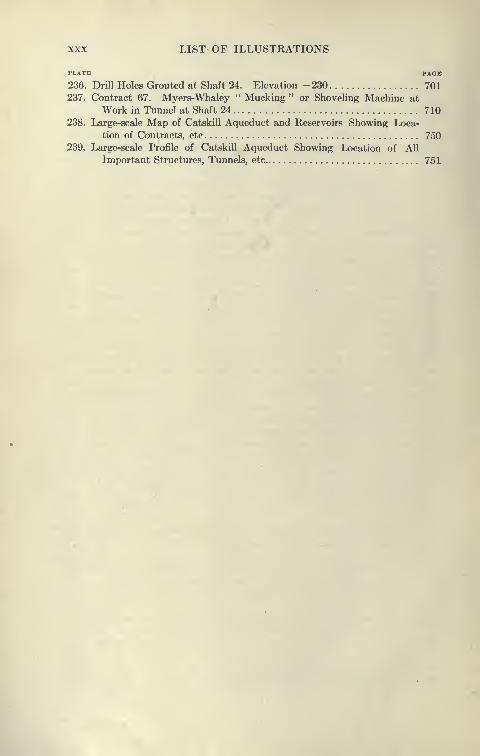
236. Drill Holes Grouted at Shaft 24. Elevation -230 701
237. Contract 67. Myers-Whaley " Mucking " or Shoveling Machine at
Work in Tunnel at Shaft 24 710
238. Large-scale Map of Catskill Aqueduct and Reservoirs Showing Loca-
tion of Contracts, etc 750239. Large-scale Profile of Catskill Aqueduct Showing Location of All
Important Structures, Tunnels, etc 751
LIST OF TABLES
, TITLB rAom
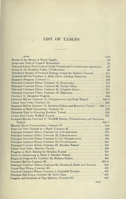
Forces of the Board of Water Supply 32Areas and Yield of Catskill Watershetls 45Unit and Linear Foot Costs of Grade Tunnel and Cut-and-cover Aqueducta . 67Strata in the Rondout Valley (Thicknesses) 68Tabulated History of Inclined Borings Across the Hudson Channel Ill
Itemized Bid for Contract 3, Main Dams Ashokan Reservoir 118
Required Progress, Contract 3 126
Principal Contract Prices, Contract 10, Headworks 172
Principal Contract Prices, Contract 60, Hurley Dikes 174
Principal Contract Prices, Contract 48, Kingston Sewer 177
Principal Contract Prices, Contract 59, Highways 178
Contract 11, Required Progress ^ 196
Itemized Bid for Contract 11, Cut-and-cover and Peak Tunnel 198-9
Linear Foot Costs, Contract 12 249
Itemized Bid for Contract 12, Rondout Siphon and Bonticou Tunnel . . . 2r>0-l-2
Methods of Shaft Excavation, Contract 12 27.'i
Materials Used in Grouting Rondout Tunnel 320
Linear Foot Costs, Wallkill Tunnel 332
Itemized Bid for Contract 47, Wallkill Tunnel, Cut-and-cover and Bonticou
Tunnel. 334-7
Electric Power Consumption, Contract 47 354
Force for Two Tunnels at a Shaft, Contract 47 360
Principal Contract Prices, Contract 15, Cut-and-cover 373
Principal Contract Prices, Contract 16, Cut-and-cover Ji80
Principal Contract Prices, Contract 17-18, Cut-and-cover 386
Principal Contract Prices, Contract 45, Cut-and-cover 391
Principal Contract Prices, Contract 20, Moodna Tunnel 395
Linear Foot Costi, Moodna Tunnel 396
Progress in Shaft Sinking for Moodna Tunnel 397
Force for Concreting at Shaft 6, Moodna Tunnel 401
Required Progress for Contract 90, Hudson Siphon 405
Itemized Bid for Contract 90 408-9
Principal Contract Prices, Contract 80, Breakneck Shaft and Tunnels 420
Linear Foot Prices, Contract 80 422
Principal Contract Prices, Contract 2, Peekskill Division 431
Principal Bid Prices, Contract 62, Steel Pipes '445
Lengths and Location of Pipe Siphons, Contract 62 445
xxxi

xxxii ' LIST OF TABLES
TITLE PAQB
Principal Bid Prices, Contract 68, Steel Pipes 466
Lengths and Locations of Pipe Siphons, Contract 68 466
Principal Contract Prices, Contract 23, Cut-and-cover and Grade Tunnel. . 478
Principal Contract Prices, Contract 24, Croton Siphon 483
Principal Contract Prices, Contract 25, Cut-and-cover and Grade Tunnel . . 493
Principal Contract Prices, Contract 55, Grade-tunnel Cut-and-cover and
Pressure Aqueducts .* 501
Scheduleof Tunnel Shifts, Millwood Tunnel 505
Schedule of Tunnel Shifts, Sarles Tunnel 506
Principal Contract Prices, Contract 9, Kensico Dam 522
Principal Contract Prices, Contract 52, Grade Tunnel and Cut-and-cover . . 542
Principal Contract Prices, Contract 53, Cut-and-cover 556
Principal Contract Prices, Contract 54, Yonkers Pressure Tunnel 559
Principal Contract Prices, Contract 30, Hill View Reservoir 567
Principal Contract Prices, Contract 63, Portion of City Aqueduct Tunnel. . . 596
Method of Sinking Shaft 3 600
Principal Contract Prices, Contract 65, Portion of City Aqueduct Tunnel . . 606
Method of Sinking Shaft 8 616
Itemized Bid for Contract 66, Portion of City Aqueduct Tunnel 628-9
Method of Sinking Shaft 14 632
Method of Driving Tunnels at Shaft 15 644
Itemized Bid for Contract 67, Portion of City Aqueduct Tunnel 652-4
Schedule of Pay and Hours for Compressed-air Workers 665
Comparative Caisson Data 668-9
Method of Sinking Caisson for Shaft 20 673
Comparison of Drilling by Jap and Piston Drills .... 692
Method of Excavating Shaft 20 694-5
Method of Excavating Shaft 22 698-9
Grouting Data for Shaft 24 702
Weekly Progress, Excavation for City Aqueduct Tunnels 712-5
Data on Shaft Sinking in Rock, City Tunnel 716
Approximate Wages Paid on Catskill Aqueduct 718
Progress in Sinking Shafts, Contract 12 719
Tabulation of Contracts for Catskill Water Supply 720-3
Monthly Progress of Shaft Sinking All Shafts of Catskill Aqueduct 724-7
Monthly Progress of Grade Tunnel Excavation, Catskill Aqueduct 728-30
Monthly Progress for Pressure Tunnel Excavation, Catskill Aqueduct . . 730-34
Borings, Test Pits and Soundings 735
Rainfall, Catskill Mountain Watersheds 736-7
Stream Flow, Catskill Mountain Watersheds 737
Length of Catskill Aqueduct in Feet for Various Types of Aqueducts. . . . 738-9
List of Published Articles on the Catskill Water Supply 741-8
Strata Penetrated by Tunnels on the Catskill Aqueduct 749
CATSKILL WATER SUPPLY
CHAPTER I
HISTORY OF NEW YORK WATER WORKS
Supply 1613 to 1774. The Dutch found Manhattan a well-
watered island, traversed by many brooks abounding in fish; with
a large fresh-water pond, known as the " Collect," fed by numeroussprings. The lower part of the island was underlaid with sand which
readily yielded fresh water a few feet above sea level, but the upper
part was mostly hilly and rocky, with little water.
The population of the island by 1664 was but 1500, and water
was obtained from private wells, although about 1658 a public well
was dug near Bowling Green. Later, public wells were dug sys-
tematically at the street comers by the Aldermen and Select
Councilmen of New Amsterdam. Very soon, however, as the towngrew, the wells became contaminated and the supply of water
insufficient. Those who could afford it sent for water from distant
wells. One well in particular, known as the " Tea-water Pump," wasparticularly noted; so that its 'neighborhood became so congested
with water-carts that the spout of the pump was raised and length-
ened to permit pedestrians to pass under it. This well was located
near the site of the notorious " Five Points " at Chatham Square.
By 1774 the population had increased to about 30,000, and the
City was confronted by a shortage of water, a condition which
from that time to this has only been temporarily relieved; for it
has always been that soon after the City settled down with the
comforting assurance that the new supply would be all that could
be desired, the growth of population and demand again created a
shortage of water.
The first water works were begun shortly before the Revolution
by Christopher Colles, an English civil engineer, who aimed to
pump water from wells and the Collect through hollow logs to a
2 CATSKILL WATER SUPPLY
reservoir at Broadway and White Street, employing an old New-commen engine. It was intended to pay for the work with paper
money, some notes of which are still in existence. However, the
Revolution put a stop to this.
Revolution to 1830. After the Revolution, the population hav-
ing increased to 60,000 by 1800, the need for more water was greatly
felt, and the town was spurred on to secure a new supply by the
ravages of yellow fever. After fruitless discussion, the ManhattanCompany, formed by Aaron Burr, was chartered to supply water and
incidentally to emploj^ its surplus capital in moneyed operations.
Aaron Burr's Manhattan Bank Supply. The history of NewYork City's earliest water works is associated with a most interest-
ing period in the politics in the State and country, and with two
of its most notable characters—Alexander Hamilton and Aaron
Burr. New York was then, and in fact remained until the intro-
duction of Croton water, as described by an early writer, "sl city
most destitute of the blessings of good water." In 1799 the Federalists
controlled the legislature of the State and the only banks in NewYork. Hamilton, the great leader of the Federalists, was a director
of the bank of New York, the oldest in the State. Aaron Burr was
the leader of the Republicans, afterwards the Democrats, Burr
and his associates were anxious to secure a franchise for a bank,
which was denied them. They organized the Manhattan Company,which was duly incorporated l^y the legislature in 1799, ostensibly
for the purpose of bringing water from the Bronx River. But they
secured the insertion of the following clause:
" and be it further enacted that it shall and may be lawful
for the said company to employ all such surplus capital as
may belong or accrue to said company, in the purchase
of public or other stock, or in any other monied transactions
or operations not inconsistent with the Constitution and
laws of this state or of the United States, for the sole benefit
of said company."
This generous joker gave the company power to conduct anylawful business, and it soon availed itself of this privilege by open-
ing a bank still in existence as the " Bank of the Manhattan Com-pany " at 40 Wall Street. Instead of going to the Bronx River,
it did the easiest possible thing, constructing an iron water tank
near the Collect Pond and pumping from a well with two 18-
H.P. steam engines. From this place wooden pipes consisting of
bored-out logs were laid through the lower part of the city. They
HISTORY UK NKW VUKK WATKH \VuHiC8 3
are still occasionally dug up in the subway constructions, many of
them still in a fair state of prc^servation. Although twenty miles
of these mains were laid, supplying 1400 houses, the service rendered
by the Manhattan Company was very poor in quality and quantity
(700,000 gals, per day). It remained, however, the only considerable
supply until water was brought to the city by the old Ooton aque-
duct, after which time the service of the Manhattan C^ompany wa«
only nominal and consisted in keeping its old tank full or partly full
of water. This tank is still in existence, l)oxed up in a four-Ator>'
building at the corner of Keade and Center Streets, and is still
supplied with water. Its career will soon be ended, as the prop-
erty is to be condemned, together with a large adjacent area, for a
new monumental court house recently decided upon. The Man-hattan Company is still a powerful institution.
First Public Water Supply. The first public water works were
constructed about 1830. It consisted of an elevated tank of about
230,000 gallons capacity supplied by a steam engine of 12 H.P.,
which pumped from a well at Thirteenth Street and Broadway.
There was quite a shaft, 16 feet in diameter and 112 feet deep,
with two horizontal galleries, each 75 feet long, near the lx)ttom, 98
feet of the shaft being in solid rock. Its daily yield was 21,000
gallons, but the water, which was originally soTt, deteriorated. Fromthis well cast-iron mains, 6 inches to 12 inches in diameter, were
laid and by 1833 a total of about seven miles were placed.
How inadequate the scource of supply first utilized by the city
nmst have been is demonstrated by the results of sinking the Man-hattan shafts of the City Aqueduct. The shaft for the first water
supply was about the same diameter as those of the Catskill Aqueduct.
Shaft 18 at Twenty-fifth Street and Broadway yielded at the depth
of 100 feet, about 20 gallons per minute, or 30,000 gallons per day.
Shaft 19 at Sixth Street and Fourth Avenue, yielded only about
2000 gallons [per day at 100 feet in depth. Other shafts on
Manhattan yield from gallons to 20 gallons of water per
minute.
This first municipal supply proved entirely inadequate, and
mnnerous plans were proposed for new supplies, the city lx?ing
spurred on by the example of Philadelphia, which previously had
secured an ample supply of about two million gallons per day from
the Schuylkill and had thereby conquered the yellow fever, from
which New York was suffering severely. Philadelphia was also
advancing rapidly as a city and threatened to outstrip New York
in commerce.
4 CATSKILL WATER SUPPLY
Proposed New Supplies. The Croton supply was first proposed
in 1830, but seemed a far distant source compared to others proposed,
such as the Bronx River and Rye Ponds. No progress was made,
as proper authorization was not secured from the legislature. In
1832 cholera ravaged the island and impelled the citizens to renewed
efforts. As early as 1798 the dangerous character of Manhattan
Island water was pointed out, and in 1832 the Common Council
reprinted and distributed reports to that effect. Yet it is remarkable
how persistently the people clung to their old wells. The last of
them were banished from the island by the Board of Health a few
years ago.
The first real progress was made when in 1832 Col. De Witt
Clinton was engaged to examine the various sources and routes of
water supply thus far suggested. In a little over a month he reported
and showed the most enlightened comprehension of the problem:
" With such evidence of an augmenting and multiplying wealth
and population in the increase of her ships, her manufacture and the
permanency and splendor of her public and private dwellings, and
with the most conclusive evidence from her geographical position,
and her proximity to the ocean, and the security of her harbor,
that she be to this country what London is to England, it must
be a matter of profound regret that she is destitute of a supply of
good and wholesome water and that there should exist any hesita-
tion to grant her power to obtain an element so essentially con-
nected with the property, health and comfort of her citizens."
To show how costly an inadequate supply of water is, Clinton
estimated that about $270,000 was paid annually for water in
hogsheads hauled from remote springs, and that the shipping paid,
in addition, $50,000 for water supplied from Long Island and NewJersey, not daring to use New York water. Many ships even
carried enough water in casks to last them for the journey back to
their ports to save this charge.
Col. Clinton's Croton Project. Col. Clinton estimated that the
Croton River could supply 20,000,000 gallons per day by natural
flow, and estimating only a consumption of 20 gallons per day
per person, stated that this would make the Croton River a suf-
ficient source for a long time. He recommended a low dam, near
the location of the old Croton dam, to turn the natural flow directh'
into an aqueduct built on grade all the way to New York. Theroute he suggested was that followed later in the construction of
the old Croton Aqueduct.
The Croton scheme was strongly opposed by many people,

HISTORY OF NEW YORK WATER WORKS 5
particularly by those who thought artesian wells could yield asufficient supply, and others who thought the Bronx River wa« anadequate source. A company was promoted known as the Rock-
water Company which proposed to drill wells, and advanced the
following argument:'• By thus supplying the inhabitants with fine, pure rock water
it will remove the popular pretext for using alcohol to correct the
impurities of the water now in general use, and will be the most
effectual means of promoting the great and noble cause of temperance
in this city."
Even at this time, however, it was kno\\Ti that ManhattanIsland was ill adapted to yield artesian water, as the water hitherto
found in deep wells provod both deficient in quantity and quality.
First Act for New Water Supply. In 1834 the Legislature of
New York passed " An act to Provide the City of New York with
Pure and Wholesome Water." Ever since, all the water legislation
starts with the same formula.
The first water commissioners engaged Maj. D. B. Douglas of
the United States Military Academy to make surveys and investiga-
tions. He examined both the Croton and the Bronx Rivers and
reported decidedly in favor of the former. He estimated that
the Bronx River could supply only about six million gallons per day.
Old Croton Dam. The first adequate water works for New-
York City was constructed between 1837 and 1842. To form a
reservoir an overflow weir, known as the old Croton Dam, was
built about six miles above the mouth of the Croton River. This
dam was of very peculiar construction, being founded on rock-
filled timbered cribs placed in the bed of the stream and only partly
on ledge rock. On these cribs ashlar granite masonry was laid up
to form an ogee curve of about 55 foot radius. The maximumheight of the dam was thus about 50 feet, about 240 feet of its
width forming a spillway, with its crest at an elevation of about
166.2 feet, Croton datum. A secondary crib dam 300 feet down-
stream from the apron of the main dam was built to form a water
cushion and prevent erosion of the toe of the dam; also to break
the fall of the water into two parts, 33 feet and 15 feet respectively.
Above the masonry dam was a long slope, about one in five, paved
with heavy riprap. This dam served its purpose perfectly until
the New Croton Dam was put in commission in 1907. Continuous
records have been kept of the flow over the dam, so that we have
complete records of the Croton River for over forty-five years.
Very heavy floods have repeatedly passed over the dam; in 1854
6 CATSKILL WATER SUPPLY
there' was 8 feet of water on its crest and the secondary dam was
washed out, creating considerable alarm at the time. Other floods
at times have washed great holes below the secondary dam, which
has had to be repaired frequently. It is probable that without
the protection of this secondary dam the main dam would have
been washed out.
Old Croton Aqueduct. The old Croton Aqueduct has a cross-
section of only about 53 square feet and is horseshoe shaped,
8' b"Xl' b" . The aqueduct follows mainly the surface of the
ground along the bank of the Croton River to the Hudson, thence
along the Hudson to Yonkers; thence along the ridge between the
Hudson and East Rivers to High Bridge, crossing the Harlem River
at this point on high masonry arches built in the style of the old
Roman aqueducts. This aqueduct bridge is 1450 feet between
gate houses, and consists of fifteen semi-circular arches. Eight
80-foot spans, and seven 50-foot spans. Soffit of arch is 100 feet
above high water. Four of the piers are founded on rock; others
on cofferdams sunk as low as 54 feet below tide. It was first pro-
posed to build this bridge to hydraulic grade, which would have madeit many feet higher. In order to save expense it was left low and on
the top of it two 36-inch pipes were laid. In 1860 a wrought-
iron pipe 7 feet 6§ inches in diameter was added, the side walls
raised up and roofed over, as it now appears. The pipe is still in
a very good state of preservation. The cost of High Bridge was
about $1,000,000. It is to-day almost perfect, showing no signs
of deterioration and is probably the finest piece of masonry in the
vicinity of New York.
After crossing High Bridge the aqueduct follows along Tenth
Avenue to 108th Street, crossing the Manhattan valley in a line of
two 36-inch pipes, thence in a masonry conduit to the Central
Park receiving reservoir. Though the city between Eighty-fifth and
108th Streets had been long mapped and the present street system
adopted, the first water commissioner thought there was very little
likelihood of this portion of th<^ city being built up, and he constructed
the ordinary type of aqueduct diagonally across the street system,
leaving a few archways for certain streets to pass through. How-ever, by 1865 the city had grown up into this neighborhood, and bylegislative act it became necessary to remove this portion of the
aqueduct. It was replaced by two lines of 6-foot cast-iron pipes If
inches thick. For some reason these pipes gave a great deal of
trouble, frequently splitting at the hubs, and finally had to. be
replaced by three lines of 4-foot pipes.

HISTORY OF NEW YORK WATER WORKS
COMPARATIVE SECTIONS OF
AQUEDUCTS
0^^';.
I4i8an
CATSKILL
Dit
mAQUA CLAUDIA
NEW CROTON
OLD CROTON
Plate 1.—Comparative fcjoctionjj of Ancient Roman, Croton, and Catskill
Aqueducts.
8 CATSKILL WATER SUPPLY
The grade of the aqueduct is 13J inches per mile; for the Harlem
and Manhattan siphons 2 and 3 feet extra head were used up.
Later, to draw more water from Croton Lake the upper five miles
of the aqueduct was depressed to a grade of six-tenths of a foot per
mile, to gain about 3 feet of storage. There are sixteen short tun-
nels on the old aqueduct, 160 to 1263 feet long, aggregating 6841
feet. There was a limited appropriation for the construction of
this aqueduct, so that it was necessary to be economical in its
design. A great deal of the aqueduct has been built on loose rock
fills and the slopes in the embankments are very steep, often being
held by dry rubble walls.
Consumption of Croton Water after 1842. Upon the com-
pletion of the first aqueduct it was estimated that a liberal per
capita consumption would be 22 gallons. As the population was
then but 300,000, and the capacity of the aqueduct was estimated
at 72 to 95 million gallons per day, it was thought that it would be
able to supply water to the city for a long time to come. It was
found, however, that 22 gallons was far from sufficient, as the
people learned to use water lavishly; by 1850 the per capita con-
sumption was 90 gallons. Twenty-five years after completion
the aqueduct was running at more than its maximum safe
capacity.
On some of the high embankments the aqueduct had settled
considerably. To get water by these depressions it was necessary
to put the aqueduct under pressure. At these embankments manylongitudinal cracks opened in invert and arch. Every year extensive
repairs were made, the aqueduct being drained for a few days
and reinforced by additional rings of brick and by grouting the
cracks. In 1885 an extensive break occurred ,at Van Cortlandt
Park, necessitating shutting off the aqueduct for several days, during
which time the water in the Central Park Reservoir was almost
drained down.
It was early found that the old receiving reservoir of 180,000,000
gallons capacity, and the Murray Hill distributing reservoir of
24,000,000 gallons at Forty-second Street and Fifth Avenue, whose
site is now occupied by the Public Library, were entirely inade-
quate to supply the city, particularly at times when the aqueduct
was out of service.
Central Park Reservoir. Between 1857 and 1862, the new Central
Park reservoir of 1000 million gallons capacity was constructed.
The basin for the new reservoir was made by excavating between
natural hills and building embankments. These embankments

HISTORY OF NEW YORK WATER WORKS 9
have puddled core walls, and slopes of 1} to one, the interior
slope being paved with large cemented blocks and the outer slopes
sodded. The reservoir ha.s a water surface of 90 acres and a max-imum depth of 38 feet. This reservoir is of much greater capacity
than the former one was and has l^een of great service to the city,
particularly up to the time of the completion of the 'new Croton
Aqueduct. •
High Bridge Reservoir. A considerable settlement sprang upin the neighborhood of Washington Heights at quite an early ix^riod.
This district, being above the level of the Croton Aqueduct, had t«
be supplied with a high-pressure service. In 1869 a new reservoir
was built at the Manhattan end of High Bridge, which has a water
surface elevation of 216 feet, with a capacity of 10 million gallons.
A still higher district is supplied from the water tower of 47,000
gallons capacity, elevation 324 feet. To supply this reservoir andtower some large pumps were installed.
Shortage of Water 1869, 1876, 1880, 1881. In 1869 there were
only four storage reservoirs which could be drawn upon for water,
viz., the original Croton Lake, the old receiving reservoir in Central
Park, the new Central Park Reservoir, and the Murray Hill Reservoir.
These had a combined capacity of only 1804 million gallons. Therainfall that year and the next was very small, so that all the
reservoirs were emptied and only the natural flow of the Croton
River available, estimated at about 30 million gallons per day,
ordinary flow. Luckily there were many natural lakes and ponds
in the watershed. Drastic measures were taken and the outlets
of these ponds deepened, so that they were drawn upon for 2000
million gallons. The Boyd's Comer Reservoir was put in service
in 1873, and holds 270 million gallons.
Nevertheless, in 1876-1877, the city again suffered from drought
and was confronted with a shortage of water. By special legislative
enactment the city secured permanent rights to draw water from
available lakes in the watershed, these rights being appraised by
condemnation. This met with violent opposition from the property
owners, particularly those who owned estates along the shores, as
some of these lakes are picturesquely located among the hills.
Middle Branch Reservoir on the Croton River, completed in
1878, added 4000 million gallons to the storage supply, making
a total storage of about 8000 million gallons. But, again, in 1880-
1881, the two driest years on record, all the reservoirs were emptied,
and the natural flow of the Croton River dropped down to 10 million
gallons daily. It was necessary to throttle the supply and great

10 CATSKILL WATER SUPPLY
hardship was the result. Some new ponds were again drawn upon
and the situation saved.
Bronx and Byram Supply. In order to secure a supply for the
portion of the city, then recently annexed, lying above the Harlem
River, the Bronx and Byram Rivers were drawn upon in 1884, and
a reservoir was created by the construction of the Kensico Dam,having a storage capacity of 1620 million gallons. The area of water-
sheds of the Bronx River and Byram combined is only 22 square
miles. The conduit is a 48-inch pipe, 15.2 miles long, from
Kensico Lake to Williamsbridge Reservoir. This supply was first
proposed in 1798 and then deemed sufficient to supply the whole
city of New York for a long period. The Bronx system, though
supplying only a small amount of water, has proved to be of great
value through the Kensico Reservoir, which is to be greatly enlarged
to form an essential part of the Catskill water system.
New Croton Reservoirs. In 1892 the East Branch, Sodom and
Bog Brook Reservoirs added a total of 9000 million gallons to the
storage supply.
Many of the low dams commonly built in the Croton system
are of earth with masonry core walls on rock or hardpan, but
supplied with ample masonry spillways. This tj^pe of dam is
economical in construction, and, if provided with ample length
of spillway, is safe. None of the dams of this type in the Croton
system has failed.
Shortage of Water in iSSo. By 1880 the population of the
city had increased to 1,212,000, but the water supply had remained
constant for a long time, the average amount supplied by the
Croton Aqueduct being 86 million gallons and the Bronx 16 million
gallons. This was entirely insufficient for the city, it being estimated
that 45 million gallons more per day would have been used had
the supply been sufficient. This shortage of water necessarily
caused low pressures and much pumping to secure water at the
upper stories of the houses, the day pressure being reduced to the
first- and second-story level in many parts of the city, with manymains throttled to reduce pressure and check consumption.
New Croton Aqueduct. In 1882 Isaac Newton, Chief En-
gineer, proposed that a new aqueduct be built to supply 250
million gallons per day, that it be constructed entirely in tunnel
(12 feet in diameter) with an inverted siphon under the Harlem
River. To aid in its construction, 35 shafts were to be sunk. For
additional storage a great dam was to be built at Quaker Bridge,
a few miles below the old Croton Dam. This plan met with so nmch
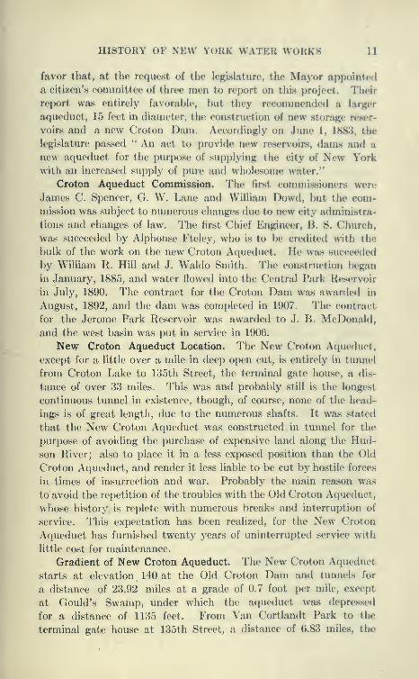
HISTORY OF NEW YORK WATER WORKS 11
favor that, at the request of the legislature, the Mayor appointcn]
a citizen's committee of three men to report on this project. Their
report was entirely favorable, but they recommended a larger
aqueduct, 15 feet in diameter, the construction of new storage reser-
voirs and a new Croton Dam. Accordingly on June 1, 1883, the
legislature passed '* An act to provide new reservoirs, dams and a
new aqueduct for the purpose of supplying the city of New Yorkwith an increased supply of pure and wholesome water."
Croton Aqueduct Commission. The first commissioners were
James C. Spencer, CI. W. Lane and William Dowd, but the com-
mission was subject to numerous changes due to new city administra-
tions and changes of law. The first Chief Engineer, B. S. Church,
was succeeded by Alphonse Fteley, who is to be cretlited with the
bulk of the work on the new Croton Aqueduct. He was succeeded
by William R. Hill and J. Waldo Smith. The construction began
in January, 1885, and water flowed into the Central Park Reservoir
in July, 1890. The contract for the Croton Dam was awardetl in
August, 1892, and the dam was completed in 1907. The contract
for the Jerome Park Reservoir was awarded to J. B. McDonald,
and the west basin was put in service in 1906.
New Croton Aqueduct Location. The New Croton Aqueduct,
except for a little over a mile in deep open cut, is entirely in tunnel
from Croton Lake to 135th Street, the terminal gate house, a dis-
tance of over 33 miles. This was and probably still is the longest
continuous tunnel in existence, though, of course, none of the head-
ings is of great length, due to the numerous shafts. It was stated
that the New Croton Aqueduct was constructed in tunnel for the
purpose of avoiding the purchase of expensive land along the Hud-son River; also to place it in a less exposed position than the Old
Croton Aqueduct, and render it less liable to be cut by hostile forces
in times of insurrection and war. Probably the main reason was
to avoid the repetition of the troubles with the Old Croton Aqueduct,
whose history is replete with numerous breaks and interruption of
service. This expectation has been realized, for the New Croton
Aqueduct has furnished twenty years of uninterrupted service with
little cost for maintenance.
Gradient of New Croton Aqueduct. The New Croton Aqueduct
starts at elevation 140 at the Old Croton Dam and tunnels for
a distance of 23.92 miles at a grade of 0.7 foot per mile, except
at Gould's Swamp, under which the aqueduct w^as depressed
for a distance of 1135 feet. From Van Cortlandt Park to the
terminal gate house at 135th Street, a distance of 6.83 miles, the

12 CATSKILL WATER SUPPLY
aqueduct is depressed below hydraulic grade, crossing under the
Harlem River at an elevation of 300 feet below mean high water.
At 135th Street the water rises vertically to near the surface and
thence through eight 48-inch cast-iron pipes to Central Park
Reservoir, a distance of 2.35 miles, making a total length of Aqueduct
from Croton Lake to Central Park of 33.1 miles. The elevation
of water surface at Central Park is 119 feet and the total fall in the
aqueduct is 33.7 feet, an average of very nearly a foot to a mile.
Construction of New Croton Aqueduct. The aqueduct was con-
structed from thirty main shafts, and ten additional shafts added
for construction purposes, and two inclines from the surface. Theshafts were spaced 4000 to 7500 feet apart, although at difficult
points they were only 400 to 1200 feet apart. The average distance
between working points was 3400 feet. The depth of the shafts
varied from 21 to 391 feet, the average being 127 feet. The shafts
were timbered with 12''xi2" sets, 3 to 6 feet apart; back of
these bents 3-inch lagging was placed, packed with cord woodor loose rock. Nearly all the shafts were lined with masonry,
and are used for inspection, repair or ventilation. Two shafts
adjacent to the Gould Swamp Siphon and the Harlem River Siphon
are arranged to allow the pumping out of the low stretches. Thedepth of the tunnel varies from 50 to 500 feet.
To explore the line of the tunnel a considerable number of
diamond-drill borings were made, although this was rather unusual
for the time. Not enough borings were taken to fully develop the
rock profile, with the result that the tunnel at several points ran
out of rock into difficult soft ground. This was particularly so at
Gould's Swamp, where, after a vain attempt to put the tunnel
through at grade, it was depressed for a distance of 1135 feet, andbuilt circular, 14 feet 3 inches in diameter.
Harlem Siphon. It was known that at the contact between the
limestone and schist, a soft band of rock existed, and this was partly
explored by diamond-drill holes from the surface of the HarlemRiver. An attempt was made to drive the headings through at
an elevation —150, but Heading 25 North ran into a soft wet rock
at the contact. This was bulkheaded off and the seam explored bj^
horizontal diamond-drill holes. It was then decided to drop the
tunnel to elevation —300, where no difficulty was experienced^
the rock being reported to be even too dry, so that water had to
be carried to wet the drill holes. The Harlem River Siphon wasconsidered to be the boldest undertaking in the new Croton Aqueduct,
carrying as it does water at a level of 420 feet below hydraulic grade.
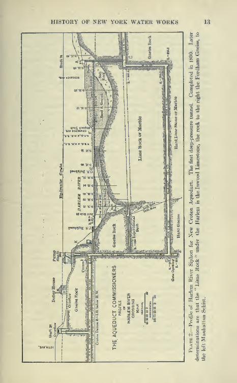
HISTORY OF NEW YORK WATER WORKS 13
OLkL
s
-
o w
c ^c -^
2 o
3 S:i
l|2 I'c 6
^.2
IIs s
s
o ^
u «o> 0)
•rs as ^
fc. oS
1" 5
• § Cc^ -^ ca
a OS S
14 CATSKILL WATER SUPPLY
It is but part, however, of a siphon 6.8 miles long, carrying water from
the city border to well within Manhattan Island. As far as known,
nothing like this had been attempted previously, unless we go back
to ancient times, when it is said that the Greeks distributed water in a
similar fashion. It is probable, however, that their tunnels were
shallow and under slight head. The Harlem River Siphon has
justified itself, as it has been in continuous operation for twenty
years. The leakage from the whole 6.8 miles under pressure is
said to be only a few hundred thousand gallons per day.
Construction of Tunnels for New Croton Aqueduct. TheCroton Aqueduct was constructed by methods very similar to those
now in use. The shaft contained two compartments in which cages
were raised and lowered by large steam hoists, the excavation being
removed in cars of about 1 cubic yard capacity. Large Randand Norwalk compressors were installed at the tops of the shafts to
furnish air at 80 to 100 pounds pressure. Ingersoll, Rand, Sergeant
and Rattler drills were in use. The cages and hoists were Otis
and Lidgerwood t^-pes. In the shaft sinking Cameron and Deanpumps were used. The headings were drilled from columns, twocolumns ordinarily being used, mounting either one or two drills,
much as in present practice. It ordinarily took from six to nine
hours to drill a heading of twenty holes, holes being used as follows
in each heading: eight cut holes 8 feet deep, six side holes 7i feet
deep, eight rim holes 5i feet deep. This heading broke about 100
square feet. The powders used were mainly dynamites, Atlas
and Forsyth. In addition, *' rackarock " powders were used to
some extent. This was mixed on the ground from its constituents,
chlorate of potash and nitrobenzole, portions 75 and 25 per cent.
At one . time this was considered good practice, as the harmless
ingredients could be shipped separately, but it is now considered
that there is more danger in preparing the powders on the ground
than in shipping, and that it is better to have the mixing done
under careful supervision at the powder mill.
It is interesting to note that incandescent electric lights were
introduced into these tunnels in 1886, although at first arc lamps
were used. Some attempt was made at artificial ventilation, a
few Baker and Sturtevant blowers being installed to pump air
through pipes into the headings, but the main reliance for ventila-
tion was upon the air released by the drills. The top headings were
driven about 100 feet in advance of the bench, much as is done
now in the standard American practice, and the progress madewas only a little less than is now usual in tunnels of this class, the
HISTORY OF NEW YORK WATER WORKS 15
average progress of headings being from 25 to 40 feet per week. Avery creditable record wjts made in tunnel 16 N, where the con-
tractors, Denton, Breuchand & Co., in order to see what they
could do, worked their plant and men at maximum capacity, andsucceeded in excavating 127 feet of heading in one week. It is
interesting to note that the ordinary contract price for excava-
tion of rock in tunnel on this Croton Aqueduct was somewhat less
than that for similar rock on the Catskill Aqueduct, averaging
about $5.50 per yard. This was probably due to the lower price of
labor at the time, and a longer working day, there being no eight-
hour law at that time. This is only partially overcome by the
better progress made at the present time.
Consumption of Water at Opening ^f New Croton Aqueduct.
When water from the New Croton Aqueduct was turned into the
Central Park Reservoir in 1890 the chronic shortage of water which
had existed for many years was immediately relieved and the con-
sumption of water jumped from 102 million gallons per day to 170
million gallons. The city now (population 1,720,000) settled downwith the comforting assurance that it would have an abundance
of water for many years, the capacity of the new aqueduct being
over 340 million gallons per day. It was, nevertheless, knownto engineers that the Croton supply could not be sufficient very
long, in view of the great growth in population and the increased
per capita consumption.
The Croton Aqueduct was purposely built larger than the
probable yield of the Croton watershed even when fully developed.
For some years the increased consumption was provided for by the
building of new reservoirs, particularly that formed by the con-
struction of the new Croton dam. By 1899 the consumption had
increased so rapidly that it bade fair to overtake the supply, yet
little effort was made to prevent waste.
Ramapo Water Company. As the City of New York was makingno effort to secure a supply outside of the Croton watershed, someshrewd up-state politicians joined with others in the city to form a
water company known as the Ramapo Water Company, which secured
very broad powers from the legislature; in fact, its powers of
acquiring water rights exceeded that enjoyed by any municipality.
By simply filing plans with any county clerk it could acquire
both reservoir rights and routes for aqueducts; and any objecting
property owner had to file a protest within fifteen days and guarantee
to pay the expenses of a commission to be appointed by the courts
in case of adverse report. On this commission was to be one civil
16 CATSKILL WATER SUPPLY
engineer who had the deciding vote. The property owner, also,
was required to propose an alternate route or scheme which, in the
judgment of this engineer, would be more favorable to the companythan the company's own project. This company put a few sur-
veying parties in the field and filed plans covering all available water
routes in the lower part of the State. And, naturally, with the law
as above outlined, few protests were made. The general scheme
adopted by the Ramapo Company's engineers bears a remarkable
resemblance to the final Catskill project now being constructed bythe City.
Proposed Ramapo Contract. Greater New York, or the present
city, came into being January 1, 1898. By its charter the Board
of Public Improvements had the power to enter into contracts for
water supply. Suddenly, on August 9, 1899, the Water Com-missioner presented to this board a proposed contract with the
Ramapo Company. This contract provided that the company was
to supply the city with 200 million gallons per day at $70 per
million gallons, and was to be in force for forty years. Con-
sequently, the city, by this single contract, would be committed to
the expenditure of about $200,000,000. To insure the performance
of this contract the company was to supply a bond of only $100,000.
Water was to be supplied at the city limits at a pressure " due to a
head at 300 feet above mean tide." This contract was prepared
in secret and suddenly sprung on the Board of Public Improvements
with the assurance that a majority would favor it. However, the
Controller and one other Commissioner strenuously opposed this
contract, but were voted down. A request that four weeks be given
to consider the proposition was also voted down. Finally, two weeks
were allowed. This was more than sufficient. On the following
day a tremendous storm of indignation arose, and the Ramapocontract proved to be one of the greatest sensations in the history
of the city, making and unmaking many politicians.
Independent investigations of this project were immediately
started by the Controller and the Merchants' Association of NewYork. It was shown that the cost of water from the Croton supply
was about one-half of the proposed Ramapo rate, and that for less
than the sum contracted for an entirely new system could be con-
structed by the city and paid for in the same time, whereas under
the Ramapo contract the city would again be helpless at the end
of forty years. The reason the Water Commissioner gave for
favoring this contract was that the private water companies hadobtained the water rights and that the city could not find any other
HISTORY OF NEW YORK WATER WORKS 17
watersheds; also that the consumption had grown so fast that in
five years the capacity of the Croton watershed would be reached.
The Water Commissioner stated that it was unnecessary to
investigate this Ramapo project, as he had personally visited
the sites of the proposed Ilamapo reservoirs and found them to
be sufficient. At the end of the two weeks' time given, the Ramapoproject was dead, and no one dared to bring it up serioasly again.
In addition, Gov. Roosevelt secured the repeal of the charter of the
Ramapo Company. The people on the watersheds awakened to
the fact that their rights had been taken away from them secretly
and became as wrought up, over the situation, as the city. •
Investigation by Merchants' Association and John R. Freeman.
This proposed Ramapo contract was of the greatest benefit bycausing the city to realize that it was greatly in need of a new water
supply. Many independent investigations were started which
directly led to the construction of the Catskill Waterworks. TheMerchants' Association in its report of August, 1900, went very
fully into the situation. In addition to this, John R. Freeman
reported to the Controller in 1900. This book has become a classic
on the subject of water supply and is a mine of information and a
most thorough review of the water situation at the time. Mr.
Freeman reported that the Croton watershed would in a few years
be drawn on to its full capacity, and favored the Ten Mile and
Housatonic Rivers as a new source of supply. He considered this
supply as ideal in every way, as an excellent dam site was found
for an immense storage reservoir which could yield 750 million
gallons per day by gravity to a distributing reservoir 300 feet above
sea level. He also estimated that the cost would not exceed $10 per
million gallons. But, unfortunately, insuperable legal obstacles
stood in the way of acquiring these water rights, as Ten Mile and
Housatonic Rivers are in the State of Connecticut, and there is no
way by which New York State can condemn water rights or prop-
erty there. At this time the government had not yet published
its geological survey maps of the Catskill region, so that in the
limited time allowed Mr. Freeman, he could not get an adequate
idea of the Catskill watersheds and formed a rather unfavorable
opinion of their possibilities.
Commission on Additional Water Supply. As the administra-
tion identified with the Ramapo contract fell into disfavor, no prog-
ress was made towards securing a new supply until a new Mayor,
Seth Low, came into office. Mayor Low appointed in 1903 Messrs.
Burr, Herring and F'reeman to constitute a Commission on
18 CATSKILL WATER SUPPLY
Additional Water Supply for the City of New York. It was
created to make a thorough, complete and exhaustive examination
and investigation into the following:
(a) The quickest and best methods of reducing the waste of
water in the city, and conserving and increasing the efficiency of
the present supply.
(b) The probable future consumption of water in each of the
boroughs of the city.
(c) The future supply for the City of New York; and
(d) A temporary supply, if feasible.
Findings of Commission on Additional Water Supply. The
commission was supplied with ample means for carrying out these
investigations and organized a large engineering force of six depart-
ments, in which were 200 men. An immense amount of work was
accomplished in a very short time, and a printed report was issued
in 1904. The commission found that the waste of water had been
exaggerated; that when account was taken of the transient popula-
tion of Manhattan Island the consumption of water was but moderate
compared with other American cities. It nevertheless recommended
that all efforts be made to prevent water waste, as it estimated that
in five years the safe capacity of the Croton watershed would be
reached. It recommended that an aqueduct to supply 500 million
gallons per day be built, and found that the most available water-
sheds were those in the Catskills, consisting of the Esopus, Ron-
dout, Schoharie and Catskill Creeks, these to be supplemented by
other watersheds east of the Hudson near the line of the proposed
Catskill Aqueduct, that is, Jansenkill, Wappinger Creek, and Fish-
kill Creek. This report met with great favor, and was regarded by,
those capable of judging, as a thorough exposition of the needs of
the city and showing a way out of the difficulties of the water
situation.
For an immediate supply the watersheds above the Croton,
such as the Fishkill, were to be first developed and used as an aux-
iliary to the Croton supply. Later, the Esopus and Rondout
supplies were recommended for development. For Brooklyn, the
commission recommended immediate development of the ground
water supplies of Long Island. They also recommended filtration
of the Croton supply and planned a complete filtration works at
Stormville for the Catskill water, although they reported that the
Catskill water was of exceptional purity and quality. The com-
mission discovered that by building a higher dam than that pro-
posed by the Ramapo Company at Olive Bridge across Esopus
HISTORY OF NEW YORK WATER WORKS 19
Creek, a very large reservoir with a flow line of 560 feet above datumcould be created, damming both the Esopus and Beaverkill Creeks
at one time, and that the Esopus watershed alone would yield 250
million gallons per day.
Nothing further was done by the Ix)w Administration toward
providing a new supply, although the work on the Croton water-
shed was pushed to completion, the immense Croton Dam l)eing
completed and new reservoirs started on branches. J. Waldo Smith
at that time was chief engineer of the Aqueduct Commission
having this work in charge.
Restrictive Legislation for Supplies East of Hudson. Mean-while, the counties in which the proposed reservoirs east of the
Hudson were to be located became alarmed, fearing that their water
rights would be taken away from them by the City of New York,
and succeeded in having passed by the legislature a law prohibiting
New York from securing further rights east of the Hudson. Thereason for this was that many scandals arose in condemnation of
land in the acquiring of water rights in the Croton watershed,
although the City of New York in the long run probably largely
overpaid the property owners. In the adjustment of the claims
there were long and exasperating delays which bore very unequally
on the residents. These restrictive laws were passed in the face
of strong opposition from the City of New Y^ork, and followed the
precedent laid down when certain restrictions were placed on the
streams of Suffolk County at the eastern end of Long Island.
McClellan Bill. Mayor McClellan on coming into office in
1904 evinced a strong interest in the movement to provide an
additional water supply for the City of New York, and in January,
1905, a water bill was introduced in the legislature providing
for the appointment of a board to have charge of the proposed
construction. The commissioners were to be nominated by three
civic bodies. Objection was raised to this as unconstitutional. In
Ofder to show his non-partisanship, the Mayor promised to appoint
these men from lists to be furnished unofficially by the Chamber of
Commerce, the Board of Fire Underwriters, and the Manufacturers
Association, hoping that this precedent would be followed in the
future. The bill became a law in June, 1905, and was considered
to be a model law, securing the principles of non-partisanship,
home rule and efficiency. The three commissioners appointed
were J. Edward Simmons of the Chamber of Commerce, Charles
N. Chadwick, of the Manufacturers' Association, and Charles A.
Shaw, of the Board of Fire Underwriters.
20 'CATSKILL WATER SUPPLY
The Board of Water Supply. The Board was organized in June,
1905, and by August 1st it had appointed John R. Freeman as
consulting engineer, J. Waldo Smith as chief engineer, and a little
later William H. Burr, and Frederick P. Stearns as consulting
engineers. By October of that year, the Board of Water Supply
had made a report to the Board of Estimate, submitting schemes
with maps for obtaining water from Catskill sources. This met with
no opposition and was adopted unanimously by the Board of
Estimate.
State Water Supply Commission. A law was enacted at the
same time as that creating the Board of Water Supply for the city,
establishing a State Water Supply Commission which was to have
general charge of the water resources of the State. This law madeit necessary for a city, before proceeding to the construction of any
water works, to secure the formal approval of the State Commission.
Recently, the work of the State Water Supply Commission has been
taken over by the Conservation Commission of the State of NewYork.
A small engineering force was put into the field by the Board
of Water Supply for the city, which surveyed a new aqueduct line
from the Ashokan Reservoir on Esopus Creek to New York.
With the aid of the information gathered by them and the invaluable
United States Geological maps of the State, a large, comprehensive
map showing the proposed reservoir and routes of the aqueduct
was prepared and submitted for approval to the State Water Supply
Commission. This was barely three months after the appointment
of the chief engineer. After extended hearings at Kingston, where
a great deal of opposition to the project on the part of the residents
of Ulster County developed, the State Commission gave favorable
decision May 18, 1906, leaving the way open for construction.
This gave the city authority to draw on Esopus, Rondout and
Catskill Creeks, and other minor streams in the Catskills, but for
some legal reasons permission to draw on Schoharie Creek was not
given. It also carried with it general approval of the route of the
aqueduct. This was quite different from that proposed by the
Commission on Additional Water Supply, due to the fact that it
was now unnecessary to go near reservoirs or streams east of the
Hudson, as their use was barred by legislation.
Future Supply for City. The only projects which can seriously
compete with the Catskill supply are those of the Housatonic,
Central Hudson, and Upper Hudson or Adirondack supplies. TheCorporation Counsel rendered an opinion that it was useless to
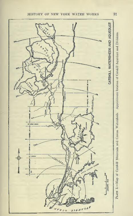
HISTORY OF NEW YORK WATER WORKS 21

22 CATSKILL WATER SUPPLY
attempt to secure water from the Housatonic, as the legal obstacles
were almost insuperable. The Commission on Additional Water
Supply found that the Central Hudson supply in the neighborhood
of Poughkeepsie would have to be filtered and pumped. In addi-
tion, impounding reservoirs would have to be built in the
Adirondacks, to prevent at times of extremely low flow, the salt
water from advancing well up the Hudson. This would make the
Hudson supply decidedly more costly and unsatisfactory than any
gravity supply. The Adirondack supply was found to be excellent,
but due to its great distance and high value of the water powers,
its cost is almost prohibitive at the present time, although it is
probable that the next supply, when New York will have outgrown
the Catskill supply, will be obtained from the upper Hudson or
Adirondacks.
Brooklyn Water Supply. The City of Brooklyn has always
been able to obtain a sufficient supply of water from Long Island, and
a portion of its own area has supplied considerable water. Long
Island is a great plain sloping gently toward the ocean, the northerlj^
portion of the island bordering Long Island Sound being a terminal
moraine. The hills here are irregular deposits of glacial drift,
ranging up to a few hundred feet in height and cut into deeply by
numerous bays. Except for the glacial drift, the surface material
is very porous, being underlaid by a depth of from 40 to 60 feet of
yellow gravel and quartz sand. Below this there is a blue clay
stratum, and below this alternating layers of gravel, sand and clay
for 500 feet or more. The main reservoir of water is that above
the layer of clay. The surface streams on Long Island are insig-
nificant and are mainly near the south shore, where they are fed to a
considerable extent by ground water. The ground water slopes
gently from the center of the island to the South shore, where its
elevation is about that of sea level. On the North shore it drops
off sharply to the level of Long Island Sound.
Long Island Sound Water Supply. The ground-water level at
the center of the island is about 80 feet above sea level and slopes
to sea level on the north shore in about 5 miles and on the south
shore in about 10 miles. The plain bordering the south shore is
from 10 to 20 miles in width and ahnost parallel to ground
water and comparatively few feet above it. Shallow wells at anypoint in this plain reach cool, fresh, and palatable water, inexhaustible
for ordinary purposes. This has given rise to the belief that an
unlimited quantity of water can be obtained from Long Island;
that it is only a question of more wells and more pumps. A careful

HISTORY OF NEW YORK WATKR WORKS 23
investigation by the Brooklyn Water Department, the Commission
on Additional Water Supply, and the Board of Water Supply has
clearly shown that there are definite limits to this supply; that the
island can be treated as an ordinary watershed dependent upon rain,
the porous strata absorbing the water and storing it up as a reservoir.
Incidentally, as the water seeps downward at rates up to 3 feet
per day it is filtered and cooled and preserved in perfect sanitary
condition until drawn upon. It is estimated that from 15 to 19
J
inches of rainfall are absorbed per year. The water naturally
flows toward either shore at an observed rate of about 2 feet per
day. It is estimated that this watershed if fully developed would
yield about 800,000 gallons per day per square mile, under ordinary
conditions.
Wells and Underground Streams. The peculiarity of a ground-
water reservoir is that it lias to be drawn upon from a great manypoints to furnish its full yield, as any single well tends to drain out
an inverted cone-shaped volume of ground adjacent to it. Asground water is reached within a few feet of the surface adjacent
to the south shore, the tendency has been to place batteries of wells
here and in the valleys of streams tributary to the bays bordering
the shore. It has been found that these wells have to be very
carefully pumped lest the flow of the ground water be reversed
and the salt water flow inward toward the well. This has
spoiled some wells, rendering them brackish. A still worse effect
is to spoil an entire district, so that to restore the original fresh-
ness of the water it is necessary to abandon the wells for a
period of several years. Various absurd statements have been
made that the ground water of Long Island is maintained by
streams flowing underground from Connecticut and New Jersey,
and attempts have been made to locate these streams. One maneven entered into contract with the city of Brooklj-n to supply
water from an underground stream which he claimed to have located.
A battery of wells was driven, and the water elevated by air Ufts.
For a short time a considerable quantity of water was supplied, but
very shortly it was found to fail and become brackish, proving
that he had merely drawn too heavily on ordinary ground water.
The Ridgewood System. At present Brookl>Ti relies entirely
on the Ridgewood System reinforced by various local supplies
provided by water companies and pumping stations within the city
limits. At present the Ridgewood system supplies about 150
million gallons per day from an area of 159 square miles. This
is probably the largest and best underground supply obtained by
24 CATSKILL WATER SUPPLY
any city. An aqueduct has been built from Ridgewood parallel
to and distant from the South shore of Long Island for a distance of
about 20 miles. This aqueduct intercepts numerous streams,
but is supplied mainly from wells and infiltration galleries. Thewater flows by gravity through this conduit to the Ridgewood
pumping station, where it is pumped to the Ridgewood Reservoir,
at which the main supply mains of Brooklyn originate. The west-
erly portion of this aqueduct was built in 1860, and the easterly
portion, or New Conduit, about 1890.
Subsequent to 1906 a 72-inch steel pipe line was laid parallel
to the original aqueduct, having a capacity of about 50 million
gallons per day, and will be about 24 miles long, into which
the water from various batteries of wells will be pumped under
full distribution pressure, supplying the city directly without pass-
ing through the Ridgewood pumping station. This pipe line will
relieve the brick conduits, which were overtaxed, and will provide
sufficient conduit capacity to fully develop the Ridgewood system.
This system will draw upon thirteen surface streams, two infiltra-
tion galleries and about twenty-five driven well stations. Thewells are usually wrought-iron pipes 2 to 8 inches in diameter,
washed down by ordinary methods. Water enters these wells
through a screened section 5 to 14 feet in length at the bottom of
the well. A 2-inch well when first driven delivers from 30 to 40
gallons per minute. This, however, demands too high a velocity
of water in the adjoining sand, which, when it contains fine material,
tends to rapidly clog the screens. For this reason it is necessary
to pull and redrive wells.
CaUfomia Stovepipe WeU. A new type of well, known as the
California stovepipe well, has been used by the Board of Water
Supply to obtain information respecting the ground-water supplies
of Long Island. It appears to have many advantages over the
ordinary driven well. This well was developed originally near
Los Angeles, where it has been very successfully used in deep gravels.
It is commonly about 12 inches in diameter, and consists of a
double shell of short steel tube, each tube fabout 2 feet long and
made up with one longitudinal lap-riveted joint. The tube is
rolled in two sizes, the larger one fitting snugly over the smaller,
and so placed that the ends of the outer shells come over the ends of
the tube of the inner shell. The transverse joints are not riveted,
but are held by friction, the ends, however, butting together
firmly. The bottom section is made of thick steel plate with a
strong cutting edge, and the whole is forced down by powerful

HISTORY OF NEW VOKK WATER WORKS 25
hydraulic jacks, working against a lioavily loaded platform andpressing down on a specially strong movable top section of
well pipe. While the jacks are pressing the pipes downward asand bucket is freeing the pipe from loose material. Six?cial l>oring
tools are also used to penetrate boulders. After l>eing driven to
the full depth, the sides of the well are perforated with a special
cutter at a depth where water-bearing sand exists. These wells have
the great advantage that they can readily be cleaned out by a sand
bucket and reperforated after being clogged, saving the great expense
of pulling up ordinary wells to clean and replace their strainers.
At first it was difficult to obtain casing from Eastern manufacturers,
it being necessary to import it at considerable expense from Cali-
fornia, but later on even better pipe was furnished by an Eastern
manufacturer who succeeded in turning out an electrically welded
casing, cheaper, stronger and in every way more satisfactory than
the riveted casing. These wells were driven up to a depth of over
800 feet and from 12 to 24 inches in diameter. Wells of this type
are now in use on Long Island, yielding a part of the Brooklyn
water supply.
New Sources of Supply for Brookljm. Both the Commission
on Additional W^atcr Supply and the Board of Water Supply rec-
ommended that Brooklyn be supplied in the future from Long Island.
This meant that Suffolk County, occupying a greater portion of
the eastern end of Long Island, be drawn upon. Unfortunately,
various residents of Long Island, including many influential men andclubs owning large estates, were fearful lest the ground waters be
depleted, and were particularly concerned about certain trout streams
and ponds supplied by ground-water infiltration. The farmers were
also alarmed lest the ground water be so drawn down that they
could no longer raise certain crops. The legislature many years
ago passed a law which in effect prohibits the City of Brooklyn
from drawing water from practically all the streams of Suffolk
County. It has been shown, however, that by judicious drawing
of ground water the farmers are not injured. The same amountof water is found in the top soil regardless of the depth of ground
water, though possibly in a few swampy places the water might
be drawn below the surface. This, however, is likely to result
in an improvement.
Suffolk County Development. The Board of Water Supply
made a very thorough examination of Suffolk County, driving
many experimental wells, locating aqueduct lines, etc. The plan
as outlined was to construct a concrete aqueduct of the cut-and-
26 CATSKILL WATER SUPPLY
cover type, parallel to the South shore. Batteries of wells were
to be sunk within a strip of about 1000 feet wide. These wells were
to be so carefully placed as to draw down the ground water at mosta few feet, intercepting the ordinary shoreward flow. This wouldresult in but little damage to any interests. The aqueduct
would have the peculiarity of increasing in size as it approached
Brooklyn. It was to be of horse-shoe shape^ similar to Catskill
Aqueduct, of maximum section, 15 feet wide by 13 feet 6 inches
wide, and 164 feet in cross-section; of 250 million gallons
capacity per day. Its ordinary grade was to be about 0.60 foot
per mile. It was computed that this system would suppl}^ the
probable future needs of Brooklyn for a long period and could
furnish a new supply within a few years. The cost of this supply
would be about the same as that of the Catskill supply, though
development cost would be much cheaper, the pumping running
the total cost up towards that of the gravity supply from the Cats-
kills.
Catskill Water for Brooklyn. The Ridgewood system whenfully developed is capable of supplying Brooklyn with sufficient
water until the Catskill supply is obtained in 1915. The Catskill
supply, being delivered at a head of about 250 feet in Brooklyn, will
effect great economies there, doing away temporarily with the
necessity for maintaining pumping stations, redriving wells, etc.
It will also allow the recuperation of the ground water where it has
been heavily drawn upon. It seems likely, however, that the Suffolk
County supply will ultimately be made use of, as an immense area
in the Borough of Queens is destined to be built upon. Theinvestigations of the Long Island ground-water supply made bythe Board of Water Supply has been published in detail in a special
book issued by that board.
CHAPTER II
THE BOARD OF WATER SUPPLY
Commissioners. The Catskill water works, although hardly
second to the Panama Canal, has been carried out with identically
the same organization as planned at the start, and its personnel to
the present time has changed hut little. Of the three original com-missioners appointed June 9, 1905, the first president, J. EdwardSimmons resigned January, 1908, shortly before his death. His suc-
cessor, John A. Bensel, remained until he became State Engineer
in January, 1911. He in turn has been succeeded by Charles Strauss
as president. Charles A. Shaw resigned in 1911 and was succeeded
by John F. Galvin. Charles N. Chadwick has been commissioner
since the start.
Administration Bureau. Reporting directly to the Commis-sioners is the Administration Bureau, consisting of Secretary and
two Assistant Secretaries, Auditor, Chief Clerk, Examiner of Real
Estate and Damages, Adjuster of Taxes and Assessments, and the
Superintendent of Board of Water Supply Police. Exclusive of the
police, there are, at the maximum, about 100 men in the Adminis-
tration Bureau. The police, known as patrolmen on the aqueduct,
number about 360 men (maximum).
Police Force. The maintenance of the police force, although
saddling a considerable expense on the city ($337,000 in 1910) was
deemed necessary by the legislature of the State of New York for
the reason that considerable disorder existed during the construc-
tion of the Croton water works, the local constables proving incapable
of coping with the new and shifting population following the work.
The law provides that the city maintain a police force along the line
of the aqueduct sufficient to insure the peace of the neighborhood
and to protect the citizens from the workmen and others attracted
by the construction. This has worked admirably for the peace
of the communities along the line of the aqueduct, very Httle dis-
order, robberies or violence being reported. Many villages are
probably considerably more secure now than when their sole
reliance was upon local constables, even though the population has
27
28 CATSKILL WATER SUPPLY
been largely augmented by workers on the aqueduct. About twenty
precincts were established at convenient places along the aqueduct
line and at the reservoirs. The patrolmen are uniformed and manyof them mounted. They patrol the roads bordering the work, rail-
road stations, etc., but do not attempt to regulate the affairs of the
country towns other than to secure the inhabitants from disturbances
from aqueduct workers.
Chief Engineer and Staff. J. Waldo Smith has been Chief
Engineer and head of the engineering bureau since the organization
of the board. John R, Freeman, William H. Burr, Frederick Stearns
and Alfred Noble are consulting engineers. For special work, to
report on geology, filtration, etc., other experts are retained from time
to time. Reporting to the Chief Engineer directly are the DeputyChief Engineer and six Department Engineers. These constitute
his staff. Merritt H. Smith is Deputy Chief Engineer; ThaddeusMerriman, Department Engineer, is attached to the office of the
Chief Engineer. C. H. Harrison, deceased, was Deputy Chief
Engineer from March, 1909, to March, 1910.
Headquarters Department. Alfred D. Flinn is in charge of this
department, the office of which is located in the same building with
the Chief Engineer. He has charge of preparation of all contracts,
including contract working drawings, etc., about 175 men (1911)
reporting to him. This force designs all structures, inspects andtests all materials.
The other four departments are in the field and have their offices
convenient to the construction of which thej^ have charge.
Reservoir Department. Carlton E. Davis, Department Engineer
Reservoir Department, located at Brown's Station, had charge of
all the work north of the Esopus Creek, including mainly the workon the Ashokan Reservoir. Reporting to him is a force of about145 men. Under him are two Division Engineers, H. S. R. McCurdy,in charge of the construction at Ashokan Reservoir, and Fred K. Betts,
in charge of the real estate survej^s, construction of highwaysaround reservoir and sewers in Kingston. J. S. Langthorn wasuntil 1911 in charge of the executive work of this department andthe supervision of Hurley dikes. Mr. Davis resigned in 1912 to
becom.e Chief of the Bureau of Water at Philadelphia, and wassucceeded by Geo. G. Honness.
Northern Aqueduct Department. Robert Ridgway, DepartmentEngineer Northern Aqueduct Department, resigned in January,
1912, to become Engineer of Subway Construction, Public Service
Commission, First District, New York, when he was succeeded
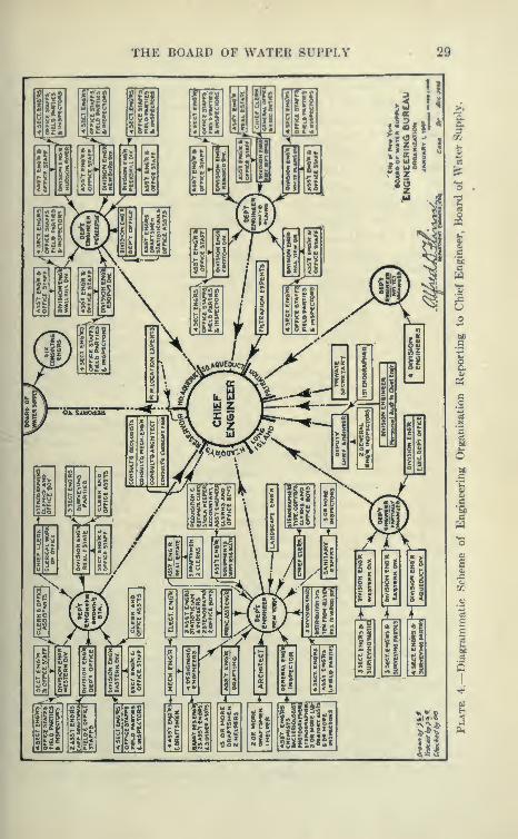
THE BOARD OF WATER SUPPLY 29

30 - CATSKILL WATER SUPPLY
by R. N. Wheeler, with his office at Poughkeepsie. This depart-
ment includes the Catskill Aqueduct between Esopus Creek and
Croton Lake, a stretch of about 62 miles. It is divided into five
divisions, as follows: Esopus Division, office at High Falls, Ulster
Co., Division Engineer, Lazarus White to 1911, later John P.
Hogan. Walkill Division, office. New Paltz; Division Engineer,
L. C. Brink, succeeded 1911 by James F. Sanborn. NewburghDivision, office, Walden, N. Y.; Alexander Thomson, Jr. HudsonRiver Division, office, Cornwall-on-Hudson; Division Engineer,
William E. Swift; succeeded by Frank E. Clapp as Acting Division
Engineer. Peekskill Division, office, Peekskill; A. A. Sproul,
Division Engineer, deceased, succeeded respectively by James F.
Sanborn, Alexander Kastl and G. P. Wood. Each division is divided
into four or five sections under a section engineer having charge of
a contract or portion of large contract, usually consisting of about
three miles of aqueduct work. Each section engineer has an office
directly on the work and has an assistant and one or two field parties
reporting to him on cut-and-cover work. On siphon tunnels with
several shafts a section engineer usually had charge of three shafts.
Field Offices. A plan was followed which added very muchto the comfort of the men and to their efficiency, the field engineers
being provided with convenient and comfortable offices. In most
cases new buildings were built designed carefully by the architect
of Headquarters Department in consultation with the field engineers.
On cut-and-cover work section offices provided with plumbing,
heating system and fireproof vault were provided. On siphon or
pressure tunnel a small office known as a locker house was built at
each shaft under the main contract. These were provided with heat,'
light and shower baths, also in some cases with telephone service. Thecost of these houses were amply returned to the city in the increased
efficiency of the engineering force. With the faciUties provided a
force smaller, than would have been otherwise necessary, could do the
work. The provision for telephone work is a particularly valuable
one, although not provided in all cases. Even in New York it was
found advisable to provide for the engineers locker houses equipped
with hot- and cold-water supply, shower baths, heat, etc.
Southern Aqueduct Department. Frank W. Winsor, Depart-
ment Engineer, has his office at White Plains and has charge of all
work south of Contract 2 and north of the city line. Reporting to
him were Geo. G. Honness, in charge of the Croton Division, suc-
ceeded by C. M. Clark, office, Pleasantville, also Wilson Fitch
Smith, office, Valhalla, in charge of the Kensico Division; E. W.
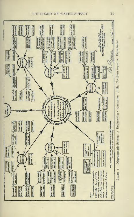
THE BOARD OF WATER SUPPLY 31
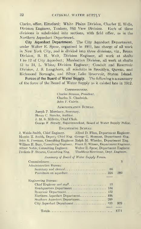
32 CATSKILL WATER SUPPLY
Clarke, office, Elmsford; White Plains Division, Charles E. Wells,
Division Engineer, Yonkers, Hill View Division. Each of these
divisions is subdivided into sections, with field office, as in the
Northern Aqueduct Department.
City Aqueduct Department. The City Aqueduct Department,
under Walter E. Spear, organized in 1911, has charge of all workin New York City, and is divided into three divisions, viz., BronxDivision, B. H. Wait, Division Engineer, all work at shafts
1 to 12 of City Aqueduct; Manhattan Division, all work at shafts
13 to 24, L. White, Division Engineer; Conduit and Reservoir
Division, J. S. Langthom, all conduits in Brooklyn, Queens, andRichmond Boroughs, and Silver Lake Reservoir, Staten Island.
Forces of the Board of Water Supply. The following is a summaryof the force of the Board of Water Supply as it existed late in 1912.
Commissioners.
Charles Strauss, President.
Charles N. Chadwick.John F. Galvin.
,
• Administration Bureau.
.Joseph P. Morrissey, Secretary.
Henry C. Buncke, Auditor.
J. M. S. Millette, Chief Clerk.
George F, Shrady, Superintendent, Board of Water Supply Police.
Engineering Bureau.
J. Waldo Smith, Chief Engineer. Alfred D. Flinn, Department Engineer.
Merritt H. Smith, Deputy Chief Eng. George G, Honness, Department Eng.
.John R. Freeman, Consulting Engineer. Ralph M. Wheeler, Department Eng.
William H, Burr, Consulting Engineer. Frank E. Winsor, Department Engineer.
.
Alfred Noble, Consulting Engineer. Walter E. Spear, Department Engineer.
Frederic P. Stearns, Consulting Eng. Thaddeus Merriman, Dept. Engineer.
Summary of Board of Water Supply Forces.
Commissioners 3
Administration Bureau:
Secretary and clerical 66
Patrolmen on aqueduct 326 392
Engineering Bureau:
Chief Engineer and staff 13
Headquarters Department 154
Reservoir Department 1 52
Northern Aqueduct Department 198
Southern Aqueduct Department 269
City Aqueduct Department 193 979
Totals 1374
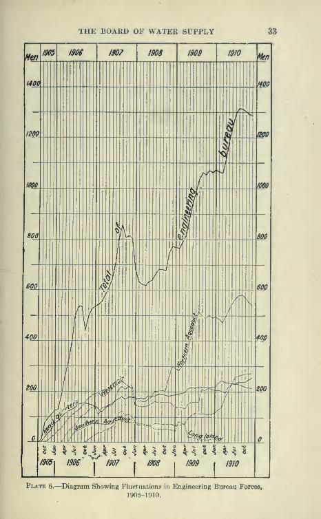
THE BOARD OF WATER SUPPLY 33
^^ms m 1907 1908 1909 1910 ^\
f40C mi' s,
/2S(t.. 1 &fO
1/m /f""'^ 1000
i
800. ._ 1 111'
800
'
\ i
.,/
SOOi 1''"'
600
7
X. \i^ i
^'''\
4Q0A ].. ITl \400
/ 1200 _
I ,1= /
^^
^'"ZOO
'W<-'"'" L^,-\\.M^'"-'
s,_y-' J
oM/Am 1906
j1907
1ms
1 UU 1^
11909 IS
Plate 6.—Diagram Showing Fluctuations in Engineering Bureau Forces,
1905-1910.
34 CATSKILL WATER SUPPLY
The fluctuation and extent of the contractors' forces are shown
on Plate 6. Fluctuations in the engineering forces are shown on
Plate 7.
Details of Engineering Organization. The Civil Service.
To give a more precise idea of the scheme of the engineering organiza-
tion the diagrams on Pis. 4 and 5 are reproduced, showing graph-
ically the organization of the engineering bureau under the chief
engineer and one of the departments in detail, the Northern Aque-
duct Department.
With the exception of the Chief, Consulting Engineers, Depart-
ment Engineers and a few of the Division Engineers, the entire force
of over 1500 men was procured through the Municipal Civil Service
of New York City by competitive examination, or by transfer
from other city departments of men who had already passed competi-
tive examinations for similar positions. The demand was so great,
at the start of the work, that enough engineers resident of New York
State could not be secured and the examinations were thrown open
to men from other States. Thus many engineers formerly in the
employ of the Metropolitan Water Board, Massachusetts (Boston
Water Works) secured positions with the Board of Water Supply.
Other men were connected with work in New York City or State,
such as the Rapid Transit Subway or the New Croton Aqueduct,
or were in the lower grades, recent graduates of various technical
schools. A large percentage of the engineering force were
graduates of technical schools such as Columbia, Harvard, Cornell,
Massachusetts Institute of Technology, etc.
The Croton Aqueduct was built before competitive examina-
tions for engineering positions in the Civil Service was well estab-
lished. Those now with the Board of Water Supply will testify
that an immense improvement has taken place in the personnel of
the city's engineers since that time (about 1890). It speaks volumes
for the civil service idea when we consider the high efficiency and
character of the work done by the engineers of the board on a
construction with already $87,000,000 of work completed to end
of 1912.
Grades and Salaries of Engineering Force. The various engi-
neering grades under Civil Service are as follows: axeman, $60 per
month; rodman, $80 per month; transitman or leveler, $100 per
month; inspector, $120 to $130 per month; assistant engineer, $1350
to $3000 per annum. Until recently, the assistant engineer could
be progressively promoted to positions of higher responsibility from
charge of line and grade party, to section engineer. This made for

THE BOARD OF WATER SUPPLY 35
flexibility and gave the men the incentive to work hard in an expand-
ing organization.
In addition to the regular onginroring work of the hoard, the
forces of the Board of Water Supply were called upon to do a great
deal of direct work such as would be done ordinarily by contract.
Many boring machines were bought and placed directly in charge
of the engineering bureau, the necessary supplies being acquired by
direct purchase. In addition, many test pits were dug to ascertain
the nature of the materials along the line of the aqueduct. Thelargest direct construction was the sinking of the east and west
shafts for the Hudson River Siphon after the first contractor had
abandoned the work, with the shafts only 250 feet deep. Thecontractor's plant was taken over and new machinery bought andinstalled. With men obtained through the Civil Service Commis-sion these shafts were sunk to a depth of over 1100 feet, and tunnels
driven part way across the river at this level.
Acquisition for Land of Croton Water Works. It was realized
at the beginning of the work that the acquisition of the necessary'
real estate would throw a heavy burden on the engineering force
in the preparation of surveys, the tracing of deeds and boundaries,
and other work necessary to assist the corporation counsel andcommissioners of appraisal.
In the acquisition of the lands for the Croton Water Works the
city had a much freer hand, it being only necessary to file mapsshowing the land required. Possession being obtained, the appraisal
of damages was usually drawn out through a period of years, the
property owner meanwhile being deprived of his land and being
paid, in some cases, years after he was dispossessed. This caused
a good deal of hardship, particularly for the small landowners and
poor farmers, who did not know how to borrow upon the moneydue them from the city. Although the City in most cases paid
overmuch for the land acquired together with deferred interest at
6 per cent, a great deal of ill feeling was created, so that the
Catskill project m.et with a good deal of opposition for this reason.
The city compromised on a feature new to the law in New York
State. The property owners were to be compensated to the extent
of one-half the assessed valuation of the land at Jan. 1, 1905,^
before the city could take possession. In addition, the city was
also to pay incidental damage to indivitluals or corporations suffer-
ing loss of business or loss of emplojTnent through the constnic-
tion of the Catskill Water Works. This feature was new to NewYork State, but was employed to some extent in Massachusetts.
36 CATSKILL WATER SUPPLY
Real Estate Division, etc. As very large areas had to be acquired
for the Ashokan Reservoir, a real estate division of the reservoir
department was created and put in charge of Division Engineer
F. K. Betts. A search was made of all the deeds covering this area
and the farm boundaries run out. Accurate real estate maps show-
ing the parcels to be acquired, acreage, etc., were prepared and
lithographed, a set of about fifty parcels constituting a section.
Application was made to Supreme Court of the county for the
appointment of three commissioners of appraisal for each section,
there being about forty-five sections in all. These applications and
all subsequent legal work were in charge of the Corporation Counsel
of the City of New York, who established headquarters at Kings-
ton. After the commissioners were appointed hearings were held,
evidence being furnished by the property holders and their counsel
and by experts furnished by the Corporation Counsel, the engineers
acting as advisers being called upon occasionally to testify as to
bounds, and technical matters principally involving water-power
rights. i>^
Water Powers. Water powers, real and imaginary, were the
subjects of much controversy. Insignificant streams, formerly
used for operation of mills and in most cases long since abandoned,
assumed great proportions on paper, and extended hearings were
held at which experts for the property owners and the city testified
at great length. In numerous cases the cost of these hearings to
the city was far in excess of the final award.
Proposed Constitutional Amendment. Although the acquiring
of private property, even for public purposes, should be carefully
guarded, it seems that altogether too much deliberation, delay and
expense is in vogue at the present time. At the last election a
Constitutional Amendment was proposed, but not passed, empower-
ing the Supreme Courts to appraise property to be condemned,
with or without a commission; the idea being that if specially
competent judges are detailed for this work they will soon become
expert, and the proceedings conducted much more expeditiously
than by the usually inexperienced commission of three. In addition,
the judges, having a fixed salary, will not have the incentive for
delay as per diem commissioners, nor are they likely to be affected
to the same extent by local feeling.
Land Surveys. Along the line of the aqueduct it was necessary
to condemn a strip, usually about 200 feet wide, with larger
areas at the shaft sites, tunnel portals, etc. This meant that
all the farms passed through had to be surveyed and the bounds
THE BOARD OF WATER SUPPLY 37
traced and deeds hunted up, etc. In a large number of cases it
was found that the deeds were not on file, the property l)eing handed
down from father to son, in some cases, from the original settlers.
It was required to exactly show the metes and bounds of the strip
condemned. In addition to this, for the information of the com-
missioners, maps were prepared showing the whole area of which
a part was seized by the city. This meant that many doubtful
cases had to be decided, such as overlapping, errors and inaccuracies
of deeds. As some of these were very hard to adjust, it was sup-
posed that some of the results as shown on the maps would
be contested, but very few controversies arose. The bounds
of thousands of farms and other plots have thus been definitely
determined and will remain as fixed by the engineers for a
long time to come. This real estate work, of great magnitude
in itself, had to be accomplished in a very short time, as no contracts
were allowed to be let until the title to the land necessary for con-
struction had i^assed to the City of New York.
Direct Purchase of Land. A provision of the law by which
the Board of Water Supply could acquire property by direct
agreement with the owners proved of little help. The purpose
of this provision was to save the expense of the long and costly
litigation of the usual condemnation method. The city had
authority to agree with the property owner as to the price to be
paid for land needed for city purposes, but this agreement had to
be approved by the Board of Estimate. In some instances where
such agreements were effected, the payment was sometimes so long
delayed that the property owner in the long run gained nothing
by it, and obtained less than he probably would have received
in condemnation proceedings. In addition, he was paid no interest
on the amount agreed upon, nor were the expenses of the nego-
tiations with the city paid him. In the regular condemnation pro-
ceedings the property owner's expenses for lawyers, expert witnesses,
and traveling expenses are paid by the city, these being
appraised by the commissioners. Also, he receives 6 per cent
interest on the final award reckoned from the time the commis-
sioners were sworn in. Were the Board of Water Supply empowered
to pay the property owner immediately on agreement with him as
to the value of his property, great savings in legal expenses could
be made, and in many cases the property owner would accept
less than the commission's awards if assured of immediate payment.
Cost of Real Estate. The total expense chargeable to real
estate, including the year 1911, is about $12,000,000. Of this only

38 CATSKILL WATER SUPPLY
$250,000 is chargable to engineering expenses, which includes all
necessary surveys, mapping, etc. Advertising alone amounted to
$430,000. The fees and expenses of special counsel and commis-
sioners of appraisal reached the total of $2,326,000. There wasallowed as counsel fees and disbursements of parcel owners about
$508,000. Interest on awards amounted to about $930,000. Of
the $12,000,000 mentioned above, only $7,330,000 represents the
direct award to property owners, the rest being expenses of one
kind or another.
In 1911 over 2500 parcels were in the possession of the city for
the work aggregating 21,135 acres.
Sanitary Work. Anyone who has had the responsibility of
building camps for laborers and keeping them in satisfactory sanitary
condition will realize that on a work of this magnitude manyproblems had to be dealt with and solved. A great majority of
the contracts were carried out in the watersheds of streams supply-
ing cities and towns. This was more particularly true of the
Southern Aqueduct Department, a large portion of this workbeing located in the Croton watersheds and the streams supplying
towns north of New York. In consequence of this, very strict
sanitary provisions were introduced into the contracts. Most of
these provisions were common to all the contracts, special ones
being introduced where danger from contamination was the greatest.
It was provided that the camps were to be located on healthful,
well-drained sites and to be provided with suitable and satisfactory
buildings for the housing, feeding and sanitary necessities of the
men, and suitable stabling for the animals employed upon the work.
Plans of the layout of the camps and the construction of the individual
houses were submitted for approval to the engineers. A good
camp is shown on PI, 8. The camps were required to be supplied
with water for drinking and bathing purposes, and with sanitary con-
veniences for the men. During the first stage of the work the
engineers alone enforced the sanitary provisions. Later on the
services of sanitary experts were obtained. A regular contract
was at first entered into with Dr. E. J. Lederle, who agreed to
provide the following services: Supervise all sanitary matters in
connection with the work of the board, prepare all plans and
specifications in relation to such matters to accompany or be
embodied in the contracts to be prepared by the Board of Water
Supply; inspect and supervise the work in the field and to report
as required to the Chief Engineer. He also was to make all neces-
sary bacteriological and chemical analyses of water, etc., using

THE BOARD OF WATER SUPPLY 39
I90P 1908 1909 1010
Men Men
/SOOO _ l$000
i\
/4000 / \ f4000
f '
IZOOO /eooo
y10000 1 _ /oooo
^
8000
(J
1
_ _ 9000
/^
tooo TXt"""-''^f \ f
1 \4000 M 4000
/\ I
"'
2000 l_ \ L,.^ - - ,i ^^^^
^i-^^-V'^^j><^^ '^V«
19V? 1908
1^ ^ S 1 4 ^ 5
19091
19101
Plate 7.—Fluctuations in Contractors* Forces During Years 1907-1910.
40 CATSKILL WATER SUPPLY
for this purpose, the facilities of the Lederle laboratory. UponDr. Lederle becoming Commissioner of Health for New York
City in 1910, this work was taken over by Dr. Pease and
A. J. Provost, Jr. They employed as their field representative
Dr. David S. Flynn, who regularly visited the line of the work,
consulting with the field engineers. The employment of sani-
tary experts did not in any way relieve the engineers of their
responsibility for the sanitary conditions of the labor camps,
the sanitary experts acting in advisory capacity. Each large con-
tract provided that a nledical officer was to be regularly in attendance
at the camps where hospital facilities were to be provided. These
company physicians made regular reports' on forms prescribed by
the sanitary experts. Very careful attention was paid to any
contagious diseases, which were immediately reported to the san-
itary experts by the engineers, and arrangements were made with
the local health authorities to isolate and treat the patients. Theremarkable sanitary conditions of the camp are shown by the fact
that, despite their great number and an average population of about
15,000 in 1910, but 321 cases of communicable diseases and 86
deaths were recorded. Of these cases but 6 were typhoid, one a
doubtful case of smallpox, 6 scarlet fever, 21 measles, 13 tuber-
culosis, 5 diphtheria, and 250 malaria. All employees of contractors
were vaccinated before beginning work, unless they could show a
recent certificate from a company physician on another contract,
this requirement being very strictly enforced. The cases of typhoid
fever were remarkably few, each case as developed being very care-
fi^ly followed, the patient isolated and any suspected cause removed.
At first there was opposition from contractors who were used to
the loose conditions ordinarily obtaining in country labor camps;
later on, although there was some grumbling over the enforcement
of certain regulations, the contractors began to feel that the expense
of laying out, building and maintaining the camps in sanitary con-
dition was small and the benefits very large in proportion to the
cost. Theywere thus relieved from the ever-present fear of epidemics
which in the past had frequently demoralized work of this character.
The better sanitary conditions and the cleanliness and healthfulness
of the camps also made it easier to keep the men. Despite the fact
that the work of the Catskill aqueduct was done during a period of
rather low industrial activity, the contractors often found it dif-
ficult to keep up the full force required for the work, particularly
on tunnel contracts.
Where camps were located in watersheds used for towns, it

THE BOARD OF WATER HLl'l'LY 41
,ji0s;'!p^
o
42 CATSKILL WATER SUPPLY
was required that their drainage be filtered. In most cases sand
filters were used, besides sterilization by chemical dosing. It was
even required to filter or sterilize water issuing from tunnels. I
most cases all organic matter originating in camps was consumed
in incinerators. The incinerators were either purchased from
regular manufacturers, or constructed on approved lines of brick
or concrete. It is probable that the destruction of organic matter
by this method is 'the most sanitary and removes most potent
causes of contamination from the camps. Moreover, it is com-
paratively inexpensive.
Sanitary Provisions of Contracts. Some of the sanitary pro-
visions in force on watersheds are:
" The contractor shall take satisfactory precautions to prevent
the contamination of or interference with any public or private
water supply by his work or by his employees, and shall provide
acceptable substitute supplies in case of unavoidable interference.
The contractor shall furnish and erect, when, where and as directed,
manproof fences along and adjacent to streams, reservoirs, etc.,
used as sources of potable water supply.*' All houses occupied by employees shall be thoroughly screened
to exclude mosquitoes and flies. Quarters for the men shall be grouped
in properly arranged camps. Camps shall, if ordered be enclosed
by satisfactory manproof fences with not more than two entrances
and the entire grounds illuminated by electric arc lamps or other
acceptable lights. The contractor shall retain the services of
acceptable, qualified, medical and surgical practitioners, to the
number ordered, and shall have the care of his employees, shall
inspect their dwellings, the stables and the sanitaries as often as
required, and shall supply medical attendance and medicine to
the employees whenever needed. They shall give their whole time
to the work, there shall be at least always one on duty, etc. Thecontractor shall provide from approved plans one or more buildings
properly fitted for the purpose of a hospital with facilities for heat-
ing and ventilating in cold weather and for screening and ventilat-
ing in warm weather. These hospitals shall have an ample numberof beds to properly care for sick and injured employees, and shall
be provided with all necessary medicines and medical appliances
for the proper care of the sick and injured. Another building of
approved design shall be provided and equipped as an isolation
hospital, and any employee who shall be found to have a com-municable disease shall be at once removed from the camp to this
hospital and there isolated and treated as directed. Whenever
THE BOARD OF WATER SUPPLY 43
practicable an employee having a communicable disease shall be
removed when and as directed to an approved permanent hospital.
*' Once a week, or more frequently, if required, the contractor
shall give the engineer, in such detail as may lx» prescribed fnjm time
to time, a written report, signed by the physican in regular attendance,
netting forth clearly the health condition of the camp or camps and
of the employees. If any case of communicable disease Ix* dis-
covered, or any case of doubtful diagnosis, it shall Ix' reported at
once to the engineer, by telephone or messenger and confirmed
in writing."
The filtering of drainage water from a camp on Sprain Brook
watershed used for Yonkers was specified as follows:
" Slow sand filters of such size as permit a run off from the,^camp
area of two-tenths of an inch per hour to be filtered in addition to
other waste at a rate not exceeding two and one-half millioas
gallons daily per acre of filter surface, and said chemical treatment
shall be done after filtering, using chlorinated lime having an the
average not less than 30 per cent available chlorine, in approved
amounts which will average about 25 pounds per million gallons
of filter drainage. Said plants shall include storage basins of
suitable size to hold a storm run-off of 3 inches on the whole camp
area, and retention basins to facilitate chemical treatment, these
basins to hold at least 15 minutes' flow from the filters at maximumrate."

44 CATSKILL WATER SUPPLY
eoer^
606r l-Uef
coei'i-uvrL^
O z> <CC -iLU toCO —LU 2

CHAPTER III
LOCATION OF CATSKILL AQUEDUCT
Proposed Catskill System of 1905. Tlie first map, dated Oct.
9, 1905, approved l)y iho State Water Suj)ply Commission a few
months later, showed an aqueduct location from the Catskills to and
through New York City. Tributary to the aqueduct were to be
the following watersheds yielding approximately as follows:
Gallons Daily
1. Esopus watershed, area 255 square miles, with storage near outlet
of about 70 billion gallons, about 250,000,000
2. Rondout watershed, area 131 square miles, with storage, in three
reservoirs, of about 20 billion gallons, about 98,000,000
Three small watersheds tributary to Rondout, area 45 square miles,
about 27,000,000
3. Schoharie watershed, area 228 square miles, with storage, partly in
Ashokan reservoir, of about 45 billion gallons, about 136,000,000
4. Catskill watershed, area 163 square miles, with storage partly in
Ashokan reservoir, of about 30 billion gallons, about 100,000,000
Six small watersheds, tributary to aqueduct, between Catskill
Creek and Ashokan reservoir, combined area about 82 square
miles, dbout 49,000,000
Total available yield of the Catskill sources, exclusive of (inter-
state) Delaware tributaries 660,000,000
General Location of Aqueduct. The aqueduct location was
based on former surveys of the Commission on Additional WaterSupply, upon the U. S. Geological maps, and upon the results of
early surveys of the first field party. It showed the aqueduct
draining the Ashokan Reservoir at West Hurley and crossing the
Hudson River a few miles below Poughkeepsie at New Hamburg,
thence southward to Kensico Reservoir, which it was planned to
enlarge to hold 40,000 million gallons, a supply suflRcient for over
eighty days in case of a break in the aqueduct above, ample
time for inspection and repairs. The Kensico reservoir was also
to be by-passed, and the aqueduct continued for 15 miles more to
Hillview Reservoir, which was to have the function of equalizing the
difference between the use of the water in the city, as it varies from
45
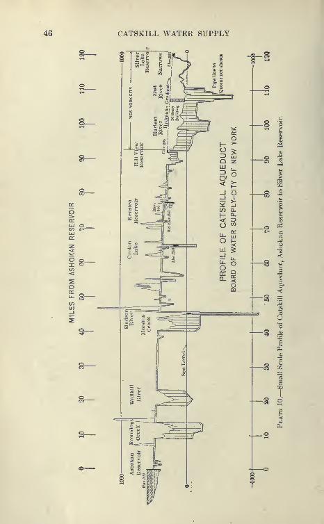
46 CATSKILL WATER SUPPLY
8—DC P,-S
o>en -1Ul ot/> c-
-Uia:
z C
-<
os^o
a

LOCATION OF CAT8KILL AQUEDUCT 47
hour to hour, and the sternly flow of the aqueduct. This reservoir,
with capacity of 900 million gallons, would also furnish considerable
water in times of maximum draft, in ciiso of conflagration, in addi-
tion to supplying a constant head to force water throughout the
city. The first plan contemplated only the distribution of 120
million gallons daily, leaving the balance to be provided for by
subsequent plans.
Due to a technicality, the Schoharie watershed was not granted.
The State Water Supply Commission formally approved of all the
other sources.
Changes in Location of Aqueduct Subsequent to 1905. As
detailed investigations were made it was discovered that it would
be much better to draw the water from near Olive Bridge Damrather than from West Hurley, where the reservoir is shallow,
requiring that the water be drawn from over the Beaverkill Swamps.
In addition, the aqueduct running southward from the reservoir
would be in a much more favorable country, shortening by several
miles the aqueduct to a reservoir on Rondout Creek. A study of
conditions in the field and on the geological maps revealed a muchmore economical location for the aqueduct west of the Hudson and
a better crossing of the river further south than New Hamburg. Along stretch of cut-and-cover of economical construction, located
in the Wallkill Valley, was secured as a substitute for an equiva-
lent length of difficult work east and west of the Hudson at NewHamburg. In addition, a short crossing was secured at Storm
King, instead of the original proposed crossmg at New Hamburg,
which would have been several miles longer, due to the wide and
low-lying Fishkill plain bordering the Hudson at this point. Theabove changes were embodied on a supplementary map dated June
25, 1907, which was filed with the State Water Supply Conmiission.
Approval of this was readily obtained.
The route of the aqueduct as finally adopted is sho\\Ti on accom-
panying map, at end of book. The route of the City aqueduct is
shown on PI. 203, Chapter XIX.Aqueduct within City Limits. As the work of construction
progressed, it became apparent that the pressure or siphon tunnel
type of aqueduct offered many advantages over surface lines, par-
ticularly in permanency of construction and economy of space,
as little land is occupied and that only at shafts.
To employ steel pipe lines m the City to distribute the vast
body of water carried by the aqueduct meant that a great manylines would have to be laid through the streets already congested
48 CATSKILL WATER SUPPLY
with subways, underground structures and pipes of all sorts, andthat the disturbance created by the laying of the pipes wouldhave to be repeated at intervals to provide for renewals. It
was proposed that a pressure tunnel be constructed southward
from Hillview to well into Brooklyn, and that numerous shafts
necessary for construction purposes be used as uptakes to distribute
the water to the regular street systems of mains, to connect to whichit would only be necessary to lay short lines. The tunnel wouldhave the advantage that it could be readily constructed of large
diameter, so that little loss of head would occur throughout its length,
thus securing the full benefit of the high elevation of Hillview
Reservoir, 295 feet, against the 116 feet of the Croton system. In
ease of conflagration, large quantities of water could be secured
from pipe lines leading to the nearest shaft. As stated elsewhere,
this scheme of pressure tunnels was partly used on the Croton
Aqueduct system, water being delivered at the northern end of
Manhattan Island through the Harlem River Siphon.
City Tunnel, Catskill Aqueduct. The proposed system of pres-
sure tunnels in the city for the new water supply, however, was
so novel and tremendous an undertaking that considerable opposi-
tion developed to its adoption. A commission of engineers, headed
by Clemens Hershel, appointed by a committee of the Board of
Estimate, after examination of the pressure tunnels under con-
struction on other parts of the aqueduct, and after making com-
parative estimates of the cost of the two systems, reported heartily
in favor of the deep rock tunnels through the city, confirming the
statements of the engineers that the cost of the tunnels would be
very much less than steel pipe lines; also that irrespective of
costs, the tunnels would be better in every way. Formal approval
of the City Aqueduct was given by the State Water Supply Com-mission in 1910. It is seldom that a proposition so original meets
with such universal approval and is used on such an immense scale
in the first instance.
Relative Cost of Croton and Catskill Water Works. The Catskill
water system will cost about the same per million gallons daily
capacity as the Croton system. This is remarkable considering
that the Catskill Aqueduct is about three times as long, and reaches
all five boroughs instead of only two, is delivered at a head of 295
feet instead of 160 feet, and is a much purer and softer water. Thenew Croton Aqueduct has a capacity of 300 million gallons per
day with about the same cost per foot of length as the 500-million
gallon Catskill Aqueduct. The surplus income of the Croton sys-

LOCATION OF CAT8KILL AQUEDUCT 49
tern, to date, has been carryinK the interest charges on the bondsissued for the construction of the Catskill water system.
Various Types of Gravity Aqueducts.* The following types of
aqueduct construction have been used for gravity aqueducts.
Aqueducts on
Hydraulic Grade
Aqueduct below
Hydraulic Grade
Following natural Burface{ ^ CurandTverr 3
Above natural surface <
'3. EmbankmentViaduct
Below natural surface 5. Grade tunnel
6. Wootlen piiKJ
7. Reinforced concrete pipe
(pressure aqueduct)
8. Steel pipe
Below natural surface 9. Pressure tunnel
Following or above natu-
ral surface
Types Used on Catskill Aqueduct. The types are enu*: erated
in the order of their relative cost, provided that in embankment or
viaduct the elevation of invert above original surface is relatively
small. On the Catskill Aqueduct, to avoid contamination, open
channel is not used. Embankment is used as sparingly as possible,
as it is deemed rather unsafe for an aqueduct of this size. Viaduct
is not used to any extent, but in a few places the aqueduct was
placed on arches and the whole covered by embankment. Woodenpipe is not to be considered for an aqueduct of this size. Rein-
forced concrete pipe is used to some extent under heads consider-
ably less than 100 feet.
Comparison between Croton and Catskill Aqueducts. Except
for the new Croton Aqueduct, the cut-and-cover type on hydraulic
grade predominates. The new Croton Aqueduct was placed entirely
in tunnel for the following reasons: greater pennanency, decreased
likelihood of accident, smaller cost of maintenance, smaller leak-
age, remote advantage of being less vulnerable in time of war,
and decreased cost of real estate. The above advantages are
very real, but unless there is some special condition which
increases the importance of one or more of these, or some great
saving could be made, they are outweighed by the smaller linear
foot cost of cut-and-cover aqueduct. Comparing the New Croton
and Catskill aqueducts, it will be found that the latter will have
twice the capacity, although its cost is less than 10 per cent greater
per linear foot. Making due allowance for the advantage in hydrau-
* Most of the material in the paragraphs to" Grade of Aqueduct " has been
contributed by Division Engineer J. P. Hogan as the result of his extensive
experience.

50 CATSKILL WATER SUPPLY
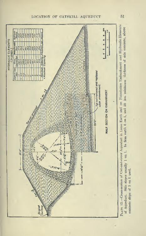
LOCATION OF CAT8KILL AQrEDICT 51
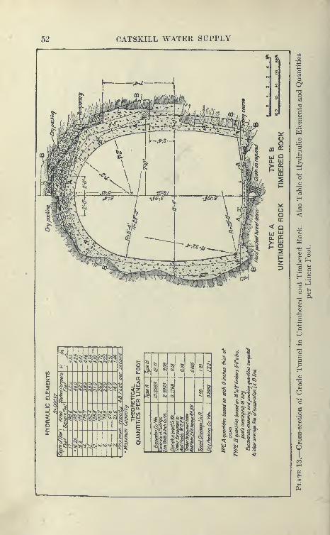
52 CATSKILL WATER SUPPLY
I
^^^1
^
t<SgiQ5;
CI) trj cij CVJ C\j
51
^ 5§
5^ ^«
§ §
1
2?
5: «v «s%
«
^a
i
1
J
i
ii 1
1
J
1
11
I lltl
iittit
r,^ »5:f
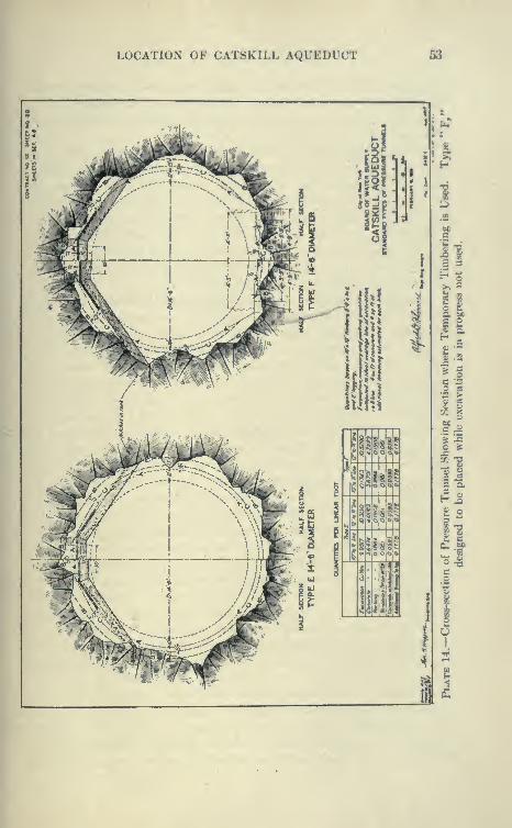
LOCATION OF CAT8K1LL ACit'EDUCT 53
IP -I
5it
« «"C 8 ! «
W§1
^11
ill
I!'
sSE
«li
Hi!
1
= 3
£ o
o
54 CATSKILL WATER SUPPLY
lie properties of the larger section, its lower unit costs of construction,
and improved methods, the lower relative cost of the Catskill Aque-
duct is in a great measure due to the substitution of cut-and-cover
for grade tunnel.
Pressure Tunnel. The high level of the Catskill Aqueduct,
and the difficult nature of the country traversed by it, greatly
increase the proportion of aqueduct below grade, and have led
to the great development of the pressure tunnel type which is
the most striking feature of this work. Pressure tunnels have been
used before on other work, but never in the magnitude or depth
below hydraulic grade. They are used wherever practicable instead
of steel pipes, on account of their permanency and greater economywhen renewals and maintenance are considered.
Comparison between Aqueduct and Railroad Location. The com-
parison between aqueduct and railroad locations brings out the
following: Both are linear structures designed to connect certain
fixed points with the greatest economy practicable under the condi-
tions. Railroad location is more of an economic problem, as it
involves the balancing of economy in original cost against economy
in operating expenses and maintenance. A railroad is susceptible
of development and may be improved and enlarged to suit a grow-
ing traffic. The only economical way to enlarge an aqueduct is
to build a new one. It is built for all time, and safety and per-
manence are therefore much more important factors. When it
is considered that an aqueduct like the Catskill costs from eight to
ten times as much per foot as an average double-tracked railroad, it
will be seen that in a problem of location much more detailed study
is justified and required. In a railroad location, grades can be
changed to suit the topography, being governed only by economy in
operation and maintenance. In gravity aqueduct location the grades
are determined by the hydraulic gradient ; to go above is impossible,
and to go below involves additional expense. On a railroad, curves
affect economy in operation and maintenance, while in an aqueduct
they are practically almost negligible. Aqueduct location is quite
dissimilar to railroad location, as aqueducts follow fixed grades and
have not the same freedom to cross embankments or bridges, and
it is dangerous to put them partly on cuts-and-fills at side hills.
Safe location is the primary object, as leakage may lead to washouts
of serious consequences in settled country. On the other hand,
aqueduct location has a certain freedom in crossing wide valleys,
using for '' inverted siphons," pressure tunnels or steel pipes. Bymeans of deep shafts and tunnels, the aqueduct may be brought
LOCATION OF CATSKILL At^LEDLCT 65
below almost any valley, the only limitation being that the top of
the uptake shaft shall be a proper distance IkjIow that of the down-take to force the water through.
Cost Curves. As soon as a decision was reached by the design-
ing division on the size and shape of cut-and-cover, grade tunnel
and pressure tunnel, the cost curves shown on PI. 15 were pre-
pared in the following manner: Unit costs were assumed for
different classes of work and applied to quantities determined
by planimetering typical sections. On the cut-and-cover sections,
costs were thus computed for every 2-foot difference in center line
elevation; for three different natural conditions, i.e., ground level,
slope four on one, and slope three on one; and for five different
subsurface conditions, i.e., all earth, all rock and earth overlying
4, 8 and 12 feet of rock respectively. The side slopes of the rock,
when masked, were assumed to be the same as that of the surface.
Cost curves were then constructed by plotting cost against depth
of cut for the five different subsurface conditions on each of three
different slopes, making fifteen different curves. By aid of the.se,
it was possible to estimate costs very rapidly from trial center line
profiles. Approximate costs of grade tunnels were also determined
from assumed unit costs and planimetered unit quantities for three
different conditions, i.e., (1) tunnel in sound rock, (2) timbered tunnel
in rock, and (3) tunnel in earth. The figures thus obtained were
used in comparing alternate lines of cut-and-cover and grade tunnel,
and were also plotted on the cost-curve sheets to indicate approx-
imately the depth of cut at which it would be economical to start
tunneling. The estimated costs of pressure tunnels depended so
much on positions of rock surface, character and position of rock
strata and other conditions peculiar to each tunnel, that independent
cost studies were made for each alternate location. A tentative
linear foot cost was estimated for each pressure tunnel for comparison
with alternate cut-and-cover, grade tunnel' and steel-pipe locations.
While the designs for steel and reinforced concrete pipes were not
in final shape until most of the locations had been completed, an
estimate of cost on a tentative design, very similar to the final one,
was prepared for use in comparison with alternate locations of
other types of aqueduct.
In preparing curves of this kind the absolute unit prices are
not of as much importance as the relative prices. If, for instance,
the relative price of excavation as compared to concrete is unduly low,
the tendency would be to favor the shorter lines. Indeed, these
curves show too low a cost for the type of aqueduct partly in rock,
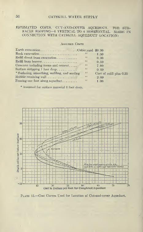
56 CATSKILL WATER SUPPLY
ESTIMATED COSTS. CUT-AND-COVER AQUEDUCT. FOR SUR-FACES SLOPING— 1 VERTICAL TO 4 HORIZONTAL. MADE INCONNECTION WITH CATSKILL AQUEDUCT LOCATION:
Assumed Costs
Earth excavation Cubic yardRock excavation
Refill direct from excavation
Refill from borrow
Concrete including forms and cementSurface stripping 1 foot deep* Surfacing, smoothing, sodding, and seeding
Rubble retaining wall
Fencing one foot along aqueduct
* Assumed for surface material 1 foot deep.
$0.30
1.50
0.30
0.50
7.00
0.60
Cost of refill plus 0.30
2.00
1.00
^ ~
r^W30
<\ <*A. ,» "^ ":r?^.tt* ---
('?'»^^» -^,-»
>y^"^ cS(, :i'l
fee ^ ^
i")^fee ^' -•'
.*'" ^- ^^
1r-i
^^ < i" ^^.^ ^,
•':-^--\^ "^
1120 y^'
^. --' *^, -^ "kxx«
OQ,y
f.-' ^, K^*
'^>r
^,.'•
i'k-^ ^
2|10
n/
•''
Ar^ J._A 1 Earth
4x k
'
ts,k'
a \ <: -. '^>
V.\^ «^,
'**-x' 1^ >,o •^^^
'-- ^k L lis in2£i
conti luatioh of t ft.. 8 ft ,
rvt 8~
&^ -•b
^^ ( aiIdl .. ofeeirthand'-alVeai th-cd
.h ^ =:
*=^ eia, !^ ^-— .^
«in _45 50 55 60 65
Cost in Dollars per foot for Ck)mpleted Aqueduct70 75
Plate 15.—Cost Curves Used for Location of Cut-and-cover Aqueduct.
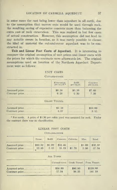
LOCATION OF CAT8KILL AQUEDUCT 57
in some cases the cost being lower than aqueduct in all earth, dueto the assumption that narrow cuts would be used through rock,
the resulting saving of expensive concrete more than balancing the
extra cost of rock excavation. This was realized in but few cases
of actual construction. However, this assumption did not lead to
any notable errors in location, as it was rarely possible to choose
the kind of material the cut-and-cover aqueduct was to be con-
structed in.
Unit and Linear Foot Costs of Aqueduct. It is interesting to
compare the original assumption of unit prices and linear costs with
the prices for which the contracts were afterwards let. The original
assumptions used on location of the Northern Aqueduct Depart-
ment were as follows
:
UNIT COSTS
Cut-and-cover
Excavationper cu.yd.*
Refillper cu.yd.
Concreteper cu.yd.
Assumed price $0.50
0.58
$0.30
0.30
$7 00Contract price 7 30
Grade Tunnel
Assumed price $5.50
5.17
$10 00Contract price 9 15
* For earth. A price of $1.50 per cubic yard was assumed for rock. Underthe contract there was no classification.
LINEAR FOOT COSTS
Cut-and-cover
Excav. Refill. Concrete. Culverts. Misc. Total.
Assumed price 1 $10.32
Contract price ^ ^^ • ^^
$5.00
5.45
$34.48
35.19 $1.70
$1.00
2.90
$50.80
57.34
All Types
Cut-and-cover. Grade Tunnel. Press. Tunnel.
Assumed price $50.80."57.34
$90.00
98.25
$120.00
141.10
58 CATSKILL WATER SUPPLY
Preliminary Contract Prices. In connection with these costs it
should be borne in mind that in contract price for tunnels certain con-
tingencies, not generally reahzed, were provided for; as, for instance,
heavier sections for poor ground, timbering, etc. General actual
cost will probably be from 5 to 10 per cent less than contract prices.
As stated before, it is of the utmost importance in determining
location to have the price of the different types relatively correct,
so that one shall not be unduly favored. Taking cut-and-cover
as a unit, the following is a comparison of relative cost of other
types, under assumed and contract prices:
Grade Tunnel. Pressure Tunnel.
Assumed cost
Contract cost
1.88
1.71
2.50
2.48
It is gratifying to see that the assumed contract prices are close
enough to indicate that the locations made on this basis were
correct.
Preliminary Reconnaissance Map. Prepare the contour recon-
naissance map with more than the usual care, using a 10-foot interval
or increasing the scale at certain points if it should be necessary.
The general location can be determined on this map, using linear-foot
costs for comparison of likely routes. The selection of these linear-
foot costs from the unit cost curves should be more closely supervised
by issuing standard tables, as was done with unit costs. In this
way all radical changes of location can be eliminated. There will
still remain alternate routes, the merits of which can only be decided
by detailed surveys. Apart from this, the location will be pinned
down to a narrow strip, the chief problem remaining being the
most economical arrangements of curves and tangents to fit the
ground.
Cross-section Contour Survey. For this purpose the writer
would favor a 2-foot contour map instead of nmning profiles and
fitting tangents in the field. This map should be prepared by laying
out on the reconnaissance map a series of tangents, as close to the
final location as can be determined. These tangents should then
be approximately located and laid out in the field, stationed con-
tinuously and used as a base line from which to take cross-sections
for 2-foot contours. The width of country to be covered will depend
on the steepness of the slopes and the possibilities for alternate
routes, and should be enough so that no additional surveys will be
LOCATION OF CAT8KILL AQUEDUCT 59
necessary. The minimum-cost contour and the contour limiting
the down-hill location of the aqueduct, determined as previouHly
described, should then he plotted on the 2-foot contour map, and the
final arrangement of tangents and curves which will l)e8t suit the
details of typography fixed by comparative cost estimate and the
exercise of judgment. The line thus determined should then he
laid out on the ground and again subjected to careful field inspection
and analysis.
Refinements to be Avoided in Location. The main dangers of
the above method arc three-fold:
1. Following too slavishly the economic cut, which will result
in an inordinately crooked location.
2. A failure to take proper account of field conditions.
3. A tendency toward over-refinement, spending too muchtime and money in consideration of relative advantages of lines whichdiffer very slightly.
The first of these may be controlled by an attempt to straighten
out the line after the final location has been made, giving proper
consideration to the advantages of a shorter line and the advantages
of eliminating curves. The second and third may be prevented
by the exercise of proper judgment by the locating engineer and bythe fact that he will be relieved of the details of fitting tangents in the
field and will have more time for the study of general considerations.
Advantages of Map Location. The advantages of this methodare as follows:
1. Less ultimate work and cost of surveys.
2. The cross-section surveys, the bulk of the field work, require
little judgment and skill, and can be entrusted to low-grade men.
3. The work of fitting curves and tangents to the ground can
be better done on a map than in the field, provided that proper
consideration is given to conditions in the field. With all due
respect to advocates of a strictly field location, there is no " eye
for country " as good as a contour map.
4. Better record of work.
5. The saving of time, and avoidance of confusion and annoyance,
by the greater ease of systematizing office work and records.
Grade of Aqueduct. The grade of the aqueduct is such as to use
up a head of about 200 feet between Ashokan Reservoir and Hill-
view Reservoir, in a distance of about 90 miles. This allowed an
average fall of something under 2 feet per mile, after certain allowances
for loss of head at the Hudson crossing and other points were made.
The problem was how to make the best use of thb head. 'Due to
60 CATSKILL WATER SUPPLY
the aqueduct running diagonally across many river valleys it wasnecessary to use several types of construction. The cost per foot
of these types varies greatly, the pressure tunnel being two or
three times as expensive as cut-and-cover. By adopting steeper
grades for the more expensive types, the cost of the whole aqueduct
is reduced, as the quantities of excavation, concrete, etc., are
decreased, in proportion to lessened area of waterway.
First Rough Location. With the aid of the geological survey
maps, using approximate grades, the first rough locations were
made from which the approximate length of each type of construc-
tion was determined. From an assumed average cost per unit
of length for each type, comparative estimates were made of the
cost of the aqueduct for various practicable slopes. It was neces-
sary that these slopes be such that when multiplied by the lengths
of each type the entire head would be consumed. By this methodthe most economical slopes could be arrived at by a few approxima-
tions, because of the narrow range of slopes practicable and the
fact that costs are not affected appreciably by any but considerable
changes. The problem at best was only capable of approximate
solution, as the final locations made many changes in the relative
lengths of the various types of construction.
Mr. Wiggin's Cost Curves. Thomas Wiggin, Senior Designing
Engineer of the Board of Water Supply, devised an exact methodof determining the relative slopes of different types of aqueduct
construction, known as the method of tangents to cost curves.
On a coordinate sheet, curves were plotted to show the variations
in cost of each type of construction with slopes. W^hen, as can be
readily demonstrated, parallel tangents to each curve give gradients
which use up the available head, the most economical slopes are
obtained. Unfortunately, the curves had a tendency to flatten
out, so that it was difficult to draw definite tangents to them. There
was also a tendency to unduly favor steeper slopes for tunnels, as
curves of tunnel cost plotted from fixed unit prices showed too great
variations of cost in favor of the smaller diameters. Experience
shows that due to heavy overhead charges of tunnels, which is
practically a fixed quantity, and to the fact that a certain size
of tunnel is desirable to secure freedom of operation, smaller tunnels
have higher unit charges. Mr. Wiggin's method of cost curves
was later used to determine the slopes of various types of construc-
tion on the Los Angeles aqueduct.
Location on Geological Survey Contour Maps. The first loca-
tion studies were made on the United States Geological maps.

LOCATION OF CAT8KILL AQUEDUCT 61
These maps, drawn to a scale of a))out a mile to an inch with 2f)-f(K>t
contours, are accurate enough for general locations, and have the
great advantage over larger maps that they give a birdseye view
of the whole country, enabling the plotting of alternate location
<
and the computation of their relative costs. Were it not for th(»se
maps, great stretches of the country woukl have had to be surveyed,
broadcast, before any definite idea as to the best place to put the
aqueduct could have been obtained. This would have meant either
many years more of work on the preliminary locations with a great
expenditure for surveys, or more likely, due to the limited time,
the selection of a route much more costly to construct than the one
adopted. This is shown by the Hudson crossing. After consider-
able work had been done on the location of a crossing at New Ham-burg an extended study of the country west of the Hudson, as shownon the geological maps, revealed the possibility of an entirely differ-
ent route with I62 miles of inexpensive cut-and-cover as opposed to
much more costly work on both sides of the river at New Hamburg,and showed that a much better crossing could be obtained in the
neighborhood of Storm King, at an estimated saving of about
$2,000,000. It was found that nothing paid as well as plotting on
the geological maps as many possible locations as could be con-
ceived, making rough comparisons of their relative costs. Fromthese many locations a few of the most favorable lines were selected
to be thoroughly studied on the ground.
Precise Levels. The importance of consistent and reliable
elevations was early realized, and a precise level party was organized
to establish bench marks convenient to the proposed work from
the Catskills to and through the city and far out on Long Lsland.
As a basis, precise bench marks previously established by the
U. S. Coast and Geodetic Survey were found at various points,
and secondary bench marks of the U. S. Geological Survey were
also used; in some instances discrepancies between them were dis-
covered. From these bench marks, lines were run along the roads
adjacent to probable aqueduct locations.
Method of Leveling. At first the ordinary wye level with single
wire and New York level rods with movable targets were used.
Later it was found that a three-wire dumpy level with 10-foot
self-reading rods gave much better results, and far greater speed
could be obtained, several miles a day being commonly run, with
a maximum speed along a railroad of 13 miles in eight hours
work. The method of the three-wire level eliminates manysources of error, it being found that an ordinary well-made dumpy

62 CATSKILL WATER SUPPLY
level gave results within the limits of error adopted by the
Coast Survey. The establishment of levels in this manner wasvery economical, and furnished the work with a great number of
convenient and reliable bench marks. All elevations were established
on a common datum, i.e., mean sea-level at Sandy Hook as estab-
lished by the Coast Survey. This was the first time that this datumwas adopted for construction in New York and its vicinity, and byi^s use the confusion and discrepancies which would otherwise have
resulted from the various datum planes commonly used at New Yorkwere avoided. From the bench marks established by the precise-
level party, lines of levels were run along the contours near which
the aqueduct was likely to be located. These level lines established
by the locating parties really were the first rough aqueduct locations
on the ground.
Location Survey by Stadia Methods. The next step was to makea transit and stadia traverse along the contour of the aqueduct.
The stakes of this traverse were all carefully placed and markedand the traverses adjusted. Following this, a regular stadia survey
was made, establishing contours from the stadia traverse and level
lines. This stadia survey was made with plane tables either on the
ground or notes were kept in a regular manner and subsequently
plotted to the desired scale, usually 200 feet to the inch.
Sketch Board. As an aid to the plotting, the notes were roughly
plotted in the field on a homemade sketch board handled in the
same way as a plane table, the man operating it using his scale in
the same way as the alidade of a plane table instrument. Thesketches, usually plotted to a scale of 400 feet to the inch, saved a
great many errors in plotting from the notes, and also helped very
much to take shots at the points which really counted most.
Without this, there are a great many wasted shots and a great
liability to error in the subsequent plotting of contours.
Cross-section Method. Toward the end of the location work the
cross-section method of locating aqueduct was used to some extent
and is probably superior to that outlined above. By this method
long tangents were established along the contour near which the
aqueduct was likely to be. The P.I's of this traverse were carefully
located as to elevation, and the azimuths and lengths of the courses
established. The stationing was then established and cross-sections
of the ground taken every 25 feet. These cross-sections can be taken
either with the level and rod in the usual way, or by stadia. The
surveys were then plotted to convenient scale, say 100 feet to the
inch, and accurate contours established on the plotting. On the
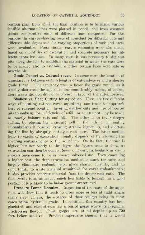
LOCATION OF CAT8KILL AQUEDUCT 63
contour plan from which the final location is to Ik* made, various
feasible alternate lines were plotted in pencil, and from commonpoints comparative costs of different lines computed. For this
purpose the curves showing costs of aqueduct for differeht cut8 and
different side slopes and for varying proportions of rock and earth
were invaluable. From similar curves estimates were also made,
based on quantities of excavation and concrete necessary for dif-
ferent tentative lines. In many cases it was necessary to dig test
pits along the line to establish the material in which the cuts were
to be made; also to establish whether certnin lines were safe or
practicable.
Grade Tunnel vs. Cut-and-cover. In some cases the location of
aqueduct lay between certain lengths of cut-and-cover and a shorter
grade tunnel. The tendency was to favor the grade tunnel, as it
usually shortened the aqueduct line considerably, unless, of course,
there was a decided difference of cost in favor of the cut-and-cover.
Shallow vs. Deep Cutting for Aqueduct. There are two different
ways of locating cut-and-cover aqueduct; one tends to approach
that of railroad location, favoring shallow cuts and use of borrow
pits to make up for deficiencies of refill ; or an attempt may be madeto exactly balance cuts and fills. The other is to favor deep?r
cutting by placing the aqueduct well in the hillside, eliminating
embankments if possible, crossing streams higher up, and shorten-
ing the line by abruptly cutting across noses. The latter method
leads to excess of excavation, usually disposed of by widening the
covering embankments of the aqueduct. On its face, the cost is
higher, but not nearly to the degree the figures seem to show, as
excavation can then be done at lower unit cost, particularly as steam
shovels have come to be in almost universal use. Even conceding
a higher cost, the deep-excavation method is much the safer, and
largely eliminates embankments, gives shorter culverts, and an
opportunity to waste material unsuitable for cover embankments;
it also provides concrete material from the deeper rock cuts. The
final result is an aqueduct much less liable to leakage, as a good
portion of it is likely to be below ground-water level.
Pressure Tunnel Location. Inspection of the route of the aque-
duct will show that it tends to cross more or less at right angles
many river valleys, the surfaces of these valleys being in most
cases below hydraulic grade. In addition, this country has been
glaciated, and each stream has a buritnl gorge where its preglacial
predecessor flowed. These gorges are at all depths up to 700
feet below sea-level. Previous experience showed that it would
64 CATSKILL WATER SUPPLY
be both dangerous and costly to attempt to locate a pressure
tunnel in anything but solid rock, and it was determined to place
the siphon tunnels so that they would have 150 to 200 feet of rock
cover at the minimum. The siphon tunnels were favored, due to
the remarkable success of the long Harlem River Siphon of the
New Croton Aqueduct previously described, which has been in
continuous operation for nearly thirty years without giving any
trouble, with very slight leakage, and outlasting steel pipe lines
laid about the same time. The locating of the lines of these siphons
was by far the most important work of the aqueduct location, and
in many cases determined long stretches of cut-and-cover leading
to and from their uptake and downtake shafts. A superficial
examination of the contours of the valleys and rock outcrops,
although of considerable value, could not begin to be sufficient to
determine their locations as to position and depth. This was
realized very early in the work and contracts were let for borings
in all the river valleys which had to be crossed. These borings
determined the position and depth of the buried gorges and the rock
structures which underlie them. This subject is treated separately,
under Borings, Hudson River Crossing, etc.

CHAPTER IV
BORINGS AND SUBSURFACE INVESTIGATIONS
Borings of the Board of Water Supply. Although only incidental
and preliminary to the main construction, the boring work of the
Board, if combined, would have made one of the major contracts
of the Catskill work, and probably the most important, as nothing
but the shallowest surface work could be safely undertaken without
the knowledge supplied by the borings. The work itself was accom-plished through numerous agents, many machines were acquired
or rented, and much work done directly by the Board, through their
engineers, with skilled drill runners and laborers.
The bulk of the borings was made, however, by contractors
whose services were obtained either })y general contract or informal
agreements. The pa>Tnents for work so done were many hun-
dreds of thousands of dollars, totaling to tlie close of 1910, 146,810
feet of core borings. The work accomplished along these lines
far transcends anything done in connection with any other great
engineering undertaking, being greatly in excess of similar workon the Panama Canal. For this reason, it warrants a separate
chapter of this book.
Preglacial Topography along Line of Work. The country
occupied l)y the reservoir and traversed by the Catskill Aqueduct
must have looked very different before the glacial period. Thenit must have been a country of much bolder relief, with many deep
canyons occupied by streams now flowing near the surface. Theadvancing and receding ice filled all the gorges with drift, forcing
many of the streams to different channels and entirely obliterating
some. In addition, many glacial lakes were formed by the dammingof streams, these lakes accumulating immense deposits, carried
down by the heavy flood waters of the melting ice sheet.
Preglacial Gorges. As the dams occupy the sites of fiUed-in
gorges and the aqueduct crosses in an oblique direction a great manystreams, ancient and modern, including the mighty Hudson, it
became necessary to thoroughly explore the rock floor and to recreate,
as it were, the original topography along the aqueduct line and at
65
66 CATSKILL WATER SUPPLY
the dam sites. It soon became apparent that the modem country,
in general rolUng, has but a superficial, and in many cases deceptive,
resemblance to the old preglacial topography; and though it
took but a short time to thoroughly map the present surface, it
was a task of considerably greater magnitude and tediousness to
reproduce, through the agency of the core drill, the ancient gorges
and rock structure. In the most extreme instance, at Storm Kingcrossing, the necessary surface surveys, including the rough High-
lands, were made in a few months, while the borings were only
partially completed in four years.
Dr. Berkey's Geological Work for Board of Water Supply. Thewhole prol^lem cannot be better stated than by freely quoting from
Bulletin No. 146 by Dr. Chas. P. Berkey, published by the NewYork State Education Department. Dr. Berkey has been from
the' start expert geologist for the Board of Water Supply and has
worked along with the engineers, acquiring a thorough grasp of the
practical problems involved in this work of exploration as well as
their purely scientific aspects.
Dr. Berkey on Rondout Crossing. ''It is sufficient at this
point to call attention to the facts of the topographic map and
point out only the most general physiographic features that mayat once be seen to materially modify the simplicity of the line.
'' For example, one has scarcely left the great reservoir, with
water flowing at 580-90 feet above tide, before the broad Rondout
Valley is reached, with a width of 4? miles, nowhere at great enough
elevation to carry the aqueduct at grade. If it is to be crossed at
all, and it must be crossed to reach New York City, some special
means must be devised. If a trestle be proposed, one finds that
it would have to be 4i miles long (24,000 feet), and in some places
300 feet high, and at all points large enough and strong enough
to carry a stream of water capable of delivering 500,000,000 gallons
daily—a stream that if confined in a tube of cylindrical form would
have a diameter of about 15 feet.
" A steel tube might be laid to carry the water across and deliver
it again at flowing grade, but here one is met with the fact that
it would require a tube of unprecedented size and strength and if
divided into a number of smaller ones the cost would be greater
than that of a tunnel in solid rock.
" The other alternative is to make a tunnel deep enough in bed
rock to lie beneath surface weaknesses and superficial gorges and
in it carry the water under pressure to the opposite side of the
valley. This is the plan that seems best suited to the magnitude

BORINGS AND SUBSURFACE INVESTK.A 1 loNS 67
of the iindortakinK ami would seem to proinis** most permanent
construction. But no sooner is this conclusion reached than it in
realized that there are now several hitherto unregarded features
that assume immediate and controlling importance. Some of these,
for example, are (1) the possibility of old stream gorges that are
buried beneath the soil, (2) the position of these old channels and
their depth, (3) the kinds of rock in the valley, (4) their character
for construction and pennanence, (5) the possible interference
of underground water circulation, (6) the possible excessive losses
of water through porosity of strata, (7) the proper depth at which
the tunnel should be placed, (8) the kinds of strata, and their
respective amounts that will be cut at the chosen depth, (9) the
position and character of the weak spots with an estimate of their
influence on the practicability of the tunnel proposition. Thenafter these have all been considered the whole situation must be
interpreted and translated into such practical engineering terms
as whether or not the tunnel method is practicable, and at what
point and at what depth it should cross the valley, and at what
points still further exploration would add data of value in correcting
estimates and governing construction and controlling contracts."
Moreover, as Dr. Berkey states, " They do not become any easier
simply to know that they miLst ultimately be stated in terms pre-
cise enough for the use of engine^s and to know, furthermore, that the
real facts are to be laid bare when construction begins and as it
progresses."
Value of Geologists* Reports. It was early seen that mere gen-
eral statements of geologists based upon outcrops, etc., were of little
use toward determining precise location, or depth of tunnels, etc.,
and that it would he necessary to know the precise thicknesses,
depths, etc., of the various strata penetrated by shafts and tunnels,
also the precise width and depth of buried gorges to be blocked by
dams and bored l^eneath by tunnels. The reports of the geologists
in advance of borings, however voluminous, entertaining and replete
with geological knowledge, were of aid only in guiding the engineers
as to the placing of borings and warning them what to look for.
As the work progressed, the geologists were called upon more and
more to interpret the borings, prepare profiles from them, and to
advise as to what new holes were necessary, etc. In this connection
their services were invaluable, as their advice was not onlj' of great
aid to the placing of n(>w holes, but served as a valuable check on the
conclusions of the engineers. In this respect the benefit was mutual,
the geologists becoming engineers (Dr. Berkey in particular) and the
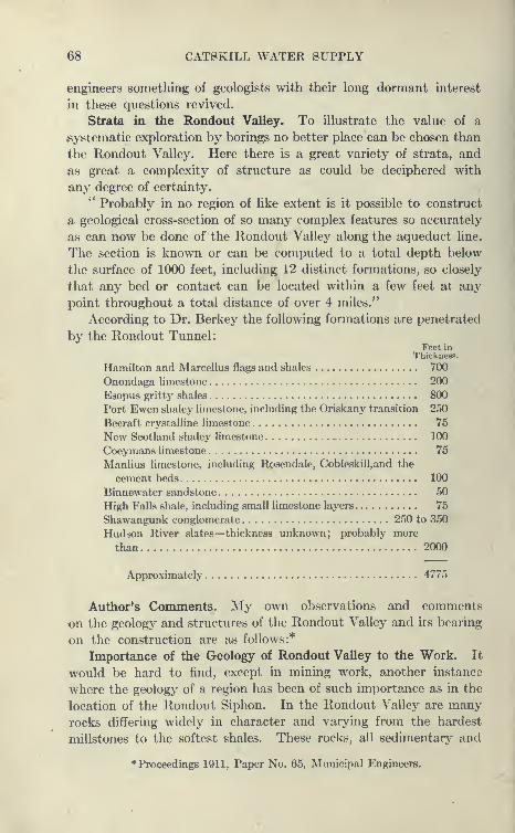
68 CATSKILL WATER SUPPLY
engineers something of geologists with their long dormant interest
in these questions revived.
Strata in the Rondout Valley. To illustrate the value of a
systematic exploration by borings no better place can be chosen than
the Rondout Valley. Here there is a great variety of strata, and
as great a complexity of structure as could be deciphered with
any degree of certainty.
" Probably in no region of like extent is it possible to construct
a geological cross-section of so many complex features so accurately
as can now be done of the Rondout Valley along the aqueduct line.
The section is known or can be computed to a total depth below
the surface of 1000 feet, including 12 distinct formations, so closely
that any bed or contact can be located within a few feet at any
point throughout a total distance of over 4 miles."
According to Dr. Berkey the following formations are penetrated
by the Rondout Tunnel
:
Feet inThickness.
Hamilton and Marcellus flags and shales 700
Onondaga limestone 200
Esopus gritty shales 800
Port Ewen shaley limestone, including the Oriskany transition 250
Becraft crystalline limestone 75
New Scotland shaley limestone 100
Coeymans limestone 75
Manlius limestone, including Rosendale, Cobleskill,and the
cement beds 100
Binnewater sandstone 50
High Falls shale, including small limestone layers 75
Shawangunk conglomerate 250 to 350
Hudson River slates—thickness unknown; probably more
than 2000
Approximately 4775
Author's Comments. My own observations and comments
on the geology and structures of the Rondout Valley and its bearing
on the construction are as follows:*
Importance of the Geology of Rondout Valley to the Work. It
would be hard to find, except in mining work, another instance
where the geology of a region has been of such importance as in the
location of the Rondout Siphon. In the Rondout Valley are manyrocks differing widely in character and varying from the hardest
millstones to the softest shales. These rocks, all sedimentary and
* Proceedings 1911, Paper No. 65, Municipal Engineers.
BORINGS AND SUB8UKFACE INVESTIGATIONS 69
originally deposited in level beds, are now tilted up at various angles,
and folded and faulted in a complex way, but still capable of being
correctly interpreted from outcrops and borings. In addition, the
rocks and depressions are buried under a deep mantle of glacial
drift. In fact, two glacial gorges w(»re l)clioved to be present.
Lesson of the Loetschburg Tunnel Disaster. Some of the best
geologists were engaged to examine th(» locality, and from out-
crops and other data a profile wiis worked up. This proved to Ix?
of great aid in subsequent investigation, but was qualitative rather
than quantitative. It gave a good idea of what to look for, but
no definite location could be made, as the thickness of the various
strata and the depths of the buried gorges had to be worked
out by diamond-drill l^orings. Finally the contract profile was
developed and confidently believed to be nearly correct. Theborings took a great deal of time and were expensive, but the
resultant certainty of location and foreknowledge of conditions
to be met amply repaid the expense and time. In a deep tunnel
of this character, it is considered absolutely necessary to keep the
tunnel in solid rock and not let it penetrate the drift of filled-in
gorges. A depth of at least 150 feet below the lowest point of
these gorges was considered safe. The Loetschburg Tunnel illus-
trates well the enormous cost and disastrous result of running into
a gorge. The Kandar River was to be passed at a safe depth in
solid rock, but an estimate of geologists based only on superficial
evidence was used, no borings being taken. When about 600 feet
below the river, soft, water-bearing drift was struck, which quickly
overwhelmed twenty-five men, filled up the tunnel and caused the
abandonment of over one mile of it. Subsequent borings showed
that the gorge extended far below tunnel grade, and that this fact
could have been very easily determined in advance. It speaks
volumes for the thoroughness of the Board of Water Supply work
when we consider that despite the many streams which have been
passed, no disagreeable surprises of this nature have yet occurred.
Growth of Geological Knowledge through Borings. To show
the difference between our knowledge of the rocks of the Rondout
Valley and the growth of this knowledge with the progress in l)oring,
the data shown on Plate 16 were prepared, reproducing the various
interpretations of the stratifications as the boring work progressed.
It will readily be seen how imperfect the original information was
and how the complicated folding or faulting had to be introduced
to correctly interpret the borings. In particular it will be noted that
the two preglacial gorges reversed the assumed depths, the deeper

CATSKILL WATER SUPPLY
w i \
1
\ isr
..!
B ^
:i!H io tooV
looan /
-I-i
•^1
t
s \\
'ip i»H )
~'
'^-.^ 1 \
9 no. »a / ;\^^
1 ^OOJ 1/ i;
^>^
"^ \a
/<'•^ ^ g
-'
^^J
^1f /'
,/'
s
1
g
i
4 s\ /{< ^i''
1
5
>.
o§-§
% ^i^^ 1 i V'l 8
\ \ \
1r^
fl
s"\
Ills*" -^l-
"li-1
i \1a
p "af
-~~ ^- !._r-~.
\& V "a /',
a /;) 1^
1 /^' s ,
I7»
/',/''
<; 5 '.
-?s
i' 1 li r^1
V -',
"•.'
'« o\. ^
UIH*" xoo\\ »^- s
\Itowa — -r- 1 \_
I P
io<»aJ
»af
'
,'
,'
1^<<"ajf /
'
s 1 '' t
1 ^oo
/'-?
./«" !
1
1^
4'/
8
^ 's s
1^
/ m1
I /^^1
^ '^— ^, .___ l^ ^ ^/^//
If^'' "^-~^-£.
.
(
•r o ',
•
2 i
3
"^=;._^Y^ (-^^N
•,-
PTOM v- —f- r g /
1 VM3nopooji
Vh ^
K / ^/'
t yAn ,' ,^
, .'-' 2
p«>H yi ^:/ is
)->'
,'' 1a
i 1 io
?s
. . ,1
Vv c ' / / »
\\
3
1 /''
/ / I1 ! ^
Jf/
/ / ^
1
g"
5-
r S•
' /I 1
/ < i^s;...a
1nopaoM
r L
f 5t»-zi- -h#>*^ ''•5' z^"O^S
^
r
i# 1
z
i[ i 1 g % /
\j
Vn.
^\^ j'
5?
1 /
§ \ 1- 2 1
f, \ ' '
i< . y
1 V / /^'"D '' ^.
•',%« ,'
inopaoH:'^^- ' '^y
f I yi
'I
i 1'§ s 1
\ /'.>^ /
\ I c*" /
i \ ,/1i
1£
M n»«r) \i s'i 5^
1
»nopaoi
t ?-^ t.'
.A j'*
<
«^*
.
«
,
^_j
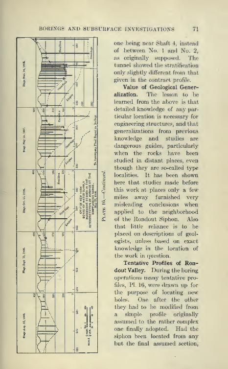
BORINGS AND SUBSURFACE INVESTIGATIONS 71
one lK?ing near Shaft 4, instead
of l)etween No. 1 and No. 2,
as originally supposed. Thetunnel showed the stratification
only slightly different from that
given in the contract profile.
Value of Geological Gener-
alization. Tlie lesson to l)e
learned from the above is that
detailed knowledge of any par-
ticular location is necessary for
engineering structures, and that
generalizations from previous
knowledge and studies are
dangerous guides, particularly
when the rocks have been
studied in distant places, even
though they are so-called type
localities. It has been shownhere that studies made before
this work at places only a few
miles away furnished very
misleading conclusions whenapplied to the neighborhood
of the Rondout Siphon. Also
that little reliance is to be
placed on descriptions of geol-
ogists, unless based on exact
knowledge in the location of
the work in question.
Tentative Profiles of Ron-dout Valley. During the boring
oj)erations many tentative pro-
files, PI. 16, were drawn up for
the purpose of locating newholes. One after the other
tliey had to be modified from
a simple profile originally
assumed to the rather complex
one finally adopted. Had the
siphon been located from any
but the final assumed section,
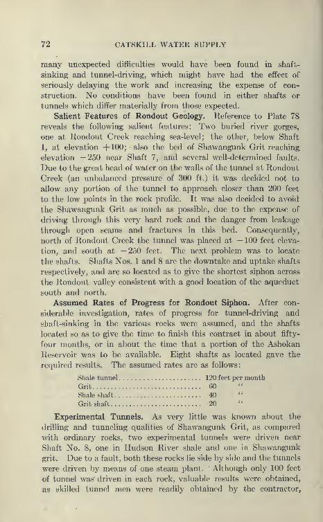
72 CATSKILL WATER SUPPLY
many unexpected difficulties would have been found in shaft-
sinking and tunnel-driving, which might have had the effect of
seriously delaying the work and increasing the expense of con-
struction. No conditions have been found in either shafts or
tunnels which differ materially from those expected.
Salient Features of Rondout Geology. Reference to Plate 78
reveals the following salient features: Two buried river gorges,
one at Rondout Creek reaching sea-level; the other, below Shaft
1, at elevation +100; also the bed of Shawangunk Grit reaching
elevation —250 near Shaft 7, and several well-determined faults.
Due to the great head of water on the walls of the tunnel at Rondout
Creek (an unbalanced pressure of 300 ft.) it was decided not to
allow any portion of the tunnel to approach closer than 200 feet
to the low points in the rock profile. It was also decided to avoid
the Shawangunk Grit as much as possible, due to the expense of
driv4ng through this very hard rock and the danger from leakage
through open seams and fractures in this bed. Consequentlj^
north of Rondout Creek the tunnel was placed at —100 feet eleva-
tion, and south at —250 feet. The next problem was to locate
the shafts. Shafts Nos. 1 and 8 are the downtake and uptake shafts
respectively, and are so located as to give the shortest siphon across
the Rondout valley consistent with a good location of the aqueduct
south and north.
Assumed Rates of Progress for Rondout Siphon. After con-
siderable investigation, rates of progress for tunnel-driving and
shaft-sinking in the various rocks were assumed, and the shafts
located so as to give the time to finish this contract in about fifty-
four months, or in about the time that a portion of the Ashokan
Reservoir was to be available. Eight shafts as located gave the
required results. The assumed rates are as follows:
Shale tunnel 120 feet per month
Grit 60
Shale shaft 40
Grit shaft 20 "
Experimental Ttmnels. As very little was known about the
drilling and tunneling qualities of Shawangunk Grit, as compared
with ordinary rocks, two experimental tunnels were driven near
Shaft No. 8, one in Hudson River shale and one in Shawangunk
grit. Due to a fault, both these rocks lie side by side and the tunnels
were driven by means of one steam plant. " Although only 100 feet
of tunnel was" driven in each rock, valuable results were obtained,
as skilled tunnel men were readily obtained by the contractor.
BORINGS AND SUBSURFACE INVESTIGATIONS
; Hs
e HS
xi a
i*
£2
c S
I J
o ~
Q 1
Q 2
^-
C 3e3 S3

74 CATSKILL WATER SUPPLY
Naughton & Co., from the neighboring Rosedale cement mines.
At the expenditure of only a few thousand dollars, information
was obtained which materially aided in the location of the tunnel.
The conclusions reached have been amply borne out by the workin the Rondout Siphon.
Relation of Rondout Problems to Others. What has been
said about the Rondout will sufficiently illustrate the problems of
the other pressure tunnels, although each is sufficiently important
to warrant separate treatment, but it would unduly lengthen this
book. The problem of the Hudson crossing is of such special
interest that it will be separately treated.
Exploratory Work for Grade Tunnels. For the grade tunnels,
it was necessary in most cases to merely determine the materials
at the portals and the nature of the rocks to be penetrated. In
some of the larger grade tunnels, as the Garrison, conditions similar
to pressure tunnels had to be determined and overcome. Thelonger the crossing of a valley the more likely is the pressure tunnel
to be adopted, as then the cost of the shafts does not make relatively
such a large proportion of the total cost. To cross a narrow gorge
the shaft may have to be as deep as in a wide one and the cost then
becomes too great to stand comparison with steel pipes, even whenallowance is made for the latter's shorter life.
Peekskill Creek and Foundry Brook Siphons. It was for some
time undecided whether the Foundry Brook or Peekskill Creek
siphons would be built as pressure tunnels or steel pipes. Therock, as determined by borings, appeared to be of such poor quality
that the pressure tunnel location was abandoned in favor of
the steel pipes.
Tunnels versus Cut-and-cover Aqueduct. In general, it maybe stated that the difficulties of tunneling are met mostly in the
preliminary stages of location and during construction. Once built,
they cease to trouble and, granting proper construction, their main-
tenance cost is small. For this reason, the cut-and-cover aqueduct
is not in the long run as economical a construction as it appears in
the first instance, as miles of embankments, fences, culverts, etc.,
have to be maintained on the surface where they are exposed to
the elements. Grade tunnels are, of course, due to absence of shafts,
much cheaper to build than pressure tunnels. They also have small
maintenance charges and have the advantage that they can be
easily inspected. In mountainous and hilly regions,, in particular,
they tend to greatly shorten the line and to eliminate doubtful and
extreme types of cut-and-cover aqueduct.

BORINGS AND SUBSURFACE INVESTIGATIONS 75
Geology of Ashokan Reservoir. The great glacial deposits in
the vicinity of Olive Bridge on the Esopus alone made it practicable
to construct a reservoir at anything like elevation 600. Were it
not for these impervious deposits of glacial till the crest of the damcould hardly reach elevation 450, which is 50 feet l)elow the
invert of the aqueduct as constructed. Esopus Creek was rudely
treated by the glaciers, having been forced to carve new channels for
itself more than once. These gorges could only l)e discovered by
borings. The engineers, before definitely locating the dam, were
most anxious to ascertain the character of the glacial <lrift which
would have to be relied upon to act as a natural auxiliarj' to the
structure to be built and to furnish secure foundation. In addition,
it was necessary to determine the locations and depths of the
buried gorges of the Esopus and other streams in so far as they
might affect the construction or location. Dr. Berkey gives the
following account of the geologic history of the Esopus Valley.-*
Preglacial Esopus Creek According to Dr. Berkey. *' In pre-
glacial time the Esopus Valley was occupied by a stream of similar
capacity to the present Esopus Creek. Its channel lay t© the
north side of the narrow valley, having adjusted itself in conformity
to the slight dips of the Hamilton sandstones and its principal
joints. At the points under investigation this original channel is
buried under several kinds of glacial deposits whose source of accu-
mulation was chiefly from the north and northeast, blocking the
stream channel and forcing the stream to the opix)site (south)
side. The direction of movement was favorable to the damming
of the Esopus Creek Valley, and the deposits indicate that this
occurred at several different times and at different elevations and
that corresponding lake conditions occasionally prevailed. It
is equally clear that there were intervals of retreat of the ice with
attendant stream action and the development of gravel beds, fol-
lowed by another ice advance, either obliterating the surface features
or covering the previous deposits with another till layer. With
each successive withdrawal the local streams found themselves
more or less completely out of place, and consequently their
characteristic deposits formed in these intervals may be found
in unlooked-for places wholly inconsistent with present surface con-
tour.
" At the final withdrawal of the ice, Esopus Creek found itself
intrenched along the southern margin of the valley and has cut a
Bulletin 146, N. Y. State Education Department.

76 CATSKILL WATER SUPPLY
postglacial rock gorge, instead of removing the compact till fromthe original channel. But wherever only modified drift, either
sand or clay, was the valley filling, it scooped out great bends, so
that a large proportion of this type has been removed from the
valley, and only the margins remain as terraces or covered beneath
other protecting deposits."
Tongore Dam Site vs. Olive Bridge Site. From surface indications,
there were two excellent dam sites for the Ashokan Reservoir, one
at Tongore, the other at Olive Bridge. Surface topography appeared
to favor the Tongore site, as, although the main masonry damwould be 290 feet high as against 210 for Olive Bridge, the total
length of dam and dikes would be only 2 miles against 3.8 miles
for Olive Bridge. In addition the Tongore site could furnish morewatershed by 6 square miles, besides shortening the Catskill Aqueduct
more than 2 miles, and eliminating two troublesome pipe siphons
at Esopus and Tongore creeks.
Borings at Tongore Dam Site. Surface indications are, however,
often deceptive, and are not to be trusted to point out safe damsites. On the south bank of the Esopus good rock outcrops were
found and the rock in the river bed appeared to be sound blue-
stone and shale without water-bearing streams. One boring,
however, happened to straddle a narrow seam (less than 1 inch thick).
This was followed from 90 feet below river bed to 104 feet, the
core brought up showing both sides of seam and much iron pyrites.
The seam yielded water under pressure which rose 10 feet above
top of casing. This flow, although constant, was not considered
of great importance owing to the great depth of sound overlying
rock.
North of the dam site lies a long high ridge which alone makes a
tight dam at the Tongore site possible. This ridge was thoroughly
explored by borings.
About 2000 feet to the north of the present gorge, an older
channel, supposed to be the preglacial course of the Esopus, was
discovered. This had been cut to elevation 250 feet, about 60
feet lower than the present stream. Over it was 10 to 150 feet
of water-bearing sand and gravel, and above this a surface coat of
100 feet of impervious glacial drift. The water-bearing character
of the sand was indicated by the loss of wash water in the borings
as soon as the wash rods reached its level.
Test Shaft at Tongore Dam Site. To obtain definite data, a
shaft was sunk by contract with Naughton & Co., It was 16'X24''
in plan and protected by 12"X12" timbers and 3-inch sheeting.

BORINGS AND SUBSURFACE INVESTIGATIONS 77
The material for the shaft was piled up carefully and so spread
out upon the ground as to indicate plainly the depth from which it
was obtained. The impervious top drift (depth 87 feet) was readily
penetrated, but below this the water-l)earing ground above men-tioned gave great difficulty, the water increajsing from 10 gallons to
160 gallons per minute at a depth of 114 feet, when the shaft wasabandoned. Indications were, therefore, very strong that a sub-
terranean water passage or porous zone of considerable extent
existed. To make this site safe, a core wall 1400 feet long would
probably have had to be built to rock at an almost prohibitive
cost, as its height would have had to be at the maximum 250 feet
below ground and 150 above. Due also to the small cros.s-section
of the ridge on which the dam would have had to be founded, there
would have been considerable danger of the water escaping below
the dam.
Supplementing borings with data obtained by shafts at the
critical points is much to be commended, as materials washed upby borings have a strong tendency to indicate too much sand and
gravel, the finer particles of clay being wasted with the wash water.
Unfortunately, shafts are expensive, and as it takes considerable
time to sink them, it is not feasible to have many, but they serve
as a decided check on the materials and interpretations of wash
borings.
Olive Bridge Dam Site. The Olive Bridge site when thoroughly
explored by numerous borings and several shafts gave nothing but
favorable indications. The glacial drift overlying the rock is of a
dense impervious nature (boulder till) extending down to rock over
which there is no intervening porous layer, as at the Tongore sit3.
For the following reasons, the Olive Bridge dam site was chosen:
Dr. Berkey's Reasons for Recommending Olive Bridge Dam Site.
*' Because of the (a) higher bedrock throughout, and {b) the more
uniform and impervious quality of drift deposits, and (c) the more
massive cross-section of drift barrier for foundations, and (d) the
perfectly tight contacts of till ami bedrock, and (e) the limitation
of the more porous materials to higher levels, and (/) the glacial
history connected with the development of all these parts, 'Olive
Bridge ' is the preferable location for the proposed Ashokan Damon Esopus Crook." •$»
Rock Profile at Olive Bridge Dam. The profile along the center
line of the dam, shows clearly what has been stated, that rock is
the foundation of the dam for only a small portion of its length.
Two preglacial gorges have to be crossed. The old Esopus gorge,
78 CATSKILL WATER SUPPLY
about 50 feet below the modern gorge and about 1000 feet to the
north, lies below a drumlin of impervious material known as Winchell
Hill. No effort will be made to go below it, as it is crossed by acore-wall dike founded on the overlying impervious drift.
Beaver Kill Preglacial Gorge. A very interesting gorge wasfound under the present Beaver Kill, a sluggish stream whichno one would suspect of possessing any particular energy past
or present. Yet it had carved a gorge about 100 feet below the
present bed. As it was excavated for the purpose of blocking
it with an arched core wall, a perfect trapezoidal cut was exposed,
sloping regularly downward from one bluestone ledge to another,
both sides being very symmetrical. Under each ledge is a soft
layer of shale. The bottom material was supposed to be water-
bearing, but no difficulty was experienced in the excavation. It
was simply a loose boulder till with much gravel and enough fine
material to hold back the ground water, which reached the cut
only in small quantities. Subsequent excavation has amply con-
firmed the borings and preliminary investigation; everywhere the
glacial material, upon which most of the dam is founded and with
which the greater dikes were made, proved to be impervious and
admirably adapted to the purpose. See Plate 49.
Summary of Subsurface Investigations at Ashokan Reservoir.
To illustrate the amount of work done, there was available for
the information of intending bidders on the dam and dikes the fol-
lowing records: B. W. S. Report for 1907:" 270 borings, aggregating 29,480 feet.
'* 169 test pits, trenches and shafts from 5 to 155 feet deep.'' 214 pits in sand deposits.
" Sixty-four of these holes were in quarries to show character
of rock available for the work. They aggregate 512 feet in earth
and 2385 feet in rock.
" Prior to the arrival of prospective bidders to look over the
ground, the entire line of dams and dikes was staked out and the
location of each boring marked. The detailed boring records,
samples of materials penetrated, and cores of rock were on exhibi-
tion at the office. Test pits and shafts were open, and the material
excavated therefrom was ready for inspection, and photographic
records showing the material encountered, were at the service of
bidders. Various trenches down the face of steep bluffs were exposed,
test pits in several sand deposits could be inspected, borings at
various possible quarry sites were indicated by signs, cores were
displayed at the office and the boring records were in convenient
BORINGS AND SlJBSrRFACE INVESTIGATIONS 79
form for the contractors to study. Boring n-foniM ami Harnplrs
from possible borrow-pits were also on exhibition."
River Control at Dam Site. To show jts fully as possible the
cliaracter of the river Ijottom at the dam and to gain time, aft4?r the
letting of the contract for main dam, river control works were con-
structed directly by the Board, J. F. Sanlx)m Ixnng in charge
under Department Engineer C. E. Davis.
Two timber-crib, rock-filled cofferdams were built across the
stream 400 feet apart and two 8-foot steel pipes iastalled between
them. The cofferdams, hoadworks and pipe foundatioas were
built by the forces of the Board. The two steel pipes were fur-
nished and laid by the T. A. (lillespie Company. The stream flow
was turned into the two pipes and the space between the cofferdams
unwatered. Loose material was removed from the bed of the creek
and the rock exposed for examination. Besides giving a correct
idea of what the river bottom is, it enabled the contractor the fol-
lowing year to immediately begin the work of excavating the founda-
tions of the dam between the cofferdams and saved a full working
season. The pipes did their work perfectly, except when one
freshet temporarily flooded the excavation, which was anticipated.
Boring Machinery Used in Reservoir Department. In the
Reservoir Department borings were made both Vjy the forces of the
Board of Water Supply operating city-owned drilling outfits and by
contractors for wash borings to determine the depth of surface
materials. Small outfits were used, consisting of derrick, hand pump,
wash and drive pipes, etc. The complete drilling outfits used by
the Board of Water Supply consist of portable boiler, derrick,
steam pump, Badger screw-feed drill made by the Sullivan Machinery
Company, drill rods with equipment of core barrel and diamond
bit, wash pipe, chopping bits and necessary tools and fittings. The
contractors, Sprague & Henwood, of Scranton, Pa., used a similar
outfit, except that they operated several large hydraulic-feed diamond
drills made mostly by Sullivan Machinery Company. In general
in the reservoir department the main difficulty was to reach ledge
rock with the casing through which the boring in the rock was
subsequently made.
Getting Casing by Boulders by Chopping and Blasting. The
greatest difficulty in boring is that caused by l)oulders. Whena boulder is reached too large to be chopped through, dynamite is
lowered into the casing resting on the boulder. The casing is then
pulled up a few feet, the dynamite exploded by means of magneto
and battery wires. Repeated blastings may have to be resorted

so CATSKILL WATER SUPPLY
to before the boulder is sufficiently broken to allow the casing to
pass. A large boulder may not yield even to this rough treatment,
but it may become necessary to drill a hole into it with the diamonddrill, after which more dynamite is lowered into this hole and the
boulder shot into bits. It sometimes happens that if the casing is
not pulled up high enough the dynamite will split it, so that whenit is attempted to drive it down again it will collapse, thus spoiling
the hole. The various difficulties encountered by drills will be
described more at length later.
Details of Diamond Drilling. After the casing is well seated
on the bedrock, the rock drilling is carried on as follows : Specially
hea\'y diamond-drill rods with square threads which may previously
have been used as wash pipes are connected and lowered to the rock.
To the lower end of this line of rods is screwed a core barrel about
10 feet long to which in turn is fastened a short core shell containing
the diamond bit. The diamond bit is a soft steel pipe about an
inch long, one end screwed into the core shell, the other turned
square and having embedded in it two rows of diamonds. All the
diamonds project slightly from the metal, those on the outside so
as to cut a hole in the rock large enough to receive the core barrel,
those on the inside so as to cut a core to pass through the bit and
core shell into the core barrel. At the bottom of the core shell is a
hard metal spring with upward-facing teeth which allows the rock
core to pass upward but not downward. The upper end of the
drill rod is passed through the drill, and the steam pump is connected
with its top by means of a rubber hose and water swivel. Thedrill rods are then revolved in the same manner as an ordinary drill
press and the rods are fed downward as fast as the core is cut, by
one or two methods—either by a screw-feed as in the Badger drill,
which is adjustable for different rates of cutting, or as in hydraulic
machines, by a hydraulic cylinder and piston, through which the
drill^rods pass. The pressure of water maintained by the steam
pump forces the rods downward as fast as the diamond bit cuts.
It also gives the proper pressure for the best operation of the diamonds.
In case of long lengths of rods, the hydraulic machine may be so
controlled as to partly balance the weight of the rods, preventing
excessive pressure on the diamonds. The diamonds are, however,
remarkably strong and able to stand a heavy steady pressure, no
difficulty being experienced in getting a few small diamonds to
support as much as 600 feet of heavy drill rods. While the drill
is being rotated water is forced, under considerable pressure,
through the rods, clearing away the chippings from the bit and keep-
BORINGS AND SUBSURFACE INVESTIGATIONS 81
ing the bit cool. If there be any interruption of the supply of cooling
water the diamonds become too hot and the bit is liable to fuse,
in which case the hole may be lost, with the diamonds.
Efficiency of the Diamond Drill. The diamond drill is a remarkably
efficient tool, and were it not for the heavy cost of the black diamonds
used would be much more extensively employed. It has been used
now for such a long period that the present drills are as well madeand reliable as almost any machine-shop tool. There is a tendency
to exaggerate the diamond loss in drilling and the value of diamonds
lost in bits not recovered. The experience on the Board's work
would indicate that one bit is lost to about every 10,000 feet drilled.
Valuing a bit at the high cost of $1000, this would mean a charge
of 10 cents per foot. In addition, the diamond loss may run from
a few cents a foot to 50 cents or more, depending on the hardness
of the rock. The writer is aware of no other machine capable of
boring rock and yielding core which can be depended upon to makethe progress and to penetrate rock of any nature, hard or soft,
seamy or compact.
Contract Boring at Ashokan Reservoir. The linear feet of bor-
ings made in the Reservoir Department has previously been given.
The contract prices were $3 to $4 per foot for core borings, but the
cost of the direct work was somewhat less. The rocks bored into
are the Hamilton beds of the Devonic Era and consist of alternate
layers of sandstone (bluestone) and shale, which offer no great dif-
ficulty to boring.
Borings in Northern Aqueduct Department. Undoubtedly the
most difficult drilling of the entire work was that necessarj' to deter-
mine the location of the 17.25 miles of aqueduct below grade in this
department. In addition, some work was necessary to determine
the material to be penetrated by the 6J miles of grade tunnel beside
some work for the 36j miles of cut-and-cover. But the latter could
usually be determined by test pits, except in the very deep earth
cuts where borings were necessary. The one great problem of
this work, of course, was that of the Hudson River crossing, and this
has stood out so conspicuously as to obscure the subsurface investi-
gation necessary for the other siphons.
Rondout Siphon Borings. The work of this character on the
Rondout Siphon has already been referred to. Here the greatest
difficulties encountered were in the deep deposits of glacial drift
over the preglacial gorges. Between Shafts 1 and 2 over 250 feet
of drift had to be penetrated, some of it bouldery; but the greatest
difficulty was experienced in penetrating a slatey gravel which packed
82 CATSKILL WATER SUPPLY
at the bottom of the casings and was very difficult to wash
out even with chopping bits. The work on this siphon wasperformed under various agreements with Sprague & Henwood,
and directly by the Board's forces, the prices varying between
$2.35 and $6 per foot. It was early found that the Shawangunkgrit was difficult and costly to drill—a small screw-fed machine
only averaging 2 to 3 feet per eight-hour day—and so wearing the
diamonds ('' polishing the bits ") that it was necessary to reset the
stones daily. Later, the contractor would not do work in this bed
under $6 per foot, but it was found that by the use of a heavy hydrau-
lic machine (Sullivan '' B ") 6 to 8 feet per day could be secured
with much less diamond loss per foot than with the light rig. It
was explained that the light rig merely rotated and " polished"
the diamonds against the quartz pebbles of the conglomerate, not
getting sufficient pressure to do much cutting. With the hydraulic
machine heavy pressure could be brought to bear, cutting the rock
at the same time the machine rotated. The wear on the diamonds
was of course large, a bit needing resetting each 6 to 8 feet. Theprojecting edges of the diamonds were worn off, so that to cut at all
new faces had to be exposed, giving the necessary clearance. Thediamond losses in these holes averaged probably about 50 cents per
foot, but in exceptional cases where seams were penetrated diamonds
would be torn loose from the bit or shattered. In all hard drilling
it was noted that good, well-tested black diamonds give a muchsmaller loss than those of cheaper and poorer grades, so that it is
true economy to have the best diamonds in the bits, even at the risk
of their total loss due to some seam or cave or other unforeseen con-
dition. Black diamonds from Brazil are used. Before being placed
on the market the stones are crushed and large pieces (1-2 carats)
with sharp edges selected. They are worth $40 to $75 per carat,
according to size and grade of the individual stones, and are two or
three times as expensive as they were in 1895. It takes a good deal
of experience to select a stone, as some will soon shatter under use
while others will wear very slowly and stand a great many resettings.
It follows that tested diamonds which have been used in bits are
worth a great deal more than new stones.
Borings Made by City-operated Machines.^ The first wash boring
machines at work along the line of the aqueduct were owned by the
City. They were only able to put down a single line of 2i-inch cas-
ing, and it was soon found that heavy glacial material could not be
penetrated with any success. Boulders would stop the casing as
effectually as ledge rock and misleading reports as to rock surface
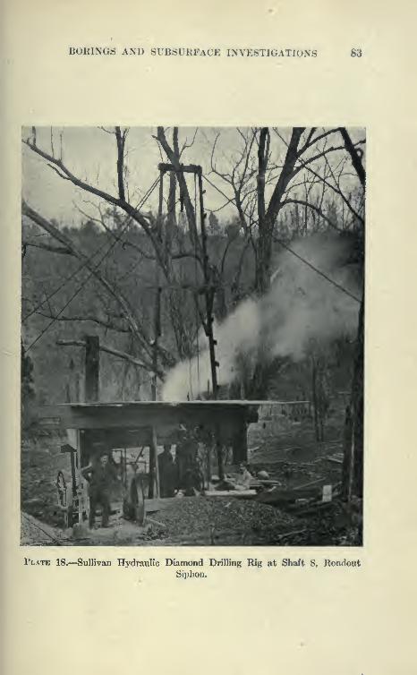
BORINGS AND SUBSURFACE INVESTIGATIONS 83
Plate 18.—Sullivan Hydraulic Diamond Drilling Rig at Shaft 8, RondoutSiphon.
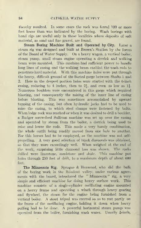
84 CATSKILL WATER SUPPLY
thereby resulted. In some cases the rock was found 100 or morefeet lower than was indicated by the boring. Wash borings with
hand rigs are useful only in those localities where deposits of soft
material, as sand and fine gravel, are found.
Steam Boring Machine Built and Operated by City. Later a
steam rig was designed and built at Brown's Station by the forces
of the Board of Water Supply. On a heavy wagon, a vertical boiler,
steam pump, small steam engine operating a derrick and walking
beam were mounted. This machine had sufficient power to handle
long lines of casing and the walking beam enabled the wash rods to
penetrate hard material. With this machine holes were put through
the heavy, difficult ground of the buried gorge between Shafts 1 and
2. Here in the deepest portion holes were started with the 6-inch
casing, reducing to 4 inches, then to 2J, and even as low as If.
Numerous boulders were encountered in this gorge which required
blasting, and consequently the raising of the inner line of casing
before blasting. This was sometimes accomplished by upward
tapping of the casing, but often hydraulic jacks had to be used to
raise the casing, to which steel clamps were fastened by bolts.
When ledge rock was reached or when it was desired to drill a boulder,
a Badger screw-feed Sullivan machine was set up over the casing
and operated by steam from the boiler, a derrick being used to
raise and lower the rods. This made a very handy combination,
the whole outfit being readily moved from one hole to another.
For this horses had to be employed, as the machine was not self-
propelling. A very good selection of black diamonds was obtained,
so that they wore exceedingly well. When weighed at the end of
the work, surprising little diamond loss was shown. The rocks
drilled were limestone, sandstone and shale. This machine put
holes through 250 feet of drift, to a maximum depth of about 600
feet.
The Minnesota Rig. Sprague & Henwood, who did the bulk
of the boring work in the Rondout valley, under various agree-
ments with the board, introduced the " Minnesota " rig, a very
simple and efficient machine for doing heavy surface work. This
machine consists of a single-cylinder oscillating engine mounted
on a heavy frame and operating a winch through heavy gearing
and fljrwheel, the steam for the engine being furnished from a
vertical boiler. A stout tripod was erected so as to rest partly on
the frame of the oscillating engine, holding it down when heavy
pulling had to be done. A powerful horizontal steam pump was
operated from the boiler, furnishing wash water. Usually 5-inch,

BORINGS AND SUBSURFACE INVESTIGATIONS 85
Plate 19.—Board of Water Supply steam drillinR rig. Machine operated 88
a "Wash Rig" to reach rock and then furnished steam for Badger-SuUivan
diamond drill, raised and lowered drill rods, etc.
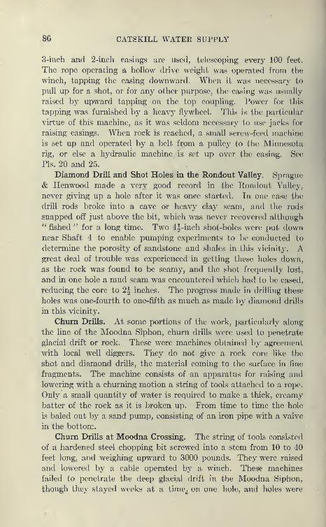
86 CATSKILL WATER SUPPLY
3-inch and 2-inch casings are used, telescoping every 100 feet.
The rope operating a hollow drive weight was operated from the
winch, tapping the casing downward. When it was necessary to
pull up for a shot, or for any other purpose, the casing was usually
raised by upward tapping on the top coupling. Power for this
tapping was furnished by a heavy flywheel. This is the particular
virtue of this machine, as it was seldom necessary to use jacks for
raising casings. When rock is reached, a small screw-feed machine
is set up and operated by a belt from a pulley to the Minnesota
rig, or else a hydraulic machine is set up over the casing. See
Pis. 20 and 25.
Diamond Drill and Shot Holes in the Rondout Valley. Sprague
& Henwood made a very good record in the Rondout Valley,
never giving up a hole after it was once started. In one case the
drill rods broke into a cave or heavy clay seam, and the rods
snapped off just above the bit, which was never recovered although*' fished " for a long time. Two 4§-inch shot-holes were put downnear Shaft 4 to enable pumping experiments to be conducted to
determine the porosity of sandstone and shales in this vicinity. Agreat deal of trouble was experienced in getting these holes down,
as the rock was found to be seamy, and the shot frequently lost,
and in one hole a mud seam was encountered which had to be cased,
reducing the core to 2^ inches. The progress made in drilling these
holes was one-fourth to one-fifth as much as made by diamond drills
in this vicinity.
Chum Drills. At some portions of the work, particularly along
the line of the Moodna Siphon, churn drills were used to penetrate
glacial drift or rock. These were machines obtained by agreement
with local well diggers. They do not give a rock core like the
shot and diamond drills, the material coming to the surface in fine
fragments. The machine consists of an apparatus for raising and
lowering with a churning motion a string of tools attached to a rope.
Only a small quantity of water is required to make a thick, creamy
batter of the rock as it is broken up. From time to time the hole
is baled out by a sand pump, consisting of an iron pipe with a valve
in the bottom.
Chum Drills at Moodna Crossing. The string of tools consisted
of a hardened steel chopping bit screwed into a stem from 10 to 40
feet long, and weighing upward to 3000 pounds. They were raised
and lowered by a cable operated by a winch. These machines
failed to penetrate the deep glacial drift in the Moodna Siphon,
though they stayed weeks at a time^ on one hole, and holes were
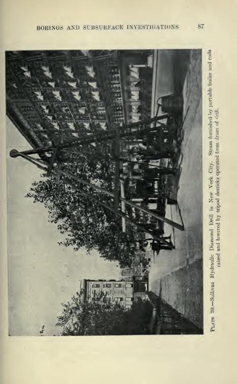
BORINGS AND SUBSURFACE INVESTIGATIONS 87
88 CATSKILL WATER SUPPLY
abandoned with casing at various depths. Later on Sprague
Henwood, under another agreement, installed Minnesota rigs,
and succeeded in reaching bedrock with no great difficulty. Glacial
drift along the line of the Moodna Siphon is of extraordinary
thickness, the maximum, 350 feet, being the greatest depth of drift
discovered along the line of the Aqueduct, with the exception of
that overlying the Hudson gorge.
Shot Drills. The shot or calyx drill uses rods and core barrels
similar to the diamond drill, except that the core barrel is generally
larger in proportion to the size of the rod. It is fitted with a bit at
the lower end, which is a heavy pipe with a single notch cut in it.
Hardened steel shot is fed to this bit with the water, and the rock
is cut by the grinding of the shot below the bit. An annular
groove is cut and the core rises in the core barrel. At the top of
the core barrel is a calyx extension and into this the chippings are
collected, as the velocity of the wash water is usually not sufficient
to carry the chips to the surface. When it is desired to bring the
core to the surface, a few handfuls of coarse sand or gravel are poured
into the rods and washed down. This grouts the core to the core
barrel and it can be pulled up. Shot drills were used to only a limited
extent in the Northern Aqueduct Department, as they were
not able to work to good advantage due to the difficulties in getting
holes through the difficult rocks there, but in the Southern Aqueduct
Department they were able to do good work in the schists and
gneisses of that region. They were •[also used to a considerable
extent in New York on the City Aqueduct.
Because of the extensive use of boring machines of all kinds on
the aqueduct work the engineers gradually came to learn that drill-
ing demands the highest skill and patience of the men operating
the machines and that it is poor economy to engage poorly equipped
and inexperienced contractors to do this work.
Difficulties of Drilling. In addition to the troubles before enu-
merated, the following maybe mentioned:*
In drilling surface material hard boulders are often encountered.
A boulder in sand may offer great difficulties, the sand washing into
the casing and making it hard to chop the boulder, or it may drop
into a hole washed out under the casing. When the casing is
raised to blast the boulder, the sand may rise in the casing, pre-
venting the dynamite from reaching the boulder. Measurements
* See Robert Ridgway's Article, Proceedings Municipal Engineers, 1908,
Subsurface Investigations of the Board of Water Supply.

BORINGS AND SUBSURFACE INVESTIGATIONS 89
should be carefully made to see whether it is low enough, or else
the casing will be destroyed.
Great difficulty is experienced in deep holes in exploding the
dynamite. This has been variously explained—by short-circuiting
in the battery wires, by chilling of the explosive, or what is morelikely, by the breaking of the exploder, by the pressure of the water,
so that the spark is not properly formed when the magneto is
discharged.
Various Difficulties Encountered in Sinking Casing, etc. Gravel
is often difficult to penetrate, leading away the wash water andwedging the bit, separating it from the wash rods. The conical
recovering tap is then let down on a line of rods, and cuts a thread
on the end of the broken pipe, so that it can be raised. Thesame device is used when the diamond-drill rotl is used to rotate the
bit parts for some rcjison. Both inside and outside recovering
taps are used. Sometimes the chopping bit lies at such an angle
as not to be recovered; in that case, it can be burnt up by repeated
shots of dynamite, a very troublesome and tedious o])eration.
Wash pipes are sometimes wedged in the casing by fine sand flow-
ing between the two pipes. It has been found that a powerful
pump is of great aid in preventing this, as it is in all other washing
operations. Casings are often bent and parted by the severe
usage given them in driving and pulling. It has been found that
it pays to use extra heavy casing and heavy coupling. Even with
heavy casings, they must be treated gently, as the power of almost
any boring machine is sufficient to cause injury by heavy pountling
or driving.
Drilling Rock with Diamonds. In drilling rock with diamond drills
the machine must he carefully watched to see that an upward flow
of water is always maintained, properly carrying away the cuttings
and cooling the diamonds, also that the bit is fed carefully down-
ward. If the first precaution is neglected the bit may run dry and
the diamonds be lost through fusing of the steel. If a bit is used
too long, the diamonds may become loose and fall out, or cores
may become wedged in the hard rock, and cause the shattering of
the inner diamonds. Sometimes a bit may be recovered when lost
by reaming down to it with a larger bit and then raising it with
recovering tap or electro-magnet.
On the City Aqueduct work, out of a total 17,687 feet of holes
drilled, three bits wore lost.
Breakage of Diamonds. In working through seams in hard
rock, heavy diamond loss is sometines experienced by the shattering
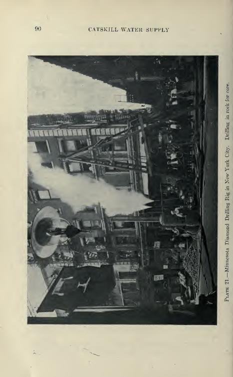
90 CATSKILL WATER SUPPLY
BORINGS AND SUBSURFACE INVESTIGATIONS 91
of the diamonds when the rods drop unexpectedly. The same
thing may happen if, when pulling, the rods are allowed to slip back
into the hole, erushing the (liiinionds.
Breakage of Diamond Drill Rods. If a diagonal seam is encoun-
tered, the rods are apt to be defleeted so that the weight of the rods
above the seam will l)reak the rod at the seam, and the lower length
will snap back out of line, so that it cannot l)e n^ached by the recover-
ing tap. There is a slight chance of reeoverinir it by an electro-
magnet.
Advantage of Diamond Drills. The diamond drill iia.s the great
advantage of working positively, a diamond bit being, without
doubt, the most efficient rock-cutting tool known, and were it not
for the high cost of diamonds would be extensively used for a great
many purposes. As it is, its use is almost confined to exploratory
work, such as that of the Board of Water Supply, to investigate
foundations, mineral veins, etc. The diamond drill will work at
any angle and will penetrate almost any rock, sound or seamy.
In case rock is very bad, however, the hole may have to be reduced
by casing, and the use of a smaller bit. The usual cores obtained
by diamond drills are less than 2 inches in diameter. It is entirely
practicable to drill larger holes, but the diamond loss becomes very
high and the holes, consequently, very expensive. Also the bits
used for obtaining large cores represent a heavy investment and the
risk is rather large.
Limitations of the Shot Drill. Shot drills are of great use in
drilling large holes; in fact, they can more readily obtain 4-inch
cores than smaller sizes, and have been used to drill holes 15 inches
or more in diameter for plunger elevators and for openings into
mines. They seem to be most efficient in drilling in a uniform
rock of medium hardness, but are very slow in drilling in seamy
rock and very hard rock. Seamy rock with a strong flow of water
will wash away the shot, leaving bare pipes to do the work alone.
In very hard rock, such as the Shawangunk grit, it has been found
that the shot drills are exceedingly slow and impracticable. For pure
exploratory work where a small core is sufficient and where rapid
progress is required to obtain needed information, the diamond drill
is far and away more efficient than the shot drill and, due to its
much faster progress, will generally drill more cheaply. It htus been
found that in some strata where the diamond drills couid do 10
to 20 feet per eight-hour daj^ the shot drill could penetrate only 3
feet, the diamond drill, of course, furnishing less than 2-inch core,
and the shot drill less than 4 2-inch. There is no doubt that the
92 CATSKILL WATER SUPPLY
shot drill has its place and that it is an extremely valuable tool for
obtaining large cores, and there are a great many places where
large cores are desirable. The diamond drill, however, seems to be
a perfected tool, while the shot drill is still capable of great improve-
ment. As diamonds tend to be more and more expensive, the shot
drill will tend to approach the diamond drill in efficiency.
Interpretation of Borings. After a boring is completed it
then becomes necessary to interpret properly the samples and cores
obtained, which can best be done by those who have witnessed the
operation of the drill, as the various occurrences and methods of
operations, the personnel and skill of the drillers all have a bearing.
No better statement has been made than that of Mr. Ridgway :
Mr. Ridgway*s Conclusions Concerning Borings, ''To the engineer
unused to such work it is difficult to judge whether a boring con-
tract is being handled properly. The tendency is to magnify the
difficulties encountered, when the trouble may lie with the con-
tractor's methods or appliances. Months may be spent in gaining
only a few feet at great labor, and anybody watching the operation
might conclude that the difficulty was insurmountable. The sub-
stitution of a different machine or of men more efficient in this class
of work means in nearly every case the successful completion of
the boring. The experience of the drill runner is of course a very
large factor in successful boring, but his experience alone cannot
make up for inferior machines or equipment. Such troubles as the
bending or breaking of the casing is frequently attributed to the
difficult character of the ground, but the employment of heavy
casing or proper machines will usually overcome the difficulty. Thesame considerations apply to boring in rock as in earth. A shot
machine may be employed to do work for which it is entirely
unsuited, or a small diamond drill, not of the hydraulic type, maybe found inadequate for a certain rock.
'' As stated above, misleading conclusions are apt to be made from
boring work and records. Where a boring is having great trouble
due to seams in the rock, one is apt to conclude that the rock itself
is very hard, whereas such a conclusion may not follow at all.
For instance a rock in which the strata are in a vertical position
may be very difficult to bore with a diamond drill, but is in just
the right position for tunneling through, as the layers will support
themselves instead of caving in flat slabs, which might happen were
the strata in horizontal position. Seams in rock will bother a rotary
drill greatly, whereas a percussion machine may readily penetrate it.
" Reliance cannot always be placed upon the percentage of core
BORINGS AND SUBSURFACE INVESTIGATIONS 93
recovered from different rocks. These percentages are apt to vary
according to the variety of drill and manner in which the machine
is handled. The dip of the strata is an important factor; slate
on edge is very easily tunneled into, hut may yield a very low per-
ct^ntage of core, whereas material difficult to tunnel may give a high
percentage of core.
" It is most difficult properly to interpret wa.sh-boring samples.
If clay or uniform sand is being penetrated the samples are all
right, but in a majority of materials only the coarser particles are
likely to be preserved unless great care is used. Where hardpan,
composed of a large percentage of clay, is being penetrated in drilling,
it will cause the loss of most of the clay in the wash water, so that the
little material recovered may be labeled * Sand and Gravel ' by the
drillers, and an examination of the contents of the sample bottle
will apparently bear out this erroneous conclusion."

CHAPTER V
EXPLORATIONS FOR HUDSON RIVER CROSSING
The Hudson River. That the Hudson is a barrier of considerable
difficulty is shown by the fact that no bridge crosses the lower 75
miles of its course, there being only one in 150 miles. That it wasat one time an active stream below Albany and not a tidal estuary
is shown by its submarine gorge, which can plainly be traced for
120 miles south of New York to the continental border, beyondwhich the bottom drops abruptly from 600 feet in depth to 6000
feet, where there are remains of an old Hudson gorge at least 2800
feet deep.
Preglacial Gorges. In preglacial times the continental border
was elevated so as to present a front about 3000 feet high to the sea;
through this the Hudson cut deeply and the tributaries tended to
cut back their valleys to the elevation of the Hudson bottom. Butbefore this could be accomplished, subsidence occurred, and while
the tributaries were in hanging valleys the whole was submerged
to the extent of placing the Hudson valley far below sea level, the
others at a little above. This was only brought out by the Boardof Water Supply borings, the current theory among geologists being
that the tributary streams, such as the Esopus, Rondout, Wallkill,
Moodna, etc., having had a long time to work, had cut their valleys
to the level of the Hudson for the lower portion of the course, andhence we would find at our aqueduct crossings buried gorges far
below sea level. Much to the surprise of the geologists, no gorge
much below sea level was found, even at the Moodna crossing 3
miles from the Hudson. But it took many borings to convince themof this, and it was only after there seemed no chance whatever of
finding such gorges by borings that they gave up the search. Since
then the shallowness of the gorges has been absolutely proven bythe driving through solid rock of the Rondout, Wallkill and Moodnapressure tunnels below the streams. It would seem that the con-
tinent was elevated several thousand feet for a long enough period
to allow the swiftly moving Hudson to cut a canyon rivaling the
94
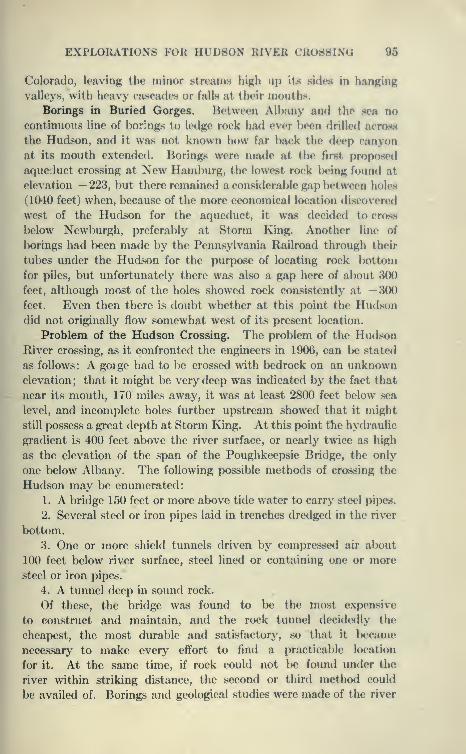
EXPLORATIONS FOR HUDSON RIVER CROSSING 95
Colorado, leaving the minor streams high up its sides in hanging
valleys, with heavy cascades or falls at their mouths.
Borings in Buried Gorges. Between Albany and the sea no
continuous line of borings to ledge rock had ever l>een drilled across
the Hudson, and it was not known how far back the deep canyon
at its mouth extended. Borings were made at the first proposed
aqueduct crossing at New Hamburg, the lowest rock being found at
elevation —223, but there remained a considerable gap Ix'tween holes
(1040 feet) when, because of the more economical location discoveretl
west of the Hudson for the aqueduct, it was decided to cross
below Newburgh, preferably at Storm King. Another line of
borings had been made by the Pennsylvania Railroad through their
tubes under the Hudson for the purp)ose of locating rock bottom
for piles, but unfortunately there was also a gap here of alK)ut 300
feet, although most of the holes showed rock consistently at —300feet. Even then there is doubt whether at this point the Hudsondid not originally flow somewhat west of its present location.
Problem of the Hudson Crossing. The problem of the HudsonRiver crossing, as it confronted the engineers in 1906, can l>e stated
as follows: A gorge had to be crossed with bedrock on an unknownelevation; that it might be very deep was indicated by the fact that
near its mouth, 170 miles away, it was at least 2800 feet below sea
level, and incomplete holes further upstream showed that it might
still possess a great depth at Storm King. At this point the hydraulic
gradient is 400 feet above the river surface, or nearly twice as high
as the elevation of the span of the Poughkeepsie Bridge, the only
one below Albany. The following possible methods of crossing the
Hudson may be enumerated:
1. A bridge 150 feet or more above tide water to carry steel pipes.
2. Several steel or iron pipes laid in trenches dredged in the river
bottom.
3. One or more shield tunnels driven by compressed air about
100 feet below river surface, steel lined or containing one or more
steel or iron pipes.
4. A tunnel deep in sound rock.
Of these, the bridge was found to be the most expensive
to construct and maintain, and the rock tunnel decidedly the
cheapest, the most durable and satisfactory, so that it became
necessary to make every effort to find a practicable location
for it. At the same time, if rock could not be found under the
river within striking distance, the second or third method could
be availed of. Borings and geological studies were made of the river

96 CATSKILL WATER SUPPLY

EXPLORATIONS FOR HUDSON RIVER CROSSING 97
from Peggs Point, 3 miles above New Hamburg, to Anthony's Nosein the Highlands, a distance of 21 miles. A narrow channel at the
point of crossing was desirable, and geological conditions were animportant factor. At Storm King and Little Stony Point granitic
gneiss of a good quality was found on both sides of the river, with
no indications of a change between. At the other crossings, lime-
stone was found which it was desirable to avoid on account of its
uncertain character. This favorable geological condition taken
in connection with the narrowness of the river at Storm King andwith the better location of the aqueduct leading to it on lK)th sides
of the river decided the crossing at this point. Therefore workwas concentrated at Storm King. The explorations were madeby the following methods:
1. Wash borings.
2. Core borings.
3. Test shafts on the shores of the river from chambers in which
diamond-drill holes were put out under the river.
Wash Borings. At fourteen cross-sections of the river, lines of
borings were made across the stream by means of wash drills
operated from the deck of a large lighter. These gave only nega-
tive results, as the wash rods were stopped at from 100 to 300 feet
by boulders and no attempt made to blast them through. Bedrock
was later found to be several hundred feet lower.
Core Borings. These were made under contract with the
American Diamond Rock Drill Company, and their assignees, the
Phoenix Construction and Supply Company, of New York. Theprice paid by the city for vertical borings varied from $9.75 per
foot to $50 per foot, depending on depth of hole. The equipment
for drilling is described as follows by Messrs. Dodge and Hoke,
Hudson River Crossings of Catskill Aqueduct, Proceedings of
Municipal Engineers for 1910:
Equipment for River Borings. '' The equipment which experience
has shown to be best is a pile-driving scow 35'X 100' with ways
60 feet high, a hoisting engine of 40 H.P. with two 7"X10" cylin-
ders and two 12-inch drums, two 12" XT" XI 2" pumps with
capacity for 100 gallons per minute each at 120 pounds pressure,
and a 60 H.P. boiler, casing and wash pipe of 18-inch and 14-inch
steel-welded pipe and 10-inch, 8-inch, 4-inch, 2^-inch and 2-inch,
extra heavy wrought-iron drive pipe with screw joints and extra long
sleeve couplings, a drilling machine, Ij-inch rods and enough dia-
monds for two bits. When the casing is surely seated in ledge and
drilling under way the large scow and other equipment for wash

98 CATSKILL WATER SUPPLY
boring can be dispensed with, the drilling machine being carried onon a platform clamped to the casing, and pump and boiler kepton a scow about 20'X30'.
" The scow is kept in position by at least six anchors at bow,stern and four corners. These must be from two to three tons each
and have leads of 400 to 500 feet of |-inch wire cable. The severe
gales and rough water encountered at times make it hard to keepthe scow exactly in position, while any movement, if it is toward the
hole, is likely to bend the standing casing and destroy the borings.
General Method of Sinking Casing. '' The general method of
boring is to sink first a line of large casing as far as possible without
too severe driving, then to put down the next smaller size inside
of it, * telescoping,' as it is called, and continue downward again,
the telescoping of casing being repeated when necessary, until bed-
rock is reached. A line of casing, of course, encounters skin fric-
tion against the drift material only below the bottom of the next
larger casing, and in general an advance of 100 feet or more should
be made with each size, though the first two sizes should be madeconsiderably more than that in the fine material which lies on top.
The importance of not having too much frictional resistance on aline of casing comes from the necessity not only of moving the line
down, but of being able to draw it back, so that its end will be out
of harm's way when blasting is done, hence care is taken against
forcing when much resistance is felt. In the early work before
the great depth of the gorge was known, and when the contractor
knew less of how to do this kind of boring, the mistake was madeof starting with too small casing and so coming down to the smallest
size practicable while still a long way from rock; this made the last
of the work on these holes excessively difficult and one of them hadto be abandoned in an unfinished condition for this reason. Thelatest and deepest holes have been started with 18-inch casing; six
reductions are then possible.
" The casing is lowered and raised by a wire cable fall passing
over the sheave at the top of the pile falls to the drum of the hoistei
.
As the casing goes down, it is added to in 20-foot lengths, the addi-
tional piece being supported by the fall while the men screw it into
the coupling at the top of the line. Great care is taken with the
joint, the coupling is extra long and an effort is made to have the
pipe ends meet, so that in driving, the blows of the hammer will
not be carried by the threads entirely.
Washing down Large Casing. " The first material encoun-
tered is mud and silt, and the large casing, being very heavy, goes

EXPLORATIONS FOR HUDSON RIVER CROSSING 99
II<
1§MaCO
s«
a
c
s

100 CATSKILL WATER SUPPLY
into it for the first 50 feet very easily. When light driving ceases
to have an effect, a 4-inch pipe is put down inside and connected
with the pump by hose and a powerful stream of water forced
through it, to stir up the material just below the bottom of the
casing, the water returning inside the casing and bringing up the
lighter material with it. The casing is at the same time poundedlightly by the piledriver hammer, which has a hole in its center
through which the wash pipe passes.
" The position of the bottom of the wash pipe is a matter fo)
careful attention; it must be at or below the bottom of the casing
to act upon the resisting material while, if it is too far below, the
water of the jet escapes under the edo^e of the casing and no material
is brought up. The position should vary with the material; in
clay the wash pipe may go several feet below the casing without
harm, while in gravel the water will escape in a few inches of space.
" In the large casings, the space between wash pipe and casing
is so great that the returning wash water has little velocity andbrings up only the finer material; the pebbles remain and must be
taken out from time to time by a bailer. This consists of a 10-foot
length of 8-inch or 6-inch pipe with foot-valve and a plunger, which
can be operated from the surface; it is lowered to the bottom,
the plunger churned up and down, and it brings up sometimes a
large quantity of gravel and cobblestones. An 8-inch bailer will
take in a 4-inch cobble. The bailer is an effectual way of removing
material from large casing, but has the disadvantage, as compared
with the wash pipe, that driving must stop while it is in use. Withcasing smaller than 6 inches the bailer cannot be used, but on the
other hand, in a 6-inch or smaller casing, the space between the
casing and wash pipe is small, and the returning wash water has
enough velocity to be effective in removing the material.
I Use of Wash Pipe and Chopping Bit. '' When the casing is
stopped by cobbles too large for the bailer or when the bailer can-
not be used, a chopping bit having edges in the shape of a cross or Xis put onto the bottom of the drill rods, and used as in churn drilling,
the fine of rods being repeatedly raised several feet by the bolster
and dropped. The water jet is kept going at the same time, escap-
ing through perforations at the end of the bit. This method is
usually effective, if the stones are not too large, in breaking them
up so that the wash water carries them off and the casing continues
downward." The action of the chopping bit gives some indication of the
nature of the obstacle; if it is a moderate-sized cobble, it breaks
EXPLORATIONS FOR HUDSON RIVER CROSSING 101
up after a time, chips from it wash up and the casing can be driven
down ; if a large stone is squarely in the way, the line of pipe rel)ounds
upon hitting it and drilling into it is slow; if it is a nest of cobbler,
chips come up freely, but the progress is slow and the casing usually
does not go down at all.
Blasting below Casing. " In either of the latter cases, blasting
is resortetl to. The hit is removed and a line of 2§-inch or 4-inch
pipe, with its lower end open, is washed down as far as possible into
the hole made by the chopping bit in the sand and cobbles. Thecharge is put down in bundles of two or five sticks each, according
as the 2^-inch or the 4-inch pipe is used, strung end for end on the
exploding wire so that they will pjiss through the pipe; it is lowered
by the wire, which is carefully measured off so as to surely reach the
bottom. The pipe is then carefully lifted, leaving the charge amongthe cobbles or resting on the boulder as the case may be; the casing,
if necessary, is also raised so as to be at least 10 feet above the
dynamite. The charge is then set off by means of an electric battery
and the casing immediately driven down again as far jis possible.
" The dynamite most used is 60 per cent forcite, though in extreme
cases a gelatin composed of 93 per cent nitroglycerine and 7 per cent
guncotton has been used. A special exploder covered heavily
with gutta-percha to bear the heavy water pressure has been used
in the deep holes, as it has been found that a hydrostatic pressure
of 500 feet will force in the plug of an ordinary exploder, breaking
the fuse bridge and rendering it inoperative. A number of exploders
are always used, located at different places in the charge, to insure
its going off. The explosives are used very freely in difficult ground.
A usual charge is from four to twenty sticks of forcite, and there is a
record of one place where in advancing ,1 foot eight shots and three
failures of shots were made and 1 pound of forcite and 76 pounds of
gelatine used, the charge which finally made an end of the obstacle
being made up of 10 pounds of nitrogelatine. At times the shots
fail to go off, either from the fault of the exploders, from leakage
of the electric current or from chilling of the dynamite in the water,
and the process has to be repeated."
Difficulties of Boring at Hudson Crossing. No work knownto the writer requires a greater tlegree of patience, ingenuity and
perseverance than boring through hard surface under the con-
ditions prevailing at the Storm King crossing. In addition to
swift tides and heavy river traffic, various governmental restric-
tions as to the space taken, etc., there is a short working season,
entirely too short to put down a 700-foot hole. This made it
102 CATSKILL WATER SUPPLY
necessary to disconnect at the river bottom and cap the hole,
recovering it if possible in the 'spring. Long lines of casing,
however strong, are damaged by the heavy pounding and pulling
necessary, bent by boulders and shattered by blasting, necessitating
frequent pulling of wash rods and casing. In four years of driUing
only six holes reached river bottom. When at last one hole wassupposed to have reached bottom at the depth of about 600 feet,
a river steamer which had broken a propellor drifted on theboring rig, bending the casing when only a few feet of core hadbeen pulled. The difficulties of the boring came to be associated
with the entire work and people began to believe the river bottom-less, and vague accounts were circulated of a great fault in the bot-
tom and *' rifts " in the rock, etc.
Time Taken to Sink to Rock. If the driving and telescoping of acasing could have been continuous, a depth of 1000 feet would havebeen reached in a few months, by slow and steady downward progress,
but the frequent pulling of the casing preparatory to blasting heavyIboulders was a tremendous consumer of time and patience. Often,
also, the wash pipe was stuck by inflowing sand and gravel grouting
itself to the casing for several feet, and to free the pipe it becamenecessary to pull the whole line of casing. This also occurred at
times so that it became necessary to pull the inner casing. Inflowing
sand also lowers the efficiency of the chopping bit by forming acushion between it and the boulders, or floats up the dynamiteto a point above the boulder where it is not effective, or where it
may even split or damage the casing.
Breakage of Wash Pipes and Casing. Often the wash pipes broke
apart, and then many days were spent fishing for the lower piece
by means of conical recovering taps. Chopping bits were twisted
off and had to be washed to one side or shot or " burned " up bydynamite, but before this was accomplished the bit or piece of pipe
might have followed down the casing for a long way, only yielding
to repeated shots. One of the worst mishaps is to have the casing
get " pinched " between two boulders, crumpling it up or bending
it to one side, if one boulder is the agent. The hole might then
as well be abandoned, as shown by one instance where after a
depth of 588 feet had been reached, a bent casing at the bottom wascut off above the bend by means of a rotary cutter .w^hich could be
expanded against the pipe at any desired depth. Five weeks' time
and much dynamite was consumed in trying to force a bent casing
to one side, but without success. A special tool was used called a
gouge/' which is a solid core designed to force out the crumpled
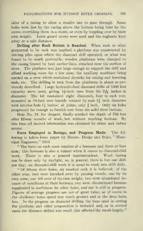
EXPLORATIONS FOR HUDSON RIVER CROSSING 103
sides of a casing to allow a smaller one to pass through. Someholes were lost by the casing alK)ve the lK)ttom Inking bent by the
scows overriding them in a storm, or even by toppling over by their
own weight. Later guard scows were u.sed and the tugboats kept
away at a safe distance.
Drilling after Rock Bottom is Reached. When rock or what
purported to be rock was reached a platform was constructed by
driving piles upon which the diamond drill operated, or what was
found to be much preferable, wooden platforms were clamped to
the casing braced by taut anchor lines, attached near the surface of
river. The platform was just large enough to support the drill and
afford working room for a few men, the auxiliary machines l)eing
carried on a scow which contained derricks for raising and lowering
rods, etc. The drilling in rock from the platforms is alx)ut as pre-
viously described. Large hydraulic-feed diamond drills of 1000 feet
capacity were used, giving 1^-inch core from bit 2^ inches in
diameter. The bit contained eight diamonds, four in each row,
mounted in 10-foot core barrels rotated by rods 1| inch diameter
with interior hole 1^ inches; at joints, only f inch. Only six holes
progressed far enough to furnish core from the solid river bottom.
Hole No. 24, the deepest, finally reached the depth of 768 feet
after fifteen months of work, but without reaching bottom. Bythis time all desired information was obtained by other and l>etter
means.
Force Employed in Borings, and Progress Made. The fol-
lowing is taken from paper by Messrs. Dodge and Hoke, " Muni-
cipal Engineers," 1910.
*' The force on each scow consists of a foreman and three or four
men; this foreman is also a runner when it comes to diamond-drill
work. There is also a general superintendent. Wash boring
can be done only by daylight, so, in general, there is but one shift
per day; on diamond-drill work it is usual to work two shift daily.
"Of fifteen river holes, six reached rock it is believed; of the
other nine, two were knocked over by passing vessels, one by its
own scow, one fell over of its o\\ti weight, two were abandoned be-
cause of conditions at their bottoms, two were discontinued l)ecause
supplanted in usefulness by other holes, and one is still in progress.
Figures of average progress are not of great value, as of course in
the shallower holes speed was much greater and in the deep holes
less. In the progress on diamond drilling the time used in setting
the platform and other preparation is included and, as in several
cases the distance drilled was small, this affected the result largely."
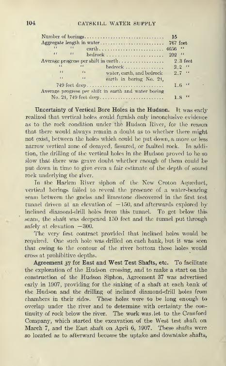
104 CATSKILL WATER SUPPLY
Number of borings 15
Aggregate length in water 767 feet
earth 4656 "" " bedrock 202 "
Average progress per shift in earth 2.3 feet
bedrock 2.2 "*
' " water, earth, and bedrock 2.7 "'* " earth in boring No. 24,
749 feet deep 1.6 "
Average progress per shift in earth and water boring
No. 24, 749 feet deep 1.8 "
Uncertainty of Vertical Bore Holes in the Hudson. It was early
realized that vertical holes ivould furnish only inconclusive evidence
as to the rock condition under the Hudson River, for the reason
that there would always remain a doubt as to whether there might
not exist, between the holes which could be put down, a more or less
narrow vertical zone of decayed, fissured, or faulted rock. In addi-
tion, the drilling of the vertical holes in the Hudson proved to be so
slow that there was grave doubt whether enough of them could be
put down in time to give even a fair estimate of the depth of sound
rock underlying the yiver.
In the Harlem River siphon of the New Croton Aqueduct,
vertical borings failed to reveal the presence of a water-bearing
seam between the gneiss and limestone discovered in the first test
tunnel driven at an elevation of —150, and afterwards explored byinclined diamond-drill holes from this tunnel. To get below this
seam, the shaft was deepened 150 feet and the tunnel put through
safely at elevation —3.00.
The very first contract provided that inclined holes would be
required. One such hole was drilled on each bank, but it was seen
that owing to the contour of the river bottom these holes would
cross at prohibitive depths.
Agreement 37 for East and West Test Shafts, etc. To facilitate
the exploration of the Hudson crossing, and to make a start on the
construction of the Hudson Siphon, Agreement 37 was advertised
early in 1907, providing for the sinking of a shaft at each bank of
the Hudson and the drilling of inclined diamond-drill holes from
chambers in their sides. These holes were to be long enough to
overlap under the river and to determine with certainty the con-
tinuity of rock below the river. The work was. let to the Cranford
Company, which started the excavation of the West test shaft on
March 7, and the East shaft on April 6, 1907. These shafts were
so located as to afterward become the uptake and downtake shafts,
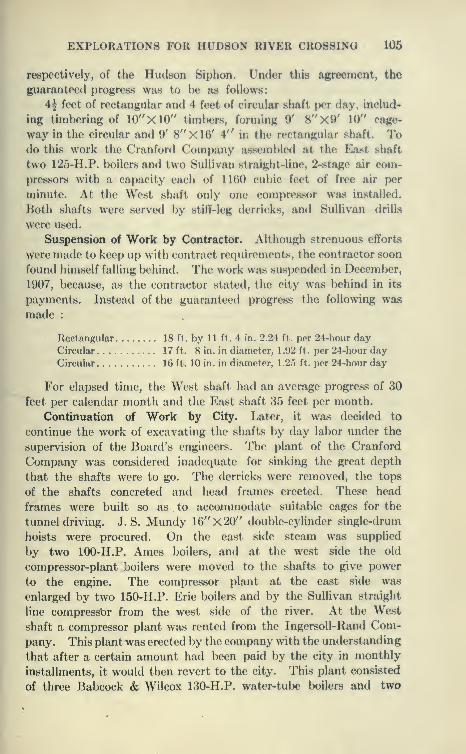
EXPLORATIONS FOR HUDSON RIVER CROSSING 106
respectively, of the Hudson Siphon. Under this agreement, the
guaranteed progress was to l)e as follows:
4^ feet of rectangular and 4 feet of circular shaft per day, includ-
ing timbering of 10"X10" timl)ers, forming 9' 8"X9' 10" cage-
way in the circular and 9' 8"X16' \" in the rectangular shaft. Todo this work the Cranford Company assembled at the East shaft
two 125-H.P. boilers and two Sullivan straight-line, 2-stage air com-
pressors with a capacity each of 1160 cubic feet of free air per
minute. At the West shaft only one compressor Wiis installed.
Both shafts were served by stiff-leg derricks, and Sullivan drills
were used.
Suspension of Work by Contractor. Although strenuous efforts
were made to keep up with contract requirements, the contractor soon
found himself falling behind. The work was suspended in December,
1907, because, as the contractor stated, the city was behind in its
payments. Instead of the guaranteed progress the following was
made :
Rectangular 18 ft. by 11 ft. 4 in. 2.24 ft. por 24-hour day
Circular 17 ft. 8 in. in diameter, 1.92 ft. per 24-hour day
Circular 16 ft. 10 in. in diameter, 1.25 ft. per 24-hour day
For elapsed time, the West shaft had an average progress of 30
feet per calendar month and the East shaft 35 feet per month.
Continuation of Work by City. Later, it was decided to
continue the work of excavating the shafts by day labor under the
supervision of the Board's engineers. The plant of the Cranford
Company was considered inadequate for sinking the great depth
that the shafts were to go. The derricks were removed, the tops
of the shafts concreted and head frames erected. These head
frames were built so as to accommodate suitable cages for the
tunnel driving. J. S. Mundy 16"X20" double-cylinder single-drum
hoists were procured. On the east side steam was supplied
by two 100-H.P. Ames boilers, and at the west side the old
compressor-plant boilers were moved to the shafts to give power
to the engine. The compressor plant at the east side was
enlarged by two 150-H.P. Erie boilers and by the Sullivan straight
line compressbr from the west side of the river. At the West
shaft a compressor plant was rented from the Ingersoll-Rand Com-
pany. This plant was erected by the company with the understanding
that after a certain amount had been paid by the city in monthly
installments, it would then revert to the city. This plant consisted
of three Babcock & Wilcox 130-H.P. water-tube boilers and two
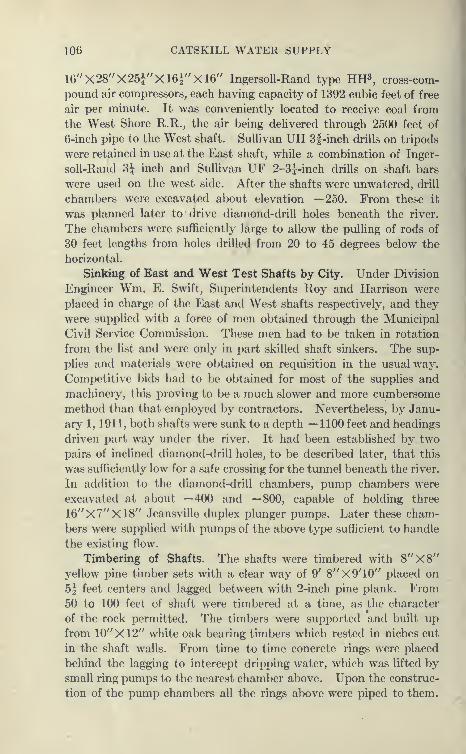
106 CATSKILL WATER SUPPLY
16"X28''X25i"Xl6i"Xl6" IngersoU-Rand type HH^, cross-com-
pound air compressors, each having capacity of 1392 cubic feet of free
air per minute. It was conveniently located to receive coal from
the West Shore R.R., the air being delivered through 2500 feet of
6-inch pipe to the West shaft. Sullivan UH 3f-inch drills on tripods
were retained in use at the East shaft, while a combination of Inger-
soll-Rand Bj inch and Sullivan UF 2-3|-inch drills on shaft bars
were used on the west side. After the shafts were unwatered, drill
chambers were excavated about elevation —250. From these it
was planned later to drive diamond-drill holes beneath the river.
The chambers were sufficiently large to allow the pulling of rods of
30 feet lengths from holes drilled from 20 to 45 degrees below the
horizontal.
Sinking of East and West Test Shafts by City. Under Division
Engineer Wm. E. Swift, Superintendents Roy and Harrison were
placed in charge of the East and West shafts respectively, and they
were supplied with a force of men obtained through the Municipal
Civil Service Commission. These men had to be taken in rotation
from the list and were only in part skilled shaft sinkers. The sup-
plies and materials were obtained on requisition in the usual way.
Competitive bids had to be obtained for most of the supplies and
machinery, this proving to be a much slower and more cumbersome
method than that employed by contractors. Nevertheless, by Janu-
ary 1, 1911, both shafts were sunk to a depth — 1100 feet and headings
driven part way under the river. It had been established by two
pairs of inclined diamond-drill holes, to be described later, that this
was sufficiently low for a safe crossing for the tunnel beneath the river.
In addition to the diamond-drill chambers, pump chambers were
excavated at about —400 and —800, capable of holding three
16''X7"X18" Jeansville duplex plunger pumps. Later these cham-
bers were supplied with pumps of the above type sufficient to handle
the existing flow.
Timbering of Shafts. The shafts were timbered with 8''X8"
yellow pine timber sets with a clear way of 9' 8"X9'10'' placed on
5^ feet centers and lagged between with 2-inch pine plank. From50 to 100 feet of shaft were timbered at a time, as the character
of the rock permitted. The timbers were supported and built up
from 10"X12'' white oak bearing timbers which rested in niches cut
in the shaft walls. From time to time concrete rings were placed
behind the lagging to intercept dripping water, which was lifted bysmall ring pumps to the nearest chamber above. Upon the construc-
tion of the pump chambers all the rings above were piped to them.
EXPLOKATIONS FUK HUDSON RIVEK CKOS8IN(J 107
Ventilation and Pumping at Shafts. Onlinarily shafts aro not
artificially vcntihittHl cxc^'pt by compn'SrtCil air released by drills
and opening of air pipes at the manifold after blasting. However,
at the East shaft a " smokejack " VH" X4' was coastructed of 2-
inch tongue-and-groove l)oards in one eorner of the shaft. A strong
upward current of air was caused to circulate in this by exhausting the
pump operated on part steam and part air. At the West shaft the
same function was performed by a 30-inch fan exhausting through
a 12-inch spiral riveted pipe. It was anticipated that as the shafts
were sunk very close to the water's edge a strong inflow of water
might be obtained. Nevertheless they proved to be remarkably
dry. At depth of 250 feet only 5 gallons per minute was yielded by
the East shaft, and by the West shaft, 12 gallons. At the full depth
of the shafts, 1100 feet, they made only 150 gallons in the East shaft
and 30 gallons in the West shaft. At a depth of —367' a water-
bearing seam was struck in the East shaft which threatened to be
very wet and finally yielded only 20 gallons per minute. Strange
to say, a small diamond-drill hole driven beneath the river gave
more water than the total shaft, yielding at one time 180 gallons
per minute when open." Popping " Rock in Shafts. The rock in general encountered
in the shafts was firm and hard, except that near the bottom
of the West shaft " popping " rock was struck. The rock here
seemed to be under great stress, so that when the surface of the rock
was exposed to the air in the shaft, small flaky wedge-shaped pieces
snapped off with a popping noise. This is a common phenomenon
where rocks are under great compression, and particularly noted in
mines and even in quarries. Geologists classify the rock as granitic
gneiss with diorite veins. The " popping " rock was made safe by
using steel plate lagging supported by circular steel ribs and packed
with broken rock. The progress made under the City, based on
elapsed time, averaged 39 feet in the East shaft and 40 feet in the
West shaft, tl.e maximum monthly progress in the East shaft being
65 feet and 69 in the W^est. It was decided, when the shafts were
down, that driving the tunnel and the lining of it and the shafts
would be (lone by contract.
Agreement No. 74 for Inclined Holes. As soon as the diamond-
drill chambers were excavated Agreement No. 74 was let to bore
inclined holes from them. This agreement was dra^^^l up in the
light of the experience obtained by boring similar holes in the mines
of Lake Superior, which had previously been visited l)y Senior
Designing Engineer Wiggin. The exi>erience from this region
108 CATSKILL WATER SUPPLY ,
is that the holes usually turn upward, so that the bit tends to gain
a higher elevation than the first pointing of the rod would indicate.
The holes were to be so placed as to pass at elevation —1200 and
the agreement was so drawn as to pay the contractor (Sprague &Henwood) a higher price in case they terminated within a certain
prescribed zone. The two items of the bid were as follows
:
Item No. 1. For drilling the first 900 feet of any hole or for
drilling the remainder beyond 900 feet of any hole not included in
item No. 2, the sum of $6.50 per lineal foot.
Item No. 2. For drilling the remainder beyond 900 feet of any
hole which either terminates within the ordered zone or passes in
solid rock about the ordered zone a hole from the opposite side of
the river, the sum of $10 per lineal foot.
IncUned Hole for East Shaft, l/A-74. The first hole No. l/A-74
was started June 1, 1909. A Sullivan B drill (see PI. 24) rated for
3000 feet of hole was set at an angle of 43 degrees below the horizon-
tal, the slope of the tangent to the prescribed zone above mentioned.
It was expected that due to the sagging of the drill rods in the hole
the bit would turn upward so as to traverse the zone, the great
fear being that it would turn up too much, so that the bit, core
barrel and 60 feet of rod immediately following were all of the
same size, actually 2yJ inch in diameter. Behind these guide rods
ordinary 2-inch rods were coupled on as the hole lengthened. A2^-inch bit set with 8 diamonds were set to only ^-inch clearance.
Contrary to expectation, the hole turned downward. At a depth
of 177 feet the guide rods were taken off and ordinary 2-inch
rods used, the expectation being that the sagging of these rods
would force the bit upward. At 280 feet, however, the rods were
adhering to a straight line, and so continued to a depth of 641 feet.
Here a 2-inch bit was substituted. A tapered core barrel was also
used and the hole took an upward turn at an angle of 37° 20'. At
1398 feet the hole turned downward again and continued so until
the end.
Occurrences in Drilling Hole from East Shaft. Hole No. l/A-74
encountered water at a small depth. This gradually increased in
amount until at a depth of 734 feet the flow was 90 gallons per minute,
and was hampering the work. At this point the hole was nearly
lost as a result of the back pressure exerted by the water, the pumpfailing to keep the flow through the hollow drill rods. The bit
heated and was burned fast to the rock. The rods were withdrawn,
leaving the bit in, which, however, was subsequently recovered
by reaming a 2^-inch hole and removing it as core with the steel
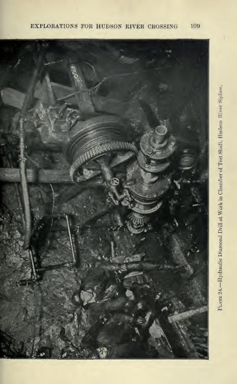
EXPLORATIONS FOR HUDSON RIVER CROSSING 109
o
Q
I
110 CATSKILL WATER SUPPLY
and diamonds fused into the rock. The water was then shut off
by casing the hole with 2|-inch flush-joint pipes at the end of
which diamonds were set. The whole pipe was turned by the
machine until the end containing the diamonds fused into the rock,
as in the case above described. This reduced the flow of water to
5 gallons per minute, but at a depth of 1085 feet the hole again wasmaking 180 gallons per minute, sending a solid stream of water
10 feet from the mouth of the hole, when the rods were withdrawn.
This made drilling very disagreeable, and the pressure was strong
enough to push the rods into the drill chamber without the aid of
the hoist. At a depth of 1234 feet it was again cased with 2-inch
flush-joint casing, and the hole drilled to its final depth, the flow at
the end being only 70 gallons per minute, which was judged to be
the maximum flow this long hole would give under full head.
Loss of Diamond Bit. At a depth of 1834 feet the bit, valued
at $1500, was again burned fast and never recovered, although two
months were spent trying to recover it and 600 feet of rods. This
hole, although it did not quite reach the center of the river, together
with that from the west side furnished valuable information.
Inclined Hole from West Shaft. The hole started from the Westshaft at an angle of 38° was much more successful and met with
little difficulty. This hole never had to be cased. The flow of water
was never greater than 5 gallons per minute. This hole also tended
to point downward rather than upward, as desired. It was, however,
drilled a distance of 2051 feet, so that its end overlapped the first
hole, although 80 feet below it (see PI. 22). With the completion
of this hole, No. 2/A-74, indisputable proofs were at hand that the
crossing of the Hudson River by a deep timnel was entirely prac-r
ticable, as the cores of both holes were almost continuous, showing
the presence of no fault or poor rock. Together these two holes
showed that the river bottom did not extend below the depth of
— 1450 and that the lowest rock in the river bottom might be con-
siderably higher.
Agreement No. 77 for Two More Inclined Holes. A new agree-
ment No. 77 was prepared, Sprague & Henwood again being the
successful bidder. This required the drilling of a pair of holes to
cross at about elevation — 900 feet. These tw^o holes were drilled to
a length of 1651 feet, crossing at elevation —955 feet. No attempt
was made to curve these holes upward, and although the bits were
set for small clearances, the slope of the holes tended to increase.
No particular difficulty was experienced in drilling these holes, the
core obtained showing continuous and sound granite. These holes
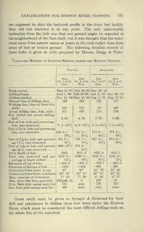
EXPLORATIONS FOR HUDSON KIVKU CROSSING 111
are supposed to skirt the bed-rock profile in the river, but luckily
they did not intersect it at any point. The only unfavorable
indication from the hole wa.s that wet ground might be expected in
the neigh})orhood of the Ea-st shaft, but it was thought that the water
must come from narrow seams or joint^s in the rock rather than from
areas of bad or broken ground. The following detailed records of
these holes is given in table prepared by Messrs. Dodge & Hoke:
Tabulated History of Inclined Borings Across the Hudson Channel
First S.t. Second Set.
Hole Hole Hole HoleNo. 1/A.74. No. 2/A-74. No. 1/A.77. No. 2 A-77.
East. Went. Eut. West.
Work started May 24, '09 July 20/09 Mar.29.'10l
Drilling begun June 1, '09 July 29 '09 !Anr. .5. '10 Anr. 20. '10
Drilling finished Don. l.^i. '09 Mar. Sl.'lO Aug. 4, '10 Auk. 25.'1()
Elapsed time of drilling, days 198 214 122 127
Working time, days of three 8-hr.
shifts 167
331
192
42985
214107
Actual drilling time, 8-hr. shifts
.
279
Feet drilled per actual drilling
shift 5.54 4.78 7.72 5.92
Feet of 4-in. hole and percentage
3-in. core recovered 7.2—47% 8.0—75% 8.5—78% 7.1—76%Feet of 2|-in. hole and percentage
2-in. core recovered 633.8—79%
711.3—91%
715.5—84%
772.4—83%
Feet of 2i^-in. hole and percent- 593.0— 759.5— 927.4— 872.6—age 1 f in. core recovered 41% 76% 48% 68%
Feet of 1^-in. hole and percent- 600—27% 572.8—age \ g-in. core recovered 22%
Total dcnth of hole . . . 1834 2051.6 1651.4 1652.1
Total core recovered and per- 1013.2— 1360.3— 1052.1— 1245^0--
centage of depth drilled 55% 66% 64% 75%Elevation of top of hole -281.0 -251.2 -279.7 -245.8
p]levation of bottom of hole -1482 -1564 -965 -961
Inclination below horiz. at top. . .43° 38° 22° 53' 23° 40'
Inclination below horiz. at bottom 38° 55' 44° 47' 23° 35' 25« 55'
Max. variation of inclination .... 7° 15' 7° 20' 2° 52' 2° 27'
Max. water flow from open hole . . 180 gals./m 5 120 25
2^-in. flush joint casing used, feet 735 none 724 723
2-in. flush joint casing used, feet . 499 none none none
Great credit must be given to Spragiie & Kenwood for their
skill and persistence in drilling these four holes under the Hudson
River, which must be considered the most difficult drilling work on
the whole line of the aqueduct.
112 CATSKILL WATER SUPPLY
Method of Obtaining Inclination of Drill Hole. To obtain the
inclination of the holes hydrofluoric acid was used to etch glass tubes
inserted at various depths. An ordinary vial | inch outside diameter
about 5 inches long containing a solution of 9 parts of water and 1
part of hydrofluoric acid is placed in a water-tight steel shell about 1
foot long, which has the same outer diameter as the rods and is
bored to exactly hold the bottle. The shell or tester is coupled to
the rods and lowered to the required depth. During the time of
lowering the rods no definite line is etched, because the rods in
turning supply the acid to all sides of the tubes and the solution is
too weak to act during this interval. At the required depth the
rods are clamped and allowed to rest long enough to etch a line on
the tube. At great depths this period may be as long as one hour.
When withdrawn, it is found that the acid has etched an approx-
imately horizontal line on the tube, and this operation is repeated
for various depths. To obtain the angle of the etched lines with the
axis of the glass tube, a protractor is used. Owing to the effect of
capillary attraction on the acid, the observed angle is not the true
angle and various corrections have to be made. These corrections
are found by clamping tubes at various angles and observing the
angle of the etched line to the horizontal. A minus correction,
varying from 4° for a reading of 26° to 8° for a reading of 52°, had to
be applied to obtain the true slope. Tests were made in the holes
at depths not more than 100 feet apart.
Pressure Gauge and Hydrofluoric Acid Test for Obtaining Incli-
nation of Holes. The hydrofluoric acid test had the objection that
one erroneous reading would change the position of all the holes
below it. An effort was made to obtain an independent check on the
acid test by the use of a pressure gauge. This gauge was designed
by Dr. Kalmus and Mr. Lewis of the Massachusetts Institute of
Technology, and consisted of a flat steel tube so arranged that whenunder water, it would force a column of mercury to varying heights,
depending on the pressure. This instrument was calibrated so as to
read correctly various depths of water. It was found, however,
that when lowered in the hole, no matter how carefully, various
impact pressures were produced, which ran the readings up higher
than they should have been, so that unfortunately no reliable read-
ings were obtained. It is probable that the hydrofluoric acid tests
give fairly good, reliable results, but by this means the depth of the
holes and not the direction was determined. As yet no reliable
apparatus has been invented for determining the horizontal direc-
tion of drills, though an instrument has been devised by which a
EXPLORATIONS FOR HUDSON RIVER CROSSING 113
compass needle is allowed to rotate in liquid paraffine at pre-
scribed depths, the paraffine being melted by an electric current.
When the current is turned off, the paraffine hardeas, and the
needle is recovered when the rods are withdrawn in the position it
occupied at a known depth. This probably can give but a rough
determination at best.
Final Determination by Borings at Hudson Crossing. Thefour inclined holes gave definite enough information to enable the
engineers to fix the crossing for the tunnel at elevation ~ 1100, which
ought to give at least 200 feet of sound rock at the lowest point
of the gorge.
The uncertainty for a long period as to the depth of rock
bottom of the Hudson River, and the agitation conducted by
certain newspapers against the whole project, created the impres-
sion among a number of people that there was something particularly
difficult or insurmountable about the Catskill Aqueduct project
and an effort was made to postpone the letting of any contracts
until the exact status of the Hudson crossing could be deter-
mined. Had this been done four valuable years would have l)een
lost and the cost of the whole project greatly increased through inter-
est charges, to say nothing of the tremendous loss which would
be entailed should a water famine caused by insufficiency of the
Croton water supply overtake the city, such as was narrowly
escaped in 1911. The engineers of the Board, and particularly those
in direct charge in the field always had implicit faith that the Storm
King crossing was entirely feasible. As a matter of fact, the diffi-
culties overcome in constructing the Rondout siphon, were, in the
opinion of Department Engineer Ridgway, far greater than those
encountered at the Hudson River crossing.
CHAPTER VI
THE ASHOKAN DAMS AND RESERVOIRS
Contract 3
Ashokan Reservoir. The principal contract of the Catskill
water works, Contact 3, was advertised early in 1907. This con-
tract and several smaller ones provide the work necessary to form
the great Ashokan reservoir, see PI. 25. Under it the Esopus and
the Beaverkill are dammed, the former by the great Olive Bridge
dam, containing the heavy masonry section, the latter by various
dikes. A dividing weir and dike, joining the Beaverkill dikes to
Green Hill, form an East and West basin with flow lines at eleva-
tion 587 and 590 above sea-level. The surface water from the
West basin discharges over the dividing weir into the East basin,
whence excess flood water is disposed over the Waste Weir, which
discharges into a small brook flowing into the Esopus, over three
miles below Olive Bridge dam. This spillway is a small masonry
overflow weir founded on rock, and the waste channel is a con-
crete apron formed on it. The overflow charmel being large, there
is absolutely no danger to the main structures to be apprehended
from flood.
Water from Schoharie and Catskill creeks may be stored eco-
nomically in the Ashokan reservoir. The water from Schoharie
Creek can be delivered into Esopus Creek some miles above the
reservoir by a tunnel ten miles long through the Catskills; the
Schoharie in turn is to be dammed near Prattsville, and the water
from the reservoir there formed to be directed into the tunnel.
In addition, Catskill Creek water can be delivered into the easterly
end of the Ashokan reservoir by a small branch aqueduct about
thirty-two miles long.
Source of Catskill Aqueduct. It was originally intended to
place the connection with the aqueduct at the east end of the East
basin near West Hurley, but the swampy character of the ground
in this basin made it undesirable to lead all the water from the
Esopus through it. A deep channel, longer than the combined
114
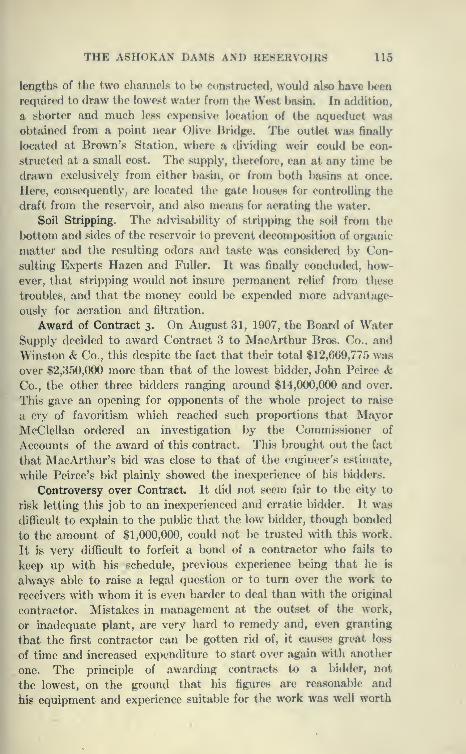
THE ASHOKAN DAMS AND RESERVOIRS 115
lengths of the two channels to be constructed, would also have l)een
required to draw the lowest water from the West basin. In addition,
a shorter and much less expensive location of the aqueduct was
obtained from a point near Olive Bridge. The outlet waa finally
located at Brown's Station, where a dividing weir could be con-
structed at a small cost. The supply, therefore, can at any time be
drawn exclusively from either basin, or from \x>th ba«ins at once.
Here, consequently, are located the gate houses for controlling the
draft from the reservoir, and also means for aerating the water.
Soil Stripping. The advisability of stripping the soil from the
bottom and sides of the reservoir to prevent decomposition of organic
matter and the resulting odors and taste was considered by Con-
sulting Experts Hazen and Fuller. It was finally concluded, how-
ever, that stripping would not insure permanent relief from these
troubles, and that the money could be expended more advantage-
ously for aeration and filtration.
Award of Contract 3. On August 31, 1907, the Board of Water
Supply decided to award Contract 3 to MacArthur Bros. Co., and
Winston & Co., this despite the fact that their total $12,669,775 was
over $2,350,000 more than that of the lowest bidder, John Peirce &Co., the other three bidders ranging around $14,000,000 and over.
This gave an opening for opponents of the whole project to raise
a cry of favoritism which reached such proportions that MayorMcClellan ordered an investigation by the Commi.ssioner of
Accounts of the award of this contract. This brought out the fact
that MacArthur's bid was close to that of the engineer's estimate,
while Peirce's bid plainly showed the inexperience of his bidders.
Controversy over Contract. It did not seem fair to the city to
risk letting this job to an inexperienced and erratic bidder. It was
difficult to explain to the public that the low bidder, though bonded
to the amount of $1,000,000, could not be trusted with this work.
It is very difficult to forfeit a bond of a contractor who fails to
keep up with his schedule, previous experience being that he is
always able to raise a legal question or to turn over the work to
receivers with whom it is even harder to deal than with the original
contractor. Mistakes in management at the outset of the work,
or inadequate plant, are very hard to remedy and, even granting
that the first contractor can be gotten rid of, it causes great loss
of time and increased expenditure to start over again >vith another
one. The principle of awarding contracts to a bidder, not
the lowest, on the ground that his figures are reasonable and
his equipment and experience suitable for the work was well worth
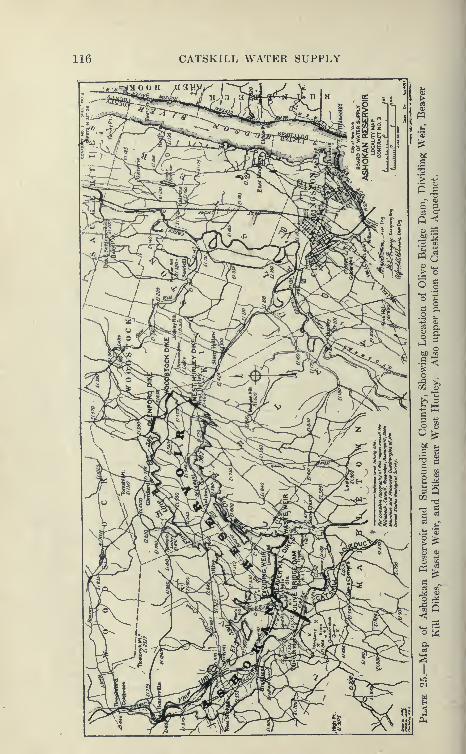
116 CATSKILL WATER SUPPLY

THE ASHOKAN DAMS AND KE8KRVOIR8 117
fighting for, as shown by the history of this and other contracts
on the aqueduct.
The progress made so far on Contract 3 has l)een satisfactory,
so that nobody would now question the wisdom of the Iward's
award. John Peirce & Co., a short time after this controversy,
failed and went into the hands of receivers.
Work under Contract 3. Under this contract a reservoir of
127,000 million gallons will be created by the construction of the
OHve Bridge dam, Beaverkili dikes, Wa.ste Weir and Dividing
Weir, together with the gate chamber, inlet channels, pressure
aqueducts, etc., shown on plan. The total length of dams will be
about four miles. Ultimately highways will traverse the tops of the
dams, the West and Middle dikes and the Dividing Weir, and high-
ways will also encircle the reservoir; but these are to be constructed
on other contracts, as are also some dikes 1 .6 miles long closing gaps
at West Hurley.
Under this contract the preliminary estimate gives 2,480,000
cubic j^ards excavation in all classes; 425,000 cubic yards of rock
excavation, and 7,500,000 cubic yards of embanking and refilling.
The masonry of all classes totals 882,000 cubic yards, for which over
1,000,000 barrels of cement will be required. The approximate
quantities and the successful bid are shown in table on page 118.
Olive Bridge Dam. Although the dams of Contract 3 extend
for a distance of four miles, only a portion of the Olive Bridge dam.
1000 feet; the Dividing Weir, 1100 feet long; and the Wa.ste Weir,
about 1000 feet long, are to be of solid masonry, the remaining
structures being concrete core walls surrounded by rolled embank-ments. The Olive Bridge dam was designed in the light of the
experience obtained in others of its class, and has several original
features. On similar dams it was found that contraction cracks
occur, causing unsightly leaks on their downstream faces, this occur-
ring even where reinforced by steel. It was, therefore, decided to
divide the dam above a certain elevation into sections by trans-
verse expansion joints, the interval between joints being well within
the distance at which the occurrence of cracks had beenu observed.
This interval was fixed at from 84 to 91 feet.
Expansion Joints. An expansion joint formed by building
vertical faces of concrete blocks is shaped as a tongue-and-groove
joint normal to face of dam, thus preventing a continuous opening
through the dam. At each expansion joint a vertical inspection
well is formed of concrete blocks. This will afford an opportunity
for studying conditions at the joint, and should the leakage through
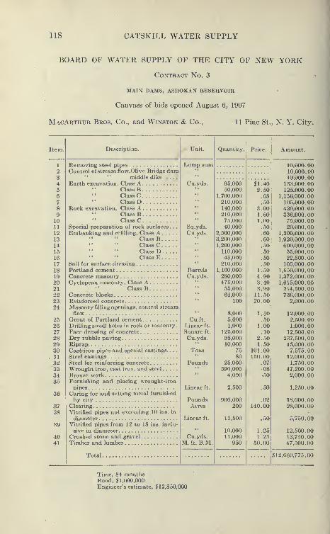
118 CATSKILL WATER SUPPLY
BOARD OF WATER SUPPLY OF THE CITY OF NEW YORK
Contract No. 3
main dams, ashokan reservoir
Canvass of bids opened August 6, 1907
MacArthur Bros, Co., and Winston & Co., 11 Pine St., N. Y. City.
Item. Description.
Removing steel pipes
Control of stream flow,Olive Bridge dammiddle dike ....
Earth excavation, Class AClass BClass CClass D
Rock excavation, Class AClass BClass C
Special preparation of rock surfaces . .
.
Embanking and refilling, Class AClass BClass CClass DClass E
Soil for surface dressing
Portland cementConcrete masonryCyclopean masonry. Class A
Class BConcrete blocksReinforced concreteMasonry filling openings, control streamflow
Grout of Portland cementDrilling small holes in rock or masonry
.
Face dressing of concrete ...
Dry rubble pavingRiprapCast-iron pipes and special castings. . . .
Steel castings
Steel for reinforcing concrete
Wrought iron, cast iron, and steel
Bronze workFurnishing and placing wrought-iron
pipesCaring for and setting metal furnished
by city
ClearingVitrified pipes not exceeding 10 ins. in
diameterVitrified pipes from 12 to 18 ins. inclu-
sive in diameterCrushed stone and gravel
Timber and lumber
Unit.
Total
.
Lump sum
Cu.yds.
Sq.yds.
Cu.yds.
Barrels
Cu.yds.
Cu.ft.
Linear ft.
Square ft.
Cu.yds.
Tons
Pounds
Linear ft.
PoundsAcres
Linear ft.
Cu.yds.M.ft. B.M.
Quantity. Price.
95,606 ii!4650,000 2.50
1.700,000 .68210,000 .50140,000 3.00210,000 1.6075,000 1.0040,000 .50
2,500,000 .603,200,000 .60
1,200.000 .50110,000 .5045,000 .50
210,000 .501,100,000 1.50280,000 4.90475,000 3.4055,000 3.9064,000 11.50
100 20.00
8,000 1.505,000 .501,000 1.00
125,000 .1095,000 2.5010,000 1.50
75 101.0080 150.00
25.000 .07
590,000 084,000 .50
2,500 .50
900,000 .02200 140.00
11,500 .50
10,000 1.2511,000 1.25
950 50.00
Amount.
10,000.0010,000.0010,000.00
133,000.00125,000.00
1,156,000.00105,000.00420,000 . 00336,000.0075,000.0020,000.00
1.500,000.001,920,000.00600.000.0055,000.0022,500.00105,000.00
1,650,000.001,372,000.001,615,000.00214,500.00736,000.00
2,000.00
12,000.002,.500.00
1,000.0012,500.00
237.500.0015,000.007,575.00
12,000.001,750.00
47,200.002,000 . 00
1,250.00
18,000.0028.000.00
5,750.00
12,500.0013,750.0047,500.00
$12,669,775.00
Time, 84 monthsBond, §1,000,000Engineer's estimate, $12,850,000

THE A8H0KAN DAMS AND RE8EKV0IR8 U»
i^ , ' ^'M^' - ft
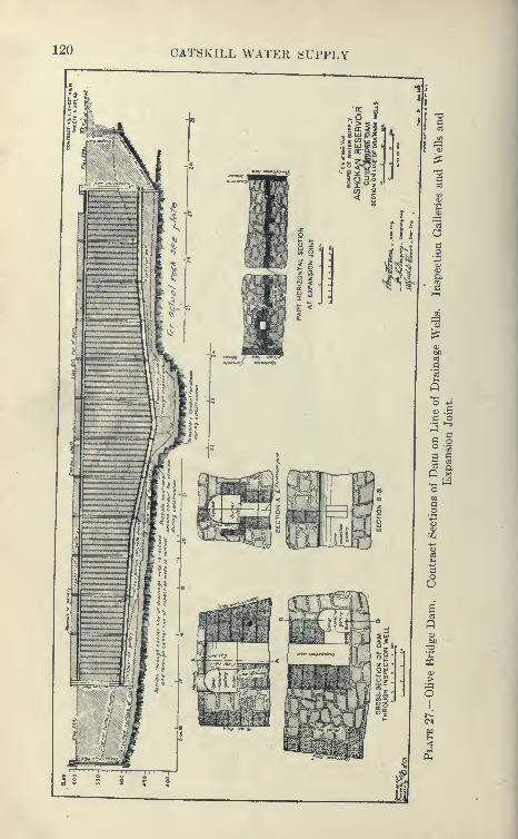
120 CATSKILL WATER SUPPLY
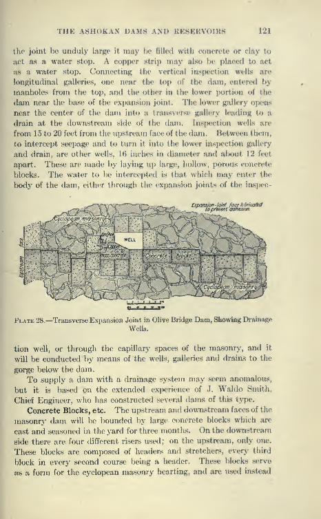
THE ASIIOK'AN DAMS AND HKSKRVniKS 121
the joint hv unduly larj^c it may be filled with eoncrele or elay to
act as a water stop. A eopper strip may also he placed to act
as a water stop. ConnectinR tlie vertical inspection wells are
longitudinal galleries, one near the top of the <lam, entered by
manholes from the top, and the other in the lower portion of the
dam near the base of the expansion joint. The lower gallery op<'ns
near the center of the dam into a transverse gallerj' leading to a
drain at the downstream side of the dam. Inspection wells are
from 15 to 20 feet from the upstream face of the dam. Between them,
to intercept seepage and to turn it into the lower inspection gallery
and drain, are other wells, 16 inches in diameter and al)out 12 feet
apart. These are made by laying up large, hollow, porous concrete;
blocks. The water to be intercepted is that which may enter the
body of the dam, either through the expansion joints of the inspec-
Expansion -joint facekbricaMto prevent adhenon.
''v'.-'.Q-' . -^>-.
;^io^O"^
^^' Cyclopean masonry
ft f t ffi.
Plate 28.—Transverse Expansion Joint in Olive Bridge Dam, Showing Drainage
Wells.
tion well, or through the capillary spaces of the masonry, and it
will be conducted by means of the wells, galleries and draias to the
gorge below the dam.
To supply a dam with a drainage system may seem anomalous,
but it is based on the extended experience of J. Waldo Smith,
Chief Engineer, who has constructed several flams of this type.
Concrete Blocks, etc. The upstream and downstream faces of the
masonry dam will l)e bounded by large concrete blocks which are
cast and seasoned in the yard for three months. On the downstream
side there are four different risers used; on the upstream, only one.
These blocks are composed of headers and stretchers, every third
block in every second course being a header. These blocks serve
as a form for the cyclopean masonry hearting, and are used instead
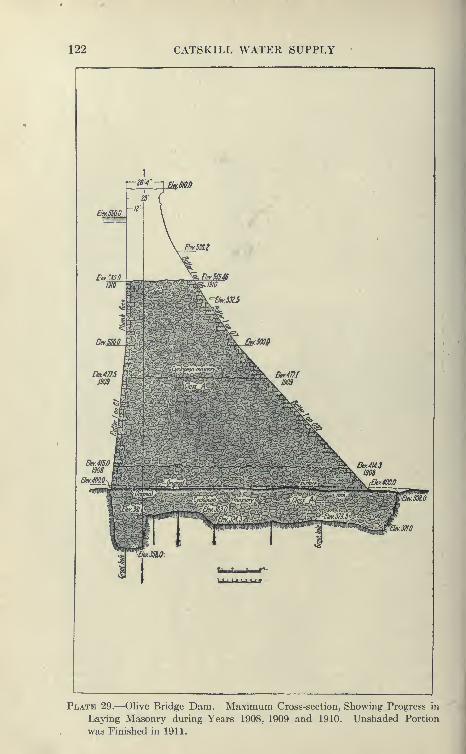
122 CATSKILL WATER SUPPLY
Plate 29.—Olive Bridge Dam. Maximum Cross-section, Showing Progress in
Laying Masonry during Years 1908, 1909 and 1910. Unshaded Portion
was Finished in 1911.
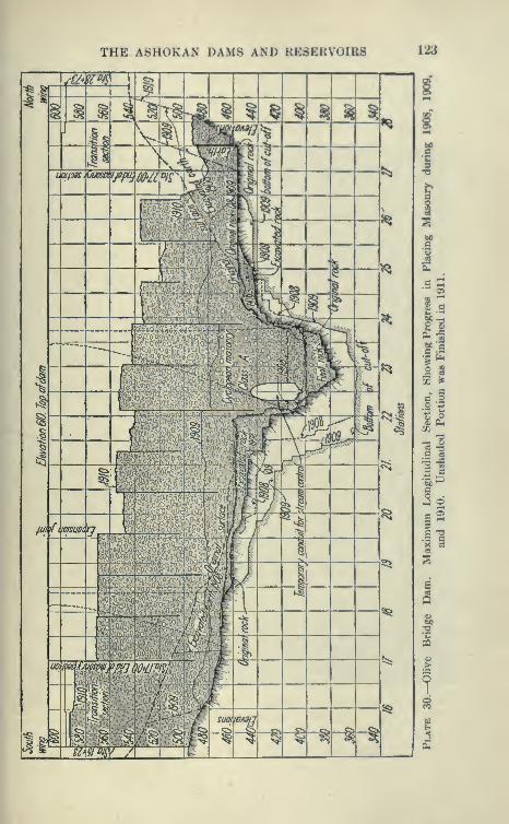
THE ASHOKAN DAMS AND RESERVOIRS 123

124 CATSKILL WATER SUPPLY
of ashlar, because they are cheaper and can be obtained in a muchshorter time, particularly in this region remote from quarries of
granite or other suitable stone.
The Cyclopean masonry is composed of bluestone which can
be conveniently quarried or handled. This stone is bedded in
concrete, each being separately jogged into place in the soft con-
crete, the aim being to obtain the largest proportion of stone
consistent with good work.
The division of the dam into sections by means of transverse
joints bounded by blocks greatly facilitates the work, as one section
can be run up higher Mian the next, thus increasing the efficiency
of the derricks and plant.
Comparison of Olive Bridge and New Croton Dams. The damhas a maximum height of 210 feet above the original ledge rock in
the bed of the stream. This was increased to 236 feet by excavat-
ing to sound rock, and to 252 feet to the bottom of the cut-off
wall, which extends to about 42 feet below the original stream bed.
The New Croton Dam has its crest 149 feet above the old river-
bed of earth, 234 feet above ledge rock, and 294 feet above the
lowest point of excavation. Its cross-section is much lighter than
that of the Olive Bridge dam, particularly for the first 110 feet
below the crest.
Beaverkill Dikes. Beaverkill dikes consist of the West dike,
from Winchell Hili to Dividing Weir; the Middle dike, from the end
of the West dike to Leonard Hill; and the East dike, from Leonard
Hill to the Waste Weir. These dikes are earth embankment with
concrete core wall founded on rock where it is within 10 feet of
the surface of the ground, and where the rock is deep, on rock or
hardpan. At the crossing of the Beaverkill, the core wall is arched
and extends to the bottom of the preglacial gorge. The maximumheight of the dikes above the ground is found here where they
extend above the original surface 115 feet and above the rockbed
of an old preglacial gorge, as excavated, 185 feet. The total length
of the dikes is about 2.5 miles.
The Dividing Weir. The Dividing Weir extends from the
junction of the West and Middle dikes to Green Hill and divides
the reservoir into an East and West basin. The north portion will
be built of masonry with an overflow section over which the flood
flow will pass from the West to the East basin on its way to the
Waste Weir. The south portion, or Dividing Weir dike, will be an
earth embankment. The weir portion is founded on solid ledge
rock. Footings for piers for a bridge are to be built in connection

THE ASHOKAN DAMS AND KE8ERVOIR8 125
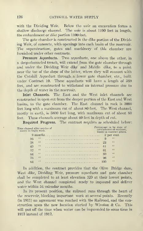
126 CATSKILL WATER SUPPLY
with the Dividing Weir. Below the weir an excavation forms a
shallow discharge channel. The weir is about 1100 feet in length,
the embankment or dike portion 1100 feet.
The gate chamber is constructed in the dike portion of the Divid-
ing Weir, of concrete, with openings into each basin of the reservoir.
The superstructure, gates and machinery of this chamber are
furnished under other contracts.
Pressure Aqueducts. Two aqueducts, one above the other, in
a deep-channeled trench, will extend from the gate chamber through
and under the Dividing Weir dike and Middle dike, to a point
near the toe of the slope of the latter, where they will connect with
the Catskill Aqueduct through a lower gate chamber, etc., built
under Contract 10. These aqueducts will have a length of 560
feet, and are constructed to withstand an internal pressure due to
the depth of water in the. reservoir.
Inlet Channels. The East and the West inlet channels are
constructed in open cut from the deeper portion of the East and West
basins, to the gate chamber. The East channel in rock is 3000
feet long with a maximum cut of about 80 feet. The West channel,
mostly in earth, is 5800 feet long, with maximum cut of about 80
feet. These channels average about 40 feet in depth of cut.
Required Progress. The contract requires as scheduled below:
Time elapsed after service of
notice to begin work.
PercentaEC to be done oftotal amount of contract.based on cont
9 months 2 per cent
16
28
40
52
64
76
84
9
23
41
61
80
96
100
act prices.
In addition, the contract provides that the Olive Bridge dam,
West dike, Dividing Weir, pressure aqueducts and gate chamber
shall be completed to at least elevation 520 at their lowest points,
and the West channel completed ready to impound and deliver
water within 54 calendar months.
In its present position, the railroad runs through the heart of
the reservoir, blocking important work at several points. Recently
(in 1911) an agreement was reached with the Railroad, and the con-
struction upon the new location started by Winston & Co. This
will put off the time when water can be impounded to some time in
1913 instead of 1912.

THE ASHOKAN DAMS AM) HK8ERV()IR8 127
128 CATSKILL WATER SUPPLY
Specifications of Contract 3. Some important provisions of
Contract 3 are abstracted below
:
General Statement. Section 36. " During the construction of
the main dams the ordinary and flood flows of Esopus Creek, Hog Vly
Kill, and Beaver Kill nmst be safely carried over and past or diverted
from the sites of the Olive Bridge dam, West and Middle dikes,
respectively, in such manner as will permit, as far as possible,
uninterrupted work on these structures.
Esopus Creek Watershed. Section 37. " The area of the water-
shed above Olive Bridge dam is approximately 240 square miles.
There is practically no natural storage on the watershed. A flood
flow of 38,000 cubic feet per second has been estimated at Olive
Bridge and may be exceeded. Floods of 15,000 cubic feet per
second may be expected each year.
Beaver Kill Watershed. Section 39. "The watershed of the
Beaver Kill above the site of the Middle dike is approximately 17
square miles. It is estimated that a maximum flood of 2500 cubic
feet per second may occur. The watershed contains a large per-
centage of swamp area which will probablj^ afford considerable
natural storage.
Steam Control Works Installed by Board. Section 41. '' Twocofferdams, two 8-foot steel pipes, and pumping plants installed
by the Board will probably be in operation in the gorge of
Esopus Creek, at Olive Bridge dam site, at the date of execu-
tion of the contract, as mentioned in the information for
bidders. Within thirty days after the service of the notice
instructing the Contractor to begin work, he shall take over
and operate these controlling works, including the two coffer-
dams, the two 8-foot steel pipes, and the Brooks centrifugal pump,
with 12-inch suction and 10-inch discharge, and direct-connected
Sturtevant engine. . . . When directed, the Contractor shall dis-
connect and carefully remove, in sections not exceeding 30 feet in
length, the two 8-foot steel pipes, and store the sections at a designated
place within 2000 feet of their position in the gorge. These steel
pipes shall remain the property of The City. In making his bid
under Item 2, for controlling works for Esopus Creek, the Contractor
shall make due allowance for these existing works and for the Brooks
pump and engine, as specified in this section.
Section 46. " Until the general level of the masonry dam shall
have been raised to elevation 470, and at such other times as directed,
a portion of the masonry dam, between two expansion joints located
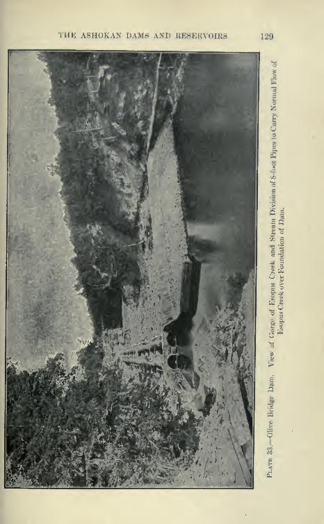
THE ASHOKAN DAMS AND KE8EHVOIU8 129
Z .2
130 CATSKILL WATER SUPPLY
near the center of the gorge, shall be kept depressed about 10 feet
below the level of the other masonry.
Excavation for Core Walls. Section 77. " Excavations for the
core walls at each end of the Olive Bridge dam, and for the core walls
of the Beaver Kill dikes and the dike portion of the Dividing Weir
shall be made of sufficient depths to secure acceptably, sound and
impervious foundations, and of sufficient widths either to contain
the masonry, placed directly against their sides, or to allow for
acceptable sheeting, bracing and forms outside the prescribed
masonry lines. Core wall trenches, not more than 20 feet wide on
the bottom and 20 feet deep, shall, in general, have approximately
vertical sides and, if directed, be braced and sheeted as herein
provided. Other core wall trenches are expected to have side
slopes of 1 vertical on 1 horizontal, but may, when permitted, have
steeper slopes if sufficient to insure stability during the progress of
the work.
Section 78. " Whenever a core wall is to be built on rock, the
rock shall be thoroughly cleaned and all cracks and seams raked
out and filled with mortar or grout.
Classification of Excavated Earth. Section 80. " Excavated
earth shall be classified for payment as follows:
" Class A, Item 4, shall include earth excavated from depths less
than 20 feet in trenches less than 20 feet wide on the bottom with
sides approximately vertical for the whole or a part of their depth. . .
" Class B, Item 5, shall include earth excavated from the depths
below 20 feet in trenches less than 20 feet wide on the bottom with
sides approximately vertical for the whole or a part of their depth. . .
This class shall include also earth excavated from the Beaver Kill
gorge from depths below 20 feet, and other similar deep excavations,
if any be ordered." Class C, Item 6, shall be earth excavated for the Olive Bridge
dam, between Station 15+23 and Station 28+73, including the
cleaning of the gorge, for the gate-chamber, for the inlet channels,
for the aqueducts, and for the Waste Weir and Dividing Weir, with
their adjacent channels, and the portions of the lengths of the trenches
for core walls wherever for their full depths they have side slopes
flatter than 6 vertical on 1 horizontal. Class C shall include,
also, earth from miscellaneous excavations for grading, for high-
ways and for building temporary roads for the purpose of maintain-
ing trajfic on the present highways, and from all other excavations
not specifically enumerated." Class D, Item 7, shall include top soil removed from the sites
THE ASHOKAN DAMS AND RESERVOIRS 131
of the excavations and embankments as provided in Section 71,
hut shall not include top soil excavated from other areas for the pur-
pose of completing the surface dressing of embankments or other
graded ureas.
Measurement of Trenches. Section 81. "All trenches with
approximately vertical sides to be paid for under Items 4 and 5, shall
be measured as having side slopes of 6 vertical on 1 horizontal and
the designated bottom widths. Trenches and other excavations
having side slopes flatter than 6 vertical on 1 horizontal shall l)e
measured as if the side slope were 1 on 1, excepting in such cases as
flatter slopes shall have been expressly ordered, in which viisai the
slopes ordered shall be used for purposes of measurement.
Rock Excavation for Olive Bridge Dam. Section 82. " Hock is
to be excavated for the masonry portion of Olive Bridge dam to a
sufficient depth to secure a foundation on sound ledge rock, free
from open seams, or other objectionable defects. A cut-oflf trench
will be required near the upstream side of the foundation, under
the whole or a part of the length of the masonry dam. It is the
intention to build the masonrj' against the sides of these rock exca-
vations. To preserve these sides in the soundest possible condition,
and to obtain over the whole foundation a rock surface free from
seams or cracks, unusual precautions will be required in the exca-
vation. Rock for the foundation of the masonry portion of the
Olive Bridge dam shall be removed by channeling, drilling and
wedging, barring, or other similar methods. No blasting shall be
done except by special permission, and only then with light charges
of explosives. The rock excavation from the cut-off trench shall be
removed only by channeling or other acceptable method.
Rock Excavation for Core Walls. Section 83. " Wherever the
rock is not sufficiently sound at its surface for the foundation of a core
wall, excavation shall be made to the extent directed and in the
manner prescribed for rock excavation under the masonry portion
of the Olive Bridge dam.
Section 85. " Excavations similar to those specified in Section 82
shall be made for the Dividing and Waste weirs; but the requirements
for their foundations may be less exacting because these structures
are much lower and subject to different conditions.
Rock Excavation in Esopus Gorge. Section 89. " Projecting,
overhanging, unsound and loose rock shall be excavated to the extent
directed from the sides and bottom of the Esopus gorge above the
Olive Bridge dam, from areas that are to be covered by embank-
ments, and from such other areas in the gorge as may be designated.

132 CATSKILL WATER SUPPLY
Care shall be taken in the removal of this rock not to loosen nor
injure the remaining rock.
Preparation of Rock Foundation for Masonry. Section 90. " Thesurface of the excavations for rock, foundations shall be left suf-
ficiently rough to bond well with the masonry. The rock foundations
for any structure, if required, shall be cut to rough benches or steps.
Before any masonry is built on or against the rock, it shall be scru-
pulously freed from all dirt, gravel, boulders, scale, loose fragments,
and other objectionable substances. Streams of water under
sufficient pressure, stiff brushes, hammers or other effective meansshall be used to accomplish this cleaning. Steam jets shall be used
to thoroughly remove ice or snow, if any be found on the rock,
when it is desired to lay masonry.
Classification of Excavated Rock. " Class A, Item 8, shall include
all rock excavated from the foundation of the masonry portion of
the Olive Bridge dam, for the core walls, for the Dividing Weir and
Waste Weir, and all rock excavated for the aqueducts, beginning at
a point on their center line 60 feet southerly from the intersection
of the center line of the inlet channels and the aqueducts." Class B, Item 9, shall include all rock excavated from the chan-
nels and retaining walls adjacent to the Dividing and Waste Weirs,
(except the core wall of Dividing Weir dike), for the inlet channels
and adjacent retaining walls, and for the gate chamber between a
point 60 feet southerly from the intersection of the center lines of
the inlet channels and the aqueducts and the northerly outer face
of the foundation walls of the gate chamber.
i
" Class C, Item 10, shall be all other rock excavated, except from
quarries, borrow pits, or for purposes of the Contractor, and not
included in Classes A and B. In this class shall be included all
boulders of 1 cubic yard or larger in any ordered excavation.
r Rock Trenches. Section 92. " Rock trenches for drains and rock
excavation for other minor structures not otherwise designated,
shall be measured as of the bottom dimension stipulated herein, or
ordered, and as if the rock were taken out with side slopes of 6
vertical on 1- horizontal. Before measuring, the surface of ledge
rock shall be cleared of earth, boulders, and other encumbrances,
which would interfere with correct measurement. The areas of
rock surfaces so cleared at any one place or time shall be of reasonable
extent. Whenever any portion of the ledge rock of any boulders
are ready for measurement, the Contractor shall Hotify the Engineer,
and only that rock will be paid for which shall have been properly
measured.
THE ASlloKAN DAM- \\l> l.r.-r.KS « iIKS liiii
Preparation of Base for Embankments. Section 08. " Embank-ments shall start from a firm hast* from which soil ami otlicr pcrinh-
able matter shall have IxH'n romovecl to the extent (iirectc<l, an
provided under Sections 71 and 251. If n»quired, the base un<ler the
embankment shall be picked to make a bond with the emlmnkmentmaterial, and on sloping ground shall be stepped where and as
directed.
Control of Springs. Section 99.'' Springs encountered on the
sites of the embankments shall hv controlled by ])lugging or drain-
ing, or by other approved methods. Ma.sonry, piix*s, grout, broken
stone, cement, or other materials used, or excavations made for
such control shall be paid for under the appropriate items, a.s deter-
mined by the Engineer. In general, springs encountered on the
downstream side of a core wall shall be led into the drainage system
at the downstream toe of the embankment.
Allowance for Shrinkage. Section 103. " The embankments shall
be built to a height above the finished grade, which will, in the opinion
of the Engineer, allow for the shrinkage of the material. If such
ordered overfill results in an excess section of any embankments,
the Contractor shall be allowed payment for such excess. If any of
the embankments or refillings settle so as to be below the required
levels for the proposed finished surface at any place, before the final
acceptance of the work to be done under this contract, the Contrac-
tor shall, at his own cost and expense, supply approved materials
and build up the low places as directed.
Classification of Embanking and Refilling. Section 106. " Em-bankments and refills shall be classified for payment according
to their physical characteristics and special requirements, as fol-
lows:" Class A, Item 12, shall include the impervious embankments
and refills of selected fine earth, deposited and compacted as herein-
after specified, on the upstream sides of the core walls of the damand dikes, excepting the Dividing Weir dike, on the upstream side
of the masonry dam (excepting the portion deposited through the
water after the reservoir shall have been partially filled with water),
and the refills, below the bases of the embankments, against the down-
stream faces of core walls.
" Class B, Item 13, shall include the embankments of selected
earth, deposited and compacted as hereinafter specified, on the down-
stream sides of the core walls of the dam and dikes alx)ve the ba.ses
of embankments and on the downstream side of the masonry dam,
the embankments and refills of the Dividing Weir and the Waste
134 CATSKILL WATER SUPPLY
Weir, and the embankments above the tops of the core walls, on
both sides of the dam and the dikes.
" Class C, Item 14, shall include the layer of durable boulders,
stones and rock fragments of any size and shape placed as herein-
after specified on the upstream and downstream surfaces of the dam,
the dikes, and the weirs, except the paving and riprap to be paid
for under Items 28 and 29. The layer of clayey earth placed on top
of the stony layer on the downstream sides of the dam and dikes,
to support the top soil, shall also be included in Class C. The quan-
tity of Class C material to be deposited on the downstream side of
the dam and dikes will vary with the nature of the material from
excavations and borrow pits, but will extend approximately within
the sloping lines shown, over at least one-third of the height of the
dam and dikes where shown on the contract drawings.'' Class D, Item 15, shall l)e the fine earth deposited through the
water, after the partial filling of the reservoir with water, on the up-
stream side of the Olive Bridge dam.
Class E, Item 16, shall include all embankments and refills shown
on the drawings or specifically ordered, not included in Classes Ato D, both inclusive, except embankments or refills made by the
Contractor for his own use or convenience."
Care in Foundation Work. Particular attention is called to the
great care required in the preparation of the foundation for the
main dam and core walls and the power given to the engineers to
secure special treatment for the bottom and sides of the gorge, also
the care demanded in excavating. These precautions were also fair
to the contractor, as opportunity was given to him to bid on several
classes of excavation in proportion to the care demanded. Another
feature working toward the same ends is the division into several
classes of earth embankment, in accordance with the necessity for
imperviousness above or below the core walls, etc.
Payment Items. Another feature of all Board of Water Supply
contracts is the division into a number of payment items. This
makes for more exact bidding and estimating, and greatly facilitates
estimating both before and during the construction. It also aids in
exact specification and description of the work to be done. In con-
nection with each item is a section of the specification, defining exactly
how measurements are to.be taken in estimating each. This will be
appreciated by anybody who has taken part in litigation over pay-
ment on contracts.
General Preparations. Soon after the contract was awarded,
active preparations were made to install an equipment preliminary
THE ASHOKAN DAMS AND RESERVOIRS 135
to vigorous prosecution of the work. A striking feature of the pros-
ecution of this work was the apparent unity of purpose shown bythe contractor. Railroad connection was established with the
Ulster & Delaware Iluilroad at Brown's Station. A large machineshop, power plant, central crushing plant, quarry, and a very large
camp were cstahlishod.
Contractor's Camp. As the country in the vicinity of this contract
is sparsely settled, it was necessary to establish a camp at the very
start of the work. The camp was laid out at the beginning in streets
with all the necessary conveniences for accommodating a maximumnumber of workmen. The site of the camp was just below the damon a bluff overlooking Esopus Creek. It was overgrown by athick second-growth woods, and many of the trees were left standing.
It has a natural drainage to Esopus Creek. In accordance with
the terms of the contract a sewage disposal plant was built and
sewers laid throughout the camp. Water is provided for drinking
and sanitary purposes, and for fire. The drinking water is from a
spring of pure water. Several of the streets are paved and lighted
by electricity. Garbage and ashes are collected and disposed of
daily.
Camp Buildings. A school, hospital, bakery, store, bank, ice-
house, etc., have been provided. The barracks, dormitories, dining
hall and cottages have all been built in a .substantial manner. Atypical four-room house for laborers with families is 16'X40', with
extension 12'X12', rough boarded on the outside and sheathed with
plain matched boards on the inside. The roof and sides are covered
with rubberoid or Amazon paper, making it warm and weather proof.
The floors are double, with paper between. Such a house costs about
$400, not including a sewer and water system, and rents for $15
monthly, including all fuel, water and sanitary protection. In the
quarters for laborers without families, the buildings are arranged
as barracks and dormitories, the former being divided into rooms
containing two double and one single bunk, the charge being $1.50
to $2 per month. The store is very large and contains all supplies
at reasonable prices. It is not a commissary, but does strictly a
cash business, and prices here compare very favorably with outside
stores. The hospital is very well ecjuipix'd. The unique feature
of this camp is a night school for the instruction of mlult lalxjrers
in the English language, etc., the same school being u.sed for children
in the daytime. The bank, known as the Ashokan Bank, is supported
by the contractors, and in the same building are halls used as club
The superintendents and engineers of the contractors
136 CATSKILL WATER SUPPLY
are provided with well built and pleasantly located bungalows.
Altogether this camp is provided with more conveniences and is
more comfortable than any of the villages in the neighborhood. In
addition to the above, smaller camps are maintained at various
other points convenient to the work.
Contractor's Railroad. The contractor's railroad is standard
gauge and equipped with rolling stock comparable to many public
carriers. The railroad organization is separate from the construc-
tion force and business is carried on in much the same way as a public
road. The main line, double tracked, runs from its junction with the
Ulster & Delaware Railroad at Brown's Station to the main plant
at Ohve Bridge dam. At this point numerous side tracks are laid
to the block yard, cement house, coaling siding, compressor plant,
crusher, and unloading tracks under the four main cableways which
serve the dam. The line continues to the Yale quarry, crossing
Esopus Creek three-quarters of a mile from the dam on a steel via-
duct 85 feet high and 390 feet long, entering the quarry about 2^
miles from the dam on a switchback. The line is double tracked
to the Esopus. Leading off from this point, there is a single-track
branch to the sandpits. Near the power plant is a line leading to
the west dike around Winehell Hill. There are two more branches
leading off this line to the north wing, one of which supplies sand,
stone and cement to the concrete mixing plant, the other delivers the
earth for embankment. The Middle dike branch leaves the main
line near Brown's Station and crosses the Ulster & Delaware Rail-
road twice with overhead crossing. Spurs are laid from this branch
to the Dividing Weir, to the Aqueduct, and to the discharge chan-
nel. The rolling stock of the railroad consisted of nine 40- to 65-ton
American locomotives of the saddle tank type; 115 fiat cars
equipped with air, 4 gondolas, 72 6-yard Western side-dump cars,
and about 250 narrow-gauge 4-yard cars with 14 narrow-gauge
18-ton Porter locomotives. An American hoist locomotive crane
was also a part of the rolling stock, being used to lay track, erect
overhead bridges, and for miscellaneous purposes. The total track-
age, including all branches, was about 20 miles, all of heavy rail laid
on first-class ties. The maximum grade was 2| per cent. This rail-
road during its life has handled an enormous tonnage, consisting of
all the incoming freight for the work and camps, transportation of
stone, concrete material, concrete blocks to the four cableways,
and other plants, and in addition, great quantities of earth for the
embankments.

THE A8H0KAN DAMS AND RESERVOIRS 137

138 CATSKILL WATER SUPPLY
Compressor Plant and Use of Compressed Air for Power. This
plant was established at the beginning of the work at a point con-
venient to the dam and railroad. It consisted of a battery of five
265-H.P. Babcock & Wilcox water-tube boilers which furnished steam
to four air compressors built by the Ingersoll-Rand Co. Two of
these machines of 500 H.P. each were previously used at the Wachu-
sett and Cross River dams. The other two were new and rated
at 450 H.P. each. Their engines were compound-condensing with
compressors furnished with inter and after coolers. The large
machines had a capacity of 3500 cubic feet of free air per minute,
the smaller 2500, making a total of 12,000 feet. Two dynamos
installed in this plant are used for furnishing current for lighting the
work and the camp. The coal used by this plant and by the rail-
road was stored in bins under a trestle. About 1400 tons of coal
monthly were used for all purposes. The compressed air was carried
in pipes of 12 to 4 inches to nearly all parts of the work, including
the Yale quarry 2 miles distant, delivered at about 80 pounds pres-
sure. It was used for a great variety of purposes, operating the cable-
ways, all the derricks, and pumps, and many rock drills. This
plant illustrates well the adaptability of compressed air to workcovering a great area, and the economy and durability of a central
compressor plant.
Olive Bridge Dam Foundation. The Olive Bridge Dam is 4620
feet long, including the masonry portion 1000 feet long. It contains
about 420,000 cubic yards of cyclopean masonry, 56,000 yards of
concrete blocks, and about 2,000,000 cubic yards of embankment.The Board of Water Supply in order to save a season's work, installed
two 8-foot riveted pipes to carry the ordinary stream flow, andexposed the creek bottom under the dam by two crib cofferdams.
These pipes remained in commission until the cyclopean masonrywith an arch conduit built in it reached their level. The Esopushad eroded a channel about 220 feet wide and 40 feet deep with nearly
perpendicular sides. The bottom layer was a thick bed of blue-
stone with many open seams. It was carefully excavated to soundrock at a maximum depth of 30 feet below the original surface of
the bed.
Cut-off Trench. A cut-off trench 20 feet wide reached across
the channel just below the upstream edge of the dam, and was exca-
vated to about 40 feet maximum depth. This cut-off channel wascarried into the side walls of the gorge, the bottom being steppedup when the character of the rock was good. All loose and unsoundrock was excavated from the sides of the gorge. Below the top layer

THE ASUOKAN DAMS AND HESERVOIKS 139
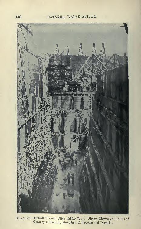
140 CATSKILL WATEK SUPPLY
Plate 36.—Cut-off Trench, Olive Bridge Dam. Shows Channeled Rock andMasonry in Trench; also Main Cableways and Derricks.
THE A8H0KAN DAMS AND RESERVOIRS 141
of the bluestone was found alternating layers of slate, shale and
bluestone. Geologists state that when the shale wiis relieved of
its superimposed load of other strata hy the cutting of the Esopus
gorge, it expanded and developed seams along the bedding plane.
The limit of rock excavation was determined by the extent of these;
seams which decreased in number with tlie depth, extending to greater
depths at the center of the gorge, with the result that the excavation
was in a series of steps. The cut-off trench intercepts all seams
to a depth of 40 feet below the bed of the stream.
Grout Holes. As a still further precaution a row of 3-inch grout-
ing holes was drilled 20 feet below the bottom of that trench, reaching
the greatest depth at which the pressure tests had indicated the
presence of seams. Shnilar grouting holes were drilled to about the
depth of the cut-off to insure the sealing of any seams that might
exist in the rock under the main body of the dam ; 255 holes were
drilled, aggregating 2707 feet. Two-inch iron pipes were cemented
in the toi)s of the drill holes and carried up into the masonry to
permit grouting when the dam had reached sufficient height to
withstand the pressure of the grout.
Diamond-drill Holes to Test Rock Foundation. It might be
interesting here to describe the borings made under the dam founda-
tions. Nineteen diamond-drill holes were put down in the bed of
the stream and adjacent rock sides. Some of the holes reached a
depth of 100 feet below the bed of the stream and were tested at each
foot in depth for seams. These tests indicated small seams near the
surface of the rock and two other general seams at depths of 40 and
60 feet below the bed of the creek, extending in the rock for the full
width of the dam but not far beyond the sides of the gorge. Beneath
the lower of these seams the test showed the rock to be entirely free
of seams. The rock excavation for the dam developed all the seams
indicated by these tests, but did not disclose any additional ones or
any characteristics in the rock not indicated by the experiments.
The communication from one hole to another through the seams was
shown by water dyed with '^ uranine."
Main Cableways. To aid in the excavation for the foundations
for the dam and for building the masonry section four Lidgerwood
traveling cableways were installed, each having a clear span of 1530
feet, a lifting capacity of 15 tons and a speed of 1200 feet per minute.
The cableway towers were about 90 feet high, running on tracks 150
feet above the bed of the stream. The tracks were 600 feet long and
in three sets, one track of three rails, and two of two rails each.
The hoisting engines were on the towers on the north bank and

142 CATSKILL WATER SUPPLY
operated by compressed air from the power house. The tail towers
had engines used only for the purpose of moving cableway along the
tracks. Near the towers on the north bank eight standard gauge
tracks were operated under the cableways.
Rock Excavation. In general, the lines along the edge of the rock
excavation for the dam were cut with Sullivan channeling machines,
after which light charges of powder were used to break up the rock
which was then loaded into large skips raised by the cableways
and dumped to form rock cones. This excavation required a very
large amount of channeling, as shown in Plate 36. The cableways
proved to be invaluable for placing excavating machinery in the
gorge and delivering materials to the south bank, otherwise inacces-
sible. Every effort was made to complete the rock excavation
and the dam to the level of the temporary steel pipes during the
season of 1908. Work on both rock excavation and masonry was
therefore carried on night and day. From the 1st of June till the
end of the season there was only one delay of two days, when the
flood was too great for the 8-foot pipes to carry.
Work of First Season (1908). There were excavated during this
season 60,000 cubic yards of earth and 41,000 cubic yards of rock.
About 26,000 cubic yards of masonry were placed. The stream was
diverted through the opening of the dam, and the 8-foot pipes removed
in December, after which the work shut down for the winter. At
this time the general level of the masonry was about 15 feet above
the bed of the stream, except at a portion of a cut-off' trench where
the rock excavation into the wall of the gorge was not completed.
Considering the immense amount of plant which had to be installed
before this work could be done the above is certainly a remarkable
showing.
Grouting under Dam. The grout pipes built in with the dam were
grouted with neat cement by the use of a Cockburn Barrow Machine
of 4 cubic feet capacity, operated under a pressure of 25 to 80 pounds.
The holes were drilled by large Ingersoll-Rand piston drills to a
maximum depth of 30 feet, requiring the use of extraordinarily long
steel drill rods. The 45 holes which went below the lowest seam took
about 175 cubic feet of grout, the remaining 172 holes tapping the
upper seam taking 925 cubic feet of grout.
Main Crushing and Concrete Plant. On the north bank just
above the dam, where it could be served by the numerous tracks of
the railroad, a very large central concrete and crushing plant washoused in a building 80' X 100' and 62 feet high. All the machinery
was belted from two main shafts driven by 250-H.P. engine supplied
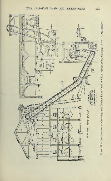
THE A8H0KAN DAMS AND RESERVOIRS 143
144 CATSKILL WATER SUPPLY
with steam through a 6-inch pipe from the boilers of the main power
house about 150 feet distant. Stone from the quarry was deliv-
ered in 5-yard steel skips, four to a flat car. Two stiff-legged
derricks dumped the skips directly into the crushers, one No. 9
McCuUey, and two No. 6 Austin crushers, the latter recrushing the
oversize stone. The crushers had a combined capacity of 100
cubic yards per hour. After passing through 2^-inch holes in a
revolving screen, the stone was elevated to the top of the building
by an inclined link belt conveyor 88 feet long having 24''X30"
buckets. This conveyor discharged into a chute which delivered the
stone to two 30-inch link belt conveyors 90 feet long which traversed
the full length of the building over the top of the storage bins, capacity
800 cubic yards. Movable trippers enabled the stone to be dumped
at any point in the bin, thus keeping the latter properly trimmed
without any hand work. The screenings were delivered through a
chute to a conveyor belt below the crusher floor which discharged
them on the sand conveyor belt, thus mixing the dust and fine stone
uniformly with the sand. The rejects were automatically delivered
by a conveyor to the No. 6 crushers. The crusher plant usually
operated in two shifts, working from 12 to 17 men.
Sand Supply. Seven-yard side-dump cars delivered the sand to a
storage bin below the ground which had concrete walls. This bin,
capacity 500 cubic yards, delivered by gravity to a belt conveyor
which received also the stone dust and screenings mentioned above.
This conveyor discharged into a bucket elevator running to the top
of the building, whence the sand was distributed by a conveyor in
the same manner as described for the stone bins. The crusher
dust usually ran about 40 per cent of the fine material used in the
concrete. The side-dumping cars were loaded at the Winchell
Stewart sandpit by a Page drag-line excavator, 7 men working one
8-hour shift per day, and in 248 days during 1910, about 130,000
cubic yards of sand were taken out of this pit.
Cement Delivery. Cement of Alsen and Giant brands wasunloaded by hand from the box cars directly into the cement house,
of 18,000 bag capacity, adjoining the mixing plant. An inclined belt
conveyor, 24 inches wide and 60 feet long, delivered the cement bagsfrom the storage house to the charging platform, where they weredeposited on the floor or delivered to an auxiliary horizontal belt
conveyor 40 feet long which ran to the charging hoppers. The bagswere emptied by hand into the charging hoppers at the mixers.
Concrete Mixers and Their Supply. The stone and sand bins
were about 24 feet above the ground and are provided with horizontal
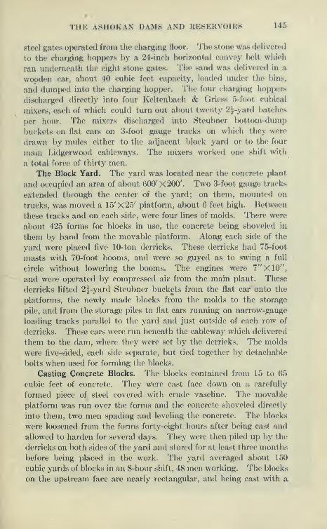
THE A8H0KAN DAMS AND REBERVOIRS 145
steel gates operated from the charging floor. The stone was delivered
to the charging hoppers by a 24-inch horizontal convey belt which
ran iindemoath the eight stone gates. The sand was delivered in a
wooden car, al)out 40 cubic feet capacity, loaded under the bias,
and dumped into the charging hopper. The four charging hoppers
discharged directly into four Keltenbach & Griess 5-foot cubical
niixers, each of which could turn out about twenty 2J-yard batches
per hour. The niixers discliargod into Steubner bottom-dump
buckets on flat cars on 3-foot gauge tracks on which they were
drawn by mules either to the adjacent block yard or to the four
main Lidgerwood cableways. The mixers worked one shift with
a total force of thirty men.
The Block Yard. The yard was located near the concrete plant
and occupied an area of about 600' X 200'. Two 3-foot gauge tracks
extended through the center of the yard; on them, mounted on
trucks, wa.s moved a 15'X25' platform, about 6 feet high. Between
these tracks and on each side, were four lines of molds. There were
about 425 forms for blocks in use, the concrete being shoveled in
them by hand from the movable platform. Along each side of the
yard were placed five 10-ton derricks. These derricks had 75-foot
masts with 70-foot booms, and were so guyed as to swing a full
circle without lowering the booms. The engines were 7"X10",
and were operated by compressed air from the main plant. These
derricks lifted 2^-yard Steubner buckets from the flat car onto the
platforms, the newly made blocks from the molds to the storage
pile, and from the storage piles to flat cars running on narrow-gauge
loading tracks parallel to the yard and just outside of each row of
derricks. These cars were run beneath the cableway which delivered
them to the dam, where they were set by the derricks. The molds
were five-sided, each side separate, but tied together by detachable
bolts when used for forming the blocks.
Casting Concrete Blocks. The blocks contained from 15 to 65
cubic feet of concrete. They were cast face down on a carefully
formed piece of steel covered with crude vaseline. The movable
platform was run over the forms and the concrete shoveled directly
into them, two men spading and leveling the concrete. The blocks
were loosened from the forms forty-eight hours after being cast and
allowed to harden for several days. They were then piled up b\^ the
derricks on both sides of the yard and stored for at least three months
before being placed in the work. The yard averaged about 150
cubic yards of blocks in an 8-hour shift, 48 men working. The blocks
on the upstream face are nearly rectangular, and being cast with a
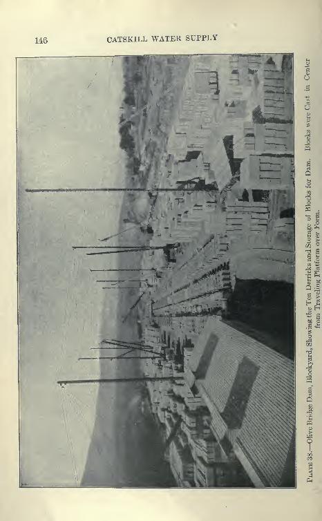
146 CATSKILL WATER SUPPLY
03
?

THE ASHOKAN DAMS AND RESERVOIRS 147
J3
o
M
4>
SICD a>
tc a
*i ^o.C3
CO
0)
O
os
t'1

148 CATSKILL WATER SUPPLY
liberal fillet on the exposed edges little trouble was experienced in
obtaining perfect casting. Those on the downstream face have rather
an acute angle, and some of them were broken by handling and in
transportation. The contract allowed the broken blocks to be used
in other portions of the masonry.
Main Quarry. Large quantities of rock were supplied by the
deep cuts at the main gate chambers, the foundations of the damitself, and various other points in the work. The Yale quarry on
Acorn Hill was the main source of supply. This quarry has a vertical
face of 1200 feet long and 30 to 40 feet high. A double-track spur
from the contractor's railroad parallels the quarry face, and a row
of 10 guy derricks served for handling the 5-yard steel skips from
the quarry to the car. The cars were placed on one track for load-
ing, and as they were loaded were taken out by the locomotives. Thederricks, meanwhile, loaded trains on the other track, making the
work continuous. The trains made the 3-mile trip to the dam with 10
cars in fifteen minutes, and back up grade with empties in twenty
minutes. Three gangs of 12 men and 1 foreman each loaded the skips
with the help of the derricks. The smaller stones were loaded sepa-
rately into skips for the crushers, the larger ones being loaded by a
derrick and used for the cyclopean masonry. The ledge is of blue-
stone of a hard and durable quality, but yields stone suitable for
cyclopean masonry only in limited amounts. Like all the stone of
this region, it tends to quarry into flat slabs with large beds andlittle rise, and of shape not favorable to a high percentage of large
stone for the cyclopean masonry. Though an effort was made to
place as many large stones as possible in the dam, on the total yard-
age of 426,000 they amount to only about 25 per cent. The face of
the quarry was drilled in two hfts by Ingersoll-Rand air drills,
the average daily output being about 800 cubic yards (Eng. Cont.,
Oct. 19, 1910). The holes were placed 6 to 8 feet apart, and the samedistance back from the face of the quarry, the lifts varying from16 to 22 feet. The holes were first sprung with from 1 to 5 sticks
40 per cent dynamite, and then loaded with from 1 to 2 kegs of blackpowder, tamped with dry clay. The firing was done by an electric
battery.
Crushing Plant at Quarry. On the hillside below the quarryfloor a crushing plant was installed, consisting of a No. 7^ and aNo. 5 McCulley crusher, with a rated capacity of 70 yards per hour.The cars were loaded from the bins below this plant by gravity. Aningenious method of loading from a large storage pile was devisedfor this place. A spur track was surrounded by timbering, such as
THE A8HOKAN DAMS AND RESERVOIRS 149
used in tunnels, and stone was deposited around it in a large pile.
The cars were hacked into this tunnel and loaded through ehutes
with little trouble. The crushing plant at the cjuarry served as anaid to the one at the dam, and supplied stone for various parts of the
work.
Laying Up the Masonry Dam. The dam is composed of Cyclo-
pean masonry laid between walls of concrete blocks which acted as
forms at the faces, and at the expansion joints. The cableways
delivered the 3-yard Steul)ner bottom-dumping buckets to timber
loading platforms, built either on or alongside the dam. Fromthese landing platforms a 10-ton stiff-legged derrick with 60-foot
boom lifted the buckets to the place where they were dumped by
hand to form a bed for the large })locks of bluestone, varying in
size from 1 to 10 tons. At the maximum there were about 16 derricks
arranged in two rows. From elevation 500 upward advantage was
taken of expansion joints, the derrick usually being located on alter-
nate sections, which were built up considerably above the level
of those adjoining. Below elevation 500, a section of concrete was
built between walls which were carried up in advance of the body
of masonry. These walls were racked back and consisted of large
stones set close together embedded in concrete.
Use of Derricks at Dam. The derricks could be readily movedfrom place to place by the cableways. As the dam progressed upit narrowed in section, so that finally but one row of derricks could
be worked, two of the cableways loading the platforms against the
upstream and downstream faces of the dam. During the first
season 8 gangs of men were employed with 16 derricks. During the
second season 6 gangs of 8 men each were employed on the cyclopean
masonry, but as the dam grew in height the proportion of this masonry
decreased and the gangs were decreased. For setting concrete blocks
an average of 7 gangs with 3 men each were used with a maximumof 10. In addition, 2 gangs were generally employed for one shift
at night storing blocks and stone on the wall for use the following
day. The total force employed at the masonry dam was about
156 men on day shift and 35 men at night.
Placing Cyclopean Masonry. The placing of cyclopean masonry,
which is of utmost importance in dam construction, is here
described in some detail. The first work was to clean old
masonry or rock with wire brooms and water under pressure.
Laitance was carefully removed from the hollows where at times
it forms several inches thick. Next a thin cement grout wash
was applied immediately before a batch of concrete was dumped

150 CATSKILL WATEH SUPPLY
'"''"nVmZ^J C™;:"' ''Z"''^°"™ ^"•'^^ Dam. Showing Concrete
pLIgMason;v i °T ^^'"°";>'' Cableways. and Derricks Used inacing Masonry, also Transverse Expansion Joint Across n»n.
THE A8H0KAN DAMS AND RESERVOIRS 151
and thoroughly broomed up to take up any loosened matter,
securing a better l)ond between new and old work. Next a
25-yard batch of concrete 1 : 3 : 6 or 1 : 2^ : 5 was dumped on
this prepared surface and spaded to remove air and to obtain an
even distribution of the aggregate. Next the cyclopean stones,
after being thoroughly cleanetl and welt?d down were lowered into
place on the concrete by the stiff-legged derrick and well bedded
by joggling with iron crowbars. Before being used each stone was
carefully examined and those having seams were split and broken up
in spalls. Very large stones were placed at least 2 feet apart and
often required two or three batches of concrete for a bed, and whenbeing joggled into place by four bars were. partly supported by a
derrick. The joggling continued until there was no indication of
escaping air from underneath. The cyclopean stones were trans-
ported in steel skips by the cableway before being handled by the
derricks. In a total yardage of 426,000 on the dam the cement
ran one barrel per yard for cyclopean.
Concrete Block Setting. The concrete blocks were handled bythe cableways and derricks the same as the cyclopean stone, except
that they received much more careful treatment. The blocks were
carefully set to break joints and well bedded in 1 : 2 mortar. Thevertical joints were filled with liquid grout and later all face joints
were raked out and pointed with 1 : 1 mortar. The blocks have
grooves cast on the sides for dowel holds and to help bond themtogether. Owing to the great number of blocks in the dam, partic-
ularly at the upper portion, some difficulty was experienced in
keeping the blocks laid ahead.
Concrete blocks make a clean-cut construction and greatly aid
in concreting. Nevertheless, it would seem that a more economical
method would be to use forms at all joints and surfaces not exposed
to view. Well-designed and heavy steel forms used in panels sup-
ported by bolts in the masonry could be readily raised, and used
repeatedly to form these surfaces, in which case the cyclopean
masonry could be deposited directly against the forms with consider-
able saving. There is no doubt, however, that the concrete blocks
give better appearing work than could be secured by forms. Thecost of concrete blocks is ordinarily about one-half that of cut-stone
masonry. Cyclopean masonry in turns costs less than half that of
concrete blocks, although if considerable form work were required,
this cost would certainlj' be much higher.
Very few forms were used on the main dam, the inspection gal-
leries being about the only work requiring small forms. A temporary
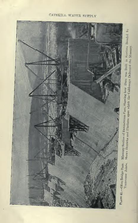
CATSKILL WATER SUPPLY
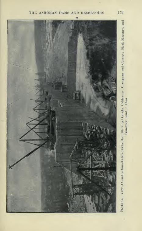
THE ASHOKAN DAMS AND RESERVOIRS 153
Io>i

154 CATSKILL WATER SUPPLY
conduit for stream control was formed with the aid of 24-inch steel
I-beams spanning the opening. These beams supported lagging
on which concrete was placed, avoiding the use of false work which
might be carried away by floods.
Records in Placing Masonry. It is believed that cyclopean
masonry was deposited at a greater speed in this dam than, pre-
viously, at any other. During the month of October, 1909, 33,182
cubic yards of masonry were placed and 2117 cubic yards of concrete
blocks were set in 29 days by 8 gangs per day. During 1909,
154,000 yards of cyclopean masonry, and 9000 yards of blocks
were placed and set, and in 1910, 175,000 yards of cyclopean masonry
and 27,000 yards of blocks set. The working season is about nine
months. The last concrete block in the main dam was set
March 2, 1911, so that in 27 working months, 426,000 cubic yards of
cyclopean masonry, 7000 yards of mass concrete, and 56,000 yards
of concrete blocks were set.
Earth Dams. The bulk of the work of Contract 3 consists in
the building of earth dams or dikes. Each end of the Olive Bridge
Dam terminates in a dike known as the north and south wing, the
other dikes being the East, Middle and West Dikes. The entire
area of the surface which the dikes cover was stripped of all soil andvegetable matter. Numerous boulders were moved to permanentpositions at the toe of the slopes. A vertical trench along the center
line was then excavated to rock, when within reasonable depths
or to suitably compact hardpan. In trench a concrete core wall
was built. The core wall is 4 feet wide on top, each face havinga batter of 1 on 20.
Rolling of Embankments. The embankment was started byspreading layers of earth which were rolled to 4 inches on the waterside and 6 inches on the dry side of the core wall. These layers
were rolled with 12-ton Monarch and Kelly steam-grooved rollers of aspecial design of unusually high horse-power for their weight. Prior
to dumping the material for a new layer, the surface was sprinkledwith water, and the roller then traveled back and forth, lappingover one-quarter to one-sixth of its width. Occasionally cross rolling
was required.
Core Walls. The core wall was usually built in courses 6 feet highand 75 to 150 feet long corresponding to the amount of concrete whichcould be placed in a single 8-hour day. The cantilever form usedin building a greater part of the core walls is shown on Plate 44.This form proved its great efficiency on miles of core walls and is
applicable to wide range of similar work, such as retaining walls.
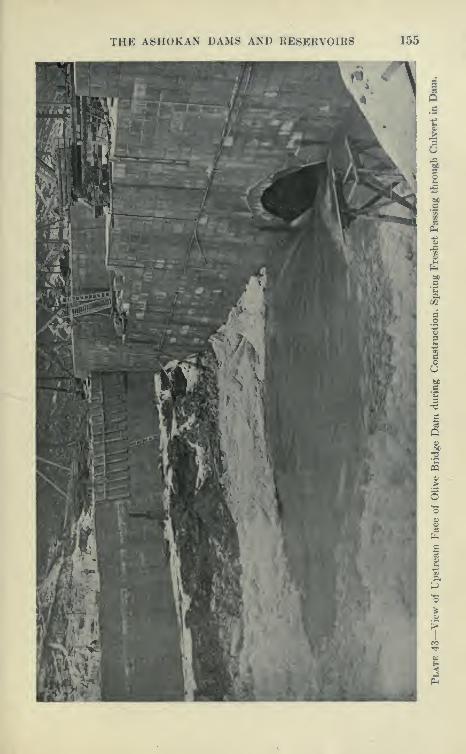
THE ASHOKAN DAMS AND RESKRVOIRS 155
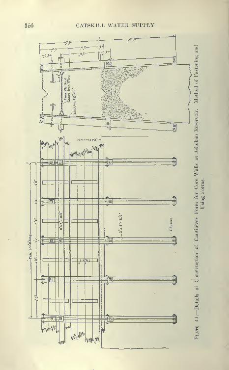
156 CATSKILL WATER SUPPLY

THE ASHOKAN DAMS AND RE8ERVOIHS 157
It is simply constructod of pairs of vertical 3"X8"X14' timbers
spaced 1 inch apart, the pairs })eing 4 feet center to center. For the
top G2 feet horizontal 1 {"X()" lagKing was nailed. The verticals are
held in position by bolts embedded in concrete and by wires twisted
so as to give the required width of wall. In each 6-foot lift a pair
of bolts is concreted, after which the form is moved upward, the bolts
fitting in the slot l)etween the 3"X8" uprights. The form is lined
up by wedging the projecting lower ends of verticals against the con-
crete and })y twisting the wire spacers.
South Wing. The surface was stripped by hand work, using
wagons drawn by mules. The trench for the core wall was excavated
with a Page excavator. Due to the numerous boulders encountered
this machine could not work with advantage and later was converted
into a derrick and used to convey buckets and skips in the ordinary
manner. For the concrete work a quarry was opened on the hill
above the work about 1000 feet from the concreting plant at the south
end of the dike. The stone from the quarry was brought to a No.
5 Gates crusher at the mixer in 3-yard side-dump cars on a narrow-
gauge track. Crushed stone was drawn from the bins directly into
a 1-yard Hansome mixer. Sand was brought from the main pit by
the railroad and cableway and hauled by bottom-dump wagons to
storage pile at mixer. The concrete was conveyed in 1| cubic-
yard Steubner buckets on a narrow-gauge flat car run bj' gravity.
A traveling derrick deposited the concrete in the forms.
Building Embankment. For building the embankment a 70-ton
Bucyrus steam shovel loaded 4-yard dump cars which were hauled, in
two trains of 12 cars each, over a narrow-gauge track to the embank-
ment. The earth after being dumped from the tracks was spread
by hand in layers and the stones culled out and hauled on stone
boats by mules to the Class C embankments, and placed at once
on the completed slope. The track was thrown by hand as often as
necessary to build out the layers. To loosen the material in the
borrow pit so as to be readily handled, a Star well-digging machine
was used, holes being sprung and blasted in the usual manner. Onthe south wing the average output under favorable conditions of
the mixing plant was 100 cubic yards in eight hours, and about 900
cubic yards of embankment per day were placed. About 2 miles
of narrow-gauge track was placed. In addition to the equipment
before described, 40 mules and dump wagons were used for hauling.
A typical working gang was, borrow pit crew, 10 men; two train
crews of 4 men each; a track gang of 19 men, and a spreading gang
of 40 men. The south wing was built by Johnson & Briggs.
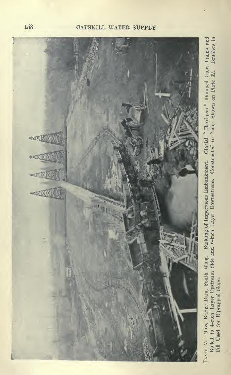
158 CATSKILL WATER SUPPLY

THE ASHOKAN DAMS AND RESERVOIRS 159
North Wing of Main Dam. The soil was stripped in the sjune
manner as for the south winp;, and excavation for the core wall madewith traveling derricks. The concrete was mixed in a 22-yard cubical
mixer which discharged into a Steubner bucket, and wa.s placed
in the forms by traveling derricks. Material for the concrete wasbrought by carload trains from the main crusher, sandpit and cement
house. Material for the embankment was brought from the Winchell
borrow pits in three trains of 9 to 1 1 4-yard Western dump cars hauled
by 20-ton American dinkies. The borrow pit was excavated })y a
70-ton Bucyrus steam shovel with a 2^-yard dipper. The haul from
the borrow pit was about a mile, and the daily progress was 1000
cubic yards in eight hours under favorable weather conditions. Thematerial from this borrow pit contained many boulders which were
hauled in stone boats to the slopes of the embankment, this being
the general rule on this work.
Typical gangs on the embankment were, borrow pit force, 13
men; trains, 11 men; track work, 23 men; spreading gang, 53 men.
The typical gang for the core wall was: erecting form, 7 men; mixer,
18 men; hauling and placing, 14 men; the average output being
150 cubic yards in eight hours.
West Dike. This is located just east of Winchell Hill, and is
about 1800 feet long. After the soil had been removed in the usual
way, the core wall trench was excavated with a Page excavator
and traveling derricks. Adjoining Winchell Hill, 2 to 10 feet of
disintegrated rock were removed in the foundation for this wall.
A traveling cableway similar to those at the main dam of 1534-foot
span was installed here, and handled part of the excavation and the
concrete, also the earth for building the embankment on each side
of the core wall.
Concrete Plant. A mixing plant of large capacity and unique
construction was installed. Two tracks of the contractor's rail-
road were led over large stone and sand piles. Under these piles
a timber tunnel with chutes opening into the sand and stone wasbuilt. In this tunnel, a large link belt conveyor was installed, the
buckets of the conveyor being fed from the chutes and discharging
at a considerable elevation into the sand and stone bins which in
turn discharged into measuring hoppers, feeding a 2^-yard cubical
mixer. This in turn discharged into bottom dumping buckets on
flat cars drawn to the cal^leways supplying the core walls.
Making Embankments with Mule Teams. It was found that with
sixteen 14 -cubic yard capacity wagons drawn by teams of three
mules a distance of about 1000 yards over fair roads, an average of

160 CATSKILL WATER SUPPLY
11« i
IIC H
C
THE ASHOKAN DAMS AND RESERVOIRS 161
280 loads or 420 cubic yards of embankment could be hauled in eight
hours. However, a greater part of the material was delivered- in
6-yard skips from standard fiat cars hauled in trains of from 10 to
13 cars each, from the westerly end of the West channel, and dumiMnl
into position by cableway. Due to height of drop the material
compacted and had to be loosened by plowing before it could be
spread and rolled. About 1000 cubic yards under favorable con-
ditions were placed in eight hours.
The Middle Dikes. This is 7100 feet long, extending from the
west dike easterly to Leonard Hill. The construction was carried
on in three sections, viz., the west, 2200 feet long; the center, 2350;
and east, 2550.
West Portion of Middle Dike. Clearing and stripping was done
as before described; excavation for core walls was taken out by hand,
good rock being found from 2 to 8 feet down. The first concrete
done was with a small portable mixer which discharged into wheel-
barrows which placed the concrete in the forms. Embankmentmaterial was hauled in Western side-dump cars from the Winchell
Hill borrow pits on tracks running over top of core wall; material
dumped to either side was spread by two-mule drag scrapers. The
material was similarly hauled from the central part of the west
channel excavation, but dumped directly into place on the embank-
ment.
Comparative Advantages of Building Embankments by Dumpingfrom Wagons and from Trains. Generally the most economical and
satisfactory method is to haul directly to the embankment, dumping
from tracks thrown by hand. The making of embankments by
hauling in bottom-dumping wagons and spreading by hand and then
rolling gives probably the best results, the wagons giving a rolling
additional to that of the steam rollers, though it is not nearly so
economical for the contractor as hauling over tracks.
Center Portion of Middle Dike. This dike, the highest and
most important, crosses Beaverkill Creek, which was diverted into
a 14'X 9' concrete conduit 600 feet long. Most of the core-wall
trenches were 10 to 15 feet deep, excavated by hand.
Excavation of Preglacial Gorge of the Beaverkill. During the
first season, 1908, the excavation in the preglacial gorge of the
Beaverkill was handled by two Page excavators. These machines
formed slopes of about 1 on 1 and loaded into wagons,
through hoppers, the material being then used in embankments.
Many large boulders which required considerable blasting delayed
the excavation, which proceeded at the rate of 400 to 600 cubic

162 CATSKILL WATER SUPPLY
i^^^r *^^HHRIIi
i
i ^^^^^^^K^^^R^Ep^bfiMHM^BBHI^^^^' ' '' fiHli^E
i..
.

THE A8H0KAN DAMS AND RESERVOIRS 163
o
?
164 CATSKILL WATER SUPPLY
yards per eight hours for both excavators. The excavation by Page
bucket was economical within reach of the swing of the boom for a
depth of about 30 feet. Part of the time the buckets were hauled
to the further limits of the excavation by wire cable and auxiliary
engine on the opposite side of the gorge. This increased considerably
the radius of action of the machine. The material was so hard
and dry that considerable of it was drilled by ordinary percussion
drills and blasted to loosen up the hardpan for the Page buckets.
When wet the material ran out of the bucket about as fast as it
filled.
Construction in Beaverkill Gorge. During the second year,
1909, the Beaverkill gorge was spanned by a cableway which rapidly
removed the material to a depth of about 80 feet, the Page excavator
having previously worked to a depth of 30 to 40 feet. The pre-
glacial gorge was fully exposed and found to be very symmetrically
stepped from the top width of 150 feet to the bottom width of 40
feet, a depth of 80 to 90 feet. The bottom was at elevation 422, or
165 feet below the water surface of the East Basin. The floor of
the gorge was found to be sound rock and little excavation was
necessary at the sides which were composed of alternating layers of
bluestone and shale. The material near the bottom of the gorge
was found to be sand, gravel and boulders with some clay. Fromthe borings it was anticipated that this would be wet, although little
water was encountered in the excavation. To guard against loss of
water through this buried channel an arched core wall 30 feet thick
was built in the gap and the remainder of the excavation refilled with
compact material which was dumped from skips by the cableway
into a water puddle. At this point the embankment for the Middle
Dike will have a maximum height of 115 feet above the original
surface of the ground, and about 185 feet above the bottom of the
preglacial gorge.
Easterly Portion of Middle Dike. This section was done byNewel & Snowling Construction Co. & N. S. Brock. Clearing,
stripping and excavation for the core wall were done by hand.
The core waif was concreted in 6-foot lifts and the embankmentcarried up to the top of the wall before the new lift was placed.
This method allowed the use of a minimum amount of plant and wasvery economical. The core-wall concrete was mixed in a 1-yard port-
able Municipal mixer, discharging into bottom-dump buckets whichwere lifted and dumped into place by a traveling derrick alongside
the core wall opposite the concrete plant. The cement and sandwere supplied by the main contractor and hauled by teams to the
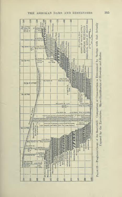
TIIK ASllUKAN DAMS AM) l{KSKiC\ oIKS 165
1 03
>>xXi -3
-3 ic o
s<1> 3Q sCO •l I
C3 OC ao o
n^u
tf ya
O 1««. Mo •?
r-l
X y^^rt
cc: .2
U >SJ—
^ Wo> ^'^o
>,
:;.O
—
<
T^C
o W
^ X
oO, ,
•2
J
1
1
^S<
fin
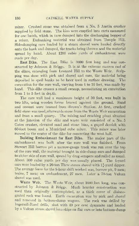
166 CATSKILL WATER SUPPLY
mixer. Crushed stone was obtained from a No. 5 Austin crusher
suppUed by field stone. The bins were emptied into carts measured
for one batch, which in turn dumped into the discharging hopper of
a mixer. Embanking material was obtained from Temple Hill.
Side-dumping cars loaded by a steam shovel were hauled directly
onto the bank and dumped, the tracks being thrown and the material
spread by hand. About 1200 cubic yards of embankment were
made per day.
East Dike. The East Dike is 3600 feet long and was con-
structed by Johnson & Briggs. It is at the extreme eastern end of
the dikes, extending from Leonard Hill to the Waste Weir. Strip-
ping was done with pick and shovel and cars, the material being
deposited in spoil banks to be later used in surface dressing. Theexcavation for the core wall, varying from 4 to 10 feet, was made by
hand. This dike crosses a small swamp, necessitating an excavation
from 1 to 5 feet in depth.
The core wall had a maximum height of 30 feet, was built in
two lifts, using wooden forms braced against the ground. Sand
and cement were teamed from -Brown's Station. At first, crushed
field stone was used, afterwards stone from the Waste Weir excavation
and from a small quarry. The mixing and crushing plant situated
at the junction of the dike and waste weir consisted of a No. 5
Gates crusher, elevated sand and stone bins, a guyed derrick with
60-foot boom and a Municipal cube mixer. This mixer was later
moved to the center of the dike for concreting the west half.
Building Embankment for East Dike. The major part of the
embankment was built after the core wall was finished. FromStewart Hill borrow pit a narrow-gauge track was run over the top
of the core wall, the material brought in side-dump cars and dumpedto either side of core wall, spread by drag scrapers and rolled as usual.
About 300 cubic yards per day was usually placed. The 4-yardcars were loaded by a 20-ton Thew steam shovel with l}-yard dipper.
The average force for the 8-hour shift worked was, borrow pit, 9 men;trains, 7 men; on embankment, 27 men. Later a 70-ton Vulcanshovel was used.
Waste Weir. The Waste Weir, about 1000 feet long, was con-structed by Johnson & Briggs. Much heavier construction wasused than originally contemplated, as a thick cover of disinte-
grated rock was found. Earth excavation was by pick and shoveland removed in bottom-dump wagons. The rock was drilled byIngersoll-Rand drills, shot with 40 per cent dynamite and loadedby a Vulcan steam shovel into skips on flat cars or into bottom-dump

THE ASHOKAN DAMS AND RESERVOIRS 167
wagons. Compressed air was supplied by a 6-drill Ingersoll-Rand
compressor. A cut-off trench about 6 feet wide and 4 to 6 feet
deep was excavated the entire length of the waste weir on the
upstream side.
The design of the waste weir is shown m plan and cross-section
on Plates 50 and 51.
Masonry for Waste Weir. This weir is built entirely of cyclo-
poan masonry and has a maximum height of 11 feet. The crushing
plant was that described for the East Dike and a 1-yard Ransomcmixer was located near by. The concrete was discharged in 1-yard
Stuebner bottom-dump buckets placed on flat cars and run by gravity
on narrow-gauge track to the forms where they were placed by a
traveling derrick. The forms were built of wood, braced against the
ground or finished masonry, which was carried up in steps about 2 to 5
feet high, the full thickness of the weir, and for a length of 25 to
40 feet between expansion joints. The surface of the concrete at
the end of a day's work was sloped toward the upstream side with
large cyclopean blocks projecting to make a bond for the next lift.
A good deal of the sand was artificially made by a small stone ja\\
crusher feeding into a pair of Sturtevant sand rolls. The stone wai
quarried near by and delivered to crusher in steel skips on flat cars.
Downstream from the Waste Weir, the rock, being soft, was exca^
vated to a depth of 18 inches with light charges of powder, also
by barring and pick and shovel, and was replaced by a concrete
floor built in alternate blocks 7 feet square. The concrete was
delivered to this floor in Koppel side-dump cars running on narrow-
gauge track.
West Channel. This cut was necessary to make the upper 100
feet of the reservoir available, the gate chamber being located in
rather high ground. About 1,000,000 cubic yards of excavation
will be removed, practically all earth and acceptable material to be
used for Class A or B rolled embankment. The cut begins at the
Esopus about 6000 feet from the gate chamber. At this point a
70-ton Atlantic steam shovel with 2^-yard dipper loaded 5-yard skips
on flat cars, 12 to a train. Trains were hauled to the west end of the
West Dike where a cableway dumped the skips into place. About
1000 cubic yards per day were removed at this point under favorable
conditions. At a second point about the middle of the channel
another 70-ton shovel loaded into Western side-dumping cars which
were hauled over narrow-gauge track to the westerly edge of the
middle dike, the shovel averaging in good weather about 1000 yards
per day of eight hours.

168 CATSKILL WATER SUPPLY
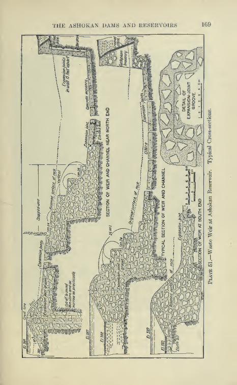
THE AttlluKA.N DAM6 AMj Kh^Ki{\ i M KS 169
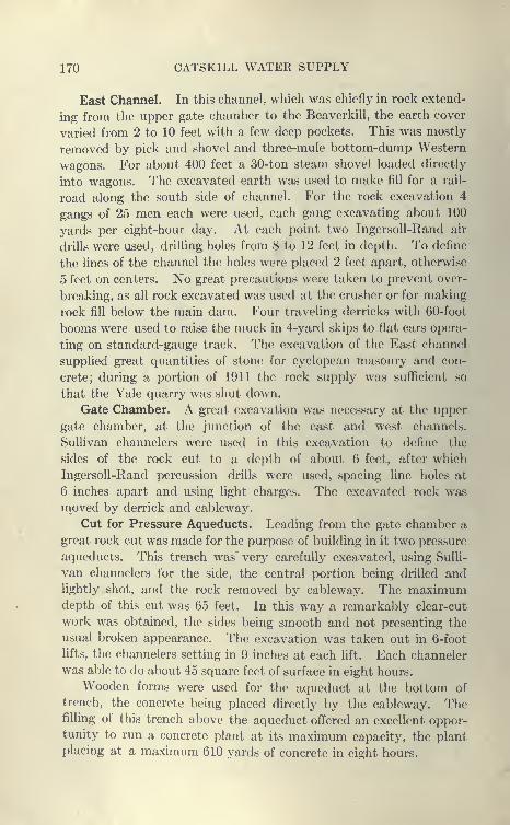
170 CATSKILL WATER SUPPLY
East Channel. In this channel, which was chiefly in rock extend-
ing from the upper gate chamber to the Beaverkill, the earth cover
varied from 2 to 10 feet with a few deep pockets. This was mostly
removed by pick and shovel and three-mule bottom-dump Western
wagons. For about 400 feet a 30-ton steam shovel loaded directly
into wagons. The excavated earth was used to make fill for a rail-
road along the south side of channel. For the rock excavation 4
gangs of 25 men each were used, each gang excavating about 100
yards per eight-hour day. At each point two IngersoU-Rand air
drills were used, drilling holes from 8 to 12 feet in depth. To define
the lines of the channel the holes were placed 2 feet apart, otherwise
5 feet on centers. No great precautions were taken to prevent over-
breaking, as all rock excavated was used at the crusher or for making
rock fill below the main dam. Four traveling derricks with 60-foot
booms were used to raise the muck in 4-yard skips to flat cars opera-
ting on standard-gauge track. The excavation of the East channel
supplied great quantities of stone for cyclopean masonry and con-
crete; during a portion of 1911 the rock supply was sufficient so
that the Yale quarry was shut down.
Gate Chamber. A great excavation was necessary at the upper
gate chamber, at the junction of the east and west channels.
Sullivan channelers were used in this excavation to define the
sides of the rock cut to a depth of about 6 feet, after which
IngersoU-Rand percussion drills were used, spacing line holes at
6 inches apart and using light charges. The excavated rock wasmoved by derrick and cableway.
Cut for Pressure Aqueducts. Leading from the gate chamber a
great rock cut was made for the purpose of building in it two pressure
aqueducts. This trench was' very carefully excavated, using Sulli-
van channelers for the side, the central portion being drilled andlightly shot, and the rock removed by cableway. The maximumdepth of this cut was 65 feet. In this way a remarkably clear-cut
work was obtained, the sides being smooth and not presenting the
usual broken appearance. The excavation was taken out in 6-foot
lifts, the channelers setting in 9 inches at each lift. Each channeler
was able to do about 45 square feet of surface in eight hours.
Wooden forms were used for the aqueduct at the bottom of
trench, the concrete being placed directly by the cableway. Thefilling of this trench above the aqueduct offered an excellent oppor-tunity to run a concrete plant at its maximum capacity, the plant
placing at a maximum 610 yards of concrete in eight hours.
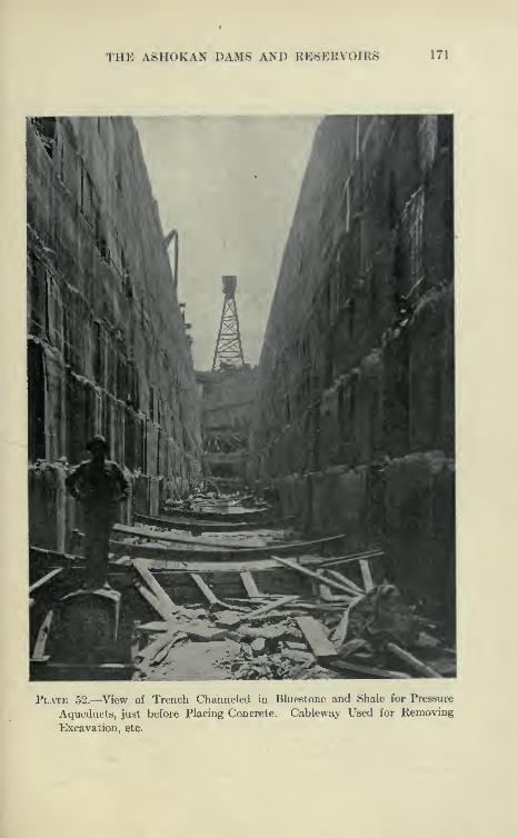
THE ASHOKAN DAMS AND RESERVOIRS 171
Plate 52.—View of Trench Channeled in Bluestone and Shale for Pressure
Aqueducts, just before Placing Concrete. Cableway Used for Removing
Excavation, etc.
172 CATSKILL WATER SUPPLY
Contract 10
Headworks of Catskill Aqueduct at Ashokan Reservoir. This
contract was awarded Dec. 1, 1909, to Jules Breuchaud, for a total
of $1,146,600. The principal items are:
Earth excavation, per cu.yd $0.68
Rock excavation,'
' 2.50
Refilling and embanking, " 20 and . 60 for 2,000 yds.
Concrete masonry, " 5.80 " 165,000 "
Reinforced concrete
Masonry, " 8.00
Portland cement, per barrel 1 . 50
This contract has a length of 4300 feet, of which 840 feet is special
aqueduct, screen chamber and lower chamber aqueduct, and 3460
feet cut and cover. With the exception of the cover-and-cover,
work on this contract is very special and extremely complicated.
Mr. Breuchaud was also connected with the contract for Ashokan
dams, so that Contract 10 was carried out in conjunction with Con-
tract 3, from which material, plant, equipment and men were freely
drawn.
Excavation. Earth excavation in the open cut was made as
follows: Upper portion was removed by the steam shovel, wheel
scrapers, and also by hand. The earth trimmed just in advance of
the invert was shoveled into skips and removed by derricks. Theinvert was constructed in the usual way.
Wooden Forms for Cut and Cover. This contract was unique
in that it is the only one on which wooden forms were successfully
used for concreting full-size cut-and-cover aqueduct. The side
forms were built in two parts, the lower form allowing the concrete
in the side walls to be raised to- an elevation of 8 feet above invert.
These forms were set on the invert, heavily braced transversely,
the wooden lagging being covered with 23-gauge galvanized metal.
The forms for the arch were set on the invert after the side-wall
forms were moved ahead. They were heavily trussed and braced.
The outside forms were also wood, supported by bolts placed in the
concrete of the side wall and invert. Excellent work was obtained
with these forms, but as the concreting was started in two or three
places and a stretch of only 3000 feet was constructed, they were not
used over again many times. Toward the end they showed signs
of distortion, so that it is probable they would have had to be renewedor remade for a longer stretch of aqueduct. Derricks were erected
alongside the cut and were used to place concrete and remove the
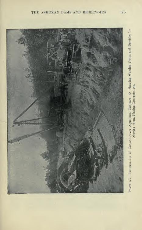
THE ASHOKAN DAMS AND RESERVOIRS 173
I
o! O
1.1
s So
i|I-I3
S

174 CATSKILL WATER SUPPLY
wooden forms. Concrete was mixed in small portable mixers to
which material was brought in carts from the main dam. Although
the first cost of the wooden forms is probably less, it does not appear
to the writer that they are as economical as steel forms, as they can-
not be taken down and erected as rapidly, or used over and over
for an indefinite number of times.
Contract 60
Hurley Dikes, Work and Prices. This contract was awarded in
December, 1909, to McArthur Bros., for the total contract price of
$971,000. Under it, the Glenford, Woodstock and West Hurley
dikes, 1.6 miles long, were constructed. These dikes close gaps at
the eastern end of the East Basin. The main prices are
Earth excavation, per cu.yd $1 .40
Rock excavation, " 3 . 00
Refilling and embankment, " 50
Concrete masonry, " 4 . 75
Portland cement, per barrel 1 . 40
Construction of Embankments. The construction of core walls
and embankment was similar to that described under Contract 3.
In the borrow pits three steam shovels ranging from 70 to 20 tons
were used. To transport the material for earth embankmentsabout 4^ miles of narrow-gauge road were built upon which were
operated trains hauled by 12- to 18-ton locomotives, hauling 3- to
4-yard dump cars. The material from the borrow pits after being
dumped from cars was hauled to place by slip scrapers and compacted
by special 13-ton Monarch roller, the boulders being hauled to one
side. For the wider part of this embankment the earth was deposited
directly into place by narrow-gauge trains, the tracks on the dikes
being thrown as each layer of embankment advanced across the fill.
An excellent view of the construction of the Woodstock dike is shownon Plate 54.
Core Walls. A core wall 1835 feet long for the Glenford dike
was. founded on rock, the depth from the surface to rock
varying up to 30 feet. The core-wall trench was excavated
with vertical sides in compact material. The Woodstock dike wasbuilt in a similar manner, the material being obtained from the bor-
row pit 3000 feet distant. When the embankment became too nar-
row to accommodate narrow-gauge tracks a single track was placed
on the core wall from which, after being dumped, the material wasdistributed by slip scrapers.

THE ASHOKAN DAMS AND RESERVOIRS 175
176 CATSKILL WATER SUPPLY
Concreting of Core Wall. To concrete the core walls small
stationary mixing plants of ^-yard capacity were arranged with bins
to receive crushed stone and sand, the stone being supplied from
small crushers fed with loose stone from adjacent quarries. The
concrete was delivered to the core walls in small steel dump cars
which discharged into the trench while the core wall was below
ground. Above the ground the forms were built in panels about 6
feet high and concrete cars run on top of them. During 1910 about
31,000 cubic yards of concrete were placed, the maximum for one
month being 7410, about 290,000 cubic yards of embankment being
placed in the same year, the maximum for any month being 58,000.
Contracts 5 and 48.
Kingston Sewer. By legislative enactment the City of New York
was required to divert that portion of the sewage of the City of
Kingston emptying into Esopus Creek to another outlet, for the reason
that after the completion of the Ashokan Reservoir insufficient
water would flow in Esopus Creek to properly carry away sewage.
The main outlet sewer was diverted to Rondout Creek by the con-
struction of 6200 feet of 24-inch pipe sewer, and 6200 feet of sewer
tunnel; 4900 feet of the 24-inch pipe was laid under Contract 5 bythe Haggerty Construction Co., the remainder under Contract 48
by King, Rice & Ganey Co.
Sewer Tunnel. The sewer tunnel was built to avoid a deep cut
and to contain the pipe sewer. It was constructed from four shafts,
ranging in depth from 21 to 94 feet. The tunnel, which is at an
average depth of 80 feet, is constructed mostly in Esopus shale
and for a short distance in a seamy limestone having an eroded sur-
face and dipping at points below tunnel grade. The tunnel has a
rectangular section 5'X7', just large enough to allow a few men to
work and lay the 24-inch pipe. It was found very difficult to con-
struct short stretches of this tunnel in the usual manner, as large
runs of soft material (water-bearing sand) from the surface of the rockwas caused by the excavation, the street surface overhead settling.
It was necessary to use compressed air to penetrate the worststretch. After the locks were installed, the soft ground was easily
passed.
Compressed Air for Soft Ground. This tunnel, although small,
illustrates very well the advantage of compressed air for passing soft
ground. Many instances have occurred where great expenditureshave been made to penetrate heavy water-bearing material, using
THE A8HOKAN DAMS AND RESERVOIRS 177
ordinary timherinK niotliods at the cost of great delay and danger
to surrounding property, due to loss of ground and runs into the
excavation. As in this case, with the installation of air locks and the
use of moderate air pressures, no difficulty would have been Qxpe-
rienced, the cost being not much more than ordinary work without
comj^ressed air. Outside of large cities, where the compressed-air
men are strongly organized, men can be secured for work in mcxlerate
pressures, say, up to 20 pounds, at slightly increased wages. Aproper installation of air locks will permit the prosecution of the work
at almost the same rate as outside work. The additional expen-
diture for compressed air is not a large item. A central air plant,
as originally installed for Contract 48, consisted of one Ingersoll-
Rand two-stage air compressor with a capacity of 1200 cubic feet
of free air a minute compressed to 80 to 100 pounds. This air was
distril)uted to over 12,000 feet of pipe from 6 to 2 inches in diameter.
The shafts were equipped with derricks and small head frames
operated by hoisting engines.
The total of Contract 48 was $146 631 some of the principal
items being:
Shaft in earth, linear ft $60
Shaft in rock, " 70
Tunnel in rock, " 15
Tunnel in earth " 40
Lining tunnel in earth and rock, " 2 . 25 (solid rock)
14 . 00 (insecure rock)
Compressed-air Equipment. The compressed-air equipment
installed consisted of an Ingersoll-Rand No. 2 upright compressor,
capacity 500 cubic feet of free air per minute under 20 pounds
pressure, driven by a 50-H.P. G.E. motor. Attempt to maintain a
pressure of 15 pounds in 450 feet of heading failed, due to leakage
through seams in the rock. By filling between 1-inch boards
(supported on cap or posts) and the roof with earth, a pressure of
9 pounds was reached and used on the ordinary working pressure.
The original high-pressure compressor mentioned furnished about
one-half the air used in the heading. The ground, which originally
could not be kept from running into the heading, now worked like
putty. Air was observed to bubble up in a brook 1200 to 1500 feet
from the tunnel.

178 CATSKILL WATER SUPPLY
Contract 59.
Highways around Ashokan Reservoir. This contract provided
for the construction of 27 1 miles of road around the reservoir and was
awarded to C. P. Bower Construction Co., December, 1909, for
$323,861. The main items are:
Earth excavation, cu.yd $0.55
Rock excavation, ** 1 . 05
Concrete masonry, " 7 . 98
A part of the excavation was done by hand. A No. 1 Thewautomatic shovel was successfully used for the bulk of the
excavation, although the cuts were usually light.
Operation of Ashokan Reservoir and Headworks.
The following is given to show how the Ashokan Reservoir is
to be drawn upon and the various gate chambers, aeration basin,
screen chambers, etc., are to be operated.
Depth of Water that can be Drawn from Ashokan Reservoir.
Examination of the maps of locality of Ashokan Reservoir (Plates
25 and 34) will show that the land surface of Ashokan Reservoir
(except for a small area in gorge of the Esopus between the dam and
Bishop's Falls at Olive Bridge about one-half mile above) is all above
elevation 490, the level of the invert of the cut-and-cover aqueduct
below the gate houses. Were the reservoir drawn to this elevation
there would remain only a long narrow pool in the Esopus gorge
above the dam and various isolated pools in the basin. The gates
are so arranged that the full capacity of the aqueduct can be used
with water surface as low as elevation 516, making 74 feet available
for the West Basin and 71 feet for the East Basin.
East and West Basins. As the Beaverkill has a drainage area
of only 17 square miles (against 240 for the Esopus) it can only furnish
a very small amount of water to the East Basin, which will receive
its supply from water going over the overflow weir which separates
it from the Esopus or West Basin, or its level may be maintainedby the opening up of the gates of the Dividing Weir gate house.
(See Plate 55.) The floods of the Esopus will after raising the
West Basin to above elevation 590 pass over the Dividing Weir over
1000 feet long and to a depth of 20 feet before overtopping dams or
dikes, a vastly greater flood than any ever recorded.
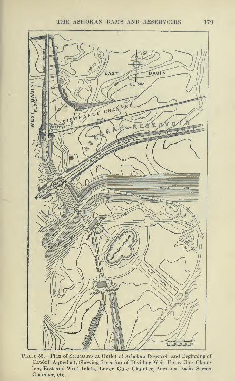
THE ASHOKAN DAMS AND RESERVOIRS 179
Plate 55.—Plan of Structures at Outlet of Ashokan Reservoir and Beginning of
Catskill Aqueduct, Showing Location of Dividing Weir, Upper (late Cham-ber, East and West Inlets, Lower Gate Chamber, Aeration Basin, Screen
Chamber, etc.
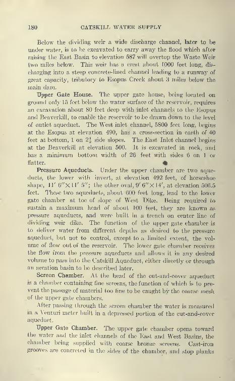
180 CATSKILL WATER SUPPLY
Below the dividing weir a wide discharge channel, later to be
under water, is to be excavated to carry away the flood which after
raising the East Basin to elevation 587 will overtop the Waste Weir
two miles below. This weir has a crest about 1000 feet long, dis-
charging into a steep concrete-lined channel leading to a runway of
great capacity, tributory to Esopus Creek about 3 miles below the
main dam.
Upper Gate House. The upper gate house, being located on
ground only 15 feet below the water surface of the reservoir, requires
an excavation about 80 feet deep with inlet channels to the Esopus
and Beaverkill, to enable the reservoir to be drawn down to the level
of outlet aqueduct. The West inlet channel, 5800 feet long, begins
at the Esopus at elevation 490, has a cross-section in earth of 40
feet at bottom, 1 on 2^ side slopes. The East Inlet channel begins
at the Beaverkill at elevation 500. It is excavated in rock, and
has a minimum bottom width of 26 feet with sides 6 on 1 or
flatter. #Pressure Aqueducts. Under the upper chamber are two aque-
ducts, the lower with invert, at elevation 492 feet, of horseshoe
shape, 11' e^'Xll' 5"; the other oval, 9' 6''X14', at elevation 506.5
feet. These two aqueducts, about 600 feet long, lead to the lower
gate chamber at toe of slope of West Dike. Being required to
sustain a maximum head of about 100 feet, they are known as
pressure aqueducts, and were built in a trench on center line of
dividing weir dike. The function of the upper gate chamber is
to deliver water from different depths as desired to the pressure
aqueduct, but not to control, except to a limited extent, the vol-
ume of flow out of the reservoir. The lower gate chamber receives
the flow from the pressure aqueducts and allows it in any desired
volume to pass into the Catskill Aqueduct, either directly or throughan aeration basin to be described later.
Screen Chamber. At the head of the cut-and-cover aqueductis a chamber containing fine screens, the function of which is to pre-
vent the passage of material too fine to be caught by the coarse meshof the upper gate chambers.
After passing through the screen chamber the water is measuredin a Venturi meter built in a depressed portion of the cut-and-coveraqueduct.
Upper Gate Chamber. The upper gate chamber opens towardthe water and the inlet channels of the East and West Basins, thechamber being supplied with coarse bronze screens. Cast-irongrooves are concreted in the sides of the chamber, and stop planks

THE A8H0KAN DAMS AND KESERV()IR« 181
placed in those so as to enable the water to he drawn from anydesired depth. Next the water passes through short 8t(»el pipes
fitted at the inlet end with a sluice gate, at the center with a gate
valve, and at the outlet end with a stop disk for emergency use.
The center of the sluice gates is about opposite the center of the
pressure aqueducts, and only 50 feet distant.
Lower Gate Chamber. From the pressure aqueduct at the lower
gate chaini)er a battery of 60-inch steel pipes lead upward from the
floor of the chamber. These pipes are controlled by a battery of
60-inch gate valves placed next to a manifold out of which a battery
of pipes lead to reinforced concrete conduits discharging into an
aerator basin, these pipes in turn being controlled by 60- and
48-inch valves, some of them of special construction.
Special Aqueducts to Screen Chamber. To provide for the use
of the aqueduct when aerator is out of commission another battery of
pipes lead directly from the pressure aqueducts to two similar special
aqueducts discharging directly into the screen chamber, about 700
feet distant. The discharge into these aqueducts is controlled at
the lower gate chambers by a gate and control valve. The aque-
ducts leading directly to the lower gate chamber reach hydraulic
grade just above the screen chamber. In order to prevent the
aqueduct below the screen chamber from being under a head which
could readily be obtained from the pressure aqueducts by opening
too wide the valves at the lower gate chamber, they are arranged
to overflow into a waste channel of large capacity, which passes
under the screen chamber and into an open channel to the
Beaverkill.
Turbines at Lower Gate Chamber. To make use of a portion of
the head available at the lower gate chamber when the reservoir sur-
face is considerably above hydraulic grade at the screen chambers,
a 48-inch steel pipe leads upward to the floor of the gate chamber,
discharging into two turbines, whose draft tubes discharge into the
lower special aqueduct to screen chamber. These tui bines will supply
light and power for local service at the gate chambers and in vicinity.
Below is appended a detailed description of the operation
of the headworks, taken mainly from the Catskill Water System
News of Aug. 5, 1911.
Headworks. " The structures comprising the headworks of the
Catskill Acjueduct at Ashokan Reservoir are necessarily of rather
complicated design. To make their functions more readily under-
stood, the accompanying sketch, Plate 59, has been prepared with
the tops of the structures removed at critical places in such a manner

182 CATSKILL WATER SUPPLY
SECTION A-
A
Plate 56.—Upper Gate Chamber at Ashokan Reservoir. Sections and Detailsof Pressure Aqueducts and Dividing Weir Dike.
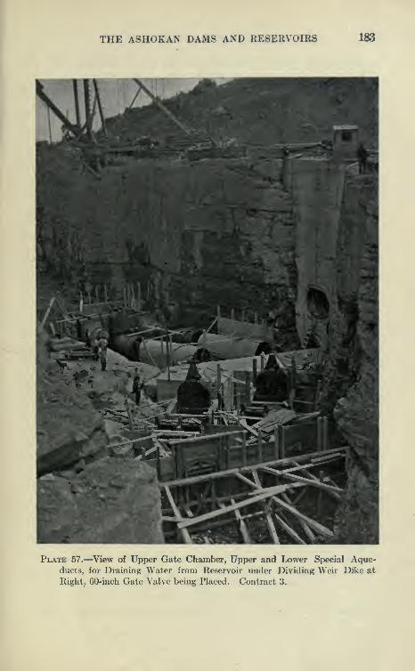
THE ASHOKAN DAMS AND RESERVOIRS 183
Plate 57.—View of Upper Gate Chamber, Upper and Lower Special Aque-ducts, for Draining Water from Reservoir under Dividing Weir Dike at
Right, 60-inch Gate Valve being Placed. Contract 3.

184 CATSKILL WATER SUPPLY
as will quickly convey the relation of elevations, sizes and other
features of the water passages without detailed dimensions.
"The headworks include the upper gate chamber and pressure
aqueducts in Contract 3 and the lower gate chamber, screen chamber,
aerator, special aqueducts, waste weirs and channel in Contract 10.
Upper Gate Chamber. '' The upper gate chamber, not shown in
sketch, is located in the dividing weir dike and provides for drawing
water from either or both basins of the reservoir at any elevation,
controlled by shutters lowered in the stop plank grooves of the
outer wells. On the outer faces of the chamber bronze guides are
provided in which coarse racks will be installed from preventing
logs or other large objects from getting into the aqueduct. In
designing the water passages the Venturi principle was utilized as
far as possible to reduce the loss of head at the contracted section
of the valves. Under normal conditions there will be no control
of quantity in this chamber, the 60-inch valves being either wide
open or closed. However, when the reservoir is being first filled,
and perhaps at other times, it may be convenient to temporarily
control the flow by the 3'X8' guard gates upstream from the
valves.
"From the upper gate chamber the water is delivered to the
lower gate chamber through one or both of the pressure aqueducts,
built of plain concrete in a deep rock trench which is backfilled with
concrete sufficient of its own weight to withstand the upward water
pressure.
Lower Gate Chamber. " The lower gate chamber, where the
manipulation of the flow will take place, is located at the junction
of the West and Middle dikes. From here the water may be delivered
directly into the screen chamber through the two special aqueducts
or by way of the aerator. The 48-inch control valves of special
design permit manipulation for the discharge of any desired quantity
without the annoying '^ chattering " so often attendant on control
by large gate valves and sluice gates. A 48-inch connection from
each aqueduct provides for power development for operating gates,
lighting, etc. Bronze gauge pipes from the standard aqueduct below
the screen chamber lead to float wells in the lower gate chamber so
that the person in charge of the operation of the valves can tell directly
the depth of water in the aqueduct below as uninfluenced by con-
ditions of cleanliness of the screens. It can be seen from the sketch
that the lower pressure aqueduct supplies water through four valves
to the lower special aqueduct and also to the aerator pipes throughtwo valves shown in the lower right-hand comer of the sketch. The

THE ASHOKAN DAMS AND RESERVOIRS 185

186 CATSKILL WATER SUPPLY
upper pressure aqueduct supplies the upper special aqueduct through
two valves shown in the upper right-hand corner of the sketch and
also the aerator by means of two valves directly adjacent to similar
valves obtaining water from the lower pressure aqueduct. The arrows
in all cases indicate the direction of the flow. The water from the
aerator basin flows over a weir into the upper special aqueduct.
Special Aqueducts. " The somewhat unusual section of the
special aqueducts between the lower gate chamber and the screen
chamber is due to several conditions. The lower one, for which
a 6'X15' waste gate is provided in the screen chamber, is to be
used for emptying either basin of the reservoir in the early stages of
operation in case it may be advisable as a means for overcoming
possible undesirable conditions of the water when the reservoir
bottom is first flooded, or for other reasons. This necessitated run-
ning the aerator outlet over the top of the lower aqueduct so that
the aerated water can be delivered through the upper aqueduct
at the same time the lower one is used for wasting. The water
area is approximately a mean between that of the pressure aqueducts
and the standard cut-and-cover section below the screen chamber.
The inside radius of the arch, GJ feet, is used also for practically
all the other small arches in the vicinity, in order to simplify form
work.
Overflow Weir. " Just above the screen chamber an 100-foot
overflow weir is provided in the lower special aqueduct with the crest
at about the hydraulic grade line and a 40-foot one in the upperaqueduct primarily to prevent undue head on the aqueduct, belowthe screen chamber. These weirs are designed to discharge the
maximum quantities of water that can reach them in excess of oneaqueduct capacity, assuming all gates above open. The weir for
the lower aqueduct will also carry whatever the waste gate will
not discharge when water is being wasted. A waste channel coveredfor 100 feet from the screen chamber will discharge into the Beaver-kill gorge.
Screen Chamber.*
' Piers with stop plank grooves divide the screenchamber into two symmetrical parts so that either side can be usedin screening the water. Economy has been sought by an arrange-ment of grooves permitting screens to be placed in a broken line
like a Greek border, thus providing the necessary screen area in astructure of minimum size for the purpose. The arrangement will
also permit screens to be fastened together as a sort of hamper withthe upstream face open, so as to handle three lines of screens on oneoperation. Grooves have been provided immediately below the

THE ASHOKAN DAMS AND RESERVOIRS 187

188 CATSKILL WATER SUPPLY
main screening area for guard screens to be placed during the opera-
tion of cleaning the regular screens. Water under pressure from
the reservoir will be available for washing screens on the washing
floor at one side of the chamber. Float wells in this chamber will
record losses of head in passing the screens. Stop planks and screens
not in use can be stored in a room for this purpose into which a track
runs from the main floor. Whenever it is desired to waste water
through the waste channel, stop planks will be inserted in grooves
located in piers immediately above the main screens.
Capacity of Headworks. '* The headworks are so designed that it
will be possible to draw the full capacity of the Catskill Aqueduct
through the lower aqueduct, from either basin of the Ashokan
Reservoir, with the water as low as elevation 518 or 519. If the lower
aqueduct is supplied from both basins of the reservoir the full capacity
can be drawn when the water surface in the reservoir is as low as
about elevation 516. The upper aqueduct, on account of throttling
at the two 48-inch control valves in the lower gate chamber, can
deliver the full Catskill Aqueduct capacity only down to about
elevation 540 in the reservoir. With all valves on both aqueducts
wide open from both basins the full capacity can be drawn as low
as elevation 514. These elevations are for flow directly to the screen
chamber without aeration. With the reservoir full (elevation 587
and 590) the maximum discharging capacity for drawing off either
basin of the reservoir through the lower aqueduct is 2500 to 3000
cubic feet per second. Starting with the East Basin full it wouldtake about fifty days to empty it in this way down to elevation 520
and eight days more to drain out the remainder, with no allowance
for inflow during the period of emptying."
Aeration Basin. Reinforced aqueducts from the lower gate
chamber discharge into an aeration basin. This basin is about
200' X 400', of irregular shape, and is to be the feature of an elaborate
landscape treatment at this point. In it will be several hundredbronze nozzles discharging the entire flow of the aqueduct in a series
of jets so as to free the water from objectionable gases and odors
and to charge it with oxygen. Passing through the chamber is ahorseshoe aqueduct with a side slit at the top to receive aerated
water. This aqueduct discharges over a weir into the special aque-
duct just above the screen chamber.
Soil Stripping. Early in the work an extensive investigation
was conducted as to the advisability of stripping the soil from the
bottom and sides of the Ashokan Reservoir, and a thorough report
was made in 1907 by Messrs. Allen Hazen and Geo. W. Fuller (see

THE A8H0KAN DAMS AND RESERVOIRS 189
Annual Report, 1907). They conclu(Je(i that the cost of stripping
the Ashokan Reservoir, estimated as over $5,0(X),0<X), was not war-
ranted l)v any eoniiiionsurate improvement in tiie water, as follows:
Report of Hazen and Fuller. " 1. The stripping of the sides and
l)ottom of a reservoir will ordinarily prevent stagnation of the lx)ttom
layers for a period of years, the length of which depends upon various
local conditions. In the Boston reservoirs this i>eriod does not seem
to exceed from ten to twenty years.
Plate 60.—Cross-section of Special Bronze Nozzles Used for Aerating WaterDrawn from Ashokan and Kensico Reservoirs.
"2. Ultimately it makes comparatively little difference as to
stagnation of the bottom layers whether the sides and bottom of
a reservoir are stripped or not.*
" 3. By aeration and filtration of the bottom water of deep reser-
voirs there can be obtained a better quality of water without the
benefit of stripping than it is possible to obtain with the aid of strip-
ping in the absence of aeration and filtration.
190 CATSKILL WATER SUPPLY
"4. In the absence of stripping substantially as good a quality
of bottom water may be obtained, after aeration and filtration,
as in the presence of stripping. In fact, as just stated, decolor-
ization and purification are facilitated by the absence of stripping
due to bacterial agencies which make some of the iron in the soil
available as a coagulant.
"5. In view of the above and as aeration and filtration will ulti-
mately be required in order to obtain satisfactory results in this
climate, present evidence and experience indicate that beyond
grubbing a reservoir it is unwise to spend money for further removing
organic matter from the bottom and the sides."
Operation of Aerator. A detailed description of the similar
Kensico aerator and its workings is here appended, taken from the
Catskill Water System News of June 20, 1911:
" The aerator basin is a shallow pool 460 feet long and 240 feet
wide at its widest part. It is lined with concrete and is surrounded
by a concrete apron 20 to 25 feet wide to insure the return to the
basin of any water blown beyond its enclosing walls. Its shape is
that of a rectangle to which semicircles have been added on the ends
and on one long side. The object of the pool is to collect the water
and dehver it into the aqueduct through an outlet conduit extending
under the basin on its long axis, and having a long narrow opening
in the top to receive the water." Water is delivered to the basin through a group of concrete con-
duits from the lower effluent chamber. In the basin these conduits
branch into smaller pipes which run parallel to the long axis of the
aerator and in the top of which are set nozzles for discharging the
water vertically into the air. There are seven of these nozzle pipes,
each one of which feeds about 215 nozzles. In addition there are
groups of nozzles in each of the three semicircular portions of the
basin, making the total number of nozzles about 1600." Experiments have been performed in the endeavor to select a
type of nozzle most suitable I'or aeration. The design which will
probably be adopted consists of a cylindrical base with a short conical
tip. Within the base on the sides of the nozzle are fixed three vanes
which extend into the waterway. They start at the bottom parallel
to the direction of flow and gradually assume an inclination of about
60 degrees with the element of the cylindrical base. The result
is that the water issuing from the nozzle is thrown outward fromthe tip and forms a very regular fan-shaped jet in which a distinct
whirling motion is perceptible. It was noted that this type of
nozzle is more efficient in breaking up the water, while at the
THE A8H0KAN DAMS AND RESERVOIRS 191
same time the jet is more stable in the wind than that from other
types." The available head for aeration is about 20 feet at the base of
the nozzle, which gives a jet about 15 feet high. The jets for the
most part are spaced uniformly about 16 inches apart so that there
is an interference of two adjacent jets almost as soon as the water
issues from the orifice, and a nozzle line when in operation will appear
as a solid wall of spray. It is intended, however, to form breaks
in the lines by omitting the nozzles at two places in each line so chosen
that two lanes or vistas about 15 feet wide will be formed across
the aerator. The borders of these vistas as well as the ends of the
nozzle lines will be emphasized by placing there additional nozzles,
forming symmetrical clusters.
" In the small semicircular units the arrangement and design of
nozzles is such as to give some variety to the appearance, with a
view to helping the artistic effect. In the center, clusters of smooth
nozzles without vanes are provided. These are surrounded by a
line of the regular nozzles and outside of all is a line of special nozzles
designed to give a wide low jet.
" It is intended to operate the aerator always under the full avail-
able head and to meet variations in flow by shutting off certain
portions rather than by throttling. To this end, the nozzles are
divided into groups of varying capacity, each group controlled by
a separate gate in the lower effluent chamber. By this means, the
flow may be increased or diminished by stages of about 25 M.G.D.The groups are so arranged that with any combination of units
in service there will be a symmetrical arrangement of jets in the
basin."
Venturi Meter. The first apparatus for measuring the flow of
water in tlie aqueduct is the Ashokan Venturi meter. This structure
is a few hundred feet below the screen chamber at a depression
formed by a small stream. The total length is about 400 feet,
depressed so that the throat is under a head of about 25 feet. It is
all of reinforced concrete, changing at each end from the shape of
the standard horseshoe cut and cover to the circular throat casting
7 feet 9 inches in diameter. To obtain accurate sections of aqueduct
at the points where Piezometer tubes are attached, two bronze
castings are set, known as the upper Piezometer casting and the throat
casting. The upper casting is 17 feet 6 inches in diameter and 1
foot wide, the lower about 7 feet 9 inches in diameter and about
8 feet long, the upper casting being set about 30 feet upstream from
the throat. Two tapered sections occupy a length of about 148
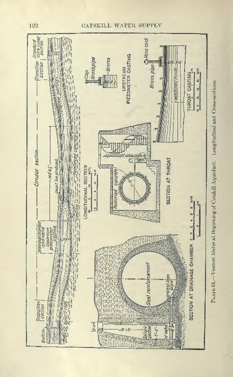
192 CATSKILL WATER SUPPLY

THE ASHOKAN DAMS AND RESERVOIRS 193
feet. Adjacent to the throat casting a small chamber is built to
contain the automatic recording apparatus.
Three other Venturi meters are built along the line of the aqueduct,
at Pleasantvil'e to measure the flow into the Kensico Reservoir,
at Valhalla to measure the outflow of the Kensico, and in the City
Aqueduct tunnel to measure the flow into the City of New York.
In addition, there are several gauging manholes by which the water
in the cut-and-cover aqueducts can be measured by ordinary current
meters. These manholes are conveniently built so that the meter
can run on two bronze rails transverse to the aqueduct, and the flow
obtained at numerous points in the rectangular section at the gauging
manhole. With these facilities it will be easy to ascertain the exact
flow in the aqueduct at numerous points, thus giving a valuable
check on the leakage from various stretches, and evaporation and
losses from the reservoirs. The aqueduct being of unprecedented
size with numerous types of structures, valuable and interesting
data should be obtained.
CHAPTER VII
ESOPUS CUT-AND-COVER AND PEAK TUNNEL
Contract 11.
Amount of Work under Contract ii. This contract comprises
about 6^ miles of concrete aqueduct in cut-and-cover, and the Peak
tunnel 3470 feet long. Its northerly end adjoins the Esopus steel
pipe siphon (Contract 62) 1 mile south of Brown's Station and runs
continuously except for a small gap at Tongore Siphon (Steel Pipe
Contract 62) to a point 2^ miles northwest of High Falls Station
at Shaft No. 1 of the Rondout Siphon (Contract 12). The work
lies in the watersheds of Esopus and Rondout Creeks, the divide
between being pierced by the Peak grade tunnel. From the northern
to the southern end is a distance of 7j miles measured along center
line. Next to Contract 2 and Contract 55 this is the largest cut-and-
cover and grade-tunnel contract on the entire aqueduct. It wasawarded to Stewart-Kerbaugh-Shanley Co., the lowest bidder, for
$2,368,920; time allowed for completion, forty-eight months from
notice to begin work, served Aug. 5, 1908.
Location of Aqueduct. The aqueduct on Contract 11 is located
in a rather wild, inaccessible country and skirts the base of the Cats-
kill foothills, cutting numerous bluestone ledges of the Hamiltonformation and hills of glacial drift. It is remote from railroads
and reached only by very rough country roads with numerous steep
grades.
Because of the roughness of the country to be traversed, the
location of this aqueduct presented all the problems likely to be
met with on work of this class. Its location was very carefully
made and was reviewed by consulting engineer Horace Ropes. Atthe north end, instead of following the minimum cost contour,
long tangents with rather deep average cut were adopted and asaving made in distance and probably in cost.
The central section passes through many abandoned bluestone
quarries and ledges, a very puzzling country in which to place the
aqueducc. There it was necessary, in order to keep the aqueductclear of embankments, to make numerous deep rock cuts. At the
194
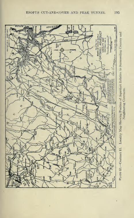
ES0PU8 CUT-AND-COVER AND PEAK TUNNEL 195
196 CATSKILL WATER SUPPLY
little town of Atwood, the aqueduct traverses a precipitous side
hill overlooking the Esopus. To provide a safe location it was
necessary to make a rock cut about 900 feet long averaging over
25 feet in depth, in order to place the structure well back from
the face of the cliff in sound rock.
A cut-and-cover location around the Peak mountain was nearly
adopted, but careful study showed that the Peak tunnel location
would save much in distance and probably in cost. The cut-and-
cover location would have had the advantage, however, of giving
a continuous right of way for a railway and pipe lines along the
aqueduct. Until the Peak tunnel was driven through and a through
track laid, the work was cut into two parts, that south of the Peak
being much more accessible.
Avoidance of Embankment Section. Numerous alternate loca-
tions of the center line of the aqueduct were made on the plane table
contour map, staked out in the field, profiles run over them and cost
comparison made before the final location was decided upon. Aremarkable feature of this contract is that in nearly 7 miles of rough
country only about 300 feet were built on embankment, the various
crossings of streams, gullies, etc., being made high enough to keep
the aqueduct in cut, except of course for the very short stretches
necessary for culverts, in which case the invert of the aqueduct
rests directly on the heavy culvert arches.
Contract Prices. As Contract 11 is representative of many,tabulation of the bid prices of the successful bidder is here given
:
On the basis of contract quantities and prices the cost of cut-and-
cover aqueduct to the city has been estimated at $60.66 per foot,
cost of grade tunnel at $86.55. On actual quantities the cost was$59.25 per foot of cut-and-cover aqueduct, of grade tunnel $68.65.
Cost of culverts averaged about $2.70 per foot of main aqueduct,
costing from $2180 for 6-foot culvert to $1224 for 3-foot culvert.
The Peak tunnel proved to be in such a good sound rock, requir-
ing practically no timbering, that the quantities of excavation, etc.,
were much lower than originally estimated.
Required Progress. The following is the schedule of required
progress contained in the contract
:
Percentage to be done of total amount ofTime elapsed after service contract, based on the Approximate
of notice to begin work. Statement of Quantities and the con-tract prices.
6 months 1 per cent12 months 10 "
24 months 50 "36 months 85 "
48 months 100 "
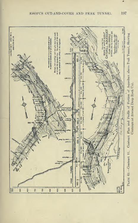
E80PUS CUT-AND-COVER AND PEAK TUNNEL 197
\ -r
?73 ^
5i'^"'i""i

198 CATSKILL WATER SUPPLY
w gP4
gij
^J
w p;^
^ uo H 00
!>^H C3
Ht—
I
o m-U y. <N
o >,
HQl^
faO g I
ft. o>^ ^ r/5
^ H :^PLh m
m
P^ o ^W ^ fi
^ i3«oPU
oooooooooooooooooooooooooooooooooooooooooooooooooooooooooooooooooooooooooooooooooooooooiOOOC'OOiOGOiOOOOOOOiO»OQt^"*iO<MiOCOI^OcO^'-icOOOOiOOOiM005iCrtHCDOOO'*OCDOt^'-HCO^T-HOt>-iOCCX(M(MO'^
t^OO-*GO^'^COOOOiOOCOCOTH(Nt^t^r^t^eOt^t^(N<Mt^I^(MiMI^iO-<:t<-^Tt<iOt^05Tt<OiCTjHCX)05»0»OeOCOCOCOiOCOCOTt<rfCOCOTtHTt<CO
OOOOOOOOOOOOOOOOOOOOOOOOOOOOOOOOOOOOOOOOOOOOOOOOOOOOOOOOOOOOOOOOOOOOOOOOOOOOOOOOOOOOOOO
m<<!<<pQcQ««mcQoq<:<ip20) a; <u o o 0)
HHHHHHaaaaaaac
.+ . . .0(MOOi:^i;Ccorfi
^oooot^ocoo.-<cocO'-tcoior^
T-( i-H ,-1 (N C^ (M (N
S^ O Sc<MOOt^O
oy o'\ o oOT-H(rocDr=ico
•^»00(MI^O K^<N TfO OCQ fiCO CC CO Tti Tt< Tji o
•-P: : : :: ::
e3
0<0_L.CO
COrt^ioOooOOOO(NCOCOOCOO"'^'^o o o '^ o '7 o o
CDCOTfiiOcCXMt^O>Ol^T-(C>qTtioO(M(Tic^coeocoTt^TfiTt*
02
cc
3-2 1^
a^- :::::::::::: SO 03 O
I—( -^3
IL,.,, i.So;----------- — ^.Oft, a3
KMCOTt^iCCOt^XOO^tMCO-^iOOt^OOOJO^C^ieOT^iOOJ^OOOi,-1rHr-l,-(r-(,-lr-l^r-(,-l(N(N(N(NC^(N(N(N(M(N

E80PUS CUT-AND-COVER AND PEAK TUNNEL
g8888SSS888S88888gSgS8S8S888S88 8
00 3f "t «o~m" •-«" o" C-fCC ^ <N lO M* »C fC "^"^^^ co" iO"9.'
CO
199
J5^5!8888S8882888S8S?S8S8SS28c^.S8S : 8
gSSQQ^OOQg^JOOgggOOCgOOg;cc cc --
I
8
I
1
;j:§ song's « 6
•il
03 >>
c o-
pII
"=^ C >. c3 «5
- 5 O
c c
)^^
.S'oi c
-S-5^ S:S
QOxO>HH
C-E
.2 ^ ca.s
o
j^ 4;— t< — O ^
'S I S-^Sec §
-^11
C3 IM >.
tec; bc
^% o C C3
^.^2^
200 CATSKILL WATER SUPPLY
The contract was completed on time.
Test Pits and Soundings. It will be noted from the itemized
bid that no classification of excavation as earth and rock was made,
but that the contractor bid on excavation, refilling and embanking
in fourteen sections. Previous to the reception of bids the line of
the aqueduct was carefully staked out, and test pits dug at close
intervals, to the number of 200. These were left open, so that intend-
ing bidders could examine the material taken out of them and thus
get an idea of what they were likely to encounter. Although not
officially given out, from the test pits and numerous soundings the
probable rock profile was plotted and given to the bjdders by the
engineers on the ground. This in connection with the information
given by the test pits was ample to give a very good idea of the
materials to be excavated.
Classification of Materials of Excavation. As a matter of general
policy for the whole line of cut-and-cover, it was decided that no
classification of material would be attempted, as it was felt that in
the excavation of the surface rocks, much of which was decomposed
and shaly, it would be hard to difi'erentiate the rock from the over-
lying earth. This proved to be the case, as many of the cuts were
taken out in one lift, the bottom rock being drilled through the earth,
and after being blasted excavated with its burden by steam shovels
or other tools.
Payment Lines. For the standard cut-and-cover section shownon Plates 11 and 12 definite payment lines were prescribed, so
that the contractor knew in advance to what slopes he would be
paid, these slopes being fixed for sections between definite stations.
The engineers had no authority to modify slopes, but could movethem outward if conditions warranted. The experience on miles of
cut-and-cover work shows that the payment lines in dry, loose earth
slopes, on type A, are liberal, but that it is difficult to excavate to
the lines of the compact earth section and even more difficult
to excavate to the lines of the rock section, for which 6 on 1
slope was prescribed, with 20 inches as a minimum thickness of
side wall.
Difficulties of Excavation in Rock Cuts. In order to make reason-
able progress in the laying of the aqueduct, it was necessary to exca-
vate a considerable length of trench per day, which involved the
handling of much material, so that hand methods were out of thequestion. This meant that power machinery had to be used, withfrequent blasting in rock. This made it impracticable to excavateto the close lines of the rock section, unless the rock proved to be
ESOPUS CUT-AND COVER AND PEAK TUNNEL 201
particularly s^od, which is seldom the case, as it was found that no
matter what the variety of rock, the first few feet of the surface was
intersected by numerous open seams and heads into which the powder
tended to work, and as these seams seldom parallel the excavation
at the proper distance, cuts tended to break wide. It is probable
that by channeling the rock on each side, a close section of rock
cut could be secured, but this would be enormously expensive, very
slow and not contemplated by the contract.
Estimating Quantities from Payment Lines. In the preparation
of the estimates the lines were usually moved outward in rock and
compact earth sufficiently to cover the excavation made where
contractors had exercised due care. Experience seems to show that
in tunnels a close definition of payment lines is practical and just,
but this does not appear to be the case in an open cut, due to weather-
ing of the surface material. Some engineers are in favor of not
prescribing in advance the slopes, but leaving this to be determined
in the field by the engineers directly in charge. There is room for a
fair difference of opinion, but it would appear that defining the
payment lines leads to better bidding, the contractors having a well-
defined idea as to what they will be required to do and for what
they will probably be paid.
Specifications Contract 11. The specifications of Contract 11,
like all those issued later, are indexed by means of the payment items.
All references to any item are found under the number of that item
and in consecutive order. Thus section 2.16, is the sixteenth section
under item two, and so on. The items are easily found by means
of heavily lettered numbers in the right-hand corner. Some of the
principal sections of this contract are here given:
I One Price of Excavation. Section 2.13. " One price only is to be
paid under each item, to cover the excavation of all materials, except
top-soil. Payments shall be made under each item for the materials
excavated according to orders, between the designated stations,
for the aqueduct and its appurtenances, for rights of way across
the aqueduct lands, for public highways, whether temporary or
permanent, and for such other purposes as may be directed. Nothing
in this contract shall be so construed as to include payment under
Items 2 to 15, any materials taken from borrow-pits, sand and gravel-
pits or quarries, or from other excavations made for the purpose of
obtaining materials. Materials re-excavated from storage piles
shall not again be paid for as excavation. No direct payment shall
be made under Items 2 to 15 for excavations of whatever nature
made in connection with the Contractor's plant, his roads, or rail-
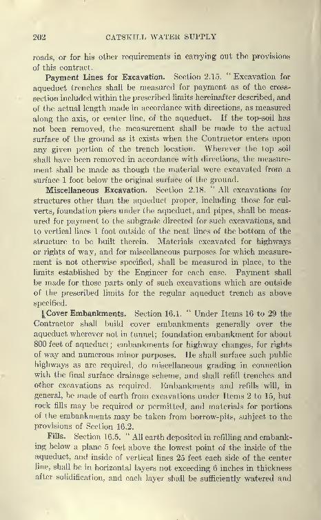
202 CATSKILL WATER SUPPLY
roads, or for his other requirements in carrying out the provisions
of this contract.
Payment Lines for Excavation. Section 2.15. " Excavation for
aqueduct trenches shall be measured for payment as of the cross-
section included within the prescribed hmits hereinafter described, and
of the actual length made in accordance with directions, as measured
along the axis, or center line, of the aqueduct. If the top-soil has
not been removed, the measurement shall be made to the actual
surface of the ground as it exists when the Contractor enters upon
any given portion of the trench location. Wherever the top soil
shall have been removed in accordance with directions, the measure-
ment shall be made as though the material were excavated from a
surface 1 foot below the original surface of the ground.
Miscellaneous Excavation. Section 2.18. " All excavations for
structures other than the aqueduct proper, including those for cul-
verts, foundation piers under the aqueduct, and pipes, shall be meas-
ured for payment to the subgrade directed for such excavations, and
to vertical lines 1 foot outside of the neat lines of the bottom of the
structure to be built therein. Materials excavated for highways
or rights of way, and for miscellaneous purposes for which measure-
ment is not otherwise specified, shall be measured in place, to the
limits established by the Engineer for each case. Payment shall
be made for those parts only of such excavations which are outside
of the prescribed limits for the regular aqueduct trench as above
specified.
|. Cover Embankments. Section 16.1. " Under Items 16 to 29 the
Contractor shall build cover embankments generally over the
aqueduct wherever not in tunnel ; foundation embankment for about
800 feet of aqueduct; embankments for highway changes, for rights
of way and numerous minor purposes. He shall surface such public
highways as are required, do miscellaneous grading in connection
with the final surface drainage scheme, and shall refill trenches andother excavations as required. Embankments and refills will, in
general, be made of earth from excavations under Items 2 to 15, butrock fills may be required or permitted, and materials for portions
of the embankments may be taken from borrow-pits, subject to the
provisions of Section 16.2.
Fills. Section 16.5. " All earth deposited in refilling and embank-ing below a plane 5 feet above the lowest point of the inside of the
aqueduct, and inside of vertical lines 25 feet each side of the center
line, shall be in horizontal layers not exceeding 6 inches in thickness
after solidification, and each layer shall be sufficiently watered and
ES0PU8 CUT-AND-COVER AND, PEAK TUNNEL 203
thoroughly compacted. Above this plane and beyond these lines,
rolling or ramming will not be required. Any settlement or sliding
of materials ])elo\v the designated embankment lines, whether due
to lack of rolling or to any other cause, shall be repaired at the
Contractor's expense before the completion of the contract.
Foundation Embankments. Section 16.6. "All aqueduct founda-
tion eml)ankni('nts, below a plane 2^ feet above the lowest part of the
inside of the aqueduct and inside of vertical lines 25 feet each side of
the center line of the aqueduct, shall be built with extreme care with
carefully selected earth. All stones larger than 3 inches in diameter
shall be thrown out. The materials shall be deposited and spread in
horizontal layers which will not exceed 3 inches in thickness after roll-
ing, and each layer shall be sufficiently watered and rolled with a
heavy grooved roller to thoroughly compact and solidify the
materials. When directed during the construction, and if required,
three times after the completion of the embankments, this portion
shall be so thoroughly saturated that water will stand upon the
surface. The building of the aqueduct upon such foundation
embankments shall not be begun until they have stood at least six
weeks after completion, unless otherwise directed.
Haul. Section 30.1. " The surface of refills and embankments,
the slopes of excavations and any other earth surfaces, wherever and
as ordered, shall be dressed with top-soil of the thickness directed.
The Contractor shall not be required to procure top-soil from beyond
the limits of the City's lands, nor to haul top-soil more than 3000
feet, excepting as provided in Section 1.2, nor to provide top-soil
for a greater thickness than 12 inches.
Top-soiling. Section 30.3. " Surfaces prepared in accordance
with Section 30.2 shall be dressed with an acceptable fertilizer in the
proportions directed, and shall be sown with first quality grass seed of
an approved mixture. If required, the seeded areas shall be watered
at such intervals as directed, until the grass is well started. Grass-
ing shall be done immediately after the preparation of the earth
surface for which it is ordered, unless other directions are given.
If there be any delay for which the Contractor is responsible, during
which weeds grow on the surface to be grassed, or the soil is washedoff, he shall remove the weeds or replace the soil without compen-
sation. If any portion of the seeded areas are not thoroughly
covered by grass they shall be refertilized and reseeded.
Settlement of Embankments. Section 30.2. " In general, top-soil
shall not be deposited until, in the opinion of the Engineer, anyrefill or embankment upon which it is to be placed shall have approx-
204 CATSKILL WATER SUPPLY
irrately reached its final condition of settlement, or until satisfactory
provision shall have been made for possible future settlement.
Wherever necessary, in the opinion of the Engineer, the surface upon
which top-soil is to be placed shall be raked or otherwise satisfactorily
prepared to insure a proper bond.
Order of Work. Section 31.26. " The provisions of Section 18 re-
lating to the order of doing the work shall be closely followed. In plac-
ing the concrete in the aqueduct section, the invert shall be built in
sections not over 15 feet long unless otherwise directed, with a keyed
joint between adjacent sections, substantially as shown on Sheet
9. The construction of the key blocks for this joint shall precede
the placing of the concrete for the rest of the invert by at least such
time as directed. Especial care shall be taken to obtain a smooth
and true top surface parallel to the inside of the invert, on each key
block, and unless otherwise directed, the top of each block shall be
coated with cold-water paint, asphaltum or other approved inad-
hesive substance or lubricant. Unless otherwise ordered, pockets
shall be left in the top of the concrete at each of the invert joints
for the proper bonding of the expansion-joint of the upper portion
of the aqueduct to the invert. The portion of the aqueduct above
the invert shall be built in sections of some multiple of the length
between invert joints, but in no case exceeding 75 feet. Any section
once begun, whatever its length, shall be completed by the contin-
uous laying of concrete, except that the Contractor will take approved
measures to secure a good bond, to build the portion above the
invert in two operations, provided that the division between the
two does not occur at a greater height than 8 feet above the lowest
part of the inside of the invert. The portion of the arch above
this 8-foot limit shall be built, in any case, by the continuous laying
of concrete.
Testing of Aqueduct. Section 39.1. " Portions of the aqueduct in
open cut and on embankment, aggregating not more than 15 per cent
of the total length of such aqueduct included in this contract, shall
be tested for water tightness.
Hydrostatic Test. Section 39.2.*' The testing of a portion of the
aqueduct will be conducted in general as follows : The bulkheads hav-ing been placed and made water-tight, the Contractor shall fill the por-
tion with clean water to a designated level. The water shall be main-tained approximately at the designated level for purposes of observa-tion until such time as a change of level is ordered. The testing shall
be continued with the water at as many different levels and for suchlengths of time as may be required, but the total time for any one
ES0PU8 CUT-AND-COVER AND PEAK TT^XNEL 205
portion shall not exceed 30 consecutive calendar days after the
filing of the first designated level or after the completion of approved
repairs, if any are required, in accordance with Section 39.6. TheContractor shall provide adequate means for drawing off the whole
or any part of the water at any time, in such manner as to avoid
damage' to the aqueduct, its appurtenances, or adjacent property."
Grade Tunnel. Contract 1 1 contains the usual provisions cover-
ing work in grade tunnel. These will be more fully discussed under
Contract 12.
First Season's Work. Work on this contract was started within
a few days of notice to begin work and vigorously prosecuted during
the remainder of the year (1908). It was planned to bring in all
plant materials over the Ontario & Western R. R. at High Falls.
A tract of level land above the railroad station was secured, and
used as a yard connecting with the main line by a long siding with
a good grade. Alongside of this siding were constructed a cement
shed, storehouses, derricks.and so on, and from it branched a long
trestle for storing and loading coal into wagons and cars. This
yard proved to be very convenient, and an improved highway was
constructed from it to the line of the aqueduct.
Improvement of Highways and Use of Traction Engines. Thecontractor's superintendent had considerable experience in construct-
ing State roads, and the requisite plant, consisting of portable crushers
and road rollers, were available. Some of the roads were straight-
ened in grade and line, stone walls being used to form a Telford base
upon which were placed layers of crushed stone and stone dust, which
were rolled; this gave an excellent roadbed, in some respects superior
to the State roads, inasmuch as it was founded upon an old hard
country road rather than fills. In this manner 3 miles of road were
macadamized, and upon them four Buffalo-Pitts traction trains were
in daily operation hauling supplies and materials. These trains
did excellent work, and proved capable of keeping the work well
supplied for the first season.
Excavation of Top-soil, etc. The first contract work consisted
of clearing and stripping top-soil over the entire line. After the trees
were cut, the top-soil was removed by drag or wheel scrapers and
stored in neat piles alongside the right of way for future use to cover
embankments previous to grassing.
Moving Steam Shovels over Public Roads. Later, six shovels
were transported over the roads to the site of the work, and by
December all of them were in operation. At first, the work of
transporting the shovels over the road was very expensive, as they
206 CATSKILL WATER SUPPLY
were hauled over a track laid just in advance of the shovels, of
cross ties and rails loosely spiked, the track at the rear of the shovel
being taken up and relaid in advance. Later, the cost of this work
was considerably lessened by using rails spiked to longitudinal string-
ers, the rails being held to gauge by stiff cross-bars hooked to eye-
bolts in the timbers, these bars being readily taken off and replaced.
A still better and far cheaper method was later developed.
Special, very wide wheels were fastened to axles and substituted
for the usual flanged wheels. These axles were turned so as to fit
the regular journal boxes. When they were in place, the shovels
could be readily hauled over the roads by traction engines, two or
more being used. The traction engines were Buffalo-Pitts, and the
shovels 20- and 60-ton Marions.
Method of Excavation. A 20-ton shovel was put at each side of
the Peak tunnel to excavate the portal cuts, other shovels being
Used to make first cut within 8 feet of subgrade. The contract pro-
hibited excavated material to be taken off city land, so that it would
be available later on for the cover embankment. Though it did not
expressly so provide, it was expected that excavation would be madejust in advance of the concrete arch and immediately used to cover
it. The contractor, acquiring for a small price several farms adja-
cent to the city land, thought from his previous experience on heavy
railroad construction that he could more economically prosecute
the work by wasting or spoiling the excavation from the aqueduct
trench and later securing the embankment material from borrow
pits of suitable material on his own land.
The contractor proposed to make the first cut within 8 feet
of subgrade along the entire line of the aqueduct, with the
exception of points of deep rock excavation. The material
from these cuts was to be cast partly on the downhill side to
make a berm upon which narrow-gauge tracks were to be laid,
later to be used for the transportation of concrete, etc. The material
not necessary for this purpose was to be spoiled in some cases imme-diately adjacent to the aqueduct, and in others somewhat removed.
Before this method could be formally approved, it was necessary
to secure a modification of the contract to the extent of deeding over
the contractor's land to the city for the life of the work. It wasfeared that if this were not done, in case of the failure of the con-
tractor and the sale of these lands, the city would be left without
sufficient earth to cover the concrete arch. It was also specified that
the contractor was to leave the spoil banks and borrow pits in a pre-
sentable condition where exposed to public view.
E80PUS CUT-AND-COVER AND PEAK TUNNEL 207
For the first season the steam shovels made very good progress,
and it seemed that this method would be successful.
When the steam shovels had completed the portal cuts of the
Peak tunnel, a start was made in the tunnel, using steam. It wasoriginally proposed to' handle the muck of the tunnel bench by 20-ton
steam shovels, using a special very short boom. It was found that
these shovels could not work in loss than the narrow section
reciuired— IG-foot tunnel 18 feet high by 15 feet wide to C line.
Electric Power. It was planned to operate mixing mn.chinery,
compressors, etc., by electric power obtained from Honk Falls, where
there was a hydro-electric plant sending current over a 33,000-volt
line to Kingston and Poughkeepsie.
Water Supply for Contract. A small mill pond was acquired
from which a 6-inch water line was laid to the aqueduct. Fromthis point a 4- and 2-inch line ran through the length of the contract.
This gave a gravity supply at a head of 100 feet, but due to the
numerous bends and crooks in the wrought-iron pipe 'line, there wasbut little available head a few miles from the pond. To reinforce
this supply in times of low water, a pumping station was installed
on Esopus Creek, which pumped directly into the pipe line.
Work Accomplished During First Year. During 1908 the force
averaged 356 men, with a maximum of 750 in December. These
men were housed mostly in two camps, one at Atwood, accommo-dating 300 men, the other at south portal of Peak tunnel, accommo-dating 200. Considerable progress was made in excavation, andseveral large concrete culverts were built, the portals of the Peaktunnel excavated, a large storage yard containing many buildings
established, several miles of road rebuilt and a great deal of plant
brought in.
Compressor Plant. During the second year, 1909, a high-ten-
sion transmission line was built from High Falls to the south portal
of the Peak tunnel. An electric compressor plant was here installed,
consisting of two belt-driven Laidlaw-Dunn-Gordon two-stage
compressors, each of a capacity of 1530 feet of free air to 125 lbs.
pressure. Between the high- and low-pressure cylinders an inter-
cooler was provided; the motors were 250 H.P. at a constant speed
517 revolutions per minute. Across the Peak a 6-inch wrought-iron
screw-joint pipe line was laid to the north portal and later on extended
2| miles further to Atwood, where two steam shovels and several
drills were operated at times by compressed air from this power-
house. The line was also laid southward, operating steam drills,
hoist, etc. It was found that a steam shovel could be very efficiently

208 CATSKILL WATER SUPPLY
operated by compressed air, and with considerable economy, when
the shovel was in a place to which it was difficult or expensive to
haul coal.
Peak Tunnel. During 1909 the work of excavation of Peak tun-
nel was vigorously pushed, as it was highly desirable to secure the
Plate 64.—View of South Portal of Peak Tunnel, Looking from Interior of
Completed Cut-and-cover Aqueduct.
use of this tunnel for a railroad track, giving direct communication
with the north end, otherwise reached by a tedious and difficult
country road. The rock was firm Hamilton shale underlying a
bluestone layer; it was easy-driUing and stood up well without
support, requiring only three short stretches of timbering, one inside

ES0PU8 CUT-AND-COVER AND PEAK TUNNEL 209
at a fault, the other two at the portals. The ordinary top heading and
bench method was used, and an average i)rogress of about 240 feet
per month per heading made. Mucking of the bottom was greatly
handicapped by use of 4-cubic yard side-dumping cars intended for
steam shovel use. Headings met on Oct. 27, 1909, the Peak tunnel
being the first one of a long series of tunnels in the Catskill Aqueduct
to be comph'tely excavated.
Tunnel Section Obtained. The top heading was usually driven
to a good line and section, particular pains being taken by the engi-
neers to secure this, but there was a decided tendency to leave the
bottom half narrow, with one or more feet of solid rock above sub-
grade. This was due largely to rivalry between two superintendents
on different sides of the tunnels in an endeavor to excel one another
in progress. Also, in tlie wet portions, there was a tendency to run
up to keep the tracks dry. Later, the trimming of this tunnel proved
to be rather expensive, showing that it would have been cheaper to
have driven more carefully from the start.
Trimming of Bottom and Laying of Drain. A very good method
of trimming the hard bottom was developed and used in conjunction
with the laying of the subdrain. Holes were driven from drills
mounted on a car running on a track through the tunnel. These
holes when shot and mucked out formed a trench in which a wooden
box drain was laid. Toward this drain trench the remaining bottom
was shot after holes were drilled along the side walls of the tunnel,
the drain meanwhile very efficiently carrying off the water.
Side walls of the tunnel when tight were drilled from a platform
car running on the center track. Later, concrete footing courses were
laid at each side wall to an accurate line and grade. Upon them a
templet was mounted, supported by a small trestle on wheels. This
templet was carefully run through the tunnel, and all rock neces-
sary to be taken down before concreting removed. The final result
was a tunnel trimmed very close to line and one in which rapid prog-
ress was made in concreting.
Construction of Culverts. During the second year, 1909, aside
from installing a compressor plant and excavating the Peak tunnel,
as previously described, not much progress was made. North of
the Peak tunnel, the only concrete work consisted of the building of
culverts. The plant used for building culverts consisted of derricks,
a Smith mixer, and small portable road crushers. This work,
although conducted at a loss, was of great help later on during the
construction of the aqueduct, as it saved delay which otherwise
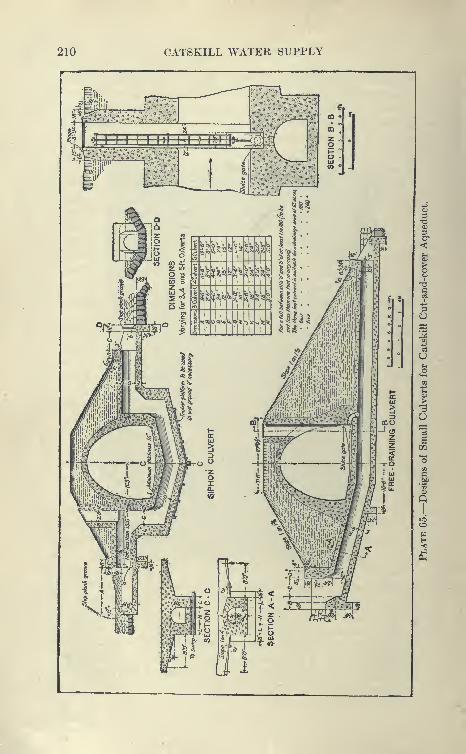
210 CATSKILL WATER SUPPLY
jiii JT^
4°)-l-M-4^M-4-4-t-A^^CT:i5
'>"' €:;(? flj • s
'«,?,' m ,.1.-' z „ „
o1-
~
..^ ^,-•I'l. <o " _
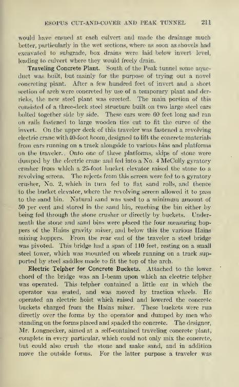
ESOPUS CUT-AND-COVER AND PEAK TUNNEL 211
would have ensued at each culvert and made the drainage muchbetter, particularly in the wet sections, where as soon as shovels had
excavated to subgrade, box drains were laid below invert level,
leading to culvert where they would freely drain.
Traveling Concrete Plant. South of the Peak tunnel some aque-
duct was built, but mainly for the purpose of trying out a novel
concreting plant. After a few hundred feet of invert and a short
section of arch were concreted by use of a temporary plant and der-
ricks, the new steel plant was erected. The main portion of this
consisted of a three-deck steel structure built on two large steel cars
bolted together side by side. These cars were 60 feet long and ran
on rails fastened to large wooden ties cut to fit the curve of the
invert. On the upper deck of this traveler was fastened a revolving
electric crane with 40-foot boom, designed to lift the concrete materials
from cars running on a track alongside to various bins and platforms
on the traveler. Onto one of these platforms, skips of stone were
dumped by the electric crane and fed into a No. 4 McCully gyratory
crusher from which a 25-foot bucket elevator raised the stone to a
revolving screen. The rejects from this screen were fed to a gyratory
crusher. No. 2, which in turn fed to flat sand rolls, and thence
to the bucket elevator, where the revolving screen allowed it to pass
to the sand bin. Natural sand was used to a minimum amount of
50 per cent and stored in the sand bin, reaching the bin either bybeing fed through the stone crusher or directly by buckets. Under-
neath the stone and sand bins were placed the four measuring hop-
pers of the Hains gravity mixer, and below this the various Hains
mixing hoppers. From the rear end of the traveler a steel bridge
was pivoted. This bridge had a span of 110 feet, resting on a small
steel tower, which was mounted on wheels running on a track sup-
ported by steel saddles made to fit the top of the arch.
Electric Telpher for Concrete Buckets. Attached to the lower
chord of the bridge was an I-beam upon which an electric telpher
was operated. This telpher contained a little car in which the
operator was seated, and was moved by traction wheels. Heoperated an electric hoist which raised and lowered the concrete
buckets charged from the Hains mixer. These buckets were run
directly over the forms by the operator and dumped by men whostanding on the forms placed and spaded the concrete. The designer,
Mr. Longnecker, aimed at a self-contained traveling concrete plant,
complete in every particular, which could not only mix the concrete,
but could also crush the stone and make sand, and in addition
move the outside forms. For the latter purpose a traveler was

212 CATSKILL WATER SUPPLY
erected on the top of the bridge and was operated by a chain
hoist.
Method of Moving Plant. The plant was to move itself longitu-
dinally by an electric-motor operating chains to the axles of the car
much as a steam shovel moves, but this did not appear to work well.
However, it was found that the plant could easily be moved by a
dinky engine hauling over a rope attached to blocks fastened to the
ties and to the plant. The saddles were in the rear of the bridge and
were elevated by a chain hoist attached to an I-beam on the rear
tower, turned 90°, hauled through the tower, and deposited parallel
to their original position, each saddle containing 5 feet of track.
All the machinery on the plant was electrically operated, power
being obtained from a transmission line paralleling the aqueduct.
Troubles Experienced with Traveling Plant. As might be
expected from such a complicated system of machinery, placed
in new conditions, trouble was experienced in getting the plant
to work smoothly. It was found that the electric revolving hoist
had not sufficient capacity to raise the necessary material for con-
creting a 30-foot section in eight hours and heated up badly. This
was remedied by fastening a small air- or steam-operated stiff-legged
derrick to the framework of the structure. This derrick, operated
by hoists, raised stone and sand, the electric hoist then being largely
used to elevate skips of cement to charging level of mixer.
First Blaw Aqueduct Forms. The first installation of Blawforms on the Catskill Aqueduct was used here. The interior
forms were designed to collapse and telescope. The outside
form was of steel panels bolted together in a large number of
units. This form gave considerable trouble, as it was lacking
in rigidity. This was remedied by the use of stiffening angles.
The panels w^re riveted together so that they could be handled in
5-foot sections the full height of the form. The interior form wasfound to be rather weak, the plates and interior bracing being light.
The interior forms were collapsed and moved on a wooden A-frameoperated by hand-jacks. The form contained three hinges, at the topand at the sides near the bottom, the bottom panels being folded
inward before dropping the form to position, when it could be passed
forward through the forms set up for concreting. All the curves
in this contract being planned to a 200-foot radius, the inside andoutside forms were cut wedge-shaped, so that when turned theywould approximate a 200-foot curve with chords of 5 feet on thecenter line. In passing from a tangent to a curve, or vice versa,
every other 5-foot section would be turned 180° by means of a turn-
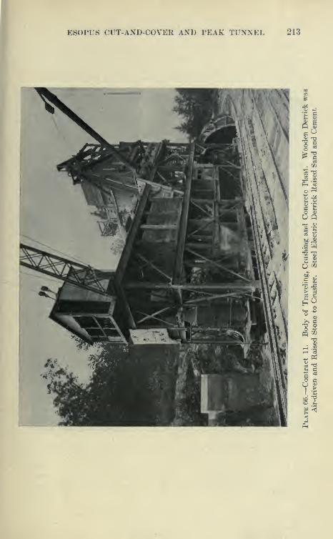
E80PU8 CT^T-AND-COVER AND PEAK TUNNEL 213
is
J16. aa; I—
I
6&
^ O
O fl
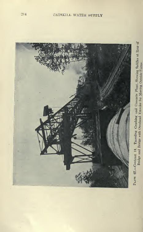
214 CATSKILL WATER SUPPLY
ES0PU8 CUT-AND-COVER AND PEAK TUNNEL 215
table upon which the A-frames carrying the forms were mounted.
This feature did away with the necessity of inserting fillers on the
curve, and was desiejied to save time and to give smoother work.
Performance of Plant During First Year, 1909. The traveling
plant succeeded in placing 2150 feet of completed aqueduct
from August to December, the best month's progress being 485
feet. This was considerably less than the planned progress of
30 feet of completed aqueduct per working day. During the first
operation of this plant the concrete for invert, after being mixed
in the Hains mixer in the usual way, was run through to the front
end on a long belt feeding into cars which were pushed by hand on
rails to the invert block l)eing placed. It was found difficult to
feed the belt at the proper rate, and a great deal of wet concrete
was spiilled. I^ater a locomotive crane was used to load buckets on
cars running on the bank, whence they were pushed by dinkies
and dumped over the ])ank to the invert.
Method of Building Invert for Cut-and-cover Aqueduct. Dur-
ing this year key blocks were constructed at 15-foot intervals. These
were cast between steel forms; on them other 8-inch steel forms
were placed to the grade of the aqueduct, and alternate blocks of
l(>-inch invert cast to 32 feet 4 inches radius. The key blocks were
for the purpose of producing a water-tight joint and to facilitate the
la^-ing of the invert to exact grade. At first screed boards were used
between the invert forms. These boards required considerable
manipulation and labor to get the concrete in proper shape for
troweUng.
A solid steel shaft, turned down at the ends, so that long handles
could be fastened at right angles to the shaft, was then used.
The shaft, after the concrete had set a little, was rolled on the forms,
beating down the stones and shaping the concrete to proper grade,
and leaving it in such condition that little troweling was necessary.
This shortened the time for forming the invert and also gave a
better finish to the concrete. This shaft had such obvious merit
that it was universally adopted by the contractors, and it should
be applicable to other similar classes of work.
Expansion Joints at Bulkheads. At the end of each day's workgrooves were cast which formed tongues of concrete when the adja-
entsections were deposited. As the concrete changed in temperature
this acted as an expansion joint, designed to prevent leakage. Atfirst cast-iron })locks with a draw of f of an inch in 5 inches were
used for forming the groove. These were found unwieldy, so that
eventually solid seasoned oak blocks were used for this purpose,

216 CATSKILL WATER SUPPLY
•J aC O
l2
Ph

E80PU8 CUT-AND-COVER AND PEAK TUNNEL 217
these blocks being bolted to tlu* <io<A l)ulkhearl fonns separating
the inner and outer arch forms.
Steaming of Concrete at Bulkheads. During the cool weather
it was found that unless several days were allowed for the concrete
to set, the pulling of the bulkhead forms with the blocks would tear
the concrete, so that poor expansion joints were formed.
As the plant required the concrete arch to be cast in contiguous
sections, this was a considerable handicap until a steam radiator
was devised. This was formed of two pipes roughly curved to the
shape of the aqueduct resting on the projecting inside form. Over
this was cast some canvas, so that when the steam was turned through
the radiator, the face of the bulkhead would be heated. In this
way it was found that the bulkheads could be pulled in a few hours,
giving clean-cut grooves and corners. The steaming of the joints
cost very little, as the dinky engines idle through the night were
used. It would seem that steaming forms to enable them to
be pulled quicker might save many delays in construction work,
particularly where steel forms are used. Steel forms cool off con-
crete much faster than wooden ones, the angles of a panel form
particularly helping radiation, acting much as the fins cast on the
cylinder of an air-cooled gasoline engine.
Concrete Tongue vs. Steel Plates. Contract drawings allowed
the use of either the grooved or steel-plate joint at the ends of the
day's work. The contractor elected to use the grooved joint, as
they deemed it less troublesome than the other. Upon testing somesections of the aqueduct during the winter, it was found that the
concrete tongue-and-groove joint was liable to leakage, the tongues
occasionally being sheared off in the grooves. It was thought bycarefully casting the grooves with a liberal draw and painting themwith asphaltum this would be prevented, but broken joints were found
in the best work. Some other contractors elected to use the steel
plates, and an examination of these sections during the winter of
1910-11 showed that they were less liable to leakage, so during
1911 all joints were cast with steel plates in the bulkhead. These
plates are 6 inches wide and f inch thick, covered with asphaltum
and placed in a groove in the bulkhead so as to project about
equally into adjacent sections of arch. See Plate 74.
Substitution cf Steel Plates at Invert Joints for Key Blocks.
Examination of the invert also showed that the key block joints were
leaking somewhat, and it was decided to eliminate them, casting the
invert with square ends in which were inserted plates similar to those
in the arch joints. This change of method was very agreeable to most

218 CATSKILL WATER SUPPLY
of the contractors, as key blocks were troublesome to cast, especially
where the invert was wet, and as the whole bottom could not be
excavated to final grade previously to placing the invert, shallow
cross-trenches had to be dug for the key block forms. These tended
to fill with water and had to be individually pumped out. Byeliminating the key blocks the bottom could be graded off and the
invert cast in one piece. The superintendent for Contract 11 esti-
mated that 50 per cent more progress could be made in laying
invert without the key blocks, and at the same time fully as good
work obtained and with tighter joints.
Hains Derrick Mixer. An effort was made to concrete culverts
with the Hains derrick mixer. This mixer was supposed to be
the simplest made, composed merely of three or four conical buckets,
each equipped with small, double doors opening downwards. Thebuckets are connected by chains on the outer perimeter. Theconcrete material is placed in the top bucket, properly proportioned.
The buckets rest one within the other. The derrick hook is fastened
to a cross chain on the upper bucket and elevated slowly. This
lifts the buckets one after the other, the doors opening by gravity,
letting the concrete through. While the derrick is swinging to the
place where the concrete is to be deposited the concrete passes through
all the buckets and is deposited in place mixed. This device is eco-
nomical where small quantities of concrete are to be deposited by a
movable plant. Unfortunately, although every effort was made to
get a good mix, it seemed impossible to get uniformly goodresults; an occasional batch would bQ very well mixed andothers very poorly, so that the contractor was forced to abandonthis device.
Management of Contract ii. During the first two seasons, the
superintendent at the work reported to the board of directors of
the Stewart-Kerbaugh-Shanley Company. Early in 1910, the workwas placed solely in charge of H. S. Kerbaugh, to whom the
superintendent reported till its completion in 1912.
New Blaw Forms. The Blaw forms used during 1909 were sent
away and new forms substituted. These forms were designed in theoffice of the contractor, and although on the general lines of the usualBlaw forms were much heavier, being composed of i-inch plates
braced by heavy ribs, and horizontal angles dividing the form into
small stiff panels. The inside forms were jointed in three places anddesigned to be used telescoping. They were built wedge-shape toform tangents of 200-foot curves as previously described. Bothinside and outside forms were in 5-foot sections. These forms are
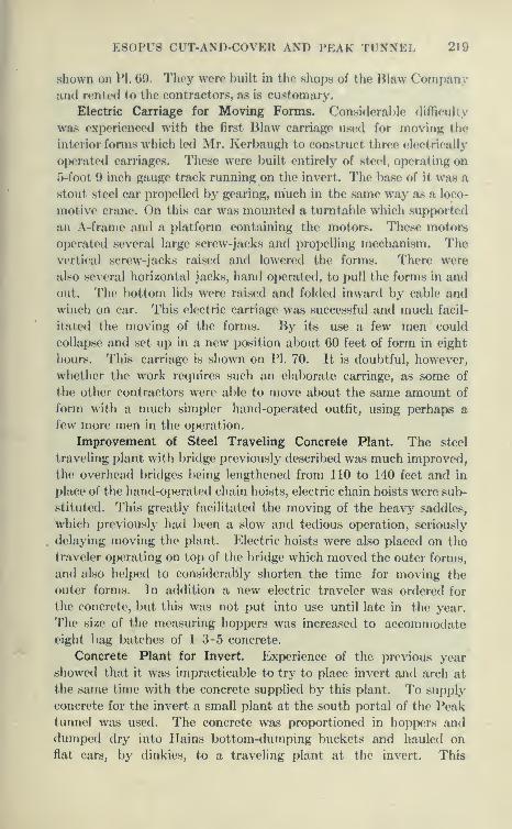
E80PUS CUT-AND-COVER AND PEAK TUNNEL 2l9
shown on 1^1. G9. They were built in the shops of the Blaw Companyand rented to the eontractors, as is customary.
Electric Carriage for Moving Forms. Considerable difficulty
was experienced with the first IMaw carriage used for moving the
interior forms which led Mr. Kerbaugh to construct three electrically
operated carriages. These were built entirely of steel, operating on
o-foot 9 inch gauge track running on the invert. The base of it was a
stout steel car propelled by gearing, much in the same way as a loco-
motive crane. On this car was mounted a turntable which supported
an A-frame and a platform containing the motors. These motors
operated several large screw-jacks and propelling mechanism. Thevertical screw-jacks raised and lowered the forms. There were
also several horizontal jacks, hand operated, to pull the forms in and
out. The bottom lids were raised and folded inward hy cable and
winch on car. This electric carriage was successful and much facil-
itated the moving of the forms. By its use a few men could
collapse and set up in a new position about 60 feet of form in eight
hours. This carriage is shown on PI. 70. It is doubtful, however,
whether the work requires such an elaborate carriage, as some of
the other contractors were able to move about the same amount of
form with a much simpler hand-operated outfit, using perhaps a
few more men in the operation.
Improvement of Steel Traveling Concrete Plant. The steel
traveling plant with bridge previously described was much improved,
the overhead bridges being lengthened from 110 to 140 feet and in
place of the hand-operated chain hoists, electric chain hoists were sul>
stituted. This greatly facilitated the moving of the heavy saddles,
which previously had been a slow and tedious operation, seriously
delaying moving the plant. Electric hoists were also placed on the
traveler operating on top of the bridge which moved the outer forms,
and also helped to considerably shorten the time for moving the
outer forms. In addition a new electric traveler was ordered for
the concrete, but this was not put into use until late in the year.
The size of the measuring hoppers was increased to accommodateeight bag batches of 1-3-5 concrete.
Concrete Plant for Invert. Experience of the previous year
showed that it was impracticable to try to place invert and arch at
the same time with the concrete supplied by this plant. To supply
concrete for the invert a small plant at the south portal of the Peaktunnel was used. The concrete was proportioned in hoppers anddumped dry into Hains bottom-dumping buckets and hauled onflat cars, by dinkies, to a traveling plant at the invert. This
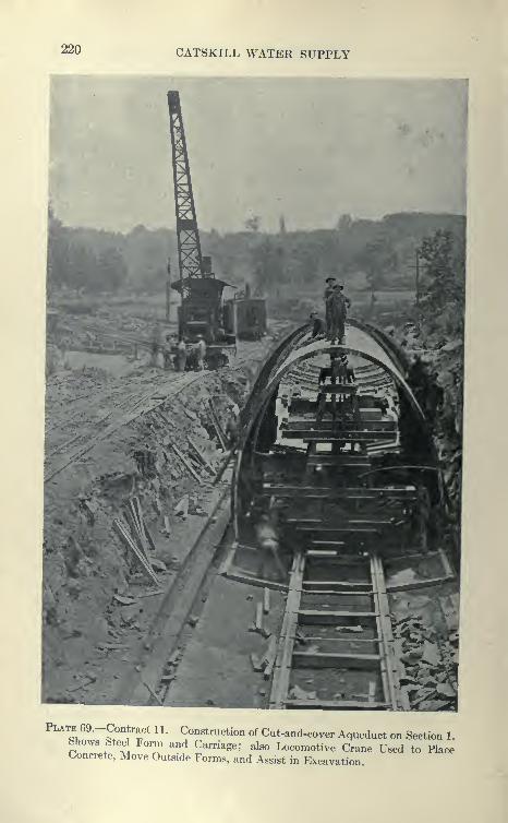
220 CATSKILL WATER SUPPLY
Plate 69.-Contract 11. Construction of Cut-and-cover Aqueduct on Section 1.Shows Steel Form and Carriage; also Locomotive Crane Used to PlaceConcrete, Move Outside Forms, and Assist in Excavation

ES0FU8 CUT-AND-COVER AND PEAK TUNNEL 221
Plate 70.—Contract 11. Electric Carriage for Moving Interior Forms for
Cut-and-cover Aqueduct. Carriage and Upper Jacks are Motor Driven.
Side Jacks and Turntable Hand Driven.

222 CATSKILL WATER SUPPLY
plant was constructed on a platform spanning flat cars, the main
parts being a small derrick and a Smith mixer. The derrick picked
up the buckets, dumping them into the mixer, which in turn emptied
into a chute directly into the invert. The mixing plant operated on a
narrow-gauge track close to the edge of the cut. This plant was
found to be very efficient and readily placed at night 60 feet of
invert.
Operation of Traveling Plant during 191 o. The large traveHng
plant was left free to make arch in the daytime, and at this it was
very successful. Stone from the Peak tunnel was excavated from
the spoil bank by a 20-ton steam shovel loading onto wooden skips
placed on flat cars. Parallel to the trench on the downhill side was
a double narrow-gauge dinky track. The skips were lifted from the
flat cars by a wooden stiff-legged derrick. Cement and sand were
elevated by the electric hoist. As soon as a stretch of 45 or 60
feet of arch had been concreted, which took about eight hours, the
outside forms were moved forward; also the saddles, the plant being
hauled by the dinky engine. During the night the inside forms were
moved, the invert concreted, and everything put into readiness for
the next day's work. The plant maintained a rate of 45 feet of
completed aqueduct per day for forty-one consecutive days, and
60 feet per day for the next five days, without any breakdown or
delay. From May until October the plant concreted about 5400
feet of arch. After reaching Shaft 1 the plant was dismantled andremoved from the work. The Browning locomotive crane was used
to move the saddles upon which the plant traveled and to assist it
in other ways. It also operated a grab bucket for trimming invert.
Comparative Success of Traveling Concrete Plant. The travel-
ing plant described fulfilled its guarantees, as the designer at first
built it only to construct 30 feet of aqueduct per day, and it finally
proved capable of doing 45 and 60 feet, although it was not successful
in building invert at the same time. The contractor expressed
himself as being well pleased with the operation of this plant, althoughhe later developed a method, by the use of stationary mixing plant
and locomotive cranes, of constructing aqueduct more cheaply,
when the heavy first cost of the traveling plant is taken into con-
sideration. This plant probably cost from $30,000 to $40,000,
including the cost of alterations, which had to be charged up to
only 7000 feet of aqueduct.
Excavation of Firm Earth Section by Steam Shovel. Remarkablework was done by a 60-ton steam shovel which excavated the lower
8 feet of cut in advance of the traveling plant. This shovel excavated

ESOPUS CUT-AND-COVER AND PEAK TUNNEL 223
224 CATSKILL WATER SUPPLY
to the close lines of the aqueduct in firm earth, with bottom width
of only 20^ feet with 6 on 1 slopes. The shovel was able to excavate
to close lines on both curves and tangents, leaving its tooth marks
on the firm hardpan in almost exactly the correct lines. All that
remained was a little of the invert to be shoveled into piles excavated
by grab buckets operated by locomotive crane. The shovel loaded
directly in 4-yard dump cars, which were hauled to the uphill side
of the excavation and dumped directly into the embankment over
the completed aqueduct a few hundred feet behind the traveling
plant. This disposed of the excavation in an ideal way, and the con-
tractor was paid for excavation and refill at the same time. Well-
shaped embankments were immediately obtained. This is probably
the longest stretch—about 6000 feet—of firm or compact earth
section on the Catskill aqueduct. The saving is about $10 a foot
over the loose-earth section, type A. In most other localities it was
found difficult to excavate to the close lines of the type B excavation,
the sides not standing up sufficiently well to enable the concrete to
be placed directly against them, so that excavation lines in whole
or in part had to be widened to the maximum section, although by
provisions of the contract payment lines were maintained to the
6 on 1 slope.
Plant North of Peak Tunnel. Entirely new plants were installed
north of the Peak tunnel. At a bluestone quarry adjacent to
the aqueduct a large stationary Champion jaw-crusher plant was
installed. This plant was supposed to be of large capacity, and
was also equipped with sand rolls. While only a moderate amountof crushed stone was needed, this plant met the requirements, but
later it was unable to keep up with the work and a large No. 8
McCully gyratory crusher was installed. The bucket elevator of
this crusher discharged into the screens over the large bins, the
jaw crushers merely taking the rejects. It was early found that the
sand rolls could not stand up to their work, the rolling of the hardblue stone causing frequent breakdowns and heavy repairs. Theordinary crusher dust, however, was used mixed with fine natural
sand obtained from a local sandbank. Near this crusher a large
Hains mixing plant was installed equipped with the usual sand,
stone and cement elevators. In addition, another concrete plantof this character was also installed on Section 1. (See PI. 72.)
Excavation by Steam Shovels. Two 60-ton Marion steam shovelswere installed at the junction of Sections 1 and 2, one working northand the other south, excavating the final cut. The standard boomswere removed from these shovels and special long booms installed.
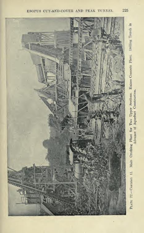
ESOPUS CUT-AND-COVER AND PEAK TUNNEL 225

226 CATSKILL WATER SUPPLY
These, although equipped with 2^-yard buckets, were able to place
material in cars 28 feet from center of shovel and 17 feet above the
rail upon which the shovels ran. They much facilitated the work,
enabling the shovels to dig in one operation trenches which other-
wise would have been excavated in two lifts. These shovels were
able to keep ahead of the concreting and the earth cuts, but with
great difficulty in the rock cuts, even though they worked two or three
shifts.
Power to drive the drills for the rock cuts was obtained from a
long compressed-air line from a plant at the south of Peak tunnel.
Concreting with Locomotive Crane. A double narrow-gauge
track was laid close to the lower side of the aqueduct, and over it
concrete buckets and excavated material were hauled. For con-
creting invert, a locomotive crane was used to swing the buckets
from the cars into the cut, the invert being laid as previously
described.
** Spacing Out " Method of Setting Arch Forms. On a stretch
of completed invert about 380 feet of steel forms were erected,
and after being concreted, one half was used northward on Section
1, and the other half southward on Section 2. These forms were
designed to be used telescoping, but were employed in a different
way, using the ''spacing out" method as follows: Each length
of, say, 180 feet of form, was concreted in three 60-foot sections,
working from the forward end backward, using steel bulkheads to
form the expansion joints at the end of ^ day's work. While the
third section was being concreted, the first 60 feet of forms wasrun ahead 180 feet from its previous position and concreted while
the two following sections would be placed adjacent to it, the third
section of inside form closing the gap and overlapping by a few feet
the concrete arch previously placed. By this method, the forms need
not be telescoped, and therefore do not require much folding in
and out, giving much greater flexibihty. The forms can be movedin the daytime. Although the forms were made very heavy, it wasfound that they still deflected so as to cut into the waterway.This was remedied by the use of pipe braces in the ends of whichwere set hand-operated screw-jacks. On the upper sections electric
carriages for moving forms were employed.
Details of Concreting and Handling Forms. After consider-
able experience on this and other contracts the following practice
in concreting cut-and-cover aqueduct came to be nearly standard.
After the invert was cast the forms were set up carefully on woodensills, so as to give a waterway about f-inch larger all around
ES0PU8 CUT-AND-COVER AND PEAK TUNNEL 227
than the theoretical. After being used, the forms were carefully
cleaned of loose concrete with kerosene and greased with heavy
oils or mixture of crude vaseline or Albany grease with kerosene
or engine oil. In some cases the forms were cleaned with steam
jets, but it was found that a light skim of cement on the forms when
greased gave a good finish. The forms were internally braced to
prevent undue movement while concreting; and inside and outside
forms were tied together securely with taper bolts about three to a
side, on 5-foot centers. To prevent cracking of the adjoining arch
due to rising of the interior form while concreting it was found
necessary to very securely brace the interior form with horizon-
tal timbers where the form overlapped the adjoining concrete
arch. Extra bolts between interior and exterior forms at the
face of the old concrete also helped materially. The concrete (about
1-3-5) was brought up very wet in level layers, 'the depth being kept
nearly the same on both sides of the forms. The concrete was
dumped on top of the arch forms and allowed to flow or was pushed
down the sides. Two or three men were kept between forms on
each side to distribute and spade the concrete; when the concrete
rose about half way they came out and worked from top. The top
of inside form was regreased previously to covering with concrete,
which was then mixed a little dryer to allow the proper shape to be
obtained. Usually upon pulling the form a smooth finish was
obtained, although there was considerable trouble at times with
peeling and sandy streaks. The inside forms were struck by pulling
in the sides and lowering. The bolt-holes in concrete were grouted
by pouring with a thick grout, a httle head being obtained by using
a sort of clay swallow's nest at the outer end of holes. Upon test
these holes were always found to be tight.
The arch was placed in the same manner as the invert, by
the use of locomotive cranes and bottom-dumping buckets, the
cranes being also employed to move the outside forms. TheHains bottom-dumping bucket, although it operated satisfactorily
at the traveling mixing plant in Section 3, previously described,
was found to be very troublesome when used to haul concrete any
considerable distance. The concrete, arching in the bottom of the
conical bucket, refused to come out even when the doors were wide
open. This bucket was replaced by the Steubner bucket, which
gave good satisfaction.
Transmission Line. The 33,000-volt transmission line wasextended to the upper mixing plant and from it the current was
transformed down to 2200 volts to drive the twin Champion crushers
228 CATSKILL WATER SUPPLY
and to 220 volts to drive the other motors of the mixing, crushing
plant, etc.
Failure of Hauling by Traction Engines. Strenuous efforts
were made this season, 1910, to catch up with the required progress,
and no stint was made by the contractor of plant, materials or men.
The roads were improved and several new traction engines installed
to operate trains and haul cement and material. The operation of
the three concrete plants at the same time caused a great demandfor cement which the traction engines hauled to the south portal,
where it was reloaded on narrow-gauge cars and used at the
three plants. Each traction engine was capable of hauling a flat
car of 340 bags of cement. In dry weather they were barely able
to keep up with the work, but on wet days the traction engines hadto be doubled up to negotiate the heavy grades, although the road
was well macadamized between High Falls and the Peak. Thetraction engines were continually ditching themselves in wet weather
and tearing up sections of the best road, making heavy repairing
necessary. The engines themselves were also constantly breaking
down, keeping a large machine shop at Atwood going under high
pressure and at very heavy expense. By the middle of the summerit became manifest that it would be impossible to keep the workgoing by the use of traction engines.
Construction of Connecting Railroad from High Falls. Thecontractor secured the rights of way for a narrow-gauge railroad
from the High Falls yard to the south portal of the Peak tunnel,
a distance of 4^ miles. To secure this right of way it was necessary
for him to buy several farms outright, and the rights were very costly.
Great speed was made in the laying of this road, 4| miles of track
being graded and made ready for the trains in three weeks. Theexpense of building this road justified itself, as thereafter it waseasy to supply the work with cement, coal, and other materials,
the road taking the place of nine traction engines and about all
the teams which could be hired in the neighborhood. It would seemfrom the experience that it would have paid the contractor to
have laid at the beginning of the work the tracks connecting theO. & W. R. R. with all parts of the aqueduct line.
Standard- vs. Narrow-gauge Tracks. The contractor's superin-tendent is also of opinion that a standard-gauge track would havebeen far preferable to the narrow-gauge road, as the expense of
unloading and transferring to the narrow-gauge cars would havebeen saved. In addition, the expense also of considerable numberof small cars could have been saved, as cement and coal cars of the
ESOPUS CUT-AND-COVER AND PEAK TUNNEL 229
railroad could have been directly used. The steam shovels and
locomotive cranes could have been taken at much less expense to the
work over a standard-gauge track, and also from place to place on
tlie work. It was often necessary, in taking a shovel from one part
of the work, to another; to lay tracks over rough ground to the nearest
road, jack up the shovel, place flat wheels under it, and haul it by
several traction engines to a point near the acjueduct, and again lay
a track up steep hills to get the shovel to its next working position.
Standard-gauge locomotives are much more efficient than narrow-
gauge, as also are standard-gauge cars of all types. It is estimated
tliat a single standard-gauge track alongside the cut with proper
switches could have taken the place of the double-track narrow-
gauge line used. It was found that locomotive cranes were not
stable on narrow-gauge tracks, and it was necessarj^ to lay a third
rail and intermediate ties to make a standard track for them to
operate on. This would have also been saved by a standard-gauge
track in the first instance. Standard-gauge equipment is also more
salable and far more readily transferred from one job to another.
Excavating Rock Cuts during 191 o. During this season it was
found that the steam shovels could not keep ahead of the invert
where rock was encountered, although every effort was made.
The rock where suitable was sent to the crushing plant and used for
concrete; otherwise it was either spoiled or used over the aqueduct.
This caused a deficit of embankment material, and it was necessary
to place shovels in borrow pits to furnish embankments for the
required line. When a suitable borrow pit was obtained and track
connections made embankments could be made very rapidly at a
low cost, so that it paid to keep the shovels well in advance, rather
than to delay the work, even though considerable material had to
be spoiled.
Excavation of Rock Cut at Atwood. During the winter of 1910-
11, the steam shovel was kept at work on a deep rock cut at AtwoodCliff, excavating it to subgrade in several Hfts. A large quantity
of this rock after being crushed was stored in a large stock pile.
As the contract contained provision for advance payment on crushed
stone of 80 cents per yard, this work not only paid for itself, but was
an immense help in the following year's work, which would otherwise
have been seriously delayed by this deep cut. A great deal of material
excavated in this work was used in forming a high berm or fill at
8 feet above invert level. Upon this was laid a double narrow-gauge
track. Invert and aqueduct through this stretch was thus con-
structed rapidly in the usual manner; otherwise it would have

230 CATSKILL WATER SUPPLY
had to be constructed in through cut from one end, which is slow
and expensive.
Progress During 1910. During the season of 1910 there were
constructed on the three sections a total of 16,710 feet of aqueduct,
bringing the work up to contract requirements. Nevertheless, the
contractor was dissatisfied with the progress as compared with the
expense.
Work above Tongore Creek. Above Tongore Creek was a
stretch of 2973 feet of aqueduct cut off from the rest by a deep
gorge. Nothing had been done on this stretch except to exca-
vate and store topsoil, and it was given over to the firm of
Cinedella & Gardetto, who installed a small central crushing and
Smith mixing plant. The crushing plant was supplied with stone from
a near-by quarry and from walls. The first excavation at the south
exposed a great deal of sand which was stored and used throughout
the contract. The contractor aimed to do the excavation by a
very economical method, thinking that the amount did not warrant
the use of steam shovels. Though an efficient force of laborers was
employed, it was found that they could not load the skips and buckets
fast enough to enable even 15 feet of aqueduct to be completed per
day. A large traveUng derrick and a locomotive crane were employed
to remove and raise skips and to operate an orange-peel bucket,
which in hardpan could make but slow progress. A narrow-
gauge track paralleled the trench, and backfill was hauled over the
aqueduct. Bottom-dumping concrete buckets were used for invert
and arch, handled by the locomotive crane, which dumped the con-
crete by use of a second fall line. Buckets were Cockburn auto-
matic self-dumping. Flat cars were pushed by hand or hauled by
horses.
Ransome Steel Forms. Ransome steel forms were used. These
are built much as the Blaw forms, with three pin joints, but with 7^
feet square-end panels requiring the use of wooden fillers to pass
curves. Plates of these forms were | inch stiffened by 5 inch I-beams
bent to the curve of aqueduct. The interior forms were moved bya wooden carriage operated by a hand windlass which rotated side
leaves, collapsing or raising the forms, the windlass being connected to
chains geared to the axle. Although the carriage gave considerable
trouble at the start it worked fairly well later on, but apparently
not as well as the positively operated carriage with screw-jacks
commonly used elsewhere.
Hand Labor Inadequate. Installation of Steam ShoveL Thework of the first season made it clear that hand labor alone could

E80PU8 CUT-AND-COVER AND PEAK TUNNEL 231
not be relied upon to excavate the trench in advance of the invert,
except at a ruinous cost or at a very slow rate. A small Vulcan
shovel was obtained for the trench and operated during the last
season. This shovel excavated and loaded into cars which were
run back and dumped over the aqueduct. Concrete brought
from the mixer over a narrow-gauge track was placed by the locomo-
tive crane which dumped the Cockbum automatic bucket. Anaverage rate of 15 feet per day was regularly made with a very
economical organization, about 90 men being employed for one
8-hour shift. All excavation was in hardpan with no rock except
boulders.
Work Accomplished during 1910. On Section 1 during 1910
a determined effort was made to reach Tongore Creek, which would
enable the upper mixing plant to be dispensed with. Night shifts
were put on and 75-foot sections of arch attempted. Nevertheless,
at the end of the season there remained 3176 feet of aqueduct
trench incomplete, the shovel having been retarded by a heavy
rock cut and even more by a few feet of hard bluestone overlaid
by wet ground. Serious inconvenience was also caused in wet
ground by attempting to build the culverts in the rear instead of
ahead of the shovel. This prevented free drainage, which was
otherwise secured by laying wooden box drains below the invert
and leading them to holes in sides of completed culverts. It was
found that when a few feet of hard rock was overlaid by earth muchbetter work could be done by stripping the rock with steam shovel,
backing the shovel to the completed trench, setting up drills and
blasting in advance of the shovel, which removed the rock to sub-
grade, loading into dump cars which ran to crusher or dump.Preparations during Winter of 1910-11. During the winter
of 1910-11 two steam shovels were kept busy on Section 2 exca-
vating several thousand feet of rock trench to subgrade. The rock
of the first shovel was either wasted or used to make embankments;
that from the second shovel on the deep Atwood Cliff was crushed as
previously described. Where necessary the downhill side between
Peak tunnel and Atwood was built out by material from the shovel
to carry a double narrow-gauge track, the track rock-ballasted
and put in first class shape f(3r the next season's work.
Rearrangement of Hains Mixer Plant. The Hains mixer plant
at the crusher was moved southward 1^ miles to a more convenient
side-hill site. Stone and sand bins were constructed to feed into a
bucket elevator. It was found during the previous year that delays
ensued because only one bucket elevator was installed, making it
232 CATSKILL WATER SUPPLY
necessary to empty the stone bin before raising sand or vice versa.
This deficiency was remedied by estabhshing a stock pile of sand
within reach of a derrick, operating a grab bucket with long enough
boom to reach the sand bin. Sand, during 1911, was hauled from
a pit near the new branch fine laid to High Falls and brought in at
night in sufficient quantities to be stored at the mixer for the next
day's use. The previous year the lack of sufficient sand of good
quality was greatly felt, although a long siding was laid to a sand
pit at Atwood.
Opening of New Quarry. A new quarry was developed uphill
from the aqueduct and an independent track laid to it from the
crusher. This quarry together v ith the s ock pi furn hed sufficient
stone to carry on the work at a high rate. During the previous year it
was difficult to keep at hand a sufficient supply of crushed stone. The
quarry adjacent to crusher being exhausted, the contractor was forced
to gather up stone walls at great expense. The new quarry developed
a fine face of good bluestone, which after being drilled and shot was
loaded into side dump cars by a 60-ton steam shovel. The cars
were hauled to the McCully No. 8 crusher. The Ingersoll-Rand
drills used were operated by steam. The quarry was called upon
to supply about 700 yards of broken stone per day during the sum-
mer of 1911, but was not quite able to keep this up, so that the stock
pile accumulated during the winter was drawn upon and used up
just as the demand lessened.
Efficiency of New Mixer Plant. The new mixer plant at Station
305 proved to be very efficient, largely through the convenient lay-
out of tracks leading to and from it, and to the abundance of con-
crete material supplied. This layout is shown on PI. 73. Cementwas shifted at High Falls to the narrow-gauge cement cars, hauled
by dinkies to a shed at the mixer, and elevat d to the mixer platform
by a belt conveyor, most of the cement being directly fed from the
cars to a chute supplying the elevator.
Aqueduct on Longitudinal Walls. The shovel after passing
Atwood cliff working toward Peak tunnel was able to keep ahead
of invert laying without trouble. At the south end of Atwoodcliff a large culvert was built at Davis gully. It was originally
intended to build the aqueduct on embankment, but this was thought
objectionable owing to the difficulty of properly rolling the layers
in such a rough place. At another similar situation an embankmentwas puddled by casting glacial drift, mostly clay, into water dammedup so as to be only a few inches deep. This made an impervious
embankment, but unfortunately was found to be still soft and
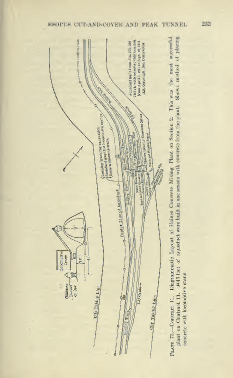
ES0PU8 CUT-AND-COVEK ANlJ PEAK TUNNEL 233

234 CATSKILL WATER SUPPLY
quaking the following year. In this instance, three walls and, in the
Davis gully case, two longitudinal walls, were carried down to hard
ground, and filled between with good material which was shaped up
as a form for longitudinal arches for the invert springing between them
and deposited in the usual manner in 15-foot alternate blocks. Upon
the invert arches the main aqueduct was built, there then being no
fear of settlement. In this manner three of the four embankments
were eliminated. The only considerable foundation embankment
built on Contract 11 was that at Station 274 (Hendricks Killitje)
which was carefully built to a maximum height of about 16 feet
(length 900 feet) with material carefully rolled in 3-inch layers.
Although very carefully tested no settlement nor cracking of
masonry was detected, showing that by careful work embankments
can be safely! built upon, although they are always a source of
anxiety.
Record Progress during 191 1. During the season of 1911
only one shift was worked on concreting and excavation, the
only night work being the hauling of sand to the mixer and the
moving of outside forms. Nevertheless, far greater progress was
made than in 1910, when night shifts were in vogue. This was
made possible by having a long stretch of excavation completed, a
better sand pit, better quarry and trackage, and last, but not least,
a better organization. This was accomplished by so systematizing
the work that it repeated itself every day. On account of the change
of method of laying invert, doing away with key blocks and sub-
stituting steel plates, the invert could be laid much faster than in
previous seasons, seven blocks, 105 feet, being commonly laid in one
shift, while at the same time 60 feet of arch were placed. The dinky
train hauled from the mixer six bottom-dump Steubner buckets with
eight bag batches (1.5 cubic yards). These were raised over the arch
forms by two locomotive cranes. Browning and Bay City, and dumpedby men on the forms, rammed and leveled by others between the
inside and outside forms, very wet concrete being used. A 60-foot
section of about 240 yards was usually placed in about five hours.
The invert concrete was deposited in a similar fashion by a locomotive
crane. The invert, gaining 15 to 45 feet per day on the arch, soonnearly reached its limit at the Peak tunnel. After the forms onSection 1 were freed, they were set up so that two sections of arch
could be concreted in one day. On Section 2 the best day's workwas two sections of arch (a 60-foot and 45-foot section, 105 feet total)
and 45 feet of invert, totaling 470 cubic yards of concrete, whichwas hauled an average distance of over J mile from the Hains mixing
E80PU8 CUT-AND-COVER AND PEAK TUNNEL 235
plant. During one week the plant built 690 feet of arch and 180
feet of invert (about 3000 cubic yards). Between May 20th and
Aug. 29th inclusive, 6378 feet of arch and 6925 feet of invert were
concreted, the best season's work of any cut-and-cover plant on
the Catskill Aqueduct.
Completion of Section 1. On Section 1 the remaining 3000 feet
south of Tongore Creek was completed without particular difficulty
in the season of 1911. After waiting until the bottom had dried
out as much as could be expected, the long boom shovel was
started up, the cut being carefully drained by box drains laid to
the completed culverts or trenches previously dug for culverts.
The Hains mixing plant was started and a uniform progress of 45
feet per day at first and later 60 feet per day was made until Section
1 was completed, the excavation being sent back over the uphill
track and dumped over completed concrete arch to form embank-
ment. The forms were then sent back to Section 2, and the shovel
placed in a borrow pit to finish excavation for embankment.
Summary of Work on Contract 11. The construction of Con-
tract 11 is here given in considerable detail, because it passed through
very interesting stages and much experimental work was done
before an economical method was developed. To summarize:
First, to save costly fuel transportation, all machinery—compres-
sors, etc.—as far as practicable, were operated by electricity, a special
transmission line being built along the aqueduct line. Second,
compressed air was used to a large extent to furnish power for drilling
the Peak tunnel; to operate miscellaneous machinery, such as
derricks, pumps, etc. ; to operate steam shovels and to drill the rock
in open cut along several miles of aqueduct trench. Third, traction
engines being found inadequate, a narrow-gauge connection to the
Ontario & Western Railroad was built. Had the connection been
made the first season much time and money would have been saved,
and still more if the connection had been of standard gauge with
standard-gauge equipment th.'oughout.
Efficiency of Steam Shovels. For excavation, the steam shovel,
Model 60, particularly when equipped with a long boom, was found
to be the ideal tool and fully able to keep ahead of concreting in
earth cuts, though it required a long start and winter work for the
rock cuts, necessitating the spoiling of excavated material to be
made good later from borrow pits.
Blaw Forms. For concreting, the steel forms as later made bythe Blaw Company were satisfactory and gave good results whensupplemented by pipe braces. The electric carriage for moving
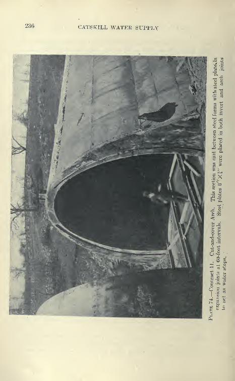
236 CATSKILL WATER SUPPLY
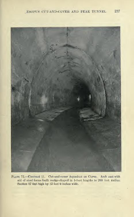
E80PUS CUT-AND-COVER AND PEAK TUNNEL 237
Plate 75.—Contract 11. Cut-and-cover Aqueduct on Curve. Arch cast with
aid of steel forms built wedge-shaped in 5-foot lengths to 200 feet radius.
Section 17 feet high by 17 feet 6 inches wide.
238 CATSKILL WATER SUPPLY
inside forms was entirely satsifactory but somewhat expensive in
first cost.
Efficiency of Locomotive Cranes. The locomotive crane wasfound to be an invaluable tool for moving outside forms, placing
concrete and doing miscellaneous work. At first a small second-
hand Browning hoist was installed and later two double-truck
Bay City, and two double-truck Browning hoists. The double-
truck hoist was found to be the most efficient. It may be said
that an entirely satsifactory and probably the best aqueduct-
building plant can be built around the locomotive crane, the problem
being to excavate ahead of it, furnish it a track to run upon, andkeep it supplied with concrete, and let the crane do the rest. It
can excavate with the aid of drag-line scrapers and orange-peel or
clam-shell buckets, place concrete, move outside forms, etc., but
the best adjunct to it is a long-boom steam shovel and a good sta-
tionary mixing plant, dinkies, cars, etc.
Applications of Cut-and-cover Methods to other Work. The
method best adapted to aqueduct construction as apphed to this
and other cut-and-cover contracts is also of wide apphcation, as
demonstrated by the very successful application of practically the
same methods to a section of subway constructed on Fourth Avenue
in Brooklyn. The pipes and sewers in this street, a wide thorough-
fare, were first laid to one side and the street provided with plank
roadways on each side supported by piles. The bulk of the excava-
tion was then removed by a steam shovel, which loaded cars hauled
in trains which were dumped in scows at a convenient point of a
neighboring canal.
A stationary mixing plant was constructed below ground, the
bins being filled by dumping from the street above. B ottom-
dumping concrete buckets were loaded in the cut below directly
from a rotary mixer, and hauled in trains to a locomotive crane
operating in the cut, which dumped the cars over steel forms.
The forms were furnished by the Blaw Company, and operated in
carriages somewhat as the cut-and-cover aqueduct forms. Thesection was of reinforced concrete, and all four tracks were cast at
once, in lengths of about 30 feet. Very rapid progress was madeand the work was economically done by the method outlined
above.
A stationary mixing plant and locomotive crane for general use
and concreting were very successfully used in a similar mannerat a long drydock in the Brooklyn Navy Yard, by Holbrook,
Cabot & Rollins.
E80PUS CUT-AND-COVER AND PEAK TUNNEL 239
In placing the foundation of the Adams Express buildings the
work was laid out so that two locomotive cranes served a large
number of compressed-air caissons doing a great deal of miscel-
laneous work, removing excavation, placing concrete, etc., and
dispensing with all the usual derricks at a considerable saving.
Efficiency of Hains Mixer. The Hains mixing plant performed
the service it was called upon to do and was able to mix good con-
crete, but some difficulty was experienced when rather dry concrete
was attempted. It requires greater skill and experience for opera-
tion than ordinary rotary mixers, but when a gang is thoroughly
broken in to the work, it excels any mixer in speed and capacity.
It is probable that its first cost and operation are more expensive
than the ordinary rotary mixer (such as Smith or Ransome) where
used to furnish the amount of concrete ordinarily used on aqueduct
work. The fiains mixer requires rather heavy timbering, owing
to the height necessary to obtain the gravity mix through the conical
hoppers; also to get the best speed requires separate sand, stone and
cement elevators. A stationary rotary mixer plant with overhead
bins is much lower, requires much less framing and can be supplied
with concrete material by elevators or derricks and is, therefore,
more readily taken down and transported from place to place. TheHains mixer is said to work better with gravel than broken
stone.
The advantage of the Hains mixer is that it mixes easily from
50 to 75 yards of concrete per hour, and is economical for any-
thing over 400 yards per day of eight hours. It required about
22 men for its operation on Contract 11, where it was necessary
to mix to its capacity, requiring a large amount of rolling
stock, etc.
Repair Plant and Machine Shop. From the beginning of the
work a large and well-eciuipped machine and carpenter shop was
operated at Atwood, which was later connected with the contractor's
tracks. This shop proved to be a good investment and did muchto keep the work going smoothly, saving breakdowns, etc., and
accounts in a large measure for the fine record of uninterrupted work
on this contract. It was electrically operated and supplied with
compressed air from the tunnel plant which was used for a large
steam hammer and for other purposes.
Rock Trenches. It was found very difficult to excavate the
surface rock to the lines of the minimum rock section (21 feet wide,
6 on 1 slope). Although carefully drilled to within the line, the pow-
der worked along numerous seams and heads, widening the trench
240 CATSKILL WATER SUPPLY
in an irregular way. In some case after the shovel passed, the sides
had to be pulled down to prevent falls. Later this was prevented
by allowing the shovel in the final cut to tear down all loose
rock.
Payment Lines in Rock. Nothing in the contract prevents the
board from widening payment lines, so that the contractors were
partly compensated for the wide breakage. However, even so,
a considerable saving to the city was effected over the maximumsection in rocks which otherwise would be paid for if no attempt
to excavate economically were made. The excavation of the rock
trenches was carefully watched, as the depositing of concrete invert
and sides against shattered rock is liable to cause leakage when
the aqueduct is full. Nothing short of channeUng, which is entirely
too slow and expensive, and not contemplated by the contract, can
be expected to give good rock sides. It is probable that if the work
were to be done over again a modified rock section would be advisable,
somewhat narrower at the base than the loose earth section, but
with the same waterway. The trench could then be blown out with
no concern as to the sides, and the aqueduct constructed between
inside and outside forms as in loose earth. This is also true of the
firm earth section (Tj^pe B) which was not practicable to nearly
the extent first thought. The invert in rock was usually deposited
on rock spalls or debris. To prevent leakage an occasional block
was cleaned out to firm rock and concreted. This was done at each
side of culverts to prevent leakage into them.
Testing of Aqueduct in Sections. At the suggestion of one of
the department engineers (Mr. Ridgway) a provision was inserted
in Contract 11, and all subsequent cut-and-cover contracts, requir-
ing the testing, under regular items, of sections of aqueduct during
construction. Stretches of from 200 to 400 feet were bulkheaded
off at specified points and filled with water and the leakage observed
by measurements of the water surface. Careful examination wasalso made of leaking joints, etc. In some cases, slight repairs were
made, such as caulking or grouting leaking joints and new tests then
made. This gave invaluable information and kept the contractor
and engineers on their mettle, resulting in improvements in construc-
tion, particularly the discarding of the concrete tongue-and-groove
expansion joint and key blocks and the substitution of the steel
plate joint.
Grouting of Joints of Cut-and-cover Aqueduct. The. hydro-static tests made on various contracts showed that both the con-
crete key and steel plate expansion joints were liable to leakage, due
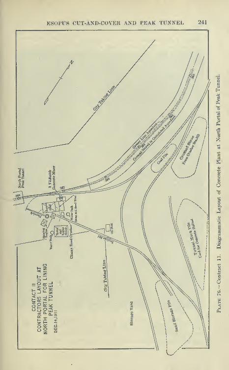
ESOPUS CUT-AND-COVER AND PEAK TUNNEL 241
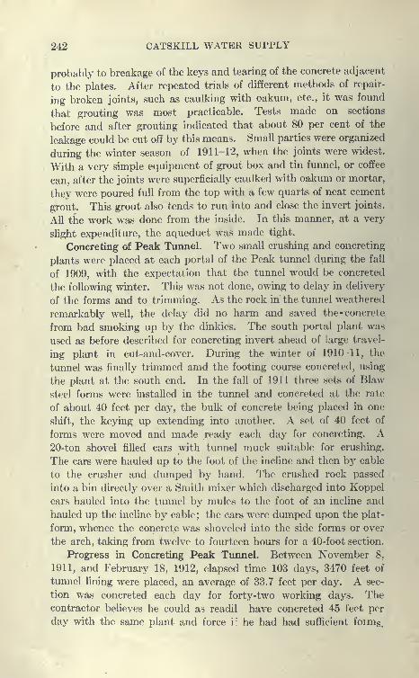
242 CATSKILL WATER SUPPLY
probably to breakage of the keys and tearing of the concrete adjacent
to the plates. After repeated trials of different methods of repair-
ing broken joints, such as caulking with oakum, etc., it was found
that grouting was most practicable. Tests made on sections
before and after grouting indicated that about 80 per cent of the
leakage could be cut off by this means. Small parties were organized
during the winter season of 1911-12, when the joints were widest.
With a very simple equipment of grout box and tin funnel, or coffee
can, after the joints were superficially caulked with oakum or mortar,
they were poured full from the top with a few quarts of neat cement
grout. This grout also tends to run into and close the invert joints.
All the work was done from the inside. In this manner, at a very
slight expenditure, the aqueduct was made tight.
Concreting of Peak Tunnel. Two small crushing and concreting
plants were placed at each portal of the Peak tunnel during the fall
of 1909, with the expectation that the tunnel would be concreted
the following winter. This was not done, owing to delay in delivery
of the forms and to trimming. As the rock in the tunnel weathered
remarkably well, the delay did no harm and saved the -concrete
from bad smoking up by the dinkies. The south portal plant was
used as before described for concreting invert ahead of large travel-
ing plant in cut-and-cover. During the winter of 1910-11, the
tunnel was finally trimmed amd the footing course concreted, using
the plant at the south end. In the fall of 1911 three sets of Blaw
steel forms were installed in the tunnel and concreted at the rate
of about 40 feet per day, the bulk of concrete being placed in one
shift, the keying up extending into another. A set of 40 feet of
forms were moved and made ready each day for concreting. A20-ton shovel filled cars with tunnel muck suitable for crushing.
The cars were hauled up to the foot of the incline and then by cable
to the crusher and dumped by hand. The crushed rock passed
into a bin directly over a Smith mixer which discharged into Koppel
cars hauled into the tunnel by mules to the foot of an incline and
hauled up the incline by cable; the cars were dumped upon the plat-
form, whence the concrete was shoveled into the side forms or over
the arch, taking from twelve to fourteen hours for a 40-foot section.
Progress in Concreting Peak Tunnel. Between November 8,
1911, and February 18, 1912, elapsed time 103 days, 3470 feet of
tunnel fining were placed, an average of 33.7 feet per day. A sec-
tion was concreted each day for forty-two working days. Thecontractor believes he could as readil have concreted 45 feet per
day with the same plant and force i" he had had sufficient forms.

ESOPUS CUT-AND-COVER AND PEAK TUNNEL 243
Plate 77.—Peak Tunnel Fully Excavated and Honriy lor v oncrete Lining.
Footing Courses are in Place. Center Track for Hauling Material, to
Upper Portion of Contract IL Tunnel is 3450 feet long on tangent.
244 CATSKILL WATER SUPPLY
The invert was concreted by the method firs u ed for the south
half of Bonticou tunnel. One half of The invert (about 7 feet) was
defined by a longitudinal strip and transverse strip every 15 feet to
define the grade and to guide the surface screeding. Concrete
was delivered over a track placed on the other half and dumpeddirectly into place. Great speed was made by this method, the
whole 3360 feet of 14-foot invert 5 inches thick being placed in six-
teen days, as much as 915 feet of half invert being made in one day.
It is believed that the progress made in concreting the Peak
tunnel is about the best of any. grade tunnel on the aqueduct.
It was due to the lessons learned from previous tunnels and to
the admirable organization of the work, and also to the fact that
all the trimming had been completed after laying footing courses
previous to the placing of arch forms.
Later in lining Garrison tunnel, Contract 2, in 1913, muchgreater progress was made from a single concrete plant at a central
shaft.
CHAPTER VIII
RONDOUT PRESSURE TUNNEL AND NORTH HALF BONTICOUGRADE TUNNEL
Contract 12
General Description of Contract 12. This contract was let in
June, 1908, to the T. A. Gillespie Company, and comprised a short
stretch of cut-and-cover adjacent to Contract 11, 4^ miles of pres-
sure tunnel under Rondout Creek near High Falls, and 3340 feet
of Bonticou grade tunnel. This contract totaled $6,290,803,
being the largest aqueduct contract and the one on which, up to the
present time, the most difficult work was accomplished. The tunnel
was constructed from eight shafts, varying in depth from 370 to 708
feet. The shafts and tunnel penetrated material varying in hardness
from shale to millstone grit. Some strata were found to be dry,
others porous and water bearing, besides containing quantities of
irritating sulphur gas. Very numerous borings, made previous to the
letting of the contract, and elaborate porosity and pumping tests
made on these same holes, gave pretty definite information as to the
difficulties which would be encountered. It was aimed to have the
aqueduct completed between Ashokan Reservoir and Croton Lake
by the time a portion of the reservoir would be ready to impound
water, and as the Rondout siphon was considered the most difficult
piece of work, the contract called for its completion in fifty-four
months.
Preliminary Investigations. During the advertising of the con-
tract, all information ol)tained by })orings and pumping' tests wasshown to intending bidders, so that the work could l)e bid on with afull realization of the difficulties to be encountered. On their face
the prices obtained by the contractor, although he was the lowest
bidder, may seem high, but taking into consideration that this wasthe first siphon to be constructed and the known difficulties to be
encountered, they are probably fair. The following description
will show that the contractor spared no expense and pains to makethis work successful, supplying the work with the best machinery
245

246 CATSKILL WATER SUPPLY
CO ca
S«io noonnog f g,«

RONDOUT PRESSURE TUNNEL 247
and plant which could he obtained, and manning it with experi-
enced and capal)le superintendents and skilled workmen.
Unusual Pumping Provisions. Contract 12 contains special
provisions under Items 10, 14 and 15 which it is of interest to note
here. As the Ilondout siphon was the first pressure tunnel and the
indications from borings and geological investigations were that
Plate 79.—Spouting Diamond-drill Hole over Tunnel. This hole ceased to
flow when tunnel was driven below. Flow renewed when lining was
grouted.
quantities of water were likely to be met with in certain formations,
special provisions were inserted with the object of eliminating as
far as practicable some of the risks involved in this kind of work,
or, to put it differently, the City undertook to help the contractor
finance the work by paying separately for the pumping plant under
Item 14, and also for the actual pumpage of water from the shafts.
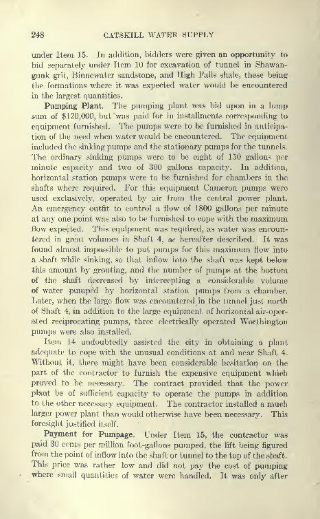
248 CATSKILL WATER SUPPLY
under Item 15. In addition, bidders were given ^n opportunity to
bid separately under Item 10 for excavation of tunnel in Shawan-
gunk grit, Binnewater sandstone, and High Falls shale, these being
the formations where it was expected water would be encountered
in the largest quantities.
Pumping Plant. The pumping plant was bid upon in a lump
sum of $120,000, but was paid for in installments corresponding to
equipment furnished. The pumps were to be furnished in anticipa-
tion of the need when water would be encountered. The equipment
included the sinking pumps and the stationary pumps for the tunnels.
The ordinary sinking pumps were to be eight of 150 gallons per
minute capacity and two of 300 gallons capacity. In addition,
horizontal station pumps were to be furnished for chambers in the
shafts where required. For this equipment Cameron pumps were
used exclusively, operated by air from the central power plant.
An emergency outfit to control a flow of 1800 gallons per minute
at any one point was also to be furnished to cope with the maximumflow expected. This equipment was required, as water was encoun-
tered in great volumes in Shaft 4, as hereafter described. It wasfound almost impossible to put pumps for this maximum flow into
a shaft while sinking, so that inflow into the shaft was kept below
this amount by grouting, and the number of pumps at the bottomof the shaft decreased by intercepting a considerable volumeof water pumped by horizontal station pumps from a chamber.
Later, when the large flow was encountered in the tunnel just north
of Shaft 4, in addition to the large equipment of horizontal air-oper-
ated reciprocating pumps, three electrically operated Worthington
pumps were also installed.
Item 14 undoubtedly assisted the city in obtaining a plant
adequate to cope with the unusual conditions at and near Shaft 4.
Without it, there might have been considerable hesitation on the
part of the contractor to furnish the expensive equipment whichproved to be necessary. The contract provided that the powerplant be of sufficient capacity to operate the pumps in addition
to the other necessary equipment. The contractor installed a muchlarger power plant than would otherwise have been necessary. This
foresight justified itself.
Payment for Pumpage. Under Item 15, the contractor waspaid 30 cents per million foot-gallons pumped, the lift being figured
from the point of inflow into the shaft or tunnel to the top of the shaft.
This price was rather low and did not pay the cost of pumpingwhere small quantities of water were handled. It was only after
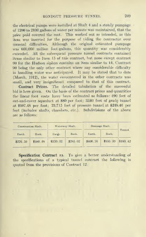
RONDOUT PRESSURE TUNNEL 240
the electrical pumps were installed at Shaft 4 and a steady pinnpaKe
of 1200 to 2100 gallons of water per minute was maintained, that the
price paid covered the cost. This worked out as intended, a.s this
item was inserted for the purpose of tiding the contractor over
unusual difhculties. Although the original estimated pumpage
was 600,000 million foot-gallons, this quantity was considerably
exceederl. All the subseciuent pressure tunnel contracts contained
items similar to Item 15 of this contract, but none except contract
90 for the Hudson siphon contains an item similar to 14, Contract
90 being the only other contract where any considerable difficulty
in handling water was anticipated. It may be stated that to date
(March, 1912), the water encountered in the other contracts was
small, and very insignificant compared to that of this contract.
Contract Prices. The detailed tabulation of the successful
})id is here given. On the basis of the contract prices and quantities
the linear foot costs have been estimated as follows: 490 feet of
cut-and-cover aqueduct at S80 per foot; 3340 feet of grad§ tunnel
at $107.48 per foot; 23,715 feet of pressure tunnel at $248.46 per
foot (includes shafts, chambers, etc.). Subdivisions of the above
are as follows:
Construction Shaft. Waterway Shaft. Drainage Shaft.
Earth. Rock. Eartfi. Rock. Earth. Rock.
Tunnel.
$276.59 $380.48 $350.32 $285.02 $400.76 $335.39 $180.42
Specification Contract 12. To give a better understanding of
the specifications of a typical tunnel contract the following is
quoted from the provisions of Contract 12.

250 CATSKILL WATER SUPPLY
O
o
Hl-H
o
o
w.
p^
Caom
888888 88 888 88888o o o oo o »o olO O t^ 00 00 oc
8888»0 O CO 05
K" »o' eo' rH o '^" o" r-T --T o" bf of ci o"
©^ (M lO C^ rt^ O T-H
in"
"<^ CO Tt lO or-t 0> T-l 00
88888 888888^3O O O CI olO lO >0 rH lO(N CO CO (N
O O lO O»o o or u:»i-H t^ lO i-t
o o oo: CO OlO t^ o
BSSSB00 00 * O 00
Oi >0 OO 05 ot^ r^ Tt< CO uo
^ S ^>> « >.
.2 - • ^ ,« wIS 4^ IS
oo
T3 73
o
WW- ^ -J-
S.sS 73
73 '^
f^ .S
c3 O
^- o
G i= C
o3 M C=« ^%§ G ^
•+-J TJ .y
§ =^ ^
2
.5 03 flM
oa E • rf^ bC -*^ oC-d 03 ^ .
=3 -r --
>i ««o3 T3 O
t-i o3 o3
O) . >03 (S c
C a> *^
-^.s «»-
o ^
tn
so
S i=
C c
73 -^
3-5
:: s G ci
-S-oJ a G-«> S bc ^"^ CO C
.- G^
.2 ^ ^^|.S § ^^ bC C S" I G -iS y « g
33 02 c
fe^ 3 G S ^
br ^ .2 ^ «^ .5
ijf;o bC
''^
<S bC.^ 03oj j3
03 !L,
+i ^03 bC
^.S0;SbC ^C OJ
G3 m 3
2^ 23 02 D.
w .3? G
bC G -_G O -
'3 o3
- a
-2.
JH u "^ G -Sfc, a; C G o33 sX O 3 sj
uo
rH C<1 CC ""^l »0 CO l>OCOiO'-H(MCO'*tiO'X> l>OOOiO^rtT_|fHrH,-lr-l,-t r-4,-tr-l<N(M
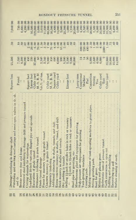
RONDOIJT TRESSURE TUNNEL 251
8 888888888gSgg8g88888SS888gSg?8S|
« ^'" ro 2^\iS ifi ^ oT o" -^^ 00 eo «f »-«" ^^ p >o <<t cc »o cT cf or' o o cc r>.' o »o
^ 2g^8888SS888888^S^ 888S88888J355g M ^ M «d Q -*
2 2 2 2 <5 Q 2 Q o o o Q o o Q o Q o o
lei: §:s
1 1
3 5 5 O CC 3 3
lis -2^
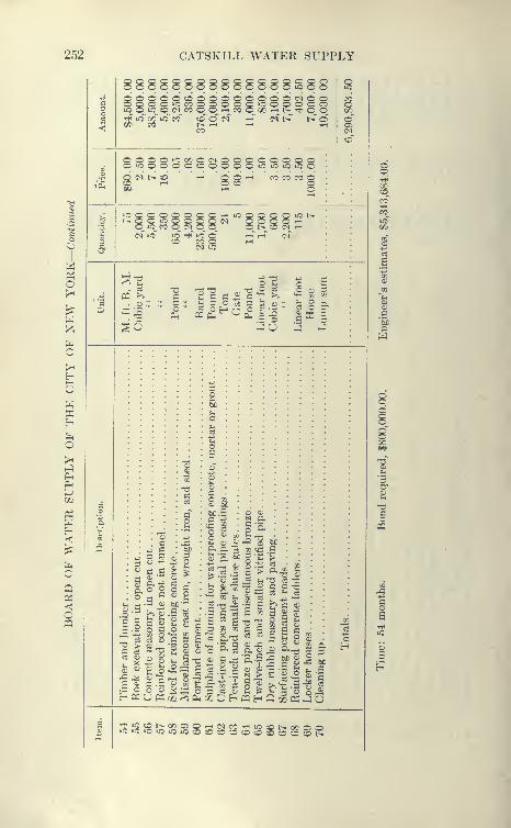
252 CATSKILL WATER SUPPLY
oooooooooooooo»coo iC
"v p. ^^ ^- "^^ "^ p.Tt<" ic cc ic co" ccT o" c<r€^ CO t^ T-H
CO
C^l o o- _ _ o o o
00 i-H l^ Tti o o
O <M 1> OCO rH ^ 8§^ CO CO CO O
o o o »c t^
0_ iO_ CO C_ C<1^
CO CO O
s5
? lie:: p z b = o
TJ J I
ph s-e
oO Ci
03 O
h^ H-;
Gc
_ 3 3
"ega o oO a ^
o flW O
o eg
Go
bc.S
ll8 «
a3 a tjD !?
s
_ o
^ 'a 3 ^**- Sq t- o
bCc>a
-a o
C O -13
03 ^ e3
3 so o
G ^
CO 024^
.
"' G s ec o
CO 5;
c
3c
Gc
•S o
soG .So O
"S 2 g «
3 83 o 2 HQ'I I I I
a H°
iOCOt^QCOiOT-l(McO">#iOCOl^X)OiO
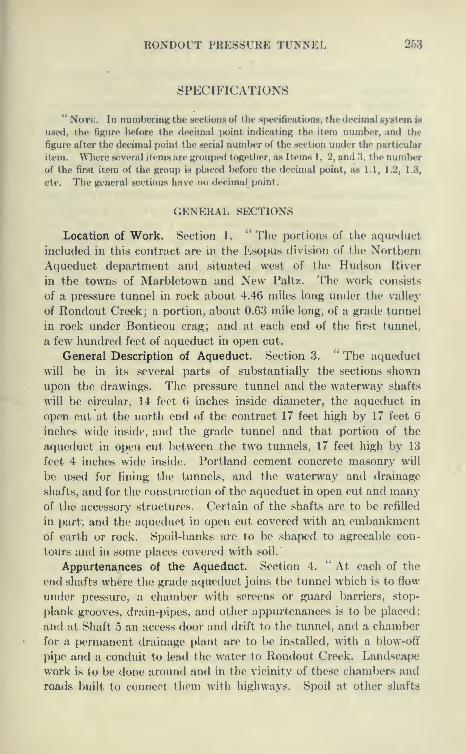
RONDOUT PRESSURE TUNNEL 253
SPECIFICATIONS
" NoTK. In numbering the sections of the specifications, the decimal system is
used, the figure before the decimal jioint indicating the item number, and the
figure after the decimal point the serial number of the section under the particular
item. Where several items are grouped together, as Items 1, 2, and '.i, the numberof the first item of the group is placed before the decimal point, as 1.1, 1.2, 1,3,
etc. The general sections have no decimal point.
GENERAL SECTIONS
Location of Work. Section 1.'* The portions of the aqueduct
included in this contract are in the Esopus division of the Northern
Aqueduct department and situated west of the Hud.son River
in the towns of Marbletown and New Paltz. The work consists
of a pressure tunnel in rock about 4.46 miles long under the valley
of Rondout Creek; a portion, about 0.63 mile long, of a grade tunnel
in rock under Bonticou crag; and at each end of the first tunnel,,
a few hundred feet of acjueduct in open cut.
General Description of Aqueduct. Section 3.'' The aqueduct
will be in its several parts of substantially the sections shown
upon the drawings. The pressure tunnel and the waterway shafts
will be circular, 14 feet 6 inches inside diameter, the aqueduct in
open cut at the north end of the contract 17 feet high by 17 feet 6
inches wide inside, and the grade tunnel and that portion of the
aqueduct in open cut between the two tunnels, 17 feet high by 13
feet 4 inches wide inside. Portland cement concrete masonry will
be used for lining the tunnels, and the waterway and drainage
shafts, and for the construction of the aqueduct in open cut and manyof the accessory structures. Certain of the shafts are to be refilleii
in part", and the aqueduct in open cut covered with an embankment
of earth or rock. Spoil-banks are to be shaped to agreeable con-
tours and in some places covered with soil.'
Appurtenances of the Aqueduct. Section 4.'' At each of the
end shafts where the grade aqueduct joins the tunnel which is to flow
under pressure, a chamber with screens or guard barriers, stop-
plank grooves, drain-pipes, and other appurtenances is to be placed
;
and at Shaft 5 an access door and drift to the tunnel, and a chamber
for a permanent drainage plant are to be installed, with a blow-otf
pipe and a conduit to lead the water to Rondout Creek. Landscape
work is to be done aroimd and in the vicinity of these chambers and
roads built to connect them with highways. Spoil at other shafts

254 CATSKILL WATER SUPPLY
is to be so deposited as to be as unobjectionable in appearance as
practicable.
Orders. Section 11. " Whenever the Contractor is not present on
any part of the work where it may be desired to give directions,
orders may be given by the Engineer, and shall be received and
obeyed by the superintendent or foreman who may have charge of
the particular part of the work in reference to which orders are
given.
Lines and Grades. Section 12. " All lines and grades will be given
by the Engineer, but the Contractor shall provide such materials
and give such assistance as may be required, and the marks given
shall be carefully preserved. The Contractor shall keep the
Engineer informed, a reasonable time in advance, of the times and
places at which he intends to do work, in order that lines and grades
may be furnished and necessary measurements for record and pay-
ment may be made with the minimum of inconvenience to the Engi-
neer or of delay to the Contractor. Whenever the Engineer finds it
necessary to carry on his operations on Sundays, legal holidays,
or at other times when the work of the Contractor is not in progress,
the Contractor shall furnish all necessary service and assistance
in shafts and tunnels. No special compensation shall be made for
the cost to the Contractor of any of the work or delay occasioned
by giving lines and grades, or making other necessary measurements,
or by inspection; but such cost shall be considered as included in
the prices stipulated for the various items.
Information about Quantities of Materials. Section 16. " To aid
the Engineer in determining the quantities of metal work, cement
and other materials to be paid for, the Contractor shall, whenever
so requested, give him access to the proper invoices, bills of lading,
and other papers, or shall provide scales and assistance for weighing,
or assistance for measuring, any of the materials.
Planimeter. Section 17. " For the estimating of quantities in
which the computation of areas by geometric methods would be com-paratively laborious, it is stipulated and agreed that the planimeter
shall be considered an instrument of precision adapted to the
measurement of such areas.
Contractor's Telephone System. Section 19. " The Contractor
shall install and at all times maintain in good working order a
telephone system connecting the bottom of each shaft with the shaft
head, and connecting each shaft head with the Contractor's central
offices and central power house, if any, and with the Section Engineer's
offices near Shafts 2 and 7. All telephone instruments above

RONDOUT PRESSTTRE TUNNEL 255
ground, and the arrangements of telephone circuits and switch-
boards shall be such, and such connections shall be made, as to
permit telephone communications from any shaft head to the office
of the Division Engineer near High Falls station.
Repair Shops and Duplicate Parts. Section 20. " The Contractor
will be required to establish one or more suitable repair-shops,
at or near the site of the work, and he shall also have at the site of
the work, at all times, duplicates in good condition, of such machines
or parts of machines or appliances as are especially likely to wear
rapidly, or break, or be lost.
Power. Section 42. *' All power machinery and tools within the
tunnels and shafts shall be operated by electricity, compressed-air
or hydraulic power, except that permission may be granted for the
temporary use of steam at the outset of the work, while plants of the
required kind are being installed.
Lighting. Section 43. " Tunnels and shafts shall be lighted with
electric lights in sufficient number to insure proper work and iaspec-
tion. Lamps for general illumination along uncompleted portions
of the tunnels and completed portions through which materials
orjmen^must pass, shall have an illumination equivalent to one
16-candle-power lamp for each 35 feet of tunnel. At headings,
at places where forms are being erected, concrete or packing placed,
grouting done and at any other points where work is going on or
inspection is to be made, adequate special illumination shall be pro-
vided.
Lighting of Shafts. '' No general illumination of the shafts,
except where work is going on, will be required, but the shafts shall
be wired throughout, and suitable water-proof outlets to which
lamps or flexible conductors can be readily attached, shall be provided
at intervals of not more than 50 feet. The wiring circuit for these
outlets in any shaft shall be separate from the circuits for furnish-
ing light or power at the pumping-stations and in the tunnel; and
there shall be no outlets in the shaft on the latter circuits. Current
shall be at all times shut off from the shaft-lighting circuits except
when lights in the shaft are in use.
Wiring. Section 44. " All wiring for electric light and power shall
be installed and maintained in a first-class manner, and at all points
securely fastened in place. Unless otherwise permitted, circuits
separate from lighting circuits shall be used for all power purposes.
All permanent wiring in shafts shall be installed in waterproof
metallic conduits securely fastened to the timbers. Electric light
and power wires shall be kept as far as possible from telephone or
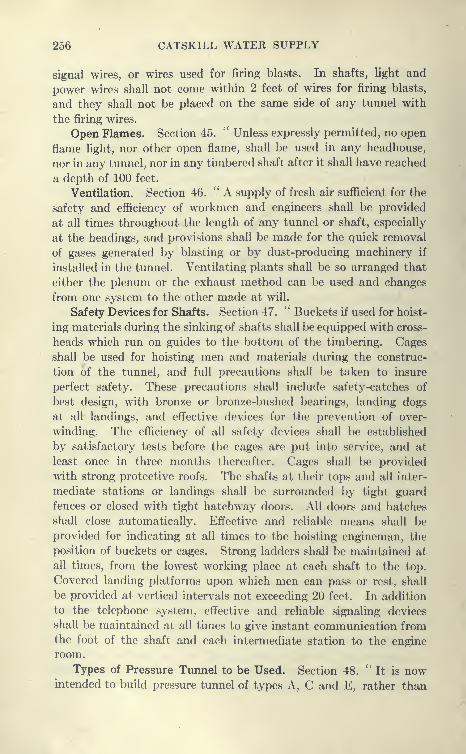
256 CATSKILL WATER SUPPLY
signal wires, or wires used for firing blasts. In shafts, light and
power wires shall not come within 2 feet of wires for firing blasts,
and they shall not be placed on the same side of any tunnel with
the firing wires.
Open Flames. Section 45. " Unless expressly permitted, no open
flame light, nor other open flame, shall be used in any headhouse,
nor in any tunnel, nor in any timbered shaft after it shall have reached
a depth of 100 feet.
Ventilation. Section 46. ''A supply of fresh air sufficient for the
safety and efficiency of workmen and engineers shall be provided
at all times throughout the length of any tunnel or shaft, especially
at the headings, and provisions shall be made for the quick removal
of gases generated by blasting or by dust-producing machinery if
installed in the tunnel. Ventilating plants shall be so arranged that
either the plenum or the exhaust method can be used and changes
from one system.to the other made at will.
Safety Devices for Shafts. Section 47.'' Buckets if used for hoist-
ing materials during the sinking of shafts shall be equipped with cross-
heads which run on guides to the bottom of the timbering. Cages
shall be used for hoisting men and materials during the construc-
tion of the tunnel, and full precautions shall be taken to insure
perfect safety. These precautions shall include safety-catches of
best design, with bronze or bronze-bushed bearings, landing dogs
at all landings, and effective devices for the prevention of over-
winding. The efficiency of all safety devices shall be established
by satisfactory tests before the cages are put into service, and at
least once in three months thereafter. Cages shall be provided
with strong protective roofs. The shafts at their tops and all inter-
mediate stations or landings shall be surrounded by tight guard
fences or closed with tight hatchway doors. All doors and hatches
shall close automatically. Effective and reliable means shall be
provided for indicating at all times to the hoisting engineman, the
position of buckets or cages. Strong ladders shall be maintained at
all times, from the lowest working place at each shaft to the top.
Covered landing platforms upon which men can pass or rest, shall
be provided at vertical intervals not exceeding 20 feet. In addition
to the telephone system, effective and reliable signaling devices
shall be maintained at all times to give instant communication fromthe foot of the shaft and each intermediate station to the engine
room.
Types of Pressure Tunnel to be Used. Section 48. ''It is nowintended to build pressure tunnel of types A, C and E, rather than
RONDOUT PRESSURE TUNNEL 257
types B, D and F. If, however, the ej^cavation of shafts has not pro-
gressetl in accordance with the requirements of Article VI, or if the
rock s(H'ins to be sucli as to make it advisal)le not to leave it long ex-
posed to the air, the Engineer may order the work done in acrconhince
with the last mentioned types, and the Contractor shall then carry on
lining of side walls and arch simultaneously with excavation, so as
to keep the lining finished to within 500 feet of the heading. The
Engineer may also order tunnel that has once been excavated in
accordance with types A, C and E to be trinmied out to types H,
D and F in order that it may be promptly lined. If the trinmiing
is ordered on account of the desire to protect the rock from decom-
position, it shall be paid for under Item 34, Additional Trinuning;
if it is ordered because the Contractor is delinquent in progress, it
shall be paid for under the regular items of tunnel excavation. It
is intended usually to construct the pressure tunnel and the lower
100 feet of permanent shafts in accordance with the right half of
the cross-sections, that is, 12 inches thick to the ' A line ' in shafts,
unsupported tunnel and lower part of supported tunnel; and the
upper parts of permanent shafts in accordance with the left half
of the sections, that is, 10 inches to the * A line.'
Reference Lines on Shaft and Tunnel Sections. Section 49.
" Certain reference lines, designated as the ' A line,' the ' B Hne '
and the ' C line,' are shown on the contract drawings. Wherever
they appear on these drawings, or on construction drawings which
may be issued from time to time, they shall have the significance
described in the following sections.
" A Line." Section 50.'' The ' A line ' is the line within which
no unexcavated material of any kind, no timbering or bracing, and
no metallic or other support for the sides, roof or other part of the
excavation shall be permitted to remain. The ' A line ' is, there-
fore, the line of minimum thickness of masonry lining wherever
such lining is to be built.
" B Line." Section 51. " The ' B line ' delimits the excavation
to be paid for, whatever the areas of the sections actually excavated.
In certain specified cases the ' B line ' is also a payment line for
masonry and dry packing.'^ The ' B line ' is fixed arbitrarily 13 inches outside of the ' A
line,' except adjacent to permanent support, where it is as nearly
as practicable 13 inches outside the support, not counting projecting
rivet and bolt heads, and in the invert of the grade tunnel, where
it is but 2 inches outside of the * A line,' except as provided in
Section 58. This relative position will not be altered whatever

258 CATSKILL WATER SUPPLY
modifications of section may be made, and no pecuniary allowance
will be made, except under Item 35, on account of any discrepancy
which may develop between the volume within this line and the
volume actually excavated. Information is on file in the office of
the Engineer and may be seen by bidders, relating to the distance
between lines corresponding to the ' A line ' herein described and
the position of the average line of excavation in a number of well-
known tunnels.
" C Line." Section 52.'' The ' C line ' is the line of effective
average thickness of masonry lining. Rock or other foreign materials
will be permitted to remain within the ' C line ' only under circum-
stances such that the effective strength of the lining against external
pressures, below grouting, considered in lengths not exceeding 4
feet, is not thereby reduced.'' Since the natural breakage of the rock in ordinary methods of
tunneling is such that only a very small percentage will remain in
close proximity to the ' A line,' the ' C line ' in unsupported por-
tions of shafts and tunnels in rock has been placed 5 inches outside
of the ' A line.' Whatever the method of tunneling, any edges
or flat surfaces of rock remaining within the ' C line ' to an extent,
or in a manner which would impair the strength of the lining, shall
be trimmed away sufficiently to make an effective average thickness
at least as great as to the ' C line.'
Non-permanent Materials in Lining. Section 54. '^ Foreign mate-
rials imbedded in the lining of shafts or tunnels, if they are, like wood,
non-permanent or more compressible than masonry, shall be placed
not only so as not to violate the provisions of Sections 50 and 52,
but also so as not to interpose a too continuous cushion between the
masonry and the rock. Thus in pressure tunnel no wood lagging
or continuous wood posting is permissible, and in grade tunnel
continuous lagging is permissible over the top of the arch only.
Section 55. '' Definite thicknesses of lining masonry are shownon the drawings of standard types of tunnels and shafts, but these
thicknesses are subject to modification, provided no thinner lining
shall be ordered in the case of pressure tunnel and shafts thanshown on the lighter, or left-hand, half-sections on the drawings, andin the case of the grade tunnel than one inch less than shown on the
drawings.

RONDOUT PRESSURE TUNNEL 260
Construction Pumping Plant
Item 14
Work Included. Section 14.1. " Under Item 14 the Contractor
shall furnish and orrct, renew, rephice if damaged or destroyed,
change about as the work requires, and remove at the end of the
work all the pumping machinery, piping and appurtenances, together
with the power-generating plants for operating this machinery,
required for removing the water from the pressure tunnel and shafts
during construction. He shall also, as a part of Item 14, excavate
and refill with masonry, as hereinafter described, any spaces in the
rock outside of the ' B line ' of excavation of shafts or tunnels,
that may be necessary for pump-stations, sumps, etc., provided
under this item. Low-lift hand-pumps or other pumps used for
local unwatering in connection with preparing the bottom of the
tunnel to receive masonry, or for passing water over a section of
the invert, are not included in Item 14, but in Item 16 (see Section
16.1, paragraph 7).
General Requirements. Section 14.2. '' The pumping-plant shall
contain machinery and appurtenances equal to those hereinafter
specified in detail, not only for taking care of the water immediately
in prospect, but also in reserve for coping promptly with flows
up to 1800 gallons per minute, at any one of the several shafts and
headings. The equipment for meeting these requirements will
be at the Contractor's option, subject to approval. The Contrac-
tor shall, within two months after service of notice to begin work,
submit a detailed description, with drawings, of the method and
apparatus which he proposes to employ, and shall modif}^ this
plan promptly if required. The capacities indicated have no known
relation to the anticipated quantity of water, but many of the
pumps are prescribed as an assurance against possible delay. It
is, therefore, of the essence of their value to The City that they be
supplied before they can, in the opinion of the Engineer, be possibly
needed.
Detailed Requirements. Section 14.3.^' Requirements will differ
in certain details according as the Contractor elects to pump from
the shallower shafts in one lift or in two. A plant to fulfill the
requirements outlined in Section 14.2 must contain the following
essentials or their equivalent:
Intercepting Water from Earth Shaft. (1) ''A pump-station
and equipment in each shaft, not waterproofed as specified in Sec-

260 CATSKILL WATER SUPPLY
tions 1.4 and 5.8, in which the leakage from above sound rock is
more than 10 gallons per minute, so arranged as to pump this ground-
water to the surface. The Contractor may elect, in case of small
flow, fo omit this outfit, but as provided in Section 15.4, the payment
for pumping such water will be as if the equipment were installed.
Sinking-pumps. (2)'' A sufficient number of sinking-pumps
to supply all shafts simultaneously in accordance with their various
requirements: eight sinking-pumps of 150 gallons per minute each
and two of 300 gallons per minute each, will be considered a reason-
able initial provision. All pumps shall have the capacity prescribed
when operating against the maximum head required.
Station Pumps. (3)" Station pumps for the bottoms of shafts
and for the intermediate stations. Each station shall have more
than one pump unless that is a double one. In general, two units
each of 150 gallons per minute continuous capacity will suffice, but
other units shall be in readiness so as to provide double the capacity
in at least three shafts. The small sinking-pumps provided under
(2) above, may be used, at the bottoms of the shafts, for a part of
this equipment, if desired."
Shaft-sinking Organization. With a realizing sense of the dif-
ficulties of shaft sinking Mr. Gillespie very wisely secured the ser-
vices of two 'shaft-sinking organizations, the Dravo Contracting
Co. and S. J. Harry Co. Both had previously sunk many shafts
in the coal regions and they were considered about the best two
shaft-sinking organizations in the East. Shafts 1 and 2 were assigned
to the Dravo Contracting Co.; shafts 3, 4, 5, and 6 to the S. J.
Harry Co. The Contractors elected to sink shafts 7 and 8 directly.
Sinking was started early at all the shafts, the work being well under
way by July 23. Temporary plants were assembled, pending the
construction of perm.anent power plants. At shafts Nos. 1 and 2, the
Dravo Co. installed for each an independent plant, composed of boil-
ers, air compressors, dj^namos, steel head frames, etc. These plants
were previously used on other shafts, and after completing the
work here were again used. Shaft-sinking is not so much a matter
of plant as it is of organization and experience. Better progress
has been made by simple and comparatively inexpensive plants
than in places where much more elaborate plants were installed.
It may be of interest to enumerate the machinery used, as follows:
Temporary Shaft Plants. At Shaft No. 1 the temporary
plant consisted of a return tubular boiler, bricked in and enclosed
in a corrugated-iron building, which also housed a compressor,
dynamo, pump. etc. The hoisting engine, with single drum 3 feet
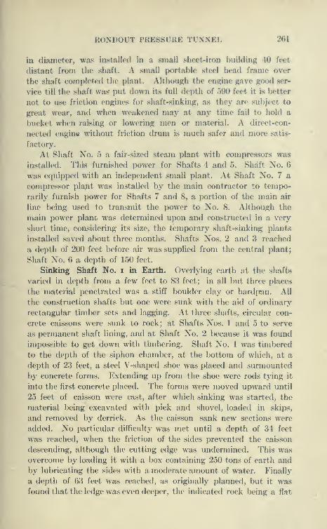
HONDOUT PRESSURE TUNNEL 261
in diameter, was installed in a small sheet-iron building 40 feet
distant from the shaft. A small portable steel head frame over
the shaft completed the plant. Although the engine gave good ser-
vice till the shaft was put down its full depth of 590 feet it is l^etter
not to use friction engines for shaft-sinking, as they are subject to
great wear, and whim weakened may at any time fail to hold a
bucket when raising or lowering men or material. A direct-con-
nected engine without friction drum is much safer and iiio!*' satis-
factory.
At Shaft No. 5 a fair-sized steam plant with compressors was
installed. This furnished power for Shafts 4 and 5. Shaft No. 6
was equipped with an independent small plant. At Shaft No. 7 a
compressor pla^t was installed by the main contractor to tempo-
rarily furnish power for Shafts 7 and 8, a portion of the main air
line being used to transmit the power to No. 8. Although the
main power plant was determined upon and constructed in a very
short time, considering its size, the temporary shaft-sinking plants
installed saved about three months. Shafts Nos. 2 and 3 reached
a depth of 200 feet before air was supplied from the central i)lant;
Shaft No. 6 a depth of 150 feet.
Sinking Shaft No. i in Earth. Overlying earth at the shafts
varied in depth from a few feet to 83 feet; in all but three places
the material penetrated was a stiff boulder clay or hardpan. All
the construction shafts but one were sunk with the aid of ordinary
rectangular timber sets and lagging. At three shafts, circular con-
crete caissons were sunk to rock; at Shafts Nos. 1 and 5 to serve
as permanent shaft lining, and at Shaft No. 2 because it was found
impossible to get down with timbering. Shaft No. 1 was timbered
to the depth of the siphon chamber, at the bottom of which, at a
depth of 23 feet, a steel V-shaped shoe was placed and surmounted
by concrete forms. Extending up from the shoe were rods tying it
into the first concrete placed. The forms were moved upward until
25 feet of caisson were cast, after which sinking was started, the
material being excavated with pick and shovel, loaded in skips,
and removed by derrick. As the caisson sank new sections were
added. No particular difficult}^ was met until a depth of 34 feet
was reached, when the friction of the sides prevented the caisson
descending, although the cutting edge was undermined. This was
overcome by loading it with a box containing 250 tons of earth and
by lubricating the sides with a moderate amount of water. Finally
a depth of 63 feet was reached, as originally planned, but it wasfound that the ledge was even deeper, the indicated rock being a fiat

262 CATSKILL WATER SUPPLY
',, ,, .
''
f lMln'Mi'>n'niilr*l>M»iM >»>>!' I'M ''
|;i; ;i:ii)!:i;i;!iiii;;;;;!as»|i'>MitirV,i,.
, ,,

RONDOUT PRESSURE TUNNEL 263
boulder. The material below the caisson was a remarkably stiff,
dry and uniform l)oulder clay, allowing the earth to be excavated to
rock to the required shape. An inside form was placed and concrete
deposited between it and the earth. This was brought up to serve
as a foundation for the caisson, which is thus practically founded
upon rock 20 feet below. Tiiroufth pipes concreted in the caisson
the space back of the caisson was grouted.
Sinking Caisson at Shaft 2. Shaft No. 2 is located near a level
plain supposed to be the bed of a glacial lake formed by the dam-ming up of an old stream. The material of the lake bottom is a
very fine silt with some clay and when wet may be properly classed
as a quicksand. Overlying the rock is quite a bed of large lime-
stone boulders also surrounded l)y soft material. The boulders
may have been carried out into the lake by ice and dropped into
its soft bottom. An abortive attempt was made to get down with
ordinary wooden sheeting and bracing, but after a few feet had been
penetrated this was abandoned.
The method of the drop shaft was next tried. A few feet
below the surface a steel shoe was built in place and sections
of concrete built on it, forming a cylinder 2 feet thick and 16
feet interior diameter. The caisson was sunk without trouble to
a depth of 19 feet, the only difficulty being to excavate quicksand
which had to be shoveled from planks. At this depth a little firmer
material was encountered and the shoe was undermined. Thecaisson then suddenly started to drop, and plunged downward
7^ feet in a few seconds, stopping with the top of the concrete just
at the level of the soft ground outside. Had it sunk a little more
it would have been filled up and probably lost. As the caisson
dropped, the material inside the caisson rose, carrying the menworking therein with it, but doing no harm. The material in which
the caisson dropped was a very fine sand thoroughly saturated with
water, but allowing little water to flow through it. Upon being
dumped it assumed an almost flat slope, about 1 vertical to 100
horizontal. After a few days, the material gripped the sides of the
caisson like mud does a pile, and new sections were built up and
sinking resumed. Thereafter the cutting edge was always several
feet below the material inside, and it was only exposed when it reached
boulders. During the latter part of the sinking the caiijson appeared
to float around like a huge cork, although weighing hundreds of tons,
and at times was several feet out of plumb in different directions.
A great deal of material flowed under the cutting edge from without,
and large settlements took place, necessitating the moving back-
264 CATSKILL WATER SUPPLY
wards of the derrick. The sinking was very difficult through the
boulders and soft ground. A platform was built on top of the
caisson off center and loaded to right it. In addition, compressed
air was blown through grout pipes in the concrete shell. This les-
sened considerably the friction on the side. Finally at a depth of
56 feet the caisson was landed on rock 1| feet out of plumb with
center of gravity shifted 1.1 feet from its original position. Bycutting away some of the interior concrete the caisson was made
large enough to take two standard cages, and served its purpose
admirably, keeping out all water, etc.
Open Caissons vs. Compressed-air Caissons. It will be noted
that this caisson was sunk to about 50 feet below ground water
without the aid of compressed air and that the difficulties encountered
were due to this. With a caisson sunk by compressed air no ground
would have been lost and the rock would have been reached with-
out difficulty except that the cost would probably have been higher.
Were a drop shaft required to be sunk through similar material
where settlement of the surrounding ground was not allowa])le,
compressed air would be required, as in the case of the shafts in lower
New York and Brooklyn, where from 30 to 100 feet of wet ground
was penetrated.
Caisson at Shaft 5. The third caisson was sunk at Shaft 5, where
the surface material was found by borings to be 50 feet in depth.
Samples obtained by the borings indicated sand and gravel, and as
the rock surface is considerably below the adjacent surface of Rondout
Creek it appeared to be a serious matter to reach rock. It was known,
however, that wash borings when penetrating hard material tend
to wash away the clay, leaving a residuum of sand and gravel. Atest pit sunk to a depth of 15 feet showed a compact hardpan com-
posed of clay, sand, gravel and boulders. Nevertheless, it still
remained possible that some layers of water-bearing gravel might
be encountered.
Sinking of Caisson. After the chamber had been sunk to a
depth of 12 feet, sheathed and braced, a heavy steel shoe was riveted
up in place and a concrete caisson 16 feet in diameter and 2 feet thick
constructed upon it. The requirements at this shaft were very rigid,
as it was necessary to sink the shaft nearly plumb on account of the
discharge pipe, etc., for the drainage system; also it was necessary
that no ground should be lost, as any settlement of the surface
would endanger a large drainage chamber to be built at the top
of the shaft. Between the horizontal joints of each successive
day's work, sufficient steel was to be placed to carry half the weight
RONDOUT PRESSURE TUNNEL 265
of the caisson below. When the caisson had sunk to a depth of
20 U'vt in very dry hardpnn tho friction hecjimo so great that even
with the cutting edge entirely undermined it ceivsed to sink, at this
time being 3 inches out of plumb. The outside of the caisson waslul>ricated with water and rakers were placed inside to right it.
It then lowered a littlo and straightened up so as to be only 1 inch
out of plumb. The caisson then stuck very stubbornly, and refused
to go even when loaded with 100 tons of stone, the sides lubricated
and the interior flooded.
Breaking Apart of Caisson. After trying vainly for a week to
get down, several sticks of dynamite were set off in the water without
permission. This settled the caisson 3J feet in a very short time.
The concussion must have strained the cylinder, because the follow-
ing day, when everything wiis going smoothly, it broke in two, the
cutting edge burying itself 2J feet in the soft clay below, the upper
section remaining bound in the boulder clay. The gap between
the two parts of the caisson, which had increased to SJ feet, was
concreted anfl while still soft the upper portion was freed by poking
rods along the sides, and it settled onto the lower portion. A few
days after the two portions of caisson were reunited, rock was
reached at a depth of 50 feet, the caisson being only lA inches
out of plumb.
It would appear from the experience of sinking these three
caissons that the sections should be bound together securely,
enough steel being inserted at each joint to carry the weight of
the entire caisson below; also that it is difficult to penetrate more
than 50 feet of dry material without loading the top very heavily.
A good strong V-shaped cutting edge securely tied to the concrete
above aids materially in the sinking, as does the guiding of the caisson
the first 15 or 20 feet. Similar caissons have been sunk over 100
feet through water-bearing ground, by the use of compressed air
and loading v/ith pig iron to overcome a friction of from 600 to 1100
pounds a square foot. This is described under Contract 67,
Chap. XX.Earth Portion of Shaft 8. The sinking of Shaft 8 through 40 feet
of drift presented some unusual features. In order to provide room
for concreting the siphon chamber, it was started 30'X30'. After
penetrating 20 feet of good ground using ordinary timbering and
sheeting, soft ground was struck in one comer, causing considerable
settlement of the timbering. The situation was saved by a new super-
intendent, who built a stout horizontal frame on the bottom of the
shaft about 2 feet from the sides of the shaft. This frame followed
266 CATSKILL WATER SUPPLY
the excavation down and from it small braces were run to support
the bottom of the sheeting, which was driven ahead as pohng boards
in about 6-foot lengths. Using great care and caution, rock was
uncovered at 42 feet, and to secure the timbering a portion of the
siphon chamber was concreted.
Main Power Plant. It was determined to operate all the machin-
ery- as far as possible with compressed air, the contractor not deeming
the electric power lines in this vicinity dependable for tunnel purposes.
It was anticipated that large quantities of water would be encountered
and it would mean flooding of the shafts and tunnels if power were
shut off even for a short time. This meant the building of a large
power plant to meet the requirements of the 15 headings which might
be simultaneously in operation. The master mechanic, Mr. Carmiff,
with this as a basis, thought it advisable to design the plant to fur-
nish air for the pumps, hoists, crushers, concrete mixers, etc., which
were installed from time to time, this being done largely for the pur-
pose of securing the greatest reliability. The additional cost for powerover steam and electricity for these purposes was not considered
of much moment, inasmuch as the central power plant could furnish
air with great economy. An almost ideal location for the powerplant was found adjacent to Rondout Creek near the center of the
Rondout Siphon. Here a large field was leased and a siding con-
structed from the 0. & W. R. R., this siding ending in a trestle for
the dehvery of coal. An unlimited supply of fine water for all pur-
poses was obtained from the creek.
Largest Compressor Plant. The power plant for Contract 12
is said to be the largest compressed-air plant constructed for anycontractor. Although its life was to be only a few years, it was in
all respects constructed as a permanent plant, except for the woodenstructure, 80' X 160', housing the machinery. Even this was regretted
on account of the fire risk, but to give as good protection as possible,
the building was surmounted by a water fine which could throughnumerous openings cover the roof with a flood of water. In addition,
numerous fire plugs were connected up inside and outside of the build-
ings, and the attendants were trained, at a given signal, to instantly
spring to appointed places and work the apparatus.
Capacity of Plant. A careful estimate of the probable air con-sumption was made at the outset as follows:
8 hoisting engines 2600 cu.ft. of free air per min.15 headings, 6 drills each (assuming one-half work-
ing at a time) 5600 " "
Miscellaneous use of air 1000 " "
9200 " "
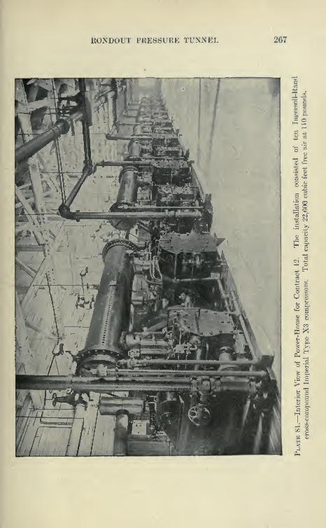
RONDOUT PRESSURE TUNNEL 267
II
5 «s
u
.2 %
II
si I
ei
^ 8
I??
<
268 CATSKILL WATER SUPPLY
In addition the contract specified that power was to be furnished
for a certain minimum requirement of pumps (150 gallons at 6
shafts and 300 gallons at 2 shafts) with an emergency outfit capable
of lifting 1800 gallons of water per minute from the bottom of the
deepest shaft. These pumps were computed to take 16,820 cubic
feet of air, or a total for the entire plant of 26,200 cubic feet of free
air per minute compressed to 100 pounds.
Types of Compressors Installed. To supply the above total,
ten IngersoU-Rand compound steam-driven, two-stage air com-
pressors were installed, eight of 421 H.P. and two of 300 H.P. each
(see Plate 81). The total capacity of compressors was 22,600
cubic feet of free air compressed to 110 pounds, or with 25 per cent
overload, 28,250 cubic feet per minute. The compressors were of
the IngersoU-Rand " Imperial " Type X3 driven by compound con-
densing engines, equipped with inter-coolers between the low- and
high-pressure cylinders and with after-coolers.
Boiler Plant. Coal was brought over a trestle connecting with
the Ontario & Western Railroad and dumped directly into bins.
Low-priced buckwheat coal obtained from the washeries was used.
This was readily handled, but required the use of forced draft. Coal
was shoveled by a few firemen from the bins directly into the four
Heine water-tube boilers of 380 H.P. and the four vSterling water-
tube boilers of 250 H.P. each. By means of the Mason fans which
operated automatically by a regulator controlled by the steam
pressure, the long grate fires were supplied with air under pressure,
very efficiently burning the buckwheat coal and maintaining the
steam pressure steadily at 150 pounds.
Aiixiliary Plant and Condensers and Generators. The exhaust
steam was led to a barometric jet condenser which maintained a
high vacuum aided by a 5-inch dry-air vacuum pump. Water for
condensation coohng and other purposes was suppHed by a 24-inch
pipe leading from Rondout Creek to a pit below the river level
in which was placed a battery of reciprocating and rotary pumps.
Two General Electric steam turbine generators of 150 K.W.each distributed three-phase 2200 volts current to all the shafts,
where it was used to drive the ventilator blowers and for lighting,
after being stepped dc^wn to 110 volts.
Compressed Air-pipe Lines. The air was distributed at 110
pounds to 12-inch lines, reducing to 10 and 8 inches at the terminal
shafts. Down each shaft a 6-inch line was run, branching to 4-inch
lines into each heading. The horizontal length of line was 4^ miles.
Pressure at the heading was never below 80 to 90 pounds. Each
RONDOI'T I'RESSrRK TrXXEL 269
pipe was fitted with a Dresser joint, such as Ims been successfully
used for a long time in (listril)utinK natural gas. Plain end pipes
with a slight bead were used. They were fitted together in a sleeve
between which and two end plates two rubber gaskets were com-
pressed by bolts drawn between the plates. The pipes were fitted
together very rapidly on the ground. Each pipe, having an expan-
sion joint, was laitl to a very irregular profile and lowered into place
in a shallow trench. The Dresser joint pipe makes a very efficient
air line, giving much less trouble than the usual screw-joint line.
Performance of Central Plant. Construction on the plant was
started July 20, 1908. By Nov. 4 it began to supply air regularly
to the various shafts, and to the end of the work there was only
one interruption of service, when, at a sharp change in grade, the
pipe line puUetl apart. The plant was remarkable for the perfect
control of the boilers and compressors. The daily disk charts show
very small variation in either steam or air pressure. The plant satis-
factorily performed the work it was designed for. However, at
Shaft 4, where great quantities of water had to be pumped and
where it was necessary to install reserve pumps of still greater
capacity, a small auxiliary steam plant was constructed to help out
the air pumps, and later, connection was made with a power line
to operate three six-stage electrical centrifugal pumps.
Sinking Shaft No. i in Rock. After 84 feet of earth had been
penetrated as described, there remained 509 feet of rock in the shaft.
Rock excavation started with progress about one month behind.
Nevertheless, the shaft was excavated six months ahead of time,
taking only about six months to be put down. The first month
only 60 feet was sunk in rock, the superintendent being unfamiliar
with circular shafts. A new superintendent increased this to
100 feet per month, then 120, and this by the record month of 138
feet of shaft sunk with 132 feet timbered. There was at that time
no shaft on record in this country which had been put down at
such a high speed. Later, the same company at Shaft No. 1 on the
Moodna siphon excavated 168 feet in Hudson River shale untim-
bered, and better still at Breakneck shaft made 183 feet in granite,
which is undoubtedly the best record in this country. In South
Africa there is a record of 213 feet of shaft sunk in one month with
Kaffir labor by hand drilling.
Advantage of Circular Shafts. At the time Shaft No. 1 was started
very few circular shafts had been sunk in this country, some
contractors claiming that they would be difficult and slow to put
down. This was apparently borne out by the experience of the
270 CATSKILL WATER SUPPLY
first contractors of the Hudson River test shaft, who, however,
tried to operate without skilled shaft sinkers. Investigation showed
that in England from 3 to 6 feet per daj^ was readily made in cir-
cular shafts, including simultaneous brick lining.
Circular and elliptical shafts, concrete lined, were beginning to
come in vogue in the coal regions, and as they give the best water-
way, and there being no intrinsic reason against circular shafts,
they were adopted for all permanent shafts on the Catskill Aqueduct.
Timbering vs. Concreting of Shafts. Considerable thought was
given at the time as to whether it was better to timber the shafts,
leaving the timbering to be taken out and the shafts concreted after
the tunnels were driven, or to sink the shaft in stretches and lining
with concrete, thus dispensing with timbering. This was thought
too advanced a practice for the first contract, and segmental timber-
ing was specified, and placed as shown in Plate 83. In all the later
contracts timbering was dispensed with, it being provided that the
shafts were to be sunk in stretches of not more than 100 feet before
being lined with permanent concrete. This method has a great
advantage of absolutely securing the shaft, and in wet ground cut-
ting off leakage, as whatever water-bearing seams are encountered
may be grouted or led away to the ring pumps. Contrary to what
was predicted, the shaft sinkers were found to be the most capable
of placing the lining, as they are far more skilled in handling them-
selves and material m shafts than are ordinary concrete men, par-
ticularly being able to move and set the forms much quicker.
Organization at Shaft i. The organization at Shaft No. 1
consisted of an American superintendent and foreman with Slav
workmen. These men all had had previous experience in Penn-
sylvania or West Virginia shafts, the workmen being particularly
steady and hardworking. The general method was to have a com-plete cycle of shaft-sinking operations in one day, and not to attempt
to make a greater advance than consistent with such a cycle. Bythis method a day's advance for sinking was increased from 5 to 6 feet,
the monthly progress, including timbering, from 100 to 138 feet.
Drilling and Mucking System. The holes were all drilled in
one shaft from tripods, using piston drills. Three circles of holes
were used. The first circle of holes, called the cut holes, was 11 feet
in diameter and drilled 8 feet deep, sloping inward to blow out a
cone; the second circle was 13 feet in diameter with holes 6 feet deep;
the third, or trimming holes, sixteen in all, and 6 feet deep were placed
on the '^ C " or effective breakage line required, 17 feet in diameter.
The close spacing of the trimming holes is particularly necessary

RONDOUT PRESSURE TUNNEL 271
in circular shafts, as they save time in trimming and give the true
shape. The five drillers and the five helpers in the shaft took five
hours to drill 31 holes, totaling 198 feet, the remaining three hours
in hoisting drills, etc., out of the shaft, and in loading and " shoot-
ing " the central cone of cut holes. The second shift mucked out
the cuts and blasted the second round of relief holes. This shift
consisted entirely of muckers, with the exception of one or two
drillers, who did the blasting and any odd drilling necessary. Thethird shift consisted entirely of muckers who removed the material
thrown down by the sixteen trimming holes. This last shift had
the hardest work.
Record Month at Shaft i. During March, 1909, the record
month, an average of 5 feet 9 inches was made per advance, which
corresponds to about 57 yards of rock in the solid, shoveled into
buckets in about fourteen hours, each man filling about five buckets
of muck in his shift. During the record month 132 feet of shaft was
timbered in 8 shifts, which is also the record for shaft timbering.
Had no timbering been required, by working Sundays, 170 feet
of shaft could have been sunk.
Timbering in Shaft. As the rock was somewhat treacherous,
only about 60 feet of rock wall was allowed to be exposed at a time.
Hitches or notches in the rock were then cut, and on them heavy
round sticks of timber were placed parallel to the segmental timbers
above. On these " dead " logs the first set of squared timbers were
placed, the next set on posts to space bents 5 feet apart, bolts fastened
between, lagging spiked on, and space between rock and lagging
thoroughly packed with cordwood. To facilitate the work a firm
platform was made in three parts which was raised from one bent to
another a section at a time by the winding rope fastened to a ring.
This platform formed a firm and secure place for the men to work
on. In other shafts much time was lost by the use of insecure
platforms of loose plank.
Bonus Paid. The men were encouraged to their best work by
being paid a bonus based upon a monthly progress of 90 feet, each
5 feet of timbering counting as 1 foot. During the record month
the men received about 40 per cent of their wages in bonus. Thecontractor was more than compensated by the decreased cost per
foot of the shaft.
Rectangular Shafts. Rectangular shafts, such as Shaft 2, were
sunk by the method clearly shown on Plate 86. This is a usual
method of sinking shafts and with it excellent progress was madein these shafts, varying considerably with the hardness and other
272 CATSKILL WATER SUPPLY
qualities of the rock. The best average monthly progress was 89
feet in Shaft 2 in Onondaga limestone. The maximum progress in
any rectangular shaft was 102 feet. The average monthly progress
made in the following formations are as follows
:
Hamilton shale 87 feet
Esopus shale 73 '
'
Helderberg limestone 55 "
Shawangunk grit 40 "
Hudson River shale 66 *
'
See also Table, page 273, and at end of book.
Shaft No. 4. Pumping Test at Bore Holes. As anticipated,
by far the greatest difficulties were encountered in sinking Shafl
No. 4. Diamond-drill holes drilled in this vicinity located at
low points yielded strong artesian flows from two porous strata.
To further determine the water-bearing character of these rocks,
two 4-inch shot-drill holes were put down at alternate locations
of this shaft. An attempt was made to pump out these holes
with an oil-well rig having a capacity of 90 gallons per minute.
At the site of the shaft a discharge of 130 gallons per minute
was obtained, exceeding the theoretical capacity of the pump by59 per cent. This was supposed to be due to the gas in the water,
forcing the water through the working barrel of the pump. Bymeans of packers it was arranged to pump the water from below
any given level, and it was found that after about a million gallons
had been pumped the ground-water level was lowered very little.
At the other hole, 750 feet away, the ground water was lowered
53 feet by pumping 2,000,000 gallons. The water pumped from
both holes was strongly impregnated with minerals and sulphur
gas. These tests gave the impression that the shaft would be very
wet, but furnished no definite data other than that the water encoun-
tered would be far in excess of 100 gallons per minute. A good^
idea of these porous rocks was also obtained from an examination
of their outcropping in the gorge of Rondout Creek below the
falls. It was shown that some of the layers of High Falls shale
and Binnewater sandstone were spongy, containing numerous small
cavities connecting with each other in a tortuous way. These weresupposed to be due to the dissolving out of the calcareous portion
of the rock.
Sinking of Upper Portion of Shaft 4. Given the choice of twolocations, the contractor chose that at location 607 -{-50. The shaft
was sunk rectangular, 10'X22' over all, timbered with lO^'XlO'' wall
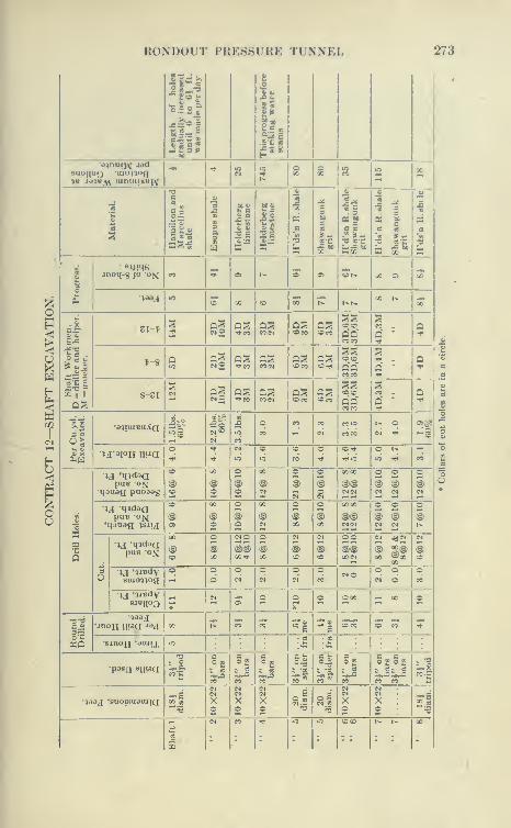
KOXDOUT PUESSUHK 11 NNKL 273
Length
of
holes
gradually
increased
until
6
to
6)
ft.
was
made
per
day 1
2s
Hi•d^nucjv jod
suo||«o monoa%v J*t1«;Vl uinuiix«iv
•*• '" S s s s «2 00
•a•co li
111
1
111 11
1
a
a
c
•O 08-C
ri•1
Xe
i jnoq^ JO oM CO * O r* « a> or* 00 e» 00
-»30J Id o QO «e 00 r* t*r^00 t«
00
OS
Sl-t^2
c5-I'M eO(M <oco
Q?5oco
coco
CO .
^-8 Qnet
oococo
S-oT5?
(NO COMOS«oeo
CIS IScoco
CO .
Q '
Q
•SI
II
•a^iuiBuXaoeo
eo CO co«o
coco
r» o<N •«lJ
OS?
u'^ioH nnao ^
^ So O 1-
"^i
1
•5J 'q?daapu8 ox
qouaa puoaag(§)
00
@o
Oio
00
@ 1?3
o oooo
(§) (§)(g)
o oi iN <N
2 1
@CM
puB ON'qaaag -jsjij
00
®oio
00
@o@
oi
OOM
@@MM
O Oi iN M
oi
a
puB ox
00
®oi00
NO oi00 1
OO
OOM
N ^Ni si00 @x
Ni
suio^iogo o
do o o o
CONO o o
N dOCO
BJBiioo *
•*•
a>o o
*o OM -H 00 O
•»aaj« ?r CO eo -i -i fflCO o eo ^
•BjnoH 'auiiX lO: :i|;i [ •
•pOSfl BllUQ
COft li
CO"
CO
^ 03^ 03
CO COhi
viaaj 'Buoreuaaiia Xo
§3
Xo
SI
Xo ^1
SI
Xo
?! :
Xo n
OS
M CO ^ .o "5 t» t- 00
274 CATSKILL WATER SUPPLY
plates, 6"X8'' buntons and 2-inch lagging, and divided into three
compartments. The shaft was rapidly sunk in dry limestone to a
depth of 80 feet, when the 4-inch bore hole in the shaft broke forth,
flowing at an estimated rate of 600 to 800 gallons per minute, flood-
ing the shaft to ground-water level 40 feet from the surface. The
shaft was recovered with the aid of an air lift consisting of a high-
pressure pipe inserted at the bottom of a 10-inch Root spiral rivetted
pipe which at first threw 1600 gallons per minute but with much
diminished efficiency as the shaft was drained, although two more
stages were added. With the aid of two No. 9 Cameron sinking-
pumps the water was lowered so that a nipple could be driven into
the bore hole. The shaft was allowed to fill up, and through a
casing attached to the nipple the hole was grouted through a
1-inch pipe, effectually stopping the flow.
Flooding of Shaft 4. The shaft was dry until a depth of about
230 feet was reached, when the Binnewater sandstone began to yield
water at a gradually increasing rate, until the shaft was making
at 260 feet, 225 gallons per minute. This was handled by two No.
9 Cameron sinking-pumps. At this depth the indications were that
the shaft would be very wet, and as the next round of holes was driven,
they were plugged. However, one of the holes struck such a strong
flow that the men had to leave the shaft hurriedly, abandoning their
drills, the flow drowning out the sinking-pumps. This was Dec. 20,
1908. The shaft was flooded at this time to within 70 feet of the
top, the estimated maximum flow being 600 gallons per minute.
Recovery of Shaft with Air Lift and Pumps. A long delay
ensued while four No. 12 tandem sinking-pumps, each with a capacity
of 450 gallons at 500 feet head, were being secured, in addition to
one No. 10 with a capacity of 300 gallons per minute. By means
of the air lift, the water was lowered to within 30 feet of the bottom,
although this required three stages and immense quantities of air.
By January 24, 1909, the shaft was recovered with the aid of two
new No. 12 Cameron sinking-pumps, and the hole was plugged with
a 2-inch nipple and gate valve. The gauge on this pipe indicated
75 pounds pressure. Many vertical holes were then drilled, each
being plugged with pipes and valves, as water was encountered.
Repeated Flooding of Shaft and Recovery. On February 3
the discharge hose of one of the pumps broke and the shaft wasagain flooded. The very heavy sinking-pumps were continually
causing trouble, due to the wearing out of suction and discharge
hose and the breaking of pipe lines.- The pumps were recovered
again by the use of the air lift. An additional No. 12 pump was

RONDOUT PRESSURE TUNNEL 275
fAfjJtSit^imLt*L.
"^scftflUH^BUtt
AOC NO. AQ.E. 52. JAN. 1 .1909
Plate 82.—Contract 12. Recovering Flooded Shaft by Aid of Air-lift. Trans.
Am. Soc. C. E., LXXIII, 1911.
.-r ', / ff^f^^-^-*"
igtdL^T— "
^^H t^: 'f \ 'i
V ^^^^s^^^^^
w'^'
''^
1mMO'^^' --??^-:.. -^ L'-JI. :^PP^P^-v5f
^^fe.^'P^^"^^-'kl>-
Plate 82a.—Contract 12. Headframe and Measuring-box at Shaft 4. Waterfrom tunnol was measured by orifice, the head on which was obtained byFriez Automatic Stage Recorder. Trans. Am. Soc. C. PI, LXXIII, 1911.

276 CATSKILL WATER SUPPLY
lowered into the shaft. On February 10 the shaft was again flooded
due to trouble with the pumps, and again recovered by the air lift
and two No. 9 Cameron pumps, and 'the leaking holes were plugged.
More holes were drilled and capped with pipes and valves, but the
shaft was again flooded and not recovered until March 12. The
holes indicated that within as close a distance as 18 inches from
the bottom there were numerous seams open as much as 8 inches.
Grouting of Shaft. Twenty-seven vertical holes were drilled, 14
to 20 feet deep, and capped with pipes and valve^, for the purpose
of grouting the seams. A battery of four Canniff tank grouting
machines was set up at the top with a 2|-inch pipe in the shaft and
a 2-inch hose connection at the bottom. These machines mix and
discharge by air and are very rapid, particularly when worked
as a battery. At first, the grout leaked back into the shaft in con-
siderable volume and it seemed that it would be necessary to place
a concrete blanket at the bottom of the shaft. Various methods
were tried to prevent this leakage—oats, bran, and horse manure,
the latter clogging the seams and stopping most of the leakage in
the shaft. The shallower holes took 2900 bags of cement, and the
20-foot holes only 60 bags. This grouting proved to be so success-
ful that it was determined to try to grout the deeper seams, knownto be porous and water-bearing.
Diamond drills were obtained and six holes sunk around the
perimeter of the shaft to the Shawungunk grit, depth 360 feet.
These holes were grouted but only 175 bags of cement could be
forced in at a pressure of 275 pounds. It is probable that the
latter grouting was only partially successful, the small quantity of
grout placed indicating that the porous layers did not freely open
into the diamond-drill holes, or that the grout clogged in the deep
holes.
Sinking after Grouting. Sinking was resumed April 25, after
a delay of four months. In the first 15 feet numerous seams were
excavated containing quantities of grout. The grout penetrated
the porous rock in a peculiar manner, solidly filling up some cavities
and leaving others, even adjacent, vacant, but probably filled enough
to prevent anything like free passage of water through the seams. Theleakage into the shaft at this point was 225 gallons, which increased to
350 gallons per minute at a depth of 380 feet. The trouble with
the sinking-pumps had become so frequent, due to the high Uft,
that it was decided to put in a collecting ring at a depth of 265 feet.
The pump on the bottom discharged into the ring, whence the water
was relayed to the top by two No. 12 Cameron sinkers protected

RONDOl'T PRESSURE TUNNEL 277
l)y a hiilkhoad of timbers. At a depth of 3(K) foot another riiiK was
installed with one No. 12 Cameron sinker pumping to the surface;
the shaft then making 450 gallons per minute. The water con-
tinued to increase to 525 gallons at a depth of 320 feet and progress
wjis exceedingly slow. The shaft at this time was so full of pumpsand discharge lines that little effective work could be done. Toatld to the troubles, the water was strongly charged with sulphur,
and the H2S gas liberated attacked the men's eyes and caused
abrasions to develop into running sores. It was difficult to procure
men for work in this shaft and the hours of labor had to be consider-
ably shortened.
Construction of Pump Chamber at 310 Feet. It was decided
to excavate a large chamber in the sitle at a depth of 310 feet, to
place in it three horizontal Cameron pumps of a capacity of 350
gallons per minute, 500 feet head. On July 15 the pumps at the
upper ring broke down and the shaft was flooded for the sixth and
last time. The shaft was unwatered by the aid of air lift and sink-
ing-pumps, and excavation of the chamber started on August 1.
This chamber was 17' X 24' X 10' high with a sump of 14,500 gallons
capacity. It was excavated at the wettest and most gaseous part
of the shaft and square in the middle of it was a water-bearing seam
which exuded a water strong enough to leave deposits of pure
sulphur on the walls. The excavation of this chamber w^as exceed-
ingly difficult work, but it was successfully accomplished and the
three pumps installed. To relieve the heavy load on the power
house, these pumps were operated by steam from three 100 H.P.
boilers set up at the top of the shaft. A 4-inch steam line from the
boilers to the pumps was wrapped with asbestos, felt and tin to
prevent condensation and fog in the shaft. A seam at the cham-
ber level which had apparently been partly grouted in the shaft
through the diamond-drill holes, in the excavation of the chamber
yielded 200 gallons a minute.
Ventilation of Shaft. To ventilate the shaft and make it possible
for men to work in it, three Sturtevant blowers, two No. 35 and one
No. 45, were installed at the top with 10- and 14-inch pipe lines.
In addition, a chemist recommended that the sides of the shaft
be sprayed with a mixture of one part chloride of lime and twenty
parts ordinary lime to neutralize the acid sulphur gas. A large
wooden tank was filled with this solution and it was liberally sprayed
in the shaft with some effect. It was not notably successful.
The FHmips in the Chamber. The pumps in the chamber were
condensing, the steam exhausting into the suction. The steam

278 CATSKILL WATER SUPPLY
pumps worked very smoothly, giving little trouble, as they were
rigidly connected with discharge lines in the shaft which in turn
were permanently fastened to the timbers. Later, when air could
be spared for these pumps, a mixture of steam and air was used,
largely to prevent freezing of the exhaust valves. This was found
to work very well.
Final Sinking to Tunnel Grade. After the installation of the
steam pumps, sinking was resumed September 9, and various seams
were grouted with small quantities of cement before the grit was
reached. At this point the bore holes again broke out, increasing
the flow from 725 to 850 gallons. This was grouted again for the
last time, taking 350 bags of cement. In Dec. 31, 1909, the shaft
reached tunnel grade, at a depth of 497 feet. About 150 feet of grit
was penetrated, which contained numerous narrow water-bearing
seams, and increased the flow to a maximum of 710 gallons.
Some of it was cut off by grouting, so that when the bottom,
of the shaft was reached the flow was only 610 gallons. This
shaft took eighteen months to ' sink, at an average rate of 28
feet per month, taking one year longer to sink than any of the other
shafts. The highest monthly progress was 80 feet in the limestone.
In all about 300 million gallons of water were pumped from this
shaft against an average head of about 300 feet. When the inflow
of water became great it was necessary to keep the bottom pumpsin operation continuously. This was accomplished bj^ excavating
the shaft in separate halves. W^hen blasting the pumps were movedto the opposite end and protected by a bulkhead. Water was kept
off the bottom as much as possible by rings. In placing grout pipes
in the holes it was difficult to get a tight fit by the use of woodenwedges, the usual method. Later, the pipes were wrapped on a
lathe with a cone of flannel. This when pounded into the hole bythe piston of a drill makes a very tight connection through which
grouting can be accomplished.
The shaft was sunk to the depth of the large pump chamber bythe S. J. Harry Co., after which, as the shaft required an entirely
new plant, it was taken over, other superintendents of the T. A.
Gillespie Co. completing the work.*
Lessons of Shaft 4. The lessons to be learned from this shaft
are: place as little reliance as possible on vertical sinking pumps,
* A paper on this subject together with an extensive discussion was printed
in the Transactions of the American Society of Civil Engineers, September,1911, under the title " Sinking a Wet Shaft," by John P. Hogan. Much of
the matter on Shaft 4 was taken from this paper.

RONDOUT PRESSURE TUNNEL 279
using rings and cham])ers to handle all the water except that
which comes in below the lowest ring. This bottom water can
be readily raised by sinking-pumps, with discharge pipes only as
long as necessary to reach the lowest station pump. A pump so
rigged can be readily raised and lowered. The very large sinking-
pumps such as those first used weighed over 5 tons and against high
heads never ran at more than half their rated capacity. It was
impossible to keep tight connections while running at full speed.
At first a spirally riveted flanged pipe was used as a discharge, but
this did not stand up, and it was necessary to use very heavy screw-
joint pipes. The air lift is valuable for recovering a flooded shaft,
but is very wasteful of power. It would appear unwise to timber
a very wet shaft, as much better results can be obtained by con-
creting, the water being led through the concrete by grout pipes,
and subsequently after the concrete has thoroughly set, the seams
may be grouted, cutting off considerable leakage. In this contract
no provision was made for concreting in construction shafts, but
due to the experience here such provision was added to subsequent
contracts. Grouting of well-defined seams in a shaft is of great
aid and well worth trying in any case, as water is exceedingly bother-
some at the bottom of a shaft. In the operation of the sinking pumpsit was found that considerable trouble was given by the exhaust ports
freezing. This could be obviated by using the air with a small
amount of steam, as in the case of the chamber pumps described.
Reheaters were tried, but they gave considerable trouble.
Rectangular Shafts and Their Equipment. Contract 12, as well
as most of the other siphon contracts, specified a minimum size
of rectangular construction shaft. This allowed for cages only
3'9"X5'6". The contractor, however, was given the option of
enlarging the temporary shafts if he deemed it advisable, but was paid
for only the per foot contract price. He chose to enlarge the shaft
to the size showTi on Plate 83, the excavated area being increased
about 30 per cent and the cage area 100 per cent. This probably
increased the cost of shaft about $10 per foot, as it meant only
that much more mucking and somewhat longer timbers to pay for
and place. This additional expense was more than compensated
by the increased capacity of the cages, and freedom of getting
materials into and out of tunnels. In order to maintain a good
average, tunneling and concreting at times has to be foiced
at the highest obtainable speed. For instance over the entire
period of this contract an average of only 7 yards per hour need be
handled by two cages, whereas at Shaft 7, during the maximum
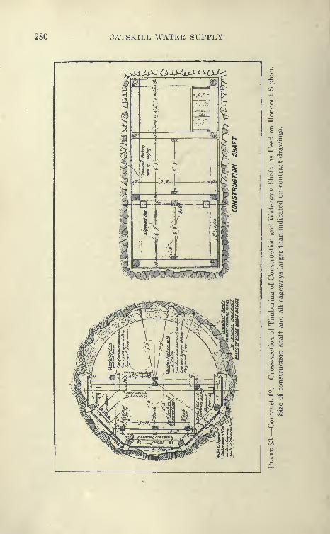
280 CATSKILL WATER SUPPLY
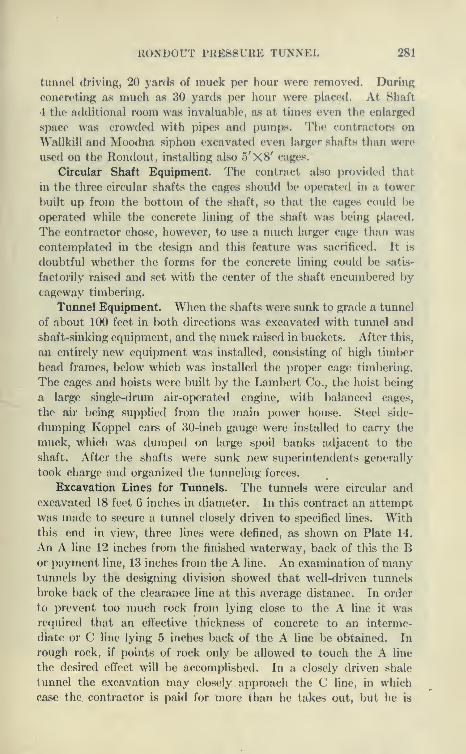
RONDOUT PRESSURE TUNNEL 281
tunnel driving, 20 yards of muck per hour were removed. During
concTeting as much as 30 yards per hour were placed. At Shaft
4 the additional room was invalual)le, as at times even the enlarged
space was crowdetl with pipes and pumps. The contractors on
Wallkill and Moodna siphon excavated even larger shafts than were
used on the Hondout, installing also 5'X8' cages.
Circular Shaft Equipment. The contract also provided that
in the three circular shafts the cages should be operated in a tower
built up from the bottom of the shaft, so that the cages could be
operated while the concrete lining of the shaft was being placed.
The contractor chose, however, to use a much larger cage than was
contemplated in the design and this feature was sacrificed. It is
doubtful whether the forms for the concrete lining could be satis-
factorily raised and set with the center of the shaft encumbered by
cageway timbering.
Timnel Equipment. When the shafts were sunk to grade a timnel
of about 100 feet in both directions was excavated wdth tunnel and
shaft-sinking equipment, and the muck raised in buckets. After this,
an entirely new equipment was installed, consisting of high timber
head frames, below which was installed the proper cage timbering.
The cages and hoists were built by the Lambert Co., the hoist being
a large single-drum air-operated engine, with balanced cages,
the air being supplied from the main power house. Steel side-
dumping Koppel cars of 30-inch gauge were installed to carry the
muck, which was dumped on large spoil banks adjacent to the
shaft. After the shafts were sunk new superintendents generally
took charge and organized the tunneling forces.
Excavation Lines for Timnels. The tunnels were circular and
excavated 18 feet 6 inches in diameter. In this contract an attempt
was made to secure a tunnel closely driven to specified lines. Withthis end in view, three lines were defined, as shown on Plate 14.
An A line 12 inches from the finished waterway, back of this the Bor payment line, 13 inches from the A line. An examination of manytunnels by the designing division showed that well-driven tunnels
broke back of the clearance line at this average distance. In order
to prevent too much rock from lying close to the A line it wasrequired that an effective thickness of concrete to an interme-
diate or C line lying 5 inches back of the A line be obtained. In
rough rock, if points of rock only be allowed to touch the A line
the desired effect will be accomplished. In a closely driven shale
tunnel the excavation may closely approach the C line, in which
case the contractor is paid for more than he takes out, but he is
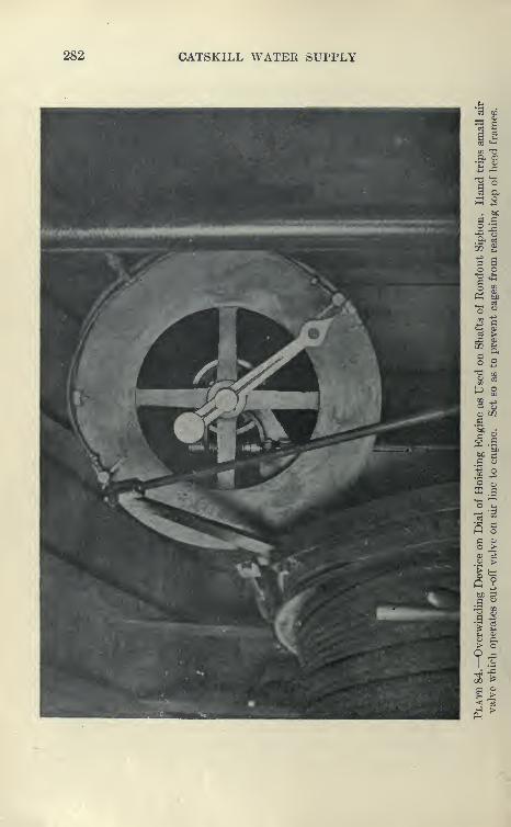
282 CATSKILL WATER SUPPLY
o03 a,
W -2
bCa ao
a si
CK fi,
-+J ^3 ao cTS fc4<^c;
!1
'o o
^ a*t2 a>c3 >^ a>
C» ti
§ 2
en^
6 O
G
bC £3
-3 ^'
> o
?00 t*
J >
RONDOUT PRESSURE TUNNEL 283
•*!W«^:
^^ O
7
284 CATSKILL WATER SUPPLY
thought to be entitled to this for his careful work, it being provided
in all cases that he be paid the bid price for concrete and excavation
to the B line. Any saving of concrete made by the contractor is
shared in by the city to the extent of the cement saved. In case
of excess breakage outside the B line, he is not paid for this excava-
tion, but only for the excess concrete, and at a fixed price of $3
per yard.* As this does not yield a profit, it is not to the contractor's
interest to break outside the B line. On previous tunnels muchlitigation over excess breakage has been the experience where the
amount of breakage beyond the masonry to be paid for has not been
specified. In other cases this has been left to the contractor and all
breakages paid for, leading to very careless and wild work. As
the contractor benefits by this it is very difficult to prevent. In
the case of the New Croton Aqueduct, no payment was made for
excavation outside the specified masonry lines, which led to long
litigation, the contractor finally losing in the court, but securing
partial pa^nnent through an Act of Legislature.
Means Employed to Secure Closely Driven Tunnel. The experi-
ence gained in the excavation of over 35 miles of tunnel in the Cats-
kill Aqueduct shows that the payment lines are fair to both parties.
On the Rondout siphon, close driving was sought for by both the
engineers and the contractors. After each shot the face of the head-
ing was carefully painted in red, the C line being used. Fromthis the heading boss or superintendent laid out his holes. In
addition, the heading was trimmed just behind the face, which
was found to have a very good effect on the driving. The cross-
sections by means of the sunflower was taken every 10 to 20 feet
and plotted in pencil on cross-section sheets. These were shownfrequently to the superintendents. Location of " collars " and" butts " of holes were also made from time to time and plotted
on the cross-section to show how the holes were drilled. In this
manner very accurate sections were obtained, the contractor saving
considerable in excavation and concrete. For instance, the Bonticou
grade tunnel, 3400 feet long, saved 856 yards over B line excavation.
This, however, was very close work, and it is not felt that, ordinarily,
the contractors will save much over the B line. The same system
was applied to the sinking of the circular shafts, which were paid
for on the yardage basis. Shaft No. 1 was drilled within the Bline, the contractor saving 211 yards of excavation in 400 feet of
shaft. At Shafts Nos. 5 and 8 little saving was made.Difficulties of Driving in Circular Tunnel. In the circular
* Excess breakage is figured in stretches of 100 feet.
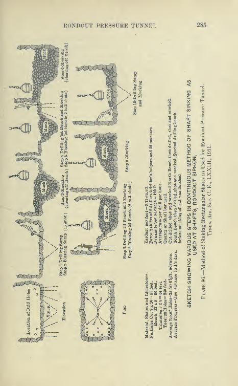
KoNDolT I'KE.SSl'KE TUNNEL 285

286 CATSKILL WATER SUPPLY
tunnel section, the bench or lower half gives the most trouble, as
this is generally taken out with vertical holes. Close results were
obtained by driving a little narrow in the softer rocks and then
trimming out later to exact lines with ''Jap " drills. This does not
pay in the harder rocks and, consequently, there is some tendency to
be wide at the bottom. It was found that closeness of tunnel to lines
depended more than anything else on the accurate placing of the,
holes and more particularly upon the direction the hole is given, so
as not to bring the butts outside the cross-section.
Bonticou Tunnel. The first tunnel to be started was the Bonticou,
driven from a portal at Shaft 8. The method used for driving is
shown on Plate 86a. The same method was used on the pressure
tunnels where, however, the bottom holes have to be gauged differ-
ently than here showTi to form the lower half.
A short stretch at the bottom of Shaft 8 was driven by bottom
heading, but was soon given up, as it proved to be more expensive.
Good Progress in Tunneling. Contract 12 was remarkable
for the great amount of tunneling in progress at one time. During
the week of Oct. 20, 1909, there were 11 headings in pressure tunnel
in progress and one in grade tunnel, the total linear progress of com-
pleted tunnel excavated being 907 feet. The best monthly
progress in all headings (12) of pressure tunnel was that of October,
1909, 3647 feet, ranging from 430 to 280 feet and averaging 304
feet per heading. For this month the contractor's estimate was
one-third of a million dollars, nearly all for tunnel excavation. In
each heading four drills were usually used on two columns with two
drills in tripods for bench holes, all Ingersoll-Rand. During this
month the central compressed-air plant furnished with apparent
ease power for all the 13 tunnels, for all the hoists, pumps, etc.,
also electricity for light and motor-driven blowers. During this period
all ten compressors were running with almost perfect regulation
despite extreme fluctuation in demand, the self-recording pressure
indicator cards making a circle very close to 110 pounds. By the
automatic blowers very close regulation of steam pressure was also
obtained.
Method of Driving. Despite the individual methods of the various
shaft superintendents, who were given considerable authority to carry
out their own views, it was surprising how close they all came to
the same standard method. Usually the bench was kept about
75 feet behind the heading. Closer than this, the muck from shooting
the face hampered the work of drilling the bench. For more than
this the wheelbarrow haul is unnecessarily long. From the bench
RONDOUT PRESSURE 'TUNNEL 287
the upper part of the tunnel is trimmed to true shape by means
of Jap drills, barring, etc.
Altliough the platform, composed of telescoping pipes upon
which a few boards are laid from the bench seems crude, it is
really very effective, as from it the cars are directly loaded ^ith
the heading muck by wheelbarrows without disturbing the drilling
or mucking at the bench, and is easily taken down and romoved
before shooting the bench.
Wheelbarrows vs. Mucking Machines. Numerous attempts
have been made to supersede the wlioelbarrow method of mucking
heading, but without any marked success. The great number of
headings on the tunnels of the Catskill Aqueduct gave an unrivaled
opportunity to try out and demonstrate a superior method. Onthe Eastview and Yonkers tunnels mucking macliines were used,
but without marked success. At Breakneck, Hunter's Brook, and
Hillview, bottom headings were used, but in the writer's opinion
showed no superiority to the top heading and wheelbarrow.
Short vs. Long Bench. In some tunnels an effort was made to
keep bench close to the face of heading, so that the heading muck
could be shot over the bench and shoveled onto cars with the
bench muck, saving wheeling and erection of platform. This had
to be abandoned, as the heading rock cumbered up the bench so
that the drills could not properly drill the down holes. Moreover,
instead of two mucking gangs, only one could be used to advantage.
Probably on large tunnels where steam shovels can be used to
advantage to load the muck it pays to keep bench close to heading.
Where a complete tunnel is driven by the bottom heading method
the construction and moving of heavy timber platforms upon which
the upper rock is shot more than offsets the advantage of eliminat-
ing wheelbrrow loaading.
Temporary Timbering. The top heading was admirably adapted
to the placing of timbering necessary for about 10,000 feet of tunnel.
Through these long stretches the bottom heading method would
have been extremely dangerous, as a flat roof is left which is struc-
turally weak and for which it would be wasteful to use timbers, as
they would have to come out before the Tipper portion could be
placed. Throughout most of the timbered portion three-piece
timbers with 2-inch lagging packed to the rock with cordwood
were used. From platforms similar to, and, in some cases, an
extension of the regular platform in front of bench, hitches were
cut into the rock by hand, and the timbers, cut to fit, were placed
from the platforms, lagged, and packed. Where the rock was very

288 CATSKILL WATER SUPPLY
RONDOUT PRESSURE TUNNEL 289
bad the timber oxtondod over the bench, but usually was placed just
back of the bench. Although not expected to carry heavy loatfs the
timbering is very strong, the hitches holding remarkably well, even
in very soft rock, as the thrust of the legs tends to be outward rather
than downward. They were placed within the ordinary cross-section
and thus required no additional excavation, being taken down in
advance of the concreting. It was predicted that this would be
expensive and dangerous, but did not prove to be, as by placing half
a stick of dynamite back of each leg, they were easily brought down,
together with whatever loose rock had accumulated upon them. In
the Wallkill siphon the timbers were pulled over by a hoisting engine.
Permanent Steel Roof Support. The pressure tunnel specifica-
tions require that all timber be removed previous to concreting,
as it was feared that wood would compress and rupture the concrete
lining under the enormous internal pressure of water obtained when
the tunnel was in service. The contract drawings showed for ground
requiring permanent support a design of steel arch ribs and L-beam
lagging. In Tunnel 5 North a heavy roof was encountered where
nearly level beds of shale broke away from the grit bed above. This
was carried safely by three-piece temporary timbering, but it was
feared that difficulty would be experienced in taking it down, so that
about 135 feet of steel roof support was erected and carefully packed
back of lagging with pieces of rock. The steel ribs soon started to
buckle and failed in various ways, so that they had to be hurriedly
posted and supported by three-piece timbers in hitches, until the time
of placing the concrete arch.
Although the steel ribs were computed to be as strong as a
10" X 10" bent, they proved to be much inferior in strength. Where a
roof is heavy, it is almost impossible to prevent eccentric loading on
the supports. Although packed and braced carefully, the steel ribs
really failed as beams, not as arch ribs in perfect compression as
figured. Other heavy ground was again encountered in Heading
3 South, and an entirely different type of steel support was used.
This was deeigned on the ground and used as shown in Plate 88.
It was, however, unnecessary to use the complete section as shown,
support for only part of roof or sides being required. This system
proved to be very flexible and exceedingly strong, as the I-beams
and timber bents can be spaced as the ground requires. It is only
necessary to expose a small portion of the bad ground, which is
immediately supported by the channel lagging.
Steel Support in Bad Cavy Ground. Previous to placing the
concrete all the wood was removed, leaving the*steel to be concreted
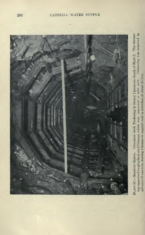
290 CATSKILL WATEK SUPPLY
h»
T3a;
•S >-p owB
I ^
§ec :s-»j
'^ bC
^ .ccc '»i4
oPH s^ Hs
^'u:)
o fcn»—
1
tDS -1^
(D ;3
B.r: Q-^ ^'^ > c3
h C3*©
>03 s<u -d ^w « 1.g
'g-
2^o -!-:»
bt c Mo
•SOJ b-l
s 21^
1^ i3 a< ^ S
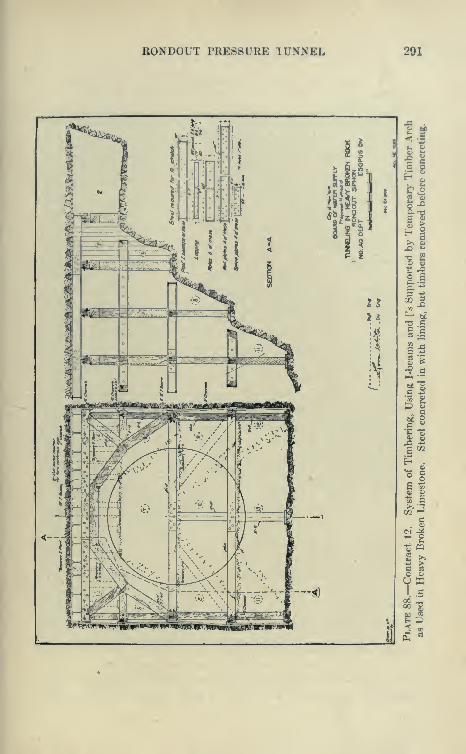
RONDOUT PRESSURE TUNNEL 291
i
.^1
—a)
tti^
:4
uI"?
o gc -^
§;§
S f•9 a
.1°
I I
oa
Y
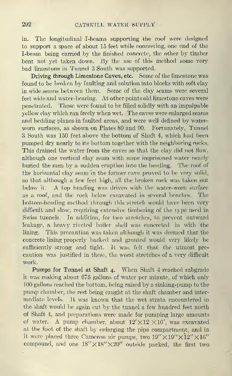
292 CATSKILL WATER SUPPLY
in. The longitudinal I-beams supporting the roof were designed
to support a space of about 15 feet while concreting, one end of the
I-beam being carried by the finished concrete, the other by timber
bent not yet taken down. By the use of this method some very
bad limestone in Tunnel 3 South was supported.
Driving through Limestone Caves, etc. Some of the limestone was
found to be broken by faulting and solution into blocks with soft clay
in wide seams between them. Some of the clay seams were several
feet wide and water-bearing. At other points old limestone caves were
penetrated. Those were found to be filled solidly with an impalpable
yellow clay which ran freely when wet. The caves were enlarged seams
and bedding planes in faulted areas, and were well defined by water-
worn surfaces, as shown on Plates 89 and 90. Fortunately, Tunnel
3 South was 150 feet above the bottom of Shaft 4, which had been
pumped dry nearly to its bottom together with the neighboring rocks.
This drained the water from the caves so that the clay did not flow,
although one vertical clay seam with some imprisoned water nearly
buried the men bj^ a sudden eruption into the heading. The roof of
the horizontal clay seam in the former cave proved to be very solid,
so that although a few feet high, all the broken rock was taken out
below it. A top heading was driven with the water-worn surface
as a roof, and the rock below excavated in several benches. Thebottom-heading method through this stretch would have been very
difficult and slow, requiring extensive timbering of the type used in
Swiss tunnels. In addition, for two stretches, to prevent outward
leakage, a heavy riveted boiler shell was concreted in with the
lining. This precaution was taken although it was deemed that the
concrete lining properl}^ backed and grouted would very likely be
sufficiently strong and tight. It was felt that the utmost pre-
caution was justified in these, the worst stretches of a very difficult
work.
Pumps for Timnel at Shaft 4. When Shaft 4 reached subgrade
it was making about 675 gallons of water per minute, of which only
100 gallons reached the bottom, being raised by a sinking-pump to the
piunp chamber, the rest being caught at the shaft chamber and inter-
mediate levels. It was known that the wet strata encountered in
the shaft would be again cut by the tunnel a few hundred feet north
of Shaft 4, and preparations were made for pumping large amountsof water. A pump chamber, about 12' X 12 X 16', was excavated
at the foot of the shaft by enlarging the pipe compartment, and in
it were placed three Cameron air pumps, two 19"Xl9"xi2"Xl6"compound, and one 18" X 18"X 20" outside packed, the first two
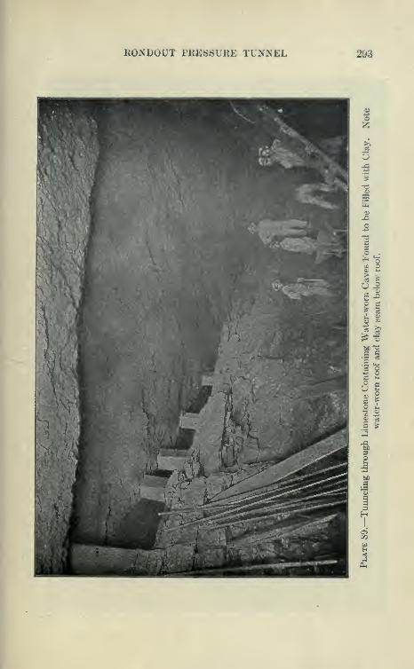
ROxSDOUT PRESSURE TUNNEL 293
w p
II
g I
«1i3 §s *-
O G^ O= I
3
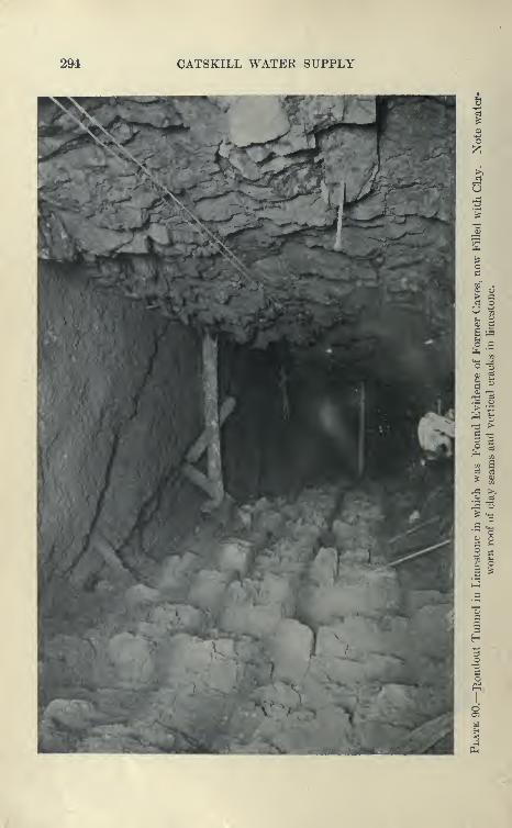
294 CATSKILL WATER SUPPLY
^ 01
o a
> "^
S ^
si
c P
o
o

RONDOUT PRESSURE TUNNEL 295
of 450 gallons capacity and the other of 330 gallons capacity, under
500-foot head. In addition, and as was later done, it was planned
to remove the three 24" X 10" X 20" Cameron pumi)s from the
Ae«ulC«p.^mp o«ll. p« BlM
PUMP DATA
No. Make Type
1 CameroD RwlproctlBJ
2
3
4 •••
66
7 •• ••
8
9 WorthlaftaaElectrical
C«Dtriru(al
11 • • -
S4'x lO'x 20_^
2i"x lo'x 20*^
24 'x lO'x 20*
19 X 19 X 12 X le'Componnd.
18'x 8 X 20*OuUldo packed.
19 "x 19''x 12 X le'Compoond.
18 X Wx 20'x 2.)"
19 X 19"x 12 "x 18" "
O^taffe. 115 Kw., c'ducbargc
O"-.. 125 •• 5" "
QUI O' " 126 •• O" '•
4900 OaU. per Uio. » ToUl Capacity.
Lift 900 ft.
Sta. 607+03.5, Shaft 4
CROSS SECTION OF PIPECOMPARTMENT OF SHAFT
100
Cage Guide rr® ©
o30 (DM
WestSide
North SideKEY;-
1 a'Discharge.6' Steam.O'CoDipressed Air.
20"Blower.10"Di8charge.8"Di8cliarge.
12"Blower.12"Dbcharse.lO'Discharge.
Elec. Light Conduit.4"Conipre8std Air.
1 Elec. Power Conduit13 i for Centrifugal Pump*14 Signal Whistle.
Plate 91.— Position cf Pumps and Pijjing Used at Shaft 4, Rondout Siphon, to
Pump 1000 to 2200 CJallons of Water per Minute to Surface. Total pumpingcapacity about 4900 gallons under 500 foot head.
chamber to the bottom, where they each would ])e able to raise 350
gallons per minute to the surface. Only 575 gallons per minute were
then being pumped from the chamber and the water was rapidly fall-

296 CATSKILL WATER SUPPLY
ing, so that before the tunnels had advanced far, the shaft was prac-
tically dry. The two 450-gallon pumps in the chamber were old
sinkers weighing 9000 pounds, which proved too heavy and cum-
bersome, for use in shafts in vertical position, but proved very
satisfactory when mounted horizontally.
Driving through Wet Shawangiink Grit. Progress in driving
northward was very slow in the grit, and the water struck, at first
in small volumes, contained considerable H2S gas, which made it
difficult to keep men at work, although ventilation was obtained
by two Sturtevant blowers operating through 10- and 12-inch pipe
lines. Finally, a seam was struck which yielded 300 gallons of water
per minute from two drill holes. These holes were plugged with
pipes wound with Canton flannel. Six others also reached water and
were plugged in the same way. Against a back pressure of water of 85
pounds, the heading was grouted with Canniff machines operated by
air at a pressure of 300 pounds per square inch furnished by a West-
inghouse compressor. The water-bearing holes were found to freely
communicate and 319 bags of cement were injected. This grout-
ing cut down the water from 850 gallons to 350 gallons. Later a
No. 11 Sturtevant blower was installed, pumping or exhausting air
through a 20-inch discharge line and operated by a 40 H.P. engine.
When shot, the water-bearing seam in the grit was found to be
J to f inch wide and thoroughly grouted.
Trouble with H2S Gas. Slow progress was subsequently madethrough the grit, which yielded at numerous places small quantities
of water heavily charged with H2S gas. The men were protected
by tarpaulins overhead, and various styles of goggles were tried out to
protect the eyes, and the wages of the men substantially increased.
At this time the men suffered severely from sore eyes, and some
complained of congestion of the lungs.
Grouting a Wet Heading. The grit was finally passed and a
much-faulted stratum of the High Falls shale encountered. At first,
the total pumpage was only about 550 gallons, a decrease since the
tunnels started, accounted for by the fact that more water was lost
by the shaft than gained in the tunnel. The shale was dry for a
short distance, when the heading holes again yielded water to the
amount of 300 gallons per minute. The holes were closed with
pipes and grouted, but the heavy pressure used, 200 pounds per square
inch, blew off 3 feet of the face of the heading, the holes being about
6 feet deep. More holes were drilled and a heavy flow met about
10 feet from the face. These holes were drilled around the per-
iphery of the tunnel and grouted so as to dry the rock well outside
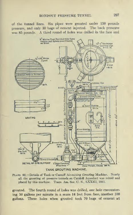
RONDOUT PRER8URE TUNNEL 297
of the tunnel lines. Six pipes were grouted under 150 pounds
pressure, and only 30 bags of cement injected. The back pressure
was 85 pounds. A third round of holes was drilled in the face and
9^'Mixing Vont ProTided with VmUOatiide aad SpUtta-aoftrd Ixulde
on Head. Ux I Tle-8tr«pabetwecD Leo
3 = iH lb.
IKxKFlat IronUlb.
DETAIL OF PIPE SUPPORTTotal
TANK GROUTING MACHINE.
eight, Kmpty 6001b.
Plate 92.—Details of Tank or Canniff Air-mixing Grouting Machine. Nearly
all the grouting of pressure tunnels on Catskill Aqueduct was mixed and
placed by this machine. Tran.s. Am. Soc. C. E., LXXIII, 1911.
grouted. The fourth round of holes was drilled, one hole encounter-
ing 50 gallons per minute in a seam 14 feet from face, another 100
gallons. These holes when grouted took 70 bags of cement at

298 CATSKILL WATER SUPPLY
300 pounds head. A fifth round of holes was drilled and still
encountered water, the new holes spouting like fire hydrants at
85 pounds pressure.
Additional Pumping Equipment. Electrical Pumps. It was
apparent that the pumping plant installed could not do the work it
would be called upon to do; that in the heavily faulted and broken
shale with dissolved-out irregular cavities, grouting was hopeless,
and could not be expected to reduce the leakage into the tunnel
materially. The contractor took radical steps, enlarged the tunnel
about 75 feet from the shaft to take two more pumps of 330 and 450
gallons capacity, an 18" X 19" X 20" X 20", and a 19" X 19" X 12" X 16"
compound Cameron. The power house, however, could not- give
air for more pumps than this, and an additional margin was required,
although the air pump capacity totaled 3000 gallons per minute.
Three six-stage Worthington centrifugal pumps were installed,
rated as follows: 700, 600 and 540 gallons. A total installation
of 8 air and 3 electric pumps of 4770 gallons per minute com-
bined capacity. Considerable difficulty was experienced in getting
a proper equipment to stand the sulphur gases in the air. Thefirst switchboard was eaten out in a very short time. This
was remedied by using starting boxes entirely enclosed, such as
are used for operating trolley cars. To supply current a separate
power line of 33,000 volts was run to High Falls and a transformer
house equipped near top of shaft. The transformers stepped downthe current to 440 volts.
Concrete Bulkhead. To prevent loss of the shaft in case of fail-
ure of the pumps, a concrete bulkhead which could be closed by a
heavy wooden door was erected at the foot of the 15 per cent incline.
(See Plate 93.) All pipes were concreted in and provided with
valves on the outside, and a slot for the cable used to raise cars upthe incline. This bulkhead proved its worth when the powder
magazine at the top of shaft exploded and wrecked the transformer
house and damaged the air, light and steam lines also. All the
pumps were stopped when the inflow was 1650 gallons per minute.
Men were sent through from the next shaft and the bulkhead wasclosed. The heading soon filled up back of the bulkhead, but only
a small amount of water leaked through to the shaft, which wasreadily handled by the air pumps after they w^ere started up.
By strenuous work the electrical pumps were started up again in
eighty-four hours and the heading pumped out in five hours.
Six Hundred-gallon Leak Revealed by Heading Shot. Thefirst shot made after a shut down of about three months revealed
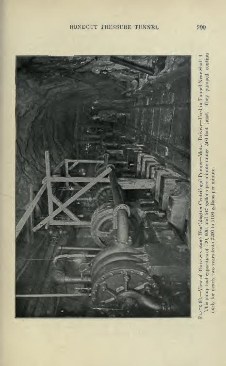
RONDOUT PRESSURE TUNNEL 299
« a7. 8
n_ a
P >»
I 8
3 ^
^-^8
& i t!
Si: ^
lisCO C «—
300 CATSKILL WATER SUPPLY
a water-bearing crevice to the right of the tunnel very near holes
which had been repeatedly grouted. The crevice, 2'X8", was in
the axis of a fold, the stratum being doubled on itself, in the sand-
stone, and extended indefinitely backward and upward. Into this
crevice spurted innumerable streams of water, the crevice shunting
the water into the tunnel like a V-shaped flume. This yielded about
600 gallons per minute, and at this place over 1000 gallons of water
spurted into the heading, running swiftly down the 15 per cent
incline in a leaping cascade. The total pumpage then reached a
maximum of about 2000 gallons per minute, which was easily handled
by the pumps. A large sump was used to settle the grit before the
water was taken by the electrical pumps. However, some of themwere cut badly and had to be repaired.
Diamond-drill Exploratory Hole. While the tunnel was shut
down a diamond-drill hole was placed along the axis of the heading
to explore the ground ahead in a search for caves, etc. The hole
revealed little, only a small percentage of core being recovered.
Tunneling on 15 Per Cent Incline. Numerous leaks were
encountered beyond the m.ain water-bearing area in the broken andfaulted shales and sandstones, but fair progress was made in the
heading, which was driven ahead to connect with the heading
advancing down the incline fro;ii Shaft 3.
The main leaks decreased rapidly, losing more than made byothers encountered ahead. The water in the wet ground waspumped down to elevation— 200 (about 50 feet above the bottomof Shaft 4) so that the heading was drj^ when the incline reached this
elevation. It was most fortunate that this incline was situated here.
Had the tunnel been carried through at a uniform elevation of
— 250 feet the difficulties of tunneling would have been immenselyincreased, as a long stretch of wet ground with clay seams, etc.,
would have had to be penetrated. It was found practicable to oper-
ate cars on the 15 per cent grade and drive both up and down the
grade by means of hoists and cables, although the danger from
runaway cars was considerably increased.
After the headings met the bench was drilled and shot and the
muck taken out through Shaft 4, rapid progress being made. Theinflow of water dropped to about 1200 gallons per minute, remaining
nearly constant at this until finally grouted off. It is probable that
the early large flows represented the accumulation of water in the
underground reservoir, and that the 1200 gallons per minute of
steady flow represented its normal supply.
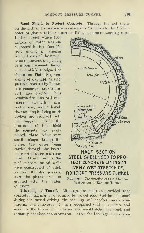
RONDOUT PRESSURE TUNNEL 301
Steel Shield to Protect Concrete. Through the wet tunnel
on tlie incline, the section was enlarged to 24 inches to the A line in
order to give a thicker concrete lining and more working room.
In the stretch where 1000
gallons of water was en-
countered in less than 150
feet, issuing in streams
from all parts of the tunnel,
so as to prevent the placing
of a sound concrete lining,
a steel shield (designed as
shown on Plate 94), con-
sisting of overlapping steel
plates supported by I-beam
ribs concreted into the in-
vert, was erected. This
construction also had con-
siderable strength to sup-
port a heavy roof, although
the roof, despite being muchbroken up, required only
light support. Under the
protection of this shield
the concrete was easily
placed, there being very
small leakage through the
plates, the water being
carried through the invert
pipes without accumulating
head. At each side of the
roof support cut-off walls
were constructed of brick
so that the dry packing
over the plates could be
grouted with the water
quiescent.
Trimming of Timnel. Although the contract provided that
concrete lining might be required to protect poor stretches of tunnel
during the tunnel driving, the headings and benches were driven
through and excavated, it being recognized that to concrete andexcavate the tunnel at the same time would delay the work andseriously handicap the contractor. After the headings were driven
/jp/ates
"6 Ybranch^6'main drain
HALF SECTIONSTEEL SHELLUSED TO PRO-TECT CONCRETE LINING IN
VERY WET STRETCH OF.
RONDOUT PRESSURE TUNNELPlate 94.—Construction of Steel Shell for
Wet Section of Rondout Tunnel.

302 CATSKILL WATER SUPPLY
"S >»
tn<D-*j
o3t—^ "dPh
T3(U
1—4
6o (Dd
<y"E [S
c CO• 1-1
bfi
u .s
G>,GaS
Vwrt
^ ^02 uo«*- >O
,g43
O_d
^ c-73g
c •T332 3
^ ^
^^-§
_c 8o
'o ^02 § bh
, o aa; -tJ
« 02 '^
OQ C Q&
CO
Cl.
11
j» '^'§+3 <^
-do o o73 ^ ^c1
OQ
& s-
1 sa
^ .s
1g 1 g< _c ^J -«^
Ph

RONDOUT PRESSURE TUNNEL 303
through and the benches excavated between shafts the muck under
the tracks was excavated and all rock within the prescribed lines
taken out. It was found best to start this work at the shafts, working
toward the center in order to give drainage. The difficulty of driving
a circular tunnel was here revealed, as in order to get room for the
tracks it was necessary to allow 1 foot or more of material to remain
in the bottom. For considerable stretches it was found that the
bottom holes did not pull as low as expected, so that the lowest
excavation had to be taken out as a sort of sub-l)onch. As the
concrete lining of the tunnel has to withstand great internal pressures,
all loose rock shattered by blasts was excavated. Where holes had
been placed too deep this considerably increased the excavation
necessary. On solid bottom a new track was laid and subsequently
used for concreting invert, etc. It was found easy to enlarge the
shale tunnels to the required lines, when driven narrow. This
proved to be slow work in the hard rock such as the limestone andgrit. The roof was generally high enough except for one stret^^^h
where the bottom of the grit bed was allowed to come down into the
tunnel. This could only be taken out by large drills, as Jap drills
were unable to put holes into this rock and the harder limestones.
The experience gained by the contractor on the first stretches trimmed
was such that later great pains were taken to excavate all hard rocks
so as to leave little trimming, and particularly not to allow anyhigh bottom.
Concreting of Tunnel. The work reached an entirely new stage
when the concreting started. Previous to this a road had been con-
structed over the right of way connecting all the shafts, but making
use in a few places of stretches of public road. In some instances
rather deep cuts and fills were necessary. This road was a great
convenience for hauling supplies, etc., but it was recognized that it
would be very expensive to haul the concrete materials by wagonover these roads with their very steep grades.
Aerial Tramway. A Roebling aerial tramway was installed,
operating from Shaft 5 to Shaft 2. This tramway was about 12,000
feet long and was supported on towers from 10 to 45 feet high placed
about 300 feet apart, with one 800-foot span at Rondout Creek.
An air-operated engine hauled the endless traction rope at a speed of
about 350 feet per minute, the buckets placed about 200 feet apart
running on fixed cable on top of the towers.
The Quarry. At the loading station just beyond Shaft 5 a large
McCulley crusher plant was erected. At a distance of about one-
half mile a quarry in the Shawungunk grit was opened and the rock

304 CATSKILL WATER SUPPLY
i §
as
T3 CO
a gg s
o
RONDOUT PRESSURE TUNNEL 305
from this quarry hauled up a trestle and dumped into the No. 8
crusher. The drills at the quarry were supplied with air from the
central plant and the rock loaded into the cars by derricks. Owingto the hardness and refractory qualities of the grit the operation
of this quarry, was rather expensive, particularly so as a great deal
of stone had to be sledged or mud capped to a small enough size
to pass through the crusher. The experience here and at many other
points was that it would have paid to install a much larger crusher
to save this sledging, even though of much greater nominal capacity
than required. The plant was also equipped with sand rolls, })ut
these were not found profitable to operate, the cost of repairs being
too great.
Sand Pit and Operation of Tramway to Supply Concrete Materials.
A very good sand pit was discovered near the stone quarry and a track
was laid so that the cars could be filled by hand. These cars were
])rought to the stone crusher and the sand elevated to bins adjacent to
the crushed-stone bins of the central plant. The buckets of the aerial
tramway passed underneath these bins and were filled with stone
and sand as required. At each shaft the tramway passed over
sand and stone bins so that the buckets could be dumped into themby a man releasing the catch. At the crushing plant the buckets
could also be loaded with cement hauled from the central storehouse
adjacent to the O. & W. railroad. The tramway therefore supplied
four shafts, 2, 3, 4 and 5, with all necessary concrete material.
This plant was so economical and successful in operation that the
contractor regretted not having installed it earlier, as he thinks it
could have been used for handling timber and general supplies, and
also that it could have been readily extended to take in Shafts
5 and 7, and perhaps also the terminal Shafts 1 and 8, which, however,
would have been more difficult to reach on account of the steepness
of the adjoining slope.
Concrete Plant at Shaft i. At Shaft 1 the only concreting
done was the lining of the shaft and a small stretch of tunnel. Asmall crusher was set up here and fed with field stone gathered from
neighboring stone walls. The sand was hauled from a neighboring
sand bank and the cement from the storehouse at Shaft 2.
Concrete Plant for Shafts 7 and 8 and Bonticou Tunnel. Between
Shafts 7 and 8 a quarry in grit was opened and a crushing plant
erected similar to that at Shaft 5. Tracks were laid from this
plant to bins at Shaft 7, the cars of crushed stone being dumpeddirectly into the bins by means of an overhead trestle. Theywere hauled up the steep grade to Shaft 8 by means of a cable
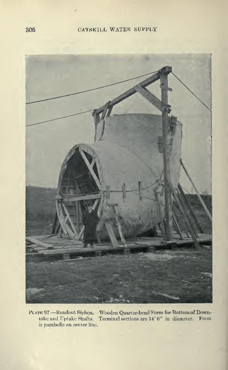
306 CATSKILL WATER SUPPLY
Plate 97.—^Rondout Siphon. Wooden Quarter-bend Form for Bottom of Down-take and T^ptake Shafts. Terminal sections are 14' 6" in diameter. Formis paraboHc on center Une.
RONDOUT PRESSURE TUNNEL 307
and dumped into the bins used to supply concrete to Bonticou
tunnol and the lining for Shaft 8. Sand and cement were hauled
by wagons to Shafts and 7 and to the foot of the incline at Shaft 8.
With the plants above described no difficulty was experienced in
furnishing sufficient concrete material. Due to the hardness of
the grit the wearing parts of the gyratory crushers, though madeof manganese steel, had to be frequently replaced.
Concrete Mixing Plants. At the portal of the Bonticou tunnel
a Smith mixer was installed which was charged by measuring cars
filled directly from the bins. At the other shafts Chicago cube
mixers were installed. Some of them were equipped with self-
charging devices. These were not found to be satisfactory and were
taken off, the mixers being charged directly from measuring cars
filled at the bins. These cars were operated on incUnes by small
rotary air engines and cables. The measuring cars were end dump-ing, subdivided into sand and stone spaces by hinged diaphragm.
These proved to be very handy and gave an accurate measure of
the concrete material. The concrete cars were side-dumping
Koppel and Youngstown, holding about 22 cubic feet. Theywere run on the cages from the mixer and hauled to the forms bymules.
Concreting of Tunnel with Full Circular Forms. The concreting
of so many miles of circular tunnel under the rigid specifications
governing this class of work presented new problems in construction.
To give a start for lining Shaft 8, Blaw circular steel forms were
ordered. These consisted of channel ribs, 5-foot centers, uponwhich were bolted steel plates. The concrete pedestal blocks were
set to proper grade, upon which the steel forms were erected and a
30-foot section successfully concreted in one operation. This wasseen to be very expensive, as the forms had to be taken down by handand set up piece by piece. It was also found not to give very good
work, as it was hard to get the concrete to flow beneath the forms.
The contractor then devised a new method which proved very
adaptable to the work, cut down the cost and increased the progress.
This method, which is given below, has been followed in nearly all
the pressure tunnel contracts on the aqueduct. The concrete wasplaced in three stages, invert, side walls, and arch.
Invert Concrete. After cleaning all muck from the bottom and
exposing the solid ledge, continuous wooden forms were placed for a
5-foot wide invert. These side boards were set on a radial line tied
together with ties and spreaders and braced down. They had a
depth equal to the average required thickness of concrete lining.

308 CATSKILL WATER SUPPLY
At first the plane of the side boards was carried down into the low
point bj^ short boards. This was later simplified by allowing the con-
crete to fill the bottom level to the base of the side boards, whence it
was formed into radial shape by the side boards, thus filling up manyholes with concrete which otherwise would accumulate muck and be
hard to clean out when the side forms were set. The concrete was
usuallj^ placed by dumping the cars onto a platform, where it was
shoveled into wheelbarrows which dumped from a runway directly
into the form. When the forms were filled the concrete was shaped up
roughly with shovel, and as it stiffened was worked to the required
C.L. of Planki
Plate 98.—Details of Continuous Invert Form for Pressure Tunnels. Also
"high hne" for placing concrete directly from cars.
curve by the use of screeds and trowels. The progress per day varied
from 75 to 250 feet, depending mainly upon getting the bottommucked out and the forms set up. The concrete was all placed bythe day shift, the other two shifts being used for mucking and setting
forms. Owing to the fact that the pressure tunnels were mostly onvery flat grade without subdrains, the damming off of the sections,
installing of pumps, and a thorough cleaning of the bottom pre-
paratory to placing invert represented a great deal of work. On the
Rondout siphon, the invert was mostly placed from wheelbarrows,
but on the Wallkill siphon, owing to the electric locomotives, there
used, the cars could be hauled up slight inclines and dumped directly

RONDOUT PKE8SURE TUNNEL 309
Plate 99.—Screeding Invert for Rondout Siphon. Concrete was laid between
continuoTis forms held in position by pipe spreaders. Skip is 5 feet wide
with radial side joints and bonding grooves.
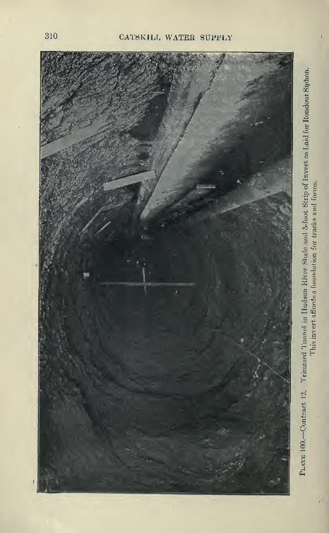
310 CATSKILL WATER SUPPLY
o
ao
a2 ^3
12 ^
s2 C
> c
s §
X to

RONDOUT PRES8URF Tl'NNEL 311
into the invert, thus giving greater progress. Forms and method
of placing invert are shown on Plate 98.
Side Wall and Arch Concreting. At first it was planned to
start side walls as soon as a sufficient stretch of invert was laid.
Later it was found much better to complete entire invert between
.shafts before setting side-wall forms. The side-wall forms were con-
structed by^the Blaw Company, and as originally made were composed
of semicircular ribs and plates set directly on invert concrete, as in
the case of the complete circular forms first described, they were to be
taken down piece by piece and reassembled. As this was slow and
expensive the contractor devised a method by which the forms
could be made collapsible in 60-foot units. The top braces were
cut and turnbuckles inserted so that the sides could be sprung awayfrom the concrete. The forms were also mounted on wooden
carriages running on beveled wheels on the invert. Small screw-
jacks on these carriages raised and lowered the forms by means of the
bottom braces. For constructing arch these forms were turned
over and mounted on high wooden carriages running on rails.
On later work the arch forms also ran on beveled wheels on the
invert. These forms are well shown by Plates.
To reach the concrete platform at the level of springing line 'of
arch, an inclined track about 70 feet long was built, so as to be
readily moved on trucks. The cars were hauled up this incline by
an air-operated engine placed ahead of the forms. During the first
season's work the side-wall concrete to the springing line was first
placed, and after a section of the tunnel side wall between adjacent
shafts had been completed, the forms were reversed, and in samestretch arch was placed.
Progress Made in Concreting Sidewalls. In order to allow the
concreting of a section of side wall every day, three sets of forms 60 to
80 feet in length were set up, so that with them a space of one-half the
distance between shafts could be concreted. While a form was being
filled, another was struck and moved. The forms were so arranged
that the mules could pull concrete cars through them. It was usually
easy to fill a form in a few hours, but it was difficult to get one ready
for filling every day, due to the amount of cleaning necessary- around
invert. In wet tunnels this could only be accomplished by the
formation of temporary sandbag dams and considerable pumping.
The forms were allowed to be struck within twenty hours after
being concreted. Wooden bulkheads were used at the ends of the
sections with a key to engage the next section. Longitudinal keys
were also cast at the top of the side wall to engage with the arch
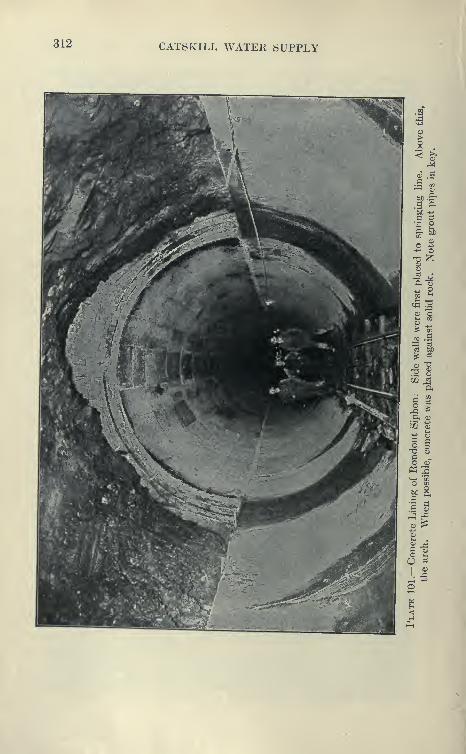
312 CATSKILL WATER SUPPLY
73 gc3
S3 fcC
'^ c3
"?
7?, SU2 eS
Ch
g ^^
&, a»
J/2
jh;
;3 ao o-d «co 0)
Si-^ m
&(
-J fl.~ CL>
J _a
a j^
CJ
o -C
C) 03
1
<D-C
7^owH-«J

RONDOUT PRESSURE TUNNEL 313
above. After a form was struck it was readily moved forward by
the hoist used to raise concrete up the incline. The maximum weekly
progress of the side walls for the whole contract, with concreting in
progress between five pairs of shafts, was 1175 feet. The maximumweekly progress for any one stretch of tunnel was 452 f(»et with
three sets of forms, two 60-foot lengths and one 80-foot length,
between shafts 2 and 3. The best monthly progress in side walls
l^etween these two shafts was 1770 feet, concrete being obtained
from both shaft plants.
Method of Placing Arch Concrete and Key. The forms used for
side walls were luniod over and (>ini)loye(l for arch work, mounted
on a specially designed carriage running on a pair of rails, carried
on 6"X6" in timbers laid on the invert, the rails being spaced by
6"X6" ties 5 feet apart. The same incHnes were used to bring the
concrete up to the platform at the springing line. The cars were
dumped on the platform and the concrete shoveled by hand into
the back of the forms, all plates of the form being in place except
a few at the top, the rest of the arch panels being added as the con-
crete was placed. For watertightness a very wet concrete was
used, making it necessary to use radial boards to form the arch key.
These boards were placed next to the key-plates, and the concrete
banked up above these as steep as it would stand. For the first
10 feet the key-boards were not necessary, as the concrete could be
cast directly in place over the plates. As soon as the concrete
obtained a slight set the key-boards were taken down, and from a
temporary platform 3J feet above springing line the concrete was
shoveled into the key, key-plates being placed from one end. The
time required to place a 40-foot section of arch was from eighteen
to thirty-six hours, the average about twenty-two hours, a consider-
able portion of the time being taken up in placing the key.
Concreting Arch without Key-joints. Where the roof was low,
a method was sometimes used in placing the arch concrete, so as to
avoid the use of the key-boards and radial joints. The concrete
v/as shoveled back of the forms in the usual way until about one-
half of the arch is placed and then brought up on a sloping line, a por-
tion of the key concrete being placed by casting over the form which
was completely erected next to the completed lining. Concrete
was added along this slope so as to keep it always in a fresh con-
dition unset, the 22-foot key-plates being added gradually. In this
manner the concrete arch was carried up as a monolith.
Progress Made in Arch Concrete. The concreting of arch
proceeded until the forms met, when it was necessary to make a
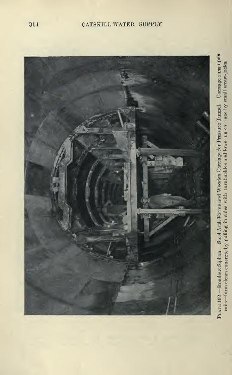
314 CATSKILL WATER SUPPLY
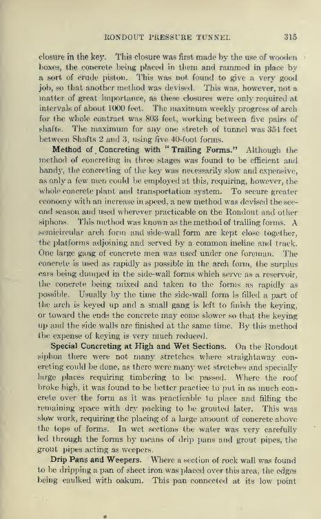
RONDOUT PRESSURE TUNNEL 315
closure in the kej'. This closure was first made by the use of woodenboxes, the concrete being placed in them and rammed in place bya sort of crude piston. This was not found to give a very good
job, so that another method was devised. This was, however, not a
matter of great importance, as these closures were only required at
intervals of about 10()0 feet. The maxinmm weekly progress of arch
for the whole contract was 803 feet, working l)etween five pairs of
shafts. The maximum for any one stretch of tunnel was 354 feet
between Shafts 2 and 3, using five 40-foot forms.
Method of Concreting with " Trailing Forms." Although the
method of concreting in three stages was found to be efficient andhandy, the concreting of the key was necessarily slow and expensive,
as only a few men could be employed at this, requiring, however, the
whole concrete plant and transportation system. To secure greater
economy with an increase in speed, a new method was devised the sec-
ond season and used wherever practicable on the Rondout and other
siphons. This method was kno\vn as the method of trailing forms. Asemicircular arch form and side-wall form are kept close together,
the platforms adjoining and served by a common incline and track.
One large gang of concrete men was used under one foreman. Theconcrete is used as rapidly as possible in the arch fonn, the surplus
ears being dumped in the side-wall forms which serve as a reservoir,
the concrete being mixed and taken to the forms as rapidly as
possible. Usually by the time the side-wall form is filled a part of
the arch is keyed up and a small gang is left to finish the keying,
or toward the ends the concrete may come slower so that the keying
up and the side walls are finished at the same time. By this methodthe expense of keying is very much reduced.
Special Concreting at High and Wet Sections. On the Rondoutsiphon there were not many stretches where straightaway con-
creting could be done, as there were many wet stretches and specially
large places requiring timbering to be passed. Where the roof
broke high, it was found to be better practice to put in as much con-
crete over the form as it was practicable to place and filling the
remaining space with dry packing to be grouted later. This wasslow work, requiring the placing of a large amount of concrete abovethe tops of forms. In wet sections the water was very carefully
led through the forms by means of drip pans and grout pipes, the
grout pipes acting as weepers.
Drip Pans and Weepers. Where a section of rock wall was foundto be dripping a pan of sheet iron was placed over this area, the edges
being caulked with oakum. This pan connected at its low point
31G CATSKILL WATER SUPPLY
with a 2-inch pipe led through the form. Where the pan was likely
to be ruptured by the pressure of the wet concrete, it was backed with
broken stone. It was found that neglect in providing for the free
outlet of water led to porous concrete, for as soon as any head accu-
mulated against the green concrete the water would force its waythrough. In the wet sections considerable areas had to be so cov-
ered, and the placing of drip sections and grout pipes was a large
part of the work preparatory to concreting. The care taken to
provide for water was amply rewarded, as many long stretches
through wet ground showed no leaks through the body of the concrete,
the water all issuing through the grout pipes. To reach the space
formed by the shrinking away of the key concrete from the roof,
pipes were placed at frequent intervals directly on top of the arch.
At specially high points long pipes were inserted to act as vent pipes
to allow the escape of the air when the lower pipes were grouted.
The specially wet section north of Shaft 4 was concreted beneath
a steel plate protection, as described before.
Concreting Shaft 8. Shaft 8 was the first to be concreted, no
cages being placed in this shaft, the tunnel from 7 to 8 being driven
from Shaft 7. The shaft was 710 feet deep, and was lined from the
bottom up, the timbers previously placed being removed in stretches
of 50 to 100 feet in reverse order as placed. The Blaw steel forms
were used, made up in 5-foot panels in quadrants. They were
internally trussed and collapsed by pulling out a wooden key. Theaverage progress made in placing concrete lining and removing
timbering was about 5 feet per calender day.
Concreting Shaft i. Much better progress was made at Shaft 1,
with the same forms. As in Shaft 8 concrete lining was alternated
with the removal of timbering, which was here taken out in stretches
of 60 feet to 120 feet at the rate of 30 feet per day. A very efficient
little concrete plant was here installed. Stone from the bins of a small
crusher was wheeled to the charging hopper of a Chicago cube
mixer, together with the necessary sand and cement. Small flat
cars containing bottom-dumping Steubner buckets were run along-
side the mixer and the buckets filled. The cars were then run on
two counterweighted doors over the shaft, the bucket hooked and
lifted part way into the head frame, the car run off and the doors
opened, so that the bucket could be lowered into the shaft. Thedoors immediately closed, a cable operating in a slit between the
doors. To each door one rail of the track was spiked. This
arrangement was very rapid and very safe, as the top of the shaft
was protected at all times except for the short intervals when a
KuMm)1 1 I'KK^ftlKK 11 .NNEL 317
bucket was near the top. All concrete was readily placed on the
day shift, the forms being set on the two night shifts. At first
the lining was done in 15-foot sections, later in 20-foot sections.
Even longer stretches could have been readily concreted, but the
forms proved incapable of standing the pressure of any greater
length. Including the quarter bend at the bottom, this shaft, about
600 feet in depth, was untimbered and concreted in seventy-five days
elapsed time, or at the rate of 7^ feet per calendar day. Excluding
quarter bend and bell-mouth the average progress was 9 feet per
calendar day. Concreting was in progress only thirty-three days,
or 105 hours. The shaft was very dry, making only one gallon of
water per minute, and therefore interfering \^'ith the concreting
very little.
Concreting Shaft from Bottom iip, vs. Concreting from Top
Down. It is a decitled disadvantage to concrete a shaft from the
bottom up, as comparatively little water will form a heavy rain
at the bottom of the shaft, greatly inconveniencing the men in
setting forms and placing concrete. On the other hand, if a shaft
is concreted during the sinking, water can be shut or led off so
that the concreting of shaft lining at the greater depths is not
inconvenienced.
Concreting Shaft 5. Concreting at Shaft 5 was quite a tedious
operation, as it required an outer and inner lining, the outer lining
being placed similarly to that at Shaft 1. The forms used at Shaft 1,
14 feet 6 inches in diameter, were adapted to the outer lining of
Shaft 5 by the use of fillers. After the outer lining was placed,
2-inch vitrified tile was laid against this and waterproofed, and by
the use of a new interior form the inner lining was cast. This form
contained accurate castings to shape concrete guides to be used
later for the floating pumping plant. The concreting of the inner
lining was necessarily slow and tedious, but averaged about 7 feet
per day.
Grouting Cut-off Walls. During the first concreting of the
arch, a cut-off wall of concrete was carefully placed in every section,
at a low point in the profile, and the arch was caulked with oakumand mortar at the end of a day's work. This was specified for the
purpose of grouting short stretches of arch under pressure. In
every case, where possible, the concrete was placed solidly to the roof,
dry packing being used only for exceptionally high places. It was
realized that the settling of the green concrete away from the roof
would leave plenty of grouting space, and that dry packing was
unnecessary for this purpose.
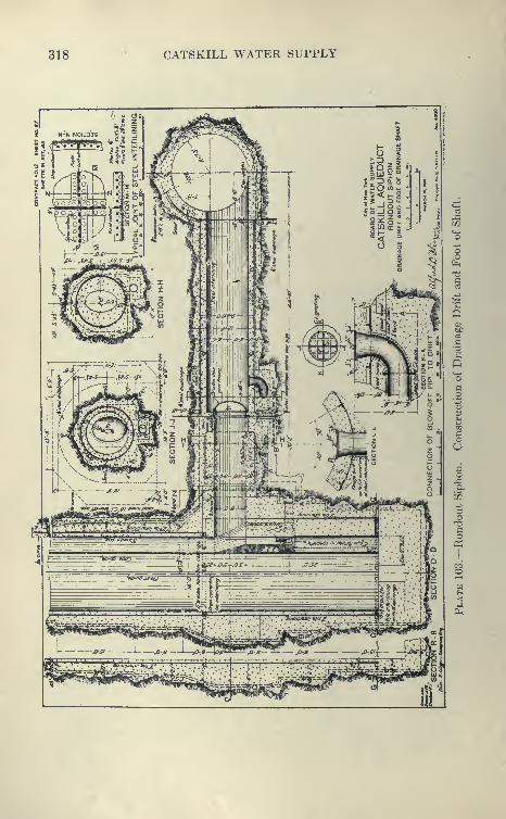
318 CATSKILL WATER SUPPLY

RONDOUT PRESSURE TUNNEL 319
"* to
.2 —
aoa

320 CATSKILL WATER SUPPLY
Grouting Equipment. The contract provided that the grouting
was to be done up to a pressure of 300 pounds. To raise the normal
pressure of 100 pounds to 300 pounds, Westinghouse high-pressure
air pumps were used to supply air to operate the Caniff tank grout-
ing machines. Westinghouse pumps and a battery of two or three
Caniff grouting machines were mounted on a car, back of which
were other cars containing sand and cement. The whole outfit was
hauled along the tunnel track as necessary, by cable and hoist.
The grouting car contained platforms from which connections could
readily be made. By this apparatus the grouting could be rapidly
done.
Methods of Grouting. It was soon found that the cut-off walls
did not cut off, and that grout passed through them somewhat freely,
probably passing through small fissures in the rock next to the con-
crete and between the concrete and the rock» After attempting
to follow out the original plan, which provided that the sections
should be put under high pressure one at a time, forcing the grout
into the surrounding rock, and thus filling up all voids and stopping
leaks, low points in the rock profile of the roof were selected and filled
with grout, using pressures as low as 40 pounds, it being found that
higher pressures threw the grout too far and discharged too much air
over the arch. After these stretches were set, the intermediate spaces
were filled under pressure of 100 pounds, using the low pipes until the
highest ones overflowed. The high vent pipes were then cleaned so
that the last remaining spaces could be grouted under pressure, which
in this case was run up to 300 pounds. It was felt, however, that
these high pressures were obtained only on small sections adjacent to
these pipes. Tests made by cutting into the roof and into the
dry-packed sections showed that the space between the roof and
arch was apparently solidly filled with grout, which, however, hada somewhat laminated appearance due to the separation of sand
and cement used in the proportion of about 1 to 1. This grout whenset weighed about 134 pounds per cubic foot. Dry packing wasfound to have from 45 to 59 per cent voids which took grout. Thecost of dry packing plus the grout necessary to fill its voids wassomewhat more than solid concrete. It was found that the pipes
which opened to the rock below the top of the waterway could be
grouted individually under high pressures, the grout seldom com-municating from one to another. They seldom took more than
enough grout to plug them. This is supposed to be due to the
fact that green concrete tends to press against the rock below the top
of the form and shrink away above this level.

RONDOUT PRESSURE TUNNEL 321
Plate 105.—Contract 12. Grouting Outfit as Used in Rondout Tunnel. Worth-
ington High-stage Compressor (350 lbs.) and Caniff Grouting MachineMounted on Movable Platform. Valve on grout pipe is operated by menon platform. Grouting was mostly done by direct air pressures of 40 to
. 100 lbs. per square inch. Remainder with high air up to 350 lbs. per
square inch.
322 CATSKILL WATER SUPPLY
Trouble Caused by Leaky Joints. It was found difficult to
hold the grout under pressure above the arch because the
transverse joints above springing line, which occur about every
45 feet, opened slightly and leaked considerably when placed under
pressure. The opening at the joints is explained by the decrease in
temperature from the time of setting, about 100°, to the time of
placing grout, about 50°. The grout was usually 1 cement to 1
very fine sand by volume, the sand being of great aid in plugging
joints, and preventing the undue running of the grout. However,
even a 1 to 1 grout seemed to run freely for hundreds of feet when
first placed, so that almost any pipe leading to the top of the arch
could be used for grouting, and no sharp distinction between grout
and vent pipes was necessary.
Grouting between Shafts 5 and 6. Great care was used in
grouting the stretch between Shafts Nos. 5 and 6. The work was
gone over several times until finally there remained no spaces to
be filled with grout. Some of the high pipes were opened up repeatedly
and regrouted. The vertical joints in the wet stretches, despite
every eJBFort, still leaked slightly. Holes were drilled into the joints,
grout pipes placed and attempts made to fill them with grout.
This proved ineffective, as water circulating through the joint would
gradually wash out the. grout, starting up the old leak. In fact,
it is extremely difficult to stop any leak which comes through the
body of the concrete by grouting, as the grout which may reach the
porous concrete, crack or joint responsible for the leak is carried
to the face of the concrete by the water.
Grout Pads. Grout pads as required by the contract were
furnished and tried. These consist of a column, similar to that used
for mounting drills, at the end of which is a casting containing a
rectangular rubber gasket. The pad, 15"X20'' about 3" deep,
is jacked against the leaky spot by means of screw-jacks at the other
end of the column, after which grout is pumped into the pad, and
allowed to set, the theory being that the grout will penetrate the
porous concrete, stopping off the leak. It was, however, found
that the area covered is too small for effective work and the pads
with columns, etc., very clumsy to handle. Its utility at any rate
was small. In very few cases did any grout leak through the body
of the concrete, this being in places where dry concrete was inadvert-
ently used. None of the sections placed with wet, dense concrete
was penetrated by the water.
Grouting between Shafts 7 and 8. In the next stretch grouted
between Shafts 7 and 8, advantage was taken of the experience
RONDOUT PRESSURE TL.N.NJiL 323
gained between Shafts 5 and 6, and a simple method of grouting
adopted. Machines were started at Shaft No. 7 and the grout
driven ahead, air pressure of 50 pounds to the square inch being used.
No attention was paid to cut-off walls, the grout being pumped con-
tinuously into a pipe until it appeared about 150 feet ahead,
when the grout plant was moved this distance and a new connec-
tion made. The isolated pipes below the top of the waterway were
plugged with grout, pressures up to 250 pounds being used. Afew of the high pipes in the arch were opened and grouted at high
pressure, but these took comparatively little grout. This grouting
was aided by the 2 per cent incline up which the grouting was
done. Rapid progress was made by this method and the results
obtained appeared to })e very good.
Grouting Wet Stretch North of Shaft 4. Perhaps the most
interesting work of grouting was that performed in the very wet
stretch of ground on the incline north of Shaft 4. As described
before, the inflow into 350 feet of tunnel was 1950 gallons per minute
(Dec. 1, 1910), which gradually diminished to 1000 gallons per
minute at the time of grouting (Jan. 27, 1912). The rock along the
stretch was porous and much broken up by folding and faulting. Thewettest stretch of 175 feet was protected by a steel shell (Plate 94).
The concrete in the invert was placed, first, in stretches of 25 to
40 feet, most of the water being diverted through 6-inch branches
into the 8 inch-spiral riveted main drain. Water which got
between the invert forms through seams or springs was dammedoff by sandbags and diverted into a hole in the top of the subdrain.
Over a portion of the bottom it was necessary to lay stone drains.
The 2-foot concrete lining was readily placed inside the steel shell,
which effectively shed the water, very little dripping through the
plate joints.
Cut-ofT walls were built over the arch at each end of the wet
stretch; they were composed of four brick walls built tight against
the roof and the space between them grouted. The tunnel both above
and below the very wet stretch was thoroughly grouted in the usual
way, as it was deemed advisable to force all the water into the
stretch covered by steel lining where special provisions had been
made for handling it.
Grout Pipes. Two systems of grout pipes were placed, one to
reach the dry packed space back of the steel lining; the other,
known as deep-seated pipes, was inserted, previously to the placing
of the steel, into all flowing seams to depths of 3 to 4 feet,

324 CATSKILL WATER SUPPLY
Grouting behind Steel Shell. Before grouting the dry packing the
8-inch drain at the bottom was closed by a valve, and a few pipes
left open to prevent accumulation of head. This formed a pond of
still water into which neat cement grout was placed, as experiments
previously made showed that grout of sand and cement was liable
to stratify when forced into a confined space containing water.
A battery of four Caniff machines mounted on a car was used,
grouting proceeding from the lower end. As the grout rose, it
could be followed by opening pipes at various levels. The deep-
seated pipes were allowed to flow so as to reduce the pressure
while the dry packing was being grouted; however, a few which
showed grout were promptly closed, but later opened after the
grout had set. The final grouting of dry packing was done at a
pressure of 90 pounds at the top of the incline. The machines
forced in 7693 batches of neat grout (1.2 cu.ft. each) in 10 shifts,
the maximum quantity for any one shift being 1207 batches, this
being the record for any tunnel on the Hne.
Grouting Deep-seated Pipes. After the grout had set a few days
the deep-seated pipes, through which a few hundred gallons of water
issued per minute, were grouted with a thin grout, each taking
from a few batches to 531 batches under a pressure of 300 pounds.
Reduction of Leakage through Grouting. The leakage on the
incline was reduced from 1000 gallons per minute to 8 gallons,
and the grouting was thus extremely satisfactory and successful.
The inflow through the lining has increased only slightly, although
the head on the tunnel increased from 58 feet upon the completion
of the grouting to 106 feet ten days later and increased, as sho^^Ti
on Plate 106. The size of the rock reservoir adjacent to Shaft 4
is indicated by the absorption of over 1000 gallons of water per
minute for forty days, while the rock water level was rising from
elevation —185 to elevation —65, the latter being the elevation of
the pump chamber. Pumps were placed in the chamber to enable
the shaft plug to be placed.
The results achieved at Shaft 4 were due to the great care in
providing for the free passage of water while concreting, and to the
placing of the pipes so as to enable the lining to be surrounded by a
layer of grout, which effectively sealed off the water.
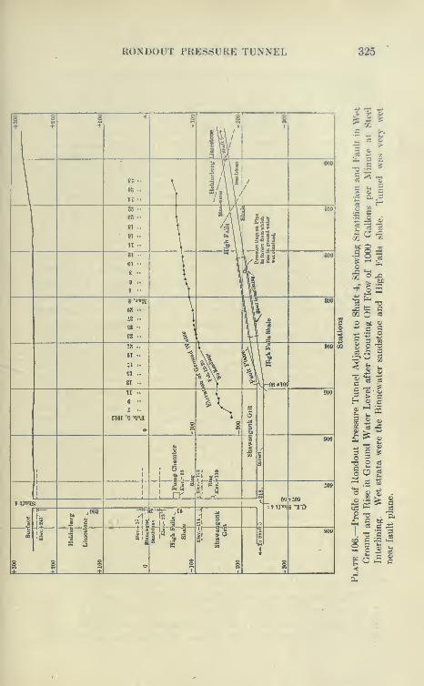
RONDOUT PRESSURE TUNNEL 325
§ I 1 i 1 § §+ +
1|"
\ m\|000
\88..
\ ^/\\/
\n " \ /
\»s ••
' s \ y\
88 ••
'i\f tfi
109
08 -1
81 ..
t• 91 ..
\
l\i filln ••
\81 ••
01 ••
" ill^is809
8 ..
\9 •• \> ••
\8*-««K \ 809
68 •• \ Ul98 ••
,. u 1£8 •• \ T"\ -3
T8.. ^ I a\\ 2 T09
61 ..
il ..
ST ..1 \'
« ..^»-
r
^ ^^,-06-HOJ
n . ^ {
^909
6 • l\I '• ^
8I6I '9 -qoj \
e s 11^ 909
1
1i
;1 6! .S
1 1 a 1
1 la -i -1 :09
1 1
I rr -J J" 2
^%T^ 3 ->}}tn{R 'Trt
I1
^•^./•'
K^- ,10
1-Ji ? » 1 1-i \i
1 ^ii|
•'
1
1
809
i i g o 1 i §-•- +
i^-
S c -^
s o"So
•^
-MK
frt T5j= tc CM o sS
o w, oc cJ3
o
^ 2n
-a
03T5<
?^ fc
ad
CC5
1 ^ ^£ ^,^ 13 «3 C !$n
o^ ej
O f*
tf a -s
*© "£
«X3^
§P -o "EPh ^ ^
1 -o c 3CO sO
o S 03-
^ OC
<

326 CATSKILL WATER SUPPLY
MATERIALS USED IN GROUTING RONDOUT PRESSURE TUNNEL
Be-tween
Dis-tance,
BarrelsCement
SandUsed.
BarrelsCement
PoundsSand Remarks.
Shafts. Feet. Used. Tons. Foot. Foot.
1-2 3900 2712 323 0.695 166 Only 4 cu.yds. dry packing used.
2-3 4400 2528 322 0.576 146 Only 10 cu.yds. dry packing used.
3-4 4050 9649 856 2.380 423 Includes vertical cavities in roof anddry packing behind steel lining.
4-5 2750 2539 323 0.921 235 Includes 168 cu.yds. dry packing.
5-6 3200 2607 327 0.816 204 Includes 391 cu.yds. dry packing.
6-7 3200 2103 272 0.666 170 Includes 119 cu.yds. dry packing.
7-8 2000 947 125 0.473 125 No dry packing; 2 per cent grade.
General Conclusions as to Grouting. The grouting of a tunnel
being a process performed more or less in the dark, is not one for
which an exact procedure can be laid down in advance. It is found
that equally good men will grout with quite different methods, but
the results will be about equal. It is an operation requiring a
great deal of patience and persistence and repeated going over
of same work. Where there are many pipes placed, the exact order
in which they are connected is not a matter of great importance,
though in general it is better to connect with the shorter pipes in the
arch, using the high ones as telltales, and vents for the escape of air and
water. In some of the later concreting, special effort was made to
obtain tight joints in wet sections. In each arch joint two or more
grout pipes were placed, and in some cases grouting grooves were
formed. Although with these devices grout could freely be forced
into the joints, still when grouting ceased water would slowly circulate
through the joint, opening up new channels, resulting in the restora-
tion of the old leaks. Steel plates were used in some other cases
in the arch joint, the purpose being to provide a stop for the grout,
which after setting would permanently tighten the joint. This
has proven to furnish the best joint for wet sections.
Considerable success has been recently attained in closing leaky
expansion joints by hand calking. A deep groove is cut in the
joint and |-inch lead wire hammered in. This is inexpensive and
apparently permanent. Joints have been successfully calked
against an outside pressure of over 130 pounds per square inch.
Final Leakage into and out of Lined Tunnel. It is to be noted that
leaks through the joints as described is an inward leakage due to the
surrounding ground water, and has no necessary relation to outwardleakage when the tunnel is in service. Further, these inward leaks.
RONDOUT PRESSURE TUNNEL 327
though very conspicuous, amount to very little in gallons per minut«.
For the water to escape it would be necessary to penetrate hundreds
of feet of rock after passing the tunnel lining. The grouting* is
indispensable and invaluable for this class of work, as it fills up
the voids back of the tunnel lining, so that the internal pressure is
transmitted to the rock, and moreover prevents the water from
circulating over the arch and reaching porous places in the rock.
Originally it was hoped that by the use of high grouting pressures
the rock in contact with the lining could be thoroughly impregnated
with grout so as to make it waterproof independently of the con-
crete lining. However, it was not found that high grouting pres-
sures could be used to much advantage. The process of grouting
is really a gradual silting up of the spaces surrounding the arch
and plugging up of springs leading to the vent pipes. It is not
probable that the grout will prevent the ground water from reaching
the concrete lining which after all must be the main reliance in
keeping the water out when the tunnel is empty or in when in
service. For this reason the concrete arch should be reasonably
thick so that the men can conveniently work behind the forms.
Ten or twelve inches of rich dense concrete placed very wet and
rammed in level layers with all spaces behind grouted will prove
very tight. Considering that this tunnel is hundreds of feet below
ground water and without waterproofing, the dryness of the con-
crete is remarkable.
Sealing Construction Shafts. The construction shafts were
sealed against future outward leakage from the tunnel when in
service by removing the lower 75 feet of timbering and placing a
concrete plug in which were inserted three grout pans about 6 feet,
13 feet, and 31 feet from top of waterway. These pans were 2 feet
wide and continuously united around the shaft. They were placed
against the rock sides and the lower edge was sunk 6 inches into set
concrete, the upper edge being caulked with oakum and cement.
Two grout pipes led upward to the top of the plug and one, a vent
or drain pipe, to the waterway below. The pans were cleaned with
air and water, and neat grout forced in at 300 pounds pressure,
using a Caniff machine and Westinghouse booster. At Shaft 6, the
lower pan took 76 cubic feet of grout, the middle pan 54, and the
upper pan 64 cubic feet, some of the grout, which was forced under
heavy pressure to the top of the plug, appearing along the sides in
seams which, however, soon plugged themselves. The water enter-
ing the shaft above the plug was collected in a ring about 75 feet
above the waterway and led through a pipe to the tunnel.

328 CATSKILL WATER SUPPLY
Leakage through Plug at Shaft 7. The efficiency of the shaft
plugs was well demonstrated by a test at Shaft 7. The inflow into
this shaft was about 65 gallons per minute, which, when the drain
pipe through the plug was closed after grouting, rapidly accumulated
above in the shaft to ground-water level, a depth of 419 feet, as
indicated by 182 pounds pressure on a gauge in the drain pipe at
the foot of the shaft. This pressure increased the leakage into a
stretch of 660 feet of tunnel each side of the shaft from 2 gallons
per minute to 9 gallons per minute, an increase of only 7 gallons.
The increased leakage appeared mainly at two transverse points
near the shaft. This is considered a very creditable showing.
Concreting Bonticou Grade Tunnel. Bonticou tunnel was the
first grade tunnel concreted, and the standard practice and forms
were here developed. As in the case of the pressure tunnel, Blaw
forms were used, and they were delivered without carriages, the
intention being to take the forms apart and carry them forward
by hand and set them up. This was found impracticable and a
wooden carriage with jacks, such as used for the bottom forms,
in the pressure tunnel, was fitted to 30 feet lengths and the forms
made collapsible by cutting the braces at the springing line and
equipping them with turnbuckles. By unbolting the ribs at the
top they could be collapsed and the forms lowered and sprung in
by the turnbuckles, clearing the concrete sufficiently to allow the
form to be moved forward on the wide-gauge track provided. '.J As
the grade-tunnel section is high and narrow, side walls and arch
are concreted in one operation, with all except a few of the top
plates left permanently in place.
The concrete was hauled in side-dumping cars j by mules
from a mixing plant at the portal and raised by a cable to
the platform at the springing line up an incline similar to that
used in pressure tunnels; the concrete after being dumped wasthen shoveled behind the forms, the men in them spading andleveling. Above the springing line the concrete was cast in place
by hand. To reach the key a higher temporary platform wasused. The keying proceeds from the end nearest the finished con-
crete, 2^-foot key-plates being gradually added. Three sets of
30-foot forms were used, the forms allowing the concrete cars to
pass through. A form was usually made ready and filled every day,
as usual the slow part of the work being the keying. Several
changes had to be made toward strengthening and improving the
forms used. Nevertheless good progress was made, 3340 feet of
side wall and arch being concreted in six months, the maximum

RONDOUT PRESSURE TUNNEL 329
Plate 107.—Contract 12. Blaw Grade Tunnel Forms. Form was filled in
30-foot lengths and collapsed by pulling in sides at mid-diameter with turn-
buckles, unbolting ribs at center and lowering with jacks on wooden carriage
running on rails. See also Plate 113.

330 CATSKILL WATER SUPPLY
monthly progress being 766 feet. To provide foundation for the
forms, narrow footing courses, 9 inches thick by 2 feet wide, were
laid to proper grade each side of the tunnel. These proved to be of
great assistance in setting forms.
Concreting of Invert. The arched invert was laid last, only
about 5 inches thick, being provided with a box drain, frequent
openings being made through the invert to prevent pressure from
accumulating on it when the aqueduct is not in service. The
invert was rapidly laid at the rate of 100 feet a day, profile boards
being wedged in against the side walls and used to serve as guides
for the long screeds used for shaping invert.
Placing of Weepers and Drip Pans. In concreting the grade
tunnels, the pip)es were used as weepers to prevent water from
percolating through the concrete while green, wet areas being also
protected by drip pans as previously described in the pressure tun-
nels. To prevent ground water from accumulating upon the arch,
pipes were concreted in with the key. No effort was made to secure
tight joints, as the inward leakage into the grade tunnel can do no
harm. A short section of tunnel was grouted near the portal and the
sub-drain plugged to prevent outward leakage around the tunnel
lining.
Hydrostatic Test of Rondout Siphon. The contract provides for a
hydrostatic test for the whole of the Rondout siphon. Three months
after the concrete lining is all placed and grouted, the tunnel is to
be filled with water to hydraulic grade. From the terminal shafts
observations can then be readily made. At the drainage shaft. No.
5, a centrifugal electrically operated pumping plant is to be provided
under another contract. The pumps are to be mounted on a cylin-
drical steel float which will descend in the shaft as fast as the water
is lowered by pumping, a length of discharge pipe being added at
the same rate. This plant on reaching the bottom will pumpout the entire siphon at the rate of 3000 gallons per minute. Anexamination is then to be made of the tunnel to see how it with-
stands the internal pressure and any defects repaired, after which
the tunnel will again be filled, and the leakage noted, and if thought
necessary again pumped out for re-examination.

BONDOUT PRESSURE TUNNEL 331
If
'5 ^
II
o -a
1
so
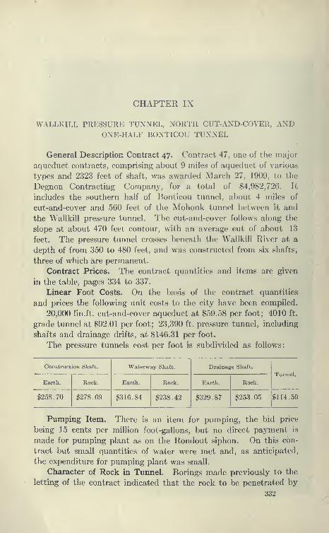
CHAPTER IX
WALLKILL PRESSURE TUNNEL, NORTH CUT-AND-COVER, ANDONE-HALF BONTICOU TUNNEL
General Description Contract 47. Contract 47, one of the major
aqueduct contracts, comprising about 9 miles of aqueduct of various
types and 2323 feet of shaft, was awarded March 27, 1909, to the
Degnon Contracting Company, for a total of $4,982,726. It
includes the southern half of Bonticou tunnel, about 4 miles of
cut-and-cover and 560 feet of the Mohonk tunnel between it and
the Wallkill pressure tunnel. The cut-and-cover follows along the
slope at about 470 feet contour, with an average cut of about 13
feet. The pressure tunnel crosses beneath the Wallkill River at a
depth of from 350 to 480 feet, and was constructed from six shafts,
three of which are permanent.
Contract Prices. The contract quantities and items are given
in the table, pages 334 to 337.
Linear Foot Costs. On the basis of the contract quantities
and prices the following unit costs to the city have been compiled.
20,000 lin.ft. cut-and-cover aqueduct at $59.58 per foot; 4010 ft.
grade tunnel at $92.01 per foot; 23,390 ft. pressure tunnel, including
shafts and drainage drifts, at $146.31 per foot.
The pressure tunnels cost per foot is subdivided as follows:
Construction Shaft. Waterway Shaft. Drainage Shaft.
Tunnel.
Earth. Rock. Earth. Rock. Earth. Rock.
$258.70 $278.69 $316.84 $238.42 $329.87 $253.05 $114.59
Piimping Item. There is an item for pumping, the bid price
being 15 cents per million foot-gallons, but no direct payment is
made for pumping plant as on the Rondout siphon. On this con-
tract but small quantities of water were met and, as anticipated,
the expenditure for pumping plant was small.
Character of Rock in Tunnel. Borings made previously to the
letting of the contract indicated that the rock to be penetrated by
332
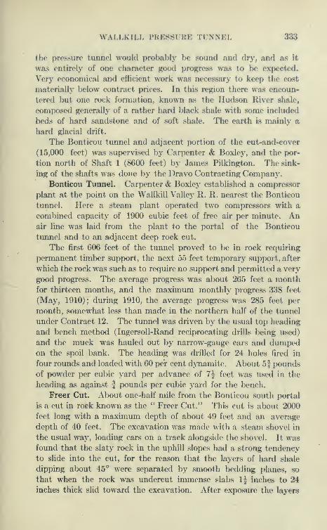
WALLKILL PRESSURE TUNNEL 333
the pressure tunnel would probably be sound and drj', and as it
was entirely of one character good progress was to be expected.
^'ery economical and efficient work was necessary to keep the cost
materially below contract prices. In this region there was encoun-
tered but one rock formation, known as the Hudson River shale,
composed generally of a rather hard black shale with some included
bods of hard sandstone and of soft shale. The earth is mainly a
hard glacial drift.
The Bonticou tunnel and adjacent portion of the cut-and-cover
(15,000 feet) was supervised by Carpenter & Boxley, and the por-
tion north of Shaft 1 (8600 feet) by James Pilkington. The sink-
ing of the shafts was done by the Dravo Contracting Company.Bonticou Tunnel. Carpenter & Boxley established a compressor
plant at the point on the Wallkill Valley R. R. nearest the Bonticou
tunnel. Here a steam plant operated two compressors with a
combined capacity of 1900 cubic feet of free air per minute. Anair line was laid from the plant to the portal of the Bonticou
tunnel and to an adjacent deep rock cut.
The first 606 feet of the tunnel proved to be in rock requiring
permanent timber support, the next 55 feet temporary support, after
which the rock was such as to require no support and permitted a very
good progress. The average progress was about 265 feet a monthfor thirteen months, and the maximum monthly progress 338 feet
(May, 1910); during 1910, the average progress was 285 feet per
month, somewhat less than made in the northern half of the tunnel
under Contract 12. The tunnel was driven by the usual top heading
and bench method (Ingersoll-Rand reciprocating drills being used)
and the muck was hauled out by narrow-gauge cars and dumpedon the spoil bank. The heading was drilled for 24 holes fired in
four rounds and loaded with 60 per cent dynamite. About 5.4 pounds
of powder per cubic yard per advance of 7^ feet was used in the
heading as against J pounds per cubic yard for the bench.
Freer Cut. About one-half mile from the Bonticou south portal
is a cut in rock known as the " Freer Cut." This cut is about 2000
feet long with a maximum depth of about 49 feet and an average
depth of 40 feet. The excavation was made with a steam shovel in
the usual way, loading cars on a track alongside the shovel. It wasfound that the slaty rock in the uphill slopes had a strong tendency
to slide into the cut, for the reason that the layers of hard shale
dipping about 45° were separated by smooth bedding planes, so
that when the rock was undercut immense slabs 1| inches to 24
inches thick slid toward the excavation. After exposure the layers
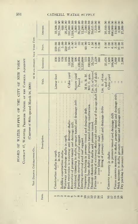
334 CATSKILL WATER SUPPLY
888888iO^ C-lO (>J^ p^ o^(>f r-T (O ic oo"
2 Q 2 ® o '-'^ o <^D O O O O <M (M OI5_ tC (N_^ to 0_O CO_ 00>f co" c-T t^" o" Qo" t> i-T
CC T-H CO CO
288888^^ cq^ O^ O^ O^ iq_
o" ^'' o"^ -rf t>r
S8888888S8:2§88 88888SO lO lO o lO :d Tfi
w b
Ph Qo W>H
^<1
H :^
^ ^
P2^ ^o o>< HH PHCJ
Ec.
nww HH Z
.Zb li
C H>^
Hti
&(Ih CO
As Up «S Ph
P5 ^WH Jef ij
^•<
§Q tl
rt <3
S 1eq o
>CS3 a
o
a
C O O LOCO ro cc Cr-l Oi t-H rH
CO CO o o
^ >o c o o oI (M Q LO CI O> ^ o r^ <M CO
d~ o -T co' i^"" o" oc^ o
'I Ma:
-c >." d ^ °
. T5 .s>
O^ .S .S
-^ if
2 c
"C -rt "o
o a1 ^ =
f 2 £ 303-O -C »
;;^ ^ '^~
•S^ bo -"
»5 ^ S ':3
OQ i^ 3 ^0) ^ -2 =^^
bC si O C
« c fc 5.2 "^ S
g.2 I£ ^ o
q ><
t5 g
CJ bCi'Z
c -c **
eJ _ 0}
O G 3
o ^ g p iS 'B S I
-^ o fe
O-'t^a; tH d.^ eS
S I'S
n C3 X-
^ b o -^ "a^
is ^ I e §
3 ei
^ ^3
I'd'
O ;=
'S if
— - w
liseJ OJ C« ai3 - -^^
§|£
3 a ^ S
4^ ?^ ^- <U
y^ 2 ^^^
•S .3
5
a;-
O 03 g
S a
C bO
S-^.c o ^ ..
T3 3 Si a< 3 iiH P^Q
c O 3
rH C<l CO '^•lO Ot>.000iO'-i(MC0rti»O
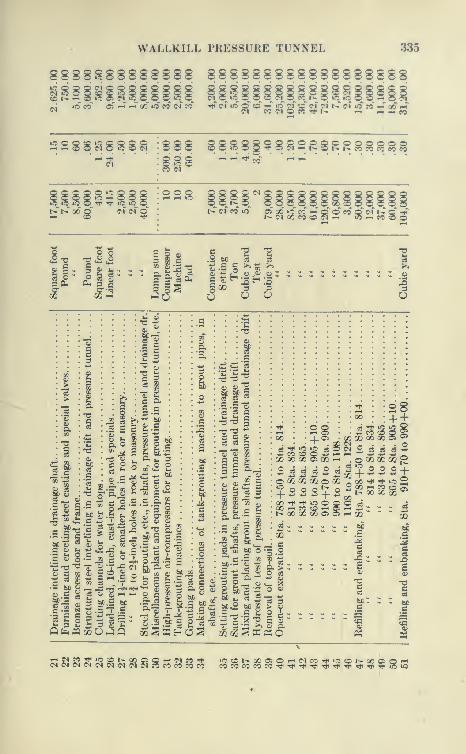
WALLKILL PRESSURE TUNNEL 335
88S8S88S88888 888888888888888888
*^ »occ oT f-H*"^''
00 »o ec cT eo ^ c^ »« c ?b -- lO 23^' c^r c^i i>.' cf ic cc'--'" x ^
to S © 2
i-HOOC^liSSSS 888 88S8§58g2g8gRgggg§g8§s "--*« --
t>r t>r QO Q ci (N o" i>^ c<r CO ic oT «~ uf c*f ^* c o* CO o* m' »-' =' •^''
Jt3 T3 J J
eg* cg';3
S O oi
3 § C
36
1" 3 ^ IS
Xl
1
s.
-e-S
Ci o
^5 00 ^
<5 ^ fe
c fc 8^•^-^
II
N
•5 c c
"3 §-aJ 2
2 I
11
£.? =
•^ -s^
c3 C u
= M5 ^ -c n S
g S3 « =
g o £ ^ ^3 hC.S bC
p ::j ^ = :
fc 3 2- C ^« 2
II 1 1.1
rt P e
^ I S -
C so 3 oj
« m bC O^ C .£ '^
« .2 -- .S ^-
00
Zi CCOi 00
ox"? o
+O iO 03 O (N O 5J 5J
QO 5 CO ^ . aHJUl
' t^ 00 QC
m
d 3
28+ ±
- 5
oJSJ?5^^SS5?5^^cS?3^^ »o«ot>.ooo50'-ic^cO'^»o«r>.ooo50'-»

336 CATSKILL WATER SUPPLY
8S888SSS88888S8SSS8S8888SR R RR O O »0 CO sd CO ^ (N 1^2 '* t^ -"tl COTj^ CO to 05 CO (M CO t>-
^:^ CO
OQQOOOOOOQOOiOiOC0OOOOt0O»OOOOOO(MCD Qq_»0_'^^»0^.-H^iOI>CDOOiO^O_0^0
i-T i-T oo~ -^^ T-T i>r i> CO*" (>f o"(M .-H
COCOcDtCOOO»OiCOtCOOOOOOOiCOOOOtOiO'iOC000»O(NC0(Mi-iOiOf-iOOr-^
T-< Oi I> CO o
8888SI^8S8^?; OOiOOOOQiOOOOTj< »00000(NiOi-4rtr-l ^tOlOi-H.-(.-l OO
^ 3M
'o
^ do^o ^.G
hJ•—
'
OO <30
O <M
P q
c
« K c
•I i ? c
c3 Si 2
3-1^
^- ^o i
S § c .2
CO O
.s s
^ ^ aes « >
C C OJ
o fe c
S bC^
a;
a
Xa;
S
a it I
5oO>H
5»C sr
.2 S-t-i •r'
13 t^
3l3
O ^'^ O
3 3
bc bC bC;3J3 C oj
03 3 O
03 fi
o3 2 o !»
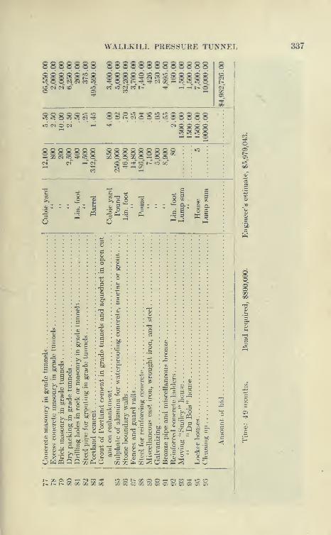
WALLKILL PRESSURE TUNNEL 337
88888S8 8888888888888»j5 O O "^ C 1^ CDiC O O C^ ?l CC lO
8 «0 Q lO Q^ C"l »0 Oi «5t^ "4 '«r (Ti QC ^
-^ t^ o
S S 8 S S <N
«3 C^ d (N
88RSS8g IS 88888•c ."?; 1?5
8 8 888g
CO
Q O 'i" CO t^ O Xi^ -^ ^ X
1
o
§ 13 5 M ^ X
-3h^
c 5
c3 *>
cc
o
O 03
S C3
O bc
COSbC ^ O
^, M *- C^^^ §- O ^^ «
o X '^ i i i^ oO W ffl Q Q r^ Oh
£ "^ «2
bC3
^ O
rs 9 .S > JZ
ilPh Oi
«« co o
ii
2 «- s sc-i:C -to
s §- -^ ;3 t O
^ §-§ ^8
tl|l|02 02 &ti X 2
^ TJ o —3 s
£ "ti :; ,22
£ c03 o
bC QJ^
3 a 8£oj
•
si N
~ 22
>/o
'5 3xQ
Oi .3 o
•ac
s 3S
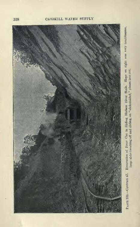
338 CATSKILL WATER SUPPLY
o c
I?^ o
|.s
6%
CQ
1:1

WALLKILL PRESSURE TUNNEL 339
up to 500 cubic yards would crumble and slide toward the cut at
unexpected times and endanger steam shovel and drills. The rock on
the downhill slopes stood up very well, the tendency there being
for the layers to support themselves. It was found advisable to
throw the center line of the cut further east and to allow flat slopes
on the west side in order not to again undercut the beds on that side,
which would prol)al)ly cause heavy slides with danger to life and
property, and to build the aqueduct with a wido Ivise instead of the
usual rock section.
Excavation and Concreting. For ordinary cuts a long-boom 60-
ton shovel was used with lift of 26 feet and reach of 40 feet. Theexcavation was spoiled on the downhill side of the trench and used
for grading a 36-inch-gauge track, or loaded upon side-dump cars
hauled by dinkies, to fill in the low spots for tracks or carried to
spoil banks.
The aqueduct was concreted with the usual equipment of sta-
tionary mixing plant, locomotive crane, and Blaw forms. A simple
concreting plant was installed which proved to be very efficient.
The stone and sand was supplied from the main contractor's railroad,
the cars dumping directly into bins built on the uphill slope of the
cut. A 31-cubic foot Smith rotary mixer discharged into Lockwoodautomatic bottom-dumping buckets hauled in trains of four flat cars
to the work, where they were dumped over the forms by an Indus-
trial locomotive crane with a 45-foot boom. The crane was supplied
with a double hook attached to two lines on its drum (see Plate 112).
The concreting was kept from 150 to 1500 feet from the shovel, and
the invert 15 feet to 900 feet ahead of the arch. Four buckets
were carried on two flat cars and a maximum haul of 6800 feet
was made in fifteen minutes.
Usually 60 feet of arch were concreted daily. With this plant,
75 feet of arch were concreted in 52 hours, but the usual progress
was 60 feet per day, as it is not practicable to get ready such a
length of form each day. The" maximum monthly work in 1911 was985 linear feet, and the average progress 785 feet. Concreting wasnot done every day.
Concreting in Freer Cut. The concreting of the aqueduct in the
Freer cut had to be done from one end, as no tracks could be laid
at the side. This delayed progress somewhat, so that only 45 feet
of arch could be concreted every other day. It was necessary to
carry the concrete on a track on the completed invert and place
the buckets ahead by the locomotive crane, which was elevated
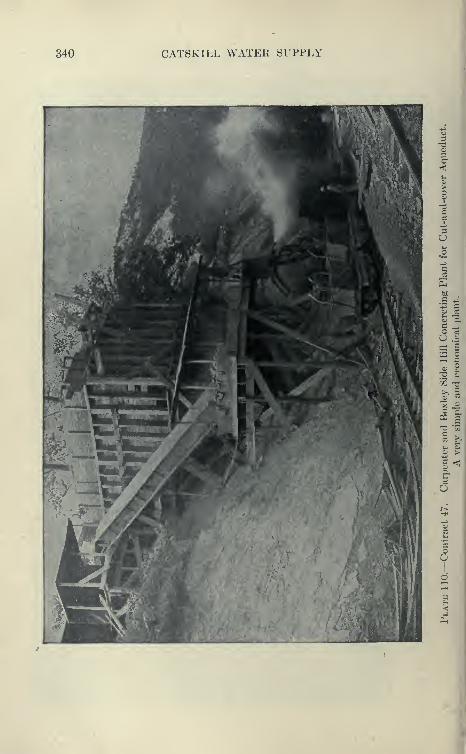
340 CATSKILL WATEK SUPPLY
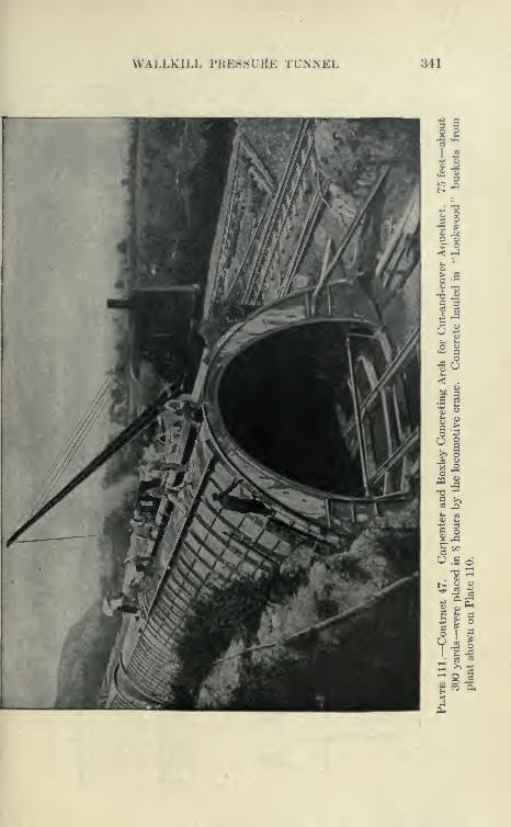
WALLKILL PKESSUKE TUNNEL 341
= I
JO J
11
c o
5|^ a^ o
•J 2
^J9 >»
IJ^ =®
O.S d
S g «
''-si
<
o

342 CATSKILL WATER SUPPLY

WALLKILL PRESSl^RE TrXNEL 343
above the invert on a trestle, so as to reach the front end of the form.
(See Plate 112.)
Concreting Bonticou Tunnel South. Blaw forms similar to those
used in Contract 12 were installed in Bonticou tunnel south, one set
of 30 feet at the end and two others of 30 feet at each third point.
No difficulty was cxporicnced in filling a 30-foot section with con-
crete in about fourteen hours, 117 30-foot sections being concreted
in 120 working days (about 10,290 cubic yards). The force was
disposed as follows:
8 A.M. to 4 P.M. Concreting at forms, 13 men; moving forms, 13
men; at mixer, 7 men.
4 P.M. to 12 P.M. In tunnel, 13 men: at mixer, 7 men.
12 P.M. to 8 A.M. Sealing rock and miscellaneous work, 10 men.
Invert Concreting. The invert was concreted one-half at a
time with a longitudinal joint on the center line. Forty cubic foot
side-dump Koppel cars were loaded at the portal from a mixer set
overhead, discharging through 45 feet of 10-inch pipe. The cars
dumped directly into the forms. About 600 feet on one side was
concreted, after which the track was thrown onto the finished invert
and the other half concreted. From 300 feet to 655 feet of one-half
invert was concreted in one eight-hour day (30 to 65 cubic yards).
The bottom drain was left open and connected with 2-inch pipes, at
200 feet intervals, through' the invert to prevent upward pressure
on the light 5-inch bottom.
Work South of Mohonk Tunnel. On this section of cut-and-cover
a plant entirely different from any other on the line of the aqueduct
was installed. Mr. Pilkington, the superintendent, previously had wide
experience in constructing sewers in cities, and endeavored to build
this part of the aqueduct in a similar manner. A trestle about 750 feet
long was erected of 12"X12'' timber bents spaced 15 feet on centers,
spanning the trench and carrying a system of four travelers, three
equipped with a derrick and hoisting engine, and one traveler carry-
ing in addition a concrete mixer. The function of the first traveler
was to build the trestle in advance as fast as the fourth traveler took
it up in the rear, and send the timber ahead on the dinky track
paralleling the trench. The second mucked out the trench bottom
and handled the concrete forms. The third lifted the dry concrete
in skips from dinky cars on the track alongside, mixed the concrete
and discharged it directly into the forms. The fourth traveler
handled the outside forms from the completed aqueduct, placed the
refill with an orange-peel bucket, and finally took down the trestle.
Derricks and steam shovels were used for the excavation. It
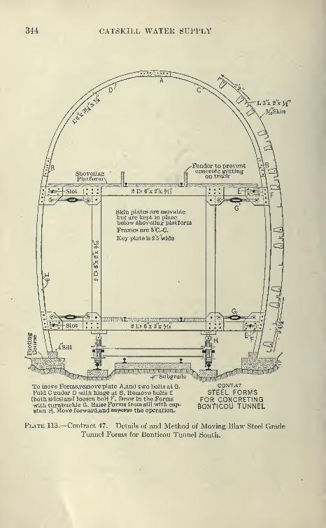
344 CATSKILL WATER SUPPLY
L3x2"xJi"
To move Fornis,removeplate A,and two bolts at B.
Fold C under D with hinge at B. Remove bolts E(both sides) and loosen bolt F. Draw in the Formswith turnbuckle G. RaiseForms from sill with cap-stan H.. Move forward^andESV^rse the operation.
CONT.47
STEEL FORMSFOR CONCRETINGBONTICOU TUNNEL
Plate 113.- -Contract 47. Details of and Method of Moving Blaw Steel GradeTunnel Forms for Bonticou Tunnel South.

WALLKILL PRESSURE TUNNEL 345
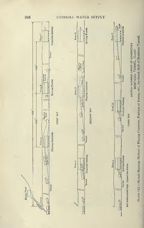
346 CATSKILL WATER SUPPLY
tr)
V
\JI
1
D 1
1I
1
si X
tm 'fl
fl
i z ^3
III o.^ o
o -1
z o Co -^1 oo mII. _I .,
,
o LU oa z «+5
lU z 03
Qtr
O 1-
(5 ZD;:l
H Z C) o*
1o OJ
jri1- ;-!
W oI m oo
a;
^«)
^ ON
o •« 4CQ oS)
1 ^s
•^
U
oq:
I f2
M 6

WALLKILL PRESSURE TUNNEL 347
was found that the above described plant of travelers and der-
ricks was unsuited to rough, open country on side hill, much work
being necessary to shape the ground to carry the tr<»stle, so that
alow progress was made.
In advance of the travelers described, a 4 -yard Vulcan shovel
excavated and spoiled on the downhill side except in deep cuts,
where cars were loaded alongside and hauled to the dump. Occa-
sionally the material was spoiled in the rear of the shovel to Ix*
picked up by the orange-peel bucket operated by the first derrick
on the trestle. In a later arrangement an extra derrick was moved
on skids in cut. The mixer was also moved to a central place, leav-
ing only three travelers on the trestle, the central derrick placing
the concrete with side-dump })uckets.
Wooden Forms. During the first season the aqueduct was
built with wooden forms similar to those used on Contract
10. After the invert was built, the side-wall forms were built
in 15-foot sections to 8 feet above invert. The vertical ribs
were 4 inches by 10 inches, 3 feet 9 inches apart, and were covered
with 2-inch lagging and i^-inch steel plate. They were adjustable
by trench braces. The side-wall forms produced very good work,
but the wooden arch forms, composed of 2-inch lagging supported by
steel arched ribs hinged at the crown, proved to be slow and cumber-
some. They distorted so much and made such a bad offset at the
8-foot line that they were later discarded in favor of the Blaw steel
forms.
In 1910, working one shift per day, the plant placed 1335 feet
of invert and 1065 feet of arch. In 1911, 2855 feet of invert and
2725 feet of arch were placed. During 1912 standard methods
were employed, using steel forms, locomotive cranes, etc.
Shaft Sinking. For the sinking of the shafts the Dravo Companyinstalled two temporary steam plants from which air was supplied
by pipe lines to all six shafts.
The shaft-sinking organization from the Rondout siphon was
transferred to this work together with the usual equipment of head
frames, hoisting rig, etc. No trouble was experienced in getting down
to rock except at Shaft 2, where an open caisson was sunk part way
(64 feet), the rock being reached by timbering from the caisson.
Three construction shafts were rectangular timbered shafts 11X22feet. These shafts were put down in from six to eight months,
the average progress of excavation and timbering being from
50 to 60 feet per month, the maximum about 90 feet. Thecontractor here, as on the Rondout siphon, exercised his option of
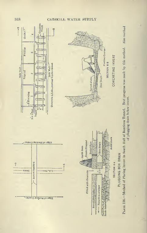
348 CATSKILL WATER SUPPLY
M
oejnoo Sunooj jo sSpg
K
eeanoo Sanooj jo oapa
o 2 U2
1-
oa>
1-UJ 'i
in cc a(J
92z ^C) ^
i
O
LII
. ^- -9
i!
m 'o 'H,— ^- t; o^ CJ K^ o ^^/ 3N
z ^^ <c a
q:
VI
<<
' zo
QXOca
a1—
1
-^- p a c
x" tuz
o3\.< (rt C3
=3
s"o
p_l

WALLKILL PRESSURE TUNNEL 349
sinking a larger shaft than required by the contract drawing,
accepting payment on the bid price per foot. The three waterway
shafts were sunk accortling to new specifications, requiring sinking
and lining in stretches of not more than 100 feet; that is, after
100 feet of rock was exposed by the excavation, forms were
inserted and permanent concrete lining placed, thus rendering
timbering unnecessarj-.
Permanent Shafts. The permanent shafts are circular, about
14 feet 6 inches finished diameter. The excavation of the downtake
shaft was taken out in a manner similar to that described for Shaft
1 of the Rondout siphon. While excavation wa,s in progress on this
shaft, a monthly advance ranging from 50 to 110 feet was
made. This, of course, was interrupted by the concreting, which
was placed in stretches of from 40 feet to 80 feet. Steel forms
designed by the Dravo Company were used. These were built
in quarter sections, 5 feet wide, and were internally trussed and
braced, and collapsed with the aid of wooden keys. These forms
gave a satisfactory and true surface for the waterway. Usually about
two sections were filled per day, from a small concrete plant at the
surface. The rock in uptake shaft, No. 6, proved to be rather wet
and unsound, so that the placing of the concrete lining was a great
advantage in securing this shaft. The progress p?r month was
rather slow, the maximum being 77 feet of excavation and 91 feet of
lining.
The details of shaft sinking and concreting are as follows:
Excavation of Construction Shafts. Compressed-air drills
drilled four sets of holes, called sump, relief, bench, and end or
side holes. The sump holes were started 6.5 feet each side of the
center line, four on a side parallel with the center line, and were 10
feet deep, the butts being about 6 inches apart. The sump was shot
and while being mucked the bar on which the drills were operated
was set up. The remaining holes were 8 feet deep. A total of
28 to 32 holes were drilled, and the advance was about Sa feet in
five eight-hour shifts. Each shift consisted of foreman, 2 drillers,
2 helpers, 4 muckers, 4 topmen, 1 blacksmith and 1 helper.
From 35 to 97 feet of shaft were excavated per month.
Excavation of Circular Shaft (Shaft 6). Three circular rounds
were drilled in one shift; next the sump holes were shot and mucked;
next the side holes were shot and mucked; and next the rim holes
were shot and mucked. Tripod drills were used. The drilling shift
consisted t)f foreman, 5 drillers and helpers and 6 topmen. Themucking shift consisted of foreman, 7 to 10 muckers, and 4 topmen.
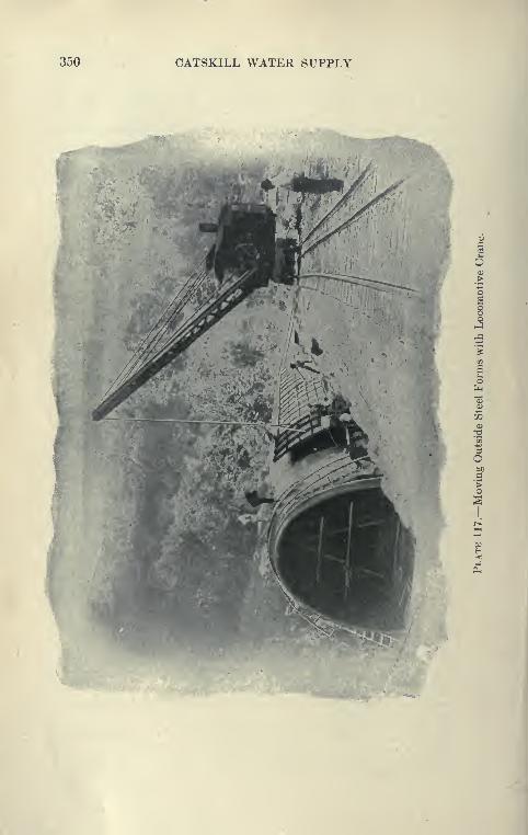
350 CATSKILL WATER SUPPLY
O
'mm^-^
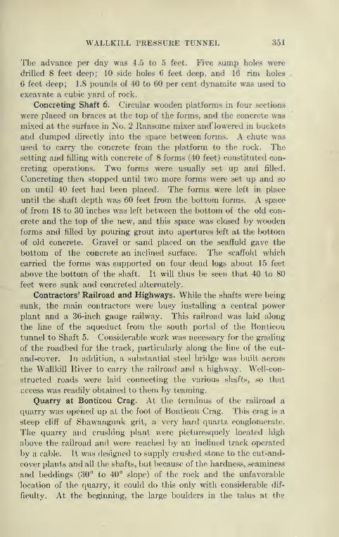
WALLKILL PRESSURE TUNNEL 351
The advance per day was 4.5 to 5 feet. Five sump holes were
drilled 8 feet deep; 10 side holes feet deep, and 16 rim holes
6 feet deep; 1.8 pounds of 40 to 60 per cent dynamite was u.sed to
excavate a cubic yard of rock.
Concreting Shaft 6. Circular wooden platforms in four .sections
were placed on braces at the top of the forms, and the concrete was
mixed at the surface in No. 2 Ransome mixer and' lowered in buckets
and dumped directly into the space between forms. A chute was
used to carry the concrete from the platform to the rock. Thesetting and filling with concrete of 8 forms (40 feet) constituted con-
creting operations. Two forms were usually set up and filled.
Concreting then stopped until two more forms were set up and so
on until 40 feet had been placed. The forms were left in place
until the shaft depth was 60 feet from the bottom forms. A space
of from 18 to 30 inches was left between the bottom of the old con-
crete and the top of the new, and this space was closed by wooden
forms and filled by pouring grout into apertures left at the bottom
of old concrete. Gravel or sand placed on the scaffold gave the
bottom of the concrete an inclined surface. The scaffold which
carried the forms was supported on four dead logs about 15 feet
above the bottom of the shaft. It will thus be seen that 40 to 80
feet were sunk and concreted alternately.
Contractors* Railroad and Highways. While the shafts were being
sunk, the main contractors were busy installing a central power
plant and a 36-inch gauge railway. This railroad was laid along
the line of the aqueduct from the south portal of the Bonticou
tunnel to Shaft 5. Considerable work was necessary for the grading
of the roadbed for the track, particularly along the line of the cut-
and-cover. In addition, a substantial steel bridge was built across
the Wallkill River to carry the railroad and a highway. Well-con-
structed roads were laid connecting the various shafts, so that
access was readily o})tained to them by teaming.
Quarry at Bonticou Crag. At the terminus of the railroad a
quarry was opened up at the foot of Bonticou Crag. This crag is a
steep cliff of Shawangunk grit, a very hard quartz conglomerate.
The quarry and crushing plant were picturesquely located high
above the railroad and were reached by an inclined track operated
by a cable. It was designed to supply crushed stone to the cut-and-
cover plants and all the shafts, but because of the hardness, seaminess
and beddings (30° to 40° slope) of the rock and the unfavorable
location of the quarry, it could do this only with considerable dif-
ficulty. At the beginning, the large boulders in the talus at the
352 CATSKILL WATER SUPPLY
foot of the crag had a strong tendency to roll into the workings
of the quarry and cramp men and plant. Drills had to be lowered
down the face of the crag from a point 100 feet above, and great
boulders loosened by the blasting were constantly rolling down,
preventing the opening of a satisfactory working face. In the
early stages of the work, these boulders often buried the track to
the crusher. Considerable mud capping of these boulders was done,
this being found to be more satisfactory than drilling. A No. 20
Marion shovel was employed to load 4-yard side-dump cars movedby gravity to the crushers and hauled back by mules.
Crushing Plant. During most of 1910 a No. 6 Kennedy gyratory-
crusher was in operation; later a No. 8 Kennedy crusher was installed,
rated to deliver 125 to 200 tons of 3- to 13-inch stone to two No. 6
crushers. The revolving screens over the bins were 24 inches in
diameter, 20 feet long, the perforations of the screens being | inch
and 2^ inches. The main screen was partly surrounded by a jacket
screen with j-inch perforations. The average output of the plant
was 450 cubic yards per working day. During the winter of 1910-11
a storage pile of approximately 20,000 cubic yards was accumulated.
This was fortunate, as in May, 1911, a fire destroyed the bins and
screen house, and the pile was nearly exhausted in the month required
to rebuild them. During the working season the output was very
close to the demand, and at times 600 cubic yards were daily shipped
to the working. The stone dust for the concrete was mixed with
natural sand in the proportion of one part to two. About 80 to 100
men, 3 air drills and 6 mules were employed at the quarry.
The drills averaged about 4 feet per hour.
Wear on Crushing Plant. As in the case of the grit quarries
on Contract 12, the stone was found to be very severe on the wearing
parts of the crushing plants and screens. A set of concaves for the
crushers lasted about three months. Three complete sets of revoh^-
ing screens were worn out in less than two seasons, together with
practically the entire conveyor system. The quarry, though very
favorably situated to supph^ stone to the entire nine miles of the
work, proved to be expensive in operation, owing to the hardness of
the rock and the difficulty of keeping working space in a quarry on a
steep slope at the foot of a high cliff with a talus of huge boulders.
Progress Made During 1909. By the end of 1909 all the shafts
of the siphon had been sunk and the headings turned, with the
exception of two terminal shafts completed shortly afterward. Thecentral power plant was built between Shafts 4 and 5 to furnish air
and electric power along the entire pressure tunnel. The plant
WALLKILL PRESSURE TUNNEL 353
was operated by electricity furnished by the Poughkeepsie Light,
Hoat and Power Conipan}', wiiich controlled a system of power
plants and tramjinission lines, so that it was pretty safe to figure
on a constant service. Two of their plants were hydraulically oper-
ated, others by steam at three Hudson River towns, tied together
so that power could be obtained from any one plant. As a favorable
rate for electricity was quoted, it was decided to use electricity
rather than steam, as in the Contract 12 plant.
Power Plant for Wallkill Tunnel. The plant was housed in a
steel building and operated entirely by electricity, using 33,000
volts three-phase alternating current. At the plant the current
was stepped down to 2200 volts, and divided into three circuits
—
one for the air compressors, the other two for the shafts, for
hoisting and for lighting and operating electric equipment con-
sisting of electric pumps, ventilating fans, electric locomotives,
concrete-mixer motors and machine-shop motors. The compres-
sor circuit operated motor-driven belt-connected two-stage air
compressors, two built by the Laidlaw-Dunn-Gordon Company,and three by the Ingersoll-Rand Company. These required 2300
H.P. with an output of about 11,700 cubic feet of free air per minute,
at 100 pounds gauge pressure. From the power house to the shafts
the air pipes varied from 12 inches to 6 inches. The force required
to operate the plants was 1 chief engineer, 3 compressor engine-
men, 3 electricians, 3 oilers, 1 wiper, and 1 laborer. From Aug. 31,
1910, to Jan. 4, 1911, which covered a period of tunnel driving,
3,562,000 K.W.H. were metered at the central plant.
Hoisting Equipment. Permanent timber head frames were
erected in which were operated two balanced cages. The Lambert
hoist installed at each shaft with drums 66 inches in diameter was
connected to a 150 H.P. three-phase 2200-volt motor, equipped
with solenoid brakes and overwinding devices. The cages operated
at the usual speed of 400 feet per minute. In addition, ventilating
fans and pumps were also electrically operated. Some trouble was ex-
perienced with the electrical equipment, but this was finally overcome.
Power Consumption. Careful records were kept at the power
plant and at the shafts of the consumption of electricity and air
for various purposes. It is very unusual to obtain reliable figures
for power consumption for a work of this magnitude, and the fol-
lowing are given :*
* Much of the following information on the tunneling of the Wallkill siphon
was obtained from an article by Assistant Engineer Raymond Hulsart, Engineering
News, Oct. 20. 1910.
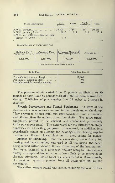
354 CATSKILL WATER SUPPLY
Power Consumption.Com-
pressors.Hoists,
Lights,Blowers,etc. Total.
K.W.H. per day 25,300
30.2
2.5
27803.3
15701.9
29,65035 4K.W.H. per cu. yd.
K.W.H. per 1000 c
pressed to 100 Ibj
u.ft. free air eom-5.
Consumption of compressed air:
Drills per Day.*Cubic Feet Free Air.
Pumps per Day.Cubic Feet Free Air.
Leakage in Mains andOther Losses per Day. Total per Day,
5,545,000 3,855,000 720,000 10,120,000
* Includes air used for blowing smoke.
Drills Used. Cubic Feet Free Air.
Per shift, (4^ hours
Per minute, includi
Per minute while at
drilling) 25,9009fitig stop
jtually running 166
The pressure of air varied from 95 pounds at Shaft 4 to 80pounds at Shaft 1 and 85 pounds at Shaft 6, the air being transmitted
through 25,000 feet of pipe varying from 12 inches to 6 inches in
diameter.
Electric Locomotives and Tunnel Equipment. At three of the
shafts electric locomotives were used in the tunnels and on the dump.They proved to be successful and were considered more economical
and efficient than the mules at the other shafts. The entire tunnel
equipment proved to be efficient and economical, particularly
in the power consumed. The compressed air was furnished in amplequantities for all drilling purposes. It was used, in addition, to aconsiderable extent in clearing the headings after blasting supple-
menting an efficient blower plant and to some extent for pumps.Method of Tunneling. For the excavation, the ordinary top
heading and bench method was used at all the shafts, the benchbeing carried within about 100 feet of the face of the heading, andthe tunnel trimmed as it advanced, the aim being to obtain imme-diately a completed tunnel, so as to leave little to be excavated at
the final trimming. Little water was encountered in these tunnels,
the maximum quantity pumped from all being only 600 gallons
per minute.
The entire pressure tunnel was excavated during the year 1910 at
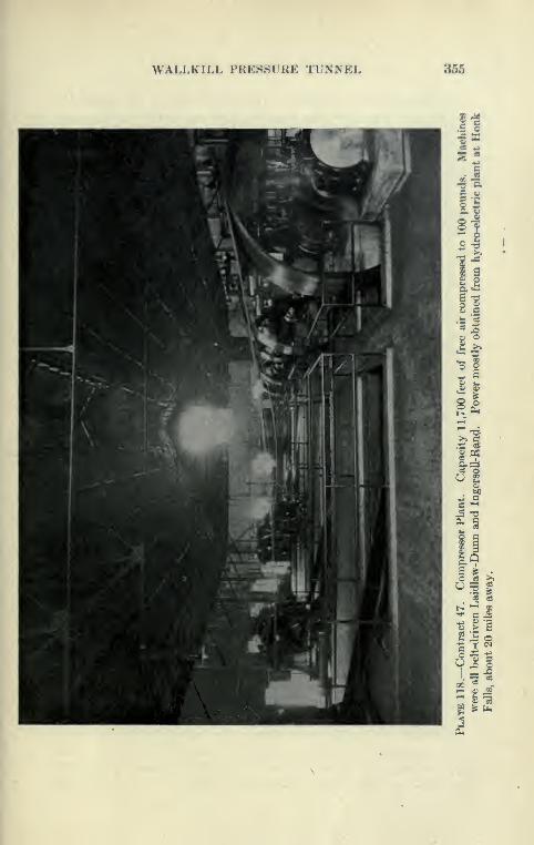
WALLKILL PRES8UKE TUNNEL 355

356 CATSKILL WATER SUPPLY
a high average rate of progress. This was favored by the uniformity
of the rock formation and the fact that so many headings were
going at the same time, offering an opportunity to compare the
work of different shaft organizations, each of which was in charge
of an efficient superintendent and foreman, some of whom were fresh
from similar work on the Rondout siphon.
The first pair of headings were holed through in July, the others
following until January, 1911. In 1910, over 23,000 feet of tunnel
were driven from six shafts and ten headings. Many of the tunnels
averaged considerably^ over 300 feet per month. The maximumprogress was 523 feet at Shaft 3 north, this being for the completed
circular tunnel about 10 cubic yards per foot. This is probably
the best progress made to date in the United States for a tunnel of
this size driven in hard rock. A detailed account of the method
used is given elsewhere.
Ventilation. The ventilation of a siphon tunnel during excava-
tion is of great importance, but in most of the tunnels it can hardly
be said that the plants were very successful in clearing the smoke
after blasting, this being responsible for delays in waiting for tunnels
to clear and the hampering of the men while actually at work.
Among the most successful ventilating plants were those used on
the Wallkill siphon. Sturtevant blowers capable of furnishing
7500 feet of free air at 6^-ounce pressure were used; 12-inch galvan-
ized iron pipe was brought within 300 to 400 feet of face of heading.
Though the plant was rigged up to either blow or exhaust it was
found more advantageous to blow fresh air into the heading, forcing
the smoke to the shafts. The blower worked about twelve hours
in twenty-four. In addition, during blasting, compressed air was
liberated as an aid to the blowing plant. In this way a minimumtime was lost due to smoke and gas in the tunnels. On some of the
other contracts good ventilating plants were installed, but they failed
to properly .clear the tunnels, due to use of either too small blower
pipes or, more commonly, to leaky joints in the pipes.
The tunnel was well lighted by 16-candle-power lamps every
25 feet. The water was pumped to the surface by air pumps, six
of 200-gallon capacity and four of 100-gallon capacity. Worthington
centrifugal pumps, two of 100 and two of 200-gallons capacity,
were also installed, but were only occasionally used.
Details of Tunnel Excavation. The tunnels were excavated
by the ordinary top heading and bench method, the bench being
kept within about 75 feet of the base of the heading. Two eight-
hour drilling shifts were used in each heading. They ordinarily
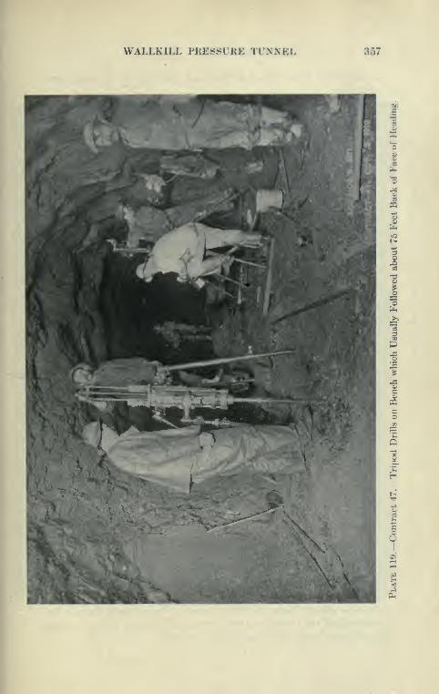
WALLKILL PRESSURE TUNNEL 357
9
I
3
w
Y
358 CATSKILL WATER SUPPLY
accomplished the work of drilUng and shooting the heading about
as follows:
Hours. Minutes.
Setting up drills 1 45
Drilling 4 30
Removing drills 15
Loading 30
Shooting 45
Balance 15
Total 8 00
The heading holes were drilled in three rounds by four drills
mounted on horizontal arms clamped to two columns. The bench was
drilled by two drills on tripods. IngersoU-Rand and Sullivan drills
were both used. About 189 feet of hole were drilled per round, about
6 feet per cubic yard of heading, and only 1.8 feet per cubic yard
of bench. The heading ordinarily ran 5^ cubic yards per foot and
the bench 3f cubic yards. About 4.6 pounds of 60 per cent Forcite
dynamite was used per cubic yard of heading, and 1.4 pounds in
bench. Between each drilling shift there was a four-hour interval
which was used to muck heading sufficiently to set up drills. Three
eight-hour shifts of muckers were used, who were able to work about
nineteen hours in twenty-four.
Force Used to Excavate Tunnels, Record Month. At a shaft with
two headings in operation, 260 men and 8 mules were employed, 6
drillers with their helpers constituting a drilling shift for each heading.
Usually an advance of 6^ feet was made per round ; with two rounds
per day, this would give a progress of about 13 feet, but the daily
progress from month to month ran from 9 to 12 feet at the various
headings. The record progress of 523 feet per month was madeby drilling unusually long holes in the heading, 12-foot steel being
used for the cut holes, giving an 8.7 foot advance per round. Tofacilitate the work here, two drillers and helpers set up the columns
in the four-hour interval between the regular drilling shifts. Therecord was made pretty well toward the end of the work with a
picked force, and it is significant only as it shows what can be
done under very favorable conditions. The average progress per
heading ranged from 265 feet to 356 feet per month. The slower
progress is accounted for by difficulty of drilling the sandstone
strata encountered. Some of this rock was very hard, requiring from
fifteen to twenty hours to drill a round. The ordinary shale of the
remainder of the tunnel was rather easily drilled, the drills averaging
lOJ feet per hour, including changes of steel.
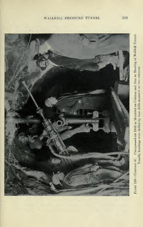
WALLKILL PRESSURE TUNNEL 359
0, »
•2 1
1.173 aa oas ^S C3 SO So =
C 3=3 .2
Q-O
7
360 CATSKILL WATER SUPPLY
To facilitate mucking, steel plates were so placed that the
blasted material fell upon them. The five hours lost from mucking
is accounted for as follows: Taking down runways, twenty-five
minutes; shooting, sixty minutes; replacing runways, thirty-five
minutes; two hours each shift, and one hour for lunch. Where
electric locomotives were used the 1^ yard steel side-dumping
Koppel cars, of which there were twenty-four at each shaft, were
hauled by mules from the bench to a siding 200 feet away.
There they were made up into trains of three and four cars and
hauled to the cages by electric locomotives. One locomotive was
found sufficient for one pair of tunnels, and was more economical
than entire haulage by mules.
The force for twenty-four hours at one shaft for two headings was
as follows:
260 men and 8 animalsNo. No. of shifts.
Superintendent I 1
Asst. superintendent 1 1
Master mechanic 1 1
Hoist runner 1 3Blacksmith and helper 2 3Mechanic 1 2
Pipeman 2 3
Carpenter 1 1
Electrician, day shift 2 1
' * night shift 1 2
Signalmen and cagemen 4 3Heading foremen 2 2Drillers and helpers 12 2
Jap drillers < 2 1
Nippers 2 2
Waterboys 2 2Powderman 1 2Muck bosses 2 3Muckers 40 3Trackmen 2 3Trolleyman 1 3
Dump boss 1 3Dump men 3 3Drivers 4 3Mules 4 2
Concreting of Invert. The third season was devoted almost
entirely to concreting. Before the invert was placed the tunnel
was trimmed to the prescribed lines and the loose muck in the bot-
tom removed. Separate concrete plants were installed at four of
the shafts, the crushed stone being delivered to them from the
Bonticou quarry, also from a crusher plant erected at Shaft 5 to
use the tunnel muck from the sandstone layers. The invert was

WALLKILL PRESSURE TUNNEL 361
II.5 ^.5
^
o i
w a
1^
S h
2 3
i^ O
fl

362 CATSKILL WATER SUPPLY
concreted by the use of continuous side forms, the method followed
being the same as that on Contract 12, except that the concrete
was dumped directly into the forms from the cars run on a track
over them, instead of being wheeled by hand from a platform. Theentire invert concrete was placed, starting half way between the
shafts and working toward them. The invert was 5 feet wide withradial joints 10 inches deep, the bond being a groove. Below the
form the concrete was allowed to flow out level, filling in the lowpoints, this making it much easier to prepare the bottom for the
side-wall forms.
Shaft 5
Shaft 4
Shaft 3
? %% Orade\
Plate 122.—Contract 47. Profile of Portion of Wallkill Pressure Tunnel,
Showing Position of Forms for Concreting Lining.
Concreting Side Walls and Arch. Blaw forms for side walls and
arch were used, equipped with carriages similar to those used on
Contract 12, and were collapsed and used in the same way. The
forms here used were improved by being longitudinally braced and
having the vertical posts bolted to the form instead of being pin-
connected, as on Contract 12. A few stretches were concreted
in two stages, but mainly the method of working the side-wall and
arch forms together, known as the trailing form method, was
used (see Plate 125). In this manner very good progress was madein concreting. At first 40-foot side-wall arch forms were used, but
these were afterwards lengthened to 50 and later to 60 feet. Three
sets of forms were usually used at each shaft, one set being concreted
each day, usually in less than sixteen hours. The shaft mixing plant
was run at a high rate, filling Youngstown cars which were hauled

WALLKILL PRESSURE TUNNEL 363
in trains of three and four to the foot of the incline. The incline
was a light steel structure })uilt to he easily dismounted and moved.
Electric hoists on the rear end of the platform hauled the trains up the
incline and to the long platform serving both side wall and arch.
The concrete was shoveletl into the arch forms as fast as possible,
the remainder being used for the side walls. By the time the arch
forms were filled and partly keyed up, the side-wall forms were filled,
after which a second small shift of specially picked men built the
remainder of the key, in a manner similar to that described in the Ron-
dout siphon, using radial boards and key-plates. At some points the
side^walls were not started until late in the afternoon but were
completed about the same time as the arch. Generally four-
teen working hours were taken to fill a 60-foot section of arch and
side wall, using for the day shift four or five spaders and twelve
shovelers; for the night shift four spaders and twelve shovelers.
Five men shoveled directly into the key at one time. The keying-
up gang consisted of five men closing on a bulkhead at the free end
of the form.
Concreting Key with Blocks. An endeavor was made to shorten
up the time of keying the arch by the use of two separate gangs,
making closure by means of a'concrete block. This block was cast
with radial ends and parallel sides 19^ inches by 22 inches and
placed through a 20''X20" hole in the form, after which angles were
bolted onto the plate to hold the block, which was grouted in place
through a pi|^e cast in it. Although this method of keying was at
first considered to effect a considerable saving of time, it was not
much used, it probably being found that it was unnecessary as the
keying-up gangs became more proficient.
Progress Made on Tunnel Lining. The best progress made on
tunnel lining was as follows : In Shaft 2, 1670 feet of side wall and 1652
feet of arch placed in one month of thirty days. In Shaft 5,
1737 feet of arch and 1133 feet of side wall in one month. At
Shaft 2 three sets of arch and side-wall forms were used, the concrete
being placed evory day of the month except one. At Shaft 5 two
sets of arch and side-wall and one arch form was used, the concrete
being placed every day. Clearances were such that the electric
locomotive could pull the cars through the forms, but this was a
source of some trouble, as derailments were apt to occur. The
forms were found to work very well, there being no difficulty experi-
enced in getting a set ready every day. As the concreting took
only a little more than one shift, plenty of time was available for
a separate gang to move and set forms, clean up tunnel, etc. The
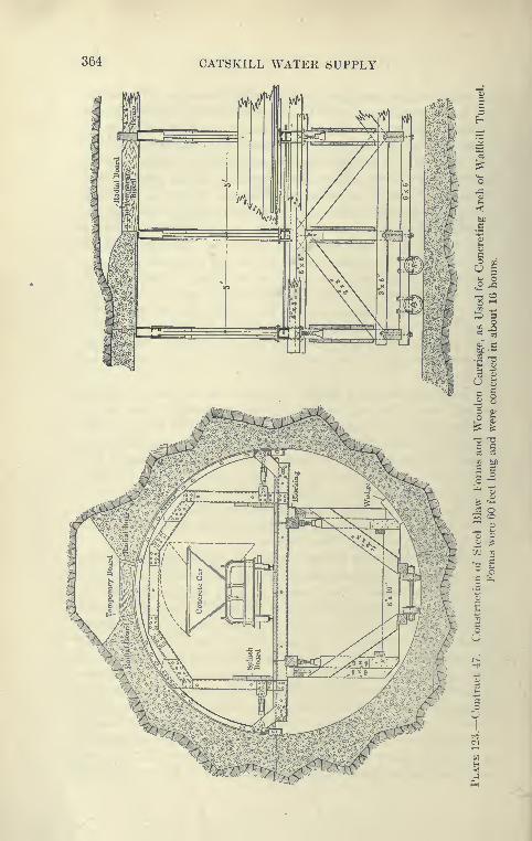
364 CATSKILL WATER SUPPLY
oCI .
O I
.5 T3
a>
n O

WALLKILL PRESSURE TUNNEL 365
increased progress made in the Wallkill tunnel over the Rondout
was largely due to the use of electric locomotives instead of mules,
and the use of trailing forms.
Ransome Form. A trial was made of full-circle forms built
by the Ransome Company. The forms were made in unit lengths
of 5 feet bolted together. The forms were collapsed on a special
carriage, the working platform traveling on a car of its own. The
forms did not prove practicable or economical, as they could not be
separated into arch and side walls and cars of concrete could not
be pulled through. Only a little more than 100 feet of concrete
was placed before their use was discontinued.
Protection of Green Concrete in Wet Areas. In general there
was much less trouble from water on the Wallkill than on the Rondout
siphon, so that the placing of drip pans over wet areas and grout
pipes was not such a feature. However, there were several
stretches quite wet. One 50-foot section passed 25 gallons of water
per minute. Here it was necessar>' to pan the entire roof, the water
intercepted by these pans being led to five 2-inch pipes on each
side. On the Rondout siphon it was customary to place drip pans
to cover wet areas of rock, the water intercepted by these pans
being led away by grout pipes passed through holes in the
forms, cut where needed. This was the practice at first on the
Wallkill siphon. Later an endeavor was made to simplify the work
by leading all water to pipes placed in a few fixed positions. This
reduced the number of holes in the plates of the forms. These
positions were as follows: Elevation about 2 feet above inner edge
of invert, just below springing line, and 3 feet above the springing
line. The pipes placed were straight, leading to the bottom of the
drip pans placed above their level. The drip pans were made of light
sheet metal braced to the forms or nailed to wooden plugs driven
in holes drilled for this purpose. Another method was to pan all
leaks above the springing line to pipes just below it. By this method
a pipe was placed just below the top of the side-wall concrete and
carried to a pan placed against the rock as usual. This pan was
carried 2 feet or more above the side wall and its free end later con-
nected with pans brought down from higher leaks. This method
has the advantage of taking away all grout pipes from the arch
except those placed in the key, and it leads away all the water so as
not to affect the arch concrete. The disadvantages of placing
grout pipes only in fixed positions are as follows: It leads to the
placing of large and long drip pans, so that the leaks cannot be
gotten at as directly as when drip pans are used to cover only wet

366 CATSKILL WATER SUPPLY
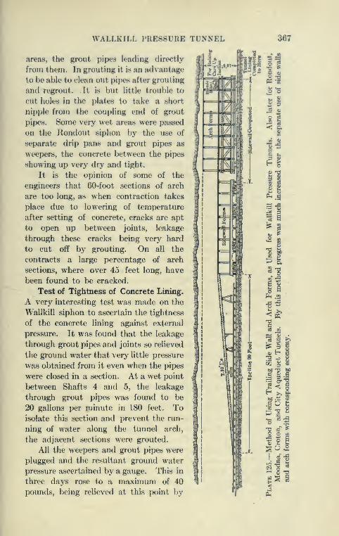
WALLKILL PRESSURE TUNNEL 367
areas, the grout pipes leading directly
from them. In grouting it is an advantage
to be able to clean out pipes after grouting
and regrout. It is but little trouble to
cut holes in the plates to take a short
nipple from the coupling end of grout
pipes. Some very wet areas were passed
on the Rondout siphon by the use of
separate drip pans and grout pipes as
weepers, the concrete between the pipes
showing up very dry and tight.
It is the opinion of some of the
engineers that 60-foot sections of arch
are too long, as when contraction takes
place due to lowering of temperature
after setting of concrete, cracks are apt
to open up between joints, leakage
through these cracks being very hard
to cut off by grouting. On all the
contracts a large percentage of arch
sections, where over 45 feet long, have
been found to be cracked.
Test of Tightness of Concrete Lining.
A very interesting test was made on the
Wallkill siphon to ascertain the tightness
of the concrete lining agaiast external
pressure. It was found that the leakage
through grout pipes and joints so relieved
the ground water that very httle pressure
was obtained from it even when the pipes
were closed in a section. At a wet point
between Shafts 4 and 5, the leakage
through grout pipes was found to be
20 gallons per minute in 180 feet. Toisolate this section and prevent the run-
ning of water along the tunnel arch,
the adjacent sections were grouted.
All the weepers and grout pipes were
plugged and the resultant ground water
pressure ascertained by a gauge. This in
three days rose to a maximum of 40
pounds, being relieved at this point by
»'m-fm
mil
.9
^9s1

368 CATSKILL WATER SUPPLY
some leakage through five transverse arch joints. A connection was
then made to Shaft 5 pump discharge pipe, which raised the pressure
in the space over the tunnel arch to a maximum of 135 pounds.
The maximum leakage through the five expansion joints was only
7 gallons per minute. A peculiar feature of this was that this
leakage rapidly diminished in about one week to less than 2 gallons.
Damp areas on the concrete increased somewhat, but the amount of
water seeping through the concrete was less than one-half gallon
per minute, a large part of the arch under pressure being entirely
dry. Longitudinal joints in key and side wall leaked very httle.
This test would indicate that the arch lining, which averages here
about 20 inches in thickness, can be relied upon to be very tight.
It must be remembered that this section had not been grouted at the
time of the test, and that the grout will probably make the concrete
lining of the tunnel still tighter against external pressure. How-ever, there is no direct relation of internal to external leakage in a
tunnel of this character, as at a place where water comes in freely
through a joint, outward-moving water would have to penetrate
hundreds of feet of rock in very minute seams. On the other hand
in some cases where there is access to a reservoir of ground water,
water may more freely escape than enter the tunnel.
Grouting of TimneL The Wallkill pressure tunnel was grouted
after concreting by the continuous method, no attempt being
made to build cut-off walls. The grout was forced over the arch
under a low pressure (about 80 pounds), connections being madeabout every 150 feet, working from shaft to shaft. A few high pipes
were kept open and subsequently grouted under high pressure and
also served as vents and telltales. The weeping pipes in side wall
were grouted under pressure or plugged with mortar by hand,
these pipes being left open to the last to keep water pressure from
accumulating on the arch.
The final leakage into the tunnel for its 4^ miles was about 82
gallons per minute. Considerable time was saved by using woodenplugs instead of valves, at telltale pipes not connected to, and byplugging pipes with mortar by hand where connections with grout
pipes were deemed unnecessary. High pipes were kept open whendeemed necessary by ramming a plug of oakum to the upper end.
This could readily be removed before grouting, thus saving con-
siderable time otherwise used in drilling out pipes for regrouting.
Comparison of Eastern and Western Tunnels. In this connec-
tion it is interesting to compare the records and methods of the
contractors on the Catskill Aqueduct with those in the West.
WALLKILL PRESSURE .TUNNEL 369
Very good progress has been made in the past few years at various
water tunnels at Los Angeles and through the I^ookies. Over
1000 feet JXT month was made in a rock tuimel on the lx)s Angeles
Aqueduct, but the material was a soft sugary rock taken out with
the aid of augers, and is, therefore, not in the hard-rock class.
However, in the Elizabeth Lake Division, which constituted the
hard rock section, a progress of 604 feet was made during the
month of April, 1910, using Leyner rock drills.
Laramie-Poudre Timnel. The best progress on record for the
United States with rock drills in hard rock was made in the tunnel
connecting the waters of the Laramie ami Poudre Rivers in Col-
orado.* This tunnel has a cross-section of about y^'XO^' in
width intended to be drilled so as to give an approximately rect-
angular section. The tunnel is 11,306 feet long and was driven
between January, 1910, and August, 1911. At the west end of the
tunnel, working down grade, the average progress per month was
308 feet. The average progress at the east end per month was 474
feet for nineteen months, 509 feet per month for sixteen months,
and 525 feet per month for the last year of work, with the record of
653 feet for March, 1911. This seems to be far in excess of any
other American tunnel heading on record.
The tunnel was driven entirely in heading from two portals, using
two No. 8 Leyner drills mounted on a horizontal bar, and a third drill
less than half the time, 2.4 drills being above the average. Twosettings of the bar were necessary for each round which was drilled to
give a long advance (10 to 7 feet), there being twenty-one holes 10
to 12 feet long drilled for this purpose. Three shifts of from 2 to 3
drillers, 2 helpers and 4 to 6 muckers and 1 foreman were used.
Fuses were used to fire the shots, thirty minutes being lost after each
shot to permit the heading to clear of smoke, after which the drill-
bar was set in its upper position while mucking proceeded, iron
plates being used to make the shoveling easier. The wages paid
were very high, $4.50 to drillers, $4 to helpers, and muckers $3.50,
blacksmiths $4.50, drivers $3.50, and foremen $6. In addition,
a liberal bonus was paid for work beyond a certain speed. Therock excavated was a hard gray and red granite, requiring little
timbering.
Comparison of Wallkill with Laramie-Poudre Timnel. Condi-
tions, it will readily be seen, were far more favorable for rapid
progress at the Laramie-Poudre Tunnel than on the Wallkill Siphon.
The Wallkill tunnel has a circular section about 18 feet in diameter,
*See Trans. Am. Soc. C.E., 1912.

370 CATSKILL WATER SUPPLY
requiring heading and bench, 10 yards per foot, as against the rectan-
gular section 7.5'X 9.5' of about 2.5 yards per foot, less than one-
half the yardage of the Wallkill headings alone. The small section
allowed the use of the horizontal bar, impracticable for the larger
circular section. Very much more careful work was necessarj^ in
the circular pressure tunnel to shape the rock for the concrete lining.
The Laramie-Poudre tunnel is to be lined only in the timbered sec-
tions. Better progress can be made in a grade tunnel where long
trains of cars can be hauled to the portals instead of to shafts, where
delays are apt to occur. The Laramie-Poudre tunnel was practically
a drift or heading of a section to admit of rapid driving. The
face was drilled with a great number of long holes loaded to within
2J feet of the collars with 100 per cent blasting gelatine and 50-60
per cent dynamite, so as to pulverize the rock, excess breakage
not being objectionable, as in the circular Catskill tunnels, where
expensive concrete lining was necessary. Fuse firing was practiced in
the tunnel in common with most Western tunnels, resulting in a
considerable saving of time, as all the fuses can be touched off at
once, the sequence of shots being determined l)y varying the length
of fuse. For some reason, firing by electricity is almost universal
in Eastern tunnels, probably due to the belief that fuses are more
liable to miss fire.
Comparison of Alpine Tunnels and Laramie-Poudre Tunnel.
The Laramie-Poudre tunnel affords the nearest approach to Swiss
tunnel methods and progress yet made in this country. The head-
ing was about the same size and shape as the bottom heading of the
Swiss tunnels and the methods were very similar. The horizontal drill
bar is used in the Alps, but is usually supported on a carriage mountedon wheels instead of being carried in by hand. Percussion drills
(Ingersoll-Sergeant and Meyer) have also been used on the Loetsch-
berg, where the maximum tunnel progress has been made. Theheadings also are rapidly drilled with many holes and shot heavily
with 85 per cent dynamite, shattering the muck in small bits onto
iron plates, from which it is shoveled. The first step is to make a
passage for the drill carriage carrying four or five drills. Muchshallower rounds are drilled in the Alps (about 4 feet) but many moreadvances per day (4 to 6) are made. The Loetschberg tunnel madefrom 18 to 25 feet per day with a maximum monthly record of over
900 feet. The greater speed is obtained by (1) thorough OT-ganiza-
tion for a long job, usually five years, (2) permanency of tunnel
force, who are compensated for extra good work on the bonus sys-
tem, and (3) superior plant, manifested mostly in the ventilating
WALLKILL PRESSURE TUNNEL 371
outfit and spraying of headings while drilling and after blasting.
The Loetschberg tunnel used fans 11.5 feet in diameter, furnishing
53,000 cubic feet of air per minute at 5.5 ounce pressure. Compressed
air was also freely used during the blastings. Drill carriages,
shallow advances and large charges of high explosives (over 6 pounds
per yard of 85 per cent dynamite) were used.
The wonderful organization of the Swiss tunnel is shown by
the immense amount of work carried on just back of the heading.
Upraisers are made every 500 to 600 feet and the tunnel enlarged to
full size, timliered and lined without interfering with heading progress.
The Loetschberg tunnel was double tracked, about 25 feet wide, 22
feet high, with semicircular top and masonry lining 2 or more feet
thick.
Cost of Swiss Tunnels. The cost of the Swiss tunnels is muchhigher than American tunnels, although the scale of wages is muchlower, drill runners getting only SI.00 per day, muckers S0.80,
and masons $1.00. The bonus paid on the Loetschberg tunnel
increased the pay about 75 per cent. Original estimated cost per
foot was $211, a notable decrease, however, over the earlier Swiss
tunnels.*
The American tunnels are rapidly approaching the Swiss tunnels
in speed of driving, at the same time lowering the imit costs so that
there is little need of copying Swiss methods in toto, although there
are several features of Swiss tunnel practice which make toward
both speed and economy which have not as yet been adequately
realized in this country.
Details of Swiss Tunneling. The driving of a Swiss tunnel can
be compared to the serving and firing of a big gun where by military
precision every second is made to count. In the Simplon tunnel
the following program was followed while drilling in antigoric gneiss
Bringing up and adjusting drills 20 minutes.
Drilling 1 hour 45 minutes
to 2 hours 30 minutes.
Charging and firing 15 minutes.
Cleaning away d6bris 2 hours.
Or for one whole advance of 3 ft. 9 in ... . 4.5 to 5.5 hours.
resulting in a daily advance of 18 feet, despite high rock temperatures
(about 95 degrees) and floods of hot water. In the Simplon tunnel
Brandt hydraulic drills were used, but as good progress was made
* The writer is indebted to a paper read by W. L. Saunders before Am.Inst. Mining Engrs., in 1911, for valuable information about Alpine tunnels.

372 CATSKILL WATER SUPPLY
later in the Loetschberg tunnel, on the same railroad, by the use of
pneumatic drills. In the Loetschberg tunnel the following schedule
for tunnel advance of 3.5 to 5 feet was followed:
Fifteen or sixteen heading holes were drilled in 1.1 to 1.5 hours.
Loading and firing of holes took only a few minutes, 6 to 8 pounds
of 85 per cent dynamite per yard being fired by fuses. Quantities
of compressed air were freed at the heading, the fans kept going and
the face and muck sprayed, enabling mucking to be started within
five minutes after firing. The tunnel muck was rapidly shoveled
from the iron plates to the cars. The men worked in relays, resting
after filling a <;ubic meter car (36 cubic feet) in five minutes.
Another gang then filled the second car, etc. As much as 14 car
loads have been taken away in ninety minutes.
American Tunnel Progress. To attain the high speed of the
Alpine tunnels a large force of highly trained men is necessary, so
that it would seem that with the much higher wages prevailing in
the United States, the Swiss tunnel progress will probably not soon
be attained. With the shorter tunnels here this would appear to
be entirely unnecessary. This is best illustrated by the Laramie-
Poudre tunnel, located in one of the most inaccessible regions of the
United States in the heart of the Colorado Rockies. The tunnel
plant had to be hauled 65 miles over the roughest mountain roads,
this being accompUshed in the dead of ^vinter. To supply power
for the compression and dynamos, the Poudre River was dammedand piped to a power house at one of the portals, and utilized with
Pelton water wheels. W^ork on the plant began Dec. 1, 1909, and
the tunnel was driven between Januar}-, 1910, and August, 1911. It
would seem that, if we can do all the work of installing plant and a
camp in an inaccessible mountain region and drive a tunnel over
2 miles long in less than two years, and that with a much smaller
force than used abroad and at a much smaller cost, we can be
satisfied with our progress in tunnel driving during the last few years.
CHAPTER X
WALKILL VALLEY CUT-AND-COVER AQUEDUCT
Contract 15
Contract 15 Mces. This contract, comprising 3 miles of ciit-
and-covor aqueduct on the Wallkill division south of the Wallkill
tunnel, was awarded to Elmore & Hamilton Contracting Company,
September, 1908, the total contract price being $933,000. Dueto the gravelly nature of the earth, loose earth section was entirely
used, except for a short stretch partly in rock. Prices obtained
for a few of the main items are as follows:
Open-cut excavation cu.yd $0.45Refilling and embankment, " 25Concrete masonry, " 5 . 50Portland cement, bbl 1 . 55
On the basis of contract quantities and prices the 15,900 feet
of this contract will cost the city $58.73 per foot.
Connecting Track and Gravel Bank. The work of this 3-mile
stretch oft'ered no special difficulties, except that suitable concrete
material could not be obtained on the right of way, the rock exca-
vated being rather soft Hudson River shale. During the first season
a standard-gauge track was laid from the south end of the contract
to the Wallkill Valley Railroad, about 3 miles distant. This track
passed near a deposit operated by a company with whom the
contractors had arranged for a supply of sand and gravel. Several
test pits dug here indicated great thickness of gravel, but whenthe excavation was started, after a complete plant composed
of steam shovel, cars, sand-washing machinery, screens, etc., was
installed, it was found that only a small percentage of the material
excavated was gravel, the remainder being sand. This caused a
dela}^ on both Contracts 15 and 16, for which this company had
contracted to supply gravel. Gravel deposits are commonly over-
estimated, the proportion of gravel usually running much smaller
than anticipated. There has hardly been a deposit discovered
373
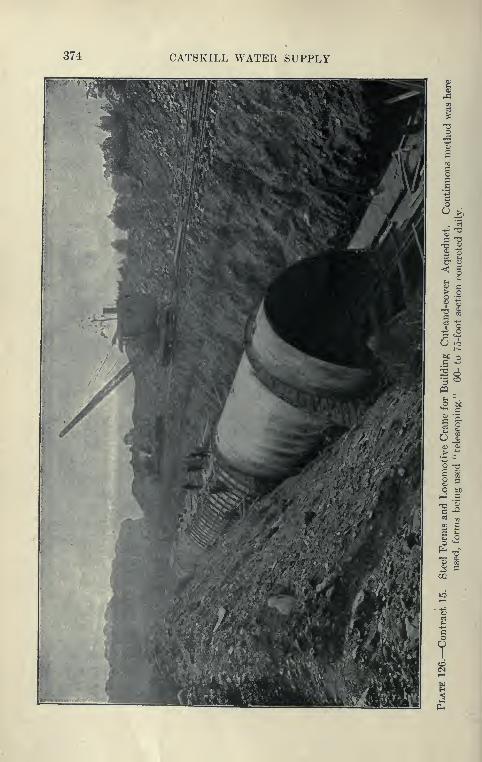
374 CATSKILL WATER SUPPLY
u
7
wallk;ill valley cut-and-cover aqueduct 375
along the entire line of the aqueduct sufficient to yield any con-
siderable (luantity of coarse material.
Plant Used on Contract 15. Contract 15 must Im* credited with
introducing methods which in many respects have become standard,
and with first showing what could be accomplished with the loco-
motive crane. After a certain amount of work had been done
with small steam shovels and wagons, a Marion 60-ton steam
shovel was equipped with a specially long boom made by the same
company. This shovel had a clear lift of 26 feet from top of rail
to bottom of open dipper, and a reach-out of 40 feet from the center
of the track. Working one shift per day, with a force of 9 men,
from 15,000 to 26,000 cubic yards per month was excavated, averag-
ing 19,000 cubic yards. The shovel was started from the south
end, working at subgrade and piling excavated material on the
downhill side, and at the same time grading for a railroad to run
along the bank. Along this track was operated a double-truck
Bay City locomotive crane having a 40-foot boom. The crane
was equipped with a clam-shell bucket which dredged the material
along the deeper cuts, depositing it further downhill, and removed the
bottom trimming excavation. In this manner the standard-gauge
track was extended as fast as the steam shovel excavated.
Concreting Plant. A long stretch of invert was laid, and on
this was erected 300 feet of Blaw collapsible steel forms operated
in the usual manner. The concrete was mixed in 1| cubic yards
Smith mixer located at a stationary plant at the south end of the
contract, which was later moved to a point 3000 feet south of the north
end. The concrete was loaded into bottom-dumping 1-yard Steubner
buckets, 5 being placed on each of two large flat cars and hauled
by two 35-ton American locomotives to the work, and dumped
into the invert or arch by a large locomotive crane. The feature
of the 1911 plant was its great simplicity and at the same time its
great capacity. The mixer was mounted on a timber tower, so as to
discharge directly into a storage hopper holding four batches. With
a batch in the mixer, this was a train load, permitting the con-
tinuous operation of the mixer and speedy loading from the storage
hopper directly into the buckets. The sand and stone bins over
this mixer were filled by a large derrick operating a Ij-cubic yard
clam-shell bucket. During the night sand, gravel and stone were
hauled to the plant and dumped on the slope of an adjoining side
hill. The derrick could easily raise sufficient material, including
cement, to enable the mixing plant to supply 300 cubic yards of
concrete in one eight-hour shift. This is noteworthy in com-

376 CATSKILL WATER SUPPLY
Plate 127.—Section of Inside Form—5 Feet— Being Moved to New Positionand Turned around to Form Curve. Sections are wedge-shaped for 200-footradius curve.
WALLKILL VALLEY CUT-AND-COVER AQrKt)t^CT 377
parison ^vith the much more elaborate plant usually operated on
other contracts. The standard-gauge equipment also demonstrated
its superior advantages and capacity, as no difficulty was met with
in transporting the concrete over the singl'e track.
Unfortunately this contract was hampered by lack of gravel,
so that it was necessary (in 1911) to equip and operate a crushing
plant at Rosendale many miles distant. Just when the quarry
wjis in satisfactory operation, Mr. Elmore died, so that the company
was obliged to go into the hands of a receiver, with a consequent
delay in the work. Nevertheless, the contract will Ix^ finished nearly
on time, due to the speed made by the receivers with their well-
planncMl method of work.
Refill. After the arch was built, the excavated material was
dredged out by the locomotive cranes operating either the clam-
shell or orange-peel buckets and was dumped over the aqueduct.
About 200 cubic yards of refill was placed by each crane in eight
hours. A criticism might be made of this metho<.l, in that it is
difficult to shape the embankments to the prescril^ed lines and to
clean up the excavated material along the right of way. Steam
shovel and trains were also used during part of 1910 and 1911 to
make n^fill over the aqueduct.
Steel Forms Used. A good deal of trouble was experienced
with the forms used during the first year, these being the same
forms which were superseded on Contract 11 and other places by
heavier forms. The contractor found, however, that by the use of
five bolts connecting the inner and outer forms and by rigidly
bracing the bottom of the forms very good service could be obtained.
The forms here were always used telescoping, the work proceeding
continuously from the south end. During the year 1911 the average
concrete placed in a month, working one shift every day, including
Sundays, was 1362 feet, the maximum progress being 1740 feet in
27 shifts in October, 1911.
Rock Cuts. In the rock cuts a good deal of excavation was
removed in skips by derricks or by the locomotive cranes, the
steam shovel in these places only removing the earth to the rock.
The total force working on the contract varied from 120 to 180
men.
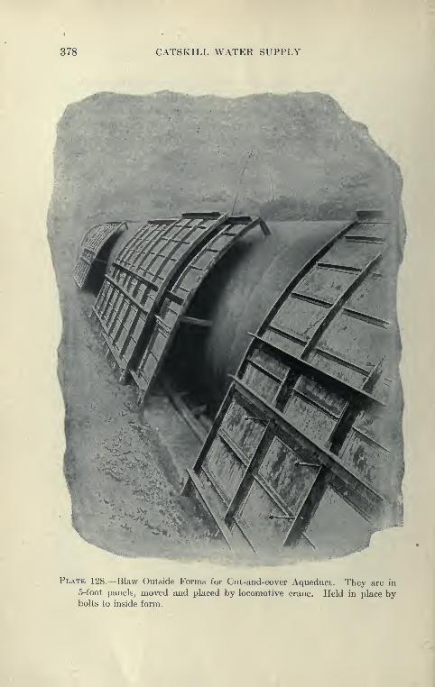
378 CATSKILL WATER SUPPLY
Plate 128.—Blaw Outside Forms for Cut-and-cover Aqueduct. They are in
5-foot panels, moved and placed by locomotive crane. Held in place bybolts to inside form.
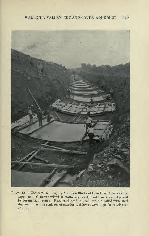
WALLKILL VALLEY CLT-AND-COVER AQUEDUCT 379
^•^,~-?-5!^>^'.: :; "]
Plate 129.—Contract 15. Laying Alternate Blocks of Invert for Cut-and-coverAqueduct. Concrete mixed at stationary plant, hauled on cars and placed
by locomotive cranes. Blaw steel profiles used, surface rolled with steel
shafting. On this contract excavation and invert were kept far in advanceof arch.

380 CATSKILL WATER SUPPLY
Contract 16
Contract Prices. This contract for cut-and-cover aqueduct for
2i miles at the northern end of the Newburgh Division was awarded
to the King, Rice & Ganey Co., in March, 1909, the total contract
price being $610,000. Some of the principal items are as follows:
Open-cut excavation 50 cents per cubic yard.
Refilling 25 cents per cubic yard.
Concrete masonry $5.15 per cubic yard.
Portland cement 1,50 per barrel.
On the basis of contract prices and quantities the 12,700 feet o6
this contract will cost the city $48.06 per foot.
Plant and Methods. I'he construction was all simple cut-and-cover
aqueduct, the firm earth type predominating. The excavated
material was mostly compact earth, underlaid in most places by a few
feet of shale rock. The track built by Elmore & Hamilton wasextended so as to serve this contract, which was also to l>e supplied with
gravel from the bank near the Wallkill Valley Railroad. Standard-
gauge equipment, as on Contract 15, was used throughout. The plant
installed was very complete and has been described, with a good deal
of justification, as a model aqueduct building plant. The excava-
tion was started at the extreme south end of the work with a 90-
ton Marion special steam shovel, following the precedent set on
Contract 15, equipped with a long boom with a lift of 26 feet and a
cast of 35 feet. Working one shift per day, excluding Sundays,
the average excavation per working month in 1910 was 14,000 cubic
yards; in 1911 was 16,000 cubic yards. Work under this contract
was carried on under a very compact plan, the entire operation of
excavating, concreting, and refiUing being completed within a distance
of 700 feet. The steam shovel worked just ahead of the invert,
loading material on a temporary standard-gauge track on the uphill
side of the cut. The main running track on the downhill side was
previously graded and laid for the entire length of the work. As
soon as a short section of arch, from 50 to 200 feet back of the
shovel, had been completed, the back fill was made from the side-
dump cars loaded directly by the steam shovel and hauled to and
fro by standard-gauge dinkies. When no spoil area was available
over completed arch, the excavated material was carried ahead
and spoiled temporarily on the center line and rehandled later instead
of being placed in permanent spoil banks, which on this contract
would have been unsightly and undesirable. Just ahead of the
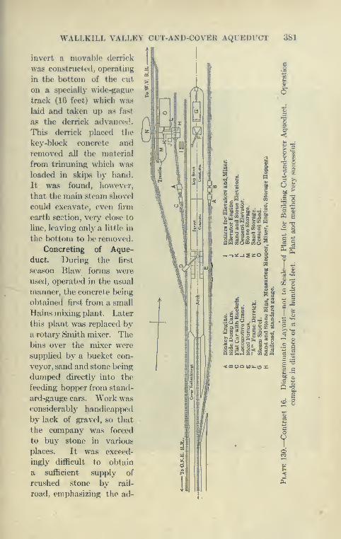
WALLKILL VALLEY CUT-AND-COVER AQUEDUCT 381
invert a movable derrick
was constructed, operating
in the bottom of tlie cut
on a specially wide-gapue
track (16 feet) which wa.s
laid and taken up as fast
as the derrick advanced.
This derrick placed the
key-block concrete and
removed all the material
from trimining which was
loaded in skips by hand.
It was found, however,
that the main steam shovel
could excavate, even firm
earth section, very close to
line, leaving only a little in
the lx)ttom t-o ]>e removed.
Concreting of Aque-
duct. Durinji; the first
season Blaw forms were
used, operated in the usual
manner, the concrete being
obtained first from a small
Hains mixing plant. Later
this plant was replaced bya rotary Smith mixer. Thebins over the mixer were
supplied by a bucket con-
veyor, sand and stone being
dumped directly into the
feeding hopp^T from stand-
ard-gauge cars. Work wasconsiderably handicapped
by lack of gravel, so that
the company was forced
to buy stone in various
places. It was exceed-
ingly diflicult to obtain
a sufficient supply of
rcushed stone by rail-
road, emphasizing tlie ad-
I
2 5
•§ • 2 . • CO
Su-^^S Scow
.->:^_I2Z0
3« . M
OOUQ UJU-O X
I
8l
u >
2 J'5 Ztt a
c3
W '^. j2
53^-5
I 'I
*§^oo2coa^ -^ ^&Q «a*^64 e "^ P ^ J'
OcOPMt-]co: CO CO (h tz ^
5 c
B
f

382 CATSKILL WATER SUPPLY

WALLKILL VALLEY CUT-AND-COVER AQUEDUCT 383
vantage to a large construction in the country, of an inde-
pendently operated quarry and crusher. As on Contract 15, the
concrete was loaded dinn'tly from the mixer into bottom-dump-
ing buckets and -hauled on a single flat car to the work. When the
distance was not too great, a single dinky could haul sufficient con-
crete to complete one section of about 200 yards in a few hours,
running at times at the rate of 30 miles an hour, a speed which could
not be obtained with narrow-gauge equipment.
King, Rice & Ganey Steel Forms. During the second season
forms designed and built by the contractor were in ase. These forms,
shown on Plate 132, were made of j-inch steel plate with a single
hinge at the top and truss members from the hinge to the bottom
spaced at 5-foot intervals. The plate was stiffened longitudinally
by purlins. The forms were of 5-foot rectangular sections, the
curves being obtained by wooden fillers. They were not telescopic
and collapsed only enough to permit them to be moved through the
completed arch. They rested on a large wooden sill placed on invert
with wedges under sill. Steel pipe braces v/ith jacks at one end
were used to prevent the sides from coming in during the placing
of the concrete. The forms were struck by knocking out wedges,
then prying out the wood sills, and with steel wedges loosening
the forms from the concrete, after wl ich the side screw-jacks were
used to provide clearance to move ahead and to adjust forms
to line. A screw-jack on the carriage lowered the forms, which
were then moved ahead 15 feet at a time. The outside forms
were plates reinforced in two directions with angles and moved in
15-foot lengths. Connecting the forms were steel tapered bolts.
These bolts, which were first used in Contract 11, are known as Irwin
quick-fastening bolts. They have no threads,, being set up and
removed by the use of a steel key fitted between a slotted nut and a
slot in the bolt itself. They saved considerable time over the
bolts ordinarily used, and as they were of correct length, also acted
as spacers. They were heavily tapered, and being made of hardened
steel could be used many times. The inside forms were moved on
a simple A-frame car running on the invert, the spacing out methodbeing used. The outside forms were moved by a Browning locomotive
crane, which was also used for placing the concrete. Nine menworking one-half shift moved the inside forms, 85 feet of which
could be set up in four hours. Seven men moved the outside forms
in four hours. With this plant, a 60-foot stretch of invert and arch
was readily placed in a day, working only one shift; at times 75
feet, and even 90 feet (two 45 's).
384 CATSKILL WATER SUPPLY
Rock Excavation. When rock was encountered, it was hard to
keep the excavation sufficiently ahead. A Keystone well-digging
machine was used to bore holes through the overlying earth and
into the shale bottom, which was blasted ahead of the steam shovel.
In these places it was necessary to work the shovel two shifts to
keep ahead.
Progress Made. During* 1910, working one shift per day,
excluding Sundays, an average of 970 feet of arch was placed in a
working month. In 1911, the average per month was 1040 feet.
The last concrete arch was placed Aug. 30, 1911, and the entire
work was accepted early in 1912, being the first aqueduct contract
entirely completed.
Merits of Contract i6 Methods. It is probable that the work
on Contract 16 was the most economical on any contract, showing
a high average output per man. It is well to note that the work
was very simple and well served by a direct railroad connection over
which cement and other materials were readily and cheaply delivered.
The country is almost level, so that there were no deep cuts or special
work to break up the work into parts.
The method of excavating and immediately using material for
back filling was one favored by the engineers, as the concrete arch
is immediately covered up and protected from the weather and the
work is at all times kept clean and in good shape. It is, however,
hardly practicable in places where deep and irregular cuts are
encountered, nor can it be economically carried out in solid rock
cuts, which have to be excavated a long way ahead to keep the
concrete plant going at full capacity. The work on Contract 11
brings out these points especially well. Better progress can probably
be made by stripping rock ledges with the steam shovel for some
distance, and then backing the shovel to subgrade and excavating
the remaining ledge by use of steam drills, picking up the shat-
tered rock with the shovel, rather than by the method of drilling
through the overlying drift with well drills as described above.
Typical gangs working on concreting were 38 men; on earth
excavation, 27 men; rock excavation, 35 men; on earth refill, 15
men, and rock refill, 30 men.

WALLKILL VALLEY CUT-AND-COVER AQUEDUCT 385
Plate 132.—Contract 16. Steel Form—King, Rice & Ganey. Form has only
One Joint, at Crown, and was Easily Moved by Carriage Shown. Hy-draulic jacks raised and lowered forms, sides were pulled in by ratchet-jacks
on side. Form was non-telescoping and very successful for "spacing out"method of building cut-and-cover aqueduct.
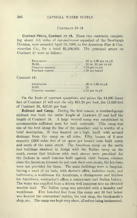
386 CATSKILL WATER SUPPLY
Contract 17-18
Contract Prices, Contract 17-18. These two contracts, compris-
ing about 5.6 miles of cut-and-cover aqueduct of the NewburghDivision, were awarded April 19, 1909, to the American Pipe & Con-struction Co., for a total $1,558,695. The principal prices on
Contract 17 were as follows:
Excavation 39 to 1.00 per cu.yd.
Refill 25 to .35 per cu.yd.
Concrete masonry 5.25 per cu.yd.
Portland cement 1,50 per barrel
Contract 18:
Excavation 38 to 1.60 cu.yd.
Refill 25Concrete masonry 5.25 per cu.yd.
On the basis of contract quantities and prices the 14,100 linear
feet of Contract 17 will cost the city $51.24 per foot, the 15,600 feet
of Contract 18, $53,60 per foot.
Railroad and Camp. During the first season, a standard-gauge
railroad was built the entire length of Contract 17 and half the
length of Contract 18. A large central camp was established to
accommodate sufficient men for both contracts. This camp wasone of the best along the line of the aqueduct and is worthy of a
brief description. It was located on a high knoU with natural
drainage from the camp on all sides. Fifty houses of 8 mencapacity (3200 cubic feet of air space per house) were built north
and south of the main street. The American camp on the north
had buildings identical in design with the Itahan camp on the
south, except that kitchens with cook stoves were provided for
the Italians in small lean-tos built against their houses, whereas
since the American laborers do not cook their own meals, the kitchens
were not provided for them. The main buildings were a hospital,
having a ward of six beds, with doctor's office, isolation room, andbathrooms, a washhouse for Americans, a dining-room and kitchen
for Americans, contractor's office, a commissary and Italian bakery.
The water was supplied from a driven well pumping into an elevated
wooden tank. The Italian camp was provided with a laundry andwashhouse. Five hundred feet from this camp and 50 feet below
was located the contractors' stables, the tool shop, the blacksmith's
shop, etc. The camp was kept very clean, all refuse being incinerated.

WALLKILL VALLEY CUT-AND-COVEH AQUEDUCT 387
§5 I S 5 f
5§ I a §

388 CATSKILL WATER SUPPLY
Special Features of Contract 17-18. The only two features
of importance on this contract are at the crossing of the New England
Railroad, and the St. Elmo brook. At the railroad, the standard
aqueduct section is used, but reinforced with steel rods, so that where
depressed below the railroad it will stand at a slight head. AtSt. Elmo brook, to avoid a high embankment, the aqueduct is car-
ried on a viaduct. The piers for this viaduct are carried down to
bed rock, the earth between left in place and shaped to form the
intrados of the arches supporting the invert of aqueduct. Theordinary concrete arch is then placed on this and covered over with
earth filling, the final appearance being the same as the usual cut-
and-cover aqueduct. Two of the transverse arches are used to form
a culvert for St. Elmo brook.
Excavation with Scraper Bucket. Excavation was started at
St. Elmo brook, using a Lidgerwood-Page-Cra^vford excavator operat-
ing a drag scraper bucket. The material contained a large percentage
of boulders and this excavator did not work satisfactorily, the boulders
preventing the bucket from obtaining a full load of earth, or over-
turning the bucket while at work. The excavator worked more
successfully at another point where the trench had fewer boulders..
It was necessary, however, to use a gang of 10 or 12 laborers, trim-
ming on one side of the trench, while the excavator worked on the
other' side, the laborers shoveling toward the center line. In this
way the steep slopes of the firm earth section were maintained.
This operation, however,was found to be very costly, and the excava-
tor was replaced by a steam shovel, but was used for a time to place
cover embankment from material spoiled at the sides. It was
unsuccessful in this and was removed from the work.
Methods of Excavation. In a long rock trench in Contract 18,
a 60-ton IVIarion steam shovel was operated, removing blasted rock
in three cuts. The rock was a shale interbedded with hard sandstone
in such a manner that however carefully blasted the breakage lines
were so uncertain as to produce a cut varying widely each side of
the required section, the sides zigzagging back and forth along various
cleavage planes. The spoil from the cut was placed on an area
provided at the north end of the cut. This contract is noted for
the variety of excavating machinery used. At some points movable
A-frame derricks were erected in the trench. These operated
Owen grab buckets, which resemble a clam-shell with the addition of
steel teeth for digging. The steam shovels loaded partly on cars and
a portion of the time spoiled alongside the cut. The material spoiled
was reexcavated by grab buckets to make the fill over the arch.

WALLKILL VALLEY CUT-AND-COVER AQUEDUCT 389
Mr 1 ^^Hm^R^A V ^HH|
1 F^v"^*^*^ ^^^^^^^^H
if ^jBfj]Hi J
1. jii i. ^-^"-^--^te^
m^^.^.^f'i^i^ ',^''
'^ V
^.a. 'li^^a^SS#
Iflp"" 1
liv' ttiHhK3..' . _,,.-,..-«
^
390 CATSKILL WATER SUPPLY
Owego Steel Forms. The steel forms used on this contract
were built by the Owego Bridge Company, and were made to
concrete a section of the arch to 8 feet above invert. After build-
ing a short stretch it was found, however, much better to build the
entire arch in one operation, and the forms were thereafter so used.
The first forms were hinged at the top and jointed at the 8-foot level,
but required considerable interior bracing. The outside forms were
steel panels very heavily trussed, to avoid the use of tie-bolts. This
made them rather clmnsy to use and it was difficult to place concrete.
This was later obviated by the use of a V-shaped dumping saddle.
The later forms had hinged joints 2 feet above the invert instead
of the bolted joint at 8 feet. The forms were designed to be used
telescopic, but were collapsed only sufficiently to permit moving
them through the completed arch, setting ahead on the invert and
working back to the completed section. Fourteen men working
on day shift and 8 men on a night shift moved and erected the arch
forms.
Concreting Methods. An unusual method of mixing and plac-
ing concrete was employed in 1910. Instead of mixing concrete
directly at a central plant, what is known as a proportioning plant
was used. At this point, buckets were loaded with dry cement,
sand and stone in the proper proportions. A supply train con-
sisting of a standard-gauge locomotive with two flat cars, each
car carrying 12 one-yard side-dump buckets, operated between the
proportioning plant and the mixer, which was located alongside of
the arch to be concreted. A locomotive crane placed the dry mate-
rial in a rotary mixer, which discharged the concrete into Steubner
bottom-dump buckets, which were raised and placed between the
forms by another locomotive crane. This method made necessary
a double track wherever the concrete was being placed, in order
to make the scheme at all satisfactory. There was apparently no
good reason for not mixing the concrete at the proportioning plant
and carrying it directly to the arch to be placed in the usual mannerby a locomotive crane, such as was done on Contracts 15 and 16.
What was aimed at in this contract was probably to avoid the
transportation of wet concrete for long distances. It was found,
however, on Contract 11, that concrete could be readily transported
a distance of over 6000 feet without material separation or setting.
On Contract 17, in 1911, the concrete was mixed at a central plant
near Station 1605, and was hauled and placed as on Contract 16.
Crushing Plant. On Contract 18, a large crushing plant wasinstalled. It was operated for a time with stone obtained from

WALLKILL VALLEY CUT-AND-COVER AQUEDUCT 391
walls. The supply of walls for a considerable distance was soon
exhausted and recourse was had to a sandstone quarry. For heavy
concrete work such as the aqueduct, it was found that only a limited
amount of stone could be economically obtained from walls, &s the
haul soon passed the economic limit.
Progress Made. On Contract 17 about 3500 feet of aqueduct
was completed in 1910, the best month's work beinj^ about 700
feet; on Contract 18, about the same amount of work was done.
During 1911, G189 feet of aqueduct was concreted on Contract 17;
on Contract 18, 6510 feet of arch. The concreting work was com-
pleted in 1912.
Contract 45
Contract 45. Work and Prices. This contract comprises 5Jmiles of cut-and-cover aqueduct at the lower end of NewburghDivision. The only special features of this contract are three heavy
foundation embankments of a maximum height of 20 feet and a
heavy rock and earth cut about 7000 feet long, averaging 33
feet in depth with a maximum of 60 feet. The contract was awarded
in June, 1909, to the Pittsburgh Contracting Company, for a total
of $1,675,290. The main prices are:
Open-cut excavation 0.57 per cubic j'ard.
Refill and embankment 27 j per cubic yard.
Concrete masonry 5.25 per cubic yard.
Portland cement 1.30 per barrel.
On the basis of contract quantities the 28,189 feet of this contract
will cost the city $59.56 per foot.
This contract was divided into two natural parts by the
Washington Square pipe siphon. North of this, connection was madewith the Central New England Railroad over the tracks laid over
Contract 18. A portion of the trench in a heavy rock cut was
excavated by 60- and 90-ton steam shovels, the material being used
for back fill and embankments, and in spoil banks.
Experience with Scraper Buckets. A distinguishing feature
of this contract was the extensive use made of 3 Lidgerwood-Page-
Crawford excavators, which operated scraper buckets and did all the
main trench excavation excepting the above mentioned heavy cut.
The record made by these excavators on Contract 45 working in
glacial drift with some boulders is rather poor when compared with
steam shovels. They rarely excavated more than 10 feet of com-
plete aqueduct trench of 12 to 14 feet cut in one shift of eight hours,
392 CATSKILL WATER SUPPLY
or about 60 cubic yards, whereas the steam shovel in like material
could make from 50 to 60 feet.
In comparing the excavator and shovel for aqueduct purposes,
the following was experienced on this contract: (1) The steam
shovel generally moves along on level ground in the cut, whereas the
Page excavator works in advance of the cut, and therefore must
go along the grades of the original ground. In wet ground this
may be an advantage, as the cut tends to drain the water away from
the surface, leaving the excavator on dry ground. (2) The number
of men needed for the excavator is about the same as that for the
shovel. (3) The excavator cannot progress through very bouldery
or hard material at nearl}^ the rate of the steam shovel, which digs
with a rigid arm with powerful leverage; working nmch like the
human arm it can throw boulders and stumps to one side without
difficulty. (4) The excavator machinery is more frequently out
of order on account of the difficult going. (5) In soft ground, the
excavator has the advantage in that it has a longer reach and can
dig a very deep or very wade cut in one lift and without changing
its position. This is the work for which the excavator was developed
and where it reaches its maximum efficiency. The steam shovel
undoubtedly excavates closer to line, leaving less of expensive trim-
ming work to be done. In this connection it may be noted that the
shovel (Plate 131) used on Contract 16 averaged per month during
1910, 14,000 cubic yards, and in 1911, 16,000. The shovel worked
mostly only one shift except in rock, when two shifts were occa-
sionally worked.
Crushing and Mixing Plant. In concrete work crushed field
stone was largely used. The first plant contained two crushers and
a set of sand rolls. Later, two plants were built without the sand
rolls, as thej^ were not successful. The mixing plants were located
at the crushers, one-yard mixers discharging directly into bottom-
dumping buckets, hauled on flat cars over the narrow-gauge road to
the point of concreting, where their contents were placed over steel
Blaw forms in the usual manner by locomotive crane.
Monell's Fill, Largest on Aqueduct. The largest fill to support
the Catskill Aqueduct is that constructed under Contract 45, and
kno^\^l as Monell's fill. This fill is 975 feet long, 90 feet wide at a
point 2^ feet above the invert, 188 feet wide at the widest point of
the bottom, and 23 feet high at this point. It contains 68,000
cubic yards of material below 2^ feet above the invert, of which
37,000 cubic yards is rolled embankment. The rolled embankmentportion extends 25 feet each side of the center line at 2J feet above

WALLKILL VALLEY CUT-AND-COVER AQUEDUCT 393
the invert and, except for about 175 feet at each end, where the Bides
of the rolled portion are vertical, it has side slopes of 1 on 1.
Stripping of Top Soil. The site of this embankment was a saddle,
the water draining freely away on each side. It was cleared during
July, 1909, and the stone, among which were many loose lK)ulder8,
was hauled to the crusher. The top soil wa.s removed during
August, 1909, by a Lidgerwood-Page-Crawford excavator with
the scraper bucket, and stored along the sides. This machine was
very satisfactory for the work, handling about 4500 cubic yards in
three weeks, working two shifts per day, and removing all stumps,
roots, etc.
Making the Fill. The construction of the embankment was
started August 30, 1909. The contractor obtained permission to
build the rolled portion of the embankment first, placing on the sides
only sufficient material to support it.
The remaining part of the sides was ordinary fill, 22,000 cubic
yards in all, and was dumped over the sides from the tracks along the
top in the spring of 1911, after the rolled portion had been completed.
The material used was hardpan, very difficult to dig, with a
high percentage of boulders in places. It compacted readily and
very solidly. It was obtained from the aqueduct trench and from
borrowpits alongside the same. It could be plowed to a depth of
3 feet below the surface, and the excavator would dig it to a depth
of 6 feet below the surface. Below that it was more economical
to blast.
Rolling the Fill. On the fill, to insure a solid embankment and
one that would not settle, the work was done as follows: The site
was thoroughly rolled, all stump holes being filled with hand-rammed
material. The earth was then spread in a horizontal layer about
4f inches thick before rolling, the surface covered being thoroughly
wet just before spreading. A 12-ton road roller, having a wide-
grooved front wheel and two large cleated rear wheels, then passed
forward and back in such a manner that one rear wheel touched
every point of the surface. The surface was then dampened if
necessary and rolled crosswise in the same manner. As the work
progressed the traction engines gradually took up the work of rolling
as they brought the material to the fill, and finally superseded the
roller entirely. The slow progress resulted in the fill getting a
thorough soaking from rains every third or fourth layer, and this
helped materially toward extreme solidification of the fill. At
times the fill was so solid that a small boulder lying on it would be
crushed by the traction engine passing over it.
394 CATSKILL WATER SUPPLY
Progress Made on Embankment. Small boulders were per-
mitted in the fill only if they could be rolled out of sight in the
layer being placed, which was about 3i inches after solidification.
All others were kept out. In scheme No. 1 the excavator dropped
the excavated material into a hopper having a sloping grating of
50-pound rails on top. The earth dropped through into a wagon,
and the boulders ran off into the cut. In scheme No. 2 the boulders
were thrown to one side or hauled to the crusher. In scheme No. 3,
earth and boulders were dumped on the fill and the boulders either
thrown over the bank to be handled later or hauled to the crusher.
While working scheme one, 125 yards of embankment per working
of shift were placed under scheme two, 122 yards and under scheme
three, 108 yards per working shift.
In all about 10,000 cubic yards of stone were hauled to the
crusher from the fill and borrow pits.
Settlement of Embankment. Measurements taken in April, 1911,
six months after the completion of the rolled embankment, showed
a settlement of i inch. The aqueduct was constructed on this
embankment in September and October, 1911, and up to date has
shown no signs of settlement.
After considerable difficulty was experienced in the excavation
of a deep cut the last concrete arch on this contract was placed in
1912, leaving considerable refill to be made in the following season.

CHAPTER XI
MOODNA, HUDSON, BREAKNECK AND BULL HILL TUNNELS OFTHE HUDSON RIVER DIVISION
Contract 20
General Description of Contract 20 (Moodna Siphon). This
contract comprises work l)etween the long stretch of cut-and-cover in
the Newburgh Division and the Hudson River. It is a tunnel about
25,000 feet long constructed from seven shafts, 371 to 586 feet deep.
The only waterway shaft is No. 1, connecting with the cut-and-cover.
Shaft 7 will be an access shaft, and all the others, except No. 1,
will be refilled. The Moodna tunnel is really a portion of one siphon
known as the Moodna-Hudson-Breakneck Siphon, constructed from
ten shafts. The shaft east of the Hudson4s to be used as a drainage
shaft for the entire siphon. About two-thirds of the tunnel pene-
trates Hudson River shale, and the remainder granite, similar to
that of Storm King and Breakneck. Numerous borings were madealong the center line, principally to determine the preglacial gorge
of the Moodna, which was found to be very wide, reaching an eleva-
tion of about — 50 and determining the depth of the tunnel at about
-200.
Contract Prices. The contract was let in June, 1909, to the
Mason & Hanger Co. The total contract price was $3,492,511.
Some of the bid prices are as follows:
Construction shaft in earth per foot $180 to S200Construction shaft in rock (granite) per foot.. .
.
$2.50" (shale) per foot 200
Excavation of tunnel in granite per cu.yd 6.75Excavation of tunnel in shale per cu.yd 5.40Rock excavation in downtake shaft per yd 15.00Concrete masonry in shafts per cu.yd 8.00
" " in tunnel per cu.yd 5.25Portland cement, per bbl 1 . 20Forms for lining tunnel, per foot 4.00
On the basis of contract quantities and prices the 337 feet of
cut-and-cover aqueduct of this contract will cost the city $56.87
395
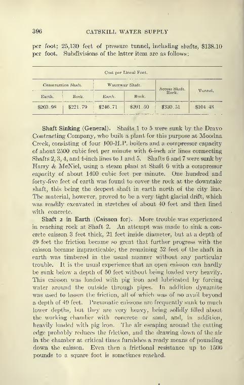
396 CATSKILL WATER SUPPLY
per foot; 25,130 feet of pressure tunnel, including shafts, $138.10
per foot. Subdivisions of the latter item are as follows:
Cost per Lineal Foot.
Construction Shaft. Waterway Shaft.Access Shaft.
Rock. Tunnel.
Earth. Rock. Earth. Rock.
$203.98 $221 . 79 $246.71 $201.50 $330.51 $104.48
Shaft Sinking (General). Shafts 1 to 5 were sunk by the Dravo
Contracting Company, who built a plant for this purpose at MoodnaCreek, consisting of four 100-H.P. boilers and a compressor capacity
of about 2500 cubic feet per minute with 6-inch air hues connecting
Shafts 2, 3, 4, and 4-inch lines to 1 and 5. Shafts 6 and 7 were sunk by
Harry & McNiel, using a steam plant at Shaft 6 with a compressor
capacity of about 1400 cubic feet per minute. One hundred and
forty-five feet of earth was found to cover the rock at the downtake
shaft, this being the deepest shaft in earth north of the city line.
The material, however, proved to be a very tight glacial drift, which
was readily excavated in stretches of about 40 feet and then lined
with concrete.
Shaft 2 in Earth (Caisson for). More trouble was experienced
in reaching rock at Shaft 2. An attempt was made to sink a con-
crete caisson 3 feet thick, 21 feet inside diameter, but at a depth of
49 feet the friction became so great that further progress with the
caisson became impracticable; the remaining 52 feet of the shaft in
earth was timbered in the usual manner without any particular
trouble. It is the usual experience that an open caisson can hardly
be sunk below a depth of 50 feet without being loaded very heavily.
This caisson was loaded with pig iron and lubricated by forcing
water around the outside through pipes. In addition dynamite
was used to lessen the friction, all of which was of no avail beyond
a depth of 49 feet. Pneumatic caissons are frequently sunk to muchlower depths, but they are very heavy, being solidly filled about
the working chamber with concrete or sand, and, in addition,
heavily loaded with pig iron. The air escaping around the cutting
edge probably reduces the friction, and the drawing down of the air
in the chamber at critical times furnishes a ready means of pounding
down the caisson. Even then a frictional resistance up to 1500
pounds to a square foot is sometimes reached.
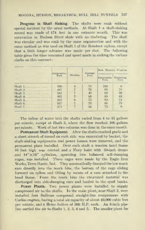
MOODNA, HUDSON, BREAKNECK, Bl LL HILL TUNNELS 397
Progress in Shaft Sinking. The shafts were sunk without
special incident by tlie usual methods. At Shaft 1 a shaft-sinking
record was made of 174 feet in one estimate month. This was
excavation in Hudson River shale with no timVx^ring. The shaft
was circular and was sunk by the same organization and with the
same method as was used on Shaft 1 of the Ilondout siphon, except
that a little longer advance was made per shot. The following
table gives the time consumed and speed made in sinking the various
shafts on this contract
:
Excavation.Feet. Months.
Average.Feet.
Best Monthly ProKresa.
Excavation.Feet.
Timbering.Feet.
Shaft 1
Shaft 2 ...586
487342403432.537
373
8
7
7
5
6
7
7
73
70
498072
7954
166
86608982
8675
79
Shaft 3 30
Shaft 4 88
Shaft 5
Shaft 6.
72
79
Shaft 7
The inflow of water into the shafts varied from 4 to 45 gallons
per minute, except at Shaft 3, where the flow reached 100 gallons
per minute. Work of last two columns was done in the same month.
Permanent Shaft Equipment. After the shafts reached grade and
a short stretch of tunnel on each side was excavated by bucket, the
shaft-sinking equipments and power houses were removed, and the
permanent plant installed. Over each shaft a wooden head frame
44 feet high was erected and a Flory hoist Avith 60-inch drums
and 14"X18" cylinders, operating two balanced self-dumping
cages, was installed. These cages were made by the Eagle Iron
Works, Terre Haute, Ind. They automatically dumped the low muckcars directly into the muck bins, the bottom of the cage sliding
forward on rollers and tilting by means of a cam attached to the
head frame. From the muck bins the excavated material was
discharged into side-dumping cars and hauled to the spoil banks.
Power Plants. Two power plants were installed to supply
compressed air to the shafts. In the main plant, near Shaft 3, were
installed four Sullivan compound straight-line compressors with
Corliss engines, having a total air capacity of about 10,000 cubic feet
per minute, and 4 Heine boilers of 300 H.P. each. An 8-inch pipe
line carried the air to Shafts 1, 2, 3, 4 and 5. The smaller plant for
398 CATSKILL WATER SUPPLY
Shafts 6 and 7 was located near the West Shore Railroad at Cornwall
and was equipped with two cross-compound Ingersoll-Rand compres-
sors with a combined capacity of 5000 cubic feet of free air per minute
and three 250 H.P. water-tube boilers.
Progress Made in Driving Tunnel. The tunnel was excavated
by the ordinary top-heading and bench method, no attempt being
made to secure great speed, but every effort was put forth to secure
economy in driving. While nmning with full force, the average
progress of excavation for completed tunnel was between 200 to
250 feet per month with a maximum of about 322 feet. During
the month of November, 1910, when tunnel progress was at a max-
imum, 3204 feet of completed tunnel was excavated in 13 headings
at an average progress of 246 foot per heading, maximum 304 feet,
and minimum 171.
The organization for Shafts 6 and 7 for both excavation and
concrete was furnished by Mr. Mundy, whose progress in excava-
tion of granite tunnel was remarkable, averaging for some months
about 300 feet.
Tunneling with One Drilling Shift. Two general methods of
excavation were used. In shale, at shafts with two headings, the
heading was drilled and shot and entirely mucked out, the drillers
not returning until this was done. Only one drilling gang and two
mucking gangs were employed in each heading. By this arrange-
ment the drillers always worked in headings clear of muck and smoke,
the muckers having their shifts arranged so as to suffer little delay
from the shooting and from smoke. By this method a daily advance
of Jrom 6^ feet to 8^ feet per round was made, and the labor
charges were cut down to the lowest, but the progress was only
about one-half as much as made with two drilling shifts and three
mucking shifts in the Wallkill and Rondout pressure tunnels in
similar rock. It is a question whether the overhead charges by this
method did not more than make up for the decreased labor cost.
Overhead charges in tunnel driving are nearly fixed, so that lessened
progress means a less yardage per month to charge it to.
Tunneling with Two Drilling Shifts. Another method, and
probably the most economical for shale excavation, by which a very
good progress was obtained, is as follows: Two drilling gangs were
worked per day at each shaft between 8 a.m. and 4 p.m. and 8 p.m.
and 4 a.m., so as to drill two rounds per day in each heading. Byallowing four hours between drilling shifts opportunity was given to
clear the heading of the muck before the arrival of the next drilling
gang. Three shifts of muckers were employed in each heading.
MOODNA, HUDSON, BREAKNECK, BULL HILL TUNNELS 399
Tunneling Method in Granite. For tunneling in granito, where
it took sixteen hours to drill 24 heading holes with four 31-inch
tripod drills on columns, two methods were usedj First, three
drilling shifts and three mucking shifts in the two headings were
alternated so that drillers always set up in a clear hea<ling. hy the
second method, three shifts of drillers and three shifts of muckers
worked in each heading, but lost two to four hours per day on
account of shooting ; the cut often requiring loading three times l^efore
it was satisfactorily blasted. By the first method the cost per yard
excavated was considered to be less. About 41 pounds of 75 per
cent dynamite was used per cubic yard excavated, and about 208
feet of holes was drilled for a 7^ foot advance, equal to 35 cubic
yards excavated, which was sought for every day.
Character of Rock in Moodna Tunnel. The rocks penetrated
by the Moonda tunnel gave little trouble except at two spots, one
in the shale directly under the buried Moodna Valley where con-
siderable water was encountered, and the other where the shale was
weakened by the over-thrusting of Storm King Mountain upon it.
Here some structural steel roof support was placed at the contact.
In general the tunnels were dry and yielded little water. A feature
was the good progress made at Shaft 6 in the Storm King granite.
Concreting Invert. After the main excavation was completed
the tunnels were trimmed and the bottom muck excavated to solid
ledge. A 5-foot invert strip was then placed in the same way as
that described under Wallkill and Rondout tunnels, except that at
some shafts the invert was placed by working away from instead
of toward the shafts as in the other two tunnels. This meant that
the track had to be placed on the newly laid invert. The advantage
of this method is that the laying of a track is saved together with
some saving in cleaning up bottom.
Concrete Plants at Shafts 2 and 3. Blaw steel forms for side walls
and arch were installed siniilar to those used in the Wallkill tunnel,
and the method of '' trailing " forms followed, using inclines as
before described. At Shafts 2 and 3 a Lakewood mixer at the sur-
face discharged its concrete directly into a car placed on the shaft
cage, which was stopped a few feet below the landing platform.
This has the advantage of eliminating a few men required to push the
cars off and on the cages, as in the method of mixing to one side
practiced on the Rondout and Wallkill tunnels; but it also has the
disadvantage of tying up the cages for other uses while the mixer
is discharging concrete, and also creates more or less of a nuisance,
due to spilled concrete.
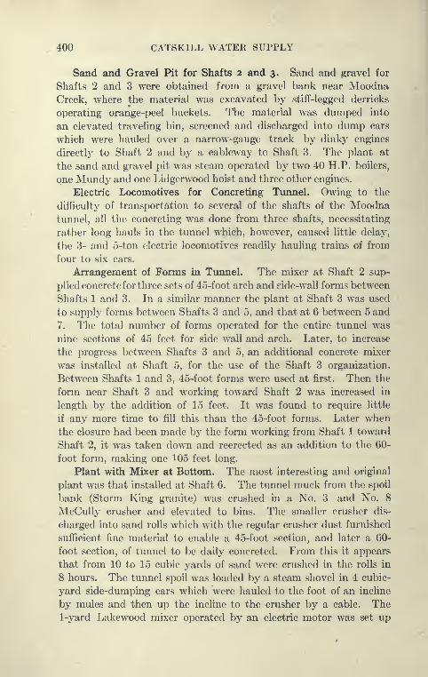
400 CATSKILL WATER SUPPLY
Sand and Gravel Pit for Shafts 2 and 3. Sand and gravel for
Shafts 2 and 3 were obtained from a gravel bank near MoodnaCreek, where the material was excavated by stiff-legged derricks
operating orange-peel buckets. The material was dumped into
an elevated traveling bin, screened and discharged into dump cars
which were hauled over a narrow-gauge track by dinky engines
directly to Shaft 2 and by a cableway to Shaft 3. The plant at
the sand and gravel pit was steam operated by two 40 H.P. boilers,
one Mundy and one Lidgerwood hoist and three other engines.
Electric Locomotives for Concreting TunneL Owing to the
difficulty of transportation to several of the shafts of the Moodnatunnel, all the concreting was done from three shafts, necessitating
rather long hauls in the tunnel which, however, caused little delay,
the 3- and 5-ton electric locomotives readily hauling trains of from
four to six cars.
Arrangement of Forms in Tunnel. The mixer at Shaft 2 sup-
plied concrete forthree sets of 45-foot arch and side-wall forms between
Shafts 1 and 3. In a similar manner the plant at Shaft 3 was used
to supply forms between Shafts 3 and 5, and that at 6 between 5 and
7. The total number of forms operated for the (^ntire tunnel was
nine sections of 45 feet for side wall and arch. Later, to increase
the progress between Shafts 3 and 5, an additional concrete mixer
was installed at Shaft 5, for the use of the Shaft 3 organization.
Between Shafts 1 and 3, 45-foot forms were used at first. Then the
form near Shaft 3 and working toward Shaft 2 was increased in
length by the addition of 15 feet. It was found to require little
if any more time to fill this than the 45-foot forms. Later whenthe closure had been made by the form working from Shaft 1 toward
Shaft 2, it was taken down and reerected as an addition to the 60-
foot form, making one 105 feet long.
Plant with Mixer at Bottom. The most interesting and original
plant was that installed at Shaft 6. The tunnel muck from the spoil
bank (Storm King granite) was crushed in a No. 3 and No. 8
McCully crusher and elevated to bins. The smaller crusher dis-
charged into sand rolls which with the regular crusher dust furnished
sufficient fine material to enable a 45-foot section, and later a 60-
foot section, of tunnel to be daily concreted. From this it appears
that from 10 to 15 cubic yards of sand were crushed in the rolls in
8 hours. The tunnel spoil was loaded by a steam shovel in 4 cubic-
yard side-dumping cars which were hauled to the foot of an incline
by mules and then up the incline to the crusher by a cable. The1-yard Lakewood mixer operated by an electric motor was set up

MOODNA, HUDSON, BREAKNECK, BULL HILL TUNNELS 401
at the bottom of the shaft about 4 feet above the floor of the
tunnel. At first it was fed with sand and stone bj^ an 8-inch pipe,
but this gave a groat deal of trouble, because of frequent clogging,
and it wore out rapidly.
Use of Bins in Shaft. Later, one cage compartment was divided
into two bins, one for sand and one for stone, this being sulxiivided
horizontally into compartments 70 feet high, the material flowing
from one bin to the one lower through a 12-inch hole. This worked
satisfactorily, the shaft bins being fed from the surface bin, which
was fed by the crushing plant at the top. The shaft bins were not
kept full. The sand and stone were fed to the wooden chutes on
signal from the bottom. The material entering at the top fell to
the bottom of the first compartment, where a sort of conical hopper
of the material itself was formed which received the impact
of the falling stone or sand. This prevented the wearing of the
bottom. The sides did not wear, because in the 70- or 80-foot drop
the stone fell vertically and its first contact was the hopper
of material which had formed around the hole in the floor. The
charging hopper of the mixer was placed underneath the chute
gates of the sand and stone bins in the shaft and the mixer discharged
into the cars running on the tracks under the mixer. These cars
held a 5-bag batch and were hauled in a train of four cars by a
3-ton electric trolley locomotive.
With this plant rapid and economical work was done. At times
a 45-foot form was filled in fourteen hours. Cement was brought
to the mixer, 25 bags at a time, on the single cage which was kept
in operation in the shaft.
The force employed while concreting at Shaft 6 was about as follows
:
ForemanHoist runner
FiremanSignalmanLaborerCarpenterElectrician
PumpmanMotormanPolemanEnginemenCranesmanBlacksmithBlacksmith helper
.
Mechanic
12 P.M. to 8 A.M.
41
1
2
24
2
1
1
9
8 A.M. to 4 p.
3
1
2
2
41c,
1
2
2
2
2
1
4 P.M. to 12 P.M.
o
1
1
1
24
1
1
22
402 CATSKILL WATER SUPPLY
Total about 150 men for three shifts, including top force at crush-
ing plant.
Comparison of Top and Bottom Shaft Concrete Plants. By com-
parison itwould appear that the Wallkill progresswas somewhat better
where latterly a 60-foot section was filled in two shifts, using at the
forms 23 men on one shift and 17 on the other. It would also appear
that the top concrete plant as arranged on the Wallkill and Rondout
tunnels has certain advantages: First, all the work is at the top,
the machinery being open to inspection and repair by daylight,
most of the mixing being also done then; second, the expense of
building bins and taking them out of the shaft is saved; and third,
both cages are kept in operation, and no cement need be sent sep-
arately to the bottom. Locating the mixer in the tunnel saves
men used to place cars in cages and to push them off at the bottom
to make up trains. This is probably offset by the two men necessary
to handle the cement off and on the cages. With either plant the
concrete can be mixed faster than is practicable to take the concrete
at the forms. The type to be used is the one most convenient
for the place in question, but the consensus of opinion is that the
top concrete plant is preferable for deep shafts.
Hudson Siphon—Contract 90.
Urgency of Work. The two shafts known as the Hudson River
test shafts and later as the downtake and drainage shafts of the
Hudson siphon reached tunnel grade late in 1910, this work being
executed, as before explained, directly by the forces of the Board of
Water Supply. At this time all contracts from Ashokan Dam to
the city line had been let and were well under way, particularly those
contracts of the Northern Aqueduct department above Croton
Lake. The long-predicted shortage of water caused by overdraft
on the Croton watershed was impending, and it seemed necessary
to make every effort to deliver the Catskill water to Croton liake
to enable the Croton aqueduct to continue to supply the city with
its maximum flow. The condition of the contracts of the Northern
Aqueduct department was such that it seemed likely that water
could be delivered to Croton Lake late in 1913 in case the tunnel
under the Hudson was completed by this time.
Time Limits of Contract. Contract 90 contained requirements
very unusual in public contracts. The main feature was the
high rates of progress demanded and very specifically laid
down in the contract. This contract, for which bids were opened

MOODNA, HUDSON, BREAKNECK, BULL HILL TUNNELS 403
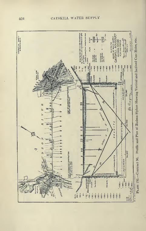
404 CATSKILL WATER SUPPLY
III- f/
It •& 5
^1 § , li
l^ll lU III
; oc J i o
sI
8 , f §1? f H V H f f f f|T If
I * I It
:? 8 ° 8'i § i i i § 2 i i liffiJ

MOODNA, HUDSON, BREAKNECK, BULL HILL TUNNELS 405
May 23, 1911, provides that by April 1, 1913, the work should l)c
far enough along to permit the use of the siphon as a part of the
aqueduct. October 13, 1913, is mentioned for the completion of
the entire work.
. Required Progress. In the light of the experience gained on the
other sijjhons, tlie following rates of progress were thought to l)e
feasible and were specified for Contract 90:
Estimated Necessary Average Rates of Progress for Main Operations
Operation. Rate per Calendar Month.
Excavation of Hudson siphon tunnel 200 linear fe«'t of full .section or
equivalent in each heading.
Lining of Hudson siphon tunnel invert, ineluding
necessary trimming and cleaning of invert. . .900 linear feet in each heading.
Lining Hudson siphon tunnel above invert 625 linear feet in one or each
heading, as necessary.
Lining portion of downtake shaft below elevation
-233, including removal of support 210 linear feet.
Lining drainage shaft below elevation —197,
including removal of support 170 linear feet.
Placing outer and inner linings of drainage shaft
above elevation —175, including steel inter-
lining, steel anchor ring and blow-off nozzle, ^
but not placing steel frame, cover and anchor
bolts; removal of supiK)rt included 60 linear feet.
The above rates include all delays due to periods of preparation
between different kinds of work, and rates coiisiderably higher will
be necessary for most of the time to attain these average rates.
The contract also specifies that delays and accidents will not relieve
the contractor from the necessitj^ of accomplishing the work on or
before April 1, 1913. Also that in default of completing the work
by the above date the suni of $200 per day is to be paid to the City
as liquidated damages. It was recognized that with the city plant
at hand to be turned over to the contractor the progress specified
could not be nmde.
Requirements for Plant. The contract specifically names the
plant to be installed in addition to that already on hand. This is
a very unusual feature and ordinarily not advisable, as it is pretty
certain to increase the contract cost and, in case the conditions do
not turn out as expected, it is liable to leave the City in an uncertain
legal position, for if the specified plant should prove to be inadequate
and not fitted for the work the contractor can claim damages or
relief from the guarantees of the contract, or at best the contract
may be modified by mutual agreement, in which case the cost is
very liable to be largely increased and the time extended. How-ever, it was felt that sufficient experience and information had l)een

406 CATSKILL WATER SUPPLY
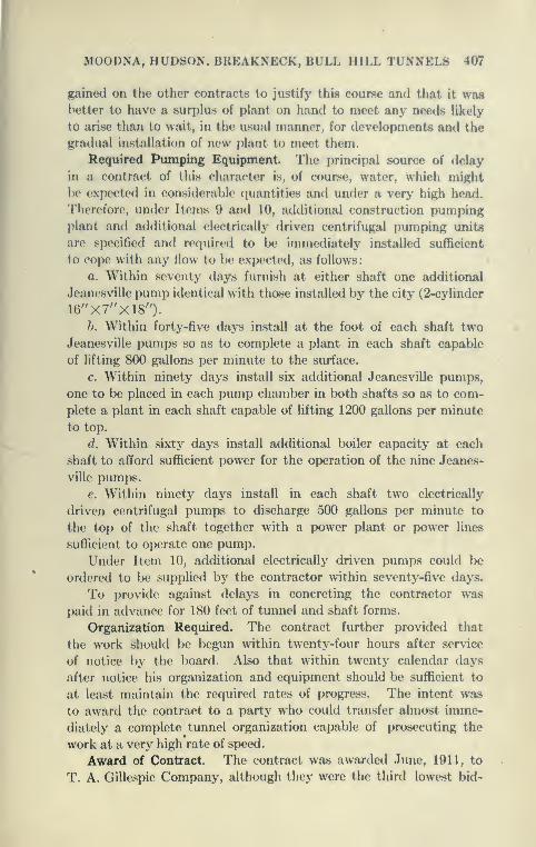
MOODNA, HUDSON. BREAKNECK, BULL HILL TUNNELS 407
gained on the other contracts to justify this course and that it wasbetter to have a surplus of plant on hand to meet any needs likely
to arise than to wait, in the usual manner, for developments and the
gradual installation of new plant to meet them.
Required Pumping Equipment. The principal source of delay
in a contract of this character is, of course, water, which might
be expected in considerable quantities and under a very high head.
Therefore, under Items 9 and 10, additional construction pumpingplant and additional electrically driven centrifugal pumping units
are specified and required to be immediately installed sufficient
to cope with any flow to be expected, as follows:
a. Within seventy days furnish at either shaft one additional
Jeanesville pump identical with those installed by the city (2-cylinder
16"X7"X18").h. Within forty-five days install at the foot of each shaft two
Jeanesville pumps so as to complete a plant in each shaft capable
of lifting 800 gallons per minute to the surface.
c. Within ninety days install six additional Jeanesville pumps,
one to be placed in each pump chamber in both shafts so as to com-
plete a plant in each shaft capable of lifting 1200 gallons per minute
to top.
d. Within sixty days install additional boiler capacity at each
shaft to afford sufficient power for the operation of the nine Jeanes-
ville pumps.
e. Within ninety days install in each shaft two electrically
driven centrifugal pumps to discharge 500 gallons per minute to
the top of the shaft together with a power plant or power lines
sufficient to operate one pump.
Under Item 10, additional electrically driven pumps could be
ordered to be supplied by the contractor within seventy-five days.
To provide against delays in concreting the contractor was
paid in advance for 180 feet of tunnel and shaft forms.
Organization Required. The contract further provided that
the work should be begun within twenty-four hours after service
of notice by the board. Also that within twenty calendar days
after notice his organization and equipment should be sufficient to
at least maintain the required rates of progress. The intent was
to award the contract to a party who could transfer almost imme-
diately a complete tunnel organization capable of prosecuting the
work at a very high rate of speed.
Award of Contract. The contract was awarded June, 1911, to
T. A. Gillespie Company, although they were the third lowest bid-
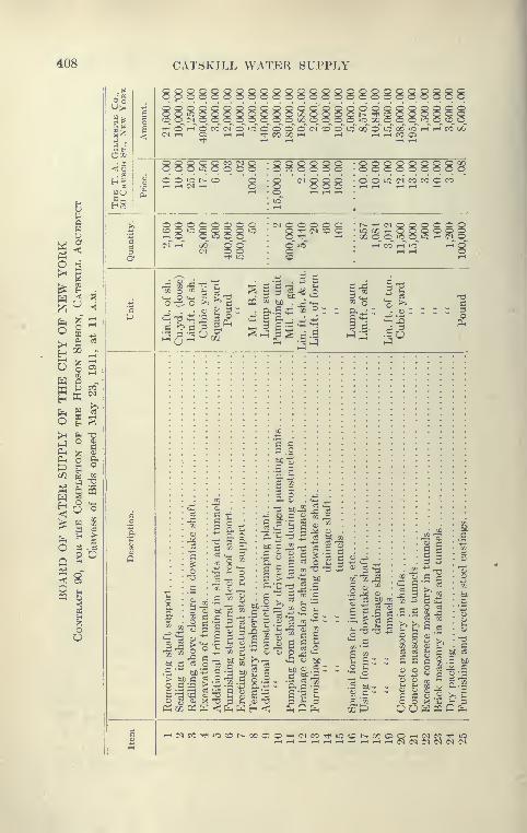
408 CATSKILL WATER SUPPLY
Q
w 5
^ I ^•
^^ <
^ ^^
S ISw -
gs
K o V-
opooogocoooooooooooogooogoddodooddoddo'ddddddddddddOO'0OOOOOOOOCX)OOQOt^TtiC0OQOOOQOO^(MOOOOOOOO00OOOO>O0COOO»COcq^O^^ G --T o" CO (>f d' lo" d~ d~ d" d~ c^" co~ d" io~ 00" d~ o" 00" "o" ^-T »-r co^ 00C^T-< Oi T-iT-( TftCOOOi-l 1-1 i-Hi-iCOCi
8 8
8^8888
(M Q O O OQ '^ (N O
88888888OOiO(MCOCOOCO
r^ •'ff CN Q»0 00 »-H OX o o »o
8888»0 r-l (N O
•" o '^is e; ^
• O g =5
^ S3 g
J5
R CI, tHCO
1111
-73 tpJ£K
bC C c3 o
> bC C ^
o g a; X
-^ S-c^
.1
c
*^ '^ 5 cJ bC
2 g i I 2
> -^ C bC
^ s^ s
s i2 ^ ^^
3
O fc- •-< r^ Ti5 § Si R-S^^
CO
bC
,S c
-3 a,
|g
c3 "mS c
B 3
43 00j^
g -^ bC
c3 O
53 £SO
o o _«i3 u bC
.t: -^ ^ C^:
bC
si g
S:
.i:i bC-
c3 c3
s e
o o
bC c3
OU WP3CPI.
'-H(MCCT}HiOCOt^XC;0^(MeC'<*tOOt^G0050'-HC<ICOTt<iO
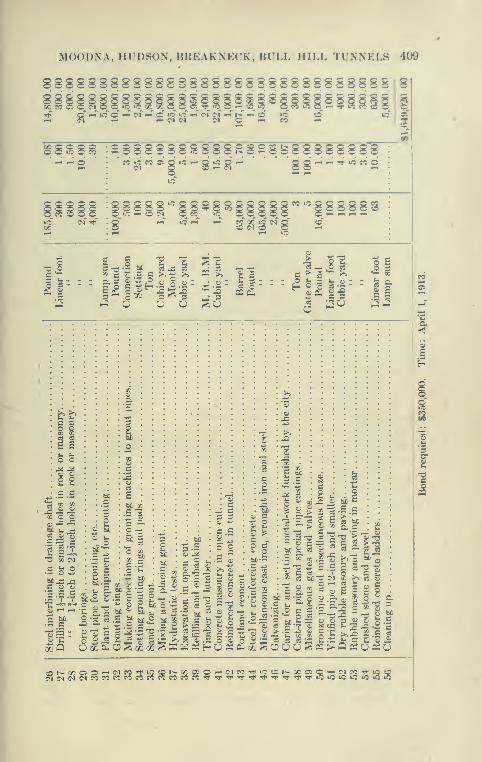
MOODXA, HUDSON, BREAKNECK, BULL HILL TUNNELS 409
8SSSSSSSSS8SS8SS8SSSSSSSgSSS88Sl88SS88ii8888iS8S8§8888SSS
"if
§8S8^ :2888888?888R8S§fe8888888888-^ -^
lii'^ll^isw-'tgggggg
1-1 ir: r-t CC OC »C (M QO C^J o o,-1 lO
•§ s g ^ -s •§ s-s
J " o o o So
c > co b 5H ° O 53 -2
Si c
o ;ju
c c
s e
J4 ^O p
Cj O cj
13 Sq <N
c 5- o
Coo'S .s ^•— 'T 'T
^1
ilco •
O -T3
^Q
'.S C-T3
OmPm
c
O 33 O
I!
c
c.S
. -^
§ SW O03 O
^ t: Sf u-s
p -= r q .2
o
as
2^ ? C
uE "c
bCo 3
c
C *3
II!8 ^ 8-^
f:; i'c .2 =2
"S
5.5 g
o 5 c ^:=:
c iso 'S
Pui QC .*5
bcc..^ I
O
o c c'E
. . o
J Q - C
.2^*c
^ c"^ '^
^ -J £COOScQ
S s g g
"S'3^'5
•- A =5 ^
c8
o bO
P

410 CATSKILL WATER SUPPLY
der. The lower bidders were not equipped with a tunnel organiza-
tion which could be transferred to this work, although the competencj^
of the second bidder, Winston & Co., could not be questioned for
any ordinary contract. The Rondout siphon under Contract 12
was so far along toward completion that a large part of the expe-
rienced force there could be transferred to the Hudson siphon. The
general superintendent, R. J. Gillespie, and his assistants there-
after supervised both contracts. The total of the contract was
$1,649,000, but this sum will probably not be paid out, as the pumping
is certain to fall far short of the estimated amount, the other items
being also liberally estimated to provide for contingencies not likely
to be met.
The designs of Contract 90 are very interesting and show several
unusual features, in some respects improvements on previous con-
tracts, this being the last siphon contract prepared, although the
City Aqueduct contracts were awarded later.
Improved Cross-section for Excavation. Following the advice
of the engineers engaged on the construction of the previous siphons,
although the waterway is circular (14 feet in diameter), the excava-
tion lines were fixed so as to give a flat bottom about 10 feet
wide, to avoid delays and difficulties experienced in excavating
a circular tunnel. In order to get room for the tracks it was
necessary heretofore to leave considerable muck in the bottom,
particularly at the double-tracked stretches and cross-overs, and it
was also found that considerable trimming remained to be done in
the bottom, previous to concreting. Because of the horseshoe sec-
tion of the Hudson siphon the bottom was excavated to sub-
grade in the first operation and the tracks laid directly on the
rock floor, leaving very little muck to be taken out before
concreting.
Water-bearing Seam at East Shaft. Shortly before the letting
of Contract 90, while the City forces were driving the tunnel west-
erly from the East shaft, at a distance of 275 feet from the shaft a
water-bearing seam was opened by the shooting of the heading.
At the time no pumping equipment was in place at the bottom of
the shaft, so that the tunnel was flooded, causing the report to spread
that the Hudson River had been broken into and that the tunnel
was lost. The water before it could rise in the shaft was pumpeddown by several small pumps and the fissure through which the water
was issuing was blanketed with concrete while the water (about
150 gallons per minute) was allowed to flow through a 4-inch pipe.
The concrete was rafted through the tunnel to the bench. After

MOODNA HUDSON, BREAKNECK, BULL HILL TUNNELS 411

412 CATSKILL WATER SUPPLY
the concrete in the heading face had set, the water rose in the 4-inch
pipe 386 feet to the pump chamber at elevation —788.
Beginning of Work by T. A. Gillespie Company. After the bench
had been excavated the work was turned over to the T. A. Gillespie
Company on June 22, 1911. While the work of tunneling was being
vigorously prosecuted at the West shaft and additional plant was
installed at both sides of the river, preparations were made to take
care of a large volume of water at the water-bearing seam encountered
near the East shaft. A very thick concrete bulkhead (see Plate 139)
with steel door was built about 200 feet from the shaft to safeguard
the tunnel against a repetition of the flooding. Between the bulk-
head and the shaft the pumping plant was installed. Meanwhile
a diamond-drill hole was driven into the face of the heading to
explore the ground ahead. Little water was struck, however, 513
feet of hole yielding only 14 gallons per minute, with sound core.
Grouting with Pump. Preparations were next made to grout
off the water-bearing seam. Holes were drilled until the water was
struck, or to a depth of 20 feet, and plugged with pipes and valves.
A reinforced concrete bulkhead was then placed to fill the entire
heading, the pipes extending through. This was done for the pur-
pose of preventing the pressure of grout from blowing out the face
of the heading.
The contractor found that he could not secure an air compressor
to give the required pressures for grouting the heading, where the
gauges in the pipes indicated a water pressure of about 470 pounds
per square inch. It was then resolved to try grouting with a pump.
An air-driven Cameron pump, 10''X3§'X13" was connected
with a Canniff grout tank partly filled with neat cement grout,
which placed this grout under a hydraulic pressure of 1000 pounds
per square inch, driving the grout into the rock through pipes in the
bulkhead which were connected up one by one. This grouting
was found to be ver^^ successful, as when excavation was resumed
on October 12th (three days after grouting), the water-bearing seam
was encountered and although previously under a high head yielded
only a small drip. The seam consisting of only a few inches of ground
rock was found to be well filled with grout; later when the bench
was blowTi out about 20-30 gallons flowed steadily from the lower
portion of seam. This was the first instance on the aqueduct where
high pressure grouting was done directly by a pump, but the result
indicated that this method has several advantages over air injec-
tion. Higher pressures can readily be obtained and no air is
entrained with the grout. The pulsating of the pump probably aids
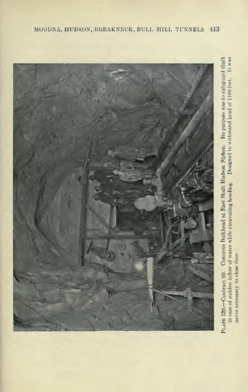
MOODNA, HUDSON, BREAKNECK, BULL HILL TUNNELS 413
414 CATSKILL WATER SUPPLY
in forcing the grout in, overcoming the friction of the grout in
entering narrow seams.
Electric Power Plant. Although the work of tunneling wasvigorously carried on, bj^ far the largest work for the first six months
was the installation of the plant required by the contract. In addi-
tion to the Jeanesville pumps specified, two Worthington 8-stage
electrically driven centrifugal pumps of 500 gallons per minute
capacity under 1160 feet head were installed at each shaft. Themain power plant for supplying current was installed at the East
shaft and consisted of a kilowatt Curtiss steam turbine generator, a
cable being laid under the river to supply the pump at the west
side, current being stepped down from 6000 to 450 volts.
Compressed-air Plant. Compressed air at the west shaft was
supplied from the City plant there, which was considerably enlarged
by compressors and boilers brought down from the power plant at
High Falls (Contract 12), consisting of two Ingersoll-Rand 2-stage
2400-foot air compressors operated by a 350-H.P. Heine boiler.
Four 100-H.P. Nagle locomotive-type boilers were installed as an
emergency outfit to operate the Jeansville pumps.
Tunnel Progress at West Shaft. At the west shaft little time
was lost in getting started, and good progress was made despite
the treacherous nature of the Storm King granite penetrated. Anaverage progress of 269 feet per month was made, maximum 300
feet and minimum 238 feet. " Popping " rock gave considerable
trouble at times, resulting in failure to obtain the usual daily progress
of two rounds in the heading. At the worst stretches, a light steel
roof support was erected, a total of 646 feet being placed in thirteen
places.
Popping Rock. The phenomenon of " popping rock " was first
observed in the lower portion of the west shaft, where steel lagging
was placed to protect the men. The rock appeared to be under
considerable stress and peeled off in layers for three to four weeks
and continued to scale and pop, although apparently perfectly
sound when first exposed. It was confined to the west side
mostly, in a greenish granite, never in the pink varieties or in
the diorite veins. Where encountered the rock has been very
dry; for 300 feet of shaft and 1600 feet of tunnel only 5 gallons
per minute of water had been intercepted. The rupture occurred
on the north side wall and in the roof almost exclusively. Thefragments dislodged were usually thin slabs ys inch to 2 inches thick,
which did not always fly away from the mass and could be noted
clinging to the walls. After removing these, the rock may sound
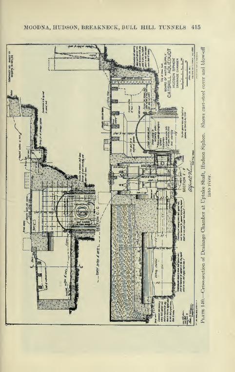
MOODNA, HUDSON, BREAKNECK, BULL HILL TUNNELS 415

416 CATSKILL WATER SUPPLY
^
o
o1-1
I

MOODNA, HUDSON, BREAKNECK, BULL HILL TUNNELS 417
solid under the hammer, yet in a day or two loose pieces would l)e
found at the point marked. Some of the rock in the Hondouttunnel also exhibited this " popping " feature, notably in the Esopus
shale and the Onondaga limestone. In the former the rock broke
loose into conchoidul fragments; in the latter in flat slabs. In both
the Hudson and the Kondout tunnels the phenomenon gave great
annoyance to the engineers, who would find their scales and line
plugs under a mass of rock fragments, after carefully selecting what
they thought to be the most solid places.
•Tunneling Method. From the west shaft two rounds per daj- were
shot. Two drilling shifts were employed between 8 a.m. and 4 p.m.
and 8 p.m. and 4 a.m. Four drills were used in the heading, mounted
in columns, two on tripods for the bench. Each drilling shift, before
leaving, shot the round drilled by them. Three mucking shifts
were employed to clear the tunnel. The flat bottom proved to be
a great help, enabling the tunnel to be cleared down to subgrade,
the track being placed directly on the bottom.
Single Cage in Shafts. Only one cage could be installed in the
1100-foot shafts owing to the arrangement of shaft timbers. Theywere at first operated unbalanced by the Mundy engines, which gave
considerable trouble. Later, Lambert hoists from the Rondout
shafts practically superseded the Mundy hoists, working excel-
lently. Although excellent progress was made with the single
cage it is said that with two balanced cages such as used in the
Rondout and Wallkill tunnels, better progress could have been
made because of greater freedom in sending materials in and out
of the tunnel. The need of quicker hoisting facilities was felt more
keenly during concreting, when even two cages are hard pressed to
lower concrete as fast as it can be placed in the forms. To increase
the capacity of the West shaft for concrete, the single cage was
equipped with a l^-yard hopper dumping from two sides into con-
crete tunnel cars upon reaching the bottom.
The tunnel was concreted through the West shaft, as the East
shaft is much more complicated and lined throughout its depth.
"Holing" through of Hudson Tunnel. On Jan. 30, 1912,
]Mayor Gaynor in the presence of a distinguished assembly, includ-
ing the Commissioners of the Board of Water Supply, and various
City officials, fired the shot which broke down the rock wall separat-
ing the east and west tunnels, so that those present could walk through
a hole in solid rock 1100 feet below the surface of the river. This
was signalized by the Mayor as the culmination of the gieatest feat
in water supply construction since the dawn of history, far out-

418 CATSKILL WATER SUPPLY
MOODNA, HUDSON, BREAKNECK, BULL HILL TUNNELS 419
ranking the Roman aqueducts in size and durability of construction.
At that time nearly 80 per cent of the construction essential to the
delivery of the Catskill water to Croton Lake was completed, andthere remained no difficult portion of construction which was not
far enough along to cause anxiety as to its completion.
The Hudson tunnel when holed through could be walked dryshod from shaft to shaft, large portioas of the walls being bonedry, what little water there was appearing in few wet streaks.
To give the pumps a little work, all the water in the shafts wasallowed to flow to the bottom, where after the sumps were filled the
electric pumps were run till they wpre emptied, this being done to
keep the pumps in running order. They later were removed from
the tunnel, so that the concreting could be proceeded with.
Concreting of Tunnel. A very convenient plant was installed
at the top of the West shaft to supply concrete for the entire tunnel.
Barges of sand and broken stone were unloaded at the dock by a
derrick and grab bucket, which filled a small hopper feeding onto a
belt which in turn discharged into a longitudinal belt over the sand
and stone bins near the shaft. The belt over the bin was equipped
with a tripper so that the bins could be kept uniformly filled. Theconcrete measuring and charging cars were filled from the bins and
hauled by a small hoist up an incline to a large Smith mixer, which
discharged a batch twice the usual size directly into a large twin-
hopper car on the cage. This car at the bottom of the shaft
automatically discharged into two cars, one each side of the shaft.
The concrete cars were hauled by electric trolley dinkies to the
forms, which were used in a manner very similar to that employed
at the Wallkill and Rondout siphons. Although a 40-foot side wall
and arch form was filled daily, it is reported that the single cage is a
considerable handicap during concreting, as there was little time to
take the hopper car off and use the cage for other purposes such as
cleaning and mucking out tunnel, etc. A particularly rich mix,
about 1-1^-3 (2 barrels cement per yard) was used for all the
concrete in order to secure water-tightness. The lining averaged at
least 17 inches effective thickness (see Plate 138).
Grouting of Timnel. After grouting the ground-water head accu-
mulated rapidly back of the lining, showing pressure, where grout pipes
were kept open, up to 450 pounds per square inch. It is very remark-
able how dry large areas of this concrete appears even with the enor-
mous pressure back of it. Stretches show perfectly dry with not even
moisture on the surface. At a few places, particularly near the
wet seam near the East shaft, trouble was experienced in the grouting.
420 CATSKILL WATER SUPPLY
Most of the grouting was done under low pressure and ejected over
the arch in the usual manner, using a Canniff grouting machine, air
stirred, as described under Rondout and Wallkill siphon. Theflowing pipes were wisely left open to the last to prevent the water
from accumulating, under high head above the arch. To do the
high-pressure grouting a very ingenious combination of air and
water-pressure pump was devised. A Canniff machine was partly
filled with grout which was placed under a pressure of about 350
pounds with a Westinghouse compressor connected as usual with
the tank. Then a powerful Cameron pump with large air end and
small water end was started and pumped water into the tank through
another connection, reducing the volume of air above the grout
so as to raise the pressure up to 600 pounds per square inch, if
desired. The discharge valve of the tank was then opened and the
pimip kept going to maintain the pressure while the grout flowed
slowly into the space back of the concrete lining. By this arrange-
ment grouting under almost any pressure is feasible. Special
heavy connections, of course, were used.
At a few points where large areas had been panned back of
the lining and at joints in the concretenear water-bearing seams,
the lining was slightly cracked by the enormous grouting pressures,
but these cracks were repaired by cutting out patches of con-
crete so that new concrete could be keyed in. The grouting of
the Hudson siphon due to the high pressures used was entirely
unprecedented, but there is every reason to believe that it was
successful.
Contract 80
—
Breakneck Shaft and Tunnels
"Work and Prices. Contract 80, although only 2532 feet long,
includes the construction of all types of tunnel and a shaft 589
feet deep, in addition to 710 feet of cut-and-cover. It connects the
East shaft of the Hudson siphon wdth a stretch of cut-and-cover
leading to the Bull Hill tunnel (Contract 22). This contract was
awarded to the Dravo Contracting Company, June, 1910, for a
total of $456,515, some of the unit prices being as follows:
Shaft excavation, cubic yard $20.00
Excavation pressure tunnel, cubic yard 7.00
Excavation grade tunnel, cubic yard 6.00
Concrete shaft and tunnel, cubic yard 6.00
Forms for shaft, linear feet 5.00
Forms for pressure tunnel, linear feet 6.00
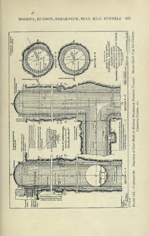
MOODNA, HUDSON, BREAKNECK, BULL HILL TUNNELS 421
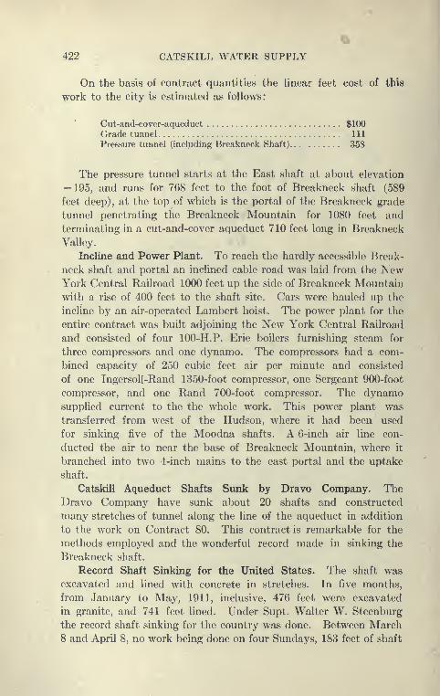
422 CATSKILL WATER SUPPLY
On the basis of contract quantities the hnear feet cost of this
work to the city is estimated as follows:
Cut-and-cover-aqueduct $100Grade tunnel Ill
Pressure tunnel (including Breakneck Shaft) 358
The pressure tunnel starts at the East shaft at about elevation
— 195, and runs for 768 feet to the foot of Breakneck shaft (589
feet deep), at the top of which is the portal of the Breakneck grade
tunnel penetrating the Breakneck Mountain for 1080 feet and
terminating in a cut-and-cover aqueduct 710 feet long in Breakneck
Valley.
Incline and Power Plant. To reach the hardly accessible Break-
neck shaft and portal an inclined cable road was laid from the NewYork Central Railroad 1000 feet up the side of Breakneck Mountain
with a rise of 400 feet to the shaft site. Cars were hauled up the
incline by an air-operated Lambert hoist. The power plant for the
entire contract was built adjoining the New York Central Railroad
and consisted of four 100-H.P. Erie boilers furnishing steam for
three compressors and one dynamo. The compressors had a com-
bined capacity of 250 cubic feet air per minute and consisted
of one Ingersoll-Rand 1350-foot compressor, one Sergeant 900-foot
compressor, and one Rand 700-foot compressor. The dynamosupplied current to the the whole work. This power plant was
transferred from west of the Hudson, where it had been used
for sinking five of the Moodna shafts. A 6-inch air line con-
ducted the air to near the base of Breakneck Mountain, where it
branched into two 4-inch mains to the east portal and the uptake
shaft.
Catskill Aqueduct Shafts Sunk by Dravo Company. TheDravo Company have sunk about 20 shafts and constructed
many stretches of tunnel along the line of the aqueduct in addition
to the work on Contract 80. This contract is remarkable for the
methods employed and the wonderful record made in sinking the
Breakneck shaft.
Record Shaft Sinking for the United States. The shaft was
excavated and lined with concrete in stretches. In five months,
from January to May, 1911, inclusive, 476 feet were excavated
in granite, and 741 feet lined. Under Supt. Walter W. Steenburg
the record shaft sinking for the country was done. Between March8 and April 8, no work being done on four Sundays, 183 feet of shaft
MOODNA, HUDSON, BREAKNECK, BULL HILL TUNNELS 423
were excavated. A total depth of 588 feet was sunk in ninety-thiee
working days, or G§ feet per day. Total elapsed time was 118
days. The concrete lining, inelucHng 20 feet of Ix'll-mouth and 541
feet of regular shaft lining, was placed in forty-six working days,
in an elapsed time of fifty-three days.
The shaft was very accurately drilled, so that the excavation
averaged about the C line. The organization of Mr. Steenburg
also made the record at Shaft 1 of the Moodna tunnel.
Method of Excavating Breakneck Shaft. The shaft was excavated
to an average diameter of 16 J feet by drilling two circles of holes,
the inner or cut circle, 10 feet in diameter, contained ten 8-foot holes;
the outer circle, 16 feet 6 inches in diameter, contained twenty
7-foot rim holes. All the holes were drilled in from 5 to 6} hours
with 3 s Ingersoll-Rand drills mounted on tripods. The cut holes
were shot with the usual center or " buster " hole used to break up
the muck to small size. After the cone l)lown out by the first
round was sufficiently excavated the trimming holes were loaded
and shot and all the muck removed in the third shift. The rock
in this shaft was a medium hard gneissoid granite, uniform and
dry. Conditions were favorable, as shown by the use of only two
rows of holes, as against the three rows usually necessary. Therecord made at this shaft is in every way unique and deserving
of all credit.
The Le3mer Drill. Contract 80 was distinguished by the use
made of the Leyner drill for tunnel driving. This drill was manu-
factured at Denver, Colorado, and has been used for many years
in Western mines and in tunnels. It is now made by the Ingersoll-
Rand Company, and called the Leyner-IngersoU drill. Some of
these tunnels, as that at Los Angeles and the Roosevelt Drainage
tunnel, had been driven at record speed for the United States, and
the LejTier drill, consequently, attracted a good deal of attention.
Previous to the construction of the Catskill Aqueduct the drill had
not been introduced into the East, but some of the contractors about
to start long tunnels sent personal representatives to the West to
examine the working of the Leyner drills and arranged with the
manufacturers for a trial.
Le3mer Drill at Rondout Tunnel. On the Rondout siphon the
contractors found that but slow progress could be made with piston
drills in Shawangunk grit, usually taking 12-16 hours to drill a
heading, with a lesulting large consumption of steel and high cost
of resharpening bits, particularly the starters. As drilling in hard
rock was claimed to be easily accomplished by the I-^yner drill
424 CATSKILL WATER SUPPLY
several of these machines were introduced and operated under the
personal direction of a representative of the drill company.
The Leyner drill is essentially a hammer drill, and uses hollow
steel through which a combined stream of air and water is blown
to clear the bottom of the hole of chippings. For this purpose
there is a double connection, one the usual air line and the other
a small water line from a pressure tank or from a pipe with water
•under pressure. Drill holes as large as made by the usual piston
drills are made by the Leyner drills.
The drills for the Rondout tunnel arriving before the grit headings
were ready, were tried in a tunnel in Hudson River shale, and found
to work very well, but were at a disadvantage in drilling down or
vertical holes in the bench. On the other hand, they were par-
ticularly good for the so-called dry holes, or those pointing upward,
as the Leyner drill readily clears itself in such a hole by the air and
water. When first used in the grit tunnel, the drills were found
to drill holes at a very much faster rate than the piston drills and
were far more sanitary, inasnmch as they made no dust. The
dust made by the piston drills in the dry holes while working in
quartz rock is particularlj^ dense and irritating to the workmen.
After the drills were in operation a short time parts began to break,
and as the Leyner Company did not furnish sufficient parts to keep
them in repair they were replaced by Ingersoll-Rand piston drills.
Advantages and Disadvantages of Hammer Drills. Many advan-
tages are claimed for hammer drills, the greatest being that they
use less than one-half the power of piston drills; that they can be
used by unskilled labor and do not require .helpers, and that one
skilled man can direct several machines. In practice, this is hard to
attain. The hammer of the drill maj' weigh only a fraction of the
combined weight of the piston and steel of the ordinary drill. This
means, that to strike an equal blow the hammer has to travel manytimes as fast as the piston of the ordinary drill, thus causing crystal-
lization in the hammer and steel, the hammer breaking itself, side rods,
anvil blocks, etc., by its tremendous velocity and frequency of blows.
In addition breaks occur at the cutting edges of the bits and in the
welds. The water connections of the Leyner drill are also apt
to cause trouble, particularly when the water used is not clean. Theabove disadvantages are cited not because they are insurmountable,
but to illustrate the difficulties w^hich have to be overcome before
the hammer drill is perfected.
Leyner Drills at Wallkill Timnel. The drill manufacturers were
frank to acknowledge the defects of the drill as brought out by the

MOODNA, HUDSON, BREAKNECK, BULL HILL TUNNELS 425
Rondout tests and claimed that in a newer model they were largely
eliminated. Another and more complete test wa.s arrangetl by the
contractors of the Wallkill siphon. A shaft with its two tunnels
was turned over to a representative of the drill manufacturers as
superintendent; in this capacity he was given entire charge. Anoutfit of Leyner drills was employed in both tunnels. Unfortunately
the work done at this shaft with these drills did not compare favorably
in speed or cost with the work done at other shafts. This was due
largely to the fact that the Leyner representative was not an
experienced shaft superintendent, so that his organization with the
Leyner drills could not overcome this disadvantage. This probably
was not a good place for a drill test, as the rock was a very
free-drilling shale, through which almost any drill could make
sufficient progress. The problem here was not the drilling of the
holes, but the removal of nmck. With the percussion drills the
tunnel heading was readily drilled and shot in less than eight hours,
but unless the mucking arrangements were very good, the tunnel
would be l)locked._
Leyner Drill at Breakneck Tunnel. The third test of the Leyner
drills at Breakneck was far more satisfactory than the other two.
The rock drilled here was a gneissoid granite, locally known as the
Storm King granite. It is a rather hard rock, but drills well, and
is probably similar to the Western granite with which the LejTier
drill had made its records. From experience on the Rondout and
Wallkill siphons, it was known that it was difficult to break in the
ordinary Eastern drill runner to use the Leyner drill. It is a com-
paratively delicate machine and cannot or ought not to be handled
as roughly as the simple piston customarih^ is. In the Western
mines and tunnels where the Le>Tier drills are used the pay of
the drill runners is higher than in the East, and the men are said to
be better mechanics and more capable of keeping the drill in running
order.
An organization of Western drill runners was brought East and
placed in charge of a tunnel on Contract 80. The drill worked well
under their charge, but the method of placing holes in the tunnel
was not to the liking of the superintendent. In driving Western
drifts or drainage tunnels, it is customary to place the holes at a
slight inclination to each other and to rely on powder heavily loaded
in the numerous holes to pull the cut. This was considered wasteful
and new men were obtained. The superintendent found that it
was very hard to overcome the prejudice of the ordinary drill runner
against the use of the Leyner drills, or, it might be better stated,

426 CATSKILL WATER SUPPLY
to change the habits of the ordinary drill runner acquired in running
piston drills. It was found that any intelligent man unaccustomed to
drills could soon be broken in to run the Leyner drills and do very
good work. While working, the footage was considerably higher
than the piston drills, but they were still subject to breakdo^ATis.
The Leyner drills made 5 feet per hour in granite, drilling a roundin about ten hours. Later, in the arch they made 7 feet per hour,
drilling the round in 5^ hours. The bottom heading was drilled with
eight 7^-foot cut holes and seventeen 6|-foot side holes. In the
arch eight to sixteen 10-foot holes were used. Taking into account
the time lost in repairs, their performance was about the same as
the piston drills. It is said that the Leyner drill was considerably
improved during this work, it being found that by the use of a heavier
and better material in the cylinders and other parts of the drill muchof the trouble could be eliminated.
Leyner Drill at Contract 30 (Hill View). The Dravo Companyused the drill later on Contract 30, driving the pressure tunnel at
Hill View Reservoir where they did excellent work, giving muchless trouble than previously, due to improvements in work-
manship and materials, and reducing time of drilling hard gneiss
materially. The tunnels here, however, were rather short, and the
test can hardly be said to be conclusive.
Merits of Leyner Drills. It would seem that the Leyner drill
has many distinct merits, and that if its defects can be overcomeits use in driving tunnel headings should increase, and should be
encouraged for the reason that it eliminates the dust of drilling,
the breathing of which undoubtedly shortens the lives of tunnel
workmen. The Leyner drill is now manufactured in the East
and has been placed on the market in an improved form—as the
Leyner-Ingersoll drill.
Excavation of Breakneck Tunnel. Breakneck grade tunnel
was excavated with a bottom heading, drilling being done by Leyner
drills operated on a horizontal shaft bar. After a portion of the
muck had been removed the horizontal bar was blocked across the
heading and drilling progressed while mucking was going on. Withvertical bars it is necessary to muck the face to the floor of the
heading.
Crushing Plant. From the east heading the muck was run to a
crusher plant, consisting of a No. 5 rotary Gates crusher and a
No. 4 Champion jaw crusher. After being crushed the stone waselevated to a rotary screen and separated into dust and stone, the
stone being piled by a conveyor belt around a wooden tunnel into
MOODNA, HUDSON, BREAKNECK, BULL HILL TUNNELS 427
which cars were run and filled by gravity. This was probably as
economical as any crushing plant operated in connection with atunnel.
Bottom Heading. The method of excavating a complete tunnel
in connection with a })ottom heading by shooting the arch or top
half with horizontal holes down onto a portable timber platform
was tried, but was soon abandoned as costly and slow. The supposed
advantage of this method is that nmcking can be readily done byloading cars below the platform through trap doors, without mate-
rially delaying the work in the bottom heading. Actually, the
platforms were frequently broken by shots and were cumbersome
to move and set up. Considerable muck also fell down on the
lower track, requiring several men to keep it clear. The method
is a crude adaptation of that used in Swiss tunnels. The resem-
blance is not very real, however, as in the Alps a small bottom
drift is excavated and timbered with frequent upraisers to the tunnel
roof, the material from the upper headings and enlargements being
loaded through trap doors into cars on tracks below.
The method used in the bottom headings at Breakneck approx-
imated closely that used in Western drainage tunnels, but as the
tunnels were short no good comparisons can be made. It maybe said that the rock was exceptionally good and sound, requiring
no timbering. The tunnels were also dry, so that the placing of
the horizontal l)ottom holes was not impeded by water.
Excavation above Bottom Headings. After the headings were
driven through, the top half was taken down by drilling horizontal
holes and shooting the material from the arch to the bottom of the
tunnel, after which the drilling was resumed b}^ setting columns
on the muck pile. Very good progress was made in this work,
about 170 feet being drilled and shot and 140 feet mucked per
week. Methods similar to those described were used in the pres-
sure tunnel.
Fuse-firing; Advantages and Disadvantages. The method
of excavating the grade-tunnel bottom heading is here given in
more detail. Two drilling shifts of four men and helpers were
employed from 8 p.m. to 4 a.m., and 8 a.m. to 4 p.m., mucking l)eing
done by three mucking shifts of ten men each and one nmle for
pulling cars. All the heading holes were loaded at the same time
and shot with time fuses of lengths such as to pull the cut holes
first, then the side round and then the trimming holes. The menwere able to return to the face in from fifteen to thirty minutes
after touching off the fuses. By this method a round was generally
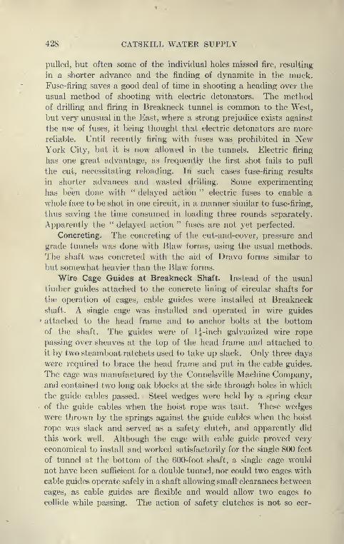
428 CATSKILL WATER SUPPLY
pulled, but often some of the individual holes missed fire, resulting
in a shorter advance and the finding of dynamite in the muck.
Fuse-firing saves a good deal of time in shooting a heading over the
usual method of shooting with electric detonators. The methodof drilling and firing in Breakneck tunnel is common to the West,
but very unusual in the East, where a strong prejudice exists against
the use of fuses, it being thought that electric detonators are more
reliable. Until recently firing with fuses was prohibited in NewYork City, but it is now allowed in the tunnels. Electric firing
has one great advantage, as frequently the first shot fails to pull
the cut, necessitating reloading. In such cases fuse-firing results
in shorter advances and wasted drilling. Some experimenting
has been done with ^' delayed action " electric fuses to enable a
whole face to be shot in one circuit, in a manner similar to fuse-firing,
thus saving the time consumed in loading three rounds separately.
Apparently the " delayed action " fuses are not yet perfected.
Concreting. The concreting of the cut-and-cover, pressure and
grade tunnels was done with Blaw forms, using the usual methods.
The shaft was concreted with the aid of Dravo forms similar to
but somewhat heavier than the Blaw forms.
Wire Cage Guides at Breakneck Shaft. Instead of the usual
timber guides attached to the concrete lining of circular shafts for
the operation of cages, cable guides were installed at Breakneck
shaft. A single cage was installed and operated in wire guides
attached to the head frame and to anchor bolts at the bottom
of the shaft. The guides were of IJ-inch galvanized wire rope
passing over sheaves at the top of the head frame and attached to
it by two steamboat ratchets used to take up slack. Only three days
were required to brace the head frame and put in the cable guides.
The cage was manufactured by the Connelsville Machine Company,and contained two long oak blocks at the side through holes in which
the guide cables passed. Steel wedges were held by a spring clear
of the guide cables when the hoist rope was taut. These wedges
were thrown by the springs against the guide cables when the hoist
rope was slack and served as a safety clutch, and apparently did
this work well. Although the cage with cable guide proved very
economical to install and worked satisfactorily for the single 800 feet
of tunnel at the bottom of the 600-foot shaft, a single cage would
not have been sufficient for a double tunnel, nor could two cages with
cable guides operate safely in a shaft allowing small clearances between
cages, as cable guides are flexible and would allow two cages to
collide while passing. The action of safety clutches is not so cer-
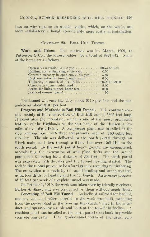
MOODNA, HUDSON, BREAKNECK, BULL HILL TUNNELS 429
tain on wire rope as on wooticn guides, which, on the whole, are
more satisfactory although considerably more costly in installation.
Contract 22. Bull Hill Tunnel.
Work and Prices. This contract was let March, 10()9, to
Patterson & Co., the lowest bidder, for a total of $824,942. Someof the items are as follows:
Open-cut excavation, cubic yard $0.75 to 1.50
Refilling and embanking, cubic yard 0.50
Concrete masonry in open cut, cubic yard 5.50
Rock excavation in tunnel, cubic yard 0.00
Timbering in tunnel, M. feet B.M (iO.OO to 70.00
Concrete in tunnel, cubic yard 5.90
Forms for lining tunnel, linear feet 2.00
Portland cement, barrel 1.70
The tunnel will cost the City about $110 per foot and the cut-
and-covor about $101 per foot.
Progress and Methods in Bull Hill Tunnel. This contract con-
sists mainly of the construction of Bull Hill tunnel, 5365 feet long.
It penetrates the mountain, which is one of the most prominent
features of the Highlands on the east bank of the Hudson a few
miles above West Point. A compressor plant was installed at the
river and equipped with three compressors, each of 1160 cubic feet
capacity. The air was delivered to the north portal through an
8-inch main, and then through a 6-inch line over Bull Hill to the
south portal. In the north portal heavy ground was encountered,
necessitating the excavation of wall plate drifts and the use of
permanent timbering for a distance of 200 feet. The south portal
was excavated with derricks and the tunnel heading started. Therock in the tunnel proved to be a hard granite requiring no timbering.
The excavation was made by the usual heading and bench method,
using four drills for heading and two for bench. An average progress
of 40 feet per week of complete tunnel was made.
On October 1, 1910, the work was taken over by friendly receivers.
Barker & Shaw, and was conducted by them without much delay.
Concreting of Bull Hill Tunnel. An inclined railroad for hauling
cement, sand and other material to the work was built, extending
from the power plant at the river up Breakneck Valley to the aque-
duct, and operated by a cable and hoist at the top of the incline. Acrushing plant was installed at the north portal spoil bank to provide
concrete aggregate. Blaw grade-tunnel forms of the usual con-

430 CATSKILL WATER SUPPLY
struction were installed in the tunnel in three places, one 40 feet
long and two 30 feet long. The concreting was carried continuously
through three shifts, a new form being started as soon as it was ready.
Concrete was hauled up inclines in the usual manner, but time
was saved by depositing enough dry concrete on the platform to
enable about one-half the key to be completed after the incline
was removed.
Concreting Record for Grade Tunnels. It took a form gang about
five to six hours to strike, move and set up a set of forms. Fromthe south portal concrete plant, 2772 feet was concreted in ninety-
six days, or 29 feet per day. From the north portal plant 2592 feet
was concreted in tifty-nine days, or 44 feet per day. In one week,
working seven days, 340 feet of arch was concreted, the best weekly
progress so far made in grade tunnels, but later exceeded in the
Garrison tunnel, where 593 feet was concreted in one week. Thehaul to the three sets of forms was 1500 feet, 2300 feet and 2900 feet.
The shortest time for concreting a form was twelve hours; the
longest, twenty hours; the average, fifteen hours. From 8 to 10
men and a foreman shoveled concrete, 4 to 6 mules and drivers
hauled cars, 4 men and foreman were at the mixer, and a fore-
man and 8 men moved the forms, with 4 men to put on plates
during concreting.
Comparison of Peak and Bull Hill Concreting. The average
progress per working day was 35 feet in concreting this tunnel against
38 feet per working day in the Peak tunnel. Contract 11. As the
work of the Peak tunnel was organized on the basis of two con-
creting and one moving shift against straight three-shift work for
the Bull Hill tunnel, it is probable that the method of the Peak
tunnel was more economical, as it had the advantage of the bulk
of the work being done on the day shift.
Cut-and-Cover. The cut-and-cover was largely rock, earth-
covered, which was excavated by drag scrapers and by traveling
guy derricks lifting the skips, the material being run back to makerefill. The concreting was done with Blaw forms. Bottom-dumping
buckets were used, hauled by dinkies on flat cars and placed by the
traveling derricks.

CHAPTER XII
PEEKSKILL DIVISION CUT-AND-COVER AND GRADE TUNNELS
Contract 2
Location and Work of Contract 2. Tho first main contract
was awarded April, 11)07, to the Thomas McNally Company of
Pittsburgh, Pa. Work on the location and preparation of the prop-
erty maps and contract was rushed, as it was deemed important
to have this work finished ahead of any other portion, as it madepossible the delivery of additional water to the Croton watershed
by diverting the Peekskill or other streams of the Highlands which
this work crossed. This contract embraces all the work of the
Peekskill Division with the exception of three pipe siphons at Indian
and Sprout brooks and Peekskill creek. It traverses the Highlands
between Cold Spring and Peekskill, the roughest and most dif-
ficult country between the Catskills and New York, and includes
about 8 miles of cut-and-cover and 2.8 miles of grade tunnel,
known as Cat Hill, Garrison and Mekeel tunnels. The Garrison
tunnel is the longest grade tunnel in the Aqueduct, having a length
of 11,430 feet. It was to be constructed from a shaft and two
portals, but due to difficulty at the north portal other shafts were
sunk.
Contract Prices. The total contract price was $4,126,423.
Some of unit prices are as follows:
Excavation in open cut per cubic yard $0.94 to 1.33
Refilling 0.26
Concrete masonry in open-cut aqueduct, cu.yd. 4.29
Rock excavation in tunnel, cu.yd 3.27
Concrete masonry in tunnel, cu.yd 5.61
Forms for ma.sonry lining, linear foot 4.12
Portland cement per barrel 1.85
Estimated cost of cut-and-cover aqueduct based on contract
quantities is $71.63 per foot; of grade tunnel $76.30 per foot.
Work of the First Year, 1907. The prices for cut-and-cover are
considered fair when judged by other contracts, but the tunnel
431
432 CATSKILL WATER SUPPLY
excavation figure is very low, and accounts largely for the subse-
quent history of this contract. As this contract started much in
advance of any other, methods for doing this type of work had to be
developed. Mr. McNally previously had large experience with the
steam shovel for railroad work, and several of these were obtained
and put to work excavating the trench for the aqueduct. A con-
siderable amount of excavation was acccomplished during the
first year, but the material was disposed of in a rather haphazard
way, being cast to one side of the trench or disposed of in embank-
ments adjacent to the aqueduct. Short stretches of track were laid
alongside of the trench but were not connected by any particular
plan for any considerable distance. A few culverts were built
and a few roads relocated during the same year.
Garrison Tunnel, 1907. The main shaft of the Garrison tunnel
was sunk to grade during 1907. It was found that at the north por-
tal the rock was about at the level of the tunnel roof, the material
above being wet glacial drift. This necessitated very heavy tim-
bering, and such slow progress was made that it was decided to sink
a pump shaft 380 feet south of the portal, its depth being only 61
feet. The contractor seemed to have been bothered by insufficient
working capital, and particularly so as 1907 was a year of financial
panic.
Plant on Hand, 1908. When work started in 1908 the contractor
had on hand the following plant: Two 38-ton Marion steam shovels;
four 70-ton Bucyrus steam shovels, locomotives, cars, track, etc.;
also compressor plants at Garrison and Cat Hill tunnels. During
this year the first concreting of aqueduct was accomplished. For this
purpose, three distinct plants were used, but these were radically
changed from time to time. All the plants were served by locomotives
and trains on 3-foot gauge tracks, running to cement sheds, sand
pit and both crusher plants. There was considerable interference
of trains due to incomplete and faulty arrangements of tracks.
Concreting Plant, 1908. One of the first plants used on Section 2
consisted of a Foote continuous mixer mounted on a traveler running
on rails laid on the concrete invert just outside the interior of the aque-
duct. The various hoppers for the mixers were filled by a Browning
locomotive crane similarly mounted on a traveler. The concrete was
delivered by the mixer to end-dumping cars running on parallel
tracks above the top of arch. Various minor modifications of this
plant were tried, but the best results were obtained by the above
arrangement. The locomotive crane was wrecked before the end
of the season, and for it was substituted a derrick, installed at the side

PEEKSKILL CUT-AND-COVER AND GRADE TUNNELS 433
of the trench. This plant was handicapped by the fact that materials
could he supplied to it only with difficulty on account of the poor track
arrangement, also by the necessity of building tracks on top of the
forms and the instability of the crane mounted high in the air on a trav-
eler. It contained, however, all the elements of the plants later suc-
cessfully used. The locomotive crane should have been placed on
tracks alongside of the cut and the mixer in some location convenient
to the materials, so that the concrete could be run directly to the crane
over suitable tracks and directly placed between the forms. Theconcrete for key blocks and invert for about 1000 feet of invert wasmixed in a stationary Hains mixer and conveyed in bottom-dumping
buckets which were placed by locomotive cranes. The best success
was obtained with this plant, and a great deal of invert concreted
by substantially the same method as was used in subsequent con-
tracts, except that on Contract 2, during this year, the track arrange-
ments wore always inadequate.
Casting of First Arch, July 13, 1908. The first section of arch of
the entire aqueduct was concreted on July 13, 1908. The plant
here used consisted of 1-yard Smith mixer fed with sand and stone
from hoppers mounted on a car running on a standard-gauge track
alongside of the aqueduct trench. These hoppers were filled by an
A-frame derrick mounted on the same track. The concrete was
placed in the forms by aid of another A-frame derrick. It is inter-
esting to note that this 30-foot section of arch took about twelve
hours to be concreted. With later plants on other contracts this
could easily have been done in two or three hours. The mixer
was subsequently mounted on a traveler running on the finished
invert. On the same traveler were mounted a boiler and hoist
which raised from the tracks skips of proportioned concrete material.
These skips were run inboard on a trolley running on a cantilever armat right angles to the track, and discharged directly into the mixer
which in turn discharged into the side-dumping cars running on a track
al)ove the form. This plant was slow and awkward in operation.
Hains Mixer Plant. The best progress in concreting was madewith the stationary Hains mixing plant, which discharged into
1^-yard bottom-dumping buckets carried on platform cars hauled
to the side of the work by dinkies, where they were dumped into
the forms by locomotive cranes. This plant was similar to that
subsequently used on Contract 11, where the maximum progress in
concreting cut-and-cover aqueduct was made. The McNally plant,
however, was not provided with proper trackage, so that materials
could not be rapidly hauled to and from it.
434 CATSKILL WATER SUPPLY
First Steel Forms Used. The first steel forms in use on the
aqueduct were designed and built for this contract. They were
collapsible in 5 foot-sections. The inside forms were mounted on a
carriage equipped with jacks. As the proper carriage and methodof collapsing steel forms were not yet worked out they gave con-
siderable trouble and were moved with great difficulty. The out-
side forms were constructed of steel ribs connected with the inside
forms by rods or wires. Between the I-beam ribs tongue-and-
groove lagging in 5-foot lengths was inserted as the concrete rose.
Wooden transverse bulkheads were used in which were inserted the
steel plates used to prevent leakage from expansion joints. During
the season of 1908, 4.385 feet of invert were laid and 1485 feet of arch.
At the Garrison tunnel about 1150 feet of tunnel was excavated
from the main shaft, and a short stretch of timbered top heading
was driven from the auxiliary shaft near the north portal. Someprogress was made in the north portal heading, and about 500 feet
of the Cat Hill tunnel was also excavated.
McNally Receivership, 1909. During the latter part of 1908
the contractor operated with considerable difficulty, and early in
1909 receivers were appointed to carry on the work. The work
was subdivided into four parts by the receivers, and they were let
to the following superintendents: John J. Hart, work south of
Peekskill Creek; Cleveland Tunnel Construction Company, Cat
Hill tunnel, and adjoining section of cut-and-cover of the south,
comprising work between Peekskill and Sprout Brook siphons;
Gore-Meenan Company, Garrison tunnel and adjoining cut-and-
cover, comprising the stretch between Sprout Brook and Indian
Brook. This last company operated until March, 1910, when it in
turn failed and the work was then taken over by the Hicks, John-
son Company, Inc. The north end, comprising the cut-and-cover
work north of Indian Brook, and Mekeel tunnel, was under R. K.
Everett & Co., knoA\Ti subsequently to September, 1911, as the
Spring Hill Construction Co.
R. K. Everett Work. The work of this company comprised
the Nelsonville cut-and-cover, 3574 feet; the Mekeel tunnel,
900 feet; and the north end of Garrison cut-and-cover, 3900 feet.
No work had been done on this section by the McNally
Company, the original contractor, so that the new companyhad opportunity to work with a plant and plan of their
own. The excavation in earth was made with a 70-ton Bucyrus
steam shovel. In rock cuts stationary derricks were installed on the
downhill side and used for hoisting rock from the trench and building

I'EEKSKILL CUT-AND-COVER AND UKAOE TUNNELS 435
lit
O o
* "aJ
s a
^' IP. 8
^ o
I §8
?
.^
Soo oOS ^£ as
3S o

436 CATSKILL WATER SUPPLY
a heavy dry rubble retaining wall on the lower side. Through-
out a great portion of this section the aqueduct is located on a steep
sidehill, and is to a large extent inaccessible. The northerly 1300
feet was an easy country and operations were begun here, the con-
tractor planning to have the trench ready for concrete as the con-
struction proceeded southward; also to install a crusher plant where
rock was available from the cuts and to build a track for conveying
material along the line of the work.
Mekeel Tunnel. The Mekeel tunnel was excavated by ordinary
heading and bench method from one end, but despite its shortness
was the scene of one of the worst tunnel accidents, several men being
killed in the heading by a premature explosion.
Concreting of Mekeel Tunnel. The Mekeel tunnel was con-
creted with the aid of Blaw tunnel forms. The concrete from a
mixer at a portal was discharged through a chute directly into con-
crete cars. These cars were carried on an elevated platform, twoor three at a time; the platform ran on rails and at the sameelevation as the form platform, so that the cars could be run on the
forms and dumped into place. This saved the work of constructing
an incline and operating a hoist as usually used. It was well adapted
for a tunnel only 900 feet long, but could not well be used in a longer
tunnel where it is necessary to pull the cars through the form. Theplatform was hauled to and fro by mules.
Cut-and-Cover Construction Plant. During 1909 considerable
aqueduct trench was excavated, but due to the delay in the installa-
tion of the crusher plant, it was necessary to leave an earth trench
with steep slope standing over winter. A large amount of caving
resulted and the bottom of the trench had to be re-excavated the fol-
lowing year. The following concrete plant was used in the construc-
tion of the aqueduct: No. 4 Ransome mixer located in the trench
was served by a stationary derrick, the materials being brought in
trains on the construction track. Concrete was deposited in the
forms by a traveling derrick. Ordinary steel forms of the Blawtype were used and handled in the same way as previously described
under other contracts.
Special Foundation Work. In order to secure the aqueduct,
which was here built along the steep slopes of the Highlands, special
precautions were taken to obtain suitable foundations. Where the
bottom was entirely in rock the invert subgrade w^as generally
cleared of all debris and the concrete carried down to firm rock.
Where the rock fell considerably below subgrade on the downhill
side the foundation walls, about 5 feet wide, extending parallel to

PEEKSKILL CUT-AND-COVER AND GRADE TUNNELS 437
the center line, were carried down to rock or other solid material.
In somo places transverse steel rods were used in the invert for rein-
forcomont.
Cat Hill Tunnel. Cleveland Tunnel Construction Company.
The work of this company included tlio Cat Hill tunnel and
atljaccnt sections of cut-and-cover. The tunnel had been partly
excavated by the McNally Company, and was completed by the
Cleveland Tunnel Company, by the ordinary top heading and
bench method, although considerable heading was driven before the
bench was started. This tunnel illustrates the costliness of not
driving to required section or line. Due to inadequate plant and
frequent changes of force, the tunnel was so driven by the McNally
Company that much costly trimming was necessary to makeroom for the tunnel lining, and, in addition, a large amount of dry
packing and excess concrete were necessary outside the required
thickness of concrete lining. This dry packing occupied spaces
where the tunnel was driven wide or out of line.
Concreting of Cat Hill Timnel. A common crushing and mixing
plant supplied concrete to both the tunnel and cut-and-cover, and
consisted of a Gates crusher, bins and two ^-yard Smith mixers.
The method of concreting was similar to that used in the Bonticou
and other tunnels, except that 20-foot stretches of Blaw forms were
concreted at a time, the cars being raised from the bottom tracks
by an electric driven elevator to the level of the shoveling plat-
form. This elevator was constructed to avoid the use of incline and
hoist such as is commonly used, but it is doubtful whether it is
an improvement, as 'the incline has a large capacity, being able to
raise two or more cars in trains, whereas the elevator was good for
onl}- one car at a time.
Cut-and-Cover Work. The upper lift of the cut-and-cover
excavation (mostly rock) was removed by steam shovel in 1908.
A cableway of 250-foot span was erected for finishing the work of
excavating. The excavated material was hauled in cars by nmles or
small locomotive. The cableway was moved from place to place
along the center line. This is one of only a few instances on this
work kno^vn to the writer where a cableway was used for excavation
of cut-and-cover aqueduct trench. It was given serious considera-
tion by other contractors, but they came to the conclusion that it
was not adapted to this kind of work. Blaw steel fonns were used
and concrete deposited in them by means of traveling crane running
on the invert. Side-dump cars or buckets were hauled, from the
central plant.
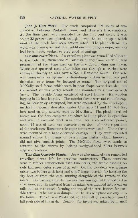
438 CATSKILL WATER SUPPLY
John J. Hart Work. The work comprised 3.9 miles of cut-
and-cover between Peekskill Creek and Hunter's Brook siphons.
At the time work was suspended by the first contractor, it was
about 22 per cent completed, though it was the section upon which
most of the work had been concentrated. The plant left on this
work was taken over and after additions and various improvements
had been made, worked to very good advantage.
Cut-and-cover Plant. An excellent plant was remodeled adjacent
to the Coleman, Breucheud & Coleman quarry from which a large
proportion of the stone used on the new Croton dam was taken.
Waste and quarried rock after being run through a crusher were
conveyed directly to bins over a No. 4 Ransome mixer. Concrete
was transported in 1^-yard bottom-dump buckets in flat cars and
deposited over forms by locomotive crane. The original set of
McNally steel forms, which were in poor shape, were discarded, but
the second set was partly rebuilt and mounted on a traveler with
jacks. The outside forms consisted of steel frames with woodenlagging in 16-foot lengths. The interior forms were not run telescop-
ing, as previously attempted, but were operated by the spacing-out
method previously described under Contracts 11 and 16, but first
here used on any notable scale by Mr. Hart. The x>lant described
above was the first complete aqueduct building plant in operation
and with it excellent work was done; for a considerable period,
about 45 feet of arch was concreted per day. For other portions
of the work new Ransome telescopic forms were used. These forms
were mounted on a hand-operated carriage. They were operated
around curves by means of overlapping plates, which, however,
did not give smooth joints. The McNally forms were made to
conform to the curves by bolting wedge-shaped fillers between
adjacent sections.
Traveling Concrete Plants. Use was also made of two remodeled
traveling plants left by previous contractors. These travelers
were of timber construction with two decks, the whole running on
rails laid near outer edges of invert. On the top deck was a large
mixer, two boilers with hoist and a stifif-legged derrick for hoisting the
dry batches from the cars, running alongside of the trench, to the
mixer. For casting arch the traveler was run against the end of the
steel form, and the material from the mixer was dumped into a car on
rails laid over channels forming the top of the steel frames for out-
side forms. The car was dumped at the desired place directly into
the forms. The car was W-shaped, so that half of each batch would
fall each side of the arch. Concrete for invert was mixed by a small
PEEKSKILL CUT-AND-COVER AND GRADE TUNNELS 439
440 CATSKILL WATER SUPPLY
mixer on the lower deck which discharged into the side-dump cars
operated on a track laid on a wooden trestle in the center of the
trench. These travelers worked fairly well, but apparently are
not as economical or as flexible as the ordinary method of deposit-
ing concrete directly from the locomotive crane. The main advantage
.of the traveler appears to be that use is made of the space over the
invert and it can be served by a single track. Another advantage
is that the concrete is deposited in place soon after being mixed.
However, it has been found on other contracts that concrete can be
successfully hauled over a mile and deposited.
Excavation and Refill. Considerable of the excavation of this
section was done by the McNally Company (except about 3000
feet at the south end and some intermediate stretches), the chief
of which were the heavy rock cut at the north end, the Todd cut
for a maximum depth to subgrade of nearly 55 feet at Crompond
Road crossing and quite an extensive rock cut south of the Coleman,
Breucheud & Coleman quarry. The rock cuts were excavated with
stationarj^ denicks and the spoil hauled away in trains, all suitable
rock being used at the crusher plant. At the heavy Todd cut a
70-ton Buycrus steam shovel, a locomotive crane and an orange-peel
bucket were used. At the south end of the cut a Lidgerwood cable-
way with 55-foot towers and 840-foot span was used to convey the
spoil, the skips being loaded partly by hand and partly by steam
shovel. The excavated material was deposited at the side of the
trench, or part used for refill over the aqueduct. Part of the excava-
tion and refilling was done at night. Considerable refill was also placed
by a locomotive crane and clam-shell or orange-peel bucket, handling
the material originally excavated and placed at side of trenches.
This crane had to be assisted by men with pick and shovel, as the
material had consolidated through standing several years.
Gore-Meenan and Hicks-Johnson Work. After the McNally
Company went into the receiver's hands, the Garrison tunnel and
7670 feet of cut-and-cover north of the tunnel and 3350 feet of
aqueduct south of the tunnel were given to the Gore-Meenan Co.
This company, handicapped by lack of capital, was forced to
give up the work; which was continued later by the Hicks-Johnson
Company, Inc. This company considerably reinforced the plant
of the main shaft by adding a 500-H.P. Sterling boiler and an Inger-
soll-Rand compressor of 2400 cubic feet capacity. Electric loco-
motives were also installed to haul muck in the tunnel.
Garrison Tunnel Excavation. This company prosecuted the
work with vigor and on October 4, 1911, the headings between the

PEEK8KILL CUT-AND-COVER AND GRADE TUNNELS 441
main and north shafts met. The south heading from the mainshaft continuod in liard, compact granitic gneiss until Sopteml^er,
1911, when a variable flow of water, amounting to al)out 100
gallons per minute, was struck in a seam between hard and soft
rock. Work was suspended for a while, but the bad ground waspassed by careful timbering. At the end of 1911 there remained
1175 feet between the two headings, and the headings met in May,1912. This makes elapsed time five years of work on the excava-
tion of the Garrison tunnel alone, a much longer time than has
been taken on any other tunnel, nmch longer even than on the
Hudson siphon with its 1100-foot shafts, and a year longer than the
Rondout sii)hon, although the Garrison tunnel is only 2.1 miles long.
The delay in excavating this tunnel was caused mainly Ijy the
low \init price bid for excavation of tunnels, thus well illustrating
the fact that physical obstacles are more readily overcome than
financial.
Soft Groimd at North Portal. The Garrison tunnel, nevertheless,
was by no means an easy one. The rock as a rule was very hard and
the numerous streams of water met in the headings were very
troublesome. There were several difficult points to be passed, the
most difficult being that at the north portal.
The stretch of 700 feet of tunnel at the north jwrtal has a very
interesting history, extending over a period of five years. In 1907,
in order to save delay in starting the excavation of the tunnel, a
shaft was sunk at the contract portal, Station 604+80, to tunnel
grade previous to excavating the deep portal cut. This heading
was in rock and in earth, a wet glacial drift which brought great
pressure upon the timbers. 380 feet from the portal shaft, at Station
601, a small pump shaft was simk in September, 1908, 61 feet to
tunnel grade, its purpose being to drain the earth and make tun-
neling easier. This shaft did not intercept much water, and it
was pumped from only for a short period. At the same time a
construction shaft 105 feet deep was sunk to tunnel grade at Station
598, 680 feet from the portal. A timbered heading 22 feet long
was driven northward from this toward the difficult ground,
when work was stopped and not resumed again till April, 1911,
two and one-half years later. In 1911, 338 feet additional was
excavated in the north heading. The face of the portal heading
at this time was partly in quicksand, and it was thought advisable
to sink a new shaft at Station 602+74, at the end of the portal
heading, from which a new type of timbering could l)e advanced
southward. This new shaft was sunk 34 feet in December,
442 CATSKILL WATER SUPPLY
1911, when about 100 feet of soft ground tunnel remained to be
driven. This was holed through in February, 1912, completing
the difficult stretch at the north portal.
Timbering Bad Ground, North Portal Garrison Tunnel. Thematerial in the heading north of Station 598+00 consisted of a
very soft, decomposed rock extending to within a few feet of the
roof of the tunnel, overlaid by glacial drift—a blue hardpan with large
boulders. The decomposed rock when first exposed was fairly
firm and snow white, but the action of air and water caused it to
soften and turn brown, so that very heavy timbering was required,
and slow progress was made on account of the care necessary to
prevent runs of earth and water. The first step was to drive a top
center drift, about 20 feet long. In this drift the regular cap and
leg bents of 8-inch timbers were placed, 4 feet center to center. Overthese poling boards 2"X8"X5' long were driven, two and even
three thicknesses being required in some places. The next step
was to post two crown bars 18" to 24" in diameter and 18 feet long,
under the cross-caps. The step following was to take the legs one
at a time from the bents in the drift and drive side poUng boards
over the crown bars at right angles to the center fine. New bars
were set to support the outer ends, just enough excavation being
made to give room for the bar, after which additional crown bars
were set and poHng boards driven in the same manner until the full
width of the roof was covered. After this the wall plates were set,
supporting segmental timbers and lagging. The space above the
segmental timbers was packed with stone as the work advanced.
The last operation was to take out the bench (about 12 feet high) andpost up the wall plates. The pressure on the timbers was so great
that it was necessary to set the segmental timbers bent against bent
and to use extra interior bracing. To secure the timbering it becamenecessary to begin concreting earlier than was anticipated, and the
floor of the tunnel was concreted, beginning in December, 1911.
Since April, 1911, 330 feet of heading and 342 feet of bench wasexcavated by the above method, about 10 feet a week, working
three shifts in twenty-four hours. This progress is about the same as
that made under conditions somewhat similar to those described under
Eastview tunnel. Contract 52, in which tunnel compressed air wasresorted to and the progress much increased. The question naturally
arises whether a great deal of time might not have been saved at
the north portal of the Garrison tunriel by the use of compressed air.
Contract 2, however, unlike that of 52, contained no provision bywhich compressed-air work could be ordered by the engineers. It
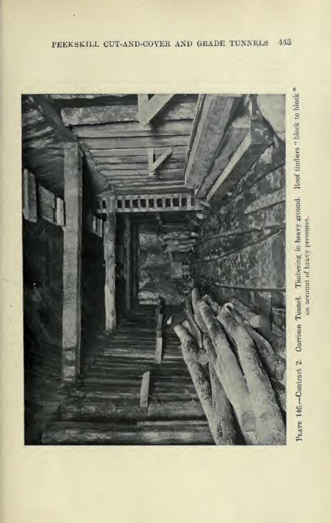
PEEKSKILL CUT-AND-COVEK AUD GRADE TUNNELS 443
444 CATSKILL WATER SUPPLY
is stated, however, that experts employed by the contractors reported
against the use of compressed air at this point.
Lining Garrison Tunnel. At this writing (February, 1913), the
lining of Garrison tunnel is in progress. Six sets of Blaw forms,
each 50 feet long, are distributed through the tunnel and served by
mixer at bottom of main shaft. Side-dump cars, electric locomo-
tives and inclines are used. The best week's progress so far (Jan-
uary, 1913), is 593 feet of completed arch.
Cut-and-Cover at Garrison Tunnel. The cut-and-cover work
adjacent to the Garrison tunnel was excavated with steam shovel,
locomotive cranes equipped with orange-peel buckets and very little
by pick-and-shovel gangs loading skips. The crushing and concret-
ing plant located near the north portal used stcne direct from the
tunnel, a stiff-legged derrick elevating sand obtained from the aque-
duct right of way about 1500 feet distant. Concreting was done
in the usual manner by bottom-dump buckets and locomotive
cranes. Two hundred and eighty feet of the first McNally forms
were used after extensive repairs. To move the interior forms
a car was equipped with jacks to gradually strip the forms, pulling
in at the bottom edge. A great deal of trouble was experienced
here on account of the peeling of the concrete while removing forms.
This was shown to be largely due to the use of a slow-setting cement
which did not obtain sufficient set in some two to four days to over-
come the adhesion of the concrete to the steel. After a quicker-
setting cement was substituted this trouble largely disappeared.
Outside Forms. The outside forms, made of steel ribs and wooden
lagging, were moved in an original manner. After being jacked up
a few inches, they were pulled ahead on rollers resting on longi-
tudinal rails, supported on the arch concrete at the back and on
trestles on the inside forms in front. This had the advantage of
requiring no locomotive crane or derrick, as the forms were movedforward in a full 30-foot section, and also did away with the neces-
sity of taking the ribs apart and removing and setting up the woodenlagging.
CHAPTER XIII
STEEL PIPE LINES
Contract 62
Contract 62—Prices. This contract was let in December, 1909,
to the Snare & Trieste Co., for a total of $1,643,000. Some of the
unit prices are as follows:
Earth excavation $ .50 per cu.yd.
Rock excavation 2 . 50 per cu.yd.
Refill and embankment 40 and .35 per cu.ydi
Control of streams $25009 ft. 6 ins. steel pipe, i^-in. steel plate, J-in.
steel plate $31 to 50 per linear foot
Mortar lining for steel pipe 2 . 50 per linear foot
Concrete masonry around steel pipe 6 . 00 per cu.yd.
Estimated cost of siphon chambers is $13,200 per chamber,
of steel pipe complete $65.17 per foot, of cut-and-cover, $70.76
per foot.
Location. This contract embraces all the steel pipe lines to be
laid in the Northern Aqueduct Department from Ashokan Reservoir
to Peekskill, and consequently the work is spread out over a great
stretch of country (about 60 miles). The siphons are isolated and
each one was handled practically as a separate job. The advantage
of combining the seven pipes was that a single contractor could secure
better prices on a combined order for all the pipes; and also to a
certain extent make the repeated use of forms and other plant pos-
sible. The seven siphons are as follows:
Length of Pipe.Feet.
Max. Head on Pipe,Feet.
Esopus (near Brown Station) . . . 2100700
3300380060022006700
120
Tongore. " " " 80Washington Sq. (near Newburgh)Foundry Brook (near Cold Spring)
Indian Brook (near Cold Spring)
110
21090
Sprout Brook (near Peekskill)
Peekskill Creek (near Peekskill)
260360
446
446 CATSKILL WATER SUPPLY
First Pipe Laid. Each one of these siphons consists of a single
line of 9 foot 6-inch pipe with gate chambers at each end and adjacent
portions of standard cut-and-cover aqueduct. The gate chambers
are rather complicated structures equipped with sluice gates with
5'X13' opening and arranged for stop planks. They are built
so as to allow the future installation of two additional lines of pipe,
the single line contracted for being the central one. The single
pipe line can easily carry 250 million gallons per day, the yield of
the Esopus watershed. As it will probablj^ be many years before
other watersheds are made use of, the city will save the interest on
the deferred pipes and also be the gainer in case there be any
depreciation of such lines. To secure as permanent a construc-
tion as possible the pipes are surrounded by a heavy envelope
of concrete 6 to 18 inches in thickness and lined with mortar
2 inches in thickness, the whole being covered with embankmentin a manner similar to cut-and-cover aqueduct, which it is hoped
the pipe will approach in permanency. Cross-sections of this
construction are shown on Plate 147, and of siphon chambers on
Plate 148.
Esopus Siphon. This siphon connects Contracts 10 and 11,
crossing Esopus Creek about one-half mile below Olive Bridge
Dam. A diamond-drill boring showed that below the north bank a
preglacial gorge of the Esopus existed, so that shafts for a pressure
tunnel would have to be disproportionately deep. The contract
is drawn so as to allow this siphon to be delayed until after the
closing of the dam, so that the pipe could be laid in the dry
bed of the stream, a small culvert being used to carry the drain-
age below the dam. The contractor chose, in order to complete
the contract, to lay the pipe previous to the completion of the dam.
During the season of 1911 a temporary dam was built to permit of
the excavation in the bed of the stream, but this dam was washed
away by a flood and the work was resumed in 1912.
Tongore Siphon. About f of a mile below the Esopus siphon is
Tongore Creek, which has eroded a gorge 90 feet deep and 900
feet wide. The borings show the stream to have a much deeper
preglacial gorge close to its present location, so it was decided to
cross the present gorge by a steel pipe similar to that to be described
under Indian Brook.
Washington Square Siphon. This is located in the Newburgh
Division near a place of the same name. It crosses a depression
3300 feet long and 110 feet deep. Work was started in 1910. The
steel pipe was hauled in wagons from the Ontario & Western
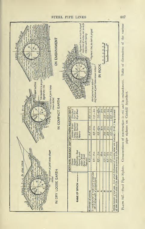
STEEL PIPE LINES 447
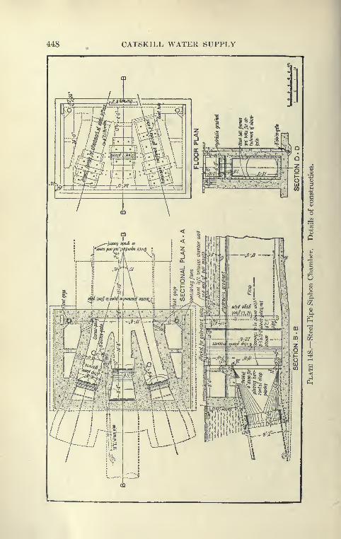
448 CATSKILL WATER SUPPLY
Mr:::::i
STEEL PIPE LINES 449
Railroad, 2J miles distant, riveting and pipe laying here being
done in the usual manner.
Foundry Brook Siphon. Next to the Pookskill siphon this is
the longest on the contract. It crosses Foundry Brook about
li miles from its outlet at Cold Spring. Considerable boring workwas done in this vicinity for a proposed pressure tunnel, but as
some zones of decayed rock were found which apparently extended
to considerable depth, the tunnel was given up in favor of the pipe
siphon. Work on this siphon was started early in 1910, and ^^go^-
ously pushed, so that by the end of the year the pipe had been
entirely laid, riveted, tested, and partially concreted in. The gate
chaml)ers and several minor structures were practically completed.
To aid in the construction of this siphon a 650-foot cableway wasused to span the stretch in the bottom of the valley, including the
Brook crossing. Later this cableway was moved to concrete the
northern portion. A railroad was built parallel to the pipe, over
which cars were operated by cables and over the adjacent portion
of the cut-and-cover by a dinky engine. The first work done wasto build the retaining walls for a 30-foot culvert carrying FoundryBrook, which is spanned by the pipe siphon built as a tubular bridge
with extra heavy sections. The contract included at the south
end about 1700 feet of cut-and-cover, which was built in the usual
manner.
Indian Brook Siphon. This siphon was one of the earliest
started, and the methods of construction followed are typical for
Contract 62. Indian Brook Crossing is about 3 miles by road from
Cold Spring-on-the-Hudson. The stream flows through a narrow
and veiy picturesque valley surrounded by large estates. At the
point where the aqueduct crosses, it is well wooded and near a
main highway.
Proposed Masonry Bridge. It was originally planned to con-
struct a monumental arched bridge here, but this was abandoned,
because previous experience has shown that it is difficult to main-
tain a large aqueduct crossing a bridge without great danger from
leakage. In addition, a bridge is much more expensive. It was
near this crossing that ground was broken on June 20, 1907, to markthe beginning of the construction of the Catskill water system.
Transportation. To secure the a<lvantages of water transporta-
tion a dock was lea.sed at Cold Spring, upon which was erected a
stiff-legged derrick and a large storehouse. To this dock practically
air materials and supplies for both Foundry and Indian Brook
siphons were brought on lighters and unloaded by the derrick,

CATSKILL WATER SUPPLY
CQ
am
ICO
B
1
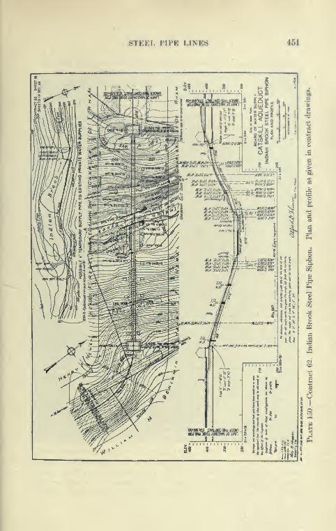
STEEL PIPE LINES 451
2?..,.?....?....?
" SU-VJiU-lkM.fSUi ,.^v~
M^ V.lii.!
a
452 CATSKILL WATER SUPPLY
and either stored or placed on trucks. Coal was removed from the
barges by clam-shell grab buckets. For the transportation of the
steel pipes and cement a large motor truck was used to great advan-
tage. A 15-foot length of steel pipe weighing about 5 tons was
placed directly on the truck by the derrick unloading the scow and
carried to Indian Brook, about 4 miles distant, up one hill of over 15
per cent, and unloaded by a cableway, the round trip from the dock to
the place of delivery taking about one hour. The cement was loaded
on the truck by the derrick in skips holding about 100 bags and
unloaded by cableway which landed them at the mixer shed. Themotor truck proved to be eflficient and economical even under the
unfavorable conditions at Cold Spring.
Plant at Indian Brook. The work at Indian Brook, although
consisting of the construction of less than 1000 feet of aqueduct,
value about $100,000, represents many types of construction placed
in an unfavorable location. The gorge is 110 feet deep, is crossed bytwo public roads, and a portion of the bank has a slope of over 62
per cent. The main plant consisted of the following: Mead-Morrison cableway of 800-foot span, which covered all the siphon
portion of the work; a stiff-legged derrick with 70-foot boom used
at the brook crossing and at the siphon chambers; a concrete plant
consisting of a Champion crusher and Chain Belt mixer. Powerwas supplied by four boilers, which operated the mixer, the crusher,
the small compressor for pipe riveting, the pumps and the cableway.
Stream Diversion. Intakes for several domestic water supplies
were located downstream from the crossing, making it necessary
to prevent pollution during construction. A small concrete dam was
built 75 feet above the pipe crossing, and about 1800 feet of 4-inch
pipe was laid downstream to connect the private intakes with this
dam. This dam also acted as a headworks to divert the stream
into a temporary flume to carry the brook during the construction of
the abutments at the pipe crossing.
Excavation in Rock and Earth. To remove a small ledge, Inger-
soll drills were used. It was attempted to excavate the remaining
material, glacial drift, by means of a 1^-yard orange-peel bucket
operated at the cableway, but this was found to be inefficient and
hand excavation was resorted to. The spoil from the lighter cuts
was cast up on the sides and that from the deeper ones was shoveled
into buckets and transported by cableway and derricks to storage
piles. No timbering was used in the trench and except in the excava-
tion for the abutments no water was encountered. On account of
the steep slopes the pipe trench excavation was carried only to the

STEEL PIPE LINES
Plate 151.—Contract ()2. Indian Brook Siphon. E.xcavation of trench for
pil)e on steep side hill using cableway and grab brackc t.
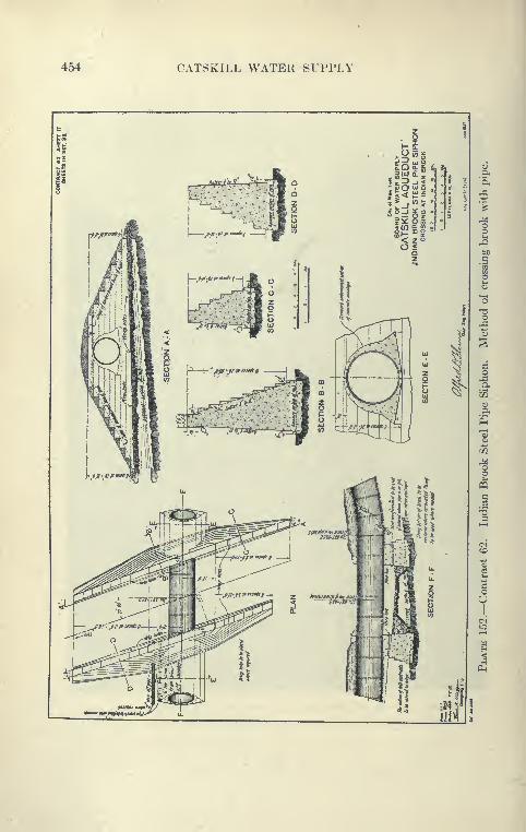
454 CATSKILL WATER SUPPLY
zo
2D yj9
<zoo<oz
'V><»/>i^iM*»m«V

STEEL PIPE LINES 466
level of the bottom of the pipe, and trnasverse dikes of earth were
necessary at frequent intervals to prevent erosion dtirinR storms.
Just before concreting the cradle blocks, the final excavation of 6
to 8 inches was made for them, and when pipe-laying b<»gan, trans-
verse trenches 1 foot dt^ep by 2 f(»et wide were dug at the joints to
give room for riveting and caulking. At the brook two retaining
walls about 18 feet high were built parallel to the stream for a length
of about 80 feet. The steel pipe was supiK)rted by these walls with
the bottom 5 feet above the stream, giving ample area for flood
waters. At this point a small valve allows the siphon to be
emptied.
How Pipes were Made Up. The 15-foot lengths of pipe consisted
of 2 sheets rivetcKl together in the shop with transverse joints 7J
feet apart. All seams were single riveted except those within 100
feet of the brook, which were double lap riveted with plates iV inch
thick. The plates were not painted, and after lx»ing inspected at
the shop were given a coat of whitewash before shipping, but this
did not prove very lasting. No paint was put on the pipes, as it
was desired to get the best possible contact of the concrete with
the steel.
Concrete Cradle Blocks. Previous to lajing the pipe, concrete
cradle blocks 3 feet along the axis of the pipe, 3^ feet wide and
6 inches deep were built at T^-foot intervals midway between riveted
joints. The tops of these were carefullj' finished to a surface of a
little larger radius than the bottom of the pipe, and slightly lower
than the theoretical grade, in order to obviate the necessity of cutting
them if the pipe ran a little low. The increase of radius was to allow
the use of wedges and to facilitate cleaning between blocks and the
pipe. On steep slopes care was taken to hold the blocks in place by
stmts and prevent them from being undermined by water. Bysome it is thought that narrower blocks not less than 1 foot thick
would be better, especially in loose ground, where the excavation of
the bell or joint holes tends to undermine them. Narrower blocks
prevent an uneven bearing of the pipe, which L« apt to break the
thinner blocks. It is very essential that the top surface be finished
off to the longitudinal slope of the pipe.
Laying of F*ipes. The lengths of pipe were carried by the cable-
way from the motor truck to their approximate position in the trench,
a few lengths in addition being stored at the sides. The first lengths
were bolted in place at the brook crossing on trestle bents l)etween
the abutments, after which the pipes were laid uphill in both direc-
tions. The workmanship of the pipes was good, but the beveled
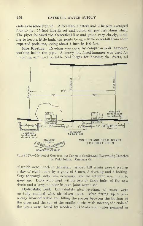
456 CATSKILL WATER SUPPLY
ends gave some trouble. A foreman, 5 fitters and 3 helpers averaged
four or five 15-foot lengths set and bolted up per eight-hour shift.
The pipes followed the theoretical line and grade very closely, tend-
ing to keep a little high, the joints being a Uttle downhill from their
expected positions, losing about 1 inch in 100 feet.
Pipe Riveting. Riveting was done by compressed-air hammer,
working inside the pipe. A heavy flat faced-hammer was used for
" holding up " and portable coal forges for heating the rivets, all
j^ 2'-0iL-) i<9".'!
l lO'' '!'-^'^^^"^
CRADLES AND FIELD JOINTSFOR STEEL PIPES
CONCRETE CRADLE
Plate 153.—Method of Constructing Concrete Cradles and Excavating Trenchesfor Field Joints. Contract 68.
of which were 1 inch in diameter. About 350 rivets were driven in
a day of eight hours by a gang of 8 men, 5 riveting and 3 bolting.
Very thorough work was necessary, and no attempt was made to
speed up. Bolts were kept within two or three holes of the newrivets and a large number in each joint were used.
Hydrostatic Test. Immediately after riveting, all seams werecarefully caulked with air-driven tools. After fitting up a tem-porary blow-off valve and filling the spaces between the bottom of
the pipes and the top of the cradle blocks with mortar, the ends of
the pipes were closed by wooden bulkheads and water pumped in
STEEL PIPE LINES 457
to test the joints under the working pressure. A few of the field
joints and lonRitudinal shop joints showed a slight leakage, but a
little caulking stopped most of this. The great<'st leakage from any
joint was one-half gallon in twenty-four hours.
Concreting. The concrete work at Indian Brook comprised the
building of siphon chambers at each end of the steel pipe, a stretch
of cut-and-cover aqueduct at each siphon chamber with traasition
sections between, and the outside concrete cover and inside 2-inch
mortar lining of the steel pipes; also the building of abutment walls
at the brook supporting a length of pipe below which the stream
flowed.
A jaw crusher was fed with field stones hauled by teams and
so located that the crushed stone fell into a pile just above the
5-yard chain-belt mixer located about one-half way down the
south slope. Sand was supplied from a near-by bank by teams.
Cement was hauled by motor trucks from Cold Spring and delivered
to cement shed at the mixer by cableway. The mixed concrete was
delivered into place by the cablewaj' or to derricks located at abut-
ments and gate chambers. The average output was 20 batches
of concrete per hour, mixed 1 : 2 : 4 for certain parts of the gate cham-
ber and 1:3:5 for the abutments.
The facing of the exposed portions of the gate chambers was
a 2-inch layer of mortar, containing ^ inch crushed pink granite
placed against the forms and bracked by ordinary concrete. Sometime after the forms were removed, the outer layer of cement was
tooled off and the pink granite exposed to give a warm appearance
to the finish of the chambers, which was formed into wide courses
with much relief. See Plate 158.
Concrete Cover and Forms. The pipe cover was placed in two
portions. First the lower half was placed to mid-diameter of pipe,
using no forms in the rock trench and a single wooden panel in the
earth trench. The upper form was of steel, consisting of ribs 5 feet
center to center with steel connecting plates. At changes of slope
'V-shaped wooden fillers were necessary. The forms, several panels
at a time, were easily moved by cableway. Lengths from 10 to 30
feet were concreted at one time.
For the cut-and-cover aqueduct steel Blaw forms were usctl with
improvements suggested by the contractors. They were specially
rigid and were readily moved by steel carriages. The cut-and-
cover aqueduct was concreted in 15-foot lengths, but was done
incidentally to the other work when the force was not busy
elsewhere.
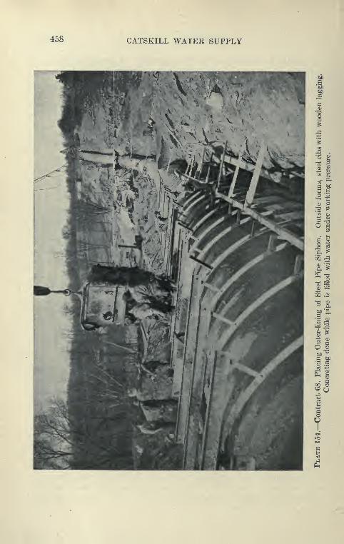
458 CATSKILL WATEK SUPPLY
^-^
O a
1^
a w)•3 .S
CD j^
7
STEEL PIPE LINES 459
Chamber Forms. The gate or siphon chambers were especially
complicated, and special forms were built in a mill at Cold SprinR.
They were built in units easily handled and with the use of fillers
and special pieces could Ixj made to fit several chambers. Thepanels were built of 2-inch tonKue-and-groove planks placed on one
side and supported by 2"X8" studs. Each panel was l)eveled
to faciUtate removal after concreting, and was also provided with
lifting rings and painted. The largest panel was 21' X4'. The
forms were not covered with sheet iron as is sometimes required.
This, in the writer's opinion, is poor practice, as the inevitable
warping of the wooden forms creases and wrinkles up the metal
lining to the detriment of the finish, and particularly the joints.
Forms should either be all wood or all metal. Each siphon chamber
required about 1000 yards of concrete and in it was bedded large
amounts of reinforcing steel and bolts for gate valves. The forms
were moved from the south chamber, set up in the opposite cham-
ber and concreted in six weeks, a very satisfactory showing con-
sidering the complexity of the work. It is stated that with careful
handling and housing the forms could be used five to six times.
Laboratory Tests. Laboratory tests were made before letting of
the steel pipe contracts to determine the effectiveness of mortar
as a protection for steel. Steel plates were cleaned by pickling and
emery cloth, and covered with mortar slabs. Another set of plates
similarly treated was covered with a slab of cement not in contact
with the steel but separated by two metal strips, about .04 of an
inch thick. These two sets of plates were placed in a tank of
Croton water together with other unprotected plates and were
examined two years later. The unprotected plates showed heavy
corrosion. The plates covered directly with mortar were perfectly
protected; those protected by cement slabs separated from the plates
by .04 inch were rusted to a very slight extent, showing that they
were well protected, probably due to the neutralization of any
acid in the water film by the lime of the cement.
Mortar Lining. The placing of the 2-inch mortar lining inside
the steel pipe presented some novel problems, as Indian Brook siphon
was the first place where this was attempted. It was soon found that
the pipes when filled with water, as described, did not come to a
true circle, the maximum shortening of the vertical diameters being
about 6 inches. This occurred at the end near the gate chamber,
where the water acted as a dead load, not being under enough
pressure to straighten out the pipe. In general, the differences of
diameter varied inversely with the head on the pipe. This fact was

460 CATSKILL WATER SUPPLY
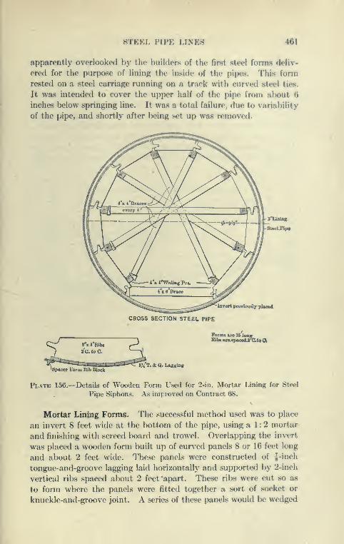
STEEL PIPE LINES 461
apparently overlooked by the builders of the first steel forms deliv-
ered for the purpose of lininp; the Inside of the pi|ws. This form
rested on a steel curriaj^e running on a track with curved steel ties.
It was intended to cover the upper half of the pipe from al)OUt 6
inches below springing line. It was a total failure, due to variability
of the pipe, and shortly after being set up was removed.
^^pC-^i^xl-WaUngPc^ ^W J^^ 4'x 6'Brace ^\^:^^^^vert prevlouriy pUoed
CRQSS SECTION STEEL PIPE
I''orms are 18 longiiUa«u.paoe4aUtQa-^ 2''x8''RiU P ^
)^ a'CtoC. ~\
Jp*c«;rEorm Rib Block^^T.& a. Lapsing
Plate 156.—Details of Wooden Form Used for 2-in. Mortar Lining for Steel
Pipe Siphons. As inij. roved on Contract 68.
Mortar Lining Forms. The successful method used was to place
an invert 8 feet wide at the bottom of the pipe, using a 1 : 2 mortar
and finishing with screed board and trowel. Overlapping the invert
was placed a wooden form built up of curved panels 8 or 16 feet long
and about 2 feet wide. These panels were constructed of I -inch
tongue-and-groove lagging laid horizontally and supported by 2-inch
vertical ribs spaced about 2 feet 'apart. These ribs were cut so a.s
to form where the panels were fitted together a sort of socket or
knuckle-and-groove joint. A series of these panels would be wedged
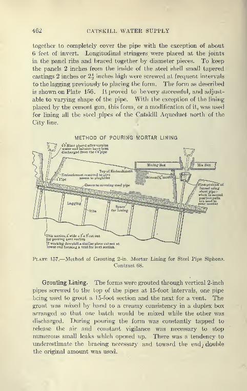
462 CATSKILL WATER SUPPLY
together to completely cover the pipe with the exception of about
6 feet of invert. Longitudinal stringers were placed at the joints
in the panel ribs and braced together by diameter pieces. To keep
the panels 2 inches from the inside of the steel shell small tapered
castings 2 inches or 2h inches high were screwed at frequent intervals
to the lagging previously to placing the form. The form as described
is shown on Plate 156. It proved to be very successful, and adjust-
able to varying shape of the pipe. With the exception of the lining
placed by the cement gun, this form, or a modification of it, was used
for lining all the steel pipes of the Catskill Aqueduct north of the
City line.
METHOD OF POURING MORTAR LINING
4 Riser placed after surplus'water and laitaiice have beendischarged from the I'O pipe
^-This section,* wide x 2 x 9 cut outfor pouring next section
If working downhill a similar piece cut out atlower end forming a vent for next sectioa
^rst position offunnel usingshort pipe;-when in secondposition pailsare used topour mortar.
Plate 157.—Method of Grouting 2-in. Mortar Lining for Steel Pipe Siphons.
Contract 68.
Grouting Lining. The forms were grouted through vertical 2-inch
pipes screwed to the top of the pipes at 15-foot intervals, one pipe
being used to grout a 15-foot section and the next for a vent. Thegrout was mixed by hand to a creamy consistency in a duplex box
arranged so that one batch would be mixed while the other was
discharged. During pouring the form was constantly tapped to
release the air and constant vigilance was necessary to stop
numerous small leaks which opened up. There was a tendency to
underestimate the bracing necessary and toward the endj double
the original amount was used.

STEEL PIPE LINES ' 463
About sixteen l-baR batches of 1 : I mixture and twenty-four
1-bag batches of 1:2 mixture were required for grouting a
15-foot section, the richer mixture lx»ing used Ix'low the spring-
ing line.
With three sets of forms it was generally possible to pour a
15-foot section every working day or 90 feet a week.
Probable Results from Lining Pipe. The resulting mortar lining
was very smooth and satisfactory, tlie methods originated at Indian
Brook being generally used elsewhere. The lining, due to temp<'rature
changes, now show numerous small cracks, particularly at the exposed
crossing of the lirook, sounding showing some separation of the lin-
ing from the pipe, but this is supposed to be very small. Time only
will tell whether the expectation of permanency of this lining will
be realized. If so, this will constitute a distinct advance in this
style of construction, as not only will the rather rapid corrosion usual
in steel pipes be avoided, but the flow through the pipe will remain
high due to the permanent smoothness of the lining.
Sprout Brook Siphon. This siphon is located 1 mile north of
the Peekskill siphon, is 2400 feet long and is under about 200 feet
head. It was constructed in 1911, and the usual methods were used.
One feature of this work was laying the pipe with a derrick equipped
with an 80-foot boom. The excavation was accomplished by pick
and shovel, wheelbarrows and teams.
Peekskill Creek Siphon. The Peekskill pipe siphon crosses Peeks-
kill Creek 3 miles above its mouth. It is the longest pipe siphon and
the one under the greatest head. The hydraulic grade at this point
is about 390 feet. Peekskill Creek flows at elevation about 50, and
the pipe depressed below its bottom, is under a head of about 350
feet. The pipe is built of plates varying from i^ to f inch in thick-
ness. The lighter plates are lap riveted, the heaviest plates triple
riveted with inside and outside butt straps, lOg inches and 1G|
inches wide. Four rows of rivets penetrate all three plates, on
3.58-inch pitch, the two outer rows penetrate the plates and inside
strap on 7.16-inch pitch. See Plate 162.
Excavation. The slope at the north of the creek is very steep,
with trench in earth and shale. South of Peekskill Creek the slopes
are not excessive with the exception of a short stretch. The trench
is here in glacial drift consisting in places of excellent sand and gravel
and in places of earth and boulders. For the excavation a long-boom
35-ton Vulcan steam shovel was used, depositing material alongside
the trench. Some hand excavation was also done. A diversion

464 CATSKILL WATER SUPPLY
channel for Peekskill Creek 300 feet long and 15 feet wide at the
bottom was excavated^by means of drag scrapers. The pipe trench
at the creek crossing was excavated with pick and shovel and with
steam drills where the rock outcrops.
La3ang Pipe. The steel pipe was hauled from Peekskill dock
by automobile truck and lowered by steam hoists or gravity in
15-foot lengths, on flat cars. For laying the pipes, a cable-way,
stationary derrick and a traveling A-frame derrick were used.
Between April 11, and September 21, 1911, all except 60 feet of the
pipe was laid, riveted and partially caulked.
Concreting. For concreting around the pipe, the steel forms
previously used at other siphons in this contract were emploj^ed;
also wooden forms with steel ribs. A considerable portion of the
concrete placed around the pipe was mixed by hand on platforms
set above the forms and shoveled directly into place, and all out-
side concrete excepting cradle blocks placed in one operation. Aconcreting plant was erected near Peekskill Creek and used for con-
creting the pipe at the creek and north of the creek for north siphon
chamber and for a short stretch of cut-and-cover constructed under
this contract. The concrete was transported from this mixer to
the form by cableway and beyond the cableway by two derricks and
car on tracks. Small mixers were also set at three other points
along the works. Crushed stone wasobtained from boats at Peeks-
kill and hauled to the work on trolley cars, where it was distributed in
cars hauled by a locomotive and by cables attached to winding
drums. Sand was excavated from the pipe trench and cement was
hauled by trolley. Back filling followed the concreting. All the
work with the exception of that in connection with the creek crossing
and delivery of the steel pipe was performed by Hadley Bros.
Contract 68
Location Contract 68. This contract was awarded June, 1910,
to David Peoples, who soon after starting the work assigned it to
the T. A. Gillespie Company. Under this contract were built
seven steel pipe lines averaging in length from 700 feet to 5600 feet,
and consisting of single lines of riveted steel pipe 9 feet 9 inches and
11 feet 2 inches inside diameter, lined with Portland cement mortar
2 inches thick, enveloped in concrete and covered with embank-ments of earth or rock. These pipes siphon are all located in the
Southern Aqueduct Department.
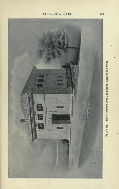
STEEL FIFE UNES 465
Oi
T

466 CATSKILL WATER SUPPLY
Contract Prices. The total bid price was $1,189,557. Some of
the prices are given below:
Earth excavation, cu.yd 60Rock excavation, cu.yd 2 . 50Refill, cu.yd 0.329'9" &teel pipe t^" plate, linear foot 29.0011'3" " " i^" " linear foot 33.001 1 '3" " " i" '
' (lap joints) linear foot ... 38 . 0011'3" " " \" " (long-butt joints) lin. ft.. 46.0011'3" " " ^" " (long-butt joints) lin. ft.. 50.00Concrete around pipe, cu.yd 5 . 25
Mortar lining, 9'9", lin. ft 3.00" 11'3", lin. ft 3.50
Portland cement, per bbl 1 . 60
Estimated gross contract cost of 9 foot 9 inch pipe is S64.12 per
foot, of 11 foot 3 inch pipe $74.48 per foot, of cut-and-cover $88.16
per foot.
Details of Pipes. Data concerning the seven pipe siphons of
Contract 68 are given below:
Location.Length,Feet.
Thickne-ss ofPlate and Kind
of Joint.
Maximum Head,Feet.
Hunters BrookTurkey MountainHarlem Railroad
1493
1510
6941625
14901267
2714
150
2465
255
5584
A'' lap
< <
i c
h" lap
h" longse
A" long .se
110
92
60Kensico 50Elmsford . 68Fort Hill 72Bryn Mawr
Bryn Mawr total length
214
am butt jointed
am butt jointed
This contract comprised work from Hunters Brook north of
Croton Lake to Bryn Mawr near Yonkers. Consequently the
work was accomplished with isolated plants and generally with the
same methods adopted on Contract 62, as previously described.
The interior lining of Hunters Brook siphon, however, was
placed with the cement gun in an entirely different manner from
all the others, as will be described.
Hunters Brook Siphon. This, the most northerly pipe siphon
of this contract, is located on a tributary of the Croton River, a few
miles from the new Croton dam. It is 1493 feet long under a
maximum head of 110 feet and built of pipe 9 feet 9 inches in
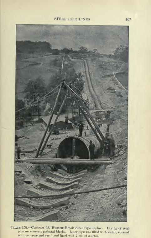
STEEL PIPE LINES 467
Plate 159.—Contract 68. Hunters Brook Steel Pipe Siphon. Laying of steel
pipe on concrete pedestal blocks. Later pipe was filled with water, coveredwith concrete and earth and lined with 2 ins. of mortar.
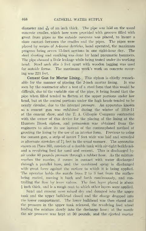
468 CATSKILL WATER SUPPLY
diameter and yq of an inch thick. The pipe was laid on the usual
concrete cradles, which here were provided with grooves filled with
grout from pipes as the outside concrete was placed, to insure a
close contact between the cradles and the pipes. The pipes were
placed by means of A-frame derricks, hand operated, the maximumprogress being seven 15-foot sections in one eight-hour day. The
steel riveting and caulking w^as done by hand pneumatic hammers.
The pipe showed a little leakage while being tested under its working
head. Steel arch ribs 5 feet apart with wooden lagging was used
for outside forms. The maximum week's work on concrete cover-
ing was 22.3 feet.
Cement Gun for Mortar Lining. This siphon is chiefly remark-
able for the manner of placing the 2-inch mortar lining. It was
seen by the contractor after a test of a steel form that this would be
difficult, due to the variable size of the pipe, it being foimd that the
pipe when filled tended to flatten at the upper portions under low
head, but at the central portions under the high heads tended to be
nearly circular, due to the internal pressure. An apparatus knownas a cement gun was exhibited during the winter of 1910-11
at the cement show, and the T. A. Gillespie Company'- contracted
with the owner of this device for the placing of the lining at the
Hunters Brook siphon, and permission was obtained from the
engineers to allow its use instead of the contemplated method of
grouting the lining by the use of an interior form. Previous to using
the cement gun, a strip of invert 7 feet wide was laid and screeded
in alternate stretches of 7^ feet in the usual manner. The apparatus
shown on Plate 160, consists of a double tank with air-tight bulkheads
and a revolving feed for sand and cement. This is discharged by
air under 40 pounds pressure through a rubber hose. As the mixture
reaches the nozzles, it comes in contact with water discharged
through a parallel hose, and the combined spray is discharged
with great force against the surface to which it is being applied.
The operator holds the nozzle from 2 to 3 feet from the surface
being coated, moving it back and forth continuously, and con-
trolling the flow by lever valves. The first layer placed is about
^ inch thick, and is a rough coat to which other layers were applied.
Sand and cement were mixed dry and dmnped into the upper
tank and the upper bulkhead closed and the charge dropped into
the lower compartment. The lower bulkhead was then closed andthe pressure in the upper tank released, the revolving feed wheel
feeding the mixture slowly into the discharge hose; at the nozzle
the air pressure was kept at 30 pounds, and the ejected mortar
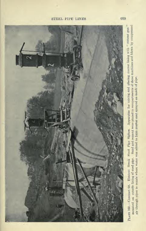
STEEL PIPE LINES
e 2
11
•ill
•p. - o•2 S o
= I'St o >»^ 8 2».S g-
I"? ^ij8
a> o
d ^ S
1^ a
'^ S q
•=• S ^
-^ ^SO 'S. as
2 m O
X •£ ^- I
2-2 2
§§a•a
<.4

470 CATSKILL WATER SUPPLY
deposited in alternate sections. All the lining was placed between
April 25 and August 12, using for part of the time two machines
and two shifts, the maximum weekly progress in placing the interior
lining being 254 feet.
The final shape was obtained by screeding the fresh mortar
with a straightedge working against two laths placed to give
proper thickness of lining. It must be admitted that the lining of a
pipe is difficult for this kind of work, as considerable sand and cement
rebounds, making the air in the confined space difficult to breathe.
In addition, some dry material, nearly all sand, tends tx) accumulate
near the bottom of the pipe next the invert. To make up for this
an excess of sand is put in, so that the lining may be no richer than
is intended. On this account the dry mixture was changed from
1 : 2 to 1:2^, and later to 1 cement : 3 sand, with the idea of securing
a 1 to 2 mixture in the finished lining. The accumulated material
which fell to the invert from the cement gun contained cement
in proportion of about l:3f, indicating a considerable waste of
cement.
It was found that mortar from the cement gun, being less well
supplied with water than a grouted lining, has a greater tendency
to crack, and more attention must be paid to keeping it moist.
Failure to do this may be responsible for the greater amount of crack-
ing of the lining made by the use of the cement gun. The lining
placed by the cement gun, due probably to its final screeding, is very
smooth, but contains many fine cracks.
When the mortar invert was placed much in advance of the arch
the upper portion of the invert tended to pull away from the pipe, in
extreme cases to | inch at the upper edge to nothing 18 inches down.
This space was grouted before placing remainder of lining.
The work accomplished by the cement gun was considered
satisfactory, but the apparatus had not been developed to
an extent to compete commercially with the ordinary method
and was not used subsequently. The cement gun is an apparatus
which has been found very useful for placing stucco on buildings
and covering steel beams, and has been used to protect the sides
of cuts in rocks from the action of weather. It has been exper-
imented with for this purpose on the Panama Canal and the
Bergen Hill cut of the Erie Railroad at Jersey City.
Elmsford Siphon. The Elmsford steel pipe siphon between
Tarrytown and White Plains is 1774 feet long. It crosses a depres-
sion about 70 feet below hydraulic grade. The unit length of pipe
is 7^ feet and is made up of two steel plates lapped 3J inches with
STEEL PIPE LINES 471
single-riveted joints, with 2J-inch pitch. Two such pipe* are. shop-
riveted together and sliipped to tlie work in 15-foot lengths, the ends
having the holes punched for field riveting to the next length.
Laying of the Pipes. After the trench, excavatetl by ordinary
metliods, the material being cast to one side, was completed, the
concrete cradles, 3 feet wide, to 10 inches deep and 11 feet long,
were cast in the bottom of the trench on TJ-foot centers midwaybetween the riveted joints. The pipes were then set by a guy
derrick on these cradles, which have the same curvature as the
bottom of pipe. At the field-riveted joints, 15 feet apart, a cross-
trench 3J feet wide and 18 inches deep was dug, to allow working
room underneath the pipe for the riveting. The pipes were riveted
by pneumatic hammers operated by a small compressor. The ends of
the overlapping plates were then pneumatically caulked by upsetting
and driving the lower part of the overlapping plates agaiast the plate
underneath as much as J to | inch. The pipes were then bulkheaded
at lx)th ends and filled with water to the hydraulic grade of the
Catskill Aqueduct. This pressure was maintained by pumping
into a riser pipe located at one of the bulkheads and maintaining
the elevation in this pipe constant. The pipes and rivets were then
caulked by hand where leaks showed. This leakage was found to
be very small, the pumpage into the siphon being merely that neces.sary
to compensate for leakage at the bulkhead.
Covering Pipe. After filling the pipe with water the space
between the cradles and the pipe was grouted by pouring grout
into 2-inch grooves cast in the cradle to insure complete contact of
cradle and pipe. The cradles were sufficiently strong to support
the pipe. The forms were then placed outside the pipes, consisting
of arched angle-iron ribs with wooden lagging and steel bulk-
heads. The angle irons were joined over the top of the pipe, and,
in addition, supported a horizontal channel-steel tie for the track
over the pipe along which cars were run. The ribs were well braced
by Wooden struts to the ground. The lagging was made with shiplap
joint, and put in place between the ribs as fast as the concrete rose
in the form. This made a simple and very satisfactory form for
this purf)ose. It would be difficult to adjust a steel panel form, such
as is used on the cut-and-cover aqueduct, to the varying grades and
the vertical and horizontal curves of the steel i)ipes.
Change of Shape in Pipe when Full of Water. As specified
for all the steel-pipe siphons the concreting was done while
the pipe was filled with water, the purposes being to hold the
pipe in the shape that it will finally assume, so that when
472 CATSKILL WATER SUPPLY
the mortar lining is placed no change in shape will occur after
the water is again admitted. It was found -that the pipes
flattened a good deal under their own and the water load, so that
there was a considerable difference between the vertical and horizontal
diameters, as much as 6 inches. The pressure of the water contained
in the pipe is not sufficient to bring it to its circular shape, although
it* is more effective at the higiier heads, but it made the pipe very
solid and stable during the placing of the concrete. The shape
of the pipe when filled with water is a resultant of the dead load and
the internal pressure of the water. At high heads the pipe comes
to a nearly circular shape.
Concreting of Elmsford Siphon. The material for the con-
crete was received from the Pittsburgh Contracting Company's
railroad, which reached the north end of the pipe line. The
concrete was hauled from the mixer in Koppel side-dmnp cars,
pushed along a narrow- auge track by man power or up inclines
by a cable operated by steam hoist, and dumped directly into
the forms. A 30-foot section of all the outside concrete, except
the cradles, was placed in two shifts, so as to form a monolith.
A part of the material excavated in the trench was decom-
posed schist which was readily drilled by steam drills operated
from a 40-H.P. boiler, this boiler also supplying power for a derrick
which lifted skips of excavated rock to the sides of the trench, later
used for back-filling. After the complete concrete envelope was
placed and back-filled the water under pressure inside was drawn
off and the interior 2-inch mortar lining grouted as previously
described.
Bryn Mawr Siphon and Triple Portal of Yonkers Siphon. North
of Hillview reservoir there is a depression of about 3.3 miles. Orig-
inally it was supposed that this would be passed by means of a pres-
sure tunnel, with the usual downtake, uptake and drainage shafts.
Exploration by core drills showed that the lower two-thirds adjacent
to the Hillview Reservoir would be in Yonkers gneiss of very good
quality. North of this, underlying the valley of Sprain Brook, was
found a belt of decomposed Hmestone extending to a great depth.
For this reason it was decided to adopt an unique construction.
For the northern portion of the depression a steel-pipe siphon, 11 foot
3-inch pipe, was used. The lower portion was tunneled in the
usual manner for pressure tunnels, but it has at the north end in the
side hill a triple portal joined 275 feet back to form the single 16-
foot 7-inch circular tunnel of the Yonkers pressure tunnel. Thethree tunnels at the portals are excavated to enable 175 feet of the
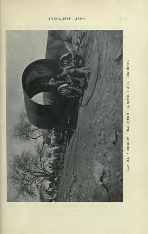
STEEL I'lI'K LINES 473
474 CATSKILL WATER SUPPLY
steel pipes of the Byrn Mawr siphon to be securely concreted in.
At present only the central steel pipe will be laid, the two side
tunnels being bulkheaded off. From the north portal of the
Yonkers tunnel the steel pipe extends a distance of 1.1 miles to its
siphon chamber at hydraulic grade, and is the longest pipe siphon
in the Southern Aqueduct Department. It was laid under Contract
68, by T. A. Gillespie Company. Included in this work is a blow-
off chamber for draining not only this siphon, but several miles of
the adjacent aqueduct on the north and the Yonkers pressure tunnel
on the south. In addition there is another 12-inch blow-off and a
drain for the chamber connecting with the Yonkers pressure tunnel.
Earth Excavation and Foundations. Earth was generally
removed by the use of horses, slip scrapers and by hand. For
the deep trench north and south of the Sprain Brook, a traveling
stiff-legged derrick with 35-foot boom operated on broad gauge
track alongside the trench, the material being loaded by hand into
1-yard buckets. The rock excavation was accomplished by ordi-
nary methods, using steam drills. Soon after the concrete envelope
for the pipe was placed, the earth removed was put back as embank-
ment. Some of the pipe was founded upon embankment made and
rolled in the usual manner. In two stretches of a few hundred
feet, water-bearing sand and gravel were found in the trench. For a
foundation a timbered platform was used, and the trench was drained
by a box drain. The trench bottom was excavated to subgrade
-with transverse slopes toward the center 1 on 6 to 1 on 18. 2"X8''
longitudinal stringers were embedded in the trench bottom with either
one or two thicknesses of inch boards spiked across them with their
inner ends resting on the edge of the 6''X8'' box drain in the center.
The drain led to a sump in the blow-off chamber excavation, from
which the water was pumped to Sprain Brook. This effectively
dried the bottom and provided suitable foundation for the concrete
supports of the pipe. A considerable excavation had to be madefor the blow-off chamber; 2-inch sheeting was driven to a depth of
22 feet by hand and supported by 8"X8'' timber sets 3 feet apart
vertically. Pulsometer and centrifugal pumps handled the water,
which ran as high as 800 gallons per minute.
Laying of Pipes. The pipe was supported on concrete cradles
3 feet wide, 10 feet long and 18 inches thick. These were hand
mixed on the bank, the materials being supplied by wagons. Pipe
sections, generally 15 feet in length, were delivered and stored along-
side of the trench between November, 1910, and May, 1911. All of
the 5600 feet of pipe was laid between April and September, 1911.
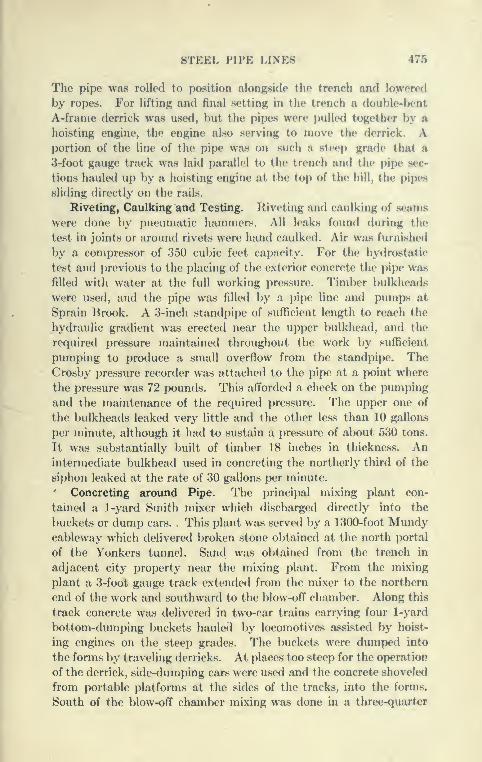
STEEL PIPE LINES 475
The pipe was rolled to position alongside the trench and lowered
by ropes. For lifting and final sotting in the trench a double-hent
A-frame derrick wa.s used, but the pipes were puUetl together by a
hoisting engine, the engine also serving to move the derrick. Aportion of the line of the pipe was on such a steep grade that a
3-foot gauge track was laid parallel to the trench and the pijM* sec-
tions hauled up by a hoisting engine at the top of the hill, the pipes
sliding (liroctly on tlio rails.
Riveting, Caulking and Testing. Riveting and caulking of seams
were done by pneumatic hammers. All leaks found during the
test in joints or around rivets were hand caulked. Air was furnished
by a compressor of 350 cubic feet capacity. For the hydrostatic
test and previous to the placing of the exterior concrete the pipe was
filled with water at the full working pressure. Timber })ulkheads
were used, and the pipe was filled by a pipe line and pumps at
Sprain Brook. A 3-inch standpipe of sufficient length to reach the
hydraulic gradient was erected near the upper bulkhead, and the
required pressure maintained throughout the work by suflficient
pumping to produce a small overflow from the standpipe. TheCrosby pressure recorder was attached to the pipe at a point where
the pressure was 72 pounds. This afforded a check on the pumping
and the maintenance of the required pressure. The upper one of
the bulkheads leaked very little and the other less than 10 gallons
per minute, although it had to sustain a pressure of about 530 tons.
It was substantially built of timber 18 inches in thickness. Anintermediate bulkhead used in concreting the northerly third of the
siphon leaked at the rate of 30 gallons per minute.
' Concreting around Pipe. The principal mixing plant con-
tained a 1-yard Smith mixer which discharged directly into the
buckets or dump cars. . This plant was served by a 1300-foot Mundycableway which delivered broken stone obtained at the north portal
of the Yonkers tunnel. Sand was obtained from the trench in
adjacent city property near the mixing plant. From the mixing
plant a 3-foot gauge track extended from the mixer to the northern
end of the work and southward to the blow-off chamber. Along this
track concrete was delivered in two-car trains carrying four 1-yard
bottom-dumping buckets hauled by locomotives assisted by hoist-
ing engines on the steep grades. The buckets were dumped into
the forms by traveling derricks. At places? too steep for the operation
of the derrick, side-dumping cars were used and the concrete shoveled
from portable platforms at the sides of the tracks, into the forms.
South of the blow-off chamber mixing was done in a three-quarter
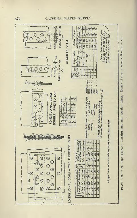
476 CATSKILL WATER SUPPLY
J.—
—
—
1
Cr^^j " i-*-i
"
10 1® B ©jj
^-
© . ©iT® ® © ©ll 1© B 1
K ^
f oll te ©1
© ©1-
1
'
"/« —
-
!/A —
4
^-^
STEEL PIPE LINES 477
cubic yard Smith mixer. Broken stone wa« obtainerl from the
Yonkers tunnel and sand delivered by |a cableway. The mixer dis-
charged directly into bottom-dumping cars, operated on a track laid
on top of the pipe, lowered into place by a cable hoist. The con-
crete was discharged from the cars directly onto the pipe. Bottom-
dumping cars running on short stretches of track directly on top
of the pipe were also used at other points which could not con-
veniently be reached by the derrick car, which filled the cars from
the buckets operated on the track alongside the trench.
Forms. The forms were the usual steel ribs supporting wooden
shiplap lagging, placed as the concrete rose in the forms. Theentire stretch of outside concrete was completed between August
and December, 1911, a total of about 10,0(X) cubic yards. Theinterior 2-inch mortar lining was placed during 1912 by the use
of the usual interior forms and grouting method.

CHAPTER XIV
CROTON DIVISION CUT-AND-COVER AQUEDUCT AND GRADE ;
TUNNELS
Contract 23
Work and Prices. This contract, comprising the northerly 2.2
miles of the Southern Aqueduct Department, was awarded March,
1909, to the Glyndon Contracting Company, the total contract
price being $1,109,102. Some of the unit prices are given below:
Open-cut excavation per cu.yd $0.35 to .65
Refill per cu.yd 23 to .50
Excavation in tunnel per cu.yd 6.75Timbering in tunnel per M 45 temporary
60 permanentConcrete in open cut per cu. yd 5 .25
Concrete in tunnel per cu.yd 5.75Portland cement per bbl 1 . 90
Forms for lining in tunnel per ft 2 . 75
Medical and surgical practitioners per
month for 42 months 125.00Sanitary services per month for 42 months 200 . 00
On the basis of contract quantities the linear foot cost of cut-and"
cover is $67.50; of grade tunnel, $114.96.
The last two items were for the purpose of compensating con-
tractors for special precautions to prevent pollution of the neigh-
boring Croton Lake, which lies just south of this work. It was
required that all organic matter be incinerated and water from the
camps or even from the tunnels be filtered or sterilized. The con-
tract consists of Scribner grade tunnel, 300 feet long; Hunters Brook
tunnel, 6150 feet long; and three adjacent stretches of cut-and-cover,
200 feet, 2600 feet and 2650 feet long respectively.
Power Plant. A large central power plant was constructed
between the two tunnels and consisted of two Mosher water-tube
boilers, each of two units, 150 H.P. per unit; three Ingersoll-Rand
compound condensing compressors, each rated at 1400 feet of free
air per minute. About 8500 feet of 5-inch pipes was laid to the north
478
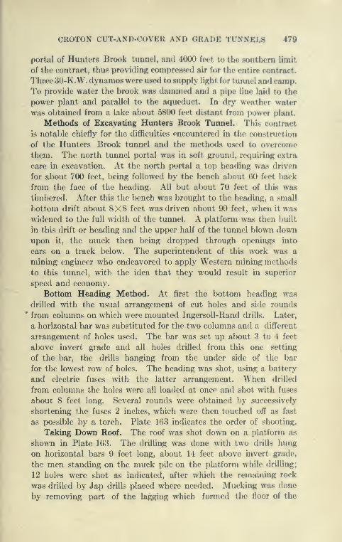
CROTON CUT-AND-COVER AND GRADE TUNNELS 479
portal of Hunters Brook tunnel, and 4000 feet to the southern limit
of the contract, thus providing compressed air for the entire contract.
Three 30-K.W. dynamos were used to supply light for tunnel and camp.
To provide water the brook was dammed and a pipe line laid to the
power plant and parallel to the aqueduct. In dry weather water
was obtained from a lake about 5800 feet distant from power plant.
Methods of Excavating Hunters Brook Tunnel. This contract
is notable ehieily for the difficulties encountered in the construction
of the Hunters Brook tunnel and the methods used to overcome
them. The north tunnel portal was in soft ground, requiring extra
care in excavation. At the north portal a top heading was driven
for about 700 feet, being followed by the bench about 60 feet back
from the face of the heading. All but about 70 feet of this was
timbered. After this the bench was brought to the heading, a small
bottom drift about 8X8 feet was driven about 90 feet, when it was
widened to the full width of the tunnel. A platform was then built
in this drift or heading and the upper half of the tunnel blown downupon it, the muck then being dropped through openings into
cars on a track below. The superintendent of this work was a
mining engineer who endeavored to apply Western mining methods
to this tunnel, with the idea that they would result in superior
speed and economy.
Bottom Heading Method. At first the bottom heading wa.s
drilled with the usual arrangement of cut holes and side rounds
from columns on which were mounted Ingersoll-Rand drills. Later,
a horizontal bar was substituted for the two columns antl a different
arrangement of holes used. The bar was set up about 3 to 4 feet
above invert grade and all holes drilled from this one setting
of the bar, the drills hanging from the under side of the bar
for the lowest row of holes. The heading was shot, using a battery
and electric fuses with the latter arrangement. When drilled
from columns the holes were all loaded at once and shot with fuses
about 8 feet long. Several rounds were obtained by successively
shortening the fuses 2 inches, which were then touched off as fjist
as possible by a torch. Plate 103 indicates the order of shooting.
Taking Down Roof. The roof was shot down on a platform as
shown in Plate 103. The drilling was done with two drills hung
on horizontal bars 9 feet long, about 14 feet above invert grade,
the men standing on the muck pile on the platform while drilling;
12 holes were shot as indicated, after which the remaining rock
was drilled by Jap drills placed where needed. Mucking was done
by removing part of the lagging which formed the floor of the
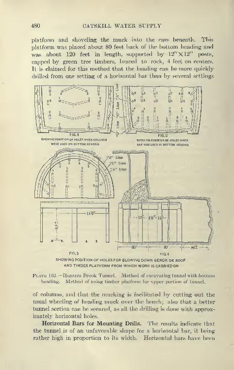
480 CATSKILL WATER SUPPLY
platform and shoveling the muck into the cars beneath. This
platform was placed about 80 feet back of the bottom heading and
was about 120 feet in length, supported by 12"X12" posts,
capped by green tree timbers, braced to rock, 4 feet on centers.
It is claimed for this method that the heading can be more quickly
drilled from one setting of a horizontal bar than by several settings
FIG.1
SHOWING POSITION OF HOLES WHEN COLUMNS
WERE USED ON BOTTOM HEADING
FIG. 2
SHOWING POSITION OF HOLES WHENBAR WAS USED IN BOTTOM HEADING
FIG. 3 FIG. 4
SHOWING POSITION OF HOLES FOR BLOWING DOWN BENCH OR ROOFAND TIMBER PLATFORM FROM WHICH WORK IS CARRIED ON
Plate 163.—Hunters Brook Tunnel. Method of excavating tunnel with bottomheading. Method of using timber platform for upper portion of tunnel.
of columns, and that the mucking is facilitated bj^ cutting out the
usual wheeling of heading muck over the bench; also that a better
tunnel section can be secured, as all the drilling is done with approx-
imately horizontal holes.
Horizontal Bars for Mounting Drills. The results indicate that
the tunnel is of an unfavorable shape for a horizontal bar, it being
rather high in proportion to its width. Horizontal bars have been
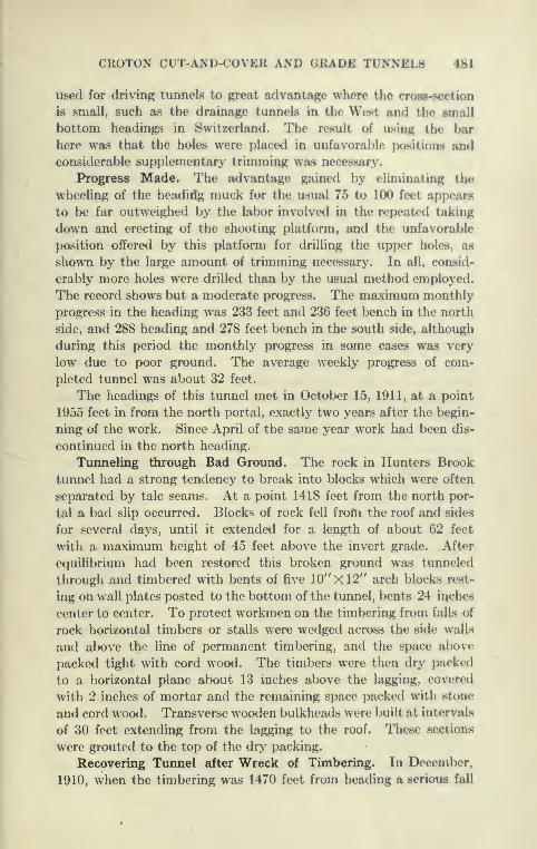
CROTON CUT-AND-COVER AND GRADE TUNNELS 481
used for driving tunnels to great advantage where the cross-section
is small, such as the drainage tunnels in the West and the small
bottom headings in Switzerland. The result of using the bar
here was that the holes were placed in unfavorable positions andconsidorahle supplementary trimming was necessary.
Progress Made. The advantage gained by eliminating the
wheeling of the headirfg muck for the usual 75 to 100 feet appears
to be far outweighed by the labor involved in the repeated taking
down and erecting of the shooting platform, and the unfavorable
position offered by this platform for drilling the upper holes, as
shown by the large amount of trimming necessary. In all, consid-
erably more holes were drilled than by the usual method employed.
The record shows but a moderate progress. The maximum monthly
progress in the heading was 233 feet and 236 feet bench in the north
side, and 288 heading and 278 feet bench in the south side, although
during this period the monthly progress in some cases was very
low due to poor ground. The average weekly progress of com-
pleted tunnel was about 32 feet.
The headings of this tunnel met in October 15, 1911, at a point
1955 feet in from the north portal, exactly two years after the begin-
ning of the work. Since April of the same year work had been dis-
continued in the north heading.
Timneling through Bad Ground. The rock in Hunters Brook
tunnel had a strong tendency to break into blocks which were often
separated by talc seams. At a point 1418 feet from the north por-
tal a bad slip occurred. Blocks of rock fell from the roof and sides
for several days, until it extended for a length of about 62 feet
with a maximum height of 45 feet above the invert grade. After
equilibrium had been restored this broken ground was tunneled
through and timbered with bents of five 10"X12" arch blocks rest-
ing on wall plates posted to the bottom of the tunnel, bents 24 inches
center to center. To protect workmen on the timbering from falls of
rock horizontal timl)ers or stalls were wedged across the side walls
and above the line of permanent timbering, and the space above
packed tight with cord wood. The timbers were then dry packed
to a horizontal plane about 13 inches above the lagging, covered
with 2 inches of mortar and the remaining space packed with stone
and cord wood. Transverse wooden bulkheads were built at intervals
of 30 feet extending from the lagging to the roof. These sections
were grouted to the top of the dry packing.
Recovering Tunnel after Wreck of Timbering. In December,
1910, when the timbering was 1470 feet from heading a serious fall

482 CATSKILL WATER SUPPLY
occurred, displacing five sets of timbers. These sets were blocked
up and work was resumed; a small drift 6' X8' was then driven through
the broken rock of the slip. A few days later another fall occurred
which wrecked nineteen sets of timbers south of a point 1440 feet
from portal, including the sets first displaced. The timbering in
many of these sets was badly crushed and was immediately posted
up to prevent further settlement. The small dVift was then excavated
through the broken ground to the bottom heading previously
excavated. The wrecked timbers were replaced together with manynew sets. For a portion of the distance the timbers were placed
back to back. Concreting was then ordered for this bad stretch,
which was supported by 80 feet of lining placed in January to March,
1911. Drilling of the bottom heading was resumed February 26,
and the bench March 9. The rock seemed to be improving, but
the roof was seamy and treacherous, small falls of rock occurring.
After excavating for a few weeks work was discontinued at a point
1955 feet from portal. Timbering was continued for a short time
after this, when all work stopped in the north heading.
Disadvantages of Bottom Heading in Bad Ground. The con-
tractor showed ability in getting by bad ground after the falls
occurred, but the bottom heading method is unsuited for work of
this kind, as it is not practicable to place timbering until the entire
tunnel is excavated, whereas by the top-heading method the tim-
bers can be placed soon after the poor ground is exposed. Atthe south portal the bottom heading was driven in 221 feet and the
top then blown down. This resulted in compacting the fallen rock,,
so that mucking was difficult. The top-heading and bench methodwas continued for 819 feet in, when this method was discontinued
for the bottom heading, as described heretofore. Two drilling
shifts were used and two advances a day made, averaging 5 feet
each. The firing was done by battery and with fuses, 60 per cent
forcite being used. Three mucking shifts were employed to shovel
rock into the cars, their work being aided by placing iron plates onfloor of heading.
Excavation of Roof, South End. The top or roof was shot downupon a platform of heavy posts 6 feet long capped by timbers 14
feet long. These sets were spaced 4 feet apart and floored over
with 3-inch planking. This platform averaged about 120 feet in
length, half of it being the roof to be shot down. As the platform
behind was cleared of muck sets were removed and set up ahead. Toprevent the breaking of caps a third post was placed under the center
of each set previous to shooting. The excavation of the top was as.
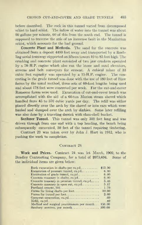
CROTON CUT-AND-COVER AND GRADE TUNNELS 483
before described. The rock in this tunnel varie<i from decomposed
schist to hard schist. The inflow of water into the tunnel was about
90 gallons per minute, 60 of this from the south end. The tunnel is
supposed to traverse the axis of an immense fault in the Manhattanschist, which accounts for the had ground.
Concrete Plant and Methods. The sand for the concrete wasobtained from a deposit 4400 feet away and transported by a Roeb-
ling aerial tramway supported on fifteen towers 10 to 85 feet high. Thecrushing and concrete plant consisted of two jaw crushers operated
by a 70 H.P. engine which also ran the 'stone and sand elevators,
screens and belt conveyors for cement. A cubical mixer of 33
cubic feet capacity was operated by a 15-H.P. engine. The con-
creting in the grade tunnel was done with the use of 180 feet of Blaw
forms by the usual method, three sets of 60-foot lengths being used
and about 178 feet were concreted per week. For the cut-and-cover
Ransome forms were used. Excavation of cut-and-cover trench wasaccomplished with the aid of a 60-ton Marion steam shovel which
handled from 45 to 376 cubic yards per day. The refill was either
placed directly over the arch by the shovel or into cars which were
hauled and dumped over the arch by dinkies. Some later refilling
was also done by a traveling derrick with clam-shell bucket.
Scribner Ttinnel. This tunnel was only 300 feet long and was
driven through from one end with a top heading, the bench being
subsequently excavated, 50 feet of the tunnel requiring timbering.
Contract 23 was taken over by John J. Hart in 1912, who is
pushing the work to completion.
Contract 24
Work and Prices. Contract 24 was let March, 1909, to the
Bradley Contracting Company, for a total of $973,694. Some of
the individual items are given below:
Rock excavation in shafts per cu.yd $13.00Excavation of pressure tunnel, cu.yd 6.00Excavation of grade tunnel, cu.yd 6.00Concrete masonry in shafts, cu.yd 6.00Concrete masonry in pressure tunnel, cu.yd 5.46Concrete masonry in open cut, cu.yd 5. 17
Portland cement, bbl 1 . 70Forms for lining shafts per foot 10.00
Forms for tunnel per foot 3 . 00Open-cut excavation, cu.yd .60
Refill, cu.yd 40Medical and surgical practitioners per month. .
.
150.00Sanitary services, per month 300 . 00

484 CATSKILL WATER SUPPLY
This contract is only 1.2 miles long and comprises three
types of construction, cut-and-cover .4 of a mile, grade tunnel
.3 of a mile, and .5 of a mile pressure tunnel under Croton
Lake.
Computed from contract quantities the linear foot cost of cut-
and-cover is $69, of grade tunnel $119, of pressure tunnel $126,
shaft $203.
Sanitation and Camp. As the aqueduct crosses the lake a short
distance below the intake for the new Croton Aqueduct, this contract
contains stringent sanitary provisions. Before any construction
work could be done, camps had to be established, fenced and
furnished with sanitary equipment. Camp Bradley was located
near the aqueduct on private land 140 feet above the lake. It
consisted of sixteen buildings, including incinerators, the buildings
being heated by steam, lighted by electricity and supplied with
water from the lake. A sewer system collected the wash water
from the camp and discharged it into a filter bed, and the rain water
from the camp area was led by ditches to a settling basin and then to
the filters. Four incinerators were in operation at the camp and were
used daily for the burning of all organic matter, including garbage.
At the north portal of the Turkey Mountain tunnel rain-water run-
off from the spoil bank was collected in a settling basin from which the
water seeped into the ground, and the tunnel drainage pumped into
a setthng basin. At the south portal of the Turkey Mountain tunnel
and the downtake shaft of the Croton Lake pressure tunnel, the tunnel
drainage and the spoil-bank run-off were collected in a setthng basin
and then discharged onto sand filters. The same provision was madeat the uptake shaft. Ditches were constructed around the camp,
which was sewered, and all drainage water led to sand filters, the
effluent from which was also dosed with hypochlorate of lime, as
was also done at the other filters.
Croton Lake Siphon. The Croton Lake siphon is a pressure
tunnel similar to that of the Rondout and Wallkill, but it is the
shortest on the line of the Catskill Aqueduct. It was constructed
in sound Manhattan schist about 350 feet below high water in the
lake. The downtake shaft (Plate 167) is very important and was
constructed so as to discharge, through a blow-off conduit into
Croton Lake, the full capacity of the Catskill Aqueduct, or any
portion desired to reinforce the Croton supply. The difference in
elevation at this point between the hydraulic grade of the Catskill
Aqueduct and high water in Croton Lake is about 160 feet. This
head, of course, will be wasted by discharging into Croton Lake.
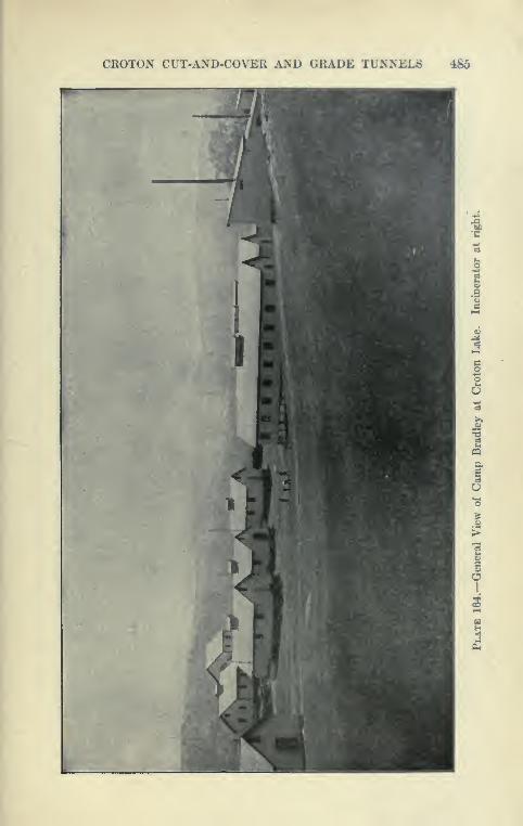
CROTON CUT-AND-COVER A>'D GRADE TUN^'EL8 485
w
3
O
o
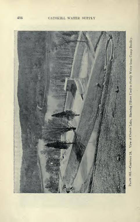
486 CATSKILL WATER SUPPLY
aSaU£o
a
o

CROTON CUT-AND-COVER AND GRADE TUNNELS 487
This feature of coastruction is to provide for the interval previous
to tho coniplotion of tho aqueduct into the city.
Downtake Chamber. The downtake chamber of the Croton Lakesiphon is so built as to provide for connections with possible future
hiKh-level aqueduct to soino of the upper Croton reservoirs. Suchan aquefhict would enable a portion of the Croton supply to Ik^
delivered into New '^'ork with the pressure of the Catskill water.
Central Power Plant. A central compressor plant wa.s built
about 2500 feet east of the aqueduct line, consisting of two Heine
water-tube boilers, 210 H.P. each, to which later was added a marine
boiler of 240 H.P. Two Ingersoll-Uantl Imperial Typ<? X air com-
pressors, each of 1750 cubic feet capacity. operated by cross-compound
condensing engines, equipped with condensers, furnished power
through G-inoh and 7-ineh pipe lines to the shafts. Two 35-K.W.
electric generators furnisherl current for lighting.
Tvu-key Moimtain Tunnel. This is a grade tunnel 1400 feet
long of the ordinary section, and was excavated by the usual top-
heading and bench method. An average weekly progress of 28
feet in heading and 34 feet in the bench was made. The maximumweekly progress was 54 feet of heading and 51 feet of bench. After
the footing courses were concreted, the side walls and arch were
placed, using the standard Blaw forms. An attempt was madeto drill this tunnel close to line, but it was found upon concreting
that considerable trimming was necessar>'.
Concreting Turkey Mountain Tunnel. The concrete was mixed
near the Downtake shaft and taken in side-dumping cars to the portal
and dumped through a chute to a tunnel car, which wa^ hauled by a
cable hoist up an incline to the form platform 12 feet above invert.
The plates were in place up to the platform and the side walls were
filled directly from the cars. Above the platform the plates were
put on and the concrete shoveled in. No spading was done, the mass
being compacted and the air expelled by striking the inner forms
with a hammer. This method gave good results ^v^th a smooth
face comparatively free from voids. It is not to be reconnnended
as a substitute for the spading of concrete. By this method it is
necessary to have the concrete homogeneous and uniform in mixture,
as any separation of the materials of the concrete cannot be matle
good by shoveling. The side walls and arch were placed in one con-
tinuous operation, first in a section 20 feet long, and later in lengths
of 60 feet, the latter taking from thirty to forty hours. To facilitate
the keying of the arch in the 60-foot section the work was started
from each end, and the closure made by using three T-shaped con-

488 CATSKILL WATER SUPPLY
CROTON CUT-AND-COVER AND GRADE TUNNELS 489
Crete blocks, each 1 foot long, the center one provided with a pipe
through which grout could be forced to fill the space at the closure.
Later, sections as long as 90 feet were concreted in one operation.
The concrete was obtained from a mixer placed in the adjoining cut-
and-cover aqueduct and fed with concrete materials by cars which
dumped through a hole in the arch, the mixer being dLschargcnl
into the concrete cars below which were carried to the concrete
platform as usual.
Construction of Croton Shafts. The two shafts of the Croton
siphon were constructed by Harry & McNeil, with a plant which
had previously been used on the Rondout siphon. The excavation
was started with a derrick which was later superseded by head
frames through which buckets were operated in the usual manner.
The maximum weekly progress was 23 feet, the average 13 feet.
The rock was an excellent schist containing very little water. Thedowntake shaft was circular with a rectangular extension to the blow
off. The circular part was drilled with eight 10-foot cut holes, twelve
8-foot side holes, and fifteen 8-foot rim holes, fired in three shots. Therectangular extension was kept 10 to 20 feet higher than the main
shaft and shot as a bench. The shaft was concreted, using circular
Blaw forms, a 10-foot section usually being concreted each day in
four or five hours, the remainder of the day being used in removing
and setting up forms. •
Drill Frame for Shaft. In the construction of this shaft a
drill frame designed by Mr. Harry was used. This frame consists
of a ring from which radiates several bars equipped with jacks at
their ends. The ring with the bars was lowered into place by cables
attached to a drum of a hoisting engine. The drills were then clamped
to the radial bars and the three circular rows of holes drilled. It is
claimed for this frame or spider that it much facilitates the drilling
of a circular shaft by furnishing a firmer support for the drills than
the usual tripod; also by increasing the speed with which the drills
may be removed and lowered into the shaft after shooting. Thedrill frame may be raised with some or all of the drills attached. Thering may be made from pipe and equipped with connections so as
to serve as a manifold for the drills, and thus decreasing the amount
of flexible hose otherwise necessary. Drill frames somewhat sim-
ilar to this have been used in England and it is claimed with a good
deal of success.
Uptake Shaft. The uptake shaft, which is 505 feet deep, was
constructed in a similar manner. The average weekly progress was

490 CATSKILL WATER SUPPLY
Superstructure of doivntoke chamber^Support for screen rack
rDividing pier
ITlftiTT
Plate 167.—Contract 24. Croton Lake Downtake Shaft. Shows how flow
into Croton Lake through conduit is controlled by gate valves. Overflowweir also discharges into conduit to lake.
CROTON CUT-AND-COVER AND GRADE TUNNELS 491
16 feet and the maximum 25 feet. The maximum weekly progress
in lining was 76 feet.
Shaft Equipment. Permanent tunnel equipment wa.** installed
after tlio shafts were sunk and concreted. High head frames were
constructed so that muck cars could be dumped directly in the
crushers. The shafts were equipped with Lambert air hoists and a
single Lambert cage. This cage was counterweighted and raised
and lowered between wooden guides constructed in a rather unusual
way. Cables were suspended from the top to the bottom of the
shaft and boxed in to the dimensions of the usual timber guide.
The cage was equipped with the usual safety dogs which gripped the
suspended guides. In this manner it was unnecessary to drill the
concrete for bolts by which wooden cross-pieces are fastened, these
in turn supporting the guides, as in the usual construction. It
seems to the writer, however, that the usual arrangement is safer,
for in case of accident to the suspended guides, a bad wreck might
result. Although the distance between the uptake and downtake
shaft is only 2640 feet and the one cage was probably adequate, it
would appear that the extra cost of installing two cages would
probably have been warranted by increased facility in operation
and the time saved at critical moments.
Excavation of Croton Pressure Tunnel. The tunnel was driven
with an equipment of Ingersoll-Rand drills, using a top heading.
At the beginning of the work an attempt was made to carry along
the bench so close to the heading that the muck from the latter
would be shot over the bench, saving wheeling. This did not prove
satisfactory, as the two operations of drilling heading and bench
and mucking heading and bench were hampered by lack of room.
This repeated the experience of other parts of the work where the
same attempt was made. The tunnel was then driven nearly
through and the bench later excavated. The tunnel proved to be
unusually dry, the inflow with the shafts only being about 33 gallons
per minute, which is less per foot than some of the adjoining grade
tunnels. The heading was excavated by the following method:
A drilling shift of 14 men, including 4 drillers and 4 helpers, drilled
most of the holes in their shift. The next shift completed the drilling
and shot the heading; the third, a mucking shift, cleared the heading,
so that it was ready for the setting up of the columns and drills
for the next shift. This mucking shift consisted of 1 foreman and 6
laborers, and overlapped a regular mucking shift of 1 foreman and
11 laborers. The bench was drilled by two tripod drills, operated
by 3 drillers, each shift drilling and shooting a round of six holes

492 CATSKILL WATER SUPPLY
in transverse rows SJ feet apart. Meanwhile mucking was going
on steadily in three shifts with 1 foreman and 8 laborers. Themuck from the heading was crushed at the downtake shaft for the
concrete and that from the bench at the uptake shaft. The best
progress made was about 250 feet of heading in one month and
about 108 feet of bench per week.
Concreting Pressure Tunnel. Concreting was done in a mannervery similar to that of the Wallkill tunnel. It was found feasible
to concrete an invert strip 6 feet wide instead of a 5-foot strip, which
was said to be of considerable assistance in preparing for the side-
wall forms. Steel Blaw forms equipped with carriages the same as
those used on the Wallkill siphon were used, and the method of
trailing forms followed. Twenty-five feet of arch and side wall
were usually concreted in a day. This tunnel is 14 feet in diameter
and the lining is 13 inches effective thickness, 8 inches to the A line.
The cut-and-cover stretches were excavated by derrick and the
material deposited on spoil banks. The concrete was placed against
Blaw forms by a Browning crane, a 30-foot section being completed
in eight hours. Later the crane was used for refill over the arch
and to grade the embankments.
Blow-off Conduit. Under Contract 24 about 730 feet of the
blow-off conduit into Croton Lake was constructed, 450 feet in tunnel,
6'X6', and the remainder in cut-and-cover, 6'X8'. This tunnel
joined the downtake shaft 80 feet below the invert level of the cham-
ber. Two 60-inch gates (in tandem) will control the flow from the
main shaft. By setting stop planks in the downtake chamber,
water may be sent through a by-pass and drop manhole into the
blow-off tunnel without going into the main shaft. It will then
be under such a head that the very steep 6'X8' conduit below
will carry the full capacity of the aqueduct at an estimated velocity
at the lake of about a mile a minute. This velocity of discharge
makes the design of this conduit a very interesting one, particularly
so as the outlet is on an earth slope. It was decided that an
open channel was preferable to a closed conduit, as it was feared that
the latter would give trouble because of air being confined. Theunique part of the design adopted is the spreader with which the
channel terminates. This has an invert curved upward so as to
throw the water out in a sheet while at same time spreading it so as
to fall as far as possible from the terminal structure. Further
protection is furnished by a small concrete apron and a large rock
fill. The spreader will only come into full use when the lake is below
the lip of the spreader at elevation 164. The maximum flow line

CROTON CUT-AND-COVER AND GRADE TUNNELS 493
of the lake is 202 feet. It has been computed that with a maximumpossible discharge of 1000 niillion gallons per day the center of the
descending sheet of water will fall at a distance of alxjut 130 feet
from the end of the spreader. With a discharge of 50 million gallons
per day the distance will be about 25 feet. Coefficients of friction
for velocities as high as those which may obtain in this channel
(maximum 75 feet per second) are unknown, and the computations
are subject to large errors.
Contract 100
Outlet of the Croton Blow-ofif. The lower 150 feet of the Croton
blow-off as above described was let under Contract 100 to Stobaugh
& Co., for $41,500. At this time the surface of the Croton Lake
was about 40 feet below flow line, making it possible to construct
outlet and spreader in shallow water. This was accomplished by a
three-sided cofferdam of Lackawanna steel sheathing. The piles
were driven into the bottom with a steam hammer and rendered
tight by dumping wood pulp outside the cofferdam. The remaining
leakage was readily handled by a small pump. The spreader was
then built on a good foundation of hardpan and the projecting steel
piling cut off above the level of the riprap by an oxy-acetylene flame.
The bulk of this work was accomplished within a few weeks in the
fall of 1911. The Lake was low at the starting of the work, but
rose rapidly thereafter, so that the work had to be pushed with
much vigor, but was completed in time to avoid damage by flooding
the cofferdam.
Contract 25
Contract Prices. Contract 25 was awarded to Chas. W. Blakelee
& Sons, April, 1909, for a total of $1,269,830. Some of the bid prices
were as follows:
Open-cut excavation, cu.yd $0 . 50 to 1 . 30
Refilling, embanking, cu.yd 0.35 to 0.45
Concrete masonry for open-cut aqueduct,
cu.yd 5. 10
Rock excavation in tunnel 5 . 95
Timbering in tunnel, M ft. B.M 50 to 60
Concrete masonrj' in tunnel, cu.yd 5.65
Forms for lining tunnel, linear foot 3.00
Sanitary provisions, per month 225 00
Medical and surgical practitioner, per mon. 200.00
49-1 CATSKILL WATER SUPPLY
From contract quantities the linear foot cost of cut-and-cover
is $67, of grade tunnel, $102.
Kind of Work. This contract lies just south of Croton Lake,
and includes 2.5 miles of cut-and-cover and 0.7 mile of grade tunnel
from north to south, as follows : 1050 feet of cut-and-cover aqueduct,
3000 feet of Croton grade tunnel, 3500 feet of cut-and-cover, 700
feet of Chadeayne grade tunnel, and 8700 feet of cut-and-cover.
The southern end of the work was reached from the Putnam division
of New York Central Railroad, to which a spur track was constructed
for the contractor's use. The northern end was reached from Kitch-
awan by team.
Camp Sanitation. As the work lies very close to the intake
to Croton aqueduct the sanitary provisions were stringent, and whatis considered one of the best camps on the line of the Catskill Aque-
duct was established. About forty buildings, including incinerators,
were erected and supplied with electric light, running water andstoves. The entire camp was surrounded by a man-proof fence.
The water supply was obtained from two driven wells and the sewage
and drainage from camp led to filters. All the garbage was collected
daily and all excreta incinerated. At points convenient to the work
movable shelters for sanitaries were placed and tight cans provided,
the contents being collected and burned daily at the incinerators.
At Croton and Chadeayne tunnels chemical dosing plants sterilized
the water from the tunnels and from the brook running from campfilters.
Power Plant. A central compressed-air plant was installed near
the south portal of Croton tunnel and used for both grade tunnels.
Steam was furnished by four fire-tube boilers of 100 H.P. each, two
Ingersoll-Rand 125 H.P. compressors, each of 1075 cubic feet
capacity, and equipped with condensing, circulating and feed-
water pumps. Power was distributed through 3400 feet of air line.
One 30 K.W.A.C. dynamo and one 22| K.W.D.C. dynamo supplied
current for lighting.
Croton TunneL The Croton tunnel was driven entirely from
the south portal. The top heading and bench method was employed
for a distance in, after which the bottom heading, was tried for a
few hundred feet, and finally the top heading alone was driven to the
north portal. Ventilation was supplied by a blower and pipe, but
later three holes driven near the north end of the tunnel from the
surface by a Keystone drill supplied ample ventilation.
When the top heading method was used the usual arrangement
of holes was employed, consisting of three rounds of about 24
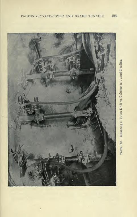
CROTON CUT-AND-COVER AND GRADE TUNNELS 495
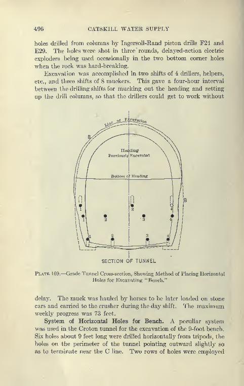
496 CATSKILL WATER SUPPLY
holes drilled from columns by IngersoU-Rand piston drills F24 and
E29. The holes were shot in three rounds, delayed-action electric
exploders being used occasionally in the two bottom corner holes
when the rock was hard-breaking.
Excavation was accomplished in two shifts of 4 drillers, helpers,
etc., and three shifts of 8 muckers. This gave a four-hour interval
between the drilling shifts for mucking out the heading and setting
up the drill columns, so that the drillers could get to work without
»/
SS^Woo
// //"^ \\ ^''X
//Herding
Previously Excavated
/'\ \
Bottom o^ Heading \
/
(
1
1
\\r
!
i \
\ \
? %1
\ \\ \\ \i 2
•3
i/
SECTION OF TUNNEL
Plate 169.—Grade Tunnel Cross-section, Showing Method of Placing Horizontal
Holes for Excavating "Bench."
delay. The muck was hauled by horses to be later loaded on stone
cars and carried to the crusher during the day shift. The maximumweekly progress was 73 feet.
System of Horizontal Holes for Bench. A peculiar system
was used in the Croton tunnel for the excavation of the 9-foot bench.
Six holes about 9 feet long were drilled horizontally from tripods, the
holes on the perimeter of the tunnel pointing outward slightly so
as to terminate near the C line. Two rows of holes were employed
CROTON CUT-AND-COVER AND GRADE TUNNELS 497
loaded with 40 to 60 per cent forcite and shot with fuses or delayed-
action electric exploders, as follows: First, the upper center holes,
then two upper side holes, then the lower center hole and then twolower side holes. All the fuses were touched off at once, or a current
sent simultaneously through all the exploders, the order of shooting
being governed by length of fuse or setting of exploders.
Horizontal vs. Vertical Holes for Bench. One drilling shift
of 2 drillers, helpers, etc., and two mucking shifts of 8 nmckers
were employed, in excavation of the bench, giving an average
advance of 65 feet per week, a maximum progress of 79 feet being
made. This system has the advantage of excavating a tunnel
with the lower half driven closer to the line than that obtained
by the usual method of vertical holes. Because of the curved sides
of the tunnel it is usual to find the sides tight midway thereof, necessi-
tating some trimming. It seems, however, that the vertical-hole
method has the great advantage of enabling the rounds to be drilled as
far ahead of the shattered bench as desired, so that the shooting maytake place at any time. A considerable stretch of bench can be
shot up in advance, although blasting against the muck requires
the use of more powder with some danger of the bottom shooting
high, necessitating additional holes later on. With the method
employed in the Croton tunnel the holes cannot be placed until
the face of the bench is cleared of the muck, and it is rather awkward
to drill horizontal holes from tripods. The methods employed in
the Croton tunnel were very good, but in the writer's opinion
more economical results are secured by carrying the bench along
with the heading, using vertical holes for the latter and employing
the same schedule of drilling sliifts and mucking shifts, but increas-
ing the numl)er of men sufficiently to carry on the bench.
Cut-and-cover Excavation. The cut-and-cover excavations
were made mainly with steam shovels, of which there were employed
two 60-ton Marion, one with 35-foot boom, one 20-ton Marion,
and one Vulcan shovel. The material excavated by the shovels
was loaded diroctly into cars hauled by dinkies to spoil banks or to
make refill over the completed concrete arch. The final excavation
not possible by the steam shovel was shoveled by hand into scale
boxes and removed by derricks and locomotive cranes to the cars.
Large rock cuts were drilled and blasted, the shattered material
being moved by pick, shovel and derricks and deposited on banks
or taken to crushers.
Crushing Plants. The crushing plant over the Chadeayne
tunnel received the tunnel muck directly from the bins at the portal

498 CATSKILL WATER SUPPLY
and consisted of a No. 5 Kennedy gyratory crusher operated by a
50 H.P. engine. A bucket conveyor discharging into bins 100'X 18'
X 15' was used.
A second crushing plant was built on leased land near the south
end of the contract and consisted of jaw crusher with screens, bins,
etc. The crusher supplied material for two Chicago cubical mixers
at the portal. Ground storage was resorted to so as to have an
ample supply of crushed stone on hand at all times.
Concreting Cut-and-cover Aqueduct. Concrete was placed in
the cut-and-cover aqueduct by the usual methods, using bottom-
dump buckets hauled in dump cars by dinkies to the site of the
work and dumped into place between Blaw steel forms by loco-
motive cranes or derricks. The invert of the aqueduct was rein-
forced when on clay bottom and at points where the materials
changed suddenly from rock to earth. At some places it was
placed 24 inches thick, and at others it was reinforced by steel
rods. The concrete was obtained from two mixing plants. Max-imum invert built in one week was 440 feet, and the maximumarch was 435 feet; 30- to 45-foot sections were concreted in one
day.
Plant and Equipment. This contract was very well started. Arailroad track was gradually extended from the Putnam Railroad
at Millwood to the north end of the work, the railroad equipment
consisting of 6700 feet of 36-inch-gauge track, 8 dinky locomotives,
1 standard-gauge locomotive, 58 dump cars, etc. Other plant con-
sisted of 18 steel tunnel cars, 2 Keystone well drills, 1 churn drill,
24 rock drills, 1 stiff-legged derrick, 2 Brown hoists, 18 guy derricks,
and 14 hoisting engines with boilers, 180 feet of Blaw cut-and-cover
forms, and 60 feet of Blaw steel tunnel forms, etc.
Refill over Aqueduct. Refill for the aqueduct was obtained from
the excavation direct, from the spoil alongside of excavation, or
from a spoil bank where a 60-ton Marion shovel loaded cars which
were hauled and dumped over the arch. Some material was replaced
over the arch by the Brown hoist.
Chadeayne Tunnel. ChadeajTie tunnel was excavated from
one end, drilling the heading through first and then excavating the
bench. The heading averaged 44 feet per week, the bench 47 feet.
Muck was loaded into the scale boxes on cars, pulled to the portal
and hoisted upon the cars to the crusher on the spoil bank. Thetunnel was concreted in the usual manner with Blaw forms equipped
with carriage and inclines. The concrete placed in the arch aver-
aged 60 feet per week, using one eight-hour shift per day. The

CROTON CUT-A^'D-COVER AND GRADE TUNNELS 499
h
§•5
l-so 3
I 2
"o 'S.
li
i..s
*5 a
is
"a
^l-H O

500 CATSKILL WATER SUPPLY
same method was used in the Croton tunnel, but the progress was
80 to 160 feet per week, using two eight-hour shifts.
In general, very good progress was made on Contract 25, the
entire work being nearly completed within forty-four months, nearly
eight months ahead of contract time.
CHAPTER XV
Contract 55
GRADE TUNNELS, CUT-AND-COVER AND PRESSURE AQUEDUCTS
Contract Prices. The contract was let October, 1909, to Rine-
hart & Dennis, for a total of $4,545,(KX). Some of the items are
given below:
Open-cut excavation, per cubic yard $0.80 to fl .00
Rock excavation, per cubic yard (oi)en cut) 1 .00
Refill, per cubic yard 0. 10 to 0.25
Mass concrete, per cubic yard 5.00.to 5.25
Reinforced concrete for by-pass aqueduct, per cubic yard
.
5 . 75" " for gate chamber, pec cubic yard. ... 8.00
Rock excavation in tunnel, per cubic yard 5 . 00" '
'
Lakehurst tunnel, per cubic yard .... 5 . 50
Forms for masonry lining in tunnel, per foot 2 . 50
Concrete in timnel, per cubic yard 5 . 50
Steel for reinforcing concrete, per pound . 04
Portland cement, per barrel 1 . 60
Using contract quantities the linear foot cost of cut-and-cover
is $77.84, grade tunnel $94.02, by-pass aqueduct $46.91, Lakehurst
tunnel $62.45, and effluent aqueduct $102.98.
Work Included. This contract extends from near Millwood
on the Putnam division of the New York Central Railroad to a
point near Kensico Cemetery station on the Harlem Railroad,
crossing that raihoad near Pleasantville. It is one of the longest of
the cut-and-cover and grade-tunnel contracts, the total contract
price being the greatest. It contains gate hou.ses and effluent cham-
bers from the Kensico reservoir, including an aeration basin. Tobring the aqueduct to Kensico it was necessary to take it awaj' from a
favorable north-and-south location, and lead it across country
through several tunnels and even somewhat below hydraulic grade,
making necessary a circular pressure aqueduct nearly 3 miles long.
It contains eight grade tunnels, the last three under slight pressure,
aggregating in length 3.7 miles, the tunnels from north to south Ix^ing
known as Millwood, 4750. feet long; Sarles, 5230 feet long; Harlem
501

502 CATSKILL WATER SUPPLY
R. R., 1100 feet; Pleasantville, 700 feet; Re\Tiolds Hill, 3650 feet
Lakehurst, 1650 feet; Dike, 1166 feet; and Kensico, 1515 feet; and
about 3 miles of cut-and-cover aqueduct. The total construction
aggregates 9.6 miles of aqueduct, including more types of special
structures than any other contract.
Influent Weir and Venturi Meters. At the point where the
cut-and-cover approaches the future Kensico reservoir the aqueduct
is constructed so as to feed the reservoir through a section about
200 feet long built so as to open toward the reservoir, the structure
being known as the Kensico Influent Weir. One side of the aqueduct
is built with the standard section and the other as a heavy weir, with
a gap of about 4 feet through which the water is to flow. The crown
of the arch is supported by piers 18 feet apart. This construction
is shown on Plate 174. Near this point there is also an influent
chamber equipped with gates and stop planks. From the weir
an inlet channel is excavated to the reservoir. There are two
Venturi meters similar to that at Ashokan to be constructed under
this contract to measure the water flowing in and out of this Kensico
reservoir. At the outlet of the reservoir there are two effluent gate
chambers, an aeration basin and a screen chamber.
Putnam Siphon. Crossing the Putnam Railroad is the Putnamsiphon, which is reinforced concrete circular section, instead of the
steel pipe usually used. This structure is about 600 feet long and
will be under a maximum head of about 50 feet.
Circular Tunnels. The contract is also peculiar" in containing
grade tunnels of circular section under slight pressure, 11 feet to
17 feet in diameter.
Main Power Plant. A standard-gauge siding was laid from the
Harjem Railroad at Kensico Cemetery, where land was leased for a
yard, cement shed, power plant, etc. From this point a narrow-
gauge railroad extended as far as Pleasantville in the Croton
Division, which contains the upper 6 miles of this contract. Thepower plant contains three 125-H.P. boilers and two Ingersoll-
Rand compressors -of 1100 cubic feet free-air capacity. Eight-inch
to 3-inch compressed-air lines laid from this plant furnish power to
three tunnels of the Kensico Division, for drills on the inlet channel
and quarry and excavation for the by-pass aqueduct, and Reynolds
Hill tunnels. The pipe lines total 4.5 miles. At the power plant
was also operated a 30-K.W. A.C. current generator which pro-
vided light for the tunnels from Reynolds Hill south and for CampColumbus. The current was transmitted over 13,000 feet of pole
lines and connections.

CONTKACT 56 503
it
£z
•^-C 3
11
-I
a -**
2 —Z O
6l.
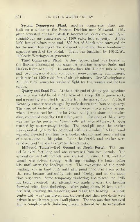
504 CATSKILL WATER SUPPLY
Second Compressor Plant. Another compressor plant was
built on a siding to the Putnam Division near Millwood. This
plant consisted of three 125-H.P. locomotive boilers and one Randstraight-line air compressor of 1300 cubic feet capacity. About
3400 feet of 4-inch pipe and 1800 feet of 3-inch pipe conveyed air
for the north heading of the Millwood tunnel and the cut-and-cover
aqueduct north of the portal. Light was furnished by 160-K.W.,
1100-volt Westinghouse generator.
Third Compressor Plant. A third power plant was located at
the Harlem Railroad at the aqueduct crossing between Sarles and
Harlem Railroad tunnels. It contains three 150-H.P. fire-tube boilers,
and two IngersoU-Rand compound non-condensing compressors,
each rated at 1200 cubic feet of air per minute. One Westinghouse
A.C. 50 K.W. generator furnished light for the tunnels and for two
camps.
Quarry and Sand Pit. At the north end of the by-pass aqueduct
a quarry was established at the base of a steep cliff of gneiss rock,
and a crushing plant fed ])y gravity from the quarry floor. A No. 6
Kennedy crusher was charged by mule-drawn cars from the quarry.
The crushed material was run by a conveyor into a rotary screen,
where it was sorted into bins for 2-inch and J-inch stone and crusher
dust, combined capacity 1100 cubic yards. The stone of this quarry
was used as far north as Pleasantvi lie, all parts of this work being
reached by narrow-gauge tracks. The sand-pit near the crusher
was operated by ar derrick equipped with a clam-shell bucket; sand
was also elevated into bins by a bucket elevator and some crushing
of stones done at this point. Later the derrick and crusher were
removed and the sand excavated by scrapers.
Millwood Tunnel—Bad Groimd at North Portal. This tun-
nel is 4750 feet long and was excavated from two portals. Theexcavation at both portals was started in June, 1910, and the
tunnel was driven through with top heading, the bench being
left until after the headings met. The excavation of the north
heading was in hard rock until at a point 1350 feet from portal
the rock became noticeably soft and blocky, and at the same
time very wet. Some temporary timbering was placed, no drill-
ing being required. An attempt was made to carry the heading
forward with light timbering. After going about 40 feet a slide
occurred, crushing the timbering and filling the heading. A small
center drift was then driven and timbered and then side drifts were
driven in which were placed wall plates. The top was then removed
and a complete arch timbering placed, followed by the excavation
CONTRACT 66 605
of the core. After placing al)out 80 feet of timbering in this mannergood rock was again encountered and excavation proceeded untini-
bered as before. Several months later a hole wjw discovered on
the surface over the point where the cave-in occurred, where there
is 130 feet of ground over the tunnel. To prevent further cave and
to strengthen the tunnel at this point, cut-off" walls w<Te built at
each end of the timbered section to contain the grout placed al)ove
the timbers. In a stretch of about 110 feet 148 yards of liquid
grout were forced in by air pressure, using a Caniff" grouting machine.
Method of Excavation at North Portal. For the excavation
of the north heading of Millwood tunnel Ingersoll-Kand F 94 3|-inch
piston drills were used, mounted on vertical columas. At first -
these drills were mounted on two columns, using 10-foot ste<'l
for cut, and 8-foot steel for side rounds, giving an average pull
of 6.7 feet. Later four drills were mounted on two colunms,
using 12-foot steel for cut holes and 10-foot for other holes, giving
an average pull of 7.6 feet. The 12-foot holes were started 2\ inches
in diameter, reducing every 2 feet to l\ inches at bottom. The usual
V-shaped cut was drilled with parallel side round. The trimming
holes were started on C line, pointed to reach B line at the butts.
The cut generally required to be shot twice. Electric fuses and 60
per cent forcite were used, about 6 pounds per yard.
Schedule of Shifts. The following schedule of work was fol-
lowed :
Drilling shifts:
4.00 P.M. to 12 P.M.
12 P.M. to 8 A.M. (Shot at end of 2d shift.)
Mucking shift
:
9 A.M. to 5.30 P.M. (^ hour for lunch.)
5.30 P.M. to 2 A.M. (2 hour for lunch.)
Drilling shift: 4 drillers, 4 helpers, 1 nipper, 1 blacksmith, 1 helper.
Mucking shift: 4 muckers, 1 dump man, 1 driver, 1 mule.
It is apparent that an attempt was made here to make a long
advance per round — 7.6 foot.
Method Used in Millwood and Sarles Tunnels. In the south
heading of the Millwood tunnel and the adjoining Sarles tunnel it
was aimed to make only a short advance— 4.25 feet— at the lowest
possible labor cost as follows:
Two Ingersoll-Rand drills (3| inches) were mounted in the
heading, each on a column, and all holes were drilled to a depth of
6 feet with the usual arrangement of V-cut, side, round and trimming
holes. All holes were loaded before the first shot with 60 per cent

506 CATSKILL WATEE SUPPLY
forcite and shot in three rounds with electric exploders. About
6.3 pounds of powder were used per yard.
Schedule of Shifts. The following arrangement of shifts wasused:
Drilling shifts:
8 A.M. to 5 P.M. (1 hour for lunch.)
9 P.M. until 5 A.M. (1 hour for lunoh.)
Each shift drilled a round of 6-foot holes.
Mucking shifts:
7 A.M. until 4 P.M. (1 hour for lunch.)
7 P.M. until 4 A.M. (1 hour for lunch.)
^Heading muckers:
5 A.M. to 9 A.M.1 2 shifts of 4 hours each.
5 P.M. to 9 P.M. I
Typical force:
Drilling shift, 2 drillers, 2 helpers, 1 nipper, 1 blacksmith, 1 helper.
Mucking shift, 4 muckers, 1 dump man, 1 driver, 1 mule.
Heading muckers, 2 muckers, working 5 day on each .shift.
In general the routine was for the drillers to drill and shoot the
heading (about 7 feet high) in each shift; then followed a three-hour
interval in which the heading was mucked back sufficiently by two
muckers to allow the drills to be set up by the next shift, and to
allow the heading to clear of smoke before the main mucking shift
came on, two hours after shooting. In this manner two advances
of about 4.25 feet per day were made of about 4 yards per foot of
advance.
Advantage of Methods Used in Millwood Tunnel. The arrange-
ment of shifts as used in Millwood South is very advantageous for
eight-hour shifts. With ten-hour shifts (not here legal) there is a
natural interval between which the tunnel can be cleared of smoke,
etc. Where three shifts are worked per day a great deal of time is
necessarily lost while blasting is going on and while the tunnel
air is too thick for work. An interval of a few hours between drilling
and mucking shifts gives an opportunity to clear the tunnel of smoke,
and by using a few men the heading can be sufficiently cleared to
allow the setting up of drills before the drillers report. Somesuperintendents claim that it is economical to train laborers to set
the drills so that everything will be in readiness when the drill
runners report. In Millwood South it was preferred to make one
short advances for each shift rather than one long advance per day,
as in the north tunnel. The short advance is the right principle,
as 9.5 feet was made with an average force of 31 men in the south
CONTRACT 55 507
tunnel against 7.6 feet per day in the north tunnel with an average
daily force of 41 men. Both headings were in hard gneiHS, each
encountering about 35 gallons of water iK»r minute. An average
weekly progress of 35 feet was made in the north heading and 47
feet in the south heading, the maximum weekly progress lx>ing Gl
feet.
Bench Excavation by Horizontal Holes. The headings were
driven shallow, leaving a bench of about 12 feet to Ix? excavated.
An attempt was made to take this out, using 8-foot vertical holes
to take down the upper portion (6 feet) and 10-foot lifting holes
to remove the lower 6 feet. This was soon abandoned in favor of
the method of excavating bench by the use of two rows of horizontal
holes as used in the Croton tunnel. The average weekl>' progress
on the bench as made by this method was 44 feet, maximum 66
feet.
Comparison of Methods of Millwood and Bonticou Tunnels. It
is not apparent that the care taken in the Millwood tunnel to carry
on the excavation with the minimum force effected any saving in
the yardage cost over the methods employed, for instance, in the
Bonticou grade tunnel. By carrying a larger force working accord-
ing to the admirable system developed in the heading Millwood
South, it would seem that with two full drilling shifts working
four drills at a time, two advances of say 5.5 feet each (total 1 1 feet)
could have been made, using two heavier mucking shifts. It would
also appear that a deeper heading (about 9 feet) could have l>een
taken out with advantage, thus allowing the bench to be taken
out with vertical holes in one lift. Moreover, by the use of two
tripod drills for the bench work with additional muckers for the
bench, a complete tunnel could have been excavated and trimmed
without delaying the heading progress. The monthly progress in the
heading alone at Millwood averaged about 204 feet, and maximum240 feet, whereas in the Bonticou tunnel north over 300 feet of
complete tunnel was averaged, maximum month, 425 feet. In the
south tunnel of Bonticou the average progress was about 285 feet
per month. It is to be noted, however, that Bonticou tunnel was
driven in shale while Millwood was in gneiss.
Sarles Tunnel Progress. The Sarles tunnel, one of the longest
grade tunnels in the Southern Aqueduct Department (5230 feet),
is separated by about one-half mile of cut-and-cover south of Mill-
wood tunnel, and was constructed by the methods descrilx»d under
Millwood tunnel. The north heading was lx»gun July, 1910, and
driven 1870 feet before the bench excavation was started. From

508 CATSKILL WATER SUPPLY
the south portal the heading was driven 3360 feet to the meeting
with the north heading and then the bench excavation was started.
Harlem Railroad Timnel Timbering at Portal. The Harlem Rail-
road tunnel (1100 feet long) is separated from the Sarles tunnel onthe north by a short steel-pipe siphon built under the Harlem Rail-
road under Contract 68. The heading was driven through to the
south end from the north portal, after which the bench was exca-
vated. The portal cut was found to be of a treacherous nature,
collapsing after a heavy rain in April, 1910, and filling the cut, not-
withstanding a crib work of timber. The cut was re-excavated and
protected by permanent timbering for a stretch of 88 feet, such as
used in grade tunnels. The five-piece arch bents were covered with
2-inch planking and filled over with 3 feet of earth. The rock in
portions of this tunnel and at the north portal was found to be
a thoroughly decomposed schist. This material has the appear-
ance of rock, showing the marks and banding of rock, but it could
be taken out with the fingers and kneaded into balls like putty.
Three Methods of Timbering Harlem Railroad Tunnel. There
were three methods of timbering used on the tunnel. First, Theheading was completely excavated and wall plates placed somedistance back at the sides, supporting five-piece arch bents, cov-
ered with lagging and dry packed to the roof. The bench was taken
out in two lifts, care being taken not to disturb the wall plates,
which were temporarily supported by short posts when the upper
lift was removed. All posting was ultimately carried to grade.
Second. Side drifts 7'X7' were driven about 15 feet ahead and
lightly supported by 2''X8" sheeting laid box fashion. Wall plates
were placed inside of the drift with some side pieces of arch rib.
Then the core between was removed and the timber arch completed,
lagged and dry packed, partly on 2^-foot centers and partly on 5-foot
centers. As the bench was removed lO^'XlO" posts were erected,
supporting the wall plates and covered with 2-inch lagging whennecessary.
Third. A center top drift, 7.5'X 10' wide, was excavated and
roughly arched. Then the sides were trimmed to full width and
the top taken down, so as to place the five-piece timber arch,
lagged and dry packed as usual. Wall plates were later used sup-
ported by posts which were lagged to protect sides, where neces-
sary.
Concreting of Harlem Railroad Tunnel. For concreting the tun-
nel a plant was constructed over the north portal cut, which was
timbered as described. A bridge was constructed transverse to the

CONTRACT 65 609
cut at ground level so that wagons could be driven on it, dumping
sand and stone directly to bins Mow. Below these bins in turn
a Ransonie mixer was placed, so as to be fetl from these bins with
p>»UwL
f 1-1 1
''. -11i. Mi '
;• ^f
, '.;^ 1- v^
1
& iw-
£ iv"
H 1 M- S ^ ^^^k.t-. o
s mm
1wL
^'0-
SECTION OF HEADING PLAN OF DRIFT
1-Drifts 2-Core1-Drifts oxcnvatedla £i.l«B9 on eftherjside i
theaside ribs erected3-Core removed and upper timl)ers placed
HARLEM R. R. TUNNELMETHOD OF TUNNELING
DETAIL OF DRIFT TIMBERING
Plate 172.—Harlem R. R. Tunnel. Method of Timbering in Heavy Ground,
Using Wall Plate Drifts.
sand and stone and with cement through a covered chute from a
cement house on the surface. The mixer discharged directly into
concrete cars running below the timber arch on a trestle about 10
510 CATSKILL WATER SUPPLY
feet high laid on the floor of tunnel. The trestle is a light portable
construction made of 4"X6" posts and cap cross braced with 2"X10"planking and spaced 8 feet center to center. On the caps is laid
a platform 6 feet wide, built of 2''X12" planks, upon which the
rails are spiked to a 2-foot gauge. This trestle, called a high line,
connected three 40-foot sets of Blaw grade tunnel forms, eliminating
the necessity for the usual inclines or elevators used to raise con-
crete cars from invert level. Of course, as the forms are movedit is necessary to take down and erect portions of the trestle adjacent
to the forms. But it is claimed that this is a sm^all item and that the
lumber cost per yard does not exceed 12 cents. The concrete cars
were at first pushed by hand from mixer to form, but later a gaso-
lene '' mule " was used. A progress of 120 feet per week was madeworking only one eight-hour shift.
Relative Merits of Trestle and Incline for Concreting. It is
probable that the work of erecting and taking down inclines
is overrated. When properly built and arranged to be carried
on cars which also serve as supports for the incline, the labor
upon them is not any more than taking down and erecting 80
feet of trestle, and they contain much less lumber per foot of concrete
tunnel. Working one full shift of concrete men and form movers
and a small keying-up shift at the Peak, Bonticou and Bull Hill
grade tunnels, no trouble was experienced in concreting one 35 to
45-foot form per day. In Peak tunnel 280 feet or twice that at
Harlem tunnel was averaged per week with a somewhat larger force
as explained. Nevertheless, the employed method at the Harlem
tunnel was very good for the purpose, the tunnel being less than
one-third the length of the others mentioned. The contractor did
not try to push the work of concreting the Harlem tunnel, as it
was short and the work beyond not completed, but at the Mill-
wood tunnel, using the same method, 200 to 240 feet of tunnel
was lined per week..
Pleasantville Timnel. Pleasantville tunnel is only 700 feet long.
It is in crystalline limestone and was driven by the same methods
and care employed in the Millwood South and Sarles tunnels.
Reynolds Hill Tunnel. Reynolds Hill tunnel (3650 feet long)
pierces the divide between the Sawmill River and the Bronx, the
south portal being about one-half mile from the influent weir to
Kensico reservoir. It is separated by about 1^ miles of cut-and-
cover from the Pleasantville tunnel on the north.
Reynolds Hill is of Manhattan schist, extends about 100 feet
above the tunnel and has a rather gentle slope at the north portal,
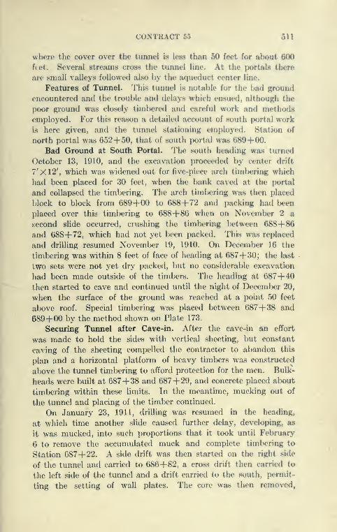
CONTRACT 55 511
where the cover over the tunnel is less than 50 feet for alx)ut 600
f(et. Several streams cross the tunnel line. At the portals there
are small valleys followed also by the aqueduct center line.
Features of Tunnel. This tunnel is notable for the bad ground
encountered and the trouble and delays which ensued, although the
poor ground was closely timbered and careful work and methods
employed. For this reason a detailed account of .south portal work
is here given, and the tunnel stationing employed. Station of
north portal wjis 652+50, that of south portal was 689+00.
Bad Ground at South Portal. The south heading was turned
October 13, 1910, and the excavation proceeded by center drift
7'X12', which was widened out for five-piece arch timbering which
had been placed for 30 feet, when the bank caved at the portal
and collapsed the timbering. The arch timbering was then placed
})lock to block from 689+00 to 688+72 and packing had l)een
placed over this timbering to 688+86 when on Novemlx'r 2 a
second slide occurred, crushing the timbering between 688+86and 688+72, which had not yet been packed. This was replaced
and drilling resumed November 19, 1910. On December 16 the
timbering was within 8 feet of face of heading at 687+30; the last
two sets were not yet dry packed, but no considerable excavation
had been made outside of the timbers. The heading at 687+40then started to cave and continued until the night of December 20,
when the surface of the ground was reached at a point 50 feet
above roof. Special timbering was placed between 687+38 and
689+00 by the method shown on Plate 173.
Securing Tunnel after Cave-in. After the cave-in an effort
was made to hold the sides with vertical sheeting, but constant
caving of the sheeting compelled the contractor to abandon this
plan and a horizontal platform of heavy timbers was constructed
above the tunnel timbering to afford protection for the men. Bulk-
heads were built at 687+38 and 687+29, and concrete placed about
timbering within these limits. In the meantime, mucking out of
the tunnel and placing of the timber continued.
On January 23, 1911, drilling was resumed in the heading,
at which time another slide caused further delay, developing, as
it was mucked, into such proportions that it took until February
6 to remove the accumulated muck and complete timbering to
Station 687+22. A side drift was then started on the right side
of the tunnel and carried to 686+82, a cross drift then carried to
the left side of the tunnel and a drift carried to the south, permit-
ting the setting of wall plates. The core was then removed,
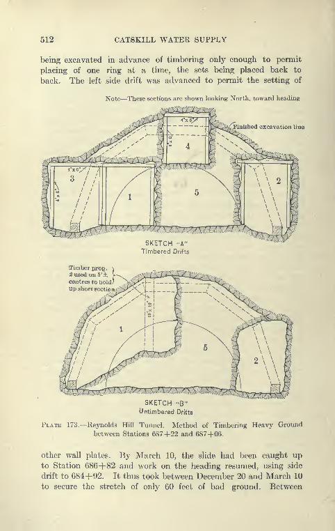
512 CATSKILL WATER SUPPLY
being excavated in advance of timbering only enough to permit
placing of one ring at a time, the sets being placed back to
back. The left side drift was advanced to permit the setting of
Note—These sections are shown looking North, toward heading
jFinished excavation line
SKETCH "A"Timbered Drifts
Timber prop.2 used on 5
centres to hold,
up short sectipn;
SKETCH -B"Untimbered Drifts
Plate 173.—Reynolds Hill Tunnel. Method of Timbering Heavy Ground
between Stations 687+22 and 687+06.
other wall plates. By March 10, the slide had been caught up
to Station 686+82 and work on the heading resumed, using side
drift to 684+92. It thus took between December 20 and March 10
to secure the stretch of only 60 feet of bad ground. Between

CONTRACT 55 513
6874-50 to 6874-39 the timl>ering was so badly distorted by the
slip that the dry packing outside was grouted lx*fore proceeding
with the bench excavation. The full heading was excavated between
684+90 and 6774-20, work being then discontinued on heading,
and the bench excavation resumed. The Reynolds Hill tunnel will
probal)ly be the last on the Southern Aqueduct Department to hole
through.
Lakehurst Tunnel. The Lakehurst tunnel, 1650 feet long,
was excavated during 1910, the headings l^eing driven nearly
through before the bench work was started. The bench was exca-
vated by drilling horizontal holes. Permanent timbering was
placed for about 1000 feet in different stretches.
The Lakehurst grade tunnel is of special shape, circular, 1 1 feet
finished diameter, and has a horseshoe-shaped waterway 11 feet
high and 12.5 feet wide.
Kensico Tunnel. The Kensico tunnel, 1515 feet long, was
driven through with top heading between February 14 and July 16,
1910. The top heading was small, not over 6 feet high. A special
steam shovel was used in mucking the north heading, and a con-
veyor was installed for transporting the excavated material to
cars at the rear of the shovel, but the excavator did not work and,
together with the shovel, was taken out of the tunnel. There is
no instance known to the writer of the profitable use of a steam
shovel or mucking machine in any of the tunnels of the Catskill
Aqueduct. The north bench was removed in two lifts.
Dike Tunnel. The Dike tunnel connects the upper and lower
effluent chambers of Kensico reservoir. It was excavated by a
middle heading 7 feet high to full width of tunnel, leaving a 5-foot
bench. The roof was removed by from four to six holes, 13 feet
long, for 12-foot advances. The bench was removed by four vertical
holes for 5-foot advances.
Cut-and-Cover Methods. The cut-and-cover on Contract 55
aggregates 3 miles in about six stretches between the numerous
tunnels. Consequently no very good opportunity offered itself to
develop methods for this class of work. In general, standard
methods of excavation were used, steam shovels being employed
wherever practicable, sometimes the material being cast to one
side of the trench and sometimes loaded on dinky trains for spoil
banks, or refill over arch. A long-boom Marion shovel was em-
ployed in a rock cut, working to near subgrade, the rock from the
final trimming being loaded by hand into scale boxes and raised
and dumped to one side by A-frame derrick. Concreting was done
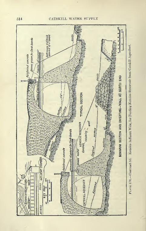
514 CATSKILL WATER SUPPLY
CONTRACT 65 515
in the usual manner, Raasome cut-and-cover forms, filled by bucketsof concrete hauled on flat cars and deposited by Brown hoist or
derrick, hv'inp, usod.
Location and Design of By-pass Aqueduct. The by-pass aque-duct which connects the influent weir with the upper efliuent gate
chamber of Kensico reservoir is of the type known as pressure
aqueduct; that is, it is an aqueduct built in open cut so as to resist
a niodorate internal pressure. This stretch, to secure favorable
alignment, is located entirely below hydraulic gradient. Thereis a head available for delivering water between the influent weir
and the upper effluent chamber of about 32 feet. This may be
reduced to 22 feet when the Eastview filters are in operation, at whichtime the maximum head will be about 19^ feet on center. Themaximum possible head might be 42 feet. The by-pass aqueduct is
located within the flow line of the reservoir, so that when the reservoir
is full it will be completely submerged. The weight of the masonryis such that it cannot float even when empty. The waterway is
circular and 11 feet in diameter. The outside is horseshoe-shaped,
about 1 foot thick at the crown. The sections are shown on Plate
175. It is reinforced with steel so that under usual working condi-
tions the steel will be stressed less than 2000 pounds to the square
inch.
The by-pass is designed to be covered by an embankment of
earth and rock, but the slopes being submerged are made muchflatter than those for the standard aqueduct. Culverts will take
care of the surface flow before the completion of the reservoir andprevent the formation of pools, in case the reservoir should be sub-
sequently drawn down.
Construction of By-pass Aqueduct. The by-pass aqueduct wasexcavated with a 65-ton Marion steam shovel to within 1 foot of
subgrade, and the material excavated used for foundations and
embankments, in spoil banks, or as refill. The bottom of the trench
was shaped to the invert by hand just before the concrete wasplaced. It was constructed with circular llansome telescopic
steel forms in sections 7.5 feet long, the forms l)eing supported
on concrete blocks built to line and grade of invert. For use
on curves steel fillers were bolted to the forms. The outside
forms were also steel and horseshoe shape, resting on rock
bottom or on its concrete cradle, and equipped \vith doors so
placed that all parts of the inside forms could be reached with
straight rammers. The difficulties of securing a perfect cast of a
full circular section in one operation are well illustrated by the

516 CATSKILL WATER SUPPLY

CONTRACT 65 517
experience here, where the operation was made more difficult by the
reinforcing rods, two rows of l^-inch square twisted rods not morethan 18 inches apart tied together by J-inch longitudinal rods 4 feet
apart. Difficulty was found at the start in securing a good surface
for the invert, there being a tendency for the concrete to l)ecome
wedged on its way to the center line, forming small banks of stone
from which the mortar partially drained out; the result Ixjing
that between these banks a void was left. On the effluent aqueduct
where wooden forms were used and where the diameter is 6 feet
more, the trouble was even greater, and here an attempt was madeto remedy this by drilling holes in the bottom of the iaside forms,
to observe whether the mortar was thoroughly rammed below the
forms. It was found later that the horizontally reinforcing rods
were partly responsible for the separation of the concrete, and whenthe lowest rod was moved away from the critical point more satis-
factory results were obtained. Very great care in ramming was,
however, still essential.
Forms for and Concreting of By-pass Aqueduct. The outside
forms used during 1910^ had only a few removable plates; con.se-
quently, on account of the curvature of the inside form there were
many places which could not be effectively reached bj^ rammers.
The forms were rebuilt the following winter, making all of the out-
side plates removable except the narrow ribs of the two angles back
to back, and one out of every three of the vertical panels. Theremovable sections were so fitted that they could be readily and
securely fastened. This form enabled the concrete to be readily
placed and inspected.
The circular inside forms were designed to be used with heavy
counter-weighted car to resist the flotation of the concrete. Later
it was found that the counter-weighting was unnecessary, this
probably being largely due to the reinforcing rods which were
supported on blocks resting on the top of the inside form, the
blocks being removed as the concrete neared the top. Originally
the cars carried jacks to support the forms. Later when the cars
were dispensed with, screw-jacks and columns were used to keep
the top of the forms from sagging; turn-buckles and ratchet-jacks
in a horizontal position drew the sides together, thus giving a true
circular shape. The following schedule was followed in concreting
the pressure aqueduct:
Concreting By-pass Aqueduct. One shift began work at 4 a.m.
to finish the preparation of the forms for the day's cast; at 8 a.m.
the regular concrete shift placed the concrete within the forms; and
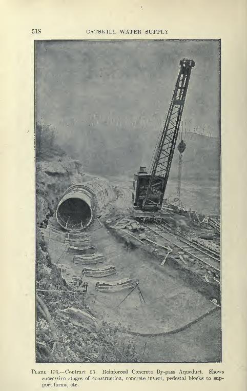
518 CATSKILL WATER SUPPLY
Plate 176.—Contract 55. Reinforced Concrete By-pass Aqueduct. Shows
successive stages of construction, concrete invert, pedestal blocks to sup-
port forms, etc.

CONTRACT 55 519
a third shift coming on at noon took down the back formfi over
which previously placed concrete had set, pa«se(i them through
the forms being concreted, and partially assembled them and the
reinforcing rods. Usually six 45-foot sections were placed within aweek; 1138 feet of this circular aqueduct has been placed within amonth. This was very good work.
In earth and soft rock cuts a concrete cradle 7 inches thick
was placed over the entire width of the invert to aid in placing the
concrete. Upon this concrete cradle narrow, traasverse blocks
spaced about 7^ feet apart were built to support the form. In
a hard rock cut the cradle was omitted. The concrete for the
aqueduct itself was dumped in at the top and placed in the space
between the invert blocks and under the inside forms by menworking through open panels in the outside forms, these panels
being closed as fast as the concrete rose in the forms. The 120
feet of llansome telescopic centering was used for the inside form and90 feet for the outside. Fillers were used on curves, together
with steel })ulkhoads and steel forms for invert blocks.
Effluent Aqueduct. The effluent aqueduct extending from the
lower effluent chamber to Kensico tunnel and south of the tunnel
to the Kensico siphon chamber is similar in open-cut construction
to the by-pass aqueduct, but is 17 feet in diameter, and is heavily
reinforced with two circular rows of bars If inches square, spaced
not more than 7| inches apart, with J-inch longitudinal rods 6 feet
apart.
Two kinds of forms, Blaw steel forms provided with a car for
moving and to support the forms from sagging, and wooden forms
designed on the ground, were used in the construction of this aque-
duct. The wooden inside forms were covered with steel plates and
consisted of three portions, two of equal size hinged at the top
and one smaller section hinged at the lower edge of one of the upper
sections. Each section of the form is braced so as to form a bow-
string truss. Along with these, outside wooden forms were also
used, consisting of wooden ribs in which wooden lagging wa,s placed
as the concrete rose. The wooden interior forms were carried near
their top on an I-beam supported by two towers, one tower on the
finished invert and one on the bottom in advance of the work.
Both towers ran on tracks, the I-beams supporting the forms con-
tinually, making unnecessary the placing of the form-support
blocks necessary with the steel forms. The form was readily
moved by folding up the bottom section and pulling the sides of
the two upper sections inward and lowering them a short distance
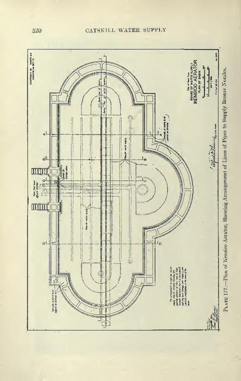
520 CATSKILL WATEK SUPPLY
pit
!^
CONTRACT 66 521
onto the supporting I-beams. The steel Blaw forms were sup-
ported on the invert blocks as in the case of the Ilaasome by-pass
forms. The effluent aqueduct has also given trouble in the .securing
of a good invert. The reinforcing rods took up so much room,
and the diameter of the inside forms was so great that unless groat
care was taken the middle 4 feet of invert showed coasideral)le
voids. It was necessary to spread the rods and slow up the placing
of the concrete at this point and send men to thoroughly spade.
Very great care in spading entirely overcame this difficulty.
Difficulties Met in Casting Circular Aqueduct Monolithic. It
seems clear from the experience on this contract and in other places
that the concreting of circular sections of aqueduct monolithic
between transverse joints is attended with difficulties; that addi-
tional expense is necessary for forms and that there is danger of secur-
ing imperfect concrete below mid-diameter. Experience in pressure
tunnels shows that a verj^ good invert and lower half of circular aque-
duct can be secured by concreting in three pieces, and that the
longitudinal joints give rise to little leakage. It might \ye argued
that in reinforced sections, such as the by-pass and effluents aque-
ducts, the monolithic construction is stronger, but experience shows
that separation of layers is apt to occur due to interruption of work;
also that reinforcing steel cannot take up any rea.sonable working
stress before the concrete shows incipient cracks. In the con-
struction of portions of Venturi meters of circular reinforced sections,
the invert has been cast separately from the upper portion, the
longitudinal joints being protected against leakage by steel plates.
The resulting aqueduct is very satisfactory. At the Putnam
siphon the invert was cast in advance, after which the upper
half, about two-thirds of section, was concreted, using a wooden
collapsible form. All the joints were provided with 6-inch steel
plates to act as water stops. This section was heavily reinforced.
CHAPTER XVI
KENSICO DAM AND APPURTENANT WORKS
Works and Prices. Contract 9. This contract was awarded to
John C. Rodgers, J. M. Rodgers, and J. J. Haggerty, December,
1909, but was assigned, September, 1910, to H. S. Kerbaugh, Inc.
The total bid price was $7,953,000. Some of the items are as
follows
:
Earth excavation, Class A, B, C, D. . 1,340,000 cu.yds. $0.50 to 2.00 per cu.yd-
Rock excavation under dam without
blasting 40,000 "1.50 per cu.yd.
Refilling and embanking 1,340,000 '
'
0.20 to 0.55 per cu.yd.
Surface dressing and grassing 100,000 " 0.50 per cu.yd.
Portland cement 900,000 bbls. 1.50 per bbl.
Mass concrete 37,500 cu.yds. 5.25 to 5.75 per cu.yd.
Cyclopean masonry 900,000 '
'
2.65 per cu.yd.
Concrete blocks . . ^ 60,000 '
'
7.50 per cu.yd.
Dimension stones 24,700 ** 23.05 to 24.54 per cu.yd.
Steel for reinforcing concrete 1,250,000 lbs. 0.035 to 0.04 per lb.
Face dressing of
Quarry face workBull-pointed workRough pointed
Fine pointed
Four-cut workSix- to 8-cut work
410,000 sq.ft. 0.13 to 1.00 per sq.ft.
Magnitude of Contract 9. Contract 9 is the second largest con-
tract of the Catskill water system, and because of its complexity,
a period of ten years is allowed for its completion, and workwill be under construction several years after the Catskill Aqueduct
is bringing water into the City through the City aqueduct. This is
made possible by the By-pass aqueduct (Contract 55), which permits
Kensico reservoir to be cut out.
Location of New Kensico Dam. Originally it was proposed to
build the new Kensico dam just below the old dam forming LakeKensico. This had the advantage of not disturbing the old reservoir
and the old dam so that water could continue to be delivered through
the 48-inch pipe forming the Bronx conduit to Williamsbridge
522

KEN8IC0 DAM AND APPURTENANT WORKS 523
Plate 178.—Contract 9. Map of Kensico Reservoir and Adjacent Structures,
such as Dam, Influent Weir, By-pass Aqueduct, Effluent Chamber, Aerator,
etc.
524 CATSKILL WATER SUPPLY
reservoir supplying a portion of Bronx Borough. Further consider-
ation showed that it would be dangerous to make the large anddeep excavation necessary below the old dam for the foundations
of the much higher dam to be built, and a favorable site having been
discovered by borings above the old dam it was decided to drain
Lake Kensico and build the new dam just upstream from the old
one. This made it necessary to build temporary works to supply
the Bronx conduit, as, pending the delivery of Catskill water, all
the water which can now be obtained is urgently needed. All
this work is provided for under Contract 9, as shown on Plate 178.
Temporary Water Works to Supply Bronx Conduit and Highways.A temporary reservoir known as New Rye reservoir was formed by an
earth embankment 475 feet in length, 50 feet high, with a woodencore wall. This embankment, known as the New Rye dike, is also
supplied with a waste weir and waste channel. To secure the flow
of the Bronx River, this stream is dammed by an embankment about
460 feet long with a maximum height of 42 feet, and also con-
tains a timber core wall. This embankment, known as the Bronxdike, is also supplied with a waste weir and waste channel. Thewater impounded by this dike is diverted into a short tunnel, piercing
the divide to New Rye reservoir. This, known as the Bronx-Rye
tunnel, is only 655 feet long. To carry the water from the NewRye reservoir 10,634 feet of 36-inch riveted steel pipe line were laid
to the Bronx conduit below the old Kensico dam. The temporary
reservoirs will have about 5,000,000,000 gallons available capacity
and cover an area of 709 acres. In order to guarantee a supply for
the Williamsbridge reservoir an outfit of turbine pumps was installed
at Jerome Park reservoir, so that a supply of Croton water could
be pumped into the Williamsbridge reservoir in case of shortage
of the temporary supply.
Because the new reservoir is to be so much larger than the
present reservoir, it was necessary to build also several miles of
new highways. These highways were constructed above the flow
line of the new reservoir and across arms of the reservoir on
permanent bridges, the most important of which is the Rye Outlet
bridge, which crosses at a height of about 110 feet above the bed
of the reservoir and has a length, including approaches, of about
924 feet, with five reinforced concrete arches. These auxiliary
works occupied practically the first two years of coitstruction
work.
Swamp Covering. The contract provided that several hundred
acres of swamp land and shallow borders on the sites selected for the
KENSICO DAM AND APPURTENANT WORKS 526
reservoir be covered with clean earth and sand. This covering
was obtained by shovels working in various borrow-pits and loading
narrow-gauge cars, which were dumped from the tr?vk«^ .riro^tlv
into place.
Plant for Rye Outlet Bridge. A power plant was installed near
the Rye Outlet bridge and consisted of three locomotive l>oilers
with a combined capacity of 230 H.P., two Ingersoll-Sergeant com-
pressors of 3600 cubic feet free air per minute combined capacity,
and a generator for furnishing light for the Bronx-Rye tunnel.
From this plant air was furnished for drills and derricks on the RyeOutlet bridge, to drills in operation along the highway to the north
of the bridge and in the Bronx-Rye tunnel.
Rye Outlet Bridge. The Rye Outlet bridge is an imposing
structure of five spans, the central span 128 feet 7 inches, two inter-
mediate spans 127 feet 7 inches, and end spans 124 feet 7 inches,
the total length of bridge, including approaches, being 924 feet.
The maximum clear height of bridge is 110 feet. Each span con-
sists of two concrete arch ribs, reinforced by four steel ribs of fabri-
cated angles and bars, in addition to which there are in the entire
bridge nearly 1800 separate steel bars of 275 different lengths and
sizes. For the construction of this bridge a special concrete plant was
installed. A quarry was opened a few hundred feet north of the
bridge, and the stone crushed in a near-by plant and conveyed to
bins over the mixer on a trestle about 265 feet long. The sand bin
over the mixer was filled by a 90-foot bucket conveyor, the sand
being delivered in wagons.
Construction of Rye Outlet Bridge. Two Ransome concrete
mixers at the plant discharged into buckets operated as elevators and
raised above the false work for the superstructure of the bridge. Theconcrete there was discharged into cars and was pushed along on a
track on the false work and deposited in place through chutes. The
main element in its construction was the forms required for the
large spans. These forms settled only .03 to .06 of a foot after the
arches were cast. To remove all form marks and to provide amore artistic surface a 3-inch mortar face, later tool dressed,
was placed on the exposed sides of the bridge. This was at first
obtained by the aid of steel diaphragms placed edge to edge within
3 inches of the forms and pulled up from time to time as facing and
concrete were placed around them. It was found practically impos-
sible to keep these diaphragms in place and the use of i-inch square-
mesh wire was resorted to. The facing mortar was mixed rather
dry and rammed down between the netting and the form fast enough

626 OATSKILL WATER SUPPLY
tf
1
-a
o
o
7
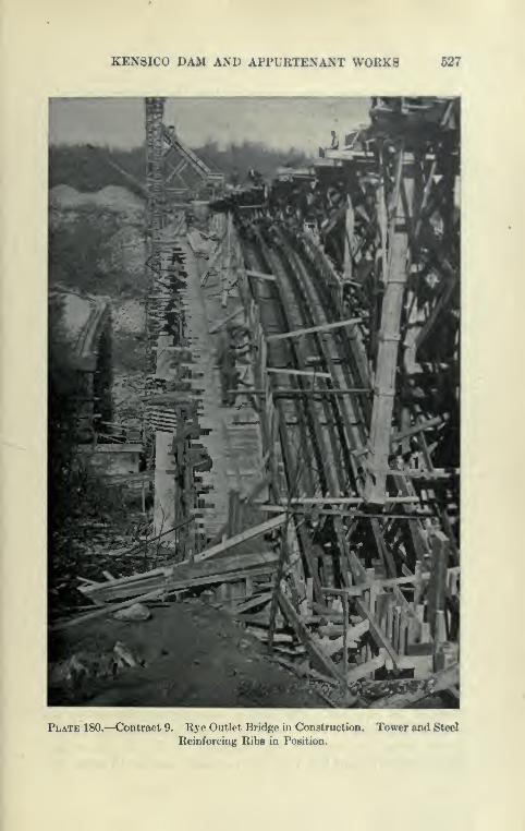
KEN8IC0 DAM AND APPURTENANT WORKS 527
Plate 180.—Contract 9. Rye Outlet Bridge in Construction.
Reinforcing Ribs in Position.
Tower and Steel
528 CATSKILL WATER SUPPLY
to keep slightly ahead of the concrete. After the forms were movedthe facings were dressed down with hammers and axes.
Kensico Dam. Kensico dam will be a much larger masonrystructure than the corresponding portion of the Olive Bridge dam,
but mil be of very similar construction as to cyclopean masonry, con-
crete blocks, expansion joints, inspection wells, drainage wells, etc., but
for architectural effect the exposed face will be of granite ashlar. It
will have a maximum height of about 170 feet above the present river
bed, but will extend 130 feet further to solid ledge rock, which will
make it at the maximum about 300 feet high, or about 50 feet higher
than the Olive Bridge dam. It will be about 1830 feet long, or
nearly twice the length of the masonry portion of the Olive Bridge
dam. Extending from hillside to hillside the dam will not be flanked
by long stretches of dikes or core wall dams, such as are used to
form the Ashokan Reservoir. The drainage area of the Bronx River
being very small in proportion to the area of Kensico reservoir, a
waste weir only 50 feet long, built across the shallow channel near
the easterly end of the dam, will suffice. A small gate chamber will
be installed in the dam from which the 48-inch Bronx conduit can
be supphed. It is expected that considerable cut-stone masonry will
be used for the exposed surface of the downstream face of the dam.
An effort is to be made to develop the architectural possibilities
of the dam and its setting, as this locality is very accessible by good
roads from New York and other communities near by. The reservoir
itself, being of very irregular outline containing islands and numerous
arms and surrounded by picturesque hilly country, will have the
appearance of a natural lake and will probably be maintained at
a nearly constant elevation.
Kensico Reservoir. This reservoir is to have an available
capacity of 29,000 million gallons and its flow line will be at elevation
355; 110 feet above old Kensico Lake. As described under Con-
tract 55, it wiU be supplied by a weir at the head of the by-pass
aqueduct, while 3 miles below the lake is to be drained through
an effluent channel to the effluent aqueduct. The reservoir will
contain a supply for about sixty days at maximum draft and will
serve to tide the city over an emergency occasioned by a break
in the aqueduct above this point, or what is more likely, enable
inspection and repairs to be made from time to time on different
parts of the aqueduct. The Kensico reservoir will also act as a
large settling basin for the Catskill water, and in addition, all water
drawn from the reservoir will normally be aerated. BetweenKensico reservoir and Hill View reservoir there are only 15 miles of
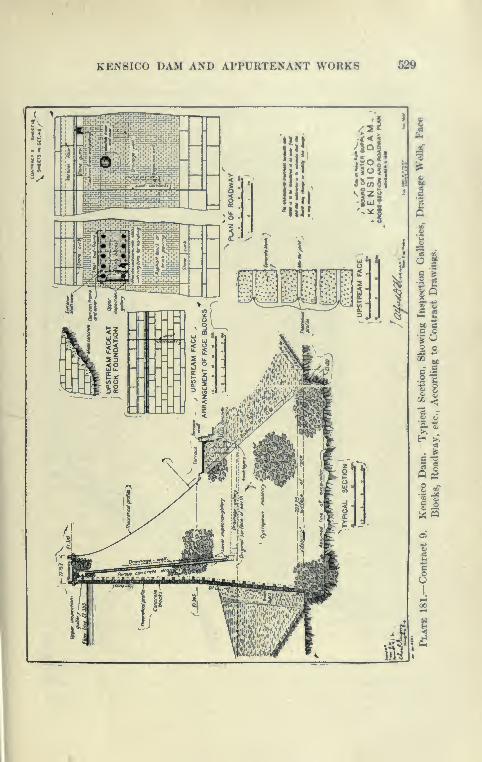
KEN8IC0 DAM AND APPURTENANT WORKS 529
*5• i -t
1
tawH — —
•ii1
>

530 CATSKILL WATER SUPPLY
KEN8IC0 DAM AND APPURTENANT WORKS 631
aqueduct against 75 miles al)ove, and therefore there is muchless likelihood of a break occurring l^etwwn the reservoirs thanabove Kensico.
Power Plant at Dam. For construction there is at the top of
the hill near the east end of the dam a compressor plant consisting
of two Laidlaw-Dunn-Gordon compressors of 1500 cubic feet capacity,
belted to two G. E. 300-H.P. induction motors, used to supply
air to points at or near the dam. This plant is capable, however,
of furnishing only a small portion of the power needed. A high-
tension line was built along the aqueduct from New York City so
that power can be secured from electric companies in New York.
It is planned to use electricity as a source of power as far as
practicable, only shovels and traction engines being operated bysteam.
Drawing Down of Lake Kensico. In September, 1911, water
was sent through the Rye pipe line from the newly completed Bronx-
Rye reservoir, and the normal draft from Lake Kensico soon drew
down the water so that a large part of the remainder could be drawTi
off through the blowout in the old dam, and the pool which re-
mained was pumped down, and quantities of fish gathered up in
seines were transferred alive to other city reservoirs. An earth
dike was built across the old lake bottom a short distance above
the foundation for the new dam. From the end of this dike a
ditch was dug to the old blowoff, a pump was installed, and the
site of the dam unwatered.
Flume for General Drainage and Waste Conduit. To perma-
nently carry during construction the drainage from above the dam a
wooden flume was constructed skirting the east bank,, so that where it
crosses the site of the new dam it will be entirely in rock at about the
final depth of excavation. This flume continues through the old
Kensico dam and into the new waste conduit. This conduit is built of
concrete and is of horse-shoe shape 7 feet 6 inches high by 8 feet
3 inches wide, and carries the waste from the new reservoir under-
neath the plaza below the dam to an outlet into the Bronx River.
The excavation for the flume was made by two steam shovels
which worked toward each other along the center line of the flume
and breached the old Kensico dam, which was widened to provide
room for a railroad.
General Plan of Construction. The general method of work at
the Kensico dam both in excavation for foundations and placing of
masonry is very different from that employed at the Ashokan dam.
The main tool at the Ashokan dam was the cableway which was

532 CATSKILL WATER SUPPLY
employed to remove material from the foundation of the damin the Esopus gorge and to transport all the masonry placed bythe derrick on and around the dam. At Kensico the railroad is
the main agent of transportation and the cableways merely auxil-
iaries. The excavation at Kensico was nearly all loaded into cars
by steam shovel and hauled over standard-gauge track directly
to the fills. The masonry will similarly be carried out on the damon trains operating on several hnes of tracks and placed by traveling
cranes operating on parallel tracks. Two cableways of 1860 feet
span will be used mainlj^ to raise the tracks on the dam, as will be
explained.
Method of Excavation. Some excavation on the side- hill por-
tion to the west was removed by orange-peel bucket and hand
loading into skips and placed into a fill immediately to the south,
but the bulk of the material was removed by standard-gauge 8-yard
cars, loaded by three 70-ton Marion steam shovels. The shovels
worked themselves down about 80 feet below the original surface of
stream bed to near the lowest point of rock, the loaded trains being
hauled up an incline by two hoists and then taken to large fill south
of the dam by dinkies. The shovels for a considerable depth were
excavating a very fine sand (97 per cent through a No. 50 sieve),
wet but not water-bearing. This sand could be but imperfectly
drained by sump and ditches.
Shovels Operating on Rafts in Soft Ground. It was necessary
in order to keep the shovel from becoming mired to use rafts of
three 14-inch timbers 24 feet long securely bolted together. These
were placed transversely close together in front of the shovel and
the shovel moved onto them, submerging the platform in less than
five minutes. This made such a steep grade for the advancing
shovel that it was helped by a locomotive crane, which also placed
and moved the heavy platform.
Rock Excavation. The rock when exposed was blasted and
removed by steam shovel; and also by traveling hoists which movedthe hand-loaded skips. A very interesting formation of limestone (a
few hundred feet wide), known as the " Inwood," was uncovered.
This bed, found also under the Croton dam, under the Harlem
River, and even as far south as Delancey Street at the lower end
of Manhattan Island, separates the old Fordham gneiss from the
younger Manhattan schist. The rock dips about 55 degrees to the
west and strikes about at right angles to the dam. The Manhattanschist contact is very sound, but that between the limestone andgneiss is much decayed, the gneiss breaking up into a rusty light-

KEN8ICO DAM AND APPURTENANT WORKS 533
^ -
Si
2 "^
61
o .
08 U
« 2o «fe a
i|
fS 3
534 CATSKILL WATER SUPPLY
clay powder and the limestone into a sugary-white sand. At this
writing the contact has not yet been thoroughly explored.
Electric Power and Drills. The work at Kensico dam is to
furnish the largest and most varied application of electric power
to construction work for the Catskill supply. An electric power
line was built over the aqueduct right-of-way clear to Yonkers
(about 4 miles) and current at 66,000 volts furnished by the
New York Edison Company. The current, of course, will be trans-
formed at the dam site and used to operate air compressors, hoists,
lights, drills, etc. The compressor plant which was formerly used at
the Peak tunnel. Contract 11, was put in operation and furnishes
power to many drills, but the bulk of the rock drilling is being done
by electric drills.
Temple-IngersoU Electric Air Drills. After investigation, the con-
tractor decided to install Temple electric air drills, both for work on
the dam foundation and at the quarry, the reason for installing these
drills being to save power, as it was estimated that they operate
for about one-half the power charge of the ordinary air drills. TheTemple-IngersoU drill is operated by a pulsator which is a sort of
compressor carried on a small wheeled carriage near the drill. Thepulsator contains one or two long cylinders in which a motor-driven
piston reciprocates. Each end of the cylinder connects with a
flexible hose about 15 feet long, which leads to the valve chamber
of a simplified air drill. The pulsator alternately furnishes air to
each side of the piston of drill and the same air is used over and
over again in a closed circuit.
The contractor has already put into use 35 F5 Temple electric
air drills and states that they drill hard gneiss a little faster than
the regular air-operated drills.
Militating against the undoubted advantages of the IngersoU-
Temple drill is its high unit cost per drill and the handicap (in
certain places) of the pulsator carriage power lines, etc. Its great
single advantage is that (where abundant electric power is available)
the amount of drilling done can be increased indefinitely and will not
strain the capacity of the compressor plant.
Temple Electric Air Traction or Deep Hole Drill. To drill deep
holes at the quarry, four large traction drills mounted on wagons
similarly to the familiar well or churn drill were installed. They,
in fact, drill holes of the same type as the well drills, up to 40 feet
in depth, tapering from 5| to 4 inches in diameter.
The base of the machine is a heavy steel wagon mounted on flat
wheels; forward is a heavy turntable carrying the drill, pulsator,
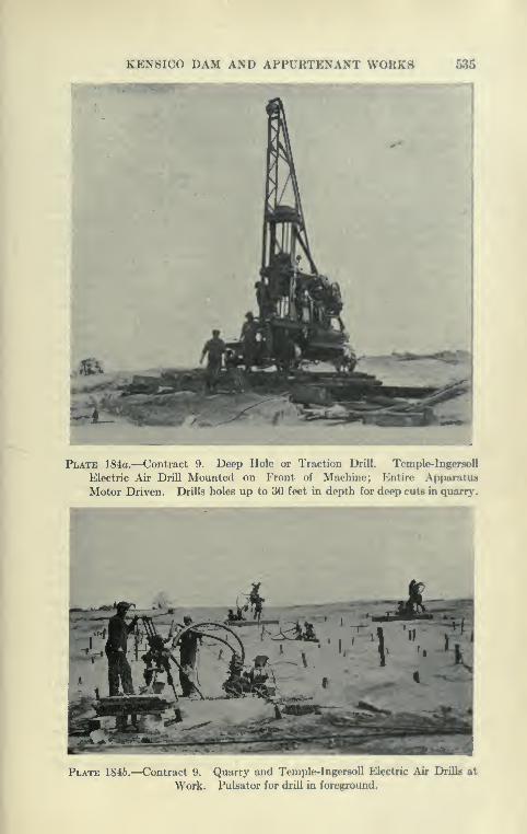
KEN8IC0 DAM AND APPURTENANT WORKS 636
Plate 184a.—Contract 9. Deep Hole or Traction Drill. Temple-IngersoU
Electric Air Drill Mounted on Front of Machine; Entire Apparatus
Motor Driven. Drills holes up to 30 feet in depth for deep cuta in quarrj'.
Plate 1846.—Contract 9. Quarry and Temple-Ingersoll Electric Air Drilla at
Work. Pulsator for drill in foreground.
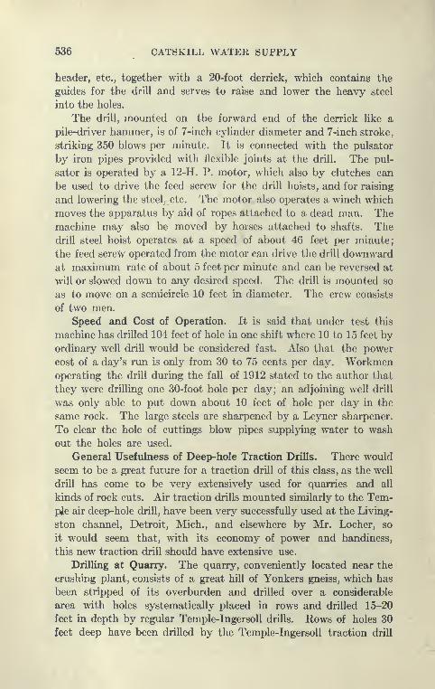
536 CATSKILL WATER SUPPLY
header, etc., together with a 20-foot derrick, which contains the
guides for the drill and serves to raise and lower the heavy steel
into the holes.
The drill, mounted on the forward end of the derrick like a
pile-driver hammer, is of 7-inch cylinder diameter and 7-inch stroke,
striking 350 blows per minute. It is connected with the pulsator
by iron pipes provided with flexible joints at the drill. The pul-
sator is operated by a 12-H. P. motor, which also by clutches can
be used to drive the feed screw for the drill hoists, and for raising
and lowering the steel, etc. The motor also operates a winch which
moves the apparatus by aid of ropes attached to a dead man. Themachine may also be moved by horses attached to shafts. Thedrill steel hoist operates at a speed of about 46 feet per minute;
the feed screw operated from the motor can drive the drill downwardat maximum rate of about 5 feet per minute and can be reversed at
will or slowed down to any desired speed. The drill is mounted so
as to move on a semicircle 10 feet in diameter. The crew consists
of two men.
Speed and Cost of Operation. It is said that under test this
machine has drilled 104 feet of hole in one shift where 10 to 15 feet byordinary well drill would be considered fast. Also that the power
cost of a day's run is only from 30 to 75 cents per day. Workmenoperating the drill during the fall of 1912 stated to the author that
they were drilling one 30-foot hole per day; an adjoining well drill
was only able to put down about 10 feet of hole per day in the
same rock. The large steels are sharpened by a Leyner sharpener.
To clear the hole of cuttings blow pipes supplying water to wash
out the holes are used.
General Usefulness of Deep-hole Traction Drills. There would
seem to be a great future for a traction drill of this class, as the well
drill has come to be very extensively used for quarries and all
kinds of rock cuts. Air traction drills mounted similarly to the Tem-pie air deep-hole drill, have been very successfully used at the Living-
ston channel, Detroit, Mich., and elsewhere by Mr. Locher, so
it would seem that, with its economy of power and handiness,
this new traction drill should have extensive use.
Drilling at Quarry. The quarry, conveniently located near the
crushing plant, consists of a great hill of Yonkers gneiss, which has
been stripped of its overburden and drilled over a considerable
area with holes systematically placed in rows and drilled 15-20
feet in depth by regular Temple-Ingersoll drills. Rows of holes 30
feet deep have been drilled by the Temple-Ingersoll traction drill

KENSICO DAM AND APPURTENANT WORKS 637
to give a start for the steam shovel. The holes are shot in
batteries of many hundred, loosening up many acres at a time
so as to be handled by 90-ton steam shovels. It is i)lann(xl
to obtain cyclopean, concrete and dimension stones from this
quarry.
The above quarry is outside of the city land and has lx»en con-
nected by a track with the dam wliich includes a steel highway bridge
and a tiin})or trestle across the spillway.
First Masonry to be Laid. Although no masonry in the maindam will be laitl before the spring of 1913, the plan of operation
is now pretty well worked out. The deep gorge, which has lK»on
dug out about 200 feet wide and 130 feet deep, will be filled with
masonry by derricks. This will take alx)ut 70,000 cubic yards,
and will give a practically level bottom, upon which will Ik; laid
six tracks parallel to the axis of the dam.
Tracks on Dam. The two interior tracks will be of wide gauge
for travelers ; on each side of them will be a pair of standard-gauge
running tracks. When the masonry reaches track elevation the
track will be elevated 20 feet, resting on concrete piers incorporated
in the masonry of the dam. The two cableways will be used to
set the concrete pier blocks for the tracks and to raise the track
in sections, but not for the direct handling of masonry as at Olive
bridge.
The concrete will be mixed in Hains mixers over the tracks, and
together with cyclopean stone, concrete blocks and dimension
stone will be hauled on flat cars to be placed by the derricks on
the traveler. Each traveler will be equipped with two electrically
operated derricks and there will be eight travelers working in
batteries of four, facing each other so as to build a section l)etween
adjacent transverse expansion joints. Two of the tracks will l>e
used to bring in blocks and will for that day serve a group of four
travelers setting blocks. The other two tracks and four travelers
will be employed in placing cyclopean masonry. The operations
will be reversed on the following day. It is expected that this
plant will be capable of placing 1500 cubic yards of masonry in one
shift of eight hours, which is beyond what was accomplished at the
Ashokan dam.
The Block Yard. The filled-in area below the dam was availed
of for a block yard. A plant containing overhead bins, fed by a
cantilever projecting over an adjacent material track, fills steel
forms directly from a rotary mixer. The plant spans several lines
of forms and moves on tracks.
538 CATSKILL WATER SUPPLY
Crushing Plant. The plant installed at the quarry is probably
the largest ever placed on contract work. Rock is drilled with
pneumatic machines capable of boring a 5-inch hole to the depth
of 30 feet. The blasted stone is handled by 90-ton steam shovels
with 4-yard dippers, loading directly into 8-cubic-yard cars hauled in
trains by 40-ton locomotives. The cars are hauled to the crushing
plant and dumped into a chute leading directly into the initial
crusher, which is a Blake jaw crusher, probably the largest of its
type yet made. This crusher is designed to take stones as large
as can be handled by the steam shovel, thus saving a great deal
of redrilling and mud-capping of stones too large for ordinary
crushers.
Largest Jaw Crushers to Date. The initial crusher has a clear
opening of 5'X7'. The rock is here reduced to a size of about
9 inches and finer, and then passes over a grizzly with 4j-inch
openings. The under size goes directly to the elevator, while
the over size is run through a second crusher of the same type
with an opening 3'X6', reducing it to 4 inches and finer, and
passes together with the under size from the grizzly to an ele-
vator which raises it to a 7'X30' screen. This screen removes
material below J inch, to be used for sand and stored separately,
while the coarse aggregate, between i and 2^ inches, is dis-
tributed by a 30-inch belt conveyor into a 10,000-ton storage bin.
The over size from the screen is recrushed by a 60"x30" roll.
The storage bins are constructed over tracks so arranged that
the standard-gauge cars can be readily loaded from many points.
The main bucket elevator has steel buckets 40 inches wide,
18 inches deep and 19 inches projection. The large crusher with
the jaw opening 5'X7' is designed to take a stone weighing 10
tons and reduce it within one minute. It is constructed of cast
steel with the exception of the two large flywheels, and has a total
weight of 450,000 pounds. The flywheels are 12 feet in diameter
and weigh 15 tons each. The swinging jaw is 13' X 7' wide and
weighs 74,000 pounds. The wearing plates are interchangeable
and of manganese steel.
Crusher Rolls. The 60"X30" heavy-duty roll is said to be
one of the largest ever built and has a designed capacity of 300
cubic yards per hour, crushing from 4 inches down to 2 inches.
Rolls are about 5 feet in diameter with 30-inch face, and the
shafts are 16 inches in diameter, and the frame alone weighs 30
tons. The large crusher is driven by a 300-H.P. induction motor,
the smaller crusher by a 150-H.P. motor, and the crushing roll by

KEN8IC0 DAM AND APPURTENANT, WORKS 639
a 100-H.P. motor, the elevator and screen by a 50-H.P. motor.
The two belt convej'ors are operated by 5- and 15-H.P. motors.*
Comparative Size of Kensico Crushers. The only cnwher of
larger size is that installed at Tomkins Cove in 1910. This i« anEdison roll capable of taking stones lO'XlO' up to a weight of 20
tons, and has a rated capacity of 3000 tons per hour, although the
entire capacity of the plant is less. McCuUy and Gatc»s gyratory
crushers have been built to take stone of 10 tons, 42"X9G" and48" X 120" respectively, while the Blake jaw crusher descril>ed
will take stones of 10 tons up to 60"X84" and crush 700 tonn per
hour, about the capacity of the gyratory crushers mentioned.
Temporary Dikes. An interesting type of timber-core wall dike
was developed on Contract 9 for'the temporary dikes. Instead of
vertical 4-inch groove-and-spline sheeting supported by horizontal
wales, the contractor used triple-ply sheeting laid horizontally with
vertical wales. Each ply is made of l^-inch boards, the two outside
layers dressed on one side and the middle layer on both sides. Theboards are so placed as to break joints 3 feet horizontally and IJ
inches vertically, forming a tongue-and-groove effect. The wales
are spaced 7 feet apart and are bolted to the sheeting every 2 feet.
The advantage of this construction is that the core wall can be
carried up as the embankment grows, and is always accessible to
a man standing on the ground. This type of core wall is both
easier to construct and more satisfactory than one built with
vertical boards or planking.
The new Rye dike with timber-core wall has a top ^vidth of 20
feet with a slope of 1 on 2^ to the water side and 1 on 2 on the
other side, constructed in 6-inchflayers, with riprap on both slopes.
Labor Camp, Welfare Work. As the work is to take ten years
the camps are substantially built with many conveniences of a city.
In addition to physical comfort other needs have been attended to.
An immigrant school was established by the North American Civic
League. This house, although of large size, was soon outgrown,
and an assembly room with a stage and dressing rooms was added,
and the old schoolrooms turned into club and reading rooms. There
are kindergarten classes every day, and practically every child in
camp of suitable age attends. In the afternoon there are sewing
and housekeeping classes for the women. In the evening there
are two-hour sessions for the men, who are taught to read and write
English and also such subjects as will fit them for citizenship. These
* The plant is described in detail in Engineering News, Feb. 2, 1912.
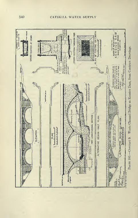
540 CATSKILL WATER SUPPLY

KEN8IC0 DAM AND APPURTENANT WORKS 541
night classes are in charge of teachers who understand the various
languages and dialects and are very well attended. The Russians
in camp are particularly quick in learning to read and write English.
At the assembly room dances are given, also moving picture shows
and musical selections rendered on the phonograph. There is also
a playground for the children. This work has done a great deal
to improve the general tone of the camp and the relationship of the
men toward each other and toward the contractor.
CHAPTER XVII
WHITE PLAINS DIVISION
Contract 52
Location and Work Included in Contract 52. Contract 52
is situated in Westchester County near Elmsford, and lies
conveniently between the Harlem and Putnam divisions of the
New York Central Railroad and in general parallel to them.
It comprises several stretches of cut-and-cover aqueduct, aggre-
gating 2.8 miles, and three tunnels—Eastview tunnel, 5400 feet
long, driven from two portals, and a central construction shaft
2040 feet north of the south portal; Elmsford tunnel, 2375 feet long;
and Elmsford tunnel south, 950 feet long. Between these stretches
is Elmsford steel pipe siphon, a portion of Contract 68. At the
south portal of Eastview tunnel a gate chamber is to be built to
provide connection with a proposed filtration plant to be built
under another contract.
Contract Prices. This contract, aggregating $2,852,000, was
let to the Pittsburgh Contracting Co., January, 1910. To give some
idea of the prices obtained, the following is given:
Open-Cut excavation $0. 55 per cu.yd.
Refill and embankment . 30 "Concrete masonry for cut-and-cover aqueduct. 5 . 25 "
Rock excavation in tunnel 5.50 "Timbering in tunnel 50.00 per M ft. B.M.Concrete in tunnel 6 . 00 per cu. yd.
Portland cement 1 . 55 per bbl.
Additional price for compressed air work in tunnel, excavation
$1, timbering $2 per M feet B.M.; concrete $1 per yard. Estimated
cost of cut-and-cover aqueduct is $68 per foot; of grade tunnel $130
per foot.
Sanitation. As the aqueduct line crosses through several small
watersheds used by neighboring towns, also part of the Bronx
watershed which supplies some water to the City of New York, the
sanitary requirements were very strict, so that the main work at
542

WHITE PLAINS DIVISION 543
the beginning was the establishing of camps. Three camps wereestablished, known as Eastview, Bonner and Elmsford, and of all
these. Eastview camp is typical.
This camp was located on land taken for the E^tview filters.
It consisted of an office, eight barracks accommodating 184 men,
two hospitals, a washhouse and outdoor kitchen. These build-
ings were lighted by electricity and heated by stoves. The campwas provided with a water supjily from a spring. A sewer system
conveyed wash water from the camj) into a settling tank which in turn
discharged through a Wagner 4-in('h automatic siphon onto a small
filter bed, effluent from tlie filter bed draining into a brook. All
organic matter from the camp was burned in incinerators.
General Plant. A standard-gauge track was laid from a point
on the Putnam division of the Central Railroad north of Elmsford
to the central crusher and mixing plant. This road was li miles
long and passes through a sand pit, and all supplies and sand were
hauled over it. From the crusher, a single track on downhill side
of aqueduct was extended northward 3700 feet to the B^tviewtunnel and southward 5000 feet to the Elmsford siphon. The road
was equipped with standard-gauge locomotives and side-dump cars.
Four Interstate locomotive cranes were installed. These cranes are
self propelling over the standard-gauge track and were used for
excavation, placing concrete and back filling. When excavating
they were equipped with drag or scraper buckets; also for some
classes of digging with Ha^'ward orange-peel buckets.
Compressor Plant. For the tunnels a compressed-air plant
was installed, that at Eastview consisting of three electrically
operated Ingersoll-Rand Air Compressors, Imperial Tji^e X, two
of capacity 1056 cubic feet; the other, 528 cubic feet of free air
per minute. Six- and 5-inch lines supplied air to the portals and
shaft. This pipe line had a length of 8400 feet. The current was
supplied by the Westchester Lighting Company, at a voltage of
13,000, and was converted by transformers to 2200 volts, which was
used in G. E. Co. three-phase induction motors to operate the
compressors.
Central Crushing and Mixing Plants. A conspicuous feature
of this contract was the large central crushing and mixing plant
used for the cut-and-cover work, of a capacity of 36 cubic yards
of concrete per hour. This plant was located at the intersection
of the branch line to the Central Railroad and the contractor's line
paralleling the aqueduct. Sand was brought to it in 6-yard side-
dump cars loaded at the sand pit by a derrick operating 1-yard
544 CATSKILL WATER SUPPLY
Hayward clam-shell buckets. At the central mixer the sand wasdumped through a chute to a large sand and stone bucket elevator
which raised it to a high sand bin of 150 cubic yards capacity. Stone
was brought to the plant from a quarry about 700 feet away in side-
dump 1^-cubic-yard Koppel cars hauled up an incline to the level
of the crusher by an electric hoist. The quarry was excavated with
2 to 4 IngersoU-Rand, and 1 Sullivan drill and was blasted with
60 per cent forcite, the muck being placed in steel skips and lifted
by a derrick onto the cars. A crusher (No. 5 Kennedy gyratory)
discharged into the 80-foot bucket elevator above described. Theelevator, in turn, discharged into a rotary screen at the top of the
plant where the material fell into an appropriate bin of a capacity
of 250 yards. Cement was delivered in car-load lots and unloaded
into the cement shed alongside mixer, the capacity of the shed
being 2000 barrels. From here it was elevated as needed by a cement
bag elevator to the level of the mixing platform. Below the bin
were measuring hoppers for sand and stone which discharged into
a 1-yard Ransome mixer which in turn discharged into bottom-
dumping Steubner buckets which were placed by a derrick onto
flat cars and hauled to the site of the work, where they were unloaded
by locomotive cranes. A mixing plant similar to above was also
installed near the south end of the contract and a connected bya track with Putnam Railroad. Features making for considerable
saving in transportation were the convenient connections to the
main line of the Central Railroad, from which all materials were
obtained, and the use of standard-gauge equipment over the whole
work.
Excavation by Locomotive Crane Operating a Drag Scraper.
For the earth excavation and open cut, an Interstate locomotive
crane operating a 1^-cubic yard scraper was used. This machine
moved in advance of the cut on 30-foot lengths of rail, which were
moved ahead as fast as the machine advanced. As a rule, the
scraper track was graded by hand before moving up the machine.
The drag scraper deposited top soil on the uphill side, so that it
could afterward be used to cover the embankment. The bulk of the
excavation was spoiled in piles on the downhill side, being partly
used for grading the service track. This grading was usually
done by drag scrapers well in advance of other work. Thematerial was rather hard to excavate by a drag scraper, as
numerous boulders impeded its progress and prevented it shaping the
cut to any well-defined lines, although as a whole the excavation
was done nearly to the required slope. It was not allowed to work
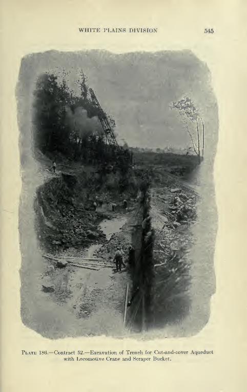
WHITE PLAINS DIVISION 546
Plate 186.—Contract 52.—Excavation of Trench for Cut-and-cover Aqueduct
with Locomotive Crane and Scraper Bucket.

546 CATSKILL WATER SUPPLY
closer than within ^ foot of subgrade, hence considerable hand trim-
ming had to be done on sides and bottom just before concreting.
Hand trimming of trench was economically done by piling the
material in the trench and removing with locomotive crane
and clam-shell bucket.
The above method has the great advantage of minimizing the
handling of material, as it is deposited directly by the crane with-
out the use of cars. Later on, the excavated material was recov-
ered mostly by an orange-peel bucket, and by a clam-shell bucket
operated by locomotive crane and then dumped over the aqueduct
to form the completed embankment.
It is estimated that eight men worked on the excavation,
averaging about 135 cubic yards per shift of eight hours.
Comparison of Drag Scraper with Steam Shovel. Excavation
by drag scraper, as conducted on the contract, has the advantage
that only one track is required for all operations, the machine
operating on a temporary short length of track ahead of the
trench, and piling material far enough to one side not to interfere
with the single track alongside the trench; and subsequently,
after concrete is placed, putting the excavation back, using orange-
peel bucket. On Contracts 11 and 16 the steam shovels loaded
directly into the cars, which required the use of an additional
track laid on the uphill side and cutting in on the arch of the contract
where a center track was used. This refill track was not con-
tinuous, however, and was taken up from time to time. In some
cases on Contract 11 the shovels worked at night, filling cars operat-
ing on main concrete tracks. The writer is inclined to the belief
that the expense of extra track laying of the steam-shovel method
over drag-scraper method is more than repaid by the greater
speed of both excavation and refill. A further comparison is
made under Contract 53.
Excavation of Rock. In rock cuts four Ingersoll-Rand and one
Sullivan drill, air driven, were used, the power being supplied by
a pipe line from the main compressor plant. Blasted rock was
spoiled at the sides of the cut by a 40-ton Interstate locomotive
crane with 50-foot boom, operating an orange-peel bucket, the
crane running on standard-gauge track alongside the trench.
The rock was spoiled down hill from the track, as in the case of
earth excavation, the intention being later to dredge it with orange-
peel bucket to form main cover embankment.
Concreting of Cut-and-Cover. After the main portion of
the trench was excavated by a drag scraper, as described, it was
WHITE PLAINS DIVISION 547
trimmed to sub-grade by hand, after which 15-foot sections of
invert 16 inches thick were cast in alternate blocks, the concrete
being hauled by an 18-ton dinky on a flat car holding eight buckets
delivered from the central mixing plant and placed by a locomotive
crane, which lifts the bottom-dumping IJ-cubic yard Steubner
buckets from the flat cars.
Construction of Invert. During 1910 the joints between the
inverts were placed over key blocks 8"X8" in section, as shownin the contract drawings. During the winter of 1910-11 tests
on completed aqueducts showed that these joints were liable to
leak. During 1911 the invert blocks were cast with squared
ends in which were inserted steel plates 6 inches wide and of a
length to join similar steel plate joints at the ends of arch blocks.
These plates act as cut-offs to prevent water from escaping through
these joints after they have opened through temperature changes.
These plates were painted with asphalt paint. It was found
that this not only gave a better joint, but one which saved con-
siderable time in concreting invert over the old key-block joint.
After some length of invert was concreted, steel Blaw forms of
the usual pattern were set up and 30- to 75-foot sections of arch
cast complete in one operation, the concrete for this being furnished
and placed as described for invert. Concreting was carried out
simultaneously with the excavation, which was generally about
200 feet in advance of concrete invert and 500 feet in advance of the
arch. On account of the greater speed of the concreting, usually
accomplished in from one to two shifts, the excavation was often
continued through two and often three shifts.
Eastview Timnel. The Eastview tunnel is a grade tunnel of
the usual design except that special provisions were made in the
contract to pass about 1000 feet of a wet, sandy, boulder clay,
filling the valley of a preglacial gorge. This depression might have
been crossed by a siphon tunnel, as suggested by an alternate
profile on contract drawing, but this seemed hardly worth while,
as the stretch is so short. Provision was made in the contract
for the use of compressed air, to pay for which special items were
included.
Excavation in Bad Groimd. The tunnel between portals is
5456 feet long, with a construction shaft 90 feet deep, 2000 feet
from the south portal. In this shaft two balanced cages operated
by a Lambert hoist were installed. The heading from the north
portal was driven by the usual top heading and bench method
for about 1900 feet, when bad lock and a great deal of water was
548 CATSKILL WATER SUPPLY
encountered, causing a suspension of the work here. The tunnel
from the south portal presented no unusual features. Northward
from the shaft the tunnel was driven without special difficulty
for about 350 feet, when a material containing hard clay, sand,
boulders and wet seams was encountered. The timbering was begun
with 12''XV2" timbering, five segments to the arch, placed 3 feet
on centers. Wall plates in 20-foot lengths were placed in side
drifts in advance of the heading proper. It was found that this
timbering was giving way and intermediate ribs were placed with
posts to support the cracked timbers. This, however, was not
found sufficient, and the timbering was then placed 18 inches on
centers and then skin to skin, but even this required the support
of numerous cross-braces, the crown of the arch settling about
6 inches with some settlement of the ground overhead, indicating
that the timbering carried the whole weight of the earth over the
tunnel. The progress by this method was very slow, being only
about 9 feet per week.
Use of Compressed Air. The contractor then asked for permis-
sion to use compressed air, which was granted November, 1910.
A concrete bulkhead was built 260 feet north of the shaft and in
it were placed a horizontal muck and man lock, and a 30-foot
rail and timber lock. The excavation was continued, using air
pressures from 9 to 25 pounds—average 20 pounds per square
inch. The method of excavation and timbering was practically the
same under the compressed air as in the open, but the progress was
very much better, increasing from 9 to 25 feet per week.
The method of timbering was as follows
:
Timbering in Compressed Air. Side drifts were driven ahead
and in them 15-foot wall plates were placed. These drifts generally
stood up, but were supported where necessary. In the next step
the core was removed between the wall plates, to place the 5-foot
segmental timbers, the tunnel being unsupported about 4 feet
ahead of the timbers. The third step was the excavation of the
bench and the setting of plumb posts between the wall plates. The
trench for the plumb posts was excavated so that they could be set
4 feet in advance of the general bench excavation. The fourth
step consisted of the placing of the invert timbering and interior
bracing of the posts. When the solid rock dropped below grade sandy
clay was encountered and solid invert timbering was placed, consist-
ing of two 12"X12'' sticks sawed so as to give a drop of 9 inches
toward the center to provide arch action. In addition there were two
horizontal rows of 12"X12'' spreaders and numerous vertical posts.
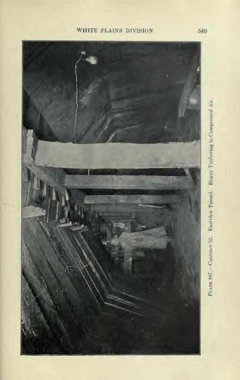
WHITE PLAINS DIVISION M9
u

550 CATSKILL WATER SUPPLY
This type of construction was carried about 300 feet through the
softest of the material, until a mass of disintegrated boulders was
met and the bottom timbering discontinued. The timbering adopted
Plate
6 X 12 ioot block
-Eastview Tunnel Timbering in Heavy Ground and Concrete
Lining. Used mostly for tunnel in compressed air,
is shown on Plate 188, and also on Plate 187. The arch timbers
were set 12 inches high to allow for settlement, but it was found
that the settlement was usually about 5 inches above the wall plates,
WHITE PLAINS DIVISION 661
this increasing very little with the placing of the plumb posts andinverts. An accidental demonstration of the pressure on the
timbers of this tunnel was made at a time when the interior bracing
lagged for about 100 feet l)ehind the bench, due to the delay in
timber delivery. At this time the comprt»ssor broke down for aperiod of three hours, the air pressure dropping to only 7 pounds.
The 100-foot stretch became deformed, the wall plates forced out
and twisted, and the segments settling so that the key block
encroached about 6 inches on the concrete. As soon as this wasdiscovered, interior bracing was placed and no further settlement
occurred. In addition, this stretch was grouted with the use of a
Caniff machine. A higli-pressure line was used to force the grout
from this machine, the mixture being 1 of cement and 2 of sand.
Holes were bored through the timbers in about 15-foot intervals
to take the grout pipes. It was found difficult to prevent leakage
of grout between the timbers, but examination showed that the
space back of the timbers was well filled with grout. Later a
Cockburn-Barrow machine was used to place grout. When the
arch concrete construction reached the depressed key blocks, the
roof was chopped and the side walls moved out, so as to give an
equivalent waterway and at the same time secure the required
thickness of arch concrete. A large pipe was laid through the con-
crete, connecting the standard portions of the tunnel to prevent
entrained air from reducing the waterway when under pressure.
Previous to the breaking through of the compressed-air heading
to the tunnel excavated from the north portal an air lock wa^ placed
in a concrete bulkhead built in the completed lining of the open-
air tunnel. The forms used for this part of the tunnel were thus
locked in and used to line the stretch excavated in compressed air.
It was not deemed advisable to remove the compressed air until after
the concrete lining was placed.
Advantages of Compressed Air. The use of compressed air
in this tunnel is considered to be of benefit both to the city and the
contractor, and was the means of shortening what would otherwise
have been a very long and tedious job. As is usually the case, the
wet running ground held back by compressed air was dried out
so that it could be readily handled. Considerable air escaped
through the fissures in the rock, this being observed when the com-
pressed-air heading was within 40 or 50 feet of the north head-
ing. At one of the shafts of the new Croton Aqueduct not very
far from this point soft ground was encountered, and several years
were taken to drive a few hundred feet, the work, however, being

552 CATSKILL WATER SUPPLY
BoO

WHITE PLAINS DIVISION 653
intermittent. Heavy timbering of the usual croiMi-har and poling-
board type was used hero, the stretch finally iK'ing parsed only
after a great deal of settlement had occurred in the ground alxjvc.
This place could probably have been readily excavat<?d by the use
of compressed air, but at that time compressed air for this purpose
was comparatively little used. Nevertheless, there still remains
on the part of many engineers and contractors a timidity in the
use of compressed air, and much effort is wasted in driving through
soft ground which could readily be saved by the use of air at
moderate pressures.
Concreting Grade Timnel. At the north end of the Eastview
tunnel 93 feet of the usual type of Blaw tunnel forms were set up.
These forms were mounted on carriages so that they could be movedin three sections. It is usually found that the concreting of tunnel
lining progresses rather rapidly at first, when the side walls are being
placed, but slows up materially when the keying-up of the arch
begins. To save this delay and to keep the mixer working at a
fairly uniform speed, Mr. Brink originated a method of concreting
the whole 93-foot sections at one operation. A wooden bulkhead
was built from the forms to the rock at each end and in the middle
of the 93-foot section. The first concrete from the central plant,
in side-dumping cars, was raised on a 90-foot I-beam incline to the
platform 10 feet above the invert and placed in the side-wall
section furthest from the portal. The concrete was carried up level
on both sides to the point where keying up becomes necessary, the
key concrete being started at the end and worked toward the center
bulkhead. The surplus concrete was placed in the second section
of the side wall, lower planks of the central bulkhead being
removed to allow this concrete to joint up with the first side wall
placed, which has had about twelve hours to set.
Ke3ring up Arch. The central wooden bulkhead was taken down
as fast as the concrete rose in the second side-wall section. Bythe time the inner half section was ready for keying the outer half
section key was almost finished. The inner half key was filled, work-
ing from both ends toward its center, where four molded blocks were
placed on top of steel form, giving an opening about 20 inches
square, and the key concrete carried against these molded blocks,
and the closure made by forcing concrete in this 20-inch opening
through a special box operated by a piston. This metal box,
fastened to the last key plate placed, was filled with concrete, and a
piston operating in it was forced upward by a feed screw taken from
an air drill.
554 CATSKILL WATER SUPPLY
Method of Moving Forms. Concrete cars, two cars at a time,
were hauled from the mixer to the forms by an electric locomotive
and up the incline to the platform by an electric hoist. The incline
was a light steel structure resting on wooden bents. Before the entire
key concreting of a 93-foot section was completed, 30 feet of the
outer forms were unbolted ready to be moved ahead. The last
of the forms are loosened up about fifteen hours after finishing
the key closure. In the interval between finishing concrete and
moving forms forward the regular gangs work ahead, cleaning
and getting a section of the tunnel ready for concreting. It
usually took five shifts of eight hours to concrete a 93-foot section,
and an interval of another five shifts elapsed before the concreting
of another section starts. Fifty men usually worked on the day
shifts and 25 men on each of the night shifts.
Comparison of Eastview and Usual Method. The progress
made by this method is not greater than by the method usually
used, such as described under the Bonticou tunnel, but it has
the advantage that one setting of the incUne is necessary for
93 feet, and considerable time is probably saved by cleaning at
only one point, and it is unnecessary to pull the concrete cars
through the forms. There should be some economy in this
method, as the concrete plant is kept at pretty nearly its full
capacity, instead of at times very slowly, as when keying up is
alone in progress under the ordinary method. The general
principle is the same as that used in the siphon tunnels whenside walls and arch are concreted at the same time by the use
of trailing forms, as described under Rondout and Wallkill
siphons. Comparison with the method of concreting used at
Eastview tunnel and Peak tunnel, shows that the latter was
probably more economical as greater progress (40 feet per day)
was made with a smaller daily force, the bulk of the work
being done in practically one shift, whereas three shifts were carried
at Eastview. With the ordinary methods of working three shifts,
as at Bull Hill tunnel, 340 feet has been made in one week as
against about 210 feet at Eastview.
Concreting in Compressed Air. The concrete was mixed at the
south portal plant, and hauled to the south bulkhead by electric
trolley in cars small enough to go through the air lock. Within
the compressed-air section, the cars were pushed by hand to the
forms, where'they were raised to the platform on an elevator built
onto and moved with the forms. Two sets of forms, each 30 feet
long, were used, one working from the south end and one from the
WHITE PLAINS DIVISION 5S5
north towards each other. The elevator in each case was on the
forward end of the forms. The elevator was necessary on account
of the large amount of internal bracing, which did not permit the
use of the ordinary incline. Eight hundred feet of tunnel wasconcreted by this method between March 11, and May 24, 1912.
The track carrying the concrete cars wa.s laid on stringers blocked
up so that the invert could be built in alternate sections under it.
After the first sections had set, the blocking was shifted to them,
and the remaining sections built. This invert concreting was kept
as close as possible to the work on the arch. The compressed air
was removed on June 4, 1912, and it was found that tlio tnnnfl
showed very few leaks.
Rock Drills used in Eastview Timnel. In the earthy portion
of the Eastview tunnel the material had to be blasted, Ix'ing too
hard to be either picked or shoveled. This material was usually
drilled by hand drills, churned in and out with water, it l)eing
found that the electric drills stuck in the holes. In rock, compressed-
air drills were used, fifteen Ingersoll-Rand and two Sullivan.
Four drills were mounted on two vertical columns, drilling the
heading in the usual way. The bench was drilled by two machines
mounted on tripods. The average progress made in the Eastview
tunnel in rock, outside of compressed air, was about 200 feet per
month. Considering the unususal difficulties to be overcome the
progress made is very creditable to the contractor.
Electric Drills, Fort Wa3me. This contract is distinguished
from others by the use made of electric drills, of which three types
were used, the Fort Wayne, the Dulles-Baldwin, and the Pneum-
electric. The Fort Wayne drill operates a twist bit with chisel
edge like an auger striking repeated blows as the bit is rotated.
The motor is belt-connected to a device which drives a numlxT of
hammers by centrifugal force against the top of the drill steel.
This drill worked fairly well in the soft material penetrate in
the Eastview tunnel, under compressed air, but it was not success-
ful for harder material. The drill was tried later by the same
company on Contract 65 at the bottom of shafts in Manhattan
schist, but it could make but slow progress in this moderately
hard rock. It has been elsewhere used to advantage in drilling
coal and soft shales.
Pneumelectric Drill. The Pneumelectric drill is operated by
an electric motor compressing the air by means of a piston op<»rat-
ing in the same cylinder as the hammer, which strikes a dolly which
in turn strikes the hollow steel through which water is forced through

556 CATSKILL WATER SUPPLY
a connection with the dolly. This machine was at a disadvantage
at Elmsford owing to the lack of water under pressure.
Dulles-Baldwin Drill. The Dulles-Baldwin drill was the mostsuccessful under the conditions encountered on Contract 52.
This seems to be the simplest type of electric drill and is the nearest
approach to the ordinary reciprocating piston drill, using the samesteel and bit attached to a piston connected directly to the chuck
of the drill. An electric motor attached to the top of the drill
operates a reciprocating piston which by means of suitable valves
compresses air alternately on each side of the piston attached
to the drill steel. Man}^ minor improvements were made in this
drill during the progress of this work by the manufacturer, but
it was deemed expedient to carry a duplicate equipment of these
drills to avoid delays.
Dulles-Baldwin in Elmsford Tunnel. The Dulles-Baldwin drill
has been used in the Elmsford tunnel, where it was not given a
good trial, owing to a wide fault with soft rock extending from
500 to 600 feet and necessitating timbering close to heading. Upto March, 1912, the average weekly progress in the tunnel was only
23 feet for the heading, maximum 53 ; for the bench 36 feet, max-imum 70 feet. In driving the Elmsford tunnel after March 12,
the heading was driven wide to accommodate timbering, but in
excavating the bench below the wall plates considerable rock remained
within the C line, and owing to the absence of an electric Jap drill
there was no means for taking this out except by hand drilling or
bull point, or by installing a traveling compressor to operate hammerdrills. The Pittsburgh Contracting Company also used electric
drills on Contract 65 of the City Aqueduct, and a more extended
discussion of them is there given.
Contract 53
Contract Prices. Contract 53 was awarded to the Elmore &Hamilton Contracting Company, in December, 1909. The total
contract price was $1,715,160.
Following the death of Mr. Elmore in June, 1911, this contract,
as well as Contract 15, on the Wallkill Division, went into the
hands of the receivers, Messrs. Sleden and Hand.Some of the bid prices were as follows:
Open-cut excavation, cubic yards $0.45 to 1 .00Refilling and embanking, cubic yards 0.25 to 0.50Concrete masonry in open cut, cubic yards 5 . 25Portland cement, barrels 1 . 60
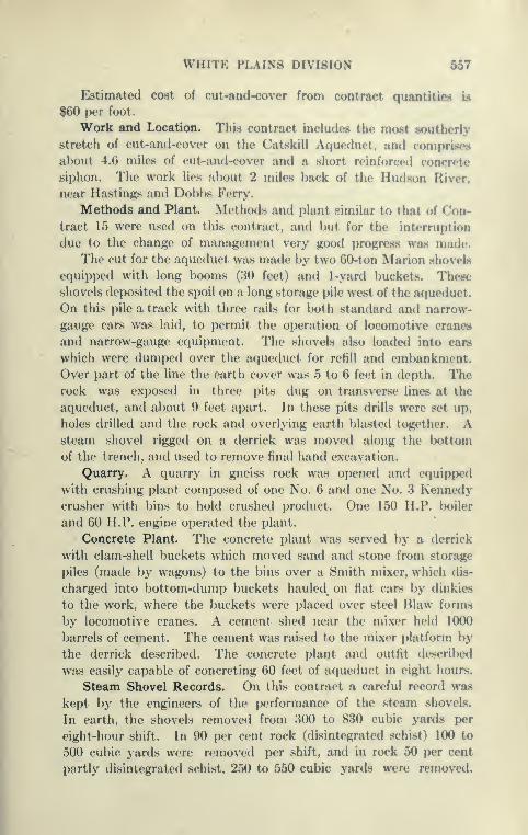
WHITE PLAINS DIVISION fi67
Estimated cost of out-and-cover from contract quantities is
$60 per foot
.
Work and Location. This contract includes the most southerly
stretch of cut-and-cover on the Catskill Aqueduct, and comprises
about 4.6 miles of cut-and-cover and a short reinforced concrete
siphon. The work lies jilnjut 2 miles back of the Hud.son Hiver.
near Hastings and Dobbs Ferry.
Methods and Plant. Methods and plant .similar to that ot ( on-
tract 15 were used on this contract, and but for the interruption
due to the change of management very good progress was made.
The cut for the aqueduct was made by two 00-ton Marion shovels
equipped with long booms (30 feet) and 1-yard buckets. These
shovels deposited the spoil on a long storage pile west of the aqueduct.
On this pile a track with three rails for both standard and narrow-
gauge cars was laid, to permit the operation of locomotive cranes
and narrow-gauge equipment. The shovels also loaded into cars
which were dumped over the aqueduct for refill and embankment.
Over part of the line the earth cover was 5 to 6 feet in depth. Therock was exposed in three pits dug on transverse hues at the
aqueduct, and about 9 feet apart. In these pits drills were set up,
holes drilled and the rock and overlying earth blasted together. Asteam shovel rigged on a derrick was moved along the bottom
of the trench, and used to remove final hand excavation.
Quarry. A quarry in gneiss rock was opened and equipped
with crushing plant composed of one No. 6 and one No. 3 Kennedycrusher with bins to hold crushed product. One 150 H.P. boiler
and 60 H.P. engine operated the plant.
Concrete Plant. The concrete plant was served by a derrick
with clam-shell buckets which moved sand and stone from stonige
piles (made by wagons) to the bins over a Smith mixer, which dis-
charged into bottom-dump buckets hauled on flat cars by dinkies
to the work, where the buckets were placed over steel Blaw forms
by locomotive cranes. A cement shed near the mixer held 1000
barrels of cement. The cement was raised to the mixer platform by
the derrick described. The concrete plant and outfit described
was easily capable of concreting 60 feet of aqueduct in eight hours.
Steam Shovel Records. On this contract a careful record was
kept l)y the engineers of the performance of the steam shovels.
In earth, the shovels removed from 300 to 830 cubic yards per
eight-hour shift. In 90 per cent rock (disintegrated schist) 100 to
500 cubic yards were removed per shift, and in rock 50 yyer cent
partly disintegrated schist, 250 to 550 cubic yards were removed.

558 CATSKILL WATER SUPPLY
One shovel in all materials averaged 354 cubic yards per eight-hour
shift, the other 366 cubic yards in the same time. Although these
records are much below the usual performance of a 60-ton shovel
under favorable conditions, when account is taken of the narrow
trenches and variable materials in which the shovels worked, the
work was very good.
Advantages of Steam Shovels as Compared to Other Excavating
Tools. Off-hand, it would appear that to use a machine under
conditions which compel it to work far below its average speed,
would not pay. Nevertheless, experience shows that while the steam
shovel cannot, in aqueduct trenches of the size and shape required
for the Catskill cut-and-cover aqueduct, do its best work, it still
is capable of doing much more and better work than any other exca-
vating tool used, as shown by careful records kept of the perform-
ance of the locomotive crane with a 75-foot boom and drag buckets,
operated on the neighboring Contract 52. The performance of
this machine was only 136 cubic yards per shift of eight hours exca-
vating in earth, ranging per shift from 70 to 240 yards. This is only
about one-third the performance of the steam shovel. The steam
shovel is a perfected tool of wonderful reliability, it being very
seldom necessary to stop it for repairs or because of breaking down.
As shown by the records, the locomotive crane during the season
of 1910 was laid up for repairs for considerable periods. The shovel
has the great advantage of being able, when operating in deep cuts,
to dig at a high rate and get out of the way of concrete or other
operations. For the same reason, it can take advantage of favorable
weather conditions, and so does not suffer so much from bad weather.
The steam shovel can also dig much closer to line and grade than
any other machine excavator, and with its powerful arm is capable
of removing boulders, stumps, and other obstructions which impede
its path.
CHAPTER XVTII
YONKERS PRESSURE TUNNEL AND HILL VIEW RESERVOIR
Contract 54
Work and Prices. This contract, located just north of the Hill-
view reservoir, comprises all of the Yonkers pressure tunnel except
1200 feet adjacent to the uptake shaft included in Contract 30.
It was let early in 1910 to Geo. W. Jackson, Inc., of Chicago. It
is 11,149 feet (2.1 miles) long, finished diameter 16 feet 7 inchc»8.
It is constructed from three shafts and a triple portal at the north-
ern end. The shafts are 154, 106 and 116 feet in depth. The total
contract price is $1,479,425, which is moderate for a tunnel of
this size and length. Some of the prices are as follows:
Construction shaft in rock, per foot $210 00Refilling construction shaft, per foot 40.00Excavation of tunnels, cubic yards 4 . 75Concrete masonry in shaft and tunnels, cubic yards . . 4 . 80Cement, barrels 1 . 55
Based on contract quantities the estimated cost of pressure
tunnel, including valves and chamber, is $126 per foot, of con-
struction shaft in rock, $253 per foot.
This work, after being in operation one year, was taken over
by a creditors' committee, although Mr. Jackson continued in
charge of the work for the committee.
Power Plant. A central power plant was installed electrically
operated by a 6600-volt A.C. current, transformed down to 440
volts to operate the motors for the five air compressors, as follows:
1 Ingersoll-Sergeant 800 cu.ft. per minute
1 Ingersoll-Rand 1200
3 2-stage Ingersoll-Rand 2000
All these compressors were belt-driven and housed in one wooden
building. In an adjacent concrete building were housed the
switchboards and transformers. From this plant, situated at
559

560 CAT8KILL WATER SUPPLY
Shaft 2, 8- and 6-inch pipe Unes ran to the other shafts and to the
portals, 4-inch Unes carrying the air into the portals.
Sinking of Shafts. All three shafts were sunk in dry rock, Shafts
2 and 3 requiring a little pumping, maximum amount pumped per
shaft being 70 gallons per minute. To reduce surface leakage
and provide found'ation for head frames the upper portions of
Shafts 3 and 2 were concreted down to 35 feet. At Shaft 1 the head
frame was founded directly on the rock surface at the top of the
shaft, this shaft being extremely dry, yielding practically no water.
Stiff-legged derricks were used to excavate the shafts, which were
excavated to subgrade in about four months with the contractors'
organization. Until the compressor plant was put into operation
power was furnished to the drills from portable 40 H.P. boilers.
Shaft Equipment. Shafts are rectangular and were equipped
with two balanced Otis cages operating in two compartments; the
third compartment is used for ladders and pipeways. The cages
were suspended from double cables equipped with flyball-operated
safety clutches. This device was operated by a hemp rope which
ran over wheels on the cage and extended down the depth of the
shaft. At the bottom of the rope a heavy weight was permanently
attached. In case the cable breaks and the cage drops too fast,
the wheels of the governor rotate to force a wedge against each of
the steel shaft guides. This device is not considered as reliable
as the toothed cams operated against wooden guides, such as is
ordinarily used. The cages are operated by Otis single drumhoist, using compressed air from the central power house.
Tunnel lExcavation. In general the headings were carried through
between shafts and portals before starting work on the bench as
the only ventilation of these tunnels was that due to the operation
of drills and the liberation of air from the 4-inch high-air lines
at the headings. Some parts of the tunnels were very smokythroughout most of the day previously to the meeting of headings.
The method of excavation varied from time to time, owing largely
to the frequent changing of superintendents on the ground. Usually
the full top heading was taken out to about 1 foot above springing
line, though for some distance a narrow 9X 12-foot heading was exca-
vated. At first an endeavor was made to pull 10 -foot cuts in the
headings, working three drilling and three mucking shifts, the drill
holes varying in number from 26 to 32 for the full heading. This
method often required reloading of the cut holes as much as three
times before pulling to the full depth, so that it was impossible
to make regular scheduled progress, and it was therefore abandoned.
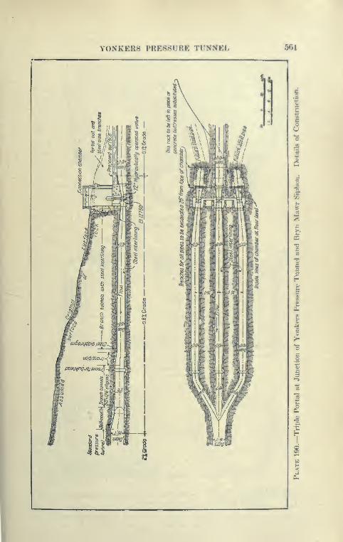
Y0NKER8 PRESSURE TUNNEL 5<U
^s^^ ill§ ^ /'I i' -lis
/ ^41
\a>ai
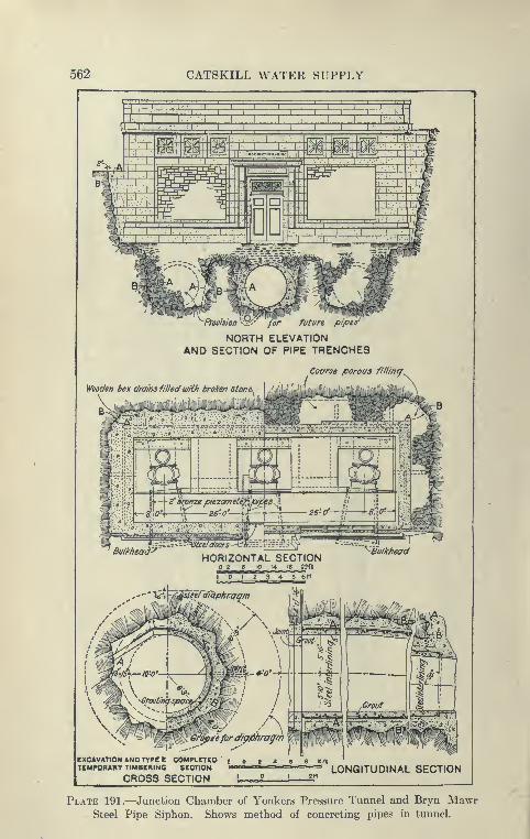
562 CATSKILL WATER SUPPLY
mm
-Plvmion^<;:'y for future pipes'
NORTH ELEVATIONAND SECTION OF PIPE TRENCHES
Coarse porous fillincf^
Wooden box drains filled u/fth broken ston^
EXCAVATION AND TYPrE COMPLETED £ o 2 t 6 8 ionTEMPORARY TIMBERING SECTION LONGITUDINAL SECTION
CROSS SECTION
Plate 191.—Junction Chamber of Yonkers Pressure Tunnel and Bryn Mavvr
Steel Pipe Siphon. Shows method of concreting pipes in tunnel.

Y0NKER8 PRESSURE TUNNEL 563
This mistake is commonly made in tunnels driven with too lonR
holes. It is better to make regular daily progress, using a depthof out pra('tic'a))l(' to blast t<j nearly full depth with one loading.
Another Method of Tunneling. The second method was to cut
down the advance to only 5 feet; 6 to 8 cut holes were drilled, 4 to
6 relievers, 6 bottom side and 3 top-dry holes, a total from 19 to 23
holes, requiring the use of 150 pounds of 60 per cent d.vnamite.
The drill steel used varied from 2] to 1 J inches. The heading wa.s
drilled and blasted in each of two drilling shifts, the three rounds
of holes being fired separately. At each drilling shift, 4 drillers
and 4 helpers and a foreman were engaged. With each <lrilling
shift a mucking gang of 1 foreman and 8 to 12 muckers worked from
12 P.M. to 8 A.M., and from 12 noon to 8 p.m. In addition, a split
mucking shift of picked men worked from 8 a.m. to noon, and from
8 p.m. to 12 P.M., in an endeavor to clear the headings, to allow
the setting up of the two columns with their two drills.
Bonus System, etc. The work was partly done under a bonus
system based on the daily or weekly progress, and the yards per foot
excavated. A disadvantage of the bonus system is that although
it tends to rapid driving, it is apt to lead to a rather poorly driven
tunnel. The general superintendent of the Rondout siphon after
consulting the cross-sections obtained by the engineers succewled
in discouraging poor driving by liberally discounting the poorer
tunneling, so that on the whole the tvmnels were well driven. Thebench was excavated by working four drills, two on triixxls and
two on columns. The column drills were used for trimming head-
ings, which in many places were driven rather narrow. The drilling
shift worked from 8.30 to 4.30 p.m. blasting the bench between
3 and 4.30. Two shifts of 12 nmckers worked from 12 p.m. to
8 a.m. and 8 a.m. to 4 p.m. Throughout all the excavation
Ingersoll-Rand 3^ inch F94 drills were used. The rock exca-
vated was very hard Yonkers and Fordham gneiss, requiring no
timbering.
Mucking Machine. An effort was made in one tunnel heading
to use a mucking machine patented by Mr. Jackson. After a few
weeks it was abandoned, but was later used on the spoil bank. The
machine was mounted on a truck having broad wheels and moved
by its own power on a board platform and operated a series of
buckets on an endless inclined chain, the buckets digging into the
muck and dumping the same onto a belt conveyor which loaded the
cars. The machine was used for loading the tunnel muck from the
spoil bank onto 2-yard cars which were hauled to the crusher and

564 CATSKILL WATER SUPPLY

Y0NKER8 PRESSURE TUNNEL 565
was operated by an enpnoman and a helper whose duty was mostlyto froe the machine from hoinR jammed by the large stones of thespoil bank. It was operated by compressed air, its claimed capacitybeing about 50 cubic yards per day. Four machines were delivered
but only one was tried in the tunnel.
Concreting Methods. The concreting plants, method andforms used at the Yonkers tunnel, Contract 54, were entirely dif-
ferent from those employed at any other similar work on theaqueduct, and therefore will \ye described in some detail.
At each shaft there was a stone-crushing plant consisting of aNo. 6 McCully gyratory crusher with conveyor, screens and elevated
bins. From Shaft 1 to the portal at the north end an aerial tram-way 3000 feet in length was operated by a 25 H.P. motor andequipped with buckets of 3-yard capacity. The cableway was used
for the transportation of concrete material l>etween these twopoints.
All the concrete plants in use were gravity mixers of the Hains-
Weaver type, containing four superimposed hoppers of 17 cubic
feet capacity. At the portal one of these plants was located in
the cut near the East tunnel entrance; at Shaft 1 the mixers were
situated at the foot of the shaft just under the tunnel roof, the
clearance below the bottom hoppers being sufficient to permit
1-yard cars to run beneath and receive the concrete. The aggre-
gates were measured in wooden tilting hoppers at the top of the
shaft and discharged into chutes of 15-inch spiral riveted pipes lead-
ing to the mixer hoppers. The cement was carried in bags on the
cages to the working platform directly under the tunnel roof and
there put into the hoppers by hand. The portal plant was charged
with materials from overhead bins in the usual manner.
Operations of the Hains Mixers. The mixers as usetl here were
not entirely satisfactory. The tunnel afforded too small a height
for the proper placing of the four Hains hoppers and consequently
the concrete was not mixed nearly as well as when the full drop
from bucket to bucket is obtained, as in the full-sized Hains plant
mounted in towers. The sand and stone frequently clogged in
the 15-inch pipe, causing considerable delay until the pipe could
be freed by long poles. Here, as elsewhere, it was found difficult
to send damp materials through pipes, either excessive wear or
clogging resulting.
The mixer plant at the portal was arranged so that one mancould open all the pockets from the top, saving the men who usually
operate the door at each platform level. This device was tried
566 CATSKILL WATER SUPPLY
out also on Contract 11, and with the same experience as here.
The top man found it hard to operate the doors at the proper time,
so that the batch was apt to drop through without being caught in
each bucket, and the concrete, for this reason, was deUvered in a
poorlj^ mixed condition, which often required remixing at the forms.
Invert. At first 90 feet of invert was laid to the width of 9 feet,
but experience proved this to be too wide, and the width was
reduced to 7 feet, the finished diameter of the tunnel being 16 feet
7 inches, as against 14| feet where 5-foot inverts were usually used.
The invert forms were made of continuous side planks 3''X16" set
radially and supported from 6"X8" timbers braced across the
tunnel at 9-foot intervals about 2^ feet above the invert grade.
Geo. W. Jackson Forms for Side Walls and Arch. For side
walls and arch the Geo. W. Jackson forms were used. These
forms differ from the usual Blaw forms used on other siphons,
in that they are not provided with carriages and are intended to be
moved piece by piece. They consisted of complete circular ribs of
the diameter of the tunnel made of 5-inch steel I-beams, or of two
5-inch channels riveted together back to back and of |-inch steel
lagging plates l'x3', stiffened by li^'xii'' steel angles. Theribs were placed 3 feet apart and the lagging put on as the con-
crete rose. These forms contained no heavy pieces. About 90
linear feet of forms were provided at each working point. As fast
as the concreting proceeded the forms were taken down at the rear,
carried through and set up in advance, this all being done by hand.
The forms afford good facilities for spading the concrete, as the
plates are continuously added, but the small size of the lagging
units give many joints to be finished off. Side walls and arch
were brought up separately, the side walls being placed ahead of
the arch. The concrete was hauled to the working platform at
springing line up an incline by a hoisting engine at forward end
of the platform, after which the cars were pushed by hand to the
point where they were dumped. While concreting was in progress
trimming and excavation of the bench was also carried on, and
the muck hauled through the forms to the shaft. This was done
probably because the headings had been driven through muchbefore the benches were excavated and the contractor did not care
to wait until the tunnel was entirely excavated before beginning
concreting. The experience on other siphons is that it is better
and more economical to finish all the excavation before attempt-
ing to concrete, as it has been found that the two operations con-
flict with each other. The progress made with Jackson forms was
HILL VIEW RESERVOIR 567
much slower than that made with forms equipped with carriaf^,
as the latter forms can he moved and set up much quicker. Theaverage progress made per day at one set of forms was alxiut 14
feet, with two eight-hour shifts of concreters and a third shift of
form setters. As previously described, on the Wallkill and other
siphons, a daily progress of from 40 to 60 feet was readily made with
another type of form.
Contract 30. Hill View Reservoir and Pressure Tunnels
Contract Prices and Work Included. This contract wa*awarded in December, 1909, to the Millard Con-struction Com-pany; later the board approved the change of firm name to the
Keystone State Construction Company. This contract includes
the construction of Hill View reservoir and 1184 feet of the Yon-
kers pressure tunnel, an uptake shaft 141 feet deep connecting
this pressure tunnel with the reservoir, a downtake shaft 304 feet
deep at the other end of the reservoir leading into the city aqueduct
tunnel (Van Cortlandt pressure tunnel), and 1809 feet of this tun-
nel. The total contract price of this work was $3,270,000. Someof the quantities and prices are as follows:
2,900,000 yds. excavation at $0.28 cu.yd.
2,750,000 yds. embankment at 20 impervious refill; 10 eta. other refill
4,700 cu.yds. of shaft excavation at . . 16 . 00 per cu.yd.
39,500 yds. tunnel excavation at 6.20 per cu.yd.
135,000 yds. concrete in open cut 4 . 70 cu.yd.
60,000 cu.yds. reservoir lining
75,000 cu.yds., walls, chambers, etc.
Forms for Uning tunnel 3.00 lin.ft.
14,400 yds. concrete in tunnel 6.00 cu.yd.
215,000 bbls. Portland cement 1 .60 per bbl.
Cost of pressure tunnel based uix)n contract quantities is about
$142 per foot, of waterway shaft about $303 per foot.
Hill View Reservoir. Hill View reservoir will contain 900 million
gallons and its purpose is to equalize the difference l^etween the
consumption of water in the city and the steady flow of the aqueduct,
particularly in times of fire. Were it not for this reservoir the
Yonkers pressure tunnel and the city aqueduct would l)e directly
connected. As it is, there is a space of about 2500 feet between
the Uptake shaft of the Yonkers tunnel and the Downtake shaft
of the" City aqueduct. These two shafts are situated within the
reservoir embankments and are connected acrass the Hill View
reservoir by a circular by-pass aqueduct, 12 feet in diameter under

568 CATSKILL WATER SUPPLY

HILL VIEW KESEKVOIK 569

570 CATSKILL WATER SUPPLY
-a 24-foot head at its crown, in the heavy concrete dividing wall
of the reservoir. This reservoir occupies an area of about 90
^cres on both sides of the dividing wall, and will when full cover
the top of wall with 3J feet of water. It is entirely artificial being
excavated at the top of a large glacial hill. It was a most for-
tunate circumstance to find a hill so near the city line, largely
unoccupied and obtained at a price comparatively small. It is
composed entirely of boulder till or unmodified glacial drift. The
central portion of the reservoir was excavated to a depth of 20 to 45
feet, the material so excavated being used for surrounding earth
embankments, a portion of which is composed of carefully rolled
layers, 4 inches thick, the remainder on the outside being deposited
in 2-foot layers without rolling.
Soil Stripping. The reservoir site was well wooded. The trees
were cut up into railroad ties and lumber by the contractor's
saw mill. The future embankments will be grassed and require
the use of a large quantity of topsoil. This topsoil was carefully
removed and with considerable difficulty, on account of the large
number of stumps and boulders. The soil was loosened with mat-
tocks, excavated with hand shovels, and transported to storage
piles on wagons or cars. Two-foot-gauge cars were run on an
industrial track, which was laid on a down grade so that the loaded
train traveled nearly the entire distance to the spoil bank by gravity.
The empty cars were hauled back by horses. In this manner
133 acres were stripped—212,800 cubic yards.
Main Excavation. The excavation and embankment work
were such that steam shovels could be used under almost ideal
conditions. Although the glacial drift with numerous boulders could
readily be dug by the shovels, it was still stiff enough to stand on
almost vertical slopes even through the wdnter. To loosen up the
material holes were put down by well or chum drills. These were
sprung and blasted in the usual manner. The first excavation
was made by steam shovels near the uptake and downtake shafts,
where an area of three acres was excavated to reservoir grade to
make room for a crushing and concrete plant and storage roomfor materials. These excavations were connected by a cut along
the location of the dividing wall. This made room for the starting
of the two shafts and for the subsequent building of the dividing
wall, besides giving good faces for the steam shovels. The shovels
were as follows: Two 70-ton Bucyrus, one 60-ton Marion, one
65-ton Bucyrus, and four 30-ton Ohio. Three of the larger shovels
mentioned were served by 4-yard Western dump cars, hauled by

HILL VIEW KE8ERVOIR 671
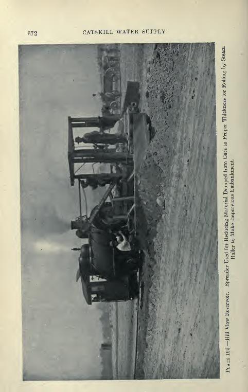
f>72 CATSKILL WATER SUPPLY
HILL VIEW RESERVOIR 573
locomotives on tracks of 3-foot gaugo, and their contents dcpofiitixi
in the embankments. After this material was dumped, it wasleveled off by a special leveling car which oi)erates in a man-ner similar to the ordinary road scraper, but is pushed by alocomotive.
Impervious Embankment Construction. The inside ix)rtion of
the embankment is formed of select(»d mat(»rial spread in 5-inch hori-
zontal layers which when rolled are not more than 4 inches thick.
Great care was given to the preparation of the base of this embank-ment, all soil, loose boulders, stumps and roots l)eing removed, andthe ground was roughened with a ])low and sprinkled In'fore placing
the first layer. When wagons were used the earth was dump*^! in
rows spread to the required thickness by four-horse roa<l scrapers
and rolled by 10-ton Buffalo grooved steam rollers. The material
as it came from the excavation contained enough moisture to com-pact properly, but during hot weather the embankment required
sprinkling before a fresh layer was spread. The })ase of the 2-foot
embankment was prepared by removing topsoil, stumps and nests
of boulders.
Excavation 191 1 to 1912. During 1911 one 65-ton and one
70-ton Bucyrus shovel were added to the equipment and the daily
capacity for excavation increased to 5500 cubic yards. Thret* of
the heavy shovels were served by trains of 4-cubic-yard Western
dump cars, one by wagon, three small shovels by wagons alone,
and a fourth by wagons and train. There were eight shovels working
at one time mostly in the west basin. Drilling and loosening the
deep portions of the excavation with powder ahead of the shovel
was the common practice. The reservoir was gradually excavated
from the sides of the two basins toward the center, the shovels
working to a few feet above the bottom. At the close of 1912
219,000 cubic yards of topsoil and 2,160,000 cubic yards of main
excavation had been removed, all of the latter being used for 4-inch
embankment (846,000 cubic yards) or for refilling and pmb.-uikmrnt
(mostly 2 foot layers) of other classes.
Making Embankments 191 1. As at the Ashokan dam (I on-
tract 3) it was found that embankment could be most exiM»ditiousIy
and satisfactorily made by train. A double line of 3-foot-gauge
track was installed on the east and west embankments. After
dumping the trains of 4-yard side-dump cars along the full length
of a track, the spreader car was twice run along the track, spreading
the material. The track was then moved back 13 J feet by horses,
and spreading and leveling for the 4-inch layers completed by a
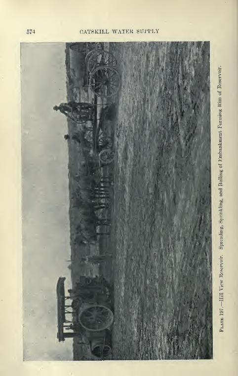
574 CATSKILL WATER SUPPLY
a.
HILL VIEW RESERVOIR 675
four-horse road scraper aft^r which the 10-ton grooved roller com-pleted the operation.
Removing Boulders. A great many Iwulders were rejected
by the steam shovel, hut many reached the embankment*, where they
were separated by hand during dumping and spreading, loaded
on wagons and hauled to crushers. As it was necessary to remove
the stones promptly a large number of men were required for this
purpose. A very- convenient rig for breaking up boulders con-
sisted of a gasolene-operated compressor which furnished air to
jap drills. A few holes and plug and feathering sufficed to break
the boulders into blocks almost ideal for the heavy 18-inch pavement
which will be used in great quantities adjacent to the water line
of the reservoir. The material for the outside embankment in
2-foot layers was mostly hauled in traim?, but it proved impractic-
able to save the boulders from the material. A considerable amount
of excavation for both classes of embankment continued to be hauled
in wagons.
Plant Used for Excavation and Embankment. The plant for
excavation and embankment, besides the 8 steam shovels men-
tioned, Bucyrus, Marion and Ohio, included 16 3-foot gauge
locomotives (Porter, Baldwin, Davenport and Dixon, makers)
19,200 feet of narrow-gauge tracks, 90 Western dump cars, 5 road
scrapers (Western and Champion), 3 Buffalo-Pitts 10-ton grooved
steam rollers, 112 Troy dump wagons, 6 sprinkler wagons (Austin
and Studebaker), 2 Western levelers, etc.
Shaft Plants. The two shafts and adjacent tunnels were super-
intended by the Dravo Contracting Company, who did all the work
of excavating and lining shafts and tunnel. Independent air-
compressing plants were erected at each shaft. At the uptake
three horizontal fire-tube boilers, combined capacity 280 H.P., two
Ingersoll-Sergeant single-stage air compressors operated by steam
and rated at 1100 cubic feet free air per minute, also a direct-current
dynamo operated by a 30 H.P. Erie engine. At the do^v'ntake
shaft the plant was very similar except that one compressor was
two stage and rated at 1300 cubic feet of free air per minute.
Shaft Excavation. The shafts were sunk by means of stiff-
legged derrick operated by Lidgenvood double-drum engine. The
uptake shaft was sunk through 50 feet of earth and 22 feet of dis-
integrated rock which required timbering. Below this the rock was
sound Yonkers gneiss or granite, and required no timbering, the
total depth of the shaft being 143 feet. The average, progress made
in sinking was 38 feet a month, maximum 67 feet. The down-

576 CATSKILL WATER SUPPLY
Plate 198.—Hill View Reservoir. Timbering of Earth Portion of DowntakeShaft.
HILL VIEW RESERVOIR 677
t
take shaft was carried through 67 feet of earth requiring timUT-ing; the remaining distance, 244 feet, was sunk through soUd
Yonkcrs gneiss to tunnel grade, requiring no timlM'ring. This shaft
made an average progress of about 75 feet per month, maximum90 feet. Yonkers gneiss is a very solid rock which most people
would class as a pink granite. It is ver>' hard to drill and no great
progress can be made in it either with shaft |or tunnel, but it is
usually sound and often carries coasiderable water in narrow seams
which bothers the excavation little, but is very troublesome fin ring
concreting.
Timnel and Crushing Plant. The shafts were lined in the usual
manner, using steel forms designed and constructed by the Dravo
Company. At the downtake shaft 200 feet of lining in one monthwas placed. After the shafts were concreted, structural head
frames 60 feet high were erected. These were composed of four
temporary shaft-sinking head frames bolted together and strength-
ened by timber braces. In them were operated two balanced
Connellsville self-dumping shaft cages, worked by a Vulcan mine
hoist with 66-inch drum. A special low steel muck car was designed
and built for the Dravo Company. This car sat very low on the
frame and was equipped with a front door, the arrangement l>eing
such that when the cage reached the top of the head frame its floor
was tilted by wheels entering a curved trackway, the floor of the cage
being mounted on shafts. The car was held fast while the front
door was automatically opened and the muck deposited in a high
timber bin, from which it was run into a crusher and through a screen,
the screen feeding onto a long belt convej^or, supported on
high trestles so as to dump the crushed rock into a high conical
storage pile. All the rock of the tunnel was directly crushed up in
this manner to stone grading up to about 2 inches in size. The
fine screening or stone dust made excellent sand which was used
in the concrete as a substitute for natural sand, which in this neigh-
borhood is very scarce. The stone-crushing arrangement above
mentioned was most excellent, as it economically disposed of the
tunnel muck by converting 100 per cent of it into materials used in
the concrete. Yonkers gneiss gives little trouble in the crushers
and screens, contrary to the experience with most tunnel muck,
which is very apt to be wet and sticky, clogging the crushers and
screens, so that the resultant product is a varying mixture of broken
stone and fine crusher dust.
Bottom Heading. A feature in driving the tunnel was the use of
the bottom heading method. After a short distance had been driven

578 CATSKILL WATER SUPPLY
Plate 199.—Hill View Reservoir. Connellsville Self-dumping Cage and Low
Muck Car Used by Dravo Company in Excavating Pressure Tunnels.
HILL VIEW RESERVOIR 579
in each tunnel with the usual top heading, it was found that
progress was slow using this method and the ordinary percussion
drill. An attempt was made to better this by the use of the l)ottom
heading and Leyner drills. After the bottom hea<ling was driven
by an arrangement of horizontal drill holes which yieldtni after
shooting a circular l)ottom with flat roof about mid-diameter, the
remaining rock could be readily excavated by the use of a few
horizontal holes loaded and fired to shoot the upper half onto aheavy timber platform. Under this platform the muck cars were
run and loaded through trap doors, thus saving much handling.
It was found in some instances that the shooting of the upper
headings broke the timber platform, such an accident inconvenienc-
ing the work a good deal. South from the downtake shaft, after
a few hundred feet, the bottom heading was driven through to
the end of the contract and the top shot down and mucked with-
out the aid of the timber platform.
By this method the tunnel was driven to a very true shape,
as the perimeter was formed by horizontal holes. In hard rock,
with the ordinary top heading method, it is usually found difficult
to shape the lower half by the usual vertical holes. From the
progress made, it is doubtful whether this method reallj' saved
over the top heading, as the cost of moving and replacing the plat-
form, etc., probably more than offset its advantages.
Firing with Fuses. At first, electric firing was used, three
rounds of holes being fired in the usual manner; this took from one
to two hours, although a ventilating plant of ordinary type was used.
To save a portion of this time fuse firing was introduced. All the
holes in the heading were loaded at once and exploders inserted in
cartridges as usual. Instead of these exploders being connected with
electric wires they are crimped to fuses expressly constructed for this
purpose. They were heavily wrapped and waterproofed and loaded
with gunpowder so as to burn at a uniform rate 24 inches per
minute. The cut holes contained the shortest fuses, the side round
fuses a little longer, and the trimming hole the longest. All the fuses
were lit at once and burned for a sufficient time for the men to
leave the tunnel, after which the cut holes would first go off, fol-
lowed by the side rounds and then by the trimming holes. Theman would usually leave about the end of a shift and before
the next shift entered the tunnel the air would be clear. The
superintendent in charge reports that this firing was invariably
successful, no misfiring occurring, and that a great saving of time
resulted.
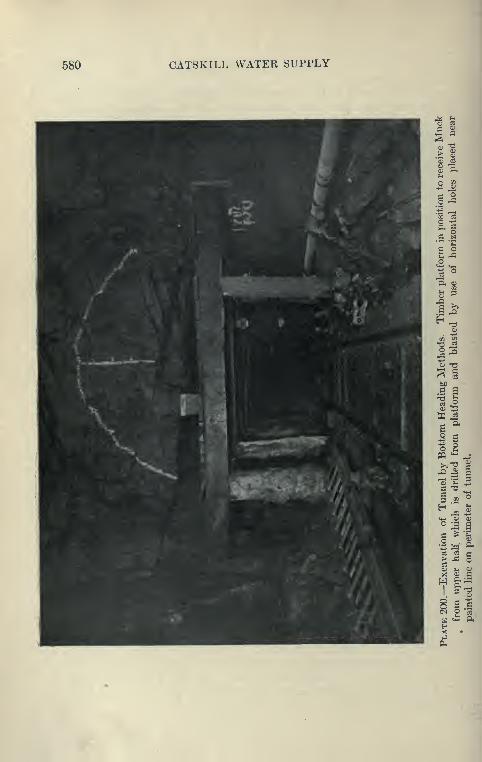
580 CAT8KILL WATER SUPPLY
5 Ph
03 e3
ft G
ilo
il
s §tiC
c a
1 sO)
W ^aa
3 g-ieoW '*-' ^1
aa3'3 u
3 .2?
H 0)X -iS
_o a>o ^ aa ^ '?^
o aa 03 CJ> ,£3 odo Ui (U
X OJ aH §:
;=5
1.3 2
g .1CI o si
H vm ftH<J •
iJ
(^
HILL VIEW RE8ERV0IR 581
Leyner Drills. The Ivoyncr drills at first gave considerable
trouble, but later it was reported that the parts which formerly
broke down after being replaced l)y special steel castinRs stood
up well, the superintendent claiming that two of these drills could
do the work of the four drills formerly used, and even then save
some time, eight hours usually being consumed in drillling andblasting a heading. A Leyner drill sharpener was in use for makingbits and welding steel. As both the tunnel headings were short,
it is probable that they did not give sufficient opportunity to
thoroughly test the drills. The average progress made in driving
north from Uptake shaft was 110 feet of completed timnel excava^
tion per month, south of Downtake 150 feet of completed tunnel
per month, the Leyner drill increased the heading progress to amaximum of 273 feet per month.
Concreting of Tunnel. The tunnels were concreted in the usual
manner, the finished diameter of waterway being 16 feet 7 inches
for the Yonkers siphon, and 15 feet for the Van Cortlandt siphon.
This allowed an invert 6 feet wide to be laid by the use of con-
tinuous wooden strip forms, screed boards, etc. Upon this invert
was erected the usual Blaw steel form with carriage, and back of
this the arch forms both with carriages on the invert, with platform
of both forms connected so that the concrete cars hauled up the
incline could supply either arch or side wall, the side walls being
used as reservoirs to hold the concrete which could not be jilaced
in the arch. The method was very similar to" that described under
Contracts 12 and 47. Crusher dust obtained from the Yonkers
gneiss was used as sand, but it does not give quite as goo<l a finish
to the concrete as when natural sand is used. Using three pairs
of trailing arch and side-wall forms, in 20-foot units, no diflficulty
was experienced in concreting 20 feet per day on the Yonkers
siphon and 30 feet on the Van Cortlandt siphon. The actual
concreting time was usually eight hours. The concrete was discharged
from the mixer directly into Koppel cars on the cage at the top
of the shaft and drawn by mules to the foot of the 75-foot
incline.
Hains-Weaver Concrete Plant. Near the downtake shaft
a full-sized Hains-Weaver concrete mixing plant was erected,
equipped with electrically operated stone, sand and cement-bag
elevators. This plant, constructed of heavy timber and with the
usual hopper and platform, was capable of easily mixing 400 to 500
yards per shift of eight hours. All the concrete used on the divid-

582 CAT8KILL WATER SUPPLY
ing wall was mixed here and carried in bottom-dumping double-
door Dowd buckets to the site of the work and dumped in the
forms with large electrically operated traveling derricks.
Sand-rolling Plant. The stone used in the concrete was largely
obtained from the storage pile accumulated by crushing the stone
muck as described before. A portion was used for lining the pres-
sure tunnel by the Dravo Contracting Company, and the remainder
loaded on cars and fed to the bucket elevator on mixer. Crusher
dust and natural sand was used for the fine aggregate. Hillview
is remote from good available sand deposits and natural sand is
therefore costly on the ground. To meet the situation a sand-
rolling plant was erected near the mixer. This plant consisted
of a No. 5 McCully gyrating crusher, into which was fed the hard
boulders obtained from the excavation. The crushed stone, about
1^-inch size, was fed to a large pair of flat Cresson rolls which rolled
the stone into a finer product which in turn was crushed by a second
pair of flat rolls to a size supposed to be below j inch. It was
found necessary to screen the product again and to send the flat
rejects above j inch back to the fine rolls, in the same manner
as rejects are recrushed in the main crusher. The foreman stated
that about 150 cubic yards of boulders could be turned into sand
per day; that the gyratory crusher could do far more than this,
but any effort to feed faster would overload the rolls. This supply
was not sufficient and it was necessary to pui'chase natural sand
in addition. From the force and plant charges the cost of this artifi-
cial sand must be considerable, and it is doubtful whether it is
a commercial success. It is reported that the rolls are standing
up very well under their severe work, though they are forced to
pulverize very tough trap rock.
The glacial drift at Hillview contains considerable ground-up
rock, which when washed out by the rain accumulates in the
depressions and gulleys as good sand. An attempt was made to
wash the drift, using a Weaver sand-washing machine. This suc-
ceeded in recovering a quantity of very good sand, but the machine
is a small one and it is not known whether the product pays the
cost of operation.
Preparing Concrete Bottom for Dividing Wall. After the exca-
vation for the dividing wall was removed by steam shovels, the
final trimming was done by hand to about 3 feet below the grade
of the reservoir bottom. The dividing wall containing the 12-foot
circular by-pass aqueduct was built in two lifts. The bottom lift
HILL VIEW RESERVOIR 683
is 20i feet high, 34J feet wide at the bottom and 12 feet at the lop,
and contains 435 yards in a 30-foot section. The upixT lift is 16
feet high and 4 feet wide at the top. As the excavation for the
dividing wall was completed, steel pedestal block forms 7J'X3'wide at the ba.se and stepped to 6'X9" at the top were set to
grade and filled with concrete screened to form a portion of the
invert of the l)y-pass aqueduct. They were l)uilt 7\ feet apart
at first, but later 10 feet, and were carried 90 fe<»t ahea<l c>f the
wall. The next operation was to cover the bottom with 12-inch
concrete for a length of 30 feet and inilK*d large stones in it.
Forms for By-pass Aqueduct. Upon the invert blocks were
erected the full circle 12-foot steel forms built by the Blaw com-
pany. The waterway forms were divided into two parts at a
point about 3 feet above the invert, the forms being keyed at top
and bottom, and the upper and lower parts bolted together through
3-inch beveled steel plates. (See Plate 201.)
The forms were moved on a very ingenious car which ran
on inverted angles bolted to the invert form. The car was
equipped with jacks at the top and with arms carrying turn-
buckles. The top was a double channel forming a track for the
chain-block hoists which could be run out about 7 feet at each
end beyond the body of the car on its cantilevered track. In
moving the forms, the invert forms at the rear of the work were
folded and raised by the chain hoists and run through the Inxly
of the car on the cantilevered overhead track and dropped into place
on the concrete invert blocks. This operation was repeated till
the invert was placed for a 30-foot section. An arch section was
then lowered on the screw-jacks mounted above the channels and
drawn away from the concrete by turnbuckles and the car moved
ahead to its new position, where it was raised into pasition and
its fillers again bolted in. The forms were in TJ-foot lengths
and were loaded with cars filled with pig iron to prevent
flotation.
Outside Forms for Dividing Wall. The outside fonns were of
steel in 5- or 7 2-foot sections extending the full height of bottom
lift of the wall and were moved in 15-foot units by the derricks.
The forward panel of each setting of outside forms contained lx)lts
with washers imbedded in the concrete to act a.s anchors when the
next forms were moved ahead and bolted to them. Lines of ^-inch
cables were used to tie the bottom of the panels together, tajHTed
steel bolts fastened the side panels to the waterway forms, and in
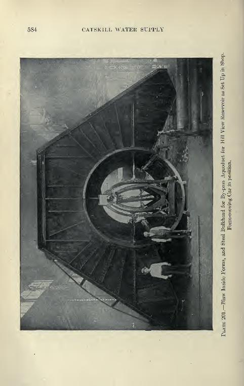
584 CATSKILL WATER SUPPLY
^ ia o
1?
HILL VIEW RESERVOIR 686
addition it was found necessary to stiffen the waterway forms with
12''X12" timbers.
The bullciiead was of steel and after being assembled for the
first time it was moved as a unit. The construction of forms andcarriapje is shown on Phite 202.
Difficulties Met in Casting Circular Aqueduct. Although the
operation of the forms was successful and was performed as required
by the specifications, one cannot but wonder at the difficulty of
casting a full circular aqueduct in one operation. A circular aqueduct
can be very simply obtained by the method used in the pressure
tunnels; that is, by casting first an invert strip, then .side walls
to mid-diameter, and then the arch. This would necessitate two
simple forms and carriages. The outside of the wall could also
be readily cast by the use of a wooden or steel cantilevered panel
form similar to that used for the construction of core walls at
Ashokan Reservoir, for the Panama Canal lock walls, and numerous
other places, and the dividing wall run up to full height after the
arch is cast. The forms for casting the upper 16 feet of dividing
wall gave considerable trouble. When first used they were of steel
and rested upon bolts set loosely into the concrete wall below and
were tied together with ^-inch wire rope cables and tapered lx)lts.
The bursting pressure of the concrete was so great, however, as to
rupture some of the tie lines, necessitating the use of timber trusses
and additional cables. These forms later were entirely rebuilt and
stiffened by trusses built up of structural steel.
Progress Made in Concreting By-pass Aqueduct. The concrete
was hauled from the Hains-Weaver mixer at the do\vntake shaft
in IJ-cubic yard bottom-dumping Dowd buckets on flat cars drawn
to the point of deposit by 3-foot-gauge electric motor cars operateil
by current from a third rail. Tracks for these cars were con-
structed each side of the dividing wall as the work progressed.
The concrete was deposited in place by electrically operated trav-
elers. A total length of 2188 feet of by-pass aqueduct was built
between April 12 and November 25, 1911, at first in 1.5-foot sections
and later in 30-foot sections. A 30-foot section, about 435 cubic
yards, was concreted in seven hours. Average progress per month
was about 275 feet, about 3900 cubic yards; for two successive
months, 390 feet, or 5G00 cubic yards. On Contract 11 during the
season of 1911 about 1500 feet of ordinary cut-and-cover a<iueduct,
about 7500 cubic yards, were cast per month of the working season,
with a very similar plant.
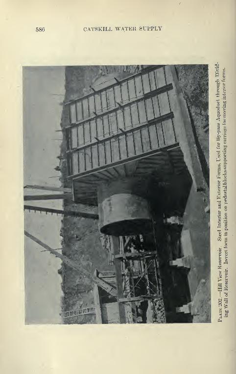
586 CATSKILL WATER SUPPLY
HILL VIEW RE8ERVOIK 687
Power House and Auto Trucks. To furnUh power for hwelectric machinery the contractor operated a central KeneratinK
plant at his camp.
Two 5-ton Mack trucks and one 6-ton Saurer automobile
truck were employed to haul cement from the siding at Wakefield
on the Harlem Railroad, the trucks also carrviutt coal and miscel-
laneous articles.
CHAPTER XIX
CITY TUNNEL—BRONX DIVISION
City Aqueduct. Construction work on the Catskill Aqueductwithin the limits of the City of New York was not started until
1911, about four years after work above the city line was under way.
The experience gained during the construction of pressure tunnels,
and the thorough investigation of the distribution problem of NewYork City led to the plan of distributing water throughout the
City by means of deep tunnels. This, because of its origirality, metwith a good deal of opposition which took time to overcome. It
was fortunate that delay did ensue, as the Rondout siphon in par-
ticular was far enough along to serve as an object lesson as to whatcould be done under conditions more difficult than those likely to
be encountered in New York.
Reasons for Adopting Tunnels. The single tunnel to be con-
structed, varying from 15 feet to 11 feet in finished diameter, will
take the place of thirty-two 48-inch pipes or sixteen 66-inch pipes
which otherwise would be necessary to carrj- the flow of 500 million
gallons per day and deliver it under the same head as the tunnel.
A summary of the reasons which led to the final adoption of the
pressure tunnel is here given, taken from the Catskill Water System
News:" When the problem of distributing the 500 million gallons per day
Catskill supply within the city, came up for solution, it appeared
that there were but two possible ways of doing this. One was to
carry the supply in metal pipes, laid in the street close to its surface;
the other, through a tunnel deep in the rock. The magnitude and
difficulties of the first method can readily be appreciated, when it is
realized that it would take thirty-two 48-inch pipes or sixteen
66-inch pipes to carry the flow of 500 M. G. D. and deliver it at the
same elevations as would the then-proposed tunnel.
" A summary of the reasons which finally led to the adoption of
the pressure tunnel is given below:
1. " That the plan provides for the delivery of all the Catskill
water.
588
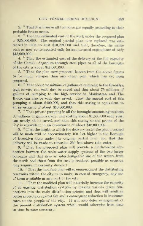
CITY TUNNEL-BKONX DIVISION 580
2. " That it will serve all the Iwirouuhs ffjunllv arrorrlin? in tlu-ir
probable future needs.
3. ** That the estimated cost of the work uiKicr tiic pnjiKwcd plan
is $25,000,000. The original partial plan now replace<i was i»j*ti-
matecl in 1905 to cost $10,224,000 and that, therefore, the entire
plan as now contemplated calls for an increase<l expenditure of only
$15,000,000.
4. '' That the estimated cost of the delivery of the full capacity
of the Catskill Aqueduct through stt»el pipes to all of the boroughs
of the city is about $47,000,000.
5. *' That the plan now proposed is seen from the al)ove figures
to be much cheaper than any other plan which has yet l>een
proposed.
6. '* That about 25 millions of gallons of pumping to the Brooklyn
high service can each day be saved and that alx)Ut 75 millioas of
gallons of pumping to the high service in Manhattan and TheBronx can also be each day saved. That the annual cost of this
pumping is about $400,000, and that this saving is equivalent to
an investment of about $10,000,000.
7. *' That private pumping in all the boroughs amounting to about
30 millions of gallons daily, and costing about $1,500,000 each year,
can nearly all be saved, and that this saving to the people of the
city is equivalent to an investment of about $40,000,000.
8. " That the height to which the delivery under the plan proposed
will be made will be approximately 100 feet higher in the Borough
of Brooklyn than under the original partial plan, and that this
delivery will be made to elevation 260 feet above tide wat-er.
9. " That the proposed plan will provide a much-nee<led con-
nection between the main water supply systems of the two larger
boroughs and that thus an interchangeable use of the waters from
the north and those from the east is rendered possible as occasion
may require or necessity demand.
10.'' That the modified plan will so cross-connect the distributing
reservoirs within the city as to make, in case of emergency, any one
of them available in any part of the city.
11. " That the modified plan will materially increase the capacity
of all existing distribution systems by making various direct con-
nections into the main distribution arteries and thus will result in
better protection against fire and a consequent reduction in insurance
rates to the people of the city. It will also defer enlargement of
the present distribution system which would othenvise from time
to time become necessarv.
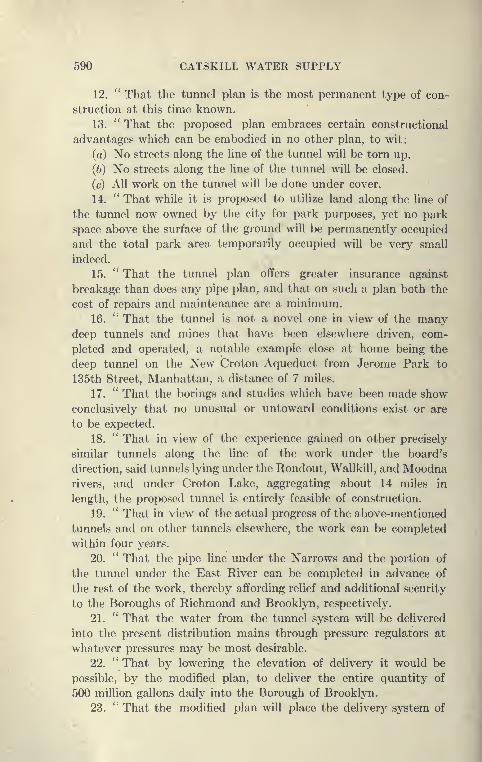
590 CATSKILL WATER SUPPLY
12. '' That the tunnel plan is the most permanent type of con-
struction at this time known.
13. " That the proposed plan embraces certain constructional
advantages which can be embodied in no other plan, to wit:
(a) No streets along the line of the tunnel will be torn up.
(6) No streets along the line of the tunnel will be closed.
(c) All work on the tunnel will be done under cover.
14. " That while it is proposed to utilize land along the line of
the tunnel now owned by the city for park purposes, yet no park
space above the surface of the ground will be permanently occupied
and the total park area temporarily occupied will be very small
indeed.
15. " That the tunnel plan offers greater insurance against
breakage than does any pipe plan, and that on such a plan both the
cost of repairs and maintenance are a minimum.
16. '' That the tunnel is not a novel one in view of the manydeep tunnels and mines that have been elsewhere driven, com-
pleted and operated, a notable example close at home being the
deep tunnel on the New Croton Aqueduct from Jerome Park to
135th Street, Manhattan, a distance of 7 miles.
17. " That the borings and studies which have been made show
conclusively that no unusual or untoward conditions exist or are
to be expected.
18. '' That in view of the experience gained on other precisely
similar tunnels along the line of the work under the board's
direction, said tunnels lying under the Rondout, Wallkill, and Moodnarivers, and under Croton Lake, aggregating about 14 miles in
length, the proposed tunnel is entirely feasible of construction.
19. " That in view of the actual progress of the above-mentioned
tunnels and on other tunnels elsewhere, the work can be completed
within four years.
20. " That the pipe line under the Narrows and the portion of
the tunnel under the East River can be completed in advance of
the rest of the work, thereby affording relief and additional security
to the Boroughs of Richmond and Brooklyn, respectively.
21. '' That the water from the tunnel system will be delivered
into the present distribution mains through pressure regulators at
whatever pressures may be most desirable.
22. " That by lowering the elevation of delivery it would be
possible, by the modified plan, to deliver the entire quantity of
500 million gallons daily into the Borough of Brooklyn.
23. " That the modified plan will place the delivery system of

CITY TUNNEL-BRONX DIVISION 601
the city on a plai?e superior to that of any in the world, and thatso nearly as can now be foreseen, no material changes or additionswill be necessary for many years to come.
24. "That the modified plan calls for the acquisition of onlyabout 1640 lineal feet of right of way from private particfl or cor-
poration, since for the balance of its length it lies under parknand pul)lic streets."*
Location of City Aqueduct. Th(» location of the city aqueductis shown on Plate 203. It continues the tunnel leading from Hill
View reservoir south through the boroughs of The Bronx and Man-hattan and Brooklyn, where it forks, leading to two terminal shafts,
each equipped with two 6-foot riser pipes, the tunnel its<»lf gradually
reducing from 15 feet at the upper end to 11 feet at the terminal
shafts. From the terminal shafts pipe lines are to be laid into the
Borough of Queens and through the Borough of Brookl\Ti under the
Narrows to Silver Lake reservoir in the Borough of Richmond, whichis the terminus of the Catskill Aqueduct, 120 miles from its source.
Narrows Siphon. The pipe under the Narrows is to be a flexible
jointed cast-iron line 10,000 feet long, laid in water of a maximumdepth of about 60 feet, and subjected to a current of more than
3 miles an hour with short quiet periods between tides. It wasfound by various experiments with anchors that the pipe would be
sufficiently protected by 8 feet of silt. The requirements of the
War Department will necessitate a trench 28 feet deep for a con-
siderable portion of the work which will have to be constructed
in the main channel of New York harbor.
Use to be Made of City Tunnel. Provisions are to be ma<le for
draining the 17| miles of tunnel for inspection or repair. At shafts 1
1
and 21 at deep points in the profile caused by depressions at Harlem
and East River are to be drainage shafts similar to those on other
siphons of the aqueduct. To enable the timnel to l)e drained in
sections two of the shafts are to be equipped with valves built in
the main tunnel, which will enable portions of the tunnel to be
examined without putting it all out of commission. At Shaft 3 a
connection will be made to the Croton .\queduct system through
an 8-foot tunnel extending to the gate house at the north end of
the Jerome Park reservoir. This tunnel will \ye capable of deliver-
ing 300 million gallons daily to and from the reservoir. At Shaft 10
a future connection can readily l)e made with the 135th Street
gate house and terminal shaft of the New Croton Aqueduct.
* See also volume issued by Board of Water Supply in 1912, entitled ** Re-
ports, Letters, etc., on the City Tunnel."
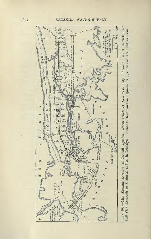
592 CATSKILL WATER SUPPLY
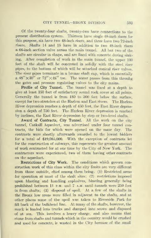
CITY TUNNEL—BRONX UlVi.Slo.S 593
Of the twonty-four shafts, twonty-two hftvo ronnoctions to tho
present (iistribution system. Thirteen have single 48-ineh naen for
this purpose, six have two 48-inch risers, and three have two 72-inchrisers. Shafts 14 and 18 have in addition to two 48-inch riHen*
a 66-inch section valve across the main tunnel. All hut two of the
shafts are circular in shape, and are lined with concrete during sink-
ing. After completion of work in the main tunnel, the upjx'r 100
feet of the shaft will Ix) concreted in solidly with the steel riser
pipes, to the bottom of which will be attached conical riser valves.
The riser pipes terminate in a bronze shaft cap, which is c^s.sentially
a 48"X30" or 72"X48" tee. The water passes from this throuhgthe gates and pressure regulating valves to the city mains.
Profile of City Tunnel. The tunnel wa,s fixed at a depth to
give at least 150 feet of satisfactory sound rock cover at all points.
Generally the tunnel is from 180 to 300 feet l>elow the surface,
except for two stretches at the Harlem and East rivers. The HarlemRiver depression reaches a depth of 450 feet, the East River depres-
sion a depth of 730 feet. The Harlem River depression is reached
by inclines, the East River depression by step or two-level shafts.
Award of Contracts, City Tunnel. All the work on the city
tunnel, Catksill Aqueduct, was advertised under four tunnel con-
tracts, the bids for which were opened on the same day. Thecontracts were shortly afterwards awarded to the lowest bidders
for a total of $19,085,000. With the exception of contracts let
for the construction of subways, this represents the greatest amountof work contracted for at one time by the City of New York. Thecontractors were experienced, two of them having other contracts
on the aqueduct.
Restrictions of City Work. The conditions which govern con-
struction work of this class within the city limits are very different
from those outside, chief among them being: (1) Restricted areas
for operation at most of the shaft sites; (2) restrictions imposed
upon blasting and handling explosives, blasting generally IxMng
prohibited between 11 p.m. and 7 a.m. until tunnels were 250 feet
in from shafts; (3) disposal of spoil. At a few of the shafts in
the Bronx low areas were filled in adjacent to the shaft.s, and at
other places some of the spoil was taken to Riverside Park for
fill back of the bulkhead line. At many of the shafts, however, the
muck is loaded into trucks and dumped into sco^vs and dispose* 1
of at sea. This involves a heavy charge, and also means that
stone from shafts and tunnels which in the countr>' would lx» cnished
and used for concrete, is wasted in the City because of the small
594 CATSKILL WATER SUPPLY
shaft areas and the nuisance from the operation of crushers.
Due to the higher cost of Hving in the City and to the strength
of labor unions, the pay of the men averages considerably higher
than in the country. There are also restrictions on Sunday work
caused by City ordinances and double pay for union men.
Advantages of City Work. On the other hand, there are advan-
tages connected with City work of this class, a very important one
being the ease of obtaining skilled tunnel men, from superintendents
down. New York ajad its vicinity has been the scene of extensive
tunnel operations since the beginning of the work on the New Croton
aqueduct in 1890. The thirty miles of tunnel on the New Croton
aqueduct was the means of training many men; this was followed
later by tunnel and rock excavation on subways, and a little later
by the Pennsylvania tunnels, and finally by the aqueduct tunnels.
Then, again, labor camps are not necessary, with all their attendant
worries.
Electric Power. The contracts provide that the plants are
to be electrically operated, the Edison Company promising in
advance of letting the contracts to sell electricity at the following
rates
:
6600 volt A.C 1 ct. per kilowatt hour, plus.
Maximum demand per kilowatt
for 5-minute peak load $20 per year per kilowatt.
Direct current 2^ cts. per kilowatt hour (straight
charge).
Electric power in New Y'ork is very reliable, due to the numerous
power-houses which are tied in to each other, so that any one
district can be supplied from several sources. The use of electric
power, more than anything else, has enabled the contractors to
make good use of the small areas allotted to them at the down-
town shafts.
Benefits Gained by Former Experience. The contractors on
the City aqueduct were in a very favorable position due to the
experience gained on aqueduct work above the City line. The
methods of shaft sinking, tunneling, and concreting were thoroughly
tested and developed, so that this work could proceed with but
little delay. The progress made in the methods of shaft sinking
was particularly beneficial to the City contracts, as shown by the
high average progress made at the shafts, although they were sunk
in large part by tunnel men who, however, had learned the methods
introduced into this section by the older shaft-sinking organizations.
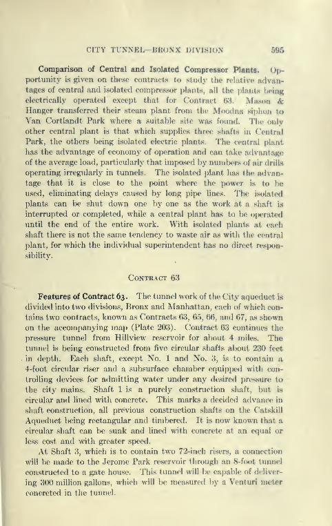
CITY TrNNEL—HKO.NX hiMr^H tS fi05
Comparison of Central and Isolated Compressor Plants. Op-portunity is given on these contracts to study the rehitive advan-tages of central and isolated compressor plants, all the plantit lioinK
electrically operated except that for Contract 6.'^. Mason &Hanger transferred their steam plant from the McKxIna siphon to
Van Cortlandt Park where a suitable site was fountl. The only
other central plant is that which supplies three shafts in Central
Park, the others being isolated electric plants. The central plant
has the advantage of economy of operation and can take a<lvantag(»
of the average load, particularly that imposed by numlx'rs of air drilLs
operating irregularly in tunnels. The isolated plant has the advan-
tage that it is close to the point where the power is to l)e
used, eliminating delays caused by long pipe lines. The isolate<l
plants can be shut down one by one as the work at a shaft is
interrupted or completed, while a central plant has to be o|x?rate<i
until the end of the entire work. With isolated plant<s at each
shaft there is not the same tendency to waste air as with the central
plant, for which the individual superintendent has no direct respon-
sibility.
Contract 63
Featixres of Contract 63. The tunnel work of the City aqueduct is
divided into two divisions, Bronx and Manhattan, each of which con-
tains two contracts, known as Contracts 63, 65, 66, and 67, as shown
on the accompanying map (Plate 203). Contract 63 continues the
pressure tunnel from Hillview reserv^oir for about 4 miles. Thetunnel is being constructed from five circular shafts al)Out 230 feet
in depth. Each shaft, except No. 1 and No. 3, is to contain a
4-foot circular riser and a subsurface chamber equipped with con-
trolling devices for admitting water under any desired pressure to
the city mains. Shaft 1 is a purely construction shaft, but is
circular and lined with concrete. This marks a decided advance in
shaft construction, all previous construction shafts on the Catskill
Aqueduct being rectangular and timbered. It is now known that a
circular shaft can be sunk and lined with concrete at an equal or
less cost and with greater speed.
At Shaft 3, which is to contain two 72-inch risers, a connection
will be made to the Jerome Park reservoir through an 8-foot tunnel
constructed to a gate house. This tunnel will be capable of deliver-
ing 300 million gallons, which will be measured )>y a Venturi meter
concreted in the tunnel.
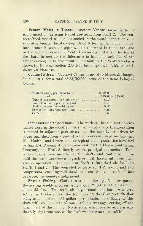
596 CATSKILL WATER SUPPLY
Venturi Meter in Tunnel. Another Venturi meter is to he
-constructed in the main tunnel upstream from Shaft 2. The con-
crete-hned tunnel will be contracted in the usual manner on each
side of a bronze throat-casting about 8 feet in diameter. Three-
inch bronze Piezometer pipes will be concreted in the tunnel and
in the shaft, operating a Venturi recording meter at the top of
the shaft, to register the differences in head on each side of the
throat casting. The v/onderful adaptability of the Venturi meter is
shown by its construction 230 feet below ground. This meter is
shown on Plate 204.
Contract Prices. Contract 63 was awarded to Mason & Hanger,
June 1, 1911, for a total of $3,709,000, some of the items being as
follows
:
Shaft in earth, per linear foot $292 . 00rock " 310.00 to 335.00
Tunnel excavation, per cubic yard 8 . 30Tunnel concrete, per cubic yard 6 . 75
Shaft concrete, per cubic yard 9 . 50Forms for lining pressure tunnel 4 . 00Cement 1 . 50
Plant and Shaft Conditions. The work on this contract approx-
imates work in the country. At three of the shafts the excavation
is spoiled in adjacent park areas, and the tunnels are driven by
powTr furnished from a central plant, previously used on Contract
20. Shafts 1 and 2 were sunk by a plant and organization furnished
by Smith & Powers; 4 and 5 were sunk by the Dravo Contracting
-Company, and Shaft 3 directly by the principal contractor. Tem-porary plants were installed at the shafts and continued in use
until the shafts were down to grade or until the central power plant
was in operation. The plant at Shaft 1 furnished air for both
Shafts 1 and 2. This consisted of three 75 H.P. boilers and two
compressors, one Ingersoll-Rand and one Sullivan, each of 550
cubic feet per minute displacement.
Shaft I Sinking. Shaft 1 was sunk through Yonkers gneiss,
the average weekly progress being about 12 feet, and the maximumabout 22 feet. The rock, although sound and hard, was very
seamy, particularly near the top, making the shaft wet, the flow
being at a maximum 39 gallons per minute. The lining of this
shaft with concrete was of considerable advantage, cutting off the
larger part of the inflow. No attempt was made to secure a par-
ticularly tight concrete, as the shaft was later on to be refilled.
1

CITY TUXXEI^BROXX DIVIHION 507
598 CATSKILL WATER SUPPLY
Shaft 2 Sinking. Shaft 2 was sunk in material similar to Shaft 1,
and was also quite wet. The placing of the concrete lining here,
was done with considerably more care than in Shaft 1, as this will
be used as a waterway. Excessive water was prevented from
dropping into the forms by sheds constructed of tar-paper and sheet
iron, and leaks in the rock were carried through the concrete forms
by the use of drip pans and pipes. Upon stripping the forms the
concrete was found to be excellent, very little water coming through
the body of the concrete. In this shaft the average weekly progress
was about 15 feet, the maximum 22.
Sinking Shaft 3. At Shaft 3 a large rock excavation in open
cut was necessary to provide room for the chamber and connections
to the Jerome Park reservoir. This excavation was timbered and
a circular shaft sunk below and concreted in the usual manner.
Good progress was made here, the average weekly progress being
15 feet, the maximum progress 33 feet. Excellent work was
done at the shaft, which was started late in July and the headings
turned early in December, 1911. This shaft, about 19 feet in diam-
eter, was excavated by means of rectangular cut and relief holes.
The eight cut holes were 8 feet deep and in rows 4 feet on each side
of the center line. The next round was the relief, also of eight
holes in rows 2 feet from the cut holes. The third was the trimming
round, consisting of eighteen vertical holes about 6 feet deep, which
gave the correct shape of the shaft. About 5 feet was pulled at
an advance, using about 2.6 pounds of dynamite per cubic yard.
The method of placing the cut and relieving holes in parallel rows
is rather unusual in circular shafts, the usual plan being to drill
three circular rows of holes, though it is quite common to drill the
cut holes in parallel rows. The progress made at this shaft is
rshown in Plate 205, the method of excavation in Plate 206.
Sinking Shaft 4. At Shaft 4 the Dravo Construction Companyinstalled a temporary plant to supply power for both Shafts 4 and 5.
The main features of this plant were two 100-H.P. boilers, and one
Ingersoll-Rand cross-compound air compressor of 1500 cubic feet
displacement. The upper portion of the shaft was sunk by the aid
of a stiff-legged derrick which was later replaced by temporary
head frames. The equipment at Shafts 4 and 5 were six to eight
3f-inch Sullivan or Ingersoll piston drills. After excavating and tim-
bering 14 feet of earth overlying the rock at Shaft 4, very good prog-
ress was made for the next 150 feet, the maximum weekly progress
being 32 feet. The diameter of this shaft is 17 feet 6 inches to B line,
and was excavated by three circular rows of holes on 4^-foot,
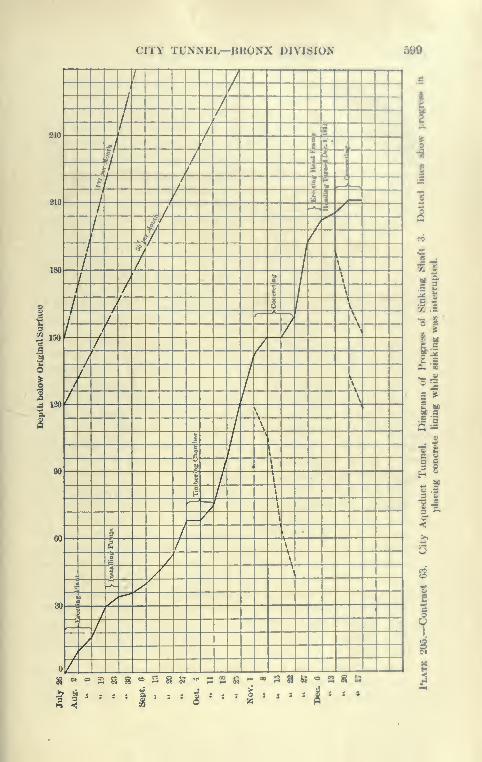
CITY TUNNEL—BRONX DIVISION 590
7
I
-7 4-^ A-t- a
m L irX- *C2 -T - Jl^ I
i J - it// f It^
'i'~ 1 :|-j^-(
; ' I"!
t ~<2 ^S"/^
C 1t - v^''
-T ^ T^ y J
^ 1 t 4 C- I t Xi it ^
z 2 J~ :- it ^lit -it 5 AIT' z ^
%'^ t ' 11 -/
I t 11 ' -t VImL ^ ^O. 7 ^^ HI \
4 \\
- - — o,
00 t t\
1 7^ t"
J
^-^ .
» 2" r t \
I" ^ \X T ^g— - ^ - /
«.:t ^"/
=^Z- :
/— /- —
oZ^ : 1 1 1 !—1—1—!—I—I—
2-2
'I. s
£ 'a
'I
cr
^'sas^ss^'*;: te • s a u
^ to -
S
f
3 O
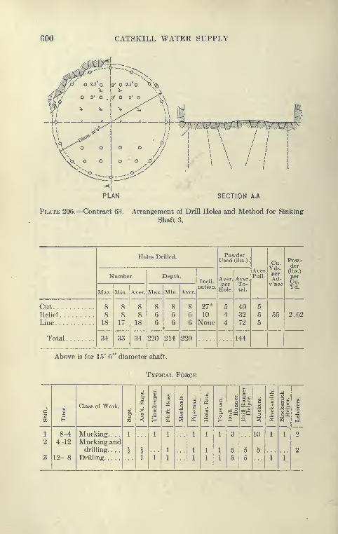
600 CATSKILL WATER SUPPLY
^^>.N
O 2.5 O |3' O 2.5 O «-^^«
I
^
O 3' O . 13' O 3' O ^^V\
SECTION A-A
Plate 206.—Contract 63. Arrangement of Drill Holes and Method for Sinking
Shaft 3.
Holes Drilled. PowderUsed (lbs.).
Aver.Pull.
Cu.Yds.perAd-v'nce
Pow-der
Number. Depth.Incli-
nation.
Aver,
ifole.
Aver.To-tal.
(lbs.)
Max. Min. Aver. Max. Min. Aver.Yd.
CutRelief .
8
818
8
8
17
8
8
18
86
6
8 8
6
27°
10
None
5
4
4
403272
5
5
5
55 2.62
Line
Total .... 34 33 34 220 214 220 144
Above is for 15' 6'^ diameter shaft.
Typical Force
H
Class of Work.
3CO
1CO
<
112
6"a
a
t
dsai
.2o
c
o.
at
c
Q
a
e
3
S
1ll 1
1 8-4 Mucking. . . . 1 1 1 1 1 1 3 10 1 1 2
2 4-12 Mucking anddrilling. . . .
i i1 1 1 1 5 5 5 ?
8 12- 8 Drilling 1 1 1 1 1 1 5 5 1 1
CITY TUNNEL—BKONX DIVISION 601
7-foot, and 8-foot radii. The first row of holes 8 feet deep wasdrilled to an inward slope of 1 to 4, the second row 8 feet deep wasdrilled to an inward slope of 1 to 2, the third row of holes 6 feet
long was drilled vertically. The two outer rows contained seven-
teen holes and the inner nine. All the holes were drille<i in oneshift by six drill runners and helpers. The next two shifts wereengaged in shooting and mucking, eight men working in each shift.
This rotation was maintained, so that an advance of al)out G feet
per day was made. This was the standard methcxi of the DravoContracting Company and one well a<lapt(M:i to city use whereblasting is restricted to certain hours.
On Contract 63 the best monthly progress in shaft sinking was99 feet at Shaft 4.
Grouting Water-bearing Rock. The shaft was dry to a depth
of 150 feet, when 120 gallons of water per minute flowed from the
drill holes. This decreased in a few hours to about 50 gallons.
Pipes were inserted in the lioles in the usual manner, and 46 bags
of neat cement grout was forced in at high pressure, using a Caniflf
grouting machine. This cut off the flow completely and sinking
was resumed. At a depth of 181 feet water, under pressure of 70
pounds, was again struck by the drills. There being no large pumpsat hand the holes were plugged one by one as the water was struck,
and no determination of the possible inflow made. Encountering
water in this shaft gave a good deal of concern, as it is alongside
the Jerome Park reservoir, and the hydrostatic pressure wasfound to correspond with its water surface, It was feared that
the water encountered came from the reservoir through seams which
might have been opened in this rock by the heavy blasting during
the reservoir construction. An analysis of the water in the shaft
showed, however, that it differed from the Croton water by con-
taining a larger quantity of solids. The drill holes where water was
encountered were grouted and the flow cut off. Fourteen-foot pilot
holes were next driven vertically, again striking water, and indicating
bad seams, as pieces of rock up to 1 inch in diameter were carried
through the holes. These holes were grouted under a pressure of
240 pounds obtained from a Westinghouse high-pressure compre8.sor.
A 5-foot sump was then shot, exposing a 2-inch grouted seam, and
disintegrated material well grouted. A row of 16-foot holes 18 inches
on centers was put down around the perimeter of the shaft and
grouted. Nine yards of grout were used in these holes, much of
which leaked into the shaft. A concrete blanket was then put
over the bottom of the shaft to hold the grout, but this was ineflfective
602 CATSKILL WATER SUPPLY
and the sinking was resumed. The maximum flow of water encoun-
tered after sinking was resumed was about 100 gallons per minute.
The operation of grouting took about eighteen days, during which
850 batches of about 55 yards were placed, mostly in two holes.
The rock of this shaft is largely a sound Fordham gneiss, a dark
banded rock. At the point where the grouting was done the rock
was ground up into a very light sandy material easily penetrated
by the grout, which partly solidified the sand and partly accumu-
lated in rather large masses and layers by forcing the sand to one
side.
Success of Grouting. It is probable that the crushed zone,
which varied from a few feet to 20 feet in thickness, could have
been penetrated with the aid of a larger pumping equipment, but
power for this was not then available, due to the non-completion
of the main plant. Although eighteen days were taken in the
grouting, this was a much shorter time than would ordinarily take
to install a new pumping plant. After excavating 10 feet below the
disintegrated area into the solid rock, the shaft was concreted. For
20 feet a special section of 24 inches minimum thickness of concrete,
reinforced l)y 1-inch rods placed about 12 inches center to center
vertically and horizontally, was placed. To take care of the water
while concreting, the disintegrated area was covered with sheet
iron. The spaces back of these pans were packed with rock, grout
pipes leading the water through the forms. In this manner a
very good lining was placed, and one which readily withstood a
pressure of 77 pounds, as shown by a gauge after the pipes were
plugged. The dry packing back of the concrete is to be grouted.
As the bad ground encountered in this shaft occurred near the
roof of the tunnel, the shaft was deepened 14 feet to bring the
tunnel into sound rock. The average progress in sinking this shaft
was 13 feet per week.
The work at this shaft illustrates very well the advantages of
grouting to pass water-bearing seams, and more particularly the
advantage of concreting the shaft while sinking. Were this shaft
timbered, a great deal of the water would have escaped, to the
detriment of the work below.
Shaft 5. Excavation of Chamber, Steel Piling. Shaft 5, the last
on Contract 63, located at 183d Street, is very close to the old Croton
Aqueduct, the invert of which is slightly above the top of the shaft,
making cautious work necessary to prevent undermining that
structure. For the chamber excavation a 4-inch tongue-and-groove
sheet piling was used to a depth of 20 feet with practically no loss

CITY TUNNEL-BRONX DIVISION 003

604 CATSKILL WATER SUPPLY
of ground. Below this there was encountered 14 feet of water-
bearing clay, sand, gravel, and boulders, which was penetrated by
steel sheet piling supported by timber sets 2 feet 6 inches center
to center. The piling was driven by pneumatic hammers, the points
of the piles being kept about 5 feet in advance of excavation. The
rock was reached without much trouble, but it was found that
the sheet piling was forced out of line in many places ])y boulders;
and portions in the way of subsequent concreting were cut ofT by
the oxy-acetylene torch. Despite claims to the contrary, steel
sheet piling cannot penetrate bouldery ground without injury
unless considerable care is taken. Individual members should be
carefully driven, particular pains being taken to stop after boulders
are encountered. By carefully driving those not in contact with
boulders, sufficient excavation can be safely taken out to enable
the boulders to be removed in advance. After sinking the rock
shaft a short distance the upper concrete was placed to the elevation
of bottom of shaft chamber, that portion of the concrete lining
opposite the steel piling being reinforced by horizontal and vertical
steel bars, after which the steel sheeting was pulled and the space
grouted. Shaft 5 in rock was sunk by the same method used at
Shaft 4.
Power Plant. At the date of this writing all shaft excavation
on Contract 63 has been completed and the tunnels are well
under way. Cages and plant similar to that in use on Contract 20
(Moodna siphon) are in operation. Power is supplied from a main
tunnel plant located in Van Cortlandt Park with a convenient
railroad connection. This plant contains as its essential parts:
2 Keeler water-tube boilers 300 to 600 H.P.
4 Heine water-tube boilers 250 to 1000 H.P.
2 Sullivan cross-compound compressors, 2500
feet displacement 5000
2 Ingersoll-Rand cross-compound compressors,
2500 feet displacement 7500
Total (cubic feet per minute) 12500
It is said that this plant, which is an economical compound-
condensing steam-driven plant, furnished compressed air at less cost
than the electrically driven plants, on other contracts, using current
at City rates as given.
Tunnel Plant. After the shafts were sunk the main contractors
erected wooden head frames in which were placed balanced 5 X8self-dumping Eagle cages similar to those used dn the Moodna siphon.
Low, convenient cars were used for mucking and were hauled

CITY TUNNEL—BRONX DIVISION 005
by mules to the shafts. At Shafts 2 and 4 the tuiiinl murk a» chimpcdfrom the eages is crushed directly by c<)nveni<»ntly phiced McCullygyratory crushers and the crushed rock and dust distributt^l into
large piles by. a long belt on trestles. At Shafts 1 and 3 the muckis dumped in low areas in the adjacent parks. It is. hauled awayfrom Shaft 5 in wagoms.
Tunnel Driving. The rock at Shafts I and 2 proved to be very
hard to drill and quite wet in seams and broken areas. The tunnel
progress during 1912 average<l about 122 f(H»t per month in each
heading.
At Shafts 3, 4, and 5 the formation of Fordham gneiss was
tunneled. This rock proved to be rather hard to drill, average
time to drill heading being about 12 hours, and the average
weekly progress per heading being about 40 feet when the rock
was sound. In the north heading of Shaft 3 and l>oth headings
of Shaft 4 very poor, broken, and wet ground was encountered,
but successfully passed by the use of temporary timbering and steel
roof support of two types—longitudinal steel I-I)eams \\ith channel
lagging on wooden bents and steel hcnts lagged with small
I-beams and dry packed. The poor ground encountered south of
Shaft 4 is supposed to be the same zone of rock successfully grouted
off in the shaft. This zone yielded 300 to 400 gallons of water,
which was easily handled by an outfit of La^^Tence 250 g.p.m.,
and Worthington 450 g.p.m., electrically driven centrifugal pumps.
The methods of tunnel driving pursued on Contract 03 are very
similar to those described under Contract 20, Moodna siphon. For
excavating a pair of headings at each shaft, 3 drilling shifts of 7
drillers and helpers and 3 mucking shifts of al>out 20 muckers
were employed per day. It took from 8.5 to 11 hours to drill the
heading, and about 12 advances of from 6 to 7.5 feet were made
per week, using the usual top heading and bench method. The
heading drills were mounted upon 3 columns. Usually 2 tripod
drills were used for bench.
Contract 65
Work and Prices. This contract continues the tunnel south-
ward from Contract 63 at 179th Street, in the Borough of the
Bronx, a distance of 5.36 miles to a point in Manhattan at West
Ninety-ninth Street in Central Park. It contains seven shafts,
varying in depth between 246 and 461 feet, aggregate depth 2552
feet. The shafts are spaced from 2500 to 5100 feet apart, six of
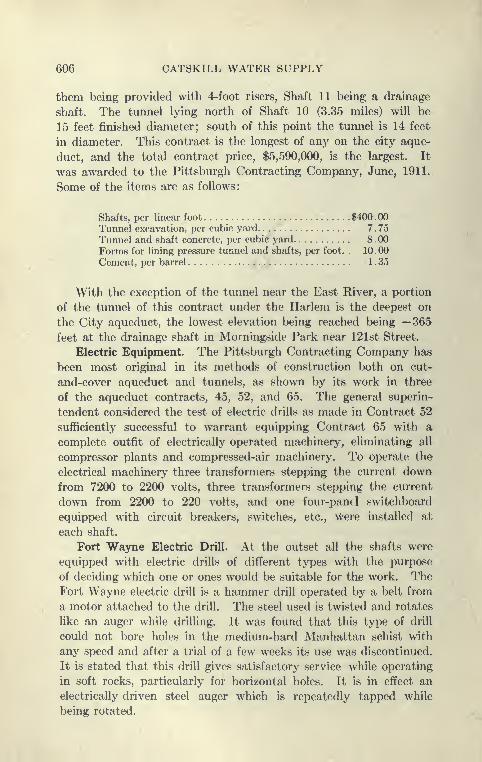
606 CATSKILL WATER SUPPLY
them being provided with 4-foot risers, Shaft 11 being a drainage
shaft. The tunnel lying north of Shaft 10 (3.35 miles) will be
15 feet finished diameter; south of this point the tunnel is 14 feet
in diameter. This contract is the longest of any on the city aque-
duct, and the total contract price, $5,590,000, is the largest. It
was awarded to the Pittsburgh Contracting Company, June, 1911.
Some of the items are as follows:
Shafts, per linear foot $400.00
Tunnel excavation, per cubic yard 7 . 75
Tunnel and shaft concrete, per cubic yard 8 . 00
Forms for lining pressure tunnel and shafts, per foot. . 10.00
Cement, per barrel 1 . 35
With the exception of the tunnel near the East River, a portion
of the tunnel of this contract under the Harlem is the deepest on
the City aqueduct, the lowest elevation being reached being —365
feet at the drainage shaft in Morningside Park near 121st Street.
Electric Equipment. The Pittsburgh Contracting Company has
been most original in its methods of construction both on cut-
and-cover aqueduct and tunnels, as shown by its work in three
of the aqueduct contracts, 45, 52, and 65. The general superin-
tendent considered the test of electric drills as made in Contract 52
sufficiently successful to warrant equipping Contract 65 with acomplete outfit of electrically operated machinery, eliminating all
compressor plants and compressed-air machinery. To operate the
electrical machinery three transformers stepping the current downfrom 7200 to 2200 volts, three transformers stepping the current
down from 2200 to 220 volts, and one four-panel switchboard
equipped with circuit breakers, switches, etc., Were installed at
each shaft.
Fort Wajrne Electric Drill. At the outset all the shafts were
equipped with electric drills of different types with the purpose
of deciding which one or ones would be suitable for the work. TheFort Wayne electric drill is a hammer drill operated by a belt from
a motor attached to the drill. The steel used is twisted and rotates
like an auger while drilling. It was found that this type of drill
could not bore holes in the medium-hard Manhattan schist with
any speed and after a trial of a few weeks its use was discontinued.
It is stated that this drill gives satisfactory service while operating
in soft rocks, particularly for horizontal holes. It is in effect an
electrically driven steel auger which is repeatedly tapped while
being rotated.
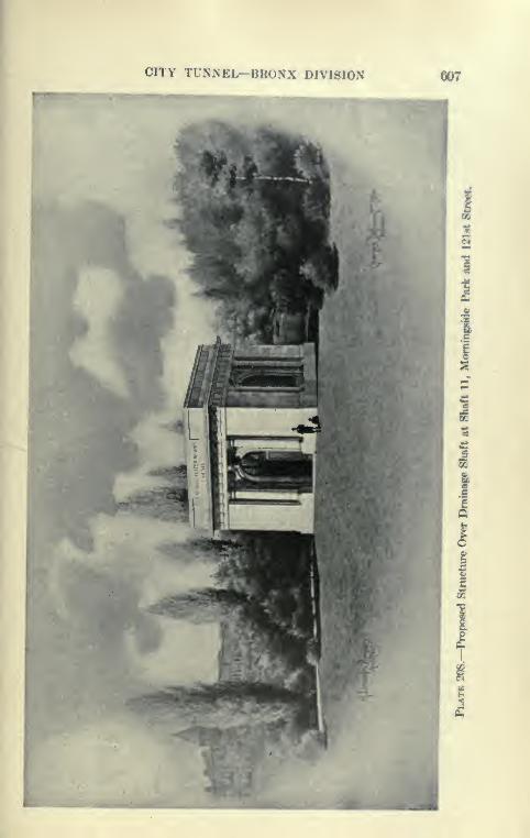
CITY TUNNEL-BRONX DIVISION 607
cS
Ic
II.
II
5
608 CATSKILL WATER SUPPLY
Temple-IngersoU Electric Air Drill. The electric air drill made by
the Ingersoll-Rand Company was tried for a short time at Shaft 6,
but it was found to occupy too much space at the bottom of the
shaft and its use was disc<..itinued. The Temple-Ingersoll or elec-
tric air drill is operated by a small pulsator mounted upon a Uttle
truck. As the pulsator oscillates the air is compressed • alternately
on each side of the piston of a simplified air drill witli which it is
connected by two lines of air hose. The pulsator is driven by an
electric motor connected to the main feed wires. The air com-
pressed is not freed, but is repeatedly used in a closed circuit. Thedrill used is an air drill modified by omitting the valve chest and
valve, also the springs, side rods, etc., both cylinder heads being
solid. This drill has given good service where there is plenty of
room for the puslators, air pipes, and electric connections, and is
particularly designed for work in large " rooms," in mines and in
headings where only one or two drills are necessary and where there
is very good ventilation, the drill exhausting no air. From the
experience at Shaft 6, its use could not be recommended for shaft
sinking, although in Colorado shafts have been sunk with the elec-
tric air drill.
After a time the use of the electric drills was confined to Shaft
9 and 11. At Shaft 9 the Dulles-Baldwin drill was used; at Shafts
11 the Pneumelectric.
Dulles-Baldwin Electric Drill. The DuUes-Baldwin is a large-
size piston drill upon which an electric motor is mounted, so as
to operate a piston which compresses the air in a cylinder similar
to that of an ordinary piston drill. At each operation of the elec-
trically operated compressor piston, the piston of the drill is driven
downward, and on the return stroke air is admitted below the piston
and again compressed in the down stroke. An adjustment is pro-
vided by which the length of the stroke is regulated. The Dulles-
Baldwin drill appears to be the simplest type of electric drill in the
class where the motor is directly mounted upon the drill. It
strikes a hard blow and can drill at a fair rate of speed. Its dis-
advantages will be given later. At Shaft 9 the Dulles-Baldwin drill
has been in use for about six months, during which time it had been
remodeled and practically rebuilt, as weaknesses developed from
time to time. The progress at the shaft with this drill has not
kept pace with the other, but it was claimed that the work here was
intended to develop the drill and to perfect it for its proposed use
in the tunnels to be driven after the shafts are down. The Dulles-
Baldwin drill appeared to be well made, but it was heavy—575
CITY TUNNEL—BRONX DIVISION 609
pounds including a 3-H.P. removable motor (140 pounds)—required
constant attention and suffered from motor troubles.
Pneumelectric Drill. The Pneumelectric drill is an electric
haninior drill corresponding to the I^yner drill. M()unte<l Ujxin
the back of the drill is a motor which operates a piston which com-presses air })ack of a hammer which strikes an anvil block which
in turn strikes the end of a hollow drill rod, as in a '' Jap " drill.
The hammer is returned in the up-stroke by a partial vacuumcaused by the return of the compressor piston. Through the anvil
blocks a fine stream of water is fed through the hollow steel, cooling
the bit and clearing the hole of chippings. A water connection is
provided on the drill cylinder fed by a flexible hose attachwl to a
water main under pressure. This drill is quite complicated and looks
light, but can drill at a fair rate of speed. At Shaft 1 1 the Pneum-electric drill has maintained a fair progress, but as at Shaft 9, the work
here was intended to develop the possibilities of this drill and to per-
fect it for future use in the tunnels. A large number of Pneumelectric
drills have been tried out at Shaft 11 and there was a large equip-
ment of drills on hand (about 22) with mechanics specially desig-
nated to take care of them. As in the case of the Dulles-Baldwin
drill, this drill has been entirely remodeled during the few months
of this work. This drill has the disadvantage for shaft work that
all the water used to clear the bit has to be pump<^d from the
bottom of the shaft, and the water lines introduce further compli-
cations.
Advantages of Electric Drills. Credit must be given to the
Pittsburgh Contracting Company for their patience and per-
sistence in trying out the electric drill. The electric drill has
obvious advantages well worth striving for, viz.: (1) It simplifies
the work by rendering unnecessary compressor plants and pipe
lines; (2) it is much more economical in power while working. It
is claimed that electric drills use one-third to one-fourth of the power
consumed by air drills. They are particularly advantageous in
locations within the reach of electric power lines from which cur-
rent can be obtained at favorable rates. The advantages citetl
have long been recognized, and there are numerous records of
previous efforts to use and perfect these drills. As long ago as
1879 Siemens-Halske built a percussion electric drill. Rotary
drills or augers driven by motor-driven flexible shafts have been
partially successful in boring coal and soft rock.
The Siemens-Halske, Gardner, Adams-Dukw, and Dietz drills
use a crank shaft driven by electric motor. The crank shaft carries

610 CATSKILL WATER SUPPLY
a heavy flywheel and operates the cross-heads which strike the
drill steel after being cushioned by springs. Such drills are heavyand cumbersome.
The Dulles-Baldwin and the Pneumelectric closely simulate
the action of the two types of air drills, the piston and hammerdrill, and thus get rid of a good many troubles of the earlier drills
with positive acting hammers or cross-heads driven directly bythe motor; but, in the opinion of the writer, certain fundamental
difficulties remain, chief of which is that a small compressor plant
is mounted in a position subject to excessive vibration, dampness,
gas, and misuse, and is compelled to do very irregular work, the
loads and resistances constantly varying. This is made manifest
by the fact that much of the troubles are caused by the motors,
the heaviest and most expensive parts of the machine. Both the
drills referred to are much heavier and more costly than ordinary
piston drills. For shaft work it has been demonstrated on the
same contract that better work can be done by " Jap " drills than
electric drills, with only a part of their weight and cost.
E. M.,Weston on Electric Drills. In this connection the author
quotes from a book by E. M. Weston, " Rock Drills, Design,
Construction and Use, 1910 "
" In attempting to compare electric with air drills, one can
only say that, for mining purposes, there does not seem to be alarge field open for them in competition with air drills under ordi-
nary conditions. Their use might be recommended in places where
power costs are very high and where high altitudes reduce the
efficiency of compressor per unit of air cylinder area, where con-
ditions are such that separate artificial ventilation, or efficient
natural ventilation would have to be provided, regardless of the
type of drilhng machine employed." DjTiamos and their insulation are on the surface guarded
from jar or undue stresses of any kind, and from working in adusty atmosphere. In mining they are mounted on a machine
whose function is to produce jar and concussion. On the surface
such machines are placed in the hands of skilled certified mechanics.
Underground they must be left to the tender mercies of the manwhose chief tools are the hammer and the drill.
" Air drills have one great advantage over electric drills in that
they provide ventilation and cool the working place. Rapid
development work in the Rand, for instance, would be impossible
if the same air hose that worked the drill were not there to blow
out the smoke after blasting."

CITY TUNNEL—BRONX DIVISION 611
Mr. Weston makes the following prediction, which ha« in great
measure been lx)rne out by the experience on this work:" The development of the air-hammer drill han, I think, prac-
tically cut off the chance of any large use of electric drills. Theyare able to bore more rapidly, are simpler and lighter than anyelectric drill; while their consumption of power is smaller than
that of a piston drill for the same work, in certain cases, the ratio
of power developed at generator to power exerted on the lx)ttom
of the hole will almost l>ear comparison with that of the electric
drill. The Temple electric-air drill should also limit the sphere of
usefulness of any purely electric drill."
The above might have almost been written after the work on
Contract 65 was well under way.
Hammer or Jap Drills for Shaft Sinking. When it wa.s seen
that the electric drills needed further development, small IngersoU-
Rand compressors, of 350 cubic feet free air per minute capacity,
were installed at all shafts except 9 and 11 and driven by a 50-H.P.
electric motor. This equipment furnished sufficient power to operate
five or six plug drills and with them excellent progress was madein drilling and shaft sinking. The Manhattan schist is usually
rather soft and easily drilled, and except where badly faulted is of
fairly uniform consistency. In this rock the plug drills worked
well, particularly good work being done by the Ingersoll-Hand
F94 90-pound rotary "Jap," put upon the market in 1911, and
used perhaps for the first time at these shafts. This drill has a
mechanism revolved by the air which continuously rotates the
socket in which the hollow steel is inserted. It has .sufficient
power to drill holes up to 8 feet in depth with a diameter large
enough to take l|-inch dynamite. With the Jap drills, at several
of the shafts of this contract, a single round of holes, thirty-six
holes, totaling 240 feet, was drilled in one shift of eight hours by
six drill runners with only one nipper and three laborers to assist,
no helpers being used. This gave a daily advance of about 5 feet.
At Shaft 10, with Sullivan Japs, 37 feet have been made in one week,
and 108 feet in one month. See also Contract 67, Shafts 19 and 20.
Comparison of Hammer and Piston Drills. In this connection
it might be well to compare the hammer and piston drills. Thehammer or "Jap" drill has all the advantage theoretically; It
uses one-half the power of small piston drills, wears out much less
steel, can be used by unskilled labor, or a skilled man can direct
several; is much lighter and handier, and can be used in places
where tripod piston drills are hard to get in and out. Lastly, they

612 CATSKILL WATER SUPPLY
are much cheaper per unit, and a given number can be operated
by a smaller compressor plant. Nevertheless, there are disad-
vantages under which the hammer drill operates. The hammerhas to travel many times as fast as a piston to equal the blow of
60 pounds of reciprocating piston with drill steel. This causes
crystallization of hammers, anvil blocks and steel, breaks the cutting
edge of the bit, and develops weaknesses in welds. Hollow steel
frequently breaks. It is said that fortunes have been spent in
experimenting with special steel for hollow drills, and although
great improvements have been made, there is still a great deal of
breakage of the hollow steel by the users of hammer drills.
The advantages and disadvantages of Jap drills were well
shown by the experience at several shafts of Contract 67. At
Shafts 19 and 20 the rotating Ingersoll Jap drill was used to
great advantage, drilling a complete round of 310 feet of holes in
six hours with seven drills in the medium-hard Manhattan schist.
Some trouble was caused by the breakage of steel and jamming
in^ holes. At Shafts 22 and 24 Jap drills were installed and worked
to good advantage on trimming holes in the hard grano-diorite
there. This is a hard dark intrusive granite, which at Shaft 22
was quite uniform while at Shaft 24 it contained numerous seams.
Trouble was experienced in drilling with Jap drills and muchbreakage of steel occurred. At Shafts 22 and 24 a combination
of piston and Jap drills were used, and later piston drills alone.
Weston on Drill Efficiency. It is interesting to again quote from
Weston, who admirably sums up the arguments on drill efficiency:
" The best drill is the most efficient. Mechanical efficiency
is a different thing from practical efficiency. The theoretical
engineer hankers after a tool which ^vill give a percentage of
efficiency of work done approaching that of the best triple-expan-
sion pump in lifting water. His soul hankers after electrical trans-
mission. He is grieved and indignant that any one should be
content to use a tool driven by compressed air acting without
expansion with an efficiency of only a few per cent of the force
developed at the prime mover. He forgets this equation holds
good in practice, P = practical efficiency; M = mechanical effi-
ciency or power cost of operating drill; T^^ = wages; C = cost of
repairs or sharpening steel; aS = standing interest and administra-
tion charges of undertaking; F = feet bored per unit of time. Then
M+W-{-S-{-C
CITY TUNNEL—BRONX DIVISION 613
" When this equation is reduced to plain fiRures in actual caMS,it is soon to be seen that M forms but a comparatively small partof the total figure. Boring sp<»eds l)einK ecjual the l>est ma(*hino in
the one that will cost least for maintenance and consume the mini-mum of power. It must, however, l)e rememlxTCKl that averageboring speed is dependent on other factors than mere speed of
reciprocation, or weight of blow. A machine might excel in these
respects and yet break down so frequently as to wa«te much timeunderground in replacements and repairs. Or a drill might beso heavy and unhandy to set up, that the proportion of actual
time available to perform work would be so small that a machineof slower maximum boring speed, that was light and handy, andcould be kept at work for a greater proportion of working time
would be preferable.
" No portable mechanical appliance of man as used by manhas to do its work under such severe conditions as a rock drill.
" The average remedy for anything irregular in the workingof the machine, due to drill bit sticking in the hole, is to take ahammer and hit hard and often and not to be too particular where.
" The modem type of rock drill may be considered one of the
most wonderful products of inventive genius, when one realizes
the manner in which difficulties have been overcome." To do this, however, has called for the best work that civiliza-
tion can supply in selected materials and high-grade workman-ship."
The shafts and tunnels of the City Aqueduct afforded a unique
opportunity to demonstrate the qualities of many types of rock
drills. More detailed information will be given in connection with
the descriptions to follow.
Excavation of Shaft 6. Shaft 6 at Aqueduct Avenue and
McCombs Road was sunk in Fordham gneiss, the first 70 feet
breaking wild, due to mud seams and crushed rock. This was
secured by concreting in the usual way, using Blaw shaft forms.
The maximum weekly progress here during 1911 was 16 feet. Workat this shaft was started with the electric air drills and Fort Wayne,
})ut these were superseded by Jap drills operated by a small
Ingersoll-Rand compressor. In seven months this shaft was sunk
260 feet and 190 linear feet of lining placed.
Excavation of Shaft 7. Open Concrete Caisson. Shaft 7 at
Sedgwick Avenue and 167th Street, close to the Harlem River,
offered special problems of its own, particularly in the upper part.
Before starting the chamber excavation it was necessary to rebuild

614 CATSKILL WATER SUPPLY
H\'

CITY TUNNEL—BRONX DIVISION 615
a 48-inch brick sewer and a 10-inch water main. After the cham-ber was excavated there remained 13 feet of sand and clay on the
rock which it was supposed would l)e water l)earinK. To meetthe difficult}' it was decided to sink an open concrete' caimon andseal it into the rock. The caisson shoe was set at elevation
and 13 feet of concrete cylinder built on it, and the Kinking com-menced. At elevation —6 feet a badly decomposed led^e wasstruck. Slow progress was made thereafter in sinking the caiflson
to elevation —24, at which time it was 24 feet long and 12 inches
out of plumb. During the sinking of the caisson alK)ut 25 gallons
of water per minute came in lx»low the cutting edge. The excava-
tion was then carried 10 feet below the cutting edge of the caisson
and the outer lining placed. Thirteen feet below this sound rock
was encountered at elevation —47 feet and more concrete lining
placed. Between the caisson and elevation —47 feet the lining
was reinforced with 1-inch horizontal bars. The shaft was sub-
sequently sunk with the usual equipment of Ingersoll-Rand Japdrills and compressor, as before described.
Excavation of Shaft 8. Shaft 8 at Highbridge Park and 165th
Street was started with Fort Wayne electric drills, but these were
found unsuital^le for the Manhattan schist encountered. A small
Chicago pneumatic tool compressor was installed and sinking
tried with small Jap drills. This was foimd to work so well that
a larger Ingersoll-Rand compressor and Ingersoll-Rand rotary Jap
drills as described were installed. With this equipment gcxxl
progress has been made. A particularly well-shaped shaft has
been obtained in the sound rock of this shaft, the Jap drills putting
down the trimming holes close to the outer perimeter of the
circular shaft. The method of excavation of Shaft 8 is sho^^'n
on Plate 209, progress made on Plate 210. The maximum weekly
progress in 1911 was 20 feet, the average 12 feet. This shaft
was sunk 450 feet in seven months and 80 feet of concrete lining
placed.
Excavation of Shaft 9. Shaft 9 was sunk with the Dulles-
Baldwin electric drill previously descril^ed. The first 15 feet is
in earth, the remainder in Manhattan schist of good quality to
100 feet. At this depth the shaft was concreted to the chaml>er,
14 feet internal diameter, using Blaw shaft forms of the usual
type. Below 100 feet, 40 feet of bad ground was encountered
with numerous slips extending the excavation as much as 9 feet
outside the payment lines. This stretch was concreted in 20-foot
lengths. Below the bad ground the rock is good and consistent
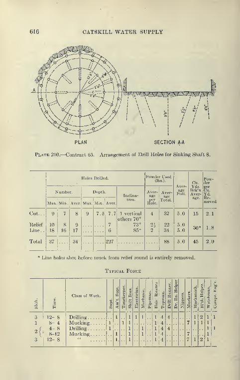
616 CATSKILL WATER SUPPLY
^/^^\\^\
A.fl:.t.4.^-_^^:=^-.-U:a
SECTION A-A
Plate 210.—Contract 65. Arrangement of Drill Holes for Sinking Shaft 8.
_ Holes Drilled. Powder Used(lbs.).
Aver-
P^ull
Cu.Yds.Brk'nAver-age.
Pow-der
Number. Depth.Inclina-
tion.
Aver-age
Hole.
Aver-age
Total.
Yd.
Max. Min.]
Aver. Max. Min. Aver. moved
Cut. . .
Relief
9
10
18
7
8
16
8
9
17
9 7.5 7.7
7
6
1 vertical
others 70°
73°
85-
4
2^
32
22
5.0
5.05.0
15
30*
2.1
Line. . 2 341.8
Total 37 34 227 88 5.0 45 2.0
* Line holes shot before muck from relief round is entirely removed.
Typical Force
i
Class of Work.
o.
i.3CO
i
I
i
1
d
11
cS3
e
1
1a
.2
aa
1
1c
Q
1
ecm
Q
2
1
2
13
1
m
1
sB
6
3 12- 88- 44- 88-1212- 8
Drilling 1
1
I,
1
1 1
1
1
" 4
4
4
4
4
4
4 ••
7
7
7
1
1
1
2
1
2
1
1
3
MuckingDrilling
Mucking
1
1 1

CITY TUNNEL—BRONX DIVISION 617
T ' ^T-i 4-
7 7t ^
m 2713 2
It?/^
^ ^t -C^
7 4II 1
r -/ ^» -A Z -. I] _i
i ^ t' 3 31 ^H t t 1 X C- 160 ' / 1 ! » ,
1 / 3_i j:^
t 7 4 i^ x^! / 3 —-2^» y! i^Sia,Z^ tt5 t1 i
2c
90 J- ^90 ^J-
j V7 Tr T^
60 * ^ IS7 3 /"II" r-
11 Z vli 7 t
» 1^ y X1 ^^ A-l ^'^ T
'—^—^^r
0^^ss
I'
a i3 ^ S -»sa8"S8Sl
21CO ^
"I
3
O 5 s : S
618 CATSKILL WATER SUPPLY
progress was made. The maximum weeklj^ progress here was 20
feet during 1911, average 11 feet. Due to the constant remodeUng
of the Dulles-Baldwin electric drill, it was hard to keep a sufficient
equipment of drills at work. The greatest trouble was with the
motors, which have a tendency to overheat or burn out. Average
progress at this shaft was, sinking, only 66 feet; sinking and lining,
49 feet monthly.
Excavation of Shaft lo. Shaft 10, at St. Nicholas Avenue and
135th Street, was outfitted with Pneumelectric drills which were
used for about two months, after which a small Ingersoll-Rand
compressor and an outfit of Ingersoll and SulUvan hammer drills
were installed. Good progress was then made. The record for
this shaft was 37 feet for a week, the average weekly progress being
18 feet. The rock here is a uniform hard Manhattan schist, and
very dry, the maximmn water inflow being 10 gallons per minute
with 65 feet unlined. Very deep holes were drilled here with the
Ingersoll-Rand rotary Jap drills, 6-foot cuts being pulled with
holes nearly 8 feet long. The shaft was sunk 260 feet in four
months and lined with 206 feet of concrete.
Excavation of Shaft ii. At Shaft 11, Morningside Park near
121st Street, an outfit of Pneumelectric drills was installed and
the shaft sunk with them. At this shaft these electric drills were
thoroughly tested and improved from time to time. The first
drills were replaced by those of a later model, said to be more
rugged and satisfactoiy. These drills are at a disadvantage in shaft
sinking, as all the water used for cleaning the bits has to be raised
to the top. The shaft is, however, very dry, so that the water can
be readily bailed out. This feature, although adding complica-
tions to the handling of the machine, should be of a corresponding
advantage in driving horizontal holes, particularly the so-called
" dry-heading " holes.
During March there were twenty-two drills at the shaft, which
was apparently being used as an experiment station for the Pneum-
electric drill, consequently the operating charges for attendance
was high. The drill has been greatly improved, but there was still
trouble with the motors, which heated after several hours of
continuous work. With this drill fair progress was made during
1911, the best weekly advance being 25 feet, the average 15 feet.
The rock in the shaft is Manhattan schist with some pegmatite
veins. The shaft is circular but somewhat larger than usual, as
it is a drainage shaft. This shaft was sunk 240 feet in five months
and lined with 175 feet of concrete.

CITY TUNNEL—BRONX DIVISION 619
^ i
11
11
II5' .23- o
o ua
§5
11
' ja
. sSi
Y
1^ S-5
620 CATSKILL WATER SUPPLY
Shaft 12 was sunk with the Ingersoll-Rand hammer drills operated
by 350-foot compressor to a depth of 230 feet in five months, during
which time 120 feet of concrete lining was placed. The hammerdrills were even used to good avdantage to drive the headings at
the foot of the shaft being mounted on tripods for use in driving
horizontal holes.
Electric Drills in Tunnels. After the shafts of this contract
had reached tunnel grade, they were, with the exception of Shafts
7 and 12, equipped with outfits of electric drills, the Pneumelectric
at Shafts 10 and 11, and Dulles-Baldwin at the others, and work
with the latest models of these drills vigorously pushed. This
work afforded a much better test of the electric drills than the
shaft sinking. While sinking shafts drills are removed after each
drilling and thus an opportunity is given to thoroughly overhaul
and to replace defective parts on drills. The ventilation of shafts
is also simple, although much time "was lost at Shaft 11 waiting
for smoke to clear after each shot. This, however, could be readily
remedied by installing blowers and " smoke-jacks " or canvas hose
reaching nearly to the bottom.
Difficulties with Ventilation while Using Electric Drills. As
might be anticipated, the absence of air while drilling proved to be
a serious disadvantage, the electric drills (particularly the Dulles-
Baldwin) furnishing no air, but considerable quantities of heat and
oily fumes from overheated motors and drills. Particularly when
the drills were operating in the heading back of the muck piles
the odor from the men and drills and the dusty atmosphere was
almost overpowering. Where it was entirely practicable with air-
operated drills to drill and shoot the heading in eight hours, this
proved to be entirely impracticable with the electrics, due to their
slower speed of drilling and frequent breakdowns and replace-
ments of drills.
Final Results with Pneumelectric Drills. The final results of
the use of Pneumelectric drills is summed as follows:
The first direct-current motors gave considerable trouble from
water entering the casing and burning out the armatures. Whenreplaced by alternating-current motors there was still trouble from
overheating, necessitating the changing of one or two out of seven
motors per shift. The power consumption per drill for horizontal
holes was metered at 3 H.P., for vertical holes at 4 H.P. The drills
cut horizontal holes at the rate of 4 feet per drill hour against 8.5
feet per drill hour for a 3j-inch-piston air drill. The feet drilled
per horse-power hour is 1.4 foot for the electric drill against 0.3
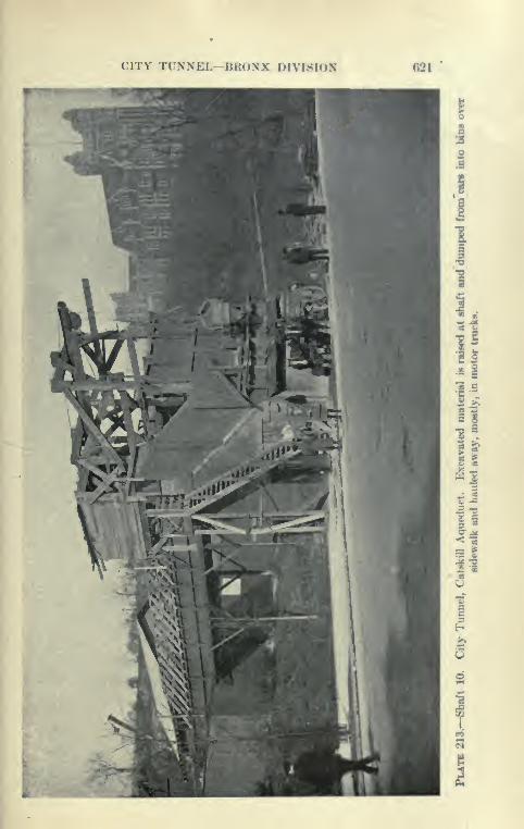
CITY Tt'NXEl.—BRONX DIVISION 021
II
1
I.
v2
ir
3
1 §
= t
d
622 CATSKILL WATER SUPPLY
foot per horsG-power hour for air drill, showing that the electric
drill had a mechanical efficiency of four times the air drill, but
nevertheless could only drill one-half as fast as the air drill.
Principal Troubles of Pneumelectric Drills. The principal
troubles which developed in the use of this drill were loss of
pressure, breaking of dolly blocks, failure to rotate, stripping of
gear, and breaking of piston rods.
Several of these defects were remedied by use of chrome vana-
dium steel for dolly blocks, improving of packing around piston
rod, substitution of steel for cast iron, etc. This drill was very
carefully made and in many respects was up to the standard of
automobile machinery. The drill was finally after eight months
of constant use and experiment discarded in favor of piston air
drills, owing to the impossibility of securing adaquate ventilation
without compressed air, especially while loading between shots
and the impossibility of drilling two rounds a day in each heading.
Results Attained by DuUes-Baldwin Electric Drills. The Dulles-
Baldwin drill appeared to work better while mounted on tripods
for shaft work, as then its great weight was not objectionable,
since the drills were readily handled by the hoisting engine and
cable in shaft.
The drills weighed 435 pounds, although without motor, which
was readily removed, it weighed 140 pounds less. AVhile driUing
heading it was difficult to secure proper mounting, and especially
heavy columns, etc., were required. While starting a hole with
the drill well back, the strain on the mounting was great and the
vibration of drill tremendous. The drills consumed about 4 H.P.
Over a period of five weeks when the drills were working at their
best, they averaged about 5.3 feet per drill hour, but it took a full
shift of eight hours with five drills to drill a heading, and usually
one or two drills were disabled before the completion of the round.
Usually many trips were made in taking drills and spare parts
in and out of the heading during a drilling shift, and in order to
allow this it was customary to completely muck out the headings
before setting up drills. This led to very slow progress.
Principal Troubles of Dulles-Baldwin Drills. The principal
sources of trouble with the Dulles-Baldwin drill were as follows
:
Electrical: Grounding of motors, burning out of armatures,
and short circuits in leads.
Mechanical: Stripping and breaking of gear teeth, shearing stud
bolts holding gear to crank shaft, breaking guide shells, breaking
cyfinders, which was largely reduced by making cylinder and crank
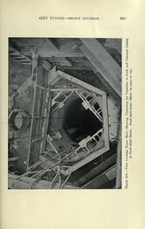
CITY TUNNEL—BRONX DIVISION 023
If
ItsS
n
'/j.
- sw O
IS
rl
624 CATSKILL WATER SUPPLY
end of one piece, breaking piston rings and rotation mechanism,
loss of compression in cylinder and heating of drills. The loss
of compression and failure of rotation mechanism were the chief
causes of trouble.
Final Change from Electric to Piston Air Drills. The Pittsburgh
Contracting Company, after giving the electric drills a most patient
and persistent trial for over a year and sparing no cost, were con-
vinced that it was impracticable to continue with them and installed
individual compressors at all the shafts as fast as they could be
brought and installed.
Use of Large Hammer or Jap Drills for Tunnel Driving. AtShafts 7 and 12 an effort was made to drive the tunnels with
Ingersoll-Rand rotating Jap drills operated from small 350-foot
compressors. The drills were mounted upon small tripods and
fed with a feed screw much as an ordinary piston drill. Although
these drills did excellent work, far outstripping the electrical drills
in progress, they were found not equal to the task, making muchdust and not exhausting sufficient air to materially benefit the men.
These drills in turn were superseded by 3j-inch piston drills, mostly
Ingersoll-Rands.
Typical Plant at Shaft after Listalling Compressors. Whentunnel driving was resumed subsequent to the installation of piston
air drills the typical plant at a shaft consisted of the following:
Steel head frame and Lambert electrically driven hoist, these
having been installed during the shaft sinking after the derricks
were discontinued in the early part of the work. I^ambert plat-
form cages (5^X8') operating balanced, were installed, and as
the shafts are nearly all on side hills, they raised the two yard
Koppel cars to the level of a steel trestle which led to bins at the
roadside. The side-dumping cars fill the bins, which in turn are
discharged into motor trucks of 5- to 6-ton capacity. These
trucks were made by Garford, Saurer and Vulcan companies and
gave very good service, hauling to fills at the foot of 129th Street,
where the large steel skips hauled by the motors are dumped into
the Hudson River by steel derricks. It is said that each truck
could do the work of several teams. At three of the Shafts, 6, 7,
and 8, the tunnel rock is crushed for concrete aggregate or used for
other purposes. The usual compressor plant at each shaft consists
of an Ingersoll-Rand compressor of 1000 cubic feet capacity and a
smaller one used in shaft sinking of 600 feet capacity. A very
large No. 8 or No. 9 or No. 10 Sturtevant blower, 3700 to 4800
feet capacity at 2 pounds initial pressure, is installed at each shaft,

CITY TUNNEL—BRONX DIVISION 625
furnishing air through a 16-inch galvanized pip<' down the Hhafts,
branching into two 12-inch pipes into headings.
Tunnel Drivings Contract 65. After installing air compresBore,
the progress in tunnel driving was much iinprovcnl, hut as only
two or three drilling shifts are used in each shaft hut moderate
progress is striven for. The rock at Shaft 6 is a hard Fordhamgneiss, taking usually twelve hours to drill with two drilling shiftH;
the progress since permanent organization was eflFected is usually
40 feet per week per heading.
At Shaft 7 the tunnel under the Harlem Railroad penetrated the
contact of Fordham gneiss and Inwood limestone which proveil
to be sound and dry; further along considerable water wa-s encoun-
tered in a broken zone in the limestone. At the other shafts the rock
is Manhattan schist of a good quality with the exception of stretches
north of Shaft 10 and Shaft 12. The average weekly progress, since
permanent organization was effected, in Manhattan schi.st, using
three drilling shifts for two headings, was alK)ut 40 feet per we<*k
per heading during 1912. At Shaft 12 in a badly broken zone per-
manent steel bents consisting of straight I-beam cap and inclined
legs supporting I-beam lagging was placed.
CHAPTER XX
CITY TUNNEL, MANHATTAN DIVISION
Contract 66
Work and Location. Contract 66 includes the construction of
4.8 miles of the city aqueduct pressure tunnel between 100th
Street at Central Park and Fourth Avenue at Fourteenth Street.
About three miles is to be 14 feet in finished diameter, one mile,
13 feet, the remainder 12 feet in diameter. Although the six shafts
are located in the heart of the city, only one shaft site, that at
Fiftieth Street, had to be condemned, five shafts being located in
Central, Bryant, and Worth Monument parks.
The Shafts of Contract 66. The six shafts, numbered 13 to 18
inclusive, are to be equipped with risers connecting the tunnel
with the distribution system*. The shafts vary in depth between
205 feet and 250 feet, and are spaced from 2300 to 4500 feet apart.
All the shafts are circular, 14 feet in finished diameter, except Shafts
13 and 18, which are irregular shafts containing two risers apiece
and a section valve built in the tunnel, so that the water north or
south can be cut off. In addition, each section valve shaft will
have a permanent circular opening 9 feet in diameter through
which access can be obtained to the tunnel after it is emptied of
water. The section valve shafts are extremely complicated, as
can be judged by examination of Plate 215.
Contract Prices. The contract was awarded to Grant Smith
& Co. and Locher (later known as Smith, Hauser & Locher) in
June, 1911, at a total contract price of $4,512,605. The unit
prices are shown on pages 628 and 629.
Organization. The construction work of this contract has
been under the charge of a member of the firm with considerable
Western tunnel experience. He, however, has for most of the
work employed shaft and tunnel men whose experience was gained
in the East and particularly on previous work of the Catskill
Aqueduct. Equipment and methods are accordingly Eastern.
The three shafts in Central Park were sunk by the Dravo Con-
tracting Company, who furnished the organization and shaft equip-
ment, while the main contractor furnished the power.
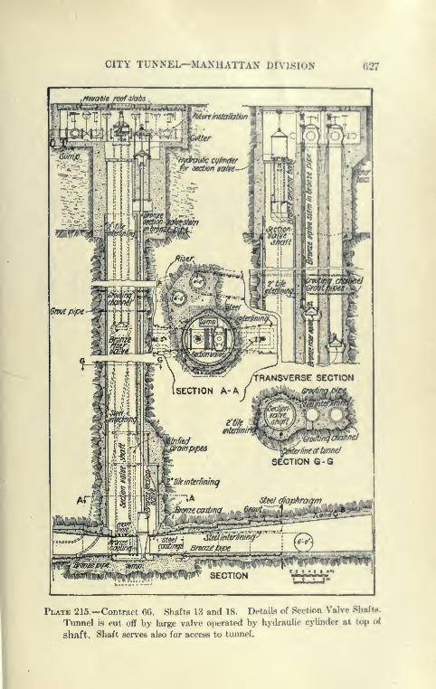
CITY TUNNEL-MANUAriAN i>l\i.^lu.N «27
Plate 215.—Contract 66. Shafts 13 and 18. Details of Section Valve Shaft«.
Tunnel is cut off by large valve operated by hydraulic cylinder at top of
shaft. Shaft serves also for access to tunnel.
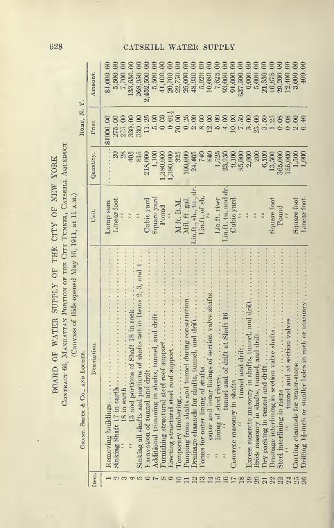
628
o 5
pq
^ «2 §
o ««
g
oO
CATSKILL WATER SUPPLY
888SS888SS888888888S888888u5^ i-^ '©. 05^ ic »o T}H^ t>-^ i>._^ o^ 05 o o_ cq_ o^ o^ »o o^ o_ co^ oo_ c-i -^^ o <!}<
i-T uf t>r CO oo" (m" »d"^ <o Oi «f od' io o" i--^ eo" '-^' t>^' o lo i-T co' oT of co~©& C0CO»O Tt<(M(N(M'>^ 1-1 0505(^3 (Mr-((MrH
T-i (N rti «3
(M
o 88888^8§S8^^888888S88§^gg85£
QiCiOOO'-"iOOOOO(NOC(MiOTtHOI>COiOCO'-iOO(MO
O00»OiCQQQQ
00 ^ O o~1-1 00 00
O O iC O Q'f -^ (N lO Ol> 00 lO CI T-i
88 8O CO ^o iC
1-t CO iOCO 1-^
32
11^ I i
'
3 2
o.g'
o o o
o ^
03
oq" O
*2 a
;s t^ 00 CO ^ P2 ^ rt ^ ^ -H-
«-d
.2
3 ^
5 .SPh in
bC"SC >
bC eS
•S 3
S 2
-O 3
o
11
s?
tK C 73
.C 302 J
_C 3^ T^
1^ - C
^ .3 ^ '*' -3 " -i^ 3f S 2 —
.3 O .3 03
:a a a 3
*-i 5 3 ^
02 "3 T!" 3;- 03
3 ^C 3
v_ ^ill03 -^ 3B cB
fe 3 bCSob§ §:5O g O
X E *H
en
ijD t: 3.S 3
*^
3 •""
;3 bC
3 ^ -
3 S03 'T
=5 A
rH(NCO'^iC«Ot>-QC050'-i(MCOTtiiOOt^00050^(MOO TtniOor-(,-(,-(r-li-(r-<,-(r-Hr-l,-l(N(N(MC^l (NC^C^
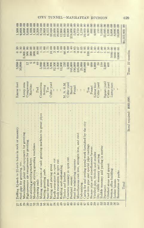
CITY TUNNEL—MANHATTAN DIVISION 62B
8888S88888S88888S888888S8888888 8
s§ s'8 £i j2 21 »«'«'-
?;
«^ '' ' ^' •': - ^- 5
;
tc o o « 00 00 ^4_ r^-^ o ^,^" oT »o ec ^"^ eo" 00 ci to
S§^8S888i^8.^888888$*^S3888888 8S5888
(M CO «0 5»C<NPC»r5(NtO(N C^
3
u
5 2, g tsC
rt S c bC- O M C
3 5P ~
.S --o T\Z 2 - .£— T" O^ ofJT! 3_v'
-PES
?s
&
1JQ ^ ;^ K '< S
p oj t; c
3 0^ B U
Jill I
'^ I ^ ^fhC «' c; C ^;
5!^5;§§»j$$S5SS3J8SB5
630 CATSKILL WATER SUPPLY
Shaft Plant. Pending the delivery of the permanent plant installa-
tion at Shaft 14, three Sullivan electrically driven compressors of
about 600 cubic feet of free air per minute were set up at Shaft 15 and
connected with the permanent transmission lines for compressed air
laid between the three Central Park shafts. A 12-inch screw-joint
line leads from the main plant at Shaft 14 to Central Park West,
branching there to two 8-inch lines to Shafts 13 and 15.
Sinking Shaft 13. Shaft 13 was sunk to the depth of about
100 feet with a stiff-leg derrick, after which a permanent head frame
was erected and sinking resumed with a temporary electric hoist
operating a non-rotating cable. This shaft, owing to its irregular
shape and to the delay which would have ensued by waiting for
the necessary risers, valve-stem pipes, etc., was timbered in the
usual manner in stretches of from 50 to 100 feet. After a depth of
about 125 feet was reached, a light pipe cross-head working on wire
rope guide was installed in the hoisting compartment and the top
of the shaft equipped with automatic door for safety.
Progress was necessarily slow and averaged while sinking about
14 feet per week. About 70 feet of timber were placed per week,
during which time no excavation was in progress.
Grouting Water-bearing Seams. Shaft 13 proved to be the
most difficult of all the shafts on the contract to sink, numerous
slips and faults in the rock requiring timbering. In addition,
three water-bearing seams were encountered, the highest being
passed with no great trouble. The water from it was collected
by a ring back of the shaft timbers and raised to the surface
by a small horizontal air pump. The second seam at a depth of about
125 feet was encountered by the drill holes at one side of the shaft and
yielded about 100 gallons of water per minute through a few holes.
These holes were grouted under a pressure of about 250 pounds with
neat cement, using a Caniff machine and Westinghouse booster with-
out interrupting the sinking, a narrow bench being left from which the
grouting was done. Later, this seam, after grouting, was uncovered,
and proved to be a steep narrow pegmatite vein yielding very little
water. Near the bottom of the shaft at a depth of over 200 feet
another and very much larger seam was encountered, yielding so muchwater (about 100 gallons per minute) as to flood the shaft. Addi-
tional pumps were obtained and the holes grouted off as before,
taking over 300 bags of neat cement grout at a pressure of about
300 pounds, the same equipment as before described being used.
Sinking Shaft 14. The best progress at any shaft of Contract
66 was made at Shaft 14, which was excavated through excellent
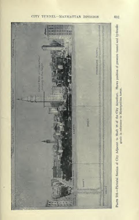
CITY TUNNEL-MANHATTAN DIVISION «81
^« 1 1 : ; -. : : : ,
1 t«ii::::::::= s,j»
t-.Sfcs'i-
-J
2
»- .
/
q^:^^4|^^Bfl^|
u .
C3(/I -
w ;
uaa
I.
1
c
"6
8
1
t:.' jnt^iii! tllKliliadlllljfa'ff'VH
\4pSllBSeMB
n^l^H
-#3 r
5c:
: •;
3
8
1 >
2
r
5
.^#,i
-, ;

632 CATSKILL WATER SUPPLY
Manhattan schist of very uniform quality, and unusually free
from slips and seams. This shaft, though located close to and
between Central Park reservoir and a small natural lake, yielded
practically no water. Shaft 14 was sunk by a skilled shaft-sinking
organization in the usual manner. A uniform progress while
sinking of about 5 feet per day was made, using three rounds of
holes, 5 feet, 6 feet 9 inches and 8 feet in radius with a central hole
to aid in breaking the cut. Holes were drilled with five large
tripod piston drills 8 feet, 7 feet, and 6 feet deep, for the circular
rows. The total number of holes were forty-one, aggregate length
272 feet; about 7 feet of hole per cubic yard and 3 pounds of 60
per cent d^Tiamite were used. All the holes were usually drilled
in one shift at night, and shot and the shaft mucked out in the
two other shifts. The force at the shaft totaled about fifty menfor the three shifts (average shift seventeen men) including five
drill runners and helpers for one drilling shift, and nineteen
muckers to the two mucking shifts. The best sustained progress
for the contract was made at this shaft, 96 feet for three weeks, the
average progress while sinking being 22 feet per week.
DetaUed Tabulation of Method of Sinking Shaft 14.
Orderof
Shoot-ing.
No.of
Holes.
Depthof
Holes.
Am't60%Dyn.
iFofe.
TotalA'mtDyn.Lbs.
DepthPulled.
Cu. Yds.Pulled.
Dyn. perCubic Yd.
No.Expl.
TotalLin.ft.
Holes.
No.Drills
1
234
1
5152,0
7876
4.43.53.22.2
4.417.548.044.0
1
51520
740105120
Total 41 113.9 5 38± 3 lbs. 41 272 5
Typical Force.
1a
c
1 1
0)
aa
«
'o
a
c
i
3
t 1.2c
ca3
Q
1 .
II
Q1
£S3
'c
<
aS3
g
S5)aH
c.0.
a
.a
1
8 A.M. to 4 P.M. mucking. . . .
4 P.M. to 12 mid. mucking. . .
12 mid. to 8 a.m. drilling. . .
.
1
i'
1
1
1
1
1
1
1
1
1
99
1
21 1 ^ ... ... 1 3
366 1
15 5 1
Totals 2 3 3 3 18 3 ' ' 1 5 5 1 6 12 1 1 1
Averages 1 day to drill and muck one round as per diagram.Plant Used. From Sept. 5, 1911, to Nov. 20, 1911, drills run by air supplied by power
plant at Shaft 15. Three Sullivan compressors, 11"X14"X18", supplying 300 cu.ft. of air
per minute each.From Nov. 20, 1911, to Dec. 6, 1911, air supplied from permanent plant at Shaft 14.
Three No. WN2 Sullivan compressors, 26" X15^" X18", run by electricity, and supplying2100 cu.ft. per minute each. Only one compressor used.
1 Lidgerwood electric hoist, 40 H.P.; 1 General Electric motor, 40 H.P.; 1 Cameron No. 6pump; 3 f-yd. buckets; 1 derrick, mast 30', boom 43'; 5 Ingersoll-Rand drills. No. F94 large,
3f" cyl. 8" str.; 2 Ingersoll-Rand drills. No. F94 small, 3i" cyl. 6" str.; 1 blacksmith shop,
and miscellaneous small tools; head frame in use from Nov. 4, 1911.

CITY TUNNEL—MANHAITAN DIVISION 888
Concreting Shaft 14. The shaft was concret«I in two fltfetch«,
using steel segmental forms built for the Dravo Contracting Com-pany from Mr. Donaldson's design. They are similar to the Blawshaft forms hut are heavier with somewhat different details.
Central Power Plant. Before the Central Park shafts hadreached grade, the permanent central plant at Shaft 14 wax in
service and furnished compressed air for all three shafts. This plant
consists of three Sullivan cross-compound compressors, cylinders
26'' X 15^" X 18", Cla^ss WN2, having a capacity of 2100 Un-i of free
air per minute. They are driven by three Wcstinghouse 400-H.P.,
6600-volt alternating-current motors supplied with current by the
New York Edison Company. The water after cooling the compressor
flows to a tank below ground from which it is raised to woo<ien
cooling tanks above ground by a Cameron air pump, the tanks
being at a sufficient elevation to force the water by gravity through
the water jackets and intercooler of the compressors. Although
the water after circulating for some time reaches about the Imiling
point, it keeps the cylinder and air from getting too hot, effecting
a large saving in the water bills rendered previous to the installa-
tion of this system. Connection is also provided for the direct
use of Croton water for cooling in case of failure of the alwve
system to work. The compressors are supplied with a system of
oil pipes through which the oil is supplied to the bearings from
a central pump and filter below ground. The plant has given good
service with few interruptions.
Shaft 15. Shaft 15 was sunk in a manner very similar to
Shaft 14, but somewhat slower, the maximum week's progress
being 32 feet, with an average of 21 feet. The shaft was the
scene of a sad accident, caused by drilling into a portion of an
unexploded charge of dynamite.
Shaft 16. Possession of the area at Shaft 16 on Fiftieth
Street west of Sixth Avenue was not obtained until Octolxr,
1911, yet such good progress was made that in January, 1912,
the heading was turned. This shaft illustrates the value of con-
crete lining, which was placed in two short stretches, 15 to 70 feet
and 70 to 110 feet, to retain very blocky ground. After this the
shaft was sunk to tunnel grade, depth 204 feet, and then concreted.
Concreting Shaft 16. A portable Smith self-charging mixer
served by wheelbarrows loaded at the sand and stone piles dumped
near by was used here. With this simple outfit, it wa.s remarkable
how quickly the Blaw shaft forms could be set up in the shaft,
filled at the rate of 15 to 20 feet per day, taken out of the shaft

634 CATSKILL WATER SUPPLY
and sinking resumed. At each concreting, hardly a week's inter-
ruption in the sinking was caused. It was found that the con-
crete Hning could be started on the muck, after blasting the last
cut in the shaft, without suffering any appreciable injury, except
to the surface finish, when sinking and blasting were resumed.
Cases are known where the concrete shaft Uning has been placed
on solid bottom and the shooting resumed a few days later without
injuring the concrete other than marring the surface. It is said
that concrete a few days old will resist shocks very well where
older and hard-set concrete might crack.
Method of Sinking Shaft i6. Very good progress was made
in sinking Shaft 16 which averaged 19 feet per week with 26 feet
as a maximum. Although the shaft excavation is circular, about
17 feet diameter, the cut holes were drilled on the perimeter of a
square about 5 feet on a side, 7 feet deep; the next on a square
about 8 feet on a side; the third row of sixteen holes, 6.5 feet
deep, was spaced on a circle about the C line. The reason given
for the peculiar arrangement of holes is that it was desirable to take
advantage of the nearly vertical stratification by drilling the holes
parallel with the strike to enable the cut and side rounds to be
pulled with few holes. This is borne out by the figures, which gave
4.44 feet of hole per cubic yard excavated against 4.90 to 6.10 feet
per cubic yard for the other circular shafts. Despite this the
shaft was driven close to line.
Sinking Shaft 17. Shaft 17, at Bryant Park and Forty-first
Street, was started in August, 1911, and sunk to grade and headings
turned December of the same year. Depth of shaft is 209 feet.
The method of sinking was similar to that of Shaft 14, the average
weekly progress being 17 feet, the best 24 feet. Rock at the bottom
of the chamber was found to be badly disintegrated, requiring
timber support, and was later concreted with an enlarged section
reinforced by rods. The rock was generally sound below this with
the exception of one ground-up zone which necessitated a stretch
of about 30 feet of concrete to be placed above the depth of
140 feet.
Compressor Plant, Shaft 17. Excavation here was started with
steam, which was soon replaced by compressed air, furnished by a
permanent compressor of 2100 cubic feet per minute capacity.
This compressor was one of the newest types of IngersoU-Rand
two-stage directly connected electrically driven compressors, size
25i"xl5|"X2l", Class PE. It is driven by a Crocker-Wheeler
motor of 360 H.P., 6600 volts alternating current.
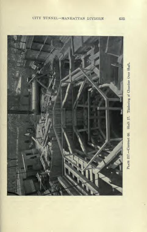
CITY TUNNEL-MANHATTAN DIVISION 686
S
^
636 CATSKILL WATER SUPPLY
Compressors similar to these were also furnished for Shafts 10
and 18 and used for both the sinking and tunnel driving. They
are remarkable for their quiet and smooth running, a very desir-
able feature where compressors have to be operated in crowded
neighborhoods, as at these shafts. The single compressor at Shaft 17
supplied air for the shaft-sinking and tunnel-driving, running
continuously for about sixteen months without a single delay.
The compressors at shaft 16 or 18 to date have done about as well.
Electric Hoists. The shafts were sunk to a depth of 100 feet
with derrick operated by small friction electric hoists. Later
wooden head frames, 50 feet high, and large Lidgerwood single-
drum direct-connected hoists were used. These hoists were
operated by 90-H.P. D.C. motors, and, being equipped with care-
fully cut gears, made little noise. The cages were later operated by
the same hoists.
Shaft Equipment. After the shafts reached tunnel grade they
were concreted to near the level of the roof and two headings driven
about 75 feet each way, and the cages installed. They are self-
dumping cages and operate on wooden guides fastened to the
head frame and concrete lining. The low Sanford-Day cars of
36 cubic feet capacity are equipped with end doors and are
automatically dumped into the bins by a cam on the head frame.
This cam engages rollers on the floor of the cage, which slides
forward and tilts when above the bins, the cars being held
by stirrups which automatically engage a pair of car wheels when
hoisting of the cage from the bottom begins. These cars and the
arrangements described work very well. Time is saved at the
top of the shaft and the low car used is very convenient for loading.
Storage Battery Locomotives in Tunnel. Storage-battery loco-
motives, General Electric (3 to 5 tons), are being used for hauling
in the tunnel, and are very successful, doing away with the
dangerous and troublesome trolley wires. They have the great
advantage of being able to run clear into the heading or to the face
of the bench, and are more easily operated by switches than
engines with trolleys. They have the disadvantage of requiring
several hours for re-charging, which sometimes causes delay or
necessitates extra locomotives or sets of batteries. As a rule
charging can be done during waits at the shaft for blasting or
other reasons. They are somewhat liable to get out of order due
to battery troubles. The contractors express themselves as well
pleased with their performance and state that their operating cost
is low.

CITY TUNNEL—MANHATTAN DIVI8ION 637
Ventilation. Ventilation is providwl by Roots prcasure blowers,
which force air through a 10-inch galvanized iron pipe with crimped
longitudinal joints; the transverse stove-pipe joints are lK)und with
muslin dipped in coal tar and clami)ed with sh<*««t-imn ringH. Atthe end of the pipe, to reach the heading after shooting, a canvas
pipe equipped with a 4-inch nozzle is unreeled, the air then l)eing
forced directly to the face of the heading to displace the smokeand gas. This system has been used with success, but the canvas
pipe was little used.
Shaft i8. Shaft 18 is a section valve shaft similar to Shaft 13.
It is located at Twenty-fourth Street at the intersection of Fifth
Avenue and Broadway. Old maps indicate that a stream useti to
cross at this point, and the experience in sinking the upper portion
of the shaft seems to prove this. This same stream gave con-
siderable trouble in driving the Pennsj-lvania tunnel at Fifth Avenue
and Thirty-third Street.
Steel Piling. After the valve chamber had l)een excavated to
dimensions of 43'X38 to a depth of 13.8 feet, using heavy wooden
sheeting and bracing, United States sheet-steel piling was placed
to the irregular outline of the shaft in earth and driven by steam
hammers into a gravelly wet ground with numerous lK)ulder8.
The piling was guided by stout timber frames placed as the
excavation deepened. No attempt was made to drive the sep-
arate piles much deeper than the ])ottom of the excavation, as
boulders were liable to bend the sheeting or throw it out of line.
This occurred at one place where a few piles were driven hard
against a boulder, contrary to instructions. When rock was a
reached at a depth of about 41 feet, or 29 feet below the chaml)er
floor, it was found to be very soft and decomposed, necessitating
driving the steel piling several feet into the ledge. This was accom-
plished by carefully excavating the rock below the sheet piling,
which was driven down a few units at a time. When the piling was
entirely driven, a very good job was obtained. About 40 gallons
of water per minute came through the joints in the piling, but this
gradually decreased through silting up of piling or by draining
the ground. The rock was found to be rather soft mica schist
to a depth of over 100 feet, requiring constant timl^ering.
Fortunately it became much better near the bottom, where the
shaft excavation was considerably enlarged.
Progress at Shaft i8. Considering the difficulties encountered
at Shaft 18 very good work was accomplished. Between July 7
and December 20, 1911, the shaft was excavated to full depth,

638 CAT8KILL WATER SUPPLY
Plate 218.—Contract 66. Shaft 18. Steel Sheet Pibng Used to Reach Rock
through Water-bearing Gravel. Piling driven by steam hammer.
CITY TUNNEL—MANHATTAN DIVISION 630
timbered, and a start made on the heailinRs. The rock in thetunnels near the shaft is very interestinR, consisting of IxhIh of
pure mica, pegmatite and talc veins, hlocky mica schist, and evena well-defined vein of asbestos. Further along the rock in anonlinary mica schist.
Use of Explosives. As might be expecttnl, the deliver>', storage,
handling, and firing of explosives in quantities necessary for goo<i
progress in the shafts and tunnels in the heart of Manhattan caused
considerable anxiety on the part of the City authorities. The Fire
Department of New York is in charge, through the Municipal
Explosives Commission, whose ex-officio member is the Fire
Commissioner, and the Bureau of Combustibles. The Municipal
Explosives Commission is empowered by the State to enact regula-
tions governing the use of all explosives, provided such regulations
are not inconsistent with the State laws or regulations. . The Bureau
of Combustibles issues the licenses for and inspects the transport-
ing, storing, and use of explosives, subject to the regulation of the
Municipal Explosives Commission. The Fire Department was very
reluctant to allow the storage of more than 100 pounds of dynamite
at the shafts in congested neighborhoods, so that most of the shafts
were sunk with 100-pound licenses. Later, 200- to 400-pound
licenses were issued, the dynamite being stored at many shafts in
first-class magazines, supplied with a hot-water heating system for
thawing, and covered with sheet iron to make them bullet proof.
All the powder used is 40 to 60 per cent dynamite, supplied by the
Dupont Company, usually by two deliveries daily. The magazines
are in charge of three shifts of licensed tenders and subject to very
close inspection by the Board of Water Supply.
Underground Magazines. The Fire Department l)eing ver>'
reluctant to grant licenses for the storage of 500 to 1000 pounds of
dynamite, which is required for driving a pair of tunnels, the
subject of storing powder at each shaft underground was inves-
tigated. It was found that underground magazines have been
built in France and Germany and experiments there made; in one
case 1000 pounds of dynamite was set off to test the construction.
Usually it is considered objectionable to store dynamite lielow
ground, owing to the liability of deterioration from moisture and
danger to the underground workings and shaft in case of an
explosion. But in most of the shafts the damage would be so
great from the accidental explosion of a surface magazine, that
it was determined to construct underground magazines at the
tunnel grade. A large chamber was formed, entered from a
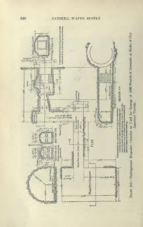
640 CATSKILL WATER SUPPLY

CITY TUNNEL—MANHATTAN DIVISION m\
crooked drift 75 feet long, and the entrance to the drift cloecd
by a very heavy automatic door to shut off ga.s<'s in case of anexplosion. A large conical wooden plug has alno l>een used in
Germany in place of a tloor, mounted so as to close the drift
when driven by the gas generated by explosions of the maga-zine. It is estimated that the discharge of 10(K) pounds of dynamitewill give a pressure le^s than 100 pounds per scjuare inch on the door.
The magazine adopted is very similar to one used in Europe with
reported success. Its construction is shown on Plate 219.** Safety ** Powders. The Municipal Explo-sives Commi&sion
has been very anxious to bar out dynamite in winter time, due to
danger from improper thawing, and has investigated many so-called
non-freezing " safety " powders. Two of the.se were tried on Con-tract 65 and one on Contracts 66 and 67, and founcF very inferior
to dynamite. A low-freezing powder with the good pro|K?rties of
dynamite is something much needed, and lately such an explosive
has been put on the market by the Dupont Company and used in
the City since November, 1912, as by an ordinance of the Municipal
Explosives Commission, nitroglycerine compounds subject to freezing
are barred during the winter months. This compound, known as
Dupont gelatin, is said to remain soft down to 0° to 10** F. It looks
like a soft gelatin dynamite and so far has given very good .satisfaction.
Bottom Heading. At Shaft 14 a good trial of the l>ottom
heading method was given and a few hundred feet driven each
way from the shaft, after which it became apparent that the
expense of driving the lower half was .so much that no pos.sible
saving in taking down the upper part could compensate for it.
It was deemed impracticable to carry along a timber platform
such as was used at Hunter's Brook tunnel. Horizontal holes
were drilled around the perimeter of the upper half, which
was shot down with light charges of djTnanite. The supposed
advantage of this method was not realized, the muck breaking
up into large blocks which required considerable block holing
and blasting. It was also found that considerable mucking at
the face was necessary before the drill columns could l>e set up
again. The rock at Shaft 14 was unusually sound, except in
one place where cut by a dry clay seam. This gave some con-
cern, as it seemed to weaken the flat roof over the l)ottom head-
ing. It was impracticable to timber here, owing to the small clear-
ances, but when the roof was taken down it no longer gave any
concern, acting as a radial joint in a stone arch, illustrating the
greater security of the arched over flat roof.
642 CATSKILL WATER SUPPLY
Comparison of Top and Bottom Headings. In general the
experience on this contract was that a full section could be driven
at much lower unit cost than any half section, the bench being
carried along by the aid of a few extra drillers and muckers with
no increased overhead expenses. This advantage cannot be obtained
with the bottom head method without considerable cost for tim-
ber platforms, etc.
Tvmneling along Strike of Rocks. The City aqueduct tunnels
in Manhattan and The Bronx running north and south follow in
general the strike of the almost vertical beds of gneiss and schist,
making it difficult to obtain a well-driven tunnel, particularly
in a circular tunnel, which tends to break with more or less parallel
sides below the springing line. Seams and decomposed layers are
troublesome, inasmuch as the tunnel tends to follow them for
long distances. It is also reported that much dynamite wasneeded to blast the heading, the rock being reported as '' rubbery."
It is probable that more powder is needed to disrupt rock while
working along rather than across the strike and that the mica schist
is resilient and has a power to absorb shocks without being dis-
rupted. Although 8-foot side-cut holes and 6-foot side rounds were
usually used, the average advance was usually a little under 5
feet, the cut often requiring reloading, so that the average use of
60 per cent dynamite was 5 to 6 pounds per yard.
Progress in Timnel Driving, Contract 66. On March 4, 1913, the
excavation was completed, 23,000 feet of tunnel being driven in
fifteen months, the first heading (Shaft 14 south) being turned
December 6, 1911. The tunnels between Shafts 16 and 17 holed
through October 2, 1912; between 13 and 14, February 19, 1913.
The southern limit of the contract was reached February 25, 1913.
This is a very good record, practically all the tunnel being com-
pletely excavated in one year. Very consistent progress was madein the 12 headings driven from the 6 shafts, the average progress
from the time of installing cages and completing tunnel organiza-
tion being about 46^ feet of completed tunnel per six-day week per
heading. The best progress was made at Shaft IS, where the
longest headings were driven, the average progress being about
53 feet per six-day week per heading. The slowest progress was
made at Shaft 17, but here the most bad ground was encountered
and the headings were shortest (1106 and 1650 feet). Considering
the conditions, the average progress here, 33 feet per week, was
good. The maximum progress was made at Shaft 18, where 152
feet of completed tunnel was excavated in the two headings in one
CITY TUNiNEL-MANHATTAN DIVISION 643
week of six working days. The tunnels were excavated to about18 feet in diameter from Shaft 13 to Shaft 17, between 17 and 18,
to 17 feet, and south of 18 to 16 feet.
Four-drilling Shift Schedule. The tunnel schedule adoptedwas such as to lead to economical excavation at a fair speed, and noattempt was made at very rapid driving. At the shafts with long
headings four drilling shifts were used in both tunnels; a i*om-
plete round was drilled and shot in each eight-hour drilling shift,
followed by an interval of four hours,which gave time for the tunnels
to clear of smoke and allowed a margin for shootings etc., in
case special difficulties were met in drilling or shooting. Fourdrills on columns for heading and two on tripods for l)enfh wereusually employed, the bench being left alx)ut 50 feet back of face.
A regular mucking gang consisted of 8 to 10 muckers and fore-
man. At times a split shift was employed in the four-hour
interval })etween drilling and regular mucking shifts to help .set
up drills, muck, etc. With this arrangement two advances were
usually made per day in each heading. A consistent effort wasmade to turn out all work inside the C line while driving the
tunnel, leaving practically no excavation above track level to Ijc
taken out after holing through. The four-drilling shift method is
given in detail in table, page 644.
Three-drilling Shift Schedule. The other schedule, used
in the shorter tunnels and when the longer ones were in striking
distance of each other, was to employ only three drilling shifts for
each pair of tunnels at a shaft. The schedule for one tunnel was
as described for the four-drilling shift method with, however, an
eight-hour interval between drilling shifts, but the other tunnel
had only one shift for that day. The next day two shifts woultl
be alternated so as to keep the average progress the same in both
tunnels. This method had the advantage of giving ample time
every other day to completely muck out the tunnel, trim, lay tracks,
dig ditches, scale heading and keep everything in first-class shape.
With the four-drilling shift method, it was found more difRcult to
keep enough muckers to do the work. The cost per yard excavated
to the contractors of the three-shift method was about the siimr
as the four-shift method, but in long tunnels, or where there is
ample labor and good superintendence, it is probable that the
four-shift method is more economical, as the overhead charges
remain the same for a greater progress. The average progress
by the three-shift method was about 42 feet of completcnl tunnel
per week per heading. For more detailed description of this
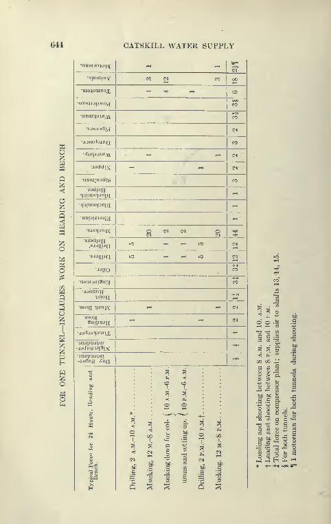
644 CATSKILL WATER SUPPLY
•aBuiJO'ioi^; r-t 1-H
SIBUIUIV CO (M CO QO
•sja^suiTjax ^ ^t^ ^ ^•uBiuaapAvoj 1 CO
•OBuiqa^B^W^ CO
•aauiadij (^
•uauiduinQ CO
•^oqjajBAV ^ ^ (M
•jsddiM ^ ^ c^
•aBui|Bu3ig CO
•jadpHqiiuis^ioBia:
^
•mimsjfOBia -
•UBpiiJOOia -•
•sj3>iDnpv ^ ^ ^ g ^•BjadiaH
.BjojiualO T-H i-i lO (N
•sjaiiua lO 1-H i-H lO (N
"HO•HI-
CO
-aataauiau^++CO
•jaanny^sioH 1-H
•ssoa Jianiv ^•ssogauipsaH
1—1 1—1 (N
•jodao^aiuij, ^•^aapaa^ui-jadng^q3if^
rtIN
•^aapuaim-iadng ;Cbq
HM
1
g
e3(0
23Ow
IN
II
*
o7 ^
bbc c
s 1
Mucking
down
for
col-
(
10a.m.-6p.m.
umns
and
setting
up.
(
10p.m.-6a.m.
Drilling,
2
p.m.-IO
p.M.f
Mnclciner.
12
m.-S
p.m
3
lO»-H
rf
CO
S3^•
5^ s th
o o ^ aS3
1-o -ts Ss c j3S3 03 P t/j
S S 3bC
««; ^ CO
300 GO vp
ii 1
II ->->
bC bC <^ ^fl c p
I'l i 50^
ri3 -J5 <u oai M c C
"^"So c
^ §^ fi3
1 o B-5 "5 '^ ^e3 c3
o o^ ^ H fe '-^

CITY TUNNEL—MANHATTAN DIVISION 645
method see description of tunnel driving at Shaft 19, Con-tract 67.
Close Driving of Tunnels. In this connection the method ofobtaining well-drivon tunnoU Is worthy of note. From phmimetlami)s, hung from center line plugs set by the engimHT. the centerline of tunnel was spotted on face of heiuling and the C line
of excavation painted in red by heading lx)ss or HUperinten<lent,
aided in some ca^^es by the engineers. This gave a very good guidefor the systematic placing of holes. Preliminary sectioas wereobtained by the " sunflower " every 20 feet and plotted on cross-
section sheets. Every week copies of t>iMcal sectioas were sent
the contractor for his information and on them attention wascalled to irregular breakage, low or high bottom, etc. The contractor
also looked over the sectioas in the engineers' offices. Jap drills
were used to drill the tight places, which were frequent along the
springing line of roof due to vertical bedding of rock. In mostof the tunnels a very fair approximation to the circular section
was secured with little to be trimmed above tlie track level. Theindicatioas are that the tunnels will be found to average a little under
the B or payment line established by che contract.
Timbering Used on Contract 66. In the driving of over 4
miles of tunnel on Contract 66, not more than 16()0 feet of the roof
required support. Isolated stretches of the Manhattan schist
where badly broken by faulting were supported on 3-piece l>ents
of temporary timber. A short stretch north of Shaft 13, and a
much longer stretch north of Shaft 17, were supported by longi-
tudinal I-beams supported on timber bents. At Shaft 13 the
rock was badly faulted into blocks with soft talcy seams Ix'tween.
These blocks kept dropping out and the roof ran up several
feet.
Bad Ground North of Shaft 17. At Shaft 17 the tunnel hap-
pened to follow exactly along the line of a longitudinal fault which
cut the rock so that the tunnel roof was poorly supported at the
right side wall by a ground-up layer of slippery talcose schb*t. The
rock penetrated by the tunnel was dragged from a vertical to
horizontal position and as it happened to be a rather hard quartz-
ose schist was broken into small blocks. Shortly after the head-
ing was shot, the material of the roof would run, requiring quick
support, after which it was safe. It was feared that if tem|Xirary
timbers were placed—and these would have IxHjn amply strong-
difficulty would be found when they were removed previously to
concreting.

646 CATSKILL WATER SUPPLY
Supporting Roof by Transverse Bents of Channels and Timbers.
For a stretch of 75 feet improvised bents of wood and steel
were used. These bents were composed of a 12-foot cap of two
10-inch channels clamped to a 8''x8'' timber core, and inclined
legs of lO'^XlO'' timbers supported on wall plates of channels
and timber built up like the cap, steel channels spanned from
cap to cap and supporting the roof when dr}^ packed. Where
the roof broke high it was supported by I-beams, and chan-
nel lagging cribbed up from the cap. This system worked
very well, the necessary steel being obtained out of stock on
short notice. As the timber legs supporting the cap were set
back of the C line in order to give sufficient concrete, the
required section to be excavated was rather large. It was also
felt that it would be safer not to concrete any large timber in pres-
sure tunnel lining, so that the method of supporting roof was
changed to a system similar to that used in bad ground on the
Rondout siphon as described under Contract 12, but the method
was modified and simplified to meet the conditions here.
Tunneling System Using Longitudinal I-beams as Crown-bars.
A top heading of variable width was driven ahead as far as thought
safe, in some cases only 5 to 10 feet ahead of the roof support, the
main members of which were pairs of 9-inch I's bolted together
with a timber between which also acted as a splice, or with bolts
and pipe separators and steel splice plates. The I-beams were 12
feet long and broke joints. They were known as steel crown-bars
and were used in a similar manner to the usual wooden crown-bars.
The crown-bars were continuously spliced longitudinally to
the center line of tunnel, and at first blocked up close to roof on
temporary cap and legs known as " horse heads." Usually three
lines were placed 5 feet apart transversely, but at times when
the heading broke wide an additional line was used. When the
heading was particularly bad, it was driven narrow and two lines
of crown-bars placed. The crown-bars alone, when blocked up
to the roof, gave considerable support and usually the lagging could
be placed several days later. About 50 to 100 feet back of the face
the heading was widened out to receive wall plates and the regular
3-piece bents placed on them to support the temporary horse heads.
Where the roof required support transverse 6-inch channel lagging
in 5-foot lengths was placed transversely. When the bench was
excavated the wall plates were readily supported on posts. Thewall plates, composed of channels and 10-inch timber, were of
great strength and readily spanned a gap at face of bench.
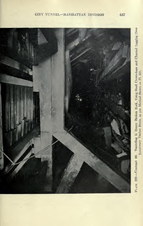
CITY TUNNEL—MANHATTAN iJlMftiON 647
I
I
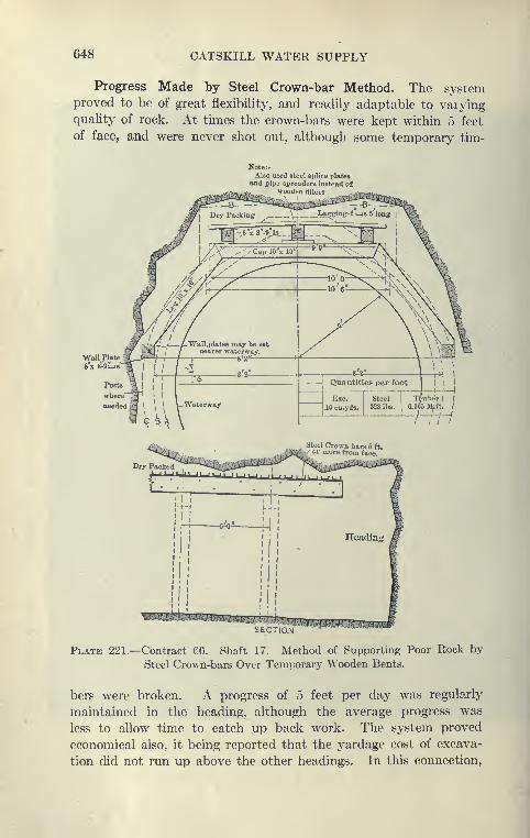
648 CATSKILL WATER SUPPLY
Progress Made by Steel Crown-bar Method. The systemproved to be of great flexibility, and readily adaptable to varyingquality of rock. At times the crown-bars were kept within 5 feet
of face, and were never shot out, although some temporary tim-
Note:.Also UEcd steel splice plates
and pip3 spreaders instead ofwoodc.li lillcrs
SECTIQN
Plate 221.—Contract 66. Shaft 17. Method of Supporting Poor Rock by
Steel Crown-bars Over Temporary Wooden Bents.
bers were broken. A progress of 5 feet per day was regularly
maintained in the heading, although the average progress was
less to allow time to catch up back work. The system proved
economical also, it being reported that the yardage cost of excava-
tion did not run up above the other headings. In this connection,

CITY TUNNEL-MANHATTAN DIVISION M9
it is well to note that the payment lines on this contract arc fixed
at 13 inches outside any supporting steel, so that the section paid
for ran 1.3 yards more per foot. About 3(X) fwt were supportedas described and although st<'el had to be orderetl from time to
time, it was taken from stock and readily adapt^nl to the work,
merely requiring to be cut to 5- or 12-foot lengths and punchedwith holes. This is a decided advantage of this system at tinica
of steel shortage as compared to any regularly framed l>ent. It
took about 14 weeks to pass the stretch of 361 feet requiring
steel roof support.
Method of Concreting Arch below Roof Steel. The wall plates
and timber bents supporting the longitudinal croun-bars were
taken out in advance of the concreting of arch, so that in this
section no wood was imbedded, except a few wall-plate poHts,
the concrete lining abutting on the rock walls or on dry packer] steel
lagging.
It was expected that the longitudinal Ts would span a gap of
about 20 feet, allowing three bents to be removed in advance of
the concrete lining. The wall plates being placed 2 feet al)ove
springing line allowed the side walls to Ik? placed without dis-
turbing the timbering. To facilitate the placing of the arch, light
steel bents of 9-inch Fs were placed below the steel crown-bars
and between the wooden bents at intervals of about 15 feet.
These bents were blocked to the roof beams so that the I-beam
legs were bedded for a depth of about 2 feet into the concrete of
the side walls, which after a few hours readily supported the l)ents.
The timbers were then removed from the concrete jilatform
of side wall form so that later the arch form was movcnl into
the same position as Is usual with the method of using " trailing"
arch and side-wall forms. The stretch of tunnel supported by steel
was, owing to its large section, concreted in lengths of from 40
to 60 feet, and as was expected the removal of the t'iml)ers Ix'low
the steel crown-bars did not delay the operation, this merely
requiring small gangs to remove timbers between concreting or
from-moving shifts.
Concrete Plant at Shaft 17. As soon as the tunnels l)etween
Shafts 16 and 17 holed through in Octol>er, 1912, the erection of
the large concrete plant at Shaft 17 began simultaneously with the
trimming of the tunnel each way from Shaft 17. The trimming
was completed by the time the plant was ready for operation
in November. This concrete plant is ver>' complete, although
erected on a very small area, formerly partly Occupied by the com-
650 CATSKILL WATER SUPPLY
pressor plant. It consists of a one-yard Chain-belt mixer, which
is fed from two small overhead sand and gravel bins, and through
a 12-inch pipe from the overhead cement shed. Alongside the
small bins are two large bins of gravel and sand, 616 cubic yards and
360 cubic yards, extending to the ground. Over the large bins are
the cement shed and operating machinery. Two vertical bucket
conveyors, Stephens-Adamson Co., raise the sand and gravel from
V-shaped hoppers below ground which are filled by auto trucks (4- to
6-yard Knox and Garfords) which dump directly into them through
horizontal gratings at ground level. The vertical elevators are
discharged by movable chutes directly into the small bins feeding
the mixer, or more usually into the large bins, which can in turn
through openings at the bottom be fed into the conveyors, so as
to keep the small bins over mixer supplied at times when the trucks
are not coming as fast as the concrete materials are used. The
cement (Edison) is unloaded directly from the trucks to a bag
elevator which delivers the bags to the cement shed above the bins.
All the machinery in the plant is electrically operated.
Method of Concreting Tunnel. The mixer discharged through
a flat chute directly into Koppel concrete cars on the cages. This
was changed so that the cages were supported on landing dogs
at platform level so that the cars can be run off and charged
below the mixer from a concrete hopper holding two batches.
This keeps things neater and expedites the loading. The con-
crete cars are made up into trains of three cars below and
hauled by electric storage battery dinkies to the forms. Thedinkies are very handy and simplify construction very much by
doing away with the troublesome and dangerous trolley wires
usually used. About the same methods of concreting as used on
the Wallkill siphon and elsewhere is used, including Blaw forms,
steel inclines, hoists on platforms, etc. It is expected that the
tunnel will be rapidly concreted in 60-foot sections, using the
" trailing form " method. Conditions for concreting are usually
favorable, the tunnels usually being quite dry.
Expected Progress in Concreting. The speed of concreting
tunnels and the methods of moving forms, etc., have now been so
well standardized and are so reliable that it is confidently expected
that-by using the plant at Shaft 17, and a similar one at Shaft 14,
the entire tunnel lining in the contract from Ninety-ninth Street
to Fourteenth Street (over 23,000 feet) can be concreted in a few-
months. The largest haul of concrete in the tunnel will be about
7500 feet. It is expected that two storage battery dinkies will be

CITY TUNNEL—MANHATTAN DIVISION 651
sufRcient at each plant, but to ianurc having charged locomotives
on blind two others will ho kept in reserve.
Contractors' Yard and Auto Trucks. The contractor aecurad
from the Park Department an area at Eighty-fir»t Street andRiverside Drive recently filled in by dumping tunnel muck hauled
from the upper shaft. Sco^vs of sand and gravel are delivere*!
alongside the bulkhead and unloaded by a wide-gauKc» MeMyler" Interstate " locomotive crane which stores the material on large
stock piles back of the bulkhead and also fills charging bins from
which the contractors' auto trucks are loaded. These truck.s easily
surmount a ver>' steep grade on Seventy-ninth Street, where horse
trucks have to be assisted by extra helping t<»ams. The auto
trucks are deemed to be more economical than horses for this
service.
Contract 67
Contract 67. Prices. Contract 67 was awarded to Holbrook,
Cabot & Rollins Corp., George B. Fry, and T.B. Bryson, June, 1911,
for a total contract price of $5,272,435. The items of the contract
are given in the table on pages 652-4.
Work Included. The work to be done under this contract
includes the concrete-lined tunnel extending from Union Square
to Fourth Avenue, the Bowery, Delancey and Clinton streets,
under the East River, and into Brooklyn as far as Fort Greene Park
and Flatbush and Third avenues and Schermerhom Street, where
the two terminal shafts of the City Aque<luct are located. The
northerly 7560 feet of tunnel will have an inside diameter of 12
feet and the remainder 11 feet. The six shafts excavated are spaced
from 3800 to 5200 feet apart and vary in depth from 310 feet (Shaft
23) to 757 feet (Shaft 21), the latter depth including the sump at
the foot of the shaft. Shaft 21 \vill be the deepest shaft on the
line of the aqueduct with the exception of the shafts at the Hud-
son River. Shafts 19 and 22 will contain one 4-foot riser, Shaft
20 two 4-foot risers, the terminal shafts (Nos. 23 and 24) two
6-foot risers, and Shaft 21 will be the drainage shaft, containing
also a 4-foot riser.
Features of Contract. The distinguishing feature of this contract
is that compressed air was required to reach rock at all the shaft.**,
the depth of rock below ground water varying from 36 to over 100
feet. Another feature is the small finished diameter of the tunnel,
the step shafts, and the crooked alinement through the East Side
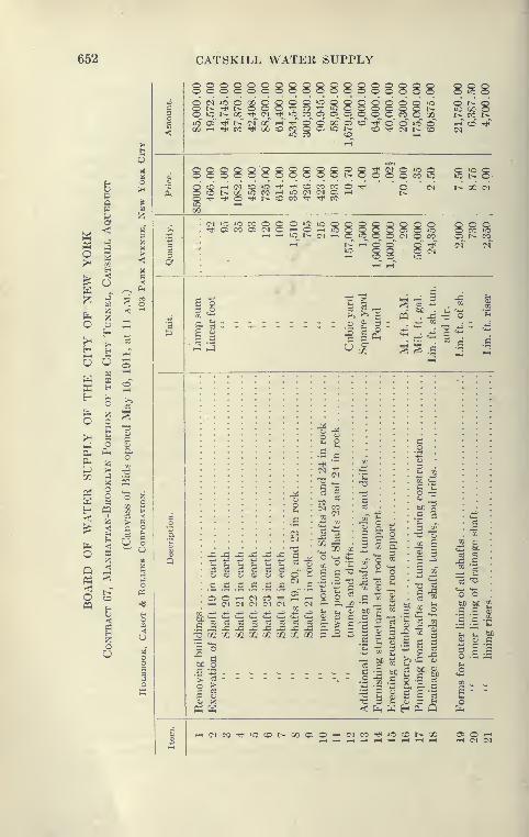
652 CATSKILL WATER SUPPLY
o o
^^
om
13
O(M>OO0C'OOOOi0Oc^r:^^rPOO^co^»o »o
(M Tfi lO CO Cl Ci C5^ »c t^^ oc ^_^ _^ _^ _^ __ _^ _
»0~ oT "(^ tC (>r GC~ '-h" ^" O" O' 00 of o©&r-ITt<CCTt<00COC0OC5»Ot^
lO CO CO
Q O OQ O O _ -O^ O^ CO^ 0_ 00rlT o' O^ iC O"CO Tti (M t^ O
O t^ oIC 00 ot^ CO t^
0000000000©l>-OOOOwS Sb^O'CO'-H(MCOiO'^'*iCOCOCOO'<tiCDt>-XiOC0<-t»O(M(MC5i-irtH-^O-^t^CDCOTti-^CO
(M lO iC CO O<:t< Ci CO O; (N _
,-1 ,-1 lO t^ (M T-i O »C O
g (N t^ 00 (M
c^^T^*^
2,900
7302,350
c/. "^ pq . x5 -c o ^
215^ C 3 - — - _ •
^ ^ S S .£ ;!
C^
i£ O
I ^C a<U XP4 H
o C
'i^ ^ o ^
*- ^ G
c^ ^ ^ ,22'"' —
3 CO
-S S3
c3 c5
U2 CO
i^ 5 c -^o ~ c a
•2 -^ .£ o.-M •-: *j c'O t. o CTJ 3 ^- o^ f^ W H
i: Of!
CI c
2 -c
^ bb
-^ .S
b£ bC
.2 .S"S 'c
S -
^(NCOTt^iOCOt^OOOiO'-H(MCOT*H

CITY TUNNEL—MANHATTAN DIVISION 653
8S8 8 88 SS 8^8 88 S888888 888888888i§i§§l^ii§§i§§§i.^§§S§§li.^§i§§I" I ^^ "^^ ^' ^ ^^ ^ ""' "' ^^ '^^ 8 '^^ "^ ^' •^' ''' 2 «^'
« ^ k '^ i ^ § 4«"
{2gS88S^BiS8S5g88888SS88S888gSS
O O O O --^ CO oCC (M !>. TJ»
c
I, IIc
OJ C2i S:
lisCO t, •—!» 1
c5 o
-acc3
3 -a^ crr
««
CO IC 3
^ hi)
li
li
-^1£ 2
O 7i
« en 5 c
•-dj
btj '
bO
s -
'S-
c a
Q Q
C3 ^
g CO CN
^ o *-
^ -c J=cooc .£ .£eS T 7JS -^ nw
bC bC3 C
.= 2 £c
•5 fcO « U *J l;
2: fe3
I
o j2
55
•^1
bC i
= S c
c bCw 3
5 g 08
S o S i
- .£
s
o3
c 5 o
£ 3C/ -
3O' 3
i 1 £ ^ 'E
^ 3 ^
^g?^^g^g5S^?3??S§JSiJ§^So§«^§5^555§i;5?§S

654 CATSKILL WATER SUPPLY
Q o o o o o o O O O c o o o o 1oooooocoooooqo oaooodoogoooogoo ^
g t^OOOC2(MiOto<X)iOiOi-iOOCC Tt<
£ (>* «0 (XT Ttn'" i-T r-n" CO ^" OO" O" (N
< ^ lO ^ rri
i§§8ggS8SSS8S88
c ©& O (Mi-HiCCDCCCO(NOiOPLh GO O
>.oggoogooggo 8 8
•-; 00'~'C^C^I'^'—'lOto o ot iS o" 40 i-T »o oo" irj
a Tf CO3<y
nd n ndfoot
yard yard yardfoot
sumfoot
nd
'c
t3 PouTo
PouLinear
CubicSquare Cubic Linear
Lump
Linear
Pou
ioo
"l^
>>-o
-B
1
Co
1C
>
1•S ^
bi
1
Q
ing
meta
cial
pipe
llaneous
to
24-inc
and
smal
nd
pavin
)aving
in
J1!2
,
bua
JH V Q^ _ . ci "^ cS ^ ;i Si
"t^ C o J= X ^ ^ £ ^ c o•3 ^.2 g g >.^
- i T. 22 i' 1 >. i iM i-^ y
'cc-
aring
for
and
ast-iron
pipe
ronze
pipe
an
itrified
pipe,
:
ry
rubble
ma
ubble
masoni
rushed
stone
einforced
con
)ction
and
loc
nking
casing
3
OOU«> QrtfLiOP^ccJcC
S3 S S :S {§ J§ iJ5 S § S S S S S1
8"^
I
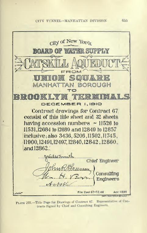
CITY TUNNEL—MANHATTAN DIVISION 6&5
BOARD OF mMBRggggLY
f-^Kyt^^^ O ^
UNION SQUAREMANHATTAN BOROUGH
BROOKIJni TIEI^MINALS
Contract drawings for Contract 67
consist of tliis litle sheet and 32 sheets
having accession numbers -' 11526 to
11531,12684 to 12689 and 12849 to 12857
iinclusive; also 3436,5206,11502,11745,
11900,12491,12497,12840,12842,12860,
iandl2862;
- y^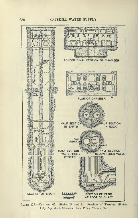
656 CATSKILL WATER SUPPLY
^^ 'j7nt
jlj|iwwniiiiinirii|i |iiiii||niw iiiriw ii
](i »iiiVB:'il!iMiMM i niii|Wji i^
LONGITUDINAL SECTION OF CHAMBER
^Ts-sr?
mchannels ^'
HALF SECTIONIN EARTH
. Stee/interiinin,
HALF SECTIONWATERTIGHTSTRETCH
ALF SECTIONIN ROCK
HALF SECTIONBELOW RISER VALVEl
SECTION OF SHAFT b&hmSh'* SECTION OF BENDiBBs=a!=S" AT FOOT OF SHAFT
Plate 223.—Contract 67. Shafts 23 and 24. Sections of Terminal Shafts,
City Aqueduct, Showing Riser Pipes, Valves, etc.
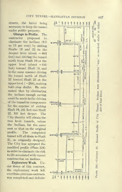
CITY TUNNEL-MANHATTAN DIVISION 657
streets, the latter being
necessary to keep the tunnel
under public property.
Change in Profile. Thecontractor i)roposed to
ehminate the inclines (9.7
to 15 per cent) by sinking
Shafts 19 and 22 to the
deepest level (about — 664
feet) and driving the tunnel
north from Shaft 19 at the
upper level (about —181feet) toward Shaft 18, andin the same manner driving
the tunnel north of Shaft
22 toward Shaft 23 at the
upper level (-288), makingboth step shafts. He esti-
mated that by eliminating
the inclines enough saving
could be made in the driving
of the tunnel to compensate
for the expense of sinking
Shaft 19, 181 feet and Shaft
22, 191 feet deeper. TheCity thereby will obtain the
two level tunnels, minusthe inclines, for the samecost as that on the original
profile. The completed
tunnel will all drain to Shaft
21, a.s originally designed.
The City has accepted the
modified profile (Plate 224)
in order to eliminate the risk
to hfe associated with tunnel
construction on inclines.
Exploratory Work. Un-der items of this contract,
the exploratory work left
over from previous contracts
was completed and definite
Llillii
I
I
1
8|
So§-1Ha
&
a^MMHHffl
658 CATSKILL WATER SUPPLY
determination made of the rock through the East Side by diamond-
drill borings, which gave all the information necessary to fix the
final grades of the tunnel.
All core-drilling under this contract was done by machines
and force furnished by Sprague & Henwood. For sinking
casings, outfits known as " Minnesota Rigs " were employed.
After rock was reached, diamond drills, either hydraulic or screw-
feed, were employed to obtain cores to the depth desired. Tenold holes, which had been left in an incomplete condition bj^ for-
mer contractors, were reoccupied, but the condition of the casing
found in a few of these holes was such that they could not be
deepened and new holes were substituted in addition to several
new holes required to give additional information. Nineteen
holes in all were occupied and a total depth of 6890 feet drilled.
Nine of the holes reached a depth of over 700 feet, the deepest being
hole No. 405, on Allen Street, which was 753 feet deep. These,
in common with previous holes drilled in this neighborhood, were
the deepest vertical holes drilled for the Board of Water Supply,
with the exception of those in the Hudson River. A great deal of
soft rock had to be penetrated in boring, resulting in the loss of
one diamond bit and repeated attempts to get down. The workaccomplished was very creditable, yielding d somewhat higher
percentage of core than in holes drilled previously; also indicat-
ing that the quality of the rock at or near the tunnel grade wasbetter than originally supposed, and that some deep points in
the soft rock indicated on the contract drawings did not extend
to depth shown. Two borings were driven close to the caisson
at Shaft 23, to determine rock surface and length required for caisson.
The type of drill rig used is shown on Plate 21.
Drilling of Hole No. 406. Unsuccessful Attempts. To illustrate
the method and the difficulties of drilling deep holes in soft rock
a detailed description of the boring of Hole No. 406 is here given.
The East Side holes were probably among the mp^t difficult.
I Hole No. 406, near Hester and Essex streets, was started July
12, 1911. The hole had previously been drilled to 457 feet, and
contained 161 feet of 6-inch, 164 feet of 4-inch, 208 feet of 2^-inch
and 345 feet of 1^-inch casings.
When the hole was reoccupied a cave was found at depth 417
feet by washing. In order to get casing below this, the lowest
casing was removed, the hole reamed down to 427 feet and 425
feet of l|-inch casing put in. During the reaming the rods were
stuck several times and once broke at 200 feet depth. Often after
CITY TUNNEL—MANHATTAN DIVISION 659
removing the rods, the hol(» would vuw in for u di.stunr<* of 10 to30 feet, especially in depths 390 to 440 fe<>t. At this depth it wtmestimated that only 75 per cent of the wa«h water retumod tothe surface; to keep the hole clear constant purnpinR, under premure,was necessary. The ground below the l}-inch caning continuedto cave and it was further found impossible to either drive or pull
out the casing, which finally broke at depth of 243 feet, leavine182 feet in the hole.
The drillers finally succeeded in starting a new hole to mw sun-
from bottom of 2.^-inch casing, getting it ilown to 3G6 fe<«t, although
constantly troubled with cavy walls, and occasionally by the
top of the old 1^-inch left in the ground. This wius bhwtwl »o
as to chamber out hole at this point, after which the 2}-ineh casing
was entirely removed and the work continual by drilling and driv-
ing new 22-inch casing, which broke and had to \w again removed.
The 2^-inch casing was finally driven to 257 feet and blasting
was done ahead of this to loosen the ground to enable further driv-
ing. The 2^-inch casing again broke 65 feet down and wasremoved. The old 4-in(;h casing was now removed and was found
to have been broken and damaged by the blasting.
Final Success at Drilling Hole No. 406. New 4-inch casing was
then put down to 219 feet by washing and driving. The drillers
then put down 22-inch casing to 230 feet by washing, chopping,
and })lasting. After August 11 good consistent progress was ma<!e,
by drilling with diamond bit inside of 2-inch casing down to 462,
with full return of the pump water and recovering 87 feet of 1}-
inch core. Next 462 feet of l^-inch casing was put in the hole,
which was finished September 8th to depth of 736 feet, recover-
ing 58 feet of il-inch core between levels 462 and 736 feet. Todrive the casing the Minnesota rig was used, to drill rock a Sullivan
hydraulic feed diamond drill.
Shaft Sites and their Use. At all the shaft sites, save at Shaft
19, substantial increases over the original contract area were
obtained from the city authorities by the contractors, either by
occupying large areas of bridge plaza or park space, or more
usually by decking over the streets adjoining the shaft. The
decking over of the street accomplishes a two-fold purpose: it
gives the contractor more working room and lessens the inter-
ference of the work with traffic; derrick houses, etc., l)eing sup-
ported overhead by heavy timber columns an<i I-l>eam.s. At
Shaft 19 little increased area could be obtained, and the con-
tractor, therefore, increased his working space l>y decking over the
660 CATSKILL WATER SUPPLY
entire area, the upper deck projecting about 6 feet over the fence
at the ground level. Although the ground area at the shaft is
only about 5000 square feet, such good use has been made of it
by very carefully planning each portion of the plant, driveways,
muck bins, etc., that the plant is very efficient and work seems
to be hampered only to a slight degree. The arrangement of the
plant at Shaft 19 is well shown on Plate 225. It may be here noted
that electric power alone makes it feasible to keep so muchmachinery in such a limited area, a small fraction of what would
be occupied for the same purpose in open country.
Two Stages of Work. The work of Contract 67 passed
through two stages. The first stage when the compressed-air work
was done and the later stage of shaft sinking and tunnel driving.
For the first work, temporary compressed-air plants were installed
and the work was accomplished under the supervision of T. B.
Bryson, a member of the contracting firm. These plants were
obtained mainly by transfer from the Brooklyn Navy Yard, where
similar work was drawing to a close. A typical plant consisted
of a large upright boiler furnishing power for large stiff-legged
derricks with booms ranging from 55 to 85 feet, a low-pressure
compressor, and the usual outfit of steel shafting, locks, concrete
mixing plant, etc.
Valve Chamber Excavation. The first work was to excavate
the large valve chambers in open cut, using 4-inch sheeting and
12"X12" wales and bracing. The valve chambers of Shafts 23
and 24 are of considerable size, 30'X60' and 30 feet deep. Nodifficulty was met with in the excavating, the 4-inch sheeting
being driven in single lengths, by hand and steam hammers or
by pile drivers, operated by a derrick engine, in guides suspended
from the boom. The last method was particularly satisfactory,
as it could be readily operated by any derrick and is simple of
construction. The material excavated was mainly sand of good
quality and was later used for concrete, except in the Manhattan
shafts, where the sand proved too fine and not worth saving.
Concrete Caissons. As soon as the valve chambers were con-
structed, the V-shaped steel shoe or cutting edge was bolted up
at the bottom, and on it the concrete caisson was built with the aid
of inside Blaw forms, of the type usually used in shafts, and out-
side steel-panel forms constructed by the Logan Iron Works.
These caissons were entirely of concrete, reinforced by a double
row of vertical and horizontal hoop-rods. The vertical rods are
from 1 inch to If inch in size, connected by sleeves or turn-
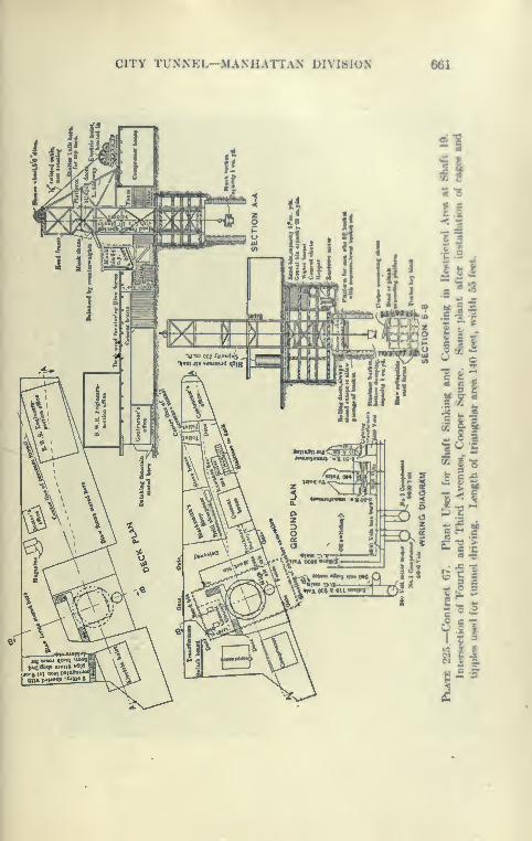
CITY TUNNEL—MANHATTAN DIVISION 661

662 CATSKILL WATER SUPPLY
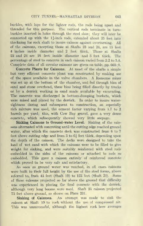
CITY TUNNEL—MANHATTAiN DIVISION 663
buckles, with laps for the lighter rods, the rods being up«ct andthreaded for this purpose. The vertical rods terminate in turn-
buckles inserted in holes through the steel shoe; they will later lie
connected up with the U-inch rods, extended atx)ut 25 feet into
th© lining for rock shaft to insure caisson agaiast overturning. All
of the caissons, excepting those at Shafts 23 and 24, are 15 feet
4 inches inside diameter ami 2 feet thick. Those at Hhaftii
23 and 24 are 18 feet inside diameter and 3 feet thick. Thepercentage of steel to concrete in each caisson varied from 2.2 to 3.4.
Complet<' data of all circular caissons are given on table, pp. 668-:9.
Concrete Plants for Caissons. At most of the shafts a simple
but very efficient concrete plant was constructed by making use
of the space available in the valve chambers. A Raasome mixer
was set up at the bottom of the chaml>er, and fed through bins of
sand and stone overhead, these bins being filled directly by trucks
or by a derrick working in sand made available by excavating.
The concrete was discharged in bottom-dumping buckets, which
were raised and placed by the derrick. In order to insure water-
tightness during and subsequent to construction, an especially
rich mixture was used, the cement factor varying from 1.7 to 2
barrels per yard; this, with Cow Bay gravel, gave a very deasc
concrete, which subsequently showed very little seepage.
Sinking Caissons to Groimd-water Level. Sinking of the cais-
sons alternated with concreting until tlie cutting edge reached ground
water, after which the concrete deck was constructed from 6 to 7
feet above cutting edge anrl from 3 to 6^ feet thick, depending upon
the depth of the caisson. The decks were designed to take the
load of wet sand with which the caissons were to be filled to give
weight for sinking, and were suitably reinforced with steel rods
embedded in the sides of the caissons or attached to rods so
emV^edded. This gave a caisson entirely of reinforced concrete
which proved to be very safe and satisfactory-.
As soon as ground water was reached, in all cases caissons
were built to their full height by the use of the steel forms, above
referred to, from 45 feet (Shaft 19) to 123 feet (Shaft 23). Some
of these caissons projected so far above the ground that difficulty
was experienced in placing the final concrete >Nnth the derrick,
although very long booms were used. Shaft 23 caisson projected
73 feet above ground, as shown on Plate 231.
Sinking of Caissons. An attempt was made to sink the
caisson at Shaft 19 to rock without the use of compressed air.
This was unsuccessful, although the highest rock here averages

664 CATSKILL WATER SUPPLY

CITY TUNNEL-MANHATTAN DIVISION 665
only 20 feet below ground water. The material penetrated wan aver>' fine sand whirh hoiled up inside the caijwon after it hail lKH»n
excavated 5 feet below ground water. A concrete dock 3 feet
thick was then built and the cai8.*«on sunk to rock in a few dayswithout difficulty. Before compr(»«se<l-air men were employe<l,
3-foot steel shafting was carried alK)ve the top of caisKon Huf-
ficiently, in most cases, to make room for the pig-iron platform.
Two lines of shafting were used in all cases, except at Shaft 19, andsupplied with Mattsen air locks. These locks are providf<l with
the usual bottom and side doors moving on a track and supplied
with rubber gaskets. The small cylindrical buckets arc; con-
tinuously operated in the shafting and are raised and lowered bya derrick operating a rope which passes through stuffing-hoxes
at the top of the lock and guided by a sheavc»-whe<*l held by a
gooseneck on top of the lock. Usually one lock Is used as a man-lock and the other for muck. At the first shaft sunk only one lock
was provided with a hoist, the men climbing up a vertical ladder
riveted to sides of the shaft. At the suggestion of the engineers,
both locks were provided with hoists to save the men the exhaus-
tion of a climb. This proved to be beneficial to the men and also
expedited the sinking of the caissons, as both hoi.sts could l)e ased
for mucking as well as for the men. After being fully Wjuipped,
the sinking of the shafts through the sand to the rock was a com-
paratively simple matter, the sand first remove<l being usetl to
fill the interior of the caisson to add weight, after which it was
removed by the derrick and carted to the dumps or stored for future
use. A speed ranging up to 16 feet per day was made while sink-
ing through sand and earth.
Schedule of Pay and Hours for Compressed-air Workers. The
men employed on comi)ressed-air work all belong to the Compn*sse<l
Air and Foundation Workers' Union, under the following schedule:
Pressure,Lbs. per Sq.in.
Hours,Total.
Worked per Shift.
Waccs per Shift.
Foreman. l4ibor«T orHanil Hoc.
1 to 22
22 to 3030 to 35
35 to 4040 to 45
Over 45
8
6
4
3
2
1 hr. 20 m.
^ hour out for lunch
3 on; 2 or 3 off; 3 on2 on; 4 off; 2 on
H on; 4 J oflf; 1} on1 on; 5 off; 1 on
As arrang<Hl
$5.005.255.505 756.00
$4 004 254 504 75
5 00A» nrrangod
In addition, the wages are increased 50 cents r>er shift when doing concrete
work.

666 CATSKILL WATER SUPPLY
As the number of hours per shift decreased, more shifts were
taken on, so that the work was carried on continuously through-
out the twenty-four hours, previous experience having shown that
it is dangerous to have idle periods during caisson sinking.
Loading of Caissons for Sinking. A point was soon reached
in the sinking of the caissons when the weight of concrete and
sand filling was insufficient to force them down. Additional weight
was then secured by loading up the platform at top of the caisson
with pig iron, several hundred tons of this being required in most
cases. Frictional resistance was found to vary from 300 pounds
per square foot to over 1600 pounds per square foot. The mate-
rial in New York City, composed of fine, micaceous sand, gave
much lower frictional resistances than the Brooklyn coarse sand.
The friction per square foot was found to be considerably higher
for the caissons of larger diameter than for the smaller. At Shaft
24 the weight of the caisson was 1780 tons, but to reach rock an
additional load of over 4000 tons was required.
Plumbing of Caissons. Every effort was made to sink the
caissons plumb. While sinking, observations were taken on
plumb-bobs in the working chamber, and on points at known
elevations on the outside of the caisson. The best device was
found to be a plumb-bob whose top was fastened in a pipe and
concreted into the deck. This line was carefully compared with
one suspended for the whole length of the caisson, so that foreman
and inspectors merely had to measure the distance from the line
to the concrete. The caissons at Shafts 19 and 20 were sunk
nearly plumb, but those at the other two shafts were found to be
out about 6 inches in 100 feet.
Sealing Caissons into Rock. The bulk of the work of sinking
caissons is that in connection with sealing them into the rock.
Although this character of work has probably been done where a
caisson has been sunk for mine shafts, no records of the methods
followed were available, and an original method had to be worked
out for this contract. It was deemed dangerous to excavate
outside the caisson and place concrete filling after sufficient pene-
tration of rock had been obtained. The contractor proposed a
method which was adopted for Shaft 19. This was to concrete a
collar below the cutting edge and to a diameter I inch larger than
the outside of the caisson. While this was being done, the caisson,
being heavy, was supported on wooden posts which were shot out,
allowing the caisson to slip through the concrete collar, after
which the cutting edge was concreted in and the space back

CITY TUNNEL—MANHATTAN DIVISION 667
of the shoe and around the concrete collar wbh grouted through pipMplaced in the bench and through the walls of the caii«K>n lx>low the
deck. This was found to Ixj effective here, hut there were indica-
tions that with higher heads there was danger of nins occurring
between the concrete collar and the caisson after the firnt drop.
A shorter and more effective method was originated by the engi-
neers and subsequently used on all of the other circular caimonH.
After the rock had been excavated the required distance to allow
for proper building of the concrete collar and l)ench, in which
were placed grout pipes, the caisson was dropped onto a thick
wad of oakum which was compressed by the cutting edge and
formed an effective seal, made permanent by grouting the space
back of the lower portion of caisson. The method of sealing is
clearly shown on Plate 228. With sufficient pressure in the
working chamber to keep out water, it was found that very good
concrete work could be secured and that the set was ver>' rapid
in compressed air. All of the sealing operations were very suc-
cessful, leakage at some of the shafts being almost imperceptible,
with a maximum of from one to two gallons per minute after the
air was drawn off. The rock at most of the shafts was found to
be very irregular, and to make a proper seal it was necessar>' to
go about 3 feet below the lowest point of the rock, and considerable
rock excavation at the highest pressures was necessary. This
work was accomplished with the aid of Jap drills and dyniunite
to blast inside the caissons, at which time it was neces.sary to
remove all the men and shoot from the air lock. After the cais-
son was sufficiently ventilated by locking out the air containing
the powder smoke, the men returned. The final lowering of the
caisson after all the preparations for the seal had been made wjis
readily accomplished by drawing down the air and allowing the
caisson to settle hard on the oakum placed on the bench. To
prevent the possibility of breaking the concrete bench, wooden
posts capped by steel plates were concreted in so as to absorb the
shock of the dropping. It Is probable, however, that the con-
crete bench is of sufficient strength to withstand the shock without
the wooden posts.
Comparative Caisson Data. Complete data obtained during the
construction and sinking of the caissons of Contract 67 arc given
on pages 668 and 669.
Caisson at Shaft 20. A complete description of the sinking
of the caisson at Shaft 20, Delancey and Eldridgc streets, follows.
This probably represents the most advanced construction and the
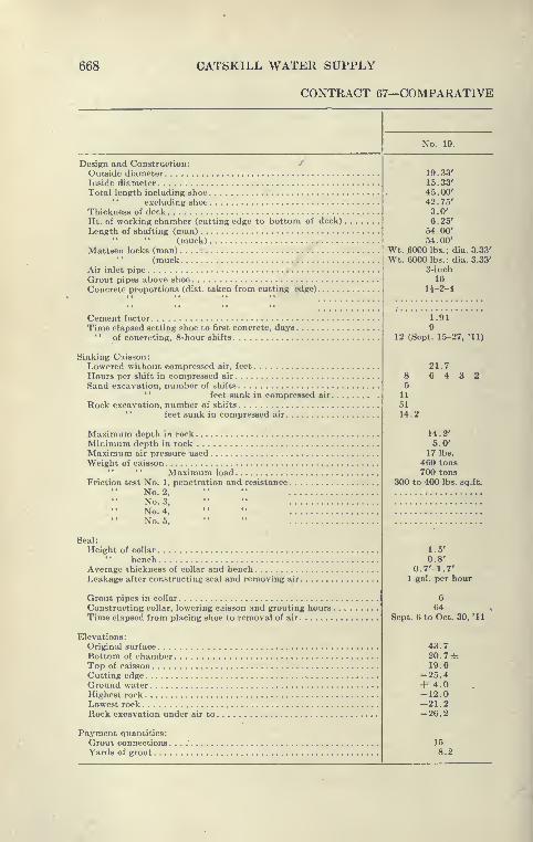
668 CATSKILL WATER SUPPLY
CONTRACT 67—COMPARATIVE
No. 19.
Design and Construction: /
Outside diameterInside diameterTotal length including shoe
'
'
excluding shoeThickness of deckHt. of working chamber (cutting edge to bottom of deck)
.
Length of shafting (man)" " (muck)
Mattsen locks (man)(muck
Air inlet pipeGrout pipes above shoeConcrete proportions (dist. taken from cutting edge)
Cement factor
Time elapsed setting shoe to first concrete, days.'
' of concreting, 8-hour shifts
Sinking Caisson:Lowered without compressed air, feet
Hours per shift in compressed air
Sand excavation, number of shifts'
'
feet sunk in compressed air
.
Rock excavation, number of shifts
feet sunk in compressed air
Maximum depth in rockMinimum depth in rockMaximum air pressure usedWeight of caisson
" " Maximum loadFriction test No. 1, penetration and resistance.
No. 2,
No. 3,
No. 4,
No. 5,
Seal:
Height of collar'
' bench ,
Average thickness of collar and benchLeakage after constructing seal and removing air
.
Grout pipes in collar
Constructing collar, lowering caisson and grouting hours
.
Time elapsed from placing shoe to removal of air
Elevations:Original surface
Bottom of chamberTop of caisson
Cutting edgeGround waterHighest rockLowest rockRock excavation under air to
.
Payment quantities:
Grout connections.Yards of grout ...
19.33'15.33'45.00'
42 .75'
3.0'
6.25'54.00'54.00'
Wt. 6000 lbs.; dia. 3.33'
Wt. 6000 lbs.- dia. 3.33'
3-inch
16
lJ-2-4
1.919
12 (Sept. 1.5-27, '11)
21.76 4 3 28
511
5114.2
14.2'5.0'
17 lbs.
460 tons700 tons
300 to 400 lbs. sq.ft.
1.5'
0.8'0.7'-1.7'
1 gal. per hour
64Sept. 6 to Oct. 30, '11
43.720. 7±19.6
-25.4+ 4.0-12.0-21.2-26.2
158.2
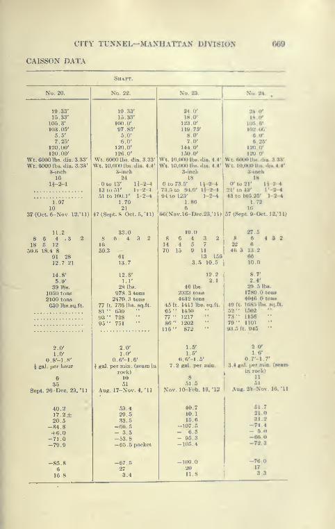
CITY TUNNEL—MANHATTAN DIVISION
CAISSON DATA
609
SHArr.
No. 20. No. 22. No. 23. No. tl. ,
19 .
33' WtS.i' 2*jy uiy15.33' 15.33' 18. 0* ISC
105.3' 100.0' 123 0' ua.v103.05' 97.85' 119 75' 102 00'
5.5' 5.0' KO* 0'
7.25' 6.0' 7.0- 0.26'120.00' 120.0' 114 0* 120.0*
120.00' 126.0' LW 0' 120 0*
Wt. 6000 lbs. dia. 3.33' Wt. 60(K) lbs. dia. 3.33' Wt. 10.f)00lb«.di«.4.4' wt.floooih«.di« s-ayWt. 6000 lbs. dia. 3.33' Wt. 10,000 lbs. dia. 4.4' Wt. 10,000 lb«. dia. 4.4' Wt. 10.000lb<i dui4 4'
3-inch 3-inch 3-inch 3Moeb16 24 18 18
11-2-4 Otol3' 11-2-4 to 73.5' 11 -2-
4
0*10 21' 11-2-413 to 51' It-2-451 to 100.1' 1-2-4
1.70
73.5 to 94.0' l*-2-494 to 123' 1-2-4
1.86
21' to 43' I '-2-4
43 to 105.25' 1-2-41^97 1.72
10 21 6 16
37(Oct.6-Nov. 12,'ll) 47 (Sept. 8- Oct. 5. '11) 66(Xov.lO-Deo23.Mn 57 (S..pi <J Ort 1 2.* in
11.2 33.0 19 2t •'
8 6 4 .3 2 8 6 4 3 2 8 6 4 3 2 8 4 3 2
18 5 12 16 14 4 5 7 22
50.6 18.4 8 50.3 70 15 9 11 40.3 13.2
91 28 61 13 156 AG
12.7 21 13.7 3.5 10.5 10.0
14.8' 12.8' 12.2 8.7'
5.9' 1 1' 2.1 2 4'
39 lb.s. 28 lbs. 46 lbs. 29 5ih«.
1050 tons 978.3 tons 2323 tons 1780.0 toM2100 tons 2470.3 tons 4612 tons 4040.0toM630 Ibs.sq.ft. 77 ft. 736 lbs. sq.ft. 45 ft. 1411 lbs. sq.ft. 40 ft. 1085 lbs. sq.ft.
81 " 63093" 72895" 751
65" 1450 "77" 121786" 1202116" 872
1.5'
52" 150273" 115679" IIOI93.5 ft. 945 "
2.0' 2.0' 20'1.0' 1.0' 1.5' 1.0'
0.8'-1.8' 0.6'-1.6' 0.6'-1.5' 0.7'-l 7'
i gal. per hour i gal. per niin. (seam in 7.2 gal. per min. 3.4 cat. per min. (sMin
rock) inroek)
6 10 8 11
35 51 51.5 51
Sept. 26-Dec.23. "11 Aug. 17-Nov. 4, '11 Nov. 10-Feb. 19. '12 Aug. 2:^-Nor. 10. '11
40.2 53.4 40.7 61.7
17. 2± 29.5 10.1 21.0
20.5 33.5 15.6 31.2
-84.8 -66.5 -107.5 -74 4
+6.0 - 3.5 - 6.5 - 6 U
-71.0 -53.8 - 95.3 -06
-79.9 -65.5 pocket -106.4 -72 3
-85.8 -67.5 -109.0 -70.0
6 27 20 17
16.8 3.4 11.8 S.S
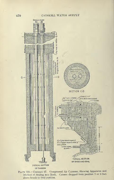
670 CATSKILL WATER SUPPLY
JIattsen locks
c—
TYPICAL SECTION
OF SHOE AND SEAL
TYPICAL SECTION
OF CAISSON
Plate 228.—Contract 67. Compressed Air Caissons, Showing Apparatus and
Method of Seahng into Rock. Caisson dropped from position 2 or 3 feet
above bench to final position.
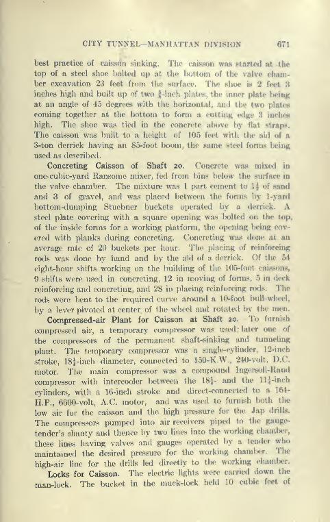
CITY TUNNEL—MANHATTAN DIVISION 671
best practice of caisson sinking. The caisson was started at the
top of a steel shoe lK)lte(l up at the Iwttoni of the valve cham-ber excavation 23 feet from the surface. The shoe is 2 feet 3inches high and built up of two J-inch plates, the inner plate l>eing
at an angle of 45 degrees with the horizontal, and the two plat<«
coming together at the bottom to form a cutting e<lge 3 inchcH
high. The shoe was tied in the concrete above by Hat strap«<.
The caisson was built to a height of lOo feet with the aid of a
3-ton derrick having an 85-foot boom, the snuw sfcil Utnn> In ing
used as described.
Concreting Caisson of Shaft 20. Concrete wils mixt-d in
one-cu])ic-yar(l Ransome mixer, fed from bias below the surface in
the valve chamber. The mixture was 1 part cement to 1 J of sand
and 3 of gravel, and was placed between the forms by 1-yanl
bottom-dumping Stuebner buckets operated by a derrick. Asteel plate covering with a square opening was lK)lte<l on the top.
of the inside forms for a working platform, the opening Iwing cov-
ered with planks during concreting. Concreting was done at an
average rate of 20 buckets per hour. The placing of reinforcing
rods was done by hand and by the aid of a derrick. Of the 54
eight-hour shifts working on the building of the 105-foot rais.si)ns,
9 shifts were used in concreting, 12 in moving of fonns, 5 in deck
reinforcing and concreting, and 28 in placing reinforcing rotls. The
rods were bent to the required curve around a 10-foot bull-whe<"l,
by a lever pivoted at center of the wheel and rotated by the men.
Compressed-air Plant for Caisson at Shaft 20. To furnish
compressed air, a temporary compressor was used ; later one of
the compressors of the permanent shaft-sinking and tunneling
plant. The temporary compressor was a single-cylinder, 12-inch
stroke, IS^-inch diameter, connected to 150-K.W., 240-volt, D.C.
motor. The main compressor was a compound Ingersc^ll-Hand
compressor with intercooler between the ISJ- and the llj-inch
cylinders, with a 16-inch stroke and direct-connected to a 154-
H.P., 6600-volt, A.C. motor, and was used to furnish both the
low air for the caisson and the high pre.s.sure for the Jap drills.
The compressors pumped into air receivers piped to the gauge-
tender's shanty and thence by two lines into the working chamlier,
these lines having valves and gauges oi>erat(Hl by a tender who
maintained the desired pressure for the working chanilx-r. The
high-air line for the drills led directly to the working chaml)er.
Locks for Caisson. The electric lights were carriwi down the
man-lock. The bucket in the muck-lock held 10 cubic feet of
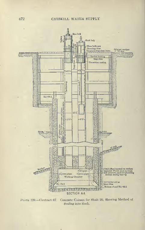
672 CATSKILL WATER SUPPLY
Oriijfinal surface
ifeiiuired offset marked on surfaceInspector Plumb lines at south
; east quarters, used for plumbingcaisson during sinking
"1:2 mortar collar
/steel Shoe
, Bottom of seal EI.-8S.5
SECTION A-A
Plate 229.—Contract 67. Concrete Caisson for Shaft 20, Showing Method of
Sealing into Rock.
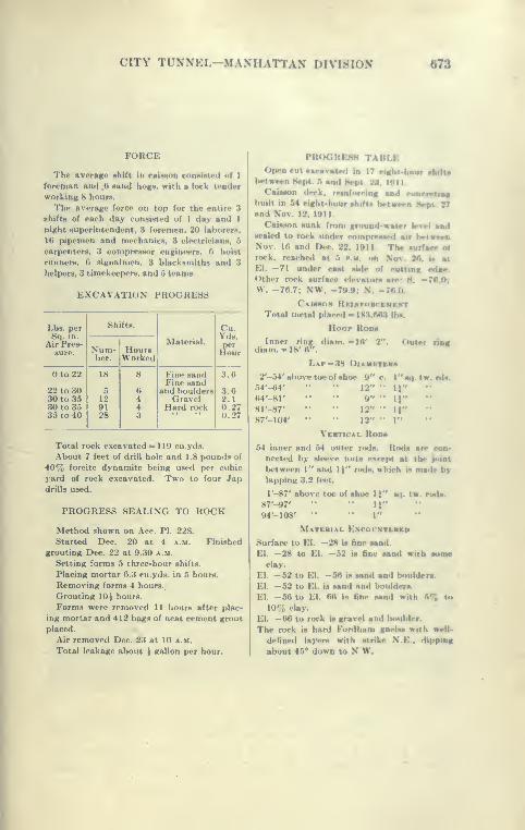
CITY TUNNEL-MANHATTAN DIVISION 073
FORCE
The average shift in caisson consisted of 1
foreman and 6 sand hogs, with a lock ti'ndcr
working 8 hours.
The average force on top for the entire 3
shifts of each day consisted of 1 day and 1
night superintendent, 3 foremen, 20 laborers,
16 pipcmen and mechanics, 3 electricians, 5
carpenters, 3 compressor engineers, hoist
runners, 6 signalmen, 3 blacksmiths and 3
helpers, 3 timekeepers, and 5 teams.
EXCAVATION PROGRESS
Lbs. perSq. in.
Air Pres-sure.
Shifts.
Material.
Cu.Yds.
iFourXum-ber.
HoursWorked
0to22
22 to 3030 to 3530 to 3535 to 40
18
5129128
8
6443
Fine sandFine sand
and bouldersGravel
Hard rock
3.6
3.02.10.270.27
Total rock excavated = 119 cu.yds.
About 7 feet of drill hole and 1.8 pounds of
40% forcite dynamite being used per cubic
yard of rock excavated. Two to four Japdrills used.
PROGRESS SEALING TO ROCK
Method shown on Ace. PI. 228.
Started Dec. 20 at 4 a.m. Finished
grouting Dec. 22 at 9.30 a.m.
Setting forms 5 three-hour shifts.
Placing mortar 0.3 cu.yds. in 5 hours.
Removing forms 4 hours.
Grouting lOi hours.
Forms were removed 11 hours after plac-
ing mortar and 412 bags of neat cement grout
placed.
Air removed Dec. 23 at 10 a.m.
Total leakage about | gallon per hour.
M(04,HK.-«.-» |.\I»I.K
Open cut •scavatr<l in 17 eicht-bourbetwwn Sept. ."i and Hrpt 23. 1011.
CaisMon deck, rrindtrrmg mmI conerHiagbuilt in 54 eight-hour shift* bvtwwa 8«pi. 97and Nov. 12. 1011.
Caisson sunk from ground-waier level madsealed to rock under comprrased air betweenNov. 10 and Dec 22. 1911. The suHare of
rock, reached at .'» p.m. on Nov. 20, u at
El. —71 under east side of cutting ed«e.
Other rock surface elevatoni are: H. -76.0;W. -70.7: NW. -799; N. -700
Caisson Rei.*(row-KMKNT
Total metal placed - 1K3,0A3 lbs.
Hoop Roim
Inner ring diam. -16' 2"diam. -18' W'.
Lap -38 Diambtcbs
2'-54' above toe of shoe 9'
Outer ring
c. •q.tw.nU.54'-64'
64'-8r8r-87'
87'-l(M
12" " U"9" •• U12" •• U12" *' 1"
Vertical Roim
54 inner and 54 outer rods. Rods are ron*
nected by sleeve nuts except at the joint
between 1" and 1)" rods, which is made by
lapping 3.2 feet.
r-87' above »<- of -»wv,. i»" ^. .^ rttdm.
87'-97'
94'- 108' "
Material K.NCot-NTERCO
Surface to El. -28 is fine sand.
EI. -28 to El. -52 is fine aand with aom*clay.
El. -52 to El. -50 is sand and boulder*.
El. —52 to El. is sand and boulders.
El. -56 to El. 00 is fine sand with 5% to
10% clay.
El. —66 to rock is gravel and boulder.
The rock is hard For<lham gneiss with well-
defined layers with strike N.E.. dipping
about 4.5° down to N W.

674 CATSKILL WATER SUPPLY
earth and was operated by a 10-H.P. General Electric hoist
at 220 volts. The Mattsen locks used are shown on Plates 229
and 230, the bucket being supported by the cable which runs over
the sheave-wheel supported by a gooseneck through a 10-inch
tapered hole into the lock. The bottom door allows the bucket
to descend; the side door allows tipping of bucket for dumping.
The man-lock, in addition to an outside valve for decompressing
air, was fitted inside with valves for letting air in or out of lock,
to be operated by the men themselves. The valve in the man-lock
for letting air in was 1 inch in size, and for letting air out was 1 inch
reduced to | inch. The outside valve on the man-lock was of the
2-inch size.
Sinking Caisson. In sinking in earth a gang of from four to six
shovelers was used, who filled the single bucket operating in the
shaft. Excavation was kept level, the shoe being usually buried
3 feet in the sand. Enough air pressure was used to keep the
material dry. The caisson was kept plumb by watching plumb-
bobs suspended from the deck of working chamber. At 17 pounds
pressure, 138 cubic feet of free air per minute was used; when rock
was reached, the working pressure in the chamber being maintained
at about 34 pounds, 874 cubic feet of free air per minute compressed
to 108 pounds was used. The leakage increased considerably when
rock excavating started, as it was necessary then to expose the
cutting edge. This was prevented in a large measure by banking
the slope of the shoe with clay, loose or in bags, or clay mixed with
straw. This caisson was found to be heavy, the friction amounting
to about 630 pounds to the square foot, so that it was necessary
to support the caisson either on knobs of rock or on the perimeter
on timbers. While supported on three 12''xi2'' timbers and when
cutting edge was 4 feet from the rock, everything being ready for
the final seal, three posts were crushed in and the caisson dropped
3 feet, making it necessary to excavate that much miore rock for
the seal. While excavating in rock, 960 cubic feet of free air per
minute, compressed to 120 pounds, was used. Four Jap drills
were operated, making holes 3 to 4 feet deep, after which they
were shot with light charges of 40 per cent dynamite. During
sinking in rock, one or two men were constantly " mudding up "
between rock and the cutting edge.
The " Bends.'* A good deal of trouble was experienced in
getting the men to come out slowly enough to avoid the " bends."
As the caisson locks were of small capacity, extra precautions were
taken to insure tightness of doore, and particularly of the stuflftng-

CITY TUNNEL-MANHATTAN DIVISION 675
Plate 230.—Contract 67. Shaft 19. Mattwn Air I>ook in Position Over
Shaft Leading to Working Chainhcr i)f ('< ncrrtc C'ai«»«Hi. Lock is closed by
a revolving door fitting oijcuiug uiiU a trap door at bottoiu.
676 CATSKILL WATER SUPPLY
box through which the hoisting rope operates and from whichair leaked out rather rapidly. There were several light cases of
the bends, and one fatal case, the hospital lock at the shaft
being used to relieve these cases, a physician being in constant
attendance. Experience gained at this shaft convinced the con-
tractors that it was desirable to raise the men out instead of allow-
ing them to climb out, as is the usual practice. The ladders
in the shafts are vertical, riveted to the sides, and hard to
climb.
Sealing Caisson . The method of making the seal is as before
described and shown on Plate 228, a 2-foot collar being built.
Before the last drop caisson was supported on eight 12''xl2''
posts, these being knocked out by sledges and the air pressure low-
ered. The caisson then descended easily, sealing itself off. After
the grout placed back of the caisson was allowed to set for about
twenty-four hours, air was drawn off slowly, resulting leakage
from rock seal being only one-half gallon per hour. Although
the external ground-water pressure on the caisson is at a maximumof about 90 feet, it was found after excavating the interior of the
caisson that the 2-foot concrete walls were very tight, only a few
square feet of damp area appearing.
Sinking of Caisson at Shaft 23. The sinking of the caisson
at Shaft 23 offered the greatest difficulty. After the valve chamber
had been excavated to a depth of 30 feet, a steel shoe wa.s set upand the caisson concreted between a steel Blaw and a Logan form,
as previously described. The caisson wavS then sunk to ground-
water level (—6 feet) alternately concreting and sinking, after which
it was built up to full height, 123 feet from cutting edge, project-
ing 76 feet above ground. This was accomplished with difficurty,
even with a derrick with an 85 foot-boom set up on a platform.
The caisson, which had an outside diameter of 24 feet and was
three feet thick, then weighed about 2300 tons, including 2.2 per
cent of steel reinforcement, and was equipped with a reinforced
concrete deck 6.5 feet thick, allowing 7 feet head room above the
cutting edge. Two 3-foot lengths of steel shafting were con-
creted in the deck and carried up in 15-foot lengths to above the
top of the caisson. Each shafting was topped with a Mattsen
lock in which was operated a bucket by means of small electric
hoist and cable. Both locks were equipped to carry men and
muck and contained an equipment of valves and gauges by which
the men could let themselves in and out at any desired speed.
This double equipment was found to work very well, and great
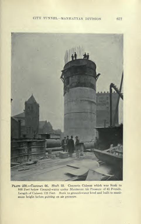
CITY TUNNEL-MANHATTAN DIVISION 677
Plate 231.—Contract 66. Shaft 23. Concrete Caisson which was Sunk to
100 P'eet below dround-water under Maxinjuni Air l*re«Hure of 45 Pounds.
Length of Cai^^son 123 Feet. Sunk to ground-water level and built to
mum height before putting on air presbure.

678 CATSKILL WATER SUPPLY
speed was made, both hoists being used for raising men and muck-
ing. In three days the caisson was sunk about 36 feet, the
coarse sand excavated being dumped inside to give weight. Fric-
tion was such that the added weight was given by pumping water
into the caisson, saturating the 90 feet of sand inside.
Collapse of Steel Shafting. At this point the excavation was
stopped, so that the locks could be raised to allow a pig-iron deck
to be placed by extending the shafting. This had been done with
one lock, and the other lock was just in place, the shafting being
under normal pressure, obtained by closing a door in the working
chamber placed at the bottom of the shaft for this purpose, when
the pressure of the wet sand, not being compensated by the 17
pounds of internal pressure, collapsed one shaft (which was soon
followed by the collapse of the other) and the working chamber
and both shafts were filled with sand and water to ground-water
level. Very fortunately no men were inside the chamber, although
frequently air locks are raised while men are at work.
The sand was excavated and the wrecked shafting removed.
The various lengths had collapsed in interesting ways, some being
completely flattened, others falling in two directions, forming
a Maltese cross in section. An attempt to get down in the
open to the concrete deck failed, the water boiling up from
below through the wrecked shafting. A heavy temporary tim-
ber deck was then constructed above ground-water level and
a single line of shafting with an air lock built into it. Air
pressure was then put on and the material over the concrete deck
was rapidly removed. The wrecked shafting in the deck was
cut out with an ox^^-acetjdene blow^iipe, new shafting was sub-
stituted and concreted in, and an extra foot of concrete was placed
on the old deck. To prevent the repetition of the accident described,
the two steel shafts were enclosed in a rectangular block of con-
crete to a height of about 60 feet above the deck, and thus relieved
of the pressure of wet sand. The air locks were placed high enough
to enable a heavy pig-iron platform to be placed. Sinking wasthen resumed as before, and proceeded rapidly until rock was
reached at elevation —95 in 6 days. Friction on the side of the
caisson for some reason proved to be much greater than else-
where, necessitating the placing of 2300 tons of pig iron and
wet sand. This may be attributed to the great depth of coarse
sand penetrated. Strangely enough when the rock was reached
the friction rapidly fell off, and great quantities of pig iron were
removed.

CITY TUNNEL-MANHATTAN DIVI8ION 670
Plate 232.—Contract 67. Shaft 23. Steel Shaftinj?. C'olI.ips^Hl by KxlernaJ
Pressure of Wet Sand while Sinking Caisj>*)ii.

680 CATSKILL WATER SUPPLY
Frictional Resistance of Caisson at Shaft 23. The friction
on outside of caisson at Shaft 23, as determined at various depths
of penetration, was as follows:
45 feet 141 1 lbs. per square foot
65 feet 145086 feet 1202116 feet 872
Although there was a considerable depth of fine sand over the
rock, the theoretical water column pressures had to be carried.
Rock Excavation under 45 Pounds Air Pressure. The rock
excavation was made with the aid of Jap drills, a pressure of about
115 pounds being carried at the compressor, giving a net working
pressure of about 70 pounds. Two compressors were used, a
low-pressure Ingersoll-Rand and high-pressure two-stage compres-
sor, a part of the permanent equipment. It took both compres-
sors working at full capacity to furnish sufficient air. The low-
pressure compressor could compress 900 feet of free air to 45
pounds, the high-pressure compressor 1300 feet of free air to 110
pounds. The excavation of the rock was made under 45-pound
pressure, the men working two hours per day in one-hour shifts,
with five hours off between shifts. To keep the work going con-
tinuously, 12 sets of men (usually 7) were employed at the rates
previously given. The men suffered little from the '* bends
"
and appeared to realize the dangers, taking from 20 to 30 minutes
to come out of the locks. It is believed that the relief from the
usual long climb up vertical ladders obtained by hoisting the menout was of material assistance. Although the men worked with a
will, it took 351 hours to excavate 161 yards of rock, from which
the high cost of this work can be appreciated. Just before mak-ing the seal, a bearing of one of the compressors burned out under
the continuous twenty-four hour grind. The other compressor
not furnishing sufficient air, the men were taken out. The pressure
dropped to about 40 pounds, and the working chamber was filled
with about 2 feet of sand. The compressor was soon repaired
and the work resumed.
Sealing Caisson into Rock (Shaft 23). The final seal was madeby dropping the caisson onto the usual concrete bench and oakum.
Pressure was drawn down to 36 pounds in a few minutes, this being
equivalent to pounding the caisson with a load of 298 tons. After
the space around the caisson at the bottom was grouted, the air
was drawn off and the leakage found to be about 7 gallons per
minute. This was much larger than the other shafts, but the con-
CITY TUNNEL—MANHATTAN DIVISION fIBl
ditions here were much more severe, the seal Mng matle under
a head of over 100 feet of water. It Is l)elieve<! alM) that the
run described brought the sand to the lK)ttom cutting e<lge l)efore
the final drop, so that some of it mixed with the oakum on the
bench when the air was drawn don-n for the lant drop. A little
of the fine sand was then washe<l out Jxjtween the oakum and
cutting edge, so that some water was allowed to flow in. Theleakage found was not at all serious, and was readily taken care
of in the sinking. In this connection, it is lK»lieve<l that a more
certain seal can be made by loa<ling the caisson until it is " heavy "
before the final drop, thus avoiding the necessity of " pound-
ing down '* the caisson by drawing off air within the working cham-
ber. In this way one would be sure that the cutting e<lge dropixsl
on clean oakum and not on a mixture of sand and oakum. With
the caisson heavy, it would be necessary to support it on timl>er
posts which could be shot out with dynamite y>efore the final drop,
as was done at Shaft 19.
Shaft 21 in Earth. The excavation of the upj)er portion of shaft
21 ofTered a problem peculiar to itself. The contract drawings
indicated two methods—one to sink separate caisson or the shaft
proper and several smaller ones for the foundation of the drainage
chamber and the building to be constructed over the shaft. The
caisson (for the shaft proper would have had to be very large
and of irregular shape. An alternate method suggested by a note
in the drawings was to enclose the area of the shaft and valve
chambers by rectangular caissons. As this plan was preferred by
the contractor, permission to follow it was given.
Construction of Wall Caissons at Shaft 21. Four rectangular
caissons about 37 feet high and from 38 feet to 43 feet were con-
structed of wood in the manner usual for foundation caissons. The
cutting edge was formed from 6"xl2" yellow pine strips, and
the working chamber was sheeted horizontally with 4-inch planks
and vertically with 2-inch planking carried up to the top of the
caissons. Tht: 6-foot chamber was roofed ^vith 3-inch planks
and braced about every 5 feet by C"X12" frames al)out 12 feet
high. The portion above the chamber was tied together at alx)ut
5-foot intervals with bolts carried through pipes in the interior,
placed so as to act a.s spreaders and which after concreting allowe<l
the removal of the bolts at each end of the caisson above the work-
ing chamber. The space above the deck was filled with 1:2:4
concrete to form a foundation for the building. Alx)ve this
temporary 1:5:10 concrete was placed to act as a dam to keep

682 CATSKILL WATER SUPPLY
>o
>a aa; s^^ bC
IK
y -2
73 OJ
73 O73 O
"3 3^ §
CITY TUNNEL-MANHATTAN DIVISIOK 688
ground and tide-water out of the onclo8ure. At each emi of thecaisson a recess was formed, called a *' half-moon." lieing tlie
term originally used when semicircular keys were fonned lietwe(«o
adjoining caissons to form a water-tight excavation, to permitthe interior cellar area Inflow high buildings and lK»tw«'<»n Tfwk andground water to be utilized. In this case the " half-moon " wastrapezoidal in shafx*, 3'x2'x3' deep. The working chamlier
was reached through a 3-foot steel shaft and Mattsen l(K*k. A tem-porary plant was iastalled, coasisting of a Injiler, steam-oiN*rate(l
Ingcrsoll-Rand coniprt»ssor and a stiflf-legged derrick mounte<l on aplatform. The wooden caissoas were built on the iU*i'k Mnd swunginto place previously to concreting by the derrick.
Sinking of Wall Caisson at Shaft 21. The caissoas were sunk
one at a time, tlie material excavated from each iH'ing a mixture of
sand, gravel, clay and lx)ulders. The working cham!)er wa*< divi<le<i
by interior cross-braces into seven pockets, three on either side
of the bucket compartment. One man wa.s generally worked
in each pocket, the material being cast from j)ocket to ixx'ket
toward the bucket. ^lany of the boulders were of Ihtk*' ^'\7*' rmd
had to be blasted into smaller pieces for handling.
The caissons were invariably sunk in " jumps " of from 12 to
24 inches each by lowering the air pressure. Thej' buckleii rea<!ily
during the sinking under the excessive weight of pig-iron when
the cutting edge was jammed on the boulders, the working chaml)er
buckling inward and its longitudinal distortion n<'cessitating
additional interior braces, so that the difficulties of sinking were
increased.
Sealing of Wall Caissons to Rock. During sinking it was nec-
essary to " mud " or paint with grout the wooden joints and
cracks of working chamber to prevent the air from escaping and
flowing freely through the loose ground around the caUson. Whenthe rock was reached and the sheeting carried, board by l»oanl,
down from the cutting edge to the surface of rock in deep pockets
the air loss increased rapidly, it then being difficult and almo8t
impossible to get enough jiressure to dry out the low |XK'kets in
the rock, as the ground would not hold the increased pressure.
A feature of the wooden caissons was their lack of rigiiiity against
stresses, especially in the working chaml)er, and they therefore
buckled and conformed to stresses without rupturing. The east
caisson was the last of the four caissons to \ye sunk, and profiting
by the experience gained, several improved methods of working
were carried out here:
684 CATSKILL WATER SUPPLY
(1) The wooden joints in the interior of the working cham-ber were caulked with oakum by the sand-hogs, as it
was found that the wooden joints dried out and shrank
and oakum placed prior to sinking could be pulled out
in dry lumps.
(2) Very little pig-iron was loaded on, and only as needed, to
avoid making the caisson heavy and jamming the
cutting edge down on the boulders.
(3) Packing the surface with excavated material and keeping
the pressure within the caisson low, to prevent blow-
holes in the adjacent ground.
Air Used in Sinking Caissons. A steam-driven compressor,
which compressed 6§ cubic feet of free air for each revolution,
to a pressure from 3 to 4 pounds higher than that needed in the
working chaml^er, made from 70 to 90 revolutions per minute.
When rock was reached and cleaning of its surface began, the
compressor made from 125 to 140 revolutions; when concrete cov-
ered the entire bottom up to the cutting edge, it dropped downto 70 to 90, a.s before.
Support of Building. An adjoining reinforced concrete coal
pocket was carried on horizontal I-beams supported by screw-
jacks, so that any settlement of the building could be taken up.
Below the I-beams the foundation settled about 1^ inches, but
the opening between was subsequently caulked, the building suf-
fering no damage.
Excavation of " Half Moons " and Interior. After all four
caissons were sunk they were found to be out of plumb about
10 inches and out of level end to end, in one instance, 1 foot. This
caused the caissons to be separated at the bottom of the half moonsfrom 3 inches to 16 inches. The half moons were unwatered by
Cameron pmnps suspended from pipe tripods, and as the water
was lowered the interior bracing was removed by hand and sheet-
ing placed between the joints of two caissons. The boards of
the working chambers were removed, allowing contact between
the concrete in the working chamber and that placed in the half
moons, to tie the adjoining caissons together and to form water-
tight joints. The concrete was placed in the open without the
assistance of an air lock. The interior was excavated with a derrick
and the bracing placed as the depth increased. The rock on being
exposed was found to be irregular, hard and very seamy. Verylittle water came through the seal placed in the working chamber,
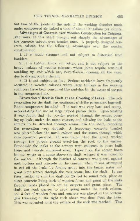
CITY TUNNEL-MANHATTAN DIVISION 686
but two of the joints at the ends of the working chamber madeunder compressed air leaked a total of about HK) palhm'* |mt minute.
Advantages of Concrete over Wooden Construction for Caissons.
The work at this shaft brought out sharply the advantagi^^ oi
the concrete caisson over wooden ones. A properly do»tgne<l con-
crete caisson has the following advantages over the wiKxh-n
construction:
1. It is much stronger and not subject to .li^ti.rti.m from
boulders.
2. It is tighter, holds air l)etter, and is not sulijett to the
heavy leakage of wooden caissons, whose joints require continual
mudding up and which are, nevertheless, opening all the time,
due to drying out by the air.
3. It is not subject to fire. Serious accidents have frequently
occurred in wooden caissons where large timbers in the working
chambers have been consumed like matches by the excess of oxygen
in the compressed air.
Excavation of Rock in Shaft 21 and Grouting of Leaks. The rock
excavation for the shaft was continued with the permanent IngersoU-
Rand compressors installed. The rock was very hard and seamy,
necessitating the use of large tripod piston drills, (,'pon l)lasting
it was found that the powder worked through the seams, open-
ing up leaks under the north caisson, and allowing the leaks at the
corners to be diverted through seams into the shaft, rendering
the excavation very difficult. A temporary concrete blanket
was placed below the north caisson and the seams through which
runs occurred grouted. It was found that the grout worked
through the porous ground overlying the rock to the surface.
Previously the leaks at the corners were collected in lx)xes built
there and heavily concreted over. Pipes from the comer boxes
led the water to a sump above the shaft, whence it was rai.sed to
the surface. Although the blanket of concrete was placed against
rock bottom and concrete in the caisson, when it was attempted
to cut off the leaks by forcing grout into the l)oxes, water and
grout were forced through the rock seams into the shaft. It was
then decided to sink the shaft for 25 feet to sound rock, place an
outer concrete lining back of wooden forms and grout off the leaks
through pipes placed to act a.s weepers and grout pipes. The
shaft was sunk narrow to avoid going under the north cais.Hon.
and 5 feet of wooden form and concrete was placed at the bottom.
The trimming of the tight rock above was done from the form.
This was repeated until the surface of the rock was reached. This
686 CATSKILL WATER SUPPLY
was thoroughly cleared off and covered with a blanket of about
3 feet of concrete. The shaft was then grouted at about 100
pounds pressure, and nearly all the leaks stopped. The woodenforms were left in place so that grouting could be done soon after
concreting. This method was supposed to yield better results,
the wooden forms preventing the grout from breaking away at
leaky jjoints or porous areas, if there were any. The corner leaks
were completely stopped.
Progress in Shaft Sinking. The shaft sinking was then resumed
and good progress made—about 24 feet per week, about 17 cubic
yards per foot of excavation—with the handicap of an irregular
shaft and 30 gallons of water. The concreting and grouting of the
top changed the very unfavorable condition for sinking to favor-
able, thus amplj^ repaying the contractor for the work done.
It illustrates anew the great advantage of placing a concrete lining
in shafts troubled by bad rock and water.
Lining Shaft 21. After sinking to a depth of about 100 feet
with the derrick, the outer lining of the shaft was placed, and the
shaft in earth built between inner and outer forms to serve as a
foundation for the steel head-frame. The shaft in earth corresponded
to what would have been built and sunk with a concrete caisson
by the original contract plan, but this was now easily accomplished
in the open.
Riser Pipe. The 4-foot riser pipe at this shaft is to be over
700 feet long, leading directly from the tunnel to the shaft cap
in the valve chamber. The contract drawings show that the
pipe was to be lowered and grouted into place in a hole formed in
the outer lining. The pipe was to be bolted up with an inside flange
and afterwards lined in place with a 4f-inch mortar lining, which
together with the grout outside would perm.anently protect the metal.
The contractor was given permission to use the following method:
1. To build the pipe in 10-foot lengths with outside instead of
inside flanges.
2. To concrete the pipe in with the outer lining, which is to be
placed in stretches of about 100 feet while sinking shaft. Lead
gaskets are used between the pipe lengths. Slip joints with
sleeves to be slipped over gaps between the pipes are used at the
bottom of each stretch of concrete and caulked by pouring lead
between the sleeve and pipe. In this way, the placing of the riser
pipe was much facilitated.
Plant at Shaft 19 for Sinking. The excavation of shaft in rock
was first started at Shaft 19, where the compressed air work was of
OITY TUNNEL-MANHATTAN DIVISION
shortest duration. The temporary plant iwoci for the cainoii ink-ing wiw removed, with the exception of the steam (hrrrick CD^amfor a time used in sinking. A 75-foot loj-ton steel liead frame wtmfurnished and erected upon the concrete caisson hy the Ijicknwnniui
Bridge Company. (Se(» Plat«»s 225 and 220.) It wa** (•xtiriiat4'<l
that the steel head frame, deducting salvage, will c<i«t alnjul the
same as timber frames and will l^e much more rigid and »erviceal>le.
Time was also saved in erection, as it arrive<l on the ground rcaily
to bolt up. The steel frames at all six shafts are of the somedesign, with the heights varied by adding to or taking off Uittommembers. The head frame is equipped with two pennanirnt
5.0 diameter sheave wheels of cast-iron rims and steel s|)(>kes.
For safety in operation the outside of the hea<l frame is Umh-redin to the level of the dumping platform, at which level two enclosed
balanced doors are installed. Instead of the ordinary bull chain
or outrigger for dumping the shaft-sinking buckets, a pivote<l tim-
ber chute was installed. To dump muck the top doors are ojH'ned,
the bucket raised to the top of the frame, the nmck chute lowered
to nearly horizontal position and the bucket dumped without
leaving the center of the shaft. The workmen below are abso-
lutely protected, as the bucket cannot be dumix»d without clos-
ing the top doors. With this device, such accidents as have occurred
from stones or buckets falling back into the shaft are prevented.
In a similar manner the men are protected while concreting by
two sliding doors near the top of the caisson, these doors )>eing
closed when the concrete flows into the bucket from the chute
to the mixer. At Shaft 23 a broken sheave wheel cut the cable, but
the bucket was caught by the upi)er doors, thus avoiding a .serious
accident to the men working at l)ottom of shaft.
Electric Hoist. An Exeter Machine \A'orks electric hoist was
installed close to the head frame and* mounted upon a heavy timlx»r
platform about 15 feet above ground. Ordinarily it is coa'«idero<l
necessary to mount such a large engine uiwn heavy concn'te
foundations, but the hoist was found to work well on the timl)or
foundation. The drum of the engine is 5 feet in diameter an<l 6
feet 6 inches long. It is operated by a G. E. induction motor.
112 HP., 440 volts. Hoisting engines op<»rated by alternating-
current motors have the disadvantage that it is difficult to hoi.nt
at low speeds, particularly with a single sinking bucket. On
the Exeter hoist the large band brake instead of l)eing operate<l
by hand levers is tightened by a hand wheel mounted in a column
at right hand of the engineman. By setting up the brake with
688 CATSKILL WATER SUPPLY
the wheel the hoist can be operated at slow speed with the resist-
ance furnished. This, of course, wastes some power and causes
wear on the brake lining, but it adds much to the handiness and
smooth running of the hoist. There is also a foot pedal by which
the brake can be operated. The engine has also an automatic
solenoid brake, which operates when current is shut off. It is
equipped with a large dial for indicating the position of the bucket
or cage. The revolving hand of the dial operates an overwind-
ing device in a very simple way by throwing a cut-off switch affixed
to the dial when the bucket or cage reaches a determined posi-
tion near the top of the head-frame.
Typical Compressor Plant for Shaft and Timnels. The per-
manent power plant installed at the shaft consisted of two Inger-
soll-Rand compressors. Type P.E. They are electrically operated
by two G. E. motors, 164 H.P. and 215 H.P. at 6600 volts. The
smaller compressor is 18|"xlli,'' cylinder 16-inch stroke, with
a capacity of 900 cubic feet; the larger 21j''xi2^,'' cylinder 18-inch
stroke, having a capacity of 1300 cubic feet. Both are two-stage
compressors with " hurricane " valves, and run very smoothly
in oil. It was decided to install two compressors instead of one
in order to save power, the smaller compressor sufficing for shaft
sinking and for the tunnel when little power is needed. Thecombination is also more reliable, as at least one machine of the
two can be counted on to be in operation. In New York City
there is a " Peak Load " charge placed upon the maximum demand
in kilowatts. This is an annual charge which may be incurred
on any day by careless operation of the compressors. A small
compressor is less liable to run up such a bill.
Methods of Drilling Holes in Shaft 19. At the outset an equip-
ment of Jap or hammer drills, each operated by one man, was
installed as follows: Two 52-pound McKiernan-Terry drills and
three 41 -pound Sullivan drills, both types requiring hand rotation
of the bit; also four Ingersoll-Rand B.C.R. 96-pound Jap drills
with self-rotating bit. With these drills excellent progress was
made and maintained. Three rounds of holes, the usual cut,
side, round and trimming holes, were drilled at night in one shift
by five drillers. The cut holes were placed in two roughly parallel
rows to secure the advantage of the lay of the rock, which is nearly
vertical. Side rounds were nearly parallel to the cut holes and
consisted of 12 holes 6i feet long. Trimming holes were 6^ feet
long and 20 to a circle of 17 feet 6 inches diameter. A continuous
routine was kept up, drilling in one shift, shooting and muck-
CITY TUNNEL-MANHATTAN DIVISION
ing cut and side round in another, and shooting trimmingand final cleaning up in the last shift.
DriU Equipment at Shaft 19. The hammer driilH were foundto work very well, but the smaller drills guve way to the largerotating Japs, which were capable of drilling holes 7 to 8 feetdeep, using 1-inch and l}-inch steel, and in the mica schist ofthis shaft accomplished 50 per cent more than the hourly rate oflarge piston drills. They have the advantage of handiness andless consumption of power and much lower lalwr coet. On theother hand they are more delicate than piston drills, frequentlybreaking, particularly the hammers and steel. The steel sticks
more often in the holes, as the Jap drills have no pulling
power. The specially hard steel and rose bits are difficult tosharpen.
The experience with Jap drills is summed up in the following
matter (to p. 693), contributed by Charles Goodman.B.C.R. Rotating Jap Drills. The drill is run ^^ith compressed
air fed into the throttle near the handle. The air passes a butter-
fly valve,which is merely a flat plate pivoted at its center and flapping
to and fro in a vertical groove about J inch wide. In one position
the valve allows air to enter through port holes to the space above
the piston cylinder which is forced against the anvil block andexposes some open port holes. The air exhausts through these
port holes in the walls of the cylinder which leads to one end of
the butterfly valve, where it closes the valve and cuts off the air
supply to the cylinder, and partly through similar holes to the
top of the anvil block, whence it passes through the center holes
of both the anvil block and drill steel, exhausting at the cutting
face and thus blowing out the cuttings. The piston rel)oun(ls in
striking the anvil block, air Is again let in by the butterfly valve
and the action is repeated.
Directly from the butterfly valve, and without interference
from it, air is fed through port holes to the rotation valve. In
this way the rotation of the drill steel is independent of the ptnton
action.
The parts most subject to breakage and wear are the anvil
blocks, pawls and pawl springs. At Shaft 20 in three weeks
ninety-nine pawl teeth were dulled and fifteen anvil blocks were
broken by eight machines. The pawl teeth are resharpened and
retempered and again used. In this time 648 holes averaging
7^ feet deep were drilled. Thus for each forty-five holes drilled each
machine required one new anvil block and seven pawl sharpeningB.

690 CATSKILL WATER SUPPLY
Drill Steel. The drill steel used is 1- or l|-inch hexagonal upset
to 2|-inch for the 2-foot starter and l|-inch for the 8-foot steels.
The steels are used in approximately 2-, 4-, 6- and 8-foot lengths and
have through the center of each a |-inch hole for exhaust air. At
the start of the work at Shaft 19 a four-point bit was used, but
was abandoned and the six-point bit is now exclusively used because
the rock face is cut smoother, allowing easier rotation and less
straining of the steel.
A difficulty with all Jap drills is the wear and tear of steel.
It is weakened by the hole through its center, and as the manhandling the drill may continually change the pointing, so that often
the steel bit is at an angle instead of square against the face, tor-
sional strains are induced which snap the steel about 2 inches from
the bit, where it is generally weakened by the tempering. Thefracture very often presents a plain glassy appearance, due to
blows of the adjacent steel before the break is discovered, but
the usual steel fracture, however, is occasionally seen.
On August 13, Shaft 20, for drilling 36 down holes (8 to 7 feet
deep) twenty-one 2-foot starters; twenty-two 4-foot, fifty 6-foot
and fifty-four 8-foot steels were used, a total of 147 steels, which
may be considered the usual number for a round. Of these an
average of twenty steels will be broken of which three will be the
2- or 4-foot lengths and seventeen the 6- or 8-foot lengths. Theactual breakage per day varies from ten to thirty steels and the
drill holes lost from broken steel sticking in them will average 30
feet per round.
Tempering Steel. At Shaft 20 each steel is heated to a red
heat, sharpened and then allowed to cool slowly for about two
hours. It is then reheated and about J inch from the bit end is
immersed in water, hardening the point. The steel is then
thrown aside and left to cool. Very often the hammer end of the
steel is chipped and broken. This end is cut off and tempered
in oil or cyanide of potassium solution in a manner similar to
that above.
Drilling. Eight machines at Shaft 20 are handled by eight
drillers with the occasional assistance of the foreman. A round
is drilled in four to five hours; the drills average from 7 to 8 feet
per drjll hour, including change of bits and all delays. The actual
speed while drilling is 15 to 16 feet per hour. As the drills occupy
very little space, eight drills can be comfortably used in an 18-foot
diameter shaft and still leave room for bucket and steels. An8-foot depth of holes is considered the economical limit, since the
CITY TUNNEL-MANHATTAN DlVIsInV 601
steel binds in the holes and excessive breakaK«' «Hrurv um' - , ,'. r
depth. This is in part due to the fact that the si . ;. >
reciprocating motion, but is merely fed forward by the blows fromthe anvil block.
Whether the hole should be wet or dry seems to be a qucntion.
A very dry hole is cleaned rapidly by the exhaust air, whercaH ahole slightly damp will mud up, clog the hole, block the exhaustand stop the steel from rotating. When this occurs water is fed
very freely and the mud washes out satisfactorily.
When drilling dry holes the entire shaft is clouded with thick
dust which is inhaled into the lungs and clogs up the no«e. Toremedy this the " Automatic Respirator and Smoke Protector
"
made of rubber, is used with success by the drillers at Shaft
20. These cost about $1 each. A wet sponge is fastened in the
nose of the respirator and as the driller inhales, the dust is collected
in the sponge. The exhaled air passes out through an opening
with a mica clap valve. When six or eight machines are working
the sponges get filled with dust in about three hours and are then
washed clean and replaced.
Size of Hole. A large size at the bottom of a hole, as is well
known, is a considerable advantage, for, when the d^'namite charge
is heavy near the bottom the pull is better and the rock breaks
smaller. In this respect, therefore, the Jap drill is at a disadvantage.
A Jap steel hole at 8 feet depth ha.s a diameter of IJ to If inches,
whereas the ordinary 3^ or 3f-inch tripod will bottom an 8-foot
hole with from IJ to 2|-inch diameter, and 1 foot of l|-inch hole
will hold 25 cubic inches of djuamite, whereas 1 foot of 2-inch
hole will hold 38 cubic inches of dynamite. In the smaller hole
the charge tends to leave guns and to break the muck into larger
pieces. This is especially true of the cut which requires a heavy
charge to lift it. At Shafts 19 and 20 the guns from Jap drills
run from 1 to 1| feet.
Comparison with the Tripod Drill. All the Jap drilU can Xre
taken down in one bucket and immediately put to work. They
are readily moved from hole to hole, change steel rapidly and
have actually drilled, including all delays, about 64 feet in an eight-
hour shift at either of Shafts 19, 20 or 21. At Shaft 14 it took
1| hours from the time five tripod drills were started do^-n before
they commenced work; at Shaft 21 it averages one hour before
tripod machines started to work and in addition time is also lost
when shifting tripods and hoisting them out of the hole; so that
at Shaft 21 only 44 feet is drilled in an eight-hour shift.

692 CATSKILL WATER SUPPLY
The table shows some comparative data.
Per Cubic Yard Excavated.
Shaft No.
Drill Hole, Feet.60 Per Cent Dynamite
Pounds.
Rlectric Power.K.W. Hours for
Drilling.
19
2021
14
6.4
6.05.06.1
1.8
1.9
1.8
3.0
15
13
18
Type of Drills.No. ofDrilh.
Fore-man. Driller. Helper. Nipper.
Muck-ers.
t7 1 7 1 3
t8 1 8*9 1 9 9 1
t5 1 5 5 1
Material.
19 90 lbs. Jap20 90 lbs. Jap21 3i in. tripod
14 3 1 in. tripod
Schist
Gneiss
Granodiorite
Schist
* Main part of shaft only, as the auxiliary riser shaft is drilled with Jap drills,
t The excavation diameters of Nos. 19. 20, and 14 are each about 18 feet.
A marked advantage of the Jap drill is that it can be used at the
same time with and without delay to the mucking, whereas with
tripod drills this could not be done without serious delays. Thus it
is possible to drill relief and trim rounds while the previous rounds
are being mucked, thus distributing the power required through-
out the day and *therefore allowing the use of smaller compressor
capacity. Each Jap drill u.ses per minute only one-half the com-
pressed air required for 3|-inch tripod drill.
For tunnel bench in suitable rock the Jap drill would appear
to be ideal, as the holes will hold sufficient powder and it practically
does not offer any obstructions to the heading work and would elim-
inate the large percentage of delay usual with bench tripod drills
in moving between holes and before they can set up on or start
the hole in solid rock.
On the other hand, the tripod drill is less apt to get out of order;
its drilling speed while working being very near that of Jap drills,
it makes a larger hole. In very hard rock the Jap drill breaks
more readily and would prove unsuitable.
However, at Shafts 19 and 20 the drills stood up sufficiently
well as to warrant the statement that they were superior in giving
safety and economy with as good progress as could have been madewith tripod drills handled by an efficient organization. This
drill is patented by the IngersoU-Rand Company.

CITY TUNNEL-MANHATTAN DIVISION
Progress Made in Sinking Shaft 19. The profcraM made atSlmft 19 was very con.stant. Working three nhiftn, exclutlinR
Sundays, between Dec. 11, 1911 and March 20, 1912, 283 feet ofshaft were excavated and 259 feet concrettnl, the himhhI of con-creting being three times that of excavation. The rock in Shaft
19 proved to be uniform nmhum hard Maniiattan schist, with vit>'
little water, hardly enough to nioisten sides and ix>ttoni.
Excavation of Shaft 20 in Rock. Excavation of lh<' ro<k U-lowthe caisson at Sliaft 20 started Feb. 15, 1912, wven wcvks UMngconsumeil in dismantling compressed-air plant, installing headframe and shaft -sinking equipment. The rock l)elow the cai^Kon
was carefully drilled and shot as required, so as not to break the
seal. Four IngersoU-Rand Jap drills were operated by the .•<nialler
compressor (capacity, 900 cubic feet iree air per minute), drilling
all the holes for an advance of alx)ut 6 feet in one shift. Theholes were drilled in three circular rounds mXh one center or
"buster" hole as follows: Eight cut holes, on sloi)e of al)out
72 degrees to horizontal, to depth of 8 feet, with top of holes ona circle of 4.7 feet radius. Fourteen relief holes with top on circle
of 6.7 feet radius to depth of 7.5 feet on slope of 80 degrees to
horizontal. Twenty rim holes on circle of 8.1 foot radius to
depth of 7.0 feet drilled so a.s to point slightly outward.
Details of Sinking Shaft 20. The details of the method followed
and result achieved are tabulated below from very careful records
kept by the engineers of the Board of Water Supply:
Plant at Shaft 22. Sinking in rock l)elow caisson at Shaft
22 began with a plant similar to that at Shaft 19. The area
here is much larger and more convenient than at Shaft 19. Aset of balanced doors was installed at ground level and were found
to be of great assistance in loading and unloading the drills, ste<*I,
etc. Above the muck bins sand and stone bias were installed and
fed by a Robbias belt conveyor. The bins discharge into a
measuring hopper, feeding a one-yard Raasome mixer placed
above ground, so as to discharge through a chute directly into
concrete buckets in the shaft which are manipulated from two
hinged doors, at surface of ground. This plant will l)e permanent
and is placed so as to fill the concrete cars on the cages. Cement
will be raised to the level of the mixer by a cement bag elevator.
Progress in Sinking at Shaft 22. An outfit of Jap drills was
first used here for sinking. They were found to work well, par-
ticularly the large rotary Japs. The rock "here Is hanl grano-
diorite, an intrusive black granite. This rock is rather too hard

694 CATSKILL WATER SUPPLY
0)
co
a 3
§2
"S " B
-S S c
o :=!
fc, o3 CO
00 3
»0 j3CO t"
o I
3 ®O ^
rH --J
2 I
•S S3
(» b£
bC bC03 a
;5 M o i^ -^ -S I
a o-^=3 -^ ;a sa 3 fH S
H 00 rH (M
o a
bC
O :a
3 ^
-S
T3 S
C3 4)
cq -^
Oj 4)
^ a
73 X! t/j
^c3 -^ -H|a>
Ph -Q ^-i , , hO
1_C
a -SH
X ^C/J ^^ .(J
Tfi »oto <N
If.
i!l
PQ
O
3oO
Forcite Dynamite.
Per
Cubic
Yard.
Pounds,
60%.
05
6 -i
Q 5
O
.or.-
oCO
II
«5
ti-
llOCD
Pumpage
fiom
Bottom.
Gallons
per
Minute.
Od
a! 5
u00
00

CITY TUNNEL—MANHATTAN DIVISION 606
•I»>ox pwJO ?jI'c^,
jMoqvq -
-jaAUQ'^
1ao
1
1
•aaoiadij M C^ M
V!OH^^^
•a«aii«a8ig ^^^
-aamdox »- C^ ^
•a«i3U')Daia
1•jadloH
B.q»IU18)13Bja^^^
1•q^iuiBJiOBia
•duio3^^«
daauiajoj ^H 1-H
6
'SidlliJQ CO »M M
<•Bjajionw ^ OlOS
o •ssoa »|iqs ^^^
1
i
§
1K
•BJ3Joq«T CO f-^
•8j*»aadjB0 ^
•BJ388IH ^ (M --^
-aaaiajoj -
•jadaaijauiix Hn^ '^n
•OBOiqa^BMaio^g
nWMvinin
-aBUiq3)e;VV Mtnnmntn
jadaa^ajo)g .^««««
•ioa-paa^auadng
i03
12-88-4
4-12
8
TJ ^
Ji w;
««^ h^
^ -^ ^
s
112 11
§
DO
*»•
C^l
H
ri
SM o«2u Hs
^AS ts 11s s
i.Bt3 c
.5-2
s:o ;2s
u sg si:
u a^
1
1
1 wIJ
s^
h
P
•
.• 18
1Jz
I"Is
II
II
S II
II
ItIS
»5 « 33
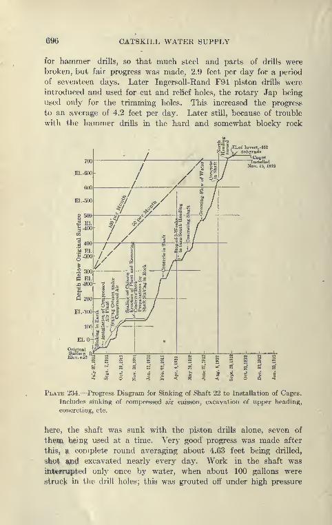
696 CATSKILL WATER SUPPLY
for hammer drills, so that much steel and parts of drills were
broken, but fair progress was made, 2.9 feet per day for a period
of seventeen days. Later Ingersoll-Rand F94 piston drills were
introduced and used for cut and relief holes, the rotary Jap being
used only for the trimming holes. This increased the progress
to an average of 4.2 feet per day. Later still, because of trouble
with the hammer drills in the hard and somewhat blocky rock
Id § ,El.of lnvert.-662
^X^ V S"t>graJe
_ ~~Y^•^ Cages
/ /\ wTI N.E1.-600
Plate 234.—Progress Diagram for Sinking of Shaft 22 to Installation of Cages.
Includes sinking of compressed air caisson, excavation of upper heading,
concreting, etc.
here, the shaft was sunk with the piston drills alone, seven of
them being used at a time. Very good progress was made after
this, ^ complete round averaging about 4.63 feet being drilled,
shpt Wti excavated nearly every day. Work in the shaft was
ihtcprupted only once by water, when about 100 gallons were
struck in the drill holes; this was grouted off under high pressure

CITY TUNNEL-MANHATTAN DIVISION flOT
the total delay for the season being about twenty-nine tihdin.The fine definite water-lK^arinR cracks in the rock (up to about }inch) were found to be completely fillwl with cement Rrout, rt*nder-ing the shaft at this point nearly dry and amply repaying the timespent in grouting.
Complete Shaft-sinking Data. When the level of the upperlevel tunnel was reached it was excavated to a length of aUiut225 feet and shaft sinking resume<l after alx)ut a month'n <Iflay
for this reason. While the shaft w:ls In'ing sunk to the lowrr
h—
w
Plate 235.—Arrangement of Drill Holes as Used for Sinking Shaft 22.
level the magazine chamber in the upper level was being excavated
so as to have its use as soon as possible. Very good and consistent
progress was made in sinking at Shaft 22, and complete data are
for this reason here given. A graphical diagram of the progress
at this shaft from the time of starting work is also given. Plate 234,
as it shows complete data of shaft sinking, including the installation
of plant, sinking of caisson, etc.
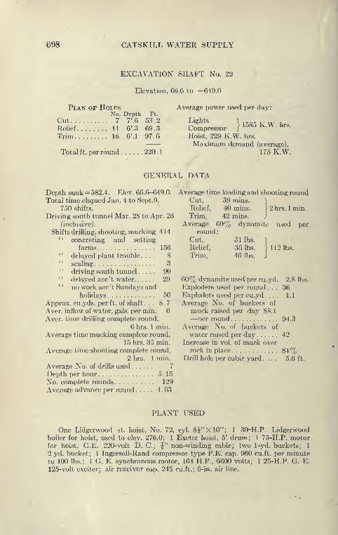
698 CATSKILL WATER SUPPLY
EXCAVATION SHAFT No. 22
Elevation, 66.6 to -649.0
Plan of HolesNo. Depth Ft.
Cut 7 7'.6 53.2Relief 11 6'.3 69.3Trim 16 6'.1 97.6
Total ft. per round 220.
1
Average power used per day:
1585 K.W. hrs.liights
CompressorHoist, 229 K.W. hrs.
Maximum demand (average),
175 K.W.
GENERAL DATA
Depth sunk = 582.4. Elev. 66.6-649.0.
Total time elapsed Jan. 4 to Sept.9,
750 shifts.
Driving south tunnel Mar. 28 to Apr. 26
(inclusive).
Shifts drilling, shooting, mucking 414" concreting and setting
forms 156' * delayed plant trouble .... 8'
' scaling 3'
' driving south tunnel 90" delayed acc't water 29*
' no work ace 't Sundays andholidays 50
Approx. cu.yds. per ft. of shaft ... 8.7
Aver, inflow of water, gals, per min. 6
Aver, time drilUng complete round,
6 hrs. 1 min.
Average time mucking complete round,
15 hrs. 35 min.
Average time shooting complete round,
2 hrs. 1 min.
Average No. of drills used 7
Depth per hour 5.15
No. complete rounds 129
Average advance per round 4 . 63
Average time loading and shooting roundCut, 39 mins. 1
Relief, 40 mins. > 2 hrs. 1 min.
Trim, 42 mins. J
Average 60% dynamite used perround
:
Cut, 31 lbs.
Relief, 35 lbs. 1-112 lbs.
Trim, 46 lbs.
60% dynamite used per cu.yd. 2.8 lbs.
Exploders used per round. . . 36Exploders used per cu.yd ... . 1.1
Average No. of buckets of
muck raised per day 88.1
—oer round 94.3
Average No. of buckets of
water raised per day 42Increase in vol. of muck over
rock in place 84%Drill hole per cubic yard .... 5.6 ft.
PLANT USED
One Lidgerwood st. hoist, No. 72, cyl. 8^"X10"; 1 30-H.P. Lidgerwoodboiler for hoist, used to elev. 276.0; 1 Exeter hoist, 5' drum; 1 75-H.P. motorfor hoist, G.E. 220-volt D. C; |" non-winding cable; two 1-yd. buckets; 1
2 yd. bucket; 1 IngersoU-Rand compressor type P.E. cap. 960 cu.ft. per minuteto 100 lbs.; 1 G. E. synchronous motor, 164 H.P., 6600 volts; 1 25-H.P. G. E.
125-volt exciter; air receiver cap. 245 cu.ft.; 6-in. air hne.

CITY TUNNEL-MANHATTAN DIVISION (m
TYPICAL FORCE ACCOUNT
i 6
I
Top Gang
Bottom Gang
12 -8 1 1 7 78- 4 1 1 1 1 104-12 1 1 1 12
ill
12- 8 1 1 1 2 2 I 1 f }8 -4 1 1 1 2 2 2 1 1 1 i 2 44-12 § 1 1 2 2 1 1 I i
Sinking Shaft 21. The most difficult shaft sinking on the
City Aqueduct was that at Shaft 21, due to the various complica-
tions there met. The shaft, being a combination drainage andriser shaft, is very complicated, and of irregular shape, consisting
of a large circle with a smaller one close by to accommodate the
riser. The larger shaft was sunk in advance with using ti to 11
Ingersoll, and McKiernan-Terry 3|-inch piston drills, the .small
riser shaft alongside was drilled with B.C.R. rotary Japs, and
shot into the adjoining larger shaft. Usually al)Out 4^ feet of shaft
were sunk per day which, considering the large .section, 17.9 yards,
and the hard grano-diorite rock here encountered, was very creditable.
Concreting and Setting Riser Pipe. When the shaft had
sunk about 100 feet below the concrete lining or when it was
advisable to concrete to cut off water, a platform was .set near the
bottom, and pouring started, concreting in the steel 4 fc*et 9}-inch
riser pipe which was bolted together in 10-foot lengths with out-
side flanges and lead gaskets. When a closure wa.s made with the
pipe above, the 44-inch inside lining of the pipe wa.s pla(*ed with
the aid of 4-foot diameter wooden forms.
Concrete Plant at Shaft 21. A very convenient plant was
erected alongside of shaft, consisting of a 1-yard Kan^me mixer,
fed from overhead bins which were filled by an incline<i bolt and
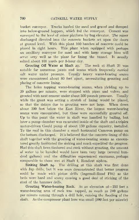
700 CATSKILL WATER SUPPLY
bucket conveyor. Trucks hauled the sand and gravel and dumpedinto below-ground hoppers, which fed the conveyor. Cement was
conveyed to the level of mixer platform by bag elevator. The mixer
discharged directed into the concrete buckets set upon the doors
at ground level. With this plant 160 batches of concrete could be
placed in eight hours. This plant when equipped with perhaps
an auxiliary conveyor for sand and with large storage bins will
serve very well as the plant for lining the tunnel. It usually
mixed about 100 yards per 8-hour day.
Grouting Off Water at Shaft 21. The rock at Shaft 21 was
notable for numerous joints and seams which frequently carried
salt water under pressure. Usually heavy water-bearing seams
were encountered about 80 feet apart, necessitating grouting and
placing of concrete lining.
The holes tapping water-bearing seams, when yielding up to
20 gallons per minute, were stopped with pipes and valves and
grouted with neat cement under about 300 pounds pressure. Usually
while the grout was setting a stretch of lining would be placed,
so that the delays due to grouting were not large. When downabout 500 feet below the East River, the largest water-bearing
seams were encountered, but these were successfully grouted off.
Up to this point the water in shaft was handled by bailing, but
later a pump chamber was excavated inside of the shaft and a triplex
motor-driven Gould pump of about 150 gallons capacity, installed.
To the roof in this chamber a small horizontal Cameron pump on
the bottom discharged. It is believed that the concrete lining of this
shaft together with the grouting of water-bearing seams as encoun-
tered greatly facilitated the sinking and much expedited the progress.
Had this shaft been timbered and sunk without grouting, the amountof water to be handled would have been very large (several hun-
dred gallons) and the difficulties experienced enormous, perhaps
comparable to those met at Shaft 4, Rondout siphon.
Sinking Shaft 24. The drilling at this shaft was first done
with Jap drills, but it was soon demonstrated that better progress
could be made with piston drills (IngersoU-Rand F94) as the
beds were hard and seamy causing a good deal of sticking of the
steel of the hammer drills.
Grouting Water-bearing Rock. At an elevation of— 230 feet a
water-bearing area of rock was tapped, as much as 240 gallons
per minute coming through a drill hole, causing the flooding of the
shaft. As the compressor plant here was small (900 feet per minute)

CITY TUNNEL-MANHATTAN DIVISION 701
a temporary steam plant and compreflsor, guch m tiiied for ,„^^.
sinking, was erected and the shaft rcKJOvcrvd. The bolei wvrefinally grouted off, although some of the holes had to lie t!onfMeiedto several times, as apparently a slight circulation of water in theseams carried the grout away from the pipc«. It is a commcmoccurrence when grouting ro(!k with neat cement to find a pipewhich was apparently tightly plugged with cement flowing waterwhen the valves are opened several hours later.
Plate 236—Drill Holes Grouted at Shaft 24. Elevation — 230.
A belt of about 75 feet of seamy, water-lx'aring rock had to
be passed before dry rock was reached at the Iwttom. The wet
rock was a hard grano-diorite intersected by distinct seams or cracks
about i inch thick, from which the water Issued and which were
successfully filled with grout. The concrete lining in this stretch
was placed in short stretches and wat3r-l>earing pipes groute<i off.
To give a clear idea as to the method and results obtained by
grouting, the following table is appended. It shows clearly howrepeated grouting of the same hole waa necessary;

702 CATSKILL WATER SUPPLY
GROUTING DATA FOR SEAM AT EL. -230; SHAFT 24, CITY TUNNEL
i
%n 1^
a
w
o e
1? .
Ah
Remarks.
1 3-25-12 -228.5 7.5' 7
4- 5-124- 7-124- 9-124- 9-124-10-124-10-124-11-12
456.0085.5042.7542.7519.952.859.97
135-300225-300265-345300300300300-375
4.0'
Water pressure, shown bygauge, as follows:
4-6-12 =75 lbs.
4-7-12 =85 lbs.
Max. flow: 240 G. P. M.
2 4-8-12 -230.0 9.0' 2 4- 8-124-10-12
131.1011.40
260-300270
4.0' Water at El.-230
3 4- 8-12 -230.0 9.0' 4
4- 8-124- 9-124-10-124-11-12
57.0014.258.554.27
275-300275-300300325
4.0'Water at EI. -230
* 4- 8-12 -232.0 11.0' 3
4- 9-124-10-124-10-12
51.305.704.27
275-300275-300300
4.5'Passed through grout El.
-232Water, El. -232
6 4- 9-12 -231.0 10.0' 3
4- 9-124- 9-124- 9-12
14.25199.5085.50
275-300275-300275-300
4.5'Water, very slight
6 4- 9-12 -234.0 13.0' 4
4- 9-124-10-124-10-124-11-12
8.559.9711.407.12
275-300300270300-375
4.5'Water, very slight
7 4- 9-12 -237.0 16.0' 1 4-11-12 5.70 300-375 4.0'
8 4-10-12 -235.0 14.0' 3
4-10-124-10-124-11-12
5.7076.9545.60
300270300-375
7.0'Water at El. -231
9 4-10-12 -235.0 14.0' '34-10-124-10-124-11-12
11.408.558.55
270270300-375
4.5'Water at El.- 231
10 4-10-12 -238.5 17.5' 1 4-10-12 11.40 270 6.0' Water at El.-237 *
11 4-11-12 -233.0 12.0' 1 4-11-12 5.70 325 7.0' Little water at El. -231
* Flow of 32.0 G. P. M. after shooting cut.
Total yards grout =54.2.Note.—Holes inclined outwards 3 feet in 12 feet. No water in holes Nos. 12, 13, 14,
Little water in No. 15, flow stopped.
Sinking Shaft 23. Shaft 23 was sunk without difficulty, using
the same methods employed at Shaft 24, but no wet rock was encoun-
tered, and no grouting done except a little below the cutting edge
to insure a better seal. The location of this shaft was most for-
tunate, as a few hundred feet beyond the wettest stretch of rock
so far encountered on the City Aqueduct was pierced by the tunnel.
Summation of Shaft-sinking Methods, Contract 67. Theshaft-sinking methods on Contract 67 were undoubtedly as
advanced of any employed on the Catskill Aqueduct, and sums
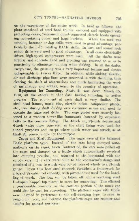
CITY TUNNEL-MANHATTAN DIVISION 708
up the experience of the entire work. In brief as foUowi: theplant consisted of steel head frames, enclosed and c<|uippcd withprotecting doors, permanent direct-connected electric hointii opcraWing non-rotating ropes, and large bucket*. When» the ruck wmmsuitable, hammer or Jap drills were us<hI to great advant«|p>, par-ticulariy the I.-R. rotating B.C.R. drills. In hard and Meamy iwkpiston drills were used to good advantage. In all caw* electrically
driven high-speed compressors were used. All the Mhafta wencircular and concrete lined and grouting was resorted to so aa topractically to eliminate pumping while sinking. In all the Mhafta,
except two, the grouting was a very important feature and almontindispensable in two or three. In addition, while sinking, electric,
air and discharge pipe lines were concreted in with the lining, thunclearing the shaft of obstructions and much facilitating the workof installation and adding much to the security of operation.
Equipment for Tunneling. Shaft 21 was down March 15,
1913, all the others at that date having tunneling in active
progress. The equipment at each shaft is very similar. Thesteel head frames, muck bins, electric hoists, compressor plants,
etc., used during shaft sinking were continued in use and used to
operate the cages and drills. The cage guides were securely fas-
tened to a wooden tower-like framework fastened by expansion
bolts to the concrete lining. The 4-inch air, 2)-inch electric and6-inch water pipes concreted in the shaft lining were used for
tunnel purposes and except where much water was struck, as at
Shaft 23, proved ample for the purpose.
Cages and Shaft Equipment. The cages were of the balanced
Eagle platform type. Instead of the cars being dumped auto-
matically on the cages, as on Contract 66, the cars were* pulled off
the cages and dumped on a tipple which automatically revolved
into dumping position, and returned to the horizontal with the
empty cars. The cars were built to the contractor's design and
consisted of a base to which were bolted pairs of whwls to a 24-inch
gauge. Upon this base steel channels furnished a framework for
a box of 38 cubic feet capacity, with pivoted front u.sed for the hand-
ling of muck. The box can be taken oflF and a r<»volving steel
U-shaped Koppel top placed to serve for concreting. This effected
a considerable economy, as the costliest portion of the muck car
could also be used for concreting. The platform cages with tipple
were adapted in preference to the self-<lumping t>TX', to save in
weight and cost, and because the platform cages are roomier and
handier for general purposes.

704 CAT8KILL WATER SUPPLY
Automatic Tipple vs. Self-dumping Cages. The automatic
tipples used in connection with these cages were designed to secure
the advantages of the self-dumping cages, as they allowed the
use of muck bins close to the head frame, and the immediate
return of the muck cars to the cages and tunnel. It takes two
men, however, to shove the cars off and on the cages, whereas
the operation is entirely automatic with the self-dumping cages.
By making the dumping level the main platform for men and
materials also, but one more man was necessary, as a " top-
man " is necessary in any arrangement. However, it seems to the
writer that the self-dumping cages with muck cars such as used on
Contract 63 and 66, are somewhat handier and more economical
than the tipples and higher bodied cars used on Contract 67.
Method of Excavating Tunnel. The small tunnels of the con-
tract (15 feet diameter as excavated) in Brooklyn were driven
mostly as heading with short and shallow benches. The bench, a few
feet high and about 10 to 15 feet long, was drilled after the head-
ing holes were put down by turning the drills on the columns. This
allowed most of the muck to be shot over the bench, saving wheeling.
As the rock is mostly a hard grano-diorite and the drilUng of the
headings the slow feature, the mucking of these small tunnels
(6.5 yards per foot) was not the governing feature as on the other
contracts. General Electric storage battery locomotives were used
on this contract as on Contract 66, and gave good service at a
low operating cost.
In some of the tunnels three shifts of drillers were employed,
it usually taking more than a shift to drill and shoot the headings.
The grano-diorite proved to be very variable in hardness, often
taking as much as twelve hours to drill with 3f-inch Ingersoll-
Rand piston drills. This made it difficult to maintain a schedule
such as employed on Contract 66.
Timneling at Shaft 19 by Three-shift Method. The tunneling
method followed at Shaft 19 in the early part of 1913 was that
known as the three-drilhng shift or continuous method. Between
the two headings, three drilling and mucking shifts were employed
with three small shifts for setting up the drills. The schedule wassuch that a complete operation of drilling, blasting and mucking
was performed in 16 hours, the tunnel advancing about 7.0 feet.
The tunnel was excavated in dry Manhattan schist, which yielded,
when 1000 feet long, in the North heading about 2^ gallons of water
per minute; in the South, only J gallon per minute. It is circular
and excavated to about 16 feet in diameter. The usual top heading

CITY TUNNEL-MANHATTAN DIVISION 705
and bench was employed, the tunnel usuullv In^inK complctdyexcavated to invert grade about 70 feet !)aek of the fence.
To give the method in detail, the following description in
given :
Details of Drilling System. The drilling gangs* who work from12 P.M. to 8 A.M., 8 A.M. to 4 P.M., and 4 p.m. to 12 p.m., uponarriving at the heading find that the drilLs have »x«en wa up bythe previous setting-up gang and the muck nearly cleared out bythe mucking gang. Two 8-foot columns are .set up al)out 3) feetfrom side of tunnel and 4 feet back of the face. Three drillM aremounted on one colunm and two on the other, using 2- and 3-footcolumn arms, the drills being 3} E 44 IngersoU-Rand reeiprcK-at-
ing. To drill the bench with vertical holes a tripod pLston drill
or rotating Jap drill is used.
Air is supplied through a 6-inch pipe carried down the shaftand branching to 4-inch line in each heading, the 4-inch line Ijeing
laid on floor of tunnel to within 30 or 40 feet of lx?nch, from whichpoint a flexible hose carries the air to the heading manifold supply-ing the drills.
The drilling gang for heading and bench, consisting of a fort*-
man, 6 drillers and 6 helpers, usually drills the round in alxiut
6 hours, consisting of six cut holes 10 feet deep, eight relief holes*
8 feet deep, and ten rim holes 8 feet deep. The cut holes start
6i to 7 feet apart and " bottom " within a foot. The rim holes
start within 4 inches of the C line and point outwanl from
6 inches to a foot. The relief holes are distributee! l)etween the cut
and rim holes. The six bottom holes usually point down about
18 inches. Steels drilling 2-, 4-, 6-, 8-, and 10-foot holes are used,
and vary from 2f inches for the starters to1J inches for the 10-foot
steels. The drills are sharpened by a Lake Shore Engine Worksdrill sharpener, requiring a blacksmith and helper for each shift.
The use of the drill sharpener rather than hand sharpening has
been found to be economical and expeditious, but some trouble
was experienced from breakage of pistoas, due to the severe work
required of drill sharpeners. Eight- and 10-foot steels, before
sharpening, are usually used twice for holes in the Manhattan schist,
the others only once. The + bit is use»d for all steels.
The bench, usually kept about 70 feet back of face, is drilled
by a driller and helper operating a piston or Jap drill. The rows
are about 3 J to 4 feet apart and contain five holes. Additional
holes are often drilled when bottom breaks high, to allow Uying
of track to invert grade.
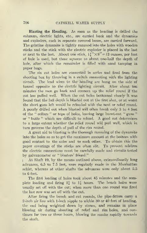
706 CATSKILL WATER SUPPLY
Blasting the Heading. As soon as the heading is drilled the
columns, electric lights, etc., are carried back and the dynamite
and exploders, each in separate covered boxes, are carried forward.
The gelatine dynamite is tightly rammed into the holes with woodensticks and the stick with the electric exploder is placed in the last
or next to the last. About one stick, li''X8'' = 13 ounces, per foot
of hole is used, but these squeeze to about one-half the depth of
hole, after which the remainder is filled with sand tamping in
paper bags.
The six cut holes are connected in series and fired from the
shooting box by throwing in a switch connecting with the lighting
circuit. The lead wires to the heading are hung on the side of
tunnel opposite to the electric lighting circuit. After about ten
minutes the men go back and connect up the relief round if the
cut has pulled well. When the cut holes bottomed closely it was
found that the full depth is blasted out at the first shot, or at worst
the short guns left would be reloaded with the next or relief round.
A poorly drilled cut when blasted will often break only 3 to 4 feet
of the " collars " or tops of holes, leaving large burnt-out '' guns "
or " butts " which are difficult to reload. A good cut determines
to a large extent whether the relief round will pull well, which in
turn governs the depth of pull of the rim round.
A great aid to blasting is the thorough ramming of the dynamite
into the holes so as to get the maximum amount at the bottom with
good contact to the sides and to each other. To obtain this the
paper coverings of the sticks are often slit. To prevent misfires
the electric connections must be carefully made and circuits tested
by galvanometer or " blasters' friend."
iAt Shaft 19, by the means outlined above, extraordinarily long
advances, 6.5 to 7.5 feet, were regularly made in the Manhattan
schist, whereas at other shafts the advances were only about 5.5
to 6 feet.
The first loading of holes took about 45 minutes and the com-
plete loading and firing IJ to 1| hours. The bench holes were
usually set off with the cut; when more than one round was fired
the last row was set off with the cut.
After firing the bench and cut rounds, the pipe-fitters carry a
2-inch air line with 1-inch nipple to within 30 or 40 feet of heading,
the end being weighted down by stones, and remains in place
blowing air during shooting of relief and rim holes, and con-
tinues for two or three hours, blowing the smoke rapidly towards
the shaft.
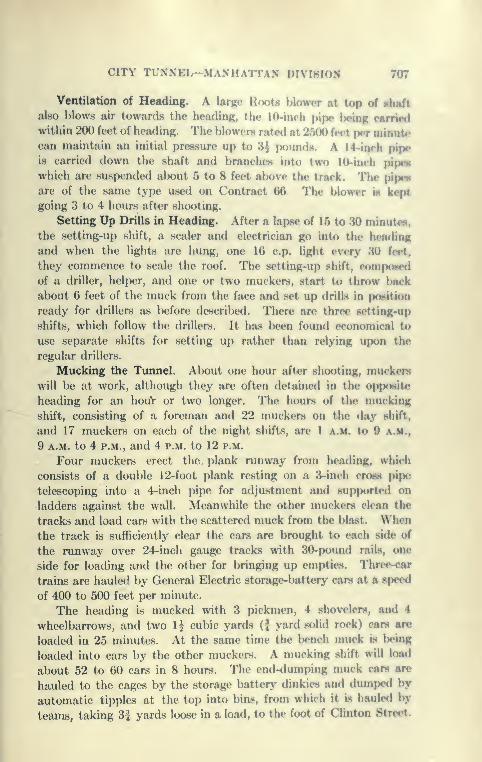
CITY TUNNEL—MAMI ATI A.N lUVlJ^lUN 707
Ventilation of Heading. A larRo Hoots hlowor at top of shaft
also blows air towanls the headinR, the lO-inch pipe* Ijcing outimIwithin 200 feet of heading. The blowers rated at 2500 feet f^er minuU*can maintain an initial pressure up to 3 J iK)unds. A 14-inrh pipe
is carried down the shaft and branches into two HV-inrh pipmwhich are suspended about 5 to 8 feet alwve the track. The pipe*
are of the same type used on Contract 66 The l)lower ih kept
going 3 to 4 hours after shooting.
Setting Up Drills in Heading. After a lapse of 15 to 30 minute**,
the setting-up shift, a scaler and electrician go into the heading
and when the lights are hung, one 16 c.p. light every 30 feci,
they commence to scale the roof. The setting-up shift, eomponed
of a driller, helper, and one or two muckers, start to throw back
about 6 feet of the muck from the face and set up drills in position
ready for drillers as before described. There are three setting-up
shifts, which follow the drillers. It has l>een found economical to
use separate shifts for setting up rather than relying upon the
regular drillers.
Mucking the Tunnel. About one hour after shooting, muckers
will be at work, although they are often detaine<i in the opposite
heading for an houV or two longer. The hours of the mucking
shift, consisting of a foreman and 22 muckers on the day shift,
and 17 muckers on each of the night shifts, are 1 a.m. to 9 a.m.,
9 A.M. to 4 P.M., and 4 p.m. to 12 p.m.
Four muckers erect the plank runway from heading, which
consists of a double 12-foot plank resting on a 3-inch cross pipe
telescoping into a 4-inch pipe for adjustment and supported on
ladders against the wall. Meanwhile the other muckers clean the
tracks and load cars with the scattered muck from the blast. Whenthe track is sufficiently clear the cars are brought to <*ach side of
the runway over 24-inch gauge tracks with 30-pound rails, one
side for loading and the other for bringing up empties. Three-car
trains are hauled by General Electric storage-battery cars at a speed
of 400 to 500 feet per minute.
The heading is mucked with 3 pickmen, 4 shovelers, and 4
wheelbarrows, and two li cubic yards (J yard solid rock) care are
loaded in 25 minutes. At the same time the l)ench muck is lx»ing
loaded into cars by the other muckers. A mucking shift w\\\ load
about 52 to 60 cars in 8 hours. The end-dumping muck care are
hauled to the cages by the storage battery dinkies and dumpe<l by
automatic tipples at the top into bins, from which it is hauled by
teams, taking 3| yards loose in a load, to the foot of Clinton Street.

708 CATSKILL WATER SUPPLY
When the mucking of a round is completed, 4 or 5 muckers
lay overlapping |-inch plates, 5'X6', over entire top of bench and
on tracks at foot of the bench. The blasted rock falling upon these
plates is much more readily handled than otherwise. Four muckers
take down the plank runway in from 15 to 30 minutes and load all
the material of runway into a car, which, is pushed back out of
the way.
The total force at Shaft 19 averaged about 179 men whenoperating on the three-drilling and mucking shift basis.
Water at Shaft 23. Pumping Plant. So far no unusual dif-
ficulties have been encountered save at Shaft 23, where a very
heavy flow of water was struck in the drill holes, a few hundred
feet from the shaft. While pumps were being installed the holes
were grouted under 300 pounds pressure, but the next shot
exposed seams yielding about 300 gallons of water per minute.
The grout did not penetrate far into the broken-up rock, which
appeared to be at a contact with the Fordham gneiss. It is very
difficult to grout broken-up rock without well-defined seams, and
it hardly pays to persist in tunnels where water is readily handled;
whereas in shafts it may be imperatively necessary, as a few
hundred gallons of water at the bottom of a deep shaft is an almost
overwhelming handicap. A pump chamber was excavated in the
side of the shaft, and two 300-gallons per minute Triplex Gould
piston pumps installed. They were belt-driven from A.C. motors.
They proved to be very smooth working, reliable and satisfactory.
The tunnel was then driven ahead after four weeks delay, and
a belt of broken-up rock penetrated, yielding at the maximumabout 550 gallons of water per minute. The value of the pump-ing item to the contractor was here shown. Although for the
usual small quantities encountered the price of 35 cents per mil-
lion foot-gallons is not profitable to him, for the larger quantity,
such as handled at Shaft 23, with electrically driven pumps, a
good daily margin was realized above power and attendance charges,
which will probably reimburse him for the cost of installation of
pumps, delays due to water, etc., exactly as the engineers hoped
would be the workings of this provision.
Mucking Machines for Tunnels. The experience on most
tunnels is that it is hard to keep the mucking shifts full, and muchcomplaint is made about the increasing wage ($2 for eight hours),
demanded by the muckers, who are said to be of an inferior quality.
This has furnished the incentive to strive for a mucking machine
which would largely reduce the force of muckers necessary. As

CITY TUNNEL—MANHATTAN DIVIHION 709
stated before, although several types have Ijecn triwl on tho Cabfkitl
Aqueduct, none hjus yet been suecessful.
Myers-Whaley Mucking Machine. Tlie MycTh-Whalry muck-ing or shoveling nmchinc has U'cn for some tinit* ujmhI in niim-Ji
where it is said to be successful. It was ir'mi out at Tallulab
Falls, in Georgia, where representatives of the contractors for Con-tract 67 saw it at work, and were favoral)ly inipresMe<l. However,the conditions here were very unfav()ra!)le, the main contractors
failing before the machine could Ix' fairly trieti out.
Mucking Machine at Shaft 23. Soon after Shaft 23 tunnel
was under way a new Myers-Whaley mucking machine was Mecuntl,
and placed in the tunnel. This machine is motor driven, runn
on a 42-inch gauge track, and is ver>' compact and low. It weigha
about seven tons, and is 25 feet long, and 4 feet 9 inches wide.
The power is applied to shafts and chains so as to prop<'l the
machine, operate belt conveyors and a powerful shovel. This
shovel moves in a path much as a hand shovel, scooping up the
muck, throwing it into a bucket which in turn throws the muck into
a belt which passes it, another belt feeding the cars (see Plate 237).
The whole machine is pivoted on a king pin so that the shovel
can be directed at any point on the bottom. One of the principal
features of the machine is a cone clutch through which the mechan-
ism of the shovel is controlled and the machine reversed. The,
clutch is set to slip at a designated load (about 15(K) pounds) for the
shovel and to relieve the machine of undue strains and shoeLs
when the operator attempts too much or when a hard boulder
of rock is struck. The machine can load cars on either of two
tracks.
The Myers-Whaley machine is a thoroughly designed and W€»ll
constructed piece of machinery, and wonderfully ingenious, and
did good work during its two months of service at Shaft 23. The
experience there showed that the work of nmcking a tunnel is
much more severe than handling coal in mines. Tunnel scluHlules
have to be rigid, and delays are expensive. The machine ha«
repeatedly mucked out the tunnel in two to three hours, and has
filled 1-yard cars in two to three minutes. It wius found at the
outset that a good track was necessary, and special track arrange-
ments to get around the machine. To allow the machine to muck
well down, sections of track are laid jus for a steam shovel, the
sectioas being built of rails riveted to flat bars, without croBB
ties. The machine proved to Ix' rather light for the work, so that
numerous small delays were experienced, due to breakage and

710 CATSKILL WATER SUPPLY
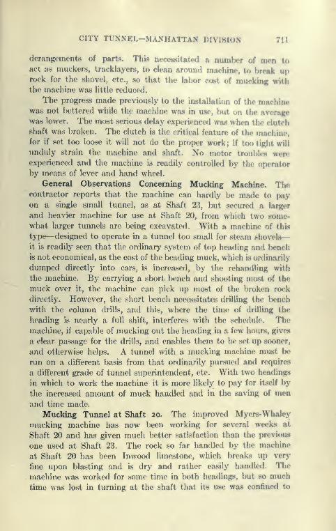
CITY TUNNEL-MAXHATTAN DIVISION 711
derangements of parts. This neceasitatetl a numbor of men toact a.s muckers, tracklayers, to clean around machine, t<» break uprock for the shovel, etc., so that the lal>or cost of nnirkinK with
the machine was little reduced.
The progress made previously to tin' installation of the machinewas not bettered while the machine was in use, but on the Avera|i(e
was lower. The most serious delay experienced was when the clutch
shaft was broken. The clutch is the critical feature of the machine,for if set too loose it will not do the proper work; if too tight will
unduly strain the machine and shaft. No motor troubl(»s wereexperienced and the machine is readily controlled by the oiKTator
by means of lever and hand wheel.
General Observations Concerning Mucking Machine. Thecontractor reports that the machine can hardly be made to payon a single small tunnel, as at Shaft 23, but secured a larger
and heavier machine for use at Shaft 20, from which two some-what larger tunnels are being excavated. With a machine of this
type—designed to operate in a tunnel too small for steam shovels
—
it is readily seen that the ordinary system of top heading and Ix^nch
is not economical, as the cost of the heading muck, which is ordinarily
dumped directly into cars, is increased, by the rehandling with
the machine. By carrying a short bench and shooting most of the
muck over it, the machine can pick up most of the broken rock
directly. However, the short bench necessitates drilling the Ix^nch
with the column drills, and this, where the time of drilling the
heading is nearly a full shift, interferes with the schedule. Themachine, if capable of mucking out the heading in a few hours, gives
a clear passage for the drills, and enables them to be set up sooner,
and otherwise helps. A tunnel with a mucking machine must lx»
run on a different basis from that ordinarily pursued and requires
a different grade of tunnel superintendent, etc. With two headings
in which to work the machine it is more likely to pay for itself by
the increased amount of muck handled and in the saving of menand time made.
Mucking Timnel at Shaft 20. The improved Mycrs-Whaley
mucking machine has now been working for several weeks at
Shaft 20 and has given much better satisfaction than the previous
one used at Shaft 23. The rock so far handled by the machine
at Shaft 20 has been Inwood limestone, which breaks up ver>'
fine upon blasting and is dry and rather easily handled. The
machine was worked for some time in lx)th headings, but so much
time was lost in turning at the shaft that its use was confined to

712 CATSKILL WATER SUPPLY
one heading where is has worked to good advantage, using about
six muckers to aid the machine, saving about six men per shift.
In this heading the best week's progress to date has been 83 feet,
but conditions were unusually favorable.
It now seems clear that the success of the machine depends
upon its durability, whether it can stand the hard work in the
tunnel long enough to pay for the expense of the installation.
Method of Computing Timnel Excavation and Excess Concrete.
Every effort was made to drive all the tunnels closely to the
C line and thus save as much excavation, mucking, and disposal
charge as possible, the contractors heartily cooperating Avith the
engineers. The tunnels which have thus far been trimmed have
come rem.arkably close to the circular shape, but it is felt that,
in the circular tunnel, it is rather difficult to get the bottom close
and that a section as used on Contract 90 (Plate 138) would be
preferable, and for a given circular waterway and thickness of
lining result in about the same actual excavation. To make the
method of paying for excavation and excess concrete clear, the
following is given: Excavation is always paid to the B line,
whether excavated closer or not. Excess concrete is computed for
100-foot stretches by deducting from the actual excavation in
any 100-foot stretch the theoretical volume to the B line. The sumof the positive volumes for any tunnel gives the excess concrete,
which is paid for at a price fixed in advance by the contract. All the
cement is paid for separately, whether or not in excess concrete.
PROGRESS TUNNEL EXCAVATIONFor week ending December 18, 1912.
Previous RecordWeek's Work For the Week. To Date.
Shaft.Tunnel
Diameter.
Combined Headings.
Heading.|
Comp. Heading. Bench. Heading. Bench.
IN 15 ft.80 ! 82
40 41 1048 997IS 31 30 1036 974
' 2N83 85
34 32 1375 13102S 38 51 897 8513N
801
8336 36 1006 897
3S 34 38 1710 16474N
87 8537 46 1146 1086
4S 42 51 1163 11025N
98 10034 36 1284 1257
5S' 39 43 1334 1299
Total f()r Contra c t No. 63 365 424 11999 11460

CITY TUNNEL-MANHATTAN DIVISION 718
PROGRESS TUNNEL EXCAVATION-Con/miwrf
Shaft.Tunnel
Diameter.
Previous RecurdWeek'. Work
Combined Headincn.For the Wwk. T" f»^.-
Heading. Comp.Tunnel.
Headint. Beneh. llrMbac BM«lk
6N6S7N7S8N8S9N9SION10 S11 Nlis12 N12 S
15
14
ft.
ft.
86
80
89
65
131
82
91
8.5
86
83
74
87
78
92
40
43
395546
44303556
5628
33
4963
4243355342383723
4743574214
79
881
AM65454!
619347
3705191225
491
478631
1031
886429Mttfi06
5803183364121140
410406563086
Total for Contract No. 65 617 1 595 1 9151 ' fUJW
13 N13 S14 N14 S15 N15 S16 N16 S17 N17 S18 N18 S
14
13
12
ft.
ft.
ft.
124
112
123
103
105
136*
128
117
125
107
106
152t
61
4661
Completed2050
65CompletedCompletedCompleted
6561
71
3861
42
3373
CompletedCompletedComplete*!
6563
1357
1523
1978
1664
1961
1995
1856
1189
1098
1649
24452402
1200
14681031
1657
10481007
1806
1173
1114
1593
24162377
Total for Contract No. 66
.
429 446 211 17 20680
19 N19 S20 N20 S22 N22 S2324
12 ft.
<(
(<
lift.
77
43
112
6067
73
37
112
6367
455012
584654
56
4255n7
58465457
2732599486
361
3178981115
255251
7060
351
3078001100
Total for Contract No. 67 321 330 1 3403 3208
* L. Eblir, Supt. t P. Paglioni, Supt.
This Week:Record progress: L. Eblir, Supt. No. 18, 126 ft. in two headinfER.
" " " 127 ft . complete*! t unnel two 1
" E. Duffy, Supt. No. 16, "I „^-, . . ..
L. Eblir, Supt. No. 18. /^"^ '*• '" «"^ ^^«**'"«-
"J. Conners, Supt. No. 12, 71 ft. completed tunnel one hdg.
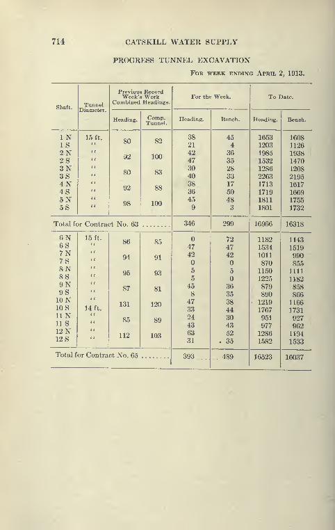
714 CATSKILL WATER SUPPLY
PROGRESS TUNNEL EXCAVATION
For week ending April 2, 1913.
Shaft.Tunnel
Previous RecordWeek's Work
Combined Headings.For the Week. To Date,
Heading. Comp.Tunnel.
Heading. Bench. Heading. Bench.
INIS2N2S3N3S4N4S5N5S
15 ft.80
92
80
92
98
82
100
83
88
100
3821
42473040383645
9
45
43635
283317
50483
16531203
1985
1532
1286
22631713
1719
1811
1801
16081126
19381470
1208
21951617
1669
1755
1732
Total for Contract No. 63 346 299 16966 16318
6N6S7N7S8N8S9N9SION10 SUNlis12 N12 S
15 ft.
(
<
< (
((
<<
<(
< (
14 ft.((
< (
86
94
95
87
131
85
112
85
91
93
81
120
89
103
4742
5
8473324
436331
72
4742
5
36353844304352
. 35
1182
1534
1011
8701150
1225
8798901219
1767951
9771286
1582
1143
1519
9908551111
1182
8588661166
1731
9279621194
1533
Total for Contract No. 65 393 .. 489 16523 16037
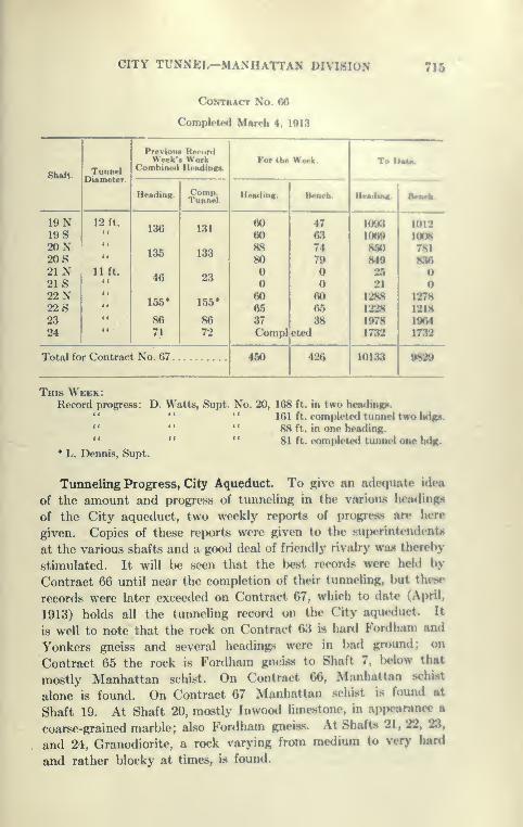
CITY TUNNEL—MANHATTAN DIVISION 715
Contract No. 66
Completed March 4, 1013
Shaft.Tunnel
Diameter.
Previoua RecordWeek's Work
Combined Headings.For tb« W«dc. ToDm^
Heading. Comp.Tunnel.
Heading. Beoeb. HMdiAg. BMMk
19 N19 S20N20S21 N21 S22N22 S2324
12 ft.
((
if
lift.((
((
{(
<<
((
•
136
135
46
155*
8671
131
133
23
155*
8672
60608880
606537CompI
476374
79
6065
38eted
1003
1060
8608402521
1288
1228
1978
1732
1012
1008
781
830
1278
12181064
1732
Total for ContrftfitNo. 67 450 426 10133 0S20
This Week:Record progress: D. Watts, Supt. No. 20, 168 ft. in two headinipi.
" " " 161 ft. complpied tunnel two bd^i.'* " " 88 ft. in one heading.*' " " 81 ft. completed tunnel one hdn.
* L. Dennis, Supt.
Tunneling Progress, City Aqueduct. To give an adequate idea
of the amount and progre.ss of tunneling in the various hcadingB
of the City aqueduct, two weekly report.s of progrejw are here
given. Copies of these reports were given to the superintendents
at the various shafts and a good deal of friendly rivalry wa« thereby
stimulated. It will be seen that the Ixjst records were held by
Contract 66 until near the completion of their tunneling, but the«e
records were later exceeded on Contract 67, which to date (April,
1913) holds all the tunneling record on the City aque<iuct. It
is well to note that the rock on Contract 63 is hard Fordhani and
Yonkers gneiss and several headings were in bad ground; on
Contract 65 the rock is Fordham gneiss to Shaft 7, below that
mostly Manhattan schist. On Contract 66, Manhattan schist
alone is found. On Contract 67 Manhattan schist is found at
Shaft 19. At Shaft 20, mostly Inwood limestone, in appearance a
coarse-grained marble; also Fordham gneiss. At Shafts 21, 22, 23,
and 24, Granodiorite, a rock varying from medium to very hard
and rather blocky at times, is found.
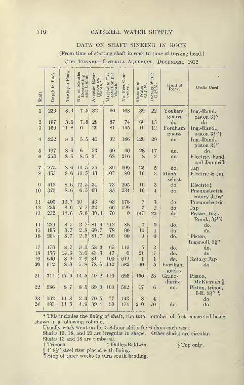
716 CATSKILL WATER SUPPLY
DATA ON SHAFT SINKING IN ROCK(From time of starting shaft in rock to time of turning head.)
City Tunnel—Catskill Aqueduct, December, 1912
d
1a
1
1
t
1 o.
of
Months
Excavating
and
Lining.
verage
Exca-
vation
per
Month.*
J
6%
hi1
%6
Kind ofRock. Drills Used.
w Q >" Z1 < ;^ •z % <
1 233 8.4 7.5 32 60 168 39 22 Yonkers Ing.-Rand.
gneiss piston 3f"
2 197 8.6 7.5 28 67 74 60 15 do. do.
3 169 11.8 6 29 81 145 16 12 Fordhamgneiss
Ing.-Rand.,
piston 3j"t4 222 8.6 5.5 40 92 186 120 29 do. Ing.-Rand.,
piston 3|"
5 197 8.6 6 33 60 40 28 17 do. do.
6 253 8.6 8.5 31 68 216 8 2 do. Electric, handand Jap drills
7 275 8.6 11.5 25 89 199 25 5 do. Jap8 453 8.6 11.5 40 107 80 10 2 Manh.
schist
Electric & Jap
9 418 8.6 12.5 34 73 295 10 3 do. Electric t
10 375 8.6 6.5 60 85 234 10 4 do. Pneumelectric
rotary Japs^
11 400 10.7 10 43 93 176 7 3 do. Pneumelectric12 235 8.6 7.7 32 66 129 3 2 do. Jap13 232 14.6 5.9 39.4 70 147 23 do. Piston, Ing.-
Rand., 3|"§14 220 8.7 2.7 81.4 112 88 do. do.
15 195 8.7 2.8 69.7 78 90 10 4 do. do.
16 204 8.7 2.5 81.7 100 90 do. Piston,
Ingersoll, 31"17 176 8.7 3.3 53.3 65 115 5 3 do. do.
18 156 14.6 3.6 43.3 47 21 17 do. do.
19 640 8.9 7.9 81.1 109 612 1 1 do. Rotary Jap20 612 8.8 7.8 78.5 112 582 40 5 Fordham
gneiss
do.
21 714 17.9 14.5 49.2 110 695 150 23 Grano-diorite
Piston,
McKiernan[[
22 586 8.7 8.5 69.0 103 562 17 6 do. Piston, tripod,
I-R. 3f " If
23 162 11.8 2.3 70.5 77 143 8 4 do.
24 193 11.8 4.9 39.4 59 174 240 70 do. do.
* This includes the lining of shaft, the total number of feet concreted beingshown in a following column.
Usually work went on for 3 8-hour shifts for 6 days each week.Shafts 13, 18, and 21 are irregular in shape. Other shafts are circular.
Shafts 13 and 18 are timbered.
t Tripods. % Dulles-Baldwin. § Top only.
II4' 9f" steel riser placed with lining.
H Stop of three weeks to turn south heading.

TABLES

718 TABLES
APPROXIMATE WAGES PAID FOR EIGHT HOURS' WORK ON CATS-
KILL AQUEDUCT *
Cut-and-Cover. Rate. Tunnels in City. Rate.
Per Month. Per Day.
Steam shovel man $125
75 to 90
Drillers $3 75
Steam shovel crapesman Driller's helpers 2.00
Dinkey runner 90 Muckers and laborers 2.00
Locomotive cranesman. 100
Per Day.
1.60 to 1.75
Muck boss 3 00 to 3 50
Pipeman 3.00General laborers, exca-
vation and concrete.
.
Pipeman helpers 2.00 to 2.50
Driller 3.00
2.25
3.00
4.80Helper Compressor engineer.
Hoist runner
Blacksmiths
4.25
Tunnels Outside City. Rate.3.75
Carnenters 3 00
Drill runner
Per Day.
$3.00Heading Boss 4.50
Drill runner's helpers . . 2.00_
Muckers 1.75
1.75 to 2.00Concrete laborers
Hoist runners 3.00
Average payj of men in cut-and-cover, $2.00 per day (about).
Average pay tunnel men outside of city, $2.25 per day (about).
Average pay tunnel men in city, $2.50 per day (about).
* This table is unofficial, wages varying with locality and year,
t Total pay roll divided by number of men.
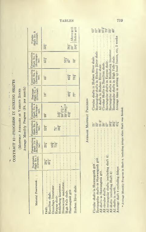
TABLES 710
OO iii4 II'^^oOQ^
s sss5r« •
n <« Z4« «. «CO M t>. C^
III"rf • »o -^ »o
o^'^5« •
2 . 3
l^g^ H« H«to c^i 00
i'sl"TJ4 to !>•
qOQ^„_^ lO .
rn .C3 « .'T'
lOUS
ROCKI
.
per
mont III00 t-
QmO1-H •^ f*
g^i.
> structi
ift
No.;ctangt
lar).
2 o m 8 S^S?;5 :
H 2 en 1 :5 P-i O . 3"< ^ - O W)
Avernthly
)n8truc
haft
NRectan
lar). S fc^ :
as 6^-BINO i
z ^ •5 O 3 ^ ^ '.
Construe
Shaft
N(Rectang
lar).
?5 Si3•
-5"-^08 O as «. •
ice £2
1 istt> c a> 1
is
1
II4
illilP
: -a
it ^
ill
'z
C
;1
\iiJi^
3 C
33
3 [T
\ 1
I 3§
^sioSur:*^^
I
Ijil.|-..|-^£
S ^ W
•** « 8 *" « « «c w *c .£ w C 4^— «9 S " as « « a
K "Z y, X "Z ~ ~ «*
EcC »: Sl & Ec &.5 5 «^
V V V 5
'&
11
&11 =
lis
IliiI IIIfc 9 *
3 -f
31
00 i»tl«»2»-
»o to 3 S§ 10 S <N ^r JCO
I»
S»
11
I
§55; f
«<<<<<
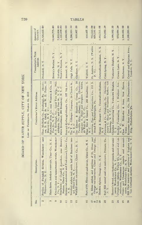
720 TABLES
<0
S 88 8
O r-l OO rH
d in" CD N'^ (N e<5 05
00 r-
o
fa 2
CO §
oQ
Om
o ^2 ^
^•3Pi
.06
Z^
,^ :| :h^
I 2
c .£ «- «Ph 2
t jC -^• 3 « «
enO 0)
6B^ ^
C '^ M
£ oa "^ *^
O ., 93 CO
£ — ' =
IPd CO
22
xi •;:!
S c
- ^
O;
o
.0 -r a
•£2: £«« a
85 1-5
:pq
co^-
O W O
o
«T3PHi2>H .
U pq O
;0 5
(X.
« • "^ '^ T)
3 . — << eS
ft • j:«! - (-
ft • 2 6 *"
: ,=« O §
.2"- 3
«o «a; i:z; o c «W K W tf ^
83
15
o
CO
"S 83 "K '5 *
._< CO O) ^
00"^
ffi>.
3Z p o o
> 1t> ^ O
S ° ° = :S
-1 rt «« r-l IN
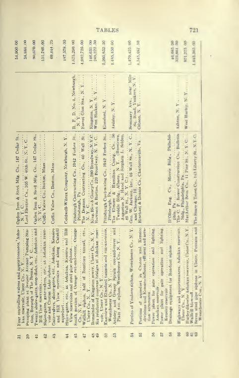
TABLES 721
8 8 8 8^ 8 8 8 88 S 8
8S«t-^ •oSh-SciS —S S 8 S 8 — ^ « ^
:•/•.
o "^
. ^ O
IIll
I i
J Iu <
8 S
53'
M •
: c •
CI . D . i
^o
^ t^
*i -t),
:ffl I
: >» c
:o «i: i ^
tS -J 1. ^ -J 'OmZ o mZ oO hJ C O
|I<S
Hi0. H
oil
2.r ft«K 3
- cu j= H -•:
X 2"- 5* ^- 4"
C OS
I
I:?
llllx^ *
I :| -.J
g :io^a -a. .^
'z<a X " i- T«0 c.CQ c.
« JE ^ o^P «=
«
.£ .h c M iS O CS s ij
£ ^ "c. £ 3
o =11ti!0
^ o
CO 6^
k. es *? M 4)
?'*£'">
5 o
i-C
1 i
:
ec
'o a
•5-5 ^"^i ^
'^ Br et
O J<
Si
illlit.
o .
d
: « • 3 u
a • S -c
o
= ^15 3a a
o
= fc.sl
> '• _ -1
"a
6 -S d 2 iOWUO c.
^ f I
§u ^;-» S.s
" " £ 5 >•3 i« -c <1.* ! « Ji »<
M <
o *
H.si
3 C
II
1^
1;1
S:3
I!
^ I
1I
i9J
I':.
• ^ .-5 •{•SB***
9
2 S S & 3 S 8S8
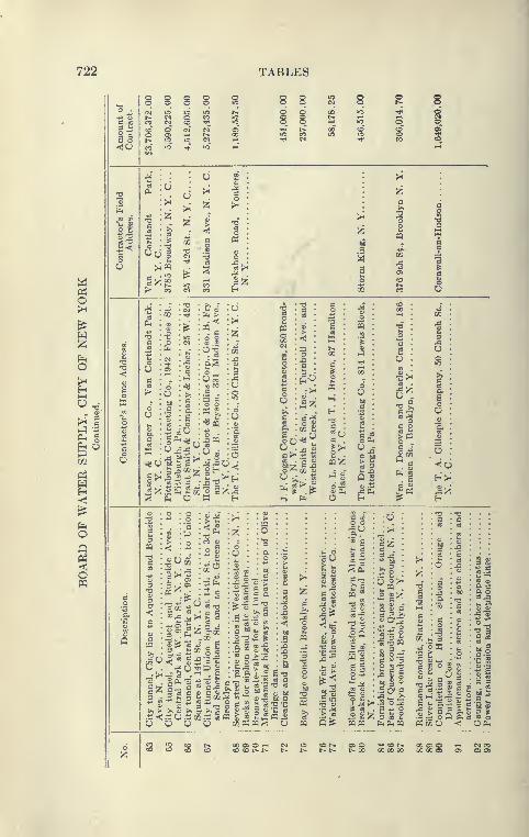
722 TABLES
6 ao
§ 8 § g!>• y-i
to O N No o> »-i t*l^ »q U5 (N
C«3 lO TjJ' lO
(2 ;^
I :^O TS
o
° °
S • o o
S :i :•««
S ph c a
-e.g. 5§ : «»
•;tj
m : « • SS • > <a
^ < : Xe^ :- • t^
5 :h'o
2. H
:0 C r^ *^ on
'E^ «^
^^
Iooo
. TO k^
3
.2 >^
; o :<« ®"^
:o §
- -M -
.i«^ § I3 C ^ •--f3
8 .'"' - £
, G "^ c x:8 C « C «, 3 ^ a 02,
t5 £
a 03" o<U Oaxa.a— 05 S N 05 C
o P3
2 ^
jgtf pq^ O
^ "CO
•5 -^
I -si
PQ Q^
^5^;5
TO
£ TO-
SI
^ 05
«pq
1^
O TO ~3
.'2'o2c *^ o
TS^ aox
a o
1^
?l
o g
III!
2=^ill03 03 O

TABLE8 738
SS§8 o § S§ SB S 2=2 2 222 7S« S

724 TABLES
Oi Oi Oi
05 Oi Oi
^^^00 CO 00 CO
<S4
O , O Oi Oi 05 o1-1 r-i O O O i-t
05 05 05 05 03 05
Q^ Q S
CO o •*Oi Tf* t^lO "* CO
Oi as»0 lO
CO 00 CO O O00 »C l^ lO »oTjH CO CO CO CO
Oi O fO i-H b*O Oi O 05 's**
lO CO CO -^ Tt*
lO »0 00i-t -* oCO CO CO
s
H SOP 03
Q ^N o
;3II< w
hJ1
hJ r'n
w Zrr u:
H -^
^ wO
g<!
CQ
00
1-H Oo" cf uf
GO I
^ O oro »o ^CO to
• 00
CO ^
81
TT''^ CO
TT
CO o"
00 oCO ^co^o'
co'
" 00
oo-o
TiO -CO
H H HH H H
1-1 (N CO Tj<

TABLES 735
© ©
s s ^t£ t I <5
I60 M) M) M3 3 3 3
tr N 52 53 r^ CO
$ ^i 1$ S ;;
:? S S
So ss
M Q ^
18
;JS O o
^ i O ^"
I
I ow - T00 o^CO rrT .
»Ci I .CO I »o
Tji ;0 rt*
flfO CO "^
!ss«
3:4,
1
51 3
m
JIffT"CC
1M O
l!fffOS CO i A So
IS' » " -^
Ms
I CO . «- "*
c^ .S »' 2i»^"
»c " ;d CO M
222Sg"
ill
iii
ill
oSSe
« — QO
$8
= 1
ff!
852
I
1o

726 TABLES
Q O
o o oT—I T-H 1—
I
a oi Oi
o. W) bC
^3 3
<N (N Cl <N (MT—I ,—I ,—I T—( 1—
t
05 05 05 05
d^ bb
s^4;2a s
.1
II
I•i
HII
H
o o o05 05 05
ss:^b3 bj
05 05 05 C5 05
>i bC >i bC tsC
02 >-i
CO i-H
rH CO
lO 00 00 (N CO 00'^ (M tH Tj< (N t^(N CN (N (M (M (N
O (M CO 00 lO lO'Jt* (N r-i (M 05 t>-(N C<J (N (N --H (N
00 CO
J. ^
Q II
e %
O
i iff 05-^6^
lO CO -"^
(N
T»0 CO
CO ^
HWH
O o3
c3 ^ >-i
-g, O^ (N CO Tti lO CO
O e3
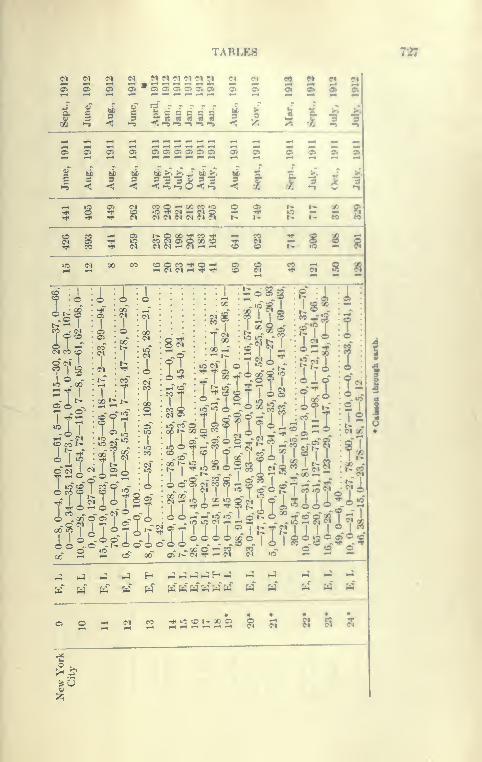
TARI.E8
22
21—1
CI M ^ ^ ^2 i2 iJ ^* '='*
1 s 1912 1912
i •-9
a< •^ iiiiii i i i i n
^ <: ->!
O) 9) O) O O) 0>
bC >^ >•..fcj bC 5^.
<•-»•-» o < «-» i t a i
5OS M
?J ?3 ?i 8 J^ it t>. ? m M
S. § § §
»0 C^ 00 CO «osss^s?;: s § 9 s S §
Aido r^.o
t>. ^
"3 .(30
05 O -
I.ICO t^
1?
»o
!si
O . 00 Q OSI _~9
••T
:i
!
*?8
i;2
t^*Sg :?eI I
ra
I!-
IT'rl
' —r9 o »^ I «r
1
»o
t3
& 00
1
»,c?5^::S3 ?5 « 2 2 s
i4 ^^ ^ *^
H H P^
-^ (M CO sssass 8 a as
12;
727
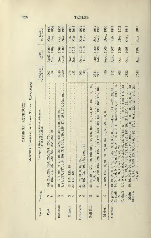
728 TABLES
o
><oXW
HOQ
O*
t^ o
<< aSh
z& VH ?^
03
H >O -v< <a xtO g
OS > >O O
05 Oi
(M 00
00 of(N 00^CO
<S> ~O Oi
CD t^,-H CO
05 -o lo(M ^00 ^-^ CO(M O
^cc
^1
CO CO
'••' CO
CO "-^
(N
CC ^-
05 COO CO
CO CO
-co1—1 •rtl
^ 00o ^.-H CO
^OJ
9. ^ ^ aS<^
05 rHt^ 00
^02
o o05 C5
OO
lO OSo -^(N 00
^ O05 a
03 o•-s CO
^1
CO t^
<M '-I .-H
05 Ci O
00 00
C5 Oi
t>. CO (Mr-l CO COCO CO 00
O) i-H
o ^
r-l OiCO ^
t^ oCO 1-1
^cc
§
;s
I-H Oi
CO
s
rS
9&
o"o'
co^c^c4~
,-H O '-^
----TOO<M ^ iC
-O cc00 --o
COCO
o C^^
CO (>i
^ (M
d°
^00CO ^-o o
(N -^
-COCO O:
z-no oTo"2
8 2
3§
O co~cO
l-H O^coO 01
o~cc"
2 -^ •i^O, CO <H
i^ilz; izi 02
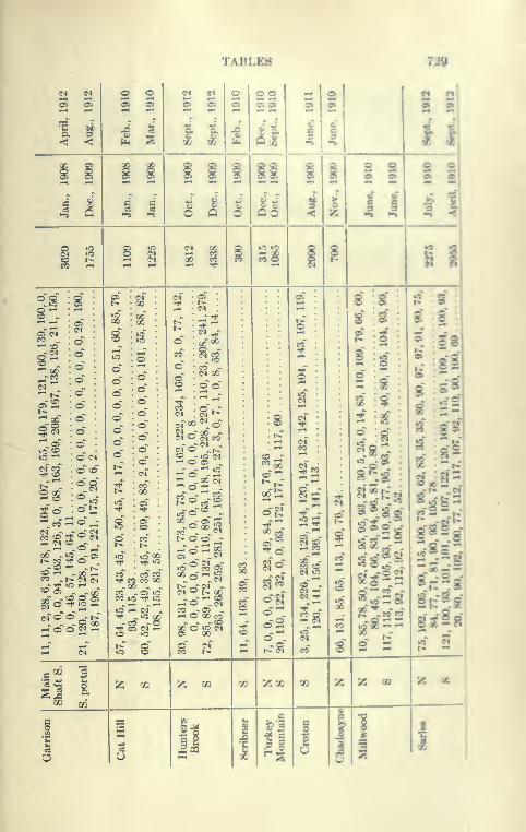
TABLES 720
0» 05
a 9<5 -<
o o
I I
2 *^ 22S 9
^1
§ §
s s
2 S 2 2
I a 9 S i i a II Hi §
:s
t§2
soo"
oooodddd <N
d"d
d~?^
cfd^"d
t^ (N (N
S
d" ~t-r
^"32 J3 a
s
.3
o o
g
<N o ^eo
2ds^.-d'l.S
ic o *1 -
t>. o O ^-
CO O "^ lO
"3 »-< M «^ -"3 00-M -O
^ M
-?5
lo CO <5ood-^?ldgg-
CO ^-d »^ O QO CO
i
s
s
l1
03
00 tl
d^
dg[
o ..
;5M
^3
a
?!5
8
2 S
;e
2-
2*2rf!
Sr Sa-
gs 2 a'
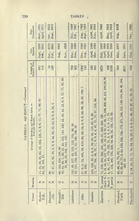
730 TABLES /
IOPP
3HO
1—
1
tH (N e^ O ^_, 2 S i-H 1—1 1-^ t-4 1—
1
(M No l-H 1—
t
t-H »—
t
T-4 ,-H tH tH 1—1 T-l« Oi 05 o o> a> S o> S 05 05 05 Oi Oi 05 05
«« Tl T—
I
T-H r-
(
1—1>-< rH rH 1—t rH .—
(
T-t
5 11 II ll <1 02
q3 oT
1 |l bb
i
o ^ (N l-H (N O o o O (N o o o o o o (N 1-H ^^1—t 1-H ,—1 T—
1
.—1 1—
1
r^ rH"6 OJ 05 05 a 05 S Oi as S O: Oi a> 05 Oi CT> O: OS 05 05
nIS 44'
1 1 S5c5 bi
ll1 s &•
s ^ s
li lO lOg|
00 (M 00 CO o ^ 00 tJ4 »—
(
1
o00 1—
t
00 CD o -^t S88 t^ CD ^-* lOM-S 00 1—
1
b- 00 00 CO c; CO o Oi
gg""• 1—
t
<N
H-3fl
h
S" •
oo" 1
-
00
1 r-l
CO
s? (N
^co"
s 8(£ OC
•
^
2T-l
r-T
CO ^ §8b-
~ § s
eo"
Ccc
c
• cc
o'"
g
'^^co'SuD i> cr
-
CO
a^ o CO oc .vb'""
00 —TTt cT
^1
1—1
a
s
c
t—
1
CO
CO -^
r^ C-
CO»-H
• r-(
^CD
> eo" o - <N ^ „ ^ CD ^<^^ c^ r-t
-< QO • C"- °.SS(
" c^ "' S O CN oi ^ c^ c^ 1—t ., 00^ ^^ ^t^ ^Oi ^ -.=*= t^CO a5 00_-r^ ~ o . (N -pc^ 05 -*CD -^^ oi g CO a5 25 CO J^
i^ oc CO ~ t^"^u- ~ ^ <N c: rtl >-4 o : ©"c ^O t>.
(M r- u-J ^ -a ^1—
(
'"' ^ ^^ : c5 00 ^
S! : Sc- |gSj ' 1>
»C r- ^ ^ - c>f ^rft^ ^^ ^ TtH" -^^ g^* O If) (M I> O S '^ ^ - ^.C iO
CO iC t^ rH CO ?; » -c ^" ^Ttl t^ -^H rH Tj< ^ T-4 O t- ^ I— c^ co"i2~'- :3!
»o »o ^Tjl -^ COlO u-
I S^r g^^ ^ ».1 i^ oc5 <N C^
) CO c rH ^ ^t. co'cT^ CV ,-i c- ) I-H l> 1> lO Tt< r- rtl r-l (N
bi) ^^03 -ic
1!z;aJ 02 JZ; ^Oi ^aJ ^aI ^a
> a|||I,
^K '^^^a:
ia
|p:
; t/
p:
J
<
ap:
1
1
1 1
i
1
.8>
1
1
. i

TABLES 731
S5O
<><Xw
H S5
g i
£
5
5l02
o oOS o> isii§§§§§§
iiii iUUUiit§§§
SSSSS2SSSSSSSSoSSSSSS
S22SS8888-
iili^ g^iilliiili Miiiiiii
« Q o> "1! »^ o» OS oo O t; t^ -+ QO «-•
lO eo<£> »CO lO-OS
CO eo
CO Mo ^CO 00
00 -(N ^
CO ^(N lO
o ^
^i
3
n I :!: ^ I::^
CO fO
<S S 8
l-H t^ **^ >• *
csf r>r Qo" «r
> -OS1/3 lO i-»
-^ -M •^eo ?o _CO -ciOS W
(N C^
eo r^ CO
^ OS »o-»^
eo os""^ 3S8
2S?5S?? 5ssSS§SgSi
iiiiilii
515!
S
3!^« CO
CO ^ 3j afc
-fi eo w^ to n .
— eo w .
£! - -feo so •>* r'.-^^ — CI
«0 M M .
8
2 5S2p: ^ ^ o
r>- —eo CI
ci'-f
^ ^ «.OS oe
!>. 1^ a•2 eo «
eo , .
!i
35^.
£SSg!S39SSS
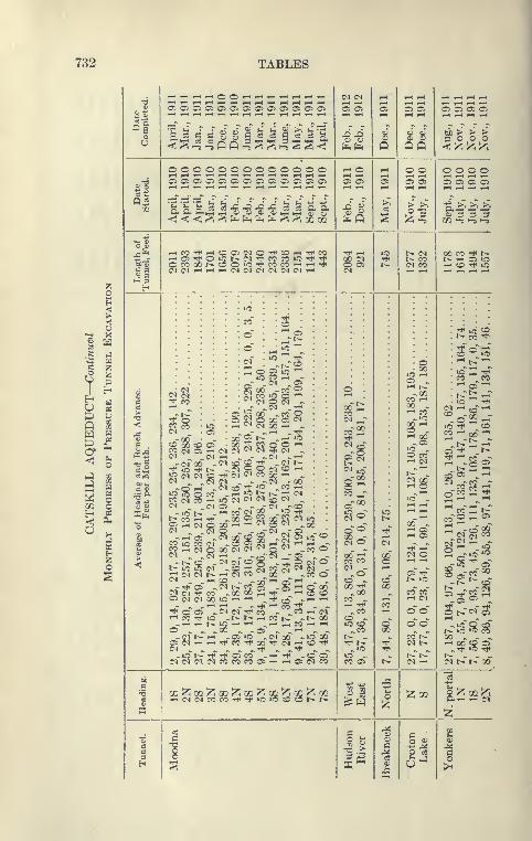
732 TABLES
S5o
<>
42 a
^HUQ
^ o
CO o
B3H
O
CO
§^
5 «
3"^ »3 e3•< ^ "-s "-s
3 ^ <1^ ^^^^^^4*
ooooooooooooo
i-HcoTtt^oastMOTt^coi-H
(N(Ni-H.-i,-((M(N(N(M<N(N
^ CO
^^
^ f^Oi ,—1
*^ ^
^^CO ,-4
Oi (M
i-H CO
Oi (M<M ^
• <>« s
00 SCD 05
CO "—
'
(M CO
o oT
X "CO »o(M Ooc ^o 00(N 00
CO 00
<^ on
cd^^00 ^'
co"^
CO 2°1
-CO ^
^CO
-CO
:::§
'^ ^ -- l^^ ^ COl^ i-H CO t>- -t^ 00^ ^rH ^ CO 1-H ^
00 "^00 "O(N rH CO
-* -co1-H 05 (N
C5 05
fefe
1—( I-H
05 05
^ ,-1
00 COo aCO
Q
00 C:
05(N
CO ®
^%CO o
00 Tfi
-00CO -
-COCO -lO «o
t^ -
lO -CO OS
m^ ui"^ m^ m'^ xfi^ m"^ mi-iC0C0COCO'^'^»C>CCOcOt^t^
QQtJD > > >3 o o o
o o1—1 1—
I
t^ COt^ COCO CO
Oi -—I t^-00
CO r^00 -—' CO
'-< 00-Ci
»o -O COT-( CO- 1—1
t^ -C^l X'-' o
00 -
o o
m
^co
C3
O 03
o o o oT—I 1-H 1—( »—
t
Oi 05 C5 Oi
00 CO ^ t^t^ rH 05 lOrH CO Tt< lO
t>- CO ^TjT^ ,-ro "-^ o
CO CO
• t^-j:;^-
CO ^ 00 »-•
CO 05 >—
'
-?2 CO nJ
'^co''^^ t^f
ro O ^ Oi
§ - ^S3
^^^<£-t^ ^ CO
Oi TiTco ^^^
- -
o i> co"^-io~o ccT
t^ lO lO CO00 - - -rH 00 CO Ci
t^ - - -CO l> t^ 00
ar-( r-H CO
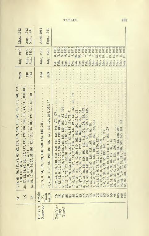
TABLES 738
1 a
c^iMMci o*^HHikHHHHH WWWWWO O"0> OS
c i^3 3
9o>osi»c&oo»a)O»oia»oke»Ok»0»ooioioiOk
WeO*O>O>00QCQQrChJ^I>;jij|»©j-:«Vrf9tfl*
fa ^ ^ Q Q >^ ^ h. :i. ^. ^t ^. ^. ^. »< •-. #^. xi «< ^
sO M
s§
s
CO
,-1 . c-5
»c
i
_- ^ c^" o" of
CO CO
^ CO CO
gj
CO
-:. ^
oT S
8
0) I •
-St/-' ^
p a
CO CO
00i^ (M 3 « 2 ?^'^- '^-
ofi c^" ^ ::!
2:2g^wSo^'^„':wrcc.-S
»ocOicOOC)|f5-^^ ^ .CO ac
si iaa :
i;;^^- « ^ t^ ^' s n? - - "^^""-^^ o K -2 2 -
S J§ ^f c^ CO c^f ^ ^ '*-""- rf 2 •- « "" •^* 1 2
>r X* 1^' ?« ^ - * - .« .
So
COCO . .0> .»0 -'^'^'^'»'^-_J-® ® «C|^,-^o-rt^^"^"^ % cts 00 2 « « «D - ss^aa«£28
22gg5§^55S252sSsSs5$g82
a> O
K«

734 TABLES
55OP<>•<
'^
ss H
Jg H^ p
1P
f^ HU „U> tf
Q ^W CD
P£^E^
f-^O
H-; rn1—
1
1H»S
< «o Cli
COeO(N(NC<>COCOC<><N(MMCO CO ftj ipHi—(,—ti—1,—It—li—1.—It—1,—ll—|T-I r-t
o-S Oi02050iOlOi050iO:Cl050S OS
"J-• *;: ci d d J" fJ' ^J ^i~-tJ^ J2 ' fe
C<l(NC<IC^(N'--irH,-i^C^(N'-ii-ii-ii-iC^lC<)(NC<ICOCOC^(>l(N(N
.Oi050iOi05050iOiOiOi05a>Oi0505050i050500i050iOOi
1^ o" co" oo" co" co" t^." CO TjT ^*" ,-r th iS (S o~ r-^"^ >if GO t>r oT o" o" lo"(Ni-(^(N(N r-(rH(N(N^^(N(M(N ^^ rH(M^
m
:^i
liiiiisSsi^s(MCO
Is i-ii-i(Mi-tT-i(N(N'-Hi-ii-H(NCO
H * *
CO t^(N lO^ (N
c::ro'"»o t^(M (N
S ec(N (M
o5 x"^rf^(M rt< • to" C^ C^l
• t^ c^ c^ OiO ^ ^ ^ ,_ 00 co't^"
i- -O .05 .CO CO -^
03 X cq (M -<N - (N (Na
- -00-^ -^ -w ^"^^
< <© 't c^ "^ ^ ^ ^ ^^l^-^ (N (N \. r-^ Tt* ^ -^ -«* (M
i^05 --CO-'"' -*-^ "^ (>i CO c^CO 05 cx) cft Oi -r^ - '^ i-J <N (N «o 1(M,^(MCC»,^O00^t>- ^(M ^^
00 ^C<> (N ^c<l O (N CC (N 05 ^co 00
T—(,—lOOiOc^lO'—"(NOlCOcOC^ ^ -
^?? 1
CO (M
^s (N ^^c^ \,o^^<^^Cia>\io^Ssl-O -^-00 -C^ -'-' ^ ^CO lO »o
^s COCCii-tb:-Oi'^ ^lO „ -iO^(M<Nd s t^(MCOpil^cOCOiO(N(Mt>.(M ^ ^
w^ - -'-' "^ ^'-' r! '"' 5 "^ - -oo -^coco - -r^ -<N - '-' '-^ (M IC t^ CO^(NCOCOcoo --^ - -.r^-'tlNfN
o r^(Mt^(MMXi00t^O300r-H(M _ . t^2S CD^CO"05 - ^^C^\,(Nt:-<NGOt^ ^ ^^>- o c^
i ^ Q SS -^-(M -'^ ^'-^-^rf^r-t-oooocvj lO gv^ t^ <NT-iOOOli-iOocO -co ~ -OiOi-i'-iO - *^ - -"^
v ^ .-( t^ t^ i=; CO Oi <N C5 iC rii C^ ^ ^<N OGO ® O of> ufc^ -^'-' -'-'£^<m^:jij - -oco -:^
-< J§^^ - -Oi^ ^<M -<N(N(MCCO0i0i(NC0^S'-"OOicor^c5 -(M " -Scoc^i-Hco -occo
„ ^-^icU^iocOCOOOicii^CI „ ^<M^r-l<N -_riO -^"^(M'-*'-! ,-il:>.(MCCCO ^^^CC -l^ -^ Tj^ O Tj^ 05
^ ^'^^^o o s cf '^..0 -i-tg ?? 2 ^ § ;:g glO ^-(N iO(N O ^(M
^G CO ^ ^ T^ r-i lO C<i OO Oi r^ r-i ^ ^^©^^ -_-Ttlcd\. - - - ^^^'^^CO „ ^05»0 - - - ~ Ci O (M ^05 1^ o P °£ ci -^ -'-' '-iOTfi-i'-iiooTt<io CO -rH O^ r-H i=4 t^ CO CVJ t^ -^ - -lOlOl-tT-H ^ ^0000 -O .,IMtC_^--^eoec(Ncoco ^^^^oot^i „^ <N -(M -O O rH CO
^ \, loo ^^'^(N'^00 ^^^»-r-< .„ - oc" oo"" 00OOt* - -T-(05 - - - ^QOo:)C<J(N(MCOOOI^<N'-iOOOCi-iOt^CO(NOO'*-*«00500rH'-lrHi-ICOr-((N(Ni-li-HiOi-l.-<i-H
til
a a^^oD^aj^oo^oi^cK^ai^aj^cc^ai^ai^GQ^^^ T-5(Mc5cOCC^TtHiCiOCOcOt^t^000005a>OOi-;^(N01COrM
^;i_l,_,,_(,_|,_(rHT-li-ll-<T-lrH,-lTH,-lF-l,-<(M(M(N(N<N<N(N(N
19 ^n §H a
^2b-

TABLES 785
^1
so
§ I i S -l^ Bg §g ISK K S SS" «- SK
«o Op ^5? a
— « 00 06
SB
it3S
ts*.
•213 6
< «t
6«
30»
r>. I* c^ o CI r>- « »H
is ?^a -I
S ^igii ^i
<x> a c-i CO ui n O) a <oco h*^•»j« ^ «
©
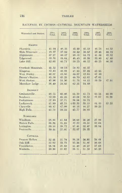
736 TABLES
RAINFALL IN INCHES—CATSKILL MOUNTAIN WATERSHEDS
Watershed and Station. 1911. 1910, 1909, 1908, 1907,Total. Total. Total. Total. Total;
41.04 48.56 45.93 45.13 46.78
48.97 57.82 54.62 50.87 53.45
37.27 40.32 35.55 34.72 41.56
40.56 48.64 46.43 46.98 52.90
42.65 46.71 50.23 46.52 49.25
41.52 49.18 54.82 46.37
42.43 40.98 41.85 37.18 42.85
40.07 43.85 46.67 42.05 47.40
45.38 45.23 48.79 42.01 47.01
45.96 51.30 51.76 44.13 50.59
56.49 58.63 62.31 54.80
46.55 42.46 44.10 41.73 43.24
42.69 45.25 43.61 40.52 47.07
57.19 57.71 56.06 58.71
41.89 43.75 +39.35 39.19 44.45
46.12 47.09 44.16 44.27 50.23
43.79 39.35 42.77 38.93
28.86 41.14 36.68 36.26 37.98
38.38 48.19 47.32 48.51 52.64
30.14 38.72 37.41 32.47 36.94
30.44 37.01 32.07 28.25
32.41 31.78 34.16 30.81 34.41
32.92 33.73 35.38 31.97 36.68
28.91 31.59 31.49 28.27 37.68
30.30 31.02 33.11 31.53 35.28
1906.Total.
ESOPUS
Phcrnicia
Slide Mountain . . .
HighmountEdgewoodLake Hill
Overlook Mountain
Kingston
West Hurley
Brown's Station . . .
West Shokan
Moonhaw Lodge. .
RONDOUT
Gpahamsville
SundownPeekamoose
LackawackClaryville
High Falls
Schoharie
WindhamHaines Falls
Lexington
Prattsville
Catskill
Preston Hollow ...
Oak Hill
Franklinton
Westerlo
44.52
58.72
42.82
47.85
46.30
47.91
44.68
46.96
42.55
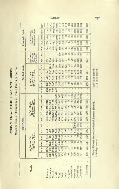
TABLES 737
I 8
W «2
M »M 2
^ Q
^1
1«l
^, i««
1
«J ss »J tf?
JPI
it
§£2
1^, 2 CO
5l|
?o8-*
!» X C*9 ^ fO CO
^ S« 19 S^S
S?g
g|§|38RgggIS
• «iH CO V ^ «^ •-• •"
^ M OJ C^ M 0>lA ic to r«> r» ^c5 M « »-« ^ ^
'^2^^^*'^*"*fi'
^
ill
llffllHsfflf85gg
fill gISH^TFT?iiiis§§iiis
§i
•O "O -fSSSttSS I
fHilllS~3~S"•25 « t>.
^ OS © 0>
00 Ss 00 ^ S&S9S
IIS SS$52OS O) 0^
O M 5 TWWW ¥
II
il
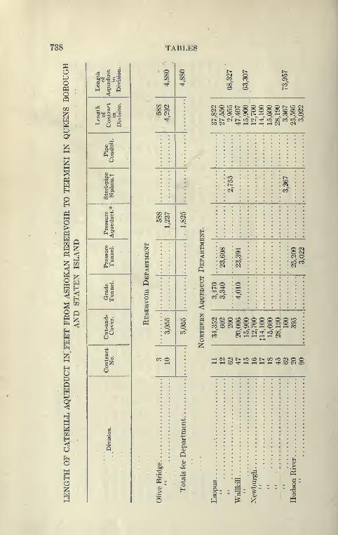
738 TABLES
a
00 05
P
a;h
00 !>•
00 COto (N
P^
t» ^ t*
cc ^ §s s CO
I>
Sigfe g 8 8 Q O b- lO (NO Oi O Oi (N00 lO o: Tfl Oi i^ 1-t CO lO ot^ t^ (N r^ »0 (N TfH »o 00 CO lO COCO (N Tt* T-t r-i l-H <N (N
Ue
I ^^f3 CO COa^
8(N(N O
(N(NQOQQQQOQ»0OOOQQOOO05005CO__ O <N O O t>^
--J^CD^ T-J^ i-H CO
TjT o lO" C<r rfT lO OO"
0)
• • : i-a S
a. . ^^ 1^ — ^ I
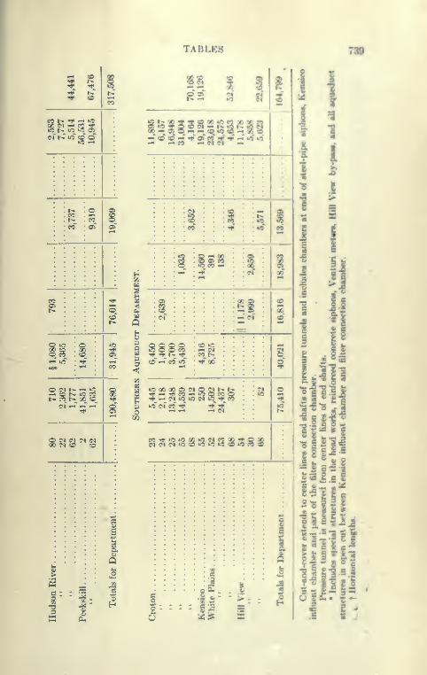
%t>. -^^ ^ tcM »-^ eo ^b- »0 lit A
cf t>r ic CO o"
^ in
O C^ b- '-' »o^ O l^ »C PCt- eo t^ « «o
s
c :
TABLES
R2 3 a
7»
1
1
1 i
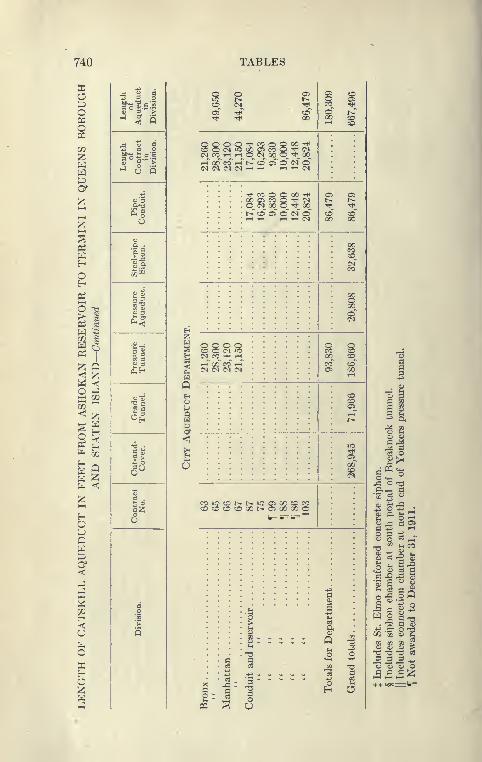
740 TABLES
o t 1 i s? s s g ??
p ^•o^.S.2 CO <N Tt CC TfS ° 3" >^ ^
Oi Tt^ CC i %owm ^1-2 §8^S^owg'*^ '
^ t^^B^- 1 5
^CX)COi-it^cDOiO<MC(N(N(M(N^^ i-H^C^
^ •• • '^COOQOO-* o- a-
^ H 00 05 CO O '^ ? b- b-. O C^ GO O ''t' OC rt Tf
^% • • • • t>. ;0 05 O (N C CC CC
^ o : : : :^ "^ ^ ^ c^ OC OC
.
S «
H i~
g
II
Si ^1 ^
i| gj- o o o o cA Y S§ CO O <M »C
?/ CC -i
Z Q
«3n «
^H
?5 c5 c5 ?3 : ? 1Q oO (-3
1t^
go
<
6
-^ S
li5"
0^ S
II
fo <;•« a^ a
g Bo COlOCOt^t^"5O500COCC CD *^ ^a^ COCOCOCOOOt^OiOOOOC -2 0*3 •
H 6 &=iF=t="- 2^ ^S^u ^-S ^ 2P O 3 t^ ^
CJ O <^ ^-^
y,Z ^"^P 8"^^ §3C<t1
">
Q 1
c
1
Q4
-3
1^1 =
S 2 S io T3 c 73 -d -O as
W C3 Cc3 03 ,3 T3 o o o O
s^w ^
1^....1 C
HH ffl s u
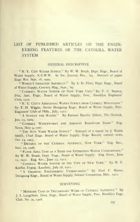
LIST OF PUBLISHED ARTICLES ON THE ENGIN-EERING FEATURES OF THE CATSKILL WATERSYSTEM
GENERAL DESCRIPTIVE
" N. Y. City Water Supply." By W. W. Brush, Dcpt. Engr.. Board ci
Water Supply, N.E.W.W. As Soc. Journal, Dec, *og. AlMtract of pftpcr
Engr. Rec. Sept. i8, iqoq.
'* World's Greatest Aqubduct." By A. D. Flinn, Dcpt. Engr., Board
of Water Supply, Century Mag., Sept., 'eg.
" Catskill Water System of New York City." By P. C. Barney.
Prin. Asst. Engr., Board of Water Supply, Proc.. Brooklyn Engincen'
Club, iQio.
" N. Y. City's Additional Water Supply from Catskill Moumttalvs."
By T. H. Wiggin, Senior Designing Engr., Board of Water Supply. Proc.
Engineers' Club of Phila., July, 1911.
" A Subway for Water." By Earnest Hamlin Abbott, The Outlook.
Jan. 23, 1909.
" Catskill Waterworks and Ashokan Reservoir Dams." Eng.
News, May 9, 1907.
" The New York Water Supply." Abstract of a report by J. Waldo
Smith, Chief Engr. Board of Water Supply, Engr. Record, current news,
Oct. 14, 1905." Details of the Catskill Aqueduct, New York." Eng. Rec..
Nov. 10, 1906.
" Floor Area Unit as a Basis for Estimating Water Consitmption.'*
By W. W. Brush, Dept. Engr., Board of Water Supply. Eng. New*,. June
13, 1912. Eng. Rec, June 15, 191 2.
" Catskill Water System of the City of New York." By H. P.
Kiefifer, Engng. (London), July 28, 1911.
"A Gigantic Engineering Undertaking." By Fred F. Moore,
Designing Engr., Board of Water Supply. Science Conspectus, Mar., igii.
SURVEYING
" Methods Used in Preliminary Work on Catskill AofEDfCT." By
J. S. Langthorn, Divn. Engr., Board of Water Supply. Prix Bnwklyn Engr.
Club, No. 79, 1908.741
742 LIST OF ARTICLES ON CATSKILL WATER SYSTEM
" Bench Levels and N. Y. City Datums." By C. Goodman, Asst.
Engr., Board of Water Supply, Proc. Mun. Engrs. of the City of N. Y., 1908.
Eng. Rec, Oct. 3, 1908.
" Stadia Surveys. Catskill Aqueduct." By Boris Levitt, Asst.
Engr., Board of Water Supply. Eng. News, Sept. 3, 1908.
" Bench Level Operations on the Catskill Aqueduct Line." ByM. E. Zipser, Asst. Engr., Board of Water Supply, Eng. News, Feb. 20, 1908.
GEOLOGICAL INVESTIGATION
" Some Geological Features Affecting the Catskill Water Supply."
By J. F. Sanborn, Asst. Engr., Board of Water Supply, Harvard Engng. Jour.,
June, 1908.
" Subsurface Investigation—Catskill Aqueduct." By R. Ridg-
way, Dept. Engr., Board of Water Supply, Eng. Rec, April 18, 1908. Eng.
Rec, April 25, 1908.
" Core Drilling under the Hudson River for the Catskill Aque-
duct." By W. E, Swift, Div. Engr., Board of Water Supply, Eng. News,
Apr. 7, 1910.
" Studies and Explorations for the Hudson River Crossing of the
Catskill Aqueduct." By S. D. Dodge and W. B. Hoke, Asst. Engineers,
Board of Water Supply, Proc. Mun. Engr. of N. Y., 1910. Eng. Rec, April
25, 1908. Eng. Rec, Oct. 8 and 15, 1910.
" Geological Problems Presented by the Catskill Aqueduct of
the City of New York." By J. T. Kemp, Consulting Geologist, Board of
Water Supply, Qr. Bui. of Can. Min. Inst., Oct. 5, 191 1.
" Geology of the New York City (Catskill) Aqueduct." By Chas.
P. Berkey, Consulting Geologist. Board of Water Supply, N. Y. State
Museum Bui. No. 146, 191 1.
" Testing Dlamond Drill Borings at the Site of the Olive Bridge
Dam, Ashokan Reservoir." Eng. Rec, July 4, 1908.
" California Stove-Pipe Wells of Long Island." Describes the
method of driving these wells and the outfit used. Eng. Rec, Feb. 29, 1908.
" Geology of New York City in its Relation to Engineering Prob-
lems." By Chas. P. Berkey, Consulting Geologist, Board of Water Supply,
and John R. Heal^, Asst. Engr., Board of Water Supply. Proc Mun. Engrs.
of the City of N. Y., 191 1.
" Quarries, Ashokan Reservoir Stone Quarry." Eng. Rec, Apr. 2,
1910,
" Quality of Bluestone in the Vicinity of the Ashokan Dam." ByChas. P. Berkey, Consulting Geologist, Board of Water Supply. Col. Sch.
of Mines Qr., Jan., 1908.
" Inclined Diamond-drill Borings under the Hudson River." Eng.
Rec, Jan. 15, 1910.
" Deep Inclined Diamond-drill Borings. Hudson River Crossing.
Catskill Aqueduct." Engr. Rec, Apr. 2, 1910.
LIST OF ARTICLES ON CAT8KILL WATKR HY8TKM 743
"Bore Holes." Determining ihc direction ot deep bof« hrha tadtesting their watertight ness. Illustrates and dcMTibct aii ioilnifneat de-vised by John J. Horan, .\sst. Engr.. Board of Water Supply, for me in €mhnection with the work of building the great aquctluct that it to awry addi-tional water to New York City. Engr. News. May 33. IQ07.
" The Storm King Crossing op the Hudson Rivee by thk Nkw Cai%-KILL Aqueduct of New York City." By J. F. Kemp. Amer. Journal ofScience, July, 191 2.
" Subsurface Investigation Catskill and I^nc Island AQUtoi-mi."Robt. Ridgway, Dep. Engr.; W. E. Spear, Dep. Engr.; W. Fitch Smith. Div.Engr., and D. S. Mallctt, Asst. Engr., Board of Water Supply. Proc. Mun.Engrs., City of N. Y., 1908.
CONSTRUCTION—GENERAL
" Tunnel Lining, Catskill Aqueduct." By M. E. Zipser, A»t. Engr.,
Board of Water Supply, Eng. News, May 2, 1Q12. Eng. Mag., July, igii.
" Grouting the Concrete Lining of the Rondout Prf^ssuie Tunnel."By R. L. Wittstein, Asst. Engr., Board of Water Supply, Eng. Rec., Dec.
30, 1911.
" Rye Outlet Bridge at Kensico Reservoir, Concrete Amcb Bkidce."
Eng. Rec, Oct. 14, 191 1.
" A Large Timber Bulkhead under 168 Feet Head." By A. W.Tidd, Asst. Engr., Board of Water Supply, Eng. News, July 25, IQ13.
" Methods of Alignment in Three Pressure Tunnels." Vonkers
Pressure Tunnel: By Jas. L. Davis, '.\sst. Engr., Board of Water S-,:
Van Cortlandt Siphon: By Edward A. May, .\sst. .\ngr., Boanl of \S
Supply. Wachusett Aqueduct Tunnel: By A. W. Tidd, Aast. Engr.. Board
of Water Supply. Eng. News, June 20, 191 2.
" The Removal of Entrained Air from the Catskill Aqueduct."
Eng. Rec, Aug. 3, 191 2.
" Method of Trussing Concrete Forms." By .Arnold Becker. Eng.
Rec, Nov. 25, 191 1.
" Meeting of the Headings of the Catskill Water Supply Tunnel."
Eng. News, Feb. 15, 191 2.
" Catskill Aqueduct." Eng. Rec, Jan. 3, 1910.
" Esopus Section." Eng. Rec, Nov. 5, 1910.
CONSTRUCTION—RESERVOIRS A.NU l>A.\Ls
" Masonry Dam Formulas, Series of Formulas Deduced in Connec-
tion with Studies made for the Board of Water Supply." By O. L.
Brodie, Asst. Engr., Board of Water Supply, Col. Sch. of Mines Qr., Apr. igoS.
" Dams for Catskill Water Works." By A. D. Flinn, DepC. Eofr..
Board of Water Supply Harvard Engr. Journal. Nov., 1909.
744 LIST OF ARTICLES ON CATSKILL WATER SYSTEM
" New Kensico Dam." By A. D. Flinn, Dept. Engr., Board of Water
Supply. Eng. News, Apr. 25, 191 2.
" AsHOKAN Reservoir." Specifications for the main dam. Gives
sections from specifications with explanatory notes, Eng. News, Aug. i, 1907.
" Construction or Pressure Aqueduct, Ashokan Reservoir." Eng.
Rec, July 12, 191 1.
" Hill View Reservoir, Plan, Section and Brief Description,"
Eng. Rec, Dec. 18, 1909.
" Kensico Reservoir." Eng. Rec, Dec. 25, 1909.
" Grouting the Olive Bridge Dam," Eng. Rec, April 8, 191 1.
" Soil Stripping." Is it worth while to strip the surface soil from
Ashokan reservoir sites? Abstract by Hazen and Fuller. Eng. News, Jan.
3, 1907-
" Hill View Reservoir." Features of the design, provisions for hous-
ing and feeding laborers and horses, dump carts, cars, stone crushers, etc
Mun. Jour, and Engr., August 3, 1910.
" Construction of Waste Weir at Ashokan Reservoir." Eng.
Rec, July 22, 1911.
CONSTRUCTION—SHAFTS
" Shaft Sinking—Record Made—Moodna Siphon." March 3-April 3,
1910. Eng. Rec, April 16, 1910.
" Shaft Sinking—Record—(Catskill Aqueduct)." Eng. Rec, Apr.
15, 1911-
" Some Interesting Cases of Shaft Sinking." By John S. Franklin,
Cassier's Magazine, Feb., 191 2.
" Rapid Shaft Sinking in Hard Rock. East Shaft Hudson Tunnel."
Eng. News, April 13, 191 1. Eng. Rec, April 15, 191 1.
" Shaft Sinking, Catskill Aqueduct." By F. Donaldson, Mines and
Minerals, April, 1909.
" Sinking a Wet Shaft." By J. P. Hogan, Asst. Engr. Board of Water
Supply, Am. Soc C.E. Proc, March, 1911 (Abstract) , Eng. Rec, April 8, 1911.
" RoNDOUT Siphon, Lining the Uptake Shaft." By H. L. Wittstein,
Asst. Engr., Board of Water Supply, Eng. Rec, March 11, 1911.
CONSTRUCTION—PRESSURE TUNNEL
" Moodna Pressure Tunnel." Eng. Rec, June 4, 19 10.
" RoNDOUT Pressure Tunnel Lining." Eng. Rec, Sept. 17, 1910.*' Wallkill Pressure Tunnel." Eng. Rec, Apr. 2, 1910.
" Wallkill Pressure Tunnel Excavation." By C. R. Hulsart, Asst.
Engr., Board of Water Supply, Eng. News, Oct. 20, 1910.
" Test of Watertightness of Concrete Tunnel Lining under HighHead." (Wallkill Pressure Tunnel.) By C. R. Hulsart, Asst. Engr., Board
of Water Supply. Eng. News, Dec 14, 1911.

U8T OF ARTICLES ON CAT8KILL WATKB HYHTEM 746
"Holing through the Hudson Caoasmo Tuwkel." Eog. Newt,Feb. I, 1912. Eng. Rcc. Current News Suppl., Feb. 3, 191 j.
" Hudson River Crossing op the Caiskill Aqueouct." By IL lUdg-way, Dept. Engr., Board of Water Supply, N.E.W.W. Awn. Jounul, Sept..
1911.
"The Deepest Siphon Tunnel in the World." By R. K. ToqiUa,
Jr., Scribner's Magazine, May, 191 2.
" Construction of the Rondout Pressure Tunnel or the Catikiu.Aqueduct." By L. White, Div. Engr., Board of Water Supply. PipcMun. Engrs. of the City of N. Y., 191 1.
" Hudson Tunnel of the Catskili. Aqueduct for Water SupplyOF N. Y. City." By A. D. Flinn, Dcpl. Engr.. Board of Water Supply.
Eng. News, Mar. 23, 191 1.
" Design of Pressure Tunnels of the Catskill Aqueduct." ByT. H. Wiggin, Sen. Des. Engr. Board of Water Supply, Eng. Rcc., Jan. 2q,
1910. Abstracts, Eng. Rec, Feb. 5, 1910. Proc. Mun. Engrs. of the City
of N. Y., 1909.
" Rondout Pressure Tunnel." By A. D. Flinn, Dept. Engr., Board
of Water Supply, Eng. News, June i, 191 1.
" Rondout Pressure Tunnel. Driving a Wet .'Vqueduct Tunnelin Hard Rock." By B. H. Wait, Asst. Engr., Board of Water Supply.
Eng. Rec, June 17, 191 1.
" Deep Tunnel Alignment." By H. M. Hale, Asst. Engr., Board of
Water Supply, Harvard Eng. Jour., Nov., 1910. Eng. Rec., Jan. 14, 1911.
CONSTRUCTION—GR^VDE TUNNEL
" Lining a Part of the Bonticou Grade Tunnel. Methods Fol-
lowed on A 17 X13 Ft. Rock Tunnel on the Catskill Aqueduct." By
John H. C. Gregg, Eng. Rec, June 22, 191 2.
" A Compressed Air Tunnel Driven wiTHOirr a Shield through WetEarth at East View." Eng. Rcc. July 20, 1912.
" Tunneling in Wet Earth.'' Eng. Rec, July 20, IQ12.
" Soft Ground Tunneling without Compressed Air on the Cats-
kill Aqueduct." By Chester M. Gould, Asst. Engr., Board of Wat rr ^i!f.f»lv.
Eng. Rec, Aug. 10, 191 2.
"Hunter's Brook Tunnel Construction." Eng. Rec, Apni 2, 1910.
" Hunter's Brook Tunnel Cave." Eng. Rec. March 18, iqii.
" Hunter's Brook Tunnel, Bottom Heading." Eng. Rec, Sept. 23.
1911.
CONSTRUCTION—CITY AQUEDUCT TUN.SEL .\ND PIPE LINES
" Under-City Tunnel for Delivering Catsioll Water to the Dw-
tribution Mains, N. Y. City." By A. D. Flinn. Dept. Engr.. Board of
Water Supply. Harvard Eng. Jour., Jan., ion.
746 LIST OF ARTICLES ON CATSKILL WATER SYSTEM
" New Water Supply Tunnel under N. Y. City." Eng. News, MayII, 1911.
" Progress on City Tunnels." By W. E. Spear, Dept. Engr., Board
of Water Supply, Proc. Mun. Engrs. of N. Y., 191 2.
" Water Supply Tunnel beneath the East River." Eng. News,
July 7, 1910.
" Proposed Delivery System of the Catskill Water Supply." Eng.
Rec, Dec. 11, 1909. Eng. News, Dec. 9, 1909. Eng. News, June 2, 1910.
" New Water Supply Tunnel under New York City." Eng. News,
May II, 1911.
" City Aqueduct to Deliver Catskill Water Supply to the Five
Boroughs of Greater New York." By W. W. Brush, Dept. Engr., Board
of Water Supply, Proc. Brooklyn Engrs. Club, 1910.
" Ship's Anchors and Submerged Pipe Lines." (Narrows' Pipe Line).
Eng. Rec, Dec. 9, 191 1.
" Motor Trucks for Hauling Blasted Rock from City AqueductTunnel, N. Y." Eng. Rec, March 30, 191 2.
CONSTRUCTION—STEEL AND REINFORCED CONCRETE PIPE
" Foundry Brook." Eng. Rec, April 15, 191 1.
" Protection of Steel Pipes, Catskill Aqueduct." By A. D. Flinn,
Department Engr., Board of Water Supply, N.E.W.W. Assn. Journal, Sept.
191 1. (Abstract) Eng. Rec, Sept. 16, 191 1. Eng. News, Nov. 2, 191 1.
" Handling Large Steel Pipes in the Trench by a Novel Method."By Chas. H. Howe, Eng. Rec, Oct. 14, 191 1.
" Aqueduct Construction at Ashokan Reservoir, Contract 10."
Eng. Rec, April 22, 191 1.
" Kensico By-Pass Aqueduct Construction." By H. W. Nelson.
Eng, Rec, April i, 191 1.
CONSTRUCTION CUT-AND-COVER
" Cut-and-cover Aqueduct of New York Additional Water Supply."
By A. D. Flinn, Dept. Engr., Board of Water Supply, Worcester Polytechnic
Inst. Jour., March, 191 1.
" Design of Large Conduits in Open Cut, Concrete Section." Eng.
Rec, Oct. 28, 1911. Assn. Eng. Soc, Journal, Sept., 1911.
CONTRACTORS' PLANTS
" Construction Plant Employed on the N. Y. Water Supply." ByH. P. Kieffer, Mun. Engr., August, 1909.
" Use of Electricity on the Catskill Aqueduct." Elec World,
March 2, 191 1.
" Concrete Plant—Olive Bridge Dam." Eng. Rec, April 3, 1909.
*U8T OF ARTICLES ON CAT8KILL WATER 8YHTKM 747
" Methods of Construction and Coktractoi'i Puutt on rmReservoir." Engr. Contg., Oct. 19, igio.
" Compressed Air Pla.st por the Rondout SiFflON." Eng. Uee^Apr. 10, 1910.
" Large Portable Plant for Crushing, Mixing and Plaono Concmmon Catskill Aqueduct." Engng. Contg., Dec. 7, iqio.
" Steam Rollers used in the Construction or the Eartm Dams orthe Ashokan Reservoir." Eng. News, Oct. 21, iqoq.
"Compressed Air Plant, Contracts 12 and 54." By F. Richanb,Eng. News, April 20, 191 1.
" Air Compressor Plant for Driving the Moodna Siphon on theNew York Aqueduct." (Abstract.) Eng. News, Feb. 23, ion.
" Rock Crushing Plant, Kensico Dam." By S. W. Tnylor, Eng.News, Feb. 22, 191 2. Eng. Rec, Feb. 24, 191 2.
CONTRACTORS' CAMPS—SANITATION
" Sanitary Problems on the Catskill Aqueduct Work." Eng. Rec.,
May 6, 191 1.
" The Contractor's Camp at the Ashokan Reservoir." Eng. Rec.,
March 25, 191 1. Correction, April 8, 1911.
" Construction Camps—N. Y. State Barge Canal and N. Y. CiXY't
New Aqueduct." The Survey, Vol. 23, No. 14, Jan. 1, iqio.
" Sanitation in Construction Camps of the Catskill Aqueduct."
Eng. Rec, April 2, 1910.
" Housing Conditions and Wages on the N. Y. State Barge CanalAND ON the Ashokan Dam, Board of Water Supply, New York City.**
Eng. News, Aug. 5, 1909.
" The Sanitation of Contract-or's Camps and the Patrol or Water-
sheds. Sanitation of Contractor's Camps, N. Y. C. Water Supply."
By A. J. Provost, Sanitary Expert, Board of Water Supply, I*roc. Asioc.
Eng. Soc, March, 191 2.
" Sanitary Problems of the Catskill Aqueduct." By DavHl S.
Flynn, M. D., Sanitary Inspector, Board of Water Supply, Proc. Eng. Club.
Philadelphia, Oct., 1911.
" Protection of New York's Water Sihtly from Pollution Dur-
ing CoNSTRUcnoN Work." By A. J. Provost. Sanitary Expert, Board of
Water Supply, N.E.W.W. Association Jour, Sept., iqii.
" Sanitary Problems of the B. W. S." By A. J. Provost. Sanitary
Expert, Board of Water Supply, Proc. Mun. Engrs. of the City of New York,
1911.
MISCELLANEOUS
"The Organization of an Engineering Force." By A. D. Flinn.
Dept. Engr., Board of Water Supply. Proc. Mun. Engr., 1906. (Abairact.)
Eng. Rec, Sept. 29, 1906.
748 LIST OF ARTICLES ON CATSKILL WATER SYSTEM
" Filing and Indexing System of the Board of Water Supply."
By A. D, Flinn, Dept. Engr., Board of Water Supply. Jour. Assoc. Engn.
Soc, Oct., 1909.
" Filing and Indexing System of the Board of Water Supply."
By J. Leo Murphy, Asst. Engr., Board of Water Supply. Eng. News, Aug.
6, 1908.
" Drafting Methods of the Board of Water Supply." By C. F.
Bell, Asst. Engr. in Charge of Drafting, Board of Water Supply. Proc.
Mun. Engrs. of the City of N. Y., 191 2. Eng. Rec, April 6, 191 2.
" Permeability of Concrete and Solubility of Aggregates. Tests
Made During 1909 by the Board of Water Supply." Eng. Rec, Jan.
21, 1911.
" A 250-TON Hydraulic Compression Testing Machine." By J. L.
Davis, Asst. Engr., Board of Water Supply, Eng. News, Feb. 11, 1909.
" Investigations of Impermeable Concrete by the Laboratory of
THE Board of Water Supply, N. Y. C." By J. L. Davis, Asst. Engr., Board
of Water Supply, Engng. Contg., Feb. 26, 1908.
" Sluice Gates and Valves for the Catskill Waterworks." Eng.
Rec, Sept. 9, 1911.'' Catskill Aqueduct Control Valves." By James Owen, Eng. News,
Feb. I, 191 2.
" Venture Meters. How the Flow of Water through the Cats-
kill Aqueduct Will be Measured. Description of the Three Largest
Venturi Meters Ever Constructed and Apparatus for Making Con-
tinuous Records of the Flow." Eng. Rec, Jan. 20, 191 2.
" Aerator Nozzle Tests for Catskill Water Supply." Eng. Rec,
Dec. 2, 1911.
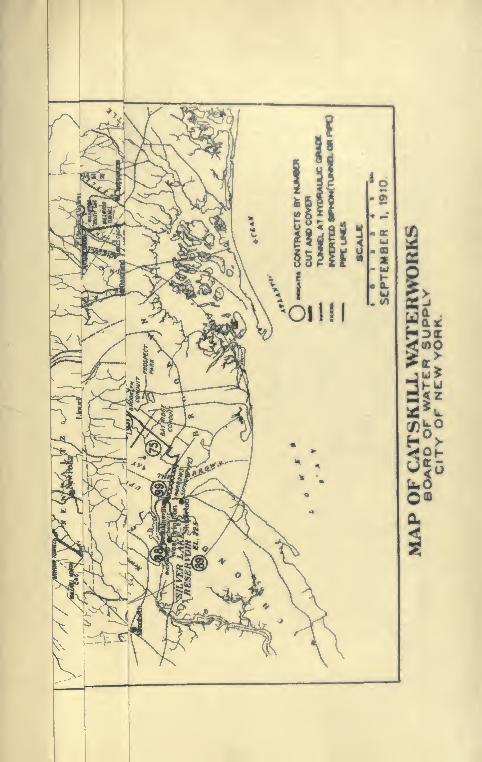

PI-ATK 289
BY 1
GARRISONGRADETUNNEL 5 ? ««
11472 ^1n^
nnewuink gri
id 78,
tween\
lite
oid gr^
<ri»3T
OS-.. St.CB-I - ^^
jIVTT5m
i
•O MI«.U
-^•Y" BAY RIDGE NARROWS
hpiPt CONDUIT 3e«ci tfe' 48 CI PIPE FLC»IBLC PiPtD^ 16289' 9630" O
Zo
: o
ih(Co2

INDKX
* Denotes illujilniUoiM.
Aeration basin, 188, 189*, 190, 191
Aerator, 520
Aerial tramway. See CablewayAir lift, 274, 275*, 279
Aqueduct, By-pass, 515, 516*, 517,
518*, 571*, 585
Aqueduct, Catskill, 7*, 21*
cut-and-cover, 50*, 51*, 63, 74,
236*, 237*
effluent, 519
grade tunnel, 52*, 63, 74
lengths, 738, 740
location, Catskill, 45, 47, 54, 55, 58,
59, 60, 61, 62, 72, 74, 95, 114, 194,
196, 472, 501
NewCroton, 7*, 10, 11
Old Croton, 6, 7*
pressure, 126, 127*, 170, 171*, 180,
182*, 502, 521
pressure tunnel, 53*, 54, 63, 72, 74,
256, 411*
Roman, 7*
steel pipe siphons. See Steel pipes,
types, 49, 50, 51, 52, 53, 738, 740
Arch closure, 315, 363, 489, 553
Articles published, 741 to 748
Ashokan Reservoir structures, 114,
116*, 117, 178, 179*, 186, 187*
Atwood rock cut, 197*, 229
Auto trucks, 452, 587, 651
Beaverkill dikes. See Dike.
Berkey, Dr. Chas. P., 66, 75
Blasting, 352, 369, 427, 479, 579, 593,
639, 640*, 641, 706
Blow-off, 492, 493
Board of Water Supply, 20, 27, 32
Bonus. 271. 563
BoriniQfi:
brcakafd* of diamondii, §0bnuUcitffe of rutin, 91, 1Q3
churn drill, 80
concluskmg and intcrpraUtiom, n,104
0001,81,82.97, 110
diamond drill, 12, 35, 73, 76. 7», 81,S.}*, 84, 86, 87», 90, 91. 97, 101,
300. 412. 658,650diamond drill, working deUiK 70,
80, 97, 98, 101, 103
difficulties, 88. 89, 101. 110
Hudson River, 95, 96*. 97. 98, 99*,
101, m\, 113
inclinr<l holm, 96*, 104, 107, 108,
lot)*, 110, 112
North .Aqueduct Departinml. 81
of Hoani of Water Supiily, 65, 84,
85*
prograsB, 102, 103, 111
Rondout siphon, 81
shot drill, 86, 88, 01
tables, 735
wash, 82, 97, 96, 100
Bottom hoiuling. See Tunnel £kcs»-
vation.
Bridgefl, 525, 526,* 527*, 5I0*
Br(M>klyn Wator Supply, 22, 23, 2S. 28
BuildingH. 607*. 684
Burr, Aaron, water supply, 2
Burr, William II., 17
By-|>a88 Aqut<<luci, 515, 616*. 517.
518*, 571*, 685
Cableways, 141. 160*. 162*. 164. 308,
304*, 305, 437. 440, 463, 463*,
483.666
740
750 INDEX
Cages. See Shaft cages.
Caissons, 261, 263, 264, 265, 347, 396,
613, 614*, 661, 663, 664, 666, 667,
668, 670*, 671, 672*, 673, 674,
675, 676, 677*, 678, 679*, 680,
681, 682*, 684, 685
CatskiU Aqueduct, 7*, 21*, 46*
California Stove pipe well, 24
Cement gun, 468*, 469
Central Park reservoir, 8
Channeling, 142
Church, B. S., 11
City aqueduct design, 588, 591, 592,
595, 605, 626, 631*, 651, 657
City restrictions, 593, 594, 659
Cleaning foundation. See Masonryfoundation.
Chnton's, DeWitt, Croton project, 4
Commission on additional water sup-
ply, 17
Compressed-air plants, 138, 177, 207,
266, 267*, 268, 269, 286, 353,
355*, 397, 414, 422, 478, 487, 494,
502, 504, 531, 543, 558, 595, 604,
633, 634, 671, 688
Compressed-air work, 176, 548, 551,
554, 665* to 683*
Concrete blocks, 121*, 145, 146*, 147*,
151, 537
Concrete expansion joints, 117, 121,
152*, 153*, 215, 217, 240
Concrete plant, 142, 143*, 144, 159,
164, 166, 211, 212, 213*, 214*,
219, 222, 223*, 224, 225*, 231, 232,
233*, 241, 307, 340, 375, 381*, 400,
432, 436, 438, 444, 452, 483, 499,
543, 557, 565, 581, 649, 699
Concrete porous blocks, 121
Concrete steaming, 217
Concrete surfacing, 525
Concreting circular aqueduct. See
Aqueduct by-pass,
cut-and-cover arch, 226, 227, 230,
339, 341*, 390, 433, 439*, 498,
517, 518*, 521, 547
Concreting grade tunnel, 242, 328,
330, 343, 346*, 348*, 429, 430,
436, 437, 444, 487, 508, 553, 554
Concreting invert of cut-and-cover,
215, 216*, 339, 379*, 447
Concreting pressure tunnel, 258, 307,
308*, 309*, 310*, 311, 312*, 313,
315, 331*, 360, 362, 363, 364*, 365,
399, 400, 401, 402, 419, 492, 566,
581, 649, 650
Concreting shaft, 258, 270, 316, 317,
327, 351, 418*, 633, 661*, 663,
671, 686
Condemnation of land, 19, 35, 36, 37Construction methods, 235, 238, 260,
279, 380, 53 i, 537, 659Contaminated water, 4Contract No. 2, 431
No. 3, 114
No. 9, 522
No. 10, 172
No. 11, 194
No. 12, 245
No. 15, 373
No. 16, 380
Nos. 17 and 18, 386No. 20, 395
No. 22, 429
No. 23, 478
No. 24, 483
No. 25, 493
No. 30, 567
No. 45, 391
No. 47, 332
No. 52, 542
No. 53, 556
No. 54, 559
No. 55, 501
No. 59, 178
No. 60, 174
No. 62, 445
No. 63, 595
No. 65, 605
No. 66, 626
No. 67, 651
No. 68, 464
No. 80, 420
No. 90, 402
No. 100, 493
Contract award, 115
Contract controversy, 115
Contract prices, 118, 134, 172, 174, 177,
178, 196, 198, 199, 249, 251, 332,
334, 336, 373, 380, 386, 391, 395,
408, 420, 422, 429, 431, 445, 466,

INDEX Til
Contract prices—C<miinu«f:
478, 483, 493, 501, 522, 642, 556,
558, 567, 596, 606, 628, 652Contractor's camps, 41*, 42, 136, 8M|
484, 485 •, 539
Contractor's forces, 39*, 103
Contractor's railroad, 136, 137*, 228,
351, 373, 386, 543
Contractor suspending work, 105
Contracts, list of, 720, 722
Core walls, 130, 154, 160*, 162», 174.
176
Cost of aqueduct*, 48, 49, 56*, 57
Croton aqueduct commission, 11
new, 7*, 10, 12
old, 6, 7*
Croton dam, old, 5
Crushing plant, 142, 143*, 144, 148,
166, 211, 212*, 213*. 214*, 223\224, 225*, 305, 352, 390, 426, 483,
497, 538, 543, 565, 577, 582
Culverts, 209, 210*, 231
Cut-and-cover aqueduct. See Aque-
duct, cut-and-cover.
Cyclopean concrete, 124, 149, 150*
Dam drainage wells, 121*
Kensico, 10
location, 76, 522
New Croton, 124
New Kensico, 522, 523*, 528, 529*,
530*, 533*, 537
Old Croton, 5
Olive Bridge, 76, 77, 117, 119*, 120*,
122*, 123*, 125*, 138, 139*, 140*,
141, 149, 152*, 153*, 155*
Dike, Beaver KiU, 124, 159, 161, 162,*
163*, 164
Dikes, 127*, 154, 159, 524, 539
Dividing wall, 582
Dividing weir, 114, 124, 182*
Drag bucket. See Excavator.
Drainage shafts. See Shafts.
Drain under aqueduct, 474
Drills, efficiency, 612
electric, 555, 556, 606, 608, 609, 616,
620, 622, 624
electric air, 534, 535*, 636, 608
hammer, 611
jap, 611, 624, 689, 690, 691, 692
DrUk. Leywr, m. 4M, 49B» 491,mpisum. 106. 466*. eM, 6il. «i
EmI channel »«r labt
Effluent nquedurt, 619
Electric drilb. 8w DrilbL
looomoUvva, 364, 361 *, 400. 440i «»iraiMmknoa, 227. 414. 631. 634
EmUnkmeoto. 8. 133, 134. 164. 167.
168*. 169. 100. 161. 166. 174. 176*.
202, 203, 232, 377. 302, 168, 994,
498, 672*. 673. S7A\ 676
Engineering foroe, 34
Eaopufl cuV^ad-cow, 194. 196*. 197*
ExcavaUoaofMrth. 130. 167. 160. 161.
167. 170. 172. 201, 206. 222. 230.
381. 434. 437, 440. 463. 463, 474.
497. 613. 632. 644. 570. 673, 676
Excavation ItiMw. 130. 131. 200. 201.
202, 267. 268. 2H1. 410. 712
Excavatkm of rock. 131. 132, 161. 170,
200, 201. 206, 229, 231, 239. 210.
284. 333. 377. 384. 388, 391. 434,
437, 440, 452. 497. 613. 632, 646,
557
Excavator, 157. 161. 164. 388, 989*.
544, 646*, 546, 558
Expaniaon jointA. See CoDerato »-paniuon joinU.
Experimental tunneb. 72
Field offioee for eofpnceri, 30
Filtem, 43, 190
Forms. See Stwl; trr Wood.
Foundatkin emliankniciita. Sea E»-bankment4(
Foundry Brook siphon, 74
Freeman, John K., 17
Freer cut. :m. 338*, :«». 342*
Fteley, Al|)ln»niie, 11
Fuse hlaMting. See Blaatinx.
Gate chamber, 170, 180, 161, lO*,
183*. 184
Gauging manhokv, 196
Geoiog>':
Aahokan Hrwrrvoir, 76, 77, IS
Beaver Kill (Kngr, 78
City tunnek, 626. 639
752 INDEX
Geology:
Hudson River, 94, 96*, 104, 107
Kensico dam, 532
Moodna Valley, 399
Preglacial gorges, 66, 75, 78, 94, 161,
165*, 446
Preglacial topography, 65
reports, 67, 69
Rondout Valley, 66, 68, 69, 70*, 71*,
72, 73*, 246*
strata tables, 749
Walkill valley, 332
Yonkers siphon, 472
Grade of Catskill aqueduct, 59
New Croton aqueduct, 11
tunnel aqueduct. See Aqueduct
grade tunnel.
Grouting, 141, 142, 276, 279, 296, 297*,
317, 320, 321*, 322, 323, 324, 326,
327, 345*, 368, 412, 419, 505, 601,
602, 630, 700, 701*, 702
Hains mixer, 211, 218, 225*, 231, 233,
239, 381, 433, 537, 565, 581
Harlem siphon of New Croton aque-
duct, 12, 13*
High Bridge, 6
reservoir, 9
Highways, 178
Hospitals, 42
Hudson River borings. See Borings,
siphon, 35, 95, 104
Influent Weirs. See Weirs.
Inlet channels, 126, 167, 170, 180
Kensico dam. See Dams.Kingston sewer, 176
Land surveys, 36
Length of structures, 738, 740
Lighting, 255
Line and grade, 254, 284
List of contracts. See Contracts.
Location of aqueduct. See Aqueduct
location.
Locomotive crane, 220*, 226, 238
Loetschberg tunnel disaster, 69
Long Island water supply, 18, 22, 26
Machine shop, 239
Masonry foundation, 132, 134, 138,
232, 387, 436
McClellan bill, 19
Medical supervision, 40
Merchant's Association, 17
Monell's fill, 392, 393, 394
Mucking machine, 287, 563, 708, 709,
710*, 711
Narrows siphon, 591
New Croton aqueduct, 7, 10
New York City aqueduct tunnel, 48
New York City water supply:
Bronx and Byram, 10
capacity of supply, 8, 10, 15, 178,
188, 524
cast-iron piping, 6, 10
Catskill, 45
Croton Lake, 4
future, 20
per capita, 8
ponds, 1,2
private, 1, 2
public, 3, 5
Ramapo Water Co., 15
shafts, 3
tanks, 3
water shortage, 1, 2, 9, 10, 113, 402
wells, 1, 23, 24
wood piping, 2, 3
wrought-iron piping, 6
Old Croton aqueduct, 6, 7
dam, 5
Olive Bridge dam. See Dams.river control, 79
Order of work, 204
Organization of Board of Water
Supply, 27* to 36*
Oxy-acetylene torch, 604, 678
Payment lines. See Excavation lines.
Peak tunnel. See Tunnels.
Peekskill Creek siphon, 74
Plan and Profile, 13*, 21*, 46*, 70*,
71*, 96*, 116*, 179*, 195*, 197*,
246*, 403*, 404*, 451*, 488*, 568*,
592*, 657*^
INDEX 758
Popping rock, 107, 414
Porous concrete blocks. See Concret<»
blocks.
Power consumption, 353
Pressure aqueducU. »Sec Aquoducta.
Tunnel aquotlucts. See Aque<lurt«.
Progrt^ss of construction, 44*, 126, 142,
196, 405
Published articles, 741 to 748
Pumping, 247, 248, 259, 260, 272, 274,
275*, 276, 277, 292, 295*, 298,
299*, 407, 414, 708
Putnam siphon. See Aqueduct pre»-
Quaker Bridge dam, 10
Quarries, 148, 232, 303, 351, 504, 536,
544,557
Railroads. See Contractors' railroads.
Rainfall tables, 736
Real estate cost, 37
Record work, 15, 154, 234, 242, 368,
363, 384, 422, 430, 444
Refilling. See Embankments.
Reservoirs:
Ashokan, 75, 114
Bog Brook, 10
Boyd's Corner, 9
Central Park, 8, 9
East Branch, 10
Hill View, 567, 569*, 571*
High Bridge, 9
Jerome Park, 11
Kensico, 10, 531
Middle Branch, 9
Murray Hill, 9
New Croton, 11
New Kensico, 528
New Rye, 524
Old Central Park, 9
Ridgewootl, 23
Sodom, 10
Ridgcwood water system, 23
Riser pii)e, 686, 699
Roman aqueduct, 7*
Rondout siphon g«>logy. See Geobgy.
Ropes, Horace, 194
Rye outlet bridge. See Bridges.
Band pit. 144. SOB, 801, 5aSan<l nilbi. 107. 224. 382, BOSaiiit idol.. 3K, 42. 4m. 401, Hi^ .Imt». ihti. \mM •.-'79,2W,2H|.3|R«.J|9»,
415*, 4I6-, 42f. 400Ml»»Shaft cAfftv, 250, 21C2*. 283*. 417. 428,
401, fiOO. 578
Shaft oooereUnfu 8n OoMrHintilMri.Shaft plant, 106, 300, 380, 878^ 888w
030, 001 •,002, 008, 068Shaft puminng. 100, 107
Shaft ainkioK, 70, 106, 100, 301, 388,
205, 200, 270, 271, 278», 278, 278,
285*, 347. 340, 300, 307, 423. 423.
432, 480, 600, 676, 670*. 606, 608,
509*, 000*, Oil, 013, 016, 010*.
017*, 018, 010*, 030, 033. 034. 000,
085, 080, 088, 003, 004, 006, 080*.
007*. 008, 000, 700, 703
Shaft-sinking tablm. 710. 710. 734. 730
Shaft timlN-ring. 105, 100. 270. 271.
576*, 035
Shaft ventilation. See VcntiittiOB.
Shortage of water. See N. Y. Water
Supply.
Shrinkage of omhankmeoi. 8m &»-ImnknientM.
Smith, J. Waldo. 11. 10
Soil stripping. 115, 188, 180
S|)ecificatiomi. 128, 130. 131. 132. 133.
200, 201. 253
State water supftly unnmiMinB, 30
Steaming concn>tc. See StuMning
Steam shovel. 157, 167. 206, 233, 231,
230, 235, 375, 382*. 640, 667, 668,
373
Steel fomu:cut-and-cover aqueduct. 212. 218,
219, 220*. 221. 22G. 230, 236. 360*.
374*, 376*. 377, 378*. 383, 386*,
390, 434, 435*. 438, 444, 467
gratle tunnel. 329*. 344 *, 345*
pressure cut-«nd-coTer aequeduet,
517. 510. 683, 684*, 680*
preasure tunnel. 307. 314*. 384*.
305. 360*, 307*. 600
riiaft. 310, 340. 023*, 033. 061*, 004
•t«el pipM. 468», 408, 471, 477
walls. 151.460.683

754 INDEX
Steel piling, 602, 603*, 637, 638*
Steel pipe, 74, 445, 446, 447*, 448*,
449, 460, 465*, 473*, 476*, 561*,
562*, 564*
concreting, 455, 457, 464, 472, 475
distortion, 471
laying, 450*, 454*, 455, 456, 463,
464, 467*, 471, 474, 475
mortar lining, 459, 461, 462, 463, 468
riser. See Risers.
Steel roof support. See Tunnel steel
roof support.
St. Elmo crossing, 387*, 388
Storage battery locomotives. See
Electric locomotives.
Strata table, 749
Stream control, 128, 129*, 133, 155,
452, 463, 531
Stream flows, 737
Suffolk Co. development, 25
Surveys. See 'Aqueduct location.
Swamp covering, 524
Telpher, 211
Testing aqueduct, 204, 240, 328, 330,
367, 456
Test pits, 35, 200, 735
Test shafts, 76
Title page of contract drawing, 655*
Tongore dam site, 76
Top soil, 203, 205, 570
Traction engine, 205, 228
Traveling derricks, 343, 438, 474
Trenches. See Excavation.
Tunnel bulkhead, 298, 413*, 552*
Tunnel excavation
:
Bonticou north half, 286, 288*, 507
Bonticou south half, 333
bottom heading, 287, 426, 427, 479,
480*, 482, 577, 580*, 641, 642
Breakneck, 426
Bronx-Rye, 524
Bull Hill, 429
Cat Hill, 437
Chadeayne, 498
City siphons, 605, 621*, 624, 642,
643, 644, 645, 704, 705, 707, 708
Croton grade tunnel, 494, 496, 497
Croton Lake siphon, 491
Dike, 513
Tunnel excavation:
Eastview, 547, 548
Elmsford, 556
Garrison, 440, 441, 442, 443*
Harlem R. R., 508, 509*
Hill View tunnels, 577
Hudson River siphon, 406, 414, 417
Hunters Brook, 479, 480, 481
Kensico, 513
Kingston sewer, 176
Lakehurst, 513
Laramie-Poudre, 369, 370
Loetschberg, 370
Los Angeles, 368
McKeel, 436
Millwood, 504, 505, 506, 507
New Croton aqueduct, 14
Peak, 194, 195*, 208, 209, 243*
Pleasantville, 510
records, 15, 358
Reynolds Hill, 510, 511, 512*
Rondout siphon, 284, 286, 292, 293,
294, 300
Sarles, 505, 506, 507
Scribner, 483
Simplon, 371
Turkey mountain, 487
under compressed air, 176
WalkiU siphon, 354, 356, 357*, 359*,
370
Yonkers siphon, 560, 561*, 563
Tunnel gas, 296
Tunnel plant, 281, 353, 355*, 397, 491,
624, 636, 703
steel roof support, 289, 291*, 605,
625, 645, 646, 647*, 648, 649
timbering, 287, 290, 442, 443*, 481,
508, 509*, 511, 512*, 548, 549*,
550*, 645, 646, 647*, 648*
trimming, 301
Tunnels, experimental, 72
Tunneling bad ground, 289, 291*, 292,
293*, 441, 442, 481, 504, 511, 547,
605, 645
TunneUng tables, 712, 713, 714, 715,
728, 730, 732, 734
Valves, 185*, 627*
Ventilation, 14, 256, 356, 620, 637, 707
of shafts, 107, 277

INDKX 7U
Venturi meter. 191, 192*, 193, 302.
503 •, 596, 597*
Waxes, 665, 718
Waate weir, 166. 167, 168*, 169*
Water fwwers, 36
Wat«r aeanw, 107, 108, 274, 292, 296,
298, 301*, 302», 325 •, 410, 441,
548, 601, 605, 630, 700. 706
WntmJ.»^l«, I2ft
W.im. '*r2, r,\r
Wrat channri. tkc InlH duuinH.
Wininm Thomaa, tmH rfopt marvM, 00Woooai fonm!
wdk, lfi6M«2*. 306*
catHUid-«of«r Aqueduet, I7!2, 173*,
347
•tod pipe, 461


a
CO
<
Q
C>
8CO
ST
88-
. 8.
2t3
^
e.E
X
IX
1-
|i
£^
I 5 I
illc c c
c k
2
oz<CQ
IS
o
.t; c
^ ^ >
2 375s
"^ "^
t 3 ^
c - .
•> c a.
bO • *
» «> s•£ _** •* c
b -.£<>
•s g c
.r.i;
3 «•-
S - ^> 2 -r
« o &n -3 c
OU
P
a:
O
CO
ALPHA PORTLAND CEMENTTHE RECOGNIZED STANDARD AMERICAN BRAND
DAILY OUTPUT: ANNUAL OUTPUT20,000 bbls. 7,000,000 bbls.
WORKS:Two Plants at Alpha, N. J., 70 miles west of New York on Lehigh
Valley R.R.
Two Plants at Martins Creek, Pa., 80 miles west of New York on
P.R.R., D.L. & W.R.R., and L. & N.E.R.R.
One Plant at Manheim, W.Va., on M. & K. and B. & O.R.R.
One Plant at Catski 1, N. Y., 100 miles north of New York on
N.Y.C. & H.R.R.R, and Hudson River, Boat shipments direct to all
Barge Canal points, Atlantic Coast and Foreign Ports.
ALPHA, Guaranteed to Pass All Standard, State and
Government Specifications, has been on the market for
the past 22 years. We manufacture but One Grade—A Strictly Straight Portland of the Highest Pos-
sible Quality.
One and One-Quarter Million Barrels of ALPHAused by the Various Contractors in the
Construction of Catskill Aqueduct
OUR SHIPPING FACILITIES ARE UNSURPASSED
WE GUARANTEE PROMPT SHIPMENTS
ALPHA PORTLAND CEMENT COGeneral Office: EASTON, Pa.
BRANCH OFFICKS;BOSTON, Board of Trade Bldg-
NKVV YORK, Hudson Terminal BUlg.PITTSBURGH, Oliver Bldg.
FHILAI>ELPHIA, Harrison Bldg.CHICAGO, 3Iarqiiette Bldg:.
BUFFALO, Builders FxchangeBALTIMORE, Builders Exchange
SAVANNAH, National Bank Bldff.

RQEBLINGWIHH HOFF
gave good service in building the CaUikill aqueduct On«
alone used 100,000 feet of hoisting rope on iU derricka. Thia ropv aa
well as that used for the cableways at Valhalla, for lifting th* •le-
vators in the long shafts at Cornwall, for the incline railway at Storm
King and for hoisting and hauling materials at many other ptrinu
was all made by
JOHN A. ROEBLING'S SONS CO.TRENTON. N. J.
Designers and Builders
of
Steel forms for Concrete Construction
Blaw Steel Construction Co,
General Offices : Westinghouse Building
PITTSBURGH, Pa.
Steel Buildings, Bridges, Transmission Towers
THE FOURTEEN
STEEL PIPE SIPHONS9'—6" to ir—3" Dia.
aggregating
33031 FEET IN LENGTH
The Eight Foot Riveted Steel Pipe806 FEET LONG through ASHOKAN DAM
THE SIXTY-SIX INCH
Lock-Bar and Riveted Steel Pipe17020 FEET LONG through BROOKLYN STREETS
WERE MANUFACTURED BY
THE EAST JERSEY PIPE CO.Works : PATERSON, N. J. Offices : SO CHURCH ST., N.Y. C.
AMERICAN CIVIL ENGINEERS' POCKET BOOKSECOND EDITION, ENLARGED. TOTAL ISSUE, 15,000
Editor-in-Chief, MANSFIELD MERRIMANSection1. Mathematical Tables. By Mansfield Merriman, Member of American Society of Civil
Engineers.2. Surveying, Geodesy, Railroad Location. By Charles B. Breed, Associate Professor of Civil
Engineering in Massachusetts Institute of Technology.3. Steam and Electric Railroads. By Walter Loring Webb, Member of American Society of
Civil Engineers.4. Materials of Construction. By Rudolph P. Miller, Superintendent of Buildings, New York
City.5. Plain and Reinforced Concrete. By Frederick E. Turneaure, Dean of College of Engineer-
ing, University of Wisconsin.6. Masoniy, Foundations, Earthwork. By Ira O. Baker, Professor of Civil Engineering in
University of Illinois.
7. Masonry and Timber Structures. By Walter J. Douglas, Member of American Society ofCivil Engineers.
8. Steel Structures. By Frank P. McKibben, Professor of Civil Engineering in Lehigh Uni-versity.
9. Hydraulics, Pumping, Water Power. By Gardner S. Williams, formerly Professor of CivilEngineering in University of Michigan.
10. Water Supply, Sewerage, Irrigation. By Allen Hazen, Member of American Society of CivilEngineers.
11. Dams, Aqueducts, Canals, Shafts, Tunnels. By Alfred Noble and Silas H. Woodard,Members of American Society of Civil Engineers.
12. Mathematics and Mechanics. By Edward R. Maurer, Professor of Mechanics in Universityof Wisconsin.
13. Physics, Meteorology, Weights and Measures. By Louis A. Fischer, Chief of Division ofWeights and Measures, U. S. Bureau of Standards.
14. Steam and Electric Engineering. By George A. Goodenough, Professor of Thermodynamicsin University of Illinois, and F. Malcolm Farmer, Engineer, Electrical Testing Labora-tories, New York.
15. Highways and Streets. By Arthur H. Blanchard, Professor of Highway Engineering in
Columbia University.
i6mo, Morocco, viii+i475 pages, 1200 cuts, 500 tables. Price S5.00 net (21/- net)
JOHN WILEY & SONS, Inc.
London, CHAPMAN & HALL, Limited
432 Fourth Avenue, New YorkMontreal, Canada, RENOUF PUB. CO.


i4m^-' ' '^^'1'^^! V' :^feirJ
'7
:. /.
• 4>
uo
o
r-i
P.P«
n
u
St
S 3
fS
Q
O
University of Toronto
Library
DO NOTREMOVEiiii:
CARD
FROM
THIS
\cmc Librarj" (-ard PiK-ket
I'lvWt Pat. "Rrt. Index Kil^"
ide by LIBRARY BUREAU

Related Documents