THE CANSOLV ® SYSTEM PROCESS: A NEW PARADIGM FOR SO 2 RECOVERY AND RECYCLE Patrick M. Ravary and John N. Sarlis Cansolv Technologies Inc. 8475, avenue Christophe-Colomb, Suite 2000 Montreal, Quebec, H2M 2N9 Canada http://www.cansolv.com ABSTRACT Significant progress has been made in the last 25 years in the control of emissions resulting from the burning of sulfur bearing fuels and from other industrial processes. The dominant desulfurization technology today is limestone or lime-based scrubbing in various forms. While in general reliable and, in some forms, capable of high SO 2 removal efficiency, they produce large quantities of low value waste products, are relatively expensive to build and operate and are difficult to retrofit in constrained sites due to the large equipment size necessary for their implementation. With increasing concern over the cost and availability of landfill sites and public demand for resource recovery and recycling, recovery-type SO 2 removal processes are becoming increasingly more desirable. The CANSOLV ® System is an aqueous amine-based, regenerative gas desulfurization process capable of removing SO 2 down to a few ppm, if desired, from most stationary sources. The process can be applied to feed gases with <0.1 to 100% SO 2 , it is flexible, robust, easy to operate and quickly responsive to changes in gas feed conditions. It represents an effective response to regulation-driven market needs, both domestically and internationally, and it does so in a manner which vastly improves upon existing desulfurization technologies in terms of physical dimensions, capital and operating costs, and environmental impact. In many cases, the CANSOLV ® System can be integrated to an existing plant flowsheet to improve profitability of the process. The CANSOLV ® System can be applied to sulfuric, acid spent acid recovery plants, sulfide ore smelters, sulfur recovery units, SO 2 production and its safe storage and transportation, flue gas desulfurization units and pulp mills. This paper describes the CANSOLV ® System process technology and its various applications, as well as pilot plant results from multiple industry applications.

Welcome message from author
This document is posted to help you gain knowledge. Please leave a comment to let me know what you think about it! Share it to your friends and learn new things together.
Transcript
THE CANSOLV® SYSTEM PROCESS:A NEW PARADIGM FOR SO2 RECOVERY AND RECYCLE
Patrick M. Ravaryand
John N. SarlisCansolv Technologies Inc.
8475, avenue Christophe-Colomb, Suite 2000Montreal, Quebec, H2M 2N9
Canadahttp://www.cansolv.com
ABSTRACT
Significant progress has been made in the last 25 years in the control of emissionsresulting from the burning of sulfur bearing fuels and from other industrial processes. Thedominant desulfurization technology today is limestone or lime-based scrubbing invarious forms. While in general reliable and, in some forms, capable of high SO2 removalefficiency, they produce large quantities of low value waste products, are relativelyexpensive to build and operate and are difficult to retrofit in constrained sites due to thelarge equipment size necessary for their implementation. With increasing concern over thecost and availability of landfill sites and public demand for resource recovery andrecycling, recovery-type SO2 removal processes are becoming increasingly more desirable.
The CANSOLV® System is an aqueous amine-based, regenerative gas desulfurizationprocess capable of removing SO2 down to a few ppm, if desired, from most stationarysources. The process can be applied to feed gases with <0.1 to 100% SO2, it is flexible,robust, easy to operate and quickly responsive to changes in gas feed conditions. Itrepresents an effective response to regulation-driven market needs, both domestically andinternationally, and it does so in a manner which vastly improves upon existingdesulfurization technologies in terms of physical dimensions, capital and operating costs,and environmental impact. In many cases, the CANSOLV® System can be integrated toan existing plant flowsheet to improve profitability of the process.
The CANSOLV®System can be applied to sulfuric, acid spent acid recovery plants,sulfide ore smelters, sulfur recovery units, SO2 production and its safe storage andtransportation, flue gas desulfurization units and pulp mills. This paper describes theCANSOLV® System process technology and its various applications, as well as pilotplant results from multiple industry applications.
2
INTRODUCTIONEnvironmental regulations are trending to stricter values of allowable emissions almostuniversally for all pollutants, from all sources and in all jurisdictions. Often, theutilization of Best Available Commercial Technology (BACT) is required by regulatoryauthorities and more recently Maximum Achievable Commercial Technology (MACT)which result in capital and operating cost increase for the industry. The CANSOLV®
System Process as applied to receptive industries introduces a new paradigm for SO2
recovery and recycle, by simultaneously reducing emissions and cost.
The dominant desulfurization technology today is limestone or lime-based scrubbing invarious forms. While in general reliable and, in some forms, capable of high SO2 removalefficiency, they produce large quantities of low value waste products, are relativelyexpensive to build and operate and are difficult to retrofit in constrained sites due to thelarge equipment size necessary for their implementation. With increasing concern over thecost and availability of landfill sites and public demand for resource recovery andrecycling, recovery-type SO2 removal processes are becoming increasingly more desirable.
Recovery processes have been used by some utilities and industrial companies to effectremoval of SO2 and to produce wallboard-grade gypsum or other useful products. Formany utilities though, and for such industrial applications, such as oil refining, natural gasprocessing, smelting or pulp and paper, the preferred by-products are sulfur dioxide,elemental sulfur or sulfuric acid. Regenerable processes such as sodium sulfite and MgOprocesses have addressed this need, but have gained limited commercial acceptance, due tohigh costs.
The CANSOLV® System is an aqueous amine-based, regenerative gas desulfurizationprocess capable of removing SO2 down to a few ppm, if desired, from most stationarysources. The process can be applied to feed gases with <0.1 to 100% SO2, it is flexible,robust, easy to operate and quickly responsive to changes in gas feed conditions. Itrepresents an effective response to regulation-driven market needs, both domestically andinternationally, and it does so in a manner which vastly improves upon existingdesulfurization technologies in terms of physical dimensions, capital and operating costs,and environmental impact. In many cases, the CANSOLV® System can be integrated toan existing plant flowsheet to improve profitability of the process.
The CANSOLV® System can be applied to sulfuric acid, spent acid recovery plants,sulfide ore smelters, sulfur recovery units, SO2 production and its safe storage andtransportation, flue gas desulfurization units and pulp mills. This paper describes theCANSOLV® System process technology and its various applications, as well as pilotplant results from multiple industry applications.
3
CANSOLV“ SYSTEM TECHNOLOGY
PROCESS CHEMISTRYDue to technical simplicity, economic advantage and lack of waste by-product,regenerable SO2 absorption with homogeneous aqueous absorbents is generally preferredover once-through processes. In water solution, dissolved SO2 undergoes reversiblehydration and ionization according to the following equations:
SO2 + H2O ¤ H+ + HSO3- (1)
HSO3- ¤ H+ + SO3
= (2)Reactions (1) and (2) are half completed at pH values of 1.81 and 6.91, respectively, at18°C 2. The quantity of SO2 dissolved can be increased by adding a buffer, such as anamine, to the water. The buffer drives the above equilibria to the right by reacting with thehydrogen ions to form ammonium salts:
R1R2R3N + H+ ¤ R1R2R3NH+ (3)
In order for the process to be regenerable, the buffering agent should operate in a pHregion sufficiently low so as to present a desirable value of SO2 vapor pressure over thesolution at the regeneration temperature. Steam stripping of the vapor phase SO2 in amultiple stage column will then reverse reactions (1) - (3), regenerating the absorbent.
Sulfite anions, added to water as a salt such as sodium sulfite, can also be utilized as abuffer:
H+ + SO3= ¤ HSO3
- (4)
This is the basis of the Wellman-Lord process. However, since the sulfite anion is a fairlystrong base (pKa = 6.91), it buffers at too alkaline a pH. This has the effect of makingthe regeneration of the solution more difficult, resulting in increased steam usage and/orincomplete stripping.
The CANSOLV“ System process is based on a unique class of diamine absorbents thatoptimally balance the ability to absorb and regenerate sulfur dioxide. One of the aminefunctionalities of the absorbent is so strongly basic that it is not thermally regenerableunder the CANSOLV“ System process conditions. So, once reacted into a salt by SO2 orany stronger acid, this strongly basic amine functionality will remain permanently as asalt while in process. This is illustrated in Eq. 5, for the case of virgin diamine reacting forthe first time in process with an acid HX, where X- is any anion of a relatively strongacid, such as Cl - , NO3
- etc. A strong dibasic acid such as sulfuric would protonate twoamines and yield SO4
= as the anion X-.

4
R1R2N-R3-NR4R5 +HX ¤ R1R2NH+-R3-NR4R5 + X- (5)
The monoprotonated amine on the right hand side of Eq. 5 is the in-process lean aminewhich is used to scrub SO2 . Because it is a salt, it is totally non-volatile and since it isnon-heat regenerable, it will stay in salt form throughout the process.
The second amine functionality (the ‘sorbing nitrogen’) is less basic and it buffers in thedesired range for regenerability of SO2, which in practice is about pH 4 for the rich amineand pH 6 for the lean. This buffering range provides the proper balance of absorption andregenerability and is the essence of the CANSOLV“ System technology. This reaction isshown in Eq. 6.
R1R2NH+-R3-NR4R5 + SO2 + H2O ¤ R1R2NH+-R3-NH+R4R5 + HSO3- (6)
In Eq. 6, the anion X- is not shown as it does not participate in the SO2 reaction with thesorbing nitrogen. The nature of X- can affect the functioning of the process: if it is sulfite,SO3
=, it can contribute to SO2 scrubbing according to Eq. 4. However, if X- is the anionof a strong acid and is allowed to accumulate to more than 1 equivalent per mole of amine,it will neutralize the sorbing nitrogen and thereby decrease the SO2 scrubbing capacity ofthe solvent. Thus, the level of these ‘heat stable salts’ (HSS), is kept below 1 equivalentper mole by a slipstream electrodialysis purification unit which replaces non-regenerableanions such as sulfate by sulfite or bisulfite.
The diamine absorbents are described in the basic process patent, U.S. Patent 5,019,361.Normally, a 25 - 30% solution of the amine in water is utilized in the process.
These absorbents provide significant advantages:
• since the amine absorbent is always present in the process as a salt, it is totallynon-volatile and equilibrium vapor phase losses of solvent to the treated gas arezero
• up to about 1 equivalent of strong acid anions per mole of amine, i.e. heat stableamine salts (HSS) of the strong amine functionality, may be present in theabsorbent without decreasing the normal scrubbing capacity by the sorbingnitrogen
• if the HSS level is kept below 1 equivalent/mole of amine, then extra scrubbingcapacity or ability to scrub at higher temperature is gained through use of SO2
absorption by sulfite, as in Equation (4), at the expense of higher steamconsumption
• if the HSS are regenerated to bicarbonate salts as described in U.S. Patent5,292,407 and then used in the "Superclean" flowsheet according to U.S.5,262,139, the feed gas can be treated to an SO2 level of a few ppm, limited onlyby mass transfer efficiency.

5
Compared to alkaline salt absorbents such as sodium sulfite or sodium phosphates, theamine absorbents of the CANSOLV“ System technology have the very significantadvantage of easy HSS removal by electrodialysis as described in U.S. Patent 5,292,407.
Other advantages of the CANSOLV“ System absorbent are:
• inhibition of SO2 oxidation by oxygen to sulfate• high thermal and chemical stability• high water solubility, giving a homogeneous liquid absorbent• relatively low toxicity (no mortality at 20.0 g/kg, rats)• low foaming tendency
The absorption of SO2 by the absorbent is gas side mass transfer limited, since thereactions of SO2 in solution are for all practical purposes instantaneous. This minimizesscrubber cost and makes possible the use of innovative mass transfer devices.
The absorbent is highly selective for sulfur dioxide over carbon dioxide - by a factor ofabout 50,000. Acids stronger than SO2, such as sulfuric and hydrochloric acids, are alsoabsorbed effectively. However, since they are not heat regenerable, they are removed fromthe solvent by electrodialysis in a slipstream solvent purification unit. The absorbed SO2
is completely recovered as SO2 product. There is negligible oxidation and loss to SO3.
PROCESS DESCRIPTIONThe generic CANSOLV‚ System scrubbing process was successfully piloted during a 9-month trial in 1991 at the Suncor Oil Sands plant in Fort McMurray, Alberta, in Flue Gas
Desulfurization service(5). The process as shown in Figure 1 has four main components,excluding conventional equipment such as waste heat boilers, byproduct SO2 conversionprocesses and wastewater treatment systems.

6
TREATED
GAS TO STACK
QUENCH
WET SO2EFFLUENT
BFW
ABSORBERSO2
FEED GAS
BLOWDOWN TO
DISPOSAL
AMINE SURGE TANK
REGENERATOR
REFLUX ACCUMULATOR
REBOILER
PRE-SCRUBBER
MAKE-UP WATER
ELECTRODIALYSISUNIT
TO PRESCUBBER
LEAN AMINE
RICH AMINE
CW
Figure 1. CANSOLV“ System PFD
PrescrubberThe prescrubber contacts the oxidized feed gas with recirculated water in a spray tower.This cools and saturates the feed gas and removes a large fraction of the particulates,depending on their size. Strong acids such as sulfuric and hydrochloric acid are alsoscrubbed, decreasing the duty on the HSS removal unit. In cases where the adiabaticsaturation temperature of the feed gas is high (such as in a sulfur recovery unit tail gascleanup unit application), the prescrubber is also used as a direct cooler by adding a heatexchanger to the water circulation loop (analogous to a Quench Column). The level ofdissolved acids in the prescrubber water is controlled by blowdown, neutralization anddischarge into a wastewater treatment system. Suspended solids are controlled bysettling.
When treating strong acid and particulate free gas, such as sulfuric acid plant tail gas, theprimary function of the prescrubber would be to saturate the feed gas prior to SO2
absorption. Saturation of the feed gas will occur in the absorber in any case, making a

7
separate prescrubber optional. In such a case, continuous water addition to the amineabsorbent would be used to maintain the water balance of the amine solution.
AbsorberThe absorber is a mass transfer device for contacting the absorbent with the feed gas.Since the CANSOLV‚ System absorbent reacts reversibly with SO2, multi-stage
countercurrent contacting must be used to achieve maximum loading of the acid gas in therich absorbent. Any conventional absorber type may be used, such as a packed or trayedtower. The selection of absorber type is based on normal engineering and economicconsiderations.
RegeneratorThe rich SO2 laden absorbent from the absorber is pumped to the regenerator via alean/rich heat exchanger. The regenerator is normally a trayed or packed tower with asteam heated reboiler. As the absorbent flows down the column, the SO2 is stripped fromthe liquid and carried overhead into a reflux condenser, where most of the steamcondenses and is returned to the top of the regenerator as reflux. The gaseous, watersaturated sulfur dioxide leaves the regenerator via a blower or compressor. The lean amineleaves the reboiler and is pumped back to the absorber via the lean/rich heat exchanger, atrim amine cooler and a surge tank.
Amine Purification UnitA slipstream of effectively about 0.1- 0.3% of lean amine flow is fed to the electrodialysisHSS removal unit. There, heat stable anions like sulfate are replaced by regenerable sulfiteanions sourced from the stripper reflux. The heat stable anion containing waste stream ispumped into the prescrubber water loop.
EQUIPMENT MECHANICAL DESIGNSince the CANSOLV‚ System SO2 absorption process is very similar to the well knownamine treating processes for removal of H2S and CO2 from refinery streams and naturalgas, the same engineering methods, equipment selection and process control choices aregenerally applicable to both systems. Materials of construction are adjusted to handle thelower pH values resulting from the higher acidity of SO2 compared to H2S and CO2.
Because SO2 containing feed gas streams often contain stronger acids such as sulfuricacid, the rate of heat stable salt accumulation is higher than in conventional amine treaters.Disproportionation of sulfite may also contribute to HSS accumulation. Therefore, incontrast to conventional amine treaters, an HSS removal unit is included in the processequipment.
8
TECHNOLOGY DEVELOPMENT STATUSDevelopment of the CANSOLV‚ System SO2 scrubbing process was begun by UnionCarbide Canada Limited in 1988. Studies of possible novel absorbents led to the issue ofU.S. Patent 5,019,361 in 1991 for the basic process. The required physical property andsafety data were generated to support engineering of a large, versatile pilot plant, whichwas operated for 9 months at the Suncor Inc. Tar Sands Plant in Fort McMurray,Alberta. The unit operated from February 28 to November 28, 1991, scrubbing 3600scfm of flue gas from the site’s utility boilers. The fuel in the boilers was petroleum cokeproduced in the tar upgrading process and had a sulfur content of 7%. On manyoccasions in the course of performing the statistically designed experiments, SO2 in thetreated gas was <15 ppmv. Results of the test program exceeded expectations anddemonstrated the CANSOLV‚ System process to be robust, effective and easy tooperate. A statistical process model was developed based on the test data.Subsequently, a rigorous thermodynamic model was generated on the ASPEN Plusplatform. The two models are in good agreement.
In 1992, Union Carbide received an award under the U.S. Department of Energy’s CleanCoal Program to demonstrate the process at a 75 MW scale at Alcoa’s WarrickGenerating Station in Indiana, scrubbing flue gas from a coal fired boiler. Furtherengineering and laboratory studies were conducted to support this project and aDefinition of Technology was compiled. At this point, Union Carbide cancelled theCANSOLV‚ System program due to a corporate strategic decision to concentrate on corecompetencies in the petrochemical area. Key technical personnel involved in the processdevelopment purchased the technology from Union Carbide in 1997 in order tocommercialize the technology.
Heat stable salt removal from the process absorbent is effected by a metathesiselectrodialysis (ED) process under U.S. Patent 5,292,407. Electrodialysis of this form,sometimes called double decomposition electrodialysis, is utilized commercially in otherapplications, while simple two-compartment ED heat stable salt removal from refinery
amine treater solvents is practiced commercially (6). The Superclean CANSOLV‚
System process flowsheet modification has been patented (7). This modification permitsremoval of SO2 in the treated gas to essentially zero.
A patent application has been filed for the SO2SAFE“
sulfur dioxide storage technology,
an inherently safer method compared to liquid SO2 storage. The sulfur dioxide is held insolution at atmospheric pressure and regenerated by steam stripping on demand. In theevent of a leak or spill of the loaded solution, only a relatively small amount of SO2 isreleased, greatly reducing the hazard. This process can be used as buffer storage of SO2 inorder to decouple process units, or to safely transport SO2 and regenerate it on demand.
9
Another Cansolv Technologies Inc. process, “ CANSOLV‚ SRU”, is discussed elsewhere(8). This application of CANSOLV‚ System SO2 scrubbing is covered by patents (9).
Cansolv Technologies Inc. along with their engineering company partners Black & Veatchand Simon-Carves Fenco Inc. are actively pursuing applications to various industries.During these efforts, these partners are critically challenging the process technology andcurrent process designs to ensure successful commercial application. The companies arecurrently bidding for a first applications of the CANSOLV® System Technology.
MARKETS
The CANSOLV® System Technology can be applied to sulfuric acid manufacture, spentacid recovery plants, sulfide ore smelters, sulfur recovery units, SO2 production and safestorage and transportation, flue gas desulfurization units and pulp mills. Details of theseapplications can be found in other Cansolv Technologies Inc. (CTI) publications as wellas in CTI’s Web site (http://www.cansolv.com). The following paragraphs summarize theapplication of the CANSOLV® System Technology in the various industrial and utilitymarkets.
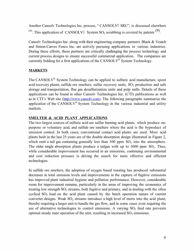
SMELTER & ACID PLANT APPLICATIONSThe two largest sources of sulfuric acid are sulfur burning acid plants, which produce on-purpose or voluntary acid, and sulfide ore smelters where the acid is the byproduct ofemission control. In both cases, conventional contact acid plants are used. Most acidplants built in the last 25 years are of the double absorption design illustrated in Figure 2,which emit a tail gas containing generally less than 500 ppm SO2 into the atmosphere.The older single absorption plants produce a tailgas with up to 3000 ppm SO2. Thus,while considerable improvement has occurred in air emissions, continuing environmentaland cost reduction pressure is driving the search for more effective and efficienttechnologies.
In sulfide ore smelters, the adoption of oxygen based roasting has produced substantialdecreases in total emission levels and improvements in the capture of fugitive emissionshas improved plant industrial hygiene and pollution performance. However, considerableroom for improvement remains, particularly in the areas of improving the economics oftreating low strength SO2 streams, both fugitive and primary, and in dealing with the oftencyclical SO2 load on the acid plant caused by the batch operation nature of currentconverter designs. Weak SO2 streams introduce a high level of inerts into the acid plant,thereby requiring a larger unit to handle the gas flow, and in some cases even requiring theuse of alternative technologies to control emissions. A varying SO2 feed rate preventsoptimal steady state operation of the unit, resulting in increased SO2 emissions.
10
Figure 2. Double Absorption Acid Plant Gas Flow
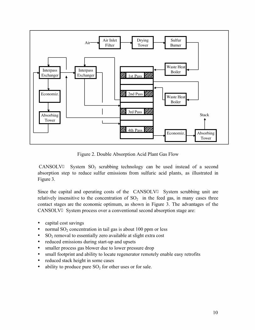
CANSOLV‚ System SO2 scrubbing technology can be used instead of a secondabsorption step to reduce sulfur emissions from sulfuric acid plants, as illustrated inFigure 3.
Since the capital and operating costs of the CANSOLV‚ System scrubbing unit arerelatively insensitive to the concentration of SO2 in the feed gas, in many cases threecontact stages are the economic optimum, as shown in Figure 3. The advantages of theCANSOLV‚ System process over a conventional second absorption stage are:
• capital cost savings• normal SO2 concentration in tail gas is about 100 ppm or less• SO2 removal to essentially zero available at slight extra cost• reduced emissions during start-up and upsets• smaller process gas blower due to lower pressure drop• small footprint and ability to locate regenerator remotely enable easy retrofits• reduced stack height in some cases• ability to produce pure SO2 for other uses or for sale.
3rd Pass 3rd Pass 3rd Pass
4th Pass
1st Pass
2nd Pass
3rd Pass
Air InletFilter
DryingTower
SulfurBurner
Waste HeatBoiler
Waste HeatBoiler
Economiz. AbsorbingTower
InterpassExchanger
InterpassExchanger
Economiz.
AbsorbingTower
Stack
Air
11
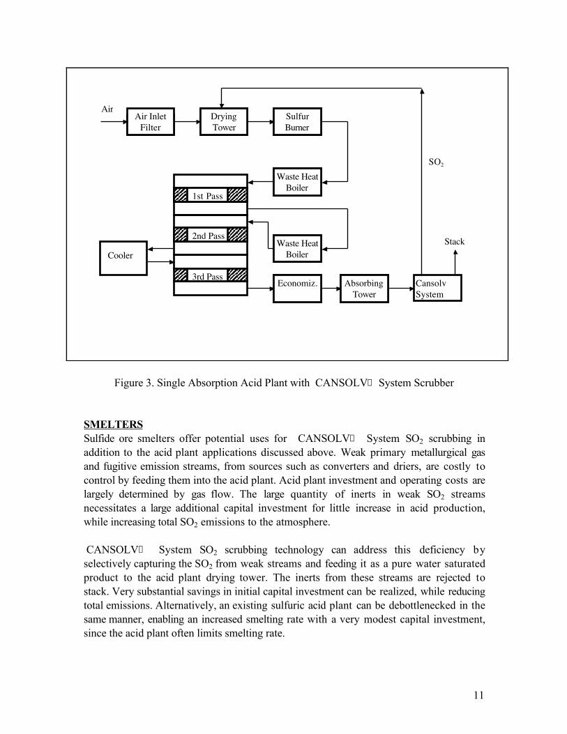
Figure 3. Single Absorption Acid Plant with CANSOLV‚ System Scrubber
SMELTERSSulfide ore smelters offer potential uses for CANSOLV‚ System SO2 scrubbing inaddition to the acid plant applications discussed above. Weak primary metallurgical gasand fugitive emission streams, from sources such as converters and driers, are costly tocontrol by feeding them into the acid plant. Acid plant investment and operating costs arelargely determined by gas flow. The large quantity of inerts in weak SO2 streamsnecessitates a large additional capital investment for little increase in acid production,while increasing total SO2 emissions to the atmosphere.
CANSOLV‚ System SO2 scrubbing technology can address this deficiency byselectively capturing the SO2 from weak streams and feeding it as a pure water saturatedproduct to the acid plant drying tower. The inerts from these streams are rejected tostack. Very substantial savings in initial capital investment can be realized, while reducingtotal emissions. Alternatively, an existing sulfuric acid plant can be debottlenecked in thesame manner, enabling an increased smelting rate with a very modest capital investment,since the acid plant often limits smelting rate.
3rd Pass 3rd Pass 3rd Pass
1st Pass
2nd Pass
3rd Pass
Air InletFilter
DryingTower
SulfurBurner
Waste HeatBoiler
Waste HeatBoiler
Economiz. CansolvSystem
AbsorbingTower
Stack
Air
SO2
Cooler
12
Metallurgical acid plants often operate with a very cyclical inlet SO2 concentration, due tothe batch operating nature of current converter designs. This has the undesirable effect ofpreventing the acid plant from operating in a steady state optimum manner, which tendsto increase emissions. Additionally, the mechanical stresses caused by thermal cyclingtends to increase maintenance costs. The SO2SAFE
“ Storage Technology can mitigate
these effects by providing load-leveling capability. During peaks, SO2 is scrubbed fromthe acid plant feed gas and the loaded solvent is held in a buffer storage tank. At times oflow SO2 concentration in the acid plant feed, rich solvent is regenerated and the SO2 isadded to the acid plant feed gas. The response time constant of the CANSOLV‚ Systemprocess is of the order of one minute or less, enabling accurate load following. Theoptimum degree of damping the cyclicality is site specific. In the limit, completedecoupling of the smelter and acid plant can be achieved by specifying a sufficiently highrate and storage capacity for the load leveling equipment.
Finally, the use of CANSOLV‚ System Flue Gas Desulfurization can enable the use ofhigh sulfur, low cost fuels such as petroleum coke and heavy refinery residues in the siteutility boilers or cogeneration unit. The SO2 byproduct can be converted to H2SO4 in theexisting acid plant. Payback periods of 2 years or less are projected for the additionalplant investment over a gas fired cogeneration unit.
REFINERY & NATURAL GAS APPLICATIONSIn natural gas, growing demand and rising prices are making the production of sour gaseconomical, leading to a growth in sweetening and sulfur recovery capacity, while havingto deal with the tightening of emission regulations.
The refining industry is facing three trends with serious cost increase implications. Theglobal average crude oil is getting heavier and higher in sulfur, while regulations arerequiring lower sulfur content in the products and lower emissions from the refineries.Exacerbating the situation is the shrinking market for residue fuels which in the past dealtwith a substantial fraction of the crude slate sulfur content. In fact, disposition of thebottom of the barrel (very heavy residues and petroleum coke) is a growing problem forrefiners. The impact of all these factors on refineries has been to require increased refinerycomplexity, increased hydrotreating, higher SRU capacity, cleaner refinery fuels andreduced emissions from the major sources such as the sulfur recovery unit (SRU), boilersand the fluidized catalytic cracking unit (FCCU) regenerator flue gas (CO boiler flue gas).The refining industry is thus facing major capital investments, while having to deal with avery competitive marketplace for products.
Reduction of sulfur emissions from SRU’s is being achieved by the application of varioustechnologies:
• tail gas treatment with H2S recycle processes (BSR/Amine, SCOT, etc.)• selective catalytic oxidation (Selectox, Superclaus etc.)• sub-dewpoint processes (Amoco CBA, MCRC, Sulfreen etc.)
13
The above processes reduce emissions adequately, but do increase costs significantly andsome have operating constraints requiring careful control.
SRU capacity expansion, as an alternative to construction of a complete new train, iscurrently most often achieved by oxygen enrichment of the thermal stage combustion air.This reduces the inerts flow through the unit, making room for additional acid gas. At highlevels of enrichment or with pure oxygen, extensive modifications to existing equipmentmust be made. The use of oxygen of course incurs a significant operating cost increase.
FCCU sulfur emission control is now practiced by primarily two technologies - the use ofsulfur transfer catalysts or caustic (or soda ash) scrubbing. Costs of both control optionsare quite sensitive to the concentration of SO2 in the uncontrolled tail gas. Thus thetrends to heavier, high sulfur crudes and to increased residue cracking are increasingemission control costs significantly. Units losing grandfathering and new FCCU’s willhave to bear the compliance cost.
While these and other advances in technology have helped operating companies to meetrequirements, the pressures to improve environmental performance and reduce costs areunrelenting. CANSOLV“ System technologies offer new tools to deal with thesechallenges. The processes, as described below, now provide a new options for SRU tailgas treatment, debottlenecking and for new sulfur recovery units of conventional design.The CANSOLV“ System process also introduces a new paradigm for SRU design, due toits ability to economically, selectively and regenerably scrub SO2 from gas streams. Theability to remove SO2 from flue gas at lower cost, and to the most stringent standards,opens the door for FCCU emission control and the use of low value, high sulfur residualsand petroleum coke as refinery fuel or in cogeneration.
The following discussion is applicable to both natural gas and refinery SRU’s. Refinerscan take advantage of the considerable economies and operating advantages accruing fromdestruction of dirty feed streams containing ammonia, hydrocarbons etc. Natural gasprocessors with low H2S to CO2 ratios will benefit from the capital and operating costadvantages resulting from the almost complete equilibrium selectivity of the CANSOLV“
System scrubbing process for SO2 over CO2. Conventional TGTU’s can absorb largequantities of CO2 along with H2S , resulting in the recycle of inert material to the SRU.
CANSOLV“ System TGTUA CANSOLV“ System unit can perform sulfur removal from natural gas plant andrefinery Claus unit tail gas, simply replacing a conventional TGTU, as shown in Figure 4.The major difference is that the Claus tail gas is incinerated and then scrubbed, rather thanreduced and scrubbed as in conventional technology.
14
The CANSOLV“ System TGTU has very significant advantages over a conventionalTGTU:
• competitive or lower capital and operating costs• higher sulfur recovery - all sulfur species, including elemental sulfur and COS,
are converted to SO2 by incineration with excess air and removed to a few ppm, ifrequired
• all combustible species in the Claus tail gas are destroyed, avoiding interferencewith the scrubbing process and emissions to air
• accurate control of H2S / O2 stoichiometry is not critical, since the Claus tailgas sulfur content is converted totally to SO2 , regardless of whether it was H2S or SO2
rich• need for reheater, reducing gas and catalytic reactor is eliminated• recycle of inert CO2 to the Claus unit along with the sulfur is eliminated, due to
the very high equilibrium selectivity of the CANSOLV“ System scrubbing processcompared to MDEA treating
• problems due to SO2 breakthroughs in conventional TGTU are eliminated• low cost sensitivity to feed SO2 content may enable elimination of third
converter.
DebottleneckingEven greater benefits can be obtained by actually integrating CANSOLV“ Systemtechnology into the operation of the SRU, beyond just tail gas treatment, as is illustratedin Figure 5. In this configuration, a part of the acid gas bypasses the Claus unit and isincinerated with excess air, along with the Claus tail gas. The SO2 recycled to the Clausthermal stage reduces the combustion air requirement, thereby also reducing the processgas flow by eliminating the nitrogen inerts. This effectively unloads the SRU, allowing forincreased capacity at a low incremental cost over the CANSOLV“ System TGTU alone.The high operating cost of oxygen enrichment is avoided, while realizing in addition to theabove advantages the following additional benefits:
• capacity expansions of up to 170 - 200%+• in refineries, streams containing troublesome species such as ammonia and
hydrocarbons can be incinerated with excess oxygen, avoiding unit derating and operatingproblems
• acid gas replaces incinerator support fuel
Varying degrees of debottlenecking can be implemented by changing the amount of acidgas bypassed to the incinerator. Large capacity expansions will possibly require somemodifications to the existing equipment, to deal with the higher sulfur production and heatrelease.
CANSOLV“ System SRU
15
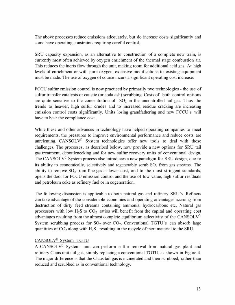
The end point for the paradigm shift driven by incorporation of CANSOLV“ Systemtechnology into sulfur recovery units is the “CANSOLV“ System SRU” illustrated inFigure 6. This new design paradigm is projected to have substantially lower capital costthan current designs. As can be seen by comparison to Figure 5, fewer pieces of majorequipment are required, reducing cost and simplifying operation. Extremely high sulfurrecoveries can be achieved in a simple, easier to operate process. Due to the rejection ofinerts contained in the acid gas bypassed to the incinerator, the sulfur reactantconcentrations in the feed to the catalytic stages are increased. This will push theapplication envelope of the CANSOLV“ System SRU process to lower H2Sconcentration acid gas than that treatable with conventional technology.
The operational advantages mentioned above are also obtained in the CANSOLV“ SystemSRU process configuration. A further saving in this design is the lower air blower headrequired, because the combustion air is fed to the essentially atmospheric pressureincinerator, rather than the thermal stage of a conventional unit which operates at apressure of 6 - 12 psig.

Thermal Stage Waste HeatBoiler Sulfur Condenser
1st Catalytic Stage2nd Catalytic Stage3rd Catalytic Stage
Gas Cooler
Air
Acid Gas
SS
S
S
CANSOLV“
System Scrubber
Lean AmineRich Amine
Incinerator
Regenerator
Treated Tail Gas To Stack
SO2
Figure 4. Claus Unit with CANSOLV“ System TGTU
Air + Fuel

Lean Amine
Thermal Stage Waste HeatBoiler Sulfur Condenser
1st Catalytic Stage2nd Catalytic Stage3rd Catalytic Stage
Gas Cooler
Air
Acid Gas
SS
S
S
CANSOLV“
System Scrubber
Rich Amine
Incinerator
Regenerator
Treated Tail Gas To Stack
SO2
Figure 5. Claus Unit Debottlenecking with CANSOLV“ System Unit
Air
Sour WaterStripper Gas
Waste HeatBoiler Gas Cooler
Acid Gas
CANSOLV“
System Scrubber
Lean AmineRich Amine
Incinerator
To Stack
Regenerator
Treated Tail Gas
SO2
Figure 6. CANSOLV“ System SRU
2nd Catalytic Stage1st Catalytic Stage
S S
Air
Sour Water Stripper Gas
Heater
19
FGD APPLICATIONSOne of the principal attributes of FBC is its ability to combust most solid fuels, includinglow reactivity materials. Its use can be most attractive when using low cost fuels such ashigh sulfur coal or petroleum coke.
Combustion of such high sulfur fuels requires that an efficient desulfurization method beutilized in order to meet the increasingly stringent regulatory emission limits. Traditionalmethods using limestone involve the introduction and later collection and disposal oflarge quantities of solids.
Disposal of these solid by-products can be problematic. In certain jurisdictions the solidsmay be considered hazardous waste, increasing disposal costs and reducing disposaloptions. In those areas where waste disposal is difficult, expensive or impossible butwhere an economic incentive to burn low cost high sulfur fuels exits, a regenerable SO2
scrubbing technique would be advantageous, especially when this technique is costcompetitive with conventional limestone scrubbing.
The CANSOLV® System FGD process is a regenerable SO2 scrubbing process thatutilizes a solvent specific for the capture of SO2, and produces a pure SO2 by-product.The solvent is not consumed in the process and does not contribute to the by-productstream. The cost of the scrubbing process is largely insensitive to SO2 concentration inthe flue gas or the sulfur content in the fuel. Thus the highest sulfur, lowest cost fuel canbe consumed, maximizing the economic benefits.
With limestone desulfurization, FBC only converts an air emission problem into a wastesolids disposal problem. As much as a half-ton of waste may be generated per ton of fuelburned or ten tons per hour for the equivalent of a 50 MW boiler.
The problem is becoming more severe as the higher sulfur removal efficiencies beingmandated by current legislation are forcing boiler operators to increase the ratio oflimestone to fuel in their feed. This leads to greater costs and difficulty in disposing of thesolid by-products, as well as a decrease in boiler efficiency.
CANSOLV® SYSTEM FGD WITH FBCThe use of limestone with FBC’s is a proven technology for controlling SO2 emissions.Limestone is introduced in the furnace where it is calcined to lime. The lime reacts withthe SO2 released by the combustion of the fuel to form calcium sulfite and calcium sulfate.Excess limestone is added in order to increase overall SO2 capture.
The calcium sulfite/sulfate by-product is collected with the unreacted quicklime, carbonand ash as a solid waste requiring disposal. The calcium sulfite/sulfate and residual limecan represent more than 80% of the overall solid waste collected depending on sulfur andash content in the fuel and SO2 removal efficiency in the FBC.
20
The CANSOLV® System FGD process is an alternative to limestone FGD. Similar toconventional amine treating for H2S and CO2 scrubbing, it is a regenerable process whichutilizes a water soluble amine that is highly selective to SO2. The amine, onceregenerated, is reused. The SO2 recovered can be used as is, or converted to sulfur orsulfuric acid. CANSOLV“ System FGD is a robust and easy to operate process. Itconsumes no chemicals and, other than the ash collected, generates virtually no additionalwastes. Total emissions, to air, water and landfill are minimized.
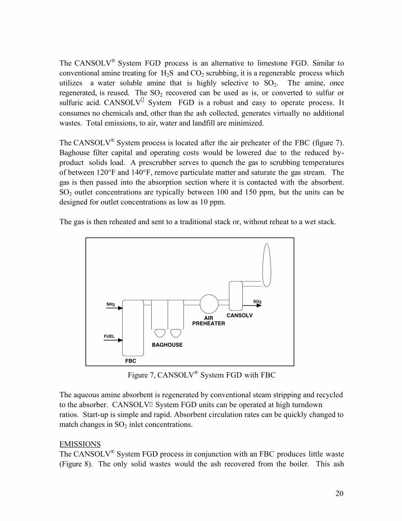
The CANSOLV® System process is located after the air preheater of the FBC (figure 7).Baghouse filter capital and operating costs would be lowered due to the reduced by-product solids load. A prescrubber serves to quench the gas to scrubbing temperaturesof between 120°F and 140°F, remove particulate matter and saturate the gas stream. Thegas is then passed into the absorption section where it is contacted with the absorbent.SO2 outlet concentrations are typically between 100 and 150 ppm, but the units can bedesigned for outlet concentrations as low as 10 ppm.
The gas is then reheated and sent to a traditional stack or, without reheat to a wet stack.
FBC
BAGHOUSE
AIRPREHEATER
CANSOLV
SO2NH3
FUEL
Figure 7, CANSOLV® System FGD with FBC
The aqueous amine absorbent is regenerated by conventional steam stripping and recycledto the absorber. CANSOLV‚ System FGD units can be operated at high turndownratios. Start-up is simple and rapid. Absorbent circulation rates can be quickly changed tomatch changes in SO2 inlet concentrations.
EMISSIONSThe CANSOLV® System FGD process in conjunction with an FBC produces little waste(Figure 8). The only solid wastes would the ash recovered from the boiler. This ash

21
having no calcium would be relatively neutral in pH. In addition, the quantity of ashgenerated would not be a function of the sulfur content of the fuel. Unlike withconventional limestone scrubbing, there would be no disincentive to burning the highestsulfur, lowest cost fuels possible. The economic advantages of burning high sulfur fuelscould now be fully realized.
Because the process can reduce SO2 flue gas concentrations to 10 ppmv or lower, theprocess will never be out of compliance with even the most stringent regulations that maybe imposed in the future. Existing CANSOLV® System FGD units could easily andinexpensively be retrofitted to meet the most stringent requirements.
The capital cost of the CANSOLV® System FGD process is competitive withconventional wet limestone scrubbing, while the operating costs are significantly lower,especially for higher sulfur fuels.
Tons (dry) per ton of coke feed
FBC @1.0
CA/S ORPC FGD
FBC @1.5
CA/S
FBC @2.0
CA/S
CANSOLV0
0.1
0.2
0.3
0.4
0.5
FBC @1.0
CA/S ORPC FGD
FBC @1.5
CA/S
FBC @2.0
CA/S
CANSOLV
Figure 8. Solid By-product from High Sulfur Petroleum Coke(7%S, 0.5% ash. 95% sulfur removal)
NOx emissions levels from FBC are in general lower than from pulverized coal boilers, souncontrolled NOx emission levels from FBC may meet the applicable requirements. Iflower levels of NOx are required, SNCR can be utilized. This is a relatively low costcontrol method giving NOx reductions of 60% to 70%.
22
The degree of NOx emission reductions with SNCR is typically limited by ammonia slip,which manifests itself as a plume. The first unit operation of the CANSOLV® SystemFGD process, the prescrubber water spray which serves to quench the gas, removeparticulates and strong acid such as sulfuric, nitric and hydrochloric. The acidic nature ofthe prescrubber spray ensures that any residual ammonia (slip) is collected. Ammoniaslip thus being controlled, the SNCR ammonia additions can be increased to achieve ahigher level of NOx reduction.
BY-PRODUCTSThe process produces a pure, water saturated SO2 stream (97%+ SO2, balance water),that may be utilized on site as such, converted to sulfuric acid or sulfur, or shipped offsiteusing the SO2SAFE
“ technology. There are numerous industrial uses for SO2, currently
supplied as liquid SO2 or produced on site by burning sulfur.
SO2SAFE“
SO2 Storage Technology consists of shipping the SO2 dissolved in the
absorbent and regenerating the absorbent at the user’s site on demand. In this manner, thecosts of handling and storage and the hazards associated with liquid SO2 are avoided.Transportation within a radius of up to 300 miles would be economical.
The water saturated pure SO2 by-product is utilized extensively in the pulp and paperand corn wet milling industries. It can also be used to produce certain chemicals such assodium sulfite, bisulfite and hydrosulfite. Liquid SO2 which is utilized in theseapplications is priced at $275/ton CAD, fob Copper Cliff, Ontario. If desired, the sulfurdioxide can be converted to sulfur or sulfuric acid by conventional technology.
In the continental U.S. there are about 100 sulfuric acid plants. Sulfuric acid is utilized ina large number of industrial processes. The largest consumer is the phosphate fertilizerindustry which is concentrated in Florida. Areas such as these where the value anddemand for sulfuric acid is highest, would provide attractive returns on the byproduct.
Every petroleum refinery has a Claus sulfur unit on site. It is relatively simple to feed theSO2 directly into the Claus unit for conversion to elemental sulfur. The addition of pureSO2 to the Claus unit feed would result in an increase in the sulfur production capacityof the unit. Refineries also are the source of petroleum coke. Ideally a refinery supplyingpetroleum coke to a nearby FBC operator would accept the by-product SO2 and convertit to elemental sulfur.
SULFITE PULP MILL APPLICATIONSAmmonia based sulfite pulp mills utilize ammonium bisulfite plus dissolved sulfurdioxide as the chemical reagent to delignify wood in order to produce a cellulose pulp.Unreacted SO2 from the cook is recovered by scrubbing the blowpit gases with aqueousammonia. The sulfur and energy contents of the lignosulfonate present in the spent sulfite

23
liquor (SSL) are recovered by burning the SSL in a recovery boiler. The flue gas is alsoscrubbed with aqueous ammonia to recover the SO2. Makeup SO2 is provided by a sulfurburner and/or liquid SO2.
Deficiencies of this mill flowsheet include significant SO2 and/or ammonia emissions,chemical imbalance in the mill and the expense of SO2 makeup, all of which complicatemill operation and raise operating and capital costs. SO2 recovery and recycle with theCANSOLV‚ System SO2 scrubbing process, rather than with ammonia, reducesemissions, makeup requirements and total cost. Recovery and recycle of the SO2 as apure gas, rather than as ammonium bisulfite, is a further major advantage of using theCANSOLV‚ System process: the chemical imbalance is eliminated and the cooking liquorpreparation and SO2 recovery operations are decoupled. This decoupling removes severeoperating constraints from the mill operation. Full application of CANSOLV‚ SystemSO2 scrubbing has the potential to yield a major increase in mill operating margin, whileimproving environmental performance and safety.
DEFICIENCIES OF CONVENTIONAL FLOWSHEETAmmonia based sulfite pulping as currently practiced has a number of deficiencies whichdetract from the economics, environmental impact and operability of the process.Reduction in the impact of these factors could enhance the competitiveness of sulfitepulping, which otherwise is a very desirable process. The deficiencies of the conventionalprocess are discussed below.
Chemical ImbalanceThe most serious drawback to the conventional sulfite mill flowsheet is the fact that whilethe cooking liquor consumes both combined and free SO2 , the recovery operations yieldmainly combined SO2 . This inevitably leads to chemical imbalance: the quantity ofcombined sulfur dioxide recovered is greater that required in cooking liquor preparation.By mass balance, the excess must be either emitted to air or water, or transferred off site.This loss must then be balanced by fresh SO2 makeup from the sulfur burner orpurchased SO2 . The operating, maintenance and raw material cost of a sulfur burner is aconsiderable cost penalty resulting from this deficiency. In addition, many millssupplement their SO2 requirements with purchased liquid SO2 to adjust free SO2 to levelsnot attainable with the sulfur burner. The difficulties of coping with the chemicalimbalance constraint are exacerbated by the fact that operation of the recovery boiler iscoupled to that of the acid plant (cooking liquor preparation area). Unscheduled recoveryboiler outages, the production of pulp grades requiring high free SO2 , changes from a hightotal SO2 grade to one requiring less combined SO2 all cause changes in the inventory ofSSL and weak acid (ammonium bisulfite) and create scheduling and inventory managementdifficulties, adding to plant operating complexity.

24
Feed Chemical UsageThe recovery of sulfur fed to the digesters is typically about 80%. About 2% of thesulfur leaves with the washed pulp and essentially all of the rest is due to the inefficiencyof the recovery system. While some of the losses will be difficult to control, being in theform of dilute equipment wash waters for example, a significant reduction in losses ispossible by application of better technology.
The ammonia is not recycled at all, since it is burned in the recovery boiler. However,excess ammonia consumption can be caused by air oxidation of sulfite to sulfate in therecovery process. Since ammonium sulfate is not active in the pulping process, thecontained ammonia is wasted.
If caustic is used for the final cleanup of gas streams prior to venting to atmosphere, it islost to waste water on a once through basis, as is the captured SO2.
Energy ConsumptionThe use of multiple stages of absorption in the SO2 scrubbing system leads to anunnecessarily high gas side pressure drop, requiring powerful fans. If candle filters areused on the recovery boiler to control ammonium bisulfite aerosol emissions, these add tothe pressure drop in the flue gas cleaning system. Also, in cases where the cooling watertemperature is high, chillers may be required to cool the gas stream in order to getacceptable SO2 removal.
Capital CostThe complexity of the SO2 recovery system, with multiple absorbers, storage tanks,pumps, candle filters, chillers etc. leads to a high capital and maintenance costs and largespace requirements for the SO2 recovery system.
Environmental ComplianceMeeting stringent emission levels with ammonia scrubbing requires operating the recoverysystem at the limit of its capabilities. With ammonia scrubbing, a delicate compromise hasto be struck between high SO2 removal and low ammonia or ammonium bisulfiteemissions: it is very difficult to obtain both simultaneously. This is the justification forfinal polishing of some streams with caustic prior to venting to atmosphere. Disposal ofthe sodium sulfite produced is usually to the waste water treatment system, addingchemical oxygen demand that must be treated. If candle filters are used, the water washesrequired to remove the captured ammonium bisulfite can contribute to ammoniadischarged to receiving streams.
If all the lignosulfonate cannot be burned in the recovery boiler due to chemical imbalance,disposal of the material can be problematic. While there are established uses forlignosulfonate as a cement additive for example, the market is not very large. Use of
25
lignosulfonate as a road dust suppressant is possible, but it has raised questions ofenvironmental impact.
Fugitive emissions from various sources such as pulp washers, sulfur burner etc. can alsoimpact on the emissions and particularly the level of ambient SO2 within the plant itself.
CANSOLV‚ SYSTEM TECHNOLOGY IN SULFITE PULPINGAll of the deficiencies of current sulfite pulping technology can be reduced or eliminatedby the use of CANSOLV‚ System SO2 recovery and recycle instead of ammonia ormagnesium hydroxide scrubbing. The most important benefits result from the recovery ofthe sulfur as pure sulfur dioxide:
1. The chemical imbalance between combined and free SO2 is eliminated.2. The recovery and cooking liquor preparation operations are decoupled if provision is
made for storage of recovered SO2 in SO2SAFE“
solution form, or as liquid SO2
under pressure, if the safety issues are properly addressed.
Removal of these two constraints simplifies plant operation, reduces equipmentcomplexity, allows maximum use of free SO2 where this improves quality or reducescooking time and allows total burning of SSL in the recovery boiler. The very highrecovery efficiency of the CANSOLV‚ System SO2 scrubbing process maximizes sulfurrecovery and minimizes emissions, both to air and water.
The Cansolv Absorbent DS actually inhibits oxidation of SO2 to SO3, the amount ofsulfur dioxide is increased due to reduced losses to sulfate. Also, since the absorbent istotally non-volatile, no amine bisulfite is emitted, avoiding the use of candle filters. Sincethe absorption of SO2 can be performed in a single vessel, equipment complexity, fanpower, space and maintenance can all be reduced compared to current technology.
Beyond the obvious application of CANSOLV‚ System technology to simply replacethe conventional SO2 absorption system with a more efficient and less costly technology,new possibilities for further simplification and cost reduction become possible. Firstly, ifthe mill operates a fossil fuel fired boiler, replacement of low sulfur emission compliantfuel by a cheaper high sulfur product such as petroleum coke, liquid fuel or coal becomesan option. The payback for the investment in CANSOLV‚ System flue gasdesulfurization is usually less than 2 years, particularly if a common regenerator is usedfor the absorbers on all the different gas streams. The sulfur dioxide recovered from thehigh sulfur fuel can be used to reduce the sulfur burner duty, reducing sulfur purchaserequirements. In effect, the sulfur content in high sulfur fuel has a negative cost.Considering the reduced sulfur makeup requirement resulting from the higher recoveryefficiency of CANSOLV‚ System scrubbing, the extra sulfur input from the high sulfurfuel may be sufficient to shut down the sulfur burner. If required, elemental sulfur added

26
to the boiler or the recovery boiler could make up any shortfall. Elimination of the sulfurburner (or purchased SO2 ) is a desirable cost reduction and operating simplification step.The application of CANSOLV‚ System technology to a sulfite mill is shown inFigure 9.

27
FIGURE 9. CANSOLV‚ SYSTEM APPLICATIONS
SulfurBurner
Blow pits
SO2SAFEStorage
RecoveryBoiler
Digesters
Stack
CansolvAbsorber
Stack
CansolvAbsorber
Stack
CansolvAbsorber
Stack
CansolvAbsorber
Liquid
Regenerator
NH3
NH4(HSO3)SO2
To Digesters
Residual SO2
Optional
Flue Gas
Flue Gas
Flue Gas
Blow Pit Gas
High Sulfur Fuel
High Sulfur Fuel
Sulfur
Sulfur
Sulfur
SO2
Utility/Cogen Boiler
Optional(Optional)
(Optional)
(Optional)
VentGases
28
THE SO2SAFE“
TECHNOLOGY FOR STORAGE AND TRANSPORT OF SO2
Sulfur dioxide, SO2, is a widely used chemical in industries such as wood pulping and bleaching,corn wet milling, water treatment and the production of sulfuric acid(1). It is a colorless, non-inflammable toxic gas, with a boiling point of -10.0o C at atmospheric pressure of 1013 mbar.Currently, the normal method of storing and transporting bulk quantities of SO2 is as a liquefiedgas in suitable pressure vessels. This presents a serious risk due to the possibility of acatastrophic release of SO2 in the case of storage vessel or fitting failure. In such a case, while theprobability of occurrence is low, the effects are extremely serious. Gaseous SO2 is very toxic,showing adverse health effects at concentrations as low as 3 parts per million. Since SO2 gas isheavier than air, any release will tend to stay at ground level, maximizing human exposure.
The majority of SO2 for captive use or for merchant sale is produced either by sulfur burning orby capture from metallurgical gas streams. Both processes are rather expensive and the latterusually requires transportation over long distances to the consuming site. Since transportationroutes often pass through metropolitan centers, large segments of the population are exposed torisk in case of a spill. On the other hand, SO2 produced by burning sulfur containing fuel is eitheremitted as a pollutant or turned into low-value gypsum by limestone scrubbing. TheCANSOLV“ System SO2 scrubbing technology, when combined with the SO2SAFE
“ SO2
Storage and Transportation process, addresses both issues by enabling economical, safe andefficient pollution control and SO2 recovery and recycle.
CANSOLV‚ SYSTEM TECHNOLOGYThe patented CANSOLV“ System SO2 scrubbing process has been described in detailelsewhere2,3,4,5. It utilizes an aqueous amine absorbent that is highly selective for removal of SO2
from various gas streams such as flue gas. The process flowsheet is very similar to the wellknown alkanolamine process for removal of H2S and CO2 from natural gas and refinery gasstreams. The essence of the process is absorption of SO2 into the solvent in an absorber andrecovery by stream stripping in a regenerator. The byproduct SO2 is recovered as a pure, watersaturated stream and the regenerated solvent is recycled to the absorber. Removal of SO2 from thefeed gas to <10 ppmv is economically viable.
A patent application has been filed for the SO2SAFE“
SO2 storage technology, which is an
extension of the CANSOLV“ System scrubbing process. It consists of storing and shipping theSO2 dissolved in the absorbent and regenerating the absorbent at the user’s site on demand. Thesame or a different absorbent may be used for scrubbing and storage, depending on the specificrequirements of a particular application. A 25 - 30% solution of the amine in water is utilized inthe process. These absorbents provide significant advantages:
• since the amine absorbent is always present in the process as a salt, it is totally non-volatile and equilibrium vapor phase losses of solvent to the treated gas are zero
• the product SO2 is pure with no amine contamination
29
• a high usable loading of SO2 in the rich solvent• up to about 1 equivalent of strong acid anions per mole of amine, i.e. heat stable amine
salts (HSAS), may be present in the absorbent without decreasing the normal scrubbingcapacity by the sorbing nitrogen
• HSAS are removed easily and efficiently by a patented electrodialysis process• inhibition of SO2 oxidation to sulfate by oxygen• high thermal and chemical stability
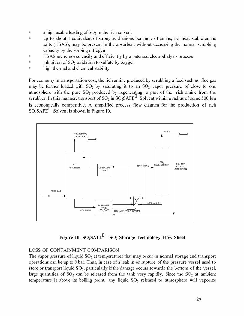
For economy in transportation cost, the rich amine produced by scrubbing a feed such as flue gasmay be further loaded with SO2 by saturating it to an SO2 vapor pressure of close to oneatmosphere with the pure SO2 produced by regenerating a part of the rich amine from thescrubber. In this manner, transport of SO2 in SO2SAFE
“ Solvent within a radius of some 500 km
is economically competitive. A simplified process flow diagram for the production of richSO2SAFE
“ Solvent is shown in Figure 10.
RICH AMINELEAN AMINE
TANK
LEAN AMINE
TREATED GASTO STACK
RICH AMINE
FEED GAS
RICH AMINE TO CUSTOMER
ABSORBER
REGENERATORSO2
SO2
RICH AMINETANK
SO2 SAFE( )
WET SO2
SO2 FORSOLVENT
SATURATION
Figure 10. SO2SAFE“
SO2 Storage Technology Flow Sheet
LOSS OF CONTAINMENT COMPARISONThe vapor pressure of liquid SO2 at temperatures that may occur in normal storage and transportoperations can be up to 8 bar. Thus, in case of a leak in or rupture of the pressure vessel used tostore or transport liquid SO2, particularly if the damage occurs towards the bottom of the vessel,large quantities of SO2 can be released from the tank very rapidly. Since the SO2 at ambienttemperature is above its boiling point, any liquid SO2 released to atmosphere will vaporize
30
rapidly, creating a vapor cloud of toxic gas that tends to stay at ground level, being heavier thanair. Prevailing winds can then disperse the vapors, creating conditions hazardous to health or evenlethal conditions over a large area. Concentrations of 5–10 ppmv of SO2 in air will lead toirritation of the respiratory tract and concentrations above 400-500 ppmv, even for a fewminutes, are dangerous to life. Areas adjacent to industrial SO2 storage sites and railroads or roadsused for the transport of SO2 are thus at risk in the event of such a release.
The release of SO2 from solution in the SO2SAFE“
SO2 solvent is much less and slower. While
the initial partial pressure of SO2 over the solvent is up to 1 atmosphere, evolution of the gasfrom solution is inhibited by a) formation of a liquid side SO2 depleted boundary layer whichdecreases the mass transfer rate, and b) cooling of the liquid by the heat of vaporization of theSO2 which i) decreases the equilibrium vapor pressure and ii) increases liquid viscosity, makingthe boundary layer thicker.
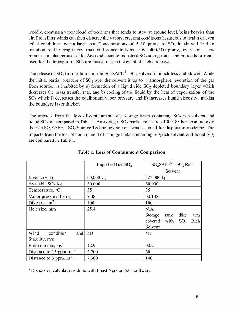
The impacts from the loss of containment of a storage tanks containing SO2 rich solvent andliquid SO2 are compared in Table 1. An average SO2 partial pressure of 0.0188 bar absolute overthe rich SO2SAFE
“ SO2 Storage Technology solvent was assumed for dispersion modeling. The
impacts from the loss of containment of storage tanks containing SO2 rich solvent and liquid SO2
are compared in Table 1.
Table 1. Loss of Containment Comparison
Liquefied Gas SO2 SO2SAFE“
SO2 Rich
SolventInventory, kg 60,000 kg 323,000 kgAvailable SO2, kg 60,000 60,000Temperature, oC 35 35Vapor pressure, bar(a) 7.48 0.0188Dike area, m2 100 100Hole size, mm 25.4 N.A.
Storage tank dike areacovered with SO2 RichSolvent
Wind condition andStability, m/s
5D 5D
Emission rate, kg/s 12.9 0.02Distance to 15 ppm, m* 2,700 60Distance to 3 ppm, m* 7,300 140
*Dispersion calculations done with Phast Version 5.01 software
31
The distances to similar toxic concentrations of SO2 are much shorter for a loss of containmentof SO2 rich solvent than for liquefied gas SO2 : 60 m vs. 2,700 m for 15 ppm and 140 m vs. 7,300m for 3 ppm, respectively. The loss of containment consequences for the SO2 rich solvent arethus almost three orders of magnitude less than for liquid SO2. In an urban SO2 storage facility,liquid SO2 storage has the potential to affect a large population, while the SO2 Rich Solventimpacts only the immediate vicinity of the site. The SO2SAFE
“ SO2 rich Solvent is by its
nature intrinsically safer.
PILOT TESTING
FLUE GASThe generic CANSOLV‚ System scrubbing process was successfully piloted during a 9-monthtrial in 1991 at the Suncor Oil Sands plant in Fort McMurray, Alberta, in Flue GasDesulfurization service. Removal rates in excess of 99% were consistently demonstrated. Theabsorbent was found to be very stable and capable of effecting high removal rates at low liquid togas ratios. The unit operated from February 28 to November 28, 1991, scrubbing 3600 scfm offlue gas from the site’s utility boilers. The fuel in the boilers was petroleum coke produced in thetar upgrading process and had a sulfur content of 7%. On many occasions in the course ofperforming the statistically designed experiments, SO2 in the treated gas was <15 ppmv. Resultsof the test program exceeded expectations and demonstrated the CANSOLV‚ System processto be robust, effective and easy to operate.
METALLURGICAL GAS AND PULP & PAPERCTI designed and constructed a highly versatile mobile pilot unit, for the purpose ofdemonstrating the CANSOLV‚ System Process technology, and obtaining fundamental sitespecific scale up data. The pilot plant unit is mounted on a 16-foot trailer. It consists of a 13foot, 4“ ID insulated absorption tower with structured packing mass transfer elements and an 18foot, 4“ ID insulated regeneration tower, also containing structured packing. The regenerator hasa steam heated reboiler, and an overhead condenser and condensate accumulator. The associatedperipheral equipment consist of three process pumps, a plate and frame heat exchanger, a vacuumpump, a feed gas blower, two absorbent particulate filters and an activated carbon filter. TheCANSOLV® System mobile pilot plant also includes an absorbent heat stable salt removal unitbased on the principle of electrodialysis.
Feed gas containing SO2 enters the absorption tower, where the Cansolv Absorbent DS solventpicks up the sulfur dioxide, thus cleaning the effluent gas down to a few ppm SO2 . The solventis then regenerated in the regeneration tower and returned to the absorption tower in a cyclicalmode to pick up additional SO2. Instrumentation for monitoring process parameters consists oflocal indicators. Gas SO2 concentration is monitored with a non-dispersive infrared processanalyzer.
The unit was commissioned and run in at a metallurgical acid plant. Both acid plant feed and tailgases, at 7.5% and 1500 – 2000 ppm SO2 respectively, were treated. The treated gas in both

32
cases had less than 50 ppm SO2 and the unit performed satisfactorily in all respects. It was thenmoved to the pulp mill for the trials.
The results obtained with this small scale pilot unit were consistent with data available fromprevious large scale (6,000 Nm3/h gas flow) testing and from a rigorous thermodynamic processmodel on the Aspen Plus® platform1.
GAS STREAM CONDITIONSField tests were run at an ammonia based sulfite mill on both blowpit gas and recovery boiler fluegas. The two streams are quite different, as can be seen from Table 1.
TABLE 1
DESCRIPTION OF GAS STREAMSParameter Blowpit Gas Recovery Boiler Flue Gas
SO2 1 to25+% 3200 ppmvPressure ± 1 bar ± 1 barTemperature 40°C 35°CWater content Saturated SaturatedOrganics Present W Absent
W The organic content was not quantified. Compounds identified by GC/MS included methanol,acetone, furfural and p-cymene .
The blowpit gas presented the greater challenge due to the highly cyclical SO2 concentrationresulting from the batch nature of the digester operation. When a cook was blown into theblowpit, a large fraction of the unreacted free SO2 flashed off with the steam generated from thesuperheated cooking liquor. This gas stream also contained organics originating from the woodresin and from the reaction products of the cooking process. Prior to being treated for SO2
removal, the blowpit gas is cooled in direct and indirect coolers. Between blows, a vacuum reliefvalve admits air into the blowpit.
The recovery boiler flue gas results from the excess air combustion of SSL concentrated to asolids level of about 55-60% and therefore has a high water content. Prior to SO2 removal, it iscooled and saturated in a direct cooler.
1 Aspen Plus is a registered trademark of Aspen Technology, Inc.
33
TEST RESULTSVery high removal of SO2 was obtained from both gases. The treated recovery boiler flue gas hadSO2 concentrations consistently below 30 ppmv at steady state operation. Due to the cyclicalityof SO2 concentration in the blow pit gas, the absorbent flow rate was increased for the durationof the SO2 peak during a digester blow. This minimized the average absorbent flow rate. Treatedblowpit gas contained less than 45 ppm SO2, proving the load following capability of theCANSOLV‚ System process.
The water saturated SO2 byproduct from blowpit gas contained only very minor quantities oforganics, demonstrating the capability of the process to reject these and prevent theiraccumulation in the overall mill process. The SO2 produced was greater than about 95% purity,with the balance being essentially water. In particular, no Cansolv Absorbent DS could bedetected in the byproduct SO2.
The total on-stream time of the test was about 160 hours. No adverse effects on the absorbent ortreating performance were noted.
CONCLUSIONSThe CANSOLV® System Process has introduced a new paradigm for SO2 recovery and recycle,by simultaneously reducing toxic emissions and cost.
The field testing of the CANSOLV‚ System SO2 scrubbing process demonstrated the ability torecover and recycle SO2 from metallurgical gas and in a sulfite pulp mill, as free SO2. Extremelylow levels of SO2 emissions are achievable, while reducing plant complexity and costs. Thedecoupling of recovery and pulping operations will reduce operating complexity and constraints.
The excellent results obtained on the four different gas streams tested with the unit support thegeneral applicability of the technology to other uses such as in smelters, acid plants, flue gasdesulfurization, refineries and sulfur recovery units. A larger test unit is under construction fordemonstrations of the process, starting with a smelter application in mid 1999.
Related Documents