An ISO 9001:2008 registered company Phone: 403.342.4494 Email: [email protected] www.canaltaflow.com Exceptional Value means adding to your Bottom Line without sacrificing Quality, Service or Performance The Canalta Dual Chamber Orifice Fitting Call Us Toll Free: 1-855-CANALTA

Welcome message from author
This document is posted to help you gain knowledge. Please leave a comment to let me know what you think about it! Share it to your friends and learn new things together.
Transcript

An ISO 9001:2008 registered company
Phone: 403.342.4494Email: [email protected]
Exceptional Value means adding to your Bottom Linewithout sacrificing Quality, Service or Performance
The Canalta Dual Chamber Orifice Fitting
Call Us Toll Free: 1-855-CANALTA
The Soft Seat Valve Seal is available for all dual chamber models. Effective in all scenarios, but particularly suited to low pressure applications, this unique design enables a bubble-tight seal between the upper and lower chambers without the need for frequent lubrication. The specially machined seal channel helps prevent O-ring dislocation, and the O-ring seals incorporated are available in a wide variety of compositions.
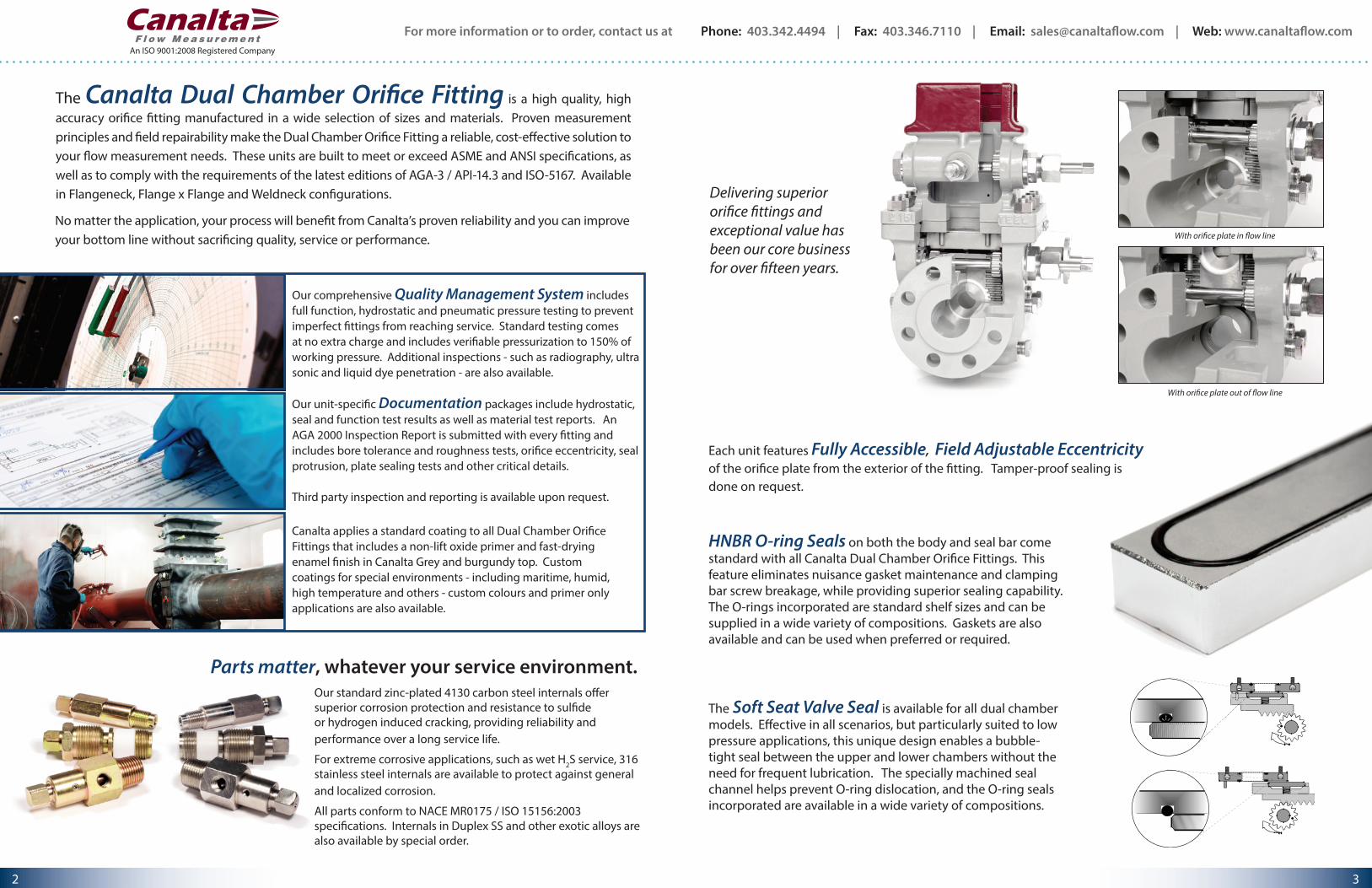
With orifice plate in flow line
With orifice plate out of flow line
HNBR O-ring Seals on both the body and seal bar come standard with all Canalta Dual Chamber Orifice Fittings. This feature eliminates nuisance gasket maintenance and clamping bar screw breakage, while providing superior sealing capability. The O-rings incorporated are standard shelf sizes and can be supplied in a wide variety of compositions. Gaskets are also available and can be used when preferred or required.
Each unit features Fully Accessible, Field Adjustable Eccentricity of the orifice plate from the exterior of the fitting. Tamper-proof sealing is done on request.
Our comprehensive Quality Management System includes full function, hydrostatic and pneumatic pressure testing to prevent imperfect fittings from reaching service. Standard testing comes at no extra charge and includes verifiable pressurization to 150% of working pressure. Additional inspections - such as radiography, ultra sonic and liquid dye penetration - are also available.
Our unit-specific Documentation packages include hydrostatic, seal and function test results as well as material test reports. An AGA 2000 Inspection Report is submitted with every fitting and includes bore tolerance and roughness tests, orifice eccentricity, seal protrusion, plate sealing tests and other critical details.
Third party inspection and reporting is available upon request.
Canalta applies a standard coating to all Dual Chamber Orifice Fittings that includes a non-lift oxide primer and fast-drying enamel finish in Canalta Grey and burgundy top. Custom coatings for special environments - including maritime, humid, high temperature and others - custom colours and primer only applications are also available.
The Canalta Dual Chamber Orifice Fitting is a high quality, high accuracy orifice fitting manufactured in a wide selection of sizes and materials. Proven measurement principles and field repairability make the Dual Chamber Orifice Fitting a reliable, cost-effective solution to your flow measurement needs. These units are built to meet or exceed ASME and ANSI specifications, as well as to comply with the requirements of the latest editions of AGA-3 / API-14.3 and ISO-5167. Available in Flangeneck, Flange x Flange and Weldneck configurations.
No matter the application, your process will benefit from Canalta’s proven reliability and you can improve your bottom line without sacrificing quality, service or performance.
Our standard zinc-plated 4130 carbon steel internals offer superior corrosion protection and resistance to sulfide or hydrogen induced cracking, providing reliability and performance over a long service life.
For extreme corrosive applications, such as wet H2S service, 316 stainless steel internals are available to protect against general and localized corrosion.
All parts conform to NACE MR0175 / ISO 15156:2003 specifications. Internals in Duplex SS and other exotic alloys are also available by special order.
Parts matter, whatever your service environment.
Delivering superior orifice fittings and exceptional value has been our core business for over fifteen years.
For more information or to order, contact us at Phone: 403.342.4494 | Fax: 403.346.7110 | Email: [email protected] | Web: www.canaltaflow.com
3 2
An ISO 9001:2008 Registered Company
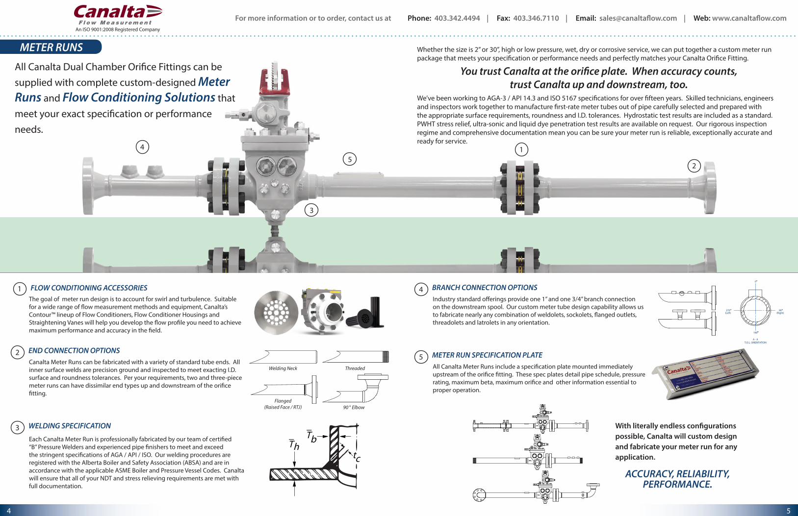
1 FLOW CONDITIONING ACCESSORIES
14
25
3
METER RUNS
All Canalta Dual Chamber Orifice Fittings can be supplied with complete custom-designed Meter Runs and Flow Conditioning Solutions that meet your exact specification or performance needs.
3 WELDING SPECIFICATIONT
Thb
tc
__
2 END CONNECTION OPTIONSCanalta Meter Runs can be fabricated with a variety of standard tube ends. All inner surface welds are precision ground and inspected to meet exacting I.D. surface and roundness tolerances. Per your requirements, two and three-piece meter runs can have dissimilar end types up and downstream of the orifice fitting.
Welding Neck
Flanged(Raised Face / RTJ)
Threaded
90 ° Elbow
4 BRANCH CONNECTION OPTIONSIndustry standard offerings provide one 1” and one 3/4” branch connection on the downstream spool. Our custom meter tube design capability allows us to fabricate nearly any combination of weldolets, sockolets, flanged outlets, threadolets and latrolets in any orientation.
0
(Right)
180
90
A - AT.O.L. ORIENTATION
270(Left)
With literally endless configurations possible, Canalta will custom design and fabricate your meter run for any application.
ACCURACY, RELIABILITY, PERFORMANCE.
5 METER RUN SPECIFICATION PLATEAll Canalta Meter Runs include a specification plate mounted immediately upstream of the orifice fitting. These spec plates detail pipe schedule, pressure rating, maximum beta, maximum orifice and other information essential to proper operation.
Whether the size is 2” or 30”, high or low pressure, wet, dry or corrosive service, we can put together a custom meter run package that meets your specification or performance needs and perfectly matches your Canalta Orifice Fitting.
You trust Canalta at the orifice plate. When accuracy counts, trust Canalta up and downstream, too.
We’ve been working to AGA-3 / API 14.3 and ISO 5167 specifications for over fifteen years. Skilled technicians, engineers and inspectors work together to manufacture first-rate meter tubes out of pipe carefully selected and prepared with the appropriate surface requirements, roundness and I.D. tolerances. Hydrostatic test results are included as a standard. PWHT stress relief, ultra-sonic and liquid dye penetration test results are available on request. Our rigorous inspection regime and comprehensive documentation mean you can be sure your meter run is reliable, exceptionally accurate and ready for service.
Each Canalta Meter Run is professionally fabricated by our team of certified “B” Pressure Welders and experienced pipe finishers to meet and exceed the stringent specifications of AGA / API / ISO. Our welding procedures are registered with the Alberta Boiler and Safety Association (ABSA) and are in accordance with the applicable ASME Boiler and Pressure Vessel Codes. Canalta will ensure that all of your NDT and stress relieving requirements are met with full documentation.
The goal of meter run design is to account for swirl and turbulence. Suitable for a wide range of flow measurement methods and equipment, Canalta’s Contour™ lineup of Flow Conditioners, Flow Conditioner Housings and Straightening Vanes will help you develop the flow profile you need to achieve maximum performance and accuracy in the field.
For more information or to order, contact us at Phone: 403.342.4494 | Fax: 403.346.7110 | Email: [email protected] | Web: www.canaltaflow.com
5 4
An ISO 9001:2008 Registered Company
PARTS & REPAIR KITS
REPLACEMENT PARTS
COMPATIBLE WITH OTHER
INDUSTRY LEADING BRANDS
CONTACT US TODAY
FOR DETAILS
Canalta supplies OEM Parts and Accessories for all of our Dual Chamber Orifice Fitting models. These are high quality carbon and stainless steel internals that offer superior corrosion protection and resistance to sulfide or hydrogen induced cracking, providing reliability and performance over a long service life.
All materials meet the applicable ASTM requirements and are traceable to the original foundry. Wherever possible, Canalta has endeavoured to ensure that our parts and accessories are interchangeable with the current industry standard orifice fitting brand, making Canalta Orifice Fitting Parts and Accessories suitable for re-builds and re-works of our competitors' product lines.
Close attention to detail and tight quality control auditing ensure that Canalta parts are reliable and ready for service in the field.
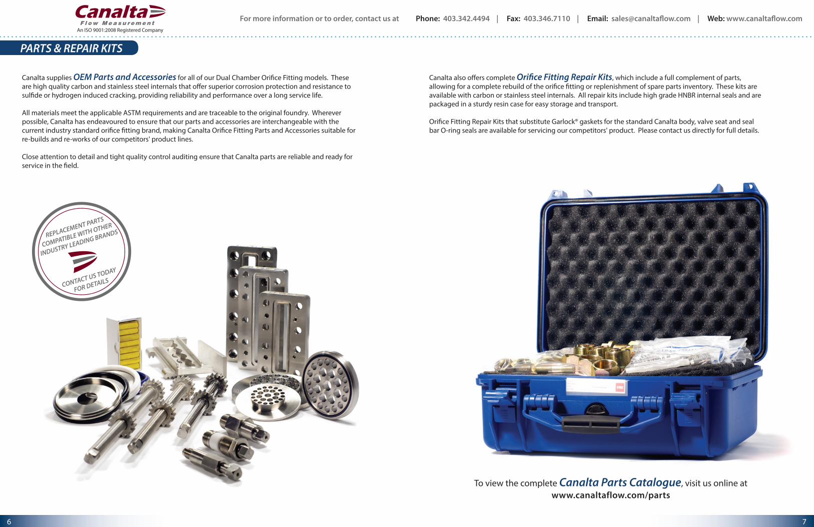
Canalta also offers complete Orifice Fitting Repair Kits, which include a full complement of parts, allowing for a complete rebuild of the orifice fitting or replenishment of spare parts inventory. These kits are available with carbon or stainless steel internals. All repair kits include high grade HNBR internal seals and are packaged in a sturdy resin case for easy storage and transport.
Orifice Fitting Repair Kits that substitute Garlock® gaskets for the standard Canalta body, valve seat and seal bar O-ring seals are available for servicing our competitors' product. Please contact us directly for full details.
To view the complete Canalta Parts Catalogue, visit us online atwww.canaltaflow.com/parts
For more information or to order, contact us at Phone: 403.342.4494 | Fax: 403.346.7110 | Email: [email protected] | Web: www.canaltaflow.com
7 6
An ISO 9001:2008 Registered Company
FLOW CONDITIONING ACCESSORIES
by
Canalta's Contour™ FCH Flow Conditioner Housing brings the ease, safety and practicality of inspecting and changing an orifice plate to the flow conditioner. This long overdue concept allows for regular inspections of the flow conditioner without breaking apart the flow line. The Contour™ FCH allows the operator to easily perform flow conditioner inspection and maintenance on the same regular schedule as the orifice plate. With this innovative, patented design, you can be sure that your flow profile has not been degraded by damage, blockage or residue accumulation.
All bore surfaces and internal dimensions within the housing are manufactured to strictly comply with the latest editions of AGA-3 and ISO-5167. The Contour™ FCH is effective for custody transfer applications or any measurement scenario where flow profile and measurement accuracy are critical.
Canalta's Contour™ FCH utilizes the new Contour™ K5+ and Z+ Flow Conditioners. These isolating flow conditioners incorporate a non-protruding HNBR seal around the downstream face to prevent bypass leakage and protect the integrity of your flow profile.
CONTACT US TODAY TO FIND OUT MORE
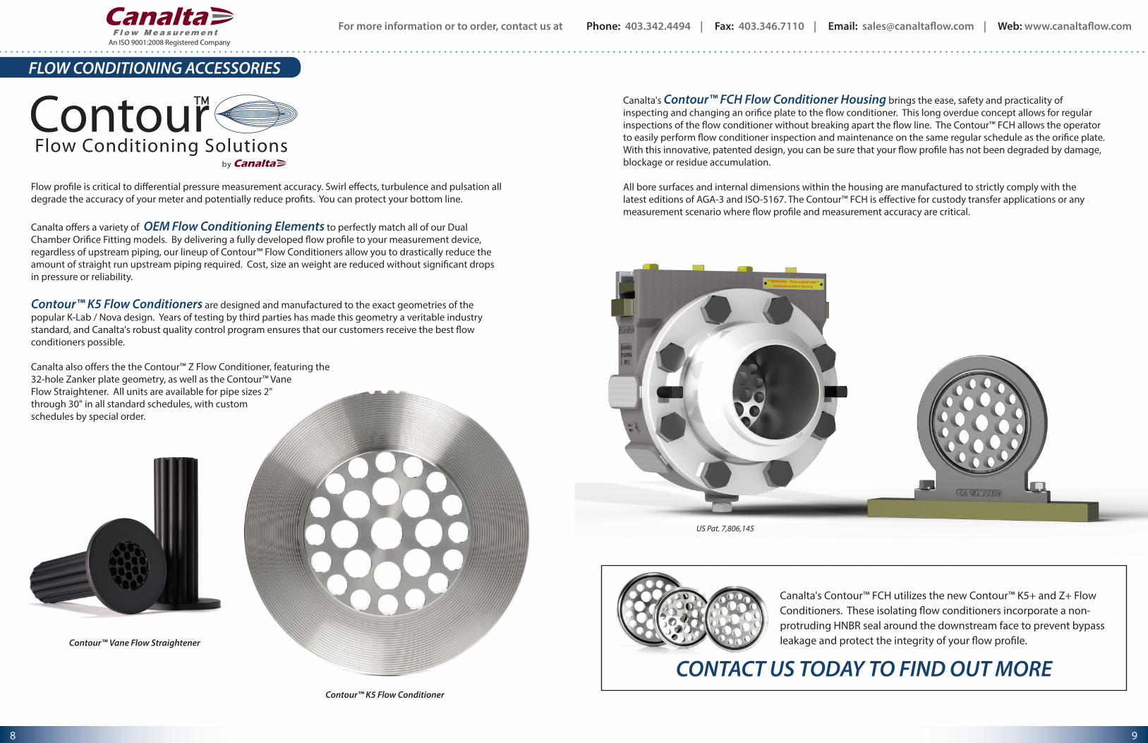
Flow profile is critical to differential pressure measurement accuracy. Swirl effects, turbulence and pulsation all degrade the accuracy of your meter and potentially reduce profits. You can protect your bottom line.
Canalta offers a variety of OEM Flow Conditioning Elements to perfectly match all of our Dual Chamber Orifice Fitting models. By delivering a fully developed flow profile to your measurement device, regardless of upstream piping, our lineup of Contour™ Flow Conditioners allow you to drastically reduce the amount of straight run upstream piping required. Cost, size an weight are reduced without significant drops in pressure or reliability.
Contour™ K5 Flow Conditioners are designed and manufactured to the exact geometries of the popular K-Lab / Nova design. Years of testing by third parties has made this geometry a veritable industry standard, and Canalta's robust quality control program ensures that our customers receive the best flow conditioners possible.
Canalta also offers the the Contour™ Z Flow Conditioner, featuring the 32-hole Zanker plate geometry, as well as the Contour™ Vane Flow Straightener. All units are available for pipe sizes 2" through 30" in all standard schedules, with custom schedules by special order.
Contour™ K5 Flow Conditioner
Contour™ Vane Flow Straightener
US Pat. 7,806,145
For more information or to order, contact us at Phone: 403.342.4494 | Fax: 403.346.7110 | Email: [email protected] | Web: www.canaltaflow.com
9 8
An ISO 9001:2008 Registered Company
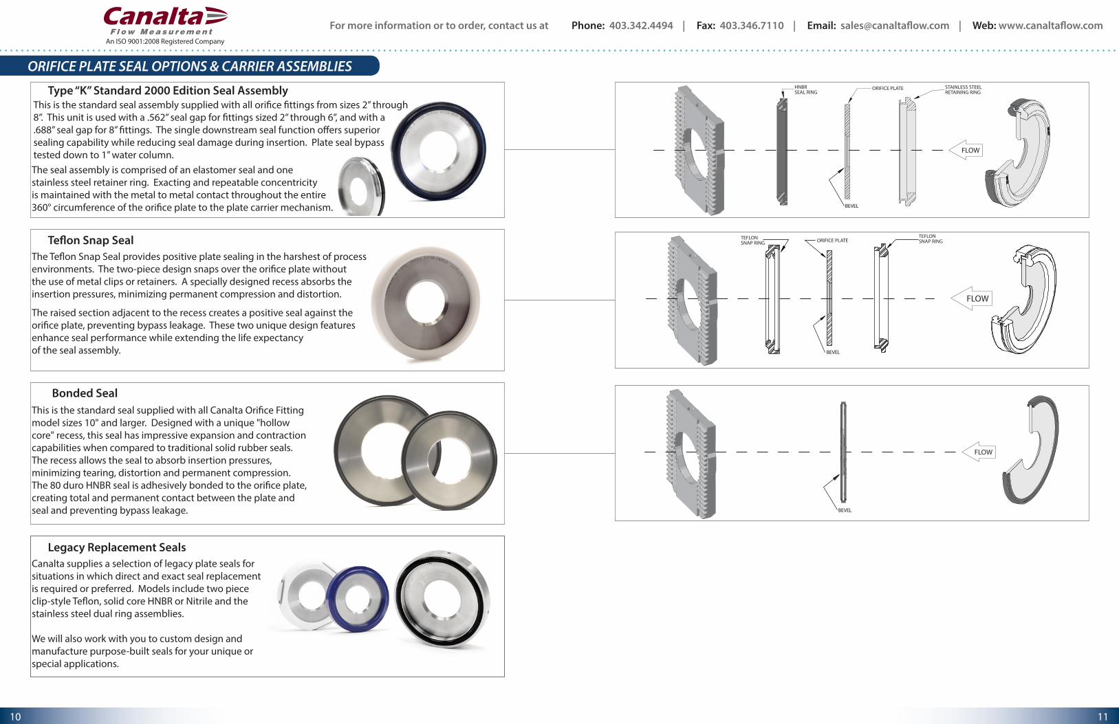
Type “K” Standard 2000 Edition Seal AssemblyThis is the standard seal assembly supplied with all orifice fittings from sizes 2” through 8”. This unit is used with a .562” seal gap for fittings sized 2” through 6”, and with a .688” seal gap for 8” fittings. The single downstream seal function offers superior sealing capability while reducing seal damage during insertion. Plate seal bypass tested down to 1” water column.The seal assembly is comprised of an elastomer seal and one stainless steel retainer ring. Exacting and repeatable concentricity is maintained with the metal to metal contact throughout the entire 360° circumference of the orifice plate to the plate carrier mechanism.
Teflon Snap SealThe Teflon Snap Seal provides positive plate sealing in the harshest of process environments. The two-piece design snaps over the orifice plate without the use of metal clips or retainers. A specially designed recess absorbs the insertion pressures, minimizing permanent compression and distortion.
The raised section adjacent to the recess creates a positive seal against the orifice plate, preventing bypass leakage. These two unique design features enhance seal performance while extending the life expectancy of the seal assembly.
HNBR SEAL RING
ORIFICE PLATE STAINLESS STEELRETAINING RING
FLOW
BEVEL
TEFLON SNAP RING
TEFLON SNAP RINGORIFICE PLATE
FLOW
BEVEL
FLOW
BEVEL
ORIFICE PLATE SEAL OPTIONS & CARRIER ASSEMBLIES
Bonded SealThis is the standard seal supplied with all Canalta Orifice Fitting model sizes 10" and larger. Designed with a unique "hollow core" recess, this seal has impressive expansion and contraction capabilities when compared to traditional solid rubber seals. The recess allows the seal to absorb insertion pressures, minimizing tearing, distortion and permanent compression. The 80 duro HNBR seal is adhesively bonded to the orifice plate, creating total and permanent contact between the plate and seal and preventing bypass leakage.
Legacy Replacement SealsCanalta supplies a selection of legacy plate seals for situations in which direct and exact seal replacement is required or preferred. Models include two piece clip-style Teflon, solid core HNBR or Nitrile and the stainless steel dual ring assemblies.
We will also work with you to custom design and manufacture purpose-built seals for your unique or special applications.
For more information or to order, contact us at Phone: 403.342.4494 | Fax: 403.346.7110 | Email: [email protected] | Web: www.canaltaflow.com
11 10
An ISO 9001:2008 Registered Company
All fittings come standard with a documentation package including hydro-test, function test, inner valve seal test, quality control inspection and material test reports. Trace ability is maintained in accordance with the ISO-9001 Quality Control Program. All fittings are manufactured within the guidelines of ASME 16.34 and ASME 16.5. When required, radiography, stress relief, ultra-sonic and liquid dye penetration tests can be per-formed with the relevant report submitted.
An AGA 2000 inspection report is included with the purchase of every fitting. The documented tests include: • I.D. Bore Tolerance • Instrument Tap Diameter • Instrument Tap Location • Tap Communication • Plate Seal Test • Seal Protrusion • Orifice Eccentricity • Bore Inside Diameter • Bore Roughness
Conformance
Reporting
Design . . . . . . . . . . . . . . . . . . . . . . .
Body Materials . . . . . . . . . . . . . . .
Internal Parts . . . . . . . . . . . . . . . . .
Sizes and ANSI Class . . . . . . . . . .
U/S D/S Connections . . . . . . . . . .
Internal Bore Sizes . . . . . . . . . . . .
Sealing Compounds . . . . . . . . . .
Line Bore I.D. Tolerance . . . . . . .
Eccentricity Repeatability . . . . .
Tap Connections . . . . . . . . . . . . .
Orifice Plate Seal Gap . . . . . . . . .
Operating Shaft Location . . . . .
Operating Temperature . . . . . . .
Operating Position . . . . . . . . . . .
Orifice fittings supplied in Canada are built in accordance with the ABSA Quality Control Program and carry a CRN registration number.Industry Canada Approval Number AF-0014.In compliance with ASME 16.34 and ASME 16.5, ASTM specifications, AGA-3 Latest Edition and ISO-5167.
A216 WCB, A216 WCC, A352 LCC, A358 CF8M, A995 Gr4A, A995 Gr6A, Custom
AISI 4130 Carbon Steel, 316 or A351 CF8M Stainless Steel
2” through 12" 150 through 2500 ANSI raised face flange 14" through 16”, 150 through 1500 ANSI raised face flange18” through 30”, 150 through 600 ANSI raised face flange600, 900, 1500 and 2500 flanges also available in RTJ face flange
Flangeneck design (weldneck U/S, flange D/S)Flange x flangeWeldneck both ends
40, 60, 80, 100, 120, 160 and custom sizes
Seal bar - HNBR O-ring standard, gasket optionalShafts - Teflon packing standard, HNBR O-ring optionalInner valve - Grease seal standard, HNBR O-ring optionalOrifice plate - Type “K” 2000 Edition formed HNBR seal on a 316 SS retainer ring Dual Ring HNBR O-rings standard on a 316 SS retainer ring assembly Teflon Snap Seal two-piece virgin Teflon assembly
In conformance with AGA-3 and ISO-5167 Latest Editions
In conformance with AGA-3 and ISO-5167 Latest Editions
Two 1/2” NPT per side standard, two 1/2” NPT additional per side optional (TT) 2” and 3” fitting sizes center bored to .375” inside diameter4” and larger sizes center bored to .500” inside diameterTolerance +/- 1/64”
2” through 6” = 0.562”, 8” through 14” = 0.688”, 16” through 20” = 0.813”, 24” through 30” = 0.875”
Left hand mount standard on sizes 2” through 14”Dual operation on sizes 16” and larger
Standard at -20° to 100° F, optional -40° to 1200° F
Vertical or horizontal
TECHNICAL SPECIFICATIONS
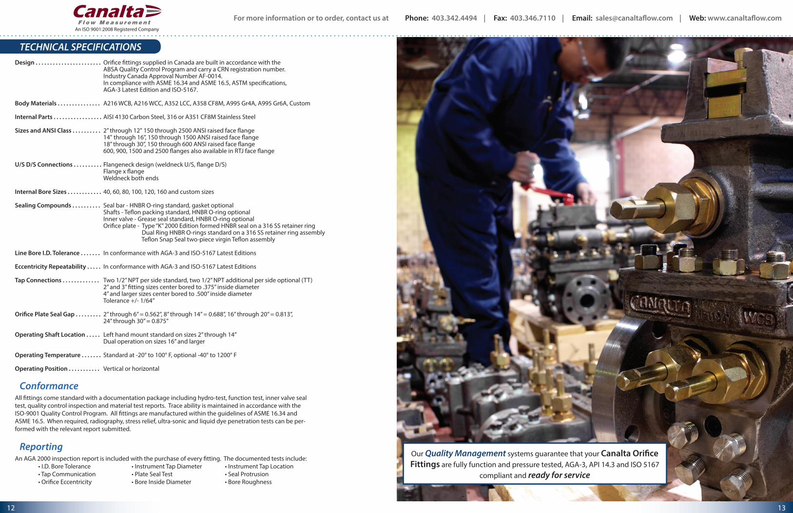
Our Quality Management systems guarantee that your Canalta Orifice Fittings are fully function and pressure tested, AGA-3, API 14.3 and ISO 5167
compliant and ready for service
For more information or to order, contact us at Phone: 403.342.4494 | Fax: 403.346.7110 | Email: [email protected] | Web: www.canaltaflow.com
13 12
An ISO 9001:2008 Registered Company
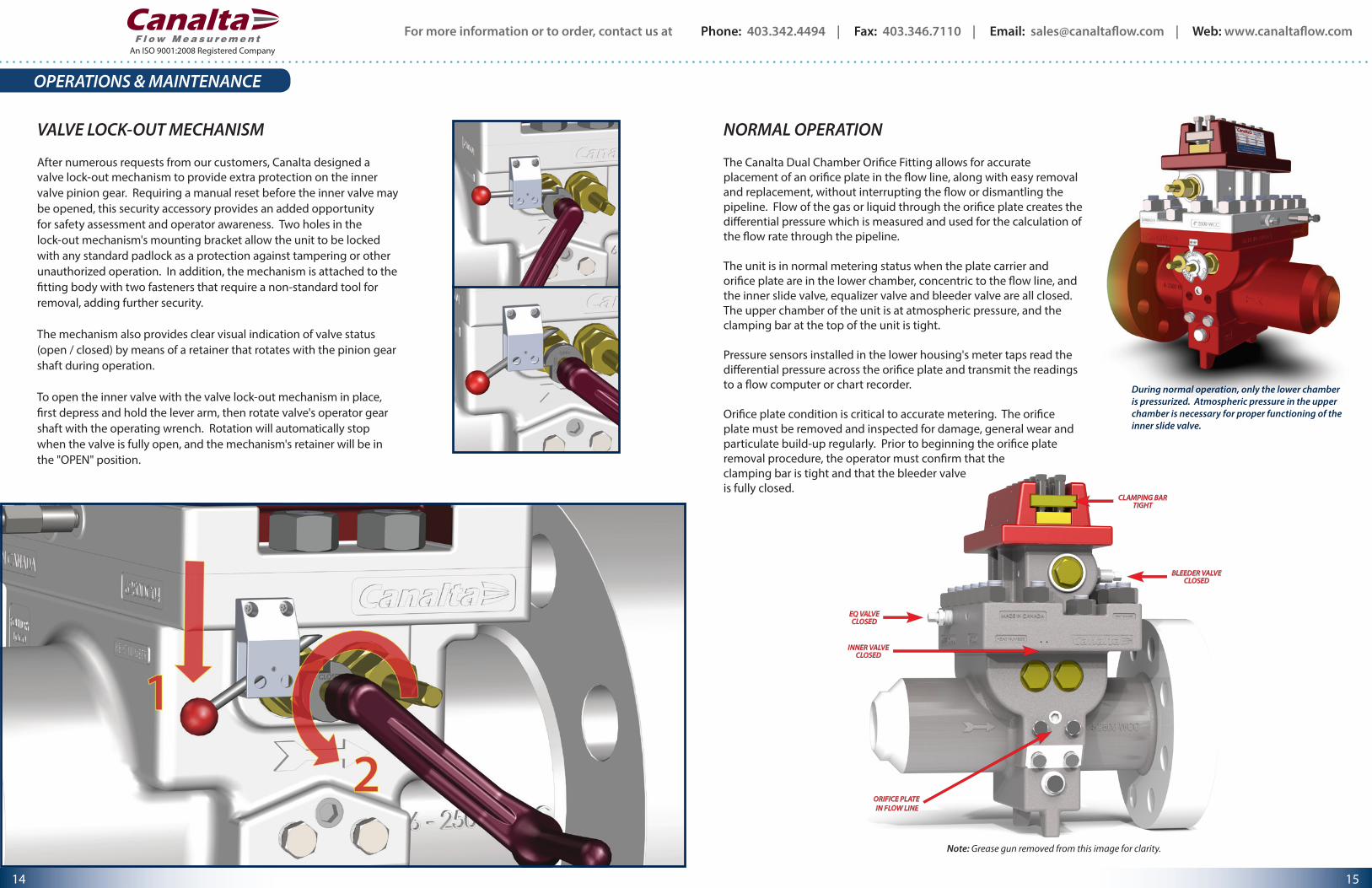
VALVE LOCK-OUT MECHANISM
After numerous requests from our customers, Canalta designed a valve lock-out mechanism to provide extra protection on the inner valve pinion gear. Requiring a manual reset before the inner valve may be opened, this security accessory provides an added opportunity for safety assessment and operator awareness. Two holes in the lock-out mechanism's mounting bracket allow the unit to be locked with any standard padlock as a protection against tampering or other unauthorized operation. In addition, the mechanism is attached to the fitting body with two fasteners that require a non-standard tool for removal, adding further security.
The mechanism also provides clear visual indication of valve status (open / closed) by means of a retainer that rotates with the pinion gear shaft during operation.
To open the inner valve with the valve lock-out mechanism in place, first depress and hold the lever arm, then rotate valve's operator gear shaft with the operating wrench. Rotation will automatically stop when the valve is fully open, and the mechanism's retainer will be in the "OPEN" position.
OPERATIONS & MAINTENANCE
15
EQ VALVECLOSED
INNER VALVECLOSED
ORIFICE PLATE IN FLOW LINE
BLEEDER VALVECLOSED
CLAMPING BARTIGHT
During normal operation, only the lower chamber is pressurized. Atmospheric pressure in the upper chamber is necessary for proper functioning of the inner slide valve.
NORMAL OPERATION
The Canalta Dual Chamber Orifice Fitting allows for accurate placement of an orifice plate in the flow line, along with easy removal and replacement, without interrupting the flow or dismantling the pipeline. Flow of the gas or liquid through the orifice plate creates the differential pressure which is measured and used for the calculation of the flow rate through the pipeline.
The unit is in normal metering status when the plate carrier and orifice plate are in the lower chamber, concentric to the flow line, and the inner slide valve, equalizer valve and bleeder valve are all closed. The upper chamber of the unit is at atmospheric pressure, and the clamping bar at the top of the unit is tight.
Pressure sensors installed in the lower housing's meter taps read the differential pressure across the orifice plate and transmit the readings to a flow computer or chart recorder.
Orifice plate condition is critical to accurate metering. The orifice plate must be removed and inspected for damage, general wear and particulate build-up regularly. Prior to beginning the orifice plate removal procedure, the operator must confirm that the clamping bar is tight and that the bleeder valve is fully closed.
Note: Grease gun removed from this image for clarity.
For more information or to order, contact us at Phone: 403.342.4494 | Fax: 403.346.7110 | Email: [email protected] | Web: www.canaltaflow.com
15 14
An ISO 9001:2008 Registered Company
An ISO 9001:2008 Registered Company
OPERATIONS & MAINTENANCE
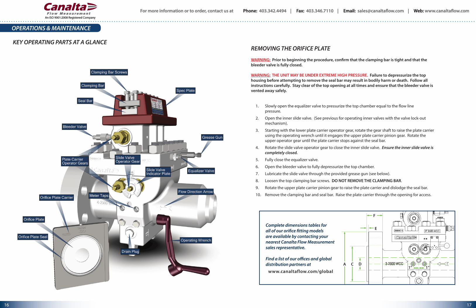
KEY OPERATING PARTS AT A GLANCEREMOVING THE ORIFICE PLATE
WARNING: Prior to beginning the procedure, confirm that the clamping bar is tight and that the bleeder valve is fully closed.
WARNING: THE UNIT MAY BE UNDER EXTREME HIGH PRESSURE. Failure to depressurize the top housing before attempting to remove the seal bar may result in bodily harm or death. Follow all instructions carefully. Stay clear of the top opening at all times and ensure that the bleeder valve is vented away safely.
1. Slowly open the equalizer valve to pressurize the top chamber equal to the flow line pressure.
2. Open the inner slide valve. (See previous for operating inner valves with the valve lock-out mechanism).
3. Starting with the lower plate carrier operator gear, rotate the gear shaft to raise the plate carrier using the operating wrench until it engages the upper plate carrier pinion gear. Rotate the upper operator gear until the plate carrier stops against the seal bar.
4. Rotate the slide valve operator gear to close the inner slide valve. Ensure the inner slide valve is completely closed.
5. Fully close the equalizer valve.
6. Open the bleeder valve to fully depressurize the top chamber.
7. Lubricate the slide valve through the provided grease gun (see below).
8. Loosen the top clamping bar screws. DO NOT REMOVE THE CLAMPING BAR.
9. Rotate the upper plate carrier pinion gear to raise the plate carrier and dislodge the seal bar.
10. Remove the clamping bar and seal bar. Raise the plate carrier through the opening for access.
D
E
F
CA1” 1”
Complete dimensions tables for all of our orifice fitting models are available by contacting your nearest Canalta Flow Measurement sales representative.
Find a list of our offices and global distribution partners at
www.canaltaflow.com/global
For more information or to order, contact us at Phone: 403.342.4494 | Fax: 403.346.7110 | Email: [email protected] | Web: www.canaltaflow.com
17 16
An ISO 9001:2008 Registered Company
For more information or to order, contact us at Phone: 403.342.4494 | Fax: 403.346.7110 | Email: [email protected] | Web: www.canaltaflow.com
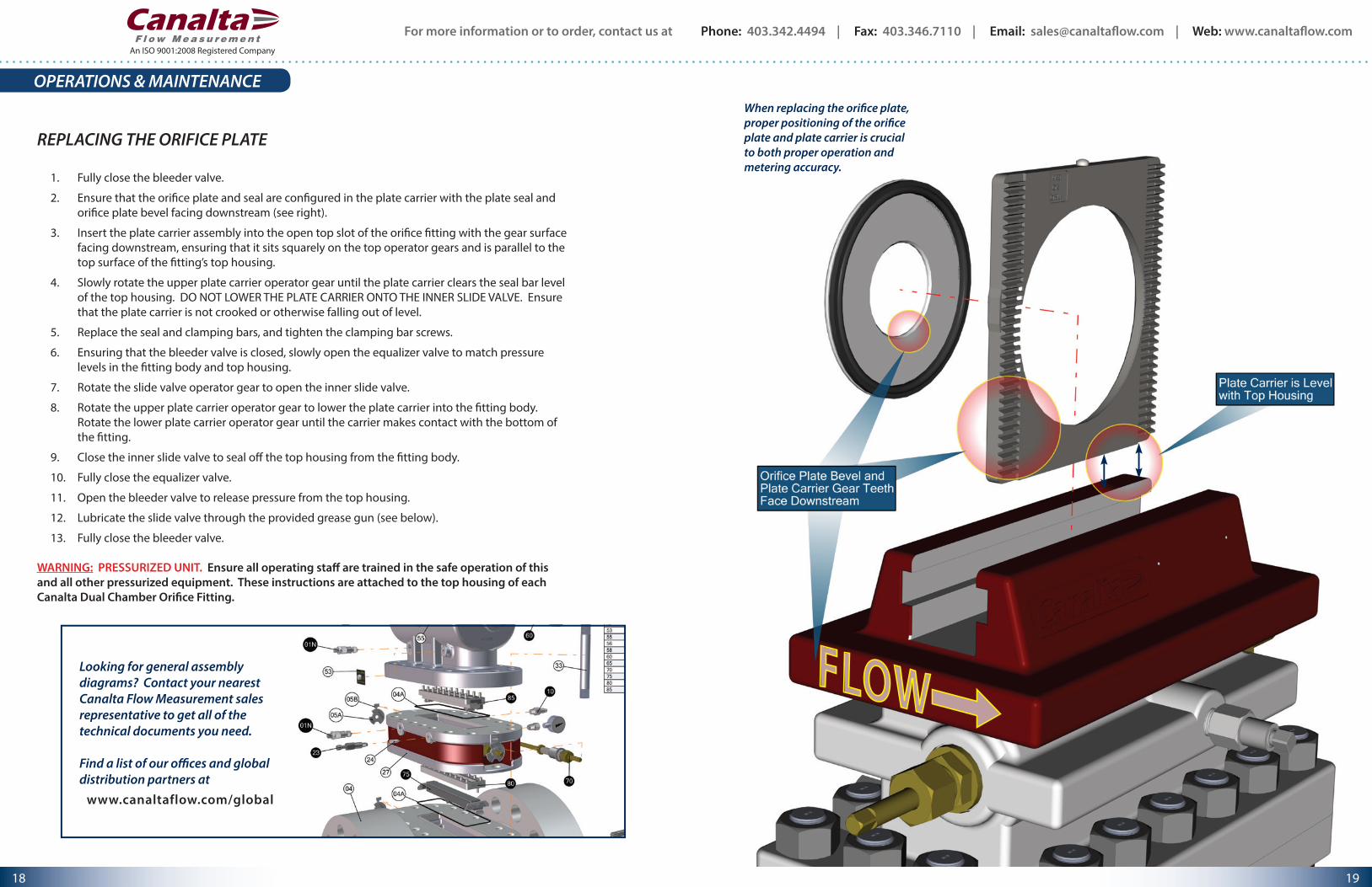
REPLACING THE ORIFICE PLATE
1. Fully close the bleeder valve.
2. Ensure that the orifice plate and seal are configured in the plate carrier with the plate seal and orifice plate bevel facing downstream (see right).
3. Insert the plate carrier assembly into the open top slot of the orifice fitting with the gear surface facing downstream, ensuring that it sits squarely on the top operator gears and is parallel to the top surface of the fitting’s top housing.
4. Slowly rotate the upper plate carrier operator gear until the plate carrier clears the seal bar level of the top housing. DO NOT LOWER THE PLATE CARRIER ONTO THE INNER SLIDE VALVE. Ensure that the plate carrier is not crooked or otherwise falling out of level.
5. Replace the seal and clamping bars, and tighten the clamping bar screws.
6. Ensuring that the bleeder valve is closed, slowly open the equalizer valve to match pressure levels in the fitting body and top housing.
7. Rotate the slide valve operator gear to open the inner slide valve.
8. Rotate the upper plate carrier operator gear to lower the plate carrier into the fitting body. Rotate the lower plate carrier operator gear until the carrier makes contact with the bottom of the fitting.
9. Close the inner slide valve to seal off the top housing from the fitting body.
10. Fully close the equalizer valve.
11. Open the bleeder valve to release pressure from the top housing.
12. Lubricate the slide valve through the provided grease gun (see below).
13. Fully close the bleeder valve.
WARNING: PRESSURIZED UNIT. Ensure all operating staff are trained in the safe operation of this and all other pressurized equipment. These instructions are attached to the top housing of each Canalta Dual Chamber Orifice Fitting.
When replacing the orifice plate, proper positioning of the orifice plate and plate carrier is crucial to both proper operation and metering accuracy.
OPERATIONS & MAINTENANCE
Looking for general assembly diagrams? Contact your nearest Canalta Flow Measurement sales representative to get all of the technical documents you need.
Find a list of our offices and global distribution partners at
www.canaltaflow.com/global
For more information or to order, contact us at Phone: 403.342.4494 | Fax: 403.346.7110 | Email: [email protected] | Web: www.canaltaflow.com
19 18
An ISO 9001:2008 Registered Company
SLIDE VALVE LUBRICATION MAINTENANCE & STORAGE REQUIREMENTS
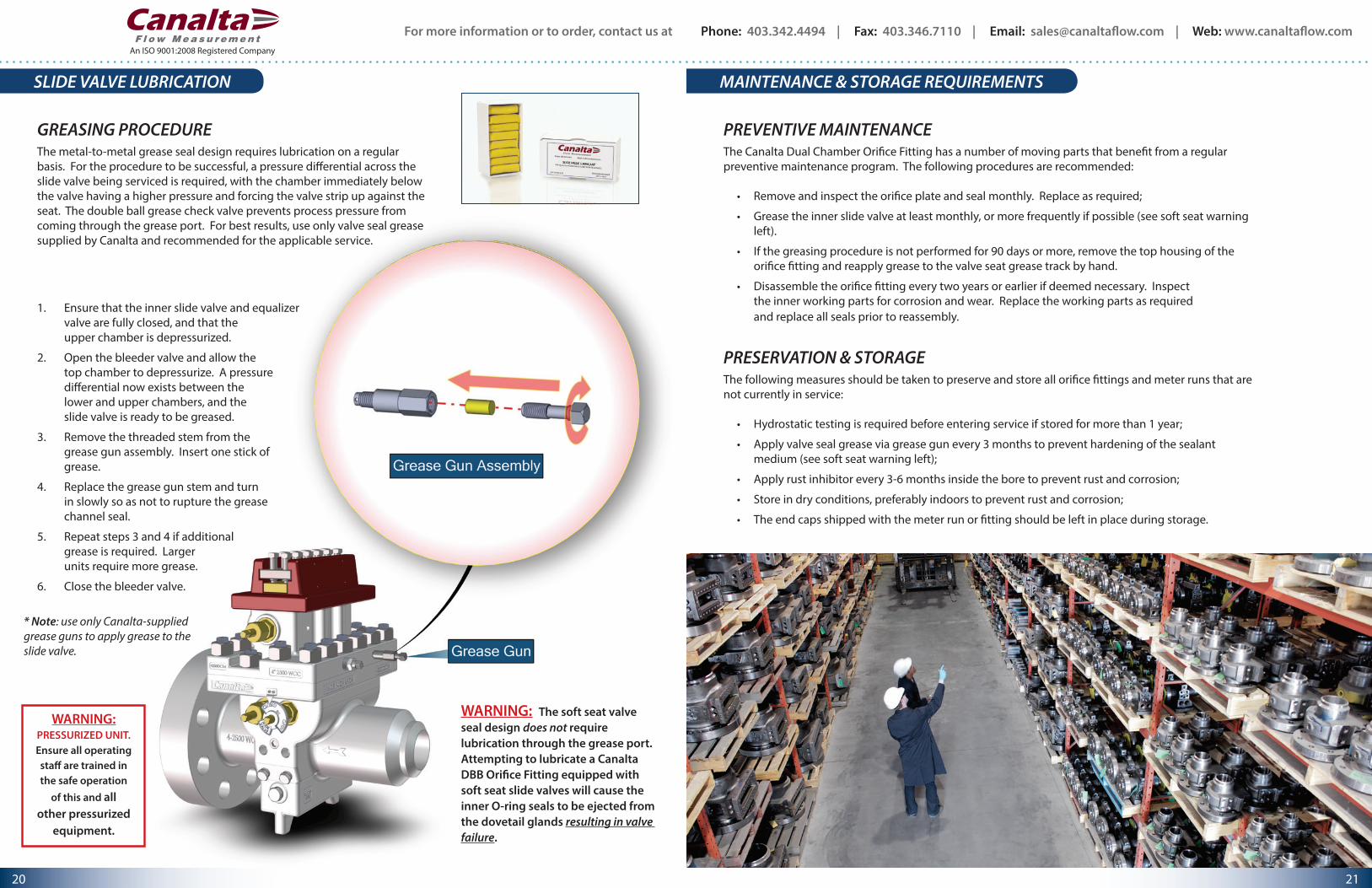
1. Ensure that the inner slide valve and equalizer valve are fully closed, and that the upper chamber is depressurized.
2. Open the bleeder valve and allow the top chamber to depressurize. A pressure differential now exists between the lower and upper chambers, and the slide valve is ready to be greased.
3. Remove the threaded stem from the grease gun assembly. Insert one stick of grease.
4. Replace the grease gun stem and turn in slowly so as not to rupture the grease channel seal.
5. Repeat steps 3 and 4 if additional grease is required. Larger units require more grease.
6. Close the bleeder valve.
* Note: use only Canalta-supplied grease guns to apply grease to the slide valve.
WARNING: The soft seat valve seal design does not require lubrication through the grease port. Attempting to lubricate a Canalta DBB Orifice Fitting equipped with soft seat slide valves will cause the inner O-ring seals to be ejected from the dovetail glands resulting in valve failure.
GREASING PROCEDUREThe metal-to-metal grease seal design requires lubrication on a regular basis. For the procedure to be successful, a pressure differential across the slide valve being serviced is required, with the chamber immediately below the valve having a higher pressure and forcing the valve strip up against the seat. The double ball grease check valve prevents process pressure from coming through the grease port. For best results, use only valve seal grease supplied by Canalta and recommended for the applicable service.
WARNING: PRESSURIZED UNIT.Ensure all operating staff are trained in the safe operation
of this and all other pressurized
equipment.
PREVENTIVE MAINTENANCEThe Canalta Dual Chamber Orifice Fitting has a number of moving parts that benefit from a regular preventive maintenance program. The following procedures are recommended:
• Remove and inspect the orifice plate and seal monthly. Replace as required;
• Grease the inner slide valve at least monthly, or more frequently if possible (see soft seat warning left).
• If the greasing procedure is not performed for 90 days or more, remove the top housing of the orifice fitting and reapply grease to the valve seat grease track by hand.
• Disassemble the orifice fitting every two years or earlier if deemed necessary. Inspect the inner working parts for corrosion and wear. Replace the working parts as required and replace all seals prior to reassembly.
PRESERVATION & STORAGEThe following measures should be taken to preserve and store all orifice fittings and meter runs that are not currently in service:
• Hydrostatic testing is required before entering service if stored for more than 1 year;
• Apply valve seal grease via grease gun every 3 months to prevent hardening of the sealant medium (see soft seat warning left);
• Apply rust inhibitor every 3-6 months inside the bore to prevent rust and corrosion;
• Store in dry conditions, preferably indoors to prevent rust and corrosion;
• The end caps shipped with the meter run or fitting should be left in place during storage.
For more information or to order, contact us at Phone: 403.342.4494 | Fax: 403.346.7110 | Email: [email protected] | Web: www.canaltaflow.com
21 20
An ISO 9001:2008 Registered Company
INSTALLATION RECOMMENDATIONS MODEL NUMBERING SYSTEM
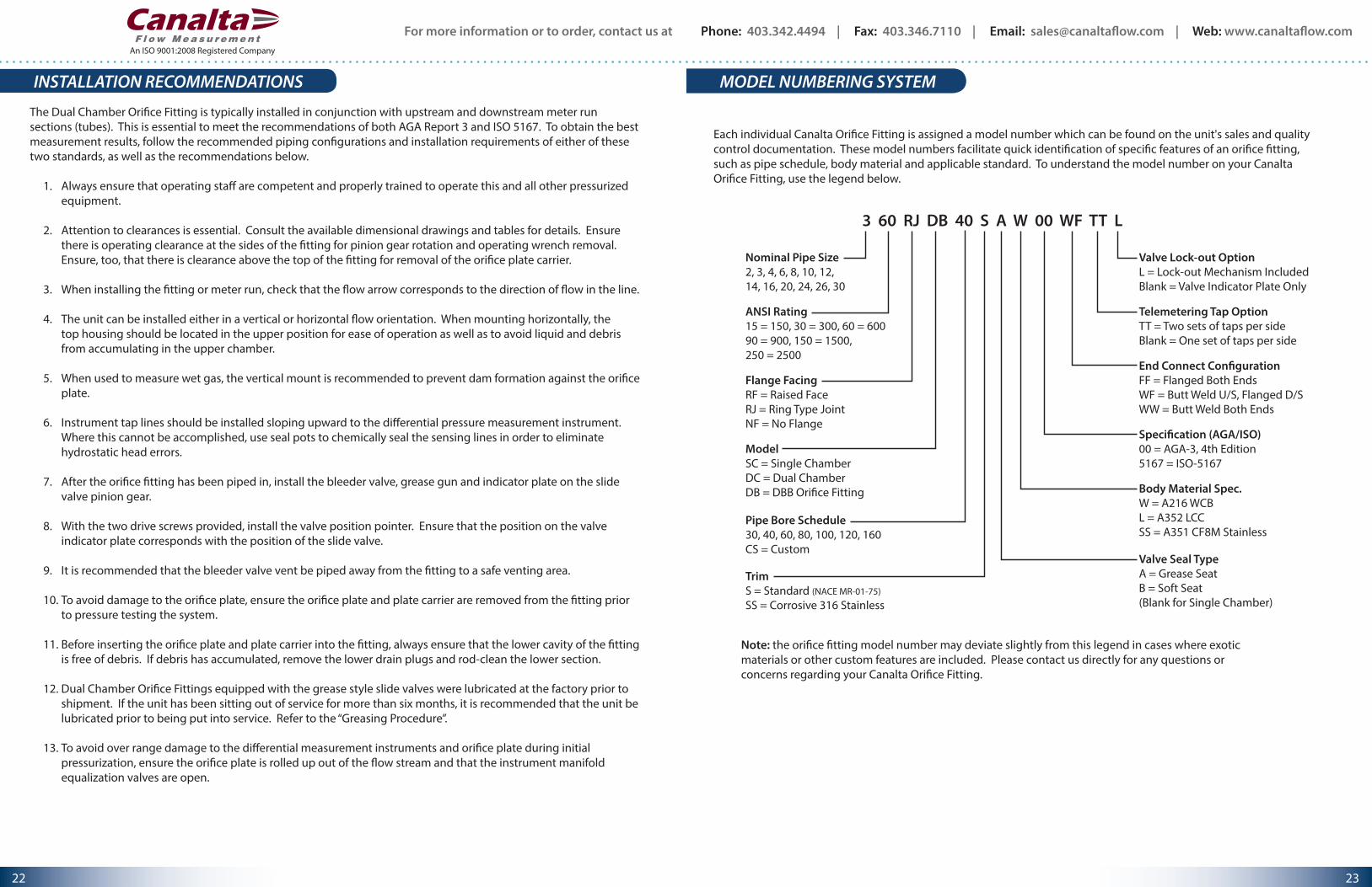
3 60 RJ DB 40 S A W 00 WF TT L
Nominal Pipe Size2, 3, 4, 6, 8, 10, 12,14, 16, 20, 24, 26, 30
ANSI Rating15 = 150, 30 = 300, 60 = 60090 = 900, 150 = 1500, 250 = 2500
Flange FacingRF = Raised FaceRJ = Ring Type JointNF = No Flange
ModelSC = Single ChamberDC = Dual ChamberDB = DBB Ori�ce Fitting
Pipe Bore Schedule30, 40, 60, 80, 100, 120, 160CS = Custom
Valve Lock-out OptionL = Lock-out Mechanism IncludedBlank = Valve Indicator Plate Only
End Connect Con�gurationFF = Flanged Both EndsWF = Butt Weld U/S, Flanged D/SWW = Butt Weld Both Ends
Speci�cation (AGA/ISO)00 = AGA-3, 4th Edition5167 = ISO-5167
Body Material Spec.W = A216 WCBL = A352 LCCSS = A351 CF8M Stainless
TrimS = Standard (NACE MR-01-75)SS = Corrosive 316 Stainless
Valve Seal TypeA = Grease SeatB = Soft Seat(Blank for Single Chamber)
Telemetering Tap OptionTT = Two sets of taps per sideBlank = One set of taps per side
Each individual Canalta Orifice Fitting is assigned a model number which can be found on the unit's sales and quality control documentation. These model numbers facilitate quick identification of specific features of an orifice fitting, such as pipe schedule, body material and applicable standard. To understand the model number on your Canalta Orifice Fitting, use the legend below.
The Dual Chamber Orifice Fitting is typically installed in conjunction with upstream and downstream meter run sections (tubes). This is essential to meet the recommendations of both AGA Report 3 and ISO 5167. To obtain the best measurement results, follow the recommended piping configurations and installation requirements of either of these two standards, as well as the recommendations below.
1. Always ensure that operating staff are competent and properly trained to operate this and all other pressurized equipment.
2. Attention to clearances is essential. Consult the available dimensional drawings and tables for details. Ensure there is operating clearance at the sides of the fitting for pinion gear rotation and operating wrench removal. Ensure, too, that there is clearance above the top of the fitting for removal of the orifice plate carrier.
3. When installing the fitting or meter run, check that the flow arrow corresponds to the direction of flow in the line.
4. The unit can be installed either in a vertical or horizontal flow orientation. When mounting horizontally, the top housing should be located in the upper position for ease of operation as well as to avoid liquid and debris from accumulating in the upper chamber.
5. When used to measure wet gas, the vertical mount is recommended to prevent dam formation against the orifice plate.
6. Instrument tap lines should be installed sloping upward to the differential pressure measurement instrument. Where this cannot be accomplished, use seal pots to chemically seal the sensing lines in order to eliminate hydrostatic head errors.
7. After the orifice fitting has been piped in, install the bleeder valve, grease gun and indicator plate on the slide valve pinion gear.
8. With the two drive screws provided, install the valve position pointer. Ensure that the position on the valve indicator plate corresponds with the position of the slide valve.
9. It is recommended that the bleeder valve vent be piped away from the fitting to a safe venting area.
10. To avoid damage to the orifice plate, ensure the orifice plate and plate carrier are removed from the fitting prior to pressure testing the system.
11. Before inserting the orifice plate and plate carrier into the fitting, always ensure that the lower cavity of the fitting is free of debris. If debris has accumulated, remove the lower drain plugs and rod-clean the lower section.
12. Dual Chamber Orifice Fittings equipped with the grease style slide valves were lubricated at the factory prior to shipment. If the unit has been sitting out of service for more than six months, it is recommended that the unit be lubricated prior to being put into service. Refer to the “Greasing Procedure”.
13. To avoid over range damage to the differential measurement instruments and orifice plate during initial pressurization, ensure the orifice plate is rolled up out of the flow stream and that the instrument manifold equalization valves are open.
Note: the orifice fitting model number may deviate slightly from this legend in cases where exotic materials or other custom features are included. Please contact us directly for any questions or concerns regarding your Canalta Orifice Fitting.
For more information or to order, contact us at Phone: 403.342.4494 | Fax: 403.346.7110 | Email: [email protected] | Web: www.canaltaflow.com
23 22
An ISO 9001:2008 Registered Company
CONTACT INFORMATION
Phone: 403.342.4494Fax: 403.346.7110
Email: [email protected] Web: www.canaltaflow.com
6759 65th AvenueRed Deer, AB T4P 1X5
CANADAFind a list of our global distribution partners at www.canaltaflow.com/global
The "Canalta Flow Measurement" and "Contour" names and logos are trademarks of Canalta Controls Ltd. All other trademarks are the property of their respective companies.
All information presented here is for information purposes only. Though every effort has been made to ensure their accuracy, the contents of this publication shall not be construed as warranties or guarantees, expressed or implied, regarding the products or services described herein, or their use or applicability. Due to Canalta’s commitment to quality and innovation, all product designs, specifications and information material, including the contents of this publication, are subject to change without notice. Responsibility for the proper selection, maintenance and use of any product remains with the customer. SAFETY FIRST.
Copyright, trademark and other forms of proprietary rights protect the contents of this publication.
© 2011-2013 Canalta Controls Ltd. All rights reserved. Unauthorized reproduction in whole or in part is prohibited.
Call Us Toll Free: 1-855-CANALTA
ADDITIONAL PRODUCT LINESADDITIONAL PRODUCT LINES
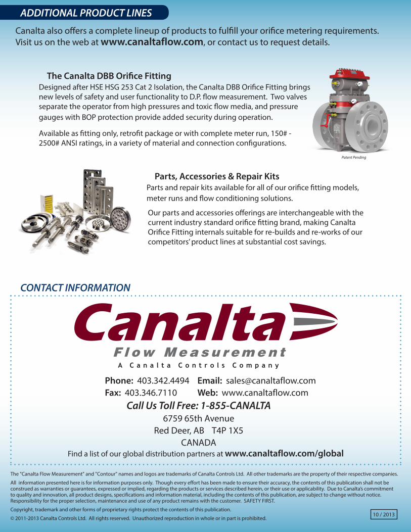
Canalta also offers a complete lineup of products to fulfill your orifice metering requirements. Visit us on the web at www.canaltaflow.com, or contact us to request details.
Parts, Accessories & Repair KitsParts and repair kits available for all of our orifice fitting models, meter runs and flow conditioning solutions.
Our parts and accessories offerings are interchangeable with the current industry standard orifice fitting brand, making Canalta Orifice Fitting internals suitable for re-builds and re-works of our competitors’ product lines at substantial cost savings.
The Canalta DBB Orifice FittingDesigned after HSE HSG 253 Cat 2 Isolation, the Canalta DBB Orifice Fitting brings new levels of safety and user functionality to D.P. flow measurement. Two valves separate the operator from high pressures and toxic flow media, and pressure gauges with BOP protection provide added security during operation.
Available as fitting only, retrofit package or with complete meter run, 150# - 2500# ANSI ratings, in a variety of material and connection configurations.
Patent Pending
10 / 2013
Related Documents