The benefits of Light Weight Deflectometer for im- proved seismic performance of infrastructure in New Zealand 2017 NZSEE Conference N. Barounis, T.N. Smith and J. Philpot Cook Costello, Christchurch, New Zealand. ABSTRACT: The Light Weight Deflectometer (LWD) is a portable device that measures the onsite dy- namic or resilient modulus (Evd) of subgrade soils and pavements. The LWD, which has been used extensively in Europe and the United States, has become popular for as- sessing the stiffness of embankments, structural fills and other earth structures. It as- sesses the degree of compaction that has been attained onsite beyond the usual "rela- tive compaction" 95% Maximum Dry Density (MDD) target undertaken using a Nuclear Density Meter (NDM). The LWD assessment considers the stiffness and compressibility characteristics of the materials under testing; acknowledging the fact that the achieved dry density does not necessarily coincide with the maximum resilient modulus Evd that can be achieved onsite. It is essential to understand the dynamic load response behav- iour of highway embankments and pavements at the design and construction monitor- ing stages as it affects their earthquake performance. This paper discusses the benefits that may arise from use of the LWD for New Zealand infrastructure, which often experi- ences high levels of earthquake shaking. The fundamental principles behind the testing are presented and explained along with the benefits that may arise from its use on spe- cific applications. Such applications include the design and construction monitoring of gravel rafts, engineered and non-engineered fills, landfills, MSE walls, pipelines and ser- vices, evaluation of ground improvement effectiveness and soil stiffness mapping. The paper also examines the potential benefits that may arise from LWD in the performance based design of pavements and other earth structures and how it can be used along with well-established tests like NDM and static plate load testing. 1 INTRODUCTION The Light Weight Deflectometer (LWD) is a portable device that measures the onsite dynamic or re- silient modulus (Evd) of subgrade soils and pavements. The LWD test method has been gaining in pop- ularity following its use in European countries and the USA for over 30 years. The test method was originally designed to measure the resilient modulus (Evd) of an in-situ material which indicates the materials stiffness. Numerous standards have been developed for the LWD and allow the characterisation of various ma- terials based on Evd, which can facilitate the estimation of bearing capacity, dynamic spring stiffness (Kd) and the compaction degree of engineered fills. This is extremely beneficial for infrastructure de- sign and testing as it allows a fundamental engineering parameter (Evd) to be measured and used in the design and construction process. The resilient modulus (Evd) represents the elastic response of the soil specimen after many cycles of loading. Cyclic triaxial tests, used for measuring the resilient modulus (Evd) of untreated base/subbase

Welcome message from author
This document is posted to help you gain knowledge. Please leave a comment to let me know what you think about it! Share it to your friends and learn new things together.
Transcript

The benefits of Light Weight Deflectometer for im-proved seismic performance of infrastructure in New Zealand
2017 NZSEE Conference
N. Barounis, T.N. Smith and J. Philpot
Cook Costello, Christchurch, New Zealand.
ABSTRACT:
The Light Weight Deflectometer (LWD) is a portable device that measures the onsite dy-
namic or resilient modulus (Evd) of subgrade soils and pavements. The LWD, which has
been used extensively in Europe and the United States, has become popular for as-
sessing the stiffness of embankments, structural fills and other earth structures. It as-
sesses the degree of compaction that has been attained onsite beyond the usual "rela-
tive compaction" 95% Maximum Dry Density (MDD) target undertaken using a Nuclear
Density Meter (NDM). The LWD assessment considers the stiffness and compressibility
characteristics of the materials under testing; acknowledging the fact that the achieved
dry density does not necessarily coincide with the maximum resilient modulus Evd that
can be achieved onsite. It is essential to understand the dynamic load response behav-
iour of highway embankments and pavements at the design and construction monitor-
ing stages as it affects their earthquake performance. This paper discusses the benefits
that may arise from use of the LWD for New Zealand infrastructure, which often experi-
ences high levels of earthquake shaking. The fundamental principles behind the testing
are presented and explained along with the benefits that may arise from its use on spe-
cific applications. Such applications include the design and construction monitoring of
gravel rafts, engineered and non-engineered fills, landfills, MSE walls, pipelines and ser-
vices, evaluation of ground improvement effectiveness and soil stiffness mapping. The
paper also examines the potential benefits that may arise from LWD in the performance
based design of pavements and other earth structures and how it can be used along
with well-established tests like NDM and static plate load testing.
1 INTRODUCTION
The Light Weight Deflectometer (LWD) is a portable device that measures the onsite dynamic or re-
silient modulus (Evd) of subgrade soils and pavements. The LWD test method has been gaining in pop-
ularity following its use in European countries and the USA for over 30 years. The test method was
originally designed to measure the resilient modulus (Evd) of an in-situ material which indicates the
materials stiffness.
Numerous standards have been developed for the LWD and allow the characterisation of various ma-
terials based on Evd, which can facilitate the estimation of bearing capacity, dynamic spring stiffness
(Kd) and the compaction degree of engineered fills. This is extremely beneficial for infrastructure de-
sign and testing as it allows a fundamental engineering parameter (Evd) to be measured and used in
the design and construction process.
The resilient modulus (Evd) represents the elastic response of the soil specimen after many cycles of
loading. Cyclic triaxial tests, used for measuring the resilient modulus (Evd) of untreated base/subbase

2
materials, are expensive and difficult to execute in New Zealand due to the lack of accredited labora-
tories and technicians experienced in undertaking such tests. This has caused the measurement of
such an important geotechnical parameter to often be ignored during the design and construction
process of infrastructure in New Zealand. The LWD test method therefore offers a great alternative
for measuring the onsite resilient modulus, at a fraction of the laboratory cost.
2 BENEFITS TO NEW ZEALAND CONSTRUCTION
2.1 Main Benefits
The LWD has become an internationally recognised test method for many areas of construction fol-
lowing its use in Europe and the United States over the last 30 years. The major benefits of using the
LWD from a practical perspective are:
• It relies on sound principles of geotechnical engineering
• It is portable and easily operated by one technician
• It produces repeatable results
• It is fast
• It is cost-effective
• The geotechnical parameters measured allow a more robust performance based approach to
be adopted in the design and construction monitoring phases
• It is environmentally safe and does not have the safety and transport issues of a nuclear den-
sity meter (NDM)
Looking at several of the more common test methods utilised in New Zealand practice (Clegg ham-
mer, CPT, DCP/Scala penetrometer, shear vane, CBR, FWD), it is clear that none of them actually
measure the soil modulus. All of these methods are providing the soil modulus by using published
correlations. Some of these correlations are more reliable than others. However, many of these cor-
relations are only suitable for site-specific soils found overseas (e.g. CBR-Evd correlations for overseas
soils that may not be applicable in New Zealand).
The LWD offers a substantial advantage over the above available methods as it can characterise a di-
rect geotechnical parameter (Evd) of the underlying material to a depth equal to twice the plate diam-
eter (Adam and Kopf, 2004). For a 300mm diameter plate, the depth to which it can characterise the
soil is 600mm below the plate level. This 600mm thickness can be the same uniform soil layer or a
composite section made of subgrade, subbase and base materials. By measuring the modulus di-
rectly and on-site, rather than correlating from other test methods, the designer is able to incorpo-
rate to the design a reliable geotechnical parameter (Evd). At the site investigation stage, this provides
a more accurate assessment of the likely performance characteristics of a site, which in turn allows a
more robust and precise design to be produced. By also incorporating the use of LWD into the con-
struction process, the quality of the build process is assured through accurate measurement of an
important geotechnical parameter during the construction monitoring process.

3
2.2 Benefits to Earthquake Resilient Design
The benefits extend into the earthquake resilient design of earth structures and the foundations
placed on top of these by improving the quality of the design inputs. From this, incorporation of the
modulus measured onsite to the design and construction process allows a more robust, perfor-
mance-based seismic design and build process to be carried out. This in turn provides infrastructure
that is more robust and earthquake resilient.
3 LWD TEST METHOD, STANDARDS AND APPARATUS
3.1 LWD Test Method
The principle of this test was developed in 1981. The test simulates a truck with a 10ton axle weight
travelling on a road at 80km per hour. A steel plate of 300mm diameter is placed on the soil to be
tested. A 10kg weight drops from a height of 72 cm onto the plate. The load pulse creates a soil pres-
sure of 100kPa under the plate. The approximate duration of the load pulse is around 17ms and it is
created by means of engineered springs located above the plate. An acceleration sensor is arranged
on the load plate. The generated acceleration signal is recorded. From single and double integration
of the acceleration signal, the velocity and the displacement (settlement) of the plate is calculated.
From this simple test method the recorded values can be used for determining:
• Resilient or dynamic soil modulus (Evd)
• Bearing capacity
• Dynamic spring stiffness (Kd)
• Degree of compaction and compaction quality control
The resilient modulus Evd is given in MPa by the equation:
Evd = 22.5
𝑠 (1)
where s is the measured plate settlement in mm.
The specifications for the LWD apparatus are defined in both ASTM E2835-11 and ZTVE-StB 09 and
conform to strict equipment production criteria. The apparatus is also required to be calibrated on an
annual basis by an accredited calibration institute.
Figure 1 shows the technical specification for LWD testing equipment as defined by the above two
standards.

4
Figure 1: Technical specifications for light weight deflectometer apparatus as per ASTM E2835-11
3.2 Standards
Numerous international standards have been produced following the inception of the LWD as a test
procedure. The two main internationally accepted test methods are:
• ASTM E2835-11: American Standard Test Method for Measuring Deflections using a Port-able Impulse Plate Load Test Device
• ZTVE-StB 09: German Engineering Code for Soil and Rock in Road Construction While these test methods are the most widely accepted in industry, many other standards have been produced to complement more specific design codes and procedures. Some other available interna-tional standards on LWD include:
• TP BF-StB B 8.3 version 2012: German Engineering Code for Soil and Rock in Road Con-struction
• ZTV E-StB 09: German additional terms of contract and rules for earthwork in road con-struction
• ZTV T-StB 95: German additional terms of contract and rules for subbases in earthworks
• ZTV A-StB 97: German additional terms of contract and rules for excavation in traffic access
• RVS 08.03.04 March 2008: Austrian regulation - Compaction test by means of dynamic plate load test
• RIL 836, Deutsche Bahn AG: Guideline for the use of the Light Drop-Weight Tester in rail-way construction
• UNE 103807-2:2008: Spanish regulation - Plate Load Test by means of the Light Drop Weight Tester-Part 2
• TB 10102-2004, J338-2004: Chinese regulation - Standard for soil testing in railway con-struction
The number of standards available shows that the test procedure is widely accepted and utilised for
a diverse range of engineering applications throughout the globe. This also provides a simple plat-
form for the integration of the LWD into New Zealand design and construction procedures through
the utilisation of these existing standards.
5
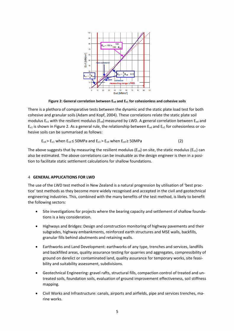
Figure 2: General correlation between Evd and Ev1 for cohesionless and cohesive soils
There is a plethora of comparative tests between the dynamic and the static plate load test for both
cohesive and granular soils (Adam and Kopf, 2004). These correlations relate the static plate soil
modulus Ev1 with the resilient modulus (Evd) measured by LWD. A general correlation between Evd and
Ev1 is shown in Figure 2. As a general rule, the relationship between Evd and Ev1 for cohesionless or co-
hesive soils can be summarised as follows:
Evd > Ev1 when Evd ≤ 50MPa and Ev1 > Evd when Evd ≥ 50MPa (2)
The above suggests that by measuring the resilient modulus (Evd) on site, the static modulus (Ev1) can
also be estimated. The above correlations can be invaluable as the design engineer is then in a posi-
tion to facilitate static settlement calculations for shallow foundations.
4 GENERAL APPLICATIONS FOR LWD
The use of the LWD test method in New Zealand is a natural progression by utilisation of ‘best prac-
tice’ test methods as they become more widely recognised and accepted in the civil and geotechnical
engineering industries. This, combined with the many benefits of the test method, is likely to benefit
the following sectors:
• Site investigations for projects where the bearing capacity and settlement of shallow founda-
tions is a key consideration.
• Highways and Bridges: Design and construction monitoring of highway pavements and their
subgrades, highway embankments, reinforced earth structures and MSE walls, backfills,
granular fills behind abutments and retaining walls.
• Earthworks and Land Development: earthworks of any type, trenches and services, landfills
and backfilled areas, quality assurance testing for quarries and aggregates, compressibility of
ground on derelict or contaminated land, quality assurance for temporary works, site feasi-
bility and suitability assessment, subdivisions.
• Geotechnical Engineering: gravel rafts, structural fills, compaction control of treated and un-
treated soils, foundation soils, evaluation of ground improvement effectiveness, soil stiffness
mapping.
• Civil Works and Infrastructure: canals, airports and airfields, pipe and services trenches, ma-
rine works.

6
5 APPLICATION OF LWD IN CHRISTCHURCH
5.1 LWD equipment and site description
Testing has been undertaken using the HMP LFG Pro deflectometer and NDM apparatus on gravel
rafts, used as a ground improvement method under foundations in Christchurch. This was carried out
in order to investigate the behaviour of compacted soils from the perspective of “stiffness quality
control” and compare it with the common NDM dry density approach. The test site chosen for analy-
sis consisted of a 1.2m thick gravel raft, compacted in 200mm lifts and utilising crushed gravel CAP65.
The equipment utilised during the testing and analysis is produced and calibrated in Germany by
HMP Magdeburger Prufgeratebau GmbH as per ASTM E2835-11. The LWD is mainly utilised for road-
ing and railway construction in Germany, but is also utilised for other applications as outlined in Sec-
tions 3.2 and 4.
Both LWD and NDM testing were carried out at the same locations on the finished surface of the
gravel raft in order to provide the most accurate correlation between measurements. The NDM was
used to measure both the dry density and the moisture content of the gravel, while the LWD meas-
ured the resilient modulus.
Figure 3 shows a schematic view of the LWD apparatus produced by HMP with the inclusion of the
electronic recorder. As shown in Figure 3 and Figure 4, the equipment is small and portable, allowing
it to be easily transported and utilised on a construction site by one technician.
Figure 3. Components of the Light Weight Deflectometer (LWD) as per ASTM E2835-11
The apparatus is controlled during testing by means of an electronic recorder that provides a step by
step guidance to the operator during the testing process. This removes the potential for any meas-
urement errors. The operational procedure of the HMP LFG Pro LWD apparatus is as follows.
Setup: Level the test area, lay down the full-sized load plate, put loading mechanism on to the plate,
and connect it to the measuring instrument.
Measure: Switch on the measuring machine and follow the instructions on the display, perform three
successive pre-compacting impacts and three measuring impacts, display the settlement after each
impact.
Evaluate: Automatic calculation and display of all measured data and the Evd value after completion
of the measurement series. When testing series is ended, store, printout or transfer measurement.

7
Figure 4. Image of the HMP LFG Pro LWD apparatus in use
Following the test procedure, the electronic recorder on the apparatus provides an instant graphical
and tabular display of the results which is stored on the device for download. The apparatus also in-
cludes a built-in printer that can instantly print the results onsite for quality assurance records.
5.2 Comparison between NDM and LWD and discussion of results
The dry density (NDM) and resilient modulus (LWD) results, were then plotted against the moisture
contents (NDM) measured at each location. Figure 5 shows the dry density versus the moisture con-
tent as measured onsite at each different location. As shown in Figure 5, the measured dry density at
the test site tends to increase as the moisture content increases. This is in contrast to the modulus
values measured using the LWD. As shown in Figure 6, the modulus measured onsite at each differ-
ent location shows that generally decreases as the moisture content increases. These results are in
agreement with published results from various researchers (Briaud and Saez, 2015 and NCHRP,
2014).
Figure 5. Dry density versus moisture content for CAP 65 gravel raft
8
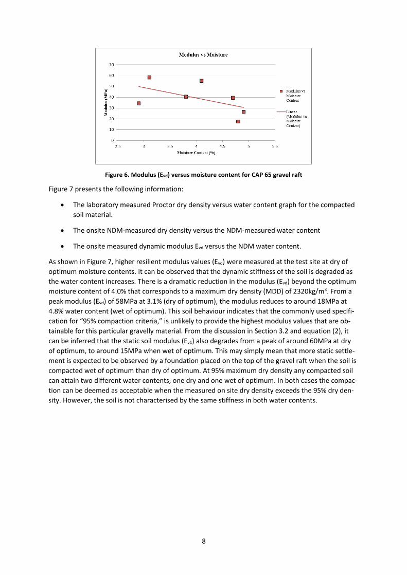
Figure 6. Modulus (Evd) versus moisture content for CAP 65 gravel raft
Figure 7 presents the following information:
• The laboratory measured Proctor dry density versus water content graph for the compacted
soil material.
• The onsite NDM-measured dry density versus the NDM-measured water content
• The onsite measured dynamic modulus Evd versus the NDM water content.
As shown in Figure 7, higher resilient modulus values (Evd) were measured at the test site at dry of
optimum moisture contents. It can be observed that the dynamic stiffness of the soil is degraded as
the water content increases. There is a dramatic reduction in the modulus (Evd) beyond the optimum
moisture content of 4.0% that corresponds to a maximum dry density (MDD) of 2320kg/m3. From a
peak modulus (Evd) of 58MPa at 3.1% (dry of optimum), the modulus reduces to around 18MPa at
4.8% water content (wet of optimum). This soil behaviour indicates that the commonly used specifi-
cation for “95% compaction criteria,” is unlikely to provide the highest modulus values that are ob-
tainable for this particular gravelly material. From the discussion in Section 3.2 and equation (2), it
can be inferred that the static soil modulus (Ev1) also degrades from a peak of around 60MPa at dry
of optimum, to around 15MPa when wet of optimum. This may simply mean that more static settle-
ment is expected to be observed by a foundation placed on the top of the gravel raft when the soil is
compacted wet of optimum than dry of optimum. At 95% maximum dry density any compacted soil
can attain two different water contents, one dry and one wet of optimum. In both cases the compac-
tion can be deemed as acceptable when the measured on site dry density exceeds the 95% dry den-
sity. However, the soil is not characterised by the same stiffness in both water contents.

9
Figure 7. Laboratory dry density, modulus Evd and NDM dry density versus moisture content
for CAP 65 gravel raft
When incorporating the above observations into a design process, it is important that the exact per-
formance characteristics required from the gravel raft are considered. The design engineer needs to
decide whether it is critical to achieve maximum density or maximum stiffness for the given project.
If stiffness is the main performance criteria for a gravel raft, the above information suggests that
compacting the gravel at a moisture content slightly drier than optimum (as calculated from the
proctor curve) is likely to achieve higher resilient moduli and thus a stiffer performance. The above
indicates the behaviour of crushed alluvial gravel aggregates from Christchurch; different aggregates
may behave in a different manner. During the design life of a fill structure, the water content and
thus E is expected to variate. The designer needs to consider maximum water content and thus mini-
mum E that could be expected during the design life of the fill structure. The LWD can assist towards
these considerations. Currently, there is significant discussion and research occurring in the American
geotechnical community on the development of a modulus-based construction specification for ac-
ceptance of compacted geomaterials (NCHRP 10-84, 2014). However, modulus-based construction
specifications are already well-established and accepted in European practice.
6 CONCLUSIONS
The Light Weight Deflectometer (LWD) is an internationally recognised and utilised test method that
has been gaining in popularity following its use in European countries and the USA for over 30 years.
However, its utilisation in New Zealand for both design and construction has been limited to date for
various reasons. With modern and robust test equipment now available, and internationally ac-
cepted standards readily available, utilisation of the LWD in New Zealand is likely to become more
prolific.
The LWD provides many advantages over other in-situ and laboratory test methods by quickly and
easily measuring the resilient modulus (Evd), and allowing it to be easily incorporated into the design
process or utilised at the construction monitoring phase.
7 REFERENCES
ASTM E2835-11 (2015). Standard Test Method for Measuring Deflections using a Portable Impulse
Plate Load Test Device. American Society of Testing and Materials
10
Adam, D. and Kopf, F. (2004). Operational devices for compaction optimization and quality control
(Continuous Compaction Control & Light Falling Weight Device). Proceedings of the International
Seminar on Geotechnics in Pavement and Railway Design and Construction, Athens, Greece, 16-17
December 2004. Gomes Correia and Loizos (eds), Millpress, Rotterdam.
Briaud, J.-L. and Saez, D.(2015). Chapter 9 in Ground improvement case histories: compaction, grout-
ing and geosynthetics. Elsevier BH, UK.
German Road and Transport Research Association Working Group for Foundation and Soils Engineer-
ing (2003). Technical Test Code for Soil and Rock Mechanics in Road Construction BF-StB Part B 8.3:
Dynamic Plate Load Testing with the Light Drop-Weight Tester.
German Earthworks and Foundation Engineering Task Force (2009). Supplementary Technical Terms
and Conditions of Contract and Guidelines for Earthworks in Road Construction ZTVE-StB 09.
National Cooperative Highway Research Program NCHRP Project 10-84 (2014). Modulus-based con-
struction specification for compaction of earthwork and unbound aggregate.
Related Documents