Welcome message from author
This document is posted to help you gain knowledge. Please leave a comment to let me know what you think about it! Share it to your friends and learn new things together.
Transcript
The Behaviour and Design of Steel Structures to AS 4100

The Behaviour and Design of Steel Structures to AS 4100
Third edition — Australian
N . S . T R A H A I RChallis Professor of Civil Engineering The University of Sydney
andM. A. B R A D F O R DAssociate Professor in Civil Engineering The University o f New South Wales
Taylor &. Francis GroupBoca Raton London New York
CRC Press
CRC Press is an imprint of theTaylor & Francis Group, an informa business
CRC PressTaylor & Francis Group6000 Broken Sound Parkway NW, Suite 300Boca Raton, FL 33487-2742
First issued in hardback 2017
© 1998 N.S. Trahair and M.A. BradfordCRC Press is an imprint of Taylor & Francis Group, an Informa business
No claim to original U.S. Government works
ISBN-13: 978-0-4192-2920-9 (pbk)ISBN-13: 978-1-1384-7032-3 (hbk)
This book contains information obtained from authentic and highly regarded sources. Reasonable efforts have been made to publish reliable data and information, but the author and publisher cannot assume responsibility for the validity of all materials or the consequences of their use. The authors and publishers have attempted to trace the copyright holders of all material reproduced in this publication and apologize to copyright holders if permission to publish in this form has not been obtained. If any copyright material has not been acknowledged please write and let us know so we may rectify in any future reprint.
Except as permitted under U.S. Copyright Law, no part of this book maybe reprinted, reproduced, transmitted, or utilized in any form by any electronic, mechanical, or other means, now known or hereafter invented, including photocopying, microfilming, and recording, or in any information storage or retrieval system, without written permission from the publishers.
Trademark Notice: Product or corporate names may be trademarks or registered trademarks, and are used only for identification and explanation without intent to infringe.
Typeset in 10/12pt Times by SPS, Madras, India
Visit the Taylor & Francis Web site at http://www.taylorandfrancis.com
and the CRC Press Web site http://www.crcpress.com
British Library Cataloguing in Publication Data A catalogue record for this book is available
from the British Library
Contents
pagePreface ixPreface to the second edition revised xiPreface to the second edition x iiiPreface to the first ed ition xvU nits and conversion factors xixG lossary o f term s xxiN otation xxv
1 Introduction 11.1 Steel structures 11.2 Design 31.3 Material behaviour 71.4 Member and structure behaviour 141.5 Loads 171.6 Analysis of steel structures 201.7 Design of steel structures 241.8 References 30
2 T ension m em bers 332.1 Introduction 332.2 Concentrically loaded tension members 332.3 Eccentrically connected tension members 372.4 Bending of tension members 392.5 Stress concentrations 402.6 Design of tension members 412.7 Worked examples 442.8 Unworked examples 472.9 References 48
3 C om pression m em bers 493.1 Introduction 493.2 Elastic compression members 503.3 Inelastic compression members 543.4 Real compression members 593.5 Effective lengths of compression members 633.6 Design by buckling analysis 713.7 Design of compression members 753.8 Appendix - elastic compression members 79
vi Contents
3.9 Appendix - inelastic compression members 813.10 Appendix - effective lengths of compression members 833.11 Appendix - design by buckling analysis 883.12 Worked examples 893.13 Unworked examples 953.14 References 98
4 Local buckling o f th in plate elem ents 1004.1 Introduction 1004.2 Plate elements in compression 1004.3 Plate elements in shear 1144.4 Plate elements in bending 1194.5 Plate elements in shear and bending 1224.6 Plate elements in bearing 1244.7 Design against local buckling 1274.8 Appendix - elastic buckling of plate elements
in compression 1374.9 Worked examples 1394.10 Unworked examples 1464.11 References 147
5 In-plane bending o f beam s 1495.1 Introduction 1495.2 Elastic analysis of beams 1515.3 Bending stresses in elastic beams 1525.4 Shear stresses in elastic beams 1575.5 Plastic analysis of beams 1695.6 Strength design of beams 1775.7 Serviceability design of beams 1835.8 Appendix - bending stresses in elastic beams 1845.9 Appendix - thin-walled section properties 1865.10 Appendix - shear stresses in elastic beams 1895.11 Appendix - plastic analysis of beams 1915.12 Worked examples 1985.13 Unworked examples 2145.14 References 216
6 Lateral buckling o f beam s 2186.1 Introduction 2186.2 Elastic beams 2206.3 Inelastic beams 2286.4 Real beams 2316.5 Effective lengths of beams 2346.6 Design by buckling analysis 2426.7 Monosymmetric beams 250
Contents vii
6.8 Non-uniform beams 2536.9 Design against lateral buckling 2546.10 Appendix - elastic beams 2606.11 Appendix - effective lengths of beams 2656.12 Appendix - monosymmetric beams 2666.13 Worked examples 2676.14 Unworked examples 2776.15 References 278
7 B eam -colum ns 2827.1 Introduction 2827.2 In-plane behaviour of isolated beam-columns 2837.3 Flexural-torsional buckling of isolated beam-columns 2977.4 Biaxial bending of isolated beam-columns 3057.5 Appendix - in-plane behaviour of elastic beam-columns 3087.6 Appendix - flexural-torsional buckling of elastic
beam-columns 3117.7 Worked examples 3137.8 Unworked examples 3197.9 References 321
8 Fram es 3238.1 Introduction 3238.2 Triangulated frames 3248.3 Two-dimensional flexural frames 3268.4 Three-dimensional flexural frames 3478.5 Worked examples 3488.6 Unworked examples 3598.7 References 361
9 C onnections 3659.1 Introduction 3659.2 Connection components 3659.3 Arrangement of connections 3699.4 Behaviour of connections 3719.5 Design of bolts 3819.6 Design of bolted plates 3849.7 Design of welds 3879.8 Appendix - elastic analysis of connections 3899.9 Worked examples 3929.10 Unworked examples 3979.11 References 398
10 T orsion m em bers 39910.1 Introduction 39910.2 Uniform torsion 401
viii Contents
10.3 Non-uniform torsion 41410.4 Torsion design 42610.5 Torsion and bending 43010.6 Distortion 43410.7 Appendix - uniform torsion 43610.8 Appendix - non-uniform torsion 43810.9 Worked examples 44210.10 Unworked examples 44810.11 References 449
Index 451
Preface
This third Australian edition has been directed specifically to the design of steel structures in accordance with the Australian standard AS4100-1990 and its Amendments 1, 2, and 3. The removal of material on British and American methods of design has allowed the inclusion of additional material relevant to Australian practice, and of more detail in the worked examples. Thus Australian designers, teachers, and students will find greater clarity and more helpful material.
The previous Chapter 7 has been divided into two new chapters, Chapter 7 on Beam-Columns, and Chapter 8 on Frames. The latter has been significantly expanded, both with new material and worked examples, and also with material on frame buckling from the previous Chapter 3. Torsion is now dealt with in Chapter 10. This includes new material on designing for torsion and for combined torsion and bending which is based on recent research. Chapter 9 on Connections has been expanded by including material on standardised Australian connections.
The preparation of this third Australian edition has provided an opportunity to revise the text generally to incorporate the results of recent findings and research. This is in accordance with the principal objective of the book, to provide students and practising engineers with an understanding of the relationships between structural behaviour and the design criteria implied by the rules of design codes such as AS4100.
The manuscript for this third edition has been expertly prepared by our dedicated secretary Cynthia Caballes, while the figures have been completely redrawn by Ron Brew.
We would like to acknowledge the unfailing support of our wives, Sally and Suzanna, without whom the revision of this book would not have been possible.
NS Trahair and MA Bradford March 1997

Preface to the second edition revised
Since publication of the second edition of this book in 1988, the British Standard has been revised as BS 5950: Part 1: 1990, and the new Australian Standard AS 4100-1990 (referred to in this book as the AS) based on the draft revision DR87164 has been published. As a consequence of these revisions, and using the opportunity of a reprint, a number of changes have been made to this book to reflect the changes in the British and Australian Standards.
NS Trahair and MA Bradford June 1991

Preface to the second edition
The second edition of this book has been prepared following the very significant revisions made to the British, American and Australian methods of designing steel structures. The British BS 449:1969 has been replaced by the BS 5950: Part 1: 1985 ‘Structural Use of Steelwork in Building’, the American AISC has published its 1986 ‘Load and Resistance Factor Design Specification for Structural Steel Buildings’ to be used as an alternative to its updated 1969 Specification, and a draft Australian limit state revision of the updated AS 1250-1975 ‘SAA Steel Structures Code’ has been issued. The second edition of this book deals specifically with these revisions, which are referred to as the BS 5950, the AISC, and the AS in the text.
The principal change in these revisions is the replacement of the Working Stress Method of Design discussed in the first edition by the more logical and efficient Limit State (or Load and Resistance Factor) M ethod o f Design. The general basis of this new method is explained in section 1.7.3.4, and the details of the method are fully discussed in each chapter.
The revisions are also changed substantially and expanded, reflecting the better understanding of the behaviour of steel structures which has developed from more than a decade of intensive research and investigation. The bases of these changes and expansions are explained in this second edition as a continuation of the objective of the first edition, which sought to provide students and structural engineers with an understanding of the relationships between structural behaviour and the design criteria implied by the rules of design codes, and of the bases and limitations of these rules.
The opportunity provided by the preparation of the second edition has been used to expand the material on connections into a full chapter (Chapter 9), and to add to the material on frames (sections 7.5-7.7). Modifications have also been made based on further teaching experiences in Australia, New Zealand and Canada, at the suggestions of interested users, while unworked examples have been suggested in Chapters 2-9.
The preparation of this second edition was made possible by the significant contributions made by my co-author, Dr M.A. Bradford of the University of New South Wales. We would both like to thank all those who assisted in the preparation of this second edition, particularly Dr R.Q. Bridge, my secretary Jean Whittle and the tracing staff led by Ron Brew at the University of Sydney.
Nicholas Trahair

Preface to the first edition
The designer of a steel structure must make a proper choice of a method to analyse the structure and of the design criteria to be used to proportion it. To do this he needs a sound knowledge of structural steel behaviour, including the material behaviour of the steel itself, and the structural behaviour of the individual members and of the complete structure. He also needs to understand the relationships between structural behaviour and the design criteria implied by the rules of design codes, and the bases and limitations of these rules. Thus, the basic training of a student of structural engineering has as its object the promotion of this understanding.
Structural knowledge is continually increasing, and techniques for analysis, design, fabrication, and erection of structures are being extended or revised, while new types of structure are being introduced. These changes are reflected by the continual changes being made to the design criteria given in steel design codes, and by their growing detail and sophistication. The structural engineer who does not keep pace with these increases in knowledge may come to use design codes blindly by accepting the rules at their face value and without question, by interpreting them rigidly, and by applying them incorrectly in situations beyond their scope. On the other hand, the structural engineer who has kept abreast of these increases in knowledge and who understands the bases of the code rules will be able to design routine structures more efficiently, and to determine appropriate design criteria for unusual structures and for structures to which the design codes do not directly apply.
There are many excellent textbooks available on the analysis of frame structures, while there are a number of texts which demonstrate the application of design code rules to the proportioning of structural steel members. This book, which is concerned with the behaviour and design of steel structures, is not one of either of these types, although it is assumed that it will be used in courses preceded by appropriate courses in structural analysis and accompanied by suitable assignments on the design of steel structures. Instead, the purpose of this book is to promote the understanding of the behaviour of steel structures by summarizing the present state of knowledge, and to facilitate design by relating this behaviour to the criteria adopted for design, with particular reference to the Australian Standard AS 1250-1975 (SAA Steel Structures Code), the British Standard BS449:Part 2:1969 (The Use of Structural Steel in Building), and the American Institute of Steel Construction 1969 Specification (for the Design, Fabrication and Erection of Structural Steel for Buildings). The book is written in metric (SI) units, which are now in use in England and Australia, and which are being introduced into technical papers published in the USA. However, most of the material is presented in a
non-dimensional format, and those readers who wish to continue using Imperial units will not be unduly inconvenienced.
This book is for use by undergraduate and graduate engineering students and by practising structural engineers. Because of this wide range of usage, the level of the material presented varies somewhat, and the user of the book will need to select material suitable to his purpose. Thus, for a first undergraduate course, some of the topics treated in the book should be passed over until they can be presented in a later course, while the teacher may also simplify other topics by omitting some of the finer details. On the other hand, the simpler subject matters already treated can be omitted from advanced undergraduate or postgraduate courses, while some teachers may wish to expand some of the material presented in the book, or even to add material on additional specialist topics. Finally, the book is intended to be of interest and use to research workers and practising designers. It is anticipated that designers will find it of value in updating their knowledge of structural behaviour, and in furthering their understanding of the code rules and their bases.
The book is not intended, however, to be an advanced treatise for the exclusive use of research workers, so many of the analytical details have been omitted in favour of more descriptive explanations of the behaviour of steel structures. However, where a solution of a characteristic problem can be simply derived, this has been done in an abbreviated form (usually in an appendix which the reader can pass over, if desired) in order to indicate to those interested the rigour of the results presented. Further details may be obtained from the references quoted.
Chapter 1 - Introduction deals with the scope of the book, with the role of structural design in the complete design process, and with the relationships between the behaviour and analysis of steel structures and their structural design. It also presents relevant information on the material properties of structural steels under static, repeated, and dynamic loads. The behaviour of connections, members, and structures is summarized, while the dead and live loads and the forces of nature which act on structures are discussed.
Chapters 2, 3, 5, and 8 are concerned primarily with the more common behaviour of structural steel members under simple loading conditions. Chapter 2 - Tension Members and Chapter 3 - Compression Members deal with axially loaded members and frames, while Chapter 5 - In-Plane Bending of Beams deals with transversely loaded members and frames, and Chapter 8 - Torsion Members deals with the twisting of steel members. Some of the material given in these chapters is at an advanced level, and might well be taught in a postgraduate course. This includes the analysis of shear due to transverse forces given in Chapter 5, and the analysis of torsion and distortion given in Chapter 8. The material on plastic analysis given in Chapter 5 is available in many textbooks, but is included here because of its relevance to the ultimate strength of beams and flexural frames.
xvi Preface to the first edition
Preface to the first edition xvii
Chapters 4, 6, and 7 contain material much of which is often omitted from a first course in structural steel design, and some of which might well be taught in a postgraduate course. Chapter 4 - Local Buckling of Thin Plate Elements discusses the local strength of thin plates under in-plane loading, and the design of the flanges and webs of steel members. Chapter 6 - Lateral Buckling of Beams deals with the flexural-torsional buckling of laterally unsupported beams and rigid-jointed flexural frames. Chapter 7 - Beam-Columns and Frames discusses the in-plane behaviour, the flexural-torsional buckling, and the biaxial bending of members subjected to both axial and transverse loads, and of rigid-jointed frames composed of these members.
The author has been greatly influenced in his preparation of this book by his own teaching and research experiences in Australia at the University of Sydney, in the USA at Washington University, and in the UK at the University of Sheffield, and also by his work with the Standards Association of Australia. The discussions that he has had with his own teachers, with his colleagues and other structural engineers, and with his students have also been important. Thus, while a significant proportion of the material in this book has been developed by the author, much of the material is not original, but has been gathered from many sources. Unfortunately, it is very difficult or even impossible to acknowledge individual sources, and so the references given in this book are restricted to those which the general reader may wish to consult for further information.
The author would like to thank all those who assisted in the preparation of this book. These include the University of Sydney and the University of Sheffield for the facilities made available, including the typing of the manuscript and the tracing of the figures, and the author’s colleagues for their helpful advice and criticism, especially Dr D.A. Nethercot of the University of Sheffield.

Units and conversion factors
Units
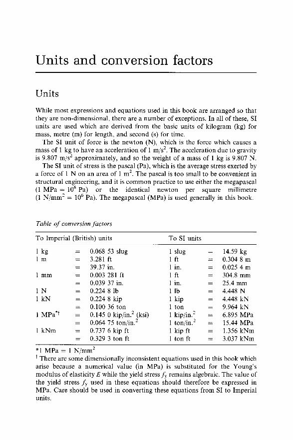
While most expressions and equations used in this book are arranged so that they are non-dimensional, there are a number of exceptions. In all of these, SI units are used which are derived from the basic units of kilogram (kg) for mass, metre (m) for length, and second (s) for time.
The SI unit of force is the newton (N), which is the force which causes a mass of 1 kg to have an acceleration of 1 m/s2. The acceleration due to gravity is 9.807 m/s2 approximately, and so the weight of a mass of 1 kg is 9.807 N.
The SI unit of stress is the pascal (Pa), which is the average stress exerted by a force of 1 N on an area of 1 m2. The pascal is too small to be convenient in structural engineering, and it is common practice to use either the megapascal (1 MPa = 106 Pa) or the identical newton per square millimetre (1 N/mm2 = 106 Pa). The megapascal (MPa) is used generally in this book.
Table o f conversion factors
To Imperial (British) units To SI units
1 kg = 0.068 53 slug 1 slug 14.59 kg1 m = 3.281 ft 1 ft = 0.304 8 m
= 39.37 in. 1 in. = 0.025 4 m1 mm = 0.003 281 ft 1 ft = 304.8 mm
= 0.039 37 in. 1 in. = 25.4 mm1 N = 0.224 8 lb 1 lb = 4.448 N1 kN = 0.224 8 kip 1 kip = 4.448 kN
= 0.100 36 ton 1 ton = 9.964 kN1 MPa*t = 0.145 0 kip/in.2 (ksi) 1 kip/in.2 = 6.895 MPa
= 0.064 75 ton/in.2 1 ton/in.2 = 15.44 MPa1 kNm = 0.737 6 kip ft 1 kip ft = 1.356 kNm
= 0.329 3 ton ft 1 ton ft = 3.037 kNm
*1 MPa = 1 N/mm2* There are some dimensionally inconsistent equations used in this book which arise because a numerical value (in MPa) is substituted for the Young’s modulus of elasticity E while the yield stress f y remains algebraic. The value of the yield stress f y used in these equations should therefore be expressed in MPa. Care should be used in converting these equations from SI to Imperial units.

Glossary of terms
Beam A member which supports transverse loads or moments only.Beam-column A member which supports transverse loads or moments
which cause bending and axial loads which cause compression.Biaxial bending The general state of a member which is subjected to
bending actions in both principal planes together with axial compression and torsion actions.
Brittle fracture A mode of failure under a tension action in which fracture occurs without yielding.
Buckling A mode of failure in which there is a sudden deformation in a direction or plane normal to that of the loads or moments acting.
Capacity factor A factor used to multiply the nominal capacity to obtain the design capacity.
Cleat A short length component (often of angle cross-section) used in a connection.
Column A member which supports axial compression loads.Compact section A section capable of reaching and maintaining the full
plastic moment until a plastic collapse mechanism is formed.Connection The means by which members are connected together and
through which forces and moments are transmitted.Dead load The weight of all permanent construction.Deformation capacity A measure of the ability of a structure to deform as
a plastic collapse mechanism develops without otherwise failing.Design capacity The capacity of the structure or element to resist the
design load. Obtained as the product of the nominal capacity and the capacity factor.
Design load A combination of factored nominal loads which the structure is required to resist.
Distortion A mode of deformation in which the cross-section of a member changes shape.
Effective length The length of an equivalent simply supported member which has the same elastic buckling load as the actual member.
Effective width That portion of the width of a flat plate which has a non- uniform stress distribution (caused by local buckling or shear lag) which may be considered as fully effective when the non-uniformity of the stress distribution is ignored.
Factor of safety The factor by which the strength is divided to obtain the working load capacity and the maximum permissible stress.
Fastener A bolt, pin, rivet, or weld used in a connection.
Fatigue A mode of failure in which a member fractures after many applications of load.
First-order analysis An analysis in which equilibrium is formulated for the undeformed position of the structure, so that the moments caused by products of the loads and deflections are ignored.
Flexural-torsional buckling A mode of buckling in which a member deflects and twists.
Friction-grip joint A joint in which forces are transferred by friction forces generated between plates by clamping them together with tensioned high tensile bolts.
Girt A horizontal member between columns which supports wall sheeting.Gusset A short plate element used in a connection.Inelastic behaviour Deformations accompanied by yielding.In-plane behaviour The behaviour of a member which deforms only in
the plane of the applied loads.Joint A connection.Lateral buckling Flexural-torsional buckling of a beam.Limit states design A method of design in which the performance of the
structure is assessed by comparison with a number of limiting conditions of usefulness. The most common conditions are the strength limit state and the serviceability limit state.
Live load The load assumed to act as a result of the use of the structure, but excluding wind, snow, and earthquake loads.
Load factor A factor used to multiply a nominal load to obtain part of the design load.
Local buckling A mode of buckling which occurs locally (rather than generally) in a thin plate element of a member.
Mechanism A structural system with a sufficient number of frictionless and plastic hinges to allow it to deform indefinitely under constant load.
Member A one-dimensional structural element which supports transverse or longitudinal loads or moments.
Nominal capacity The capacity of a member or structure computed using the formulations of a design code or specification.
Nominal load The load magnitude determined from a loading code or specification.
Non-compact section A section which can reach the yield stress, but which does not have sufficient resistance to inelastic local buckling to allow it to reach or to maintain the full plastic moment while a plastic mechanism is forming.
Non-uniform torsion The general state of torsion in which the twist of the member varies non-uniformly.
Plastic analysis A method of analysis in which the ultimate strength of a structure is computed by considering the conditions for which there are sufficient plastic hinges to transform the structure into a mechanism.
xxii Glossary of terms
Glossary of terms xxiii
Plastic hinge A fully yielded cross-section of a member which allows the member portions on either side to rotate under constant moment (the plastic moment).
Post-buckling strength A reserve of strength after buckling which is possessed by some thin plate elements.
Purlin A horizontal member between main beams which supports roof sheeting.
Reduced modulus The modulus of elasticity used to predict the buckling of inelastic members under constant applied load, so called because it is reduced below the elastic modulus.
Residual stresses The stresses in an unloaded member caused by uneven cooling after rolling, flame cutting, or welding.
Resistance Capacity.Second-order analysis An analysis in which equilibrium is formulated for
the deformed position of the structure, so that the moments caused by products of the loads and deflections are included.
Service loads The design loads appropriate for the serviceability limit state.
Shear centre The point in the cross-section of a beam through which the resultant transverse force must act if the beam is not to twist.
Shear lag A phenomenon which occurs in thin wide flanges of beams in which shear straining causes the distribution of bending normal stresses to become sensibly non-uniform.
Slender section A section which does not have sufficient resistance to local buckling to allow it to reach the yield stress.
Splice A connection between two similar collinear members.Squash load The value of the compressive axial load which will cause
yielding throughout a short member.Strain-hardening A stress-strain state which occurs at stresses which are
greater than the yield stress.Strength limit state The state of collapse or loss of structural integrity.Tangent modulus The slope of the inelastic stress-strain curve which is
used to predict buckling of inelastic members under increasing load.Tensile strength The maximum nominal stress which can be reached in
tension.Tension-held A mode of shear transfer in the thin web of a stiffened plate
girder which occurs after elastic local buckling takes place. In this mode, the tension diagonal of each stiffened panel behaves in the same way as does the diagonal tension member of a parallel chord truss.
Tension member A member which supports axial tension loads.Ultimate load design A method of design in which the ultimate load
capacity of the structure is compared with factored loads.Uniform torque That part of the total torque which is associated with the
rate of change of the angle of twist of the member.
Uniform torsion The special state of torsion in which the angle of twist of the member varies linearly.
Warping A mode of deformation in which plane cross-sections do not remain plane.
Warping torque The other part of the total torque (than the uniform torque). This only occurs during non-uniform torsion, and is associated with changes in the warping of the cross-sections.
Working load design A method of design in which the stresses caused by the service loads are compared with maximum permissible stresses.
Yield strength The average stress during yielding when significant straining takes place. Usually, the minimum yield strength in tension specified for the particular steel.
xxiv Glossary of terms
Notation
The following notation is used in this book. Usually, only one meaning is assigned to each symbol, but in those cases where more meanings than one are possible, the correct one will be evident from the context in which it is used.
A Area of cross-section, orArea of weld group
Ac Minimum area of threaded length of boltAe Area enclosed by hollow section, or
Effective area of cross-section Aep Area of end plateAfc Flange area at critical sectionAfm Flange area at minimum sectionAg Gross area of cross-sectionAt Area of hole reduced for staggerAj Area of ith connectorAn Area of nth rectangular element, orAn Area of cross-section reduced for holes, or
Net area of a cross-section, or Bolt area in nth shear plane
As Area of stiffener, orArea defined by distance s around section, or Tensile stress area of a bolt
Aw Area of webA \,A 2,Ai ConstantsB BimomentB* Design bimomentBq Nominal bimoment capacityBp Fully plastic bimomentBy First yield bimomentD Plate rigidity Et3/ 12(1 — v2){£)} Vector of nodal deformationsE Young’s modulus of elasticityEr Reduced modulusEst Strain-hardening modulusEt Tangent modulusF Buckling factor for beam-columns with unequal end
momentsG Shear modulus of elasticity[G] Stability matrix
xxvi Notation
Gst Strain-hardening shear modulusH Height, or
Horizontal reactionI Second moment of areah J c Second moments of area of beam and columnIcy Second moment of area of compression flangeh Effective second moment of areaIf Second moment of area of a flange — Iy/ 2Im Second moment of area of memberIn = b l t j nIt Second moment of area of restraining member or rafterIs Second moment of area of stiffener/w Warping section constanth J y Second moments of area about the jc, y axesIxlyl Product second moment of area about the x \ , y\ axeslym Value of Iy for critical segmentlyr Value of Iy for restraining segmentJ Torsion section constantK Beam or torsion constant = y/(ii2EIw/GJL2), or
Fatigue life constant[K\ Elastic stiffness matrixKm = y/{n2EIyd^/AGJL2)L Length of member, or
Length of weldLb? Lc Lengths of beam and columnLc Length of column which fails under N aloneU Effective lengthI'ex-) I>cy Effective lengths for buckling about the x, y axesI'd Effective length for torsional bucklingI'm Length of critical segment, or
Member lengthu Length of reduced cross-section, or
Length of restraining segment or rafterLF Load factorM MomentM* Design bending momentMa, Mb End momentsMb, Mx Bottom and top flange end momentsMbrx? Mbrj; Nominal major and minor axis beam-column moment
capacitiesMbtc Out-of-plane moment capacity of a tension member in
bendingMbx, Mby Nominal major and minor axis beam moment capacitiesMbxo Value of Mbx for uniform bending
Notation xxvii
Moo Elastic buckling moment of a beam-columnMcx Lesser of M^ and MoxMe = (n/L)y/(EIyGJ)Mt Flange momentMf Design first order end moment of frame member
Braced component of Mf*Mfp Major axis moment resisted by plastic flanges, or
Minor axis full plastic moment of a flangeM(y First yield moment of a flangeMfs Sway component of Mf*Mi Inelastic beam buckling momentMi u Value of Mi for uniform bendingMa,M\y Nominal in-plane member moment capacitiesMe Limiting end moment on a crooked and twisted beam at first
yieldMm, Mmax Maximum momentM*m Design first order maximum moment in frame memberM0 Reference uniform moment at elastic bucklingMoa = M0b/Mob Maximum moment at elastic bucklingM0bo Value of M0b f°r centroidal loadingM0X Nominal out-of-plane member moment capacityMpx, Mpy Full plastic momentsMprx , MpVy Reduced full plastic momentsMrx , Mfy Nominal section moment capacities reduced for axial loadMs Simple beam momentMs, , M^ Nominal section moment capacitiesM^ Lesser of Mrx and MoxMu Ultimate moment, or
Uniform torqueM*u Design uniform torqueMue Nominal uniform torque capacityMup Fully plastic uniform torqueMurx, MUVy Values of M ^, Muy reduced for axial load
A/u y Major and minor axis bending strengths of a beamMu,u, MUyU Values of M^^M^y for uniform bendingMu Y First yield uniform torqueMw Warping torque, or
Moment in a webm ; , m ; Design moments about x, y axesMx, My, Mz Moments about x, y, z axesMy Nominal first yield moment = / yZMyz Value of M0b for a simply supported doubly symmetric beam
in uniform bending
xxviii Notation
MyzX Value of Myz reduced for incomplete torsional end restraintMz Total torqueN Applied axial loadN* Design axial loadNc Nominal member capacity for axial compression, or
Average column forceNcx, NCy Values of Nc for failure about the x, y axesm Vector of initial axial forcesN{ m Initial member axial forceNly Inelastic minor axis compression buckling loadn l Limiting compression force on a crooked column at first yieldNm Maximum loadN0 Elastic buckling loadNoc Elastic buckling compression loadN0\ Elastic local buckling compression loadn oL Euler buckling load = n2EI/L2^omb? ^oms Elastic buckling compression loads of braced and sway
membersNox, Noy, Noz Loads at elastic buckling about the x, y, z axesNr Reduced modulus buckling load, or
Average rafter forceNs Nominal section capacity for axial compression, or
Axial force in stiffenerNt Nominal tension force capacity, or
Tangent modulus buckling loadN* Design tension forceNt f Nominal tension force capacity of fastenerVt*f Design tension force in fastenerNti Tension in friction grip boltNu Strength of a concentrically loaded member, or
Ultimate loadN\XX, NUy Strengths of a compression member about the x, y axesNy Squash loadNyr Reduced squash loadNz Force in z directionNzi Axial force in ith fastenerQ Concentrated loadQ¥ Design concentrated loadQd Nominal concentrated dead loadQr Flange forceQl Nominal concentrated live loadQm Upper bound mechanism estimate of QuQo Value of Q at elastic bucklingQms Value of Qs for the critical segment
Notation xxix
Q0\j Value of Q at elastic beam bucklingQts Value of Qs for an adjacent restraining segmentQs Buckling load for an unrestrained segment, or
Lower bound static estimate of Qu Qu Value of Q at plastic collapseR Ratio of minimum to maximum stress, or
Radius of circular cross-section, or Reaction force, OrRatio of column and rafter stiffnesses
R* Design reaction forceR, R\, Ri->
7?3, R4 Restraint parametersR\y Nominal web capacity in bearing7?bb Nominal web buckling capacity in bearingRby Nominal web yielding capacity in bearingRs\y Nominal bearing buckling capacity of a stiffened webRsy Nominal bearing yield capacity of a stiffened webSF Factor of safetySx, Sy Major and minor axis plastic section moduliT Applied torqueT* Design torqueTu Torque exerted by bending momentTp Torque exerted by axial loadTo End torqueTu Nominal uniform torsion torque capacityTw Nominal warping torsion torque capacityU Strain energyF Shear forceF* Design shear force, or
Design horizontal storey shear Vf Nominal bolt shear capacity, or
Flange shear force Vf* Design bolt shear forceVf, Vw Flange and web shear forcesVp Longitudinal shear force in a fillet weldVI Design longitudinal shear force in a fillet weldVp Nominal bearing capacityV* Design bearing forceFr Resultant shear forceVSf Nominal bolt shear slip capacityk j Bolt shear force for design against slipVjx, Vry Transverse shear forces in a fillet weld*?*> Viy Design transverse shear forces in a fillet weldVu Nominal web capacity under uniform shear
xxx Notation
Vum Nominal web uniform shear capacity in the presence ofbending moment
Vy Nominal web shear capacityV* Design web plate shear forceVyi Shear force in ith fastenerVyf Nominal web shear yielding capacityVx, Vv Shear forces in x, y directionsW WorkZ Elastic section modulusZc Value Ze for a compact sectionZe Effective section modulusZx, Zy Major and minor axis elastic section moduliZxB, Zxj Values of Zx for bottom and top flangesa = y/(EIyf/GJ), or
Distance along member, or Distance from web to shear centre
aQ Half length of shear failure pathao Distance from shear centreb Width, or
Width of rectangular section b\y Bearing length at neutral axisfebf Bearing length at flange-web junctionbQ Effective widthbes Stiffener outstand from the face of the webbf Flange widthbf0 Distance from nearer edge of flange to web mid-planebn Net width of a tension member (see Fig. 2.8), orbn Width of rcth rectangular elementbs Length of stiff bearing plateCmx? cmy Bending coefficients for beam-columns with unequal end
momentsd Depth of section, or
Depth of rectangular section, or Diameter of hole
d\ Clear depth between flanges, ignoring fillets or weldsdc, dm Values of d at critical and minimum sectionsde Depth of elastic core, or
Effective diameter df Diameter of fastener, or
Distance between flange centroids dQ Outside diameter of a circular hollow section, or
Overall depth of section dv Depth of web panel
Notation xxxi
e Axial extension, or Eccentricity
e*t Axial extension at strain-hardeningeY Axial extension at yieldf Normal stressf * Design normal stress rangeAc, /at Stresses due to axial compression and tensionA Bending stress in a web/b Design bending normal stressfbcx Compression stress due to bending about x axis/**/ bg Design bending stress for gross sectionr*J bn Design bending stress for net section/btx? /bty Tension stresses due to bending about x, y axesf c Fatigue endurance limitf t ith design normal stress rangeA Limiting major axis stress in a crooked and twisted beam at
first yield/max Maximum stressf i nin Minimum stress/obi Elastic local buckling stress in bending/oblO Elastic local buckling stress in bending alonefo l Elastic local buckling stress in compressionfo p Elastic buckling stress in bearingfopO Elastic buckling stress in bearing alone/ov Elastic buckling stress in shear/ovO Elastic buckling stress in shear aloneA Bearing stress/tf Shear stress resisted by tension field/u Minimum tensile strength, or
Calculated stress at failure/uf Minimum tensile strength of fastener/up Minimum tensile strength of a plateApb Ultimate bearing stress of a platefu w Nominal tensile strength of weld/w Warping normal stress, or
Normal stress on fillet weld throat/ ; Design warping normal stressJ x "> J y Design normal stresses in x, y directionsfy Yield stressf y s Yield stress of stiffenerh Column heighths Storey heighti Integer
J Factor for transverse stiffener stiffness k Deflection coefficient, or
Modulus of foundation reaction kb Plate buckling coefficientkQ Effective length factorkf Local buckling form factor for compression memberk\ Load height effective length factorkb Hole factor for friction grip jointskm Member effective length factorkv Factor for long sheqr connections, or
Effective length factor for restraint against lateral rotationkt Axial stiffness of connector, or
Correction factor for distribution of forces in a tension member, orTwist restraint effective length factor
kv Shear stiffness of connectorm Torque per unit lengthm, n Integersnsc Number of load cyclesn* Number of cycles in the ith stress rangenim Fatigue life for ith stress rangePp Probability of failurep(z) Particular integralq Intensity of uniformly distributed transverse loadq* Design distributed transverse loadqp) Nominal intensity of uniformly distributed dead loadqi Initial loadqQb Value of q at elastic bucklinggL Nominal intensity of uniformly distributed live loadg* Uniformly distributed load for plastic designqu Ultimate distributed load, or
Value of q at plastic collapse r Radius of gyration, or
Radius, or Radius of a fillet
rt Distance from centre of rotation to zth connectorrx, ry Radii of gyration about x, y axesro = + r2y)r\ = V(>o+xl+yo)s Distance around thin-walled section, or
Stiffener spacing Sf, Sy, Distances along flange and web
Transverse gauge distance between lines of holes Staggered pitch of holes
Notation
3g
Notation xxxiii
spm Minimum staggered pitch for no reduction in effective areat Thickness of thin-walled sectiont\, t2 Side widths of fillet weld
tw Flange and web thicknessests Stiffener thicknesstx Design throat thickness of a fillet weldtm Maximum thicknesstn Thickness of rcth rectangular elementtp Thickness of plateu, v Deflections of shear centre in x, y directionsU{ Flange deflectionuo,vo Initial deflectionsvab Settlement of B relative to Avc Mid-span deflectionvw Nominal capacity of a fillet weld per unit length
Design force per unit length on a fillet weld w Warping deflection in z directionx, y Principal axes of section, or
Principal axes of connector group Xi, yi Coordinates of /th connector, or
Distances from initial origin Xic, ylc Coordinates of centroid from initial originxl, xr Distances to extreme side fibresxn, yn Coordinates of centroid of rcth elementxp, yp Distances to plastic neutral axesxr, yr Coordinates of centre of rotationxo, yo Coordinates of shear centrey Distance to centroidys, yr Distances to extreme bottom and top fibresyc Distance to buckling centre of rotationyn Distance below centroid to neutral axisyQ Distance below centroid to loadyT Distance below centroid to restraintz Longitudinal axis through centroid, or
Axis normal to connection plane zm Distance to point of maximum momenta Unit warping (see equation 10.31), or
Bearing area ratio, or Inclination to principal axis, or Rotational or translational restraint stiffness, or Coefficient used to determine effective width
ai, 0C2 Rotational restraint stiffnesses at ends of memberaa Compression member slenderness modifierab Compression member cross-section parameter
Buckling coefficient for beam columns with unequal end momentsInelastic moment modification factor for bending and compressionValue of abc for ultimate strength Compression member slenderness reduction factor Tension field factor for web shear capacity Flange restraint factor for web shear capacity Limiting value of a for second mode buckling Indices in interaction equations for biaxial bending Moment modification factor for beam lateral buckling= aSo atdsStiffness factor for effect of axial load Rotational and translational stiffnesses Stiffness of torsional end restraint Slenderness reduction factor, or Fatigue life indexBuckling moment factor for stepped and tapered beams Slenderness factor for web shear capacity Major axis stiffness Safety indexStiffness factor for far end restraint conditions Ratio of end moments, or End moment factorMonosymmetry section constant for I-beam Load factor, orIndex in biaxial bending equation for tension member capacity, orFactor for transverse stiffener arrangement Dead load factor Live load factorIndex used in biaxial bending equations for member capacityFactors used in moment amplificationIndex used in biaxial bending equations for section capacityRelative end stiffnesses of a member in a frameSway deflectionStorey swayDeflection, orCentral deflection, orMoment amplification factorSecond order central deflectionPlastic design amplification factorMoment amplification factor for a sway memberInitial central deflection
Notation
Notation XXXV
£ Strain, or= {K/n)2yQ/df
est Strain at strain-hardening8y Strain at yieldrj Crookedness or imperfection parameter6 Central twist, or
Torsion stress function, or Slope change at plastic hinge, or Joint rotation, or Member end rotation, or Inclination of fillet weld throat
6n Orientation of nth rectangular element0X, 0y, 6Z Rotations about x, y, z axes60 Initial central twistA Compression member slendernessAc Frame load parameter at elastic bucklingAcm Member estimate of AcId Design load factorAe Plate element slendernessAef, Aew Values of Ae for flange and webAep, Aey Plate element plasticity and yield slenderness limitsAi In-plane load factorAms Storey estimate of AcAn Modified compression member slendernessAp Load factor at full plasticityAr Rafter buckling load factorAs Section slendernessASf, Asp Sway buckling load factors for fixed and pinned base portal
framesAgp, Asy Section plasticity and yield slenderness limitsAu Load factor at failure, or
Uniform torsion load factor Aw Warping torsion load factorAz Torsion load factorII = y /{N /E l )fin Coefficient of friction for nth interfacev Poisson’s ratio£ Compression member slenderness functionp Perpendicular distance from centroidpm Monosymmetric section parameter = Iyc/Iyp0 Perpendicular distance from shear centret Shear stressih, t v Shear stresses due to Vx, VyThe? Tvc Shear stresses due to a circulating shear flow
xxxvi Notation
Tho, tvo Shear stresses in an open sectionTm Maximum shear stress
Maximum design shear stress tu Uniform torsion shear stresst* Design uniform torsion shear stressTuf Ultimate shear stress of fastenert* Design shear stresstw Warping shear stress, or
Shear stress on fillet weld throat Design warping torsion shear stress
T*y Design shear stresstxz, tyz Shear stresses in z directionTy Yield shear stresst zx, t^ Transverse shear stressesO Cumulative frequency distribution of a standard normal
variate, or Curvature
(j) Angle of twist rotation, orCapacity factor
4>m Maximum value of 04>um Uniform torsion value of </>m(f)wm Warping torsion value of <j)m4>o Initial angle of twist rotationij/c Load combination factor
1 Introduction
1.1 Steel structures
Engineering structures are required to support loads and to resist forces, and to transfer these loads and forces to the foundations of the structures. The loads and forces may arise from the masses of the structures, or from man’s use of the structures, or from the forces of nature. The uses of structures include the enclosure of space (buildings), the provision of access (bridges), the storage of materials (tanks and silos), transportation (vehicles), or the processing of materials (machines). Structures may be made from a number of different materials, including steel, concrete, wood, aluminium, stone and plastic, etc., or from combinations of these.
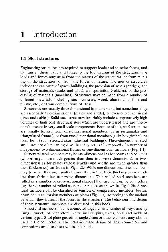
Structures are usually three-dimensional in their extent, but sometimes they are essentially two-dimensional (plates and shells), or even one-dimensional (lines and cables). Solid steel structures invariably include comparatively high volumes of high cost structural steel which are understressed and are uneconomic, except in very small scale components. Because of this, steel structures are usually formed from one-dimensional members (as in rectangular and triangulated frames), or from two-dimensional members (as in box girders), or from both (as in stressed skin industrial buildings). Three-dimensional steel structures are often arranged so that they act as if composed of a number of independent two-dimensional frames or one-dimensional members (Fig. 1.1).
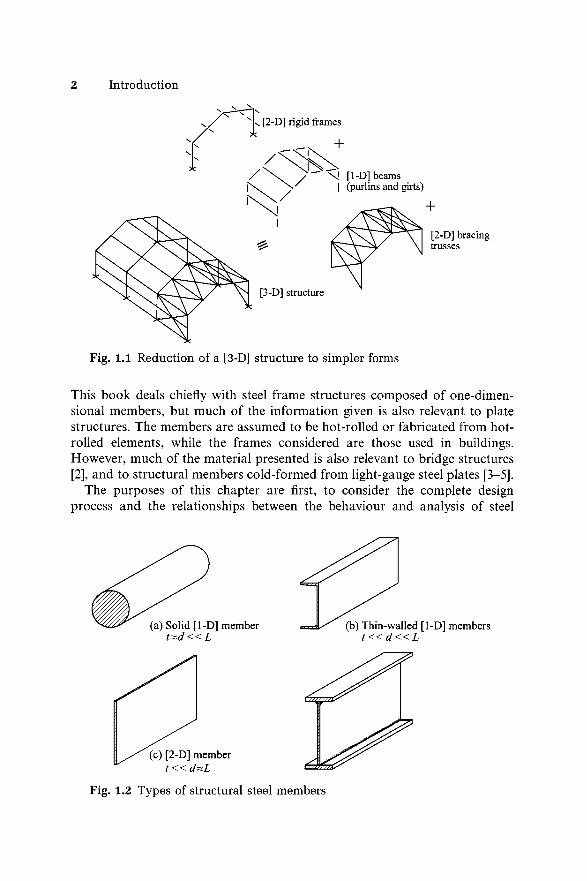
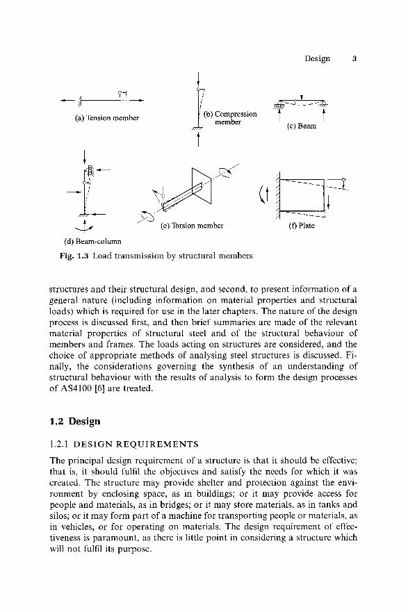
Structural steel members may be one-dimensional as for beams and columns (whose lengths are much greater than their transverse dimensions), or two- dimensional as for plates (whose lengths and widths are much greater than their thicknesses), as shown in Fig. 1.2c. While one-dimensional steel members may be solid, they are usually thin-walled, in that their thicknesses are much less than their other transverse dimensions. Thin-walled steel members are rolled in a number of cross-sectional shapes [1] or are built up by connecting together a number of rolled sections or plates, as shown in Fig. 1.2b. Structural members can be classified as tension or compression members, beams, beam-columns, torsion members or plates (Fig. 1.3), according to the method by which they transmit the forces in the structure. The behaviour and design of these structural members are discussed in this book.
Structural members may be connected together in a number of ways, and by using a variety of connectors. These include pins, rivets, bolts and welds of various types. Steel plate gussets or angle cleats or other elements may also be used in the connections. The behaviour and design of these connectors and connections are also discussed in this book.
Introduction
+
[2-D] bracing trusses
This book deals chiefly with steel frame structures composed of one-dimensional members, but much of the information given is also relevant to plate structures. The members are assumed to be hot-rolled or fabricated from hot- rolled elements, while the frames considered are those used in buildings. However, much of the material presented is also relevant to bridge structures[2], and to structural members cold-formed from light-gauge steel plates [3-5].
The purposes of this chapter are first, to consider the complete design process and the relationships between the behaviour and analysis of steel
Fig. 1.2 Types of structural steel members
Design
?1
(a) Tension member
/
(b) Compression member
---
(c) Beam
0A *
(d) Beam-column
Fig. 1.3 Load transmission by structural members
(f) Plate
structures and their structural design, and second, to present information of a general nature (including information on material properties and structural loads) which is required for use in the later chapters. The nature of the design process is discussed first, and then brief summaries are made of the relevant material properties of structural steel and of the structural behaviour of members and frames. The loads acting on structures are considered, and the choice of appropriate methods of analysing steel structures is discussed. Finally, the considerations governing the synthesis of an understanding of structural behaviour with the results of analysis to form the design processes of AS4100 [6] are treated.
1.2 D esign
1.2.1 D E S I G N R E Q U I R E M E N T S
The principal design requirement of a structure is that it should be effective; that is, it should fulfil the objectives and satisfy the needs for which it was created. The structure may provide shelter and protection against the environment by enclosing space, as in buildings; or it may provide access for people and materials, as in bridges; or it may store materials, as in tanks and silos; or it may form part of a machine for transporting people or materials, as in vehicles, or for operating on materials. The design requirement of effectiveness is paramount, as there is little point in considering a structure which will not fulfil its purpose.
4 Introduction
The satisfaction of the effectiveness requirement depends on whether the structure satisfies the structural and other requirements. The structural requirements relate to the way in which the structure resists and transfers the forces and loads acting on it. The primary structural requirement is that of safety, and the first consideration of the structural engineer is to produce a structure which will not fail in its design lifetime, or which has an acceptably low risk of failure. The other important structural requirement is usually concerned with the stiffness of the structure, which must be sufficient to ensure that the serviceability of the structure is not impaired by excessive deflections, vibrations, and the like.
The other design requirements include those of economy and of harmony. The cost of the structure, which includes both the initial cost and the cost of maintenance, is usually of great importance to the owner, and the requirement of economy usually has a significant influence on the design of the structure. The cost of the structure is affected not only by the type and quantity of the materials used, but also by the methods of fabricating and erecting it. The designer must therefore give careful consideration to the methods of construction as well as to the sizes of the members of the structure.
The requirements of harmony within the structure are affected by the relationships between the different systems of the structure, including the load resistance and transfer system (the structural system), the architectural system, the mechanical and electrical systems, and the functional systems required by the use of the structure. The serviceability of the structure is usually directly affected by the harmony, or lack of it, between the systems. The structure should also be in harmony with its environment, and should not react unfavourably with either the community or its physical surroundings.
1.2.2 T H E D E S I G N P R O C E S S
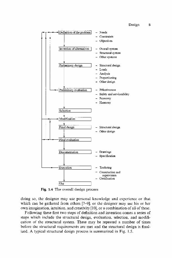
The overall purpose of design is to invent a structure which will satisfy the design requirements outlined in section 1.2.1. Thus the structural engineer seeks to invent a structural system which will resist and transfer the forces and loads acting on it with adequate safety, while making due allowance for the requirements of serviceability, economy, and harmony. The process by which this may be achieved is summarized in Fig. 1.4.
The first step is to define the overall design problem by determining the effectiveness requirements and the constraints imposed by the social and physical environments and by the owner’s time and money. The structural engineer will need to consult the owner; the architect, the site, construction, mechanical and electrical engineers; and any authorities from whom permissions and approvals must be obtained. A set of objectives can then be specified, which if met, will ensure the successful solution of the overall design problem.
The second step is to invent a number of alternative overall systems and their associated structural systems which appear to meet the objectives. In
Design
\ Definition of the problem |
Invention of alternatives
| Preliminary design"
\ Preliminary evaluation
Selection
■\ Modification
Final design
j Final evaluation
Documentation
-j Execution
Use
NeedsConstraintsObjectives
Overall system Structural system Other systems
Structural design Loads Analysis Proportioning Other design
EffectivenessSafety and serviceabilityEconomyHarmony
Structural design Other design
- Drawings- Specification
- Tendering- Construction and
supervision- Certification
Fig. 1.4 The overall design process
doing so, the designer may use personal knowledge and experience or that which can be gathered from others [7-9]; or the designer may use his or her own imagination, intuition, and creativity [10], or a combination of all of these.
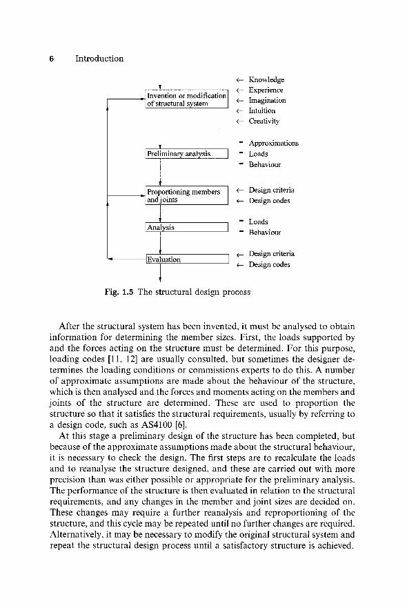
Following these first two steps of definition and invention comes a series of steps which include the structural design, evaluation, selection, and modification of the structural system. These may be repeated a number of times before the structural requirements are met and the structural design is finalized. A typical structural design process is summarized in Fig. 1.5.
6 Introduction
Invention or modification of structural system_____
| Preliminary analysis
Proportioning members and joints
1 Analysis
\ Evaluation
<-<-<-<-<-
KnowledgeExperienceImaginationIntuitionCreativity
" Approximations “ Loads ~ Behaviour
<— Design criteria <— Design codes
“ Loads " Behaviour
Design criteria <— Design codes
Fig. 1.5 The structural design process
After the structural system has been invented, it must be analysed to obtain information for determining the member sizes. First, the loads supported by and the forces acting on the structure must be determined. For this purpose, loading codes [11, 12] are usually consulted, but sometimes the designer determines the loading conditions or commissions experts to do this. A number of approximate assumptions are made about the behaviour of the structure, which is then analysed and the forces and moments acting on the members and joints of the structure are determined. These are used to proportion the structure so that it satisfies the structural requirements, usually by referring to a design code, such as AS4100 [6].
At this stage a preliminary design of the structure has been completed, but because of the approximate assumptions made about the structural behaviour, it is necessary to check the design. The first steps are to recalculate the loads and to reanalyse the structure designed, and these are carried out with more precision than was either possible or appropriate for the preliminary analysis. The performance of the structure is then evaluated in relation to the structural requirements, and any changes in the member and joint sizes are decided on. These changes may require a further reanalysis and reproportioning of the structure, and this cycle may be repeated until no further changes are required. Alternatively, it may be necessary to modify the original structural system and repeat the structural design process until a satisfactory structure is achieved.
Material behaviour 7
The alternative overall systems are then evaluated in terms of their serviceability, economy, and harmony, and a final system is selected, as indicated in Fig. 1.4. This final overall system may be modified before the design is finalized. The detailed drawings and specifications can then be prepared, and tenders for the construction can be called for and let, and the structure can be constructed. Further modifications may have to be made as a consequence of the tenders submitted or due to unforeseen circumstances discovered during construction.
This book is concerned with the structural behaviour of steel structures, and the relationships between their behaviour and the methods of proportioning them, particularly in relation to the structural requirements of the Australian Steel Structures Code AS4100 [6]. Detailed discussions of the overall design process are therefore beyond the scope of this book, but further information is given in [10, 13] on the definition of the design problem, the invention of solutions and their evaluation, and in [14-17] on the execution of design. Further, the conventional methods of structural analysis are adequately treated in many textbooks [18, 19] and are discussed in only a few isolated cases in this book.
1.3 M aterial behaviour
1.3.1 M E C H A N I C A L PROPERTIES U N D E R STATIC LOAD
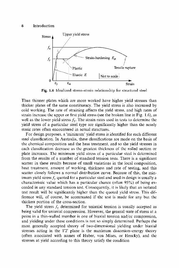
The important mechanical properties of most structural steels under static load are indicated in the idealized tensile stress-strain diagram shown in Fig. 1.6. Initially the steel has a linear stress-strain curve whose slope is the Young’s modulus of elasticity E. The values of E vary in the range 200 000- 210 000 MPa, and the approximate value of 200 000 MPa is often assumed. The steel remains elastic while in this linear range, and recovers perfectly on unloading. The limit of the linear elastic behaviour is often closely approximated by the yield stress / y and the corresponding yield strain sy = f y/E. Beyond this limit the steel flows plastically without any increase in stress until the strain-hardening strain est is reached. This plastic range is usually considerable, and accounts for the ductility of the steel. The stress increases above the yield stress / y when the strain-hardening strain est is exceeded, and this continues until the ultimate tensile stress / u is reached. After this, large local reductions in the cross-section occur, and the load capacity decreases until tensile fracture takes place.
The yield stress / y is perhaps the most important strength characteristic of a structural steel. This varies significantly with the chemical constituents of the steel, the most important of which are carbon and manganese, both of which increase the yield stress. The yield stress also varies with the heat treatment used and with the amount of working which occurs during the rolling process.
8 Introduction
Fig. 1.6 Idealized stress-strain relationship for structural steel
Thus thinner plates which are more worked have higher yield stresses than thicker plates of the same constituency. The yield stress is also increased by cold working. The rate of straining affects the yield stress, and high rates of strain increase the upper or first yield stress (see the broken line in Fig. 1.6), as well as the lower yield stress / y. The strain rates used in tests to determine the yield stress of a particular steel type are significantly higher than the nearly static rates often encountered in actual structures.
For design purposes, a ‘minimum’ yield stress is identified for each different steel classification. In Australia, these classifications are made on the basis of the chemical composition and the heat treatment, and so the yield stresses in each classification decrease as the greatest thickness of the rolled section or plate increases. The minimum yield stress of a particular steel is determined from the results of a number of standard tension tests. There is a significant scatter in these results because of small variations in the local composition, heat treatment, amount of working, thickness and rate of testing, and this scatter closely follows a normal distribution curve. Because of this, the minimum yield stress / y quoted for a particular steel and used in design is usually a characteristic value which has a particular chance (often 95%) of being exceeded in any standard tension test. Consequently, it is likely that an isolated test result will be significantly higher than the quoted yield stress. This difference will, of course, be accentuated if the test is made for any but the thickest portion of the cross-section.
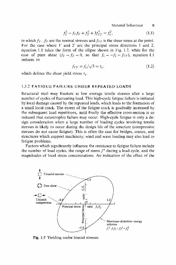
The yield stress / y determined for uniaxial tension is usually accepted as being valid for uniaxial compression. However, the general state of stress at a point in a thin-walled member is one of biaxial tension and/or compression, and yielding under these conditions is not so simply determined. Perhaps the most generally accepted theory of two-dimensional yielding under biaxial stresses acting in the 1'2' plane is the maximum distortion-energy theory (often associated with names of Huber, von Mises, or Hencky), and the stresses at yield according to this theory satisfy the condition
Material behaviour 9
f v - f v h + f i + V v 2 ' = f h (I-*)
in which / f , f 2> are the normal stresses and f V2> is the shear stress at the point. For the case where 1' and 2' are the principal stress directions 1 and 2,equation 1.1 takes the form of the ellipse shown in Fig. 1.7, while for thecase of pure shear ( f y = f 2< = 0, so that f \ — —f 2 — f v v ) , equation 1.1 reduces to
/ l ' 2 ' = / y / V 3 = Ty, (1 .2)
which defines the shear yield stress ry.
1.3.2 F A T I G U E F A I L U R E U N D E R R E P E A T E D L O A D S
Structural steel may fracture at low average tensile stresses after a large number of cycles of fluctuating load. This high-cycle fatigue failure is initiated by local damage caused by the repeated loads, which leads to the formation of a small local crack. The extent of the fatigue crack is gradually increased by the subsequent load repetitions, until finally the effective cross-section is so reduced that catastrophic failure may occur. High-cycle fatigue is only a design consideration when a large number of loading cycles involving tensile stresses is likely to occur during the design life of the structure (compressive stresses do not cause fatigue). This is often the case for bridges, cranes, and structures which support machinery; wind and wave loading may also lead to fatigue problems.
Factors which significantly influence the resistance to fatigue failure include the number of load cycles, the range of stress /* during a load cycle, and the magnitudes of local stress concentrations. An indication of the effect of the
Fig. 1.7 Yielding under biaxial stresses
10 Introduction
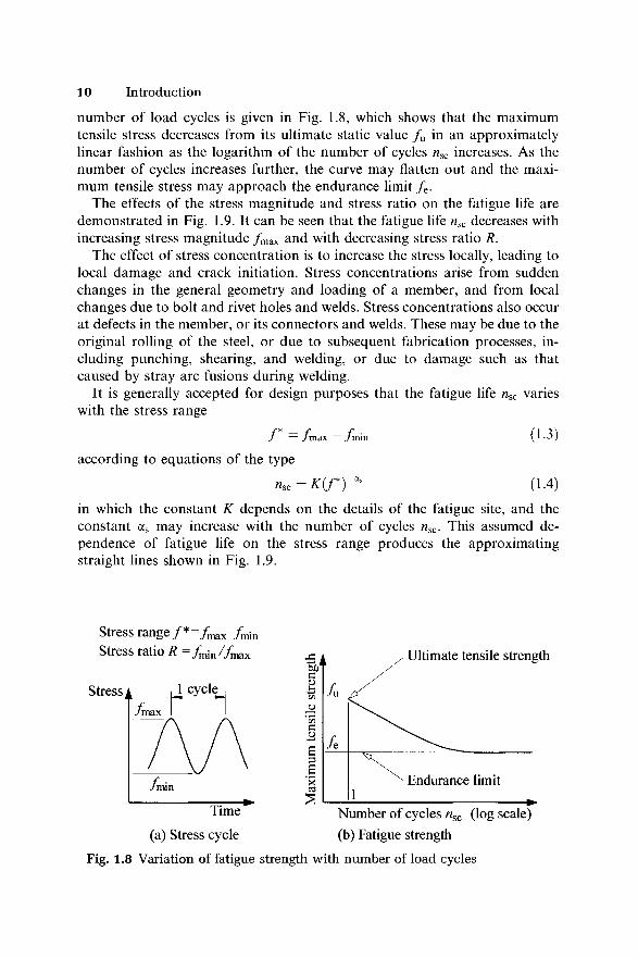
number of load cycles is given in Fig. 1.8, which shows that the maximum tensile stress decreases from its ultimate static value / u in an approximately linear fashion as the logarithm of the number of cycles nsc increases. As the number of cycles increases further, the curve may flatten out and the maximum tensile stress may approach the endurance limit / e.
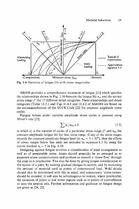
The effects of the stress magnitude and stress ratio on the fatigue life are demonstrated in Fig. 1.9. It can be seen that the fatigue life nsc decreases with increasing stress magnitude / max and with decreasing stress ratio R.
The effect of stress concentration is to increase the stress locally, leading to local damage and crack initiation. Stress concentrations arise from sudden changes in the general geometry and loading of a member, and from local changes due to bolt and rivet holes and welds. Stress concentrations also occur at defects in the member, or its connectors and welds. These may be due to the original rolling of the steel, or due to subsequent fabrication processes, including punching, shearing, and welding, or due to damage such as that caused by stray arc fusions during welding.
It is generally accepted for design purposes that the fatigue life nsc varies with the stress range
/ * = / m a x - / m i n ( 1 . 3 )
according to equations of the type
nsc= K i f T * & (1.4)in which the constant K depends on the details of the fatigue site, and the constant as may increase with the number of cycles nsc. This assumed dependence of fatigue life on the stress range produces the approximating straight lines shown in Fig. 1.9.
Stress range / * fm&x frmn Stress ratio R — / / m a x
(a) Stress cycle (b) Fatigue strength
Fig. 1.8 Variation of fatigue strength with number of load cycles
Material behaviour 11
no
Typical of experiments
Approximate equation 1.4
(Compression) Minimum stress fm[n (Tension)
Fig. 1.9 Variation of fatigue life with stress magnitudes
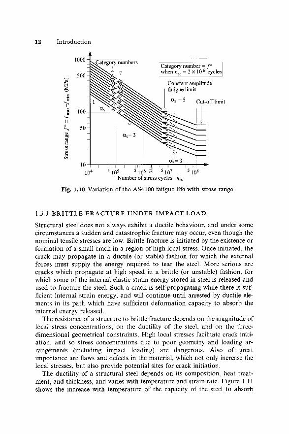
AS4100 provides a comprehensive treatment of fatigue [21] which specifies the relationships shown in Fig. 1.10 between the fatigue life nsc and the service stress range /* for 17 different detail categories. These relationships and detail categories (Table 11.5.1 and Figs 11.6.1 and 11.6.2 of AS4100) are based on the recommendations of the ECCS Code [22] for constant amplitude stress cycles.
Fatigue failure under variable amplitude stress cycles is assessed using Miner’s rule [23]
in which n* is the number of cycles of a particular stress range f* and nim the constant amplitude fatigue life for that stress range. If any of the stress ranges exceeds the constant amplitude fatigue limit (at nsc = 5 x 10⁶), then the effects of stress ranges below this limit are included in equation 1.5 by using the curves marked as = 5 in Fig. 1.10.
Designing against fatigue involves a consideration of joint arrangement as well as of permissible stress. Joints should generally be so arranged as to minimize stress concentrations and produce as smooth a ‘stress flow’ through the joint as is practicable. This may be done by giving proper consideration to the layout of a joint, by making gradual changes in section, and by increasing the amount of material used at points of concentrated load. Weld details should also be determined with this in mind, and unnecessary ‘stress-raisers’ should be avoided. It will also be advantageous to restrict, where practicable, the locations of joints to low stress regions such as at points of contraflexure or near the neutral axis. Further information and guidance on fatigue design are given in [24, 25].
(1.5)
12 Introduction
Fig. 1.10 Variation of the AS4100 fatigue life with stress range
1.3.3 B R I T T L E F R A C T U R E U N D E R I M P A C T L O A D
Structural steel does not always exhibit a ductile behaviour, and under some circumstances a sudden and catastrophic fracture may occur, even though the nominal tensile stresses are low. Brittle fracture is initiated by the existence or formation of a small crack in a region of high local stress. Once initiated, the crack may propagate in a ductile (or stable) fashion for which the external forces must supply the energy required to tear the steel. More serious are cracks which propagate at high speed in a brittle (or unstable) fashion, for which some of the internal elastic strain energy stored in steel is released and used to fracture the steel. Such a crack is self-propagating while there is sufficient internal strain energy, and will continue until arrested by ductile elements in its path which have sufficient deformation capacity to absorb the internal energy released.
The resistance of a structure to brittle fracture depends on the magnitude of local stress concentrations, on the ductility of the steel, and on the three- dimensional geometrical constraints. High local stresses facilitate crack initiation, and so stress concentrations due to poor geometry and loading arrangements (including impact loading) are dangerous. Also of great importance are flaws and defects in the material, which not only increase the local stresses, but also provide potential sites for crack initiation.
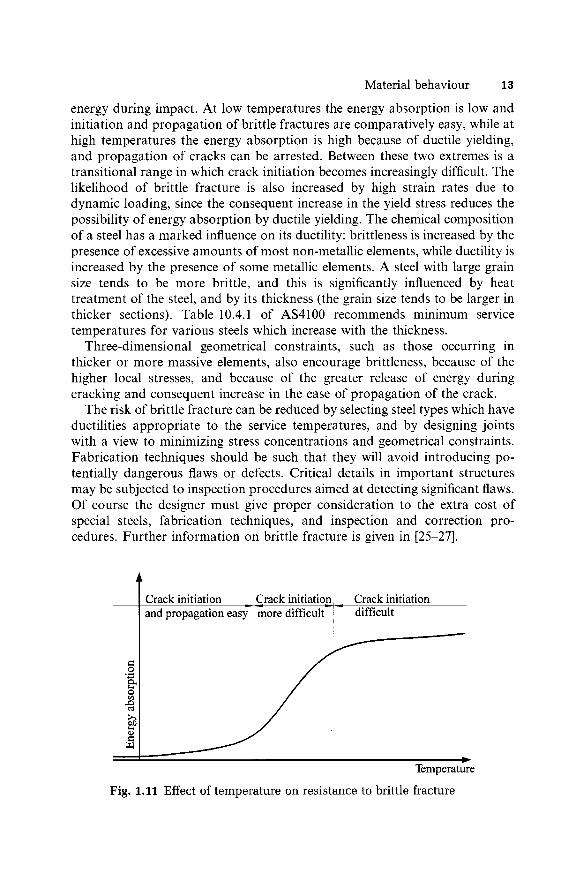
The ductility of a structural steel depends on its composition, heat treatment, and thickness, and varies with temperature and strain rate. Figure 1.11 shows the increase with temperature of the capacity of the steel to absorb
Material behaviour 13
energy during impact. At low temperatures the energy absorption is low and initiation and propagation of brittle fractures are comparatively easy, while at high temperatures the energy absorption is high because of ductile yielding, and propagation of cracks can be arrested. Between these two extremes is a transitional range in which crack initiation becomes increasingly difficult. The likelihood of brittle fracture is also increased by high strain rates due to dynamic loading, since the consequent increase in the yield stress reduces the possibility of energy absorption by ductile yielding. The chemical composition of a steel has a marked influence on its ductility: brittleness is increased by the presence of excessive amounts of most non-metallic elements, while ductility is increased by the presence of some metallic elements. A steel with large grain size tends to be more brittle, and this is significantly influenced by heat treatment of the steel, and by its thickness (the grain size tends to be larger in thicker sections). Table 10.4.1 of AS4100 recommends minimum service temperatures for various steels which increase with the thickness.
Three-dimensional geometrical constraints, such as those occurring in thicker or more massive elements, also encourage brittleness, because of the higher local stresses, and because of the greater release of energy during cracking and consequent increase in the ease of propagation of the crack.
The risk of brittle fracture can be reduced by selecting steel types which have ductilities appropriate to the service temperatures, and by designing joints with a view to minimizing stress concentrations and geometrical constraints. Fabrication techniques should be such that they will avoid introducing potentially dangerous flaws or defects. Critical details in important structures may be subjected to inspection procedures aimed at detecting significant flaws. Of course the designer must give proper consideration to the extra cost of special steels, fabrication techniques, and inspection and correction procedures. Further information on brittle fracture is given in [25-27].
Fig. 1.11 Effect of temperature on resistance to brittle fracture
14 Introduction
1.4.1 M E M B E R B E H A V I O U R
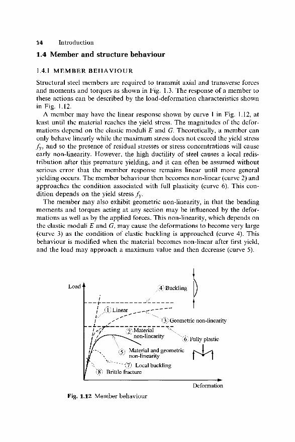
Structural steel members are required to transmit axial and transverse forces and moments and torques as shown in Fig. 1.3. The response of a member to these actions can be described by the load-deformation characteristics shown in Fig. 1.12.
A member may have the linear response shown by curve 1 in Fig. 1.12, at least until the material reaches the yield stress. The magnitudes of the deformations depend on the elastic moduli E and G. Theoretically, a member can only behave linearly while the maximum stress does not exceed the yield stress / y, and so the presence of residual stresses or stress concentrations will cause early non-linearity. However, the high ductility of steel causes a local redistribution after this premature yielding, and it can often be assumed without serious error that the member response remains linear until more general yielding occurs. The member behaviour then becomes non-linear (curve 2) and approaches the condition associated with full plasticity (curve 6). This condition depends on the yield stress / y.
The member may also exhibit geometric non-linearity, in that the bending moments and torques acting at any section may be influenced by the deformations as well as by the applied forces. This non-linearity, which depends on the elastic moduli E and G, may cause the deformations to become very large (curve 3) as the condition of elastic buckling is approached (curve 4). This behaviour is modified when the material becomes non-linear after first yield, and the load may approach a maximum value and then decrease (curve 5).
1.4 Member and structure behaviour
t
Deformation
Fig. 1.12 Member behaviour
Member and structure behaviour 15
The member may also behave in a brittle fashion because of local buckling in a thin plate element of the member (curve 7), or because of material fracture (curve 8).
The actual behaviour of an individual member will depend on the forces acting on it. Thus tension members, laterally supported beams, and torsion members remain linear until their material non-linearity becomes important, and then they approach the fully plastic condition. However, compression members and laterally unsupported beams show geometric non-linearity as they approach their buckling loads. Beam-columns are members which transmit both transverse and axial loads, and so they display both material and geometric non-linearities.
1.4.2 S T R U C T U R E B E H A V I O U R
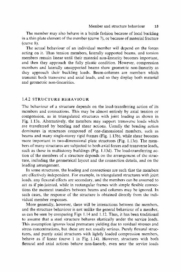
The behaviour of a structure depends on the load-transferring action of its members and connections. This may be almost entirely by axial tension or compression, as in triangulated structures with joint loading as shown in Fig. 1.13a. Alternatively, the members may support transverse loads which are transferred by bending and shear actions. Usually the bending action dominates in structures composed of one-dimensional members, such as beams and many single-storey rigid frames (Fig. 1.13b), while shear becomes more important in two-dimensional plate structures (Fig. 1.13c). The members of many structures are subjected to both axial forces and transverse loads, such as those in multistorey buildings (Fig. 1.13d). The load-transferring action of the members of a structure depends on the arrangement of the structure, including the geometrical layout and the connection details, and on the loading arrangement.
In some structures, the loading and connections are such that the members are effectively independent. For example, in triangulated structures with joint loads, any flexural effects are secondary, and the members can be assumed to act as if pin-jointed, while in rectangular frames with simple flexible connections the moment transfers between beams and columns may be ignored. In such cases, the response of the structure is obtained directly from the individual member responses.
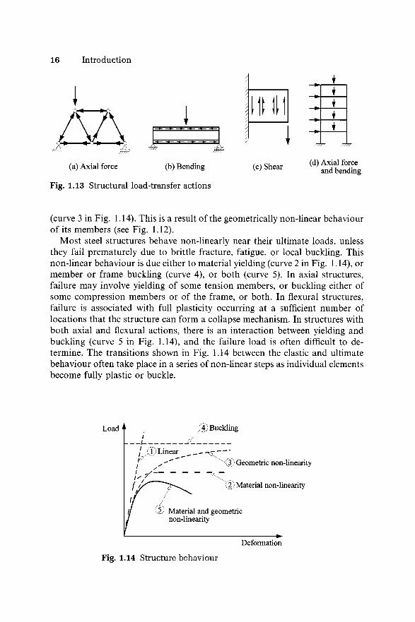
More generally, however, there will be interactions between the members, and the structure behaviour is not unlike the general behaviour of a member, as can be seen by comparing Figs 1.14 and 1.12. Thus, it has been traditional to assume that a steel structure behaves elastically under the service loads. This assumption ignores local premature yielding due to residual stresses and stress concentrations, but these are not usually serious. Purely flexural structures, and purely axial structures with lightly loaded compression members, behave as if linear (curve 1 in Fig. 1.14). However, structures with both flexural and axial actions behave non-linearly, even near the service loads
16 Introduction
/
I tini"rtrrb/////
(a) Axial force (b) Bending (c) Shear (d) Axial force and bending
Fig. 1.13 Structural load-transfer actions
(curve 3 in Fig. 1.14). This is a result of the geometrically non-linear behaviour of its members (see Fig. 1.12).
Most steel structures behave non-linearly near their ultimate loads, unless they fail prematurely due to brittle fracture, fatigue, or local buckling. This non-linear behaviour is due either to material yielding (curve 2 in Fig. 1.14), or member or frame buckling (curve 4), or both (curve 5). In axial structures, failure may involve yielding of some tension members, or buckling either of some compression members or of the frame, or both. In flexural structures, failure is associated with full plasticity occurring at a sufficient number of locations that the structure can form a collapse mechanism. In structures with both axial and flexural actions, there is an interaction between yielding and buckling (curve 5 in Fig. 1.14), and the failure load is often difficult to determine. The transitions shown in Fig. 1.14 between the elastic and ultimate behaviour often take place in a series of non-linear steps as individual elements become fully plastic or buckle.
Load
(3) Geometric non-linearity
2) Material non-linearity
Deformation
Fig. 1.14 Structure behaviour
Loads 17
1.5 Loads
1.5.1 G E N E R A L
The loads acting on steel structures may be classified as dead loads, as live loads, including both gradually applied and dynamic loads, as forces of nature such as wind, snow, and earthquake forces, or as indirect forces, including those due to temperature changes, foundation settlement, and the like. The structural engineer must evaluate the magnitudes of any of these loads which will act, and must determine which are the most severe combinations of loads for which the structure must be designed. These loads are discussed in the following subsections, both individually and in combinations.
1.5.2 D E A D LOADS
The dead loads acting on a structure arise from the weight of the structure including the finishes, and from any other permanent construction or equipment. The dead loads will vary during construction, but thereafter will remain constant, unless significant modifications are made to the structure or its permanent equipment.
The dead load may be assessed from a knowledge of the dimensions and specific weights or from the total weights of all the permanent items which contribute to the total dead load. Guidance on specific weights is given in [11], the values in which are average values representative of the particular materials. The dimensions used to estimate dead loads should also be average and representative, in order that consistent estimates of the dead loads can be made. By making these assumptions, the statistical distribution of dead loads is often taken as being of a Weibull type [28]. The practice sometimes used of consistently overestimating dimensions and specific weights is often wasteful, and may also be dangerous in cases where the dead load component acts in the opposite sense to the resultant load.
1.5.3 LIVE LOADS
The live loads are those loads on the structure which result from its use by man, and these usually vary both in space and time. Live loads may be subdivided into two groups, depending on whether they are gradually applied, in which case static load equivalents can be used, or whether they are dynamic, including repeated loads and impact or impulsive loads.
Gradually applied live loads, which include the horizontal forces exerted on earth or water retaining structures as well as the vertical gravity loads, may be sustained over long periods of time, or may vary slowly with time [29]. The past practice, however, was to consider only the total live load, and so only extreme values (which occur rarely and may be regarded as lifetime maximum
18 Introduction
loads) were specified. The present strength live loads specified in loading codes [11] often represent peak loads which have 95% probability of not being exceeded over a 50 year period based on a Weibull type distribution [28]. Short and long term service live loads are specified in [11] by multiplying the strength live loads by reduction factors.
It is usual to consider the most severe spatial distribution of the live loads, and this can only be determined by using both the maximum and minimum values of the live loads. In the absence of definite knowledge, it is often assumed that the minimum values are zero. When the distribution of live load over large areas is being considered, the maximum live loads specified, which represent rare events, are often reduced in order to make some allowance for the decreased probability that the maximum live loads will act on all areas at the same time.
Dynamic live loads which act on structures include both repeated loads and impact and blast loads. Repeated loads are of significance in fatigue problems (see section 1.3.2), in which case the designer is concerned with both the magnitudes, ranges, and number of repetitions of loads which are very frequently applied. At the other extreme, impact loads (which are particularly important in the brittle fracture problems discussed in section 1.3.3) are usually specified by values of extreme magnitude which represent rare events. In structures for which the static loads dominate, it is common to replace the dynamic loads by static force equivalents [11]. However, such a procedure is likely to be inappropriate when the dynamic loads form a significant proportion of the total load, in which case a proper dynamic analysis [30, 31] of the structure and its response should be made.
1.5.4 F O R C E S OF N A T U R E
The wind forces which act on structures have traditionally been allowed for by using static force equivalents. The first step is usually to determine a basic wind speed for the general region in which the structure is to be built by using information derived from meteorological studies. This basic wind speed may represent an extreme velocity measured at a height of 10 m and averaged over a period of 3 s which has a return period of 50 years (i.e. a velocity which will, on average, be reached or exceeded once in 50 years, or have a probability of being exceeded of 1/50). The basic wind speed may be adjusted to account for the topography of the site, for the ground roughness, structure size, and height above ground, and for the degree of safety required and the period of exposure. The resulting design wind speed may then be converted into the static pressure which will be exerted by the wind on a plane surface area (this is often referred to as the dynamic wind pressure because it is produced by decelerating the approaching wind velocity to zero at the surface area). The wind force acting on the structure may then be calculated by using pressure coefficients appropriate to each individual surface of the structure, or by using force coefficients appropriate to the total structure. Many values of these
Loads 19
coefficients are tabulated in [12], but in special cases where these are inappropriate, the results of wind tunnel tests on model structures may be used.
In some cases it is not sufficient to treat wind loads as static forces. For example, when fatigue is a problem, both the magnitudes and the number of wind fluctuations must be estimated. In other cases, the dynamic response of a structure to wind loads may have to be evaluated (this is often the case with very flexible structures whose long natural periods of vibration are close to those of some of the wind gusts), and this may be done analytically [30, 31], or by specialists using wind tunnel tests. In these cases, special care must be taken to model correctly those properties of the structure which affect its response, including its mass, stiffness, and damping, as well as the wind characteristics and any interactions between wind and structure.
Other forces of nature include snow loads and earthquake loads. Both of these vary in intensity with the region in which the structure is to be built, and in many cases their occurrence is so rare that they may be neglected. Where snow loads are important, they are usually allowed for by making appropriate changes to the design live loads calculated for the exposed areas of the structure.
In regions of high seismicity, the effects on the structure of earthquake ground motions of appropriate magnitude and distribution in time must be allowed for. Very flexible structures with long natural periods of vibration respond in an equivalent static manner to the high frequencies of earthquake movements, and so can be designed as if loaded by static force equivalents. On the other hand, stiff structures with short natural periods of vibration respond significantly and so a proper dynamic analysis [30, 31] should be made in such a case. Additional minimum requirements for earthquake design are given in AS4100.
1.5.5 I N D I R E C T F O R C E S
Indirect forces may be described as those forces which result from the straining of a structure or its components, and may be distinguished from the direct forces caused by the dead and applied loads and pressures. The straining may arise from temperature changes, from foundation settlement, from shrinkage, creep, or cracking of structural or other materials, and from the manufacturing process as in the case of residual stresses. The values of indirect forces are not usually specified, and so it is common for the designer to determine which of these forces should be allowed for, and what force magnitudes should be adopted.
1.5.6 C O M B IN A T IO N S OF LOADS
The different loads discussed in the preceding subsections do not occur alone, but in combinations, and so the designer must determine which combination is
20 Introduction
the most critical for the structure. However, if the individual loads, which have different probabilities of occurrence and degrees of variability, were combined directly, the resulting load combination would have a greatly reduced probability. Thus, it is logical to reduce the magnitudes of the various components of a combination according to their probabilities of occurrence. This is similar to the procedure used in reducing the live load intensities used over large areas.
The past design practice was to use the worst combination of dead load with live load and/or wind load, and to allow increased stresses whenever the wind load was included (which is equivalent to reducing the load magnitudes). These increases seem to be logical when live and wind loads act together because the probability that both of these loads will attain their maximum values simultaneously is greatly reduced. However, they are unjustified when applied in the case of dead and wind load, for which the probability of occurrence is virtually unchanged from that of the wind load.
A different and more logical method of combining loads is used in the AS4100 limit states design method [6], which is based on statistical analyses of the loads and the structure capacities (see section 1.7.3.4). Strength design is usually carried out for the most severe combination [11] of
(1) (1.25 x dead) + (1.5 x live),(2) -(0 .8 x dead) + (1.5 x live),(3) (1.25 x dead) + (iAc x live) + (wind),(4) -(0 .8 x dead) + (wind),
in which the negative signs indicate that the dead loads act in the opposite sense to the live or wind load. The partial factor i]/c is a live load combination factor which is equal to 0.4 or 0.6. The different factors used for dead, live and wind loads reflect the different probabilities of overload associated with each individual load (for example, the probability of a 50% increase in the dead load is much less than that for an equal increase in the live load), and with each load combination. The use of load combinations in design according to AS4100 is illustrated in [32].
1.6 A n alysis o f steel structures
1.6.1 G E N E R A L
In the design process, the assessment of whether the structural design requirements will be met or not requires a knowledge of the stiffness and strength of the structure under load, and of its local stresses and deformations. The term structural analysis is used to denote the analytical process by which this knowledge of the response of the structure can be obtained. The basis for this process is a knowledge of the material behaviour, and this is used first to
Analysis of steel structures 21
analyse the behaviour of the individual members and connections of the structure. The behaviour of the complete structure is then synthesized from these individual behaviours.
The methods of structural analysis are fully treated in many textbooks [e.g. 18-20], and so details of these are not within the scope of this book. However, some discussion of the concepts and assumptions of structural analysis is necessary so that the designer can make appropriate assumptions about the structure and make a suitable choice of the method of analysis.
In most methods of structural analysis, the distribution of forces and moments throughout the structure is determined by using the conditions of static equilibrium and of geometric compatibility between the members at the joints. The way in which this is done depends on whether a structure is statically determinate (in which case the complete distribution of forces and moments can be determined by statics alone), or is statically indeterminate (in which case the compatibility conditions for the deformed structure must also be used before the analysis can be completed).
An important feature of the methods of structural analysis is the constitutive relationships between the forces and moments acting on a member or connection and its deformations. These play the same role for the structural element as do the stress-strain relationships for an infinitesimal element of a structural material. The constitutive relationship may be linear (force proportional to deflection) and elastic (perfect recovery on unloading), or they may be non-linear because of material non-linearities such as yielding (inelastic), or because of geometrical non-linearities (elastic) such as when the deformations themselves induce additional moments, as in stability problems.
It is common for the designer to idealize the structure and its behaviour so as to simplify the analysis. A three-dimensional frame structure may be analysed as a number of independent two-dimensional frames, while individual members are usually considered as one-dimensional and the connections as points. The connections may be assumed to be frictionless hinges, or to be semi-rigid or rigid. In some cases the analysis may be replaced or supplemented by tests made on an idealized model which approximates part or all of the structure.
1.6.2 A N A L Y S I S OF S T A T I C A L L Y D E T E R M I N A T E M E M B E R S A N D S T R U C T U R E S
For an isolated statically determinate member, the forces and moments acting on the member are already known, and the structural analysis is only used to determine the stiffness and strength of the member. A linear elastic (or first- order elastic) analysis is usually made of the stiffness of the member when the material non-linearities are generally unimportant and the geometrical non- linearities are often small. The strength of the member, however, is not so easily determined, as one or both of the material and geometric non-linearities
22 Introduction
are most important. Instead, the designer usually relies on a design code or specification for this information. The strength of isolated statically determinate members is fully discussed in Chapters 2-7 and 10.
For a statically determinate structure, the principles of static equilibrium are used in the structural analysis to determine the member forces and moments, and the stiffness and strength of each member are then determined in the same way as for statically determinate members.
1.6.3 A N A L Y S I S OF S T A T I C A L L Y I N D E T E R M I N A T E S T R U C T U R E S
A statically indeterminate structure can be approximately analysed if a sufficient number of assumptions are made about its behaviour to allow it to be treated as if determinate. One method of doing this is to guess the locations of points of zero bending moment and to assume there are frictionless hinges at a sufficient number of these locations that the member forces and moments can be determined by statics alone. Such a procedure is commonly used in the preliminary analysis of a structure, and followed at a later stage by a more precise analysis. However, a structure designed only on the basis of an approximate analysis can still be safe, provided the structure has sufficient ductility to redistribute any excess forces and moments. Indeed, the method is often conservative, and its economy increases with the accuracy of the estimated locations of the points of zero bending moment. More commonly, a preliminary analysis is made of the structure based on the linear elastic computer methods of analysis [33, 34], using approximate member stiffnesses.
The accurate analysis of statically indeterminate structures is complicated by the interaction between members: the equilibrium and compatibility conditions and the constitutive relationships must all be used in determining the member forces and moments. There are a number of different types of analysis which might be made, and some indication of the relevance of these is given in Fig. 1.15 and in the following discussion. Many of these can only be used for two-dimensional frames.
For many structures, it is common to use a first-order elastic analysis which is based on linear elastic constitutive relationships and which ignores any geometrical non-linearities and associated instability problems. The deformations determined by such an analysis are proportional to the applied loads, and so the principle of superposition can be used to simplify the analysis. It is often assumed that axial and shear deformations can be ignored in structures whose action is predominantly flexural, and that flexural and shear deformations can be ignored in structures whose member forces are predominantly axial. These assumptions further simplify the analysis, which can then be carried out by any of the well-known methods [18-20], for which many computer programs are available [35, 36]. Some of these programs can be used for three-dimensional frames.
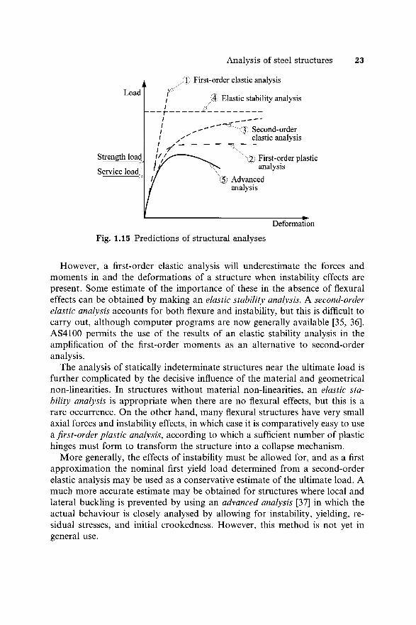
Analysis of steel structures 23
However, a first-order elastic analysis will underestimate the forces and moments in and the deformations of a structure when instability effects are present. Some estimate of the importance of these in the absence of flexural effects can be obtained by making an elastic stability analysis. A second-order elastic analysis accounts for both flexure and instability, but this is difficult to carry out, although computer programs are now generally available [35, 36]. AS4100 permits the use of the results of an elastic stability analysis in the amplification of the first-order moments as an alternative to second-order analysis.
The analysis of statically indeterminate structures near the ultimate load is further complicated by the decisive influence of the material and geometrical non-linearities. In structures without material non-linearities, an elastic stability analysis is appropriate when there are no flexural effects, but this is a rare occurrence. On the other hand, many flexural structures have very small axial forces and instability effects, in which case it is comparatively easy to use a first-order plastic analysis, according to which a sufficient number of plastic hinges must form to transform the structure into a collapse mechanism.
More generally, the effects of instability must be allowed for, and as a first approximation the nominal first yield load determined from a second-order elastic analysis may be used as a conservative estimate of the ultimate load. A much more accurate estimate may be obtained for structures where local and lateral buckling is prevented by using an advanced analysis [37] in which the actual behaviour is closely analysed by allowing for instability, yielding, residual stresses, and initial crookedness. However, this method is not yet in general use.
24 Introduction
1.7 D esign o f steel structures
1.7.1 S T R U C T U R A L R E Q U I R E M E N T S A N D D E S I G N C R I T E R I A
The designer’s task of assessing whether or not a structure will satisfy the structural requirements of serviceability and strength is complicated by the existence of errors and uncertainties in his or her analysis of the structural behaviour and estimation of the loads acting, and even in the structural requirements themselves. The designer usually simplifies this task by using a number of design criteria which allow him or her to relate the structural behaviour predicted by his or her analysis to the structural requirements. Thus the designer equates the satisfaction of these criteria by the predicted structural behaviour with satisfaction of the structural requirements by the actual structure.
In general, the various structural design requirements relate to corresponding limit states, and so the design of a structure to satisfy all the appropriate requirements is often referred to as a limit states design. The requirements are commonly presented in a deterministic fashion, by requiring that the structure shall not fail, or that its deflections shall not exceed prescribed limits. However, it is not possible to be completely certain about the structure and its loading, and so the structural requirements may also be presented in probabilistic forms, or in deterministic forms derived from probabilistic considerations. This may be done by defining an acceptably low risk of failure within the design life of the structure, after reaching some sort of balance between the initial cost of the structure and the economic and human losses resulting from failure. In many cases there will be a number of structural requirements which operate at different load levels, and it is not unusual to require a structure to suffer no damage at one load level, but to permit some minor damage to occur at a higher load level, provided there is no catastrophic failure.
The structural design criteria may be determined by the designer, or he or she may use those stated or implied in design codes. The stiffness design criteria adopted are usually related to the serviceability limit state of the structure under the service loads, and are concerned with ensuring that the structure has sufficient stiffness to prevent excessive deflections such as sagging, distortion, and settlement, and excessive motions under dynamic load, including sway, bounce, and vibration.
The strength limit state design criteria are related to the possible methods of failure of the structure under overload and understrength conditions, and so these design criteria are concerned with yielding, buckling, brittle fracture, and fatigue. Also of importance is the ductility of the structure at and near failure: ductile structures give warning of impending failure and often redistribute load effects away from the critical regions, while ductility provides a method of energy dissipation which will reduce damage due to earthquake and blast
Design of steel structures 25
loading. On the other hand, a brittle failure is more serious, as it occurs with no warning of failure, and in a catastrophic fashion with a consequent release of stored energy and increase in damage. Other design criteria may also be adopted, such as those related to corrosion and fire.
1.7.2 E R R O R S A N D U N C E R T A I N T I E S
In determining the limitations prescribed by design criteria, account must be taken of the deliberate and accidental errors made by the designer, and of the uncertainties in his or her knowledge of the structure and its loads. Deliberate errors include those resulting from the assumptions made to simplify the analysis of the loading and of the structural behaviour. These assumptions are often made so that any errors involved are on the safe side, but in many cases the nature of the errors involved is not precisely known, and some possibility of danger exists.
Accidental errors include those due to a general lack of precision, either in the estimation of the loads and the analysis of the structural behaviour, or in the manufacture and erection of the structure. The designer usually attempts to control the magnitudes of these, by limiting them to what he or she judges to be suitably small values. Other accidental errors include what are usually termed blunders. These may be of a gross magnitude leading to failure or to uneconomic structures, or they may be less important. Attempts are usually made to eliminate blunders by using checking procedures, but often these are unreliable, and the logic of such a process is open to debate.
As well as the errors described above, there exists a number of uncertainties about the structure itself and its loads. The material properties of steel fluctuate, especially the yield stress and the residual stresses. The practice of using a minimum or characteristic yield stress for design purposes usually leads to oversafe designs, especially for redundant structures of reasonable size, for which an average yield stress would be more appropriate because of the redistribution of load which takes place after early yielding. Variations in the residual stress levels are not often accounted for in design codes, but there is a growing tendency to adjust design criteria in accordance with the method of manufacture so as to make some allowance for gross variations in the residual stresses. This is undertaken to some extent in AS4100.
The cross-sectional dimensions of rolled steel sections vary, and the values given in section handbooks are only nominal, especially for the thicknesses of universal sections. The fabricated lengths of a structural member will vary slightly from the nominal length, but this is usually of little importance, except where the variation induces additional stresses because of lack-of-fit problems, or where there is a cumulative geometrical effect. Of some significance to members subject to instability problems are variations in their straightness which arise during manufacture, fabrication, and erection. Some allowances
26 Introduction
for these are usually made in design codes, while fabrication and erection tolerances are specified in AS4100 to prevent excessive crookedness.
The loads acting on a structure vary significantly. Uncertainty exists in the designer’s estimate of the magnitude of the dead load because of variations in the densities of materials, and because of minor modifications to the structure during or subsequent to its erection. Usually these variations are not very significant and a common practice is to err on the safe side by making conservative assumptions. Live loadings fluctuate significantly during the design usage of the structure, and may change dramatically with changes in usage. These fluctuations are usually accounted for by specifying what appear to be extreme values in loading codes, but there is often a finite chance that these values will be exceeded. Wind loads vary greatly and the magnitudes specified in loading codes are usually obtained by probabilistic methods.
1.7.3 S T R E N G T H D E S I G N
1.7.3.1 Load and capacity factors, and factors o f safety
The errors and uncertainties involved in the estimation of the loads on and the behaviour of a structure may be allowed for in strength design by using load factors to increase the nominal loads and capacity factors to decrease the structural strength. In the previous codes that employed the traditional working stress design, this was achieved by using factors of safety to reduce the failure stresses to permissible working stress values. The purpose of using these various factors is to ensure that the probability of failure under the most adverse conditions of structural overload and understrength, remains very small. The use of these factors is discussed in the following subsections.
1.7.3.2 Working stress design
The working stress methods of design given in previous codes and specifications required that the stresses calculated from the most adverse combination of loads must not exceed the specified permissible stresses. These specified stresses were obtained after making some allowances for the non-linear stability and material effects on the strength of isolated members, and in effect, were expressions of their ultimate strengths divided by the factors of safety SF. Thus
- . ^ , Ultimate stress ^Working stress ^ Permissible stress « --------—-------- . (1.6)
SrIt was traditional to use factors of safety of 1/0.60 approximately.
The working stress method of the previous steel design code has been replaced by the limit states design method of AS4100. Detailed discussions of the working stress method are available in the first edition of this book [38].
Design of steel structures 27
1.733 Ultimate load design
The ultimate load methods of designing steel structures required that the calculated ultimate load carrying capacity of the complete structure must not exceed the most adverse combination of loads obtained by multiplying the working loads by the appropriate load factors LF. Thus
(Working load x LF) ^ Ultimate load. (1.7)
These load factors allowed some margins for any deliberate and accidental errors, and for the uncertainties in the structure and its loads, and also provided the structure with a reserve of strength. The values of the factors should depend on the load type and combination, and also on the risk of failure that could be expected and the consequences of failure. A simplified approach often employed (perhaps illogically) was to use a single load factor on the most adverse combination of the working loads.
The previous codes and specifications allowed the use of the plastic method of ultimate load design when stability effects were unimportant. These used load factors of 1/0.60 approximately. However, this ultimate load method has also been replaced in AS4100, and will not be discussed further.
1.73.4 Limit states design
It was pointed out in section 1.5.6 that different types of load have different probabilities of occurrence and different degrees of variability, and that the probabilities associated with these loads change in different ways as the degree of overload considered increases. Because of this, different load factors should be used for the different load types.
Thus for a limit states design, the strength limit state of a structure is deemed to be satisfactory if its calculated nominal capacity, reduced by an appropriate capacity factor </>, exceeds the sum of the nominal load effects multiplied by different load factors y, so that
y^(y x Nominal load effects) ^ </> x Nominal capacity (1.8a)
or
Design load effect ^ Design capacity, (1.8b)
where the nominal load effects are the appropriate bending moments, torques, axial forces or shear forces, determined from the nominal applied loads by an appropriate method of structural analysis.
Although the limit states design method is presented in deterministic form in equations 1.8, the load and capacity factors involved are usually obtained by using probabilistic models based on statistical distributions of the loads and the capacities. Typical statistical distributions of the total load and the structural capacity are shown in Fig. 1.16. The probability of failure p? is
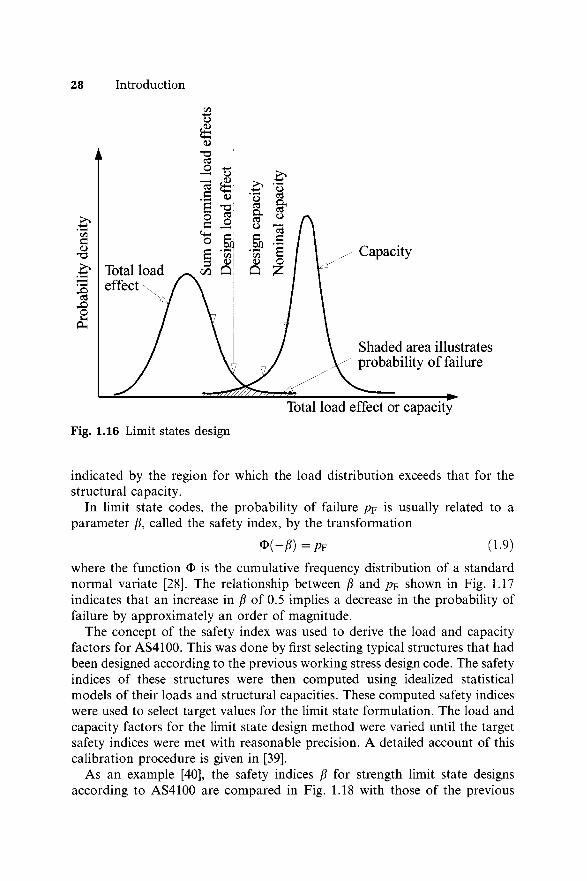
28 Introduction
<D
Fig. 1.16 Limit states design
indicated by the region for which the load distribution exceeds that for the structural capacity.
In limit state codes, the probability of failure p? is usually related to a parameter /?, called the safety index, by the transformation
* ( - P ) = P F (1.9)where the function O is the cumulative frequency distribution of a standard normal variate [28]. The relationship between /? and p? shown in Fig. 1.17 indicates that an increase in /? of 0.5 implies a decrease in the probability of failure by approximately an order of magnitude.
The concept of the safety index was used to derive the load and capacity factors for AS4100. This was done by first selecting typical structures that had been designed according to the previous working stress design code. The safety indices of these structures were then computed using idealized statistical models of their loads and structural capacities. These computed safety indices were used to select target values for the limit state formulation. The load and capacity factors for the limit state design method were varied until the target safety indices were met with reasonable precision. A detailed account of this calibration procedure is given in [39].
As an example [40], the safety indices /? for strength limit state designs according to AS4100 are compared in Fig. 1.18 with those of the previous
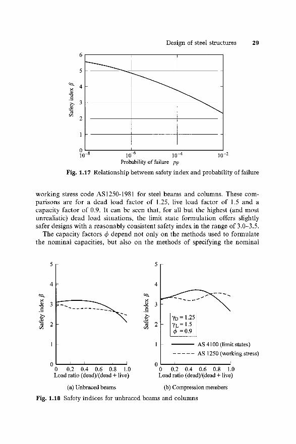
6
Design of steel structures 29
Probability of failure pF
Fig. 1.17 Relationship between safety index and probability of failure
working stress code AS 1250-1981 for steel beams and columns. These comparisons are for a dead load factor of 1.25, live load factor of 1.5 and a capacity factor of 0.9. It can be seen that, for all but the highest (and most unrealistic) dead load situations, the limit state formulation offers slightly safer designs with a reasonably consistent safety index in the range of 3.0-3.5.
The capacity factors </> depend not only on the methods used to formulate the nominal capacities, but also on the methods of specifying the nominal
Load ratio (dead)/(dead + live)
(a) Unbraced beams
Load ratio (dead)/(dead + live)
(b) Compression members
Fig. 1.18 Safety indices for unbraced beams and columns
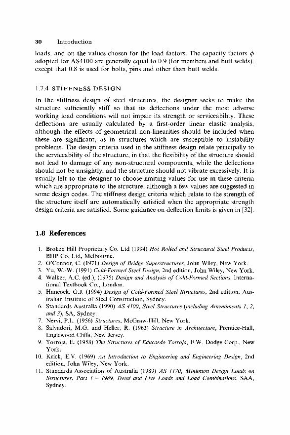
30 Introduction
loads, and on the values chosen for the load factors. The capacity factors </> adopted for AS4100 are generally equal to 0.9 (for members and butt welds), except that 0.8 is used for bolts, pins and other than butt welds.
1.7.4 S T I F F N E S S D E S I G N
In the stiffness design of steel structures, the designer seeks to make the structure sufficiently stiff so that its deflections under the most adverse working load conditions will not impair its strength or serviceability. These deflections are usually calculated by a first-order linear elastic analysis, although the effects of geometrical non-linearities should be included when these are significant, as in structures which are susceptible to instability problems. The design criteria used in the stiffness design relate principally to the serviceability of the structure, in that the flexibility of the structure should not lead to damage of any non-structural components, while the deflections should not be unsightly, and the structure should not vibrate excessively. It is usually left to the designer to choose limiting values for use in these criteria which are appropriate to the structure, although a few values are suggested in some design codes. The stiffness design criteria which relate to the strength of the structure itself are automatically satisfied when the appropriate strength design criteria are satisfied. Some guidance on deflection limits is given in [32].
I .8 R eferences
1. Broken Hill Proprietary Co. Ltd (1994) Hot Rolled and Structural Steel Products, BHP Co. Ltd, Melbourne.
2. O’Connor, C. (1971) Design of Bridge Superstructures, John Wiley, New York.3. Yu, W.-W. (1991) Cold-Formed Steel Design, 2nd edition, John Wiley, New York.4. Walker, A.C. (ed.), (1975) Design and Analysis of Cold-Formed Sections, Interna
tional Textbook Co., London.5. Hancock, G.J. (1994) Design of Cold-Formed Steel Structures, 2nd edition, Aus
tralian Institute of Steel Construction, Sydney.6. Standards Australia (1990) A S 4100, Steel Structures (including Amendments f 2,
and 3), SA, Sydney.7. Nervi, P.L. (1956) Structures, McGraw-Hill, New York.8. Salvadori, M.G. and Heller, R. (1963) Structure in Architecture, Prentice-Hall,
Englewood Cliffs, New Jersey.9. Torroja, E. (1958) The Structures of Educardo Torroja, F.W. Dodge Corp., New
York.10. Krick, E.V. (1969) An Introduction to Engineering and Engineering Design, 2nd
edition, John Wiley, New York.II. Standards Association of Australia (1989) A S 1170, Minimum Design Loads on
Structures, Part 1 - 1989, Dead and Live Loads and Load Combinations, SAA, Sydney.
References 31
12. Standards Association of Australia (1989) A S 1170, Minimum Design Loads on Structures, Part 2 - 1989, Wind Forces, SAA, Sydney.
13. Australian Institute of Steel Construction (1973) Steel Structures, Part 1, Planning, SAA, Sydney.
14. Australian Institute of Steel Construction (1973) Steel Structures, Part 8, Fabrication, SAA, Sydney.
15. Australian Institute of Steel Construction (1969) Steel Structures, Part 9, Erection, SAA, Sydney.
16. Antill, J.M. and Ryan, P.W.S. (1982) Cm/ Engineering Construction, 5th edition, McGraw-Hill, Sydney.
17. Australian Institute of Steel Construction (1991) Economical Structural Steelwork, AISC, Sydney.
18. Norris, C.H., Wilbur, J.B. and Utku, S. (1976) Elementary Structural Analysis, 3rd edition, McGraw-Hill, New York.
19. Coates, R.C., Coutie, M.G. and Kong, F.K. (1988) Structural Analysis, 3rd edition, Van Nostrand Reinhold (UK), Wokingham.
20. Hall, A.S. and Kabaila, A.P. (1986) Basic Concepts of Structural Analysis, GreenwichSoft, Sydney.
21. Grundy, P. (1985) Fatigue limit state for steel structures, Civil Engineering Transactions, Institution of Engineers, Australia, CE27, No. 1, February, pp. 143-8.
22. European Committee for Standardization (1992) Eurocode 3: Design of Steel Structures - Part 1.1 General Rules and Rules for Buildings, ECS, Brussels.
23. Miner, M.A. (1945) Cumulative damage in fatigue, Journal of Applied Mechanics, ASM E, 12, No. 3, September, pp. A-159-A-164.
24. Gurney, T.R. (1979) Fatigue of Welded Structures, 2nd edition, Cambridge University Press.
25. Lay, M.G. (1982) Structural Steel Fundamentals, Australian Road Research Board, Melbourne.
26. Navy Department Advisory Committee on Structural Steels (1970) Brittle Fracture in Steel Structures (ed. G.M. Boyd), Butterworth, London.
27. Australian Welding Research Association (1980) AWRA Technical Note 10 - Fracture Mechanics, AWRA, Sydney, June.
28. Walpole, R.E. and Myers, R.H. (1978) Probability and Statistics for Engineers and Scientists, Macmillan, New York.
29. Ravindra, M.K. and Galambos, T.V. (1978) Load and resistance factor design for steel, Journal of the Structural Division, A S C E , 104, No. ST9, September, pp. 1337— 54.
30. Clough, R.W. and Penzien, J. (1975) Dynamics of Structures, McGraw-Hill, New York.
31. Irvine, H.M. (1986) Structural Dynamics for the Practising Engineer, Allen and Unwin, London.
32. Woolcock, S.T., Kitipornchai, S. and Bradford, M.A. (1993) Limit State Design of Portal Frame Buildings, 2nd edition, Australian Institute of Steel Construction, Sydney.
33. Harrison, H.B. (1973) Computer Methods in Structural Analysis, Prentice-Hall, Englewood Cliffs, New Jersey.
32 Introduction
34. Harrison, H.B. (1990) Structural Analysis and Design, Parts 1 and 2, Pergamon Press, Oxford.
35. Engineering Systems Pty Ltd (1996) M icroSTRAN Users Manual, Engineering Systems, Sydney.
36. Integrated Technical Software Pty Ltd (1995) SPA CEG A SS Reference Manual, ITS Pty Ltd, Werribee, Victoria.
37. Clarke, M.J. (1994) Plastic-zone analysis of frames, Chapter 6 of Advanced Analysis of Steel Frames: Theory, Software and Applications, (eds W.F. Chen andS. Toma), CRC Press, Inc., Boca Raton, Florida, pp. 259-319.
38. Trahair, N.S. (1977) The Behaviour and Design of Steel Structures, 1st edition, Chapman and Hall, London.
39. Leicester, R.H., Pham, L. and Kleeman, P.W. (1985) Use of reliability concepts in the conversion of codes to limit states design, Civil Engineering Transactions, Institution of Engineers, Australia, CE27, No. 1 February, pp. 1-6.
40. Pham, L., Bridge, R.Q. and Bradford, M.A. (1986) Calibration of the proposed limit states design rules for steel beams and columns, Civil Engineering Transactions, Institution of Engineers, Australia, CE28, No. 3, pp. 268-74.
Introduction Broken Hill Proprietary Co. Ltd (1994) Hot Rolled and Structural Steel Products, BHP Co. Ltd,Melbourne. O’Connor, C. (1971) Design of Bridge Superstructures, John Wiley, New York. Yu, W.W. (1991) Cold-Formed Steel Design, 2nd edition, John Wiley, New York. Walker, A.C. (ed.), (1975) Design and Analysis of Cold-Formed Sections, International TextbookCo., London. Hancock, G.J. (1994) Design of Cold-Formed Steel Structures, 2nd edition, Australian Instituteof Steel Construction, Sydney. Standards Australia (1990) AS 4100, Steel Structures (including Amendments 1, 2, and 3), SA,Sydney. Nervi, P.L. (1956) Structures, McGraw-Hill, New York. Salvadori, M.G. and Heller, R. (1963) Structure in Architecture, Prentice-Hall, Englewood Cliffs,New Jersey. Torroja, E. (1958) The Structures of Educardo Torroja, F.W. Dodge Corp., New York. Krick, E.V. (1969) An Introduction to Engineering and Engineering Design, 2nd edition, JohnWiley, New York. Standards Association of Australia (1989) AS 1170, Minimum Design Loads on Structures, Part1 – 1989, Dead and Live Loads and Load Combinations, SAA, Sydney. Standards Association of Australia (1989) AS 1170, Minimum Design Loads on Structures, Part2 – 1989, Wind Forces, SAA, Sydney. Australian Institute of Steel Construction (1973) Steel Structures, Part 1, Planning, SAA,Sydney. Australian Institute of Steel Construction (1973) Steel Structures, Part 8, Fabrication, SAA,Sydney. Australian Institute of Steel Construction (1969) Steel Structures, Part 9, Erection, SAA, Sydney. Antill, J.M. and Ryan, P.W.S. (1982) Civil Engineering Construction, 5th edition, McGraw-Hill,Sydney. Australian Institute of Steel Construction (1991) Economical Structural Steelwork, AISC,Sydney. Norris, C.H. , Wilbur, J.B. and Utku, S. (1976) Elementary Structural Analysis, 3rd edition,McGraw-Hill, New York. Coates, R.C. , Coutie, M.G. and Kong, F.K. (1988) Structural Analysis, 3rd edition, VanNostrand Reinhold (UK), Wokingham. Hall, A.S. and Kabaila, A.P. (1986) Basic Concepts of Structural Analysis, GreenwichSoft,Sydney. Grundy, P. (1985) Fatigue limit state for steel structures, Civil Engineering Transactions,Institution of Engineers, Australia, CE27, No. 1, February, pp. 143–148. European Committee for Standardization (1992) Eurocode 3: Design of Steel Structures – Part1.1 General Rules and Rules for Buildings, ECS, Brussels. Miner, M.A. (1945) Cumulative damage in fatigue, Journal of Applied Mechanics, ASME, 12, No.3, September, pp. A-159–A-164. Gurney, T.R. (1979) Fatigue of Welded Structures, 2nd edition, Cambridge University Press. Lay, M.G. (1982) Structural Steel Fundamentals, Australian Road Research Board, Melbourne. Navy Department Advisory Committee on Structural Steels (1970) Brittle Fracture in SteelStructures (ed. G.M. Boyd ), Butterworth, London. Australian Welding Research Association (1980) AWRA Technical Note 10 – FractureMechanics, AWRA, Sydney, June. Walpole, R.E. and Myers, R.H. (1978) Probability and Statistics for Engineers and Scientists,Macmillan, New York. Ravindra, M.K. and Galambos, T.V. (1978) Load and resistance factor design for steel, Journalof the Structural Division, ASCE, 104, No. ST9, September, pp. 1337–1354. Clough, R.W. and Penzien, J. (1975) Dynamics of Structures, McGraw-Hill, New York. Irvine, H.M. (1986) Structural Dynamics for the Practising Engineer, Allen and Unwin, London. Woolcock, S.T. , Kitipornchai, S. and Bradford, M.A. (1993) Limit State Design of Portal FrameBuildings, 2nd edition, Australian Institute of Steel Construction, Sydney.
Harrison, H.B. (1973) Computer Methods in Structural Analysis, Prentice-Hall, Englewood Cliffs,New Jersey. Harrison, H.B. (1990) Structural Analysis and Design, Parts 1 and 2, Pergamon Press, Oxford. Engineering Systems Pty Ltd (1996) MicroSTRAN Users Manual, Engineering Systems,Sydney. Integrated Technical Software Pty Ltd (1995) SPACEGASS Reference Manual, ITS Pty Ltd,Werribee, Victoria. Clarke, M.J. (1994) Plastic-zone analysis of frames, Chapter 6 of Advanced Analysis of SteelFrames: Theory, Software and Applications, (eds W.F. Chen and S. Toma ), CRC Press, Inc.,Boca Raton, Florida, pp. 259–319. Trahair, N.S. (1977) The Behaviour and Design of Steel Structures, 1st edition, Chapman andHall, London. Leicester, R.H. , Pham, L. and Kleeman, P.W. (1985) Use of reliability concepts in theconversion of codes to limit states design, Civil Engineering Transactions, Institution ofEngineers, Australia, CE27, No. 1 February, pp. 1–6. Pham, L. , Bridge, R.Q. and Bradford, M.A. (1986) Calibration of the proposed limit statesdesign rules for steel beams and columns, Civil Engineering Transactions, Institution ofEngineers, Australia, CE28, No. 3, pp. 268–274.
Tension members Bennetts, I.D. , Thomas, L.R. and Hogan, T.J. (1986) Design of statically loaded tensionmembers, Civil Engineering Transactions, Institution of Engineers, Australia, CE28, No. 4,November, pp. 318–327. Roark, R.J. (1965) Formulas for Stress and Strain, 4th edition, McGraw-Hill, New York. Timoshenko, S.P. and Goodier, J.N. (1970) Theory of Elasticity, 3rd edition, McGraw-Hill, NewYork.
Compression members Shanley, F.R. (1947) Inelastic column theory, Journal of the Aeronautical Sciences, 14, No. 5,May, pp. 261–327. Rotter, J.M. (1982) Multiple column curves by modifying factors, Journal of the StructuralDivision, ASCE, 108, ST7, July, pp. 1665–1669. Structural Stability Research Council (1988) Guide to Stability Design Criteria for MetalStructures, 4th edition (ed. T.V. Galambos ), John Wiley, New York. Bradford, M.A. , Bridge, R.Q. , Hancock, G.J. , Rotter, J.M. and Trahair, N.S. (1987) Australianlimit state design rules for the stability of steel structures, Proceedings, First StructuralEngineering Conference, Institution of Engineers, Australia, Melbourne, pp. 209–216. Mutton, B.R. and Trahair, N.S. (1975) Design requirements for column braces, Civil EngineeringTransactions, Institution of Engineers, Australia, CE17, No. 1, pp. 30–36. Timoshenko, S.P. and Gere, J.M. (1961) Theory of Elastic Stability, 2nd edition, McGraw-Hill,New York. Bleich, F. (1952) Buckling Strength of Metal Structures, McGraw-Hill, New York. Livesley, R.K. (1964) Matrix Methods of Structural Analysis, Pergamon Press, Oxford. Home, M.R. and Merchant, W. (1965) The Stability of Frames, Pergamon Press, Oxford. Gregory, M.S. (1967) Elastic Instability, E. & F.N. Spon, London. McMinn, S.J. (1961) The determination of the critical loads of plane frames, The StructuralEngineer, 39, No. 7, July, pp. 221–227. Stevens, L.K. and Schmidt, L.C. (1963) Determination of elastic critical loads, Journal of theStructural Division, ASCE, 89, No. ST6, pp. 137–158. Harrison, H.B. (1967) The analysis of triangulated plane and space structures accounting fortemperature and geometrical changes, Space Structures, (ed. R.M. Davies ), Blackwell
Scientific Publications, Oxford, pp. 231–243. Harrison, H.B. (1973) Computer Methods in Structural Analysis, Prentice-Hall, Englewood Cliffs,New Jersey. Lu, L.W. (1962) A survey of literature on the stability of frames, Welding Research CouncilBulletin, No. 81, pp. 1–11. Archer, J.S. et al. (1963) Bibliography on the use of digital computers in structural engineering,Journal of the Structural Division, ASCE, 89, No. ST6, pp. 461–491. Column Research Committee of Japan (1971) Handbook of Structural Stability, Corona, Tokyo. Brotton, D.M. (1960) Elastic critical loads of multibay pitched roof portal frames with rigidexternal stanchions, The Structural Engineer, 38, No. 3, March, pp. 88–99. Switzky, H. and Wang, P.C. (1969) Design and analysis of frames for stability, Journal of theStructural Division, ASCE, 95, No. ST4, pp. 695–713. Davies, J.M. (1990) In-plane stability of portal frames, The Structural Engineer, 68, No. 8, April,pp. 141–147. Davies, J.M. (1991) The stability of multi-bay portal frames, The Structural Engineer, 69, No. 12,June, pp. 223–229. Bresler, B. , Lin, T.Y. and Scalzi, J.B. (1968) Design of Steel Structures, 2nd edition, JohnWiley, New York. Gere, J.M. and Carter, W.O. (1962) Critical buckling loads for tapered columns, Journal of theStructural Division, ASCE, 88, No. ST1, pp. 1–11. Trahair, N.S. (1993) Flexural-Torsional Buckling of Structures, E. & F.N. Spon, London. Galambos, T.V. (1968) Structural Members and Frames, Prentice-Hall, Englewood Cliffs, NewJersey. Chajes, A. and Winter, G. (1965) Torsional–flexural buckling of thin-walled members, Journal ofthe Structural Division, ASCE, 91, No. ST4, pp. 103–124.
Local buckling of thin plate elements Timoshenko, S.P. and Woinowsky-Krieger, S. (1959) Theory of Plates and Shells, 2nd edition,McGraw-Hill, New York. Timoshenko, S.P. and Gere, J.M. (1961) Theory of Elastic Stability, 2nd edition, McGraw-Hill,New York. Bleich, F. (1952) Buckling Strength of Metal Structures, McGraw-Hill, New York. Bulson, P.S. (1970) The Stability of Flat Plates. Chatto and Windus, London. Column Research Committee of Japan (1971) Handbook of Structural Stability, Corona, Tokyo. Allen, H.G. and Bulson, P.S. (1980) Background to Buckling, McGraw-Hill (UK). Bradford, M.A. , Bridge, R.Q. , Hancock, G.J. , Rotter, J.M. and Trahair, N.S. (1987) Australianlimit state design rules for the stability of steel structures. Proceedings, First StructuralEngineering Conference, Institution of Engineers, Australia, Melbourne, pp. 209–216. Basler, K. (1961) Strength of plate girders in shear, Journal of the Structural Division, ASCE, 87,No. ST7, pp. 151–180. Evans, H.R. (1983) Longitudinally and transversely reinforced plate girders, Chapter 1 in PlatedStructures: Stability and Strength (ed. R. Narayanan ), Applied Science Publishers, London, pp.1–37. Rockey, K.C. and Skaloud, M. (1972) The ultimate load behaviour of plate girders loaded inshear, The Structural Engineer, 50, No. 1, pp. 29–47. Usami, T. (1982) Postbuckling of plates in compression and bending, Journal of the StructuralDivision, ASCE, 108, No. ST3, pp. 591–609. Kalyanaraman, V. and Ramakrishna, P. (1984) Non-uniformly compressed stiffened elements,Proceedings, Seventh International Specialty Conference Cold-Formed Structures, St Louis,Department of Civil Engineering, University of Missouri-Rolla, pp. 75–92. Merrison Committee of the Department of Environment (1973) Inquiry into the Basis of Designand Method of Erection of Steel Box Girder Bridges, Her Majesty’s Stationery Office, London. Rockey, K.C. (1971) An ultimate load method of design for plate girders, Developments inBridge Design and Construction, (eds K.C. Rockey , J.L. Bannister , and H.R. Evans ), Crosby
Lockwood and Son, London, pp. 487–504. Rockey, K.C. , El-Gaaly, M.A. and Bagchi, D.K. (1972) Failure of thin-walled members underpatch loading, Journal of the Structural Division, ASCE , 98, No. ST12, pp. 2739–2752. Roberts, T.M. (1981) Slender plate girders subjected to edge loading, Proceedings , Institutionof Civil Engineers, 71, Part 2, September, pp. 805–819. Roberts, T.M. (1983) Patch loading on plate girders, Chapter 3 in Plated Structures: Stabilityand Strength (ed. R. Narayanan ), Applied Science Publishers, London, pp. 77–102.
In-plane bending of beams Popov, E.P. (1968) Introduction to Mechanics of Solids, Prentice-Hall, Englewood Cliffs, NewJersey. Hall, A.S. (1984) An Introduction to the Mechanics of Solids, 2nd edition, John Wiley, Sydney. Pippard, A.J.S. and Baker, J.F. (1968) The Analysis of Engineering Structures, 4th edition,Edward Arnold, London. Norris, C.H. , Wilbur, J.B. and Utku, S. (1976) Elementary Structural Analysis, 3rd edition,McGraw-Hill, New York. Harrison, H.B. (1973) Computer Methods in Structural Analysis, Prentice-Hall, Englewood Cliffs,New Jersey. Harrison, H.B. (1990) Structural Analysis and Design, Parts 1 and 2, 2nd edition, PergamonPress, Oxford. Hall, A.S. and Kabaila, A.P. (1986) Basic Concepts of Structural Analysis, GreenwichSoft,Sydney. Coates, R.C. , Coutie, M.G. and Kong, F.K. (1988) Structural Analysis, 3rd edition, VanNostrand Reinhold (UK), Wokingham. Broken Hill Propriety Co. Ltd (1994) Hot-Rolled and Structural Steel Products, BHP, Melbourne. Bridge, R.Q. and Trahair, N.S. (1981) Bending, shear, and torsion of thin-walled beams, SteelConstruction, 15, No. 1, 2–18. Hancock, G.J. and Harrison, H.B. (1972) A general method of analysis of stresses in thin-walledsections with open and closed parts, Civil Engineering Transactions, Institution of Engineers,Australia, CE14, No. 2, pp. 181–188. Papangelis, J.P. and Hancock, G.J. (1995) THIN-WALL – Cross-section Analysis and FiniteStrip Buckling Analysis of Thin-Walled Structures, Centre for Advanced Structural Engineering,University of Sydney. Timoshenko, S.P. and Goodier, J.N. (1970) Theory of Elasticity, 3rd edition, McGraw-Hill, NewYork. Winter, G. (1940) Stress distribution in and equivalent width of flanges of wide, thin-walled steelbeams, Technical Note 784, National Advisory Committee for Aeronautics. Abdel-Sayed, G. (1969) Effective width of steel deckplates in bridges, Journal of the StructuralDivision, ASCE, 95, No. ST7, pp. 1459–1474. Malcolm, D.J. and Redwood, R.G. (1970) Shear lag in stiffened box girders, Journal of theStructural Division, ASCE, 96, No. ST7, pp 1403–1419. Kristek, V. (1983) Shear lag in box girders, Plated Structures. Stability and Strength, (ed. R.Narayanan ), Applied Science Publishers, London, pp. 165–194. Baker, J.F. and Heyman, J. (1969) Plastic Design of Frames – 1. Fundamentals, CambridgeUniversity Press, Cambridge. Heyman, J. (1971) Plastic Design of Frames – 2. Applications, Cambridge University Press,Cambridge. Horne, M.R. (1978) Plastic Theory of Structures, 2nd edition, Pergamon Press, Oxford. Neal, B.G. (1977) The Plastic Methods of Structural Analysis, 3rd edition, Chapman and Hall,London. Beedle, L.S. (1958) Plastic Design of Steel Frames, John Wiley, New York. Horne, M.R. and Morris, L.J. (1981) Plastic Design of Low-Rise Frames, Granada, London. Woolcock, S.T. , Kitipornchai, S. and Bradford, M.A. (1993) Limit States Design of Portal FrameBuildings, 2nd edition, Australian Institute of Steel Construction, Sydney.
Lateral buckling of beams Vacharajittiphan P. , Woolcock, S.T. and Trahair, N.S. (1974) Effect of in-plane deformation onlateral buckling, Journal of Structural Mechanics, 3, pp. 29–60. Nethercot, D.A. , and Rockey, K.C. (1971) A unified approach to the elastic lateral buckling ofbeams, The Structural Engineer, 49, pp. 321–330. Timoshenko, S.P. and Gere, J.M. (1961) Theory of Elastic Stability, 2nd edition, McGraw-Hill,New York. Bleich, F. (1952) Buckling Strength of Metal Structures, McGraw-Hill, New York. Structural Stability Research Council (1988) Guide to stability Design Criteria for Metalstructures, 4th edition, (ed. T.V. Galambos ) John Wiley, New York. Barsoum, R.S. and Gallagher, R.H. (1970) Finite element analysis of torsional andtorsional–flexural stability problems, International Journal of Numerical Methods in Engineering,2, pp. 335–352. Krajcinovic, D. (1969) A consistent discrete elements technique for thin-walled assemblages,International Journal of Solids and Structures, 5, pp. 639–662. Powell, G. and Klingner, R. (1970) Elastic lateral buckling of steel beams, Journal of theStructural Division, ASCE, 96, No. ST9, pp. 1919–1932. Nethercot, D.A. and Rockey, K.C. (1971) Finite element solutions for the buckling of columnsand beams, International Journal of Mechanical Sciences, 13, pp. 945–949. Hancock, G.J. and Trahair, N.S. (1978) Finite element analysis of the lateral buckling ofcontinuously restrained beam-columns, Civil Engineering Transactions, Institution of Engineers,Australia, CE20, No. 2, pp. 120–127. Brown, P.T. and Trahair, N.S. (1968) Finite integral solution of differential equations, CivilEngineering Transactions, Institution of Engineers, Australia, CE10, pp. 193–196. Trahair, N.S. (1968) Elastic stability of propped cantilevers, Civil Engineering Transactions,Institution of Engineers, Australia, CEIO, pp. 94–100. Column Research Committee of Japan (1971) Handbook of Structural Stability, Corona, Tokyo. Lee, G.C. (1960) A survey of literature on the lateral instability of beams, Welding ResearchCouncil Bulletin, No. 63, August. Clark, J.W. and Hill, H.N. (1960) Lateral buckling of beams, Journal of the Structural Division,ASCE, 86, No. ST7, pp. 175–196. Trahair, N.S. (1993) Flexural-Torsional Buckling of Structures, E. & F.N. Spon, London. Galambos, T.V. (1968) Structural Members and Frames, Prentice-Hall, Englewood Cliffs, NewJersey. Papangelis, J.P. , Trahair, N.S. and Hancock, G.J. (1995) Elastic flexural-torsional buckling ofstructures by computer, Proceedings, Sixth International Conference on Civil and StructuralEngineering Computing, Cambridge, pp. 109–119. Anderson, J.M. and Trahair, N.S. (1972) Stability of monosymmetric beams and cantilevers,Journal of the Structural Division, ASCE, 98, No. ST1, pp. 269–286. Nethercot, D.A. (1973) The effective lengths of cantilevers as governed by lateral buckling, TheStructural Engineer, 51, pp. 161–168. Trahair, N.S. (1983) Lateral buckling of overhanging beams, Instability and Plastic Collapse ofSteel Structures, (ed. L.J. Morris ), Granada, London, pp. 503–518. Nethercot, D.A. and Trahair, N.S. (1976) Inelastic lateral buckling of determinate beams,Journal of the Structural Division, ASCE, 102, No. ST4, pp. 701–717. Trahair, N.S. (1983) Inelastic lateral buckling of beams, Chapter 2 in Beams and Beam-Columns. Stability and Strength, (ed. R. Narayanan ), Applied Science Publishers, London, pp.35–69. Mutton, B.R. and Trahair, N.S. (1973) Stiffness requirements for lateral bracing, Journal of theStructural Division, ASCE, 99, No. ST10, pp. 2167–2182. Mutton, B.R. and Trahair, N.S. (1975) Design requirements for column braces, Civil EngineeringTransactions, Institution of Engineers, Australia, CE17, No. 1, pp. 30–35. Nethercot, D.A. (1973) Buckling of laterally or torsionally restrained beams, Journal of theEngineering Mechanics Division, ASCE, 99, No. EM4, pp. 773–791. Trahair, N.S. and Nethercot, D.A. (1984) Bracing requirements in thin-walled structures, Chapter3 of Developments in Thin- Walled Structures –2, (eds J. Rhodes and A.C. Walker ), ElsevierApplied Science Publishers, Barking, pp. 93–130.
Nethercot, D.A. and Trahair, N.S. (1975) Design of diaphragm braced I-beams, Journal of theStructural Division, ASCE, 101, No. ST10, pp. 2045–2061. Trahair, N.S. (1979) Elastic lateral buckling of continuously restrained beam-columns, TheProfession of a Civil Engineer, (eds D. Campbell-Allen and E.H. Davis ), Sydney UniversityPress, Sydney, pp. 61–73. Austin, W.J. , Yegian, S. and Tung, T.P. (1955) Lateral buckling of elastically end-restrainedbeams, Proceedings of the ASCE, 81, No. 673, April, pp. 1–25. Trahair, N.S. (1965) Stability of I-beams with elastic end restraints, Journal of the Institution ofEngineers, Australia, 37, pp. 157–168. Trahair, N.S. (1966) Elastic stability of I-beam elements in rigid-jointed structures, Journal of theInstitution of Engineers, Australia, 38, pp. 171–180. Nethercot, D.A. and Trahair, N.S. (1976) Lateral buckling approximations for elastic beams,The Structural Engineer, 54, pp. 197–204. Bradford, M.A. and Trahair, N.S. (1981) Distortional buckling of I-beams, Journal of theStructural Division, ASCE, 107, No. ST2, pp. 355–370. Bradford, M.A. and Trahair, N.S. (1983) Lateral stability of beams on seats, Journal of StructuralEngineering, ASCE, 109, No. ST9, pp. 2212–2215. Bradford, M.A. (1992) Lateral-distortional buckling of steel I-section members, Journal ofConstructional Steel Research, 23, No. 1–3, pp. 97–116. Trahair, N.S. (1966) The bending stress rules of the draft ASCA1, Journal of the Institution ofEngineers, Australia, 38, pp. 131–141. Nethercot, D.A. (1972) Recent progress in the application of the finite element method toproblems of the lateral buckling of beams, Proceedings of the EIC Conference on Finite ElementMethods in Civil Engineering, Montreal, June, pp. 367–391. Vacharajittiphan, P. and Trahair, N.S. (1975) Analysis of lateral buckling in plane frames,Journal of the Structural Division, ASCE, 101, No. ST7, pp. 1497–1516. Vacharajittiphan, P. and Trahair, N.S. (1974) Direct stiffness analysis of lateral buckling,Journal of Structural Mechanics, 3, pp. 107–137. Trahair, N.S. (1968) Interaction buckling of narrow rectangular continuous beams, CivilEngineering Transactions, Institution of Engineers, Australia, CE10, No. 2, pp. 167–172. Salvadori, M.G. (1951) Lateral buckling of beams of rectangular cross-section under bendingand shear, Proceedings of the First US National Congress of Applied Mechanics, pp. 403–405. Kitipornchai, S. , and Trahair, N.S. (1980) Buckling properties of monosymmetric I-beams,Journal of the Structural Division, ASCE, 106, No. ST5, pp. 941–957. Kitipornchai, S. , Wang, C.M. and Trahair, N.S. (1986) Buckling of monosymmetric I-beamsunder moment gradient, Journal of Structural Engineering, ASCE, 112, No. 4, pp. 781–799. Wang, C.M. and Kitipornchai, S. (1986) Buckling capacities of monosymmetric I-beams,Journal of Structural Engineering, ASCE, 112, No. 11, pp. 2373–2391. Wang, C.M. and Kitipornchai, S. (1986) On stability of monosymmetric cantilevers, EngineeringStructures, 8, No. 3, pp. 169–180. Kitipornchai, S. and Trahair, N.S. (1972) Elastic stability of tapered I-beams, Journal of theStructural Division, ASCE, 98, No. ST3, pp. 713–728. Nethercot, D.A. (1973) Lateral buckling of tapered beams, Publications, IABSE, 33, pp.173–192. Bradford, M.A. and Cuk, P.E. (1988) Elastic buckling of tapered monosymmetric I-beams,Journal of Structural Engineering, ASCE, 114, No. 5, pp. 977–996. Kitipornchai, S. and Trahair, N.S. (1975) Elastic behaviour of tapered mono-symmetric I-beams,Journal of the Structural Division, ASCE, 101, No. ST8, pp. 1661–1678. Bradford, M.A. (1989) Inelastic buckling of tapered monosymmetric I-beams, EngineeringStructures, 11, No. 2, pp. 119–126. Lee, G.C. , Morrell, M.L. and Ketter, R.L. (1972) Design of tapered members, Bulletin 173,Welding Research Council, June. Bradford, M.A. (1988) Stability of tapered I-beams, Journal of Constructional Steel Research, 9,pp. 195–216. Trahair, N.S. and Kitipornchai, S. (1971) Elastic lateral buckling of stepped I-beams, Journal ofthe Structural Division, ASCE, 97, No. ST10, pp. 2535–2548. Trahair, N.S. , Hogan, T.J. and Syam, A.S. (1993) Design of unbraced beams, SteelConstruction, Australian Institute of Steel Construction, 27, No. 1, pp. 2–26.
Trahair, N.S. (1993) Design of unbraced cantilevers, Steel Construction, Australian Institute ofSteel Construction, 27, No. 3, pp. 2–10.
Beam-columns Chen, W.F. and Atsuta, T. (1976) Theory of Beam-Columns, Vol. 1 In-Plane Behavior andDesign, McGraw-Hill, New York. Galambos, T.V. and Ketter, R.L. (1959) Columns under combined bending and thrust, Journal ofthe Engineering Mechanics Division, ASCE, 85, No. EM2, April, pp. 1–30. Ketter, R.L. (1961) Further studies of the strength of beam-columns, Journal of the StructuralDivision, ASCE, 87, No. ST6, August, pp. 135–152. Young, B.W. (1973) The in-plane failure of steel beam-columns, The Structural Engineer, 51,pp. 27–35. Trahair, N.S. (1986) Design strengths of steel beam-columns, Canadian Journal of CivilEngineering, 13, No. 6, December, pp. 639–646. Bridge, R.Q. and Trahair, N.S. (1987) Limit state design rules for steel beam-columns, SteelConstruction, Australian Institute of Steel Construction, 21, No. 2, September, pp. 2–11. Salvadori, M.G. (1955) Lateral buckling of I-beams, Transactions, ASCE, 120, pp. 1165–1177. Salvadori, M.G. (1956) Lateral buckling of eccentrically loaded I-columns, Transactions, ASCE,121, pp. 1163–1178. Home, M.R. (1954) The flexural–torsional buckling of members of symmetrical I-section undercombined thrust and unequal terminal moments, Quarterly Journal of Mechanics and AppliedMathematics, 7, pp. 410–426. Column Research Committee of Japan (1971) Handbook of Structural Stability, Corona, Tokyo. Trahair, N.S. (1993) Flexural–Torsional Buckling of Structures, E. & F.N. Spon, London. Cuk, P.E. and Trahair, N.S. (1981) Elastic buckling of beam-columns with unequal endmoments, Civil Engineering Transactions, Institution of Engineers, Australia, CE 23, No. 3,August, pp. 166–171. Bradford, M.A. , Cuk, P.E. , Gizejowski, M.A. and Trahair, N.S. (1987) Inelastic lateral bucklingof beam-columns, Journal of Structural Engineering, ASCE, 113, No. 11, November, pp.2259–2277. Bradford, M.A. and Trahair, N.S. (1985) Inelastic buckling of beam-columns with unequal endmoments, Journal of Constructional Steel Research, 5, No. 3, pp. 195–212. Cuk, P.E. , Bradford, M.A. and Trahair, N.S. (1986) Inelastic lateral buckling of steel beam-columns, Canadian Journal of Civil Engineering, 13, No. 6, December, pp. 693–699. Home, M.R. (1956) The stanchion problem in frame structures designed according to ultimateload carrying capacity, Proceedings of the Institution of Civil Engineers, Part III, 5, pp. 105–106. Culver, C.G. (1966) Exact solution of the biaxial bending equations, Journal of the StructuralDivision, ASCE, 92, No. ST2, pp. 63–83. Harstead, G.A. , Birnsteil, C. and Leu, K.C. (1968) Inelastic H-columns under biaxial bending,Journal of the Structural Division, ASCE, 94, No. ST10, pp. 2371–2398. Trahair, N.S. (1969) Restrained elastic beam-columns, Journal of the Structural Division, ASCE,95, No. ST12, pp. 2641–2664. Vinnakota, S. , and Aoshima, Y. (1974) Inelastic behaviour of rotationally restrained columnsunder biaxial bending, The Structural Engineer, 52, pp. 245–255. Vinnakota, S. and Aysto, P. (1974) Inelastic spatial stability of restrained beam-columns,Journal of the Structural Division, ASCE, 100, No. ST11, pp. 2235–2254. Chen, W.F. and Atsuta, T. (1977) Theory of Beam-Columns, Vol. 2 Space Behavior and Design,McGraw-Hill, New York. Pi, Y.L. and Trahair, N.S. (1994) Nonlinear inelastic analysis of steel beam-columns. I: Theory,Journal of Structural Engineering, ASCE, 120, No. 7, pp. 2041–2061. Pi, Y.L. and Trahair, N.S. (1994) Nonlinear inelastic analysis of steel beam-columns. II:Applications, Journal of Structural Engineering, ASCE, 120, No. 7, pp. 2062–2085. Tebedge, N. and Chen, W.F. (1974) Design criteria for Η-columns under biaxial loading,Journal of the Structural Division, ASCE, 100, No. ST3, pp. 579–598.
Young, B.W. (1973) Steel column design, The Structural Engineer, 51, pp. 323–336. Bradford, M.A. (1995) Evaluation of design rules for the biaxial bending of beam-columns, CivilEngineering Transactions, Institution of Engineers, Australia, CE37, No. 3, pp. 241–245.
Frames British Standards Institution (1969) PD3343 Recommendations for Design (Supplement No. 1 toBS 449), BSI, London. Nethercot, D.A. (1986) The behaviour of steel frame structures allowing for semirigid jointaction, Steel Structures – Recent Research Advances and Their Applications to Design, (ed.M.N. Pavlovic ), Elsevier Applied Science Publishers, London, pp. 135–151. Nethercot, D.A. and Chen, W.F. (1988) Effect of connections of columns, Journal ofConstructional Steel Research, 10, pp. 201–239. Pippard, A.J.S. and Baker, J.F. (1968) The Analysis of Engineering Structures, 4th edition,Edward Arnold, London. Norris, C.H. , Wilbur, J.B. and Utku, S. (1976) Elementary Structural Analysis, 3rd edition,McGraw-Hill, New York. Coates, R.C. , Coutie, M.G. and Kong, F.K. (1988) Structural Analysis, 3rd edition, VanNostrand Reinhold (UK), Wokingham, England. Kleinlogel, A. (1931) Mehrstielige Rahmen, Ungar, New York. Owens, G.W. and Knowles, P.R. (eds.), (1992) Steel Designers’ Manual, 5th edition, BlackwellScientific Publications, Oxford. Harrison, H.B. (1973) Computer Methods in Structural Analysis, Prentice-Hall, Englewood Cliffs,New Jersey. Harrison, H.B. (1990) Structural Analysis and Design, Parts 1 and 2, 2nd edition, PergamonPress, Oxford. Hancock, G.J. , Papangelis, J.P. and Clarke, M.J. (1995) PRFSA User’s Manual, Centre forAdvanced Structural Engineering, University of Sydney. Engineering Systems Pty Ltd (1996) MicroSTRAN User’s Manual, Engineering Systems,Sydney. Integrated Technical Software Pty Ltd (1995) SPACEGASS Reference Manual, ITS Pty Ltd,Werribee, Victoria. Hancock, G.J. (1984) Structural buckling and vibration analyses on microcomputers, CivilEngineering Transactions, Institution of Engineers, Australia, CE 24, No. 4, pp. 327–332. Bridge, R.Q. and Fraser, D.J. (1987) Improved G-factor method for evaluating effective lengthsof columns, Journal of Structural Engineering, ASCE, 113, No. 6, June, pp. 1341–1356 Wood, B.R. , Beaulieu, D. and Adams, P.F. (1976) Column design by P-delta method, Journal ofthe Structural Division, ASCE, 102, No. ST2, February, pp. 411–427. Wood, B.R. , Beaulieu, D. and Adams, P.F. (1976) Further aspects of design by P-delta method,Journal of the Structural Division, ASCE, 102, No. ST3, March, pp. 487–500. Column Research Committee of Japan (1971) Handbook of Structural Stability, Corona, Tokyo. Davies, J.M. (1990) In-plane stability of portal frames, The Structural Engineer, 68, No. 8, April,pp. 141–147. Davies, J.M. (1991) The stability of multi-bay portal frames, The Structural Engineer, 69, No. 12,June, pp. 223–229. Bridge, R.Q. and Trahair, N.S. (1987) Limit state design rules for steel beam-columns, SteelConstruction, Australian Institute of Steel Construction, 21, No. 2, September, pp. 2–11. Lai, S.M.A. and MacGregor, J.G. (1983) Geometric non-linearities in unbraced multistoryframes, Journal of Structural Engineering, ASCE, 109, No. 11, pp. 2528–2545. Merchant, W. (1954) The failure load of rigid jointed frameworks as influenced by stability, TheStructural Engineer, 32, No. 7, July, pp. 185–190. Levi, V. , Driscoll, G.C. and Lu, L.W. (1965) Structural subassemblages prevented from sway,Journal of the Structural Division, ASCE, 91, No. ST5, pp. 103–127. Levi, V. , Driscoll, G.C. and Lu, L.W. (1967) Analysis of restrained columns permitted to sway,Journal of the Structural Division, ASCE, 93, No. ST1, pp. 87–108.
Hibbard, W.R. and Adams, P.F. (1973) Subassemblage technique for asymmetric structures,Journal of the Structural Division, ASCE, 99, No. ST11, pp. 2259–2268. Driscoll, G.C. , et al. (1965) Plastic Design of Multi-Storey Frames, Lehigh University,Pennsylvania. American Iron and Steel Institute (1968) Plastic Design of Braced Multi-Storey Steel Frames,AISI, New York. Driscoll, G.C. , Armacost, J.O. and Hansell, W.C. (1970) Plastic design of multistorey frames bycomputer, Journal of the Structural Division, ASCE, 96, No. ST1, pp. 17–33. Harrison, H.B. (1967) Plastic analysis of rigid frames of high strength steel accounting fordeformation effects, Civil Engineering Transactions, Institution of Engineers, Australia, CE9, No.1, April, pp. 127–136. El-Zanaty, M.H. and Murray, D.W. (1983) Nonlinear finite element analysis of steel frames,Journal of Structural Engineering, ASCE, 109, No. 2, February, pp. 353–368. White, D.W. and Chen, W.F. (editors) (1993) Plastic Hinge Based Methods for AdvancedAnalysis and Design of Steel Frames, Structural Stability Research Council, Bethlehem, Pa. Clarke, M.J. , Bridge, R.Q. , Hancock, G.J. and Trahair, N.S. (1993) Australian trends in theplastic analysis and design of steel building frames, Plastic hinge based methods for advancedanalysis and design of steel frames, Structural Stability Research Council, Bethlehem, Pa, pp.65–93. Clarke, M.J. (1994) Plastic-zone analysis of frames, Chapter 6 of Advanced Analysis of SteelFrames: Theory, Software, and Applications, (eds. W.F. Chen and S. Toma ), CRC Press, Inc.,Boca Raton, Florida, pp. 259–319. White, D.W. , Liew, J.Y.R. and Chen, W.F. (1993) Toward advanced analysis in LRFD, Plastichinge based methods for advanced analysis and design of steel frames, Structural StabilityResearch Council, Bethlehem, Pa, pp. 95–173. Vacharajittiphan, P. and Trahair, N.S. (1975) Analysis of lateral buckling in plane frames,Journal of the Structural Division, ASCE, 101, No. ST7, pp. 1497–1516. Vacharajittiphan, P. and Trahair, N.S. (1974) Direct stiffness analysis of lateral buckling,Journal of Structural Mechanics, 3, No. 1, pp. 107–137. Trahair, N.S. (1993) Flexural-Torsional Buckling of Structures, E. & F.N. Spon, London. Papangelis, J.P. , Trahair, N.S. and Hancock, G.J. (1995) Elastic flexural-torsional buckling ofstructures by computer, Proceedings, Sixth International Conference on Civil and StructuralEngineering Computing, Cambridge, pp. 109–119. Bradford, M.A. , Cuk, P.E. , Gizejowski, M.A. and Trahair, N.S. (1987) Inelastic buckling ofbeam-columns, Journal of Structural Engineering, ASCE, 113, No. 11, pp. 2259–2277. Pi, Y.L. and Trahair, N.S. (1994) Nonlinear inelastic analysis of steel beam-columns –Applications, Journal of Structural Engineering, ASCE, 120, No. 7, pp. 2062–2085. Home, M.R. (1956) The stanchion problem in frame structures designed according to ultimatecarrying capacity, Proceedings of the Institution of Civil Engineers, Part III, 5, pp. 105–146. Home, M.R. (1964) Safe loads on I-section columns in structures designed by plastic theory,Proceedings of the Institution of Civil Engineers, 29, September, pp. 137–150. Home, M.R. (1964) The plastic design of columns, Publication No. 23, BCSA, London. Institution of Structural Engineers and Institute of Welding (1971) Joint Committee SecondReport on Fully-Rigid Multi-Storey Steel Frames, ISE, London. Wood, R.H. (1973) Rigid-jointed multi-storey steel frame design: a state-of-the-art report,Current Paper, CP 25/73, Building Research Establishment, Watford, September. Wood, R.H. (1974) A New Approach to Column Design. HMSO, London. Pi, Y.L. and Trahair, N.S. (1994) Nonlinear inelastic analysis of steel beam-columns – Theory,Journal of Structural Engineering, ASCE, 120, No. 7, pp. 2041–2061.
Connections Kulak, G.L. , Fisher, J.W. and Struik, J.H.A. (1987) Guide to Design Criteria for Bolted andRivetted Joints, 2nd edition, John Wiley and Sons, New York. Firkins, A. and Hogan, T.J. (1991) Bolting of Steel Structures. 3rd edition, Australian Institute ofSteel Construction, Sydney. Hogan, T.J. and Firkins, A. (1985) Standardized Structural Connections, Part A, Details andDesign Capacities, 3rd edition, Australian Institute of Steel Construction, Sydney. Hogan, T.J. and Thomas, I.R. (1994) Design of Standardized Structural Connections, 4thedition, Australian Institute of Steel Construction, Sydney. Thomas, I.R. , Bennetts, I.D. and Elward, S.J. (1985) Eccentrically loaded bolted connections.Proceedings, Third Conference on Steel Developments, Australian Institute of SteelConstruction, Melbourne, May, pp. 37–43. Harrison, H.B. (1980) Structural Analysis and Design, Parts 1 and 2, Pergamon Press, Oxford. Swannell, P. (1979) Design of fillet weld groups subject to static loading, Steel Construction,Australian Institute of Steel Construction, 13, No. 1, pp. 2–15. Hogan, T.J. and Thomas, I.R. (1979) Fillet weld design in the AISC standardised structuralconnections, Steel Construction, Australian Institute of Steel Construction, 13, No. 1, pp. 16–29. Pham, L. and Bennetts, I.D. (1983) Reliability of fillet weld design, Proceedings, MetalStructures Conference, Institution of Engineers, Australia, May, pp. 44–49. Standards Association of Australia (1985) AS 1554.1–1985, SAA Structural Steel WeldingCode, Part 1 – Welding of Steel Structures, SAA, Sydney.
Torsion members Kollbrunner, C.F. and Basler, K. (1969) Torsion in Structures, 2nd edition, Springer-Verlag,Berlin. Timoshenko, S.P. and Goodier, J.N. (1970) Theory of Elasticity, 3rd edition, McGraw-Hill, NewYork. El Darwish, I.A. and Johnston, B.G. (1965) Torsion of structural shapes, Journal of theStructural Division, ASCE, 91, No. ST1, pp. 203–227. The Broken Hill Proprietary Co. Ltd (1994) Hot-Rolled and Structural Steel Products, BHP,Melbourne. Terrington, J.S. (1968) Combined bending and torsion of beams and girders, Publication No. 31(First Part), British Construction Steelwork Association, London. Heins, C.P. and Seaberg, P.A. (1983) Torsional Analysis of Steel Members, American Instituteof Steel Construction, Chicago. Nethercot, D.A. , Salter, P.R. and Malik, A.S. (1989) Design of members subject to combinedbending and torsion, SCI Publication 057, The Steel Construction Institute, Ascot. Hancock, G.J. and Harrison, H.B. (1972) A general method of analysis of stresses in thin-walledsections with open and closed parts, Civil Engineering Transactions, Institution of Engineers,Australia, CE14, No. 2, pp. 181–188. Papangelis, J.P. and Hancock, G.J. (1995) THIN-WALL – Cross Section Analysis and FiniteStrip Buckling Analysis of Thin-Walled Structures – Users Manual, Centre for AdvancedStructural Engineering, University of Sydney. Von Karman, T. and Chien, W.Z. (1946) Torsion with variable twist, Journal of the AeronauticalSciences, 13, No. 10, pp. 503–510. Smith, F.A. , Thomas, F.M. and Smith, J.O. (1970) Torsion analysis of heavy box beams instructures, Journal of the Structural Division, ASCE, 96, No. ST3, pp. 613–635. Galambos, T.V. (1968) Structural Members and Frames, Prentice-Hall, Englewood Cliffs, NewJersey. Kitipornchai, S. and Trahair, N.S. (1972) Elastic stability of tapered I-beams, Journal of theStructural Division, ASCE, 98, No. ST3, pp. 713–728. Kitipornchai, S. and Trahair, N.S. (1975) Elastic behaviour of tapered mono-symmetric I-beams,Journal of the Structural Division, ASCE, 101, No. ST8, pp. 1661–1678.
Vlasov, V.Z. (1961) Thin Walled Elastic Beams, 2nd edition, Israel Program for ScientificTranslations, Jerusalem. Zbirohowski-Koscia, K. (1967) Thin Walled Beams, Crosby Lockwood and Son, Ltd, London. Owens, G.W. and Knowles, P.R. (eds.), (1992) Steel Designers’ Manual, 5th edition, BlackwellScientific Publications, Oxford. Syam, A. (1992) Beam formulae, Steel Construction, AISC, 26, No. 1, pp. 2–20. Piaggio, H.T.H. (1962) Differential Equations, 3rd edition, G. Bell , London. Trahair, N.S. and Pi, Y.L. (1996) Simplified torsion design of compact I-beams, SteelConstruction, AISC, 30, No. 1, pp. 2–19. Dinno, K.S. and Merchant, W. (1965) A procedure for calculating the plastic collapse of I-sections under bending and torsion, The Structural Engineer, 43, No. 7, pp. 219–221. Farwell, C.R. and Galambos, T.V. (1969) Non-uniform torsion of steel beams in inelastic range,Journal of the Structural Division, ASCE, 95, No. ST12, pp. 2813–2829. Aalberg, A. (1995) An experimental study of beam-columns subjected to combined torsion,bending, and axial actions, Dr.ing. thesis, Department of Civil Engineering, Norwegian Instituteof Technology, Trondheim. Pi, Y.L. and Trahair, N.S. (1995) Inelastic torsion of steel I-beams, Journal of StructuralEngineering, ASCE, 121, No. 4, pp. 609–620. Pi, Y.L. and Trahair, N.S. (1994) Inelastic bending and torsion of steel I-beams, Journal ofStructural Engineering, ASCE, 120, No. 12, pp. 3397–3417. Subcommittee on Box Girders of the ASCE-AASHO Task Committee on Flexural Members(1971) Progress report on steel box bridges, Journal of the Structural Division, ASCE, 97, No.ST4, pp. 1175–1186. Vacharajittiphan, P. and Trahair, N.S. (1974) Warping and distortion at I-section joints, Journalof the Structural Division, ASCE, 100, No. ST3, pp. 547–564. Goodier, J.N. and Barton, M.V. (1944) The effects of web deformation on the torsion of I-beams,Journal of Applied Mechanics, ASME, 2, pp. A-35–A-40. Kubo, G.G. , Johnston, B.G. and Eney, W.J. (1956) Non-uniform torsion of plate girders,Transactions, ASCE, 121, pp. 759–785. Wright, R.N. , Abdel-Samad, S.R. and Robinson, A.R. (1968) BEF analogy for analysis of boxgirders, Journal of the Structural Division, ASCE, 94, No. ST7, pp. 1719–1743. Hetenyi, M. (1946) Beams on Elastic Foundations, University of Michigan Press.
Related Documents