Tribology Transactions, 54: 589-606, 2011 Copyright C Society of Tribologists and Lubrication Engineers ISSN: 1040-2004 print / 1547-397X online DOI: 10.1080/10402004.2011.582571 The Behavior of Indentation Marks in Rolling–Sliding Elastohydrodynamically Lubricated Contacts G. E. MORALES-ESPEJEL 1,2 and A. GABELLI 1 1 SKF Engineering & Research Centre Nieuwegein, The Netherlands 2 Universit ´ e de Lyon INSA-Lyon, CNRS, LaMCoS UMR5259 F69621, France Indentation marks in rolling–sliding contacts are known to increase the risk of failures in heavily loaded elastohydrody- namically lubricated contacts found in machine elements, like gears and rolling bearings. In this article, literature is discussed showing the different hypotheses available to explain the in- teraction of sliding with the indentation marks, in both gears and rolling bearings. With the use of semi-analytical simula- tions, it is shown that the failure mechanism and its initiation point may be influenced by different mechanisms, depending on the rolling–sliding magnitude and the lubrication conditions (high sliding is different from nearly pure rolling situations). One possible mechanism is the well-known stress concentra- tion produced by the pressure ripple at the edges of the dent. The other mechanism (rarely mentioned in the literature) is a possible local film collapse (including wear) located at the lead- ing edge of the dent in nearly pure rolling situations (bearings). The amount of sliding influences the pressure and clearance ripples. These ripples are made of two components, one travel- ing with the speed of the dented surface and the other traveling with the average speed of the lubricant. With large sliding, the failure may then be related to the location and condition when these two components superimpose. The theoretical results are qualitatively verified with the use of experiments carried out in- house. KEY WORDS Indentations; Microgeometry; EHL; Lubrication; Topogra- phy; Rolling–Sliding INTRODUCTION Surface defects (e.g., roughness extreme values, scratches, in- dentation marks, etc.) are known to be a source of damage in rolling–sliding heavily loaded lubricated contacts. These contacts Manuscript received December 20, 2010 Manuscript accepted April 13, 2011 Review led by Michael Kotzalas generally work under elastohydrodynamic lubrication conditions (EHL) but sometimes mixed lubrication can take place, these contacts are found in many machine elements like gears and rolling bearings. Surface features can generate local film thickness fluctuations and pressure ripples, causing stress concentrations. Surface stress induced by geometrical features passing through Hertzian-like (EHL) contacts have been studied by many re- searchers in the past with the use of numerical, experimental, and semi-analytical methods. Theoretical Investigations An early study with a full numerical solution for EHL pres- sures and stresses of surface indentations and comparisons with test results of rolling bearings is due to Lubrecht, et al. (1), who showed that by including the transient effects in the EHL cal- culation (in pure rolling) the stresses generated by the hydrody- namic pressures around the indentation present a higher value in the back of the moving dent (trailing edge), the preferred site for spalls to develop. One of the first numerical solutions under rolling–sliding con- ditions (with Newtonian fluid) was presented by Venner (2) for furrows, bumps, and waviness passing through an EHL contact. This work depicts the asymmetry of the hydrodynamic pressures around furrows as a function of sliding, showing that pressure fluctuations and deformed clearances disassociate with each other when sliding is introduced. Venner concluded that the pressure travels with the speed of the rough surface, whereas the clearance travels with the mean speed of the lubricant. More recently, Ai and Cheng (3) numerically solved the problem of an EHL point contact with Newtonian fluid and studied a moving 3D dent. Ai, et al. (4) studied the non-Newtonian effects on a moving dent. Ai and Lee (5) numerically analyzed moving dents in EHL con- ditions and the related subsurface stresses, including sliding and non-Newtonian effects, by using a limiting shear stress fluid. Xu, et al. (6), (7) investigated the effects of debris indentations in EHL contacts, including residual stresses produced by the in- dentation process. They concluded that the maximum internal stresses were smaller when the residual stresses from the indenta- tion were included. However, some plastic deformation (perhaps damage) occurred in the dent shoulders. Xu, et al. (8) carried 589 Downloaded by [75.149.200.233] at 13:51 13 May 2013

Welcome message from author
This document is posted to help you gain knowledge. Please leave a comment to let me know what you think about it! Share it to your friends and learn new things together.
Transcript

Tribology Transactions, 54: 589-606, 2011Copyright C© Society of Tribologists and Lubrication EngineersISSN: 1040-2004 print / 1547-397X onlineDOI: 10.1080/10402004.2011.582571
The Behavior of Indentation Marks in Rolling–SlidingElastohydrodynamically Lubricated Contacts
G. E. MORALES-ESPEJEL1,2 and A. GABELLI1
1SKF Engineering & Research CentreNieuwegein, The Netherlands
2Universite de LyonINSA-Lyon, CNRS, LaMCoS UMR5259
F69621, France
Indentation marks in rolling–sliding contacts are known to
increase the risk of failures in heavily loaded elastohydrody-
namically lubricated contacts found in machine elements, like
gears and rolling bearings. In this article, literature is discussed
showing the different hypotheses available to explain the in-
teraction of sliding with the indentation marks, in both gears
and rolling bearings. With the use of semi-analytical simula-
tions, it is shown that the failure mechanism and its initiation
point may be influenced by different mechanisms, depending
on the rolling–sliding magnitude and the lubrication conditions
(high sliding is different from nearly pure rolling situations).
One possible mechanism is the well-known stress concentra-
tion produced by the pressure ripple at the edges of the dent.
The other mechanism (rarely mentioned in the literature) is a
possible local film collapse (including wear) located at the lead-
ing edge of the dent in nearly pure rolling situations (bearings).
The amount of sliding influences the pressure and clearance
ripples. These ripples are made of two components, one travel-
ing with the speed of the dented surface and the other traveling
with the average speed of the lubricant. With large sliding, the
failure may then be related to the location and condition when
these two components superimpose. The theoretical results are
qualitatively verified with the use of experiments carried out in-
house.
KEY WORDS
Indentations; Microgeometry; EHL; Lubrication; Topogra-phy; Rolling–Sliding
INTRODUCTION
Surface defects (e.g., roughness extreme values, scratches, in-dentation marks, etc.) are known to be a source of damage inrolling–sliding heavily loaded lubricated contacts. These contacts
Manuscript received December 20, 2010Manuscript accepted April 13, 2011
Review led by Michael Kotzalas
generally work under elastohydrodynamic lubrication conditions(EHL) but sometimes mixed lubrication can take place, thesecontacts are found in many machine elements like gears androlling bearings. Surface features can generate local film thicknessfluctuations and pressure ripples, causing stress concentrations.Surface stress induced by geometrical features passing throughHertzian-like (EHL) contacts have been studied by many re-searchers in the past with the use of numerical, experimental, andsemi-analytical methods.
Theoretical Investigations
An early study with a full numerical solution for EHL pres-sures and stresses of surface indentations and comparisons withtest results of rolling bearings is due to Lubrecht, et al. (1), whoshowed that by including the transient effects in the EHL cal-culation (in pure rolling) the stresses generated by the hydrody-namic pressures around the indentation present a higher value inthe back of the moving dent (trailing edge), the preferred site forspalls to develop.
One of the first numerical solutions under rolling–sliding con-ditions (with Newtonian fluid) was presented by Venner (2) forfurrows, bumps, and waviness passing through an EHL contact.This work depicts the asymmetry of the hydrodynamic pressuresaround furrows as a function of sliding, showing that pressurefluctuations and deformed clearances disassociate with each otherwhen sliding is introduced. Venner concluded that the pressuretravels with the speed of the rough surface, whereas the clearancetravels with the mean speed of the lubricant. More recently, Aiand Cheng (3) numerically solved the problem of an EHL pointcontact with Newtonian fluid and studied a moving 3D dent. Ai,et al. (4) studied the non-Newtonian effects on a moving dent.Ai and Lee (5) numerically analyzed moving dents in EHL con-ditions and the related subsurface stresses, including sliding andnon-Newtonian effects, by using a limiting shear stress fluid. Xu,et al. (6), (7) investigated the effects of debris indentations inEHL contacts, including residual stresses produced by the in-dentation process. They concluded that the maximum internalstresses were smaller when the residual stresses from the indenta-tion were included. However, some plastic deformation (perhapsdamage) occurred in the dent shoulders. Xu, et al. (8) carried
589
Dow
nloa
ded
by [
75.1
49.2
00.2
33]
at 1
3:51
13
May
201
3

590 G. E. MORALES-ESPEJEL AND A. GABELLI
NOMENCLATURE
a = Hertzian semi-width along the rolling direction, x (m)B = Bulk modulus of the lubricant,
dρ/dp = ρ/B (Pa)h = Clearance (m)ha = Amplitude of the clearance ripple (particular integral)
(m)hc = Amplitude of the clearance ripple
(complementary function) (m)L = Characteristic length inside
the contact related to roughness attenuationL = L = hc(E′/τ0)1/2 (m)L∗ = Modified length inside the contact related to the decay
of the complementary waveL∗ = L∗ = L(|1 − u2/u|)1/2 = hc
√(E′/τ0)|S/2| (m)
p = Pressure (Pa)pa = Amplitude of the pressure ripple (particular integral)
(m)pc = Amplitude of the pressure ripple (complementary
function) (m)ph, p0 = Hertzian pressure (Pa)r = Initial roughness function (m)ra = Amplitude of the initial roughness (m)S = Slide-to-roll ratio S = (u2 − u1)/u,
for values in%, multiply by 100t = Time (s)u = Mean velocity, u = (u1 + u2)/2 (m/s)u2 = Velocity of the rough surface (m)
va = Amplitude of the displacement ripple (particularintegral) (m)
x = Rolling direction coordinate (m)y = Transverse direction coordinate (m)z = Vertical coordinate (m)α = Viscosity–pressure coefficient (Pa−1)β = Decay rate of the complementary waveη = Lubricant viscosity (Pa s)ηx, ηy = Lubricant equivalent viscosities in x and y directions
for a non-Newtonian fluid (Pa)η0 = Lubricant viscosity at ambient conditions (Pa s)γ = Shear rate (s−1)λx, λy = Wavelength of waviness components in x and y (m)ρ = Lubricant density (kg/m3)ρa = Amplitude of the lubricant density ripple
(particular integral) (kg/m3)τ = Shear stress (Pa)τ0 = Eyring equivalent stress (Pa)τm = Mean shear stress (Pa)τvM = von Mises shear stress
=√
[(σx − σy)2 + (σy − σz)2 + (σz − σx)2]/6 + τ2xy + τ2
yz + τ2zx
(Pa)ωx, ωy = Wavenumber in x and y directions (m−1)
Subscripts
x = x-Directiony = y-Direction1 = Smooth surface2 = Rough surface
out further studies (numerical and experimental) to show that thedamage mechanism around an indentation may be related to theaccumulation of damage as a result of plastic deformation. Byconducting dry contact tests in pure rolling, they showed that theinitial spall in this situation appearred in the back (trailing edge)of the indentation; therefore, they claimed that the spall locationis controlled by the friction force and not necessarily by the EHLpressure ripple location.
Experimental Observations
Cheng, et al. (9) carried out an experimental investigation oncrack development in the neighborhood of artificially producedindentation marks in rolling–sliding contacts, such as dents andgrooves under EHL lubrication conditions with S = ±0.24. Theystudied the effect of roughness, hardness, temperature, sliding,and geometry. The analysis was complemented with some nu-merical simulations with non-Newtonian fluid that showed thatsliding changes the position and magnitude of the pressure ripplearound the indentations, becoming higher in the front (leadingedge) of the dent when the dented surface is traveling slower thanthe smoother one and vice versa.
Nelias, et al. (10); Nelias and Ville (11); Ville and Nelias (12);and Ville, et al. (13) have carried out numerous experimentalobservations and numerical simulations of indentations in EHLcontacts with conditions of pure rolling and rolling–sliding. Nu-merical simulations in Nelias and Ville (11) with Newtonian flu-ids showed that any increase of sliding will increase the maximum
shear stress underneath the contact (e.g., higher sliding higherstress). Also, from numerical simulations in Nelias and Ville (11)and Nelias et al. (10), it was shown that sliding increases the pres-sure peaks around the dent in comparison to pure rolling (thesame observations as in Cheng, et al. (9)). Nelias and Ville (11)concluded that this is why spalls in rolling–sliding conditions aremore severe than in pure rolling; they also noted that spalls tendto propagate in the direction of sliding and not in the direction ofrolling. In Ville and Nelias (12), further experiments were con-ducted and some simulations as well for S = ±0.015. The ex-periments confirmed earlier conclusions that the preferred sitefor spalls to develop depends on the friction direction. A dentedslower surface tends to develop a spall at the leading edge of thedent, whereas a dented faster surface tends to develop the spallat the trailing edge of the dent. The simulations (Newtonian lu-bricant) also showed that the areas of higher stress coincide withthese sites. For pure rolling conditions it is argued that the spallcould appear in either side. However, a further observation is thatfor some tests with a higher shoulder in the front of the dent (un-der the same sliding–rolling ratio) the spalls appear much fartheraway from the dent edge than in the lower rolling speed tests. Noclear explanation is given for this; perhaps dynamic effects in themachine are involved.
Recent notable experimental work related to the study ofsurface irregularities in EHL contacts mainly on film thicknessinclude Kaneta, et al. (14), Choo, et al. (15), Felix-Quinonez,et al. (16) and Krupka, et al. (17), (18). Kaneta, et al. (14) showed
Dow
nloa
ded
by [
75.1
49.2
00.2
33]
at 1
3:51
13
May
201
3

Indentation Marks Rolling–Sliding EHL 591
experimentally at high sliding how two waves are separated in thefilm thickness from an indentation mark, each one of them travel-ing at a different speed. They also showed areas of low film thick-ness at the edges of the dent, notably in pure rolling condition.
Indentations Marks and Fatigue Life
Work conducted to relate the effect of debris damage inrolling bearings was presented by Ai and Nixon (19). They de-veloped a model to predict a life reduction factor in rolling bear-ings as a function of the dent geometry (dent slope: diameter anddepth) and the operating conditions in the bearing, including lu-brication. The model was then experimentally verified (Ai andNixon (20)); unfortunately, they did not consider the dent shoul-ders geometry. Ai (21) also discussed the entrapment mechanismof debris in EHL contacts. Gabelli, et al. (22) discussed stressesfrom indentions and rolling bearing life.
More recently, Biboulet et al. (23) studied the pressureripple generation in EHL contacts around indentations as afunction of the operating conditions of the contact and the geom-etry of the indentation (shoulder included) in a parametric fash-ion in pure rolling conditions. In Biboulet (24), the connectionbetween pressure stresses and life of the contact was outlined.Gabelli, et al. (25) explored the use of the so-called amplitudereduction method in EHL to make the connection between lubri-cation conditions, roughness, and dent populations and the stressconcentration factors ηc and ηb in the prediction of rolling bearinglife.
Finally, Warhadpande and Sadeghi (26) presented a novelmethod based on the consideration of the granular structure ofthe steel via Voronoi tessellation to study the effect of indenta-tions in the fatigue life of EHL contacts.
Micro-EHL Modeling
Initially numerical simulations were used in the study of mi-crogeometry effects in EHL (e.g., Venner (2); Goglia, et al.(27), (28); Kweh, et al. (29); Lubrecht (30); Ioannides andKuijpers (31); Tripp, et al. (32)). However, lately the semi-analytical method called amplitude reduction has been used. Inthis methodology, the fundamental solution of the Newtonianproblem (pressure and deformation) was first derived for thetransverse surface waviness by Morales-Espejel (33) and Green-wood and Morales-Espejel (34). A three-dimensional model forthe pressures and clearances induced by low-amplitude micro-geometry in EHL conditions and pure rolling was describedin Morales-Espejel, et al. (35). This model is based on thetransverse-roughness model described in Morales-Espejel, et al.(36) and modified for the longitudinal roughness components ofpressure and clearances by using the amplitude reduction curvefor isotropic waviness from Venner and Lubrecht (37). Recently,a truly three-dimensional model that also includes rolling–slidingwith an Eyring fluid (non-Newtonian behavior) was proposedby Hooke (38) and Hooke, et al. (39). The model used in thisstudy is largely based on the scheme from Hooke (38) andHooke, et al. (39), but some modifications have been intro-duced to simplify the calculation of the amplitude of the comple-mentary function. The details are described in Morales-Espejel,et al. (40).
State of the Art of Understanding
In summary, from numerical simulations with Newtonian fluidfor indented EHL contacts (Nelias and Ville (11)), it was ob-served that the higher the sliding imposed on the EHL contact,the higher the maximum shear stress in the subsurface and there-fore possibly the shorter the life around the indentation. Fromdry contact experiments (Xu, et al. (8)) it was concluded that be-cause the spall appears in the back side (trailing edge) of the denton the driving surface, it is the friction force on the surface that isthe main mechanism promoting spalling of indented surfaces.
Objective of the Present Article
The objective of the present study is to explore ways in whichsliding might affect the behavior of indentation marks in EHLcontacts and how it might change the way these contacts fail.The analysis emphasizes the lubrication aspects and pressure gen-eration. Fatigue and material damage aspects are treated in amore general way. Initially the theoretical work is presented withthe use of an amplitude reduction methodology. Then, it followssome in-house experimental results to qualitatively verify the the-oretical predictions. The results show that pure rolling conditionsmainly promote a film reduction in the leading edge of the dent,which might be an important source of wear and failure in poorlubrication conditions but not in a full-film situation. However,rolling–sliding contacts will produce two pressure waves travelingat different speeds, one at the speed of the dented surface and theother at the mean speed of the lubricant. Furthermore, moderatesliding (S ≤ |0.05|; with non-Newtonian lubricant) is not neces-sarily cause for high shear stresses for the surface. In high slidingsituations, the maximum pressure peak is obtained in the loca-tion when these two waves superpose. Therefore, the location ofthe initial failure may depend on the amount of sliding (rollingbearings being different from gears).
SEMI-ANALYTICAL MODEL
This article utilizes a fast methodology for the solution ofEHL contacts, meant to calculate pressure and clearance fluc-tuations of deterministic surface microgeometry features of lowamplitude (e.g., roughness, indentations, scratches, patterning,etc.). The methodology is based on fundamental solutions forsingle sinusoidal waves, within the central zone of an EHL con-tact. In this central (high pressure) area the fundamental solu-tion of the problem is nearly linear; thus the superposition prin-ciple can apply. Complex microgeometry can then be treated bymeans of superposition of Fourier components with the use ofdiscrete Fourier transforms (DFTs). The methodology has beendeveloped for pure rolling and rolling–sliding contacts because itcan model Newtonian and non-Newtonian fluids. The completedmethod has been described in several papers by the authors andwill not be repeated here. For Newtonian fluid full-film lubrica-tion, see Gabelli, et al. (25) and Morales-Espejel, et al. (35). Fornon-Newtonian (sliding) full-film lubrication, see Hooke, et al.(39), (41). For partial lubrication conditions and non-Newtonianfluid, the methodology is modified with the introduction of a drycontact model as described in Morales-Espejel, et al. (40). A briefdescription of the physical basis of the semi-analytical approachis given next.
Dow
nloa
ded
by [
75.1
49.2
00.2
33]
at 1
3:51
13
May
201
3

592 G. E. MORALES-ESPEJEL AND A. GABELLI
The Central Zone of an EHL Contact
The central zone of an EHL contact is particularly inter-esting due to the large pressures involved. Venner (2) andVenner and Lubrecht (42) observed that in the central zone ofa rolling–sliding EHL contact with Newtonian fluid and trans-verse waviness, the pressures seemed to travel across the con-tact with the speed of the rough surface (u2), whereas thefilm thickness variations seem to travel with the lubricant en-trainment speed (u). In Venner and Lubrecht (42), simulationsare shown where pressures and clearances appear with differ-ent wavelengths (apparent disassociation) when rolling–sliding isconsidered.
Venner (2) speculated that in this high-pressure zone of thecontact, the lubricant viscosity can be so large that the influenceof the Poiseuille term in the Reynolds equation simply vanishes,reducing this equation to the transport (wave) equation, which isa linear equation,
u∂ρh∂x
+ ∂ρh∂t
= 0 [1]
Morales-Espejel (33) and Greenwood and Morales-Espejel (34)showed that Venner’s (2) observations can be explained by sepa-rately considering the inlet of the contact. In this region, the pres-sure is low and so is the roughness deformation; therefore, eachroughness peak entering the contact behaves as a flow exciter,closing and opening the inlet to allow less or more fluid to en-ter. This inlet excitation of unknown amplitude (complementaryfunction) has to be added to the stationary EHL solution (par-ticular integral) to produce the complete EHL transient solution;see Fig. 1. The scheme also provides an explanation of how pres-sures and clearances can exhibit the apparent dissociation in fre-quencies shown by the numerical solutions. In pure rolling con-dition, the same model applies, only it becomes impossible todistinguish the two components from each other, because theytravel at the same speed and thus they have the same frequency.Morales-Espejel (33) and Greenwood and Morales-Espejel (34)provide equations for the calculation of the pressure and clear-ance fluctuations in the case of transverse sinusoidal waviness.The model is based on the linearization of the Reynolds equa-tion in the high-pressure zone of the EHL contact (valid only forlow amplitude waviness). However, the amplitude of the com-
plementary function remained unknown. Recently, a truly three-dimensional model that also includes rolling–sliding with anEyring fluid (non-Newtonian behavior) was proposed by Hooke(38) and Hooke, et al. (39). The model used here is largely basedon the scheme from Hooke (38) and Hooke, et al. (39) but somemodifications have been introduced to simplify the calculationof the complementary function amplitude. Details of the modelare given elsewhere (Hooke, et al. (39), (41); Morales-Espejel,et al. (40)).
As described in the references provided, in the center ofan EHL contact variations of the microgeometry with smallamplitude will produce products of fluctuations (pressures andclearances) and products of derivatives in the Reynolds equa-tion that can be neglected; thus, the Reynolds equation can bewritten as
h3
12
(1ηx
∂2p∂x2
+ 1ηy
∂2p∂y2
)= u
∂h∂x
+ ∂h∂t
+ hB
(u∂p∂x
+ ∂p∂t
)[2]
Assuming sinusoidal waves in roughness (r), pressures (p), elasticdisplacements (v), clearances (h), and density (ρ) one has,
δr = ra exp(iωxx) exp(−iωxu2t) exp(iωyy)
δp = pa exp(iωxx) exp(−iωxu2t) exp(iωyy)
δv = va exp(iωxx) exp(−iωxu2t) exp(iωyy)
δh = ha exp(iωxx) exp(−iωxu2t) exp(iωyy)
δρ = ρa exp(iωxx) exp(−iωxu2t) exp(iωyy)
ωx = 2π/λx and ωy = 2π/λy, ha = ra + va
va = 4pa
E′√ω2
x + ω2y
[3]
where ρa is related to the pressure variation by
ρa = (ρ/B)pa [4]
where B is the bulk modulus of the lubricant at a given pressure,dρ/dp = ρ/B.
In order to calculate the particular integral, pressure, clear-ance and density variations can be added to the smooth contactand substituted in Eq. [2], thus solving for pa with the use ofthe effective viscosities. For an Eyring fluid γ = τ0
ηsinh( τ
τ0) the
Fig. 1—Schematics showing the two components of the kinematics for transverse waviness in rolling–sliding contacts, as given in Morales-Espejel (33).
Dow
nloa
ded
by [
75.1
49.2
00.2
33]
at 1
3:51
13
May
201
3

Indentation Marks Rolling–Sliding EHL 593
Fig. 2—Bearing raceway indentation, view of the surface imprint, and related dent profile.
effective viscosities (Ehret, et al. (42)) are
ηx = η
cosh(τm/τ0)
ηy = η(τm/τ0)sinh(τm/τ0)
[5]
where τm is the mean shear stress.In the general problem of rolling–sliding, the complementary
waves (pressures and clearance fluctuations) will decay in ampli-tude as they propagate in the contact due to the non-Newtonianeffects from sliding. Hooke, et al. (39) suggested an exponen-tial decay with respect to the inlet (x′ = x + a) location. In ad-dition, because they propagate with the average speed of the lu-bricant, effectively they will have a wavenumber in x such thatωx′ ≈ ωx(u2/u). Assuming that the waves decay exponentiallywith distance at a rate β, the amplitude of the clearance and asa consequence the pressure can be expressed as:
δhc = hc exp(iψx′) exp(−iωxu2t) exp(iωyy)δpc = pc exp(iψx′) exp(−iωxu2t) exp(iωyy)
[6]
with ψ = ωx′ + iβ.Substituting these equations and the associated changes in
density into the linearized Reynolds Eq. [2] and collecting
the first-order terms, Hooke, et al. (39) obtaine the solutionfor ψ.
The decay of the complementary wave was given by Hooke,et al. (39) in terms of the fractional residue (namely, as exp(βL))of its amplitude at the end of a length L or a modified value withsliding L∗. The decay of this wave increases with sliding S, withthe traveled distance from the inlet of the contact L, with low val-ues of τ0 and with short wavelengths along the rolling direction(i.e., small dents will produce complementary waves that attenu-ate faster than large dents).
Limitations of the Semi-Analytical Methodology
The limitations of the amplitude reduction methodology aredescribed in the above-mentioned references and a good sum-mary can be found in Morales-Espejel, et al. (40). In short, itcan be said that this methodology is applicable for low-amplitudefeatures. That is, those amplitudes that do not promote pres-sure minima below a certain value; that is, where the simplifi-cation of the Reynolds equation does not lead to Eq. [2] withthe required accuracy. It is difficult to provide a specific cri-terion for this limit, because it also depends on the particulargeometry of the feature. However, Morales-Espejel, et al. (35)
Fig. 3—Schematic view of SKF type 2 machine used for rolling bearing fatigue experiments.
Dow
nloa
ded
by [
75.1
49.2
00.2
33]
at 1
3:51
13
May
201
3

594 G. E. MORALES-ESPEJEL AND A. GABELLI
Fig. 4—Microscopic view of two raceway dents, from two 6205 inner ringsafter (a) 749 millions cycles and (b) 2,250 million overrolling cy-cles.
Fig. 5—Schematics showing the configuration of the two-disc test rig.(color figure available online).
concluded that actual pressures inside the contact lower than 0.5GPa (for typical bearing roughness) may put the accuracy ofthe method at risk. This limit is by no means universal but de-pends on the topographical slopes and operating conditions. Forexample, surprisingly the method provides excellent agreementwith experiments for the very lightly loaded case (ph ≈ 0.5 GPaand minima pressure nearly zero) from Choo, et al (15), even un-der mixed-lubrication conditions as shown in Morales-Espejel,et al. (40). It can be concluded that the use of the semi-analytical model, as used in the present work, is limited tocalculated pressures that are always positive. When negativepressures are predicted they will be simply truncated and, ofcourse, the calculated deformed clearances under negative pres-sures will be inaccurate (i.e., should be disregarded from anyconclusion).
EXPERIMENTAL WORK
In order to gather information regarding the evolution of therolling contact fatigue damage generated around raceway dentsduring repeated overrolling, specific experiments were set up.
Full-Bearing Tests
The first type of experiment was conducted using deep-grooveball bearings, type 6205, made out of AISI 52100 steel hardenedto 62 HRC.
The inner ring of the test bearing was indented with threeequally spaced dents produced using a 1-mm-diameter tungstencarbide ball pressed on the center of the raceway. This was car-ried out using standard hardness test equipment and an indenta-tion load of 275 N. This load provided a regular dent shape witha dent diameter of 220 µm, 6.3 µm dent depth, and raised edgeheight of about 0.4 µm.
Figure. 2 shows a microscopic photograph of a fresh inden-tation of the bearing raceway and related dent profilometry. Sev-eral pre-indented bearing samples were run on an SKF type 2 test
Fig. 6—Experimental result of the fatigue damage around the dent after54 million overrolling cycles in the two-disc machine. (color figureavailable online).
Dow
nloa
ded
by [
75.1
49.2
00.2
33]
at 1
3:51
13
May
201
3

Indentation Marks Rolling–Sliding EHL 595
TABLE 1—ARTIFICIAL DENT GEOMETRIES FOR DENTS USED IN
THIS STUDY
Code φ (µm) hp (µm) sp (µm) Comment
1 400 70.0 6.0 Two-disc2 220 6.34 0.4 62053 160 2.8 0.154 200 1.0 0.155 80 2.5 0.8 ref.
machine, shown schematically in Fig. 3. The bearings were sub-jected to a radial load of 3.5 kN, providing a maximum Hertzianstress (for the most loaded rolling element) of 2.7 GPa and a max-imum slip-to-roll ratio of 2.9% at the center of the raceway. Un-der those conditions, the resulting width of the Hertzian contactin the rolling direction is wider than the dent size, thus provid-ing the full inclusion of the dent diameter in the Hertzian contactduring the overrolling.
The bearings were run at a speed of 6,000 rpm and lubricatedwith plain stock ISO VG 68 oil, to ensure full-film lubrication con-dition for the ball–raceway contact. The experiments were runfor different numbers of revolutions to observe the progressionof the fatigue damage resulting from the stress concentration andlubrication conditions of the dents.
The process of fatigue damage development of the dent regionwas observed and documented using microscopic inspection andphotography of each dent site after testing; see Fig. 4. Because allof the dents were of nominally identical geometry, it was foundthat the evolution of the fatigue damage of the dents followed avery similar process. This is illustrated in Fig. 4, which shows themicroscopic view of two dents from different inner rings run for adifferent number of cycles. The two microscopic images show analmost identical degradation process taking place at the two dentsites.
1. The leading edge of the dents shows a plastically deformedflattened area, with a glazed appearance. This worn, mirror-like highly reflective surface is shown in the micrographs as adarker area located at the leading edge of the dent (Fig. 4).This glazed surface is an indication of reduced lubricant filmthickness leading to boundary lubrication for that particulararea of the dent contact.
2. The trailing edge of the dent shows a quite different degra-dation process. The surface at this location appears to havean increased roughness. It shows an increased presence ofmicroscopic pits, whose severity and extension increase withthe number of overrolling cycles of the dent. See comparative
Fig. 7—Schematics showing definition of speeds and dent positionpoints.
differences of the trailing dent region of Fig. 4a, with 749million cycles and Fig. 4b, with 2,250 millions cycles. Indeed,the trailing edge of the dent of Fig. 4b shows clear character-istics of advanced micropitting damage. This is more visibleat the trailing edge region of the dent of Fig. 4b. In this area,the heavy micropitting damage indicates the inception of afatigue crack. Note that additional running time showed thatthe trailing edge region is indeed the location for Fig. 4b theinitiation of a fatigue crack and spalling of the dent.
From the comparison of the dents in micrographs in Fig. 4aand 4b it can be seen that an increase of the number of over-rollings has the effect of increasing the severity of the micropit-ting fatigue damage of the trailing edge region of the dent.
Experiments on a Two-Disc Machine
The two-disc machine for rolling contact fatigue consists ofone specimen disc (the upper disc) of smaller diameter and alower disc of 100 mm in diameter with a radius profile to give therequired contact size and Hertzian stress. Each disc is mountedon a shaft supported by deep-groove ball bearings, and each isdriven by a toothed belt-and-pulley arrangement. The drive hasa fixed 5:1 speed ratio to generate nominally pure rolling motionat the disc contact. The slip-to-roll ratio level of the test can becontrolled by using discs of slightly different diameters, and con-tact load is generated by pivoting the head supporting the smalldiameter disc and loading through an arm. Test loads of up to2 kN can be applied and continuously monitored with a load cell,and drive speed is continuously variable to a maximum small discspeed of 10,000 rpm. The schematic configuration of the two-disctest rig is shown in Fig. 5.
TABLE 2—OPERATING CONDITIONS USED IN PRESSURE AND FILM SIMULATIONS
Code S po (GPa) hc (µm) η0 (Pas) α (GPa−1) u (m/s) E′ (GPa) Eyring τ0 (MPa) Comment
1 0 2.0 0.9 0.066 2.0 10.47 230 8 Two-disc2 −0.029 2.7 0.31 0.0196 2.0 5.88 230 8 62053 −0.02, 0, 0.02 1.73 0.327 0.031 2.0 2.0 230 84 −0.1, 0, 0.1 1.73 0.327 0.031 2.0 2.0 230 85 −0.3, 0, 0.3 1.73 0.327 0.031 2.0 2.0 230 86 −0.5, 0, 0.5 1.73 0.327 0.031 2.0 2.0 230 87 −0.015 3.0 0.998 0.0078 2.0 40 230 8 ref.
Dow
nloa
ded
by [
75.1
49.2
00.2
33]
at 1
3:51
13
May
201
3

596 G. E. MORALES-ESPEJEL AND A. GABELLI
Fig. 8—Schematics showing the main parameters describing the dentgeometry.
The test specimen (upper disc) is a cylindrical roller of 20 mmdiameter made out of AISI 52100 steel hardened to 62 HRC. Theoverrolling raceway of the test specimen was dented using a simi-lar procedure as used for the bearing inner ring raceway denting.Thusm a set of nine equally spaced dents of 400 µm diameter, 70µm depth, and raised edge height of about 6 µm were produced
Fig. 9—(a) Initial geometry (dent 4, Table 1). Operating condition 3 (S = 0)of Table 2. (b) Deformed clearance and pressure fluctuations inthe contact at the central value of y, profile along the rollingdirection x (overrolling direction from right to left). (color figureavailable online).
Fig. 10—Dent 3, Table 1. Operating condition 3 of Table 2. Deformedclearance and pressure fluctuations in the contact at the cen-tral value of y, profile along the rolling direction x (overrollingdirection from right to left). In all cases the dent is in the middleof the contact. (a) S = 0; (b) S = 0.02; and (c) S = −0.02. (colorfigure available online).
on the test specimen. The test roller was subjected to a radial loadproviding a maximum Hertzian stress of 2.1 GPa. The test nom-inal slip was set to zero, although absolute zero slip is in practiceimpossible to achieve because the curvature and deformationof the contacting bodies and other geometrical tolerances will
Dow
nloa
ded
by [
75.1
49.2
00.2
33]
at 1
3:51
13
May
201
3

Indentation Marks Rolling–Sliding EHL 597
Fig. 11—Dent 3, Table 1. Operating condition 3 of Table 2. Dimensionlessvon Mises stress on the lower smooth surface and pressurefluctuations in the contact at the central value of y, profile alongthe rolling direction x (overrolling direction from right to left),and a friction coefficient of 0.05. The dotted line shows the un-deformed dent profile normalized with hc. In all cases the dentis in the middle of the contact. (a) S = 0; (b) S = 0.02; and (c)S = −0.02. (color figure available online).
Fig. 12—Dent 3, Table 1. Operating condition 4 of Table 2. Deformedclearance and pressure fluctuations in the contact at the cen-tral value of y, profile along the rolling direction x (overrollingdirection from right to left). In all cases the dent is in the middleof the contact. (a) S = 0; (b) S = 0.1; and (c) S = −0.1. (colorfigure available online).
always lead to a microscopic amount of slip, which in this testconfiguration was estimated to be in the range of 0.02 and 0.04%,about a factor of 100 lower than the case of the radially loaded6205 deep groove ball bearing. In the case of the two-disc test,the resulting width of the Hertzian contact in the rolling direction
Dow
nloa
ded
by [
75.1
49.2
00.2
33]
at 1
3:51
13
May
201
3

598 G. E. MORALES-ESPEJEL AND A. GABELLI
Fig. 13—Dent 3, Table 1. Operating condition 4 of Table 2. Dimension-less von Mises stress on the lower smooth surface and pres-sure fluctuations in the contact at the central value of y, profilealong the rolling direction x (overrolling direction from right toleft), and a friction coefficient of 0.05. The dotted line showsthe undeformed dent profile normalized with hc. In all casesthe dent is in the middle of the contact. (color figure availableonline).
was wider than the dent size. This was done to ensure the fullinclusion of the dent within the Hertzian contact during the over-rolling of the dent. The tests were run at a speed of 10,000 rpm(upper disc speed) and lubricated with plain stock ISO VG 68oil to ensure a full-film lubrication condition for the Hertziancontact.
A typical result of the two-disc test is provided in Fig. 6, whichshows severe pitting at the trailing edge of the dent. This dam-aged area is about to initiate the development of larger forms ofpits and cracks. Indeed, most dents tested under these conditionsshowed the development of spalling at the trailing edge of thedent after less than 60 million cycles.
Observations from the Experiments
The leading edge of the dent from the two-disc machineexperiment (Fig. 6) shows significant differences from the 6205results (Fig. 4). Indeed, under the condition of nominal zeroslip the glazed area normally formed at the leading edge of thedent (Fig. 4) is now absent. Instead, the leading edge of thedent is affected by a slight form of micropitting. In the 6205 test(Fig. 4), the glazed area was clearly developed at the leadingedge of the dent after a few million revolutions. Therefore, itcan be concluded that the presence of 2 or 3% slip is a keyaspect of the 6205 wear process of the leading edge of thecontact, which is reinforced considering the collapse of the filmthickness predicted by the theoretical model, as discussed inthe next section. Most important, contrary to a certain believe,slip does not significantly affect the generation of micropitting.See comparison of the test micrographs in Fig. 4 (6205 test with2.9% slip) and Fig. 6 (two-disc test with about zero slip) showingsimilar micropitted areas at the trailing edge of the contact.
This experimental observation coincides with the calculatedresults to be presented next, which show higher pressures andhigher risk of fatigue failure for the trailing edge of the dent fora significant amount of slip, 2–3%, and also for nominal zero slipconditions of the contact.
MODELING RESULTS
Before describing the modeling results, the velocity nomen-clature used in the present article and the location points in thedent are provided. Figure 7 shows the upper surface as the dentedsurface with a velocity u2 moving from left to right; therefore, theback (trailing edge) of the dent is at the left-hand side and thefront (leading edge) is at the right-hand side in Fig. 7. The lowersmooth surface moves with a velocity u1.
Some theoretical results with the use of the semi-analyticalmodel are presented. All dent geometries used here either in sim-ulations or experiments are summarized in Table 1 and the oper-ating conditions are given in Table 2. All of the dent geometriesin Table 1 except the geometry no. 4 represent idealizations ofactual dents produced on bearing steel (AISI 52100) with a Rock-well C indenter and different loads. Dent geometry 4 representsa shallower dent suitable for use with the semi-analytical model,because typical EHL operating conditions in Table 2 do not showactual negative pressures. The indentation nominal geometry is
Dow
nloa
ded
by [
75.1
49.2
00.2
33]
at 1
3:51
13
May
201
3

Indentation Marks Rolling–Sliding EHL 599
Fig. 14—Dent 5, Table 1. Operating condition 7 of Table 2. (a), (c) Dimensionless von Mises stress on the lower smooth surface and pressure fluctuationsin the contact at the central value of y, profile along the rolling direction x (overrolling direction from right to left), and a friction coefficient of0.05. The dotted line shows the undeformed dent profile normalized with hc. (b), (d) Pressure fluctuations and component waves. In all casesthe dent is in the middle of the contact. (color figure available online).
given by Eq. [7], which depends on three geometrical parametersas described in the schematics of Fig. 8, where φ represents the di-ameter of the dent, hp is the maximum depth, and sp is the heightof the shoulders.
z(x, y) = −hp
⌊10−ct/4φ2
cos(
2π√
t/2φ)⌋
[7]
thus, t = x2p + y2
p , where xp and yp are coordinates x and y mea-sured from the center of the dent. For φ, hp , and sp prescribed,the constant c is found numerically by making z(x, y) = sp at theshoulder location. This location can be calculated with the helpof the derivative of Eq. [7].
Pure Rolling Condition
An indentation mark with geometry 4 (Table 1) and the oper-ating condition 3 of Table 2 was simulated on the upper surface(u2) by using the semi-analytical model (i.e., pure rolling condi-tions); the results are shown in Fig. 9. The initial 3D geometry
is shown in Fig. 9a, and the profiles for clearance and pressurefluctuations at the center of y and along the rolling direction xare shown in Fig. 9b displays the dent at t = 0 when it has justentered the Hertzian zone. Because the condition is pure rolling,neither the deformed shape nor the pressures will change withinthe Hertzian zone.
Figure 9 clearly shows a clearance reduction in the leadingedge of the dent. When this reduction is compared with the ac-tual calculated central film thickness (e.g., Table 2) it can be seenthat for the present conditions the upper surface is still far frommaking contact with the lower surface. However, this will con-tinue to more severe conditions; thus, this area will be the first tomake contact.
In pure rolling conditions (ideal situation) under the hypothe-sis of Coulomb, even with contact, surface tractions will not exist.Thus, a spall or substantial wear seems unlikely to develop in thislocation under the above conditions and with no contact areas.However, a very small amount of slip will be sufficient to produce
Dow
nloa
ded
by [
75.1
49.2
00.2
33]
at 1
3:51
13
May
201
3

600 G. E. MORALES-ESPEJEL AND A. GABELLI
Fig. 15—Dent 3, Table 1. Operating condition 5 of Table 2. Dimension-less von Mises stress on the lower smooth surface and pres-sure fluctuations in the contact at the central value of y, profilealong the rolling direction x (overrolling direction from right toleft), and a friction coefficient of 0.05. The dotted line showsthe undeformed dent profile normalized with hc. In all casesthe dent is in the middle of the contact. (color figure availableonline).
high surface tractions (if contact exists). Notice that the pressuresare not the highest in this point, but at the rear of the dent; there-fore, under noncontact conditions a spall at the rear of the dent(trailing edge) is more likely to develop. To show this in a morevisible way.
Figure 10a depicts the deformed clearances and pressure fluc-tuations corresponding to a more severe geometry given by dent3 in Table 1 (with the operating condition 3 in Table 2), a higherpeak of pressures for the rear of the dent than for the leadingedge and the film collapse in front of the dent conditions (typicalfor pure rolling conditions) is evident.
Rolling–Sliding Condition—Low Sliding
Simulations for low values of sliding (e.g., representative ofrolling bearings) should tend to behave more toward the pure
Fig. 16—Dent 3, Table 1 with S = 0.5. Operating condition 6 of Table 2.Deformed clearance and pressure fluctuations in the contactat the central value of y, profile along the rolling direction x(overrolling direction from right to left). (a) t = 0 s; (b) t = 2 ×10⁻⁴ s; and (c) t = 4 × 10⁻⁴ s. (color figure available online).
rolling condition. For this reason, the more severe geometry (dent3 in Table 1) was used under the operating condition 3 in Table2 (typical of rolling bearings) to show pressure and clearance be-havior.
Dow
nloa
ded
by [
75.1
49.2
00.2
33]
at 1
3:51
13
May
201
3

Indentation Marks Rolling–Sliding EHL 601
Fig. 17—Dent 3, Table 1 with S = −0.5. Operating condition 6 of Table2. Deformed clearance and pressure fluctuations in the contactat the central value of y, profile along the rolling direction x(overrolling direction from right to left). (color figure availableonline).
Figure 10 and 11 show film and pressure fluctuations andcorresponding subsurface stresses for the case of very low slidingtypical of the central part of the raceway in a ball (or sphericalroller) bearing, S ≈ ±0.02 (e.g., 2%), compared with the case ofpure rolling. It can be seen that with so little sliding, positive and
negative sliding show little differences and somehow still theyresemble the pure rolling case, in which the highest pressure andstress are in the back and the highest risk of film collapse is inthe front. This explains the observations from the experimentswhere the location of the fatigued areas (micropitting) did notchange with the sliding when comparing the two-disc with thefull-bearing results; this damaged area was always in the trailingedge of the dent.
However, for significant increase of sliding, differences beginto emerge.
Figure 12b and 12c show the deformed clearances and pres-sure fluctuations along x corresponding to the cases with S = −0.1and S = 0.1 This slip range is typical of the low-pressure zone ofa ball bearing raceway contact. From these figures one can ob-serve clearly that for positive sliding (dented surface faster thanthe smooth one; i.e., overrolling and friction in the same direc-tion) the highest pressure peak is at the rear of the dent, whereasfor negative sliding (dented surface slower than smooth one; i.e.,overrolling and friction in opposite direction) the highest pres-sure peak is in the front of the dent. Again, this is in agreementwith the experimental observations of Kaneta, et al. (14) andKrupka, et al. (17), (18) (Krupta et al. define the slide-to-roll ratiowith an opposite sign) respect to the present definitions.
Cheng, et al. (9); Nelias and Ville (11); Ville and Nelias (12);and Ville, et al. (13) studied the effect of sliding on the fatiguelife of EHL contacts with dents and found that when the dentis on the fastest moving surface (positive sliding), the spall typ-ically appears on the rear of the dent. However, when it is onthe slowest moving surface (negative sliding) the spall typicallyappears on the leading edge of it. For pure rolling conditions,they also found spalls mainly in the rear of the dent. This is inagreement with the pressure maxima observed here. For the de-scribed conditions and considering only the film collapse mecha-nism and the presence of contact (poor lubrication and high fric-tion), one would expect all of the spalls or heavy wear to occur inthe leading edge of the dent (lower clearances, e.g., Fig. 9b). How-ever, if there is no contact (positive clearance) or contact withhigh wear and considering only the asymmetry in pressures, per-haps all of the spalls should occur at the location of the pressuremaximum. Certainly, a more reasonable explanation as shownby Ville, et al. (13) is the actual maximum shear stress valuesfound in the subsurface for the different cases with positive clear-ance, because friction changes direction with the sign of sliding.Of course, contact would modify the shear stress distribution andthe location of the failure in full-film conditions, whereas frictiondoes not significantly modify the stresses because it has a very lowvalue.
Figure 13 shows the corresponding subsurface dimension-less von Mises stresses on the lower smooth surface corre-sponding to the cases of Fig. 12b, for which a full-film frictioncoefficient of 0.05 has been assumed. The results correspondqualitatively to the results obtained by Ville and Nelias (12)even if they assumed a Newtonian lubricant because the slid-ing was low. Fig. 13b, with S = 0.1 (lower smooth surface mov-ing slower than dented surface), shows that the highest stressis in the back of the dent, with this condition being the mostsevere. In Fig. 13a with S = 0 (both surfaces moving at the
Dow
nloa
ded
by [
75.1
49.2
00.2
33]
at 1
3:51
13
May
201
3

602 G. E. MORALES-ESPEJEL AND A. GABELLI
Fig. 18—Results of experiment and simulations of the full-bearing (6205) test. (a) Initial dent geometry in simulations, (b) pressures and stresses at themaximum load, (c) micropitting damage after 749 × 106 overrolling cycles, (d) Palmgren-Miner accumulated risk (1 means failure). The horizontalarrows mean the overrolling direction: (a) experiment and (b) model. (color figure available online).
same speed) the highest stress is in the back of the dent, butit is not very different from the front value. For the case ofFig. 13c with S = −0.1 (lower smooth surface moving fasterthan dented surface) the highest stress is in the front of thedent.
Influence of Operating Conditions
As mentioned before, the results of Fig. 13c with S = −0.1show that for this case the pressure maximum is in the lead-ing edge of the dent, which can explain some experimental re-sults obtained by Cheng, et al. (9) and Ville and Nelias (12)for spalls in this location. However, the sliding value usedby Ville, et al. (13) is quite low (S = −0.015) in comparisonto the value used by Cheng, et al. (9) (S = −0.24) and thevalue in Fig. 13c (S = −0.1). To explain the reasons of thischange in the maximum pressure location even at very lowsliding values, the indentations type A of Ville and Nelias
(12) were simulated (dent 5, Table 1 with operating condi-tion 7, Table 2). The pressure and stress results are shown inFig. 14a; to understand the pressure composition, Fig. 14b hasbeen plotted, and the two pressure components are shown. Inorder to show the influence of the operating conditions in thepressures, the same case but with 10 times lower viscosity wassimulated (see Fig. 14c), where the maximum pressure locationcomes back to the trailing edge of the dent; the correspondingpressure composition is shown in Fig. 14d. From these figures,it can be seen that the main change in pressure comes from theparticular integral that is substantially modified for the case ofreduced central film thickness. Therefore, no general rule in re-lation to the maximum pressure location and the sliding valuecan be outlined. The operating conditions and resulting hydro-dynamics have a substantial influence on the resulting maximumpressure, whereas friction and friction direction in relation to theoverrolling direction is unimportant.
Dow
nloa
ded
by [
75.1
49.2
00.2
33]
at 1
3:51
13
May
201
3

Indentation Marks Rolling–Sliding EHL 603
Fig. 19—Damage evolution around an indentation for the case of the 6205bearing for 2,250 × 106 overrolling cycles: (a) experiment and(b) model. The horizontal arrows mean the overrolling direction.(color figure available online).
Rolling–Sliding Condition—High Sliding
In this section, simulations at high sliding will be discussed(e.g., typical of gears); once more the geometry 3 (Table 1)on the upper surface was utilized to simulate two conditions ofrolling–sliding at different times. Notice that the model does notconsider thermal effects; in reality, high sliding might reduce thefilm thickness in the contact, promoting partial lubrication condi-tions.
Figure 15a, with S = 0.3, shows the effect of higher sliding inthe contact (condition 5, Table 2). When compared with Fig. 13bone can observe that the highest von Mises stress is no longer0.6 but lower and is no longer at the back of the dent. Here thesecond pressure wave (traveling at the average speed of the lubri-cant) is beginning to be separated from the faster wave (travelingat the speed of the dented surface). An opposite effect can beseen in Fig. 15b where again the maximum value of the von Misesstress compared with Fig. 13c is lower because the two pressurewaves have separated, thus showing that increasing sliding doesnot necessarily result in higher subsurface stresses in the EHLcontact, contrary to Newtonian models.
For really high sliding (S = ±0.5), unlikely in rolling bearingsbut possible in gears, the dent geometry is also 3 (Table 1) and theoperating conditions for the simulation are condition 6 (Table 2)with S = 0.5.
Figure 16 shows the pressure and clearance profiles at the cen-ter of y along the rolling direction x for three different times, t = 0s, t = 2 × 10⁻⁴ s, and t = 4 × 10⁻⁴ s. At the start of the simulation(t = 0) the shape of the dent has been substantially distorted anda second wave in pressures and shape (particular integral) travel-ing at the speed u2 is already ahead the second wave (complemen-tary function), traveling at u. These two waves do not overlap anymore as in pure rolling; thus, the film collapse in the leading edgeof the dent is still there but less pronounced than in pure rolling.In the next time steps the waves continue to separate until theexit of the contact.
Figure 17 shows the same situation as above but for S = −0.5,with u > u2. Here the opposite occurs: the complementary wave(not totally attenuated by the non-Newtonian behavior) travels atu faster than the dent itself (u2) and it is ahead. As the time pro-gresses, the two waves separate even more. Again, the film col-lapse at the leading edge is less pronounced than in pure rolling.The pressure asymmetry still exists, but it has been reversed,and the highest pressure is at the leading edge of the dent, inagreement with the observations of Kaneta, et al. (14) andKrupka, et al. (18).
From these examples, it can be seen that rolling–sliding (withhigh sliding conditions) seems to attenuate the pure-rolling filmcollapse in the leading edge of the dent, perhaps promoting a dif-ferent failure mechanism than in pure rolling (with poor film).Here, for a sufficiently long contact the two waves overlap onlyat one time instant and they move with different speeds; fatiguemicrocycles rather than film collapse are possibly more relevantin the control of the failure when high sliding is involved andrelatively good film exists. The pressure maxima seem to main-tain a pattern (rolling and positive sliding have the highest valueat the rear of the dent whilst negative sliding at the front), al-though this pattern is not clearly visible or does not last longenough, because the two pressure waves move away from eachother fairly quickly. This is especially true for large contacts (rel-ative to the size of the dent) more likely representing the case ofgears.
Micropitting around Dents
It is well known that in general the failure mode of indenta-tions begins with micropitting in the shoulder area around thedent before becoming a full spall. It is therefore interesting to un-derstand how micropitting occurs and what the main parametersare that drive this mechanism. One of the authors has previouslydeveloped a micropitting model for rolling bearings (Morales-Espejel and Brizmer (44)) in which the bearing material proper-ties considered are given. The model uses the hydrodynamic pres-sure calculation described in this article but modified to accountfor partial lubrication. In this section, simulations are carried outto show that the micropitting development around indentationshas the same physical basis as the normal raceway micropittingin poor lubrication conditions. Notice that in the simulations theresidual stresses from the indentation process are not considered.
Dow
nloa
ded
by [
75.1
49.2
00.2
33]
at 1
3:51
13
May
201
3
604 G. E. MORALES-ESPEJEL AND A. GABELLI
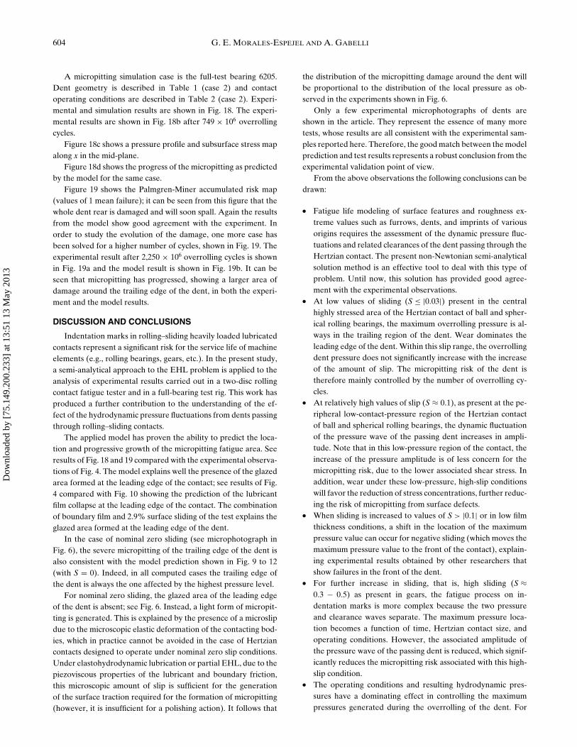
A micropitting simulation case is the full-test bearing 6205.Dent geometry is described in Table 1 (case 2) and contactoperating conditions are described in Table 2 (case 2). Experi-mental and simulation results are shown in Fig. 18. The experi-mental results are shown in Fig. 18b after 749 × 106 overrollingcycles.
Figure 18c shows a pressure profile and subsurface stress mapalong x in the mid-plane.
Figure 18d shows the progress of the micropitting as predictedby the model for the same case.
Figure 19 shows the Palmgren-Miner accumulated risk map(values of 1 mean failure); it can be seen from this figure that thewhole dent rear is damaged and will soon spall. Again the resultsfrom the model show good agreement with the experiment. Inorder to study the evolution of the damage, one more case hasbeen solved for a higher number of cycles, shown in Fig. 19. Theexperimental result after 2,250 × 106 overrolling cycles is shownin Fig. 19a and the model result is shown in Fig. 19b. It can beseen that micropitting has progressed, showing a larger area ofdamage around the trailing edge of the dent, in both the experi-ment and the model results.
DISCUSSION AND CONCLUSIONS
Indentation marks in rolling–sliding heavily loaded lubricatedcontacts represent a significant risk for the service life of machineelements (e.g., rolling bearings, gears, etc.). In the present study,a semi-analytical approach to the EHL problem is applied to theanalysis of experimental results carried out in a two-disc rollingcontact fatigue tester and in a full-bearing test rig. This work hasproduced a further contribution to the understanding of the ef-fect of the hydrodynamic pressure fluctuations from dents passingthrough rolling–sliding contacts.
The applied model has proven the ability to predict the loca-tion and progressive growth of the micropitting fatigue area. Seeresults of Fig. 18 and 19 compared with the experimental observa-tions of Fig. 4. The model explains well the presence of the glazedarea formed at the leading edge of the contact; see results of Fig.4 compared with Fig. 10 showing the prediction of the lubricantfilm collapse at the leading edge of the contact. The combinationof boundary film and 2.9% surface sliding of the test explains theglazed area formed at the leading edge of the dent.
In the case of nominal zero sliding (see microphotograph inFig. 6), the severe micropitting of the trailing edge of the dent isalso consistent with the model prediction shown in Fig. 9 to 12(with S = 0). Indeed, in all computed cases the trailing edge ofthe dent is always the one affected by the highest pressure level.
For nominal zero sliding, the glazed area of the leading edgeof the dent is absent; see Fig. 6. Instead, a light form of micropit-ting is generated. This is explained by the presence of a microslipdue to the microscopic elastic deformation of the contacting bod-ies, which in practice cannot be avoided in the case of Hertziancontacts designed to operate under nominal zero slip conditions.Under elastohydrodynamic lubrication or partial EHL, due to thepiezoviscous properties of the lubricant and boundary friction,this microscopic amount of slip is sufficient for the generationof the surface traction required for the formation of micropitting(however, it is insufficient for a polishing action). It follows that
the distribution of the micropitting damage around the dent willbe proportional to the distribution of the local pressure as ob-served in the experiments shown in Fig. 6.
Only a few experimental microphotographs of dents areshown in the article. They represent the essence of many moretests, whose results are all consistent with the experimental sam-ples reported here. Therefore, the good match between the modelprediction and test results represents a robust conclusion from theexperimental validation point of view.
From the above observations the following conclusions can bedrawn:
� Fatigue life modeling of surface features and roughness ex-treme values such as furrows, dents, and imprints of variousorigins requires the assessment of the dynamic pressure fluc-tuations and related clearances of the dent passing through theHertzian contact. The present non-Newtonian semi-analyticalsolution method is an effective tool to deal with this type ofproblem. Until now, this solution has provided good agree-ment with the experimental observations.
� At low values of sliding (S ≤ |0.03|) present in the centralhighly stressed area of the Hertzian contact of ball and spher-ical rolling bearings, the maximum overrolling pressure is al-ways in the trailing region of the dent. Wear dominates theleading edge of the dent. Within this slip range, the overrollingdent pressure does not significantly increase with the increaseof the amount of slip. The micropitting risk of the dent istherefore mainly controlled by the number of overrolling cy-cles.
� At relatively high values of slip (S ≈ 0.1), as present at the pe-ripheral low-contact-pressure region of the Hertzian contactof ball and spherical rolling bearings, the dynamic fluctuationof the pressure wave of the passing dent increases in ampli-tude. Note that in this low-pressure region of the contact, theincrease of the pressure amplitude is of less concern for themicropitting risk, due to the lower associated shear stress. Inaddition, wear under these low-pressure, high-slip conditionswill favor the reduction of stress concentrations, further reduc-ing the risk of micropitting from surface defects.
� When sliding is increased to values of S > |0.1| or in low filmthickness conditions, a shift in the location of the maximumpressure value can occur for negative sliding (which moves themaximum pressure value to the front of the contact), explain-ing experimental results obtained by other researchers thatshow failures in the front of the dent.
� For further increase in sliding, that is, high sliding (S ≈0.3 − 0.5) as present in gears, the fatigue process on in-dentation marks is more complex because the two pressureand clearance waves separate. The maximum pressure loca-tion becomes a function of time, Hertzian contact size, andoperating conditions. However, the associated amplitude ofthe pressure wave of the passing dent is reduced, which signif-icantly reduces the micropitting risk associated with this high-slip condition.
� The operating conditions and resulting hydrodynamic pres-sures have a dominating effect in controlling the maximumpressures generated during the overrolling of the dent. For
Dow
nloa
ded
by [
75.1
49.2
00.2
33]
at 1
3:51
13
May
201
3

Indentation Marks Rolling–Sliding EHL 605
bearing raceways the micropitting risk of the dent is morerelated to these pressures than to the value of the sliding torolling ratio or to the directionality of the associated friction.However, the directionality of the frictional stress may verywell play a role during the propagation phase of the cracks de-veloped around dents, and this may explain some of the con-clusions of previous works (Nelias and Ville (11); Ville andNelias (12)).
� The micropitting phenomenon occurring around indentationmarks can be described with the same physical model ofthe micropitting of bearing raceways (Morales-Espejel andBrizmer (44)), which takes into account the progression of sur-face fatigue induced by locally reduced lubrication conditions.
ACKNOWLEDGEMENTS
The authors wish to thank Mr. A. de Vries, Director SKFGroup Product Development, for his kind permission to publishthis article.
REFERENCES(1) Lubrecht, A. A., Venner, C. H., Lane, S., Jacobson, B. O., and Ioannides,
E. (1990), “Surface Damage—Comparison of Theoretical and Experimen-tal Endurance Lives of Rolling Bearings,” Proceedings of the InternationalTribology Conference, Nagoya, Japan, pp 185-190. Oct 29-Nov 1.
(2) Venner, C. H. (1991), “Multilevel Solutions of the Line and Point Con-tact Problems,” Ph.D. Dissertation, University of Twente, Enschede, TheNetherlands.
(3) Ai, A. and Cheng, H. S. (1994), “Influence of Moving Dent on Point EHLContact Problems,” Tribology Transactions, 37(2), pp 323-333.
(4) Ai, A., Cheng, H. S., and Zheng, L. (1993), “A Transient Model for Mi-croelastohydrodynamic Lubrication with Three-Dimensional Irregulari-ties,” Journal of Tribology, 115, pp 102-110.
(5) Ai, A. and Lee, S. C. (1996), “Effect of Slide-to-Roll Ratio on InteriorStresses around a Dent in EHL Contacts,” Tribology Transactions, 39(4),pp 881-889.
(6) Xu, G., Sadeghi, F., and Cogdell, J. (1997), “Debris Denting Effects onElastohydrodynamic Lubricated Contacts,” Journal of Tribology, 119(3),pp 578-587.
(7) Xu, G., Sadeghi, F., and Hoeprich, M. R. (1997), “Residual Stress Due toDebries Effects in EHL Contacts,” Tribology Transactions, 40, pp 613-620.
(8) Xu, G., Sadeghi, F., and Hoeprich, M. R. (1998), “Dent Initiated SpallFormation in EHL Rolling/Sliding Contact,” Journal of Tribology, 120, pp453-462.
(9) Cheng, W., Cheng, H. S., and Keer, L. M. (1994), “Experimental Investi-gation on Rolling/Sliding Contact Fatigue Crack Initiation with ArtifitialDefects,” Tribology Transactions, 37, pp 1-12.
(10) Nelias, D., Dumont, M.-L., Couhier, F., Dudragne, G., and Flamand, L.(1998), “Experimental and Theoretical Investigation on Rolling ContactFatigue of 52100 and M50 Steels Under EHL or Micro-EHL Conditions,”Journal of Tribology, 120, pp 184-190.
(11) Nelias, D. and Ville, F. (2000), “Detrimental Effects of Debris Dents onRolling Contact Fatigue,” Journal of Tribology, 122, pp 55-64.
(12) Ville, F. and Nelias, D. (1999), “Early Fatigue Failures in EHL ContactsDue to Dents in EHL Contacts,” Tribology Transactions, 42, pp 795-800.
(13) Ville, F., Coulon, S., and Lubrecht, A. A. (2006), “Influenceof Solid Contaminants on the Fatigue Life of Lubricated Ma-chine Elements,” Proceedings of the Institution of MechanicalEngineers - Part J: Journal of Engineering Tribology, 220, pp 441-445.
(14) Kaneta, M., Kanada, T., and Nishikawa, H. (1997), “Optical Interferomet-ric Observations of the Effects of a Moving Dent on Point Contact EHL,”Elastohydrodynamics ’96, Tribology Series, 32, Dowson, D., et al. (Ed.), pp69-79, Elsevier: Leeds, U.K.
(15) Choo, J. W., Olver, A. V., Spikes, H. A., Dumont, M.-L., and Ioannides,E. (2008), “Interaction of Asperities on Opposing Surfaces in Thin Film,Mixed Elastohydrodynamic Lubrication,” Journal of Tribology, 130, pp021505-1-021505-10.
(16) Felix-Quinonez, A., Ehret, P., and Summers, J. L. (2005), “On Three-Dimensional Flat-Top Defects Passing Through an EHL Point Contact:
A Comparison of Modeling with Experiments,” Journal of Tribology, 127,pp 51-60.
(17) Krupka, I., Hartl, M., Urbanec, L., and Cermak, J. (2007), Single DentWithin Elastohydrodynamics Contact—Comparison Between Experimen-tal and Numerical Results,” Proceedings of the Institution of MechanicalEngineers - Part J: Journal of Engineering Tribology, 221, pp 635-644.
(18) Krupka, I., Vrbka, M., Vaverka, M., Poliscuk, R., and Hartl. M. (2009),“Effect of Surface Dents on Contact Pressure in ElastohydrodynamicsContacts,” Proceedings of the Institution of Mechanical Engineers - PartJ: Journal of Engineering Tribology, 223, pp 683-693.
(19) Ai, A. and Nixon, H. P. (2000), “Fatigue Life Reduction of Roller Bear-ings Due to Debris Denting: Part I—Theoretical Modelling,” TribologyTransactions, 43, pp 197-204.
(20) Ai, A. and Nixon, H. P. (2000), “Fatigue Life Reduction of Roller Bear-ings Due to Debris Denting: Part II—Experimental Validation,” TribologyTransactions, 43, pp 311-317.
(21) Ai, A. (2001), “Effect of Debris Contamination on the Fatigue Life ofRoller Bearings,” Proceedings of the Institution of Mechanical Engineers- Part J: Journal of Engineering Tribology, 215, pp 563-575.
(22) Gabelli, A., Voskamp, A. P., Shearer, S., and Ioannides, E. (1998), “TheService Life of Rolling Element Bearings—Stress Field and Material Re-sponse Analysis,” VDI Berichte Gleit und Walzlagerungen, 1380. Conf.Proc.
(23) Biboulet, N., Lubrecht, A. A., and Houpert, L. (2008), “Contact Pressurein Indented Elastohydrodynamic Lubrication Contacts,” Proceedings ofthe Institution of Mechanical Engineers - Part J: Journal of EngineeringTribology, 222, pp 415-421.
(24) Biboulet, N. (2008), “Influence of Indentations on Rolling Bearing Life,”Ph.D. Thesis, INSA de Lyon, France.
(25) Gabelli, A., Morales-Espejel, G. E., and Ioannides, E. (2008), “ParticleDamage in Hertzian Contacts and Life Ratings in Rolling Bearings,” Tri-bology Transactions, 51, pp 428-445.
(26) Warhadpande, A. and Sadeghi, F. (2010), “Effects of Surface Defectson Rolling Contact Fatigue of Heavily Loaded Lubricated Contacts,”Proceedings of the Institution of Mechanical Engineers - Part J: Journal ofEngineering Tribology, 224, pp 1061-1077.
(27) Goglia, P. R., Cusano, C., and Conry, T. F. (1984), “Effects of Irregular-ities on the EHL of Sliding Line Contacts, Part 1—Single Irregularities,”Journal of Tribology, 106, pp 104-112.
(28) Goglia, P. R., Cusano, C., and Conry, T. F. (1984), “Effects of Irregularitieson the EHL of Sliding Line Contacts, Part 2—Wavy Surfaces,” Journal ofTribology, 106, pp 113-119.
(29) Kweh, C. C., Evans, H. P., and Snidle, R. W. (1989), “Micro-EHL ofan Elliptical Contact with Transverse and Three-Dimensional SinusoidalRoughness,” Journal of Tribology, 111, pp 577-583.
(30) Lubrecht, A. A. (1987), “The Numerical Solution of the Elastohydrody-namically Lubricated Line and Point Contact Problem using MultigridTechniques,” Ph.D. Dissertation, University of Twente, Enschede, TheNetherlands.
(31) Ioannides, E. and Kuijpers, J. C. (1986), “Elastic Stresses Below Asperitiesin Lubricated Contacts,” Journal of Tribology, 108, pp 394-402.
(32) Tripp, J. H., Houpert, L. G., Ioannides, E., and Lubrecht, A. A. (1987),“Dry and Lubricated Contact of Rough Surfaces,” Proceedings of the In-stitution of Mechanical Engineers, International Conference 1987-1985,Mech. Eng. Pub. Ltd., London, pp 71-80.
(33) Morales-Espejel, G. E. (1993), “Elastohydrodynamic Lubrication ofSmooth and Rough Surfaces,” Ph.D. Dissertation, University of Cam-bridge, Cambridge, U.K.
(34) Greenwood, J. A. and Morales-Espejel, G. E. (1994), “The Behaviour ofTransverse Roughness in EHL Contacts,” Proceedings of the Institution ofMechanical Engineers - Part J: Journal of Engineering Tribology, 208, pp121-132.
(35) Morales-Espejel, G. E., Lugt, P. M., van Kuilenburg, J., and Tripp, J. H.(2003), “Effects of Surface Micro-Geometry on the Pressures and InternalStresses of Pure Rolling EHL Contacts,” Tribology Transactions, 46, pp260-272.
(36) Morales-Espejel, G. E., Venner, C. H., and Greenwood, J. A. (2001),“Kinematics of Transverse Real Roughness in ElastohydrodynamicallyLubricated Line Contacts Using Fourier Analysis,” Proceedings of the In-stitution of Mechanical Engineers - Part J: Journal of Engineering Tribol-ogy, 214, pp 523-534.
(37) Venner, C. H. and Lubrecht, A. A. (1999), “Amplitude Reduction ofnon-Isotropic Harmonic Patterns in Circular EHL Contacts, Under PureRolling,” Proceedings of the 25th Leeds-Lyon Symposium on Tribology
Dow
nloa
ded
by [
75.1
49.2
00.2
33]
at 1
3:51
13
May
201
3

606 G. E. MORALES-ESPEJEL AND A. GABELLI
1998, Elsevier Tribology Series, 34, Dowson, D. et al. (Ed.), pp 151-162,Elsevier: Amsterdam.
(38) Hooke, C. J. (1998), “Surface Roughness Modification in Elastohydrody-namic Line Contacts Operating in the Elastic Piezoviscous Regime. Part2: General, Non-Sinusoidal Roughness,” Proceedings of the Institution ofMechanical Engineers - Part J: Journal of Engineering Tribology, 212, pp145-162.
(39) Hooke, C. J., Li, K. Y., and Morales-Espejel, G. E. (2007), “Rapid Cal-culation of Pressures and Clearanaces in Rough, Rolling-Sliding Elas-tohydrodynamically Lubricated Contacts. Part 1: Low-Amplitude, Sinu-soidal Roughness,” Proceedings of the Institution of Mechanical Engi-neers - Part C: Journal of Mechanical Engineering Science, 221, pp 535-550.
(40) Morales-Espejel, G. E., Wemekamp, A. W., and Felix-Quinonez, A.(2010), “Micro-Geometry Effects on the Sliding Friction Transition inElastohydrodynamic Lubrication,” Proceedings of the Institution of Me-
chanical Engineers - Part J: Journal of Engineering Tribology, 224, pp 621-637.
(41) Hooke, C. J., Li, K. Y., and Morales-Espejel, G. E. (2007), “Rapid Cal-culation of Pressures and Clearanaces in Rough, Rolling-Sliding Elasto-hydrodynamically Lubricated Contacts. Part 2: General, Non-SinusoidalRoughness,” Proceedings of the Institution of Mechanical Engineerings -Part C: Journal of Mechanical Engineering Science, 221, pp 551-564.
(42) Venner, C. H. and Lubrecht, A. A. (1994), “Transient Analysis of SurfaceFeatures in an EHL Line Contact in the Case of Sliding,” Journal of Tri-bology, 116, pp 186-193.
(43) Ehret, P., Dowson, D., and Taylor, C. M. (1998), “On Lubricant Trans-port Conditions in Elastohydrodynamic Conjunctions,” Proceedings of theRoyal Society of London Series A, 454, pp 763-787.
(44) Morales-Espejel, G. E. and Brizmer, V. (2011), Micropitting Modellingin Rolling—Sliding Contacts: Application to Rolling Bearings,” TribologyTransactions. 54, pp 625-643.
Dow
nloa
ded
by [
75.1
49.2
00.2
33]
at 1
3:51
13
May
201
3
Related Documents


![Subsurface Stresses in Rolling & Sliding Machine Components [Sadeghi, Sui; Int.comp.Eng.conf., 1988]](https://static.cupdf.com/doc/110x72/577cd14b1a28ab9e7894160a/subsurface-stresses-in-rolling-sliding-machine-components-sadeghi-sui.jpg)
![Effects of cold-rolling on the indentation hardness of copperThompson] HardnessofCold-RolledCopper 747 oxygen-freecopper.Specimensvaryingininitialthicknessfrom0.2 to3.0incheswererolledtothicknessesof0.02inchorless,without](https://static.cupdf.com/doc/110x72/5e94886687a57c16e541ce6a/effects-of-cold-rolling-on-the-indentation-hardness-of-copper-thompson-hardnessofcold-rolledcopper.jpg)


