Citation: Abdulhameed, A.A.; Al-Zuhairi, A.H.; Al Zaidee, S.R.; Hanoon, A.N.; Al Zand, A.W.; Hason, M.M.; Abdulhameed, H.A. The Behavior of Hybrid Fiber-Reinforced Concrete Elements: A New Stress-Strain Model Using an Evolutionary Approach. Appl. Sci. 2022, 12, 2245. https://doi.org/ 10.3390/app12042245 Academic Editor: Seong-Cheol Lee Received: 20 December 2021 Accepted: 19 February 2022 Published: 21 February 2022 Publisher’s Note: MDPI stays neutral with regard to jurisdictional claims in published maps and institutional affil- iations. Copyright: © 2022 by the authors. Licensee MDPI, Basel, Switzerland. This article is an open access article distributed under the terms and conditions of the Creative Commons Attribution (CC BY) license (https:// creativecommons.org/licenses/by/ 4.0/). applied sciences Article The Behavior of Hybrid Fiber-Reinforced Concrete Elements: A New Stress-Strain Model Using an Evolutionary Approach Ali A. Abdulhameed 1, * , Alaa Hussein Al-Zuhairi 2 , Salah R. Al Zaidee 2 , Ammar N. Hanoon 1 , Ahmed W. Al Zand 3, * , Mahir M. Hason 4 and Haider A. Abdulhameed 5 1 Department of Reconstruction and Projects, University of Baghdad, Baghdad 10071, Iraq; [email protected] 2 Department of Civil Engineering, University of Baghdad, Baghdad 10071, Iraq; [email protected] (A.H.A.-Z.); [email protected] (S.R.A.Z.) 3 Department of Civil Engineering, Universiti Kebangsaan Malaysia, Bangi 43600, Malaysia 4 Disaster Information Management Centre, Ministry of Science and Technology, Baghdad 10071, Iraq; [email protected] 5 Civil Engineering Department, University of Technology, Baghdad 10066, Iraq; [email protected] * Correspondence: [email protected] (A.A.A.); [email protected] (A.W.A.Z.) Abstract: Several stress-strain models were used to predict the strengths of steel fiber reinforced concrete, which are distinctive of the material. However, insufficient research has been done on the influence of hybrid fiber combinations (comprising two or more distinct fibers) on the characteristics of concrete. For this reason, the researchers conducted an experimental program to determine the stress-strain relationship of 30 concrete samples reinforced with two distinct fibers (a hybrid of polyvinyl alcohol and steel fibers), with compressive strengths ranging from 40 to 120 MPa. A total of 80% of the experimental results were used to develop a new empirical stress-strain model, which was accomplished through the application of the particle swarm optimization (PSO) technique. It was discovered in this investigation that the new stress-strain model predictions are consistent with the remaining 20% of the experimental stress-strain curves obtained. Case studies of hybrid–fiber– reinforced concrete constructions were investigated in order to better understand the behavior of such elements. The data revealed that the proposed model has the highest absolute relative error (ARE) frequencies (ARE 10%) and the lowest absolute relative error (ARE > 15%) frequencies (ARE > 15%). Keywords: fibrous concrete; high–strength concrete (HSC); mechanical characteristics; steel fiber; hybrid fibers; concrete damage plasticity (CDP); concrete modeling 1. Introduction The use of high–strength concrete (HSC) in buildings is spreading as the cross-section of members can be actually reduced. With the low water/cementitious materials ratio for high strength concrete, concrete durability can be improved. Compressive strength, on the other hand, causes concrete to become more brittle [1]. Steel fibers can improve section behavior [2,3], since they provide a bridging action across matrix microcracks and improve crack opening resistance [4]. Steel fibers’ ability to cross microcracks is greatly influenced by the shear stress at the interface between the fibers and the matrix (bond strength between steel fibers and the matrix). Fibers and the matrix are held together by an interfacial connection as a result of this shear stress [4]. To increase the mechanical properties of concrete, numerous types of fibers are com- monly used [5–7]. Hybrid fiber-reinforced concrete (HFRC) has been developed by com- bining different types of fibers in order to get the desired mechanical features of fiber- reinforced concrete. However, many fiber mixes, such as carbon and polypropylene, glass and polypropylene, and glass and carbon fibers, have been used to generate HFRC [8–10]. Appl. Sci. 2022, 12, 2245. https://doi.org/10.3390/app12042245 https://www.mdpi.com/journal/applsci

Welcome message from author
This document is posted to help you gain knowledge. Please leave a comment to let me know what you think about it! Share it to your friends and learn new things together.
Transcript

�����������������
Citation: Abdulhameed, A.A.;
Al-Zuhairi, A.H.; Al Zaidee, S.R.;
Hanoon, A.N.; Al Zand, A.W.; Hason,
M.M.; Abdulhameed, H.A. The
Behavior of Hybrid Fiber-Reinforced
Concrete Elements: A New
Stress-Strain Model Using an
Evolutionary Approach. Appl. Sci.
2022, 12, 2245. https://doi.org/
10.3390/app12042245
Academic Editor: Seong-Cheol Lee
Received: 20 December 2021
Accepted: 19 February 2022
Published: 21 February 2022
Publisher’s Note: MDPI stays neutral
with regard to jurisdictional claims in
published maps and institutional affil-
iations.
Copyright: © 2022 by the authors.
Licensee MDPI, Basel, Switzerland.
This article is an open access article
distributed under the terms and
conditions of the Creative Commons
Attribution (CC BY) license (https://
creativecommons.org/licenses/by/
4.0/).
applied sciences
Article
The Behavior of Hybrid Fiber-Reinforced Concrete Elements:A New Stress-Strain Model Using an Evolutionary ApproachAli A. Abdulhameed 1,* , Alaa Hussein Al-Zuhairi 2 , Salah R. Al Zaidee 2, Ammar N. Hanoon 1 ,Ahmed W. Al Zand 3,* , Mahir M. Hason 4 and Haider A. Abdulhameed 5
1 Department of Reconstruction and Projects, University of Baghdad, Baghdad 10071, Iraq;[email protected]
2 Department of Civil Engineering, University of Baghdad, Baghdad 10071, Iraq;[email protected] (A.H.A.-Z.); [email protected] (S.R.A.Z.)
3 Department of Civil Engineering, Universiti Kebangsaan Malaysia, Bangi 43600, Malaysia4 Disaster Information Management Centre, Ministry of Science and Technology, Baghdad 10071, Iraq;
[email protected] Civil Engineering Department, University of Technology, Baghdad 10066, Iraq;
[email protected]* Correspondence: [email protected] (A.A.A.); [email protected] (A.W.A.Z.)
Abstract: Several stress-strain models were used to predict the strengths of steel fiber reinforcedconcrete, which are distinctive of the material. However, insufficient research has been done on theinfluence of hybrid fiber combinations (comprising two or more distinct fibers) on the characteristicsof concrete. For this reason, the researchers conducted an experimental program to determine thestress-strain relationship of 30 concrete samples reinforced with two distinct fibers (a hybrid ofpolyvinyl alcohol and steel fibers), with compressive strengths ranging from 40 to 120 MPa. A total of80% of the experimental results were used to develop a new empirical stress-strain model, whichwas accomplished through the application of the particle swarm optimization (PSO) technique. Itwas discovered in this investigation that the new stress-strain model predictions are consistent withthe remaining 20% of the experimental stress-strain curves obtained. Case studies of hybrid–fiber–reinforced concrete constructions were investigated in order to better understand the behavior of suchelements. The data revealed that the proposed model has the highest absolute relative error (ARE)frequencies (ARE 10%) and the lowest absolute relative error (ARE > 15%) frequencies (ARE > 15%).
Keywords: fibrous concrete; high–strength concrete (HSC); mechanical characteristics; steel fiber;hybrid fibers; concrete damage plasticity (CDP); concrete modeling
1. Introduction
The use of high–strength concrete (HSC) in buildings is spreading as the cross-sectionof members can be actually reduced. With the low water/cementitious materials ratiofor high strength concrete, concrete durability can be improved. Compressive strength,on the other hand, causes concrete to become more brittle [1]. Steel fibers can improvesection behavior [2,3], since they provide a bridging action across matrix microcracks andimprove crack opening resistance [4]. Steel fibers’ ability to cross microcracks is greatlyinfluenced by the shear stress at the interface between the fibers and the matrix (bondstrength between steel fibers and the matrix). Fibers and the matrix are held together by aninterfacial connection as a result of this shear stress [4].
To increase the mechanical properties of concrete, numerous types of fibers are com-monly used [5–7]. Hybrid fiber-reinforced concrete (HFRC) has been developed by com-bining different types of fibers in order to get the desired mechanical features of fiber-reinforced concrete. However, many fiber mixes, such as carbon and polypropylene, glassand polypropylene, and glass and carbon fibers, have been used to generate HFRC [8–10].
Appl. Sci. 2022, 12, 2245. https://doi.org/10.3390/app12042245 https://www.mdpi.com/journal/applsci

Appl. Sci. 2022, 12, 2245 2 of 26
The hybrid steel–polypropylene fibers have been the subject of a lot of research. Becausethe fibers contribute to the toughness, which lowers brittle failure under static and dynamicstresses, HFRC exhibits an increased reaction. It also improves energy absorption.
It is well acknowledged that steel fibers can improve mechanical properties suchas compressive and tensile strengths; ductility; impact resistance; toughness; and so on(ACI Committee 544 [11]). However, the effect of the combinations of hybrid fibers (twoor more different types of fibers) on the concrete properties is not extensively addressed.Requirements for high–strength fiber reinforced concrete has been increasing significantlyover the past few decades due to the need for design members that are small in size,which also decreases the mass of members, to lead to effective seismic-resistant concretestructure [12,13]. By extending the post-peak region of stress-strain diagrams, which isotherwise nearly nonexistent or steeply sloped in high-strength concrete (HSC), the fibersin FRC improve toughness [13]. This enhancement in structural response can only beconsidered once the stress-strain curves of the resulting FRC have been studied in detail.Stress-strain diagrams can be used to assess the toughness of FRC. By extending the post-peak region of stress-strain diagrams, which is otherwise nearly nonexistent or steeplysloped in high-strength concrete (HSC), the fibers in FRC improve toughness [13]. Thisenhancement in structural response can only be considered once the stress-strain curves ofthe resulting FRC have been studied in detail. Stress-strain diagrams can be used to assessthe toughness of FRC. In addition, using the steel fibers for reinforcing the normal strengthconcrete (NSC) and reactive powder concrete (RPC) had been investigated [14]. Where, thestudy confirmed that the aggregate interlock, crack surface friction and steel fiber contentare the main three factors influenced the shear strength of the NSC, meanwhile, on RPC,only the factors of crack surface friction and steel fibers are affected.
The effects of replacing Portland cement with pumice powder and nano-clay werestudied [15]. The possibility of making pervious concrete with varied amounts of recycledconcrete aggregate (RCA) was made with a combination of new and used materials, in-cluding recycled and industrial fibers. The author(s) recommends the usage of perviousconcrete containing 50% RCA and 2% steel fiber in the constructions of structures. Otherresearchers investigated the use of recycled concrete aggregate and pozzolanic additives infiber-reinforced pervious concrete reinforced with industrial and recycled fibers [16]. Theydiscovered that introducing 2% steel fiber increased compressive and flexural strengths byup of 65% and 79%, respectively, over the unreinforced counterpart mix (STF). Additionally,it was reported that the use of 100% RCA with 2% STF and 2% nano-clay (NC) results in aprevious concrete suited for structural purposes. Sinaei et al. [17] investigated the efficacyof composite fiber reinforced polymer (CFRP) layers for five exterior beam-column connec-tions using a finite element model (FEM) based on previously collected experimental data.It was discovered that L-shaped FRP composite overlays at the beam-column interface werean appropriate method for increasing ductility. Additionally, U-shaped overlays beneaththe beam and the use of FRP on both lateral sides of the beam were excellent reinforcingsolutions for enhancing the RC joints’ strength and ductility.
Through the use of artificial neural networks (ANN) and extreme learning machines,scholars have evaluated the influence of fly ash and silica fume replacement content onthe strength of concrete [18]. Various ratios of fly ash with (without) additional silica fumehave been evaluated for this. The ratio of water to cement varies throughout the test. FAcontributed less to the strength of concrete at younger ages, but significantly more at olderages. As a result, the increased effect of a small amount of SF on compressive strengthwas not statistically significant. In the short term, adding fly ash decreased compressivestrength, but boosted it in the long run. Adding silica fume increases the strength inthe short term but diminishes it over time. The behavior of angle shear connections wasexamined numerically by researchers [19]. Thermo-mechanical finite element modeling wasdone on push-out samples using the ABAQUS software, and the findings were compared tothose obtained from laboratory tests. The research findings indicated that the numericallymodels were capable of effectively predicting laboratory results such as shear strength

Appl. Sci. 2022, 12, 2245 3 of 26
and slip. Additionally, data indicated that increasing the temperature to 850 ◦C resultsin a 56% reduction in the shear strength of the samples. Shariati et al. assessed thecompressive strength of concrete combining furnace slag and fly ash in place of cement [20].A database of 1030 data sets was used in the evaluation of the compressive strength ofthe modified concrete. The author(s) utilized a hybrid artificial neural network-geneticalgorithm (ANN-GA) in the study. The ANN-GA model for concrete compressive strengthprediction outperformed an ANN-BP model in terms of precision, the study’s findingsrevealed. Furthermore, the hybrid ANN technique was adopted for theoretically predictedthe cohesion between the sand-soil that combined with fibers [21].
A uniaxial compression test was used to characterize the behavior of 48 cylindri-cal specimens prepared from fiber-reinforced concrete with end-hooked steel fibers andanalytical model was proposed [22]. The test revealed a ductile behavior of steel fibre-reinforced concrete specimens even exceeding its compressive strength. Additionally, itwas demonstrated that the strain at compressive strength generally increased as the fibervolumetric ratio and aspect ratio increased, although the elastic modulus reduced. Chaliorisand Panagiotopoulos studied the flexural response of steel fibrous concrete cross-sectionswith a randomly chosen geometry through a computational approach [23]. Moreover, acompressive stress-strain graphs and 257 strength values were used to construct a newcompressive stress-strain model for steel fibrous concrete. The proposed sectional analysiswas validated against experimental data for 42 SFC beams, and it accurately predicts theflexural capacity and curvature ductility of SFC members. The behavior of double-endedhook steel fiber concrete elements with 80 MPa compressive strength was also investigatedconsidering specimens dimensions, shape, content, aspect ratio, and tensile strength ofthe embedded steel fiber [24]. The mechanical testing-crack opening displacement testwas used to determine the flexural performance of the specimens, and the findings werecompared to code specifications. Further studies are concerned the cracking behavior of thefiber-reinforced concrete element with synthetic fibers [25], and steel fiber-reinforced beamsunder cyclic deformation [26]. In general, further researchers have been concerned thebehaviors of the corroded concrete [27] and using hybrid extreme learning machine-greywolf optimizer to predict concrete strength that partially replacement of cement [28]. Anew technique off-site and self-form segmental concrete masonry was also experimentallystudied [29].
Using the extended finite element method, Abbas and AlZuhairi investigated thebehavior of simply supported reinforced concrete beams [30]. The experimental programincludes two RC beams loaded in two points. It was found that the mesoscale numericalmodel produced findings that were closer to the experimental data, and that mesoscalemodeling of reinforced concrete is most convenient when the maximum aggregate size isreduced. Hason et al. investigated the effects of numerous critical parameters on the energyabsorption (EA) of torsional RC beams reinforced with external FRP [31]. Whereas, (81)gathered datasets for investigating (28) factors were studied and evaluated including theconcrete compressive strength through using response surface methodology (RSM). Theyclaimed that the proposed model has an acceptable correlation coefficient (R) of around 80%and is reasonably accurate and the EA also works as a safety index for FRP-strengthenedRC beams exposed to torsional loads, preventing unexpected structural failure.
Analytical models for predicting the stress-strain diagram of steel fiber reinforcedconcrete that take into account the major properties of a single type of fibers have beenproposed in current research. This is because, to date, a lack of information in predictingthe compressive stress-strain relation of concrete with two or more different types of fibershas been reported. For this purpose, this study was suggested to carry the experimentalprogram for testing varied concrete samples reinforced with hybrid fibers (polyvinyl alcoholand steel fibers). The majority of the experimental results were used to develop an empiricalmodel to simulate the HFRC stress-strain relationship. The proposed model simulation wasdone using the particle swarm optimization (PSO). Besides, the validity of the proposedmodel was verified with the experimental test results. In addition, ten finite elements (FE)

Appl. Sci. 2022, 12, 2245 4 of 26
models have been developed using ABAQUS software to further prove the validity ofthe new proposed stress-strain model when adopted in the numerical analysis methods.Concrete cubes with hybrid–fibers and steel fiber–reinforced concrete columns are used ascase studies for this numerical investigation. The findings that predicted using this newlyproposed model substantially align with the balanced outcomes achieved in this analysisof the experimental stress-strain curves.
2. Research Significance
Fibers are frequently used in the construction industry to improve the mechanicalproperties of concrete parts. Given the fact that no single type of fiber can increase allthe desired mechanistic characteristics of concrete, combinations of fibers (hybrid fibers)can have a higher effect, which is referred to as high-performance reinforced concrete(HFRC). The HFRC exhibits collaborative behavior as a result of the contributions of steeland polyvinyl alcohol fibers, among other factors. Steel fibers, on the other hand, addto the material’s crack resistance and toughness by increasing the material’s toughness.Polyvinyl alcohol fibers, on the other hand, are essential in order to prevent the formationand development of microcracks. The use of hybrid fibers in the manufacturing of high-strength HFRC improves toughness by altering the post-peak region of the stress-straingraphs, as seen in the figure. It is proposed in this paper that a stress-strain model forhigh-frequency reinforced concrete be utilized to improve the structural response in presentdesign procedures.
3. Work Methodology
The methodology approach followed in the current study included a literature survey,experimental program, optimization analysis, and numerical simulations using finiteelement (FE) analysis. Figure 1 displays a schematic depiction of the methodology approachadopted in the current study.
3.1. Experimental Program3.1.1. Testing Materials
Two kinds of Portland cement (PC) naming, type I (CEM I 42.5R) and II (CEM I 52.5R),were utilized in the batches. The use of supplementary cementing materials “silica fume SF”and coal combustion residue “fly ash (FA)” as cement substitutes has been widely accepted.Cementitious material’s chemical and physical properties are listed in Table 1. The additionof a chemical admixture, superplasticizer (SP), reduced the amount of water required toobtain the desired consistency of concrete mixture. It was decided to use river sand as boththe fine and coarse aggregates, which had a finesse modulus of 2.67. A constant ratio of 3has been adopted for water (w) to binder (B) (w/B = 0.3). In addition, the fraction of SF of8% by weight has been adopted as a cement replacement. In order to reduce the amount ofcement required, FA/B (15, 35, and 65%) was utilized as a fly ash binder with three ratios ofaggregate (A/B) (1, 2, and 3). Two different fibers: polyvinyl alcohol (P) and hocked steel(S) have been used in this work, as shown in Figure 2 (length L = 18 mm, and diameterD = 0.4 mm, respectively). Table 2 lists the characteristics of the fibers that were employed.P and S Fiber have a maximum volume fiber fraction of 0.75% and 0.75%, respectively,while the maximum total fiber fraction is 1.5%.
3.1.2. Sample Preparation and Testing
Ordinary composite Portland cement type II conforming to ASTM C150/C150M-19a [32] was used as a binding material in the mixture of the concrete. This study preparedand tested a total of 30 concrete mixtures, the proportions of which are listed in Table 3.The batches were prepared using a 40-L concrete mixer pan. First, the sand and gravel arecombined for 3 min in a dry environment to ensure a uniform distribution. Then, for 5 min,the dry blend was supplemented with cement and fly ash. Afterwards, silica fume andsuperplasticizer are dissolved in water and slowed added to the mixture for at least five

Appl. Sci. 2022, 12, 2245 5 of 26
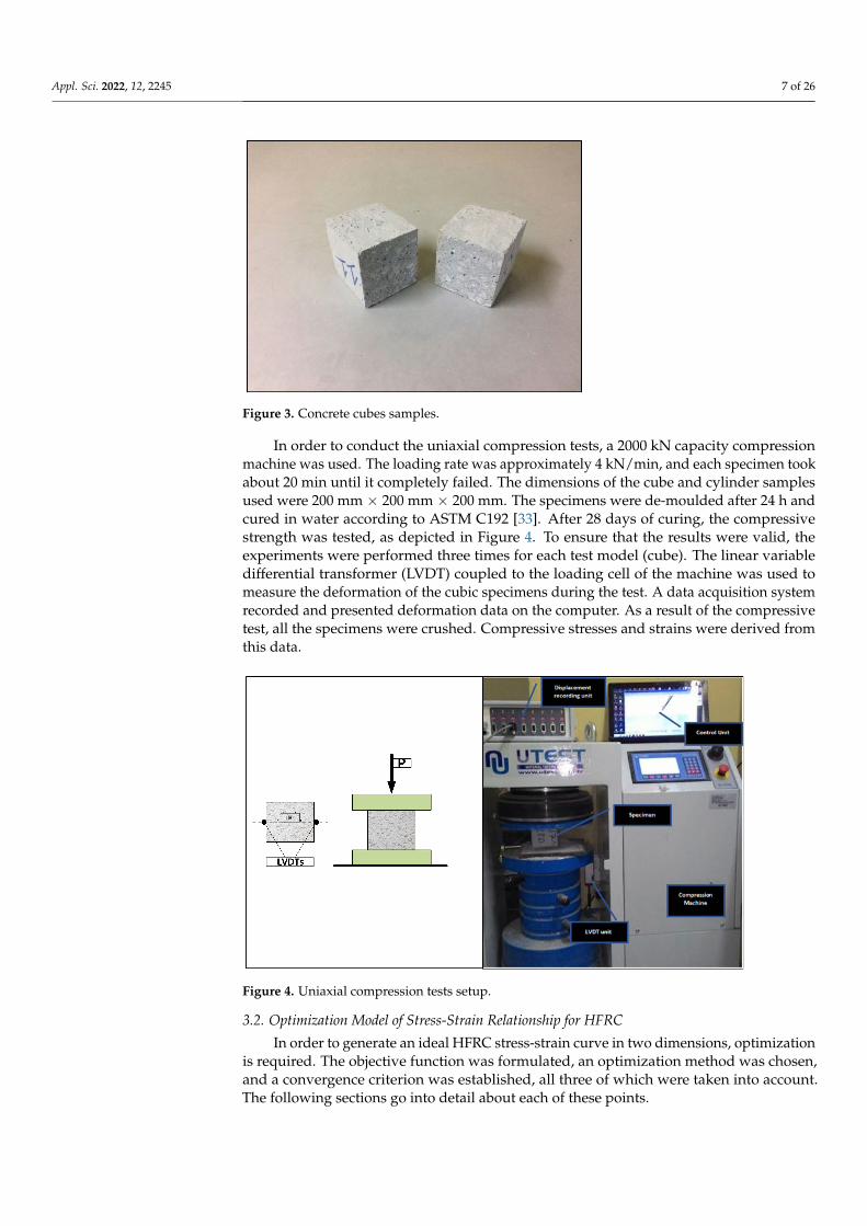
minutes until the desired consistency is reached. After fibers are added, the entire mixtureis re-mixed for 5 min. Figure 3 shows the compression test specimens, which are cuboidalspecimens with dimensions of (150 mm).
Figure 1. A diagrammatic illustration of the research approach.
Table 1. Portland cement, Class-F fly ash, and silica fume composition and properties.
Chemical Composition, %Portland Cement (PC)
FA SFCEM I 42.5R CEM I 52.5R
SiO2 20.77 21.6 57.01 91.96Al2O3 5.55 4.10 20.97 1.20Fe2O3 3.35 0.26 4.15 0.84MgO 2.49 1.30 1.76 1.02CaO 61.4 65.7 9.78 0.62
Na2O 0.19 0.19 2.23 0.67K2O 0.77 0.77 1.53 1.16
Loss on Ignition (LOI) 2.2 3.20 1.25 1.86Physical properties
Specific gravity 3.15 3.15 2.2 2.3Blaine fineness (m2/kg) 325 460 290 -

Appl. Sci. 2022, 12, 2245 6 of 26
Figure 2. Respective features of (a) Steel fiber and (b) polyvinyl alcohol fiber.
Table 2. Properties of the fibers used.
Material Length(mm)
Diameter(mm)
TensileStrength
(MPa)
Stiffness(Gpa) Specific Gravity
P 18 0.4 1000 29 1.3S 30 0.75 1100 200 7.8
Table 3. Mixture proportions.
MixtureNo.
Cement Ikg/m3
Cement IIkg/m3 Fly Ash Silica Fume
kg/m3Waterkg/m3
PVAkg/m3
Steel Fiberkg/m3
Fine Agg.kg/m3
Coarse Agg.kg/m3
A/BRatio
1 739 0 144 77 288 0 0 351 609 12 533 0 327 75 281 0 0 342 594 13 243 0 585 72 270 0 0 329 572 14 739 0 144 77 288 0 58.5 351 609 15 533 0 327 75 281 0 58.5 342 594 16 243 0 585 72 270 0 58.5 329 572 17 739 0 144 77 288 9.75 58.5 351 609 18 533 0 327 75 281 9.75 58.5 342 594 19 243 0 585 72 270 9.75 58.5 329 572 1
10 531 0 104 55 207 9.75 58.5 506 879 211 386 0 237 54 203 9.75 58.5 497 862 212 178 0 428 53 198 9.75 58.5 482 837 213 419 0 82 44 163 9.75 58.5 598 1038 314 302 0 186 42 159 9.75 58.5 593 1029 315 141 0 341 42 157 9.75 58.5 576 1000 3
16 0 739 144 77 288 0 0 351 609 117 0 533 327 75 281 0 0 342 594 118 0 243 585 72 270 0 0 329 572 119 0 739 144 77 288 0 58.5 351 609 120 0 533 327 75 281 0 58.5 342 594 121 0 243 585 72 270 0 58.5 329 572 122 0 739 144 77 288 9.75 58.5 351 609 123 0 533 327 75 281 9.75 58.5 342 594 124 0 243 585 72 270 9.75 58.5 329 572 125 0 531 104 55 207 9.75 58.5 506 879 226 0 386 237 54 203 9.75 58.5 497 862 227 0 178 428 53 198 9.75 58.5 482 837 228 0 419 82 44 163 9.75 58.5 598 1038 329 0 302 186 42 159 9.75 58.5 593 1029 330 0 141 341 42 157 9.75 58.5 576 1000 3
Appl. Sci. 2022, 12, 2245 7 of 26
Figure 3. Concrete cubes samples.
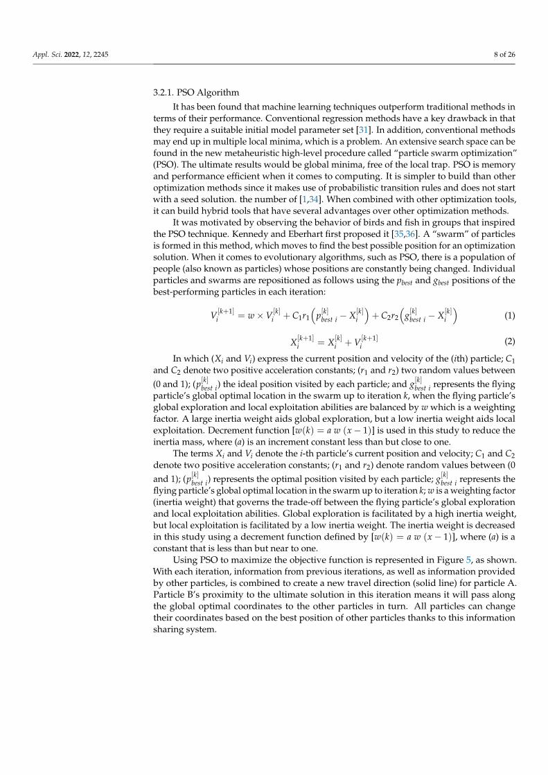
In order to conduct the uniaxial compression tests, a 2000 kN capacity compressionmachine was used. The loading rate was approximately 4 kN/min, and each specimen tookabout 20 min until it completely failed. The dimensions of the cube and cylinder samplesused were 200 mm × 200 mm × 200 mm. The specimens were de-moulded after 24 h andcured in water according to ASTM C192 [33]. After 28 days of curing, the compressivestrength was tested, as depicted in Figure 4. To ensure that the results were valid, theexperiments were performed three times for each test model (cube). The linear variabledifferential transformer (LVDT) coupled to the loading cell of the machine was used tomeasure the deformation of the cubic specimens during the test. A data acquisition systemrecorded and presented deformation data on the computer. As a result of the compressivetest, all the specimens were crushed. Compressive stresses and strains were derived fromthis data.
Figure 4. Uniaxial compression tests setup.
3.2. Optimization Model of Stress-Strain Relationship for HFRC
In order to generate an ideal HFRC stress-strain curve in two dimensions, optimizationis required. The objective function was formulated, an optimization method was chosen,and a convergence criterion was established, all three of which were taken into account.The following sections go into detail about each of these points.
Appl. Sci. 2022, 12, 2245 8 of 26
3.2.1. PSO Algorithm
It has been found that machine learning techniques outperform traditional methods interms of their performance. Conventional regression methods have a key drawback in thatthey require a suitable initial model parameter set [31]. In addition, conventional methodsmay end up in multiple local minima, which is a problem. An extensive search space can befound in the new metaheuristic high-level procedure called “particle swarm optimization”(PSO). The ultimate results would be global minima, free of the local trap. PSO is memoryand performance efficient when it comes to computing. It is simpler to build than otheroptimization methods since it makes use of probabilistic transition rules and does not startwith a seed solution. the number of [1,34]. When combined with other optimization tools,it can build hybrid tools that have several advantages over other optimization methods.
It was motivated by observing the behavior of birds and fish in groups that inspiredthe PSO technique. Kennedy and Eberhart first proposed it [35,36]. A “swarm” of particlesis formed in this method, which moves to find the best possible position for an optimizationsolution. When it comes to evolutionary algorithms, such as PSO, there is a population ofpeople (also known as particles) whose positions are constantly being changed. Individualparticles and swarms are repositioned as follows using the pbest and gbest positions of thebest-performing particles in each iteration:
V[k+1]i = w×V[k]
i + C1r1
(p[k]best i − X[k]
i
)+ C2r2
(g[k]best i − X[k]
i
)(1)
X[k+1]i = X[k]
i + V[k+1]i
(2)
In which (Xi and Vi) express the current position and velocity of the (ith) particle; C1and C2 denote two positive acceleration constants; (r1 and r2) two random values between(0 and 1); (p[k]best i) the ideal position visited by each particle; and g[k]best i represents the flyingparticle’s global optimal location in the swarm up to iteration k, when the flying particle’sglobal exploration and local exploitation abilities are balanced by w which is a weightingfactor. A large inertia weight aids global exploration, but a low inertia weight aids localexploitation. Decrement function [w(k) = a w (x− 1)] is used in this study to reduce theinertia mass, where (a) is an increment constant less than but close to one.
The terms Xi and Vi denote the i-th particle’s current position and velocity; C1 and C2denote two positive acceleration constants; (r1 and r2) denote random values between (0and 1); (p[k]best i) represents the optimal position visited by each particle; g[k]best i represents theflying particle’s global optimal location in the swarm up to iteration k; w is a weighting factor(inertia weight) that governs the trade-off between the flying particle’s global explorationand local exploitation abilities. Global exploration is facilitated by a high inertia weight,but local exploitation is facilitated by a low inertia weight. The inertia weight is decreasedin this study using a decrement function defined by [w(k) = a w (x− 1)], where (a) is aconstant that is less than but near to one.
Using PSO to maximize the objective function is represented in Figure 5, as shown.With each iteration, information from previous iterations, as well as information providedby other particles, is combined to create a new travel direction (solid line) for particle A.Particle B’s proximity to the ultimate solution in this iteration means it will pass alongthe global optimal coordinates to the other particles in turn. All particles can changetheir coordinates based on the best position of other particles thanks to this informationsharing system.

Appl. Sci. 2022, 12, 2245 9 of 26
Figure 5. The main concept of using PSO.
3.2.2. Objective Function
Objective function is defined as the difference between predicted and observed values.Measurement of agreement between model output predictions and experimental outcomesis a primary goal of this objective function. The root-mean-square error is chosen as theobjective function (RMSE). This objective function [37–39] can be calculated using thefollowing expression:
RMSE =
√1n
n
∑i=1
(SA − SE)2 (3)
where SA and SE represent the actual and predicted levels of stress, with n denoting thesample size.
3.2.3. Convergence Criteria
There must be a set point at which the PSO search can be stopped because of its iterativenature. The two most prevalent criteria for convergence are the number of iterations andthe smallest error in the objective function. If the optimum value is known in advance,the algorithm can be tested or fine-tuned. Although this is true in theory, it does nothold true in real-world structural optimization issues. PSO parameters are summarized inTable 4, while the PSO convergence parameters used in this study are listed and explainedin Table 5.

Appl. Sci. 2022, 12, 2245 10 of 26
Table 4. The primary PSO variables.
Description Details
Particle count, NBetween 10 and 40 is a common range. Thenumber can be extended to 50–100 for somechallenging or specific problems.
The dimension of particles, D Optimum solution is decided by the problemat hand
Inertia weight, w
As a rule of thumb, w = 0.7 is considered to bea good starting point [38]. It is also possible tomake changes to it throughout subsequentrounds.
Lower and upper bounds for each of the ndesign variables, x, LxUU
Optimum solutions are based on the problemto be optimized. In general, a variety of rangescan be used for different particle diameters.
Cognitive and social characteristics Usually (c1 = c2 = 1.494) and other numbersare acceptable as long as [0 < c1 + c2 < 4] [40].
Table 5. Parameters governing PSO convergence.
Description Details
T-max is the maximum number of iterationsthat can be completed in a particulartime period.
In combination with other PSO parameters, thecomplexity of the issue to be optimized (D, N)
k f is the number of times the improvement ofthe objective function meets theconvergence condition.
A convergence has occurred if the objectivefunction’s improvement over the last k fiterations (including this one) is less than orequal to f m.
The minimum improvement f m in theobjective function’s value
3.2.4. Proposed Analytical Model and Data Processing
Four analytical models were used and modified to attain a good agreement betweenpredicted and measured stress-strain relationships. In the proposed model, the stress-strainrelationship of the HFRC was simulated using MATLAB code. PSO is used to find apreviously unknown set of coefficients in the solution space. In the proposed model, thestress-strain relationship of the HFRC was simulated using MATLAB code.
Due to its consistency and simplicity, the formula suggested by Carreira and Chu [41]was used. For optimization analysis conducted using their experimental results, thefollowing equations were obtained:
f ′HFRC = α0 f ′c + α1(RIws)α2 + α3
(RIwp
)α4 (4)
ε′HFRC = α5ε′c + α6RIws + α7RIwp (5)
β = α8 + α9(RIws)α10 + α11
(RIwp
)α12 (6)
where fc′ is the compressive strength of plain concrete (MPa), ε′c is the strain to correspond
to fc′ (ε′c = 0.002). RIws and RIwp are reinforcing index, which is is determined based on
the fiber fraction:
RIw = w f ·L f
d f(7)

Appl. Sci. 2022, 12, 2245 11 of 26
where w f = fiber weight fraction (w f ≈ 3Vf , Vf = fiber volume fraction), L f = length offiber (mm) and d f = diameter of the fiber (mm):
fHFRCf ′HFRC
=
α13β(
εεo
)α14β− α15 +
(εεo
)α16β
(8)
Here, fHFRC is the stress acting on the concrete (MPa); f ′HFRC, the compressive stressof concrete (MPa); ε, the compressive strain; εo is the strain at peak stress; and β, a coefficientthat determines the slope and shape of the curve.
The values of unknown coefficients, α13 to α14 are obtained from the PSO algorithm,as presented in the following section. These values are then inserted in Equation (8) togenerate the stress-strain curve. Figure 6 displays a flowchart of the proposed model.
Figure 6. Flowchart of the proposed algorithm.
It is possible to use soft-computing technologies to infer models that can predict withinthe data range given. Because the accuracy of the final models depends on the amount ofdata adopted during the modeling process, the magnitude of this data is important. Thesize of a dataset and the distribution of its variables have an impact on the performanceof any model that is developed utilizing this data. There were two independent datasets:one to build the model, and the other to test it once it had been built. Twenty-four (80%) ofthe 30 curves were utilized to build the model; the remaining six (20%) were used to testthe model. Using a fraction of three samples for each variable, were able to attain modeladequacy [42]. The construction set ratio was 4 in this investigation, which fulfills andexceeds the requirement specified in the study design (i.e., 3).

Appl. Sci. 2022, 12, 2245 12 of 26
4. Results and Discussion4.1. Experimental Results
During the experimental program, a dataset containing 30 various mixing proportionswas achieved, which was utilized to build and verify the proposed stress-strain model ofhybrid fiber concrete. Figure 7 graphically depicts the results of the compressive strengthof 30 mixtures at 28 days of curing, the red dashed line representing the best fit changing inthe maximum compressive strength of the tested concrete samples. At the same ratio offiber content and aggregate (A) to binder (B) ratio (A/B), the results show that increasingthe replacement ratio of FA induces a loss in compressive strength. Due to the higherparticle size of FA compared to conventional Portland cement (NPC), this may be the cause.Cement particles dissolving in an alkaline liquid provide a smaller surface area than FA,which contributes to a delayed hydration process [43].
Figure 7. Compressive strength.
Each concrete specimen’s maximum strain can be determined from its stress-straincurves, based on the results of the experiments. The maximum strain of all samples can beshown to vary depending on the variance of the FA, fiber, and A/B ratios of the samples.The results show that using cement type I I causing a reduction in the maximum strainvalues. Moreover, increasing the FA and A/B ratios has opposite effects where FA has apositive trend in increasing the strain value while the A/B leads to a decrease in the strain,as shown in Figure 8, the red dashed line representing the best fit changing in the maximumstrain values of the tested concrete samples. The stress-strain compressive behavior withincreasing strain of the tested hybrid concrete specimens has been investigated throughdisplacement-controlled tests, as illustrated in Figure 9.
4.2. Building of Stress-Strain Relationship Model4.2.1. Development of the Proposed Models
The primary target is to develop stress-strain models that are based on the PSOapproach’s ability to predict the best matching parameters. It is well established thatmodels developed utilizing soft-computing exhibit predictive capability within the datarange used in their creation. The amount of data that may be gathered is of paramountimportance, since it has a substantial impact on the trustworthiness of the resulting models.The entire database was partitioned into a building dataset and a validation dataset forpost-construction validation. A 24 (80%) of the 30 tested concrete combinations were used

Appl. Sci. 2022, 12, 2245 13 of 26
to develop the model, while the remaining six testing samples (20%) were used to verifythe suggested model. The minimum ratio of objects to specified variables is three for modelacceptability. Scholars claim that a value of five is more secure [42]. In this study, theadopted ratio is 30/3, or about ten, which is significantly greater than the stated threshold.
Figure 8. Maximum strain.
The PSO method was run by obtaining the aimd function for 40, 60, 80, and 100 swarmsusing the PSO parameter settings stated in Section 3.2.1 as displayed in Figure 10. ThePSO method is able to pick the swarms with the smallest error and the shortest time byimplementing several swarms. With the RMSE as an objective function, a suitable goal waschosen. As a result, four different swarms of varying sizes were evaluated. When the givenconvergence condition is met, the PSO search strategy continues. According to the resultsin Figure 10, the search became stable after 4100 iterations since the goal functions couldonly handle a maximum of 5000 iterations. To find the swarms with the lowest error andfastest convergence, a variety of swarms were tested. As shown in Figure 10, the optimalsolution for the PSO method is achieved by using 100 swarms.
According to the proposed model, variables that have optimum coefficients are shownin Table 6. Per the data in the table, the stress-strain relationship predicted by the suggestedmodel is accurate. To demonstrate its accuracy and consistency, as depicted in Figure 11,the acceptable model predicts output with an average value of 0.93, standard deviation of0.122, and covariance of 12.67%. In addition, the following final description of the proposedmodel is obtained after rounding the coefficients for simplicity and replacing them intoEquations (4)–(8):
f ′HFRC = 1.54 f ′c − 0.0024 (RIws)1.09 + 6
(RIwp
)9.17 (9)
ε′HFRC = 0.031 ε′c + 0.82 RIws − 38.45 RIwp (10)
β = −0.29 + 80.39(RIws)31.42 − 23.51
(RIwp
)61.91 (11)
fHFRCf ′HFRC
=
−6.40β(
εεo
)−4.31β− 0.09 +
(εεo
)−17.86β
(12)

Appl. Sci. 2022, 12, 2245 14 of 26
Figure 9. Stress-strain curves of cubic specimens with various fiber content percentages.

Appl. Sci. 2022, 12, 2245 15 of 26
Figure 10. Convergence of swarms of various sizes.
Table 6. The PSO algorithm and the best possible values for the unknown coefficients.
ParametersSwarms Size
40 Swarms 60 Swarms 80 Swarms 100 Swarms
α0 1.5407 1.0783 0.7533 0.7560α1 −0.0024 −0.0001 0.0008 0.0008α2 0.00003 −0.0008 −0.0007 −0.0007α3 1.0873 1.0873 1.0873 1.0873α4 5.9940 6.8733 6.6133 5.9445α5 9.1699 6.7863 8.4157 3.8006α6 0.0310 0.2989 0.2234 0.0147α7 0.8189 0.0531 0.6006 0.9368α8 −38.4471 −11.0016 21.0096 −0.2854α9 63.6051 11.0420 −36.6410 80.3926α10 37.4007 62.5102 1.0888 31.4167α11 −47.4932 45.0255 48.2601 −23.5096α12 0.2754 3.5791 44.1699 61.9069α13 7.1427 −71.4840 39.3211 −6.4045α14 7.0842 −43.5667 26.5333 −4.3061α15 −89.6652 1.5469 1.0000 0.0886α16 −22.8279 −12.7488 4.4237 −17.8640
MV 1.065 0.952 1.004 0.963SD 0.224 0.161 0.186 0.122CoV% 21.03 16.95 18.56 12.67
Figure 11. Using the proposed model, a comparison of predicted and experimental stress capacity.
Based on these factors, a model’s performance can be evaluated using the followingcriteria [44,45]:

Appl. Sci. 2022, 12, 2245 16 of 26
• Predicted and actual values have a very strong correlation if the model’s, |R| > 0.8.• Good correlation can be found between actual and predicted values when an R-squared
model provides 0.2 < |R| < 0.8.• When a model provides, |R| < 0.2, the correlation between the expected and the actual
values is weak.
As depicted in Figure 12, this work used a variety of statistical methods to verifythe geographic variation of the expected stress capacity by the proposed model over thatwhich was observed in a single topology. These results, as illustrated in this figure, showthe superior performance of the proposed model for stress capacity forecast because theyare so similar to what has been measured. Additionally, Figure 12 shows that the PSOmodel accurately predicts target values with a high R-value. This suggests that the modelpresented is capable of prediction based on low values and the applicability performancebased on comparable values.
Figure 12. Taylor diagrams of predicted versus observed standardized stress capacity using the PSOmodel (for 80% of the data).
4.2.2. Error Evaluation of the Proposed Model
For additional validation, it has been suggested that the model’s estimate abilityshould be calculated using the relative error distribution [46]. Therefore, the absoluterelative error (ARE) percentage is calculated as follows:
ARE =
∣∣∣∣SAi − SEiSAi
∣∣∣∣× 100 (13)
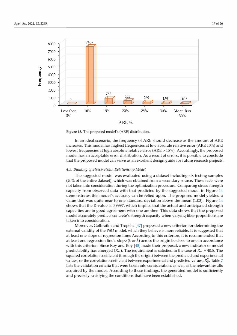
With a high R-value, the PSO model accurately predicts the required values with highaccuracy, as shown in Figure 13. As a result, the proposed model has a good ability topredict (i.e., low values) and to generalize (i.e., similar values).
Appl. Sci. 2022, 12, 2245 17 of 26
Figure 13. The proposed model’s (ARE) distribution.
In an ideal scenario, the frequency of ARE should decrease as the amount of AREincreases. This model has highest frequencies at low absolute relative error (ARE 10%) andlowest frequencies at high absolute relative error (ARE > 15%). Accordingly, the proposedmodel has an acceptable error distribution. As a result of errors, it is possible to concludethat the proposed model can serve as an excellent design guide for future research projects.
4.3. Building of Stress-Strain Relationship Model
The suggested model was evaluated using a dataset including six testing samples(20% of the entire dataset), which was obtained from a secondary source. These facts werenot taken into consideration during the optimization procedure. Comparing stress strengthcapacity from observed data with that predicted by the suggested model in Figure 14demonstrates this model’s accuracy can be relied upon. The proposed model yielded avalue that was quite near to one standard deviation above the mean (1.03). Figure 14shows that the R-value is 0.9997, which implies that the actual and anticipated strengthcapacities are in good agreement with one another. This data shows that the proposedmodel accurately predicts concrete’s strength capacity when varying fiber proportions aretaken into consideration.
Moreover, Golbraikh and Tropsha [47] proposed a new criterion for determining theexternal validity of the PSO model, which they believe is more reliable. It is suggested thatat least one slope of regression lines According to this criterion, it is recommended thatat least one regression line’s slope (k or k) across the origin be close to one in accordancewith this criterion. Since Roy and Roy [48] made their proposal, a new indicator of modelpredictability has emerged (Rm). The requirement is satisfied in the case of Rm = 40.5. Thesquared correlation coefficient (through the origin) between the predicted and experimentalvalues, or the correlation coefficient between experimental and predicted values, R2
o . Table 7lists the validation criteria that were taken into consideration, as well as the relevant resultsacquired by the model. According to these findings, the generated model is sufficientlyand precisely satisfying the conditions that have been established.

Appl. Sci. 2022, 12, 2245 18 of 26
Figure 14. Taylor diagrams of predicted versus observed standardized stress capacity using the PSOmodel (for 20% of the data).
Table 7. The PSO model’s statistical parameters for verification.
No. Expression Limitation Model Suggestion
1 R =∑n
i=1(PDAi−PDAi)(PDEi−PDEi)√∑n
i=1(PDAi−PDAi)2
∑ni=1(PDEi−PDEi)
2R > 0.8 0.9997
2 k = ∑ni=1(PDAi×PDEi)
PDAi2 0.85 < k < 1.15 1.0010
3 k = ∑ni=1(PDAi×PDEi)
PDEi2 0.85 < k′ < 1.15 0.9989
4 Rm = R2 ×(
1−√∣∣R2 − R2
o∣∣) Rm > 0.5 0.7584
where, R2o = 1− ∑n
i=1(PDEi−PDAoi )
2
(PDEi−PDEi)2 , PDAo
i = k× PDEi
5. Modeling of Hybrid Fiber-Reinforced Concrete Elements5.1. Modeling of the Structural Elements
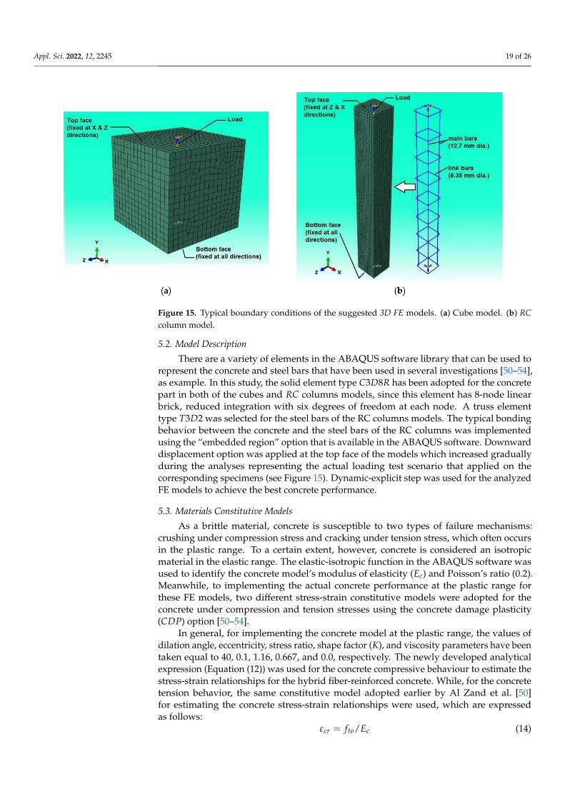
The main purpose of this section is to further validate the newly suggested stress-strainexpression (Equation (12)) that developed earlier in Section 4.2, where we demonstratethat the nonlinear finite element (FE) technique could be used to simulate the structuralbehavior of fiber-reinforced concrete elements using the ABAQUS software. Therefore, atotal of 10 structural elements have been selected to exam the model (Equation (12)) ofthe stress-strain relationship of the HFRC, included five plain cubes tested in the currentresearch and five specimens of RC columns that were tested in [49]. The typical structuralgeometry and boundary conditions of the selected structural elements are presented inFigure 15 for both models of cubes (150 mm) and RC columns (150 mm × 150 mm ×1200 mm).
Appl. Sci. 2022, 12, 2245 19 of 26
Figure 15. Typical boundary conditions of the suggested 3D FE models. (a) Cube model. (b) RCcolumn model.
5.2. Model Description
There are a variety of elements in the ABAQUS software library that can be used torepresent the concrete and steel bars that have been used in several investigations [50–54],as example. In this study, the solid element type C3D8R has been adopted for the concretepart in both of the cubes and RC columns models, since this element has 8-node linearbrick, reduced integration with six degrees of freedom at each node. A truss elementtype T3D2 was selected for the steel bars of the RC columns models. The typical bondingbehavior between the concrete and the steel bars of the RC columns was implementedusing the “embedded region” option that is available in the ABAQUS software. Downwarddisplacement option was applied at the top face of the models which increased graduallyduring the analyses representing the actual loading test scenario that applied on thecorresponding specimens (see Figure 15). Dynamic-explicit step was used for the analyzedFE models to achieve the best concrete performance.
5.3. Materials Constitutive Models
As a brittle material, concrete is susceptible to two types of failure mechanisms:crushing under compression stress and cracking under tension stress, which often occursin the plastic range. To a certain extent, however, concrete is considered an isotropicmaterial in the elastic range. The elastic-isotropic function in the ABAQUS software wasused to identify the concrete model’s modulus of elasticity (Ec) and Poisson’s ratio (0.2).Meanwhile, to implementing the actual concrete performance at the plastic range forthese FE models, two different stress-strain constitutive models were adopted for theconcrete under compression and tension stresses using the concrete damage plasticity(CDP) option [50–54].
In general, for implementing the concrete model at the plastic range, the values ofdilation angle, eccentricity, stress ratio, shape factor (K), and viscosity parameters have beentaken equal to 40, 0.1, 1.16, 0.667, and 0.0, respectively. The newly developed analyticalexpression (Equation (12)) was used for the concrete compressive behaviour to estimate thestress-strain relationships for the hybrid fiber-reinforced concrete. While, for the concretetension behavior, the same constitutive model adopted earlier by Al Zand et al. [50]for estimating the concrete stress-strain relationships were used, which are expressedas follows:
εcr = fto/Ec (14)

Appl. Sci. 2022, 12, 2245 20 of 26
ft = Ec·εt for εt ≤ εcr (15)
ft = fto·(εcr/εt)0.8 for εt < εcr (16)
where Ec is the elastic modulus of concrete; ft and fto are the concrete tensile strength, andthe cracking failure (0.31(0.8 fcu)
1/2), respectively. The fc and fcu are the cubic compressivestrength and the ultimate cubic compressive strength of concrete, respectively. The εtand εcr are the strains of concrete at relevant tensile stress ( ft) and cracking strain at fto,respectively. The CDP of the concrete model under compression and tension stresses areillustrated in Figure 16, where their damage parameters (dc and dt) and the related inelasticand cracking stains (εin and εck) are estimated as follows:
dc = 1− fc/ fcu (17)
dt = 1− ft/ fto (18)
εin = εc − fc/Ec (19)
εck = εt − ft/Ec (20)
Figure 16. The CDP of concrete FE model. (a) Under compression stresses. (b) under tension stresses.
Both the steel bars’ elastic modulus and Poisson’s ratio as well as their yield strengthswere determined in the elastic-isotropic option, whereas their plastic-isotropic (relatedplastic strain) were identified. Stress-strain models similar to those used in [49] wereemployed in this work.
5.4. Validate the FE Models
The selected mixtures from the current study to modeling the FE cubes are Mix-1,Mix-17, Mix-22, Mix 26, and Mix-28, which achieved fcu values equal to 55.8, 75.4, 86.5,100.5 and 118.3 MPa, respectively (see the above Table 3 and Figure 7). Due to the FEanalyses study, the related cubes models achieved very close fcu values as compared inFigure 17, where the FE analyses showed slightly overestimated the actual tested valueswith acceptable deviations of about 6% (estimated from the average results of all five cubemodels). The actual crushed concrete behavior under the compression test once reachedthe ultimate mixture strength has been simulated accurately in the currently analyzed FEcubes model, as presented in Figure 18 for the model with mix-17 as an example.

Appl. Sci. 2022, 12, 2245 21 of 26
Figure 17. Compression of the cubes ultimate compression strengths.
Figure 18. The failure mode of the FE cube model (Mix-17).
Furthermore, five hybrid-fiber reinforced concrete columns tested in [49] were selectedto verify the newly developed analytical concrete stress-strain model. The cross-sectionaldetails of HFRCs are depicted in Figure 19, which is representing the same details givenin [49]. Particularly, current FE columns models are prepared to simulating the testedcolumns with sample labels HC0.7–0.1, HC0.8–0.3, HC0.8–0.7, HC1.0–0.3, and HC1.0–0.9which achieved fcu values equal to 34.38 MPa, 37.81 MPa, 32.05 MPa, 35.17 MPa, and29.74 MPa respectively, as given in [49]. The FE analyses showed that the HFRC columnsmodels achieved slightly higher ultimate loading capacity values compared to the relatedtested specimens in [50], as presented in Figure 20. This deviation could be occurreddue to the idealistic behavior that usually behaved by the numerical elements of the FEmodel compared to the actual elements of the experimental specimen’s components [49].Generally, the overall standard deviations obtained from the comparisons between theFE column results and the corresponding tested columns are equal to 2.7%, which wasestimated from the average values of ultimate loading capacities of the FE models to thetested specimens. In addition, the failure modes that achieved numerically for the analyzed

Appl. Sci. 2022, 12, 2245 22 of 26
columns are fairly matched to the actual crushed failures of the corresponding testedcolumns (HC1.0–0.9), as shown in Figure 21.
Figure 19. Cross-sectional details of RC columns specimens.
Figure 20. Compression of the ultimate axial load capacity of HFRC columns.

Appl. Sci. 2022, 12, 2245 23 of 26
Figure 21. The failure mode of the FE HFRC model HC1.0–0.9.
6. Conclusions
This work developed a stress-strain curves for hybrid fiber reinforced concrete (HFRC)in compression with varying fiber content. This study is limited to two fibre types:polyvinyl alcohol and hocked-end steel fibers. The suggested stress-strain relationshipmodel was developed and validated using a dataset containing 30 HFRC mixtures. TheCoV, the mean, and the correlation coefficient (R) values of 12.67%, 0.963, and 0.9997, re-spectively, were found in the statistical analysis, confirming the model’s excellent predictiveaccuracy and consistency, so it is possible to precisely predict concretes’ stress and straincapacity by using a proposed model that incorporates polyvinyl alcohol and hocked-endsteel fibers.
The PSO technique was discovered to be a highly useful instrument for predictingstress-strain problems and providing an optimum solution for estimating stress capacityvalues utilizing a variety of parameters with a tolerable degree of precision. The devel-opment approach entails the collection of 30 HFRC curves. High-strength concrete witha compressive strength between 40 and 120 MPa can be estimated using the proposedstress-strain model. The proposed model has the highest ARE frequency (ARE 10%) andthe lowest ARE frequency (ARE > 15%). Carreira and Chu’s model has been modifiedto incorporate two distinct fibers. The updated equation’s critical parameters have beenempirically determined as a function of concrete strength.
The results display that, increases in the hocked steel fiber content up to a particularlevel, with a constant polyvinyl alcohol fiber amount, lead to increases in the stress capacityvalues. The established model can be utilized for practical predesign purposes becauseit is produced from testing on mixes with a wide variety of material components andattributes. The adequacy of modeling the structural elements that have varied containsfibers (one or more) have been achieved through a valid compression with the resultsof their corresponding tested specimens, confirming that the hybrid-reinforced concretemixtures can be simulated adequately using the proper FE analysis software, opening thegate to further investigations of numerical analyses in this field.
Appl. Sci. 2022, 12, 2245 24 of 26
Author Contributions: Conceptualization, A.A.A., A.H.A.-Z. and S.R.A.Z.; Data curation, A.A.A.,A.H.A.-Z. and A.N.H.; Formal analysis, A.W.A.Z., M.M.H. and A.N.H.; Funding acquisition, A.A.A.,A.H.A.-Z. and H.A.A.; Investigation, A.H.A.-Z. and S.R.A.Z.; Methodology, A.A.A., S.R.A.Z. andA.N.H.; Project administration, A.A.A., A.H.A.-Z., S.R.A.Z. and A.N.H.; Resources, S.R.A.Z., A.W.A.Z.,M.M.H. and H.A.A.; Software, A.N.H., A.W.A.Z. and M.M.H.; Supervision, S.R.A.Z. and H.A.A.;Validation, A.N.H., A.W.A.Z., and A.A.A.; Visualization, A.H.A.-Z., M.M.H. and H.A.A.; Writing—original draft, A.A.A., A.H.A.-Z., A.N.H. and A.W.A.Z.; Writing—review and editing, S.R.A.Z.,M.M.H., A.A.A., A.W.A.Z. and H.A.A. All authors have read and agreed to the published version ofthe manuscript.
Funding: This research received no external funding.
Institutional Review Board Statement: Not applicable.
Informed Consent Statement: Not applicable.
Data Availability Statement: Data are presented in the article.
Acknowledgments: The authors would like to express their gratitude for the support provided bythe University of Baghdad-Iraq, Universiti Kebangsaan Malaysia, Ministry of Science and Technology,and University of Technology-Iraq.
Conflicts of Interest: The authors declare no conflict of interest.
References1. Hanoon, A.N.; Al Zand, A.W.; Yaseen, Z.M. Designing new hybrid artificial intelligence model for CFST beam flexural perfor-
mance prediction. Eng. Comput. 2021, 1–27. [CrossRef]2. Mahmod, M.; Hanoon, A.N.; Abed, H.J. Flexural behavior of self-compacting concrete beams strengthened with steel fiber
reinforcement. J. Build. Eng. 2018, 16, 228–237. [CrossRef]3. Odaa, S.A.; Hason, M.M.; Sharba, A.A.K. Self-compacting concrete beams reinforced with steel fiber under flexural loads: A
ductility index evaluation. Mater. Today Proc. 2021, 42, 2259–2267. [CrossRef]4. Thomas, J.; Ramaswamy, A. Mechanical Properties of Steel Fiber-Reinforced Concrete. J. Mater. Civ. Eng. 2007, 19, 385–392.
[CrossRef]5. Akcay, B.; Tasdemir, M.A. Mechanical behaviour and fibre dispersion of hybrid steel fibre reinforced self-compacting concrete.
Constr. Build. Mater. 2012, 28, 287–293. [CrossRef]6. AbdulHameed, A.A.; Said, A.I. CFRP Laminates Reinforcing Performance of Short-Span Wedge-Blocks Segmental Beams. Fibers
2020, 8, 6. [CrossRef]7. Al-Zuhairi, A.H.; Al-Ahmed, A.H.A.; Hanoon, A.N.; Abdulhameed, A.A. Structural Behavior of Reinforced Hybrid Concrete
Columns under Biaxial Loading. Lat. Am. J. Solids Struct. 2021, 18. [CrossRef]8. Almusallam, T.; Siddiqui, N.; Iqbal, R.A.; Abbas, H. Response of hybrid-fiber reinforced concrete slabs to hard projectile impact.
Int. J. Impact Eng. 2013, 58, 17–30. [CrossRef]9. Abbas, H.; Almusallam, T.; Al-Salloum, Y. Improving the Impact Resistance of Reinforced Concrete. Adv. Mater. Res. 2014,
919–921, 1924–1929. [CrossRef]10. Bajaj, V.; Singh, S.P.; Singh, A.P.; Kaushik, S.K. Flexural fatigue analysis of hybrid fibre-reinforced concrete. Mag. Concr. Res. 2012,
64, 361–373. [CrossRef]11. ACI-Committee. Design Considerations for Steel Fiber Reinforced Concrete. ACI Struct. J. 1988, 85. [CrossRef]12. Chin, M.S.; Mansur, M.A.; Wee, T.H. Effects of Shape, Size, and Casting Direction of Specimens on Stress-Strain Curves of
High-Strength Concrete. ACI Mater. J. 1997, 94, 209–219. [CrossRef]13. ACI-Committee. State of the Art Report on High-Strength Concrete. ACI J. Proc. 1984, 81. [CrossRef]14. Al-Quraishi, H.; Lafta, M.J.; Abdulridha, A.A. Direct Shear Behavior of Fiber Reinforced Concrete Elements. J. Eng. 2018, 24,
231–248.15. Mehrabi, P.; Shariati, M.; Kabirifar, K.; Jarrah, M.; Rasekh, H.; Trung, N.T.; Shariati, A.; Jahandari, S. Effect of pumice powder
and nano-clay on the strength and permeability of fiber-reinforced pervious concrete incorporating recycled concrete aggregate.Constr. Build. Mater. 2021, 287, 122652. [CrossRef]
16. Toghroli, A.; Mehrabi, P.; Shariati, M.; Trung, N.T.; Jahandari, S.; Rasekh, H. Evaluating the use of recycled concrete aggregateand pozzolanic additives in fiber-reinforced pervious concrete with industrial and recycled fibers. Constr. Build. Mater. 2020,252, 118997. [CrossRef]
17. Sinaei, H. Numerical investigation on exterior reinforced concrete Beam-Column joint strengthened by composite fiber reinforcedpolymer (CFRP). Int. J. Phys. Sci. 2011, 6, 6572–6579. [CrossRef]
18. Shariati, M.; Armaghani, D.J.; Khandelwal, M.; Zhou, J.; Khorami, M. Assessment of Longstanding Effects of Fly Ash and SilicaFume on the Compressive Strength of Concrete Using Extreme Learning Machine and Artificial Neural Network. J. Adv. Eng.Comput. 2021, 5, 50–75. [CrossRef]

Appl. Sci. 2022, 12, 2245 25 of 26
19. Davoodnabi, S.M.; Mirhosseini, S.M.; Shariati, M. Analyzing shear strength of steel-concrete composite beam with angleconnectors at elevated temperature using finite element method. Steel Compos. Struct. 2021, 40, 853–868. [CrossRef]
20. Shariati, M.; Mafipour, M.S.; Mehrabi, P.; Ahmadi, M.; Wakil, K.; Trung, N.T.; Toghroli, A. Prediction of concrete strength inpresence of furnace slag and fly ash using Hybrid ANN-GA (Artificial Neural Network-Genetic Algorithm). Smart Struct. Syst.2020, 25, 183–195. [CrossRef]
21. Armaghani, D.J.; Mirzaei, F.; Shariati, M.; Trung, N.T.; Shariati, M.; Trnavac, D. Hybrid ANN-based techniques in predictingcohesion of sandy-soil combined with fiber. Geomech. Eng. 2020, 20, 191–205. [CrossRef]
22. Lee, S.-C.; Oh, J.-H.; Cho, J.-Y. Compressive Behavior of Fiber-Reinforced Concrete with End-Hooked Steel Fibers. Materials 2015,8, 1442–1458. [CrossRef] [PubMed]
23. Chalioris, C.E.; Panagiotopoulos, T.A. Flexural analysis of steel fibre-reinforced concrete members. Comput. Concr. 2018, 22, 11–25.[CrossRef]
24. Choi, W.-C.; Jung, K.-Y.; Jang, S.-J.; Yun, H.-D. The Influence of Steel Fiber Tensile Strengths and Aspect Ratios on the FractureProperties of High-Strength Concrete. Materials 2019, 12, 2105. [CrossRef]
25. Voutetaki, M.E.; Naoum, M.C.; Papadopoulos, N.A.; Chalioris, C.E. Cracking Diagnosis in Fiber-Reinforced Concrete withSynthetic Fibers Using Piezoelectric Transducers. Fibers 2022, 10, 5. [CrossRef]
26. Chalioris, C.E. Steel fibrous RC beams subjected to cyclic deformations under predominant shear. Eng. Struct. 2013, 49, 104–118.[CrossRef]
27. Shariati, M.; Mafipour, M.S.; Haido, J.H.; Yousif, S.T.; Toghroli, A.; Trung, N.T.; Shariati, A. Identification of the most influencingparameters on the properties of corroded concrete beams using an Adaptive Neuro-Fuzzy Inference System (ANFIS). Steel Compos.Struct. 2020, 34, 155. [CrossRef]
28. Shariati, M.; Mafipour, M.S.; Ghahremani, B.; Azarhomayun, F.; Ahmadi, M.; Trung, N.T.; Shariati, A. A novel hybrid extremelearning machine–grey wolf optimizer (ELM-GWO) model to predict compressive strength of concrete with partial replacementsfor cement. Eng. Comput. 2020, 1–23. [CrossRef]
29. AbdulHameed, A.A.; Said, A.I. Experimental Investigation of the Behavior of Self-Form Segmental Concrete Masonry Arches.Fibers 2019, 7, 58. [CrossRef]
30. Abbas, E.; AlZuhairi, A.H. Effect of Maximum Size of Aggregate on the Behavior of Reinforced Concrete Beams Analyzed usingMeso Scale Modeling. J. Eng. 2020, 26, 143–155. [CrossRef]
31. Hason, M.M.; Hanoon, A.N.; Al Zand, A.W.; AbdulHameed, A.A.; Al-Sulttani, A.O. Torsional Strengthening of ReinforcedConcrete Beams with Externally-Bonded Fibre Reinforced Polymer: An Energy Absorption Evaluation. Civ. Eng. J. 2020, 6, 69–85.[CrossRef]
32. ASTM C150/C150M-19a; Standard Specification for Portland Cement. ASTM International: West Conshohocken, PA, USA, 2019.33. ASTM-C192; Standard Practice for Making and Curing Concrete Test Specimens in the Laboratory Annual Book of ASTM
Standards 4.02. ASTM International: West Conshohocken, PA, USA, 2003.34. Hason, M.M.; Hanoon, A.N.; Abdulhameed, A.A. Particle Swarm Optimization Technique Based Prediction of Peak Ground
Acceleration of Iraq’s Tectonic Regions. J. King Saud Univ. Eng. Sci. 2021. [CrossRef]35. Kennedy, J.; Eberhart, R.C.; Shi, Y. Chapter seven—The Particle Swarm. In Swarm Intelligence; Kennedy, J., Eberhart, R.C., Shi, Y.,
Eds.; Morgan Kaufmann: San Francisco, CA, USA, 2001; pp. 287–325.36. Bratton, D.; Kennedy, J. Defining a Standard for Particle Swarm Optimization. In Proceedings of the 2007 IEEE Swarm Intelligence
Symposium, Honolulu, HI, USA, 1–5 April 2007; pp. 120–127. [CrossRef]37. Hanoon, A.N.; Jaafar, M.S.; Hejazi, F.; Aziz, F.N.A.A. Energy absorption evaluation of reinforced concrete beams under various
loading rates based on particle swarm optimization technique. Eng. Optim. 2016, 49, 1483–1501. [CrossRef]38. Hanoon, A.N.; Jaafar, M.; Hejazi, F.; Aziz, F.N.A. Strut-and-tie model for externally bonded CFRP-strengthened reinforced
concrete deep beams based on particle swarm optimization algorithm: CFRP debonding and rupture. Constr. Build. Mater. 2017,147, 428–447. [CrossRef]
39. Al-Sulttani, A.O.; Ahsan, A.; Hanoon, A.N.; Rahman, A.; Daud, N.; Idrus, S. Hourly yield prediction of a double-slope solar stillhybrid with rubber scrapers in low-latitude areas based on the particle swarm optimization technique. Appl. Energy 2017, 203,280–303. [CrossRef]
40. Lavanya, D.; Udgata, S.K. Swarm intelligence based localization in wireless sensor networks. In International Workshop onMulti-disciplinary Trends in Artificial Intelligence; Springer: Berlin/Heidelberg, Germany, 2011.
41. Carreira, D.J.; Chu, K.-H. Stress-strain relationship for plain concrete in compression. J. Proc. 1985, 82, 797–804. [CrossRef]42. Frank, I.E.; Todeschini, R. The Data Analysis Handbook. In Data Handling in Science and Technology; Frank, I.E., Todeschini, R.,
Eds.; Elsevier: Amsterdam, The Netherlands, 1994; pp. 1–352.43. Berry, E.; Hemmings, R.; Zhang, M.; Malhotra, V. Fourth International Conference on Fly Ash, Silica Fume, Slag, and Natural Pozzolans
in Concrete: Supplemental Proceedings; Electric Power Research Inst.: Istanbul, Turkey, 1992.44. Smith, G.N. Probability and Statistics in Civil Engineering; Collins Professional and Technical Books; Nichols Publishing Company:
New York, NY, USA, 1986; 244p.45. Taylor, K.E. Summarizing multiple aspects of model performance in a single diagram. J. Geophys. Res. Atmos. 2001, 106, 7183–7192.
[CrossRef]

Appl. Sci. 2022, 12, 2245 26 of 26
46. Bagheri, M.; Bagheri, M.; Gandomi, A.H.; Golbraikh, A. Simple yet accurate prediction method for sublimation enthalpies oforganic contaminants using their molecular structure. Thermochim. Acta 2012, 543, 96–106. [CrossRef]
47. Golbraikh, A.; Tropsha, A. Beware of q2! J. Mol. Graph. Model. 2002, 20, 269–276. [CrossRef]48. Roy, P.P.; Roy, K. On Some Aspects of Variable Selection for Partial Least Squares Regression Models. QSAR Comb. Sci. 2008, 27,
302–313. [CrossRef]49. Raza, A.; Khan, Q.U.Z. Experimental and numerical behavior of hybrid-fiber-reinforced concrete compression members under
concentric loading. SN Appl. Sci. 2020, 2, 701. [CrossRef]50. Al Zand, A.W.; Badaruzzaman, W.H.W.; Tawfeeq, W.M. New empirical methods for predicting flexural capacity and stiffness of
CFST beam. J. Constr. Steel Res. 2020, 164, 105778. [CrossRef]51. Al Zand, A.W.; Ali, M.M.; Al-Ameri, R.; Badaruzzaman, W.H.W.; Tawfeeq, W.M.; Hosseinpour, E.; Yaseen, Z.M. Flexural Strength
of Internally Stiffened Tubular Steel Beam Filled with Recycled Concrete Materials. Materials 2021, 14, 6334. [CrossRef] [PubMed]52. Hernoune, H.; Benabed, B.; Kanellopoulos, A.; Al-Zuhairi, A.H.; Guettala, A. Experimental and Numerical Study of Behaviour of
Reinforced Masonry Walls with NSM CFRP Strips Subjected to Combined Loads. Buildings 2020, 10, 103. [CrossRef]53. Al-Zuhairi, A.H.; Taj, A.I. Finite Element Analysis of Concrete Beam under Flexural Stresses Using Meso-Scale Model. Civ. Eng. J.
2018, 4, 1288. [CrossRef]54. Hosseinpour, E.; Baharom, S.; Badaruzzaman, W.H.W.; Shariati, M.; Jalali, A. Direct shear behavior of concrete filled hollow steel
tube shear connector for slim-floor steel beams. Steel Compos. Struct. 2018, 26, 485–499. [CrossRef]
Related Documents