1 www.tucson.ars.ag.gov/agwa www.epa.gov/water-research/automated-geospatial-watershed-assessment-agwa-tool-hydrologic-modeling-and-watershed The Automated Geospatial Watershed Assessment Tool Introduction to the AGWA Urban Tool: Assessing post-development effects and the impact of green infrastructure practices in an urban subdivision Introduction In this exercise you will use the AGWA Urban tool to assess the potential impacts of green infrastructure practices in an urban development. Goal To familiarize yourself with the AGWA Urban tool to run the KINEROS2 model to simulate urbanization and green infrastructure practices. Assignment Run the KINEROS2 model on a subdivision with 66 lots to compare pre-development and post-development hydrology. Design three different green infrastructure practices and run the model to assess the impact of these practices. Background Increasing urban development in the arid and semiarid regions of southwestern United States has led to greater demand for water from limited water resources. Impervious areas in urban environments decrease infiltration and increase surface runoff, thereby reducing groundwater recharge. Green Infrastructure (GI) practices aim to increase onsite infiltration of rainfall, or capture rainfall for local use, which results in a decrease in surface runoff. Retention basins, permeable pavements, and rainwater harvesting are three of the most commonly used GI practices. The Automated Geospatial Watershed Assessment (AGWA) tool was modified to allow the design and placement of these GI practices, in order to simulate urban hydrology using the Kinematic Runoff and Erosion (KINEROS2) model. KINEROS2 has an "Urban" component (Figure 1) which consists of up to six overland flow areas that contribute to a paved, crowned street with the following configurations: (1) directly connected pervious area, (2) directly connected impervious area, (3) indirectly connected impervious area, (4) indirectly connected pervious area, (5) connecting pervious area, and (6) connecting impervious area. The “Urban” component represents an abstraction of a typical subdivision. Figure 1: The KINEROS2 Urban element

Welcome message from author
This document is posted to help you gain knowledge. Please leave a comment to let me know what you think about it! Share it to your friends and learn new things together.
Transcript
1 www.tucson.ars.ag.gov/agwa
www.epa.gov/water-research/automated-geospatial-watershed-assessment-agwa-tool-hydrologic-modeling-and-watershed
The Automated Geospatial Watershed Assessment Tool
Introduction to the AGWA Urban Tool: Assessing post-development effects
and the impact of green infrastructure practices in an urban subdivision
Introduction In this exercise you will use the AGWA Urban tool to assess the potential impacts of green infrastructure practices in an urban development.
Goal To familiarize yourself with the AGWA Urban tool to run the KINEROS2 model to simulate urbanization and green infrastructure practices.
Assignment Run the KINEROS2 model on a subdivision with 66 lots to compare pre-development and post-development hydrology. Design three different green infrastructure practices and run the model to assess the impact of these practices.
Background Increasing urban development in the arid and semiarid regions of southwestern United States has led to
greater demand for water from limited water resources. Impervious areas in urban environments
decrease infiltration and increase surface runoff, thereby reducing groundwater recharge. Green
Infrastructure (GI) practices aim to increase onsite infiltration of rainfall, or capture rainfall for local use,
which results in a decrease in surface runoff. Retention basins, permeable pavements, and rainwater
harvesting are three of the most commonly used GI practices. The Automated Geospatial Watershed
Assessment (AGWA) tool was modified to allow the design and placement of these GI practices, in order
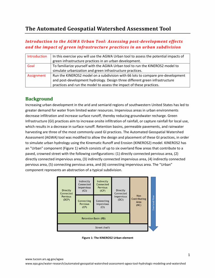
to simulate urban hydrology using the Kinematic Runoff and Erosion (KINEROS2) model. KINEROS2 has
an "Urban" component (Figure 1) which consists of up to six overland flow areas that contribute to a
paved, crowned street with the following configurations: (1) directly connected pervious area, (2)
directly connected impervious area, (3) indirectly connected impervious area, (4) indirectly connected
pervious area, (5) connecting pervious area, and (6) connecting impervious area. The “Urban”
component represents an abstraction of a typical subdivision.
Figure 1: The KINEROS2 Urban element
2 www.tucson.ars.ag.gov/agwa
www.epa.gov/water-research/automated-geospatial-watershed-assessment-agwa-tool-hydrologic-modeling-and-watershed
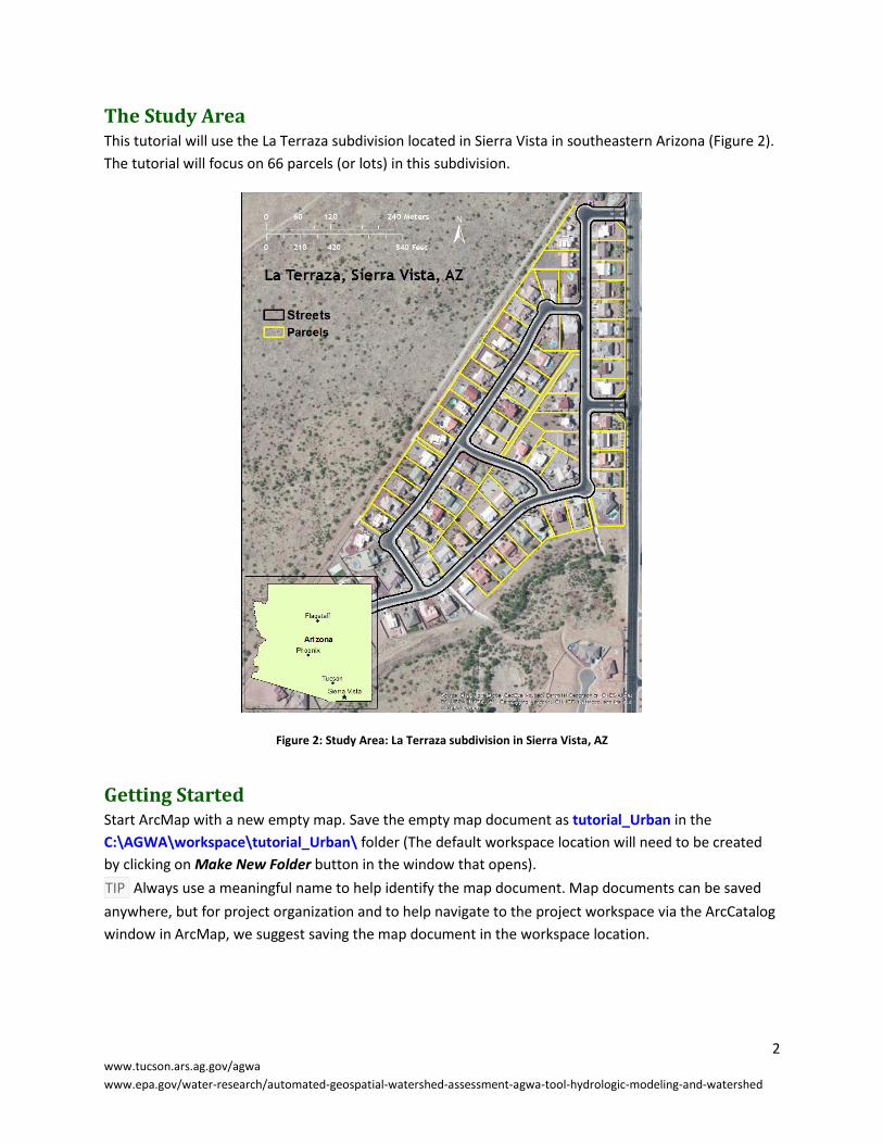
The Study Area This tutorial will use the La Terraza subdivision located in Sierra Vista in southeastern Arizona (Figure 2).
The tutorial will focus on 66 parcels (or lots) in this subdivision.
Figure 2: Study Area: La Terraza subdivision in Sierra Vista, AZ
Getting Started Start ArcMap with a new empty map. Save the empty map document as tutorial_Urban in the
C:\AGWA\workspace\tutorial_Urban\ folder (The default workspace location will need to be created
by clicking on Make New Folder button in the window that opens).
TIP Always use a meaningful name to help identify the map document. Map documents can be saved
anywhere, but for project organization and to help navigate to the project workspace via the ArcCatalog
window in ArcMap, we suggest saving the map document in the workspace location.

3 www.tucson.ars.ag.gov/agwa
www.epa.gov/water-research/automated-geospatial-watershed-assessment-agwa-tool-hydrologic-modeling-and-watershed
If the AGWA Urban Tools toolbar is not visible, turn it on by selecting Customize > Toolbars > AGWA
Urban Toolbar on the ArcMap Main Menu bar. Once the map document is opened and saved, set the
Home, Temp, and Default Workspace folders by selecting AGWA Urban Tools > AGWA Preferences on
the AGWA Toolbar.
Home: C:\AGWA\
Temp: C:\AGWA\temp\
Default Workspace: C:\AGWA\workspace\tutorial_Urban\
The default workspace location will need to be created by clicking on the Make New Folder
button in the window that opens if you did not create it when saving the map document earlier .
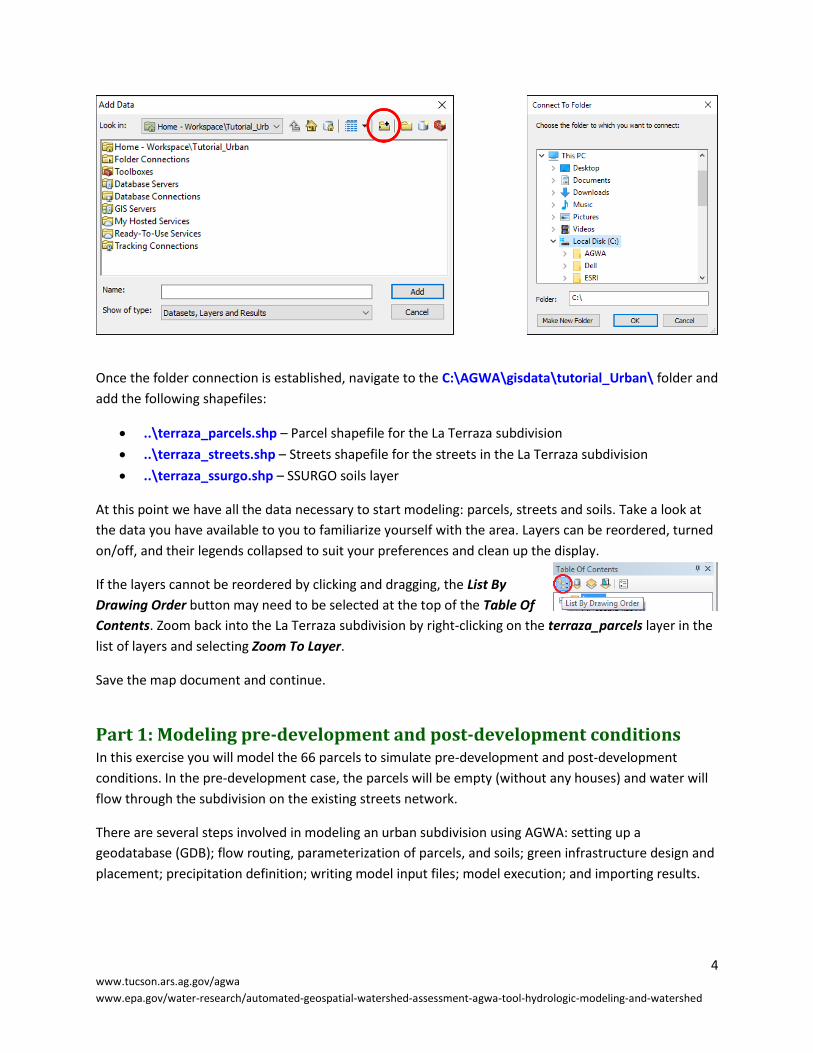
GIS Data Before adding data to the map, connections to drives and folders where your data are stored must be
established if they have not been already. To establish folder connections if they don’t already exist,
click on the Add Data button below the menu bar at the top of the screen. In the Add Data form
that opens, click the Connect To Folder button and select Local Disk (C:).
The Home directory contains all of the look-up tables, datafiles, models, and documentation required
for AGWA to run. If this is set improperly or you are missing any files, you will be presented with a
warning that lists the missing directories or files that AGWA requires.
The Temp directory is where some temporary files created by AGWA will be placed. You may want to
routinely delete files and directories in the Temp directory if you need to free up space or are
interested in identifying the temporary files associated with your next AGWA use.
The Default Workspace directory is where delineation geodatabases will be stored by default. This
can be a helpful timesaver during the navigation process if you have a deeply nested directory
structure where you store AGWA outputs.
4 www.tucson.ars.ag.gov/agwa
www.epa.gov/water-research/automated-geospatial-watershed-assessment-agwa-tool-hydrologic-modeling-and-watershed
Once the folder connection is established, navigate to the C:\AGWA\gisdata\tutorial_Urban\ folder and
add the following shapefiles:
..\terraza_parcels.shp – Parcel shapefile for the La Terraza subdivision
..\terraza_streets.shp – Streets shapefile for the streets in the La Terraza subdivision
..\terraza_ssurgo.shp – SSURGO soils layer
At this point we have all the data necessary to start modeling: parcels, streets and soils. Take a look at
the data you have available to you to familiarize yourself with the area. Layers can be reordered, turned
on/off, and their legends collapsed to suit your preferences and clean up the display.
If the layers cannot be reordered by clicking and dragging, the List By
Drawing Order button may need to be selected at the top of the Table Of
Contents. Zoom back into the La Terraza subdivision by right-clicking on the terraza_parcels layer in the
list of layers and selecting Zoom To Layer.
Save the map document and continue.
Part 1: Modeling pre-development and post-development conditions In this exercise you will model the 66 parcels to simulate pre-development and post-development
conditions. In the pre-development case, the parcels will be empty (without any houses) and water will
flow through the subdivision on the existing streets network.
There are several steps involved in modeling an urban subdivision using AGWA: setting up a
geodatabase (GDB); flow routing, parameterization of parcels, and soils; green infrastructure design and
placement; precipitation definition; writing model input files; model execution; and importing results.

5 www.tucson.ars.ag.gov/agwa
www.epa.gov/water-research/automated-geospatial-watershed-assessment-agwa-tool-hydrologic-modeling-and-watershed
Step 1: Set up the Urban Geodatabase This step creates a geodatabase (GDB) to store copies of the input shapefiles, feature classes and tables
created in subsequent processes.
1. Select AGWA Urban Tools > Setup Urban GDB.
DESCRIPTION In the Setup Urban Geodatabase form, several parameters are defined including the
output location, the name of the geodatabase, the name of the discretization, the parcels layer, and
the streets layer.
1.1. Output Location box
1.1.1. Workspace textbox: (if it isn’t already populated) navigate to and select/create
C:\AGWA\workspace\tutorial_Urban\
DESCRIPTION The workspace specified is the location on your hard drive where the
urban geodatabase is stored.
1.1.2. Geodatabase textbox: enter terraza
NOTE You will be required to change
the name of the geodatabase if a
geodatabase with the same name
exists in the selected workspace.
1.1.3. Discretization textbox: enter d1
1.2. Layers box
1.2.1. Parcels: select terraza_parcels
NOTE The parcels shapefile must have
a column in the attribute table which
defines the parcel width intersecting
the road.
1.2.2. Streets: select terraza_streets
1.3. Click Create
1.4. Click Close once setup is complete.
1.5. Save the map document and continue.
At this point, AGWA has created a new geodatabase named terraza. Inside the geodatabase, the input
parcels and streets shapefiles are converted to feature classes, named parcels_d1 and streets_d1,
respectively. A feature class, named results_d1 is also created, which will be used to display
accumulated runoff on the streets.
Step 2: Routing the flow of water on the streets Flow routing is an important step in simulating an urban subdivision as post construction flow paths are
typically different from pre-development topography. KINEROS2 requires the path that water will follow
from the lot to the basin outlet. The Urban element in KINEROS2 assumes all of the rainfall will flow
from the lot towards the street. The street is assumed to be crowned to allow the routing of water along
the streets.

6 www.tucson.ars.ag.gov/agwa
www.epa.gov/water-research/automated-geospatial-watershed-assessment-agwa-tool-hydrologic-modeling-and-watershed
2. Perform the flow routing step by selecting AGWA Urban Tools > Urban Flow Routing
DESCRIPTION In the Urban Flow Routing form, the user can draw flow paths on the map to indicate
the route that the water will take to reach the outlet.
2.1. Input box
2.1.1. Discretization: select terraza\d1
2.1.2. Routing Name: enter rt1
2.2. Flow Paths
2.2.1. Click on the Draw flow paths button to draw lines on the parcels to indicate the flow path
the water will follow along the streets to reach the outlet. You can use figure 3 to draw
the route on your map.
DESCRIPTION Click on a parcel to start a route and double click to complete drawing the
route. You can include bends in the route by clicking once on a parcel. There are certain
rules that must be followed while drawing routes. These are shown in figure 4.
Figure 3: Flow routes for the La Terraza Subdivision
7 www.tucson.ars.ag.gov/agwa
www.epa.gov/water-research/automated-geospatial-watershed-assessment-agwa-tool-hydrologic-modeling-and-watershed
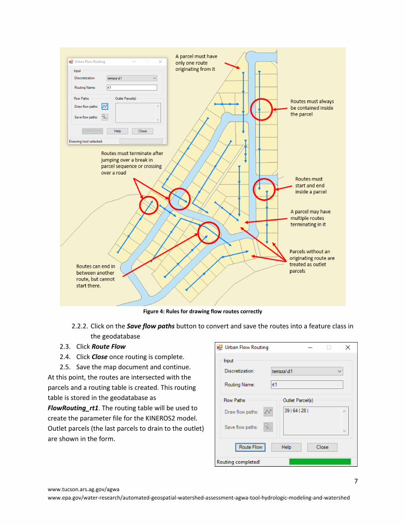
Figure 4: Rules for drawing flow routes correctly
2.2.2. Click on the Save flow paths button to convert and save the routes into a feature class in
the geodatabase
2.3. Click Route Flow
2.4. Click Close once routing is complete.
2.5. Save the map document and continue.
At this point, the routes are intersected with the
parcels and a routing table is created. This routing
table is stored in the geodatabase as
FlowRouting_rt1. The routing table will be used to
create the parameter file for the KINEROS2 model.
Outlet parcels (the last parcels to drain to the outlet)
are shown in the form.

8 www.tucson.ars.ag.gov/agwa
www.epa.gov/water-research/automated-geospatial-watershed-assessment-agwa-tool-hydrologic-modeling-and-watershed
Step 3: Parameterizing the urban elements for KINEROS2 Parameterizing defines model input parameters based on parcel (slope, house and driveway
parameters), street (dimensions and slope parameters), land cover (roughness, interception and canopy
cover), and soils properties. Model input parameters represent the physical properties of the subdivision
and are used to write the model input files.
3. Perform the element, land cover, and soils parameterization
for the subdivision by selecting AGWA Urban Tools > Urban
Parameterizer.
3.1. Input box
3.1.1. Discretization: select terraza\d1
3.1.2. Parameterization Name: enter pre
3.2. Elements box
3.2.1. Parameterization: select Create new
parameterization
3.2.2. Click Select Options. The Element Parameterizer
form opens.
3.3. In the Element Parameterizer form
3.3.1. Parcels tab
3.3.1.1. Parcel Width Field: select P_Width
3.3.1.2. House Area Field: click on the New checkbox
3.3.1.2.1. House Area: Move the slider to 0%
3.3.1.3. Driveway Area Field: click on the New checkbox
3.3.1.3.1. Driveway Width: Move the slider to 0ft
3.3.1.3.2. Driveway Length: Move the slider to 0ft
3.3.1.4. Slope Field: click on the New checkbox
3.3.1.4.1. Overland Slope: do nothing (we will
accept the default value)
3.3.2. Streets tab
3.3.2.1. Lane Width Field: select WIDTH
3.3.2.2. Cross Slope Field: click on the New checkbox
3.3.2.2.1. % Cross Slope: do nothing (we will
accept the default value)
3.3.2.3. Grade Field: click on the New checkbox
3.3.2.3.1. % Grade: do nothing (we will accept
the default value)
3.3.3. Click Continue. You will be returned to the
Parameterizer form to create the Land Cover and
Soils parameterization.

9 www.tucson.ars.ag.gov/agwa
www.epa.gov/water-research/automated-geospatial-watershed-assessment-agwa-tool-hydrologic-modeling-and-watershed
3.4. Back in the Land Cover and Soils box of the
Parameterizer form
3.4.1. Parameterization: select Create new
parameterization
3.4.2. Click Select Options. The Land Cover and Soils
form opens.
3.5. In the Land Cover and Soils form
3.5.1. Land Cover box
3.5.1.1. Roughness box
3.5.1.1.1. Impervious Surfaces: do nothing (we
will accept the default value)
3.5.1.1.2. Pervious Surfaces: do nothing (we will
accept the default value)
3.5.1.1.3. Streets: do nothing (we will accept
the default value)
3.5.1.2. Interception box
3.5.1.2.1. Impervious Surfaces: do nothing (we
will accept the default value)
3.5.1.2.2. Pervious Surfaces: do nothing (we will
accept the default value)
3.5.1.3. Canopy Cover: do nothing (we will accept
the default value)
3.5.2. Soils box
3.5.2.1. Soils layer: select terraza_ssurgo
3.5.2.2. Soils database: click on the Add Data
button and browse to the
C:\AGWA\gisdata\tutorial_Urban folder
and select soilmu_a_az671.mdb
3.6. Click Continue. You will be returned to the
Parameterizer form where the Process button will
now be enabled.
3.7. In the Parameterizer form, click Process.
3.8. Click Close once parameterization is complete.
In this step, parameterization look-up tables for the urban
elements have been created to store the model input
parameters representing the physical properties of the parcels.
Step 4: Repeat for Post-development conditions AGWA can store multiple parameterizations in the parameterization look-up tables. Running the
parameterization with a different set of options (element, soils, or land cover) will append data to the
existing look-up tables instead of overwriting them, so the parameterization can be accessed again at a
10 www.tucson.ars.ag.gov/agwa
www.epa.gov/water-research/automated-geospatial-watershed-assessment-agwa-tool-hydrologic-modeling-and-watershed
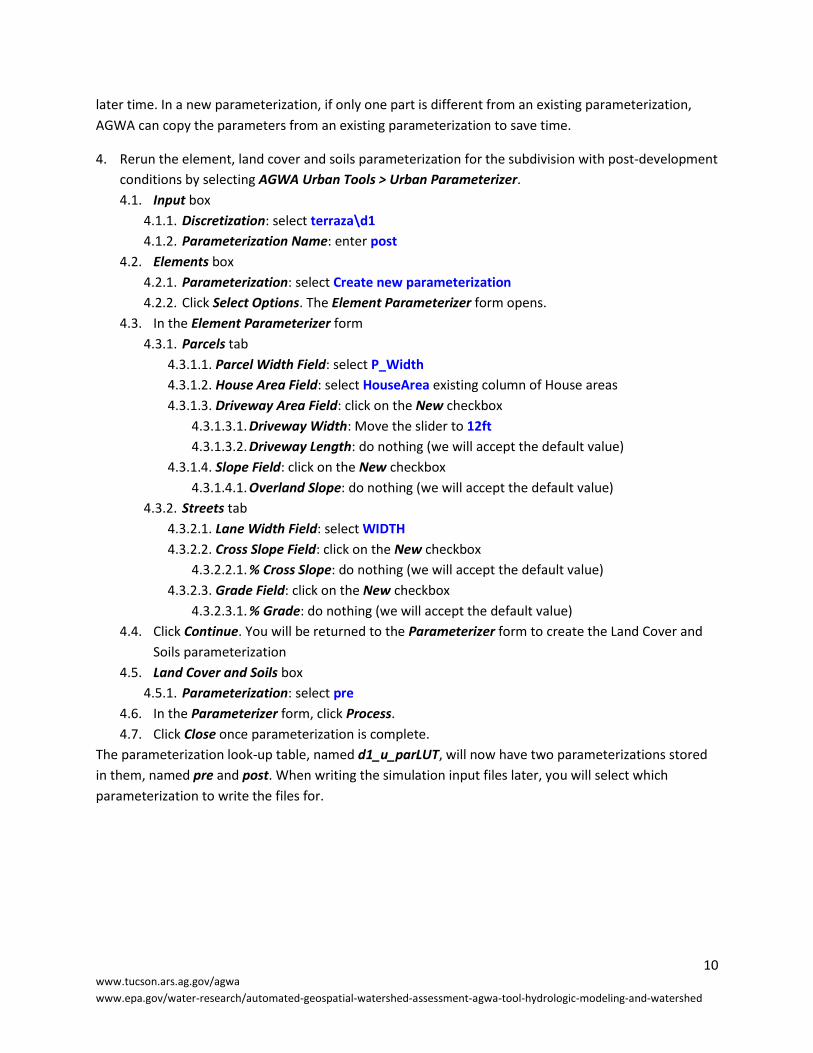
later time. In a new parameterization, if only one part is different from an existing parameterization,
AGWA can copy the parameters from an existing parameterization to save time.
4. Rerun the element, land cover and soils parameterization for the subdivision with post-development
conditions by selecting AGWA Urban Tools > Urban Parameterizer.
4.1. Input box
4.1.1. Discretization: select terraza\d1
4.1.2. Parameterization Name: enter post
4.2. Elements box
4.2.1. Parameterization: select Create new parameterization
4.2.2. Click Select Options. The Element Parameterizer form opens.
4.3. In the Element Parameterizer form
4.3.1. Parcels tab
4.3.1.1. Parcel Width Field: select P_Width
4.3.1.2. House Area Field: select HouseArea existing column of House areas
4.3.1.3. Driveway Area Field: click on the New checkbox
4.3.1.3.1. Driveway Width: Move the slider to 12ft
4.3.1.3.2. Driveway Length: do nothing (we will accept the default value)
4.3.1.4. Slope Field: click on the New checkbox
4.3.1.4.1. Overland Slope: do nothing (we will accept the default value)
4.3.2. Streets tab
4.3.2.1. Lane Width Field: select WIDTH
4.3.2.2. Cross Slope Field: click on the New checkbox
4.3.2.2.1. % Cross Slope: do nothing (we will accept the default value)
4.3.2.3. Grade Field: click on the New checkbox
4.3.2.3.1. % Grade: do nothing (we will accept the default value)
4.4. Click Continue. You will be returned to the Parameterizer form to create the Land Cover and
Soils parameterization
4.5. Land Cover and Soils box
4.5.1. Parameterization: select pre
4.6. In the Parameterizer form, click Process.
4.7. Click Close once parameterization is complete.
The parameterization look-up table, named d1_u_parLUT, will now have two parameterizations stored
in them, named pre and post. When writing the simulation input files later, you will select which
parameterization to write the files for.

11 www.tucson.ars.ag.gov/agwa
www.epa.gov/water-research/automated-geospatial-watershed-assessment-agwa-tool-hydrologic-modeling-and-watershed
Step 5: Preparing rainfall files AGWA allows you to create rainfall data for KINEROS2 in a number of ways:
Design storm depth and duration from the database (our technique).
Design storm depth and duration based on precipitation frequency maps.
User-defined hyetograph.
User-defined depth and duration.
In this exercise, we will define the storm by providing the depth and duration obtained from NOAA’s
National Weather Service, precipitation frequency data server (http://hdsc.nws.noaa.gov/hdsc/pfds/,
Figure 5). We will be using a 10-year, 1-hour storm with a precipitation depth of 1.68 inches (42.67 mm).
Figure 5: Location of rain gauge from the NOAA website
12 www.tucson.ars.ag.gov/agwa
www.epa.gov/water-research/automated-geospatial-watershed-assessment-agwa-tool-hydrologic-modeling-and-watershed
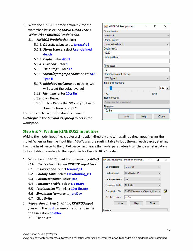
5. Write the KINEROS2 precipitation file for the
watershed by selecting AGWA Urban Tools >
Write Urban KINEROS Precipitation.
5.1. KINEROS Precipitation form
5.1.1. Discretization: select terraza\d1
5.1.2. Storm Source: select User-defined
depth
5.1.3. Depth: Enter 42.67
5.1.4. Duration: Enter 1
5.1.5. Time steps: Enter 12
5.1.6. Storm/hyetograph shape: select SCS
Type II
5.1.7. Initial soil moisture: do nothing (we
will accept the default value)
5.1.8. Filename: enter 10yr1hr
5.1.9. Click Write.
5.1.10. Click Yes on the “Would you like to
close the form prompt?”
This step creates a precipitation file, named
10r1hr.pre in the terraza>d1>precip folder in the
workspace.
Step 6 & 7: Writing KINEROS2 input files Writing the model input files creates a simulation directory and writes all required input files for the
model. When writing the input files, AGWA uses the routing table to loop through each parcel, starting
from the head parcel to the outlet parcel, and reads the model parameters from the parameterization
look-up tables to write into the input files for the KINEROS2 model.
6. Write the KINEROS2 input files by selecting AGWA
Urban Tools > Write Urban KINEROS Input Files.
6.1. Discretization: select terraza\d1
6.2. Routing Table: select FlowRouting_rt1
6.3. Parameterization: select pre
6.4. Placement Table: select No BMPs
6.5. Precipitation file: select 10yr1hr.pre
6.6. Simulation Name: enter preDev
6.7. Click Write.
7. Repeat Part 1, Step 6: Writing KINEROS input
files with the post parameterization and name
the simulation postDev.
7.1. Click Close.
13 www.tucson.ars.ag.gov/agwa
www.epa.gov/water-research/automated-geospatial-watershed-assessment-agwa-tool-hydrologic-modeling-and-watershed
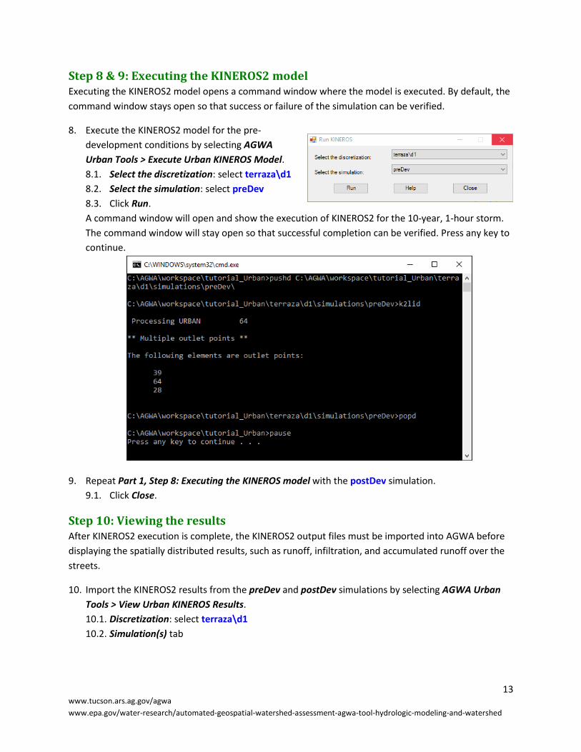
Step 8 & 9: Executing the KINEROS2 model Executing the KINEROS2 model opens a command window where the model is executed. By default, the
command window stays open so that success or failure of the simulation can be verified.
8. Execute the KINEROS2 model for the pre-
development conditions by selecting AGWA
Urban Tools > Execute Urban KINEROS Model.
8.1. Select the discretization: select terraza\d1
8.2. Select the simulation: select preDev
8.3. Click Run.
A command window will open and show the execution of KINEROS2 for the 10-year, 1-hour storm.
The command window will stay open so that successful completion can be verified. Press any key to
continue.
9. Repeat Part 1, Step 8: Executing the KINEROS model with the postDev simulation.
9.1. Click Close.
Step 10: Viewing the results After KINEROS2 execution is complete, the KINEROS2 output files must be imported into AGWA before
displaying the spatially distributed results, such as runoff, infiltration, and accumulated runoff over the
streets.
10. Import the KINEROS2 results from the preDev and postDev simulations by selecting AGWA Urban
Tools > View Urban KINEROS Results.
10.1. Discretization: select terraza\d1
10.2. Simulation(s) tab
14 www.tucson.ars.ag.gov/agwa
www.epa.gov/water-research/automated-geospatial-watershed-assessment-agwa-tool-hydrologic-modeling-and-watershed
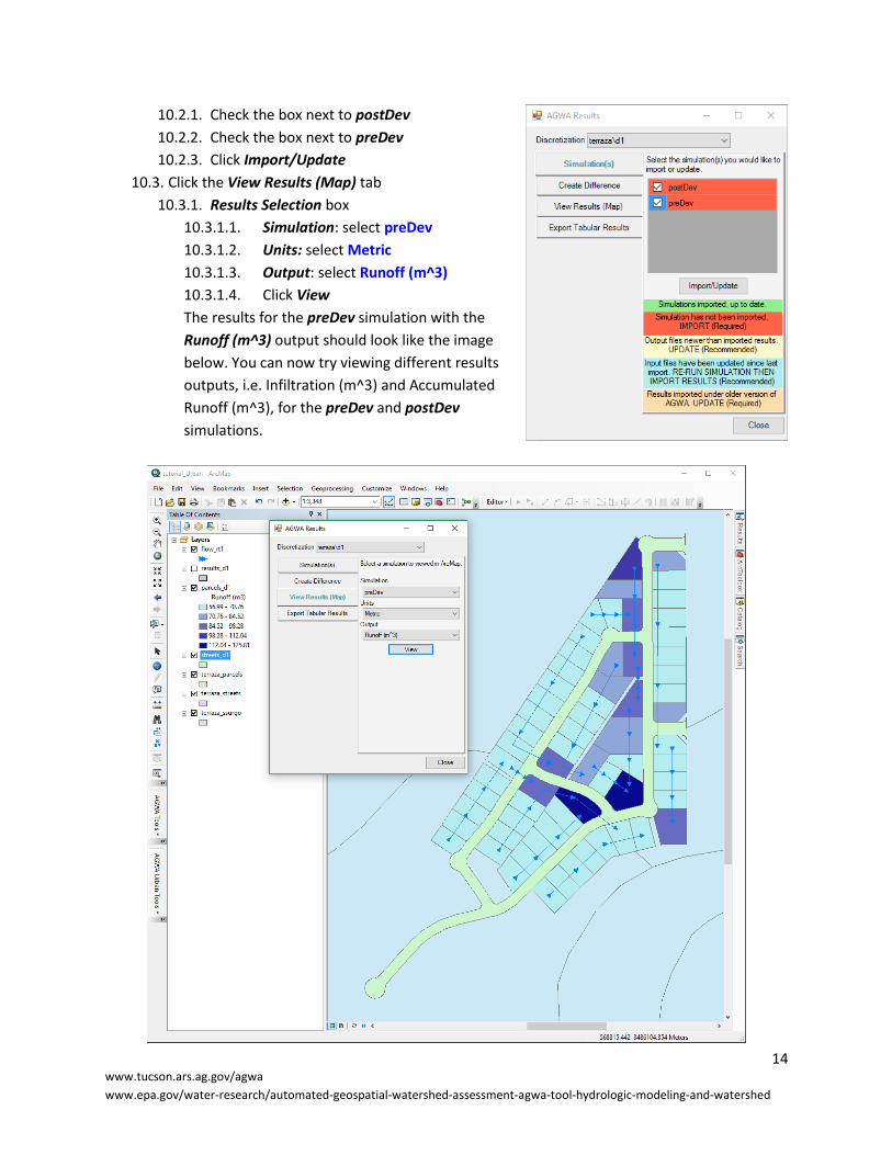
10.2.1. Check the box next to postDev
10.2.2. Check the box next to preDev
10.2.3. Click Import/Update
10.3. Click the View Results (Map) tab
10.3.1. Results Selection box
10.3.1.1. Simulation: select preDev
10.3.1.2. Units: select Metric
10.3.1.3. Output: select Runoff (m^3)
10.3.1.4. Click View
The results for the preDev simulation with the
Runoff (m^3) output should look like the image
below. You can now try viewing different results
outputs, i.e. Infiltration (m^3) and Accumulated
Runoff (m^3), for the preDev and postDev
simulations.
15 www.tucson.ars.ag.gov/agwa
www.epa.gov/water-research/automated-geospatial-watershed-assessment-agwa-tool-hydrologic-modeling-and-watershed
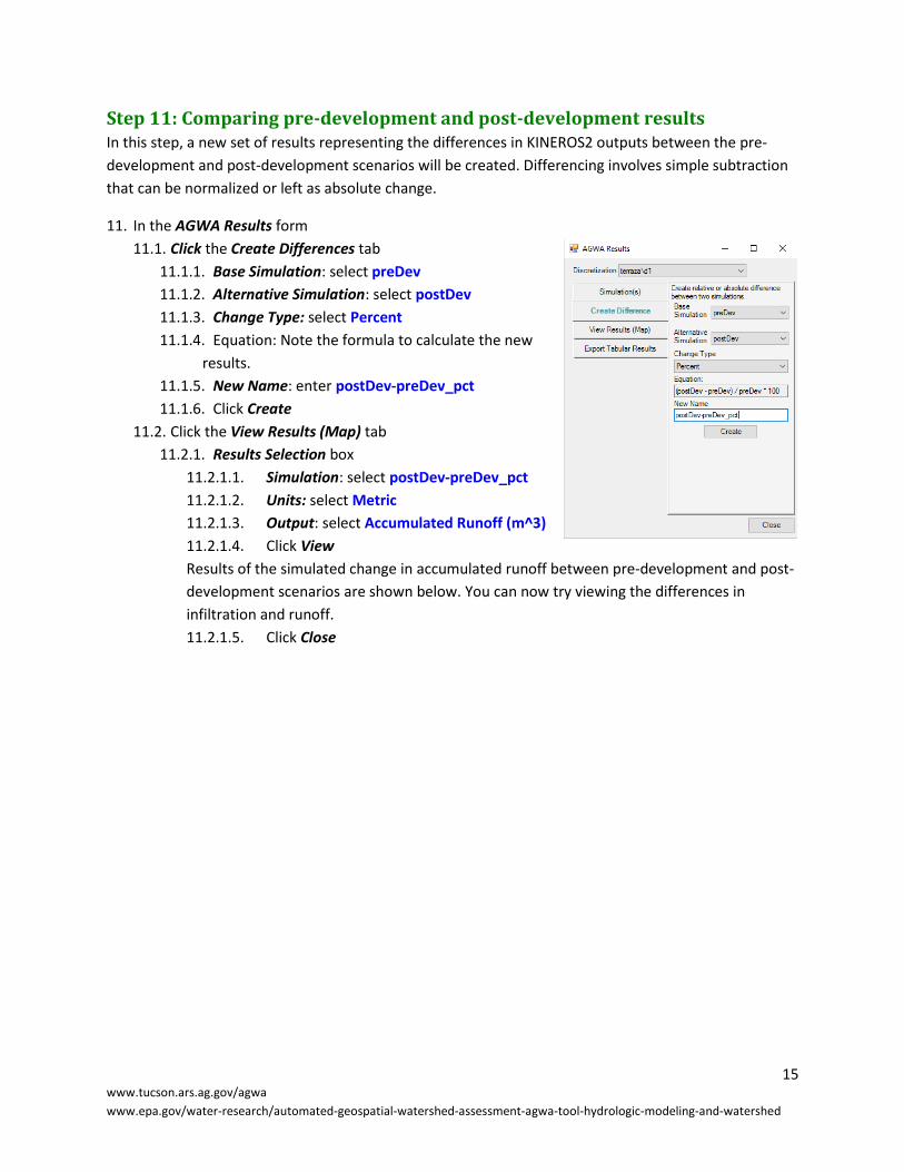
Step 11: Comparing pre-development and post-development results In this step, a new set of results representing the differences in KINEROS2 outputs between the pre-
development and post-development scenarios will be created. Differencing involves simple subtraction
that can be normalized or left as absolute change.
11. In the AGWA Results form
11.1. Click the Create Differences tab
11.1.1. Base Simulation: select preDev
11.1.2. Alternative Simulation: select postDev
11.1.3. Change Type: select Percent
11.1.4. Equation: Note the formula to calculate the new
results.
11.1.5. New Name: enter postDev-preDev_pct
11.1.6. Click Create
11.2. Click the View Results (Map) tab
11.2.1. Results Selection box
11.2.1.1. Simulation: select postDev-preDev_pct
11.2.1.2. Units: select Metric
11.2.1.3. Output: select Accumulated Runoff (m^3)
11.2.1.4. Click View
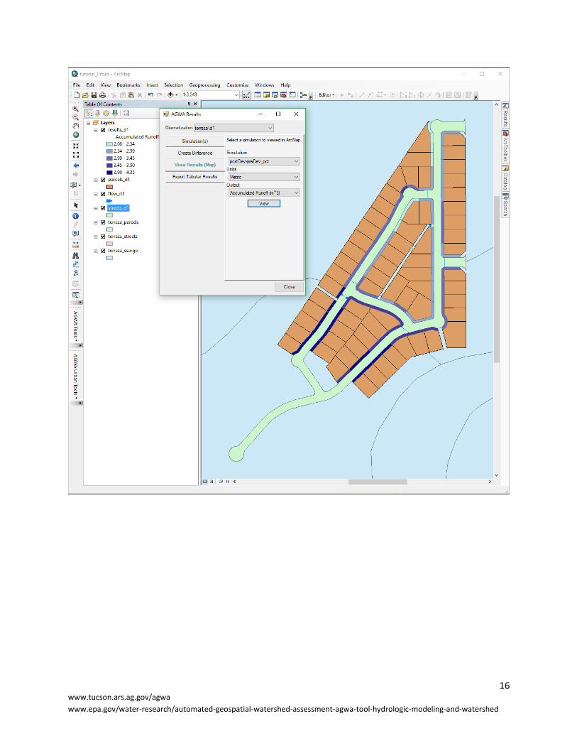
Results of the simulated change in accumulated runoff between pre-development and post-
development scenarios are shown below. You can now try viewing the differences in
infiltration and runoff.
11.2.1.5. Click Close
16 www.tucson.ars.ag.gov/agwa
www.epa.gov/water-research/automated-geospatial-watershed-assessment-agwa-tool-hydrologic-modeling-and-watershed
17 www.tucson.ars.ag.gov/agwa
www.epa.gov/water-research/automated-geospatial-watershed-assessment-agwa-tool-hydrologic-modeling-and-watershed
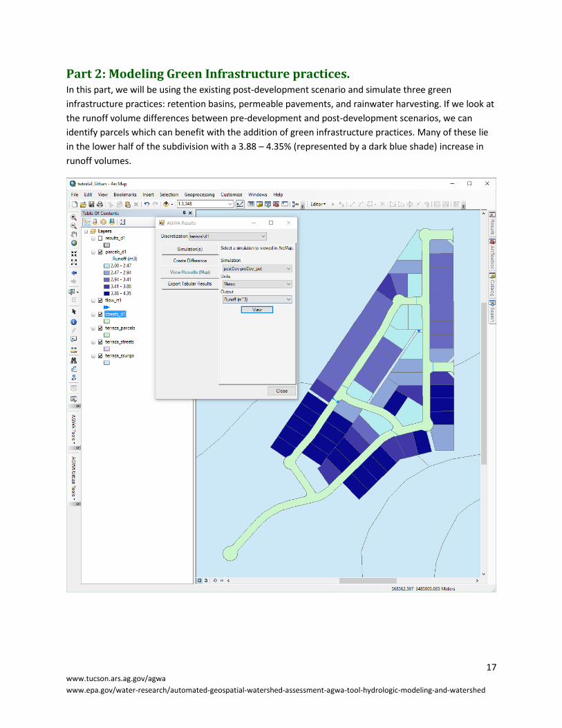
Part 2: Modeling Green Infrastructure practices. In this part, we will be using the existing post-development scenario and simulate three green
infrastructure practices: retention basins, permeable pavements, and rainwater harvesting. If we look at
the runoff volume differences between pre-development and post-development scenarios, we can
identify parcels which can benefit with the addition of green infrastructure practices. Many of these lie
in the lower half of the subdivision with a 3.88 – 4.35% (represented by a dark blue shade) increase in
runoff volumes.

18 www.tucson.ars.ag.gov/agwa
www.epa.gov/water-research/automated-geospatial-watershed-assessment-agwa-tool-hydrologic-modeling-and-watershed
Step 1: Design and place Retention Basins In this step, we will design a retention basin with a surface area of 72 square feet (12 x 6 feet) and a
retention capacity of 144 cubic feet (2 feet deep).
1. Select AGWA Urban Tools > GI Design and Placement tool.
1.1. Discretization: select terraza\d1
1.2. Placement Plan Name: enter basins
1.3. Retention Basin tab
1.3.1. Designer box
1.3.1.1. Width: enter 6
1.3.1.2. Length: enter 12
1.3.1.3. Depth: enter 2
1.3.1.4. Hydraulic Conductivity: do nothing (we will accept the default value)
1.3.1.5. Name: enter rb12x6x2
1.3.1.6. Click Save Design
1.3.2. Placement box
1.3.2.1. Select Design: do nothing (design rb12x6x2 should already be selected)
1.3.2.2. Selected Parcels: click on the select ( ) tool to select the shown parcels
1.3.2.3. Click Save Placements
19 www.tucson.ars.ag.gov/agwa
www.epa.gov/water-research/automated-geospatial-watershed-assessment-agwa-tool-hydrologic-modeling-and-watershed
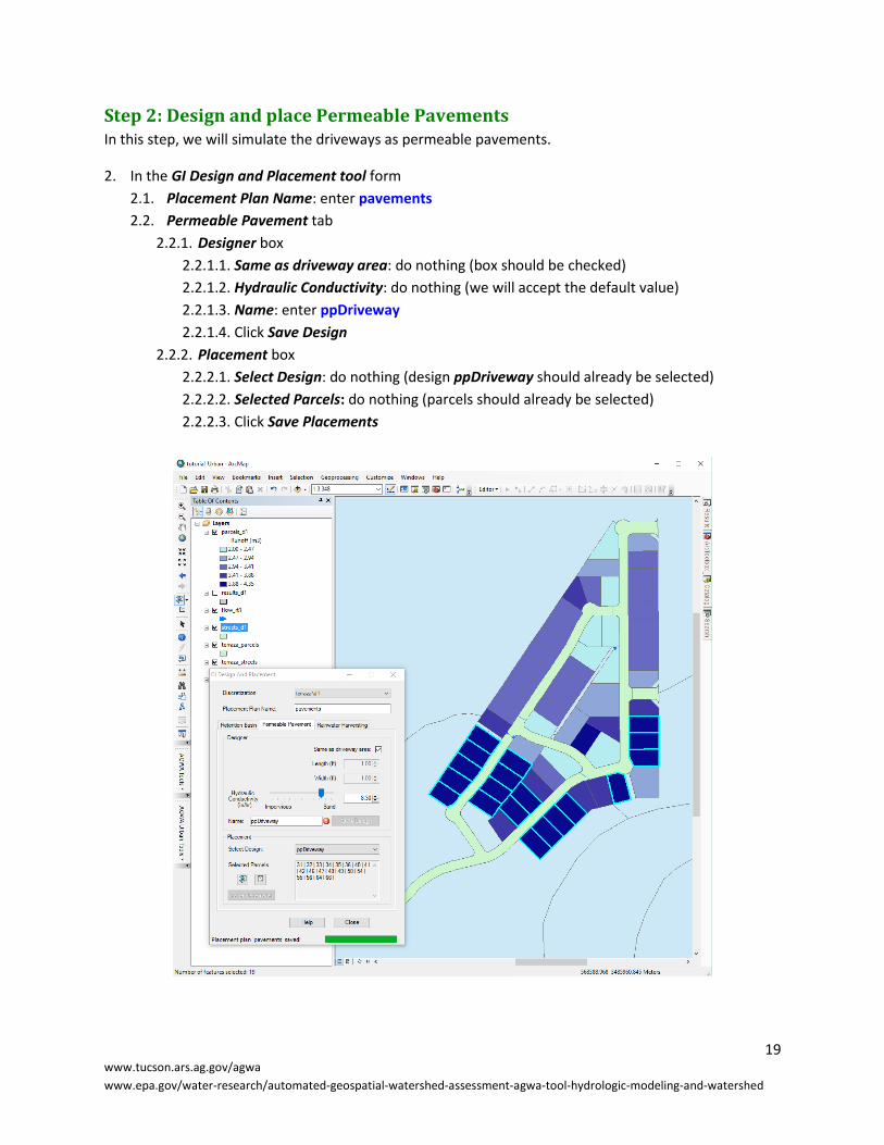
Step 2: Design and place Permeable Pavements In this step, we will simulate the driveways as permeable pavements.
2. In the GI Design and Placement tool form
2.1. Placement Plan Name: enter pavements
2.2. Permeable Pavement tab
2.2.1. Designer box
2.2.1.1. Same as driveway area: do nothing (box should be checked)
2.2.1.2. Hydraulic Conductivity: do nothing (we will accept the default value)
2.2.1.3. Name: enter ppDriveway
2.2.1.4. Click Save Design
2.2.2. Placement box
2.2.2.1. Select Design: do nothing (design ppDriveway should already be selected)
2.2.2.2. Selected Parcels: do nothing (parcels should already be selected)
2.2.2.3. Click Save Placements
20 www.tucson.ars.ag.gov/agwa
www.epa.gov/water-research/automated-geospatial-watershed-assessment-agwa-tool-hydrologic-modeling-and-watershed
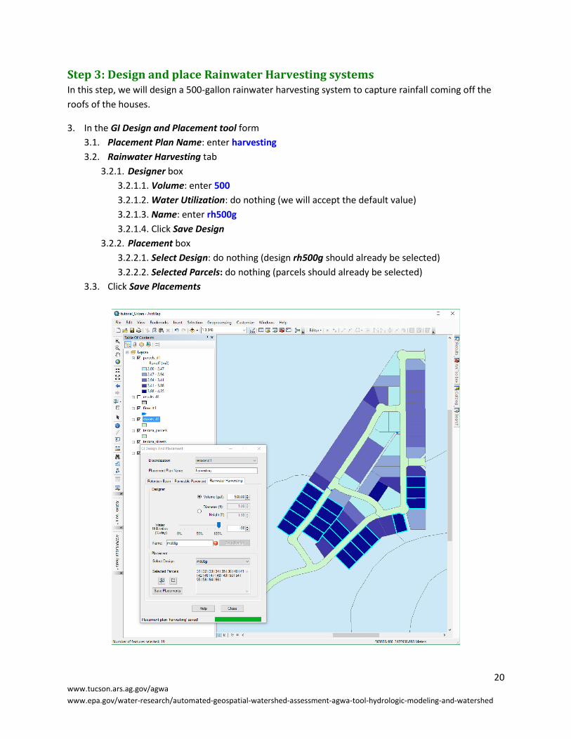
Step 3: Design and place Rainwater Harvesting systems In this step, we will design a 500-gallon rainwater harvesting system to capture rainfall coming off the
roofs of the houses.
3. In the GI Design and Placement tool form
3.1. Placement Plan Name: enter harvesting
3.2. Rainwater Harvesting tab
3.2.1. Designer box
3.2.1.1. Volume: enter 500
3.2.1.2. Water Utilization: do nothing (we will accept the default value)
3.2.1.3. Name: enter rh500g
3.2.1.4. Click Save Design
3.2.2. Placement box
3.2.2.1. Select Design: do nothing (design rh500g should already be selected)
3.2.2.2. Selected Parcels: do nothing (parcels should already be selected)
3.3. Click Save Placements

21 www.tucson.ars.ag.gov/agwa
www.epa.gov/water-research/automated-geospatial-watershed-assessment-agwa-tool-hydrologic-modeling-and-watershed
Step 4: Place a combination of green infrastructure practices In this step, we will use the above three designs and place them in combination in the subdivision.
4. In the GI Design and Placement tool form
4.1. Placement Plan Name: enter combo
4.2. Retention Basin tab
4.2.1. Placement box
4.2.1.1. Select Design: do nothing (rb12x6x2 should already be selected)
4.2.1.2. Selected Parcels: do nothing (parcels should already be selected)
4.2.1.3. Click Save Placements
4.3. Permeable Pavement tab
4.3.1. Placement box
4.3.1.1. Select Design: do nothing (ppDriveway should already be selected)
4.3.1.2. Selected Parcels: do nothing (parcels should already be selected)
4.3.1.3. Click Save Placements
4.4. Rainwater Harvesting tab
4.4.1. Placement box
4.4.1.1. Select Design: do nothing (rh500g should already be selected)
4.4.1.2. Selected Parcels: do nothing (parcels should already be selected)
4.4.1.3. Click Save Placements
4.5. Click Close
Step 5, 6, 7 & 8: Writing KINEROS2 input files In order to simulate the addition of green infrastructure practices, we have to create simulation
scenarios by writing the input files again.
5. Write the KINEROS2 input files by selecting AGWA Urban Tools > Write Urban KINEROS Input Files
5.1. Discretization: select terraza\d1
5.2. Routing Table: select FlowRouting_rt1
5.3. Parameterization: select post
5.4. Placement Table: select PlacementPlan_basins
5.5. Precipitation file: select 10yr1hr.pre
5.6. Simulation Name: enter postBasins
5.7. Click Write
6. Repeat Part 2, Step 5: Writing KINEROS input files with the post parameterization,
PlacementPlan_pavements placement table, and name the simulation postPavements.
7. Repeat Part 2, Step 5: Writing KINEROS input files with the post parameterization,
PlacementPlan_harvesting placement table, and name the simulation postHarvesting.
8. Repeat Part 2, Step 5: Writing KINEROS input files with the post parameterization,
PlacementPlan_combo placement table, and name the simulation postCombo.
8.1. Click Close
22 www.tucson.ars.ag.gov/agwa
www.epa.gov/water-research/automated-geospatial-watershed-assessment-agwa-tool-hydrologic-modeling-and-watershed
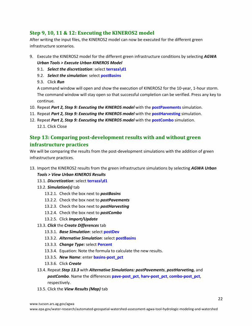
Step 9, 10, 11 & 12: Executing the KINEROS2 model After writing the input files, the KINEROS2 model can now be executed for the different green
infrastructure scenarios.
9. Execute the KINEROS2 model for the different green infrastructure conditions by selecting AGWA
Urban Tools > Execute Urban KINEROS Model
9.1. Select the discretization: select terraza\d1
9.2. Select the simulation: select postBasins
9.3. Click Run
A command window will open and show the execution of KINEROS2 for the 10-year, 1-hour storm.
The command window will stay open so that successful completion can be verified. Press any key to
continue.
10. Repeat Part 2, Step 9: Executing the KINEROS model with the postPavements simulation.
11. Repeat Part 2, Step 9: Executing the KINEROS model with the postHarvesting simulation.
12. Repeat Part 2, Step 9: Executing the KINEROS model with the postCombo simulation.
12.1. Click Close
Step 13: Comparing post-development results with and without green
infrastructure practices We will be comparing the results from the post-development simulations with the addition of green
infrastructure practices.
13. Import the KINEROS2 results from the green infrastructure simulations by selecting AGWA Urban
Tools > View Urban KINEROS Results
13.1. Discretization: select terraza\d1
13.2. Simulation(s) tab
13.2.1. Check the box next to postBasins
13.2.2. Check the box next to postPavements
13.2.3. Check the box next to postHarvesting
13.2.4. Check the box next to postCombo
13.2.5. Click Import/Update
13.3. Click the Create Differences tab
13.3.1. Base Simulation: select postDev
13.3.2. Alternative Simulation: select postBasins
13.3.3. Change Type: select Percent
13.3.4. Equation: Note the formula to calculate the new results.
13.3.5. New Name: enter basins-post_pct
13.3.6. Click Create
13.4. Repeat Step 13.3 with Alternative Simulations: postPavements, postHarveting, and
postCombo. Name the differences pave-post_pct, harv-post_pct, combo-post_pct,
respectively.
13.5. Click the View Results (Map) tab

23 www.tucson.ars.ag.gov/agwa
www.epa.gov/water-research/automated-geospatial-watershed-assessment-agwa-tool-hydrologic-modeling-and-watershed
13.5.1. Results Selection box
13.5.1.1. Simulation: select basins-post_pct
13.5.1.2. Units: select Metric
13.5.1.3. Output: select Infiltration (m^3)
13.5.1.4. Click View
Results of the simulated percent change in infiltration between post-development with and
without retention basins are shown below. Notice an up to 38% increase (represented by
the color black) in infiltration in the parcels with the addition of retention basins. You can
now try viewing the differences for post-development scenarios, with and without
permeable pavements, rainwater harvesting, or a combination of all three green
infrastructure practices.
13.5.1.5. Click Close
Related Documents