arXiv:1311.4773v1 [physics.optics] 19 Nov 2013 THE ASYMMETRIC GOOS-H ¨ ANCHEN EFFECT THE ASYMMETRIC GOOS-H ¨ ANCHEN EFFECT • • Journal of Optics 16, 015702-7 (2014) Journal of Optics 16, 015702-7 (2014) • • Abstract. We show in which conditions opti- cal gaussian beams, propagating throughout an homogeneous dielectric right angle prism, present an asymmetric Goos-H¨ anchen (GH) effect. This asymmetric behavior is seen for incidence at criti- cal angles and happens in the propagation direction of the outgoing beam. The asymmetric GH effect can be also seen as an amplification of the standard GH shift. Due to the fact that it only depends on the ratio between the wavelength and the minimal waist size of the incoming gaussian beam, it can be also used to determine one of these parameters. Multiple peaks interference is an additional phe- nomenon seen in the presence of such asymmetric effects. Manoel P. Araujo Gleb Wataghin Physics Institute State University of Campinas (Brazil) mparaujo@ifi.unicamp.br Silvˆ ania A. Carvalho Department of Applied Mathematics State University of Campinas (Brazil) [email protected] Stefano De Leo Department of Applied Mathematics State University of Campinas (Brazil) [email protected] I. INTRODUCTION II. DIELECTRIC SYSTEM GEOMETRY AND OUTGOING BEAM III. ASYMMETRIC GH EFFECT AND MULTIPLE PEAKS INTERFERENCE IV. CONCLUSIONS [ 13 pages, 6 figures ] I. INTRODUCTION II. DIELECTRIC SYSTEM GEOMETRY AND OUTGOING BEAM III. ASYMMETRIC GH EFFECT AND MULTIPLE PEAKS INTERFERENCE IV. CONCLUSIONS [ 13 pages, 6 figures ] • • Σ δ Λ Σ δ Λ • •

Welcome message from author
This document is posted to help you gain knowledge. Please leave a comment to let me know what you think about it! Share it to your friends and learn new things together.
Transcript
arX
iv:1
311.
4773
v1 [
phys
ics.
optic
s] 1
9 N
ov 2
013
THE ASYMMETRIC GOOS-HANCHEN EFFECTTHE ASYMMETRIC GOOS-HANCHEN EFFECT
•• Journal of Optics 16, 015702-7 (2014)Journal of Optics 16, 015702-7 (2014) ••
Abstract. We show in which conditions opti-cal gaussian beams, propagating throughout anhomogeneous dielectric right angle prism, presentan asymmetric Goos-Hanchen (GH) effect. Thisasymmetric behavior is seen for incidence at criti-cal angles and happens in the propagation directionof the outgoing beam. The asymmetric GH effectcan be also seen as an amplification of the standardGH shift. Due to the fact that it only depends onthe ratio between the wavelength and the minimalwaist size of the incoming gaussian beam, it canbe also used to determine one of these parameters.Multiple peaks interference is an additional phe-nomenon seen in the presence of such asymmetriceffects.
Manoel P. AraujoGleb Wataghin Physics InstituteState University of Campinas (Brazil)[email protected]
Silvania A. CarvalhoDepartment of Applied MathematicsState University of Campinas (Brazil)[email protected]
Stefano De LeoDepartment of Applied MathematicsState University of Campinas (Brazil)[email protected]
I. INTRODUCTIONII. DIELECTRIC SYSTEM GEOMETRY AND OUTGOING BEAMIII. ASYMMETRIC GH EFFECT AND MULTIPLE PEAKS INTERFERENCEIV. CONCLUSIONS
[ 13 pages, 6 figures ]
I. INTRODUCTIONII. DIELECTRIC SYSTEM GEOMETRY AND OUTGOING BEAMIII. ASYMMETRIC GH EFFECT AND MULTIPLE PEAKS INTERFERENCEIV. CONCLUSIONS
[ 13 pages, 6 figures ]
•• ΣδΛΣδΛ ••
I. INTRODUCTION
The behavior of laser gaussian beams in the presence of symmetric and asymmetric wave numberdistributions is the subject matter of this paper. The importance of the difference among such kindsof distributions can be understood if one takes into account the analogy between optics [1, 2] andnon relativistic quantum mechanics [3,4] and discuss the behavior between stationary and dynamical
maxima.A non-relativistic free (gaussian) particle in its rest frame is described by the following wave packet
Ψ(x, y, t) = Ψ0
d
4 π
∫+∞
−∞
dkx
∫+∞
−∞
dky exp
[
−(k
2
x + k2
y) d2
4+ i
(
kx x+ ky y − ~k
2
x + k2
y
2mt
)]
= Ψ0 G(
x
d,
~ t
md 2
)
G(
y
d,
~ t
md 2
)
, (1)
where
G (α , β) = exp
[
− α2
1 + 2 i β
]
/√1 + 2 i β .
This wave convolution is solution of the two-dimensional Schrodinger equation [3],[
∂xx + ∂yy + 2 i m~∂t]
Ψ(x, y, t) = 0 . (2)
The gaussian probability density, |Ψ(x, y, t)|2
, grows with the beam diameter as a function of time. Itsmaximum, which decreases for increasing values of time, is always located at x = y = 0. It representsa stationary maximum. It is obvious that the previous analysis is a consequence of the choice of asymmetric momentum distribution centered in kx = ky = 0.
To illustrate the idea behind our study, let us consider a gaussian momentum distribution withonly positive momentum values for ky, i.e.
Φ(x, y, t) = Φ0 G(
x
d,
~ t
md 2
)
d√π
∫+∞
0
dky exp
[
−k
2
y d2
4+ i ky y − i ~
k2
y
2mt
]
= Φ0 G(
x
d,
~ t
md 2
)
G(
y
d,
~ t
md 2
)
[
1 + erf
(
iy
d/√
1 + i2 ~ t
md 2
)]
. (3)
The maximum of this distribution can be estimated by using a basic principle of asymptotic analysis[5]. For oscillatory integrals, rapid oscillations over the range of integration means that the integrandaverages to zero. To avoid this cancelation rule, the phase has to be calculated when it is stationary,i.e.
0 =
{
∂
∂ky
[
ky y − ~k
2
y
2mt
]}
ky=〈ky〉
⇒ y =~ 〈ky〉m
t .
The breaking of symmetry in the gaussian momentum distribution implies now an expected value ofky different from zero,
〈ky〉 =∫
+∞
0
dky ky exp
[
−k
2
y d2
4
]
/∫
+∞
0
dky exp
[
−k
2
y d2
4
]
=2
d√π
, (4)
and, consequently, a dynamical maximum at
ymax =2 ~
md√π
t . (5)
For non-relativistic quantum particles, the difference between stationary and dynamical maxima canbe roughly represented as the difference between symmetric and asymmetric wave number distribu-tions. The aim of this paper is to investigate in which conditions we can reproduce dynamical maximafor laser gaussian beams propagating throughout an homogeneous dielectric right angle prism.
1
The Maxwell equations[
∇2 − ∂ttc2
]
E(r, t) = 0 , (6)
for time harmonic electric fields (exp[− i ω t ]) and for plane waves, modulated by a complex amplitudeA(r), which travel along the z-direction (exp[ i k z ] with k = ω/c = 2 π/λ),
E(r, t) = E0 ei (k z−ω t) A(r) ,
reduce to [6]
0 = E0 ei (k z−ω t)
[
∂xx + ∂yy∂zz + 2 i k ∂z − k2
+ω2
c2
]
A(r)
= E0 ei (k z−ω t) [∂xx + ∂yy + ∂zz + 2 i k ∂z] A(r) . (7)
In the paraxial approximation [1], A(r) is a slowly varying function of z and the previous equationbecomes
[ ∂xx + ∂yy + 2 i k ∂z] A(x, y, z) = 0 . (8)
The analogy between the paraxial approximation of the Maxwell equations, Eq.(8), and the non-relativistic Schodinger equation, Eq.(2), is then clear if we consider the following correspondencerules [7, 8]
z ←→ t and k ←→ m/~ .
It is interesting to ask in which circumstances, by using optical paraxial beams, it is possible to havean asymmetrical wave number distribution and, consequently, produce a dynamical shift. The studypresented in this paper aims to give a satisfactory answer to this intriguing question.
Gaussian beams are the simplest type of paraxial beams provided by a laser source. The electricfield amplitude of the incident paraxial gaussian beam is given by [9, 10]
E(r, t) = E0 ei (k z−ω t) w
20
4π
∫+∞
−∞
dkx
∫+∞
−∞
dky exp
[
−(k
2
x + k2
y)w20
4+ i
(
kx x+ ky y −k
2
x + k2
y
2 kz
)]
= E0 ei (k z−ω t) A(r) , (9)
where w0 is the minimal waist size of the beam. After performing the kx and ky integrations, weobtain
A(r) = G(
x
w0
,z
kw20
)
G(
y
w0
,z
kw20
)
. (10)
The density probability distribution of the gaussian electric field,
|E(r, t) |2
= |E0 |2[
w0
w(z)
]2
exp
[
− 2x2 + y2
w2(z)
]
, (11)
growths in beam diameter as a function of the z-distance from the beam waist w0,
w(z) = w0
√
1 +
(
2 z
kw0
)2
.
The maximum, which decreases for increasing values of z, is always located at x = y = 0. Thismaximum plays the role of the stationary maximum for the quantum non-relativistic particle in itsrest frame.
In this paper, we investigate the behavior of optical gaussian beams which propagates through aright angle prism, see Fig. 1. For incidence angle θ > θc, the beam is totally reflected at the secondinterface, its wave number distribution is symmetric and centered at kx = ky = 0. Consequently,the Goos-Hanchen shift [11] is stationary in the direction of the beam propagation. The opticalphenomenon in which linearly polarized light undergoes a small phase shift, δ ≈ λ, when totally
2
internally reflected is widely investigated in litterature [12–19]. For incidence at and near criticalangles [20–22], we find a frequency crossover in the GH shift which leads to an amplification effect,δc ≈
√kw0 λ . In this paper, we shall present a new effect for incidence at critical angles. Depending
on the magnitude of kw0, only the positive values of ky , in the wave number distribution, contributeto reflection and this asymmetry produces a dynamical Goos-Hanchen shift. It is thus the breakingof the symmetry in the wave number distribution which opens the door to a dynamical maximum.A detailed analysis of this new phenomenon will be discussed in section III. Before of our numericalstudy, in section II, we introduce our notation and the geometry of the dielectric system used in thispaper. In such a section, we also give, for s and p polarized waves, the reflection and transmissioncoefficients at each interface. Our final considerations and proposals are drawn in the last section.
II. DIELECTRIC SYSTEM GEOMETRY AND OUTGOING BEAM
The incident gaussian beam (9) propagates along the z-axis and forms an angle θ with zin, normal to
the first air/dielectric interface (see Fig. 1a),(
yin
zin
)
=
(
cos θ sin θ− sin θ cos θ
)(
yz
)
= R (θ)
(
yz
)
. (12)
Observing that the spatial phase of the incoming beam is
kin· r
in= k · r , (13)
with kz = k − (k2
x + k2
y )/2 k, we obtain, for the beam propagating within the dielectric after the firstair/dielectric interface, the following phase
qin· r
in= kx x+ ky
inyin
+√
n2k2 − k2
x − k2
yin
zin
. (14)
In order to follow the beam motion within the dielectric, we have to introduce two new axes rotations,see Fig. 1a,
(
yout
zout
)
= R
(
−3 π
4
)(
y∗
z∗
)
= R(
−π
2
)
(
yin
zin
)
, (15)
with z∗and z
outrespectively normal to the second and third dielectric/air interface. The spatial phase
of the beam moving within the dielectric in the direction of the last dielectric/air discontinuity canbe given in terms of the outgoing axes,
qout· r
out= kx x+ qy
outyout
+ qzout
zout
, (16)
where(
qyout
qzout
)
= R
(
− 3 π
4
)(
qy∗
− qz∗
)
=
(
− kyin
qzin
)
.
Observe that the spatial phase of the reflected beam at the second dielectric/air interface is obtainedreplacing qz∗ by − qz∗ . Finally,
kout· r
out= kx x+ qy
outyout
+√
k2 − k2
x − q2
yout
zout
= kx x+ kyin
zin
+ kzin
yin
= kx x + [ kz cos(2 θ)− ky sin(2 θ) ] y + [ kz sin(2 θ) + ky cos(2 θ) ] z , (17)
As expected from the Snell law [1, 2],[
∇ (kout· r
out)]
(kx=0,ky=0)= [ 0 , k cos(2 θ) , k sin(2 θ) ] . (18)
The amplitude of the outgoing beam is given by [9, 10]
A[s,p]
out(r, θ) =
w20
4π
∫+∞
−∞
dkx
∫+∞
−∞
dky T[s,p]
θ(kx, ky) exp
[
−(k
2
x + k2
y)w20
4+ i ϕ
out(kx, ky; r, θ)
]
, (19)
3
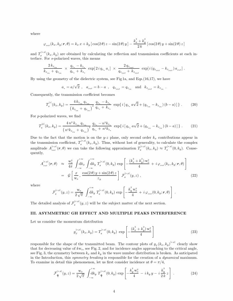
where
ϕout
(kx, ky; r, θ) = kx x+ ky [ cos(2 θ) z − sin(2 θ) y ]−k
2
x + k2
y
2 k[ cos(2 θ) y + sin(2 θ) z ]
and T[s,p]
θ(kx, ky) are obtained by calculating the reflection and transmission coefficients at each in-
terface. For s-polarized waves, this means
2 kzin
kzin
+ qzin
× qz∗ − kz∗qz∗ + kz∗
exp[ 2 i qz∗ a∗] ×
2 qzout
qzout
+ kzout
exp[ i (qzout− kz
out) a
out] .
By using the geometry of the dielectric system, see Fig 1a, and Eqs.(16,17), we have
a∗ = a/√2 , a
out= b− a , qz
out= qz
inand kz
out= kz
in.
Consequently, the transmission coefficient becomes
T[s]
θ(kx, ky) =
4 kzin
qzin
(
kzin
+ qzin
)2
qz∗ − kz∗qz∗ + kz∗
exp{ i [ qz∗ a√2 + (qz
in− kz
in) (b − a) ] } . (20)
For p-polarized waves, we find
T[p]
θ(kx, ky) =
4n2 kzin
qzin
(
n2kzin
+ qzin
)2
qz∗ − n2kz∗qz∗ + n2kz∗
exp{ i [ qz∗ a√2 + (qz
in− kz
in) (b− a) ] } . (21)
Due to the fact that the motion is on the y-z plane, only second order kx contributions appear in
the transmission coefficient, T[s,p]
θ(kx, ky). Thus, without lost of generality, to calculate the complex
amplitude A[s,p]
out(r, θ) we can take the following approximation T
[s,p]
θ(kx, ky) ≈ T
[s,p]
θ(0, ky). Conse-
quently,
A[s,p]
out(r, θ) ≈ w2
0
4π
∫+∞
−∞
dkx
∫+∞
−∞
dky T[s,p]
θ(0, ky) exp
[
−(k
2
x + k2
y)w20
4+ i ϕ
out(kx, ky; r, θ)
]
= G[
x
w0
,cos(2 θ) y + sin(2 θ) z
zR
]
F [s,p]
θ(y, z) , (22)
where
F [s,p]
θ(y, z) =
w0
2√π
∫+∞
−∞
dky T[s,p]
θ(0, ky) exp
[
−k
2
y w20
4+ i ϕ
out(0, ky; r, θ)
]
.
The detailed analysis of F [s,p]
θ(y, z) will be the subject matter of the next section.
III. ASYMMETRIC GH EFFECT AND MULTIPLE PEAKS INTERFERENCE
Let us consider the momentum distribution
g[s,p]
T(kx, ky) = T
[s,p]
θ(0, ky) exp
[
−(k
2
x + k2
y)w20
4
]
(23)
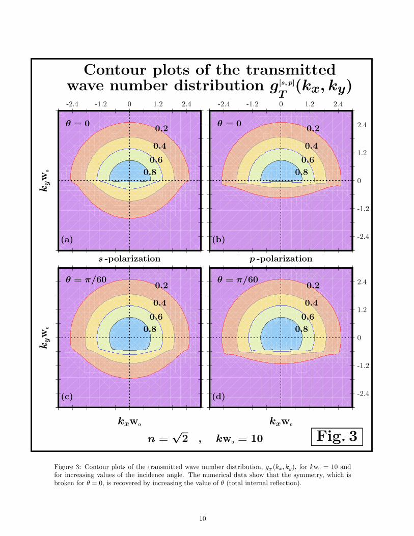
responsible for the shape of the transmitted beam. The contour plots of gT(kx, ky)
[s,p]
clearly showthat for decreasing value of kw0, see Fig. 2, and for incidence angles approaching to the critical angle,see Fig. 3, the symmetry between kx and ky in the wave number distribution is broken. As anticipatedin the Introduction, this symmetry breaking is responsible for the creation of a dynamical maximum.To examine in detail this phenomenon, let us first consider incidence at θ = π/4,
F [s,p]
π4
(y, z) =w0
2√π
∫+∞
−∞
dky T[s,p]
π4
(0, ky) exp
[
−k
2
y w20
4− i ky y − i
k2
y
2 kz
]
. (24)
4

To estimate the maximum, we can apply the stationary phase method [5],
0 =
{
∂
∂ky
[
phase[
T[s,p]
π4
(0, ky)]
− ky y −k
2
y
2 kz
]}
ky=〈ky〉
.
Due to the fact that the phase of the transmission coefficient T[s,p]
θ(0, ky) is not dependent on the
spatial coordinates, we can immediately find an analytical expression for the shift in y between twomaxima, i.e.
∆y = − 〈ky〉k
∆z . (25)
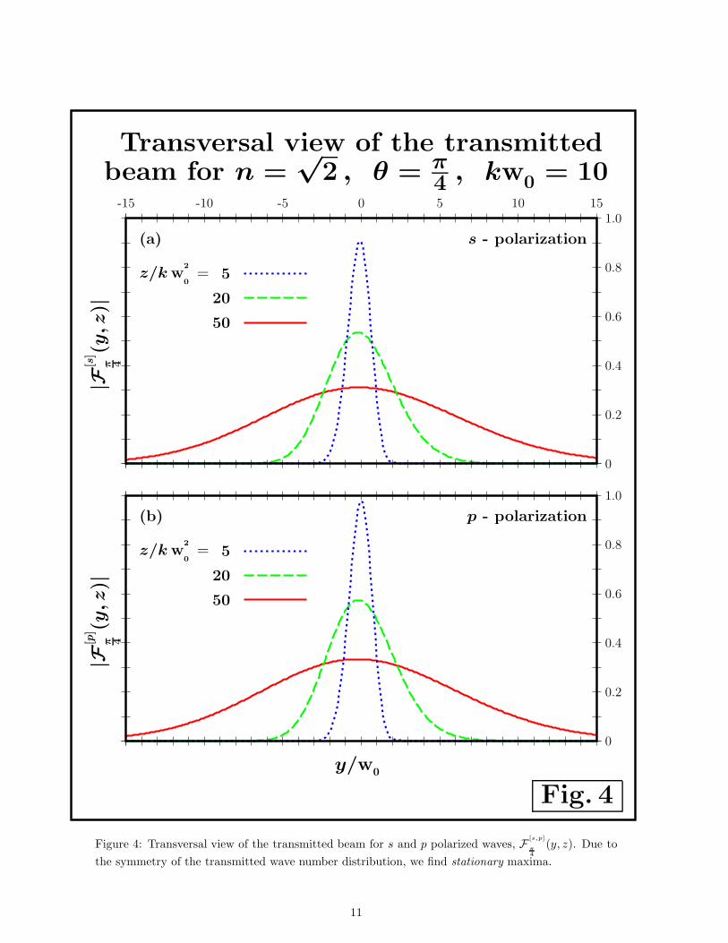
For θ = π/4, n =√2, and kw0 ≥ 10, the wave number distribution is a symmetric distribution
centered at ky = 0. Consequently, 〈ky〉 = 0 and the maximum does not change its position. Wethus recognize a stationary maximum. The numerical analysis confirms this theoretical prediction,see Fig. 4.
Let us now consider incidence at critical angle,
sin θc +√
n2 − sin2 θc =√2 .
For n =√2 the critical angle is θc = 0 and the transversal y-z profile is determined by
F [s,p]
0(y, z) =
w0
2√π
∫+∞
−∞
dky T[s,p]
0(0, ky) exp
[
−k
2
y w20
4+ i ky z − i
k2
y
2 ky
]
. (26)
In this case, the z-shift of the maximum in terms of the y location of the detector is given by
∆z =〈ky〉k
∆y . (27)
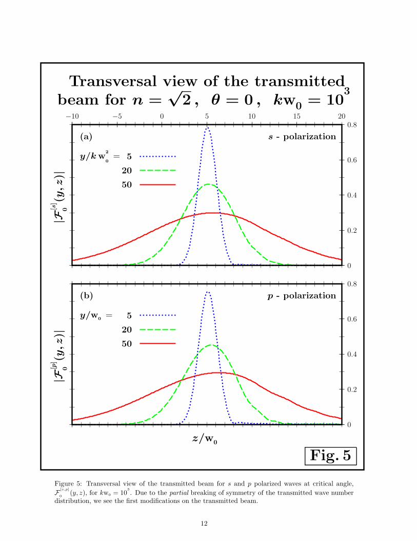
For kw0 = 103
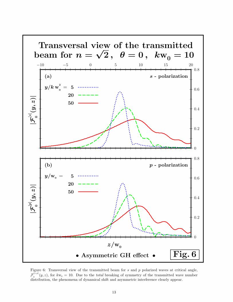
, the wave number distribution is not completely symmetric in ky and this produce thefirst modifications on the transmitted beam, see Fig. 5. Such a little modification is more evident forp-polarized waves. By decreasing the value of kw0 up to 10, we lose the symmetry (see Fig. 2) andwe clearly find a dynamical maximum. To estimate this dynamical shift, we observe that, as seen insection I, for kw0 = 10 only positive values of ky contribute to the mean value, this implies
〈ky〉 =2
w0
√π
(28)
and, consequently, the shift in z of the transmitted optical beam is given by
∆z =2
kw0
√π∆y . (29)
The numerical analysis, shown in Fig. 6, confirms such a prediction. In such a plot, it is also clear theasymmetric interference which appears in the presence of dynamical maxima.
IV. CONCLUSIONS
Optics sure represents a very stimulating field to reproduce quantum mechanical phenomena. Forexample, the well known Goos-Hanchen shift [11] is the optical analogous of the delay time in non-relativistic quantum mechanics [3, 13]. These optical and quantum effects are due to the fact thatevanescent waves exist in the classical forbidden region. This intriguing shift which is always matterof scientific investigation [16–19] is, in general, a stationary shift. In this paper, we have analyzed inwhich situations this stationary shift becomes a dynamical shift.
Due to the fact that the dynamical shift is a direct consequence of the breaking of symmetryin the wave number distribution, this new optical phenomenon can be also seen as an asymmetric
5
GH effect. In our study, we have seen that the more convenient circumstances to reproduce this newphenomenon are the choice of incidence at critical angles and of beam waists, w0 ≈ 10/k ≈ 1.6λ, of theorder of the wavelength of the incoming gaussian beam. This seems to be too restrictive for a possibleexperimental implementation of the theoretical analysis presented in this article. Nevertheless, thisdifficulty is very similar to the difficulty found in detecting the standard Goos-Hanchen sfhit whichis of the order of the wavelength of the incoming beam. Consequently, it can be overcome with thesame trick, i.e. amplifying the shift. For example, by preparing a dielectric structure which allows2N + 1 internal reflections, we obtain for the transmission coefficient the following expressions
∣
∣
∣T
[s,2N+1]
θ(kx, ky)
∣
∣
∣=
4 kzin
qzin
(
kzin
+ qzin
)2
∣
∣
∣
∣
qz∗ − kz∗qz∗ + kz∗
∣
∣
∣
∣
2N+1
(30)
and∣
∣
∣T
[p,2N+1]
θ(kx, ky)
∣
∣
∣=
4n2 kzin
qzin
(
n2kzin
+ qzin
)2
∣
∣
∣
∣
qz∗ − n2kz∗qz∗ + n2kz∗
∣
∣
∣
∣
2N+1
. (31)
At critical angles, we have
k2
z∗> 0 for ky < 0 and k
2
z∗< 0 for ky > 0 .
Consequently, by increasing the number of internal reflections, we can select the positive ky compo-nents in the transmitted wave number distribution for value of the beam waist, w0, greater than thewavelength, λ, of the incoming laser beam. The symmetry breaking in the wave number distribution,responsible for recovering the second order ky contribution to the phase which contributes to themaximum with the term 〈ky〉 y/k, can be thus optimized for experimental proposals by using thenumber of internal reflection N and the ratio w0/λ.
In a forthcoming paper, we shall analyze the asymmetric GH effect for frustrated total internalreflection [23, 24] and resonant photonic tunneling [25]. Another interesting future investigation isrepresented by the possibility to include in our calculation the focal shift [20]. This additional shiftrepresents a second order correction to the GH shift and consequently acts as a delay in the spreadingof the outgoing optical beam.
ACKNOWLEDGEMENTS
We gratefully thank the Capes (M.P.A.), Fapesp (S.A. C.), and CNPq (S.D. L.) for the financialsupport and the referee for his useful suggestion on the new title and for drawing our attention toreferences on the GH shift and, in particular, on the interesting second order correction which leadsto the focal shift [20].
REFERENCES
[1] M. Born and E. Wolf, Principles of optics, Cambridge UP, Cambridge (1999).
[2] B. E.A. Saleh and M.C. Teich, Fundamentals of photonics, John Wiley & Sons, New York (2007).
[3] C.C. Tannoudji, B. Diu and F. Laloe, Quantum Mechanics, Wiley, Paris (1977).
[4] D. J. Griffiths, Introduction to quantum mechanics, Prentice Hall, New York (1995).
[5] R. B. Dingle, Asymptotic expansions: their derivation and interpratation, Academic Press, NewYork (1973).
[6] G.B. Arfken and H. J.Weber, Mathematical Methods for Physicists, Academic Press, San Diego(2005).
[7] S. Longhi, Quantum-optical analogies using photonic structures, Las. Phot. Rev. 3, 243-261(2009).
6
[8] S. De Leo and P. Rotelli, Localized beams and dielectric barriers, J. Opt. A 10, 115001-5 (2008).
[9] S. De Leo and P. Rotelli, Laser interaction with a dielectric block, Eur. Phys. J. D 61, 481-488(2011).
[10] S. Carvalho and S. De Leo, Resonance, multiple diffusion and critical tunneling for Gaussian
lasers, Eur. Phys. J. D 67, 168-11 (2013).
[11] F. Goos and H. Hanchen, Ein neuer und fundamentaler Versuch zur Totalreflexion, Ann. Phys.436, 333-346 (1947).
[12] B.R. Horowitz and T. Tamir, Lateral displacement of a light beam at a dielectric interface,J. Opt. Soc.Am. 61, 586-594 (1971).
[13] K. Yasumoto and Y. Oishi, A new evaluation of the Goos-Hanchen shift and associated time
delay, J. Appl. Phys. 54, 2170-2176 (1983).
[14] S. R. Seshadri, Goos-Hanchen beam shift at total internal reflection, J. Opt. Soc. Am. A 5, 583-585(1988).
[15] J. Broe and O. Keller, Quantum-well enhancement of the Goos-Hanchen shift for p-polarized
beams in a two-prism configuration, J.Opt. Soc. Am. A 19, 1212-1222 (2002).
[16] A. Aiello, Goos-Hanchen and Imbert-Federov shifts: a novel perspective, New J. of Phys. 14,013058-12 (2012).
[17] C. Prajapati and D. Ranganathan, Goos-Hanchen and Imbert-Federov shifts for Hermite-Gauss
beams, J. Opt. Soc. Am. A 29, 1377-1382 (2012).
[18] M.R. Dennis and J. B. Gotte, The analogy between optical beam shifts and quantum weak mea-
surements, New. J. of Phys. 14, 073013-13 (2012).
[19] K.Y. Bliokh and A. Aiello, Goos-Hanchen and Imbert-Fedorov beam shifts: An overview,J. ofOptics 15, 014001-16 (2013).
[20] M. McGuirk and C. K. Carniglia, An angular spectrum representation approach to the Goos-
Hanchen shift, J.Opt. Soc. Am. 67, 103-107 (1977).
[21] H.M Lai, F. C. Cheng, and W.K Tang, Goos-Hanchen effect around and off the critical angle,J. Opt. Soc.Am. A 3, 550-557 (1986).
[22] C.C. Chan and T. Tamir, Beam phenomena at and near critical incidence upon a dielectric
interface, J.Opt. Soc. Am. A 4, 656-663 (1987).
[23] A. Haibel, G. Nimtz and A.A. Stahlhofen, Frustrated total internal reflection: the double prism
revisited, Phys. Rev. E 63, 047601-3 (2001).
[24] S. Carvalho and S. De Leo, Light transmission thorugh a triangular air gap, J. Mod. Opt. 60,437-443 (2013).
[25] S. De Leo and P. Rotelli, Resonant laser tunneling, Eur. Phys. J. D 65, 563-570 (2011).
7

Geometric Layout
b
θ
n
a
b
zinz∗
zout
z
(a)
Axes Rotations
a
a
(b)
Critical Incidence for n =√
2
kx x + ky y + kz z
kx x + ky z + kz y
Fig. 1
Figure 1: Geometric layout of the dielectric structure analyzed in this paper.
8

0 1.2 2.4-1.2-2.4 0 1.2 2.4-1.2-2.4
-2.4
-1.2
0
1.2
2.4
-2.4
-1.2
0
1.2
2.4
s -polarization p -polarization
kw0= 10 kw
0= 10
kw0= 100 kw
0= 100
0.2
0.4
0.6
0.8
0.2
0.4
0.6
0.8
0.2
0.4
0.6
0.8
0.2
0.4
0.6
0.8
Fig. 2
Contour plots of the transmittedwave number distribution g[s, p]
T(kx, ky)
(a)
(c)
(b)
(d)
kyw
0k
yw
0
kxw0kxw0
n =√
2 , θ = 0
Figure 2: Contour plots of the transmitted wave number distribution, gT(kx, ky), at critical angle for
increasing values of kw0. The numerical data show that the symmetry, which is broken for kw0 = 10,is recovered by increasing the value of kw0 (total internal reflection).
9
0 1.2 2.4-1.2-2.4 0 1.2 2.4-1.2-2.4
-2.4
-1.2
0
1.2
2.4
-2.4
-1.2
0
1.2
2.4
s -polarization p -polarization
θ = 0 θ = 0
θ = π/60 θ = π/60
0.2
0.4
0.6
0.8
0.2
0.4
0.6
0.8
0.2
0.4
0.6
0.8
0.2
0.4
0.6
0.8
Fig. 3
Contour plots of the transmittedwave number distribution g[s, p]
T(kx, ky)
(a)
(c)
(b)
(d)
kyw
0k
yw
0
kxw0kxw0
n =√
2 , kw0= 10
Figure 3: Contour plots of the transmitted wave number distribution, gT(kx, ky), for kw0 = 10 and
for increasing values of the incidence angle. The numerical data show that the symmetry, which isbroken for θ = 0, is recovered by increasing the value of θ (total internal reflection).
10
|F[s
]
π 4
(y,z
)|
Transversal view of the transmittedbeam for n =
√2 , θ = π
4 , kw0 = 10
0
0.2
0.4
0.6
0.8
1.0
-15 -10 -5 0 5 10 15
z/k w2
0
= 5
20
50
(a) s - polarization
|F[p
]
π 4
(y,z
)|
y/w0
0
0.2
0.4
0.6
0.8
1.0
z/k w2
0
= 5
20
50
(b) p - polarization
Fig. 4
Figure 4: Transversal view of the transmitted beam for s and p polarized waves, F [s,p]
π4
(y, z). Due to
the symmetry of the transmitted wave number distribution, we find stationary maxima.
11
|F[s
]
0(y
,z)|
Transversal view of the transmittedbeam for n =
√2 , θ = 0 , kw0 = 10
3
0
0.2
0.4
0.6
0.8
−10 −5 0 5 10 15 20
y/k w2
0
= 5
20
50
(a) s - polarization
|F[p
]
0(y
,z)|
z/w0
0
0.2
0.4
0.6
0.8
y/w0
= 5
20
50
(b) p - polarization
Fig. 5
Figure 5: Transversal view of the transmitted beam for s and p polarized waves at critical angle,
F [s,p]
0(y, z), for kw0 = 10
3
. Due to the partial breaking of symmetry of the transmitted wave numberdistribution, we see the first modifications on the transmitted beam.
12
|F[s
]
0(y
,z)|
Transversal view of the transmittedbeam for n =
√2 , θ = 0 , kw0 = 10
0
0.2
0.4
0.6
0.8
−10 −5 0 5 10 15 20
y/k w2
0
= 5
20
50
(a) s - polarization
|F[p
]
0(y
,z)|
z/w0
0
0.2
0.4
0.6
0.8
y/w0
= 5
20
50
• Asymmetric GH effect •
(b) p - polarization
Fig. 6
Figure 6: Transversal view of the transmitted beam for s and p polarized waves at critical angle,
F [s,p]
0(y, z), for kw0 = 10. Due to the total breaking of symmetry of the transmitted wave number
distribution, the phenomena of dynamical shift and asymmetric interference clearly appear.
13
Related Documents