2/2005 The Arup Journal

Welcome message from author
This document is posted to help you gain knowledge. Please leave a comment to let me know what you think about it! Share it to your friends and learn new things together.
Transcript
2/2005
The Arup Journal

CCTV Headquarters, Beijing, China: Structural engineering
design and approvals Chris Carroll, Paul Cross,
Xiaonian Duan, Craig Gibbons,
Goman Ho, Michael Kwok,
Richard Lawson, Alexis Lee,
Andrew Luong, Rory McGowan,
Chas Pope
The Scottish Parliament Building, Edinburgh David Hadden, Don Henning,
Patricia Johnstone, David Lewis,
Duncan Richards, Alan Tweedie,
Simon Webster. Robin Wilkinson
Constitutional Court, Johannesburg Altstair Avern-Taplin
'The Hub' Community Resource Centre, London Chris Trott
Making knowledge work Dominique Poole, Tony Sheehan
Plantation Place development, City of London
35 Plantation Place Mick Brundle
39 Plantation Lane Lee Hosking, Dec/an O'Carro/1
41 Plantation Place South Graham Goymour
Miami Airport QTA: risk-informed performancebased fire protection Richard Custer. Matthew Johann
Brian McLaughlin,
Brian Meacham, Jeffrey Tubbs,
Christopher Wood, Eileen Wood
Designing buildings for a wireless world Bob Cather. Alan Newbold,
Edwin Stokes
Caltrans District 7 Headquarters, Los Angeles Eugene Desouza, Andy Howard,
Teena Videriksen
CClV Headquarters, Beijing China: Structural engineering design and approvals
Chris Carroll Paul Cross Xiaonian Duan Craig Gibbons Goman Ho Michael Kwok Richard Lawson Alexis Lee Andrew Luong Rory McGowan Chas Pope
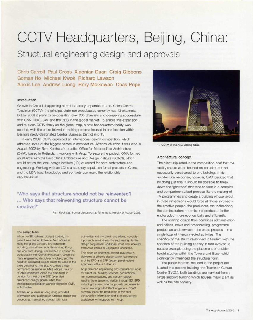
Introduction
Growth in China is happening at an historically unparalleled rate. China Central
Television (CCTV), the principal state-run broadcaster, currently has 13 channels,
but by 2008 it plans to be operating over 200 channels and competing successfully
with CNN, NBC, Sky, and the BBC in the global market. To enable this expansion,
and to place CCTV firmly on the global map, a new headquarters facility was
needed, with the entire television-making process housed in one location within
Beijing's newly-designated Central Business District (Fig 1).
In early 2002, CCTV organized an international design competition, which
attracted some of the biggest names in architecture. After much effort it was won in
August 2002 by Rem Koolhaas's practice Office for Metropolitan Architecture
(OMA), based in Rotterdam, working with Arup. To secure the project, OMA formed
an alliance with the East China Architecture and Design Institute (ECADI) , which
would act as the local design institute (LOI) of record for both architecture and
engineering. Working with an LOI is a statutory stipulation for all projects in China,
and the LOI 's local knowledge and contacts can make the relationship
very beneficial.
'Who says that structure should not be reinvented? ... Who says that reinventing structure cannot be creative?'
Rem Koolhaas, from a discussion at Tsinghua University, 5 August 2003.
The design team
When the SD (scheme design) started, the project was divided between Arup offices In Hong Kong and London. The core team, including six staff seconded from Hong Kong and one from Beijing, was located in London to work closely with OMA in Rotterdam. Given the many engineering disciplines involved, and the need for dedicated project teams for each of the three buildings on the site, Arup had a nearpermanent presence In OMA's offices. Four of ECADl 's engineers joined the Arup team in London for most of the EPD (extended preliminary design) phase, while their architectural colleagues worked alongside OMA in Rotterdam.
Another Arup team In Hong Kong provided information and guidance on Chinese design and procedures, maintained contact with local
authorities and the client , and offered specialist input such as wind and fire engineering. As the design progressed, additional input was received from Arup offices in Beijing and Shenzhen.
This close co-operation proved invaluable in delivering a scheme design within four months and the EPD and EPR (expert panel review) approvals within a further six.
Arup provided engineering and consultancy input for structural, building services, geotechnlcal , fire, communications, and security design, leading the engineering design through SO, EPD including the associated approvals processes to tender, working with ECADI engineers. ECADI currently leads the production of the final construction information and is to provide site
assistance with support from Arup.
1. CCTV in the new Beijing CBD.
Architectural concept
The client stipulated in the competition brief that the
facility should all be housed on one site , but not
necessarily constrained to one building. In his
architectural response, however, OMA decided that
by doing just this, it should be possible to break
down the 'ghettoes' that tend to form in a complex
and compartmentalized process like the making of
TV programmes and create a building whose layout
in three dimensions would force all those involved -
the creative people, the producers, the technicians ,
the administrators - to mix and produce a better
end-product more economically and efficiently.
The winning design thus combines administration
and offices, news and broadcasting, programme
production and services - the entire process - in a
single loop of interconnected activities. The
specifics of the structure evolved in tandem with the
specifics of the building as they in turn evolved, a
notable example being the placement of double
height studios within the Towers and Base, which
significantly influenced the structural form.
The public facilities included in the project are
located in a second building, the Television Cultural
Centre (TVCC); both buildings are serviced from a
single support building which houses major plant as
well as the site security.
The Arup Journal 2/2005 3

Progress to construction
Given the challenging and unprecedented nature of the winning design, the
competition was followed by a further period of justification and persuasion, during
which Arup applied considerable effort at substantial risk. During the next four
months, feasibility studies were made and two key proof-of-concept meetings held
between the client 's technical advisors and key members of the Arup team. These
primarily addressed the safety, buildability, and overall cost of the scheme, and
concluded that though there was no precedent for such a building, it could be
achieved. Once the client was convinced of this, contracts were signed and the
experienced international design team required to deliver the project was mobilized.
The official ground-breaking ceremony took place on 22 September 2004, but
although construction started relatively recently, it is felt that rather than wait more
than three years until completion, the fantastic story of the realization of CCTV
should start to be told now. This first article is principally a description of the
structural design, analysis, and approvals process for the main CCTV building.
Subsequent editions of The Arup Journal will contain episodes on the building
services and security engineering for the main building, on the TVCC and support
buildings, and on the construction process to completion and opening.
The new CCTV headquarters development
The entire CCTV development has a site area of 187 OOOm2 and will provide a total
of 550 OOOm2 gross floor area. The estimated construction cost is around 5bn RMB
(or $US600M), and the project as a whole (Fig 2) includes:
• the China Central Television headquarters building (CCTV building)
• the Television Cultural Centre (TVCC)
• a service and security building
• a landscaped media park with external features.
The 450 000m2, 234m tall (Fig 3), CCTV building consists of a nine-storey 'Base'
and three-storey basement, two leaning Towers that slope at 6° in each direction,
and a nine to 13-storey 'Overhang ', suspended 36 storeys in the air, all combining
to form a 'continuous tube' . Viewed in other terms.the total building form can be
seen as four distinct volumes, each approximately the size of One Canada Square
in London 's Canary Wharf, two of them leaning towards each other from opposite
corners of the site, and joined at the top and bottom by the other two, both
horizontal and with opposite 90' angles in their middles.
400m
300
200
100
Jin Mao Tower (420m)
Eiffel Tower (320m) CCTV
Building 234m
CCTV
2. The site layout, showing programme distribution.
4 The Arup Journal 2/2005
CJ Administration
CJ Multlbusiness
CJ News and broadcasting
CJ Broadcasting transmission
CJ Production
CJ Hotel
CJ Public facilities
CJ Service building
CJ Special vehicle park
CJ Guards accommodation
CJ Mediapark
Express elevators
Tower lobby
Public space and ci rculation
Studio and broadcast
VIP lounge
VIP lounge
Canteen -+--'--!!,+
VIP lobby
Central kitchen
Staff canteen
Staff and VIP faci lit ies
Gym
3. The functions and layout within the CCTV building.
Tower lobby

Structural form
Superstructure - the 'continuous tube '
Early on, the team determined that the only way to
deliver the desired architectural form of the CCTV
building was to engage the entire fac;:ade structure,
creating in essence an external continuous tube
system. Adopting this approach gave proportions
that could resist the huge forces generated by the
cranked and leaning form, as well as extreme
seismic and wind events.
This 'tube' is formed by fully bracing all sides of
the fac;:ade (Fig 4). The planes of bracing are
continuous through the building volume in order to
reinforce and stiffen the corners. The continuous
tube system is ideally suited to deal with the nature
and intensity of permanent and temporary loading
on the building, and is a versatile, efficient structure
which can bridge in bending and torsion between
the Towers, provide enough strength and stiffness in
the Towers to deliver loads to the Base, and stiffen
up the Base to reinforce the lower Tower levels and
deliver loads to the foundations in the most
favourable possible distribution, given the geometry.
Vertical cores housing lifts, stairs, and risers are
oriented and stepped so that they always sit within
the footprint of the sloping Towers. Sloping cores,
to allow consistency of floor plate layout, were
considered but ruled out due to constraints on the
procurement of the lift systems.
In addition to the cores, the floor plates of the
Towers take support from many vertical columns.
Given the nature of the sloping Towers it is not
possible to continue vertical column lines from top
to bottom, so a two-storey deep system of transfer
trusses is used at approximately mid-height. The
floor plates of the Overhang are also supported
by vertical columns that are transferred to the
external tube structure via a two-storey deep
transfer deck (Fig 5).
The continuous tube structure has behind its
final irregular arrangement a regular base pattern of
perimeter steel or steel-reinforced concrete (SRC)
columns, perimeter beams, and diagonal steel
braces set out on a typically two-storey module.
The regular base pattern was tuned or optimized by
adding or removing diagonals and changing brace
plate thickness to match the strength and stiffness
requirements of the design.
The two-storey base pattern was chosen to
coincide with the location of several two-storey high
studios within the Towers. A stiff floor plate
diaphragm can only be relied on every two storeys,
hence lateral loads from intermediate levels are
transferred back to the principal diaphragm levels
via the internal core and the columns.
4. Principles of the tube structure: regular grid of columns and edge beams + patterned diagonal bracing = braced tube system.
The braced tube structure gives the leaning Towers ample stiffness during
construction, allowing them to be built safely within tight tolerances before they are
connected and propped off each other. The tube system also suits the construction
of the Overhang, as its two halves will cantilever temporarily from the Towers.
Robustness
The continuous tube has a high degree of inherent robustness and redundancy, and
offers the potential for adopting alternative load paths in the unlikely event that key
elements are removed. This was studied in detail and provides the building with a
further level of safety.
Substructure and foundations
The main Towers stand on piled raft foundations. The piles are typically 1 .2m in
diameter, and about 52m long. Given the magnitude and distribution of the forces
to be transferred to the ground, the raft is up to 7.5m thick in places and extends
beyond the footprint of the Towers to act as a toe, distributing forces more
favourably into the ground. The foundation system is arranged so that the centre of
the raft is close to the centre of load at the bottom of each Tower, and no
permanent tension is allowed in the piles. Limited tensions in some piles are only
permitted in major seismic events.
For the Base plus three-storey basement, a traditional raft foundation is used,
with tension piles between column locations to resist uplift from water pressure
acting on the deep basement. 15-20m long, 600mm diameter tension piles will be
arranged under the raft with additional 1 .2m diameter piles under secondary cores
and columns supporting large transfer trusses from the studio areas (Fig 6) .
5. 6. (a) Internal columns starting (b) Internal columns supported The foundation system. from pilecap level. on transfer structures.
The Arup Journal 2/2005 5

Developing and optimizing the bracing pattern
The diagonal braces within the continuous tube structure visually express the pattern of forces wtthin the structure and are an important aesthetic aspect of the cladding system. The bracing pattern was determined through an intense iterative analysis and in close collaboration with the architect.
The principal structure of the building was modelled in Oasys GSA and representative loading applied, including a static equivalent load for a level 1 earthquake. Initially, a uniform bracing pattern (Fig 7) was adopted, and the SRC and steel columns sized
6 The Arup Journal 2/2005
appropriately. The distribution of forces within the braces was then investigated, and the results categorized into three groups with an appropriate action applied to the braces within a particular group:
• density the mesh by adding braces; 'doubling'
• keep the same
• rarefy the mesh by removing braces: 'halving'.
The structure is highly indeterminate, so changing the bracing pattern resulted in a new distribution of forces within the columns, braces, and edge-beams.
Changes in stiffness also changed the dynamic behaviour of the structure and hence the seismic forces that are attracted. Patterning became an extremely involved iterative process.
An unfolded stress pattern view of the structure was developed (Fig 8) to clearly display the results of the whole building in one view, or alternatively folded up into a 3-D model (Fig 9). This enabled the design team to visually process the results quickly, while keeping the architect up-to-date and involved in the development of the pattern.
A performance-based design approach
Chinese approvals process
The legal framework in China governing building
design practice is similar to those of Japan and
some continental European countries where the
design codes are legal documents published and
enforced by the state government. Design
engineers must comply with the codes when
designing buildings and structures covered by their
scope, but equally the codes provide legal
protection to the design engineers who are relieved
of any legal responsibilities by virtue of compliance.
The Chinese code for seismic design of buildings
(GB50011 - 2001), sets out its own scope of
applicability, limiting the height of various systems
and the degree of plan and vertical irregularities.
Design of buildings exceeding the code must go
through a project-specific seismic design expert
panel review (EPA) and approval process as set out
by the Ministry of Construction.
Although the 234m height of the CCTV building
is within the code's height limit of 260m for steel
tubular structural systems (framed-tube, tube-in
tube, truss-tube, etc) in Beijing, its geometry is non
compliant. The Seismic Administration Office of the
Beijing Municipal Government appointed an expert
panel of 12 eminent Chinese engineers and
academics to closely examine the structural design,
focusing on its seismic resistance, seismic structural
damage control , and life safety aspects.
Arup realised the importance of engaging the
expert panel early in the design process, and three
informal meetings were held to solicit feedback and
gain trust before the final formal presentation. The
panel was under enormous public and state
scrutiny to closely examine Arup's design, the
rigorous nature of which - aided by successful
collaboration with ECADI - was of vital importance.
From day one the building received wide publicity in
China, and concerns were voiced by both the
general public and the government over the safety
of the adventurous design - indeed it came to be
referred to by the public and the media as 'Wei
Fang ' (the dangerous building) : an indicator of the
scrutiny the project and hence Arup were under.
Seismic requirements
As the seismic design lay outside the scope of the
prescriptive Chinese codes of practice, Arup
proposed a performance-based design approach
from the outset, adopting first principles and state
of-the-art methods and guidelines to achieve set
performance targets at different levels of seismic
event. Explicit and quantitative design checks using
appropriate linear and non-linear seismic analysis
were made to verify the performance for all three
levels of design earthquake.
The criteria for this performance-based design are
beyond those usually applied to such buildings in
China, and were set by the Arup design team in
consultation with the expert panel to reflect the
importance of the building both to the client and to
the Chinese Government. The basic qualitative
performance objectives were:
• no structural damage when subjected to a level
1 earthquake with an average return period of
50 years (63% probability of exceedance in
50 years)
• repairable structural damage when subjected to
a level 2 earthquake with an average return
period of 475 years (10% probability of
exceedance in 50 years)
• severe structural damage permitted but collapse
prevented when subjected to a level 3
earthquake with an average return period of
2500 years (2% probability of exceedance in
50 years)
For the CCTV development site, the peak horizontal
ground acceleration values associated with the
three levels of design earthquake are 7%, 20% and
40% of gravity respectively.
Elastic superstructure design
With the bracing pattern determined from the initial
concept work, a full set of linear elastic verification
analyses were performed, covering all loading
combinations including level 1 seismic loading, for
which modal response spectrum analyses were
used. All individual elements were extensively
checked and the building 's global performance
verified . Selected elements were also initially
assessed under a level 2 earthquake by elastic
analysis, thus ensuring key elements such as
columns remained elastic .
The elastic analysis and design was principally
performed using SAP2000 and a custom-written
Chinese steelwork code post-processor, which
automatically took the individual load cases applied
to the building and combined them for the limit
state design . Capacity ratios were then visually
displayed, allowing detailed inspection of the critical
cases for each member. Due to the vast number of
elements in the model - 10 060 elements
representing nearly 90 OOOm of steel and SRC
sections - and the multitude of load cases, four
post-processors were run in parallel , one for steel
columns, one for SRC columns, one for braces, and
another for the edge beams that together form the
continuous tube. The SRC columns used a modified
post-processor to account for the differences
between the steel and SRC codes; section
properties of these columns were determined using
XTract, which also computed the properties for the
subsequent non-linear analyses.
Software
Many software packages were used to deliver the CC1V structural design, some developed in house by Arup:
CSI SAP2000: limited nonlinear structural analysis and design with static, dynamic and push-over capability
Oasys LS-DYNA Environment: non-linear explicit time history analysis
Oasys GSA: linear structural analysis with static and response spectrum analysis dynamic capability
Oasys Vdisp: plug-in for GSA to analyze non-linear soil stiffness
Oasys GSRaft: iterative nonlinear soil-structure interaction analysis
Oasys Compos: composite steel beam and concrete slab analysis and design
Oasys Adsec: composite (SRC) cross-section analysis
Oasys ADC: reinforced concrete design package
Xtract : non-linear large strain composite (SRC) crosssection analysis
MSC/Nastran: heavy duty finite element analysis package
Xsteel: 3-D CAD package.
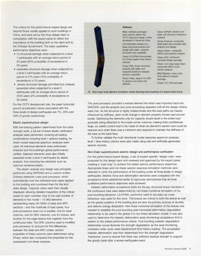
10. Non-linear finite element simulation model showing local buckling of a typical steel brace.
The post-processor provided a revised element list which was imported back into
SAP2000, and the analysis and post-processing repeated until all the design criteria
were met. As the structure is highly indeterminate and the load paths are heavily
influenced by stiffness, each small change in element property moves load around
locally. Optimizing the elements only for capacity would result in the entire load
gradually being attracted to the inside corner columns, making them prohibitively
large, so careful control had to be made of when an element's section size could be
reduced and when there was a minimum size required to maintain the stiffness of
the tube at the back face.
To further validate the multi-directional modal response spectrum analyses,
level 1 time-history checks were also made using real and artificially-generated
seismic records.
Non-linear superstructure seismic design and performance verification
For the performance-based design, a set of project-specific 'design rules ' were
proposed by the design team and reviewed and approved by the expert panel ,
creating a 'road map' to achieve the stated seismic performance objectives.
Appropriate linear and non-linear seismic response simulation methods were
selected to verify the performance of the building under all three levels of design
earthquake. Seismic force and deformation demands were compared with the
acceptance limits established earlier to rigorously demonstrate that all three
qualitative performance objectives were achieved.
Inelastic deformation acceptance limits for the key structural brace members in
the continuous tube were determined by non-linear numerical simulation of the
post-buckling behaviour. LS-DYNA, commonly used to simulate car crash
behaviour, was used for this work. The braces are critical to both the lateral as well
as the gravity systems of the building and are also the primary sources of ductility
and seismic energy dissipation. Non-linear numerical simulation of the braces was
needed to establish the post-buckling axial force/axial deformation degradation
relationship to be used in the global 3-D non-linear simulation model. It was also
used to determine the inelastic deformation (axial shortening) acceptance limit in
relation to the stated performance criteria. Post-buckling inelastic degradation
relationship curves illustrate the strength degradation as the axial shortening
increases under cyclic axial displacement time history loading. The acceptable
inelastic deformation was then determined from the strength degradation
'backbone' curve to ensure that there was sufficient residual strength to support
the gravity loads after a severe earthquake event.
The Arup Journal 2/2005 7
11 . GSRaft model of the piled foundation.
5 x Sm raft springs
51.Sm long, 1.2m diameter piles. Load transferred to soil at 46.Sm below base of raft
Having established the inelastic global structure and
local member deformation acceptance limits, the
next step was to carry out non-linear numerical
seismic response simulation of the entire 3-0
building subjected to level 2 and level 3 design
earthquakes. Both the non-linear static pushover
analysis method and the non-linear dynamic time
history analysis method were used to determine the
seismic deformation demands in terms of the
maximum inelastic inter-storey drifts and the
maximum inelastic member deformation. These
deformation demands were compared against the
structure's deformation capacities storey-by-storey
and member-by-member to verify the seismic
performance of the entire building. All global and
local seismic deformation demands were shown to
be within their respective acceptance limits,
demonstrating that the building achieves the
quantitative and hence qualitative performance
objectives when subjected to level 2 or level 3
earthquakes.
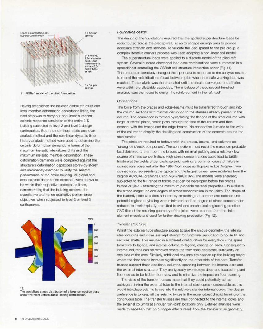
MPa
0
100
200
300
400
500
600
12. The von Mises stress distribution of a large connection plate under the most unfavourable loading combination.
8 The Arup Journal 2/2005
Foundation design
The design of the foundations required that the applied superstructure loads be
redistributed across the pilecap (raft) so as to engage enough piles to provide
adequate strength and stiffness. To validate the load spread to the pile group, a
complex iterative analysis process was used adopting a non-linear soil model.
The superstructure loads were applied to a discrete model of the piled raft
system. Several hundred directional load case combinations were automated in a
spreadsheet controlling the GSRaft soil-structure interaction solver (Fig 11 ).
This procedure iteratively changed the input data in response to the analysis results
to model the redistribution of load between piles when their safe working load was
reached . The analysis was then repeated until the results converged and all piles
were within the allowable capacities. The envelope of these several-hundred
analyses was then used to design the reinforcement in the raft itself.
Connections
The force from the braces and edge-beams must be transferred through and into
the column sections with minimal disruption to the stresses already present in the
column. The connection is formed by replacing the flanges of the steel column with
large 'butterfly ' plates, which pass through the face of the column and then
connect with the braces and the edge-beams. No connection is made to the web
of the column to simplify the detailing and construction of the concrete around the
steel section.
The joints are required to behave with the braces, beams, and columns as
'strong joint/weak component' . The connections must resist the maximum probable
load delivered to them from the braces with minimal yielding and a relatively low
degree of stress concentration. High stress concentrations could lead to brittle
fracture at the welds under cyclic seismic loading, a common cause of failure in
connections observed after the 1994 Northridge earthquake in Los Angeles. Two
connections, representing the typical and the largest cases, were modelled from the
original AutoCAD drawings using MSC/NASTRAN. The models were analyzed,
subjected to the full range of forces that can be developed before the braces
buckle or yield - assuming the maximum probable material properties - to evaluate
the stress magnitude and degree of stress concentration in the joints. The shape of
the butterfly plate was then adapted by smoothing out corners and notches until
potential regions of yielding were minimized and the degree of stress concentration
reduced to levels typically permitted in civil and mechanical engineering practice.
CAD files of the resulting geometry of the joints were exported from the finite
element models and used for further drawing production (Fig 12).
Transfer structures
Whilst the external tube structure slopes to give the unique geometry, the internal
steel columns and cores are kept straight for functional layout and to house lift and
services shafts. This resulted in a different configuration for every floor - the spans
from core to fac;:ade, and internal column to fac;:ade, change on each. Consequently,
internal columns can be removed where the floor span decreases sufficiently on
one side of the core. Similarly, additional columns are needed up the building height
where the floor spans increase significantly on the other side of the core. Transfer
trusses support these additional columns, spanning between the internal core and
the external tube structure. They are typically two storeys deep and located in plant
floors so as to be hidden from view and to minimize the impact on floor planning.
The sizes of the transfer trusses mean that they could potentially act as
outriggers linking the external tube to the internal steel cores - undesirable as this
would introduce seismic forces into the relatively slender internal cores. The design
preference is to keep all the seismic forces in the more robust diagrid framing of the
continuous tube. The transfer trusses are thus connected to the internal cores and
the external columns at singular 'pin-joint' locations only. Detailed analyses were
made to ascertain that no outrigger effects result from the transfer truss geometry.
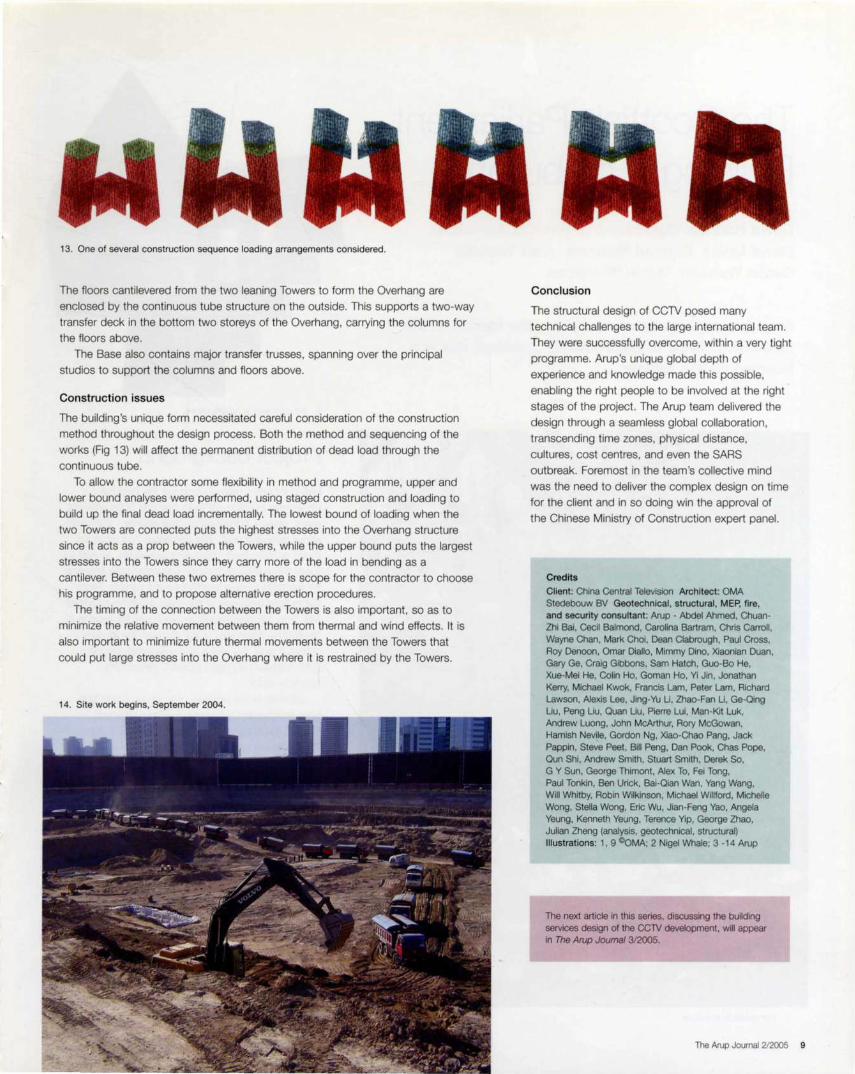
13. One of several construction sequence loading arrangements considered.
The floors cantilevered from the two leaning Towers to form the Overhang are
enclosed by the continuous tube structure on the outside. This supports a two-way
transfer deck in the bottom two storeys of the Overhang, carrying the columns for
the floors above.
The Base also contains major transfer trusses, spanning over the principal
studios to support the columns and floors above.
Construction issues
The building 's unique form necessitated careful consideration of the construction
method throughout the design process. Both the method and sequencing of the
works (Fig 13) will affect the permanent distribution of dead load through the
continuous tube.
To allow the contractor some flexibility in method and programme, upper and
lower bound analyses were performed, using staged construction and loading to
build up the final dead load incrementally. The lowest bound of loading when the
two Towers are connected puts the highest stresses into the Overhang structure
since it acts as a prop between the Towers, while the upper bound puts the largest
stresses into the Towers since they carry more of the load in bending as a
cantilever. Between these two extremes there is scope for the contractor to choose
his programme, and to propose alternative erection procedures.
The timing of the connection between the Towers is also important, so as to
minimize the relative movement between them from thermal and wind effects. It is
also important to minimize future thermal movements between the Towers that
could put large stresses into the Overhang where it is restrained by the Towers.
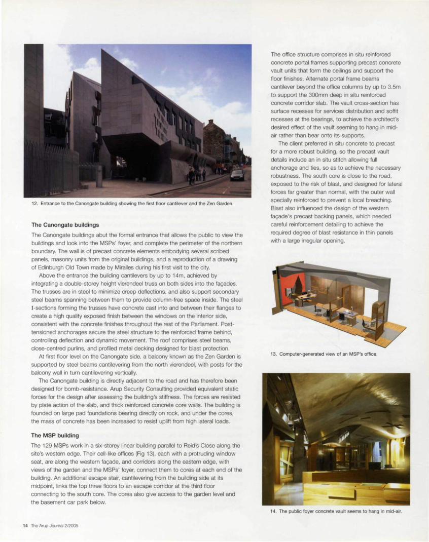
14. Site work begins, September 2004.
Conclusion
The structural design of CC1V posed many
technical challenges to the large international team.
They were successfully overcome, within a very tight
programme. Arup's unique global depth of
experience and knowledge made this possible,
enabling the right people to be involved at the right
stages of the project . The Arup team delivered the
design through a seamless global collaboration ,
transcending time zones, physical distance,
cultures, cost centres, and even the SARS
outbreak. Foremost in the team's collective mind
was the need to deliver the complex design on time
for the client and in so doing win the approval of
the Chinese Ministry of Construction expert panel.
Credits
Client: China Central Television Architect: OMA Stedebouw BV Geotechnical , structural, MEP. fire, and security consultant: Arup - Abdel Ahmed, ChuanZhi Bai, Cecil Balmond, Carolina Bartram, Chris Carroll, Wayne Chan. Mark Choi, Dean Clabrough, Paul Cross, Roy Denoon. Omar Diallo, Mimmy Dino, Xiaonian Duan. Gary Ge, Craig Gibbons, Sam Hatch, Guo-Bo He, Xue-Mei He, Colin Ho, Goman Ho, Yi Jin, Jonathan Kerry, Michael Kwok, Francis Lam, Peter Lam, Richard Lawson, Alexis Lee. Jing-Yu Li, Zhao-Fan Li, Ge-Qing Liu, Peng Liu, Quan Liu, Pierre Lui, Man-Kit Luk, Andrew Luong, John McArthur. Rory McGowan, Hamish Nevile, Gordon Ng, Xiao-Chao Pang, Jack Pappin, Steve Peet, Bill Peng, Dan Pook, Chas Pope, Oun Shi, Andrew Smith, Stuart Smith, Derek So. G Y Sun, George Thimont, Alex To. Fei Tong, Paul Tonkin, Ben Urick, Bai-Qian Wan, Yang Wang, Will Whitby, Robin Wilkinson. Michael Willford, Michelle Wong, Stella Wong, Eric Wu, Jian-Feng Yao. Angela Yeung, Kenneth Yeung, Terence Yip, George Zhao, Julian Zheng (analysis, geotechnical, structural) Illustrations: 1 , 9 COMA; 2 Nigel Whale; 3 -14 Arup
The nex1 article in this series, discussing the building services design of the CCTV development, will appear in The Arup Joumal 3/2005.
The Arvp Journal 212005 9
The Scottish Parliament Building, Edinburgh David Hadden Don Henning Patricia Johnstone David Lewis Duncan Richards Alan Tweedie Simon Webster Robin Wilkinson
From the contemplative seating in the fa9ade to the innovative shape of the debating chamber, this is a building for the people.
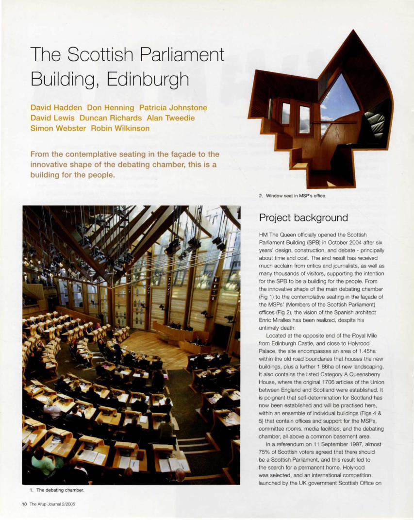
1 . The debating chamber.
1 0 The Arup Journal 2/2005
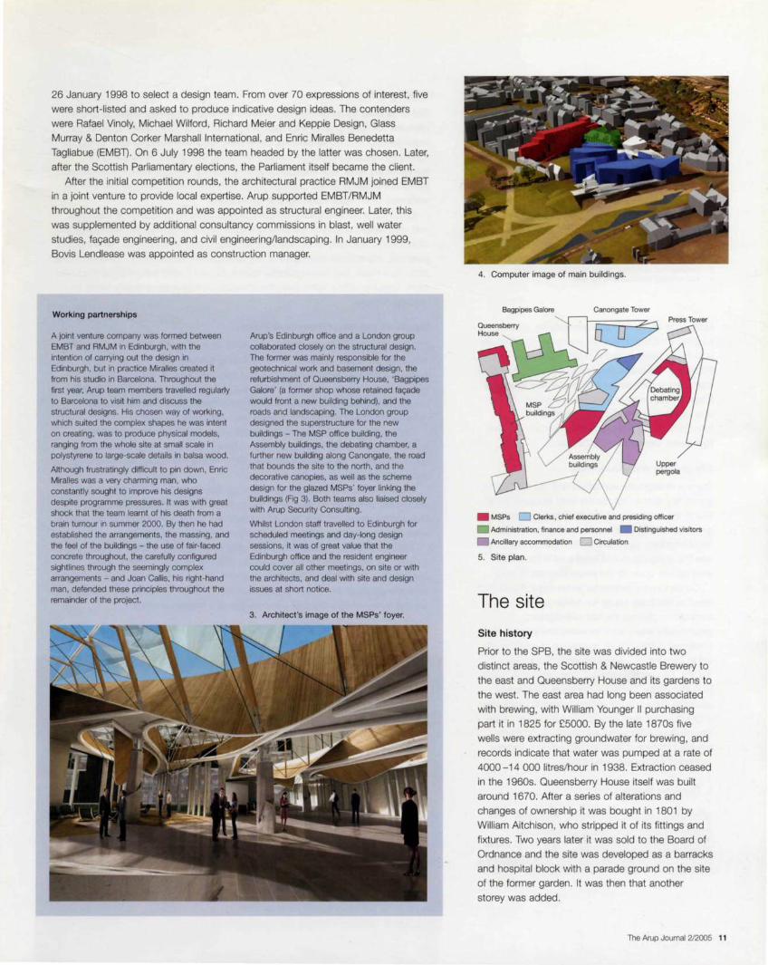
2. Window seat in MSP's office.
Project background
HM The Queen officially opened the Scottish
Parliament Building (SPB) in October 2004 after six
years ' design, construction, and debate - principally
about time and cost. The end result has received
much acclaim from critics and journalists, as well as
many thousands of visitors, supporting the intention
for the SPB to be a building for the people. From
the innovative shape of the main debating chamber
(Fig 1) to the contemplative seating in the fac;:ade of
the MSPs' (Members of the Scottish Parliament)
offices (Fig 2), the vision of the Spanish architect
Enric Miralles has been realized , despite his
untimely death.
Located at the opposite end of the Royal Mile
from Edinburgh Castle, and close to Holyrood
Palace, the site encompasses an area of 1 .45ha
within the old road boundaries that houses the new
buildings, plus a further 1.86ha of new landscaping .
It also contains the listed Category A Queensberry
House, where the original 1706 articles of the Union
between England and Scotland were established. It
is poignant that self-determination for Scotland has
now been established and will be practised here,
within an ensemble of individual buildings (Figs 4 & 5) that contain offices and support for the MSPs,
committee rooms, media facilities, and the debating
chamber, all above a common basement area.
In a referendum on 11 September 1997, almost
75% of Scottish voters agreed that there should
be a Scottish Parliament, and this result led to
the search for a permanent home. Holyrood
was selected, and an international competition
launched by the UK government Scottish Office on
26 January 1998 to select a design team. From over 70 expressions of interest, five
were short-listed and asked to produce indicative design ideas. The contenders
were Rafael Vinoly, Michael Wilford, Richard Meier and Keppie Design, Glass
Murray & Denton Corker Marshall International, and Ernie Miralles Benedetta
Tagliabue (EMBT). On 6 July 1998 the team headed by the latter was chosen. Later,
after the Scottish Parliamentary elections, the Parliament itself became the client.
After the initial competition rounds, the architectural practice RMJM joined EMBT
in a joint venture to provide local expertise. Arup supported EMBT/ RMJM
throughout the competition and was appointed as structural engineer. Later, this
was supplemented by additional consultancy commissions in blast , well water
studies, fac;;ade engineering, and civil engineering/landscaping. In January 1999,
Bovis Lendlease was appointed as construction manager.
Working partnerships
A joint venture company was formed between EMBT and RMJM in Edinburgh, with the intention of carrying out the design in Edinburgh, but in practice Miralles created it from his studio in Barcelona. Throughout the first year, Arup team members travelled regularly to Barcelona to visit him and discuss the structural designs. His chosen way of working, which suited the complex shapes he was intent on creating, was to produce physical models, ranging from the whole site at small scale In pclystyrene to large-scale details in balsa wood.
Although frustratingly difficult to pin down, Enric Miralles was a very charming man, who constantly sought to improve his designs despite programme pressures. It was with great shock that the team learnt of his death from a brain tumour in summer 2000. By then he had established the arrangements, the massing, and the feel of the buildings - the use of fair-faced concrete throughout, the carefully configured sightlines through the seemingly complex arrangements - and Joan Callis, his right-hand man, defended these principles throughout the remainder of the project.
Arup's Edinburgh office and a London group collaborated closely on the structural design. The former was mainly responsible for the geotechnical work and basement design, the refurbishment of Queensberry House, 'Bagpipes Galore' (a former shop whose retained fai;;ade would front a new building behind), and the roads and landscaping. The London group designed the superstructure for the new buildings - The MSP office building, the Assembly buildings, the debating chamber, a further new building along Canongate, the road that bounds the site to the north, and the decorative canopies, as well as the scheme design for the glazed MSPs' foyer linking the buildings (Fig 3). Both teams also liaised closely with Arup Security Consulting.
Whilst London staff travelled to Edinburgh for scheduled meetings and day-long design sessions, it was of great value that the Edinburgh office and the resident engineer could cover all other meetings, on site or with the architects, and deal with site and design issues at short notice.
3. Architect 's image of the MSPs' foyer.
4. Computer image of main buildings.
Bagpipes Galore
Press Tower
• MSPs D Clerks , chief executive and presiding officer
• Administration, finance and personnel • Distinguished visitors
Ancillary accommodation D Circulation
5. Site plan.
The site
Site history
Prior to the SPB, the site was divided into two
distinct areas, the Scottish & Newcastle Brewery to
the east and Queensberry House and its gardens to
the west. The east area had long been associated
with brewing, with William Younger II purchasing
part it in 1825 for £5000. By the late 1870s five
wells were extracting groundwater for brewing, and
records indicate that water was pumped at a rate of
4000 -14 OOO litres/hour in 1938. Extraction ceased
in the 1960s. Queensberry House itself was built
around 1670. After a series of alterations and
changes of ownership it was bought in 1801 by
William Aitchison , who stripped it of its fittings and
fixtures. Two years later it was sold to the Board of
Ordnance and the site was developed as a barracks
and hospital block with a parade ground on the site
of the former garden. It was then that another
storey was added.
The Arup Journal 2/2005 11

36
34
- Groundwater level
• Existing well
6. Conjectured rockhead levels, groundwater levels, and existing wells across the site.
From 1815 onwards it was successively a public
hospital , a House of Refuge, and a geriatric hospital
until it was finally closed in 1996 and bought by
Scottish & Newcastle Breweries. Its varied life had a
significant impact on the building fabric 's structural
integrity, and it was in poor condition when handed
over to the Parliament. In 1997 Scottish &
Newcastle made Queensberry House and the land
to the east available for the new SPB.
Site geology and groundwater
The site stratigraphy comprises drift deposits (sand,
gravel , silt) above rock; to the west lies sandstone
and to the east volcanic basalt. Rockhead levels
generally fall from Canongate to Holyrood Road,
and particularly significant for the foundation design
was the sharp dip in rockhead level in the south
west corner, down to 6m below foundation level.
Conjectured groundwater levels were plotted and
taken as the base values for design and
construction . During the site investigation,
groundwater levels were recorded and subsequently
confirmed during regular monitoring of water levels
within standpipes located strategically throughout
the site. Design groundwater levels are taken in the
long term to be 2m above the current measured
values to allow a factor of safety against future rises
in groundwater level ; the high levels in parts of the
site influenced the structural design, in particular
requiring the use of tension piles where buoyancy
exceeded the applied dead loads.
7. Foundation strategy.
600mm piles
1 2 The Arup Journal 2/2005
Water table
Mlnlpiles
Rockhead
Existing and new wells
Out of 20 wells found on the main brewery site (Fig 6), six main ones, up to 3m in
diameter, had shafts up to 44m deep with bores up to 100m deep. To enhance
water extraction rates for brewing, these wells were connected to each other,
mostly by headers (horizontal culverts) 6m deep, though two were linked by
horizontal mines at 18m and 2:1m depth respectively. As they were concentrated
beneath the new debating chamber, great care was taken to expose and infill the
wells and co-ordinate foundations to avoid them.
Given the site's successful extraction history, Arup proposed to the client that
well water might provide a sustainable supply for the SPB. The firm was appointed
to produce a feasibility study and hydrogeology report to assess the viability of this
proposal, and analyze the impact of any groundwater extraction on the surrounding
area. As a result , two new boreholes were sunk which yield around 5000 litres/hour
each. Together with a buffer tank, they provide cooling water and grey water for
building services.
Basement and foundation construction
This involved excavation to depths of around 4m in the west and 7m in the east,
where the plantroom areas below the debating chamber and Assembly towers are
located. A hard/soft secant piled wall was used for much of the excavation
perimeter to minimize movement felt by surrounding structures and to prevent
groundwater entering. To the east, an open battered excavation sufficed, as
groundwater levels are lower and there are no adjacent structures.
Piled walls retaining Queensberry House were designed to limit movement
behind to 1 Omm horizontally and 5mm vertically, due to the listed building's
sensitivity. During excavation a programme of regular monitoring was established to
record any movements.
The foundations are typically pad footings, bearing on rock exposed during
excavation. Where rock levels lie up to 2m below the underside of the pad
foundations, mass concrete was infilled between pad and rock. Only in the south
west corner were piles used, due to the low rockhead level (Fig 7) .
The basements, which lie beilow the water table, are defined in the client brief as
a Grade 2 (better utility) space, in line with 8$8102. This requires no water
penetration and to achieve this, the basement slabs were designed as a watertight
concrete structure with crack widths limited to <0.2mm. The external retaining walls
are not designed as watertight concrete but as a drained cavity wall.
8. Stairs leading down to the MSPs' foyer.

9. Computer model of the debating chamber roof.
The new buildings
The public entrance and debating chamber
The main public foyer is on the east side, opposite
Holyrood Palace, and contains an exhibition,
information facilities, and a retail outlet. As the
'parliament of the people', the SPB opened its
public areas in September 2004, complete with
guided tours. By the end of November more than
130 OOO people had visited the building, making it a
considerable tourist attraction in its own right.
The foyer is characterized by its high quality fair
faced concrete finishes and, in particular, three in
situ reinforced concrete vaults with random saltire
crosses and irregular light wells, each having an
individual geometry with a tapered plan section,
making it unique in construction terms. They form a
dramatic ceiling (Fig 14), and contrast with the light
and airy spaces beyond. The vaults rest on three
main steel beams supported by high quality precast
columns, also of unique shape and form, which
required them to be cast offsite and upside down.
All the concrete, whether precast or in situ , was
produced from consistent materials to ensure a
correct colour match.
10. Model of the Assembly buildings.
I j
11. Committee room.
The debating chamber (Fig 1 ), some 49m long and 25m maximum width, is
immediately above the public foyer. The floor is a major steel grillage that both acts
as a transfer structure to cope with the variable column positions above and below
this level, and allows the chamber to cantilever beyond the ground floor structure
and support the heavy fa9ade and its finishes, designed to withstand terrorist
action. This floor is stepped and integrates the supply air systems and complex
electrical installations within its depth, as well as supporting various mezzanine
levels and the public galleries. All finishes are in oak and this theme is extended
upwards to the roof structure and ceiling arrangements.
Spanning across the entire space is a roof supported on major three
dimensional timber trusses with stainless steel ties and connections (Fig 9). This
structure is entirely sculptured and its geometry required unique nodes and bracing
systems. The roof extends further skyward on its western boundary, forming large
roof-lights that allow in considerable natural daylight. In keeping with Parliamentary
strength and longevity, the roof materials are of the highest quality - European oak
for the glu-lam compression members, and stainless steel for all other elements.
The roof geometry coheres with the chamber shape by having the trusses
arranged in three distinct groups, separated by discontinuity zones with changes of
ceiling level. This ceiling level is set above the trusses, with a steel purlin roof again
above, carrying the final roof finishes. The trusses are supported on a tri-girder at
the rear of the chamber and on external concrete-clad steel columns at the inner
fa9ade. These columns extend like cathedral buttresses from the bottom of a
basement light well to the top of the structure. The combination of exposed
structure and high quality finishes forms a dramatic space for the Parliament to
conduct its business publicly and openly.
Assembly buildings
The Assembly buildings (Fig 10) accommodate the committee rooms and support
facilities where most Parliamentary business is carried out - an ensemble through
which the MSPs pass at first floor level from their garden to the debating chamber.
Miralles likened the Assembly buildings' external appearance to upturned boats on
a Scottish shore; their geometry and interaction with each other is subtly complex
and the roofs especially so, with stepped double curvatures, achieved by structural
steelwork, reflected in the internal ceilings to give an ecclesiastical ambience
(Fig 11). These spaces contribute to encouraging collaboration rather than
confrontation.
The buildings are designed in post-tensioned reinforced concrete, principally to
achieve clear spans of up to 14m with structural depths of 350mm, thus providing
column-free spaces with minimum floor heights allowing integration of the building
services. The leading points of the buildings are truncated at the lower levels and
cantilever significantly from the main body. The floor structures and shear walls act
together to achieve these cantilevers, which enhance the spaces thus formed at
the ground floor.
The Arup Journal 2/2005 13
12. Entrance to the Canongate building showing the first floor cantilever and the Zen Garden.
The Canongate buildings
The Canongate buildings abut the formal entrance that allows the public to view the
buildings and look into the MSPs' foyer, and complete the perimeter of the northern
boundary. The wall is of precast concrete elements embodying several scribed
panels. masonry units from the original buildings, and a reproduction of a drawing
of Edinburgh Old Town made by Miralles during his first visit to the city.
Above the entrance the building cantilevers by up to 14m, achieved by
integrating a double-storey height vierendeel truss on both sides into the fac;;ades .
The trusses are in steel to minimize creep deflections, and also support secondary
steel beams spanning between them to provide column-free space inside. The steel
I-sections forming the trusses have concrete cast into and between their flanges to
create a high quality exposed finish between the windows on the interior side,
consistent with the concrete finishes throughout the rest of the Parliament. Post
tensioned anchorages secure the steel structure to the reinforced frame behind,
controlling deflection and dynamic movement. The roof comprises steel beams,
close-centred purlins, and profiled metal decking designed for blast protection.
At first floor level on the Canongate side, a balcony known as the Zen Garden is
supported by steel beams cantilevering from the north vierendeel, with posts for the
balcony wall in turn cantilevering vertically.
The Canongate building is directly adjacent to the road and has therefore been
designed for bomb-resistance. Arup Security Consulting provided equivalent static
forces for the design after assessing the building's stiffness. The forces are resisted
by plate action of the slab, and thick reinforced concrete core walls. The building is
founded on large pad foundations bearing directly on rock, and under the cores,
the mass of concrete has been increased to resist uplift from high lateral loads.
The MSP building
The 129 MSPs work in a six-storey linear building parallel to Reid 's Close along the
site's western edge. Their cell -like offices (Fig 13), each with a protruding window
seat, are along the western fac;;ade, and corridors along the eastern edge, with
views of the garden and the MSPs' foyer, connect them to cores at each end of the
building. An additional escape stair, cantilevering from the building side at its
midpoint, links the top three floors to an escape corridor at the third floor
connecting to the south core. The cores also give access to the garden level and
the basement car park below.
14 The Arup Journal 2/2005
The office structure comprises in situ reinforced
concrete portal frames supporting precast concrete
vault units that form the ceilings and support the
floor finishes. Alternate portal frame beams
cantilever beyond the office columns by up to 3.5m
to support the 300mm deep in situ reinforced
concrete corridor slab. The vault cross-section has
surface recesses for services distribution and soffit
recesses at the bearings, to achieve the architect's
desired effect of the vault seeming to hang in mid
air rather than bear onto its supports.
The client preferred in situ concrete to precast
for a more robust building, so the precast vault
details include an in situ stitch allowing full
anchorage and ties, so as to achieve the necessary
robustness. The south core is close to the road ,
exposed to the risk of blast, and designed for lateral
forces far greater than normal, with the outer wall
specially reinforced to prevent a local breaching.
Blast also influenced the design of the western
fac;;ade's precast backing panels, which needed
careful reinforcement detailing to achieve the
required degree of blast resistance in thin panels
with a large irregular opening.
13. Computer-generated view of an MSP's office.
14. The public foyer concrete vault seems to hang in mid-air.

- -- -- - - -15. Upper and lower pergolas and the north-east canopy.
Canopies and pergolas
The main public entrance is framed by a complex of three structures. the upper and
lower pergolas and the north-east canopy (Fig 15). Both pergolas are supported by
conical 'flame-shaped ' columns that match others in the SPB. Their stocky forms
act as cantilevers and resist moments from the upper pergola. The columns are
carried on pad footings designed to resist overturning moments.
The upper pergola is a 58m x 9m grillage of stainless steel hollow sections
covered by a random arrangement of 'bamboo' (actually Scottish oak), suspended
6m - 8m above ground by raking stainless steel hollow sections. The pergola acts
as a vierendeel on plan to take the horizontal forces to the flame-shaped columns and the raking props cast into them. Ties from the tips of the flame-shaped
columns to the tips of the raking columns were introduced to control the deflections
at the extreme ends of the pergola, where the cantilever length is around 9m.
The 'lower pergola' is a grillage of fair-faced concrete beams running along the
whole east fa9ade of the SPB, approximately 5m above ground level. This was
designed to be constructed in situ but was re-designed in conjunction with the
contractor as precast beams.
The north-east canopy is a concrete slab, curved in section and cantilevering up
to 9m from the building, taking its principal support by hanging from the pergola
above it and with its backspan disappearing into the main building. It is further complicated by the presence of an opening, through which one of the flame
shaped columns passes, thus preventing the canopy taking direct support
from the column (Fig 16).
Although the canopy would deflect significantly under dead load, this was not
seen as a problem as no partitions, cladding , or other fittings were affected, and
the already curved shape made the deflection visually insignificant. The canopy was
designed for a live load of 1 .5kN/m2, with a deflection limit of span/500 in case of
unintentional pedestrian loading, perhaps from political protesters!
The architect required the canopy and the lower
pergola to have exposed concrete to all faces.
This had to be considered in conjunction with the
requirement for a 100-year design life, and
concerns about the long-term appearance of the
concrete when viewed from overlooking windows
finally led the architect to agree to cladding the
upper surface of the canopy. For the lower pergola
beams stainless steel reinforcement was specified ,
to reduce the risk of unsightly staining in this highly
visible structure.
16. 'Flame-shaped ' column passing through canopy opening.
The Arup Journal 2/2005 15

Fac;ades
Introduction
Arup Fac;;ade Engineering (AFE) was initially
appointed for three months to support
EMBT/RMJM on two critical cladding packages,
the foyer roof and the specialist glazing, but its
involvement grew into other areas of the project.
Ultimately three separate teams were contracted for
the MSP building elevations, the precast concrete
elements, and the next phase of the specialist
glazing and foyer roof packages.
Foyer roof
Previous work on Portcullis House, Westminster,
with its many similarities in design life requirements
and bomb blast protection, was extremely valuable,
whilst designs developed for the 'lens' at City Hall ,
London, also proved useful in achieving the required
flush outer glazed face that would also deliver good
panel retention against lateral loads. The design
principles progressed through workshops with
Mero, the specialist glazing subcontractor, and were
then developed through detailed design with Arup
Security Consulting. The installed cladding (Fig 17)
is largely unchanged from these initial principles.
17. External view of foyer roof.
16 The Arup Journal 2/2005
18. Feature panels on the fac;ade of the Assembly tower.
Specialist glazing
This had a much wider scope than the foyer roof package, including glazing to the
debating chamber, the bridge that links it with the Assembly towers, and the
complex shapes enclosing the public stair from the foyer to the end of the bridge.
In addition to specific blast requirements for the specialist glazing, the walls and
rooflights to the debating chamber also had very onerous acoustic performance
criteria to limit road noise penetration. The eventual design employed double-glazed
units, with acoustic damping and blast protection performance, built into the
laminated unit construction , combined with acoustically enhanced curtain-walling
profiles. This system is one of the best performing double-glazed walls yet
developed, and was empirically tested prior to manufacture, to demonstrate
performance in practice.
MSP building
Originally tendered as one package, the east and west fac;;ades were repackaged
into different elements including the timber windows, structural steelwork, stainless
steel , concrete mullions, timber louvres, and stone. Interfaces between the
packages and the wide palette of materials were further complicated by variations
in detailing throughout the fac;;ade, which affected the weathering line of the
envelope. Combining the demanding bomb blast requirements with effective
thermal performance involved extensive use of condensation risk analysis. The team
also advised on other features, including rooflights and the tower windows.
Precast concrete
The cladding to the debating chamber, press tower, and boundary walls was
technically very challenging , and required AFE involvement throughout. A key issue
was its behaviour in the event of a blast - the panels have to stay on the building!
Others included the complex geometry, fixing , buildability (and handling), and many
intricate interfaces with other fac;;ade elements. Aspects considered in the designs
included durability, robustness, weathertightness and interface with the weathering
envelope, and thermal performance. The cladding also includes fenestration
elements such as large feature panels (3.5m to 5.5m high) of granite and oak louvre
grills (Fig 18), and bamboo panels fixed onto steel carrier frames that stand proud
of the precast cladding (Fig 19). Bespoke concealed brackets and fixings were
designed and fabricated to accommodate the different tolerance requirements,
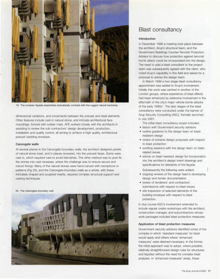
19. The complex fa<;:ade assemblies dramatically contrast with the rugged natural backdrop.
dimensional variations, and movements between the precast and steel elements.
Other features include cast-in natural stone, and intricate architectural face
mouldings, formed with rubber mats. AFE worked closely with the architects in
assisting to review the sub-contractors ' design development, production,
installation and quality control , all aiming to achieve a high quality, architectural
precast cladding envelope.
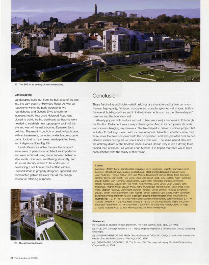
Canongate walls
At several places in the Canongate boundary walls, the architect designed panels
of natural stone inset, and in places recessed, into the precast faces. Some were
cast in, which required care to avoid blemishes. The other method was to post-fix
the stones into cast recesses, where the challenge was to ensure secure and
robust fixings. Many of the natural stones were hand-carved with inscriptions or
patterns (Fig 20), and the Canongate boundary walls as a whole, with these
intricately shaped and sculpted inserts, required complex structural support and
casting techniques.
20. The Canongate boundary wall.
Blast consultancy
Introduction
In December 1998 a meeting took place between
the architect, Arup's structural team, and the
Government Buildings Counter-Terrorist Protection
Advisor to discuss how protection against terrorist
bomb attack could be incorporated into the design.
The need to add a blast consultant to the project
team was subsequently agreed with the client, who
noted Arup's capability in this field and asked for a
proposal to advise the design team.
In March 1999 a two-stage blast consultancy
appointment was added to Arup's involvement.
Initially this work was centred in another of the
London groups, where experience of blast effects
had been enhanced by extensive involvement in the
aftermath of the city's major vehicle bomb attacks
of the early 1990s 1 . The later stages of the blast
consultancy were conducted under the banner of
Arup Security Consulting (ASC), formally launched
in July 2001 .
The initial blast consultancy scope included:
• liaison with Government security advisers
• outline guidance to the design team on blast
resistant design
• review of scheme design proposals with respect
to blast protection
• working sessions with the design team on blast
related issues
• advice on blast-resistant design for incorporation
into the architect's design intent drawings and
specifications for elements of the fa9ade.
Subsequently the following were added:
• ongoing reviews of the design team 's developing
design and tender documentation
• review of tenderers ' and contractors '
submissions with respect to blast issues
• site inspection of selected elements of the
building envelope with respect to blast
protection.
In due course ASC's involvement extended to
include regular onsite workshops with the architect, construction manager, and subcontractors whose
work packages included blast protection measures.
Application of blast protection measures
Government security advisors identified zones of the
complex in which 'standard measures' for blast
would apply and others where 'enhanced
measures' were deemed necessary. In the former,
the initial approach was to adopt, where possible,
relatively straightforward design rules for structures
and fa9ades without the need for complex blast
analyses. In 'enhanced measures ' areas, these
The Arup Journal 2/2005 17

21 . Test arrangement for MSP building west elevation window.
design rules were to be augmented by explicit
analysis of structures and fac;:ades under blast
loading, which itself was to be derived from a
specified weight of explosive material and a stand
off distance appropriate to the element under
consideration . While for a more conventional
building the prescriptive 'standard measures'
approach might ensure an acceptable degree of
occupant protection, the challenging geometry and
palette of materials of the SPB meant that a more
rigorous approach was often necessary, and not
only in the 'enhanced measures' zones.
To evaluate the intense but very short-lived
airblast pressures created by a high explosive
detonation, extensive use was made of ConWep2, a
US military program to which ASC has access
through its involvement in UK Government projects.
ConWep's blast pressure time-histories were used
to analyze dynamically the global behaviour of
complete structures, or local effects on individual
building elements or areas.
The approach was not to seek to avoid damage
entirely under these extreme conditions, but to
ensure that it was within acceptable limits that
would still provide appropriate protection to building
occupants. The analysis and design of structural
elements in steel and concrete was based on
US methods3, while assessment of glazing
behaviour under blast load drew on the analytical
procedures and extensive database of test results
built up by the UK Government's own explosion
protection team.
18 The Arup Journal 2/2005
Windows
In buildings for which blast protection is a design criterion , glazing is often the most
critical issue in mitigating potential hazard to occupants. At distances from an
explosion where human bodies may survive airblast effects without serious harm,
glass fragments can cause seveire, even lethal injuries. The value of laminated glass
in mitigating fragmentation is well established and its use in the innermost leaf of all
external windows is now mandatory for new UK Government buildings. A library of
proven blast-resistant glazing configurations exists for conventional fixed windows
over a limited range of sizes, but: the challenge at SPB was to achieve similar levels
of performance in windows with unique geometries or which used natural materials
and in some cases had to be openable for maintenance or to provide natural
ventilation. Through close collaboration with the architect, trade contractors and
AFE, solutions were developed to match these apparently conflicting requirements
with EMBT/RMJM's aesthetic objectives.
Conceptually, openable windows seem contradictory to blast protection.
However, as natural ventilation was fundamental to the design of certain parts of
the building, workable solutions had to be found . 'Slam-shut' windows, which can
be opened outwards a limited amount for ventilation, were developed in which the
openable casement would be forced to close by the blast shockfront. Leakage
studies were made of the likely internal pressures from the external design
explosion should the casement somehow be prevented from closing. These
showed that although internal pressures immediately inside the windows would
inevitably be high, they would quickly fall to values below the recognized threshold
for eardrum rupture. In the few locations where this criterion could not be achieved,
mechanical ventilation was introduced.
Blast testing of windows
Designs for many of the windows and other glazed elements of the building
envelope were developed with confidence in their performance under blast loading.
In certain cases, for example windows with irregular glazing shapes or timber
frames or 'slam-shut' configuration, full-scale physical trials were carried out to
prove their blast resistance.
22. MSP building west elevation winalow.

The arrangements generally adopted for such range
tests involve attaching the test sample to the open
front of a closed cubicle to prevent the blast wave
from wrapping around the target and applying a
relieving load on its rear face (Fig 21). The SPB
trials, which ASC supervised, identified weaknesses
in certain localized details but ultimately through
successful tests proved the 'blastworthiness' of the
final designs (Fig 22).
9/11 and The Holyrood Inquiry
The attacks on the World Trade Center and the
Pentagon on 11 September 2001 were undeniably
defining moments in the history of terrorism. They,
and subsequent world events, have profoundly
influenced perceptions of risk and concerns about
security. The UK has a lengthy history of terrorist
attacks, not least against government-related
facilities and, as noted earlier, the requirement to
provide blast protection was included in the 1998
brief for SPB and the blast consultant's role was
established well before 9/ 11 . After it, the principles
of occupant protection against terrorist attack
remained fundamentally unchanged - a point
recognized by Lord Fraser in his lnquiry4 : ' .. . I am
persuaded by the evidence that the events of 11
September 2001 were not the catalyst to a wholesale review of the security requirements on
the site nor were they responsible for an escalation
in the standards of protection required to meet a previously unforeseen terrorist threat.'
In his Inquiry Lord Fraser decided to consider
security issues but elected to do so by taking
evidence in camera from those most closely
involved in this aspect of the project, including ASC.
Commenting on how the blast consultant's task
was fulfilled, Lord Fraser was 'satisfied as to the
thoroughness and professionalism with which this
work was undertaken by those involved'.
Sock expansions into soft fabric core
Anchor body dependent on load but normally 15mm, 20mm, or 30mm square hollow section
23. Wall stitching with grouted anchors: length, number, and position dependent on structural condition.
24. Queensberry House after refurbishment.
Refurbishment and landscaping
Queensberry House
Because of the age and history of Queensberry House, Historic Scotland wished to
retain and incorporate as many existing floors and joists in the refurbishment as
possible. However, its poor condition, the many alterations, and the need to carry
modern office loads and provide blast resistance, resulted in just two timber floor
areas being retained . All others were replaced with a modern concrete and steel
floor system, as thin as possible to allow finished floors to match existing door
thresholds and stairs without the ceiling dropping below the tops of the windows.
Holes in the beam web allow service ducts and pipes to pass through to avoid
providing a separate service zone beneath. The new floors provide robustness and
diaphragm action as well as acoustic and fire separation, and add strength,
durability, and dynamic performance.
The walls within Queensberry House are generally stone-built , rubble-filled , and
up to 700mm thick, but in many places alterations had resulted in brick and
blockwork being introduced as new openings were formed or existing ones closed
off. This also led to a variety of lintels, with precast concrete or steel joists alongside
the original timber ones, or openings without lintels at all. Cracks became evident
once plaster and finishes were removed. Some had formed during earlier additions,
and unbridged butt joints had opened up due to settlement and movement.
Major remedial works were needed. The outer and inner wall leaves were tied
together with special grouted anchors for local strengthening, and wall panels were
similarly connected into return walls to ensure overall stability. The latter was mostly
where later extensions were built with no ties to the original frame; the new anchors
bridge the old butt joints, tying the various elements together (Fig 23) .
Such major works on Queensberry House were not originally intended, and
additionally the team was instructed fairly late to design the new/old roof (Fig 24) .
The final appearance of the roof was based on a contemporary sketch of the
Edinburgh skyline discovered after extensive archaeological research, together
with other old artworks, further buildings of the era by the same architect, and
anecdotal evidence.
The Arup Journal 2/2005 19
25. The SPB in its setting of new landscaping.
Landscaping
Landscaping spills out from the built area of the site
into the park south of Holyrood Road. As well as
roadworks within the park, upgrading two
roundabouts and Queens Drive to cater for
increased traffic flow once Holyrood Road was
closed to public traffic, significant earthworks were
needed to establish new topography south of the
site and east of the neighbouring Dynamic Earth
building. The result is publicly accessible landscape,
with embankments, canopies, water features, cycle
paths, footpaths, hard areas, newly-planted trees,
and indigenous flora (Fig 25).
Level differences within the new landscaped
areas were of paramount architectural importance
and were achieved using stone encased behind a
steel mesh. Corrosion, weathering, durability, and
structural stability all had to be addressed in
developing a solution for the Scottish climate.
Dressed stone in properly designed, specified, and
constructed gabion baskets met all the design
criteria for retaining purposes.
26. The garden landscape.
20 The Arup Journal 2/2005
Conclusion
These fascinating and highly varied buildings are characterized by two common
themes: high quality, fair-faced concrete and complex geometrical shapes, both in
the overall building outlines and in individual elements such as the 'flame-shaped'
columns and the boundary wall.
Already popular with visitors and set to become a major landmark in Edinburgh,
the Scottish Parliament was a major challenge for Arup in its complexity, its scale,
and its ever-changing requirements. The firm helped to deliver a unique project that
includes 11 buildings - each with its own individual character - contains more than
three times the area compared with the competition, and was presided over by five
different clients during the six years since it was won. The same period also saw
the untimely death of the Scottish leader Donald Dewar, very much a driving force
behind the Parliament, as well as Enric Miralles. It is hoped that both would have
been satisfied with the reality of their vision.
Credits
Architect: EMBT/RMJM Construction manager: Bovis Lendlease Quantity surveyor: Davis Langdon Structural, civil, fa9ade, geotechnical , blast and landscaping engineer: Arup -Joan Anderson, Francis Archer, Tom Barr, Monika Beyersdorff, Daniele Bosia, Mark Bowman, Geoffrey Burns, Sam Cook, Rob Davis, Brian Edie, David Guild, Tony Gulston, Arjan Habraken, David Hadden, Don Henning, Graeme Herd, Mark Holst, Fred llidio, Patricia Johnstone, Hiroshi Kawamura, Gavin Kerr, Rob Kinch. Ken Knowles, David Lewis, Joan Lindsay, John McDonald, Andrew Millar, Stewart Millar, Astrid Muenzinger, Hamish Nevile, Steve Peet, Chas Pope, Stephen Ratchye, Mark Reed, Duncan Richards. Volker Schmid, Annalisa Simonella, David C Smith, Peter Stevenson, Alan Tweedie, Simon Webster. Gary Wilkie, Robin Wilkinson Building services engineer: RMJM Specialist glazing subcontractor: Mero Structures Inc Illustrations: 1, 2, 11 , 18, 19 Arup/Adam Elder/Scottish Parliamentary corporate body; 3, 4, 10, 13 EMBT/RMJM; 5-7, 23 Arup/Nigel Whale; 8, 12, 20, 25, 26 Arup/Roland Halbe; 9 Cowley Structural Timberwork; 14, 16 Arup/Peter Cook/VIEW; 15 Arup/Paul RafteryNIEW; 17 Arup; 21 David Hadden/Arup; 22 Don Henning/Arup; 24 Ken Knowles/Arup
References
(1) HADDEN, D. Building in blast protection. The Arup Journal, 33(3), pp20-23, 1998.
(2) HYDE, OW. ConWep Version 2. 1.0. 1. USAE Engineer Research & Development Center, Vicksburg, Mississippi.
(3) US DEPARTMENT OF THE ARMY. Technical Manual TM5-1300. Design of structures to resist the effects of accidental explosions. Washington DC, 1990.
(4) LORD FRASER OF CARMYLLIE, The Rt Hon, QC. The Holyrood Inquiry. Scottish Parliamentary Corporate Body, 2004.
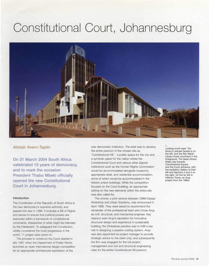
Constitutional Court, Johannesburg
Alistair Avern-Taplin
On 21 March 2004 South Africa celebrated 10 years of democracy, and to mark the occasion President Thabo Mbeki officially opened the new Constitutional Court in Johannesburg.
Introduction
The Constitution of the Republic of South Africa is
the new democracy's supreme authority, and
passed into law in 1996. It includes a Bill of Rights
and serves to ensure that political powers are
exercised within a framework of constitutional
constraints, irrespective of what might be intended
by the Parliament. To safeguard the Constitution,
widely considered the most progressive in the
world, 11 judges were sworn in.
The process to construct the Court started in
late 1997 when the Department of Public Works
launched an open international design competition
for an appropriate architectural expression of the
new democratic institution. The brief was to develop
the entire precinct of the chosen site as
'Constitutional Hill' - a public space for the city and
a symbolic place for the nation where the
Constitutional Court and various other aligned
institutions such as the Human Rights Commission
would be accommodated alongside museums,
appropriate retail, and residential accommodation,
some of which would be accommodated in the
historic prison buildings. While the competition
focused on the Court building, an appropriate
setting for the new elements within the entire site
was also called for.
The winner, a joint venture between OMM Design
Workshop and Urban Solutions, was announced in
April 1998. They were asked to recommend the
remainder of the professional team and chose Arup
as civil , structural , and mechanical engineer. Key
reasons were Arup 's reputation for innovative
structural design and experience in sustainable
building; the Zimbabwe practice was to fulfil a key
role in designing a passive cooling system. Arup
was also appointed as project manager to provide
strategic advice to the client only, and subsequently
the firm was engaged for the full project
management and civil and structural engineering
roles for the entire Constitutional Hill precinct.
1. Looking south-east: The library's precast fac;;ade is on the left, and the Rex Welsh Library tower prominent in the foreground. The Great African Stairs rise towards Constitutional Square and the Court entrance, with the exhibition Gallery to their left and Sections 4 and 5 on the right. On the far left is Hillbrow Tower, an Arup project from the 1960s.
The Arup Journal 2/2005 21

The historical area The precinct contains several historically significant buildings, including The Fort and ramparts, The Awaiting Trial Block, Sections 4 and 5 'Number Four', and the Women 's Goal.
The Fort and ramparts
At the centre of Constitution Hill is The Fort surrounded by its ramparts , originally built between 1896 and 1899 by the Boer president. Paul Kruger, as an act of defiance against the might of imperial Britain, and a way to keep watch over the uitlanders {foreigners) in the mining village of Johannesburg, who were plotting an overthrow of the Boers. In 1900, during the Anglo-Boer War, the British took Johannesburg, and imprisoned Boer soldiers in The Fort. A group of Cape Afrikaners who had fought on the side of the Boers were executed at The Fort, killings that marked the beginning of its long history as a place of punishment, confinement and abuse, and Johannesburg's main place of incarceration for eight decades.
The Fort is entered from the south through a set of huge doors that lead through a tunnel. Prisoners passed into a reception area and were then sent to a 'delousing room' where they were stripped and sprayed with cold water, before being moved to the Awaiting Trail Block. Once convicted, they were incarcerated in The Fort if they were white men, in the Native Gaol if they were black men, and in the Women's Gaol if they were female.
The Awaiting Trial Block
All prisoners went through the Awaiting Trial Block. For two weeks, the 156 Treason Trialists of 1956, led by Nelson Mandela, were held there, as were the scores of activists held for three months during the 1960 State of Emergency, and hundreds of teenagers held after the Soweto Uprising of 1976. All these groups were kept in special communal cells. In these horribly overcrowded cells for common criminals, new inmates were inducted into the brutal life of prison. They were often robbed, attacked and even raped by members of the 'Numbers' gangs who exist to this day. A visitors' room was connected to the Awaiting Trial Block, the only place of comfort for the prisoners. This has also been dismantled to make way for Constitution Square, but will be rebuilt , perhaps as a visitors' centre for the precinct.
22 The Arup Journal 2/2005
Constitutional Court
.:r£rr _\n lfr:o Four' ~u
Awaiting .............. , Trial ____.::"· : Block :.......... .. .....
_\L Hill brow Tower
0
The Fort
l~ e-=~~~~===~ =--c:::i-n~---,:~?nj \ ~ Orn
Section 4 and 5 'Number Four'
Most South Africans know the whole prison complex simply as 'Number Four', a term which symbolized courage and fear, the cruelties and indignities of colonialism and apartheid, and the prison system in general. In 1902, Section 4 and 5 of the prison replaced the native gaol built in 1893. 'Number Four' is to the north of the ramparts and west of the new Consti tutional Court. It contained the general cells for black male prisoners where violent criminals, pass-offenders and political prisoners were incarcerated side-by-side. At the extreme north of Number 4 are 24 punishment cells, which contained men who had committed an offence inside the prison such as trying to escape. These cells also held men with infectious diseases like smallpox, juveniles, and men with mental illnesses.
Section 4 and 5 is in a state of extreme disrepair, the paint peeling off its walls, and its courtyards covered in elephant grass and weeds. It forms a vital heritage component of Constitution Hill , and will not be tampered with or renovated. It is the dark heart of the precinct, giving visitors a salutary sense of what prison life must have been like.
A law library with IT links to the world
The Constitutional Court library of 40 OOO books is set to grow by 10 OOO a year until it reaches 400 OOO volumes, making it Africa's most important law reference site, and one of the most significant in the world . It has also launched the most comprehensive legal virtual library in Africa. which will carry the full text of every major court in South Africa and later all courts in sub-Saharan Africa that carry the electronic text of court judgements.
The library subscribes to all major English law reports, and to those of the German Constitutional Court, three of the German Federal Supreme Courts, and certain French public law reports. The court holds 130 different law report series.
The virtual library has an Internet portal that provides a single point of access to the library's resources. Materials can be searched for and viewed online, and printed or downloaded.
3. The library, showing its ramped floors ; the entire structure is suspended from a portal at roof level to avoid columns in the basement.
The Women's Gaol
In 1909, a new Women's Gaol was built directly east of The Fort, the handsome red brick building that remains today. It held both black and white women, but in separate sections. The vast majority of inmates were neither murderers nor freedom fighters. but ordinary women arrested mainly for pass offences or for making an independent income from beer brewing - illegal because the state controlled the sale of liquor to blacks through its beer halls. Sometimes they had small children or babies with them. This was especially true during the late 1950s, when black women were arrested in large numbers when they deliberately presented themselves to the police without passes.
The Commission on Gender Equality, an official body that looks after the rights of women, took offices in the Women's Gaol in 2003. An exhibition detailing the lives and experiences of three very different women who were incarcerated in the gaol is on display in the oval atrium that is at the centre of the building.
Constitution Hill in a nutshell The old Fort area bordered by Sam Hancock, Hospital , Kotze and Joubert streets will become an anchor and a symbol of Johannesburg's inner city regeneration. Apart from the Constitutional Court, the new precinct will also house statutory bodies and a thriving complex of heritage sites and museums, exhibition and performance spaces, offices, shops, restaurants and other tourist facilities. It will be an engine of growth and transformation for downtown Johannesburg - and a place where visitors can feel safely the heartbeat of this vibrant city. The precinct will also be home to one of South Africa's major public art collections. To this end an Artworks Project for acquisition of art for the Court and public environment has been initiated.
The entire precinct will , in fact, become a 'living ' museum. Visitors will be able to visit The Fort. At the entrance, off Kotze Street, one exhibition already being staged depicts a short history of the prison complex, whilst another shows a society in transition, looking back at the difficulties of the past and the possibilities of the future.

4. The stairs in the exhibition gallery, leading to the foyer in the distance. The Great African Stairs are outside the glass doors on the right and the administration area to the left behind the wall.
Site selection and history
All 11 Constitutional Court judges were from the start actively involved in the site
selection. Enabling the eventual building users to choose its location was an act of
empowerment, and contributed greatly towards feelings of inclusivity and
ownership. The judges warmed to the opportunity and considered several potential
sites. in Pretoria and Midrand as well as Johannesburg, but eventually settled on
the run-down The Fort precinct on the northern face of Braamfontein ridge in
Johannesburg, the apex of the Witwatersrand region and bordered by the inner-city
neighbourhoods of Hillbrow and Johannesburg.
How the site was chosen set the tone for the whole project. The judges would be actively involved throughout, and the design team welcomed this. As the project
unfolded, the design's success rested less and less on pure technical ability and
increasingly on responsive relationships established across professional and
disciplinary boundaries. Thus South Africa 's most prominent symbol of democracy
was born out of a largely democratic process.
The 12.5ha site is physically accessible and prominently situated, and was seen
to have the potential to catalyze the regeneration of Johannesburg's central
business district, but the judges selected it above all because of its rich symbolism.
Originally built in 1893 as a military defence outpost, it developed into a penal
institution - significantly designed by Sytze Wierda, official architect of the South
African Republic, who also designed the parliament and supreme court building on
Church Square, Pretoria. Over the years, many of those fighting political and social
oppression were incarcerated in the The Fort prison, the history of political struggle
bestowing on it the doubtful honour of being the only prison in the world in which
both Ghandi and Mandela were locked up.
The Fort was thus an ideally symbolic site for the
Constitutional Court. To transform the prison would
physically and visually dramatize the contrast
between a past of 'untold suffering and injustice'
and the future of 'democracy and peaceful co
existence' , as the postamble to the Constitution
puts it. More importantly, the decision to house the Court in inner-city Johannesburg also signifies
confidence in the idea of a truly shared democratic
public space arising in urban post-apartheid
South Africa.
After the site was selected and secured, it was decided that a public competition would be the
most appropriate and democratic way of choosing
a design; after negotiations, The Fort precinct was
donated by the Greater Johannesburg Metropolitan
Council to the Department of Public Works.
Constitutional Hill will also house the Museum of the
Constitution, a constitutional library, and various
democratic institutions like the Human Right
Commission, the Gender Commission, and the
Public Protector. In accordance with mixed use design principles, Constitution Hill will also include
market, work, and living spaces.
The Arup Journal 2/2005 23

The winning concept
Though right in the heart of the city, from its inception the site had been insular and
deliberately inaccessible, so it had to be connected to the neighbouring precincts,
with emphasis on pedestrian movement. Another priority was to design a building
that would benefit from the rich and complex legacy of the site, and also important
was the notion that in a democratic society civic buildings 'can either gain their
symbolic value by expressing the openness they present' or they can be 'alienating
monuments' (SA Architect, August 1998). OMM Design Workshop and Urban
Solutions sought 'the power of a pre-eminent building, without monumentality'.
The result was a series of terraces stepping down the steeply-falling site, facing
due north and thus misaligned with both the Fort and the other prison buildings.
The topography and the misalignment generate the 'Great African Stairs', which
taper as they ascend southward to the foyer and Court at the head of the complex,
aligned parallel to the Fort. Paved with bricks from the demolished Awaiting Trial
Block, the Stairs are like a stitched seam between the new Court building and
Sections 4 and 5 of the old prison to the west.To fulfil the architects' own objective
of interweaving past with future, stair towers of the former prison buildings were
retained and incorporated in the new complex, and materials like bricks were
retrieved and recycled. This approach is echoed in the principles for energy conservation, whereby interior comfort in the building is largely achieved by
harnessing the advantages of the high diurnal range experienced in Johannesburg.
Apart from the Court chamber. which is air-conditioned, an internal summer
temperature no higher than 26°C is achieved, 6-?°C below the ambient
temperature. Similarly the Court is designed not to need acoustic amplification.
The public faces of the building engage with passers-by through the various
artworks and mosaic cladding. Sun-baffles and screens too are endowed
artistically, and shelter is provided by indigenous trees.
24 The Arup Journal 212005
Existing 4 & 5 gaols
2 Great African Stairs
3 Exhibition arcade
4 Rex Welsh collection
5 Public auditorium
6 Administration
7 Council robing and meeting rooms
6.
5. Detail of artwork screens on the exhibition gallery elevation, by the top of the Great African Stairs; Constitutional Square and the Court entrance are immediately ahead, and Sections 4 and 5 on the left.
8
9
10
11
12
13
14
Internal walkway
Foyer
Court
Reference library
Judges' chambers
Existing sub-station
Judges' lounge, conference and comitee room
7. Looking east on the north side of the site, with the library on the right behind its precast fa~ade, and the first of the judges chambers wings on the left. Between is the link between the administration building and the library.

The Constitutional Court building
The building has six main zones:
• the Court foyer - the public entrance into the
building and an extension of the most public
area of the site, Constitution Square
• the Court chamber, where the judges sit, and
judicial debate is conducted in public
• the Judges' chambers, the private area where
the judges, their secretaries and researchers
have their offices; these areas are in a cloistered
courtyard, not accessible to the public
• the administration wing, where most of the Court
staff work
• the library, where most of the Court's research is
undertaken in what will be the most advanced
and largest collection of human rights material on
the African continent
• the exhibition gallery, where permanent and
temporary art exhibitions will be on display in an
extension of the public areas of the building.
The Court chamber and foyer, in the south wing , are
directly accessible to the public from Constitution
Square, whilst the library, forming the north wing , is
also partly open to the public. The two most public
functions are therefore the most visible, and located
to enable easy access.
8. The Court chamber: a glazed acoustic reflector is suspended over the judges' and counsel benches. The bricks forming the drystack wall were salvaged from the demolished Awaiting Trial Block.
9. From The Fort's ramparts: In the foreground is the foyer, with the ' light tower' built over a staircase retained from the Awaiting Trial Bock. The Court chamber is right of the foyer.
The administration wing links the foyer, Court chamber and library on a north-south
axis. The exhibition gallery doubles as an internal public walkway that parallels this
wing immediately to the west. It is enclosed but largely transparent internally to the
administration offices and externally to the Great African Stairs.
The Judges 'chambers are east of the administration wing in a series of office
suites on three floor levels. All north-facing and overlooking a courtyard to the east
(which is framed by the Court building and the Hillbrow substation on the eastern
boundary of the site) , these suites are separated from the administration wing by an
inner walkway, a light, triple-height space with timber decked bridges at different
floor levels that afford the judges private access to each other's rooms and to the
Court chamber and the library.
The Arup Journal 2/2005 25
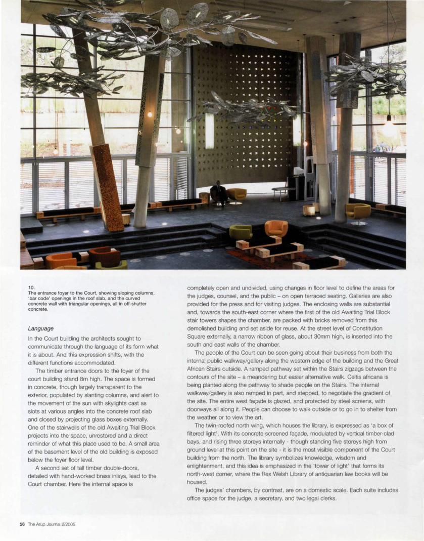
10. The entrance foyer to the Court, showing sloping columns, 'bar code' openings in the roof slab, and the curved concrete wall with triangular openings, all in off-shutter concrete.
Language
In the Court building the architects sought to
communicate through the language of its form what
it is about. And this expression shifts, with the
different functions accommodated.
The timber entrance doors to the foyer of the
court building stand 8m high. The space is formed
in concrete, though largely transparent to the
exterior, populated by slanting columns, and alert to
the movement of the sun with skylights cast as
slots at various angles into the concrete roof slab
and closed by projecting glass boxes externally.
One of the stairwells of the old Awaiting Trial Block projects into the space, unrestored and a direct
reminder of what this place used to be. A small area
of the basement level of the old building is exposed
below the foyer floor level.
A second set of tall timber double-doors,
detailed with hand-worked brass inlays, lead to the
Court chamber. Here the internal space is
26 The Arup Journal 2/2005
completely open and undivided, using changes in floor level to define the areas for
the judges, counsel, and the public - on open terraced seating. Galleries are also
provided for the press and for visiting judges. The enclosing walls are substantial
and, towards the south-east corner where the first of the old Awaiting Trial Block
stair towers shapes the chamber, are packed with bricks removed from this
demolished building and set aside for reuse. At the street level of Constitution
Square externally, a narrow ribbon of glass, about 30mm high, is inserted into the
south and east walls of the chamber.
The people of the Court can be seen going about their business from both the
internal public walkway/gallery along the western edge of the building and the Great
African Stairs outside. A ramped pathway set within the Stairs zigzags between the
contours of the site - a meandering but easier alternative walk. Celtis africana is
being planted along the pathway to shade people on the Stairs. The internal
walkway/gallery is also ramped in part, and stepped, to negotiate the gradient of
the site. The entire west fa9ade is glazed, and protected by steel screens, with
doorways all along it. People can choose to walk outside or to go in to shelter from
the weather or to view the art.
The twin-roofed north wing, which houses the library, is expressed as 'a box of
filtered light' . With its concrete screened fa9ade, modulated by vertical timber-clad
bays, and rising three storeys internally - though standing five storeys high from
ground level at this point on the site - it is the most visible component of the Court
building from the north. The library symbolizes knowledge, wisdom and
enlightenment , and this idea is emphasized in the 'tower of light' that forms its
north-west corner, where the Rex Welsh Library of antiquarian law books will be
housed.
The judges' chambers, by contrast, are on a domestic scale. Each suite includes
office space for the judge, a secretary, and two legal clerks.
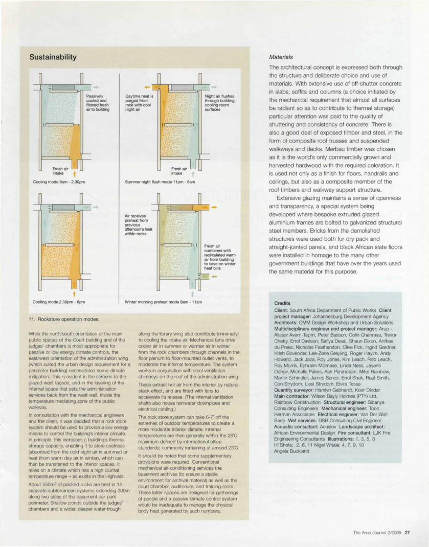
Sustainability
n I n
Passively cooled and filtered fresh air to building
Daytime heat is purged from rock with cool night air
Night air flushes through building cooling room surfaces
Fresh air intake
i=====::i I I
Fresh air intake
Cooling mode Sam - 2.30pm Summer night flush mode 11 pm - 6am
Air receives preheat from previous afternoon's heat within rocks
, ~---~ I I Fresh air combines with recirculated warm air from building to save on winter heat bills
Cooling mode 2.30pm - 6pm Winter morning preheat mode Sam - 11 am
11 . Rockstore operation modes.
While the north/south orientation of the main public spaces of the Court building and of the judges' chambers is most appropriate for passive or low energy climate controls , the easVwest orientation of the administration wing (which suited the urban design requirement for a perimeter building) necessitated some climate mitigation. This is evident in the screens to the glazed west fac;:ade, and in the layering of the internal space that sets the administration services back from the west wall, inside the temperature mediating zone of the public walkway.
In consultation with the mechanical engineers and the client, it was decided that a rock store system should be used to provide a low energy means to control the building 's interior climate. In principle, this increases a building 's thermal storage capacity, enabling it to store coolness (absorbed from the cold night air in summer) or heat (from warm day air in winter), which can then be transferred to the interior spaces. It relies on a climate which has a high diurnal temperature range - as exists in the Highveld.
About 55Qm3 of packed rocks are held in 14 separate subterranean systems extending 200m along two sides of the basement car-park perimeter. Shallow ponds outside the judges' chambers and a wider, deeper water trough
along the library wing also contribute (minimally) to cooling the intake air. Mechanical fans drive cooler air in summer or warmer air in winter from the rock chambers through channels in the floor plenum to floor-mounted outlet vents, to moderate the internal temperature . The system works in conjunction with steel ventilation chimneys on the roof of the administration wing.
These ex1ract hot air from the interior by natural stack effect, and are fitted with fans to accelerate its release. (The internal ventilation shafts also house rainwater downpipes and electrical cabling.)
The rock store system can take 6-r off the extremes of outdoor temperatures to create a more moderate interior climate. Internal temperatures are then generally within the 26'C maximum defined by international office standards; commonly remaining at around 23·c.
It should be noted that some supplementary provisions were required. Conventional mechanical air-conditioning services the basement archives (to ensure a stable environment for archival material) as well as the court chamber, auditorium, and training room. These latter spaces are designed for gatherings of people and a passive climate control system would be inadequate to manage the physical body heat generated by such numbers.
Materials
The architectural concept is expressed both through
the structure and deliberate choice and use of
materials. With extensive use of off-shutter concrete
in slabs, soffits and columns (a choice initiated by
the mechanical requirement that almost all surfaces
be radiant so as to contribute to thermal storage)
particular attention was paid to the quality of
shuttering and consistency of concrete. There is
also a good deal of exposed timber and steel, in the
form of composite roof trusses and suspended
walkways and decks. Merbau timber was chosen
as it is the world's only commercially grown and
harvested hardwood with the required coloration. It
is used not only as a finish for floors, handrails and
ceilings, but also as a composite member of the
roof timbers and walkway support structure.
Extensive glazing maintains a sense of openness
and transparency, a special system being
developed where bespoke extruded glazed
aluminium frames are bolted to galvanized structural
steel members. Bricks from the demolished
structures were used both for dry pack and
straight-jointed panels, and black African slate floors
were installed in homage to the many other
government buildings that have over the years used
the same material for this purpose.
Credits
Client: South Africa Department of Public Works Client project manager: Johannesburg Development Agency Arch itects: OMM Design Workshop and Urban Solutions Multidisciplinary engineer and project manager: Arup -Alistair Avern-Taplin, Peter Basson, Colin Chanraya, Trevor Chetty, Errol Davison, Safiya Desai , Shaun Dixon, Anthea du Preez, Nicholas Featherston, Clive Fick, Ingrid Gardner, Krish Govender, Lee-Zane Greyling, Roger Hayim, Andy Howard, Jack Jaza, Roy Jones. Kim Leach, Rob Leach, Roy Morris, Ephraim Mzimase, Linda Ness, Jayanti Odhav, Michelle Pakes, Ash Parshotam, Mike Rainbow, Martin Schindler, James Senior, Errol Shak, Rael Smith, Con Strydom, Liesl Strydom, Elvira Tessa Quantity surveyor: Hamlyn Gebhardt, Koor Dindar Main contractor: Wilson Bayly Holmes (PTY) Ltd, Rainbow Construction Structural engineer: Sibanye Consulting Engineers Mechanical engineer: Toon Herman Associates Electrical engineer: Van Der Walt Barry Wet services: DSB Consulting Civil Engineer Acoustic consultant: Acuslov Landscape architect : African Environmental Design Fire consultant: LJK Fire Engineering Consultants Illustrations: 1, 3, 5 , 8 Hi Shots; 2, 6, 11 Nigel Whale; 4, 7, 9, 10 Angela Buckland
The Arup Journal 212005 27

1. 'The Hub' in its urban South London setting.
'The Hub' Community Resource Centre, London Introduction
'New Deal for Communities' (NDC) is a UK Government programme designed to
tackle social exclusion and renew some of the country's poorest and most deprived
neighbourhoods. A central feature of the plan is to put communities themselves at
the heart of decision-making, and to this end 39 NDC partnerships have been
established in England, 10 of them in London. One of these, in the borough of
Newham, is the West Ham and Plaistow NDC, and an early outcome of its delivery
plan was to identify the need for three new community resource centres (CRCs).
Arup has been engaged for all three. 'The Hub' in Eastlea is the first; it opened
in October 2004, with Woodlands CRC following in mid-2005. The third is intended
for North Plaistow. For 'The Hub' Arup was appointed as business planning,
structural, building services and building physics consultant. working with
Eger Architects.
The projects are all strongly community-oriented and designed on sustainable
principles. They are innovative and, together with the other elements of their
delivery plan, have helped this particular NDC to become one of the most highly
rated of the 39.
The brief
The client wanted the design to 'be of a high quality standard, inviting and user
friendly, with universal appeal to help create vitality in its function . The design
should include the following elements as a guideline:
• be an imaginative landmark scheme
• be innovative in types of materials used
• include energy efficiency in terms of external and internal design functions
• use materials for self-sufficient energy and/or to sell on energy
• have flexible and spacious internal floor space standards
• embody internal and external security measures. '
28 The Arup Journal 2/2005
The client's brief required that the building should be inviting, userfriendly, with universal appeal to help create vitality in its function.
Chris Trott
Team response
The first thing was to hold a socially inclusive public
consultation , which identified the needs to be
fulfilled . The resulting programme focused on
providing space to support the economic situation
and community facilities in the area, and the
subsequent conceptual design prioritized the
project's environmental responsiveness. In parallel ,
the team evolved a business plan to ensure
that 'The Hub' remains economically viable
throughout its life.
Building form and layout
The site is some 1 OOm long by 20m wide. The need
for an appropriate scale to the building in the
context of the surrounding residential area. together
with a 'right to light' envelope, constrained its
height. This proved quite challenging, particularly in
view of the amount of new accommodation that
was required. The site had previously
accommodated garages which, together with their
hard-standings, were removed, as was an existing
derelict house.
The building form was also driven by the need
for significant and very diverse areas to
accommodate business start-up units (BSUs) , a
cafe, a pharmacy, a nursery, and a multi-purpose
community hall , as well as being significantly
influenced by energy and renewable materials
considerations.

Carbon optimization of form
Early in the design, studies were made of how this
could be constructed as an environmentally responsive, carbon-optimized building. This process
addressed the simultaneous beneficial use of
daylight and solar gain to warm the building by using well-positioned windows, glazed elements,
and wintergarden zones. The analysis led to
recommendations for the orientation and size of
windows, and setting appropriate levels of insulation
to minimize carbon impact.
This allowed the form, orientation, and overall
mass of the building to be developed within a
rigorous conceptual framework designed to ensure
optimum user comfort, excellent daylight, and
minimized energy use. The resulting design gives
high levels of insulation to the permanently
occupied accommodation, which surrounds a
transiently occupied wintergarden that is partially
heated in winter. An ETFE (ethylene
tetrafluoroethylene) roof covering to the
wintergarden was felt to be justified because the
space below is not heated fully and because the
material used is fully recyclable.
Choice of structural and services systems
Having ensured that the building 's passive design
was optimized, the building systems were then
chosen with the aim of further reducing
carbon impact, via both carbon in use and
embodied carbon.
3. Upper level walkway and offices beneath skylights.
l Rainwater storage collects from roof
Planted sunscreens
Exposed concrete soffit providing thermal mass
Condensing boiler for additional heat
Fa~ade: integrated PV cells
Piled foundations used to minimize 'excavated' material and temporary works due to high water table
2. Energy-saving structural and services concepts.
Structural systems
Opening rooflights
Skylights
Wintergarden (not heated generally)
Natural and intermittent mechanical vent ilation
Planted sunscreens
Natural ventilat ion
Harvested rainwater
-Jw- Renewable electricity
'Ground-coupled' heat transfer loop
....... Heat storage and recovery
Local underfloor heating
After considering the merits of a concrete structure with thermal storage properties
that could have provided further passive cooling and heating, and which would
have been designed for extended life, the team decided that the nature of the site
and the building required a more lightweight treatment. A structure that could be
demounted and reused (or recycled) was therefore adopted, though it was
recognized that the potential for reuse elsewhere (or if this proves not possible,
reuse of parts or recycling) was only possible for the superstructure.
As the site was overlain by 2.5m to 3m of moderately contaminated fill , the safe working practice of capping and leaving in situ was adopted. Methane was
detected during the site investigation, and this required mitigation through suitable
ground slab design and following the best practice guidance in CIR/A Report 1491•
A pile solution was adopted, which allowed all the fill material on site to be
retained and avoided the environmental penalties of considerable muck-shift and
the associated embodiment of carbon in the sub-structure. Should the site again be
redeveloped , the piles could be reused for residential or similar buildings. The
ground-bearing slabs contain 30% of cement replacement material to reduce the
quantity of cement required .
The structural frame is in steel , with suspended slabs of precast concrete;
encased floor beams were avoided, and a minimal concrete cover to the precast
slabs was used to simplify future dismantling. The steelwork is punched with its
designated size and grade, and jointed by bolting to allow it to be easily identified
and dismantled in the future.
Services systems
The ventilation is mixed mode. When weather permits, occupants can use natural
ventilation , drawn in through the external windows and passing via internal windows
to the wintergarden, from which it exits at high level. At other times modest levels of
fresh air are introduced via heat pumps. As well as having windows, the south fac;:ade is clad with photovoltaic (PV)
elements. This has several merits. It provides a renewable electrical supply to the
ground-coupled heat pumps, nominally sufficient for their annual supply, and also
acts as a rainscreen with a cavity behind, allowing air to be drawn into the heat
pumps in cold weather, having recovered waste heat from the PV elements. In
addition, it provides shade in summer to the business start-up units. The windows
have retractable shades so that the occupants can harvest useful solar gain in
winter when the sun is low.
The Arup Journal 2/2005 29

4. The public face of 'The Hub': street entrance to the cafe.
Because the BSUs were developed to allow for a high degree of cellularization , and
IT-intensive users were expected, a modest level of cooling was deemed
appropriate in those areas, albeit only to limit internal temperatures to a maximum
28?C on design days. Various heating and cooling systems were considered,
and a ground-coupled heat pump system was chosen as it offered minimum
carbon impact and also allows the BSUs to be heated as required. Eight 150mm
ground bores along the northern border of the site were drilled 80m deep to take
heat from and discharge to the surrounding ground.
The remaining areas of the building have no mechanical cooling, and are
heated either by radiators, or in the case of the partially-heated wintergarden,
via underfloor units in the cafe 's seated area. A condensing boiler provides boost and back-up heating.
Water conservation features include low consumption fixtures and fittings in toilet
areas, with a root irrigation system for the planted walls. A rainwater storage tank is
provided below the children 's external play area to the nursery and is expected to
contribute to a saving in mains water of around 50% pa. Harvested rainwater is
used for toilet flushing and plant irrigation.
Electrical systems include the PV arrays on the south fac;:ade, which feed the
building 's main distribution board with power, offsetting around 20% of the total
demand. Metering arrangements allow for export of power to the local grid
when demand is below the building 's requirements. Low-energy luminaires are
used throughout.
Business planning and photovoltaic funding application
The functional planning was informed by a business plan which Arup developed to
ensure that 'The Hub' has a sustainable future post-handover. By an iterative
process, spatial planning focused on maximizing the higher-value areas of the
project. Capital costs, rental incomes, operating costs, and consumables costs,
together with appropriate risk profiling, were built into the business plan at concept
sign-off stage, after which the client took over detailed development of the business
planning framework directly.
The building systems design described above contributed to making the
business plan sustainable, and it is anticipated that energy and water consumption
costs will be reduced by around 50% as a result.
On behalf of the client , Arup also compiled the funding application for the PV
installation to the UK Department of Trade and Industry-funded major PV grant
scheme. The project was awarded the maximum possible grant of 70%.
30 The Arup Journal 2/2005
Optimum Worst Case
5. SPeAR diagram showing 'The Hub's 'green credentials' .
Sustainability assessment
In support of the PV funding application, a
sustainability assessment was carried out , using
Arup's SPeAR~ methodology to demonstrate its
sustainable credentials. The building 's primary foci
on strengthening the local community's economic
base through the provision of business start-up
opportunities and providing a wide range of services
to the community are clearly evident from the
assessment, where the socio-economic indicators
demonstrate that the project priorities have been
successfully met.
Summary
'The Hub' began with a clear vision, and the brief
and design process flowed directly from that. It
opened to the public in October 2004, following
four months of fitting out by various tenants. It is
operating successfully and its design and
development have produced useful feedback for the
subsequent CRCs in the delivery plan.
Cred its
Client: New Deal for Communities Architect : Eger Architects Multidisciplinary engineer: Arup - Simon Bourne, Dave Clarke, Ed Clarke, Ulrike Elbers, Andrew Fraser, Lesley Graham, Richard Harpin, lnka Heile, Stephen Hill, Carole Large, Wolfgang Muller, Vicky Potts, Les Stokes, Gareth Thyer, Cyrus Toms. Chris Trott. Julie Wood Illustrations: 1, 3, 4 Arup/ Dennis GilbertNIEW; 2, 5 Lesley Graham
Reference
(1) CONSTRUCTION INDUSTRY RESEARCH AND INFORMATION ASSOCIATION. Report R149. Protecting development from methane, by GB Card. CIRIA, 1996.
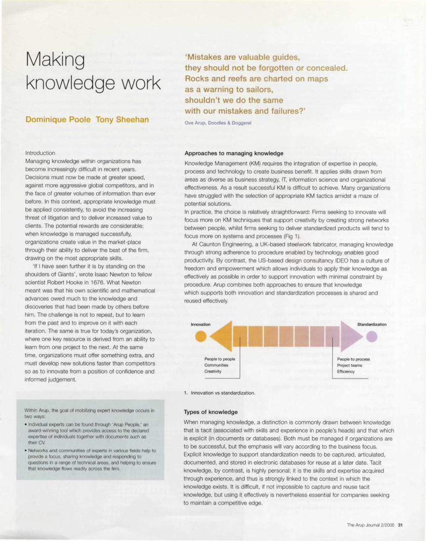
Making knowledge work
Dominique Poole Tony Sheehan
Introduction
Managing knowledge within organizations has
become increasingly difficult in recent years.
Decisions must now be made at greater speed,
against more aggressive global competitors, and in
the face of greater volumes of information than ever
before. In this context, appropriate knowledge must
be applied consistently, to avoid the increasing
threat of litigation and to deliver increased value to
clients. The potential rewards are considerable;
when knowledge is managed successfully,
organizations create value in the market-place through their ability to deliver the best of the firm ,
drawing on the most appropriate skills. ' If I have seen further it is by standing on the
shoulders of Giants' , wrote Isaac Newton to fellow
scientist Robert Hooke in 1676. What Newton
meant was that his own scientific and mathematical
advances owed much to the knowledge and
discoveries that had been made by others before
him. The challenge is not to repeat, but to learn
from the past and to improve on it with each
iteration. The same is true for today's organization,
where one key resource is derived from an ability to learn from one project to the next. At the same
time, organizations must offer something extra, and
must develop new solutions faster than competitors
so as to innovate from a position of confidence and informed judgement.
Within Arup, the goal of mobilizing expert knowledge occurs in two ways:
• Individual experts can be found through 'Arup People,' an award-winning tool which provides access to the declared expertise of individuals together with documents such as their CV.
• Networks and communities of experts in various fields help to provide a focus, sharing knowledge and responding to questions in a range of technical areas, and helping to ensure that knowledge flows readily across the firm.
'Mistakes are valuable guides, they should not be forgotten or concealed. Rocks and reefs are charted on maps as a warning to sailors, shouldn't we do the same with our mistakes and failures?' Ove Arup, Doodles & Doggerel
Approaches to managing knowledge
Knowledge Management (KM) requires the integration of expertise in people,
process and technology to create business benefit. It applies skills drawn from
areas as diverse as business strategy, IT, information science and organizational
effectiveness. As a result successful KM is difficult to achieve. Many organizations
have struggled with the selection of appropriate KM tactics amidst a maze of
potential solutions.
In practice, the choice is relatively straightforward: Firms seeking to innovate will
focus more on KM techniques that support creativity by creating strong networks
between people, whilst firms seeking to deliver standardized products will tend to focus more on systems and processes (Fig 1).
At Caunton Engineering, a UK-based steelwork fabricator, managing knowledge
through strong adherence to procedure enabled by technology enables good
productivity. By contrast, the US-based design consultancy IDEO has a culture of
freedom and empowerment which allows individuals to apply their knowledge as
effectively as possible in order to support innovation with minimal constraint by
procedure. Arup combines both approaches to ensure that knowledge
which supports both innovation and standardization processes is shared and reused effectively.
People to people
Communities
Creativity
1. Innovation vs standardization.
Types of knowledge
I Standardization
People to process
Project teams
Efficiency
When managing knowledge, a distinction is commonly drawn between knowledge
that is tacit (associated with skills and experience in people's heads) and that which
is explicit (in documents or databases). Both must be managed if organizations are
to be successful, but the emphasis will vary according to the business focus. Explicit knowledge to support standardization needs to be captured, articulated,
documented, and stored in electronic databases for reuse at a later date. Tacit
knowledge, by contrast, is highly personal; it is the skills and expertise acquired
through experience, and thus is strongly linked to the context in which the
knowledge exists. It is difficult, if not impossible to capture and reuse tacit
knowledge, but using it effectively is nevertheless essential for companies seeking
to maintain a competitive edge.
The Arup Journal 2/2005 31
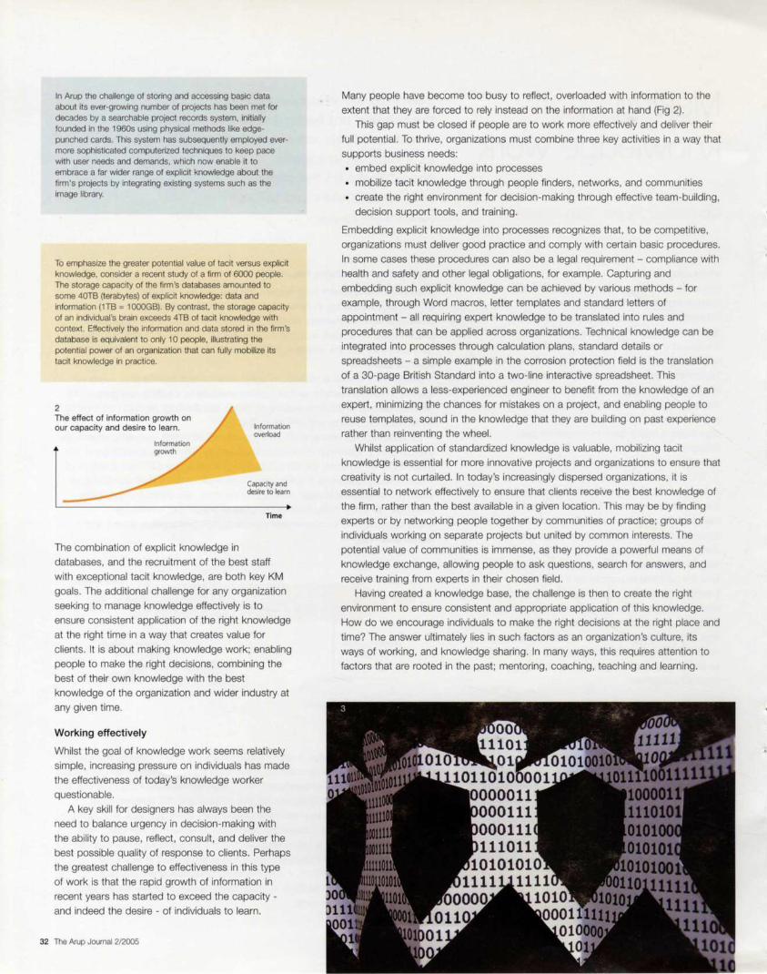
In Arup the challenge of storing and accessing basic data about its ever-growing number of projects has been met for decades by a searchable project records system, initially founded in the 1960s using physical methods like edgepunched cards. This system has subsequently employed evermore sophisticated computerized techniques to keep pace with user needs and demands, which now enable it to embrace a far wider range of explicit knowledge about the firm 's projects by integrating existing systems such as the image library.
To emphasize the greater potential value of tacit versus explicit knowledge, consider a recent study of a firm of 6000 people. The storage capacity of the firm's databases amounted to some 40TB {terabytes) of explicit knowledge: data and information {1TB = 1000GB). By contrast, the storage capacity of an individual's brain exceeds 4TB of tacit knowledge with context . Effectively the information and data stored in the firm 's database is equivalent to only 10 people, illustrating the potential power of an organization that can fully mobilize its tacit knowledge in practice.
2 The effect of information growth on our capacity and desire to learn.
The combination of explicit knowledge in
Information overload
Capacity and desire to learn
Time
databases, and the recruitment of the best staff
with exceptional tacit knowledge, are both key KM
goals. The additional challenge for any organization
seeking to manage knowledge effectively is to
ensure consistent application of the right knowledge
at the right time in a way that creates value for
clients. It is about making knowledge work; enabling
people to make the right decisions, combining the
best of their own knowledge with the best
knowledge of the organization and wider industry at
any given time.
Working effectively
Whilst the goal of knowledge work seems relatively
simple, increasing pressure on individuals has made
the effectiveness of today's knowledge worker
questionable.
A key skill for designers has always been the
need to balance urgency in decision-making with
the ability to pause, reflect, consult, and deliver the
best possible quality of response to clients. Perhaps
the greatest challenge to effectiveness in this type
of work is that the rapid growth of information in
recent years has started to exceed the capacity -
and indeed the desire - of individuals to learn.
32 The Arup Journal 2/2005
Many people have become too busy to reflect, overloaded with information to the
extent that they are forced to rely instead on the information at hand (Fig 2).
This gap must be closed if people are to work more effectively and deliver their
full potential. To thrive, organizations must combine three key activities in a way that
supports business needs:
• embed explicit knowledge into processes
• mobilize tacit knowledge through people finders, networks, and communities
• create the right environment for decision-making through effective team-building,
decision support tools, and training.
Embedding explicit knowledge into processes recognizes that , to be competitive,
organizations must deliver good practice and comply with certain basic procedures.
In some cases these procedures can also be a legal requirement - compliance with
health and safety and other legal obHgations, for example. Capturing and
embedding such explicit knowledge can be achieved by various methods - for
example, through Word macros, letter templates and standard letters of
appointment - all requiring expert knowledge to be translated into rules and
procedures that can be applied across organizations. Technical knowledge can be
integrated into processes through calculation plans, standard details or
spreadsheets - a simple example in the corrosion protection field is the translation
of a 30-page British Standard into a two-line interactive spreadsheet. This
translation allows a less-experienced engineer to benefit from the knowledge of an
expert, minimizing the chances for mistakes on a project, and enabling people to
reuse templates, sound in the knowl!edge that they are building on past experience
rather than reinventing the wheel.
Whilst application of standardized knowledge is valuable, mobilizing tacit
knowledge is essential for more innovative projects and organizations to ensure that
creativity is not curtailed. In today's increasingly dispersed organizations, it is
essential to network effectively to ensure that clients receive the best knowledge of
the firm, rather than the best available in a given location. This may be by finding
experts or by networking people together by communities of practice; groups of
individuals working on separate projects but united by common interests. The
potential value of communities is immense, as they provide a powerful means of
knowledge exchange, allowing people to ask questions, search for answers, and
receive training from experts in their chosen field.
Having created a knowledge base, the challenge is then to create the right
environment to ensure consistent and appropriate application of this knowledge.
How do we encourage individuals to make the right decisions at the right place and
time? The answer ultimately lies in such factors as an organization's culture, its
ways of working , and knowledge sharing. In many ways, this requires attention to
factors that are rooted in the past; mentoring, coaching, teaching and learning.

Individual Organization
• Work/Life • Increased productivity
• Stress management • Agility
• Interesting work • Differentiation
Young engineers working alongside their more experienced peers need the
opportunity to learn by observing, by listening. By doing this, they can acquire
valuable skills, such as managing risk and learning from failure, progressive
problem-solving, self-organization, and interpersonal skills. In the present economic
environment all this is becoming harder to achieve, as increasing workloads and
tighter budgets drive many firms towards ways of optimizing performance,
increasing productivity, and eliminating unnecessary activities. There is a danger
that increasing workloads prevent senior staff from devoting sufficient time to junior
staff. In the short term, this may achieve cost savings and improve efficiency, but
the long-term consequences are alarming - lack of knowledge transfer runs the risk
of repeating mistakes that are well known to experienced staff.
Looking to the future
Effective KM demands that organizations consider:
• how best to recruit , develop, and retain the best people
• how best to combine the skills of individuals
• how to create distinct capabilities in an increasingly competitive business
environment
• how to create value for clients and communicate it effectively.
Recruiting the best people is essential to sustain competitive advantage, yet
remains a particular challenge in the engineering sector where increasingly talented
individuals are being lured into purely commercial and financial firms where better
paid careers may be on offer. In the face of such competition for talent,
organizations must recognize the need to engage individuals, recognize their needs,
and respond to these to ensure people are happy to work for the organization
rather than merely being employed to do so. In recent years, the difficulty in
recruiting good staff has put individuals in a much stronger position. People are
now more likely to hire organizations than vice versa.
People expect to be involved in interesting work, to achieve an appropriate
balance between work and home life, and to be treated fairly in terms of rewards of
recognition. Ultimately a split has emerged between individual and organizational
priorities resulting in the need to strike a balance.
The future will see people as increasingly key to effective KM and business
performance. Organizational pressures to achieve increased productivity, greater
agility, and competitiveness in the marketplace can only be achieved if knowledge is
managed and applied in ways that complement the needs of the individual. The
knowledge challenge is to successfully achieve this balance between organizational
needs and individual motivations (Fig 3).
Organizations must , therefore, consider how to get the best from the people
they recruit , addressing such diverse issues as culture, motivation, and the
workplace itself. The physical space in which people work offers opportunities to
encourage creative thought and knowledge
exchange. The metaphor of the mediaeval
monastery is a good example of customized space,
providing a variety of environments for different
knowledge needs. Cloisters were spaces geared to
accidental contact, and certain conventions were
adopted in their use. For example, monks would
walk in pairs to discuss issues, but an individual
walking alone holding an open breviary was
understood by others to be meditating. Similarly the
UK Government Communications Headquarters
(GCHQ) building in Cheltenham, England, has been
designed to promote the exchange of knowledge to
aid the global 'war against terrorism ' . The threats of
terrorism require different ways of working , with a
new emphasis on knowledge sharing and the ability
to create serendipitous links and to form
multidisciplinary quick-response teams. Open-plan
offices, hot desking, spaces with comfortable sofas,
artwork, and statues have all been incorporated to
stimulate creative thinking and encourage open talk.
Conclusion
Successful organizations of the future will make
knowledge work for their clients better than ever
before. Clients will come to organizations
demanding access to the best experience rather
than merely the best available. They will expect
people to deliver current good practice through
appropriate processes, supplementing this with an
ethos of improvement and innovation. Client
expectations will continue to rise, and organizations
that fail to match these standards will not survive.
To thrive in the future, organizations must
manage knowledge strategically, developing an
ability to recognize and exploit new market needs
through effective combinations of skills and
interests. Arup, for example, has already applied
expertise developed in the germ warfare sector to
address the spread of disease in hospitals, and
finite element analysis developed in the building
sector to car design. The key challenge will be
responsiveness , and the ability to combine existing
skills and interests from unexpected sources in
ways that create client value . Knowledge will still
have to be managed - not just to solve today's
business problems, but to ensure that organizations
continue to generate new capabilities for the future.
Credits
Tony Sheehan is Group Knowledge Manager for Arup. Dominique Poole is Knowledge Project Manager at Arup. Illustrat ions: 1, 2 Nigel Whale; 3 Ng Choon Boon; 4 Philippe Pellerin
The Arup Journal 2/2005 33
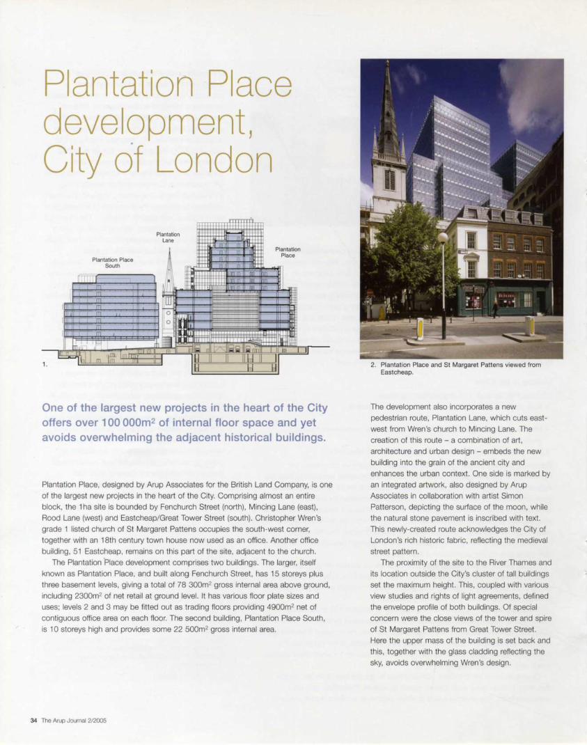
Plantation Place development, City of London
1.
Plantation Place South
Plantation Lane
Id
Plantation Place
One of the largest new projects in the heart of the City offers over 100 ooom2 of internal floor space and yet avoids overwhelming the adjacent historical buildings.
Plantation Place, designed by Arup Associates for the British Land Company, is one
of the largest new projects in the heart of the City. Comprising almost an entire
block, the 1 ha site is bounded by Fenchurch Street (north), Mincing Lane (east) ,
Rood Lane (west) and Eastcheap/Great Tower Street (south). Christopher Wren's
grade 1 listed church of St Margaret Pattens occupies the south-west corner,
together with an 18th century town house now used as an office. Another office
building, 51 Eastcheap, remains on this part of the site, adjacent to the church.
The Plantation Place development comprises two buildings. The larger, itself
known as Plantation Place, and built along Fenchurch Street, has 15 storeys plus
three basement levels, giving a total of 78 300m2 gross internal area above ground,
including 2300m2 of net retail at ground level. It has various floor plate sizes and
uses; levels 2 and 3 may be fitted out as trading floors providing 490Qm2 net of
contiguous office area on each floor. The second building, Plantation Place South,
is 10 storeys high and provides some 22 500m2 gross internal area.
34 The Arup Journal 2/2005
2. Plantation Place and St Margaret Pattens viewed from Eastcheap.
The development also incorporates a new
pedestrian route, Plantation Lane, which cuts east
west from Wren's church to Mincing Lane. The
creation of this route - a combination of art,
architecture and urban design - embeds the new
building into the grain of the ancient city and
enhances the urban context. One side is marked by
an integrated artwork, also designed by Arup
Associates in collaboration with artist Simon
Patterson, depicting the surface of the moon, while
the natural stone pavement is inscribed with text.
This newly-created route acknowledges the City of
London 's rich historic fabric, reflecting the medieval
street pattern.
The proximity of the site to the River Thames and
its location outside the City 's cluster of tall buildings
set the maximum height. This, coupled with various
view studies and rights of light agreements, defined
the envelope profile of both buildings. Of special
concern were the close views of the tower and spire
of St Margaret Pattens from Great Tower Street.
Here the upper mass of the building is set back and
this, together with the glass cladding reflecting the
sky, avoids overwhelming Wren's design.

Plantation Place Mick Brundle
The overall form
The overall architectural form developed in response
to the site 's complex constraints, but was also
conceived as a positive contribution to the civic
realm in this part of the City. Through a series of
adjustments in plan, angled cuts and set-backs, the
building transforms itself from the street-defining
base and reinvents and fragments its form as it
ascends, culminating in a pair of glass cube forms
in the skyline. The resulting composition , while
accommodating the very considerable programme,
disseminates its volume into its immediate
surroundings. It is seen from the surrounding streets
not as a single object but a series of vignettes.
The stratification of the building vertically, into
street architecture below and deep setback terraces
of smaller office floors above, suggests two fa<;ade
types and provides the opportunity for opening
windows for fresh air and garden terraces at the
upper levels.
3. Plantation Place building anatomy.
4. The Plantation Place atrium.
The internal anatomy
The Fenchurch Street entrance is defined by a change of alignment of the existing
street pattern, which together with the recycled and critically-acclaimed Marketing
Suite Beacon ', establishes the building 's presence when viewed from the
Gracechurch and Lombard Street part of the City.
A pair of Jura limestone-clad towers framing the glass entrance screen provide a
cordon sanitaire between the office entrance and retail areas, which occupy most of
the ground plan. A double-height entrance hall leads via a wide Jura limestone
staircase to a 43m high central atrium. A dematerialized glass bridge connects
together the first floor levels and provides a dramatic threshold before entering the
atrium interior.
The offices are on either side of the atrium, with two cores to each side
containing lifts that serve all floors and escalators at the rear to the lower levels. The
cores also contain services risers. staircases and washrooms, and allow easy
access to all parts, particularly the larger floors, so walking distances are minimized.
In section the atrium is stepped towards the south on the upper levels, bringing
daylight and sunlight deep into the lower level. This configuration provides a more
usable contiguous floor plate arrangement at the upper levels; the atrium forms the
centre of a U-shaped office floor at levels 7 to 9 and is bridged over completely at
levels 10 to 14.
Service access for both buildings is from a vehicle entrance in Rood Lane. A
two-way ramp provides access to an upper basement level with head clearance for
large trucks and refuse vehicles. There is parking for 46 cars at this level. Two
further basement levels, the middle and lower basements, contain plantrooms and
tenant storage. An additional plant room is provided at level 15.
The Arup Journal 212005 35
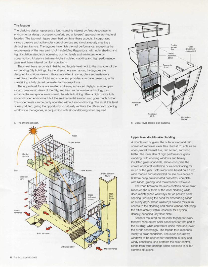
The fa9ades
The cladding design represents a long-standing interest by Arup Associates in
environmental design, occupant comfort, and a 'layered' approach to architectural
far;:ades. The two main types described combine these aspects, incorporating
various passive and active solar control devices and simultaneously creating a
distinct architecture. The far;:ades have high thermal performance, exceeding the
requirements of the new part 'L' of the Building Regulations , with solar shading and
high insulation standards increasing comfort levels and minimizing energy
consumption. A balance between highly insulated cladding and high performance
glass maintains internal comfort conditions.
The street base responds in height and fa9ade treatment to the character of the
surrounding City buildings. As the streets here are narrow, the fa9ades are
designed for oblique viewing . Heavy modelling in stone, glass and metalwork
maximizes the effects of light and shade and provides an urbane presence, while
maintaining a fully glazed perimeter to the deep floors.
The upper-level floors are smaller, and enjoy enhanced daylight, a more open
aspect , panoramic views of the City, and fresh air. Innovative technology can
enhance the workplace environment; the whole building offers a high quality, fully
air-conditioned environment but the environmental solution also goes much further.
The upper levels can be partly operated without air-conditioning. The air at this level
is less polluted, giving the opportunity to naturally ventilate the offices from opening
windows in the fa9ades, in conjunction with air-conditioning when required.
5. The atrium concept.
East
core
East lift cores
36 The Arup Journal 2/2005
West
Entrance lobby
Glass entrance
Stone services
High level fresh
~ ' ···-. . . . . . . . . .
Aluminium grill
I
Aluminium CHS
Double glazed unit
Glazed spandrel • panel
6. Upper level double-skin cladding.
Upper level double-skin cladding
Cast aluminium component
Aluminium flat bar
A double skin of glass, the outer a wind and rain
screen of frameless clear tiles tilted at 3°, acts as an
open-jointed thermal flue, rain screen, and wind
baffle. The inner skin of high performance glass
cladding, with opening windows and heavily
insulated glass spandrels, allows occupiers the
choice of natural ventilation or air-conditioning for
much of the year. Both skins were based on a 1 .5m
wide module and assembled on site as a series of
600mm deep prefabricated cassettes , complete
with blinds, glazing, and maintenance walkways.
The zone between the skins contains active solar
blinds on the outside of the inner cladding while
deep maintenance walkways act as passive solar
shading, reducing the need for descending blinds
on sunny days. These walkways provide maximum
access to the cladding and blinds without disturbing
the office activity within , essential for a typical
densely-occupied City floor plate.
Sensors mounted on the inner far;:ade for every
tenancy zone detect solar conditions for that part of
the building, while controllers inside raise and lower
the blinds accordingly. The far;:ade thus responds
locally to solar conditions. The outer skin allows
windows to be opened for ventilation in rainy and
windy conditions, and protects the solar control
blinds from wind damage when deployed in all but
extreme situations.

7. The atrium at podium level.
The architectural expression of the upper building massing provides a distinctive
silhouette on the City skyline. This, in combination with the layered fa9ade of the
reflective glass tiles, active solar blinds and metal filigree, enhances the skyline
presence and positively locates the development in the City context.
Lower level cladding
As the lower floors, with their deep-plan offices, are large and close to noise and
pollution from vehicles, natural ventilation is not appropriate. Instead a curtain of
linked Jura limestone fins on a 3m horizontal module 600mm deep orthogonal to
the fa9ade replaces the outer glass screen of the upper level cladding.
The reason for this is part contextual and part environmental. The building
replaced a collection of stone buildings including the neoclassical commodity
trading building Plantation House. Although none were of great architectural merit, it
was a condition of planning that the new building should present itself to the City as
one clad largely in stone.
The stone fins form a three-dimensional curtain which, together with horizontal
fixed metal louvres and heavily insulated glass spandrels, provides sun shading to
the office floors and a suitable architectural composition to the urban setting.
Though the fa9ades are fully glazed, the mostly oblique views from the narrow
streets show the fins closing up to conceal the glass and forming a more solid
elevational expression. This also benefits occupiers, as the fin screen and glass
insulated spandrel provide an element of privacy in the manner of an Ottoman
jalousie, whilst the fins themselves, similar to a conventional stone reveal , act as
light reflectors into the interior.
To maximize the street retail presence around most of the building, the stone
curtain stops at first floor level , the ground plane with the exception of the main and
service entrances being expressed as metal clad columns with glass shop windows
and entrance screens between.
Stainless steel fabricated clamp bracket
Jura limestone
Aluminium brlse solell
8. The lower level cladding.
Smoke clearing vent
Double glazed unit
Lateral restra int
Stainless steel rod
The Arup Journal 2/2005 37

The atrium cladding
The skin defining the atrium's spatial envelope
continues the theme of manipulating light.
Resonating with the principle of the external curtain
of stone fins, the atrium cladding is designed as a
series of projecting vertical glass fins on a 750mm
horizontal module within the atrium supporting the
glass perimeter cladding. The layer of fins forms a
screen between the occupiers of the office floors,
allowing some privacy and visually defining the
seven-storey atrium as a large 'room'.
The fins are fabricated from shattered toughened
glass, encapsulated between two sheets of low iron
glass. They transform ambient light from various
natural and artificial sources into coruscating light,
an optical device similar to a cut glass chandelier.
Stainless steel 'shoes' spanning between floor
levels continuously support the fins, which are
edge-bonded to the atrium glass cladding with
structural silicone, providing stiffness and reduced
glass thickness to the whole cladding assembly.
With the varying external light entering from the
southern sky, a dramatic and ever-changing interior
is created at the heart of the building.
9. The atrium cladding.
~ . ' . .
Fritted glass spandrel
~
Slab fixing bracket Projector
light • less steel
38 The Arup Journal 2/2005
Encapsulated crackled glass fin
support shoes
Atrium glass bridge
·-The client required the first floor plates bisected by the atrium to be linked by a bridge, which Arup Associates desired to be as light and ephemeral as possible. It was thus built substantially of glass. the glazed floor providing both visual lightness and significant lateral stability. The spanning elements are integrated with the floor structure above and are not visible in the finished enclosure.
A ladder chassis of stainless steel flats is suspended by stainless steel rods attached to the floor beams above. The interaction between the suspending and suspended structures was checked for overall dynamic performance. Laminated glass floor panels were laid laterally with a continuous silicone seal into the ladder structure using an EPDM separating strip. This ensured that they contribute to the lateral stiffness of the frame over the full 18m span.
The critical structural element is the coupling piece that connects the ladder chassis to the suspension rods. This element supports the glass wall panels via cantilevered brackets and resists the lateral balustrade and kick rail loads.
11 . The atrium cladding: corner detail.
10. The glass bridge interior.
The laminated glass wall panels are supported via neoprene pads on these brackets and restrained laterally at their corners using EPDM shims to avoid glass-to-metal contact. There is an allowance for vertical alignment at either end of the tie rods, and the structure is restrained longitudinally by connection to the floor structure at one end only.
The ladder chassis came to site as one piece and was slid into position on a moving platform. The rods were then attached and adjusted for alignment and subsequently for load equalization prior to glass installation.

12. Level 10 garden terrace.
13. Level 10 garden concept.
The garden terraces
The step between the upper and lower atrium chambers occurs at level 7,
corresponding to a garden terrace level. A south-facing wintergarden on the floor of
the upper atrium has direct access to the outside garden terrace. As the building
steps back, other terraces are formed, culminating in the main large garden terrace
at level 10 with direct access for occupiers from the two main lift cores through the
upper fac;:ades.
This garden was designed as a series of arboreal chambers of soft and hard
landscape linked to a main pedestrian route around the building perimeter, giving
occupiers a sheltered, private and attractive amenity. A maintenance railway for cleaning cranes occupies the inner part of the terrace. By designing the rails flush
with the hard paving and providing parking alongside the two cores for the cranes,
the sense of 'garden ' is maintained when viewed from the level 10 occupied floors .
The terraces are linked to the south by a vertiginous bridge over the glass roof of
the atrium, which allows a 360° promenade around the building with exceptional
views of the Thames and the City. The gardens have happily provided a habitat for
insect and bird life, which surprisingly proliferate at this level in the City, when given
the opportunity.
'Time and Tide' artwork: Plantation Lane Lee Hosking Declan O'Carroll
Artistic vision
This close collaboration between the artist Simon
Patterson and Arup Associates, funded by
developers British Land, is part of an initiative to
'put something back' into the City of London. The
artwork is integral to Arup Associates ' public realm
concept, and crucially was developed hand-in-hand
with the design of the new public space, rather than
commissioned separately.
The work, 41 m long and 6m high, was
conceived to suggest constancy during times of
change, and Patterson also devised a collection of
texts to be inset into the stone of the new
pavement. The text sits along a series of great arcs,
which appear to slide underneath the mass of the
new buildings. Each curve of text represents a
different timeline, beginning with Roman gods and
goddesses, and moving through miscellaneous
information such as the City Guilds, the Livery
Companies and the different membership degrees
of the Freemasons. 'The visitor can either follow a
particular timeline, or choose a more random but
equally fascinating reading by cross-referencing the
different timelines', says art critic Andrea Schlieker2.
14. Plantation Lane looking west.
The Arup Journal 2/2005 39

15. The illuminated Moon screen: orthogonal projections.
Patterson settled on an image of the Moon to
counterpoint the difficult, rapid and often violent
changes that have imposed themselves on the
people of London across the ages. Londinium's
Roman inhabitants used the Moon's cycles to
underpin their calendar, and today it is a symbol of scientific progress.
'As the same hemisphere of the Moon always
faces the Earth, people will have witnessed the identical sight in the night sky throughout history,
from the first settlers in Londinium to today's City
bankers', says Schlieker. 'The image of the Moon is
particularly rich in associations, within the field of
pagan and sacred symbolism, as ubiquitous symbol
in legends and myths, as locus for romantic
yearning, but also as incarnation of scientific
progress in the 20th century. Patterson wants to
allude to all of these different concepts with this
mysterious and emblematic image.'
Engineering
The screen foundations were cast well in advance
of the final geometry being resolved . An oversized
1200 x 650mm deep supporting reinforced
concrete beam was necessary to give flexibility for
the artistic vision, leaving room for some minor
deviation in the plan geometry and size.
In its final resolution, the curved geometry of the
screen lines the middle of Plantation Lane's south
edge, set out easl/west using a 2.4m x 750mm
module along a radial geometry. The steel frame of
the giant light box comprises a series of structural
UC sections 6m tall at 2.4m centres, positioned at
its rear and attached and levelled to the concrete
below by baseplates, with post-drilled bolts.
To maintain the clarity and simplicity of the
design vision, the support system had to minimize
shadowing inside the screen when illuminated and
be positioned far enough behind the artwork to not
show through immediately behind the glass. As the
structure was never designed to be visible, the
lightness of the members was entirely a
consequence of the lighting performance.
A simple system of horizontal arms bolted to the
40 The Arup Journal 2/2005
column sections supports the glass screen, and provides the first level of vertical
adjustment. These arms are in turn supported by threaded diagonal tension rods that carry the glass dead load, and also provide further adjustment. Cruciform
stainless steel clamping brackets with no visible external fixings are fixed into
threaded ends of these arms. This allows horizontal adjustment to maintain the
screen curvature. The glass itself is 1.5m x 2.4m modules in landscape orientation.
The glass and artwork were prototyped in a series of 1 m square samples,
inspected in a purpose-built lightbox. In all, 24 samples were examined before the
final glass build-up and printing technique was chosen. Multiple procedures were involved, including several different methods of ink-jet printing onto both glass and
laminate material.
The final glass build-up is a laminate of two sheets of 12mm low iron glass with
an anti-reflective acid-etched finish to the outer visible surface. This was to avoid
reflections in the surface when viewed obliquely - an important consideration, as
the approach is always at an angle along the narrow Lane. The rear of the inner
glass pane is covered with a 100% ceramic white frit, which diffuses the light
source and eliminates views inside the screen through the 'white' areas of the
monochromatic image. The final artwork was produced photographically and
laminated with a clear pvb interlayer to complete the sandwich. The completed
image can be viewed in daylight as well as by artificial light.
The glass panel installation is finished with a clear silicone joint to reduce particle
migration inside the screen, and to minimize maintenance needs. The back of the
screen is powder-coated aluminium panels, attached by 'hook-on' cladding
technology, which can be removed for maintenance. The joints between them are
sealed with gaskets to eliminate light leakage, which would have been a distraction to the offices behind the screen.
Color Kinetics Co/orB/ast LED fittings supply the illumination in rows at the top
and bottom of the light box at 800mm centres, fed from two separate control
boxes at each end of the screen. The software-controlled lighting enables a
constantly changing colour rendering behind the glass. The top row of light fittings
is accessed externally via a discreet glazed hinged lid complete with gas struts to
allow safe maintenance, and restraining clasps to avoid wind uplift.
16. The Moon screen: colour variations.

Plantation Place South Graham Goymour
Overall form
As a discreet element in the development, Plantation Place South adheres to many
of the design principles developed for the site as a whole, while establishing a clear
identity for itself on the southeast corner. It is designed around a central core, with
principal south and east-facing frontages onto Great Tower Street and Mincing
Lane. It connects at basement level to share servicing facilities with the overall
development.
17. Plantation Place South from the junction of Mincing Lane and Great Tower Street.
The building's massing responds to its prominent
corner location with set-backs at upper levels to
create sympathetic relationships with adjoining
buildings and to reinforce the sense of architectural
order in the fac;:ade, arranged in three tiers. At
ground level a double-height colonnade supports
the main body of five floors, whose plates extend to
the site boundaries to reinforce the surrounding
urban pattern and correspond with adjoining
parapets and setbacks. Above this, three upper
levels are set back in two stages to create terraces
and to break down the building's massing.
Entry sequence and integration into
urban context
To further augment the public realm on the site, the
design of Plantation Place South incorporates its
own route at ground level linking Great Tower Street
to the new pedestrian route, Plantation Lane. This
internal link is designed as part of the building's
entry sequence, which takes visitors through an
external arcaded space into a large, double-height
entrance hall. This leads directly to the ground level
lift lobby and is extended northwards, via a gradual
incline, to Plantation Place. The entire sequence of
spaces is lined on one side by the broad sweep of
a curved chain mail screen that finally connects to
the external illuminated screen in Plantation Lane.
The intention behind this internal route is to
encourage cross-movement though the entire site
to the benefit of the greater development and the
building itself, which is served by a secondary
entrance from Plantation Lane.
Fac;:ade design: loadbearing stone
With its proximity to the conservation area, the
Wren church and indeed, Plantation Place, the
building's architectural identity appropriately relies to
a large extent on the use of natural stone. At the
same time, compliance with Building Regulations
suggested a very deliberate approach to limiting the
amount of glass. These considerations led to the
evolution of a fac;:ade where stone transcends its
common use as a cladding material to one in which
structural, architectural, and environmental
concerns could find a common expression.
The fac;:ade design for Plantation Place South
also evolved from patterns established in the first
phase of the project, particularly the use of
suspended stone fins. A Jurassic limestone from
Bavaria was chosen for its excellent weathering
properties and high compressive strength, and in
Plantation Place South these properties are utilized
in a loadbearing construction.
The Arup Journal 212005 41
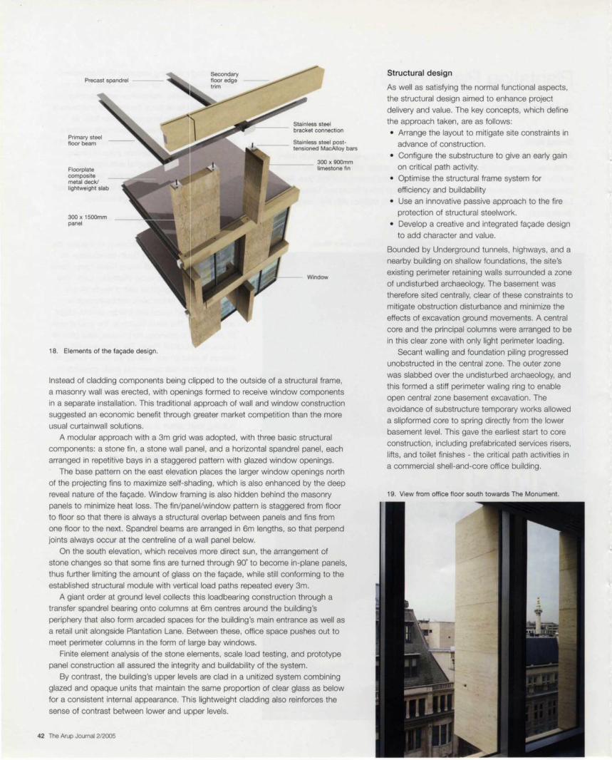
Precast spandrel
Primary steel floor beam
Floorplate composite metal deck/ lightweight slab
300 x 1500mm panel
18. Elements of the fa<,ade design.
Stainless steel bracket connection
Stainless steel posttensioned MacAlloy bars
300 x 900mm limestone fin
Window
Instead of cladding components being clipped to the outside of a structural frame,
a masonry wall was erected , with openings formed to receive window components
in a separate installation. This traditional approach of wall and window construction
suggested an economic benefit through greater market competition than the more
usual curtainwall solutions.
A modular approach with a 3m grid was adopted, with three basic structural
components: a stone fin , a stone wall panel , and a horizontal spandrel panel, each
arranged in repetitive bays in a staggere1d pattern with glazed window openings.
The base pattern on the east elevation places the larger window openings north
of the projecting fins to maximize self· s~1ading, which is also enhanced by the deep
reveal nature of the fa9ade. Window framing is also hidden behind the masonry
panels to minimize heat loss. The fin/panel/window pattern is staggered from floor
to floor so that there is always a structural overlap between panels and fins from
one floor to the next. Spandrel beams are arranged in 6m lengths, so that perpend
joints always occur at the centreline of a wall panel below.
On the south elevation, which receivEis more direct sun, the arrangement of
stone changes so that some fins are turned through 90° to become in-plane panels,
thus further limiting the amount of glass on the fa9ade, while still conforming to the
established structural module with vertical load paths repeated every 3m.
A giant order at ground level collects this loadbearing construction through a
transfer spandrel bearing onto columns at 6m centres around the building's
periphery that also form arcaded spaces for the building's main entrance as well as
a retail unit alongside Plantation Lane. Between these, office space pushes out to
meet perimeter columns in the form of large bay windows.
Finite element analysis of the stone elements. scale load testing , and prototype
panel construction all assured the integrity and buildability of the system.
By contrast , the building 's upper leve·ls are clad in a unitized system combining
glazed and opaque units that maintain the same proportion of clear glass as below
for a consistent internal appearance. This lightweight cladding also reinforces the
sense of contrast between lower and upper levels.
42 The Arup Journal 212005
Structural design
As well as satisfying the normal functional aspects,
the structural design aimed to enhance project
delivery and value. The key concepts, which define
the approach taken, are as follows:
• Arrange the layout to mitigate site constraints in
advance of construction.
• Configure the substructure to give an early gain
on critical path activity.
• Optimise the structural frame system for
efficiency and buildability
• Use an innovative passive approach to the fire
protection of structural steelwork.
• Develop a creative and integrated fa9ade design to add character and value.
Bounded by Underground tunnels, highways, and a
nearby building on shallow foundations, the site 's
existing perimeter retaining walls surrounded a zone
of undisturbed archaeology. The basement was
therefore sited centrally, clear of these constraints to
mitigate obstruction disturbance and minimize the
effects of excavation ground movements. A central
core and the principal columns were arranged to be
in this clear zone with only light perimeter loading.
Secant walling and foundation piling progressed
unobstructed in the central zone. The outer zone
was slabbed over the undisturbed archaeology, and
this formed a stiff perimeter waling ring to enable
open central zone basement excavation. The
avoidance of substructure temporary works allowed
a slipformed core to spring directly from the lower
basement level. This gave the earliest start to core
construction , including prefabricated services risers,
lifts, and toilet finishes - the critical path activities in
a commercial shell -and-core office building.
19. View from office floor south towards The Monument.
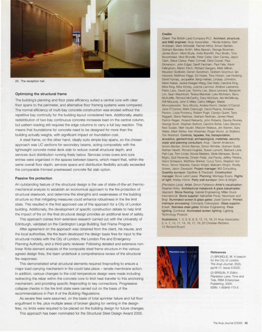
20. The reception hall.
Optimizing the structural frame
The building's planning and floor plate efficiency suited a central core with clear floor spans to the perimeter, and alternative floor framing systems were compared.
The normal efficiency of multi-bay concrete construction was eroded without the
repetitive bay continuity for the building layout considered here. Additionally, elastic
redistribution of two-bay continuous concrete increases load on the central column.
but pattern loading still requires the edge columns to carry a full bay reaction. This
means that foundations for concrete need to be designed for more than the
building actually weighs, with significant impact on foundation cost.
A steel frame, on the other hand, ideally suits simple bay spans, so the chosen
approach was UC sections for secondary beams, acting compositely with the
lightweight concrete metal deck slab to reduce overall structural depth, and
services duct distribution running freely below. Services cross-overs and core
entries were organized in the spaces between beams, which meant that, within the
same overall floor depth, services space and distribution flexibility actually exceeded
the comparable thinnest prestressed concrete flat slab option.
Passive fire protection
An outstanding feature of the structural design is the use of state-of-the-art thermo
mechanical analysis to establish an economical approach to the fire protection of
structural steelwork, and determine the strengths and weaknesses of the building
structure so that mitigating measures could enhance robustness in the fire limit
state. This resulted in the first approved use of this approach for a City of London
building. Additionally, the development of specific construction details to help limit
the impact of fire on the final structural design provides an additional level of safety.
This approach comes from extensive research carried out with the University of
Edinburgh, validated on the Cardington Large Building Test Frame Program.
After agreement on the approach was obtained from the client. his insurer, and
the local authorities, the fire team developed the design basis fires for input to the
structural models with the City of London. the London Fire and Emergency
Planning Authority, and a third-party reviewer. Following detailed and extensive nonlinear finite element analysis of the composite steel frame structure in the various
agreed design fires, the team undertook a comprehensive review of the structural
fire responses.
This demonstrated what structural elements required fireproofing to ensure a
major load-carrying mechanism in fire could take place - tensile membrane action. In addition, various changes to the cold temperature design were made including
redirecting the rebar within the concrete core to limit heat transfer to this anchoring
mechanism, and providing specific fireproofing to key connections. Progressive
collapse checks in the fire limit state were carried out on the basis of the
recommendations in Part A of the Building Regulations.
As severe fires were assumed, on the basis of total sprinkler failure and full floor
engulfment in fire, plus multiple areas of broken glazing for venting in the design
fires, no limits were required to be placed on the building design for future changes.
This approach has been nominated for the Structural Steel Design Award 2005.
Credits
Client : The British Land Company PLC Architect , structural , and M&E engineer: Arup Associates - Nicola Adams, Gert Andresen, Mark Arkinstall, Rachel Atthis, Simon Barden, Graham Bardsley-Smith, Mike Beaven, George Bowman, James Bown, Mark Boyle, Anita Bramlitt, Paul Brislin , Tony Broomhead, Mick Brundle, Peter Caller. Glen Carney, Jason Clark, Steve Clarke, Peter Connell, Chris Cowell , Paul Dickenson, John Edgar, Geoff Farnham, Paul Felix, Kevin Fellingham, Martin Finch, Richard Gargaro, Matt Gilliver, Maureen Godbold, Darren Goodman, Graham Goymour, Ian Hazzard, Matthew Higgs. Ed Hoare, Tony Hoban, Lee Hosking, David Hymas, Jacqueline Jiang-Haines. Lindsay Johnston. Mario Kaiser, Jackie Keegan-Warg, Dan Kelly, Caroline King. Mike King , Mike Kinney, Joanne Larmour, Andrew Lawrence, Pablo Lazo, David Lee, Tommy Lee, Steve Leonard, Benjamin Lim. Sean Macintosh, Teresa Marshall. Luke McAdam, Barry McAulliffe, Richard McCarthy, Daryl McClure, Abi McGillivray, Will McLardy, John E Miles, Cathy Milligan, Marek Monczakowski , Terry Moody, Andrea Nanni, Declan O'Carroll, Jane O'Connor, Mark Oxbrough, David Pearce, Annelise Penton, Lizzie Pomeroy, Robert Pugh, Carolyn Quinn, Terry Raggett , Steve Ratchye, Graham Redman, James Reed, Patrick Regan, Roland Reinardy, John Roberts, Davina Rooney, George Scott , Stephen Setford, Caroline Sohie, Lexy Stevens, Nick Suslak, Matt Vaudin , Malcom Wallace, Jim Warren, Gary Webb, Mark Winter, Ken Wiseman, Roger Wood, Jo Wolbers, Tim Worsfold Controls, fa~ades, fire, transportation, acoustics, geotechnical , archaeolog ical, materials , security, water and planning consultant: Arup - Darren Anderson, Simon Barden, Simon Barnes, Simon Brimble, Graham Dodd, Nathan Hewitt, Richard Hughes, Susan Lamont, Barbara Lane, Pein Lee, Tom Linder. Nicola Masters, Silole Menezes, Bruno Miglio, Zedi Nyirenda, Dinesh Patel , Joe Pavely, Jeffrey Pereira, Haico Schepers, Matthew Shinkel, Cyrus Toms, Stephan Von Roon, Simon Webster, Darren Wright , Malcolm Wright, Roddy Wykes, Jason Zawadzki Project manager: M3 Consulting Quantity surveyor: Gardiner & Theobald Construction manager: Bovis Lend Lease Planning: Montagu Evans Rights of light: Anstey Horne Party wall surveyor: Dron & Wright
[Plantation Lane] Art ist : Simon Patterson Artist 's visualization: Stephen Kirby Architectural metalwork & glass balustrades: Glazzard Stone flooring : Gabriel Engineering; Miller Druck International Stone supplier: ltalmarble Pocai , Neumeyer and Brigl Illuminated screen & glass gates: Josef Gartner Printed interlayer processing: Concepta Colourglass Glass supplier: Eckelt Stainless steel gates: Kimber Engineering Floor lighting: Zumtobel Illuminated screen lighting: Lighting Technology Projects
Illustrations: 1, 3, 5, 6, 8, 9, 13, 15, 18, 21 Arup Associates; 2, 4, 7, 10, 11 , 14, 16, 17, 19, 20 Christian Richters; 1 2 Richard Bryant
References
(1) BRUNDLE, M. A beacon for the City o f London. The Arup Journal, 35(2), pp1 6-17, issue 2/2000.
(2) BRISLIN , P, Editor. Plantation Lane: Time and Tide. RIBA Enterprises Publishing, 2005. ISBN: 1-85946-173-5
The Arup Journal 2/2005 43
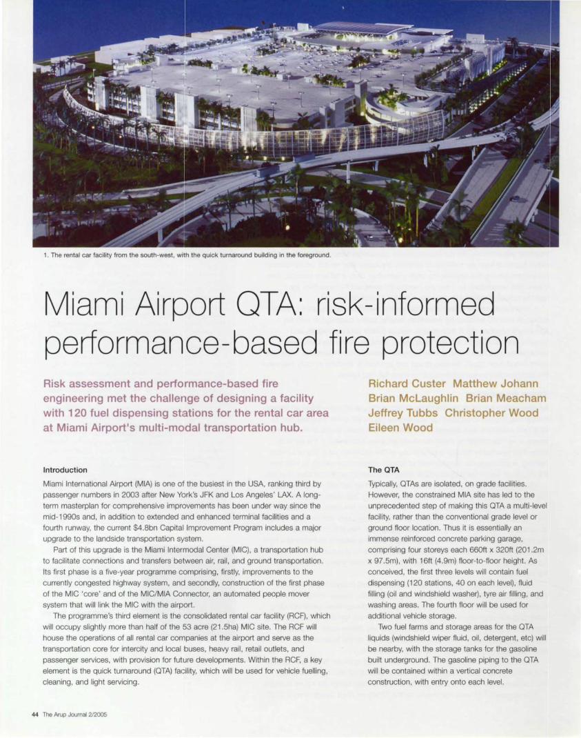
1. The rental car facility from the south-west, with the quick turnaround building in the foreground.
Miami Airport OTA: risk-informed performance-based fire protection Risk assessment and performance-based fire engineering met the challenge of designing a facility with 120 fuel dispensing stations for the rental car area at Miami Airport's multi-modal transportation hub.
Introduction
Miami International Airport (MIA) is one of the busiest in the USA, ranking third by
passenger numbers in 2003 after New York's JFK and Los Angeles' LAX. A long
term masterplan for comprehensive improvements has been under way since the
mid-1990s and, in addition to extended and enhanced terminal facilities and a
fourth runway, the current $4.8bn Capital Improvement Program includes a major
upgrade to the landside transportation system.
Part of this upgrade is the Miami lntermodal Center (MIC), a transportation hub
to facilitate connections and transfers between air, rail, and ground transportation.
Its first phase is a five-year programme comprising, firstly, improvements to the
currently congested highway system, and secondly, construction of the first phase
of the MIC 'core' and of the MIC/MIA Connector, an automated people mover
system that will link the MIC with the airport.
The programme's third element is the consolidated rental car facility (RCF), which
will occupy slightly more than half of the 53 acre (21.5ha) MIC site. The RCF will
house the operations of all rental car companies at the airport and serve as the
transportation core for intercity and local buses, heavy rail, retail outlets, and
passenger services, with provision for future developments. Within the RCF, a key
element is the quick turnaround (QTA) facility, which will be used for vehicle fuelling,
cleaning, and light servicing.
44 The Arup Journal 2/2005
Richard Custer Matthew Johann Brian McLaughlin Brian Meacham Jeffrey Tubbs Christopher Wood Eileen Wood
The OTA
Typically, QTAs are isolated, on grade facilities.
However, the constrained MIA site has led to the
unprecedented step of making this QTA a multi-level
facility, rather than the conventional grade level or
ground floor location. Thus it is essentially an
immense reinforced concrete parking garage,
comprising four storeys each 660ft x 320ft (201 .2m
x 97.5m), with 16ft (4.9m) floor-to-floor height. As
conceived, the first three levels will contain fuel
dispensing (120 stations, 40 on each level), fluid
filling (oil and windshield washer), tyre air filling, and
washing areas. The fourth floor will be used for
additional vehicle storage.
Two fuel farms and storage areas for the QTA
liquids (windshield wiper fluid, oil, detergent, etc) will
be nearby, with the storage tanks for the gasoline
built underground. The gasoline piping to the QTA
will be contained within a vertical concrete
construction, with entry onto each level.
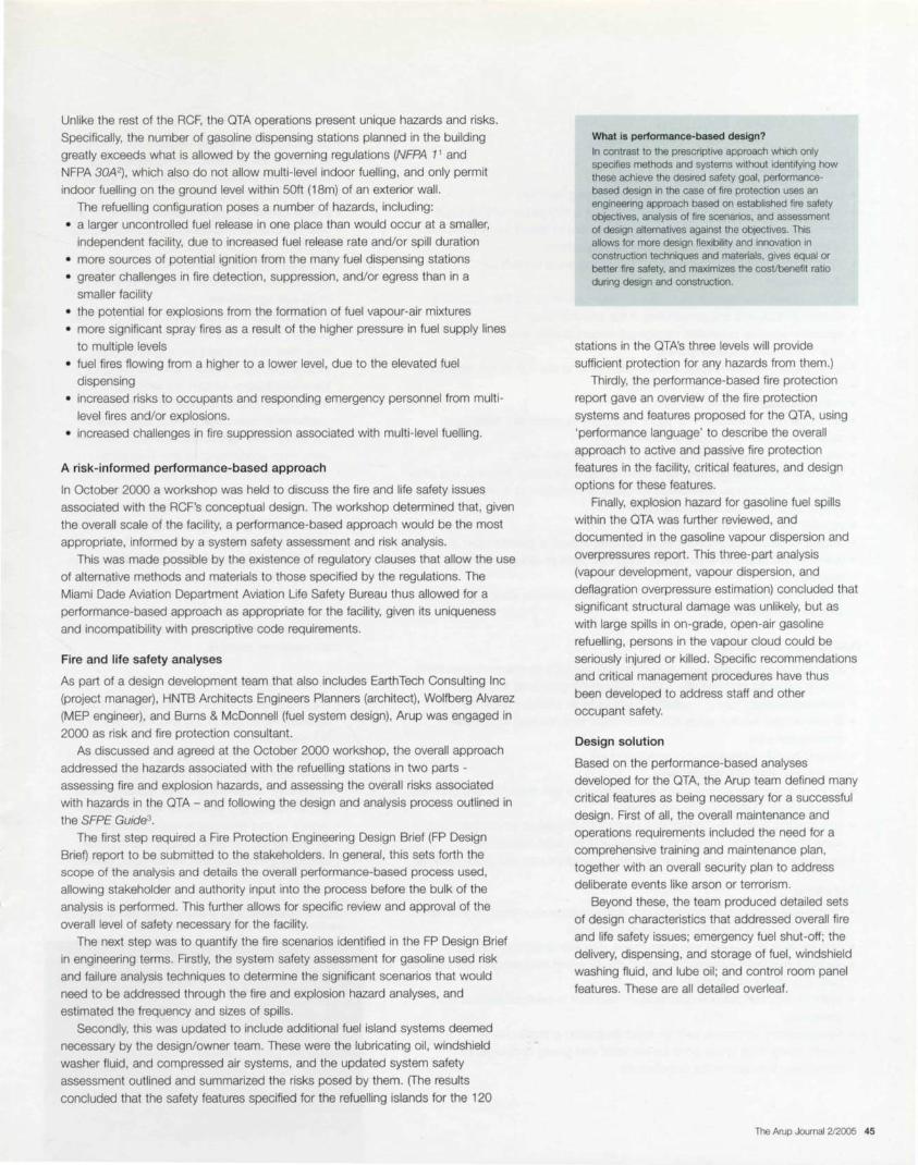
Unlike the rest of the ACF, the OTA operations present unique hazards and risks.
Specifically, the number of gasoline dispensing stations planned in the building
greatly exceeds what is allowed by the governing regulations (NFPA 11 and
NFPA 30A2) , which also do not allow multi-level indoor fuelling, and only permit
indoor fuelling on the ground level within 50ft (18m) of an exterior wall.
The refuelling configuration poses a number of hazards, including:
• a larger uncontrolled fuel release in one place than would occur at a smaller,
independent facility, due to increased fuel release rate and/or spill duration
• more sources of potential ignition from the many fuel dispensing stations
• greater challenges in fire detection, suppression, and/or egress than in a
smaller facility
• the potential for explosions from the formation of fuel vapour-air mixtures
• more significant spray fires as a result of the higher pressure in fuel supply lines
to multiple levels
• fuel fires flowing from a higher to a lower level, due to the elevated fuel
dispensing
• increased risks to occupants and responding emergency personnel from multi
level fires and/or explosions.
• increased challenges in fire suppression associated with multi-level fuelling .
A risk-informed performance-based approach
In October 2000 a workshop was held to discuss the fire and life safety issues
associated with the RCF's conceptual design. The workshop determined that. given
the overall scale of the facility, a performance-based approach would be the most
appropriate, informed by a system safety assessment and risk analysis .
This was made possible by the existence of regulatory clauses that allow the use
of alternative methods and materials to those specified by the regulations. The
Miami Dade Aviation Department Aviation Life Safety Bureau thus allowed for a
performance-based approach as appropriate for the facility, given its uniqueness
and incompatibility with prescriptive code requirements.
Fire and life safety analyses
As part of a design development team that also includes EarthTech Consulting Inc
(project manager), HNTB Architects Engineers Planners (architect), Wallberg Alvarez
(MEP engineer) , and Burns & McDonnell (fuel system design), Arup was engaged in
2000 as risk and fire protection consultant.
As discussed and agreed at the October 2000 workshop, the overall approach
addressed the hazards associated with the refuelling stations in two parts -
assessing fire and explosion hazards, and assessing the overall risks associated
with hazards in the OTA - and following the design and analysis process outlined in
the SFPE Guide3. The first step required a Fire Protection Engineering Design Brief (FP Design
BrieQ report to be submitted to the stakeholders. In general, this sets forth the
scope of the analysis and details the overall performance-based process used,
allowing stakeholder and authority input into the process before the bulk of the
analysis is performed. This further allows for specific review and approval of the
overall level of safety necessary for the facility.
The next step was to quantity the fire scenarios identified in the FP Design Brief
in engineering terms. Firstly, the system safety assessment for gasoline used risk
and failure analysis techniques to determine the significant scenarios that would
need to be addressed through the fire and explosion hazard analyses, and
estimated the frequency and sizes of spills .
Secondly, this was updated to include additional fuel island systems deemed
necessary by the design/owner team. These were the lubricating oil , windshield
washer fluid, and compressed air systems, and the updated system safety
assessment outlined and summarized the risks posed by them. (The results
concluded that the safety features specified for the refuelling islands for the 120
What is performance-based design?
In contrast to the prescriptive approach which only specifies methods and systems without identifying how these achieve the desired safety goal, performancebased design in the case of fire protection uses an eng1neenng approach based on established fire safety objectives, analysis of fire scenarios, and assessment of design alternatives against the obiectives. This allows for more design flexibility and innovation in construction techniques and materials, gives equal or better fire safety, and maximizes the cosVbenefit ratio during design and construction.
stations in the OTA's three levels will provide
sufficient protection for any hazards from them.)
Thirdly, the performance-based fire protection
report gave an overview of the fire protection
systems and features proposed for the OTA, using
'performance language' to describe the overall
approach to active and passive fire protection
features in the facility, critical features, and design
options for these features.
Finally, explosion hazard for gasoline fuel spills
within the OTA was further reviewed, and
documented in the gasoline vapour dispersion and
overpressures report. This three-part analysis
(vapour development, vapour dispersion, and
deflagration overpressure estimation) concluded that
significant structural damage was unlikely, but as
with large spills in on-grade, open-air gasoline
refuelling , persons in the vapour cloud could be
seriously injured or killed . Specific recommendations
and critical management procedures have thus
been developed to address staff and other
occupant safety.
Design solution
Based on the performance-based analyses
developed for the OTA, the Arup team defined many
critical features as being necessary for a successful
design. First of all , the overall maintenance and
operations requirements included the need for a
comprehensive training and maintenance plan,
together with an overall security plan to address
deliberate events like arson or terrorism.
Beyond these, the team produced detailed sets
of design characteristics that addressed overall fire
and life safety issues; emergency fuel shut-off; the
delivery, dispensing, and storage of fuel , windshield
washing fluid , and lube oil ; and control room panel
features. These are all detailed overleaf.
The Arup Journal 2/2005 45

Critical design features
Fire and life safety
• four-hour rated vertical chases and concrete piping trenches
• fuel island retention area sized to accommodate a 100-gallon (455 litre) spill
• combination ultraviolet and infrared (UV/IR) sensors to detect flame in the fuel
dispensing areas and initiate automatic fire suppression
• 212°F (100°C) heat detectors over fuel dispensing areas to back up
UV/IR sensors
• overhead and floor-level alcohol-resistant foam system at the fuel dispensing
stations to suppress and control fires in the retention area
• automatic sprinkler protection throughout, except directly over the retention
basins at the fuel dispensing areas
• water curtain that won't spray into retention basin at the 20ft (6.1 m) clear zone
• water curtains at the QTNRCF interface
• manual fire alarm stations throughout
• standpipe and hose stations at egress stairs and as necessary throughout
• voice communication devices throughout
• visual alarms where required by code or due to ambient noise
• four-hour fire resistance rating for all floor-ceiling assemblies, columns, and other
structural components, with tested fire-resistive protection to floors and ceilings
directly above the fuel dispensing areas
• properly fire-rated expansion joints
• access for tenant spaces from refuelling1 areas through a corridor open at the top
• drains for the retention to be raised, like a roof drain, to reduce potential
blockage
• minimum 3ft (900mm) free area above the tenant spaces to allow a substantial
path for explosion venting .
Fuel delivery and storage
• fuel delivery within a dedicated unloading area having a containment area sized
to hold the entire contents of a tanker truck (8000 gallons/36 400 litres)
• containment areas having dedicated drainage to an oil/water separator
• fill connections located within spill containment pads draining to concrete
containment area
• integral overfill valves within the tank drop tube
• double-wall steel fuel storage tanks
• tanks provided with integral automatic gauging and leak detection systems, with
control panels in the fire command room
• tank gauging system to monitor total product level , product temperature, and
water level , designed to alarm at high-leivel and low level conditions
• monitoring system for tank interstitial space (leak detection) and pump sensors.
Fuel piping
• double-wall welded carbon steel piping, and welded carbon steel containment
piping, with 100% radiographic inspection of welds
• nitrogen-filled double-wall interstitial space, with leak detection monitoring
• separate dedicated systems for each of the six piping sections (two per floor, 20
fuelling positions per section)
• systems velocities below recommended maximum to minimize static charge
generation
• pipe grounding to provide path for rapid dissipation of static charge
• supply piping drain to low point connections , and gravity discharge, to
completely drain system for maintenance.
46 The Arup Journal 2/2005
Fuel pumping
• dedicated tank-mounted vertical turbine pumps
for each of the six dedicated piping sections
• pumps sized to provide maximum flow 200gpm
(15 litres/sec) (20 positions at 1 Ogpm each)
• pumps to start on signal from one dispenser and
time-out after 10 minutes if no additional signals
received
• hydraulic control/pressure reducing valves at
each service level at QTA entrance for each set
of 20 fuelling positions
• control/pressure reducing valves to fail in closed
position; to modulate to limit pipe pressure
regardless of inlet pressure; to shut off upon
excess flow, leak detection alarm, emergency
fuel shut-off alarm, or tank low level alarm
• automatic recirculation valves at the pump
discharge to recirculate approximately 30% of
the design flow back to the tank to prevent the
pump from operating at no flow conditions
• thermal relief valves located within each piping
segment, actuating to protect each segment
from over-pressurization from thermal heat gain,
and discharging into a gravity system that drains
back to the underground storage tanks
• service level high pressure switches downstream
of the control/pressure reducing valves at each
service level
• pumps provided with a shut-down feature if
service level high pressure switch increases to
set maximum pressure.
Emergency fuel shut-off
• stations at each dispenser island and at remote
locations within 20ft (6.1 m) and 1 OOft (30m) of
the dispensers
• stations to shut off the following components on
a 'per-floor' basis: all fuel pumps, all fuel
dispensers, all control/pressure reducing valves,
and all lube oil and windshield washer systems
• system to shut down upon receipt of alarm from
an emergency fuel shut-off station or from the
voice communication and fire detection system.
2. Computer simulation of the explosive range zone of a gasoline leak from a fuelling station after 120 seconds.

.· .. ··
·. ·. . ... ···· ·· ..... ··
3.
w
Parking (two levels)
Flame detectors w w
Top: plan of RCF and OTA showing the constraints on site area by highw ays and rail lines. Above: layout option for UV/ IR flame detectors at fuelling islands, configured to prevent fi res being hidden from detector view by parked vehicles with doors, hood and trunk open or closed.
Windshield washing fluid and lube oil
delivery/storage
• washing fluid stored in two 2000 gallon (9100
litre). vertical, flat bottom polyethylene, above
ground tanks in the fluids storage rooms
• lube oil stored in two 1 OOO gallon (4550 litre).
horizontal, cylindrical, above-ground tanks in the fluids storage rooms
• delivery through a locked pedestal-mounted spill
containment box outside fluids storage rooms
• integral pressure-rated overfill prevention valve in
the fill drop tube to close, and the high-high level
alarm to alarm, when high-high fluid level is
reached within storage tanks.
Windshield washing fluid and lube oil : dispensing, piping, and pumping
• dispensing through a spring return hose-reel at each fuelling island
• each dispensing location controlled by a normally-closed, fluid line solenoid valve
• normally-closed, fluid line solenoid valves to close when any fire detection
system device or emergency fuel shut-off station is activated
• dispensing reel hoses limited to 30ft (9m), with an aluminum gooseneck, manual fill, hose end control
• washing fluid piping to be 1 .5in (38mm) stainless steel tubing
• lube oil piping specified as Schedule 40 carbon steel
• lube oil joints to be weld connections, except at connections to equipment
• separate pumps for each zone on each floor, each pump serving 20 servicing
positions
• washing fluid pump valves to shut down when any fire detection systems device
or emergency shut-off station is activated.
Control room panel features
• two separate programmable logic controllers for increased reliability, both to
operate in parallel or with one in 'hot-standby' mode (ie where one unit controls
the operations while the other is kept updated and ready to control operations
should the first unit fail)
• programmable logic controller for all fuel systems operations, interacting with the
voice communication and fire detection system, emergency fuel shut-off system,
leak detection system, and low product level alarm
• fuel delivery systems only to operate when the voice communication and fire
detection system is operating and functioning properly, the emergency fuel shut
off and leak detection systems are not in alarm, and the automatic tank gauging
system is not in low product level alarm
• programmable logic controllers designed to include an interface panel to display
alarms and system information
• control panel designed to alarm if high pressure switch increases to set
maximum pressure .
Conclusion
The Arup team 's analysis was peer-reviewed and has been ultimately accepted by
the authorities. Construction of the OTA and RCF is expected to commence later
this year, with the whole facility scheduled to open for use in 2007. Arup provided
significant value by demonstrating that this structure could be designed and built
safely at an overall reduced operating cost, which made the analysis and protection
features well worth the cost.
Credits
Project owner: Miami International Airport Client and project manager: EarthTech Consulting Inc Design architect: HNTB Architects Engineers Planners Architect of record : Sequeira & Gavarrete Design MEP engineer: Wolfberg Alvarez Design fuel system: Burns & McDonnell Fire engineer: Arup - Richard Custer, Matthew Johann. Brian Mclaughlin, Brian Meacham, Jeff Tubbs, Christopher Wood, Eileen Wood Illustrations: 1 EarthTech; 2 Arup; 3 Nigel Whale
References
{1) NATIONAL FIRE PROTECTION ASSOCIATION and WESTERN FIRE CHIEFS ASSOCIATION. NFPA 1: Uniform fire code. NFPA, 2003.
(2) NATIONAL FIRE PROTECTION ASSOCIATION. NFPA 30A: Motor fuel dispensing facilities and repair garages. NFPA, 2003.
(3) SOCIElY OF FIRE PROTECTION ENGINEERS. Engineering guide to performance-based fire protection analysis and design of buildings. SFPE, 2000.
The Arup Journal 2/2005 47

Introduction
People at work want both universal access to information, increasingly through
mobile communications, and security and privacy for their communications.
The challenge is to meet both requirements simultaneously in the workplace.
Currently mobile communications infrastructure and systems are designed on the
basis of detailed analysis of radio frequency (RF) coverage and capacity
requirements. Security and privacy needs can be met through good design, but
eavesdropping remains an issue. How can building design and fitout aid the design
of wireless communications systems, and reduce the problems of eavesdropping,
by using frequency selective surfaces (FSS) and attenuating materials?
Demand for spectrum continues to grow, and hence propagation characteristics
within buildings are becoming a more important consideration. Generally, as the
frequencies of operation rise from 450MHz, 900MHz, and 1.8GHz, to 2.4GHz and
5.2GHz, the ability to penetrate building materials reduces significantly.
As new wireless systems with limits to the number of available channels and
operating at higher frequencies are installed in buildings, it is time to consider
selecting different types of material for use in construction, based on their RF
characteristics. For example, reflecting material could be used to prevent signals
from propagating into rooms; RF-attenuating film could be added to double-glazed
windows; and FSS could be deployed to allow certain frequencies to propagate
into a room while reflecting other frequencies.
One of the hardest challenges designers face is to predict the frequencies that
will be used in the future, as wireless technologies develop and users demand ever
increasing bandwidth . Buildings are constructed to last many years and internal fit
outs occur every few years, but new wireless standards are developed every few
months; a detailed understanding of the latest developments in wireless
communications standards and products, and an appreciation of the characteristics
of the frequencies they use, are required.
48 The Arup Journal 2/2005
Can buildings be engineered to allow desired wireless frequencies to enter whilst deflecting others for privacy or security? Frequency selective surfaces (FSS) may be the answer.
Designing buildings for a wireless world Alan Newbold
Research on FSS for Ofcom
In a team that also included Culham
Electromagnetics and Lightning (project managers),
the National Physical Laboratory, and Warwick
University, Arup Communications and Arup
Materials Consulting recently took part in a project
for the UK regulatory body Ofcom (Office of
Communications) to research the practical potential
of FSS in a real office environment to aid in
spectrum efficiency. The specific aim was to
demonstrate the possibility of reducing the
coverage area of a wireless system through the use
of FSS and attenuating materials. This would then
allow the radio channels to be reused over a shorter
distance and result in a more spectrum-efficient
system through increasing capacity per m2.
2. A 5.2GHz bandstop FSS.

A 63m2 demonstrator facility was constructed to simulate an office environment,
and then partitioned into three electrically isolated areas and equipped with both
IEEE802.11 b (2.4GHz) and IEEE802.11 a (5.2GHz) wireless local area network
(WLAN) systems. This particular construction was lined with a reflective material
that provided approximately 60dB of attenuation throughout the facility, which
allowed the team to benchmark the capability of the FSS.
Defining FSS frequency requirements
Before constructing the FSS panels, the attenuation characteristics and target
frequencies were defined. To determine these characteristics, the team analyzed
the main in-building requirements for wireless communications, covering wide area
network (WAN), local area network (LAN) and personal area network (PAN). In the
wide area, the ability to access mobile cellular networks is fundamental for any
organization and so coverage into the building is needed at frequencies between
900MHz - 2.2GHz.
In addition, and particularly due to some recent highly publicized problems, the
requirement to allow TETRA (terrestrial trunked radio) frequencies into a building for
the emergency services is critical, as is allowing PMR (private mobile radio) services
to operate for specific client requirements, including IT and security departments.
Hence coverage needs to be available from 350-4 ?OM Hz and from 870-900MHz in
a building.
For most organizations, the use of personal wireless communications is
assumed to occur within a relatively short distance (<10m) and hence when
considering the propagation of radio waves the signals are assumed to work within
a restricted area and not as part of LAN or WAN systems.
The main RF requirement affected by building design and fit-out today is the
deployment of LAN systems, including those developed under the IEEE802.11 b/g
and IEEE802.11 a/h standards at 2.4GHz and 5.2GHz. Most users of the former
standard are accustomed to the concept of a wi-fi hotspot, where coverage is
provided in a particular predicted high-use area. However with new applications like
wireless voice over IP, the ability to achieve roaming coverage, where users can
walk from area to area without dropping the connection, will become a minimum
requirement in offices.
In the local area, wireless IEEE802.11 b systems use the 2.4GHz band with
22MHz channels, limiting the system to three non-overlapping channels, each
providing up to about 11 Mbps raw data throughput or 5.5Mbps shared data
throughput to the users covered by the access point. Where many users are
located in a small area, like an airport departure lounge, coverage is often
overlapped to provide a higher aggregated throughput. Also, where in the event of
an access point failure a minimum level of RF coverage is required, coverage is
overlapped to provide resilience. To ensure provision of aggregated throughput and
RF resilience the RF design can become very complex and in some cases
impossible without some level of inter-access point interference.
New wireless standards and systems are continually being developed to improve
performance within these constraints. The ratified IEEE802.11 g standard increases
the overall throughput up to about 20Mbps. However it still offers only a limited
number of non-overlapping channels. Although the IEEE802.11 a/h systems aid this
particular problem through the provision of eight non-overlapping channels, the
2.4GHz systems are still increasing in popularity and applications like voice have
not yet been developed at the 5.2GHz frequency. This will probably result in two
radio systems being required for use in buildings, operating at 2.4GHz and 5.2GHz.
Alongside frequency management problems, the security of wireless systems,
particularly wi-fi , is poor. Many of the security risks that have been highlighted can
be mitigated through careful design, but the radio link will always remain vulnerable
as it is difficult to place boundaries on RF transmission. There have been many
documented cases of potential hackers eavesdropping open networks from outside
the building.
The 2.4GHz and 5.2GHz bands are categorized as
licence-exempt industrial , scientific and medical
{ISM) bands and are becoming more heavily utilized.
These bands are self-regulated and hence any
interference between systems needs to be resolved
by users. This will become much more of an issue
with heavier use of these areas of spectrum. For
example, some major hospitals have started to have
problems with some of their medical equipment due
to utilization of the ISM band, and in some cases
agreements have been reached to move medical
electronics away from the ISM band and into a
dedicated band.
10
8
6
2
0
0 2 6 8
3. Software modelling results: GSM signals from outside the building.
4.
Power (dBm)
-100
-105
-110
-115
-120
-125
-130
-135
-140
-145
The Ofcom test installation: the dielectric cladding was polyethylene, the FSS substrate was polyester, and the core was extruded polystyrene.
The Arup Journal 2/2005 49

Given the limited number of non-overlapping
channels in the IEEE802 .11 a/b/g/h systeims, it was
felt that if a cost-effective FSS could be designed to
selectively reflect certain frequencies in the 2.4GHz
or 5.2Ghz bands, then buildings could be designed
to aid in the efficient use of these frequencies and
hence aid RF design. Although research carried out
on another Ofcom project shows that it iis
theoretically possible to achieve the required results,
to design a practical example will be very
challenging.
The next desirable objective is to design an FSS
able to stop or pass 2.4GHz and 5.2GH.z bands in
their entirety. This would allow an organization to
selectively prevent the 5.2GHz band used by staff
or operations from being transmitted across a
physical boundary and into a common area, but
allow the common-use 2.4GHz band to pass across
the boundary unaffected and maintain public or
voice communications.
Due to the separation between target
frequencies, it is relatively easy to provide about
45d8 attenuation in the stop band, with only 2-3d8
attenuation in the pass band. Software propagation
modelling showed that a relatively small FSS panel
could be used to provide sufficient signal strength
into the appropriate room from the transmitting AP.
The FSS were made from two layers, each using a
dielectric core of extruded polystyrene SE3parated by
a spacer. The total thickness of the structure was
about 30mm and the outside of each FSS was clad
with a dielectric material.
The project demonstrated that an FSS could
allow a 5.2GHz signal to propagate through it whilst
preventing a 2.4GHz signal from passing. This
meant that through a combination of the
appropriate shielding and FSS it is possilble to
isolate 2.4GHz signals from one room to another
whilst allowing a 5.2GHz signal to pass into both
rooms. The reverse of this was also demonstrated.
To show that it was possible to meet the
requirements of allowing mobile cellular and
emergency communications into a building whilst
preventing all higher frequencies from paissing, a
low pass FSS was constructed. This proved that
signals up to 1 GHz could be allowed to pass into a
building, hence allowing TETRA emergency
services, PMR signals or 0.9GHz GSM signals in.
Currently it is not possible to design an affordable
FSS to permit 1 .8GHz to pass whilst preventing the
transmission of 2.4GHz.
50 The Arup Journal 2/2005
Choice of FSS materials Bob Cather Edwin Stokes
The practical issues around incorporating FSS materials in a real office/building environment had to be considered - issues of both the inherent suitability of candidate materials and their interaction with construction and building operation. For this project, two general forms of construction were considered as the base. Office buildings are constructed either traditionally, with brick structural walls and lightweight concrete partitions within, or in the more modern combination of concrete and/or steel-framed structure, with lightweight timber or plasterboard partitions. Most prestige City offices are of 'modern' construction, though due to increased desire to reuse or refurbish existing buildings, a significant and possibly increasing number may be of the 'traditional' methods and materials.
The Arup Materials Consulting team analyzed the constraints and requirements arising from building regulations, the compatibility with adjoining materials, and the practicalities of installation and maintenance. When locating FSS within partition walls, these factors include compatibility with adjoining components including junctions and joints, health and safety considerations, acoustic properties, fire performance, the nature of any applied finishes, and durability and maintenance. When incorporated in the fa9ade, there are additional issues of continuity of weathertightness and fa9ade thermal and comfort perfonmance, and accommodation of movement and deflections.
With all these factors in mind, as well as considerations of in-service modification, replacement and maintenance, the next task was to determine the suitability of candidate substrate materials proposed by project partners for installed FSSs. Five materials were proposed: PET (Melinex), polyimide (Kapton), GRP laminate (/so/a), polymethacrylimide (Rohacet~. and extruded polystyrene foam (Styrofoam).
Melinex PET is a clear thermoplastic film commonly used as protective film on glazing. It is flexible but vulnerable to tear, and is inherently flammable. However, it has good UV resistance, with typically a 10-year service life exposed on glazing.
Kapton is a translucent yellow thermoset film, typically used in the electronics industry as a flexible substrate. Like Melinex PET it is flexible and vulnerable to tear, but it is far less flammable. It has excellent chemical resistance but absorbs moisture easily.
Isola is a thin and rigid glassfibre reinforced plastic (GRP) laminate, typically used as a substrate of printed circuit boards. Like Kapton it has good fire resistance and chemical resistance, but its susceptibility to moisture absorption can lead to delamination.
Rohacell is a polymethacrylimide (PMI) foam, and comes in two grades: A (aircraft structural grade) and HF (high frequency antenna grade). It has good resistance to most solvents and
fuels (though not to alkalis), low flammability, good high temperature stability, and can be readily shaped and formed.
Styrofoam extruded polystyrene foam is widely used in buildings for thermal insulation in roofs and wall cavities. It is very flammable and has limitations on mechanical damage compared to the other candidate materials. It has good acid and alkali resistance but poor solvent resistance.
The various service requirements and the materials properties were compared, to draw tentative conclusions on the most appropriate basis for further development. Incorporated within the building structure and fabric , the FSS will be impractical to inspect. modify or replace. so it must be robust enough to tolerate site conditions and have confident long-term performance. In interior fit-out, aesthetics, UV, abrasion, fire spread and reaction to cleaning regimes are all important issues; whilst when FSS are incorporated into local workstations, aesthetics and unit cost come to the fore. The material needs to be unobtrusive, and workstation configurations may change many times in the life of a building.
With every issue weighed in the balance, the team concluded that though Styrofoam is a viable and cost-effective option for internal partitions, it would need to be encased to meet the fire performance regulations and was too open to damage, so Rohacell would probably be the most appropriate due to its robustness, versatility and fire performance. For fa9ade use, Melinex PET is probably the best option because of its flexibility and UV resistance.
5. A more familiar use for PET.

6. Terminal 5 at London Heathrow Airport will use the latest technologies to tailor its wireless infrastructure.
Applications in buildings
Most of today's landmark buildings, including airport terminals, major stations and
corporate headquarters, use glass fa9ades and are fitted out as open plan office or
public spaces. This in itself creates enormous challenges for designers of wireless
systems, particularly in resolving coverage vs. capacity, and addressing the issues
of frequency management. One of the main security problems for these buildings is
preventing unauthorized users from eavesdropping on their wireless networks from
outside the building perimeter, but the distance from which a potential
eavesdropper can 'sniff' a wireless network can be greatly reduced through the
appropriate selection of building materials. It is possible today to procure glass with
a significant level of attenuation built into it so that it will reduce the leakage of the
radio signal outside the building. When supplemented with special screening
material that can be fitted to the inside of windows, this could bring the distance of
leaked signal to within the physical perimeter of the site.
A screening solution will also attenuate mobile cellular, PMR and TETRA signals,
but by adding a low pass FSS into the walls at appropriate points it is possible to
allow the required signals to propagate into the building. These principles can be
applied in airports, major stations and trains, and theatres and auditoria as well
as offices.
Airports and major stations have many tenants with independent wireless
communications requirements. In areas where there are physical boundaries
between adjacent tenants it may be possible to physical separate the tenant
systems using FSS combined with reflective screening. This would allow the
landlord systems to function as normal.
One interesting problem for train operators is ensuring the propagation of
mobile cellular signals into the new carriages made with metalized windows,
where signal strengths are varied at best. Using a FSS designed for train carriage
operation it would be possible to allow the mobile cellular frequencies to propagate
into the carriage.
Increasingly clients are requesting that some or all wireless communication is
prevented within a specific space, eg operating theatres, auditoria, lecture theatres,
and some meeting rooms. Through a combination of careful building planning and
the use of special materials it is possible to achieve up to 120dB of attenuation,
which could therefore have the desired effect.
Conclusion
In the future, construction firms, landlords, and
tenants should take closer interest in RF
propagation as wireless communications become
more and more critical to business. Consultants and
designers will also need to use the building
materials, fit-out materials, RF materials, FSS,
intelligent antennas, and wireless systems in a
combination of ways to achieve the desired results.
Though an FSS really needs to be able to
differentiate cost-effectively between individual
channels in the 2.4GHz frequency band, the current
developments in this technology have many
potential applications in industry.
The project was one of 10 funded by Ofcom as
part of the Spectrum Efficiency Schemes 2003-
2004. The detailed results and findings will be
published on the OFcom website,
http://www.ofcom.org. uk/research/ industry _market_
research/ technology _research/ses/ses2003-04.
This feature is based in part on the article
'Designing buildings for the wireless age' in IEE
Communications Engineer, June/July 2004.
Credits
Client: Ofcom Team members: Culham Electromagnetics and Lightning: National Physical Laboratory; Warwick University; Arup - Bob Cather, Ken Kilfedder, Bruce Laidlaw, Alan Newbold, Edwin Stokes Illustrations: 1 Tim Pohl; 2 Ofcom; 3, 4 Arup; 5 Todd Smith ; 6 Richard Rogers Partnership
The Arup Journal 2/2005 51

The Caltrar1s District 7 H,aadquarters, Los Angeles Eugene Desouza Andy Howard Teena Videriksen
Taking advantage of the prevailing climate of Southern California, the new headquarters - opened on time and on budget - achie~ves high standards of energy-efficiency and sustainability.
1. North-west view from City Hall, featuring tho light bar and the Eli & Edythe Broad Plaza.
52 The Arup Journal 2/2005
Introduction
In March 2005, Thom Mayne of Morphosis was
awarded the 2005 Laureate of the prestigious
Pritzker Prize for architecture. The Caltrans District
7 Headquarters, Mayne's most recently completed
project, was described as one of his more important
projects: 'The design of this building goes beyond
merely providing functional spaces. It seeks in every
way to actively engage the city and people while
blurring the distinction between outside and inside,
with the objective of creating a government bureau
that works as a truly public building.'
The California Department of Transportation is, in
its own words, 'undergoing a transformation from a
transportation bureaucracy to a mobility company'.
Historically responsible for operating the labyrinth of
freeways and highways in California, its scope of
responsibility now extends to other transport modes
including rail and mass transit, and embraces issues
of appropriate land use and environmental
responsibility.
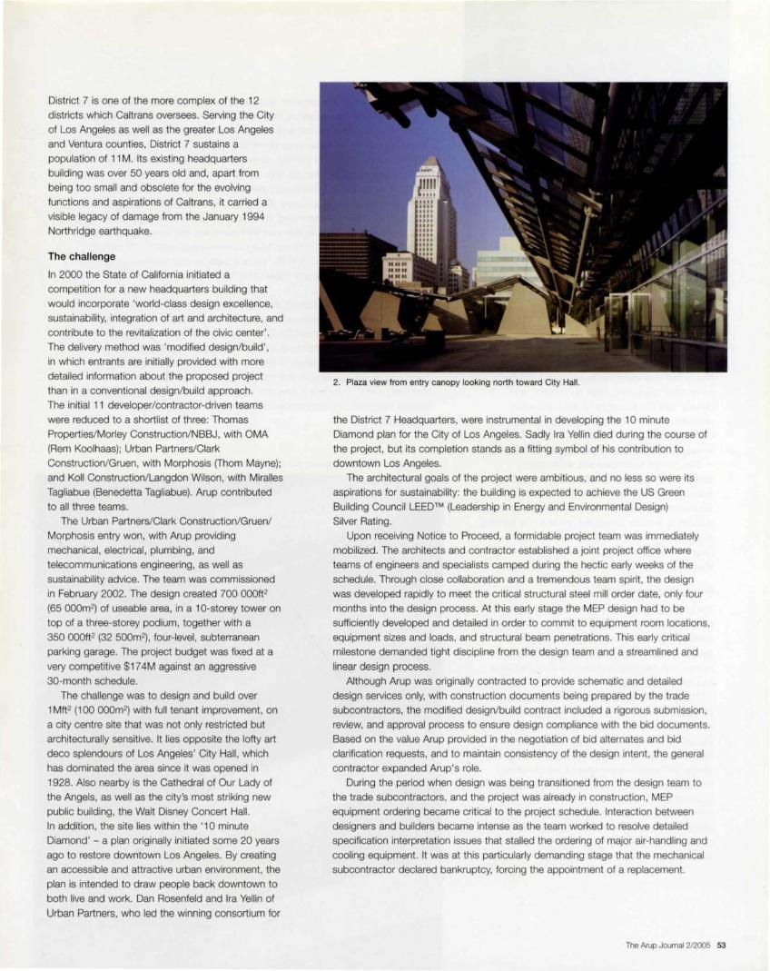
District 7 is one of the more complex of the 12
districts which Caltrans oversees. Serving the City
of Los Angeles as well as the greater Los Angeles
and Ventura counties, District 7 sustains a
population of 11 M. Its existing headquarters
building was over 50 years old and, apart from
being too small and obsolete for the evolving
functions and aspirations of Caltrans, it carried a
visible legacy of damage from the January 1994
Northridge earthquake.
The challenge
In 2000 the State of California initiated a
competition for a new headquarters building that
would incorporate 'world-class design excellence,
sustainability, integration of art and architecture, and
contribute to the revitalization of the civic center'.
The delivery method was 'modified design/ build' ,
in which entrants are initially provided with more
detailed information about the proposed project
than in a conventional design/build approach.
The initial 11 developer/contractor-driven teams
were reduced to a shortlist of three: Thomas
Properties/Morley Construction/NBBJ, with OMA
(Rem Koolhaas); Urban Partners/Clark
Construction/Gruen, with Morphosis (Thom Mayne);
and Koll Construction/Langdon Wilson, with Miralles
Tagliabue (Benedetta Tagliabue) . Arup contributed
to all three teams.
The Urban Partners/Clark Construction/Gruen/
Morphosis entry won, with Arup providing
mechanical, electrical, plumbing, and
telecommunications engineering, as well as
sustainability advice. The team was commissioned
in February 2002. The design created 700 000ft2
(65 000m2) of useable area, in a 10-storey tower on
top of a three-storey podium, together with a
350 000ft2 (32 500m2), four-level, subterranean
parking garage. The project budget was fixed at a
very competitive $17 4M against an aggressive
30-month schedule.
The challenge was to design and build over
1 Mft2 (100 000m2) with full tenant improvement, on
a city centre site that was not only restricted but
architecturally sensitive. It lies opposite the lofty art
deco splendours of Los Angeles' City Hall, which
has dominated the area since it was opened in
1928. Also nearby is the Cathedral of Our Lady of
the Angels , as well as the city's most striking new
public building, the Walt Disney Concert Hall.
In addition, the site lies within the '10 minute
Diamond' - a plan originally initiated some 20 years
ago to restore downtown Los Angeles. By creating
an accessible and attractive urban environment, the
plan is intended to draw people back downtown to
both live and work. Dan Rosenfeld and Ira Yellin of
Urban Partners, who led the winning consortium for
2. Plaza view from entry canopy looking north toward City Hall.
the District 7 Headquarters, were instrumental in developing the 10 minute
Diamond plan for the City of Los Angeles. Sadly Ira Yellin died during the course of
the project, but its completion stands as a fitting symbol of his contribution to
downtown Los Angeles.
The architectural goals of the project were ambitious, and no less so were its
aspirations for sustainability: the building is expected to achieve the US Green
Building Council LEED™ (Leadership in Energy and Environmental Design)
Silver Rating.
Upon receiving Notice to Proceed, a formidable project team was immediately
mobilized. The architects and contractor established a joint project office where
teams of engineers and specialists camped during the hectic early weeks of the
schedule. Through close collaboration and a tremendous team spirit, the design
was developed rapidly to meet the critical structural steel mill order date, only four
months into the design process. At this early stage the MEP design had to be
sufficiently developed and detailed in order to commit to equipment room locations,
equipment sizes and loads, and structural beam penetrations. This early critical
milestone demanded tight discipline from the design team and a streamlined and
linear design process.
Although Arup was originally contracted to provide schematic and detailed
design services only, with construction documents being prepared by the trade
subcontractors, the modified design/build contract included a rigorous submission,
review, and approval process to ensure design compliance with the bid documents.
Based on the value Arup provided in the negotiation of bid alternates and bid
clarification requests, and to maintain consistency of the design intent, the general
contractor expanded Arup's role.
During the period when design was being transitioned from the design team to
the trade subcontractors, and the project was already in construction, MEP
equipment ordering became critical to the project schedule. Interaction between
designers and builders became intense as the team worked to resolve detailed
specification interpretation issues that stalled the ordering of major air-handling and
cooling equipment. It was at this particularly demanding stage that the mechanical
subcontractor declared bankruptcy, forcing the appointment of a replacement.
The Arup Journal 2/2005 53

3. Interior view from office of scrim pneumatic actuators.
Arup's role was immediately expanded to ensure
progress of the construction documents, and
provide daily site presence to aid in the rapid
orientation of the new mechanical subcontractor.
Ultimately Arup's involvement on the project
increased to 50% more than originally anticipated.
The general contractor and entire team
collaborated in an intense effort to overcome the
setback caused by the loss of this key trade
subcontractor. Incredibly the project schedule was
recovered , and the completed building was handed
over to a very happy client at the end of the
programmed 30-month concurrent design/
build period.
Energy efficiency
The building orientation evolved in response to
functional requirements and the surrounding urban
environment, and the resulting form presented
extensive east , south, and west fa9ades on a
narrow plan designed to maximize occupant views
and the use of daylight.
The thermal performance of the fa9ade was
identified as critical to achieving the aggressive
energy conservation targets set forth in the
design/build brief. The client specified that the
measured building performance should better the
energy efficiency requirements of the California
Energy Commission Title 24 by 20%. This equated
to about a 30% improvement on ASHRAE 90. 1, which is adopted in many states as an energy
usage benchmark. The team exceeded this goal by
documenting 30% savings on Title 24 (equating to
40% improvement on ASHRAE 90.1).
54 The Arup Journal 2/2005
The design/build process against such an aggressive schedule demanded that cost
and value engineering be strong and continual components of the design process.
The fa<;:ades became the focus of detailed costing, value, and constructability
review early in the process. Arup developed fa9ade modelling using ROOM and
NATFAC to determine the thermal performance and internal comfort conditions
produced by a range of fa9ade options. ROOM is part of the E+ TA (environmental
and thermal analysis) software suite developed by OASYS, Arup's software
development and sales company. The team selected for detailed evaluation, a
semi-active solution incorporating an exterior 'scrim' of perforated sheet metal.
The lifecycle value of the fa9ade was then assessed and compared with other
more traditional solutions. The modelling demonstrated capital cost savings
derived from reduction in the HVAC system capacity and, more importantly to
Caltrans, a significant lifecycle benefit that helped gain support for the
unconventional approach.
The scrim comprises framed aluminum panels punched with holes of varying
sizes to provide 48% openness, and allow for clear vision and natural light. The
scrim acts as a second skin 1 Oin (250mm) away from the inner fa9ade, while also
contributing significantly to the character of the building and its presence on the LA
skyline. In addition to its clean, hi-tech aesthetic, the scrim reduces energy
consumption effectively while maintaining a bright working environment and
providing views of the city. It also acts as a shade, reducing solar heat gains and
limiting infiltration of unconditioned outside air by reducing wind pressure on the
inner fa9ade.
4. Detail of photovoltaic panels and south escape stairway.

To further reduce heat gain, the east and west
fa9ades have been designed as thermal flues, using
the building height and hot sun on the external face
of the scrim to generate high air change rates
between the outer and inner fa9ades. This serves to
keep the driver of conductive heat exchange close
to the ambient air temperature. Many of the scrim
panels are powered to open automatically in
response to the position of the sun, playfully
punctuating the otherwise clean lines and flat
planes of the building's outer skin.
Balancing cost and fa9ade performance was a
continual challenge, particularly as the team
explored options for some form of protection for the
south elevation that would provide contrast with the
east and west fa9ades . A range of solutions that
met the architectural objectives and engineering
performance criteria was quickly developed,
however delivering these solutions within the
contractor's budget demanded a more innovative
approach to design and procurement. Ultimately,
the team went up-market for a cheaper solution,
leveraging the financial incentives offered by the
State and utility providers to promote alternative
energy generation .
On the south fa9ade the aluminum scrim is
replaced with an open lattice framework that
supports a vision glass wall incorporating a
14 000ft2 (1300m2) array of 895 building integrated
photovoltaic (BIPV) panels. The panels harvest solar
energy and convert it to electricity during peak
hours when cooling demands are at their highest,
providing significant energy savings due to the
punitive peak demand energy tariff structure. The
direct current power generated by the BIPV cells
flows through power conversion equipment and into
the building's electrical distribution system,
contributing 92kW of peak power.
In addition to its energy saving properties, the
south fa9ade behaves similarly to the east and
west, reducing the heat load by shading from the
opaque, monocrystalline BIPV cells. reducing
infiltration, and promoting natural ventilation
between the two vertical layers of fa9ade.
Detailed sunpath studies were undertaken to
determine:
• the optimum power output angle of the panels
• their vertical spacing to prevent self-shading
• the optimum cell density in the panels to achieve
the required output and maximize natural light in
the offices
• their positioning relative to each other in order
to balance aesthetic with the occupant lines
of sight.
Savings by Design
This programme, funded by California utility customers under the auspices of the Public Utilities Commission and administered through four utilities - the Pacific Gas and Electric Company (PG&E), San Diego Gas and Electric (SDG&E}, Southern California Edison Company (Edison or SCE} and Southern California Gas Company (SoCal Gas} - exists to encourage high-performance non-residential building design and construction.
Financial incentives are available to owners when a new building's efficiency exceeds the minimum Savings by Design thresholds, generally 10% better than Title 24 standards. These incentives encourage owners to make energy efficiency a major goal in their new buildings, and help to defray some of the costs of energy-efficient building components .
To supper! the extra effort for integrated energy design and to reward exceptional design accomplishments, Savings by Design also offers financial incentives to design teams. In its Whole Building Approach, a computer simulation model calculates the energy savings
5. View from behind photovoltaic panels.
of the building compared to the Title 24 baseline. The design team qualifies for incentives when the building design saves at least 15%.
http://www.savingsbydesign.com
Through extensive computational modeling of the sun path across the annual cycle,
a balance was struck between the BIPV summer and winter applications. This
resulted in a panel angle of 50° off the horizontal and a spacing between panels of
5ft (1 .5m).
The design/build team was able to reduce the cost of the unique multifunctional
fa9ade system by securing $800 OOO in rebates from Savings by Design, the
Southern California Gas Company, and the Los Angeles Department of Water
and Power.
In addition to the effective performance of the composite fa9ade, the energy
conservation target was exceeded through a combination of measures including:
• control of minimum outside air supply using C02 measurement
(demand ventilation)
• premium efficiency motors for all equipment
• extensive use of variable speed drives interfacing with the building
management system (BMS)
• variable volume pumping
• increased chiller efficiency
• equipment sizing to maintain efficiency at actual operating points
(ie high peak and part load efficiencies)
• improved control system accuracy and performance
• the building control and automation systems
• system commissioning
• appropriate minimum thicknesses for pipe and duct insulation
• optimized thermal insulation performance for building envelope
• use of dual-pane, low-E, and low solar heat gain coefficient glazing
• external environmental control in the form of the scrim on the east and
west fa9ades
• angled photovoltaic panels over the entire south fa9ade fenestration.
The Arup Journal 2/2005 55
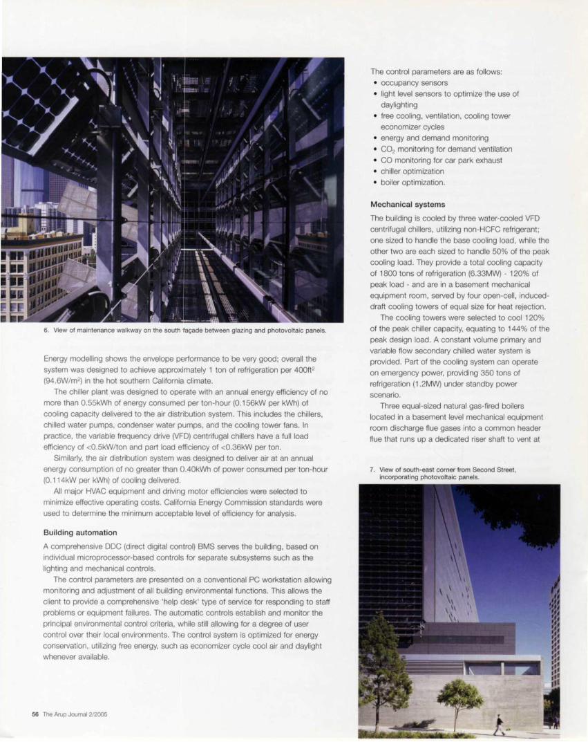
6. View of maintenance walkway on the south fa9ade between glazing and photovoltaic panels.
Energy modelling shows the envelope performance to be very good; overall the
system was designed to achieve approximately 1 ton of refrigeration per 400ft2
(94.6W/m2) in the hot southern California climate.
The chiller plant was designed to operate with an annual energy efficiency of no
more than 0.55kWh of energy consumec! per ton-hour (0.156kW per kWh) of
cooling capacity delivered to the air distribution system. This includes the chillers,
chilled water pumps, condenser water pumps, and the cooling tower fans. In
practice, the variable frequency drive (VFD) centrifugal chillers have a full load
efficiency of <0.5kW/ton and part load e'fficiency of <0.36kW per ton.
Similarly, the air distribution system was designed to deliver air at an annual
energy consumption of no greater than 0.40kWh of power consumed per ton-hour
(0.114kW per kWh) of cooling delivered.
All major HVAC equipment and drivin1~ motor efficiencies were selected to
minimize effective operating costs. California Energy Commission standards were
used to determine the minimum acceptable level of efficiency for analysis.
Build ing automation
A comprehensive DOC (direct digital control) BMS serves the building, based on
individual microprocessor-based controls for separate subsystems such as the
lighting and mechanical controls.
The control parameters are presented on a conventional PC workstation allowing
monitoring and adjustment of all building environmental functions. This allows the
client to provide a comprehensive 'help desk' type of service for responding to staff
problems or equipment failures. The automatic controls establish and monitor the
principal environmental control criteria, while still allowing for a degree of user
control over their local environments. Th13 control system is optimized for energy
conservation , utilizing free energy, such as economizer cycle cool air and daylight
whenever available.
56 The Arup Journal 2/2005
The control parameters are as follows:
• occupancy sensors
• light level sensors to optimize the use of
daylighting
• free cooling, ventilation, cooling tower
economizer cycles
• energy and demand monitoring
• C02 monitoring for demand ventilation
• CO monitoring for car park exhaust
• chiller optimization
• boiler optimization.
Mechanical systems
The building is cooled by three water-cooled VFD
centrifugal chillers, utilizing non-HCFC refrigerant;
one sized to handle the base cooling load, while the
other two are each sized to handle 50% of the peak
cooling load. They provide a total cooling capacity
of 1800 tons of refrigeration (6.33MW) - 120% of
peak load - and are in a basement mechanical
equipment room, served by four open-cell, induced
draft cooling towers of equal size for heat rejection .
The cooling towers were selected to cool 120%
of the peak chiller capacity, equating to 144% of the
peak design load. A constant volume primary and
variable flow secondary chilled water system is
provided. Part of the cooling system can operate
on emergency power, providing 350 tons of
refrigeration (1.2MW) under standby power
scenario.
Three equal-sized natural gas-fired boilers
located in a basement level mechanical equipment
room discharge flue gases into a common header
flue that runs up a dedicated riser shaft to vent at
7. View of south-east corner from Second Street, incorporating photovoltaic panels.

roof level, 14 floors up. These boilers supply 150%
of the building heating load required by the client, ie
50% standby/redundancy. The total installed
heating capacity is 8925MBH (2.6MW).
Eight exterior AHUs, each supplying about
45 000ft3/min (21 m3/sec) of air, are at upper roof
level and serve levels 4-13. Seven more AHUs in
basement mechanical equipment rooms, and on
the lower roof, serve all spaces from ground level
to level 3. All AHUs serving office areas are
equipped with airside economizers controlled on
dry bulb temperature.
The mechanical rooms are strategically located
to take into account the wind direction around the
building and to ensure that the intake louvres, for
the full outside air economizers, avoid excessive
wind pressures, entrainment of noxious pollutants,
toilet exhaust fan discharge, and discharge effluent
from the cooling tower systems. A combination of
smaller AHUs and fan coil units (FCUs) serve the
elevator machine rooms and electrical closets,
which contain transformers and communication
closets on each floor. The AHUs can supply up to
523 OOOft3/min (246m3/sec) of air into the building.
The AHUs are sized to optimize the air velocity
through the filters and over the cooling coils,
thereby optimizing the system static pressure
requirements. Belt-driven plenum (plug) fans are
used to achieve the most effective fan selection to
satisfy the system characteristics, and to provide
optimum acoustic performance. Each AHU has the
capability for full airside economizer operation, using
the return fan as exhaust fans in this application,
through the articulation of the damper systems.
The turndown operating characteristics of the
individual AHUs has been evaluated to ensure
acceptable performance at lower air flow quantities.
Kitchenettes and core toilets are connected to
the general exhaust air system within the two
common risers, extending through the building core.
In the event of a fire, this riser doubles for smoke
exhaust, drawing air off the fire floor and negatively
pressurizing the space.
In the data centre, close control CRAC
(computer room air-conditioning) units with filters,
chilled water coil and electric steam humidifiers,
meet the room loads. These units, together with
part of the chilled water system, operate on
emergency power to maintain conditions if the main
power fails.
The four basement levels of parking are
ventilated by a mechanically-driven push-pull
system, in which supply shafts drop down at the
north end of the parking levels and exhaust shafts
rise up at the south end. Fans are located at each
of these riser shafts, and supply air is brought in via
elevated external air intake openings within
8. View of plaza featuring plaza artwork and signage.
architectural structures. A common header connects the air inlet points to the top
of each supply air dropper.
On the south fa9ade, a plenum tower discharges exhaust air more than 15ft
(4.5m) above ground via external louvres, and away from populated areas such as
the sidewalk, open plaza and exterior playground. Sensors control variable speed
supply and exhaust fans to maintain acceptable levels of CO within the parking
garage. Utilizing VFDs ensures that substantial energy is saved when operating the
garage ventilation system. The exhaust fans are rated to work at 250°F as they also
serve as smoke exhaust fans for the parking levels. Up to 623 OOOft3/min
(294m3/sec) of air is exhausted from the parking garage.
Telephone services and communication rooms housing sensitive electronic
components are conditioned by ceiling-mounted chilled water FCUs, served by part
of the building's 24/7 air-conditioning system.
The design includes an additional 10% capacity for future use on all the building
systems, including but not limited to all of the air systems and the chilled water and
heating hot water systems. All equipment, ducting and piping meets this
requirement by being sized to accommodate this future load . The equipment sizes
were determined based on the highest air flow rate obtained from computer
generated heat gain calculations to offset each room 's load at the time of the
building's peak block load.
The Arup Journal 212005 57

9. Aerial view from the north-west.
Fire engineering
The high rise smoke management is provided by
rated exhaust fans on the upper roof. There are two
fans at the top of two dedicated riser shafts, one
per full building height core, and each sized at a
capacity of 35 OOOft3/min (16.5m3/sec). Fire-rated
shafts extend down the full building height. Under a
fire scenario, the smoke dampers off these rising
shafts will open on the fire floor and the fans on the
roof will ramp up as required for the particular
smoke/ fire zone. These smoke exhaust fans are
provided with emergency power from thE3
emergency generators for this purpose. Fire
fighting/escape stairwells are provided with stairwell
pressurization systems, with the ability to
introduce 12 00Qft3/min (5 .6m3/sec) of outside air
into the stairwells, distributed over the fuill height
of the building.
Lighting
The open office spaces are illuminated by pendant
direct/indirect three-lamp fluorescent luminaries with
state-of-the-art control to create a visually dynamic
environment. The fixtures are unique in that they are
provided with digital addressable ballasts and are
controlled both via a network lighting control system
and locally. These ballasts are based on the DALi
(digital addressable lighting interface)
communication protocol and are compa1tible with
other open protocols used in building automation
systems, thus presenting opportunities for total
building system integration.
58 The Arup Journal 2/2005
The indirect lighting provides general ambient lighting and is controlled through the
building automation system. The direct lighting is primarily used to enhance the
working environment for staff and their performance. The luminaries at each
workstation are equipped with integral occupancy sensors that control the
operation of direct lighting component to reduce the amount of energy wasted.
The perimeter fixtures are furnished with integral photocell/occupancy sensors,
which automatically dim when there is sufficient natural daylight available or
when someone leaves the space, thereby creating a functional and energy
efficient environment.
Communications
The data communications cabling infrastructure is supported by two completely
redundant incoming service routes. One is designed to support local service
providers and the Caltrans fibre optic ring, while the second supports other tenants,
and serves as the building's redundant pathway to the outside world . The pathways
for incoming services are designed to support current cabling infrastructure with an
allowance of 25% for future expansion. Both routes serve the main incoming
service room (MPOE). Through various pathways (conduit and cable tray) , the
MPOE is connected to the main distribution frame (MDF).
The 900ft2 (84m2) main computer room, or data centre, is adjacent to the MDF.
Two sets of telecom rooms. vertically stacked, are designed to provide riser
pathways to connect all 14 floors to the MDF and data centre. A fully redundant
fibre optic ring connects all telecom rooms to the data centre.
The data cabling system comprises a network of copper cable supported by
fibre optic cable. The data centre houses the electronics that support a network of
cameras throughout the Los Angeles metropolitan area, as well as Caltrans data
and voice networks. Multiple radio systems are installed in this building to
communicate with incoming helicopters. various Caltrans departments, police and
Caltrans satellite offices.
State raises the bar
Through a design/build process that promoted and placed emphasis on design
excellence through the unique bidding procedure. the State of California has
procured an outstanding piece of urban architecture within an aggressive budget
and to an ambitious schedule. The project has already won several awards and is
expected to receive the US Green Building Council's LEED™ Silver Rating for its
demonstrable achievement of exemplary sustainability goals. The building is a
credit to those involved and raises the bar for future public projects in the City
of Los Angeles.
Credits
Owner: Department of General Services, California; User: District 7, California Department of Transportation; Design/build team: Main and First Design/Build Associates. Inc .. which consists of: Urban Partners. LLC (Developer); The Clark Construction Group, Inc. (General Contractor); Morphosis (Design Architect); and Gruen Associates (Executive Architect); Mechanical , electrical, plumbing and telecommunications engineers: Arup - Peter Alspach, Robert Buckley, Joe Ceballos. Susan Chen, Vahik Davoudi , Eugene de Souza. Steve Done, Keith Franklin, Kathleen Hannon. Andy Howard, Rick Lasser, Craig Macadang, Julian Mamro, Anait Manjikian. Vahan Margaryan, Maurya McClintock. Bruce McKinlay, lldiko Mezei, Josef Nejat, Morad Pajouhan, Jonathan Phillips, Fernando Rivas. Jerry Rodriguez. Lisamarie Roed, Massoud Safaee, Helen Sinanyan, Raymond Tam, Armen Topakian; Construction manager: O'Brien Kreitzberg/URS Corporation; Structural engineer: John A. Martin Associates, Inc Illustrations: 1, 7, 10 John Linden; 2, Benny Chan/Fotoworks; 3. 6. 8, 9, Roland Halbe; 4, 5 Jim Sinsheimer
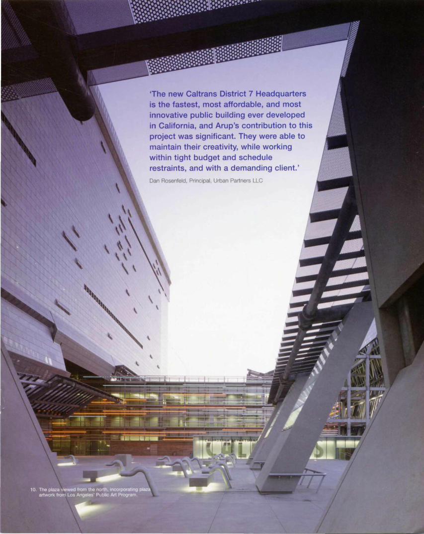
'The new Caltrans District 7 Headquarters is the fastest, most affordable, and most innovative public building ever developed in California, and Arup's contribution to this project was significant. They were able to maintain their creativity, while working within tight budget and schedule restraints, and with a demanding client.'
Dan Rosenfeld, Principal, Urban Partners LLC

ARUP The Arup Journal Vol.40 No.2 (2/2005) Editor: David J Brown Designer: Nigel Whale Editorial: Tel: +1 508 616 9990 Fax: +1 508 616 9991 E-mail: [email protected] Published by Corporate Communications Group, Arup, 13 Fitzroy Street, London W1T 480, UK. Tel: +44 (0)20 7636 1531 Fax: +44 (0)20 7580 3924 E-mail: [email protected]
Arup is a global organization of designers. It has a
constantly evolving skills base, and works for local and international clients throughout the world.
w.ar p.com
Illustrations: 1. M,ami AlrPort OTA: performance-based fire protectoo: Arup: 2. 'The Hub' Community Resource Centre, London: Arup/Oenn,s G,lberWIEW: Front cover. 3. 4, 5. Plantahon Place development Chnst,an R,chters: 6. Makong knowledge work: Ng Choon Boon: 7 Constotut,onal Court. Johannesburg: Angela Buckland: 8. Des,gn,ng bu,ld,ngs lor a wireless world: N,gel Whale; 9 The Scottosh Parliament Bu,ld,ng. Edinburgh: Peter Cook/V,ew; 10. Caltrans D1stroct 7 Headquarters. Lus Angeles: Roland Halbe t t, Inside front cover. CClV Headquarters, Be11,ng, China: OMA
Pnnted 1n England by Beaccn Press using their pureprlnf environmental pr,nt technotogy. The pnnt1ng inks are made from vegetable based Olis and 95% of cleaning solvents ara recycled lor further use. All electnc1ty was generated lrom renewable sources and on average 88% ol any waste assoc,ated with th,s product will be recycled. Beacon Press 1s a Carbon Neutral'" company and has planted 3000 trees to offset its carbon emissions, and ,s registered to environmental standards 14001 and EMAS.
Related Documents