?'^s?^^3Kr^-'t':>'y!',-'»' <r-,'-''

Welcome message from author
This document is posted to help you gain knowledge. Please leave a comment to let me know what you think about it! Share it to your friends and learn new things together.
Transcript

?'^s?^^3Kr^-'t':>'y!',-'»'
<r-,'-''

t-"^!
M^
".• ^Ai 'IK*'-'; ,'. •V - < '-, :;< ?v, . r^% '^ v^,r.fi>^3riSrn
5^v *'^^^i^!11?^^^
r*:^
^OANNQT LEAVE THE LIBRARY.
Chap. ZX^.^Xl^-O
Shelf. lC^.^T.C,
i COPYRIGHT DEPOSIT. ^
1^^ LIBRARY OF CONGRESS, ml
^^^^^^s? ^.

7
)V'
/i^^^3i^0-
.
^r^'
J^rjf^j
.'>/
K* /
?rA: ^a- .c<
,/^'

i2


WORKS OF I. McKIM CHASE
PUBLISHED BY
JOHN WILEY & SONS.
Screw Propellers and Marine Propulsion.
8vo, X -f- 230 pages, 31 full-page plates. Cloth, $3.00.
The Art of Pattern-making.
A Comprehensive Treatise. Numerous Examples of
all kinds of Pattern Work for Green-sand, Dry-sand,
and Loam Moulding. Pattern Work for Marine En-
gines and Screw Propellers. Also Useful Inforii a-
tion and Rules for the Practical Use of Pattern-makers
and Others. lamo, vi -|- 254 pages, 215 figures.
Cloth, I2 50.

THE ARTOF
PATTERN-MAKING.
A COMPREHENSIVE TREATISE,
NUMEROUS EXAMPLES OF ALL KINDS OF PATTERN WORKFOR GREEN-SAND, DRY-SAND, AND LOAM MOULDING.
PATTERN WORK FOR MARINE ENGINES ANDSCREW PROPELLERS. ALSO USEFUL INFOR-MATION AND RULES FOR THE PRACTI-
CAL USE OF PATTERN-MAKERSAND OTHERS.
BY
I. McKIM CHASE, M.E.
FIRST EDITION,FIRST THOUSAND.
NEW YORK:
JOHN Wn.EY & SONS.
London : CHAPMAN & HALL, Limited.
1903-

THE LfBRARYOFCONGRESS.
Two Copies Received
JUL 28 '00?
copyright Entry
kSsO ^ XXo No.
ic U- ^ oCOPY A.
T
Copyright, 1903,
BY
JOHN WILEY & SONS.
fcCC , c t
ROBERT DRUMMOND, PRINTER, NEW YORK.
3 f/i^l

PREFACE.
The author's extensive experience in connection
with pattern-making in nearly all of its variations
impressed him with the belief that great benefit
would be derived by many members of the craft byacquiring a more general knowledge of the busi-
ness. No individual can have had the experience
of many. The acquisition, then, of the knowledgeof others must be gained through lectures or litera-
ture. The literature pertaining to pattern-making
is by no means as extensive as the importance of the
business warrants. There are many pattern-makers
competent to treat the subject in a satisfactory
manner, but have been deterred by the amountof time and labor necessary to do the subject
justice.
The subjects chosen for illustration herein are
chiefly those with which the author has had per-
sonal experience and were originally written for
publication in "Machinery." He also records the
experience of others in pattern-making ; these ex-
amples have been selected chiefly from the corre-
spondence of the ''American Machinist." He hasiii

IV PREFACE.
embodied whatever in his opinion would be of interest
to the pattern-making fraternity.
Providing for the interior of castings, or core-box
work, is correctly regarded as the most intricate and
important part of pattern-making. Amongst the
subjects several excellent examples of core-box
work will be found.
Screw propellers are a special feature, and the
examples given are thoroughly elucidated.
The author has always entertained a deep interest
in pattern-making owing to its intricacy, the skill and
intelligence required for its execution. In present-
ing this volume to its readers he hopes and believes it
will be found a useful and desirable acquisition to
the literature of pattern-making.

CONTENTS.
PAGE
I. Introduction ^
II. Equipment of a Modern Pattern-shop 13
III. The Management of a Modern Pattern-shop 24
IV, Pattern Work for Moulding in Loam 34
V. Pattern Work for a Cylinder 39
VI. Pattern Work for an Elbow 44
VII. Pattern Work for Steam-cylinder of Marine Engine 49
VIII. Pattern Work for a Pedestal 5^
IX. Pattern Work for Screw Propellers when Swept Up in
Loam «^i
X. Pattern Work for Rifle-projectiles 74
XI. Pattern for Launch-engine 7^
XII. Patterns of Deck-lug for Dry-sand Moulding 83
XIII. Pattern Work for Water-collar 88
XIV. Pattern Work for High- pressure Cylinder for Marine
Engine 93
XV. Pattern for a Gun-mount Pedestal 100
XVI. Pattern Work for Screw Propeller Cast Entire 104
XVII. Method of Making a Pattern for a Screw Propeller with
Separable Blades "2
XVni. Construction of Small Screw Propellers 123
XIX. Pattern Work for Moulding a Large Belt-pulley or Fly-
wheel \^32
XX. Pattern for an Oblique Chute 137
XXI. Patterns with Branches 1 43
XXII. Teeth of Gear-wheel Patterns • •I55
XXIII. Belt-pulleys and Fly-wheels -160
XXIV. Standard Patterns ^^V

VI CONTENTS.
PAGE
XXV. Glue and its Use i68
XXVI. Loose Pieces 170
XXVII. Wood Lagging for an Elbow 171
XXVIII. The Lathe and Lathe-work 175
XXIX. How to Make a Wooden Face-plate 182
XXX. Marking, Recording, and Storing Patterns 184
XXXI. Sectignal Lining in Mechanical Drawings 190
XXXII. Practical Geometry 192
XXXIII. Some Useful Rules for the Shop 200
XXXIV. Handy Tools for Pattern-makers 212
XXXV. Method of Making Special Shrinkage Rules 216
XXXVI. A Handy Straight edge for Marking 218
XXXVII. Filing Hand-saws 219
XXXVIII. Wax Fillets 222
XXXIX. Inserting Wood-screws into End Grains of Wood 224
XL. Board Measure 226
XLI. To Compute Volume of Squared Timber 227
XLII. Timber Measure 228
XLIII. Strength and Weight of Woods 229
XLIV. Miscellaneous Tables, etc 230
XLV. Standard Wood-screws 234
XLVI. How to Approximate the Weight of an Iron Casting
from its Observation 236
XLVII. Prismoidal Formula 241
XLVIII. To Compute the Area of a Figure Bounded by a Curve . 245
XLIX. Weights and Measures 248

THE ART OF PATTERN-MAKING.
I.
INTRODUCTION.
The art of pattern-making comprises the model-
ing of objects that are intended to be cast of metals.
Its origin is contemporaneous with that of the cast-
ing of bronze, and, like that of the latter, the period
of its inception is lost in the oblivion of remote
ages.
The first patterns were probably made of clay or
of similar material, and were models of those rude
bronze castings that have been found in ancient
ruins. At a later period wax was employed for
patterns which represented the more artistic bronze
articles. In both these methods the models were
usually destroyed in the process of moulding, and
their consequent disappearance, in conjunction with
the then existent limited knowledge of bronze found-
ing, made the castings rare and valuable.
In the ancient wax process the modeling was
done directly in the wax. When the object was
large a core representing the interior form of the
2 THE ART OF PATTERN-MAKING.
object was made of the same materials that formed
the mould. Over this the wax was modeled and
the mould was built around the model or pattern
thus formed. In building the mould, inlets or gates
through which the metal entered, and vents through
which the gases escaped from the mould, were pro-
vided; these were also represented in wax. Whenthe mould was heated in the process of baking, the
wax melted and escaped through outlets provided
for the purpose during the construction of the mould.
Wax is still used for patterns, although chiefly
for ornamental work. In the modem process the
modeling is done in clay, and a plaster mould madeof the object thus modeled. The wax model is
then produced by filling the plaster mould with
molten wax. Plaster patterns are also used to a
large extent in ornamental work. The process of
producing them is similar to that of making waxpatterns.
For many kinds of patterns plaster is a convenient
material. It will readily take impressions with
fidelity, its durability is such that it will withstand
repeated use, and it is sufficiently cohesive to allow
of a pattern being made in sections for convenience
in moulding.
As the various arts requiring castings advanced
and demanded larger and more complicated cast-
ings, the art of founding progressed with it. Tomeet this created demand it became necessary to
produce larger and more complicated as well as more
durable patterns.

INTRODUCTION. 3
Wood, then, of all materials, has been found to
possess the qualities which are requisite in the con-
struction of large and intricate patterns at moderate
expense. Of the various kinds of wood suitable for
pattern work, clear, dry white pine stands pre-
eminent. Its abundance and cheapness, the ease
with which it can be worked, combined with its
constancy in retaining its form, has induced its
employment for pattern work to a greater extent
than all other materials combined. The kind of
pine that grows in the neighborhood of the Great
Lakes is the best. It is better without knots or
sap, although a small knot or a little sap occasion-
ally is not objectionable, especially for large pat-
terns, provided the wood is thoroughly seasoned anddry, for this latter quality is of the first importance.
The shrinkage of white pine across the grain is
well understood. It has been asserted that it will
also shrink with the grain lengthwise, and under
certain conditions this is possible to a small extent
when the wood is of curly or cross-grained nature.
A case of apparent shrinkage in length of white
pine was related to the writer by a reliable person.
In making a pattern he joined together two pieces
of white pine and then planed off their ends, thus
insuring their being of the same length. Subse-
quently, after the pattern had been used for mould-
ing and had been stored in the pattern loft for sometime, it was noticed that the two pieces were of
imequal lengths. From the nature of the construc-
tion of the pattern and the position of the two pieces

4 THE ART OF PATTERN-MAKING.
in it, the opinion was formed that the shorter piece
had shrunk in length. The resistance that soft,
white pine offers to compression is not very great.
If a piece of this wood, of cross-section small in
comparison to its length, is left standing on end a
sufficient space of time, it is possible for it to de-
crease in length owing to its small power of withstand-
ing compression, and thus create the belief that
shrinkage was the cause of the change. For all
practical purposes it may be said that soft, straight-
grained white pine will not change its length by
shrinkage.
When patterns are to be subjected to rough
usage, or are to be used for many castings, harder
woods, such as baywood, cherry, ash, maple, etc.,
are selected. The first-named of these possesses
some of the qualities of white pine, in that it is
easily worked and will hold its shape well; but it
is the most expensive of the woods used. Of late
years redwood has been largely employed in mak-
ing patterns, but, although somewhat cheaper, it
does not work as freely as white pine. Except for
large and plain patterns, where the cost of material
amounts to a large proportion of the entire expense
of construction, the use of redwood for pattern
work is of doubtful economy.
Metal patterns are also largely employed, but of
course the original must have been made of wood
or other material, and the metal pattern produced
by process of founding.
Green-sand moulding is practiced to a greater

INTRODUCTION. 5
extent than other methods, because it is the cheap-
est for producing castings, especially for small workthat is to be much duplicated. In .this the mould-
ing is done in a suitable sand, moistened sufficiently
to make it adhere together. Patterns for green-
sand moulding are models of the object to be cast,
and are made in such a manner that they may be
readily withdrawn from the sand without mutilating
the mould. To enable this to be accomplished the
pattern is made in two or more sections, as the case
necessitates, and so joined together as to allow the
different parts to be withdrawn separately and in a
manner depending on the form and position of the
part. Core-prints are provided where necessary
to locate and support the cores. Cores are bodies
of prepared sand, baked. Their exterior form cor-
responds to an interior part of a casting, or to under-
cuts on its exterior that will prevent a model of it
being withdrawn from the sand. In such a case the
pattern is provided with core-prints which abolish
the imdercuts and leave impressions into which
cores are inserted to supply the part or parts of
the mould made vacant by the core-prints.
Dry-sand moulding is next in importance. In
this method the moulding is done in sand mixed
with raaterials that will cause it, after being baked
in an oven, to adhere firmly together and withstand
greater pressure without distortion than with green
sand. Another advantage the dry-sand method
possesses is that the mould may be "cheeked," as
foundrymen say; that is, it may be divided into

6 THE yiRT OF PATTERN-MAKING.
a number of parts and those parts lifted away to
relieve undercuts and similar places in the patterns.
Statuary is moulded in this manner.
Patterns for dry-sand moulding are constructed
and finished in a similar manner to those for green
sand, except that they can often be made with
fewer pieces when the mould is to be " cheeked'
'
and drawbacks employed.
Loam moulding is used for the larger and heavier
castings. In this method the moulding is not done
in a flask, as in the case of the two previously de-
scribed methods, but is built up of brickwork,
strengthened by rods and plates where necessary.
The moulding material is a mixture of sand and
other materials of about the consistency of mortar.
It is worked into the mould between the pattern
and brickwork. By this method the mould can
be made into any number of necessary sections,
which can be disjointed, thus relieving the pattern
and allowing its withdrawal. When the sections
are assembled in a pit and clamped together with
sand firmly rammed around the mould the latter is
prepared for the metal.
In constructing a pattern to be moulded in loam
it is advisable to use wood sparingly, and where it
is used provision should be made for its swelling,
which it will do by absorbing moisture from the
loam. A strike or sweep used in loam moulding
is a flat piece of board with the edge so shaped as
to conform to the profile of a part of the desired
casting by revolving it on a spindle or moving it

INTRODUCTION. 7
along guides, as the case requires. The required
part of the mould can be formed without necessitat-
ing the pattern being worked out for it. A pattern
to be moulded in loam is often but a skeleton of
woodwork, some parts of it representing corre-
sponding parts of the intended casting and other
parts forming guides for sweeps. For instance, the
mould for a plain cylinder may be formed alto-
gether with sweeps by securing them to a spindle
and revolving them while building up the mould.
Wooden patterns are usually finished with a
coating of shellac dissolved in alcohol. This methodis quick, furnishing a smooth surface, and provides
protection against dampness when the pattern does
not remain in the mould very long, as generally is
the case with green-sand moulding. But when the
pattern reraains in the mould for a length of time,
especially in a loam mould, which is very wet,
shellac does not afford a very good protection against
the absorption of moisture by the pattern, andswelling is then the result. Painting the pattern is
the alternative in this case, but it is seldom prac-
ticed in this country, in consequence of its incon-
venience. Thoroughly oiling the pattern previously
to its being placed in a loam mould is the usual
practice.
All metals in passing from the liquid to the solid
state suffer expansion when in the plastic condi-
tion. It is this feature in the transition that en-
ables metals to take and retain the impressions of
moulds with such fidelity. In cooling from the

8 THE ART OF PATTERN-MAKING.
plastic condition to the solid state metals contract;
the amount of this contraction to normal tempera-
ture will vary for the various kinds of metals.
Patterns have therefore to be made larger than the
intended casting by this amount, and here occurs the
necessity on the part of the pattern-maker for the
use of discreet judgment based upon extended
experience in order to obtain the best possible
results, because different kinds of varying mixtures
of iron as well as that of alloys will contract with
varying amounts. Moreover, the varying propor-
tions of castings when made of the same material
will vary in their amount of contraction. Thus an
extended and plain casting will contract differently
from one of more compact form, though both maybe of equal weight and cast at the same time and of
the same material. It is necessary also to makean allowance for the parts of a casting that are to
be finished, taking into consideration the liability
of imperfection in the form of the casting.
All woods contain moisture to some extent. Woodkept for several years in a dry place will contain
15 or 20 per cent, of water. Wood that has been
thoroughly kiln-dried will, when exposed to the air
under ordinary circumstances, absorb 5 per cent,
of moisture in the first three days, and will continue
to absorb until it approximates 15 per cent, of
water. Wood, however dry, is subject to change;
it will swell or shrink according to the humidity
of the atmosphere or the hygrometric conditions
under which it is placed. These circumstances

INTRODUCTION. 9
must be taken into consideration when a pattern is
about to be constructed, and the material so manipu-
lated that its swelling and shrinking will counteract
each other in order that the pattern may retain its
form and dimensions as nearly as possible.
There is another peculiarity of wood—its ten-
dency to warp in one direction, the cause of which
needs to be considered when a structure is to be built
up with pieces of wood of various shapes and dimen-
sions.
When a tree is sawn across it is observed appar-
ently to be made up of a number of annular rings.
One ring is reckoned for each year in the age of
the tree. These rings are composed of numerous
minute tubes known as capillary tubes. The sap
which gives life and growth to the tree is absorbed
by its roots from the soil through which they run.
This sap is conveyed through the capillary tubes
or veins of the tree by a mysterious force known
as capillary attraction. When the capillary tubes
are deprived of moisture they contract in diameter
and consequently the system which they compose
becomes smaller.
Fig. I illustrates a section of a tree with the
capillary tubes somewhat exaggerated. If such a
piece is cut at a season of the year when the tubes
contain sap, it will split in the course of drying, as
shown by Fig. 2, because the outside tubes dry out
first and in shrinking the tenacity of the wood is not
sufficient to overcome the resistance to compression
offered by the wood within, which has not shrunk

lo THE ART OF PATTERN-MAKINC.
SO much, and consequently as the shrinkage occurs
with great force the outer wood is pulled apart. To
prevent this tendency to split, a hole is often bored
through the center with the grain; this enables the
Fig. 1. Fig. 2.
wood to dry and shrink from the inside as well as
from the periphery. Fig. 3 shows the section cut
with the grain into three parts, and Fig. 4 shows it
cut into six parts ; they also show the direction in
Fig. Fig. 4.
which the shrinkage and warping occur. A knowl-
edge of this tendency of wood to shrink and warp in

INTRODUCTION. ii
drying is important to possess, and a proper regard
for it in joining woodwork will avoid many difficul-
ties.
Pattern-making is of infinite variety, and the
pattern-maker is never done learning. New formsand devices are continually appearing ; these necessi-
tate constant study and scheming on the part of
the pattem-rriaker to meet the new conditions. Anextended range of thought, skill, and experience is
necessary for efficient pattern-making. A modelof an object is not necessarily a pattern, because it
may be made in such a manner that it will be im-
practicable to mould it.
To become an expert pattern-maker necessitates
talents superior to those required for any of the
branches of the machine business except designing.
The pattern-maker should possess the qualifications
of a moulder and also a draftsman, and must be able
to read any mechanical drawing readily and conceive
the form and intention of the object illustrated by the
draftsman, and comprehend its details in the mi-
nutest degree. He must be able to determine howand in what manner the object is to be moulded be-
fore he can intelligently begin the construction of
the pattern, and avoid the errors likely to occur byhis inability to do so. Expert pattern-makers are
classed with the best general mechanics.
It is a mistaken opinion of some persons that anymechanic working in the trades where the chief
material used is wood can work at pattern-making.
The pattern-maker is trained to the greatest refine-

12 THE ART OF PATTERN-MAKING,
ment in the art of working wood. There are few
employments which require greater speciaHzed
knowledge of rather a wide range than that of
pattern-making.
Good carpenters and cabinet-makers can becomepattern-makers after the necessary training, their
degree of success as pattern-makers depending in a
great measure on how great an impression the habits
acquired in their respective trades have made upon
them.

II.
EQUIPMENT OF A MODERN PATTERN-SHOP.
The most advantageous arrangement that can be
given a modem pattern-shop depends upon the floor-
plan.
Assuming that the room is rectangular, of ample
dimensions, and is sufficiently lighted on the sides,
the most convenient disposition is to place the work-
benches along one side and the machines along the
other. By this arrangement the dust and shavings
can be kept under better control and the trans-
mission of the power to the machines facilitated.
Where the dimensions of the floor are about equal
lengthwise and across, and there is sufficient roomfor the benches along both sides, it is advisable to
place the machines in the middle or at one end of
the workshop. A room in which to keep the various
articles used about the shop by the workmen and
belonging to the works, such as hand-screws, clamps,
and other tools, should be partitioned off. It should
be the duty of the sweeper to see that these articles,
when not in use, are kept in a place provided for
them.
Stands or shelves should be erected at each lathe,
and the various attachments, such as chucks, cen-
ters, etc., kept upon them when not in use. Simi-
13

14 THE ART OF PATTERN-MAKING,
lar fixtures should also be provided, where neces-
sary, for the other machines.
The line shaft should run from 250 to 300 revolu-
tions per minute. All wood-working machines
require high speeds. With a moderately high
speed to begin with, the necessary speed of the ma-
chines can be transmitted from the line shaft to
better advantage than when a lowerer speed of the
shaft prevails.
Wood-turning lathes are indispensable in a pat-
tern-shop, and there should be several of them, their
number depending on the number of workmenemployed. In a shop having a force of forty
pattern-makers at least four lathes are necessary.
One of these should be a face-lathe for large diame-
ters, ten feet or thereabouts. Another should be a
combined face and tailstock lathe, having an ovei*-
hanging face-plate capable of swinging pieces of about
six feet in diameter, and a capacity of two feet in
diameter between the centers. The others should be
ordinary wood-turning lathes of smaller capacity, one
of which should be suitable for the smallest work.
Wooden cones are preferable for wood-turning
lathes, and they should be carefully balanced. Thespeed for wood-turning may vary from 1200 to
2500 feet per minute, according to the nature of
the work.
In a shop of the foregoing capacity two circular-
saw machines are necessary, both of which should
be provided with an iron table and an arrangement
by which the vertical height of the saw may be

EQUIPMENT OF A MODERN PATTERN-SHOP. 15
adjusted. One of these should be capable of receiv-
ing a saw 28 inches in diameter, and the other a
saw 14 inches in diaraeter. The smaller machines
should combine both cross-cut and rip saws, and be
so arranged that they can be made to ''wabble"
for rabbeting.
The usefulness of the machines depends largely on
the condition in which they are kept. An excellent
system is to have the teeth of circular saws shaped
as in Fig. 5, and do all the filing on their front or cut-
ting sides, the backs of the teeth being spiral curves.
By this method, when the teeth are all filed equally
on their fronts, the saw will be reduced uniformly
in diameter, the amount of reduction depending
on the spirality of the backs of the teeth and the
extent of the filing.
To gum such a saw, a rotary or milling tool should
be used. There are various neat little machines of
this kind on the market, using mills of various sizes
which can be clamped on the saw and the mill re-
volved by means of a crank, while it is fed to the
tooth automatically. The mills make a rounded
throat, which should extend slightly under the face
of the teeth, so that in filing it will be unnecessary to
extend the filing to the throat. This methodrequires but little filing to keep the saw sharp. If
the saw is of sufficient size to admit of the employ-
ment of a swage for the setting of the teeth, this
method should be adopted, as with it better results
can be obtained from the saw than by bending the
points of adjacent teeth in opposite directions. An
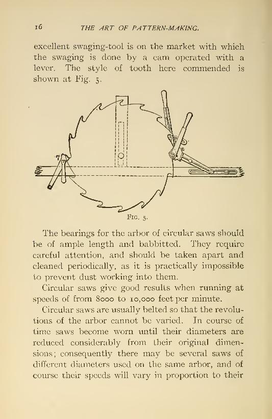
i6 THE ART OF PATTERN-MAKING.
excellent swaging-tool is on the market with which
the swaging is done by a cam operated with a
lever. The style of tooth here commended is
shown at Fig. 5.
Fig. 5.
The bearings for the arbor of circular saws should
be of ample length and babbitted. They require
careful attention, and should be taken apart and
cleaned periodically, as it is practically impossible
to prevent dust working into them.
Circular saws give good results when running at
speeds of from 8000 to 10,000 feet per minute.
Circular saws are usually belted so that the revolu-
tions of the arbor cannot be varied. In course of
time saws become worn until their diameters are
reduced considerably from their original dimen-
sions; consequently there may be several saws of
different diameters used on the same arbor, and of
course their speeds will vary in proportion to their

EQUIPMENT OF A MODERN PATTERN-SHOP. 17
diameters. These conditions are met and the best
results obtained from the machine by driving the
arbor to the hmit of speed for the largest diameter
of saw to be used; that is, at about 10,000 feet per
minute for the periphery of the teeth.
A handy device for use when dressing saws is
shown in Fig. 5. It consists of a T frame with the
horizontal bar secured to a bench. The upright
has a slot for the vertical adjustment of the saw.
To the right is a swage, whose pivot can be adjusted
on the horizontal bar; to the left is a small vise, 7,
to receive one tooth of a saw. This vise is adjustable
on the horizontal bar, to which it can be clamped
by a thumb-screw. By gluing a piece of paper
around the end of the file and keeping it bearing on
the shelf while filing, all the teeth can be filed alike
without difficulty.
The next most important tool for a pattern-shop
is the band-saw machine. In a shop of the before-
mentioned capacity there should be at least two of
these, one to carry saws up to ij inches wide, and
the other to carry saws up to one inch. One great
disadvantage in the use of these machines is the
want of stiffness in the frames. There are but few
made which are not deficient in this respect.
Band-saws give good results when run at a speed
of 3500 to 4000 feet per minute. These machines
are usually provided with breaks for the stoppage
of the saw, and should always be so arranged that
a pressure on a pulley beyond a certain fixed limit
cannot be produced by them. If they are not so

1
8
THE ART OF PATTERN-MAKING.
provided and the saw is stopped very suddenly, it
is likely to break in consequence of the strain thus
created. A great drawback to the use of these
machines is the cost of the saws, which consequently
break. That a band-saw will give way in the course
of time is inevitable. Every time that a saw passes
over the wheels while running, it bends and straight-
ens again. This fatigues the material, and with
continued running it is distressed beyond ultimate
endurance, just as any similar piece of metal would
be broken by being bent back and forth a sufficient
number of times.
The breakage of saws may be reduced by careful
attention to their condition and that of the ma-
chine. In joining them they should be scarfed
and lapped two teeth and brazed with silver solder.
Immediately the tongs are removed from the joint,
a few drops of oil should be dropped on the saw bythe side of the lap. If not so treated, the saw is
likely to become too soft on either side of the joint
and will break there earlier than at any other part.
Band-saws should always be kept sharp and have
a proper set to the teeth, and the wooden jaws on the
guide-bar of the machine should be kept set up close
to the saw. The mouth-block in the table also
requires frequent attention, as the deflection of
the saws, especially the smaller ones, cuts themaway.
An excellent little machine for sharpening and
setting band-saws is to be found on the market. It
can be secured to a post and occupies little room.
EQUIPMENT OF A MODERN PATTERN-SHOP. 19
Being driven by power, a saw can be put in, the
machine set going and allowed to run without fur-
ther attention until the saw is finished.
Another important machine in the pattern-shop
is a hand-planer. There should be two of these
machines, one with 16-inch knives, to be kept for
rough work, the other with 24-inch knives, to be
reserved exclusively for the cleaner and finer class
of work, because, if allowed to be used indiscrim-
inately, the latter will seldom be in the condition
essential for the kind of work required of it andfor which the machine is specially adapted. Theback table of a hand-planer should be provided
with a locking arrangement, in order that its posi-
tion cannot be changed after having been adjusted
to the knives.
The speed recommended for hand-planers is
4000 feet per minute, but they will work satisfac-
torily between that speed and 3500.
A surface or cylinder planer is also a useful ma-chine in a pattern-shop. An improved machine of
this kind does not require a great amount of atten-
tion; it suffices to have the knives kept in proper
condition and the bearings inspected occasionally, to
see that the oil is properly performing its functions.
The speed is the same as for the hand-planer.
When it is difficult to obtain 4000 feet per minute,
a speed between that and 3500 feet will give satis-
faction.
A Daniels planer is very useful in a pattern-shop.
It is simple, effective and durable, requiring but
20 THE ART OF PATTERN-MAKING.
little instruction regarding its care and use.
With this planer the lumber can be planed out of
wind, which cannot be done with a cylinder planer,
although the work is not so rapidly done as with the
latter.
The cutters of a Daniels planer should run at a
high rate of speed, say from 10,000 to 1 1,000 feet per
minute. The style of cutters recommended for a
Daniels planer are shaped like the letter J, the cut-
ting edge being on the side.
A jig-saw is required in a pattern-shop for inside
sawing. The band-saw, which has supplanted it
for outside sawing, is not adapted for positions
bounded entirely by the material.
An advisable speed for this machine is from 500
to 1000 strokes per minute, according to the char-
acter of the machine.
A vertical boring-machine is also useful in a
pattern-shop. One having a capacity for boring
holes up to 2 inches in diameter is preferable, and
should be arranged with two speeds, one to produce
850 or 900 revolutions of spindle, for bits more than
i\ inches in diameter, the other 1200 or 1300 revo-
lutions, for smaller bits.
A core-box machine is another very useful ma-chine in a pattern-shop. A machine of this kind is
on the market, on which core-boxes of any length
and from f to 20 inches in diameter can be worked.
Staves and similar pieces can also be worked
accurately and rapidly on their hollow sides bythis machine.

EQUIPMENT OF A MODERN PATTERN-SHOP. 21
Among the minor power machines that a pattern-
shop should have are a grinder for planer-knives,
a wet emery-grinder for bench-tools, and two grind-
stones, one of the latter being corrugated for the
convenience of grinding inside bevel gouges.
Trimmers are indispensable in a modem pattern-
shop. It is advisable to have at least two of the
largest size for the general use of the shop, and several
of smaller size, one being located convenient to each
two benches.
There are several other necessary adjuncts to
the complete equipment of a pattern-shop, but
these are so well known that description of themis here unnecessary.
The bearings of wood-working machinery require
very careful attention, in consequence of the high
speed at which it revolves and their liability to
the deteriorating effects of dust. Bearings should
always be provided with tallow-boxes, which should
be kept filled with tallow or, better, with Albany
grease. A small hole should be made through the
grease near each end of the bearing, into which a
little oil should be dropped before starting the ma-chine ; then, should the oil work off with continuous
running, the grease will continue to keep the bear-
ing lubricated.
The foregoing is noted as to machines necessary
for the equipment of an up-to-date pattern-shop,
one that should be able to perform with precision,
expedition, and economy, as far as facilities are con-
cerned, the work required of it.

22 THE ART OF PATTERN-MAKING.
Of course it is possible to get along, in a manner,
with less machinery, but such a shop would be
at a disadvantage when competing with a better-
equipped concern.
In many shops a great variety of woodwork is
done other than that of pattern-making. In such
establishments additional machinery is necessary,
the kind and quantity of which will be governed by
the nature and extent of the work.
The style of work-bench usually furnished pat-
tern-makers is the ordinary carpenter's bench, i6
feet long. Pattern-makers seldom have need of a
bench more than 12 feet long, and Fig. 6 repre-
sents a convenient style.
^<~7y T-^4^^ |"-.r-vr-vr-vW^^^M-x
Fig. 6.
The dimensions of a double bench of this kind,
well adapted for pattern work, are: 12 feet long,
4 feet wide, and 3 feet high. For a single bench the
width should be 3 feet, and the other dimensions
the same as for a double bench. Each bench should

EQUIPMENT OF A MODERN PATTERN-SHOP. 23
have a shelf about i foot from the floor, extending
over the entire space between the legs of the bench.
It should also have a drawer for each workman.The framing and the top should be of hard woodabout 3 inches thick, except for about 18 inches in
the middle of the width of the top; this can be of
I -inch pine placed flush with the bottom of the side
pieces, forming a recess in the middle of the bench,
as illustrated. This recess is convenient for the
retention of small tools and articles to be used about
the bench. The jaw of the vise is placed horizon-
tally, and to it is attached a ratchet bar sliding in
bearings under the end of the bench. A pawl is
fitted into the bench over the bar by means of which
the jaw can be adjusted to suit the work to be
clamped. This device is shown in detail, marked a.
The vise-screw is of iron, which works more easily
than if made of wood. The above arrangement of
the vise is more convenient than the ordinary ver-
tical position, as this necessitates stooping on the
part of the workman in order to attend to the ad-
justment ; and rather than do this he will often use
the vise in an awkward position, at the risk of result-
ing damage. Of late years iron bench-vises are
becoming much used and are meeting with justly
increasing favor.
When sufficient space is available, single benches
are preferable. With double benches the space
necessary per workman in the length of the bench
row is about 5I feet ; with single benches it is about
6J feet.

III.
THE MANAGEMENT OF A MODERNPATTERN-SHOP.
The qualifications necessary for a foreman to
possess in order to successfully manage the affairs
of a large pattern-shop are that he should be a
draftsman, a good arithmetician, should have athorough knowledge of the art of moulding, and
should be a good judge of human nature as well as
of the different materials used in his department.
He should be able to decide the manner in which
any pattern is to be moulded, and to direct the
construction of the pattern accordingly. He should
also have a thorough knowledge of the construction
and care of wood-working machinery, and not the
least of the necessary qualifications are energy,
good character, and good habits.
By some persons the pattern-shop is considered a
drawback to the machine business in consequence
of the expense because patterns do not show in a
completed structure as other materials do, and are
considered unproductive. Yet the pattern-shop is
more essential than the drawing department, to
which it is closely allied. It is possible to dis-
pense with the latter in the machine business,
24
My4NAGEMENT OF A MODERN PATTERN-SHOP. 25
though not with the former where castings are
required. But unfavorable criticism of the pattern-
shop is frequently the result either of the critic's
inexperience in mechanical pursuits, or the assump-
tion of knowledge that he does not possess. Theperson who invents a method of making castings
without the aid of patterns has both fame andfortune awaiting him.
The expense attendant on the use of patterns is
often unnecessarily increased, owing to the abuse
which they receive in the foundry. Some mould-
ers are veritable pattern-smashers, and will do moredamage to a pattern in making a half-dozen castings
than others will in making a hundred.
Pattern work, like all other kinds of model work,
is expensive, and can be made more or less so accord-
ing to the work required of the pattern. In this
respect patterns may be divided into three classes,
and the cost of producing them should be varied
accordingly.
a. Patterns of a temporary character, those not
likely to be used more than once. These should be
made with as little expenditure of labor and ma-
terial as possible to enable them to perform their
functions. These patterns should not be preserved,
as they unnecessarily encumber the pattern-loft.
h. A class "of patterns likely to be used occasion-
ally, sometimes at long intervals. These should be
preserved, and more pains be taken in their con-
struction than with the former, as they have to
withstand the usage in the foundry as well as the

26 THE ART OF PATTERN-MAKING.
distortion likely to occur to them during their storage
in the pattern-loft.
c. A class of patterns regarded as standard and
which are frequently used. These cannot be madetoo well, and when properly constructed are neces-
sarily expensive in first cost.
When a drawing is received in the pattern-shop
the first duty of the foreman in connection there-
with is to acquaint himself with it and decide howthe pattern is to be made, and in what manner
moulded. If detail drawings of a machine or other
device to be constructed are received, a general
drawing should accompany them, or else the fore-
man should be made acquainted with the general
arrangement of the parts. When this is done he
will often be able to detect errors which might not
otherwise be discovered until after the castings have
been made and the machining of them is in progress.
There are several allowances necessary to be de-
termined previous to beginning the construction
of a pattern. The one most troublesome to the
pattern-maker is that for finishing. The amount
that will answer for one machinist will not suit
another. It is advisable to leave as little as possible
for finishing, and to have sufiicient to allow for the
proper finishing of the castings. This allowance
will depend a great deal on the result of the casting
and its likeness to the pattern. This is likely to
vary according to the manner of moulding the pat-
tern. As a rule, the castings requiring the greatest
amounts for finishing are those which have been
MANAGEMENT OF A MODERN PATTERN-SHOP. 27
moulded in loam, and castings made of steel.
These are liable to vary from the proper dimen-
sions to a greater extent than those moulded bythe other methods. Large castings of steel are
never as true to pattern as those of other metals.
For patterns to be moulded in loam and for steel
castings an allowance of from one fourth to one
half of an inch, according to the part to be finished,
is necessary.
For ordinary castings moulded in green or dry
sand an allowance of from one eighth to one quarter
of an inch is sufficient. For the smaller castings,
which have been moulded neatly and are of sound
metal, an allowance of from one sixteenth to one
eighth of an inch will answer.
The allowance for shrinkage, or the amotmt the
pattern is required to be made larger than the in-
tended casting, is another important preliminary
matter to be determined before constructing a
pattern. The conventional allowance for iron cast-
ings is one eighth of an inch per foot, but this rule
needs modification in applying it to castings of
various shapes, dimensions, and mixtures of metals.
To insure accuracy in castings much depends on
the judgment of the pattern-maker in providing
for their construction. Hard irons, as gun-iron,
will shrink more than the above amotmt, while soft
iron will shrink less. Yellow brass will shrink more
than bronze. A plain cylinder will shrink less in
diameter than in length.
With large cylindrical or box-shaped castings

28 THE ART OF PATTERN-MAKING.
of iron it is good practice to allow one tenth of an
inch per foot for shrinkage in length, and one half of
this amount in diameter, or across. The shrinkage
in length of such castings is generally very little
restricted, while in diameter it is resisted by the
cores or internal parts of the mould. Two castings
of the same weight and of the same kind of material,
one of which is extended and the other more com-
pact, will shrink differently, the latter shrinking
less than the former.
Metals, like water, are densest in their liquid
state, the point of greatest density being near the
temperature at which they solidify. From this
point they will expand either with a reduction or
an elevation of temperature. Iron, when about to
solidify, undergoes a sudden expansion, owing to
the effort of the molecules to arrange themselves
in definite positions. After solidification takes place
it begins to contract, with a further loss of tem-
perature. When the contraction begins, the metal
is just leaving its plastic condition, and its cohesive
strength is considerably below that of its normal
state. If at this period the contraction of the metal is
resisted by parts of the mould, a fracture of the metal
is likely to occur. With some of the more contracti-
ble metals, as with steel, to avoid fractures it be-
comes necessary, as soon as the metal has set, to
relieve the interior parts of the mould and allow
the metal freedom in shrinkage. In the case of a
plain cylinder, where its shrinkage is resisted by an
internal core, the metal will contract within its

MANAGEMENT OF A MODERN PATTERN-SHOP. 29
annular wall until its cohesive strength becomessufficient to compress the core, at which period it
will have undergone part of its contraction. This
accounts for the reduced shrinkage of cylinders
diametrically.
The usual allowances for the shrinkage of castings
of different metals are, per foot
:
For iron one eighth of an inch." bronze five thirty seconds of an inch,"
brass three sixteenths of an inch." yellow brass seven thirty seconds of an inch."
steel three sixteenths of an inch." aluminum seven thirty-seconds of an inch."
zinc seven thirty-seconds of an inch."
lead seven thirty-seconds of an inch"
tin three sixteenths of an inch.'
It is not always known where the castings for
which a pattern is to be constructed are to be made.
The opinions of moulders will differ widely as to the
best method of moulding some patterns. In such
cases the foreman is often perplexed. His desire
should always be to have a pattern made to be
moulded to the best advantage of the foundryman.
Where there is any doubt as to the best way of
moulding a pattern, the foreman moulder should
be consulted where it is possible. As he is respon-
sible for the proper production of the castings, his
desire should be regarded and the pattern madefor his convenience.
It is too often the case that strained relations
exist between the heads of the pattern-shop andthe foundry in consequence of the perversity of

30 THE ART OF PATTERN-MAKING.
one or the other, or through attempts made to shift
responsibiUties. Each should desire harmony in
their business intercourse, because without this
the work cannot be carried on to the best advantage
of their employers.
The foreman of a pattern or any other shop should
be relieved of any clerical work. His proper place
is in the shop among the workmen, observing what
is going on ; to inspect and direct the work in prog-
ress ; to see that every employee is performing his
duty properly, and that the materials and machin-
ery are properly used. When he performs all this,
he will have little time to devote to office work.
With pattern lumber at from seven to ten cents per
foot, and where large quantities are being used, it is
an important part of a foreman's duty to see that it is
economically employed. The repairs to machines,
belting, etc., and the sharpening of cutters is quite
an item in the running expenses, and the desire
should be to reduce this to a minimum.
A foreman should have full control of the em-
ployees in his shop as long as he is held responsible
for its management. Without this it is probable
that by some he will not be respected as he should
be. He should be gentlemanly in his intercourse
without being too familiar with his subordinates,
and should insist on being respected by them. In
some instances the responsibility of employing and
discharging employees, as well as other duties
which should belong to the foreman, are assumed
by others above him. Where such a condition

MANAGEMENT OF A MODERN PATTERN-SHOP. 31
prevails, the inevitable tendency is to impair the
efficiency of the shop, and it behooves the foreman
to use his judgment very discreetly if he desires to
reduce to a minimum the annoyances inseparable
from such a system.
One thing that reflects credit on the managementof a pattern-shop is to have it look clean and tidy.
Of course it is impossible, where so many shavings,
etc., are made, to have such a shop look as clean as
some other kinds of shops. However, it can be kept
reasonably clean without an excessive amount of
labor by a proper system, making it the business of
a person to clean the shop. What helps to make a
pattern-shop look untidy is the accumulation of
scraps, etc., that litter the floor under the work-
benches, thrown there by the workmen for future-
use, but who seldom trouble themselves to look
through the lot when it is easier to cut a board.
This accumulation is aided by the unsuitableness
of the ordinary carpenter's work-bench, which is
the kind usually supplied to pattern-makers. Withthe style of bench previously illustrated and de-
scribed, having under it a shelf about one foot from
the floor for the reception of articles not wanted
for immediate use, the space under the bench can
be swept clean and accumulation of rubbish pre-
vented.
It is too frequently the case that work-benches
are unnecessarily abused. Some workmen will
use the bench-stop while sawing and thereby risk
cutting into the top and vise rather than take the

32 THE ART OF PATTERN-MAKING.
trouble of making a bench-hook. The undue dis-
figurement of a work-bench is infalhble evidence
that it has been occupied by a careless and slovenly
workman.
The machines in the pattern-shop most likely
to cause accidents, as well as to be misused, are the
circular saw and the hand-planer. When workmenare careless or ignorant of the use of machines they
should be instructed how to use them properly. Nosaw should ever be forced beyond its limit for doing
good work. Even a good saw in the best of con-
dition can be made to work unsatisfactorily by forc-
ing the work too hard upon it. In using a circular
saw a person should never place his hand behind
it while standing in front, nor even let the hand pass
in front of the saw while so standing. A stick should
be kept handy, and when the end of the work is near
the saw, finish by pushing it through with the stick.
Should the saw incline to run out when not forcing
it, withdraw the work and investigate the cause,
which will likely be one of the following : a dull sawor one with insufficient set. Should the work spring
and bind on the saw, withdraw it at once and begin
sawing at the other end, or else have some one insert
a wedge after the end has passed the saw. Manydeaths have been caused by the board being sawn,
binding on the back of the saw, which causes the
board to be raised until the top of the saw comes in
contact with it and throws it forward with great
force.
The band-saw is not considered a dangerous tool,
MANAGEMENT OF A MODERN PATTERN-SHOP. 33
but it is liable to great abuse by the use of saws
that are too dull or insufficiently set, or by attempt-
ing to saw curves smaller than those in which the
saw will freely turn.
Nearly every accident occurring on the hand-
planer is caused by attempting to plane short pieces
which, before they are made to bridge the mouth of
the planer, are caught by the knives and drawn in.
Often a hand goes in with the piece of work, and the
person is maimed for life. A good rule to be ob-
served in using this machine is never to attempt to
plane a piece of work on it less than lo inches long
nor less than f of an inch thick.

IV.
PATTERN WORK FOR MOULDING IN LOAM.
The present chapters have not been written with
the view of teaching the art of pattern-making, but
rather presuppose a knowledge of it; proficiency
must be acquired by practical work, patient applica-
tion, and the stimulus of ingenuity at the drawing-
board, bench, and lathe. Aided even by the exer-
cise of these qualifications, only they who possess
natural aptitude and who labor long for success can
hope to achieve their object and become expert in
their profession.
The examples given have been selected from
many cases of actual practice, have all borne satis-
factory results, and are therefore considered reliable.
They are given for the purpose of awakening
thought and with the desire to encourage independ-
ent suggestion and inventive power; for this will
be the surest pathway to a knowledge of the best
methods of constructing patterns that will satisfy the
varied requirements of the moulder.
In a shop employing a large number of workmenand doing a great variety of work there will always
be found those who excel in a particular kind of
work. Some will be more expert in one class and
others in another. In the giving out of work it
34
PATTERN JVORK FOR MOULDING IN LOAM. 35
is well to consider the efficiency of the workmen in
this respect, and, as far as possible, to make a judi-
cious distribution.
When giving out a job the foreman should express
to the workman his opinion as to how the pattern
should be made and moulded, but he should also
listen to and consider any suggestion made by the
workman regarding it. Should the workman desire
to make the pattern in a different way from that
suggested by the foreman, and if a result equal in
efficiency and economy can be thereby accom-
plished, he should be allowed to proceed in his ownway, as he will then probably feel a greater interest
in producing a good result.
Many good workmen consider it humiliating not
to be allowed to use their own judgment as to the
manner in which a piece of work should be done,
and it is good policy not altogether to disregard
their opinions unless they are manifestly at fault,
but rather through an interchange of opinion arrive
at a mutual understanding.
Men should be dealt with as men, and boys as
boys, and not the reverse, which is sometimes at-
tempted.
Loam moulding is resorted to when the article
wanted is of too large dimensions or is too compli-
cated in form to be moulded by any other method, or
when the casting is not likely to be often duplicated.
It is considered the most intricate, varied, and expen-
sive method of producing castings, whether of iron,
brass, or steel. On the other hand, the pattern

36 THE ART OF PATTERN-M/tKING.
work for loam moulding, while often very intricate,
is of the most inexpensive kind-
Patterns for loam moulding are both of the sim-
plest and the most complicated kind. The sim-
plest are for bodies of revolution, or those objects
which can be formed by revolving a radial section
of the body about an axis. One of the simplest
examples is the pattern work for a large plain kettle.
These comprise a number of sweeps or strikes, in
some places called strickles. A sweep consists of a
plain piece of board whose profile is that exposed
by a plane cutting the body parallel with and pass-
ing through its axis.
The first sweep used in constructing a mould for
a kettle is that marked A, Fig. 7. It is secured to
the spindle, a, which is free to revolve about a
vertical axis. The mould is built up of brickwork.
PATTERN JVORK FOR MOULDING IN LOAM. 37
with a thickness of loam intervening between it
and the edge of the sweep, and, when the latter is
revolved, it strikes or dresses the loam off to the
form of the sweep. This part of the mould, whencompleted, is called the core, and forms the inside
of the kettle.
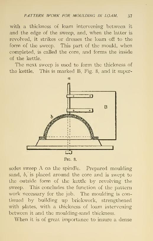
The next sweep is used to form the thickness of
the kettle. This is marked B, Fig. 8, and it super-
a
sedes sweep A on the spindle. Prepared moulding
sand, b, is placed around the core and is swept to
the outside form of the kettle by revolving the
sweep. This concludes the function of the pattern
work necessary for the job. The moulding is con-
tinued by building up brickwork, strengthened
with plates, with a thickness of loam intervening
between it and the moulding-sand thickness.
When it is of great importance to insure a dense

38 THE ART OF PATTERN-MAKING,
and solid bottom the kettle is moulded in the re-
verse position, bottom down. This is a somewhat
more expensive method than the former. Whenmoulded the latter way the sweeps are made the
reverse of those described, and are used in the
reverse order.

V.
Px\TTERN WORK FOR A CYLINDER.
Large cylinders, with nozzles such as are used
in beam engines, are objects well adapted to be
moulded in loam. They require somewhat more pat-
tern work than the former example. Fig. 9 repre-
sents a section of mould for a cylinder of this kind.
When preparing the pattern work for such a cylin-
der the first piece required by the moulder is the
sweep. Fig. 10. This is used to form the seat or
foimdation of the mould. After the seat has been
swept up and the sweep removed the seat is lined
off. The segment. Fig. 11, is the next in order,
and is made of board the thickness of the bottom
flange of the cylinder and having an inside radius
equal to that of the outside of the flange. It is set
as illustrated, and moulding sand is rammed inside
of it to form the pattern of the lower flange of the
cylinder.
The next piece in order used is the outside or
cope sweep, Fig. 12. This being secured to the
spindle, everything is prepared for the building of
the outside of the mould. The patterns of the noz-
zles. Fig. 13, being prepared, they are set by lines
in their proper positions during the building of the
outside of the mould. The outside flange seen on the
39

40 THE ART OF PATTERN-MAKING.
a^^Fig. 13
Fig. 15.
Fig. 10. Fig. II.
a
Fig. 12.
&^
Z
3
1Fig. 9. Fig. 14.
PATTERN fVORK FOR A CYLINDER, 41
nozzle pattern is to form a seat for a covering-plate.
These plates have holes through them, through
which the nozzle-cores pass. The outside wall, or
cope, of the mould being finished as far as the top
of the upper flange and the sweep. Fig. 12, removed,
the cope is then removed from the seat, leaving the
latter intact.
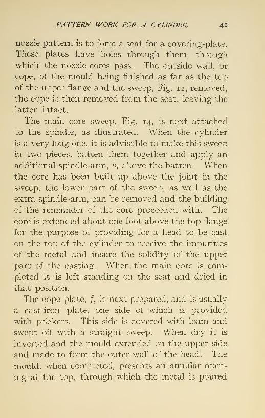
The main core sweep. Fig. 14, is next attached
to the spindle, as illustrated. When the cylinder
is a very long one, it is advisable to make this sweep
in two pieces, batten them together and apply an
additional spindle-arm, h, above the batten. Whenthe core has been built up above the joint in the
sweep, the lower part of the sweep, as well as the
extra spindle-arm, can be removed and the building
of the remainder of the core proceeded with. Thecore is extended about one foot above the top flange
for the purpose of providing for a head to be cast
on the top of the cylinder to receive the impurities
of the metal and insure the solidity of the upper
part of the casting. When the main core is com-
pleted it is left standing on the seat and dried in
that position.
The cope plate, /, is next prepared, and is usually
a cast-iron plate, one side of which is provided
with prickers. This side is covered with loam and
swept off with a straight sweep. When dry it is
inverted and the mould extended on the upper side
and made to form the outer wall of the head. The
mould, when completed, presents an annular open-
ing at the top, through which the metal is poured
42 THE ART OF PATTERN-MAKING.
and drops to the bottom. Fig. 15 is the core-box
for the nozzle-cores, and Fig. 9 represents a section
of the mould when assembled.
A column of cast iron 3.84 inches in height and
of one square inch in area weighs one pound and
exerts that pressure per square inch on its base
when in a liquid state.
Assuming the foregoing cylinder to be 16 feet or
192 inches in height from the bottom to the head,
the pressure will consequently be fifty pounds per
square inch on the bottom of the mould. This
great pressure has a straining effect on the mould
—
a tendency to separate its walls. If the walls of
the mould are parallel with each other, that is,
have a uniform distance between them from top
to bottom, the casting would probably show a
greater thickness of metal at the bottom. It is
advisable, therefore, to set the sweeps to counteract
this straining of the mould by the metal.
For a cylinder 10 or 12 feet in height the core
should be made one eighth of an inch larger in
diameter at the bottom than at the top, and the
outer wall one eighth of an inch smaller in diameter
at the bottom than at the top. The mould would
then measure one eighth of an inch less between its
walls at the bottom than at the top, but the thick-
ness of the casting would most likely be uniform,
owing to the straining effect of the metal on the
mould while being filled. For a cylinder of 15 or 18
feet in height this difference between the walls of

PATTERN IVORK FOR A CYLINDER. 43
the mould at the top and the bottom can be increased
to three sixteenths of an inch.
The result of pressure on the liquid metal in a
mould is to increase its density and strength whencold. In some instances moulds are arranged to
receive a pressure in addition to that produced bythe metal alone, as in the case of the Whitworth
process of casting steel. Even should the mould
not be strained to the extent allowed for, the cast-
ing will be strongest at the bottom, owing to the
benefit resulting from the greater pressure there.

VI.
PATTERN WORK FOR AN ELBOW.
In constructing loam moulds it is not always
necessary to have a spindle. Other bodies than
bodies of revolution can be swept up in loam when
the necessary guides are provided for the sweeps.
Figs. i6 to 31 represent a large valve-chamber com-
bined with a nozzle, or elbow, or bend. Fig. 16 is a
frame made of |- or i|-inch material. The interior
of the frame corresponds with a horizontal section
of the casting. The size of the opening at each
end is extended in the frame for the same purpose
that core-prints are made to form a seat, or support,
as well as a guide for setting the core. The outside
of the frame is worked off, to be parallel with the
inside, for the purpose of forming a guide for the
sweeps. Fig. 17 is the pattern for the flange at
the valve-chamber end; Fig. 18 that of the end of
the bend; Fig. 19 is the pattern to form the bell
shape where the diameters change; these are
shown attached to plate 16. A pattern for this
part is not absolutely necessary, as it can be
formed by sweeps; but a pattern facilitates the
moulding; Fig. 20 is the pattern for the branch,
or nozzle; Fig. 21 is the sweep to form the outside
of the mould at the bottom or drag part of the
44
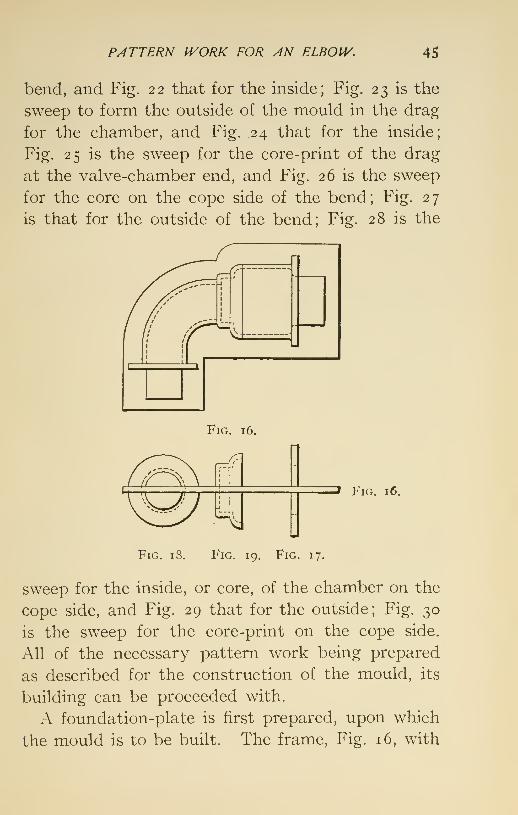
PATTERN IVORK FOR AN ELBOJV. 45
bend, and Fig. 22 that for the inside; Fig. 23 is the
sweep to form the outside of the mould in the drag
for the chamber, and Fig. 24 that for the inside;
Fig. 25 is the sweep for the core-print of the drag
at the valve-chamber end, and Fig. 26 is the sweep
for the core on the cope side of the bend; Fig. 27
is that for the outside of the bend; Fig. 28 is the
Fig. 16,
» Fig. 16.
Fig. 18. Fig. 19. Fig. 17.
sweep for the inside, or core, of the chamber on the
cope side, and Fig. 29 that for the outside; Fig. 30
is the sweep for the core-print on the cope side.
All of the necessary pattern work being prepared
as described for the construction of the mould, its
building can be proceeded with.
A foundation-plate is first prepared, upon which
the mould is to be built. The frame. Fig. 16, with

46 THE ART OF PATTERN-MAKING. •
the lower or drag parts of the pattern screwed
thereto is set up on the plate, and brickwork of
the usual kind for loara moulding is built up to the
frame, P'ig. 16. While building up the mould the
Fig. 20.
Fig. 25.
Fig. 28.
Fig, 29.
Fig. 30.
Fig. 21. Fig. 23.
Fig. 22. Fig. 24.
Fig. 26. Fig. 27.
Fig. 31.
proper sweeps are used. The sweep Fig. 21 is
used to form the outside of the mould by moving it
around the bend with the semicircular part pro-
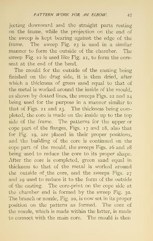
PATTERN IVORK FOR AN ELBOJV. 47
jecting downward and the straight parts resting
on the frame, while the projection on the end of
the sweep is kept bearing against the edge of the
frame. The sweep Fig. 23 is used in a similar
manner to form the outside of the chamber. Thesweep Fig. 22 is used like Fig. 21, to form the core-
seat at the end of the bend.
The mould for the outside of the casting being
finished on the drag side, it is then dried, after
which a thickness of green sand equal to that of
the metal is worked around the inside of the mould,
as shown by dotted lines, the sweeps Figs. 22 and 24
being used for the purpose in a manner similar to
that of Figs. 21 and 23. The thickness being com-
pleted, the core is made on the inside up to the top
side of the frame. The patterns for the upper or
cope part of the flanges, Figs. 17 and 18, also that
for Fig. 19, are placed in their proper positions,
and the building of the core is continued on the
cope part of the mould, the sweeps Figs. 26 and 28
being used to reduce the core to its proper shape.
After the core is completed, green sand equal in
thickness to that of the metal is worked around
the outside of the core, and the sweeps Figs. 27
and 29 used to reduce it to the form of the outside
of the casting. The core-print on the cope side at
the chamber end is formed by the sweep Fig. 30.
The branch or nozzle, Fig. 20, is now set in its proper
position on the pattern as formed. The core of
the nozzle, which is made within the latter, is madeto connect with the main core. The mould is then
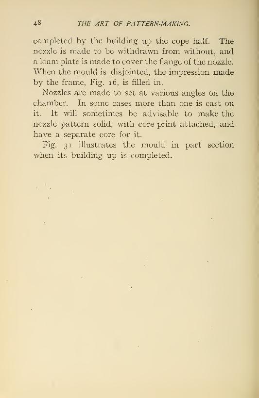
4^ THE ART OF PATTERN-MAKING.
completed by the building up the cope half. Thenozzle is made to be withdrawn from without, and
a loam plate is made to cover the flange of the nozzle.
When the mould is disjointed, the impression madeby the frame. Fig. i6, is filled in.
Nozzles are made to set at various angles on the
chamber. In some cases more than one is cast on
it. It will sometimes be advisable to make the
nozzle pattern solid, with core-print attached, and
have a separate core for it.
Fig. 31 illustrates the mould in part section
when its building up is completed.

VII.
PATTERN WORK FOR STEAM-CYLINDEROF MARINE ENGINE.
The pattern of a large steam-cylinder, with steam-
and exhaust-passages, when moulded in loam, de-
mands a greater proportionate amount of detail
than is required by those described already. Thepattern work can be made more or less elaborate,
according to the manner in which the moulder
desires to proceed in order to construct the mould.
The following pattern work and method of pro-
cedure have been applied with successful results in
producing satisfactory castings of large cylinders.
Fig. 32 shows a plain view. Fig. 33 an elevation,
and Fig. 34 a section of a casting designed for a
low-pressure cylinder with receiver for a compoundengine.
When a loam mould is to be made for such a
cylinder the pattern-maker is required to prepare
the necessary pattern work before the moulder can
proceed with its construction.
The cylinder is moulded inverted; that is, the
open end, or that which is upward when it is in the
engine, is moulded downwards.
The first piece required is the seat, or foundation
sweep, Fig. 35. This sweep forms a level surface,
49

so THE ART OF PATTERN-MAKING,
ri

STEAM-CYLINDER OF MARINE ENGINE. 51
Fig. 38.
Fig. 39.
t ST^2
Fig. 40
I
Mi
Fig. 43.
H
Fig. 42.
Fig. 41
P
i
^
Fig. 44. Fig. 45.

52 THE ART OF PATTERN-MAKING.
Upon which the pattern work is -placed ; and it also
forms the flange facing, against which the cylinder-
head is bolted. Fig. 36 represents a framework of
wood. Its exterior is the form of the exterior of
the casting. It also contains the valve-chest,
which is the same in form as that represented in
the sectional view, Fig. 34, except that where the
openings are shown in the valve-face core-prints are
placed, as shown by the dotted lines a, a, etc., pro-
jecting from the valve-face. These core-prints
are for the purpose of locating and supporting the
cores for the induction and eduction passages.
The cylindrical parts can be formed with revolving
sweeps, secured to a spindle, which method is pre-
ferred by some moulders ; but a framework of wood
is preferable in cases of this character, as with it there
is less difficulty in retaining the parts in their proper
positions. The flanges projecting inward in the
valve-chest are screwed or put on with draw-pins,
in order that they may be released and withdrawn
outwardly. The framework is made in sections and
screwed together to facilitate its being taken apart
and withdrawn from the mould. The patterns
for the exhaust-nozzle h and nozzle c are made
blank and cored out with special cores inserted
from the outside of the mould.
The foundation, or seat, being prepared and lined
off, the framework is placed upon it and properly
located. Everything is then prepared for the
building of the cope, or outer wall of the mould,
to be proceeded with. The framework has open

STEAM-CYLINDER OF MARINE ENGINE. 53
places, as d, d, etc. When the mould is being
built up past these places, a strike, e, is used
from the inside to shape these parts of the mould.
When the exterior of the mould is completed to the
top of the upper flange it is struck off by a plain
sweep fixed at right angles to the spindle. A line
is drawn across the top of the mould through the
center of the cylinder and valve-chest, and another
line at right angles to the former and through the
axis is also scribed on the top of the mould. These
lines are for the purpose of locating the position of
the covering-plate of the mould. When the exterior
of the mould, which has been made in sections, is
sufficiently dry to handle, it is removed from the
seat, leaving the latter intact.
The framework is then removed from the seat,
after which the main-core sweep. Fig. 37, is se-
cured to the spindle and the main core built up on
the seat, where it is dried and dressed and remains
undisturbed. A core-seat is formed in the upper
part of the main core, into which a core is set to
core out the hole in the head of the cylinder for the
plug which contains the stuffing-box for the piston-
rod. Previous to setting the core the main core is
filled with sand, as a precaution against accident,
the metal being liable to make its way into the inte-
rior of the core during the filling of the mould.
The cover of the mould, or cope-plate as it is
sometimes called, is made to form the head of the
cylinder. It is a plate provided with prickers, and
is specially cast for the purpose. When preparing
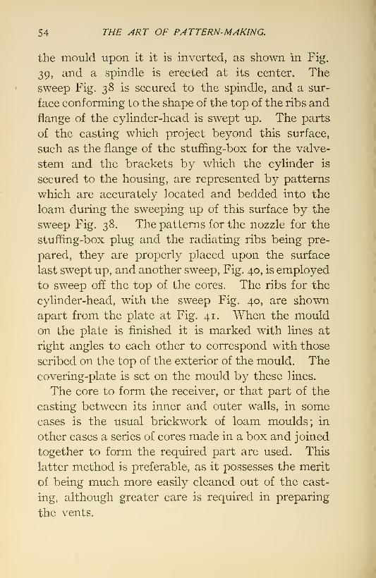
54 THE ART OF PATTERN-MAKING.
the mould upon it it is inverted, as shown in Fig.
39, and a spindle is erected at its center. The
sweep Fig. 38 is secured to the spindle, and a sur-
face conforming to the shape of the top of the ribs and
flange of the cylinder-head is swept up. The parts
of the casting which project beyond this surface,
such as the flange of the stufling-box for the valve-
stem and the brackets by which the cylinder is
secured to the housing, are represented by patterns
which are accurately located and bedded into the
loam during the sweeping up of this surface by the
sweep Fig. 38. The patterns for the nozzle for the
stuffing-box plug and the radiating ribs being pre-
pared, they are properly placed upon the surface
last swept up, and another sweep. Fig. 40, is employed
to sweep off the top of the cores. The ribs for the
cylinder-head, with the sweep Fig. 40, are shownapart from the plate at Fig. 41. When the mouldon the plate is finished it is marked with lines at
right angles to each other to correspond with those
scribed on the top of the exterior of the mould. Thecovering-plate is set on the mould by these lines.
The core to form the receiver, or that part of the
casting between its inner and outer walls, in some
cases is the usual brickwork of loam moulds; in
other cases a series of cores made in a box and joined
together to form the required part are used. This
latter method is preferable, as it possesses the merit
of being much more easily cleaned out of the cast-
ing, although greater care is required in preparing
the vents.

STEAM-CYLINDER OF MARINE ENGINE. 55
At Fig. 42 are shown three views of a core-box
for receiver cores. The cyHnder herein described
will require eight of these cores, two in height and
two around each side. The box is made a segment
of ninety degrees, but the cores complete will not
extend so far. They are made the required size
and shape to fit the mould by placing stopping-off
pieces in the ends of the box. / shows such a piece
for stopping off the cores. Where the exhaust
emerges it requires two of these pieces, one right-
and one left-hand. Two more of the proper form,
right and left, are required to stop off the cores which
go to the open side opposite the valve-chest. Fig.
43 represents the box in which the core for the
exhaust-passage is made. Three views are shown
—
plan, elevation, and section. The box is made to
be taken apart.
Fig. 44 shows the box in which the cores for the
steam-passages are made. These passages are of
the double-ported variety. Three views of these
are shown—plan, elevation, and section. Fig. 45
represents the core-box for coring out the cylinder-
head nozzle, into which is fitted the plug containing
the stufQng-box for the piston-rod.
VIII.
PATTERN WORK FOR A PEDESTAL.
Occasionally a large casting of some kind is called
for, a duplicate of which is never likely to be re-
quired. To make in the usual way a pattern for
such a casting would consume considerable time,
which might cause delay as well as involve -unneces-
sary expense. In such cases, therefore, recourse is
had to temporary expedients. Fig. 46 shows such
a casting in the form of a tapered pedestal, whose
length and comparatively small diameter are such
as to make it inadvisable to sweep it up vertically,
after the manner of making a cylinder mould, or to
incur the expense of constructing a pattern of the
usual kind. It being decided to cast the pedestal
in a horizontal position, a barrel, upon which the core
is made, is the first piece required. The pattern of
the core-barrel will be formed by strikes, or sweeps,
guided by proper templet, the skill of the moulder
being called in to form the pattern after the pattern-
maker has provided the necessary appliances. Fig.
47 illustrates a section of the mould and pattern for
the core-barrel. An iron flask is first constructed
which, when very long, as in the present case, is madein two pieces. The usual brickwork of loam moulds
56

PATTERN IVORK FOR A PEDESTAL. 57
is built inside the flask, and the guide a is set at
one end of the drag, the guide / at the opposite end,
and guide c midway between the two. When thus
arranged, their circles are such that when a straight-
edge is moved around the inside, the required uni-
form taper will be produced. The middle guide is
not absolutely essential, but with it the strike need
be only one half the length of the mould, thus being
more conveniently handled, h is the sweep for
forming the lower or drag half of the mould, and
being half the length of the latter, it is used alter-
nately at each end. The recess in the mould formed
by the offset on the sweep h represents the thickness
of the casting. When the mould is sufficiently dry
this recess is filled in with green sand, and a straight-
edge moved around the guides reduces it to the
proper thickness. This last operation completes
the lower half of the mould and pattern. The core
is next made on the inside of the mould up to the
joint. The guide h having been set in a, and g in /,
these determine the diameter of the upper half of
the core. The half-collar d is set midway between
the other two for the convenience of a guide for the
sweep, which is a straight-edge, of half the length
of the mould. When the core is formed the collar d
is removed and its impression in the core filled in.
The core being sufficiently dry, the half-collar d is
set midway of its length, and green sand is placed
aroimd the core ; the sweep i is then used to reduce
the sand to the thickness of the intended metal.
This completes the core and pattern for the upper
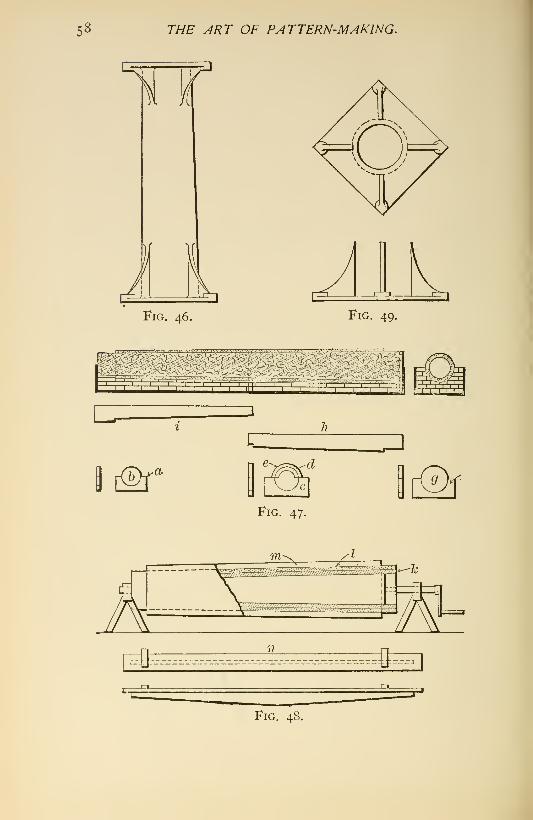
58 THE ART OF PATTERN-MAKING.
Fig. 46. Fig. 49.
[3d
I t^-^Fig. 47.
[Of

PATTERN IVORK FOR A PEDESTAL, 59
or cope half of the mould. The mould is then com-pleted in the usual manner. The illustration shows
the various guides and sweeps for the core in the
relative positions which they occupy in the mould,
but separated from it.
When the mould is taken apart and the core
lifted out, the thickness of green sand is removed,
and the mould and core are then finished in the
usual manner. Numerous small cores, the samelength as the thickness of metal, are fixed around
the mould for the purpose of casting holes in the
core-barrel. The core-barrel k, being cast, is mountedbetween bearings, as illustrated at Fig. 48. The core
is made in the usual manner by winding the barrel
with rope made of hay, then coating this with loam, /,
and reducing the loam to the required size and
shape by revolving the core while in contact with
one side of the sweep n, which is so set as to obtain
the proper diameter of the core.
When the core is sufficiently dry, which is accom-
plished by building a fire imder it while it remains
in the bearings, a second coat, w, of specially pre-
pared loam is laid on and brought to the required
thickness, which is equal to that of the metal, byrevolving the core, while the reverse edge of the
sweep n is fixed so as to reduce the loam to the re-
quired diameter. This being accomplished, the
second coat forms the pattern for the body of the
pedestal. When this outer coat is dry and dressed
it is ready to receive the top and bottom flanges,

6o THE ART OF PATTERN-MAKING,
Fig. 49, ribs, bosses, and whatever else is necessary
to complete the pattern.
These parts are made of wood, and are fitted to
the pattern formed for the body of the pedestal,
the flanges parting through their center and the
bosses arranged so that they can be drawn in through
the vacancy left by withdrawing the flanges.
The pedestal pattern is supported in a horizontal
position when it is being made, the supports being
under the gudgeons which project from the ends of
the core-barrel. The mould is constructed of
brickwork in the usual manner of constructing
loam moulds. When the mould has been com-
pleted and taken apart the coating of loam repre-
senting the thickness of metal is removed from the
core and the latter dressed. After the mould has
received like treatment it is reassembled.
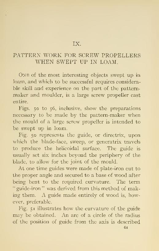
IX.
PATTERN WORK FOR SCREW PROPELLERSWHEN SWEPT UP IN LOAM.
One of the most interesting objects swept up in
loam, and which to be successful requires considera-
ble skill and experience on the part of the pattern-
maker and moulder, is a large screw propeller cast
entire.
Figs. 50 to 56, inclusive, show the preparations
necessary to be made by the pattern-maker whenthe mould of a large screw propeller is intended to
be swept up in loam.
Fig. 50 represents the guide, or directrix, uponwhich the blade-face, sweep, or generatrix travels
to produce the helicoidal surface. The guide is
usually set six inches beyond the periphery of the
blade, to allow for the joint of the mould.
At one time guides were made of plate-iron cut to
the proper angle and secured to a base of wood after
being bent to the required curvature. The term*' guide-iron" was derived from this method of mak-ing them. A guide made entirely of wood is, how-
ever, preferable.
Fig. 51 illustrates how the curvature of the guide
ma}^ be obtained. An arc of a circle of the radius
of the position of guide from the axis is described61

62 THE ART OF PATTERN-MAKING.
for the base. The degrees of the arc should be
somewhat greater than the angle occupied by the
blade when it is viewed parallel with the axis, in
order to allow for a joint at both the top and bottom
edges of the blades. The arc is divided into any
number of equal parts, as a, h, and c. The length
of the inclined rail is obtained by laying down its
angle with one end intersecting one extremity of
the base line, and the other end intersecting a per-
pendicular from the other extremity of the base.
The length of the rail is divided into the same num-
ber of equal parts as the base and ordinates of like
letters made equal in length. A curve drawn
through the extremities of the ordinates will be the
elliptic arc, to which the rail is to be worked. In
constructing the guide, the rail is left sufficiently
wide to allow for finishing the top edge, which is the
last work done on it. To lay off the guide a line is
described parallel with the base and about four
inches from the bottom, which is to allow for a joint
in the mould. The length of this line, or arc, will
be that intersecting radial lines which are tangent
to the edges of the blade when it is viewed parallel
with the axis. The arc is divided into equal parts,
and it is advisable to have one of the intersections
in the center, to be used as a center line. Per-
pendiculars are erected from the intersections, and
the length of the ordinates for the angle of the guide
laid off on them. A thin strip, or batten, is then
tacked on the inside of the rail, intersecting the
extremities of these ordinates. A line drawn along

SCREIV PROPELLERS IVHEN SIVEPT UP IN LOAM. 63
the top of the batten on the rail will be the guide
line. The rail is to be worked off to this line, a try-
square, with the stock held vertically, being used to
gauge the shape of the edge.
For a screw of uniform pitch the guide line
developed on a plane is a straight line. For a
screw of expanding or increasing pitch the line
developed is a curve, the ordinates for which should
always be given on the drawing.
Fig. 52 is a thickness piece representing a section
of the blade at the first division from the hub, and
Fig. 53 represents a similar section, the first divi-
sion from the periphery. These should be made of
pine board about three fourths of an inch thick, and
are curfed with a saw for about three fpurths of their
thickness. The curfs are made parallel with the
axis of the screw, and the distance between themshould be such as to permit the thickness pieces
being bent to the line marked for them on the pier
by the notches in the blade-face sweep. The thick-
ness pieces are secured to the piers with nails.
Fig. 54 is the sweep for the foundation, or seat;
Fig. 55, that for the hub; and Fig. 56, the sweep for
the generatrix, or face of the blades. Sweep Fig. 56
is made of plain board about i\ inches thick. Thegeneratrix, or working edge of the sweep, is made of
various shapes, according to the ideas of the de-
signer. In the present case it is a right line per-
pendicular to the axis of the screw. The distance
between the hub and the periphery is divided into
as many parts as there are thickness pieces to be

64 THE ART OF PATTERN-MAKING,
Fig. 51.
Fig. 50. Fig. 52. Fig. 53.
Fig. 54.
Fig. 55. Fig. 56. Fig. 57.

SCRE^V PROPELLERS IVHEN SIVEPT UP IN LOAM. 65
Fig. 58. Fig. 59.
Fig. 60. Fig. 61.
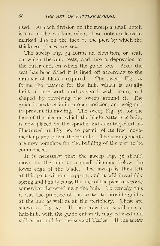
66 THE y4RT OF PATTERN-MAKING.
used. At each division on the sweep a small notch
is cut in the working edge; these notches leave a
marked line on the face of the pier, by which the
thickness pieces are set.
The sweep Fig. 54 forms an elevation, or seat,
on which the hub rests, and also a depression at
the outer end, on which the guide sets. After the
seat has been dried it is lined off according to the
number of blades required. The sweep Fig. 55
forms the pattern for the hub, which is usually
built of brickwork and covered with loam, and
shaped by revolving the sweep around it. The
guide is next set in its proper position, and weighted
to prevent its moving. The sweep Fig. 56, for the
face of the pier on which the blade pattern is built,
is now placed on the spindle and counterpoised, as
illustrated at Fig. 60, to permit of its free move-
ment up and down the spindle. The arrangements
are now complete for the building of the pier to be
commenced.
It is necessary that the sweep Fig. 56 should
move by the hub to a small distance below the
lower edge of the blade. The sweep is thus left
at this part without support, and it will invariably
spring and finally cause the face of the pier to become
somewhat distorted near the hub. To remedy this
it was the practice of the writer to provide guides
at the hub as well as at the periphery. These are
shown at Fig. 57. If the screw is a small one, a
half-hub, with the guide cut in it, may be used and
shifted around for the several blades. If the screw

SCREIV PROPELLERS IVHEN SIVEPT UP IN LOAM. 67
is a large one, a framework of wood, having as
many cylindrical faces as there are blades, is pro-
vided. It is made somewhat less in diameter than
the least diameter of the hub. A curfed strip is
nailed on each of the cylindrical faces at the required
angle according to the radius adopted, and these
form the guides for the inner end of the sweep Fig.
56. When this arrangement is used nails are
driven into the cylindrical faces, to hold the loamwith which it is covered; it is reduced to size andshape by a hub sweep. When sufficiently dry the
loam is cut away to expose the guides.
Fig. 58 shows the seat completed; Fig. 59, the
hub swept up and the guide set. Fig. 60 illustrates
two piers completed and one in course of building.
At Fig. 61, a illustrates one pier as lined off with
the thickness pieces in position. Another pier, h,
is shown with -the pattern of the blade formed byfilling in sand between the thickness pieces anddressing it off to the shape of the blade. Theother pier, c, shows the cope, or upper part of the
mould, which covers the blade completed upon it.
After the copes are all completed the mould is
taken apart and stripped of the patterns of the huband blades.
When a sweep at one end follows the axis andthe other end the guide, the pitch will be uniform
radially. It is sometimes desired to have the pitch
variable in a radial direction, or a less pitch at the
axis than at the periphery. In such a case the
sweep is required to travel with a lower axial veloc-
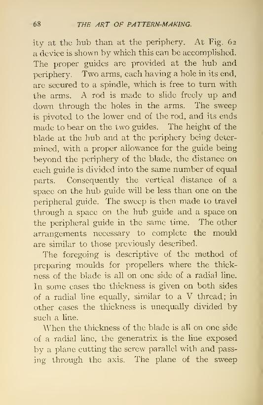
68 THE ART OF PATTERN-MAKING.
ity at the hub than at the periphery. At Fig. 62
a device is shown by which this can be accomphshed.
The proper guides are provided at the hub and
periphery. Two arms, each having a hole in its end,
are secured to a spindle, which is free to turn with
the arms. A rod is made to slide freely up and
down through the holes in the arms. The sweep
is pivoted to the lower end of the rod, and its ends
made to bear on the two guides. The height of the
blade at the hub and at the periphery being deter-
mined, with a proper allowance for the guide being
beyond the periphery of the blade, the distance on
each guide is divided into the same number of equal
parts. Consequently the vertical distance of a
space on the hub guide will be less than one on the
peripheral guide. The sweep is then made to travel
through a space on the hub guide and a space on
the peripheral guide in the same time. The other
arrangements necessary to complete the mould
are similar to those previously described.
The foregoing is descriptive of the method of
preparing moulds for propellers where the thick-
ness of the blade is all on one side of a radial line.
In some cases the thickness is given on both sides
of a radial line equally, similar to a V thread; in
other cases the thickness is unequally divided by
such a line.
When the thickness of the blade is all on one side
of a radial line, the generatrix is the line exposed
by a plane cutting the screw parallel with and pass-
ing through the axis. The plane of the sweep

SCREW PROPELLERS IVHEN SPVEPT UP IN LOAM. 69
Fig. 62.
Fig. 63. Fig. 64. Fig. 65.

7o THE ART OF PATTERN-MAKING.
must lie in the same plane as that cutting the
screw.
It is possible to generate the face of a screw bythe line exposed by a plane cutting the screw per-
pendicularly to the axis, the sweep lying in the
same plane; but the vertical plane for the sweep
is preferable.
When the thickness of the blade is divided by a
radial line, the generatrix is the line exposed by a
plane cutting the screw parallel with but passing
outside of the axis, the degree of obliquity depend-
ing on the way in which the thickness is divided.
When the generating line is not a right line per-
pendicular to the axis of the screw, but a line of
unusual form, occupying some peculiar position
with reference to the axis of the screw, it becomes
quite a difficult problem to work out the line on
paper. The writer has found it convenient to workthis out, as well as many other tedious problems,
to a scale on white-pine blocks, and then develop
the line from the one resulting.
What is meant by the thickness being on one
side of a radial line is shown by Fig. 63, where the
thicknesses are exaggerated. Fig. 63 is a plan
view, and a a section, of such a blade. Fig. 64 is a
plan view of a blade where the thickness is on both
sides of a radial line, the face of the blade being flat
or straight; h is the section of the blade. Fig. 65
is a plan view of a blade where the thickness is also
on both sides of a radial line, but the face and back

SCREIV PROPELLERS IVHEN SIVEPT UP IN LOAM, n
of the blade are convex alike; c is a section of the
blade.
When the thickness of the blade is on both sides
of a radial line and the face of the blade is flat, as
shown at Figs. 63 and 64, either of the devices shown
for sweeping up propellers can be employed, pro-
vided the pitch is uniform radially; but when the
section of the blade is like that of Fig. 65, or when the
pitch is not uniform radially, the device shown at Fig.
62 is alone applicable. With this device the sweep
is fixed at right angles to the rod when the pitch is
uniform radially, and pivoted thereto when the
pitch is not imiform. W^hen the latter device is
used, and the face of the blade is convex, the gui'de
at the hub is so shaped as to produce the required
convexity.
Figs. 66 to 69 show a working drawing of a
two-bladed screw propeller. The arcs a, h, c, d
on the plan view are intended to represent sections
of the blade at these points. These arcs are devel-
oped into straight lines as shown, and are then
projected to furnish the basis of the angles A, B, C,
and D. The length of the blade measured axially
being determined, it is laid off at one end of these
base lines and perpendicular to them, the triangles
being completed by a hypotenuse drawn between
the extremities of each of the base and perpendic-
ular lines. This hypotenuse is the length of the
section of the blade developed. The greatest thick-
ness of the blade at each of these sections being
determined, it is laid off in the center of the hypote-

72 THE ART OF PATTERN-MAKING.
Fig. 69. Fig. 68.
GUIDE
Fig. 67.
SCREfV PROPELLERS JVHEN SIVEPT UP IN LOAM. 73
nuse, and an arc of a circle described through the
extremity of this thickness dimension and tangent
to arcs of one-half inch radius at the ends of the
hypotenuse incloses the developed area of the
section of the blade it represents.
These sections furnish the forms and dimen-
sions of the thickness pieces. These are made of
pine board about three fourths of an inch thick.
Fig. 66 shows a thickness piece which has been
curfed with a saw, in order that it may be bent to
the required curvature, the curfs being made par-
allel with the axis of the screw. Fig. 67 shows the
angle of the guide, whose base is also the length
of its arc developed.
The full hypotenuse line, which is a straight
one, is the developed guide line for a true screw,
and the dotted line is the guide for a screw of ex-
panding pitch. Fig. 68 is a side elevation of the
screw, and Fig. 69 is a scale of thickness through
the thickest part of the blade. The sections repre-
sented should always be given on a working draw-
ing.
When the screw is of expanding pitch, the lengths
of at least five ordinates for the curvature of the
guide line should be given.

X.
PATTERN WORK FOR RIFLE-PROJECTILES.
Dry-sand moulding is adopted chiefly for large
and intricate castings requiring solidity and accu-
racy of form. It is a somewhat less expensive
method of producing castings than by moulding
in loam, especially when the castings are to be
duplicated. Dry-sand moulds are made of spe-
cially prepared sand, and are dried in an oven or
a heated room; consequently metallic flasks be-
come necessary.
Patterns designed for moulding in dry sand do
not materially differ from those intended for green
sand. In some cases, however, they can be formed
of fewer pieces, as cores and drawbacks are fre-
quently made in the mould of the same material as
the mould itself, and to better advantage than if
made in separate boxes.
Projectiles designed to carry explosives must be
free from porosity to avoid the liability of the
charge they contain becoming ignited by the firing
of the gun, with the result of a premature explo-
sion of the shell. When such projectiles are madeof cast iron every precaution is taken to secure
dense and accurate castings. The location of the
core in reference to the exterior of a rifle-shell is
74

PATTERN IVORK FOR RIFLE-PROJECTILES, 75
very important. Should there be eccentricity of
the interior with the exterior, the flight of the pro-
jectile is effected and the accuracy of aim is
destroyed.
Figs. 70 and 71 show a 13-inch rifle-shell. Fig. 70
is the pattern and Fig. 7 1 the core-box. The pattern
is made solid, preferably of baywood. When large,
as in the present case, two- or three-inch lumber is
glued up imtil the desired size is obtained. A bar
of ij-inch round iron, provided with a collar, is
fitted through the center of the block and screwed
half-way into a nut let into one end of the block, andthe collar on the bar is let into the opposite end of
the block. The remainder of the thread in the nut
is for the double purpose of securing an eye-bolt
when the pattern is to be withdrawn from the
mould, and also to secure a center when the block
is to be placed in the lathe. The end of the bar
projecting outside the pattern contains a center,
and the pattern is swung between those centers
while being turned. The projecting bar, or center
pin, is also turned so as to be concentric with the
pattern. The pattern which is shown in the flask,
with the position of the core dotted, is moulded in
the position shown, and the draft or taper is towardthe point of the shell. A cylindrical projection is
made at the point of the shell to provide a sinking
head.
The core-box is made in sections as illustrated,
segments of baywood being glued and nailed in
the usual manner to form them. The sections are

76 THE ART OF PATTERN-MAKING.
Fig. 71. Fig. 70.

PATTERN IVORK FOR RIFLE-PROJECTILES, 77
made to match by turning a projection on one end
of a section and a corresponding recess on the end
of the adjoining section. The core being tapered
allows the sections to be drawn from the core in an
axial direction.
The first or lower section of the core-box is fitted
with a sleeve, which is for the purpose of holding
the vent-tube concentric with the core. The vent-
tube performs two functions, that of carrying off
the gases from the core, and supporting the core in
position in the mould. That part of the vent-tube
covered by the core is perforated with numerous
holes, and small pine sticks are placed in these
holes to assist in venting the core as well as to help
secure it to the tube. The shells are moulded in
a vertical position in special brass flasks, made in
sections to facilitate ramming up. The first section
of the flask has a cross-bar with a boss in the center
of the flask; a hole through this boss corresponds
with the diameter of the bar projecting from the
pattern, also with that of the vent-tube projecting
from the core. By this means, when the vent-tube
is secured in the hole, the core is brought concentric
with the mould. The core is set while the mouldremains as when the pattern was drawn. After
the core is set the mould is inverted and the shell
cast with its point uppermost.

XI.
PATTERN FOR LAUNCH-ENGINE.
Figs. 72-86 represent the pattern for an 8X8launch-engine. The cyHnder, valve-chest, frame,
and bed-plate are combined in one casting.
Fig. 72 shows a plan, Fig. 73 a front elevation,
and Fig. 74 a side elevation of the pattern. Fig. 75
shows a section of the cylinder through the steam-
and exhaust-passages. The pattern is arranged
for moulding with the valve-chest down, or in the
drag, and is made to part through the axis of the
cylinder.
In making the pattern of the cylinder it is pref-
erable to use well-seasoned lumber of thickness
sufficient to allow of its being turned to the required
dimensions without the gluing together of several
pieces. To do this, lumber some five inches thick
is required. In turning the cylinder, scores of about
one quarter inch deep are made where the flanges
are located; the latter are sawed out and fitted
into these scores, being there glued and nailed and
finished with the remainder of the cylinder.
The open or top end of the cylinder has a core-
print turned there. In length it is about equal to
that part of the core which enters the cylinder in
order to obtain sufficient support for the core, as
78

PATTERN FOR LAUNCH-ENGINE. 79
a
Fig. 75.
Fig. 76.
o o
MFig. 77.
Fig. 82.
"R^
ii^ri
Fig. 78.
Fig. 79.
I I-
Fig. 83.
4^
Fig. 80.
I
Fig. 81.
^Fig. 84.
Fig. 85
mFig. 86.

So THE ART OF PATTERN-MAKING.
little can be had from the opposite or stuffing-box
end, in consequence of the small diameter of the
core there.
The lower end of the cylinder has a cavity or
recess turned in it, into which the pattern of the
stuffing-box is fitted. The stuffing-box with its
attached core-print, like the body of the cylinder,
is made in halves and attached to the latter bydovetails in such a manner that it can be lifted out
with the main core without affecting the cylinder.
The main core is that which is formed below the
cylinder and between the framing or housing and
bed-plate. As commonly said, the pattern leaves
its own core in that part.
The bed-plate is made by framing together four
pieces of the required thickness, of width sufficient
to allow the plate to be reduced to the required
shape. After the plate is worked to shape and
lined off, the bearings for the shaft are added, and
also the ribs or flanges which project below the
plate. It is then sawed through the center of the
bearings with a thin saw and the two halves dowelled
to make it part in the same plane as that of the
cylinder.
The framing consists of conical-shaped frames,
placed opposite each other, and which connect the
bed-plate with the cylinder. Each is made in two
pieces which part in the same plane as that of the
cylinder and bed-plate, viz., on the line ah. In
fitting the framing to connect the cylinder with the
bed-plate, a surface board is first prepared and

PATTERN FOR LAUNCH-ENGINE. 8i
lined off. The dowel or drag halves of the cylinder
and bed-plate are secured to this board in their
correct relative positions.
The drag halves of the frames are let into the
cylinder about one and a half inches and secured
there with glue and screws. At the opposite ends
the frames are fitted against the bed-plate andglued to it; screws are also driven from the under
side of the bed-plate into the ends of the frame. Alarge fillet is glued and nailed around the frame
and to the bed-plate, and this aids materially in
making the pattern more rigid at that part.
The drag halves of the cylinder and bed-plate
being secured to the framing, the pattern is released
from the board and turned over; the cope halves
of the cylinder and bed-plate are placed upon their
drag halves, the cope framing being secured to themin a similar manner to that adopted with the drag.
The valve-chest is fitted and secured to the drag
half of the cylinder, the flange is fitted to the chest
with steady-pins, but separates from it in the
mould where a parting is made to enable the flange
to be withdrawn.
Figs. 76 and 77, respectively, show an end view
and an elevation of one half of the core-box for the
cylinder.
Figs. 78 and 79 show a plan and a section of the
core-box for the valve-chest.
Figs. 80, 81, and 82 show a plan, a section, andan end elevation of the core-box for the steam-
passages.
82 THE ART OF PATTERN-M/iKING.
Figs. 83, 84, 85, and 86 show a plan, an end eleva-
tion, and a longitudinal and transverse section of
the core-box for the exhaust-passage.
In moulding the pattern, which is done in an
iron flask, the drag part is laid upon a follow-board,
and a box representing one half the main core is
put between the frame to form the parting there.
The mould is rammed up to the face of the valve-
chest flange, a core is placed over the flange to cover
it, and the mould is then continued until it sur-
rounds the core. The latter is then removed and
the pattern of the flange taken out, after which the
core is replaced and the ramming of the drag com-
pleted. The flask being turned over, the box repre-
senting the main core is removed and a lifting-plate
for the core is placed in the bottom of the space it
formerly occupied. The main core is built upon
the plate up to the parting. The cope half of the
pattern is now placed in position and the main
core is continued to completion. The cope of the
mould is next completed and removed with the
cope part of the pattern, leaving the stufling-box
in the main core. The latter is now lifted out and
the stufling-box removed from it. The main core
being out of the way, the drag half of the pattern is
withdrawn from the mould.
More than one hundred castings have been madefrom a single pattern of baywood as thus described.

XII.
PATTERNS OF DECK-LUG FOR DRY-SANDMOULDING.
In constructing large patterns to be moulded in
dry sand it is frequently advantageous to arrange
them for moulding somewhat after the manner of
constructing loam moulds ; that is, to permit of the
mould being made in sections which can be lifted
away from the seat or foundation of the mould.
The main core can then be made and finished on
the seat and be allowed to remain there. Thesides of the mould, which are sometimes called
cheeks, are assembled around the core. This plan
obviates handling the core, which may be large or
of such a shape as to make the safe handling of it
very difficult.
Figs. 87-94 represent such an object, which is
a deck-lug for a gun-mount. Three views of the
casting are given—apian (Fig. 87), a side (Fig. 88),
and an end elevation (Fig. 89).
The pattern is moulded with the bearing down-
ward. The ribs, flanges, and other parts pro-
jecting from the sides are arranged to be removedwith the cheeks. Fig. 88 also answers for the side
view of the pattern when completed. The dotted
83

84 THE ART OF PATTERN-MAKING.
:hgSA^ J
THEHHFi'^r ^
Fig. 87.
Fig. 90.
_1J II li IJ—-IJ-
FiG. 89.
Fig. 92.
Fig. 93.
Fig. 91. Fig. 94

DECK-LUG FOR DRY-SAND MOULDING. 85
lines outside the inclined ends represent the core-
prints for the main core. The pattern separates
or parts on the line ah.
In constructing the pattern a number of frames
made of 2 -inch lumber are first provided. These
frames should be about if inches less all round
than the section of the pattern where the frames
are located. The frames are set up and properly
arranged according to the position they are to occupy
in the pattern; they are then covered with boards
a little in excess of if inches thick; these are se-
cured to the frames with screws and glue, the holes
for the screw-heads being counterbored and plugged
after the screws are in.
When the box so formed is dressed down to the
proper dimensions it forms the body of the pattern
upon which the outside ribs, bosses, flanges, and other
projecting parts are secured. This is done with
draw-pins, screws being also used to insure the
parts against shifting until the pattern is set up
for moulding. The draw-pins are removed as the
mould is being built up.
Shallow core-prints are fitted to the two inclined
sides of the pattern for the purpose of locating the
core-box when placed upon the seat of the mould.
The upper or cope part of the pattern, e, is con-
structed in a manner similar to that described in
the foregoing.
Three views are given of the main core-box, Fig.
90 being a longitudinal section. The plan, Fig. 91,
not being correct to scale in width, is shown broken

36 THE ART OF PATTERN-MAKING.
through the middle. Fig. 92 represents a half
cross-section of the box.
The main core-box is constructed by first pre-
paring a bottom board, which is secured to frames
having the angles of the pattern where the core-
prints are located. The sides and ends of the core-
box are erected upon the bottom and are screwed
together so that they can either be taken apart or
removed from the bottom without being taken
apart.
The bottom board of the main core-box is not
essential, absolutely, when the core is made in the
place it is to occupy in the mould, as here intended.
But by having it the box is better retained in shape,
and, if so desired, the core can be made and set in
the mould afterwards, as commonly done.
Fig. 93 shows the box for the trunnion-bearing
cores, and Fig. 94 the box in which the cores are
made for the cope part of the pattern. These are
plain boxes and require no further description.
In moulding the pattern there is first prepared a
seat or foundation corresponding in shape to the
part of the pattern where the core-prints are located,
and the pattern is placed upon this seat. Thesides or cheeks of the mould are then built up and
arranged to be lifted away from the mould without
affecting the seat. The ribs, flanges, etc., on the
sides of the pattern are lifted away with the cheeks,
the pins and screws which secured them to the
sides of the pattern having been withdrawn when
the cheeks were being built up. The cope, or cover,
DECK-LUG FOR DRY-SAND MOULDING. §7
of the mould is also completed before the mould is
taken apart.
After the cheeks are removed the main core-box
is lifted from its bottom and placed upon the seat
of the mould, according to the position marked bythe core-prints; the core is then completed and
allowed to remain on the seat. When the mould is
being assembled the rectangular cores are sup-
ported on chaplets placed upon the main core.

XIII.
PATTERN WORK FOR WATER-COLLAR.
Figs. 95-104 represent a water-collar and the
pattern work for it.
Water-collars are used in connection with the gun-
turrets of war-ships, and consist of two principal
parts; one of these is fixed and the other revolves
with the turret. Water, under pressure, passes
into the collar through a branch in the outer mem-ber, thence to a central passage in the inner member,
and through it to the motors in the turret. Theexhaust-water returns by another pipe, through
an annular passage in the inner member, and thence
through an outlet branch in the outer member.These castings are quite intricate; their patterns
are interesting examples of pattern work, and con-
siderable skill is required in their construction.
Fig. 95 shows a side elevation and Fig. 96 a
section of the device when assembled. The glands
used for making the collar water-tight being ordi-
nary glands, they are omitted.
Fig. 97 shows a plan and Fig. 98 a side elevation
of the pattern for the inner member; it is made in
halves, the pattern parting on the line ab. Thecore-prints c, d form bearings to support the central
core, and the prints e, /, bearings for supporting the
annular core. Fig. 99 shows one half the box in
which the central core is made. The annular core
88

PATTERN PVORK FOR HEATER-COLLAR. 89
is made in halves. Fig. 100 shows a plan and sec-
tion of the box in which the half-cores are made.
These cores cut through the outside of the casting
at g, h, where prints are located on the pattern to
assist in supporting them in the mould, as well as to
aid the venting. The holes so made are plugged in
finishing the casting.
In making the box for the annular core a bottomboard of sufficient size, and which should be battened
to prevent warping, is first prepared. Upon this
board is fitted the body y, representing the outside
of the metal inclosing the central passage. Twopieces, one right- and one left-hand, shown by dotted
lines, are made for the upper end of this part where
the bend is located. By interchanging these pieces
both halves of the core can be made from the samebox. To form the outside of the core, two pieces, x,
one right- and one left-hand, are worked out on the
inside to the outside form of the core over the bend
;
an opening, e, is cut through one side of the pieces
to form the outlet opening in the side of the casting,
where the core-print, e, is located. By interchang-
ing these pieces to correspond with the bend the
opening is made to match when the halves of the
core are set in the mould. Fitted to the opposite
end of the box is a piece, n, worked out to form that
part of the core which lays in the impression madeby the print /. The strike, i, is for the purpose of
shaping the part of the core between the two end
pieces.
After this part of the core is struck off, the piece k^

90 THE ART OF PATTERN-MAKING.
Fig. 96.
Fig. 95.
Fig. 97.
1 -v
°1
t \
-L
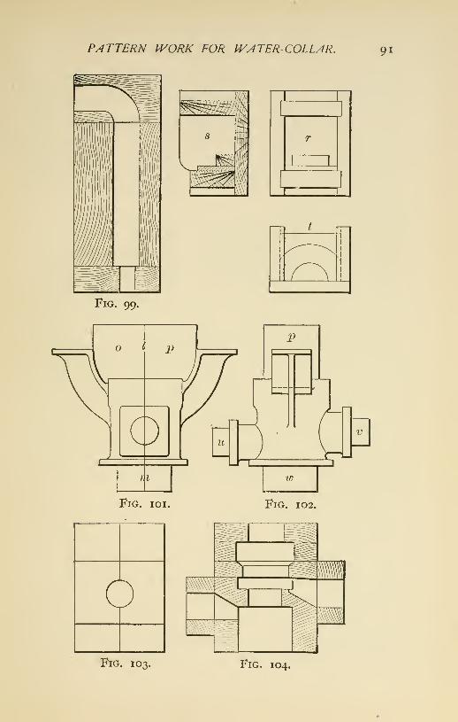
PATTERN IVORK FOR IVATER-COLLAR. 91
\>y<'-^'
W.
Fig. 99.
Fig. ioi. Fig. 102.
^Fig. 103. Fig. 104.

92 THE ART OF PATTERN-MAKING.
which has dowel-pins to fit holes provided to locate
its position on the board, is placed over the core
and the small branches g and h are added to the
main part by extending the core through the hole
in piece k. The square hole or socket in the upper
end of the casting is formed by an ordinary square
core.
Fig. loi shows a side elevation and Fig. 102 an
end elevation of the pattern for the outer member,
which has two supporting brackets attached. The
pattern is in halves, and is made to part on the line
Im. The spandrel between the brackets is formed
by two similar cores, one of which is secured in the
drag, and the other in the cope part of the mould.
The core-prints 0, p form the bearings for support-
ing these cores, which contain a bearing for the upper
end of the interior core. When the mould is closed
the cores meet at the joint of the mould. One ele-
vation, r, and two sections, 5 and t, of the box in
which these cores are made are also shown.
Fig. 103 shows an end elevation of the box in
which the interior core is made.
Fig. 104 shows one half the box viewed from the
interior. The box is built up of several pieces, as
the illustration indicates; this facilitates working
out the different diameters contained in the box.
After being worked out the several pieces are assem-
bled and secured together.
The core is supported in the mould by the bear-
ings made by the core-prints u, v, and w, and by the
bearing in the cores between the brackets.

XIV.
PATTERN WORK FOR HIGH-PRESSURECYLINDER FOR MARINE ENGINE.
Figs. 105-117 represent a more intricate casting
made in a dry-sand mould. It shows the high-
pressure cyHnder of a compound engine having a
valve-chest and a receiver combined with the cylin-
der. Fig. 105 is a half plan and half cross-section
and Fig. 106 is a vertical section through the axes
of the cylinder and valve-chest.
Prior to commencing the construction of such a
pattern its position and the method of moulding
must be decided. Having chosen a horizontal
position, the pattern will be made to part or separate
through the axes of the cylinder and valve-chest on
the line ab.
Four frames of 2 -inch lumber are prepared.
These frames extend beyond the cylinder proper, or
casting, and the core-print for the receiver core is
formed on this extension. Each frame is made in
two pieces, the joint running through the axes of
the cylinder and valve-chest. The contour of each
frame is less by about ij inches than the exterior
of the finished pattern. The finished exterior is
illustrated in Fig. 107.
A frame is placed at each end of the pattern, the
93

94 THE ART OF PATTERN-MAKING.
other two being set intermediate and equidistant
between the end ones, as shown at Fig. io8. Theframes are covered on their outer edges with staves
running parallel with the axis of the cylinder, as
shown in Fig. 109. The staves are made of 2 -inch
lumber, and are secured to the frames with screws
and glue. After dressing the ends of the staves
fair with the frames, the pattern is lined off, andfinished to this line by removing the surplus material
with planes. The screws having been countersunk,
to avoid coming in contact with the tools, the screw-
holes are filled by plugs.
The lower head of the cylinder is cast in ; that is,
it is made a part of the casting. To form this head
in the mould a piece is built up of segments, and
turned to the required shape and dimensions. Theframe at the proper end of the cylinder is cut awaysufficiently to allow the insertion of the turned
piece, which is secured to the pattern, as shown in
Fig. 108, where is also shown a section of the pattern
through the axes of the cylinder and valve-chest.
The piece forming the nozzle with core-print at-
tached is fitted to the head, and is made to lift out
of it when the mould is being separated. This
relieves that portion of the mould forming the
head, which parts as does the pattern and allows of
removal from the flask after the mould is opened.
When this part of the mould, or drawback as it is
sometimes called, is removed, the pattern is free
for withdrawal from the mould.
The part of the pattern that forms the valve-chest

CYLINDER FOR MARINE ENGINE. 95
is made in halves, with a core-print at each end. It
is built up of staves, in a manner similar to that of
the body of the cylinder, and, being of moderate size,
is turned to the proper shape and dimensions in a
lathe. The valve-chest is secured to the other
part of the pattern with screws and glue. Theprojections on the valve-chest that form the outer
walls of the steam-passages are next fitted, after
which the part containing the induction-passage
and nozzle is fitted and secured to the valve-chest.
This piece is made to part like the other portion of
the pattern, and is worked out of solid material,
the core-print and flange being turned and addedto it.
The top and bottom flanges, which extend all
around the ends of the cylinder and valve-chest,
are next added, after which the brackets by which
the casting is secured to the engine framing are
added; also the bosses for the relief-valves and
facings for the hand-holes, etc., are fitted. Thecore-print for the upper or open end of the cylinder
is built up of segments and turned to dimensions.
It is secured to the end of the cylinder with screws
and glue.
The pattern is now ready to be cleaned off andto receive its coat of shellac. The completed pat-
tern is shown in Fig. 107.
A plan and a sectional view of the core-box for
the receiver core are shown respectively in Fig. noand Fig. in. It is a half-box, the one box an-
swering for both halves by having right and left

96 THE ART OF PATTERN-MAKING.
pieces, c, d, which are secured in the box according
to the half of core to be made.
Fig. 114. Fig. 115. Fig. 116. Fig. 117.
Fig. 106. Fig. 107.
The box is constructed by first preparing a bottom
board, then fitting together the sides and mounting

CYLINDER FOR MARINE ENGINE.
a
97
Fig. 112.

^8 THE ART OF PATTERN-MAKING.
them on the board. The half-cylinder which forms
the inner wall of the receiver is constructed bypreparing heads and securing staves to them, which,
when worked off, will produce the required cylin-
drical dimensions. The upper edges of the sides are
worked to the outer shape of the core, a straight-
edge being used to sweep off the core to the form
of the sides of the box.
Each half-core is supported in the mould at the
open end of the receiver, at two places on the cylin-
der, /, /, and at one on the valve-chest, m, where the
cylindrical openings cut through the outer wall of
the casting. The corresponding letters on the core-
box show where the core is extended for this pur-
pose. The openings are plugged up in course of
finishing the casting.
Fig. 112 illustrates the core-box for the induction-
passage to the valve-chest. The view shows the
inside of one half the box when separated. Fig. 113
shows a section through both halves of the box.
This core is made in halves, the parting being on
the line ef, and it is supported in the mould at
the three ends where core-prints have left im-
pressions. A cylindrical opening is made through
the core for the purpose of providing support for
the cores for the steam-passages to the cylinder.
Fig. 114 represents one half the box in which
the cores for the steam-passages are made ; the box'
is made to part or separate on the line hi. Twoof these cores are necessary, differing in length
where they pass through the induction-core. One

CYLINDER FOR MARINE ENGINE. 99
core is made with the piece g attached to the box,
and one, Fig. 115, for the upper passage without
it. The box is made open on the upper side, k, to
facihtate ramming the core up. These cores are
supported in the mould on one side by the induc-
tion-passage core, which they pass through, and on
the other side by the exhaust end of the receiver
core. It is necessary to support them also bychaplets.
Fig. 117 illustrates the core-box for the interior
of the cylinder. Two views are shown, a plan andan end view. For that part of the core containing
its large diameter a half-box for the lower half of
the core is sufficient, the upper half of the core
being formed by a strike, /, which is shown in the
position in which it is used. It is advisable to
make both halves for the other end of the box, which
contains the smaller diameter.
The part projecting inwardly, marked m, is madeto lift out with the core when it is taken from the
box, and is withdrawn from the core afterwards.
This core can also be made by turning it up on a
core-barrel ; but if this has to be specially made, it
will be more economical to dispense with it andmake a box like that described above.
L.ofC.

XV.
PATTERN FOR A GUN-MOUNT PEDESTAL.
Figs, i 18-12 5 represent a pattern for the pedestal
of a gun-mount. It consists of a socket combined
with a flanged housing, by which it is secured to
the deck of the vessel.
The top carriage, on which the gun is mounted,
has a pivot on its lower side, and when the pivot
rests in the socket of the pedestal the top carriage
can be revolved in a horizontal plane.
Pedestals are subjected to very heavy strains,
and their construction consequently must be relia-
ble and solid.
Fig. 118 is a plan view. Fig. 119 a side elevation,
Fig. 120 a longitudinal and Fig. 121 a transverse
section of the pattern.
The flange, a, and the central body, or boss, for
the socket, b, are the pieces first required when
beginning the construction of the pattern. The
former is built up with two courses of segments
glued and screwed together. The latter, which is
turned, is preferably made of thick material in order
to have as few glue-joints as possible.
These pieces being prepared, the flange is secured
to a surface board and the center piece, b, set up and100

PATTERN FOR A GUhl-MOUNT PEDESTAL. lOI
secured in its proper position relatively to the flange.
The housing, c, which surrounds the central boss
Fig. 1 20. Fig. 121.
rrtr-?^-><%
Fig. 124.
If
Fig 122. Fig, 123. Fig. 125.
is then fitted to the flange at the bottom and to the
boss at the top. The staves forming the housing
are about four inches wide at their bottom ends.

I02 THE ART OF PATTERN-MAKING.
Considerable work is involved in fitting and shap-
ing the staves conformably with the different posi-
tions which they occupy in the housing. They are
secured in place by glue and screws, nails also
being used where necessary. When securing themin place three staves are closely joined and secured
together, and then a joint is left open about one
eighth of an inch. This is continued alternately
around the pattern, to allow for the swelling of the
wood while the pattern is being moulded, and has
been found necessary in consequence of the great
width made around the pattern by the staves.
The openings in the sides of the housing for the
purpose of allowing access to the interior of the
pedestal are formed with cores. Fig. 124 shows
an end view and Fig. 125 a section of the box in
which these cores are made, d and d, Fig. 120, are
the core-prints for the location and support of these
cores. The central piece, h, Fig. 121, and also the
ribs, e, which connect the former with the housing,
are arranged to lift out with the main core.
Fig. 122 shows an end view of the core-box for
the socket, and Fig. 123 shows one half of the boxas viewed from the inside. The prints for the sup-
port of the core are shown in / and g. The flange,
a, Fig. 118, is made in two parts; the part pro-
jecting beneath the housing is made to separate
from that outside of it, that it may be withdrawn
from the mould independently of the remainder of
the pattern.
In moulding, the pattern is first inverted and

PATTERN FOR A GUN-MOUNT PEDESTAL. 103
the main core made inside. This completed, thepart of the flange projecting inside the housing isremoved and the position of the pattern with thecore IS reversed. The mould is completed and thecastmg made in this latter position.

XVL
PATTERN WORK FOR SCREW PROPELLERCAST ENTIRE.
When screw propellers are of large size and cast
entire they are usually swept up in loam, but
when the blades are made separate and are to be
bolted to the hub, or when the screw is to be dupli-
cated, a pattern of the blade is usually made andthe moulding done in dry sand.
To construct the pattern of a screw-propeller
blade attached to a hub is an interesting and in-
structive example of pattern-making. Workingdrawings of screws are made in different ways,
according to the ideas of the draughtsman; one
way has been described.
Figs. 1 2 6-1 3 1 show another method. Fig. 126
represents a plan and Fig. 127 an elevation of a
right screw with two of the four blades broken off.
These views are often assumed by the draughtsman
to be all that is necessary in order to enable the
pattern-maker to proceed with the construction of
the pattern; but the developed sections should be
worked out by the draughtsman. When they are not
so done the pattern-maker may develop them himself.
In this event, after receiving the drawing, the first
Z04

SCREIV PROPELLER CAST ENTIRE. 105
thing he should do is to lay down full-size developed
sections of the blade. These are readily deter-
mined in the following manner: Draw a line ah,
Fig. 128, for a center line somewhat longer than the
radius of the screw. With the radius of the screw
and with one point of the trammel on the center line
describe an arc equal in length to the fraction of
the circumference occupied by one blade. Develop
this arc into a right line at right angles to the center
line, and from its extremities draw radii to the
center from which the arc was described. Divide
the center line into as many parts as it is desired
to have sections of the blade (four are used in the
illustration), and through the intersections drawlines at right angles to the center line and inter-
secting the two outside radial lines; the length of
the lines between these intersections are those of
the bases of the triangles c, d, e, and /, or periphery.
The triangles are completed. Fig. 128, by erecting a
perpendicular from the end of each base line. Theheight of these perpendiculars should be equal to
the length of the screw, measured parallel with its
axis. Now join the top of the perpendicular with
the opposite end of the base line by a straight line
for a right screw, as that represented.
For the purpose of laying down the thickness of
blade at the different sections, as well as the parallel
pieces with which the blade is built, it will be found
convenient to arrange the triangles as shown in
Fig. 129.
From a scale of thickness as that shown in connec-

to6 THE ART OF PATTERN-MAKING.

SCREIV PROPELLER CAST ENTIRE. 107
tion with the plan view, Fig. 126, which showsthe thickest part of the blade at right angles to
the face, take the thickness of each section,
as c, d, e, f, and also at the hub. Lay it off at
right angles to the center of the hypotenuse
of the triangle corresponding in section. From the
ends of each hypotenuse describe an arc the radius
of which is equal to that of the edge of the blade.
For each section describe an arc of a circle inter-
secting the arcs at the ends and the thickness dimen-
sion in the center of the hypotenuse, and the area
thus inclosed will be the section of the blade at that
part.
Now determine the thickness of the parallel
pieces (Fig. 130), as i, 2, 3, 4, 5, and 6, to be em-ployed in constructing the pattern. This thick-
ness may vary from if to if inches, according to
the size of the blade. Draw lines through the sec-
tions of blade parallel with each other and perpen-
dicular to the axis of the screw, with a distance
between them equal to the thickness of the material
adopted. From each intersection of those par-
allel lines with the lines bounding the sections of
the blade through which they pass, other lines at
right angles to them are drawn to the adjacent line,
and thus a series of rectangles is produced which
are the widths of the parallel pieces necessary to
make the thickness at those parts.
When the screw is a true or right one, as that
under consideration, the face lines of these parallel
pieces are right lines radiating from the center of

io8 THE ART OF PATTERN-MAKING.
the screw, because a right screw is generated by a
right Hne perpendicular to the axis radiating from
the center and having a uniform axial progress
while revolving. But all screws are not so made.
The generating line is made of various forms and is
set at different positions with the axis. It is also
given variable as well as uniform axial motion
while revolving. Sometimes the generating line is
given the form of an arc of a circle described from
the rearward of the axial line. In such a case the
face line of the parallel pieces will be a spiral of in-
creasing curvature toward the periphery. Then,
again, the generatrix may be made a right line
radiating from the axis, but having a less axial
motion at the axis than at the periphery, producing
a screw of diminishing pitch toward the axis. In
this latter case when the pattern is built up of pieces
of parallel thickness only, the center line between
the extremities of the pitches will be a right line per-
pendicular to and radiating from the axis. Witheach succeeding piece forward of the center line
the face line will increase in convexity, while for
each succeeding piece aft of it the face line will
increase in concavity and the face line would have
to be worked out for each piece of parallel thick-
ness.
In a case of this kind the construction of the
pattern will be made easier by making the pieces
tapering instead of parallel in thickness, reducing
the thickness of each piece at the axis in proportion
to the difference in the pitches; and then the face
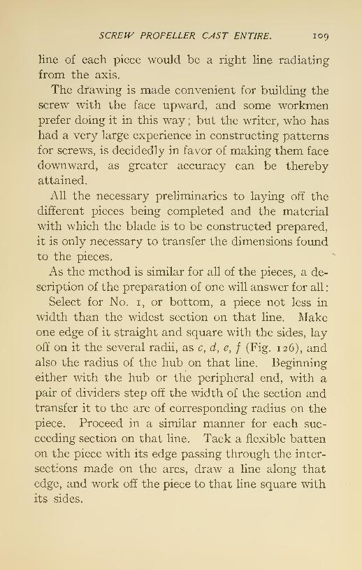
SCREIV PROPELLER CAST ENTIRE. 109
line of each piece would be a right line radiating
from the axis.
The drawing is made convenient for building the
screw with the face upward, and some workmenprefer doing it in this way ; but the writer, who has
had a very large experience in constructing patterns
for screws, is decidedly in favor of making them face
downward, as greater accuracy can be thereby
attained.
All the necessary preliminaries to laying off the
different pieces being completed and the material
with which the blade is to be constructed prepared,
it is only necessary to transfer the dimensions found
to the pieces.
As the method is similar for all of the pieces, a de-
scription of the preparation of one will answer for all
:
Select for No. i, or bottom, a piece not less in
width than the widest section on that line. Makeone edge of it straight and square with the sides, lay
off on it the several radii, as c, d, e, f (Fig. 126), andalso the radius of the hub on that line. Beginning
either with the hub or the peripheral end, with a
pair of dividers step off the width of the section andtransfer it to the arc of corresponding radius on the
piece. Proceed in a similar manner for each suc-
ceeding section on that line. Tack a flexible batten
on the piece with its edge passing through the inter-
sections made on the arcs, draw a line along that
edge, and work off the piece to that line square with
its sides.

no THE ART OF PATTERN-MAKING.
Grouped in Fig. 130 are shown the different
pieces shaped and ready for building the blade.
A surface-board is necessary to insure satisfactory
work. It should be lined off and the hub secured
in its proper position upon it. The pieces are fitted
against the hub. As the blade is to be made face
upward, a guide secured at the periphery is neces-
sary to insure the proper angle; props are also to
be employed beneath the pattern to keep the pieces
up to the guide, as there is a tendency of the pieces
to depress on their overhanging side. Each piece,
as the building up progresses, is set back on the
piece below it and glued and nailed thereto, care
being observed that the nails are out of the way of
the tools in working the blade off. In the latter
case it is only necessary to work down to the lines
formed by the outside of the joints to obtain the
required thickness throughout the blade. After
the blade is worked off it can be made any desired
shape within the limits of the pattern by laying off
the outline and working off the surplus material, and
easing off the back to suit the shape adopted.
When the screw is not very large the hub maybe formed at the same time that the blade is
being built up by laying off a section of the hub
and blade on the same piece, as shown shaded
by g, Fig. 131. But when the screw is of large
size, it is more convenient to turn the hub sepa-
rately and fit the pieces to it while building the
blade.
Unless the screw is quite small, it is not necessary

SCREIV PROPELLER. CAST ENTIRE, iii
to make more of the pattern than one blade andthe hub, as the pattern can be shifted around inmoulding to make the required number of bladesin the casting.

XVII.
METHOD OF MAKING A PATTERN FOR ASCREW PROPELLER WITH SEPARABLEBLADES.
Figs. 132-135 show a screw propeller different in
shape from the one previously described. The
views are numbered to follow consecutively those
that have already appeared. The screw is a true
one, that is, its pitch is imiform both radially and
axially.
It will be observed that a blade developed on a
plane is oval in shape, as shown in Fig. 132. The
outer oval figure is intended to represent the shape
of the blade as thus developed. Instead of the
screw being cast entire the blades are made sepa-
rately and provided with a flange for bolting them
to the hub or boss. This is the type usually adopted
for the propellers of ocean-going steamers. It pos-
sesses a distinct advantage when in need of repairs,
for a broken blade can be renewed without removal
of the screw from the vessel. However, a propeller
of this kind is more expensive in first cost.
When a pattern is to be made of such a screw, and
the drawing, as is generally the case, does not show112

SCREJV PROPELLER JVITH SEP/4RABLE BLADES. 113
the developed sections of the blade, these should
be developed by the pattern-maker to full size.
He should then determine the thickness of the
material of which the blade is to be built and line
off the sections with parallel lines according to the
thickness adopted. It is well to dress up the lum-
ber for the blade, rip it in pieces of sufficient size
and allow it to stand until wanted for use. Nextmake two guide-frames, one to conform to the angle
of the pitch at the hub and the other to the angle
of the pitch at the periphery. As the blade pattern
is to be made with the face downward, the angles
of these guides will determine the proper helical
form of the face of the blade. The method of makingthese guides has been explained.
A substantial surface-board is required. It should
be somewhat longer than the radius of the screw,
and in width a little greater than the length of base
of the largest guide. On this board draw a line
through it lengthwise for a center line. With the
radius of the screw and with one point of the trammel
on the center line describe an arc across the board,
the arc at the center line being about five inches
from the end of the board. From the same center
with a radius equal to that of the hub describe
another arc across the board. Step off the length
of the base of the triangle e, at Fig. 133, the periphery
of which will be equal to the length of the base of the
largest guide. Transfer this length to the arc corre-
sponding on the surface-board, making it equal on
each side of the center line. From the extremities of

114 THE ART OF PATTERN-MAKING.

SCREIV PROPELLER WITH SEPARABLE BLADES. 115
the arc draw radii to the center, and the sector thus
formed will be that with which a plan view of the
blade will agree when its top and bottom edges are
perpendicular to the axis of the screw.
To determine the necessary length of the base of the
guide when the outline of the blade is of special shape
like that under consideration, it is necessary to
lay down a projected view of the blade as viewed
in line with the axis of the screw. Radial lines
are then drawn tangent to the edges of the blade
as at /, Fig. 132. The length of the arc at the
periphery intersecting these lines is the fraction of
the circumference the blade extends through and
it is also the length of the base of the guide.
The two guides being prepared and having center
lines drawn upon them, are to be secured to the sur-
face-board, their center lines and curvatures coin-
ciding with the arcs drawn on the board ; the guide
on the periphery being on the inside of its arc. Apattern for the flange by which the blade is secured
to the hub is required. It is to be secured to the
surface-board by brackets, being properly situated
in relation to the face of the blade as determined
by the guides.
To facilitate laying off the pieces for the blade
a templet like that illustrated in Fig. 134 will be
foimd useful. It is made of thin stuff equal in
length to the radius of the screw. The arcs of the
different sections, as a, h, c, d, and also those of
the hub and periphery, are described upon it and
enough of the templet cut away to admit of the

Ii6 THE ART OF PATTERN-MAKING.
arcs acting as guides while they are being markedon the blade pieces. The necessary preparations are
now completed to allow the building of the blade to
proceed.
It is not absolutely necessary with a blade pat-
tern of this shape, where so much of it is cut awaytoward the periphery, to continue every piece to
the outside guide. But the writer has found it
good practice to do so. The small amount of mate-
rial saved by stopping some of the pieces at the top
and bottom short of the outside guide does not
compensate for the extra care it involves to insure
accuracy.
To begin the building of the blade pattern, select
from the stuff previously prepared a piece of suffi-
cient size to make the bottom piece marked i,
straighten one edge and make it square with the
sides. Fit the straight edge of the piece against the
guides with its side lying on the surface-board bybeveling the edge where it comes in contact with
the guides, being careful to have the bevels ter-
minate exactly at the upper edge of the piece where
it touches the guides. If it should occur in fitting
a piece that the top of the bevel is carried in beyond
the edge, the edge can be planed off until it coincides
with the bevel. In this lies one of the advantages
of fitting the pieces to the guides before reducing
them to the shape in which they are built into the
pattern.
Now mark the periphery of the blade on the
piece which will be the outer edge of the outside

SCREIV PROPELLER IVITH SEPARABLE BLADES, n?
guide; also mark the radius of the hub, which is
the inside edge of the inner guide. Lay the templet
on the piece, the marks for hub and. periphery coin-
ciding with those of the templet, and mark the arcs
of the different radii a, h, c, d, etc. Take the widths
of the piece i at the different sections and lay themoff on the piece i. On the arcs corresponding to
the section draw a line through these intersections
with the aid of a batten, work off the edge to this
line square with the sides, place the piece on the
surface-board where it was fitted against the guides,
securing it there against shifting, but in such a
manner that it may be readily released when de-
sired. Proceed in a similar manner with piece
No. 2, which, when prepared, secure on the piece
No. I by glue, and with nails where they are not
likely to come in contact with the tools in working
the blade off. The remainder of the blade is simi-
larly proceeded r/ith until completed to the desired
height. Where the parallel pieces come in contact
with the flange they are fitting against it as well as
against the guides. The shapes of the several pieces
forming the blade are shown in Fig. 135.
After the pattern has been completed to the
required height and before it is removed from the
guides, it is to be roughly worked off on the back.
Large, inside bevel gouges are useful for this purpose.
The pattern is then to be turned over, with the face
upward, utilizing the guides to hold it while the
face is being worked off. When the face of the
pattern is finished down to the lines formed by the

ii8 THE ART OF PATTERN-MAKING.
joints of the pieces, the configuration of the blade is
the next thing in order. This can be laid off di-
rectly on the face of the pattern, or a templet of
<^^
Fig. 136.
d
Fig. 137. Fig. 138.
Fig. 139.
Fig. 140. Fig. 141.
the shape can be made of stiff paper and the pattern
marked by it.
The shape of the blade being lined off on the face

SCRE^V PROPELLER IVITH SEPARABLE BLADES. 119
of the pattern, the surplus material outside of this
boundary is to be removed. This accomplished,
the face is given a coat or two of shellac and the
pattern turned with its face downward and its backworked off down to the lines formed by the joints
of the pieces of which the pattern is composed.
The edges are next to be finished by working ofE
the back to an easy curve where it trends toward
the face.
When building up the blade it is well to avoid
gluing the flange to the blade pieces. By arranging
the flange to be removed while the blade is being
worked off the latter is accomplished much easier.
After the flange has been secured permanently
to the blade, the fillets where they join are com-pleted. The fillet on the back may be worked on the
pieces which compose the blade, but the fillet on
the face is best fitted separately.
After being sandpapered and receiving several
coats of shellac, the pattern is ready to be moulded.
Glue alone should not be depended upon to hold
the pattern together while being moulded. Brads
should also be freely used for the purpose.
Fig. 142 shows a partly built-up blade pattern.
It differs in shape from those shown in the draw-
ings. For the purpose of making prominent the
manner in which the pieces of parallel thickness
are fitted upon each other and to the guides they are
shown somewhat disproportionate in thickness.
Figs. 1 36-141 show the method of constructing
the pattern for the hub, or, as it is termed in Eng-

I20 THE ART OF PATTERN-MAKING.
land, the boss, which is generally moulded in loamwhen very large. When so moulded the pattern is
made a model of the casting, but so constructed thatIt can be taken apart to permit of its withdrawalfrom the mould and the release of the interior parts

SCREIV PROPELLER IVITH SEPARABLE BLADES. 121
or cores which have been made in the course of
moulding it.
When the hub is of moderate size it is best moulded
in dry sand. In this case it is first constructed in
the form of a box which separates or parts diago-
nally across its ends. To form the sides four
frames, as in Fig. 136, are made of stuff sufficient in
thickness to allow of their being worked to the
required spherical form. Each frame is made of
four pieces. When these are joined together,
they leave an opening in the middle of the frame
which is covered by the core-print for that core
which forms the recess in the side.
The frames are fitted together with miter-joints
(see Fig. 137). They are secured in pairs, each pair be-
ing glued and nailed together where they unite. The
ends of the box, which are square in shape, are madein two pieces parting diagonally across the square.
After these are secured to the sides corner blocks
are glued and nailed inside the box to strengthen
it at the comers where it is liable to be reduced to
small thickness in being worked to the spherical form.
Previous to securing the frames together their mi-
tered ends are marked oft' by a templet having the
radius of the hub, and the material outside of this
line is worked off square with the joint. When the
four frames are put together the outline of the miter
joints gives the shape to which the pattern is to be
worked in reducing it to the spherical form. The
spherical form can be obtained either by turning
in a lathe or by working the pattern off by hand.

122 THE ART OF PATTERN-MAKING.
The writer has employed both methods, but prefers
the latter when the pattern is to be moulded in dry
sand and cores are used to form the interior of the
mould.
After the spherical form has been given to the
pattern it is ready for the core-prints. The prints
a, h, Fig. 138, for the tapered core which forms the
shaft-hole are secured permanently to the pattern;
but c, d, e, f, on the sides, for the cores which form
the recesses where the blades are secured to the
hub, are made removable. They are held in place
by draw-pins, which are withdrawn while the pat-
tern is being moulded, thus releasing the prints
from the pattern and allowing the latter to be
drawn from the mould first and the prints after-
wards.
The recess cores are inserted from the inside of the
mould previous to setting the main core, and are
secured in the impressions made for them by the
prints.
Fig. 139 shows a longitudinal and transverse
section of the box for the core which forms the hole
for the shaft through the hub. When but one cast-
ing is needed a half-box can be made to answer;
but when several castings are required it pays to
make a whole box.
Fig. 140 shows a plan and a section of the boxfor the core which forms the recesses in the sides of
the hub where the blades are bolted to it. Fig. 141
shows a plan and a section of the box for the core
which forms the recess in the flange of the blade.

XVIII.
CONSTRUCTION OF SMALL SCREW PRO-PELLERS.
In constructing small screw propellers, unless
special precautions are taken in view of the frailty
of the pattern, much difficulty will be encountered in
making it retain its shape while being moulded.
In moulding a wooden pattern of this kind it be-
comes necessary to provide a block or follow-board
for the support of the pattern while the mould is
being rammed up. This block is sometimes madeof plaster of Paris, its form being obtained from
the pattern itself.
In an establishment where many patterns of
small screws of various forms were made, andwhere different methods of making and moulding
such screws were tried, that which insured the
greatest satisfaction was first to make a block of
wood whose helicoidal face represented the equiva-
lent of the screw desired. Upon this block the pat-
tern for the blade was built of alternate pieces of
pine and baywood. The block was afterward em-ployed to support the pattern while being moulded.
This method has special merit when the screw is
123

124 THE ART OF PATTERN-MAKING,
of peculiar form and a correct casting is desired. Bythis method, also, the moulding is done with green
sand in a core-box, a pattern of but one blade being
necessary in order to obtain as many blades as maybe required in the casting. It also insures the cast-
ing of all blades as nearly alike as it is practically
possible to make them, and secures uniformity
throughout the casting—which is very important
when experimental data are desired.
Fig. 143 shows the first step of the process, namely,
that of making the block. This is made of about
2 J inches greater radius than that of the pattern to
allow for the joint of the mould. It is not neces-
sary to make the block of the full dimensions of the
box, but merely of sufficient width and depth to
admit a joint around the outside of the pattern of
the blade. If the screw is to be a true or right one,
as that illustrated, the block should be built up of
pieces of equal thickness, the edges being straight
and radiating from the center. Given the diameter
and pitch of the screw, the first thing is to lay off a
developed diagram of the periphery of the block,
from which diagram are to be determined the thick-
ness and width of the pieces that will constitute the
block.
Suppose a true screw, of four blades 30 inches
in diameter and 45 inches pitch, is required. Add-ing 2^ inches to the radius for the joint of the mouldwill make the block 17 J inches radius. One fourth
of the corresponding circumference will make the
base of the triangle 27J inches, and one fourth of the

CONSTRUCTION OF SMALL SCREIV PROPELLERS, 125
pitch will give an altitude of 11 J inches. Dividing
this last by ten will give i \ inches, the thickness of
the pieces. Dividing the base by the same num-ber gives 2f inches as the distance on the periphery
that the edge of each piece must be set back of the
piece below it when building up the block from the
bottom. When preparing the pieces it is advisa-
ble to make them somewhat wider than their finished
widths, as by so doing the joints can be more easily
made. The surplus material may be removed after
the block has been worked off.
In building the pattern of the blade it is advisa-
ble to have the two outside edges of baywood.
Beginning at the bottom, which will be the after
edge of the blade, a piece of baywood is fitted to the
block and. tacked thereto in its proper position.
A piece of pine is next fitted to the block, and, to
make a close joint with the baywood strip to which
it is to be glued, this pine piece is also tacked to the
block. The other pieces which go to form the blade
are prepared in a similar manner. As each piece
is fitted, the thickness of the blade at that part is
laid off on it and the back of the piece is chamfered
to the line. The thickness can be obtained by lay-
ing down the sections of the blade as shown in Fig.
152. In order not to have the pieces too thin (in
which case it would be more difficult to make good
joints) it is advisable to shape the pieces as shown
in Fig. 152. In this sketch the lower parts of the
sections of the blade are shown built up with pieces
somewhat thicker than the finished dimensions, with

126 THE ART OF PATTERN-MAKING.
Fig. 151.
Fig. 152.

CONSTRUCTION OF SMALL SCREIV PROPELLERS. 127
one of their sides chamfered to the finished Hne.
The upper parts of the sections are represented as
when reduced to finished size.
When all the pieces forming the blade are glued
together and sufficiently dry, the pattern is removedfrom the block, its face smoothed, the outline of the
blade laid off and the edges worked to the line. Theback of the pattern is next worked off, and the
whole then finished with shellac, when it is ready
to be fitted to the hub. If preferred, the section
of the hub can be fitted in its place on the block,
and the pieces forming the blade fitted on at the
same time that they are being fitted to the block.
There is little choice, however, between the twomethods. The blade is to be secured to the hubby glue and screws. Sufficient margin for the
joints of the mould is to be laid off on the block
outside the blade, and the surplus material of the
block removed. The pattern will then be prepared
for the core-box. This is made four or five inches
deeper than the block and pattern, and should be
made to be taken apart, as in Fig. 145. The angle
of the core-box is made according to the numberof blades required in the screw. For a three-bladed
screw the box will extend through 120 degrees;
for a four-bladed screw, through 90 degrees, etc.
The box should be made of two-inch material, put
together with screws, and the outside or circular end
so arranged as to admit of easy removal.
Before beginning the mould, it is necessary to
provide a skeleton of cast iron for building in the

128 THE ART OF PATTERN-MAKING.
cores for the drag parts of the mould, and skeletons
also for the copes; all these should be provided
with suitable lifters.
When beginning the mould, the block with the
pattern being in the bottom of the box, the remain-
der of the box is rammed up with green sand,
the skeleton having been properly placed in the
mould during the operation. The drag being com-
pleted, the box is inverted and the block which sup-
ported the pattern removed, leaving the latter in
the mould. The parting having been prepared and
the gates and risers properly arranged, the oper-
ation of ramming up the cope is proceeded with.
The skeleton for the cope should not only have
lifters, but be provided with prickers or wires ex-
tending to within a half-inch of the pattern and
joint of the mould. The purpose of these is to
support the sand. The cope being completed,
the sides and end of the box are removed, the cope
lifted off and held suspended, the pattern with-
drawn, and the mould dressed. A bed having been
prepared, the drag is lifted from the bottom board
and placed on the bed and the cope placed upon it.
One fourth of the mould is now complete, as illus-
trated in Fig. 150. In the same way the other
sections of the mould are prepared. When all parts
of the mould are in place they are weighted with
plates made for the purpose and conforming in shape
to the sections of the mould. A curb of thin boiler-
plate bent to a circular shape, with flanges turned
outwardly and radially for bolting together, is

CONSTRUCTION OF SMALL SCREIV PROPELLERS, 129
made to encircle the mould. The space between
the mould and the curb is rammed with sand, and
after the pouring-gate is prepared the mould is
ready to be poured.
In making the core-box it is advised that it be
made of sufficient radius to answer for the largest
screw likely to be wanted. Screws up to four feet
in diameter have been successfully made by this
method. When small screws are to be duplicated
it is best to have a metal pattern and do the mould-
ing in a flask. The metal pattern can be advan-
tageously made, as the foregoing explains.
Figs. 153-156 illustrate a pattern of a globe
valve. This is selected from correspondence be-
cause it furnishes an excellent example of making
what is regarded a difficult pattern. Fig. 153
shows one half of the pattern, which serves the
purpose of elucidation, the other half being of
course the counterpart of that shown. The two
pieces comprising the half-pattern are glued to-
gether on the line MN. Both of the pieces can be
turned in a lathe, the only hand work necessary
being the squaring of the core-prints BB and cut-
ting the hexagon DD.Fig. 154 shows one half of the main core-box ; both
halves are counterparts and are doweled together
with the pins EE ; the spherical part is turned out
in a lathe.
Fig. 155 shows a block made to fit the slot F,
Fig. 154, and which aids to form the circular wall
aroimd the valve-seat as well as the hole through

l^o THE ART OF PATTERN-MAKING.
Fig. 153.

PATTERN FOR GLOBE VALVE, 131
the seat G, The boss R is turned to the radius of
the outside wall H, Fig. 153, while the groove / forms
the core for the inside wall. A handle is fitted to
the block by means of which the latter can be drawn
out of the way before the core-box is separated.
Two cores from this box are required for each mould.
A straight round core made by the box Fig. 156 is
for the stem end. The end of this core fits against
the spherical surface of the main core at K, Fig. 153,
To accomplish this a plug K' , with a spherical sur-
face to match the main core, is fitted into the end
of this box.

XIX.
PATTERN WORK FOR MOULDING A LARGEBELT-PULLEY OR FLY-WHEEL.
A COMPLETE pattern for a large belt-pulley or fly-
wheel is now never made to obtain a casting there-
from, but recourse is had to expedients involving
a comparatively small amount of pattern work.
The pattern work to obtain such a casting consists
of a former for the outer wall of the mould, a core-
box for the arms, a core-box for the center core, andtwo core-boxes for covering cores.
In beginning the mould the first pieces required
are the former for the outside wall, shown by a
and b, Figs. 157 and 158, respectively, and the
center pin 0, Fig. 158.
The former requires to be substantially madeand consists chiefly of a base-board having a
hole to suit the center pin, and a segment whoseconvex side is worked off to the radius of the ex-
terior of the rim of the wheel. The segment is se-
cured to the base-board and braced thereto in
order to maintain a concentric position with the
center and a right angle with the face of the board.
o shows the center pin about which the former re-
132

LARGE BELT-PULLEY OR FLY-IVHEEL.
Fig. 157.
133
Fig. 158.
Fig. 159.

134 THE ART OF PATTERN-MAKING.
volves. In Fig. 159 / shows a plan and elevation
of a segment of the rim, and g shows a plan andsection of the core-box for the core which covers
the center or hub opening of the mould.
In Fig. 162 c shows a plan and section of a core-
box containing a pattern of one half of an arm of the
wheel. Two cores from this box are required for
each arm. e shows a plan and section of the core-
box for the cores to cover the rim opening of the
mould. These comprise all of the pattern work neces-
sary to enable the moulder to complete the mould.
In beginning the mould, a level bed is first pre-
pared and the center pin, o, Fig. 158, is located and
fixed in place. The former is centered on the pin
and the building of the outer wall of the mould pro-
ceeded with by ramming green sand against the
former and striking it off level with the upper edge
of the segment. This completed, the former is
moved around about two thirds of the length of
the segment and the outer wall extended by repeat-
ing the previous operation. The wall is continued
in this manner until the entire circle is covered.
The outer wall being completed, the mould is lined
off according to the number of arms the wheel is
to contain. The mould is then ready to receive the
cores. It is assumed that the cores have been madein the mean time, while the mould was being pre-
pared to receive them.
The cores for the arms are the first required.
The segment /, Fig. 159, is placed in the mould in
the position shown by h, Fig. 160, and the bottom

LARGE BELT-PULLEY OR FLY-IVHEEL.
Fig. i6o.
135
Fig, 161.
IS]

136 THE ART OF PATTERN-MAKING.
half of an arm core is set radially according to the
line prepared for it, with its outer end against the
segment which gauges the thickness of the rim.
The upper half of the core is then placed upon the
lower. This operation is repeated until all of the
arm cores are placed, Fig. 160. The spaces between
the cores are filled in with green sand, the segment
being used to stop off the sand, and this completes
the inner wall of the mould. The center core for the
hub, which is a plain cylindrical one, is set, and the
covering cores from box g, Fig. 159, placed. The
covering cores from box e, Fig. 162, are next placed
over the rim opening.
The gates and risers having been provided for
through the covering cores, the mould is weighted,
and the top built up with green sand to the height
necessary for the runners, gates, vents, etc. This
completed, the mould is prepared to receive the
metal.

XX.
PATTERN FOR AN OBLIQUE CHUTE.
Pattern-makers occasionally meet with problems
that are exceedingly perplexing, especially to those
who have neglected the study of geometry ; moreover,
Fig. 163.
such problems are often by no means easy to solve
even by those fairly informed in that science. Fig.
163 shows the pattern and casting which are the sub-
137

13^ THE ART OF PATTERN-MAKING,
ject of one of those problems. A cast-iron chute rect-
angular in section is required to pass in an oblique
direction through a brick wall 17J inches thick. It
passes through at an angle of 35 degrees with the per-
pendicular and 45 degrees with the face of the wall.
As the illustration shows, the chute emerges from
the wall with its sides parallel with the vertical
joints of the brickwork, but its top and bottom
are oblique to the horizontal joints of the wall.
This obliquity results from the combination of
angles and the rectangular section of the chute.
There are several ways of determining the length of
the pattern and the angle of its ends in such a case,
and two of these ways will be described.
In order to obtain the proper dimensions and
angles of the pattern it is advisable to lay down full
size the necessary views, as illustrated in Fig. 164.
First draw the plan A, making a equal to the thick-
ness of the wall and h equal to the base of the required
triangle horizontally. In this case the horizontal
angle being 45 degrees makes both sides of the tri-
angle 17J inches. Draw the line d parallel with the
hypotenuse c and make the perpendicular distance
between the two lines equal to the external width
of the chute, 14 inches, and extend d to e. Draw the
side elevation B equal to the thickness of the wall,
making the line / 35 degrees with the perpendicular.
Project a line from g toward h and extend it indefi-
nitely. Project the point i toward k and extend it
indefinitely. Project the point / and intersect ik
at k ; connect km : this line will give the angle of the

PATTERN FOR AN OBLIQUE CHUTE, 139
chute through the wallwhenviewed in front elevation.
Project the point e, and intersect the line gh at h.
Project the point n toward and extend it indefinitely.
~?^
\WM,'/MIW}}}\ y*
1 i
!
: SECTION i-
OF CHUTE ^ 7
li,^M/mv/mw/w/M
-FRONT ELEVATION ^— -\l\i' >j
Fig. 164.
From the point h draw the line kp parallel with mk,
intersecting no at o ; connect ko, and the length of the
line so formed will equal the length of the angular
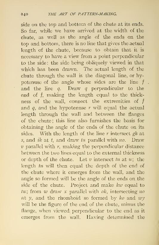
=140 THE ART OF PATTERN-MAKING.
side on the top and bottom of the chute at its ends.
So far, while we have arrived at the width of the
chute, as well as the angle of the ends on the
top and bottom, there is no line that gives the actual
length of the chute, because to obtain that it is
necessary to have a view from a point perpendicular
to the side : the side being obliquely viewed in that
which has been drawn. The actual length of the
chute through the wall is the diagonal line, or hy-
potenuse of the angle whose sides are the line /
and the line q. Draw q perpendicular to the
end of /, making the length equal to the thick-
ness of the wall, connect the extremities of /
and q, and the hypotenuse r will equal the actual
length through the wall and between the flanges
of the chute ; this line also furnishes the basis for
obtaining the angle of the ends of the chute on its
sides. With the length of the line r intersect gh at
s, and ik at /, and draw in parallel with no. DrawV parallel with r, making the perpendicular distance
between the two lines equal to the external thickness
or depth of the chute. Let v intersect tu at u; the
length tu will then equal the depth of the end of
the chute where it emerges from the wall, and the
angle so formed will be the angle of the ends on. the
side of the chute. Project and make kw equal to
tu\ from w draw x parallel with ok, intersecting no
at y, and the rhomboid so formed by ko and wywill be the figure of the end of the chute, minus the
flange, when viewed perpendicular to the end as it
emerges from the wall. Having determined the

PATTERN FOR AN OBLIQUE CHUTE. 14
1
most important part of the problem, and proper
length and angles for the pattern, its construction
is not difficult. The pattern complete except the
core-box, which is a plain rectangular one, is shown
at the left in Fig. 163.
To begin the pattern a box or core-print whose
cross-section equals that of the interior of the chute
is built up of^ one-inch material; the length of the
print iS' sufficient to allow bearings for the core
beyond the flanks at each end. Upon the print
the length and angles of the pattern are lined off and
the thickness for the metal is added on in conformity
with the lines. Where the thickness forms under-
cuts, as at one end of the sides, the undercut pieces
are made to be drawn separately from the body of
the pattern ; they are secured in place by draw-pins.
After the thickness is completed the flanges at the
end are fitted to the pattern and secured by draw-
pins; they remain in the sand and are drawn out after
the body of the pattern has been lifted from the sand.
Another way which the writer has often used with
great advantage and unvarying success in working
out difficult problems of this character is to make a
wood model to a convenient scale and develop the
object from it. He would especially recommend
this method where a number of different angles
are involved, because it enables one to comprehend
the problem more readily by having the chief fea-
tures of the object under view, thereby impressing
them more deeply on the mind and making mis-
takes less liable.

142 THE ART OF PATTERN-MAKING.
Fig. 165 shows a model of all that is necessary
to solve the present problem, and in making the
pattern it would save tenfold time spent in making
the model. It is not necessary that such models
should be very elaborate, but accuracy is abso-
FiG. 165.
lutely essential. It so happens in this case that
the angles of the ends of the chute agree with those
with which it passes through the wall, 3 5 degrees and
45 degrees, or so near to them that they answer
practical purposes; but this result does not follow
as a rule for any combination of angles.
A problem of the foregoing character was once
submitted to the author after its solution had baffled
the efforts of several excellent draughtsmen for a
number of days, and he solved it with the aid of a
model which required less than two hours to make.

XXL
PATTERNS WITH BRANCHES.
Fitting branches to patterns, such as pipes andvalves, by the usual cut-and-try method is tedious
and consumes unnecessary time, especially when the
body to which the branch is to be fitted is of somepeculiar form. By preparing paper patterns of
the line of juncture of the two parts, and marking
this line off on the branch, the work is more skil-
fully performed and the job expedited. Several
different forms of preparing these patterns are here
elucidated. When the principles involved in these
problems are mastered, they can be applied to a wide
range of work.
When the body and branch are of equal and uni-
form diameter, it is simply necessary to first cut the
end of the branch on either side at 45 degrees with
the center line, as at A in Fig. 166. The line so
produced on the circumference of this branch will
be that of its juncture with the body, and when the
branch is cut across to this line it will fit the bodyif the work is accurately performed.
B presents a problem not so simple as the pre-
vious one. Here the branch is smaller in diameter
143

144 THE ART OF PATTERN-MAKING.
Fig. 166.

PATTERNS IVITH BRANCHES, 145
than the body to which it is to be fitted, and a paper
pattern is to be made to mark off the Hne of juncture.
Lay down a plan and a* section of one half of the
body and branch, as a and h\ divide the semicir-
cumference of the branch a into any number of
equal parts, so as to have a line in the center, andnumber the intersections. From these intersections
project lines intersecting the curve of the body h.
Now tack down a piece of suitable paper, c, in the
position shown, and on it draw two parallel lines, as
o and 6, whose distance apart is equal to the circum-
ference of half the branch a. Divide this distance
into the same number of parts as that of a, and drawlines parallel with the outside lines. From the
intersections of the lines from branch a with the
body project lines intersecting the lines on the
paper c with corresponding numbers. A curve
drawn through these intersections will give the
developed curve of juncture of the branch with the
body, and as in this case both halves of branch are
alike, the pattern will answer for both. To arrive
at this developed curve it is not absolutely necessary
to lay down the plan view when both the branch andbody are cylindrical and are at right angles; but
when it is desired to show the projected curve of
the juncture, the plan view is necessary, and the
intersections for it are obtained by projecting from
the sectional views, a and h, to ordinates with corre-
sponding numbers on the plan.
Fig. 167 shows a branch fitted diagonally to the
body of the pattern. To obtain the developed
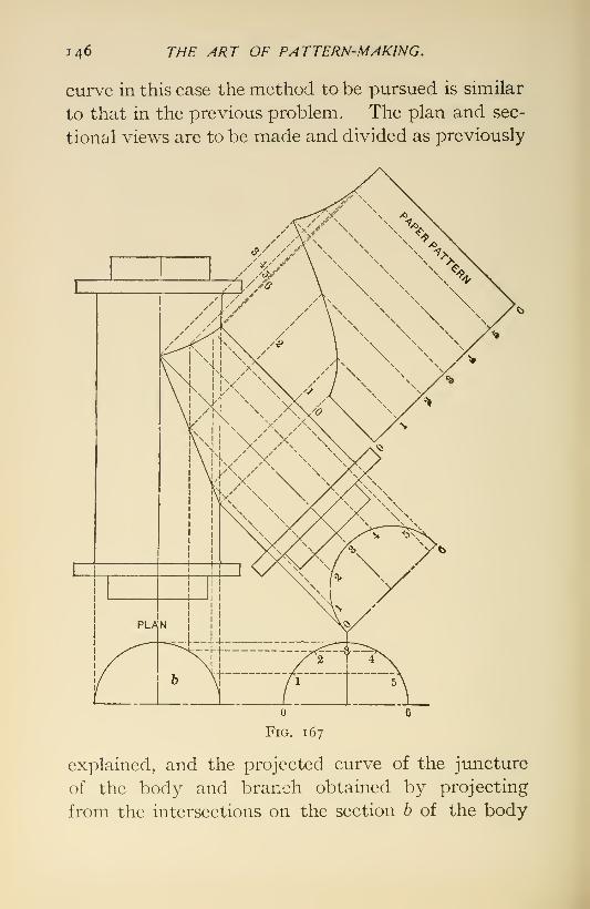
146 THE ART OF PATTERN-MAKING.
curve in this case the method to be pursued is similar
to that in the previous problem. The plan and sec-
tional views are to be made and divided as previously
Fig. 167
explained, and the projected curve of the juncture
of the body and branch obtained by projecting
from the intersections on the section h of the body

PATTERNS IVITH BRANCHES, I47
to ordinates correspondingly numbered on the plan
view of the branch. The developed curve of the
juncture is then obtained by placing the paper along-
side of the branch and projecting from the latter.
Lay off on the paper two lines parallel with each
other, and with the axis of the branch make the dis-
tance apart of the lines equal to the circumference
of one half of the branch, and divide this distance
into the same number of equal parts as that of the
branch. From the intersections which produced
the projected curve of juncture of the branch with
the body on the plan, project lines at right angles
to the axis of the branch to the ordinates on the
paper, intersecting those correspondingly numbered.
A curve drawn through these last intersections will
give the developed curve of juncture.
Fig. 1 68 illustrates the body of a pattern which
is not cylindrical, but which has a cylindrical branch
fitted to it. With many workmen, at first sight,
it would seem a very difficult problem to work out
the developed curve of juncture of branch with
body in this case, but if the previous examples
have been studied and mastered, it will be found
quite an easy matter to do so.
The plan view is to be first laid down, or so muchof it as is covered by the branch. Draw a section
of one half of the branch in the position shown by a,
and divide its circumference as in previous examples.
Through these intersections draw lines parallel with
the axis of the branch, extending across the body,
thus cutting the body into as many sections as lines.

148 THE y4RT OF PATTERN-MAKING.
6^5 4 a
Fig. 168.

PATTERNS IVITH BRANCHES. 149
These sectiorxS of half the body are to be drawn
below the body in the position shown by 6, and
numbered correspondingly to those on the body.
A section of the branch is drawn in the position
shown by c, and the half-circumference divided the
same as that for the plan view. From these inter-
sections lines are drawn intersecting the sections of
the body correspondingly numbered. From these
last intersections both the developed and the pro-
jected curve of juncture are obtained by following
the method of doing so explained in the previous
examples.
It is sometimes required to fit a branch or boss
on a body away from the center line of the latter.
Fig. 169 shows two such cases. In the upper view, A ,
the branch is at right angles to the body and to one
side of its center. To obtain the developed curve
of the juncture of the branch with the body in this
case lay down the branch and so much of the
body as necessary in both end and side views.
Draw end views of the branch and divide them into
equal parts; from these intersections project lines
parallel with the axis of the branch and intersecting
the body. Number these ordinates correspondingly.
Tack down the paper in the position shown and draw
two lines parallel with each other and with the axis
of the branch ; make the distance apart cf the two
lines equal to the circumference of the branch.
Divide this distance into the same number of equal
parts as the end view of the^branch, and draw ordi-
nates parallel with the outside lines. Number the
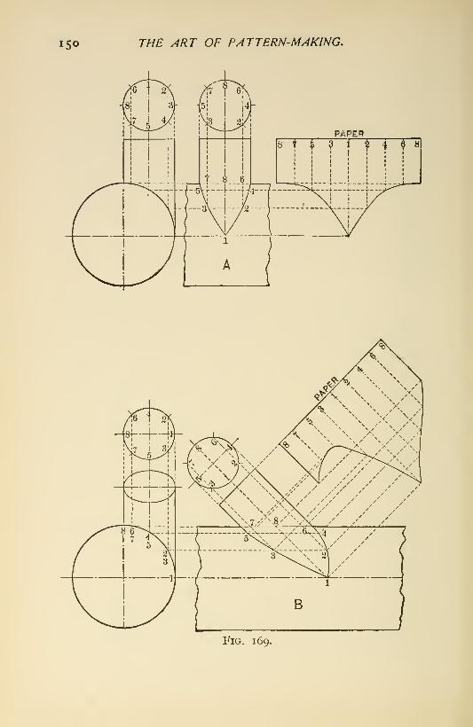
15© THE ART OF PATTERN-MAKING.
Fig. 169.

PATTERNS fVITH BRANCHES. 151
ordinates to correspond with those projected from
the end view of the branch. From the intersection
of the ordinates on the branch with the body project
lines intersecting the ordinates correspondingly num-bered on the side view and on the paper ; a curve drawnthrough these intersections on the side view will give
the projected curve, and a curve drawn through
the intersections on the paper will give the developed
curve, of the jimcture of the branch with the body.
The lower view, B, shows the branch located to
one side of the center of the body as in the previous
case, viewing the body on the end ; but viewing the
body on the side, the axis of the branch is inclined
to that of the body.
To obtain the projected curves of juncture in this
case draw the two views as before and draw ordinates
on the branch projected from intersections on its
end view. From the intersections of these ordinates
with the body on the latter' s end view project lines
intersecting the ordinates correspondingly num-bered on the side view. A curve drawn through
these latter intersections will give the projected
curve of juncture of branch with body. To obtain
the developed curve tack down the paper in the
position shown, and upon it draw two lines parallel
with each other and with the axis of the branch onthe side view, making the distance between the lines
equal to the circumference of the branch. Divide
this distance into the same number of equal parts as
the branch, and draw ordinates parallel with the twoend lines. Number the ordinates to correspond

152 THE ART OF PATTERN-MAKING.
with those on the branch. From the intersections
of the ordinates on the branch with the body, as
shown in the side view, project lines at right angles
with the axis of the branch intersecting ordinates
correspondingly numbered on the paper. A curve
drawn through these last intersections will give
the developed curve of the juncture of the branch
with the body.
Where there is frequent occasion for fitting
branches when making plain patterns, such as
pipes, etc., a device like that shown in Fig. 170 will
be found a great advantage. It consists chiefly
of a base-plate having a true surface, with a spindle
fixed near one end and perpendicular to the true
surface of the plate ; also a head which has both a
sliding and a revolving motion on the spindle. The
sliding head carries a radius-bar set at right angles
to the axis of the spindle. The radius-bar is ad-
justable to suit different radii, and one end is pro-
vided with a scriber held in a clamp bearing so that
it can be adjusted to suit different diameters of
branches.
A and B are cradles to which the work is secured
by w^ood-screws while being operated upon. Thecradles can be made of wood, but are much better
when made of metal and finished accurately. There
should be a center line scribed on the surface of the
base-plate parallel with its sides and intersecting
the axis of the spindle to serve as a datum line for
setting the cradles when the work is to be marked.

PATTERNS tVITH BRANCHES. 153

154 THE ART OF PATTERN-MAKING.
The cradle A is intended for parted work, and B for
work not parted.
The device is equally handy whether the boss or
branch is set at right angles to the body of the pat-
tern or at any other angle, or whether it is to set awayfrom the center line of the body. In the former
case it is only necessary to secure the work at the
desired angle in the cradle, or, where it is set to
one side of the center line of the body of the pattern,
to set the cradle accordingly on the base-plate
while the curve is being scribed on the work.
After the work is scribed, which will be on the
upper side as it sets in the cradle, the latter can be
taken to the band-saw and the work cut to the line.
If the entire operation has been carefully and accu-
rately done, the branch will need very little further
fitting to allow it to be secured in the place intended
for it.
XXII.
TEETH OF GEAR-WHEEL PATTERNS.
The increasing use in machine construction of
cut gear and also of machine-moulded gear has
somewhat lessened the extent that gear-wheel work
formerly held in the trade of pattern-making. But
notwithstanding this tendency gear-wheel work is
still a very important factor in the trade of pattern-
making because of the skill and expertness required
in its performance. There are few patterns of the
class that are regularly made for machine castings
that require greater skill and expertness to com-
plete than a bevel-wheel pattern.
As to the best method of working the teeth and
attaching them to the rim of a gear-wheel pattern
there has been much discussion amongst pattern-
makers. Fig. 171 shows five methods of secur-
ing the teeth to the rim; each of these has its
advocates. A gear-wheel pattern to be made prop-
erly should be made accurately; it matters not howwell made otherwise, if not accurate it is not suited
for the purpose for which gear-wheels are intended.
Of the different methods shown here the author is
decidedly in favor of securing the teeth as shown
by No. 5. This method of securing the teeth to
155

156 THE ^RT OF PATTERN-MAKING
Fig. 171.

TEETH OF GEAR-JVHEEL PATTERNS. 157
the rim is amongst the eadiest practiced, and for
accuracy and durabih'ty has no superior. Theobjection urged against this method that it is
difficult to form suitable fillets at the roots of the
teeth, owing to the delicacy of the edges there, is of
small moment, because with care and the aid of
sandpaper and shellac satisfactory fillets can be se-
cured. The devices shown in connection with the
teeth and rim of the wheel are intended to facilitate
the working and attaching the teeth to the rim
when method No. 5 is adopted. A, B, C, are respec-
tively a plan, an end, and a side view of a com-
bined box clamp and gauge by means of which the
size and shape of the dovetail tenons on the tooth-
blccks are worked. The gauge, a, is intended for
use when cutting the dovetail slots in the rim ; it is
made of hard wood and equal in length to the face
of the rim, and has a center line scribed through its
length and on the ends. The angle of the sides
should be about 22° 30' with the center line, and
the taper in length f inch per foot. The gauge in
use is secured to the rim by two sharp-pointed wire
brads, which are allowed to project to enable themto be readily withdrawn to change the position of
the gauge. After the rim has been stepped off andlined, the gauge is secured to the rim by the pointed
bi;ads to coincide with a center line for a tooth.
The saw, 6, is applied and kept close to the side of
the gauge while sawing the rim to the line scribed
on the rim for the depth of the slot. After the
sides of the slot have been sawed and the gauge

158 THE ART OF PATTERN-MAKING.
removed, it is advisable to saw one or two kerfs
between those outside. These will facilitate the
removal of the material in working out the slot.
The box, ABC, should be made substantial and of
a size to allow its use for different sizes of teeth.
The small sizes of teeth can be worked in the box by
fitting a liner under the block and making a wedge,
d, to suit the space between the block and the side
of the box. The bottom of the box should be of
sufficient thickness to allow the box to be held in
the bench-vise while the dovetails on the blocks are
being worked. The top of the box, c, which is the
gauge for the taper and bevel for the dovetail
tenon, is adjustable. The plane, e, is a rabbet
beveled on the face to suit that of the gauge, a. Astrip is secured to the side of the plane which, by
bearing on the top of the box, c, gauges the depth
of the dovetail. After one side of the dovetail
tenons have been worked on the blocks the top, c, is
reversed in angle and the remaining sides worked.
The dovetail tenons should be made a trifle full for
the slots, as a little fitting will be found necessary
even when pains have been taken to insure accuracy,
and for this reason, also, they should be somewhat
longer than the width of the rim; they can be cut
to the required length after being fitted into the
rim.
If the teeth are to be cut by machinery, the blocks
are secured to the rim by applying glue to about
one-half inch at the large end of the dovetail.
Gluing at one end only is to allow for any possible

TEETH OF GEAR-IVHEEL PATTERNS. 159
shrinkage of the rim. If the teeth are to be worked
out by hand, the blocks, after the shape of the teeth
have been laid off, are backed out, each being
marked as it is removed from the rim ; they are then
worked in the usual way by being held by a hand-
screw in the bench-vise while being shaped. In
finally replacing the teeth in the rim three or four
should not be glued ; these should be properly
marked: they are for the purpose of allowing the
moulder to back them out to mend the mould
should that become necessary.
As to the best material for making gear-wheel
patterns there is nothing better than clear, soft,
white pine for the body of the wheel and straight-
grained cherry for the teeth. All of the material
of course should be thoroughly seasoned and dry
when used.
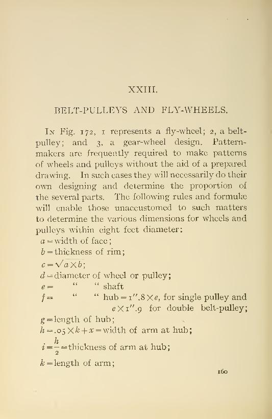
XXIII.
BELT-PULLEYS AND FLY-WHEELS.
In Fig. 172, I represents a fly-wheel; 2, a belt-
pulley; and 3, a gear-wheel design. Pattern-
makers are frequently required to make patterns
of wheels and pulleys without the aid of a prepared
drawing. In such cases they will necessarily do their
own designing and determine the proportion of
the several parts. The following rules and formulae
will enable those unaccustomed to such matters
to determine the various dimensions for wheels and
pulleys within eight feet diameter;
a = width of face
;
h = thickness of rim
;
J = diameter of wheel or pulley;
e= " " shaft
/ = *' ** hub = i".8 X^, for single pulley and
eXi^.g for double belt-pulley;
g:= length of hub;
h = .o^Xk-\-x = width of arm at hub
;
f=- = thickness of arm at hub;2
^= length of arm;160
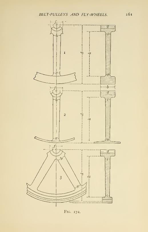
BELT-PULLEYS AND FLY-IVHEELS. i6i
Fig. 172.

1 62 THE ART OF PATTERN-MAKING.
:x: = width of arm at rim;
y=-= thickness of arm at rim.
The thickness of the edge of rims should be ".25
for double- and ".2 for single-belt pulleys, the thick-
ness to increase ''.125 per foot to center of rim.
The arms should be oval in section, the radius of the
edges made about one eighth of the width of the
arm. The application of formulas is apt to cause
timidity in some mechanics when solving problems,
but by following the examples worked out the
dimensions of the details for any other diameter
than that given may be easily arrived at by substi-
tuting the given diameter.
Example.
It is required to find the size of arms and hub for
a single belt-pulley 48'' diameter for 3'' shaft.
Formula: x = " .^^j^-^ .o^d.
^ = "•375 + 1-92 =2^.3 = width of arm at rim;
oc 2 "?
-1; = - = -^ i.ir =thickness of arm at rim
;
^ = 24 — 3=21 =length of arm.
/i = 2iX.o5 + 2.3= width of arm at hub
;
2 "^
i =—^ = 1.1';= thickness of arm at hub
;
2^
/ = 3 X 1.8 = 5.4 =diameter of hub.
A close approximation of the length of arm for
pulleys can be obtained by subtracting the diameter
of shaft from the radius of the pulley, as done in the
above example.
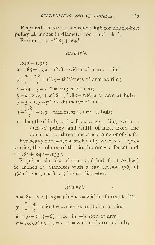
BELT-PULLEYS AND FLY- IVHEELS, 163
Required the size of arms and hub for double-belt
pulley 48 inches in diameter for 3-inch shaft.
Formula: x-=".%^-\- .o/^d.
Example.
.04^ = 1.92;
:t = .85 + 1.92 =2". 8 = width of arm at rim;
^ 2.8 ,, . . .
y =-^— = I ''.4 = thickness of arm at rim;-^ 2 2
^ = 24 — 3 =21" = length of arm;
h = 2i X.o5 + 2''.8 = 3".85 = width of arm at hub;
/ = 3 X1.9 = 5". 7 = diameter of hub.
i = —— = 1.0= thickness of arm at hub
;
2^
g = length of hub, and will vary, according to diam-
eter of pulley and width of face, from one
and a half to three times the diameter of shaft.
For heavy rim wheels, such as fly-wheels, c, repre-
senting the volume of the rim, becomes a factor and
rr-.85^|-.04J + .i53C.
Required the size of arms and hub for fly-wheel
60 inches in diameter with a rim section (ab) of
4X6 inches, shaft 3.5 inches diameter.
Example.
i\; = .85 + 2.44-.75 = 4 inches = width of arm at rim;
X 4a; = — = - = 2 inches = thickness of arm at rim
;
''22^ = 30— (3.5 + 6) =20.5 in. =length of arm;
/z = 20. 5 X .05 + 4 = 5 in. = width of arm at hub
;

1 64 THE ART OF PATTERN-MAKING.
^=- = 2.s in.= thickness of arm at hub
;
2
/ = 3.5X2=7 inches = diameter of hub.
For fly-wheels, also for pulleys when the pattern
is likely to be used for other purposes than that for
which it was specially designed, it is advisable to
make the diameter of hub double that of the shaft.
In so doing it adds but a small amount to the weight
of the pulley, but it has the advantage of making
the pattern available for a somjewhat larger shaft,
without alteration, if wanted for such.
In the case of fly-wheels like the foregoing exam-
ple it will be found that the aggregate widths of the
arms exceed the circumference of the hub, and whenthe arms are joined by a curve, a web will be formed
around the exterior of the hub which greatly strength-
ens the latter. The proportions of fly-wheel rims
will vary according to the fancy of designers, except
in cases where a belt is to be used on the rim.
Some will prefer to make the face the larger dimen-
sion, while others will make the side of the rim the
larger dimension. In either case good proportions
for rims are as 2 and 3.
When designing arms, etc., for gear-wheels the
formula for double-belt pulleys can be used, with
the addition of a web on the interior of the rim
joining the arms at that part. The thickness of
rim of a gear-wheel is usually made equal to that of
the root of the tooth.
The number of arms a pulley should have will
va.ry according to the diameter. Up to 10 inches,

BELT-PULLEYS AND FLY-IVHEELS, 165
a solid web, or 4 arms ; from 10 to 18 inches diameter,
5 arms; from 18 to 42 inches, 6 arms; and from 42
to 72 inches, 8 arms.
While it is advisable to abolish all sharp corners
in castings, great care is necessary in applying
fillets, as very large fillets, under some conditions,
may become a source of weakness to a casting
instead of adding strength. A casting is strongest
when the metal is most imiformly distributed.

XXIV.
STANDARD PATTERNS.
Standard patterns when made of wood and
which are often used should be made very durable.
They should be made wholly or in part of hard
wood, such as mahogany or cherry. Where dowel-
pins are necessary they should be of metal. The
metal dowel-pin should be about ij" long and
cylindrical for about ^'^ from the plate, then taper
yV' to the point, which should be rounded. Made
thus the plate can be set a little below the joint of
the pattern and not interfere with the parts joining
together properly. Wood dowel-pins answer their
purpose very well for ordinary patterns and are
cheaper than metal, but when a pattern with wood
pins is often used the pins are liable to stick by
becoming damp and swelling. When this occurs,
very likely the moulder will enlarge the holes to
such an extent that the doweled parts will not retain
their proper position while being rammed up in the
mould, and the result is a distorted casting. Rap-
ping- and draw-plates are great pattern-savers and
will well repay their cost when fitted to patternsI66

STANDARD PATTERNS, 167
that are used for many castings. There are severalkinds of rapping- and draw-plates on the marketvery reasonable in price. Unless for a very largepattern, plates combining both rapping and drawfeatures are the most convenient.

XXV.
GLUE AND ITS USE.
Glue is indispensable in pattern work, but it is
not every pattern-maker that can do a first-class
job of gluing. The first essential for a good job of
gluing is good glue. The author has always found
the best Irish glue thoroughly reliable. With this
glue in the hands of a competent workman whounderstands its use, there is no excuse for a bad
gluing job. The glue should always be applied
hot. Prepared liquid glues that can be applied
without heating them are very convenient and will
hold well for a while, but their adhesiveness seems
to deteriorate with age and they are not so durable
as glue applied hot. When large surfaces are to
be glued the work should be warmed where possi-
ble. Pattern-shops are not usually provided with
a special room that can be heated for gluing work.
Where there is no special room for gluing up work
it is advisable to heat the work previous to applying
the glue. A good substitute is a steam-box. Such a
box can be made of tongue-and-groove partition-
stuff and need not be very expensive. A conve-i68

GLUE AND ITS USE. 169
nient size inside is about 16 ft. 6 in. long, 24 in. wide,and 24 in. deep. The cover should be hinged andin two parts as to length. A coil of i-in. steam-pipe running along the bottom of this box shouldsupply the heat. The box should be located con-venient to the glue-heater.
XXVI.
LOOSE PIECES.
Loose pieces on patterns, although objectionable,
cannot in many cases be avoided. They are often
less objectionable than cores. When it becomes
necessary to choose between a core and a loose
piece the latter will generally prove the better
because it will insure a truer casting. A core is
especially liable to become misshapen by dressing
and handling. Loose pieces are usually attached to
patterns with draw-pins. Common brads with the
end bent near the head make excellent dr?„w-pins.
In some cases it is advisable to fit loose pieces with
dovetail tenons because when so fitted they are
less liable to be misplaced while ramming up the
mould. In fitting loose pieces with dovetails it is
the practice with many pattern-makers to make the
tenons parallel in thickness and have the taper on
the two bevel edges only. This is objectionable, as
they are liable to stick when so made. To insure
the pattern being drawn easily and leaving the
loose piece in the mould without distorting it, the
dovetail tenons should be tapered both in width
and thickness.170
XXVII.
WOOD LAGGING FOR AN ELBOW.
In covering steam-pipes with materials of low heat-
conducting properties for the purpose of retaining
heat that would otherwise be dissipated, it is neces-
sary, especially on vessels, to cover the non-con-
ducting material itself, and thus increase its dura-
bility while giving it an appropriate finish. For this
outside covering black-walnut lagging is largely
employed. This work is usually done by pattern-
makers.
In work of this kind peculiar shapes are frequently
encoimtered which tax the skill and ingenuity of
the workman in his effort to satisfactorily cover
them. The most common are bends of pipes.
Figs. 173 and 174 show the different stages in
constructing a right-angle bend for a pipe of woodlagging. On a suitable board, circles of the exterior
and interior diameters of the bend are described,
and from these the number of pieces or segments
to compose the bend is determined. The cuts
show a bend composed of twelve pieces, six in each
half.
171

172 THE ART OF PATTERN-MAKING,
The material is first brought to the required
thickness, according to the location of the several
segments in the bend, as shown by i, 2, 3, 4, 5, and
6, Fig. 173. These are all the pieces which compose
one half the bend, 6 joining next to i, 5 next to 2,
and 4 next to 3. The different segments can be laid
off directly on the material, but by the use of pre-
pared templets the material can often be worked
to better advantage.
The figures show a plan and section of the
different pieces and clearly illustrate the method of
laying them off.
After the curvature of the pieces has been workedout, the next thing in order is to bevel the edges
that the pieces may closely join when assembled.
This bevel is required to be a radial line of the cir-
cles. Fig. 174. The thicker or outside segments are
most conveniently beveled from the sides which are
to be curved, and the thinner or inside pieces from
the top or flat side.
The required thickness of the segments being
gauged after beveling, they are worked to the ex-
terior circle by templet. The insides are next workedout, which may be done roughly, as with these parts
it is only necessary to approximate the circle.
When preparing to assemble the segments an
outline of the bend is laid off on the board, and to
this are secured semicircular blocks of the inside
diameter at each end of the bend. As the segments
are assembled, they are made to fit these blocks,
which serve at once as guides and supports. Pieces

IVOOD LAGGING FOR AN ELBOIV.
Fig. 173.
173
Fig. 174.
174 THE ART OF PATTERN-MAKING.
of pine block glued to the segments will be found
convenient for securing them to the board uponwhich they rest. These blocks are easily removedwhen the bend is to be finished.
If the segments have been accurately workedand have not warped, little fitting will be necessary
when assembling them. After a segment has been
fitted and is ready to be doweled to its neighbor, a
bead is worked on one edge. For this purpose a
piece of saw-blade or other thin steel filed to form a
bead and fixed to a gauge made for the purpose is
convenient, the bead being formed rather by scrap-
ing than by shaving.
When one half the bend has been completed,
except to finishing, it is to be inverted, and the other
half assembled upon it, this last being performed
in a manner similar to that of the previous half.
If preferred, both halves may be assembled on the
board, right and left, and if due care be exercised
they will match properly.

XXVIII.
THE LATHE AND LATHE-WORK.
The first essential for doing good lathe-work is a
good pattern-maker's lathe, which should be per-
fectly balanced and run steadily. When not spe-
cially designed for very small work it should beprovided with a traveling carriage and slide-rest,
also with outside or overhanging face-plate andfloor-stand. The various appurtenances, such as
chucks, face-plates, drivers, centers, etc., have muchto do with a lathe's usefulness.
Some ingenious and handy fixtures for the
lathe have been described. They are here repro-
duced, with some modifications and additions, in
Figs. 175 and 176.
Referring to Fig. 175, a represents a driver which
possesses some points of merit for large work.
With the ordinary spur driver with the spurs
fixed and projecting nearly to the point of the
center it is often difficult to readily swing the workbetween the centers. With this driver the chisel-
points which do the driving are made adjustable bymeans of a collar with a screw-thread on its inner
circumference. The driving points move in grooves
175

176 THE ART OF PATTERN-MAKING.
C
d
-^rJi'T
9
•cr'T^'
uz7
^
c/
Fig. 175.

THE LATHE AND LATHE-IVORK. 177
J
h
Fig. 176.

178 THE ART OF PATTERN-MAKING,
cut into the projecting end of the driver. These
are threaded on their outer surface to match the
collar. By this arrangement the driving points
can be kept well out of the way until the work is
swung between the centers. After the work has
been swimg the driving points can be moved out
and forced into the work by revolving the collar
and allowing it to bear against the end of the bodyof the screw-box. When the driving points are to
be released the collar is revolved in the opposite
direction. The points can then be withdrawn.
h shows another kind of driver, convenient
where it becomes necessary to remove and again
replace the work in the lathe. In such cases
it insures the work being centered in the second
instance exactly as it was in the first. The con-
centric rings on the driver should have the taper
on their inner circumference and have their periph-
ery parallel with the axis of the lathe. This will
prevent any tendency, especially with parted work,
to move outward.
c shows the ordinary socket-chuck to screw on
the spindle. In some cases the hole for holding the
work is wrongly made square. It should always
be made circular and have a taper in the proportion
of one inch per foot.
d shows a driver similar to h intended for smaller
work and to fit the socket in the lathe-spindle.
e shows a good form of driver. It is made cylin-
drical and then milled away at the end so as to leave
a central spur and four chisel-points for driving.
THE LATHE AND LATHE-IVORK. 179
/ shows a tail-stock center with a central spur
and a concentric ring. In using this center it is
good practice to fill this cavity with tallow or Albanygrease before inserting it into the work, as it is diffi-
cult to oil when in the work. Every pattern-maker
knows the difficulty even when the work has beencentered in the first instance, of keeping it so in the
lathe when using the ordinary single-spur centers.
With the concentric-ring centers and drivers there
is little liability of the work shifting after once
being secured in the lathe, and should the workrequire removal from the lathe, it can be replaced
exactly as it was before removal.
g shows a handy chuck where it is important to
have the work accurately parted in the center. Oneside of the work is made longer than the other, andthis long side is secured to the chuck by screws.
The chuck's construction and application are so
plainly shown as to make further explanation
unnecessary.
In preparing jointed work for the lathe, espe-
cially that which is to swing between centers, andwhen sufficient time will permit, have the pieces of
ample length and glue them together outside of
the finished length. The glued part can be cut off
after the work is removed from the lathe.
In Fig. 176, h shows a face-plate with a central
boss finished to size and trued on the spindle of the
lathe. The boss is to fit a hole bored into the work
to be operated upon. A convenient size for the
boss is one inch diameter and one-quarter inch

l8o THE ART OF PATTERN-MAKING.
long. The dotted lines serve to illustrate one of
the most satisfactory operations of this simple fix-
ture. The blank shown is finished on both sides.
In operating on the first side a recess is turned in
the center of the exact size to fit the boss on the
face-plate. This insures the work being reversed and
rechucked with accuracy. The recesses are also
convenient for locating core-prints which are to be
turned with a pin to fit the recess.
i shows a similar face-plate of smaller dimen-
sions. The wood-screw shown in the center of
the face-plate is preferable to the usual taper
screw, because it is not so liable to split the work.
The screw should fit the hole in the plate tight, but
not so much so as to prevent its being backed out
in case it is desired to use screws of different lengths.
For boring the recess to fit the center boss on the
face-plate, a bit, m, should be prepared—a Forstner
bit preferred. The bit should be kept handy to
the lathe and not allowed to be used for any other
purpose than that for which it is intended.
A great advantage will result from the adoption
of a system for core-prints and have all core-prints
conform to it. All core-prints for both drag and
cope should be made tapered and core-boxes madeso that the cores will fit the impressions made bythe prints and not have cores larger than the prints,
as is too often the case. In making core-boxes for
cores which set vertically in the mould, it is the com-
mon practice to make the lower or drag print slightly
tapered and the end of the core-box straight or cylin-
THE LATHE AND LATHE-IVORK. i8l
drical. Thus made there is always a liabiHty of the
core inchning, for the reason that the core when being
set is apt to cut into one side of its seat as shown
at I. When the print is given sufficient taper and the
core-box made to suit it, there is less liability of the
core not being properly set as shown at n. The pin
on core-prints will be found advantageous when at
any time it is desired to change the size of the core.
A good standard for the taper of drag-prints is one-
eighth inch in diameter for one inch in length ; andfor cope core-prints, one-quarter inch in diameter
for one inch in length.
To facilitate the practice of this system of core-
prints it is necessary to provide gauges similar to
those shown at k for the drag, and at / for the cope
core-prints. By means of these gauges the pins
on the core-prints and the recesses for them in the
pattern can be sized. Also the size and length of
the prints gauged. A convenient place near the
lathe should be provided for the gauges and bit, and
care taken that they are always in their place whenwanted for use.

XXIX.
HOW TO MAKE A WOODEN FACE-PLATE.
A COMMON way of making wooden face-plates for
the lathe is to secure a plain wood plate to a cross.
When using hand-screws with a plate made thus
some of the screws are required to be set open to suit
the thickness of the work and plate, and others to
Fig. 177.
suit the thickness of the cross in addition. This
condition often causes vexation by picking up the
182

HO^V TO MAKE A WOODEN FACE-PLATE. 183
wrong screw in the hurry necessary when gluing
up work. The annoyance thus occasioned may beavoided by securing segments of the thickness of
the cross around the edge of the plate between the
cross (see Fig. 177), then all hand-screws are required
to be opened alike.
XXX.
MARKING, RECORDING, AND STORINGPATTERNS.
It is now being recognized that patterns repre-
sent a large amount of money with some establish-
ments, and economy requires that they should be
properly cared for. Every concern using patterns
to any extent should have a system of marking,
recording, and storing them, and should not depend
on the memory of persons for their identity and
location. With a proper system any person of
ordinary intelligence can be placed in charge of the
pattern storage in case of the absence of the regular
man whose business it is to take care of the patterns
when the foundry has finished with them.
The nomenclature of machines and their various
parts should originate and be decided upon in the
draughtsmen's department, and this information
should always be noted on the drawing. It is too
often the case that the name of the machine or its
parts is left to be decided upon in the pattern de-
partment. By the name, etc., being noted on the
drawing there would in many cases be less difficulty
in identifying a pattern.
184

MARKING, RECORDING, AND STORING PATTERNS. 185
Several systems are in use for marking and record-
ing patterns, each having its merits and demerits-
Some simply stencil or paint a number on the pattern
and have a pattern accession-book in which the
patterns are recorded. This system to be efficient
needs to be combined with their proper care andstorage, a feature too often neglected. This system
has the disadvantage of the number, etc., becoming
obliterated by continued use and neglect; but this
objection can be overcome by renewing the stenciling
when obscurity by wear becomes liable. Withproper care stenciling will prove more durable than
one would suppose who has had no experience with it.
Another method of marking is to stamp the
number and name on the patterns with stencil-cutters.
This indelibly marks it. The nuraber of the pat-
tern with whatever other necessary information in
connection with it is recorded in a pattern-book.
It is desirable, especially when standard or particu-
lar lines of machines are manufactured, to have some
mark to appear on the machine or its parts to enable
them to be readily identified and to facilitate filling
orders for such machines or their parts.
The system I would recommend, especially for
establishments using a large quantity or a great
variety of patterns, is:
I. Classify the patterns by placing in a class all
similar machines. Where a machine is extensive
and consists of many parts it may be given a class
mark of its own. The different classes to be in-
dicated by a letter or combination of letters.

i86 THE ART OF PATTERN-MAKING.
2. Give each pattern a number. Where a pat-
tern consists of a number of pieces, give each piece
the same number as the main part of the pattern.
Mark all core-boxes to correspond with class andnumber of their respective patterns.
3. Mark the pattern, its loose pieces, and core-
boxes by stamping with stencil-cutters, and in
addition secure raised letters and figures, for class
and numbers, to the pattern so that they will appear
on the casting. The advantage of stamping be-
sides the lead figures, etc., is that if a figure becomes
3Iachine
MARKING, RECORDING, AND STORING PATTERNS. 187
sample shown in Fig. 178, to be filled in with pen
and ink. The information on these forms, which
can be about 2" X 2", should give the name and
part of the machine the pattern is intended for, the
number of pieces composing it, also the numberof core-boxes belonging to the pattern, the numberand kind of castings, and any other information
deemed essential. These forms are to be fastened
with shellac to a part of the pattern subject to the
least wear, and when fixed are to be given two coats
of shellac. Thus treated they will prove quite dur-
able. The miscellaneous is likely to be the largest
class of patterns. There are, however, many pat-
terns of this class carried from year to year and
never used that should be destroyed after being
employed for the purpose for which they were made.
The pattern storeroom should not be encumbered
with a lot of patterns not likely to be used again for
the purpose for which they were made.
For recording the patterns the card system pos-
sesses many advantages over recording in a book.
The cards can be in duplicate or triplicate as deemed
desirable for use in the drawing-room, pattern-shop,
and pattern storeroom. All information about the
pattern likely to be needed can be recorded on the
card. Moreover, any change that becomes neces-
sary can be readily noted on the card or a newcard substituted. A desirable size for the record-
ing cards is 3 J" X 5^". A sample card is here shown
(Fig. 179).
The pattern storeroom should be divided into sec-

i88 THE ART OF PATTERN-MAKING.
Class

MARKING, RECORDING, AND STORING PATTERNS. 189
tions and marked to correspond with the class let-
ters on the pattern.
When an order for castings from a pattern is
completed in the foundry the man assigned to care
for patterns should collect all pieces, core-boxes,
etc., belonging to the pattern and clean them. Anyrepair needed should be done before the pattern is
stored away. The pattern should then be stored
in the section assigned to the class to which it
belongs. When patterns are sent away to have
castings made at a distant foundry the fact with
any other necessary information can be noted on
slips and filed with record-cards of the patterns in
the card-rack—the slips to be removed from the
card-rack when the patterns are returned.

XXXI.
SECTIONAL LINING IN MECHANICALDRAWINGS.
With the general use of blue-prints in place of
tracings, as formerly used for mechanical working
drawings, it becomes necessary to adopt some par-
ticular marking when it is desired to designate the
material to be employed. An effort is being madeby the leading draughtsmen and technical journals
to systematize the marking of mechanical drawings
in this respect. Fig. i8o shows the markings most
generally used at present.Z90

SECTIONAL LINING IN MECHANICAL DRAIVINGS, 191
1
:^
.1
XXXII.
• PRACTICAL GEOMETRY.
^ A KNOWLEDGE of even the rudiments of geometry
is of great assistance to pattern-makers. The fol-
lowing geometrical problems, Figs. 1 81-19 2, are
selected because of their more general practical ap-
plication. If workmen will practice and familiarize
themselves with their principles, they will add ma-
terially to a knowledge that will greatly benefit them
in laying off work.
Fig. 181 illustrates the construction of a square on
a given length of line. It also teaches how to erect
a perpendicular on the line and at the end of it.
Bisect the line ab, of given length; from the extrem-
ities a and b describe the intersecting arcs c; a
line drawn from c to the bisection of ab will be per-
pendicular to the latter line. With one half the line
ab as a radius, describe an arc from the point of
bisection 0, intersecting the perpendicular at J; a
line drawn from b through d will produce a diago-
nal of the square. With the distance db as a ra-
dius, from the point d describe an arc intersecting
ab and the diagonal at c; a line drawn from this
last intersection to a will be perpendicular to the192

PRACTICAL GEOMETRY. 193
line ah and equal to its length, thus completing
two sides of the square. With the distance ah or
ac from the points e and h describe the intersecting
arcs /. Lines drawn from this intersection to h and
e will complete the square.
Fig. 182 shows how to describe an octagon in a
given square. Construct the square as in Fig. 181.
With one half of the diagonal as a radius, and from
the points a, 6, e, /, describe arcs intersecting the
sides of the square, as gh, etc.; lines connecting
these intersections will produce the octagon.
Fig. 183. To describe a hexagon in a circle.
Draw center line and set off the diameter, ah. Froma and h as centers, with distance ao and ho from
a and 6, cut the circle at cm and en. Connect these
points with lines to complete the hexagon.
To describe a hexagon about a circle using Fig. i d>2^.
Draw center line of indefinite length and set fg for
diameter. With radius of describe an arc of circle
from f to h with the radius; connect fh with line.
Draw oh and extend indefinitely. Draw a tangent
to the circle parallel with the line fh and intersecting
radii at a and m. From as a center, with radius
oa describe circle. From a and h as centers cut the
circle with the radius and connect the intersections
with lines as in the previous case.
Fig. 184. To describe a regular polygon of any
required number of sides. From point 0, with dis-
tance oh, describe semicircle h and a, which divide
into as many parts, a, c, d, e^ /, 6, as the polygon
has sides.

194 THE ART OF PATTERN MAKING.
e

PRACTICylL GEOMETRY. 195
Fig. 189. Fig. 190.
Fig. 191.

196 THE ART OF PATTERN-MAKING.
Thus let a pentagon be required. From to the
second point, d, draw od, and through the other
points, e and /, draw lines extending indefinitely.
Apply distance oh from b to h and from d to g. Con-
nect these points. Or describe a circle intersect-
ing obd, which will determine the points g and h.
Fig. 185. To find the center of a triangle. Bi-
sect the sides of the triangle, as a, b, c. From a, b,
and c draw lines to the angle opposite each, inter-
secting at d, the center.
Fig. 186. To bisect inclination of two lines whenpoint of intersection is inaccessible. Upon given
lines ab and cd at any point draw perpendiculars
eo and sr of equal lengths, and from o and 5 draw
parallels to their respective lines intersecting at n.
Bisect the angle ons, and connect mn with a line
which will bisect the lines as required.
Fig. 187. To find the center of radius of an arc.
Divide.the arc into equal parts, as a, b, c. From a, 6,
and c as centers, with a radius greater than
their distance apart, describe intersecting arcs, as
de and fg, both inside and outside of the arc. Drawlines through these intersections and extend themuntil they meet in the apex, as at h, which will be
the center of the circle of which the arc is a
part.
Fig. 188. To describe a circular segment which
will fill the angle between two diverging lines. Bi-
sect the lines a, &, d, e by lines e, /, and connect per-
pendiculars thereto to define the boundary of a
segment to be described. Bisect angles at b and d

PRACTICAL GEOMETRY. 197
by lines intersecting at o, and from o, with radius
oe, describe arc men.
Fig. 189. To draw from or to the circumference
of a circle lines leading to an inaccessible center.
Divide the whole or any portion of the circum-
ference into the desired number of equal parts, as
a, h, c, and o\ then with any radius less than the
distance of two divisions, describe intersecting arcs,
as d, e, f. Draw lines from d to b, e to c, and /to 0,
and they will lead to the center.
Fig. 190. To draw a spiral about a given point.
Assume c the center. Draw ab and divide into
twice the number of parts that there are to be
revolutions of line. From c describe the semi-
circles d, e,f; bisect the distance between c and d at
o, and from as a center describe semicircles g, h, i.
Fig. 191. To describe an ellipse, approximately, by
circular arcs. Draw major"axis gh and minor axis ik,
set off their difference in length from o to a, and
from Xo c draw line ac\ bisect its length and set off
half from a to r ; draw rs parallel to ac. Set off on
equal to or, and om equal to os ; from 5 and m draw
lines through n and r, extending them indefinitely;
from n and r as centers, with radius rh, draw the
arcs dhf and bge\ from 5 and m as centers, with
radius sf, draw the arcs ekf and bid.
Note: This method is not satisfactory when the
minor axis is less than two thirds of the major.
An oval may be similarly described by circular
arcs with any difference of major and minor
axis.

198 THE ART OF PATTERN-MAKING.
Fig. 192. To describe an ellipse to any length
and breadth. Draw the major axis cd and minor
axis ef\ from c and d as centers, with distance
of half the major axis, describe arcs intersecting
the major axis at h and i. Insert pins at h
and i, and loop a string around them of such
length that when a pencil is introduced within it
will just reach to e or /. Bear upon the string and
sweep around the center o, and an ellipse will be
described. When an elliptograph is not available
and the ellipse is to be constructed by points, the
best and most accurate method of doing it is that
shown by Fig. 193.
7 86^-1—y—i;--
Id'
--LI
Fig. 193.
Let DB be the major and AC the minor axis,
intersecting at right angles at the center 0. With
as a center and OC as a radius describe a circle.
From the same center, with OD as a radius, describe
another circle. Divide the larger circle into any
number of equal parts, and from these intersections

PRACTICAL GEOMETRY. I99
draw radii which will also divide the inner circle
correspondingly. From the points of intersection
on the outer circle, as i, 2, 3, etc., draw lines parallel
with the minor axis, and from the intersections on
the inner circle, as i, 2, 3, etc., draw lines parallel
with the major axis. The intersection of these
lines, as at a, 6, c, etc., will determine the curve of
the ellipse.
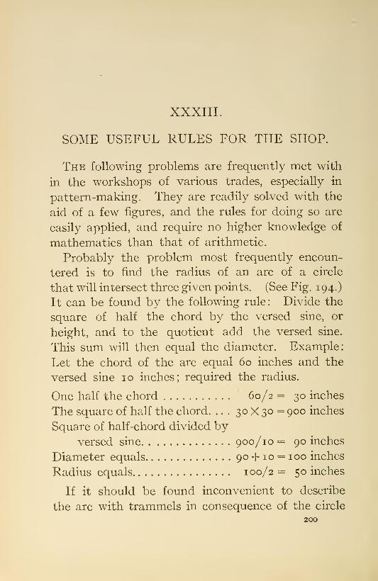
XXXIII.
SOME USEFUL RULES FOR THE SHOP.
The following problems are frequently met with
in the workshops of various trades, especially in
pattern-making. They are readily solved with the
aid of a few figures, and the rules for doing so are
easily applied, and require no higher knowledge of
mathematics than that of arithmetic.
Probably the problem most frequently encoun-
tered is to find the radius of an arc of a circle
that will intersect three given points. (See Fig. 194.)
It can be found by the following rule: Divide the
square of half the chord by the versed sine, or
height, and to the quotient add the versed sine.
This sum will then equal the diameter. Example:
Let the chord of the arc equal 60 inches and the
versed sine 10 inches; required the radius.
One half the chord 60/2 = 30 inches
The square of half the chord. ... 30 X 30 = 900 inches
Square of half-chord divided byversed sine 900/10 = 90 inches
Diameter equals 90 -f 10 = 100 inches
Radius equals 100/2 = 50 inches
If it should be found inconvenient to describe
the arc with trammels in consequence of the circle
200

SOME USEFUL RULES FOR THE SHOP,
Fig. 194
201
Fig. 196.

202 THE ART OF PATTERN-MAKING.
being very large or the center inaccessible, it maybe described as follows, when the chord of the arc
and versed sine are determined : Drive a wire brad
at each extremity of the chord and also at the end
of the versed sine. Then provide two straight-
edges ; the length of each must not be less than the
lerigth of the chord. Let the straight-edges bear
against the brads at the ends of the chord, and one
end of each bear against the brad at the end of the
versed sine. In this position secure the straight
edges together. Now withdraw the brad at the
end of the versed sine and insert a scriber in the
apex of the angle formed by the straight-edges. Bymoving the templet to the right and left while bear-
ing against the brads at the ends of the chord, the
desired arc will be described. (Fig. 195.)
When it is inconvenient to describe the arc byeither of the foregoing methods, it may be arrived
at by laying down the arc to a scale, erecting ordi-
nates from the chord, and from the dimensions thus
obtained develop to full size. The chord can be
laid down full size, the ordinates erected from it,
and with the aid of a batten intersecting their
extremities the arc can be described. (Fig. 196.)
But if greater accuracy is desired than is obtain-
able by this method, the arc may be determined bycomputing the length of the ordinates.
Let the diameter equal 304 feet.
Let the chord equal 24 feet.
In this case the first dimension to be found is the
height of the versed sine, which is determined by

SOME USEFUL RULES FOR THE SHOP. 293
the following rule: Subtract the square of half
the chord from the square of the radius and extract
the square root of the difference ; subtract this root
from the radius, and the remainder equals the versed
sine. Example
:
Radius equals 304/2 = 152 feet
Half-chord equals 24/2 = 12 feet
152^—12^ = 23104—144 = 22960. ^22960 = 151.5256
Versed sine = 152 — 151.5256 = .4744 feet.
The versed sine being determined, the ordinates
are found by the following rule : Locate the distance
of the ordinates from the versed sine. Subtract
the square of this distance from the square of the
radius and extract the square root of the difference.
Subtract the versed sine from the radius and then
subtract this remainder from the root previously
found, and the remainder is the required ordinate.
The difference of the versed sine and radius will
be a constant in finding all of the ordinates.
As the distance from the versed sine is increased
and the end of the chord is approached, accuracy is
enhanced by diminishing the distance between the
ordinates. Example:
1522-231044'= 16
Diff. =23088
\/23o88 = 151.9473
152-.4744 = 151. 5256
151-9473- 151-5256 = .4217 ordinate.

204 THE ART OF PATTERN-MAKING.
Similarly the other ordinates are determined.
\/i522-8'- 151.5256 = .2637 =Oj
V1522- 10^-151.5256 = .1451
\/i522- 11=^- 151.5256 = .0758 =03
Vi52'-iii'- 151.5256 = .0387=0,
Another problem frequently met with in laying
off work is to form an offset; that is, to join two
parallel lines with a compound curve either byemploying two different radii or a similar radius
for both sides.
Having acquired the rule for computing the radius
when the versed sine and chord of the arc are given,
it becomes a simple matter for any one to compute the
radii for this problem. In Fig. 197 it is required to
have a uniform offset of three inches in a length of
nine inches. The half-chord is one half of nine,
or 4J inches, and the versed sine is one half the
offset, or I J inches. The center line of offset mustbe joined first, and from the centers thus determined
the outside curves are described. By the rule
given. Fig. 194, the diameter = 4.571.5 -m. 5 = 15
inches. Radius equals 15/2 =7^ inches.
A peculiarity regarding this problem is that
for like offsets the sum of the radii will always
be equal, whether two similar or dissimilar radii
are employed. For instance, it is shown (Fig. 197)
that for an offset of three inches in nine, with
similar radii of curvature, the sum of the radii is 15

SOME USEFUL RULES FOR THE SHOP.
Fig. 197.
205
Fig. 198.
2o6 THE ART OF PATTERN-MAKING.
inches. If it should be desired to have one radius
twice as great as the other, it is only necessary to
take I of 15, or 10, for one radius and J of 15, or 5, for
the other (Fig. 198).* Or if it is desired to divide
into : f and j, the radius will be respectively 1 1
J
and 3|. This principle is graphically illustrated byFig. 198.
There are many other such problems as the fore-
going that are frequently met with in laying off
work, and for the solution of which the cut-and-try
method is employed, when by the use of a little
arithmetic, with a knowledge of the principles in-
volved, a solution could be obtained more readily.
Let it ibe required to cut a square out of a round
stock, as in the case of a nut where a part of the
length iS; cylindrical and a part square, the length
of the sic^e of the square only being given. To find
the dian|eter to turn the cylinder, the majority of
workmen would lay down the square and measure
across the corners; but it can be computed morereadily by the following rule : Multiply the length of
side by 1.4 142, and the product is the distance
across the corners, or the diameter of the circum-
scribing circle. Example: The side of a square is
3 inches ; required the diameter of the circumscribing
circle.
3X1.4142=4.2426 inches. (See Fig. 199.)
If, instead of a square, it is desired to find the
circumscribing circle of a hexagon, use the following
rule: Multiply the distance across the sides byI.I 547. Example: The distance across the sides of

SOME USEFUL RULES FOR THE SHOP, 207
a hexagon is 3 inches; required the diameter of
the circumscribing circle.
3X1.1547=3.4641 inches. (Fig. 200.)
To find the circumscribing circle of an octagon,
multiply the distance across the sides by 1.0824.
Example: The distance across the sides of an octa-
gon being 3 inches, required the diameter of the
circumscribing circle.
3X1.0824 = 3.2472 inches. (Fig. 201.)
A problem of common occurrence is to divide
a given length into a number of equal parts, each
part being separated by some object, as a rib or
bracket. (Fig. 202.)
The usual way of working out this is to repeatedly
try until the desired spacing is accomplished. I
have found the following to be a convenient wayof arriving at the proper spacing when the ribs are
of uniform thickness. From the entire length sub-
tract the thickness of one of the ribs and divide the
remainder by the number of spaces, and the quo-
tient will be equal to a space and a rib. With this
distance begin at the inside edge of one of the ribs,
as at a, and step off, terminating at the outside
edge of the rib at the opposite end, as h. Thenreverse this operation, beginning at c and terminat-
ing at d.
Example : A length of 90 inches, having five ribs
2 inches thick, is required to be divided into four
parts and the ribs to be of equal distance apart.
90-2=8888/4 = 22 =the distance to step off with.

2o8 THE ART OF PATTERN-MAKING,
Of the various methods of constructing right
angles without the aid of a square, the two following
are the most convenient (Fig. 203). A triangle hav-ing its sides 3, 4, and 5 in length, or in this proportion,
has one angle at right angles. Lay off AB equal to a
Fig. 200. Fig. 201.
length of 4. With a length of 5 and with one point
of the dividers at A describe an arc. With a length
of 3 and with one point of the dividers at B describe
another arc at C, Draw right lines from the inter-
sections of the arcs to A and B. The triangle thus
formed will have one right angle.
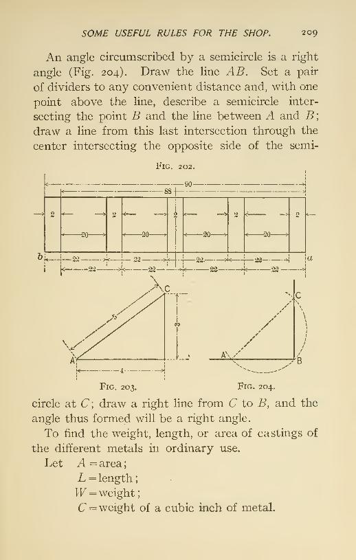
SOME USEFUL RULES FOR THE SHOP. 209
An angle circumscribed by a semicircle is a right
angle (Fig. 204). Draw the line AB. Set a pair
of dividers to any convenient distance and, with one
point above the line, describe a semicircle inter-
secting the point B and the line between A and B;
draw a line from this last intersection through the
center intersecting the opposite side of the semi-
FiG. 202.
&L—
-20- -20-
t90-
i
-22- 22
•20- -20-
-22.
—
j^22——->}< 23—^—->< 22
22 ->i |«00 .._>4
*^c
./
..A !k\/
'B
Fig. 203. Fig. 204.
circle at C\ draw a right line from C to B, and the
angle thus formed will be a right angle.
To find the weight, length, or area of castings of
the different metals in ordinary use.
Let A = area
;
L = length
;
W = weight
;
C= weight of a cubic inch of metal.
2 10 THE ART OF PATTERN-MAKING.
^ = .0926 for cast aluminum;
C = .2482

SOME USEFUL RULES FOR THE SHOP, 211
plying its weight by the following tabular numberaccording to the metal required:
Cast aluminum5 ^ ^
zinc
iron _steel
brass
bronze, G. M
16.5
17.38
18.9
19.33
21 .1copper 21.2lead
27.37

XXXIV.
HANDY TOOLS FOR PATTERN-MAKERS.
Figs. 205-208 show several handy devices for
pattern-makers which, while they are not new,
should be better known and more generally used.
Fig. 205 shows three views of the centering-plate,
which is very convenient when describing a semi-
circle from a center situated on the edge of the work.
It is made of brass about one-sixteenth inch thick.
The semicircles a and b can be respectively about
one and a half inches and one-half inch diameter, and
should have their edges bevelled to allow the indi-
cator marks to come close to the center line on the
work. The apron, c, is about one-half inch wide and
one-eighth thick. It projects perpendicularly from
the under side of the plate and is the division be-
tween the two semicircles. The centers d and e
for the divider-point are located over the edges of
the apron. A line is scribed on the plate at right
angles to the apron, passing through the two centers
and extending to edges of the semicircles.
Fig. 206 represents the plate in use. A center
line is scribed on the piece of work. The plate is
held by one hand and adjusted to make the apron212

HANDY TOOLS FOR PATTERN-MAKERS. 213
bear against the edge of the piece of work, and the
indicator mark on the edge of the semicircle to
match the center Une on the work.
The large semicircle is applied for circles larger
than its diameter, and the smaller for circles between
the two diameters on the plate.
Fig. 207 shows a simple and excellent little tool
for rounding the corners of patterns, a is a longi-
tudinal section, h a view of the working face, and
c a section on the line de. It is advisable to have
about three of these tools, one for an eighth, one
for a quarter, and one for three-eighths radius. The
cutter, which is illustrated full size for quarter inch,
is made of steel, about two and a half inches,
and including the handle, about five inches long.
Pattern-makers using these tools appreciate their
value.
Fig. 208 shows a convenient device for obtaining
the radii and laying off segments, a is a plan, and h
a section. As illustrated it is intended for sixths
of a circle, or a 60-degree angle. A brass plate hav-
ing a small hole is fitted at the apex of an angle.
The hole is intended for a center in setting the
trammels, and is situated about one-tenth inch from
the inside of the angle, to allow for fitting on the
ends of the segments. Beginning at the center of
the hole, one side of the triangle is graduated and
marked in inches and fractions of an inch.
There should be several of these angles kept in
a convenient place for the use of the shop. Oneshould be for quarters, or 90 degrees. Two sizes


HANDY TOOLS FOR PATTERN-MAKERS. 215
are necessary for sixths, or 60 degrees; one ad-
mitting of 15 inches and one of 30 inches radius.
The one for eighths, or 45 degrees, should admit of
a radius of at least 36 inches.
When preparing for a job of segment work it is
the common practice to make a pattern to markoff the segments by. In using this segment gauge,
as it may be called, the width of the piece intended
for the pattern is immaterial if it is of sufficient size
for the segment. It is simply necessary to secure
the gauge to the piece of board, and the center of the
circle will at the same time be located. The trammel
can then be set by the graduations on the side of
the triangle, the segment scribed, and its ends
marked at the insides of the triangle.

XXXV.
METHOD OF MAKING SPECIAL SHRINKAGERULES.
Pattern-makers sometimes require a special
shrinkage rule that is not usually made or to be
found for sale.
Figs. 209, 210 show a method of making such a
rule by hand graduation, which when expertly done
will give entire satisfaction.
U.S. STANDARDll .31 .3
Fig, 209.
Secure a U. S. standard rule to a board so as to
have the upper surface clear. Select a suitable
piece of wood, preferably box, beech, or maple,
make the piece perfectly straight, of the same
thickness as the standard and somewhat longer
than the required finished length.
Lay off from the end of the standard rule the216

MAKING SPECIAL SHRINKAGE RULES, 217
additional length for the particular purpose re-
quired. With the radius AB, and one point of
the trammel at A^ describe an arc intersecting a
line drawn at right angles from the end of the
standard rule at C. Secure the blank to the board
with its inner edge intersecting the points A and C.
Make a gauge, D, of thin sheet steel with a guide
flange turned down to bear against the outer edge
of the blank.
The marking-tool should be thin and sharp and
held in the same position during the graduation. Agreat deal depends upon this to secure accuracy.

XXXVI.
A HANDY STRAIGHT-EDGE FOR MARKING.
When truing up a surface with a bench-plane it is
the usual custom to use a straight-edge coated with
chalk or some colored material, to mark the high
places on the board. This substance is soon worn
off by the repeated use of the straight-edge and
consequently requires frequent renewal.
Fig. 2IO shows a convenient device which obvi-
ates the use of chalk, etc., and is always ready for
marking when wanted. A convenient size for this
device is twenty-four inches long, three inches wide,
s8
Fig. 2IO.
and the thickness made of two pieces of wood, one
five eighths and the other three eighths of an inch
thick. The thicker piece is rabbeted to receive a
strip of sheet lead about two inches wide and one
eighth of an inch thick, the lead being allowed to
project outside of the wood about one-quarter inch.
The two pieces are fastened together with screws
to hold the lead firmly in place. The lead is easily
kept straight by passing an iron plane over it occa-
sionally.
218

XXXVII.
FILING HAND-SAWS.
The hand-saw is one of the most important of
pattern-makers' tools, as it is of all other workers in
wood, and it is one of the most difficult of their tools
to put in good order. Many excellent mechanics
are not able properly to file a hand-saw without
some device to aid them.
Fig. 211 shows an appliance that will not only be
a help to the expert when filing saws, but will makeit almost impossible for the novice to go wrong whenintelligently applied. A, B, and C show a saw-
clamp, which can be of any kind. It is provided
with a shelf, a, extending from the back and at right
angles with the blade of the saw. A piece of glass,
6, preferably about a quarter of an inch thick, is
secured to the shelf in such a manner as to be easily
raised.
Three sheets of paper about the size of the glass
are prepared with heavy lines so that the lines can
be plainly seen when placed under the glass. Onesheet has the lines at right angles to the saw-blade, to
be used when filing rip- or band-saws. Two sheets
have the lines at an angle, one extending to the219

220 THE ART OF PATTERN-MAKING.
right and one to the left, according to the bevel it
is desired to have the teeth for cross-cutting.
D, the file, which is shown on a larger scale, is
B z\a
Fig. 2 11.
prepared by driving its point into a small block, c,
about three by one by a half inch. The lower
edge of the block is to rest on the glass and is
slightly rounded. The position of the comer of the
file to be used with reference to the curved edge of
the block determines the rake of the teeth.

FILING HAND-SAIVS, 221
When prepared for use the sheet whose hnes arerequired is exposed under the glass. The file withthe curved edge of the block resting on the glass is tofollow the lines when filing. Except when the teethare very large it is well not to lift the block fromthe glass, but pass the file to the next tooth byraising the handle sufficiently.

XXXVIII.
WAX FILLETS.
Fig 212 shows handy devices for making and
applying wax fillets. A represents a press made of
three-quarter-inch brass tube about five inches
long; one end of the tube is securely closed by a
wooden plug. A plunger made of close-grained
hard wood is made to work in the tube ; the fit should
be as nearly air-tight as possible to make the plunger.
A hole is made through the side of the tube close to
the inner end of the plug. The diameter of the hole
will be according to the size of the fillet desired; a
diameter of one-sixteenth inch is suitable for quar-
ter-inch fillets.
BRASS TUBE
212.
To make the fillet stock, beeswax is placed in the
tube, and pressure applied on the end of the plunger,
which will cause the wax to issue from the hole in an222
H^AX FILLETS, 223
unbroken thread; this can be coiled and preserved
for future use.' The pressure can be applied byplacing the ends of the press between the jaws of a
hand-screw or bench-vise. B shows a tool, to befound on the market, made for forming wax fillets.
The wax being placed in the desired corner, the
tool, which has been heated in hot water, is applied
and moved along the wax with sufficient pressure
with the result that a neat and quick fillet is formed
where a wood or leather fillet would be difficult. In
the absence of the above tool, one can be improvised
by grinding the end of a wire nail or a piece of wire
to the required form.

XXXIX.
INSERTING WOOD-SCREWS INTO ENDGRAINS OF WOOD.
Wood-screws inserted into the end grains, espe-
cially of soft wood, do not take a very strong hold,
but the hold may be increased by backing out the
Fig. 213.
screw after being inserted and placing a small
amount of glue in the hole and then reinserting the224

IVOOD-SCREIVS IN END GRAINS OF IVOOD. 225
screw. When screws are to be taken out and
reinserted into end-grain wood, as is often necessary
where work is required to be taken apart in the
foundry, simply screwing them into the end grain
should not be depended upon, but a plug of hard
wood should be inserted into the work and the screw
allowed to pass through it at right angles to the
grain of the plug (see Fig. 213). When the screw will
no longer hold in consequence of its repeated with-
drawals, the worn-out plug may be taken out and
a new plug inserted.
XL.
BOARD MEASURE.
In board measure all boards are assumed to be
one inch thick. When all dimensions are in feet
—
Rule: Multiply length by breadth, and product will
give surface in square feet. Example: Required
the feet, B. M., in a board i6 ft. long, 1.25 ft. wide,
and one inch thick.
16X1. 25 =20 feet.
When either dimension is in feet—Rule : Multiply
length by breadth, and the product by the thickness,
and then divide by 12. Example: Required the
feet, B. M., in a board 16 feet long, 15 inches wide,
and I J inches thick.
16X15X1.5=360, and 3604-12=30 ft.
When all dimensions are in inches proceed as
before and divide by 144. Six inches and over are
counted an additional foot.
226

XLI.
TO COMPUTE VOLUME OF SQUAREDTIMBER.
When all dimensions are in feet—Rule: Multiply
length, breadth, and thickness together and product
will give volume in cubic feet. Example: A piece
of timber is 1.25 feet square and 20 feet long. Re-
quired its volume:
1. 25X1. 25X20' = 31. 25 cubic feet.
When either dimension is in feet proceed as
before and divide by 144. Example:
15" X 15" X 20'^
..-^ "^ =31.25 cu. ft.
144
When all dimensions are in inches proceed as
before and divide by 1728. Example:
15' ' X 15^^X240^^^ .^
^- = 31.25 cu. ft.
1728 ^ ^
Allowance is to be made for bark by deducting
from each girth from .5 inch in logs with thin
bark to 2 inches in logs with thick bark.
To reduce to board measure multiply cubic feet
by 12, thus: 31.25X12=375 feet B. M.
Lineal feet is the length regardless of breadth
and thickness.
227

XLII.
TIMBER MEASURE.
To compute the volume of round timber inside of
bark. When all dimensions are in feet—Rule:
Add together the squares of the greater and lesser
ends, and the product of the two diameters. Mul-
tiply the sum by .7854 and that product by one third
of the length.
Example: A piece of timber, barked, is 15 feet
long. The diameters of the ends are 2 and 1.5 feet.
Required the volume.
2^+1.5^ + 2X1.5=9.25, which, multiplied by
.7854, and that product by— = 36.3247 cubic feet.
When all dimensions are in inches proceed as
before and divide by 1728.
To compute the square that a round log will cut.
Rule: Divide the diameter of the small end inside
of bark by 1.4 142, and the quotient will equal the
side of the square.
Example : A log is 14.5 inches in diameter at small
end. Required the side when square.
-—^—^=io.2S^ inches.1.4142
^Or multiply diameter by 0.7071.
Thus 14.5 X. 7071 =10.253 inches, the length of
the side of square.228

xLiir.
STRENGTH AND WEIGHT OF WOODS.
The strength and weight of the same kind of
wood will vary considerably; this variation is
caused by the conditions under which it grows,
is prepared and seasoned. The following table,
compiled from different authorities and the author's
own experiments, exhibits a fair average for sound
well-seasoned timber of the kinds given
:
Kind of Wood.
AverageTensileStrength
per Sq. Inch,in Lbs.
AverageCrushingStrength
pei" Sq. Inchin Lbs.
AverageWeight perCubic Ft.,in Lbs.
Ash, AmericanBeechCedarCherryChestnutCorkCypressHickoryMahogany, hard ....
soft
Oak, American white" EngHsh" Uve, Ala" upland
Pine, Southern Ga.. .
" white" white Mich. . .
.
" yellow long leaf.
Poplar, yellowRedwood, Pac. Coast.
Spruce.Walnut, red ,
black
16,00018,000
10,30012,50012,500
6,00018,00020,0008,00018,000
19,00016,40010,00010,000
11,000
19,0007,000
10,0001 1,000
17,000
5,8006,9006,000
5,300
8,9008,800
9,00010,000
7,7006,8008,900
8,000
6,0006,800
3840
3541
3915
27
53533550
556042
452826
4231
2429
3937
229

XLIV.
MISCELLANEOUS TABLES, ETC.
TABLE OF DECIMAL^ EQUIVALKNTS OF MILLIMETERSAND FRACTIONS OF MILLIMETERS.
I /lOo mm. = .0003937".
Mm.

MISCELLANEOUS TABLES, ETC. 231
TABLE OF DECIMAL EQUIVALENTvS OF 8ths, i6ths,
32DS, AND 64THS OF AN INCH.
8ths.
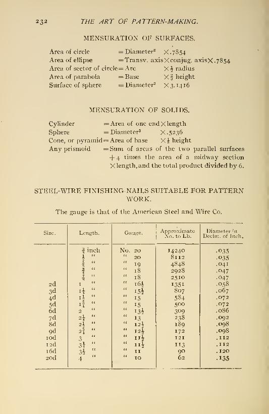
232 THE ART OF PATTERN-MAKING.
MENSURATION OF vSURFACES.
Area of circle = Diameter^ X.7S54
Area of ellipse =Transv. axisXconjug. axisX.7854
Area of sector of circle= Arc X ^ radius
Area of parabola =Base Xf height
Surface of sphere = Diameter^ X 3. 14 16
MENSURATION OF SOLIDS.
Cylinder =Area of one end X length
Sphere = Diameter^ X.5236Cone, or pyramid= Area of base Xi height
Any prismoid =Suni of areas of the two parallel surfaces
+ 4 times the area of a midway section
X length, and the total product divided by 6.
STEEL-WIRE FINISHING-NAILS SUITABLE FOR PATTERNWORK.
The gauge is that of the American Steel and Wire Co.
Size.

MISCELLANEOUS TABLES, ETC.
STEEL-WIRE COMMON NAILS.
233

XLV.
STANDARD WOOD-SCREWS.
Wood-screws are very familiar and indispensable
articles with pattern-makers, but it is doubtful if
there is one in a hundred that could state the
angle of the head if asked the question. The angle
being 41 degrees, or the sides having a subtended
angle of 82 degrees, accounts for the fact that
the ordinary commercial countersinks which com-
monly have an included angle of 60 or 90 degrees
are never just right for the heads of wood-screws.
Messrs. Asa S. Cook & Co., manufacturers of
machinery for making wood-screws, have furnished
the following table of data regarding the chief
features of wood-screws as used by all of the princi-
pal makers of them in the United States.
234

STANDARD IVOOD-SCREIVS. 235
U. S. STANDARD WOOD-SCREWS REDUCED TOTHOUSANDTHS.
Body, also Flat and Round Heads.
Body.
XLVI.
HOW TO APPROXIMATE THE WEIGHT OFAN IRON CASTING FROM ITS OBSERVA-TION.
It occasionally happens that an approximate
weight of a casting is desired where little or no
opportunity is offered for measurements, and
where simple observation of the pattern or casting
is all that is available for data.
By remembering that a cubic foot of cast iron
weighs 450 pounds, a square foot one inch thick
37.5 pounds, and 3.84 cubic inches weigh one
pound, together with a little practice in judging
dimensions, a fairly offhand, rough estimate can
be made as follows: Judge the dimensions of pat-
tern or casting and mentally estimate the cubical
or superficial contents, then mentally multiply
that by one of the above quantities accordingly as
the case requires. For instance required the
weight of a casting judged to be 10 by 5 feet and
2 inches thick. It will require very little mental
exercise to determine that these dimensions will
236

APPROXIMATE IVEIGHT OF AN IRON CASTING. 237
equal 100 square feet one inch thick, which, multi-
phed by 37.5, will equal 3750 pounds. By the
same process of reasoning the weights for other
metals can be determined by fixing in mind the
necessary data for the metals. That for steel
castings is 490 pounds per cubic foot, 40.86 poimds
per square foot, and 3.522, or, roughly, 3.5 cubic
inches per pound. But by far the most frequent
occasion for this exercise will be for cast iron.
The following tables are convenient for determining
the length of bar of the different metals com-
monly used for weights.
TABLE I, GIVING WEIGHT PER INCH IN LENGTH OFROUND BARS FROM V TO 3" DIAM.
Diam.

238 THE ^RT OF PATTERN MAKING.
TABLE II, GIVING WEIGHT PER INCH IN LENGTH OFSQUARE BARS, FROM V TO 3" SQUARE.
Side of Square.

AREAS OF CIRCLES, ETC. 239
AREAS OF CIRCLES, AND LENGTHS OF THE SIDES OFSQUARES OF THE SAME AREA.
Diam. of

240 THE ART OF PATTERN-MAKING,
AREAS OF CIRCLES, AND LENGTHS OF THE SIDES OFSQUARES OF THE SAME A.V.nA.~Continued.
Diam. of

XLVII.
PRISMOIDAL FORMULA.
(One Rule for the Contents of Various Bodies.)
A PRiSMOiD is a solid bounded by six plane sur-
faces, only two of which are parallel.
Every one who has had occasion to figure out
the volume or contents of any regularly formed
geometrical body has been perplexed in trying to
remember the exact rule for each and the way to
apply it. It is a happy state of the memory whenevery rule can be called to mind exactly whenwanted. One rule is more easily remembered
than a dozen. The following rule will solve all
the problems of solidity for regular bodies
:
• 11 ( The area of the base,Add '
^1 ^ The area of the top,tosfetner i
' Four times the area of the middle section.
Multiply this sum by one sixth of the perpen-
dicular height. The resulting product is the cubical
contents or volume required.
241

242 THE ART OF PATTERN-MAKING,
Applying the rule to a cone of lo inches diameter
of base and 12 inches perpendicular height:
The area of base 78.54
The area of top 00.00
Four times area of middle section 78.54
157.08Multiplied by one sixth of height 2
The volume in cubic inches equals 314.16
It will be observed of a cone that the middle
section is a circle one half the diameter of the base,
which is equal to one fourth its area; or, to state
in another way, four times the area of a 5 -inch
circle is equal to the area of a lo-inch circle.
The rule applied to a cylinder of 10 inches diam-
eter and 12 inches in height:
Area of base 78.54'' ''top 78.54
Four middle areas 314.16
The sum of these equals .471.24
Multiplied by one sixth of height 2
The volume in cubic inches equals 942.48
This result agrees with the mathematical demon-
stration that a cylinder has three times the volume
of a cone of the same height and diameter of base.
The rule applied to a cube of 12 inches:

PRISMOIDAL FORMULA, 243
The area of base 1 44" " "top 144
Four middle areas 576
The sum equals 864
MultipHed by one sixth the height 2
Volume in cubic inches equals 1728
The rule applies equally to pyramids and prisms
of whatever form of base or end. It also applies
to frustums of pyramids, cones, and prisms.
Whether any of these bodies have their axes
perpendicular to the base or not, this rule applies
all the same, care being taken to use the perpendic-
ular height, never the slant height.
To find the contents of a sphere 12 inches in
diameter, use the rule the same way as for the
cone, thus
:
The area of base 00 . 00" " "top oc.oo
Four middle areas 452 . 39
The sum of these equals 452 • 39
Multiplied by one sixth of the height . . 2
Volume in cubic inches equals 904. 78
There are some bodies formed like cigars, or
that have what is called spindle shape, which
require a little preparation before applying the
rule for obtaining their contents. For such they

244 THE ART OF PATTERN-MAKING.
must first be considered to be divided transversely
at their largest part, and then calculate each part
separately and add the results together for the sum.
In forms like these which have swelled sides
there must be some means of counting in the
swell, or convexity of these solids, and this very
feature is included in the measures of this rule.
The elements called'
' four times the area of middle
section" brings in the swell and includes the differ-
ence between the volume of a cone of straight
sides and having the same base and height, and
of the spindle shape having convex sides. This
element of the rule also covers the cases of cone-like
figures having concave or hollow sides. Atten-
tion is particularly called to the necessity of taking
in the exact measures of these and other similar
forms, which every rule requires if the correct
volume be sought for, because this result in every
case can only be obtained from all the essential di-
mensions.

XLVIII.
TO COMPUTE THE AREA OF A FIGUREBOUNDED BY A CURVE.
The following rule, known as Simpson's, is
the one commonly used to compute the area of
irregular figures:
Rule : Divide the line ab into any number of equal
parts by perpendiculars from base, as i, 2, 3, etc.,
which will give an odd number of points of division.
Measure length of these perpendiculars and proceed
as follows: To the lengths of the first and last
ordinates add four times the lengths of all the even-
numbered ordinates, and twice the sum of the odd
;
multiply their sum by one third of the distance be-
tween the ordinates, and the product will give the
required area.
Required the area of a space 40 ft. long boundedon one side by a curve the ordinates of which are
given in Fig. 215.
245

246 THE ART OF PATTERN-MAKING.
_5.45
3.75
_3.25
5.45
Fig, 215,

AREA OF A FIGURE BOUNDED BY A CURIAE. 247
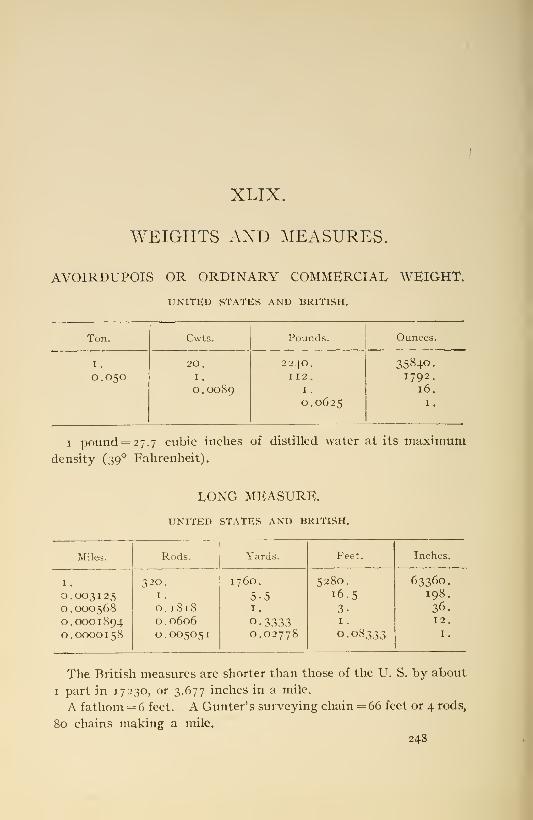
XLIX.
WEIGHTS AND MEASURES.
AVOIRDUPOIS OR ORDINARY COMMERCIAL WEIGHT.
UNITED STATES AND BRITISH.
Ton.

IVEIGHTS AND MEASURES. 249
SQUARE OR LAND MEASURE.
UNITED STATES AND BRITISH.
Sq.Miles.
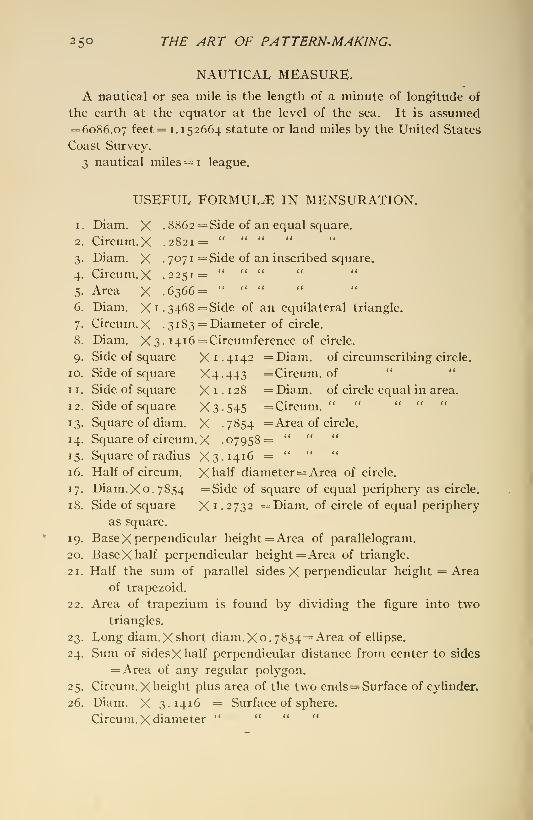
250 THE ART OF PATTERN-MAKING.
NAUTICAL MEASURE.
A nautical or sea mile is the length of a minute of longitude of
the earth at the equator at the level of the sea. It is assumed= 6086.07 feet = 1. 152664 statute or land miles by the United States
Coast Survey.
3 nautical miles = i league.
USEFUL FORMULA IN MENSURATION.
1. Diam. X .8862= Side of an equal square.
2. Circum.X .2821= " " " "
3. Diam. X . 7071 =Side of an inscribed square.
4. Circum.X .2251= " " "
5. Area X .6366= " " "
6. Diam. Xi. 3468= Side of an equilateral triangle.
7. Circum.X .3 183 = Diameter of circle.
8. Diam. X 3. 1416= Circumference of circle.
9. Side of square X 1.4 142 =Diam. of circumscribing circle.
10. Side of square X4.443 =Circum. of" "
1 1. Side of square X i . 1 28 = Diam. of circle equal in area.
12. Side of square X3.545 =Circum. " " " " "
13. Square of diam. X .7854 = Area of circle.
14. Square of circum. X .07958= " " "
15. Square of radius X3.1416 = " " "
16. Half of circum, Xhalf diameter= Area of circle.
17. Diam. X 0.7854 =Side of square of equal periphery as circle.
18. Side of square X i -2732 =Diam. of circle of equal periphery
as square.
19. BaseX perpendicular height = Area of parallelogram.
20. Base Xhalf perpendicular height = Area of triangle.
2 1
.
Half the sum of parallel sides X perpendicular height = Area
of trapezoid.
22. Area of trapezium is found by dividing the figure into twotriangles.
23. Long diam. X short diam. X 0.7854= Area of ellipse.
24. Sum of sides Xhalf perpendicular distance from center to sides
= Area of any regular polygon.
25. Circum. X height plus area of the two ends= Surface of cylinder.
26. Diam. X 3.1416 = Surface of sphere.
Circum. X diameter " " " "
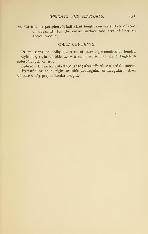
IVEIGHTS AND MEASURES. 251
27. Circum. or peripheryX half slant height convex surface of cone
or pyramid; for the entire surface add area of base to
above product.
SOLID CONTENTS.
Prism, right or oblique, = Area of base X perpendicular height.
Cylinder, right or oblique, = Area of section at right angles to
sidesX length of side.
Sphere = Diameter cubedX o . 5 2 36 ; also = SurfaceX i /6 diameter.
Pyramid or cone, right or obUque, regular or irregular, = Area
of baseX 1/3 perpendicular height.


INDEX.
Area of a figure hounded by a
curve, to compute, 245.
Band-saws, breakage, 18.
speeds, 17.
Bars of various metals, weight per
one inch in length of roundand square, 237.
Beam-engine, cylinder for, 41.
Belt-pulleys and fly-wheels, 160.
Bench vises, 23.
Board measure, 226.
Box machine, Daniels' plane andcore, 20.
Castings, allowage for shrinkage
and finishing, 27.
how to approximate weight of,
236.
strength of, increases by press-
ure, 43.
Circles, areas of, and length of
sides of squares of equal area,
239.Circular saws, care and use of, 15.
speed of, 16.
Clay, pattern made of, I.
Cylinder mould, illustrating build-
ing. 40.
Cylinder, pattern work for, 39.
Decimal equivalents and trigono-
metrican expressions, table of,
231.
millimeters and fractions of
millimeters, table of, 230.
Deck-lug, pattern of, 83.
Device for sweeping up screws ofincreasing pitch from hub to
periphery, 69.
Distributing work, 35.Drawings, duty of foreman to ex-
amine, 26.
section-lining mechanical, 190.
Elbow, pattern work for, 44.Elbows, wood lagging for, 171.
Fillets, wax, 222.
Fracture, behavior of fluid metals,
liability to, in the casting cool-
ing, 28.
Gear-wheels, teeth of, 155.Geometry, 192.
Globe-valve, pattern for, 129.
Glue and its use, 168.
Gun-mount pedestal, pattern for,
100.
Hand-planers, good rule for using,
33-
speed of, 19.
Hand-saws, filing, 219.
Lathes and lathe-work, 175.wood-turning, 14.
Launch-engine, pattern of, 78.
Loam moulding, patterns for, 36.
Loose pieces, 170.
Machines, accidents from, 32.
253
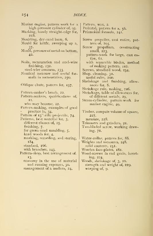
254 INDEX.
Marine engine, pattern work for ahigh-pressure cylinder of, 93.
Marking, handy straight-edge for,
218.
Moulding, dry-sand loam, 6.
Mould for kettle, sweeping up a,
37-Mould, pressure of metal on bottom,
42.
Nails, mensuration and steel-wire
finishing, 232,
steel-wire common, 233.Nautical measure and useful for-
mula in mensuration, 250.
Oblique chute, pattern for, 137.
Pattern-maker's bench, 22.
Pattern-makers, qualifications of,
II.
who may become, 12.
Pattern-making, examples of good^ practice in, 34,Pattern of i3"-rifle projectile, 74.Patterns, best material for, 3.
different classes of, 25.
finishing, 7.
for green-sand moulding, 5.
hard woods for, 4.
marking, recording, and storing,
184.
standard, 166.
with branches, 143.Pattern-shop, best arrangement of,
13-
economy in the use of material
and running expenses, 30.
management of a modern, 24.
Pattern, wax, 2.
Pedestal, pattern for a, 56.Prismoi(lal formula, 241.
Screw propeller, cast entire, pat-tern of, 104.
Screw propellers, constructingsmall, 123.
pattern-work for large, cast en-tire, 61.
with separable blades, methodof making pattern, 112.
Screws, standard wood, 234.Shop, cleaning, 31.
useful rules, 200.
Shrinkage and finishing, allow-
ances for, 8.
Shrinkage rule, making, 216.
Shrinkage, table of allowances for,
of different metals, 29.
Steam-cylinder, pattern work for
marine engine, 49.
Timber, compute volume of square,
227.
measure, 228.
Trimmers and grinders, 21.
Two-bladed screw, working draw-ing, 71.
Water-collar, pattern for, 88.
Weights and measures, 248.
solid contents, 251.Wooden face-plates, 182.
Wood-screws in end grain, insert-
ing, 224.
Woods, shrinkage of, 3, 10.
strength and weight of, 229.warping of, 9.


SHORT-TITLE CATALOGUEOF THE
PUBLICATIONSOF
JOHN WILEY & SONS,New York.
Lo^^DOiN-: CHAPMAN & HALL, Limited.
ARRANGED UNDER SUBJECTS.
Descriptive circulars sent on application. Books marked with an asterisk are
sold at net prices only, a double asterisk (**) books sold under the rules of the
American Publishers' Association at net prices subject to an extra charge for
postage. All books are bound in cloth unless otherwise stated.
AGRICULTURE.Armsby's Manual of Cattle-feeding i2mo, $i 75
Principles of Animal Nutrition 8vo, 4 00
Budd and Hansen's American Horticultural Manual:Part I.—Propagation, Culture, and Improvement i2mo, i 50
Part II.—Systematic Pomology i2mo, i 50
Downing's Fruits and Fruit-trees of America 8vo, 5 00
Elliott's Engineering for Land Drainage i2mo, i 50
Practical Farm Drainage i2mo, i 00
Green's Principles of American Forestry. (Shortly.)
Grotenfelt's Principles of Modern Dairy Practice. (WoU.) i2mo, 2 00
Kemp's Landscape Gardening i2mo, 2 50
Maynard's Landscape Gardening as Applied to Home Decoration i2mo, i 50
Sanderson's Insects Injurious to Staple Crops i2mo, i 50
Insects Injurious to Garden Crops. {In preparation.)
Insects Injuring Fruits. {In preparation.)
Stockbridge's Rocks and Soils 8vo, 2 50Woll's Handbook for Farmers and Dairymen i6mo, 1 50
ARCHITECTURE.Baldwin's Steam Heating for Buildings i2mo, 2 50Berg's Buildings and Structures of American Railroads 4to, 5 00
Birkmire's Planning and Construction of American Theatres Svo, 3 00
Architectural Iron and Steel Svo, 3 50
Compound Riveted Girders as Applied in Buildings Svo, 2 00
Planning and Construction of High Office Buildings Svo, 3 50
Skeleton Construction in Buildings Svo, 3 00
Briggs's Modern American School Buildings Svo, 4 00
Carpenter's Heating and Ventilating of Buildings Svo, 4 00
Freitag's Architectural Engineering. 2d Edition, Rewritten Svo, 3 50
Fireproofing of Steel Buildings Svo, 2 50
French and Ives's Stereotomy Svo, 2 50
Gerhard's Guide to Sanitary House-inspection i6mo, i 00
Theatre Fires and Panics .^ . t2mo, i 50'
1

Hatfield's American House Carpenter 8vo,
Holly's Carpenters' and Joiners' Handbook i8mo,
Johnson's Statics by Algebraic and Graphic Methods 8vo,
Kidder's Architect's and Builder's Pocket-book i6mo, morocco,
Merrill's Stones for Building and Decoration Svo,
Monckton's Stair-building 4to,
Patton's Practical Treatise on Foundations Svo,
Siebert and Biggin's Modern Stone-cutting and Masonry Svo,
Snow's Principal Species of Wood Svo,
Sondericker's Graphic Statics with AppUcations to Trusses, Beams, and Arches.
{Shortly.)
Wait's Engineering'and Architectural Jurisprudence Svo,
Sheep,
Law of Operations Preliminary to Construction in Engineering and Archi-
tecture Svo,
Sheep,
Law of Contracts Svo,
"Woodbury'sFire Protection of Mills Svo,
Worcester and Atkinson's Small Hospitals, Establishment and Maintenance,
Suggestions for Hospital Architecture, with Plans for a Small Hospital.
i2mo.
The World's Columbian Exposition of 1893 Large 4to,
ARMY AND NAVY.
Bernadou's Smokeless Powder, Nitro-cellulose, and the Theory of the Cellulose
Molecule i2mo,* Bruff's Text-book Ordnance and Gunnery Svo,
Chase's Screw Propellers and Marine Propulsion Svo,
Craig's Azimuth 4to,
Crehore and Squire's Polarizing Photo-chronograph Svo,
Cronkhite's Gunnery for Non-commissioned Officers 24mO; morocco,
* Davis's Elements of Law Svo,
* Treatise on the Military Law of United States Svo,
* Sheep
De Brack's Cavalry Outpost Duties. (Carr.) 24mo, morocco,
Dietz's Soldier's First Aid Handbook i6mo, morocco,
* Dredge's Modern French kv^tU^y 4to, half morocco,
Durand's Resistance and Propulsion of Ships Svo,
* Dyer's Handbook of Light Artillery i2mo,
Eissler's Modern High Explosives Svo,
* Fiebeger's Text-book on Field Fortification Small Svo,
Hamilton's The Gunner's Catechism iSmo,* Hoff's Elementary Naval Tactics Svo,
Ingalls's Handbook of Problems in Direct Fire Svo,
* BaUistic Tables Svo,
* Lyons's Treatise on Electromagnetic Phenomena. Vols. I. and II. . Svo, each,
* Mahan's Permanent Fortifications. (Mercur.) Svo, half morocco,
Manual for Courts-martial i6mo morocco,
* Mercur's Attack of Fortified Places i2mo,
* Elements of the Art of War Svo,
Metcalf's^Cost of Manufactures—And the Administration of Workshops, PubUc
and Private 8vo,
* Ordnance and Gunnery i2mo,
Murray's Infantry Drill Regulations iSmo, paper,
* Phelps's Practical Marine Surveying Svo,
Powell's Army Officer's Examiner i2mo,
Sharpe's Art of Subsisting Armies in War iSmo, morocco,
2
5
I

Effront's Enzymes and their Applications. (Prescott.) 8vo, 3 00
Erdmanii's Introduction to Chemical Preparations. (Dunlap,) i2mo, i 25
Fletcher's Practical Instructions in Quantitative Assaying with the Blowpipe.
i2mo, morocco, i 50
Fowler's Sewage Works Analyses i2mo, 2 00
Fresenius's Manual of Qualitative Chemical Analysis. (Wells.) 8vo, 5 00
Manual of Qualitative Chemical Analysis. Parti. Descriptive. (Wells.)
8vo, 3 00
System of Instruction in Quantitative Chemical Analysis. (Cohn.)
2 vols. (Shortly.)
Fuertes's Water and PubUc Health i2mo,
Furman's Manual of Practical Assaying Svo,
Gill's Gas and Fuel Analysis for Engineers i2mo,
Grotenfelt's Principles of Modern Dairy Practice. (WoU.) i2mo,
Hammarsten's Text-book of Physiological Chemistry. (Mandel.) Svo,
Helm's Principles of Mathematical Chemistry. (Morgan.) i2mo.
Hinds's Inorganic Chemistry '. Svo,
Laboratory Manual for Students i2mo,
Holleman's Text-book of Inorganic Chemistry. (Cooper.) Svo,
Text-book of Organic Chemistry. (Walker and Mott.) Svo,
Hopkins's Oil-chemists' Handbook Svo,
Jackson's Directions for Laboratory Work in Physiological Chemistry. .Svo,
Keep's Cast Iron Svo,
Ladd's Manual of Quantitative Chemical Analysis i2mo,
Landauer's Spectrum Analysis. (Tingle.) Svo,
Lassar-Cohn's Practical Urinary Analysis. (Lorenz.) i2mo.
Leach's The Inspection and Analysis of Food with Special Reference to State
Control. (In preparation.)
Lob's Electrolysis and Electrosynthesis of Organic Compounds. (Lorenz.) i2mo,
Mandel's Handbook for Bio-chemical Laboratory i2mo,
Mason's Water-supply. (Considered Principally from a Sanitary Standpoint.)
3d Edition, Rewritten Svo,
Examination of Water. (Chemical and Bacteriological.) i2mo,
Meyer's Determination of Radicles in Carbon Compounds. (Tingle.). . i2mo.
Miller's Manual of Assaying i2mo,
Mlxter's Elementary Text-book of Chemistry i2mo,
Morgan's Outline of Theory of Solution and its Results i2mo.
Elements of Physical Chemistry i2mo,
Nichols's Water-supply. (Considered mainly from a Chemical and Sanitary
Standpoint, 1SS3.) Svo,
O'Brine's Laboratory Guide in Chemical Analysis Svo,
O'DriscoU's Notes on the Treatment of Gold Ores Svo,
Ost and Kolbeck's Text-book of Chemical Technology. (Lorenz—Bozart.)
(In preparation.)
* Penfield's Notes on Determinative Mineralogy and Record of Mineral Tests.
Svo, paper, 50
Pictet's The Alkaloids and their Chemical Constitution. (Biddle.) (In
preparation.)
Pinner's Introduction to Organic Chemistry. (Austen.) i2mo, i 50
Poole's Calorific Power of Fuels Svo, 3 00
* Reisig's Guide to Piece-dyeing Svo, 25 00
Richards and Woodman's Air ,Water, and Food from a Sanitary.Standpoint . Svo, 2 00
Richards's Cost of Living as Modified by Sanitary Science i2mo, i 00
Cost of Food, a Study in Dietaries i2mo, i 00
* Richards and Williams's The Dietary Computer Svo, i 50
Ricketts and Russell's Skeleton Notes upon Inorganic Chemistry. (Part I.
—
Non-metallic Elements.) Svo, morocco, 75
Ricketts and Miller's Notes on Assaying Svo, 3 004
I

3
5

Fuertes's Water and Public Health i2mo, i 50
Water-filtration Works i2mo, 2 50
Ganguillet and Kutter's General Formula for the Uniform Flow of Water in
Rivers and Other Channels. (Bering and Trautwine.) 8vo, 4 00
Hazen's Filtration of Public Water-supply 8vo, 3 00-
Hazlehurst's Towers and Tanks for Water-works 8vo
,
2 5a
Herschel's 115 Experiments on the Carrying Capacity of Large, Riveted, Metal
Conduits 8vo, 2 00
Mason's Water-supply. (Considered Principally from a Sanitary Stand-
point.) 3d Edition, Rewritten 8vo, 4 00
Merriman's Treatise on Hydraulics, gth Edition, Rewritten 8vo, 5 00
* Michie's Elements of Analytical Mechanics 8vo, 4 00
Schuyler's Reservoirs for Irrigation, Water-power, and Domestic Water-
supply Large 8vo, 5 00** Thomas and Watt's Improvement of Riyers. (Post., 44 c additional), 4to, 6 ook
Turneaure and Russell's Public Water-supplies 8vo. 5 oa
Wegmann's Desicn and Construction of Dams 4to, 5 00
Water-supolv of the City of New York from 1658 to 1895 4to, 10 oo»
Weisbach's Hydraulics and Hydraulic Motors. (Du Bois.) 8vo, 5 00
Wilson's Manual of Irrigation Engineering Small 8vo, 4 00
Wolff's Windmill as a Prime Mover Svo.l's oo
Wood's Turbines 8vo, 2 50
Elements of Analytical Mechanics 8vo, 3 00
MATERIALS OF ENGINEERING.
Baker's Treatise on Masonry Construction 8vo,
Roads and Pavements 8vo,
Black's United States Public Works Oblong 4to,
Bovey's Strength of Materials and Theory of Structures 8vo,
Burr's Elasticity and Resistance of the Materials of Engineering. 6th ^Edi-
tion, Rewritten 8vo,
Byrne's Highway Construction 8vo.
Inspection of the Materials and Workmanship Employed in Construction.
i6mo,Church's Mechanics of Engineering 8vo,
Du Bois's Mechanics of Engineering. Vol. I Small 4to,
Johnson's Materials of Construction Large 8vo,
Keep's Cast Iron 8vo,
Lanza's Applied Mechanics 8vo,
Martens's Handbook on Testing Materials. (Henning.) 2 vols 8vo,
Merrill's Stones for Building and Decoration 8vo,
Merriman's Text-book on the Mechanics of Materials 8vo,
Strength of Materials i2mo,Metcalf's Steel. A Manual for Steel-users i2mo,Patton's Practical Treatise on Foundations 8vo,
Rockwell's Roads and Pavements in France i2mo.Smith's Wire : Its Use and Manufacture Small 4to,
Materials of Machines i2mo.Snow's Principal Species of Wood 8vo,
Spalding's Hydraulic Cement i2mo.Text-book on Roads and Pavements i2mo,
Thurston's Materials of Engineering. 3 Parts 8vo,
Part I.—Non-metallic!Materials of Engineering and Metallurgy 8vo,
Part II.—Iron and Steel 8vo,
Part III.—A Treatise on Brasses, Bronzes, and Other Alloys and their
Constituents 8vo, 2' 50
7
5

Thurston's Text-book of the Materials of Construction 8vo, 5 00
Tillson's Street Pavements and Paving Materials 8vo, 4 00
Waddell's De Pontibus. (A Pocket-book for Bridge Engineers.) . . i6mo, mor., 3 00
Specifications for Steel Bridges , i2mo, i 25
Wood's Treatise on the Resistance of Materials, and an Appendix on the Pres-
ervation of Timber 8vo, 2 00
Elements of Analytical Mechanics Svo, 3 00
RAILWAY ENGINEERING.
Andrews's Handbook for Street Railway Engineers. 3X5 inches, morocco, i 25
Berg's Buildings and Structures of American Railroads 4to, 5 00
Brooks's Handbook of Street Railroad Location i6mo, morocco, 1 50Butts's Civil Engineer's Field-book i6mo, morocco, 2 50Crandall's Transition Curve i6mo, morocco, i 50
Railway and Other Earthwork Tables Svo, i 50
Dawson's "Engineering" and Electric Traction Pocket-book. i6mo, morocco, 4 00
Dredge's History of the Pennsylvania Railroad: (1879) Paper, 5 00* Drinker's Tunneling, Explosive Compounds, and Rock Drills, 4to, half mor., 25 00
Fisher's Table of Cubic Yards Cardboard, 25
Godwin's Railroad Engineers' Field-book and Explorers' Guide i6mo, mor., 2 50Howard's Transition Curve Field-book i6mo morocco i 50
Hudson's Tables for Calculating the Cubic Contents of Excavations and Em-bankments Svo, I 00
Molitor and Beard's Manual for Resident Engineers i6mo, i 00
Nagle's Field Manual for Railroad Engineers i6mo, morocco. 3 00
Philbrick's Field Manual for Engineers i6mo, morocco, 3 00
Pratt and Alden's Street-railway Road-bed Svo, 2 00
Searles's Field Engineering i6mo, morocco, 3 00
Railroad Spiral i6mo, morocco i 50
Taylor's Prismoidal Formulae and Earthwork Svo, 1 50
* Trautwine's Method of Calculating the Cubic Contents of Excavations and
Embankments by the Aid of Diagrams Svo, 2 00
he Field Practice of [Laying Out Circular Curves for Railroads.
i2mo, morocco, 2 50* Cross-section Sheet Paper, 25
Webb's Railroad Construction. 2d Edition, Rewritten i6mn. morocco. 5 00
Wellington's Economic Theory of the Location of Railways Small Svo, 5 00
DRAWING.
Bart's Kinematics of Machinery Svo,
* Bartlett's Mechanical Drawing Svo,
Coolidge's Manual of Drawing Svo, paper,
Durley's Kinematics of Machines Svo,
Hill's Text-book on Shades and Shadows, and Perspective Svo,
Jones's Machine Design:
Part I.—Kinematics of Machinery Svo,
Part n.—Form, Strength, and Proportions of Parts Svo,
MacCord's Elements of Descriptive Geometry Svo,
Kinematics; or. Practical Mechanism Svo,
Mechanical Drawing .4to,
Velocity Diagrams ^ Svo,
* Mahan's Descriptive Geometry and Stone-cutting Svo,
Industrial Drawing. (Thompson.) Svo,
Reed's Topographical Drawing and Sketching 4to,
2

2

6

Johnson's Three-place Logarithmic Tables: Vest-pocket size paper, is
103 copies for 5 00
* Mounted on heavy cardboard, 8 X 10 inches, 25
10 copies for 2 OO'
Elementary Treatise on the Integral Calculus Small 8vo, i 5a
Curve Tracing in Cartesian Co-ordinates i2mo, i 00
Treatise on Ordinary and Partial Differential Equations Small Svo, 3 50
Theory of Errors ^nd the Method of Least Squares i2mo, i 50
* Theoretical Mechanics i2mo, 3 00
Laplace's Philosophical Essay on Probabilities. (Truscott and Emory.) i2mo, 2 00
* Ludlow and Bass. Elements of Trigonometry and Logarithmic and Other
Tables 8vo, 3 00
Trigonometry and Tables published separately Each, 2 00
Maurer's Technical Mechanics. {In preparation.)
Merriman and Woodward's Higher Mathematics Svo, 5 00
Merriman's Method of Least Squares Svo, 2 oa
Rice and Johnson's Elementary Treatise on the Differential Calculus. Sm., Svo, 3 oa
Differential and Integral Calculus. 2 vols, in one Gmall Svo, 2 50
Wood's Elements of Co-ordinate Geometry Svo, 2 oa
Trigonometry: Analytical, Plane, and Spherical i2mo, i oa
MECHANICAL ENGINEERING.
MATERIALS OF ENGINEERING, STEAM-ENGINES AND BOILERS.
Baldwin's Steam Heating for Buildings i2mo,
Barr's Kinematics of Machinery Svo,
* Bartlett's Mechanical Drawing Svo,
Benjamin's Wrinkles and Recipes i2mo,
Carpenter's Experimental Engineering .Svo,
Heating and Ventilating Buildings Svo,
Clerk's Gas and Oil Engine Small Svo,
Coolidge's Manual of Drawing Svo, paper,
Cromwell's Treatise on Toothed Gearing i2mo,
Treatise on Belts and Pulleys i2mo,
Durley's Kinematics of Machines Svo,
Flather's Dynamometers and the Measurement of Power i2mo,
Rope Driving i2mo,
Gill's Gas and Fuel Analysis for Engineers i2mo,
Hall's Car Lubrication i2mo,
Hutton's The Gas Engine, (/n preparation.)
Jones's Machine Design:
Part I.—Kinematics of Machinery Svo,
Part II.—Form, Strength, and Proportions of Parts Svo,
Kent's Mechanical Engineer's Pocket-book i6mo, morocco,
Kerr's Power and Power Transmission Svo,
MacCord's Kinematics; or, Practical Mechanism Svo,
Mechanical Drawing 4to,
Velocity Diagrams Svo,
Mahan's Industrial Drawing. (Thompson.) Svo,
Poole's Calorific Power of Fuels Svo,
Reid's Course in Mechanical Drawing Svo.
Text-book of Mechanical Drawing and Elementary Machine Design. .Svo,
RIchards's Compressed Air i2mo,
Robinson's Principles of Mechanism Svo,
Smith's Press-working of Metals Svo,
Thurston's Treatise on Friction and Lost Work in Machinery and MiU
Work Svo,
Animal as a Machine and Prime Motor, and the Laws of Energetics . i2mo,
111
2
Warren's Elements of Machine Construction and Drawing 8vo, 7 50Weisbach's Kinematics and the Power of Transmission, Herrmann
—
Klein.) 8vo, 5 00Machinery of Transmission and Governors. (Herrmann—Klein.). .8vo, 5 00Hydraulics and Hydraulic Motors, (Du Bois.) Svo, 5 00
Wolff's Windmill as a Prime Mover Svo, 3 00
Wood's Turbines. Svo, 2 50
MATERIALS OF ENGINEERING.
Bovey's Strength of Materials and Theory of Structures Svo, 7 50Burr's Elasticity and Resistance of the Materials of Engineering. 6th Edition,
Reset Svo, 7 50Church's Mechanics of Engineering ." Svo, 6 00
Johnson's Materials of Construction Large Svo, 6 00
Keep's Cast Iron Svo
,
2 50Lanza's Applied Mechanics Svo, 7 50Martens's Handbook on Testing Materials. (Henning.) Svo, 7 50Merriman's Text-book on the Mechanics of Materials Svo, 4 00
Strength of Materials i2mo, i 00
Metcalf's Steel. A Manual for Steel-users i2mo 2 00
Smith's Wire: Its Use and Manufacture Small 4to, 3 00
Materials of Machines i2mo, i 00
Thurston's Materials of Engineering 3 vols , Svo, 8 00
Part II.—Iron and Steel Svo, 3 50
Part III.—A Treatise on Brasses, Bronzes, and Other Alloys and their
Constituents Svo, 2 50
Text-book of the Materials of Construction Svo 5 00
Wood's Treatise on the Resistance of Materials and an Appendix on the
Preservation of Timber Svo, 2 00
Elements of Analytical Mechanics Svo, 3 00
STEAM-ENGINES AND BOILERS.
Carnot's Reflections on the Motive Power of Heat. (Thurston.) i2mo, i 50
Dawson's "Engineering" and Electric Traction Pocket-book. .T6mo, mor., 4 00
Ford's Boiler Making for Boiler Makers iSmo, i 00
Goss's Locomotive Sparks Svo, 2 00
Hemenway's Indicator Practice and Steam-engine Economy i2mo, 2 00
Hutton's Mechanical Engineering of Power Plants Svo, 5 00
Heat and Heat-engines '. Svo, 5 00
Kent's Steam-boiler Economy * Svo, 4 00
Kneass's Practice and Theory of the Injector Svo, i 50MacCord's Slide-valves Svo, 2 00
Meyer's Modern Locomotive Construction 4to, 10 00
Peabody's Manual of the Steam-engine Indicator i2mo, i 50
Tables of the Properties of Saturated Steam and Other Vapors Svo, i 00
Thermodynamics of the Steam-engine and Other Heat-engines Svo, 5 00
Valve-gears for Steam-engines Svo, 2 50
Peabody and Miller's Steam-boilers Svo, 4 00
Pray's Twenty Years with the Indicator Large Svo, 2 50
Pupln's Thermodynamics of Reversible Cycles in Gases and Saturated Vapors.
(Osterberg.) i2mo, i 25
Reagan's Locomotives : Simple, Compound, and Electric i2mo, 2 50
Rontgen's Principles of Thermodynamics. (Du Bois.) Svo, 5 00
Sinclair's Locomotive Engine Running and Management i2mo, 2 00
Smart's Handbook of Engineering Laboratory Practice i2mo, 2 50
Snow's Steam-boiler Practice Svo, 3 00
13

2

4
2

MISCELLANEOUS.
Barker's Deep-sea Soundings 8vo,
Emmons's Geological Guide-book of the Rocky Mountain Excursion of the
International Congress of Geologists , . . .Large 8vo,
Ferrel's Popular Treatise on the Winds 8vo,
Haines's American Railway Management i2mo,Mott's Composition.'Digestibility.and Nutritive Value of Food. Mounted chart.
Fallacy of the Present Theory of Sound i6mo,Ricketts's History of Rensselaer Polytechnic Institute, 1824-1894. Small 8vo,
Rotherham's Empnasized New Testament Large 8vo,
Steel's Treatise on the Diseases of the Dog 8vo,
Totten's Important Question in Metrology 8vo,
The World's Columbian Exposition of 1893 4to,
Worcester and Atkinson. Small Hospitals, Establishment and Maintenance,
and Suggestions for Hospital Architecture, with Plans for a SmallHospital i2mo, i 23
HEBREW AND CHALDEE TEXT-BOOKS.
Green's Grammar of the Hebrew Language 8vo, 3 00Elementary Hebrew Grammar i2mo, i 2SHebrew Chrestomathy 8vo, 2 00
Gesenius's Hebrew and Chaldee Lexicon to the Old Testament Scriptures.
(Tregelles.) Small 4to, half morocco, 5 00Letteris's Hebrew Bible 8vo, 2 23
16
I

\-

JXV •!.
-\M-;''^^.C5v
' /t.. '>\ .\. v^ • >' •/ '

m
.^ei^''
- '•• .i^.'*\^'L-. A- \^:''^^^:^^'^^'T^7^':'
.- " .
-.. ;? ' .." • •< A '' •*••- •..'
'v.iS#?^':^^'^-i^-:^

yi^--''-.-
LIBRARY OF CONGRESS
003 298 793 A #
^:^^^^;:^>f;5^^:
Related Documents