The Art Of Illumination Louis Bell 1912
Mar 27, 2016
"The art of illuminating engineering has been enriched by a large amount of valuable experience within the past few years, and its principles are now founded on a more secure scientific basis. The general principles of the art, however, remain the same and its importance in practical life is at last being adequately appreciated."
Welcome message from author
This document is posted to help you gain knowledge. Please leave a comment to let me know what you think about it! Share it to your friends and learn new things together.
Transcript


THE ART OF ILLUMINATION
Published by the
McGraw-Hill Book.CompariyNew
\Succe.s.sons to tKe Book-Departrnents of tKe
McGraw Publishing Company JHill Publishing Company
Publishers of Books for
Electrical World The Engineering and MiningJournal
Engineering Record American Machinist
Electric Railway Journal Coal AgeMetallurgical and Chemical Engineering Power
THE ARTOF
ILLUMINATION
BY
LOUIS BELL, PH. D.
Fellow, American Academy of Arts and Sciences; M. A. I.E.E.; Past-President,
The Illuminating Engineering Society; Vice-President, The Illuminating
Engineering Society (London)
SECOND EDITIONTHOROUGHLY REVISED, ENLARGED AND RESET
McGRAW-HILL BOOK COMPANY239 WEST 39TH STREET, NEW YORK
6 BOUVERIE STREET, LONDON, E.G.
1912
TH7703-
EngineeringLibrary
COPYRIGHT, 1912,
BY THE
pOOK COMPANY
Printed by
The Maple Press
York, Pa.
PREFACE.
SINCE the first edition of this book was published profound and
revolutionary changes have taken place in the available materials
of artificial illumination. Among electrical illuminants entirely
new types of arc light have come into general use, and the carbon
incandescent lamp is being rapidly pushed into obsolescence bythe metallic filament lamps which now dominate electric lighting
practice.
In the field of gas lighting, the inverted mantle burners of both
large and small capacity, and the high pressure mantle burners,
have pushed their way to the front and radically changed the
conditions of economy which previously existed. Auxiliaries of
every kind, and particularly shades and reflectors of greatly im-
proved types, have been so multiplied as to meet almost every
possible requirement. All these considerations have made neces-
sary a very complete revision of the parts of this volume dealing
with practical lighting. Moreover, the art of illuminating engi-
neering has been enriched by a large amount of valuable experience
within the past few years, and its principles are now founded on
a more secure scientific basis. The general principles of the art,
however, remain the same and its importance in practical life is
at last being adequately appreciated.
MARCH, 1912.
Vll
257828
V
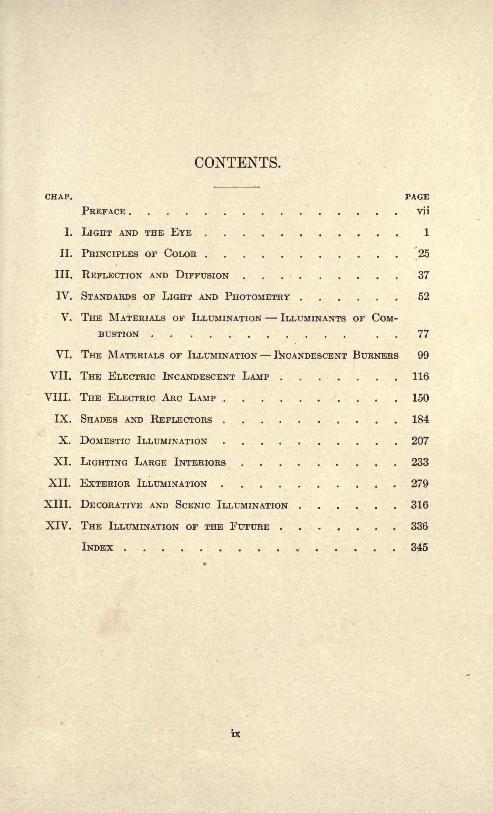
CONTENTS.
CHAP. PAGE
PREFACE vii
I. LIGHT AND THE EYE 1
II. PRINCIPLES OF COLOR 25
III. REFLECTION AND DIFFUSION 37
IV. STANDARDS OF LIGHT AND PHOTOMETRY 52
V. THE MATERIALS OF ILLUMINATION ILLUMINANTS OF COM-
BUSTION . 77
VI. THE MATERIALS OF ILLUMINATION INCANDESCENT BURNERS 99
VII. THE ELECTRIC INCANDESCENT LAMP 116
VIII. THE ELECTRIC ARC LAMP . . 150
IX. SHADES AND REFLECTORS 184
X. DOMESTIC ILLUMINATION 207
XI. LIGHTING LARGE INTERIORS ......... 233
XII. EXTERIOR ILLUMINATION .......... 279
XIII. DECORATIVE AND SCENIC ILLUMINATION 316
XIV. THE ILLUMINATION OF THE FUTURE 336
INDEX 345

THE ART OF ILLUMINATION.
CHAPTER I.
LIGHT AND THE EYE.
WHILE even the Esquimaux and the Patagonians use artificial
light and all civilized peoples count it a necessity, it is seldom
used skillfully and with proper knowledge of the principles that
should govern its employment. Since the introduction of electric
lights that very facility of application which gives them uniquevalue has encouraged more zeal than discretion in their use. It
is the purpose of the present volume to set forth some of the
fundamental doctrines, optical, physiological, and aesthetic, which
underlie the proper use of artificial illuminants, and to point out
how they may be advantageously adapted to existing conditions.
To begin with, there are two general purposes which character-
ize two quite distinct branches of the art of illumination. First
comes the broad question of supplying artificial light for carryingon such avocations or amusements as are extended into the hours
of darkness. Quite apart from this is the case of scenic illumi-
nation directed at special objects and designed to produce par-
ticular effects or illusions. Lighting a shop or a house exemplifies
the one, lighting a picture gallery or the stage of a theater the
other. Each has a distinct purpose, and requires special meansfor its accomplishment. Confusing the purposes or mixing the
methods often leads to serious mistakes. Sometimes both gen-eral and scenic illumination have to be used coincidently, but the
distinction between them should be fully realized even when it
cannot fully be preserved.
General illumination, whether intended to serve the ends of
work or play, must fulfill the following conditions: it must be
amply adequate in amount, suitable in kind, and must be so
applied as not to react injuriously upon the eye.
It must be remembered that the human eye is not merely1
2 THE ART OF ILLUMINATION
a rather indifferent optical instrument, but a physical organwhich has through unfathomable ages accumulated the characters
wrought upon it by evolution, until it bears the impress and
incurs the limitations of its environment. It works best over a
rather limited retinal area and through a range in intensity of
light which, although great, is yet immensely smaller than the
range available to nocturnal creatures. It has, moreover, become
habituated to, and adapted to, light coming obliquely from above,
and resents strong illumination, whether natural or artificial,
from any other direction. It seems to be well established, for
example, that the distress caused by the reflected glare from
sand, or water, or snow, and the grave results which follow pro-
longed exposure to it, are due not only to the intensity of the
light but to the fact that it is directed upward into the eye andis quite insufficiently stopped by the rather transparent lower
eyelid. Ordinary glasses are inefficient protection in this case,
but if the lower part of the eye be thoroughly guarded little
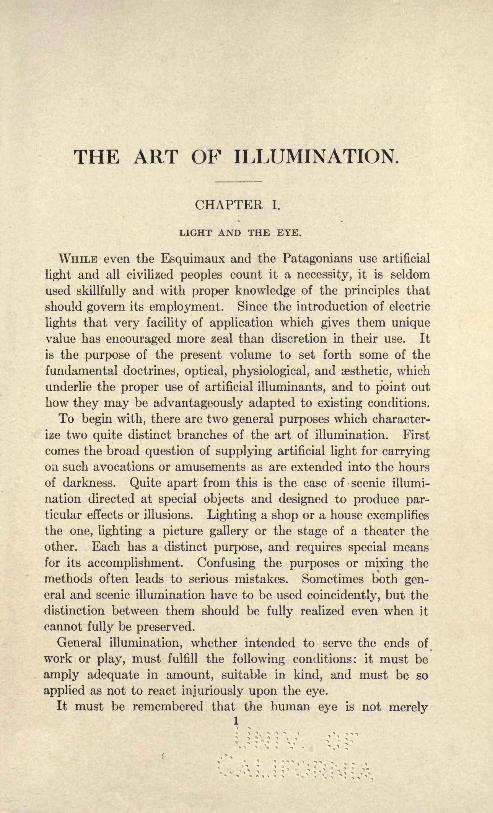
difficulty is found. The Alaskan Indians have
evolved a very effective protection against snow
blindness in the shape of leather goggles with
the eye arranged as shown in Fig. 1. The
eyepiece is merely a round bit of dark leather
with a semicircular cut made for the peephole,
the resulting flap being turned Outward andlg'
Goggles downward, so that the eye is fully guarded from
the brilliant upward beams. Blackening the
whole lower eyelid with burnt cork is stated by one distinguished
oculist to be completely efficacious for the same reason.
It is more than likely that the bad effects ascribed to the habit
of reading while lying down are due largely to the unwonted
direction, of the illumination, as well as to the unusual position
of the eye's axis.
All these matters are of fundamental importance in planning
any illumination to facilitate hard visual work. Their significance
is that we are not at liberty to depart widely from the distribu-
tion and character of natural daylight illumination. Of course,
one realizes immediately that the eye is neither fitted nor habit-
uated to working to advantage in anything like the full strength
of sunlight; but its more general properties steadiness, dominant
wave length, downward oblique direction, wide and strong dif-
LIGHT AND THE EYE 3
fusion, freedom from sharp and black shadows these must be
followed rather closely in ordinary artificial illumination, or the
eye, that has been taking form through a million years of sunlight
and skylight, will resent the change. The eye is automatically
adjustable, it is true, for wonderfully diverse conditions, but per-
sistent and grave changes in environment are more than it can
bear.
Now from a practical standpoint the key to artificial illumina-
tion is found in the thoughtful contemplation of what is knownas Fechner's law, relating to the sensitiveness of the eye to visual
impressions. It is stated by Helmholtz substantially as follows:
"Within very wide limits of brightness, differences in the strength
of light are equally distinct or appear equal in sensation, if theyform an equal fraction of the total quantity of light compared."That is, provided the parts of the visual picture remain of the
same relative brightness, the distinctness of detail does not vary
materially with great changes of absolute brightness. Now since,
barring binocular vision, our whole perception of visible things
depends, in the absence of color contrasts, upon differences of
illumination, the importance of the law just stated needs little
comment. It implies what experience proves, that within a rather
wide range of absolute brightness' of illumination our vision is
about equally effective for all ordinary purposes.
Fechner's law, to be sure, fails when extremely brilliant lights
are concerned. Few persons realize, for instance, that the sun
is twice as bright at noon as it is when still 10 to 15 degrees
above the horizon, still less that its brilliancy is reduced more than
a hundred-fold as its lower limb touches the horizon. Yet while
the eye does not detect very small changes or properly evaluate
large ones in a body so bright as the sun, the mere fact that one
can see to work or read about equally well from sunrise to sunset
is most convincing as to the general truth of the law. Full sun-
light 'at noon is over-bright for the eye if it falls directly uponthe work, but with half of it or less one can get along very
comfortably.
All this is most important from the standpoint of artificial
illumination, since it means that within rather wide limits of
intensity artificial lighting remains about equally effective for most
practical purposes.
"he actual amount of illumination necessary and desirable, theT,
4 THE ART OF ILLUMINATION
terms by which we measure it, and the laws that govern its
intensity are matters of primary importance, which must now
occupy our attention.
To arrive at a logical determination of the amount of illumina-
tion necessary for general or special purposes, one must turn to
the actual properties of the eye with,j-espect to seeing those things
which are customarily the objects of artificial illumination. Thefundamental fact at the basis of vision is that the eye can perceive
within a very wide range of absolute intensity a substantially con-
stant fractional difference of luminosity in the objects seen. This
is the purport of Fechner's law, to which reference has already
been made, and the fractional difference mentioned is well knownas Fechner's fraction. Its numerical value for ordinary eyes and
ordinary intensities of illumination is about 0.01; that is, two
adjacent surfaces can, under ordinary circumstances, be distin-
guished as separate, if one reflects to the eye about one per cent
more effective light than the other.
It is here assumed that the objects are of approximately the
same color, so that shade perception is the chief faculty of vision
involved. Even if the colors are somewhat different, the value
of Fechner's fraction is not greatly altered, provided the general
luminosity of the two surfaces remains as stated. In fact at a little
distance even somewhat strongly contrasted colors blend into each
other in a way that is altogether surprising, if they approach closely
the same general luminosity. Now, while Fechner's fraction is
fairly constant over a wide range of intensities, it varies, as already
stated, when one attempts to judge extremely brilliant lights; and
also one easily realizes that as twilight deepens his power of shade
perception is seriously impaired.
It is this variation of Fechner's fraction which determines the
minimum amount of artificial, or for that matter, natural light,
necessary for clear vision so far as shade perception is concerned.
Now, illumination sufficient to bring Fechner's fraction up to its
normal value, that is, to get the eye into its steady state with
respect to shade perception, is sufficient, so far as this matter
is concerned, for good vision, and anything above such amount
represents waste light.
Beside Fechner's fraction, which expresses shade perception,
another factor of equal importance enters into practical seeing.
This second factor is visual acuity, that is, the ability to see fine
LIGHT AND THE EYE 5
detail, assuming strong contrast, as, for example, between type and
the background of the page. This power of acuity is in a great
measure independent of the power of shade perception as such,
being determined by other physiological peculiarities of the eye.
It is possible, for example, to find eyes of normal acuity in which
shade perception is somewhat deficient, and vice versa. Acuityseems to depend on the structure of the retina and the quality
of the eye as an optical instrument rather than upon its direct
or secondary sensitiveness to stimulation by light.
In order, therefore, to see things really well one must have not
only sufficient light to bring the eye to its steady state, but suffi-
cient also to give the eye its normal powers of acuity. The wayin which one's power of perceiving detail decreases in dim light
is familiar, and the variation of acuity with the intensity of
the illumination affords an independent criterion of the necessary
requirements in artificial lighting. Fortunately the properties of
the eye with respect to both shade perception and acuity have
been the subjects of many investigations, so they may be considered
as on the whole well determined.
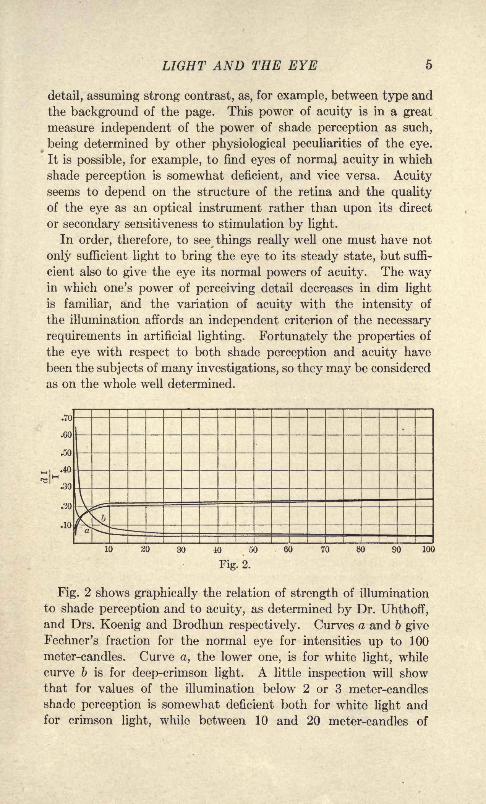
Fig. 2 shows graphically the relation of strength of illumination
to shade perception and to acuity, as determined by Dr. Uhthoff,and Drs. Koenig and Brodhun respectively. Curves a and b give
Fechner's fraction for the normal eye for intensities up to 100
meter-candles. Curve a, the lower one, is for white light, while
curve b is for deep-crimson light. A little inspection will showthat for values of the illumination below 2 or 3 meter-candles
shade perception is somewhat deficient both for white light andfor crimson light, while between 10 and 20 meter-candles of
6 THE ART OF ILLUMINATION
illumination both curves rapidly merge and are settling downto their steady value. Above 20 to 30 meter-candles they are
practically coincident, and power of discriminating thereafter
remains steady up to at least some thousands of meter-candles
of intensity.
Hence when the light reaching the eye is above 20 to 30
meter-candles further increase is of comparatively little assistance
to vision so far as shade perception is concerned. The other
curves, which are for all practical purposes coincident, are the
acuity curves for light-orange and yellowish green lights. Within
the range of hues found in practical illuminants, color, per se,
makes very little difference in visual acuity. The ordinates of these
curves are in arbitrary units, since the purpose here is merely to
analyze their shape. Their most important feature for the present
purpose is that, while showing low acuity at a few meter-candles,
these curves rise very slowly after reaching 20 to 30 meter-candles,
although they continue to rise gradually beyond this point; so it
appears that shade perception and visual acuity reach their steady
state in the eye for all practical purposes at about the same point,
and that this point is not far above 20 meter-candles. In other
words, with this illumination the eye practically reaches its normal
working condition, and beyond this point relatively little improve-
ment can be made by providing more light.
Something, as will be seen later, depends upon the state of
adaptation of the eye, that is, upon the way that it has habituated
itself temporarily to working with more or less light. For example,
an eye which has been working with a hundred meter-candles
illumination finds itself somewhat inconvenienced temporarily in
going back to 25 meter-candles, while an eye habituated to work-
ing at 10 or 15 meter-candles can do so quite comfortably and
would be temporarily much inconvenienced by the glare of 100
meter-candles. The chief point to be remembered in using, as we
shall see later, this physiological basis for the estimate of suitable
illumination is that the meter-candles specified as necessary to
bring the eye to its normal state refer to the light which the eye
can derive from the objects viewed, and not merely to the inten-
sity of the light which falls upon those objects. This is quite
another matter, since the light emitted by the objects illuminated
and available for the purpose in hand depends upon their reflective
power, which will hereafter be taken into consideration. Broadly,
LIGHT AND THE EYE 7
the illumination available for vision of an object is that incident
upon it multiplied by its coefficient of reflection.
The term here used to define illumination is practically self-
descriptive. A meter-candle of illumination means merely the
illumination a meter from a standard candle. Similarly, 2 meter-
candles is the illumination a meter from 2 candles, and so on.
Until very recently there has been great confusion in the meaningof the term "
candle" used in such connection, but in this volume
when the term " candle" is employed, the present International"candle," the origin of which will be explained in Chapter IV, is
the one thing meant. " Candle" when used in this book is used
in this sense only. For scientific purposes the metric system is
standard the world over, and no other system of units than the
metric has common currency for technical purposes; hence, so
far as the scientific investigation of illumination goes, the meter-
candle just referred to will be employed in this volume.
Both in England and in this country the common unit of il-
lumination referred to in the technical press is the foot-candle,
rather than the meter-candle, a unit of illumination, the deri-
vation of which is obvious in view of what has been stated regard-
ing the meter-candle. The writer will not hesitate to use this
common term, the foot-candle, whenever it seems desirable in
connection with practical computation of illumination in which
the distances rather generally are most conveniently obtained in
feet. The illumination a foot from a candle is written both' '
foot-
candle" and "candle-foot," the latter term being common in
English books. The terms are absolutely interchangeable, and the
use of both of them can create no confusion, although the writer
personally prefers and uses the former mainly on account of its
more euphonious and descriptive plural. The relation between
these practical units of illumination is very simple: 1 foot-candle
equals 10.76 meter-candles, so that no confusion need result from
the double use of terms. As will be seen later, the meter-candle is
the systematic unit of illumination to which properly belongs the
name lux.
For any light the illumination at one meter distance is obviously
a number of meter-candles numerically equal to the candle powerof the light.
At distances other than one meter the illuminating power is de-
termined by the well-defined, but often misapplied, "law of inverse
8 THE ART OF ILLUMINATION
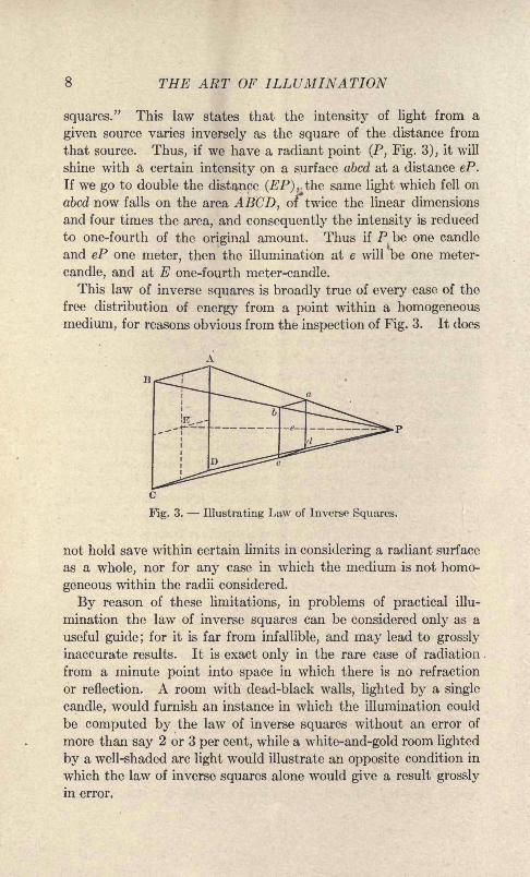
squares." This law states that the intensity of light from a
given source varies inversely as the square of the distance from
that source. Thus, if we have a radiant point (P, Fig. 3), it will
shine with a certain intensity on a surface abed at a distance eP.
If we go to double the distance (EP) ,the same light which fell on
abed now falls on the area ABCD, of twice the linear dimensions
and four times the area, and consequently the intensity is reduced
to one-fourth of the original amount. Thus if P be one candle
and eP one meter, then the illumination at e will be one meter-
candle, and at E one-fourth meter-candle.
This law of inverse squares is broadly true of every case of the
free distribution of energy from a point within a homogeneous
medium, for reasons obvious from the inspection of Fig. 3. It does
Fig. 3. Illustrating Law of Inverse Squares.
not hold save within certain limits in considering a radiant surface
as a whole, nor for any case in which the medium is not homo-
geneous within the radii considered.
By reason of these limitations, in problems of practical illu-
mination the law of inverse squares can be considered only as a
useful guide; for it is far from infallible, and may lead to grossly
inaccurate results. It is exact only in the rare case of radiation
from a minute point into space in which there is no refraction
or reflection. A room with dead-black walls, lighted by a single
candle, would furnish an instance in which the illumination could
be computed by the law of inverse squares without an error of
more than say 2 or 3 per cent, while a white-and-gold room lighted
by a well-shaded arc light would illustrate an opposite condition in
which the law of inverse squares alone would give a result grossly
in error.

LIGHT AND THE EYE 9
Fig. 4 shows how completely deceptive the law of inverse squares
may become in cases complicated by refraction or reflection. Here
one deals with an arc light of perhaps 5000 actual candle power as
the source of radiation, but a very large proportion of the total
luminous energy is concentrated by the reflector or lens system into
a nearly parallel* beam which maintains an extremely high lumi-
nous intensity at great distances from the apparatus. If the beam
were actually of parallel rays its resultant illumination would be
uniform at all distances, save as diminished by the absorption of
Fig. 4. Beam from Searchlight.
the atmosphere, probably not over 10 per cent in a mile in ordi-
narily clear weather, since the absorption of the entire thickness of
the atmosphere for the sun's light is only about 16 per cent.
The searchlight furnishes really a special case of scenic illumina-
tion, which frequently depends upon the use of concentrated beams
in one form or another, so that one must realize that a very con-
siderable branch of the art of illumination imposes conditions not
reconcilable with the ordinary application of the law of inverse
squares.
It is worth while thus to examine the law in question because
it is a specially flagrant example of a principle, absolutely and
10 THE ART OF ILLUMINATION
mathematically correct within certain rigid limitations, but par-
tially or wholly inapplicable in many important cases.
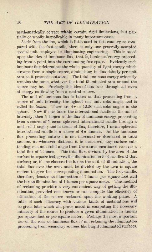
Aside from the lux, which is little used in this country as com-
pared with the foot-candle, there is only one generally accepted
special unit employed in illuminating .engineering. This is based
upon the idea of luminous flux, that is, luminous energy proceed-
ing from a point into the surrounding free space. Evidently such
luminous flux determines the whole quantity of light energy which
streams from a single source, diminishing in flux density per unit
area as it proceeds outward. The total luminous energy evidently
remains the same, whatever the total illuminated area around the
source may be. Precisely this idea of flux runs through all cases
of energy outflowing from a central source.
The unit of luminous flux is taken as that proceeding from a
source of unit intensity throughout one unit solid angle, and is
called the lumen. There are 4?r or 12.56 such solid angles in the
sphere. Now if one takes the international candle as the unit of
intensity, then 1 lumen is the flux of luminous energy proceeding
from a source of 1 mean spherical international candle through a
unit solid angle; and in terms of flux, therefore, 1 mean spherical
international candle is a source of 4 TT lumens. As the luminous
flux proceeding outward is not increased or decreased in total
amount at whatever distance it is measured, any surface sub-
tending one unit solid angle from the source mentioned receives a
total flux of 1 lumen. This total flux, divided by the area of the
surface in square feet, gives the illumination in foot-candles at that
surface; or, if one chooses the lux as the unit of illumination, the
total flux over the area must be divided by the area in square
meters to give the corresponding illumination. The foot-candle,
therefore, denotes an illumination of 1 lumen per square foot and
the lux an illumination of 1 lumen per square meter. This method
of reckoning provides a very convenient way of getting the illu-
mination, provided one knows or can compute the efficiency of
utilization of the source reckoned upon the working plane. Atable of such efficiency with various kinds of installations will
be given later which will prove useful in computing the necessary
intensity of the source to produce a given illumination in lumens
per square foot or per square meter. Perhaps the most important
use of the idea of luminous flux is* in reckoning the illumination
proceeding from secondary sources like bright illuminated surfaces.
LIGHT AND THE EYE 11
The lumens incident upon these can be at once computed from
the solid angle subtended by them with respect to the primarysource. This determined, the secondary source becomes simply a
source of a known number of lumens at a given distance from the
point at which the secondary illumination is to be reckoned.*
Several systems of units connected with illumination have been
from time to time proposed, but have not, save for the lux and
the lumen, which are common to all of them, met with sufficient
general acceptance to render discussion of them here profitable.
Most actual computations of illumination are made on the basis
of the intensity of the sources and their relation to the surfaces
to be illuminated, or by the flux-of-light method referred to the
efficiency of utilization on the working plane.
Having considered the unit strength of light and the unit strength
of illumination and of luminous flux, the other fundamental of
artificial lighting is the intensity of the luminous source gene-
rally known as intrinsic brightness. Optically this has no very
great or direct importance, but physiologically it is of the most
serious significance, and perhaps deserves more thoughtful atten-
tion than any other factor in practical illumination. It is of the
more consequence, as it is the one thing which generally receives
scant consideration, and is left to chance or convenience.
By intrinsic brightness is meant the strength of light per unit
area of light-giving surface. If we adopt the standard candle as
the unit of light, and adhere to English measures, the logical unit
of intrinsic brightness is one candle power per square inch. Onethen may conveniently express the brightness of any luminous
surface in candle power per square inch, and thus obtain a definite
basis of comparison, as in the accompanying table.
* An interesting modification of the flux-of-light method of reckoning illu-
mination is the absorption method of Dr. McAllister (Electrical World, Nov.
21, 1908). This is based upon the fact that whatever the intensity of illu-
mination in, for instance, a room, for that intensity the light sources must
produce the sum of all the luminous flux absorbed at the surfaces. Nowthe light-absorption coefficient is the familiar quantity (1 fc), and for a re-
quired flux density in foot-candles the necessary lumens equal this flux den-
sity multiplied by the area and by (1 fc). Hence whenever these quantities
are known for the various surfaces considered the total lumens, and hence
the required candle power can be at once ascertained. This very ingenious
method, which is, so to speak, the converse of the ordinary flux-of-light
computation, is occasionally very useful, and its details may be found in the
highly original paper to which reference has been made.
12 THE ART OF ILLUMINATION
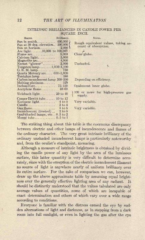
INTRINSIC BRILLIANCIES IN CANDLE POWER PERSQUARE INCH.
Source. Brilliancv. Notes.
Arc light ....... 10,000 to 100,000 +Flame arc .............. 5,000 Clear globe.Calcium light ........... 5,000Magnetite arc............ 4,000Nernst "glower" ........ 3,000 Unshaded.
Tungsten lamp ........ 1,000-1,100G. E. M.lamp ........ 750
Quartz Mercury arc . . . . GOO-1,000Tantalum lamp .......... 580Carbon incandescent lamp 300-500 Depending on efficiency.
Melting platinum ....... 129
Inclosed arc............. 75-150 Opalescent inner globe.
Acetylene flame ......... 40-60
Welsbach light .......... 20 to 40j
1C
sUpp
r
ly
m rC f r
Cooper Hewitt tube ...... 10 to 12
Kerosene light .......... 4 to 9 Very variable.Candle .................. 3 to 4
Gas flame ............... 3 to 8 Very variable.Incandescent (frosted) . . 2 to 8
Opal-shaded lamps, etc. . 0.5 to 2
Moore tube ............. 0.5 to 1
The striking thing about this table is the enormous discrepancybetween electric and other lamps of incandescence and flames of
the ordinary character. The very great intrinsic brilliancy of the
ordinary unshaded incandescent lamps is particularly noteworthy
and, from the oculist's standpoint, menacing.
Although a measure of intrinsic brightness is obtained by divid-
ing the candle power of any light by the area of the luminous
surface, this latter quantity is very difficult to determine accu-
rately, since with the exception of the electric incandescent filament
no source of light is anywhere nearly of uniform brilliancy over
its entire surface. For the sake of comparison we can, however,draw up the above approximate table by assuming equal bright-ness over the generally effective lighting area of any radiant. It
should be distinctly understood that the values tabulated are only
average values of quantities, some of which are incapable of
exact determination and others of which vary over a wide range
according to conditions.
Everyone is familiar with the distress caused the eye by sud-
den alternations of light and darkness, as in stepping from a dark
room into full sunlight, or even in lighting the gas after the eye
LIGHT AND THE EYE 13
has become habituated to the darkness. The eye is provided with
a very wonderful automatic "iris diaphragm" for its adjustmentto various degrees of illumination, but it is by no means instan-
taneous, although very prompt, in its action. Moreover, the eyeafter resting in darkness is in an extremely sensitive and receptive
state, and a relatively weak light will then produce very noticeable
after-images. These after-images, such as are seen in vivid colors
after looking at the sun, are due to retinal fatigue.
If the image of a brilliant light is formed upon the retina, it
produces certain very considerable chemical changes, akin to those
produced by light upon sensitized paper. In so doing it tempo-
rarily exhausts or weakens the power of the retina to respond at
that point to further visual impressions, and when the eye is turned
away the image appears, momentarily persistent, and then reversed,
dark for a white image, and of approximately complementary hue
for a colored one. This after-image changes color and fades awaymore or less slowly, according to the intensity of the original
impression, as the retina recovers its normal sensitiveness.
A strong after-image means a serious local strain upon the eye,
and shifting the eye about when brilliant light can fall upon it
implies just the same kind of strain that one gets in going out of
a dark room into bright sunshine. The results may be very seri-
ous. In one case recently reported a strong side light from an
unshaded incandescent lamp set up an inflammation that finally
resulted in the loss of an eye. The light was two or three feet
from the victim, whose work was such that the image of the
filament steadily fell on about the same point on the retina, at
which point the resulting inflammation had its focus. A few
weeks' exposure to these severe conditions did the mischief. This
is an extreme case, but similar conditions may very quickly cause
trouble. A few years ago the writer was at lunch facing a window
through which was reflected a brilliant beam from a white-painted
sign in full sunlight just across the street. No especial notice was
taken of this, until on glancing away a strong after-image of the
sign appeared, and although the time of exposure was only ten
or fifteen minutes, the net result was inability to use the eyes more
than a few minutes at a time for a fortnight afterwards.
To a certain extent the eye can protect itself from the bril-
liant sources of light by the automatic action of the iris. This
protection, however, is not rapid enough or complete enough to

14 THE ART OF ILLUMINATION
guard the eye properly against the brilliant sources now in com-mon use.
It is very difficult to get an exact idea of the reaction of the
pupil to light on account of the large number of factors which enter
the question and the constant slight variations to which the pupil-
lary diameter is subject. Its diameter varies from scarcely morethan 1 mm. under extreme conditions of contraction, to 7 or 8 mm.in darkness, so that to use the familiar expression applied to lens
stops, it works from somewhere about 77 to ^ ,or even ^ , when
10 20 30Meter-candles
Fig. 5. Variation of the Pupil in Different Illuminations.
Plotted from early experiments by Lambert.
in darkness the expanding iris retreats clear out to the rim of the
cornea. Ordinarily the pupillary diameter is in moderate light/>
3 or 4 mm., and the eye therefore is working at about j
A rough idea of the variation of the pupil in different illumi-
nations is given by the curve of Fig. 5, plotted from the early
experiments of Lambert. The ordinates give the area of the
pupil, the abscissae the illumination, in meter-candles. It is
interesting to note that most of the variation takes place under
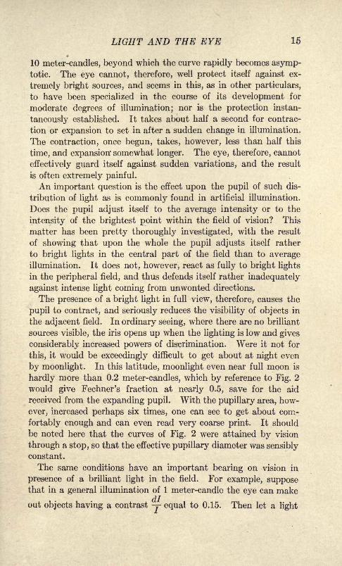
LIGHT AND THE EYE 15
10 meter-candles, beyond which the curve rapidly becomes asymp-totic. The eye cannot, therefore, well protect itself against ex-
tremely bright sources, and seems in this, as in other particulars,
to have been specialized in the course of its development for
moderate degrees of illumination; nor is the protection instan-
taneously established. It takes about half a second for contrac-
tion or expansion to set in after a sudden change in illumination.
The contraction, once begun, takes, however, less than half this
time, and expansion somewhat longer. The eye, therefore, cannot
effectively guard itself against sudden variations, and the result
is often extremely painful.
An important question is the effect upon the pupil of such dis-
tribution of light as is commonly found in artificial illumination.
Does the pupil adjust itself to the average intensity or to the
intensity of the brightest point within the field of vision? This
matter has been pretty thoroughly investigated, with the result
of showing that upon the whole the pupil adjusts itself rather
to bright lights in the central part of the field than to averageillumination. It does not, however, react as fully to bright lights
in the peripheral field, and thus defends itself rather inadequately
against intense light coming from unwonted directions.
The presence of a bright light in full view, therefore, causes the
pupil to contract, and seriously reduces the visibility of objects in
the adjacent field. In ordinary seeing, where there are no brilliant
sources visible, the iris opens up when the lighting is low and gives
considerably increased powers of discrimination. Were it not for
this, it would be exceedingly difficult to get about at night even
by moonlight. In this latitude, moonlight even near full moon is
hardly more than 0.2 meter-candles, which by reference to Fig. 2
would give Fechner's fraction at nearly 0.5, save for the aid
received from the expanding pupil. With the pupillary area, how-
ever, increased perhaps six times, one can see to get about com-
fortably enough and can even read very coarse print. It should
be noted here that the curves of Fig. 2 were attained by vision
through a stop, so that the effective pupillary diameter was sensiblyconstant.
The same conditions have an important bearing on vision in
presence of a brilliant light in the field. For example, supposethat in a general illumination of 1 meter-candle the eye can make
out objects having a contrast-j-
equal to 0.15. Then let a light
16 THE ART OF ILLUMINATION
come into the field of vision so as to increase the illumination on
the eye to 20 meter-candles without materially illuminating the
objects in the vicinity. The pupil will close to about one-third of
its former area under these circumstances, raising Fechner's fraction
to 0.3 or thereabouts, and consequently objects having the contrast
just mentioned would disappear. ^Hence, as is well known, one cannot see well across a bright light,
and even objects illuminated by it will lose in visibility unless
the change in the illumination received by them isgreater
than the
concomitant adverse change produced by the contraction of the
pupil. In short, a bright light falling on the eye quite generally
interferes with vision by decreasing the pupillary aperture, more
than it helps it by added illumination upon neighboring objects.
A very simple experiment, showing this effect of a strong source
of light on the apparent illumination, may be tried as follows:
Light a brilliant lamp, unshaded, in a good-sized room, preferably
one with darkish paper. Then put on the light an opal or similar
shade. It will be found that the change has considerably im-
proved the apparent illumination of the room, although it has
really cut off a good part of the total light. Moreover, at points
where there remains a fair amount of illumination, the shade has
improved the reading conditions very materially. If one is reading
where the unshaded light is at or within the edge of the field of
vision, the improvement produced by the shade is very conspicu-
ous. Lowering the intrinsic brilliancy of the light has decreased
the strain upon the eye and given it a better working .aperture.
As a corollary to these suggestions on the effect of bright lights
on our visual apparatus should be mentioned the fact that sudden
variations in the intensity of illumination seriously strain the eye
both by fatigue of the retina, due to sudden changes from weak to
strong light, and by keeping the eye constantly trying to adjust
itself to changes in light too rapid for it properly to follow.
A flickering gaslight, for example, or an incandescent lamp run
at very low frequency, strains the eye seriously and is likely to
cause temporary, even if not permanent, injury.
The persistence of visual impressions whereby the retinal imageremains steady for an instant after the object ceases to affect the
eye furnishes a certain amount of protection in case of very rapid
changes of brilliancy. It acts like inertia in the visual system.
In the case of arc and incandescent lamps, the thermal inertia of
LIGHT AND THE EYE 17
the filament or carbon rod also tends physically to minimize the
changes, but with a low-frequency alternating current they may'still be serious.
The exact frequency at which an incandescent lamp on an alter-
nating circuit begins to distress the eye by the flickering effect de-
pends somewhat on the ^ndividual eye and somewhat on the mass
of the filament. In general, a 16-c.p. lamp of the usual voltages,
say 100 to 120 volts, begins to show flickering at or sometimes a
little above 30 cycles per second; one foreign authority noting it
even up to 40 cycles. At 25 cycles the flickering is troublesome to
most eyes, and at 20 cycles or below it is generally quite intoler-
able. In looking directly at the lamp the filament is so dazzling
that the fluctuations are not always in evidence at their full value,
and a low-frequency lamp is quite likely to be the source of trouble
to the eye even when at first glance it appears to be quite steady.
The metallic filament lamps from their small thermal inertia are
more sensitive to these effects than carbon-filament lamps.
Lamps having relatively thick filaments can be worked at lower
frequencies than those of the common sort, so that 50-volt lamps,
particularly of large candle power, may be worked at 30 cycles or
thereabouts rather well, and out of doors even down to 25 cycles.
That is, at a pinch one can do satisfactory work when current is
available at 25 cycles or so, by using low-voltage lamps of 32,
50, or 100 candle power, which, by the way, are capable of giving
admirable results in illumination if properly disposed. Of course,
such practice is bad in point of efficient distribution of current,
but on occasion it may be useful.
As to arc lamps, conditions are not so favorable. The fluc-
tuations of an alternating arc lamp are easily detected, even at
60 cycles, by moving a pencil or the finger quickly when strongly
illuminated. The effect is a series of images along the path of
motion, corresponding to the successive maxima of light in the
arc. At 40 to 45 cycles the flickering becomes evident even when
viewing stationary objects, the exact point where trouble begins
depending upon the adjustment of the lamp, the hardness of the
carbons, and various minor factors. Inclosing the arc mitigates
the difficulty somewhat, but does not remove it.
In working near the critical frequency the best results are
attained by using an inclosed arc lamp taking all the current
the inner globe will stand, with as short an arc as will work

18 THE ART OF ILLUMINATION
steadily. Flaming arcs perform rather better on account of the
large mass of light-giving vapor.
When polyphase currents are available, as is usually the case
where rather low frequencies are involved, some relief may be
obtained by arranging the arcs in groups consisting of one from
each phase. At a little distance tern such a group the several
illuminations blend so as to partially suppress the fluctuations
of the individual arcs. This device makes it possible to obtain
fairly satisfactory lighting between 35 and 40 cycles. At these
frequencies, however, the arcs should not be used except whena very powerful light is necessary, or when the slightly yellowish
tinge of incandescents would interfere with the proper judgmentof colors. Powerful incandescents are generally better, and are,
now that large tungsten lamps are available, quite as efficient,
particularly when one takes into account proper distribution of
the light. In using incandescents in large masses, particularly
on polyphase circuits, the flickering of the individual lights is
lost in the general glow, so that even at 25 cycles the light maybe steady enough for general purposes, as was the case with the
decorative lighting at the Pan-American Exposition. The fluc-
tuations due to low frequency are usually very distressing to the
eye, and should be sedulously avoided. Fortunately, save in rare
instances, the frequency can be and should be kept well above
the danger point.
The same considerations which forbid the use of very intense
lights, unshaded; flickering lights; and electric lights at too low
frequency, render violent contrasts of brilliant illumination and
deep shadows highly objectionable. It should be remembered that
in daylight the general diffusion of illumination is so thorough
that such contrasts are very much softened, even in full sunlight,
and much of the time the direct light is modified by clouds. In
situations where the sun shines strongly down through interstices
in thick foliage, the eff.ect is decidedly unpleasant if one wishes
to use the eyes steadily; and if, in addition, the wind stirs the
leaves and causes flickering, the strain upon the eyes is most
trying.
In artificial lighting one should carefully avoid the conditions
that are objectionable in nature, which can easily be done bya little foresight. If for any purpose very strong illumination
becomes necessary at a certain point, the method of furnishing it
LIGHT AND THE EYE 19
which is most satisfactory from a hygienic standpoint is to super-
impose it upon a moderate illumination well distributed. If a
brilliant light is needed upon one's work, start with a fairly well-
lighted room and add the necessary local illumination, instead of
concentrating all the light on one spot. This procedure avoids
dense shadows and dark corners, and enables the eye to work
efficiently in a much stronger illumination than would otherwise
be practicable.
It should not be understood that the complete abolition of
shadows is desirable. On the contrary, since much of our percep-
tion of form and position depends upon the existence of shadows,the entire absence of them is troublesome and unpleasant. This is
probably due to two causes. First, the absence of shadows gives
an appearance of flatness out of which the eye vainly struggles to
select the wonted degrees of relief. In a shadowless space wehave to depend upon accommodation and binocular vision to locate
points in three dimensions, and the strain upon the attention is
severe and quickly felt.
Second, the existence of a shadowless space presupposes a nearly
equal illumination from all directions. If it be strong enoughfrom any particular direction to be convenient for work requiring
close attention of mind and eye, then, if there be no shadows,
equally strong light will enter the eye from directions altogether
unwonted. This state of things we have already found to be
objectionable in the highest degree.
The best illustration of this unpleasant condition may be found
in nature during a thin fog which veils the sun while diffusing
light with very great brilliancy. Try to read at such a time out of
doors, and, although there is no direct light on the page to dazzle
you, and there is in reading no trouble from the sense of flatness,
yet there is a distinctly painful glare which the eyes cannot long
endure without serious strain.
In artificial lighting the same complete diffusion is competentto cause the same results, so that while contrasts of dense shadows
and brilliant light must be avoided, it is generally equally impor-tant to give the illumination, even if deliberately indirect, a certain
general direction to relieve the appearance of flatness and to save
the eye from cross lights.
With respect to the best direction of illumination, only very
general suggestions can be given. Brilliant light, direct or re-
20 THE ART OF ILLUMINATION
fleeted, should be kept out of the eye and upon the objects to be
illuminated. In each individual case the nature and requirements
of the work must determine the direction of lighting.
The old rule given for reading and writing, that the light should
come obliquely over the left shoulder, well illustrates ordinary
requirements. By receiving the ligjht from the point indicated
direct light is kept out of the eyes, and any light regularly re-
flected is generally out of the way. The eye catches then only
diffused light from the paper before it, and if the light comes from
the left (for a right-handed person) the shadow of hand and armdoes not interfere with vision in writing. If work requiring both
hands is under way, the chances are that the best illumination will
be obtained by directing it downwards and slightly from the front,
in which case care must be exercised to avoid strong direct reflec-
tion into the eyes. The best simple rule is, avoid glare direct or
reflected, avoid strong shadows, and get ample diffused light from
the object illuminated.
This brings us at once to the very important but ill-defined
question of the strength of illumination required for various kinds
of work.
Fortunately, the eye works well over a wide range of brightness,
but there is a certain minimum illumination which should be ex-
ceeded if one is to work easily and without undue strain. Thematter is much complicated by questions of texture and color,
which will be taken up presently, so that only general average
results can be considered. For reading and writing, experience
joins the physiological data already given in showing that an in-
tensity of at least 10 meter-candles is the minimum amount for
ordinary type and ink, such as is here used, for instance. With
large, clear type,
like that used for this particular line,
5 or 6 enable one to read rather easily; while with ordinary typeset solid or in type of the smaller sizes,
such type as is employed in this line as a horrible example,
30 or 40 meter-candles is by no means an unnecessary amount of
lighting. Dense black ink and clear white paper not highly calen-
dered, such as some of the early printers knew well how to use,
make vastly easier reading than the grayish-white stuff and cheap,
muddy-looking ink to be found in the average newspaper.
LIGHT AND THE EYE 21
Illumination of less than 10 usually renders reading somewhatdifficult and slow, the more difficult and slower as the illumination
is further reduced. At 2 or 3 meter-candles reading is by no means
easy, and there is a strong tendency to bring the book near the
eye, thereby straining one's power of accommodation, and to con-
centrate the attention upon single words, a tendency which in-
creases as the light is still further lessened.
In fact, when the illumination falls to the vicinity of 1 meter-
candle it is of very little use for the purpose of reading or
working.
One may get a fair idea of the strength of illumination required
for various purposes by a consideration of that actually furnished
by nature. To get at the facts in the case, we must make a little
digression in the direction of photometry, a subject which will be
more fully discussed later.
To get an approximate measure of the illumination furnished
by daylight, one can conveniently use what is known as a daylight
photometer. This instrument furnishes a means for balancing the
illumination due to any source against that due to a standard
candle at a known distance. Like most common forms of photom-
eter, it consists of a screen illuminated on its two sides by the
two sources of light respectively. Equality of illumination is de-
termined by the disappearance of a grease spot upon the screen.
A spot of grease on white paper produces, as is well known, a
highly transparent spot, which looks bright if illuminated from
behind, and dark when illuminated from the front.
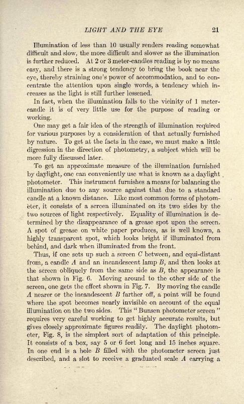
Thus, if one sets up such a screen C between, and equi-distant
from, a candle A and an incandescent lamp B, and then looks at
the screen obliquely from the same side as B, the appearance is
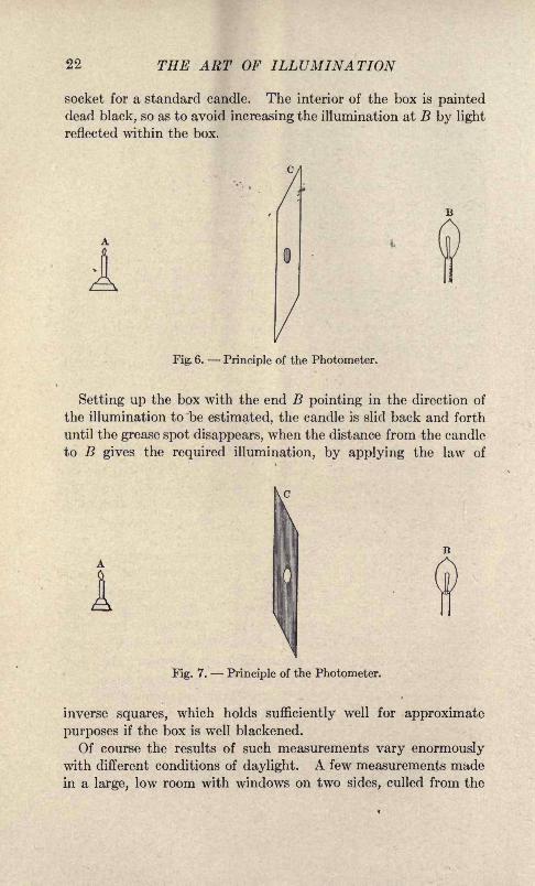
that shown in Fig. 6. Moving around to the other side of the
screen, one gets the effect shown in Fig. 7. By moving the candle
A nearer or the incandescent B farther off, a point will be found
where the spot becomes nearly invisible on account of the equalillumination on the two sides. This " Bunsen photometer screen
"
requires very careful working to get highly accurate results, but
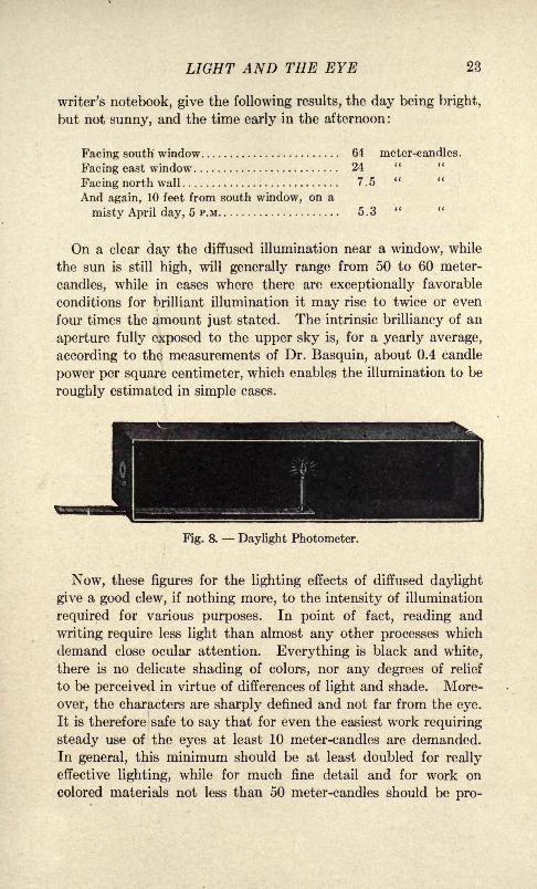
gives closely approximate figures readily. The daylight photom-
eter, Fig. 8, is the simplest sort of adaptation of this principle.
It consists of a box, say 5 or 6 feet long and 15 inches square.
In one end is a hole B filled with the photometer screen just
described, and a slot to receive a graduated scale A carrying a
22 THE ART OF ILLUMINATION
socket for a standard candle. The interior of the box is painteddead black, so as to avoid increasing the illumination at B by light
reflected within the box.
Fig. 6. Principle of the Photometer.
Setting up the box with the end B pointing in the direction of
the illumination to be estimated, the candle is slid back and forth
until the grease spot disappears, when the distance from the candle
to B gives the required illumination, by applying the law of
Fig. 7. Principle of the Photometer.
inverse squares, which holds sufficiently well for approximate
purposes if the box is well blackened.
Of course the results of such measurements vary enormouslywith different conditions of daylight. A few measurements madein a large, low room with windows on two sides, culled from the
LIGHT AND THE EYE 23
writer's notebook, give the following results, the day being bright,
but not sunny, and the time early in the afternoon:
Facing south window 64 meter-candles.
Facing east window 24
Facing north wall 7.5 "
And again, 10 feet from south window, on a
misty April day, 5 P.M 5.3
On a clear day the diffused illumination near a window, while
the sun is still high, will generally range from 50 to 60 meter-
candles, while in cases where there are exceptionally favorable
conditions for brilliant illumination it may rise to twice or even
four times the amount just stated. The intrinsic brilliancy of an
aperture fully exposed to the upper sky is, for a yearly average,
according to the measurements of Dr. Basquin, about 0.4 candle
power per square centimeter, which enables the illumination to be
roughly estimated in simple cases.
Fig. 8. Daylight Photometer.
Now, these figures for the lighting effects of diffused daylight
give a good clew, if nothing more, to the intensity of illumination
required for various purposes. In point of fact, reading and
writing require less light than almost any other processes which
demand close ocular attention. Everything is black and white,
there is no delicate shading of colors, nor any degrees of relief
to be perceived in virtue of differences of light and shade. More-
over, the characters are sharply denned and not far from the eye.
It is therefore safe to say that for even the easiest work requiring
steady use of the eyes at least 10 meter-candles are demanded.
In general, this minimum should be at least doubled for really
effective lighting, while for much fine detail and for work on
colored materials not less than 50 meter-candles should be pro-

24 THE ART OF ILLUMINATION
vided. Even this amount may advantageously be doubled for the
finest mechanical work, such as engraving, watch repairing, and
similar delicate operations. In fact, for some such cases the more
light the better, provided the source of light and direct undiffused
reflections therefrom are kept out of the eyes.
These estimates have taken no account of the effect of color,
which sometimes is a most important factor, alike in determin-
ing the amount of illumination necessary and in prescribing the
character and arrangement of the sources of light tpbe employed.

CHAPTER II.
PRINCIPLES OF COLOR.
THE relation of color to practical illumination is somewhat
intricate, for it involves considerations physical, physiological,
and aesthetic; but it is well worth studying, for while in some
departments of illumination, such as street lighting, it is of little
consequence, in lighting interiors it plays a very important part.
In lighting a shop where colored fabrics are displayed, for exam-
ple, it is necessary to reproduce as nearly as may be the color
values of diffused daylight, even at considerable trouble. Such
illumination, however, may be highly undesirable in lighting a
ballroom, where the softer tones of a light richer in yellow and
orange are generally far preferable.
In certain sorts of scenic illumination strongly colored lights
must be employed, but always with due understanding of their
effect on neighboring colored objects. Sometimes, too, the nat-
ural color of a light needs to be slightly modified by the presenceof tinted shades, serving to modify both the intrinsic brilliancy
and the color.
The fundamental law with respect to color is as follows: Every
opaque object assumes a hue due to the sum of the colors which it
reflects. A red book, for instance, looks red because from white
light it selects mainly the red for reflection, while strongly absorb-
ing the green and blue.
White light, as a look through a prism plainly shows, is a com-
posite of many colors, fundamentally red, green, and blue, inci-
dentally of an almost infinite variety of transition tints. If a
narrow beam of sunlight passes through a prism, it is drawn
out into a many-colored spectrum in which the three colors
mentioned are the most prominent. Closer inspection detects
a rather noticeable orange region passing from red to green by
way of a narrow space of pure yellow, which is never very con-
spicuous. The green likewise shades into pure blue through a
belt of greenish blue, and the blue in turn shades off into a
deep violet. If the slit which admits the sunlight is made very25
26 THE ART OF ILLUMINATION
narrow, certain black lines appear crossing the spectrum, the
Fraunhofer lines due to the selective absorption of various sub-
stances in the solar atmosphere. These lines are for the purposein hand merely convenient landmarks to which various colors
may be referred. They were designated by Fraunhofer by the
letters of the alphabet, beginning at the red end of the spectrum.
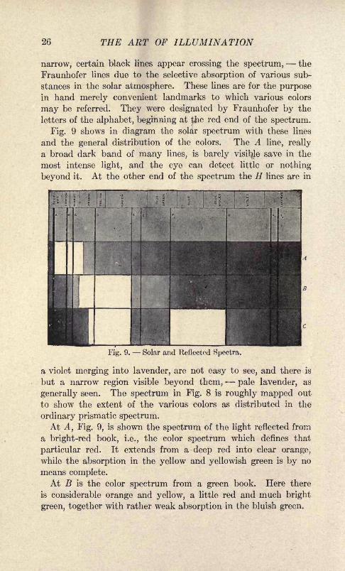
Fig. 9 shows in diagram the solar spectrum with these lines
and the general distribution of the colors. The A line, really
a broad dark band of many lines, is barely visible save in the
most intense light, and the eye can detect little or nothing
beyond it. At the other end of the spectrum the H lines are in
Fig. 9. Solar and Reflected Spectra.
a violet merging into lavender, are not easy to see, and there is
but a narrow region visible beyond them, pale lavender, as
generally seen. The spectrum in Fig. 8 is roughly mapped out
to show the extent of the various colors as distributed in the
ordinary prismatic spectrum.At A
} Fig. 9, is shown the spectrum of the light reflected from
a bright-red book, i.e., the color spectrum which defines that
particular red. It extends from a deep red into clear orange,
while the absorption in the yellow and yellowish green is by no
means complete.
At B is the color spectrum from a green book. Here there
is considerable orange and yellow, a little red and much bright
green, together with rather weak absorption in the bluish green.
PRINCIPLES OF COLOR 27
C shows a similar diagram from a book apparently of a clear,
full blue. The spectrum shows pretty complete absorption in the
red and extending well into the orange. The orange-yellow and
yellowish green remain, however, as does all the deep blue, while
there is a perceptible absorption of the green and bluish green.
Now, these reflected spectra are thoroughly typical of those
obtained from any dyed or painted surfaces. The colors ob-
tained from pigments are never the simple hues they appearto be, but mixtures more or less complex sometimes of colors
from very different regions of the spectrum. Most of the com-moner pigments produce absorption over rather wide regions of
the spectrum, but some of the delicate tints found in dyed fabrics
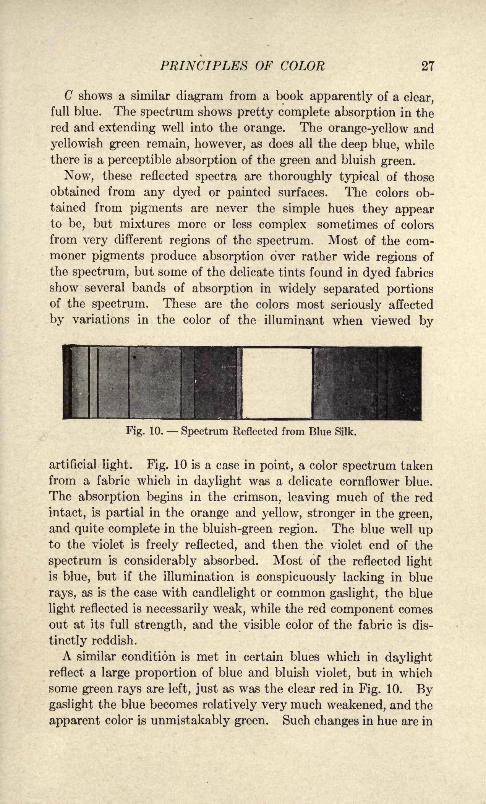
show several bands of absorption in widely separated portionsof the spectrum. These are the colors most seriously affected
by variations in the color of the illuminant when viewed by
Fig. 10. Spectrum Reflected from Blue Silk.
artificial light. Fig. 10 is a case in point, a color spectrum taken
from a fabric which in daylight was a delicate cornflower blue.
The absorption begins in the crimson, leaving much of the red
intact, is partial in the orange and yellow, stronger in the green,
and quite complete in the bluish-green region. The blue well upto the violet is freely reflected, and then the violet end of the
spectrum is considerably absorbed. Most of the reflected light
is blue, but if the illumination is conspicuously lacking in blue
rays, as is the case with candlelight or common gaslight, the blue
light reflected is necessarily weak, while the red component comes
out at its full strength, and the visible color of the fabric is dis-
tinctly reddish.
A similar condition is met in certain blues which in daylightreflect a large proportion of blue and bluish violet, but in which
some green rays are left, just as was the clear red in Fig. 10. Bygaslight the blue becomes relatively very much weakened, and the
apparent color is unmistakably green. Such changes in hue are in

28 THE ART OF ILLUMINATION
greater or less degree very common, and furnish some very curi-
ous effects. Sometimes a color clear by daylight appears dull and
muddy by artificial light, and in general the quality of the illumi-
nation requires careful attention whenever one deals with delicate
colors.
The absorption found in the pigments used in painting is seldom
so erratic as that shown in Fig. 10, but pictures often show very
imperfectly under ordinary artificial illumination.
It is no easy matter to get a clear idea of the feolor properties
of various illuminants. Of course, one can form spectra from
each of the lights to be compared, and compare the relative
strengths of the red, green, blue, and other rays in each;but this
gives but an imperfect idea of the relative color effects produced,for the results themselves are rather discordant, and the relative
brightness thus measured does not correspond accurately with the
visual effect. Lights have also been extensively compared by
color-mixing devices using colored screens to segregate red, green,
and blue portions of the spectrum which are then varied to match
the color under investigation. The results are valuable inter se,
but lack the definiteness secured by using the spectral colors.
Probably a better plan from the standpoint of illumination is to
match the visible color of a given illuminant accurately by mix-
tures of the three primary spectral colors, red, blue-violet, and
green, and to determine the exact proportions of each constituent
required to give a match. Even this evidently does not tell the
whole story, but it gives an excellent idea of the color differences
found in various lights. Such work has been very beautifully
carried out by Abney, from whose results the following table is
taken:
Incandescent lamps are not here included, but give enormouslydifferent results according to the degree of incandescence to which
they are carried. If burned below candle power, they give a light
not differing widely from gaslight ;while if pushed far above candle
power, the light is far richer in violet rays, and becomes approxi-
PRINCIPLES OF COLOR 29
mately white. Unfortunately, however, the lamp does not reach
this point save at a temperature that very quickly ends its life.
The effects of the selective absorption which so deceives the
eye when colored objects are viewed in colored lights are shown
in a variety of ways according to the colors involved, but the net
result of them all is to show the necessity of looking out for the
color of artificial lights. Of course, a really strong color mayproduce very fantastic results. For example, in the rays of an
ordinary green lantern, such as is used for railway signals, greens
generally appear of nearly their natural hues; but greens, yellows,
browns, and grays all match pretty well, although they may appeardarker or lighter in shade. Pink looks gray, darkening in shade
as it is redder, and red is nearly black, for the green light which
falls upon it is almost totally absorbed.
Practical illuminants do not often present so violent deceptions,
and yet gas or candle light is certain to change the apparent hue
of any delicate colors containing bluish-green, blue, or violet rays.
An old Welsbach mantle which gives a light of a strongly greenish
cast is pretty certain to change the color of everything not green
upon which it falls. Incandescent electric lights affect colors in
much the same way as brilliant gaslight, while arc lights give a
fair approximation to daylight. It by no means follows, however,that all colors should be matched by arc lights in preference to
other sources of illumination. A match so made stands daylight,
but may be most faulty when viewed by gaslight.
If matching colors has to be done, it is a safe rule to match them
by the kind of light by which they are intended to be viewed.
Moreover, different shades of the same color are differently affected
in artificial light. As a rule, deep, full colors are far less affected
than light tones of the same general hue. Clear yellows, reds,
and blues not verging on green are usually little altered, but pale
pinks, violets, and"robin's-egg" blues quite generally suffer. Very
often when a color is not positively altered it is made to appear
gray and muddy.For while in a green light greens look particularly brilliant, red
may be practically extinguished, absorbing all the rays which
come to it, so that a deep red will be nearly black, and a very light
red merely a dirty white, tinged with green if anything.
Quite apart from any effect of colored illumination, colors seem
to change in very dim light. This is a purely physiological matter,
30 THE ART OF ILLUMINATION
the eye itself differing in its sensibility to different colored lights.
In very faint illumination no color of any kind is perceptible
everything appears of uncertain shades of gray. As the light fades
from its normal intensity, as in twilight, red disappears first,
then violet and deep blue follow, settling like the red into murkyblackness; then the bluish green and green shade off into rapidly
darkening gray, and finally the yellow and yellowish green lose
their identity and merge into the night. At the same time the
hues even of simple colors change, scarlet fading into orange,
orange into yellow, and green into bluish green.
100
90
80
70
60
50
40
30
20
10
\
\\
\
A BC D E & F G HjH,,
Fig. 11. Effect of Faint Light on Color.
Obviously, complicated composite colors must vary widely under
such circumstances, for as the light grows dimmer their various
components do not fade in equal measure. Pinks, for instance,
generally turn bluish gray at a certain stage of illumination, owingto the extinction of the red rays. In fact, in a dim light the
normal eye is color-blind as regards red, and one can get a rather
good idea of the sensations of the color-blind by studying a set
of tinted wools or slips of paper in the late twilight.
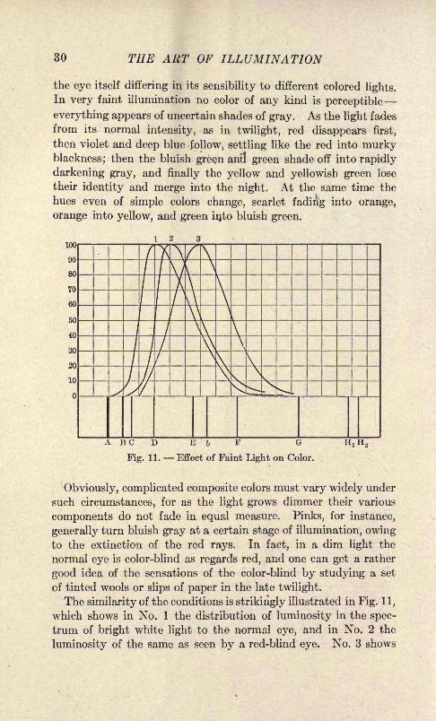
The similarity of the conditions is strikingly illustrated in Fig. 11,
which shows in No. 1 the distribution of luminosity in the spec-
trum of bright white light to the normal eye, and in No. 2 the
luminosity of the same as seen by a red-blind eye. No. 3 shows
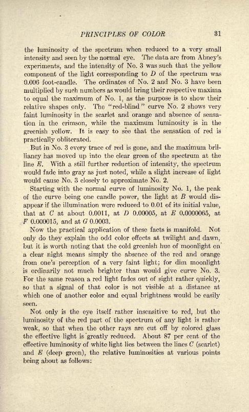
PRINCIPLES OF COLOR 31
the luminosity of the spectrum when reduced to a very small
intensity and seen by the normal eye. The data are from Abney's
experiments, and the intensity of No. 3 was such that the yellow
component of the light corresponding to D of the spectrum was
0.006 foot-candle. The ordinates of No. 2 and No. 3 have been
multiplied by such numbers as would bring their respective maximato equal the maximum of No. 1, as the purpose is to show their
relative shapes only. The " red-blind" curve No. 2 shows very
faint luminosity in the scarlet and orange and absence of sensa-
tion in the crimson, while the maximum luminosity is in the
greenish yellow. It is easy to see that the sensation of red is
practically obliterated.
But in No. 3 every trace of red is gone, and the maximum bril-
liancy has moved up into the clear green of the spectrum at the
line E. With a still further reduction of intensity, the spectrumwould fade into gray as just noted, while a slight increase of light
would cause No. 3 closely to approximate No. 2.
Starting with the normal curve of luminosity No. 1, the peakof the curve being one candle power, the light at B would dis-
appear if the illumination were reduced to 0,01 of its initial value,
that at C at about 0.0011, at D 0.00005, at E 0.0000065, at
F 0.000015, and at G 0.0003.
Now the practical application of these facts is manifold. Not
only do they explain the odd color effects at twilight and dawn,but it is worth noting that the cold greenish hue of moonlight on
a clear night means simply the absence of the red and orange
from one's perception of a very faint light; for dim moonlightis ordinarily not much brighter than would give curve No. 3.
For the same reason a red light fades out of sight rather quickly,
so that a signal of that color is not visible at a distance at
which one of another color and equal brightness would be easily
seen.
Not only is the eye itself rather insensitive to red, but the
luminosity of the red part of the spectrum of any light is rather
weak, so that when the other rays are cut off by colored glass
the effective light is 'greatly reduced. About 87 per cent of the
effective luminosity of white light lies between the lines C (scarlet)
and E (deep green), the relative luminosities at various points
being about as follows:
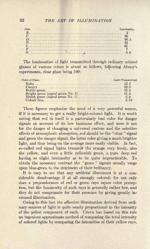
32 THE ART OF ILLUMINATION
Line. Luminosity.
B 3C 20D 98.5E 50b 35F 7G :,,. .+ 0.6
The luminosities of light transmitted through ordinary colored
glasses of various colors is about as follows, following Abney's
experiments, clear glass being 100:
Color of Glass. Light Transmitted.
Ruby 13.1
Canary 82.0Bottle green 10.6
Bright green (signal green No. 2) 19.4Bluish green (signal green No. 1) 6.9Cobalt blue 3 . 75
These figures emphasize the need of a very powerful source,
if it is necessary to get a really bright-colored light. It is worth
noting that red in itself is a particularly bad color for danger
signals on account of its low luminous effect, and were it not
for the danger of changing a universal custom and the selective
effects of atmospheric absorption, red should be the"clear
"signal
and green the danger signal, the latter color giving a much brighter
light, and thus being on the average more easily visible. In fact,
so-called red signal lights transmit the orange very freely, also
the yellow, and even a little yellowish green, a pure deep red
having so slight luminosity as to be quite impracticable. Toobtain the necessary contrast the "green" signals usually verge
upon blue-green to the detriment of their brilliancy.
It is easy to see that any artificial illuminant is at a con-
siderable disadvantage if at all strongly colored; for not only
does a preponderance of red or green rays injure color percep-
tion, but the luminosity of such rays is generally rather low, and
they do not compensate for their presence by giving greatly in-
creased illumination.
Owing to this fact the effective illumination derived from ordi-
nary sources of light is quite nearly proportional to the intensity
of the yellow component of each. Crova has based on this rule
an ingenious approximate method of comparing the total intensity
of colored lights by comparing the intensities of their yellow rays,
PRINCIPLES OF COLOR 33
either from their respective spectra or by sifting out all but the
yellow and closely adjacent rays by means of a colored screen.
Certainly for practical purposes the rays at the ends of the
spectrum are not very useful. So far as the ordinary work of
illumination goes, white or yellowish-white light is desirable, and
the only practical function of strongly colored lights is for signal-
ing and scenic illumination.
The general effect of strongly colored lights is to accentuate
objects colored like the light and to change or dim all others.
Lights merely tinted produce a similar effect in a less degree.
Bluish and greenish tinges in the light give a cold, hard hue to
most objects, and produce on the face an unnatural pallor; in
fact, on the stage they are used to give in effect the pallor of
approaching dissolution. Naturally enough such light is unfitted
for domestic illumination, as, aside from its effect on persons, it
makes a room look bare, chill, and unfurnished. In a less degree
a similar effect is produced by moonlight, which, from a clear
sky, is distinctly cold, the white light growing faintly greenish
blue as its diminishing intensity causes the red to disappear.
On the other hand, a yellow-orange tinge in the light seems to
soften and brighten an interior, giving an effect generally warmand cheery. This result is extremely well seen in stage firelight
effects. Strongly red light is, however, harsh and trying, so that
it should generally be carefully avoided.
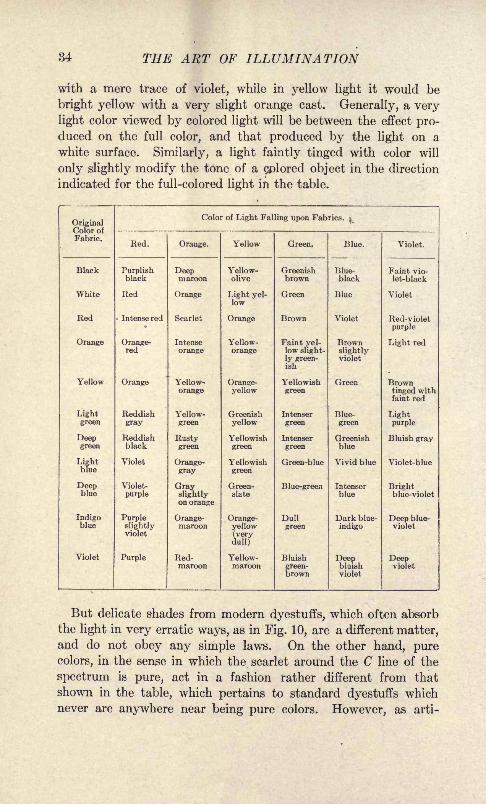
While it is not easy to predict accurately the effect of tinted
lights upon various delicate shades without a careful study of the
light rays forming each, the average effects relating to the simpler
colors are summarized in the following table. It is compiled from
the experiments of the late M. Chevreul, for many years director
of the dye works of the Gobelins tapestries. The colored lights
were from sunlight sifted through colored glass, and the effects
were upon fabrics dyed in plain, simple colors.
The facts set forth in this table show well what should be
avoided in colored illumination. As regards various shades of
the same colors, it must be remembered that light shades are
merely the full, deep ones diluted with white, which is itself
affected by the color of the incident light. In a general way,
therefore, one can use this table over a wider range than that
written down.
For instance, a very light red in blue light would look blue
THE ART OF ILLUMINATION
with a mere trace of violet, while in yellow light it would be
bright yellow with a very slight orange cast. Generally, a very
light color viewed by colored light will be between the effect pro-
duced on the full color, and that produced by the light on a
white surface. Similarly, a light faintly tinged with color will
only slightly modify the tone of a cplored object in the direction
indicated for the full-colored light in the table.
But delicate shades from modern dyestuffs, which often absorb
the light in very erratic ways, as in Fig. 10, are a different matter,and do not obey any simple laws. On the other hand, pure
colors, in the sense in which the scarlet around the C line of the
spectrum is pure, act in a fashion rather different from that
shown in the table, which pertains to standard dyestuffs which
never are anywhere near being pure colors. However, as arti-

PRINCIPLES OF COLOR 35
ficial illumination has to do only with commercial pigmejits and
dyes, the table serves as a useful guide in judging the effects
produced on interior furnishings by change in the color of the
light.
Of common illuminants, none except for the mercury arc and
the flame arc have any very decided color, yet most are somewhat
noticeably tinged. One can tabulate them roughly as follows:
Illuminant. Color.
Sun (high in sky). White.Sun (near horizon). Orange-red.Sky light. Very bluish white.
Electric arc (short). White.Electric arc (long). Bluish white to violet.
Flame arc. Commonly, yellow.
Mercury arc. Bluish green.Nernst lamp. Yellowish white.
Tungsten lamp. Yellowish white.Incandescent (normal), carbon. Yellowish.Incandescent (below voltage), Orange to orange-red.carbon.
Acetylene flame. Yellowish white.Welsbach light. Yellowish to greenish white.
Gaslight (Siemens burner). Whitish yellow tinge.
Gaslight, ordinary. Yellowish to pale orange.Kerosene lamp. Yellowish to pale orange.Candle. Orange-yellow.
Outside the earth's atmosphere the sun would look distinctly
blue, while its light, after thorough absorption in the earth's
atmosphere, gets the blue pretty completely sifted out, so that
the light from the eclipsed moon, once refracted by the earth's at-
mosphere and then reflected through it again, is in color a deep
coppery red.
Arc lights vary much in color, from clear white in short arcs
with comparatively heavy current to bluish white or whitish violet
in long arcs carrying rather small current. The modern inclosed
arcs err in the latter direction, and give tolerable color effects only
with yellowish white inner globes or shades. Incandescents, as
generally worked, verge upon the orange. Of the luminous flames
in use, only acetylene comes anywhere near being white, although
the powerful regenerative burners are a close second. Incandes-
cent gas lamps, at first showing nearly white with a very slight
greenish cast, ordinarily acquire a greenish or yellowish-green tinge
after burning for some time.
It is evident, then, that a study of the color effects produced
36 THE ART OF ILLUMINATION
by colored illuminants is by no means irrelevant, for distinct tinges
of color are the rule rather than the exception.
But this is not at all the whole story, for the general color of
the illumination in a given space depends not only on the hue of
the illuminant, but upon the color of the surroundings. Colored
shades, of course, are in common use; sometimes with a definite
purpose, more often from a mistaken notion of prettiness. Used
intelligently, as we shall presently see, they may prove very valu-
able adjuncts in interior illumination.
But far more important than shading is the modification in the
color of the light which comes from selective reflection at surfaces
upon which the light falls. In every inclosed space light is re-
flected in one way or another from all the bounding surfaces, and
at each reflection not only is the amount of light profoundly
modified, but its color may undergo most striking changes. It is
this phenomenon that gives its greatest interest to the study of
color in illumination. Its importance is not always readily recog-
nized, for few persons pay really close attention to the matter of
colors, but now and then it obtrudes itself in a way that forces
attention.
Take for example a display window lined with red cloth and
brightly illuminated. Passing along the sidewalk, one's attention
is immediately drawn to a red glow upon the street, while the
lights themselves may be ordinary gas jets. To get at the signifi-
cance of this matter, we must take up the effect of reflection and
diffusion in modifying the amount and quality of light.
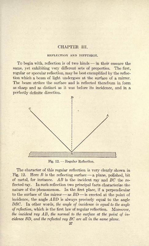
CHAPTER III.
EEFLECTION AND DIFFUSION.
To begin with, reflection is of two kinds in their essence the
same, yet exhibiting very different sets of properties. The first,
regular or specular reflection, may be best exemplified by the reflec-
tion which a beam of light undergoes at the surface of a mirror.
The beam strikes the surface and is reflected therefrom in form
as sharp and as distinct as it was before its incidence, and in a
perfectly definite direction.
Fig. 12. Regular Reflection.
The character of this regular reflection is very clearly shown in
Fig. 12. Here B is the reflecting surface a plane, polished, bit
of metal, for instance. AB is the incident ray and BC the re-
flected ray. In such reflection two principal facts characterize the
nature of the phenomenon. In the first place, if a perpendicularto the surface of the mirror as BD is erected at the point of
incidence, the angle ABD is always precisely equal to the angleDEC. In other words, the angle of incidence is equal to the angle
of reflection, which is the first law of regular reflection. Moreover,the incident ray AB, the normal to the surface at the point of in-
cidence BDj and the reflected ray BC are all in the same plane.37
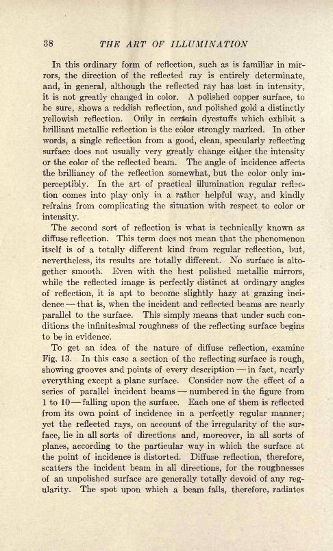
38 THE ART OF ILLUMINATION
In this ordinary form of reflection, such as is familiar in mir-
rors, the direction of the reflected ray is entirely determinate,
and, in general, although the reflected ray has lost in intensity,
it is not greatly changed in color. A polished copper surface, to
be sure, shows a reddish reflection, and polished gold a distinctly
yellowish reflection. Only in certain dyestuffs which exhibit a
brilliant metallic reflection is the color strongly marked. In other
words, a single reflection from a good, clean, specularly reflecting
surface does not usually very greatly change either the intensity
or the color of the reflected beam. The angle of incidence affects
the brilliancy of the reflection somewhat, but the color only im-
perceptibly. In the art of practical illumination regular reflec-
tion comes into play only in a rather helpful way, and kindly
refrains from complicating the situation with respect to color or
intensity.
The second sort of reflection is what is technically known as
diffuse reflection. This term does not mean that the phenomenonitself is of a totally different kind from regular reflection, but,
nevertheless, its results are totally different. No surface is alto-
gether smooth. Even with the best polished metallic mirrors,
while the reflected image is perfectly distinct at ordinary angles
of reflection, it is apt to become slightly hazy at grazing inci-
dence that is, when the incident and reflected beams are nearly
parallel to the surface. This simply means that under such con-
ditions the infinitesimal roughness of the reflecting surface begins
to be in evidence.
To get an idea of the nature of diffuse reflection, examine
Fig. 13. In this case a section of the reflecting surface is rough,
showing grooves and points of every description in fact, nearly
everything except a plane surface. Consider now the effect of a
series of parallel incident beams numbered in the figure from
1 to 10 falling upon the surface. Each one of them is reflected
from its own point of incidence in a perfectly regular manner;
yet the reflected rays, on account of the irregularity of the sur-
face, lie in all sorts of directions and, moreover, in all sorts of
planes, according to the particular way in which the surface at
the point of incidence is distorted. Diffuse reflection, therefore,
scatters the incident beam in all directions, for the roughnesses
of an unpolished surface are generally totally devoid of any reg-
ularity. The spot upon which a beam falls, therefore, radiates
REFLECTION AND DIFFUSION 39
light in a diverging cone and behaves as if it were really
luminous.
Some consideration of the nature of this diffuse reflection will
bring to light a fact which in itself seems rather surprising : namely,that the total intensities of the two kinds of reflection are not so
different from each other as might appear probable at first thought
provided the roughness of the unpolished surface is not on too
small a scale; for each of the incident rays in Fig. 13 is reflected
from the surface just as in the case of Fig. 12, in a perfectly
clean, definite, way, and there is no intrinsic reason why the
intensity of this elementary ray should be any more diminished
than in the case of regular reflection.
Fig. 13. Diffuse Reflection.
A little inspection of Fig. 13, however, shows that rays Nos. 5
and 10 are twice reflected before they get fairly clear of the sur-
face, and if one went on drawing still more incident rays and fol-
lowing out the figure on a still finer scale, a good many other rayswould be found to be reflected two or more times before finally
escaping from the surface. Such multiple reflection, of course,
diminishes the intensity of the light just as in the multiple reflec-
tion from mirrors; for there is always a little absorption, selec-
tive or otherwise, at any reflecting surface. Thus, while the
difference in the final intensities of light regularly and diffusely
reflected is not so great as might be imagined, it still does exist,
and for a perfectly logical reason.
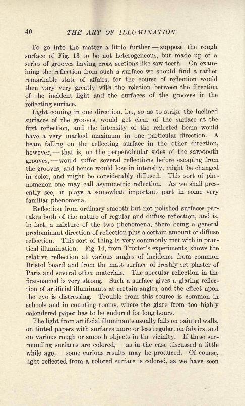
40 THE ART OF ILLUMINATION
To go into the matter a little further suppose the rough
surface of Fig. 13 to be not heterogeneous, but made up of a
series of grooves having cross sections like saw teeth. On exam-
ining the reflection from such a surface we should find a rather
remarkable state of affairs, for the course of reflection would
then vary very greatly with the relation between the direction
of the incident light and the surfaces of the grooves in the
reflecting surface.
Light coming in one direction, i.e., so as to strijke the inclined
surfaces of the grooves, would get clear of the surface at the
first reflection, and the intensity of the reflected beam would
have a very marked maximum in one particular direction. Abeam falling on the reflecting surface in the other direction,
however, that is, on the perpendicular sides of the saw-tooth
grooves, would suffer several reflections before escaping from
the grooves, and hence would lose in intensity, might be changed
in color, and might be considerably diffused. This sort of phe-
nomenon one may call asymmetric reflection. As we shall pres-
ently see, it plays a somewhat important part in some very
familiar phenomena.Reflection from ordinary smooth but not polished surfaces par-
takes both of the nature of regular and diffuse reflection, and is,
in fact, a mixture of the two phenomena, there being a general
predominant direction of reflection plus a certain amount of diffuse
reflection. This sort of thing is very commonly met with in prac-
tical illumination. Fig. 14, from Trotter's experiments, shows the
relative reflection at various angles of incidence from commonBristol board and from the matt surface of freshly set plaster of
Paris and several other materials. The specular reflection in the
first-named is very strong. Such a surface gives a glaring reflec-
tion of artificial illuminants at certain angles, and the effect uponthe eye is distressing. Trouble from this source is common in
schools and in counting rooms, where the glare from too highly
calendered paper has to be endured for long hours.
The light from artificial illuminants usually falls on painted walls,
on tinted papers with surfaces more or less regular, on fabrics, and
on various rough or smooth objects in the vicinity. If these sur-
rounding surfaces are colored, as in the case discussed a little
while ago, some curious results may be produced. Of course,
light reflected from a colored surface is colored, as we have seen
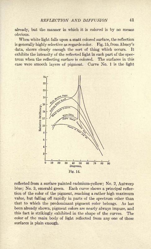
REFLECTION AND DIFFUSION 41
already, but the manner in which it is colored is by no meansobvious.
When white light falls upon a matt colored surface, the reflection
is generally highly selective as regards color. Fig. 15, from Abney's
data, shows clearly enough the sort of thing which occurs. It
exhibits the intensity of the reflected light in each part of the spec-
trum when the reflecting surface is colored. The surfaces in this
case were smooth layers of pigment. Curve No. 1 is the light
10 20 30 40 50
Degrees.
Fig. 14.
60 80 90
reflected from a surface painted cadmium-yellow; No. 2, Antwerpblue; No. 3, emerald green. Each curve shows a principal reflec-
tion of the color of the pigment, reaching a rather high maximumvalue, but falling off rapidly in parts of the spectrum other than
that to which the predominant pigment color belongs. As has
been already shown, pigment colors are nearly always impure, andthis fact is strikingly exhibited in the shape of the curves. Thecolor of the main body of light reflected from any one of these
surfaces is plain enough.
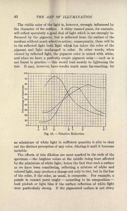
42 THE ART OF ILLUMINATION
The visible color of the light is, however, strongly influenced bythe character of the surface. A shiny enamel paint, for example,
will reflect specularly a good deal of light which is not strongly in-
fluenced by the pigment, but is reflected from the surface of the
medium without much selective action; consequently, there will be
in the reflected light both light which has taken the color of the
pigment and light unchanged in color. In other words, when
viewed by reflected light, the pigment color is mixed with white,
and when we have a perfectly simple pigment color such as is
not found in practice this would lead merely to lightening the
tint. It may, however, have results much more far-reaching; for
an admixture of white light in sufficient quantity is able to shut
out the distinct perception of any color, diluting it until it becomes
invisible.
The effects of this dilution are most marked in the ends of the
spectrum the brighter colors at the middle being least affected
by the admixture of white light; hence the fact that such a surface
as we have been considering, reflecting a mixture of white and
colored light, may produce a change not only in tint, but in the hue
of the color, if the color, as usual, is composite. For example, a
purple in enamel paint might according to its composition
look pinkish or light blue if the surface reflection of white light
were particularly strong. If the pigmented surface is not shiny
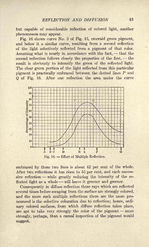
REFLECTION AND DIFFUSION 43
but capable of considerable reflection of colored light, another
phenomenon may appear.
Fig. 16 shows curve No. 3 of Fig. 15, emerald green pigment,
and below it a similar curve, resulting from a second reflection
of the light selectively reflected from a pigment of that color.
Assuming what is nearly in accordance with the fact, that the
second reflection follows closely the properties of the first, the
result is obviously to intensify the green of the reflected light.
The clear green portion of the light reflected from this particular
pigment is practically embraced between the dotted lines P and
Q of Fig. 16. After one reflection the area under the curve
ABCD E& T G
Fig. 16. Effect of Multiple Reflection.
embraced by these two lines is about 42 per cent of the whole.
After two reflections it has risen to 55 per cent, and each succes-
sive reflection while greatly reducing the intensity of the re-
flected light as a whole will leave it greener and greener.
Consequently in diffuse reflection those rays which are reflected
several times before escaping from the surface are strongly colored,
and the more such multiple reflections there are the more pro-
nounced is the selective coloration due to reflection; hence, ordi-
nary colored surfaces, from which diffuse reflection takes place,
are apt to take very strongly the color of the pigment more
strongly, perhaps, than a casual inspection of the pigment would
suggest.
44 THE ART OF ILLUMINATION
Now, as we shall presently see, in any inclosed space the light
reflected from the bounding surfaces is a very considerable por-tion of the whole, and, therefore, if these surfaces are colored,
the general illumination is strongly colored also, whatever the
illuminant may be; in other words, colored surroundings will
modify the color of the illumination just as definitely as a
colored shade over the source of light. In planning the general
color tone of a room to be illuminated, it must be remembered
that if the walls are strongly colored the dominant tone of the
illumination will be that of the walls rather than that of the
light.
An interesting corollary resulting from Fig. 16 sometimes appears
in the colors of certain fabrics. If the surface fibers of the fabric
lie in one general direction the light reflected from that fabric,
which determines its visible color, follows somewhat the same
laws laid down for asymmetric reflection, discussed in the case of
Fig. 13.
Light falling on the fabric from the direction toward which
the surface fibers run does not escape without profuse multiple
reflection, and hence takes strongly the color of the pigment.
Light, however, falling on the fabric reversely to the direction
of the fibers undergoes much less multiple reflection, and is likely
to be mixed with a large amount of white light hardly affected
by pigment at all; hence, the curious phenomenon of changeable
color in fabrics for instance, a fine purple from one direction
of illumination and perhaps very light pink from another.
If, in addition to the effects resulting from an admixture of
white light in certain directions of incidence, one also has the
curiously composite colors sometimes found in modern dyestuffs,
the changeable color effects may be and often are very conspicu-
ous; the more so, since hi such colors, by multiple reflection, or
what amounts to the same thing by more or less complete
absorption of certain rays, the resultant color may be very pro-
foundly changed.
Absorbing media sometimes show these color changes very
conspicuously; as, for example, chlorophyll, the green coloring
matter of leaves, which in a weak solution is green, but of which
a very strong solution of considerable thickness transmits only the
dark-red rays. Similar characteristics pertain to many modern
dyestuffs, and result, in connection with the composite reflection
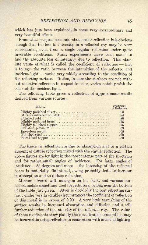
REFLECTION AND DIFFUSION 45
which has just been explained, in some very extraordinary and
very beautiful effects.
From what has just been said about color reflection it is obvious
enough that the loss in intensity in a reflected ray may be very
considerable, even from a single regular reflection under quite
favorable conditions. Many experiments have been made to
find the absolute loss of intensity due to reflection. This abso-
lute value of what is called the coefficient of reflection that
is to say, the ratio between the intensities of the reflected andincident light varies very widely according to the condition of
the reflecting surface. It also, in case the surfaces are not with-
out selective reflection in respect to color, varies notably with the
color of the incident light.
The following table gives a collection of approximate results
derived from various sources.
Mafprial' Coefficientof Reflection.
Highly polished silver .93Mirrors silvered on back .85Polished gold .80
Highly polished brass .75
Highly polished copper .75Polished platinum .63
Speculum metal .65Polished steel .60Burnished copper .50
The losses in reflection are due to absorption and to a certain
amount of diffuse reflection mixed with the regular reflection. Theabove figures are for light in the most intense part of the spectrumand for rather small angles of incidence. For large angles of
incidence 85 degrees and more the intensity of the reflected
beam is materially diminished, owing probably both to increase
in absorption and to diffuse reflection.
Mirrors silvered with amalgam on the back, and various bur-
nished metals sometimes used for reflectors, belong near the bottom
of the table just given. Silver is decidedly the best reflecting sur-
face; under very favorable circumstances the coefficient of reflection
of this metal is in excess of 0.90. A very little tarnishing of the
surface results in increased absorption and diffusion and a still
further reduction of the intensity of the reflected ray. The values
of these coefficients show plainly the considerable losses which maybe incurred in using reflectors in connection with artificial lighting.
46 THE ART OF ILLUMINATION
So far as general illumination is concerned, the light diffused at
reflecting surfaces is not by any means lost, but that absorbed is
totally useless. In the case of ordinary reflecting surfaces, one
deals with a mixture of regular and diffuse reflection, and in
practical illumination the latter is generally more important than
the former, for it determined the atfiount of light which reaches
the surface to be illuminated in ways other than direct radiation
from the illuminant.
Obviously, if one were reading a book in a rox>m completelylined with mirrors, the effect of the illumination upon the pagewould be vastly greater than that received directly from the source
of light itself. On the other hand, a room painted black through-
out would give very little assistance from reflection, and the illu-
mination upon the page would be practically little greater than
that received directly from the lamp. Between these limits falls
the condition of ordinary illumination in inclosed spaces. Gen-
erally speaking, there is very material assistance from reflection
at the bounding surfaces. The amount of such assistance depends
directly upon the coefficient of diffuse reflection of the various
surfaces concerned, varying with the color and texture of each.
As has been already indicated, diffuse reflection is rough, hetero-
geneous, regular reflection, more or less complicated, according to
the texture of the reflecting surface, by multiple reflections in the
surface before the ray finally escapes; and, therefore, the coefficients
of diffuse reflection are not so widely different from those of direct
reflection as might at first sight appear probable, so far at least
as the total luminous effect is concerned.
In certain kinds of diffuse reflection there is considerable loss
from absorption as well as from multiple reflections. This is con-
spicuously the case in the light reflected from fabrics, where there
is not only reflection from the surface fibers, but where the rays
before escaping are more than likely to have to traverse some of
them. This is illustrated in a rather crude but typical way in
Fig. 17, which gives a characteristic case of asymmetric reflection.
We may suppose that the beam of light falls upon a surface of
fabric having a well-marked nap. In the cut aa is the fabric sur-
face composed of inclined fibers or bunches of fibers. These fibers,
although colored, are more or less translucent and are not colored
uniformly throughout their substance. Owing to their direction,
rays 1, 2, and 3 get completely clear of the surface of the fabric
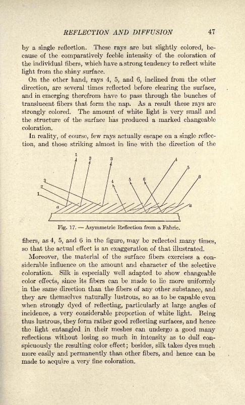
REFLECTION AND DIFFUSION 47
by a single reflection. These rays are but slightly colored, be-
cause of the comparatively feeble intensity of the coloration of
the individual fibers, which have a strong tendency to reflect white
light from the shiny surface.
On the other hand, rays 4, 5, and 6, inclined from the other
direction, are several times reflected before clearing the surface,
and in emerging therefrom have to pass through the bunches of
translucent fibers that form the nap. As a result these rays are
strongly colored. The amount of white light is very small and
the structure of the surface has produced a marked changeable
coloration.
In reality, of course, few rays actually escape on a single reflec-
tion, and those striking almost in line with the direction of the
\
Fig. 17. Asymmetric Reflection from a Fabric.
fibers, as 4, 5, and 6 in the figure, may be reflected many times,
so that the actual effect is an exaggeration of that illustrated.
Moreover, the material of the surface fibers exercises a con-
siderable influence on the amount and character of the selective
coloration. Silk is especially well adapted to show changeablecolor effects, since its fibers can be made to lie more uniformlyin the same direction than the fibers of any other substance, and
they are themselves naturally lustrous, so as to be capable even
when strongly dyed of reflecting, particularly at large angles of
incidence, a very considerable proportion of white light. Beingthus lustrous, they form rather good reflecting surfaces, and hence
the light entangled in their meshes can undergo a good manyreflections without losing so much in intensity as to dull con-
spicuously the resulting color effect; besides, silk takes dyes muchmore easily and permanently than other fibers, and hence can be
made to acquire a very fine coloration.
48 THE ART OF ILLUMINATION
Wool takes dye less readily, and it is not so easy to give the
surface fibers a definite direction. They are, however, quite
transparent and lustrous enough to give fine, rich colors. Cotton,
unless "mercerized," is much inferior to both silk and wool in
these particulars; hence, the phenomena we have been investi-
gating are seldom marked in cotton'fabrics.
In velvet, which is a very closely woven cut-pile fabric, the sur-
face fibers forming the pile stand erect and very closely packed
together. It is difficult, therefore, for light to undergo anything
except a very complex reflection, and practically all the rays
which come from the surface have penetrated into the pile and
acquired a strong coloration. The white light reflected from the
surface of the fibers hardly comes into play at all except at large
angles of incidence, so that the result is a particularly strong,
rich effect from the dyes, especially in silk velvet.
Cotton velvet, with its more opaque fibers, seems duller, and,
particularly if a little worn, reflects enough light from the surface
of the pile to interfere with the purity and intensity of the color.
Much of the richness in color of rough colored fabrics and sur-
faces is due to the completeness of the multiple reflections on
the dyed fibers, which produces an effect quite impossible to
match with a smooth surface unless dyed with the most vivid
pigments.
In practical illumination one seldom deals with fabrics to anyconsiderable extent, but almost always with papered or painted
surfaces. These are generally rather smooth, except in the case
of certain wall papers which have a silky finish. Smooth papersand paint give a very considerable amount of surface reflection
of white light, in spite of the pigments with which they may be
colored. The diffusion from them is very regular, except for
this surface sheen, and may be exceedingly strong. When light
from the radiant point falls on such a surface, it produces a verywide scattering of the rays, and an object indirectly illuminated
therefore receives in the aggregate a large amount of light.
A great many experiments have been tried to determine the
amount of this diffuse reflection which becomes available for
illumination. The general method has been to compare the
light received directly from an illuminant with that received
from the same illuminant by one reflection from a diffusing
surface.
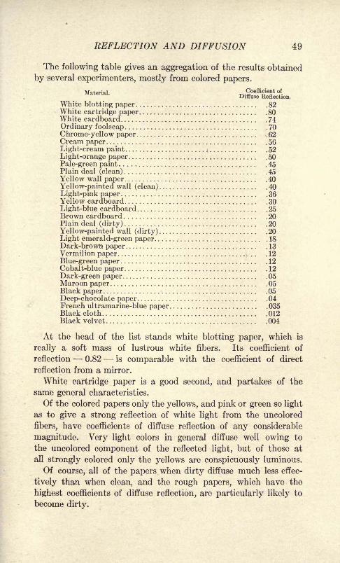
REFLECTION AND DIFFUSION 49
The following table gives an aggregation of the results obtained
by several experimenters, mostly from colored papers.
Material Coefficient ofDiffuse Reflection,
White blotting paper 82White cartridge paper 80White cardboard 74Ordinary foolscap 70Chrome-yellow paper 62Cream paper 56Light-cream paint , 52Light-orange paper 50Pale-green paint 45Plain deal (clean) 45Yellow wall paper , 40Yellow-painted wall (clean) 40Light-pink paper 36Yellow cardboard 30Light-blue cardboard 25Brown cardboard 20Plain deal (dirty) 20
Yellow-painted wall (dirty) 20Light emerald-green paper 18Dark-brown paper 13Vermilion paper 12
Blue-green paper 12Cobalt-blue paper 12
Dark-green paper 05Maroon paper 05Black paper 05
Deep-chocolate paper 04French ultramarine-blue paper 035Black cloth 012Black velvet 004
At the head of the list stands white blotting paper, which is
really a soft mass of lustrous white fibers. Its coefficient of
reflection 0.82 is comparable with the coefficient of direct
reflection from a mirror.
White cartridge paper is a good second, and partakes of the
same general characteristics.
Of the colored papers only the yellows, and pink or green so light
as to give a strong reflection of white light from the uncolored
fibers, have coefficients of diffuse reflection of any considerable
magnitude. Very light colors in general diffuse well owing to
the uncolored component of the reflected light, but of those at
all strongly colored only the yellows are conspicuously luminous.
Of course, all of the papers when dirty diffuse much less effec-
tively than when clean, and the rough papers, which have the
highest coefficients of diffuse reflection, are particularly likely to
become dirty.
50 THE ART OF ILLUMINATION
A smooth, clean, white board and white-painted surfaces gener-
ally diffuse pretty well, but lose rapidly in effectiveness as theybecome soiled. Greens, reds, and browns, in all their varieties,
have low coefficients, and it is worth noticing that deep ultra-
marine blue diffuses even less effectively than black paper coated
with lampblack, which has 'a diffusion of 0.05 as against 0.035
for the blue. Black cloth, with a surface rough compared with the
black paper, diffuses very much less light; while black velvet
of which the structure is, as just explained, particularly adaptedto suppress light has a coefficient of diffusion conspicuously less
than any of the others. A little dust upon its surface, however,is capable of reflecting a good deal of light.
These coefficients of diffusion have a very important bearing on
the illumination of interiors. It is at once obvious that exceptin the case of a white interior finish or a very pale shade of color
the illumination received by any object is not greatly strengthened
by diffused light from the walls. All of the strong colors, par-
ticularly if dark, cut down diffusion to a relatively small amount,
although it is very difficult to suppress diffusion with anythinglike completeness.
One of the standing difficulties in photometric work is to coat
the walls of the photometer room with a substance so non-reflect-
ing as not to interfere with the measurements. Even lampblackreturns as diffused light one-twentieth of that thrown upon it,
and painting with anything less lusterless than lampblack would
increase the proportion of diffused light very considerably. Walls
painted dead black, and auxiliary screens, also dead black, to
cut off the diffused light still more, are the means generally taken
to prevent the interference of reflected light with the accuracy of
the photometric measurements.
In the case of any diffusing surface, or any reflecting surface
whatever, for that matter, a second reflection has, at least approxi-
mately, the same coefficient of reflection as the first, so that for
the two reflections the intensity of the beam that finally escapes
is that of the incident beam multiplied by the square of the
coefficient of diffusion, and so on for further reflections.
Inasmuch as in any inclosed space there is considerable cross-
reflection of diffused light, the difference in the total amount of
illumination due to reflection is even more variable than would
be indicated by the table of coefficients given; for while the
REFLECTION AND DIFFUSION 51
amount of light twice diffused from white paper or paint would
be very perceptible in the illumination, that twice diffused from
paper of a dark color would be comparatively insignificant.
The color of the walls, therefore, plays a most important part
in practical illumination, for rooms with dark or strongly colored
walls require a very much more liberal use of illuminants than
those with white or lightly tinted walls. The difference is great
enough to be a considerable factor in the economics of the
question in cases where artistic considerations are not of prime
importance. The nature and amount of the effect of the bound-
ing surfaces on illumination will be discussed in connection with
the general consideration of interior lighting.
CHAPTER IV.
STANDARDS OF LIGHT ,AND PHOTOMETRY.
CONSIDERING the fact that the annual sum spent by civilized
peoples for illuminants may be reckoned by hundreds of millions
of dollars, it is somewhat extraordinary that methods of measur-
ing light and standards by which it is to be reckoned have been,
and for that matter still are, in so unsatisfactory a state. Until
very recently it would be well within bounds to say that no
commodity of similar total valuation has been so roughly and
inaccurately measured as light.
At the present time we are beginning to reach a somewhat more
satisfactory standard of precision. The fundamental difficulty
with the measurement of light is that it is a physiological rather
than a physical quantity and involves the uncertainties inherent
in physiological measurements. One can measure out a kilowatt
hour of electrical energy, or a thousand cubic feet of gas, or a
gallon of kerosene, with a degree of precision good enough from
the commercial standpoint; but to compute the light produced
by any source through direct measurements thereof is altogether
more difficult.
Until as late as 1909, at which date an informal international
convention made a single unit, the international candle, standard
in France, Great Britain, and the United States, each country was
a law unto itself in units of light and their applications. Three
questions are involved in getting a measurement of light. First, it
is necessary to have a standard of reference or primary standard
giving an amount of luminous energy to which the light to be
measured can be referred. Second, it- is necessary to have a unit
of light, that is, a conventional quantity of light which may or
may not be equal to the concrete thing used as a primary standard,
but which represents a definite quantity in terms of which other
lights are stated. Finally, it is necessary to have at least a con-
veniently uniform if not ideally precise procedure for the actual
photometric work.
Light in the last resort is the measure of the value of the illu-
52
STANDARDS OF LIGHT AND PHOTOMETRY 53
minants which one purchases, and consequently, as the aggregate
amount of the purchases is very great, the importance of suitable
standards and methods has long been recognized.
Historically, the oldest photometrical standard is the Carcel
lamp, for many years used in France, both as a concrete standard
of luminous intensity and as the unit in terms of which commercial
light was to be measured. The Carcel lamp, invented just at the
beginning of the nineteenth century, is an argand burner with a
wick and chimney of specified dimensions, consuming colza oil,
which is fed up to a uniform level at the burner by a clockwork-
driven pump placed in the base of the lamp. The wick, therefore,
draws from oil maintained at a constant level under practically
uniform conditions. The lamp is regulated to burn 42 grams of
oil per hour with a permissible variation of 4 grams on either side
of the normal.
Offhand, from general experience with oil-burning argand lamps,one would say that the Carcel lamp would give but an indifferent
approximation to uniformity and would be neither particularly
reliable nor satisfactorily reproducible as a standard. In spite of
its unpromising character, it is nevertheless true that in the hands
of the French photometricians, who are used to it, it has given
surprisingly good results, and it is a curious fact that the compari-sons of the Carcel with the Hefner lamp used in Germany are moreconsistent than the comparisons between any other pair of primarystandards which have been used. The Carcel gives a light of fairly
good yellowish hue in amount nearly 10 candle power.The next oldest standard used in recent times is the so-called
parliamentary sperm candle legalized in 1860. This was a candle
made of spermaceti, weighing 1200 grains avoirdupois, and burningat the rate of 120 grains per hour. The permissible variation in
rate of burning is from 110 to 130 grains per hour, the luminous
intensity being assumed to vary directly with the rate of burning.
The normal diameter of the candle is 0.8 inch at the top and 0.9
inch at the base, and the wick is required to be composed of three
strands, each of 18 threads.
This is the candle which is the commonest legal standard in the
present statutes of this country, and was for many years the stand-
ard in England. It was and is very unsatisfactory as a primary
standard, seldom manufactured so as to be close to the specifica-
tions, and remarkably subject to accidental variations. With great
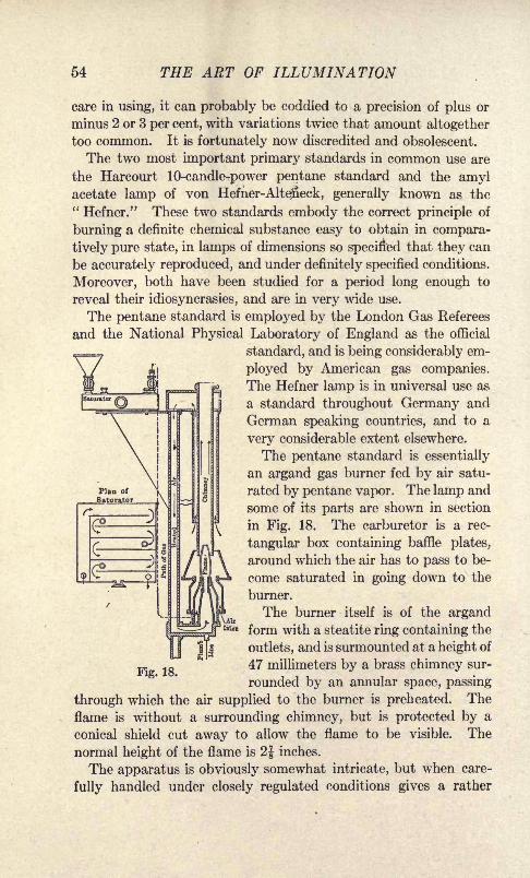
54 THE ART OF ILLUMINATION
care in using, it can probably be coddled to a precision of plus or
minus 2 or 3 per cent, with variations twice that amount altogether
too common. It is fortunately now discredited and obsolescent.
The two most important primary standards in common use are
the Harcourt 10-candle-power pentane standard and the amylacetate lamp of von Hefner-Altefieck, generally known as the"Hefner." These two standards embody the correct principle of
burning a definite chemical substance easy to obtain in compara-
tively pure state, in lamps of dimensions so specified that they can
be accurately reproduced, and under definitely specified conditions.
Moreover, both have been studied for a period long enough to
reveal their idiosyncrasies, and are in very wide use.
The pentane standard is employed by the London Gas Referees
and the National Physical Laboratory of England as the official
standard, and is being considerably em-
ployed by American gas companies.
The Hefner lamp is in universal use as
a standard throughout Germany and
German speaking countries, and to a
very considerable extent elsewhere.
The pentane standard is essentially
an argand gas burner fed by air satu-
rated by pentane vapor. The lamp and
some of its parts are shown in section
in Fig. 18. The carburetor is a rec-
tangular box containing baffle plates,
around which the air has to pass to be-
come saturated in going down to the
burner.
The burner itself is of the argandform with a steatite ring containing the
outlets, and is surmounted at a height of
47 millimeters by a brass chimney sur-
rounded by an annular space, passing
through which the air supplied to the burner is preheated. The
flame is without a surrounding chimney, but is protected by a
conical shield cut away to allow the flame to be visible. The
normal height of the flame is 2| inches.
The apparatus is obviously somewhat intricate, but when care-
fully handled under closely regulated conditions gives a rather
Plan of
u
L1 I
Fig. 18.

STANDARDS OF LIGHT AND PHOTOMETRY 55
satisfactory degree of precision. It is probably good within one
per cent on either side of the normal when carefully used, and
duly corrected for barometric pressure, humidity, and CO2 in the
air. A strong point in favor of the pentane standard is the con-
siderable light it gives, substantially 10 candle power, and the
fact that the flame is fairly white. Some care has to be taken to
Fig. 19.
secure pentane of adequate purity, as, while it is a definite chemical
compound which can be obtained absolutely pure, the commonsource of the pentane used is such as to render probable its con-
tamination with small amounts of other hydrocarbons which mayvary the illuminating power of the gas.
The Hefner lamp is simpler and more easily reproducible than
the pentane standard. It is shown in section in Fig. 19, in which
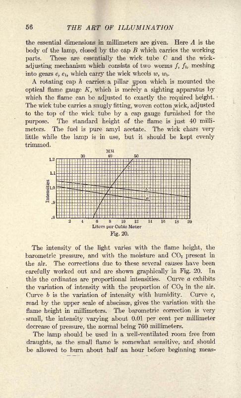
56 THE ART OF ILLUMINATION
the essential dimensions in millimeters are given. Here A is the
body of the lamp, closed by the cap B which carries the working
parts. These are essentially the wick tube C and the wick-
adjusting mechanism which consists of two worms /, /i, meshing
into gears e, e\, which carry the wick wheels w, w^.
A rotating cap h carries a pillar upon which is mounted the
optical flame gauge K, which is merely a sighting apparatus bywhich the flame can be adjusted to exactly the required height.
The wick tube carries a snugly fitting, woven cotton^wick, adjusted
to the top of the wick tube by a cap gauge furnished for the
purpose. The standard height of the flame is just 40 milli-
meters. The fuel is pure amyl acetate. The wick chars very
little while the lamp is in use, but it should be kept evenly
trimmed.
.8
8 10 12
Liters per Cubic Meter
Fig. 20.
13 20
The intensity of the light varies with the flame height, the
barometric pressure, and with the moisture and C02 present in
the air. The corrections due to these several causes have been
carefully worked out and are shown graphically in Fig. 20. In
this the ordinates are proportional intensities. Curve a exhibits
the variation of intensity with the proportion of CO2 in the air.
Curve b is the variation of intensity with humidity. Curve c,
read by the upper scale of abscissae, gives the variation with the
flame height in millimeters. The barometric correction is very
small, the intensity varying about 0.01 per cent per millimeter
decrease of pressure, the normal being 760 millimeters.
The lamp should be used in a well-ventilated room free from
draughts, as the small flame is somewhat sensitive, and should
be allowed to burn about half an hour before beginning meas-
STANDARDS OF LIGHT AND PHOTOMETRY 57
urements. The light given by the Hefner lamp as described is
0.9 of an international candle; at a flame height of 45 millimeters,
other things remaining the same, the lamp gives just one inter-
national candle.
The chief objections to the Hefner are its small luminous
intensity and the strong reddish color of the flame, which intro-
duces into comparisons made with it the difficulties of color pho-
tometry to a somewhat undesirable degree. When carefully
handled, it, like the pentane standard, is probably accurate to
about one per cent, although in the case of both these lamps vari-
ations of double this amount in case of different lamps operated
by different people should not create surprise.
The only other primary standard of light of any importanceis Violle's platinum standard, thus far of very little importance
as a concrete standard of reference, but of great significance as
being indirectly the basis of the international candle. In 1881
at the Paris Congress, Violle proposed, as a standard of light,
that radiated from a square centimeter of melted platinum at
its point of solidification.
In its original form the scheme of operations required not less
than one kilogram of molten platinum re-fused for each new
observation, and the apparatus was very troublesome to work
with. Later modifications of the apparatus by Siemens, Petavel,
and others have proved somewhat easier to operate, but the consen-
sus of opinion is that as a primary standard it is more troublesome
and less precise than either the Hefner form or the pentane lamp.
Nevertheless the Violle standard was adopted by the Paris
Electrical Congress of 1881, and the twentieth part of this unit,
determined in practice by comparison with the Carcel lamp, has
been considerably used in France under the name of the bougie
decimale, which in turn has been adopted as the present inter-
national candle.
The international candle, therefore, is not a primary standard
at all, but a unit of luminous value derived from intercomparisonof the Carcel, Hefner, and pentane primary standards. By 1907
it had become evident that there were outstanding differences
between the relative values of the units of light commonly re-
ceived, sufficient to demand commercial attention. The initiative
in the matter was taken by the Illuminating Engineering Society,
which appointed a committee on units and standards including
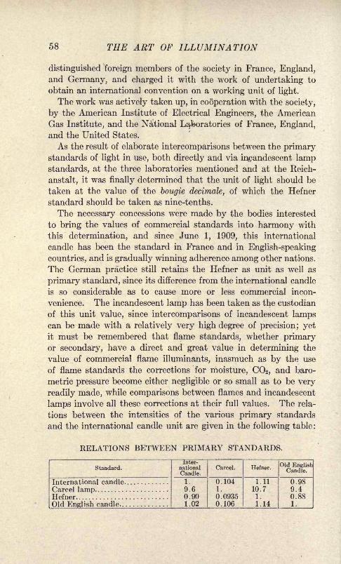
58 THE ART OF ILLUMINATION
distinguished 'foreign members of the society in France, England,and Germany, and charged it with the work of undertaking to
obtain an international convention on a working unit of light.
The work was actively taken up, in cooperation with the society,
by the American Institute of Electrical Engineers, the American
Gas Institute, and the National Laboratories of France, England,and the United States.
As the result of elaborate intercomparisons between the primarystandards of light in use, both directly and via incandescent lamp
standards, at the three laboratories mentioned and at the Reich-
anstalt, it was finally determined that the unit of light should be
taken at the value of the bougie decimals, of which the Hefner
standard should be taken as nine-tenths.
The necessary concessions were made by the bodies interested
to bring the values of commercial standards into harmony with
this determination, and since June 1, 1909, this international
candle has been the standard in France and in English-speaking
countries, and is gradually winning adherence among other nations.
The German practice still retains the Hefner as unit as well as
primary standard, since its difference from the international candle
is so considerable as to cause more or less commercial incon-
venience. The incandescent lamp has been taken as the custodian
of this unit value, since intercomparisons of incandescent lampscan be made with a relatively very high degree of precision; yet
it must be remembered that flame standards, whether primaryor secondary, have a direct and great value in determining the
value of commercial flame illuminants, inasmuch as by the use
of flame standards the corrections for moisture, C02, and baro-
metric pressure become either negligible or so small as to be very
readily made, while comparisons between flames and incandescent
lamps involve all these corrections at their full values. The rela-
tions between the intensities of the various primary standards
and the international candle unit are given in the following table:
RELATIONS BETWEEN PRIMARY STANDARDS.
STANDARDS OF LIGHT AND PHOTOMETRY 59
The secondary standard most in use, as just stated, is the in-
candescent electric lamp. After a lamp has been aged by burning
about 200 hours its candle power falls off only very gradually with
further use for about an equal period, so that if a lamp stand-
ardized after aging is used only for calibrating a working standard
it remains reliable far within the errors of observation for a con-
siderable period. Practical standards of a high degree of pre-
cision are therefore readily available in the form of incandescent
lamps.
As a secondary flame standard the Methven screen has been
considerably used, particularly in England. This standard is a
powerful argand gas burner fitted with a chimney and having
adjusted in front of it 1J inches from the axis of the flame a
blackened metal plate having a slot just in front of the flame 1
inch high by 0.233 inch in width. A section of flame thus cut
out is a very convenient and steady secondary standard of about
2 candle power. In this country the Elliot lamp has proved a
valuable adjunct in gas testing. It is a kerosene lamp, of the
"student lamp"
type, of which a definite area of the flame is
exposed by a slot, as in the Methven screen. The section of the
flat flame thus cut out remains sensibly uniform in light for a
considerable period. These secondary standards and the 10-c.p.
pentane primary standard are now rapidly displacing the discredited"standard
"candle for gas testing, so that for all illuminants there
is now a definite basis of reference to the international candle and
to the Hefner, which is a determinate fraction thereof.
Granted a unit of light intensity such as is furnished by the
international candle, and a concrete standard representing it or
a known multiple thereof, the fundamental process of light meas-
uring is the determination of the intensity of some working source
of light in terms of the unit.
Photometry is the art of comparing light intensities, and as
such it is the basis of the quantitative part of illuminating engi-
neering. In the last resort, a photometric comparison depends
upon the ability of the eye to detect small differences in lumi-
nosity, and the photometer ordinarily is an instrument designed
to present to the eye two similar juxtaposed surfaces, one lighted
by the source of known intensity and the other by the source of
unknown intensity, together with means of varying either or both
of these intensities in a determinate manner.
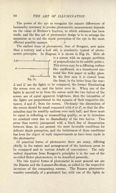
60 THE ART OF ILLUMINATION
The power of the eye to recognize the minute differences of
luminosity necessary to precise photometric measurement dependson the value of Fechner's fraction, to which reference has been
made, and the fine art of photometer design is to so arrange the
apparatus as to aid the shade perception of the eye in the mostefficient possible manner.
The earliest form of photometer, that of Bouguer, now morethan a century and a half old, is absolutely typical of photo-metric principles. In diagram it is shown in Fig*. 21. Here ab
is a screen with an opaque partitionL *~ '
acd perpendicular to its middle point c.
This screen may be a diffusing surface
like cardboard, or a translucent ma-terial like thin paper or milky glass.
LX ] b in the first case it is viewed from
the front, in the latter from the rear;
L and L' are the lights to be compared, the former illuminating
the screen over ac, and the latter over be. When one of the
lights is moved to or from the screen until the two halves of the
screen are of equal apparent brightness, then the intensities of
the lights are proportional to the squares of their respective dis-
tances, d and d', from the screen. Obviously the dimensions of
the screen should be small compared with d or d f
,so that the illu-
mination may be sensibly uniform over each half; and these must
be equal in reflecting or transmitting quality, so as to introduce
no constant error due to dissimilarity of the two halves. Twoareas thus merely juxtaposed with a black line of demarcation
between them do not present the most favorable conditions for
delicate shade perception, and the betterment of these conditions
has been the object of such improvements as have been made in
the photometer.Of practical forms of photometer there are many, differing
chiefly in the nature and arrangement of the luminous areas to
be compared and in various details of convenience. The only
radical departure from Bouguer's principles is in the case of the
so-called flicker photometers, to be described presently.
The two typical forms of photometer in most general use are
the Bunsen and the Lummer-Brodhun, so called for the respective
inventors of the comparison screens. The Bunsen photometerconsists essentially of a graduated bar, with one of the lights to

STANDARDS OF LIGHT AND PHOTOMETRY 61
be compared at each end, merely for the purpose of enabling the
distances of the two lights from the observing screen to be easily
determined. On the bar slides a sight box containing the Bunsenscreen and carrying a pointer moving over the scale. The general
disposition of the parts is shown in Fig. 22.
Fig. 22.
The length of the graduated bar is commonly 100 inches if
graduated in English measure, 2.5 or 3 meters when in metric
measure. The sight box as commonly made is shown in plan in
Fig. 23. The Bunsen screen forms the middle partition shown in
the box, upon which the light from the sources on either side
falls. Two mirrors, mi and m?, placed substantially as shown,
Fig. 23.
enable one looking into the wide sight tube T to see both sides
of the screen at once.
The Bunsen screen itself in its commonest form consists of a disk
of opaque, matt-surfaced white paper with a sharply defined central
spot made translucent by grease, usually paraffin. As already ex-
plained, such a spot appears bright or dark on the general surface
of the disk according as the illumination behind it is stronger or
weaker than that on the front. With a screen in perfect condition
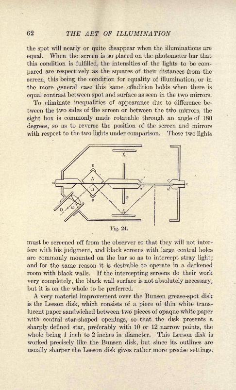
62 THE ART OF ILLUMINATION
the spot will nearly or quite disappear when the illuminations are
equal. When the screen is so placed on the photometer bar that
this condition is fulfilled, the intensities of the lights to be com-
pared are respectively as the squares of their distances from the
screen, this being the condition for equality of illumination, or in
the more general case this same condition holds when there is
equal contrast between spot and surface as seen in the two mirrors.
To eliminate inequalities of appearance due to difference be-
tween the two sides of the screen or between the t\to mirrors, the
sight box is commonly made rotatable through an angle of 180
degrees, so as to reverse the position of the screen and mirrors
with respect to the two lights under comparison. These two lights
TCI/Fig. 24.
must be screened off from the observer so that they will not inter-
fere with his judgment, and black screens with large central holes
are commonly mounted on the bar so as to intercept stray light;
and for the same reason it is desirable to operate in a darkened
room with black walls. If the intercepting screens do their work
very completely, the black wall surface is not absolutely necessary,
but it is on the whole to be preferred.
A very material improvement over the Bunsen grease-spot disk
is the Leeson disk, which consists of a piece of thin white trans-
lucent paper sandwiched between two pieces of opaque white paperwith central star-shaped openings, so that the disk presents a
sharply defined star, preferably with 10 or 12 narrow points, the
whole being 1 inch to 2 inches in diameter. This Leeson disk is
worked precisely like the Bunsen disk, but since its outlines are
usually sharper the Leeson disk gives rather more precise settings.
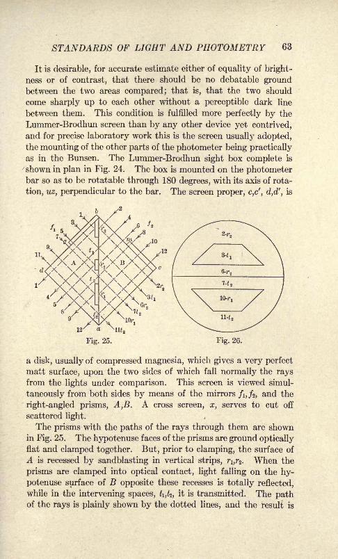
STANDARDS OF LIGHT AND PHOTOMETRY 63
It is desirable, for accurate estimate either of equality of bright-
ness or of contrast, that there should be no debatable groundbetween the two areas compared; that is, that the two should
come sharply up to each other without a perceptible dark line
between them. This condition is fulfilled more perfectly by the
Lummer-Brodhun screen than by any other device yet contrived,
and for precise laboratory work this is the screen usually adopted,the mounting of the other parts of the photometer being practically
as in the Bunsen. The Lummer-Brodhun sight box complete is
shown in plan in Fig. 24. The box is mounted on the photometerbar so as to be rotatable through 180 degrees, with its axis of rota-
tion, uz, perpendicular to the bar. The screen proper, c,c', d,d', is
Fig. 26.
a disk, usually of compressed magnesia, which gives a very perfect
matt surface, upon the two sides of which fall normally the rays
from the lights under comparison. This screen is viewed simul-
taneously from both sides by means of the mirrors /i,/2, and the
right-angled prisms, A,B. A cross screen, x, serves to cut off
scattered light.
The prisms with the paths of the rays through them are shownin Fig. 25. The hypotenuse faces of the prisms are ground optically
flat and clamped together. But, prior to clamping, the surface of
A is recessed by sandblasting in vertical strips, ri,r2 . When the
prisms are clamped into optical contact, light falling on the hy-
potenuse surface of B opposite these recesses is totally reflected,
while in the intervening spaces, t\fa, it is transmitted. The pathof the rays is plainly shown by the dotted lines, and the result is
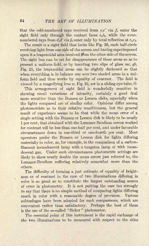
64 THE ART OF ILLUMINATION
that the odd-numbered rays received from c,cf
via /i enter the
sight field only through the contact faces t\,k, while the even-
numbered rays from d,d' via/2 enter only by total reflection at ri,r2 .
The result is a sight field that looks like Fig. 26, each half-circle
receiving light from one side of the screen and having superimposed
upon it a trapezoidal area received fom the other side of the screen.
The sight box can be set for disappearance of these areas so as to
present a uniform field, or by inserting two slips of glass me, gb,
Fig. 25, the trapezoidal areas can be slightly darkened so that
when everything is in balance one sees two shaded areas in a uni-
form field and thus works by equality of contrast. The field is
viewed by a magnifying lens w, Fig. 24, set in a sliding eye-tube, 0.
This arrangement of sight field is wonderfully sensitive in
showing small variations of intensity, certainly a good deal
more sensitive than the Bunsen or Leeson disks, especially when
the lights compared are of similar color. Opinions differ among
photometrists as to their relative sensitiveness, but the general
result of experience seems to be that while the mean error of a
single setting with the Bunsen or Leeson disk is likely to be nearly
1 per cent, that obtained with the Lummer-Brodhun screen worked
for contrast will be less than one-half per cent, and under favorable
circumstances down to one-third or one-fourth per cent. Most
operators prefer the Bunsen or Leeson disk for lights differing
materially in color, as, for example, in the comparison of a carbon-
filament incandescent lamp with a tungsten lamp or with incan-
descent gas. Under such circumstances photometric settings are
likely to show nearly double the mean errors just referred to, the
Lummer-Brodhun suffering relatively somewhat more than the
others.
The difficulty of forming a just estimate of equality of bright-
ness or of contrast in the case of two illuminations differing in
color is so great as to constitute the largest outstanding source
of error in photometry. It is not putting the case too strongly
to say that there is no simple method of comparing lights differing
much in color with a reasonable degree of precision. Various
subterfuges have been adopted for such comparisons, which are
convenient rather than satisfactory. Perhaps the best of them
is the use of the so-called"flicker
"photometer.
The essential point of this instrument is the rapid exchange of
-the two illuminations to be measured with respect to the sides
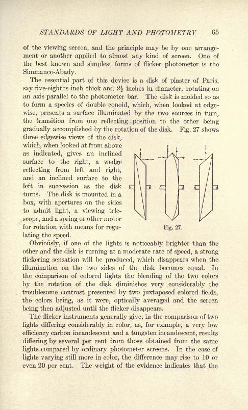
STANDARDS OF LIGHT AND PHOTOMETRY 65
\
of the viewing screen, and the principle may be by one arrange-ment or another applied to almost any kind of screen. One of
the best known and simplest forms of flicker photometer is the
Simmance-Abady.The essential part of this device is a disk of plaster of Paris,
say five-eighths inch thick and 2J inches in diameter, rotating on
an axis parallel to the photometer bar. The disk is molded so as
to form a species of double conoid, which, when looked at edge-
wise, presents a surface illuminated by the two sources in turn,
the transition from one reflecting position to the other being
gradually accomplished by the rotation of the disk. Fig. 27 showsthree edgewise views of the disk,
which, when looked at from abovej
i
as indicated, gives an inclined
surface to the right, a wedge
reflecting from left and right,
and an inclined surface to the
left in succession as the disk
turns. The disk is mounted in a
box, with apertures on the sides
to admit light, a viewing tele-
scope, and a spring or other motor
for rotation with means for regu-
lating the speed.
Obviously, if one of the lights is noticeably brighter than the
other and the disk is turning at a moderate rate of speed, a strong
flickering sensation will be produced, which disappears when the
illumination on the two sides of the disk becomes equal. In
the comparison of colored lights the blending of the two colors
by the rotation of the disk diminishes very considerably the
troublesome contrast presented by two juxtaposed colored fields,
the colors being, as it were, optically averaged and the screen
being then adjusted until the flicker disappears.
The flicker instruments generally give, in the comparison of two
lights differing considerably in color, as, for example, a very low
efficiency carbon incandescent and a tungsten incandescent, results
differing by several per cent from those obtained from the same
lights compared by ordinary photometer screens. In the case of
lights varying still more in color, the difference may rise to 10 or
even 20 per cent. The weight of the evidence indicates that the
Fig. 27.
66 THE ART OF ILLUMINATION
flicker principle is of much value in comparing lights of different
colors, since the readings obtained by a number of observers on the
same pair of lights generally show for smaller differences with the
flicker photometer than with the ordinary form.
Yet even this consistency is not wholly satisfactory evidence of
precision. Generally speaking, the flicker instruments do not allow
of as quick and easy balance as those with fixed screens, although
the precision of the balance when obtained is much better than
seems probable while it is being made. Very fyigh precision is
claimed for some of these instruments, particularly by their inven-
tors, but most photometrists hardly expect to obtain with them
any smaller average deviations than with the ordinary grease
spot. Flicker instruments work badly in weak illumination.
Two other schemes for avoiding the color difference in the com-
parison of lights are worth noticing here. One of them is the use
of standard color screens, the coefficient of absorption of which
can be obtained by the spectrophotometer and which serves to
reduce the two lights under comparison to approximately the same
color. The other is the preparation of a set of secondary standards
presenting only slight successive differences of color and yet on the
whole reaching a wide difference. This divides the color-matching
difficulty into steps, as it were, which renders photometric settings
much easier. Both these methods are somewhat roundabout and,
like the flicker photometer, lessen rather than abolish the color
difficulty. Probably any one of them yields results sufficiently
good for most commercial purposes, but where scientific precision
is required all leave much to be desired.
For a full discussion of the problem of heterochromatic photom-
etry the reader is advised to consult the various treatises and
papers dealing specifically with this matter, which will be found in-
teresting and instructive, although not always convincing. Photom-
etry is at best a process involving physiological and psychological
quantities of a somewhat indeterminate character. Even with the
same instrument and comparing lights of similar magnitude and
color, different observers are likely to find slightly different ratios,
and the same is true if one considers even the observations of the
same observer on different days. These differences may amount
to a considerable fraction of a per cent, plus or minus.
The fundamental thing in photometry is to make the best use of
the instrument at hand, to hold the lights under comparison abso-
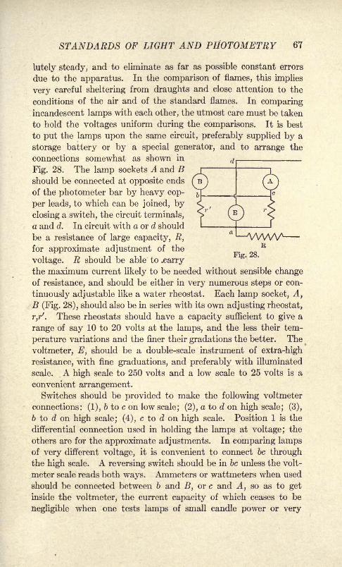
STANDARDS OF LIGHT AND PHOTOMETRY 67
lutely steady, and to eliminate as far as possible constant errors
due to the apparatus. In the comparison of flames, this implies
very careful sheltering from draughts and close attention to the
conditions of the air and of the standard flames. In comparingincandescent lamps with each other, the utmost care must be taken
to hold the voltages uniform during the comparisons. It is best
to put the lamps upon the same circuit, preferably supplied by a
storage battery or by a special generator, and to arrange the
connections somewhat as shown in
Fig. 28. The lamp sockets A and Bshould be connected at opposite ends
of the photometer bar by heavy cop-
per leads, to which can be joined, by
closing a switch, the circuit terminals,
a and d. In circuit with a or d should
be a resistance of large capacity, R}
for approximate adjustment of the
voltage. R should be able toxarrythe maximum current likely to be needed without sensible changeof resistance, and should be either in very numerous steps or con-
tinuously adjustable like a water rheostat. Each lamp socket, A,B (Fig. 28), should also be in series with its own adjusting rheostat,
r,r'. These rheostats should have a capacity sufficient to give a
range of say 10 to 20 volts at the lamps, and the less their tem-
perature variations and the finer their gradations the better. The
voltmeter, E, should be a double-scale instrument of extra-high
resistance, with fine graduations, and preferably with illuminated
scale. A high scale to 250 volts and a low scale to 25 volts is a
convenient arrangement.Switches should be provided to make the following voltmeter
connections: (1), b to c on low scale; (2), a to d on high scale; (3),
b to d on high scale; (4), c to d on high scale. Position 1 is the
differential connection used in holding the lamps at voltage; the
others are for the approximate adjustments. In comparing lampsof very different voltage, it is convenient to connect be throughthe high scale. A reversing switch should be in be unless the volt-
meter scale reads both ways. Ammeters or wattmeters when used
should be connected between 6 and J5, or c and A, so as to get
inside the voltmeter, the current capacity of which ceases to be
negligible when one tests lamps of small candle power or very
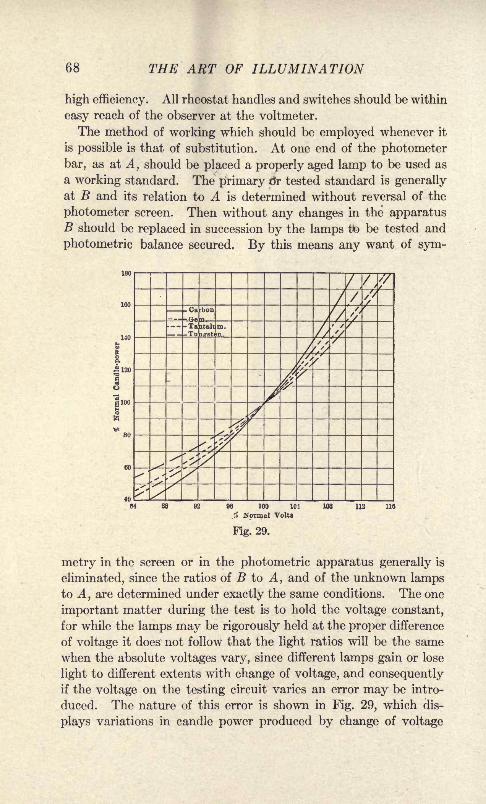
68 THE ART OF ILLUMINATION
high efficiency. All rheostat handles and switches should be within
easy reach of the observer at the voltmeter.
The method of working which should be employed whenever it
is possible is that of substitution. At one end of the photometer
bar, as at A, should be placed a properly aged lamp to be used as
a working standard. The primary rfr tested standard is generally
at B and its relation to A is determined without reversal of the
photometer screen. Then without any changes in the apparatusB should be replaced in succession by the lamps tto be tested and
photometric balance secured. By this means any want of sym-
$ Normal Volts
Fig. 29.
metry in the screen or in the photometric apparatus generally is
eliminated, since the ratios of B to A, and of the unknown lampsto A, are determined under exactly the same conditions. The one
important matter during the test is to hold the voltage constant,
for while the lamps may be rigorously held at the proper difference
of voltage it does~ not follow that the light ratios will be the same
when the absolute voltages vary, since different lamps gain or lose
light to different extents with change of voltage, and consequentlyif the voltage on the testing circuit varies an error may be intro-
duced. The nature of this error is shown in Fig. 29, which dis-
plays variations in candle power produced by change of voltage
STANDARDS OF LIGHT AND PHOTOMETRY 69
on ordinary carbon, G.E.M., tantalum, and tungsten lamps. It
will readily be seen that a variation in the general voltage of even
a half a volt is sufficient to produce measurable errors even when
the lamps are held rigorously at the required difference of voltage
for which they are supposed to be normal. It is easy to hold the
circuit voltage close enough for comparison of different carbon
lamps or of different metallic filament lamps, but in comparing a
carbon with a metallic filament lamp far greater care is necessary.
It is advisable, therefore, to have working standards of both kinds.
In comparing electric with other lamps, it is obvious that the volt-
age control must be of the most exact kind in order to avoid
material errors.
In the simplest form of comparison between two lights the com-
parison is made in a single azimuth only. Standard lamps have
commonly a certain marked direction for which they are standard-
ized, and to this direction they must be exactly oriented. It has
been rather common practice, inasmuch as incandescent lamps are
often rated by their mean horizontal candle power, to rotate the
lamps during measurements, and indeed some standards are madefor use during rotation. To this end a socket capable of revolu-
tion by a motor at three or four times a second is often provided
at one end of the photometer bar, as at B, and in this the
standards and the lamps to be tested are to be used; the workingstandard at A, being merely a light of constant value, remains at
rest.
In using these rotating sockets considerable care has to be
exercised to prevent any variable drop in voltage at the contacts,
and the tendency at present is to use the rotator less and less.
Most modern incandescents, especially metallic filament lamps,
give a nearly uniform horizontal distribution, and metallic fila-
ment lamps in particular can not be rapidly rotated without risk
of distorting the filament. Except in lamps with very peculiarly
placed filaments, three measurements taken 120 degrees apart
around the vertical axis will give the mean horizontal intensity
within the limits of ordinary commercial accuracy.
There are many devices for measuring the mean horizontal or
the mean spherical intensities of light sources, most of them rather
intricate and troublesome. Descriptions of these methods may be
found in modern treatises on photometry, but elaborate explana-
tion of them is out of place here. The one most satisfactory and
70 THE ART OF ILLUMINATION
convenient method of getting the mean spherical candle power,
which is, in modern practice, the only suitable method of com-
paring illuminants, is found in the sphere photometer commonlyknown as the Ulbricht sphere. The fundamental principle of this
is that if a luminous source be placed at the center of a hollow
sphere, the inner surface of which ,4s a good diffuse reflector, the
illumination at a peephole in the sphere shielded from direct rays
received from the source is directly proportional to the mean
spherical intensity of the source. A good account of the theoryof this sphere is given by Dr. Bloch in the Elektrotechnische Zeit-
schrift of Jan. 18, 1906, page 63. The sphere itself is commonlymade of heavy sheet metal, made up in two hemispheres separable
by handles, or in large spheres by fitting them on a sliding track.
The diameter depends on the purposes for which the photometeris intended; if for incandescent lamps, a meter is sufficient, while
for arc lamps it should be not less than two meters.
The interior of the sphere is usually painted dead white with
a barium-sulphate paint. The light at the peephole may be bal-
anced by any suitable photometer screen against a standard lamp,and the whole affair is calibrated by suspending in the sphere an
incandescent lamp of which the mean spherical candle power has
already been determined by the point-to-point method, that is,
by measuring the intensity in a considerable number of directions
uniformly spaced on the surface of an imaginary sphere surround-
ing the lamp. A description of this point-to-point method maybe found in the Journal of the Franklin Institute, September,
1885, Supplement; and a valuable paper on the precautions to be
taken in using the integrating sphere, by Sharp and Millar, is
to be found in the Transactions of the Illuminating Engineering
Society, Vol. Ill, page 502. For the testing of arc lamps, alwaysa difficult matter, the use of the integrating sphere is almost a
necessity, the only effective substitute for it being the integrating
photometer of Matthews, which, though giving satisfactory pre-
cision, is far more intricate. A description of this apparatus,
important on account of the numerous and valuable measure-
ments secured through its use, will be found in Transactions of
the American Institute of Electrical Engineers, Vol. XX, page 69.
From the standpoint of the illuminating engineer the most
interesting photometers are those intended for portable use, bywhich one is enabled to measure intensity of light sources in situ,
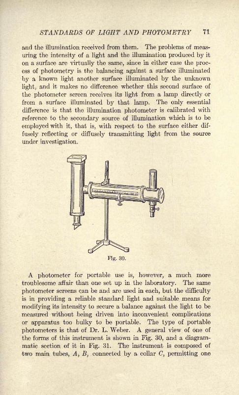
STANDARDS OF LIGHT AND PHOTOMETRY Tl
and the illumination received from them. The problems of meas-
uring the intensity of a light and the illumination produced by it
on a surface are virtually the same, since in either case the proc-
ess of photometry is the balancing against a surface illuminated
by a known light another surface illuminated by the unknown
light, and it makes no difference whether this second surface of
the photometer screen receives its light from a lamp directly or
from a surface illuminated by that lamp. The only essential
difference is that the illumination photometer is calibrated with
reference to the secondary source of illumination which is to be
employed with it, that is, with respect to the surface either dif-
fusely reflecting or diffusely transmitting light from the source
under investigation.
Fig. 30.
A photometer for portable use is, however, a much more
troublesome affair than one set up in the laboratory. The same
photometer screens can be and are used in each, but the difficulty
is in providing a reliable standard light and suitable means for
modifying its intensity to secure a balance against the light to be
measured without being driven into inconvenient complications
or apparatus too bulky to be portable. The type of portable
photometers is that of Dr. L. Weber. A general view of one of
the forms of this instrument is shown in Fig. 30, and a diagram-
matic section of it in Fig. 31. The instrument is composed of
two main tubes, A, B, connected by a collar C, permitting one
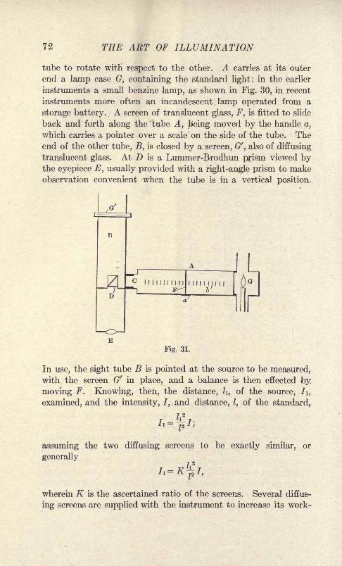
72 THE ART OF ILLUMINATION
tube to rotate witH respect to the other. A carries at its outer
end a lamp case G, containing the standard light: in the earlier
instruments a small benzine lamp, as shown in Fig. 30, in recent
instruments more often an incandescent lamp operated from a
storage battery. A screen of translucent glass, F, is fitted to slide
back and forth along the "tube A, being moved by the handle a,
which carries a pointer over a scale on the side of the tube. Theend of the other tube, B, is closed by a screen, G', also of diffusing
translucent glass. At D is a Lummer-Brodhun purism viewed bythe eyepiece E, usually provided with a right-angle prism to makeobservation convenient when the tube is in a vertical position.
Fig. 31.
In use, the sight tube B is pointed at the source to be measured,with the screen G' in place, and a balance is then effected bymoving F. Knowing, then, the distance, lit of the source, /i,
examined, and the intensity, /, . and distance, /, of the standard,
assuming the two diffusing screens to be exactly similar, or
generally
wherein K is the ascertained ratio of the screens. Several diffus-
ing screens are supplied with the instrument to increase its work-
STANDARDS OF LIGHT AND PHOTOMETRY 73
ing range, also a diffusing screen to act as a secondary source
of illumination by reflection, G' being in this case removed. In
practice it is found that the law of squares holds only very roughlyfor the positions of the movable screen F
tso that for careful work
the scale must be calibrated by experimental settings on lights of
known intensity and distance. When such calibration is properlymade in the laboratory, the instrument is capable of excellent
work. When used for determining illuminations directly, the
tube is left vertical and the light falls on the diffusing screen G f
,
or, this screen being removed, the sight tube is pointed at a white
diffusing surface set at an angle with it.
When properly calibrated for known illuminations falling on
either of these screens, the Weber photometer works well for
illumination measurements. In using it in this way the condition
of the diffusing surfaces requires very close attention, and the
calibration of this or any other instrument for a similar purpose
requires to be very carefully watched, for it cannot be predeter-
mined from the dimensions of the instrument and is subject to
change without notice from the effects of dirt.
A considerable number of portable photometers based on the
general scheme of the Weber instrument have been devised and
are in successful use. They differ chiefly in the means taken to
vary the standard light in securing a balance. A fixed diffusing
screen, the area of which is cut down by a cat's-eye; moving the
lamp itself, varying the current or voltage applied to the lamp,
are some of the methods employed, each of them in several different
instruments. They are all effective provided close watch is kepton the calibration of the instrument, and not otherwise. The
principal differences between these modified Weber photometersare differences of detail bearing on convenience of manipulation,
which in most cases leaves much to be desired.
As a class most portable photometers are only moderately
portable; very few of them can be operated without the coopera-
tion of two or more observers. Yet in skillful hands with proper
calibration they all are capable of giving fairly good precision,
good enough at least for the conditions of their use. It must not
be forgotten that portable photometers are not used to measure
lights operated as they would be in the laboratory. On the
contrary, they are commonly employed for the photometry of
arc lights, the intensity of which is subject to accidental and
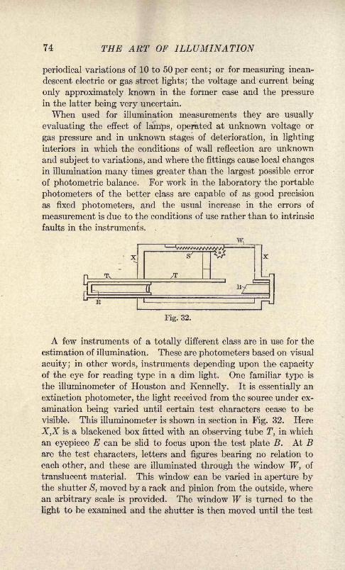
T4 THE ART OF ILLUMINATION
periodical variations of 10 to 50 per cent; or for measuring incan-
descent electric or gas street lights; the voltage and current being
only approximately known in the former case and the pressure
in the latter being very uncertain.
When used for illumination measurements they are usually
evaluating the effect of lamps, operated at unknown voltage or
gas pressure and in unknown stages of deterioration, in lighting
interiors in which the conditions of wall reflection are unknownand subject to variations, and where the fittings cause local changesin illumination many times greater than the largest possible error
of photometric balance. For work in the laboratory the portable
photometers of the better class are capable of as good precision
as fixed photometers, and the usual increase in the errors of
measurement is due to the conditions of use rather than to intrinsic
faults in the instruments.
Fig. 32.
A few instruments of a totally different class are in use for the
estimation of illumination. These are photometers based on visual
acuity; in other words, instruments depending upon the capacity
of the eye for reading type in a dim light. One familiar type is
the illuminometer of Houston and Kennelly. It is essentially an
extinction photometer, the light received from the source under ex-
amination being varied until certain test characters cease to be
visible. This illuminometer is shown in section in Fig. 32. Here
X,X is a blackened box fitted with an observing tube T, in which
an eyepiece E can be slid to focus upon the test plate B. At Bare the test characters, letters and figures bearing no relation to
each other, and these are illuminated through the window W, of
translucent material. This window can be varied in aperture bythe shutter S, moved by a rack and pinion from the outside, where
an arbitrary scale is provided. The window W is turned to the
light to be examined and the shutter is then moved until the test
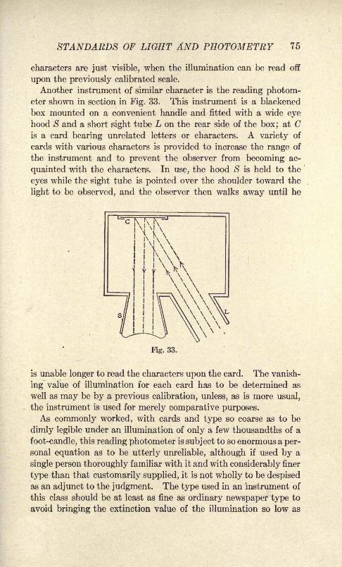
STANDARDS OF LIGHT AND PHOTOMETRY 75
characters are just visible, when the illumination can be read off
upon the previously calibrated scale.
Another instrument of similar character is the reading photom-eter shown in section in Fig. 33. This instrument is a blackened
box mounted on a convenient handle and fitted with a wide eyehood S and a short sight tube L on the rear side of the box; at Cis a card bearing unrelated letters or characters. A variety of
cards with various characters is provided to increase the range of
the instrument and to prevent the observer from becoming ac-
quainted with the characters. In use, the hood S is held to the
eyes while the sight tube is pointed over the shoulder toward the
light to be observed, and the observer then walks away until he
Kg. 33.
is unable longer to read the characters upon the card. The vanish-
ing value of illumination for each card has to be determined as
well as may be by a previous calibration, unless;as is more usual,
the instrument is used for merely comparative purposes.
As commonly worked, with cards and type so coarse as to be
dimly legible under an illumination of only a few thousandths of a
foot-candle, this reading photometer is subject to so enormous a per-
sonal equation as to be utterly unreliable, although if used by a
single person thoroughly familiar with it and with considerably finer
type than that customarily supplied, it is not wholly to be despised
as an adjunct to the judgment. The type used in an instrument of
this class should be at least as fine as ordinary newspaper type to
avoid bringing the extinction value of the illumination so low as
76 THE ART OF ILLUMINATION
to compel the eye to work under conditions that make the result
depend almost entirely on the state of adaptation of the eye and
the imagination of the observer.
The same criticisms hold to a somewhat less extent for the illu-
minometer previously described and for all other instruments that
depend on reading characters undej* greatly reduced illumination.
Such instruments when carefully used within moderate range of
intensities are sometimes very convenient and reasonably con-
sistent, but the personal equation involved in their use is too large
and too variable to render them generally trustworthy.
CHAPTER V.
THE MATERIALS OF ILLUMINATION ILLUMINANTS OFCOMBUSTION.
AT root, nearly all practical illuminants are composed of solid
particles, usually of carbon, brought to vivid incandescence. Wemay, however, divide them into two broad classes, according as
the incandescent particles are heated by their own combustion or
by extraneous means. The first class, therefore, may be regardedas composed of luminous flames, such as candles, lamps, ordinary
gas flames, and the like; while the second consists of illuminants
in which a solid is rendered incandescent, it is true, but not bymeans of its own combustion.
The second class thus consists of such illuminants as mantle
gas burners, electric incandescent lamps, and the ordinary elec-
tric arcs, which really give their light in virtue of the intense
heating of the tips of the carbons by the arc, which in itself is
relatively of feeble luminosity.
Illumination based on incandescent gas, phosphorescence, and
the like is in an early stage of development, and while it is in
this direction that we must look for increased efficienc}^ incandes-
cent illuminants are still the main reliance in artificial lighting.
To the examination of flame illuminants, then, we must first
address ourselves.
They are interesting as being the earliest sources of artificial
light, and, while usually of much less luminous efficiency than the
second class referred to, still hold their own in point of conven-
ience, portability, and ease of extreme subdivision.
We have no means of knowing the earliest sources of artificial
light as distinguished from heat. The torch of fat wood was a
natural development from the fire on the hearth. But even in
Homeric times there is clear evidence of fire in braziers for the
purpose of lighting, and there is frequent mention of torches.
The rope link saturated with pitch or bitumen was a natural
growth from the pine-wood torch, and was later elaborated into
the candle.
77
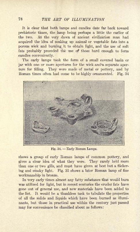
78 THE ART OF ILLUMINATION
It is clear that both lamps and candles date far back toward
prehistoric times, the lamp being perhaps a little the earlier of
the two. At the very dawn of ancient civilization man had
acquired the idea of soaking up animal or vegetable fats into a
porous wick and burning it to obtain light, and the use of soft
fats probably preceded the use of those hard enough to form
candles conveniently.
The early lamps took the form of a small covered basin or
jar with one or more apertures for the wick and*a separate aper-
ture for filling. They were made of metal or pottery, and byRoman times often had come to be highly ornamented. Fig. 34
Fig. 34. Early Roman Lamps.
shows a group of early Roman lamps of common pottery, and
gives a clear idea of what they were. They rarely held more
than one or two gills, and must have given at best but a flicker-
ing and smoky light. Fig. 35 shows a later Roman lamp of fine
workmanship in bronze.
In very early times almost any fatty substance that would burn
was utilized for light, but in recent centuries the cruder fats have
gone out of general use, and new materials have been added to
the list. It would be a thankless task to tabulate the properties
of all the solids and liquids which have been burned as illumi-
nants, but those in practical use within the century just passed
may for convenience be classified about as follows:
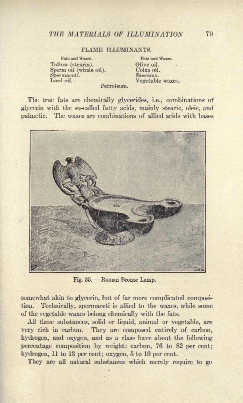
THE MATERIALS OF ILLUMINATION 79
FLAME ILLUMINANTS.Fats and Waxes.
Tallow (stearin).
Sperm oil (whale oil).
Spermaceti.Lard oil.
Petroleum.
Fats and Waxes.
Olive oil.
Colza oil.
Beeswax.Vegetable waxes.
The true fats are chemically glycerides, i.e., combinations of
glycerin with the so-called fatty acids, mainly stearic, oleic, and
palmetic. The waxes are combinations of allied acids with bases
Fig. 35. Roman Bronze Lamp.
somewhat akin to glycerin, but of far more complicated composi-tion. Technically, spermaceti is allied to the waxes, while someof the vegetable waxes belong chemically with the fats.
All these substances, solid or liquid, animal or vegetable, are
very rich in carbon. They are composed entirely of carbon,
hydrogen, and oxygen, and as a class have about the following
percentage composition by weight: carbon, 76 to 82 per cent;
hydrogen, 11 to 13 per cent; oxygen, 5 to 10 per cent.
They are all natural substances which merely require to go
80 THE ART OF ILLUMINATION
through a process of separation from foreign matter, and some-
times bleaching, to be rendered fit for use.
An exception may be made in favor of"stearin," which is
obtained by breaking up chemically the glycerides of animal
fats and separating the fatty acids before mentioned from the
glycerin. The oleic acid, in whiqfe liquid fats are rich, is also
gotten rid of in the commercial preparation of stearin in order
to raise the melting point of the product.
In a separate class stand the artificial "burning fluids" used
considerably toward the middle of the nineteenth century. As
they are entirely out of use, they scarcely deserve particular
classification. Their base was usually a mixture of wood alco-
hol and turpentine in varying proportions. From its great
volatility such a compound acted almost like a gas generator;
the flame given off was quite steady and brilliant, with muchless tendency to smoke than the natural oils, but the
"burning
fluids" as a class were outrageously dangerous to use, and for-
tunately were driven out by the advent of petroleum and its
products.
Petroleum, which occurs in one form or another at many places
on the earth's surface, has been known for many centuries, although
not in large amounts until recently. Bitumen is often mentioned
by Herodotus and other early writers, and in Pliny's time mineral
oil from Agrigentum was even used in lamps.
But the actual use of petroleum products as illuminants on a
large scale dates from a little prior to 1860, when the American
and Russian fields were developed with a common impulse. Crude
petroleum is an evil-smelling liquid, varying in color from very
pale yellow to almost black, and in specific gravity from 0.77 to
1.00, ranging commonly from 0.80 to 0.90.
Chemically it is composed essentially of carbon and hydrogen,
its average percentage composition being about as follows : carbon,
85 per cent; hydrogen, 15 per cent. It is composed in the main
of a mixture of the so-called paraffin hydrocarbons, having the
general formula CnH2n+2, and the members of this series found
in ordinary American petroleum vary from methane (CH4) to
pentadecane (Ci5 H32 ), and beyond to solid hydrocarbons still more
complicated. Petroleum from the Texas and neighboring fields
and from the Russian fields is generally less rich in the paraffin
series and contains members of other hydrocarbon series in consid-
THE MATERIALS OF ILLUMINATION 81
erable amounts, yielding interesting and valuable products, but
less of high-grade illuminating oils.
To fit petroleum for use as an illuminant, these componentparts have to be sorted out, so that the oil for burning shall
neither be so volatile as to have a dangerously low flashing pointnor so stable as not to burn clearly and freely.
This sorting is done by fractional distillation. The following
table gives a general idea of the products arranged according to
their densities :
Substance.
( Cymogene,Petroleum ether. \ Rhigoline,
I Gasoline,
C Benzine naphtha,Petroleum spirit
-jNaphtha,
I Benzine,
( Kerosene of vari-
( ous grades,
Use.
Kerosene .
Oils.
Solids,
( Lubricating oils
( of various grades
fVaseline,
\Paraffin,
Density.
0.59
0.63
0.65
0.68
0.71
0.74
i- fO-781j
to ^Illumination.
10.81 J
fO.871-( to } Lubrication.
to.
Small, as solvents.
Gas, explosion engines.
Gas lamps, engines.
Cleaning, engines.
Varnish, etc.
,93jEmollient.
Candles, insulation,
waterproofing, etc.
" Petroleum ether" and "petroleum spirit" find little direct
use in illumination, for they are so inflammable as to be highly
dangerous, and form violently explosive mixtures with air at
ordinary temperatures.
Kerosene should be colorless, without a very penetrating odor,which indicates too great volatility, and should not give off in-
flammable vapor below a temperature of 120 F., or, better still,
below 140 F. to 150 F. Oils of the latter grades are prettysafe to use, and are always to be preferred to those more volatile.
The yield of kerosene from crude oil varies from place to place,
but with good American oil runs as high as 50 to 75 per cent.
Paraffin is sometimes used unmixed for making candles, but
is preferably mixed with other substances, like stearin, to giveit a higher melting point.
Having thus casually looked over the materials burned in candles
and lamps, the results may properly be considered.
Candles. These are made usually of stearin, paraffin, wax, or
mixtures of the first two substances. They are molded hot in
82 THE ART OF ILLUMINATION
automatic machines, and, as usually supplied in this country,
are made in weights of 4, 6, and 12 to the pound. Spermaceticandles are also made, but are little used except for a standard
of light. The old English standard candle is of spermaceti, weigh-
ing one-sixth of a pound and burning at the rate of 120 grains per
hour.
Commercial candles give approximately 1 candle power, some-
times rather more, and burn generally from 110 to 130 grains per
hour. As candles average from 15 to 18 cents per pound, the cost
of 1 candle hour from this source amounts to about 0.25 cent to
0.30 cent. This is obviously relatively very expensive, although it
must not be forgotten that candles subdivide the light so effectively
that for many purposes 16 lighted candles are very much more
effective in producing illumination than a gas flame or incandescent
lamp of 16 candle power.The present function of candles in illumination is confined to
their use as portable lights, for which, on the score of safety, theyare far preferable to kerosene lamps, and to cases in which, for
artistic purposes, "thorough subdivision of light is desirable. Where
only a small amount of general light is needed, candles give a
most pleasing effect, and are, moreover, cleanly and odorless.
In efficiency candles leave much to be desired. For, taking the
ordinary stearin candle as a type, it requires in dynamical units
the equivalent of about 90 watts per candle power, consumes per
hour the oxygen contained in 4.5 cubic feet of air, and gives off
about 0.6 cubic foot of carbonic acid gas. In these respects the
candle is inferior to the ordinary lamp, and still more inferior to
gas or electric lights. Nevertheless, it is oftentimes a most con-
venient illummant.
Oil Lamps. Oils other than kerosene are used in this country
only to a very slight extent, the latter having driven out its com-
petitors. Sperm oil and, abroad, colza oil (obtained from rapeseed)
are valued as safe and reliable- illuminants for lighthouses, and in
some parts of the Continent olive oil is used in lamps, as it has been
from time immemorial.
Here, kerosene is still the general illuminant outside of the cities
and larger towns. It has the merits of being cheap (on the
average 12 cents to 15 cents per gallon in recent years), safe, if
of the best quality, and of giving, when properly burned, a very
steady and brilliant light.
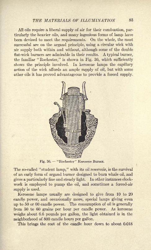
THE MATERIALS OF ILLUMINATION 83
All oils require a liberal supply of air for their combustion, par-
ticularly the heavier oils, and many ingenious forms of lamp have
been devised to meet the requirements. On the whole, the most
successful are on the argand principle, using a circular wick with
air supply both within and without, although some of the double
flat-wick burners are admirable in their results. A typical burner,
the familiar"Rochester," is shown in Fig. 36, which sufficiently
shows the principle involved. In kerosene lamps the capillary
action of the wick affords an ample supply of oil, but with some
other oils it has proved advantageous to provide a forced supply.
Fig. 36. "Rochester" Kerosene Burner.
The so-called"student lamp," with its oil reservoir, is the survival
of an early form of argand burner designed to burn whale oil, and
gives a particularly fine and steady light. In other instances clock-
work is employed to pump the oil, and sometimes a forced-air
supply is used.
Kerosene lamps usually are designed to give from 10 to 20
candle power, and occasionally more, special lamps giving even
up to 50 or 60 candle power. The consumption of oil is generally
from 50 to 60 grains per hour per candle power. As kerosene
weighs about 6.6 pounds per gallon, the light obtained is in the
neighborhood of 800 candle hours per gallon.
This brings the cost of the candle hour down to about 0.018
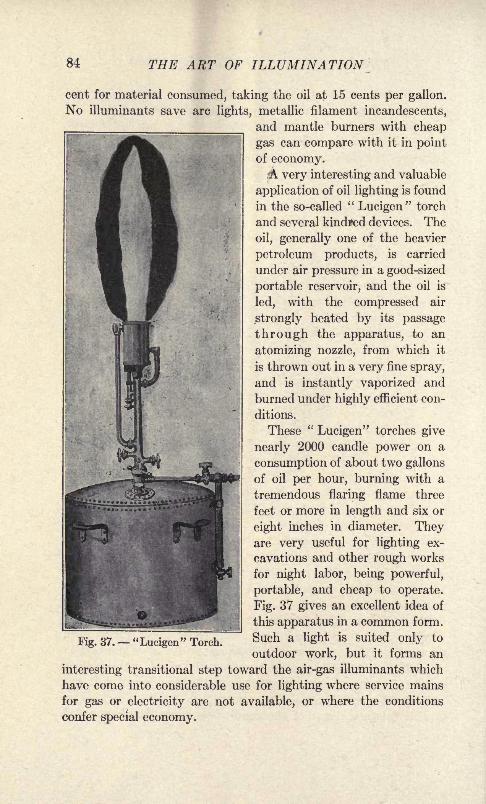
84 THE ART OF ILLUMINATION
cent for material consumed, taking the oil at 15 cents per gallon.
No illuminants save arc lights, metallic filament incandescents,
_ and mantle burners with cheap
gas can compare with it in point
of economy.A very interesting and valuable
application of oil lighting is found
in the so-called"Lucigen" torch
and several kindled devices. The
oil, generally one of the heavier
petroleum products, is carried
under air pressure in a good-sized
portable reservoir, and the oil is
led, with the compressed air
strongly heated by its passage
through the apparatus, to an
atomizing nozzle, from which it
is thrown out in a very fine spray,
and is instantly vaporized and
burned under highly efficient con-
ditions.
These "Lucigen" torches give
nearly 2000 candle power on a
consumption of about two gallons
of oil per hour, burning with a
tremendous flaring flame three
feet or more in length and six or
eight inches in diameter. Theyare very useful for lighting ex-
cavations and other rough works
for night labor, being powerful,
portable, and cheap to operate.
Fig. 37 gives an excellent idea of
this apparatus in a common form.
Such a light is suited only to
outdoor work, but it forms anKg. 37. "Lucigen" Torch.
interesting transitional step toward the air-gas illuminants which
have come into considerable use for lighting wiiere service mains
for gas or electricity are not available, or where the conditions
confer special economy.
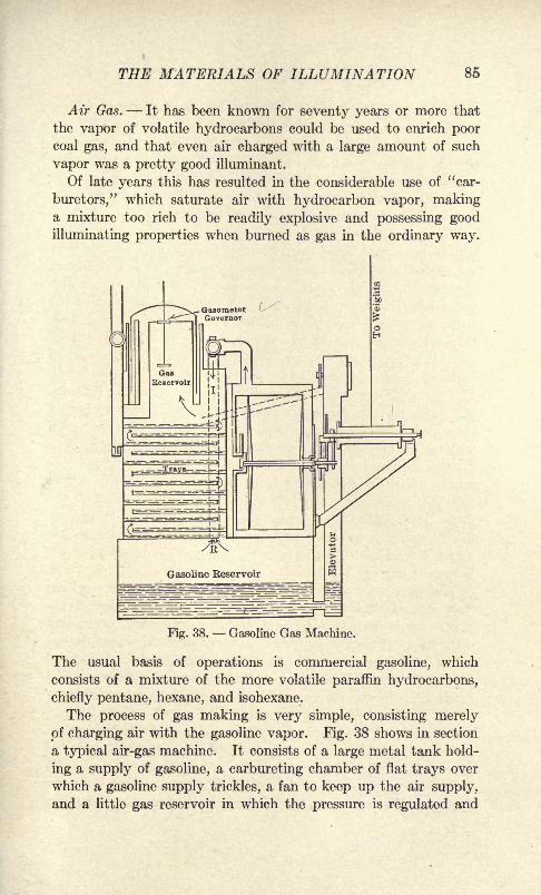
THE MATERIALS OF ILLUMINATION 85
Air Gas. It has been known for seventy years or more that
the vapor of volatile hydrocarbons could be used to enrich poorcoal gas, and that even air charged with a large amount of such
vapor was a pretty good illuminant.
Of late years this has resulted in the considerable use of"car-
buretors/7 which saturate air with hydrocarbon vapor, making
a mixture too rich to be readily explosive and possessing good
illuminating properties when burned as gas in the ordinary way.
Fig. 38. Gasoline Gas Machine.
The usual basis of operations is commercial gasoline, which
consists of a mixture of the more volatile paraffin hydrocarbons,
chiefly pentane, hexane, and isohexane.
The process of gas making is very simple, consisting merelyof charging air with the gasoline vapor. Fig. 38 shows in section
a typical air-gas machine. It consists of a large metal tank hold-
ing a supply of gasoline, a carbureting chamber of flat trays over
which a gasoline supply trickles, a fan to keep up the air supply,
and a little gas reservoir in which the pressure is regulated and
86 THE ART OF ILLUMINATION
from which the gas is piped. The fan is usually driven by heavy
weights, wound up at suitable intervals.
The whole gas machine is usually put in an underground
chamber, both for security from fire and to aid in maintaining
a steady temperature. About six gallons of gasoline are required
per 1000 cubic feet of air, and the result is a gas of very fair
illuminating power, rather better than ordinary city gas.
The cost of this air gas is very moderate, but on account of the
cost of plant and some extra labor, it is materially greater than
the cost of direct lighting by kerosene lamps. It is a means of
lighting very useful for country houses and other places far from
gas or electric supply companies. The principal difficulty is the
variation of the richness of the mixture with the temperature, owingto change in the volatility of the gasoline, a fault which is very
difficult to overcome. At low temperatures there is a tendency to
carburet insufficiently and to condense liquid in the cold pipes.
The gas obtained from these machines is burned in the ordinary
way, although burners especially adapted for it are extensively
employed. In recent years such gas has been considerably used
with mantle burners, obtaining thus a very economical result. The
air gas just described is too rich in gasoline vapor to be an explosive
mixture, the limits of danger being between 2 and 5 per cent of
gasoline vapor, and the mixture described being well above the
upper limit. Abroad air gas so lean as to be below the lower limit
of danger has come into use, carrying say 1.5 per cent gasoline
vapor instead of 10 to 15 per cent. Such gas is fit only for use
in mantle burners, but is cheap and safe.
Coal Gas. In commercial use for nearly a century, coal gas
was, until about twenty-five years ago, the chief practical illumi-
nant. Little need here be said of its manufacture, which is a
department of technology quite by itself, other than that the gasis obtained from the destructive distillation of rich coals inclosed
in retorts, from which it is drawn through purifying apparatus and
received in the great gasometers familiar on the outskirts of every
city.
The yield of gas is about 10,000 cubic feet per ton of coal of
good quality. The resulting gas consists mainly of hydrogen and
of methane (CH4 ), with small amounts of other gases, the composi-tion varying very widely in details while preserving the same
general characteristics. A typical analysis of standard coal gas
THE MATERIALS OF ILLUMINATION 87
giving 16 to 17 candle power for a burner consuming 5 cubic feet
per hour would be about as follows:
Hydrogen 53.0Paraffin hydrocarbons 33 .0
Other hydrocarbons 3.5Carbon monoxide 5.5Carbon dioxide 0.6
Nitrogen 4.2
Oxygen 0.2
100.0
Ammonia compounds, carbon dioxide, and sulphur compoundsare the principal impurities which have to be removed. Traces of
these and of moisture are regularly found in commercial gas. Sul-
phur dioxide (S02 ) is the most persistent impurity and perhaps the
most objectionable.
In point of fact, at the present time but a small proportion of
the illuminating gas used in this country is unmixed coal gas, such
as might show the analysis just given. Most of it is water gas,
or a mixture of coal gas and water gas. Water gas is produced
by the simple process of passing steam through a mass of incandes-
cent coal or coke, and thus breaking up the steam into hydrogenand oxygen, which latter unites with the carbon of the coal, form-
ing carbon monoxide.
At moderate temperatures considerable carbon dioxide would be
formed, but, as this is worse than useless for burning purposes, the
heat is always carried high enough to insure the formation of the
monoxide. The hypothetical chemical equation is:
H2O + C = CO + H2 .
The reaction is never clean in so complete a sense as this, some
C02 always being formed. This water gas as thus formed is useless
as an illuminant, and requires to be enriched by admixture of light-
producing hydrocarbons carbureted, in other words. This is
done by treating it to a spray of petroleum in some form, and at
once passing the mixture through a superheater, which breaks downthe heavier hydrocarbons and renders the mixture stable.
There are many modifications of this system worked on the
same general lines. The enriching is carried to the extent neces-
sary to meet the legal requirements, usually producing gas of 15
to 20 candle power for a 5-foot jet. A typical analysis of the
water gas after enriching would show about the following byvolume :
88 THE ART OF ILLUMINATION
Hydrogen 34.0Methane 15.0
Enriching hydrocarbons 12.5Carbon monoxide 33 .
Oxygen, nitrogen, CO2 ,etc 5.5
100.0
The latter part of the enriching process, i.e., superheating and
breaking up the heavy hydrocarbons while in the form of vapor,
is substantially that used in making" Pintsch and allied varieties
of oil gas, so that commercial water gas may be regarded as a
mixture of water gas and oil gas. The "cracking" of heavy oils
by heat has proved a convenient means of increasing the avail-
able amount of lighter hydrocarbons from petroleum. The lightest
gaseous products are sometimes separated and compressed to lique-
faction in steel cylinders, thus furnishing an easily transportable
and convenient source of gas for light and heat. Such is the
so-called "Blau-gas" and some analogous products in commercial
use to a limited extent,
Water gas, when properly enriched, is fully the equivalent of
coal gas for illuminating purposes. The main difference between
them is the very large proportion of carbon monoxide in the water
gas, which adds greatly to the danger of leaks.
For carbon monoxide is an active poison, not killing merely
by asphyxia, but by a well-defined toxic action peculiar to itself.
Hence persons overcome by water gas very frequently die under
circumstances which, if coal gas were concerned, would result
only in temporary insensibility. As the enriched water gas is
cheaper than coal gas, however, the gas companies, maintaining,
with some justice, that gas is not furnished for breathing pur-
poses, supply it unhesitatingly sometimes openly, sometimes
without advertising the fact.
Very commonly so-called coal gases contain enriched water gas
to bring up their illuminating power. In these cases the carbon
monoxide is in much less proportion, perhaps only 10 to 15 per
cent.
It is often stated that water gas is doubly dangerous from
its lack of odor. The unenriched gas is practically odorless, but
when enriched the odor, while less penetrating than that of coal
gas, is sufficiently distinctive to make a leak easily perceptible.
Gas burners for ordinary illuminating gas are of three general
types: flat flame, argand, and regenerative. The first named is
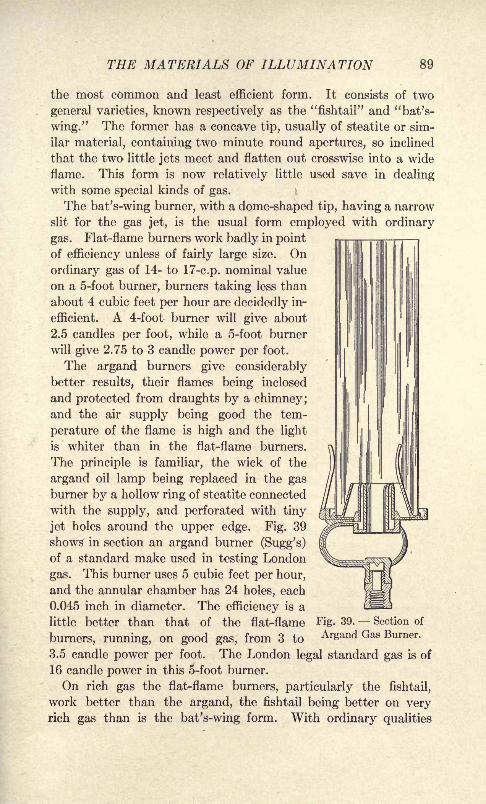
THE MATERIALS OF ILLUMINATION
the most common and least efficient form. It consists of two
general varieties, known respectively as the "fishtail" and "bat's-
wing." The former has a concave tip, usually of steatite or sim-
ilar material, containing two minute round apertures, so inclined
that the two little jets meet and flatten out crosswise into a wide
flame. This form is now relatively little used save in dealing
with some special kinds of gas.
The bat's-wing burner, with a dome-shaped tip, having a narrow
slit for the gas jet, is the usual form employed with ordinary
gas. Flat-flame burners work badly in point
of efficiency unless of fairly large size. On
ordinary gas of 14- to 17-c.p. nominal value
on a 5-foot burner, burners taking less than
about 4 cubic feet per hour are decidedly in-
efficient. A 4-foot burner will give about
2.5 candles per foot, while a 5-foot burner
will give 2.75 to 3 candle power per foot.
The argand burners give considerably
better results, their flames being inclosed
and protected from draughts by a chimney;and the air supply being good the tem-
perature of the flame is high and the light
is whiter than in the flat-flame burners.
The principle is familiar, the wick of the
argand oil lamp being replaced in the gas
burner by a hollow ring of steatite connected
with the supply, and perforated with tiny
jet holes around the upper edge. Fig. 39
shows in section an argand burner (Sugg's)
of a standard make used in testing London
gas. This burner uses 5 cubic feet per hour,
and the annular chamber has 24 holes, each
0.045 inch in diameter. The efficiency is a
little better than that of the flat-flame
burners, running, on good gas, from 3 to
3.5 candle power per foot. The London legal standard gas is of
16 candle power in this 5-foot burner.
On rich gas the flat-flame burners, particularly the fishtail,
work better than the argand, the fishtail being better on veryrich gas than is the bat's-wing form. With ordinary qualities
Fig. 39. Section of
Argand Gas Burner.
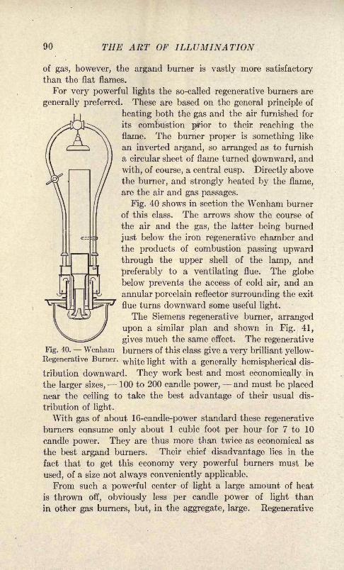
90 THE ART OF ILLUMINATION
of gas, however, the argand burner is vastly more satisfactory
than the flat flames.
For very powerful lights the so-called regenerative burners are
generally preferred. These are based on the general principle of
heating both the gas and the air furnished for
its combustion prior to their, reaching the
flame. The burner proper is something like
an inverted argand, so arranged as to furnish
a circular sheet of flame turned downward, and
with, of course, a central cusp. Directly above
the burner, and strongly heated by the flame,
are the air and gas passages.
Fig. 40 shows in section the Wenham burner
of this class. The arrows show the course of
the air and the gas, the latter being burned
just below the iron regenerative chamber and
the products of combustion passing upward
through the upper shell of the lamp, and
preferably to a ventilating flue. The globe
below prevents the access of cold air, and an
annular porcelain reflector surrounding the exit
flue turns downward some useful light.
The Siemens regenerative burner, arranged
upon a similar plan and shown in Fig. 41,
gives much the same effect. The regenerative
Fig. 40. Wenham burners of this class give a very brilliant yellow-Regenerative Burner. white light with a generaiiy hemispherical dis-
tribution downward. They work best and most economically in
the larger sizes, 100 to 200 candle power, and must be placed
near the ceiling to take the best advantage of their usual dis-
tribution of light.
With gas of about 16-candle-power standard these regenerative
burners consume only about 1 cubic foot per hour for 7 to 10
candle power. They are thus more than twice as economical as
the best argand burners. Their chief disadvantage lies in the
fact that to get this economy very powerful burners must be
used, of a size not always conveniently applicable.
From such a powerful center of light a large amount of heat
is thrown off, obviously less per candle power of light than
in other gas burners, but, in the aggregate, large. Regenerative
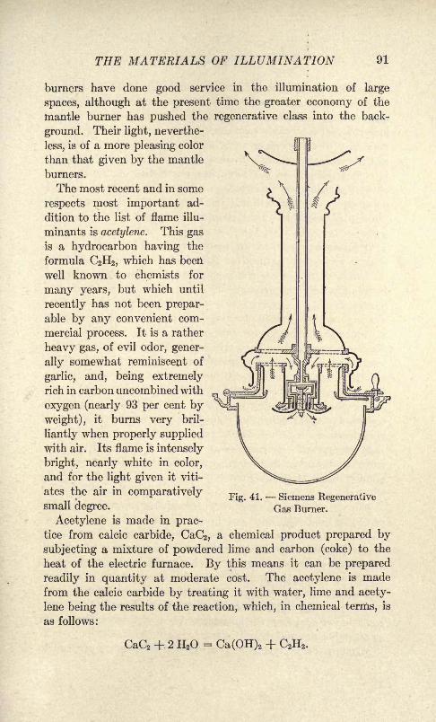
THE MATERIALS OF ILLUMINATION 91
burners have done good service in the illumination of large
spaces, although at the present time the greater economy of the
mantle burner has pushed the regenerative class into the back-
ground. Their light, neverthe-
less, is of a more pleasing color
than that given by the mantle
burners.
The most recent and in some
respects most important ad-
dition to the list of flame illu-
minants is acetylene. This gas
is a hydrocarbon having the
formula C2H2 ,which has been
well known to chemists for
many years, but which until
recently has not been prepar-
able by any convenient com-
mercial process. It is a rather
heavy gas, of evil odor, gener-
ally somewhat reminiscent of
garlic, and, being extremely
rich in carbon uncombined with
oxygen (nearly 93 per cent byweight), it burns very bril-
liantly when properly supplied
with air. Its flame is intensely
bright, nearly white in color,
and for the light given it viti-
ates the air in comparativelysmall degree.
Acetylene is made in prac-
tice from calcic carbide, CaC2 ,a chemical product prepared by
subjecting a mixture of powdered lime and carbon (coke) to the
heat of the electric furnace. By this means it can be prepared
readily in quantity at moderate cost. The acetylene is made
from the calcic carbide by treating it with water, lime and acety-
lene being the results of the reaction, which, in chemical terms, is
as follows:
Fig. 41. Siemens RegenerativeGas Burner.
CaC2 + 2 H2O = Ca(OH)2 + C2H2 .
92 THE ART OF ILLUMINATION
Commercial calcic carbide is far from being chemically pure, so
that the acetylene prepared from it contains various impurities,
and is neither in quantity nor quality just what the equation would
indicate. The carbide is extremely hygroscopic, and hence not
very easy to transport or keep, and the upshot of this propertyand the inherent impurities is that the practical yield of acetylene
is only about 4.5 to 5.0 cubic feet per pound of carbide, 4.75
cubic feet being an extremely good average unless the work is
on a very large scale, though 4.5 cubic feet is tine more usual
yield. In theory the yield should be nearly 5.5 cubic feet per
pound.The gaseous impurities are quite varied and by no means uni-
form in amount or nature, but the most objectionable ones maybe removed by passing the gas in fine bubbles through water.
If the gas is being prepared on a large scale it can readily be
purified.
Acetylene has the disadvantage of being somewhat unstable.
It forms direct compounds with certain metals, notably copper,
these compounds being known as acetylides, and being themselves
so unstable as to be easily explosive. Acetylene should be there-
fore kept out of contact with copper in storage, and even in
fixtures.
The gas itself is easily dissociated with evolution of heat into
carbon and hydrogen, and hence may be inherently explosive
under certain conditions, fortunately not common.
At atmospheric pressure, or at such small increased pressures
as are employed in the commercial distribution of gas, acetylene,
unmixed with air, cannot be exploded by any means ordinarily
at hand.
Above a pressure of about two atmospheres acetylene is readily
explosive from high heat and from a spark or flame, and grows
steadily in explosive violence as the initial pressure rises, until
when liquefied it detonates with tremendous power if ignited.
At ordinary temperatures it can be liquefied at a pressure of
about 80 atmospheres, and it has been proposed to transport
and store it in liquid form. But, although even when liquefied
it will not explode from mechanical shock alone, it is in this
condition an explosive of the same order of violence as guncotton
or nitroglycerin, and should be treated as such.
Mixtures of acetylene and air explode violently, just as do
THE MATERIALS OF ILLUMINATION 93
mixtures of illuminating gas and air. The former begin to exploderather than merely burn, when the mixture contains about one
volume of acetylene to three of air, detonate very violently with
about nine volumes of air, and cease to explode with about twentyvolumes of air.
Ordinary coal gas begins to explode when mixed with three
volumes of air, reaches a maximum of violence with about five
to six volumes, and ceases to explode with eleven volumes. Of
the two gases, the acetylene is rather the more violently explosive
when mixed with air, and it becomes explosive while the mixture
is much leaner. The difference is not of great practical moment,however, except as acetylene generators, being easily operated,
,are likely to get into unskillful hands. This fact has already
resulted in many disastrous explosions.
As regards its poisonous properties, acetylene seems to be some-
what less dangerous than coal gas and very much less dangerousthan water gas. Properly speaking, acetylene is but very feebly
poisonous when pure, and has such an outrageous smell when
slightly impure that the slightest leak attracts attention. Some
early experiments showed highly toxic properties, but these have
not been fully confirmed, and may have been due to impurities
in the gas possibly to phosphine, which is a violent poison.
The calcic carbide from which the acetylene is prepared is so
hygroscopic and gives off the gas so freely that it has to be stored
with great care on account of possible danger from fire. Fire under-
writers are generally united in forbidding entirely the use or storage
of liquid or compressed acetylene, or the storage of any but trivial
amounts of calcic carbide (a few pounds) except in detached fire-
proof buildings.
Acetylene is, when properly burned, a magnificent illuminant.
It will not work in ordinary burners, for unless very liberally sup-
plied with air it is so rich in carbon as to burn with a smoky flame
and a deposit of soot. It must actually be mixed with air at the
burner in order to be properly consumed. When so utilized its
illuminating power is very great. The various experiments are not
closely concordant, but they unite in indicating an illuminating
power of 35 to 50 candle hours per cubic foot, according to the
capacity of the burner, the larger burners, as usual, working the
more economically.
This means that the acetylene has nearly fifteen times the
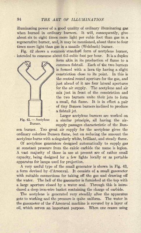
94 THE ART OF ILLUMINATION
illuminating power of a good quality of ordinary illuminating gas
when burned in ordinary burners. It will, consequently, give
about six to eight times more light per cubic foot than gas in a
regenerative burner, and, it may be mentioned, about three to four
times more light than gas in a mantle (Welsbach) burner.
Fig. 42 shows a common standard form of acetylene burner,
intended to consume about 0.5 cubic foot per hour. It is a duplexform akin in its production of flame to a
common fishtail. Each of the two burners
is formed with a lava tip having a slight
constriction close to its point. In this is
the central round aperture for the gas, and
just ahead of it are four lateral apertures
for the air supply. The acetylene and air
mix just in front of the constriction and
the two burners unite their jets to form
a small, flat flame. It is in effect a pair
of tiny Bunsen burners inclined to producea fishtail jet.
Larger acetylene burners are worked on
Fig. 42. Acetylene a similar principle, all having the air-
supply passages characteristic of the Bun-
sen burner. Too great air supply for the acetylene gives the
ordinary colorless Bunsen flame, but on reducing the amount the
acetylene burns with a singularly white, brilliant, and steady flame.
Of acetylene generators designed automatically to supply gas
at constant pressure from the calcic carbide the name is legion.
A vast majority of those in use at present are of rather small
capacity, being designed for a few lights locally or as portable
apparatus for lamps used for projection.
A very useful type of the small generator is shown in Fig. 43,
a form devised by d'Arsonval. It consists of a small gasometerwith suitable connections for taking off the gas and drawing off
the water. The bell of the gasometer is furnished at the top with
a large aperture closed by a water seal. Through this is intro-
duced a deep iron-wire basket containing the charge of carbide.
The acetylene is generated very steadily after the apparatus
gets to working and the pressure is quite uniform. The water in
the gasometer of the d'Arsonval machine is covered by a layer of
oil, which serves an important purpose. When one ceases using

THE MATERIALS OF ILLUMINATION 95
the gas the bell rises, and as the carbide basket rises out of the
water the oil coats it and displaces the water, checking further
evolution of gas. The oil also checks
evaporation, so that there is no slow evo-
lution of gas from the absorption of
aqueous vapor.
Acetylene generators on a larger scale
are operated on much the same principle,
although the generating and regulating
parts of the apparatus are commonly sepa-
rated instead of being united as in Fig.
43, and there is often means for washingthe gas. The principle adopted in the
larger generators is uniformly to feed the
calcic carbide in small quantities in a
large excess of water, thereby avoiding
the overheating which would follow were
water dropped on an excess of carbide.
Fig. 44 shows in section a typical
acetylene apparatus for medium-sized
plants such as used for house lighting.
It consists of a generator tank, a carbide
holder from which the granulated car-
bide is automatically fed in small quan-
tities, a regulating gasometer, and the FiS- 43 -~ Sma11 Acetylene
. . , i t Generator,necessary piping, valves, and water seal
to facilitate and insure the safe and convenient handling of the
output. Such apparatus runs with very little attention and is
largely used in country houses and hotels out of reach of gas and
electric supply, and even as a matter of economy where the gas
supply is indifferent in quality or too high in price.
Isolated plants of capacity as high as 5000 burners have been
installed for service in large hotels. Occasionally a fairly large
plant is found in village lighting, but for the most part the equip-
ments as generally found are for a few score or hundred burners.
These acetylene generators as now furnished are very nearly auto-
matic in their action, but at times require a little intelligent care to
keep them in first-class working order, as they are not yet entirely
foolproof, so that while the labor and upkeep cost is small it is not
negligible.
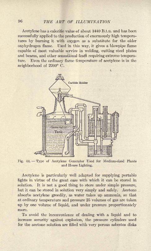
96 THE ART OF ILLUMINATION
Acetylene has a calorific value of about 1440 B.t.u. and has been
successfully applied to the production of enormously high tempera-tures by burning it with oxygen as a substitute for the older
oxyhydrogen flame. Used in this way, it gives a blowpipe flame
capable of most valuable service in welding, cutting steel plates
and beams, and other sensational featfe requiring extreme tempera-ture. Even the ordinary flame temperature of acetylene is in the
neighborhood of 2200 C.
Carbide Holder
Fig. 44. Type of Acetylene Generator Used for Medium-sized Plants
and House Lighting.
Acetylene is particularly well adapted for supplying portable
lights in virtue of the great ease with which it can be stored in
solution. It is not a good thing to store under simple pressure,
but it can be stored in solution very simply and safely. Acetone
absorbs acetylene greedily, as water takes up ammonia, so that
at ordinary temperature and pressure 25 volumes of gas are taken
up by one volume of liquid, and under pressure proportionatelymore.
To avoid the inconvenience of dealing with a liquid and to
increase security against explosion, the pressure cylinders used
for the acetone solution are filled with very porous asbestos disks
THE MATERIALS OF ILLUMINATION 97
which still leave 80 per cent of the real capacity for the acetylene-
acetone solution, which is carried up to a pressure of about
ten atmospheres. A cylinder so charged contains an amount of
acetylene equivalent at atmospheric pressure to 100 tunes its
volume. Hence a cylinder of no more than half a cubic foot
capacity can supply a 40-candle-power burner for something like
100 hours of continuous service. Acetylene thus stored has come
into very large use for lighting motor cars, portable lamps, buoys,
and other purposes where a convenient and powerful portable
source of light is needed.
At the present time, in fact, acetylene is practically the only
flame illuminant which must be seriously taken into consideration
by the illuminating engineer. For furnishing portable lights of
considerable power it is easily the most convenient source avail-
able, and in an emergency a good automobile light burning
acetylene from the usual storage tanks is capable of doing im-
mensely efficient service in lighting up night work of various kinds;
and it is available in any city on extremely short notice.
As to the value of acetylene, it is evidently worth about fifteen
times as much per cubic foot as gas burned in ordinary burners,
or three to four times as much as gas, assuming the latter to be
burned in Welsbach burners. Now, one ton of calcic carbide
of high quality, efficiently used, will produce between 9000 and
10,000 cubic feet of acetylene, equal in illuminating value to
150,000 cubic feet of gas in the one case or to 30,000 to 40,000
cubic feet in the other.
The cost of the calcic carbide is a very uncertain quantity at
present. The best authorities bring the manufacturing cost, on
a large scale and under very favorable circumstances, somewhere
between $30 and $40 per ton. It is doubtful if any finds its wayinto the hands of bona-fide users at less than about $60 per ton,
and the current price in small lots is much higher, and naturally
so, by reason of troublesome storage and the cost of transporta-
tion. Adding the necessary allowance for the cost of producingthe gas from the carbide, it is at once evident that the cost of
lighting by acetylene falls materially below that of lighting bycommon gas in ordinary burners at the common price of $1 to
$1.50 per 1000 feet.
It is equally evident that it considerably exceeds the cost of
gas lighting by Welsbach burners. Acetylene is to some extent
98 THE ART OF ILLUMINATION
used in mantle burners, but it is a question whether the moderate
increase in efficiency overbalances the practical difficulties which
have been found. Its cost of production and distribution does
not yet render it commercially attractive under ordinary condi-
tions of supply from gas and electric central distributing plants.
Nevertheless, acetylene is, for use in isolated places, one of the
very best and most practical illuminants; for it is fairly cheap,
easily made, and gives a light not surpassed in quality by anycommon artificial illuminant save the
"intensified
"electric arc.
It is peculiarly well adapted for temporary and portable use,
giving as it does a very brilliant and steady light, well suited for
use with reflectors and projecting apparatus, admirable in color,
and very easy of operation.
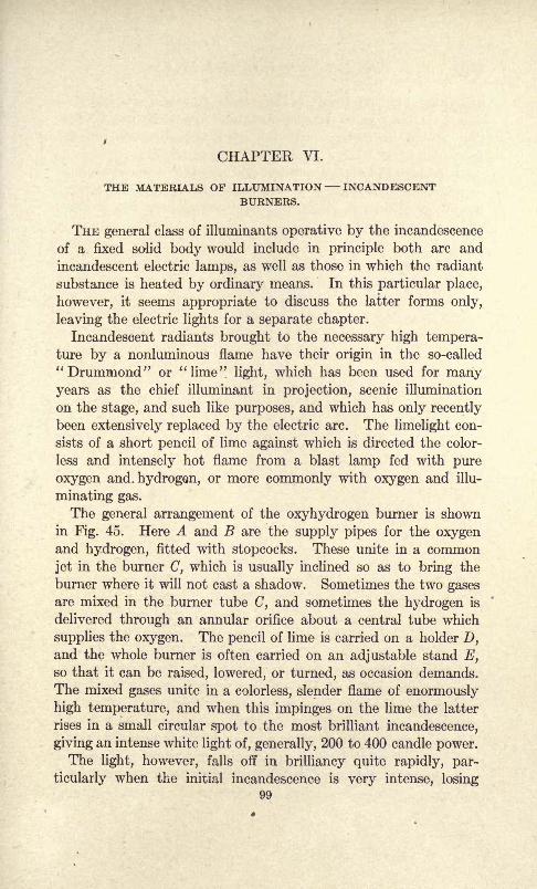
CHAPTER VI.
THE MATERIALS OF ILLUMINATION INCANDESCENTBURNERS.
THE general class of illuminants operative by the incandescence
of a fixed solid body would include in principle both arc and
incandescent electric lamps, as well as those in which the radiant
substance is heated by ordinary means. In this particular place,
however, it seems appropriate to discuss the latter forms only,
leaving the electric lights for a separate chapter.
Incandescent radiants brought to the necessary high tempera-ture by a nonluminous flame have their origin in the so-called
"Drummond" or "lime" light, which has been used for manyyears as the chief illuminant in projection, scenic illumination
on the stage, and such like purposes, and which has only recently
been extensively replaced by the electric arc. The limelight con-
sists of a short pencil of lime against which is directed the color-
less and intensely hot flame from a blast lamp fed with pure
oxygen and. hydrogen, or more commonly with oxygen and illu-
minating gas.
The general arrangement of the oxyhydrogen burner is shownin Fig. 45. Here A and B are the supply pipes for the oxygenand hydrogen, fitted with stopcocks. These unite in a common
jet in the burner C, which is usually inclined so as to bring the
burner where it will not cast a shadow. Sometimes the two gasesare mixed in the burner tube C, and sometimes the hydrogen is
delivered through an annular orifice about a central tube which
supplies the oxygen. The pencil of lime is carried on a holder Z>,
and the whole burner is often carried on an adjustable stand E,so that it can be raised, lowered, or turned, as occasion demands.
The mixed gases unite in a colorless, slender flame of enormously
high temperature, and when this impinges on the lime the latter
rises in a small circular spot to the most brilliant incandescence,
giving an intense white light of, generally, 200 to 400 candle power.The light, however, falls off in brilliancy quite rapidly, par-
ticularly when the initial incandescence is very intense, losing99
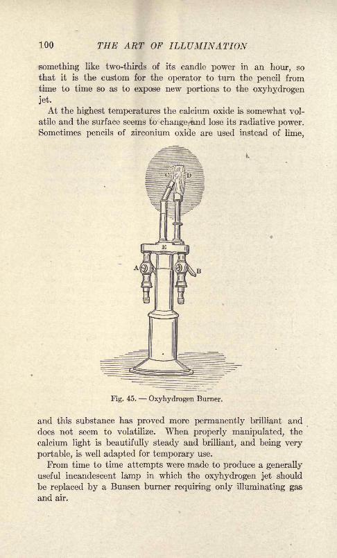
100 THE ART OF ILLUMINATION
something like two-thirds of its candle power in an hour, so
that it is the custom for the operator to turn the pencil fromtime to time so as to expose new portions to the oxyhydrogen
jet.
At the highest temperatures the calcium oxide is somewhat vol-
atile and the surface seems to change^nd lose its radiative power.Sometimes pencils of zirconium oxide are used instead of lime,
Fig. 45. Oxyhydrogen Burner.
and this substance has proved more permanently brilliant and
does not seem to volatilize. When properly manipulated, the
calcium light is beautifully steady and brilliant, and being very
portable, is well adapted for temporary use.
From time to time attempts were made to produce a generally
useful incandescent lamp in which the oxyhydrogen jet should
be replaced by a Bunsen burner requiring only illuminating gas
and air.
INCANDESCENT BURNERS 101
Platinum gauze and other substances were tried as the incan-
descent materials, but the experiments came to nothing practi-
cally until the mantle burner of Auer von Welsbach appeared.
This is generally known in this country as the Welsbach light,
but on the Continent as the Auer light. In this burner the
material brought to incandescence is a mantle, formed like a little
conical bag, of thin fabric thoroughly impregnated with the proper
chemicals and then ignited, leaving a coarse gauze formed of the
active material.
The composition of this material has been kept more or less
secret until recently, and has been varied from time to time as
the burner has gradually been evolved into its present state, but
has always consisted of the oxides of the so-called"metals of the
rare earths" and is actually composed of thoria with a minute
percentage of ceria.
These rare earths zirconia, th'oria, glucina, yttria, ceria, and a
half-dozen others still less well known form a very curious group
of chemical substances. They are whitish or yellowish very refrac-
tory oxides occurring as components of certain rare minerals, and
most of them rise to magnificent incandescence when highly
heated. The hue of this incandescence differs slightly for the
different earths, and they are only slightly volatile at any but very
high temperatures. One erbia has the property of giving a
spectrum of bright bands when highly heated instead of the con-
tinuous spectrum usual to incandescent solids, a property which
is shared in less degree by a few of its curious associates.
The present composition of the Welsbach mantle, which is
ordinarily about 99 per cent thoria and 1 per cent ceria, is the
result of long-continued work over this group of substances byDr. Auer von Welsbach, who found in purifying thoria for use in
mantles that when chemically pure it gave on incandescence very
little light. Tracing backward from this point to discover the
properties of the impurities which he had gradually eliminated,
he found that ceria possessed an extraordinary power of exciting
the thoria to most brilliant incandescence. Just how this remark-
able effect is produced is a mystery not yet fully fathomed.
Dr. Auer's own idea is that the ceria, which is easily oxidized and
reduced^ in virtue of this property acts as a species of molecular
excitant, perhaps going into combination with the thoria at one
stage of oxidation and separating at another stage. Whether this

102 THE ART OF ILLUMINATION
explanation be the final one or not, it is at least a fact that in all
cases, and they are quite numerous, in which a small percentage of
one body confers the power of intensive radiation on a large per-
centage of another body, the former is a substance readily assum-
ing several stages of oxidation, and the latter has in general only
one stage of oxidation and is highly 'refractory. At all events, in
the Welsbach mantle and in other similar cases one always finds a
fireproof oxide combined with an analogous oxide which is a facile
oxygen carrier. It has been suggested that the twte unite to form
a sort of solid solution, and some plausibility is lent to this hy-
pothesis by the curious sensitiveness of the thoria-ceria combination
to small changes in the amount of ceria. As opposed to this cataly-
456PER CENT CERIA.
10
Fig. 46. Effect on the Candle Power of a Welsbach Mantle of Varyingthe Amount of Ceria,
tic theory, some recent investigators hold that the action involved
is purely physical, the ceria being an extraordinarily good and
somewhat selective radiator, which by itself cannot be readily
pushed to sufficiently high incandescence for practical efficiency,
but which when mixed with the thoria of the mantle, itself a poorradiator but highly refractory, is heated to extreme incandescence.
According to this view, .it is practically the ceria only which gives
the brilliancy to the mantle. There are objections to both theories,
and the matter must be considered still unsettled.
Fig. 46, due to Professor Whitaker, shows the effect on the
candle power of a Welsbach mantle of varying the amount of ceria.
The highest efficiency is reached with a percentage of ceria veryclose to one per cent, which is the amount commonly found in com-
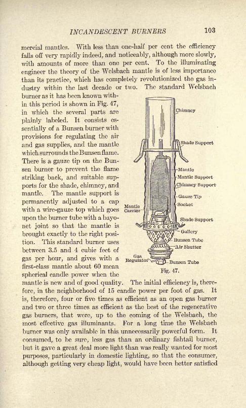
INCANDESCENT BURNERS 103
mercial mantles. With less than one-half per cent the efficiency
falls off very rapidly indeed, and noticeably, although more slowly,
with amounts of more than one per cent. To the illuminating
engineer the theory of the Welsbach mantle is of less importance
than its practice, which has completely revolutionized the gas in-
dustry within the last decade or two. The standard Welsbach
burner as it has been known with-
in this period is shown in Fig. 47,
in which the several parts are
plainly labeled. It consists es-
sentially of a Bunsen burner with
provisions for regulating the air
and gas supplies, and the mantle
which surrounds the Bunsen flame.
There is a gauze tip on the Bun-
sen burner to prevent the flame
striking back, and suitable sup-
ports for the shade, chimney, and
mantle. The mantle support is
permanently adjusted to a capwith a wire-gauze top which goes
upon the burner tube with a bayo-net joint so that the mantle is
brought exactly to the right posi-
tion. This standard burner uses
between 3.5 and 4 cubic feet of
gas per hour, and gives with a
first-class mantle about 60 mean
spherical candle power when the
mantle is new and of good quality. The initial efficiency is, there-
fore, in the neighborhood of 15 candle power per foot of gas. It
is, therefore, four or five times as efficient as an open gas burner
and two or three times as efficient as the best of the regenerative
gas burners, that were, up to the coming of the Welsbach, the
most effective gas illuminants. For a long time the Welsbach
burner was only available in this unnecessarily powerful form. It
consumed, to be sure, less gas than an ordinary fishtail burner,
but it gave a great deal more light than was really wanted for most
purposes, particularly in domestic lighting, so that the consumer,
although getting very cheap light, would have been better satisfied
Chimney
Shade Support
Mantle
Mantle Support
Chimney Support
Gauze Tip
Socket
Shade Support^̂~Gallery
Buusen Tube
'Air Shutter
GasBegulatoi Bunsen Tube
Fig. 47.

104 THE ART OF ILLUMINATION
with a smaller consumption of gas and a quantity of light better
suited to his needs.
In response to this demand, there has been made available
within the past three years what is known to the trade as the
Junior Welsbach, which is a very much smaller and simpler typeof the same structure. ^ It is well shown in Fig. 48.
It consists of a Bunsen iube like the larger burner, with
a very simple regulator carrying a tube supporting a
short perforated mica chimney bearing the mantle
already attached in position. The mantle itself is
barely 2 inches long and the whole affair about 4
inches, so that it screws on in place of an ordinary
burner tip and falls inside the shades previously used
for open flames. Chimney, support, and mantle are
removed and thrown away when used up, and the total
cost of replacement is practically the same as that of
the mantle alone in the larger type of burner. These
little burners are fully as efficient as their larger prede-Fig. 48.
cessors, and with new mantles give between 30 and
35 mean spherical candle power on a consumption of 1.75 to 2
feet of gas per hour, assuming gas of ordinary quality and pres-
sure. In other words, their initial efficiency is in the neighborhoodof 15 candle power per cubic foot of gas as in the case of the
larger burners. This high figure in so small a burner is due prob-
ably to improvements in burner and chimney design and in
mantles which have occurred concurrently with the change in size.
With the coming of this small unit the last excuse for the use
of open gas jets has become invalid. The only possible remaining
reason for continuing the use of open jets is the objection to the
color of the mantle burner, and even this is rapidly disappearing
in the changes of mantle manufacture, of which mention will be
made later. The chief fault of the small Welsbach has been the
clouding of the mica chimney, which depreciates the candle powerof the burner very materially, while the mantle itself is still in first-
class condition. This difficulty has been partly at least remedied
by slight changes in the dimensions of the chimney, and it is not
of any great importance practically, since the replacement is so
cheap and the saving of gas so considerable that it is not worth
while to work the burner beyond the point of good efficiency from
whatever cause.

INCANDESCENT BURNERS 105
The statements here made with reference to consumption of
gas per initial candle power are necessarily somewhat loose on
account of variations in the composition and pressure of the gas
and in the manufacture of the mantles themselves. The figures
given are based on a good gas of about 20 so-called candle power
supplied at the pressure of 2 to 2.5 inches. The efficiency of
a given gas in a mantle burner bears no definite relation to its
nominal candle power, nor indeed to its thermal value, so that one
can deal only in general figures. Variation of an inch of pressure
either way will affect the candle power in the corresponding direc-
tion somewhat like 20 per cent, and variations of this magnitudeare only too common in ordinary gas service. Beside the uncer-
tainty which may arise from varying quality and pressure of gas,
it must be remembered that a certain amount of variation must
be expected in the mantles themselves, particularly if they are
not from the same batch or from the same manufacturer. Gas
mantles cannot be readily sorted by actual test burning as are
incandescent electric lamps, and consequently may at times show
irregular results.
The latest forms of mantle gas burner differ somewhat radically
from those just described, in that they are inverted; that is, the
Bunsen flame burns upside down and plays upon the interior of a
round-bottomed bag-shaped mantle. The result of this arrange-ment is advantageous, in that the burner thus arranged gives a
particularly good distribution of light downward, which is often
desirable, and also a materially higher efficiency than the ordinary
upright mantle. The gain in efficiency is due chiefly to the fact
that the products of combustion are carried more effectively awayfrom the mantle and the supply of air is brought more advan-
tageously to it, so that there is a better surface combustion and
a higher incandescence.
A good many difficulties had to be overcome in making this
upside-down burner a success. A Bunsen flame has to be very
carefully adjusted and regulated in order to burn upside downwith any degree of stability, and the carrying of the heat into
and around the burner instead of away from it involves some
special difficulties. In various ingenious ways these have been
for the most part overcome, so that the inverted burner is
gradually displacing the older form. A typical inverted Welsbach
is shown in cross section in Fig. 49, in which the several parts
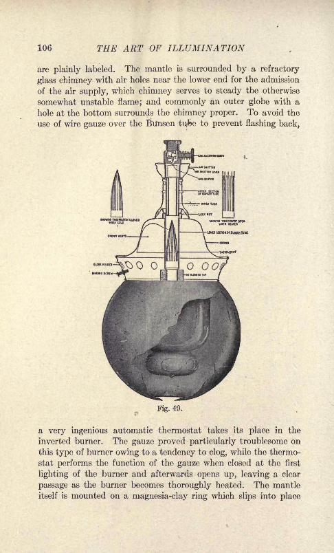
106 THE ART OF ILLUMINATION
are plainly labeled. The mantle is surrounded by a refractory
glass chimney with air holes near the lower end for the admission
of the air supply, which chimney serves to steady the otherwise
somewhat unstable flame; and commonly an outer globe with a
hole at the bottom surrounds the chimney proper. To avoid the
use of wire gauze over the Bilnsen tu&e to prevent flashing back,
Fig. 49.
a very ingenious automatic thermostat takes its place in the
inverted burner. The gauze proved particularly troublesome on
this type of burner owing to a tendency to clog, while the thermo-
stat performs the function of the gauze when closed at the first
lighting of the burner and afterwards opens up, leaving a clear
passage as the burner becomes thoroughly heated. The mantle
itself is mounted on a magnesia-clay ring which slips into place
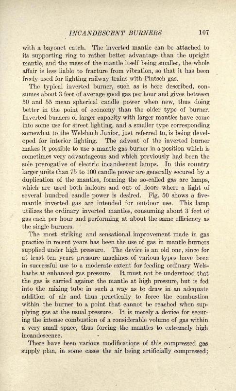
INCANDESCENT BURNERS 107
with a bayonet catch. The inverted mantle can be attached to
its supporting ring to rather better advantage than the upright
mantle, and the mass of the mantle itself being smaller, the whole
affair is less liable to fracture from vibration, so that it has been
freely used for lighting railway trains with Pintsch gas.
The typical inverted burner, such as is here described, con-
sumes about 3 feet of average good gas per hour and gives between
50 and 55 mean spherical candle power when new, thus doing
better in the point of economy than the older type of burner.
Inverted burners of larger capacity with larger mantles have come
into some use for street lighting, and a smaller type corresponding
somewhat to the Welsbach Junior, just referred to, is being devel-
oped for interior lighting. The advent of the inverted burner
makes it possible to use a mantle gas burner in a position which is
sometimes very advantageous and which previously had been the
sole prerogative of electric incandescent lamps. In this country
larger units than 75 to 100 candle power are generally secured by a
duplication of the mantles, forming the so-called gas arc lamps,
which are used both indoors and out of doors where a light of
several hundred candle power is desired. Fig. 50 shows a five-
mantle inverted gas arc intended for outdoor use. This lamputilizes the ordinary inverted mantles, consuming about 3 feet of
gas each per hour and performing at about the same efficiency as
the single burners.
The most striking and sensational improvement made in gas
practice in recent years has been the use of gas in mantle burners
supplied under high pressure. The device is an old one, since for
at least ten years pressure machines of various types have been
in successful use to a moderate extent for feeding ordinary Wels-
bachs at enhanced gas pressure. It must not be understood that
the gas is carried against the mantle at high pressure, but is fed
into the mixing tube in such a way as to draw in an adequateaddition of air and thus .practically to force the combustion
within the burner to a point that cannot be reached when sup-
plying gas at the usual pressure. It is merely a device for secur-
ing the intense combustion of a considerable volume of gas within
a very small space, thus forcing the mantles to extremely highincandescence.
There have been various modifications of this compressed gas
supply plan, in some cases the air being artificially compressed;
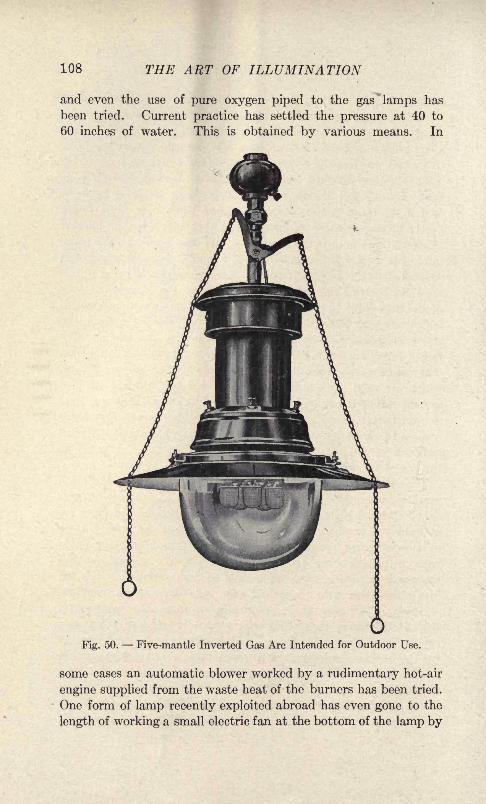
108 THE ART OF ILLUMINATION
and even the use of pure oxygen piped to the gas"lamps has
been tried. Current practice has settled the pressure at 40 to
60 inches of water. This is obtained by various means. In
Fig. 50. Five-mantle Inverted Gas Arc Intended for Outdoor Use.
some cases an automatic blower worked by a rudimentary hot-air
engine supplied from the waste heat of the burners has been tried.
One form of lamp recently exploited abroad has even gone to the
length of working a small electric fan at the bottom of the lamp by
INCANDESCENT BURNERS 109
means of current derived from a ring-shaped thermopile operated
by the waste heat. As a matter of practice, these individual lamp
compressors have found less favor than the somewhat simpler plan
of piping the burners for pressure gas supplied from a central
compressor station.
In Berlin, which city has the largest example of a press-gas
plant, several thousand powerful lamps for the streets are sup-
plied from compressor stations driven by small gas engines and
located at convenient points, whence the gas is distributed in
Mannesmann steel tubes, at a pressure of 12 centimeters of mer-
cury. The press-gas lamps used on this and similar systems have
one or more large Welsbach mantles, the upright ones being some
6 inches in height and the inverted ones of correspondingly large
dimensions. They are woven of extra-heavy material, and though
owing to the high incandescence the life is much shorter than in
the low-pressure mantles, it is said to extend to nearly a monthunder ordinary conditions of burning. The ordinary press-gas
equipments used for street lighting consume from 25 to 35 feet
of gas per hour, and give, according to pressure, from 30 to 40
mean spherical candle power per foot of gas. Roughly, there-
fore, they have more than double the efficiency of the burners
worked at ordinary pressure, and give the advantage of a simpleand easily maintained large lighting unit well adapted for outside
work.
In its evolution press-gas has passed through various stages of
pressure, the earlier burners being worked at 8 to 12 inches of
water pressure, but later the more general introduction of pressure
mains has led to the employment of the higher pressure alreadyreferred to. Press-gas lighting has not yet been utilized in this
country to any material extent, although some small experimentalinstallations have been set up. The separate piping requiredinvolves so considerable an expenditure that it has not appealedto most gas engineers, and at prices current for gas in America
the cost of gas, maintenance, and fixed charges have been rather
too high to permit competition with electric arcs on a consider-
able scale. The press-gas lamps, however, are most interesting
examples of high efficiency gas lighting and give an admirably
steady and powerful light.
In all incandescent gas lamps the vital point is the mantle, andrecent improvements have been directed chiefly toward securing
110 THE ART OF ILLUMINATION
better material and more uniform methods of manufacture. Prac-
tically all the ordinary upright mantles manufactured in this
country at the present time are made of cotton. Cotton fiber
gives a strong mantle, but one that seems to be more subject
to deterioration in service . than mantles made of some other
materials. Abroad, the major part" of the mantles, and some of
the inverted mantles in this country are made of ramie fiber.
This produces a mantle less strong mechanically than a cotton
mantle, but comparatively more homogeneous ite. structure and
likely to hold up better.
Within the past two or three years, however, a very radical step
has been taken in the substitution of artificial silk as a mantle
material for any of the natural fibers. This artificial silk is simplycellulose nitrated in a very moderate degree, substantially in fact
collodion gun-cotton. This is inflammable without being explosive,
and in manufacture is squirted into very fine threads possessing
the luster and almost the flexibility of silk fibers. The material
thus produced is wonderfully homogeneous, so that mantles madefrom it are exceptionally uniform, while also strong and holding
up better in candle power than mantles made of natural cellulose.
Many of these artificial silk mantles are in use on the Continent,
but as yet they have only been manufactured experimentally in
this country. The results obtained with them, however, are very
encouraging, the artificial cellulose fiber having apparently some-
thing of the same advantage in the incandescent gas mantle that
it had in the manufacture of the carbon electric incandescent lamp,which went through precisely the same steps of evolution, passing
from one natural fiber to another, and finally settling to the struc-
tureless artificial cellulose as the most uniform and successful
material.
Fig. 51 shows in abstract life curves from three types of mantle,
inverted mantles of ramie fiber and artificial silk, and upright
mantles of cotton. It will be noted that the two former hold
up wonderfully well, while the latter loses about one-third of its
light in a thousand hours. At first thought, it seems singular that
the material of the original mantle, which is utterly consumed in
the process of manufacture, leaving only a skeleton of the oxides
with which the saturated thread is charged, should make so pro-
found a difference in the behavior of the mantle; but the finished
mantle, which is merely the ash, partakes in every particular of the
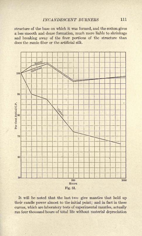
INCANDESCENT BURNERS 111
structure of the base on which it was formed, and the cotton gives
a less smooth and dense formation, much more liable to shrinkage
and breaking away of the finer portions of the structure than
does the ramie fiber or the artificial silk.
100
00
iso
\70
GO
.50
500
Hours1000
Fig. 51.
It will be noted that the last two give mantles that hold uptheir candle power almost to the initial point; and in fact in these
curves, which are laboratory tests of experimental mantles, actually
ran four thousand hours of total life without material depreciation
112 THE ART OF ILLUMINATION
of candle power. It is hardly probable that the general run of
commercial mantles of this material would turn out as well as
those here shown, any more than is the case with other com-
mercial products. The results from the cotton mantle are from
tests of a considerable group of stock mantles. Nevertheless,
the probable improvement in the average quality of mantles bythe use of ramie fiber, and particularly of the artificial silk, is veryconsiderable.
Another point in which large modifications have *been made in
mantle-burner practice is the color. As is familiar to everyone,the ordinary mantle of the past has, after a short period of burn-
ing, tended to pass over from a hue fairly near white to one
strongly tinged with greenish. A glance at Fig. 46 shows the
probable cause of this effect. The less ceria the mantle contains
the more the color of the incandescence tends to greenish or bluish;
the more ceria, the less the selective radiation in the blue and
green and the stronger the light in the yellow and orange. Theceria apparently tends to burn out of the mantle to a certain extent,
or at least to lose its activity, so that a mantle starting at one
per cent of ceria degenerates after a while to the state of a mantle
containing a considerably less percentage, losing in efficiency and
acquiring the characteristic greenish tinge. A mantle of composi-tion to give it maximum efficiency is, then, liable to this particular
kind of deterioration.
Within the past two or three years a good many mantles con-
taining slightly more ceria have been put out, which give at first
a light tending more to the yellow, and, while showing some
selective radiation in the green at a later stage, never duringtheir effective life seem to pass to the color of the earlier mantles.
Still more recently, further advance has been made in this direc-
tion, and mantles are now available giving a very soft yellowish
light for a long period of burning. They are, of course, somewhat
less efficient than the mantles containing less ceria, but are verymuch more agreeable in color and hence are better adapted for
interior lighting. Mantle manufacture is another of the manycases in which the attempt to get the very highest possible effi^
ciency leads to sacrifice in other directions. These recent types of
mantle have not come into very great use as yet, but effectively
meet the requirement of furnishing a light "on the yellow" rather
than " on the green" in hue.
INCANDESCENT BURNERS 113
Ives (Transactions Illuminating Engineering Society, Vol. V,
page 208) has given some interesting data on the color variation
produced by varying amounts of ceria. The upshot of his figures
is that while a mantle containing three-fourths of one per cent
of ceria shows rather strong selective radiation in green and bluish
green, an increase to 1.25 per cent of ceria makes a radical changein this particular and gives a fair approximation to the hue of the
metallic filament electric lamp or the acetylene flame. It is still
slightly stronger in the green and slightly weaker in the red than
these, but' a small additional amount of ceria has been found to
even things up in a very satisfactory way. As Fig. 46 shows, the
loss in efficiency even for as high as two per cent of ceria is
not at all a serious matter. Some space has been devoted to
this matter because, while the whole problem has not yet been
thoroughly worked out, it is clear that the color difficulty found
with the earlier mantle burners can be and has been overcome to
a very considerable degree.
The advantage of the mantle burner in steadiness and economyis so great that there would be no reason for using the more
common forms of gas burner indoors, except for their occasion-
ally better artistic effects and for their convenience for verysmall lights. The color question and the fragility of the mantle
have been the chief hindrances to the general introduction of
the Welsbach type, and these are certainly in large measure
avertable.
Recently there have been introduced several forms of mantle
burner worked with gas generated on the spot from gasoline or
similar petroleum products. Sometimes these are operated as
individual lamps and sometimes as small systems to which the
gas-forming fluid is piped. They give, of course, a fine, brilliant
light, and at a low cost cheaper than ordinary mantle burners
worked with any except rather cheap gas. Where gasoline gas
would be cheaper than gas taken from the nearest available main,such gasoline mantle burners will prove economical.
But, as a matter of fact, lamps locally generating and burningtheir own petroleum gas have been pretty thoroughly tried from
time to time during the past twenty-five years, and have never
taken a strong or permanent hold on the public. It is therefore
difficult to see how mantle burners worked in similar fashion are
likely to take a material hold upon the art, although in special
114 THE ART OF ILLUMINATION
cases they may prove very useful, when illuminating gas is not
available at a reasonable price.
It must be constantly borne in mind that the lighter petroleumoils are dangerous and must be used with extreme care, and also
that they are likely steadily to rise in price, owing to the increasing
use of explosion engines and gas maqfeines.
In using any mantle burner it is good economy to replace the
mantle after three or four hundred hours of burning, if it is in
regular use to any considerable extent. Of course*, in cases when
a burner is not regularly used and its maximum brilliancy is not
at all needed, the mantle may properly be used until it shows
signs of breaking. In other words, as soon as a mantle which is
needed at its full efficiency gets dim, throw it promptly away;but so long as it gives plenty of light for its situation, your con-
sumption of gas will not be diminished by a change.
The commonest trouble with mantles is blackening from a
deposit of soot owing to temporary derangement of the burner.
This deposit can generally be burned off by slightly, not consider-
ably, checking the air supply so as to send up a long, colorless
flame which will soon get rid of the carbon, after which the full
air supply should be restored. Too great checking of the air
supply produces a smoky flame.
It should finally be noted that the mantle burners are particularly
useful in cases of troublesome fluctuations in the gas supply, since,
while they may burn more or less brightly according to circum-
stances, they are entirely free from rapid flickering when properly
adjusted.
In leaving now the illuminants which depend upon the com-
bustion of a gas or liquid, a brief summation of some of their
properties may not come amiss.
The replacement of candles and lamps by gas worked a revolu-
tion, not only in the convenience of artificial lighting, but in its
hygienic relations. The older illuminants in proportion to their
luminous effect removed prodigious amounts of oxygen from the
air and gave off large quantities of carbonic acid. In the daysof candles a brilliantly lighted room was .almost of necessity one
in which the air was bad. The following table, due to a well-
known authority on hygiene, gives the approximate properties of
the common illuminants of combustion as regards their effects on
the air of the space in which they are burned:
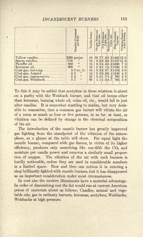
INCANDESCENT BURNERS 115
To this it may be added that acetylene in these relations is about
on a parity with the Welsbach burner, and that oil lamps other
than kerosene, burning whale oil, colza oil, etc., would fall in just
after candles. It is somewhat startling to realize, but very desir-
able to remember, that a common gas burner will vitiate the air
of a room as much as four or five persons, in so far, at least, as
vitiation can be defined by change in the chemical compositionof the air.
The introduction of the mantle burner has greatly improved
gas lighting from the standpoint of the vitiation of the atmos-
phere, as a glance at the table will show. For equal light the
mantle burner, compared with gas flames, in virtue of its higher
efficiency, produces only something like one-fifth the CC>2 andmoisture per candle power and removes a similarly small propor-tion of oxygen. The vitiation of the air with such burners is
hardly noticeable, unless they are used in considerable numbersin a limited space. Now and then one notices it in entering a
shop brilliantly lighted with mantle burners, but it has disappearedas an important consideration under most circumstances.
In cost also the modern illuminants have a material advantage.In order of diminishing cost the list would run at current American
prices of materials about as follows: Candles, animal and vege-table oils, gas in ordinary burners, kerosene, acetylene, Welsbachs,Welsbachs at high pressure.
CHAPTER VII.
THE ELECTRIC INCANDESCENT LAMP.
AT the present time the mainstay of electric illumination is the
incandescent lamp, in which a filament of high electrical resistance
is brought to vivid incandescence by the passage "of the electric
current. To prevent the rapid oxidation of the incandescent ma-
terial at the high temperature employed, the filament is mounted
in an exhausted glass globe, forming the familiar incandescent
lamp of commerce.
The first attempts at incandescent lamps were made with loops
or spirals of platinum wire heated by the electric current, either
in the air or in vacuo, but the results were highly unsatisfactory,
since in the open air the wire soon began to disintegrate, and
even in the absence of air its life was short. Moreover, the metal
itself, being produced in very limited quantities, was expensive
at best, and rose very rapidly in price under a small increase of
demand. Having a fairly low specific electrical resistance, the
wire used had either to be very thin, which made it extremely
fragile, or long, which greatly increased its cost per lamp.
Following platinum came carbon in the form of slender pencils
mounted in vacuo. These, however, were of so low resistance
that the current required to heat them was too great to allow
of convenient distribution.
To get a practical lamp it was necessary to use a filament of
really high resistance, and which was yet strong enough to keepdown the cost of replacements.
Without going into the details of the many experiments on
incandescent lamps, it is sufficient to say that after much labor
the problem of getting a fairly workable filament was solved
through the persistent efforts of Edison, Swan, Maxim, Weston,and others, about thirty years ago, the modern art dating from
about 1880.
All the carbon filaments are based on the carbonization, out
of contact with air, of thin threads of cellulose the essential
constituent of woody fiber. The early work was in the direction
116
THE ELECTRIC INCANDESCENT LAMP 117
of carbonizing thread in some form, or even paper, but Edison,
after an enormous amount of experimenting, settled upon bamboofiber as the most uniform and enduring material, and the Edison
lamp came to the front commercially.
In point of fact, it soon became evident that art could produce
a far more uniform carbon filament than nature has provided, so
that of late years bamboo, thread, paper, and the rest have been
abandoned, and all filaments, save those for some special lamps,
are made from soluble cellulose squirted into threads, hardened,
carbonized, and "treated."
Fig. 52 shows a typical modern incandescent lamp. It consists
essentially of four parts: the base adapted to carry the lamp in
its socket, the bulb, the filament, and the filament mounting,which includes the leading-in wires. In its original form the bulb
has an opening at each end, one at the base end through which
the filament and its mounting are put in place, and another in
the form of a narrow tube a few inches long, which when sealed
off produces the tip at the end of the bulb.
The filament is made in slightly different ways in different fac-
tories, and the exact details of the process, constantly subject to
slight improvements, are unnecessary here to be described. Sub-
stantially it is as follows: The basis of operations is the purest
cellulose convenient to obtain, filter paper and the finest absorbent
cotton being common starting points. The material is pulped, as
in paper making, dissolved in some suitable substance, zinc-chloride
solution being one of those used, evaporated to about the con-
sistency of thick molasses, and then squirted under air pressure
into a fine thread, which is received in an alcohol bath to harden it.
Thus squirted through a die, the filament is of very uniform
constitution and size, and after carbonization out of contact with
air it forms a carbon thread that is wonderfully flexible and strong.
But even so, there is not yet a perfectly uniform filament, and
the carbon is not dense and homogeneous enough to stand pro-
tracted incandescence.
On passage of current portions of the filament may show too low
resistance, so as to be dull, or too high resistance, so as to get too
hot and burn off. It is hard, too, to produce a durable filament
of the somewhat porous carbon obtained in the way described.
In making up the filaments they are, therefore, subjected prior
to being sealed into the lamp to what is known as the flashing
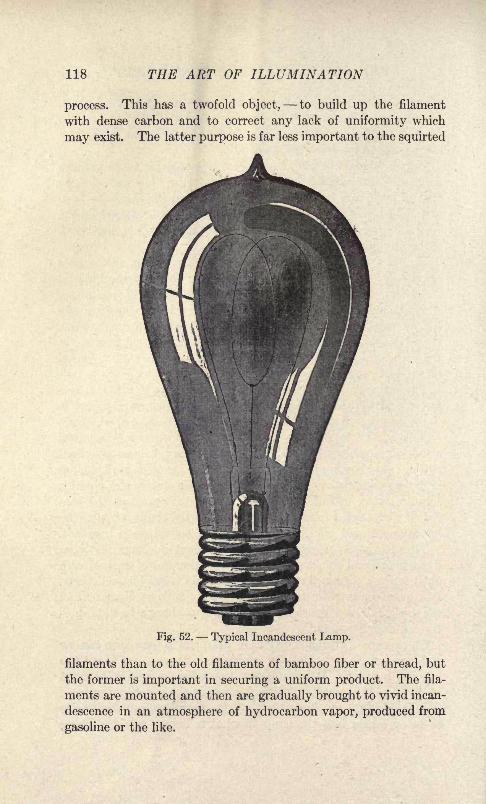
118 THE ART OF ILLUMINATION
process. This has a twofold object, to build up the filament
with dense carbon and to correct any lack of uniformity which
may exist. The latter purpose is far less important to the squirted
Fig. 52. Typical Incandescent Lamp.
filaments than to the old filaments of bamboo fiber or thread, but
the former is important in securing a uniform product. The fila-
ments are mounted and then are gradually brought to vivid incan-
descence in an atmosphere of hydrocarbon vapor, produced from
gasoline or the like.
THE ELECTRIC INCANDESCENT LAMP 119
The heated surface decomposes the vapor, and the carbon is
deposited upon tjie filament in the form of a smooth, uniform
coating almost as dense as graphite, and a considerably better
conductor than the original filament. If, as in the early bamboo
filaments, there are any spots of poorer conductivity or smaller
cross section than is proper, these become hot first and are built
up toward uniformity as the current is gradually raised, so that
the filament is automatically made uniform.
The flashing process is actually quick, the gradual rise of current
being really measured by seconds. With the squirted filaments
now used the main value of the flashing process is to enable the
conductivity of the filament to be quite accurately regulated, at
the same time giving it a firm, hard coating of carbon that greatly
increases its durability. The finished filaments are strong and
elastic, generally a fine steely gray in color, with a polished surface,
and for lamps of ordinary candle power and voltage vary from
6 to 12 inches in length, with a diameter of 5 to 10 one-thousandths
of an inch.
The filaments are joined near the base of the lamp to two short
bits of thin platinum wire which are sealed through one end of
a short piece of glass tube. Sometimes these platinum leading-in
wires are fastened directly to the ends of the filament and some-
times to an intermediary terminal of copper wire attached to the
filament. Within the tube the platinum wires are welded to the
copper leads which pass down the mounting tube and are attached
to the base. The filament itself is cemented to its copper or plati-
num wires by means of a little drop of carbon paste.
No effective substitute for platinum in sealing through the glass
has yet been found, although many have been 'tried. Platinum
and glass have very nearly the same coefficient of expansion with
heat, so that the seal remains tight at all temperatures without
breaking away. It is possible to find alloys with nearly the right
coefficient of expansion, but they have generally proved unsatis-
factory either mechanically or electrically, so that the line of
improvement has mainly been in the direction of making a veryshort seal with platinum wires.
The filament thus mounted is secured in the bulb by sealing
the base of the mounting tube or lamp stem into the base of the
bulb. This leaves the bulb closed except for the exhaustion tube
at its tip.
120 THE ART OF ILLUMINATION
The next step is the exhaustion of the bulb. This used to be
done almost entirely by mercury pumps, and great pains was taken
to secure a very high degree of exhaustion. It was soon found
that there was such a thing as too high exhaustion, but the degree
found to be commercially desirable is still beyond the easy capa-
bilities of mechanical air pumps, at least for regular and uniform
commercial practice, although they have been sometimes success-
fully used.
At the present time the slow though effective mercury pump is
being to a very large extent superseded by the Malignani process,
or modifications thereof. The bulbs are rapidly exhausted bymechanical air pumps, and when these have reached the con-
venient limit of their action the residual gas is chemically absorbed
by the vapor produced by heating a small quantity of amorphous
phosphorus previously placed in a tubulaire connected with the
exhaustion tube. The process is cheap, rapid, and effective, and
with a little practice the operator can produce exhaustion that is
almost absolutely uniform.
Whatever be the method of exhaustion, during its later stages
current is put on the filaments both to heat them, and thus to
drive out the occluded gases, and to serve as an index of the ex-
haustion. When exhaustion is complete the leading-in tube is
quickly sealed off, and the lamp is done, save for cementing on
the base and attaching it to the leads that come from the seal.
After this* the lamps are sorted, tested, and made ready for the
market.
The shape of the filament in the lamp was originally a simple
U, later often modified to a U with a quarter twist so that the
plane of the loop at the top was 90 degrees from its plane at the
base. As the voltage of distribution has steadily crept upwardsfrom 100 to 110, 120, 140, and even 250 volts, it has been necessaryeither to increase the specific resistance of the filament, to decrease
its diameter, or to increase its length, in order to get the necessaryresistance to keep the total energy, and likewise the temperatureof the filament, down to the desired point.
But the modern flashed filament cannot be greatly increased in
specific resistance without impairing its stability, so the filaments
have been growing steadily finer and longer. At present their form
is various, according to the judgment of the maker in stowing
away the necessary amount of filament within the bulb.
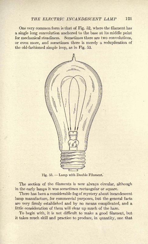
THE ELECTRIC INCANDESCENT LAMP 121
One very common form is that of Fig. 52, where the filament has
a single long convolution anchored to the base at its middle point
for mechanical steadiness. Sometimes there are two convolutions,
or even more, and sometimes there is merely a reduplication of
the old-fashioned simple loop, as in Fig. 53.
Fig. 53. Lamp with Double Filament.
The section of the filaments is now always circular, althoughin the early lamps it was sometimes rectangular or square.
There has been a considerable fog of mystery about incandescent
lamp manufacture, for commercial purposes, but the general facts
are very firmly established and by no means complicated, and a
little consideration of them will clear up much of the haze.
To begin with, it is not difficult to make a good filament, but
it takes much skill and practice to produce, in quantity, one that
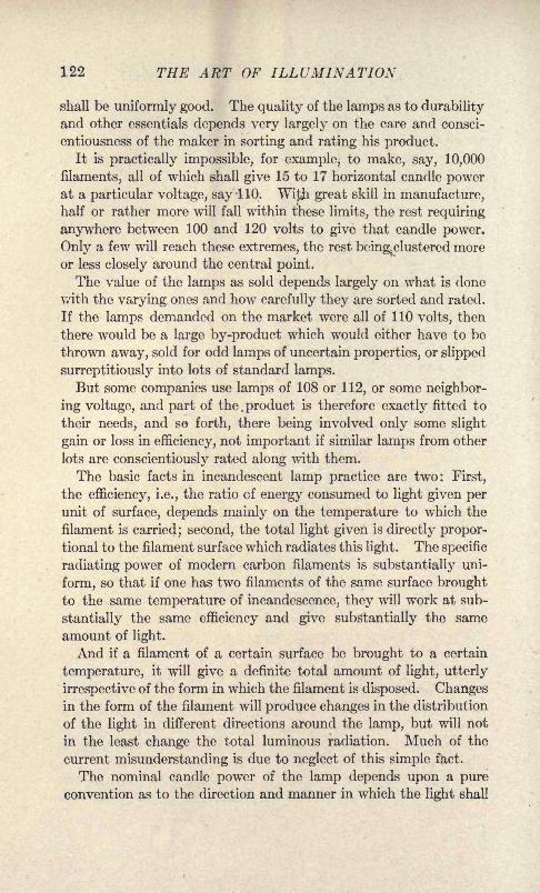
122 THE ART OF ILLUMINATION
shall be uniformly good. The quality of the lamps as to durability
and other essentials depends very largely on the care and consci-
entiousness of the maker in sorting and rating his product.It is practically impossible, for example, to make, say, 10,000
filaments, all of which shall give 15 to 17 horizontal candle powerat a particular voltage, say 110. Wih great skill in manufacture,half or rather more will fall within these limits, the rest requiring
anywhere between 100 and 120 volts to give that candle power.
Only a few will reach these extremes, the rest being.clustered moreor less closely around the central point.
The value of the lamps as sold depends largely on what is done
with the varying ones and how carefully they are sorted and rated.
If the lamps demanded on the market were all of 110 volts, then
there would be a large by-product which would either have to be
thrown away, sold for odd lamps of uncertain properties, or slipped
surreptitiously into lots of standard lamps.
But some companies use lamps of 108 or 112, or some neighbor-
ing voltage, and part of the. product is therefore exactly fitted to
their needs, and so forth, there being involved only some slight
gain or loss in efficiency, not important if similar lamps from other
lots are conscientiously rated along with them.
The basic facts in incandescent lamp practice are two: First,
the efficiency, i.e., the ratio of energy consumed to light given per
unit of surface, depends mainly on the temperature to which the
filament is carried; second, the total light given is directly propor-
tional to the filament surface which radiates this light. The specific
radiating power of modern carbon filaments is substantially uni-
form, so that if one has two filaments of the same surface brought
to the same temperature of incandescence, they will work at sub-
stantially the same efficiency and give substantially the same
amount of light.
And if a filament of a certain surface be brought to a certain
temperature, it will give a definite total amount of light, utterly
irrespective of the form in which the filament is disposed. Changesin the form of the filament will produce changes in the distribution
of the light in different directions around the lamp, but will not
in the least change the total luminous radiation. Much of the
current misunderstanding is due to neglect of this simple fact.
The nominal candle power of the lamp depends upon a pure
convention as to the direction and manner in which the light shall
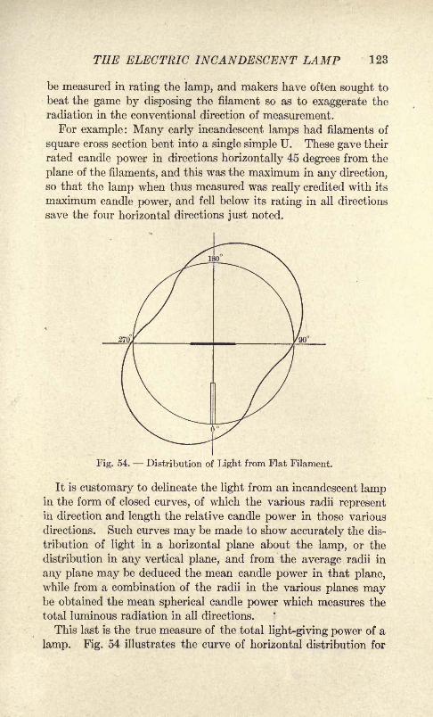
THE ELECTRIC INCANDESCENT LAMP 123
be measured in rating the lamp, and makers have often sought to
beat the game by disposing the filament so as to exaggerate the
radiation in the conventional direction of measurement.
For example: Many early incandescent lamps had filaments of
square cross section bent into a single simple U. These gave their
rated candle power in directions horizontally 45 degrees from the
plane of the filaments, and this was the maximum in any direction,
so that the lamp when thus measured was really credited with its
maximum candle power, and fell below its rating in all directions
save the four horizontal directions just noted.
Fig. 54. Distribution of Light from Flat Filament.
It is customary to delineate the light from an incandescent lampin the form of closed curves, of which the various radii representin direction and length the relative candle power in those various
directions. Such curves may be made to show accurately the dis-
tribution of light in a horizontal plane about the lamp, or the
distribution in any vertical plane, and from the average radii in
any plane may be deduced the mean candle power in that plane,
while from a combination of the radii in the various planes maybe obtained the mean spherical candle power which measures the
total luminous radiation in all directions.
This last is the true measure of the total light-giving power of a
lamp. Fig. 54 illustrates the curve of horizontal distribution for
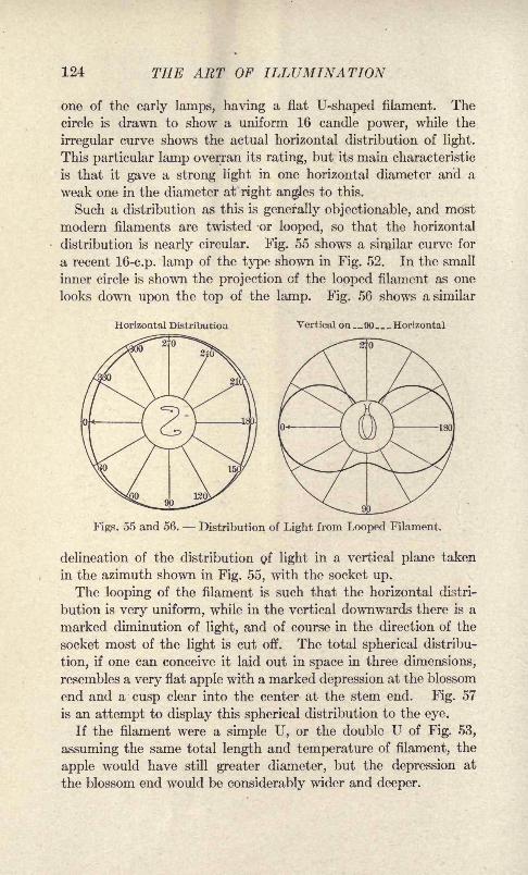
124 THE ART OF ILLUMINATION
one of the early lamps, having a flat U-shaped filament. The
circle is drawn to show a uniform 16 candle power, while the
irregular curve shows the actual horizontal distribution of light.
This particular lamp overran its rating, but its main characteristic
is that it gave a strong light in one horizontal diameter and a
weak one in the diameter at right angles to this.
Such a distribution as this is generally objectionable, and most
modern filaments are twisted -or looped, so that the horizontal
distribution is nearly circular. Fig. 55 shows a similar curve for
a recent 16-c.p. lamp of the type shown in Fig. 52. In the small
inner circle is shown the projection of the looped filament as one
looks down upon the top of the lamp. Fig. 56 shows a similar
Horizontal Distribution Vertical on 90 Horizontal
Figs. 55 and 56. Distribution of Light from Looped Filament.
delineation of the distribution gf light in a vertical plane taken
in the azimuth shown in Fig. 55, with the socket up.
The looping of the filament is such that the horizontal distri-
bution is very uniform, while in the vertical downwards there is a
marked diminution of light, and of course in the direction of the
socket most of the light is cut off. The total spherical distribu-
tion, if one can conceive it laid out in space in three dimensions,
resembles a very flat apple with a marked depression at the blossom
end and a cusp clear into the center at the stem end. Fig. 57
is an attempt to display this spherical distribution to the eye.
If the filament were a simple U, or the double U of Fig. 53,
assuming the same total length and temperature of filament, the
apple would have still greater diameter, but the depression at
the blossom end would be considerably wider and deeper.
THE ELECTRIC INCANDESCENT LAMP 125
If the filament has several convolutions, as in Fig. 58, this
depression is considerably reduced, but there is a marked flatten-
ing in one horizontal direction, so that the horizontal distribu-
tion would somewhat resemble Fig. 54. But the total luminous
radiation would be quite unchanged.If the lamps were rated by their mean horizontal candle power,
the U filament would show abnormally large horizontal illumi-
nation for the energy consumed, and would apparently be very
efficient, while if one were foolish enough to rate lamps by the
Fig. 57. Distribution of Light from Incandescent Lamp.
light given off the tip alone, Fig. 58 would show great efficiency,
the distribution in one horizontal diameter having 'been reduced
to fatten the curve at the tip. In reality, however, each one of
the three forms of lamp would have exactly the same efficiency,
and in practice there would be little choice between them.
In the everyday work of illumination carbon incandescent lampsare installed with their axes in every possible direction, the vertical
being the rarest, and angles between 30 degrees and 60 degreesdownwards from the horizontal the commonest.
Bearing in mind this general distribution of the axes and the
fact that diffusion goes very far toward obliterating differences in
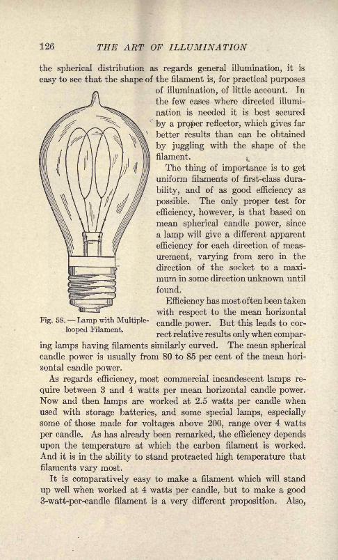
126 THE ART OF ILLUMINATION
the spherical distribution as regards general illumination, it is
easy to see that the shape of the filament is, for practical purposes
of illumination, of little account. In
the few cases where directed illumi-
nation is needed it is best secured
by a proper reflector, which gives far
better results than can be obtained
by juggling with the shape of the
filament. ^
The thing of importance is to get
uniform filaments of first-class dura-
bility, and of as good efficiency as
possible. The only proper test for
efficiency, however, is that based on
mean spherical candle power, since
a lamp will give a different apparent
efficiency for each direction of meas-
urement, varying from zero in the
direction of the socket to a maxi-
mum in some direction unknown until
found.
Efficiency has most often been taken
with respect to the mean horizontal
Fig. 58. -Lamp with Multiple- candle power> But thig leadg to CQr.
rect relative results onlywhen compar-looped Filament.
ing lamps having filaments similarly curved. The mean spherical
candle power is usually from 80 to 85 per cent of the mean hori-
zontal candle power.As regards efficiency, most commercial incandescent lamps re-
quire between 3 and 4 watts per mean horizontal candle power.Now and then lamps are worked at 2.5 watts per candle whenused with storage batteries, and some special lamps, especially
some of those made for voltages above 200, range over 4 watts
per candle. As has already been remarked, the efficiency depends
upon the temperature at which the carbon filament is worked.
And it is in the ability to stand protracted high temperature that
filaments vary most.
It is comparatively easy to make a filament which will stand
up well when worked at 4 watts per candle, but to make a good
3-watt-per-candle filament is a very different proposition. Also,
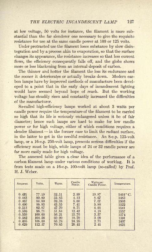
THE ELECTRIC INCANDESCENT LAMP 127
at low voltage, 50 volts for instance, the filament is more sub-
stantial than the far slenderer one necessary to give the requisite
resistance for use at the same candle power at 100 or 125 volts.
Under protracted use the filament loses substance by slow disin-
tegration and by a process akin to evaporation, so that the surface
changes its appearance, the resistance increases so that less current
flows, the efficiency consequently falls off, and the globe shows
more or less blackening from an internal deposit of carbon.
The thinner and hotter the filament the less its endurance and
the sooner it deteriorates or actually breaks down. Modern car-
bon lamps have by improved methods of manufacture been devel-
oped to a point that in the early days of incandescent lighting
would have seemed beyond hope of reach. But the working
voltage has steadily risen and constantly increased the difficulties
of the manufacturer.
So-called high-efficiency lamps worked at about 3 watts percandle power require the temperature of the filament to be carried
so high that its life is seriously endangered unless it be of fair
diameter; hence such lamps are hard to make for low candle
power or for high voltage, either of which conditions requires a
slender filament in the former case to limit the radiant surface,
in the latter to get in the needful resistance. An 8-c.p. 125-volt
lamp, or a 16-c.p. 250-volt lamp, presents serious difficulties if the
efficiency must be high, while lamps of 24 or 32 candle power are
far more easily made for high voltage.
The annexed table gives a clear idea of the performance of a
carbon filament lamp under various conditions of working. It is
from tests made on a 16-c.p. 100-volt lamp (so-called) by Prof.
H. J. Weber.
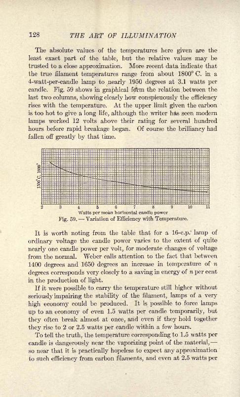
128 THE ART OF ILLUMINATION
The absolute values of the temperatures here given are the
least exact part of the table, but the relative values may be
trusted to a close approximation. More recent data indicate that
the true filament temperatures range from about 1800 C. in a
4-watt-per-candle lamp to nearly 1950 degrees at 3.1 watts per
candle. Fig. 59 shows in graphical fdrm the relation between the
last two columns, showing clearly how conspicuously the efficiency
rises with the temperature. At the upper limit given the carbon
is too hot to give a long life, although the writer h&s seen modern
lamps worked 12 volts above their rating for several hundred
hours before rapid breakage began. Of course the brilliancy had
fallen off greatly by that time.
3456789 10
Watts per mean horizontal candle power
Fig. 59. Variation of Efficiency with Temperature.
11
It is worth noting from the table that for a 16-c.p." lamp of
ordinary voltage the candle power varies to the extent of quite
nearly one candle power per volt, for moderate changes of voltage
from the normal. Weber calls attention to the fact that between
1400 degrees and 1650 degrees an increase in temperature of n
degrees corresponds very closely to a saving in energy of n per cent
in the production of light.
If it were possible to carry the temperature still higher without
seriously impairing the stability of the filament, lamps of a very
high economy could be produced. It is possible to force lamps
up to an economy of even 1.5 watts per candle temporarily, but
they often break almost at once, and even if they hold together
they rise to 2 or 2.5 watts per candle within a few hours.
To tell the truth, the temperature corresponding to 1.5 watts per
candle is dangerously near the vaporizing point of the material,
so near that it is practically hopeless to expect any approximation
to such efficiency from carbon filaments, and even at 2.5 watts per

THE ELECTRIC INCANDESCENT LAMP 129
candle the life of the lamps is so short that at present prices theycannot be used commercially.
From such experiments as those tabulated it has been shown
that the relation between the luminous intensity and the energy
expended in an incandescent lamp may be expressed quite nearly
by the following formula:
I = aW3,
wherein 7 is the candle power, W the watts used, and a is a quantity
approximately constant for a given type of lamp, but varying
slightly from type to type.
Following the universal rule of incandescent bodies, the radia-
tion from an incandescent lamp varies in color with the tempera-
ture, and thus as the voltage changes, or what is about the same
thing, as lamps of different efficiencies are used, the color of the
light varies very conspicuously. Low efficiency lamps, or lamps in
a low stage of incandescence, such as is indicated in the first four
lines of the table, burn distinctly red or reddish orange. Then
the incandescence passes through the various stages of orange-
yellow and yellow until a 3-watt lamp is clear yellowish white and
a 2.5-watt lamp still more whitish. The color is a good index of
the efficiency.
The sizes of carbon incandescent lamps in common use are 8, 10,
16, 20, 24, and 32 candle power. The standard in this country is
the 16-c.p. size, a figure borrowed from the legal requirements for
gas. Some 10 candle power lamps are used here, very few 8 candle
power, and still fewer of candle powers above 16. Abroad, 8-c.p.
lamps are used in great numbers and with excellent results. The
20-c.p. and 24-c.p. lamps are found mostly in high voltages, for
reasons that will appear shortly. Two-, 4-, and 6-c.p. lamps are
considerably used for decorative purposes or for night-lights, and
excellent 50-c.p. lamps are available for cases requiring radiants of
unusual power.
Lamps of these various sizes are made usually for voltages be-
tween 100 and 120 volts, and more rarely for 220 to 250 volts, but
in the latter case lamps below 16 candle power are used in America
only to a very small extent.
In lamps of small candle power or of high voltage there is
some temptation to get resistance by flashing the filaments less
thoroughly, to the detriment of durability, since the soft core dis-
130 THE ART OF ILLUMINATION ,
integrates more readily than the hard deposited carbon, which may.explain the frequent inferiority of such lamps. The greater the
candle power, and the less efficiency required, i.e., the greater the
permissible radiating surface, the easier it is to get a strong and
durable filament for high voltages. Hence, lamps for 220 to 250
volts are generally of at least 16 candle power, very often of 20 or
24 candle power, and seldom show an fclficiency better than 4 watts
per candle power.This forms a serious practical objection to the use of such lamps
for general distribution, unless with cheap water poweV as the source
of energy, and while improved methods of manufacture are likely
somewhat to better these conditions, yet there are inherent reasons
why it should be materially easier to produce durable and efficient
incandescent lamps of moderate candle power and voltage than
lamps of extreme properties in either of these directions.
If the lamp is started at a low efficiency, the temperature is
relatively low and the decadence of the filament is retarded, while
if the lamp is initially of high efficiency the filament under the
higher temperature deteriorates more rapidly and the useful life of
the lamp is shortened.
Under this latter condition the cost of energy to run the lampis diminished, but at the price of increased expense in lamp re-
newals. Operating at low efficiency means considerable cost for
energy and low cost of the lamp renewals. Between these diver-
gent factors an economic balance has to be struck.
It is neither desirable nor economical to operate an incandescent
lamp too long, since not only does it decrease greatly in efficiency,
but the actual light is so dimmed' that the service becomes poor.
If the lighting of a room is planned for the use of 16-c.p. lamps,
and they are used until the candle power falls to, say, 10, which
would be in about 600 hours in an ordinary 3-watt-per-candle
lamp, the resulting illumination would be altogether unsatisfactory.
Quite aside from any consideration of efficiency, therefore, it be-
comes desirable to throw away lamps of which the candle powerhas fallen below a certain point.
Much of the skill in modern lamp manufacture is directed to
securing the best possible balance between efficiency and useful
life, a thing requiring the most painstaking efforts of the manu-
facturer. Fig. 60 shows graphically the relation between life,
candle power, and watts per candle derived from tests of high-

THE ELECTRIC INCANDESCENT LAMP 131
grade foreign carbon lamps. In comparing these, like the previous
data, with American results, it should be borne in mind that these
foreign tests are made, not in terms of the English standard candle,
but generally in terms of the Hefner-Alteneck standard, which is
somewhat (approximately 10 per cent) smaller.
These curves show the results from lamps having an initial
efficiency of 2.5, 3.0, and 3.5 watts per candle power and an initial
candle power of 16. They show plainly the effect of increased
temperature on the life of the lamp, and it is unpleasantly evident
that in the neighborhood of 3 watts per candle a point is reached
at which a further increase of efficiency produces a disastrous result
Curves a=Watts per C.P. Curves 6 - C.P.
Fig. 60. Curves Showing Life, Candle Power, and Watts per Candle.
upon the life; in other words, such efficiency requires a tempera-
ture at which the carbon filament rapidly breaks down.
And so long as carbon is used as the radiant material there is a
strong probability that there can be no very radical improvementin efficiency. Of course, if incandescent lamps were greatly cheap-
ened, it would pay to burn them at higher efficiency and to
replace them oftener.
In production on a large scale the mere manufacture of the
lamps can be done very cheaply, probably at a cost not exceeding
7 to 8 cents, but the cost of proper sorting and testing to turn
out a uniform high-grade lamp, and the incidental losses from
breakage and from lamps of odd and unsalable voltages, raise the
total cost of production very materially. Much of the reduction
in the price of incandescent lamps in the past few years has resulted

132 THE ART OF ILLUMINATION
from better conditions in these latter respects, as well as from the
improved methods of manufacture.
And it should be pointed out that the difference between goodand bad lamps, as practically found upon the market, lies mostlyin their different rates of decay of light and efficiency. It is the
practice of many of the large lightkig companies who renew the
lamps for which they furnish current to reject and replace lampswhich have fallen to about 80 per cent of their initial power.
First-class modern lamps worked in the vicinity, of 3 watts per
candle power will hold up for 400 to 450 hours before falling below
this limit, and at 3.5 or 3.6 watts per candle power will endure
nearly double that time. They are often rated in candle-hours
of effective life, and on the showing just noted the recent high-
efficiency lamp will give a useful life of 6000 to 7000 candle-hours,
with an average economy of perhaps 3.25 watts per candle. Amedium-grade lamp of similar nominal efficiencj^ may not show
with a similar consumption of energy more than 250 or 300 hours
of effective life say 4000 to 4500 candle-hours.
The economics of the matter appear as follows: The first lamp
during its useful life of, say, 6500 candle-hours, will consume 21.125
kilowatt hours, costing at, say, 15 cents per kilowatt hour, $3.17,
and adding the lamp at 18 cents, the total cost is $3.35, or 0.0515
cent per candle-hour, while the poorer lamp at 4000 candle-hours
will use $1.95 worth of energy, and at 18 cents for the lampwould cost 0.0532 cent per candle-hour. To bring the two lampsto equality of total cost, irrespective of the labor of renewals,
the poorer one would have to be purchased at 11 cents. In other
words, poor lamps, if discarded when they should be, generally so
increase the cost of renewals that it does not pay to use them
at any price at which they can be purchased under ordinarycircumstances.
As has already been explained, lamps deteriorate very rapidly
if exposed to abnormal voltage, and the higher the temperatureat which the lamp is normally worked the more deadly is the
effect of increased voltage. It thus comes about that if high-
efficiency lamps are to be used, very good regulation is necessary.
Occasional exposure to a 5 per cent increase of voltage may easily
halve the useful life of a lamp, while, of course, permanent work-
ing at such an increase would play havoc with the life, cutting it
down to 20 per cent or less of the normal. Good regulation is,
THE ELECTRIC INCANDESCENT LAMP 133
therefore, of very great importance in incandescent lighting, not
only to save the lamps and to improve the service, but to render
feasible the use of high-efficiency lamps. On the whole, the best
average results seem to be obtained in working lamps at 3 to 3.5
watts per candle. Those of higher efficiency fail so rapidly that
it only pays to use them when energy is very expensive and must
be economized to the utmost. The 2.5-watt lamp of Fig. 60, for
example, has an effective life of not more than 150 hours, at an
average efficiency of about 2.75 watts per candle. A 2-watt lampwill fall to 80 per cent of its original candle power in not far
from 30 hours, at an average efficiency of about 2.25 watts, while
if started as a 1.5-watt lamp, in a few hours the filament is reduced
to practical uselessness.
There is seldom any occasion to use lamps requiring more
than 3.5 watts per candle power, save in case of very high voltage
installations, where the saving in cost of distribution may offset
the cost of the added energy. The difficulty of making durable
250-volt lamps on account of the extreme thinness of the filament
has been already referred to, and it is certainly advisable to use
in such installations lamps of 20 candle power or more whenever
possible, thus making it practicable to work at better efficiency
without increased risk of breakage. Even when power is very
cheap there is no object in wasting it, and a little care will gener-
ally secure regulation good enough to justify the employment of
incandescent lamps of good efficiency.
Further, in the commercial use'
of lamps it is necessary for
economy that the product should be uniform. It has alreadybeen shown that medium-grade lamps are characterized by a
shorter useful life than first-class lamps. Unfortunately, there
are on the market much worse lamps than those described. It
is not difficult to find lamps in quantity that are so poor as to
fall to 80 per cent of their initial power in less than 100 hours.
A brief computation of the cost of replacement will show that
these are dear at any price. Now, if lamps are not carefully
sorted, a given lot will contain both good lamps and poor lamps,
and will not only show a decreased average value, but will contain
many individual lamps so bad as to give very poor and uneco-
nomical service. Fig. 61 shows what is sometimes known as a"shotgun diagram," illustrating the variations found in carelessly
sorted commercial lamps. In this case the specifications called
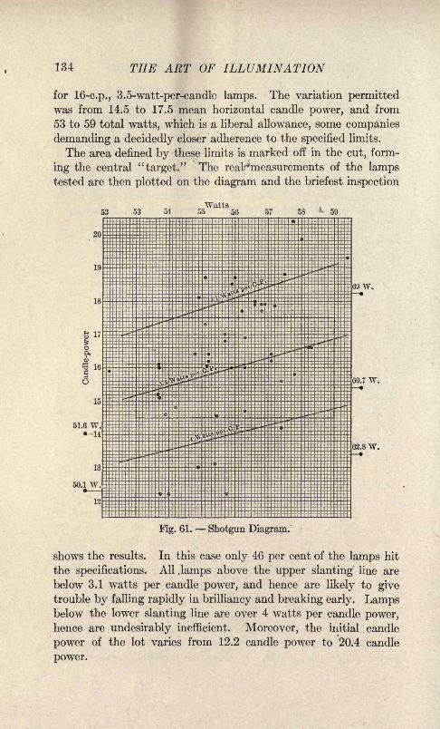
134 THE ART OF ILLUMINATION
for 16-c.p., 3.5-watt-per-candle lamps. The variation permittedwas from 14.5 to 17.5 mean horizontal candle power, and from
53 to 59 total watts, which is a liberal allowance, some companies
demanding a decidedly closer adherence to the specified limits.
The area defined by these limits is marked off in the cut, form-
ing the central"target." The reaPmeasurements of the lamps
tested are then plotted on the diagram and the briefest inspection
60.7 W.
62.8 W.
Fig. 61. Shotgun Diagram.
shows the results. In this case only 46 per cent of the lamps hit
the specifications. All .lamps above the upper slanting line are
below 3.1 watts per candle power, and hence are likely to give
trouble by falling rapidly in brilliancy and breaking early. Lampsbelow the lower slanting line are over 4 watts per candle power,hence are undesirably inefficient. Moreover, the initial candle
power of the lot varies from 12.2 candle power to 20.4 candle
power.
THE ELECTRIC INCANDESCENT LAMP 135
Such a lot will necessarily give poorer service and less satis-
factory life, and is, as a matter of dollars and cents, worth muchless to the user than if the lamps had been properly sorted at
the factory. Filaments cannot be made exactly alike, and the
manufacturer has to rely upon intelligent sorting to make use of
the product. For example, the topmost lamp of Fig. 61 should
have been marked for a lower voltage, at which it would have
done well. Nearly all the lot would have properly fallen within
commercial specifications for 16-c.p. lamps at some practicable
voltage and rating in watts per candle power. The imperfect
sorting has misplaced many of the lamps and depreciated the
whole lot.
In commercial practice lamps should be carefully sorted to
meet the required specifications, and the persons who buy lampsshould insist upon rigid adherence to the specifications, and
should, in buying large quantities, test them to insure their cor-
rectness. To sum up, it pays to use good lamps of as high
efficiency as is compatible with proper life, and to see that one
gets them.
The real efficiency of an incandescent lamp, i.e., the proportionof the total energy supplied which appears as visible luminous
energy, is very small, ordinarily from 2 to 3 per cent in carbon
lamps, not over 5 to 6 per cent even in the best metallic filament
lamps. This means that in working incandescent lamps from
steam-driven plants less than 0.5 per cent of the energy of the coal
appears as useful light.
Up to about 1905 the carbon lamp substantially as just de-
scribed was the only form of incandescent lamp used in this coun-
try. At about this time a radical modification in carbon filaments
was produced which has come into large commercial use. This
was the so-called metallized filament, substantially an allotropic
form of carbon which was the result of attempts to convert an
ordinary carbon filament into pure graphitic carbon. The manu-facture of the metallized filament starts with the ordinary squirted
cellulose filament already described as the base of operations.
This is baked in an electric furnace at a very high temperature,
and after subjection to a flashing process akin to that in general
use is again fired, the temperature being carried to the neigh-
borhood of 3000 C. The result is a complete change in the
texture and appearance of the carbon and in its physical proper-
136 THE ART OF ILLUMINATION
ties. The specific resistance is enormously reduced, falling to a
figure comparable with the poorly conducting metals, and the tem-
perature coefficient becomes positive like that of a metal, instead
of being negative, as in the ordinary forms of carbon. The metal-
lized filament in practice has only a very small temperature coeffi-
cient of either sign, and is, from its lower resistance, much slenderer
than the ordinary carbon filament and considerably more refrac-
tory, so that it can be worked at a higher temperature.
The normal initial specific consumption of these femps is about
2.5 watts per m. h. c. p., and the life and fall of candle power
during life approximately the same as for the 3.1-watt ordinary
carbon-filament lamps. Such lamps are manufactured in sizes of
50, 100, 125, 187, and 250 watts, rated respectively at 20, 40, 50,
75, and 100 candle power. The smallest size has replaced the ordi-
nary 50-watt 16-c.p. carbon lamp to a very large extent, and the
larger sizes have been considerably used in commercial lighting, but
are now rapidly disappearing under the competition of the true
metallic filament lamps.
The metallized filament, interesting as it is, was an improvementintroduced a few years too late, since at the time of its productionthe true metallic filament lamps, now coming into general use, had
already been produced abroad. The , metallized filament lamps,
therefore, which resemble in general properties and distribution of
light the carbon lamps which had preceded them, are now only of
passing interest. The first of the metallic filament group of lampswas the osmium lamp of Dr. Auer von Welsbach. Osmium is a
rare metal found associated with the platinum group in small
quantities. It has an atomic weight of 191, a specific gravity of
22.48, and a specific resistance in the lamp filaments of about 47
microhms per cubic centimeter. It is a strong acid-forming ele-
ment of extremely uncompromising mechanical qualities, and has
not yet been produced in true metallic form, but only as a black
powder. The osmium filaments were made by mixing the finely
divided metal with a binding material into a paste, squirting it
through dies into a filament, and then driving out the binder byintense heat and sintering the residuum into a coherent metallic
mass. The relatively high conductivity of the metal forbade the
successful production of filaments for ordinary voltages, and most
of the commercial lamps were intended to be burned at a pressure
of about 50 volts, either on a separate circuit, or two in series on
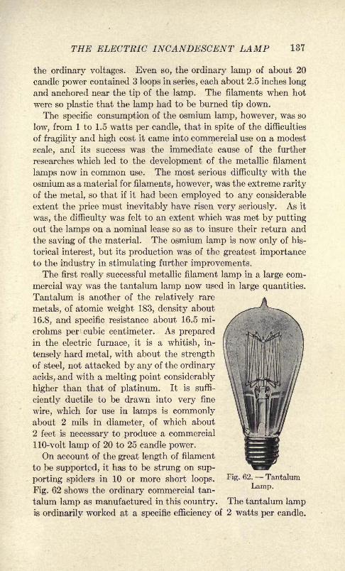
THE ELECTRIC INCANDESCENT LAMP 137
the ordinary voltages. Even so, the ordinary lamp of about 20
candle power contained 3 loops in series, each about 2.5 inches long
and anchored near the tip of the lamp. The filaments when hot
were so plastic that the lamp had to be burned tip down.
The specific consumption of the osmium lamp, however, was so
low, from 1 to 1.5 watts per candle, that in spite of the difficulties
of fragility and high cost it came into commercial use on a modest
scale, and its success was the immediate cause of the further
researches which led to the development of the metallic filament
lamps now in common use. The most serious difficulty with the
osmium as a material for filaments, however, was the extreme rarity
of the metal, so that if it had been employed to any considerable
extent the price must inevitably have risen very seriously. As it
was, the difficulty was felt to an extent which was met by putting
out the lamps on a nominal lease so as to insure their return and
the saving of the material. The osmium lamp is now only of his-
torical interest, but its production was of the greatest importanceto the industry in stimulating further improvements.The first really successful metallic filament lamp in a large com-
mercial way was the tantalum lamp now used in large quantities.
Tantalum is another of the relatively rare
metals, of atomic weight 183, density about
16.8, and specific resistance about 16.5 mi-
crohms per cubic centimeter. As prepared
in the electric furnace, it is a whitish, in-
tensely hard metal, with about the strength
of steel, not attacked by any of the ordinary
acids, and with a melting point considerably
higher than that of platinum. It is suffi-
ciently ductile to be drawn into very fine
wire, which for use in lamps is commonlyabout 2 mils in diameter, of which about
2 feet is necessary to produce a commercial
110-volt lamp of 20 to 25 candle power.
On account of the great length of filament
to be supported, it has to be strung on sup-
porting spiders in 10 or more short loops.FiS- 62 - Tantalum
Fig. 62 shows the ordinary commercial tan-
talum lamp as manufactured in this country. The tantalum lampis ordinarily worked at a specific efficiency of 2 watts per candle.
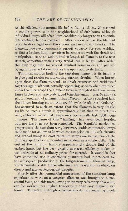
138 THE ART OF ILLUMINATION
At this efficiency its normal life before falling off, say 20 per cent
in candle power, is in the neighborhood of 800 hours, althoughindividual lamps will often burn considerably longer than this with-
out reaching the loss specified. After protracted use the filament
tends to draw tight over the spiders and eventually breaks. The
filament, however, possesses a curious capacity for easy welding,
so that a broken lamp may often be connected with the circuit and
manipulated so as to weld a broken length of filament to the next
stretch, sometimes with a very trivial loss in length, after which
the lamp may burn for several hundred hours more, and perhapsbe again rewelded if one follows the operation to its limit.
The most serious fault of the tantalum filament is its inability
to give good results on alternating-current circuits. When burned
upon these the filament tends to break crosswise and weld itself
together again without actually separating, so that when examined
under the microscope the filament looks as though it had been manytimes broken and carelessly glued together again. Fig. 63 shows a
photomicrograph of a filament thus affected. After a couple of hun-
dred hours burning on an ordinary 60-cycle circuit this"faulting
"
has occurred to such an extent that the filament is very fragile.
Its life on such a circuit is approximately half that on direct cur-
rent, although individual lamps may occasionally last 1000 hours
or more. The cause of this"faulting" has never been ferreted
out, nor has it as yet been remedied. The beautiful mechanical
properties of the tantalum wire, however, enable commercial lampsto be made for as low as 25 watts consumption on 110-volt circuits,
and abroad many 220-volt tantalum lamps are in use, two of the
ordinary spiders being mounted in tandem in a single bulb. Thecost of the tantalum lamp is approximately double that of the
carbon lamp, but the very greatly increased efficiency makes its
use desirable at all ordinary prices for current. It would in fact
have come into use in enormous quantities had it not been for
the subsequent production of the tungsten metallic filament lamp,which permits a still higher efficiency and is equally available on
direct- and alternating-current circuits.
Shortly after the commercial appearance of the tantalum lampexperimental work on a tungsten filament was brought to a suc-
cessful issue, and this metal, owing to its very refractory character,
can be worked at a higher temperature than any filament yetfound. Tungsten, although a comparatively rare metal, is much
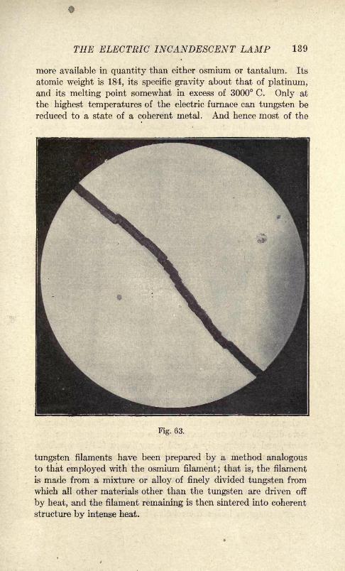
THE ELECTRIC INCANDESCENT LAMP 139
more available in quantity than either osmium or tantalum. Its
atomic weight is 184, its specific gravity about that of platinum,
and its melting point somewhat in excess of 3000 C. Only at
the highest temperatures of the electric furnace can tungsten be
reduced to a state of a coherent metal. And hence most of the
Fig. 63.
tungsten filaments have been prepared by a method analogousto that employed with the osmium filament; that is, the filament
is made from a mixture or alloy of finely divided tungsten from
which all other materials other than the tungsten are driven off
by heat, and the filament remaining is then sintered into coherent
structure by intense heat.
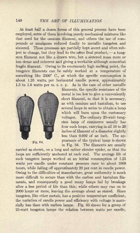
140 THE ART OF ILLUMINATION
At least half a dozen forms of this general process have been
employed, some of them involving purely mechanical mixtures like
that used for the osmium filament, and others the use of com-
pounds or amalgams reduced finally to metallic tungsten and
sintered. These processes are partially kept secret and often sub-
ject to change, but they lead to the stfme final product, a tung-sten filament not like a drawn wire, but a sintered mass more or
less dense and coherent and giving a workable although somewhat
fragile filament. Owing to its enormously high meMng point, the
tungsten filaments can be safely worked at a temperature of
something like 2300 C., at which the specific consumption is
about 1.25 watts, per horizontal candle power, approximately1.5 to 1.6 watts per m. s. c. p. As in the case of other metallic
filaments, the specific resistance of the
metal is too low to give a conveniently
short filament, so that it is necessary,
as with osmium and tantalum, to use
several loops in series to obtain a lampwhich will burn upon the customary
voltages. The ordinary 25-watt tung-
sten lamp of commerce usually'
has
four such loops, carrying in all 16 to 20
inches of filament of a diameter slightly
less than 0.002 of an inch. The ap-
pearance of the typical lamp is shown
in Fig. 64. The filaments are usually
carried as shown, on a long and rather slender spider, so that the
loops are sufficiently anchored at each end. The average life of
such tungsten lamps worked at an initial consumption of 1.25
watts per candle under constant pressure runs to about 1000
hours, while falling off approximately 20 per cent in candle power.
Owing to the difficulties of manufacture, great uniformity is muchmore difficult to secure than with the carbon and tantalum fila-
ments, and consequently a good many lamps fail by breakageafter a less period of life than this; while others may run on to
2000 hours or more, leaving the average about as stated. Since
tungsten, like other metals, has a positive temperature coefficient,
the variation of candle power and efficiency with voltage is mate-
rially less than with carbon lamps. Fig. 65 shows for a group of
25-watt tungsten lamps the relation between watts per candle,
Fig. 64.
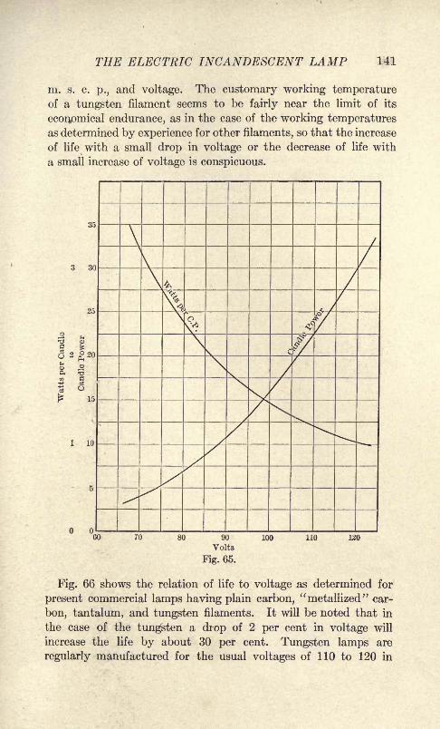
THE ELECTRIC INCANDESCENT LAMP 141
and voltage. The customary working temperatureof a tungsten filament seems to be fairly near the limit of its
economical endurance, as in the case of the working temperaturesas determined by experience for other filaments, so that the increase
of life with a small drop in voltage or the decrease of life with
a small increase of voltage is conspicuous.
Fig. 66 shows the relation of life to voltage as determined for
present commercial lamps having plain carbon, "metallized" car-
bon, tantalum, and tungsten filaments. It will be noted that in
the case of the tungsten a drop of 2 per cent in voltage will
increase the life by about 30 per cent. Tungsten lamps are
regularly manufactured for the usual voltages of 110 to 120 in
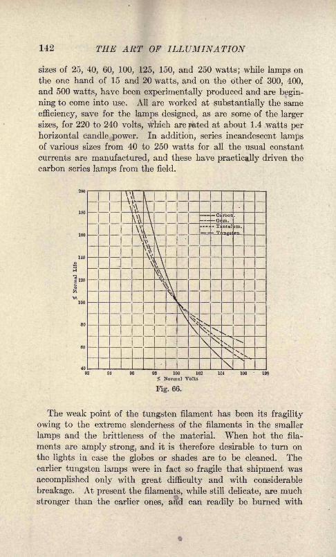
142 THE ART OF ILLUMINATION
sizes of 25, 40, 60, 100, 125, 150, and 250 watts; while lamps on
the one hand of 15 and 20 watts, and on the other of 300, 400,
and 500 watts, have been experimentally produced and are begin-
ning to come into use. All are worked at substantially the same
efficiency, save for the lamps designed, as are some of the larger
sizes, for 220 to 240 volts, which are rated at about 1.4 watts perhorizontal candle power. In addition, series incandescent lampsof various sizes from 40 to 250 watts for all the usual constant
currents are manufactured, and these have practically driven the
carbon series lamps from the field.
100 102
% Normal Volts
Fig. 66.
The weak point of the tungsten filament has been its fragility
owing to the extreme slenderhess of the filaments in the smaller
lamps and the brittleness of the material. When hot the fila-
ments are amply strong, and it is therefore desirable to turn on
the lights in case the globes or shades are to be cleaned. Theearlier tungsten lamps were in fact so fragile that shipment was
accomplished only with great difficulty and with considerable
breakage. At present the filaments, while still delicate, are much
stronger than the earlier ones, and can readily be burned with
THE ELECTRIC INCANDESCENT LAMP 143
the lamp in any position, a procedure that was distinctly unwise
at first.
The changes going on in the production of these tungsten lampsare so rapid that it is futile to attempt more than a cursory
description of the state of the art. The lamps are now manu-factured by a great number of makers both here and abroad
under a wide variety of trade names, but the differences between
them are mostly of a minor character. The most important recent
improvement in manufacture, not yet generally introduced, is the
production of a tungsten filament of drawn wire like the tantalum
filament. At the extreme temperatures of the electric furnace,
tungsten can be produced in true metallic state, and althoughbrittle when cold it is moderately ductile when hot, and is drawn
into wire in this state. The details of this difficult process have
now been fairly well worked out, so that the drawn filaments have
already come into some commercial use and show evidence of
considerably greater strength and rather better life than the sin-
tered filaments previously used. It is too early yet to speakof their exact properties. The wire drawn filaments are mounted
on spiders akin to those used in the tantalum lamps.
Tungsten lamps have already gone far in driving out the carbon
lamps, and prove particularly useful in the larger units, from
40 to 150 watts. The only objection to their employment is
their cost and the fact that they are not yet strong enough to
stand use in positions where considerable vibration is experienced.
Both these difficulties are likely to be remedied to a very material
extent. The present cost of tungsten lamps, being at retail from
60 cents upwards, according to size, is so considerable that break-
age becomes a serious item, which is, however, more than over-
balanced by the saving in current, except where current is to be
had at very low rates.
Whether the tungsten lamp represents the last stage of improve-
ment of the metallic filament remains to be seen. There is cer-
tainly no metal yet known which has a higher melting point, nor
is there a reasonable expectation of finding such a metal. It is
possible that the use of alloys may lead to improvement, but it is
fairly certain that no alloy is likely to raise the melting point
already available with tungsten, although it is highly probable
that it may be possible to work out alloys of the extremely
refractory metals which will improve their mechanical properties
144 THE ART OF ILLUMINATION
and also raise their specific resistance, an end which is highlydesirable. Many experiments have been tried and are being tried
with nonmetallic filaments composed of refractory oxides and
other compounds. None of these has yet reached a point where
it is more than experimental, except for the Nernst lamp, about
to be described, which belongs to a_somewhat different class. It is
worth mentioning, as a matter chiefly of theoretical interest, that
practically all the modern filaments have a somewhat favorable
selective radiation as compared with carbon. Jn other words,
their radiation is more efficient than the true temperature of
the filament would indicate, owing to a better distribution of
energy in the spectrum.
The Nernst lamp, introduced about ten years ago, differs materi-
ally from the other incandescent lamps in that the material of the
light-giving body is a nonconductor when cold and has to be oper-
ated in air rather than in vacuo, to the material disadvantage of
its efficiency. It was, however, the first incandescent lamp of high
efficiency to appear, and has found its way into considerable use
both here and abroad. The basic fact taken advantage of by Dr.
Nernst in the production of his lamp is that certain metallic
oxides, particularly the rare earths such as are used in the Wels-
bach mantle, while nonconductors at ordinary temperatures, con-
duct fairly well when hot. This conduction is of an electrolytic
nature, so that the"glowers
"endure best when used on alternating
current of a fairly high frequency. The fundamental principle of
the Nernst lamp is the use of a glower of such material artificially
heated at the start to render it a conductor and then allowed to
glow under the passage of the current. Many materials are avail-
able for the glower, and its composition has been changed from
time to time. In one of Nernst's original patents the compositionwas specified as of zirconia, erbia, and yttria. The later composi-
tions have substituted thoria in part or wholly for the zirconia, and
have also included the ceria that is found so effective in Welsbach
mantles. Recent glowers are of a mixture of ceria, thoria and zir-
conia. Whatever the exact composition employed, the procedurein manufacture is quite similar to that used in some of the later
lamp filaments, the active material being mixed with a binder,
formed into slender rods, and then fired at a high temperature
until nothing but the mixed oxides are left. The glower bodies
themselves are one-sixty-fourth to one-thirty-second of an inch in
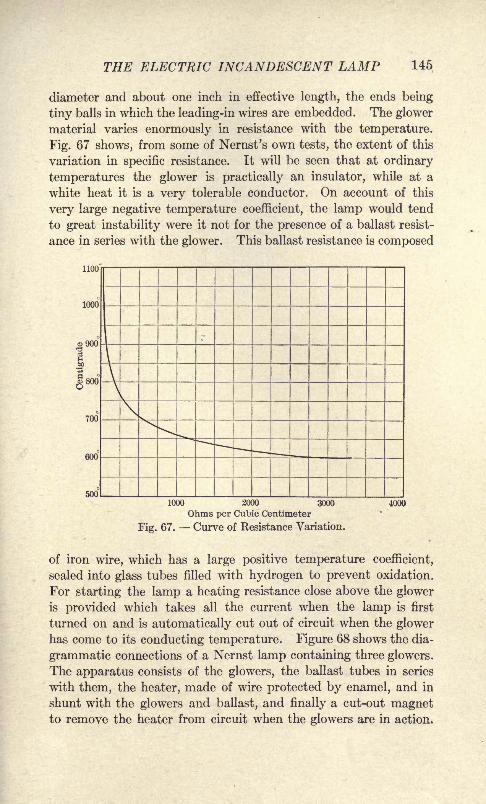
THE ELECTRIC INCANDESCENT LAMP 145
diameter and about one inch in effective length, the ends being
tiny balls in which the leading-in wires are embedded. The glower
material varies enormously in resistance with the temperature.
Fig. 67 shows, from some of Nernst's own tests, the extent of this
variation in specific resistance. It will be seen that at ordinary
temperatures the glower is practically an insulator, while at a
white heat it is a very tolerable conductor. On account of this
very large negative temperature coefficient, the lamp would tend
to great instability were it not for the presence of a ballast resist-
ance in series with the glower. This ballast resistance is composed
HOOr
1000
900 1
700
5001
1000 3000 3000
Ohms per Cubic Centimeter
Fig. 67. Curve of Resistance Variation.
4000
of iron wire, which has a large positive temperature coefficient,
sealed into glass tubes filled with hydrogen to prevent oxidation.
For starting the lamp a heating resistance close above the glower
is provided which takes all the current when the lamp is first
turned on and is automatically cut out of circuit when the glower
has come to its conducting temperature. Figure 68 shows the dia-
grammatic connections of a Nernst lamp containing three glowers.
The apparatus consists of the glowers, the ballast tubes in series
with them, the heater, made of wire protected by enamel, and in
shunt with the glowers and ballast, and finally a cut-out magnetto remove the heater from circuit when the glowers are in action.
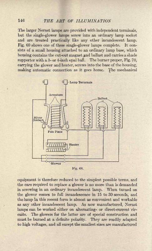
146 THE ART OF ILLUMINATION
The larger Nernst lamps are provided with independent terminals,
but the single-glower lamps screw into an ordinary lamp socket
and are treated practically like any other incandescent lamp.
Fig. 69 shows one of these single-glower lamps complete. It con-
sists of a small housing attached to an ordinary lamp base, which
housing contains the cut-out magnet and ballast and carries a shade
supporter with a 3- or 4-inch opal ball. The burner proper, Fig. 70,
carrying the glower and heater, screws into the base of the housing,
making automatic connection as it goes home. ^ne mechanical
3] [-Lamp Terminals
Glower
Fig. 68.
equipment is therefore reduced to the simplest possible terms, and
the care required to replace a glower is no more than is demandedin screwing in an ordinary incandescent lamp. When turned on
the glower comes to full incandescence in 15 to 30 seconds, and
the lamp in this recent form is almost as convenient and workable
as any other incandescent lamp. As now manufactured, Nernst
lamps can be worked either on alternating- or direct-current cir-
cuits. The glowers for the latter are of special construction and
must be burned at a definite polarity. They are readily adaptedto high voltages, and all except the smallest sizes are manufactured
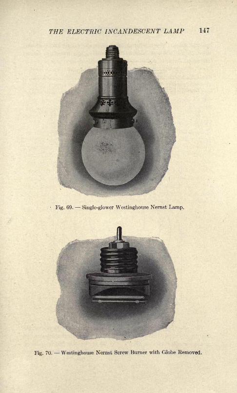
THE ELECTRIC INCANDESCENT LAMP 147
Fig. 69. Single-glower Westinghouse Nernst Lamp.
Fig. 70. Westinghouse Nernst Screw Burner with Globe Removed.
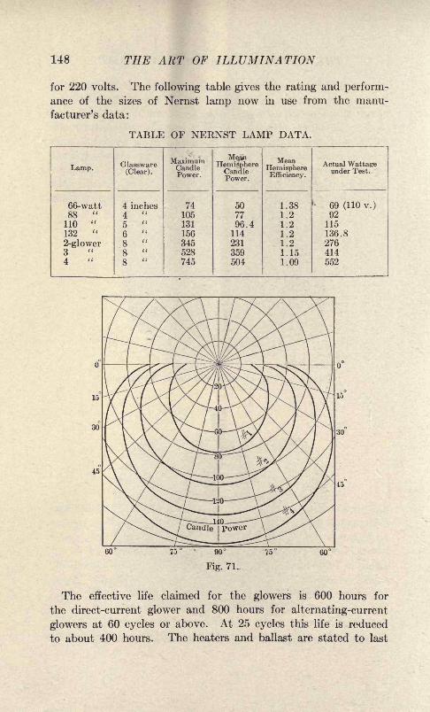
148 THE ART OF ILLUMINATION
for 220 volts. The following table gives the rating and perform-
ance of the sizes of Nernst lamp now in use from the manu-
facturer's data:
TABLE OF NERNST LAMP DATA.
GO
The effective life claimed for the glowers is 600 hours for
the direct-current glower and 800 hours for alternating-current
glowers at 60 cycles or above. At 25 cycles this life is reduced
to about 400 hours. The heaters and ballast are stated to last
THE ELECTRIC INCANDESCENT LAMP 149
about 3000 and 15,000 hours respectively, and are easily replacedwhen necessary. Fig. 71 shows the distribution of light in the
lower hemisphere of the single-glower lamps referred to in the
table. The temperature reached by the Nernst glower being
upwards of 2000 C., the light is of good color, about the sameas that from a tungsten lamp, and the efficiency is fairly high, as
will be seen from the table already given. Reckoned on the basis
of mean spherical candle power, the specific consumption, includ-
ing the ballast, is somewhere between 1.5 and 2 watts per candle
power.The structure of the lamp, however, requires that it should
be compared with other illuminants rather on the basis of its
mean lower hemispherical candle power, assuming the other lamps
compared to be equipped with suitable reflectors. Aside from its
convenient use as a practical illuminant, it furnishes for experi-
mental purposes one of the most convenient of light sources, since
once the lamp is in action it can be run in any position, and
gives a very steady and brilliant light, the intrinsic brilliancy of
the glower being about 3000 candle power per square inch. In
such use the current should be held accurately uniform by meansof a milli-amperemeter, and the glower must be very carefully
shielded from draughts, to which it is hypersensitive.
CHAPTER VIII.
THE ELECTRIC ARC LAMP."
''
f*
THE electric arc is the most intense artificial illuminant and
the chief commercial source of very powerful light. A full
account of it would make a treatise by itself, so that we can here
treat only the phases of the subject which bear directly on its
place as a practical illuminant. First observed, probably, by Volta
himself, the arc was brought to general notice by Davy in 1808
in the course of his experiments with the great battery of the
Royal Institution. If one slowly breaks at any point an electric
circuit carrying considerable current at a fair voltage, the current
does not cease flowing when the conductor becomes discontinuous,
but current follows across the break, with the evolution of great
heat and a vivid light. If the separation is at the terminals of
two carbon rods the light is enormously brilliant, and by proper
mechanism can be maintained tolerably constant. The passage of
the current is accompanied by the production of immense heat,
and the tips of the carbon rods grow white hot, and serve as the
source of light. In an ordinary arc lamp the upper carbon is the
positive pole of the circuit, and is fed slowly downward, so as
to keep the arc uniform as the carbon is consumed. The main
consumption of energy appears to be at the tip of this positive
carbon, which is by far the most brilliant part of the arc, and
at which the carbon fairly boils away into vapor, producing a
slight hollow in the center of the upper carbon, known as the"crater."
The carbon outside the crater takes the shape of a blunt point,
while the lower carbon is rather evenly and more sharply pointed,
and tends, if the arc is short, to build up accretions of carbon into
somewhat of a mushroom shape. Fig. 72 shows the shape of
these tips much enlarged, as they would appear in looking at the
arc through a very dark glass. Under such circumstances the light
from the arc between the carbon points seems quite insignificant,
and it is readily seen that the crater is by far the hottest and most
brilliant region. In point of fact the crater may reach a temper-150

THE ELECTRIC ARC LAMP 151
ature of probably 3500 to 4000 C., and gives about 50,000 candle
power per square inch of surface sometimes much more.
It is obvious that the more energy spent in this crater the more
heat and light will be evolved, and that the concentration of much
energy in a small crater ought to produce a tremendously powerful
Fig. 72. The Electric Arc.
arc. It is not surprising, therefore, to find that the larger the
current crowded through a small carbon tip, in other words,
the higher the current density of the arc, the more intense the
luminous effects and the more efficient the arc. Fig. 73 shows this
fact graphically, giving the relation between current density and
light in an open arc maintained at uniform current and voltage.
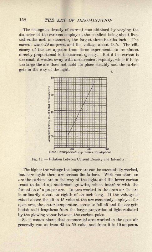
152 THE ART OF ILLUMINATION
The change in density of current was obtained by varying the
diameter of the carbons employed, the smallest being about five-
sixteenths inch in diameter, the largest three-fourths inch. Thecurrent was 6.29 amperes, and the voltage about 43.5. The effi-
ciency of the arc appears from these experiments to be almost
directly proportional to the current density. But if the carbon is
too small it wastes away with inconvenient rapidity, while if it be
too large the arc does not hold its place steadily and the carbon
gets in the way of the light.
80
!GO
200 400 600Mean Hemispherical c.p. Lower Hemisphere
Fig. 73. Relation between Current Density and Intensity.
The higher the voltage the longer arc can be successfully worked,but here again there are serious limitations. With too short an
arc the carbons are in the way of the light, and the lower carbon
tends to build up mushroom growths, which interfere with the
formation of a proper arc. In arcs worked in the open air the arc
is ordinarily about an eighth of an inch long. If the voltage is
raised above the 40 to 45 volts at the arc commonly employed for
open arcs, the crater temperature seems to fall off and the arc gets
bluish as it lengthens from the larger proportion of light radiated
by the glowing vapor between the carbon poles.
So it comes about that commercial arcs worked in the open air
generally run at from 45 to 50 volts, and from 6 to 10 amperes.
THE ELECTRIC ARC LAMP 153
The softer and finer the carbons the lower the voltage required to
maintain an arc of good efficiency and proper length, so that arcs
can be worked successfully at 25 to 35 volts with proper carbons,
and with very high efficiency, but at the cost of burning up the
carbons rather too rapidly. Abroad, where both high-grade car-
bons and labor are cheaper than in this country, such low-voltage
arcs are freely used with excellent results, and give a greatly in-
creased efficiency. Sometimes three are burned in series across
110-volt mains, where in American practice one, or at most two,
arc lamps would be used, in series with a resistance coil, the same
amount of energy being used in each case. With proper carbons
too, a steady and efficient arc can be produced taking only 3 or 4
amperes, and admirable little arc lamps of such kind are in use on
the Continent. The carbons are barely as large as a lead pencil
and the whole lamp is proportionately small, but the light is
brilliant and uniform.
The upper carbon burns away about twice as fast as the lower,
and the rate of consumption is ordinarily from 1 to 2 inches per
hour, in commercial open arc lamps.
The carbons themselves are generally about one-half inch in
diameter, and one or both are often cored, i.e., provided with a
central core, perhaps one-sixteenth inch in diameter, of carbon
considerably softer than the rest. This tends to hold the arc cen-
trally between the carbons and also steadies it by the greater mass
of carbon vapor provided by the softer portion. Generally it is
found sufficient to use one cored and one solid carbon in each arc,
although in this country arcs burning in the open air usually are
provided with solid carbons only.
In American practice such open arcs have almost passed out of
use, being replaced by the so-called inclosed arcs and by the still
more recent luminous and flaming arcs. During the past ten years
all these have gone into use in immense numbers, until at the
present time the open arc is very rarely installed, and illuminating
companies are discarding them as rapidly as they find it convenient
to purchase improved equipment.The principle of the inclosed arc is very simple. It merely con-
sists in fitting around the lower carbon a thin, elongated vessel of
refractory glass with a snugly fitting metallic cap through which
the upper carbon is fed, the fit being as close as permits of proper
feeding. The result is that the oxygen is quickly burned out of the
154 THE ART OF ILLUMINATION
globe, and the rapid oxidation of the carbon ceases, the heated gas
within checking all access of fresh air save for the small amount
that works in by diffusion through the crevices.
The carbon wastes away at the rate of only something like one-
eighth inch per hour under favorable circumstances, and the lamp
only requires trimming once an six or, eight full nights of burning,
instead of each night. For all-nighii lighting it used to be neces-
sary to employ a double-carbon lamp, in which were placed two
pairs of carbons, so that when the first pair was, consumed the
second pair would automatically go into action and finish out
the night. The inclosed lamp burns 100 hours or more with a
single trimming. Even much longer burning than this has been
obtained from a 12-inch carbon, such as is customarily used, but
one cannot safely reckon on a better performance without veryunusual care.
Fig. 74 shows a typical inclosed arc lamp, of the description
often used on 110-volt circuits, both with and without its outer
globe and case. The nature of the inner globe is at once apparent,
but it should also be noted that the clutch by which the carbon is
fed acts, as in many recent lamps, directly upon the carbon itself,
thereby saving the extra length of lamp required by the use of
a feeding rod attached to the carbon. Finally, at the top of the
lamp is seen a coil of spirally wound resistance wire. The pur-
pose of this is to take up the difference between 110 volts, which
is the pressure at the mains, and that voltage which it is desired
to use at the arc and in the lamp mechanism.
Such a resistance evidently involves a considerable waste of
energy, but in the inclosed arc the voltage at the arc itself is, of
necessity, rather high, 70 to 75 volts, so that the waste is less than
it would otherwise be.
It has been found that when burning in an inner globe without
access of air, the lower or negative carbon begins to act badly, and
to build up a mushroom tip, when the voltage falls below about
65 volts. Hence it is necessary to the successful working of the
scheme that the arc should be nearly twice as long as when the
carbons are burning in open air. This has a double effect, in
part beneficial, in part harmful. With the increased length the
crater practically disappears, and the light is radiated very freely
without being blocked by the carbons. Hence the distribution of
light from the inclosed arc is better than from an open arc.
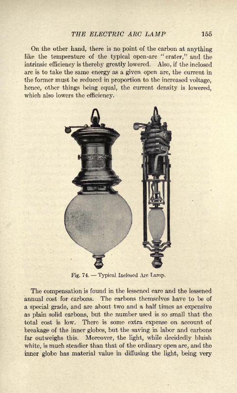
THE ELECTRIC ARC LAMP 155
On the other hand, there is no point of the carbon at anythinglike the temperature of the typical open-arc "crater," and the
intrinsic efficiency is thereby greatly lowered. Also, if the inclosed
arc is to take the same energy as a given open arc, the current in
the former must be reduced in proportion to the increased voltage,
hence, other things being equal, the current density is lowered,
which also lowers the efficiency.
Fig. 74. Typical Inclosed Arc Lamp.
The compensation is found in the lessened care and the lessened
annual cost for carbons. The carbons themselves have to be of
a special grade, and are about two and a half times as expensive
as plain solid carbons, but the number used is so small that the
total cost is low. There is some extra expense on account of
breakage of the inner globes, but the saving in labor and carbons
far outweighs this. Moreover, the light, while decidedly bluish
white, is much steadier than that of the ordinary open arc, and the
inner globe has material value in diffusing the light, being very
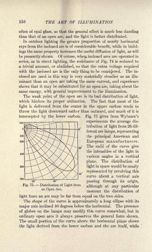
156 THE ART OF ILLUMINATION
often of opal glass, so that the general effect is much less dazzling
than that of an open arc, and the light is better distributed.
In outdoor lighting the greater proportion of nearly horizontal
rays from the inclosed arc is of considerable benefit, while in build-
ings the same property increases the useful diffusion of light, as will
be presently shown. Of course, when; inclosed arcs are operated in
series, as in street lighting, the resistance of Fig. 74 is reduced to
a trivial amount, or abolished, so that the extra voltage required
with the inclosed arc is the only thing to be considered. The in-
closed arc used in this way is very materially steadier as an illu-
minant than an open arc taking the same current, and experience
shows that it may be substituted for an open arc, taking about the
same energy, with general improvement to the illumination.
The weak point of the open arc is its bad distribution of light,
which hinders its proper utilization. The fact that most of the
light is delivered from the crater in the upper carbon tends to
throw the light downward rather than outward, and much of it is
intercepted by the lower carbon. Fig. 75 gives from Wybauw'sexperiments the average dis-
tribution of light from 26 dif-
ferent arc lamps, representing
the principal American and
European manufacturers.The radii of the curve give
the intensities of the light in
various angles in a vertical
plane. The distribution of
light in space would be nearly
represented by revolving this
curve about a vertical axis
passing through its origin,
although at any particular
moment the distribution of
800
Fig. 75. Distribution of Light from
an Open Arc.
light from an arc may be far from equal on the two sides.
The shape of the curve is approximately a long ellipse with its
major axis inclined 40 degrees below the horizontal. The presence
of globes on the lamps may modify this curve somewhat, but in
ordinary open arcs it always preserves the general form shown.
The small portion of the curve above the horizontal plane shows
the light derived from the lower carbon and the arc itself, while
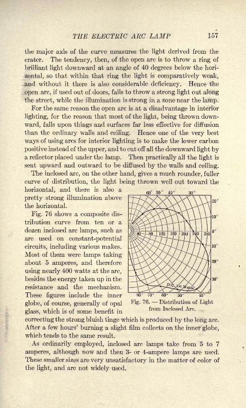
THE ELECTRIC ARC LAMP 157
60 50 40
the major axis of the curve measures the light derived from the
crater. The tendency, then, of the open arc is to throw a ring of
brilliant light downward at an angle of 40 degrees below the hori-
zontal, so that within that ring the light is comparatively weak,and without it there is also considerable deficiency. Hence the
open arc, if used out of doors, fails to throw a strong light out alongthe street, while the illumination is strong in a zone near the lamp.
For the same reason the open arc is at a disadvantage in interior
lighting, for the reason that most of the light, being thrown down-
ward, falls upon things and surfaces far less effective for diffusion
than the ordinary walls and ceiling. Hence one of the very best
ways of using arcs for interior lighting is to make the lower carbon
positive instead of the upper, and to cut off all the downward light bya reflector placed under the lamp. Then practically all the light is
sent upward and outward to be diffused by the walls and ceiling.
The inclosed arc, on the other hand, gives a much rounder, fuller
curve of distribution, the light being thrown well out toward the
horizontal, and there is also a
pretty strong illumination above
the horizontal.
Fig. 76 shows a composite dis-
tribution curve from ten or a
dozen inclosed arc lamps, such as
are used on constant-potential
circuits, including various makes.
Most of them were lamps taking
about 5 amperes, and therefore
using nearly 400 watts at the arc,
besides the energy taken up in the
resistance and the mechanism.
These figures include the inner
globe, of course, generally of opal
glass, which is of some benefit in
correcting the strong bluish tinge which is produced by the long arc.
After a few hours' burning a slight film collects on the inner globe,
which tends to the same result.
As ordinarily employed, inclosed arc lamps take from 5 to 7
amperes, although now and then 3- or 4-ampere lamps are used.
These smaller sizes are very unsatisfactory in the matter of color of
the light, and are not widely used.
:>JQ
30
80 70 60 50 40C
Fig. 76. Distribution of Lightfrom Inclosed Arc.
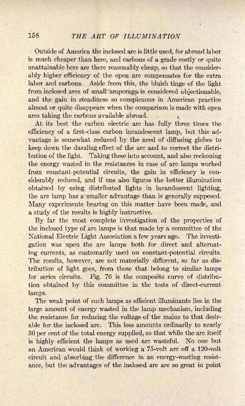
158 THE ART OF ILLUMINATION
Outside of America the inclosed arc is little used, for abroad labor
is much cheaper than here, and carbons of a grade costly or quite
unattainable here are there reasonably cheap, so that the consider-
ably higher efficiency of the open arc compensates for the extra
labor and carbons. Aside from this, the bluish tinge of the light
from inclosed arcs of small' amperage^ is considered objectionable,
and the gain in steadiness so conspicuous in American practice
almost or quite disappears when the comparison is made with openarcs taking the carbons available abroad. . ^
At its best the carbon electric arc has fully three times the
efficiency of a first-class carbon incandescent lamp, but this ad-
vantage is somewhat reduced by the need of diffusing globes to
keep down the dazzling effect of the arc and to correct the distri-
bution of the light. Taking these into account, and also reckoning
the energy wasted in the resistances in case of arc lamps worked
from constant-potential circuits, the gain in efficiency is con-
siderably reduced, and if one also figures the better illumination
obtained by using distributed lights in incandescent lighting,
the arc lamp has a smaller advantage than is generally supposed.
Many experiments bearing on this matter have been made, and
a study of the results is highly instructive.
By far the most complete investigation of the properties of
the inclosed type of arc lamps is that made by a committee of the
National Electric Light Association a few years ago. The investi-
gation was upon the arc lamps both for direct and alternat-
ing currents, as customarily used on constant-potential circuits.
The results, however, are not materially different, so far as dis-
tribution of light goes, from those that belong to similar lampsfor series circuits. Fig. 76 is the composite curve of distribu-
tion obtained by this committee in the tests of direct-current
lamps.
The weak point of such lamps as efficient illuminants lies in the
large amount of energy wasted in the lamp mechanism, including
the resistance for reducing the voltage of the mains to that desir-
able for the inclosed arc. This loss amounts ordinarily to nearly
30 per cent of the total energy supplied, so that while the arc itself
is highly efficient the lamps as used are wasteful. No one but
an American would think of working a 75-volt arc off a 120-volt
circuit and absorbing the difference in an energy-wasting resist-
ance, but the advantages of the inclosed arc are so great in point

THE ELECTRIC ARC LAMP 159
of steadiness and moderate cost of labor that the bad practice
has been considered commercially advantageous.
At present alternating-current arc lights are being rather widely
used, both on constant-potential and on constant-current circuits,
and such arcs present some very interesting characteristics. Evi-
dently when an arc is formed with an alternating current there
is no "positive" and no "negative" carbon, each carbon being
positive and negative alternately, and changing from one to the
other about 7200 times per minute 120 times per second.
Under these circumstances no marked crater is formed on either
carbon, and the two carbons are consumed at about an equal rate.
As a natural result of the intermittent supply of energy andthe lack of a localized crater, the average carbon temperature is
considerably lower than in case of the direct-current arc, and
the real efficiency of the arc as an illuminant is also much lowered.
Tests made to determine this difference of efficiency have givensomewhat varied results, but it seems probable that for unit energy
actually applied to the arc itself the direct-current arc will
give somewhere about 25 per cent more light than the alternating-
current arc. But since when working the latter on a constant-
potential circuit the surplus voltage can be taken up in a reactive
coil, which wastes very little energy, instead of by a dead resist-
ance, which wastes much, the two classes of arcs then stand upona more even footing than these figures indicate. This comparisonassumes inclosed arcs in each case.
The chief objection to the alternating-current arc has been the
singing noise produced by it. This is partly due to the vibration
produced in the lamp mechanism and partly to the pulsations
impressed directly on the air by the oscillatory action in the arc
itself. The former can be in great measure checked by proper
design and manufacture, but the noise due directly to the arc is
much more difficult to suppress.
Abroad, where, for the reason already adduced, open arcs are
commonly used, a specially fine, soft carbon is used for the
alternating arcs, and the noise is hardly perceptible. These soft,
volatile carbons, particularly when used at a considerable current
density, give such a mass of vapor in the arc as to endow it with
added stability and to muffle the vibration to a very marked
degree. The result is a quiet, steady, brilliant arc of most excellent
illuminating power. But in this country such carbons are with
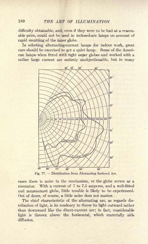
160 THE ART OF ILLUMINATION
difficulty obtainable, and, even if they were to be had at a reason-
able price, could not be used in inclosed-arc lamps on account of
rapid smutting of the inner globe.
In selecting alternating-current lamps for indoor work, great
care should be exercised to get a quiet lamp. Some of the Ameri-
can lamps when fitted with tight outer globes and worked with a
rather large current are entirely unobjectionable, but in many
60 55 50'
90 80 70 60 50"' 40
Fig. 77. Distribution from Alternating Inclosed Arc.
cases there is noise in the mechanism, or the globe serves as a
resonator. With a current of 7 to 7.5 amperes, and a well-fitted
and nonresonant globe, little trouble is likely to be experienced.
Out of doors, of course, a little noise does not matter.
The chief characteristic of the alternating arc, as regards dis-
tribution of light, is its tendency to throw its light outward rather
than downward like the direct-current arc; in fact, considerable
light is thrown above the horizontal, which materially aids
diffusion.

THE ELECTRIC ARC LAMP 161
For this reason it is often advantageous to use reflecting shades
for such lamps, so as to throw the light out nearly horizontally
when exterior lighting is being done. Indoors, diffusion answers
the same purpose, unless powerful downward light is needed, whenthe reflector is of service.
Fig. 77, from the committee report already mentioned, shows
the distribution of light from an alternating-current lamp fitted
with a porcelain reflecting shade, with an opalescent outer globe,
and -with a clear outer globe. The abolition of the outer globe
and the use of the reflector produce a prodigious effect in
strengthening the illumination in the lower hemisphere, and this
hemispherical illumination is for some purposes a convenient wayof reckoning the illumination of the lamp. But a truer test is
the spherical candle power, since that takes account of all the
light delivered by the lamp. Alternating arc lamps seem to work
best at a frequency of 50 to 60 cycles per second. Above 60
cycles they are apt to become noisy, and below about 40 cycles
the light flickers to a troublesome extent. The light of the alter-
nating arc is really of a pulsatory character, owing to the alterna-
tions. A pencil rapidly moved to and fro in the light of such an
arc shows a number of images one for each pulsation; and this
effect would be very distressing if one had to view moving objects,
like quick running machinery, by such light. A harrowing tale is
told of a certain theater in which alternating arcs were installed
for some gorgeous spectacular effects, and of the extraordinary
centipedal results when the ballet came on.
This pulsation is somewhat masked when the inclosed arc is
used, even with a clear outer globe, and is generally rather incon-
spicuous when an opal outer globe is used. It is also reduced
when a fairly heavy current (7 to 8 amperes) is used, and when
very soft carbons are employed, as they can be in open arcs.
An interesting comparison of direct-current and alternating-
current inclosed arcs, as used on constant-potential circuits, is
found in the following table, from the report already quoted.
It must be remembered that the results are in Hefner units.
This unit is exactly 0.9 candle power, so that the mean results,
reduced to a candle-power basis, are, for efficiency when usingclear outer globes, as follows:
Direct-current arc 2.89 watts per candle power.Alternating arc 2,96 watts per candle power.
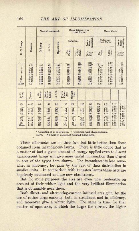
162 THE ART OF ILLUMINATION
* Condition of no outer globe, t Condition with shade on lamp.NOTE. All marked values not included in the mean.
These efficiencies are on their face but little better than those
obtained from incandescent lamps. There is little doubt that as
a matter of fact a given amount of energy applied even to 3-watt
incandescent lamps will give more useful illumination than if used
in arcs of the types here shown. The incandescents lose some-
what in efficiency, but gain by the fact of their distribution in
smaller units. In comparison with tungsten lamps these arcs are
hopelessly outclassed and are now obsolescent.
But for some purposes the arcs are even now preferable oil
account of their whiter light and the very brilliant illumination
that is obtainable near them.
Both direct- and alternating-current inclosed arcs gain, by the
use of rather large currents, both in steadiness and in efficiency,
and moreover give a whiter light. The same is true, for that
matter, of open arcs, in which the larger the current- the higher
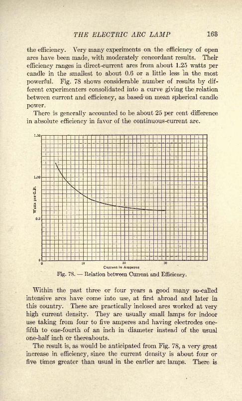
THE ELECTRIC ARC LAMP 163
the efficiency. Very many experiments on the efficiency of openarcs have been made, with moderately concordant results. Their
efficiency ranges in direct-current arcs from about 1.25 watts per
candle in the smallest to about 0.6 or a little less in the most
powerful. Fig. 78 shows considerable number of results by dif-
ferent experimenters consolidated into a curve giving the relation
between current and efficiency, as based- on mean spherical candle
power.There is generally accounted to be about 25 per cent difference
in absolute efficiency in favor of the continuous-current arc.
Current in Amperes
Fig. 78. Relation between Current and Efficiency.
Within the past three or four years a good many so-called
intensive arcs have come into use, at first abroad and later in
this country. These are practically inclosed arcs worked at very
high current density. They are usually small lamps for indoor
use taking from four to five amperes and having electrodes one-
fifth to one-fourth of an inch in diameter instead of the usual
one-half inch or thereabouts.
The result is, as would be anticipated from Fig. 78, a very great
increase in efficiency, since the current density is about four or
five times greater than usual in the earlier arc lamps. There is
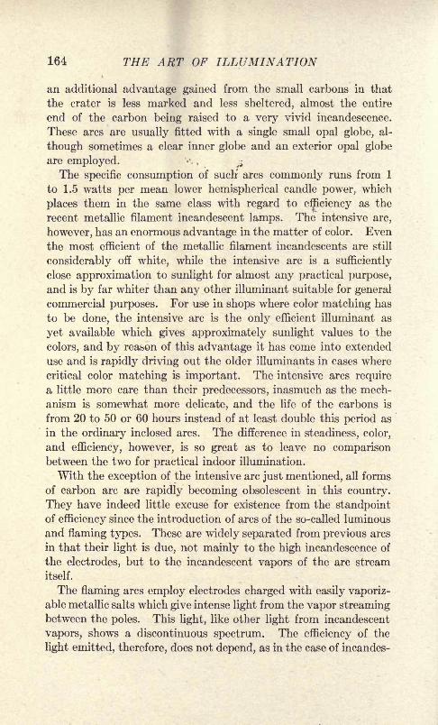
164 THE ART OF ILLUMINATION
an additional advantage gained from the small carbons in that
the crater is less marked and less sheltered, almost the entire
end of the carbon being raised to a very vivid incandescence.
These arcs are usually fitted with a single small opal globe, al-
though sometimes a clear inner globe and an exterior opal globe
are employed. -, ^
The specific consumption of such: arcs commonly runs from 1
to 1.5 watts per mean lower hemispherical candle power, which
places them in the same class with regard to e^ciency as the
recent metallic filament incandescent lamps. The intensive arc,
however, has an enormous advantage in the matter of color. Even
the most efficient of the metallic filament incandescents are still
considerably off white, while the intensive arc is a sufficiently
close approximation to sunlight for almost any practical purpose,
and is by far whiter than any other illuminant suitable for general
commercial purposes. For use in shops where color matching has
to be done, the intensive arc is the only efficient illuminant as
yet available which gives approximately sunlight values to the
colors, and by reason of this advantage it has come into extended
use and is rapidly driving out the older illuminants in cases where
critical color matching is important. The intensive arcs require
a little more care than their predecessors, inasmuch as the mech-
anism is somewhat more delicate, and the life of the carbons is
from 20 to 50 or 60 hours instead of at least double this period as
in the ordinary inclosed arcs. The difference in steadiness, color,
and efficiency, however, is so great as to leave no comparisonbetween the two for practical indoor illumination.
With the exception of the intensive arc just mentioned, all forms
of carbon arc are rapidly becoming obsolescent in this country.
They have indeed little excuse for existence from the standpointof efficiency since the introduction of arcs of the so-called luminous
and flaming types. These are widely separated from previous arcs
in that their light is due, not mainly to the high incandescence of
the electrodes, but to the incandescent vapors of the arc stream
itself.
The flaming arcs employ electrodes charged with easily vaporiz-
able metallic salts which give intense light from the vapor streamingbetween the poles. This light, like other light from incandescent
vapors, shows a discontinuous spectrum. The efficiency of the
light emitted, therefore, does not depend, as in the case of incandes-
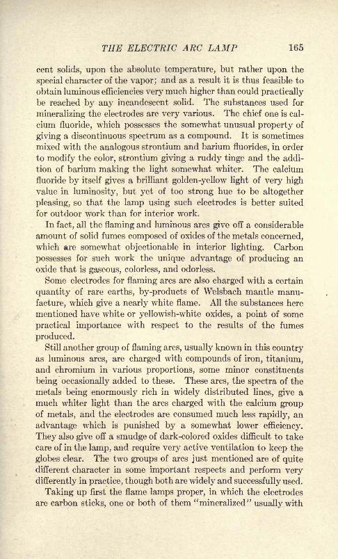
THE ELECTRIC ARC LAMP 165
cent solids, upon the absolute temperature, but rather upon the
special character of the vapor; and as a result it is thus feasible to
obtain luminous efficiencies very much higher than could practically
be reached by any incandescent solid. The substances used for
mineralizing the electrodes are very various. The chief one is cal-
cium fluoride, which possesses the somewhat unusual property of
giving a discontinuous spectrum as a compound. It is sometimes
mixed with the analogous strontium and barium fluorides, in order
to modify the color, strontium giving a ruddy tinge and the addi-
tion of barium making the light somewhat whiter. The calcium
fluoride by itself gives a brilliant golden-yellow light of very high
value in luminosity, but yet of too strong hue to be altogether
pleasing, so that the lamp using such electrodes is better suited
for outdoor work than for interior work.
In fact, all the flaming and luminous arcs give off a considerable
amount of solid fumes composed of oxides of the metals concerned,which are somewhat objectionable in interior lighting. Carbon
possesses for such work the unique advantage of producing an
oxide that is gaseous, colorless, and odorless.
Some electrodes for flaming arcs are also charged with a certain
quantity of rare earths, by-products of Welsbach mantle manu-
facture, which give a nearly white flame. All the substances here
mentioned have white or yellowish-white oxides, a point of some
practical importance with respect to the results of the fumes
produced.Still another group of flaming arcs, usually known in this country
as luminous arcs, are charged with compounds of iron, titanium,and chromium in various proportions, some minor constituents
being occasionally added to these. These arcs, the spectra of the
metals being enormously rich in widely distributed lines, give a
much whiter light than the arcs charged with the calcium groupof metals, and the electrodes are consumed much less rapidly, an
advantage which is punished by a somewhat lower efficiency.
They also give off a smudge of dark-colored oxides difficult to take
care of in the lamp, and require very active ventilation to keep the
globes clear. The two groups of arcs just mentioned are of quite
different character in some important respects and perform very
differently in practice, though both are widely and successfully used.
Taking up first the flame lamps proper, in which the electrodes
are carbon sticks, one or both of them "mineralized" usually with
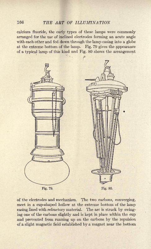
166 THE ART OF ILLUMINATION
calcium fluoride, the early types of these lamps were commonlyarranged for the use of inclined electrodes forming an acute angle
with each other and fed down through the lamp casing into a globe
at the extreme bottom of the lamp. Fig. 79 gives the appearanceof a typical lamp of this kind and Fig. 80 shows the arrangement
Fig. 79. Fig. 80.
of the electrodes and mechanism. The two carbons, converging,
meet in a cup-shaped hollow at the extreme bottom of the lamp
casing lined with refractory material. The arc is struck by swing-
ing one of the carbons slightly and is kept in place within the cupand prevented from running up on the carbons by the repulsion
of a slight magnetic field established by a magnet near the bottom
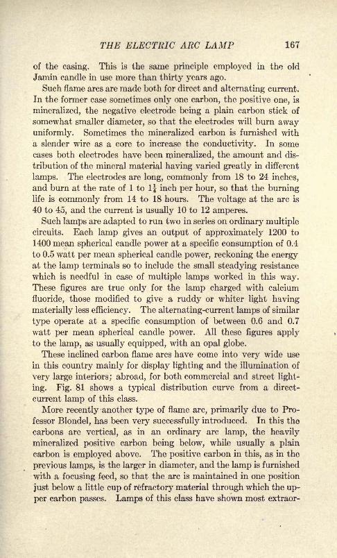
THE ELECTRIC ARC LAMP 167
of the casing. This is the same principle employed in the old
Jamin candle in use more than thirty years ago.
Such flame arcs are made both for direct and alternating current.
In the former case sometimes only one carbon, the positive one, is
mineralized, the negative electrode being a plain carbon stick of
somewhat smaller diameter, so that the electrodes will burn awayuniformly. Sometimes the mineralized carbon is furnished with
a slender wire as a core to increase the conductivity. In somecases both electrodes have been mineralized, the amount and dis-
tribution of the mineral material having varied greatly in different
lamps. The electrodes are long, commonly from 18 to 24 inches,
and burn at the rate of 1 to 1J inch per hour, so that the burninglife is commonly from 14 to 18 hours. The voltage at the arc is
40 to 45, and the current is usually 10 to 12 amperes.Such lamps are adapted to run two in series on ordinary multiple
circuits. Each lamp gives an output of approximately 1200 to
1400 mean spherical candle power at a specific consumption of 0.4
to 0.5 watt per mean spherical candle power, reckoning the energyat the lamp terminals so to include the small steadying resistance
which is needful in case of multiple lamps worked in this way.These figures are true only for the lamp charged with calcium
fluoride, those modified to give a ruddy or whiter light having
materially less efficiency. The alternating-current lamps of similar
type operate at a specific consumption of between 0.6 and 0.7
watt per mean spherical candle power. All these figures applyto the lamp, as usually equipped, with an opal globe.
These inclined carbon flame arcs have come into very wide use
in this country mainly for display lighting and the illumination of
very large interiors; abroad, for both commercial and street light-
ing. Fig. 81 shows a typical distribution curve from a direct-
current lamp of this class.
More recently another type of flame arc, primarily due to Pro-
fessor Blondel, has been very successfully introduced. In this the
carbons are vertical, as in an ordinary arc lamp, the heavily
mineralized positive carbon being below, while usually a plain
carbon is employed above. The positive carbon in this, as in the
previous lamps, is the larger in diameter, and the lamp is furnished
with a focusing feed, so that the arc is maintained in one position
just below a little cup of refractory material through which the up-
per carbon passes. Lamps of this class have shown most extraor-
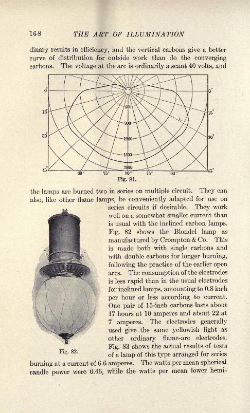
168 THE ART OF ILLUMINATION
dinary results in efficiency, and the vertical carbons give a better
curve of distribution for outside work than do the converging
carbons. The voltage at the arc is ordinarily a scant 40 volts, and
45
the lamps are burned two in series on multiple circuit. They can
also, like other flame lamps, be conveniently adapted for use on
series circuits if desirable. They work
well on a somewhat smaller current than
is usual with the inclined carbon lamps.
Fig. 82 shows the Blondel lamp as
manufactured by Crompton & Co. This
is made both with single carbons and
with double carbons for longer burning,
following the practice of the earlier open
arcs. The consumption of the electrodes
is less rapid than in the usual electrodes
for inclined lamps, amounting to 0.8 inch
per hour or less according to current.
One pair of 15-inch carbons lasts about
17 hours at 10 amperes and about 22 at
7 amperes. The electrodes generally
used give the same yellowish light as
other ordinary flame-arc electrodes.
Fig. 83 shows the actual results of tests
of a lamp of this type arranged for series
burning at a current of 6.6 amperes. The watts per mean spherical
candle power were 0.46, while the watts per mean lower hemi-
Fig. 82.

THE ELECTRIC ARC LAMP 169
spherical candle power dropped to 0.326, a very extraordinary per-
formance for an arc taking only about 260 watts at the terminals
and equipped with an opal globe. Similar arcs at 8 to 10 amperes
give an efficiency materially higher even than this.
The chief practical trouble with the flame arc being the necessity
of frequent trimming, the attention of inventors has been lately
drawn toward the production of long-burning electrodes, either by
increasing the length or cross section or slightly modifying the
ISO
composition. The first and perhaps best known of the long-burning
lamps is the Jandus regenerative flame lamp of which the general
appearance is shown in Fig. 84 and the cross section in Fig. 85.
The peculiarity of the lamp is the provision of two cooling cham-
bers, of cast iron enameled white, which pass outside the globe
and connect with the lamp casing above and below. The arc itself
burns in an inner clear-glass flue surrounded by the ordinary opal
globe. Air is admitted from the bottom and the fumes from the
lamp pass upward and outward into the cooling flues, where they
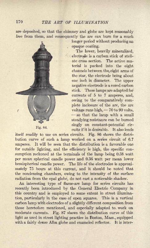
1TO THE ART OF ILLUMINATION
are deposited, so that the chimney and globe are kept reasonablyfree from them, and consequently the arc can burn for a much
longer period without producing an
opaque coating.
The lower, heavily mineralized,
electrode is a carbon stick of stell-
ate cross section. The active ma-terial is packed into the eight
channels between the^ eight arms of
the star, the electrode being about
one inch in diameter. The upper
negative electrode is a cored carbon
stick. These lamps are adapted for
currents of 5 to 7 amperes, and,
owing to the comparatively com-
plete inclosure of the arc, the arc
voltage runs high, 70 to 90 volts,
so that the lamp with a small
steadying resistance can be burned
singly on constant-potential cir-
cuits if it is desirable. It also lends
itself readily to use on series circuits. Fig. 86 shows the distri-
bution curve of such a lamp worked on a series circuit of 6.7
amperes. It will be seen that the distribution is a favorable one
for outside lighting, and the efficiency is high, the specific con-
sumption reckoned at the terminals of the lamp being 0.58 watt
per mean spherical candle power and 0.36 watt per mean lower
hemispherical candle power. The life of the electrodes is approxi-
mately 75 hours at this current, and it should be noted that
the condensing chambers, owing to the intensity of the surface
radiation from the opal globe, do not cast a noticeable shadow.
An interesting type of flame-arc lamp for series circuits has
recently been introduced by the General Electric Company in
this country and is employed to some extent in street illumina-
tion, particularly in the case of open squares. This is a vertical
carbon lamp with electrodes of a slightly different composition from
those heretofore mentioned, and especially adapted to. work on
moderate currents. Fig. 87 shows the distribution curve of this
light as used in street lighting practice in Boston, Mass., equippedwith a fairly dense Alba globe and enameled reflector. It is inter-

THE ELECTRIC ARC LAMP 171
esting, from the exceptionally good distribution, for lighting large
areas. The specific consumption with this particular globe is 0.35
watt per mean lower hemispherical power. This represents the
ordinary burning condition of the lamp, no pains being taken to
keep the globe free from the deposit. With a clear or very light
opal globe kept rigorously clean during a test the efficiency figures
would run somewhat higher. The life of the electrodes is about
20 hours.
Fig. 85.
Within the past two or three years some remarkable white-flame
electrodes, under the name of Alba, or T. B., have been produced
by Siemens and Halske, to which reference has already been made.
These have very nearly as high an efficiency as the best of the
yellow-flame electrodes, and are adapted for burning in various
forms of flame arcs. They are widely employed abroad for street
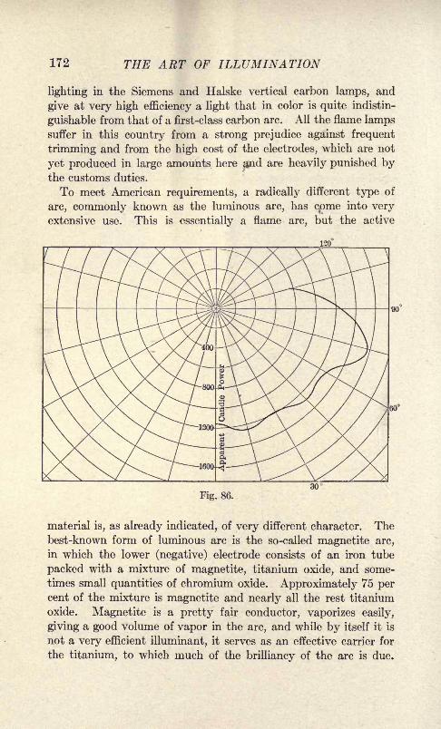
172 THE ART OF ILLUMINATION
lighting in the Siemens and Halske vertical carbon lamps, and
give at very high efficiency a light that in color is quite indistin-
guishable from that of a first-class carbon arc. All the flame lampssuffer in this country from a strong prejudice against frequent
trimming and from the high cost of the electrodes, which are not
yet produced in large amounts here #nd are heavily punished bythe customs duties.
To meet American requirements, a radically different type of
arc, commonly known as the luminous arc, has cpme into very
extensive use. This is essentially a flame arc, but the active
Fig. 86.
material is, as already indicated, of very different character. Thebest-known form of luminous arc is the so-called magnetite arc,
in which the lower (negative) electrode consists of an iron tube
packed with a mixture of magnetite, titanium oxide, and some-
times small quantities of chromium oxide. Approximately 75 percent of the mixture is magnetite and nearly all the rest titanium
oxide. Magnetite is a pretty fair conductor, vaporizes easily,
giving a good volume of vapor in the arc, and while by itself it is
not a very efficient illuminant, it serves as an effective carrier for
the titanium, to which much of the brilliancy of the arc is due.
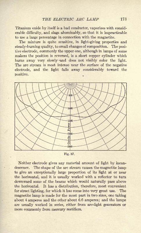
THE ELECTRIC ARC LAMP 173
Titanium oxide by itself is a bad conductor, vaporizes with consid-
erable difficulty, and slags abominably, so that it is impracticableto use a large percentage in connection with the magnetite.
The mixture is quite sensitive, in light-giving properties and
steady-burning quality, to small changes of composition. The posi-
tive electrode, commonly the upper one, although in lamps of some
makers the position is reversed, is a short copper cylinder which
burns away very slowly 'and does not visibly color the light.
The arc stream is most intense near the surface of the negative
electrode, and the light falls away considerably toward the
positive.
Fig. 87.
Neither electrode gives any material amount of light by incan-
descence. The shape of the arc stream causes the magnetite lampto give an exceptionally large proportion of its light at or near
the horizontal, and it is usually worked with a reflector to turn
downward some of the beams which would naturally pass above
the horizontal. It has a distribution, therefore, most convenient
for street lighting, for which it has come into very great use. The
magnetite lamp is made for the most part in two sizes, one taking
about 4 amperes and the other about 6.6 amperes; and the lampsare usually worked in series, either from arc-light generators or
more commonly from mercury rectifiers.
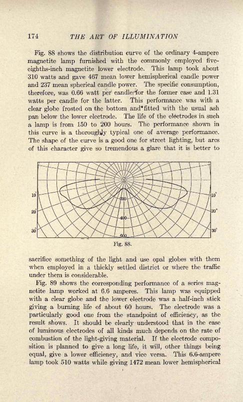
174 THE ART OF ILLUMINATION
Fig. 88 shows the distribution curve of the ordinary 4-ampere
magnetite lamp furnished with the commonly employed five-
eighths-inch magnetite lower electrode. This lamp took about
310 watts and gave 467 mean lower hemispherical candle powerand 237 mean spherical candle power. The specific consumption,
therefore, was 0.66 watt per candlerfor the former case and 1.31
watts per candle for the latter. This performance was with a
clear globe frosted on the bottom and* fitted with the usual ash
pan below the lower electrode. The life of the electrodes in such
a lamp is from 150 to 200 hours. The performance shown in
this curve is a thorougtyy typical one of average performance.
The shape of the curve is a good one for street lighting, but arcs
of this character give so tremendous a glare that it is better to
30
sacrifice something of the light and use opal globes with them
when employed in a thickly settled district or where the traffic
under them is considerable.
Fig. 89 shows the corresponding performance of a series mag-netite lamp worked at 6.6 amperes. This lamp was equippedwith a clear globe and the lower electrode was a half-inch stick
giving a burning life of about 60 hours. The electrode was a
particularly good one from the standpoint of efficiency, as the
result shows. It should be clearly understood that in the case
of luminous electrodes of all kinds much depends on the rate of
combustion of the light-giving material. If the electrode compo-sition is planned to give a long life, it will, other things being
equal, give a lower efficiency, and vice versa. This 6.6-ampere
lamp took 510 watts while giving 1472 mean lower hemispherical
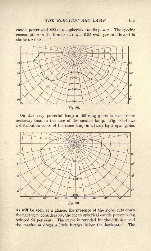
THE ELECTRIC ARC LAMP 175
candle power and 809 mean spherical candle power. The specific
consumption in the former case was 0.35 watt per candle and in
the latter 0.63.
Fig. 89.
On this very powerful lamp a diffusing globe is even more
necessary than in the case of the smaller lamp. Fig. 90 shows
a distribution curve of the same lamp in a fairly light opal globe.
80 J 90 80
Fig. 90.
As will be seen at a glance, the presence of the globe cuts downthe light very considerably, the mean spherical candle power being
reduced 23 per cent. The curve is rounded by the diffusion and
the maximum drops a little further below the horizontal. The
176 THE ART OF ILLUMINATION
distribution is still excellent, however, and for first-class street
lighting the lamp with the opal globe is much preferable to that
with the clear globe. The watts taken were 510 as before, but
the mean lower hemispherical candle power was reduced to 968
and the mean spherical candle power to 622. The specific con-
sumptions were respectively 0.53 andJ).82 watt per candle.
The chief difficulty with magnetite lamps is the production of a
quantity of brown oxides which have to be disposed of to keepthem from settling on the globe and clogging tlje
mechanism.
This is done by a central draft tube through the lamp, which
under ordinary circumstances carries out the fumes pretty suc-
cessfully. Sometimes in hot and damp weather they give trouble
by sticking to the upper electrode, causing the arc to burn un-
steadily, and by depositing a brown smudge over the inside of the
globe. These lamps, therefore, require some extra care in keepingthe globes clean, but in spite of such drawbacks the magnetite
arc is at the present time the best powerful illuminant available
for outdoor use in this country.
The earlier lamps gave a good deal of trouble both with the
mechanism and by formation of slag and welding of the electrodes,
but these difficulties have gradually been overcome, until at the
present time the trouble from lamps being out is no more than
it was in the case of the earlier carbon lamps.
From the standpoint of economy and efficiency, the carbon arc
has little reason for use as compared with the 6.6-ampere mag-netite arc. The 4-ampere magnetite arc is considerably less effi-
cient than the larger size, but still admirably suited for exterior
lighting. Unfortunately, the magnetite arc cannot be used on
alternating current, and if only alternating current is available it
must be rectified before use.
A very interesting attempt to get around this difficulty is fur-
nished by the titanium-carbide arc, which at one time promisedto come into considerable use. This lamp was adapted for alter-
nating current only, carried a carbon upper electrode about one
inch in diameter, and had as lower electrode an iron tube which
was packed with the titanium-carbide mixture. This lamp was
especially adapted for use on low currents, the ordinary type taking
only 2.5 amperes and 180 watts. So admirable was the titanium
mixture in light-giving power that the efficiency even of this small
arc ran very high, the specific consumption per mean lower hemi-
THE ELECTRIC ARC LAMP 177
spherical candle power being between 0.4 and 0.5 watt, and the
distribution resembled very much that of the magnetite arc.
Unfortunately, the titanium electrode produced a frightful smudgeof brown oxide when the current was pushed materially above
the figure just stated, so that ventilation became a very serious
matter; and when the lamp was kept to 2.5 amperes or there-
abouts it became hypersensitive to small variations in current and
irregularities of voltage, so that at the present time this interest-
ing and rather promising illuminant is making very little head-
way. It is greatly to be hoped that the difficulties met in its
development may be overcome, because so efficient a lamp em-
ploying alternating current would be of very great value to the
art if reduced to a thoroughly practical form.
We now come to a totally different class of illuminants, more
akin to arcs than to incandescents in their physical properties,
and hence classified with arcs, but yet radically different from arcs
of ordinary type, in that the arc stream is produced in sealed tubes
and the light is given by relatively long columns of vapor or gas,
not subject to oxidation, and at comparatively moderate tempera-ture. The best known of these illuminants is the Cooper-Hewitt
mercury-vapor lamp, which has now come into extended use for
the illumination of large areas. In this lamp a long glass tube
containing a small amount of mercury is supplied with current
through platinum leading-in wires, one of which dips in the mer-
cury and the other of which is attached to an iron electrode. The
mercury is the negative electrode and when the arc is once
started, as it can be very conveniently by momentarily tilting
the tube so that the mercury runs into contact with the iron
electrode and then withdraws, it fills the whole interior of the
tube with glowing mercury vapor and gives out a very brilliant
and steady light.
Fig. 91 shows one of the commonest forms of Cooper-Hewitt
lamp with its complete mounting. The upper part of the lampcontains inductance coils, an adjustable resistance, an automatic
tilting magnet,, and, in case of lamps operating in series, a shunt
resistance and a cut-out. The lamp shown takes 192 watts at the
terminals, the normal current being 3.5 amperes. The light-giving
tube is about 22 inches in length between the bulbs and of about
1 inch bore. The mercury electrode is contained in the blackened
bulb at the right of the illustration, the blackening being for the

178 THE ART OF ILLUMINATION
purpose of preventing the boiling and bubbling of the mercury in
the bulb from making itself visible as a flicker.
This particular size of lamp is intended to be operated two in
series on the 110-volt circuit. For use singly on 110 volts, tubes
of slightly more than double the length are used. When the current
is thrown on the lamp is tilted, and, dropping back, starts the arc,
which, at first curiously bluish, comes in a minute or so to intense
brilliancy and acquires a greenish cast. The light is that of the
Fig. 91.
mercury spectrum, which for light-giving purposes consists of three
intense lines in the yellowish and green, reenforced by a vivid blue-
violet line which is momentarily predominant when the arc first
starts. Red is practically absent from the spectrum, the only red
lines being too faint to produce any noticeable effect.
Though the resulting color of the light is somewhat ghastly and
plays curious tricks with colors containing red, the lamp is very pow-erful and steady, of moderate intrinsic brilliancy, some 10 to 11
candle power per square inch, and from its being approximately
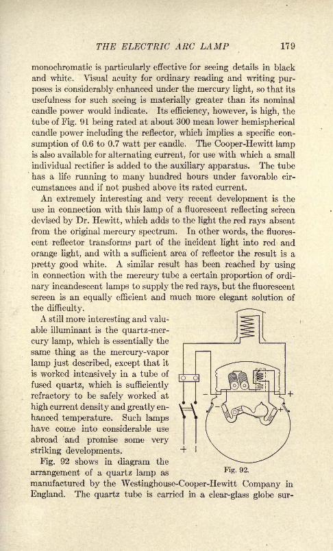
THE ELECTRIC ARC LAMP 179
monochromatic is particularly effective for seeing details in black
and white. Visual acuity for ordinary reading and writing pur-
poses is considerably enhanced under the mercury light, so that its
usefulness for such seeing is materially greater than its nominal
candle power would indicate. Its efficiency, however, is high, the
tube of Fig. 91 being rated at about 300 mean lower hemispherical
candle power including the reflector, which implies a specific con-
sumption of 0.6 to 0.7 watt per candle. The Cooper-Hewitt lampis also available for alternating current, for use with which a small
individual rectifier is added to the auxiliary apparatus. The tube
has a life running to many hundred hours under favorable cir-
cumstances and if not pushed above its rated current.
An extremely interesting and very recent development is the
use in connection with this lamp of a fluorescent reflecting screen
devised by Dr. Hewitt, which adds to the light the red rays absent
from the original mercury spectrum. In other words, the fluores-
cent reflector transforms part of the incident light into red and
orange light, and with a sufficient area of reflector the result is a
pretty good white. A similar result has been reached by usingin connection with the mercury tube a certain proportion of ordi-
nary incandescent lamps to supply the red rays, but the fluorescent
screen is an equally efficient and much more elegant solution of
the difficulty.
A still more interesting and valu-
able illuminant is the quartz-mer-
cury lamp, which is essentially the
same thing as the mercury-vapor
lamp just described, except that it
is worked intensively in a tube of
fused quartz, which is sufficiently
refractory to be safely worked at
high current density and greatly en-
hanced temperature. Such lampshave come into considerable use
abroad and promise some very
striking developments.
Fig. 92 shows in diagram the
arrangement of a quartz lamp as Fig. 92.
manufactured by the Westinghouse-Cooper-Hewitt Company in
England. The quartz tube is carried in a clear-glass globe sur-
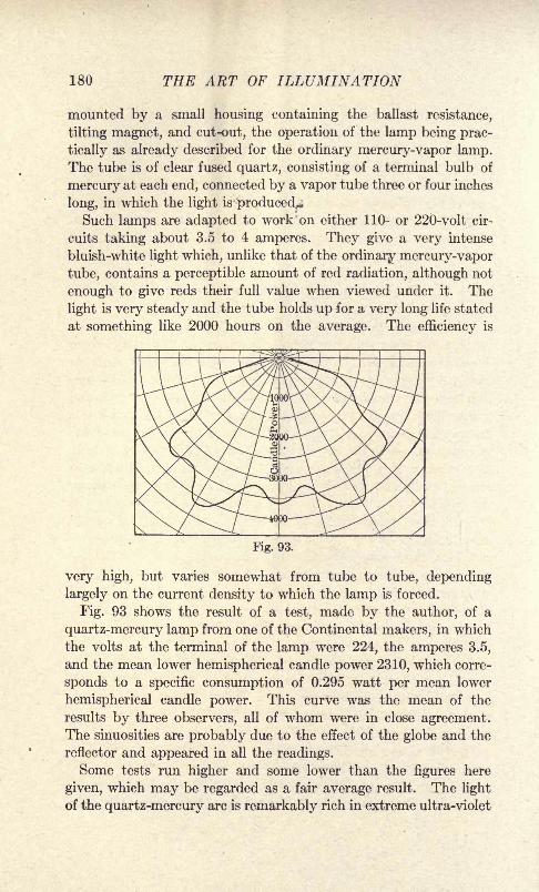
180 THE ART OF ILLUMINATION
mounted by a small housing containing the ballast resistance,
tilting magnet, and cut-out, the operation of the lamp being prac-
tically as already described for the ordinary mercury-vapor lamp.The tube is of clear fused quartz, consisting of a terminal bulb of
mercury at each end, connected by a vapor tube three or four inches
long, in which the light is-produced^Such lamps are adapted to work on either 110- or 220-volt cir-
cuits taking about 3.5 to 4 amperes. They give a very intense
bluish-white light which, unlike that of the ordinary mercury-vapor
tube, contains a perceptible amount of red radiation, although not
enough to give reds their full value when viewed under it. The
light is very steady and the tube holds up for a very long life stated
at something like 2000 hours on the average. The efficiency is
Fig. 93.
very high, but varies somewhat from tube to tube, depending
largely on the current density to which the lamp is forced.
Fig. 93 shows the result of a test, made by the author, of a
quartz-mercury lamp from one of the Continental makers, in which
the volts at the terminal of the lamp were 224, the amperes 3.5,
and the mean lower hemispherical candle power 2310, which corre-
sponds to a specific consumption of 0.295 watt per mean lower
hemispherical candle power. This curve was the mean of the
results by three observers, all of whom were in close agreement.The sinuosities are probably due to the effect of the globe and the
reflector and appeared in all the readings.
Some tests run higher and some lower than the figures here
given, which may be regarded as a fair average result. The light
of the quartz-mercury arc is remarkably rich in extreme ultra-violet
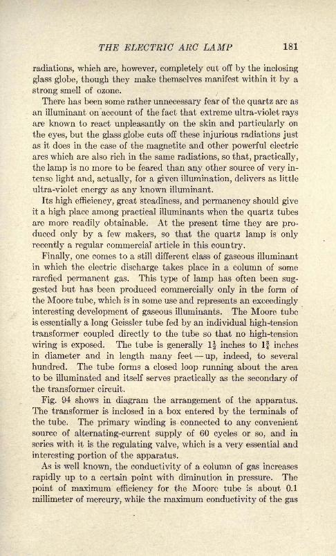
THE ELECTRIC ARC LAMP 181
radiations, which are, however, completely cut off by the inclosing
glass globe, though they make themselves manifest within it by a
strong smell of ozone.
There has been some rather unnecessary fear of the quartz arc as
an illuminant on account of the fact that extreme ultra-violet rays
are known to react unpleasantly on the skin and particularly on
the eyes, but the glass globe cuts off these injurious radiations just
as it does in the case of the magnetite and other powerful electric
arcs which are also rich in the same radiations, so that, practically,
the lamp is no more to be feared than any other source of very in-
tense light and, actually, for a given illumination, delivers as little
ultra-violet energy as any known illuminant.
Its high efficiency, great steadiness, and permanency should give
it a high place among practical illuminants when the quartz tubes
are more readily obtainable. At the present time they are pro-
duced only by a few makers, so that the quartz lamp is only
recently a regular commercial article in this country.
Finally, one comes to a still different class of gaseous illuminant
in which the electric discharge takes place in a column of some
rarefied permanent gas. This type of lamp has often been sug-
gested but has been produced commercially only in the form of
the Moore tube, which is in some use and represents an exceedingly
interesting development of gaseous illuminants. The Moore tube
is essentially a long Geissler tube fed by an individual high-tension
transformer coupled directly to the tube so that no high-tension
wiring is exposed. The tube is generally 1J inches to If inches
in diameter and in length many feet up, indeed, to several
hundred. The tube forms a closed loop running about the area
to be illuminated and itself serves practically as the secondary of
the transformer circuit.
Fig. 94 shows in diagram the arrangement of the apparatus.The transformer is inclosed in a box entered by the terminals of
the tube. The primary winding is connected to any convenient
source of alternating-current supply of 60 cycles or so, and in
series with it is the regulating valve, which is a very essential and
interesting portion of the apparatus.As is well known, the conductivity of a column of gas increases
rapidly up to a certain point with diminution in pressure. The
point of maximum efficiency for the Moore tube is about 0.1
millimeter of mercury, while the maximum conductivity of the gas
182 THE ART OF ILLUMINATION
is reached at about 0.08 millimeter pressure. As the tube con-
tinues in use the pressure in it decreases, and, with no means for
regulating the vacuum provided, would reach a point which would
gradually put the tube out of action. To avoid this difficulty a
branch tube leading to both sides of the lighting tube is turned
upward at the end and inclosed by a*slender conical plug of porous
carbon, which in the normal action of the tube is just covered by
mercury. A small solenoid in series with the primary circuit is
MOORE TUBE/^
Fig. 94.
provided with a core which carries a glass displacing tube, which
with the normal current in the lighting tube rests in equilibrium
with the tip of the carbon cone just covered. When the vacuum
falls below 0.1 millimeter and approaches the critical point of
conductivity, there is a slight increase of the current through the
tube, which lifts the displacer, uncovers the tip of the cone, and
lets gas filter in until the normal vacuum is restored.
The gas thus fed can be ordinary air when the tube is left open,
or any convenient gas, a supply of which may be connected with
the inlet tube of the valve. Ordinary air gives a slightly pinkish
light; nitrogen, which gives a higher efficiency and is more com-
monly used, gives a more yellowish tint; and when a nearly white
light is desired /the gas employed is C02. The color given by the
C02 tube in fact is a pretty close approximation to white, con-
siderably bluer than direct sunlight, but less blue than the light
of a bright-blue sky.
The efficiency of the tube as a light producer has been sub-
ject to considerable study. It is a mistake to suppose that the
light given by an electrical discharge through gases is necessarily
efficient; in fact it varies enormously in efficiency according to the
THE ELECTRIC ARC LAMP 183
particular characteristics of the spectrum given by the gas. The
nitrogen tube, which is that most commonly employed, has been
found by several experimenters to give a specific consumption of
approximately 2.4 watts per mean spherical candle power; while
the C02 tube as used, especially for color-matching purposes,
generally in short lengths, has a specific consumption under these
conditions of at least 6 or 8 watts per candle. The nitrogen tube
has, therefore, a slightly greater actual efficiency than the tan-
talum lamp and materially less than the tungsten lamp. Theintrinsic brilliancy of the tube, about 0.4 to 0.5 candle power per
square inch, and the even distribution given by its great extent,
are practical considerations which tell in its favor. The life of
the tubes, barring accidents, is very long, running certainly to
many thousand hours; indeed, it is a little uncertain what exceptaccident would limit the life, although in time the interior surface
of the tube would probably be affected. Very recently tubes filled
with the rare gas neon have been tried abroad. The color is a
beautiful orange and the specific consumption is stated to be about
0.8 watt per candle power, a figure far lower than with any other
gas yet tried.
This closes the story of practical illuminants operating by the
electrical discharge. The list of those unmentioned here would be
a long and somewhat interesting one, but unprofitable to recite
from the standpoint of practical illumination.
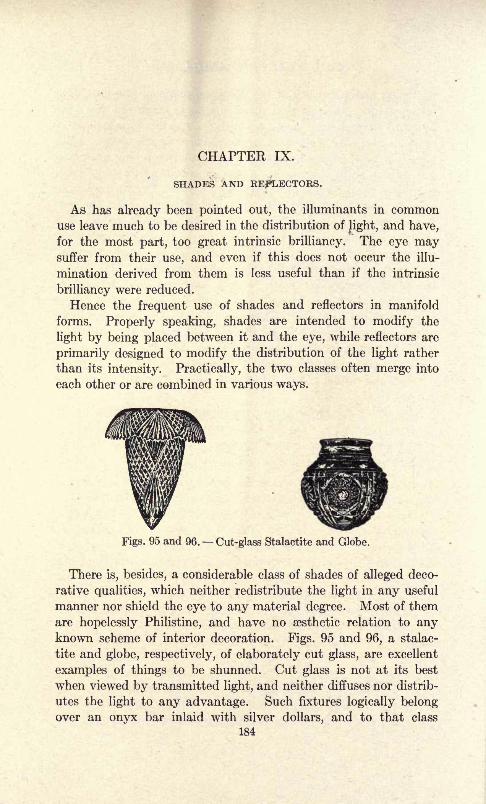
CHAPTER IX.
SHADES AND REFLECTORS.
As has already been pointed out, the illuminants in commonuse leave much to be desired in the distribution of light, and have,
for the most part, too great intrinsic brilliancy. The eye maysuffer from their use, and even if this does not occur the illu-
mination derived from them is less useful than if the intrinsic
brilliancy were reduced.
Hence the frequent use of shades and reflectors in manifold
forms. Properly speaking, shades are intended to modify the
light by being placed between it and the eye, while reflectors are
primarily designed to modify the distribution of the light rather
than its intensity. Practically, the two classes often merge into
each other or are combined in various ways.
Figs. 95 and 96. Cut-glass Stalactite and Globe.
There is, besides, a considerable class of shades of alleged deco-
rative qualities, which neither redistribute the light in any useful
manner nor shield the eye to any material degree. Most of themare hopelessly Philistine, and have no aesthetic relation to anyknown scheme of interior decoration. Figs. 95 and 96, a stalac-
tite and globe, respectively, of elaborately cut glass, are excellent
examples of things to be shunned. Cut glass is not at its best
when viewed by transmitted light, and neither diffuses nor distrib-
utes the light to any advantage. Such fixtures logically belong
over an onyx bar inlaid with silver dollars, and to that class
184
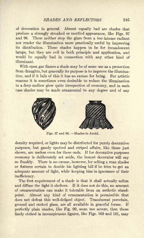
SHADES AND REFLECTORS 185
of decoration in general. Almost equally bad are shades that
produce a strongly streaked or mottled appearance, like Figs. 97
and 98. These neither stop the glare from a too intense radiant
nor render the illumination more practically useful by improvingits distribution. These shades happen to be for incandescent
lamps, but they are evil in both principle and application, andwould be equally bad in connection with any other kind of
illuminant.
With open gas flames a shade may be of some use as a protectionfrom draughts, but generally its purpose is to improve the illumina-
tion, and if it fails of this it has no excuse for being. For artistic
reasons it is sometimes even desirable to reduce the illumination
to a deep mellow glow quite irrespective of economy, and in such
case shades may be made ornamental to any degree and of any
Figs. 97 and 98. Shades to Avoid.
density required, or lights may be distributed for purely decorative
purposes, but gaudy spotted and striped affairs, like those just
shown, are useless even for these ends. If for decorative purposes
economy is deliberately set aside, the honest decorator will sayso frankly. There is no excuse, however, for selling a man shades
or fixtures certain to double his lighting bill if he tries to get an
adequate amount of light, while keeping him in ignorance of their
inefficiency.
The first requirement of a shade is that it shall actually soften
and diffuse the light it shelters. If it does not do this, no amountof ornamentation can make it tolerable from an aesthetic stand-
point. Almost any kind of ornamentation is permissible that
does not defeat this well-defined object. Translucent porcelain,
ground and etched glass, are all available in graceful forms. If
perfectly plain shades, like Fig. 99, seem too severe, then those
finely etched in inconspicuous figures, like Figs. 100 and 101, may
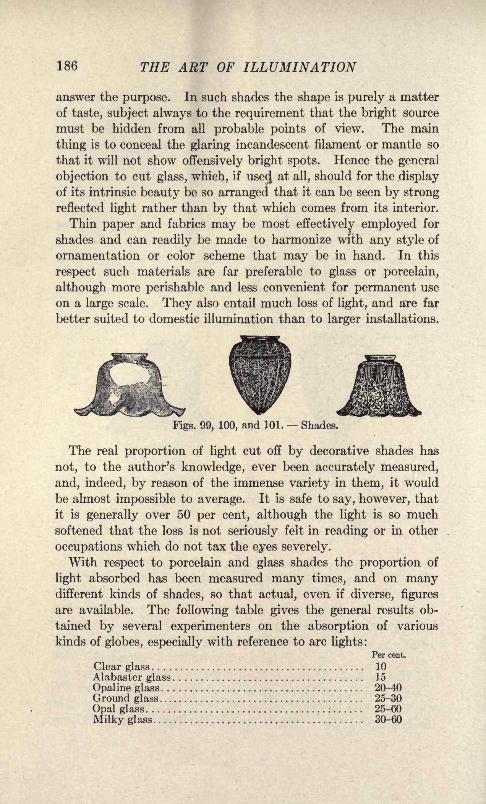
186 THE ART OF ILLUMINATION
answer the purpose. In such shades the shape is purely a matter
of taste, subject always to the requirement that the bright source
must be hidden from all probable points of view. The main
thing is to conceal the glaring incandescent filament or mantle so
that it will not show offensively bright spots. Hence the general
objection to cut glass, which, if usecj at all, should for the display
of its intrinsic beauty be so arranged that it can be seen by strong
reflected light rather than by that which comes from its interior.
Thin paper and fabrics may be mosteffectively employed for
shades and can readily be made to harmonize with any style of
ornamentation or color scheme that may be in hand. In this
respect such materials are far preferable to glass or porcelain,
although more perishable and less convenient for permanent use
on a large scale. They also entail much loss of light, and are far
better suited to domestic illumination than to larger installations.
Figs. 99, 100, and 101. Shades.
The real proportion of light cut off by decorative shades has
not, to the author's knowledge, ever been accurately measured,
and, indeed, by reason of the immense variety in them, it would
be almost impossible to average. It is safe to say, however, that
it is generally over 50 per cent, although the light is so muchsoftened that the loss is not seriously felt in reading or in other
occupations which do not tax the eyes severely.
With respect to porcelain and glass shades the proportion of
light absorbed has been measured many times, and on manydifferent kinds of shades, so that actual, even if diverse, figures
are available. The following table gives the general results ob-
tained by several experimenters on the absorption of various
kinds of globes, especially with reference to arc lights :
Per cent.
Clear glass 10Alabaster glass 15
Opaline glass 20-40Ground glass 25-30
Opal glass 25-60
Milky glass 30-60
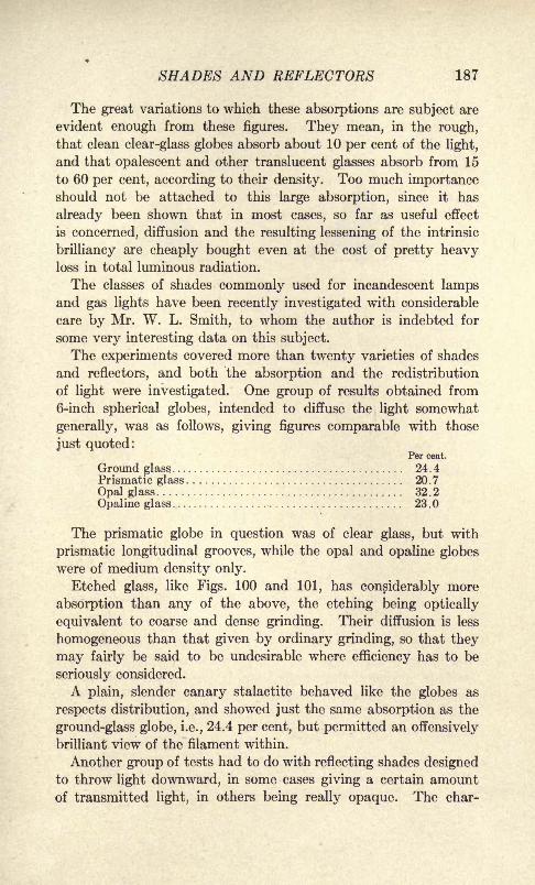
SHADES AND REFLECTORS 187
The great variations to which these absorptions are subject are
evident enough from these figures. They mean, in the rough,
that clean clear-glass globes absorb about 10 per cent of the light,
and that opalescent and other translucent glasses absorb from 15
to 60 per cent, according to their density. Too much importanceshould not be attached to this large absorption, since it has
already been shown that in most cases, so far as useful effect
is concerned, diffusion and the resulting lessening of the intrinsic
brilliancy are cheaply bought even at the cost of pretty heavyloss in total luminous radiation.
The classes of shades commonly used for incandescent lampsand gas lights have been recently investigated with considerable
care by Mr. W. L. Smith, to whom the author is indebted for
some very interesting data on this subject.
The experiments covered more than twenty varieties of shades
and reflectors, and both the absorption and the redistribution
of light were investigated. One group of results obtained from
6-inch spherical globes, intended to diffuse the light somewhat
generally, was as follows, giving figures comparable with those
just quoted:Per cent.
Ground glass 24.4Prismatic glass 20 . 7
Opal glass 32.2
Opaline glass. 23.0
The prismatic globe in question was of clear glass, but with
prismatic longitudinal grooves, while the opal and opaline globes
were of medium density only.
Etched glass, like Figs. 100 and 101, has considerably more
absorption than any of the above, the etching being optically
equivalent to coarse and dense grinding. Their diffusion is less
homogeneous than that given by ordinary grinding, so that they
may fairly be said to be undesirable where efficiency has to be
seriously considered.
A plain, slender canary stalactite behaved like the globes as
respects distribution, and showed just the same absorption as the
ground-glass globe, i.e., 24.4 per cent, but permitted an offensively
brilliant view of the filament within.
Another group of tests had to do with reflecting shades designedto throw light downward, in some cases giving a certain amount
of transmitted light, in others being really opaque. The char-
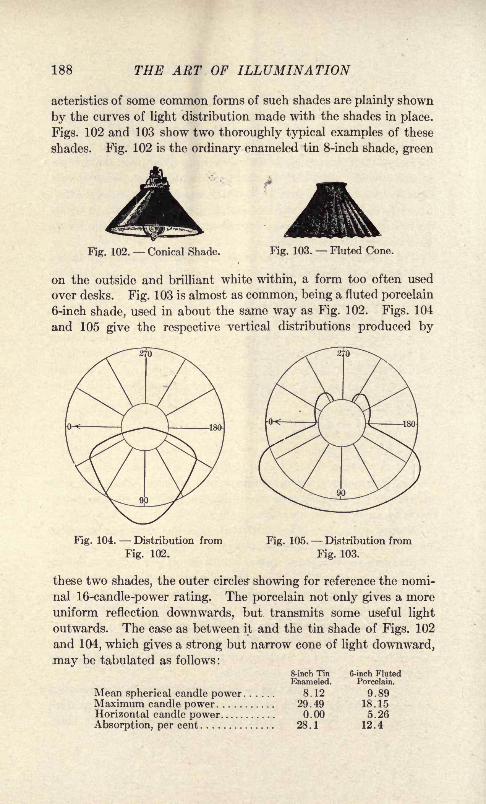
188 THE ART OF ILLUMINATION
acteristics of some common forms of such shades are plainly shown
by the curves of light distribution made with the shades in place.
Figs. 102 and 103 show two thoroughly typical examples of these
shades. Fig. 102 is the ordinary enameled tin 8-inch shade, green
Fig. 102. Conical Shade. Fig. 103. Fluted Cone.
on the outside and brilliant white within, a form too often used
over desks. Fig. 103 is almost as common, being a fluted porcelain
6-inch shade, used in about the same way as Fig. 102. Figs. 104
and 105 give the respective vertical distributions produced by
Fig. 104. Distribution from
Fig. 102.
Fig. 105. Distribution from
Fig. 103.
these two shades, the outer circles' showing for reference the nomi-
nal 16-candle-power rating. The porcelain not only gives a moreuniform reflection downwards, but transmits some useful light
outwards. The case as between it and the tin shade of Figs. 102
and 104, which gives a strong but narrow cone of light downward,
may be tabulated as follows:
Mean spherical candle powerMaximum candle powerHorizontal candle powerAbsorption, per cent
8-inch TinEnameled.
8.1229.490.00
28.1
6-inch FlutedPorcelain.
9.8918.155.26
12.4
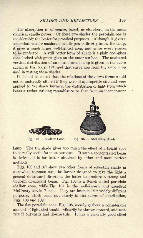
SHADES AND REFLECTORS,
189
The absorption is, of course, based, as elsewhere, on the mean
spherical candle power. Of these two shades the porcelain one is
considerably the better for practical purposes. Although it gives a
somewhat smaller maximum candle power directly below the lamp,
it gives a much larger well-lighted area, and is for every reason
to be preferred. A still better form of shade is a plain opal-glass
cone flashed with green glass on the outer surface. The unaltered
vertical distribution of an incandescent lamp is given in the curve
shown in Fig. 56, p. 124, and that curve was from the same lampused in testing these shades.
It should be noted that the relations of these two forms would
not be materially altered if they were of appropriate size and were
applied to Welsbach burners, the distribution of light from which
bears a rather striking resemblance to that from an incandescent
Fig. 106. Shallow Cone. Fig. 107. McCreaiy Shade.
lamp. The tin shade gives too much the effect of a bright spotto be really useful for most purposes. If such a concentrated beamis desired, it is far better obtained by other and more perfect
methods.
Figs. 106 and 107 show two other forms of reflecting shade in
somewhat common use, the former designed to give the light a
general downward direction, the latter to produce a strong anduniform downward beam. Fig. 106 is a 6-inch fluted porcelainshallow cone, while Fig. 107 is the well-known and excellent
McCreary shade, 7-inch. They are intended for widely different
purposes, which come out clearly in the curves of distribution,
Figs. 108 and 109.
The flat porcelain cone, Fig. 108, merely gathers a considerable
amount of light that would ordinarily be thrown upward, and scat-
ters it outwards and downwards. It has a generally good effect
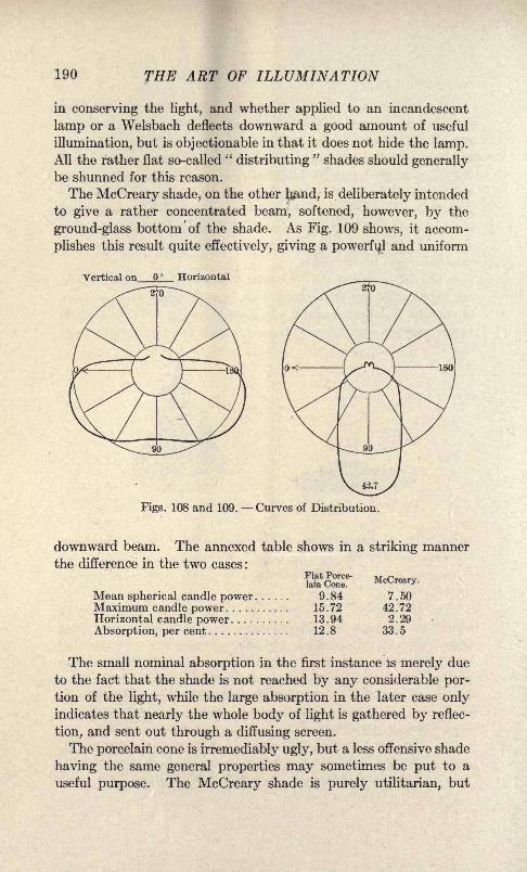
190 THE ART OF ILLUMINATION
in conserving the light, and whether applied to an incandescent
lamp or a Welsbach deflects downward a good amount of useful
illumination, but is objectionable in that it does not hide the lamp.All the rather flat so-called
"distributing
"shades should generally
be shunned for this reason.
The McCreary shade, on the other band, is deliberately intended
to give a rather concentrated beam, softened, however, by the
ground-glass bottom 'of the shade. As Fig. 109 shows, it accom-
plishes this result quite effectively, giving a powerful and uniform
Vertical ou Horizontal
Figs. 108 and 109. Curves of Distribution.
downward beam. The annexed table shows in a striking manner
the difference in the two cases :
Flat Porce-lain Cone.
Mean spherical candle power 9.84Maximum candle power 15.72Horizontal candle power 13.94
Absorption, per cent 12.8
McCreary.
7.5042.722.29
33.5
The small nominal absorption in the first instance is merely due
to the fact that the shade is not reached by any considerable por-
tion of the light, while the large absorption in the later case onlyindicates that nearly the whole body of light is gathered by reflec-
tion, and sent out through a diffusing screen.
The porcelain cone is irremediably ugly, but a less offensive shade
having the same general properties may sometimes be put to a
useful purpose. The McCreary shade is purely utilitarian, but
SHADES AND REFLECTORS 191
neat, and does its work well in producing a strong, directed illu-
mination a bit too concentrated, perhaps, for ordinary desk
work, for which it should be fitted with a lamp of 8 or 10 candle
power, but very useful for work requiring unusually bright light.
Of fancy shades modified in various ways there are a myriad,
usually less good than the examples here shown.
In cases where concentration of light downwards along the axis
of the lamp is desirable, rather efficient results are attained by
combining lamp and reflector, that is, by shaping the bulb of the
lamp itself so that when the part of it nearest the socket is silvered
on the outside it shall form an effective reflector of proper shape.
Obviously when the lamp burns out or grows dim the whole com-
bination becomes useless, in which respect the device is less
economical than an ordinary lamp in a carefully designed reflect-
ing shade like the McCreary. On the other hand, the reflector
lamps are, on the whole, somewhat more efficient during their
useful life, and for general purposes of illumination are much less
obtrusive.
In such lamps the bulb, instead of being pear-shaped, is spherical
or spheroidal, with the upper hemisphere silvered, the silvering
being protected by a coat of lacquer. The filament usually has
several convolutions of rather small radius, so as to bring as large
a proportion of the incandescent filament as possible near to the
center of the bulb. A filament so disposed throws an unusual pro-
portion of the light upwards and downwards when the lamp is
mounted with its axis vertical, but, of course, at the expense of
the horizontal illumination.
For various ilmminants shades require to be somewhat modified
in form, and an enormous variety of shades and reflectors are on
the market, of which those here described may serve merely as
samples. Shading the radiant, whatever it may be, is a simple
matter, and so is the use of a pure reflector to direct the light in
any particular direction. But the commonest fault of powerful
radiants, as we have already seen, is too great intrinsic brilliancy,
which calls for diffusion, and good diffusion without great loss of
light is difficult of attainment, particularly if at the same time
there is need of redistributing the light so as to strengthen the
illumination in any particular direction.
By far the most successful solution of this troublesome problemis found in the so-called holophane globes, devised a few years ago
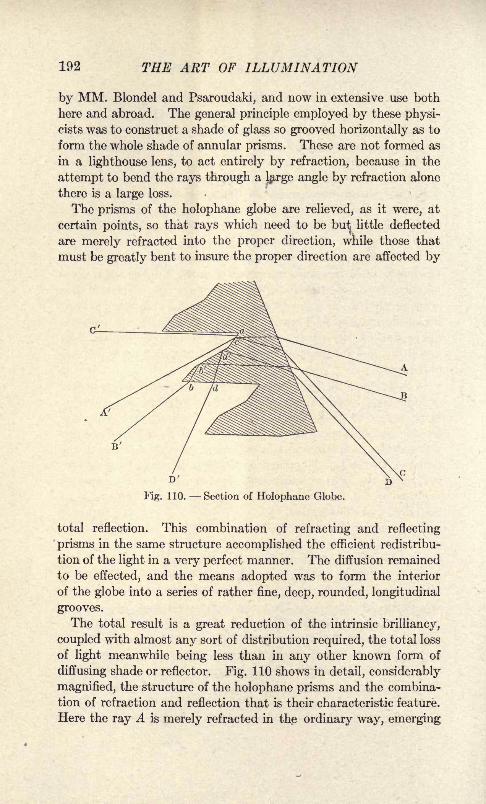
192 THE ART OF ILLUMINATION
by MM. Blondel and Psaroudaki, and now in extensive use both
here and abroad. The general principle employed by these physi-
cists was to construct a shade of glass so grooved horizontally as to
form the whole shade of annular prisms. These are not formed as
in a lighthouse lens, to act entirely by refraction, because in the
attempt to bend the rays through a large angle by refraction alone
there is a large loss.
The prisms of the holophane globe are relieved, as it were, at
certain points, so that rays which need to bebulj
little deflected
are merely refracted into the proper direction, while those that
must be greatly bent to insure the proper direction are affected by
Fig. 110. Section of Holophane Globe.
total reflection. This combination of refracting and reflecting
prisms in the same structure accomplished the efficient redistribu-
tion of the light in a very perfect manner. The diffusion remained
to be effected, and the means adopted was to form the interior
of the globe into a series of rather fine, deep, rounded, longitudinal
grooves.
The total result is a great reduction of the intrinsic brilliancy,
coupled with almost any sort of distribution required, the total loss
of light meanwhile being less than in any other known form of
diffusing shade or reflector. Fig. 110 shows in detail, considerably
magnified, the structure of the holophane prisms and the combina-
tion of refraction and reflection that is their characteristic feature.
Here the ray A is merely refracted in the ordinary way, emerging
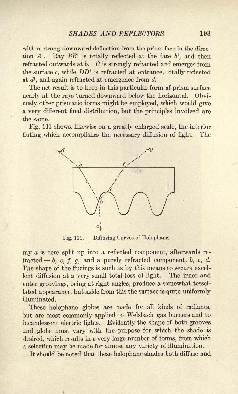
SHADES AND REFLECTORS 193
with a strong downward deflection from the prism face in the direc-
tion A 1. Ray BB 1
is totally reflected at the face 6 1
,and then
refracted outwards at 6. C is strongly refracted and emerges from
the surface c, while DD 1is refracted at entrance, totally reflected
at dl
,and again refracted at emergence from d.
The net result is to keep in this particular form of prism surface
nearly all the rays turned downward below the horizontal. Obvi-
ously other prismatic forms might be employed, which would give
a very different final distribution, but the principles involved are
the same.
Fig. Ill shows, likewise on a greatly enlarged scale, the interior
fluting which accomplishes the necessary diffusion of light. The
Fig. 111. Diffusing Curves of Holophane.
ray a is here split up into a reflected component, afterwards re-
fracted b, e, f, g, and a purely refracted component, b, c, d.
The shape of the flutings is such as by this means to secure excel-
lent diffusion at a very small total loss of light. The inner and
outer groovings, being at right angles, produce a somewhat tessel-
lated appearance, but aside from this the surface is quite uniformly
illuminated.
These holophane globes are made for all kinds of radiants,
but are most commonly applied to Welsbach gas burners and to
incandescent electric lights. Evidently the shape of both grooves
and globe must vary with the purpose for which the shade is
desired, which results in a very large number of forms, from which
a selection may be made for almost any variety of illumination.
It should be noted that these holophane shades both diffuse and
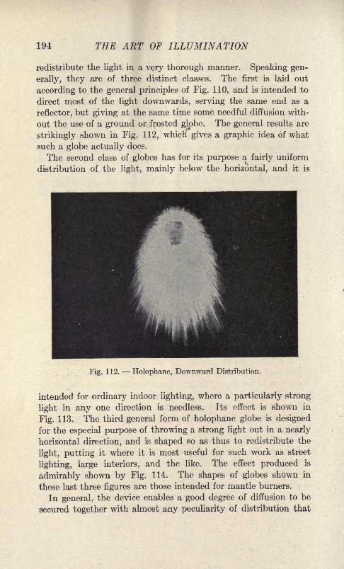
194 THE ART OF ILLUMINATION
redistribute the light in a very thorough manner. Speaking gen-
erally, they are of three distinct classes. The first is laid out
according to the general principles of Fig. 110, and is intended to
direct most of the light downwards, serving the same end as a
reflector, but giving at the same time some needful diffusion with-
out the use of a ground or. frosted globe. The general results are
strikingly shown in Fig. 112, whicK gives a graphic idea of what
such a globe actually does.
The second class of globes has for its purpose a fairly uniform
distribution of the light, mainly below the horizontal, and it is
Fig. 112. Holophane, Downward Distribution.
intended for ordinary indoor lighting, where a particularly strong
light in any one direction is needless. Its effect is shown in
Fig. 113. The third general form of holophane globe is designed
for the especial purpose of throwing a strong light out in a nearly
horizontal direction, and is shaped so as thus to redistribute the
light, putting it where it is most useful for such work as street
lighting, large interiors, and the like. The effect produced is
admirably shown by Fig. 114. The shapes of globes shown in
these last three figures are those intended for mantle burners.
In general, the device enables a good degree of diffusion to be
secured together with almost any peculiarity of distribution that
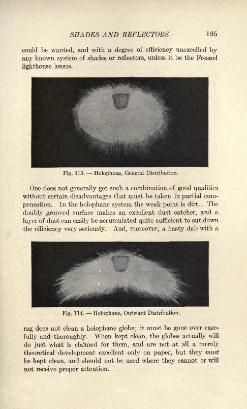
SHADES AND REFLECTORS 195
could be wanted, and with a degree of efficiency unexcelled by
any known system of shades or reflectors, unless it be the Fresnel
lighthouse lenses.
Fig. 113. Holophane, General Distribution.
One does not generally get such a combination of good qualities
without certain disadvantages that must be taken in partial com-
pensation. In the holophane system the weak point is dirt. The
doubly grooved surface makes an excellent dust catcher, and a
layer of dust can easily be accumulated quite sufficient to cut down
the efficiency very seriously. And, moreover, a hasty dab with a
Fig. 114. Holophane, Outward Distribution.
rag does not clean a holophane globe; it must be gone over care-
fully and thoroughly. When kept clean, the globes actually will
do just what is claimed for them, and are not at all a merely
theoretical development excellent only on paper, but they must
be kept clean, and should not be used where they cannot or will
not receive proper attention.
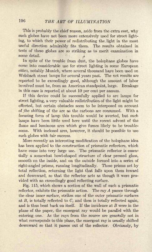
196 THE ART OF ILLUMINATION
This is probably the chief reason, aside from the extra cost, whysuch globes have not been more extensively used for street light-
ing, to which their power of redistributing the. light in the mostuseful direction admirably fits them. The results obtained in
tests of these globes are so striking as to merit examination in
some detail.
In spite of the trouble from dust, the holophane globes havecome into considerable use for street lighting in some Europeancities, notably Munich, where several thousand have been used on
Welsbach street lamps for several years past. The net results are
reported to be exceedingly good, although the amount of labor
involved must be, from an American standpoint, large. Breakagein this case is reported at about 10 per cent per annum.
If this device could be successfully applied to arc lamps for
street lighting, a very valuable redistribution of the light might be
effected, but certain obstacles seem to be interposed on account
of the shifting of the arc as the carbons are consumed. With a
focusing form of lamp this trouble would be averted, but such
lamps have been little used here until the recent advent of the
flame and luminous arcs which give fumes likely to be trouble-
some. With inclosed arcs, however, it should be possible to use
such globes with fair success.
More recently an interesting modification of the holophane idea
has been applied to the construction of prismatic reflectors, which
have come into very large use. The prismatic reflector is essen-
tially a somewhat bowl-shaped structure of clear pressed glass,
smooth on the inside, and on the outside formed into a series of
right-angled prisms, running longitudinally. These prisms act bytotal reflection, returning the light that falls upon them inward
and downward, so that the reflector acts as though it were pro-
vided with an exceedingly good reflecting surface.
Fig. 115, which shows a section of the wall of such a prismatic
reflector, exhibits the prismatic action. The ray A passes throughthe clear inner surface, strikes one of the outer prismatic surfaces
at B, is totally reflected to C, and then is totally reflected again,
and is thus bent back on itself. If the incidence at B were in the
plane of the paper, the emergent ray would be parallel with the
entering one. As the rays from the source are generally not in
what corresponds to this plane, the emergent ray is usually shifted
downward so that it passes out of the reflector. Obviously, by
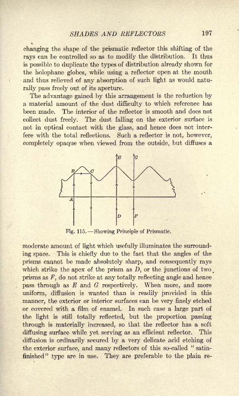
SHADES AND REFLECTORS 197
changing the shape of the prismatic reflector this shifting of the
rays can be controlled so as to modify the distribution. It thus
is possible to duplicate the types of distribution already shown for
the holophane globes, while using a reflector open at the mouth
and thus relieved of any absorption of such light as would natu-
rally pass freely out of its aperture.
The advantage gained by this arrangement is the reduction bya material amount of the dust difficulty to which reference has
been made. The interior of the reflector is smooth and does not
collect dust freely. The dust falling on the exterior surface is
not in optical contact with the glass, and hence does not inter-
fere with the total reflections. Such a reflector is not, however,
completely opaque when viewed from the outside, but diffuses a
'17
Fig. 115. Showing Principle of Prismatic.
moderate amount of light which usefully illuminates the surround-
ing space. This is chiefly due to the fact that the angles of the
prisms cannot be made absolutely sharp, and consequently rays
which strike the apex of the prism as D, or the junctions of twot
prisms as F, do not strike at any totally reflecting angle and hence
pass through as E and G respectively. When more, and more
uniform, diffusion is wanted than is readily provided in this
manner, the exterior or interior surfaces can be very finely etched
or covered with a film of enamel. In such case a large part of
the light is still totally reflected, but the proportion passing
through is materially increased, so that the reflector has a soft
diffusing surface while yet serving as an efficient reflector. This
diffusion is ordinarily secured by a very delicate acid etching of
the exterior surface, and many reflectors of this so-called"satin-
finished" type are in use. They are preferable to the plain re-
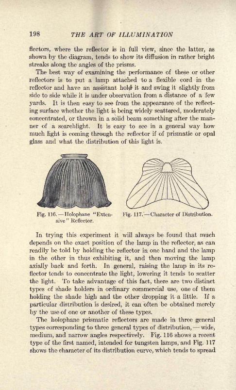
198 THE ART OF ILLUMINATION
Sectors, where the reflector is in full view, since the latter, as
shown by the diagram, tends to show its diffusion in rather bright
streaks along the angles of the prisms.
The best way of examining the performance of these or other
reflectors is to put a lamp attached to a flexible cord in the
reflector and have an assistant hol$ it and swing it slightly from
side to side while it is under observation from a distance of a few
yards. It is then easy to see from the appearance of the reflect-
ing surface whether the light is being widely scattered, moderately
concentrated, or thrown in a solid beam something after the man-ner of a searchlight. It is easy to see in a general way howmuch light is coming through the reflector if of prismatic or opal
glass and what the distribution of this light is.
Fig. 116. Holophane "Exten-
sive" Reflector.
Fig. 117. Character of Distribution.
In trying this experiment it will always be found that much
depends on the exact position of the lamp in the reflector, as can
readily be told by holding the reflector in one hand and the lampin the other in thus exhibiting it, and then moving the lamp
axially back and forth. In general, raising the lamp in its re-
flector tends to concentrate the light, lowering it tends to scatter
the light. To take advantage of this fact, there are two distinct
types of shade holders in ordinary commercial use, one of them
holding the shade high and the other dropping it a little. If a
particular distribution is desired, it can often be obtained merely
by the use of one or another of these types.
The holophane prismatic reflectors are made in three general
types corresponding to three general types of distribution, wide,
medium, and narrow angles respectively. Fig. 116 shows a recent
type of the first named, intended for tungsten lamps, and Fig. 117
shows the character of its distribution curve, which tends to spread
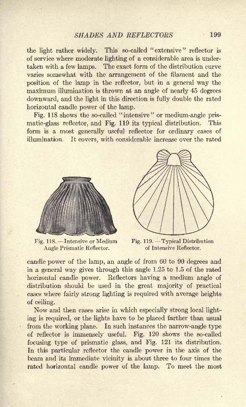
SHADES AND REFLECTORS 199
the light rather widely. This so-called"extensive" reflector is
of service where moderate lighting of a considerable area is under-
taken with a few lamps. The exact form of the distribution curve
varies somewhat with the arrangement of the filament and the
position of the lamp in the reflector, but in a general way the
maximum illumination is thrown at an angle of nearly 45 degrees
downward, and the light in this direction is fully double the rated
horizontal candle power of the lamp.
Fig. 118 shows the so-called "intensive" or medium-angle pris-
matic-glass reflector, and Fig. 119 its typical distribution. This
form is a most generally useful reflector for ordinary cases of
illumination. It covers, with considerable increase over the rated
Fig. 118. Intensive or Medium
Angle Prismatic Reflector.
Fig. 119. Typical Distribution
of Intensive Reflector.
candle power of the lamp, an angle of from 60 to 90 degrees and
in a general way gives through this angle 1.25 to 1.5 of the rated
horizontal candle power. Reflectors having a medium angle of
distribution should be used in the great majority of practical
cases where fairly strong lighting is required with average heights
of ceiling.
Now and then cases arise in which especially strong local light-
ing is required, or the lights have to be placed farther than usual
from the working plane. In such instances the narrow-angle typeof reflector is immensely useful. Fig. 120 shows the so-called
focusing type of prismatic glass, and Fig. 121 its distribution.
In this particular reflector the candle power in the axis of the
beam and its immediate vicinity is about three to four times the
rated horizontal candle power of the lamp. To meet the most
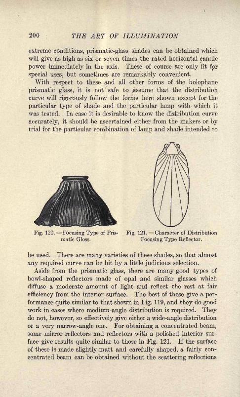
200 THE ART OF ILLUMINATION
extreme conditions, prismatic-glass shades can be obtained which
will give as high as six or seven times the rated horizontal candle
power immediately in the axis. These of course are only fit fpr
special uses, but sometimes are remarkably convenient.
With respect to these and all other forms of the holophane
prismatic glass, it is not safe to Assume that the distribution
curve will rigorously follow the forms here shown except for the
particular type of shade and the particular lamp with which it
was tested. In case it is desirable to know the distribution curve
accurately, it should be ascertained either from the makers or bytrial for the particular combination of lamp and shade intended to
Fig. 120. Focusing Type of Pris-
matic Gloss.
Fig. 121. Character of Distribution
Focusing Type Reflector.
be used. There are many varieties of these shades, so that almost
any required curve can be hit by a little judicious selection.
Aside from the prismatic glass, there are many good types of
bowl-shaped reflectors made of opal and similar glasses which
diffuse a moderate amount of light and reflect the rest at fair
efficiency from the interior surface. The best of these give a per-
formance quite similar to that shown in Fig. 119, and they do goodwork in cases where medium-angle distribution is required. Theydo not, however, so effectively give either a wide-angle distribution
or a very narrow-angle one. For obtaining a concentrated beam,some mirror reflectors and reflectors with a polished interior sur-
face give results quite similar to those in Fig. 121. If the surface
of these is made slightly matt and carefully shaped, a fairly con-
centrated beam can be obtained without the scattering reflections
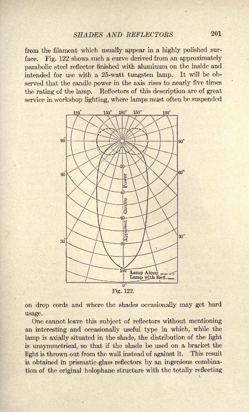
SHADES AND REFLECTORS 201
from the filament which usually appear in a highly polished sur-
face. Fig. 122 shows such a curve derived from an approximately
parabolic steel reflector finished with aluminum on the inside and
intended for use with a 25-watt tungsten lamp. It will be ob-
served that the candle power in the axis rises to nearly five times
the rating of the lamp. Reflectors of this description are of great
service in workshop lighting, where lamps must often be suspended
120 180 150
Lamp with Refl
Fig. 122.
on drop cords and where the shades occasionally may get hard
usage.
One cannot leave this subject of reflectors without mentioning
an interesting and occasionally useful type in which, while the
lamp is axially situated in the shade, the distribution of the light
is unsymmetrical, so that if the shade be used on a bracket the
light is thrown out from the wall instead of against it. This result
is obtained in prismatic-glass reflectors by an ingenious combina-
tion of the original holophane structure with the totally reflecting
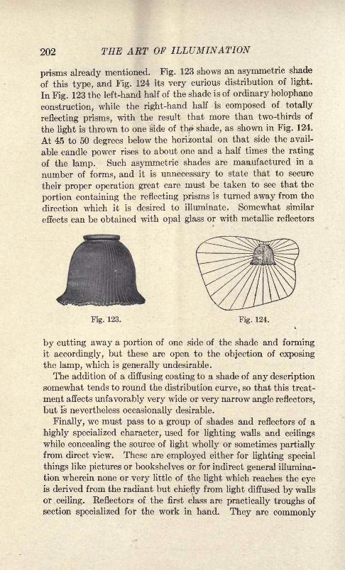
202 THE ART OF ILLUMINATION
prisms already mentioned. Fig. 123 shows an asymmetric shade
of this type, and Fig. 124 its very curious distribution of light,
In Fig. 123 the left-hand half of the shade is of ordinary holophane
construction, while the right-hand half is composed of totally
reflecting prisms, with the result that more than two-thirds of
the light is thrown to one "side of tha shade, as shown in Fig. 124.
At 45 to 50 degrees below the horizontal on that side the avail-
able candle power rises to about one and a half times the rating
of the lamp. Such asymmetric shades are manufactured in a
number of forms, and it is unnecessary to state that to secure
their proper operation great care must be taken to see that the
portion containing the reflecting prisms is turned away from the
direction which it is desired to illuminate. Somewhat similar
effects can be obtained with opal glass or with metallic reflectors
Fig. 123. Fig. 124.
by cutting away a portion of one side of the shade and formingit accordingly, but these are open to the objection of exposing
the lamp, which is generally undesirable.
The addition of a diffusing coating to a shade of any description
somewhat tends to round the distribution curve, so that this treat-
ment affects unfavorably very wide or very narrow angle reflectors,
but is nevertheless occasionally desirable.
Finally, we must pass to a group of shades and reflectors of a
highly specialized character, used for lighting walls and ceilings
while concealing the source of light wholly or sometimes partially
from direct view. These are employed either for lighting special
things like pictures or bookshelves or for indirect general illumina-
tion wherein none or very little of the light which reaches the eyeis derived from the radiant but chiefly from light diffused by walls
or ceiling. Reflectors of the first class are practically troughs of
section specialized for the work in hand. They are commonly
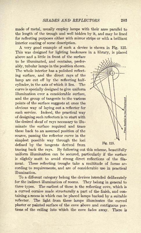
SHADES AND REFLECTORS 203
made of metal, usually employ lamps with their axes parallel to
the length of the trough and well hidden by it, and may be lined
for reflecting purposes either with mirror strips or with a brilliant
interior coating of some description.
A very good example of such a device is shown in Fig. 125.
This was designed for lighting bookcases in a library, is placedabove and a little in front of the surface
to be illuminated, and contains, prefer-
ably, tubular lamps in the position shown.
The whole interior has a polished reflect-
ing surface, and the direct rays of the
lamp are cut off by the reflecting half-
cylinder, in the axis of which it lies. Thecurve is specially designed to give uniform
illumination over a considerable surface,
and the group of tangents to the various
points of the surface suggests at once the
obvious way of laying out a reflector for
such service. Indeed, the practical wayof designing such reflectors is to start with
the desired sheaf of rays necessary to illu-
minate the surface required and trace
these back to an assumed position of the
source, passing the reflector curve in the
simplest possible way through the loci
defined by the tangents derived from
tracing back the rays. By following out this scheme, beautifullyuniform illumination can be secured, particularly if the surface
is slightly matt to avoid strong direct reflections of the fila-
ment. These reflecting troughs take a multitude of forms ac-
cording to requirements, and are of considerable use in practical
illumination.
To a different category belong the devices intended deliberatelyfor the indirect illumination of rooms. They belong in general to
three types. The earliest of these is the reflecting cove, which is
a curved cornice made structurally a part of the finish, and con-
taining a recess in which can be placed lamps backed by a suitable
reflector. The light from these lamps illuminates the curved
plaster or painted surface of the cove above and contiguous por-tions of the ceiling into which the cove fades away. There is
Fig. 125.
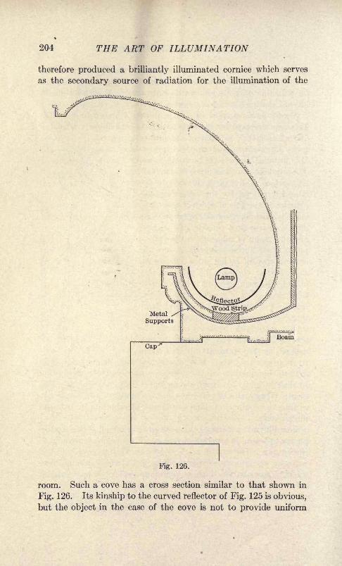
204 THE ART OF ILLUMINATION
therefore produced a brilliantly illuminated cornice which serves
as the secondary source of radiation for the illumination of the
Fig. 126.
room. Such a cove has a cross section similar to that shown in
Fig. 126. Its kinship to the curved reflector of Fig. 125 is obvious,
but the object in the case of the cove is not to provide uniform
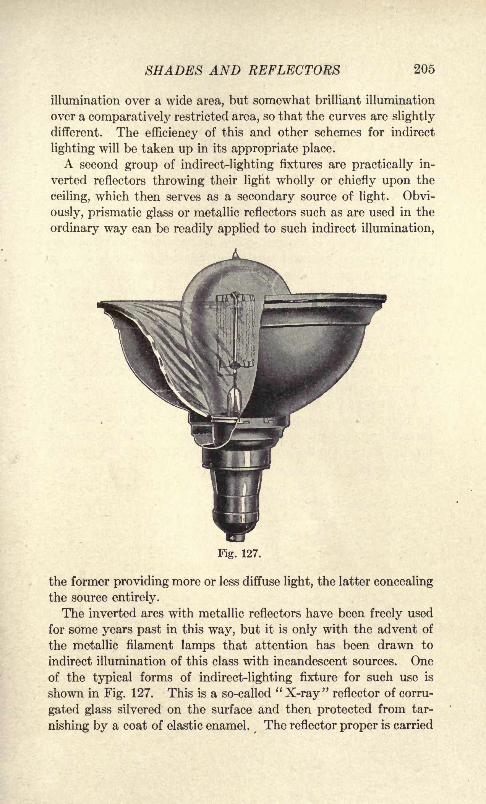
SHADES AND REFLECTORS 205
illumination over a wide area, but somewhat brilliant illumination
over a comparatively restricted area, so that the curves are slightly
different. The efficiency of this and other schemes for indirect
lighting will be taken up in its appropriate place.
A second group of indirect-lighting fixtures are practically in-
verted reflectors throwing their light wholly or chiefly upon the
ceiling, which then serves as a secondary source of light. Obvi-
ously, prismatic glass or metallic reflectors such as are used in the
ordinary way can be readily applied to such indirect illumination,
Fig. 127.
the former providing more or less diffuse light, the latter concealing
the source entirely.
The inverted arcs with metallic reflectors have been freely used
for some years past in this way, but it is only with the advent of
the metallic filament lamps that attention has been drawn to
indirect illumination of this class with incandescent sources. One
of the typical forms of indirect-lighting fixture for such use is
shown in Fig. 127. This is a so-called"X-ray" reflector of corru-
gated glass silvered on the surface and then protected from tar-
nishing by a coat of elastic enamel. The reflector proper is carried
206 THE ART OF ILLUMINATION
in a metallic casing with a suitable fixture provided for holding the
lamp in the axis of the reflector, and the whole may be mountedon a fixture or suspended from chains so that the light which would
otherwise fall below the horizontal is thrown entirely toward the
ceiling. Of course it is necessary that the reflecting surface should
be kept reasonably free from dust, in Jjiis as in all cases of reflectors
for indirect lighting. The device, however, has come into consider-
able use as a convenient way of securing indirect illumination with-
out special structural provisions in the building.^
Finally, a group of fixtures should be mentioned which are es-
pecially designed to accomplish the same result that could be reached
by using a prismatic glass reflector inverted; that is, they arc so
arranged as to throw a considerable part of the light upon the
ceiling for indirect lighting and at the same time to diffuse a soft
illumination through the space below. These direct-indirect or
semi-indirect fixtures, as they are sometimes called, have great
artistic possibilities and can be made to give beautiful illumina-
tion, but they have not yet come into large use, although the
scheme is an old one.
All these methods of indirect and semidirect lighting are rela-
tively inefficient, and not time enough has yet elapsed since the
general introduction of high-efficiency incandescent lamps and
mantles to develop the auxiliary appliances to their full measure
of usefulness.
CHAPTER X.
DOMESTIC ILLUMINATION.
THE lighting of houses is a most interesting and generally neg-
lected branch of illumination. Artificial light has been distinctly
a luxury until within comparatively recent times, and in domestic
lighting there has not been the same pressure of commercial neces-
sity which has resulted in the general efforts to illuminate other
buildings. Indeed, until within half a century there was very little
effort at really good illumination in the home, everyone dependingon portable lights, which could be brought directly to bear upon the
work in hand; gas, which provides fixed radiant points, being con-
fined to large cities, and in these to houses of the better class. Evenat the present time very little pains is taken to arrange the lighting
in a systematic and efficient manner.
The comparatively small areas to be lighted in dwellings, the
small need for extremely intense light, and the very discontinuous
character of the need for any light at all, render domestic lighting
rather a problem by itself. Of ordinary illuminants all may be
freely used for such work, save arc lamps and very powerful
gas lamps, such as the large regenerative burners and the most
powerful incandescent mantles.
Arcs are of very unnecessary power, hence most uneconomical,and are often so unsteady as to be most trying to thv; eyes.
In the home, as a general thing, one does not keep the eyes
fixed in any definite direction, as one would if working steadily
by artificial light, so that far more than usual care must be
taken to avoid intense and glaring lights. Therefore, arcs are
highly objectionable, and the gas lights of high candle power
equally so, particularly as the latter throw out a prodigious
amount of heat and burn out the oxygen of the air rather
rapidly.
As to other illuminants, the main point is to choose those of
low intrinsic brilliancy, or to keep down the intrinsic brilliancy
by adroit and thorough shading. Anything over two or three
candle power per square inch it is well to avoid as needlessly207
208 THE ART OF ILLUMINATION
trying to the eyes without any compensating advantage save
economy, which can better be secured in other ways.
Aside from the physiological side of the matter, very bright
lights seldom give good artistic results or show an interior at
anything like its true value. Of the common illuminants, gas
and incandescent lamps "are those,* generally most useful, while
petroleum lamps and candles are even now auxiliaries by no means
to be despised. Professor Elihu Thomson once very shrewdlyremarked to the writer that if electric lights had^ been in use for
centuries and the candle had been just invented, it would be hailed
as one of the greatest blessings of the century, on the groundthat it is absolutely self-contained, always ready for use, and
perfectly mobile.
Now, gas and incandescents, while possessing many virtues, lack
that of mobility. They are practically fixed where the builder or
contractor found it most convenient to install them, for while
tubes or wires can be led from the fixtures to any points desired,
these straggling adjuncts are sometimes out of order, often in
the way, and always unsightly. Besides, the outlets are often for
structural reasons in inconvenient locations, and their positions
need to be chosen very carefully if artistic effects are at all to be
considered; so that while these lights are the ordinary basis of
illumination wherever they are available, lamps and candles, which
can be put where they are wanted and not necessarily where some
irresponsible workman chose to locate them, are often most useful
additions to our resources.
In domestic, as in other varieties of interior illumination, two
courses are open to the designer. In the first place, he can plan to
have the whole space to be lighted brought uniformly, or with
some approximation to uniformity, above a certain brilliancy,
more or less approximating the effect of a room receiving daylight
through its windows. Or, throwing aside any purpose to simulate
daylight in intensity or distribution, he can put artificial light
simply where it is needed, merely furnishing such a ground-work of general illumination as will serve the ends of art and
convenience.
While the first method is for purely utilitarian purposes often
necessary, it is frequently uneconomical and inartistic in its
results. Its sin against economy is in furnishing 'a great deal
of light which is not really needed, while in so doing it usually
DOMESTIC ILLUMINATION 209
sends light in directions where it deadens shadows, blurs contrasts,
and illuminates objects on all sides but the right one. The second
method is the one uniformly to be chosen for domestic lighting,
from every point of view.
In electric lighting the most strenuous efforts are constantly
being made to improve the efficiency of the incandescent lamps
by a few per cent, and an assured gain of even 10 per cent would
be heralded by such a fanfare of advertising as has not been heard
since the early days of the art. Yet in lighting generally, and
domestic lighting in particular, a little skill and tact in using the
lights we now have can effect an economy far greater than all the
material improvements of the last twenty years. The fundamental
rule of putting light where it is most useful, and concentrating it
only where it is needed, is one too often forgotten or unknown.
If borne in mind it not only reduces the cost of illumination, but
improves its effect.
In applying this rule in practice, one of the first things which
forces itself upon the attention is the fact that the conditions can
seldom be met by the consistent use of lights of one uniform
intensity, or one uniform characteristic as regards the distribution
of the light around the radiant. Even one kind of illuminant
is sometimes an embarrassing condition. Both the kind and
quantity of the illumination must be adjusted to the actual
requirements, if real efficiency is to be secured.
As has already been shown, the effective illumination depends
upon two factors, the actual power of the radiant in candles or
other units, and the nature of the surroundings, which determine
the character and amount of the diffuse reflection which reenforces
the direct light. If the radiant in a closed space furnishes a certain
quantity of light, L, then the strength of the illumination pro-
duced at any point within the space will depend, if the walls are
nonreflecting, simply on the amount of light received from the
radiant, in accordance with the law of inverse squares. If the walls
reflect, then the total illumination at any point will be that received
directly, L, and in addition a certain amount kL (where k is the
coefficient of reflection), once reflected, a further amount k 2L twice
reflected, and so forth. The total illuminative effect will then be:
L (1 + k + k 2 + k3 + . . . fc).
As k is obviously always less than unity, this series is convergent
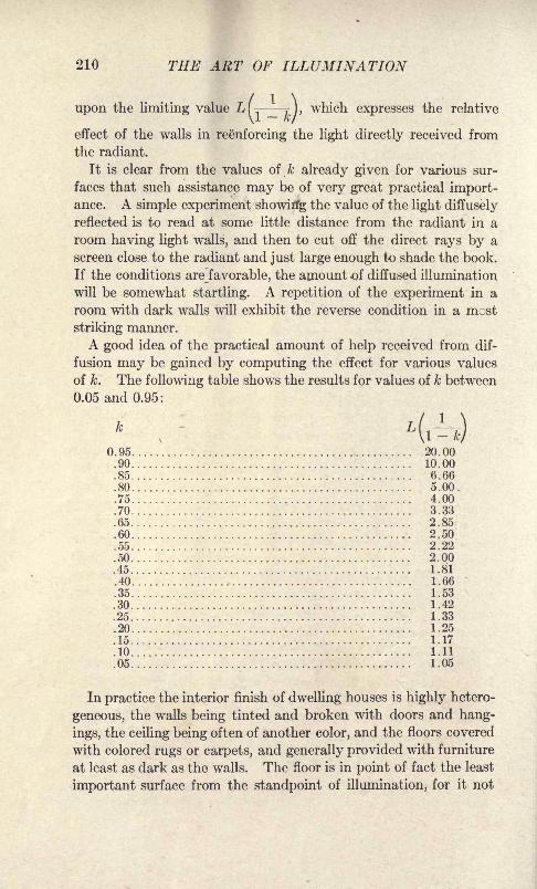
210 THE ART OF ILLUMINATION
upon the limiting value Lfrj,
which expresses the relative
effect of the walls in reenforcing the light directly received from
the radiant.
It is clear from the values of k already given for various sur-
faces that such assistance may be of very great practical import-ance. A simple experiment showirfg the value of the light diffusely
reflected is to read at some little distance from the radiant in a
room having light walls, and then to cut off the direct rays by a
screen close to the radiant and just large enough to shade the book.
If the conditions are favorable, the amount of diffused illumination
will be somewhat startling. A repetition of the experiment in a
room with dark walls will exhibit the reverse condition in a most
striking manner.
A good idea of the practical amount of help received from dif-
fusion may be gained by computing the effect for various values
of k. The following table shows the results for values of k between
0.05 and 0.95:
k
0.95 20.00.90 10.00.85 6.66.80 5.00..75 4.00.70 3.33.65... 2.85.60 2.50.55 2.22.50 2.00.45 1.81
.40 1.66
.35 1.53
.30.. 1.42
.25.... 1.33
.20 1.25
.15 1.17
.10 1.11
.05 1.05
In practice the interior finish of dwelling houses is highly hetero-
geneous, the walls being tinted and broken with doors and hang-
ings, the ceiling being often of another color, and the floors covered
with colored rugs or carpets, and generally provided with furniture
at least as dark as the walls. The floor is in point of fact the least
important surface from the standpoint of illumination, for it not
DOMESTIC ILLUMINATION 211
only carries the furniture, but from its position cannot diffuse light
directly in any useful direction. So far as it is concerned, onlythe small terms in k2 and higher powers enter the general equation,
since the illumination diffused from below is not of much account.
These values show the great difference between good and poor
diffusing surfaces in their practical effect. Reference to the table
already given shows that ordinary wall surfaces give values of k
ranging from about 0.60 down to 0.10 or less. These are likely to
be reduced by the gradual absorption of dust at the surface, but
it is quite within bounds to say that the effective illumination in
a room may be nearly or quite doubled by the light diffused from
the walls. If an average value of k is computed on the basis of
the respective areas and values of k for the several surfaces of the
room, the above table gives in practice a pretty accurate idea of the
reinforcement of the direct illumination.
The ceiling is a very important consideration, for the light
diffused downward is highly valuable. Vaulted ceilings are notori-
ous in their bad effect upon the illumination. If used at all, theyshould be employed with full knowledge of the fact that they quite
effectively nullify all attempts at brilliant general illumination, and
when considerations of harmony permit, ceilings ought to be very
lightly tinted.
As to the walls themselves, wainscoting and dark soft-finished
papers absorb light very strongly, and render lighting difficult,
while the white-painted wood and light papers freely used in
Colonial houses produce exactly the reverse effect. The character
of interior finish, being determined by the contemporaneous fashion,
can of course seldom be really subordinated to the matter of illu-
mination, which affects only personal comfort; but in planning a
scheme of decoration it is necessary to bear in mind that the darker
the general effect the more light should be provided
The outlets for gas and electricity provided for and quite ade-
quate to light a brightly finished house, will prove entirely insuffi-
cient if a scheme of decoration in dark colors be afterward carried
out, so that it is the part of wisdom to arrange the original outlets
to meet the worst probable conditions for lighting. This will gener-
ally mean arranging for about double the minimum amount of
illumination necessary on the hypothesis of strong diffusion from
the walls.
If conditions demand or fashion dictates any attempt at very
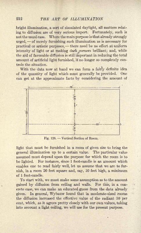
212 THE ART OF ILLUMINATION
bright illumination, a sort of simulated daylight, all matters relat-
ing to diffusion are of very serious import. Fortunately, such is
not the usual case. Where the main purpose is that already strongly
urged, of merely furnishing such illumination as is necessary for
practical or artistic purposes, there need be no effort at uniform
intensity of light or at making dark ^corners brilliant; and, while
the aid of favorable diffusion is still important in reducing the total
amount of artificial light furnished, it no longer so completely con-
trols the situation.
With the data now at hand we can form a fairly definite idea
of the quantity of light which must generally be provided. One
can get at the approximate facts by considering the amount of
20-
Fig. 128. Vertical Section of Room.
light that must be furnished in a room of given size to bring the
general illumination up to a certain value. The particular value
assumed must depend upon the purpose for which the room is to
be lighted. For instance, since 1 foot-candle is an amount which
enables one to read fairly well, let us assume that we are to fur-
nish, in a room 20 feet square and, say, 10 feet high, a minimumof 1 foot-candle.
To start with, we must make some assumption as to the amount
gained by diffusion from ceiling and walls. For this, in a con-
crete case, we can make an educated guess from the data already
given. In general, Wybauw found that in moderate-sized rooms
the diffusion increased the effective value of the radiant 50 per
cent, which, as it agrees pretty closely with our own values, takinginto account a light ceiling, we will use for the present purpose.
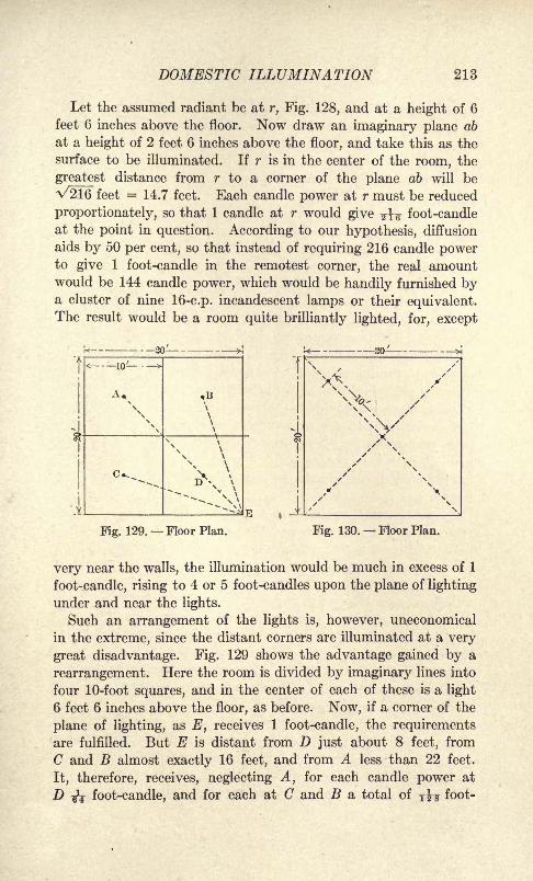
DOMESTIC ILLUMINATION 213
Let the assumed radiant be at r, Fig. 128, and at a height of 6
feet 6 inches above the floor. Now draw an imaginary plane ab
at a height of 2 feet 6 inches above the floor, and take this as the
surface to be illuminated. If r is in the center of the room, the
greatest distance from r to a corner of the plane ab will be
\/216 feet = 14.7 feet. Each candle power at r must be reduced
proportionately, so that 1 candle at r would give ^^ foot-candle
at the point in question. According to our hypothesis, diffusion
aids by 50 per cent, so that instead of requiring 216 candle powerto give 1 foot-candle in the remotest corner, the real amountwould be 144 candle power, which would be handily furnished bya cluster of nine 16-c.p. incandescent lamps or their equivalent.The result would be a room quite brilliantly lighted, for, except
. 20^
Fig. 129. Floor Plan. Fig. 130. Floor Plan.
very near the walls, the illumination would be much in excess of 1
foot-candle, rising to 4 or 5 foot-candles upon the plane of lighting
under and near the lights.
Such an arrangement of the lights is, however, uneconomical
in the extreme, since the distant corners are illuminated at a very
great disadvantage. Fig. 129 shows the advantage gained by a
rearrangement. Here the room is divided by imaginary lines into
four 10-foot squares, and in the center of each of these is a light
6 feet 6 inches above the floor, as before. Now, if a corner of the
plane of lighting, as E, receives 1 foot-candle, the requirements
are fulfilled. But E is distant from D just about 8 feet, from
C and B almost exactly 16 feet, and from A less than 22 feet.
It, therefore, receives, neglecting A, for each candle power at
D ^i foot-candle, and for each at C and B a total of T|^ foot-
214 THE ART OF ILLUMINATION
candle, or, allowing for diffusion, V and sV respectively (nearly),
so that it at once becomes evident that four 32-c.p. lamps are morethan sufficient to do the work.
Taking A into account, four 25-c.p. lamps would almost suffice,
but obviously the maximum illumination is perceptibly lowered.
It would be a maximum at the center, and for 32-c.p. lampswould there amount to 2 foot-candles. A still further subdivision
would lead to still better distribution from the point of view of
economy, and, indeed, something can still be gained by a further
redistribution of the light; for, with lights arranged as in Fig. 130,
at the center and on the circle inscribed in the room in question,
five 20-c.p. lamps would very closely fulfill the conditions, reducingthe total amount of light required to meet the assumed condition
from 144 to 100 candle power in all.
Obviously, with a fixed minimum illumination and no other re-
quirement, the conditions of economy will be most closely met bya nearly uniform distribution of the minimum intensity required.
There is, however, a limit to practical subdivision in limited areas,
such as rooms. In the case of large buildings, as we shall pres-
ently see, one can easily figure out the illumination on the basis
just taken, but in domestic lighting we have to deal with a verylimited number of radiants, at least in considering gas and elec-
tricity.
By far the best results are attained by providing a very m'od-
erate general illumination and then superposing upon it strong
local illumination for special purposes. For example, in most
rooms better practical results than those of Fig. 130 would be
reached by following the same arrangement, but using four
16-c.p. or even four 8-c.p. lamps and one 32-c.p. lamp, the latter
being placed near the point where the strongest illumination is
required. The result would be to give the extreme corners all
the light they really need, and to provide plenty of light where
it is of most practical value. In ordinary domestic lighting the
four smaller lights would often be put on brackets and the large
one installed in a table lamp.The same rules apply to the use of gas or other illuminants,
always bearing in mind that the total amount of light required
is strongly affected by the hue of the walls, and that the principal
radiant should be placed where it will do the most good. Illu-
mination thus regulated is both safer physiologically and far more
DOMESTIC ILLUMINATION 215
efficient in use of the material than any attempt at uniform distri-
bution over the entire area.
One's choice of illuminants must obviously be governed by the
question of availability. Incandescent electric lamps easily hold
the first place when economy is not the first consideration, byreason of their being quite steady, giving out little heat, and in
no way vitiating the atmosphere. They should always, however,
be furnished with ground bulbs, or, better, so shaded as greatly
to reduce their otherwise very high intrinsic brilliancy.
Next in order of desirability unquestionably comes gas. Used
with the incandescent mantle burner, it is the cheapest known
illuminant for domestic purposes unless electricity can be ob-
tained at exceptionally low rates. Mantle burners should always
be shaded, both to reduce the intrinsic brilliancy and to modifythe hue of the light, unless some of the recent mantles giving an
amber tone to the light are available. Ordinary gas jets, in case
of need, give a good but expensive subordinate illumination.
Lamps and candles have strong merits for particular purposes,
but are inferior for general work. The former are often used
with good effect to furnish the principal radiant, which may be
reenforced by small gas lights. Candles, on the other hand, are
extremely useful for partial and subsidiary illumination, since they
are the only available source of small intensity unless one goes
to considerable trouble in wiring for tiny electric bulbs, which are
better adapted to purely decorative purposes than to the regular
work of illumination.
From this general basis of facts we can now take up the prac-
tical and concrete side of domestic lighting.
As to the distribution of the lights required for interior illu-
mination, one must be guided by the intensity which is-liecessary.
The examples already given show the general character of the
problem. The laws upon which the solution depend may be
formulated as follows: If we write L for the required or existing
intensity of illumination in foot-candles at any point, C for the
candle power of the radiant, and d for the distance in feet from
that radiant, then:
If the point in question receives light from more than one radiant,
216 THE ART OF ILLUMINATION
the illuminative effects must be summed, and, if the radiants are
equal,
L is of course in foot-candles and C in ca-ndle power. In
these expressions no account is taken of the varying angles of
incidence of the light received from the several radiants. 'In
principle, L -^ ,where i is the angle of incidence; inpther
words, the illumination decreases as it becomes oblique.
In certain cases account must be taken of this fact, but since,
as a rule, objects to be lighted are oblique to the plane of illumi-
nation, and cos i is small only in case of rather distant lights, of
which the entire effect is small, and since the diffused light cannot
be reckoned with, having no determinate direction, the question
of obliquity, particularly when the radiants are numerous and well
distributed, has seldom to be dealt with. It is rendered the more
uncertain by the notorious inequality of the distribution of the
light from ordinary illuminants, and it must be remembered that
the whole aspect of the matter is changed by the use of reflectors.
It is better to take the obliquity factor by general average in
assuming the illumination required.
In ordinary interior illumination one constantly meets limita-
tions imposed by structural or artistic considerations. For example,we have already seen that the arrangement shown in Fig. 130 was
highly desirable for economic reasons. The five lamps dangling bycords or rods, from the ceiling of a room 20 feet square, might be
tolerated in an office, but would be quite inadmissible in a drawingroom. For domestic lighting one is more likely to use chandeliers,
side brackets, and ceiling lights. The last-named have been con-
siderably used of late, sometimes with beautiful effects, sometimes
unwisely.
To examine the effect of ceiling lights on the situation, refer
to Fig. 131, which shows the same room as Fig. 128. Assumingthe same general conditions, let us find the illumination at a point
p in the plane of illumination when given by a light r in the old
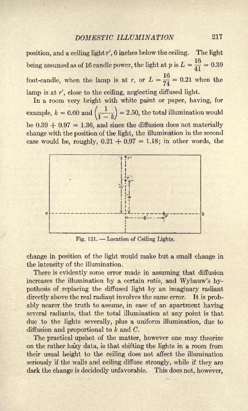
DOMESTIC ILLUMINATION 217
position, and a ceiling light r', 6 inches below the ceiling. The light1 A
being assumed as of 16 candle power, the light at p is L = = 0.39
i f\
foot-candle, when the lamp is at r, or L = ^ = 0.21 when the
lamp is at r', close to the ceiling, neglecting diffused light.
In a room very bright with white paint or paper, having, for
example, k = 0.60 and f ,
j
=2.50, the total illumination would
be 0.39 + 0.97 =1.36, and since the diffusion does not materially
change with the position of the light, the illumination in the second
case would be, roughly, 0.21 + 0.97 = 1.18; in other words, the
.if
hi
i
:
lu-*>-
Fig. 131. Location of Ceiling Lights.
change in position of the light would make but a small change in
the intensity of the illumination.
There is evidently some error made in assuming that diffusion
increases the illumination by a certain ratio, and Wybauw's hy-
pothesis of replacing the diffused light by an imaginary radiant
directly above the real radiant involves the same error. It is prob-
ably nearer the truth to assume, in case of an apartment havingseveral radiants, that the total illumination at any point is that
due to the lights severally, plus a uniform illumination, due to
diffusion and proportional to k and C.
The practical upshot of the matter, however one may theorize
on the rather hazy data, is that shifting the lights in a room from
their usual height to the ceiling does not affect the illumination
seriously if the walls and ceiling diffuse strongly, while if they are
dark the change is decidedly unfavorable. This does not, however,

218 THE ART OF ILLUMINATION
imply that ceiling lights should not be used in dark-finished rooms,
although it is very plain that if they are so used the lamps should
be provided with reflectors, or themselves form reflectors, as in
some lamps recently introduced.
If the walls have a very low coefficient of diffusion it is obvious
that all light falling upon them is nearly wasted, at least from the
standpoint of illumination, and therefore the economic procedureis to deflect this light so that instead of falling upon the walls it
shall be directed upon the plane of illumination, which is chosen
to represent the average height from the floor at which are the
things to be illuminated. If reflectors or their equivalents are
skillfully applied, the radiants, for the purpose in hand, are nearly
or quite doubled in intensity, so that there is a good opportunityfor efficient lighting. But these reflecting media must be used
with caution to avoid the appearance of beams giving definite
bright areas, and by far the best results may be obtained by using
diffusing shades in every such case. So far as economy of light
is concerned, reflectors can be advantageously used wherever the
effective reflection exceeds the total diffusion coefficient of the walls.
For example, with a hemispherical reflector having a coefficient of
reflection of 0.70, the hemispherical intensity of the radiant is
1.70 C, assuming a spherical distribution of the light. This value
corresponds, so far as the plane of illumination is concerned, with
a diffusion of k =0.40, which signifies that, except in very light
finished rooms, the radiant is used more efficiently by employing a
reflector than by trusting to the really very serviceable diffusion
from the walls.
The use of side lights close to the
wall, or on short brackets, is preferable
to lighting from the ceiling in certain
cases, as when strong local illumination
is needed. Reflector lamps may here
again be used with very great effect if
the walls are at all dark in tone. Fig.
132 gives in diagram the simplest ar-
rangement of such lamps. We mayassume their height as a trifle less than
in the case of the suspended lights,
-10--
Fig. 132. Side Lights.
say, 3 feet above the plane of illumination, and that they are
equipped with reflectors giving a hemispherical distribution of
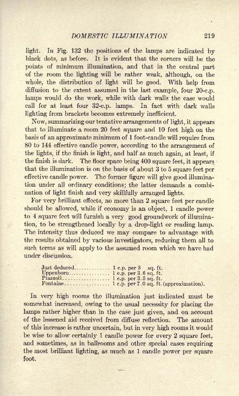
DOMESTIC ILLUMINATION 219
light. In Fig. 132 the positions of the lamps are indicated byblack dots, as before. It is evident that the corners will be the
points of minimum illumination, and that in the central partof the room the lighting will be rather weak, although, on the
whole, the distribution of light will be good. With help from
diffusion to the extent assumed in the last example, four 20-c.p.
lamps would do the work, while with dark walls the case wouldcall for at least four 32-c.p. lamps. In fact with dark walls
lighting from brackets becomes extremely inefficient.
Now, summarizing our tentative arrangements of light, it appearsthat to illuminate a room 20 feet square and 10 feet high on the
basis of an approximate minimum of 1 foot-candle will require from
80 to 144 effective candle power, according to the arrangement of
the lights, if the finish is light, and half as much again, at least, if
the finish is dark. The floor space being 400 square feet, it appearsthat the illumination is on the basis of about 3 to 5 square feet pereffective candle power. The former figure will give good illumina-
tion under all ordinary conditions; the latter demands a combi-
nation of light finish and very skillfully arranged lights.
For very brilliant effects, no more than 2 square feet per candle
should be allowed, while if economy is an object, 1 candle powerto 4 square feet will furnish a very good groundwork of illumina-
tion, to be strengthened locally by a drop-light or reading lamp.The intensity thus deduced we may compare to advantage with
the results obtained by various investigators, reducing them all to
such terms as will apply to the assumed room which we have hadunder discussion.
Just deduced 1 c.p. per 3 sq. ft.
Uppenborn 1 c.p. per 3.6 sq. ft.
Piazzoli 1 c.p. per 3 . 5 sq. ft.
Fontaine ; 1 c.p. per 7.0 sq. ft. (approximation).
In very high rooms the illumination just indicated must be
somewhat increased, owing to the usual necessity for placing the
lamps rather higher than in the case just given, and on account
of the lessened aid received from diffuse reflection. The amountof this increase is rather uncertain, but in very high rooms it wouldbe wise to allow certainly 1 candle power for every 2 square feet,
and sometimes, as in ballrooms and other special cases requiringthe most brilliant lighting, as much as 1 candle power per squarefoot.
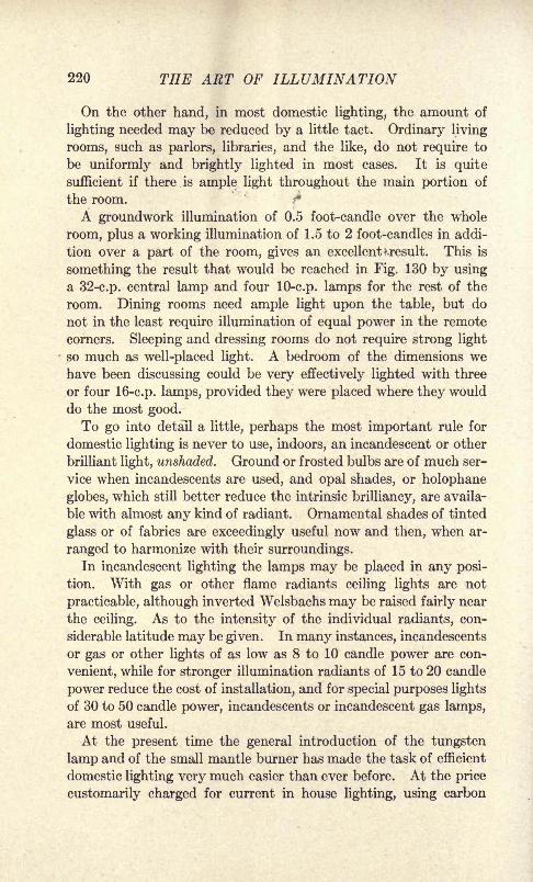
220 THE ART OF ILLUMINATION
On the other hand, in most domestic lighting, the amount of
lighting needed may be reduced by a little tact. Ordinary living
rooms, such as parlors, libraries, and the like, do not require to
be uniformly and brightly lighted in most cases. It is quite
sufficient if there is ample light throughout the main portion of
the room.
A groundwork illumination of 0.5 foot-candle over the whole
room, plus a working illumination of 1.5 to 2 foot-candles in addi-
tion over a part of the room, gives an excellent ^result. This is
something the result that would be reached in Fig. 130 by using
a 32-c.p. central lamp and four 10-c.p. lamps for the rest of the
room. Dining rooms need ample light upon the table, but do
not in the least require illumination of equal power in the remote
corners. Sleeping and dressing rooms do not require strong light
so much as well-placed light. A bedroom of the dimensions wehave been discussing could be very effectively lighted with three
or four 16-c.p. lamps, provided they were placed where they would
do the most good.
To go into detail a little, perhaps the most important rule for
domestic lighting is never to use, indoors, an incandescent or other
brilliant light, unshaded. Ground or frosted bulbs are of much ser-
vice when incandescents are used, and opal shades, or holophane
globes, which still better reduce the intrinsic brilliancy, are availa-
ble with almost any kind of radiant. Ornamental shades of tinted
glass or of fabrics are exceedingly useful now and then, when ar-
ranged to harmonize with their surroundings.
In incandescent lighting the lamps may be placed in any posi-
tion. With gas or other flame radiants ceiling lights are not
practicable, although inverted Welsbachs may be raised fairly near
the ceiling. As to the intensity of the individual radiants, con-
siderable latitude may be given. In many instances, incandescents
or gas or other lights of as low as 8 to 10 candle power are con-
venient, while for stronger illumination radiants of 15 to 20 candle
power reduce the cost of installation, and for special purposes lights
of 30 to 50 candle power, incandescents or incandescent gas lamps,
are most useful.
At the present tune the general introduction of the tungsten
lamp and of the small mantle burner has made the task of efficient
domestic lighting very much easier than ever before. At the price
customarily charged for current in house lighting, using carbon
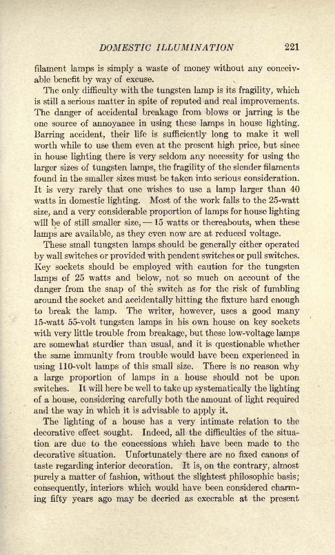
DOMESTIC ILLUMINATION 221
filament lamps is simply a waste of money without any conceiv-
able benefit by way of excuse.
The only difficulty with the tungsten lamp is its fragility, which
is still a serious matter in spite of reputed and real improvements.
The danger of accidental breakage from blows or jarring is the
one source of annoyance in using these lamps in house lighting.
Barring accident, their life is sufficiently long to make it well
worth while to use them even at the present high price, but since
in house lighting there is very seldom any necessity for using the
larger sizes of tungsten lamps, the fragility of the slender filaments
found in the smaller sizes must be taken into serious consideration.
It is very rarely that one wishes to use a lamp larger than 40
watts in domestic lighting. Most of the work falls to the 25-watt
size, and a very considerable proportion of lamps for house lighting
will be of still smaller size, 15 watts or thereabouts, when these
lamps are available, as they even now are at reduced voltage.
These small tungsten lamps should be generally either operated
by wall switches or provided with pendent switches or pull switches.
Key sockets should be employed with caution for the tungsten
lamps of 25 watts and below, not so much on account of the
danger from the snap of the switch as for the risk of fumbling
around the socket and accidentally hitting the fixture hard enoughto break the lamp. The writer, however, uses a good many15-watt 55-volt tungsten lamps in his own house on key sockets
with very little trouble from breakage, but these low-voltage lampsare somewhat sturdier than usual, and it is questionable whether
the same immunity from trouble would have been experienced in
using 110-volt lamps of this small size. There is no reason whya large proportion of lamps in a house should not be uponswitches. It will here be well to take up systematically the lighting
of a house, considering carefully both the amount of light required
and the way in which it is advisable to apply it.
The lighting of a house has a very intimate relation to the
decorative effect sought. Indeed, all the difficulties of the situa-
tion are due to the concessions which have been made to the
decorative situation. Unfortunately there are no fixed canons of
taste regarding interior decoration. It is, on the contrary, almost
purely a matter of fashion, without the slightest philosophic basis;
consequently, interiors which would have been considered charm-
ing fifty years ago may be decried as execrable at the present
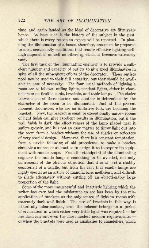
222 THE ART OF ILLUMINATION
time, and again lauded as the ideal of decorative art fifty years
hence. At least such is the history of the subject in the past,
which there is every reason to expect will be repeated. In plan-
ning the illumination of a house, therefore, one must be preparedto meet occasionally conditions that render effective lighting well-
nigh impossible, as well as others in which it becomes extremely
easy.
The first task of the illuminating engineer is to provide a suffi-
cient number and capacity of outlets to give good illumination in
spite of all the subsequent efforts of the decorator." These outlets
need not be used to their full capacity, but they should be avail-
able in case of necessity. The four usual methods of lighting a
room are as follows: ceiling lights, pendent lights, either in chan-
deliers or on flexible cords, brackets, and table lamps. The choice
between one of these devices and another is determined by the
character of the room to be illuminated. Just at the present
moment decorators, who are an imitative folk, are booming the
bracket. Now, the bracket in small or exceptionally narrow rooms
of light finish can give excellent results in illumination, but if the
wall finish is dark the effectiveness of the lamp placed near it
suffers greatly, and it is not an easy matter to throw light out into
the room from a bracket without the use of shades or reflectors
of very special design. Moreover, there is a constant temptation,
from a slavish following of old precedents, to make a bracket
simulate a sconce, or at least so to design it as to require its equip-
ment with candle lamps. From the standpoint of the illuminating
engineer the candle lamp is something to be avoided, not onlyon account of the obvious objection that it is at best a shabbycounterfeit of a candle, but from the fact that candle lamps are
highly special as an article of manufacture, inefficient, and difficult
to shade adequately without cutting off an objectionably large
proportion of the light.
Some of the most unsuccessful and inartistic lighting which the
writer has ever had the misfortune to see has been by the mis-
application of brackets as the only source of light to rooms with
extremely dark wall finish. The use of brackets in this way is
historically inharmonious, since the scheme belongs to a periodof civilization in which either very little light was required, far
less than can suit even the most modest modern requirements,or when the brackets were used as auxiliaries to chandeliers, which
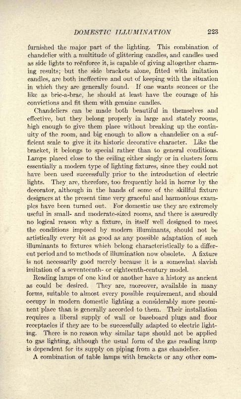
DOMESTIC ILLUMINATION 223
furnished the major part of the lighting. This combination of
chandelier with a multitude of glittering candles, and candles used
as side lights to reenforce it, is capable of giving altogether charm-
ing results; but the side brackets alone, fitted with imitation
candles, are both ineffective and out of keeping with the situation
in which they are generally found. If one wants sconces or the
like as bric-a-brac, he should at least have the courage of his
convictions and fit them with genuine candles.
Chandeliers can be made both beautiful in themselves and
effective, but they belong properly in large and stately rooms,
high enough to give them place without breaking up the contin-
uity of the room, and big enough to allow a chandelier on a suf-
ficient scale to give it its historic decorative character. Like the
bracket, it belongs to special rather than to general conditions.
Lamps placed close to the ceiling either singly or in clusters form
essentially a modern type of lighting fixtures, since they could not
have been used successfully prior to the introduction of electric
lights. They are, therefore, too frequently held in horror by the
decorator, although in the hands of some of the skillful fixture
designers at the present time very graceful and harmonious exam-
ples have been turned out. For domestic use they are extremelyuseful in small- and moderate-sized rooms, and there is assuredly
no logical reason why a fixture, in itself well designed to meet
the conditions imposed by modern illuminants, should not be
artistically every bit as good as any possible adaptation of such
illuminants to fixtures which belong characteristically to a differ-
ent period and to methods of illumination now obsolete. A fixture
is not necessarily good merely because it is a somewhat slavish
imitation of a seventeenth- or eighteenth-century model.
Reading lamps of one kind or another have a history as ancient
as could be desired. They are, moreover, available in manyforms, suitable to almost every possible requirement, and should
occupy in modern domestic lighting a considerably more promi-nent place than is generally accorded to them. Their installation
requires a liberal supply of wall or baseboard plugs and floor
receptacles if they are to be successfully adapted to electric light-
ing. There is no reason why similar taps should not be applied
to gas lighting, although the usual form of the gas reading lampis dependent for its supply on piping from a gas chandelier.
A combination of table lamps with brackets or any other com-
224 THE ART OF ILLUMINATION
mon means of lighting can be made effective from every point of
view. Sometimes, though rarely, the lighting can be trusted to
lamps alone. The writer, for example, found it desirable to illu-
minate his own library in this way, the room being long and
low, so that its continuity would have been hopelessly broken by
ceiling lights or chandeliers,.and lined with bookcases to an extent
that precluded the effective use of brackets. The use of lamps on
this scale is not particularly economical, owing to the character of
the shades which generally have to be used, but otherwise it leaves
little to be desired.
Finally, one may mention various plans for indirect lighting,
such as have already been described. The design of artistic fix-
tures for this class of work has not progressed far enough to
warrant one in being enthusiastic about it, and the concealed
cornice lighting, while it may be made very effective, is objec-
tionable in the house on account of extreme difficulty in keepingthe reflecting surfaces clean. It therefore is a form of illumina-
tion which should be used with caution.
A word here concerning the matter of fixtures, whatever type
of illumination be attempted. The fact must be recognized that
fixtures may have a high decorative value if properly designed.
With this phase of the matter the illuminating engineer is not
directly concerned, except in so far as bad design may interfere
with the suitability of the fixtures for the purpose of their use,
which is to supply light. The best fixture designers fully recog-
nize this, and can, if given a free hand, produce fixtures which are
excellent from every point of view. From the standpoint of illu-
mination, the chief thing to be borne in mind is that the fixture
must not be so located or so formed as seriously to interfere with
its illuminating function. The writer has in mind one case in
which some very elaborate wrought-iron chandeliers were pro-
vided with deep bell-shaped black iron receptacles within which
the incandescent lamps were located and almost wholly concealed.
After divers ineffective efforts to secure a perceptible amount of
light from these, the unfortunate owner resorted to "gas arcs" of
the most glaring and undecorative description.
The most effective way of protecting a client against bad fix-
tures is to persuade him to cut down his fixture appropriation
to a point that will enforce simplicity and unobtrusiveness.
The worst fixtures, as a rule, are the somewhat showy ones of
DOMESTIC ILLUMINATION 225
medium price in which an attempt has been made to obtain a
so-called decorative effect without the skill in design, and finish in
execution, really necessary for good results.
If one wishes to make fixtures a distinct decorative feature in
an interior, he must be prepared to pay for the privilege, and so
far as illumination is concerned its employment for a purely dec-
orative object is quite legitimate. When so used the man who
pays the bills should clearly understand that he is using light as a
decorative element, quite irrespective of its primary use for illu-
mination, and must also understand that he is decorating rather
than illuminating his room by such use of lights. If he is willing
to pay for it on this basis, that is his business, and no concern of
the illuminating engineer.
The writer recalls a case in his own practice where a private
library was subjected to an electric light bill about ten dollars a
month in excess of what should have been required under ordinary
illuminating practice, merely on account of the nature of the in-
terior finish and the wholesale use of brackets with candle lamps.
The owner grumbled at his electric light bills, although he prob-
ably received florists' bills of much larger amount, also incurred for
decorative purposes, with entire equanimity.
Some attention has here been paid to this phase of the matter
because the illuminating engineer and decorator are popularly
supposed to be at swords' points. Such is not at all the case in
reality, since the illuminating engineer is not concerned with the
taste of his client in the selection of fixtures or bric-a-brac. He
should, however, make it plain that if he has to work under cer-
tain fixed limitations regarding decorative effect, he cannot be
expected to give good illumination for the purpose of seeing with-
out correspondingly large cost to the owner. And, on the other
hand, there should be no concealment of the fact that the decorator
may be advising the use of finish and fixtures that will double or
even quadruple the cost of lighting a room for the ordinary pur-
pose of its use.
Taking up now the lighting of a house in detail, one maysummarize the situation about as follows:
A . Halls. The illumination of these depends entirely on the
way in which they are to be used. Ordinary entrance halls can
generally be sufficiently lighted on the basis of 4 or 5 square feet
per rated candle power. Elaborate halls, which are likely to be
226 THE ART OF ILLUMINATION
used considerably in entertaining, as part of the working space,
should have a larger allowance of light, say 1 candle power to every2 or 3 square feet. The basis of reckoning is here nearly inde-
pendent of the height of the ceiling for the reason that dwelling
houses do not commonly present any extremes of height requiring
special consideration. Back halls and other subsidiary halls require
less light, perhaps 1 candle power to*6 or 7 square feet, since they
are used only as passageways. Lanterns and side brackets are
the usual means selected, and the location should be such as to
thoroughly light the stairway. With exceptionally low ceilings,
lanterns are out of scale unless small and located close to the
ceiling, and brackets will more generally answer the purpose.
Occasionally one sees very beautiful staircase lighting from a newel
post, but the scheme is one that had better be avoided except in
work on a large scale and when the designer can be given carte
blanche for the necessary fixture.
B. Reception Rooms. These are usually of somewhat formal
character, to which the fixtures must correspond. The amount
of light required at times is considerable and should be provided
on the basis of not more than 3 square feet per candle power,
preferably 2, although the subdivision of units should be such
as to allow half or one-third of the light only to be used under
ordinary conditions. One generally finds it advisable in reception
rooms to use brackets or chandeliers, or frequently a combination
of the-two, the chandelier being really suitable only in rather large
and high rooms, and better replaced for low ceilings by a ceiling
fixture. Sometimes side brackets and table lamps make a suitable
combination, the former for general illumination, the latter for
added brilliancy when needed. Here, as everywhere in a house,
it should be the invariable rule of the illuminating engineer never
to allow a bare incandescent lamp to be visible from any point
where one is likely to be placed. If bare lamps are to be used at
all, they should be behind diffusing shades of one sort or another,
otherwise the lamp should be completely frosted, and even the use
of frosted lamps should be shunned on account of their generally
too high surface brilliancy.
C. Music Rooms. Music rooms are employed, or are sup-
posed to be employed, for a definite function. They do not ordi-
narily require high illumination save near the instrument, which is
best cared for by a suitable lamp so as to throw the light upon
DOMESTIC ILLUMINATION 227
it and not into the faces of the audience. Above all things, the
lighting should be restful in effect and the lights extremely well
shielded. Unobtrusive chandeliers or ceiling clusters with lights
well screened are the best means of meeting this requirement.
Brackets are particularly objectionable in such rooms, inasmuch
as they are constantly in the field of view and it is rather difficult
to screen the lights adequately. The amount of light providedshould be on the basis of 3 to 4 square feet per candle power, the
latter figure being quite all that is necessary, unless the room is
to be at times used for general purposes requiring a little more
illumination. These figures presume a wall finish not excessively
dark, and any room wainscoted in dark wood, or finished in paperor paint in dull reds, greens, browns, and blues, would require not
less than 50 per cent more light than here specified. Now and
then some form of concealed lighting is effectively used in a music
room. The main point, however, is that in any room where an
audience is to be assembled the light must be kept out of their
eyes, since they are not at liberty to change their positions and
escape it.
D. Libraries. By tradition libraries are usually given a dark
finish, and if actually used as libraries the walls are lined with
bookcases to an extent which implies powerful absorption of light.
Further, they are supposed to be used for reading, which requires
fairly good illumination, so that the amount of light supplied
must of necessity be considerable. The best way of furnishing
it is to apply a groundwork illumination, either from fixtures
near the ceiling or from brackets, in either case thoroughly
shaded, and then to strengthen it locally by well-shaded reading
lamps.
The total amount of light required will be commonly 1 candle
power for 3 or 4 square feet, about half the total amount being
put in the general illumination and half in the reading lamps. In
case of exceptionally dark finish a total of 1 candle power to as
low as 2 square feet may be desirable. Lamps near the ceiling are
much to be preferred to brackets for general illumination in a
library, since with these latter it is almost impossible adequatelyto light the bookcases, which must lie nearly in the same plane
with the brackets. Further, if a library is really used, it is
usually very difficult to find any space for wall brackets without
interfering with the bookcase space. The library should be wired
228 THE ART OF ILLUMINATION
for an ample supply of current, floor plugs and baseboard plugs
being especially useful.
As a rule fixtures, here as elsewhere, should have the lamps
pointing either directly up or directly down, preferably the latter.
Fixtures having a lamp at an angle are not in the least necessaryfor artistic results, and are extremely objectionable from the fact
that lamps so placed are exceptionally difficult to screen properly.
One is practically obliged in using such fixtures to employ globes
completely inclosing them, which waste an unnecessary amountof light without gaining important advantages. In ceiling lights
either inclosing globes or reflecting shades can be employed, which
can be made adequate to cover the lamp, and can be givendirective action sufficient to supply good illumination beneath.
E. Living Rooms. A living room, used as such, is best lighted
by a combination of table lamps and general illumination from
lights placed at or very near the ceiling. The amount requiredis a trifle less than in the ordinary library on account of the usually
lighter finish. One candle power to 4 square feet, at least half of
it being in table lamps placed where they will do the most good,
ought to be adequate. Few living rooms are large enough or
formal enough in character to make the use of chandeliers desirable.
Nothing is more garish and generally ineffective than the ordinarythree- or four-armed chandelier with the lights at an angle and
placed at a height where they are likely to be hit by unguardedmotions or the passage of someone more than usually tall. More-
over, lights in such a place cannot be properly screened except
by closed globes, and even these are thrust into the face of any-
body entering the room. If the lights are placed high, at or near
the ceiling, they are out of the ordinary field of view and can be
made to put illumination where it will be useful.
F. Dining Rooms. The dining room, more perhaps than anyother room in the ordinary house, is the prey of unthinking and
irresponsible fashion. Table lamps, except when small and for
purely decorative functions, are bad, since they obstruct the view
across the table. Now and then in dining rooms of the formal
and stately type chandeliers may be used with very beautiful effect,
but they belong distinctively to very high rooms giving ample
space for decorative effects, carried well above the immediate view
of the persons in the room.
Side brackets, unless for decorative use only and with the lights
DOMESTIC ILLUMINATION 229
exceedingly well screened, are highly objectionable here, since theymust be shining directly into someone's face and cannot be escaped.
With a room too low and too formal to permit a proper chandelier,
ceiling clusters answer admirably, and from the standpoint of com-
fort a good deal is to be said for the domes, which at times have
been popular and may be highly decorative, although at presentanathema from the ephemeral standpoint of fashion.
There is much to be said, too, for concealed and "semi-direct
"
lighting in rooms of this sort, where it is highly undesirable to
have agjare
of light in the faces of those sitting at table. Theamount of light required is fortunately not great. One candle
power to 4 or 5 square feet is ample if applied with any intelligence.
In passing, the writer may say that altogether the most beautiful
effect -he has ever seen in any private dining room was produced
by the use of an exquisite eighteenth-century chandelier in crystal,
reonforced by candelabra, all carrying real candles, without anyaid from modern illuminants.
G. Kitchen and Pantries. The service portion of a house in
general requires about the same illumination found elsewhere,
with this exception, that in some of the rooms already mentioned
provision must be made for exceptionally bright lighting on par-ticular occasions. The service portion requires merely good work-
ing illumination at all times. By far the best way of securing this
is by lights placed practically at the ceiling with suitable prismatic
glass or similar reflectors. In rooms of ordinary height this is the
position of the greatest advantage. Lights in a kitchen may be
located at one or more points as the arrangement of the working
space requires.
The total amount of illumination required is not great. In the
kitchen itself an average of 1 candle power to 5 or 6 square feet is
ample. Pantries^require
a little more, being generally active work-
ing spaces. One light, which sometimes has to be on a bracket,
although a properly located ceiling light frequently answers, should
be arranged to give good light in the interior of the ice chest. All
lights in the service portion should be on wall switches or pull
sockets, if tungsten lamps are to be used, as is commonly desir-
able. In lighting the service portion of a house with gas, the same
provisions for amount of light and general location hold, and it
pays to use automatic gas lighters, which pay for themselves manytimes over in decreased breakage of mantles. The same is true

230 THE ART OF ILLUMINATION
of the use of gas lights through all other portions of the house,
the rules for amount of light and most advantageous location hold-
ing rigorously true, irrespective of the particular illuminant used.
The chief trouble with gas lighting is the supposed necessity of
getting the lights far enough down to enable them to be lighted
with a match and the consequent -^wholesale use of inartistic and
inconvenient fixtures of the chandelier type. In these days of
inverted mantle burners and thoroughly worked-out systems of
lighting them, there is no difficulty in getting adequate and con-
venient illumination from gas. The combination gas-and-electric
fixtures are generally abominations from the artistic standpoint,
quite unnecessary, and not to be recommended for any purpose.
H. Bedrooms. Bedrooms generally suffer rather from badly
placed lighting than from inadequate amount. The actual amount
required is not large, say 1 candle power for every 5 square feet
in rooms of ordinary finish. These are the only rooms in the ordi-
nary house in which brackets are positively advantageous, although
here they generally could be reenforced to advantage, at least in
electrically lighted houses, by a small ceiling light for purposes of
general illumination.
Bureaus and dressing tables can be better lighted from swinging-
arm brackets than by any other device yet tried, since these
brackets can be moved to exactly the position where they will be
of the most service. The one place where a light should never be
placed is above and a little in front of the bureau or dressing table.
This is the position often picked out by the thoughtless and igno-
rant, who act as if the mirror and the top of the bureau were the
things to be lighted, instead of the person standing or sitting in
front of them.
A swinging bracket, placed not too high and carrying a lampof moderate candle power well shaded, is the form of local lighting
best suited for such use. An additional light placed over or beside
the bed and easily reached from it is a most useful addition to the
bedroom lighting equipment. At least one light should be switched
from the door, and the others may either be switched at the lampsor from a point near at hand. Three lighting units are com-
monly required for the ordinary bed room, more if the room is
exceptionally large. These units should preferably all be small,
unless a special lamp be desired for reading purposes. The same
general conditions hold for lighting with gas. Sometimes a night
DOMESTIC ILLUMINATION 231
lamp is a desirable addition; with electric lighting, a 2-c.p. lamp is
excellent for this purpose; with gas lighting, one small jet shielded
against the danger of being blown out by draughts.
I. Billiard Rooms. Where these are found in private houses
they are generally small, containing only one table. This requires
very strong lighting, say two lamps with downward, somewhat
concentrating reflectors, each lamp from 30 to 50 candle powerand equally spaced over the table area. For electric lighting two
40-watt or 60-watt tungstens are generally sufficient. With gas
lighting two small inverted Welsbachs give similar candle power.
These lights should be placed rather high, so as to be as far as
possible out of the way of the cue in masse shots. There is a gooddeal to be said for the use of indirect lighting in billiard rooms for
the avoidance of shadows, which, while mostly suppressed by the
dark hue of the cloth, are sometimes embarrassing. In case this
method is tried, two 100-watt tungstens or two large Welsbachs,with suitable reflectors to throw the light on the white ceiling, are
none too great an allowance of light for the work. When the
lighting is direct, care should be exercised in picking out the reflec-
tors so as to avoid streaks of light from direct reflections of the
filament. A matt interior surface with ordinary reflectors, or satin-
finished prismatic glass, would generally meet this requirement.
/. Basements. Rooms in the basement of a house commonly
require only a very moderate degree of lighting, varying from 1
candle power to 4 square feet in the portions most used to half
this amount elsewhere. The location of the lights is generally
definitely fixed by the shape of the subdivisions in the basement
or cellar. Lights generally should be placed as near the ceiling
as possible.
K. Bathrooms. Very little need be said for these. One small
light is usually sufficient and is best placed on a swinging bracket.
The bathrooms are usually of such size that the smallest ordinary
unit gives ample illumination, especially since the finish as a rule is
very light.
L. Closets. Most closets unless extremely well lighted from
the room require one small light, generally at the ceiling. The
same is true of storerooms and attic space. It is sometimes good
policy to place these lights, and particularly those in closets, on
automatic door switches, so that they will not be left burning
through carelessness. If only used in one or two places it is com-
232 THE ART OF ILLUMINATION
monly unnecessary, but where a considerable number of closets are
thus fitted it is wise to use automatic switches.
In general, domestic lighting is peculiar, in that a very large
number of lamps relatively to the average or maximum load is
installed. The ordinary dwelling house of ten rooms or above will
require from forty lights upwards, and the number of outlets, in-
cluding base plugs, is likely to be half as great again unless rigorous
economy in the original installation is necessary. The economyof domestic lighting depends on the convenient arrangement of
the lights in such wise that only those necessary at any time shall
be in use; hence it saves money to install ample and convenient
switching, or, in case of gas lighting, automatic lighting apparatus.Electric lights in the halls, both front and back, and in the cellar,
should be put on three-way switches, so that they can be lighted
and extinguished from more than one place. Clusters and chan-
deliers when used may advantageously be wired in two or more
circuits, so that except when full illumination is needed a small
amount of light can be used. In an ordinary electrically lighted
house at least nine-tenths of the illuminating work can best be done
by 25-watt and even 15-watt tungstens, very few larger lamps or
special lamps being ordinarily required. It is advisable, too, in
providing the wiring, to have several taps of ample capacity, in
addition to the lighting connections, provided for small heating
devices, fan motors, and vacuum-cleaner connections. Occasion-
ally someone objects to the relatively white light of tungsten lampsin domestic use, but this can so easily be toned down by the use
of tinted shades or faint tinting of the lamps themselves by dipping,
that it constitutes no serious objection; and the efficiency, even
after the color is modified, lies always with the metallic filament
lamp.
CHAPTER XI.
LIGHTING LARGE INTERIORS.
BEFORE passing to the interesting problem of lighting large in-
teriors, it may be well to consider the group of transitional cases
represented by the rooms of an ordinary office building, and par-
ticularly the smaller ones. Such buildings are variously arranged,
presenting rooms of divers sizes, used for offices or small counting
rooms, and occasionally for the display of goods. As a rule theyare of moderate size, ranging from 200 to 1000 square feet, and
commonly run from 11 to 13 feet in height of ceiling. The ordinaryfinish is on the whole thoroughly light, although the wood-work
may be dark, and in many instances the natural light is rather
poor, so that artificial lighting has to be resorted to for a con-
siderable part of the day. The outlets in office buildings are
generally badly planned, the only redeeming feature being ceiling
outlets, useful for general illumination. Brackets, when found, are
generally fixed with the lights pointing downward at an angle of
45 degrees, by all means the worst possible position, and are chiefly
useful as attachment places for portable lamps. Suitable base-
board outlets for adjustable plugs are too often infrequent and
inconveniently placed.
Now, in all such rooms there are two radically distinct modes of
procedure. One can either provide a moderate general illumination
and reenforce it by portable lamps placed upon desks or tables, or
one can provide a general working illumination alJ over the room.
With the scanty outlets commonly provided the former course is
the easier, and there is no objection to following it, except in rooms
of the larger class. In these one often sees a veritable network of
lamp cords, very unsightly, and very jnuch in the way. In addi-
tion to this disadvantage, it is almost impossible to provide enough
lights for a considerable group of tables and desks without seriously
inconveniencing some of the workers through the glare of their
neighbors' lights. It is sometimes, therefore, highly desirable to
resort to general illumination, which can be carried out successfully233
234 THE ART OF ILLUMINATION
and economically if the outlets and desks or other working spaces
can be conveniently arranged.
The main difficulty in general illumination is not physical but
psychological. Those who have habitually worked with badly
placed and ill-shaded individual lights have found by experience
that under these conditions a great de^l of light is necessary in order
to enable them to see. The eye is working under very disadvan-
tageous circumstances, and is dazzled by the glare, which has to be
reenforced, so to speak, in order to leave enough residual light bywhich to see. Now this experience becomes almost an obsession,
so that the worker forms a settled opinion that he or she can get
adequate light for seeing only by using a large lamp equipped with
a powerful reflector thrust immediately down over the work, and
draws the further conclusion that any lamp which is not powerfuland not close to the work cannot give adequate illumination.
Hence, when an attempt is made to change from individual to
general lighting, there is almost always a violent complaint that
the lighting is insufficient, although in point of fact it may be more
than adequate for the work and very much easier on the eyes than
the illumination that it has replaced. After some experience in
working with general illumination the eye gets accustomed to its
conditions and works with much less effort even with materially
lower illumination.
Nearly all classes of clerical and office work can be performed
easily under an illumination of 3 to 4 foot-candles. In rooms
where bookkeeping is carried on to a considerable extent the
larger figure mentioned is about right, while the more ordinary
office occupations can get along admirably with 3 foot-candles or
even a little less. The exception is made in favor of bookkeepingbecause men at work on ledgers and filing slips usually write with
fine pens for economy of space and with ordinary office ink of a
somewhat bluish cast as it flows from the pen. The combination
is a bad one from the standpoint of lighting. In cases where
general illumination is not attempted and individual lamps are
used in addition to a general groundwork lighting, the latter mayconveniently be between 1 and 2 foot-candles, with desk lampssufficient to bring the lighting on the work to a point not exceed-
ing 4 or 5 foot-candles. Running above this is totally unnecessaryand is apt to be trying for the eyes. Whichever method is adopted,
all the lights, both those furnishing general illumination and those
LIGHTING LARGE INTERIORS 235
lighting the work for individuals, should be thoroughly screened
so that they cannot shine into anybody's eyes.
Lighting really large interiors differs in several important respects
from ordinary practice as applied to rooms of the medium sizes
just considered. In the first place, the aid received from diffusion
from the walls is much less than in the case of smaller rooms,
as has already been indicated. The experiments of Fontaine
indicate that within moderate limits the light required is deter-
mined by the volume of the space to be illuminated, rather than
by the floor space.
Since, however, the only physical effect of the increased height
is to increase the mean distances of the diffusing surfaces and
especially the ceiling from the radiants, the change could, in point
of fact, alter only that part of the total illumination due to diffused
light, provided that with increased height of ceiling the radiants
are not themselves raised.
In large and high rooms there is a strong tendency to increase
the height of the radiants above the plane of illumination, especially
in case of using chandeliers, and this is the most important factor
in the rule aforesaid. Obviously, in increasing the distance of the
radiants one decreases the direct illumination approximately in
the ratio of the inverse squares of the distances, and does not
materially improve the diffusion.
Therefore the illumination falls off seriously. In a large and
high hall, lights arranged in the ceiling or as a frieze, while often
giving admirable effects, are quite uneconomical, and should be
used, if at all, with a full appreciation of this fact.
In large buildings, too, the quantity of light required is subject
to enormous variation, according to the purposes to which the
building is devoted, and whether the whole interior must for artistic
reasons be illuminated. In a ballroom an effect of great brilliancy
is generally aimed at, while a room of equal size used as a factory
needs strong illumination only where it will facilitate the work.
Again, in very large rooms the power of the individual radiants
can advantageously be increased, and some sources of light in-
admissible in domestic lighting, such as arc lamps; or to be used
only with caution, like powerful mantle gas burners may be
used very freely.
But in large buildings, as elsewhere, the fundamental purposeof the lighting is to produce a certain intensity at the plane of
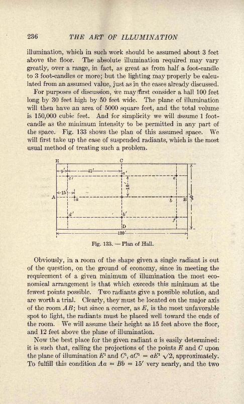
236 THE ART OF ILLUMINATION
illumination, which in such work should be assumed about 3 feet
above the floor. The absolute illumination required may vary
greatly, over a range, in fact, as great as from half a foot-candle
to 3 foot-candles or more; but the lighting may properly be calcu-
lated from an assumed value,, just as in the cases already discussed.
For purposes of discussion, we may '"first consider a hall 100 feet
long by 30 feet high by 50 feet wide. The plane of illumination
will then have an area of 5000 square feet, and the total volume
is 150,000 cubi<; feet. And for simplicity we will assume 1 foot-
candle as the minimum intensity to be permitted in any part of
the space. Fig. 133 shows the plan of this assumed space. Wewill first take up the case of suspended radiants, which is the most
usual method of treating such a problem.
E c
1
Fig. 133. Plan of Hall.
Obviously, in a room of the shape given a single radiant is out
of the question, on the ground of economy, since in meeting the
requirement of a given minimum of illumination the most eco-
nomical arrangement is that which exceeds this minimum at the
fewest points possible. Two radiants give a possible solution, and
are worth a trial. Clearly, they must be located on the major axis
of the room AB; but since a corner, as E, is the most unfavorable
spot to light, the radiants must be placed well toward the ends of
the room. We will assume their height as 15 feet above the floor,
and 12 feet above the plane of illumination.
Now the best place for the given radiant a is easily determined :
it is such that, calling the projections of the points E and C uponthe plane of illumination E 1 and C1
,aC1 = aE l
\/2, approximately.
To fulfill this condition Aa = Bb = 15' very nearly, and the two
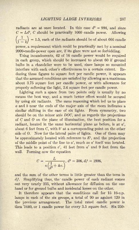
LIGHTING LARGE INTERIORS 237
radiants are at once located. In this case d2 =994, and since
C = Ld2,C should be practically 1000 candle power. Allowing
( r)=
1.5, each of the radiants should be of about 666 candle\1 Ay
power, a requirement which could be practically met by a nominal
2000-candle-power open arc, if its glare were not so forbidding.
Using incandescents, 42 of 16 candle power would be required
in each group, which should be increased to about 60 if groundbulbs in a chandelier were to be used, since lamps so mounted
interfere with each other's effectiveness to a certain extent. Re-
ducing these figures to square feet per candle power, it appearsthat the assumed conditions are satisfied by allowing as a maximumabout 3.75 square feet per candle power, or with allowance for
properly softening the light, 2.6 square feet per candle power.
Lighting such a space from two points only is usually by no
means the best way, and a much better effect would be secured
by using six radiants. The same reasoning which led us to place
a and 6 near the ends of the major axis of the room indicates a
similar shifting in the case of six lights. From symmetry, two
should be on the minor axis DOC, and as regards the projections
of C and on the plane of illumination, the best position for a
radiant, located in the same horizontal plane as before, is at a'',
about 6 feet from C, with V at a corresponding point on the other
side of 0. Now for the lateral pairs of lights. One of them maybe approximately located with reference to E 1
,and the projection
of the middle point of the line to a', much as a' itself was located.
This leads to a position c'',41 feet from a' and 9 feet from the
wall. Forming now the equation
C = r-^ -- d2 = 306, d? = 1906,
and the sum of the other terms is little greater than the term in
di2
. Simplifying thus, the' candle power of each radiant comes
out very nearly 235, without allowance for diffusion on the one
hand or for ground bulbs and incidental losses on the other.
It therefore appears that the conditions call for 15 16-c.p.
lamps in each of the six groups, a total of 90 as against 120 in
the previous arrangement. The total rated candle power is
then '1440, or 1 candle power for every 3.5 square feet. Six 250-
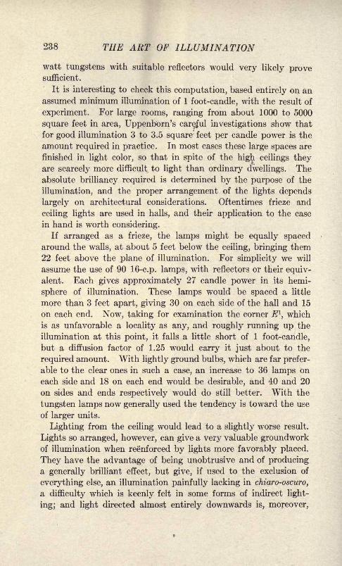
238 THE ART OF ILLUMINATION
watt tungstens with suitable reflectors would very likely provesufficient.
It is interesting to check this computation, based entirely on an
assumed minimum illumination of 1 foot-candle, with the result of
experiment. For large rooms, ranging from about 1000 to 5000
square feet in area, Uppenborn's careful investigations show that
for good illumination 3 to 3.5 square feet per candle power is the
amount required in practice. In most cases these large spaces are
finished in light color, so that in spite of the high ceilings theyare scarcely more difficult to light than ordinary dwellings. Theabsolute brilliancy required is determined by the purpose of the
illumination, and the proper arrangement of the lights depends
largely on architectural considerations. Oftentimes frieze and
ceiling lights are used in halls, and their application to the case
in hand is worth considering.
If arranged as a frieze, the lamps might be equally spacedaround the walls, at about 5 feet below the ceiling, bringing them22 feet above the plane of illumination. For simplicity we will
assume the use of 90 16-c.p. lamps, with reflectors or their equiv-
alent. Each gives approximately 27 candle power in its hemi-
sphere of illumination. These lamps would be spaced a little
more than 3 feet apart, giving 30 on each side of the hall and 15
on each end. Now, taking for examination the corner E 1
,which
is as unfavorable a locality as any, and roughly running up the
illumination at this point, it falls a little short of 1 foot-candle,
but a diffusion factor of 1.25 would carry it just about to the
required amount. With lightly ground bulbs, which are far prefer-
able to the clear ones in such a case, an increase to 36 lamps on
each side and 18 on each end would be desirable, and 40 and 20
on sides and ends respectively would do still better. With the
tungsten lamps now generally used the tendency is toward the use
of larger units.
Lighting from the ceiling would lead to a slightly worse result.
Lights so arranged, however, can give a very valuable groundworkof illumination when reenforced by lights more favorably placed.
They have the advantage of being unobtrusive and of producinga generally brilliant effect, but give, if used to the exclusion of
everything else, an illumination painfully lacking in chiaro-oscuro,
a difficulty which is keenly felt in some forms of indirect light-
ing; and light directed almost entirely downwards is, moreover,
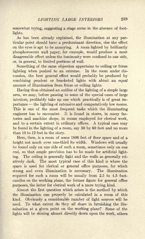
LIGHTING LARGE INTERIORS 239
somewhat trying, suggesting a stage scene in the absence of foot-
lights.
As has been already explained, the illumination at any par-
ticular point should have a predominant direction, else the effect
on the eyes is apt to be annoying. A room lighted by brilliantly
phosphorescent wall paper, for example, would produce a most
disagreeable effect unless the luminosity were confined to one side,
or, in general, to limited portions of wall.
Something of the same objection appertains to ceiling or frieze
lighting when pushed to an extreme. In the room under dis-
cussion, the best general effect would probably be produced by
combining pendent or bracketed lights with about an equal
amount of illumination from frieze or ceiling lights.
Having thus obtained an outline of the lighting of a simple large
area, we may, before passing to some of the special cases of large
interiors, profitably take up one which practically is of great im-
portance the lighting of extensive and comparatively low rooms.
This is one of the most frequent tasks which the illuminating
engineer has to encounter. It is found in stores, in many fac-
tories and machine shops, in rooms employed for clerical work,and to a certain extent in ordinary offices. A typical case maybe found in the lighting of a room, say 30 by 60 feet and no more
than 10 to 12 feet in the story.
Here, then, is a room of some 1800 feet of floor space and of a
height not much over one-third its width. Windows will usually
be found only on one side of such a room, sometimes only on one
end, so that ample provision has to be made for artificial light-
ing. The ceiling is generally light and the walls as generally rel-
atively dark. The most typical case of this kind is where the
space is used for clerical or general office purposes, for which
strong and even illumination is necessary. The illumination
required for such a room will be usually from 2.5 to 4.5 foot-
candles on the working plane, the former figure for general office
purposes, the latter for clerical work of a more trying kind.
Almost the first question which arises is the method by which
the illumination can properly be calculated in a room of this
kind. Obviously a considerable number of light sources will be
used. To what extent do they all share in furnishing the illu-
mination at a given point on the working plane? Some of the
lights will be shining almost directly down upon the work, others
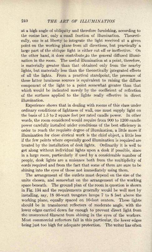
240 THE ART OF ILLUMINATION
at a high angle of obliquity and therefore furnishing, according to
the cosine law, only a small fraction of illumination. Theoreti-
cally, one is at liberty to integrate the light received at a given,
point on the working plane from all directions, but practically a
large part of the oblique light is either cut off or ineffective. Onthe other hand, it does contribute,jto the general diffused illumi-
nation in the room. The useful illumination at a point, therefore,
is materially greater than that obtained only from the nearby
lights, but materially less than the theoretically jntegrated effects
of all the lights. From a practical standpoint, the presence of
these latter luminous sources is equivalent to raising the diffuse
component of the light to a point somewhat greater than that
which would be indicated merely by the coefficient of reflection
of the surfaces applied to the lights really effective in direct
illumination.
Experience shows that in dealing with rooms of this class under
ordinary conditions of lightness of wall, one must supply light on
the basis of 1.5 to 2 square feet per rated candle power. In other
words, the room considered would require from 900 to 1200 candle
power carefully installed under conditions of the best efficiency in
order to reach the requisite degree of illumination, a little more if
illumination for close clerical work is the chief object, a little less
if the few points where especially good illumination is required are
treated by the installation of desk lights. Ordinarily it is well to
get along without individual lights upon a desk if possible, since
in a large room, particularly if used by a considerable number of
people, desk lights are a nuisance both from the multiplicity of
cords required and from the fact that some of them are sure to be
shining into the eyes of those not immediately using them.
The arrangement of the outlets must depend on the size of the
units chosen, and somewhat on the arrangement of the working
space beneath. The ground plan of the room in question is shown
in Fig. 134 and the requirements generally would be well met byinstalling, say, 18 60-watt tungsten lamps 7 to 8 feet above the
working plane, equally spaced on 10-foot centers. These lights
should be in translucent reflectors of moderate angle, with the
lower edges carried down far enough to prevent direct light from
the unscreened filament from shining in the eyes of the workers.
Most commercial reflectors fail in this particular, the lower edges
being just too high for adequate protection. The writer has often
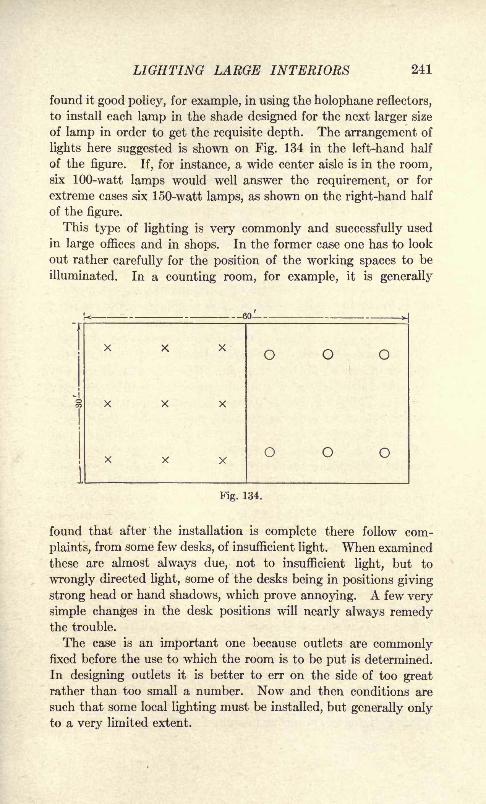
LIGHTING LARGE INTERIORS 241
found it good policy, for example, in using the holophane reflectors,
to install each lamp in the shade designed for the next larger size
of lamp in order to get the requisite depth. The arrangement of
lights here suggested is shown on Fig. 134 in the left-hand half
of the figure. If, for instance, a wide center aisle is in the room,six 100-watt lamps would well answer the requirement, or for
extreme cases six 150-watt lamps, as shown on the right-hand half
of the figure.
This type of lighting is very commonly and successfully used
in large offices and in shops. In the former case one has to look
out rather carefully for the position of the working spaces to be
illuminated. In a counting room, for example, it is generally
O O O
O O O
Fig. 134.
found that after the installation is complete there follow com-
plaints, from some few desks, of insufficient light. When examined
these are almost always due, not to insufficient light, but to
wrongly directed light, some of the desks being in positions giving
strong head or hand shadows, which prove annoying. A few very
simple changes in the desk positions will nearly always remedythe trouble.
The case is an important one because outlets are commonlyfixed before the use to which the room is to be put is determined.
In designing outlets it is better to err on the side of too great
rather than too small a number. Now and then conditions are
such that some local lighting must be installed, but generally onlyto a very limited extent.
242 THE ART OF ILLUMINATION
In the few instances where local lights are to be used to a con-
siderable extent, it is best to make preparations for them by having
an ample number of baseboard and floor plugs, and then to arrange
the overhead outlets so as to provide a general illumination of per-
haps 1.5 foot-candles to reenforce the desk lights. These latter
should not be overdone. "An 8-c.p.Carbon lamp, or the smallest
available tungsten or tantalum lamp, installed under a 7-inch or
10-inch green-flashed porcelain shade, is ample; and great care
should be taken to avert the use of larger lamps, which are quite
likely to result in eye trouble for the users from the glare on the
paper if not from lights misplaced so that they shine into the
eyes.
At this point it is pertinent to inquire concerning the use of
indirect lighting in such rooms as those here under consideration.
As already explained, indirect lighting can be carried out by two
methods, by concealing the light in coves or similar locations,
or by installing the lamps in special fixtures adapted to throw the
light on the ceiling for redistribution. The efficiency of the two
methods is practically about the-same, provided there is equal care
in design. In either case the indirect lighting is much less efficient
than the direct, as is necessarily to be expected from the circum-
stances in the case.
Assuming fairly light-colored ceilings and walls, experience shows
that the light required with either indirect system for a given illu-
mination on a working plane is nearly double that demanded for
the same illumination from lamps lighting the space directly and
equipped with suitable and efficient reflectors. Marks (Baltimore
Lectures, Vol. II, page 702) indicates practically these figures, and
the author's own experience confirms them. In one recent ex-
perience in the author's practice both methods were actually tried
and the illumination and energy carefully measured. The direct
installation was carried out with reflectors which were deep enough
fully to protect the eyes. The ceiling and walls were fairly light
in tone and the space was approximately 2500 square feet. Withthe direct system of illumination, the rated candle power of the
lamps amounted to 0.24 candle power per square foot per foot-
candle. With the indirect system under exactly the same condi-
tions, the light required was 0.45 candle power per square foot per
foot-candle. In general terms, with the indirect lighting nearly
1.8 times the candle power was required for the same effective illu-
LIGHTING LARGE INTERIORS 243
mination. Cravath in a similar test in a smaller room recently
obtained 1.76 for the equivalent ratio. Bearing in mind the fact
that both coves and inverted lighting fixtures suffer much from
dirt, it is well within bounds to say that under average conditions
the indirect system requires about twice as much light as a well-
planned direct system for equal illumination. The usefulness of
indirect lighting is, therefore, rather special than general. When
properly applied it is pleasant and effective, but never economical
as compared with well-arranged direct lighting.
One may next profitably take up the equipment of such a room
as shown in Fig. 134 when used for manufacturing purposes. The
old method of lighting a space occupied by machines and workmenwas to put an individual light shining directly on each machine or
such part of it as needed special illumination, leaving the rest of the
room in darkness. The result is what has come to be known as"spotted
"lighting and the general results are usually bad. The
strain on the eyes of the workmen owing to the constant transition
from bright light to darkness as the eye shifts from the work to the
space beyond is exceedingly trying, much in the same way that
sudden and violent flickering of light is trying. More than this,
there are very often intensely bright reflections from parts of the
machine or work, which dazzle the eye, cause the pupil to contract,
and interfere very seriously with efficient vision. It has not infre-
quently been found that workmen complain of insufficient light
under such circumstances when the actual intensity on the work
is two or three times that needed on the most liberal estimate for
proper vision. In fact, the more light the more dazzling the effect,
and the less effective the vision obtained.
The remedy for spotted lighting is diffusion, but in buildings used
for manufacturing purposes a general illumination such as indi-
cated in Fig. 134 is not often easy to apply. Considerations of
economy make it undesirable to light at maximum brilliancy cer-
tain parts of the room, since these parts may be used only for
storage, for passageways, or for rough work requiring no strong
illumination. The problem, therefore, reduces itself to lighting all
parts of the room efficiently for their uses, and this frequently
implies lighting special machines with considerable brilliancy while
leaving the general illumination low. The secret of success is so
to distribute the light as to leave no dark corners and no dark
regions upon which the eye has to fall, while yet providing at the
244 THE ART OF ILLUMINATION
points needed sufficient light for the most critical work that has
to be done.
This can best be accomplished by using local lighting at the
machine plus a general illumination to relieve the contrast of
darkness and light and to furnish for general purposes a groundwork
lighting. This end may "be reached by the installation of lights
with translucent shades which permit part of the light to pass
through for general use, while the rest is directed upon special
operations which require light. The only difficulty with this pro-
cedure, which may be carried out by lights with shades of opal
glass or of prismatic glass with diffusing surface, is that translucent
reflectors are fragile and in some cases breakage would be a serious
item. The same result can be attained by using comparatively
small lamps in suitable reflectors placed near the work and adding
general illumination from lights equally spaced over the ceiling
on cords or short stems. The general lighting obviates most of
the spotted effect which is so unpleasant, but equally essential
is the reduction of the extreme intensity produced by local lights
under ordinary conditions. The space shown in Fig. 134, when
used for ordinary manufacturing purposes, will require on the
whole about the same amount of light as already indicated, but
about one-third of that light should be devoted to general illu-
mination, the remainder being distributed over the machines.
Lighting machines is a task standing somewhat by itself, because
while the total amount of light is generally moderate, it must be
directed where it will do the most good, and machines often have
projecting arms or other parts which throw strong shadows and
interfere with the proper observation of the work. Sometimes
conditions can best be met by small lamps, usually not over 8 candle
power, with reflectors directing the light where it will do the most
good. In other cases the lights can best be placed directly over the
machines, or sometimes with diffusing screens behind the machines,the main point being that, while from 3 or 4 up to 8 or 10 foot-
candles may at times be necessary for the work, the light should
not be placed so as to throw the work into shadow or to cast
bright reflections into the eyes of the workman. In some in-
stances indirect lighting can be resorted to, utilizing the light ceiling
and walls to the utmost. It should be used, however, only whena reduction of shadow is desired with but a moderate degree
of illumination. The long and short of it is that manufacturing
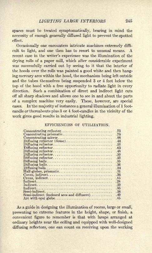
LIGHTING LARGE INTERIORS 245
spaces must be treated symptomatically, bearing in mind the
necessity of enough generally diffused light to prevent the spottedeffect.
Occasionally one encounters intricate machines extremely diffi-
cult to light, and one then has to resort to unusual means. Arecent case in the writer's experience was the illumination of the
drying rolls of a paper mill, which after considerable experimentwas successfully carried out by seeing to it that the interior of
the hoods over the rolls was painted a good white and then hang-
ing mercury arcs within the hood, the mechanism being left outside
and the tubes themselves being suspended 3 or 4 feet below the
top of the hood with a free opportunity to radiate light in everydirection. Such a combination of direct and indirect light cuts
off all sharp shadows and allows one to see in and about the parts
of a complex machine very easily. These, however, are special
cases. In' the majority of instances a general illumination of 1 foot-
candle or thereabouts plus 3 or 4 foot-candles in the vicinity of the
work gives good results in industrial lighting.
EFFICIENCIES OF UTILIZATION.
Concentrating reflector 73Concentrating prismatic 76Concentrating mirror 88
Diffusing reflector (dense) 44
Diffusing reflector .53
Diffusing reflector 63Diffusing reflector 48
Diffusing reflector 50
Diffusing reflector. 53
Diffusing balls 35
Diffusing balls 36
Diffusing balls 34
Half-globes, prismatic 51
Coves, indirect 36
Coves, indirect 15Indirect 28Indirect 29Indirect 35Semi-indirect 38Semi-indirect (inclosed arcs and diffusers) 49Arc with opal globe , 45
As a guide in designing the illumination of rooms, large or small,
presenting no extreme features in the height, shape, or finish, a
convenient figure to remember is that with lamps arranged at
ordinary heights near the ceiling and equipped with well-designed
diffusing reflectors, one can count on receiving upon the working
246 THE ART OF ILLUMINATION
plane 4 or 5 foot-candles per rated candle-power-per-square-foot.
This implies that about 50 to 60 per cent of the total flux of light
is utilized on the working plane, the rest being taken up by ab-
sorption and unutilizable reflection. The table on page 245, derived
mainly from the writer's own experience, gives the actual efficien-
cies of utilization reached in lighting installations with various
types of shades and reflectors.
These figures will serve as a useful guide in computing the
illumination by the flux of light method. It will be noted that
the highest efficiencies are with somewhat concentrating prismatic
or mirror reflectors arranged to throw as much as possible of the
light flux upon the working plane without any material utilization of
the diffusing surfaces of the room. The next grade of efficiency is
obtained with diffusing reflectors of opal or prismatic glass which
throw a large amount of the light downwards and yet transmit a
material fraction which is rediffused by the walls. A slightly lower
grade is given by the semi-indirect system, which rises in efficiency
as more of the light-flux is sent directly to the working plane
and less diffused from the ceiling. Of about the same efficiency
ar.e the lights inclosed in diffusing balls or globes, the thinner globes
of course being the more efficient. Next in order come the purelyindirect systems in which none of the light is sent directly to the
working plane but all is diffused from surfaces which are as a rule
none of the best.
i Any one of the systems indicated can be made to give thor-
oughly good illumination and any one of them can be so misused
as to be unsatisfactory. As between the ordinary direct and the
indirect systems of lighting, the former when properly installed
are always the more efficient. One interesting question which has
arisen as between the direct and indirect schemes of lighting is
the quality of the illumination as regards its usefulness. There
is no physical or physiological reason why there should be anydifference in the usefulness of a given illumination derived from
either method of arrangement, assuming each to be planned with
equal skill in the way of avoiding, on the one hand, glare from
exposed sources, and, on the other, a perhaps equally trouble-
some glare from over-illuminated surfaces. There have been some
strong expressions of opinion by those who have had a prejudicein favor of one or the other method. The first figures derived
from actual experiment on the matter are those of Millar (" Trans-
LIGHTING LARGE INTERIORS 247
actions Illuminating Engineering Society/' Vol. II, page 583),
which indicate that a given intensity of illumination derived from
indirect lighting is materially less effective than when derived
from direct lighting. On the other hand, some recent observations
by Cravath indicate exactly the reverse, based on judgments madelike Millar's by a group of independent observers. The psycho-
logical and casual physiological factors in the case are, however,so uncertain and variable that it is unsafe to generalize from either
of these diverging statements. In the author's opinion, whatever
differences have been observed are due to secondary rather than
primary causes, and must disappear when the installations are
really skillfully planned. The difference in efficiency of utiliza-
tion is, however, unavoidable.
Where merely rough work is being done, arcs may be effectively
used, always, however, shaded by ground or similar globes. These
are distinctly cheaper, because more efficient, than carbon incan-
descents, but their light lacks the steadiness desirable for work
requiring close attention. Six 350-watt arcs would give, in the
room shown in Fig. 133, very good illumination, when placed in
approximately the positions deduced for the six clusters, with a
total expenditure of 2100 watts as against about 4500 watts
required by the clustered incandescents, and, say, 3600 watts
required by about 36 pendent 32-c.p. lamps. In many cases,
less light than this would be required, and the total amount of
energy could be correspondingly reduced. As already indicated
tungstens would do even better.
From Fig. 133 it appears that in using arcs about 2000 to 2500
square feet may be assigned to each 500-watt arc, and 1000 to
1500 square feet to each 350-watt arc. It should be remembered
that the inclosed arcs with inner globes are nearly 25 per cent
less efficient than this, although to be preferred by reason of their
ordinarily greater steadiness, and that alternating arcs are slightly
less efficient than continuous-current arcs.
Arcs do their best work when placed fairly high and used in
cases where protracted close attention on the part of the workmen
is not necessary. They are preferable to incandescents of anykind when colored objects are to be illuminated.
In workshops where special objects are to be illuminated, arcs
are at a great disadvantage with respect to the distribution of
light, since their relatively small number forbids placing them

248 THE ART OF ILLUMINATION
in- the most advantageous positions with respect to all the
machines.
They have, in short, the disadvantage of being radiants too
powerful for the best distribution. It is thus found that in
practical illumination arcs are considerably less efficient than
their actual candle power would indicate. The effect of the
bright radiant upon the eyes, the : rather dense shadows, and
the slanting light at a distance from the arc, unite to produceresults that cannot be predicated from photometric measurements
alone.
For example, a 350-watt open arc is, in point of mean spherical
candle power, closely equivalent to ten 32-c.p. incandescent lamps;but in an actual installation indoors there are few cases in which
the arc could not be replaced by six such incandescents without
detriment to the illumination. With tungsten incandescent lampsat 1.25 watts per rated candle power, the ordinary carbon arc
compares unfavorably except in cases where its whiter color is
important. For such cases the intensified arc should generally
be used.
If strong illumination is the object to be attained, there is
little doubt that for gas lighting in rooms of the size considered,
mantle burners should invariably be used. As already intimated,
each such burner of the ordinary size is equivalent to about two
16-c.p. distributed incandescents. If the lamps are grouped in
each case, the mantle burner must be given a rather better rating,
being equivalent to between 2.5 and 3 such incandescents. Prop-
erly shaded, the mantle burner is a very economical and effective
illuminant.
For lighting large areas, like those we have been considering,
it is very well adapted, but if the lights are placed high it is neces-
sary not only so to shade them as to hide the mantles, but they
must, in addition, be furnished with such shades or reflectors as
will throw the light effectively downward. Reflectors or holo-
phane globes used with the mantle burners will correct this faulty
distribution and enable them to be used more effectively in the
case in hand. The modern inverted Welsbachs diminish this diffi-
culty and give excellent results, but even with these it is neces-
sary to use diffusing reflectors to shade the eye and improve the
distribution.
With higher rooms than usual, one can concentrate the radi-
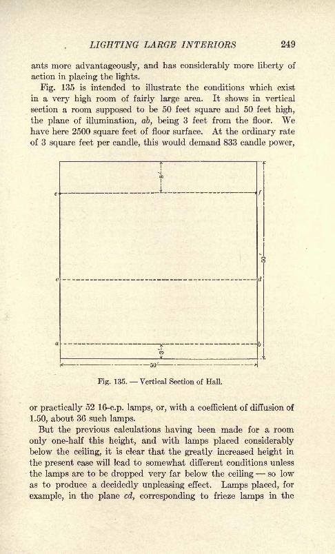
LIGHTING LARGE INTERIORS 249
ants more advantageously, and has considerably more liberty of
action in placing the lights.
Fig. 135 is intended to illustrate the conditions which exist
in a very high room of fairly large area. It shows in vertical
section a room supposed to be 50 feet square and 50 feet high,
the plane of illumination, ab, being 3 feet from the floor. Wehave here 2500 square feet of floor surface. At the ordinary rate
of 3 square feet per candle, this would demand 833 candle power,
T
Fig. 135. Vertical Section of Hall.
or practically 52 16-c.p. lamps, or, with a coefficient of diffusion of
1.50, about 36 such lamps.
But the previous calculations having been made for a room
only one-half this height, and with lamps placed considerably
below the ceiling, it is clear that the greatly increased height in
the present case will lead to somewhat different conditions unless
the lamps are to be dropped very far below the ceiling so low
as to produce a decidedly unpleasing effect. Lamps placed, for
example, in the plane cd, corresponding to frieze lamps in the
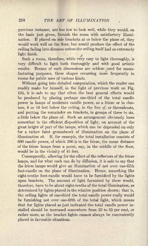
250 THE ART OF ILLUMINATION
previous instance, are too low to look well, while they would, on
the basis just given, furnish the room with satisfactory illumi-
nation. If placed on side brackets at or below the plane cd, theywould work well on the floor, but would produce the effect of the
ceiling fading into dimness unless the ceiling itself had an extremely
light finish.
Such a room, therefore, while very easy to light thoroughly, is
very difficult to light both thoroughly and with good artistic
results. Rooms of such dimensions are seldom used for manu-
facturing purposes, these shapes occurring more frequently in
rooms for public uses of various kinds.
Without going into detailed computation, which the reader can
readily make for himself, in the light of previous work on Fig.
134, it is safe to say that often the best general effects would
be produced by placing perhaps one-third of the total candle
power in lamps of moderate candle power, as a frieze or in clus-
ters, 8 or 10 feet below the ceiling, in the line ef, or thereabouts,
and putting the remainder on brackets, in groups of three to six,
a little below the plane cd. Such an arrangement obviously loses
somewhat in the efficient disposition of light, on account of the
great height of part of the lamps, which can be depended on onlyfor a rather faint groundwork of illumination on the plane of
illumination ab. If, for example, the total installation consists of
600 candle power, of which 200 is in the frieze, the mean distance
of the frieze lamps from a point, say, in the middle of the floor,
would be in the vicinity of 45 feet.
Consequently, allowing for the effect of the reflectors of the frieze
lamps, and for what each can do by diffusion, it is safe to say that
the frieze lamps would give an illumination of not over one-fifth
foot-candle on the plane of illumination. Hence, something like
eight-tenths foot-candle would have to be furnished by the lights
upon brackets. The amount of light furnished by these would,
therefore, have to be about eight-tenths of the total illumination, as
determined by lights placed in the relative position shown; that is,
the ceiling lights of one-third the total candle power really would
be furnishing not over one-fifth of the total light, which means
that for lights placed as just indicated the total candle power in-
stalled should be increased somewhere from 25 to 33 per cent, or
rather more, as the bracket lights cannot always be conveniently
placed in favorable situations.
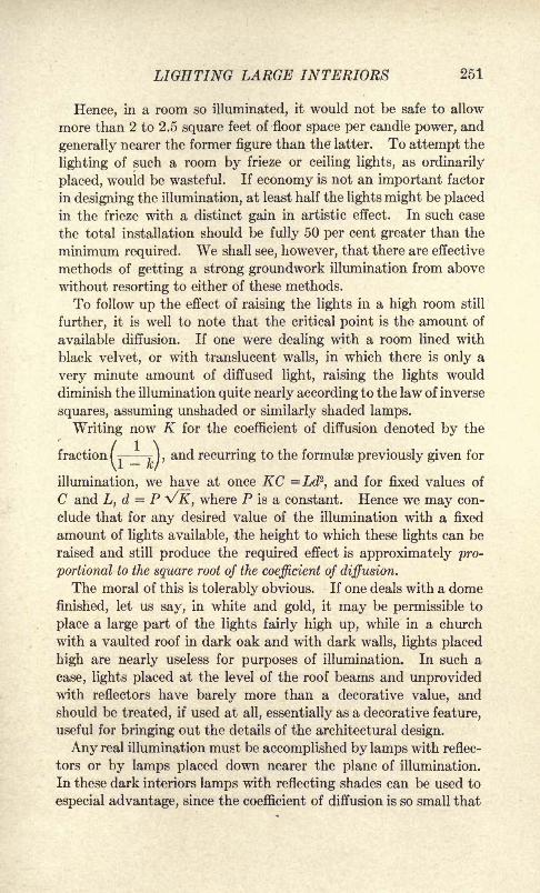
LIGHTING LARGE INTERIORS 251
Hence, in a room so illuminated, it would not be safe to allow
more than 2 to 2.5 square feet of floor space per candle power, and
generally nearer the former figure than the latter. To attempt the
lighting of such a room by frieze or ceiling lights, as ordinarily
placed, would be wasteful. If economy is not an important factor
in designing the illumination, at least half the lights might be placed
in the frieze with a distinct gain in artistic effect. In such case
the total installation should be fully 50 per cent greater than the
minimum required. We shall see, however, that there are effective
methods of getting a strong groundwork illumination from above
without resorting to either of these methods.
To follow up the effect of raising the lights in a high room still
further, it is well to note that the critical point is the amount of
available diffusion. If one were dealing with a room lined with
black velvet, or with translucent walls, in which there is only a
very minute amount of diffused light, raising the lights would
diminish the illumination quite nearly according to the law of inverse
squares, assuming unshaded or similarly shaded lamps.
Writing now K for the coefficient of diffusion denoted by the
fraction (-
r)>and recurring to the formulae previously given for
illumination, we have at once KC =Ld2,and for fixed values of
C and L, d = P VK, where P is a constant. Hence we may con-
clude that for any desired value of the illumination with a fixed
amount of lights available, the height to which these lights can be
raised and still produce the required effect is approximately pro-
portional to the square root of the coefficient of diffusion.
The moral of this is tolerably obvious. If one deals with a dome
finished, let us say, in white and gold, it may be permissible to
place a large part of the lights fairly high up, while in a church
with a vaulted roof in dark oak and with dark walls, lights placed
high are nearly useless for purposes of illumination. In such a
case, lights placed at the level of the roof beams and unprovidedwith reflectors have barely more than a decorative value, and
should be treated, if used at all, essentially as a decorative feature,
useful for bringing out the details of the architectural design.
Any real illumination must be accomplished by lamps with reflec-
tors or by lamps placed down nearer the plane of illumination.
In these dark interiors lamps with reflecting shades can be used to
especial advantage, since the coefficient of diffusion is so small that
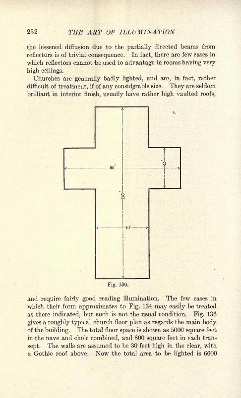
252 THE ART OF ILLUMINATION
the lessened diffusion due to the partially directed beams from
reflectors is of trivial consequence. In fact, there are few cases in
which reflectors cannot -be used to advantage in rooms having very
high ceilings.
Churches are generally badly lighted, and are, in fact, rather
difficult of treatment, if of any considerable size. They are seldom
brilliant in interior finish, usually have rather high vaulted roofs,
Fig. 136.
and require fairly good reading illumination. The few cases in
which their form approximates to Fig. 134 may easily be treated
as there indicated, but such is not the usual condition. Fig. 136
gives a roughly typical church floor plan as regards the main bodyof the building. The total floor space is shown as 5000 square feet
in the nave and choir combined, and 800 square feet in each tran-
sept. The walls are assumed to be 30 feet high in the clear, with
a Gothic roof above. Now the total area to be lighted is 6600
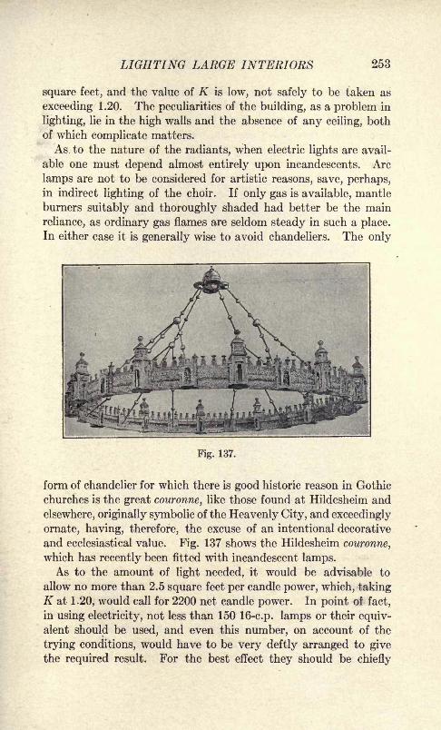
LIGHTING LARGE INTERIORS 253
square feet, and the value of K is low, not safely to be taken as
exceeding 1.20. The peculiarities of the building, as a problem in
lighting, lie in the high walls and the absence of any ceiling, both
of which complicate matters.
As to the nature of the radiants, when electric lights are avail-
able one must depend almost entirely upon incandescents. Arc
lamps are not to be considered for artistic reasons, save, perhaps,in indirect lighting of the choir. If only gas is available, mantle
burners suitably and thoroughly shaded had better be the main
reliance, as ordinary gas flames are seldom steady in such a place.
In either case it is generally wise to avoid chandeliers. The only
Fig. 137.
form of chandelier for which there is good historic reason in Gothic
churches is the great couronne, like those found at Hildesheim and
elsewhere, originally symbolic of the Heavenly City, and exceedingly
ornate, having, therefore, the excuse of an intentional decorative
and ecclesiastical value. Fig. 137 shows the Hildesheim couronne,
which has recently been fitted with incandescent lamps.
As to the amount of light needed, it would be advisable to
allow no more than 2.5 square feet per candle power, which, takingK at 1.20, would call for 2200 net candle power. In point of fact,
in using electricity, not less than 150 16-c.p. lamps or their equiv-alent should be used, and even this number, on account of the
trying conditions, would have to be very deftly arranged to give
the required result. For the best effect they should be chiefly

254 THE ART OF ILLUMINATION
lamps with diffusing globes, assigned about as follows: 90 to the
nave, 20 to the choir, and 20 to each transept. As to position,
the most efficient method would be to put them in groups of six
or eight on brackets between the windows, at half to two-thirds
the height of the wall, with possibly larger groups massed at the
four corners of the crossing.' With still more lights available, verybeautiful results could be attained by adding lights at the capitals,
and, in some cases, along the tiebeams, or on the corbels from
which the pendent posts rise. These latter arrangements are very
effective, but not economical, and if used should be installed on
the basis of about 1 candle power per 2 square feet of floor surface.
With the large tungsten units the number may be proportionally
smaller, which simplifies the fixture design. All incandescent
lamps used without diffusing shades should have ground bulbs.
The chief point in church lighting is to furnish modest reading-
illumination, say 1 to 1.5 foot-candles, without glaring sources in
the eyes of the congregation and without breach of the archi-
tectural unities of the place. The treatment must be almost
entirely guided by the individual situation, and is often hampered
by the existence of fixtures or particular developments of methods
which cannot well be gotten rid of. Now and then standards,
bearing clusters of lamps, are installed throughout the nave of a
church, and occasionally these standards are good enough to maketheir retention desirable. By fitting them with small incandes-
cent lamps within small diffusing globes very pleasing results can
sometimes be reached. As a rule, lights should not be carried
high in churches. The mediaeval church, closely copied in manymodern interiors, was a place where little light was necessary,
and that little was needed in the lower body of the church, the
towering roof gaining rather than losing in effect by fading into
obscurity above. Then, too, most worshipers either were unable
to read, so that they needed no reading illumination, or knew the
service, so far as they were required to know it, by heart, so that
again light was unnecessary.
In modern churches and forms of worship these conditions have
so changed that a good reading illumination is necessary, as has
been before remarked, but it is not generally furnished. In fact
church fixtures, on the whole, are the least adapted to their use
of any that can be found even by patient searching. The mischief
is generally done by stupid and slavish following of inappropriate
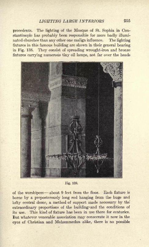
LIGHTING LARGE INTERIORS 255
precedents. The lighting of the Mosque of St. Sophia in Con-
stantinople has probably been responsible for more badly illumi-
nated churches than any other one malign influence. The lighting
fixtures in this famous building are shown in their general bearingin Fig. 138. They consist of spreading wrought-iron and bronze
fixtures carrying numerous tiny oil lamps, not far over the heads
Fig. 138.
of the worshipers about 9 feet from the floor. Each fixture is
borne by a preposterously long rod hanging from the huge and
lofty central dome, a method of support made necessary by the
extraordinary proportions of the building* and the conditions of
its use. This kind of fixture has been in use there for centuries.
But whatever venerable association may consecrate it now in the
eyes of Christian and Mohammedan alike, there is no possible
256 THE ART OF ILLUMINATION
propriety in copying so clumsy a device in modern churches of
different architectural character, with all our present illuminating
resources at hand.
In the hands of the Occidental barbarian, this type of fixture
usually degenerates into a short bronze or iron barrel, within which
is ill concealed a group of glaring* incandescent lamps throwingtheir light into the eyes of the just and unjust alike, and giving
a maximum of glare with a minimum of illumination. The only
possible method of reducing the glare is so to inclose the lights
as to give almost no illumination, and this has also sometimes
been done, less through design than through sheer stupidity.
The writer calls to mind at least a dozen churches in which such
fixtures are conspicuously useless, and, he may add, has had the
pleasure in several instances of throwing them out and replacing
them by devices less offensively glaring and far more effective.
The nave and the transepts of a church may be easily lighted
in accordance with the methods earlier suggested, preference being
given to that which lends itself most harmoniously to the archi-
tectural requirements. Above the side aisles it is often desirable
to use lights with small diffusing globes, placed close to the ceiling,
although sometimes the height is sufficient to enable brackets to
be used, if also employed for the main work of lighting the nave
and transepts.
The sanctuary is a different matter. In churches having an
elaborate ritual bright lighting here is desirable, especially in
connection with the altar. Generally there is an opportunity for
placing lights behind the chancel arch, either above, or at the sides,
or in both situations. Where the available space permits, such
lamps can with great advantage be furnished with somewhat con-
centrating reflectors arranged to flood the sanctuary with light
when desirable, and particularly so to illuminate the altar as to
bring out its full decorative value. Sometimes it is desirable
to specialize the lighting for these two functions, so that the altar
can on occasion be thrown into striking prominence. It must
not be forgotten that most elaborate altars should not be lighted
uniformly from the front, inasmuch as this tends to suppress the
detail, which is often their chief charm. To avoid this difficulty,
lights with focusing reflectors can be massed on one side of the
space behind the chancel arch so as to illuminate the altar at any
required angle, leaving enough general illumination to prevent too
LIGHTING LARGE INTERIORS 257
dense shadows. The particular arrangement of course depends on
the special things which it is desired to bring into prominence.
The lights in the sanctuary should be upon several switches
so arranged as to secure any requisite intensity of illumination
for the various cases which have to be met. Where candles are
freely used in connection with the ritual, the question of replacing
them by incandescent lamps frequently comes up. Decorative
standards used around the altar can often be fitted for small-bulb,
heavily frosted incandescents with good effect, but where the can-
dle has a symbolic value in the ritual such a substitution is in verydubious taste. One recoils from the thought of the Tenebrse with
the candles turned off by snap switches on the wall.
Suitable illumination for the reading desks goes almost without
saying. It should be given by carefully shielded reading lights
serving the purpose of their use without attracting any further
attention. Non-ritualistic churches having the form of a large
hall require the lighting appropriate to that case, and do not
involve any of the special problems inherent in other churches.
The question of stained-glass windows is one which sometimes
arises as a problem in illumination. Comparatively little has been
done in this matter save in isolated cases, but there is no reason
why, if thought desirable, the chief windows may not be illu-
minated from the outside by indirect lighting. In this case arcs
are by far the most convenient source of light, since tbey alone of
common illuminants give a light sufficiently rich in blue to bringthe stained glass to its daylight value. In cases where there is
strong daylight lighting from a dome, it may be desirable byindirect illumination to bring the interior at night to something
approaching the condition best suited to displaying it by day.Aside from such uses as these, the arc light has no place in a
church, although even flame arcs have been used, by a combination
of bad taste and bad judgment, for church lighting.
In lighting with gas, brackets are about the only thing feasible,
since the flames must point upward, and few capitals would fail to
look overloaded with adequately shaded burners. Mantle burners,
of course, do the work most efficiently, but used alone the effect is
certain to be grimly utilitarian; and especially around the choir
small ordinary jets may be used to very great advantage. Themantle burners should be as unobtrusive as possible in such a case,
even if they do the main work of the illumination.
258 THE ART OF ILLUMINATION
Only the barest hints can be given for the detail of church light-
ing, as so much depends on the architectural peculiarities and on
the scheme of decoration, but the foregoing indicates the general
principles to be followed. The most important thing is to give a
rather moderate illumination without the individual radiants ob-
truding themselves unpleasantly on* the eyes of the congregation.
Large public buildings are generally easier to light than churches,
since they are, as regards the shape of the several rooms, com-
paratively simple and are seldom dark in finish. Many rooms maybe illuminated along the lines already laid down, but, on the whole,
powerful radiants, such as arc lights and the largest tungsten
lamps, may be more freely used here than elsewhere.
In very high corridors and high halls without galleries arc lights
can be used with excellent results. They should invariably be
shielded by ground or opal globes, and, if hung very high, as is
generally desirable, to keep them out of the ordinary field of vision,
should be provided with reflectors. They should be numerous
enough to suppress the shadows that ordinarily exist under the
lamps. From the absence of such shadows the modern intensified
arcs have a very material advantage.Rooms lighted by arc lamps ought to be of light finish, since
the lamps must be placed rather high to keep them, even shaded,
from glaring unpleasantly; and they give a strong, nearly horizontal
beam, which, in lack of good diffusing surfaces, is for the most part
wasted. Reflectors deep enough to turn this downward would
usually be most unsightly and would give an unpleasant search-
light effect, which should be avoided.
Never let the eye rest simultaneously on arc and incandes-
cent lamps indoors, since the latter seem very dim and yellowishin such company, and will never be credited with anything like
their real brilliancy. Similar reasoning applies to the use of mantle
burners and ordinary gas jets in the same room. When so used
the former should be well shaded and unobtrusively placed, and
the latter massed and generally unshaded or lightly shaded, so as
not to seem of relatively very small intrinsic brilliancy.
Sometimes in large interiors the powerful regenerative burners
and high-pressure mantle burners may find a place. They givean excellent downward illumination, which is occasionally veryuseful.
Theaters present some very interesting problems in illumination
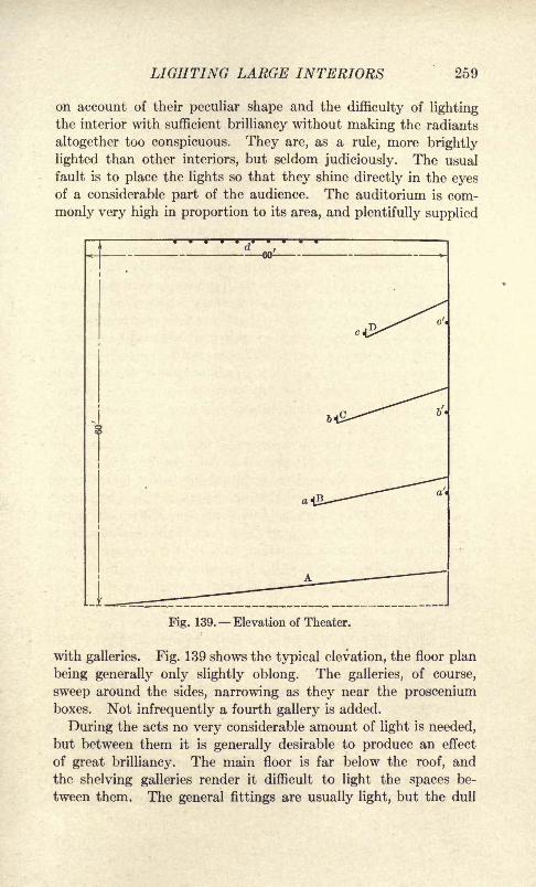
LIGHTING LARGE INTERIORS 259
on account of their peculiar shape and the difficulty of lighting
the interior with sufficient brilliancy without making the radiants
altogether too conspicuous. They are, as a rule, more brightly
lighted than other interiors, but seldom judiciously. The usual
fault is to place the lights so that they shine directly in the eyesof a considerable part of the audience. The auditorium is com-
monly very high in proportion to its area, and plentifully supplied
Fig. 139. Elevation of Theater.
with galleries. Fig. 139 shows the typical elevation, the floor plan
being generally only slightly oblong. The galleries, of course,
sweep around the sides, narrowing as they near the prosceniumboxes. Not infrequently a fourth gallery is added.
During the acts no very considerable amount of light is needed,
but between them it is generally desirable to produce an effect
of great brilliancy. The main floor is far below the roof, and
the shelving galleries render it difficult to light the spaces be-
tween them. The general fittings are usually light, but the dull
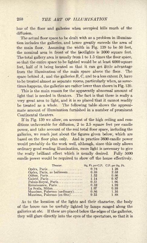
260 THE ART OF ILLUMINATION
hue of the floor and galleries when occupied kills much of the
diffusion.
The actual floor space to be dealt with as a problem in illumina-
tion includes the galleries, and hence greatly exceeds the area of
the main floor. Assuming the width in Fig. 139 to be 50 feet,
the nominal area in front of the footlights is 3000 square feet.
The total gallery area is usually from 1 to 1.5 times the floor space,
so that the entire space to be lighted would be at least 6000 square
feet, half of it being located so that it can get little advantage
from the illumination of the main space above the floor. The
space behind A, and the galleries 5, C, and to a less extent D, have
to be treated almost as separate rooms, particularly when, as some-
times happens, the galleries are rather lower than shown in Fig. 139.
This is the main reason for the apparently abnormal amount of
light that is needed in theaters. The fact is that there is really a
very great area to light, and it is so placed that it cannot readily
be treated as a whole. The following table shows the approxi-
mate amount of illumination furnished in a number of prominent
Continental theaters.
If in Fig. 139 we allow, on account of the high ceiling and con-
ditions unfavorable for diffusion, 2 to 2.5 square feet per candle
power, and take account of the real total floor space, including the
galleries, we reach just about the figures given below, which are
based on the floor plan only. And in practice 3600 candle powerwould probably do the work well, although, since this only allows
ordinary good reading illumination, more light is necessary to give
the really brilliant effect which is usually desired. Fully 5000
candle power would be required to show off the house effectively.
Theater. Sq. Ft. per C.P. C.P. per Sq. Ft.
Opera, Paris 0.78 1.28
Opera, Paris, as ballroom 0.38 2.63
Odeon, Paris 1.52 0.66
Gaiete", Paris 1.14 0.87
Palais-Royal, Paris 0.51 1.96
Renaissance, Paris 0.52 1.92La Scala, Milan 1 .07 0.93
Massimo, Palermo (ordinary) 0.86 1.16
Massimo, Palermo (en fete) . 53 1 . 88
As to the location of the lights and their character, the bodyof the house can be usefully lighted by lamps ranged along the
galleries at abc. If these are placed below the edges of the galleries,
they will glare directly into the eyes of the spectators, so that it is

LIGHTING LARGE INTERIORS 261
better to illuminate the gallery spaces from the rear and above, at
a'Vc'. The radiants may well be provided with reflectors, as the
diffusion amounts to little, and all lamps on and under the galleries
should have ground globes. These lights may be reenforced to
great advantage by ceiling reflector lamps, best sunk in the ceil-
ing deep enough to make them inoffensive from the galleries.
These, with some ornamental lighting about the stage and boxes,
should give a capital result. The main point is to light the inte-
rior brightly without thrusting bright radiants into the field of
vision.
A useful form of ceiling lighting, applicable to many very high
interiors, is arranged by replacing the lamps at d, Fig. 139, by
opal-glass skylights of rather large dimensions, and placing above
them arc lamps with reflectors. The skylight surfaces should be
flat or slightly projecting rather than recessed, and the reflectors
should be planned so that each may throw a cone of light sub-
tending an angle equivalent to the whole floor plan.
By thus superposing the indirect illumination from a group of
lamps the general steadiness of the light is greatly increased. In
thus using arcs, care should be taken to have the diffusing sky-
lights faintly tinted so as to lessen the color contrast between
the powerful ceiling lights and the incandescents used elsewhere
in the house. It is a considerable advantage thus to place lights
above the ceiling, as it avoids the serious heating effect due to
massing incandescents near the ceiling of a generally overheated
room.
On account of this heating the use of gas in theaters is highly
undesirable, and has been almost completely abandoned. In lack
of anything better, fair results could be reached by mantle burners
placed somewhat as shown in Fig. 139, and very thoroughlyshaded by holophane or other diffusing globes, much of the illu-
mination being located above the ceiling.
The Lighting of Schoolhouses. The lighting of schoolhouses
stands somewhat apart from the ordinary illumination of large
interiors on account of the exceptional uniformity desirable and
the severe requirements of lighting adequately a large number of
working spaces arranged in an entirely formal way. First-class
illumination must be provided for usually about forty pupils, and
it must be so arranged that there is no trouble from shadows
of head or hand upon the work, while each pupil must get this
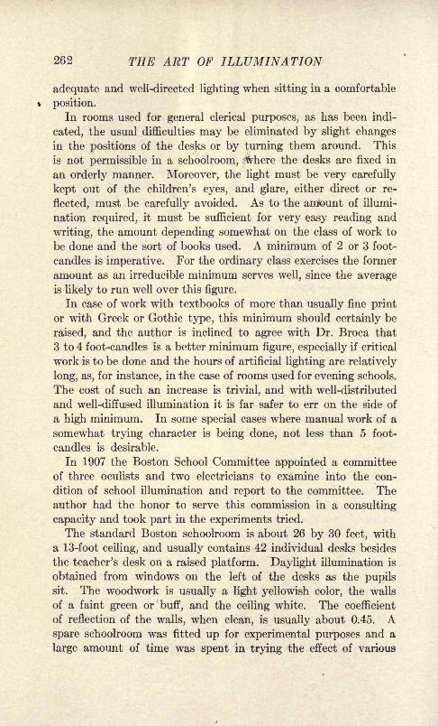
262 THE ART OF ILLUMINATION
adequate and well-directed lighting when sitting in a comfortable
position.
In rooms used for general clerical purposes, as has been indi-
cated, the usual difficulties may be eliminated by slight changes
in the positions of the desks or by turning them around. This
is not permissible in a schoolroom, ;%here the desks are fixed in
an orderly manner. Moreover, the light must be very carefully
kept out of the children's eyes, and glare, either direct or re-
flected, must be carefully avoided. As to the arrtount of illumi-
nation required, it must be sufficient for very easy reading and
writing, the amount depending somewhat on the class of work to
be done and the sort of books used. A minimum of 2 or 3 foot-
candles is imperative. For the ordinary class exercises the former
amount as an irreducible minimum serves well, since the averageis likely to run well over this figure.
In case of work with textbooks of more than usually fine print
or with Greek or Gothic type, this minimum should certainly be
raised, and the author is inclined to agree with Dr. Broca that
3 to 4 foot-candles is a better minimum figure, especially if critical
work is to be done and the hours of artificial lighting are relatively
long, as, for instance, in the case of rooms used for evening schools.
The cost of such an increase is trivial, and with well-distributed
and well-diffused illumination it is far safer to err on the side of
a high minimum. In some special cases where manual work of a
somewhat trying character is being done, not less than 5 foot-
candles is desirable.
In 1907 the Boston School Committee appointed a committee
of three oculists and two electricians to examine into the con-
dition of school illumination and report to the committee. Theauthor had the honor to serve this commission in a consulting
capacity and took part in the experiments tried.
The standard Boston schoolroom is about 26 by 30 feet, with
a 13-foot ceiling, and usually contains 42 individual desks besides
the teacher's desk on a raised platform. Daylight illumination is
obtained from windows on the left of the desks as the pupils
sit. The woodwork is usually a light yellowish color, the walls
of a faint green or buff, and the ceiling white. The coefficient
of reflection of the walls, when clean, is usually about 0.45. Aspare schoolroom was fitted up for experimental purposes and a
large amount of time was spent in trying the effect of various
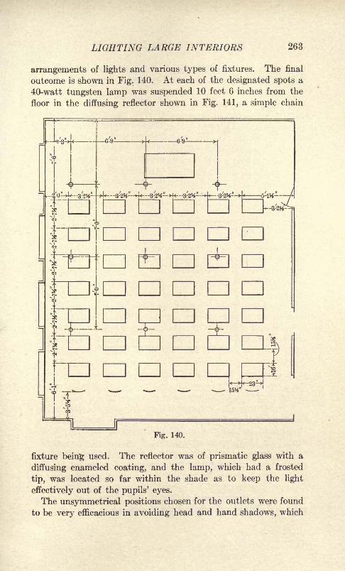
LIGHTING LARGE INTERIORS 263
arrangements of lights and various types of fixtures. The final
outcome is shown in Fig. 140. At each of the designated spots a
40-watt tungsten lamp was suspended 10 feet 6 inches from the
floor in the diffusing reflector shown in Fig. 141, a simple chain
Fig. 140.
fixture bein^ used. The reflector was of prismatic glass with a
diffusing enameled coating, and the lamp, which had a frosted
tip, was located so far within the shade as to keep the light
effectively out of the pupils' eyes.
The unsymmetrical positions chosen for the outlets were found
to be very efficacious in avoiding head and hand shadows, which
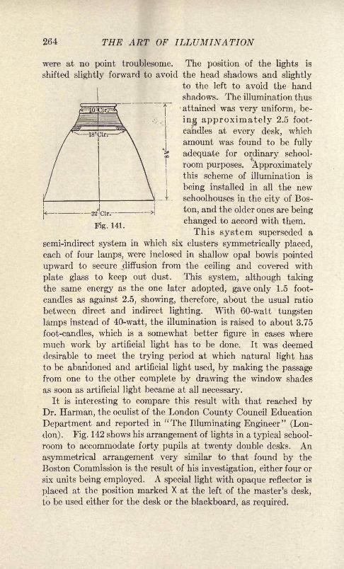
264 THE ART OF ILLUMINATION
were at no point troublesome. The position of the lights is
shifted slightly forward to avoid the head shadows and slightly
to the left to avoid the hand
shadows. The illumination thus
attained was very uniform, be-
ing approximately 2.5 foot-
candles at every desk, which
amount was found to be fully
adequate for ordinary school-
room purposes. Approximatelythis scheme of illumination is
being installed in all the newschoolhouses in the city of Bos-
ton, and the older ones are being
changed to accord with them.
This system superseded a
-->!
Fig. 141.
semi-indirect system in which six clusters symmetrically placed,
each of four lamps, were inclosed in shallow opal bowls pointed
upward to secure diffusion from the ceiling and covered with
plate glass to keep out dust. This system, although taking
the same energy as the one later adopted, gave only 1.5 foot-
candles as against 2.5, showing, therefore, about the usual ratio
between direct and indirect lighting. With 60-watt tungsten
lamps instead of 40-watt, the illumination is raised to about 3.75
foot-candles, which is a somewhat better figure in cases where
much work by artificial light has to be done. It was deemed
desirable to meet the trying period at which natural light has
to be abandoned and artificial light used, by making the passage
from one to the other complete by drawing the window shades
as soon as artificial light became at all necessary.
It is interesting to compare this result with that reached byDr. Harman, the oculist of the London County Council Education
Department and reported in "The Illuminating Engineer" (Lon-
don). Fig. 142 shows his arrangement of lights in a typical school-
room to accommodate forty pupils at twenty double desks. An
asymmetrical arrangement very similar to that found by the
Boston Commission is the result of his investigation, either four or
six units being employed. A special light with opaque reflector is
placed at the position marked X at the left of the master's desk,
to be used either for the desk or the blackboard, as required.
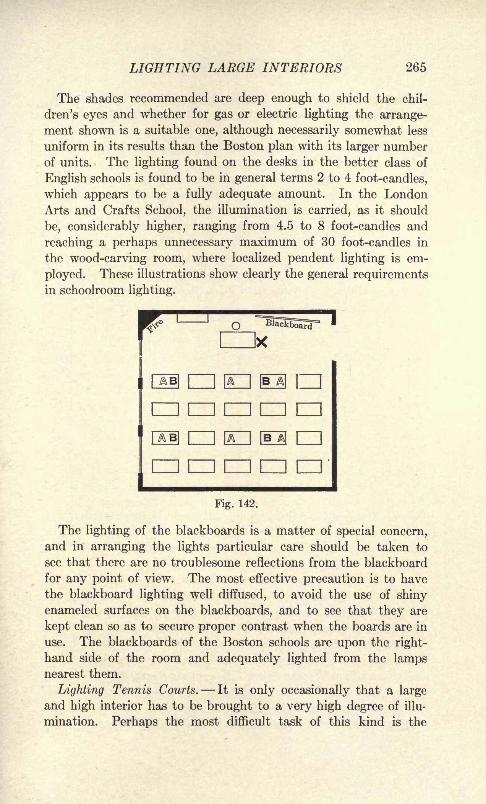
LIGHTING LARGE INTERIORS 265
The shades recommended are deep enough to shield the chil-
dren's eyes and whether for gas or electric lighting the arrange-
ment shown is a suitable one, although necessarily somewhat less
uniform in its results than the Boston plan with its larger numberof units. The lighting found on the desks in the better class of
English schools is found to be in general terms 2 to 4 foot-candles,
which appears to be a fully adequate amount. In the LondonArts and Crafts School, the illumination is carried, as it should
be, considerably higher, ranging from 4.5 to 8 foot-candles and
reaching a perhaps unnecessary maximum of 30 foot-candles in
the wood-carving room, where localized pendent lighting is em-
ployed. These illustrations show clearly the general requirementsin schoolroom lighting.
Fig. 142.
The lighting of the blackboards is a matter of special concern,
and in arranging the lights particular care should be taken to
see that there are no troublesome reflections from the blackboard
for any point of view. The most effective precaution is to have
the blackboard lighting well diffused, to avoid the use of shinyenameled surfaces on the blackboards, and to see that they are
kept clean so as to secure proper contrast when the boards are in
use. The blackboards of the Boston schools are upon the right-
hand side of the room and adequately lighted from the lampsnearest them.
Lighting Tennis Courts. It is only occasionally that a large
and high interior has to be brought to a very high degree of illu-
mination. Perhaps the most difficult task of this kind is the
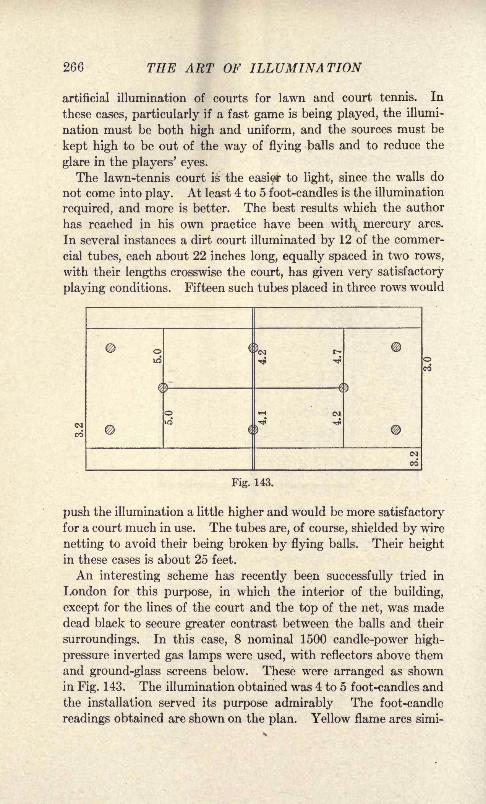
266 THE ART OF ILLUMINATION
artificial illumination of courts for lawn and court tennis. In
these cases, particularly if a fast game is being played, the illumi-
nation must be both high and uniform, and the sources must be
kept high to be out of the way of flying balls and to reduce the
glare in the players' eyes.
The lawn-tennis court is the easier to light, since the walls do
not come into play. At least 4 to 5 foot-candles is the illumination
required, and more is better. The best results which the author
has reached in his own practice have been witfy mercury arcs.
In several instances a dirt court illuminated by 12 of the commer-
cial tubes, each about 22 inches long, equally spaced in two rows,
with their lengths crosswise the court, has given very satisfactory
playing conditions. Fifteen such tubes placed in three rows would
e
Fig. 143.
push the illumination a little higher and would be more satisfactory
for a court much in use. The tubes are, of course, shielded by wire
netting to avoid their being broken by flying balls. Their height
in these cases is about 25 feet.
An interesting scheme has recently been successfully tried in
London for this purpose, in which the interior of the building,
except for the lines of the court and the top of the net, was madedead black to secure greater contrast between the balls and their
surroundings. In this case, 8 nominal 1500 candle-power high-
pressure inverted gas lamps were used, with reflectors above themand ground-glass screens below. These were arranged as shownin Fig. 143. The illumination obtained was 4 to 5 foot-candles and
the installation served its purpose admirably The foot-candle
readings obtained are shown on the plan. Yellow flame arcs simi-
LIGHTING LARGE INTERIORS 267
larly placed would give excellent results, but they are somewhat
more dazzling than the mercury tubes or the press-gas lamps.
The problem of lighting a court-tennis court is considerably more
difficult. In one instance the author obtained a good result byusing 18 double 22-inch mercury lamps, equally spaced in three
rows over the court. The interior color was, of course, greatly
changed when the artificial illumination went on, but the con-
trasts obtained were satisfactory and the installation has given
good results. Whatever be the illuminant chosen, particular pains
must be taken to get strong light in the extreme corners of the
court and on the tambour.
Hand-ball and squash courts are easily illuminated on about
the same basis as in lawn-tennis courts, but up to the present a
racquet court defies all attempts at adequate artificial illumination.
The balls are so small and the pace so terrific that no ordinary
amount of light seems to produce any useful result. At the most
modest estimate at least twice as much light is necessary as in
court tennis, and it is doubtful whether even this would be
enough for a really fast game.The Lighting of Libraries and Similar Buildings. Libraries
and museums and similar public buildings demand a somewhat
specialized illumination both with respect to intensity and distri-
bution. In a library the first condition is that there should be
in all parts of the building where general reading is to be done
light sufficient for reading, easily and comfortably, at any seat in
the room, any book which may be in use. Second, there must be
complete absence of glare either from the luminous sources them-
selves, or indirectly from the paper of the books. Third, for the
use of bookshelves or in rooms for general purposes, there must
be a comfortable general illumination irrespective of the positions
of the readers' seats.
The first requirement is a somewhat severe one, since lighting
which, for example, is quite sufficient for a school desk will be
found insufficient when reading books in fine type or studying
critically maps and engravings. Among library authorities who
have acquainted themselves with illuminating conditions, and
among illuminating engineers who have worked on this problem,
there is general agreement that illumination up to nearly 5 foot-
candles is necessary at the reading tables. For general use about
the room 1 or at most 2 foot-candles is a liberal allowance.
268 THE ART OF ILLUMINATION
The natural inference from these requirements as to intensity
is that the best system for illuminating the reading rooms of a
library is a combination of a general illumination with localized
lights on the reading tables. This is certainly the most economical
solution of the problem and perhaps the most generally applicable.
For this purpose well-shaded lights jaear the ceiling may be utilized
to produce 1 to 2 foot-candles over the whole working area. Onthe reading tables lamps carrying the sources of local illumination
should be placed, so shaded as to keep the light out of the readers'
eyes, and to avoid as far as possible strong direct reflections from
the paper.
The first part of the task, that is, general illumination, is a very
easy and obvious matter. The second is not. In many libraries
rather wide tables with fixed table lamps along the center line are
used, and sometimes with extremely bad results. A fixed lamp on
a wide table if at a sufficient height to spread the light the full
width of the table is extremely likely to shine directly into the eyesof persons below the average height when seated, and to produceserious glare by direct reflection of the light from the book.
In one library with which the author had to deal, the glare pro-duced in these ways was so serious as to make reading very un-
comfortable, and the situation was far from being relieved by the
use of unshaded, though frosted, incandescent lamps for general
illumination.
The remedy applied was to place these lamps in diffusing balls
and to substitute for the fixed standards movable student lampswith deep 10-inch porcelain shades, flashed with green on the out-
side, and containing 16-c.p. lamps, frosted, well up toward the topof the cone. The position of these shades was adjustable, and the
lamps themselves, being on flexible cord, could be shifted to suit the
requirements of the reader, so that ample light could be gainedwithout glare from the lamp itself, and the position of the light
could be so adjusted as to avoid direct reflection from the paper.
In small libraries with relatively small reading tables and a limited
number of readers, this is probably the best arrangement.For reading rooms of large size having to accommodate many
readers, movable lamps are somewhat troublesome, and if the table
is not too wide fixed lamps along the center line, shaded somewhat
as described and placed at a height to keep the light out of the eyes,
can be made to do almost equally well. They should be so adjusted
LIGHTING LARGE INTERIORS 269
that the reader when sitting at the table will naturally place his
book far enough under the lamp to avoid specular reflection into
the eyes. Lamps adjustable in height, if not in position, are highly
desirable for such reading-room use. Nothing better than the
green-flashed porcelain shade has yet been devised for a table lamp.
The distribution of light may sometimes be improved by placing
a reflector within the shade directly over the lamp to widen the
distribution, or sometimes by closing in the lower part of the shade
with a ground-glass diffusing shield. The student lamp equippedwith such a diffuser furnishes perhaps the very best form of illu-
mination, where the use of movable lamps is permissible.
Where many bookcases are around the reading room, lamps in
opaque reflectors, with their apertures facing the shelves, may be
advantageous^ used for lighting the books. An excellent form of
trough illuminator for doing this work is shown in Fig. 125. Theillumination here may well be 2 or 3 foot-candles. Similar lampswith reflectors are desirable for aiding the inspection of card cata-
logues. In this case the illumination should be pushed somewhat
higher, perhaps quite as high as at the tables, since the entries are
not always clearly legible.
In some instances very excellent results have been reached in
reading rooms by general illumination only, sometimes in the form
of wholly indirect lighting. Considering the area to be lighted and
the usual height of such rooms, however, this method, while it maybe made beautifully effective, is always wasteful of energy.
A library stack can be very well lighted by the use of reflectors
as just shown, and this is much superior to the common arrange-
ment of bare lamps upon cords hung in the spaces between the
shelves and turned on by anyone searching for books. The lights
in each bay of a stack should be controlled by a switch at the
entrance.
Delivery rooms and similar public rooms are best treated by
general illumination to the extent of 2 or 3 foot-candles, the exact
form depending on the use to which the room is to be put. In
case such public rooms contain any special features to be illumi-
nated, the plan of lighting must be subordinated to these particular
things. Here, even more than elsewhere, the installation of light
sources must be considered as only a means to an end. Perhapsthe very worst installation of lights in a library yet recorded was
the original one in the delivery room of the Boston Public Library,
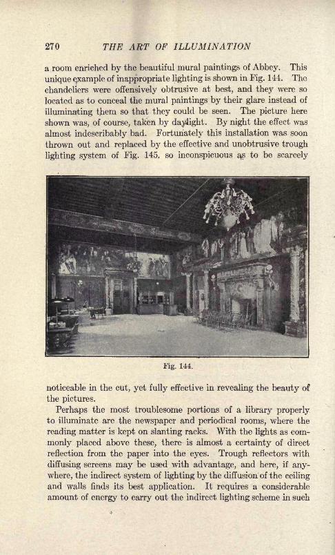
270 THE ART OF ILLUMINATION
a room enriched by the beautiful mural paintings of Abbey. This
unique example of inappropriate lighting is shown in Fig. 144. The
chandeliers were offensively obtrusive at best, and they were so
located as to conceal the mural paintings by their glare instead of
illuminating them so that they could be seen. The picture here
shown was, of course, taken by dajdight. By night the effect was
almost indescribably bad. Fortunately this installation was soon
thrown out and replaced by the effective and unobtrusive trough
lighting system of Fig. 145, so inconspicuous a,s to be scarcely
Fig. 144.
noticeable in the cut, yet fully effective in revealing the beauty of
the pictures.
Perhaps the most troublesome portions of a library properlyto illuminate are the newspaper and periodical rooms, where the
reading matter is kept on slanting racks. With the lights as com-
monly placed above these, there is almost a certainty of direct
reflection from the paper into the eyes. Trough reflectors with
diffusing screens may be used with advantage, and here, if any-
where, the indirect system of lighting by the diffusion of the ceiling
and walls finds its best application. It requires a considerable
amount of energy to carry out the indirect lighting scheme in such
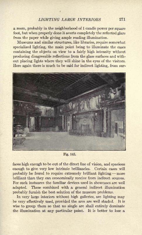
LIGHTING LARGE INTERIORS 271
a room, probably in the neighborhood of 1 candle power per square
foot, but when properly done it averts completely the reflected glare
from the paper while giving ample reading illumination.
Museums and similar structures, like libraries, require somewhat
specialized lighting, the main point being to illuminate the cases
containing the objects on view to a fairly high intensity without
producing disagreeable reflections from the glass surfaces and with-
out placing lights where they will shine in the eyes of the visitors.
Here again there is much to be said for indirect lighting, from sur-
Fig. 145.
faces high enough to be out of the direct line of vision, and spacious
enough to give very low intrinsic brilliancies. Certain cases will
probably be found to require extremely brilliant lighting more
brilliant than they can economically receive from indirect sources.
For such instances the familiar devices used in showcases are well
adapted. These combined with a general indirect illumination
probably furnish the best solution of the museum problems.
In very large interiors without high galleries, arc lighting maybe very effectively used, provided the arcs are well shaded. It is
wise to group them so that no single arc shall entirely dominate
the illumination at any particular point. It is better to lose a
272 THE ART OF ILLUMINATION
little in uniformity of the total illumination throughout the area
than to take the chances of flickering, which is not entirely sup-
pressed even in the best arc lamps.In a big space arcs can be treated much like incandescents in a
small space, but the detail of the work varies so much that only
very general suggestions can be given. Often temporary illumi-
nation has to be undertaken, and must be fitted to the case in
hand. One of the most beautiful examples of such work that
ever fell under the author's notice was the illumination of Madison
Square Garden for a chrysanthemum and orchid show some years
since. The feature of this work was the very extensive use of both
arc and incandescent lamps inclosed in Chinese lanterns. The
huge lanterns containing the arcs were very striking, and the whole
effect was most harmonious, while the illumination was thoroughly
good. It is mentioned here merely as a clever bit of temporary
lighting treated to suit the particular occasion.
In this lighting of large interiors the smaller arcs worked on
constant-potential circuits are very useful, although not very effi-
cient. Those taking 5 to 6 amperes give excellent service, and
fair results can be obtained with lamps working down even to
4 amperes. Such arcs are equivalent to from 10 to 15 16-c.p.
lamps in practical effect, and give a greater candle power per
watt. The "intensified" arcs are by all means the best for
such work.
Incandescent lamps of the Nernst type or the largest sizes of
tungsten lamps may be utilized in a similar way, in forming a goodbasis of illumination where the total amount of light is consider-
able. In other words, when one is dealing with very large inclosed
spaces, the lighting is simplified and made more efficient by utiliz-
ing the more powerful radiants.
jln certain cases, particularly railway stations and other build-
ings likely to be rather smoky, arcs have to be the main reliance,
since the globes of incandescents grow dim so quickly that cleaning
them is an almost interminable job. Hence it is best to use
comparatively few powerful radiants. The arcs should be carried
rather high, at least 20 to 25 feet above the ground or floor.
Assuming 0.5 foot-candle as the minimum, and taking into ac-
count the illumination due to adjacent lamps, each arc can be
counted on to illuminate over a distance at which it gives 0.25
foot-candle. For close detail reference must be made to the actual

LIGHTING LARGE INTERIORS 273
illumination curves of the type of lamp used, and the general
problem is analogous to street lighting.
All arcs in inclosed places should have at least one opal globe,
and when used where, as in railway stations, diffuse reflection is
of small amount, should be provided with reflectors to utilize the
light that would otherwise be wasted.
Certain classes of interiors require, on account of the uses to
which they are put, especial adaptations of the radiants, either
in kind, amount, or position. One of the commonest demands is
for an illumination of unusual brilliancy and steadiness in situ-
ations like draughting rooms, and shops where fine work is done,where the eyes are under steady, if not severe, strain. Ordinary
good reading illumination, such as we have been considering,
must be considerably strengthened to meet these requirements.
Simple increase in the number or power of the radiants sometimes
meets the conditions, if such increase can be had without thrust-
ing too powerful lights into the field of vision.
It may be necessary to furnish 1 candle power for each 2 squarefeet of area, or, in extreme cases, 1 candle power per square foot.
One of the most useful schemes for supplying such large amounts
of light is the use of the inverted arc in connection with a very
light interior finish.
The ordinary continuous-current arc, in virtue of the brilliant
crater of the positive carbon, throws its light downward; but if
the current be reversed so as to form the bright crater on the
lower carbon, most of the light is thrown upward toward the
ceiling, and is there diffused. If, as usual, these arcs are arrangedwith inverted conical reflectors of enameled steel or the like, all
the direct rays are cut off and the entire illumination is by the
diffused rays. The result is a very soft and uniform light, white
in color, and of any required brilliancy. Fig. 146 shows in dia-
gram the principle of this device. In case a white ceiling is not
available, large white diffusing screens over the lamps, of enameled
metal or even of tightly stretched white cloth or paper, answer the
purpose. Indeed, this was the original form of the device as shown
by Jaspar at the Paris Exposition of 1881.
With reference to Fig. 146, it is sufficient to note that the
conical reflector should be rather shallow, just deep enough to
throw the light wholly on the ceiling and upper walls, but shallow
enough for two neighboring lights, as shown, to distribute light

274 THE ART OF ILLUMINATION
over each other's fields, which improves the average steadiness
of the illumination. The arcs need no diffusing globes, a clear
globe being sufficient, and open arcs may be freely used, to the
material improvement of the luminous efficiency, never very highin this form of lighting.
The heights of the arcs should Depend somewhat on circum-
stances regarding the appearance and the purpose of the lights,
but will generally be half to three-fourths the height of the room.
The reflectors may be from 3 feet to 6 feet in diafcieter, and mayhave an angle at the apex of 120 degrees to 140 degrees Only in
case of having to throw the light on special screens rather than on
Fig. 146. Lighting by Inverted Arcs.
the natural ceiling should the reflectors have less aperture than
just indicated. They then become of the nature of projectors, and
the angle at the apex may be 90 degrees or so.
As to the efficiency of such illumination, one may roughly assume
1 watt per spherical candle power for powerful open continuous-
current arcs, and may reckon on a loss of about one-half in the
process of diffuse reflection. The diffuse illumination may then
be taken as being in candle power about 0.5 the number of watts
expended, not including artificial resistance. Thus, a continuous-
current arc, taking 9 to 10 amperes at about 50 volts, utilized in
this manner, will illuminate 250 square feet to 300 square feet on
the basis of 1 square foot per candle power, or 500 square feet to
600 square feet at 2 square feet per candle power.
LIGHTING LARGE INTERIORS 275
It must be noted that if ordinary inclosed arcs are used in this
way, materially less light is obtained, as is well known. Even with
both outer and inner globes clear, one cannot count on much better
than 2 watts per mean spherical candle power. Alternating lamps
require, of course, still more energy, and with inclosed arcs in
general one would hardly find it advisable to allow, when using
ceiling diffusion, more than half to three-fifths of the area per watt
just indicated for open arcs. Inclosed arcs have no crater, which
operates greatly against their effectiveness in this class of lighting.
These figures are necessarily only approximate, but while inclosed
arcs have some conspicuous virtues, high efficiency as respects mean
spherical candle power is not one of them. In all this lighting bydiffusion the diffusing surfaces must be kept clean, else there will
be much loss of light. Under even the best conditions, one does
not do very much better than 2 watts per candle power, and lack
of care or bad engineering may easily transform this into 3 or 4
watts per candle power, which is no better efficiency than incan-
descents would give. In point of efficiency the larger sizes of
tungsten lamps are better than inclosed arcs for such work.
The chief advantage of this diffused lighting is that it enables
one to secure very brilliant illumination with white light, without
trying the eyes with intense radiants.
Such illumination has, however, one curious failing, in that as
ordinarily installed it is shadowless, and the light has no deter-
minate direction. For certain kinds of work this is a very trying
peculiarity, severely felt by the eyes. It may be remedied in
various ways, of which perhaps the simplest is the lateral dis-
placement of the lamps shown in Fig. 147.
This gives a predominant direction to the light, something akin
to the effect produced by a row of windows along the side of the
room, and is probably as near an approach to artificial daylight
as can be attained by simple means.
In using the arrangement of Fig. 147, about the same relative
number of arcs is required as in Fig. 146, but they are placed in one
row instead of two. The unilateral effect could be greatly enhanced
by a diffusive screen ab, Fig. 147, running along back of the arcs.
Its angle with the ceiling evidently should depend on the shape of
the room.
Unilateral illumination, whether diffused or not, is often desirable
from a hygienic standpoint. In many cases well-shaded arcs may
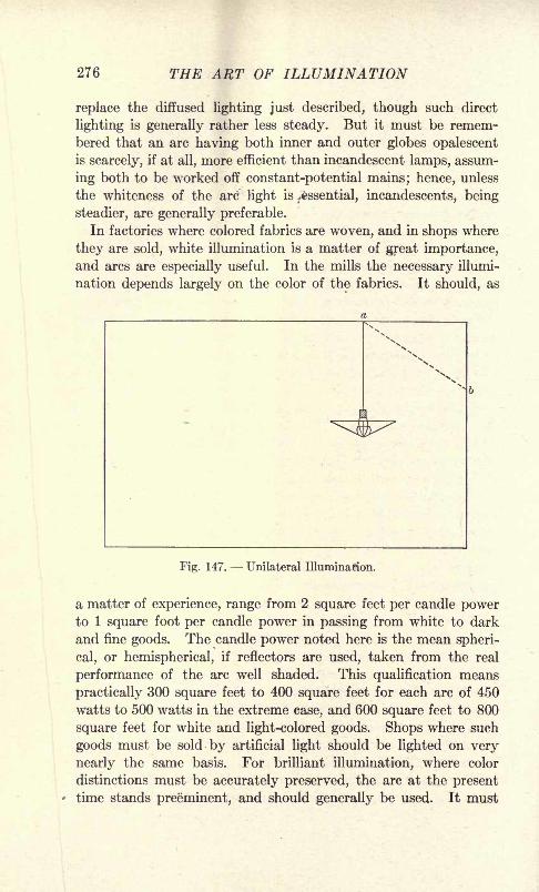
276 THE ART OF ILLUMINATION
replace the diffused lighting just described, though such direct
lighting is generally rather less steady. But it must be remem-
bered that an arc having both inner and outer globes opalescent
is scarcely, if at all, more efficient than incandescent lamps, assum-
ing both to be worked off constant-potential mains; hence, unless
the whiteness of the arc light is Essential, incaridescents, being
steadier, are generally preferable.
In factories where colored fabrics are woven, and in shops where
they are sold, white illumination is a matter of great importance,
and arcs are especially useful. In the mills the necessary illumi-
nation depends largely on the color of the fabrics. It should, as
Fig. 147. Unilateral Illumination.
a matter of experience, range from 2 square feet per candle powerto 1 square foot per candle power in passing from white to dark
and fine goods. The candle power noted here is the mean spheri-
cal, or hemispherical, if reflectors are used, taken from the real
performance of the arc well shaded. This qualification means
practically 300 square feet to 400 square feet for each arc of 450
watts to 500 watts in the extreme case, and 600 square feet to 800
square feet for white and light-colored goods. Shops where such
goods must be sold by artificial light should be lighted on very
nearly the same basis. For brilliant illumination, where color
distinctions must be accurately preserved, the arc at the present
time stands preeminent, and should generally be used. It must
LIGHTING LARGE INTERIORS 277
be remembered, however, that inclosed arcs are distinctly bluish
unless the current is pushed up nearly to the limit of endurance of
the inner globes, and hence, when used in situations where color
is important, should have shades tinted to correct this trouble.
The common opalescent inner globe is entirely insufficient for the
purpose. The "intensive" arcs are best suited to the purpose.
Where arc lights are not available, and it is desired to furnish
approximately white light, there is difficulty in meeting the require-
ment. Mantle gas burners, with extreme care in selecting tinted
shades to correct the color of the light, may be made to give fair
results, but are considerably inferior to arc lights.
It should not be forgotten that good illumination in a workshoptends materially to increase the quantity and improve the quality
of the work turned out.
In most insta'nces the color of the light within the range of
ordinary illuminants is not a matter of considerable importance,
but the light must always be reasonably steady. Hence the
incandescent lamp and the mantle burner for gas are by far the
most valuable sources of light commonly applicable. Ordinary
batwing gas burners are probably the worst in point of steadiness,
although a badly adjusted electric arc is a close second.
Where very powerful radiants are desired, the large regenerative
gas burners give a very brilliant and steady light. They throw
out, however, a great deal of heat, which is sometimes objection-
able, and are less economical of gas than the mantle burner.
The modern "press-gas" lamps with inverted mantles are still
better.
A very special branch of illumination is the lighting of immense
inclosed spaces, such as are found in exposition buildings. This
work is on such a large scale that it almost partakes of the nature
of outdoor lighting, with which it is very intimately connected
as a practical problem. The amount of light required in single
inclosed spaces of colossal dimensions, like exposition halls, varies
considerably according to the practical use to which the space is to
be put. As a rule, the most brilliant and useful illumination in
these large spaces is secured by the use of arc lights to the exclu-
sion of other illuminants. In a building covering one or several
acres, and perhaps 100 feet or more fn height, incandescents of
ordinary powers look lost; and if the roof is not to fade away into
darkness, a very large number of lights must be required to bring
278 THE ART OF ILLUMINATION
it into prominence, placed so high from the floor as to be of little
service for the general illumination.
Moreover, such buildings have generally a large amount of
glazed side and roof space, furnishing the ordinary daylight illu-
mination. Consequently the walls and ceiling diffuse very little
light. With arc lights the power oj the individual radiants bears
some respectable proportion to the size of the space to be illumi-
nated. The luminous efficiency is increased, and, by sufficient
massing of lights with reflectors, even the highest halls can be
admirably lighted. The work can, of course, be beautifully done
with incandescents if enough are available, but at considerably
lessened economy.The amount of light required per square foot of floor space is
very considerable, owing to the height and bad diffusing proper-
ties of the building, and for the best results 1 actual candle powershould be furnished for each 2 square feet to 3 square feet, accord-
ing to conditions.
Incandescent lamps have a very high decorative value in con-
nection with such work, but to be used effectively must be massed
somewhere near the plane of illumination, lights in and about the
roof being practically only for decorative purposes. Used in suffi-
cient numbers, however, they give, in virtue of their completesubdivision of the illumination, a better artistic result than can
be obtained with arcs.
The subject of exposition illumination is so large and so special
in its. character as to be hardly appropriate to the scope of the
present work.
CHAPTER XII.
EXTERIOR ILLUMINATION.
BY exterior illumination is here meant that which is applied out-
side the confining walls of buildings. Interior illumination, which
is circumscribed by such walls, is powerfully modified by their par-
ticular characteristics as to color, texture, and coefficient of reflec-
tion. Of the six surfaces which bound a typical interior space,
four or five are generally moderately good reflectors, or at least are
not so low in reflectivity as to be at all negligible. One, commonlythe floor, is often nearly or quite negligible, and sometimes, in the
case of high vaulted ceilings, another bounding surface may be left
for the most part out of account. In exterior lighting the case is
radically different. In some instances there are no bounding sur-
faces to the space illuminated of such character or at such distances
as to afford any secondary illumination worth mentioning. In
other cases there may be two or three reflecting surfaces, generally
rather bad, to be considered, but in all cases the upper limiting
surface is absent and the condition generally approximates the
illumination of an indefinitely extended room with a poorly reflect-
ing floor and an absolutely black ceiling.
One, therefore, deals, in exterior lighting, chiefly with light re-
ceived directly from the radiants, and in so far the case is theoreti-
cally simpler than interior lighting. On the other hand, the lower
bounding surface in exterior lighting may be relatively important,
particularly in certain cases of low illumination to be described
later on. Now and then there are lateral bounding surfaces which
are not negligible, and there are also extraneous sources of light
which in practical illumination are of great importance, but, on the
whole, exterior illumination depends for its effective magnitude
upon light received directly from the radiants in use.
From the economic standpoint exterior illumination presents a
favorable case, inasmuch as relatively low intensities are employed,since space out-of-doors does not need to be lighted to the degree
required for occupations or amusements customarily carried on
indoors. Broadly, then, the art of exterior illumination deals gen-279
280 THE ART OF ILLUMINATION
erally with the distribution, directly from one or more radiants, of
a moderate degree of illumination without much effective aid from
any secondary sources of light.
Most generally, illumination out-of-doors is applied to a single
surface, the ground; but there are cases in which the fundamental
requirement is the lighting .of vertical surfaces, such as are pre-
sented by buildings. It is this class of lighting which, perhaps,
bears the greatest resemblance to the conditions of interior lighting
and which will be considered in the next chapter.
The main class, therefore, of exterior illumination here to be
considered, and the one of the greatest economic importance, is
that of street lighting, in which the distribution has to be chiefly
lengthwise of the streets. Bounding surfaces in the form of build-
ings may or may not be of material importance, and the intensity
required is rather moderate. It is lighting in one dimension, rather
than in two, as in the case of public places and parks, or in three,
as in the case of interiors. Prior to discussing this, however, it
will be well to consider the somewhat more general problem of place
and park lighting.
The lighting of public places and parks differs from street light-
ing in that the areas to be illuminated are not narrow strips like a
street, but extend in both directions, and in the case of public
squares the lighting of the adjacent buildings is a thing not to be
left out of account. The purposes of these kinds of lighting differ
very widely. Public squares are illuminated with special reference
to the convenience and pleasure of the people who use them, often
in great numbers. Such places are frequently dense centers of
traffic along the streets that meet upon them, are generally located
in the more thickly populated parts of the city, and are often scenes
of great activity during at least the earlier hours of the evening.
Man has become steadily more and more a nocturnal animal, and
it is in these public squares that provision must be made for his
habits. Both his protection and his convenience are objects which
must be borne in mind when designing the illumination. The police
value of lighting has long been recognized, and emphasis was laid
on it in an interview recently by the Chief of Police in Paris, who
pleaded for adequate all-night lighting as an adjunct for the preser-
vation of order. In considering public squares, the value of ample
light as preventive of crime is very considerable, but perhaps less
important than it is in some of the streets. A public square is
EXTERIOR ILLUMINATION 281
not a spot generally chosen for "holdups" or other extreme crimes
of violence. It is, however, a location where the pickpocket and
petty thief may ply their vocations, and for full protection against
these gentry good illumination is needed.
Fundamentally, the lighting of a public square is for the con-
venience of the passersby. They not only wish to walk without
tripping over obstacles, or drive without plunging into open man-
holes, but they wish to meet and recognize their friends without
bumping into them, to glance at a railway time-table, to read the
address on a letter or the number on a house, and, in general, to
see "as comfortably and get about with as little thought of incon-
venience from lack of light as would be the case toward the end
of a winter afternoon. .In other words, the peculiar requirementsof convenience demand that public squares which are largely used
should be liberally lighted as well lighted as the best-lighted streets,
much better lighted than the ordinary streets. It is consequently
necessary that they should be lighted with some approach to uni-
formity, otherwise there will be dark spots not only unpleasant in
effect but inconvenient for the man on the street. From a practical
standpoint such requirements can be met thoroughly well in only
one way, by the use of a very large flux of light from sources
placed high enough to be out of the immediate field of view. This
is akin to the ordinary requirements of interior lighting, in that
one should be able to see easily and comfortably without brilliant
sources of light intruding themselves in the direct line of vision.
The lights ordinarily used for street lighting, if sufficiently
numerous to give the requisite volume of illumination in a public
square, are certain to interfere with vision by their brilliancy and
position near the line of sight. The author calls to mind three
famous places which serve as examples of the bad and good meth-
ods of place lighting. One of these is the Place de la Concorde,
Paris, lighted with innumerable small units placed on short posts
that stand in serried ranks all about the famous spot. The light-
ing of the pavement is moderately bright, but the effect is dis-
tinctly unpleasant and inadequate; petty from the great numberof lamps and the obtrusiveness of their supports. The second is
Trafalgar Square, London, lighted with arcs to a somewhat higher
degree than the Place de la Concorde, but yet missing somethingof distinguished beauty or notable excellence in the results. It
is a fairly well-lighted square, which could be made much better
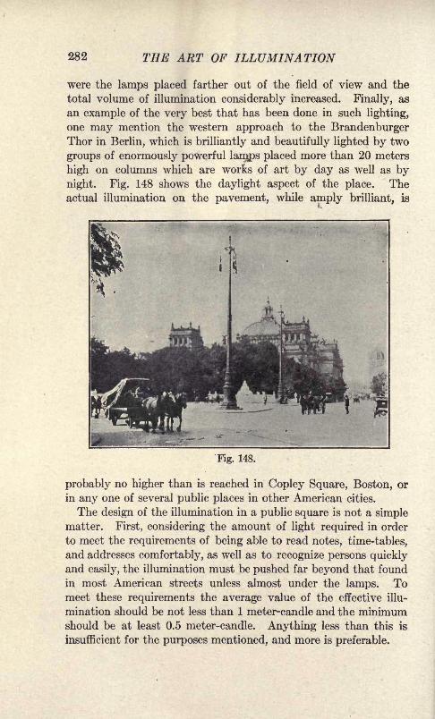
282 THE ART OF ILLUMINATION
were the lamps placed farther out of the field of view and the
total volume of illumination considerably increased. Finally, as
an example of the very best that has been done in such lighting,
one may mention the western approach to the BrandenburgerThor in Berlin, which is brilliantly and beautifully lighted by two
groups of enormously powerful lamps placed more than 20 meters
high on columns which are works of art by day as well as bynight. Fig. 148 shows the daylight aspect of the place. Theactual illumination on the pavement, while amply brilliant, is
Fig. 148.
probably no higher than is reached in Copley Square, Boston, or
in any one of several public places in other American cities.
The design of the illumination in a public square is not a simplematter. First, considering the amount of light required in order
to meet the requirements of being able to read notes, time-tables,
and addresses comfortably, as well as to recognize persons quicklyand easily, the illumination must be pushed far beyond that found
in most American streets unless almost under the lamps. Tomeet these requirements the average value of the effective illu-
mination should be not less than 1 meter-candle and the minimumshould be at least 0.5 meter-candle. Anything less than this is
insufficient for the purposes mentioned, and more is preferable.
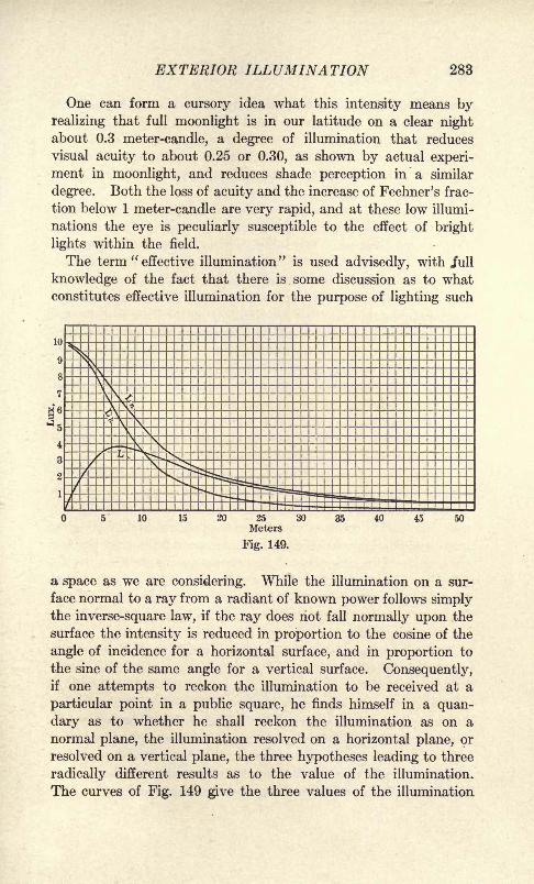
EXTERIOR ILLUMINATION 283
One can form a cursory idea what this intensity means byrealizing that full moonlight is in our latitude on a clear nightabout 0.3 meter-candle, a degree of illumination that reduces
visual acuity to about 0.25 or 0.30, as shown by actual experi-
ment in moonlight, and reduces shade perception in a similar
degree. Both the loss of acuity and the increase of Fechner's frac-
tion below 1 meter-candle are very rapid, and at these low illumi-
nations the eye is peculiarly susceptible to the effect of bright
lights within the field.
The term "effective illumination
"is used advisedly, with Jull
knowledge of the fact that there is some discussion as to whatconstitutes effective illumination for the purpose of lighting such
10
45 50
Fig. 149.
a space as we are considering. While the illumination on a sur-
face normal to a ray from a radiant of known power follows simplythe inverse-square law, if the ray does riot fall normally upon the
surface the intensity is reduced in proportion to the cosine of the
angle of incidence for a horizontal surface, and in proportion to
the sine of the same angle for a vertical surface. Consequently,if one attempts to reckon the illumination to be received at a
particular point in a public square, he finds himself in a quan-
dary as to whether he shall reckon the illumination as on a
normal plane, the illumination resolved on a horizontal plane, or
resolved on a vertical plane, the three hypotheses leading to three
radically different results as to the value of the illumination.
The curves of Fig. 149 give the three values of the illumination
284 THE ART OF ILLUMINATION
obtained on these three hypotheses from a source of 1000 uniform
spherical candle power placed at a height of 10 meters. Whichof these divergent values should be reckoned as the correct one
for the purpose of designing illumination? The question is an
intricate one on account of the varying purposes for which one
requires light in such a situation. >
Here, again, the similarity to interior lighting becomes evident,
since the case corresponds quite closely to that of a room lighted
from several sources. The solution is, in the author's judgment,
indeterminate, since there are more unknown and perhaps un-
knowable quantities than definite data which can be applied to
them. One can, however, arrive at a common-sense approximatesolution by establishing this criterion, that the light shall be such
as to meet the severest practical test among the various require-
ments of its use; that is, the reading test. For this one can always
readily take advantage of normal illumination, and one customarily
does so. This requirement means, therefore, that the normal illu-
mination received from the nearest light shall at no point fall below
0.5 meter-candle, and shall, as a whole, equal or exceed 1 meter-
candle. With this quantity of illumination all practical require-
ments other than reading are met very easily.
The problem of design, then, resolves itself into a comparatively
simple construction, the placing of radiant sources so that if one
draws about each of them a circle at such distance that the nor-
mal illumination received from the source at that circle shall be 0.5
meter-candle, these circles shall overlap so as to fully cover the area
concerned. The subsequent design consists in so planning the dis-
tribution from each source that its effective radius of action shall
be as great as possible. With all practical illuminants the illumi-
nation, if sufficient at the periphery of the circle, will be sufficient
for all points within.
For the purpose in hand, the fundamental equation connecting
the various quantities is
Ln =pCOS
2o:, (1)
where Ln is the illumination, I the height of the radiant above the
plane of reference, 7 the intensity, and a the angle of incidence,
which is equal to the angle between the ray and the lamp-post.Of these quantities in actual computation any one may be assumed
on the conditions, or any one may be required to be found. 7 and
EXTERIOR ILLUMINATION 285
the angle a are dependent variables, and in practice are taken
from the distribution curve of the radiant. This being known, the
required height of the lamp to produce a given illumination, LH}
can be obtained from the transformed equation,
For instance, taking Ln at 0.5 meter-candle and / for the angle of
incidence 70 degrees, as 2000 candle power, I comes out at about
22 meters; and it will be generally found that with distributions
common for powerful illuminants the heights, for illumination of
the order of magnitude here required, come out rather large, higher
than it is generally convenient to place the lamps.
Again, the height of the lamp being chosen at some easily prac-
ticable figure and the curve being known, the angle of incidence
corresponding to the required illumination is given by the trans-
formed equation,
cos2 a=^- (3)
Whether the angle of incidence is assumed, or thus reckoned, the
radius of the circle for the required illumination at the periphery is
r = I tan ex. (4)
Since a and / are mutually interdependent, the solutions thus ob-
tained are not exact; but having the distribution curve of the lamp,
a slide rule, and a table of natural trigonometrical functions, one can
get at the facts in the case in very short order. As an examplein the application of these formulae, the following data derived from
the illumination of Copley Square, Boston, which is lighted by four
very powerful flaming arcs, may be instructive. Here I equals 16
meters and 7 is very conservatively taken at 2000 for angles in the
vicinity of those dealt with. Fig. 150 shows the curve of the lampwith opal globe. Applying equations 3 and 4 for Ln equals 1 meter-
candle and 0.5 meter-candle, respectively; r equals 41.6 meters for
1 meter-candle and 62.5 meters for 0.5 meter-candle, approximately.
Fig. 151 shows these circles as laid down on a map of the Square.
It will be seen that the 1-meter-candle circles overlap liberally,
and the 0.5-meter-candle circles almost touch the adjacent lamps.
It was considered desirable here, especially on account of the fine
neighboring buildings and the large traffic through the streets, to
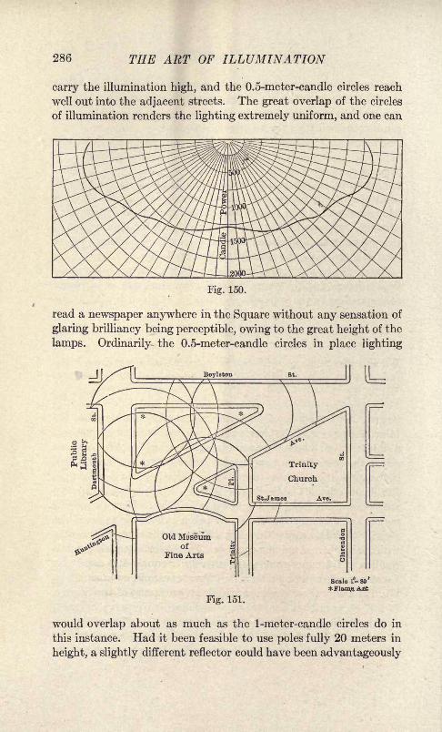
286 THE ART OF ILLUMINATION
carry the illumination high, and the 0.5-meter-candle circles reach
well out into the adjacent streets. The great overlap of the circles
of illumination renders the lighting extremely uniform, and one can
Fig. 150.
read a newspaper anywhere in the Square without any sensation of
glaring brilliancy being perceptible, owing to the great height of the
lamps. Ordinarily the 0.5-meter-candle circles in place lighting
Fig. 151.
would overlap about as much as the 1-meter-candle circles do in
this instance. Had it been feasible to use poles fully 20 meters in
height, a slightly different reflector could have been advantageously
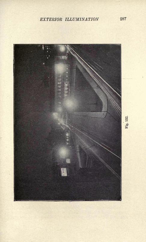
EXTERIOR ILLUMINATION 287
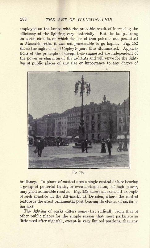
288 THE ART OF ILLUMINATION
employed on the lamps with the probable result of increasing the
efficiency of the lighting very materially. But the lamps being
on series circuits, on which the use of iron poles is not permittedin Massachusetts, it was not practicable to go higher. Fig. 152
shows the night view of Copley Square thus illuminated. Applica-
tions of the principle of "design hese suggested are independent of
the power or character of the radiants and will serve for the light-
ing of public places of any size or importance to any degree of
Fig. 153.
brilliancy. In places of modest area a single central fixture bearinga group of powerful lights, or even a single lamp of high power,
may yield admirable results. Fig. 153 shows an excellent exampleof such practice in the Alt-markt at Dresden, where the central
feature is the great ornamental post bearing its cluster of six flam-
ing arcs.
The lighting of parks differs somewhat radically from that of
other public places for the simple reason that most parks are so
little used after nightfall, except in very limited portions, that any
EXTERIOR ILLUMINATION 289
considerable degree of illumination is unnecessary. Now and then
one finds a park which is used freely in the evening, and in such
cases lighting on a liberal scale ought to be supplied, rising, rarely,
to that appropriate for other public places. Generally speaking,
however, the purpose of park lighting is purely the preservation of
order and the marking of what are, so to speak, thoroughfares
through the park.
From the police standpoint, which is the important one in park
lighting, the requirement is for moderate illumination without dark
spots in which the disorderly can lurk. Hence, as a rule, powerful
radiants which, unless brilliant illumination is attempted, would be
widely spaced and would tend to cause somewhat dense shadows
ought always to be avoided in park lighting. Their only proper
application to such work is where the illumination should approxi-
mate that of other public places, and in the case of large open
spaces. Parks in general, therefore, require less light than any other
class of public spaces which require illumination at all. In manyinstances, where parks are large and wooded, there can be no
attempt at a general illumination even for police purposes, except
in certain spots and along certain routes through the park. Where
lighting is attempted at all, its intensity along the ways in the parkshould be the same as in a very moderately lighted street. Onsuch ways it may fall still lower provided it is reasonably uni-
form, as low, indeed, as average moonlight, perhaps 0.2 meter-
candle or thereabouts. The objects to be seen by such lighting
being nothing smaller than persons, the demand for visual acuity is
small. Practically the problem amounts to furnishing enough light
in a certain area to prevent unwarranted persons from lurking in
the park after nightfall. Any light, therefore, by which the wander-
ing policeman can make out a figure serves the purpose.
As a result of this police requirement the distribution of lights
in a park has sometimes to be very singular, the lights being placed
utterly irrespective of any systematic order, but where they will
abolish dark spots under trees and behind shrubbery. For this
purpose the lights are preferably of only moderate power, and
should be placed low, where they can shine below the branches
of trees. It is also important that lights so placed should be
thoroughly screened so as to avoid glare. Under the conditions
required the guardians of the peace can fulfill their functions most
successfully when their eyes are adapted to a dim light, and dark
290 THE ART OF ILLUMINATION
adaptation is spoiled by a very brief exposure to a powerful light
or one of high intrinsic brilliancy. Even incandescent lamps,
whether gas or electric, used for such park lighting as is here under
consideration, should be put in ground glass or opal shades, pref-
erably the latter, so that their light-giving power may be utilized
without interfering with the vision of those looking toward them
or passing near them.
The best results in park lighting in the writer's experience have
been with 100-candle-power tungsten lamps in 12-inch diffusing
balls, mounted about 10 feet above the ground, and in positions
designated after conference with the police authorities. Larger
units than these can rarely be utilized to advantage on account of
their being too bright, and small ones similarly installed can fre-
quently be made to serve the purpose. If similar lights are installed
along the ways in the park which are desired to be lighted, theywill do excellent service when so spaced as to give illumination
similar to average moonlight, say 0.2 to 0.25 meter-candle. Where
people congregate in the park the illumination should be carried
higher, up to at least 0.5 meter-candle. In open spaces arcs can
here be made to do good service, the illumination being planned
exactly along the same lines as in the case of the public places
already treated. Small units closely placed are less effective, ex-
cept in lighting spaces like open-air restaurants, in which the lights
should always be shielded by diffusing balls or shades. The mini-
mum intensity of light in such places should be at least 0.5 meter-
candle, enough to enable one to read a menu card or program.Park lighting, therefore, would seem to belong in a special class
as regards intensity and distribution, and from its low intensity
requires that particular pains should be taken to avoid glare.
Street lighting is in its origin and development essentially a police
measure. Its history goes back to mediaeval times, in which the
streets, mostly unpaved and wholly undrained, were bad enough
by day but worse by night. They were infested by thieves and
highwaymen, cut-throats and drunken roisterers with rapiers readyfor a quarrel. Paris, in particular, in which we have the first
records of street lighting, was the scene of constant brigandageand crime from almost the earliest days of which we have record.
Early in the fifteenth century, under Louis XI, flambeaux were
ordered at the street corners, and lanterns in the householders'
windows to cooperate with the night watch in promoting public
EXTERIOR ILLUMINATION 291
safety. Over and over again for the next two centuries and a half
such ordinances were reiterated, always openly on the score of
public safety from crimes of violence. In 1558 lanterns were
ordered, at the corners of streets and at other suitable places, to
be kept burning from 10 o'clock in the evening till 4 o'clock in the
morning through the winter months. By these dim and flickering
lights the course of the streets was at least marked, but theyafforded scanty protection against marauders, and those who could
afford it went accompanied by a retinue of torch bearers and an
armed guard when traversing the streets at night. It was not
until more than a century later that anything approaching public
lighting was seriously attempted. In 1662 the first public lighting
concern was given a franchise under a royal edict of October 14.
This was a private enterprise of the Abbe Laudati, and its chief
feature was the constitution of a corps of public lantern bearers
carrying lanterns or flambeaux of a specified size and bearing as
insignia the arms of the city. These were stationed at fixed posts
along the streets and for a small fee would escort the nocturnal
wanderer more or less safely on his way. Systematic street light-
ing was inaugurated about five years later, and the effect on
public order seems to have been immediate, for at least two medals
were struck within the decade, celebrating the institution of public
lighting.
London was still worse off and save for the transitory effect of
ordinances requiring householders to hang out lanterns the streets
were unlighted and almost as full of danger as those across the
Channel. It is worth noting that about this period some ignoble
soul, whose name has very properly perished in oblivion, devised
the original moonlight schedule as a measure of poor and pitiful
saving. It was tried first, probably, in Paris, where it was railed
against as"candle-end economy." London copied from Paris,
and had made little progress before the end of the seventeenth
century. At this period, however, the chief streets of Paris were
systematically lighted by lanterns swung across the street, still the
most efficient position for street lights. They were placed at about
20 paces apart and hung some 20 feet above the ground or pave-
ment, as the case might be. Fig. 154 shows a nearly contempo-raneous view of such suspensions. It was well into the eighteenth
century before street lighting at public expense was customary even
in the capitals of Europe. The subsequent 200 years have seen an
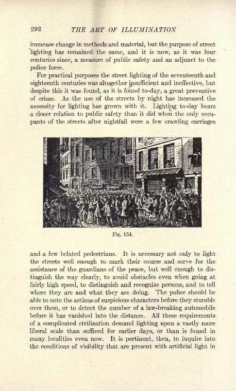
292 THE ART OF ILLUMINATION
immense change in methods and material, but the purpose of street
lighting has remained the same, and it is now, as it was four
centuries since, a measure of public safety and an adjunct to the
police force.
For practical purposes the street lighting of the seventeenth and
eighteenth centuries was altogether insufficient and ineffective, but
despite this it was found, as it is found to-day, a great preventive
of crime. As the use of the streets by night has increased the
necessity for lighting has grown with it. Lighting to-day bears
a closer relation to public safety than it did when the only occu-
pants of the streets after nightfall were a few crawling carriages
Fig. 154.
and a few belated pedestrians. It is necessary not only to light
the streets well enough to mark their course and serve for the
assistance of the guardians of the peace, but well enough to dis-
tinguish the way clearly, to avoid obstacles even when going at
fairly high speed, to distinguish and recognize persons, and to tell
where they are and what they are doing. The police should be
able to note the actions of suspicious characters before they stumble
over them, or to detect the number of a law-breaking automobile
before it has vanished into the distance. All these requirementsof a complicated civilization demand lighting upon a vastly more
liberal scale than sufficed for earlier days, or than is found in
many localities even now. It is pertinent, then, to inquire into
the conditions of visibility that are present with artificial light in
EXTERIOR ILLUMINATION 293
the streets, and to find their bearing upon the intensity of light
required.
Except in the vision of details at comparatively short range, wesee things in virtue of their differences of color and of luminosity.
In weak light color as such is inconspicuous, so that practical vision
depends chiefly upon the power of distinguishing differences of
luminosity. So far as the problems of artificial illumination are
concerned-, objects do not range over a wide scale of luminosity.
Whatever may be the absolute values of light received, the relative
values as expressed by the coefficient of reflection range practically
from about 0.8 to 0.01, or a little less. In other words, the blackest
object returns about one-eightieth the light returned by the
brightest object. Ability to distinguish between stationary objects
by their difference in luminosity depends, then, on the capacity of
the eye as regards shade perception. The fundamental fact under-
lying this is that the eye can perceive within a wide range of
absolute intensity a fairly constant fractional difference in lumi-
nosity. In bright light it ranges, say, from 2 to 0.5 per cent, with
modest variations under special circumstances both ways from
these values, which hold measurably well for values of the illumi-
nation from about 10 meter-candles up. As the illumination falls
below this point there is a material . increase in Fechner's fraction
under ordinary circumstances, and we see less well, so that by the
time the illumination is down to 1 meter-candle our shade percep-
tion is very seriously impaired, as is also our ability to distinguish
details, visual acuity. It should be mentioned that the loss
of shade perception at low illuminations is very powerfully influ-
enced by the state of adaptation of the eye with respect to light
or darkness. With the eye well adapted to the dark, fairly goodshade perception can be carried to illuminations very much lower
than ordinary. In fact at 1 meter-candle or a few tenths the
value of Fechner's fraction is influenced very much more by the
state of the eye as regards dark adaptation than by anything
else, so that when one is seeing fairly under a very low illumina-
tion, anything which tends to spoil the dark adaptation producesimmediate blinding with respect to things otherwise easily seen. It
is chiefly this fact which, from the standpoint of street illumina-
tion, renders glaring lights so troublesome.
Referring these things to the physiology of vision, the situa-
tion may be summarized by saying that below an illumination of
294 THE ART OF ILLUMINATION
1 meter-candle, normal daylight vision, which is chiefly associated
with the cones of the retina, is rapidly failing and throwing the
burden of vision upon the rods.
There is, then, a physiological dividing line that can be drawn
between illumination which permits fairly good seeing and illumina-
tion which leaves only the residual twilight vision; between the
illumination which enables one to perceive things with some degree
of definiteness and that with which one perceives chiefly forms and
shadows. The exact position of this line is somefwhat difficult to
define, as it varies more or less in different eyes and under different
conditions. At 0.5 meter-candle one has certainly not passed fully
into conditions of twilight vision. Color perception, though much
impaired, has not disappeared, and acuity, though failing, still
remains in sufficient degree to permit casual reading, although with
some little difficulty.* At 0.1 meter-candle a condition is reached
where one depends almost entirely on rod vision. Acuity has been
enormously reduced, and shade perception has become almost
wholly dependent on dark adaptation. The point at which cone
vision goes rapidly out of service, and rod vision as rapidly takes
its place for what it is worth, is somewhere about 0.2 or 0.25
meter-candle, and daylight vision is not very dependable below
0.5 meter-candle. We have here, then, the physiological charac-
ters of the eye which are already well determined by investigation
directed particularly upon them, as the basis of a physiological
criterion of illumination. In twilight vision one sees things not as
distinctly perceptible, but as dim forms and shades of uncertain
boundaries and character. Only when the objects subtend a fairly
large visual angle does one see them in the least clearly. This is
the familiar vision of a bright starlit night or a dimly illuminated
street. In its beginnings one cannot even distinguish large station-
ary objects from their background. The first perception is that
of objects in motion, which seem to catch the eye more readily
than when they are at rest. This is a familiar phenomenon in
trying to pick up objects with a night glass at sea. They can be
caught by sweeping when they quite escape detection on apparentlyslower and more careful search. This, too, is probably characteris-
tic of the vision of nocturnal animals.
The next stage of vision presents objects either as vaguely sil-
houetted against a lighter background or as faintly lighted against* One can, for instance, still read by the light of a candle 1.4 meters distant.
EXTERIOR ILLUMINATION 295
a darker background. By further increase of lighting some details
begin to be perceptible, and when the illumination has passed the
critical point of 1 meter-candle or a little more, to which reference
has been made, further details come into view and objects take on
a more natural aspect. The interesting theory of silhouetting as
a feature of street illumination, which has been recently advanced,
really concerns chiefly twilight vision and emphasizes the desir-
ability under this condition of having a light background, not be-
cause one can see a dark patch on a light background any better
than a light patch on a dark background, but because many things,
and particularly the large things, which alone fall within the scope
of twilight vision, are themselves commonly rather dark in surface,
and, consequently, are not easily rendered lighter than the back-
ground. On the other hand, many objects are of surface lighter
than, say, an asphalted street, and, consequently, are seen as
light objects, while commoner than either condition is that of
seeing an object in twilight vision only by its shadow, as one
sees a distant pebble in the street in the beam of an automobile
searchlight.
No illumination which depends chiefly on twilight vision can be
seriously considered for the important purposes of street lighting.
It has its useful place merely in enabling one to find the way.To be effective for the purposes of ordinary traffic, or as an adjunctto proper policing of a city, illumination must be sufficient to estab-
lish, at least to moderate extent, the conditions of cone vision.
The wayfarer wants to distinguish the shadow of a post from a hole
in the pavement before he is fairly upon it. The man who is
driving along a street needs to see his way clearly without risk of
running into the gutter, and the policeman should be able to tell a
belated householder from a burglar using his jimmy on a front
door. And, finally, in many places it is highly important to have
enough additional light to distinguish faces readily, to see even
trivial obstacles easily, and to read the numbers on houses or, if
need be, consult an address book or a time-table. These con-
siderations lead inevitably to the conclusion that unless one is
prepared to meet the most exacting conditions of street illumina-
tion throughout the city he must be willing to classify the lighting
that is to be undertaken, and to light each street according to its
needs, bearing in mind the amount and kind of nocturnal traffic,
and particularly the requirements of public order. We may here
296 THE ART OF ILLUMINATION
consider streets as divided for the purpose of lighting into first,
second, and third classes.
By first-class streets we mean the chief streets of a city from
the standpoint of amount of nocturnal traffic and the requirements
of the police. A chief street may be the principal business street
of a city, that is humming with activity after nightfall. It maybe a street leading to a crowded railway station where carriages
and foot passengers are constantly circulating until late in the even-
ing, or it may be a comparatively humble business street in a por-
tion of the city where the police have found from experience that
only constant watchfulness can keep down crime.
The ordinary streets of a city or town fall into another category.
Traffic after nightfall is light or only moderate. The streets are
reasonably orderly and the general conditions are such that neither
from the viewpoint of the wayfarer nor from that of the policemanis brilliant illumination necessary. Such streets are the ordinary
quiet residence streets of the average city and the business streets
on which there is little traffic by night. These streets usually
would figure up to two-thirds or three-fourths of the total mile-
age in the average city. These may be regarded as second-class
streets from the illuminating standpoint, requiring good lighting,
but not of the highest pitch of brilliancy.
Finally, there are, in every city, a number of streets which re-
quire practically very little illumination. They are mostly in the
outlying portions of the city, sometimes scantily built up, and some-
times they are mere roads leading away from the structural part
of the city, but still within its jurisdiction. For such streets it is
necessary to provide only such illumination as will serve to markthe way and to render progress through them easy considering the
conditions of traffic.
Occasional outlying streets, not at all important as residence
streets, are still considerable traffic carriers, being through-roadsfrom one part of the city to another, or from the city to some
particular suburb or neighboring town. Such, from the standpointof the illuminating engineer, are second-class streets rather than
third-class streets. They demand the illumination required byconsiderable traffic. It is difficult to lay out any exact criteria for
this classification, but there is no chief of police who could not,
after a little reflection, make it with practical precision.
As to the intensity of lighting required for streets of these several
EXTERIOR ILLUMINATION 297
classes, the requirements have, by popular consent, been slowlyand steadily rising. On the physiological basis which enables one
at least to determine what lighting is necessary to reasonably
good vision for various purposes, one can form a fair approxima-tion of conditions to be met. First-class streets in constant use for
dense traffic of one kind or another, or so classified from the police
standpoint, certainly require reading illumination, and this is the
kind of illumination that first-class streets get in most Europeanand some American cities. The intensity of the illumination re-
quired is practically that already specified for public places, that is,
an extreme minimum of at least 0.5 meter-candle, an average of
fully double that amount. Theory and practice concur in holding
that a street so lighted is well lighted. The same question arises
here as regards the way illumination should be reckoned that was
answered concerning the lighting of public places, and the answer
is much the same for both cases. In each case it should be under-
stood that the minimum cannot be permitted to apply to any con-
siderable portion of the street area. The intensity here specified is
substantially that deemed advisable by several foreign investigators
and carried into practice with entirely satisfactory results.
As regards second-class streets the requirements are, of course,
less severe. There should be, as a matter of convenience, light
enough to recognize a friend without stumbling over him, to read
an address, or see the number of a house comfortably. The
average illumination for this purpose may be set at not less than
0.5 meter-candle, and the minimum should be high enough not to
drive one into the physiologically undesirable condition of relying
upon rod vision only. This would imply that the minimum should
be nowhere less than about 0.25 meter-candle. Streets so lighted
will be comfortably bright near the lamps, and the lighting will
be as good as moonlight even at the darkest spot. This degree
of illumination is excellently serviceable for the majority of second-
class city streets.
Finally, we come to the third-class streets. If there is light
enough to mark well the way and to disclose persons or vehicles
in ample time for one to avoid them, it is sufficient. The degree
of illumination required need not be greater than is afforded by
bright moonlight, and should be fully as great as one finds in rather
dim moonlight. It is illumination similar to that which is required
for some of the park lighting, to which reference has been made,
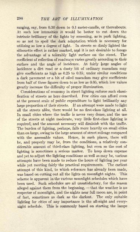
298 THE ART OF ILLUMINATION
ranging, say, from 0.30 down to 0.1 meter-candle, or thereabouts.
At such low intensities it would be better to cut down the
intrinsic brilliancy of the lights by screening, as in park lighting,
so as not to spoil the dark adaptation which is necessary for
utilizing so low a degree of light. In streets so dimly lighted the
silhouette effect is rather marked, and it is not desirable to forego
the advantage of a tolerably light surface on the street. The
coefficient of reflection of roadways varies greatly according to their
surface and the angle of incidence. At fairly Jarge angles of
incidence a dirt road or a dusty bit of ordinary macadam maygive coefficients as high as 0.25 to 0.35; under similar conditions
a dark pavement or a bit of oiled macadam may give coefficients
from half of these figures down to as low as 0.05, which low values
greatly increase the difficulty of proper illumination.
Considerations of economy in street lighting enforce such classi-
fication of streets as here described. Few cities can afford even
at the present scale of public expenditure to light brilliantly any
large proportion of their streets. If an attempt were made to light
all the streets alike, there would be no first-class lighting at all.
In small cities where the traffic is never very dense, and the use
of the streets at night moderate, very little first-class lighting is
required, and the amount necessary will diminish with the traffic.
The burden of lighting, perhaps, falls more heavily on small cities
than on large, owing to the large amount of street mileage comparedwith the assessable values. Hence, in such places, there will
be, and properly may be, from the conditions, a relatively con-
siderable amount of third-class lighting, but even so the cost of
lighting is sometimes a serious matter. To keep down expense
and yet to adjust the lighting conditions as well as may be, various
attempts have been made to reduce the hours of lighting per year
while yet meeting fairly the practical requirements. The earliest
attempt of this kind, to which reference has already been made,
was based on cutting out all the lights on moonlight nights. This
scheme is apparent in the various moonlight schedules which have
been used. Such schedules are all unsatisfactory, for the reason
alleged against them from the beginning, that the weather is no
respecter of moonlight, and the nights near full moon are, in point
of fact, sometimes as dark as the darkest. The only suitable
lighting for cities of any importance is the all-night and every-
night schedule. This is commonly based on starting the lamps
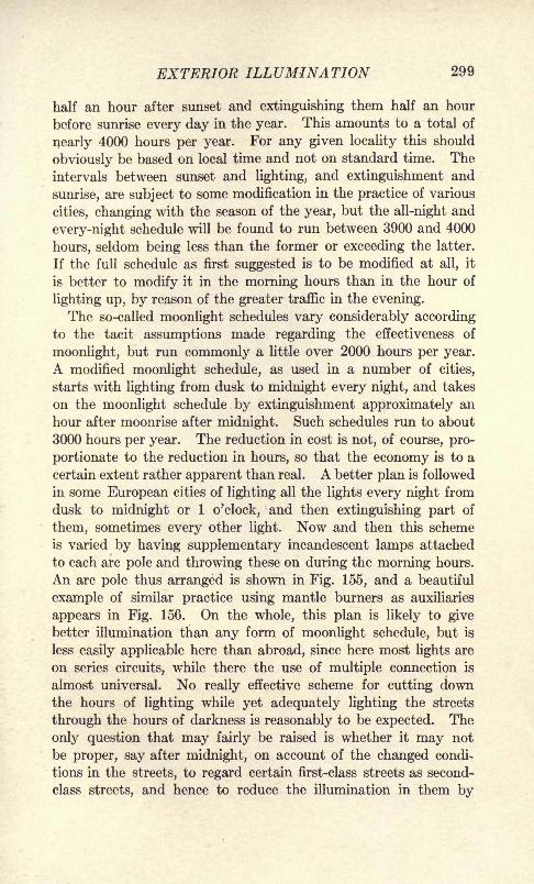
EXTERIOR ILLUMINATION 299
half an hour after sunset and extinguishing them half an hour
before sunrise every day in the year. This amounts to a total of
nearly 4000 hours per year. For any given locality this should
obviously be based on local time and not on standard time. The
intervals between sunset and lighting, and extinguishment and
sunrise, are subject to some modification in the practice of various
cities, changing with the season of the year, but the all-night and
every-night schedule will be found to run between 3900 and 4000
hours, seldom being less than the former or exceeding the latter.
If the full schedule as first suggested is to be modified at all, it
is better to modify it in the morning hours than in the hour of
lighting up, by reason of the greater traffic in the evening.
The so-called moonlight schedules vary considerably according
to the tacit assumptions made regarding the effectiveness of
moonlight, but run commonly a little over 2000 hours per year.
A modified moonlight schedule, as used in a number of cities,
starts with lighting from dusk to midnight every night, and takes
on the moonlight schedule by extinguishment approximately an
hour after moonrise after midnight. Such schedules run to about
3000 hours per year. The reduction in cost is not, of course, pro-
portionate to the reduction in hours, so that the economy is to a
certain extent rather apparent than real. A better plan is followed
in some European cities of lighting all the lights every night from
dusk to midnight or 1 o'clock, and then extinguishing part of
them, sometimes every other light. Now and then this scheme
is varied by having supplementary incandescent lamps attached
to each arc pole and throwing these on during the morning hours.
An arc pole thus arranged is shown in Fig. 155, and a beautiful
example of similar practice using mantle burners as auxiliaries
appears in Fig. 156. On the whole, this plan is likely to give
better illumination than any form of moonlight schedule, but is
less easily applicable here than abroad, since here most lights are
on series circuits, while there the use of multiple connection is
almost universal. No really effective scheme for cutting downthe hours of lighting while yet adequately lighting the streets
through the hours of darkness is reasonably to be expected. The
only question that may fairly be raised is whether it may not
be proper, say after midnight, on account of the changed condi-
tions in the streets, to regard certain first-class streets as second-
class streets, and hence to reduce the illumination in them by
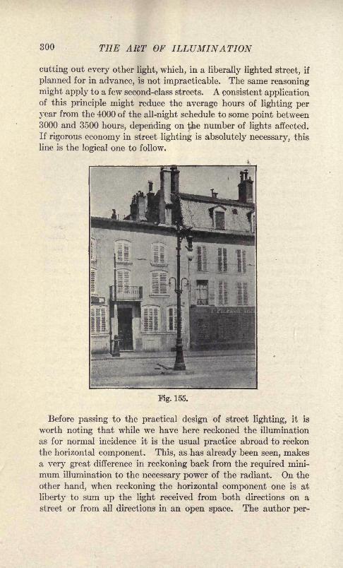
300 THE ART OF ILLUMINATION
cutting out every other light, which, in a liberally lighted street, if
planned for in advance, is not impracticable. The same reasoning
might apply to a few second-class streets. A consistent applicationof this principle might reduce the average hours of lighting per
year from the 4000 of the all-night schedule to some point between3000 and 3500 hours, depending on the number of lights affected.
If rigorous economy in street lighting is absolutely necessary, this
line is the logical one to follow.
Hg. 155.
Before passing to the practical design of street lighting, it is
worth noting that while we have here reckoned the illumination
as for normal incidence it is the usual practice abroad to reckon
the horizontal component. This, as has already been seen, makesa very great difference in reckoning back from the required mini-
mum illumination to the necessary power of the radiant. On the
other hand, when reckoning the horizontal component one is at
liberty to sum up the light received from both directions on a
street or from all directions in an open space. The author per-
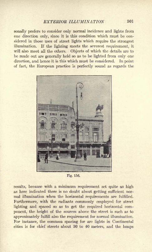
EXTERIOR ILLUMINATION 301
sonally prefers to consider only normal incidence and lights from
one direction only, since it is this condition which must be con-
sidered in those uses of street lights which require the strongest
illumination. If the lighting meets the severest requirement, it
will also meet all the others. Objects of which the details are to
be made out are generally held so as to be lighted from only one
direction, and hence it is this which must be considered. In point
of fact, the European practice is perfectly sound as regards the
%mv
Fig. 156.
results, because with a minimum requirement set quite as high
as here indicated there is no doubt about getting sufficient nor-
mal illumination when the horizontal requirements are fulfilled.
Furthermore, with the radiants commonly employed for street
lighting and spaced so as to get the required horizontal com-
ponent, the height of the sources above the street is such as to
approximately fulfill also the requirement for normal illumination.
For instance, the common spacing for arc lights in Continental
cities is for chief streets about 30 to 40 meters, and the lamps
302 THE ART OF ILLUMINATION
themselves being commonly hung 8 or 10 meters high, the angleof depression reckoned to the midway point rises to the vicinity of
30 degrees, and hence it is numerically a matter of indifference
whether one reckons the light received at this incidence normallyfrom a single lamp or the horizontal component from a lamp on
each side. Thus, in effect, the two,:-inethods of measurement lead
to practically the same result when the lighting fulfills the neces-
sary requirement for intensity on either theory of procedure. The
plane of illumination, that at which the required ^intensity should
be found, is commonly taken at 1 to 1.5 meters above the pave-ment merely as a matter of convenience, it being very difficult
to use a photometer near the pavement in the street on account
of traffic. The vertical component of illumination has practically
seldom to be considered in street lighting, save in its effect on
near-by buildings, a matter which will be taken up presently.
Reviewing the nature of the problem of street lighting, that is,
the illumination of a narrow surface extending in both directions
from the source of light, it is obvious that the vertical distribu-
tion of light around the radius is a matter of great importance.A uniform spherical distribution is bad for the purpose, and the
practical question regarding an illuminant for such use is howmuch of its effective flux of light can be conveniently turned
downward upon the street. Light above the horizontal is not
absolutely wasted, for it does some service by illuminating build-
ings. A radiant for street lighting should, however, be judged
substantially by the lower hemispherical intensity, taking the
lamp and its reflecting system together. Reflectors are useful
with all varieties of street lamps merely for the purpose of de-
flecting downward light which would be otherwise lost toward
the sky, and within limits the natural distribution from the source,
that is, the distribution without any reflector, is a matter of no
great importance, save as it may influence the convenient design
of the reflecting system. A radiant which naturally and without
a reflector casts a large proportion of its light into the downward
hemisphere does not gain materially by that peculiarity unless it
can show greater efficiency in luminous flux per watt than some
other lamp with its reflector, or possesses important practical quali-
fications in its favor quite outside the matter of distribution.
Praiseworthy efforts have been made toward securing by re-
flectors a distribution stretching up and down the street rather

EXTERIOR ILLUMINATION 303
than radially in all directions. They have, unfortunately, madelittle headway as yet for reasons psychological rather than phys-
ical. Such reflectors are apt to be awkward in appearance, which
is a great disadvantage by day, and require the maintenance of
rather exact adjustment in order to do the most efficient work by
night. Obviously, one could not push this sort of redistribution
too far lest he should get an illumination approximating that
which might have been obtained by a pair of automobile head-
lights facing up and down the street from a pole top and giving
a capital light at a distance, but little near by. If, however, one
could obtain a distribution which, instead of being circular, was
an ellipse or similar figure having a major axis two or three times
the minor, it would prove of great practical service in street light-
ing, but the improvement must not be at the expense of clumsy
appearance or require constant care in cleaning to keep up its
efficiency.
The modification of distribution is important from the stand-
point of securing the proper spacing and height of lights. A dis-
tribution curve with its maximum 50 or 60 degrees below the
horizontal is disadvantageous in that it compels a lamp to be
placed high in order to bring its zone of maximum flux of light
out toward the radius of minimum illumination indicated by the
power of the radiant. On the other hand, a maximum within
15 degrees of the horizontal is almost equally bad, since then the
most effective rays can generally be made to give the required
minimum only from a lamp placed so low that considerations of
avoiding glare make it undesirable. From a practical standpoint,
a maximum somewhere between 15 and 30 degrees below the
horizontal is most desirable, considering the available power and
the permissible height of most commercial radiants.
These considerations bring one at once to the question of the
spacing and height of lights for street lighting, and with this is
inextricably bound up the troublesome question of large versus
small units. Considering the usual circular distributions, it is
readily seen that, basing judgment upon the required minimumand average values along the street, small units have the advan-
tage in the total intensity required to meet given conditions.
This total intensity, assuming radiants of the same distribution
curve and placed at the best height, as indicated by equation
(2), page 285, varies apparently inversely with the square of the
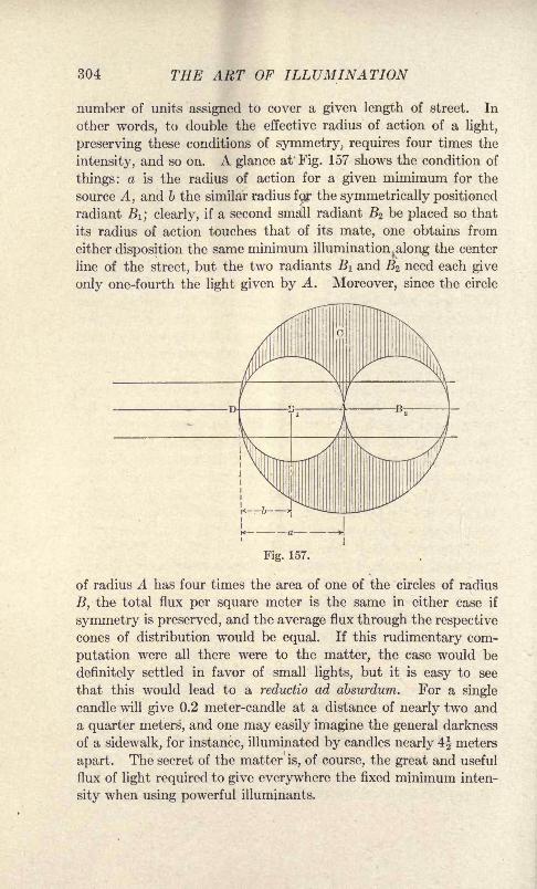
304 THE ART OF ILLUMINATION
number of units assigned to cover a given length of street. In
other words, to double the effective radius of action of a light,
preserving these conditions of symmetry, requires four times the
intensity, and so on. A glance at' Fig. 157 shows the condition of
things: a is the radius of action for a given mimimum for the
source A, and 6 the similar radius for the symmetrically positioned
radiant BI\ clearly, if a second small radiant B2 be placed so that
its radius of action touches that of its mate, one obtains from
either disposition the same minimum illumination^along the center
line of the street, but the two radiants BI and B2 need each give
only one-fourth the light given by A. Moreover, since the circle
Fig. 157.
of radius A has four times the area of one of the circles of radius
B, the total flux per square meter is the same in either case if
symmetry is preserved, and the average flux through the respective
cones of distribution would be equal. If this rudimentary com-
putation were all there were to the matter, the case would be
definitely settled in favor of small lights, but it is easy to see
that this would lead to a reductio ad absurdum. For a single
candle will give 0.2 meter-candle at a distance of nearly two and
a quarter meters, and one may easily imagine the general darkness
of a sidewalk, for instance, illuminated by candles nearly 4J meters
apart. The secret of the matter is, of course, the great and useful
flux of light required to give everywhere the fixed minimum inten-
sity when using powerful illuminants.
EXTERIOR ILLUMINATION 305
In Fig. 157 if the light A, with its effective radius a, illuminates
the circle of which it is the center, then the lights B v and B2 equally
illuminate their respective circles, but there is an equal shaded
area C shown outside them which they do not light, and which is
effectively lighted by the radiant A. Now, this large area is, from
the standpoint of street lighting, not useless. If the houses stand
well back from the street, it effectively affords them police protec-
tion; if they face close upon the street, some of the extra light is
reflected from their surfaces and again becomes useful either as
lighting directly the street or as furnishing a bright background
against which dark objects may readily be seen. In other words
while the minimum requirement, and even the average require-
ment, can be met by a much smaller total flux with small units
than with large ones, the latter do in fact add greatly to the effec-
tiveness of lighting for the purposes of its use.
Still further, if we replace one large light by n small lights under
the assumed conditions, we not only get but one n th the total flux
for the same minimum, but we have to install and maintain n lights
instead of one; and, since the investment and maintenance charges
make up a large proportion of the total cost of any street illumi-
nant, it often turns out that in an attempt to gain illuminating
efficiency by decreasing the spacing and using small lamps there is
no reduction in total cost commensurate with the loss of light flux.
It is on this practical condition that the choice between large and
small units usually depends. Also, if a certain minimum illumi-
nation be set, and a source of large power be replaced by smaller
sources, these cannot be placed as B1} B2 ,B s ,
#4 , Fig. 158, with their
circles of limit illumination merely tangent, for that. leaves muchof the street below the allowed minimum. They would have to be
placed overlapping, like Bb ,B6 ,
B 7 ,B8 ,
or else the power of each
smaller radiant must be considerably increased. Without goinginto the analysis of the requirement of overlapping enough to cover
the street at the required minimum, it is apparent that the economyin flux secured by using small sources is much smaller than at first
seems plausible, and the gain in cost smaller still. In point of
fact, small sources are advantageous chiefly in., second-class and
third-class lighting. For first-class lighting they will rarely be
found economical.
In thickly built-up and important streets the enormous light
flux from powerful light sources is so useful for the general pur-

306 THE ART OF ILLUMINATION
poses of illumination that it pays to utilize it. Particularly is this
the case since it is true both in gas and electric lighting that the
large units are of very much higher efficiency than the small ones.
On the other hand, in streets requiring only moderate illumination,
and particularly in streets low-hung with shadowing trees, the small
light, which for efficient use must be hung rather low, as we have
seen, is greatly to be preferred. In streets of the third class, where
the conditions are such that there are no lateral reflecting surfaces
to be utilized, the small unit is imperative. In everyday practice,
especially with electric illuminants, the distribution curves of the
small incandescent units and the much larger arc units, even when
Fig. 158.
both are modified with the best available reflectors, vary very
materially, so that in practice it is desirable to draw curves like
Ln (Fig. 149), giving illumination as a function of distance according
to the lamp, and thus make graphic comparison of the relative
results to be obtained in service. When installed in diffusing globes
both arc and incandescent lamps, and gas lamps as well, tend to
a rounded type of distribution, which makes reflectors necessary to
secure maximum efficiency. As a rule, all illuminants in American
practice are mounted lower than they ought to be for efficiency.
Powerful arcs or equivalent gas lamps should generally be mounted
at least 25 or 30 feet above the pavement, and in case of the very
large units even considerably more, up to 50 or 60 feet. Lamps of
the type of the larger incandescent electric units and the corre-
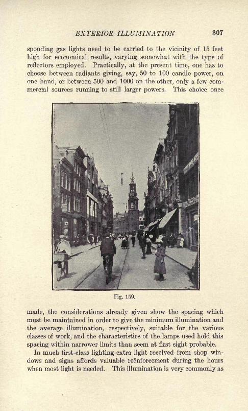
EXTERIOR ILLUMINATION 307
spending gas lights need to be carried to the vicinity of 15 feet
high for economical results, varying somewhat with the type of
reflectors employed. Practically, at the present time, one has to
choose between radiants giving, say, 50 to 100 candle power, on
one hand, or between 500 and 1000 on the other, only a few com-
mercial sources running to still larger powers. This choice once
Fig. 159.
made, the considerations already given show the spacing which
must be maintained in order to give the minimum illumination and
the average illumination, respectively, suitable for the various
classes of work, and the characteristics of the lamps used hold this
spacing within narrower limits than seem at first sight probable.
In much first-class lighting extra light received from shop win-
dows and signs affords valuable reinforcement during the hours
when most light is needed. This illumination is very commonly as

308 THE ART OF ILLUMINATION
great as that from the street lamps, and sometimes several times
greater. It is useful, but one cannot safely count much upon it,
since it is largely influenced by habit.
In placing lamps, large or small, it is imperative that they should
be so located that their useful light flux can be utilized. This con-
dition is often violated by placing la^nps where their light is very
largely cut off by trees. By far the best method of placing street
lamps from the standpoint of illumination is the cross-suspension.
The best form of this, very general in Continentalcities, is, in closely
Fig. 160.
built streets, the cross-suspension from buildings, well shown in
Fig. 159. In this country there is seldom proper provision for this,
so that one is driven to the clumsier suspension between poles. Astreet adequately lighted by lamps upon cross-suspensions mayoften fail of it when side poles are used. Nevertheless, owing to
our local conditions, it is more general to use side poles. These
are too often ugly in design and hence offensive by daylight.
There is no excuse for this, save petty economy, since poles of
graceful design are readily obtainable. A capital example of Con-
tinental practice in side poles is shown in Fig. 160, a light design
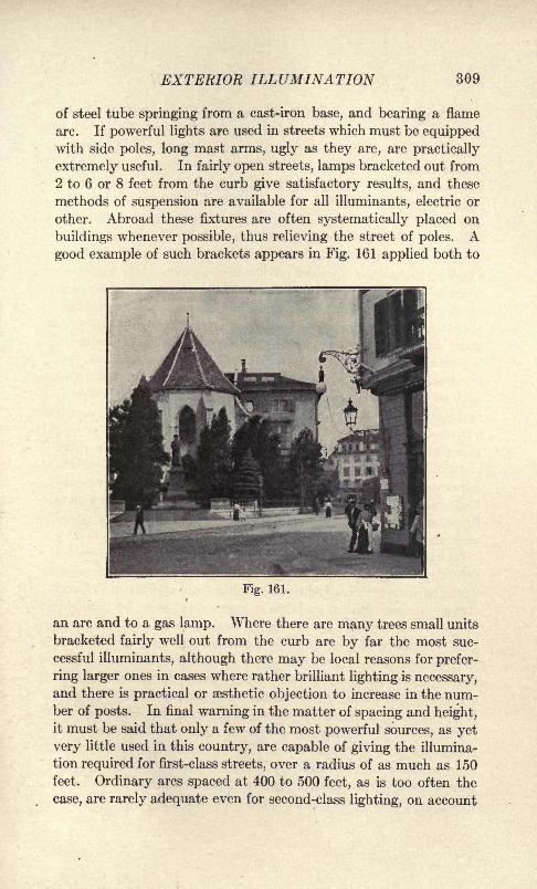
EXTERIOR ILLUMINATION 309
of steel tube springing from a cast-iron base, and bearing a flame
arc. If powerful lights are used in streets which must be equippedwith side poles, long mast arms, ugly as they are, are practically
extremely useful. In fairly open streets, lamps bracketed out from
2 to 6 or 8 feet from the curb give satisfactory results, and these
methods of suspension are available for all illuminants, electric or
other. Abroad these fixtures are often systematically placed on
buildings whenever possible, thus relieving the street of poles. Agood example of such brackets appears in Fig. 161 applied both to
Fig. 161.
an arc and to a gas lamp. Where there are many trees small units
bracketed fairly well out from the curb are by far the most suc-
cessful illuminants, although there may be local reasons for prefer-
ring larger ones in cases where rather brilliant lighting is necessary,and there is practical or aesthetic objection to increase in the num-ber of posts. In final warning in the matter of spacing and height,
it must be said that only a few of the most powerful sources, as yet
very little used in this country, are capable of giving the illumina-
tion required for first-class streets, over a radius of as much as 150
feet. Ordinary arcs spaced at 400 to 500 feet, as is too often the
case, are rarely adequate even for second-class lighting, on account

310 THE ART OF ILLUMINATION
of the long and very faintly lighted spaces which must exist. Onlythe most powerful radiants may be thus spaced.
The proper placing and screening of lights to avoid glare is
another important matter. Glare is due to a number of causes,
but practically it is chargeable to the use of sources of too great
intrinsic brilliancy, or too great absolute intensity at short dis-
tances. A powerful light, even at moderate intrinsic brilliancy,
when viewed at short range floods the eye with light to an extent
that interferes seriously with vision. It also cuts dowji the pupillary
aperture to half or one-third of its normal value, which greatly
diminishes the visibility of the less brilliantly illuminated part
of the field, and, more than anything else, it spoils the dark-
adaptation which makes enormously greater difference than any-
thing due to pupillary reaction. At considerable distances there
is very little trouble due to intrinsic brilliancy. As, however, one
is constantly coming into close range with street lights, protection
against too high brilliancy is imperative in case of powerful
radiants, either gas or electric. The smaller lights, sending muchless luminous energy to the eye, produce less disturbance by their
glare, and diffusion, while desirable, is less necessary, save whenone falls to third-class lighting, in which dark-adaptation is all-
important. No trouble would be experienced with any ordinary
illuminants if screened behind mildly diffusing globes. Unless
lights are so screened the minimum illumination must be raised
very materially for the same ease of seeing.
Owing to the comparatively weak illumination in most street
lighting, methods of measuring it are somewhat troublesome.
There is always difficulty in photometry with very weak light on
the photometer screen, and this is aggravated in street work by
frequent unsteadiness of the lights, and in some cases by their
great difference in color from the lights used as comparison stand-
ards in field work. Comparisons of illumination near and below
the minimum specified for second-class lighting are peculiarly falla-
cious, owing to the disturbing effect of varying adaptation. Indeed,
it is not putting it too strongly to say that comparisons of such kind,
say at 0.2 or 0.3 meter-candle and below, are unreliable, even whenmade with the best available field photometers. Consistent results
may sometimes be obtained by a single observer, or by two ob-
servers so used to working together that their results are in no
wise independent, but consistency is no proof of reliability.
EXTERIOR ILLUMINATION 311
Acuity photometers sometimes used for such cases are even
worse, and their results are not worthy of serious consideration
as expressions of anything more than individual opinion. These
instruments violate a fundamental rule of physical measurements,in that the quantity sought varies enormously with the one actually
used for measurement. By all means the most reliable method of
determining illumination is computing it from the known distri-
bution curves of the radiants, taken not with carefully cleaned
and adjusted lamps under laboratory conditions, but with lampsin their ordinary service condition run from the commercial wires
or gas mains, even though tested in the laboratory. The effect
of dirt on the inclosing globes is so serious that it must be taken
into account in this way.For similar reasons the intercomparison in the field of different
street illuminants is very unsatisfactory. One can tell photomet-
rically pretty nearly what a light is doing, and can judge in a general
way of the effectiveness of that particular lamp. He cannot form,
however, a correct judgment of the relative performance of two
lamps of different kinds unless they are conspicuously different
from each other, since he does not know ordinarily whether each
of the lights is burning under its normal conditions, whether one
of them is ill adjusted, and with a globe considerably dirtier than
the average, or whether the other has been carefully adjusted to
give more than its normal duty, and is as clean as care can makeit. Of course, anyone can tell a clean globe from a dirty globe,
but he can do nothing more than guess how much difference to
ascribe to this cause.
One meets a good many cases of skillful jockeying with lamps,
and even with the photometry of lamps, and while field com-
parisons may be interesting as experiments, they do not form a
suitable basis on which to found lighting contracts which mayinvolve hundreds of thousands of dollars during their terms. And
particularly is this stricture directed at reading tests so called, at
low intensity, which are largely matters of adaptation and adroit
manipulation of the conditions. It is well within bounds to saythat they are generally open to suspicion, whether directed by the
contractor for illumination or by critics inclined to be captious.
They are sometimes called"practical/' but experience teaches one
to define a"practical
"test as a test cunningly devised to divert
attention from the objectionable points of the thing tested. Their
312 THE ART OF ILLUMINATION
proper sphere is merely to furnish one item of information, and
not a very important one, about what the lights are doing. Two
lights, both in good condition and adjusted and operated by im-
partial observers, can be photometrically compared in the field
with a reasonable degree of precision, but never any more satis-
factorily than they can ''be compared under properly arranged
laboratory conditions.
To summarize briefly the characteristics of modern illuminants
for street service, one may divide them into five generally familiar
types: 1, flame or luminous arcs; 2, carbon arcs; 3, tungsten incan-
descent lamps; 4, high-pressure mantle gas lamps; 5, low-pressure
mantle gas lamps. As class 4 is little used in this country, one
need say no more here than that the high-pressure gas lamps are
powerful illuminants comparable in intensity to the flame arcs,
that is, running from, say, 1000 to 3000 candle power, and of
sufficiently good color and steadiness to meet all street require-
ments. The low-pressure mantle gas lamps are usually of 100
candle power or less, like tungsten incandescent lamps, and when
properly maintained bear the same relation to the high-pressure
lamps that the incandescent lamps do to the arcs. Considered
merely as radiants for the street, they have no peculiarities of color
or distribution which separate them from other radiants.
To summarize the arc situation already treated in Chapter VIII,
the flaming or luminous arcs are of three general classes: 1, arcs
burning carbons of which one or both are mineralized, commonlywith calcium fluoride for yellow light or with other substances for
a whiter light, with converging carbons pointed in an acute angle
downward; 2, vertical carbon flame arcs, commonly known as the
system Blondel lamps, burning similar carbons heavily mineralized
and in vertical position; 3, lamps burning electrodes, at least one
of which is charged with metallic oxides, most commonly oxides
of iron and titanium in various proportions. Such are the mag-netite arcs in common use. In this case the positive electrode is
of copper and the active mineralized one is an iron tube packedwith the oxides. All these lamps may run to high powers, from
1000 to 2000 or 3000 candle power, in the effective zones of
the lower hemisphere, aftd with mean lower hemispherical candle
power ranging up to 2000 or more. The converging carbon lampsfrom the position of the electrodes tend to throw the light down-
ward, to an extent that is not readily corrected by reflectors.
EXTERIOR ILLUMINATION 313
They should hence be placed specially high with respect to the
spacing. They are reasonably steady and have proved very sat-
isfactory illuminants. The vertical carbon flame arcs give a dis-
tribution which lends itself rather more readily to the successful
use of reflectors, and the maximum light falls, with properly de-
signed reflectors, within the useful zones from 15 to 30 degrees
below the horizontal. They are, on the whole, more efficient for
street service than the converging carbon lamps, and they are
made even up to 3000 candle power and more. The lampdescribed with reference to the lighting of Copley Square is
one of this class, and gives an intensity of about 2500 candle
power, including the opal globe, in average condition, at the angle
of about 15 degrees below the horizontal. This advantageous
distribution is due largely to a well-placed reflector. The specific
consumption of the large flame arcs of both varieties is some-
where in the region of about one-quarter to one-third watt per
candle. The metallic oxide lamps have for their chief advantage
a rather long-burning electrode, giving, within a reasonable length
of pencil of 8 or 10 inches a life of 50 to 150 hours. The products
of combustion, being brownish oxides, tend to smut the globes,
and have to be gotten rid of by special draft channels which carry
the fumes away. The commonest of this type is the so-called
magnetite lamp, which has proved extremely successful as an illu-
minant in practice. Its specific consumption, when put in a light-
opal globe, ranges in the region between one-half watt and 1 watt
per candle, according to current, as in other arc lights. It fur-
nishes a suitably steady light in the vicinity of 1000 hemispherical
candle power in the moderate sizes, and nearly as much again as
an extreme figure. The color is good and the steadiness adequate,
and the lamp has been rapidly driving out the older forms of arc,
being preferred to other flaming arcs in this country on . account
of the long life of the electrodes. The magnetite lamp is operated
at from 4 to 6 or 7 or even 10 amperes, the latter rarely, and the
voltage at the arc is about 80. These characteristics make it very
convenient for use on series circuits.
Ordinary carbon arcs are becoming obsolete for street service.
They run in sizes from 600 or 800 mean hemispherical candle
power to as low as 200 or 250. The former figure belongs to
the few powerful open arcs that are in existence, the latter to
some of the alternating-current inclosed arcs. The specific con-
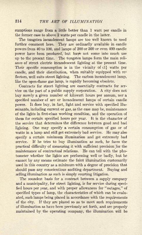
314 THE ART OF ILLUMINATION
sumptions range from a little better than 1 watt per candle in
the former case to above 2 watts per candle in the latter.
The tungsten incandescent lamps are too well known to need
further comment here. They are ordinarily available in candle
powers from 40 to 100, and lamps of 200 or 300 or even 400 candle
power have been produced, but haye not come into much use
up to the present time. The tungsten lamps form the main reli-
ance of street electric incandescent lighting at the present time.
Their specific consumption is in the vicinity of U| watts per
candle, and their distribution, when suitably equipped with re-
flectors, well suits street lighting. The carbon incandescent lamp,
like the open-flame gas lamp, is rapidly becoming obsolete.
Contracts for street lighting are essentially contracts for ser-
vice on the part of a public supply corporation. A city does not
buy merely a given number of kilowatt hours per annum, nor a
specified number of arc or incandescent lamps of certain candle
power. It does buy, in fact, light and service with specified illu-
minants, including current or gas, as the case may be, maintenance
of the lights in first-class working condition, and the operation of
them for certain specified hours per year. It is the character of
the service that determines the difference between good and bad
lighting. One may specify a certain consumption of gas or of
watts in a lamp and still get extremely bad service. He may also
specify a certain minimum illumination and get extremely bad
service. If he tries to buy illumination as such, he faces the
practical difficulty of measuring it with sufficient precision [for the
maintenance of contractual relations. He can tell with the pho-tometer whether the lights are performing well or badly, but he
cannot by any means estimate the faint illumination customarily
used in this country as a minimum with a degree of precision that
should pass any conscientious auditing department. Buying and
selling illumination as such is simply courting litigation.
The soundest basis for a contract between a supply companyand a municipality, for street lighting, is for service during speci-
fied hours per year, and with proper allowances for"outages," of
specified types of lamp, the characteristics of which can be evalu-
ated, such lamps being placed in accordance with the requirementsof the city. If they are placed so as to meet such requirements
of illumination as have been previously set forth, and are properly
maintained by the operating company, the illumination will be
EXTERIOR ILLUMINATION 315
found adequate, and its value can be on the average reckoned
from the known characteristics of the lamps with far greater pre-
cision than it can be measured on the ground. The location of
the lamps should be done under the direction of the municipality
so as to produce the illumination required, but if any definition of
the illumination is specified, both the minimum and the averageshould be included. Lighting on the basis of a contractual mini-
mum only is certain to result in bad lighting. Judging by average
illumination alone is merely an incentive to unequal distribution,
but when the illuminants themselves and the terms of their outputand operation are properly specified the illumination will take care
of itself.
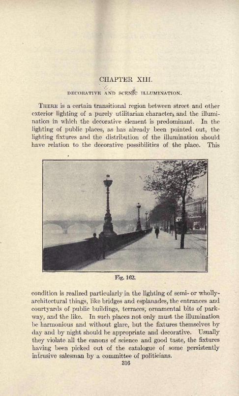
CHAPTER XIII.
DECORATIVE AND SCENIC ILLUMINATION.
THERE is a certain transitional region between street and other
exterior lighting of a purely utilitarian character^, and the illumi-
nation in which the decorative element is predominant. In the
lighting of public places, as has already been pointed out, the
lighting fixtures and the distribution of the illumination should
have relation to the decorative possibilities of the place. This
Fig. 162.
condition is realized particularly in the lighting of semi- or wholly-
architectural things, like bridges and esplanades, the entrances and
courtyards of public buildings, terraces, ornamental bits of park-
way, and the like. In such places not only must the illumination
be harmonious and without glare, but the fixtures themselves by
day and by night should be appropriate and decorative. Usually
they violate all the canons of science and good taste, the fixtures
having been picked out of the catalogue of some persistently
intrusive salesman by a committee of politicians.
316
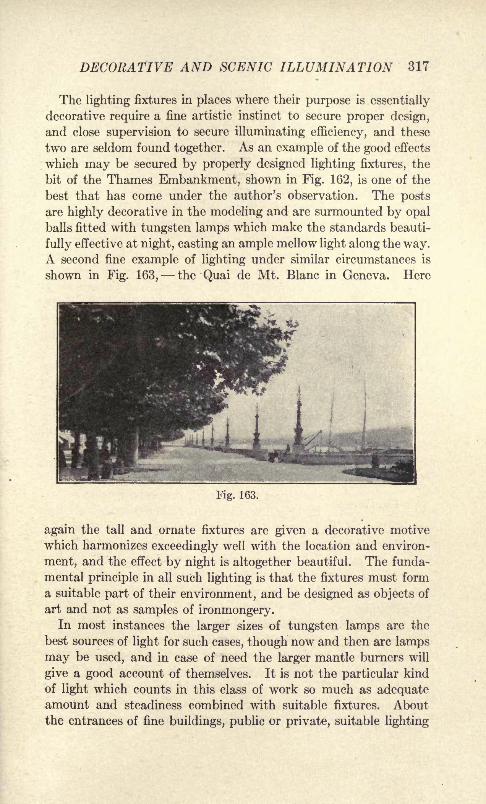
DECORATIVE AND SCENIC ILLUMINATION 317
The lighting fixtures in places where their purpose is essentially
decorative require a fine artistic instinct to secure proper design,
and close supervision to secure illuminating efficiency, and these
two are seldom found together. As an example of the good effects
which may be secured by properly designed lighting fixtures, the
bit of the Thames Embankment, shown in Fig. 162, is one of the
best that has come under the author's observation. The posts
are highly decorative in the modeling and are surmounted by opal
balls fitted with tungsten lamps which make the standards beauti-
fully effective at night, casting an ample mellow light along the way.A second fine example of lighting under similar circumstances is
shown in Fig. 163, the Quai de Mt. Blanc in Geneva. Here
Fig. 163.
again the tall and ornate fixtures are given a decorative motive
which harmonizes exceedingly well with the location and environ-
ment, and the effect by night is altogether beautiful. The funda-
mental principle in all such lighting is that the fixtures must form
a suitable part of their environment, and be designed as objects of
art and not as samples of ironmongery.In most instances the larger sizes of tungsten lamps are the
best sources of light for such cases, though now and then arc lamps
may be used, and in case of need the larger mantle burners will
give a good account of themselves. It is not the particular kind
of light which counts in this class of work so much as adequateamount and steadiness combined with suitable fixtures. About
the entrances of fine buildings, public or private, suitable lighting
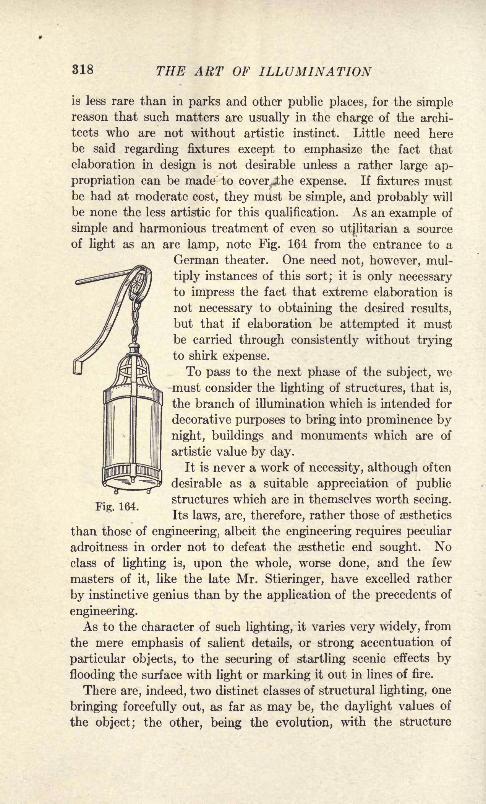
318 THE ART OF ILLUMINATION
is less rare than in parks and other public places, for the simplereason that such matters are usually in the charge of the archi-
tects who are not without artistic instinct. Little need here
be said regarding fixtures except to emphasize the fact that
elaboration in design is not desirable unless a rather large ap-
propriation can be made to cover^the expense. If fixtures mustbe had at moderate cost, they must be simple, and probably will
be none the less artistic for this qualification. As an example of
simple and harmonious treatment of even so utilitarian a source
of light as an arc lamp, note Fig. 164 from the entrance to a
German theater. One need not, however, mul-
tiply instances of this sort; it is only necessaryto impress the fact that extreme elaboration is
not necessary to obtaining the desired results,
but that if elaboration be attempted it mustbe carried through consistently without trying
to shirk expense.
To pass to the next phase of the subject, wemust consider the lighting of structures, that is,
the branch of illumination which is intended for
decorative purposes to bring into prominence bynight, buildings and monuments which are of
artistic value by day.
It is never a work of necessity, although often
desirable as a suitable appreciation of public
structures which are in themselves worth seeing.
Its laws, are, therefore, rather those of aesthetics
than those of engineering, albeit the engineering requires peculiar
adroitness in order not to defeat the aesthetic end sought. Noclass of lighting is, upon the whole, worse done, and the few
masters of it, like the late Mr. Stieringer, have excelled rather
by instinctive genius than by the application of the precedents of
engineering.
As to the character of such lighting, it varies very widely, from
the mere emphasis of salient details, or strong accentuation of
particular objects, to the securing of startling scenic effects by
flooding the surface with light or marking it out in lines of fire.
There are, indeed, two distinct classes of structural lighting, one
bringing forcefully out, as far as may be, the daylight values of
the object; the other, being the evolution, with the structure
Fig. 164.
DECORATIVE AND SCENIC ILLUMINATION 319
as a basis, of artistic results in no wise akin to the effects of
daylight. An example of the former case is the lighting of a
monument, or of the fagade of a building, so as to secure the full
artistic value of the structure. Into the latter class falls naturally
the display lighting of expositions and of special buildings and
grounds, en fete.
The methods of illuminating structures are as various as the
purposes for which the illumination is used. They may include
merely the skillful application of ordinary illuminants, the enforce-
ment of their effect by reflectors and searchlights, and the employ-ment of small lights in an infinite variety of ways. The former
methods find their largest application in lighting monuments and
fagades; the latter, in the production of scenic effects, in which
the more powerful illuminants also may be made to play a most
useful part.
Broadly, one may divide the classes of effects sought in lighting
structures into those which have to do with the lighting of surfaces
as a whole, those in which particular portions of surfaces are sought
to be emphasized, and those which are essentially scenic and
decorative in their effects and bring into prominence not surfaces
but outlines. Each kind has its legitimate field, but its applica-
bility depends in each case on quite different criteria. In general,
the first two classes belong essentially to structures beautiful in
themselves, while the last named, if skillfully carried out, which
it generally is not, may lend distinction to things comparatively
commonplace.The superficial lighting of structures, as of the whole fagade of a
great building, is both difficult to do well and somewhat expensive.
Particularly does its apparent expense run high, inasmuch as it
is a case of deliberately pouring a flood of light on an exterior,
generally from a source quite outside the building. The sources
of light have a certain detached character that brings their cost
sharply into view, while the same expense applied to even ineffi-
cient and inartistic grouping of small lights about the structure
itself would fail to produce the same psychological effect on the
auditing department.In order to be effective, surface lighting must be both somewhat
brilliant and very carefully directed. The greatest difficulty in
getting a satisfactory result is that due to obtaining the proper
direction of illumination. The fagade of a building ordinarily is
320 THE ART OF ILLUMINATION
lighted obliquely from above, without sharp shadows, save whenthe building is in brilliant sunshine. The strength of the illumina-
tion falling on a building by daylight may easily run to manyhundred or even thousand meter-candles. It is enough, at all
events, to bring out a wealth of fine detail even in a very dark
building.
The coefficient of reflection of a building surface is usually rather
small, say from 10 to 25 per cent, at ordinary angles of view, rising
notably higher than this, say to between 30 and4(j) per cent, only
in case of buildings of very light and clean brick or stone, or of
very lightly tinted concrete. In most cities the accumulation
of dirt due to smoke keeps the reflecting power low. Hence it
takes strong lighting, such as is to be had by daylight, to bring the
architectural details of a building out at anything like their full
value, if they are of any delicacy. In the artificial lighting of a
fagade, the direction of the illumination is necessarily rather from
below than from above, and unless the illumination is deliberately
planned to provide a dominant direction of lighting the effect is
usually to flatten out the projections and sink the detail into
insignificance. Light coming indiscriminately from all azimuths
along the front is likely to give a disagreeable shadowless effect,
and the delicacy of the surface of the structure is quite lost. Theillumination should, therefore, be given a predominant direction
so as not to lose the effect of light and shade, and, -in fact, some-
what to exaggerate it in order to bring out something of the
texture in a light dim compared with daylight.
If we could bring ourselves to a really progressive frame of
mind, searchlights and reflectors used from points well outside
the building to be illuminated could be made to produce muchbetter results than are obtained by any other means, and there
is much to be said for so lighting a fagade that it showrs its archi-
tectural value as it is, and not with the addition of freakish lighting
effects generally undignified and sometimes ludicrous.
A fagade with striking features, large arid dignified, is compara-
tively easy to illuminate, while one with a wealth of fine detail
requires so much light that the feat of dealing with it adequatelyis almost impossible.
Searchlights and reflectors- form the best means of getting ade-
quate surface lighting where large areas are concerned. A slight
digression regarding the searchlight for this and similar purposes

DECORATIVE AND SCENIC ILLUMINATION 321
may be here permissible, since the properties of the searchlight
as an illuminant are generally imperfectly understood. From the
standpoint of luminous flux, the case of the searchlight is a com-
paratively easy one. From the energy consumed in the arc andthe structure of the lamp, it is not difficult to form an approximateidea of the lumens which emerge from the system. Then the illu-
mination received on any surface is this total flux divided by the
area of the surface in square feet, if one wishes to express it in
foot-candles, or in square meters if he chooses, as is preferable, the
meter-candle as the unit.
The illumination delivered by a searchlight system is
4 ireirj 4 eirjL =r*
where e is the voltage at the arc, i the current, andr/ is the specific
efficiency in mean spherical candle power per watt X the net reflec-
tive coefficient of the mirror system, r being the radius of the inci-
dent beam.
Assuming
77= 1
e=80v. T4 X 80 X 50 X 1 lrn ,1N
. CA L = - = 160 meter-candles. (1)i = 50 amps. 100
r = 10
Or at the just assumed voltage and radius, 100 meter-candles would
requireLr2 100 X 100
Or to obtain 17,
If L = 100
e = 80 Lr2 100 X 100 n 7ft f^r =10 77= 4^
=4X80X40
=
i =40
rj expresses the specific efficiency of the searchlight system as a
whole, and should be the subject of systematic experiments.
This rule holds for cases in which the cosine of the semiangular
aperture of the beam is near unity, i.e., when the measured illu-
mination is substantially normal; (1) and (2) are subject to a simi-
lar limitation. As to the absorption by the atmosphere, it is in
clear weather small, amounting, from Sir William Abney's data,
322 THE ART OF ILLUMINATION
to about 15 per cent for the chief luminous rays in transmission
through the whole thickness of the atmosphere.The flux measured in lumens remains the same, barring absorp-
tion by the atmosphere, at all distances from the light, and the
intensity at the surface illuminated becomes merely a matter of
the area of the beam.
Without the use of lights comparatively distant from the surface
to be illuminated, surface lighting becomes increasingly difficult.
It can be carried out to a certain extent with lights on the struc-
ture itself, but the effect is not good if more than special portions
of the surface are so illuminated. It is an extremely difficult matter
to light a surface adequately from a point near itself without
either making the light sources too conspicuous or rendering the
illumination very uneven. Moreover, lighting at nearly grazing
incidence distorts all surface details and destroys their delicacy.
It may even produce extremely bizarre and unpleasant effects.
Striking examples of the failure of illumination at grazing incidence
may be found in the case of attempts to light paintings from reflec-
tors placed near the plane of the canvas, the effect of which is to
bring into glaring prominence every brush mark, quite destroying
the effect the artist intended to produce.
Only in rare instances can the lighting of a building by sources
placed upon it prove effective, and then only when comparativelylimited areas are sought to be illuminated, or when the effect
intended to be produced is not that of daylight illumination but
that of a special form of decoration. A striking success in this line
was the lighting of the Metropolitan Life tower in New York during
the Hudson-Fulton celebration, in which advantage was taken of
the structure of the higher parts of the tower so to place the lights
upon it as to bring the massive detail high in air into brilliant
prominence against the sky. Fig. 165 gives a rather inadequate
view of the conspicuously good result.
Spot lighting is, except in such instances as that just mentioned,
generally confined to the illumination of monuments or groups of
statuary. It too frequently would be better to leave these to the
kindly concealment of night, but now and then they are worth
the effort at illumination. As a rule, attempts to light such things
fail from placing the lights too near, and thereby producing dis-
torted shadows which quite destroy the artistic value sought. Only
massive, plain surfaces, such as the Washington Monument in
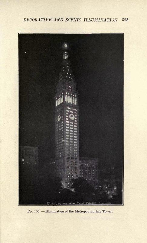
DECORATIVE AND SCENIC ILLUMINATION 323
Fig. 165. Illumination of the Metropolitan Life Tower.
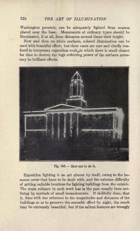
324 THE ART OF ILLUMINATION
Washington presents, can be adequately lighted from sources
placed near the base. Monuments of ordinary types should be
illuminated, if at all, from distances several times their height.
Now and then on white surfaces, colored illumination can be
used with beautiful effect; but these cases are rare and chiefly con-
fined to temporary exposition work-in which there is small chance
for time to destroy the high reflecting power of the surfaces neces-
sary to brilliant effects.
Fig. 166. How not to do it.
Exposition lighting is an art almost by itself, owing to the im-
mense areas that have to be dealt with, and the extreme difficulty
of getting suitable locations for lighting buildings from the outside.
The main reliance in such work has in the past usually been out-
lining by myriads of small incandescents. If skillfully done, that
is, done with due reference to the magnitudes and distances of the
buildings so as to preserve the ensemble effect by night, the result
may be extremely beautiful;but if the salient features are wrongly
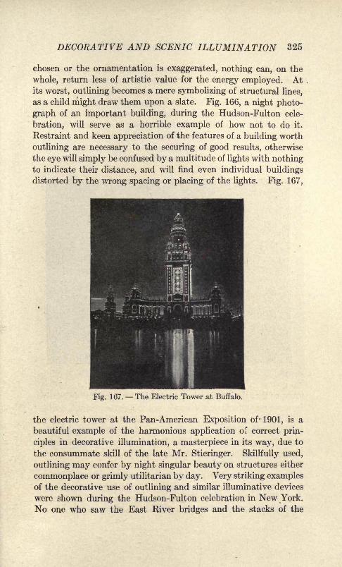
DECORATIVE AND SCENIC ILLUMINATION 325
chosen or the ornamentation is exaggerated, nothing can, on the
whole, return less of artistic value for the energy employed. Atits worst, outlining becomes a mere symbolizing of structural lines,
as a child might draw them upon a slate. Fig. 166, a night photo-
graph of an important building, during the Hudson-Fulton cele-
bration, will serve as a horrible example of how not to do it.
Restraint and keen appreciation of the features of a building worth
outlining are necessary to the securing of good results, otherwise
the eye will simply be confused by a multitude of lights with nothingto indicate their distance, and will find even individual buildings
distorted by the wrong spacing or placing of the lights. Fig. 167,
Fig. 167. The Electric Tower at Buffalo.
the electric tower at the Pan-American Exposition of- 1901, is a
beautiful example of the harmonious application of correct priri-
ciples in decorative illumination, a masterpiece in its way, due to
the consummate skill of the late Mr. Stieringer. Skillfully used,
outlining may confer by night singular beauty on structures either
commonplace or grimly utilitarian by day. Very striking examplesof the decorative use of outlining and similar illuminative devices
were shown during the Hudson-Fulton celebration in New York.
No one who saw the East River bridges and the stacks of the
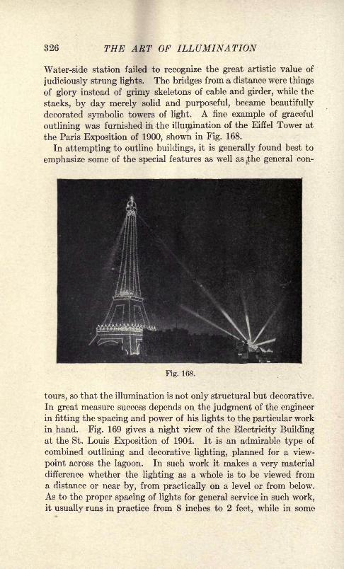
326 THE ART OF ILLUMINATION
Water-side station failed to recognize the great artistic value of
judiciously strung lights. The bridges from a distance were things
of glory instead of grimy skeletons of cable and girder, while the
stacks, by day merely solid and purposeful, became beautifully
decorated symbolic towers of light. A fine example of graceful
outlining was furnished in the illumination of the Eiffel Tower at
the Paris Exposition of 1900, shown in Fig. 168.
In attempting to outline buildings, it is generally found best to
emphasize some of the special features as well as ^the general con-
Fig. 168.
tours, so that the illumination is not only structural but decorative.
In great measure success depends on the judgment of the engineer
in fitting the -spacing and power of his lights to the particular workin hand. Fig. 169 gives a night view of the Electricity Building
at the St. Louis Exposition of 1904. It is an admirable type of
combined outlining and decorative lighting, planned for a view-
point across the lagoon. In such work it makes a very material
difference whether the lighting as a whole is to be viewed from
a distance or near by, from practically on a level or from below.
As to the proper spacing of lights for general service in such work,it usually runs in practice from 8 inches to 2 feet, while in some
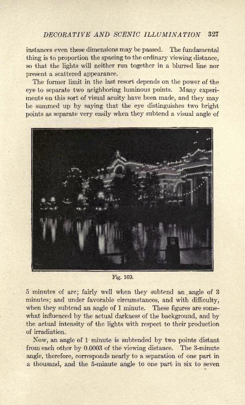
DECORATIVE AND SCENIC ILLUMINATION 327
instances even these dimensions may be passed. The fundamental
thing is to proportion the spacing to the ordinary viewing distance,
so that the lights will neither run together in a blurred line nor
present a scattered appearance.
The former limit in the last resort depends on the power of the
eye to separate two neighboring luminous points. Many experi-
ments on this sort of visual acuity have been made, and they maybe summed up by saying that the eye distinguishes two bright
points as separate very easily when they subtend a visual angle of
Fig. 169.
5 minutes of arc; fairly well when they subtend an, angle of 3
minutes; and under favorable circumstances, and with difficulty,
when they subtend an angle of 1 minute. These figures are some-
what influenced by the actual darkness of the background, and bythe actual intensity of the lights with respect to their productionof irradiation.
Now, an angle of 1 minute is subtended by two points distant
from each other by 0.0003 of the viewing distance. The 3-minute
angle, therefore, corresponds nearly to a separation of one part in
a thousand, and the 5-minute angle to one part in six to seven
328 THE ART OF ILLUMINATION
hundred. Around about this latter figure good results are obtain-
able, and the separation of lamps can often be carried up to 10
minutes of arc with advantage. Closer spacing than 3 minutes is
seldom desirable, since only in rare cases does one wish to produce
the effect of continuous lines. There is, therefore, a wide range in
spacing permissible with which to tal^e account of the important
questions relating to perspective. The frontispiece shows a remark-
ably distinguished and successful use of festooned lights in the
Court of Honor at the Hudson-Fulton celebration of 1909. Twoblocks along Fifth Avenue, from 42nd Street to 40th Street, were
included, and 36 massive pylons were erected along the avenue to
bear the central decorations of the occasion. The night effect was
very striking and beautiful, though the plate is marred by the
streaks due to the headlights of motor cars.
The effect of the spacing, intensity, and alignment of lights uponnocturnal perspective has played a very small part heretofore in
illumination, although it is well understood as a practical art bythe masters of stagecraft. Ordinarily, one wishes to preserve the
normal conditions of perspective in undertaking artificial illumi-
nation. This requirement implies a generally uniform spacing of
lights, since the eye instinctively judges the length of a line of bright
points by their apparent approximation as they reach the vanish-
ing point.
In the case of lines of light generally viewed obliquely, the spac-
ing may, however, be widened, since the visual angle between
points in such case corresponds to a narrower spacing than whenviewed normally. For example, lines of lights festooned lengthwise
of a street may be spread far more widely than usual, while still
preserving unity of effect, since they are, upon the whole, viewed
always from a very oblique angle. Lines of festoons thrown cross-
wise of the same street are always seen normally to their length,
and consequently should revert to standard spacing.
There are, however, many instances in which lights can be ad-
vantageously used, not to preserve the perspective, but to force it
and to create illusions of distance. If one were so placed as to look
down a long street, viewing it from a fixed point and not passing
along it, it would be possible to produce extraordinary illusions of
perspective by varying the spacing and the intensity of the lights.
In the absence of any permanent objects upon which the eye can
fall to determine distance, it is compelled to judge very largely by
DECORATIVE AND SCENIC ILLUMINATION 329
the apparent perspective. A row of lights down each side of the
street, diminishing in spacing or intensity, or both, would infallibly
call to the mind the conception of indefinite distance stretching out
into the night. If, on the other hand, the spacing were progres-
sively increased and the intensity also increased, each within limits,
the effect would be to produce an apparent shortening of the vista.
These effects may be very pronounced even where there is no
deliberate angular shifting of lines in the field of vision to produceillusions of perspective. Lines converged toward an artificial vanish-
ing point abnormally near are, of course, familiar in stagecraft, and
by adjusting the stage setting on a diminishing scale, with lines thus
converged, it is possible to create in great perfection the illusion of
a far-reaching space, even on a stage of very modest dimensions.
These effects, emphasized by powerful lighting in the near fore-
ground, diminishing toward the rear, are quite familiar, and are
often, in fact, overdone. When properly carried out they are
immensely striking in effect. The forcing of perspective in this
way and the taking advantage of the characteristics of vision to
create illusions of direction and distance have been known at least
since the time of the builders of the great monuments of Greece.
Not only did these masters swell their columns slightly to overcome
the illusion of outline presented to the eye at a relatively near view-
point, but they even drew the columns together and toward the
structure slightly at the top, as in the Parthenon, by an amountnot large enough to be conspicuous, yet sufficient to accentuate the
height. They knew well, too, how to proportion the scale of their
ornamentation to the viewpoint, and seemed by a fine instinct to
have discovered much that in practice has been too often forgotten
in the centuries that have intervened. Now, this same sort of
effect can be produced by judicious modification of the external
lighting of structures. For example, the author has had occasion
to overcome the tendency of a building, somewhat too tall for
symmetry, to vanish into indefinite height as night came on, by
powerfully emphasizing the decorative lighting of the cornice and
spacing a horizontal line of lights across the front, disproportion-
ately close compared with those above. The effect, as the lights
come on in a dark evening, and the towering top emerges out of dis-
tant blackness into its proper position, is somewhat striking. Bysuch devices as these one can not only overcome the curious dis-
tortions produced by night, but can, if necessary, create a wide
330 THE ART OF ILLUMINATION
variety of illusions on a large scale, less perfect, perhaps, but
almost as striking, as those worked out upon the stage.
The effect of the intensity of lights in such work is worth noting.
It is a curious fact that the eye carries so very imperfect con-
ceptions of intensity. For outlining work, signs and similar uses,
8-candle-power lamps are practically^as good as 16's, and 4's about
as effective as either. The author has actually changed 8-candle-
power lamps for 4's on one line of a sign, leaving the others
unchanged, without producing any noticeable difference whatever
when the sign was viewed from the ordinary distance of several
hundred yards. Any brilliant spot, however small, seems to serve
the purpose, and the size of the lamps used is really determined
rather by the ability to procure them than by anything else.
Recent progress in sign work has tended to smaller and smaller
lights with positive gain in the effect produced. In attempting,
therefore, to create illusions by changing the size of lights, the
change has to be an exaggerated one. The use of colored lights
in such cases as we have under consideration has been barely
touched upon in practice. It is made immensely effective in signs,
and has been used successfully in some exposition work for purely
decorative purposes, but color as an element in scenic illusion off
the stage has scarcely been tried. It possesses, nevertheless, pos-
sibilities which are worth much more intelligent study than has
yet been given them.
Colored light can be effectively used with reflector arcs, on white
surfaces, on cascades, in fountains, and the like, but is seldom
successful when tried with incandescent lamps, save on a verysmall scale. The difficulty lies in the dimness of colored bulbs and
the failure of attempts to get delicate tints in this way. Colored
glass bulbs are expensive, and coated bulbs accumulate dust and
are seldom weatherproof.
Much decorative lighting is for temporary purposes, but with
the present facilities for obtaining current and the temporary
mountings that can readily be obtained, the work is comparatively
easy.
Special receptacles for signs and decorative designs are nowmade in convenient form for quickly putting together, and enable
temporary work for special occasions to be very easily done.
Fig. 170 shows one useful form of mounting device, in which
the weatherproof receptacles can be quickly strung together with
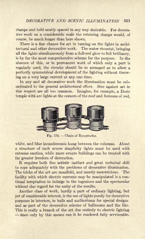
DECORATIVE AND SCENIC ILLUMINATION 331
clamps and held neatly spaced in any way desirable. For decora-
tive work on a considerable scale the retaining clamps would, of
course, be much longer than here shown.
There is a fine chance for art in turning on the lights in archi-
tectural and other decorative work. The water rheostat, bringingall the lights simultaneously from a dull-red glow to full brilliancy,
is by far the most comprehensive scheme for the purpose. In the
absence of this, or in permanent work of which only a part is
regularly used, the circuits should be so arranged as to allow a
perfectly symmetrical development of the lighting without throw-
ing on a very large current at any one time.
In any and all decorative work the illumination must be sub-
ordinated to the general architectural effect. Sins against art in
this respect are all too common. Imagine, for example, a Doric
temple with arc lights at the corners of the roof and festoons of red,
Fig. 170. Chain of Receptacles.
white, and blue incandescents hung between the columns. About
a structure of such severe simplicity lights must be used with
extreme caution, while more ornate buildings can be treated with
far greater freedom of decoration.
It requires both fine artistic instinct and great technical skill
to cope adequately with the problems of decorative illumination.
The tricks of the art are manifold, and mostly meretricious. The
facility with which electric currents may be manipulated is a con-
tinual temptation to indulge in the ingenious and the spectacular
without due regard for the unity of the results.
Another class of work, hardly a part of ordinary lighting, but
yet of considerable interest, is the use of lights purely for decorative
purposes in interiors, in halls and auditoriums for special designs
and as part of the decorative scheme of ballrooms and the like.
This is really a branch of the art due entirely to electric lighting
since only by this means can it be rendered fully serviceable.
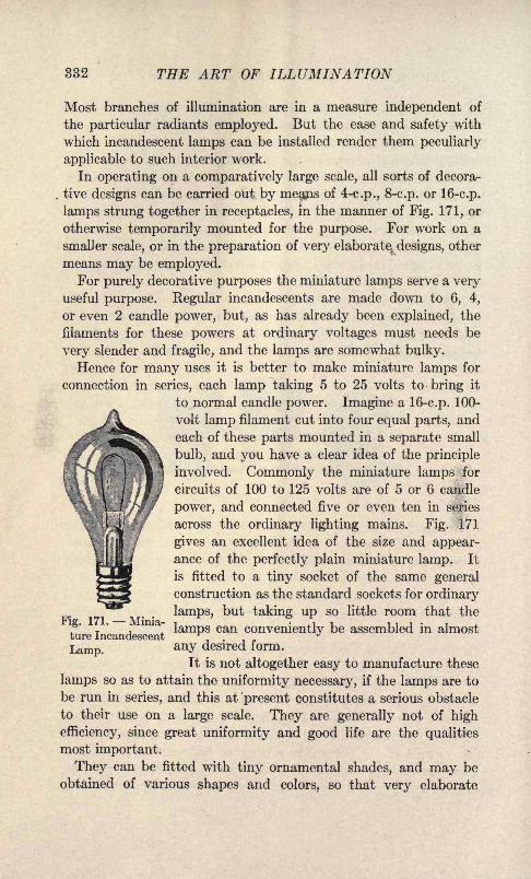
332 THE ART OF ILLUMINATION
Most branches of illumination are in a measure independent of
the particular radiants employed. But the ease and safety with
which incandescent lamps can be installed render them peculiarly
applicable to such interior work.
In operating on a comparatively large scale, all sorts of decora-
tive designs can be carried out by meajns of 4-c.p., 8-c.p. or 16-c.p.
lamps strung together in receptacles, in the manner of Fig. 171, or
otherwise temporarily mounted for the purpose. For work on a
smaller scale, or in the preparation of very elaborate designs, other
means may be employed.For purely decorative purposes the miniature lamps serve a very
useful purpose. Regular incandescents are made down to 6, 4,
or even 2 candle power, but, as has already been explained, the
filaments for these powers at ordinary voltages must needs be
very slender and fragile, and the lamps are somewhat bulky.
Hence for many uses it is better to make miniature lamps for
connection in series, each lamp taking 5 to 25 volts to- bring it
to normal candle power. Imagine a 16-c.p. 100-
volt lamp filament cut into four equal parts, and
each of these parts mounted in a separate small
bulb, and you have a clear idea of the principle
involved. Commonly the miniature lamps for
circuits of 100 to 125 volts are of 5 or 6 candle
power, and connected five or even ten in series
across the ordinary lighting mains. Fig. 171
gives an excellent idea of the size and appear-ance of the perfectly plain miniature lamp. It
is fitted to a tiny socket of the same general
construction as the standard sockets for ordinary
lamps, but taking up so little room that the
lamps can convenien% be assembled in almost
any desired form.
It is not altogether easy to manufacture these
lamps so as to attain the uniformity necessary, if the lamps are to
be run in series, and this at 'present constitutes a serious obstacle
to their use on a large scale. They are generally not of high
efficiency, since great uniformity and good life are the qualities
most important.
They can be fitted with tiny ornamental shades, and may be
obtained of various shapes and colors, so that very elaborate
Lamp.
DECORATIVE AND SCENIC ILLUMINATION 333
decorative designs can be built up of them. In indoor workcolored lamps may be freely used, anoj are capable of producingsome very beautiful effects, but the plain or ordinary frosted lampsare most generally used.
Owing to the small size of the sockets and fittings, the miniature
lamps can be packed so closely as to produce the effect of analmost uniform line of light at comparatively small distances,
so that most ornate schemes of ornamental illumination can be
carried out by their aid. They are also very useful in building
up small illuminated signs. At present many small tungsten lampswith small bulbs in standard sockets are in use. They take com-
monly 5 to 10 watts at 10 volts or so, and are supplied in multiplefrom special transformers if worked on alternating current, or in
series if worked on direct current.
Lamps of special sizes and shapes, from a tiny J-c.p. bulb, hardly
bigger than a large pea, to the candle-shaped lamp of 5 or 6 candle
power, are sometimes used with good effect in interior decoration.
When a regular electrical supply is not available, these little lampscan be obtained for very moderate voltages, say, from 5 to 10 volts,
and can be run in parallel from storage cells, or even from primary
batteries, for temporary use. All these miniature lamps can nowbe had with tantalum or with tungsten filaments which greatly
improve the situation, especially if one has to work from batteries.
Such small lamps are sometimes used in the table decorations
for banquets, and for kindred purposes. By their aid surprising
and beautiful effects are attainable, which would be quite impos-
sible with any flame illuminant. But they must be cautiously
used, for their very facility tends to encourage their employmentin effects more bizarre than artistic.
It is well, too, to add a word of caution as regards the possible
danger from fire. It is so easy to wire for incandescents that, par-
ticularly when using miniature lamps, there is a natural tendency
to rush the work at the expense of safety. Lamps in series on a
110-volt circuit are quite capable of dangerous results if anything
goes wrong, and even the battery lamps are not absolutely safe in
the presence of inflammable material.
It should, therefore, be an invariable rule not to install a tem-
porary decorative circuit without the same attention to detail that
would be exercised in a temporary circuit of the ordinary incan-
descents. The same precautions are not always necessary, but all
334 THE ART OF ILLUMINATION
the wiring should be carefully done, joints should be fully protected,
and, particularly, lamps should be kept out of contact with inflam-
mable material.
The incandescent lamp is often commended as producing little
heat, and, in fact, as compared with other illuminants, its heating
power is small. But a vessel of watejt can be boiled by plunging
an ordinary 16-c.p. lamp in it nearly up to the socket, and cloth
wrapped about such a lamp will infallibly be ignited within a com-
paratively short time. The fact that the cloth does^not
burst into
flame in a few minutes does not indicate safety, for time is an
important element in ignition, and even an overheated steam pipe
is capable of setting a fire, low as its temperature is. A good manyfires have been started in shop windows by hanging fabrics too
near to incandescent lamps, and even the miniature lamps are
quite capable of similar mischief if in contact with anything easily
inflamed. No illuminant has so high an efficiency that it produces
a negligible amount of heat from the standpoint of fire risk.
Special cable is now made to which lights can be attached with
great facility, and by this means temporary work may be quickly
and safely done.
In ordinary domestic illumination miniature lamps have verylittle place. Nothing is to be saved by using them so long as theymust be used in series at ordinary voltages. Now and then a 2-
or 4-c.p. lamp may be useful as a night lamp, but it is better to
use an ordinary lamp of moderate efficiency than to try miniature
lamps. Sometimes, however, a circuit of miniature lamps may be
installed for a dining room or a ballroom with excellent artistic
results. In such cases it is better to use frosted than plain lamps,
and, as a rule, colored lamps should be avoided, on account of
the difficulty of getting delicate tints to show effectively.
Temporary decorative circuits may, however, be very useful in
domestic illumination for fetes and the like, in which case delicately
colored ornamental shades can be applied or the lamps may be
used in Japanese lanterns. Any country house fitted for electric
lights can be temporarily wired for such purposes rather easily, and
out-of-door temporary wiring can be installed without the rigid
precautions necessary indoors.
In all decorative lighting it is important to recognize the fact
that illumination is a means to an artistic end, and not of itself the
primary object. One is, in these days of electric lighting, far more
DECORATIVE AND SCENIC ILLUMINATION 335
likely to err by providing too much light than by failing to supply
enough.Great brilliancy is far less important than good distribution and
freedom from glare. It is highly probable, for instance, that the
effect of the illumination of the Electric Tower at the Pan-Ameri-
can Exposition would have been seriously injured by the substitu-
tion of 32-c.p. lamps for the 8-c.p. actually used, and it is absolutely
certain that a dozen arc lights injudiciously placed would have
detracted greatly from the harmonious result.
In interior illumination the same rule holds true. By the reck-
less use of brilliant radiants one can key the vision up to a point
where its power of appreciating values in illumination is almost
entirely lost. In decorative lighting great care must be used not
to approach this point, but to leave the relief afforded by light
and shade, and to realize the perspective in the details of the
illumination.
The commonest cause of failure in proper illumination is thrust-
ing a brilliant light between the spectator and the object to be
viewed, with the inevitable result of losing detail and hurting the
eyes. Brilliant diffused light is in this particular only less objec-
tionable than direct light, and both should be assiduously avoided.
It must not be supposed that decorative lighting must necessarily
be electric, since very beautiful results were attained before electric
light was heard of, but electric lighting is unquestionably the most
facile means of securing artistic results on a large scale.
CHAPTER XIV.
THE ILLUMINATION OF THE FUTURE.
AT the present time the ordinary materials of illumination are
pretty well understood, and their proper use is a. matter of good
judgment and artistic sense. Illumination is not an exact science
with well-defined laws of what one might call illuminative engineer-
ing, but an art whereto an indefinable and incommunicable skill
pertains almost as it does in the magic of the painter.
There are certain general rules to be followed, certain utilitarian
ends which must be reached at all hazards, but whether the result
is brilliantly successful or hopelessly commonplace depends on the
skill that inspires it. There must be in effective illumination a
constant adaptation of means to ends, and a fine appreciation of
values that quite defies description. One may attack the problemof illuminating a great building with all the resources of electrical
engineering at his command, and score a garish failure, or he mayconceivably be confined to the meager bounds of lamps and candles,
and still triumph.The general tendency with the modern intense radiants at com-
mand is to light too brilliantly, to key the vision to so high a pitch
that it fails to appreciate the values of the chiaro-oscuro on which
the artistic result depends.The desideratum in illumination, except for a small group of
scenic effects, is the possession of cheap and fairly powerfulradiants of low intrinsic brilliancy, capable of modification in
delicate color tones. It is doubtful whether these qualities are
compatible with very high luminous efficiency in a flame or incan-
descent radiant. In modern gas and electric lighting the progress
toward efficiency is in the direction of very high temperature, which
implies high intrinsic brilliancy.
Vacuum tube lamps give hope of better things, but at great
risk of color difficulties, particularly if high efficiency is reached.
Ideally, a gaseous radiant, with nearly its whole luminous energy
concentrated in the visible spectrum, would give magnificent
efficiency, but it by no means follows that it would give a good336
THE ILLUMINATION OF THE FUTURE 337
light. Sodium vapor meets the requirements just noted tolerably
well, yet there is no more ghastly light than that given by a salted
spirit lamp.It might be possible to work with a mixture of gases such
as would give a light approximately white to the eye, and yet
be very far from a practicable illuminant; for the phenomena of
selective absorption are such, as we have already seen, that the
color of a delicately tinted fabric depends on its receiving a certain
scale of colors in the light which it reflects. To the eye a much
simpler color scheme is competent to reproduce light substantially
white, and such light falling on a colored fabric would by no means
necessarily bring out the tints that glow by daylight.
Even the firefly's secret, could man once penetrate it, mightnot prove such a valuable acquisition as it would seem at first
thought. To the eye the light of most species seems greenish,
and, in point of fact, it so completely lacks the full red and the
violet rays that its effect as an illuminant on a large scale would be
rather unpleasant, far worse than an early Welsbach at its most
evil stage of decrepitude. We must not only steal the firefly's
secret, but give him a few useful hints on the theory of color
before the net result will be satisfactory from the aesthetic stand-
point. Firefly light might do for a factory, but it would find but
a poor market as a household illuminant.
It is a somewhat difficult matter satisfactorily to define the
efficiency of an illuminant. Luminosity depends, like sound, uponthe physiological relations of a certain form of energy, and cannot
be directly reduced to a mechanical equivalent.
The commonest conception of the efficiency of an illuminant
is to regard it as defined by the proportion of the total radiant
energy which is of luminous wave lengths. From this point of
view the efficiency may approach unity either by the absence
of infra-red and ultra-violet rays, in other words, by purely
selective radiation, or by so great an increase of radiation in
the visible spectrum as to render the energy of the remainder
nearly negligible.
In the former sense the luminous radiation of the firefly is of
perfect efficiency; but, obviously, a purely monochromatic light
utilizing the same total amount of energy might give a vastly
better illumination or a much worse one, according to the wave
length of the light in relation to its effect on the eye.
338 THE ART OF ILLUMINATION
On the other hand, an intensive arc between tiny pencils of the
material used for Nernst glowers is reputed to give, so far as watts
per candle power go, an efficiency nearly as good as can be claimed
for the firefly. The experiments in this case are perhaps not
beyond cavil, but, even granting their substantial accuracy, it is
perfectly certain that such an arc $ives radiation by no means
confined to the visible spectrum.The most that can be said in a definite way is that, assuming a
continuous spectrum with its maximum luminous \ntensity in the
yellow or yellowish green, there seems to be little chance of doing
much better than about 0.2 watt per candle power.As a matter of fact, this efficiency is not approached by any
practical illuminant giving a continuous spectrum. It has been
reached and passed by some of the yellow-flame arcs burningcarbons charged with calcium fluoride, of which the spectrum has
its most intense bands in the region near to the highest point
in the luminosity curve of the human eye. Of lights giving an
approximately white light, the most efficient is the flame arc using
carbons impregnated with ceria and some similar substances,
by-products of the Welsbach industry, which closely approachesbut does not quite equal the figures just given for the yellow-
flaming arc. The white arc loses somewhat from the fact that it
is white, and consequently to secure this color must contain raysof lower specific luminosity than those of the calcium-fluoride arc.
The luminous arcs charged with iron and titanium can be pushedto somewhere between 0.5 and 0.75 watt per mean spherical candle
power, and the most efficient of the open-carbon arcs may closely
approach the latter figure. Carbon incandescent lamps scarcely
do better than 3 to 4 watts per mean spherical candle power, and
even the tungsten and other metallic filament lamps more recently
introduced show a specific consumption not better than 1.5 watts
per mean spherical candle power.
Lamps employing incandescent gas or vapor vary over a con-
siderable range, according to the spectral characteristics of the
light and other properties of gas or vapor involved. The specific
consumption of the intensive mercury arcs is approximately the
same as that of the white flame arcs, that is, 0.25 to 0.3 watt
per candle, the ordinary mercury arcs having a specific consumptionof about twice this figure. Were all the energy concentrated in
the green mercury line a startling improvement would be made,

THE ILLUMINATION OF THE FUTURE 339
since the luminous efficiency actually found for this line exceeds
50 candles per watt.
The Moore tube, worked far less intensively than the mercury
arcs, scarcely reaches a specific consumption of 2 watts per candle
with the gases ordinarily available, while the white CC>2 tube of
this type operates at 6 or 8 watts per candle, the C02 unfor-
tunately giving much radiation of very low or totally negligible
luminous value. Tubes filled with neon work at somewhat better
than 1 watt per candle power but the gas is costly and trouble-
some to work with. Thus, in spite of the improvements in
illuminants during recent years, there is still much to be done
in improving their efficiency, and especially in the -smaller units.
All the very high efficiencies yet attained have been with radiant
sources of several hundred or even several thousand candle power.For everyday work the thing most needed is an efficient light
of moderate candle power and moderate intrinsic brilliancy com-
bined with low cost and good color. Save under special circum-
stances, very powerful radiants are disadvantageous, particularly
if of great intrinsic brilliancy.
Casting about the field, it certainly appears at first glance as
though most modern radiants had been developed in the wrongdirection. In particular, electric lights have been steadily pushedin the direction of enormous working temperature and very great
intrinsic brilliancy, gaining greatly in efficiency, of course, but
losing in convenience. What is most wanted is not a light giving
5000 candle power at 0.2 watt per candle, but one for ordinary
voltages giving 5 or 10 candle power at even 1 watt per candle.
The vacuum-tube lamp seems at present to give the greatest
chance for revolutionary improvements, and even this seems to
involve very serious difficulties.
Similarly, in gaslights we have regenerative and mantle burners
giving 50 or 100 candle power at a very good efficiency or press-gas
burners of 1000 or more candle power at still very much higher effi-
ciency, but they are too powerful and too bright to be entirely
satisfactory, even were they open to no other objections. For most
purposes, a Welsbach giving 15 candle power on 1 cubic foot of gas
per hour would be vastly more useful than one giving 75 candle
power on 4 cubic feet per hour. Of flame radiants, none save
acetylene marks any material advance in recent years in point of
easy applicability. It would seem that modern chemistry might
340 THE ART OF ILLUMINATION
achieve something of value in adding to the materials of illumina-
tion. There is a group of substances possessing enormous powerof giving off radiation when suitably stimulated. It is perhaps not
too much to hope that some such material of extraordinary potencywith respect to luminous rays may reward the pertinacious inves-
tigator. There is no intrinsic reason why an exaggerated type of
phosphorescence, capable of storing sunlight at a high efficiency,
may not in due season be discovered. This would settle the arti-
ficial lighting problem unless the color were irremediably bad- in a beautifully simple way. Or it might be possible to repro-
duce by a commercial process the slow oxidation or analogous
change responsible for the glowing of decaying wood and of
certain microorganisms, and probably also for the light of the
firefly and his allies.
Whatever the method, the aim of improvement should be the
production of efficient lights of moderate intensity and intrinsic
brilliancy, coupled with good color, preferably capable of easy
modification.
The steady tendency, as the art of illumination has advanced,has been towards more and more complete subdivision of the radi-
ants, and the subordination of great brilliancy to perfect distribu-
tion. One of the most important lessons of the Pan-American
Exposition was Mr. Stieringer's demonstration of the magnificent
usefulness of 8-c.p. incandescent lamps, skillfully installed.
In the art of illumination, as much depends on the efficient use
of lights as on the efficiency of the lights themselves. A tallow
candle, just where it ought to be, is better than a misplaced arc
lamp, and, even taking our present illuminants with all their limi-
tations, skill will work wonders of economy.It is particularly in the direction of adroit use that the present
path of progress lies. One of the fundamental facts in practical
lighting, which has been many times suggested in these pages, and
which lies at the root of improvements, is the need of keeping downintrinsic brilliancy.
The true criterion of effective and efficient lighting is not simple
illumination, which resolves itself into a pure matter of foot-
candles, but visual usefulness, which takes account of the physio-
logical factors in artificial lighting.
If one denotes the illumination measured in foot-candles or other
convenient units by /, then the visual usefulness is in part meas-
THE ILLUMINATION OF THE FUTURE 341
ured by the product Iff, where a is proportional to the effective area
of the pupil. This of course is constantly shifting as the illumina-
tion changes, but, broadly, it is an inverse function of the intrinsic
brilliancy of the radiants used. Other physiological factors like
adaptation also depend directly upon the intrinsic brilliancy to
which the retina is exposed. The criterion thus becomes of the
form i T7n\ iwhere B is the intrinsic brilliancy of the radiant,
and i is the visual usefulness, or the effective brilliancy of the
illumination.
Now as a matter of practice this is important, for it indicates
that a badly placed arc light, for example, may actually work seri-
ous injury to the effective illumination, and within reasonable
limits one could fairly go as far as to say that the usefulness of an
unmodified radiant varies inversely with its intrinsic brilliancy.
Obviously, then, shading the radiant may gain useful illumi-
nation, although it actually loses light, which in fact experience
has shown to be the case.
In electric lighting, incandescent lamps at 3 watts per candle, so
disposed as to keep clear of the field of vision, are fully as valuable
illuminants as lamps at 2 watts per candle wrongly installed, so as
to either dazzle the eye or to require heavy shading to avoid it.
Shaded they must be for hygienic reasons whenever visible.
In actual practice it is a matter of great difficulty to place lights
wholly out of the field of vision, and the more brilliant the lights are
the greater necessity for shading them. Hence, it becomes a diffi-
cult matter to treat modern illuminants without loss of efficiency.
A very promising line of improvement in artificial lighting, and
the one from which much may be expected in the near future, is
indirect and semi-indirect lighting. As the intrinsic brilliancy
of the source rises, the relative importance of diffusion increases,
since shading, to be effective, must be denser.
There is room for splendid developments in diffuse lighting,
using arcs, Nernst lamps, incandescents of every sort, Welsbach
mantles, and acetylene. In this way such radiants can be used
with the full advantage of their great efficiency, and with gooddiffusion from white or nearly white surfaces the net efficiency can
be fairly well maintained. As has already been noted, lighting
by diffusion in ordinary interiors, where the surfaces are not gener-
ally good, requires a very lavish use of light, but with a careful
342 THE ART OF ILLUMINATION
study of the conditions may come the possibility of efficient and
beautiful lighting in which the radiants shall be effectively con-
cealed.
This method of working, too, has an artistic advantage, in that
the light can be slightly modified by tinted diffusing surfaces with
far greater success than by any arrangement of colored shades.
The latter are not available in delicate and easily graduated
shades, while pigments can be worked upon diffusing surfaces in
almost any desired manner.
The weak point of lighting by diffusion is the' fact that the
radiants are usually installed in rather inaccessible places, and the
reflectors are certain to suffer from dust, unless special care is taken.
It will be readily seen that the attainment of high luminous
efficiency by means of driving illuminants to a very high specific
brilliancy tends to defeat its own ends. If it .costs, as it does,
from 20 to 40 per cent of the luminous energy to secure diffusion
complete enough to render the source suitable to use, then it is
clear that it may be worth while to sacrifice a corresponding
amount in luminous efficiency, in order to obtain a light of
sufficiently low intrinsic brilliancy to be used without diffusion.
Just how low intrinsic brilliancy is necessary to render the use
of diffusers needless depends in no small measure on the amount of
luminous energy which reaches the eye from the source considered.
In other words, the physiological danger of glare from an illuminant
is a function of the rate at which the retina has to take care of the
energy which is delivered to it. Destructive and constructive work
is continually being done at the retina, and the net result dependson the balance between these two factors. Neglect of this ques-
tion of energy has led to a great deal of unnecessary alarm and
trouble.
As a matter of common experience, an arc light in a thin
diffusing globe, of which the intrinsic brilliancy is conspicuously
greater than could be tolerated at short range, is perfectly harm-
less at the distance of a few hundred feet, while a source of con-
siderably lower intrinsic brilliancy might be painful and harmful
at close range. When the eye is in a state of full dark-adapta-
tion, even very weak sources may produce harmful glare. The
author has suffered from the misquotation of a paragraph in the
first edition of this book, which set about 5 candle power per square
inch as the highest permissible intrinsic brilliancy, although in
THE ILLUMINATION OF THE FUTURE 343
the same paragraph he stated that half this value was preferable.
Five candle power per square inch is perfectly safe out of doors
or in large spaces, while even 2.5 may be excessive in lights at
short range. In ordinary interior work it is preferable to keepthe intrinsic brilliancies well below this figure, in extreme cases
perhaps even below 1 candle power per square inch.
Now, no unscreened illuminant, save the Moore tube, falls
within this particular region, and it is to vacuum-tube or lumi-
nescent lighting in one form or another that we chiefly must look
for sources of intrinsic brilliancy low enough to permit them to be
used unscreened. It seems doubtful at present whether they can
be obtained at an efficiency which makes the game worth the candle.
Considering the low intrinsic brilliancy of the Moore tube, how-
ever, it compares more favorably with necessarily screened sources
of light than its actual specific consumption in watts per candle
would indicate.
Aside from gaseous illuminants, the best chance for obtaining
sources of low intrinsic brilliancy seems to be by chemical processes
analogous to those carried on by photogenic bacteria and perhaps
by the fireflies. Nothing practical has yet appeared in this par-
ticular field. Certain luminescent phenomena akin to phosphor-escence have been the subject of some experiments, and are not
without hope for useful results, although nothing substantial has
yet been done.
Broadly, then, future progress in efficient illumination dependseither upon further increase in the luminous efficiency of intense
sources, or, on the other hand, in the development of fairly
efficient, less intense sources which make up by low intrinsic
brilliancy for their losses in specific consumption. Improvementsof the first sort have been rapid since the first edition of this
book was published, and have now reached, as the figures given
earlier indicate, a point where further progress is likely to be slow.
The improvements in the near future are likely to be rather in
length of life and steadiness of the luminous sources than in any
conspicuous increase of efficiency. Along the second line of prog-
ress there is perhaps a greater opportunity, albeit we do not know
in what particular way it is likely to be brought to our notice.
Meanwhile we must do the best we can, with the illuminants
which are now at hand, to furnish light of suitable amount and
quality. To sum up the suggestions repeatedly made in these
344 THE ART OF ILLUMINATION
pages, the commonest failings in present methods of lighting are a
tendency to use too brilliant radiants and to make up in quantity
what is lacking in quality. More study of the practical conditions
of lighting and less blind faith in bright lights would generally
both improve practical illumination and tend to economy.
Imagine, for example, an attempt to light a billiard table where
the balls had been stained to match tlie cloth. Yet this sort of
thing, on a less aggravated scale, happens far oftener than would
be thought possible. Even in buildings designed to fulfill hygienic
conditions, sins against the fundamental principles of lighting are
distressingly common. An observing writer has grimly designated
modern schools"bad-eye factories," and certainly, even with the
full advantage of natural light and buildings in which conditions
ought to be favorable, the results are frequently bad.
With artificial light the task of proper lighting is of increased
difficulty, and is further complicated by the sometimes impossible
requirements of the latest fashionable scheme of decoration. Thebest results can be attained only by constant attention to details
and a keen perception of the conditions to be met.
The illumination of the future ought to mean the intelligent
use of the lights we now have, not less than the application of the
lights which we may hope in the fullness of time to obtain.
INDEX
A.
Abney's table of color differences, 28.
Abolition of shadows, 19.
Acetylene burner, 94.
Acetylene gas, 91.
Acetylene gas, cost of, 97.
Adaptation of the eye, 6.
Adoption of international standard
candle, 58.
After-images in the eye, 13.
Air gas, 85.
Air vitiation of various illuminants,
115.
Altar illumination, 256.
Alternating- and direct-current arc
lights, comparison of, 162.
Alternating-current arc light, 159.
Alt-market, Dresden, 288.
Analysis of coal gas, 87.
Apparatus for comparison of incan-
descent lights, 67-69.
Arc lamp, Blondel's flaming, 168.
Arc light, alternating-current, 159.
Arc light carbons, 153, 155.
Arc light, comparison of direct- and
alternating-current, 162.
Arc light, current density and inten-
sity, 152.
Arc light, efficiency of, 158.
Arc light, flaming, 164.
Arc light, flaming, General Electric
Company's, 170.
Arc light, inclosed, distribution of
light from, 157.
Arc light, intensive, 163.
Arc light, inverted, 274.
Arc light, Jandus regenerating flame
arc, 169.
Arc light, luminous, 172.
Arc light, magnetite, 172.
Arc light, open, distribution of light
from, 156.
Arc lights, color of, 164.
Arc lights, efficiencies of, 162.
Arc lights in work shops, 247.
Arc lights, open, 153.
Arc lights, outdoor, 156.
Arcs, magnetic, 312.
Arcs, vertical carbon flame, 312.
Argand gas burner, 89.
Arrangement of interior lights, 213.
Artificial light, early sources of, 77.
Artificial lighting, fundamentals of,
11.
Auer light, 101.
B.
Basements, illumination of, 231.
Basic facts in incandescent lamp prac-
tice, 122.
Bathrooms, illumination of, 231.
Bedrooms, illumination of, 230.
Berlin high pressure gas plant, 109.
Billiard rooms, illumination of, 231.
Blackboards, lighting of, 265.
Blau-gas, 88.
Blondel system lamps, 312.
Blondel's flaming arc lamp, 168.
Boston schoolroom illumination, 262.
Bouguer's photometer, 60.
Brackets, use of, in interior lighting,
222.
Bunsen burner, 103.
Bunsen screen, 61.
Bunsen photometer, 60-62.
Burner, acetylene, 94.
Burner, Bunsen, 103.
Burner, oxyhydrogen, 100.
Burning fluids of early days, 80.
345
346 INDEX
C.
Candle, foot, definition of, 7.
Candle, international standard, 57.
Candle, meter, definition of, 7.
Candle, parliamentary sperm, 53.
Candles, illuminating, 81.
Calcic carbide, 92.
Carcel lamp, 53.
Carbons, arc light, 153, 155.
Ceiling lights, 217.
Ceiling lights in halls, 238.
Cellulose mantles, 110.
Ceria, action of, in Welsbach man-
tles, 102.
Ceria and color variation in mantles,
113.
Chandeliers, 223.
Chandeliers, for churches, 253.
Chevreul's experiments with tinted
lights, 34.
Church altar lighting, 256.
Church chandeliers, 253.
Churches, illumination of, 252.
Classes of illuminants, 77.
Clerical work, illumination for, 234.
Closets, illumination of, 231.
Coal gas, 86.
Color absorption, 29.
Color differences, Abney's table of,
28.
Color, fundamental law of, 25.
Color of arc lights, 164.
Color of incandescent electric lamps,129.
Color of mantle burners, 112.
Color of walls in practical illumina-
tion, 51.
Colored glass, luminosity of light
through, 32.
Colored illumination, 324.
Colored lights, effects of, on colors, 29.
Colored lights, general effects of, 33.
Colors, effects of faint illumination on,
30.
Colors of common illuminants, 35.
Colors of the solar spectrum, 26.
Colors, variation of, under artificial
light, 27.
Colors viewed in colored lights, 29.
Commercial candles, 82.
Common troubles of mantle burn-
ers, 114.
Comparing incandescent lights, 67.
Composition of petroleum, 80.
Composition of Welsbach mantle, 101.
Construction of the incandescent elec-
tric lamp, 119.
Construction of Nernst lamp glower,
146.
Consumption of gas in inverted burn-
ers, 107.
Consumption of gas in open andmantle burners, 105.
Consumption of incandescent lamps,136.
Contracts for street lighting, 314.
Converging carbon lamps, 312.
Cooper-Hewitt mercury vapor lamp,177.
Copley Square, Boston, 288.
Cost of manufacturing acetylene gas,
97.
Cost of various illuminants, 115.
Cotton mantles, 110.
Counting room illumination, 241.
Current density and intensity in arc
light, 152.
Cut glass shades, 184.
D.
D'Arsonval acetylene gas generator,
94.
Davy introduces electric arc, 150.
Daylight photometer, 21.
Decorative circuits, temporary, 334.
Decorative fixtures, 224.
Decorative illumination, 316-335.
Delivery rooms, illumination of, 269.
Determining amount of illumination
necessary, 4.
Development of the incandescent
lamp, 100.
Diffuse reflection, 38.
Diffuse reflection from colored papers,
49.
INDEX 347
Diffusion in interior illumination, 210.
Dining rooms, illumination of, 228.
Direct- and alternating-current arc
lights, comparison of, 162.
Direct-indirect reflectors, 206.
Direct vs. indirect system for offices,
242.
Disk, the Leeson, 62.
Distribution of artificial light affect-
ing the eye, 15.
Distribution of interior lights, 215.
Distribution of light from an open
arc, 156.
Distribution of light from inclosed
arc light, 157.
Distribution of street light, 302.
Dressing tables, illumination of, 230.
Drummond light, 99.
Domes, illumination of, 251.
Domestic lighting, 207-232.
Domestic lighting, important rule for,
220.
E.
Earliest sources of artificial light, 77.
Economics of the incandescent lamp,132.
Economy in street lighting, 298.
Efficiencies of arc lights, 162.
Efficiencies of utilization, 245.
Efficiency, 338.
Efficiency and temperature in incan-
descent lamps, 128.
Efficiency in incandescent electric
lamps, 130.
Efficiency of commercial incandes-
cent lamps, 126.
Efficiency of electric arc light, 158.
Electric arc light, principle of, 150.
Elliot lamp, 59.
English schoolroom lighting, 265.
Exposition buildings, 277.
Extensive reflectors, 199.
Exterior illumination, 279-315.
Eye, human, and light, 2, 5, 6, 13.
Eye, human, iris diaphragm, 13.
Eye, human, variation of pupil, 14.
F.
Fabrics, reflection from, 46-48.
Facade illumination, 320.
Factors in interior illumination, 209.
Faint illumination, effect of, on colors,
30.
Fechner's fraction, 4.
Fechner's law, 3.
Filaments, first attempts, 116.
Filaments, forms of, 120, 121.
Filaments, looped, 124.
Filaments, manufacture of, 117.
Filaments, metallized, 136.
Filaments, osmium, 136.
Filaments, tantalum, 137.
Filaments, tungsten, 138.
First-class streets, lighting, 296.
First public street lighting, 291.
Fixtures, decorative, 224.
Flame illuminants, 79.
Flaming arc light, 164.
Flat-flame gas burners, 89.
Flicker photometer, 64.
Flickering lights, 16, 17.
Flux in street lighting, 305.
Flux of light method of computation,246.
Flux, luminous, unit of, 10.
Foot-candle, definition of, 7.
Fraction, Fechner's, 4.
Fraunhofer lines, 26.
Frieze illumination, 250.
Frieze lights in halls, 238.
Fundamental law of color, 25.
Fundamentals of artificial lighting, 11.
G.
Gas, acetylene, 91.
Gas, acetylene, cost of, 97.
Gas, air, 85.
Gas burner, Argand, 89.
Gas burner, flat-flame, 89.
Gas burner, Siemens regenerative, 90.
Gas burner, Wenham, 90.
Gas burners, 88.
Gas, coal, 86.
Gas consumption in open and mantle
burners, 105.
348 INDEX
Gas lights, high pressure, 107.
Gas lights in shops, 248.
Gas machines, 85.
Gas, Pintsch, 88.
Gas, water, 87.
Gasoline gas machine, 85.
General Electric Company's flame-
arc lamp, 170.
General illumination and reflection,
46.
Generators, acetylene, 94-95.
Glass, colored luminosity of light
transmitted through, 32.
Glass shades, 187.
Globe, holophane, 191.
Globes, light absorption of various
kinds, 186.
Goggles, Indian, 2.
Grouping lights in illumination of
halls, 237.
H.
Hallways, illumination of, 225.
Halls, illumination of, 236.
Harcourt pentane standard, 54.
Hefner lamp, 53, 54.
Height of street lights, 303.
Heterochromic photometry, 66.
Hewitt's fluorescent reflecting screen,
179.
High pressure gas lights, 107.
High room illumination, 219, 249.
Holophane globes, 191.
Houston and Kennelly's illuminome-
ter, 74.
Human eye, the, 2, 5, 6, 13.
Hygienic relations of illuminants,
114.
I.
Illuminants, acetylene gas, 91-94.
Illuminants, common, colors of, 35.
Illuminants, comparative cost of, 115.
Illuminants, composition of, 77.
Illuminants, flame, 79.
Illuminants, hygienic relations of,
114.
Illuminants, interior, choice of, 215.
Illuminants, petroleum, 80.
Illuminants, street, modern varieties,
312.
Illuminating gases, 87.
Illuminating system in Boston school-
ropms, 263.
Illumination, artificial, key to, 3.
Illumination for high rooms, 219.
Illumination for machines, 244.
Illumination for public buildings, 258.
Illumination for work rooms, 243.
Illumination, indirect, 203.
Illumination of basements, 231.
Illumination of bathrooms, 231.
Illumination of bedrooms, 230.
Illumination of billiard rooms, 231.
Illumination of churches, 252.
Illumination of closets, 231.
Illumination of dining rooms, 228.
Illumination of domes, 251.
Illumination of halls, 236.
Illumination of hallways, 225.
Illumination of kitchens, 229.
Illumination of large rooms, 235-278.
Illumination of libraries, 227.
Illumination of library buildings, 267.
Illumination of living-rooms, 228.
Illumination of music rooms, 226.
Illumination of offices, 233.
Illumination of pantries, 229.
Illumination of public rooms, 269.
Illumination of public squares, 281.
Illumination of reception rooms, 226.
Illumination of schoolhouses, 261.
Illumination of shops, 247.
Illumination of tennis courts, 265.
Illumination of the Mosque of St.
Sophia, 255.
Illumination of theaters, 259.
Illumination, strength of, in relation,
to shade perception, 5.
Illumination, strength of, required for,
various needs, 20.
Illumination, to determine amount
necessary, 4.
Illumination, two general purposes
of, 1.
INDEX 349
Illuminometer, Houston and Ken-
nelly's, 74.
Incandescent electric illumination,
basic facts, 122.
Incandescent illuminants, 99.
Incandescent electric lamps, 116-149.
Incandescent electric lamps, color of,
129.
Incandescent electric lamps, con-
sumption of, 136.
Incandescent electric lamps, effi-
ciency of, 126, 130.
Incandescent electric lamps, sizes of,
129.
Incandescent electric lamp, econom-
ics of, 132.
Incandescent electric lamps, meas-
uring, 123.
Incandescent lamps, photometering,67.
Inclosed arc light, principle of, 153.
Indian goggles, 2.
Indirect illumination, 203.
Indirect illumination in large inte-
riors, 275.
Indirect lighting for offices, 242.
Indirect vs. direct system for offices,
242.
Intensive arc light, 163.
Intensive reflectors, 199.
Interior decorating, 331.
Interior illuminants, choice of, 215.
Interior illumination, factors in, 209.
Interior illumination, diffusion in,
210.
Interior lights, arrangement of, 213.
Interior lights, distribution of, 215.
International standard candle, 57.
Intrinsic brightness, definition of, 11.
Inverted arc light, 273.
Inverted mantle burners, 105.
Inverted reflectors, 205.
Iris, action of, in various lights, 15.
Iris diaphragm of the eye, 13.
J.
Jandus regenerating flame lamp, 169.
Junior Welsbach light, 104.
KKerosene lamps, 83.
Key to artificial illumination, 3.
Kitchens, illumination of, 229.
L.
Lamp, Blondel flaming arc, 168.
Lamp, Carcel, 53.
Lamp, Cooper-Hewitt mercury vapor,177.
Lamp, Elliot, 59.
Lamp, flaming arc, mechanism of,
166.
Lamp, General Electric Company'sflame-arc, 170.
Lamp, Hefner, 53, 54.
Lamp, incandescent, development of,
100.
Lamp, Jandus regenerating flame
arc, 169.
Lamp, magnetic, 313.
Lamp, magnetite arc, 172.
Lamp, Nernst, 144.
Lamps, osmium, 136.
Lamp, quartz-mercury, 179.
Lamp, tantalum, 137.
Lamp, titanium-carbide arc, 176.
Lamps, tungsten, 140.
Lamps, converging carbon, 312.
Lamps, earliest patterns, 78.
Lamps for outlining, 330.
Lamps, incandescent, photometering,67.
Lamps, magnetic arc, 312.
Lamps, miniature, 332.
Lamps, oil, 82.
Lamps, Rochester, 83.
Lamps, street, location of, 308.
Lamps, system, Blondel, 312.
Large rooms, illumination of, 235.
Law, Fechner's, 3.
Law, fundamental, of color, 25.
Law of inverse squares, 8.
Law of regular reflection, 37.
Leeson disk, 62.
Libraries, illumination of, 227.
Library buildings, illumination of,
267.

350 INDEX
Library stacks, lighting, 269.
Life of mantles, 111.
Light absorption of various globes,
186.
Light and the eye, 10-24.
Light, arc, alternating-current, 159.
Light, artificial, early sources of, 77.
Light, flaming arc, 164.
Light, inclosed arc, distribution of
light from, 157.
Light, intensive arc, 163.
Light, luminosity of, 32.
Light, luminous arc, 172.
Light, magnetite arc, 172.
Light measurement, questions in-
volved, 52.
Light, open arc, distribution of light
from, 156.
Light, quartz-mercury, 180.
Light, the Moore tube, 181.
Light, Welsbach, 101.
Lighting by inverted arcs, 273.
Lighting, direct-indirect, 206.
Lighting, domestic, important rule
for, 220.
Lighting, domestic, 207-232.
Lighting high rooms, 249.
Lighting, indirect, 205.
Lighting schoolrooms, 263.
Lighting, spotted, remedy for, 243.
Lighting tennis courts, 265.
Lights, arc, 150-183.
Lights, ceiling, 217.
Lights for signals, 32.
Lights, interior, arrangement of, 213.
Lights, open arc, 153.
Lights, side-wall, 218.
Lime lights, 99.
Living rooms, illumination of, 228.
Location of ceiling lights, 217.
Location of street lamps, 308.
Looped filaments, 124.
Lucigen torch, 84.
Lumen, definition of, 10.
Luminous arc light, 172.
Luminous flux, unit of, 10.
Lummer-Brodhun photometer, 60, 63.
Lux, as a unit of illumination, 10.
M.
McCreary shade, 189.
Machine illumination, 244.
Magnetic arc lamps, 312.
Magnetite arc light, 172.
Malignani process of exhausting
bulbs, 120.
Mantle burners, 103-106.
Mantle burners, color of, 112.
Mantle manufacture, materials used,
110. KMantles, color variation in, 113.
Mantles, common troubles, 114.
Mantles, cotton, 110.
Mantles, life of, 111.
Mantles, silk, 110.
Mantles, Welsbach, composition of,
101.
Manufacture of filaments, 117, 121.
Manufacturing cost of acetylene gas,
97.
Material in mantle manufacture, 110.
Matthew's integrating photometer,70.
Measurement of light, questions in-
volved, 52.
Measuring daylight, 21.
Measuring incandescent lamps, 123.
Measuring intrinsic brightness, 12.
Measuring street illumination, 310.
Mechanism of flaming arc lamps,166.
Mercury vapor lamp, 177.
Metallic oxide lamps, 313.
Metallized filaments, 136.
Meter-candle, definition of, 7.
Methods of determining unit of illu-
mination, 10.
Methods of interior illumination, 208.
Methods of lighting halls, 238-240.
Methven screen, 59.
Miniature incandescent lamps, 332.
Moonlight schedules, 299.
Moore tube, 181, 339.
Mosque of St. Sophia, lighting of,
255.
Multiple-looped filaments, 126.
Multiple reflection, 43.
INDEX 351
Museums, lighting, 271.
Music rooms, illumination of, 226.
N.
Nernst lamp, 144.
O.
Offices, illumination of, 233.
Oil lamps, 82.
Osmium filaments, 136.
Outdoor arc lights, 156.
Outlets for hall illumination, 240.
Outlets in interior illumination, 222.
Outlining illumination, 325.
Oxides in magnetite arc lamps, 176.
P.
Pantries, illumination of, 229.
Paper, colored, reflective qualities, 49.
Park lighting, 280, 289.
Parliamentary sperm candle, 53.
Pentane standard, 54.
Periodical rooms, illumination of, 270.
Petroleum as an illuminant, 80.
Petroleum products, 81.
Photometer, daylight, 21.
Photometer, Matthews' integrating,
70.
Photometer, portable, 71-74.
Photometers, the Bouguer, 60.
Photometer, the Bunsen, 60-62.
Photometer, the "flicker," 64.
Photometer, the Lummer-Brodhun,60, 63.
Photometer, the reading, 75.
Photometer, the Simmance-Abady,65.
Photometering incandescent lamps,67.
Photometrical standards, 53.
Photometry, 59.
Photometry, heterochromic, 66.
Pintsch gas, 88.
Place de la Concorde, illumination of,
281.
Platinum in electric lamp, 119.
Point-to-point method, 70.
Portable lights, acetylene, 96.
Portable lights, Lucigen torch, 84.
Portable photometer, 71-74.
Portable photometer, Weber's, 70-72.
Potsdamer Platz, Berlin, 282.
Press-gas lighting, 109.
Principle of the arc light, 150.
Principle of the inclosed arc light, 153.
Prismatic reflectors, 196.
Products of petroleum, 81.
Public building illumination, 258.
Public rooms, illumination of, 269.
Public squares, 280.
Pupil of the eye, variation of, 14.
Q.
Quartz-mercury lamp, 179.
Quai de Mt. Blanc, 317.
R.
Radiants for street lighting, 303.
Railway stations, 272.
Ramie fiber mantles, 110.
Rare earths in Welsbach mantles, 101.
Reading lamps, 223.
Reading photometer, 75.
Receptacles for decorative designs,
330.
Reception rooms, illumination of, 226.
Reflected spectra, 26
Reflecting cove, 203.
Reflecting shades, 188.
Reflecting surfaces, table of results
from, 45.
Reflection, diffuse, 38.
Reflection, diffuse, from various sur-
faces, 49, 50.
Reflection from fabrics, 46-48.
Reflection from colored papers, 49.
Reflection in general illumination,
46.
Reflection, multiple, 43.
Reflection, regular or specular, 37.
Reflection, selective, 36, 42.
Reflection, Trotter's experiments in,
41.
Reflectors, cove, 203.
Reflectors, extensive, 199.
Reflectors, intensive, 199.
352 INDEX
Reflectors, inverted, 205.
Reflectors, prismatic, 196.
Reflectors, X-ray, 205.
Regenerative gas burners, 90.
Remedy for spotted lighting, 243.
Rochester lamp, 83.
Roman lamps, 78.
Rule for domestic lighting, 220.
S.
Scenic illumination, 316-335.
Schoolhouses, lighting of, 261.
Schoolrooms in England, method of
lighting, 265.
Schoolrooms in Boston, method of
lighting, 264.
Screen, Hewitt's fluorescent reflect-
ing, 179.
Screening street lamps, 310.
Search lights for surface lighting, 320.
Second-class streets, lighting, 297.
Selection of interior illuminants, 215.
Selective reflection, 36, 42.
Series magnetite lamp, 174.
Shades, objectionable, 185.
Shade perception, 5.
Shade, the McCreary, 189.
Shades and reflectors, 184-206.
Shadows, abolition of, 19.
Shops, illumination of, 247.
Shotgun diagrams, 133.
Side lights, 218.
Siemens regenerative burner, 90.
Signals, lights for, 32
Silk mantles, 110.
Simmance-Abady photometer, 65.
Sizes of incandescent electric lamns.
129.
Snow blindness, 2.
Solar spectrum, 26.
Sources, earliest, of artificial light, 77.
Spacing of street lights, 303.
Special reflectors, 203.
Spectra, reflected, 27.
Specular reflection, 37.
Spot light for surface illumination,
322.
Spotted lighting, remedy for, 243.
Standard, the pentane, 54.
Standard, Violle's platinum, 57.
Street decorating, 328.
Street illuminants, 312.
Street illumination, measuring, 310.
Street lamps, height of, 307.
Streej; lamp, screening, 310.
Street lighting, 290.
Street lighting, contracts for, 314.
Street lighting, distribution of, 302.
Strength of illumination required for
various work, 20.
Structural illumination, 318.
Structural limitations in interior
lighting, 216.
Surface illumination, 319.
Switches for interior lighting, 232.
System Blondel lamps, 312.
T.
Table, Abney's, of color differences,
28.
Table, Chevreul's experiments with
tinted lights, 34.
Table, comparison of direct- and al-
ternating-current arcs, 162.
Table of intrinsic brilliancies in can-
dle power per square inch, 12.
Table of Nernst lamp data, 148.
Table, petroleum products, 81.
Table, relations between various pri-
mary standards, 58.
Table, results from various reflecting
surfaces, 45.
Tantalum lamp, 137.
Temperature and incandescent lamp
efficiency, 128.
Temporary decorative circuits, 334.
Temporary illumination, 272.
Tennis courts, illumination of, 265.
Thames Embankment, 317.
Theater illumination, 259.
Theory of the Ulbricht sphere, 70.
Third-class streets, lighting, 297.
Titanium-carbide arc lamp, 176.
Torch, Lucigen, 84.
Trafalgar square, illumination of, 281.
Trotter's experiments in reflection, 41.
INDEX 353
Tungsten filament, 138.
Tungsten lamps, 140.
Tungsten lamps in parks, 290.
Tungsten lamp in domestic lighting,
221.
Tungsten street lamp, 314.
U.
Ulbricht sphere, 70.
Unilateral illumination, 275.
Units of illumination, 10.
Utilization, efficiencies of, 245.
V.
Vacuum tube lamps, 336.
Variation in commercial incandescent
lamps, 134, 135.
Variation of color in mantles, 113.
Variation of colors under artificial
light, 27.
Variation of "law of inverse squares,"9.
Variation of the pupil of the eye, 14.
Vertical carbon flame arcs, 312.
Violle's platinum standard, 57.
Visual usefulness, 340.
Vitiation of air by various illumi-
nants, 115.
W.Water gas, 87.
Weber's portable photometer, 70-72.
Weber's tests of incandescent lampefficiency, 127.
Welsbach, Junior, light, 104.
Welsbach light, 101.
Wenham gas burner, 90.
Work-room illumination, 243.
Work-shop illumination, 247.
X.
X-ray reflectors, 205.
Y.
Yellow components in light, 32.


UNI
UNIVERSITY OF CALIFORNIA LIBRARYBERKELEY
Return to desk from which borrowed.
RETURN TO the circulation desk of any
University of California Library
or to the
NORTHERN REGIONAL LIBRARY FACILITY,
Bldg. 400, Richmond Field Station
University of California
Richmond, CA 94804-4698
ALL BOOKS MAY BE RECALLED AFTER 7 DAYS2-month loans may be renewed by calling
(510)642-6753
1-year loans may be recharged by bringing books
to NRLFRenewals and recharges may be made 4 days
prior to due date
DUE AS STAMPED BELOW
/JUL211997
LD
20,000 (4/94) U

Related Documents