The anatomical base of unilateral external fixation in the upper limb T. Gausepohl a, *, J. Koebke b , D. Pennig a , S. Hobrecker b , K. Mader a a Department of Trauma Surgery, Hand and Reconstructive Surgery, St.Vinzenz-Hospital, Merheimer Straße 221-223, D-50733 Cologne, Germany b Institute II for Anatomy, Josef-Stelzmannstraße 9, D-50739 Cologne, Germany Abstract Unilateral external fixation requires an anatomically sound implantation of screws into the upper extremity. Detailed knowledge about the anatomical situation in the areas of pin implantation is of great importance. This paper focuses on relevant anatomical landmarks when implanting screws for external fixation in the humerus, the elbow, the forearm and the hand by studying anatomical specimen. # 2000 Elsevier Science Ltd. All rights reserved. Keywords: Unilateral external fixation; Anatomical features; Upper arm; Forearm; Hand; Implantation corridor 1. Introduction Attempts to stabilise fractures by means of external fixation were described as early as the middle of the last century [7]. This method was used more regularly at the beginning of the twentieth century by the Bel- gian surgeon Lambotte, who used his own designs of unilateral external fixation devices [6]. Demands for higher stability, especially in the lower extremity and a broadening scope of indications such as lengthening procedures and correction of axes, prompted the devel- opment of ring and frame fixators. The use of ring and simple frame fixators necessitates insertion of fixator screws or wires from dierent directions into bone, aiming at the reconstitution of optimum stability in every osseous situation. The recent development of unilateral fixation devices with sucient stability [1,2] has resulted in patient comfort paired with respect to the anatomy of soft tissues, without neglecting biome- chanical considerations. One principal aim of external fixation should be the best possible ambulation during fracture healing. Pla- cement and direction of fixator screws should barely limit motion in the injured extremity while providing secure application and producing mechanical stability. For the choice of the placement of fixator screws, knowledge of the anatomy is of utmost importance. Factors which should be considered include: 1. mobility of the overlying skin 2. the thickness of the soft tissue cover 3. the expected function of involved muscles 4. the course of vessels and nerves 5. the configuration of the fracture 6. the bone quality 7. the forces acting on the bone This paper cannot suciently cover all important factors in external fixation, but tries to focus on the relevant anatomy of the upper extremity for external fixation, which prompt decisions in the operative tech- nique. Morphometric measurements should guide the surgeon to correct placement of fixator screws. 2. Material and methods Morphometric measurements were performed in 40 Injury, Int. J. Care Injured 31 (2000) 11–20 0020-1383/00/$ - see front matter # 2000 Elsevier Science Ltd. All rights reserved. PII: S0020-1383(99)00258-2 www.elsevier.com/locate/injury * Corresponding author.

Welcome message from author
This document is posted to help you gain knowledge. Please leave a comment to let me know what you think about it! Share it to your friends and learn new things together.
Transcript
The anatomical base of unilateral external ®xation in the upperlimb
T. Gausepohla,*, J. Koebkeb, D. Penniga, S. Hobreckerb, K. Madera
aDepartment of Trauma Surgery, Hand and Reconstructive Surgery, St.Vinzenz-Hospital, Merheimer Straûe 221-223, D-50733 Cologne, GermanybInstitute II for Anatomy, Josef-Stelzmannstraûe 9, D-50739 Cologne, Germany
Abstract
Unilateral external ®xation requires an anatomically sound implantation of screws into the upper extremity. Detailedknowledge about the anatomical situation in the areas of pin implantation is of great importance. This paper focuses on relevantanatomical landmarks when implanting screws for external ®xation in the humerus, the elbow, the forearm and the hand by
studying anatomical specimen. # 2000 Elsevier Science Ltd. All rights reserved.
Keywords: Unilateral external ®xation; Anatomical features; Upper arm; Forearm; Hand; Implantation corridor
1. Introduction
Attempts to stabilise fractures by means of external®xation were described as early as the middle of thelast century [7]. This method was used more regularlyat the beginning of the twentieth century by the Bel-gian surgeon Lambotte, who used his own designs ofunilateral external ®xation devices [6]. Demands forhigher stability, especially in the lower extremity and abroadening scope of indications such as lengtheningprocedures and correction of axes, prompted the devel-opment of ring and frame ®xators. The use of ring andsimple frame ®xators necessitates insertion of ®xatorscrews or wires from di�erent directions into bone,aiming at the reconstitution of optimum stability inevery osseous situation. The recent development ofunilateral ®xation devices with su�cient stability [1,2]has resulted in patient comfort paired with respect tothe anatomy of soft tissues, without neglecting biome-chanical considerations.
One principal aim of external ®xation should be thebest possible ambulation during fracture healing. Pla-
cement and direction of ®xator screws should barelylimit motion in the injured extremity while providingsecure application and producing mechanical stability.For the choice of the placement of ®xator screws,knowledge of the anatomy is of utmost importance.
Factors which should be considered include:
1. mobility of the overlying skin2. the thickness of the soft tissue cover3. the expected function of involved muscles4. the course of vessels and nerves5. the con®guration of the fracture6. the bone quality7. the forces acting on the bone
This paper cannot su�ciently cover all importantfactors in external ®xation, but tries to focus on therelevant anatomy of the upper extremity for external®xation, which prompt decisions in the operative tech-nique. Morphometric measurements should guide thesurgeon to correct placement of ®xator screws.
2. Material and methods
Morphometric measurements were performed in 40
Injury, Int. J. Care Injured 31 (2000) 11±20
0020-1383/00/$ - see front matter # 2000 Elsevier Science Ltd. All rights reserved.
PII: S0020-1383(99 )00258 -2
www.elsevier.com/locate/injury
* Corresponding author.
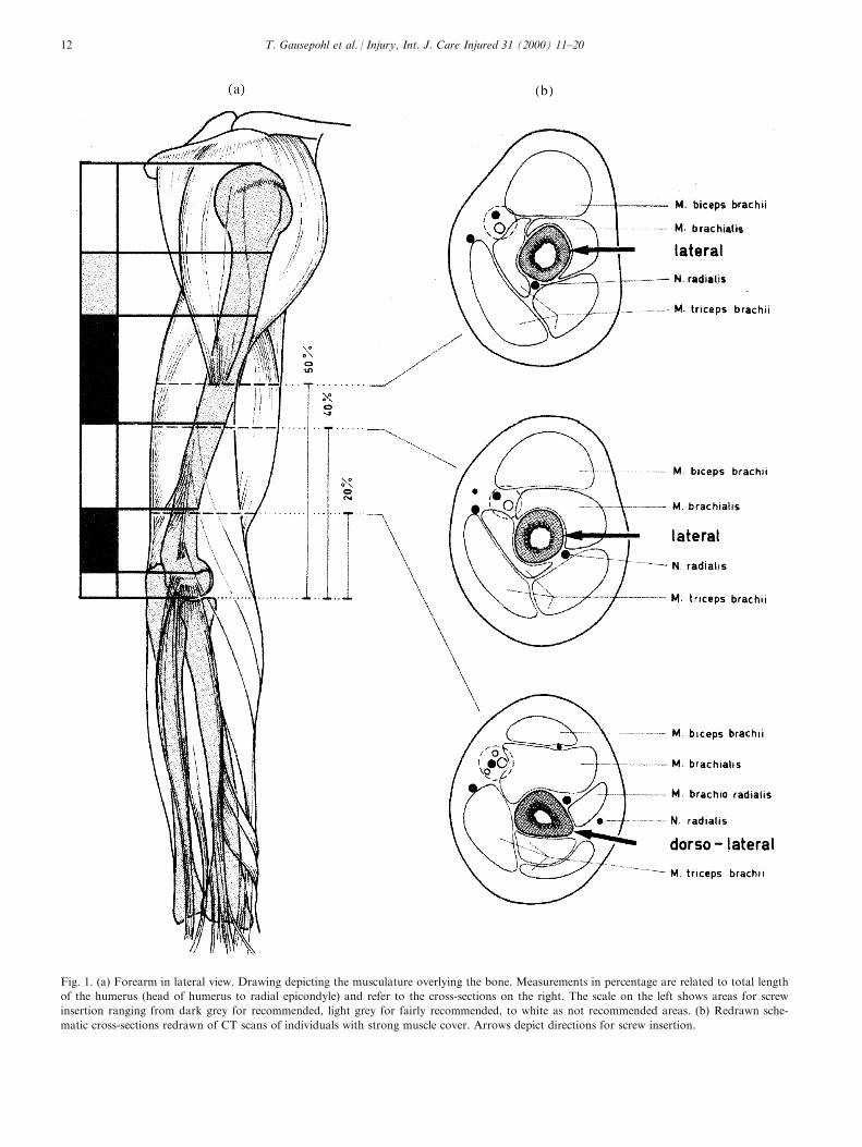
Fig. 1. (a) Forearm in lateral view. Drawing depicting the musculature overlying the bone. Measurements in percentage are related to total length
of the humerus (head of humerus to radial epicondyle) and refer to the cross-sections on the right. The scale on the left shows areas for screw
insertion ranging from dark grey for recommended, light grey for fairly recommended, to white as not recommended areas. (b) Redrawn sche-
matic cross-sections redrawn of CT scans of individuals with strong muscle cover. Arrows depict directions for screw insertion.
T. Gausepohl et al. / Injury, Int. J. Care Injured 31 (2000) 11±2012
upper limbs in the Department of Anatomy, Univer-sity of Cologne. In 20 individuals the right side wasstudied as a muscle±nerve preparation and the left sideas bone±ligament preparation.
The average age was 76.9 years (ranging from 50 to
90 years). Eleven cadavera were female (55%), ninemale (45%).
The preparations used in this study did not showany signs of injury or diseases of joint or soft tissues,which was revealed by inspection and radiological in-
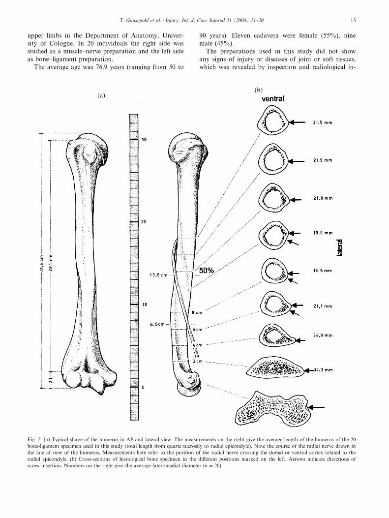
Fig. 2. (a) Typical shape of the humerus in AP and lateral view. The measurements on the right give the average length of the humerus of the 20
bone-ligament specimen used in this study (total length from quarte tucrosily to radial epicondyle). Note the course of the radial nerve drawn in
the lateral view of the humerus. Measurements here refer to the position of the radial nerve crossing the dorsal or ventral cortex related to the
radial epicondyle. (b) Cross-sections of histological bone specimen in the di�erent positions marked on the left. Arrows indicate directions of
screw insertion. Numbers on the right give the average lateromedial diameter �n � 20).
T. Gausepohl et al. / Injury, Int. J. Care Injured 31 (2000) 11±20 13
vestigation. In the bone±ligament-preparations �n �20� total lengths of the humerus, radius and ulna weremeasured. Position of surgically evident bony emi-nences were also depicted (humerus: major tubercle,radial epicondyle; forearm: olecranon, dorsal radialtubercle, radial styloid process, ulnar styloid process;hand: innominate tubercle at the base of the secondmetacarpal). On the same preparations the diameter ofthe bones in the areas of possible screw insertion weremeasured with an electronic industrial measuringdevice. In Figs. 1±3 these measurements are given asaverage numbers. On the muscle-nerve-preparations�n � 20), using the same device, we performedmeasurements of bony areas free of muscles or ten-dons. As a reference point for these measurements weused the easily detectable dorsal radial tubercle (Listerstubercle).
On six muscle±nerve-preparations (three male/three
female, average age 73.5 years), coronary CT-scans(Picker CT) were performed. CT-scans were performedin mid-pronation with the dorsal side of the humeruson the table. On the scout-view 10 equally-spaced sec-tions, 3 mm thick, were made between Lister's tubercleand the radial head. By this means, comparisonbetween di�erent individual specimens were possible.
For this reason, all measurements in Figs. 1±3 areexpressed as a percentage of the total length. The sameprincipal measurements were performed for thehumerus, using the lateral cuboidal joint area and thehead of the humerus as landmarks. For visualisationschematic drawings show the diameter in the di�erentsections (Figs. 1±3).
Additionally the radial nerve was marked with athin copper wire on six specimens and conventionallateral radiographs were undertaken to measure theposition of the nerve.
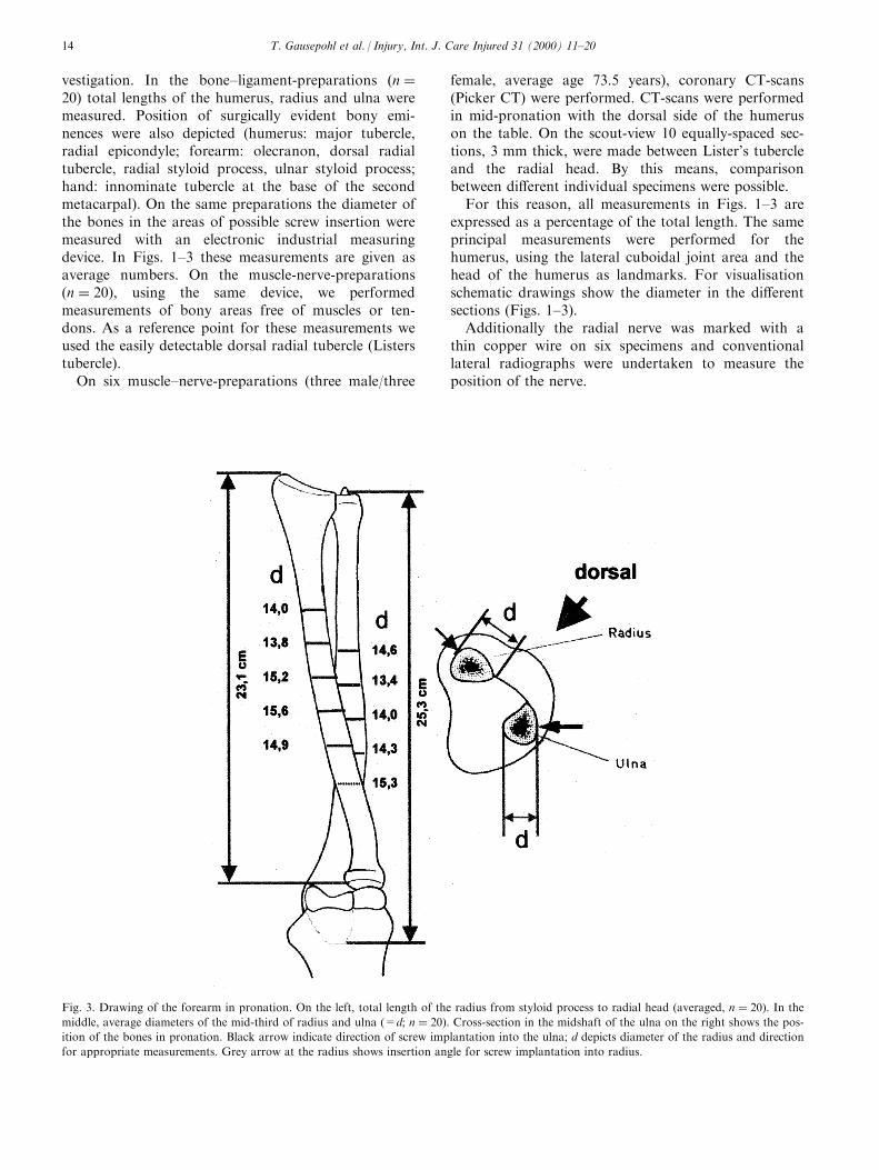
Fig. 3. Drawing of the forearm in pronation. On the left, total length of the radius from styloid process to radial head (averaged, n � 20). In the
middle, average diameters of the mid-third of radius and ulna (=d; n � 20). Cross-section in the midshaft of the ulna on the right shows the pos-
ition of the bones in pronation. Black arrow indicate direction of screw implantation into the ulna; d depicts diameter of the radius and direction
for appropriate measurements. Grey arrow at the radius shows insertion angle for screw implantation into radius.
T. Gausepohl et al. / Injury, Int. J. Care Injured 31 (2000) 11±2014
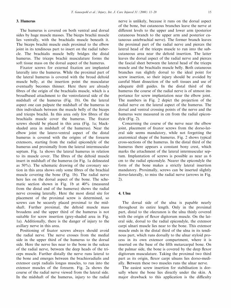
3. Humerus
The humerus is covered on both ventral and dorsalsides by huge muscle masses. The biceps brachii musclelies ventrally, with the brachialis muscle beneath it.The biceps brachii muscle ends proximal to the elbowjoint in its tendinous part to insert on the radial tuber-cle. The brachialis muscle belly bridges the distalhumerus. The triceps brachii musculature forms thesoft tissue mass on the dorsal aspect of the humerus.
Fixator screws for external ®xation are implantedlaterally into the humerus. While the proximal part ofthe lateral humerus is covered with the broad deltoidmuscle belly, at the insertion point the musculatureventually becomes thinner. Here there are already®bres of the origin of the brachialis muscle, which is abroadbased attachment to the ventrolateral side of themidshaft of the humerus (Fig. 1b). On the lateralaspect one can palpate the midshaft of the humerus inthin individuals between the muscle belly of the bicepsand triceps brachii. In this area only few ®bres of thebrachialis muscle cover the humerus. The ®xatorscrews should be placed in this area (Fig. 1a; black-shaded area in midshaft of the humerus). Near theelbow joint the latero-ventral aspect of the distalhumerus is covered with the origins of the forearmextensors, starting from the radial epicondyle of thehumerus and proximally from the lateral intermuscularseptum. Fig. 1a shows the lateral humerus in relationto its muscle cover. The ®bres of the deltoid muscleinsert in midshaft of the humerus (in Fig. 1a delineatedas 50%). The schematic drawing of the coronary sec-tion in this area shows only some ®bres of the brachialmuscle covering the bone (Fig. 1b). The radial nervehere lies on the dorsal aspect of the bone. The sche-matic section shown in Fig. 1b at 40% (measuredfrom the distal end of the humerus) shows the radialnerve crossing laterally. Here the most distal site forplacement of the proximal screw is determined, soscrews can be securely placed proximal to the mid-shaft. Further proximal, the deltoid muscle massbroadens and the upper third of the humerus is notsuitable for screw insertion (grey-shaded area in Fig.1a). Additionally, there is the danger of injury to theaxillary nerve in this area.
Positioning of ®xator screws always should avoidthe radial nerve. The nerve crosses from the medialside in the upper third of the humerus to the dorsalside. Here the nerve lies near to the bone in the sulcusof the radial nerve, between the deep heads of the tri-ceps muscle. Further distally the nerve runs lateral tothe bone and emerges between the brachioradialis andextensor carpi radialis longus muscles, to run into theextensor muscles of the forearm. Fig. 2a shows thecourse of the radial nerve viewed from the lateral side.In the midshaft of the humerus, injury to the radial
nerve is unlikely, because it runs on the dorsal aspectof the bone, but cutaneous branches leave the nerve atdi�erent levels to the upper and lower arm (posteriorcutaneous branch to the upper arm and posterior cu-taneous antebrachial nerve). The former branch leavesthe proximal part of the radial nerve and pierces thelateral head of the triceps muscle to run into the sub-cutaneous area near the deltoid insertion. The latterleaves the dorsal aspect of the radial nerve and piercesthe fascial sheet between the lateral head of the tricepsmuscle and the brachialis muscle belly. Both cutaneousbranches run slightly dorsal to the ideal point forscrew insertion, so their injury should be avoided bycareful blunt dissection of the soft tissues and use ofadequate drill guides. In the distal third of thehumerus the course of the radial nerve is of utmost im-portance for screw implantation near the elbow joint.The numbers in Fig. 2 depict the projection of theradial nerve on the lateral aspect of the humerus. Thedorsal and ventral crossing points of the nerve and thehumerus were measured in cm from the radial epicon-dyle (Fig. 2).
Concerning the course of the nerve near the elbowjoint, placement of ®xator screws from the dorso-lat-eral side seems mandatory, while not forgetting theanatomical shape of the humerus. Fig. 2 shows typicalcross-sections of the humerus. In the distal third of thehumerus there appears a constant bony crest, whichmarks the attachment of the lateral intermuscular sep-tum. Implantation of screws is possible as near as 6cm to the radial epicondyle. Nearer the epicondyle theform of the bone makes a strictly lateral insertionmandatory. Proximally, screws can be inserted slightlydorso-laterally, to miss the radial nerve (arrows in Fig.2).
4. Ulna
The dorsal side of the ulna is papable nearlythroughout its entire length. Only in the proximalpart, distal to the olecranon is the ulna thinly coveredwith the origin of ¯exor digitorum muscle. On the lat-eral side, dorsal to the radial epicondyle, the extensorcarpi ulnari muscle lies near to the bone. This extensormuscle ends in the distal third of the ulna in its tendi-nous part, which runs dorsally to the ulnar styloid pro-cess in its own extensor compartment, where it isinserted on the base of the ®fth metarcarpal bone. Onthe palmar side, the bone is covered by the deep ¯exordigitorum musculature. Taking the proximal two thirdpart as its origin, ¯exor carpi ulnans lies dorso-medi-ally. Between these two muscles runs the ulnar nerve.
The easiest screw insertion for stabilisation is dor-sally where the bone lies directly under the skin. Amajor drawback to this application is the di�culty
T. Gausepohl et al. / Injury, Int. J. Care Injured 31 (2000) 11±20 15
in placing the arm prone. Furthermore, treatmentof an isolated ulnar fracture by means of external®xation is rarely indicated. More common is theinsertion of ®xator screws into the ulna for the ap-plication of joint bridging ®xators at the elbow.Here there is the opportunity to place the ®xatorscrew, like the humeral screw, from the lateral side.Midshaft of the ulna is preferable (Fig. 3). Screwinsertion from the lateral side is possible, becausethe ulna is bending dorsally towards the elbowjoint, while the radius is directed to the centre ofmotion of the elbow joint. In strict lateral appli-cation the screws are placed through the dorsalthird of the extensor carpi ulnaris muscle (arrow inFig. 3).
Soft tissue cover is thinnest in pronation, becausehere muscles are shifting radially. We therefore preferapplication of screws in pronation.
5. Radius
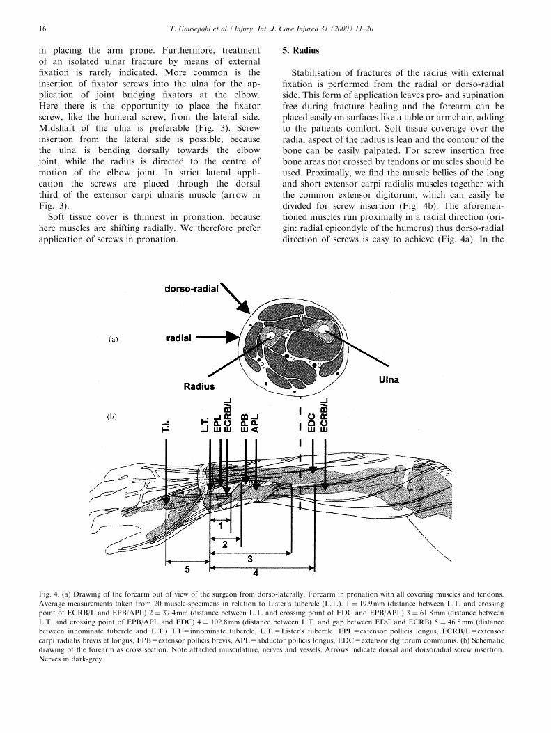
Stabilisation of fractures of the radius with external®xation is performed from the radial or dorso-radialside. This form of application leaves pro- and supinationfree during fracture healing and the forearm can beplaced easily on surfaces like a table or armchair, addingto the patients comfort. Soft tissue coverage over theradial aspect of the radius is lean and the contour of thebone can be easily palpated. For screw insertion freebone areas not crossed by tendons or muscles should beused. Proximally, we ®nd the muscle bellies of the longand short extensor carpi radialis muscles together withthe common extensor digitorum, which can easily bedivided for screw insertion (Fig. 4b). The aforemen-tioned muscles run proximally in a radial direction (ori-gin: radial epicondyle of the humerus) thus dorso-radialdirection of screws is easy to achieve (Fig. 4a). In the
Fig. 4. (a) Drawing of the forearm out of view of the surgeon from dorso-laterally. Forearm in pronation with all covering muscles and tendons.
Average measurements taken from 20 muscle-specimens in relation to Lister's tubercle (L.T.). 1 � 19:9mm (distance between L.T. and crossing
point of ECRB/L and EPB/APL) 2 � 37:4mm (distance between L.T. and crossing point of EDC and EPB/APL) 3 � 61:8mm (distance between
L.T. and crossing point of EPB/APL and EDC) 4 � 102:8mm (distance between L.T. and gap between EDC and ECRB) 5 � 46:8mm (distance
between innominate tubercle and L.T.) T.I.=innominate tubercle, L.T.=Lister's tubercle, EPL=extensor pollicis longus, ECRB/L=extensor
carpi radialis brevis et longus, EPB=extensor pollicis brevis, APL=abductor pollicis longus, EDC=extensor digitorum communis. (b) Schematic
drawing of the forearm as cross section. Note attached musculature, nerves and vessels. Arrows indicate dorsal and dorsoradial screw insertion.
Nerves in dark-grey.
T. Gausepohl et al. / Injury, Int. J. Care Injured 31 (2000) 11±2016
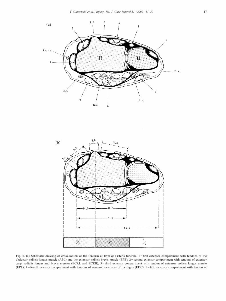
Fig. 5. (a) Schematic drawing of cross-section of the forearm at level of Lister's tubercle. 1=®rst extensor compartment with tendons of the
abductor pollicis longus muscle (APL) and the extensor pollicis brevis muscle (EPB); 2=second extensor compartment with tendons of extensor
carpi radialis longus and brevis muscles (ECRL and ECRB); 3=third extensor compartment with tendon of extensor pollicis longus muscle
(EPL); 4=fourth extensor compartment with tendons of common extensors of the digits (EDC); 5=®fth extensor compartment with tendon of
T. Gausepohl et al. / Injury, Int. J. Care Injured 31 (2000) 11±20 17
midshaft we ®nd a muscle-free area between the obli-quely running abductor pollicis longus and extensor pol-licis brevis muscles on the one side and the extensorcarpi radialis longus and brevis muscles (ECRL+B) onthe other side, which is anatomically 4±6 cm long (light-gray area between measurement 3 and 4 in Fig. 4b). Thesuper®cial branch of the radial nerve runs radially to thewrist joint extensors and therefore is not endangeredduring pin placement.
For strictly radial application one needs to insert thescrews radially to the wrist extensors (ECRL+B) care-fully avoiding injury to the super®cial branch of theradial nerve, which runs distally between the bellies ofthe brachioradialis and extensor carpi radialis longusmuscle. To traverse the bone volar-dorsally, screw inser-tion between the brachioradialis muscle and ECRL+Bseems without bene®t and unneccessarily endangers theaforementioned cutaneous nerve. So, in using strictradial direction of pin placement the radial part of theextensor radialis muscle must be pierced (arrow in Fig.4b). Its muscle belly is covered by the extensor carpiradialis longus muscle, which can easily be re¯ectedradially or radio-dorsally. Here functional aspects areimportant. All extensors of the hand have their origin atthe radial epicondyle, their tendons run fan-like radiallyor radio-dorsally into their individual tendon sheets.
Surgery on the radius is performed with the patientsupine and the arm and hand placed on a hand table.The surgeon sits facing the head of the patient and hasto pronate the forearm in order to apply the ®xatordorso-radially. Because the extensors have their originon the humerus and the radius rotates on the humerus,the tendons shift dorsally during pronation. Afterinserting the screws volar to the ECRL- tendon, it willride over the screw during supination, so insertion dor-sal to this tendon is proximally more useful.
In the midshaft, the super®cial branch of the radialnerve runs even more super®cially, transversing theabductor pollicis and extensor pollicis longus musclesto run subcutanously towards the anatomical snu�box.Both the deep and super®cial parts of the nerve areevidently more important for hand function andshould not be severed. For screw insertion in this areawe recommend a longer incision and careful dissectionunder vision of structures down to the bone.
At the distal radius there are two areas free of ten-dons or muscles. As a surgical landmark we locate onthe dorsal aspect of the radius Lister's tubercle, whichserves as a pulley for the extensor pollicis longus ten-
don and is easily papable (Figs. 4a and 5a). Even inseverely contused soft tissues, identi®cation is possibleafter a 1-cm longitudinal skin incision. For location ofthe incisions we need to know its probable anatomicalposition. This position lies quite constantly betweenthe radial and middle third of the distal forearm afterdivision into three equal parts (Fig. 5b). Proximal toLister's tubercle we ®nd a muscle- and tendon-free tri-
extensor digiti minimi muscle (EDM); 6=sixth extensor compartment with tendon of extensor carpi ulnaris muscle (ECU); 7=tendon of ¯exor
carpi ulnaris muscle (FCU); 8=Tendons of the deep common digital ¯exor (FDP) and super®cal common digital ¯exor muscles (FDS); 9=ten-
don of ¯exor palmaris longus (PL); S.R.N.=super®cial radial nerve; L.T.=Lister's tubercle; N.u.=ulnar nerve; A.u.=ulnar artery; N.m.=me-
dian nerve; A.r.=radial artery; R=radius; U=ulna. (b) Drawing as in (a): average measurements of 20 muscle specimen. Bar at the bottom
depicting position of Lister's tubercle between radial and middle third of the forarm (see text). (c) Drawing as in (a): oblique insertion of ®xator
screws with average angle of 36.78 �n � 6, after CT-scans). Average length of screw traversing bone on the left �n � 6, after CT-scans). (d) Draw-
ing as in (a): strictly dorsopalmar insertion of ®xator screws (see text). Average screw length traversing bone on the left �n � 6, after CT-scans).
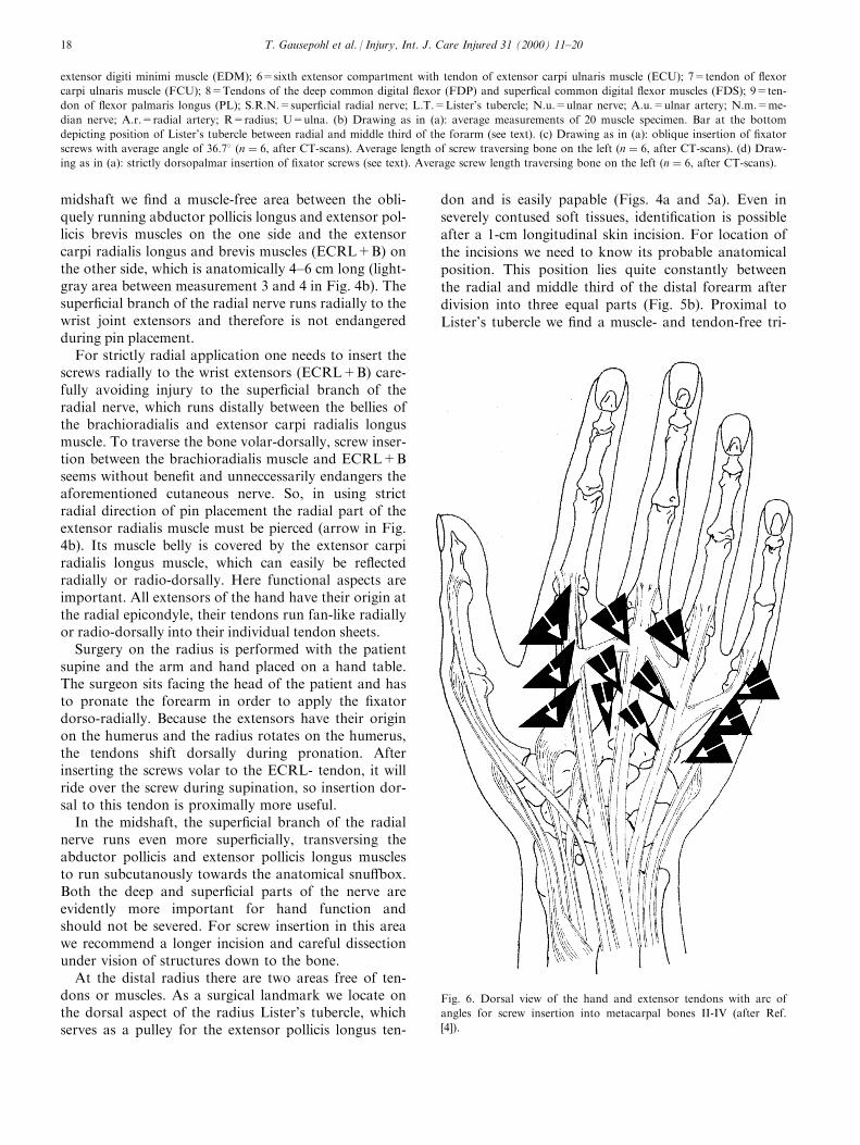
Fig. 6. Dorsal view of the hand and extensor tendons with arc of
angles for screw insertion into metacarpal bones II-IV (after Ref.
[4]).
T. Gausepohl et al. / Injury, Int. J. Care Injured 31 (2000) 11±2018
angle (light-grey area between measurements 1 and 2in Fig. 4a). In distal fractures of the radius longitudi-nal insertion of screws is seldom possible into the dis-tal fragment. Here insertion of one screw into Lister'stubercle and one radially in the area betweenECRL+B and APL+APB (Figs.4a and 5a and b) ispossible, once again avoiding injury to the super®cialbranch of the radial nerve. With this screw insertion,the shape of the distal radius is important. In strictlydorso-volar direction of pins the radial screw wouldmiss the bone or be inserted eccentrically, so screwsshould be directed from dorso-radially to volar-ulnarly(Fig. 5c). Injury to the distal radio-ulnar joint must beavoided. Measurements in Fig. 5c give the optimalangle for directing the screws (average 36.78) andexpected thread length. In special indications such ascorrective osteotomies after malunion an exact dorso-volar direction of the ®xator screws is preferable, es-pecially if gradual correction by means of hemicallota-sis is desired. In these cases we insert one screw overLister's tubercle and the other more ulnar near to thedistal radio-ulnar joint (Fig. 5d). This area is coveredby the broad fourth extensor compartment and operat-ive placement of screws requires experience. Thethread of the ®xator screw must be driven completelyinto the bone to avoid injury of the tendons duringearly mobilisation. Fig. 5d shows the expected threadlength for dorso-volar implantation.
6. Metacarpal bones
For trans-articular application of external ®xators atthe wrist, placement of the distal pin group into thesecond metacarpal seems bene®cial from the anatom-ical point. The tendons of the common extensor digi-torum run in bundles in the fourth tendoncompartment. From here they spread towards the fourulnar digits. Due to the oblique course of the tendonsthe proximal two third of the second metarcarpal isfree of tendons and allows free choice of angles for pininsertion, ranging from strict dorso-volar to strictradio-ulnar (Fig. 6),. As a landmark for pin insertionwe constantly ®nd a bony protuberance (innominatetubercle) which serves as insertion area of the longextensor carpi radialis longus muscle (Fig. 4a). At thelevel of the innominate tubercle the cancellous bone atthe base of the metacarpal, changes into compact dia-physeal bone, so we recommend screw placement 5±10mm distal to it. Screw diameter should be adjusted tothe dimension of the bone: in the second metacarpal3.0±3.3 mm is recommended to minimise the possibledanger of iatrogenic fractures.
Implantation is directed dorso-radially, neutralisingthe maximal bending stress of the bone [5]. Similarconditions can be found at the ®fth metacarpal: herescrews should be inserted into the bone dorso-ulnarly[4,5]. In the third and fourth metacarpal, ®xator screws
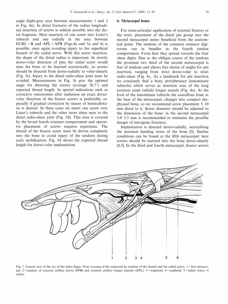
Fig. 7. Lateral view of the ray of the index ®nger. Note crossing of the trapezoid by tendons of the thumb and the radial artery. 1=®rst metacar-
pal; 2=tendons of extensor pollicis brevis (EPB) and extensor pollicis longus muscles (EPL); 3=trapezoid; 4=scaphoid; 5=radial artery; 6
radius.
T. Gausepohl et al. / Injury, Int. J. Care Injured 31 (2000) 11±20 19
can only be placed between the extensor tendons. Dueto the fan-shaped spreading of the ®nger extensors westill ®nd space distally to insert the screws, while in theproximal third, open pin placement is mandatory forsecure insertion [4] (Fig. 6). Screw insertion close tothe metacarpal heads should be avoided, since they arecovered by the so-called lamina intertendinea (tendi-nous hood). The strong collateral ligaments of theMP-joints also need attention. The dorsally papableand radiologically visible tubercles, which serve as theorigin for the collateral ligaments (Fig. 6) providelandmarks for the distal extent of screw insertion intothe metacarpals. If a very distal point of insertion can-not be avoided, it should be performed from thedorso-radial or dorso-ulnar side, otherwise motion inthe MP-joints could be severely disturbed [3].
Fractures of the ®rst metacarpal deserve specialattention. Fractures near the base of the Winterstein-type (pseudo-Bennett) can be managed without trans-articular ®xation. Here ®xator screws can be placeddorsally between the tendons of the extensor pollicisboughs and extensor pollicis breins muscles (Fig. 7).For intra-articular fractures in the base of the ®rstmetacarpal (Rolando, Bennett), trans-articular appli-cation using the trapezium can be used, but carries thedanger of severing the nearby radial artery, which
curves on the volar side of the styloid process of theradius, dorsally into the anatomical snu�box, traver-sing the trapezoid at variable levels (Fig. 7). At thelevel of the anatomical snu�box the super®cial cu-taneous branch of the radial nerve divides into a dor-sal and volar branch and is prone to iatrogenic injury.
7. Phalangeal bones
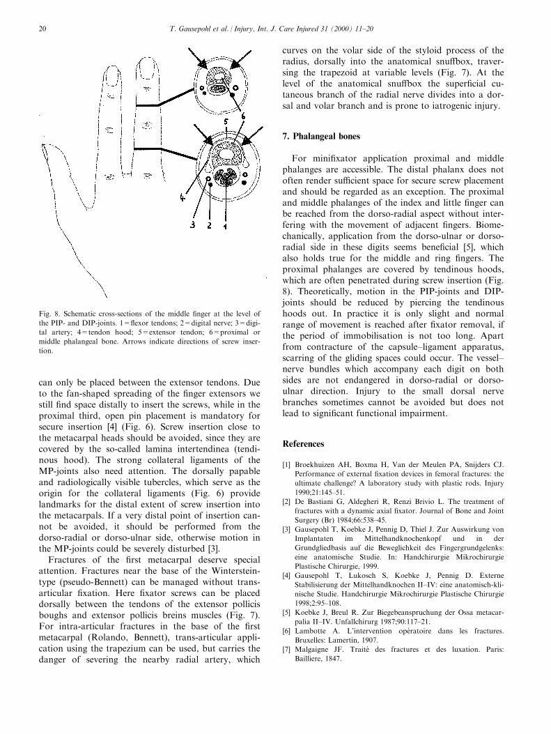
For mini®xator application proximal and middlephalanges are accessible. The distal phalanx does notoften render su�cient space for secure screw placementand should be regarded as an exception. The proximaland middle phalanges of the index and little ®nger canbe reached from the dorso-radial aspect without inter-fering with the movement of adjacent ®ngers. Biome-chanically, application from the dorso-ulnar or dorso-radial side in these digits seems bene®cial [5], whichalso holds true for the middle and ring ®ngers. Theproximal phalanges are covered by tendinous hoods,which are often penetrated during screw insertion (Fig.8). Theoretically, motion in the PIP-joints and DIP-joints should be reduced by piercing the tendinoushoods out. In practice it is only slight and normalrange of movement is reached after ®xator removal, ifthe period of immobilisation is not too long. Apartfrom contracture of the capsule±ligament apparatus,scarring of the gliding spaces could occur. The vessel±nerve bundles which accompany each digit on bothsides are not endangered in dorso-radial or dorso-ulnar direction. Injury to the small dorsal nervebranches sometimes cannot be avoided but does notlead to signi®cant functional impairment.
References
[1] Broekhuizen AH, Boxma H, Van der Meulen PA, Snijders CJ.
Performance of external ®xation devices in femoral fractures: the
ultimate challenge? A laboratory study with plastic rods. Injury
1990;21:145±51.
[2] De Bastiani G, Aldegheri R, Renzi Brivio L. The treatment of
fractures with a dynamic axial ®xator. Journal of Bone and Joint
Surgery (Br) 1984;66:538±45.
[3] Gausepohl T, Koebke J, Pennig D, Thiel J. Zur Auswirkung von
Implantaten im Mittelhandknochenkopf und in der
Grundgliedbasis auf die Beweglichkeit des Fingergrundgelenks:
eine anatomische Studie. In: Handchirurgie Mikrochirurgie
Plastische Chirurgie, 1999.
[4] Gausepohl T, Lukosch S, Koebke J, Pennig D. Externe
Stabilisierung der Mittelhandknochen II±IV: eine anatomisch-kli-
nische Studie. Handchirurgie Mikrochirurgie Plastische Chirurgie
1998;2:95±108.
[5] Koebke J, Breul R. Zur Biegebeanspruchung der Ossa metacar-
palia II±IV. Unfallchirurg 1987;90:117±21.
[6] Lambotte A. L'intervention opeÁ ratoire dans les fractures.
Bruxelles: Lamertin, 1907.
[7] Malgaigne JF. Traite des fractures et des luxation. Paris:
Bailliere, 1847.
Fig. 8. Schematic cross-sections of the middle ®nger at the level of
the PIP- and DIP-joints. 1=¯exor tendons; 2=digital nerve; 3=digi-
tal artery; 4=tendon hood; 5=extensor tendon; 6=proximal or
middle phalangeal bone. Arrows indicate directions of screw inser-
tion.
T. Gausepohl et al. / Injury, Int. J. Care Injured 31 (2000) 11±2020
Related Documents