INCAS BULLETIN, Volume 5, Issue 2/ 2013, pp. 43 – 52 ISSN 2066 – 8201 The analysis of the flying wing in morphing concept Vasile PRISACARIU* ,1 , Ionică CÎRCIU 2 *Corresponding author * ,1 “Transilvania” University of Brasov, 1 Colina Universitatii, Braşov [email protected] 2 Air Force Academy “Henri Coandă”, 160 Mihai Viteazu, Braşov [email protected] Abstract: The combination between the flying wing morphing concept and the use of modern command and control system offers exponential advantages having a leverage effect in the economy and research. The flying wing architecture has the advantage of low cost against efficiency, the morphing of this concept defining the new characteristic frontiers and aerodynamic performances which derive immediately. On designing an unmanned aerial vehicle for a various range of missions, its lifting surface needs to display optimal geometrical features, so that the UAV may maintain the induced drag and the moment coefficient at reasonable levels. The command and control of the lifting surfaces in morphing concept offer characteristics and in-flight performances at a superior level. The limits of the system depend on the reliability of the execution elements and the grade of accuracy for the control laws which are implemented in the calculation module. The paper aims at presenting an analysis regarding the robotic air systems of flying wing type through the aerodynamic analysis and with the help of specific software instruments. The performances and flight qualities depend directly on the geometry of the lifting surface of the aerial vehicle. Key Words: flying wing, stability, morphing, vortex lattice method, Clark YH airfoil 1. INTRODUCTION The unmanned aerial vehicle (UAV) had known in the last decades a quick evolution due the miniaturization technology and the market demands. The robotic aerial system is defined as a pilotless aerial vector transporting usable payloads depending on the mission and evolving under the action of the aerodynamic, non-ballistic and manual forces, or by means of an autopilot. Figure 1 shows several types of flying wings belonging to the main categories of UAVs [1]. Over the years unpiloted aerial vectors have achieved a great technological advance which imposed an extension of the searching area together with the growth of the intrinsic and related performances. An interesting zone delimited by NASA, DARPA and other great university researchers would be the performance study regarding unpiloted airships in the morphing concept. Morphing aircraft offer the advantage of changing the form of the wing during the flight for a better optimization of the performances depending on the mission objectives. Although the benefits of the morphing concept are obvious, from the aerodynamic point of view, the technical realizations are still a critical problem. The design of a morphing airplane involves new challenges regarding the design method, materials, and command and control elements [2]. The actual use of the classical hyper-sustentation represents a simplification of the morphing concept, these widgets being traditional control systems for limited condition DOI: 10.13111/2066-8201.2013.5.2.6

Welcome message from author
This document is posted to help you gain knowledge. Please leave a comment to let me know what you think about it! Share it to your friends and learn new things together.
Transcript
INCAS BULLETIN, Volume 5, Issue 2/ 2013, pp. 43 – 52 ISSN 2066 – 8201
The analysis of the flying wing in morphing concept
Vasile PRISACARIU*,1
, Ionică CÎRCIU2
*Corresponding author
*,1
“Transilvania” University of Brasov, 1 Colina Universitatii, Braşov
[email protected] 2Air Force Academy “Henri Coandă”, 160 Mihai Viteazu, Braşov
Abstract: The combination between the flying wing morphing concept and the use of modern
command and control system offers exponential advantages having a leverage effect in the economy
and research. The flying wing architecture has the advantage of low cost against efficiency, the
morphing of this concept defining the new characteristic frontiers and aerodynamic performances
which derive immediately. On designing an unmanned aerial vehicle for a various range of missions,
its lifting surface needs to display optimal geometrical features, so that the UAV may maintain the
induced drag and the moment coefficient at reasonable levels. The command and control of the lifting
surfaces in morphing concept offer characteristics and in-flight performances at a superior level. The
limits of the system depend on the reliability of the execution elements and the grade of accuracy for
the control laws which are implemented in the calculation module. The paper aims at presenting an
analysis regarding the robotic air systems of flying wing type through the aerodynamic analysis and
with the help of specific software instruments. The performances and flight qualities depend directly
on the geometry of the lifting surface of the aerial vehicle.
Key Words: flying wing, stability, morphing, vortex lattice method, Clark YH airfoil
1. INTRODUCTION
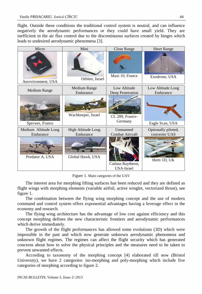
The unmanned aerial vehicle (UAV) had known in the last decades a quick evolution due the
miniaturization technology and the market demands. The robotic aerial system is defined as
a pilotless aerial vector transporting usable payloads depending on the mission and evolving
under the action of the aerodynamic, non-ballistic and manual forces, or by means of an
autopilot. Figure 1 shows several types of flying wings belonging to the main categories of
UAVs [1].
Over the years unpiloted aerial vectors have achieved a great technological advance
which imposed an extension of the searching area together with the growth of the intrinsic
and related performances.
An interesting zone delimited by NASA, DARPA and other great university researchers
would be the performance study regarding unpiloted airships in the morphing concept.
Morphing aircraft offer the advantage of changing the form of the wing during the flight for
a better optimization of the performances depending on the mission objectives. Although the
benefits of the morphing concept are obvious, from the aerodynamic point of view, the
technical realizations are still a critical problem.
The design of a morphing airplane involves new challenges regarding the design
method, materials, and command and control elements [2].
The actual use of the classical hyper-sustentation represents a simplification of the
morphing concept, these widgets being traditional control systems for limited condition
DOI: 10.13111/2066-8201.2013.5.2.6
Vasile PRISACARIU, Ionică CÎRCIU 44
INCAS BULLETIN, Volume 5, Issue 2/ 2013
flight. Outside these conditions the traditional control system is neutral, and can influence
negatively the aerodynamic performances or they could have small yield. They are
inefficient in the air flux control due to the discontinuous surfaces created by hinges which
leads to undesired aerodynamic phenomena [3].
Micro Mini Close Range Short Range
Aerovironment, USA
Orbiter, Israel
Maxi 10, France
Exodrone, USA
Medium Range Medium Range
Endurance
Low Altitude
Deep Penetration
Low Altitude Long
Endurance
Sperwer, France
Wachkeeper, Israel
CL 289, France-
Germany Eagle Scan, USA
Medium Altitude Long
Endurance
High Altitude Long
Endurance
Unmanned
Combat Aircraft
Optionally piloted,
converter UAS
Predator A, USA
Global Hawk, USA
Cutlass Raytheon,
USA-Israel
Herti 1D, UK
Figure 1. Main categories of the UAV
The interest area for morphing lifting surfaces has been reduced and they are defined as
flight wings with morphing elements (variable airfoil, active winglet, vectorized thrust), see
figure 1.
The combination between the flying wing morphing concept and the use of modern
command and control system offers exponential advantages having a leverage effect in the
economy and research.
The flying wing architecture has the advantage of low cost against efficiency and this
concept morphing defines the new characteristic frontiers and aerodynamic performances
which derive immediately.
The growth of the flight performances has allowed some evolutions (3D) which were
impossible in the past and which now generate unknown aerodynamic phenomena and
unknown flight regimes. The regimes can affect the flight security which has generated
concerns about how to solve the physical principles and the measures need to be taken to
prevent unwanted effects.
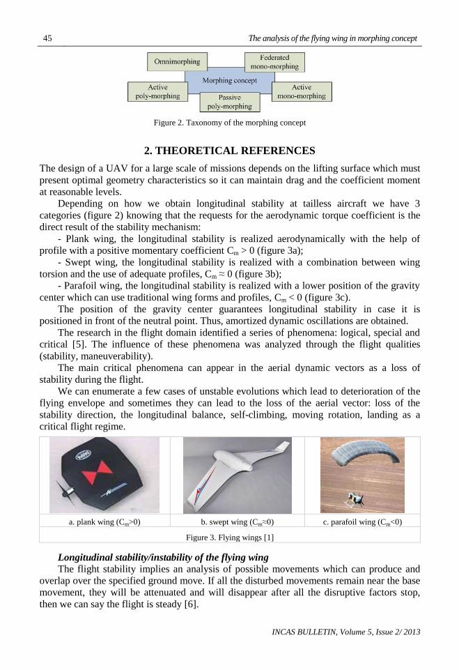
According to taxonomy of the morphing concept [4] elaborated till now (Bristol
University), we have 2 categories: iso-morphing and poly-morphing which include five
categories of morphing according to figure 2.
45 The analysis of the flying wing in morphing concept
INCAS BULLETIN, Volume 5, Issue 2/ 2013
Figure 2. Taxonomy of the morphing concept
2. THEORETICAL REFERENCES
The design of a UAV for a large scale of missions depends on the lifting surface which must
present optimal geometry characteristics so it can maintain drag and the coefficient moment
at reasonable levels.
Depending on how we obtain longitudinal stability at tailless aircraft we have 3
categories (figure 2) knowing that the requests for the aerodynamic torque coefficient is the
direct result of the stability mechanism:
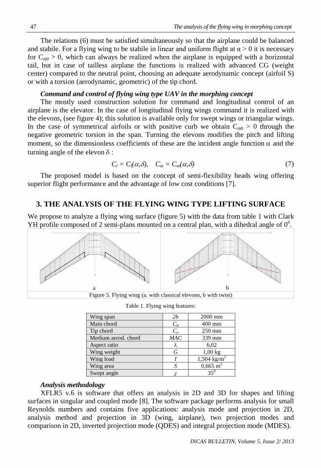
- Plank wing, the longitudinal stability is realized aerodynamically with the help of
profile with a positive momentary coefficient Cm > 0 (figure 3a);
- Swept wing, the longitudinal stability is realized with a combination between wing
torsion and the use of adequate profiles, Cm ≈ 0 (figure 3b);
- Parafoil wing, the longitudinal stability is realized with a lower position of the gravity
center which can use traditional wing forms and profiles, Cm < 0 (figure 3c).
The position of the gravity center guarantees longitudinal stability in case it is
positioned in front of the neutral point. Thus, amortized dynamic oscillations are obtained.
The research in the flight domain identified a series of phenomena: logical, special and
critical [5]. The influence of these phenomena was analyzed through the flight qualities
(stability, maneuverability).
The main critical phenomena can appear in the aerial dynamic vectors as a loss of
stability during the flight.
We can enumerate a few cases of unstable evolutions which lead to deterioration of the
flying envelope and sometimes they can lead to the loss of the aerial vector: loss of the
stability direction, the longitudinal balance, self-climbing, moving rotation, landing as a
critical flight regime.
a. plank wing (Cm>0) b. swept wing (Cm≈0) c. parafoil wing (Cm<0)
Figure 3. Flying wings [1]
Longitudinal stability/instability of the flying wing
The flight stability implies an analysis of possible movements which can produce and
overlap over the specified ground move. If all the disturbed movements remain near the base
movement, they will be attenuated and will disappear after all the disruptive factors stop,
then we can say the flight is steady [6].
Vasile PRISACARIU, Ionică CÎRCIU 46
INCAS BULLETIN, Volume 5, Issue 2/ 2013
mCcSVM 2
2
(1)
With incidence angle α:
M = M(α) or Cm = Cm (α) (2)
where have: .2
2 constV
, S – surface, c – medium aerodynamic chord.
Figure 4. Flying wing – linear and uniform flight
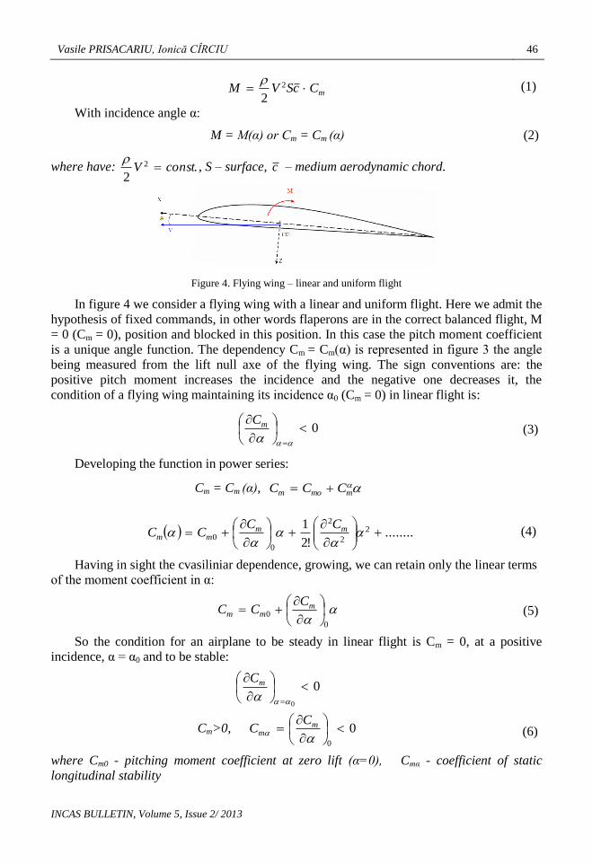
In figure 4 we consider a flying wing with a linear and uniform flight. Here we admit the
hypothesis of fixed commands, in other words flaperons are in the correct balanced flight, M
= 0 (Cm = 0), position and blocked in this position. In this case the pitch moment coefficient
is a unique angle function. The dependency Cm = Cm(α) is represented in figure 3 the angle
being measured from the lift null axe of the flying wing. The sign conventions are: the
positive pitch moment increases the incidence and the negative one decreases it, the
condition of a flying wing maintaining its incidence α0 (Cm = 0) in linear flight is:
0
mC
(3)
Developing the function in power series:
Cm = Cm (α), mmom CCC
........!2
1 2
2
2
0
0
mm
mm
CCCC (4)
Having in sight the cvasiliniar dependence, growing, we can retain only the linear terms
of the moment coefficient in α:
0
0
m
mm
CCC (5)
So the condition for an airplane to be steady in linear flight is Cm = 0, at a positive
incidence, α = α0 and to be stable:
0
0
mC
Cm>0, 00
mm
CC (6)
where Cm0 - pitching moment coefficient at zero lift (α=0), Cmα - coefficient of static
longitudinal stability
47 The analysis of the flying wing in morphing concept
INCAS BULLETIN, Volume 5, Issue 2/ 2013
The relations (6) must be satisfied simultaneously so that the airplane could be balanced
and stabile. For a flying wing to be stabile in linear and uniform flight at α > 0 it is necessary
for Cm0 > 0, which can always be realized when the airplane is equipped with a horizontal
tail, but in case of tailless airplane the functions is realized with advanced CG (weight
center) compared to the neutral point, choosing an adequate aerodynamic concept (airfoil S)
or with a torsion (aerodynamic, geometric) of the tip chord.
Command and control of flying wing type UAV in the morphing concept
The mostly used construction solution for command and longitudinal control of an
airplane is the elevator. In the case of longitudinal flying wings command it is realized with
the elevons, (see figure 4); this solution is available only for swept wings or triangular wings.
In the case of symmetrical airfoils or with positive curb we obtain Cm0 > 0 through the
negative geometric torsion in the span. Turning the elevons modifies the pitch and lifting
moment, so the dimensionless coefficients of these are the incident angle function and the
turning angle of the elevon :
Cl = Cl(,), Cm = Cm(,) (7)
The proposed model is based on the concept of semi-flexibility heads wing offering
superior flight performance and the advantage of low cost conditions [7].
3. THE ANALYSIS OF THE FLYING WING TYPE LIFTING SURFACE
We propose to analyze a flying wing surface (figure 5) with the data from table 1 with Clark
YH profile composed of 2 semi-plans mounted on a central plan, with a dihedral angle of 00.
a
b
Figure 5. Flying wing (a. with classical elevons, b with twist)
Table 1. Flying wing features:
Wing span 2b 2000 mm
Main chord C0 400 mm
Tip chord Ce 250 mm
Medium aerod. chord MAC 339 mm
Aspect ratio λ 6,02
Wing weight G 1,00 kg
Wing load I 1,504 kg/m2
Wing area S 0,665 m2
Swept angle χ 350
Analysis methodology
XFLR5 v.6 is software that offers an analysis in 2D and 3D for shapes and lifting
surfaces in singular and coupled mode [8]. The software package performs analysis for small
Reynolds numbers and contains five applications: analysis mode and projection in 2D,
analysis method and projection in 3D (wing, airplane), two projection modes and
comparison in 2D, inverted projection mode (QDES) and integral projection mode (MDES).
Vasile PRISACARIU, Ionică CÎRCIU 48
INCAS BULLETIN, Volume 5, Issue 2/ 2013
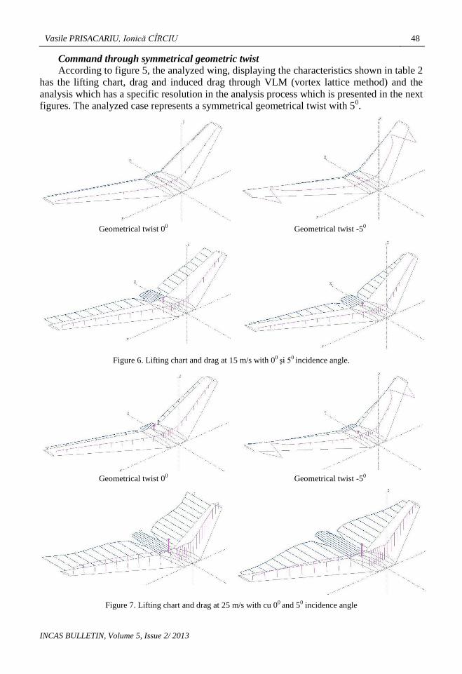
Command through symmetrical geometric twist
According to figure 5, the analyzed wing, displaying the characteristics shown in table 2
has the lifting chart, drag and induced drag through VLM (vortex lattice method) and the
analysis which has a specific resolution in the analysis process which is presented in the next
figures. The analyzed case represents a symmetrical geometrical twist with 50.
Geometrical twist 00 Geometrical twist -50
Figure 6. Lifting chart and drag at 15 m/s with 00 şi 50 incidence angle.
Geometrical twist 00 Geometrical twist -50
Figure 7. Lifting chart and drag at 25 m/s with cu 00 and 50 incidence angle
49 The analysis of the flying wing in morphing concept
INCAS BULLETIN, Volume 5, Issue 2/ 2013
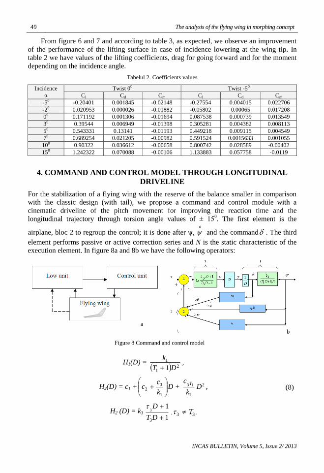
From figure 6 and 7 and according to table 3, as expected, we observe an improvement
of the performance of the lifting surface in case of incidence lowering at the wing tip. In
table 2 we have values of the lifting coefficients, drag for going forward and for the moment
depending on the incidence angle.
Tabelul 2. Coefficients values
Incidence
α
Twist 00 Twist -50
Cl Cd Cm Cl Cd Cm
-50 -0.20401 0.001845 -0.02148 -0.27554 0.004015 0.022706
-20 0.020953 0.000026 -0.01882 -0.05802 0.00065 0.017208
00 0.171192 0.001306 -0.01694 0.087538 0.000739 0.013549
30 0.39544 0.006949 -0.01398 0.305281 0.004382 0.008113
50 0.543331 0.13141 -0.01193 0.449218 0.009115 0.004549
70 0.689254 0.021205 -0.00982 0.591524 0.0015633 0.001055
100 0.90322 0.036612 -0.00658 0.800742 0.028589 -0.00402
150 1.242322 0.070088 -0.00106 1.133883 0.057758 -0.0119
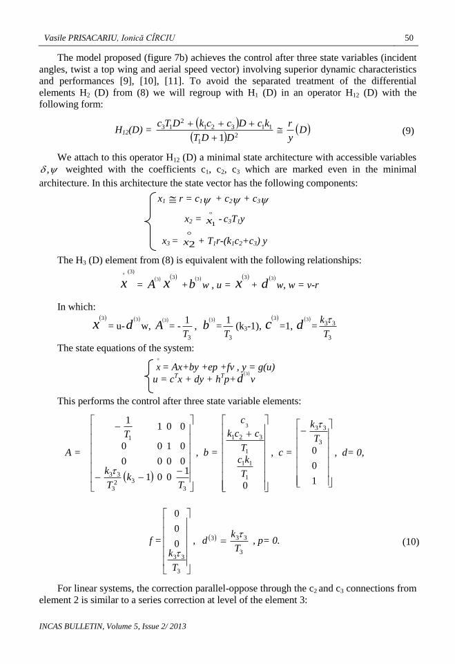
4. COMMAND AND CONTROL MODEL THROUGH LONGITUDINAL
DRIVELINE
For the stabilization of a flying wing with the reserve of the balance smaller in comparison
with the classic design (with tail), we propose a command and control module with a
cinematic driveline of the pitch movement for improving the reaction time and the
longitudinal trajectory through torsion angle values of ± 150. The first element is the
airplane, bloc 2 to regroup the control; it is done after ψ, o
and the command . The third
element performs passive or active correction series and N is the static characteristic of the
execution element. In figure 8a and 8b we have the following operators:
Figure 8 Command and control model
H1(D) = 2
1
1
1 DT
k
,
H2(D) = c1 +
1
32
k
cc D + 2
1
13 Dk
c T, (8)
H2 (D) = k3
1
1
3
3
DT
D , 33 T .
b
a
Vasile PRISACARIU, Ionică CÎRCIU 50
INCAS BULLETIN, Volume 5, Issue 2/ 2013
The model proposed (figure 7b) achieves the control after three state variables (incident
angles, twist a top wing and aerial speed vector) involving superior dynamic characteristics
and performances [9], [10], [11]. To avoid the separated treatment of the differential
elements H2 (D) from (8) we will regroup with H1 (D) in an operator H12 (D) with the
following form:
H12(D) =
Dy
r
DDT
kcDcckDTc
2
1
113212
13
1 (9)
We attach to this operator H12 (D) a minimal state architecture with accessible variables
, weighted with the coefficients c1, c2, c3 which are marked even in the minimal
architecture. In this architecture the state vector has the following components:
x1 r = c1 + c2 + c3
x2 =
1x - c3T1y
x3 =
2x + T1r-(k1c2+c3) y
The H3 (D) element from (8) is equivalent with the following relationships: )3(
x
=
A3
x3
+
b3
w , u =
x3
+
d3
w, w = v-r
In which:
x3
= u-
d3
w,
A3
= -3
1
T,
b3
=3
1
T(k3-1),
c3
=1,
d3
=3
33
T
k
The state equations of the system:
x = Ax+by +ep +fv , y = g(u)
u = cTx + dy + h
Tp+
d3
v
This performs the control after three state variable elements:
A =
3
323
33
1
1001
0000
0100
0011
Tk
T
k
T
, b =
01
11
1
321
3
T
kc
T
cck
c
, c =
1
0
03
33
T
k
, d= 0,
f =
3
33
0
0
0
T
k
,
3
333
T
kd
, p= 0. (10)
For linear systems, the correction parallel-oppose through the c2 and c3 connections from
element 2 is similar to a series correction at level of the element 3:

51 The analysis of the flying wing in morphing concept
INCAS BULLETIN, Volume 5, Issue 2/ 2013
012
2
012
233
aDaDa
bDbDbkH ee
(11)
which together with operator H3 (D) gives a general correction of the third order for
linear systems, such an equivalence being kept rigorously but the dynamic effects remain the
same. That is why the connection introduced through the third element can be transferred
partially through the reverse connections of the c2 and c3 coefficients. Simplifying the third
element through:
033 T and k3=1
we reduce the closing equation of the system at:
ybxAx 12121212
, r 1212xcT , u = v – r, y = g(u)
If the nonlinearity N is replaced with a linear element without a unitary memory path,
the equivalent operator H3e (D) has the expression:
2113
21
13
1
1)(
ckDTcDT
DDTDH e
(12)
In figure 9 we present the command and control module performed in Simulink
Matlab 2010 [12], [13].
Figure 9. Simulink model
The appearance of the derivative effect does not decouple the direct circuit in stationary
regime because this effect is compensated by the first integrator in the first element. In the
stability conditions the internal stability is amortized, the nonlinear static characteristic N
will affect the counter and partially the denominator of the equivalent operator.
5. CONCLUSIONS
The proposed module represents an upgrade of the control laws and the execution of the
existing equipment used on non piloted aerial vectors.
The command and control of the lifting surfaces in the morphing concept offers
characteristics and performances at a whole new level. The limits of the control system
depend on the reliability of the execution elements and the accuracy level of the
implemented control laws in the calculation modules.
Vasile PRISACARIU, Ionică CÎRCIU 52
INCAS BULLETIN, Volume 5, Issue 2/ 2013
The present research is based on the autopilot flight concept without the help of humans
in control. The main interest is the correlation between the sensors accuracy, the calculation
speed of the hardware platforms and the quick execution of the command elements.
ACKNOWLEDGMENT
The authors wish to thank “Transilvania” University and "Henri Coandă" Air Force
Academy of Braşov for supporting the necessary research for writing this article.
REFERENCES
[1] UAS Yearbook, Unmanned aircraft systems – The Global Perspective 2011/2012, Blyenburg & Co, June
2011, Paris, ISSN 1967-1709, 216 p., www.uvs-info.com.
[2] B. Beguin, C. Breitsamter, N. Adams, Aerodynamic investigation of a morphing membrane wing, AIAA
Journal, vol 50, no.11, p2588-2599, nov. 2012.
[3] S. Barbarino, O. Bilgen, R. M. Ajaj, M. I. Friswell, D. J. Inman, A review morphing aircraft, Journal of
intelligent material system and structures, vol 22, p823-877, 2011.
[4] T. Melin, A. T. Isikveren, M. I.Friswell, Cost appreciation of morphing uav projects at a conceptual design
stage, p 6., http://michael.friswell.com/PDF_Files/C239.pdf, 2008.
[5] V. Reghintovschi, Fenomene şi regimuri critice în dinamica şi manevrabilitatea aeronavelor militare,
Bucureşti, 176p, 1991.
[6] I. Grigore, Mecanica zborului avionului, Editura Academiei Militare, 260p, 1987.
[7] M. Boscoianu, R. Pahonie, A. Coman, Some Aspects Regarding the Adaptive Control of a Flying Wing-
Micro Air Vehicle with Flexible Wing Tips, Conference on MATHEMATICAL METHODS AND
COMPUTATIONAL TECHNIQUES IN ELECTRICAL ENGINEERING (MMACTEE'08), Sofia,
Bulgaria, 6p, May 2-4, 2008.
[8] Guidelines for XFLR5 v6.03, 2011, 71p., www.xflr5.com consulted at 16.12.2012.
[9] M. Voicu, Introducere în automatică, Editura Polirom, ISBN 973-681-111-5, 280 p, 2002.
[10] M. Lungu, L. Lungu, C. Rotaru, New Systems for Identification, Estimation and Adaptive Control of the
Aircrafts Movement, Studies in Informatics and Control, vol 20, no.3, 12p, www.sic.ici.ro, 2011.
[11] Ioan URSU, The kinematics of the rigid feedback linkage, the impedance of the hydraulic servomechanism
and the flutter occurrence, INCAS BULLETIN, Volume 4, Issue 3, (online) ISSN 2247–4528 (print)
ISSN 2066–8201, ISSN–L 2066–8201, http://bulletin.incas.ro, pp. 63 – 69, 2012.
[12] Simulink basics tutorial, 26 p. http://faculty.uml.edu/pavitabile/22.457/UMICH_Simulink_ Tutorial.pdf,
consulted at 01.02.2013.
[13] http://pundit.pratt.duke.edu/wiki/Simulink/Tutorials/Signals, consulted at 01.02.2013.
Related Documents