The Airplane Factory SLING 4 THE AIRPLANE FACTORY (Pty) Ltd. HANGAR 7 TEDDERFIELD AIR PARK, JHB SOUTH, EIKENHOF, 1872, SOUTH AFRICA PO BOX 308, EIKENHOF, 1872, SOUTH AFRICA Phone: +27 11 024 4304 Information: [email protected] The Airplane Factory, Inc 3401 Airport Drive, Torrance, CA, 90505 Phone: 310-721-9190 [email protected]

Welcome message from author
This document is posted to help you gain knowledge. Please leave a comment to let me know what you think about it! Share it to your friends and learn new things together.
Transcript
The Airplane Factory
SLING 4
THE AIRPLANE FACTORY (Pty) Ltd. HANGAR 7 TEDDERFIELD AIR PARK, JHB SOUTH, EIKENHOF, 1872, SOUTH AFRICA
PO BOX 308, EIKENHOF, 1872, SOUTH AFRICA Phone: +27 11 024 4304
Information: [email protected]
The Airplane Factory, Inc 3401 Airport Drive, Torrance, CA, 90505
Phone: 310-721-9190 [email protected]
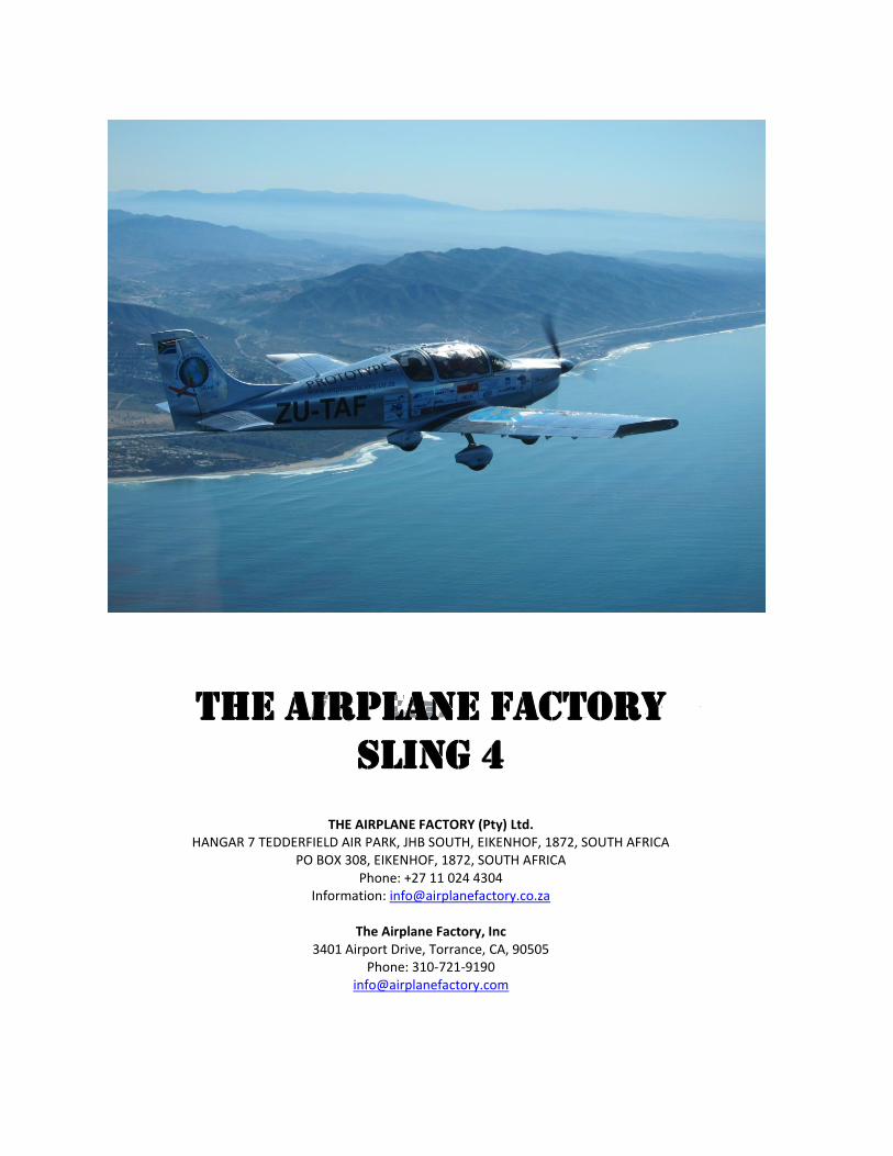
Aircraft layout
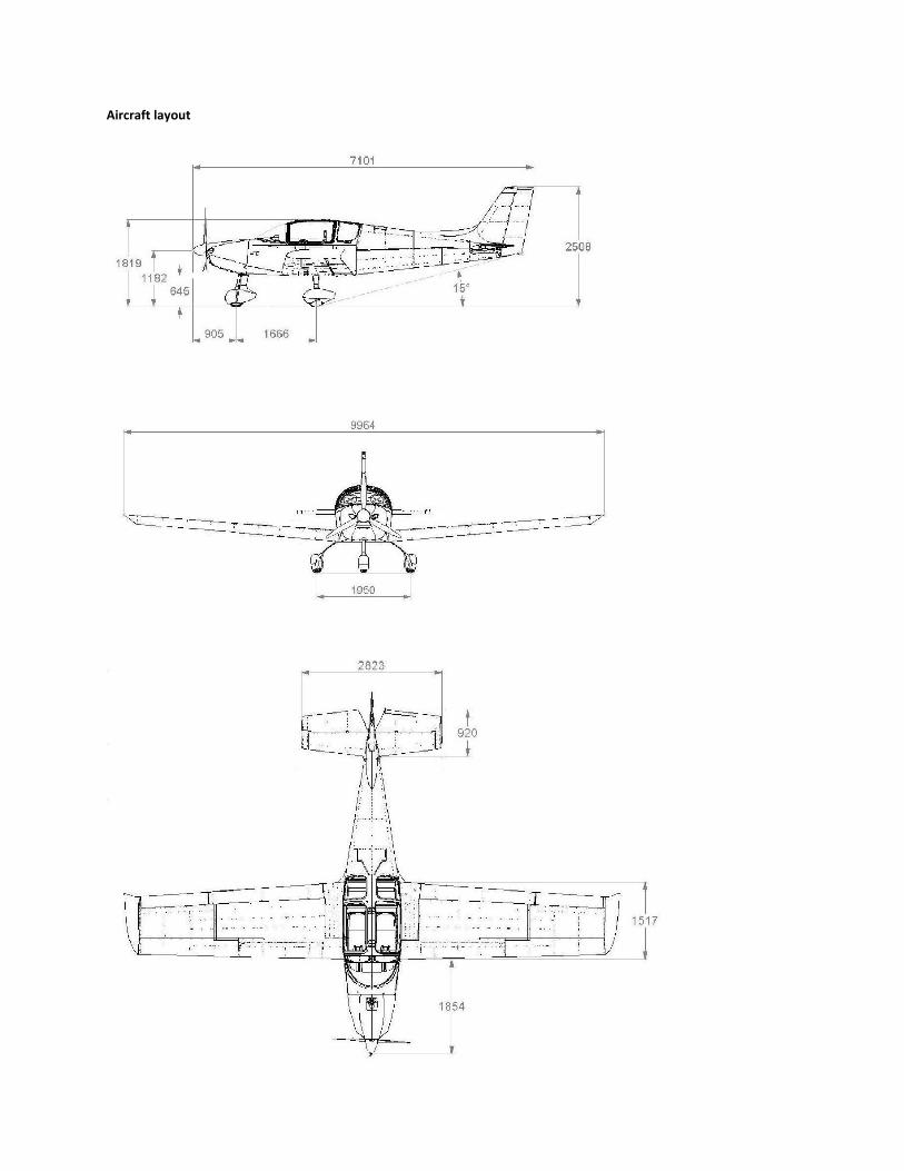
WING
Wing span: 32.7 ft (9.96 m) Mean Aerodynamic Chord: 4.5 ft (1.38 m) Wing surface area: 134.2 ft2 (12.47 m
2) Wing loading: 14.8lbft2 (72.2kgm
2)
Aspect ratio: 7.9 Taper ratio: 1.375
Dihedral: 5o
FUSELAGE
Fuselage length: 20.24 ft (6.17 m) Overall length: 23.3 ft (7.10 m) Overall width: 45.3 inches (1.15 m) Overall height: 8.2 ft (2 .50 m)
EMPENNAGE
Horizontal stabilizer span: 9.28 ft (2.83 m) Horizontal stabilizer surface area: 10.3 ft2 (0.96 m
2) Elevator surface area: 10.9 ft2 (1.02 m
2) Horizontal stabilizer angle of incidence ‐2.5
o
Vertical stabilizer span: 4.82 ft (1.47 m) Vertical stabilizer surface area: 5.7 ft2 (0.53 m
2) Rudder surface area: 6.35 ft2 (0.59 m
2)
LANDING GEAR
Wheel track: 6.4 ft (1.95m) Wheel base: 5.48 ft (1.67m) Main gear tires: 15 X 6.00 ‐ 6, 6 ply Nose gear tires: 5.00–5, 6 ply
CONTROL SURFACE TRAVEL LIMITS
Ailerons: 22o up and down
Elevator: 28o
up and 20o
down Trim tab: 20
o up and 25
o down
Rudder: 25o left and right
Flaps: 0o to 40
o down
ENGINE
Manufacturer: Bombardier‐Rotax GmbH Model: 914 UL
Type: 4 cylinder horizontally opposed with overall displacement 1211cc, mixed cooling (water‐cooled heads and air‐cooled cylinders), turbo charged, twin carburetors, integrated reduction gearbox with torque damper
Maximum power: 84.5 kW (115hp) @ 5,800 rpm (max 5 mins) 73.5 kW (100hp) @ 5,500 rpm (continuous)
Power loading: 7.8 kghp‐1
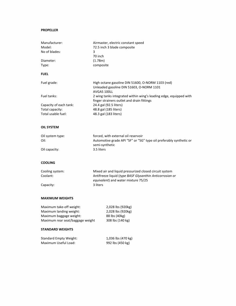
PROPELLER
Manufacturer: Airmaster, electric constant speed Model: 72.5 inch 3 blade composite No of blades: 3
Diameter: 70 inch (1.78m)
Type: composite
FUEL
Fuel grade: High octane gasoline DIN 51600, O‐NORM 1103 (red) Unleaded gasoline DIN 51603, O‐NORM 1101 AVGAS 100LL
Fuel tanks: 2 wing tanks integrated within wing’s leading edge, equipped with finger strainers outlet and drain fittings
Capacity of each tank: 24.4 gal (92.5 liters) Total capacity: 48.8 gal (185 liters) Total usable fuel: 48.3 gal (183 liters)
OIL SYSTEM
Oil system type: forced, with external oil reservoir Oil: Automotive grade API “SF” or “SG” type oil preferably synthetic or
semi‐synthetic Oil capacity: 3.5 liters
COOLING
Cooling system: Mixed air and liquid pressurized closed circuit system Coolant: Antifreeze liquid (type BASF Glysanthin Anticorrosion or
equivalent) and water mixture 75/25 Capacity: 3 liters
MAXIMUM WEIGHTS
Maximum take‐off weight: 2,028 lbs (920kg) Maximum landing weight: 2,028 lbs (920kg) Maximum baggage weight: 88 lbs (40kg) Maximum rear seat/baggage weight 308 lbs (140 kg) STANDARD WEIGHTS Standard Empty Weight: 1,036 lbs (470 kg)
Maximum Useful Load: 992 lbs (450 kg)
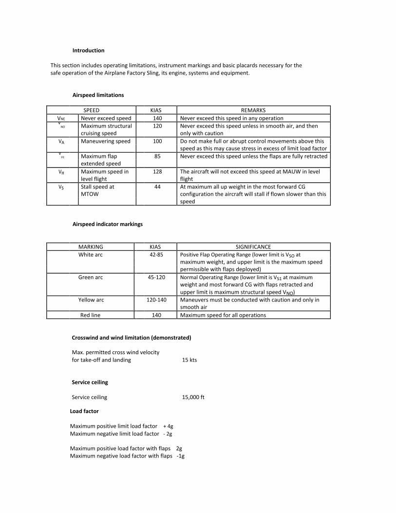
Introduction
This section includes operating limitations, instrument markings and basic placards necessary for the safe operation of the Airplane Factory Sling, its engine, systems and equipment.
Airspeed limitations SPEED KIAS REMARKS
VNE Never exceed speed 140 Never exceed this speed in any operation V
NO Maximum structural 120 Never exceed this speed unless in smooth air, and then cruising speed only with caution
VA Maneuvering speed 100 Do not make full or abrupt control movements above this speed as this may cause stress in excess of limit load factor
VFE Maximum flap 85 Never exceed this speed unless the flaps are fully retracted
extended speed
VH Maximum speed in 128 The aircraft will not exceed this speed at MAUW in level level flight flight
VS Stall speed at 44 At maximum all up weight in the most forward CG MTOW configuration the aircraft will stall if flown slower than this speed
Airspeed indicator markings
MARKING KIAS SIGNIFICANCE White arc 42-85 Positive Flap Operating Range (lower limit is VSO at maximum weight, and upper limit is the maximum speed permissible with flaps deployed) Green arc 45‐120 Normal Operating Range (lower limit is VS1 at maximum weight and most forward CG with flaps retracted and upper limit is maximum structural speed VNO) Yellow arc 120‐140 Maneuvers must be conducted with caution and only in smooth air Red line 140 Maximum speed for all operations
Crosswind and wind limitation (demonstrated)
Max. permitted cross wind velocity for take‐off and landing 15 kts
Service ceiling
Service ceiling 15,000 ft
Load factor Maximum positive limit load factor + 4g Maximum negative limit load factor ‐ 2g Maximum positive load factor with flaps 2g Maximum negative load factor with flaps ‐1g
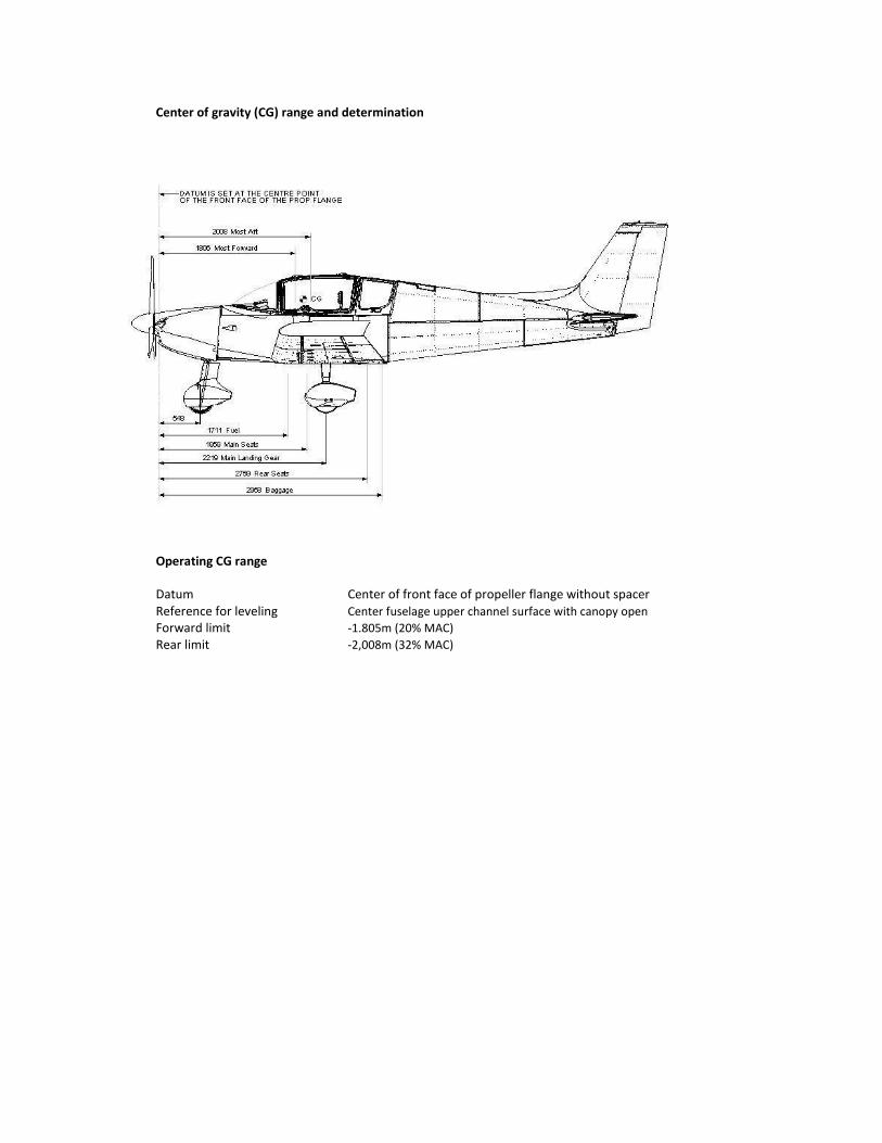
Center of gravity (CG) range and determination
Operating CG range
Datum Center of front face of propeller flange without spacer Reference for leveling Center fuselage upper channel surface with canopy open Forward limit ‐1.805m (20% MAC) Rear limit ‐2,008m (32% MAC)
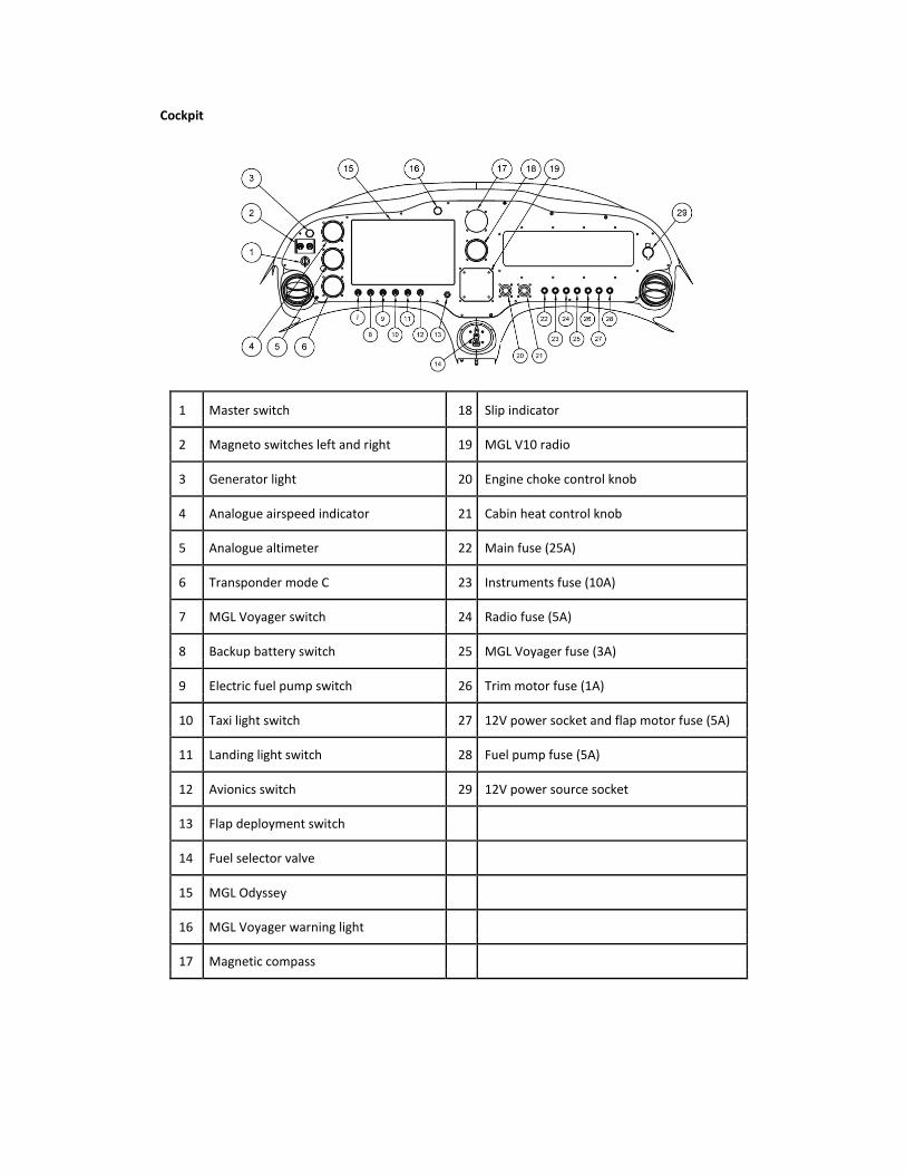
Cockpit
1 Master switch 18 Slip indicator
2 Magneto switches left and right 19 MGL V10 radio
3 Generator light 20 Engine choke control knob
4 Analogue airspeed indicator 21 Cabin heat control knob
5 Analogue altimeter 22 Main fuse (25A)
6 Transponder mode C 23 Instruments fuse (10A)
7 MGL Voyager switch 24 Radio fuse (5A)
8 Backup battery switch 25 MGL Voyager fuse (3A)
9 Electric fuel pump switch 26 Trim motor fuse (1A)
10 Taxi light switch 27 12V power socket and flap motor fuse (5A)
11 Landing light switch 28 Fuel pump fuse (5A)
12 Avionics switch 29 12V power source socket
13 Flap deployment switch
14 Fuel selector valve
15 MGL Odyssey
16 MGL Voyager warning light
17 Magnetic compass
Instruments and Avionics
• MGL Odyssey is a multifunction “glass cockpit” instrument and incorporates –
o ASI
o VSI o ALT o Compass
o Artificial Horizon o Turn co‐ordinator o G meter o Clock/timer
o Comprehensive mapping and navigation software and data o GPS o Stopwatch
o Autopilot if fitted to servos
o Full engine monitoring and management capacity including – RPM indicator CHT indicators EGT indicators Oil temperature indicator
Oil pressure indicator Fuel level indicators
Fuel flow indicator
Tachometer Flight time recorder Charge current indicator Voltmeter
See MGL Voyager operations manual for operating details.
Miscellaneous equipment
The following additional equipment and systems are used in the aircraft‐
• Ballistic parachute • MGL 2‐axis auto‐pilot • Electric flaps • Ray Allen elevator trim control motor in elevator with PTT on both control sticks • Kuntzleman wing tip nav lights with red, green and white LED • Kuntzleman strobe light on the tail • Kuntzleman wing leading edge LED landing and taxi lights on left wing • Hand actuated hydraulic brakes on main wheels with actuator in centre consol • Park brake mechanism operated by brake fluid shutoff valve in centre consol • First aid kit • Fire extinguisher
Related Documents