c. W. Davis III The Airborne Seeker Test Bed The Airborne Seeker Test Bed is a recently operational instrumentation system containing a closed-loop tracking, semi-active seeker with the capability to record high- fidelity signals pertaining to radar seeker phenomenology, target scattering character- istics, electronic countermeasures, and acquisition and tracking performance. The unique capabilities of the test bed will be used to collect data and develop computer models for evaluating and predicting missile performance. Test bed data will be used to evaluate the susceptibility of U.S. aircraft to missile attack, and to explore new directions for future systems. The test bed is also designed to support the development of advanced seekers and new electronic counter-countermeasure techniques, and to demonstrate their capabilities in flight. Major problems in missile seeker design are target -detection sensitivity and the effects of ground clutter and modem electronic counter- measures (ECM). The low radar cross section of weapons such as cruise missiles and future fighter and bomber aircraft, as well as the ability of modem targets to fly at low altitudes, makes the missile intercept problems even more diffi- cult. In addition, the effectiveness of certain modem countermeasures at degrading missile performance is not well understood. These prob- lems combine to present stressing challenges to current missile defenses. Lincoln Laboratory has undertaken a signifi- cant effort to help solve these seeker problems, with the initial emphasis on radar-guided mis- siles. The central element in this effort is the Airborne Seeker Test Bed, a flyinginstrumenta- tion system that carries a closed-loop tracking seeker and also records high-fidelity signals re- lated to radar phenomenology (clutter, multi- path), target scattering characteristics (bistatic radar cross section, scintillation statistics, angle glint), ECM, and overall seeker acquisition and tracking performance. The purpose behind the development ofthese capabilities is to collect data and to develop computer models that will assist in the design of future seekers and in the prediction of missile performance. Measured data from the test bed will be used to evaluate the susceptibility of U.S. aircraft to missile at- tack and to investigate new concepts for future The Lincoln Laboratory Journal, Volume 3. Number 2 (1990) systems. Specific features have been designed and incorporated into the test bed to support the development of techniques for electronic counter-countermeasures (ECCM), and to demonstrate those techniques in flight. The seeker is the system on the missile that performs the on-board target sensing for flight gUidance, with the ultimate purpose of bringing the intercepting missile's warhead within a le- thal radius of the target. Because of advances in radar cross-section reduction techniques and ECM, future seekers will face increasingly so- phisticated threats. In fact, the advent of low radar air vehicles has made countermeasures more attractive because the radiated power necessary to mask a vehicle's radar return has decreased to the point where small countermeasure devices are now practical. Future radar seekers will require higher sensitivity and more effective clutter rejection. These seekers will probably incorporate dual polarization sensors and multispectral sensors, such as a combination of infrared and radar. The future enhancements will help discriminate and reject false targets, including decoys. As a consequence, the burden of decision making on board the seeker will increase, as will the asso- ciated compleXity in signal processing. The system architecture of the Airborne Seeker Test Bed was selected to address this set of seeker problems. 203

Welcome message from author
This document is posted to help you gain knowledge. Please leave a comment to let me know what you think about it! Share it to your friends and learn new things together.
Transcript
c.W. Davis III
The Airborne Seeker Test Bed
The Airborne Seeker Test Bed is a recently operational instrumentation systemcontaining a closed-loop tracking, semi-active seeker with the capability to record highfidelity signals pertaining to radar seeker phenomenology, target scattering characteristics, electronic countermeasures, and acquisition and tracking performance. Theunique capabilities of the test bed will be used to collect data and develop computermodels for evaluating and predicting missile performance. Test bed data will be usedto evaluate the susceptibility of U.S. aircraft to missile attack, and to explore newdirections for future systems. The test bed is also designed to support the developmentof advanced seekers and new electronic counter-countermeasure techniques, and todemonstrate their capabilities in flight.
Major problems in missile seeker design aretarget-detection sensitivity and the effects ofground clutter and modem electronic countermeasures (ECM). The low radar cross sectionofweapons such as cruise missiles and futurefighter and bomber aircraft, as well as the abilityof modem targets to fly at low altitudes, makesthe missile intercept problems even more difficult. In addition, the effectiveness of certainmodem countermeasures at degrading missileperformance is notwell understood. These problems combine to present stressing challenges tocurrent missile defenses.
Lincoln Laboratory has undertaken a significant effort to help solve these seeker problems,with the initial emphasis on radar-guided missiles. The central element in this effort is theAirborne SeekerTest Bed, a flyinginstrumentation system that carries a closed-loop trackingseeker and also records high-fidelity signals related to radar phenomenology (clutter, multipath), target scattering characteristics (bistaticradar cross section, scintillation statistics,angle glint), ECM, and overall seeker acquisitionand tracking performance. The purpose behindthe development ofthese capabilities is to collectdata and to develop computer models that willassist in the design of future seekers and in theprediction of missile performance. Measureddata from the test bed will be used to evaluatethe susceptibility of U.S. aircraft to missile attack and to investigate new concepts for future
The Lincoln Laboratory Journal, Volume 3. Number 2 (1990)
systems. Specific features have been designedand incorporated into the testbed to support thedevelopment of techniques for electroniccounter-countermeasures (ECCM), and todemonstrate those techniques in flight.
The seeker is the system on the missile thatperforms the on-board target sensing for flightgUidance, with the ultimate purpose ofbringingthe intercepting missile's warhead within a lethal radius ofthe target. Because ofadvances inradar cross-section reduction techniques andECM, future seekers will face increasingly sophisticated threats. In fact, the advent of lowradar ~ross-section air vehicles has madecountermeasures more attractive because theradiated power necessary to mask a vehicle'sradar return has decreased to the point wheresmall countermeasure devices are nowpractical.
Future radar seekers will require highersensitivity and more effective clutter rejection.These seekers will probably incorporate dualpolarization sensors and multispectral sensors,such as a combination of infrared and radar.The future enhancementswill help discriminateand reject false targets, including decoys. As aconsequence, the burden ofdecision making onboard the seeker will increase, as will the associated compleXity in signal processing. Thesystem architecture ofthe Airborne Seeker TestBed was selected to address this set of seekerproblems.
203

Davis - The Airborne Seeker Test Bed
Seeker Performance Issues
The ability of a rriissile to intercept a target isoften limited by seeker sensitivity. ground-clutter rejection, or ECM immunity. The specificwaveform used by the seeker, which providesvarying degrees of resolution in Doppler frequency and range, also has performance implications. These subjects are reviewed in thefollowing paragraphs.
Seeker Sensitivity
Low cross-section targets tax the capabilitiesof intercepting missiles by requiring them to bemore sensitive to target detection in the presence of natural thermal noise. The followingmethods can increase the sensitivity ofa missilesystem:1. Increase transmitter power. For example,
doubling the transmitter power would increase the free-space detection range by afactor of 1.2 on a given target.
2. Increase transmitter and/or receiver antenna gains. Doubling the dimensions ofone of the antennas would increase thefree-space detection range by a factor of1.4 on a given target. In practice, thenarrow diameter of a missile restrictsantenna size, which also restricts achievable antenna gain. Typical air-to-airmissile seeker antennas are 5 to 7 inin diameter; similar antennas for surface-to-air missiles range from 9 to 16 in.
3. Lower the receiver noisejl.oor. Current systems have noise floors within 4 to 10 dB oftheoretical limits. A 3-dB improvement(which is a challenge to achieve) would increase the free-space detection range by afactor of 1.2 on a given target.
4. Increase the received signal integration period. A longer signal integration periodwould reduce the effect of thermal noise.Faster signal processing could lead to integration periods up to 10 times longerthan current systems. an increase in integration that could extend the free-spacedetection range by a factor of 1.8. Thebenefits of integration are limited. how-
204
ever, because the accelerations of targetmaneuvering smear the signal and makethe integration ineffective beyond a certain period.Significant performance gains are difficult to
achieve, as indicated in the first three categorieslisted above. Even the gains created by a longersignal integration period could be insufficientfor future low cross-section targets. A possiblesolution to the sensitivity problem is to launchthe missile and gUide it remotely by a powerfulcommand-guidance system out to a range closeenough for the seeker to detect the target. Thecommand-guidance radar would be a largersystem that could solve the sensitivity problemby increasing transmitter power and/or antenna gain. The seeker in these systems wouldneed the capability to acquire the target autonomously, since the command gUidance may beunable to put the seeker onto the target directly.Whatever missile system architecture is considered, the seeker performance implications ofthe low cross-section threat, and concepts forpossible improvements, provide a significantchallenge.
Ground Clutter
Even ifthe seeker possesses enough sensitivity. the ground clutter can limit performance bymasking the target return. Figure 1 illustratesthe clutter environment as viewed by the missile. The specific case shown is for a semi-activesurface-to-air missile with continuous-wave(CW) illumination (see the box titled "RadarGuided Missiles" for a definition of missiletypes). For outbound targets (the tail chasescenario), ground clutter seen through the antenna sidelobes directly obscures the targetreturn. For inbound targets, the target returncompetes with the noise sidebands from themissile's receiver oscillators (and other systemspecific sources), which spill into what wouldhave been a clutter-free portion of the Dopplerspectrum. The level of these noise sidebands isproportional to the strongest signal (usuallymain-beam clutter) in the receiver. If the targetis high enough in Doppler frequency (which corresponds to a high missile-to-target closing ve-
The Lincoln Laboratory Journal. Volume 3. Number 2 (l990)

locity), the target will appear in a region of thespectrum where the noise sidebands havereached a floor level. In low-clutter situationsthis floor level is the thermal noise floor of thereceiver.
Figure 1 indicates that the missile is morecapable of intercepting targets in the incomingtarget region than in the outgoing target region.Therefore, air vehicle designers must generallyemphasize lowering the nose cross section toenhance a vehicle's ability to penetrate radardefenses.
Signal integration reduces the effective levelofthe noise sidebands, with respect to the targetsignal, and reduces the sidelobe clutter. Theseeker designer further combats the effects ofclutter by attempting to achieve low sidelobes onthe antenna and high oscillator stability (lownoise sidebands) in the receiver.
Electronic Countermeasures
Many categories of ECM currently exist.Certain ECM techniques are designed to exploit
Missile
Davis - The Airborne Seeker Test Bed
an idiosyncratic Achilles' heel in the threatsystem. For example, a missile that relies onthree consecutive signal bursts to perform target-angle measurement can be confused by adistorted or amplified signal sent by the targetevery third burst. The idiosyncratic techniquesgenerally exploit some vulnerable characteristic of the victim's receiver architecture, signalprocessing technique, or control logic(and consequently require a knowledge of thecharacteristic). These ECM techniques are generally classified, since the enemy can eliminatethe specific vulnerability if the weakness beingexploited is known.
Other more fundamental techniques are difficult to overcome, even if the enemy has knowledge of them. A decoy deployed by the target, forexample, can be an actual radar target, physically separated from the true target. Since thedecoy is a real target, the seeker cannot eliminate it by a simple change in processing algorithm. We must devise a more complicated method to discriminate the true targetfrom the decoy. In addition to expendable or
RadarAntenna
/
Target
Outbound....:::::Siii~Llnbound
InboundTarget
Doppler Frequency
Fig. 1-Received clutter spectrum for a semi-active missile. The clutter return spreads out in Dopplerfrequency; clutter approached by the missile has a positive Doppler, clutter directly beneath the missilehas zero Doppler, and clutter behind the missile has a negative Doppler. Incoming targets appear at ahigher Doppler frequency than any clutter; outbound targets have a Doppler frequency that appears inthe sidelobe clutter region.
The Lincoln Laboratory Joumal. Volume 3. Number 2 (1990) 205

Davis - The Airborne Seeker Test Bed
Radar-Guided Missiles
Radar-guided missiles exist infour basic categories: commandguided. active homin<1. semi-active homin<1, and passive homing.A missile system can be designedto use each of these methods incombination. For example. a system can have command gUidancefor most of the missile fly-out.followed by semi-active homing inthe terminal phase of fli<1ht.
A command-guided missilehas neither a radar transmitternor a radar receiver on board. Aseparate radar (usually groundbased) tracks both the tar<1et andthe outgoing missile and computes the trajectory chan<1esneeded to <1uide the missile to itstar<1et. These flight commandsare communicated to the missileby a data link. The accuracy ofthemissile intercept is limited by theprecision with which the radarcan determine the target andmissile locations. This precisiondegrades as the range to theintercept increases. leadin<1 tolarger miss distances. Command<1uidance may be necessary whenother modes of missile <1uidanceare inadequate because of clutter. jamming. or missile receiversensitivity problems. Many foreign missiles employ commandgUidance modes because a command-<1uided missile does notrequire a complex on-boardseeker system.
Missile homing gUidance isneeded to achieve a smaller missdistance. which is especiallyimportant for air-to-air missilesthat carry small warheads. Anactive missile carries its ownradar. complete with transmitterand receiver (e.g .. the U.SAMRAAM). Because of a smallpayload capacity and antenna
aperture. the radar on a missile isnot as powerful as a groundbased or aircraft-mounted radar.To achieve long ranges on lowcross-section tar<1ets. activehomin<1 must be combined withother means such as commandgUidance to get the missile withinhoming range to the tar<1et. Activemissiles have the attractive features of fve-and-jorget. whichcan increase the fIre power of agiven fire control system. Adisadvantage of active missile seekersis higher cost. since a radartransmitter is reqUired in themissile.
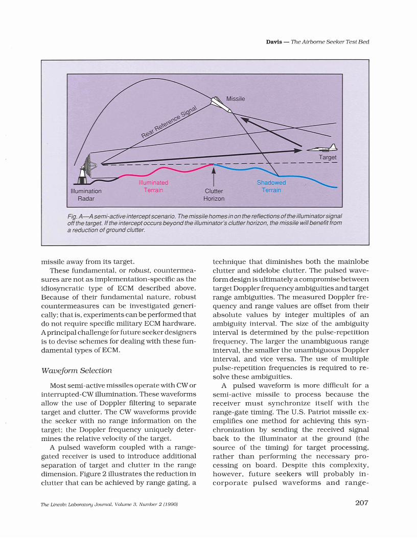
A high proportion of theworld's radar missile inventoriesuse a semi-active architecture. ascheme in which the missile carries only a radar receiver. not atransmitter (see Fi<1. A). The radartransmitter that illuminates thetarget is in a separate unit that iseither Q'round based or airborne.This architecture has severaladvantages. Delivering sufficientradar energy to a target at longran<1es requires high transmitterpower and hi<1h-gain antennas(thus requirin<1 a large antennaaperture). both ofwhich are diffIcult to achieve on a missile constrained in wei<1ht and volume.Stronger illumination is moreeasily provided by a Q'roundbased system or. to a lesser extent. by a fIghter aircraft. Thisadvantage is especially importantwhen the target has a low radarreturn. which requires hi<1her illuminator powers to achieve target detection.
Another advantage of thesemi-active approach illustratedin Fig. A is that for surface-to-airmissiles. which use a groundbased illuminator. the geometry
of the missile intercept can be arranged to minimize the effects ofclutter. The missile antenna maybe looking down at the earth. butthe earth is shielded from theilluminator by intervening terrain. A further advantage of thesemi-active architecture is thatelectronic countermeasures intended to frustrate the missile areoften directed back toward theradar source. The missile is notradiating. so the tar<1et will notknow the missile's location andmay not be able tojam the missileseeker.
Figure A also indicates the existence of a rear reference signal.For a semi-active seeker to support coherent si<1nal proceSSing(such as Doppler llitering) themissile must either carry a stablefrequency re~rence or have areceiver dedicated to listening tothe direct si<1naI from the illuminator (the rear receiver).
A passive homing seekergUides itself by radio emissionsfrom the tar<1et. These emissionsare from the target's own radar orotheron-board radiating sensors.The advantages of passive homing are that it does not require aseparate illumination radarand itoperates qUietly (a powerful illumination signal recognized by thetarget is a warning of the imminent arrival ofa missile). A disadvantage is that the passive seekerdepends on the presence of targetemissions durin<1 homing. andthese emissions are not controlled by the missile system.Another disadvantage is that theseeker must operate with a variety ofdifferentwaveforms that arespecific to particular targets. andthese waveforms are not optimalfor missile homin<1.
towed decoys. other fundamental techniquesinclude wavefront distortion (known as crosseye), for corrupting the seeker's measurement
206
of target angle, and terrain bounce jamming, in which a brightly illuminatedspot on the ground is created to draw the
The Lincoln Laboratory Joumal. Volume 3. Number 2 (I 990)
IlluminationRadar
IlluminatedTerrain
tClutterHorizon
Davis - The Airborne Seeker Test Bed
Fig. A-A semi-active interceptscenario. The missile homes in on the reflections ofthe illuminatorsignaloff the target. If the intercept occurs beyond the illuminator's clutter horizon, the missile will benefit froma reduction ofground clutter.
missile away from its target.These fundamental, or robust, countermea
sures are not as implementation-specific as theidiosyncratic type of ECM described above.Because of their fundamental nature, robustcountermeasures can be investigated generically; that is, experiments can be performed thatdo not require specific military ECM hardware.Aprincipal challenge for future seeker designersis to devise schemes for dealing with these fundamental types of ECM.
Waveform Selection
Most semi-active missiles operate with CWorinterrupted-CW illumination. These waveformsallow the use of Doppler filtering to separatetarget and clutter. The CW waveforms providethe seeker with no range information on thetarget; the Doppler frequency uniquely determines the relative velocity of the target.
A pulsed waveform coupled with a rangegated receiver is used to introduce additionalseparation of target and clutter in the rangedimension. Figure 2 illustrates the reduction inclutter that can be achieved by range gating, a
The Lincoln Laboratory Joumal. Volume 3. Number 2 (J 990)
technique that diminishes both the mainlobeclutter and sidelobe clutter. The pulsed waveform design is ultimately a compromise betweentarget Doppler frequency ambigUities and targetrange ambigUities. The measured Doppler frequency and range values are offset from theirabsolute values by integer multiples of anambigUity interval. The size of the ambigUityinterval is determined by the pulse-repetitionfrequency. The larger the unambiguous rangeinterval, the smaller the unambiguous Dopplerinterval, and vice versa. The use of multiplepulse-repetition frequencies is reqUired to resolve these ambigUities.
A pulsed waveform is more difficult for asemi-active missile to process because thereceiver must synchronize itself with therange-gate timing. The U.S. Patriot missile exemplifies one method for achieving this synchronization by sending the received signalback to the illuminator at the ground (thesource of the timing) for target processing,rather than performing the necessary processing on board. Despite this complexity,however, future seekers will probably incorporate pulsed waveforms and range-
207

Davis - The Airborne Seeker Test Bed
(a)
(b)
Clutter Geometry(Plan View)
SidelobeClutter Area
at TargetDoppler
Clutter Geometry(Plan View)
Signal Spectrum
Frequency
Signal Spectrumfor Selected Range Gate
Frequency
Fig. 2-A comparison ofthe clutter resolution ofcontinuous-wave (CW) andpulsed waveforms. (a) For theCW waveform, differentDopplerbins in the clutterspectrum divide the terrain into strips ofconstant Dopplerfrequency (called isodops). The area ofground in one of these strips multiplied by the antenna gains andclutter reflectivity value determines the strength of the clutter signal in that Doppler bin. (b) In a pulsedDoppler waveform, consecutive signal samples represent clutter returns for different ranges from theseeker. When coupled with the resolution provided by Doppler binning, the clutter level in a given rangeDoppler cell is generally reduced in comparison to CWmethods because the ground area in a cell is less.
gated receivers to reduce clutter problems.
Airborne Seeker Test Bed
Figure 3 shows the Lincoln Laboratory Airborne Seeker Test Bed that was designed tosupport investigations into the problems described in the previous section. Direct applications of the test bed are in the followingareas:1. Target radar cross-section measurement.
208
The test bed instrumentation was designed with enough sensitivity for thestudy of low cross-section targets. It provides dynamic in-flight dual-polarizedmeasurements of the target radar crosssection, scintillation (amplitude fluctuations) , and glint (an interference effect thatinduces large angle-measurement errors),all measured at transmitter and receiverangles representative of missile interceptgeometries.
The Lincoln Laboratory Joumal. Volume 3. Number 2 (1990)

2. Bistatic clutter database measurement. Adual-polarized database of bistatic (different angles to the transmitter and receiver)ground clutter can be developed for sites ofinterest and used in clutter modeling.Clutter measurements also support livefiring tests by helping to select the firing geometries.
3. Measurement oj operational scenarios ojtargets in clutter. Target and test bed flightpaths are chosen to simulate realistic intercept trajectories for evaluating targetdetectability and trackability.
4. ECM evaluation. The test bed has a highfidelity capability to measure the signals
FUR (8-12/lm)
Davis - The Airborne seeker Test Bed
generated by selected ECM. These measurements directly characterize the ECMsignals. and the measured data can also beused as input to seeker system simulations that predict the ECM effect on themodeled missile system.
5. ECCMalgorithm development. Another usefor the ECM signal data is to look for discriminants. or signal features that can beused to separate false signals from the truetarget. New ECCM algorithms will be developed and tested on the measured ECMdata. These algorithms can then be testedin real time on the test bed dUring a simulated intercept.
Fig. 3-Principal elements of the Airborne Seeker Test Bedon the Falcon 20aircraft. The principalsensor, a large X-banddual-polarized monopulse antenna, is supported by a large number of instrumentation channels and a high-speedrecorder. A Forward Looking Infrared Sensor (FUR) provides an angle reference on targetposition for use with the radardata. A wing-mounted C-band radar locates the target and directs the other sensors.
The Lincoln Laboratory Journal. Volume 3. Number 2 (1990) 209
Davis - The Airborne Seeker Test Bed
The data obtained through the five activitieslisted above will be applied to the development ofcomputer models of seeker performance, fromphenomenology models (clutter, target radarcross-section dynamics) to missile fly-out models with six degrees of freedom. From thesemodels we will extrapolate measured results toterrains other than military test ranges andevaluate the performance of new concepts forfuture missile systems.
The test bed represents a captive-cany concept (the box titled "Methods for EvaluatingMissile Performance" reviews missile performance categories). A principal advantage of acaptive-carry experiment is that it allows operation in the actual real-world environment andoffers the possibility of repeatable trajectoriesand systematic profiling. A specific advantage ofthe Airborne Seeker Test Bed is that using adedicated passenger jet (instead of pod-mounting the sensor equipment on a military jet) offers room for high-fidelity instrumentation andrecording with operator interaction.
Whenever possible, the elements of the testbed instrumentation were designed for betterperformance than the corresponding elementsof an actual missile. This level ofperformance ispossible because of the advantages offered bythe test bed platform. The nose-mounted primary antenna allows the use of a hemisphericalradome that minimizes polarization and anglemeasurement distortion, and facilitates a largeantenna aperture to provide increased sensitivity. The benign vibration environment providedby the jet platform supports better referenceoscillator stability to improve the clutter rejection performance. Signal integration can occurover longer time periods, which further increases the sensitivity and clutter rejection ofthe system.
The slower speed of the test bed leads to acompressed clutter spectrum because the Doppler spread of ground clutter is proportional tothe aircraft velocity. The velocity ofthe Falcon 20is 2.5 times slower than the velocity of a typicalmissile. For the number of Doppler cells acrossthe clutter to be comparable to a missile, theDoppler resolution in the test bed must be 2.5times finer than in the missile. This resolution is
210
achieved on the test bed by extending the integration time; in fact, Doppler resolutions morethan five times finer than those of a missile arepractical. Note that the target spectrum is notaffected by test bed speed, and the limits ontarget integration time due to target accelerationapply without scaling.
These important improvements in performance have been implemented so that the measured data will be more precise than the dataavailable to a practical missile system. To modelexisting systems the test bed data will be degraded to match the performance of the systembeing studied. The original unspoiled data areimportant both to the phenomenology studies(clutter and target signature) and to illustrateachievable seeker performance.
Overview oJTest Bed Hardware
Figure 3 shows the major elements of theAirborne SeekerTest Bed. The principal payloadof the Airborne Seeker Test Bed is the Instrumentation Head (IH), which is an X-band serniactive radar receiver configured as a missileseeker. The principal sensor of the IH is a largedual-polarized antenna mounted on a modifiedHAWK seeker gimbal. Behind the antenna are alarge number of instrumented channels. Raytheon Missile Systems Division in Tewksbury,Mass., served as subcontractor on the IH andthe Forward Looking Infrared System (FUR)discussed later in the paper.
The IH receiver was designed to accommodate a variety of different waveform types, ranging from CW waveforms to experimental rangegated (pulsed) waveforms. This capabilitymakes the IH compatible with existing illuminators such as the HAWK High Power Illuminator(HPI), the AWG-9 (on the F-14 fighter), and theAPG-63 and APG-70 (on the F-15 fighter), aswell as experimental and simulator radars.The Georgia Tech Research Institute (GTRI)constructed an experimental radar calledthe Waveform Simulator for use with the testbed, and it can generate every waveformusable by the IH. A separate radio data linkfrom the illuminator synchronizes theIH receiver when the test bed is used with
The Lincoln Laboratory Journal. Volume 3. Number 2 () 990)
Davis - The Airborne Seeker Test Bed
Methods for EvaluatingMissile Performance
Live Firing
An actual missile intercept ofatar<fet is performed in a live firing.a type of test that realisticallyevaluates a missile by recordingtrue missile dynamics. A typicalmissile research and development program can involve 100missile firings. The tests are limited. however. because only a fewlocations are available for live firings. and the amount ofdata collected can be limited by telemetryconstraints. Also. for obviousafety reasons. live fuin<fs are notperformed again t manned tar<fets. which prevents this type ofevaluation of missile susceptibility for new aircraft. Live firing isalso prohibitively expensive to doon more than a few geometries.Becau e ofthe limitations and expense. computer modelin<f isimportant in the desi<fn of te tscenarios to ensure that the livefiring yield the mo t useful data.
Captive Carry
Captive-carry experimentscarry a missile under the Wing or
belly of a piloted aircraft. Closeapproximations to real intercepts can be flown. and increasedinstrumentation over a live firin<fis potentially available. Captive-carry flights can also operate against manned tar<fet . Thisapproach offer the possibilityof more exhaustive testing inmore varied environments. compared to live firing. and it isespecially useful in the development of lar<fe databa es (e. <f..round clutter). Captive-carry
also permits the evaluation ofECM and ECCM technique insitu.
Hardware-in-the-LoopSimulations
Thi evaluation method uses abench setup to inject Signals intoselected hardware components ofa missile. Software simulation sequences the signals and hardware through a missile-intercepttime line. This approach can be aselaborate as placing a completeseeker with antenna in an anechoic chamber, where radiatin<f
hom antennas in the chamberrepre ent clutter and tar<fet.Actual measured signals(from a captive carry or livefirin<f can be u ed. but the interaction of the eeker and theenvironment is necessarily limited. This type of test relies onthe accuracy of the assumptionsmade in the software model.Thi approach is useful in exerci in<f and evaluating specificfunctions of the seeker hardware and software.
Computer Simulation
Computer simulation is themost flexible analysis techniquebecause it can be extrapolatedto cases that have not or cannot be tested. It is also likely toprOVide the least fidelity ofthe listed methods because theresults depend on the accuracy of assumptions usedin the software model. The validity of a computer simulation isenhanced <freatly by infusions ofthe data and experience gainedfrom the captive-carry and livefuin<f tests.
experimental interrupted iUuminators thatperiodically send brief bursts of illuminationenergy.
In addition to the IH, the test bed carries aC-band Beacon Tracking Radar (BTR) underthe wing. The BTR tracks a transponder onthe target aircraft and provides target-angle,range, and range-rate information in real timeto the other sensors on the test bed, sothat those other sensors can be tuned to the target signal even if they haven't yet detectedthe target. Another test bed sensor mountedunder the nose is an 8-to-I2-,um-band infraredimaging device (the FUR) that provides precision angle data on the target. A second pod un-
The Lincoln Laboratory Joumal. Volume 3. Number 2 (1990)
der the nose is currently empty and availablefor another optical sensor.
Forward Sensor Antenna
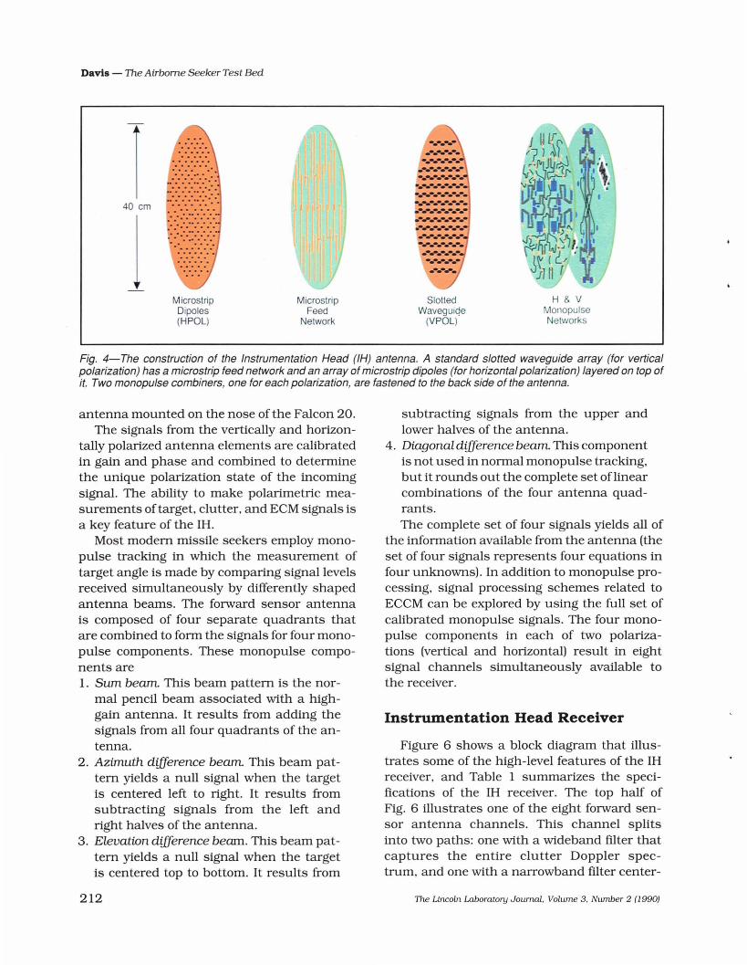
The forward sensor antenna, which is theprincipal sensor of the IH, is a large (I6-indiameter) X-band dual-polarized monopulseantenna. Figure 4 shows how the antennawas constructed as a sandwich, with an off-theshelf slotted waveguide array that senses thevertical polarization. An array of microstrip dipoles with a microstrip feed layer embeddedbeneath it senses the horizontal polarization.Figure 5 is a photograph of the forward sensor
211
Davis - The Airborne Seeker Test Bed
H & VMonopulseNetworks
SlottedWavegulC!e
(VPOL)
................•.••....•..................................................... ........-.•••.................., •.•.................................................
.......
MierostripFeed
Network
MierostripDipoles(HPOL)
... . ... : ............ ....40 em
Fig. 4-The construction of the Instrumentation Head (IH) antenna. A standard slotted waveguide array (for verticalpolarization) has a microstrip feed network and an array of microstrip dipoles (for horizontalpolarization) layered on top ofit. Two monopulse combiners, one for each polarization, are fastened to the back side of the antenna.
antenna mounted on the nose of the Falcon 20.The signals from the vertically and horizon
tally polarized antenna elements are calibratedin gain and phase and combined to determinethe unique polarization state of the incomingsignal. The ability to make polarimetric measurements of target, clutter, and ECM signals isa key feature of the IH.
Most modem missile seekers employ monopulse tracking in which the measurement oftarget angle is made by comparing signal levelsreceived simultaneously by differently shapedantenna beams. The forward sensor antennais composed of four separate quadrants thatare combined to form the signals for four monopulse components. These monopulse components are1. Sum beam. This beam pattern is the nor
mal pencil beam associated with a highgain antenna. It results from adding thesignals from all four quadrants of the antenna.
2. Azimuth difference beam. This beam pattern yields a null signal when the targetis centered left to right. It results fromsubtracting signals from the left andright halves of the antenna.
3. Elevation difference beam. This beam pattern yields a null signal when the targetis centered top to bottom. It results from
subtracting signals from the upper andlower halves of the antenna.
4. Diagonal difference beam. This componentis not used in normal monopulse tracking,but it rounds out the complete set oflinearcombinations of the four antenna quadrants.The complete set of four signals yields all of
the information available from the antenna (theset of four signals represents four equations infour unknowns). In addition to monopulse processing, signal processing schemes related toECCM can be explored by using the full set ofcalibrated monopulse signals. The four monopulse components in each of two polarizations (vertical and horizontal) result in eightsignal channels simultaneously available tothe receiver.
Instrumentation Head Receiver
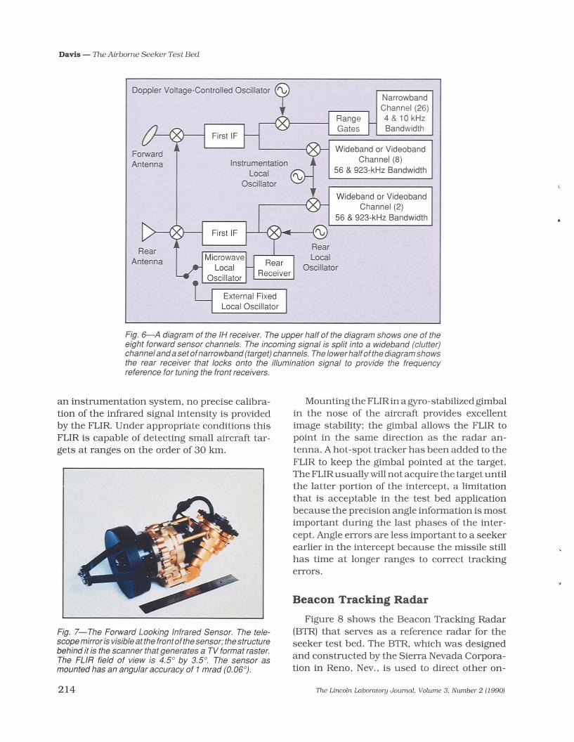
Figure 6 shows a block diagram that illustrates some of the high-level features of the IHreceiver, and Table 1 summarizes the specifications of the IH receiver. The top half ofFig. 6 illustrates one of the eight forward sensor antenna channels. This channel splitsinto two paths: one with a wideband filter thatcaptures the entire clutter Doppler spectrum, and one with a narrowband filter center-
212 The Lincoln Laboratory Journal. Volume 3. Number 2 (1990)

ed on the target. The narrowband filter rejectsthe clutter signals to improve the fidelity ofthe recorded target signature. With a pulsedwaveform, three independently controllablerange gates are in each of the narrowbandchannels, and a split gate channel (in themonopulse sum channels only) provides a rangetracking-error signal. The IH has a total of 26narrowband channels.
The bottom half of Fig. 6 illustrates the rearreceiver that receives the direct path signal fromthe illuminator via the rear antenna in the tail ofthe aircraft. The signal passes through frequency-locked and phase-locked loops to provide the stable frequency reference to mix downthe front channels. The oscillator used for thisfunction is from the AIM-7 Sparrow missile, andthe rear loop design is similar to the Sparrownarrowband rear receiver.
If problems related to missiles that carrytheir own on-board frequency reference need investigation. the rear loop can be bypassedand a separate fixed local oscillator can be
Davis - The Airborne Seeker Test Bed
used. In either configuration the vertical andhorizontal polarization signals are recorded inthe rear receiver. These two rear channels,along with the eight forward channels, make atotal of 10 wideband channels in the IH.
The Forward LookingInfrared Sensor
The role of the FUR in the test bed is toprovide a precision angle reference to the targetto compare with the radar data from the IH (Fig.7). In particular, the pointing direction of the RFseeker can be superimposed on the target imageto indicate the effects ofECM. The FUR forms a1V-compatible image from light in the infraredband (thermal radiation) with wavelengths of 8to 12 JIm. The particular infrared device we usewas manufactured by Kollmorgen and was intended for security surveillance (for example. inprison perimeter security). It was selected as alow-cost infrared sensor for angle measurementon the test bed. Because it was not designed as
Fig. 5-The Falcon 20 nose unit is shown with the radome removed, which reveals the dualpolarizedX-band antenna. The rightpodholds the FUR sensor (behind the orangezinc sulfidewindow). The left pod is currently empty and available for a future payload.
The Lincoln Laboratory Journal. Volume 3. Number 2 (1990) 213
Davis - The Airborne Seeker Test Bed
Doppler Voltage-Controlled Oscillator (9
InstrumentationLocal
Oscillator
NarrowbandChannel (26)4 & 10 kHzBandwidth
Wideband or VideobandChannel (8)
56 & 923-kHz Bandwidth
Wideband or VideobandChannel (2)
56 & 923-kHz Bandwidth
Fig. 6-A diagram of the IH receiver. The upper half of the diagram shows one of theeight forward sensor channels. The incoming signal is split into a wideband (clutter)channelanda setofnarrowband (target) channels. The lower halfof the diagram showsthe rear receiver that locks onto the illumination signal to provide the frequencyreference for tuning the front receivers.
an instrumentation system, no precise calibration of the infrared signal intensity is providedby the FUR. Under appropriate conditions thisFUR is capable of detecting small aircraft targets at ranges on the order of 30 km.
Fig. 7-The Forward Looking Infrared Sensor. The telescope mirror is visible at the front ofthe sensor; the structurebehind it is the scanner that generates a TV format raster.The FUR field of view is 4.5° by 3.5°. The sensor asmounted has an angular accuracy of 1 mrad (0.06°).
214
Mounting the FUR in a gyro-stabilized gimbalin the nose of the aircraft provides excellentimage stability; the gimbal allows the FUR topoint in the same direction as the radar antenna. A hot-spot tracker has been added to theFUR to keep the gimbal pointed at the target.The FUR usually will not acquire the target untilthe latter portion of the intercept, a limitationthat is acceptable in the test bed applicationbecause the precision angle information is mostimportant during the last phases of the intercept. Angle errors are less important to a seekerearlier in the intercept because the missile stillhas time at longer ranges to correct trackingerrors.
Beacon Tracking Radar
Figure 8 shows the Beacon Tracking Radar(BTR) that serves as a reference radar for theseeker test bed. The BTR, which was designedand constructed by the Sierra Nevada Corporation in Reno. Nev.. is used to direct other on-
The Lincoln Laboratory Journal. Volume 3. Number 2 (J 990)

Davis - The Airborne Seeker Test Bed
Table 1. Specifications for Instrumentation Head Receiver
Item Requirement
Frequency 9750-to-10,050 MHz inclusive
Signal waveforms Continuous wave (CW) and pulsedPulsewidth (min) 0.78psPRF 20 kHz to 400 kHz
Maximum signals (at antenna port)Operating
Front -10 dBmRear OdBm
SurvivableFront +60 dBm PK +30 dBm AVGRear +30 dBm PK +20 dBm AVG
Polarization of rear sensor andforward sensor Horizontal (H) &vertical (V)
Oscillator stabilityNoise sidebands
<15 kHz Microwave LO dominant15 kHz to 3 MHz -80 dBclkHz
Discrete sidebands<15 kHz -(80 + 20 log f/15) dBc
f = frequency separation in kHz15 kHz to 3 MHz -80 dBc
System noise figureForward sensor $; 8 dBRear sensor $;15 dB
Receiver bandwidthNarrowband 4 kHz & 10 kHzWideband 56 kHzVideoband 923 kHz
Coherent processing interval (Cpr)For data collection 50 msFor auto track 0.5 to 16 ms
Channel-to-channel tracking accuracy(after calibration)
Gain 0.5 dB (1a)Phase 3.0° rms
Absolute amplitude error(including calibration) <±1.0dB
IR adjunct sensorGimbal limits ± 50° pitch; ± 40° yawAngle accuracy (static positioning) $; 1.0 mrad rms
The Lincoln Laboratory Journal. Volume 3. Number 2 (1990) 215
Davis - The Airborne Seeker Test Bed
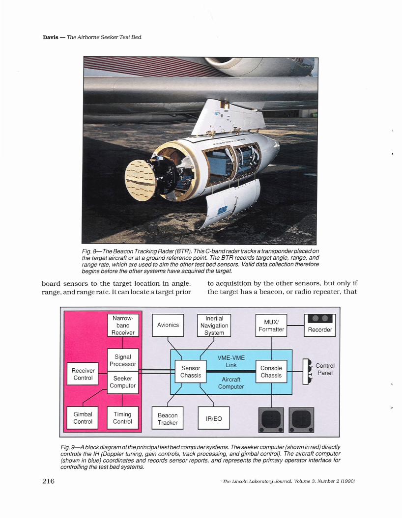
Fig. 8-The Beacon Tracking Radar (BTR). This C-band radar tracks a transponderplacedonthe target aircraft or at a ground reference point. The BTR records target angle, range, andrange rate, which are used to aim the other test bed sensors. Valid data collection thereforebegins before the other systems have acquired the target.
board sensors to the target location in angle,range, and range rate. It can locate a target prior
to acquisition by the other sensors, but only ifthe target has a beacon, or radio repeater, that
ControlPanel
Recorder
ConsoleChassis
MUX/Formatter
AircraftComputer
VME-VMELink
IR/EOBeaconTracker
SensorChassis
Avionics
Fig. 9-A block diagram oftheprincipal test bedcomputersystems. The seekercomputer (shown in red) directlycontrols the IH (Doppler tuning, gain controls, track processing, and gimbal control). The aircraft computer(shown in blue) coordinates and records sensor reports, and represents the primary operator interface forcontrolling the test bed systems.
216 The Lincoln Laboratory Journal, Volume 3, Number 2 (J 990)

sends back a strong signal in response to theBTR interrogations. Because this signal is at adifferent frequency (C-band) from the other testbed sensors, signal interference does not occur.The BTR is designed to locate the target at atypical initial range of30 km. The BTR is housedin a standard AST-4 pod and weighs210lbs; theother pod is empty and is used for aerodynamicbalance.
Computers and Data Recording
Figure 9 is a block diagram of the primarycomputers of the test bed. The red area in thefigure indicates the digital system associatedwith the IH. This system, called the seekercomputer, is responsible for receiver gaincontrol, Doppler tUning, antenna gimbal control, and performance of the closed-loop targettracking. The blue area in the figure is theaircraft computer that controls the test bed systems. It coordinates and records the sensorreports (IH, FLIR, BTR, inertial navigation system. and global positioning system) andprovides the primary operator interface forthe test bed.
The computers are multitasking multi-CPUsystems based on Motorola 68020 CPUs in aVME bus. Most of the system software is programmed in the C language. The signal processor is fully software programmable; the seekerand aircraft computer chassis have room toaccommodate hardware enhancements and asecond signal processor. These features areincluded to support future additions and modifications to the test bed.
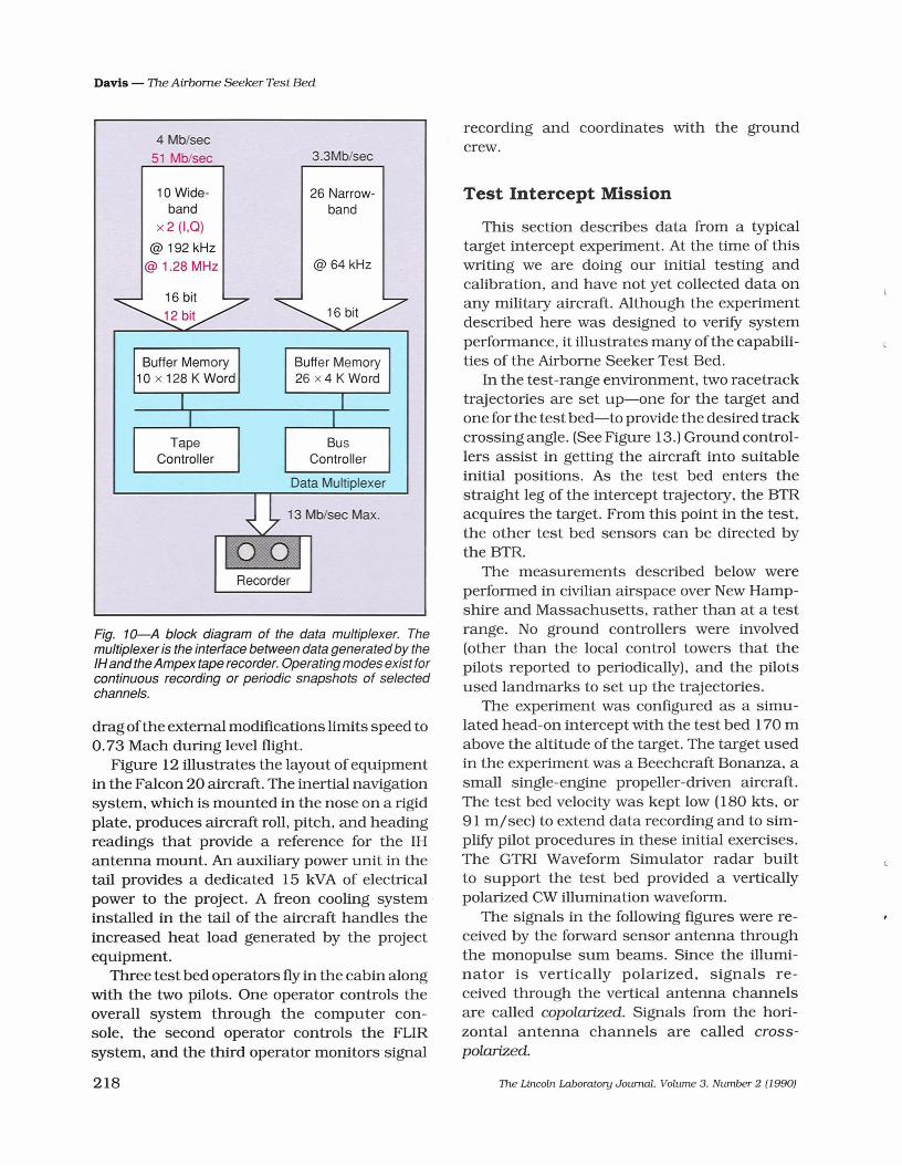
The bulk of the radar data from the IH doesnot enter the computers; it is passed to the highspeed recorder by a custom data multiplexerdeveloped by TEK Microsystems of Burlington,Mass. Figure 10 shows the data flow pathssupported by the data multiplexer. The highspeed data recorder is an Ampex DCRSi rotaryhead cassette recorder that can support datarates up to 13.3 MB/sec. Since the data ratefrom the IH can reach 50 MB/sec in somemodes. the data multiplexer can be programmed to optimize the recording. which
The Lincoln Laboratory Journal. Volume 3. Number 2 (1990)
Davis - The Airborne Seeker Test Bed
allows high data rates to be supported inbursts. The data multiplexer can also supportan additional DCRSi recorder.
Figure 11 is a photograph of the operator'scontrol panel. The operator can see full signalspectra in real time and make decisionsthroughout the intercept. Events dUring a targetintercept happen quickly, and not enough timeis available for an operator to type commands ona computer keyboard. Consequently. specificsoftware functions are tied to single buttonpresses on the control panel. For example, inan ECM mission the operator might press a button to force a reacquisition in response toinformation shown on the screen.
Mter a data collection mission, a softwaresystem implemented on Sun workstations accesses and processes the data from the testbed. A single intercept flight pass can generate700 MB of data, which can consist of 10 wideband channels, 26 narrowband channels. anda variety of sensor reports from both on boardand off board the test bed. A sophisticated architecture has been developed to allow an analyst qUick and convenient access to a desiredportion of the data. The analyst can thendefine processing operations on the data to generate the desired data products. A quick-lookcapability for checking data quality, generating signal spectra. and observing ECM effects is available in the field. Full data calibration and processing is performed back at theLaboratory. The analysis team at Lincoln Laboratory provides continuity of the knowledgebase over the life of the project.
Falcon 20
The Dassault Falcon 20 aircraft is a mediumsized business jet designed to carry nine passengers. Two major external modifications weremade to the aircraft: wing hard points wereadded to support pods (a factory kit was available), and the nose was modified to support thenew radome. the two optics pods. and the increased weight. The Falcon 20 airframe is ratedfor speeds up to 0.88 Mach, but the combination of engine performance and the increased
217
Davis - The Airborne Seeker Test Bed
4 Mb/sec51 Mb/sec 3.3Mb/sec
recording and coordinates with the groundcrew.
Fig. 10-A block diagram of the data multiplexer. Themultiplexer is the interface between data generated by theIHand the Ampex tape recorder. Operating modes exist forcontinuous recording or periodic snapshots of selectedchannels.
This section describes data from a typicaltarget intercept experiment. At the time of thiswriting we are doing our initial testing andcalibration, and have not yet collected data onany military aircraft. Although the experimentdescribed here was designed to verifY systemperformance, it illustrates many of the capabilities of the Airborne Seeker Test Bed.
In the test-range environment, two racetracktrajectories are set up-one for the target andone for the test bed-to provide the desired trackcrossing angle. (See Figure 13.) Ground controllers assist in getting the aircraft into suitableinitial positions. As the test bed enters thestraight leg of the intercept trajectory, the BTRacquires the target. From this point in the test,the other test bed sensors can be directed bythe BTR.
The measurements described below wereperformed in civilian airspace over New Hampshire and Massachusetts, rather than at a testrange. No ground controllers were involved(other than the local control towers that thepilots reported to periodically), and the pilotsused landmarks to set up the trajectories.
The experiment was configured as a simulated head-on intercept with the test bed 170 mabove the altitude of the target. The target usedin the experiment was a Beechcraft Bonanza, asmall single-engine propeller-driven aircraft.The test bed velocity was kept low (180 kts, or91 m/sec) to extend data recording and to simplifY pilot procedures in these initial exercises.The GTRI Waveform Simulator radar builtto support the test bed provided a verticallypolarized CW illumination waveform.
The signals in the following figures were received by the forward sensor antenna throughthe monopulse sum beams. Since the illuminator is vertically polarized, signals received through the vertical antenna channelsare called copolarized. Signals from the horizontal antenna channels are called crosspolarized.
Test Intercept Mission
@ 64 kHz
26 Narrowband
Data Multiplexer
Recorder
10 Wideband
x2 (I,Q)
@ 192 kHz@ 1.28 MHz
Buffer Memory Buffer Memory10 x 128 K Word 26 x4 K Word
I TI I
Tape BusController Controller
drag ofthe external modifications limits speed to0.73 Mach dUring level flight.
Figure 12 illustrates the layout of equipmentin the Falcon 20 aircraft. The inertial navigationsystem, which is mounted in the nose on a rigidplate, produces aircraft roll, pitch, and headingreadings that provide a reference for the IHantenna mount. An auxiliary power unit in thetail provides a dedicated 15 kVA of electricalpower to the project. A freon cooling systeminstalled in the tail of the aircraft handles theincreased heat load generated by the projectequipment.
Three test bed operators fly in the cabin alongwith the two pilots. One operator controls theoverall system through the computer console, the second operator controls the FURsystem, and the third operator monitors signal
218 The Lincoln Laboralory Journal. Volume 3. Number 2 (1990)
Davis - The Airborne Seeker Test Bed
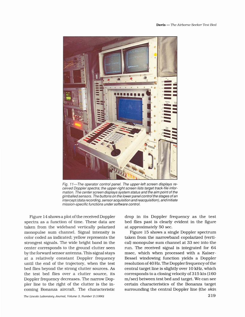
Fig. 11-The operator control panel. The upper-left screen displays received Doppler spectra; the upper-right screen lists target track-file information. The center screen displays system status and the aim point of thegimballedsensors. The buttons on the lowerpanel control the stages ofanintercept (data recording, sensoracquisition andreacquisition), and initiatemission-specific functions under software control.
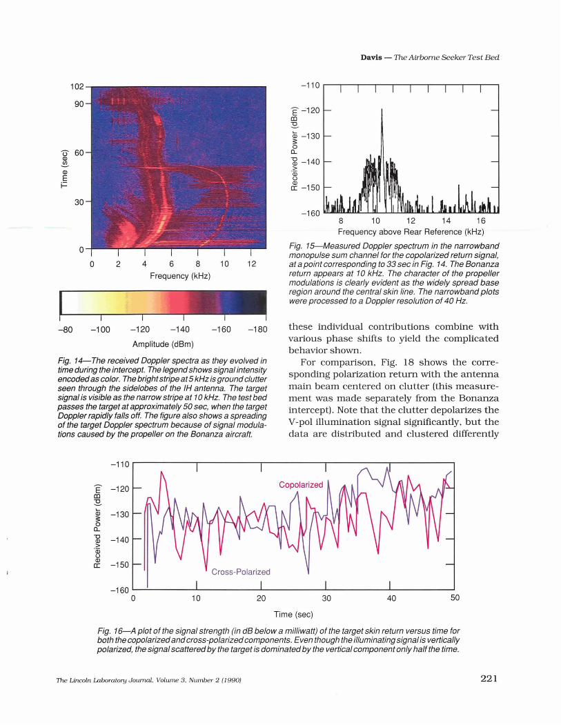
Figure 14 shows a plot ofthe received Dopplerspectra as a function of time. These data aretaken from the wideband vertically polarizedmonopulse sum channel. Signal intensity iscolor coded as indicated; yellow represents thestrongest signals. The wide bright band in thecenter corresponds to the ground clutter seenby the forward sensor antenna. This signal staysat a relatively constant Doppler frequencyuntil the end of the trajectory, when the testbed flies beyond the strong clutter sources. Asthe test bed flies over a clutter source, itsDoppler frequency decreases. The narrow Doppler line to the right of the clutter is the incoming Bonanza aircraft. The characteristic
The Lincoln Laboratory Journal. Volume 3, Number 2 (J 990)
drop in its Doppler frequency as the testbed flies past is clearly evident in the figureat approximately 50 sec.
Figure 15 shows a single Doppler spectrumtaken from the narrowband copolarized (vertical) monopulse sum channel at 33 sec into therun. The received signal is integrated for 64msec, which when processed with a KaiserBessel windowing function yields a Dopplerresolution of40 Hz. The Doppler frequency ofthecentral target line is slightly over 10kHz, whichcorresponds to a closing velocity of 315 kts (160m/sec) between test bed and target. We can seecertain characteristics of the Bonanza targetsurrounding the central Doppler line (the skin
219

Davis - The Airborne Seeker Test Bed
ForwardSensor
Fig. 12-Layoutofequipment in the Falcon 20. The inertial measurement unit in the nose determines the roll, pitch,and heading values of the test bed as well as its position in space. Most of the system electronics are in the racksalong the left side of the aircraft. The auxiliarypower unit in the tail provides the electricalpower for all of the projectequipment.
return). The broadened region of Doppler sidebands is due to propeller modulation of theradar signals; this broadening is also visible inthe spectra of Fig. 14. Similar modulations
Fig. 13-The flight-path geometry fora simulated intercept.The testbed flies radially outbound from the illuminator. Theracetrack path of the target is oriented to yield the desiredcrossing angle between test bed and target. Ground controllers direct both aircraft to cause the intercept to occur ata selected location. The test bed is 170 m higher than thetarget for safety reasons and for providing a look-downgeometry.
appear on jet aircraft targets if the engine turbine blades are visible.
Figure 16 shows the signal strength of theBonanza skin return dUring the first 50 secondsof the fly-by. The signals for the copolarized(V-pol) returns and cross-polarized (H-pol) returns were measured simultaneously dUringthe fly-by. The copolarized signal tends todominate, but the cross-polarized return is frequently seen to be stronger.
Figure 17, which shows the instantaneous polarization state of the target over a briefinterval of time, is another representation of the radar cross-section data. Thecoordinates shown are a rectangular projection of the Poincare polarization sphere,which has left-hand circular (LHC) polarization at the north pole, right-hand circular (RHC) polarization at the south pole,and a range of elliptical polarizations in between. The linear polarizations at variousrotation angles are represented around theequator. If the Bonanza did not depolarize theincident vertically polarized signal, we wouldsee the return signal clustered at V-pol, indicated by the large dot in the center of the figure.The various scattering centers on the aircraftdistort the incident polarization, however, and
+Ground Tracking Stations
+tNorth
---" ,././ '\
./ \././ \
././ I./ I
././././ ~/. /./ Tar et
Illuminator t g
~ ,,-, • 7 -,~ / \ '\I '\./ \I ' ./ \
I I\ I
'\ , Airborne Seeker Test Bed ./ /"--------------,,
220 The Lincoln Laboratory Journal. Volume 3. Number 2 (1990)
Davis - The Airborne Seeker Test Bed
Amplitude (dBm)
Fig. 14-The received Doppler spectra as they evolved intime during the intercept. The legend shows signal intensityencodedas color. The brightstripe at5 kHz is ground clutterseen through the sidelobes of the IH antenna. The targetsignal is visible as the narrow stripe at 10kHz. The test bedpasses the target at approximately 50 sec, when the targetDoppler rapidly falls off. The figure also shows a spreadingof the target Doppler spectrum because of signal modulations caused by the propeller on the Bonanza aircraft.
-1608 10 12 14 16Frequency above Rear Reference (kHz)
Fig. 15-Measured Doppler spectrum in the narrowbandmonopulse sum channel for the copolarized return signal,at a point corresponding to 33 sec in Fig. 14. The Bonanzareturn appears at 10kHz. The character of the propellermodulations is clearly evident as the widely spread baseregion around the central skin line. The narrowband plotswere processed to a Doppler resolution of 40 Hz.
these individual contributions combine withvarious phase shifts to yield the complicatedbehavior shown.
For comparison, Fig. 18 shows the corresponding polarization return with the antennamain beam centered on clutter (this measurement was made separately from the Bonanzaintercept). Note that the clutter depolarizes theV-pol illumination signal significantly, but thedata are distributed and clustered differently
E'-..:120(()
~
Q; -130~o
Q..
~ -140>·wu
£. -150
-180
12
-160-140
4 6 8 10Frequency (kHz)
-120
2
-100
oo
102
90
U 60Q)
.!E.-Q)
Ei=
30
-80
-110
E -120(()
~
Q; -130~0
Q.."0 -140Q)>·wuQ)
-150a::
-1600 10
Cross-Polarized
20 30 40 50
Time (sec)
Fig. 16-A plot of the signal strength (in dB below a milliwatt) of the target skin return versus time forboth the copolarizedandcross-polarizedcomponents. Even though the illuminating signal is verticallypolarized, the signal scatteredby the target is dominated by the vertical component only half the time.
The Lincoln Laboratory Journal. Volume 3. Number 2 (1990) 221

Davis - The Airbome Seeker Test Bed
Linear
H V H90,------.---,1---------, LHC
.- . ,.....- :.' . ... ... .. .\.:. -..-- . ... :"" ...~~ -._.1· ..:• .1 .,. , v- 'Je ~.. • ••~ 01--:-" •• • ~.I\". ..•... .._ • ..,.. •....(e : .. ...., _~ ....-.. l' . , '::::J •• ~ ...~.~ ••• '","' ...() -,...~ . ...= ..... ~.... .- I.- _:.... .: ..o· .: .._ .. . . .:
• I •-90 L-- ---L.---''--=---__-----' RHC
-180 0 180Orientation (deg)
Fig. 18-The polarization state ofan interval ofclutterdataplotted on a rectangular representation of the Poincaresphere. Even though the received polarization is diffuselydistributed, it clusters around the center dot that indicatesthe vertical polarization of the illumination signal.
high-fidelity data in a repeatable and systematicmeasurement program makes the test bed especially valuable for investigating advanced seekerconcepts and electronic countermeasures andfor developing signal processing schemes todefeat countermeasures. Though only in the airfor a few weeks as ofthis wri ling, the test bed hasalready demonstrated the basic functionalityrequired for its mission, from the proper performance of all sensor systems, operatingmodes, and data recording to the execution ofclutter and target intercept measurements.
In the near future the Airborne Seeker TestBed will operate at White Sands Missile Range ina variety of tests involving clutter, target, andECM measurements, with ground-based andairborne illuminators. A database of bistaticdesert clutter will be collected and compared toresults from other clutter measurements madeat the same locations. Bistatic target radarcross-section measurements will be collected ona T-38 aircraft both to demonstrate test bedcapabilities and to perfect flight procedures.Both ground-based and airborne illuminatorswill be used in the clutter and target measurements. Intercepts will be performed on aircrafteqUipped with angle-deception ECM to investigate the jamming characteristics and identitYpossible discriminants.
After the tests at White Sands a number oftests are planned with other air vehicles of AirForce interest to investigate their specific vulnerabilities to missile seekers. Long-term plansfor the test bed include the development and
90 ;-.:H Vi-- ---,HI , LHC
OJ<1l~
~0
~:::l~
0
... ... ... :-,- .',. ...- • .. - • • •••••• #••..... . ,. . .~.••••• ~: .. ~ ~ c.-fl't:.. ". ':\ ".': . _..-. . Linear.-.. , . .,.. .I.'. . .-g ••..,.-' .. .-. -'-t... . . , ...... ;.:. .. .a.", ~:. . _.. ':... .:... _.. . e...
-90 L...-~ ._•....I:..-10·_· -----' RHC
-180 0 180Orientation (deg)
Fig. 17-The true polarization state of the target return isderived from the amplitude and phase of the receivedvertical and horizontal polarized signal components. Thepolarization state isplottedhere on a rectangular representation of the Poincare sphere. The equator of this sphere isthe locus of linear polarizations that range from horizontalon the left to vertical in the middle to horizontal on the right.Up and down excursions on the plot represent increasingellipticity in the receivedpolarization, with left-handcircular(LHC) polarization at the north pole (the top edge of thegraph), and right-hand circular (RHC) polarization at thesouth pole (the bottom edge ofthe graph). The receivedpolarization, though fairly random, forms two distinct clusters,one around verticalpolarization and one around horizontalpolarization. The center dot indicates the vertical polarization of the illumination signal.
from those of the target returns of Fig. 17.Figure 19 shows an FUR image of the Bo
nanza as it appeared at a range of 0.8 km. Formost of an intercept the target aircraft is unresolved; it appears as a single pixel on thevideo screen. At this close range, the Bonanzaoutline is seen as dark (cool) against the warmer earth background. The bright spot on thenose of the aircraft is the exposed hot engine.A computer-generated cross hair superimposed on the FUR video indicates the radaraim point obtained from the IH. The motionof the cross hair provides a visual indicationof the dynamic behavior of the radar track andis useful for demonstrating the degree of ECMangle deception. In Fig. 19 the cross hair to theleft of the Bonanza aircraft shows where the IHwas positioned at the time, and is shown onlyfor illustration.
Lincoln Laboratory's Airborne Seeker TestBed represents a powerful tool for investigatingmissile seeker performance. The ability to collect
Summary
222 TIle Lincoln Laboratory Joumal. Volume 3. Number 2 (J 990)

Davis - The Airbome Seeker Test Bed
Fig. 19-A FUR image of the target Bonanza aircraft, taken near the end of the intercept at a range of 0.8 km. The hotengineparts appearas a positive contrast (brighter) against the earth background, while the body and wings ofthe aircraftappear as a negative contrast (darker) against the warm earth. A computer-generated cross hair superimposed on theFUR video indicates the aim point of the IH radar.
demonstration of advanced ECCM algorithms.the addition of other sensors. and the flying ofadvanced-concept brass-board seekers.
Acknowledgments
The Airborne Seeker Test Bed was developedunder the joint sponsorship ofthe Air Force andthe Army. I would specifically like to acknowledge Dr. David L. Briggs of Lincoln Laboratoryand Lt. Col. James P. Hogarty of the Air Force.the originators of the seeker test bed concept.Colonel Hogarty and Joseph Durham of theArmy Missile and Space Intelligence Commandprovided the sponsorship necessary to makethis project a reality. Program direction and
The Lincoln Laboratory Journal. Volume 3. Number 2 (1990)
support is currently being continued into theoperational phase by Lt. Col. Phil Soucy of theAir Force.
A complex project necessarily relies on thehard work and careful attention ofa large groupof people. Their tireless help has been andcontinues to be essential to the success ofthe project. Many people have been involvedin the test bed development. including numerous Raytheon contributors. I will mention onlythe principal members of the Airborne .SeekerTest Bed subcontractor teams: Raytheon program manager Victor Weisenbloom. LarryDurfee, and Tom Clougher. all of the RaytheonMissile Systems Division; Andy Reddig of TEK
223

Davis - The Airbome Seeker Test Bed
Microsystems; and George Clary and StanMcDonald of the Sierra Nevada Corp.
The Lincoln Laooratory personnel who haveseen the test bed into first flight are GroupLeaders Dr. Lewis Thurman and DennisKeane; system engineers Louis Hebert. PaulJuodawlkis. Dr. Randy Avent. and Dr. AlHearn; software developers Ken Gregson.
CURTIS W. DAVIS III is theAssistant Leader of the AirDefense Techniques Group.He received his B.S.. M.S.,and Ph.D. degrees from theOhio State University. wherehe worked on impulse radarfor underground probing.
While at Oillo State he built ultrawideband measurementsystems. designed antennas. and mathematically modeledradar performance. Since joining Lincoln Laboratory in1979 Curt has been involved in the instrumentation andperformance analyses of air defense radar systems. Hisactivities have included adding computer recording capability to an X-band ground-clutter measurement radar: thedesign. construction, and operation ofa helicopter-mountedfield -strength measuremen t system for multipath profiling;development ofmultipath modeHng algOrithms; and variousradar system analysis activities. Curt was responsible fordefining the basic architecture and specifications oftheNrborne Seeker Test Bed system. and he serves as the testbed's project engineer.
224
Jim Clarke. Al Shaver. David Bruce. DanSparrell. Dave Kohr. Pete Szymansky. CynthiaEldridge. and Lucy Smiley; engineers DickSimard. Mark Green. and John Parkins; technical assistants Al Davis. John Allen. BobCavanaugh. and Dick Thibodeau; pilotsCharlie Magnarelli and Mike Radoslovich;and chief mechanic Bob Murray.
The Lincoln Laboratory Joumal. Volume 3. Number 2 (1990)
,
•
Related Documents