Service. For internal use only The 6.0 l W12 engine in the Audi A8 - Part 1 Self-study programme 267 267

Welcome message from author
This document is posted to help you gain knowledge. Please leave a comment to let me know what you think about it! Share it to your friends and learn new things together.
Transcript
Service.
For internal use only
All rights reserved. Subject to technical modification.AUDI AGDepartment I/VK-35D-85045 IngolstadtFax 0841/89-36367140.2810.86.20Technical status as at 11/01Printed in Germany
The 6.0 l W12 enginein the Audi A8 - Part 1
Self-study programme 267
267
267
2

3
Contents
Introduction
Technical data . . . . . . . . . . . . . . . . . . . . . . . . . . . . . . . . . . . . . . . . . . . . . . . . . . . . . . . . 5Cross-section . . . . . . . . . . . . . . . . . . . . . . . . . . . . . . . . . . . . . . . . . . . . . . . . . . . . . . . . 6Longitudinal section . . . . . . . . . . . . . . . . . . . . . . . . . . . . . . . . . . . . . . . . . . . . . . . . . . 7W-design . . . . . . . . . . . . . . . . . . . . . . . . . . . . . . . . . . . . . . . . . . . . . . . . . . . . . . . . . . . . 8
Engine, Mechanics
Cylinder block . . . . . . . . . . . . . . . . . . . . . . . . . . . . . . . . . . . . . . . . . . . . . . . . . . . . . . . . 9Cylinder block and crankcase . . . . . . . . . . . . . . . . . . . . . . . . . . . . . . . . . . . . . . . . . . 12Crankshaft group . . . . . . . . . . . . . . . . . . . . . . . . . . . . . . . . . . . . . . . . . . . . . . . . . . . . 15Pistons/conrods . . . . . . . . . . . . . . . . . . . . . . . . . . . . . . . . . . . . . . . . . . . . . . . . . . . . . 18Engine mounting . . . . . . . . . . . . . . . . . . . . . . . . . . . . . . . . . . . . . . . . . . . . . . . . . . . . 19Engine lubrication . . . . . . . . . . . . . . . . . . . . . . . . . . . . . . . . . . . . . . . . . . . . . . . . . . . 20
Oil pump unit. . . . . . . . . . . . . . . . . . . . . . . . . . . . . . . . . . . . . . . . . . . . . . . . . . . 22Oil circulation in lower section of engine. . . . . . . . . . . . . . . . . . . . . . . . . . . . 24Oil circulation in upper section of engine . . . . . . . . . . . . . . . . . . . . . . . . . . . 26Oil level. . . . . . . . . . . . . . . . . . . . . . . . . . . . . . . . . . . . . . . . . . . . . . . . . . . . . . . . 30Dynamic oil level check . . . . . . . . . . . . . . . . . . . . . . . . . . . . . . . . . . . . . . . . . . 32Oil level/oil temperature sender -G266 . . . . . . . . . . . . . . . . . . . . . . . . . . . . . . 32Static oil level check . . . . . . . . . . . . . . . . . . . . . . . . . . . . . . . . . . . . . . . . . . . . . 33Engine oil change (described in SSP 268 on Page 49) . . . . . . . . . . . . . . . . . 33
Cooling system . . . . . . . . . . . . . . . . . . . . . . . . . . . . . . . . . . . . . . . . . . . . . . . . . . . . . . 34System layout . . . . . . . . . . . . . . . . . . . . . . . . . . . . . . . . . . . . . . . . . . . . . . . . . . 34Cooling circuit . . . . . . . . . . . . . . . . . . . . . . . . . . . . . . . . . . . . . . . . . . . . . . . . . . 36Continued coolant circulation pump -V51 . . . . . . . . . . . . . . . . . . . . . . . . . . . 38Other cooling circuit components. . . . . . . . . . . . . . . . . . . . . . . . . . . . . . . . . . 39System layout with auxiliary heater . . . . . . . . . . . . . . . . . . . . . . . . . . . . . . . . 40Special features with auxiliary heater. . . . . . . . . . . . . . . . . . . . . . . . . . . . . . . 42Electronically controlled cooling system . . . . . . . . . . . . . . . . . . . . . . . . . . . . 46Engine-cooling thermostat -F265 control loop . . . . . . . . . . . . . . . . . . . . . . . 47
Cylinder head . . . . . . . . . . . . . . . . . . . . . . . . . . . . . . . . . . . . . . . . . . . . . . . . . . . . . . . 48Timing mechanism. . . . . . . . . . . . . . . . . . . . . . . . . . . . . . . . . . . . . . . . . . . . . . . . . . . 50
Sealing of timing mechanism . . . . . . . . . . . . . . . . . . . . . . . . . . . . . . . . . . . . . 52SIS sealing (as of start of production) . . . . . . . . . . . . . . . . . . . . . . . . . . . . 52Silicone liquid seal (new) . . . . . . . . . . . . . . . . . . . . . . . . . . . . . . . . . . . . . . . 53
Valve timing/camshaft timing control . . . . . . . . . . . . . . . . . . . . . . . . . . . . . . . . . . . 54Exhaust-gas recirculation. . . . . . . . . . . . . . . . . . . . . . . . . . . . . . . . . . . . . . . . . 54Valve timing/adjustment range . . . . . . . . . . . . . . . . . . . . . . . . . . . . . . . . . . . . 57Control and monitoring of camshaft position . . . . . . . . . . . . . . . . . . . . . . . . 58
Camshaft adjusters . . . . . . . . . . . . . . . . . . . . . . . . . . . . . . . . . . . . . . . . . . . . . . . . . . 59Function of camshaft adjusters. . . . . . . . . . . . . . . . . . . . . . . . . . . . . . . . . . . . 60Electrohydraulic control . . . . . . . . . . . . . . . . . . . . . . . . . . . . . . . . . . . . . . . . . . 61
AttentionNoteNew
The self-study programme is not intended as a Workshop Manual. Values given are only intended to help explain the subject matter and relate to the software version applicable at the time of SSP compilation.
The self-study programme contains information on design features and functions.
Use should always be made of the latest technical publications when performing maintenance and repair work.
Page
4
Introduction
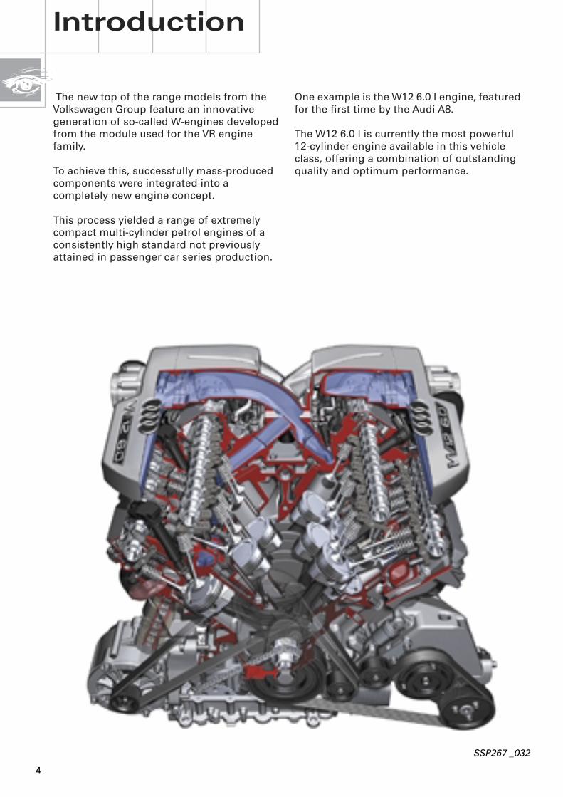
One example is the W12 6.0 l engine, featured for the first time by the Audi A8.
The W12 6.0 l is currently the most powerful 12-cylinder engine available in this vehicle class, offering a combination of outstanding quality and optimum performance.
The new top of the range models from the Volkswagen Group feature an innovative generation of so-called W-engines developed from the module used for the VR engine family.
To achieve this, successfully mass-produced components were integrated into a completely new engine concept.
This process yielded a range of extremely compact multi-cylinder petrol engines of a consistently high standard not previously attained in passenger car series production.
SSP267 _032
5
0
30
60
90
120
150
180
210
240
270
300
330
0
60
120
180
240
300
360
420
480
540
600
660
1000 2000 3000 4000 5000 6000 7000
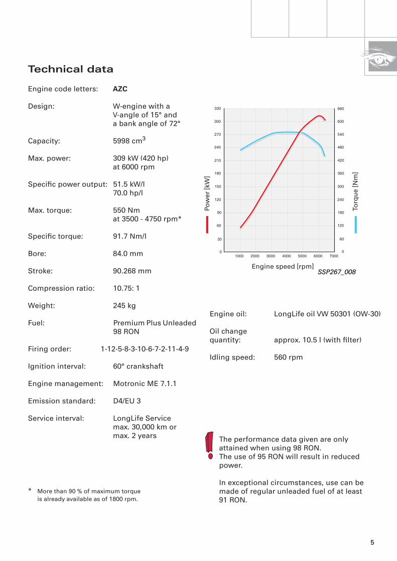
Technical data
Engine code letters:
AZC
Design: W-engine with aV-angle of 15° anda bank angle of 72°
Capacity: 5998 cm
3
Max. power: 309 kW (420 hp)at 6000 rpm
Specific power output: 51.5 kW/l70.0 hp/l
Max. torque: 550 Nmat 3500 - 4750 rpm*
Specific torque: 91.7 Nm/l
Bore: 84.0 mm
Stroke: 90.268 mm
Compression ratio: 10.75: 1
Weight: 245 kg
Fuel: Premium Plus Unleaded 98 RON
Firing order: 1-12-5-8-3-10-6-7-2-11-4-9
Ignition interval: 60° crankshaft
Engine management: Motronic ME 7.1.1
Emission standard: D4/EU 3
Service interval: LongLife Servicemax. 30,000 km ormax. 2 years
*
More than 90 % of maximum torque is already available as of 1800 rpm.
SSP267_008
Pow
er [k
W]
Torq
ue
[Nm
]
Engine speed [rpm]
The performance data given are only attained when using 98 RON. The use of 95 RON will result in reduced power.
In exceptional circumstances, use can be made of regular unleaded fuel of at least 91 RON.
Engine oil: LongLife oil VW 50301 (OW-30)
Oil change quantity: approx. 10.5 l (with filter)
Idling speed: 560 rpm

6
Special features of the W12 6.0 l engine in the Audi A8:
– 12-cylinder, W-design petrol engine
– Aluminium engine block and cylinder heads
– Oil supply with dry sump lubrication
Introduction
– Twin overhead camshafts with 4 valves each per cylinder - valve operation by means of roller-type rocker fingers
– Infinitely variable timing control for inlet and exhaust camshafts
SSP267_001
Cross-section
7
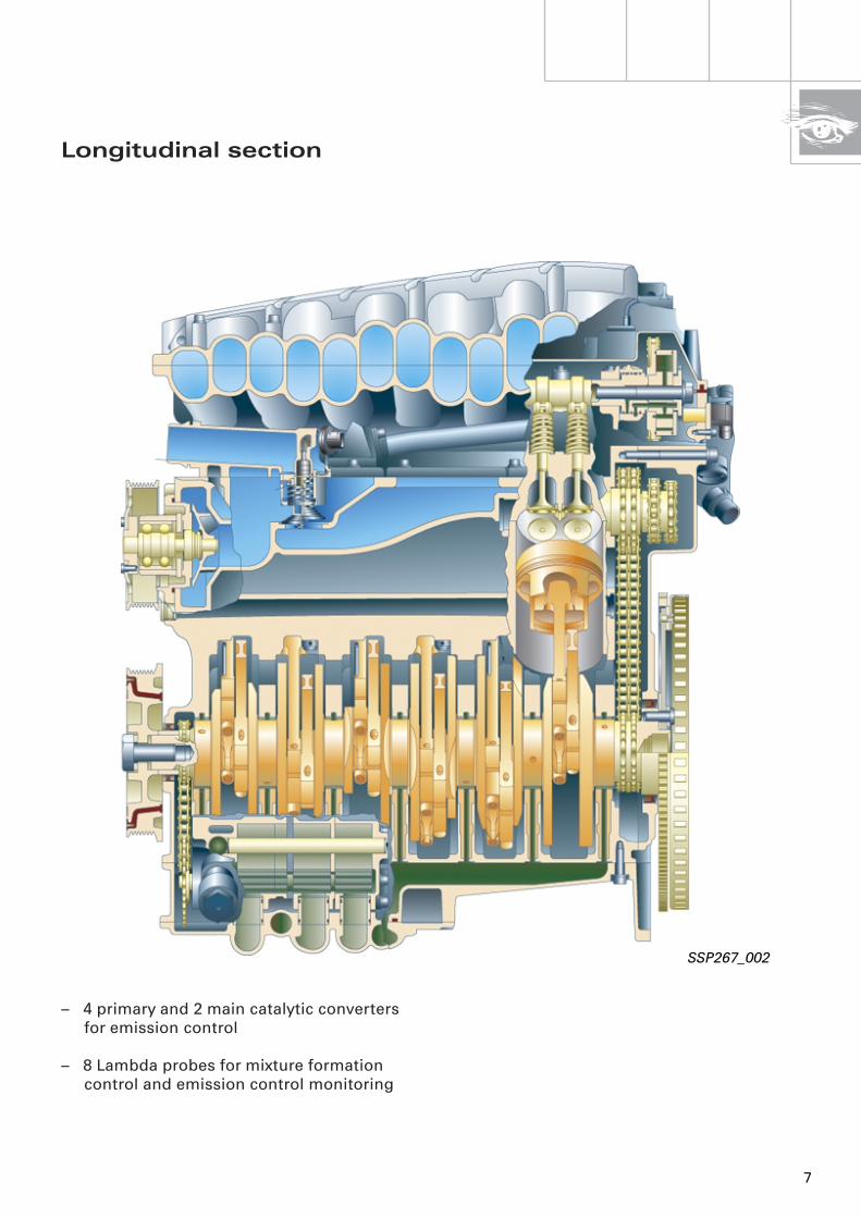
– 4 primary and 2 main catalytic converters for emission control
– 8 Lambda probes for mixture formation control and emission control monitoring
SSP267_002
Longitudinal section
8
W-design
Introduction
In-line engine V-engine
VR-engine VR-engine W-engine
SSP267_082
VR-engine(V-engine withsmall V-angle)
72°
15°60 - 90°
15°15°
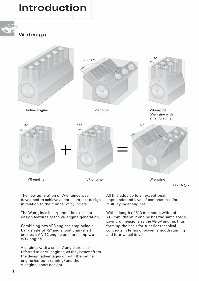
The new generation of W-engines was developed to achieve a more compact design in relation to the number of cylinders.
The W-engines incorporate the excellent design features of the VR-engine generation.
Combining two VR6 engines employing a bank angle of 72° and a joint crankshaft creates a V-V-12 engine or, more simply, a W12 engine.
V-engines with a small V-angle are also referred to as VR engines, as they benefit from the design advantages of both the in-line engine (smooth running) and the V-engine (short design).
All this adds up to an exceptional, unprecedented level of compactness for multi-cylinder engines.
With a length of 513 mm and a width of 710 mm, the W12 engine has the same space-saving dimensions as the V8-5V engine, thus forming the basis for superior technical concepts in terms of power, smooth running and four-wheel drive.
9
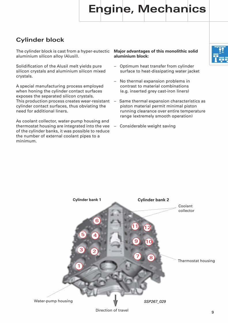
Major advantages of this monolithic solid aluminium block:
– Optimum heat transfer from cylinder surface to heat-dissipating water jacket
– No thermal expansion problems in contrast to material combinations (e.g. inserted grey cast-iron liners)
– Same thermal expansion characteristics as piston material permit minimal piston running clearance over entire temperature range (extremely smooth operation)
– Considerable weight saving
Cylinder block
The cylinder block is cast from a hyper-eutectic aluminium silicon alloy (Alusil).
Solidification of the Alusil melt yields pure silicon crystals and aluminium silicon mixed crystals.
A special manufacturing process employed when honing the cylinder contact surfaces exposes the separated silicon crystals.This production process creates wear-resistant cylinder contact surfaces, thus obviating the need for additional liners.
As coolant collector, water-pump housing and thermostat housing are integrated into the vee of the cylinder banks, it was possible to reduce the number of external coolant pipes to a minimum.
Engine, Mechanics
SSP267_029
12
Direction of travel
2
1
3
45
6
7 8
9
11
10
Cylinder bank 1
Cylinder bank 2
Coolantcollector
Thermostat housing
Water-pump housing

10
The "fan" arrangement of the cylinder bores in conjunction with a V-angle of 15° and a bank angle of 72° creates a highly compact and exceptionally rigid cylinder block.
With a conventional layout, the very narrow V-angle of 15° combined with the compact design of the cylinder block would result in cylinder overlap in BDC position.
For this reason, the cylinders are offset with respect to the axis of crankshaft rotation.
In other words, the produced cylinder centre axes do not, as is normally the case, coincide with the crankshaft axis, but rather are offset to the left or right.
Engine, Mechanics
This arrangement is known as cylinder offset.
Together with an appropriate piston skirt design, this achieves the necessary clearance in BDC position (refer to Section on Pistons/Conrods).
The offset cylinder configuration requires corresponding design modifications affecting both crankshaft group and valve timing.
More details can be found in the appropriate Sections.
SSP267_034
15° 15°
72°
Cylinder bank 1 Cylinder bank 2

11
-12,5 mm
SSP267_154
_
+
SSP267_098
Bank 1
Bank 2
12
7 9
8 10
11
6
1 3
2 4
5
The offset is as follows:
– Odd-numbered cylinders - 12.5 mm(cyl. 1-3-5-7-9-11)
and
– Even-numbered cylinders + 12.5 mm(cyl. 2-4-6-8-10-12)
+
_
Cylinder centre axis/odd-numbered cylinders
Cylinder centre axis/even-numbered cylinders
Line of crankshaft axis of rotation parallel to cylinder centre axis

12
Cylinder block and crankcase
Engine, Mechanics
The crankcase is formed by the cylinder block and bearing support made of aluminium.
SSP267_137
Bearing support
Top section of sump
Sump
Cylinder block
The sump (also aluminium) is of two-piece design.
13
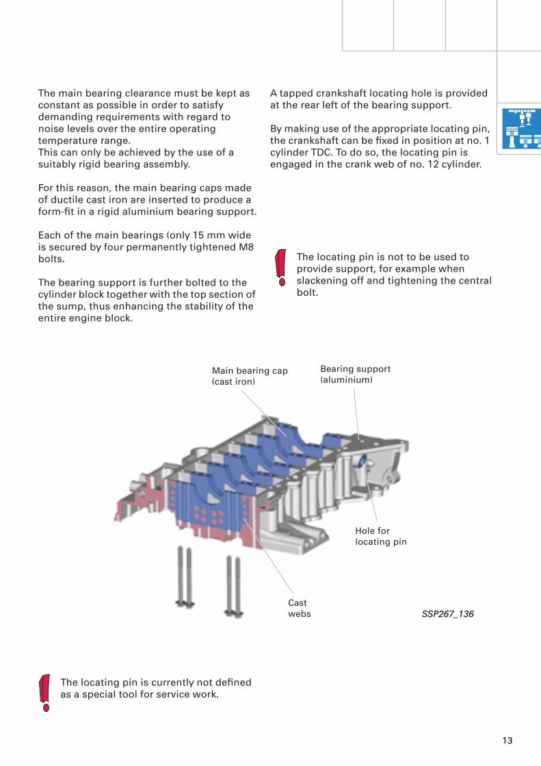
The main bearing clearance must be kept as constant as possible in order to satisfy demanding requirements with regard to noise levels over the entire operating temperature range. This can only be achieved by the use of a suitably rigid bearing assembly.
For this reason, the main bearing caps made of ductile cast iron are inserted to produce a form-fit in a rigid aluminium bearing support.
Each of the main bearings (only 15 mm wide is secured by four permanently tightened M8 bolts.
The bearing support is further bolted to the cylinder block together with the top section of the sump, thus enhancing the stability of the entire engine block.
A tapped crankshaft locating hole is provided at the rear left of the bearing support.
By making use of the appropriate locating pin, the crankshaft can be fixed in position at no. 1 cylinder TDC. To do so, the locating pin is engaged in the crank web of no. 12 cylinder.
The locating pin is not to be used to provide support, for example when slackening off and tightening the central bolt.
Bearing support(aluminium)
Main bearing cap(cast iron)
Cast webs
SSP267_136
The locating pin is currently not defined as a special tool for service work.
Hole for locating pin
14
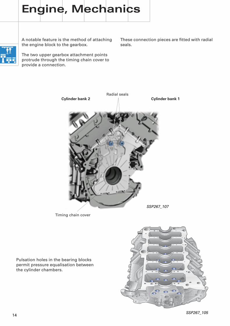
These connection pieces are fitted with radial seals.
SSP267_107
Timing chain cover
Radial seals
Engine, Mechanics
Cylinder bank 1Cylinder bank 2
SSP267_105
Pulsation holes in the bearing blocks permit pressure equalisation between the cylinder chambers.
A notable feature is the method of attaching the engine block to the gearbox.
The two upper gearbox attachment points protrude through the timing chain cover to provide a connection.

15
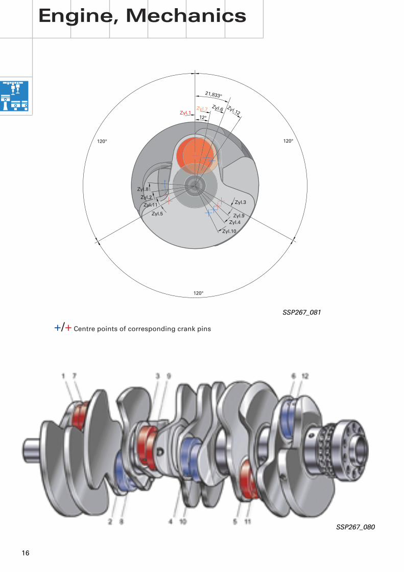
The 7-bearing crankshaft is forged andmade of heat-treated steel.
In view of the special design of the W-engine, the creation of the uniform ignition interval of 60° (standard for 12-cylinder engines) demands certain modifications to the crankshaft.
SSP267_034
SSP267_095
Crankshaft group
As is the case with V-engines, two conrods are mounted on each crank pin.
Due to the bank angle of 72°, the six crank pins are 12° offset with respect to the corresponding opposite cylinders. This is referred to as a "split pin" configuration.
15° 15°
72°
Cylinder bank 1 Cylinder bank 2
SSP267_089
16
21,833°
Zyl.7Zyl.1
Zyl.12Zyl.6
Zyl.5
Zyl.2
Zyl.8
Zyl.10
Zyl.4Zyl.9
Zyl.3Zyl.11
12°
120°
120°
120°
Engine, Mechanics
SSP267_080
+/+
Centre points of corresponding crank pins
SSP267_081
17
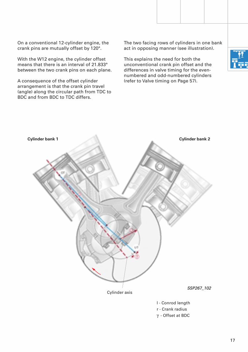
The two facing rows of cylinders in one bank act in opposing manner (see illustration).
This explains the need for both the unconventional crank pin offset and the differences in valve timing for the even-numbered and odd-numbered cylinders (refer to Valve timing on Page 57).
l - Conrod lengthr - Crank radius
g
- Offset at BDC
SSP267_102
On a conventional 12-cylinder engine, the crank pins are mutually offset by 120°.
With the W12 engine, the cylinder offset means that there is an interval of 21.833° between the two crank pins on each plane.
A consequence of the offset cylinder arrangement is that the crank pin travel (angle) along the circular path from TDC to BDC and from BDC to TDC differs.
Cylinder axis
Cylinder bank 1 Cylinder bank 2

18
Engine, Mechanics
Pistons/conrods
The pistons are cast from a eutectic aluminium silicon alloy and are identical for both rows of cylinders in each bank.
The joint flat cylinder head surface of the two rows of cylinders in each bank gives rise to an asymmetrical combustion chamber.To create a symmetrical combustion chamber, the piston crown is angled.
The installation direction is governed by the piston crown angle.
The piston skirt is of a shorter, stepped design to enable it to plunge between the bearing blocks.
As the pistons slide in aluminium cylinders they are provided with an electroplated iron coating (Ferrostan).
SSP267_031
Oil grooves
SSP267_140
The pistons are cooled with engine oil via spray jets to prevent thermal overloading on account of the high specific power output (refer to oil circuit).
To reduce the oscillating masses, the conrod is attached to the piston by a trapezoidal arrangement.
On account of the compact design of cylinder block and crankshaft, the conrods are extremely slim with a width of 13 mm at the large connecting rod eye.
As the resultant contact surface between conrod cap and conrod is very small, the bolted joint is ground and use is made of fitted anti-fatigue bolts.
Oil grooves in the conrod cap facilitate the exit of oil from the conrod bearing.
Compensation for the specific load acting on the conrod bearing is provided by means of a sputter bearing shell for the conrod and a 3-material bearing shell in the conrod cap.
For more details on sputter bearing, refer to SSP 226, Page 10.
The bearings have no lugs and use therefore has to be made of a special tool for conrod assembly (not yet available as service tool).
Crankshaft group repair work is not envisaged at present on account of its complexity.
19
Engine mounting
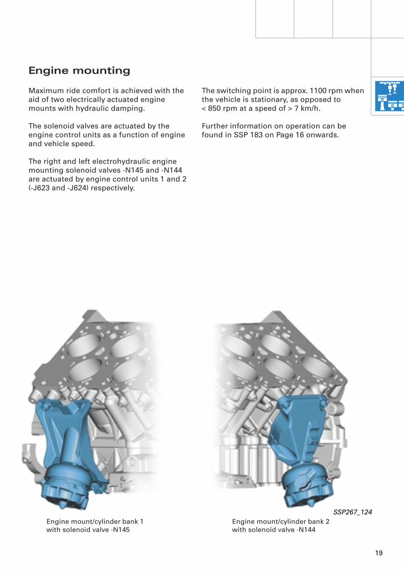
Maximum ride comfort is achieved with the aid of two electrically actuated engine mounts with hydraulic damping.
The solenoid valves are actuated by the engine control units as a function of engine and vehicle speed.
The right and left electrohydraulic engine mounting solenoid valves -N145 and -N144 are actuated by engine control units 1 and 2 (-J623 and -J624) respectively.
The switching point is approx. 1100 rpm when the vehicle is stationary, as opposed to < 850 rpm at a speed of > 7 km/h.
Further information on operation can be found in SSP 183 on Page 16 onwards.
SSP267_124
Engine mount/cylinder bank 1 with solenoid valve -N145
Engine mount/cylinder bank 2 with solenoid valve -N144

20
Engine lubrication
Engine, Mechanics
One particularly notable feature is the dry sump lubrication system.This is a special type of force-feed lubrication used primarily in off-road vehicles and sports cars.
In contrast to conventional wet sump lubrication, the pump supplies the engine with oil from a separate tank.
SSP267_036

21
The special design of the dry sump lubrication system requires specific knowledge for performing service work, repair operations and checking oil level as well as in terms of handling by the customer.
Dry sump lubrication operates with three oil pumps, namely two scavenge pumps and a pressure pump.
The scavenge pumps draw the oil returning from the lubrication circuit out of the extre-mely shallow sump and convey it into the oil tank.
The pressure pump draws the settled, defoamed oil from the oil tank and supplies it to the engine oil circuit.
Advantages of dry sump lubrication:
– Absolutely reliable oil supply, particularly in critical driving situations involving extreme longitudinal and lateral acceleration or associated vehicle tilting
– Lower air content of pressurised oil– Lower oil temperature– Relative insusceptibility to engine oil
overfilling and underfilling– Small sump volume and thus low overall
engine height
22
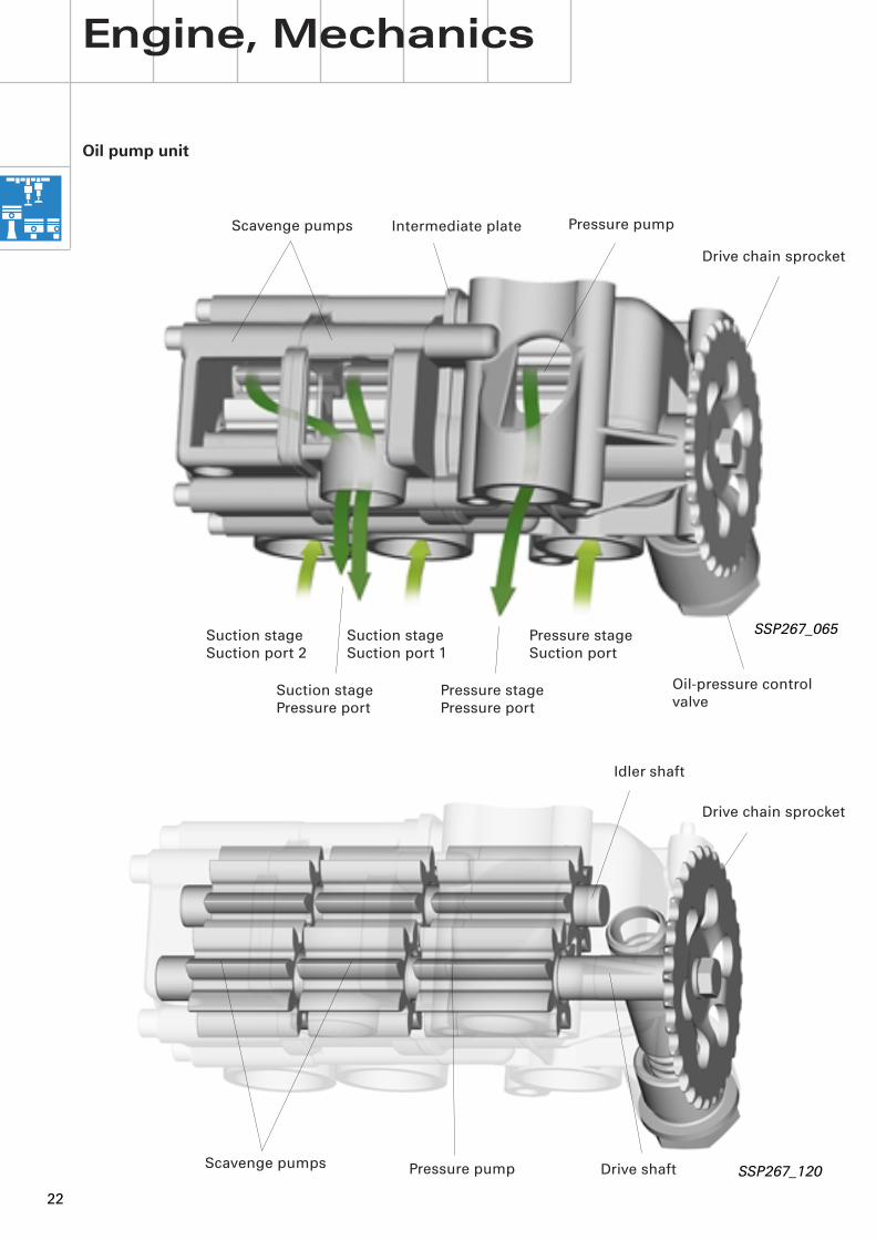
Oil pump unit
SSP267_065
Intermediate plate
Drive chain sprocket
Oil-pressure control valve
Pressure stageSuction port
Pressure stagePressure port
Suction stageSuction port 1
Suction stagePressure port
Suction stageSuction port 2
Engine, Mechanics
Pressure pumpScavenge pumps
Drive shaft
Idler shaft
Drive chain sprocket
Pressure pumpScavenge pumps
SSP267_120
23
To ensure the return flow of oil to the tank, the delivery volume of the scavenge pumps is appproximately 1.5 times that of the pressure pump.
In addition, each of the scavenge pumps is provided with a separate extraction point in the bottom of the sump positioned so as to ensure the flow of oil back to the tank even in the event of extreme longitudinal and lateral acceleration.
The scavenge pumps are internally connected on the pressure end and convey the oil to the tank by way of a joint port.
The scavenge pumps and pressure pump are designed as gear pumps and combine to form an oil pump unit.
The oil pump unit consists of three separate gear pumps. The drive gears and idler wheels are each located on a joint shaft (drive shaft, idler shaft). Use is made of a simple chain to provide direct drive from the crankshaft with a transmission ratio of approx. 1.5 : 1.
The front gear pump acts as the pressure pump, whereas the two gear pumps behind this are used for scavenging.
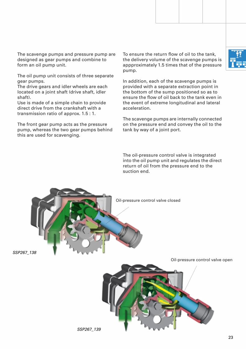
The oil-pressure control valve is integrated into the oil pump unit and regulates the direct return of oil from the pressure end to the suction end.
SSP267_138
SSP267_139
Oil-pressure control valve open
Oil-pressure control valve closed

24
Strainer 2
Strainer 1
Oil circulation in lower section of engine
A particular feature of the oil circuit on the W12 engine is that the majority of the oil is routed through the bottom of the sump, thus reducing the number of pipes to a minimum, enhancing operational reliability and permitting both a smaller overall volume and corresponding cost savings.
The oil flowing back from the engine is first conveyed by the two scavenge pumps to the oil tank. The oil tank inlet leads into the integrated cyclone where the oil is caused to rotate, thus separating the gases mixed in with the engine oil and allowing them to escape upwards. To achieve further settling, the oil flows via a bulkhead into the bottom part of the oil tank.
The following components are located on the oil tank:
– Oil temperature sender -G8 (for details, refer to SSP 268 - Part 2, Page 42)
– Oil level/oil temperature sender -G266 (for details, refer to Page 32)
– Dipstick (for details, refer to Page 33)– Crankcase breather
SSP267_094
Engine, Mechanics
Oil tank
Bracket with oil filter housing
Oil cooler
Oil pump unit
To main oil gallery
Oil-filter bypass valve
Oil temperature sender -G8
Dipstick
Oil-pressure switch
Oil drain plug
Oil level/oil temperature sender -G266
The oil cooler, a coolant/oil heat exchanger, does not have a separate housing. Instead, it is bolted directly to the top section of the sump and joined to the actual sump by way of connection pieces fitted with O-ring seals.
From oil separator (oil return)
To oil separator/intake manifold (crankcase breather)
From cylinder block (crankcase breather)
From oil filler neck (crankcase breather)
25
SSP267_118
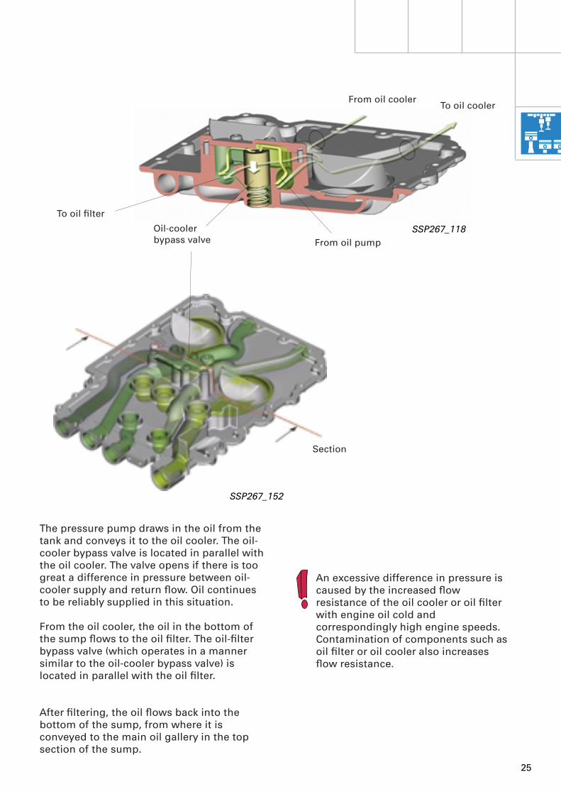
Oil-coolerbypass valve From oil pump
From oil coolerTo oil cooler
The pressure pump draws in the oil from the tank and conveys it to the oil cooler. The oil-cooler bypass valve is located in parallel with the oil cooler. The valve opens if there is too great a difference in pressure between oil-cooler supply and return flow. Oil continues to be reliably supplied in this situation.
From the oil cooler, the oil in the bottom of the sump flows to the oil filter. The oil-filter bypass valve (which operates in a manner similar to the oil-cooler bypass valve) is located in parallel with the oil filter.
After filtering, the oil flows back into the bottom of the sump, from where it is conveyed to the main oil gallery in the top section of the sump.
Section
SSP267_152
An excessive difference in pressure is caused by the increased flow resistance of the oil cooler or oil filter with engine oil cold and correspondingly high engine speeds.Contamination of components such as oil filter or oil cooler also increases flow resistance.
To oil filter
26
Engine, Mechanics
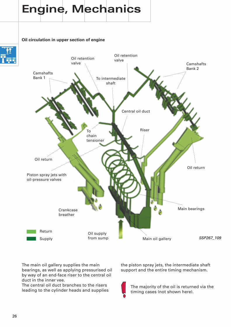
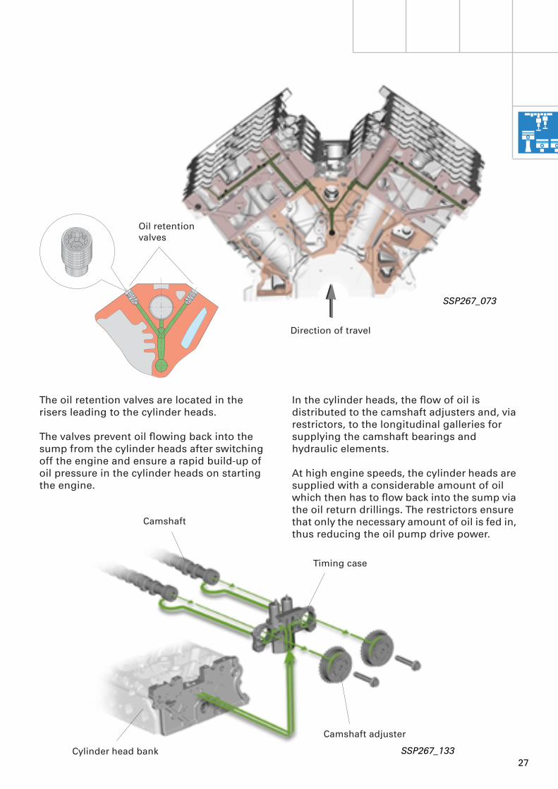
the piston spray jets, the intermediate shaft support and the entire timing mechanism.
The main oil gallery supplies the main bearings, as well as applying pressurised oil by way of an end-face riser to the central oil duct in the inner vee.The central oil duct branches to the risers leading to the cylinder heads and supplies
Oil circulation in upper section of engine
Oil retentionvalve Camshafts
Bank 2CamshaftsBank 1
Piston spray jets with oil-pressure valves
Main bearings
Main oil gallery
SSP267_109
Return
Supply
Oil return
Riser
Central oil duct
Oil return
Oil retentionvalve
To intermediate shaft
To chain tensioner
Oil supply from sump
Crankcasebreather
The majority of the oil is returned via the timing cases (not shown here).
27
Direction of travel
SSP267_073
The oil retention valves are located in the risers leading to the cylinder heads.
The valves prevent oil flowing back into the sump from the cylinder heads after switching off the engine and ensure a rapid build-up of oil pressure in the cylinder heads on starting the engine.
In the cylinder heads, the flow of oil is distributed to the camshaft adjusters and, via restrictors, to the longitudinal galleries for supplying the camshaft bearings and hydraulic elements.
At high engine speeds, the cylinder heads are supplied with a considerable amount of oil which then has to flow back into the sump via the oil return drillings. The restrictors ensure that only the necessary amount of oil is fed in, thus reducing the oil pump drive power.
Camshaft
Timing case
Cylinder head bank
Camshaft adjuster
SSP267_133
Oil retention valves
28
Engine, Mechanics
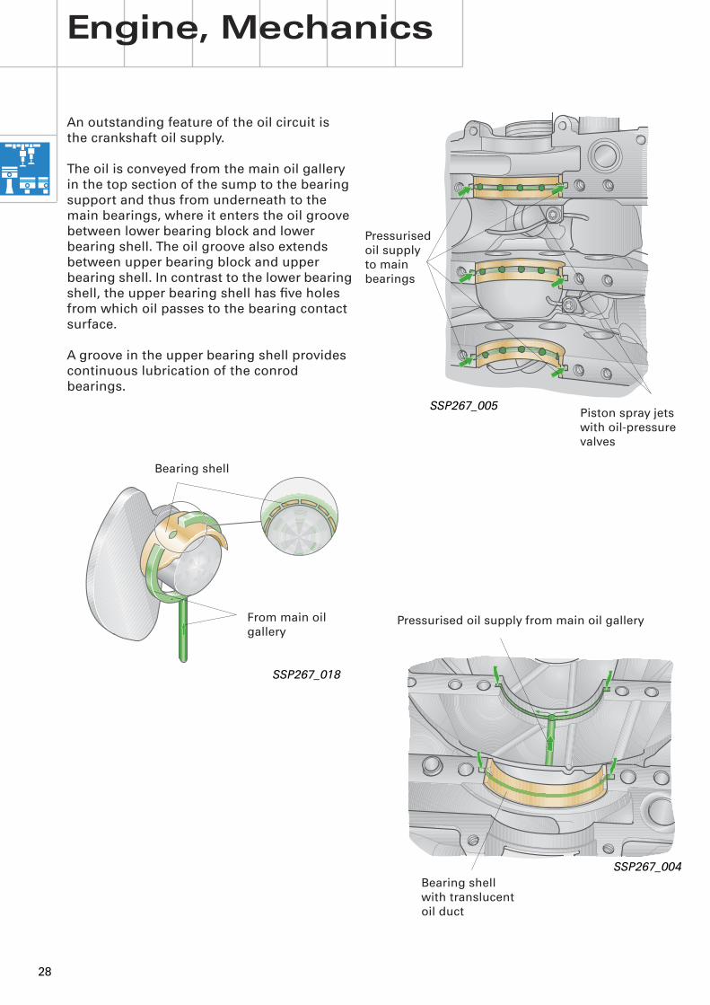
An outstanding feature of the oil circuit isthe crankshaft oil supply.
The oil is conveyed from the main oil gallery in the top section of the sump to the bearing support and thus from underneath to the main bearings, where it enters the oil groove between lower bearing block and lower bearing shell. The oil groove also extends between upper bearing block and upper bearing shell. In contrast to the lower bearing shell, the upper bearing shell has five holes from which oil passes to the bearing contact surface.
A groove in the upper bearing shell provides continuous lubrication of the conrod bearings.
SSP267_004
Bearing shellwith translucent oil duct
Pressurised oil supply from main oil gallery
SSP267_018
Bearing shell
From main oil gallery
SSP267_005
Pressurised oil supply to main bearings
Piston spray jets with oil-pressure valves

29
Notes
30
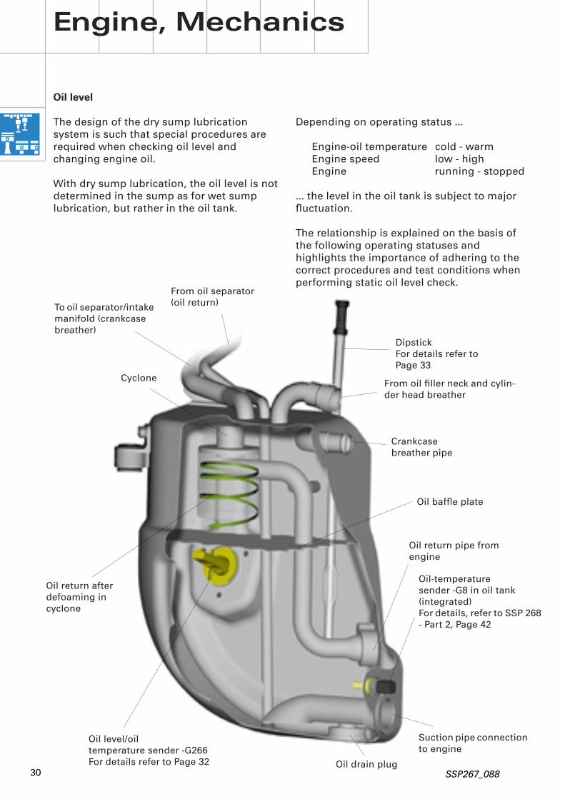
Oil level
The design of the dry sump lubrication system is such that special procedures are required when checking oil level and changing engine oil.
With dry sump lubrication, the oil level is not determined in the sump as for wet sump lubrication, but rather in the oil tank.
Depending on operating status …
Engine-oil temperature cold - warmEngine speed low - highEngine running - stopped
… the level in the oil tank is subject to major fluctuation.
The relationship is explained on the basis of the following operating statuses and highlights the importance of adhering to the correct procedures and test conditions when performing static oil level check.
SSP267_088
Oil level/oiltemperature sender -G266For details refer to Page 32
Oil-temperaturesender -G8 in oil tank (integrated)For details, refer to SSP 268 - Part 2, Page 42
DipstickFor details refer to Page 33
Suction pipe connection to engine
Oil return pipe from engine
Crankcasebreather pipe
Cyclone
Oil drain plug
Oil baffle plate
From oil filler neck and cylin-der head breather
Oil return after defoaming in cyclone
Engine, Mechanics
To oil separator/intake manifold (crankcase breather)
From oil separator (oil return)
31
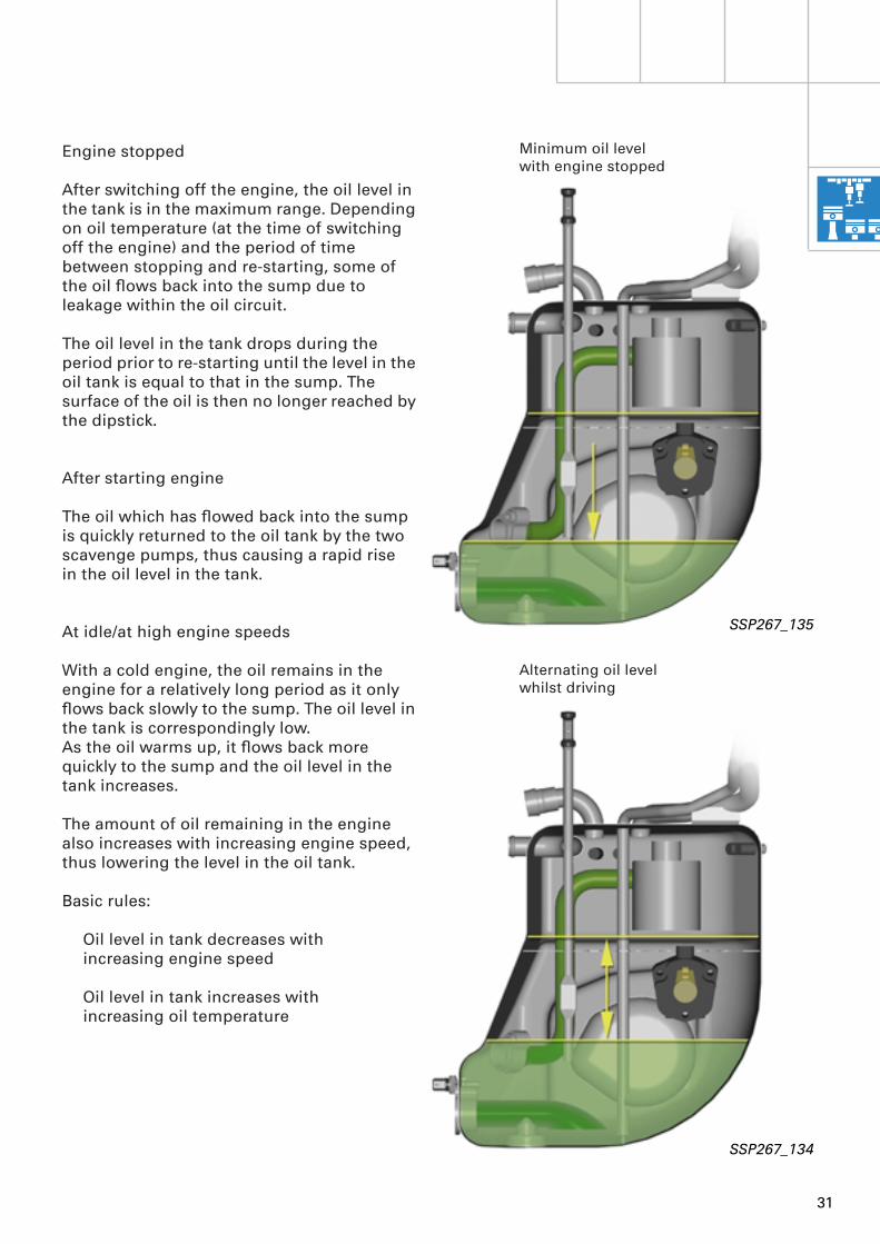
Engine stopped
After switching off the engine, the oil level in the tank is in the maximum range. Depending on oil temperature (at the time of switching off the engine) and the period of time between stopping and re-starting, some of the oil flows back into the sump due to leakage within the oil circuit.
The oil level in the tank drops during the period prior to re-starting until the level in the oil tank is equal to that in the sump. The surface of the oil is then no longer reached by the dipstick.
After starting engine
The oil which has flowed back into the sump is quickly returned to the oil tank by the two scavenge pumps, thus causing a rapid rise in the oil level in the tank.
At idle/at high engine speeds
With a cold engine, the oil remains in the engine for a relatively long period as it only flows back slowly to the sump. The oil level in the tank is correspondingly low. As the oil warms up, it flows back more quickly to the sump and the oil level in the tank increases.
The amount of oil remaining in the engine also increases with increasing engine speed, thus lowering the level in the oil tank.
Basic rules:
Oil level in tank decreases withincreasing engine speed
Oil level in tank increases withincreasing oil temperature
SSP267_134
Alternating oil levelwhilst driving
SSP267_135
Minimum oil level with engine stopped
32
Engine, Mechanics
A distinction is made between dynamic and static checking of oil level.
Dynamic oil level check
Drivers are not required to check the oil level. The oil level is established whilst driving by the oil level/oil temperature sender -G266.The driver information system provides an oil level warning on dropping below the minimum oil level.
Should the oil level warning lamp come on, 1 litre of the specified grade of engine oil is always to be added at the latest when the vehicle is next re-fuelled.
The static oil level check procedure to be employed in exceptional circumstances, e.g. before starting a long journey, is described in the Owner's Manual.
It should be noted that lighting of the oil level warning lamp is also governed to a certain extent by driving style, e.g. highly dynamic driving can lead to premature actuation.
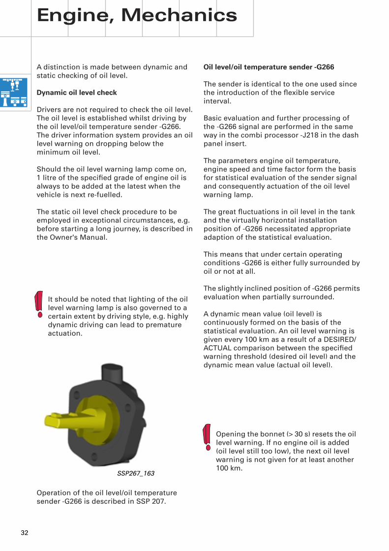
SSP267_163
Oil level/oil temperature sender -G266
The sender is identical to the one used since the introduction of the flexible service interval.
Basic evaluation and further processing of the -G266 signal are performed in the same way in the combi processor -J218 in the dash panel insert.
The parameters engine oil temperature, engine speed and time factor form the basis for statistical evaluation of the sender signal and consequently actuation of the oil level warning lamp.
The great fluctuations in oil level in the tank and the virtually horizontal installation position of -G266 necessitated appropriate adaption of the statistical evaluation.
This means that under certain operating conditions -G266 is either fully surrounded by oil or not at all.
The slightly inclined position of -G266 permits evaluation when partially surrounded.
A dynamic mean value (oil level) is continuously formed on the basis of the statistical evaluation. An oil level warning is given every 100 km as a result of a DESIRED/ACTUAL comparison between the specified warning threshold (desired oil level) and the dynamic mean value (actual oil level).
Opening the bonnet (> 30 s) resets the oil level warning. If no engine oil is added (oil level still too low), the next oil level warning is not given for at least another 100 km.
Operation of the oil level/oil temperature sender -G266 is described in SSP 207.

33
Static oil level check
To avoid inaccuracy, the static oil level check is primarily intended to be performed by authorised service personnel using a dipstick protruding into the oil tank.
Procedure/test prerequisites:
– Move vehicle onto a flat surface
– Engine warm, oil temperature min. 80 °C (check with diagnosis tester: Function 08, Display Group 134, Display Zone 1)
– Allow engine to idle for at least 2 minutes before checking oil level
– Switch off engine
– Then check oil level within 2 minutes of switching off engine.
2 different dipsticks are used.
1st type: Dipstick with 11 notches.
MIN oil level at 5th notchMAX oil level at 8th notch
One division corresponds to roughly 0.3 l.
2nd type:Dipstick with MIN and MAX mark; difference between MIN and MAX corresponds to roughly 1 l.
Engine oil change
Points to be noted when changing engine oil are described in the "Service" Section of SSP 268 - Part 2, Page 49 onwards.
SSP267_096
MIN
MAX5
8
34
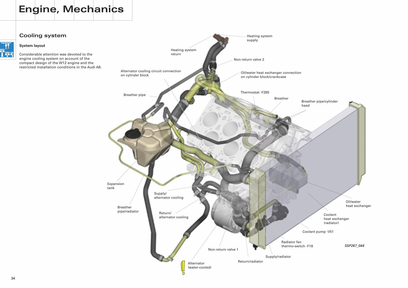
Cooling system
System layout
Considerable attention was devoted to the engine cooling system on account of the compact design of the W12 engine and the restricted installation conditions in the Audi A8.
Engine, Mechanics
Coolant pump -V51
Supply/radiator
Alternator(water-cooled)
Return/radiator
Supply/alternator cooling
Return/alternator cooling
Non-return valve 1
Thermostat -F265
Breather pipe/radiator
Alternator cooling circuit connection on cylinder block
Breather pipe/cylinder head
Heating system supply
Heating system return
Oil/water heat exchanger connectionon cylinder block/crankcase
Breather pipe
Expansion tank
SSP267_044
Coolantheat exchanger(radiator)
Oil/waterheat exchanger
Radiator fan thermo-switch -F18
Non-return valve 2
Breather

35
The cooling system of the Audi A8 with W12 engine is made up of the following components:
– Water pump in cylinder block/crankcase driven mechanically by Poly-V belt
– Map-controlled electrically operated continued coolant circulation pump -V51 as back-up for mechanical water pump and for continued coolant circulation
– Electronically controlled cooling system (map-controlled coolant thermostat)
– Map-controlled hydraulic fan and 300 W electric fan
– Map-controlled continued coolant circulation
– Water-cooled alternator (for details, refer to SSP 268 - Part 2, Page 4 onwards)
SSP267_142
Supplyto oil cooler
Supply to alternator
Returnfrom alternator
Return from oil cooler
Fitting location for coolant- temperature senders-G2 and -G62
36
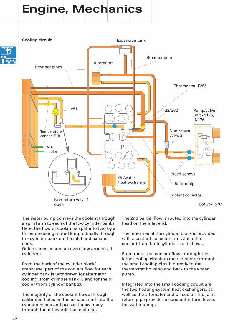
The 2nd partial flow is routed into the cylinder head on the inlet end.
The inner vee of the cylinder block is provided with a coolant collector into which the coolant from both cylinder heads flows.
From there, the coolant flows through the large cooling circuit to the radiator or through the small cooling circuit directly to the thermostat housing and back to the water pump.
Integrated into the small cooling circuit are the two heating-system heat exchangers, as well as the alternator and oil cooler. The joint return pipe provides a constant return flow to the water pump.
The water pump conveys the coolant through a spiral arm to each of the two cylinder banks. Here, the flow of coolant is split into two by a fin before being routed longitudinally through the cylinder bank on the inlet and exhaust ends.Guide vanes ensure an even flow around all cylinders.
From the back of the cylinder block/crankcase, part of the coolant flow for each cylinder bank is withdrawn for alternator cooling (from cylinder bank 1) and for the oil cooler (from cylinder bank 2).
The majority of the coolant flows through calibrated holes on the exhaust end into the cylinder heads and passes transversely through them towards the inlet end.
Engine, Mechanics
SSP267_010
Cooling circuit
Thermostat -F265
Non-return valve 1open
V51
Non-returnvalve 2
Pump/valve unit -N175, -N176
Expansion tank
Temperaturesender -F18
Bleed screws
ATFcooler
Oil/waterheat exchanger
Alternator
Coolant collector
Return pipe
Breather pipes
Breather pipe
G2/G62
37
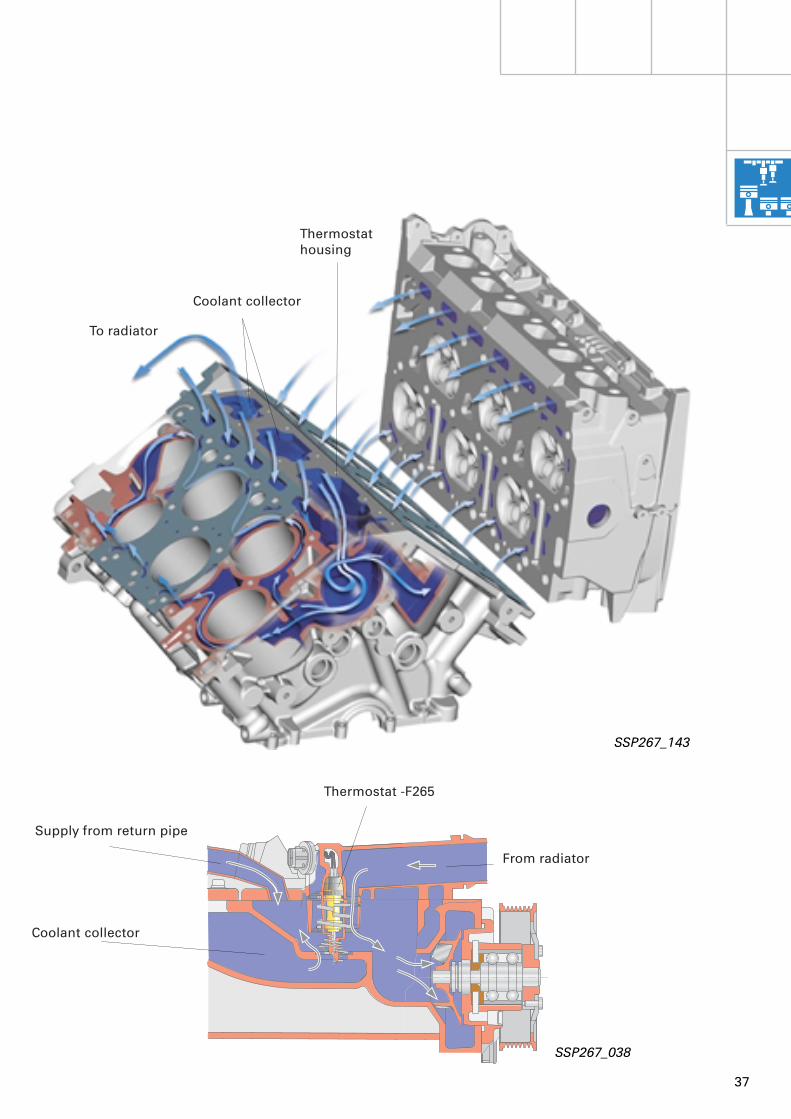
SSP267_143
To radiator
Coolant collector
Thermostat housing
SSP267_038
Supply from return pipe
Coolant collector
From radiator
Thermostat -F265
38
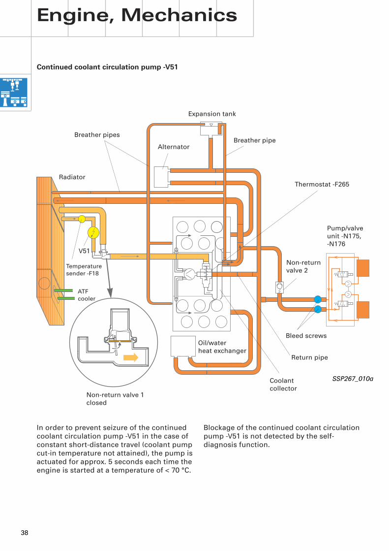
SSP267_010a
Continued coolant circulation pump -V51
Thermostat -F265
Non-return valve 1closed
V51
Non-return valve 2
Pump/valve unit -N175, -N176
Radiator
Expansion tank
Temperaturesender -F18
Bleed screws
ATFcooler
Oil/waterheat exchanger
In order to prevent seizure of the continued coolant circulation pump -V51 in the case of constant short-distance travel (coolant pump cut-in temperature not attained), the pump is actuated for approx. 5 seconds each time the engine is started at a temperature of < 70 °C.
Blockage of the continued coolant circulation pump -V51 is not detected by the self-diagnosis function.
Engine, Mechanics
Alternator
Coolant collector
Return pipe
Breather pipesBreather pipe

39
The electrically driven continued coolant circulation pump -V51 is located in parallel in the large cooling circuit in the return from the radiator.
The continued coolant circulation pump -V51 has two functions:
1. To provide back-up for the mechanically driven coolant pump at low engine speeds and to ensure adequate coolant circulation.-V51 is actuated via the additional coolant pump relay -J496 by engine control unit 1 -J623.Map control is employed to switch in the continued coolant circulation pump -V51 as required.The parameters used for this are the engine speed and the coolant temperature supplied by the coolant-temperature sender -G62.
Switching levels:
Cut-in: < 840 rpm and > 108 °CCut-out: > 3000 rpm or < 106 °C
2. To circulate the coolant during continued coolant circulation (for details, refer to SSP 268 - Part 2, under the heading Continued coolant circulation, Page 10 onwards).
Other cooling circuit components
Non-return valve 1 is designed to stop the return of coolant to the radiator when the continued coolant circulation pump -V51 is in operation.
The function of non-return valve 2 in the inlet to the heating-system heat exchangers is to prevent the flow of coolant through the heating-system heat exchangers during continued coolant circulation.
Explanation of function:
To understand the need for non-return valve 2, it is helpful to start by imagining the following situation with no non-return valve 2 in the circuit:
If a warm engine is briefly switched off at high ambient temperatures, e.g. for re-fuelling after a motorway journey, continued coolant circulation will start to operate. The continued coolant circulation pump -V51 conveys the coolant via the open thermostat and the mechanical water pump into the engine cooling jacket. The coolant then flows back to the radiator from the coolant collector.
The coolant is also passed via the permanently open return pipe and heating-system return to the pump/valve unit of the air conditioner (as opposed to when the engine is running).
As the left and right heat regulation valves -N175 and -N176 of the pump/valve unit are open when deenergized, the flow would now pass through the heating-system heat exchangers and cause them to heat up "if there were no non-return valve fitted" (as circuit to radiator would be closed off on heating-system supply end).
The combination of hot heating-system heat exchangers next to a cold, damp evaporator would cause enormous humidification of the air in the air-conditioner unit. On re-starting (blower starts up), this would result in excessive misting of the (cold) windscreen, a situation which non-return valve 2 is designed to prevent.
If non-return valve 2 is defective, this also becomes apparent from an excessively high vent outlet temperature on re-starting after a brief stop (as in the situation described above).
40
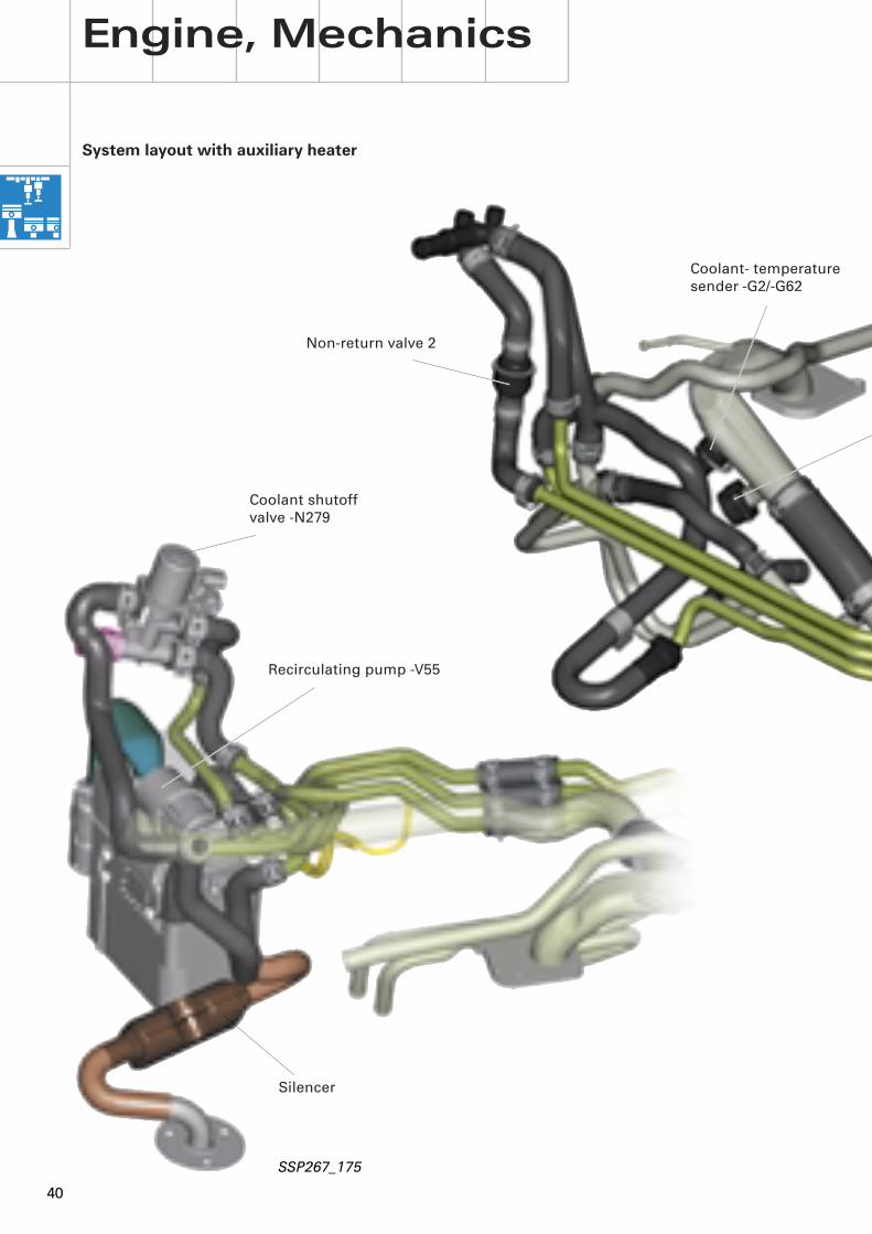
System layout with auxiliary heater
Engine, Mechanics
Coolant shutoff valve -N279
Recirculating pump -V55
SSP267_175
Non-return valve 2
Silencer
Coolant- temperature sender -G2/-G62
41
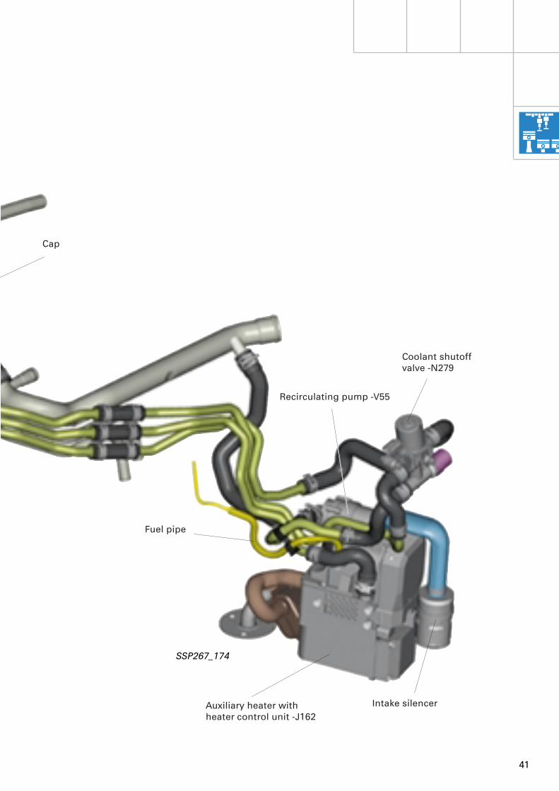
SSP267_174
Auxiliary heater withheater control unit -J162
Recirculating pump -V55
Fuel pipe
Intake silencer
Coolant shutoff valve -N279
Cap
42
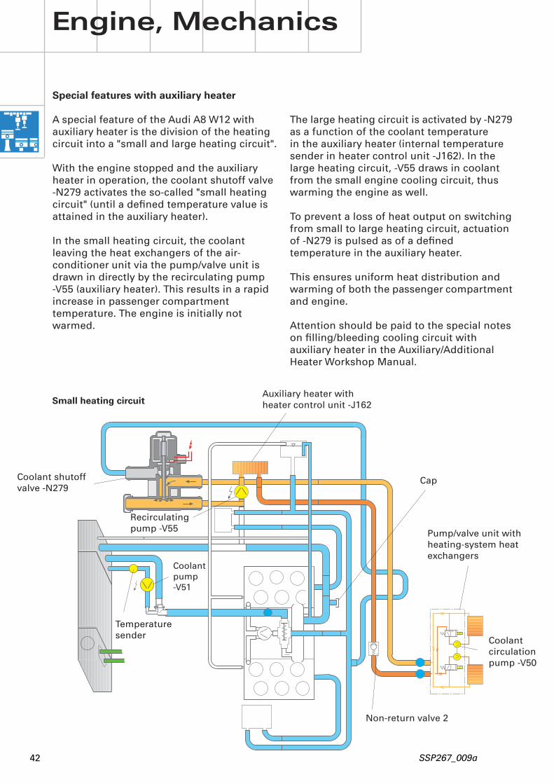
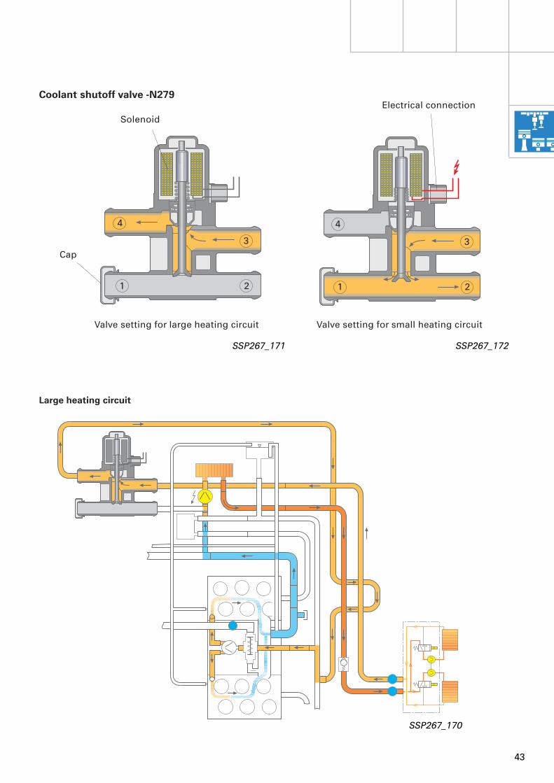
The large heating circuit is activated by -N279 as a function of the coolant temperaturein the auxiliary heater (internal temperature sender in heater control unit -J162). In the large heating circuit, -V55 draws in coolant from the small engine cooling circuit, thus warming the engine as well.
To prevent a loss of heat output on switching from small to large heating circuit, actuation of -N279 is pulsed as of a defined temperature in the auxiliary heater.
This ensures uniform heat distribution and warming of both the passenger compartment and engine.
Attention should be paid to the special notes on filling/bleeding cooling circuit with auxiliary heater in the Auxiliary/Additional Heater Workshop Manual.
Engine, Mechanics
Coolant shutoff valve -N279
Recirculating pump -V55
Auxiliary heater withheater control unit -J162
SSP267_009a
Non-return valve 2
Coolantpump -V51
Temperaturesender
Special features with auxiliary heater
A special feature of the Audi A8 W12 with auxiliary heater is the division of the heating circuit into a "small and large heating circuit".
With the engine stopped and the auxiliary heater in operation, the coolant shutoff valve -N279 activates the so-called "small heating circuit" (until a defined temperature value is attained in the auxiliary heater).
In the small heating circuit, the coolant leaving the heat exchangers of the air-conditioner unit via the pump/valve unit is drawn in directly by the recirculating pump -V55 (auxiliary heater). This results in a rapid increase in passenger compartment temperature. The engine is initially not warmed.
Pump/valve unit with heating-system heat exchangers
Cap
Small heating circuit
Coolant circulationpump -V50
43
Large heating circuit
SSP267_171 SSP267_172
SSP267_170
Cap
Electrical connection
Solenoid
Valve setting for large heating circuit Valve setting for small heating circuit
4
3
21
4
3
21
Coolant shutoff valve -N279
44
Key to -J541 pin assignment
Pin 1 Data telegram input from -J162 Information on auxiliary heater status (starting, full load, part load, interval, run-on, auxiliary ventilation, fault and final control test)
Data telegram input from -J162 Information on temperature in auxiliary heater
Pin 2 Output for actuation of -N279
Pin 3 Signal D+ from alternatorInformation on whether engine is running
Pin 4 Earth/terminal 31
Pin 5 Output for actuation of operating and display unit -E87
Pin 6 Power supply/terminal 30
Pin 7 Output to -J162 pin 3 for actuation of recirculating pump -V55
Pin 8 Not used
Pin 9 Data telegram input from -J218 Information on engine coolant temperature
Key to -J162 pin assignment
I Power supply/terminal 30
II Earth/terminal 31
Pin 1 Input from -J218 in dash panel insertActivation pulse for heating mode(> 5 V = ON)
Pin 2 Self-diagnosis K-wire
Pin 3 Input from -J541 pin 7 for actuating recirculating pump -V55
Engine, Mechanics
Control of coolant shutoff valve -N279
The coolant shutoff valve -N279 is actuated by the coolant shutoff valve control unit -J541.
For this purpose, the control unit -J541 processes information from the heater control unit -J162 and the combi processor in the dash panel insert -J218, as well as the D+ signal from the alternator.
Additional functions of -J541
- Actuation of recirculating pump -V55 on heat output request without auxiliary heater
If the engine is running and the coolant temperature transmitted to -J541 from the dash panel insert is less than approx. 80 °C, -J541 switches earth to pin 3 at the heater control unit -J162, thus activating the recirculating pump -V55. -V55 then reinforces the delivery of -V50 (in the pump/valve unit) and thus also the exchange of coolant in the heating-system heat exchangers of the air-conditioner unit. The result is an enhanced heat output.
- Actuation of operating and display unit for air conditioner -E87 in auxiliary heating mode if coolant temperature in auxiliary heater is > 30 °C
- Actuation of operating and display unit for air conditioner -E87 in auxiliary ventilation mode
It should be noted that the auxiliary heater has to be encoded for the "small cooling circuit" function. Refer to Auxiliary/Additional Heater Workshop Manual.

45
31
t° t° M MN279
J541
E87
S
J162
31
V54
III651234137964
5
7E
A B C D E F
21
28
Pin 4 Data telegram output to J541Information on auxiliary heater status (starting, full load, part load, interval, run-on, auxiliary ventilation, fault and final control test)Information on temperature in auxiliary heater
Pin 5 Input from -J218 in dash panel insertActivation pulse for auxiliary ventilation (earth)
Pin 6 Output for actuation of metering pump -V54
SSP267_177
-E87 Air conditioner display unit-J162 Auxiliary heater control unit-J541 Shutoff valve control unit-N279 Shutoff valve-V54 Metering pump
A Overheating cut-outB and D Glow plug with flame
monitor -Q8C Temperature sensor -G18E Combustion air blower -V6F Recirculating pump -V55
The data telegram is only transmitted if "small heating circuit" has been encoded. In the case of encoding for "large heating circuit", a positive signal (> 5 V = On) for activating the operating and display unit -E87 is output (on vehicles with no -J541/ -N279 - large heating circuit).
46
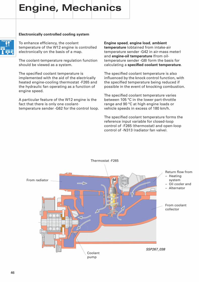
Engine speed, engine load, ambient temperature (obtained from intake-air temperature sender -G42 in air-mass meter) and engine-oil temperature (from oil-temperature sender -G8) form the basis for calculating a specified coolant temperature.
The specified coolant temperature is also influenced by the knock control function, with the specified temperature being reduced if possible in the event of knocking combustion.
The specified coolant temperature varies between 105 °C in the lower part-throttle range and 90 °C at high engine loads or vehicle speeds in excess of 180 km/h.
The specified coolant temperature forms the reference input variable for closed-loop control of -F265 (thermostat) and open-loop control of -N313 (radiator fan valve).
Electronically controlled cooling system
To enhance efficiency, the coolant temperature of the W12 engine is controlled electronically on the basis of a map.
The coolant-temperature regulation function should be viewed as a system.
The specified coolant temperature is implemented with the aid of the electrically heated engine-cooling thermostat -F265 and the hydraulic fan operating as a function of engine speed.
A particular feature of the W12 engine is the fact that there is only one coolant-temperature sender -G62 for the control loop.
Engine, Mechanics
SSP267_038
Thermostat -F265
From coolantcollector
Coolantpump
From radiator
Return flow from– Heating
system– Oil cooler and– Alternator
47
For further information onelectronic coolant control,refer to SSP 222.
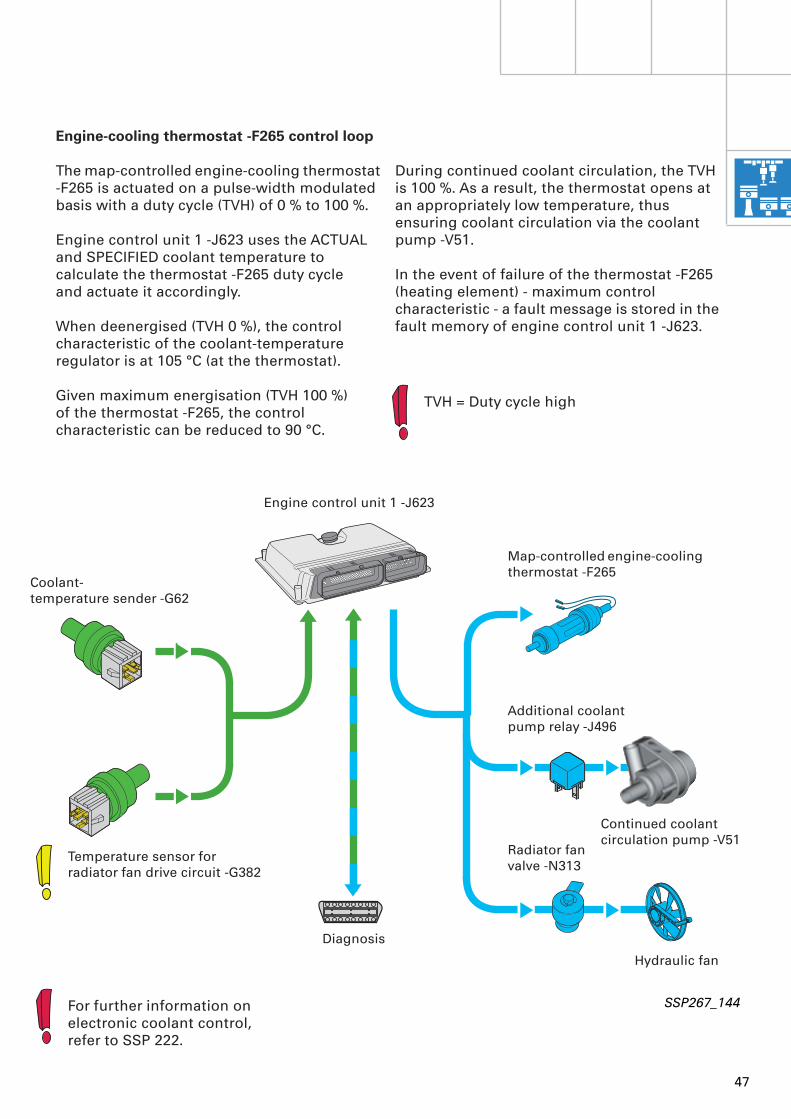
Engine-cooling thermostat -F265 control loop
The map-controlled engine-cooling thermostat -F265 is actuated on a pulse-width modulated basis with a duty cycle (TVH) of 0 % to 100 %.
Engine control unit 1 -J623 uses the ACTUAL and SPECIFIED coolant temperature to calculate the thermostat -F265 duty cycleand actuate it accordingly.
When deenergised (TVH 0 %), the control characteristic of the coolant-temperature regulator is at 105 °C (at the thermostat).
Given maximum energisation (TVH 100 %) of the thermostat -F265, the control characteristic can be reduced to 90 °C.
During continued coolant circulation, the TVH is 100 %. As a result, the thermostat opens at an appropriately low temperature, thus ensuring coolant circulation via the coolant pump -V51.
In the event of failure of the thermostat -F265 (heating element) - maximum control characteristic - a fault message is stored in the fault memory of engine control unit 1 -J623.
Coolant- temperature sender -G62
Temperature sensor for radiator fan drive circuit -G382
Map-controlled engine-cooling thermostat -F265
Additional coolant pump relay -J496
Continued coolant circulation pump -V51
Engine control unit 1 -J623
Diagnosis
SSP267_144
Radiator fan valve -N313
Hydraulic fan
TVH = Duty cycle high
48
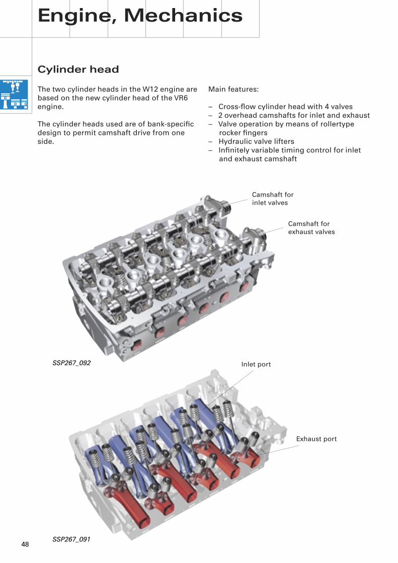
SSP267_092
Camshaft for inlet valves
Camshaft for exhaust valves
Cylinder head
The two cylinder heads in the W12 engine are based on the new cylinder head of the VR6 engine.
The cylinder heads used are of bank-specific design to permit camshaft drive from one side.
Engine, Mechanics
Main features:
– Cross-flow cylinder head with 4 valves– 2 overhead camshafts for inlet and exhaust– Valve operation by means of rollertype
rocker fingers– Hydraulic valve lifters– Infinitely variable timing control for inlet
and exhaust camshaft
Inlet port
Exhaust port
SSP267_091
49
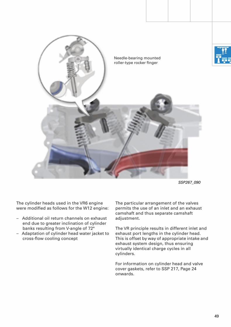
Needle-bearing mounted roller-type rocker finger
SSP267_090
The cylinder heads used in the VR6 engine were modified as follows for the W12 engine:
– Additional oil return channels on exhaust end due to greater inclination of cylinder banks resulting from V-angle of 72°
– Adaptation of cylinder head water jacket to cross-flow cooling concept
The particular arrangement of the valves permits the use of an inlet and an exhaust camshaft and thus separate camshaft adjustment.
The VR principle results in different inlet and exhaust port lengths in the cylinder head. This is offset by way of appropriate intake and exhaust system design, thus ensuring virtually identical charge cycles in all cylinders.
For information on cylinder head and valve cover gaskets, refer to SSP 217, Page 24 onwards.
50
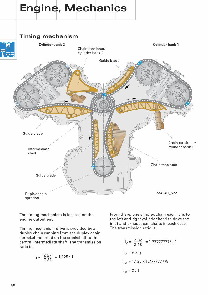
Duplex chain sprocket
SSP267_022
Guide blade
Intermediate shaft
Chain tensioner
Chain tensioner/cylinder bank 2
Guide blade
Cylinder bank 2 Cylinder bank 1
Chain tensioner/cylinder bank 1
Guide blade
Timing mechanism
Engine, Mechanics
The timing mechanism is located on the engine output end.
Timing mechanism drive is provided by a duplex chain running from the duplex chain sprocket mounted on the crankshaft to the central intermediate shaft. The transmission ratio is:
i1 = = 1.125 : 1Z 27Z 24
From there, one simplex chain each runs to the left and right cylinder head to drive the inlet and exhaust camshafts in each case. The transmission ratio is:
i2 = = 1.777777778 : 1
itot = i1 x i2
itot = 1.125 x 1.777777778
itot = 2 : 1
Z 32Z 18
51
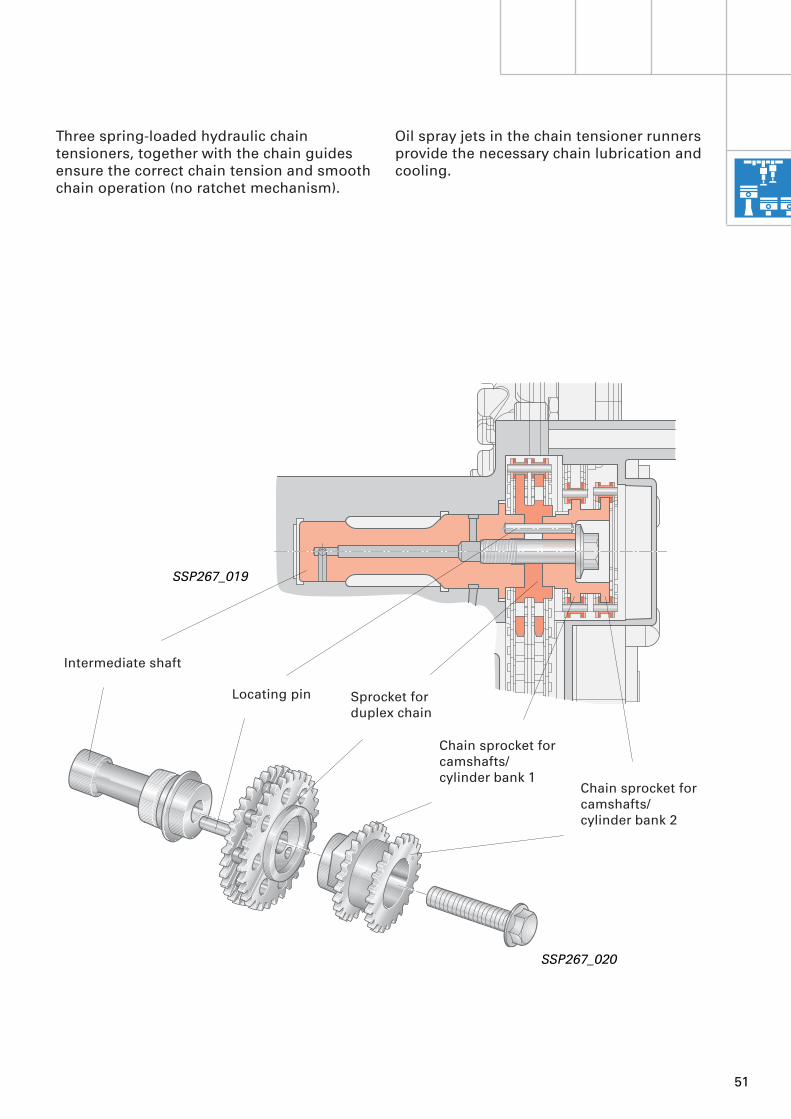
Three spring-loaded hydraulic chain tensioners, together with the chain guides ensure the correct chain tension and smooth chain operation (no ratchet mechanism).
Oil spray jets in the chain tensioner runners provide the necessary chain lubrication and cooling.
Intermediate shaft
Locating pin Sprocket forduplex chain
Chain sprocket forcamshafts/cylinder bank 1
Chain sprocket forcamshafts/cylinder bank 2
SSP267_020
SSP267_019
52
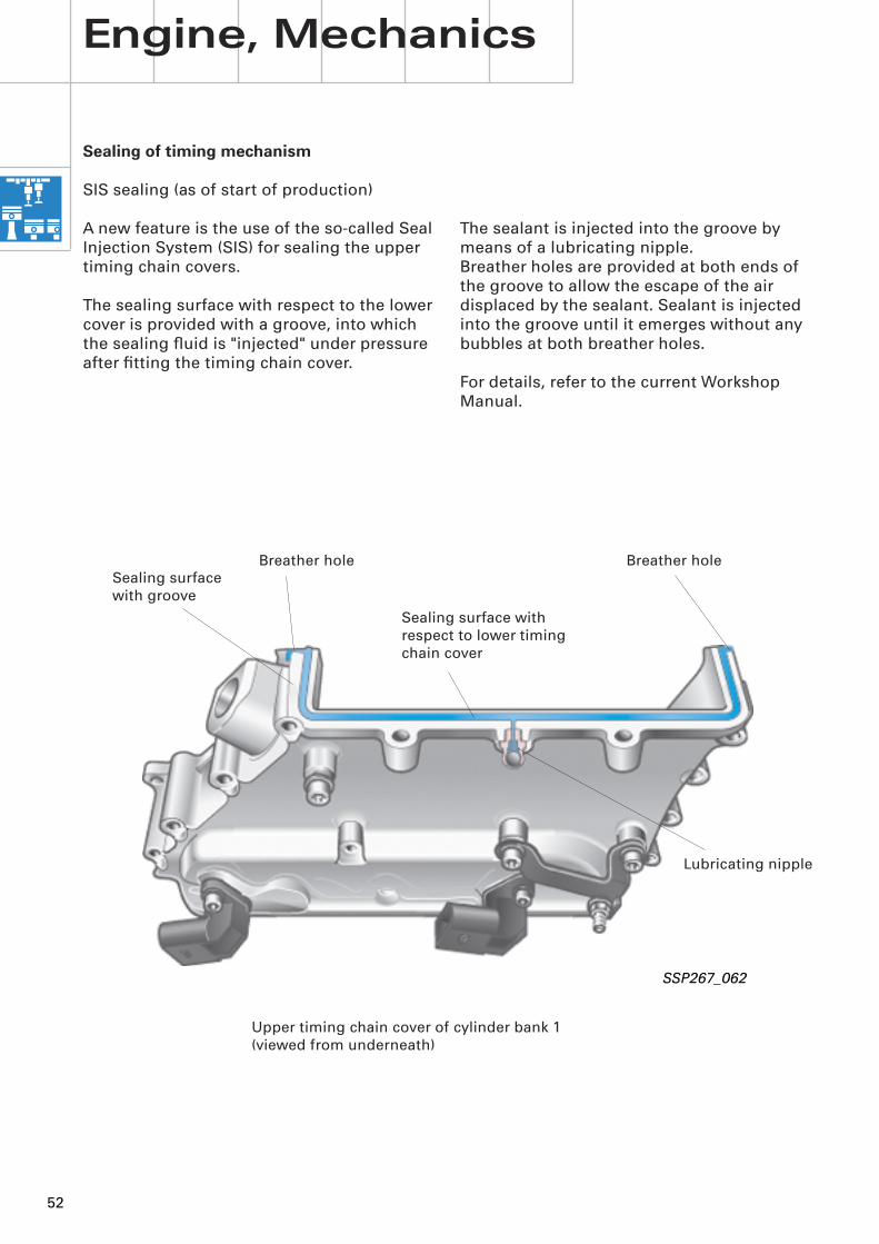
The sealant is injected into the groove by means of a lubricating nipple.Breather holes are provided at both ends of the groove to allow the escape of the air displaced by the sealant. Sealant is injected into the groove until it emerges without any bubbles at both breather holes.
For details, refer to the current Workshop Manual.
Sealing of timing mechanism
SIS sealing (as of start of production)
A new feature is the use of the so-called Seal Injection System (SIS) for sealing the upper timing chain covers.
The sealing surface with respect to the lower cover is provided with a groove, into whichthe sealing fluid is "injected" under pressure after fitting the timing chain cover.
Engine, Mechanics
SSP267_062
Upper timing chain cover of cylinder bank 1 (viewed from underneath)
Breather hole Breather hole
Sealing surface with respect to lower timing chain cover
Lubricating nipple
Sealing surfacewith groove
53
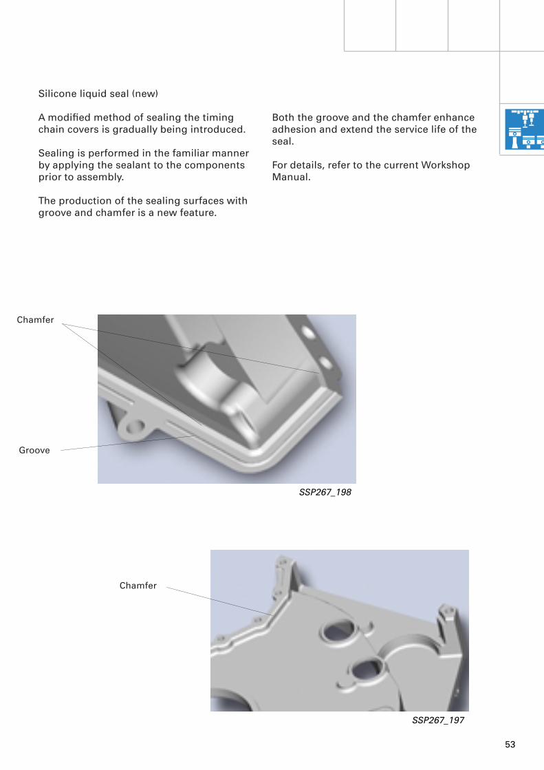
Both the groove and the chamfer enhance adhesion and extend the service life of the seal.
For details, refer to the current Workshop Manual.
Chamfer
Groove
Chamfer
Silicone liquid seal (new)
A modified method of sealing the timing chain covers is gradually being introduced.
Sealing is performed in the familiar manner by applying the sealant to the components prior to assembly.
The production of the sealing surfaces with groove and chamfer is a new feature.
SSP267_197
SSP267_198
54
Engine, Mechanics
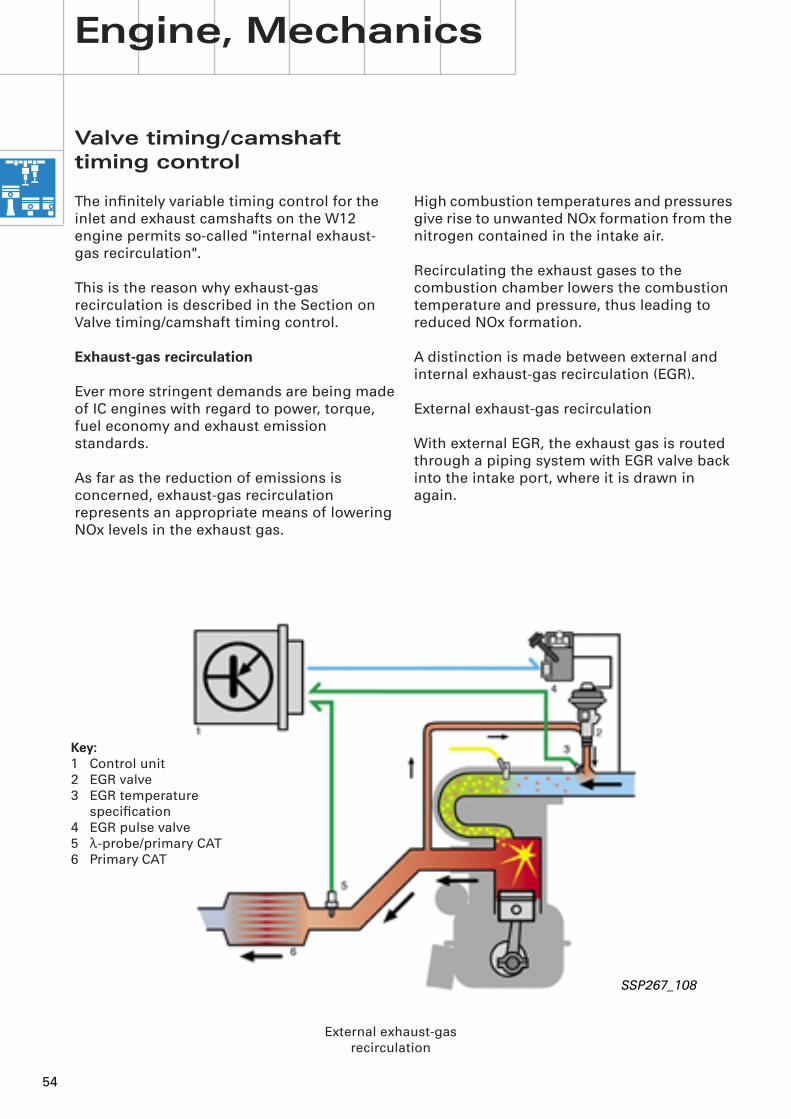
High combustion temperatures and pressures give rise to unwanted NOx formation from the nitrogen contained in the intake air.
Recirculating the exhaust gases to the combustion chamber lowers the combustion temperature and pressure, thus leading to reduced NOx formation.
A distinction is made between external and internal exhaust-gas recirculation (EGR).
External exhaust-gas recirculation
With external EGR, the exhaust gas is routed through a piping system with EGR valve back into the intake port, where it is drawn in again.
SSP267_108
Valve timing/camshaft timing control
The infinitely variable timing control for the inlet and exhaust camshafts on the W12 engine permits so-called "internal exhaust-gas recirculation".
This is the reason why exhaust-gas recirculation is described in the Section on Valve timing/camshaft timing control. Exhaust-gas recirculation
Ever more stringent demands are being made of IC engines with regard to power, torque, fuel economy and exhaust emission standards.
As far as the reduction of emissions is concerned, exhaust-gas recirculation represents an appropriate means of lowering NOx levels in the exhaust gas.
External exhaust-gas recirculation
Key:1 Control unit2 EGR valve3 EGR temperature
specification4 EGR pulse valve5 l-probe/primary CAT6 Primary CAT

55
Internal exhaust-gas recirculation
With the W12 engine, use is made of an internal exhaust-gas recirculation system to reduce the NOx level.
Internal EGR involves the optimum setting of the residual gas component in the cylinders by way of appropriate inlet and exhaust valve timing adjustment.
The volume of exhaust gas recirculated essentially depends on the amount of valve overlap.
Valve overlap is the term used to describe the angular range in which the inlet valve is already open before the exhaust valve closes.
The advantages of internal EGR include a rapid reaction time (short distances), the high recirculation rate which can be achieved, good formation of the exhaust and fresh gas mixture and fewer components.
SSP267_117
Internal exhaust-gas recirculation
56
n [ 1 /min ]
1000 2000 3000 4000 5000 6000 -30
-20
-10
-0
10
20
30
0
5
10
15
20
-5
-10
-15
-20
-25
n [ 1 /min ]
1000 2000 3000 4000 5000 6000
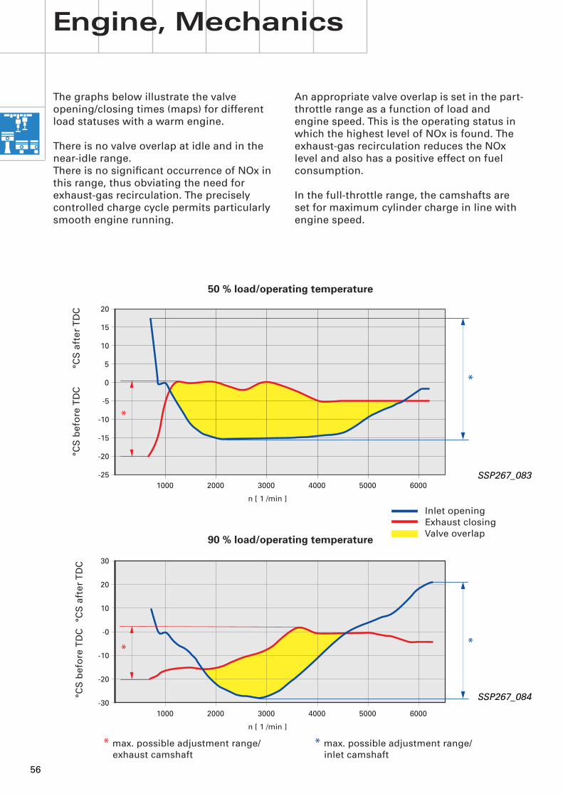
The graphs below illustrate the valve opening/closing times (maps) for different load statuses with a warm engine.
There is no valve overlap at idle and in the near-idle range. There is no significant occurrence of NOx in this range, thus obviating the need for exhaust-gas recirculation. The precisely controlled charge cycle permits particularly smooth engine running.
An appropriate valve overlap is set in the part-throttle range as a function of load and engine speed. This is the operating status in which the highest level of NOx is found. The exhaust-gas recirculation reduces the NOx level and also has a positive effect on fuel consumption.
In the full-throttle range, the camshafts are set for maximum cylinder charge in line with engine speed.
Inlet openingExhaust closingValve overlap
* max. possible adjustment range/ exhaust camshaft
°CS
bef
ore
TD
C°C
S a
fter
TD
C
* max. possible adjustment range/ inlet camshaft
* *
*
*
90 % load/operating temperature
50 % load/operating temperature
SSP267_083
SSP267_084
Engine, Mechanics
°CS
bef
ore
TD
C°C
S a
fter
TD
C
57
12
11
10
9
8
7
6
5
4
3
2
1
080 160 OT240 320 400 480 560 640
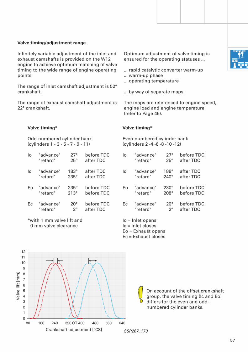
Optimum adjustment of valve timing is ensured for the operating statuses …
… rapid catalytic converter warm-up… warm-up phase… operating temperature
… by way of separate maps.
The maps are referenced to engine speed, engine load and engine temperature (refer to Page 46).
Valve timing/adjustment range
Infinitely variable adjustment of the inlet and exhaust camshafts is provided on the W12 engine to achieve optimum matching of valve timing to the wide range of engine operating points.
The range of inlet camshaft adjustment is 52° crankshaft.
The range of exhaust camshaft adjustment is 22° crankshaft.
Valve timing*
Odd-numbered cylinder bank(cylinders 1 - 3 - 5 - 7 - 9 - 11)
Io "advance" 27° before TDC"retard" 25° after TDC
Ic "advance" 183° after TDC"retard" 235° after TDC
Eo "advance" 235° before TDC"retard" 213° before TDC
Ec "advance" 20° before TDC"retard" 2° after TDC
*with 1 mm valve lift and0 mm valve clearance
Valve timing*
Even-numbered cylinder bank(cylinders 2 -4 -6 -8 -10 -12)
Io "advance" 27° before TDC"retard" 25° after TDC
Ic "advance" 188° after TDC"retard" 240° after TDC
Eo "advance" 230° before TDC"retard" 208° before TDC
Ec "advance" 20° before TDC"retard" 2° after TDC
Io = Inlet opensIc = Inlet closesEo = Exhaust opensEc = Exhaust closes
On account of the offset crankshaft group, the valve timing (Ic and Eo) differs for the even and odd-numbered cylinder banks.
SSP267_173Crankshaft adjustment [°CS]
Valv
e lif
t [m
m]
58
Engine, Mechanics
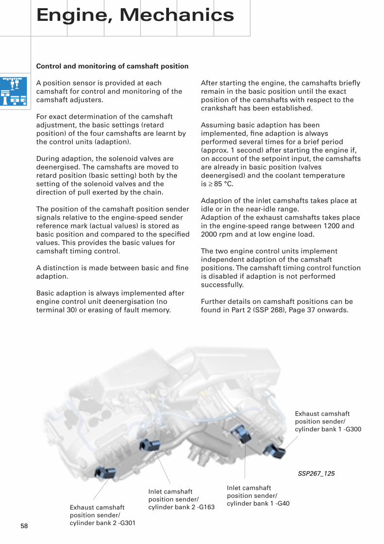
Control and monitoring of camshaft position
A position sensor is provided at each camshaft for control and monitoring of the camshaft adjusters.
For exact determination of the camshaft adjustment, the basic settings (retard position) of the four camshafts are learnt by the control units (adaption).
During adaption, the solenoid valves are deenergised. The camshafts are moved to retard position (basic setting) both by the setting of the solenoid valves and the direction of pull exerted by the chain.
The position of the camshaft position sender signals relative to the engine-speed sender reference mark (actual values) is stored as basic position and compared to the specified values. This provides the basic values for camshaft timing control.
A distinction is made between basic and fine adaption.
Basic adaption is always implemented after engine control unit deenergisation (no terminal 30) or erasing of fault memory.
SSP267_125
After starting the engine, the camshafts briefly remain in the basic position until the exact position of the camshafts with respect to the crankshaft has been established.
Assuming basic adaption has been implemented, fine adaption is always performed several times for a brief period (approx. 1 second) after starting the engine if, on account of the setpoint input, the camshafts are already in basic position (valves deenergised) and the coolant temperature is ≥ 85 °C.
Adaption of the inlet camshafts takes place at idle or in the near-idle range.Adaption of the exhaust camshafts takes place in the engine-speed range between 1200 and 2000 rpm and at low engine load.
The two engine control units implement independent adaption of the camshaft positions. The camshaft timing control function is disabled if adaption is not performed successfully.
Further details on camshaft positions can be found in Part 2 (SSP 268), Page 37 onwards.
Exhaust camshaft position sender/cylinder bank 2 -G301
Inlet camshaft position sender/cylinder bank 2 -G163
Inlet camshaft position sender/cylinder bank 1 -G40
Exhaust camshaft position sender/cylinder bank 1 -G300

59
The inlet camshaft is in retard position, whereas the exhaust camshaft is in advance position.
On starting the engine - until the point at which sufficient oil pressure has been built up - the exhaust camshafts are initially "drawn" towards retard position due to the low oil pressure and direction of chain pull.
When the solenoid valves are deenergised, the inlet and exhaust camshafts also assume the retard position.
Camshaft adjusters
The mode of operation of the camshaft adjusters is based on that of a hydraulic vane-type rotary motor, being characterised by a simple design and a short front to rear length.
This type of design is already in use on the new 2.0 l R4 (ALT) and 3.0 l V6 engines (ASN) (refer to SSP 255).
The illustration below shows the position of the camshafts with the engine idling and at operating temperature.
I - Inlet adjustment range 26° (52° crankshaft)
SSP267_128
Cylinder bank 1
Advance
Retard
Cylinder bank 2
Advance
Retard
AdvanceRetard
Advance
Retard
E - Exhaust adjustment range 11° (22° crankshaft)
E E
II
60
Pressure chamber
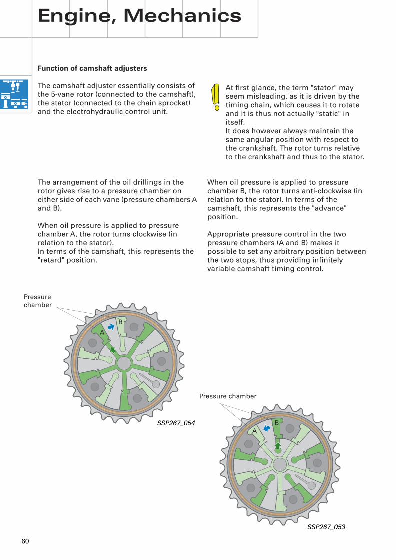
Function of camshaft adjusters
The camshaft adjuster essentially consists of the 5-vane rotor (connected to the camshaft), the stator (connected to the chain sprocket) and the electrohydraulic control unit.
At first glance, the term "stator" may seem misleading, as it is driven by the timing chain, which causes it to rotate and it is thus not actually "static" in itself.It does however always maintain the same angular position with respect to the crankshaft. The rotor turns relative to the crankshaft and thus to the stator.
The arrangement of the oil drillings in the rotor gives rise to a pressure chamber on either side of each vane (pressure chambers A and B).
When oil pressure is applied to pressure chamber A, the rotor turns clockwise (in relation to the stator). In terms of the camshaft, this represents the "retard" position.
When oil pressure is applied to pressure chamber B, the rotor turns anti-clockwise (in relation to the stator). In terms of the camshaft, this represents the "advance" position.
Appropriate pressure control in the two pressure chambers (A and B) makes it possible to set any arbitrary position between the two stops, thus providing infinitely variable camshaft timing control.
SSP267_054
SSP267_053
Pressure chamber
A
A
Engine, Mechanics
B
B
61
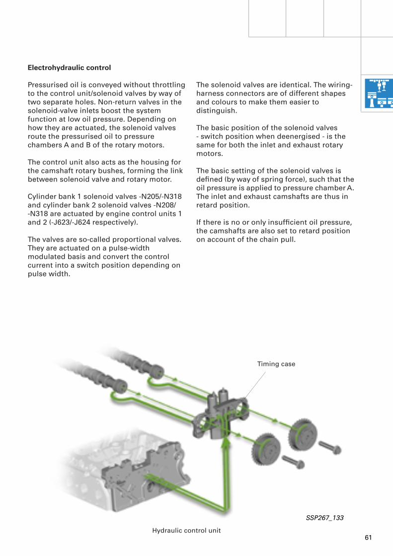
Electrohydraulic control
Pressurised oil is conveyed without throttling to the control unit/solenoid valves by way of two separate holes. Non-return valves in the solenoid-valve inlets boost the system function at low oil pressure. Depending on how they are actuated, the solenoid valves route the pressurised oil to pressure chambers A and B of the rotary motors.
The control unit also acts as the housing for the camshaft rotary bushes, forming the link between solenoid valve and rotary motor.
Cylinder bank 1 solenoid valves -N205/-N318 and cylinder bank 2 solenoid valves -N208/-N318 are actuated by engine control units 1 and 2 (-J623/-J624 respectively).
The valves are so-called proportional valves. They are actuated on a pulse-width modulated basis and convert the control current into a switch position depending on pulse width.
The solenoid valves are identical. The wiring-harness connectors are of different shapes and colours to make them easier to distinguish.
The basic position of the solenoid valves - switch position when deenergised - is the same for both the inlet and exhaust rotary motors.
The basic setting of the solenoid valves is defined (by way of spring force), such that the oil pressure is applied to pressure chamber A. The inlet and exhaust camshafts are thus in retard position.
If there is no or only insufficient oil pressure, the camshafts are also set to retard position on account of the chain pull.
Hydraulic control unit
SSP267_133
Timing case

62
SSP267_126
Port (B)
Adjustment in retard direction
Port (A)
SSP267_127
Adjustment in advance direction
Engine, Mechanics
AB
AB
Non-return valve
Non-return valve
Oil supply Oil drain

63
Adjustment in controlled position
SSP267_146
Non-return valve
AB

Service.
For internal use only
All rights reserved. Subject to technical modification.AUDI AGDepartment I/VK-35D-85045 IngolstadtFax 0841/89-36367140.2810.86.20Technical status as at 11/01Printed in Germany
The 6.0 l W12 enginein the Audi A8 - Part 1
Self-study programme 267
267
267
Related Documents