PRECISION SHOOTING EQUIPMENT INC. 2727 N. FAIRVIEW AVE. TUCSON, AZ 85705 • PSE-ARCHERY.COM DISTRIBUTED IN CANADA BY PORCUPINE CREEK SUPPLY • WWW.ARCHERYSUPPLIES.COM PN: 81606 THANK YOU FOR CHOOSING PSE! COMPOUND BOW USER’S GUIDE 1 9 7 0 - 2 0 1 8

Welcome message from author
This document is posted to help you gain knowledge. Please leave a comment to let me know what you think about it! Share it to your friends and learn new things together.
Transcript

PRECISION SHOOTING EQUIPMENT INC. 2727 N. FAIRVIEW AVE. TUCSON, AZ 85705 • PSE-ARCHERY.COM
DISTRIBUTED IN CANADA BY PORCUPINE CREEK SUPPLY • WWW.ARCHERYSUPPLIES.COM PN: 81606
THANK YOU FOR CHOOSING PSE!
COMPOUND BOW USER’S GUIDE
1970-2018

COMPOUND BOWUSER’S GUIDE
PAGE 3
PAGE 2
PSE COMPOUND BOW OWNER’S INFORMATIONFill in the following information for your personal records.
Bow Model
Bow Serial Number:See page 31 for the serial number location on your bow.
Purchased From:
Purchase Date:
Draw Length Draw Weight
PAGE INDEX
SUBJECT PAGE General product information ....................................................................................... 4
Compound bow terminology ........................................................................................5
PSE cable configurations ..............................................................................................6
PSE bow press info .................................................................................................. 7-9
Installation of accessories .......................................................................................... 10
Other adjustments ..................................................................................................... 10
Setting up your bow ................................................................................................... 11
FlexSlide 2™ and PSE String Stop installation and adjustments ......................................12
BackStop™ installation and adjustments ......................................................................13
Cable guards, TRS and FRS systems installation and adjustments ................................. 14
Shock-Modz and Limb Damper installation and adjustments ........................................ 15
PSE asymmetric idler ................................................................................................. 15
Micro LAS adjustments .............................................................................................. 16
Draw stop adjustments ...............................................................................................17
Limb stop adjustments .............................................................................................. 17
Evolve cam (ECS) adjustments ................................................................................... 18
Cam adjustments ....................................................................................................... 19
PSE Target Series- draw setting charts ........................................................................20
PSE Vapor Series- draw setting charts ..........................................................................21
PSE Evolve Series- draw setting charts.........................................................................21
PSE XS cam information ............................................................................................. 22
PSE Vision™cam information ...................................................................................... 23
Stinger™ Extreme- draw setting charts .......................................................................24
PSE Fever™ with Vision™- draw setting charts ........................................................25-26
PSE Mini Burner™ XT- draw setting charts ................................................................... 27
PSE Online store information ......................................................................................29
Notes ........................................................................................................................30
PSE warranty registration information .........................................................................31
Thank you from the entire PSE family for purchasing a PSE bow! Your bow was manufactured from the finest materials available and handcrafted with pride in the USA. With proper care you will enjoy the use of this product for years to come. Please read this entire booklet before shooting or adjusting your bow. Remember, many adjustments to a compound bow require the use of a bow press. Whenever shooting a bow, be certain of your target as well
as what else lies down range.
NOTE: IMPORTANT WARRANTY REGISTRATION INFORMATION IS ON PAGE 31
Thank You!
COMPOUND BOWUSER’S GUIDE
PAGE 5
PAGE 4
COMPOUND BOWUSER’S GUIDE
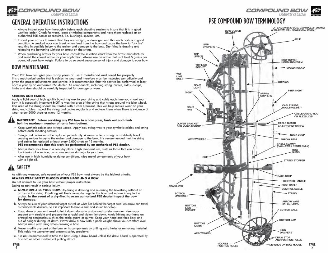
GENERAL OPERATING INSTRUCTIONS• Always inspect your bow thoroughly before each shooting session to insure that it is in good
working order. Check for worn, loose or missing components and have them replaced at an authorized PSE dealer as required, i.e. bushings, spacers, etc.
• Inspect your arrows to insure that they are straight, undamaged and that each nock is in good condition. A cracked nock can break when fired from the bow and cause the bow to “dry fire” resulting in possible injury to the archer and damage to the bow. Dry-firing is drawing and releasing the bowstring without an arrow on the string.
• When purchasing arrows for your bow, consult the selection chart from the arrow manufacturer and select the correct arrow for your application. Always use an arrow that is at least 5 grains per pound of peak bow weight. Failure to do so could cause personal injury and damage to your bow.
BOW MAINTENANCEYour PSE bow will give you many years of use if maintained and cared for properly. It is a mechanical device that is subject to wear and therefore must be inspected periodically and given the proper adjustments and service. It is recommended that this service be performed at least once a year by an authorized PSE dealer. All components, including string, cables, axles, e-clips, limbs and riser should be carefully inspected for damage or wear. STRINGS AND CABLES Apply a light coat of high quality bowstring wax to your string and cable each time you shoot your bow. It is especially important NOT to wax the area of the string that wraps around the idler wheel. This area of the string should be treated with a cam lubricant. This will help reduce wear on your string and cables. Inspect the string and cables regularly and replace them when there is evidence of wear, every 5000 shots or every 12 months.
IMPORTANT: Before servicing any PSE bow in a bow press, back out each limb bolt the maximum number of turns from bottom.
• Keep synthetic cables and strings waxed. Apply bow string wax to your synthetic cables and string before each shooting session.
• Strings and cables must be replaced periodically. A worn cable or string can suddenly break causing serious injury to the archer and damage to the bow. It is recommended that the string and cables be replaced at least every 5,000 shots or 12 months. PSE recommends that this work be performed by an authorized PSE dealer.
• Always store your bow in a cool dry place. High temperatures, such as those that can occur in the interior of a vehicle, can cause serious damage to your bow.
• After use in high humidity or damp conditions, wipe metal components of your bow with a light oil.
SAFETYAs with any weapon, safe operation of your PSE bow must always be the highest priority. ALWAYS WEAR SAFETY GLASSES WHEN HANDLING A BOW. Do not attempt to use your bow without proper instruction. Doing so can result in serious injury.
a. NEVER DRY-FIRE YOUR BOW. Dry-firing is drawing and releasing the bowstring without an arrow on the string. Dry-firing will likely cause damage to the bow and serious injury to the archer. In the event of a dry-fire, have an authorized PSE dealer inspect the bow for damage.
b. Always be sure of your intended target as well as what lies behind the target area. An arrow can travel a considerable distance, so it is important to have a safe and sound backstop.
c. If you draw a bow and need to let it down, do so in a slow and careful manner. Keep your support arm straight and prepare for a rapid and violent let-down. Avoid hitting your hand on protruding accessories such as the cable guard or quiver. Keep your head and face back and out of danger during let-down. Never draw a bow with a peak weight above your comfort level. Always use a wrist sling when drawing a bow.
d. Never modify any part of the bow or its components by drilling extra holes or removing material. This voids the warranty and presents safety problems.
e. It is not recommended to time the bow using a draw board unless the draw board is operated by a winch or other mechanical pulling device.
* = DEPENDS ON BOW MODEL
TOP LIMB(S)
TOPLIMB BOLT
SIGHT
ARROW REST
GRIP
STABILIZER
TOP CAM (HYBRID DUAL CAM MODELS- SHOWN)or IDLER WHEEL (SINGLE CAM MODEL)*
BOW QUIVERHOOD AND FOAM
CABLE GUARD RODOR FLEXSLIDE*
CABLE SLIDE, ROLLERGLIDE™
BOW SLING
STRING STOPPER
RISER OR HANDLE
BOTTOM CAM
TOP LIMBPOCKET
PSE COMPOUND BOW TERMINOLOGY
AXLE
LIMB DAMPERS
ARROW VANEor FLETCHING
LIMB DAMPERS
BOTTOM LIMB BOLT
ARROWS
QUIVER BRACKET AND QUICK-MOUNT*
SIGHTPINS
ARROW SHELF
BOTTOM LIMBS
BOTTOM AXLE
DRAW STOPAND POSITION HOLES
CABLE GUARD ADJUSTMENT SCREW
MODULE POSITION HOLES
NOCK LOOP
CABLE CLAMP*(FALL-AWAY RESTS ONLY)
PEEP SIGHTARROW GRIPPERS
BOW QUIVERHANGER
ARROW NOCK
SPEED NOCKS*
BACK STOP
SIGHTLIGHT
BUSS CABLECONTROL CABLE
STRING
BOTTOM LIMBPOCKET
COMPOUND BOWUSER’S GUIDE
PAGE 7
PAGE 6
COMPOUND BOWUSER’S GUIDE
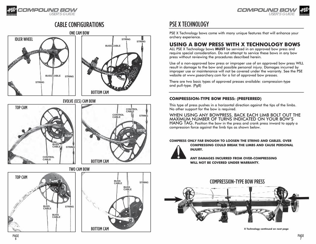
PSE X TECHNOLOGYPSE X Technology bows come with many unique features that will enhance your archery experience. USING A BOW PRESS WITH X TECHNOLOGY BOWS ALL PSE X Technology bows MUST be serviced in an approved bow press and require special consideration. Do not attempt to service these bows in any bow press without reviewing the procedures described herein.
Use of a non-approved bow press or improper use of an approved bow press WILL result in damage to the bow and possible personal injury. Damages incurred by improper use or maintenance will not be covered under the warranty. See the PSE website at www.psearchery.com for a list of approved bow presses.
There are two basic types of approved presses available: compression-type and pull-type. (Pg8)
COMPRESSION-TYPE BOW PRESS: (PREFERRED)
This type of press pushes in a horizontal direction against the tips of the limbs. No other support for the bow is required.
WHEN USING ANY BOWPRESS, BACK EACH LIMB BOLT OUT THE MAXIMUM NUMBER OF TURNS INDICATED ON YOUR BOW’S HANG TAG. Position the bow in the press and crank press inward to apply a compression force against the limb tips as shown below.
COMPRESS ONLY FAR ENOUGH TO LOOSEN THE STRING AND CABLES. OVER COMPRESSING COULD BREAK THE LIMBS AND CAUSE PERSONAL INJURY. ANY DAMAGES INCURRED FROM OVER-COMPRESSING WILL NOT BE COVERED UNDER WARRANTY.
X Technology continued on next page
COMPRESSION-TYPE BOW PRESS
ONE CAM BOW
EVOLVE (ECS) CAM BOW
CABLE CONFIGURATIONS
TWO CAM BOW
STRING
STRING
BUSS CABLE
STRING
UNIBUSS CABLE
CONTROL CABLE
CONTROL CABLE
CONTROL CABLE STRING
STRINGBUSS CABLE
BUSS CABLE
STRING
BUSS CABLE
BUSS CABLE
TOP CAM
BOTTOM CAM
BUSS CABLE
STRING
STRINGIDLER WHEEL
TOP CAM
BOTTOM CAM
BOTTOM CAM
COMPOUND BOWUSER’S GUIDE
PAGE 9
PAGE 8
COMPOUND BOWUSER’S GUIDE
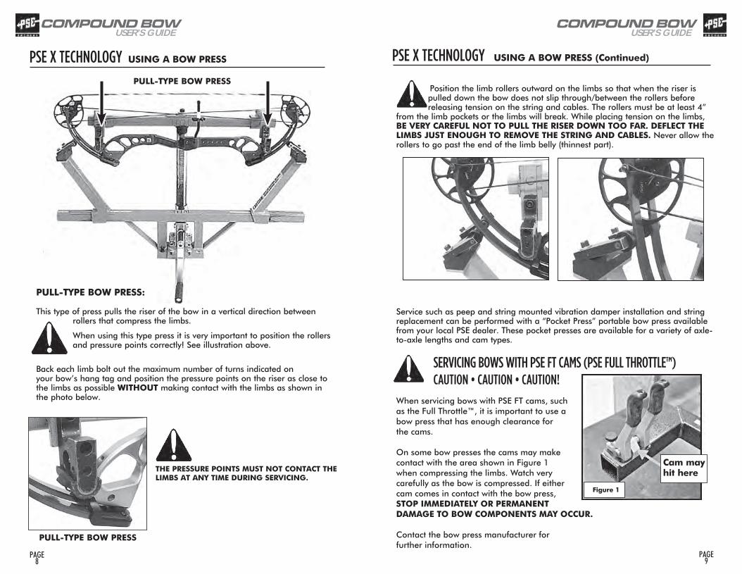
PULL-TYPE BOW PRESS: This type of press pulls the riser of the bow in a vertical direction between
rollers that compress the limbs.
When using this type press it is very important to position the rollers and pressure points correctly! See illustration above.
Back each limb bolt out the maximum number of turns indicated on your bow’s hang tag and position the pressure points on the riser as close to the limbs as possible WITHOUT making contact with the limbs as shown in the photo below.
THE PRESSURE POINTS MUST NOT CONTACT THE LIMBS AT ANY TIME DURING SERVICING.
PSE X TECHNOLOGY USING A BOW PRESS
PULL-TYPE BOW PRESS
PULL-TYPE BOW PRESS
SERVICING BOWS WITH PSE FT CAMS (PSE FULL THROTTLE™)CAUTION • CAUTION • CAUTION!
When servicing bows with PSE FT cams, such as the Full Throttle™, it is important to use a bow press that has enough clearance for the cams.
On some bow presses the cams may make contact with the area shown in Figure 1 when compressing the limbs. Watch very carefully as the bow is compressed. If either cam comes in contact with the bow press, STOP IMMEDIATELY OR PERMANENT DAMAGE TO BOW COMPONENTS MAY OCCUR.
Contact the bow press manufacturer for further information.
Figure 1
Cam may hit here
Position the limb rollers outward on the limbs so that when the riser is pulled down the bow does not slip through/between the rollers before releasing tension on the string and cables. The rollers must be at least 4”
from the limb pockets or the limbs will break. While placing tension on the limbs, BE VERY CAREFUL NOT TO PULL THE RISER DOWN TOO FAR. DEFLECT THE LIMBS JUST ENOUGH TO REMOVE THE STRING AND CABLES. Never allow the rollers to go past the end of the limb belly (thinnest part).
Service such as peep and string mounted vibration damper installation and string replacement can be performed with a “Pocket Press” portable bow press available from your local PSE dealer. These pocket presses are available for a variety of axle-to-axle lengths and cam types.
PSE X TECHNOLOGY USING A BOW PRESS (Continued)

COMPOUND BOWUSER’S GUIDE
PAGE 11
PAGE 10
COMPOUND BOWUSER’S GUIDE
SETTING-UP YOUR BOWNOCKING POINT PLACEMENT: Finger shooters: Install the nocking point so that the arrow passes the center of the arrow rest mounting hole and runs slightly point-down relative to the tuning mark on the window of the bow.Release Aid shooters: Install the nocking point so that the arrow passes the center of the arrow rest mounting hole and runs parallel to the alignment mark on the window of the bow. ARROW REST ADJUSTMENT: When shooting with a release aid, the in/out position of the arrow rest should be adjusted so that the arrow runs parallel with the tuning mark on the shelf when viewed from above. When shooting with fingers the arrow should point slightly outside the tuning alignment mark on the shelf. NOTE: Tuning alignment marks are for reference only. Adjustments will likely be necessary to nocking point and in/out position during tuning
SIGHT ADJUSTMENT: When adjusting the sight pin locations, always remember to “follow the group”. That is, if the shot group is to the left of the target, move the sight pins to the left. If the shot group is low, move the sight pins down.
Tuning Mark
Arrow rest mounting hole
•••
Alignment Mark
Tuning Mark
Your Authorized PSE Dealer is supplied with technical information on PSE bows and cams. Please see your Dealer for assistance when making these adjustments.
INSTALLATION OF ACCESSORIESArrowrest: The arrowrest should be installed according to the instructions received with the product. It is usually mounted to the riser in the threaded hole on the side opposite the shelf (Hole “A”) using the hardware provided with the arrowrest.Sight: The sight should be installed according to the instructions received with the product. It is usually mounted to the riser in the threaded holes (Holes “B”) on the side opposite the shelf using the hardware provided with the sight. Some bows are equipped with multiple sight mounting holes which allow the sight to be moved up or down. Stabilizer: The stabilizer should be mounted according to the manufacturer’s recommendation. It is usually mounted in the threaded hole on the front of the riser (Hole “C”).Bow Sling: The bow sling attaches to the riser of the bow generally with the stabilizer. If a stabilizer is not used, attach the sling to the riser with the correct sized bolt (5/16” - 24) using the hole provided for the stabilizer (Hole “C”).
OTHER ADJUSTMENTSDraw Weight: Your bow is factory-set to within 2 lbs. of the peak draw weight indicated on the bow hang tag and the last 2 digits of the serial number. Changes in draw weight can be made by turning the limb bolt in or out. Before making any changes in weight, turn the limb bolt clockwise to the bottom position. Never use extreme torque when turning the bolt or damage to the limb may occur. The limb bolt may then be turned counterclockwise to obtain the desired weight, but NEVER more than the number of turns indicated on the hang tag. Adjust each limb exactly the same. (See note and Fig. A below) Does not pertain to models using the Micro LAS system.
Hole A
Holes B
Hole C
CAUTION: On some bow models, the limb bolt locking screw, limb support screws or pocket tang locking screw MUST be loosened BEFORE adjusting.
Pocket tang locking screw
Limb support screw
Fig. A
Limb bolt
®
COMPOUND BOWUSER’S GUIDE
PAGE 13
PAGE 12
COMPOUND BOWUSER’S GUIDE
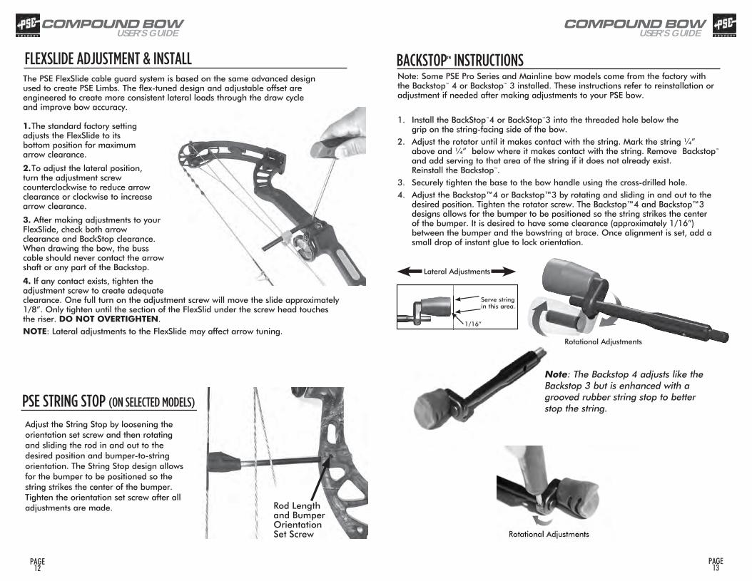
FLEXSLIDE ADJUSTMENT & INSTALLThe PSE FlexSlide cable guard system is based on the same advanced design used to create PSE Limbs. The flex-tuned design and adjustable offset are engineered to create more consistent lateral loads through the draw cycle and improve bow accuracy.
1. The standard factory setting adjusts the FlexSlide to its bottom position for maximum arrow clearance.
2. To adjust the lateral position, turn the adjustment screw counterclockwise to reduce arrow clearance or clockwise to increase arrow clearance.
3. After making adjustments to your FlexSlide, check both arrow clearance and BackStop clearance. When drawing the bow, the buss cable should never contact the arrow shaft or any part of the Backstop.
4. If any contact exists, tighten the adjustment screw to create adequate clearance. One full turn on the adjustment screw will move the slide approximately 1/8”. Only tighten until the section of the FlexSlid under the screw head touches the riser. DO NOT OVERTIGHTEN.NOTE: Lateral adjustments to the FlexSlide may affect arrow tuning.
BACKSTOP™ INSTRUCTIONSNote: Some PSE Pro Series and Mainline bow models come from the factory with the Backstop™ 4 or Backstop™ 3 installed. These instructions refer to reinstallation or adjustment if needed after making adjustments to your PSE bow.
1. Install the BackStop™4 or BackStop™3 into the threaded hole below the grip on the string-facing side of the bow.2. Adjust the rotator until it makes contact with the string. Mark the string ¼” above and ¼” below where it makes contact with the string. Remove Backstop™ and add serving to that area of the string if it does not already exist. Reinstall the Backstop™.3. Securely tighten the base to the bow handle using the cross-drilled hole.4. Adjust the Backstop™4 or Backstop™3 by rotating and sliding in and out to the desired position. Tighten the rotator screw. The Backstop™4 and Backstop™3 designs allows for the bumper to be positioned so the string strikes the center of the bumper. It is desired to have some clearance (approximately 1/16”) between the bumper and the bowstring at brace. Once alignment is set, add a small drop of instant glue to lock orientation.
Serve string in this area.
Lateral Adjustments
1/16”
Rotational Adjustments
Note: The Backstop 4 adjusts like the Backstop 3 but is enhanced with a grooved rubber string stop to better stop the string.PSE STRING STOP (ON SELECTED MODELS)
Adjust the String Stop by loosening the orientation set screw and then rotating and sliding the rod in and out to the desired position and bumper-to-string orientation. The String Stop design allows for the bumper to be positioned so the string strikes the center of the bumper. Tighten the orientation set screw after all adjustments are made. Rod Length
and BumperOrientation Set Screw
COMPOUND BOWUSER’S GUIDE
PAGE 15
PAGE 14
COMPOUND BOWUSER’S GUIDE
TRS Adjustment Screw
TRS Lock-Down Screw
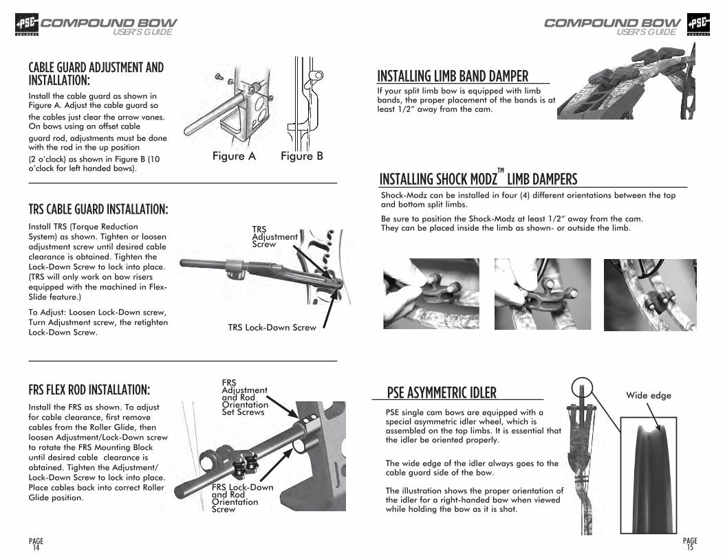
INSTALLING LIMB BAND DAMPERIf your split limb bow is equipped with limb bands, the proper placement of the bands is at least 1/2” away from the cam.
PSE ASYMMETRIC IDLER Wide edge
PSE single cam bows are equipped with a special asymmetric idler wheel, which is assembled on the top limbs. It is essential that the idler be oriented properly.
The wide edge of the idler always goes to the cable guard side of the bow. The illustration shows the proper orientation of the idler for a right-handed bow when viewed while holding the bow as it is shot.
INSTALLING SHOCK MODZ™ LIMB DAMPERSShock-Modz can be installed in four (4) different orientations between the top and bottom split limbs.
Be sure to position the Shock-Modz at least 1/2” away from the cam. They can be placed inside the limb as shown- or outside the limb.
CABLE GUARD ADJUSTMENT AND INSTALLATION: Install the cable guard as shown in Figure A. Adjust the cable guard so the cables just clear the arrow vanes. On bows using an offset cable guard rod, adjustments must be done with the rod in the up position (2 o’clock) as shown in Figure B (10 o’clock for left handed bows).
TRS CABLE GUARD INSTALLATION: Install TRS (Torque Reduction System) as shown. Tighten or loosen adjustment screw until desired cable clearance is obtained. Tighten the Lock-Down Screw to lock into place. (TRS will only work on bow risers equipped with the machined in Flex-Slide feature.)
To Adjust: Loosen Lock-Down screw, Turn Adjustment screw, the retighten Lock-Down Screw.
FRS FLEX ROD INSTALLATION: Install the FRS as shown. To adjust for cable clearance, first remove cables from the Roller Glide, then loosen Adjustment/Lock-Down screw to rotate the FRS Mounting Block until desired cable clearance is obtained. Tighten the Adjustment/Lock-Down Screw to lock into place. Place cables back into correct Roller Glide position.
Figure A Figure B
FRS Adjustment and Rod Orientation Set Screws
FRS Lock-Down and Rod Orientation Screw
COMPOUND BOWUSER’S GUIDE
PAGE 17
PAGE 16
COMPOUND BOWUSER’S GUIDE
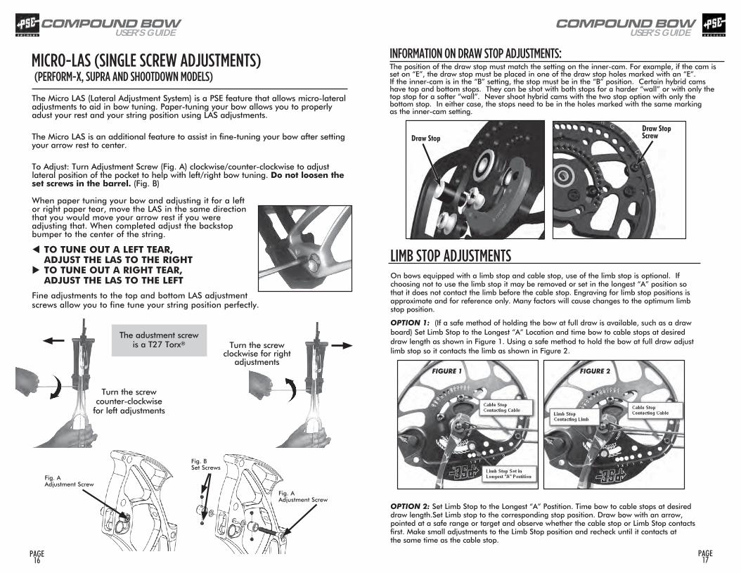
The Micro LAS (Lateral Adjustment System) is a PSE feature that allows micro-lateral adjustments to aid in bow tuning. Paper-tuning your bow allows you to properly adust your rest and your string position using LAS adjustments.
The Micro LAS is an additional feature to assist in fine-tuning your bow after setting your arrow rest to center.
To Adjust: Turn Adjustment Screw (Fig. A) clockwise/counter-clockwise to adjust lateral position of the pocket to help with left/right bow tuning. Do not loosen the set screws in the barrel. (Fig. B)
When paper tuning your bow and adjusting it for a left or right paper tear, move the LAS in the same direction that you would move your arrow rest if you were adjusting that. When completed adjust the backstop bumper to the center of the string.
tTO TUNE OUT A LEFT TEAR, ADJUST THE LAS TO THE RIGHT uTO TUNE OUT A RIGHT TEAR, ADJUST THE LAS TO THE LEFT
Fine adjustments to the top and bottom LAS adjustment screws allow you to fine tune your string position perfectly.
MICRO-LAS (SINGLE SCREW ADJUSTMENTS) (PERFORM-X, SUPRA AND SHOOTDOWN MODELS)
Fig. AAdjustment Screw
Fig. AAdjustment Screw
Fig. BSet Screws
Turn the screw clockwise for right
adjustments
Turn the screw counter-clockwise
for left adjustments
INFORMATION ON DRAW STOP ADJUSTMENTS: The position of the draw stop must match the setting on the inner-cam. For example, if the cam is set on “E”, the draw stop must be placed in one of the draw stop holes marked with an “E”. If the inner-cam is in the “B” setting, the stop must be in the “B” position. Certain hybrid cams have top and bottom stops. They can be shot with both stops for a harder “wall” or with only the top stop for a softer “wall”. Never shoot hybrid cams with the two stop option with only the bottom stop. In either case, the stops need to be in the holes marked with the same marking as the inner-cam setting.
Draw StopDraw Stop Screw
LIMB STOP ADJUSTMENTS On bows equipped with a limb stop and cable stop, use of the limb stop is optional. If choosing not to use the limb stop it may be removed or set in the longest “A” position so that it does not contact the limb before the cable stop. Engraving for limb stop positions is approximate and for reference only. Many factors will cause changes to the optimum limb stop position.
OPTION 1: (If a safe method of holding the bow at full draw is available, such as a draw board) Set Limb Stop to the Longest “A” Location and time bow to cable stops at desired draw length as shown in Figure 1. Using a safe method to hold the bow at full draw adjust limb stop so it contacts the limb as shown in Figure 2.
OPTION 2: Set Limb Stop to the Longest “A” Postition. Time bow to cable stops at desired draw length.Set Limb stop to the corresponding stop position. Draw bow with an arrow, pointed at a safe range or target and observe whether the cable stop or Limb Stop contacts first. Make small adjustments to the Limb Stop position and recheck until it contacts at the same time as the cable stop.
FIGURE 2FIGURE 1
The adustment screw is a T27 Torx®
COMPOUND BOWUSER’S GUIDE
PAGE 19
PAGE 18
COMPOUND BOWUSER’S GUIDE
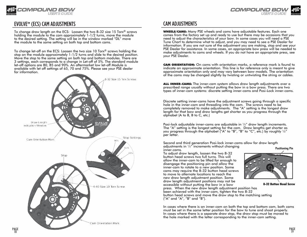
CAM ADJUSTMENTS WHEELS/CAMS: Many PSE wheels and cams have adjustable features. Each one comes from the factory set up and ready to use but there may be occasions that you need to adjust the characteristics of your bow. In some cases you will need a PSE Tune Chart to determine what to adjust, and you may need to see a PSE Dealer for information. If you are not sure of the adjustment you are making, stop and see your PSE Dealer for assistance. In some cases, an appropriate bow press will be needed to make adjustments to cams and wheels. If you do not have an appropriate press, see your PSE Dealer.
CAM ORIENTATION: On cams with orientation marks, a reference mark is found to indicate an approximate orientation. This line is for reference only is meant to give approximate orientation only and may vary between bow models. The orientation of the cams may be changed slightly by twisting or untwisting the string or cables.
ALL INNER-CAMS: The inner-cam system allows draw length adjustments over a prescribed range usually without putting the bow in a bow press. There are two types of inner-cam systems: discrete setting inner-cams and Posi-Lock inner-cams.
Discrete setting inner-cams have the adjustment screws going through a specific hole in the inner-cam and threading into the cam. The screws need to be completely removed to make adjustments. The “A” setting is the longest draw length for that bow and draw lengths get shorter as you progress through the alphabet (A to B, B to C, etc.)
Posi-lock adjustable inner-cams are adjustable in ½” draw length increments. The “A” setting is the longest setting for the cam. Draw lengths get shorter as you progress through the alphabet (“A” to “B”, “B” to “C”, etc.) by roughly ½” per letter.
Second and third generation Posi-lock inner-cams allow for draw length adjustments in ½” increments without changing inner-cams. To adjust draw length, loosen the two 8-32 button head screws two full turns. This will allow the inner-cam to be lifted far enough to disengage the positioning pin and allow the inner-cam to rotate to a new position. Some cams may require the 8-32 button head screws to move to alternate locations to reach the new draw length adjustment position. Some draw length adjustment positions may not be accessible without putting the bow in a bow press. When the new draw length adjustment position has been achieved with the inner-cam, tighten the two 8-32 button head screws and move the draw stop to the matching setting (“A” and “A”, “B” and “B”).
In cases where there is an inner-cam on both the top and bottom cam, both cams must be set in the same letter position for the bow to tune and shoot properly. In cases where there is a separate draw stop, the draw stop must be moved to the hole marked with the letter corresponding to the inner-cam setting.
Positioning Pin
8-32 Button Head Screw
EVOLVE™ (ECS) CAM ADJUSTMENTS To change draw length on the ECS: Loosen the two 8-32 size 15 Torx® screws holding the module to the cam approximately 1-1/2 turns, move the module to the desired setting. The setting will be in the window marked “DL” move the module to the same setting on both top and bottom cams.
To change let-off on the ECS: Loosen the two size 10 Torx® screws holding the stop on the module approximately 1-1/2 turns and slide to the desired position. Move the stop to the same setting on both top and bottom modules. There are 3 settings, each corresponds to a change in Let-off of 5%. The standard module let-off options are 80, 85 and 90%. An aftermarket low let-off Module is available with let off settings of 65, 70 and 75%. Please see your PSE dealer for information.
COMPOUND BOWUSER’S GUIDE
PAGE 21
PAGE 20
COMPOUND BOWUSER’S GUIDE2018 TARGET SERIES
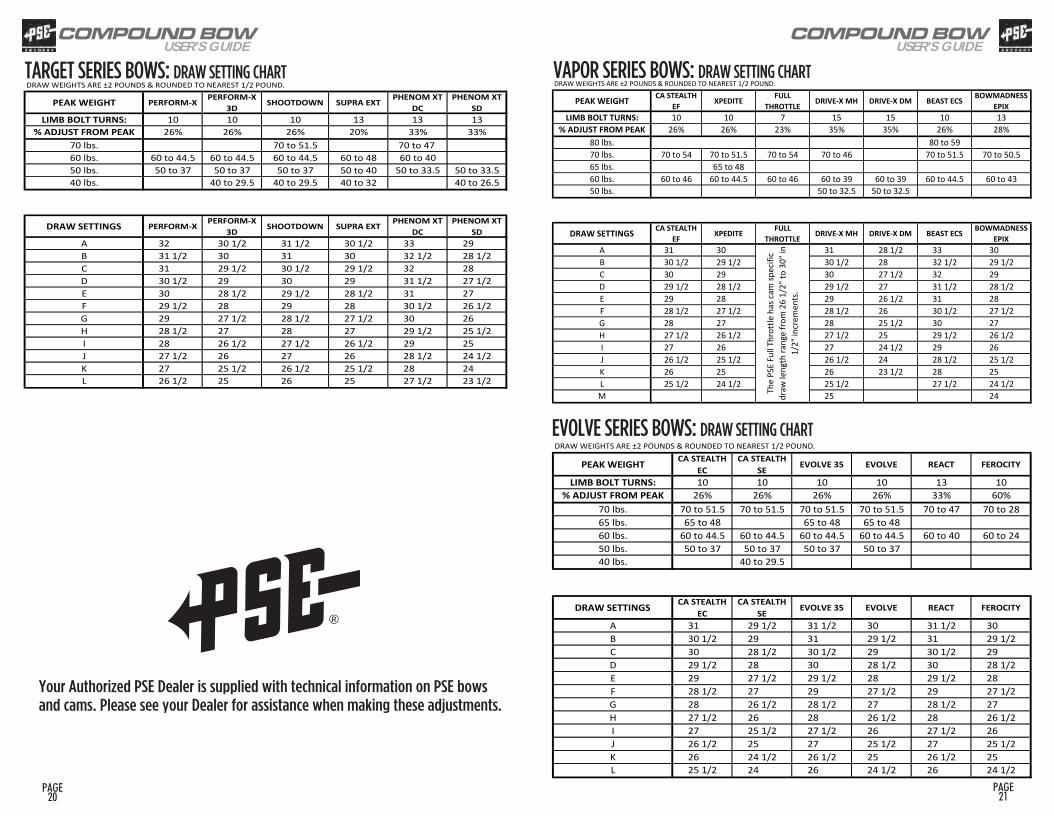
DRAW WEIGHTS ARE ±2 POUNDS & ROUNDED TO NEAREST 1/2 POUND.
PEAK WEIGHT PERFORM-X PERFORM-X 3D SHOOTDOWN SUPRA EXT PHENOM XT
DCPHENOM XT
SDLIMB BOLT TURNS: 10 10 10 13 13 13
% ADJUST FROM PEAK 26% 26% 26% 20% 33% 33%70 lbs. 70 to 51.5 70 to 47 60 lbs. 60 to 44.5 60 to 44.5 60 to 44.5 60 to 48 60 to 4050 lbs. 50 to 37 50 to 37 50 to 37 50 to 40 50 to 33.5 50 to 33.540 lbs. 40 to 29.5 40 to 29.5 40 to 32 40 to 26.5
DRAW SETTINGS PERFORM-X PERFORM-X 3D SHOOTDOWN SUPRA EXT PHENOM XT
DC PHENOM XT
SDA 32 30 1/2 31 1/2 30 1/2 33 29B 31 1/2 30 31 30 32 1/2 28 1/2C 31 29 1/2 30 1/2 29 1/2 32 28D 30 1/2 29 30 29 31 1/2 27 1/2E 30 28 1/2 29 1/2 28 1/2 31 27F 29 1/2 28 29 28 30 1/2 26 1/2G 29 27 1/2 28 1/2 27 1/2 30 26H 28 1/2 27 28 27 29 1/2 25 1/2I 28 26 1/2 27 1/2 26 1/2 29 25J 27 1/2 26 27 26 28 1/2 24 1/2K 27 25 1/2 26 1/2 25 1/2 28 24L 26 1/2 25 26 25 27 1/2 23 1/2
2018 VAPOR SERIES
DRAW WEIGHTS ARE ±2 POUNDS & ROUNDED TO NEAREST 1/2 POUND.
PEAK WEIGHT CA STEALTH EF XPEDITE FULL
THROTTLE DRIVE-X MH DRIVE-X DM BEAST ECS BOWMADNESS EPIX
LIMB BOLT TURNS: 10 10 7 15 15 10 13% ADJUST FROM PEAK 26% 26% 23% 35% 35% 26% 28%
80 lbs. 80 to 5970 lbs. 70 to 54 70 to 51.5 70 to 54 70 to 46 70 to 51.5 70 to 50.565 lbs. 65 to 4860 lbs. 60 to 46 60 to 44.5 60 to 46 60 to 39 60 to 39 60 to 44.5 60 to 4350 lbs. 50 to 32.5 50 to 32.5
DRAW SETTINGS CA STEALTH EF XPEDITE FULL
THROTTLE DRIVE-X MH DRIVE-X DM BEAST ECS BOWMADNESS EPIX
A 31 30 31 28 1/2 33 30B 30 1/2 29 1/2 30 1/2 28 32 1/2 29 1/2C 30 29 30 27 1/2 32 29D 29 1/2 28 1/2 29 1/2 27 31 1/2 28 1/2E 29 28 29 26 1/2 31 28F 28 1/2 27 1/2 28 1/2 26 30 1/2 27 1/2G 28 27 28 25 1/2 30 27H 27 1/2 26 1/2 27 1/2 25 29 1/2 26 1/2I 27 26 27 24 1/2 29 26J 26 1/2 25 1/2 26 1/2 24 28 1/2 25 1/2K 26 25 26 23 1/2 28 25L 25 1/2 24 1/2 25 1/2 27 1/2 24 1/2M 25 24Th
e PS
E Fu
ll Th
rott
le h
as ca
m sp
ecifi
c dr
aw le
ngth
rang
e fro
m 2
6 1/
2" to
30"
in
1/2"
incr
emen
ts.
2018 EVOLVE SERIES
DRAW WEIGHTS ARE ±2 POUNDS & ROUNDED TO NEAREST 1/2 POUND.
PEAK WEIGHT CA STEALTH EC
CA STEALTH SE EVOLVE 35 EVOLVE REACT FEROCITY
LIMB BOLT TURNS: 10 10 10 10 13 10% ADJUST FROM PEAK 26% 26% 26% 26% 33% 60%
70 lbs. 70 to 51.5 70 to 51.5 70 to 51.5 70 to 51.5 70 to 47 70 to 2865 lbs. 65 to 48 65 to 48 65 to 4860 lbs. 60 to 44.5 60 to 44.5 60 to 44.5 60 to 44.5 60 to 40 60 to 2450 lbs. 50 to 37 50 to 37 50 to 37 50 to 3740 lbs. 40 to 29.5
DRAW SETTINGS CA STEALTH EC
CA STEALTH SE EVOLVE 35 EVOLVE REACT FEROCITY
A 31 29 1/2 31 1/2 30 31 1/2 30B 30 1/2 29 31 29 1/2 31 29 1/2C 30 28 1/2 30 1/2 29 30 1/2 29D 29 1/2 28 30 28 1/2 30 28 1/2E 29 27 1/2 29 1/2 28 29 1/2 28F 28 1/2 27 29 27 1/2 29 27 1/2G 28 26 1/2 28 1/2 27 28 1/2 27H 27 1/2 26 28 26 1/2 28 26 1/2I 27 25 1/2 27 1/2 26 27 1/2 26J 26 1/2 25 27 25 1/2 27 25 1/2K 26 24 1/2 26 1/2 25 26 1/2 25L 25 1/2 24 26 24 1/2 26 24 1/2
TARGET SERIES BOWS: DRAW SETTING CHART VAPOR SERIES BOWS: DRAW SETTING CHART
EVOLVE SERIES BOWS: DRAW SETTING CHART
Your Authorized PSE Dealer is supplied with technical information on PSE bows and cams. Please see your Dealer for assistance when making these adjustments.
®

COMPOUND BOWUSER’S GUIDE
PAGE 22
COMPOUND BOWUSER’S GUIDE
PSE SX CAM INFORMATION BOWS: PSE STINGER™ EXTREME ADJUSTING THE SX CAM:Select the “PERFORMANCE” or “GROW WITH YOU” cable position based on the desired draw characteristics and peak weight range.
Rotate the inner-cam position (A thru P) to match the desired draw length. To adjust, loosen each #8-32 button head screw approx. 2 full turns. Rotate into position and tighten screws. NOTE: the 3rd tapped hole position in the inner-cam may be used if the screw becomes hidden behind the limb.
“Performance” Setting
“Grow With You” Setting
PSE VISION™ CAM INFORMATION BOWS: PSE FEVER™, PSE MINI BURNER™ ADJUSTING THE VISION™CAM: DRAW LENGTH: STRING POST ADJUSTMENTS
PSE Vision cams have a string post adjustment for draw length as well as inner cam
adjustments and “Flexible Cam” adjustments. To make a string post adjustment, compress
the bow in a suitable bow press and relieve tension from the string and cables. See the draw
length adjustment chart for your bow for details.
Select the draw length and the “PERFORMANCE” or “GROW WITH YOU” cable position based on the desired draw characteristics and peak weight range. If your desired draw length lies in the short post category, an approved bow press will be required to make this adjustment.Once the string is positioned onto the string posts of your choice, adjust the inner-cam to the desired location.
The inner-cam has holes marked “A” through “J” for adjusting draw length as well as a set of threaded holes marked “S” and “L”. The “L” holes are used for longer draw lengths and the “S” holes are used for shorter draw lengths. See the following tables for the setting required to achieve different draw lengths and weight for bows using this cam.
To make the necessary adjustment, remove the screw holding the inner-cam in place and rotate the inner-cam so the letter setting desired lines up with the threaded “L” or “S” hole in the cam. Replace and tighten the screw. IT IS IMPORTANT THAT BOTH TOP AND BOTTOM CAMS BE ADJUSTED THE SAME. These adjustments can be made either with or without a bow press.
PAGE 23
COMPOUND BOWUSER’S GUIDE
PAGE 25
COMPOUND BOWUSER’S GUIDE
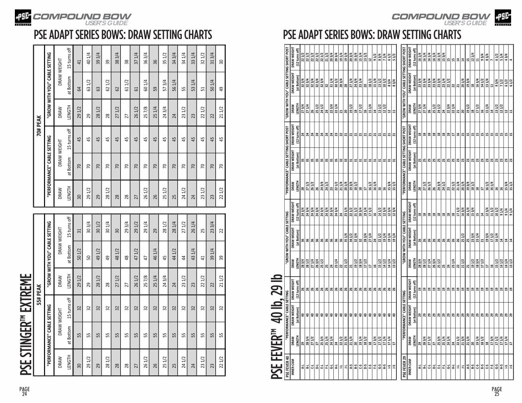
PSE ADAPT SERIES BOWS: DRAW SETTING CHARTS20
18 PS
E STIN
GER X
TREM
E
DRAW
DRAW
DRAW
DRAW
LENG
THat
Botto
m15
turn
s off
LENG
THat
Botto
m15
turn
s off
LENG
THat
Botto
m15
turn
s off
LENG
THat
Botto
m15
turn
s off
3055
3229
1/2
50 1/
231
3070
4529
1/2
6441
29 1/
255
3229
5030
3/4
29 1/
270
4529
63 1/
240
1/4
2955
3228
1/2
49 1/
230
1/2
2970
4528
1/2
6339
3/4
28 1/
255
3228
4930
1/4
28 1/
270
4528
62 1/
239
2855
3227
1/2
48 1/
230
2870
4527
1/2
6238
3/4
2855
3227
4829
3/4
2870
4527
61 1/
238
2755
3226
1/2
47 1/
229
1/2
2770
4526
1/2
6137
1/4
26 1/
255
3225
7/8
4729
1/4
26 1/
270
4525
7/8
60 1/
436
3/4
2655
3225
1/4
46 1/
429
2670
4525
1/4
5936
25 1/
255
3224
3/4
4528
1/2
25 1/
270
4524
3/4
57 3/
435
1/2
2555
3224
44 1/
228
1/4
2570
4524
56 1/
434
3/4
24 1/
255
3223
1/2
4427
1/2
24 1/
270
4523
1/2
5534
1/4
2455
3223
43 1/
426
1/4
2470
4523
53 1/
433
1/4
23 1/
255
3222
1/2
4125
23 1/
270
4522
1/2
5132
1/2
2355
3222
39 1/
423
3/4
2370
4522
50 1/
431
3/4
22 1/
255
3221
1/2
3922
22 1/
270
4521
1/2
4930
DRAW
WEIG
HT
55# P
EAK
70# P
EAK
"PER
FORM
ANCE
" CAB
LE SE
TTIN
G"G
ROW
WITH
YOU"
CABL
E SET
TING
"PER
FORM
ANCE
" CAB
LE SE
TTIN
G"G
ROW
WITH
YOU"
CABL
E SET
TING
DRAW
WEIG
HTDR
AW W
EIGHT
DRAW
WEIG
HT
PAGE 24
PSE ADAPT SERIES BOWS: DRAW SETTING CHARTS
PSE F
EVER
40IN
NER-
CAM
DR
AWDR
AW W
EIGHT
DRAW
WEIG
HTDR
AWDR
AW W
EIGHT
DRAW
WEIG
HTDR
AWDR
AW W
EIGHT
DRAW
WEIG
HTDR
AWDR
AW W
EIGHT
DRAW
WEIG
HTLE
NGTH
(at B
otto
m)
(12 t
urns
off)
LENG
TH(a
t Bot
tom
)(1
2 tur
ns of
f)LE
NGTH
(at B
otto
m)
(12 t
urns
off)
LENG
TH(a
t Bot
tom
)(1
2 tur
ns of
f)A-
L29
4026
28 3/
436
24 3/
428
3524
27 3/
432
3/4
22 1/
2B-
L28
3/4
4026
28 1/
236
24 3/
427
1/2
3524
27 1/
432
3/4
22 1/
2C-
L27
1/2
4026
27 1/
436
24 3/
426
1/2
3524
2632
3/4
22 1/
2D-
L27
4026
26 3/
436
24 3/
426
3524
25 1/
232
3/4
22 1/
2E-L
25 3/
440
2625
1/2
3624
3/4
24 3/
435
2424
1/2
32 3/
422
1/2
F-L25
1/4
4026
2536
24 3/
424
1/2
3524
2432
21 1/
2G-
L24
1/4
4026
2436
24 3/
423
3524
22 3/
431
1/4
20 3/
4H-
L24
4026
23 1/
436
24 3/
422
1/2
3523
22 1/
430
1/2
20 3/
4I-L
22 1/
240
2622
3624
21 1/
432
2221
28 3/
419
1/4
J-L21
3/4
4026
21 1/
235
1/4
23 1/
420
1/4
3221
2028
19 1/
4A-
S21
1/4
4026
2134
1/2
22 1/
219
3/4
3121
19 1/
227
1/4
20 3/
4B-
S20
4026
19 1/
232
3/4
21 1/
218
1/2
3121
1824
3/4
16 3/
4C-
S19
1/4
4026
18 3/
432
20 3/
418
3121
17 1/
223
1/4
15 1/
4D-
S18
1/2
4026
17 1/
228
3/4
19 1/
417
3121
1620
13 1/
2E-S
1840
2617
27 1/
417
1/2
16 1/
231
2115
1/4
18 1/
212
F-S17
3/4
4026
1624
1616
1/4
3121
1415
1/4
9 1/2
G-S
17 1/
240
2615
1/2
22 1/
214
1/2
1631
2113
1/2
13 1/
28 3
/4H-
S17
1/4
4026
14 1/
219
1/4
12 3/
416
3121
12 1/
210
1/2
7 1/4
I-S17
1/4
4026
14 1/
419
1/4
12 3/
415
3/4
3121
128 3
/46 1
/2J-S
1740
2613
1/2
19 1/
412
3/4
15 1/
231
2111
8 3/4
5 1/2
PSE F
EVER
29IN
NER-
CAM
DR
AWDR
AW W
EIGHT
DRAW
WEIG
HTDR
AWDR
AW W
EIGHT
DRAW
WEIG
HTDR
AWDR
AW W
EIGHT
DRAW
WEIG
HTDR
AWDR
AW W
EIGHT
DRAW
WEIG
HTLE
NGTH
(at B
otto
m)
(12 t
urns
off)
LENG
TH(a
t Bot
tom
)(1
2 tur
ns of
f)LE
NGTH
(at B
otto
m)
(12 t
urns
off)
LENG
TH(a
t Bot
tom
)(1
2 tur
ns of
f)A-
L29
2919
28 3/
426
1828
2518
27 3/
423
3/4
16 1/
4B-
L28
3/4
2919
28 1/
226
1827
1/2
2518
27 1/
423
3/4
16 1/
4C-
L27
1/2
2919
27 1/
426
1826
1/2
2518
2623
3/4
16 1/
4D-
L27
2919
26 3/
426
1826
2518
25 1/
223
3/4
16 1/
4E-L
25 3/
429
1925
1/2
2618
24 3/
425
1824
1/2
23 3/
416
1/4
F-L25
1/4
2919
2526
1824
1/2
2518
2423
1/4
15 3/
4G-
L24
1/4
2919
2426
1823
2518
22 3/
422
1/2
15H-
L24
2919
23 1/
426
1822
1/2
2517
22 1/
422
15I-L
22 1/
229
1922
2617
1/2
21 1/
423
1621
2114
J-L21
3/4
2919
21 1/
225
1/2
16 3/
420
1/4
2315
2020
1/4
14A-
S21
1/4
2919
2125
16 1/
419
3/4
2315
19 1/
219
3/4
15B-
S20
2919
19 1/
223
3/4
15 3/
418
1/2
2315
1818
12 1/
4C-
S19
1/4
2919
18 3/
423
1/4
1518
2315
17 1/
216
3/4
11D-
S18
1/2
2919
17 1/
221
1417
2315
1614
1/2
9 3/4
E-S18
2919
1719
3/4
12 3/
416
1/2
2315
15 1/
413
1/4
8 3/4
F-S17
3/4
2919
1617
1/2
11 1/
216
1/4
2315
1411
7G-
S17
1/2
2919
15 1/
216
1/4
10 1/
216
2315
13 1/
29 3
/46 1
/2H-
S17
1/4
2919
14 1/
214
9 1/4
1623
1512
1/2
7 1/2
5 1/4
I-S17
1/4
2919
14 1/
414
9 1/4
15 3/
423
1512
6 1/2
4 3/4
J-S17
2919
13 1/
214
9 1/4
15 1/
223
1511
6 1/2
4
2018
FEVE
R 40
lb, 29
lb"P
ERFO
RMAN
CE" C
ABLE
SETT
ING
"GRO
W W
ITH YO
U" CA
BLE S
ETTIN
G"P
ERFO
RMAN
CE" C
ABLE
SETT
ING
SHOR
T POS
T"G
ROW
WITH
YOU"
CABL
E SET
TING
SHOR
T POS
T
"PER
FORM
ANCE
" CAB
LE SE
TTIN
G"G
ROW
WITH
YOU"
CABL
E SET
TING
"PER
FORM
ANCE
" CAB
LE SE
TTIN
G SH
ORT P
OST
"GRO
W W
ITH YO
U" CA
BLE S
ETTIN
G SH
ORT P
OST
PSE S
TINGE
R™ EX
TREM
E
PSE F
EVER
™ 40
lb, 2
9 lb
COMPOUND BOWUSER’S GUIDE
PAGE 27
PAGE 26
COMPOUND BOWUSER’S GUIDE
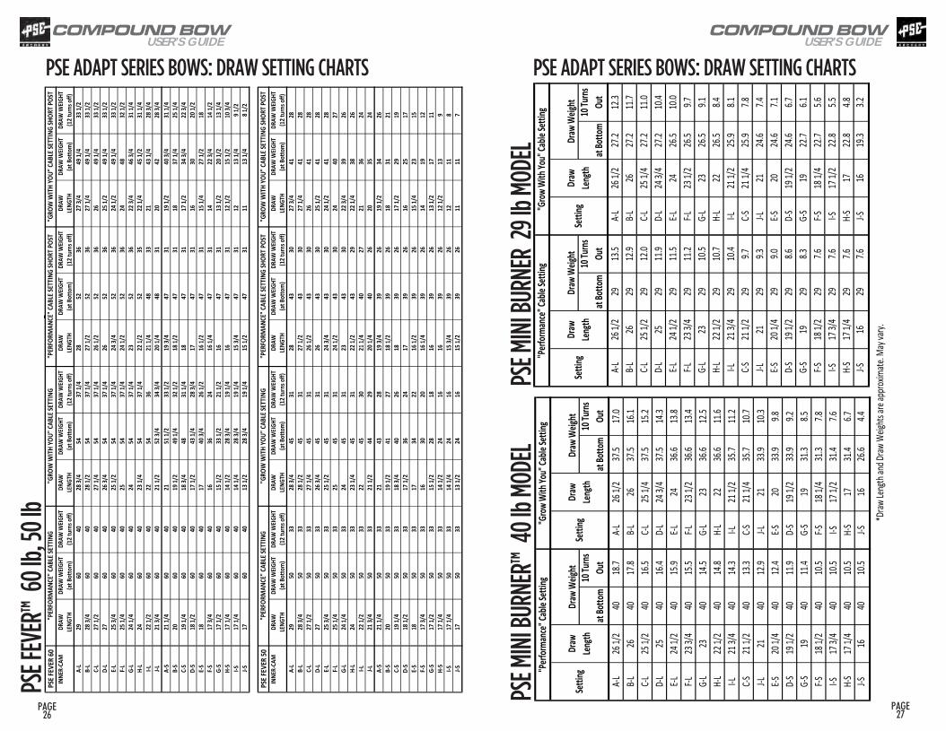
PSE F
EVER
60IN
NER-
CAM
DR
AWDR
AW W
EIGHT
DRAW
WEIG
HTDR
AWDR
AW W
EIGHT
DRAW
WEIG
HTDR
AWDR
AW W
EIGHT
DRAW
WEIG
HTDR
AWDR
AW W
EIGHT
DRAW
WEIG
HTLE
NGTH
(at Bo
ttom
)(1
2 tur
ns of
f)LE
NGTH
(at Bo
ttom
)(1
2 tur
ns of
f)LE
NGTH
(at Bo
ttom
)(1
2 tur
ns of
f)LE
NGTH
(at Bo
ttom
)(1
2 tur
ns of
f)A-
L29
6040
28 3/
454
37 1/
428
5236
27 3/
449
1/4
33 1/
2B-
L28
3/4
6040
28 1/
254
37 1/
427
1/2
5236
27 1/
449
1/4
33 1/
2C-
L27
1/2
6040
27 1/
454
37 1/
426
1/2
5236
2649
1/4
33 1/
2D-
L27
6040
26 3/
454
37 1/
426
5236
25 1/
249
1/4
33 1/
2E-L
25 3/
460
4025
1/2
5437
1/4
24 3/
452
3624
1/2
49 1/
433
1/2
F-L25
1/4
6040
2554
37 1/
424
1/2
5236
2448
32 1/
2G-
L24
1/4
6040
2454
37 1/
423
5236
22 3/
446
3/4
31 1/
4H-
L24
6040
23 1/
454
37 1/
422
1/2
5235
22 1/
445
1/2
31 1/
4I-L
22 1/
260
4022
5436
21 1/
448
3321
43 1/
428
3/4
J-L21
3/4
6040
21 1/
252
3/4
34 3/
420
1/4
4831
2042
28 3/
4A-
S21
1/4
6040
2151
1/2
33 1/
219
3/4
4731
19 1/
240
3/4
31 1/
4B-
S20
6040
19 1/
249
1/4
32 1/
218
1/2
4731
1837
1/4
25 1/
4C-
S19
1/4
6040
18 3/
448
31 1/
418
4731
17 1/
234
3/4
22 3/
4D-
S18
1/2
6040
17 1/
243
1/4
28 3/
417
4731
1630
20 1/
2E-S
1860
4017
40 3/
426
1/2
16 1/
247
3115
1/4
27 1/
218
F-S17
3/4
6040
1636
2416
1/4
4731
1422
3/4
14 1/
2G-
S17
1/2
6040
15 1/
233
1/2
21 1/
216
4731
13 1/
220
1/2
13 1/
4H-
S17
1/4
6040
14 1/
228
3/4
19 1/
416
4731
12 1/
215
1/2
10 3/
4I-S
17 1/
460
4014
1/4
28 3/
419
1/4
15 3/
447
3112
13 1/
49 1
/2J-S
1760
4013
1/2
28 3/
419
1/4
15 1/
247
3111
13 1/
48 1
/2
PSE F
EVER
50IN
NER-
CAM
DR
AWDR
AW W
EIGHT
DRAW
WEIG
HTDR
AWDR
AW W
EIGHT
DRAW
WEIG
HTDR
AWDR
AW W
EIGHT
DRAW
WEIG
HTDR
AWDR
AW W
EIGHT
DRAW
WEIG
HTLE
NGTH
(at Bo
ttom
)(1
2 tur
ns of
f)LE
NGTH
(at Bo
ttom
)(1
2 tur
ns of
f)LE
NGTH
(at Bo
ttom
)(1
2 tur
ns of
f)LE
NGTH
(at Bo
ttom
)(1
2 tur
ns of
f)A-
L29
5033
28 3/
445
3128
4330
27 3/
441
28B-
L28
3/4
5033
28 1/
245
3127
1/2
4330
27 1/
441
28C-
L27
1/2
5033
27 1/
445
3126
1/2
4330
2641
28D-
L27
5033
26 3/
445
3126
4330
25 1/
241
28E-L
25 3/
450
3325
1/2
4531
24 3/
443
3024
1/2
4128
F-L25
1/4
5033
2545
3124
1/2
4330
2440
27G-
L24
1/4
5033
2445
3123
4330
22 3/
439
26H-
L24
5033
23 1/
445
3122
1/2
4329
22 1/
438
26I-L
22 1/
250
3322
4530
21 1/
440
2721
3624
J-L21
3/4
5033
21 1/
244
2920
1/4
4026
2035
24A-
S21
1/4
5033
2143
2819
3/4
3926
19 1/
234
26B-
S20
5033
19 1/
241
2718
1/2
3926
1831
21C-
S19
1/4
5033
18 3/
440
2618
3926
17 1/
229
19D-
S18
1/2
5033
17 1/
236
2417
3926
1625
17E-S
1850
3317
3422
16 1/
239
2615
1/4
2315
F-S17
3/4
5033
1630
2016
1/4
3926
1419
12G-
S17
1/2
5033
15 1/
228
1816
3926
13 1/
217
11H-
S17
1/4
5033
14 1/
224
1616
3926
12 1/
213
9I-S
17 1/
450
3314
1/4
2416
15 3/
439
2612
118
J-S17
5033
13 1/
224
1615
1/2
3926
1111
7
"PER
FORM
ANCE
" CAB
LE SE
TTIN
G"G
ROW
WITH
YOU"
CABL
E SET
TING
"PER
FORM
ANCE
" CAB
LE SE
TTIN
G SH
ORT P
OST
"GRO
W W
ITH YO
U" CA
BLE S
ETTIN
G SH
ORT P
OST
2018
FEVE
R 60
lb, 50
lb"P
ERFO
RMAN
CE" C
ABLE
SETT
ING
"GRO
W W
ITH YO
U" CA
BLE S
ETTIN
G"P
ERFO
RMAN
CE" C
ABLE
SETT
ING
SHOR
T POS
T"G
ROW
WITH
YOU"
CABL
E SET
TING
SHOR
T POS
T
PSE ADAPT SERIES BOWS: DRAW SETTING CHARTS PSE ADAPT SERIES BOWS: DRAW SETTING CHARTS
at Bo
ttom
10 Tu
rns
Out
at Bo
ttom
10 Tu
rns
Out
at Bo
ttom
10 Tu
rns
Out
at Bo
ttom
10 Tu
rns
Out
A-L26
1/2
4018
.7A-L
26 1/
237
.517
.0A-L
26 1/
229
13.5
A-L26
1/2
27.2
12.3
B-L26
40
17.8
B-L26
37
.516
.1B-L
26
2912
.9B-L
26
27.2
11.7
C-L25
1/2
4016
.5C-L
25 1/
437
.515
.2C-L
25 1/
229
12.0
C-L25
1/4
27.2
11.0
D-L
25
4016
.4D-
L24
3/4
37.5
14.3
D-L
25
2911
.9D-
L24
3/4
27.2
10.4
E-L24
1/2
4015
.9E-L
24
36.6
13.8
E-L24
1/2
2911
.5E-L
24
26.5
10.0
F-L23
3/4
4015
.5F-L
23 1/
236
.613
.4F-L
23 3/
429
11.2
F-L23
1/2
26.5
9.7G-
L23
40
14.5
G-L
23
36.6
12.5
G-L
23
2910
.5G-
L23
26
.59.1
H-L
22 1/
240
14.8
H-L
22
36.6
11.6
H-L
22 1/
229
10.7
H-L
22
26.5
8.4I-L
21 3/
440
14.3
I-L21
1/2
35.7
11.2
I-L21
3/4
2910
.4I-L
21 1/
225
.98.1
C-S21
1/2
4013
.3C-S
21 1/
435
.710
.7C-S
21 1/
229
9.7C-S
21 1/
425
.97.8
J-L21
40
12.9
J-L21
33
.910
.3J-L
21
299.3
J-L21
24
.67.4
E-S20
1/4
4012
.4E-S
20
33.9
9.8E-S
20 1/
429
9.0E-S
20
24.6
7.1D-
S19
1/2
4011
.9D-
S19
1/2
33.9
9.2D-
S19
1/2
298.6
D-S
19 1/
224
.66.7
G-S
19
4011
.4G-
S19
31
.38.5
G-S
19
298.3
G-S
19
22.7
6.1F-S
18 1/
240
10.5
F-S18
1/4
31.3
7.8F-S
18 1/
229
7.6F-S
18 1/
422
.75.6
I-S17
3/4
4010
.5I-S
17 1/
231
.47.6
I-S17
3/4
297.6
I-S17
1/2
22.8
5.5H-
S17
1/4
4010
.5H-
S17
31
.46.7
H-S
17 1/
429
7.6H-
S17
22
.84.8
J-S16
40
10.5
J-S16
26
.64.4
J-S16
29
7.6J-S
16
19.3
3.2
*Draw
Leng
th an
d Draw
Weig
hts ar
e app
roxim
ate. M
ay va
ry.
Draw
Len
gthSe
tting
Draw
Len
gthSe
tting
Draw
Len
gthDr
aw W
eight
Draw
Weig
ht
"Perf
orman
ce" Ca
ble Se
tting
"Grow
With
You"
Cable
Settin
g
2018
Mini
Burne
r (29#
Mod
el)"P
erform
ance"
Cable
Settin
g"G
row W
ith Yo
u" Ca
ble Se
tting
Draw
Weig
htDr
aw W
eight
Settin
gDr
aw
Length
Settin
g
2018
Mini
Burne
r (40#
Mod
el)
at Bo
ttom
10 Tu
rns
Out
at Bo
ttom
10 Tu
rns
Out
at Bo
ttom
10 Tu
rns
Out
at Bo
ttom
10 Tu
rns
Out
A-L26
1/2
4018
.7A-L
26 1/
237
.517
.0A-L
26 1/
229
13.5
A-L26
1/2
27.2
12.3
B-L26
40
17.8
B-L26
37
.516
.1B-L
26
2912
.9B-L
26
27.2
11.7
C-L25
1/2
4016
.5C-L
25 1/
437
.515
.2C-L
25 1/
229
12.0
C-L25
1/4
27.2
11.0
D-L
25
4016
.4D-
L24
3/4
37.5
14.3
D-L
25
2911
.9D-
L24
3/4
27.2
10.4
E-L24
1/2
4015
.9E-L
24
36.6
13.8
E-L24
1/2
2911
.5E-L
24
26.5
10.0
F-L23
3/4
4015
.5F-L
23 1/
236
.613
.4F-L
23 3/
429
11.2
F-L23
1/2
26.5
9.7G-
L23
40
14.5
G-L
23
36.6
12.5
G-L
23
2910
.5G-
L23
26
.59.1
H-L
22 1/
240
14.8
H-L
22
36.6
11.6
H-L
22 1/
229
10.7
H-L
22
26.5
8.4I-L
21 3/
440
14.3
I-L21
1/2
35.7
11.2
I-L21
3/4
2910
.4I-L
21 1/
225
.98.1
C-S21
1/2
4013
.3C-S
21 1/
435
.710
.7C-S
21 1/
229
9.7C-S
21 1/
425
.97.8
J-L21
40
12.9
J-L21
33
.910
.3J-L
21
299.3
J-L21
24
.67.4
E-S20
1/4
4012
.4E-S
20
33.9
9.8E-S
20 1/
429
9.0E-S
20
24.6
7.1D-
S19
1/2
4011
.9D-
S19
1/2
33.9
9.2D-
S19
1/2
298.6
D-S
19 1/
224
.66.7
G-S
19
4011
.4G-
S19
31
.38.5
G-S
19
298.3
G-S
19
22.7
6.1F-S
18 1/
240
10.5
F-S18
1/4
31.3
7.8F-S
18 1/
229
7.6F-S
18 1/
422
.75.6
I-S17
3/4
4010
.5I-S
17 1/
231
.47.6
I-S17
3/4
297.6
I-S17
1/2
22.8
5.5H-
S17
1/4
4010
.5H-
S17
31
.46.7
H-S
17 1/
429
7.6H-
S17
22
.84.8
J-S16
40
10.5
J-S16
26
.64.4
J-S16
29
7.6J-S
16
19.3
3.2
*Draw
Leng
th an
d Draw
Weig
hts ar
e app
roxim
ate. M
ay va
ry.
Draw
Len
gthSe
tting
Draw
Len
gthSe
tting
Draw
Len
gthDr
aw W
eight
Draw
Weig
ht
"Perf
orman
ce" Ca
ble Se
tting
"Grow
With
You"
Cable
Settin
g
2018
Mini
Burne
r (29#
Mod
el)"P
erform
ance"
Cable
Settin
g"G
row W
ith Yo
u" Ca
ble Se
tting
Draw
Weig
htDr
aw W
eight
Settin
gDr
aw
Length
Settin
g
2018
Mini
Burne
r (40#
Mod
el)
PSE F
EVER
™ 60
lb, 5
0 lb
PSE M
INI B
URNE
R™ 4
0 lb M
ODEL
PSE M
INI B
URNE
R 29
lb M
ODEL
at Bo
ttom
10 Tu
rns
Out
at Bo
ttom
10 Tu
rns
Out
at Bo
ttom
10 Tu
rns
Out
at Bo
ttom
10 Tu
rns
Out
A-L26
1/2
4018
.7A-L
26 1/
237
.517
.0A-L
26 1/
229
13.5
A-L26
1/2
27.2
12.3
B-L26
40
17.8
B-L26
37
.516
.1B-L
26
2912
.9B-L
26
27.2
11.7
C-L25
1/2
4016
.5C-L
25 1/
437
.515
.2C-L
25 1/
229
12.0
C-L25
1/4
27.2
11.0
D-L
25
4016
.4D-
L24
3/4
37.5
14.3
D-L
25
2911
.9D-
L24
3/4
27.2
10.4
E-L24
1/2
4015
.9E-L
24
36.6
13.8
E-L24
1/2
2911
.5E-L
24
26.5
10.0
F-L23
3/4
4015
.5F-L
23 1/
236
.613
.4F-L
23 3/
429
11.2
F-L23
1/2
26.5
9.7G-
L23
40
14.5
G-L
23
36.6
12.5
G-L
23
2910
.5G-
L23
26
.59.1
H-L
22 1/
240
14.8
H-L
22
36.6
11.6
H-L
22 1/
229
10.7
H-L
22
26.5
8.4I-L
21 3/
440
14.3
I-L21
1/2
35.7
11.2
I-L21
3/4
2910
.4I-L
21 1/
225
.98.1
C-S21
1/2
4013
.3C-S
21 1/
435
.710
.7C-S
21 1/
229
9.7C-S
21 1/
425
.97.8
J-L21
40
12.9
J-L21
33
.910
.3J-L
21
299.3
J-L21
24
.67.4
E-S20
1/4
4012
.4E-S
20
33.9
9.8E-S
20 1/
429
9.0E-S
20
24.6
7.1D-
S19
1/2
4011
.9D-
S19
1/2
33.9
9.2D-
S19
1/2
298.6
D-S
19 1/
224
.66.7
G-S
19
4011
.4G-
S19
31
.38.5
G-S
19
298.3
G-S
19
22.7
6.1F-S
18 1/
240
10.5
F-S18
1/4
31.3
7.8F-S
18 1/
229
7.6F-S
18 1/
422
.75.6
I-S17
3/4
4010
.5I-S
17 1/
231
.47.6
I-S17
3/4
297.6
I-S17
1/2
22.8
5.5H-
S17
1/4
4010
.5H-
S17
31
.46.7
H-S
17 1/
429
7.6H-
S17
22
.84.8
J-S16
40
10.5
J-S16
26
.64.4
J-S16
29
7.6J-S
16
19.3
3.2
*Draw
Leng
th an
d Draw
Weig
hts ar
e app
roxim
ate. M
ay va
ry.
Draw
Len
gthSe
tting
Draw
Len
gthSe
tting
Draw
Len
gthDr
aw W
eight
Draw
Weig
ht
"Perf
orman
ce" Ca
ble Se
tting
"Grow
With
You"
Cable
Settin
g
2018
Mini
Burne
r (29#
Mod
el)"P
erform
ance"
Cable
Settin
g"G
row W
ith Yo
u" Ca
ble Se
tting
Draw
Weig
htDr
aw W
eight
Settin
gDr
aw
Length
Settin
g
2018
Mini
Burne
r (40#
Mod
el)

COMPOUND BOWUSER’S GUIDE
PAGE 29
PAGE 28
COMPOUND BOWUSER’S GUIDE
THE PSE WEBSITE IS YOUR RESOURCE FOR EVERYTHING WE HAVE TO OFFER!
www.psearchery.com
BUY PSE SIGNATURE ITEMS ONLINE! For PSE shooters, our brand name means more than just a bow; it represents a lifestyle. PSE customers live our brand 24/7 through shirts, hats, gear, and other PSE-branded accessories. We’ve dramatically expanded our Signature Series line with an exciting selection of new products…so don’t wait!
www.psearcherystore.com

PAGE 31
PAGE 30
SERIAL # OF BOW (SEE ABOVE FOR SERIAL # LOCATION)
BOW MODEL
DEALER NAME OR WHERE PURCHASED
YOUR NAME
YOUR ADDRESS APT #
CITY STATE ZIP
COUNTRY EMAIL ADDRESS
DATE PURCHASED / / PHONE ( )
#
The PSE serial number is laser etched into your riser- opposite the shelf area.
MAIL-IN WARRANTY REGISTRATION Fill out the form below completely, remove it, place in a stamped envelope and mail to:
PSE WARRANTY REGISTRATION P.O. Box 5487 Tucson, AZ 85703
IMPORTANTWARRANTY REGISTRATION
TO ACTIVATE YOUR BOW WARRANTY, PSE BOW REGISTRATION MUST BE RECEIVED BY PSE WITHIN 30 DAYS OF PURCHASE.
REGISTER YOUR BOW ONLINE OR COMPLETE THE INFORMATION AND MAIL-IN THE WARRANTY CARD INSERT.
ONLINE WARRANTY REGISTRATION
Log on at: www.psearchery.com/registration
NOTE: IF THE WARRANTY CARD IS NOT PRESENT, PLEASE USE THE FORM BELOW.
NOTES:
Related Documents