CONNECTOR INFORMATION INPUT MODEL SELECTION FEATURES AND BENEFITS 800W Fan-Cooled (Load & Temperature Controlled) Programmable Output Voltage (0% ~ 105%) Approved to EN/CSA/IEC/UL62368-1 Forced Current Sharing at Parallel Operation Constant Current Limit Selectable +5V/0.5A or +9V/0.3A Auxiliary Output Output Voltage See Model Selection Table on pg 1 Output Power 1 800W continuous – See model selection table for specific voltage model ratings Voltage Range ±5.0% Typical adjustment by potentiometer (VR1) Voltage Tolerance See Model Selection Table on pg 1 Hold-Up Time 11mS/230VAC at full load Turn On Time Rise Time 800ms 100ms at full load Ripple and Noise See Model Selection Table on pg 1 Line/Load Regulation See Model Selection Table on pg 1 Notes : 1. De-rating may apply in low input voltage. Please check the de-rating curve for more details Pinout: Mating Connector /terminal: #10 wire lugs Term. 1) AC LINE Term. 2) NEUTRAL Term. 3) GROUND Input Connector M6 Wire Lugs + and - Output Connector Connector: JST PHDR-24VS or equivalent Pins: JST SPHD-002T-P0.5 or equivalent See Signal Connector Table on pg 3 Signal Connector Protection: OVP, OLP, OTP, Fan Failure Remote ON/OFF, Remote Sense Function Power OK Signal Remote Setting Multiple PSU via RS232, RS485 & I²C Global Control via RS232 Output Volts Rated Current Current Range Output Power Ripple & Noise 1 Efficiency Model Number 4 Line Regulation Load Regulation Voltage Tolerance 3 15V 0-53.4A 800W 150mV pk-pk ±1% ±1% ±2% 90% TF800A15K 24V 0-33.5A 800W 240mV pk-pk ±1% ±1% ±2% 92% TF800A24K 12V 0-66.7A 800W 150mV pk-pk ±1% ±1% ±2% 89% TF800A12K 60V 0-13.4A 800W 600mV pk-pk ±1% ±1% ±2% 93% TF800A60K 48V 53.4A 33.5A 66.7A 13.4A 16.37A 0-16.7A 800W 480mV pk-pk ±1% ±1% ±2% 92% TF800A48K Notes : 3. Tolerance: includes setup time tolerance, line regulation and load regulation. 1. See CMD VS Output Curve. 2. Ripple & noise are measured at 20MHz of bandwidth by using a 12" twisted pair-wire terminated with a 0.1uF & 47uF parallel capacitor. 6. All specifications are typical at 230Vac, full load, at 25°C ambient unless noted. 4. Other output voltages available, consult factory. 5. Recovery after reset AC power ON or inhibit. Input Voltage and Frequency 1 100-240Vac, ±10%, 47-63Hz, 1Ø127-370Vdc Input Current 115Vac: 9.3A, 230Vac: 3.7A Inrush Current 30A/115VAC, 60A/230VAC Efficiency See Model Selection Table Power Factor 0.95/230VAC, 0.98/115VAC at full load Leakage Current < 1mA/240VAC Notes : 1. De-rating may apply in low input voltage. Please check the de-rating curve for more details OUTPUT Industrial 800W Single Output Industrial Grade TF800 Family TF800 Family Datasheet v0920 Copyright © 2020 SL Power Electronics Corp. All rights reserved. Page 1

Welcome message from author
This document is posted to help you gain knowledge. Please leave a comment to let me know what you think about it! Share it to your friends and learn new things together.
Transcript
CONNECTOR INFORMATION
INPUT
MODEL SELECTION
FEATURES AND BENEFITS800W Fan-Cooled (Load & Temperature Controlled)
Programmable Output Voltage (0% ~ 105%)
Approved to EN/CSA/IEC/UL62368-1
Forced Current Sharing at Parallel Operation
Constant Current Limit
Selectable +5V/0.5A or +9V/0.3A Auxiliary Output
Output Voltage See Model Selection Table on pg 1
Output Power1 800W continuous – See model selection table for specific voltage model ratings
Voltage Range ±5.0% Typical adjustment by potentiometer (VR1)
Voltage Tolerance See Model Selection Table on pg 1
Hold-Up Time 11mS/230VAC at full load
Turn On Time Rise Time
800ms100ms at full load
Ripple and Noise See Model Selection Table on pg 1
Line/Load Regulation See Model Selection Table on pg 1
Notes : 1. De-rating may apply in low input voltage. Please check the de-rating curve for more details
Pinout:
Mating Connector/terminal: #10 wire lugs
Term. 1) AC LINETerm. 2) NEUTRALTerm. 3) GROUND
Input Connector
M6 Wire Lugs
+ and -
Output Connector
Connector: JST PHDR-24VS or equivalentPins: JST SPHD-002T-P0.5 or equivalent
See Signal Connector Table on pg 3
Signal Connector
Protection: OVP, OLP, OTP, Fan Failure
Remote ON/OFF, Remote Sense Function
Power OK Signal
Remote Setting Multiple PSU via RS232, RS485 & I²C
Global Control via RS232
Output Volts
Rated Current
CurrentRange
OutputPower
Ripple &Noise1 Efficiency Model Number4 Line
RegulationLoad
RegulationVoltage
Tolerance3
15V 0-53.4A 800W 150mV pk-pk ±1% ±1% ±2% 90%TF800A15K
24V 0-33.5A 800W 240mV pk-pk ±1% ±1% ±2% 92%TF800A24K
12V 0-66.7A 800W 150mV pk-pk ±1% ±1% ±2% 89%TF800A12K
60V 0-13.4A 800W 600mV pk-pk ±1% ±1% ±2% 93%TF800A60K
48V
53.4A
33.5A
66.7A
13.4A
16.37A 0-16.7A 800W 480mV pk-pk ±1% ±1% ±2% 92%TF800A48K
Notes :
3. Tolerance: includes setup time tolerance, line regulation and load regulation.
1. See CMD VS Output Curve.2. Ripple & noise are measured at 20MHz of bandwidth by using a 12" twisted
pair-wire terminated with a 0.1uF & 47uF parallel capacitor. 6. All specifications are typical at 230Vac, full load, at 25°C ambient unless noted.
4. Other output voltages available, consult factory.5. Recovery after reset AC power ON or inhibit.
Input Voltage and Frequency1 100-240Vac, ±10%, 47-63Hz, 1Ø127-370Vdc
Input Current 115Vac: 9.3A, 230Vac: 3.7A
Inrush Current 30A/115VAC, 60A/230VAC
Efficiency See Model Selection Table
Power Factor 0.95/230VAC, 0.98/115VAC at full load
Leakage Current < 1mA/240VAC
Notes : 1. De-rating may apply in low input voltage. Please check the de-rating curve for more details
OUTPUT
Industrial
800W Single OutputIndustrial GradeTF800 Family 800W Single Output
Industrial GradeTF800 Family
TF800 Family Datasheet v0920 Copyright © 2020 SL Power Electronics Corp. All rights reserved. Page 1 TF800 Family Datasheet v0819 Copyright © 2019 SL Power Electronics Corp. All rights reserved.
ISOLATION SPECIFICATIONSSAFETY
PROTECTION
EMI/EMC COMPLIANCE
Isolation1
Isolation Resistance
Input-Output: 3000VacInput-Ground: 1500VacOutput-Ground : 500Vac
I/P-O/P, I/P-FG, O/P-FG: 100M Ohms/500VDC
Notes : This test is done without enclosure: I/P-O/P 4242VDC. If with enclosure: I/P-O/P 2121VDC,I/P-FG:2121VDC, O/P-FG: 707VDC
1.
Selectable +5V/0.5A or +9V/0.3A auxiliary output
120 ± 7% of Vout, Latch Type (Recovery after reset AC power ON or inhibit). (Refer to VCI vs. OVP Curve).
Constant current, auto-recovery
105% of rated power, constant current type
85±5°C measured on NTC. Auto recovery
Cooling
MTBF >112,000 hours per MIL-HDBK-217F
Safety Certifications Approved to EN/CSA/IEC/UL62368-1
Overvoltage Protection
Short Circuit Protection
Overload Protection
Overtemperature Protection
Notes : In parallel connection only one unit will operate if the total output load is less than 5% of the rated power.
1.
Surges, Line to Line (Diff Mode) and Line to GND (CMN Mode)
Conducted Emissions
Radiated Emissions
Electro-Static Discharge (ESD) Immunity on Power ports
Radiated RF EM Fields Susceptibility
Electrical Fast Transients (EFT) /Bursts
Conducted Disturbances induced by RF Fields
Rated Power frequency magnetic fields
Voltage Interruptions, Dips, Sags & Surges
Harmonic Current Emissions
Flicker Test
EN55024/IEC61000-4-5
Certified EN 55022; EN 61204-3; EN 61000-6-3
Certified EN 55022; EN 61204-3; EN 61000-6-3
EN55024/IEC61000-4-2
EN55022/EN61000-4-3
EN55024/IEC61000-4-4
EN55022/IEC61000-4-6
EN55024/IEC1000-4-8
EN55024/IECEN61000-4-11
EN61000-3-2
EN61000-3-3
Notes : The power supply is considered a component which will be installed into a final equipment. The final equipment must be re-confirmed that it till meets EMC directives.
1.
Auxiliary Power
Remote ON / OFF Control By external switch
Output Voltage Trim Adjustment of output voltage is between 0 ~ 105% of rated output
Power OK Signal Open drain signal low when PSU turns on, Max. sink current: 20mA, Max. drain voltage: 40V
Output Current Trim Adjustment of output current is between 0 ~ 105% of rated output
Please refer to Current Sharing with Remote Sensing (Parallel Connection) DiagramParallel (Current Sharing)1
20% to 90%, non-condensing
-40 ~ +85°C, 10 ~ 95% RH
1.7kg 6pcs/carton, 11.2kg/0.55CUFT
127 x 41 x 249mm. 5.0 x 1.6 x 9.80 inch
Load and temperature control fan
-25 ~ +60°C (Refer to load de-rating curve)
See Derating Curve
10 ~ 500Hz, 2G 10min./1 cycle, period for 60min. each along X, Y, Z axes Compliance to IEC 68-2-6, IEC 68-2-64
Relative Humidity
Cooling
Storage Temperature and Humidity
Weight & Packing
Operating Temperature
Temperature Derating
Vibration
Dimensions
AUXILIARY SIGNALS
RELIABILITY
ENVIRONMENT
800W Single OutputIndustrial GradeTF800 Family 800W Single Output
Industrial GradeTF800 Family 800W Single OutputIndustrial GradeTF800 Family
TF800 Family Datasheet v0819 Copyright © 2019 SL Power Electronics Corp. All rights reserved. TF800 Family Datasheet v0920 Copyright © 2020 SL Power Electronics Corp. All rights reserved. Page 2 TF800 Family Datasheet v0819 Copyright © 2019 SL Power Electronics Corp. All rights reserved.
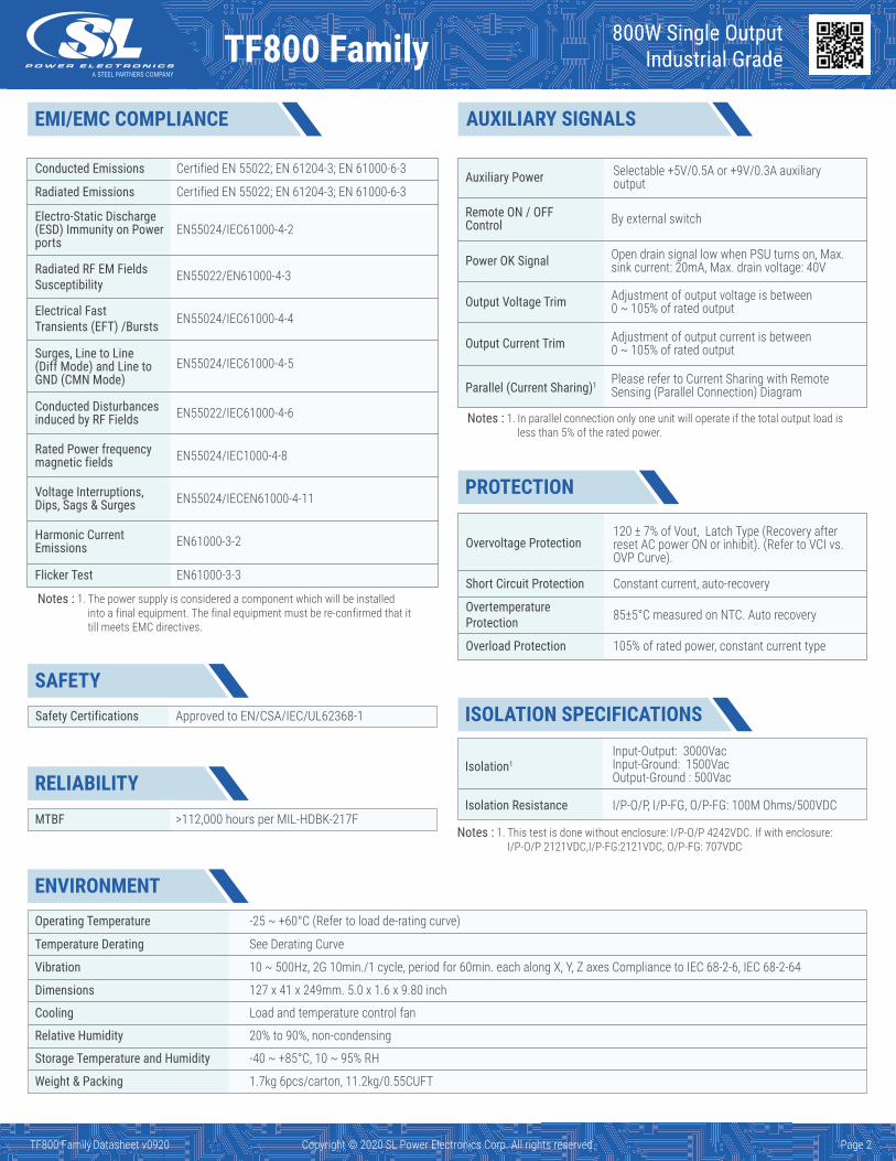
SIGNAL CONNECTOR
ACI
GNDVCI
GND
AUX
GND
SCL
SDA
AUX
GND
RX
TX
I Program
Ground
Ground
V Program
Ground
Serial Clock used in the I2C Interface
Serial Data used in the I2C Interface
For RS232 Receiver function
For RS232 Transmission function
Ground
+5V/0.5A or +9V/0.3A Auxiliary power
+5V/0.5A or +9V/0.3A Auxiliary power
13
1415
16
17
18
19
20
21
22
23
24
FunctionPin No. Function DescriptionPin No.Description
1
23
4
5
6
7
8
9
10
11
12
VS+
VO+VS-
VO-
POK
GND
PAR
VSET
EN-
GND
EN+
AUX
Power OK
Ground
Ground
Remote sense (+)
Positive output voltage
Negative output voltage
Remote sense (-)
Parallel operation current share
Aux output setting
Inhibit ON/OFF (-)
Inhibit ON/OFF (+)
+5V/0.5A or +9V/0.3A Auxiliary power
6-M4(Both Sides) L=3.0[0.12] max.
2
1
3
3-M4 L=3.0[0.12] max.
CN2
31
45678910
121311
141516171819202122
2
24 23
AddressSwitch
41[1.61]
CN2
127[
5.00
]
64.0
[2.5
2]
198.0[7.80]14.0[0.55]
74.0
[2.9
1]
37.0[1.46] 26.9[1.06]
20.5[0.81]
11.5[0.45] 221.0[8.70]
25.0[0.98]
8.0[0.31]
249[9.80]
Recommended screw length is measured from the power supply surface
LED
+V
-V
VR 1
Airflowdirection
MECHANICAL DRAWING
800W Single OutputIndustrial GradeTF800 Family 800W Single Output
Industrial GradeTF800 Family 800W Single OutputIndustrial GradeTF800 Family
TF800 Family Datasheet v0819 Copyright © 2019 SL Power Electronics Corp. All rights reserved. TF800 Family Datasheet v0920 Copyright © 2020 SL Power Electronics Corp. All rights reserved. Page 3 TF800 Family Datasheet v0819 Copyright © 2019 SL Power Electronics Corp. All rights reserved.
Ambient Temperature (°C) Input Voltage (Vac)
40
50
60
70
80
Load
(%)
90
100
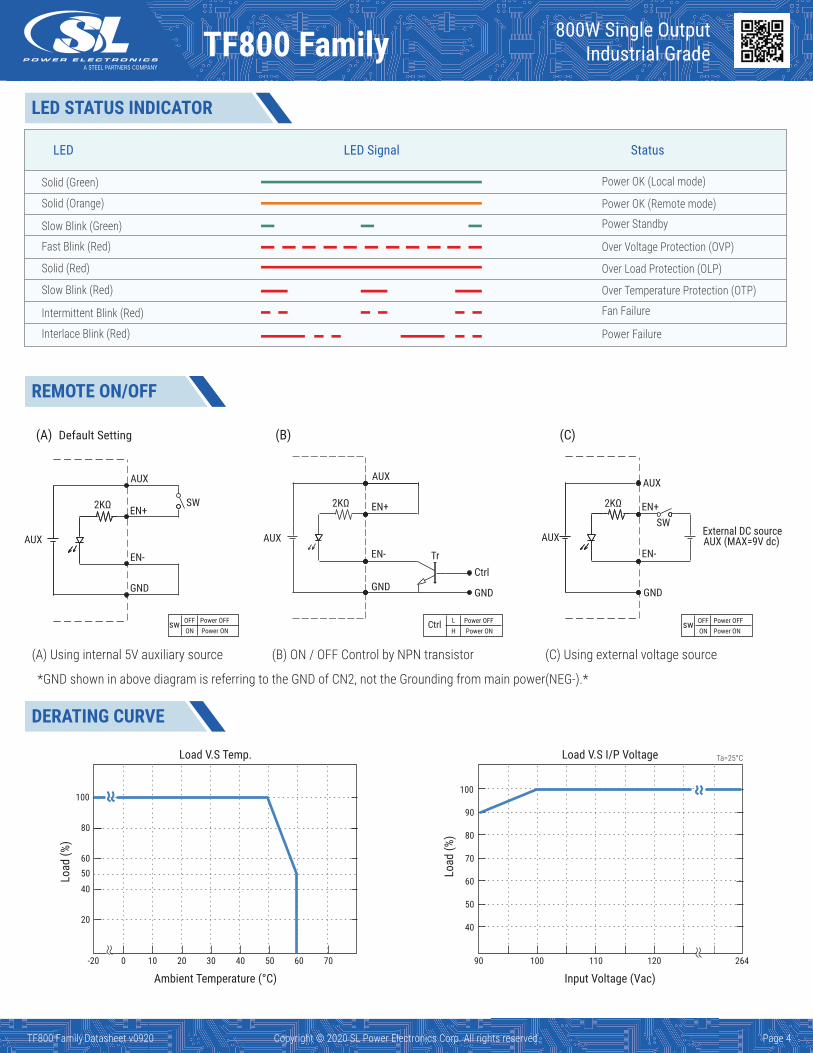
Load V.S Temp. Load V.S I/P Voltage
90 100 110 120 264-20 0 10 20 30 40 50 60 70
20
40
60
80
100
Load
(%)
50
Ta=25°C
DERATING CURVE
800W Single OutputIndustrial GradeTF800 Family 800W Single Output
Industrial GradeTF800 Family 800W Single OutputIndustrial GradeTF800 Family
TF800 Family Datasheet v0819 Copyright © 2019 SL Power Electronics Corp. All rights reserved. TF800 Family Datasheet v0920 Copyright © 2020 SL Power Electronics Corp. All rights reserved. Page 4 TF800 Family Datasheet v0819 Copyright © 2019 SL Power Electronics Corp. All rights reserved.
REMOTE ON/OFFREMOTE ON/OFF
LED StatusLED Signal
Solid (Green) Power OK (Local mode)
Solid (Orange) Power OK (Remote mode)
Fast Blink (Red) Over Voltage Protection (OVP)
Solid (Red) Over Load Protection (OLP)
Slow Blink (Red) Over Temperature Protection (OTP)
Intermittent Blink (Red) Fan Failure
Interlace Blink (Red) Power Failure
Power StandbySlow Blink (Green)
LED STATUS INDICATOR
(A) Using internal 5V auxiliary source (C) Using external voltage source
SW
Power OFFOFFswPower ONON
Power OFFOFFswPower ONON
(B) ON / OFF Control by NPN transistor
EN+
EN-
AUX
GND
SW
AUX
2KΩ EN+
EN-
AUX
GND GND
AUX
2KΩ EN+
EN-
AUX
GND
AUX
2KΩ
Default Setting
Power OFFLCtrlPower ONH
Ctrl
External DC source AUX (MAX=9V dc)
*GND shown in above diagram is referring to the GND of CN2, not the Grounding from main power(NEG-).*
(A) (B) (C)
Tr

CMD vs Output Curve VCI vs OVP Curve
To ensure the power supply output voltage and current could be accurately adjusted, please make sure to adjust the output voltage and current > 10% vs. the rated voltage and current. (e.g. for a 24V unit, please adjust the DC output voltage above 2.4V to ensure accuracy; same applies to the output current)
OUT(%)
4.8
4.7 4.9
107.5I:105105
V:100
CMD
OFF0.3
110
100
90
80
70
60
50
40
30
20
10
0 0.5 1.0 1.5 2.0 2.5 3.0 3.5 4.0 4.5 5.0V/K
114%
120%
200%
0.5V 0.75V 4.5V 4.8V
OVP
VCI
4.5V (Output 100%)0.75V (Output 6.25%)
196%
IC ≒1mA I-Shrink MIN 1mA
CTRL
A/DPWM
CTRL VCI / ACI CTRL0~5Vdc
220R VC=IC · R
R=5K
VCI / ACIVCI / ACI
I. II. III.
Power Supply Power Supply Power Supply
IC ≒1mA IC ≒1mA
CN2
12
CN2
12
VO+
VS+
VO-
VS-
GND
GND
GND
GND
GND
GND
POK
VSET
PAR
EN+
EN-
AUX
AUX
AUX
ACI
VCI
SDA
SCL
TXRX
VO+
VS+
VO-
VS-
GND
GND
GND
GND
GND
GND
POK
VSET
PAR
EN+
EN-
AUX
AUX
AUX
ACI
VCI
SDA
SCL
TXRX
2423
2423
Extemal Voltage (VDC) Extemal Resistor (KΩ)
800W Single OutputIndustrial GradeTF800 Family 800W Single Output
Industrial GradeTF800 Family 800W Single OutputIndustrial GradeTF800 Family
TF800 Family Datasheet v0819 Copyright © 2019 SL Power Electronics Corp. All rights reserved. TF800 Family Datasheet v0920 Copyright © 2020 SL Power Electronics Corp. All rights reserved. Page 5 TF800 Family Datasheet v0819 Copyright © 2019 SL Power Electronics Corp. All rights reserved.
Power OK Signal & Auxiliary Power Setting
μ*
DC / DC5V/0.5A
or9V/0.3A
AUX
AUX
P.OK
VSET
GND
GND
VSETOpen(Default Setting)
Short To GND 9V5V
*The grounding of "AUX" power and P.OK signal should be connected to "GND" port. If "VO-" is connected as Grounding, make sure to short the GND and VO- ports.
*Place an additional capacitor to have a betterperformance of auxiliary power operation.
Do NOT exceed 5V/0.5A or 9V/0.3A
Open drain signal low when PSU turns on. Max. P.OK sink current: 20mA, Max, drain voltage: 40V.
GoodFailure
Internal Circuit
AUX and P.OK Signal
AUX.LOAD
470 F 16V
*GND shown in above diagram is referring to the GND of CN2, not the Grounding from main power(NEG-)*
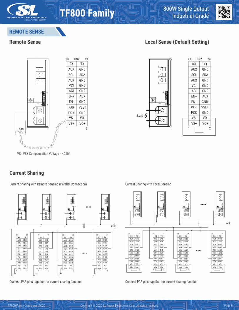
REMOTE SENSE
Remote Sense
Current Sharing
Current Sharing with Remote Sensing (Parallel Connection)
Connect PAR pins together for current sharing function Connect PAR pins together for current sharing function
Current Sharing with Local Sensing
Local Sense (Default Setting)
VS-, VS+ Compensation Voltage = <0.5V
Load
Load
RX TXAUXSCL SDA
GND
AUX
AUX
VCIACIEN+EN-PARPOK
GNDGNDGND
GND
GNDVSET
VO+VO-
VS+VS-
RX TXAUXSCL SDA
GND
AUX
AUX
VCIACIEN+EN-PARPOK
GNDGNDGND
GND
GNDVSET
VO+VO-
VS+VS-
CN223 24 CN223 24
1 2 1 2
a
b
RX TXAUXSCL SDA
GND
AUX
AUX
VCIACIEN+EN-PARPOK
GNDGNDGND
GND
GNDVSET
VO+VO-
VS+VS-
RX TXAUXSCL SDA
GND
AUX
AUX
VCIACIEN+EN-PARPOK
GNDGNDGND
GND
GNDVSET
VO+VO-
VS+VS-
RX TXAUXSCL SDA
GND
AUX
AUX
VCIACIEN+EN-PARPOK
GNDGNDGND
GND
GNDVSET
VO+VO-
VS+VS-
RX TXAUXSCL SDA
GND
AUX
AUX
VCIACIEN+EN-PARPOK
GNDGNDGND
GND
GNDVSET
VO+VO-
VS+VS-
RX TXAUXSCL SDA
GND
AUX
AUX
VCIACIEN+EN-PARPOK
GNDGNDGND
GND
GNDVSET
VO+VO-
VS+VS-
RX TXAUXSCL SDA
GND
AUX
AUX
VCIACIEN+EN-PARPOK
GNDGNDGND
GND
GNDVSET
VO+VO-
VS+VS-
RX TXAUXSCL SDA
GND
AUX
AUX
VCIACIEN+EN-PARPOK
GNDGNDGND
GND
GNDVSET
VO+VO-
VS+VS-
RX TXAUXSCL SDA
GND
AUX
AUX
VCIACIEN+EN-PARPOK
GNDGNDGND
GND
GNDVSET
VO+VO-
VS+VS-
23 24 23 24 23 24 23 24
ab
ab
ab
ab
21 21 21 2121 21 21 21
23 24 23 24 23 24 23 24
800W Single OutputIndustrial GradeTF800 Family 800W Single Output
Industrial GradeTF800 Family 800W Single OutputIndustrial GradeTF800 Family
TF800 Family Datasheet v0819 Copyright © 2019 SL Power Electronics Corp. All rights reserved. TF800 Family Datasheet v0920 Copyright © 2020 SL Power Electronics Corp. All rights reserved. Page 6 TF800 Family Datasheet v0819 Copyright © 2019 SL Power Electronics Corp. All rights reserved.
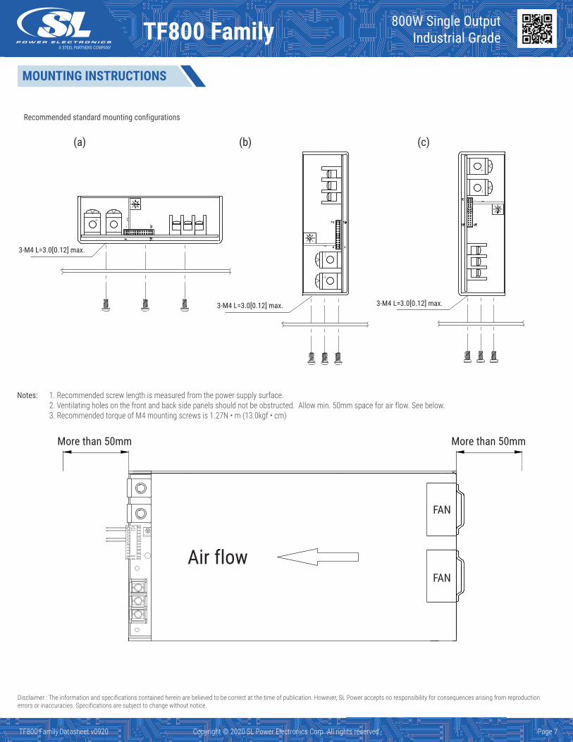
Notes: 1. Recommended screw length is measured from the power supply surface.2. Ventilating holes on the front and back side panels should not be obstructed. Allow min. 50mm space for air flow. See below.3. Recommended torque of M4 mounting screws is 1.27N • m (13.0kgf • cm)
Recommended standard mounting configurations
(a) (b) (c)
3-M4 L=3.0[0.12] max.
3-M4 L=3.0[0.12] max. 3-M4 L=3.0[0.12] max.
Air flow
More than 50mmMore than 50mm
FAN
FAN
MOUNTING INSTRUCTIONS
800W Single OutputIndustrial GradeTF800 Family 800W Single Output
Industrial GradeTF800 Family
TF800 Family Datasheet v0819 Copyright © 2019 SL Power Electronics Corp. All rights reserved. TF800 Family Datasheet v0920 Copyright © 2020 SL Power Electronics Corp. All rights reserved. Page 7
Disclaimer : The information and specifications contained herein are believed to be correct at the time of publication. However, SL Power accepts no responsibility for consequences arising from reproduction errors or inaccuracies. Specifications are subject to change without notice.

Mouser Electronics
Authorized Distributor
Click to View Pricing, Inventory, Delivery & Lifecycle Information: SL Power:
TF800A12K TF800A24K TF800A60K TF800A48K TF800A15K
Related Documents