Texas MicroCircuits – TMC3in1 Hardware & Software Installation Copyright © 2008-2016 – Texas MicroCircuits www.texasmicrocircuits.com 1 ` Texas MicroCircuits TMC3in1 – Torch & Motion Controller 3in1 Plasma w/THC-5 Axis Breakout Board - Spindle Controller Hardware & Software Installation Guide Rev 1.02 Last update: 5/2/2016 Author: Randall L Ray Very Sr. Engineer Texas MicroCircuits

Welcome message from author
This document is posted to help you gain knowledge. Please leave a comment to let me know what you think about it! Share it to your friends and learn new things together.
Transcript

Texas MicroCircuits – TMC3in1 Hardware & Software Installation
Copyright © 2008-2016 – Texas MicroCircuits www.texasmicrocircuits.com
1
`
Texas MicroCircuits
TMC3in1 – Torch & Motion Controller 3in1
Plasma w/THC-5 Axis Breakout Board - Spindle Controller Hardware & Software Installation Guide
Rev 1.02
Last update: 5/2/2016
Author: Randall L Ray Very Sr. Engineer Texas MicroCircuits
Texas MicroCircuits – TMC3in1 Hardware & Software Installation
Copyright © 2008-2016 – Texas MicroCircuits www.texasmicrocircuits.com
2
Table of Contents Hardware Installation of TMC3in1 ..................................................................... 6
TMC3in1 Locations ........................................................................................ 6 General Locations ...................................................................................... 6 TMC3in1 Connection Locations ................................................................. 8
TMC3in1 Mach3 Screen .............................................................................. 11 Definition of New TMC3in1 Mach3 Screen Controls and Indicators ......... 11
TMC3in1 Mach4 Screen .............................................................................. 14 Definition of New TMC3in1 Mach4 Screen Controls and Indicators ......... 14
Installing the TMC3in1 Hardware ................................................................. 15 Ethernet Smooth Stepper (ESS) .............................................................. 15 TMC3in1 General Installation ................................................................... 16
Connecting the TMC3in1 to the ESS .................................................... 16 Securing the TMC3in1 to the ESS ........................................................ 17 Adding ESS Ethernet Cable ................................................................. 17 Powering the TMC3in1 and ESS .......................................................... 18
Torch Height Controller ............................................................................ 20 Plasma Manufacturer’s CNC Connection ............................................. 20 Wiring the THC portion of the TMC3in1 ................................................ 21
5 Axis Breakout Board ............................................................................. 22 Spindle Speed Controller ......................................................................... 22
Software Setup for the TMC3in1 .................................................................. 23 You will need to use the recommended version of Mach3 ....................... 23 You will need to use the latest ESS Plugin............................................... 23 You will need to merge the TMC3in1 File Set .......................................... 23 Start Mach3, and select the ESS Plugin:.................................................. 24
TMC3in1 Plugin ........................................................................................... 24 Enabling the TMC3in1 Plugin ................................................................... 24 Configuring the TMC3in1 Plugin .............................................................. 25 Selecting the Voltage Divider Ratio .......................................................... 27 Selecting the Proper Voltage Input ........................................................... 28 Selecting the Desired Pierce Count ......................................................... 28 Selecting the Default Target Tip Volts ...................................................... 29 Selecting the Target Band Volts ............................................................... 29 Selecting the Linear Response Band Volts .............................................. 29 Selecting the THC Offset Volts ................................................................. 31 Selecting the Acceleration Down Parameter ............................................ 31 Selecting the Acceleration Up Parameter ................................................ 32 Selecting the Mode Run Simulator ........................................................... 32 Selecting the M11/M10 Mode ................................................................... 33 Selecting the THC Active after Arc Ok Mode ........................................... 34

Texas MicroCircuits – TMC3in1 Hardware & Software Installation
Copyright © 2008-2016 – Texas MicroCircuits www.texasmicrocircuits.com
3
Selecting the RESET TMC3in1 Off Mode ................................................ 35 Selecting Anti-Dive Options ...................................................................... 35
Selecting Linear Reduction Anti-Dive Mode ......................................... 36 Selecting Cut Out Anti-Dive Mode ........................................................ 36
Enabling THC Mode in ESS Plugin .............................................................. 36 Setting TMC3in1 Mach Ports and Pins ........................................................ 37 Mach Screen Detail ..................................................................................... 38
Appendix ......................................................................................................... 40
Texas MicroCircuits – TMC3in1 Hardware & Software Installation
Copyright © 2008-2016 – Texas MicroCircuits www.texasmicrocircuits.com
4
Figures Figure 1 – TMC3in1 General Locations 1 .......................................................... 6 Figure 2 – TMC3in1 General Locations 2 .......................................................... 7 Figure 3 - THC Pin Connections ........................................................................ 8 Figure 4 - eStop, Home/Limit, Spindle Control Pin Locations ........................ 9 Figure 5 - Axes (Step/Dir) Pin Connections .................................................... 10 Figure 6 - TMC3in1 Mach3 Screen New Controls and Indicators ................. 11 Figure 7 - ESS Card from Warp9TD ................................................................. 15 Figure 8 - Installing Standoffs .......................................................................... 16 Figure 9 - Plugging the TMC3in1 into the ESS ............................................... 17 Figure 10 - Securing the TMC3in1 to the ESS ................................................ 17 Figure 11 - Cat5 Cable Install ........................................................................... 18 Figure 12 - Connecting Power to the TMC3in1 ............................................... 18 Figure 13 - All Done .......................................................................................... 19 Figure 14 – Various Manufacturers Plasma Cutter CNC Connections ......... 20 Figure 15 - Wiring ArcOk .................................................................................. 21 Figure 16 - Wiring Divided Volts ...................................................................... 21 Figure 17 - Wiring Torch On ............................................................................. 22 Figure 18 - Select ESS Plugin .......................................................................... 24 Figure 19 - TMC3in1 Plugin is Disabled. ......................................................... 25 Figure 20 - TMC3in1 Plugin is Enabled. .......................................................... 25 Figure 21 - TMC3in1 Config Window ............................................................... 26 Figure 22 - Voltage Divider Selection .............................................................. 27 Figure 23 - Plasma Connections (Single Ended Pins 3 & 4).......................... 28 Figure 24 - Pierce Counter Selection .............................................................. 28 Figure 25 - Pierce Counter ............................................................................... 28 Figure 26 – Default Target Tip Volts Selection ............................................... 29 Figure 27 - Target Tip Volts Display ................................................................ 29 Figure 28 - Target Band Volts Selection ......................................................... 29 Figure 29 - Linear Response Band Selection ................................................. 30 Figure 30 - Voltage Band Example 1 ............................................................... 30 Figure 31 - Voltage Band Example 2 ............................................................... 31 Figure 32 - THC Offset Volts ............................................................................ 31 Figure 33 - THC Acceleration Down Setting ................................................... 32 Figure 34 - THC Acceleration Up Setting ........................................................ 32 Figure 35 - Run Simulator Mode ...................................................................... 32 Figure 36 - Ports & Pins ................................................................................... 33 Figure 37 - ESS Plugin M11/M10 ...................................................................... 34 Figure 38 - Delay After Arc Ok ......................................................................... 34 Figure 39 - RESET THC Run Option ................................................................ 35 Figure 40 - ESS Plugin PWM Selection ........................................................... 35 Figure 41 - Ports & Pins ................................................................................... 35

Texas MicroCircuits – TMC3in1 Hardware & Software Installation
Copyright © 2008-2016 – Texas MicroCircuits www.texasmicrocircuits.com
5
Figure 42 - Linear Reduction............................................................................ 36 Figure 43 - Cutout Inhibit ................................................................................ 36 Figure 44 - ESS Config THC Mode ................................................................... 36 Figure 45 - Ports & Pins ................................................................................... 37 Figure 46 - Ports 7 Pins - Input ........................................................................ 37 Figure 47 - Ports & Pins - Mill Options ............................................................ 38 Figure 48 - THC Yellow Status LED ................................................................. 38 Figure 49 - THC Green Status LED .................................................................. 38 Figure 50 - Target Tip Volts - Underlimit ......................................................... 39 Figure 51 - Target Tip Volts – Overlimit .......................................................... 39
Texas MicroCircuits – TMC3in1 Hardware & Software Installation
Copyright © 2008-2016 – Texas MicroCircuits www.texasmicrocircuits.com
6
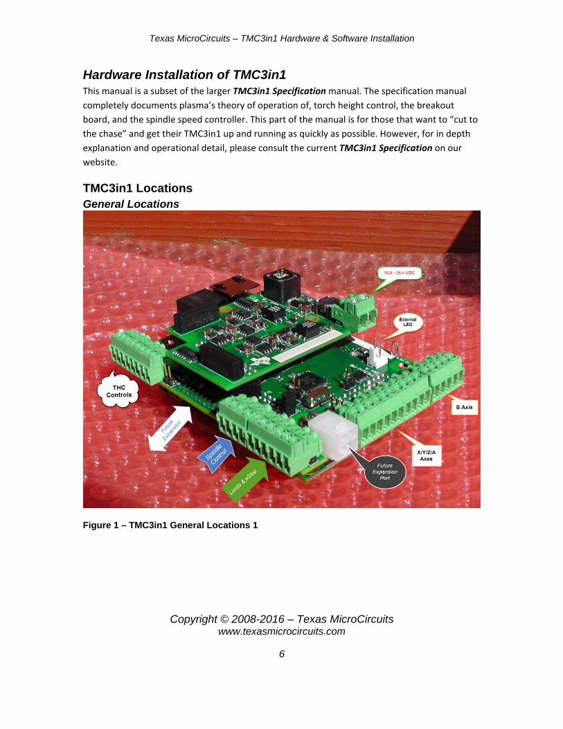
Hardware Installation of TMC3in1 This manual is a subset of the larger TMC3in1 Specification manual. The specification manual completely documents plasma’s theory of operation of, torch height control, the breakout board, and the spindle speed controller. This part of the manual is for those that want to “cut to the chase” and get their TMC3in1 up and running as quickly as possible. However, for in depth explanation and operational detail, please consult the current TMC3in1 Specification on our website.
TMC3in1 Locations General Locations
Figure 1 – TMC3in1 General Locations 1

Texas MicroCircuits – TMC3in1 Hardware & Software Installation
Copyright © 2008-2016 – Texas MicroCircuits www.texasmicrocircuits.com
7
Figure 2 – TMC3in1 General Locations 2
Texas MicroCircuits – TMC3in1 Hardware & Software Installation
Copyright © 2008-2016 – Texas MicroCircuits www.texasmicrocircuits.com
8
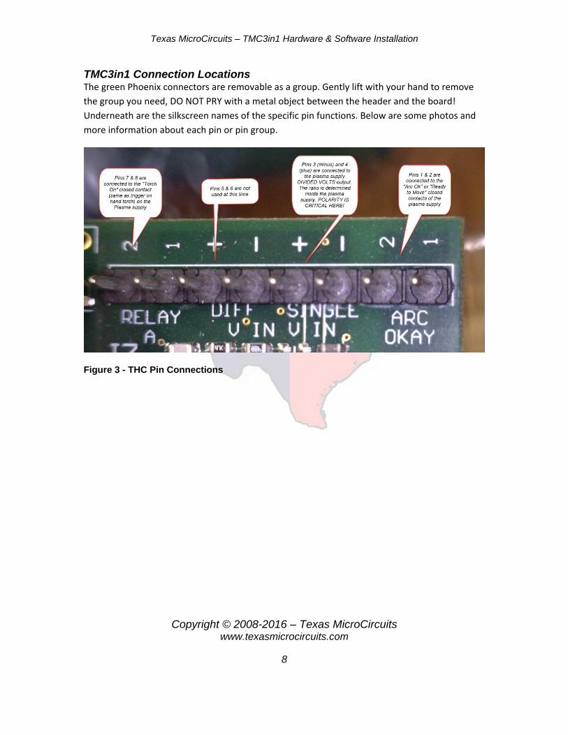
TMC3in1 Connection Locations The green Phoenix connectors are removable as a group. Gently lift with your hand to remove the group you need, DO NOT PRY with a metal object between the header and the board! Underneath are the silkscreen names of the specific pin functions. Below are some photos and more information about each pin or pin group.
Figure 3 - THC Pin Connections

Texas MicroCircuits – TMC3in1 Hardware & Software Installation
Copyright © 2008-2016 – Texas MicroCircuits www.texasmicrocircuits.com
9
The E-Stop should be considered a courtesy signal. Your E-Stop switch(s) should also control a relay that cuts off the power to your motors!
Figure 4 - eStop, Home/Limit, Spindle Control Pin Locations

Texas MicroCircuits – TMC3in1 Hardware & Software Installation
Copyright © 2008-2016 – Texas MicroCircuits www.texasmicrocircuits.com
10
Figure 5 - Axes (Step/Dir) Pin Connections

Texas MicroCircuits – TMC3in1 Hardware & Software Installation
Copyright © 2008-2016 – Texas MicroCircuits www.texasmicrocircuits.com
11
TMC3in1 Mach3 Screen There are many changes, mostly additions, to include the THC functions on the Mach screen set. Below is a screenshot of the new TMC3in1 Mach3 screen and below that are definitions of each new function.
Figure 6 - TMC3in1 Mach3 Screen New Controls and Indicators
Definition of New TMC3in1 Mach3 Screen Controls and Indicators
1. TMC3in1 Status – These 2 indicators (Green/Yellow) reflect the operational status of the TMC3in1. The Green LED indicates that the TMC3in1 Hardware and the TMC3in1 Mach3 plugin are communicating correctly. The Yellow LED indicates that the TMC3in1 hardware and the TMC3in1 Mach3 plugin are not currently communicating. Releasing

Texas MicroCircuits – TMC3in1 Hardware & Software Installation
Copyright © 2008-2016 – Texas MicroCircuits www.texasmicrocircuits.com
12
Mach3 from Reset, pressing “Send Cfg” (see number 11), or changing the target voltage (see numbers 3 and 4) should start the TMC3in1, and turn the status LED Green.
2. Actual Tip Volts – This is the actual plasma arc tip voltage received after being multiplied by the divider ratio selected in the THC Config plugin. When active, the TMC3in1 will try to bring the Z axis (torch) arc to match the Target Tip Volts.
3. Target Tip Volts – This is the target voltage set by the operator that the TMC3in1 will adjust the Z axis (torch) to while cutting. To change the number, click in the box and type in the target voltage and press the “Enter” key.
4. Increment/Decrement Arrows – Clicking on either of these arrows will increment or decrement the Target Tip Voltage by 1 volt. This can be done when cutting is active to fine tune cut height.
5. Overlimit – The overlimit indicator will turn Red when the Actual Tip Voltage exceeds the measurable voltage range for your divider ratio. The overlimit indicator may turn on when a torch is fired for piercing, but should disappear once Arc Ok is detected. The overlimit indicator may also turn on and stay on if the system is miswired or misconfigured.
6. Underlimit – An underlimit of Actual Tip Voltage has been detected. This is usually under 1 volt and is normal when the torch is not fired and no arc is detected.
7. Mode: Sim – This indicator shows when the TMC3in1 is in Simulator Mode. More about this later in this document.
8. Up/Dn Indicators – These indicators are showing Torch Up and Torch Down signals sent to Mach.
9. Pierce Count – Every time the torch is fired, this indicator increments by 1 showing total number of pierces. The indicator will turn Red to show the operator that this number is at or past the limit set by the operator in the THC Config. No action is taken by the TMC3in1 on this indicator. It is for operator display only and has no effect on plasma operations.
10. Pierce Count Reset – Clicking on this button will reset the Pierce counter. 11. Send Cfg – Even though clicking “OK” on the THC Config screen will
send any changes to the TMC3in1, this button will also send the TMC3in1 configuration.
12. Monitor – Clicking this button will display the Monitor screen. These are extra indicators showing more detailed THC function and is mostly used when debugging and installation.
13. THC CFG – Clicking this button will display the THC Configuration screen. Any changes to the configuration will be used for this instance of Mach and not stored in the XML. To store in the XML for later use, go to Mach

Texas MicroCircuits – TMC3in1 Hardware & Software Installation
Copyright © 2008-2016 – Texas MicroCircuits www.texasmicrocircuits.com
13
Config > Config Plugins > Config beside the TMC3in1 plugin. Information on what is displayed is later in this document.
14. Enable M11/M10 Usage – This indicator shows when the M11/M10 functions are enabled (but not necessarily active) in the THC Configuration.
15. THC Rate – Though this is not a new indicator, its setting can now be increased for most machines. For more information, see THC Rate in the definitions in the main TMC3in1 document.
16. Anti-Dive: % Cutout Mode – This indicator shows when the THC Configuration has enabled the Anti-Dive feature of “% Cutout Mode”.
17. Enable THC Delay after Arc Ok – This indicator shows when the THC Delay after Arc Ok has been enabled (but not necessarily active) in the THC Configuration.
18. M11/M10 Control Active – This indicator shows when the M11/M10 commands are active and being processed.
19. Anti-Dive: Linear Mode - This indicator shows when the THC Configuration has enabled the Anti-Dive feature of “Linear Mode”.
20. Delay Active after Arc Ok – This indicator shows when a delay of user set time value (set in the THC Configuration) is actually active.
More detail on the functions of these indicators is explained later in this document.

Texas MicroCircuits – TMC3in1 Hardware & Software Installation
Copyright © 2008-2016 – Texas MicroCircuits www.texasmicrocircuits.com
14
TMC3in1 Mach4 Screen TBC
Definition of New TMC3in1 Mach4 Screen Controls and Indicators TBC

Texas MicroCircuits – TMC3in1 Hardware & Software Installation
Copyright © 2008-2016 – Texas MicroCircuits www.texasmicrocircuits.com
15
Installing the TMC3in1 Hardware Before installing the TMC3in1 unit, an Ethernet Smooth Stepper card must be installed in the system first. The TMC3in1 plugs directly into the ESS utilizing Port 3 and the expansion port, but leaving Ports 1 & 2 for other user functions. The TMC3in1 also powers the ESS.
Ethernet Smooth Stepper (ESS) The ESS has always been an integral part of the architecture of the TMC3in1 because it takes a lot of the load off the PC and commands THC moves from the Z axis much faster and smoother. Many users mount the ESS in their control enclosure using 6-32” standoffs. We supply extra standoffs to allow the TMC3in1 to plug on top of the ESS and stabilize the TMC3in1.
Texas MicroCircuits does not sell the ESS card, but there are many resellers that do and also www.warp9td.com .
Figure 7 - ESS Card from Warp9TD
Texas MicroCircuits – TMC3in1 Hardware & Software Installation
Copyright © 2008-2016 – Texas MicroCircuits www.texasmicrocircuits.com
16
TMC3in1 General Installation
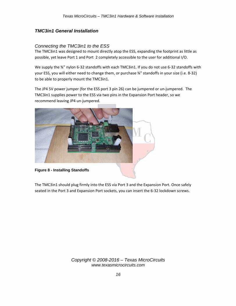
Connecting the TMC3in1 to the ESS The TMC3in1 was designed to mount directly atop the ESS, expanding the footprint as little as possible, yet leave Port 1 and Port 2 completely accessible to the user for additional I/O.
We supply the ¾” nylon 6-32 standoffs with each TMC3in1. If you do not use 6-32 standoffs with your ESS, you will either need to change them, or purchase ¾” standoffs in your size (i.e. 8-32) to be able to properly mount the TMC3in1.
The JP4 5V power jumper (for the ESS port 3 pin 26) can be jumpered or un-jumpered. The TMC3in1 supplies power to the ESS via two pins in the Expansion Port header, so we recommend leaving JP4 un-jumpered.
Figure 8 - Installing Standoffs
The TMC3in1 should plug firmly into the ESS via Port 3 and the Expansion Port. Once safely seated in the Port 3 and Expansion Port sockets, you can insert the 6-32 lockdown screws.

Texas MicroCircuits – TMC3in1 Hardware & Software Installation
Copyright © 2008-2016 – Texas MicroCircuits www.texasmicrocircuits.com
17
Figure 9 - Plugging the TMC3in1 into the ESS
Securing the TMC3in1 to the ESS
Secure the TMC3in1 by installing the 4 6-32 screws that came with the TMC3in1. The unit will now be mechanically secure.
Figure 10 - Securing the TMC3in1 to the ESS
Adding ESS Ethernet Cable
The Ethernet cable should be plugged into the RJ45 connector on the ESS. The other end goes to your network or PC network card. Make sure you plug your Ethernet cable into the ESS jack and not the TMC3in1 jack as in the photo below.

Texas MicroCircuits – TMC3in1 Hardware & Software Installation
Copyright © 2008-2016 – Texas MicroCircuits www.texasmicrocircuits.com
18
Figure 11 - Cat5 Cable Install
Powering the TMC3in1 and ESS
Last, but not least, make sure that the ESS is NOT being powered by its 5V J6 connector or any break out boards on ports 1 or 2! The TMC3in1 will supply power to the ESS. Connect 10.8V to 26.4V DC power to the TMC3in1 J1 connector.
Figure 12 - Connecting Power to the TMC3in1
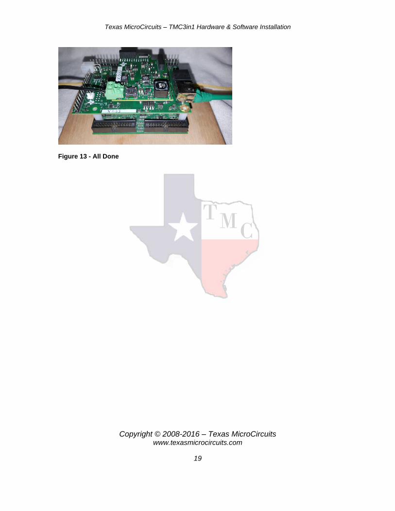
All of the basic connections are complete, and now on to wiring the TMC3in1 for the desired functions.
Texas MicroCircuits – TMC3in1 Hardware & Software Installation
Copyright © 2008-2016 – Texas MicroCircuits www.texasmicrocircuits.com
19
Figure 13 - All Done

Texas MicroCircuits – TMC3in1 Hardware & Software Installation
Copyright © 2008-2016 – Texas MicroCircuits www.texasmicrocircuits.com
20
Torch Height Controller
Plasma Manufacturer’s CNC Connection In the last 15 years, almost 95% of all major plasma supply manufacturers have incorporated (or have an option) for a CNC connection from their machine to CNC electronics. All of the major names such as Hypertherm, Thermal Dynamics (Victor/ThermoDyne), and ESAB do.
The TMC3in1 requires these signals/controls to operate:
- Arc Ok or OK to Move (2 wires) - Torch On or Gun Switch (2 wires) - Divided Tip Volts (usually divided by a standard ratio such as 50:1, 30:1,
16.67:1, etc. (2 wires)
Note: The TMC3in1 can NOT receive Raw Tip Volts as it will damage the TMC3in1
Below are examples of some of the connectors used on major plasma brands for CNC connection to the TMC3in1. You will need to consult your own plasma cutter owner’s guide for wiring information or contact your plasma representative. Many offer a “CNC cable option” and it plugs into the back of the plasma power supply. The other end has wires that can be connected to the THC connector of the TNC3in1.
Figure 14 – Various Manufacturers Plasma Cutter CNC Connections
Texas MicroCircuits – TMC3in1 Hardware & Software Installation
Copyright © 2008-2016 – Texas MicroCircuits www.texasmicrocircuits.com
21
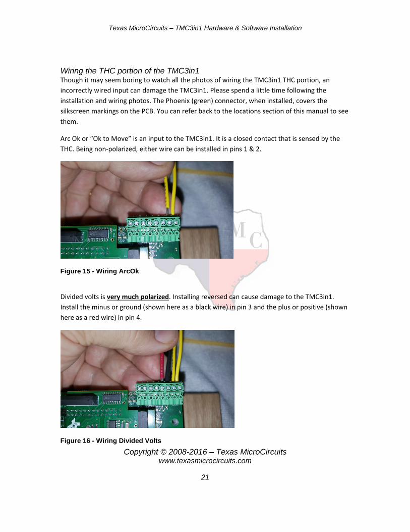
Wiring the THC portion of the TMC3in1 Though it may seem boring to watch all the photos of wiring the TMC3in1 THC portion, an incorrectly wired input can damage the TMC3in1. Please spend a little time following the installation and wiring photos. The Phoenix (green) connector, when installed, covers the silkscreen markings on the PCB. You can refer back to the locations section of this manual to see them.
Arc Ok or “Ok to Move” is an input to the TMC3in1. It is a closed contact that is sensed by the THC. Being non-polarized, either wire can be installed in pins 1 & 2.
Figure 15 - Wiring ArcOk
Divided volts is very much polarized. Installing reversed can cause damage to the TMC3in1. Install the minus or ground (shown here as a black wire) in pin 3 and the plus or positive (shown here as a red wire) in pin 4.
Figure 16 - Wiring Divided Volts

Texas MicroCircuits – TMC3in1 Hardware & Software Installation
Copyright © 2008-2016 – Texas MicroCircuits www.texasmicrocircuits.com
22
Pins 5 & 6 are not actively used at this time.
The Torch On is an output by a relay on the TMC3in1. This is a closed contact that triggers the torch to fire and is non-polarized so either wire can go into pin 7 & 8.
Figure 17 - Wiring Torch On
5 Axis Breakout Board TBC
Spindle Speed Controller TBC

Texas MicroCircuits – TMC3in1 Hardware & Software Installation
Copyright © 2008-2016 – Texas MicroCircuits www.texasmicrocircuits.com
23
Software Setup for the TMC3in1
You will need to use the recommended version of Mach3 (3.043.062) available from
http://warp9td.com/index.php/sw/software-mach#MachThree
It is assumed you know how to install Mach3 for use with an ESS (no parallel port driver). If not, please refer to installation instructions on the Mach3 website.
http://www.machsupport.com/
You will need to use the latest ESS Plugin (Released April 2016 –or– newer) from
http://warp9td.com/index.php/sw#PluginEssMachThree
It is assumed that you know how to install the ESS. If not, please visit the Warp9TD website. Be sure to use the SCU (System Configuration Utility) to make it easy to install.
http://warp9td.com/index.php/sw
You will need to merge the TMC3in1 File Set The TMC3in1 Merge File Set will soon be on our website, but for now you can send an email to:
and we will send you the latest version. This zip file includes:
- Latest TMC3in1 Plugin - Bitmaps required by the TMC3in1 Screen Set - The TMC3in1 Screen Set - TMC3in1 Scripts Folder with Files - Some miscellaneous files and scripts that may prove useful
It is NOT assumed you know how to install the TMC3in1 or you wouldn’t be reading this manual.

Texas MicroCircuits – TMC3in1 Hardware & Software Installation
Copyright © 2008-2016 – Texas MicroCircuits www.texasmicrocircuits.com
24
Start Mach3, and select the ESS Plugin:
Figure 18 - Select ESS Plugin
TMC3in1 Plugin Enabling the TMC3in1 Plugin Go into Mach3’s Menu -> Config -> Config Plugins.
In the Plugin Control and Activation window, enable the TMC3in1 plugin by changing the RED X to a GREEN check.

Texas MicroCircuits – TMC3in1 Hardware & Software Installation
Copyright © 2008-2016 – Texas MicroCircuits www.texasmicrocircuits.com
25
Figure 19 - TMC3in1 Plugin is Disabled.
Figure 20 - TMC3in1 Plugin is Enabled.
Configuring the TMC3in1 Plugin
While you are still in the Plugin Control and Activation window, press CONFIG in the yellow area.
This is the TMC3in1 Config window. These configuration values will be saved to the XML when you press OK, only when you get here from Plugin Control and Activation window.

Texas MicroCircuits – TMC3in1 Hardware & Software Installation
Copyright © 2008-2016 – Texas MicroCircuits www.texasmicrocircuits.com
26
Figure 21 - TMC3in1 Config Window

Texas MicroCircuits – TMC3in1 Hardware & Software Installation
Copyright © 2008-2016 – Texas MicroCircuits www.texasmicrocircuits.com
27
Selecting the Voltage Divider Ratio While you are still in the TMC3in1 Config window: For the Arc Voltage Divider, select whichever one your machine uses:
Figure 22 - Voltage Divider Selection
If your machine allows you to choose a value based on jumper settings, we would recommend using them in this order of preference:
- 50:1 - 40:1 - 30:1 - 20:1 - 16.67:1 - 15:1
DO NOT USE STRAIGHT (RAW) TIP VOLTS, IT WILL DAMAGE THE TMC3IN1!

Texas MicroCircuits – TMC3in1 Hardware & Software Installation
Copyright © 2008-2016 – Texas MicroCircuits www.texasmicrocircuits.com
28
Selecting the Proper Voltage Input While you are still in the TMC3in1 Config window: For the Arc Voltage Source, select “Single Ended”. This will connect to J7, with the positive wire connecting to Pin 4 of J7 and the ground wire connecting to Pin 3 of J7.
Figure 23 - Plasma Connections (Single Ended Pins 3 & 4) Selecting the Desired Pierce Count While you are still in the TMC3in1 Config window: The Desired Pierces section is optional, but will keep track of the number of pierces performed. This will help with maintenance of consumables.
Figure 24 - Pierce Counter Selection
The left box lets you set the desired number of pierces to perform before the warning light turns on, flashing Red on the main Mach3 Screen like this:
Figure 25 - Pierce Counter The Reset Pierces button will allow you to reset your current pierces count to 0.

Texas MicroCircuits – TMC3in1 Hardware & Software Installation
Copyright © 2008-2016 – Texas MicroCircuits www.texasmicrocircuits.com
29
Selecting the Default Target Tip Volts While you are still in the TMC3in1 Config window: Target Tip Volts is the tip voltage you want to cut at. This is material and speed dependent.
Figure 26 – Default Target Tip Volts Selection This can also be specified on the main Mach screen.
Figure 27 - Target Tip Volts Display
Selecting the Target Band Volts While you are still in the TMC3in1 Config window: Target Band (Volts) is the voltage band you want to stay within, above your Target Tip Volts or Below Your Target Tip Volts. 0.25V is the recommended value to use, but you may modify it. Example: 0.25 is plus and minus 0.25 for total band width of 0.5 volts.
Figure 28 - Target Band Volts Selection
When you are within the target band, the TMC3in1 will not issue any THC UP or THC DOWN signals.
Selecting the Linear Response Band Volts While you are still in the TMC3in1 Config window: Linear Response Band (Volts) is the area that the THC UP and THC DOWN signals will be generated at less than full strength. One way to think of this is as the nudging region. When you are only a little bit away from your Target Band, you just want to nudge the voltage back. If you are farther away, you move a little harder. If you are outside of the Linear Response Band, you push with full force.

Texas MicroCircuits – TMC3in1 Hardware & Software Installation
Copyright © 2008-2016 – Texas MicroCircuits www.texasmicrocircuits.com
30
Example: 20.1 is plus and minus 20.1 for total band width of 40.2 volts.
Figure 29 - Linear Response Band Selection
• 20.1 V is the default value. • If your system responds too aggressively or begins to oscillate, increase
this value. • If your system does not follow close enough to the target voltage, decrease
this value. Not tracking the target voltage may also be related to acceleration settings, or THC rate.
Examples of various voltage settings:
i. Settings a. Target Tip Volts = 120.0 b. Target Band (Volts) = 0.25 c. Linear Response Band (Volts) = 20.1
Figure 30 - Voltage Band Example 1
ii. Settings a. Target Tip Volts = 120.0 b. Target Band (Volts) = 2.0 c. Linear Response Band (Volts) = 5

Texas MicroCircuits – TMC3in1 Hardware & Software Installation
Copyright © 2008-2016 – Texas MicroCircuits www.texasmicrocircuits.com
31
Figure 31 - Voltage Band Example 2
In these images, the green line represents the Target Band (Volts) above and below our Target Tip Volts. There will be NO THC UP or DOWN signals generated when our Actual Tip Volts is in this region.
The yellow areas represent the Linear Response Band (Volts). When the Actual Tip Volts is near the green line, the THC UP or DOWN signals will just start turning on. As the Actual Tip Volts moves farther away from the green line, the THC UP or DOWN signals will be stronger. As the Actual Tip Volts approaches the red area (but while it is still in the yellow area), the THC UP or DOWN signals will be very strong.
Once the Actual Tip Volts is outside of the yellow area and in the red area, the THC UP or DOWN signals will be fully on.
Selecting the THC Offset Volts While you are still in the TMC3in1 Config window: THC Offset. This provides an offset adjust for the Actual Tip Voltage. In testing and measurements, it is not needed, which is why we set it to 0.001 V (1 mV). It is provided merely as a courtesy.
Figure 32 - THC Offset Volts
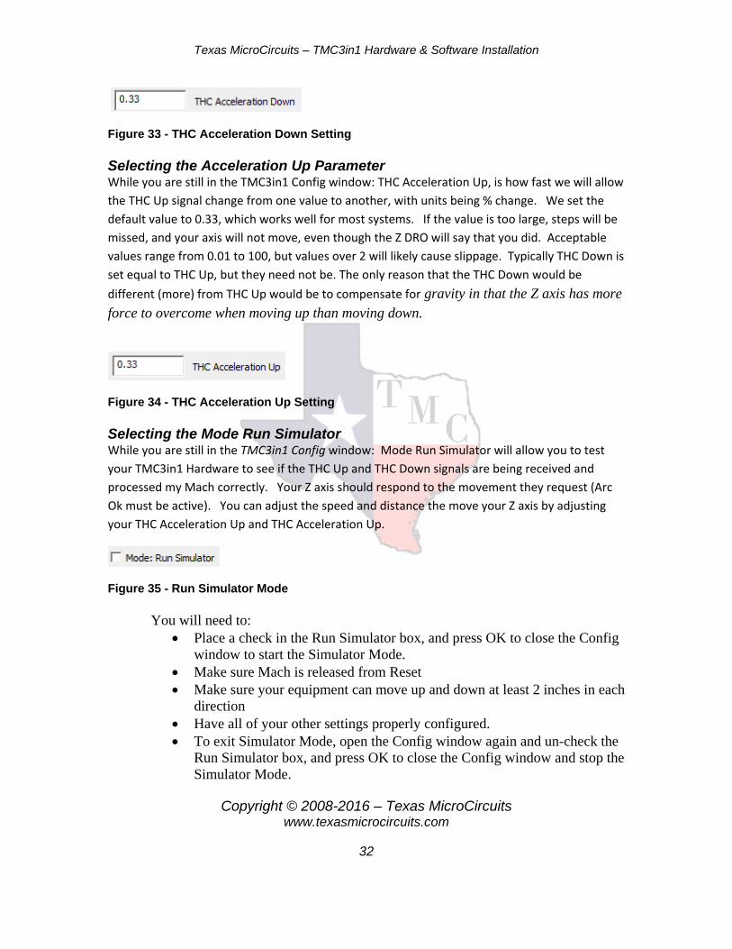
Selecting the Acceleration Down Parameter While you are still in the TMC3in1 Config window: THC Acceleration Down, is how fast we will allow the THC Down signal change from one value to another, with units being % change. We set the default value to 0.33, which works well for most systems. If the value is too large, steps will be missed, and your axis will not move, even though the Z DRO will say that you did. Acceptable values range from 0.01 to 100, but values over 2 will likely cause slippage. Typically THC Down is set equal to THC Up, but they need not be.
Texas MicroCircuits – TMC3in1 Hardware & Software Installation
Copyright © 2008-2016 – Texas MicroCircuits www.texasmicrocircuits.com
32
Figure 33 - THC Acceleration Down Setting
Selecting the Acceleration Up Parameter While you are still in the TMC3in1 Config window: THC Acceleration Up, is how fast we will allow the THC Up signal change from one value to another, with units being % change. We set the default value to 0.33, which works well for most systems. If the value is too large, steps will be missed, and your axis will not move, even though the Z DRO will say that you did. Acceptable values range from 0.01 to 100, but values over 2 will likely cause slippage. Typically THC Down is set equal to THC Up, but they need not be. The only reason that the THC Down would be different (more) from THC Up would be to compensate for gravity in that the Z axis has more force to overcome when moving up than moving down.
Figure 34 - THC Acceleration Up Setting Selecting the Mode Run Simulator While you are still in the TMC3in1 Config window: Mode Run Simulator will allow you to test your TMC3in1 Hardware to see if the THC Up and THC Down signals are being received and processed my Mach correctly. Your Z axis should respond to the movement they request (Arc Ok must be active). You can adjust the speed and distance the move your Z axis by adjusting your THC Acceleration Up and THC Acceleration Up.
Figure 35 - Run Simulator Mode
You will need to: • Place a check in the Run Simulator box, and press OK to close the Config
window to start the Simulator Mode. • Make sure Mach is released from Reset • Make sure your equipment can move up and down at least 2 inches in each
direction • Have all of your other settings properly configured. • To exit Simulator Mode, open the Config window again and un-check the
Run Simulator box, and press OK to close the Config window and stop the Simulator Mode.
Texas MicroCircuits – TMC3in1 Hardware & Software Installation
Copyright © 2008-2016 – Texas MicroCircuits www.texasmicrocircuits.com
33
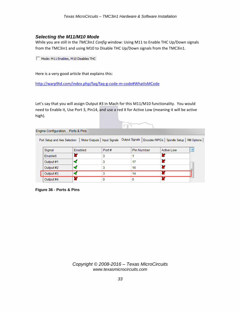
Selecting the M11/M10 Mode While you are still in the TMC3in1 Config window: Using M11 to Enable THC Up/Down signals from the TMC3in1 and using M10 to Disable THC Up/Down signals from the TMC3in1.
Here is a very good article that explains this:
http://warp9td.com/index.php/faq/faq-g-code-m-code#WhatIsMCode
Let’s say that you will assign Output #3 in Mach for this M11/M10 functionality. You would need to Enable it, Use Port 3, Pin14, and use a red X for Active Low (meaning it will be active high).
Figure 36 - Ports & Pins

Texas MicroCircuits – TMC3in1 Hardware & Software Installation
Copyright © 2008-2016 – Texas MicroCircuits www.texasmicrocircuits.com
34
In the ESS Main Config, you would also need to set the output number accordingly.
Figure 37 - ESS Plugin M11/M10
In your G-Code file you would then use the commands M11P3 or M10P3 (P3 is for port 3) followed by a move command (G0, G1 etc…).
Selecting the THC Active after Arc Ok Mode While you are still in the TMC3in1 Config window: Delay THC output signals from the TMC3in1 for X.Y seconds after the Arc Okay is received. This will allow your torch time to move away from the pierce location before THC Up or THC Down signals are generated. This helps to prevent head crashes and to resolve other pierce related issues.
Figure 38 - Delay After Arc Ok
If you are using Anti-Dive correctly, you will most likely not need this delay function, but it may prove helpful when cutting very thin materials at high speed.
Texas MicroCircuits – TMC3in1 Hardware & Software Installation
Copyright © 2008-2016 – Texas MicroCircuits www.texasmicrocircuits.com
35
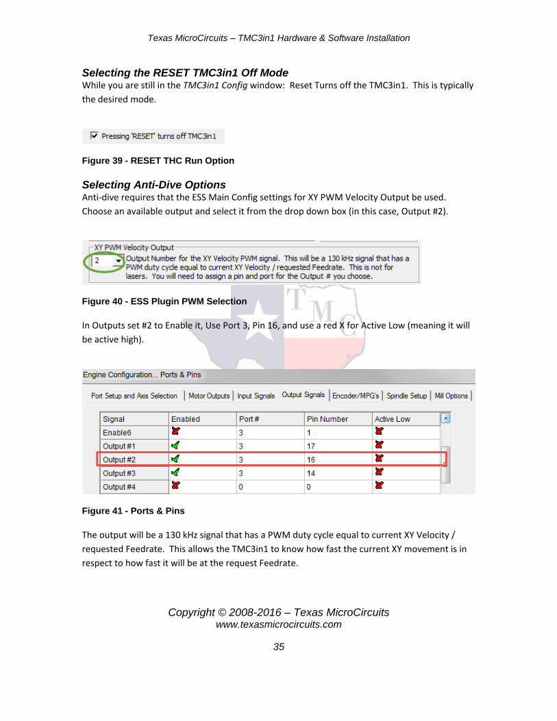
Selecting the RESET TMC3in1 Off Mode While you are still in the TMC3in1 Config window: Reset Turns off the TMC3in1. This is typically the desired mode.
Figure 39 - RESET THC Run Option
Selecting Anti-Dive Options Anti-dive requires that the ESS Main Config settings for XY PWM Velocity Output be used. Choose an available output and select it from the drop down box (in this case, Output #2).
Figure 40 - ESS Plugin PWM Selection
In Outputs set #2 to Enable it, Use Port 3, Pin 16, and use a red X for Active Low (meaning it will be active high).
Figure 41 - Ports & Pins
The output will be a 130 kHz signal that has a PWM duty cycle equal to current XY Velocity / requested Feedrate. This allows the TMC3in1 to know how fast the current XY movement is in respect to how fast it will be at the request Feedrate.
Texas MicroCircuits – TMC3in1 Hardware & Software Installation
Copyright © 2008-2016 – Texas MicroCircuits www.texasmicrocircuits.com
36
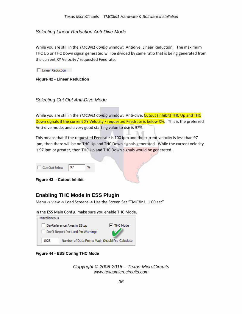
Selecting Linear Reduction Anti-Dive Mode
While you are still in the TMC3in1 Config window: Antidive, Linear Reduction. The maximum THC Up or THC Down signal generated will be divided by same ratio that is being generated from the current XY Velocity / requested Feedrate.
Figure 42 - Linear Reduction
Selecting Cut Out Anti-Dive Mode
While you are still in the TMC3in1 Config window: Anti-dive, Cutout (Inhibit) THC Up and THC Down signals if the current XY Velocity / requested Feedrate is below X%. This is the preferred Anti-dive mode, and a very good starting value to use is 97%.
This means that if the requested Feedrate is 100 ipm and the current velocity is less than 97 ipm, then there will be no THC Up and THC Down signals generated. While the current velocity is 97 ipm or greater, then THC Up and THC Down signals would be generated.
Figure 43 - Cutout Inhibit
Enabling THC Mode in ESS Plugin Menu -> view -> Load Screens -> Use the Screen Set “TMC3in1_1.00.set”
In the ESS Main Config, make sure you enable THC Mode.
Figure 44 - ESS Config THC Mode
Texas MicroCircuits – TMC3in1 Hardware & Software Installation
Copyright © 2008-2016 – Texas MicroCircuits www.texasmicrocircuits.com
37
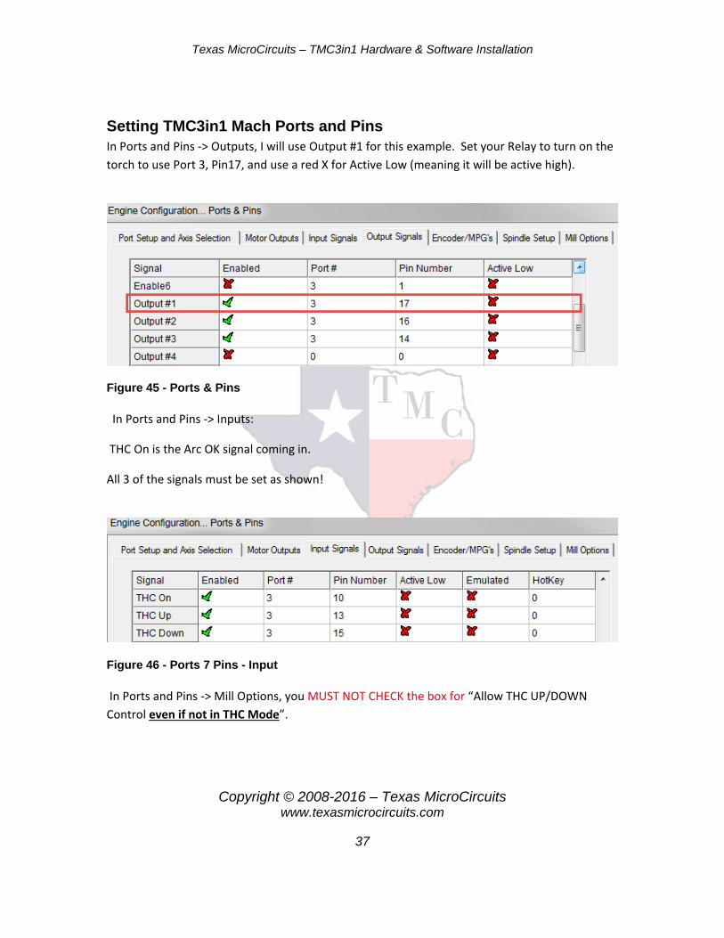
Setting TMC3in1 Mach Ports and Pins In Ports and Pins -> Outputs, I will use Output #1 for this example. Set your Relay to turn on the torch to use Port 3, Pin17, and use a red X for Active Low (meaning it will be active high).
Figure 45 - Ports & Pins
In Ports and Pins -> Inputs:
THC On is the Arc OK signal coming in.
All 3 of the signals must be set as shown!
Figure 46 - Ports 7 Pins - Input
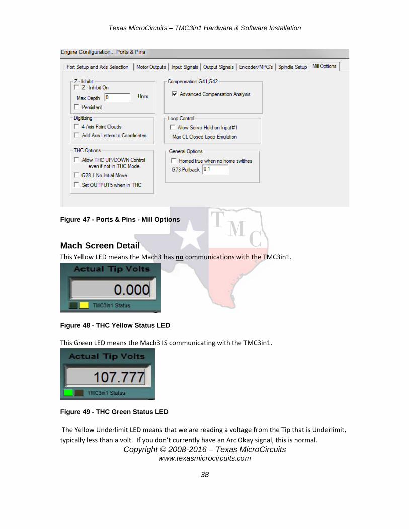
In Ports and Pins -> Mill Options, you MUST NOT CHECK the box for “Allow THC UP/DOWN Control even if not in THC Mode”.
Texas MicroCircuits – TMC3in1 Hardware & Software Installation
Copyright © 2008-2016 – Texas MicroCircuits www.texasmicrocircuits.com
38
Figure 47 - Ports & Pins - Mill Options
Mach Screen Detail This Yellow LED means the Mach3 has no communications with the TMC3in1.
Figure 48 - THC Yellow Status LED
This Green LED means the Mach3 IS communicating with the TMC3in1.
Figure 49 - THC Green Status LED
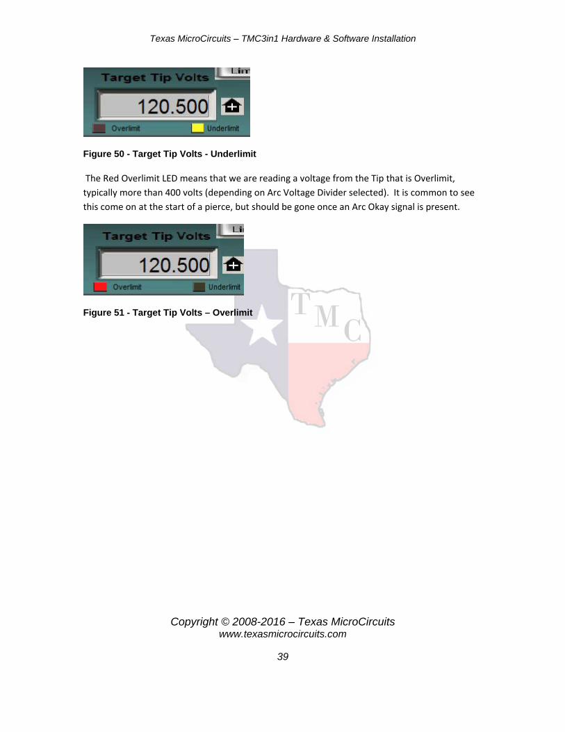
The Yellow Underlimit LED means that we are reading a voltage from the Tip that is Underlimit, typically less than a volt. If you don’t currently have an Arc Okay signal, this is normal.
Texas MicroCircuits – TMC3in1 Hardware & Software Installation
Copyright © 2008-2016 – Texas MicroCircuits www.texasmicrocircuits.com
39
Figure 50 - Target Tip Volts - Underlimit
The Red Overlimit LED means that we are reading a voltage from the Tip that is Overlimit, typically more than 400 volts (depending on Arc Voltage Divider selected). It is common to see this come on at the start of a pierce, but should be gone once an Arc Okay signal is present.
Figure 51 - Target Tip Volts – Overlimit

Texas MicroCircuits – TMC3in1 Hardware & Software Installation
Copyright © 2008-2016 – Texas MicroCircuits www.texasmicrocircuits.com
40
Appendix
Related Documents


