f ' I ' 11' The TEXAS CRASH CUSHION TRAILER TO PROTECT HIGHWAY MAINTENANCE VEHICLES by E. L. Marquis Research Engineer and T. J. Hirsch Research Engineer Research Report 146-6 Studies of Field Adaptation of Impact Attenuation Systems Research Study Number 2-8-68-146 Sponsored by Tpe Texas Highway Department in cooperation with United States Department of Transportation Federal Highway Administration August 1972 Texas Transportation Institute Texas A&M University College Station, Texas Technlcat lleports. c.- Texas TriASf.lOI'tatJoltnstltute

Welcome message from author
This document is posted to help you gain knowledge. Please leave a comment to let me know what you think about it! Share it to your friends and learn new things together.
Transcript

f ' I '
11'
The
TEXAS CRASH CUSHION TRAILER TO PROTECT HIGHWAY MAINTENANCE VEHICLES
by
E. L. Marquis Research Engineer
and
T. J. Hirsch Research Engineer
Research Report 146-6 Studies of Field Adaptation of Impact
Attenuation Systems
Research Study Number 2-8-68-146
Sponsored by Tpe Texas Highway Department
in cooperation with United States Department of Transportation
Federal Highway Administration
August 1972
Texas Transportation Institute Texas A&M University
College Station, Texas
Technlcat lleports. c.Texas TriASf.lOI'tatJoltnstltute

ABSTRACT
The Texas Crash Cushion Trailer of 20 gage 55-gallon steel drums
with 8 in. holes in the top and bottom with a set of wheels and a trailer
hitch has been successfully tested in a>head-on collision. When properly
attached to a maintenance vehicle such as a dump truck it will provide
protection to the maintenance vehicle, maintenance or construction per
sonnel, and the driver and passengers of an errant vehicle. There is
still a need for testing and evaluation for impacts at angles up to
10 degrees.
DISCLAIMER
The contents of this report reflect the views of the authors who
are responsible for the facts and the accuracy of the data presented
herein. The contents do not necessarily reflect the official views or
policies of the Federal Highway Administration. This report does not
constitute a standard, specification or regulation.
ii
•
.. I
ACKNOWLEDGEMENTS
This study was conduct~d under a cooperative program between the
Texas Transportation Institute and the Texas Highway Department. It
was sponsored by the Texas Highway Department and the Federal Highway
Administration. Laison was maintained through Mr. John F. Nixon of
the Texas Highway Department and Mr. Edward V. Kristoponis of the
Federal Highway Administration.
The cooperation of Mr. Joe G. Hanover, District Engineer, and
maintenance personnel, and use of equipment of District 17, Texas
Highway Department, were invaluable for conducting this test. In
addition, Mr. Leon Hawkins, Maintenance Engineer of the Texas
Highway Department, contributed many helpful comments and suggestions.
The crash test and evaluation was carried out by personnel of the
Highway Safety Research Center of the Texas Transportation Institute.
iii

SUMMARY REPORT
Wheels have been added to the Texas C~ash Cushion. The resulting
trailer is a workable and easily used implement for the protection of
personnel and equipment, especially when performing maintenance on our
nation's highways and streets. One crash test has been performed to
verify the design theory. This test showed that the equations of mechan
ics predicted results which were very close to the test results.
The Texas Crash Cushion Trailer varies from the usual crash cushion
in that the object supporting the crash cushion is itself movable
rather than firmly fixed in space. This fact reduces the number of steel
drums required but introduces a new variable in the form of the distance
that the trailer and back up maintenance truck will travel if impacted
by an errant vehicle. This variable of distance traveled after impact
and the number of steel drums required are determined by introducing the
equations of momentum and friction into the solution. Figure 2 in the
text is a ready reference for the selection of the number of drums re
quired for usual highway use. Figure 3 can be used to determine the
minimum distance a maintenance truck-crash cushion trailer combination
should trail or be parked behind pe~sonnel and equipment to afford pro
tection. Drawings of a Texas Crash Cushion Trailer and the type of
minor modifications necessary to a towing truck are included. There is a
need for testing and evaluation for impacts at angles up to 10 degrees.
Key Words: Crash Cushion, Trailer, Steel Drums, Impact Attenuation, Highway
Safety, 4-S Program, Structural Systems, Portable, Momentum,
Kinetic Energy, Highway Maintenance Vehicles.
iv
IMPLEMENTATION STATEMENT
The successful test conducted as described herein combined with
the vast research previously accomplished and the field service record
of the Texas crash cushion warrants the immediate implementation of the
installation. In fact several districts of the Texas Highway Depart
ment either have built trailers or are in the process of building them.
There is however a need for additional testing and evaluation for im
pacts at angles up to 10 degrees.
v

TABLE OF CONTENTS
ABSTRACT
ACKNOWLEDGEMENTS
SUMMARY REPORT
IMPLEMENTATION STATEMENT
TABLE OF CONTENTS
LIST OF FIGURES
LIST OF TABLES
INTRODUCTION
DESIGN OF TEXAS CRASH CUSHION TRAILER
Test Crash Cushion Trailer Design
VEHICLE CRASH TEST
DISCUSSION OF RESULTS
Test Data
Correlation of Test Data
SUMMARY AND CONCLUSIONS
REFERENCES
APPENDIX
vi
Page
ii
iii
iv
v
vi
vii
viii
1
2
8
12
17
17
25
27
29
...
• LIST OF TABLES
TABLE
1 Test Data
2 Table of Events
vii
Page
21
24

•
I ~
INTRODUCTION
The effectiveness of the Texas Crash Cushion in contributing to
highway safety is well documented (5, 7, 8)*. Previous research and
field experience with this device has been to protect an errant motorist
from a high speed collision with a rigid obstacle. Common examples are
elevated gores and bridge piers in median areas.
The purpose of this research was to expand the use of this energy
absorbing device to a portable or mobile trailer system to protect
slowly moving or stopped maintenance vehicles working on our highways.
The Texas Crash Cushion Trailer (TCCT) is to be used to protect high-
way maintenance equipment and personnel as well as the motoring public.
An important requirement of the TCCT is that it be portable or mobile
and easily constructed by highway maintenance personnel and be adaptable
to dump trucks and other h~ghway department vehicles.
~
*Numbers in parenthesis refer to corresponding numbers in the References.
1

DESIGN OF TEXAS CRASH CUSHION TRAILER
The design of the crash cushion trailer is based on the law of
conservation of momentum and on the dissipation of kinetic energy by
plastic deformation of steel drums and through friction. This is some-
what different than the design of fixed Texas crash cushions which
absorb energy by plastic deformation of steel drums only. The critical
energy absorbing condition for the design of the crash cushion trailer
will occur for an impact in which the automobile, crash cushion and
restraining mechanism (usually a truck) are in line at the time of
impact. See Figure 1.
For this condition the momentum of the automobile (or striking
vehicle) before impact will be equal to the total momentum of the system
immediately after impact. Assuming plastic impact
Where
w c
g
w c
wb
wt
v c
v = c
W +Wb+W c t g
v.
= Total weight of automobile, lb.'
= Total weight of the portable crash cushion,
= Total weight of the truck, lb.'
Velocity of the automobile at impact, fps.,
lb.'
v = Velocity of the entire system immediately after . 2
g = the acceleration due to gravity, ft./sec.
impact,
Solving for the velocity of the entire system after impact yields
2
fps.,

.. i
TEXAS CRASH CUSHION TRAILER
t...l
=
TRUCK ,.._ -'
FIGURE I - CRASH CUSHION TRAILER BEFORE TEST

v = w
c ------we + wb + wt
v . c
For a truck weighing 9500 lb. a portable crash cushion weighing 2000 lb:
and an automobile weighing 4500 lb. and an impact speed of 60 mph (88
fps) we have
v = 4500 88 = 24.75 fps or 16.88 mph. 4500 + 2000 + 9500
. The kinetic energy (K.E.) of the automobile before impact is computed
by the formula
K.E. MV2
= --2
K.E. 4500 X (88)2
= ....;...:...2,_X~32~.'-::2~ 541,000 ft-lb (before impact).
The kinetic energy of the automobile, crash cushion and truck after
impact is
K.E. (4500 + 2000 + 9500) (24.75) 2 = 2 X 32 •2 = 152,000 ft-lb
(after impact)
Consequently, 389,000 ft-lb of energy would be absorbed in the impact
by plastic deformation of the steel drums in the crash cushion trailer.
According to White and Hirsch (!) a single 20 gage tight-head steel
drum with 8 inch diameter holes in the top and bottom will absorb 9000
ft-lb of energy unde~ slowly applied loads. The dynamic factor has been
4

shown to be 1.5 (l)· Therefore each barrel will absorb 1.5 X 9000 or
13,500 ft-lb of dynamic energy. This would mean that the portable crash
cushion would require 28.8 steel drums. The cushion would be designed
with 30 barrels to achieve a rectangular configuration.
Figure 2 was developed as a design aid from the foregoing theory.
The number of barr~ls required is plotted against the weight of the re-
sisting truck for impacting vehicles of 2000 lb., 4000 lb., and 4500 lb.
The design impact speed is 60 mph in each case. A crash cushion trailer
would generally weigh within 15% of the valuessshown. The figure is the
design vehicle weight range recommended by FHWA (~). It can serve as
a tool for designing portable crash cushions as well as for a comparison
of the limiting conditions.
After the barrels have deformed plastically and absorbed 389,000
I ft-lb of energy there still remains 152,000 ft-lb of energy due to the
entire system moving at 24.75 fps. If all of the wheels of the truck
are locked, then the distance required to stop the vehicle is
d = K.E. (after impact) wt 11
where 11 is the coefficient of friction, say 0.7 for tires to concrete.
Then
152,000 d = 9500 X 0.7 = 22.9 ft.
Portable Crash Cushion in Motion
While the critical design f~r the energy absorption of the crash
cushion itself will be for the stationary condition, the critical
5

40
35
10 0 10
"c = 60 mph
2000 Lbs.
"'-ASSUMED TRAILER WT. 1500 Lbs.
20 30
40bbl. max.
18 bbl. MGK.
40 50
· WEIGHT OF TRUCK (THOUSANDS OF POUNDS)
FIG. 2- NO. OF BARRELS IN CRASH CUSHION TRAILER VS. TRUCK WEIGHT FOR SEVERAL AUTO WEIGHTS
6

condition for the distance traveled after impact will occur when the
crash cushion and towing vehicle are in motion. Such a condition might
occur in the protection of a paint stripping machine. In that instance
both the impacting vehicle and the impacted assembly would have initial
momentum and kinetic energy. Again assuming plastic impact and con-
servation of momentum
w wb + wt c v +
W +Wb+W c t v g c g g
or
again assuming that Vc = 60 mph, also that Vt = 10 mph for a 4500 lb
-vehicle and 9500 lb truck
V = 4500 X 60 + (2000 + 9500) 10 = 24 •06 mph or 35 •29 fps 4500 + 2000 + 9500
The kinetic energy before impact
K.E. = 4500 X 882
2 X 32.2 11500 X :1.4.6672
+ 2 X 32.2
The kinetic energy remaining after impact
= 580,000 ft-lb
K.E. = (4500 + 2000 + 9500) 35.292
2 X 32.2 = 309 '000 ft-lb.
The change in kinetic energy = 271,000 ft-lb.
7
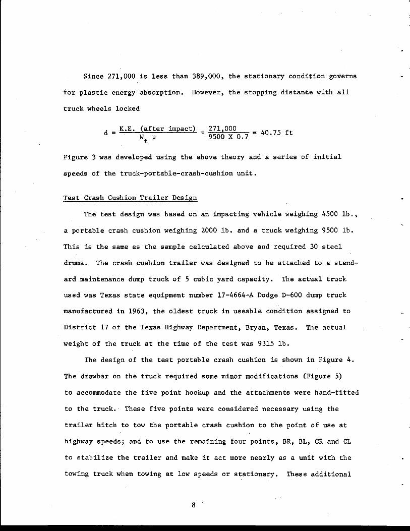
Since 271,000 is less than 389,000, the stationary condition governs
for plastic energy absorption. However, the stopping distance with all
truck wheels locked
d = K.E. (after impact) = wt ~
271,000 9500 X 0.7 = 40.75 ft
Figure 3 was developed using the above theory and a series of initial
speeds of the truck-portable-crash-cushion unit.
Test Crash Cushion Trailer Design
The test design was based on an impacting vehicle weighing 4500 lb.,
a portable crash cushion weighing 2000 lb. and a truck weighing 9500 lb.
This is the same as the sample calculated above and required 30 steel
drums. The crash cushion trailer was designed to be attached to a stand-
ard maintenance dump truck of 5 cubic yard capacity. The actual truck
used was Texas state equipment number 17-4664-A Dodge D-600 dump truck
manufactured in 1963, the oldest truck in useable condition assigned to
District 17 of the Texas Highway Department, Bryan, Texas. The actual
weight of the truck at the time of the test was 9315 lb.
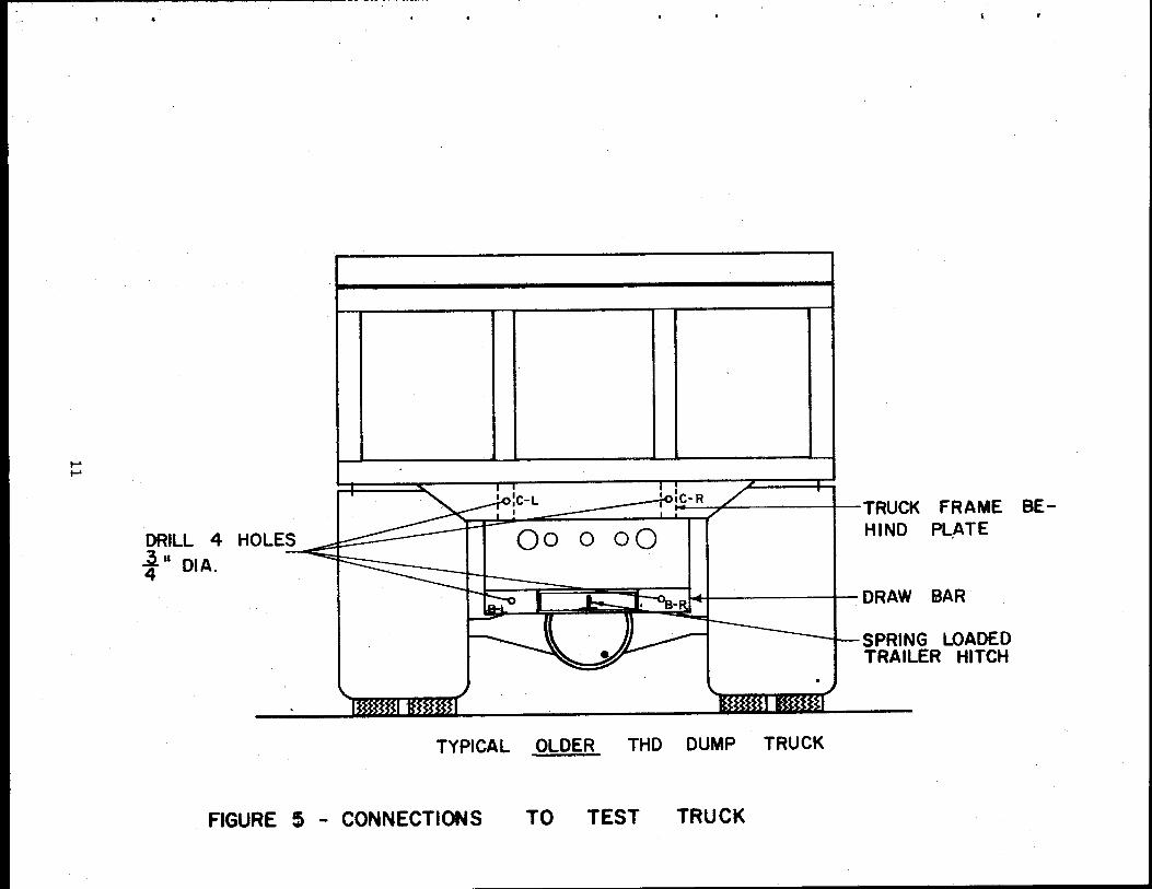
The design of the test portable crash cushion is shown in Figure 4.
The drawbar on the truck required some minor modifications (Figure 5)
to accommodate the five point hookup and the attachments were hand-fitted
to the truck. These five points were considered necessary using the
trailer hitch to tow the portable crash cushion to the point of use at
highway speeds; and to use the remaining four points, BR, BL, CR and CL
to stabilize the trailer and make it act more nearly as a unit with the
towing truck when towing at low speeds or stationary. These additional
8
I ~ I

120
100
-..... 80 L&J L&J LI-
z -60
L&J 0 z <t t; 0 (!) 40 z a: Cl. 0 t;
20
Vr = TRUCK VELOCITY
Vc = 60 mph
We = 4~ oo Lbs.
w8 = 2000 Lbs.
V. = 15 mph
oL---~----~~==~====~~~~ 20 40 50 30 0 10
WEIGHT OF TRUCK (THOUSANDS OF POUNDS)
FIGURE 3 - STOPPING DISTANCE vs. TRUCK WEIGHT FOR VARIOUS INITIAL TRUCK SPEEDS
9

~-r-o~ I :::; I I '" II -· .,, l -
II I I i -r~~ II "I
-0«-~=-- IU ~_Lt_
I
I
~ =I i!.l
I
_..£.-t!a• ·-- Q".WI
1-,
~
\
1- \ \:..~,··~
(j) dl (j) c:b
PLAN
ELEVATION
_IQ..AlllllL a...u.·~j; ---1
J:,
c <(;;)/C, ~~). \( ~x~>::~ .
() ,' '0 )~/·,' ()~)· / -...,_ (C~' \
, , (' ':c c~ , \_./ )
/ J ......... -...-· ---- __ __....,
Cl:> cv d> <D @
--,
TI!XAS ,...........,. • .._ -TI'TVT[
PCMTAILE fDM. TUT c:aasM CUSMIOII
ASSEMa.T --
~- 1-1/M/I'C ~ ~r .... .-
T?t'-1
FIGUR£ 4 - TEST CRAStt .. CUSHION TRAILER ASSEMBLY
~ ~
DRILL 4 HOLE~
t" DIA.
_________,...,;~- .. / I TRUCK FRAME BEHIND PL,ATE
~ •.. k;J· -<>e-~lj I DRAW BAR
SPRING LOADED TRAILER HITCH
TYPICAL OLDER THO DUMP TRUCK
FIGURE $ - CONNECTIONS TO TEST TRUCK

points were located to produce horizontal and vertical stability of the
portable crash cushion. That is, they would not allow the trailer to
jack-knife during impact and they would prevent the impacting vehicle
from submarining. Pictures of the completed crash cushion trailer are
shown in Figures 6 and 7.
With the exception of the removable arms all connections were welded.
The four removable arms were bolted to the face of the portable crash
cushion using six bolt-studs wrlded to the face of the crash cushion.
Four bolts were used to connect the arms to the truck. Two TTI tech
nicians pulled the portable crash cushion to the test site and made
the complete hookup in less than five minutes. The addition of hinges
on the side arms would decrease the time required to complete the hook
up for use.
VEHICLE CRASH TEST
The crash cushion trailer was hooked to the truck, using the
trailer hitch only, and towed around the TTI safety proving grounds
at speeds up to 50 mph for qualitative observation. After this exer
cise it was noted that the steel drums connected to the trailer axle and
the row directly behind the axle had slightly deformed tops. This in
dicated the desirability of moving the axle further to the rear of the
trailer to reduce the cantilever effect of the rear steel drums. The
auxillary connections were made and the trailer towed at speeds up to
25 mph around curves up to 20°. This operation was also observed quali
tatively. The trailer tracked the truck to a remarkable degree consider
ing the rigid attachment. There was, however, an abnormal amount of
12

FIGURE 6 -TEST CRASH CUSHION TRAILER BEFORE
13

\
FIGURE 7 - TEST CRASH CUSHION TRAILER TEST PCC - I CONSTRUCTION
14

wear to the tires due to side slippage. At lower speeds this wear was
insignificant, especially when compared to the life saving potential
The primary test was the dynamic or crash test on the stationary
truck-crash-cushion unit. For this test the unit was placed near the
north end of the apron at the TTl safety proving grounds. Ample dis
tance to the end of the pavement was allowed for the unit to slide after
impact. The arms were bolted in place and the truck was placed in gear
(ignition turned off) and the parking brake set.
The impacting vehicle was a 1964 Chevrolet weighing 4060 lb. Lat
eral and longitudinal accelerometers were located on the right and left
frame members of the vehicle chassis. The vehicle was towed toward the
target by a reverse tow-g~idance system (2._). The initial impact speed
was 63.3 mph and the impact angle was 0° (head on) in the c·enter of the
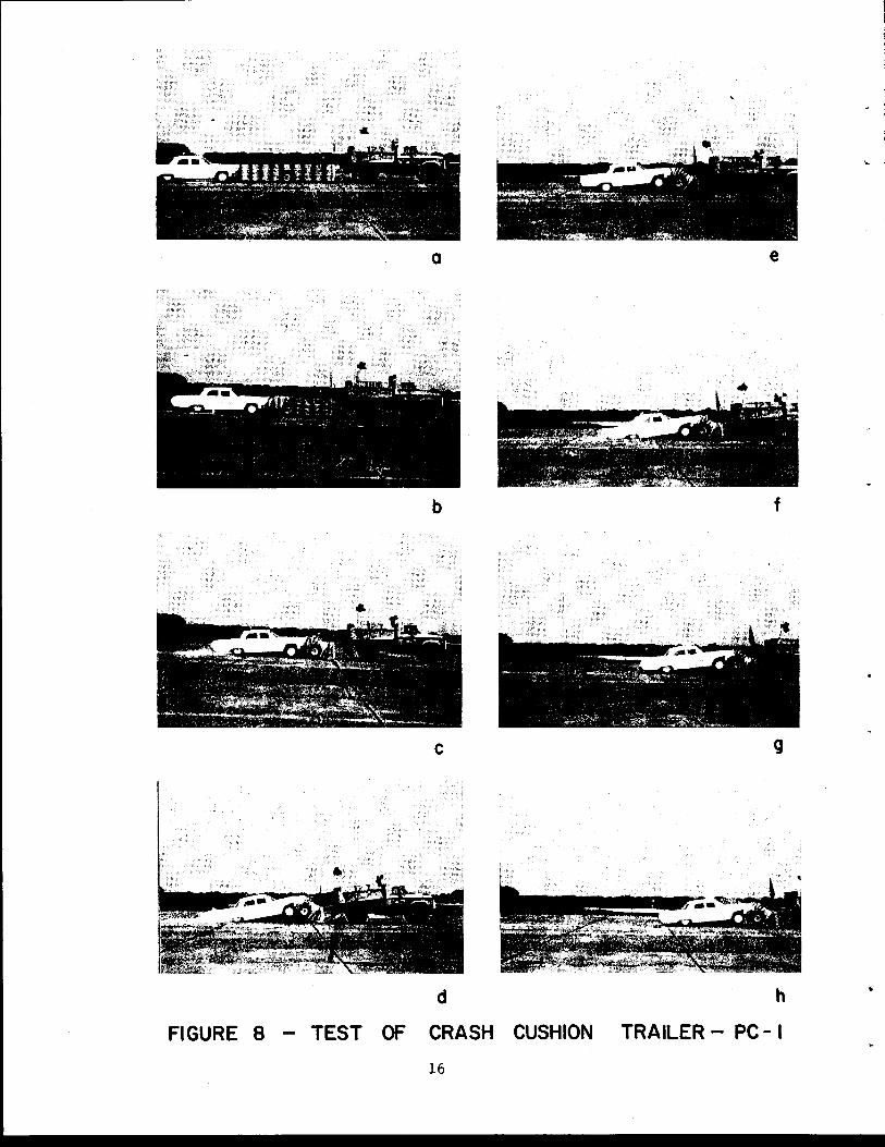
rear end of the crash cushion trailer. Figure 8, a series of pictures
from the moving picture cameras, shows the sequence of events of the
test starting at impact. It is especially interesting to observe that
the truck is virtually stationary untii the barrels have been crushed
to nearly the maximum which occurred during the test. This is important
to the use of the system in the field since it shows that the majority
of the energy is absorbed by the crash cushion before the energy wave
reaches the truck. In turn this shows that the instantaneous peak g
or jolt is at a minimum to anyone seated in the truck. It follows then
that there would be little or no damage to the truck. In fact the truck
was unhooked from the crash cushion trailer and given a brief examination
by TTl personnel who could find no damage. The truck was then returned
15
•
a
b
c
d
Fl GURE 8 - TEST OF CRASH CUSHION
16
e
f
g
h
TRAILER - PC- I

to District 17 of the Texas Highway Department. District personnel in
spected the truck thoroughly. The District Engineer then wrote to the
director of TTl confirming that they could find no damage to the truck(~).
Figure 9 shows the impacting automobile before and after the impact.
A minimum amount of damage occurred to the vehicle. In fact only the
two inside headlights were broken.
Figure 10 shows the crash cushion after the test and after the ve
hicle had been pried loose and driven away. Quite obviously the vast
majority of the available energy of the steel drums had been used.
DISCUSSION OF RESULTS
Test Data
The data from the tests was collected from three different sources,
field measurements, electronic instrumentation, and photographic instru
mentation. The electronic instrumentation included an Inter-Range
Instrumentation Group (!RIG) (1) with eight available channels. Two
channels were used for longitudinal acceleration, two for lateral accel
eration, two for speed and two spares. The data was transmitted to a
central receiver where it was put on a magnetic tape and stored. The
acceleration data was then filtered through an 80 hz filter and trans
ferred with the speeds to paper tape in the visicorder. An Impact-0-
Graph was used for back up data in the event of a malfunction of the
!RIG.
Three high speed data cameras and two documentary cameras were used
to record the test and to obtain additional data. A complete description
of data reduction techniques using the Vanguard Motion Analyzer is found
17
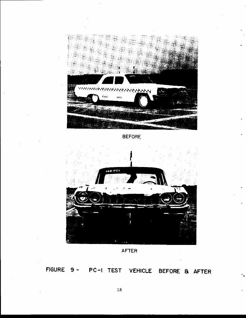
BEFORE
AFTER
FIGURE 9 - PC -I TEST VEHICLE BEFORE a AFTER
18

FIGURE 10 - CRASH CUSHION TRAILER .AFTER TEST
19

in Appendix C to report Test and Evaluation of Vehicle Arresting, Energy
Absorbing and Impact Attenuation Systems (l) published by the Texas Trans
portation Institute.
Table 1 presents a summary of the more important test data. There
are several comparisons to the theory shown and described in detail be
low. There is a 1.7 ft. difference between the maximum forward motion
of the vehicle and the final position of the vehicle. Of this, the truck
rebounded apprDximately one foot, which was probably due to the movement
of the truck acting against the compression of the engine. Also, the
barrier and vehicle rebounded an additional 0.7 ft., indicating that
there was some elasticity remaining in the barrier and the front end of
the vehicle. Figure 11 graphically shows the relative final positions of
the truck, barrier, and vehicle.
Table 2 presents the major events of the test with the time of
occurrence for each. Figure 12 is the longitudinal and acceleration
trace from the visicorder (IRIG;system). The visicorder data and the
table of events compare extremely well. The peak g occurs during the
period when the first row of steel drums is crushed. The entire crash
cushion trailer started moving forward at 211 msec. At this point the
vehicle deceleration starts to increase and there is a secondary decel
eration peak at approximately 275 msec., the point where the vehicle,
cushion and truck move as a unit. The vehicle deceleration zeros out
the first time at 366 msec., about the time the truck achieves maximum
speed. After this time the acceleration trace (not shown) ranges from
less than one to zero negative g's. Hence we see that the majority of
the energy is absorbed in plastic deformation of the barrels and elastic
20

AUTOMOBILE
Year, Make
Weight
Impact Angle
TRUCK
Year, Make
Weight
Crash Cushion Trailer (estimated) weight
EVENT DESCRIPTION
Initial Speed
TABLE 1
TEST DATA
Maximum Forward Motion of Vehicle
Time to End of Forward Motion
Maximum Forward Motion of Truck
Final Vehicle Forward Motion
Final Truck Forward Motion
Final Vehicle Deformation
Final Cushion Deformation
Average Deceleration, v2/2gS
TEST. DATA
92.8 fps or
36.4 ft
1.856 sec
21.0 ft
34.7 ft
20.0 ft
0.2 ft
14.5 ft
3.67 g's
Maximum Longitudinal Acceleration -15.2 g's
Average Longitudinal Acceleration to End of Significant Peak -6.6 g's
1964 Chevrolet
4060 lbs
0 deg
1964 Dodge
9315 lbs
2010 lbs
COMPUTATION
63.3 mph
36.8 ft
22.0 ft
14.8 ft
3.64 g's
b.V b.t (to 0.366 sec) 5.8 g's
21

N N
-
TRUCK -...
251-!11
c.
.2d-fi',
;;.RUCK MOTION
DEFORMATION ON I
BARRELS I
\ :
BARREL LOCATION BEFORE TEST
I TRAILER .. 14 --: I 0 ~0
WHEELt o ., 1 I I 3-~
- I I
J] ~
~
~-' !ii' 34
1-8
11 I
411-6
1 I 59
1 2''
DEFORMATION ~ [ l . [ J~ VEHICLE . zt.l!.= .1__1
- L 17!...5" J r - -- --- ---.
FIGURE II - DIAGRAM OF CRASH CUSHION TRAILER 1 TRUCK 1 AND VEHICLE AFTER TEST

- ~
N w
""' Q) Q)
~ I
(/)
~
- LEFT FRAME MEMBER
z 0 5,----r----,------,---j_-ti G:
~ LIJ u u cr-• -
IMPACT
0 .....
-5 I. I ll :z II :A - I I I ¥ .- I
~ ~ -10 I : I ,f I I - "~ 'r' I z s ~ -15~~------+---------4----------+--------~ s z 0 -20~--------~--------~--------~---------J ...1 0 100 200 300 400
TIME (M-SEC)
PEAK • 1~·2 G'l AVG. • 6·6 G'l
OVER 366 M·SEC
FiGURE 12 - LONGITUDINAL ACCELEROMETER DATA TEST 146 PC-I
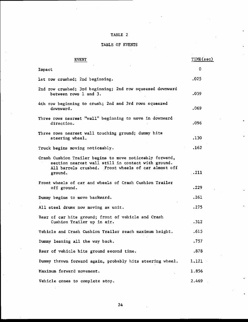
TABLE 2
TABLE OF EVENTS
EVENT
Impact
1st row crushed; 2nd beginning.
2nd row crushed; 3rd beginning; 2nd row squeezed downward between rows 1 and 3.
4th row beginning to crush; 2nd and 3rd rows squeezed downward.
Three rows nearest ''wall" beginning to move in downward direction.
Three rows nearest wall touching ground; dummy hits steering wheel.
Truck begins moving noticeably.
Crash Cushion Trailer begins to move noticeably forward, section nearest wall still .in contact with ground. All barrels crushed. Front wheels of car almost off ground.
Front wheels of car and wheels of Crash Cushion Trailer off ground.
Dummy begins to move backward.
All steel drums now moving as unit.
Rear of car hits ground; front of vehicle and Crash Cushion Trailer up in air.
Vehicle and Crash Cushion Trailer reach maximum height.
Dummy leaning all the way back.
Rear of vehicle hits ground second time.
Dummy thrown forward again, probably hits steering wheel.
Maximum forward movement.
Vehicle comes to complete stop.
24
TIME(sec)
0
.025
.039
.069
.096
.130
.162
.211
.229
.261
.275
.312
.615
.757
.878
1.121
1.856
2.469

and plastic deformation of the vehicle which is as predicted by analysis.
Correlation of Theory and Test Data
The theory based on conservation of momentum and kinetic energy
described earlier produced results which are in excellent agreement with
the test data when the test values are used. That is, from the conser-
vation of momentum and substituting values from Table 1 into equation
No. 1 we get
4060 V = 4060 + 2010 + 9315 92 •8 = 24 •5 fps~
Now the vehicle kinetic energy just prior to impact
K.E.b f e ore 4060 (92.8) 2
= ~~~~~~ 64.4
= 542,920 ft-lb
impact
and after plastic impact the remaining kine~ic energy is
= 15,385 (24.5)2
K.E. f 64 4 = 143,280 ft-lb a ter • impact
or energy lost during plastic impact = 399,640 ft-lb. The number of
barrels required were
399640 13500
= 29:60.
Each barrel is two feet in diameter and the available crush distance
available for each barrel is 75 percent of the diameter (1). Then for
three rows of barrels the crush distance is
25

29.60 X 2 X 0.75 3
= 14.8 ft.
The truck will travel after impact a distance
d = 143,280 = 22.0 ft. 9315 X 0.7
The maximum forward motion of the vehicle is 36.8 feet and the average
deceleration for the event is 3. 64 g 's. (These values are compared with
the data in Table 1. They vary less than 5% from the test data.) By
using the relationship &V/&tg for the time of the main event (366 msec)
the average deceleration is 5.8 g's. The relationship
produces values which are high (8.4 g's) for the average deceleration
to the end of the first significant peak. (Integration of the accelero-
meter trace gives 6.6 g's). This discrepancy is largely accounted for
by noting that the value for s equals the crush distance of the crash
cushion would be accurate only when the front of the barrier were totally
stationary. Whereas, during the later part of the deformation period the
barrels were crushing and moving forward simultaneously so that with an
impacting speed of 92.8 fps then· the distance required to slow the vehi-
cle to 24.5 fps would be 18.8 feet rather than the 14.8 feet calculated
as the crush distance of the portable crash cushion. From Table 2
we note that at time 0.211 sec the "crash cushion trailer begins to
move noticeably forward, ••• " and at time 0.275 sec "all steel drums now
moving as a unit." That is to say that during the 0.064 sec of this
26

time period the crash cushion trailer is both moving and crushing.
SUMMARY AND CONCLUSIONS
The crash cushion trailer is a workable easily used solution for
protection against certain classes of accidents on our nation's highways
and streets. The accidents would be the ones most likely to occur dur
ing maintenance operations where head-on or near head-on collisions would
be likely to occur. Simple equations of mechanics are extremely accu
rate for the design and use of the crash cushion trailer. Further, the
curve presented in Figure 2 can be used for the design of specific crash
cushion trailers and the curves in Figure 3 will assist in the safe loca
tion of the crash cushion. The average deceleration predicted by the
usual equations of mechanics will be very conservative, up to 25% high,
and if used should be used with discretion.
The structural connections between the crash cushion trailer and
the truck or other stabilizing vehicle should be adequate or even over
designed (see the appendix for a recommended design). The back up
plate, also, should be stiff enough so that as uniform restraining force
as possible will be applied to the barrels during an accident.
The crash cushion trailer can be used in three basic maintenance
or construction operations. The first would be to protect both workers
and errant motorists during and after working hours in detour situations
where a missed detour would cause injury to errant vehicle occupants
or workers or where combined dam~ge to the errant vehicle and barrier
would be less than what would be predicted to the construction as
27

machinery beyond the detour sign. In this situation the crash cushion
trailer with its towing vehicle could be anchored on a temporary basis
for the duration of the hazard and then moved to a new location as main
tenance or construction progressed.
Another possible use would be as a temporary stationary crash cush
ion to be used to protect workers doing routine maintenance on driving
lanes or shoulders. A few operations might be mowing, guardrail repair,
chug-hole repair, or even collecting trash along heavily traveled high
ways. A driver could stay in the truck and move along with the task.
A third type of operation would be a moving operation in which the
progress of the operation would proceed at a much slower speed than the
traffic was moving. Such an operation might be striping of traffic
lanes, placing traffic buttons or similar tasks.
It is significant to note that a crash cushion trailer for muni
cipal streets could be much smaller than one used on high speed express
ways. The distance a crash cushion trailer is placed from or follows
an obstacle or worker to be protected should be governed by calcula
tions for a safe distance or from Figure 3. An adequate margin of safe
ty should be used for the final distance.
28

REFERENCES
1. White, Monroe Carlton and Hirsch, Teddy James, HIGHWAY CRASH CUSHIONS a special report, Texas Transportation Institute, November 1971.
2. Tamanini, F. J. and Viner, John G., "Energy Absorbing Roadside Crash Barriers," Civil Engineering, January 1970, pp. 63-67.
3. TEST AND EVALUATION OF VEHICLE ARRESTING, ENERGY ABSORBING, AND IMPACT ATTENUATION SYSTEMS, Texas Transportation Institute, November 30, 1971.
4. Nordlin, Eric F., Woodstrom, James H. and Doty, Robert N., DYNAMIC TESTS OF AN ENERGY ABSORBING BARRIER EMPLOYING STEEL DRUMS, California·Division of Highways, January 1971.
5. Hirsch, T. J. and Ivey, Don L., VEHICLE IMPACT ATTENUATION BY MODULAR CRASH CUSHION, Texas Transportation Institute, June 1969.
6. Hanover, Joe G., letter to TTI Director, May 24, 1972.
7. White, Monroe C., Ivey, Don L., and Hirsch, T. J., IN-SERVICE EXPERIENCE ON INSTALLATIONS OF MODULAR CRASH CUSHIONS, Texas Transportation Institute, December 1969.
8. Hays, Gordon G., Ivey Don L., and Hirsch, T. J., FLEXBEAM REDIRECTIONAL SYSTEM FOR THE MODULAR CRASH CUSHION, Texas Transportation Institute, October 1970.
29

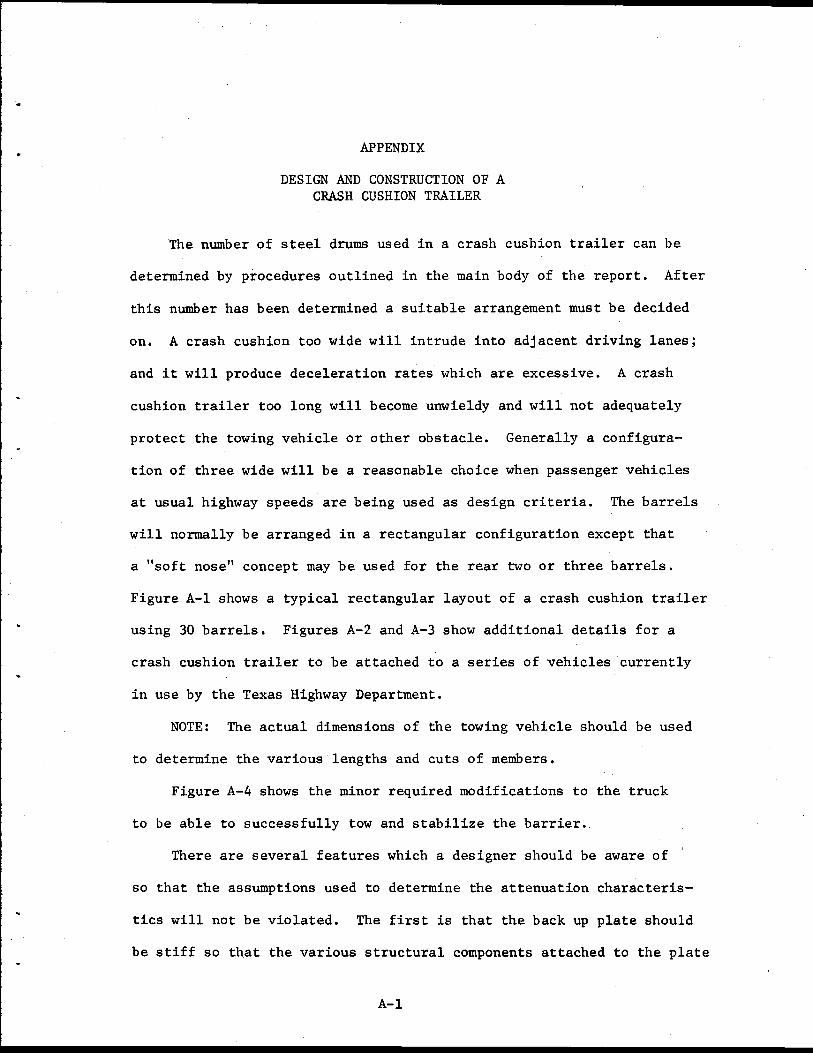
APPENDIX
DESIGN AND CONSTRUCTION OF A CRASH CUSHION TRAILER
The number of steel drums used in a crash cushion trailer can be
determined by procedures outlined in the main body of the report. After
this number has been determined a suitable arrangement must be decided
on. A crash cushion too wide will intrude into adjacent driving lanes;
and it will produce deceleration rates which are excessive. A crash
cushion trailer too long will become unwieldy and will not adequately
protect the towing vehicle or other obstacle. Generally a configura-
tion of three wide will be a reasonable choice when passenger vehicles
at usual highway speeds are being used as design criteria. The barrels
will normally be arranged in a rectangular configuration except that
a "soft nose" concept may be used for the rear two or three barrels.
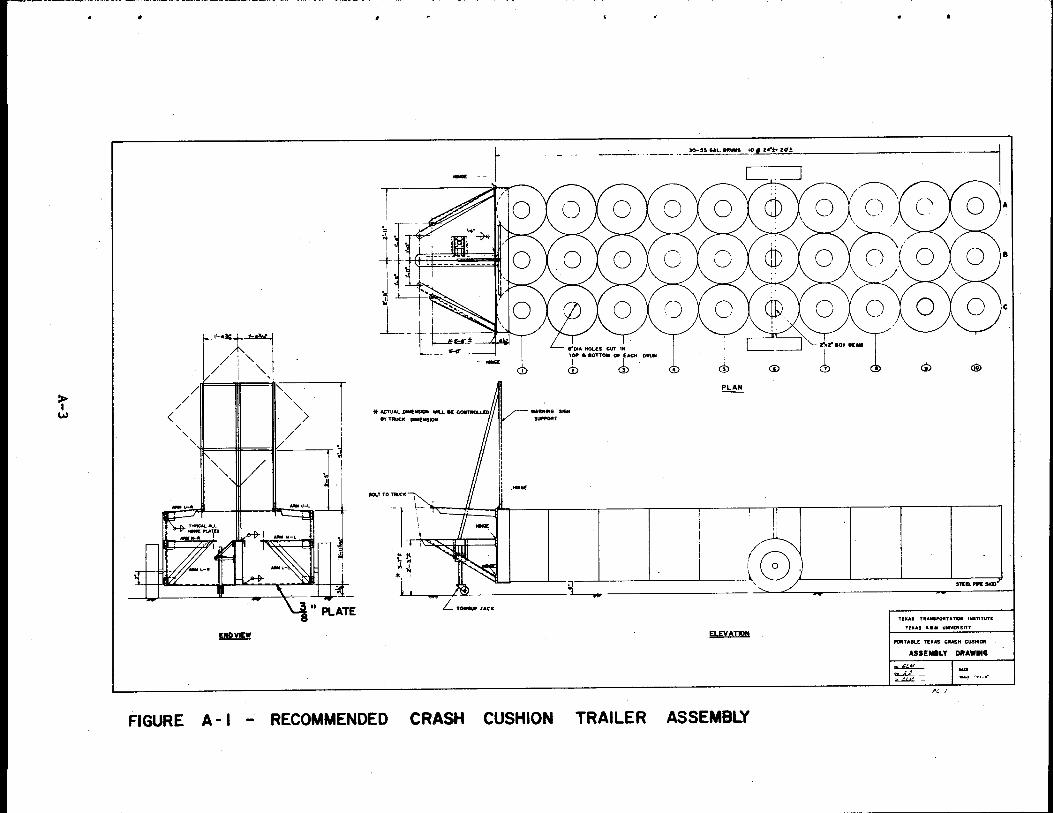
Figure A-1 shows a typical rectangular layout of a crash cushion trailer
using 30 barrels. Figures A-2 and A-3 show additional details for a
crash cushion trailer to be attached to a series of vehicles currently
in use by the Texas Highway Department.
NOTE: The actual dimensions of the towing vehicle should be used
to determine the various lengths and cuts of members.
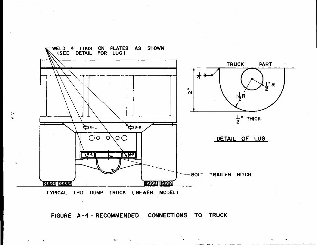
Figure A-4 shows the minor required modifications to the truck
to be able to successfully tow and stabilize the barrier.
There are several features which a designer should be aware of
so that the assumptions used to determine the attenuation characteris-
tics will not be violated. The first is that the back up plate should
be stiff so that the various structural components attached to the plate
A-1

and truck are salvageable. This will save a considerable amount of
effort in replacing the steel drums should a barrier be crushed. A
3/8 inch thick plate is sufficient for a three barrel wide crash cushion
provided the edges are stiffened as shown in Figure A-1. Next, no more
than four full rows of steel drums should be cantilevered over the trailer
wheels, otherwise the tops and bottoms of the barrels tend to buckle
under the dynamic loads imposed by high speed towing. However enough
of the barrels must overhang in order to allow the nose to completely
crush before coming in contact with the tires.
The side arms of the design shown are hinged at the barrier
plate so that they may be readily connected or disconnected. A
tongue jack is a practical necessity since the weight of the front
end of the trailer is well in excess of what two men could be expect
ed to lift.
Most states will require stop lights and direction lights. These
may be attached to a plywood sheet (1/2 in) on the rear of the trailer
or directly to the steel drums. Appendages as required or desired may
be attached to the unit provided they do not materially change the crush
characteristics of the system. Generally the preferred location for
these attachments would be at the front of the trailer such as the warn
ing sign support shown in Figure A-1. Objects such as flashing lights
which are somewhat massive and could penetrate a windshield should be
placed toward the front of the trailer where they will receive a smaller
amount of impact energy.
These above details assume new 55 gallon drums specifically designed
and manufactured for impact attenuation. However, used 55 gallon steel
A-2
:r w <
/
/ /
' ' "iL Ill iV-
ll!2.l!U
-
8'1' TRUCIC DUI£Jrl51011
......
WAtnfll& SI&N
'""""''
--- --~~~--'~e!·!..·!:·~· .. ~·)!_<f:_± _________________ _
C .. =:J
<b @ ~ ®
~
BOLT TO-~~· l ~ f ;.., \ o'\.:_ ( I I I I I I' I I I I I
T ,, • .,~.._,u::u ~
LTCNIG«.IACK
~
8 I ) . I I S~ll.Pft SKID 1
/
TIXAI TltA .. POitTATIOII lldTITUTl
TlXAS A aM UllltVlftSITT
""'TAll.! Tl!ltAS CRASH CUS"'ON
ASSEMBLY DRAWING
~ OLA..L ·~--
PC I
""' 15!!:1 ····-o·
FIGURE A- I - RECOMMENDED CRASH CUSHION TRAILER ASSEMBLY

:r ~
s JIOTt: . .., ~naN • TW: !Ill WIU. •
CCIIIWIENIAtG P RD.DCATlOIII OF Tl"':.....,.....__y
:S"a k" STm. Sl1lAP WEUJI!:D TO SIDlE OF ..... l
2"a /4" STEEL STRAP ftLOf:O TO BARREL AT All COI'IITACT POINTS
ITANDAftD AUlOMOIIU' FltOffT W.CIEL PtHDLE WELD!D TO PLATIE
3/8" OIA STEfl. ROO W£Lot:O IE:TWEEN BA'*'El.S
Z"IOIC ILW .. _ -----------~ ....... -..
.,t::=:===~ 01
WHEEL TO CUSHKJN ASSEMBLY
DETAIL OF ARM U-L
2"11:"1 j,z• STUL PLATIE WELDED TO END OF 80X BUM
BARREL ATTACHMENT DETAIL (TYPICAL !'OR 111..1.. CONTACT POINTS BETWEEN 8ARR£LS)
~-------=""'::..::.."::::""'::..::""'-:::;' lfOU CENTERED
~b ---- ~-~~--.,. :s·. :s·. "" AHGlL
1r·· ~,_,_,,. r
~·\v
DETAR.. OF ARM U-R
018" OtA. IOLT HOLt: CIN'ULIIf:O ~-:-.. ------·---------~
~
•'<1:.,;.»:.1
!' .~.-
3"• !"a "'-" ANGLl
DETAIL OF ARM M-L
. ~- .. 4"1 1 112"1 ~· CHANNEL
-..,.
~- w ,_,... ~
DETAJLOFARM T-S
.... ''"" ~ 3"•3"a ~ .. ANGLE
I ~
DETAIL ~ARM L-L
c=_·--- ----------~~-3MOl.lClNTEM:O
s· e;c· ,_ ... S'x3"a M"ANIII..E:
.. w ~!.-?· L____ -·- ~.., .. ,.,
OETAII.OFARM M-R
t~~-- l ·~ ~~ 3'0" ..j
2- 3"a3"1 ~·ANGLES
_!~--~ ~-n-~ WELD€0 TOG£THER
" ===:J ' I "-''"''"
DETAIL OF TONGUE_
~- ,. .. _,
r7 >"• 3 "• ~· ANGlE 60• j ~ . ----=- -· _. __ .... '.~
DETAIL Of ARM L -R
PORTA8L£ T£XAS CRA,. 0JSHtoN
OETAL DRMING r Dfil ~I.M
DW LJC:
"''"'-"' I'Ct!
t;. '..#0/l"Z
FIGURE A-2 RECOMMENDED CRASH CUSHION TRAILER DETAILS I
•

:r V1
,.
\ -- .- .. _.. • .-~ ... - """ t ~vz·~!:~o5ci'~e'='~l
~ .3.
i -~
s.RF.tiC£1'0~ ....... «..S<<
ARMSCU-L,U-A.M-L, M-A.L-L,L-R) WELDED
TO ROP£C'Tfll£ ltNCJf PLAT£
~----_-::: --= = = = ~~ ::: ·: '
L!------,---!=i-~ i L ---
DETAIL OF HNlE ASSDB.Y
llz•t • 4~• BOlT WITH NJT
THIS SECTION WELOEO 'TO 1/4" PLATE
THIS SECTICW WELDED
TO 1/2" PLATE
THIS SfCTION WEUlfD
TO 1-'4" PLATE
FIGURE A- 3- RECOMMENDED CRASH
• " •
)lf ~ I r . . '· ,-1,:·:~--"''
ll I
:1 1 1:.:~ I 1 _") I '
¥I' PLAN
ELEVAnON
NOTE THIS BRACKET IS CC»>STRUCTEO OF I" ANGLE
-TONGUE JACK ASSEMBLY
CUSHION TRAILER
ASSEMBLY OF TONGUE , TONGUE SUPPORT , 8 TONGUE JACK
ASSEliiLY OF ARMS L-L, L-ft, M-L,M-R
(THIS YEW Ll.USTRATES ASS£f1181..'1" (1F ARMS M-L a L-L,
AAitiiS M-A8 L-A Nit£ ON OfiPOSIT£ SID( ~ TRALEJit)
NOT£· AU. JOiflS a I08I9ECllCifCS 11) IE WELDED ALL ARQIJND WITH FILLET W£LDS, WELD sa£ TO liE muAL TO ...... TMClCIESS CIFMnALAT _,._
DETAILS II
TI:XAS~A't'OI..s1'ITUTI:
11UIAS&·M~
PORTAILE TEXAS TEST c::RIISM c.--DETAIL DIUIIIING ll
DM~I.M
OW <K CK ~i.AI
1",:- -1
& /J(}t/?Z
:r-"'
- ---
WELD. 4 LUGS ON PLATES AS SHOWN (SEE DETAIL FOR LUG )
:Hmttl:wm<~ ~H~~~~~1mn~~1
TYPICAL THO DUMP TRUCK (NEWER MODEL)
= N
t TRUCK PART
I" R 2
1.. 11 THICK 2
DETAIL OF LUG
BOLT TRAILER HITCH
FIGURE A-4- RECOMMENDED CONNECTIONS TO TRUCK
•· • "

..
...
I ~
'4
•
drums such as empty paint containers may be used. Administrative circu
lar No. 130-70 dated November 9, 1970 by the Texas Highway Department
(White, M. C., CRUSH TESTS ON USED PAINT DRUMS, Texas Transportation
Institute, a technical memorandum) outlines procedures for modifying
certain of these drums so that they will have the same crush characteris
tics as the "standard" used in the analysis. A crash cushion trailer
made of paint drums modified according to the recommendations of the
above report and designed as described herein will produce a completely
adequate unit. The use of these old drums is encouraged.
A-7

•
..
,.
Related Documents


![Untitled-1 [] · Cushion: M*2 Cushion: M*2 Cushion: M*1 Cushion: M*1 Cushion: M*2 Cushion: M*3 Cushion: M*4 Cushion: S*3 Cushion: S*2 Cushion: S*1 Cushion: M*3 S*2 Cushion: M*2 S*1](https://static.cupdf.com/doc/110x72/5fcbbac82e8c411bf55b5c66/untitled-1-cushion-m2-cushion-m2-cushion-m1-cushion-m1-cushion-m2.jpg)
