March 13, 2017 Ms. Kristina Behnke On-Scene Coordinator U.S. Environmental Protection Agency, Region 5 77 West Jackson (SE-5J) Chicago, Illinois 60604 Subject: Final Sampling and Analysis Plan for Zones 2 and 3 Residential Inspection EPA Contract No. EP-S5-13-01 Technical Direction Document No. S05-0014-1608-003 Document Tracking No. 1581 Dear Ms. Behnke: Tetra Tech, Inc. (Tetra Tech) is submitting this Final Sampling and Analysis Plan for Zones 2 and 3 Residential Inspection, to document site specific sampling procedures used by Tetra Tech at the USS Lead site. If you have any questions regarding this Sampling and Analysis Plan, please call me at (715) 456- 0128 Sincerely, Andy Kleist Project Manager Enclosure

Welcome message from author
This document is posted to help you gain knowledge. Please leave a comment to let me know what you think about it! Share it to your friends and learn new things together.
Transcript
March 13, 2017
Ms. Kristina Behnke
On-Scene Coordinator
U.S. Environmental Protection Agency, Region 5
77 West Jackson (SE-5J)
Chicago, Illinois 60604
Subject: Final Sampling and Analysis Plan for Zones 2 and 3 Residential Inspection
EPA Contract No. EP-S5-13-01
Technical Direction Document No. S05-0014-1608-003
Document Tracking No. 1581
Dear Ms. Behnke:
Tetra Tech, Inc. (Tetra Tech) is submitting this Final Sampling and Analysis Plan for Zones 2 and
3 Residential Inspection, to document site specific sampling procedures used by Tetra Tech at the
USS Lead site.
If you have any questions regarding this Sampling and Analysis Plan, please call me at (715) 456-
0128
Sincerely,
Andy Kleist
Project Manager
Enclosure
FINAL SAMPLING AND ANALYSIS PLAN FOR ZONES 2 AND 3
RESIDENTIAL INSPECTION
USS LEAD SITE
EAST CHICAGO, INDIANA
Prepared for
U.S. Environmental Protection Agency
Region 5
77 West Jackson Boulevard
Chicago, IL 60604
Submitted by
Tetra Tech, Inc.
1 South Wacker Drive
Suite 3700
Chicago, IL 60606
Date Submitted: March 13, 2017
Document Tracking Number: 1581
EPA Region: 5
TDD No.: S05-0014-1608-003
Contract No.: EP-S5-13-01
Prepared by: Tetra Tech
Project Manager: Andrew Kleist
Telephone No.: (715) 456-0128
EPA On-Scene Coordinator: Kristina Behnke
Telephone No.: (312) 237-5685
USS Lead March 13, 2017
Sampling and Analysis Plan Tetra Tech Inc.
TDD No. S05-0014-1608-003 Final
ii
CONTENTS
Section Page
1.0 Introduction ...................................................................................................................................... 1
2.0 Site Description and History ............................................................................................................ 3
2.1 Site History ......................................................................................................................... 3
2.2 Historical Site Investigations .............................................................................................. 3
2.3 2016 Site Investigation ....................................................................................................... 5
3.0 Project Objective .............................................................................................................................. 6
4.0 Field Sampling Activities and Procedures ....................................................................................... 6
4.1 Pre-Cleaning Vacuum Dust Sampling ....................................................................................... 7
4.2 Lead-based Paint Screening Using an X-Ray Flourescence Analyzer ...................................... 8
4.3 Post-Cleaning Efficacy Dust Sampling...................................................................................... 9
4.4 Field Data Collection in Support of Sampling ......................................................................... 10
5.0 Laboratory Analytical Methods ..................................................................................................... 10
6.0 Sampling Screening Standards and Actions Triggered by Exceedances ....................................... 10
6.1 Pre-Cleaning Vacuum Dust Sample Screening Levels ............................................................ 11
6.2 Lead-Based Paint Screening level............................................................................................ 12
6.3 Post-Cleaning Efficacy Vacuum Dust Sampling Screening levels .......................................... 12
7.0 Decontamination Procedures ......................................................................................................... 13
8.0 Sample Handling and Laboratory Procedures ............................................................................... 13
8.1 Sample Labels ................................................................................................................... 15
8.2 Sample Chain of Custody ................................................................................................. 15
8.3 Sample Packing and Shipping .......................................................................................... 16
9.0 Quality Assurance/Quality Control Requirements ........................................................................ 16
9.1 Vacuum Dust Sampling QA/QC ....................................................................................... 17
9.2 Lead-Based Paint Screening QA/QC ................................................................................ 17
9.3 Digital Data QA/QC ......................................................................................................... 18
10.0 References ...................................................................................................................................... 19
USS Lead March 13, 2017
Sampling and Analysis Plan Tetra Tech Inc.
TDD No. S05-0014-1608-003 Final
iii
TABLES
Table Page
TABLE 1 SUMMRY OF HISTORICAL SITE INVESTIGATIONS .......................................................... 4
TABLE 2 SUMMARY OF PREVIOUS ITERATIONS OF SITE SAMPLING AND ANALYSIS PLAN 6
TABLE 3 LABORATORY METHOD DETECTION AND REPORTING LIMITS AND
CONCENTRATIONS OF CONCERN .............................................................................................. 10
TABLE 4 GENERALIZED VACUUM DUST SAMPLE IDENTIFICATION SCHEME ....................... 14
TABLE 5 GENERALIZED LEAD-BASED PAINT SCREENING IDENTIFICATION SCHEME ........ 15
ATTACHMENTS
Attachment 1 Pacific Western Technologies, Ltd. (PWT) Standard Operating Procedure
PWT-ENSE-430A
Attachment 2 Laboratory Standard Operating Procedures
USS Lead March 13, 2017
Sampling and Analysis Plan Tetra Tech Inc.
TDD No. S05-0014-1608-003 Final
iv
APPENDICES
Appendix
A FIGURES
1 Site Location Map
2 Site Layout Map
B USS LEAD – SITE SPECIFIC DATA MANAGEMENT PLAN
C EXAMPLE CALCULATION OF LEAD LOADING IN FINE DUST
D TETRA TECH SOPS
USS Lead March 13, 2017
Sampling and Analysis Plan Tetra Tech Inc.
TDD No. S05-0014-1608-003 Final
1
1.0 INTRODUCTION
Tetra Tech, Inc. prepared this final sampling and analysis plan (SAP) for the USS Lead site in East
Chicago, Indiana. This document was prepared under U.S. Environmental Protection Agency (EPA)
Region 5 Superfund Technical Assessment and Response Team (START) Contract No. EP-S5-13-01,
Technical Direction Document (TDD) No. S05-0014-1608-003. Under this TDD, Tetra Tech START
will provide documentation, collect dust samples for analysis of lead and arsenic, screen for lead-based
paint, and if needed, collect efficacy samples after residential cleaning during the residential inspection of
Zones 2 and 3 at the USS Lead Site, located in East Chicago, Indiana (see Figures 1 and 2 in Appendix
A). The USS Lead site is divided into three zones, as depicted on Figure 2. The purpose of the
residential assessment is to evaluate whether lead and arsenic contamination exists at concentrations that
present a potential threat to human health. Site assessment activities are anticipated to be conducted from
April 2017 through December 2017.
This current SAP constitutes a transition to a full SAP format from the Abbreviated SAP format used
during previous sampling. This iteration of the SAP includes updated references to START contract-
specific standard operating procedures (SOPs) that have been developed in support of the USS Lead site.
It also updates screening levels and general sampling methodology to accurately reflect conditions
encountered at the site throughout the 2016 field season. This plan will be used to guide field sampling in
the 2017 field season, including:
Pre-Cleaning Vacuum Dust Sampling – START will collect indoor dust samples using vacuum
dust sampling techniques from residences with signed access agreements to support the
evaluation of potential threats to human health posed by metals exposure. A minimum of one and
a maximum of five dust samples may be collected in each residence. Samples will be submitted
for laboratory analysis for arsenic and lead. The analytical procedure will include sample
preparation using micro-sieving methodology to separate coarse dust (diameter greater than 150
micrometers [µm]) and fine dust (diameter less than 150µm). Each size fraction will be analyzed
separately to provide analytic concentrations in fine and coarse dust.
Pre-Cleaning Lead-based Paint Screening – START will perform limited lead-based paint
screening at each residence with a signed access agreement where vacuum dust sampling is
conducted. Lead-based paint screening will be performed using a handheld X-ray fluorescence
(XRF) analyzer. Lead-based paint screening will be performed in the vicinity of vacuum dust
sample areas to assess whether lead-based paint could be contributing to lead exposure within
each residence.
USS Lead March 13, 2017
Sampling and Analysis Plan Tetra Tech Inc.
TDD No. S05-0014-1608-003 Final
2
Post-Cleaning Efficacy Vacuum Dust Sampling – START will collect post-cleaning efficacy
samples in residences that are cleaned by EPA’s Emergency and Rapid Response Service (ERRS)
contractors. ERRS will only clean homes which have elevated Pre-Cleaning results. Post-
cleaning efficacy samples will be collected from the same locations as pre-cleaning vacuum dust
samples in each residence. Samples will be submitted for the same analytical procedure as the
pre-cleaning vacuum dust samples. Results will be used to evaluate the efficacy of cleaning at
lowering the potential human health exposure to contaminated dust.
This SAP describes the site and the site’s history in Section 2.0; outlines project objectives in Section 3.0;
describes field sampling activities and procedures in Section 4.0; presents laboratory analytical methods,
sampling screening standards, and actions initiated by results above screening levels, decontamination
procedures, and sample handling procedures in Sections 5.0, 6.0, 7.0, and 8.0; and specifies quality
assurance (QA) and quality control (QC) requirements in Section 9.0. All references cited in the plan are
listed after the text in Section 10.0. All figures referenced in the text appear in Appendix A of this SAP.
The Site Specific Data Management Plan is included in Appendix B of this SAP. An example of the
calculation to determine lead loading is included in Appendix C of this SAP. Tetra Tech SOPs are
included as Appendix D of this SAP. SOPs from other sources applied during site activities are included
in Attachments 1 and 2.
USS Lead March 13, 2017
Sampling and Analysis Plan Tetra Tech Inc.
TDD No. S05-0014-1608-003 Final
3
2.0 SITE DESCRIPTION AND HISTORY
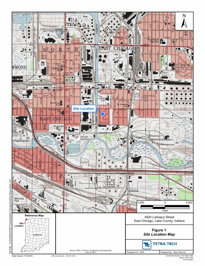
The USS Lead site is located in East Chicago, Indiana, approximately 18 miles southeast of Chicago,
Illinois. The site is divided into two operating units (OUs). OU1 consists of a primarily residential area
with commercial properties nearby and is bounded by East Chicago Avenue to the north, Parrish Avenue
to the east, East 151st Street to the south, and the Indiana Harbor Canal to the west. OU2 is a historically
heavy industrial area that housed the former USS Lead facility. OU2 is bounded by the Elgin Joliet and
Eastern Railroad to the north, Kennedy Avenue to the east, the Grand Calumet River to the south, and the
Indiana Harbor Canal to the west (see Figures 1 and 2 in Appendix A).
2.1 SITE HISTORY
The U.S. Smelter and Lead Refinery, Inc. (USS Lead) was constructed in East Chicago, Indiana, in the
early 1900s. USS Lead operated as a primary lead smelter starting in 1920, converted to a secondary lead
smelter in the early 1980s, and discontinued all operations in 1985. Smelting operations generated two
primary waste materials—blast-furnace slag and lead-containing dust. Blast-furnace slag was stockpiled
south of the plant building and spread once a year over an adjoining 21-acre wetland (SulTRAC 2012).
During operations, some lead-containing dust was deposited on area soils by the wind.
In addition to the former USS Lead facility located south of the current USS Lead site, there were several
other potential sources of lead and arsenic contamination in the residential area, including the former
Anaconda Copper Company (Anaconda) site and the E.I. DuPont de Nemours Company (DuPont) facility.
The Anaconda facility sat along the Indiana Harbor Canal where the former Carrie Gosch School and the
West Calumet Housing Complex are currently located. The Anaconda site manufactured white lead and
zinc oxide and refined metal. The DuPont facility, which was located south of the USS Lead site and east
of the former USS Lead facility, manufactured the lead arsenate-based pesticide.
2.2 HISTORICAL SITE INVESTIGATIONS
Many investigations have been conducted at the USS Lead site dating back to 1985 (SulTRAC 2012). Table
1 below summarizes the site investigations in chronological order. Sampling events were done at the
direction of and in cooperation with EPA Region 5 and its contractors, the Indiana Board of Health, the
Indiana Department of Environmental Management (IDEM), and the City of East Chicago.
USS Lead March 13, 2017
Sampling and Analysis Plan Tetra Tech Inc.
TDD No. S05-0014-1608-003 Final
4
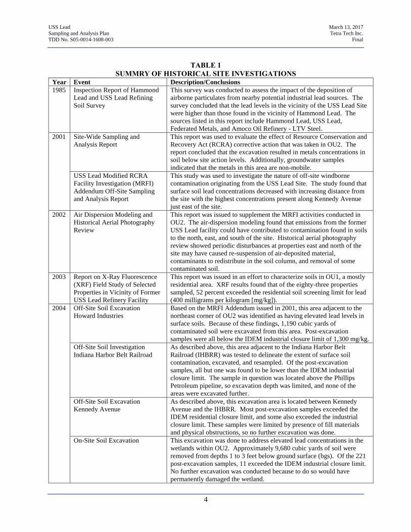
TABLE 1
SUMMRY OF HISTORICAL SITE INVESTIGATIONS Year Event Description/Conclusions
1985 Inspection Report of Hammond
Lead and USS Lead Refining
Soil Survey
This survey was conducted to assess the impact of the deposition of
airborne particulates from nearby potential industrial lead sources. The
survey concluded that the lead levels in the vicinity of the USS Lead Site
were higher than those found in the vicinity of Hammond Lead. The
sources listed in this report include Hammond Lead, USS Lead,
Federated Metals, and Amoco Oil Refinery - LTV Steel.
2001 Site-Wide Sampling and
Analysis Report
This report was used to evaluate the effect of Resource Conservation and
Recovery Act (RCRA) corrective action that was taken in OU2. The
report concluded that the excavation resulted in metals concentrations in
soil below site action levels. Additionally, groundwater samples
indicated that the metals in this area are non-mobile.
USS Lead Modified RCRA
Facility Investigation (MRFI)
Addendum Off-Site Sampling
and Analysis Report
This study was used to investigate the nature of off-site windborne
contamination originating from the USS Lead Site. The study found that
surface soil lead concentrations decreased with increasing distance from
the site with the highest concentrations present along Kennedy Avenue
just east of the site.
2002 Air Dispersion Modeling and
Historical Aerial Photography
Review
This report was issued to supplement the MRFI activities conducted in
OU2. The air-dispersion modeling found that emissions from the former
USS Lead facility could have contributed to contamination found in soils
to the north, east, and south of the site. Historical aerial photography
review showed periodic disturbances at properties east and north of the
site may have caused re-suspension of air-deposited material,
contaminants to redistribute in the soil column, and removal of some
contaminated soil.
2003 Report on X-Ray Fluorescence
(XRF) Field Study of Selected
Properties in Vicinity of Former
USS Lead Refinery Facility
This report was issued in an effort to characterize soils in OU1, a mostly
residential area. XRF results found that of the eighty-three properties
sampled, 52 percent exceeded the residential soil screening limit for lead
(400 milligrams per kilogram [mg/kg]).
2004 Off-Site Soil Excavation
Howard Industries
Based on the MRFI Addendum issued in 2001, this area adjacent to the
northeast corner of OU2 was identified as having elevated lead levels in
surface soils. Because of these findings, 1,190 cubic yards of
contaminated soil were excavated from this area. Post-excavation
samples were all below the IDEM industrial closure limit of 1,300 mg/kg.
Off-Site Soil Investigation
Indiana Harbor Belt Railroad
As described above, this area adjacent to the Indiana Harbor Belt
Railroad (IHBRR) was tested to delineate the extent of surface soil
contamination, excavated, and resampled. Of the post-excavation
samples, all but one was found to be lower than the IDEM industrial
closure limit. The sample in question was located above the Phillips
Petroleum pipeline, so excavation depth was limited, and none of the
areas were excavated further.
Off-Site Soil Excavation
Kennedy Avenue
As described above, this excavation area is located between Kennedy
Avenue and the IHBRR. Most post-excavation samples exceeded the
IDEM residential closure limit, and some also exceeded the industrial
closure limit. These samples were limited by presence of fill materials
and physical obstructions, so no further excavation was done.
On-Site Soil Excavation This excavation was done to address elevated lead concentrations in the
wetlands within OU2. Approximately 9,680 cubic yards of soil were
removed from depths 1 to 3 feet below ground surface (bgs). Of the 221
post-excavation samples, 11 exceeded the IDEM industrial closure limit.
No further excavation was conducted because to do so would have
permanently damaged the wetland.
USS Lead March 13, 2017
Sampling and Analysis Plan Tetra Tech Inc.
TDD No. S05-0014-1608-003 Final
5
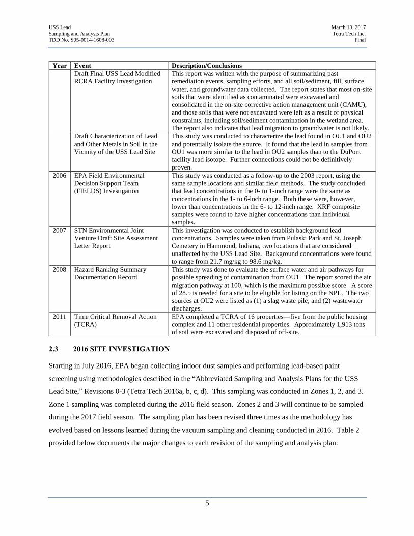
Year Event Description/Conclusions
Draft Final USS Lead Modified
RCRA Facility Investigation
This report was written with the purpose of summarizing past
remediation events, sampling efforts, and all soil/sediment, fill, surface
water, and groundwater data collected. The report states that most on-site
soils that were identified as contaminated were excavated and
consolidated in the on-site corrective action management unit (CAMU),
and those soils that were not excavated were left as a result of physical
constraints, including soil/sediment contamination in the wetland area.
The report also indicates that lead migration to groundwater is not likely.
Draft Characterization of Lead
and Other Metals in Soil in the
Vicinity of the USS Lead Site
This study was conducted to characterize the lead found in OU1 and OU2
and potentially isolate the source. It found that the lead in samples from
OU1 was more similar to the lead in OU2 samples than to the DuPont
facility lead isotope. Further connections could not be definitively
proven.
2006 EPA Field Environmental
Decision Support Team
(FIELDS) Investigation
This study was conducted as a follow-up to the 2003 report, using the
same sample locations and similar field methods. The study concluded
that lead concentrations in the 0- to 1-inch range were the same as
concentrations in the 1- to 6-inch range. Both these were, however,
lower than concentrations in the 6- to 12-inch range. XRF composite
samples were found to have higher concentrations than individual
samples.
2007 STN Environmental Joint
Venture Draft Site Assessment
Letter Report
This investigation was conducted to establish background lead
concentrations. Samples were taken from Pulaski Park and St. Joseph
Cemetery in Hammond, Indiana, two locations that are considered
unaffected by the USS Lead Site. Background concentrations were found
to range from 21.7 mg/kg to 98.6 mg/kg.
2008 Hazard Ranking Summary
Documentation Record
This study was done to evaluate the surface water and air pathways for
possible spreading of contamination from OU1. The report scored the air
migration pathway at 100, which is the maximum possible score. A score
of 28.5 is needed for a site to be eligible for listing on the NPL. The two
sources at OU2 were listed as (1) a slag waste pile, and (2) wastewater
discharges.
2011 Time Critical Removal Action
(TCRA)
EPA completed a TCRA of 16 properties—five from the public housing
complex and 11 other residential properties. Approximately 1,913 tons
of soil were excavated and disposed of off-site.
2.3 2016 SITE INVESTIGATION
Starting in July 2016, EPA began collecting indoor dust samples and performing lead-based paint
screening using methodologies described in the “Abbreviated Sampling and Analysis Plans for the USS
Lead Site,” Revisions 0-3 (Tetra Tech 2016a, b, c, d). This sampling was conducted in Zones 1, 2, and 3.
Zone 1 sampling was completed during the 2016 field season. Zones 2 and 3 will continue to be sampled
during the 2017 field season. The sampling plan has been revised three times as the methodology has
evolved based on lessons learned during the vacuum sampling and cleaning conducted in 2016. Table 2
provided below documents the major changes to each revision of the sampling and analysis plan:
USS Lead March 13, 2017
Sampling and Analysis Plan Tetra Tech Inc.
TDD No. S05-0014-1608-003 Final
6
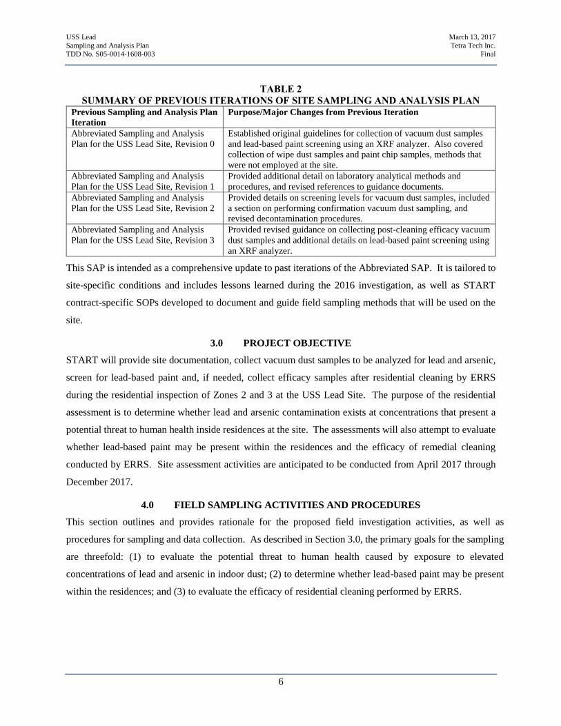
TABLE 2
SUMMARY OF PREVIOUS ITERATIONS OF SITE SAMPLING AND ANALYSIS PLAN Previous Sampling and Analysis Plan
Iteration
Purpose/Major Changes from Previous Iteration
Abbreviated Sampling and Analysis
Plan for the USS Lead Site, Revision 0
Established original guidelines for collection of vacuum dust samples
and lead-based paint screening using an XRF analyzer. Also covered
collection of wipe dust samples and paint chip samples, methods that
were not employed at the site.
Abbreviated Sampling and Analysis
Plan for the USS Lead Site, Revision 1
Provided additional detail on laboratory analytical methods and
procedures, and revised references to guidance documents.
Abbreviated Sampling and Analysis
Plan for the USS Lead Site, Revision 2
Provided details on screening levels for vacuum dust samples, included
a section on performing confirmation vacuum dust sampling, and
revised decontamination procedures.
Abbreviated Sampling and Analysis
Plan for the USS Lead Site, Revision 3
Provided revised guidance on collecting post-cleaning efficacy vacuum
dust samples and additional details on lead-based paint screening using
an XRF analyzer.
This SAP is intended as a comprehensive update to past iterations of the Abbreviated SAP. It is tailored to
site-specific conditions and includes lessons learned during the 2016 investigation, as well as START
contract-specific SOPs developed to document and guide field sampling methods that will be used on the
site.
3.0 PROJECT OBJECTIVE
START will provide site documentation, collect vacuum dust samples to be analyzed for lead and arsenic,
screen for lead-based paint and, if needed, collect efficacy samples after residential cleaning by ERRS
during the residential inspection of Zones 2 and 3 at the USS Lead Site. The purpose of the residential
assessment is to determine whether lead and arsenic contamination exists at concentrations that present a
potential threat to human health inside residences at the site. The assessments will also attempt to evaluate
whether lead-based paint may be present within the residences and the efficacy of remedial cleaning
conducted by ERRS. Site assessment activities are anticipated to be conducted from April 2017 through
December 2017.
4.0 FIELD SAMPLING ACTIVITIES AND PROCEDURES
This section outlines and provides rationale for the proposed field investigation activities, as well as
procedures for sampling and data collection. As described in Section 3.0, the primary goals for the sampling
are threefold: (1) to evaluate the potential threat to human health caused by exposure to elevated
concentrations of lead and arsenic in indoor dust; (2) to determine whether lead-based paint may be present
within the residences; and (3) to evaluate the efficacy of residential cleaning performed by ERRS.
USS Lead March 13, 2017
Sampling and Analysis Plan Tetra Tech Inc.
TDD No. S05-0014-1608-003 Final
7
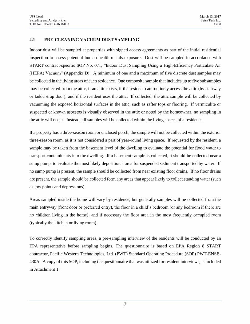
4.1 PRE-CLEANING VACUUM DUST SAMPLING
Indoor dust will be sampled at properties with signed access agreements as part of the initial residential
inspection to assess potential human health metals exposure. Dust will be sampled in accordance with
START contract-specific SOP No. 071, “Indoor Dust Sampling Using a High-Efficiency Particulate Air
(HEPA) Vacuum” (Appendix D). A minimum of one and a maximum of five discrete dust samples may
be collected in the living areas of each residence. One composite sample that includes up to five subsamples
may be collected from the attic, if an attic exists, if the resident can routinely access the attic (by stairway
or ladder/trap door), and if the resident uses the attic. If collected, the attic sample will be collected by
vacuuming the exposed horizontal surfaces in the attic, such as rafter tops or flooring. If vermiculite or
suspected or known asbestos is visually observed in the attic or noted by the homeowner, no sampling in
the attic will occur. Instead, all samples will be collected within the living spaces of a residence.
If a property has a three-season room or enclosed porch, the sample will not be collected within the exterior
three-season room, as it is not considered a part of year-round living space. If requested by the resident, a
sample may be taken from the basement level of the dwelling to evaluate the potential for flood water to
transport contaminants into the dwelling. If a basement sample is collected, it should be collected near a
sump pump, to evaluate the most likely depositional area for suspended sediment transported by water. If
no sump pump is present, the sample should be collected from near existing floor drains. If no floor drains
are present, the sample should be collected form any areas that appear likely to collect standing water (such
as low points and depressions).
Areas sampled inside the home will vary by residence, but generally samples will be collected from the
main entryway (front door or preferred entry), the floor in a child’s bedroom (or any bedroom if there are
no children living in the home), and if necessary the floor area in the most frequently occupied room
(typically the kitchen or living room).
To correctly identify sampling areas, a pre-sampling interview of the residents will be conducted by an
EPA representative before sampling begins. The questionnaire is based on EPA Region 8 START
contractor, Pacific Western Technologies, Ltd. (PWT) Standard Operating Procedure (SOP) PWT-ENSE-
430A. A copy of this SOP, including the questionnaire that was utilized for resident interviews, is included
in Attachment 1.
USS Lead March 13, 2017
Sampling and Analysis Plan Tetra Tech Inc.
TDD No. S05-0014-1608-003 Final
8
The total floor area vacuumed for each dust sample will depend on the volume of dust present in each
sampling area. The floor area where dust is collected will be measured and recorded to calculate the dust
and metals loading for different parts of the home. If there is not enough dust present in the living spaces
of the home to collect discrete samples for analysis, the discrete living space samples may be composited.
Under no circumstances will attic samples be mixed with discrete or composite living area samples.
4.2 LEAD-BASED PAINT SCREENING USING AN X-RAY FLOURESCENCE ANALYZER
Lead-based paint screening will be conducted in accordance with the intent of Title 40 Code of Federal
Regulations (CFR), Part 745.227, and U.S. Department of Housing and Urban Development’s (HUD) Lead
Safe Housing Rule (24 CFR Part 35).
Lead-based paint screening will be conducted during initial indoor sampling activities at every residence
with a signed access agreement in Zones 2 and 3. The intent of this screening is to not make an official
determination of whether lead-based paint is present at the property. An official determination would need
to be made by an Indiana-certified lead-based paint inspector. Rather, the screening is being conducted to
determine if there is a possibility that lead-based paint may be present at the property, which could
contribute to lead concentrations in indoor dust. The intent of collecting this information is to assist with
deciding whether a second cleaning will be performed at a property if a post-cleaning efficacy sample
exceeds the dust loading screening level.
Screening will be conducted using methods described in the Heuresis Pb200i XRF User Manual (Heuresis
2015a), and in accordance with “U.S. Department of Housing and Urban Development Guidelines for the
Evaluation and Control of Lead-Based Paint” (HUD 2012). These methods will be adapted to site-specific
conditions. XRF screening will be conducted near the area where vacuum samples are conducted.
Each XRF screening will use an approximately 15-second mean reading time for data collection. This
mean reading time is in accordance with the Heuresis Model Pb200i “Performance Characteristic Sheet”
(Heuresis 2015b).
Calibration will be performed routinely, and in accordance with HUD guidance, as well as the XRF unit-
specific “Performance Characteristic Sheet.” At the start of each sampling day, an initial calibration will
be performed that consists of screening a reference positive detection three times. This reference positive
detection should be a National Institute of Standards and Technology (NIST) Standard Reference Material
or Certified Reference Material with a nominal value as close as possible to 1.0 milligrams per square
centimeter (mg/cm2). The average of three readings collected using the reference positive detection must
USS Lead March 13, 2017
Sampling and Analysis Plan Tetra Tech Inc.
TDD No. S05-0014-1608-003 Final
9
fall within 0.8 to 1.2 mg/cm2 for the XRF to be considered operational (Heuresis 2015b). In addition to the
initial calibration, the calibration will be repeated each time the XRF unit is powered on, or if the unit is
operated for 4 hours. A final calibration check will also be performed at the completion of sampling each
day, utilizing the same calibration methodology. The results of all XRF calibration will be recorded in the
field logbook or digitally.
4.3 POST-CLEANING EFFICACY DUST SAMPLING
Residential properties cleaned by an EPA ERRS contractor will be sampled again to evaluate the efficacy
of the cleaning for reducing metals concentrations and loading. In Zones 2 and 3, post-cleaning efficacy
samples will be collected at all units that are cleaned by the ERRS contractor. Efficacy samples will be
collected in accordance with START contract-specific SOP No. 071, “Indoor Dust Sampling Using a HEPA
Vacuum” (Appendix D). In particular, efficacy samples will be collected from the exact same location as
the pre-cleaning dust samples. The intent of this removal efficacy sampling is to determine and evaluate
the efficacy of the cleaning techniques used and to verify the overall reduction of lead in dust that could
pose a health hazard. These results will be evaluated in accordance with the intent of HUD’s Lead Safe
Housing Rule (HUD 2012) and the Toxic Substances Control Act (TSCA).
Efficacy samples will be collected by Tetra Tech START, which is a completely independent contractor
from EPA’s ERRS contractor conducting the cleaning work. Cleaning techniques may be modified as
needed after the results of efficacy sampling have been evaluated. Collection techniques for efficacy
samples will be consistent with the collection techniques used during initial residential sampling and
inspection to the extent possible.
This efficacy sampling will be conducted in accordance with the intent of recommendations for lead
abatement clearance in existing guidance for conducting lead-based paint abatement (HUD 2012; EPA
1995; 40 CFR 745.85(b)). TSCA guidance requires only a visual inspection for clearance after residences
with known lead-based paint have been renovated. HUD guidance requires a visual inspection for visible
dust as well as collection of dust samples to evaluate the abatement or removal of lead-based paint. While
neither abatement nor renovation is being performed at the site, only cleaning, HUD guidelines for
clearance of abatement projects are being used as a guide for clearance efforts to ensure that a conservative
and stringent approach to property clearance is utilized.
USS Lead March 13, 2017
Sampling and Analysis Plan Tetra Tech Inc.
TDD No. S05-0014-1608-003 Final
10
4.4 FIELD DATA COLLECTION IN SUPPORT OF SAMPLING
It is necessary to collect field data during sampling and lead-based paint screening in order to characterize
sampling conditions. The USS Lead site makes use of digital data capture technology based on in-field use
of tablet computers, as well as written documentation in field logbooks, and photographic documentation.
Digital data capture, processing, and management will be performed in accordance with the USS Lead –
Site Specific Data Management Plan Revision 2.0 (EPA 2017).
Additional information recorded in physical field logbooks will be recorded in accordance with Tetra Tech
SOP No. 024-2, “Recording Notes in Field Logbooks.” (Appendix D)
The Data Management Plan is included in Appendix B.
5.0 LABORATORY ANALYTICAL METHODS
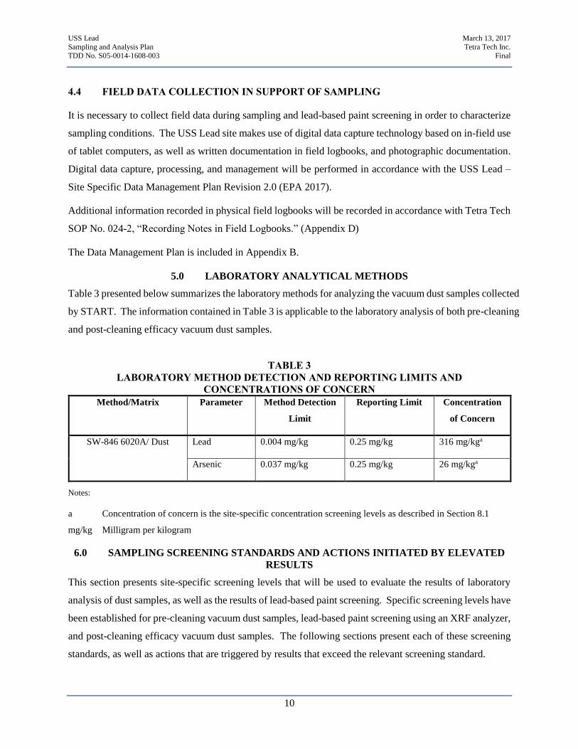
Table 3 presented below summarizes the laboratory methods for analyzing the vacuum dust samples collected
by START. The information contained in Table 3 is applicable to the laboratory analysis of both pre-cleaning
and post-cleaning efficacy vacuum dust samples.
TABLE 3
LABORATORY METHOD DETECTION AND REPORTING LIMITS AND
CONCENTRATIONS OF CONCERN
Method/Matrix Parameter Method Detection
Limit
Reporting Limit Concentration
of Concern
SW-846 6020A/ Dust Lead 0.004 mg/kg 0.25 mg/kg 316 mg/kga
Arsenic 0.037 mg/kg 0.25 mg/kg 26 mg/kga
Notes:
a Concentration of concern is the site-specific concentration screening levels as described in Section 8.1
mg/kg Milligram per kilogram
6.0 SAMPLING SCREENING STANDARDS AND ACTIONS INITIATED BY ELEVATED
RESULTS
This section presents site-specific screening levels that will be used to evaluate the results of laboratory
analysis of dust samples, as well as the results of lead-based paint screening. Specific screening levels have
been established for pre-cleaning vacuum dust samples, lead-based paint screening using an XRF analyzer,
and post-cleaning efficacy vacuum dust samples. The following sections present each of these screening
standards, as well as actions that are triggered by results that exceed the relevant screening standard.
USS Lead March 13, 2017
Sampling and Analysis Plan Tetra Tech Inc.
TDD No. S05-0014-1608-003 Final
11
6.1 PRE-CLEANING VACUUM DUST SAMPLE SCREENING LEVELS
Results for pre-cleaning vacuum dust samples will be compared with site-specific screening levels for lead
and arsenic concentrations in the fine fraction of dust. The site-specific screening level focuses on the fine
fraction of dust because past studies have demonstrated that the fine fraction consists of the size class of
particles most likely to be inhaled or ingested. Past studies have also demonstrated correlation between
decreases in particle size class and increased lead enrichment (EPA 2016b). The site-specific screening
levels for lead and arsenic concentrations in the fine fraction of dust are:
Lead: 316 mg/kg
Arsenic: 26 mg/kg
The site-specific lead screening level was established using the Integrated Exposure Uptake Biokinetic
(IEUBK) Model for Lead in Children. The model was run with a target blood lead level of 10 micrograms
per deciliter (µg/dL) and a concentration of lead in soil of 400 mg/kg. The target indoor dust lead screening
level of fine dust concentration determined via this scenario was 316 mg/kg (EPA 2016b).
The site-specific arsenic screening level was established based on EPA Remedial Screening Levels (RSL)
and Removal Management Levels (RML), and site-specific background data. RSLs are typically defined
as the concentration of a contaminant that poses a lifetime cancer risk of 1x10⁻⁶, or a non-cancer hazard
quotient of 1. RMLs are typically defined as the concentration of a contaminant that poses a lifetime cancer
risk of 1x10⁻⁴ or a non-cancer hazard quotient of 3. Both RSLs and RMLs are based on a lifetime exposure
of 24 hours per day, for 350 days per year, for 26 years (6 years as a child receptor and 20 years as an adult
receptor). The EPA RSL for arsenic in soil is 0.68 mg/kg, and the EPA RML for arsenic in soil is 68 mg/kg.
Arsenic is a naturally occurring mineral that is present in soils all across the US. A site-specific background
level of arsenic in soil was established as 26 mg/kg, based upon extensive soil sampling at the site.
Typically, indoor dust is not comprised entirely of outdoor soil particles, rather it is a mixture of soil
particles, hair and skin cells, textile fibers, paper fibers, and many other materials. For the sake of
establishing a conservative site-specific action level, the assumption was made that outdoor soil comprised
all of indoor dust material. Based on this conservative assumption, the site-specific indoor dust screening
level was set at 26 mg/kg to be representative of background soil conditions. (EPA 2016c).
Validated analytical results from pre-cleaning vacuum dust samples will be compared with the screening
levels described above, and exceedances will trigger response actions. In homes where soils require
remediation and indoor results exceed screening levels, EPA will offer interior cleaning of the residence by
EPA ERRS contractors. At homes where soil does not require remediation but indoor results exceed
USS Lead March 13, 2017
Sampling and Analysis Plan Tetra Tech Inc.
TDD No. S05-0014-1608-003 Final
12
screening levels, EPA will offer the owner of the residence access to a pool of loaner HEPA vacuums,
which the owner can use to perform cleaning of the residence.
6.2 LEAD-BASED PAINT SCREENING LEVEL
The results of lead-based paint screening performed using a handheld XRF analyzed will be compared with
the screening level of 1.0 milligrams per square centimeter (mg/cm2). This value represents the standard
metric for determining whether paint is classified as lead-based paint (; 15 U.S.C. 2681(9)). The handheld
XRF analyzer provides results in mg/cm2, allowing for direct comparison of results to the screening level.
The XRF screening results will be used to determine whether there is evidence that lead-based paint may
be present in individual residences. Results of XRF analysis that are greater than or equal to 1.0 mg/cm2
of lead will be considered evidence that the residence in question may contain lead-based paint. These
results will be used to aid in evaluating whether the potential presence of lead-based paint could be
contributing to lead contamination in indoor dust and will be used to guide response actions, as described
in Section 4.2.
6.3 POST-CLEANING EFFICACY VACUUM DUST SAMPLING SCREENING LEVELS
Post-cleaning efficacy vacuum dust samples will be compared with lead loading and arsenic loading
screening levels. Analyte-specific loading levels are frequently used to evaluate whether indoor dust
abatement projects achieve clearance standards (HUD 2012, EPA et al. 2003). Loading levels take into
consideration the areal extent of sampling as well as the total amount of dust collected, providing a measure
of the amount of a specific contaminant that is present on a weight per area basis. For a specific breakdown
of the steps used to calculate the lead loading in fine dust, see Appendix C. The site-specific screening
levels for lead and arsenic loading levels are:
Lead: 25 micrograms per square foot (µg/ft2)
Arsenic: 36 µg/ft2
These screening levels are derived from the “World Trade Center Indoor Environment Assessment:
Selecting Contaminants of Potential Concern and Assessment Setting Health-Based Benchmarks” (EPA et
al. 2003). This document evaluated various analytes, including lead and arsenic, and established screening
levels based on existing toxicological knowledge for numerous sampling media, including indoor dust.
Validated analytical results from post-cleaning efficacy vacuum dust samples will be compared with the
screening levels described above. If any results exceed the loading level screening levels, the results of the
residence’s lead-based paint screening will be reviewed. If there is no evidence that lead-based paint may
USS Lead March 13, 2017
Sampling and Analysis Plan Tetra Tech Inc.
TDD No. S05-0014-1608-003 Final
13
be present in the residence, the residence will be re-cleaned by EPA’s ERRS contractor. If there is evidence
that lead-based paint may be present in a residence, the property will not be re-cleaned by EPA’s ERRS
contractor.
In addition to screening validated post-cleaning sampling analytical results with site-specific loading level
screening levels, analytical results for post-cleaning efficacy sampling will be compared with pre-cleaning
sampling analytical results collected at the same location. As described in Section 4, post-cleaning efficacy
samples will be collected from the same sampling area as pre-cleaning samples at all properties cleaned by
EPA’s ERRS contractor. The analytical results from each pair of samples (pre-cleaning and post-cleaning)
collected from the same location will be compared with each other. This comparison will be used for
general evaluation of cleaning techniques. It will not trigger specific actions on a residence-by-residence
basis.
7.0 DECONTAMINATION PROCEDURES
Dedicated sampling equipment and personal protective equipment (PPE) will be double-bagged and
disposed of with all other used PPE waste produced at the site. Tetra Tech anticipates that the sampling
equipment will be dedicated to each sample and will be disposable. In the event that sampling equipment
requires decontamination, Tetra Tech START will decontaminate equipment in accordance with Tetra Tech
SOP No. 002, “General Equipment Decontamination” (Appendix D). Investigation-derived waste (IDW)
including PPE, sampling equipment, and supplies, will be double-bagged and disposed of as dry industrial
waste in accordance with the EPA Office of Emergency and Remedial Response (OERR), Management of
Investigation-Derived Waste during Site Inspections (Document No. EPA/540/G-91/009 May 1991).
8.0 SAMPLE HANDLING AND LABORATORY PROCEDURES
The collected samples will be labeled, packaged, and shipped to the ALS Environmental Laboratory in
Holland, Michigan, in accordance with procedures outlined in Worksheets #26 and 27 of Tetra Tech’s
START Quality Assurance Project Plan (QAPP) and Tetra Tech SOP No. 019, “Packaging and Shipping
Samples” (Appendix D). The samples will be analyzed for arsenic and lead. Based on these analytes, no
special preservation (temperature control or other) is required for shipping. Table 3 provides laboratory-
specific method detection and reporting limits, as well as concentrations of concern. Vacuum dust samples
will be analyzed in accordance with the EPA OLEM Directive 9200.1-128 (EPA 2016b), regarding
“Recommendations for Sieving Soil and Dust Samples at Lead Sites for Assessment of Incidental
Ingestion,” which indicates that dry dust samples should be weighted and sieved through a No. 100 W.S.
Tyler sieve or equivalent to identify “coarse” (diameter greater than 150 µm) and “fine” (diameter less than
USS Lead March 13, 2017
Sampling and Analysis Plan Tetra Tech Inc.
TDD No. S05-0014-1608-003 Final
14
150 µm) fractions. Procedures presented in the current laboratory soil fractionation SOP will be modified
to use a 150 µm sieve. The laboratory SOPs are included in Attachment 2.
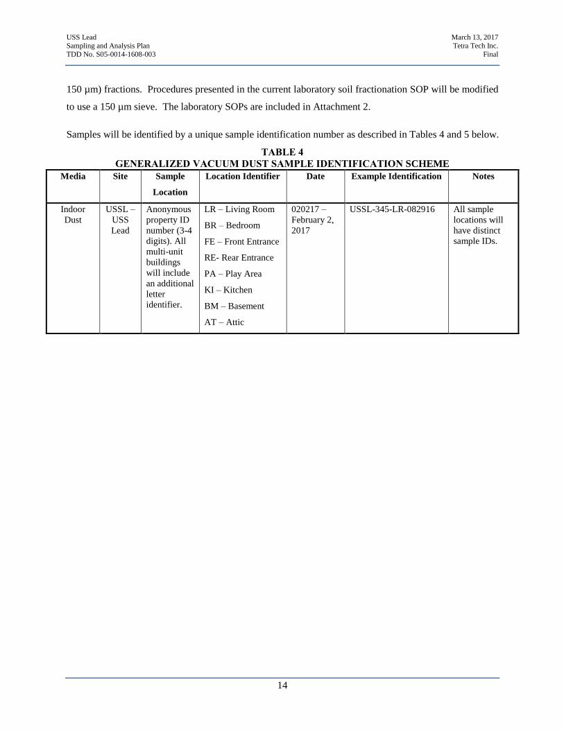
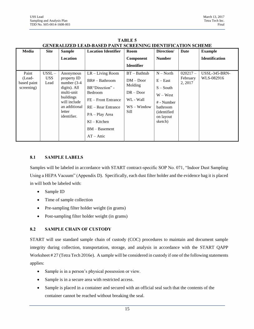
Samples will be identified by a unique sample identification number as described in Tables 4 and 5 below.
TABLE 4
GENERALIZED VACUUM DUST SAMPLE IDENTIFICATION SCHEME
Media Site Sample
Location
Location Identifier Date Example Identification Notes
Indoor
Dust
USSL –
USS
Lead
Anonymous
property ID
number (3-4
digits). All
multi-unit
buildings
will include
an additional
letter
identifier.
LR – Living Room
BR – Bedroom
FE – Front Entrance
RE- Rear Entrance
PA – Play Area
KI – Kitchen
BM – Basement
AT – Attic
020217 –
February 2,
2017
USSL-345-LR-082916 All sample
locations will
have distinct
sample IDs.
USS Lead March 13, 2017
Sampling and Analysis Plan Tetra Tech Inc.
TDD No. S05-0014-1608-003 Final
15
TABLE 5
GENERALIZED LEAD-BASED PAINT SCREENING IDENTIFICATION SCHEME
Media Site Sample
Location
Location Identifier Room
Component
Identifier
Direction/
Number
Date Example
Identification
Paint
(Lead-
based paint
screening)
USSL –
USS
Lead
Anonymous
property ID
number (3-4
digits). All
multi-unit
buildings
will include
an additional
letter
identifier.
LR – Living Room
BR# – Bathroom
BR“Direction” -
Bedroom
FE – Front Entrance
RE – Rear Entrance
PA – Play Area
KI – Kitchen
BM – Basement
AT – Attic
BT – Bathtub
DM – Door
Molding
DR – Door
WL - Wall
WS – Window
Sill
N – North
E – East
S – South
W – West
# - Number
bathroom
(identified
on layout
sketch)
020217 –
February
2, 2017
USSL-345-BRN-
WLS-082916
8.1 SAMPLE LABELS
Samples will be labeled in accordance with START contract-specific SOP No. 071, “Indoor Dust Sampling
Using a HEPA Vacuum” (Appendix D). Specifically, each dust filter holder and the evidence bag it is placed
in will both be labeled with:
Sample ID
Time of sample collection
Pre-sampling filter holder weight (in grams)
Post-sampling filter holder weight (in grams)
8.2 SAMPLE CHAIN OF CUSTODY
START will use standard sample chain of custody (COC) procedures to maintain and document sample
integrity during collection, transportation, storage, and analysis in accordance with the START QAPP
Worksheet # 27 (Tetra Tech 2016e). A sample will be considered in custody if one of the following statements
applies:
Sample is in a person’s physical possession or view.
Sample is in a secure area with restricted access.
Sample is placed in a container and secured with an official seal such that the contents of the
container cannot be reached without breaking the seal.
USS Lead March 13, 2017
Sampling and Analysis Plan Tetra Tech Inc.
TDD No. S05-0014-1608-003 Final
16
START will create COCs using Scribe, and in accordance with START site-specific Data Management Plan.
The COCs generated by Scribe will contain the following information:
Project name
Sampling location (property ID)
Name and signature of sampler
Destination of samples (laboratory name)
Sample ID number
Date and time of collection
Date shipped
Sample matrix
Number and type of containers filled
Analysis requested
Preservatives used (if applicable)
Special instructions (for example, laboratory needs to sub-sample oversized material or perform
additional homogenization)
Signatures of individuals involved in custody transfer, including the date and time of transfer
Airbill number (if applicable)
Project contact and phone number
8.3 SAMPLE PACKING AND SHIPPING
Vacuum dust samples will be packaged and shipped in accordance with START contract-specific SOP No.
071, “Indoor Dust Sampling Using a HEPA Vacuum” (Appendix D), the START QAPP Worksheets #26 and
27 (Tetra Tech 2016e), and Tetra Tech SOP No. 019, “Packaging and Shipping Samples” (Appendix D).
9.0 QUALITY ASSURANCE/QUALITY CONTROL REQUIREMENTS
Quality assurance/quality control (QA/QC) requirements will be adapted to project-specific conditions. The
Tetra Tech project manager, Andrew Kleist, will be responsible for ensuring that sample quality and integrity
are maintained and that sample label and documentation procedures are in accordance with the START QAPP
and this SAP. When the results are received, Tetra Tech START will review the laboratory data packages
for completeness and will conduct Stage 4 data validation in accordance with Tetra Tech SOP No. 203,
“Laboratory Analytical Data Verification – Minimum Requirements” (Appendix D).
USS Lead March 13, 2017
Sampling and Analysis Plan Tetra Tech Inc.
TDD No. S05-0014-1608-003 Final
17
All QA activities will accord with the SAP for the USS Lead site. A copy of the SAP will be maintained by
the field sampling team for immediate reference in resolving any QA issues that might arise during field
activities. QA/QC procedures for each type of data collected at the site are outlined below.
9.1 VACUUM DUST SAMPLING QA/QC
Vacuum dust samples are not subject to the standard QA/QC requirements applied for most other sampling
methods (field duplicates and matrix spike/matrix spike duplicate) as a result both of the nature of vacuum
dust sample collection and of the analytical methods used by the laboratory. Vacuum sampling is designed
to assess the conditions of the specific area that is vacuumed. This factor makes collection of field duplicates
difficult, since a true duplicate would need to be collected from the same sampling area as the original sample.
Because collection of the original sample includes removal of dust from this area, it is not possible to collect
a representative duplicate sample from the same sampling area. It is also not possible to split the original
sample material into a sample and a field duplicate based on the nature of dust sampling results and laboratory
analytical methods. Dust samples are used to quantify the total amount of dust in the sampling area as well
as analytic loading levels, in addition to providing information on the concentration of contaminants in dust.
As a result, the laboratory must process all sampling material as one sample to provide an accurate
measurement of the amount of dust collected over the entire sampling area. If the sampling material was
divided to allow for QA/QC analyses (field duplicates or matrix spike/matrix spike duplicate), it would be
impossible to calculate loading levels for the sampling area.
9.2 LEAD-BASED PAINT SCREENING QA/QC
Lead-based paint screening will be conducted using a direct-reading handheld XRF analyzer. As a result,
typical QA/QC procedures for sample collection do not apply. Instead, instrument-specific QA/QC
procedures will be followed. These QA/QC procedures are based on calibrating the XRF analyzer.
Calibration will be performed in accordance with HUD guidance, as well as the XRF unit-specific
“Performance Characteristic Sheet” (Heuresis 2015b). Calibration will consist of screening a reference
positive detection three times. This reference positive detection should be a NIST Standard Reference
Material or Certified Reference Material with a nominal value as close as possible to 1.0 mg/cm2. The
average of three readings collected using the reference positive detection must fall within 0.8 to 1.2 mg/cm2
for the XRF to be considered operational (Heuresis, 2015b). The results of all XRF calibration will be
recorded in the field logbook or digitally. Calibration will be performed at the following times:
Initial calibration: Prior to using the XRF for the first time each day, a calibration will be performed
utilizing the methodology described above.
USS Lead March 13, 2017
Sampling and Analysis Plan Tetra Tech Inc.
TDD No. S05-0014-1608-003 Final
18
Every 4 hours of Use: A calibration will be performed anytime the XRF is left powered on for a
duration of 4 hours. Calibration will be performed using the methodology described above.
Every time the XRF is powered on: A calibration will be performed anytime the XRF is powered
on throughout the course of the sampling day. Calibration will be performed using the
methodology described above.
Final calibration: A calibration will be performed at the end of the sampling day, after all lead-
based paint screenings for the day have been completed.
9.3 DIGITAL DATA QA/QC
Digital data collected during site activities will be subject to routine QA/QC checks. These QA/QC checks
will be performed at a minimum on a daily basis and generally will be implemented any time data are
transitioned from one operating platform to another. For example, data entered on a tablet computer are
subject to a QA/QC check when they are downloaded from the TetraForms website. That same data are
then subject to a QA/QC check when they are uploaded to the Scribe field database for COC generation, an
additional QA/QC check when they are uploaded to the central project Scribe database, and a final QA/QC
check as the central project Scribe database is populated with analytical results. The specific procedures
for QA/QC checks of digitally captured data are described in the USS Lead Data Management Plan (EPA
2017).
USS Lead March 13, 2017
Sampling and Analysis Plan Tetra Tech Inc.
TDD No. S05-0014-1608-003 Final
19
10.0 REFERENCES
Department of Housing and Urban Development. 2012. “Guidelines for the Evaluation and Control of
Lead-Based Paint Hazards in Housing”
http://portal.hud.gov/hudportal/HUD?src=/program_offices/healthy_homes/lbp/hudguidelines
Heuresis Corporation. 2015a. “User’s Guide Revision 9.0 Pb200i Alpha.”
Heuresis Corporation. 2015a. “User’s Guide Revision 9.0 Pb200i Alpha.”
Heuresis Corporation. 2015b. “Performance Characteristic Sheet.”
SulTRAC. 2012. “Remedial Investigation Report. Final. US Smelter and Lead Refinery (USS Lead)
Superfund Site. Lake County, Indiana.”
Tetra Tech, Inc (Tetra Tech). 2016a. “Abbreviated Sampling and Analysis Plan for the USS Lead Site.
Revision 0.”
Tetra Tech. 2016b. “Abbreviated Sampling and Analysis Plan for the USS Lead Site. Revision 1.”
Tetra Tech. 2016c. “Abbreviated Sampling and Analysis Plan for the USS Lead Site. Revision 2.”
Tetra Tech. 2016d. “Abbreviated Sampling and Analysis Plan for the USS Lead Site. Revision 3.”
Tetra Tech. 2016e. “START Quality Assurance Project Plan. Revision 3.”
U.S. Environmental Protection Agency (EPA). 1995. Residential Sampling for Lead: Protocols for Dust
and Soil Sampling. https://www.epa.gov/sites/production/files/2014-03/documents/20012quz.pdf
EPA et al. 2003. (Contaminants of Potential Concern Committee of the World Trade Center Indoor Air
Task Force Working Group). “World Trade Center Indoor Environment Assessment: Selecting
Contaminants of Potential Concern and Assessment Setting Health-Based Benchmarks.”
https://epa-prgs.ornl.gov/radionuclides/copc_benchmark.pdf
EPA. 2016a. USS Lead – Action Memorandum – 4th Amendment. October. On-line address:
https://semspub.epa.gov/work/05/929998.pdf
EPA. 2016b. Recommendations for Sieving Soil and Dust Samples at Lead Sites for Assessment of
Incidental Ingestion. OLEM Directive 9200.1-128.
EPA. 2016c. Memorandum: Justification for Using Site-Specific Arsenic Background Concentration in
Soil for Indoor Dust Screening Concentration for the USS Lead Site. December.
EPA. 2017. USS Lead – Site Specific Data Management Plan. EPA Region 5. April.
APPENDIX A
FIGURES
(Two Pages)
1 Site Location Map
2 Site Layout Map
±Fil
e Path
: G:\G
\G90
26-S
TART
IV\In
diana
\Eas
t Chic
ago\m
xd\Fi
g1-S
iteLo
catio
n.mxd
Date Saved: 7/13/2016
"
Indiana
4920 Larkspur StreetEast Chicago, Lake County, Indiana
Figure 1Site Location Map
Prepared For: EPA Prepared By: Tetra Tech Inc.EPA Contract No.: EP-S5-13-01
2,000 0 2,000
Feet
Source: USGS 7.5 Minute Topographic Quadrangle MapGary, IN 1991
SiteLocation
Reference Map
Coordinate System: GCS WGS 1984Datum: WGS 1984
Units: Degree
Site Location
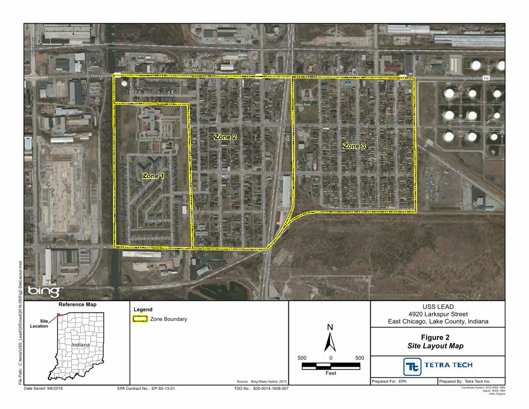
USS LEAD4920 Larkspur Street
East Chicago, Lake County, Indiana
Figure 2Site Layout Map
Prepared For: EPA Prepared By: Tetra Tech Inc.Date Saved: 9/6/2016
File P
ath: C
:\temp
\USS
_Lea
d\GIS\
mxd\2
016-0
9\Fig2
-Site
Layo
ut.mx
d
"
Indiana
EPA Contract No.: EP-S5-13-01 TDD No.: S05-0014-1608-007Source: Bing Maps Hybrid, 2013
Coordinate System: GCS WGS 1984Datum: WGS 1984
Units: Degree
±Legend
Zone Boundary
500 0 500
Feet
Reference Map
SiteLocation
APPENDIX B
USS LEAD – SITE SPECIFIC DATA MANAGEMENT PLAN
APPENDIX C
EXAMPLE CALCULATION OF LEAD LOADING IN FINE DUST
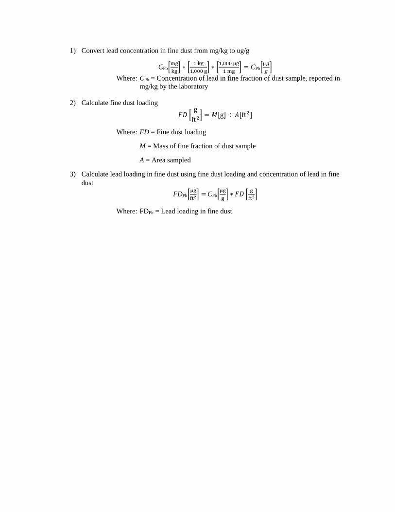
1) Convert lead concentration in fine dust from mg/kg to ug/g
CPb[mg
kg] ∗ [
1 kg
1,000 g] ∗ [
1,000 µg
1 mg] = CPb[
µ𝑔
𝑔]
Where: CPb = Concentration of lead in fine fraction of dust sample, reported in
mg/kg by the laboratory
2) Calculate fine dust loading
𝐹𝐷 [g
ft2] = 𝑀[g] ÷ 𝐴[ft2]
Where: FD = Fine dust loading
M = Mass of fine fraction of dust sample
A = Area sampled
3) Calculate lead loading in fine dust using fine dust loading and concentration of lead in fine
dust
FDPb[µg
ft2] = CPb[µg
g] ∗ 𝐹𝐷 [
g
ft2]
Where: FDPb = Lead loading in fine dust

APPENDIX D
TETRA TECH SOPS
SOP APPROVAL FORM TETRA TECH EM INC. ENVIRONMENTAL STANDARD OPERATING PROCEDURE GENERAL EQUIPMENT DECONTAMINATION SOP NO. 002 REVISION NO. 3 Last Reviewed: June 2009
6-19-09
Quality Assurance Approved
Date
Tetra Tech EM Inc. – Environmental SOP No. 002
Page 1 of 8
Title: General Equipment Decontamination Revision No. 3, June 2009Last Reviewed: June 2009
1.0 BACKGROUND
All nondisposable field equipment must be decontaminated before and after each use at each sampling
location to obtain representative samples and to reduce the possibility of cross-contamination.
1.1 PURPOSE
This standard operating procedure (SOP) establishes the requirements and procedures for
decontaminating equipment in the field.
1.2 SCOPE
This SOP applies to decontaminating general nondisposable field equipment. To prevent contamination
of samples, all sampling equipment must be thoroughly cleaned prior to each use.
1.3 DEFINITIONS
Alconox: Nonphosphate soap, obtained in powder detergent form and dissolved in water
Liquinox: Nonphosphate soap, obtained in liquid form for mixing with water
1.4 REFERENCES
U.S. Environmental Protection Agency (EPA). 1992a. “Guide to Management of Investigation-Derived Wastes.” Office of Solid Waste and Emergency Response. Washington D.C. EPA 9345.3-03FS. January.
EPA. 1992b. “RCRA Ground-Water Monitoring: Draft Technical Guidance.” Office of Solid Waste.
Washington, DC. EPA/530-R-93-001. November. EPA. 1994. “Sampling Equipment Decontamination.” Environmental Response Team SOP #2006 (Rev.
#0.0, 08/11/94). http://www.ert.org/mainContent.asp?section=Products&subsection=List
Tetra Tech EM Inc. – Environmental SOP No. 002
Page 2 of 8
Title: General Equipment Decontamination Revision No. 3, June 2009Last Reviewed: June 2009
1.5 REQUIREMENTS AND RESOURCES
The equipment required to conduct decontamination is as follows:
· Scrub brushes · Large wash tubs or buckets · Squirt bottles · Alconox or Liquinox · Tap water · Distilled water · Plastic sheeting · Aluminum foil · Methanol or hexane · Isopropanol (pesticide grade) · Dilute (0.1 N) nitric acid
2.0 PROCEDURE
The procedures below discuss decontamination of personal protective equipment (PPE), drilling and
monitoring well installation equipment, borehole soil sampling equipment, water level measurement
equipment, general sampling equipment, and groundwater sampling equipment.
2.1 PERSONAL PROTECTIVE EQUIPMENT DECONTAMINATION
Personnel working in the field are required to follow specific procedures for decontamination prior to
leaving the work area so that contamination is not spread off site or to clean areas. All used disposable
protective clothing, such as Tyvek coveralls, gloves, and booties, will be containerized for later disposal.
Decontamination water will be containerized in 55-gallon drums (refer to Section 3.0).
Personnel decontamination procedures will be as follows:
1. Select an area removed from sampling locations that is both downwind and downgradient. Decontamination must not cause cross-contamination between sampling points.
2. Maintain the same level of personal protection as was used for sampling.
Tetra Tech EM Inc. – Environmental SOP No. 002
Page 3 of 8
Title: General Equipment Decontamination Revision No. 3, June 2009Last Reviewed: June 2009
3. Wash neoprene boots (or neoprene boots with disposable booties) with Liquinox or Alconox solution and rinse with clean water. Remove booties and retain boots for subsequent reuse.
4. Wash outer gloves in Liquinox or Alconox solution and rinse in clean water. Remove
outer gloves and place into plastic bag for disposal.
5. Remove Tyvek or coveralls. Containerize Tyvek for disposal and place coveralls in plastic bag for reuse.
6. Remove air purifying respirator (APR), if used, and place the spent filters into a plastic
bag for disposal. Filters should be changed daily or sooner depending on use and application. Place respirator into a separate plastic bag after cleaning and disinfecting.
7. Remove disposable gloves and place them in plastic bag for disposal. 8. Thoroughly wash hands and face in clean water and soap.
2.2 DRILLING AND MONITORING WELL INSTALLATION EQUIPMENT DECONTAMINATION
All drilling equipment should be decontaminated at a designated location on site before drilling
operations begin, between borings, and at completion of the project. Decontamination may be conducted
on a temporary decontamination pad constructed at satellite locations within the site area in support of
temporary work areas. The purpose of the decontamination pad is to contain wash waters and potentially
contaminated soil generated during decontamination procedures. Decontamination pads may be
constructed of concrete, wood, or plastic sheeting, depending on the site-specific needs and plans. Wash
waters and contaminated soil generated during decontamination activities should be considered
contaminated and thus, should be collected and containerized for proper disposal.
Monitoring well casing, screens, and fittings are assumed to be delivered to the site in a clean condition.
However, they should be steam cleaned and placed on polyethylene sheeting on-site prior to placement
downhole. The drilling subcontractor will typically furnish the steam cleaner and water.
The drilling auger, bits, drill pipe, any portion of drill rig that is over the borehole, temporary casing,
surface casing, and other equipment used in or near the borehole should be decontaminated by the drilling
subcontractor as follows:
Tetra Tech EM Inc. – Environmental SOP No. 002
Page 4 of 8
Title: General Equipment Decontamination Revision No. 3, June 2009Last Reviewed: June 2009
1. Select an area removed from sampling locations that is both downwind and downgradient. Decontamination must not cause cross-contamination between sampling points.
2. Maintain the same level of personal protection as was used for sampling. 3. Remove loose soil using shovels, scrapers, wire brush, etc.
4. Steam clean or pressure wash to remove all visible dirt.
5. If equipment has directly or indirectly contacted contaminated media and is known or
suspected of being contaminated with oil, grease, polynuclear aromatic hydrocarbons
(PAH), polychlorinated biphenyls (PCB), or other hard to remove organic materials, rinse
equipment with pesticide-grade isopropanol.
6. To the extent possible, allow components to air dry.
7. Wrap or cover equipment in clear plastic until it is time to be used.
8. All wastewater from decontamination procedures should be containerized.
2.3 BOREHOLE SOIL SAMPLING DOWNHOLE EQUIPMENT DECONTAMINATION
All soil sampling downhole equipment should be decontaminated before use and after each sample as
follows:
1. Select an area removed from sampling locations that is both downwind and downgradient. Decontamination must not cause cross-contamination between sampling points.
2. Maintain the same level of personal protection as was used for sampling. 3. Prior to sampling, scrub the split-barrel sampler and sampling tools in a wash bucket or
tub using a stiff, long bristle brush and Liquinox or Alconox solution.
4. After sampling, steam clean the sampling equipment over the rinsate tub and allow to air dry.
5. Place cleaned equipment in a clean area on plastic sheeting and wrap with aluminum foil.
6. Containerize all water and rinsate; disposable single-use sampling equipment should also
be containerized. 7. Decontaminate all equipment placed down the hole as described for drilling equipment.
Tetra Tech EM Inc. – Environmental SOP No. 002
Page 5 of 8
Title: General Equipment Decontamination Revision No. 3, June 2009Last Reviewed: June 2009
2.4 WATER LEVEL MEASUREMENT EQUIPMENT DECONTAMINATION
Field personnel should decontaminate the well sounder and interface probe before inserting and after
removing them from each well. The following decontamination procedures should be used:
1. Select an area removed from sampling locations that is both downwind and downgradient. Decontamination must not cause cross-contamination between sampling points.
2. Maintain the same level of personal protection as was used for sampling. 3. Wipe the tape and probe with a disposable Alconox- or Liquinox-impregnated cloth or
paper towel. 4. If immiscible layers are encountered, the interface probe may require steam cleaning or
washing with pesticide-grade isopropanol. 5. Rinse with deionized water.
2.5 GENERAL SAMPLING EQUIPMENT DECONTAMINATION
All nondisposable sampling equipment should be decontaminated using the following procedures:
1. Select an area removed from sampling locations that is both downwind and downgradient. Decontamination must not cause cross-contamination between sampling points.
2. Maintain the same level of personal protection as was used for sampling.
3. To decontaminate a piece of equipment, use an Alconox wash; a tap water wash; a
solvent (isopropanol, methanol, or hexane) rinse, if applicable, or dilute (0.1 N) nitric acid rinse, if applicable; a distilled water rinse; and air drying. Use a solvent (isopropanol, methanol, or hexane) rinse for grossly contaminated equipment (for example, equipment that is not readily cleaned by the Alconox wash). The dilute nitric acid rinse may be used if metals are the analyte of concern.
4. Place cleaned equipment in a clean area on plastic sheeting and wrap with aluminum foil.
5. Containerize all water and rinsate.
Tetra Tech EM Inc. – Environmental SOP No. 002
Page 6 of 8
Title: General Equipment Decontamination Revision No. 3, June 2009Last Reviewed: June 2009
2.6 GROUNDWATER SAMPLING EQUIPMENT The following procedures are to be employed for the decontamination of equipment used for groundwater
sampling. Decontamination is not necessary when using disposable (single-use) pump tubing or bailers.
Bailer and downhole pumps and tubing decontamination procedures are described in the following
sections.
2.6.1 Bailers
1. Select an area removed from sampling locations that is both downwind and
downgradient. Decontamination must not cause cross-contamination between sampling points.
2. Maintain the same level of personal protection as was used for sampling. 3. Evacuate any purge water in the bailer. 4. Scrub using soap and water and/or steam clean the outside of the bailer. 5. Insert the bailer into a clean container of soapy water. Thoroughly rinse the interior of
the bailer with the soapy water. If possible, scrub the inside of the bailer with a scrub brush.
6. Remove the bailer from the container of soapy water. 7. Rinse the interior and exterior of the bailer using tap water. 8. If groundwater contains or is suspected to contain oil, grease, PAH, PCB, or other hard to
remove organic materials, rinse equipment with pesticide-grade isopropanol. 9. Rinse the bailer interior and exterior with deionized water to rinse off the tap water and
solvent residue, as applicable.
10. Drain residual deionized water to the extent possible.
11. Allow components to air dry.
12. Wrap the bailer in aluminum foil or a clean plastic bag for storage. 13. Containerize the decontamination wash waters for proper disposal.
Tetra Tech EM Inc. – Environmental SOP No. 002
Page 7 of 8
Title: General Equipment Decontamination Revision No. 3, June 2009Last Reviewed: June 2009
2.6.2 Downhole Pumps and Tubing
1. Select an area removed from sampling locations that is both downwind and downgradient. Decontamination must not cause cross-contamination between sampling points.
2. Maintain the same level of personal protection as was used for sampling. 3. Evacuate any purge water in the pump and tubing. 4. Scrub using soap and water and/or steam clean the outside of the pump and, if applicable,
the pump tubing. 5. Insert the pump and tubing into a clean container of soapy water. Pump/run a sufficient
amount of soapy water to flush out any residual well water. After the pump and tubing are flushed, circulate soapy water through the pump and tubing to ensure that the internal components are thoroughly flushed.
6. Remove the pump and tubing from the container. 7. Rinse external pump components using tap water. 8. Insert the pump and tubing into a clean container of tap water. Pump/run a sufficient
amount of tap water through the pump to evacuate all of the soapy water (until clear). 9. If groundwater contains or is suspected to contain oil, grease, PAH, PCB, or other hard to
remove organic materials, rinse the pump and tubing with pesticide-grade isopropanol. 10. Rinse the pump and tubing with deionized water to flush out the tap water and solvent
residue, as applicable. 11. Drain residual deionized water to the extent possible. 12. Allow components to air dry. 13. For submersible bladder pumps, disassemble the pump and wash the internal components
with soap and water, rinse with tap water, isopropanol (if necessary), and deionized water, and allow to air dry.
14. Wrap pump and tubing in aluminum foil or a clean plastic bag for storage. 15. Containerize the decontamination wash waters for proper disposal.
Tetra Tech EM Inc. – Environmental SOP No. 002
Page 8 of 8
Title: General Equipment Decontamination Revision No. 3, June 2009Last Reviewed: June 2009
3.0 INVESTIGATION-DERIVED WASTE
Investigation-derived waste (IDW) can include disposable single-use PPE and sampling equipment, soil
cuttings, and decontamination wash waters and sediments. Requirements for waste storage may differ
from one facility to the next. Facility-specific directions for waste storage will be provided in project-
specific documents, or separate direction will be provided by the project manager. The following
guidelines are provided for general use:
1. Assume that all IDW generated from decontamination activities contains the hazardous
chemicals associated with the site unless there are analytical or other data to the contrary. Waste solution volumes could vary from a few gallons to several hundred gallons in cases where large equipment required cleaning.
2. Containerized waste rinse solutions are best stored in 55-gallon drums (or equivalent
containers) that can be sealed until ultimate disposal at an approved facility. 3. Label IDW storage containers with the facility name and address, date, contents,
company generating the waste, and an emergency contact name and phone number.
4. Temporarily store the IDW in a protected area that provides access to the containers and allows for spill/leak monitoring, sampling of containers, and removal following determination of the disposal method.
SOP APPROVAL FORM
TETRA TECH, INC.
ENVIRONMENTAL STANDARD OPERATING PROCEDURE
PACKAGING AND SHIPPING SAMPLES
SOP NO. 019
REVISION NO. 7
Last Reviewed: November 2014
November 24, 2014 Quality Assurance Approved Date
Tetra Tech, Inc., EMI Operating Unit – Environmental SOP No. 019 Page 1 of 20
Title: Packaging and Shipping Samples Revision No. 7, November 2014Last Reviewed: November 2014
1.0 BACKGROUND
In any sampling program, the integrity of a sample must be ensured from its point of collection to its final
disposition. This standard operating procedure (SOP) describes procedures for packaging and shipping
samples. Steps in the procedures should be followed to ensure sample integrity and to protect the welfare
of persons involved in shipping and receiving samples.
1.1 PURPOSE
This SOP establishes the requirements and procedures for packaging and shipping samples. It has been
prepared in accordance with the U.S. Environmental Protection Agency (EPA) “Contract Laboratory
Program Guidance for Field Samplers.” Procedures described in this SOP should be followed for all
routine sample packaging and shipping. If procedures are to be modified for particular contract- or
laboratory-specific requirements, modified procedures should be clearly described in site-specific plans
such as work plans, field sampling plans (FSPs), or quality assurance project plans (QAPPs).
Deviations from the procedures in this SOP must be documented in a field logbook. This SOP assumes
that samples are already in the appropriate sample jars and that the sample jars are labeled.
This SOP does not cover the packaging and shipment of Dangerous Goods or Hazardous Materials.
The shipment of Dangerous Goods (by air) and Hazardous Materials (by ground) requires specialized
training. If you have NOT received this training in the last two years, you are NOT qualified to
package or ship these materials and may be personally liable for any damages or fines. Contact one of
Tetra Tech’s shipping experts for assistance. Instructions to access the training course, shipping
experts and health and safety (H&S) contacts, and general information on packaging and shipping
hazardous substances and dangerous goods can be obtained by checking the links provided in Section
1.4 (References).
1.2 SCOPE
This SOP applies to packaging and shipping of environmental and nonhazardous samples. This SOP does
not address shipping dangerous goods or hazardous materials.
1.3 DEFINITIONS
Airbill: An airbill is a shipping form (such as a FedEx shipping form) acquired from the commercial
shipper and is used to document shipment of the samples from the sampler to the designated analytical
laboratory (see Figure 1).
Tetra Tech, Inc., EMI Operating Unit – Environmental SOP No. 019 Page 2 of 20
Title: Packaging and Shipping Samples Revision No. 7, November 2014Last Reviewed: November 2014
Custody-of-Custody form: A chain-of-custody form is used to document the transfer of custody of
samples from the field to the designated analytical laboratory (see Figure 2). The chain-of-custody form
is critical to the chain-of-custody process and is used to identify the samples in each shipping container to
be shipped or delivered to the laboratory for chemical or physical (geotechnical) analysis (see Figure 3).
Custody seal: A custody seal is a tape-like seal and is used to indicate that samples are intact and have
not been disturbed during shipping or transport after the samples have been released from the sampler to
the shipper (see Figure 4). The custody seal is part of the chain-of-custody process and is used to prevent
tampering with samples after they have been packaged for shipping (see Figure 5).
Environmental samples: Environmental samples include drinking water, most groundwater and surface
water, soil, sediment, treated municipal and industrial wastewater effluent, indoor and ambient air,
nonhazardous bulk materials, soil gas, dust, asbestos, and biological specimens. Environmental samples
typically contain low concentrations of contaminants and, when handled, require only limited
precautionary procedures.
Field Blank: A field blank is any blank sample that is packaged and shipped from the field. Each field
blank is assigned its own unique sample number. Field blanks include trip blanks, rinse blanks, and
equipment blanks, all intended to assess potential cross-contamination. For example, a trip blank checks
for contamination during sample handling, storage, and shipment from the field to the laboratory.
Nonhazardous samples: Nonhazardous samples are those samples that do not meet the definition of a
hazardous sample and do not need to be packaged and shipped in accordance with the International Air
Travel Association’s (IATA’s) “Dangerous Goods Regulations” (DGR) or U.S. Department of
Transportation’s (U.S. DOT’s) “Hazardous Materials Regulations” (HMR) defined in Title 49 Code of
Federal Regulations (CFR).
The following definitions are provided to further distinguish environmental and nonhazardous samples
from dangerous good and hazardous samples:
Dangerous goods: Dangerous goods are articles or substances that can pose a significant risk to health,
safety, or property when transported by air; they are classified as defined in Section 3 of the DGR (IATA
2014).
Tetra Tech, Inc., EMI Operating Unit – Environmental SOP No. 019 Page 3 of 20
Title: Packaging and Shipping Samples Revision No. 7, November 2014Last Reviewed: November 2014
Hazardous samples: Hazardous samples include dangerous goods and hazardous substances.
Hazardous samples shipped by air should be packaged and labeled in accordance with procedures
specified by the DGR; ground shipments should be packaged and labeled in accordance with the HMR.
Hazardous substance: A hazardous substance is any material, including its mixtures and solutions, that
is listed in 49 CFR 172.101 and its quantity, in one package, equals or exceeds the reportable quantity
(RQ) listed in Table 1 to Appendix A of 49 CFR 172.101.
1.4 REFERENCES
General Awareness, H&S contacts, and course training information” click here. (Tetra Tech, Inc., EMI Operating Unit. Intranet) Available on-line at: https://int.tetratech.com/sites/EMI/hs/Pages/Dangerous-Goods-Shipping.aspx
International Air Transport Association (IATA). 2014. “Dangerous Goods Regulations. 2014.” For sale at: http://www.iata.org/publications/Pages/standards-manuals.aspx. Updated annually, with new edition available late in year.
U.S. Environmental Protection Agency (EPA). 40 CFR, 763 Subpart F, Asbestos Hazards Emergency Response Act (AHERA).
EPA. 2011. “Contract Laboratory Program Guidance for Field Samplers.” EPA 540-R-09-03. Available on-line at: http://www.epa.gov/oerrpage/superfund/programs/clp/download/sampler/CLPSamp-01-2011.pdf. January.
1.5 REQUIREMENTS AND RESOURCES
The procedures for packaging and shipping samples require the following:
Coolers (insulated ice chest) or other shipping containers appropriate to sample type
Ice
Bubble wrap or similar cushioning material
Chain-of-custody forms and seals
Airbills
Resealable plastic bags for sample jars and ice
Tape (strapping and clear)
Large plastic garbage bags for lining the cooler
Temperature blank sample bottle filled with distilled water can be included in the cooler if appropriate to sample type
Tetra Tech, Inc., EMI Operating Unit – Environmental SOP No. 019 Page 4 of 20
Title: Packaging and Shipping Samples Revision No. 7, November 2014Last Reviewed: November 2014
Trip blank samples used to check for volatile contamination during sample handling in the field and shipment from field to laboratory should be included in the cooler if volatile organic compounds are requested for analysis. Also see Field Blank under definitions.
2.0 PROCEDURES
The following procedures apply to packaging and shipping nonhazardous and environmental samples.
2.1 PACKAGING SAMPLES
After they have been appropriately containerized and labeled, environmental samples should be packaged
as described in this section. This section covers procedures for packing samples for delivery by
commercial carrier (air or ground) and hand delivery of environmental samples (by employee or courier),
as well as shipping asbestos and air quality samples. Note that these instructions are general; samplers
also should be aware of client-specific requirements concerning the placement of custody seals or other
packaging provisions.
2.1.1 Packaging Samples for Delivery by Commercial Carrier (Air or Ground)
Samples shipped by commercial carriers should be packed for shipment using the following procedures
and in compliance with all carrier requirements:
Preparing the sample:
1. Allow a small amount of headspace in all bottles, or as instructed by the laboratory (except volatile organic compound [VOC] containers with a septum seal) to compensate for any changes in pressure and temperature during transfer.
2. Be sure the lids on all bottles are tight (will not leak). Lids maybe taped or sealed with custody seals as added protection or as required.
3. Place sample containers in resealable plastic bags.
Preparing the cooler:
1. Secure and tape the drain plug of the cooler with fiber or duct tape.
2. It is recommended that the cooler be lined with a large plastic garbage bag before samples, ice, and absorbent packing material are placed in the cooler.
3. Wrap the sample containers in bubble wrap or line the cooler (bottom and sides) with a cushioning material to prevent breakage of bottles or jars during shipment.
4. Add a sufficient quantity of ice to the cooler to cool samples to 4 °C (+ 2 °C). Ice should be double bagged in resealable plastic bags to prevent the melted ice from leaking out. If required, include one temperature blank (a sample bottle filled with distilled water) per cooler.
Tetra Tech, Inc., EMI Operating Unit – Environmental SOP No. 019 Page 5 of 20
Title: Packaging and Shipping Samples Revision No. 7, November 2014Last Reviewed: November 2014
5. For volatile organic analysis (VOA) samples only, include one trip blank for VOA analysis per shipment matrix in each cooler.
6. Fill all remaining space between the bottles or jars with bubble wrap.
7. Securely fasten the top of the large garbage bag with tape (preferably plastic electrical tape).
8. If more than one cooler is being shipped, mark each cooler as “1 of 2,” “2 of 2,” and so forth.
9. Place the chain-of-custody forms (see Figure 2) into a resealable plastic bag, and tape the bag to the inner side of the cooler lid (see Figure 3). If you are shipping more than one cooler, copy the chain-of-custody form so that there is one copy of all forms in each cooler. The samples listed on the chain-of-custody form must match exactly with the contents of the cooler. Tape any instructions for returning the cooler to the inside of the lid.
10. Close the lid of the cooler and tape it shut by wrapping strapping tape around both ends and hinges of the cooler at least once.
11. Place two signed custody seals (see Figure 4) on opposite sides of the cooler, ensuring that each one covers the cooler lid and side of the cooler (see Figure 5; note that in contrast to the figure, the seals should be placed on the opposite sides of the cooler and offset from each other, rather than directly across from each other as shown in Figure 5). Place clear plastic tape over the custody seals so that the cooler cannot be opened without breaking the seal.
12. Shipping containers must be marked "THIS END UP.” Arrow labels, which indicate the proper upward position of the container, may also be affixed to the container (see Figures 3 and 5). A label containing the name, phone number, and address of the shipper should be placed on the outside of the container (Federal Express [FedEx] label) (see Figure 1).
13. Ship samples overnight using a commercial carrier such as FedEx.
2.1.2 Hand Delivery of Environmental Samples (by Employee or Courier)
Samples hand-delivered to the laboratory should be packed for shipment using the following procedures:
Preparing the sample:
1. Bottles can be filled completely with sample (required for VOC containers with a septum seal).
2. Be sure the lids on all bottles are tight (will not leak).
Preparing the cooler:
1. Secure and tape the drain plug of the cooler with fiber or duct tape.
2. Wrap the sample containers in bubble wrap and/or line the cooler (bottom and sides).
3. Add a sufficient quantity of ice to the cooler to cool samples to 4 °C. Ice should be double bagged in resealable plastic bags to prevent the melted ice from leaking out. If required, include one temperature blank (a sample bottle filled with distilled water) per cooler.
4. For VOA samples only, include one trip blank for VOA analysis per shipment matrix in each cooler.
5. If more than one cooler is being shipped, mark each cooler as “1 of 2,” “2 of 2,”and so forth.
Tetra Tech, Inc., EMI Operating Unit – Environmental SOP No. 019 Page 6 of 20
Title: Packaging and Shipping Samples Revision No. 7, November 2014Last Reviewed: November 2014
6. Place chain-of-custody form (see Figure 2) in a resealable plastic bag and tape to the inside of the cooler lid, close the lid, seal with custody seals, and transfer the cooler to the courier (see Figure 3). Alternatively, when samples will be delivered directly to the laboratory, close the cooler and hand-deliver it with the chain-of-custody form. The samples listed on the chain-of-custody form must match exactly with the contents of the cooler.
7. Include any instructions for returning the cooler to the inside of the lid.
8. Place two signed custody seals (see Figure 4) on opposite sides of the cooler, ensuring that each one covers the cooler lid and side of the cooler (see Figure 5, note that the seals should be placed on the opposite sides of the cooler and offset from each other, rather than directly across from each other as shown in Figure 5). Place clear plastic tape over the custody seals so that the cooler cannot be opened without breaking the seal.
9. Shipping containers must be marked “THIS END UP,” and arrow labels, which indicate the proper upward position of the container should be affixed to the container (see Figures 3 and 5).
2.1.3 Shipping Asbestos Samples
Asbestos samples shipped by commercial carriers should be packed for shipment using the following
procedures and in compliance with all carrier requirements:
1.` Place each asbestos sample in a small resealable plastic bag. Place the bags of asbestos samples in a large resealable plastic bag.
2. Select a rigid shipping container (FedEx box) and pack the cassettes upright in a noncontaminating, nonfibrous medium such as a bubble pack to prevent excessive movement during shipping.
3. Avoid using expanded polystyrene because of its static charge potential. Also avoid using particle-based packaging materials because of possible contamination.
4. Affix custody seals to the top of the cassettes or outer sample bag so that the bags cannot be opened without breaking the seal.
5. Insert the chain-of-custody form in the box. Include a shipping bill and a detailed listing of samples shipped, their descriptions and all identifying numbers or marks, sampling data, shipper’s name, and contact information.
6. Ship bulk samples in a separate container from air samples. Bulk samples and air samples delivered to the analytical laboratory in the same container will be rejected.
7. For each sample set, designate which are the ambient samples, which are the abatement area samples, which are the field blanks, and which is the sealed blank if sequential analysis is to be performed.
8. Hand-carry samples to the laboratory in an upright position if possible; otherwise, choose that mode of transportation least likely to jar the samples in transit.
9. Address the package to the laboratory sample coordinator by name when known and alert him or her of the package description, shipment mode, and anticipated arrival as part of the chain-of-custody and sample tracking procedures. This information will also help the laboratory schedule timely analysis for the samples when they are received.
Tetra Tech, Inc., EMI Operating Unit – Environmental SOP No. 019 Page 7 of 20
Title: Packaging and Shipping Samples Revision No. 7, November 2014Last Reviewed: November 2014
2.1.4 Shipping Air Samples
Packaging and shipping requirements for air samples vary depending on the media used to collect the
samples and the analyses required. Sampling media typically include Summa canisters and Tedlar bags
for whole air samples, filters for metals and particulate matter, and sorbent tubes for organic
contaminants. This section of the SOP provides general guidelines for packaging and shipping air
samples collected using these media. The project FSP or QAPP should also be reviewed for any
additional project-specific requirements or instructions.
Summa Canister Samples
1. Close the canister valve by tightening the knob clockwise or flipping the toggle switch. Replace the brass cap on the canister inlet.
2. If a flow controller was used to collect the air sample over a specified time interval, the flow controller should be removed before replacing the brass cap.
3. Fill out the sample tag on the canister with the sample number and the date and time of collection. Include the identification number of the flow controller on the sample tag if one was used. Make sure the information on the sample tag matches the chain-of-custody form.
4. Complete the chain-of-custody form. In addition to the information normally included, the form should include the following data: sample start and stop dates and times; initial and final Summa canister vacuum readings; Summa canister identification number; and flow controller identification number.
5. Package the Summa canister (and flow controller) in its original shipping box with the original packaging material. Tape the box shut and apply custody seals if required. Note: Summa canisters should never be packaged with ice.
6. Summa canister shipments typically include several canisters, and may include more than one shipping box. The chain-of-custody form for the shipment should be sealed within one of the shipping boxes.
7. Ship the samples by a method that will meet the holding time. Summa canister samples should be analyzed within 30 days of sample collection.
Tedlar Bag Samples
1. Close the Tedlar bag by tightening the valve clockwise.
2. Fill out the label on the bag with the sample number and the date and time of sample collection. Make sure the information on the label matches the chain-of-custody form.
3. Complete the chain-of-custody form.
4. Package the Tedlar bag in a shipping box with appropriate packing material. Multiple bags can be packaged in the same box. Tape the box shut and apply custody seals if required. Note: Tedlar bag samples should not be cooled or packaged with ice.
5. Tedlar bag shipments may include more than one shipping box. The chain-of-custody form for the shipment should be sealed within one of the shipping boxes.
Tetra Tech, Inc., EMI Operating Unit – Environmental SOP No. 019 Page 8 of 20
Title: Packaging and Shipping Samples Revision No. 7, November 2014Last Reviewed: November 2014
6. Ship the samples using priority overnight delivery. Tedlar bag samples should be analyzed within 3 days of sample collection.
Filter Cassette Samples
1. Disconnect the filter cassette from the air sampling pump and replace the plastic caps on the inlet and outlet openings.
2. Attach a label to the sample that includes the sample number and the date and time of sample collection. Make sure the information on the label matches the chain-of-custody form.
3. Complete the chain-of-custody form. In addition to the information normally included, the form should include the following data: sample start and stop dates and times; initial and final air flow rates (or average flow rate); volume of air sampled; and sampling pump identification number.
4. Package the filter cassettes in a shipping box (such as a FedEx box). Use an appropriate packing material (such as bubble wrap) to separate the samples and prevent damage.
5. Place the chain-of-custody form within the box, seal the box, and apply custody seals if required. Filter cassette samples typically do not need to be cooled, but check the FSP or QAPP for project-specific requirements.
6. Ship the samples by a method that will meet the holding time.
Sorbent Tube Samples
1. Disconnect the sample tube from the air sampling pump and seal both ends of the tube with plastic caps.
2. Complete a sample label that includes the sample number and the date and time of sample collection. Make sure the information on the label matches the chain-of-custody form.
3. If the tube is small and the label cannot be attached to the tube, the tube can be placed in a small sealable plastic bag and the label can be attached to the bag or placed inside the bag with the tube.
4. Complete the chain-of-custody form. In addition to the information normally included, the form should include the following data: sample start and stop dates and times; initial and final air flow rates (or average flow rate); volume of air sampled; and sampling pump identification number.
5. Packaging requirements for the sample tubes will depend on the analysis required, and the sampler should check the FSP or QAPP for project-specific requirements (for example, tubes may need to be wrapped in aluminum foil to prevent exposure to light). Packaging containers and methods include (1) shipping boxes (as described under filter cassette samples), (2) small sample coolers filled with double-bagged ice, and (3) small sample coolers filled with blue ice.
6. Place the chain-of-custody form within the box or container, seal the box or container, and apply a custody seal if required.
7. If coolers are used for shipping, tape instructions for returning the cooler to the inside of the lid.
8. Ship the samples by a method that will meet the holding time.
Tetra Tech, Inc., EMI Operating Unit – Environmental SOP No. 019 Page 9 of 20
Title: Packaging and Shipping Samples Revision No. 7, November 2014Last Reviewed: November 2014
Polyurethane Foam (PUF) Tube Samples
1. Disconnect the PUF tube from the air sampling pump and wrap the tube in aluminum foil.
2. Attach a label to the wrapped sample tube that includes the sample number and the date and time of sample collection. Make sure the information on the label matches the chain-of-custody form.
3. Wrap the PUF tube in bubble wrap and place the tube in a glass shipping jar.
4. Complete the chain-of-custody form. In addition to the information normally included, the form should include the following data: sample start and stop dates and times; initial and final air flow rates (or average flow rate); volume of air sampled; and sampling pump identification number.
5. Package the PUF tube jars in a cooler that is filled with double-bagged ice. Use bubble wrap or other cushioning material to separate the samples and prevent breakage.
6. Place the chain-of-custody form within the cooler, seal the cooler, and apply a custody seal if required.
7. If coolers are used for shipping, tape instructions for returning the cooler to the inside of the lid.
8. Ship the samples by a method that will meet the holding time. Samples collected in PUF tubes typically must be extracted within 7 days of collection.
2.2 SHIPPING DOCUMENTATION FOR SAMPLES
Airbills, chain-of-custody forms, and custody seals must be completed for each shipment of nonhazardous
environmental samples. Figures 1, 2, and 4 provide examples of these forms and instructions for
completing them.
Field staff collecting samples should also review their field work plans to confirm what documentation
must be completed during each sampling event, including client-specific requirements. For example,
some EPA programs have a specific requirement to use Scribe software, an environmental data
management system, to create sample documentation, electronically input information into Traffic Report
or chain-of-custody forms, and enter other data.
The Scribe software can be accessed from the EPA Environmental Response Team (ERT) at the following address: http://www.ertsupport.org/scribe_home.htm
The ERT User Manual for Scribe, reference, and training materials can be accessed from the Scribe Support Web site at the following address: http://www.epaosc.org/scribe
Note that some laboratories must routinely return sample shipping coolers within 14 calendar days after
the shipment has been received. Therefore, the sampler should also include instructions for returning the
cooler with each shipment, when possible. The sampler (not the laboratory) is responsible for paying for
return of the cooler and should include shipping airbills bearing the sampler’s shipping account number,
Tetra Tech, Inc., EMI Operating Unit – Environmental SOP No. 019 Page 10 of 20
Title: Packaging and Shipping Samples Revision No. 7, November 2014Last Reviewed: November 2014
as well as a return address to allow for return of the cooler (see Figure 1). Samplers should use the least
expensive option possible for returning coolers.
2.3 SHIPMENT DELIVERY AND NOTIFICATION
A member of the field sampling team must contact the laboratory to confirm it accepts deliveries on any
given day, especially Saturdays. In addition, samplers should ensure the laboratory has been notified in
advance of the pending shipment and notify any additional parties as required. The sampler needs to
know the laboratory’s contact name, address, and telephone number and be aware of the laboratory’s
requirements for receiving samples.
The sampler needs to know the shipping company’s name, address, and telephone number (see Figure 1).
In addition, samplers should be aware of the sample holding times, shipping company’s hours of
operation, shipping schedule, and pick-up and drop-off requirements to avoid delays in analytical testing.
Priority Overnight Delivery
Priority overnight delivery is typically the best method for shipment. Delays caused by longer shipment
times may cause the sample temperature to rise above the acceptable range of 4° C (+ 2 ° C) and technical
holding may expire, which in turn may compromise sample integrity and require recollection of samples
for analysis. If sample delivery procedures are to be modified for particular contract- or laboratory-
specific requirements, the procedures should be clearly described in site-specific plans such as work
plans, FSPs, or QAPPs.
Saturday Delivery
If planning to ship samples for Saturday delivery, the laboratory must be contacted in advance to confirm
it will accept deliveries on Saturdays or arrange for them to be accepted. In addition, samplers should
ensure the laboratory has been notified in advance of the pending shipment and notify any additional
parties as required.
2.4 HEALTH AND SAFETY CONSIDERATIONS
In addition to the procedures outlined in this SOP, all field staff must be aware of and follow the health
and safety practices that result from the Activity Hazard Analyses (AHA) for the project. The AHAs
include critical safety procedures, required controls, and minimum personal protective equipment (PPE)
necessary to address potential hazards. The hazards specific to project tasks must be identified and
Tetra Tech, Inc., EMI Operating Unit – Environmental SOP No. 019 Page 11 of 20
Title: Packaging and Shipping Samples Revision No. 7, November 2014Last Reviewed: November 2014
controlled to the extent practicable and communicated to all project personnel via the approved, project-
specific Health and Safety Plan (HASP).
3.0 POTENTIAL PROBLEMS
The following potential problems may occur during sample shipment:
Leaking package. If a package leaks, the carrier may open the package and return the package. Special care should be taken during sample packaging to minimize potential leaks.
Improper labeling and marking of package. If mistakes are made in labeling and marking the package, the carrier will most likely notice the mistakes and return the package to the shipper, thus delaying sample shipment. A good practice is to have labels, forms, and container markings double checked by a member of the field team.
Bulk samples and air samples delivered to the analytical laboratory in the same container. If samples are combined in this way, they will be rejected. Always ship bulk samples in separate containers from air samples.
Issues in packing asbestos samples. When asbestos samples are shipped, avoid using expanded polystyrene because of its static charge potential. Also avoid using particle-based packaging materials with asbestos samples because of possible contamination.
Improper, misspelled, or missing information on the shipper’s declaration. The carrier will most likely notice these errors as well and return the package to the shipper. A good practice is to have another field tram member double check this information.
Missed drop off time or wrong location. Missing the drop off time or having the wrong location identified for drop off will delay delivery to the laboratory and may cause technical holding times to expire. Establish the time requirements in advance of completing the field effort and be sure and provide some contingency time for potential delays such as traffic or checking and redoing paperwork.
Incorrectly packaging samples for analysis at multiple laboratories. For example, inorganic samples may be shipped to one laboratory for analysis, while organic samples may need to be shipped to another laboratory. All field staff should be aware which samples are to be shipped to which laboratory they package samples for multiple types of analysis.
Holidays or weather-related delays. Be aware of holidays and weather forecasts that could cause delays in delivery. Delays caused by longer shipping times may cause technical holding times to expire, which in turn may compromise sample integrity or require recollection of samples for analysis.
Not noting field variances in field log book. Field variances should be noted in the field log book and the project manager notified. Common field variances include:
− Less sample volume collected than planned. Notify appropriate staff and the laboratory to ensure there is an adequate amount for analysis.

Tetra Tech, Inc., EMI Operating Unit – Environmental SOP No. 019 Page 12 of 20
Title: Packaging and Shipping Samples Revision No. 7, November 2014Last Reviewed: November 2014
− Sample collected into incorrect jar because of broken or missing bottle-ware. Notify appropriate laboratory staff to ensure there is no confusion regarding the analysis of the sample.
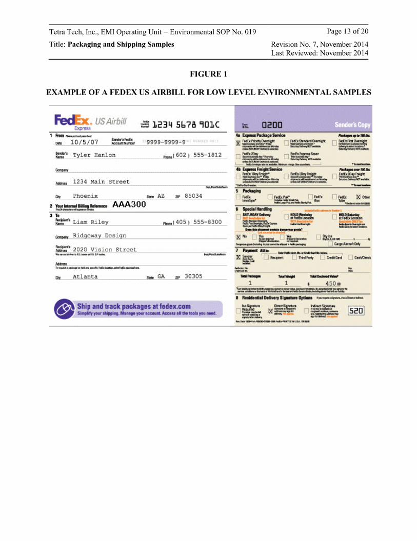
Tetra Tech, Inc., EMI Operating Unit – Environmental SOP No. 019 Page 13 of 20
Title: Packaging and Shipping Samples Revision No. 7, November 2014Last Reviewed: November 2014
FIGURE 1
EXAMPLE OF A FEDEX US AIRBILL FOR LOW LEVEL ENVIRONMENTAL SAMPLES
Tetra Tech, Inc., EMI Operating Unit – Environmental SOP No. 019 Page 14 of 20
Title: Packaging and Shipping Samples Revision No. 7, November 2014Last Reviewed: November 2014
Filling Out the FedEx US Airbill
The sender must complete the following fields on the pre-printed airbill:
− Section 1: Date
− Section 1: Sender’s FedEx Account Number
− Section 1: Sender’s Name, Company, Address, and Phone Number
− Section 2: Internal Billing Reference (Project Number)
− Section 3: Recipient’s Name, Company, Address, and Phone Number
− Section 4: Express Package or Freight Services (Priority Overnight)
− Section 5: Packaging (usually “Other,” your own packaging)
− Section 6: Special Handling (Saturday delivery if prearranged with receiving laboratory; “No” dangerous goods contained in shipment)
− Section 7: Payment (“Bill to Sender”)
− Section 7: Total Number of Packages
− Section 7: Total Weight (completed by FedEx employee)
− Section 8: Delivery Signature Options (“No Signature Required”)
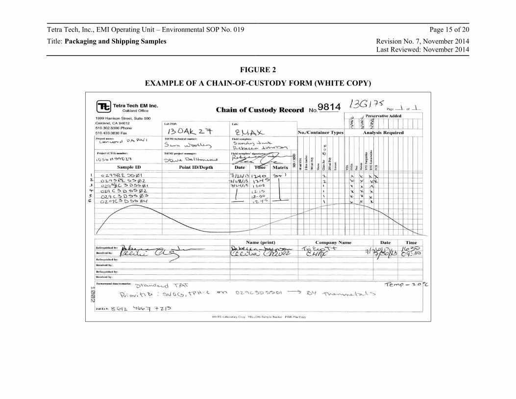
Tetra Tech, Inc., EMI Operating Unit ‒ Environmental SOP No. 019 Page 15 of 20
Title: Packaging and Shipping Samples Revision No. 7, November 2014Last Reviewed: November 2014
FIGURE 2
EXAMPLE OF A CHAIN-OF-CUSTODY FORM (WHITE COPY)
Tetra Tech, Inc., EMI Operating Unit ‒ Environmental SOP No. 019 Page 16 of 20
Title: Packaging and Shipping Samples Revision No. 7, November 2014Last Reviewed: November 2014
Completing a Sample Chain-of-Custody Form
After samples have been collected, they will be maintained under chain-of-custody procedures. These
procedures are used to document the transfer of custody of the samples from the field to the designated
analytical laboratory. The same chain-of-custody procedures will be used for the transfer of samples from
one laboratory to another, if required.
The field sampling personnel will complete a Chain-of-Custody and Request for Analysis (CC/RA) Form
(Figure 1, Chain of Custody Record) for each separate container of samples to be shipped or delivered to
the laboratory for chemical or physical (geotechnical) analysis. Information contained on the triplicate,
carbonless form will include:
1. Project identification (ID) (for example, contract and task order number);
2. Project Contract Task Order (CTO) number;
3. Laboratory Project Order (PO) number;
4. Tetra Tech Technical Contact;
5. Tetra Tech Project Manager
6. Laboratory name;
7. Field sampler names;
8. Field sampler signature;
9. Sample ID;
10. Point ID and Depth (Do NOT include this information on the laboratory copy of the chain-of-custody (top white copy);
11. Date and time of sampling;
12. Sample matrix type;
13. Sample preservation method; note “NONE” if no preservatives;
14. Number and types of sample containers and container capacity;
15. Sample hazards (if any);
16. Requested analysis;
17. Requested sample turnaround time or any special remarks;
18. Page __ of __;
19. Method of shipment;
20. Carrier/waybill number (if any);
21. Signature, name, and company of the person relinquishing the samples and the person receiving the samples when custody is transferred;
22. Date and time of sample custody transfer;
Tetra Tech, Inc., EMI Operating Unit ‒ Environmental SOP No. 019 Page 17 of 20
Title: Packaging and Shipping Samples Revision No. 7, November 2014Last Reviewed: November 2014
23. Condition of samples when they are received by the laboratory.
The sample collector will cross out any blank space on the CC/RA Form below the last sample number
listed on the part of the form where samples are listed.
The sampling personnel whose signature appears on the CC/RA Form is responsible for the custody of a
sample from time the sample is collected until the custody of the sample is transferred to a designated
laboratory, a courier, or to another Tetra Tech employee for transporting a sample to the designated
laboratory. A sample is considered to be in custody when the custodian: (1) has direct possession of it;
(2) has plain view of it; or (3) has securely locked it in a restricted access area.
Custody is transferred when both parties to the transfer complete the portion of the CC/RA Form under
“Relinquished by” and “Received by” or a sample is left at a FedEx facility pending shipment.
Signatures, printed names, company names, and date and time of custody transfer are required. When
custody is transferred, the Tetra Tech sampling personnel who relinquished the samples will retain the
third sheet (pink copy) of the CC/RA Form. When the samples are shipped by a common carrier, a Bill of
Lading supplied by the carrier will be used to document the sample custody, and its identification number
will be entered on the CC/RA Form. Receipts of Bills of Lading will be retained as part of the permanent
documentation in the Tetra Tech project file.
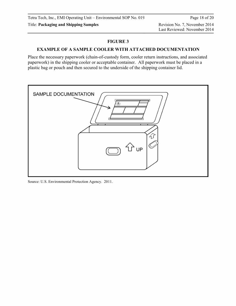
Tetra Tech, Inc., EMI Operating Unit ‒ Environmental SOP No. 019 Page 18 of 20
Title: Packaging and Shipping Samples Revision No. 7, November 2014Last Reviewed: November 2014
FIGURE 3
EXAMPLE OF A SAMPLE COOLER WITH ATTACHED DOCUMENTATION
Place the necessary paperwork (chain-of-custody form, cooler return instructions, and associated paperwork) in the shipping cooler or acceptable container. All paperwork must be placed in a plastic bag or pouch and then secured to the underside of the shipping container lid.
Source: U.S. Environmental Protection Agency. 2011.
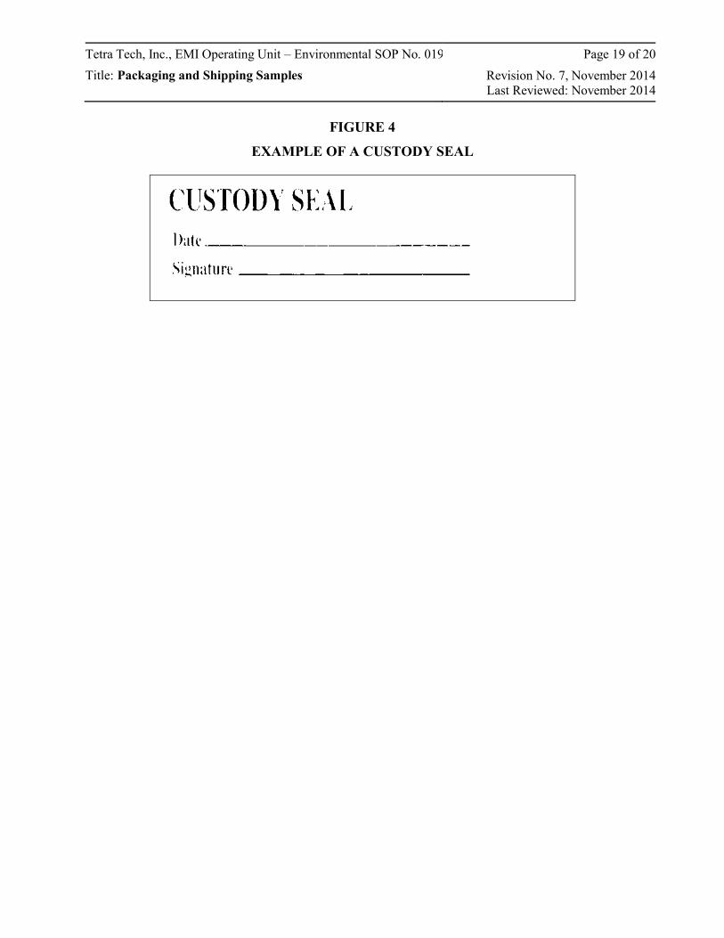
Tetra Tech, Inc., EMI Operating Unit ‒ Environmental SOP No. 019 Page 19 of 20
Title: Packaging and Shipping Samples Revision No. 7, November 2014Last Reviewed: November 2014
FIGURE 4
EXAMPLE OF A CUSTODY SEAL
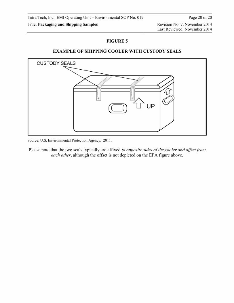
Tetra Tech, Inc., EMI Operating Unit ‒ Environmental SOP No. 019 Page 20 of 20
Title: Packaging and Shipping Samples Revision No. 7, November 2014Last Reviewed: November 2014
FIGURE 5
EXAMPLE OF SHIPPING COOLER WITH CUSTODY SEALS
Source: U.S. Environmental Protection Agency. 2011.
Please note that the two seals typically are affixed to opposite sides of the cooler and offset from each other, although the offset is not depicted on the EPA figure above.
SOP APPROVAL FORM
TETRA TECH, INC.
ENVIRONMENTAL STANDARD OPERATING PROCEDURE
RECORDING NOTES IN FIELD LOGBOOKS
SOP NO. 024
REVISION NO. 2
Last Reviewed: November 2014
November 24, 2014 Quality Assurance Approved Date
Tetra Tech, Inc. EMI Operating Unit – Environmental SOP No. 024 Page 1 of 8 Title: Recording Notes in Field Logbooks Revision No. 2, November 2014
Last Reviewed: November 2014
1.0 BACKGROUND
Complete and accurate field documentation is critical to a successful project and the field log book is an
important tool to support field documentation needs. The field logbook should include detailed records of
all field activities, document interviews with people, and record observations of conditions at a site.
Entries should be described in a level of detail to allow personnel to reconstruct, after the fact, activities and
events that occurred during their field assignments. Furthermore, entries should be limited to facts.
Avoid speculation related to field events and do not record hearsay or unfounded information that may be
presented by other parties during field activities. For example, do not record theories regarding the
presence or absence of contamination when you are collecting field screening data or speculation regarding
the reasons for a property owner’s refusal to grant access for sampling.
Field logbooks are considered accountable documents in enforcement proceedings and may be subject to
review. Therefore, the entries in the logbook must be accurate and detailed, but should not contain
speculative information that could conflict with information presented in subsequent project deliverables
and correspondence. Also be aware that the field logbooks for a site may be a primary source of
information for depositions and other legal proceedings that may occur months or years after field work is
complete and long after our memories have faded. The accuracy, neatness, and completeness of field
logbooks are essential for recreating a meaningful account of events.
1.1 PURPOSE
The purpose of this standard operating procedure (SOP) is to provide guidance to ensure that field logbook
documentation collected during field activities meets all requirements for its later use. Among other
things, field logbooks may be used for:
Identifying, locating, labeling, and tracking samples
Recording site activities and the whereabouts of field personnel throughout the day
Documenting any deviations from the project approach, work plans, quality assurance project plans, health and safety plans, sampling plans, and any changes in project personnel
Recording arrival and departure times for field personnel each morning and evening and weather conditions each day
Describing photographs taken during the project.
Tetra Tech, Inc. EMI Operating Unit – Environmental SOP No. 024 Page 2 of 8 Title: Recording Notes in Field Logbooks Revision No. 2, November 2014
Last Reviewed: November 2014
In addition, the data recorded in the field logbook may later assist in the interpretation of analytical results.
A complete and accurate logbook also aids in maintaining quality control, because it can verify adherence
to project scope and requirements.
1.2 SCOPE
This SOP establishes the general requirements and procedures for documenting site activities in the field
logbook.
1.3 DEFINITIONS
None.
1.4 REFERENCES
Compton, R.R. 1985. Geology in the Field. John Wiley and Sons. New York, NY.
1.5 REQUIREMENTS AND RESOURCES
The following items are required for field notation:
Field logbooks
Ballpoint pens or Sharpies with permanent waterproof ink
6-inch ruler (optional)
Field logbooks should be bound (sewn) with water-resistant and acid-proof covers, and each page should have
preprinted lines, numbered pages, and a single column. They should be approximately 71/2 by 41/2 inches or
81/2 by 11 inches in size. Loose-leaf sheets are not acceptable for use as field notes.* If notes are written on
loose paper, they must be transcribed as soon as possible into a bound field logbook by the same person who
recorded the notes originally. *Note: Data collection logs and field forms used to record field measurements
and data are acceptable as loose-leaf sheets maintained in a three-ring binder with numbered pages.
Ideally, distribution of logbooks should be controlled by a designated person in each office. This person
assigns a document control number to each logbook, and records the assignment of each logbook
distributed (name of person, date distributed, and project number). The purpose of this procedure is to
ensure the integrity of the logbook before its use in the field, and to document each logbook assigned to a
Tetra Tech, Inc. EMI Operating Unit – Environmental SOP No. 024 Page 3 of 8 Title: Recording Notes in Field Logbooks Revision No. 2, November 2014
Last Reviewed: November 2014
project. In the event that more than one logbook is assigned to a project, this process will ensure that all
logbooks are accounted for at project closeout.
2.0 PROCEDURES
The following subsections provide general guidelines and formatting requirements for field logbooks, and
detailed procedures for completing field logbooks.
2.1 GENERAL GUIDELINES
A separate field logbook must be maintained for each project. If a site consists of multiple subsites (or operable units), designate a separate field logbook for each subsite. Similarly, if multiple activities are occurring simultaneously requiring more than one task leader (well installation, private well sampling, or geophysical survey.), each task leader should maintain a separate field logbook to ensure that each activity is documented in sufficient detail.
At larger sites, a general field log may be kept at the site trailer or designated field office to track site visitors, document daily safety meetings, and record overall site issues or occurrences.
Data from multiple subsites may be entered into one logbook that contains only one type of information for special tasks, such as periodic well water-level measurements.
All logbooks must be bound and contain consecutively numbered pages.
No pages can be removed from the logbook for any purpose.
All information must be entered using permanent, waterproof ink. Do not use pens with “wet ink,” because the ink may wash out if the paper gets wet. Pencils are not permissible for field notes because information can be erased. The entries should be written dark enough so that the logbook can be easily photocopied.
Be sure that all entries are legible. Use print rather than cursive and keep the logbook pages free of dirt and moisture to the extent possible.
Do not enter information in the logbook that is not related to the project. The language used in the logbook should be factual and objective. Avoid speculation that could conflict with information presented in subsequent project deliverables and correspondence (see Section 1.0 above).
Use military time, unless otherwise specified by the client.
Include site sketches, as appropriate.
Begin a new page for each day’s notes.
Include the date at the top of each page.
At the end of a day, draw a single diagonal line through any unused lines on the page, and sign at the bottom of the page. Note and implement any client specific requirements (for example, some U.S. Environmental Protection Agency (EPA) programs require each logbook page to be signed).
Tetra Tech, Inc. EMI Operating Unit – Environmental SOP No. 024 Page 4 of 8 Title: Recording Notes in Field Logbooks Revision No. 2, November 2014
Last Reviewed: November 2014
Write notes on every line of the logbook. Do not skip any pages or parts of pages unless a day’s activity ends in the middle of a page.
If a line is left blank for some reason, cross out (with a single line) and initial to prevent unauthorized entries.
Cross out (with a single line) and initial any edits to the logbook entries. Edits should only be made if the initial entry is illegible or erroneous. Do not make corrections for grammar or style.
2.2 LOGBOOK FORMAT
The layout and organization of each field logbook should be consistent and generally follow the format
guidelines presented below. Some clients or contracts may have specific formatting guidelines that differ
somewhat from this SOP; review client requirements at the start of the project to help ensure any
client-specific guidelines are integrated.
2.2.1 Logbook Cover
Write the following information on the front cover of each logbook using a Sharpie
or similar type
permanent ink marker:
Logbook document control number (assigned by issuer)
“Book # of #” (determined by the project manager if there is more than one logbook for the project)
Contract and task order numbers
Name of the site and site location (city and state)
Name of subsite (or operable unit), if applicable
Type of activity (if logbook is for specific activity, such as well installation or indoor air sampling)
Beginning and ending dates of activities entered into the logbook
2.2.2 Inside Cover or First Page
Spaces are usually provided on the inside front cover (or the opening page in some logbooks) for the
company name, address, contact names, and telephone numbers. If preprinted spaces for this information
are not provided in the logbook, write the information on the first available page. Information to be
included on the inside front cover or first page includes:
Tetra Tech project manager and site manager and phone numbers
Tetra Tech office address
Tetra Tech, Inc. EMI Operating Unit – Environmental SOP No. 024 Page 5 of 8 Title: Recording Notes in Field Logbooks Revision No. 2, November 2014
Last Reviewed: November 2014
Client contact and phone number
Site safety officer and phone number
Emergency contact phone number (911, if applicable, or nearest hospital)
Subcontractor contacts and phone numbers
Site property owner or property manager contact information
2.3 ENTERING INFORMATION IN THE LOGBOOK
The following lists provide guidance on the type of information to be included in a typical field logbook.
This guidance is general and is not intended to be all-inclusive. Certain projects or clients may specify
logbook requirements that are beyond the elements presented in this SOP.
General Daily Entries:
Document what time field personnel depart the Tetra Tech office and arrive at the hotel or site. If permitted by the client to charge travel time for site work, document what time personnel leave and arrive at the hotel each day. (This information may be needed at remote sites where hotel accommodations are not near the site.)
Indicate when all subcontractors arrive and depart the site.
Note weather conditions.
Include the date at the top of each page.
Document that a site safety meeting was held and include the basic contents of the meeting.
List the level of protection to be used for health and safety.
Summarize the day’s planned activities.
Summarize which activities each field team member will be doing.
Tetra Tech, Inc. EMI Operating Unit – Environmental SOP No. 024 Page 6 of 8 Title: Recording Notes in Field Logbooks Revision No. 2, November 2014
Last Reviewed: November 2014
Field Activity Entries:
Refer to field data collection forms for details about field data collection activities (for example time, date, depth of samples, field measurements). If separate field sampling sheets are not used, see section below regarding logbook entries for sampling activities.
Refer to well purge forms, well construction logs, and other activity-specific forms as applicable rather than including this type of information in the field logbook. These other forms allow the information to be more accessible at a later date.
List any air monitoring instrumentation used, with readings and locations.
Refer to instrument field logs for equipment calibration information.
Summarize pertinent conversations with site visitors (agency representatives, property owners, client contacts, and local citizens).
Summarize any problems or deviations from the quality assurance project plan (QAPP) or field sampling plan.
Document the activities and whereabouts of each team member. (As indicated in Section 2.1, multiple logbooks may be required to ensure sufficient detail for contemporaneous activities).
Indicate when utility clearances are completed, including which companies participated.
Indicate when verbal access to a property is obtained.
Include names, addresses, and phone numbers of any pertinent site contacts, property owners, and any other relevant personnel.
Document when lunch breaks or other work stoppages occur.
Include approximate scale for all diagrams. If a scale is not available, write “not to scale” on the diagram. Indicate the north direction on all maps and cross-sections, and label features on each diagram.
Sampling Activity Entries: The following information should typically be on a sample collection log
and referenced in the log book. If the project does not use sample sheets as a result of project-specific
requirements, this information should be included in the logbook.
Location description
Names of samplers
Collection time
Designation of sample as a grab or composite sample
Type of sample (water, sediment, soil gas, or other medium)
On-site measurement data (pH, temperature, and specific conductivity)
Tetra Tech, Inc. EMI Operating Unit – Environmental SOP No. 024 Page 7 of 8 Title: Recording Notes in Field Logbooks Revision No. 2, November 2014
Last Reviewed: November 2014
Field observations (odors, colors, weather)
Preliminary sample description
Type of preservative used.
Instrument readings, if applicable
Closing Daily Entries:
Describe decontamination procedures (personnel and equipment).
Describe handling and disposition of any investigation-derived wastes.
Summarize which planned activities were completed and which ones were not.
Note the times that personnel depart site for the day.
Summarize any activities conducted after departing the site (paperwork, sample packaging, etc.). This may be required to document billable time incurred after field activities were completed for the day.
Photographic Log Entries:
For digital photographs, indicate in the text that photographs were taken and the location where the photographs can be found (for example, in the project file).
Camera and serial #
Photographer
Date and time of photograph
Sequential number of the photograph and the film roll number or disposable camera used (if applicable)
Direction of photograph
Description of photograph
2.4 LOGBOOK STORAGE
Custody of logbooks must be maintained at all times. During field activities, field personnel must keep the
logbooks in a secure place (locked car, trailer, or field office) when the logbook is not in personal
possession. When the field work is over, the logbook should be included in the project file, which should
be in a secured file cabinet. The logbook may be referenced in preparing subsequent reports and may also
be scanned for inclusion as an appendix to a report. However, it is advisable to obtain direction directly
from the client before including the logbook as a report appendix, because its inclusion may not be
appropriate in all cases.
Tetra Tech, Inc. EMI Operating Unit – Environmental SOP No. 024 Page 8 of 8 Title: Recording Notes in Field Logbooks Revision No. 2, November 2014
Last Reviewed: November 2014
2.5 HEALTH AND SAFETY CONSIDERATIONS
In addition to the procedures outlined in this SOP, all field staff must be aware of and follow the health and
safety practices that result from the Activity Hazard Analyses (AHAs) for a project. The AHAs include
critical safety procedures, required controls, and minimum personal protective equipment (PPE) necessary
to address potential hazards. The hazards specific to project tasks must be identified and controlled to the
extent practicable and communicated to all project personnel via the approved, project-specific Health and
Safety Plan (HASP).
SOP APPROVAL FORM
START CONTRACT-SPECIFIC
ENVIRONMENTAL STANDARD OPERATING PROCEDURE
Indoor Dust Sampling Using a HEPA Vacuum
SOP NO. 071
REVISION NO. 0
Last Reviewed: Not applicable (Revision No. 0)
2/21/2017 Quality Assurance Approved
Date
Tetra Tech – START Contract-Specific SOP No. 071 Page 1 of 11
Title: Indoor Dust Sampling Using a HEPA Vacuum Revision No. 0, February 2017
1.0 BACKGROUND
Indoor dust is typically sampled using a high-efficiency particulate air (HEPA) vacuum to assess human
health exposure to particulate matter found on surfaces such as floors and window sills within a building.
Dust collected using this method can be fractionated to particle sizes less than or greater than 150
micrometers (µm) in diameter to determine the chemical concentrations and evaluate ingestion impacts to
children or other sensitive receptors. Data collected can also be used to estimate dust loading on surfaces
and can be input into an Integrated Exposure Uptake Biokinetic Model (IEUBK) to evaluate risk during a
human health risk assessment.
1.1 PURPOSE
The purpose of this standard operating procedure (SOP) is to describe sampling procedures for collecting
indoor dust samples using a HEPA vacuum. Sampling is performed to evaluate human health exposure
risks.
1.2 SCOPE
This SOP describes procedures for conducting indoor dust sampling using the Atrix International, Inc.,
Omega Vac with internal HEPA filter. Samples collected using this methodology can be analyzed for
total dust and metals and can be processed using a No. 100 sieve to differentiate between fine dust (less
than 150 µm in diameter) and coarse dust (larger than 150 µm in diameter).
1.3 DEFINITIONS
Coarse Fraction: Portion of dust with particle sizes greater than 150 µm in diameter.
Dust Loading: The amount of dust per unit area, expressed in micrograms per square foot (µg/ft2) or
micrograms per square meter (µg/m2).
Filter Holder: An apparatus that supports and contains the filter medium used to collect dust. It is also
often referred to as a sampling cassette.
Fine Fraction: Portion of dust with particle sizes less than 150 µm in diameter. This size is typically
considered the portion of dust most likely to be inhaled or ingested based on its ability to be suspended in
air or to adhere to the hands and skin.
Tetra Tech – START Contract-Specific SOP No. 071 Page 2 of 11
Title: Indoor Dust Sampling Using a HEPA Vacuum Revision No. 0, February 2017
Contaminant Concentration: The mass concentration of a contaminant per mass of dust, typically
reported as micrograms per gram (µg/g) or parts per million (ppm).
Contaminant Loading: The amount of a contaminant per unit area, expressed in µg/ft2 or µg/m2.
1.4 REFERENCES
ASTM International. 2011. ASTM Standard D7144-05a, 2011, “Standard Practice for Collection of
Surface Dust by Micro-vacuum Sampling for Subsequent Metals Determination.” ASTM
International, West Conshohocken, PA. DOI: 22.04/D7144-05a.
U.S. Environmental Protection Agency (EPA). 2008. “Guidance for the Sampling and Analysis of Lead
in Indoor Residential Dust for Use in the Integrated Exposure Uptake Biokinetic (IEUBK)
Model.” Prepared by the Lead Committee of the Technical Review Workgroup for Metals and
Asbestos, Office of Superfund Remediation and Technology Innovation EPA. OSWER 9285.7-
81. December.
EPA. 2016. Memorandum concerning Recommendations for Sieving Soil and Dust Samples at Lead
Sites for Assessment of Incidental Ingestion. From Dana Stalcup, Director, Assessment and
Remediation Division. To: Superfund National Program Managers. Regions 1 through 10.
OLEM Directive 9200.1-128. July 1.
1.5 REQUIREMENTS AND RESOURCES
Dust sampling using a HEPA vacuum requires the use of one or more of the following types of
equipment:
HEPA Vacuum/Omega Vac Supreme: Atrix International Inc. (Atrix)
Trace Evidence Collection Filter with Upholstery Tool: FFUT (Atrix) or 619E2 (Sirchie)
Trace Evidence Collection Filter with Crevice Tool: FFCT (Atrix) or 619E1 (Sirchie)
4-inch HEPA (0.3 micron) Filter: DISC-4H (Atrix)
Scale with a minimum 1-gram sensitivity
In addition, the following equipment is also needed for collecting vacuum dust samples:
Nitrile gloves
Extension cord
Duct tape
Logbook and pen
Health and safety equipment
Tablet computer (optional for digital data capture)
Tetra Tech – START Contract-Specific SOP No. 071 Page 3 of 11
Title: Indoor Dust Sampling Using a HEPA Vacuum Revision No. 0, February 2017
2.0 VACUUM DUST SAMPLING ASSEMBLY
The vacuum dust sampling chain assembly consists of four primary components: (1) the HEPA vacuum;
(2) the vacuum hose; (3) the filter holder, including HEPA filter; and (4) the upholstery or crevice
collection tool. See Figure 1 at the end of this document for an example of the assembled sampling chain.
It is common for the HEPA filter and filter holder to be provided unassembled. In this case, the HEPA
filter must be installed in the filter holder in laboratory-like conditions. Typically, at least one of the filter
endcaps is labeled with a sticker as either “Tool Mount” or “Vacuum Hose Mount.” The filter endcap
that is compatible with the vacuum hose attachment should be removed, and the HEPA filter should be
placed on top of that end cap. The endcap should then be reinstalled in the clear central portion of the
filter holder, locking the HEPA filter in place. Two pieces of duct tape should then be used to secure the
filter holder endcaps in place. The duct tape should be affixed so that it is in contact with both filter
holder endcaps and the clear central portion of the filter holder. See Figure 2 at the end of this document
for an example of an assembled filter holder. The upholstery and crevice tools can be used
interchangeably based on sample location. The upholstery tool is typically used to collect samples from
relatively large sample areas, such as floors, because of its greater width. The crevice tool is typically
used to collect samples from narrow sample areas, such as window sills, as a result of its smaller profile.
The sampling chain is generally assembled in the order listed above. During sampling, the vacuum
pressure generated by the HEPA vacuum is transferred to the sampling apparatus via the vacuum hose.
The vacuum pressure is used to collect dust particles from the sampling surface via the upholstery or
crevice collection tool. The dust particles travel from the upholstery or crevice tool into the filter holder,
where they encounter the 4-inch HEPA (0.3 micron) filter. Dust particles are then trapped in the filter and
the filter holder. When sampling is completed, the entire filter holder is submitted for laboratory analysis.
3.0 VACUUM DUST SAMPLING METHODOLOGY
A single filter/filter holder is used for all sampling and laboratory analytical procedures. The total
amount of dust is determined gravimetrically, so it is important to accurately measure the weight of the
filter holder before and after sampling. The dust contained in the filter holder is then passed through a
No. 100 sieve to isolate particles with diameters less than 150 µm from those with larger diameters. The
particles that pass through this sieve are considered the fine dust fraction of the total sample. Particles
that are not able to pass through the sieve are considered the coarse dust fraction of the total sample.
Each fraction of the sample can then be analyzed separately for metals content. This analysis provides the
total weight of dust in the sample, the weight of the fine and coarse fractions of the sample, and the
concentrations of selected metal analytes in each dust fraction. The laboratory can then calculate the total
Tetra Tech – START Contract-Specific SOP No. 071 Page 4 of 11
Title: Indoor Dust Sampling Using a HEPA Vacuum Revision No. 0, February 2017
concentration of the selected metal analytes. The concentrations of selected analytes can be reported
directly and can also be used in concert with the fraction weight and area sampled to calculate analyte-
and fraction-specific dust loading. The dust loading can be calculated using the total dust weight with the
area sampled.
Vacuum dust samples by nature are composite samples of the area vacuumed. Analytical results are
reported on a gravimetric basis, as are relevant screening standards. As a result, it is important to collect
accurate data for the areal extent of each sample. It is also important to record the weight of the filter
holder before and after sampling.
3.1 SAMPLING PROCEDURE
The following sections discuss (1) preparing equipment and collecting necessary data prior to sampling,
(2) collecting the sample, and (3) collecting post-sampling data.
3.1.1 Sampling Preparation
It is necessary to collect pre-sampling data before sample collection can be initiated. This process
includes identifying sample locations, preparing equipment for sampling, and recording important data
used to characterize the sample. Sampling preparation steps are discussed in further detail below.
3.1.1.1 Select Sample Locations
Selecting sample locations should follow a site-specific methodology. A common methodology consists
of selecting sample locations to quantify (1) the worst-case exposure scenario, and (2) the exposure to the
most sensitive receptor in the residence. One sample is typically collected from within the most
frequently used entrance to the dwelling to quantify the worst-case exposure scenario. The most
frequently used entrance is the area that is most heavily exposed to dirt and dust carried into the house
from the exterior. This entrance area must be located within permanent living space in the residence. For
the purposes of sample location selection, 3-season rooms and screened porches are not considered part of
the permanent living space, as they are not utilized year-round. Samples should not be collected from 3-
season rooms or screened porches. A second sample is typically collected from the bedroom of the
youngest child that lives at the residence. If no child lives at the residence, the second sample is typically
collected from the room where the residents spend the most time. If requested by the resident, it is also
possible to collect a sample from the basement level of the dwelling to evaluate the potential for flood
water to transport contaminants into the dwelling. If a basement sample is collected, it should be
collected near a sump pump, if one exists, to evaluate the most likely depositional area for suspended
Tetra Tech – START Contract-Specific SOP No. 071 Page 5 of 11
Title: Indoor Dust Sampling Using a HEPA Vacuum Revision No. 0, February 2017
sediment and dust transported by water. If no sump is present, the sample should be collected from near
existing floor drains. If no floor drains are present, the sample should be collected from any areas that
appear likely to collect standing water (such as low points and depressions).
Composite or additional samples can be collected when multiple entrances are used equally, or when
young children sleep in multiple bedrooms. Composite samples are typically used to measure the average
exposure over the areas sampled. Additional samples can be substituted for composite samples to
measure exposure in specific locations, based on resident preference.
The specific area to be sampled should be selected after the general area (entrance/room) where sampling
will occur has been selected. The specific area should be selected to best characterize the intended
exposure scenario. The area for worst-case exposure scenario samples collected at a dwelling entrance
should encompass the space that is most likely to be walked immediately after residents enter, including
door mats or rugs. The sampling area for the most sensitive receptor exposure scenario should encompass
the space most commonly used within the general location. In bedrooms, this space typically includes the
area near the entrance to the room and the area near the bed. In living rooms, it typically includes the
most frequented walking route through the room and areas near commonly used couches and chairs.
When possible, sampling areas should be made up of a contiguous area with reasonably simple geometry
to avoid errors in calculating the total area sampled.
3.1.1.2 Record Pre-Sampling Data
It is necessary to collect detailed data before the sample is collected to (1) ensure that sampling conditions
are fully documented, and (2) provide the necessary information for determining the sample weight and
area sampled. Required pre-sampling data can be divided into two categories: property-specific data, and
sample-specific data.
Property-specific data should include at least the following information:
Property Address or Property identification (ID)/Code (should be assigned on a site-specific basis
to protect the identity and personal details of residents)
Names of Samplers
Sampling Scenario: Preliminary, Pre-remediation, Post-remediation, or other
Date of Sampling.
Sample-specific data should include at least the following information:
Time of Sample Collection
Tetra Tech – START Contract-Specific SOP No. 071 Page 6 of 11
Title: Indoor Dust Sampling Using a HEPA Vacuum Revision No. 0, February 2017
Sample ID: Use site-specific sample ID nomenclature, ensuring the nomenclature includes at
least Property ID, Sample Sub-Location, and Sample Date, at a minimum
Sample Sub-Location: Room name, entrance
Floor Type: Wood, carpet, tile, or other
Vacuum ID
Pre-Sample Filter Holder Weight.
Digital data capture technology is recommended based on the number of samples and properties typically
included in dust sampling projects. A tablet computer equipped with field data recording software (such
as iForms or Collector App) and a custom, site-specific data capture form facilitates uniform collecting,
storing, and processing of sampling data.
It is necessary to complete a sketch of the floorplan of the residence in a field logbook to document the
location of the sample. The sketch should include the layout of rooms on the floor of the residence where
the sample is being collected and major features in each room (furniture, doorways). The sketch should
include a North arrow to indicate relative direction and a note indicating that the sketch is not to scale.
The sample area should be clearly demarcated with dimensions, and total area sampled should be noted
on the sketch. It is crucial for the sketch to clearly and accurately define the location of the sampling area
within the residence. This sketch will be used to ensure that the post-cleaning sample is collected from
the exact area sampled before the residence was cleaned to allow for valid comparison of results.
After the specific sample location has been selected and the sampling apparatus is assembled, the dust
sample can be collected. The exact area to be sampled should be selected and measured to ensure
accurate accounting of the sampling area. A measuring tape can be used as a guide for sampling area, or
a count of tiles can be used if sampling is being conducted on a tile floor, provided the size of an
individual tile is known. Once the sampler has a clear understanding of the specific area to be sampled,
sample collection may commence, and the start time of sample collection should be recorded.
3.1.1.3 Prepare Sampling Equipment
After the specific area to be sampled has been selected, sampling equipment should be prepared,
including collection of relevant pre-sampling data (see Section 3.1.1.2). The following steps should be
taken before a sample is collected:
1. Remove the filter holder from the evidence bag and label it with Sample ID using site-specific
nomenclature, as described in Section 3.1.1.2. Take care to place the filter holder on a clean
surface to prevent cross contamination caused by contacting contaminated surfaces before
sampling.
Tetra Tech – START Contract-Specific SOP No. 071 Page 7 of 11
Title: Indoor Dust Sampling Using a HEPA Vacuum Revision No. 0, February 2017
2. Record pre-sampling weight of filter holder. Use a scale with minimum 1-gram sensitivity to
measure the weight of the filter holder before sampling. Make sure the entire filter holder
apparatus is weighed (including caps). Make sure scale is tared to zero before the filter holder is
weighed.
3. Assemble sampling apparatus as described below
3.1 Plug the power cord into the power port in the rear of the HEPA vacuum and into the
functioning electrical outlet closest to the sample location, using an extension cord as
needed. The power cord and vacuum hose can typically be found in the internal
compartment in the lid of the HEPA vacuum.
3.2 Insert the vacuum hose into the prefabricated slot for the hose on the front of the HEPA
vacuum.
3.3 Connect the filter holder to the vacuum hose. The filter holder should be oriented so that
the end with the HEPA filter is located closest to the vacuum hose. If the filter holder has
been assembled correctly, it will fit directly on the vacuum hose. If the filter holder does
not fit directly on the vacuum hose, it can be secured to the vacuum hose using duct tape,
or a different filter holder can be used.
3.4 Attach the upholstery or crevice collection tool directly to the open end of the filter
holder, completing the sampling chain. If the security of the connection between the
upholstery or crevice collection tool and the filter holder is in question, the tool can be
secured with duct tape.
Figures depicting the overall sampling assembly and a detail view of the filter holder and upholstery or
crevice tool assembly are provided at the end of this document
3.1.2 Sample Collection
To begin sampling, the upholstery or crevice tool should be positioned so that it is touching the nearest
boundary of the specific sampling area. The HEPA vacuum should then be powered on. The upholstery
or crevice tool should be moved over the surface of the specific sampling area at a rate of approximately
0.5 foot per second, maintaining contact with the floor surface. The upholstery or crevice tool should be
moved in a vertical pattern, taking care to ensure that the entirety of the specific sampling area is
vacuumed. The entirety of the sampling area should be vacuumed once using passes in a vertical
direction. The same area should not be vacuumed repetitively, or using passes in multiple directions.
Care should be taken to avoid relatively large debris (such as coins, paper clips, or large food particles).
If the sampling area is composed of both a hard surface and a carpeted surface, the entirety of the hard
surface should be vacuumed before the carpeted surface to prevent clogging of the sample filter.
After the entire sampling area has been vacuumed, the sampling apparatus should be held in a vertical
position with the upholstery or crevice tool facing up. The sampler should loosely place a hand over the
tool to prevent any dust from escaping and power off the HEPA vacuum, recording the ending time of
sample collection. The sampling apparatus should be disassembled using the following steps:
Tetra Tech – START Contract-Specific SOP No. 071 Page 8 of 11
Title: Indoor Dust Sampling Using a HEPA Vacuum Revision No. 0, February 2017
1. Disconnect the upholstery or crevice tool from the filter holder, ensuring the filter holder remains
in a vertical position to avoid the loss of any sample material.
2. Immediately attach the filter holder cap onto the newly exposed open end of the filter holder.
Ensure secure attachment.
3. Disconnect the filter holder from the HEPA vacuum hose. The opening does not need to be kept
vertical, as the filter prevents dust from passing through the opening.
4. Attach the remaining filter holder cap onto the exposed opening, ensuring a secure attachment.
3.1.3 Collecting Post-Sampling Data
When sample collection has been completed, the filter holder must be weighed. If the pre-sample weight
and post-sample weight of the filter holder are the same, the sample area must be expanded until at least 1
gram of dust is collected, following the steps described in Section 3.1.2.
Once the sampling is completed with a sufficient mass of dust collected, labels should be affixed on both
the filter holder and the evidence bag indicating sample ID, time of sample collection, the weight of the
unit before sampling, and the weight after sampling. Once each label is attached, the filter holder should
be placed into the evidence bag and sealed. No special preservation (temperature control or other) is
required for shipping. Samples should be placed into a box with ample packing material to ensure that
the filter holders stay in place during shipping. Any forceful contact with other samples or the sides of
the box during shipping could dislodge dust from the filters and affect the laboratory results.
3.2 POST-CLEANING SAMPLING PROCEDURE
The following post-cleaning sampling procedures outline a similar process as that described in
Section 3.1. These procedures, however, should be used in residences that have already been sampled
and cleaned and are being sampled again to evaluate the efficacy of cleaning. To accurately evaluate
cleaning efficacy, it is essential that the same sample locations and areas be sampled during both pre- and
post-cleaning sampling. The post-cleaning sampling procedure is similar to the general sampling
procedure, with a focus on ensuring the samples are collected from the same exact locations as pre-
cleaning samples. Further details are provided below.
3.2.1 Sampling Preparation
The sampling preparation process for post-cleaning samples is similar to the process described in Section
3.1.2, except for the section on identifying the sample location. Additionally, the sampler will need to
obtain the log book from the original sampling event to determine the correct sampling locations.
Sampling preparation steps are discussed in further detail below.
Tetra Tech – START Contract-Specific SOP No. 071 Page 9 of 11
Title: Indoor Dust Sampling Using a HEPA Vacuum Revision No. 0, February 2017
3.1.1.1 Sample Location Selection
During post-cleaning sampling, sample location will be established by the location of previously collected
pre-cleaning samples. The areas that were sampled before cleaning must be the exact same as the areas
sampled after cleaning to ensure a fair comparison of results. The logbook from the previous sampling
event should be used as a reference. The sketch of the floorplan and specific sampling areas included in
the logbook should be used to select the location of post-cleaning samples.
3.2.1.3 Record Pre-Sampling Data
See Section 3.1.1.3 and record the same pre-sampling data, except for the sketch of the floor plan. During
post-cleaning sampling, a note should be recorded in the logbook referencing the sketch done during the
previous sampling event, indicating that the same area is being sampled during the current sampling
event. This note should include the number of the logbook that contains the pre-cleaning sampling floor
plan. No new sketches are required during post-cleaning sampling.
3.2.1.2 Prepare Sampling Equipment
See Section 3.1.1.2 and follow the same procedures.
3.2.2 Sample Collection
See Section 3.1.2 and follow the same procedures, making sure to sample the same area that was sampled
during pre-cleaning sampling.
3.2.3 Collecting Post-Sampling Data
See Section 3.1.3. Use the same procedures to record post-sampling data and label and pack the sample.
In this instance, however, the weight of the filter holder post-sampling may be the same as the weight pre-
sampling weight because the residence was recently cleaned. Do not expand the sample area to obtain 1
gram of dust. It is crucial that the post-cleaning sample area remain the same as it was during the pre-
cleaning sample.
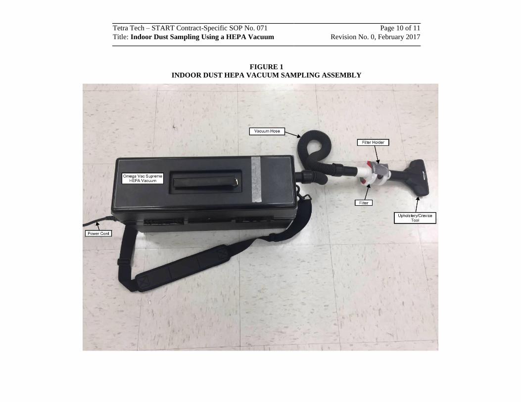
Tetra Tech – START Contract-Specific SOP No. 071 Page 10 of 11
Title: Indoor Dust Sampling Using a HEPA Vacuum Revision No. 0, February 2017
FIGURE 1
INDOOR DUST HEPA VACUUM SAMPLING ASSEMBLY
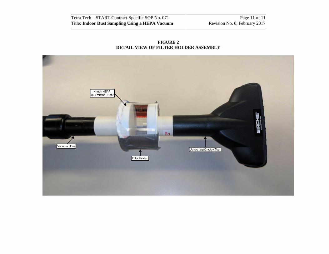
Tetra Tech – START Contract-Specific SOP No. 071 Page 11 of 11
Title: Indoor Dust Sampling Using a HEPA Vacuum Revision No. 0, February 2017
FIGURE 2
DETAIL VIEW OF FILTER HOLDER ASSEMBLY
SOP APPROVAL FORM
TETRA TECH EM INC.
LABORATORY ANALYTICAL DATA STANDARD OPERATING PROCEDURE
Laboratory Analytical Data Verification – Minimum Requirements
SOP NO. 203
REVISION NO. 00
Last Reviewed: August 2010
August 24, 2010
Quality Assurance Approved Date
Tetra Tech EM Inc. – Laboratory Analytical Data SOP No. 203 Page 1 of 8Title: Laboratory Analytical Data Verification – Minimum Requirements
Revision No. 00, August 2010 Last Reviewed: August, 2010
1.0 BACKGROUND
Data quality assurance (QA) is necessary for every project. It is the total integrated process for assuring
reliability and defensibility of decisions based on data—including analytical data. In particular,
appropriate level and accurate review of data resulting from chemical and physical analysis are essential
to ensure these data are of sufficient quality to support the project’s technical requirements.
1.1 PURPOSE
The purpose of this standard operating procedure (SOP) is to ensure laboratory data used by Tetra Tech to
make project decisions are of the quality required and provide the level of confidence needed to make the
appropriate project decisions. This SOP specifies data verification guidelines for ensuring achievement of
a minimum level of project data QA.
1.2 SCOPE
Analytical data generated for Tetra Tech projects must receive the appropriate level of data review. The
level of detail and stringency of data verification or data validation depends on the needs of the project
and program. This SOP specifies guidance for data verification procedures when program-specific or
regulatory requirements are not defined contractually or by program procedures and regulations (for
example, Phase II Environmental Site Assessments, emissions monitoring, and compliance reporting data
for permit applications).
1.3 DEFINITIONS
This subsection defines key terms used in the text.
Data package – A hard copy or electronic report from an analytical laboratory for a set of chemical and
physical analyses performed on a group of samples (sometimes referred to as a Sample Delivery Group
[SDG]). The data package should contain sufficient QA documentation to complete data verification and
determine data usability.
Data usability – A qualitative decision process whereby a qualified person determines whether the data
may be used for the intended purpose. Data should be classified into one of the following two categories:
usable or rejected (unusable).
Tetra Tech EM Inc. – Laboratory Analytical Data SOP No. 203 Page 2 of 8Title: Laboratory Analytical Data Verification – Minimum Requirements
Revision No. 00, August 2010 Last Reviewed: August, 2010
Data verification – The act of determining and documenting whether data conform to specified
requirements. The determination may involve processes such as reviewing, inspecting, testing, checking,
recalculating, and auditing.
Rejected data – Data that do not conform to some or all requirements considered critical to assuring and
confirming the quality of the data. Nonconformances may include: (1) critical quality control (QC)
criteria are not met (see Table 1); (2) appropriate methods were not followed or the methods used
involved significant deviations that might impact data quality or meaning; and (3) critical documentation
is missing or incomplete.
Sample delivery group – A unit (group) of samples received by the laboratory during a field sampling
event. A “sample date group” (SDG) is typically comprised of 20 or fewer samples, and is grouped based
on the number of samples and not the analytical testing requested. A SDG may be defined based on the
number of samples received by the laboratory on a given day or over a period of up to 7 calendar days.
Qualified person – A chemist or other person who received training in or has demonstrated skills and
knowledge of laboratory procedures and QC. The qualified person involved in data verification should
understand the data generation procedures and know project documentation and data quality requirements.
Usable data – Data conforming to most or all requirements considered critical to assuring and confirming
the quality of the data. Conformances important to achieve usability include: (1) critical QC criteria are
met (see Table 1); (2) appropriate methods were followed, or only minor deviations to the methods were
made that would not impact data quality or meaning; and (3) critical documentation is complete.
Professional judgment by a qualified person should be used to determine data usability.
1.4 REFERENCES
U.S. Environmental Protection Agency (EPA). 2002. Guidance on Environmental Data Verification and Data Validation EPA, QA/G-8. EPA/240/R-02/004. November. On-line address: http://www.epa.gov/quality/qs-docs/g8-final.pdf
EPA. 2005. “USEPA Analytical Services Branch (ASB) National Functional Guidelines for Chlorinated Dibenzo-p-Dioxins (CDDs) and Chlorinated Dibenzofurans (CDFs) Data Review.” September. On-line address: http://www.epa.gov/superfund/programs/clp/download/dlm/dlm2nfg.pdf
EPA. 2008. “USEPA Contract Laboratory Program National Functional Guidelines for Superfund Organic Methods Data Review.” June. On-line address: http://www.epa.gov/superfund/programs/clp/download/somnfg.pdf
Tetra Tech EM Inc. – Laboratory Analytical Data SOP No. 203 Page 3 of 8Title: Laboratory Analytical Data Verification – Minimum Requirements
Revision No. 00, August 2010 Last Reviewed: August, 2010
EPA. 2009. “USEPA Guidance for Labeling Externally Validated Laboratory Analytical Data for Superfund Use.” January. On-line address: http://www.epa.gov/superfund/policy/pdfs/EPA-540-R-08-005.pdf.
EPA. 2010. “USEPA Contract Laboratory Program National Functional Guidelines for Inorganic Data Review.” January. On-line address: http://www.epa.gov/superfund/programs/clp/download/ism/ism1nfg.pdf
1.5 REQUIREMENTS AND RESOURCES
The following are required for laboratory data verification as described in this SOP:
• Laboratory data package(s)
• Project-specific information for data use (i.e. work plan, sampling and analysis plan [SAP], quality assurance project plan [QAPP], proposal, or purchase order)
• Qualified person, familiar with laboratory procedures and capable of determining data usability.
Laboratory data package(s) should include the following to allow for data verification:
• Cover letter or case narrative, including the laboratory name and address, that certifies analytical results via signature of the project chemist, QA manager, or laboratory manager
• Signed field chain-of-custody form(s)
• Sample receipt and log-in forms, which include general comments and specify temperature, holding time, bottle breakages, and any nonconformances or discrepancies
• Laboratory log-in summary, including laboratory sample identification (ID), field sample ID, list of analyses performed, and analytical methods employed
• Analytical results
• Applicable analytical batch QC results (for example, method and field blanks, surrogate spikes, matrix spike/matrix spike duplicates [MS/MSD], and laboratory control sample/laboratory control sample duplicates [LCS/LCSD])
• List of laboratory data qualifier definitions.
Time required for laboratory data verification can vary greatly depending on the number of analyses per
data package and the number of samples per data package. The following rules of thumb, including
producing a record of the type found in Attachment A, may be useful for planning purposes:
Tetra Tech EM Inc. – Laboratory Analytical Data SOP No. 203 Page 4 of 8Title: Laboratory Analytical Data Verification – Minimum Requirements
Revision No. 00, August 2010 Last Reviewed: August, 2010
• 30 minutes for a SDG with one major analysis (e.g., metals or volatiles)
• 90 minutes to 2 hours for a SDG with a common suite of analyses (e.g., metals, volatiles, semivolatiles, pesticides, polychlorinated biphenyls, and total petroleum hydrocarbons)
• 30 minutes for a SDG with a common suite of wet chemistry analyses (e.g., alkalinity, pH, major anions, total organic carbon, total dissolved solids, and total suspended solids).
The times noted are estimates only. Involving a qualified person in the planning process will help ensure
proper budget for data verification.
2.0 PROCEDURES
Step 1 – The project manager identifies a qualified person with an understanding of laboratory data
generation and usability to review and verify the data. If the data are released to the client prior to
verification, the client should be advised that the data are preliminary pending this review.
Step 2 – The qualified person identifies the project analytical QA/QC needs for documentation and
technical specifications as these apply to data content and quality. A work plan, SAP, QAPP, regulatory
guidance, laboratory analytical method, client contract, or project scope of work may identify the
technical specifications and QA/QC requirements.
Step 3 – The qualified person reviews the data and documents the review findings based on the
requirements for data quality needed to achieve project objectives. Serious issues regarding data usability
are immediately brought to the project manager’s attention for further discussion and resolution. Table 1
describes the elements of data verification.
In all cases, the laboratory chain-of-custody indicating sample IDs, matrices, and analytical methods—
and perhaps frequency of collection and submittal of QA/QC samples (i.e., field duplicates, trip blanks,
field blanks, equipment rinsate blanks, and MS/MSDs)—should be cross-checked with the SAP or the
contracted scope of work.
In each case, professional judgment should be used to determine data usability. Ultimately, the project
manager’s responsibility is to ensure a qualified person has reviewed the laboratory data package, and has
deemed the data usable for the data’s intended purpose.
Tetra Tech EM Inc. – Laboratory Analytical Data SOP No. 203 Page 5 of 8Title: Laboratory Analytical Data Verification – Minimum Requirements
Revision No. 00, August 2010 Last Reviewed: August, 2010
Step 4 – The qualified person reviews and compares the analytical method detection limits (MDL),
reporting limits (RL), and practical quantitation limits (PQL) for compliance with project requirements.
Explicit definition and clarification of MDLs, RLs, and PQLs should be established prior to field activities.
Step 5 – The qualified person communicates findings. The deliverable from the qualified person includes
at least one of the following:
• An e-mail indicating data usability
• A memo summarizing the evaluated results
• A table of data showing data points considered biased or outside acceptance criteria for
various data quality indicators by a large enough factor that use of the data might affect
environmental decisions.
Some written form of communication should be provided for the project file. An example of a minimum
data verification deliverable is included as Attachment A.
3.0 DATA VERIFICATION RESULTS
As described above, potential data verification issues involving the following designations may be
encountered during this process:
Rejected data – During verification, the qualified person may reject some or all of the data (consider the
data unusable). If laboratory data are rejected due to poor quality, the project manager may ask the
laboratory to re-analyze the extracts, or re-digest and/or re-extract the original sample if enough volume
remains.
Inadequate data – The qualified person may find the data inadequate for the intended purpose, even if all
QC criteria were met—for example, a case in which laboratory reporting limits are not adequate to meet
the comparison or screening values established during the project planning process.
Incomplete data packages – The data package provided by the laboratory may not be complete. If the
laboratory data package does not include the minimum contents defined in Section 1.5, the laboratory
should be notified and required to issue a revised data package.
Tetra Tech EM Inc. – Laboratory Analytical Data SOP No. 203 Page 6 of 8Title: Laboratory Analytical Data Verification – Minimum Requirements
Revision No. 00, August 2010 Last Reviewed: August, 2010
If encountered, any of the above data designations should be addressed immediately and corrected to
minimize effects on future project deliverables. Further discussion with the analytical laboratory may
help in the effort to address each of the above designations. The data verifier and the project manager
should discuss potential remedies or corrective measures to minimize impact(s) of the above designations
on project analytical data and decisions based on those data.
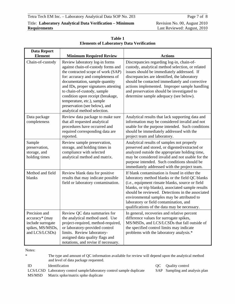
Tetra Tech EM Inc. – Laboratory Analytical Data SOP No. 203 Page 7 of 8Title: Laboratory Analytical Data Verification – Minimum Requirements
Revision No. 00, August 2010 Last Reviewed: August, 2010
Table 1 Elements of Laboratory Data Verification
Data Report Element Minimum Required Review Actions
Chain-of-custody Review laboratory log-in forms against chain-of-custody forms and the contracted scope of work (SAP) for: accuracy and completeness of documentation, sample quantity and IDs, proper signatures attesting to chain-of-custody, sample condition upon receipt (breakage, temperature, etc.), sample preservation (see below), and analytical method selection.
Discrepancies regarding log-in, chain-of-custody, analytical method selection, or related issues should be immediately addressed. If discrepancies are identified, the laboratory should be contacted immediately and corrective actions implemented. Improper sample handling and preservation should be investigated to determine sample adequacy (see below).
Data package completeness
Review data package to make sure that all requested analytical procedures have occurred and required corresponding data are reported.
Analytical results that lack supporting data and information may be considered invalid and not usable for the purpose intended. Such conditions should be immediately addressed with the project team and laboratory.
Sample preservation, storage, and holding times
Review sample preservation, storage, and holding times in compliance with selected analytical method and matrix.
Analytical results of samples not properly preserved and stored, or digested/extracted or analyzed outside the appropriate holding time, may be considered invalid and not usable for the purpose intended. Such conditions should be immediately addressed with the project team.
Method and field blanks
Review blank data for positive results that may indicate possible field or laboratory contamination.
If blank contamination is found in either the laboratory method blanks or the field QC blanks (i.e., equipment rinsate blanks, source or field blanks, or trip blanks), associated sample results should be reviewed. Detections in the associated environmental samples may be attributed to laboratory or field contamination, and qualifications of the data may be necessary.
Precision and accuracy* (may include surrogate spikes, MS/MSDs, and LCS/LCSDs)
Review QC data summaries for the analytical method used. Use project-required, method-required, or laboratory-provided control limits. Review laboratory-assigned data quality flags and notations, and revise if necessary.
In general, recoveries and relative percent difference values for surrogate spikes, MS/MSDs, and LCS/LCSDs that fall outside of the specified control limits may indicate problems with the laboratory analysis.*
Notes: * The type and amount of QC information available for review will depend upon the analytical method
and level of data package requested. ID Identification QC Quality control LCS/LCSD Laboratory control sample/laboratory control sample duplicate SAP Sampling and analysis plan MS/MSD Matrix spike/matrix spike duplicate
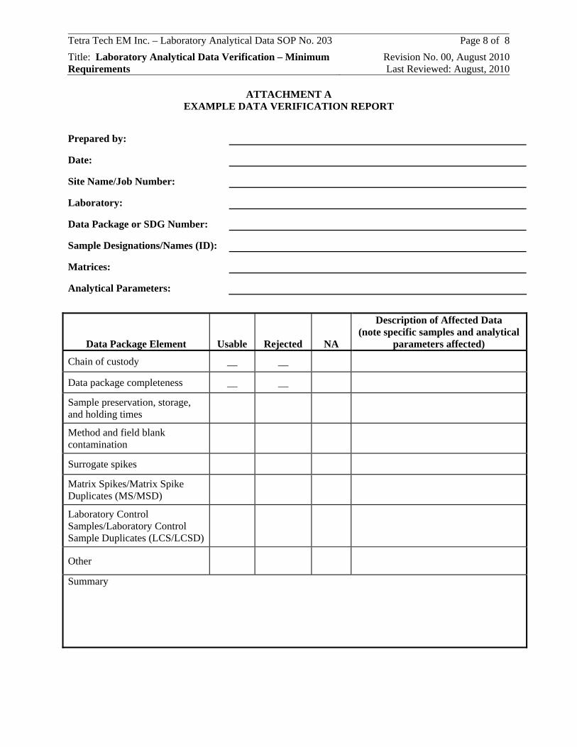
Tetra Tech EM Inc. – Laboratory Analytical Data SOP No. 203 Page 8 of 8Title: Laboratory Analytical Data Verification – Minimum Requirements
Revision No. 00, August 2010 Last Reviewed: August, 2010
ATTACHMENT A EXAMPLE DATA VERIFICATION REPORT
Prepared by:
Date:
Site Name/Job Number:
Laboratory:
Data Package or SDG Number:
Sample Designations/Names (ID):
Matrices:
Analytical Parameters:
Data Package Element Usable Rejected NA
Description of Affected Data (note specific samples and analytical
parameters affected)
Chain of custody __ __
Data package completeness __ __
Sample preservation, storage, and holding times
Method and field blank contamination
Surrogate spikes
Matrix Spikes/Matrix Spike Duplicates (MS/MSD)
Laboratory Control Samples/Laboratory Control Sample Duplicates (LCS/LCSD)
Other
Summary
ATTACHMENT 1
PACIFIC WESTERN TECHNOLOGIES SOP

PWT STANDARD OPERATING PROCEDURE
Indoor and Attic Dust SamplingProcedure No. PWT-ENSE-430
Revision 0Date effective: 9/10/2015
APPROVED: /s Page i of 12PWT Program Manager, Date
TABLE OF CONTENTS
TABLE OF CONTENTS ............................................................................................................................. i
List of Attachments.......................................................................................................................................ii
1.0 PURPOSE AND SCOPE.................................................................................................................. 1
2.0 REQUIREMENTS............................................................................................................................ 1
2.1 Key Words .................................................................................................................................... 1
2.2 Quality Assurance / Quality Control (QA/QC)............................................................................. 1
2.3 Health and Safety.......................................................................................................................... 1
2.4 Personnel Qualifications ............................................................................................................... 1
2.5 Definition ...................................................................................................................................... 1
2.6 Guidance Documents and Reference SOPs .................................................................................. 1
3.0 MATERIALS AND EQUIPMENT.................................................................................................. 2
4.0 PRIOR TO SAMPLING ................................................................................................................... 3
4.1 Indoor Dust Sampling Methodology............................................................................................. 3
4.2 Equipment Calibration .................................................................................................................. 4
4.3 Leak Check ................................................................................................................................... 4
4.4 Pre-Sampling Questionnaire and Pre-Test Survey........................................................................ 4
4.5 Selection of Indoor Dust Sampling Locations .............................................................................. 5
5.0 DOCUMENTATION ....................................................................................................................... 5
5.1 Sample Forms ............................................................................................................................... 5
5.1 Sample Identification .................................................................................................................... 5
6.0 FLOOR DUST SAMPLING PROCEDURE.................................................................................... 6
6.1 Preparing the Sampling Area ........................................................................................................ 6
6.2 Adjusting the HVS3 Nozzle Suction and Flowrate....................................................................... 7
6.3 Operating the HVS3 Unit.............................................................................................................. 7
6.4 Cleaning the HVS3 Unit ............................................................................................................... 8
7.0 ATTIC DUST SAMPLING.............................................................................................................. 9
8.0 SAMPLE HANDLING..................................................................................................................... 9
9.0 EQUIPMENT BLANKS................................................................................................................... 9
10.0 SIDE BY SIDE REPLICATES......................................................................................................... 9
PWT STANDARD OPERATING PROCEDURE
Indoor and Attic Dust SamplingProcedure No. PWT-ENSE-430
Revision 0Date effective: 9/10/2015
APPROVED: /s Page ii of 12PWT Program Manager, Date
11.0 REFERENCES ............................................................................................................................... 10
List of Attachments
Attachment A Indoor Dust Sampling Field Forms
PWT STANDARD OPERATING PROCEDURE
Indoor and Attic Dust SamplingProcedure No. PWT-ENSE-430
Revision 0Date effective: 9/10/2015
APPROVED: /s Page iii of 12PWT Program Manager, Date
REVISION LOG
Revision Number Description Date
0 Original SOP September 2015
ANNUAL REVIEW LOG
Revision Reviewed Description Date
PWT STANDARD OPERATING PROCEDURE
Indoor and Attic Dust SamplingProcedure No. PWT-ENSE-430
Revision 0Date effective: 9/10/2015
APPROVED: /s Page 1 of 12PWT Program Manager, Date
1.0 PURPOSE AND SCOPE
This Standard Operating Procedure (SOP) provides technical guidance and methods that will be used forcollection of indoor dust samples for chemical analysis during environmental investigations performedduring the Remedial Investigation (RI) in the Community Properties Study Area (CPSA) of the ColoradoSmelter Site. This procedure applies to collection of dust from a variety of indoor living space and atticsurfaces, including level loop and plush pile carpets and bare floors (wood, tile, or other). Attic samplecollection procedures vary slightly from collection of other indoor dust samples, and are discussedseparately. This SOP serves as a supplement to site-specific Health and Safety plans and the site-specificCPSA RI Quality Assurance Project Plan (QAPP).
This SOP is intended to be used in conjunction with other SOPs produced by Pacific WesternTechnologies, Ltd. (PWT) for environmental support operations on contracts for the United StatesEnvironmental Protection Agency (USEPA).
2.0 REQUIREMENTS
The following sections identify the requirements for collection of indoor dust samples.
2.1 Key Words
Indoor Dust; Attic Dust; Dust Sampling; Residential Sampling.
2.2 Quality Assurance / Quality Control (QA/QC)
Follow all QA/QC requirements as identified in the approved project planning document(s) such as theCPSA RI QAPP and this SOP. Guidance documents referenced during SOP development are identifiedin Section 2.6.
2.3 Health and Safety
Follow health and safety requirements identified in the Site-Specific Health and Safety Plan (HASP), JobSafety Analyses (JSAs), any applicable task health and safety plans prepared by PWT subcontractors, andthe associated Activity Hazard Analyses (AHAs).
2.4 Personnel Qualifications
Personnel planning to perform indoor or attic dust sampling activities will have knowledge andexperience in the required equipment and methods, or will work under the direct supervision ofknowledgeable and experienced personnel.
2.5 Definition
The dust sampling approach described in this SOP uses a High Volume Small Surface Sampler (HVS3).This specialized vacuum is designed to collect dust samples for chemical analysis, and is shown in Figure1. Attic sampling will be completed using a specialized attic sampling attachment for the HVS3.
2.6 Guidance Documents and Reference SOPs
The following PWT SOPs should be used in conjunction with this Indoor and Attic Dust Samplingprocedure:
PWT-ENSE-402 Spatial Data SubmittalsPWT-ENSE-406 Sample Handling
PWT STANDARD OPERATING PROCEDURE
Indoor and Attic Dust SamplingProcedure No. PWT-ENSE-430
Revision 0Date effective: 9/10/2015
APPROVED: /s Page 2 of 12PWT Program Manager, Date
PWT-ENSE-423 Investigation Derived Waste ManagementPWT-ENSE-424 Personnel and Equipment Decontamination
In addition to the listed SOPs, this indoor dust sampling procedure is consistent with USEPA’s Guidancefor the Sampling and Analysis of Lead in Indoor Residential Dust for Use in the IEUBK Model (USEPA,2008). The following supplemental information was also considered in development of PWT-ENSE-430,Indoor and Attic Dust Sampling.
ASTM D5438-11: Standard Practice for Collection of Floor Dust for Chemical AnalysisCS3-Inc.: High Volume Small Surface Sampler (HVS3) Operation Manual.
3.0 MATERIALS AND EQUIPMENT
This procedure is intended for use with the CS3 HVS3 unit. A schematic of the HVS3 is shown in Figure1. The equipment consists of the following components:
Nozzle – The edges and corners of the sampling nozzle are rounded and smooth. This preventsthe nozzle from snagging on any carpeted material which may be encountered. Nozzleconstruction allows for sufficient suction to separate loose particles from the bare floor orcarpeted surface and carry them to the cyclone. The nozzle is 12.5 centimeters (cm) long, and 1cm wide, with a 13-millimeter (mm) flange which tapers to the nozzle tubing at an angle equal toor less than 30 degrees. This configuration allows the nozzle to perform with the appropriatevelocities when operated correctly.Cyclone – The cyclone is constructed such that the air flow allows for separation of particles of 5-microns in diameter (or larger). The cyclone shall be made of aluminum or stainless steel. Aspare cyclone should be kept on hand if possible.Catch Bottle – The catch bottle will be purchased from an appropriate environmental supplycompany, and shall meet the requirements of the analytical laboratory. Catch bottles must betransparent so that the operator can see the sample as it is collected. Bottles should be 250-mLlow-density polyethylene (LDPE) or fluorinated ethylene propylene.Flow Control System – The flow control system allows for substantial volume adjustment. Thesuction source is capable of drawing 12 liters per second (L/s) through the system with norestrictions other than the connected nozzle, cyclone, and flow control system. A commercialvacuum cleaner may be modified for this purpose by the HVS3 manufacturer.Gaskets – Gaskets in joints will be made of an inert material appropriate to avoid samplecontamination, and to prevent air leakage.Flow Measuring and Suction Gages – Magnehelic gages are used to measure the pressure drop atthe nozzle and for control of the flow rate for the entire system.
Other equipment and materials necessary to perform the work described in the SOP include:
Digital scale accurate to 0.1 grams, for weighing samplesStopwatchTwo measuring tapes for sampling area layout, OR pre-cut, plastic templates for delineatingsampling areas. Template size may vary, but a 2-foot by 2-foot template is recommendedMasking tape (painter type masking tape is suggested, to allow for easy and damage freeremoval)
PWT STANDARD OPERATING PROCEDURE
Indoor and Attic Dust SamplingProcedure No. PWT-ENSE-430
Revision 0Date effective: 9/10/2015
APPROVED: /s Page 3 of 12PWT Program Manager, Date
Marking pensNitrile glovesSafety glassesManila envelope of file folder for leak checkThermometerRelative humidity meterInclined manometer for instrument calibrationAlconox (or equivalent) and brush for decontaminationSqueeze bottle containing deionized waterSqueeze bottle containing soap solution (Alconox or equivalent)Squeeze bottle containing deionized waterFine silica for blanksKim-wipesHand tools (screw driver, wrenches, etc)Extra sample catch bottles and capsZip-top plastic bagsStainless steel tray or clean sheets of paper/foilDigital cameraSample labelsAppropriate field forms and SOPs
Additional equipment for attic sampling includes:
HVS3 Microvac Attic Sampling attachmentTyvek protective suit
4.0 PRIOR TO SAMPLING
4.1 Indoor Dust Sampling Methodology
This SOP describes the use of the HVS3 to collect indoor dust samples for chemical analysis. Surfacedust particles are collected from the carpet or the bare floor by means of vacuum-induced suction.Particles enter the HVS3 through the sampling nozzle. The recommended pressure and flow rate aredependent on the type of surface being sampled, but must be sufficient to generate the velocity required toliberate the dust particles from carpeted and bare floor surfaces into the sampler air stream. The nozzle isdesigned to move across the floor with minimal resistance while still maintaining a seal to collect thesample.
Dust flows into the cyclone, which collects most particles larger than 5 microns in diameter. Samplecollection utilizes centrifugal force. Larger (heavier) particles move to the outside wall of the cycloneand then slide down into the catch bottle (sample container) threaded onto the bottom of the cyclone. Thesample container may then be capped and labeled for sample storage and shipment. Refer to PWT-ENSE-406, Sample Handling for details on sample labeling, storage, and shipment. Smaller particlesremain in the air stream and flow out the exhaust tube. The cyclone collects an average of 99 percent ofthe surface dust picked up by the nozzle. Any dust that is not captured in the sample container movesthrough the fan and is retained in the vacuum cleaner bag. This material will not be sent for chemicalanalysis.
PWT STANDARD OPERATING PROCEDURE
Indoor and Attic Dust SamplingProcedure No. PWT-ENSE-430
Revision 0Date effective: 9/10/2015
APPROVED: /s Page 4 of 12PWT Program Manager, Date
4.2 Equipment Calibration
The HVS3 sampling process does not require any internal calibrated flow devices. The cyclone isdesigned to create separation of particles at various flow rates throughout the range of operationalflowrates the system can produce. As a result, there is not a requirement to regularly calibrate the HVS3.Pressure gages (Magnehelic gages) should be calibrated against a primary standard at the start of each daythey will be used for sampling. Adjust the flow rate and the nozzle pressure drop to values thatapproximate those given in Section 6.2 of this SOP.
Pressure gages shall be calibrated against an inclined manometer or other primary standard. One meansof checking a Magnehelic gage is to set a flow rate through the sampling system with a manometer, thenswitch to the Magnehelic gage. This process should be repeated at two different flow rates. If thedifference in the readings is more than 3%, the gage is leaking, or is in need of repair or recalibration.The gage should be tagged “DO NOT USE” and taken out of service. Results of calibration should berecorded in the field logbook.
4.3 Leak Check
Prior to using the HVS3 to collect samples, a leak check shall be performed to verify that the equipmenthas been assembled correctly. The leak check shall be completed as follows:
Place a thick manila envelope or a file folder underneath the nozzle to seal off the opening.Turn on the HVS3. The flow Magnehelic gage should read 0-0.02 inches of water to ensure thesystem is not leaking.If leakage is suspected, and the gage reads more than 0.02 inches of water, check all gaskets andcheck tightness of clamps, catch bottle, and material covering the nozzle opening.Once all connections have been verified, recheck the flow to the Magnehelic gage to make sure itreads less than 0-0.02 inches of water before beginning sampling.If the HVS3 is unable to pass the leak check after connections have been verified, tag theequipment “DO NOT USE” and contact the project manager for instructions.
4.4 Pre-Sampling Questionnaire and Pre-Test Survey
Owners and/or occupants as appropriate (hereafter referred to as “residents”) of properties identified forindoor dust sampling will be contacted in advance to schedule a time for indoor sampling to occur. At thetime that the sampling is scheduled, residents will be asked to maintain normal cleaning routines prior tosampling.
Upon arrival at the home for indoor sampling, a member of the field team will discuss the work to becompleted with the residents. Through this discussion, the field sampler will identify appropriatesampling locations within the home, based on the information provided about how the space is used. Thesampler will confirm the most frequently occupied areas of the home, the most frequently used doors tothe outside, and whether any children sleep in the home (children’s bedrooms will be sampled ifavailable).
In order to better understand variables which are known to impact indoor dust, an Indoor Dustquestionnaire (see Attachment 1) will be completed as part of dust sampling activities. One of thesamplers will complete the questionnaire with the resident head-of-household if available, or with anotherresident of the house if necessary. Completion of the questionnaire is required prior to selection ofsampling areas within the home. Some of the factors known to impact indoor dust include pets,
PWT STANDARD OPERATING PROCEDURE
Indoor and Attic Dust SamplingProcedure No. PWT-ENSE-430
Revision 0Date effective: 9/10/2015
APPROVED: /s Page 5 of 12PWT Program Manager, Date
occupation, smoking habits, age of residence, primary heating source, floor surface (carpet vs hardsurfaces), cleaning equipment, cleaning habits, and resident hobbies.
4.5 Selection of Indoor Dust Sampling Locations
Sample collection locations are specified in the QAPP to include the main entryway (most frequentlyused entryway), the floor area of the most frequently occupied room (usually the kitchen or living room),and the floor of a child’s bedroom (or any bedroom if there is not a child living in the home). Aminimum of 3 and a maximum of 5 samples will be collected in each home.
The total floor area vacuumed to obtain dust for each sample will depend on the amount of dust present.The floor area sampled will be measured and recorded on the sampling form to allow calculation of themetals loading rate for each sample from the resulting analytical data. Sampling efforts at a location willcontinue until a minimum of 20 grams of sample is collected, or at least enough dust to completely coverthe sample container. If the initially defined sampling area (or the template, if one is used) do not provideenough sample material, a second area immediately adjacent to the first should be defined, and sampled.The sampling form should indicate the total area sampled (the initial area which yielded an insufficientsample + the additional area, typically equal to the initial area times 2). If not enough dust is present inthe individual room samples, samples from multiple living areas in the home may be composited.However, attic samples (see below) will not be composited with discrete or composite samples fromliving areas under any circumstances.
Attic dust sampling will be conducted only at those residences where the attic can be routinely accessed(e.g., by stairway, ladder/trap door, etc.). One composite sample of attic dust will be collected in eachhome where the attic is accessible.
5.0 DOCUMENTATION
All forms required are provided as attachments to this SOP. Other documentation, such as information tobe recorded in field log books, is described in this section of the SOP.
5.1 Sample Forms
The pre-sampling questionnaire must be completed prior to selection of sampling locations. Thequestionnaire may have some lines completed prior to samplers arriving at the house, if the informationwas obtained from the homeowner or resident over the telephone while scheduling sampling. Thisinformation should be verified on the day of sampling.
In addition to the Pre-Sampling Questionnaire, samplers will start an Indoor Dust Sample InformationForm immediately prior to sampling. This form will be completed during sampling for each areasampled.
For all field documentation: All lines on the forms must be filled in. In cases where a given item may notapply, mark that space “N/A”. Forms should be completed in accordance with PWT-ENSE-406.
5.1 Sample Identification
The sample identification scheme for indoor dust samples is presented in the CPSA RI QAPP, and issummarized here for sampler convenience.
PWT STANDARD OPERATING PROCEDURE
Indoor and Attic Dust SamplingProcedure No. PWT-ENSE-430
Revision 0Date effective: 9/10/2015
APPROVED: /s Page 6 of 12PWT Program Manager, Date
The first part of the sample name is a letter designating the matrix sampled, D for indoor dust, followedby a unique four digit parcel code assigned by the PWT Team. The second part of the sample nameidentifies the feature sampled at the property. The final part of the sample name is a letter to designateother sample information, such as QC sample type.
For example, the sample name D1402-E-DUP refers to a dust sample collected from the main entryway atproperty 1402. The sample is a duplicate/replicate sample, as indicated by the trailing letters “DUP”.
The features which might be sampled and the associated feature codes assigned are as follows:
For Dust:
E = main entryway
K = kitchen
L = living room
B = bedroom, if more than one bedroom is sampled, expand to B1, B2, etc.
C = residence living area composite sample (in case sufficient material could not beobtained for discrete samples)
A = attic
A unique CLP number will be assigned to each sample in addition to its sample identification asdescribed above. Both identifications will be recorded on the sample label and the chain-of-custody.
6.0 FLOOR DUST SAMPLING PROCEDURE
Indoor Dust Sampling activities shall be conducted as follows.
6.1 Preparing the Sampling Area
The areas to be sampled will have been determined during completion of the Pre-Sampling Questionnaire.First, mark off the area to be sampled. This may be done by one of two methods. Regardless of whichmethod is used, the sampled area should be at least 3 feet from any outside door, and the dimensions ofthe area will be recorded on the field form. When laying out the sampling area, it is important to leaveenough space around the perimeter of the sampling area to allow for samplers to move and for operationof the HVS3 to the full extent of the sampled area.
A pre-made sampling template may be used or the area may be measured and taped with masking tape. Ifa pre-made sampling template is to be used, wipe the template with a clean laboratory tissue and place thetemplate on the floor in the area to be sampled. Use masking tape to temporarily hold the template stillduring sampling.
To sample from a measured area, instead of a pre-made template, the procedure is as follows. Place twomeasuring tapes on the floor parallel to each other on either side of the main traffic path through the area.The tapes should be approximately 2 feet to 5 feet apart and be extended as far as the space will permit.Masking tape will be placed along the tape measures for a distance of approximately 3.5 feet for carpet orrugs, and as large as possible for bare floors, (this distance may be increased (space permitting) ifsufficient sample volume cannot be collected in the initial area).
PWT STANDARD OPERATING PROCEDURE
Indoor and Attic Dust SamplingProcedure No. PWT-ENSE-430
Revision 0Date effective: 9/10/2015
APPROVED: /s Page 7 of 12PWT Program Manager, Date
If a pre-made sampling template is used, distance marks will already be available. If a template is notused, begin at the same end of each piece of masking tape, and use a permanent marker to make a smallmark every 3 inches and a larger mark every 12 inches along the tape. Individual sampling strips aredetermined by the size of the HVS3 nozzle, and are approximately 3 inches wide.
6.2 Adjusting the HVS3 Nozzle Suction and Flow Rate
Clean the wheels and nozzle tip of the HVS3 with a clean laboratory tissue before sampling. Place theHVS3 sampler in the lower left corner of the sampling area. Adjust the flow rate and pressure at thenozzle according to the surface to be sampled.
The pressure at the nozzle is a function of the flow rate and the distance between the surface and thenozzle. The nozzle position is regulated by the height control knob on the back of the HVS3 and thenozzle level adjustment knob on the front side of the nozzle. A butterfly valve located on the control tubedownstream of the cyclone regulates the flow rate, which is measured by the pressure across the cyclone.Higher flow rates produce higher pressures. The nozzle position adjustment allows for the completesystem to be regulated.
To use the HVS3 on hard surfaces or level loop carpet (typical commercial type carpeting), adjust theheight of the nozzle until the bubble level is centered. If the HVS3 is close to the position required, butthe bubble is not quite centered, use the nozzle level adjustment knob to fine tune the adjustment. Then,set the flow rate with the butterfly valve. To check the flow rate, tip the HVS3 unit forward and check theflow on the Magnehelic gage. The flow should read at least 5 cubic feet per minute (cfm).
Next, read the pressure across the nozzle. The pressure should be approximately 9 inches of water. If thepressure reading is not 9 inches, recheck the flow and/or check that the nozzle is still level and makeadjustments accordingly.
To use the HVS3 unit on plush or shag carpet, read the pressure across the nozzle and set the pressure toapproximately 9.5 inches on the nozzle gage. The pressure can be set by using the height adjustmentknob and the level knob to keep the nozzle level. Next, set the flow rate with the butterfly valve forapproximately 20 cfm, 8 inches of water. Then re-check the pressure across the nozzle. The pressure haslikely increased due to the increased flow rate. Reset the pressure to 9.5 inches of water using the heightadjustment knob. Then recheck the flow rate and reset it to 20 cfm, 8 inches of water. It may takemultiple small adjustments to achieve the targeted flow rate of 20 cfm, 8 inches of water, and nozzlepressure of 9.5 to 10 inches of water.
Once the pressure and flow rate have been properly adjusted and verified, attach the sample container tothe HVS3.
The manometer fluid should be replaced at least annually per manufacturer instructions.
6.3 Operating the HVS3 Unit
The HVS3 unit functions best when the handle is locked in the fixed position at a 45 degree angle. Thisis done using the level at the bottom of the handle. This will allow the HVS3 unit to move forward andbackward in a smooth motion.
Starting at the bottom left corner of the sampling area, collect the sample by moving the nozzle forward ina straight line from one end of the sample area to the other at a speed of about 2 feet per second. Whenthe first pass is complete, the unit is pulled directly backwards over the same strip of floor. This is
PWT STANDARD OPERATING PROCEDURE
Indoor and Attic Dust SamplingProcedure No. PWT-ENSE-430
Revision 0Date effective: 9/10/2015
APPROVED: /s Page 8 of 12PWT Program Manager, Date
repeated 4 times for each strip of the sampling area. For the next strip, the nozzle is angled slightly to theright to the adjacent section of floor and the HVS3 is moved forward and backward 4 times. This isrepeated until all strips have been sampled, or there is enough sample in the catch bottle (samplecontainer).
After sampling the floor area within the pre-made template or the pre-measured floor area, check theamount of dust in the catch bottle. At a minimum, there must be enough dust to completely cover thebottom of the sample container. If possible, 20 grams of dust should be collected. This quantity of dust isneeded to allow for loss during sieving at the laboratory and to provide sufficient volume for laboratoryduplicate, QA/QC, or re-analysis. Hair, carpet fibers, and other large objects should be excluded fromconsideration when visually evaluating how much dust has been collected.
If the sample volume is insufficient, sampling personnel will designate/mark another sample locationimmediately adjacent (if possible). If an adjacent area is not available to be sampled, then a similar hightraffic area, frequent occupancy room, or bedroom should be selected to provide the additional samplevolume.
The additional material will be collected using the same method, as described above. When a sufficientamount of dust has been collected, turn off the HVS3 unit. Remove the sample container and attach thescrew on lid. Record the total dimensions of the sampled area on the Sample Information form.Weighing the dust sample will follow the procedure described in Section 10.
6.4 Cleaning the HVS3 Unit
The HVS3 unit will be decontaminated after collection of all dust samples at a residence (including bothLiving Space samples and the Attic sample). If the attic will not be sampled, follow this decontaminationprocedure after completion of indoor dust sampling at a residence and before beginning sampling at thenext residence.
Rubber/nitrile gloves and safety glasses shall be worn while cleaning the HVS3 unit. With the samplecontainer removed and safely stored, open the flow control valve to maximum flow, tip the sampler backso the nozzle is approximately 2 inches off the floor, and switch the vacuum on. Place a hand covered bya clean rubber glove on the bottom of the cyclone and alternate closing and opening the cyclone for 10seconds to free any loose material adhering to the walls of the cyclone and tubing.
Remove the HVS3 unit to a well ventilated area free of dust (e.g. field truck or van, field office) for wetcleaning. Remove the cyclone and elbow at the top of the nozzle tubing from the sampling unit. Holdeach section of the HVS3 over a waste container and rinse with deionized water using a squeeze bottle.After rinsing, use Kim-wipes wetted with deionized water and a brush to clean each section of thesampler. Then use Kim-wipes wetted with deionized water to clean the gaskets and connections betweeneach section of the tube. Use Kim-wipes wetted with deionized water to clean the previously usedcleaning brush.
Allow all equipment to air dry. The equipment must be completely dry before sampling again. The cleansections of the HVS3 unit can be placed in or on a clean container to air dry. Once the inside of theindividual sections are dry, re-assemble the HVS3 unit. Conduct a leak test at the next sample location toensure all clamps and gaskets have been assembled correctly.
An equipment blank will be collected every 20 decontaminations. Equipment blank sample collectionwill follow the procedure described in Section 9.
PWT STANDARD OPERATING PROCEDURE
Indoor and Attic Dust SamplingProcedure No. PWT-ENSE-430
Revision 0Date effective: 9/10/2015
APPROVED: /s Page 9 of 12PWT Program Manager, Date
7.0 ATTIC DUST SAMPLING
Attic Dust Sampling activities shall be conducted in generally the same manner as living space dustsamples. Never composite Attic dust with Living Space dust.
Attic dust will only be sampled in homes where the attic can be routinely accessed (by stairs,ladder/trapdoor, etc). If vermiculite or asbestos is identified in the attic, no sampling work will beconducted. Dust will be collected directly from exposed horizontal surfaces in the attic, such as raftertops or flooring. The dust will be collected from an area of the attic not likely to have been disturbed overtime (if possible). Attach the attic dust sampling attachment to the HVS3 unit. Complete a leak test atthe nozzle, as described in Section 4.3. After a satisfactory leak check, attach a clean sample container.
The attic dust sampling procedure is as follows:
Sampled areas in the attic will be measured and areas will be calculated and recorded on the SampleInformation Form. It is anticipated that space in attics will be limited, and it may be difficult to identify asuitable area for sampling. Areas to be sampled should be carefully measured and recorded on the fieldform. Pre-made templates may be sized to fit in typical attic spaces and used to delineate sampling areas.Once the space to be sampled has been identified and delineated with masking tape and/or the pre-madeattic sampling template, sampling can proceed in accordance with the floor sampling procedure describedin Section 6. Sampling should continue until adequate sample volume has been obtained, or until thereare no more suitable locations to sample within the attic. Decontamination of the HVS3 and the HVS3attic sampling extension will be completed as described in Section 6.4.
8.0 SAMPLE HANDLING
Samples will be preserved, stored, and handled in accordance with the project specific QAPP and PWT-ENSE-406, Sample Handling.
9.0 EQUIPMENT BLANKS
Equipment blanks or rinse blank samples will be collected after completing decontamination proceduresas described in Section 6.4. For this project, Equipment blanks shall be collected at the rate of one blankfor every 20 decontaminations performed. Equipment blanks will be collected by vacuuming fine silicaor powder through the collection device into a sample container. The material will then be submitted tothe laboratory for the same analysis as the investigative samples.
10.0 SIDE BY SIDE REPLICATES
Replicate dust samples will be collected at a frequency of one per 20 homes sampled. The replicatesample will be collected using the same procedure used for the investigative sample (as described inSection 6), from a floor area immediately adjacent to the investigative sample. Replicate samples willhave the same identifier as investigative samples, with the addition of a trailing letter “D” to indicate it isa replicate/duplicate sample (as described in Section 4.1).
PWT STANDARD OPERATING PROCEDURE
Indoor and Attic Dust SamplingProcedure No. PWT-ENSE-430
Revision 0Date effective: 9/10/2015
APPROVED: /s Page 10 of 12PWT Program Manager, Date
11.0 REFERENCES
ASTM-D5438-11, 2011. Standard Practice for Collection of Floor Dust for Chemical Analysis.American Society of Testing and Materials (ASTM) International. August.
CS3, Inc., 2001. High Volume Small Surface Sampler (HVS3) Operation Manual. Jack Hirsch.
US Environmental Protection Agency (USEPA), 2008. Guidance for Sampling and Analysis of Lead inIndoor Residential Dust for Use in the Integrated Exposure Uptake Biokenetic Model (IEUBK).Technical Review Workgroup for Metals and Asbestos, Lead Committee. OSWER 9285.7-81.December.
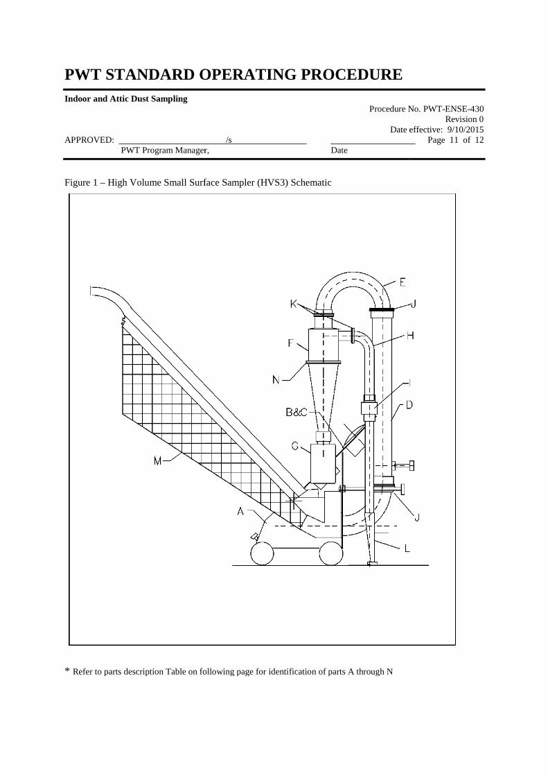
PWT STANDARD OPERATING
Indoor and Attic Dust Sampling
APPROVED:PWT Program Manager,
Figure 1 – High Volume Small Surface Sampler (HVS3) Schematic
* Refer to parts description Table on following page for identification of parts A through N
PWT STANDARD OPERATING PROCEDURE
Procedure No.
Date effective: 9/10/2015/s
Manager, Date
High Volume Small Surface Sampler (HVS3) Schematic
Refer to parts description Table on following page for identification of parts A through N
Procedure No. PWT-ENSE-430Revision 0
Date effective: 9/10/2015Page 11 of 12
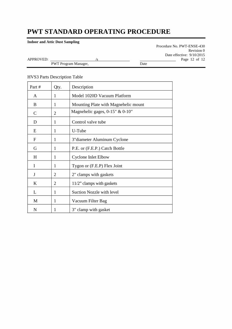
PWT STANDARD OPERATING PROCEDURE
Indoor and Attic Dust SamplingProcedure No. PWT-ENSE-430
Revision 0Date effective: 9/10/2015
APPROVED: /s Page 12 of 12PWT Program Manager, Date
HVS3 Parts Description Table
Part # Qty. Description
A 1 Model 1020D Vacuum Platform
B 1 Mounting Plate with Magnehelic mount
C 2 Magnehelic gages, 0-15" & 0-10"
D 1 Control valve tube
E 1 U-Tube
F 1 3"diameter Aluminum Cyclone
G 1 P.E. or (F.E.P.) Catch Bottle
H 1 Cyclone Inlet Elbow
I 1 Tygon or (F.E.P) Flex Joint
J 2 2" clamps with gaskets
K 2 11/2” clamps with gaskets
L 1 Suction Nozzle with level
M 1 Vacuum Filter Bag
N 1 3" clamp with gasket

ATTACHMENT A
Field Forms
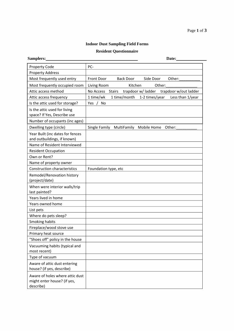
Page 1 of 3
Indoor Dust Sampling Field Forms
Resident Questionnaire
Samplers: Date:
Property Code PC-
Property Address
Most frequently used entry Front Door Back Door Side Door Other:__________
Most frequently occupied room Living Room Kitchen Other:_______________
Attic access method No Access Stairs trapdoor w/ ladder trapdoor w/out ladder
Attic access frequency 1 time/wk 1 time/month 1-2 times/year Less than 1/year
Is the attic used for storage? Yes / No
Is the attic used for livingspace? If Yes, Describe use
Number of occupants (inc ages)
Dwelling type (circle) Single Family MultiFamily Mobile Home Other:__________
Year Built (inc dates for fencesand outbuildings, if known)
Name of Resident Interviewed
Resident Occupation
Own or Rent?
Name of property owner
Construction characteristics Foundation type, etc
Remodel/Renovation history(project/date)
When were interior walls/triplast painted?
Years lived in home
Years owned home
List pets
Where do pets sleep?
Smoking habits
Fireplace/wood stove use
Primary heat source
"Shoes off" policy in the house
Vacuuming habits (typical andmost recent)
Type of vacuum
Aware of attic dust enteringhouse? (if yes, describe)
Aware of holes where attic dustmight enter house? (if yes,describe)
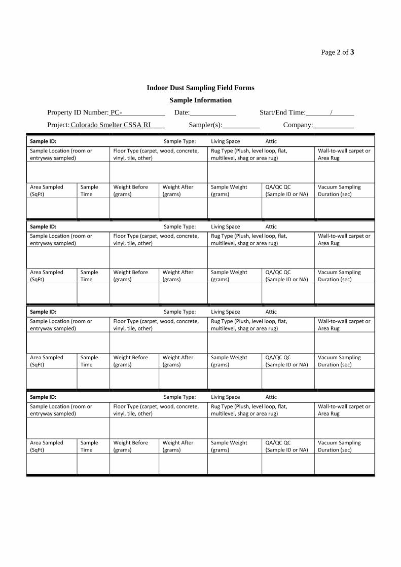
Page 2 of 3
Indoor Dust Sampling Field Forms
Sample Information
Property ID Number: PC- Date: Start/End Time: /
Project: Colorado Smelter CSSA RI Sampler(s): Company:
Sample ID: Sample Type: Living Space Attic
Sample Location (room orentryway sampled)
Floor Type (carpet, wood, concrete,vinyl, tile, other)
Rug Type (Plush, level loop, flat,multilevel, shag or area rug)
Wall-to-wall carpet orArea Rug
Area Sampled(SqFt)
SampleTime
Weight Before(grams)
Weight After(grams)
Sample Weight(grams)
QA/QC QC(Sample ID or NA)
Vacuum SamplingDuration (sec)
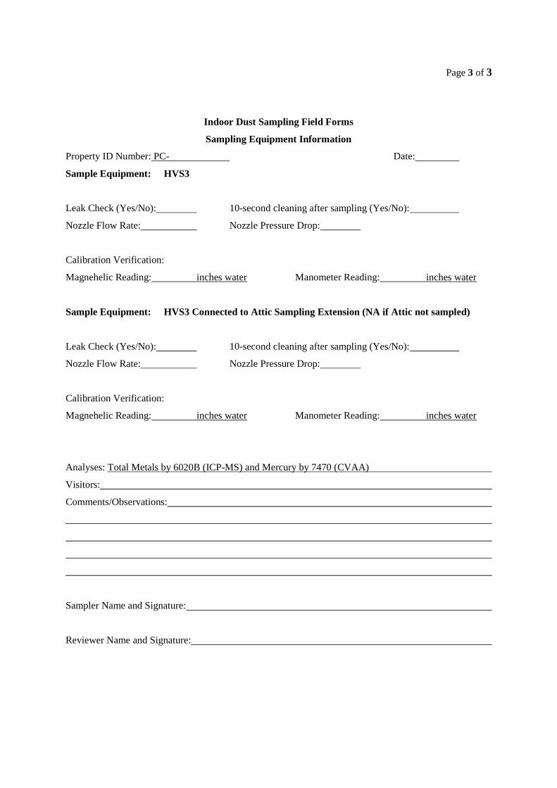
Page 3 of 3
Indoor Dust Sampling Field Forms
Sampling Equipment Information
Property ID Number: PC- Date:
Sample Equipment: HVS3
Leak Check (Yes/No): 10-second cleaning after sampling (Yes/No):
Nozzle Flow Rate: Nozzle Pressure Drop:
Calibration Verification:
Magnehelic Reading: inches water Manometer Reading: inches water
Sample Equipment: HVS3 Connected to Attic Sampling Extension (NA if Attic not sampled)
Leak Check (Yes/No): 10-second cleaning after sampling (Yes/No):
Nozzle Flow Rate: Nozzle Pressure Drop:
Calibration Verification:
Magnehelic Reading: inches water Manometer Reading: inches water
Analyses: Total Metals by 6020B (ICP-MS) and Mercury by 7470 (CVAA)
Visitors:
Comments/Observations:
Sampler Name and Signature:
Reviewer Name and Signature:

Appendix B
Validation Checklists
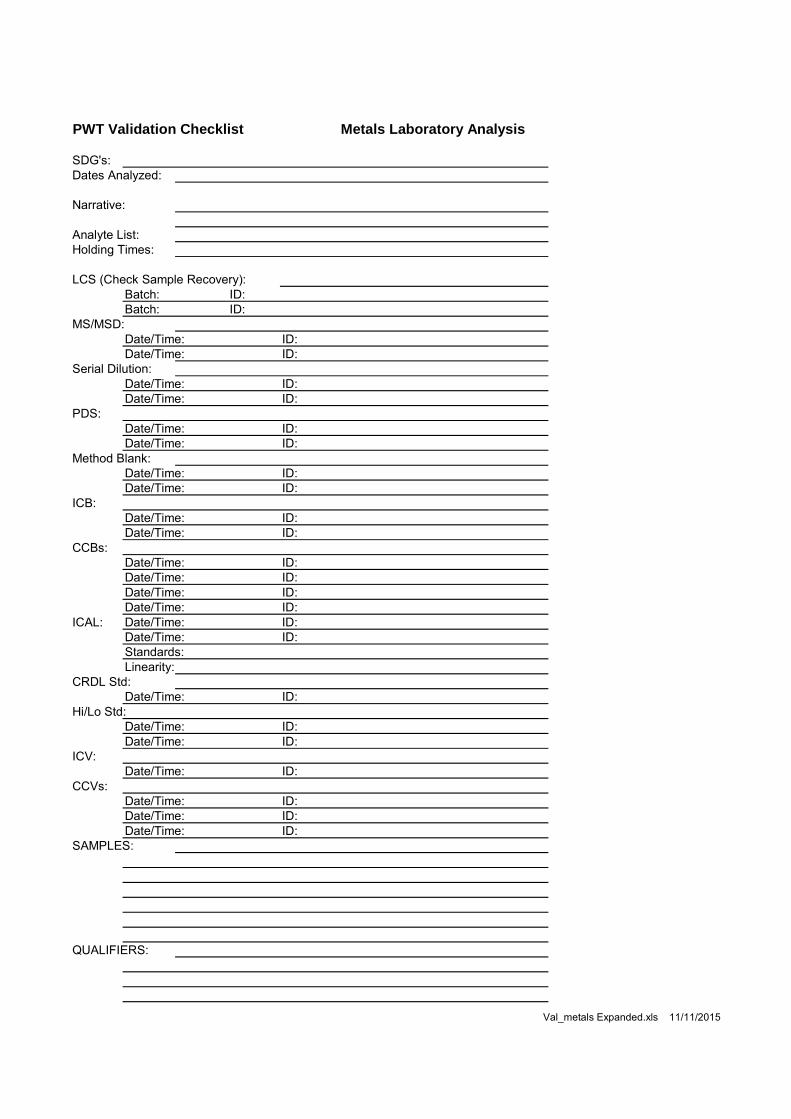
PWT Validation Checklist Metals Laboratory Analysis
SDG's:Dates Analyzed:
Narrative:
Analyte List:Holding Times:
LCS (Check Sample Recovery):Batch: ID:Batch: ID:
MS/MSD:Date/Time: ID:Date/Time: ID:
Serial Dilution:Date/Time: ID:Date/Time: ID:
PDS:Date/Time: ID:Date/Time: ID:
Method Blank:Date/Time: ID:Date/Time: ID:
ICB:Date/Time: ID:Date/Time: ID:
CCBs:Date/Time: ID:Date/Time: ID:Date/Time: ID:Date/Time: ID:
ICAL: Date/Time: ID:Date/Time: ID:Standards:Linearity:
CRDL Std:Date/Time: ID:
Hi/Lo Std:Date/Time: ID:Date/Time: ID:
ICV:Date/Time: ID:
CCVs:Date/Time: ID:Date/Time: ID:Date/Time: ID:
SAMPLES:
QUALIFIERS:
Val_metals Expanded.xls 11/11/2015
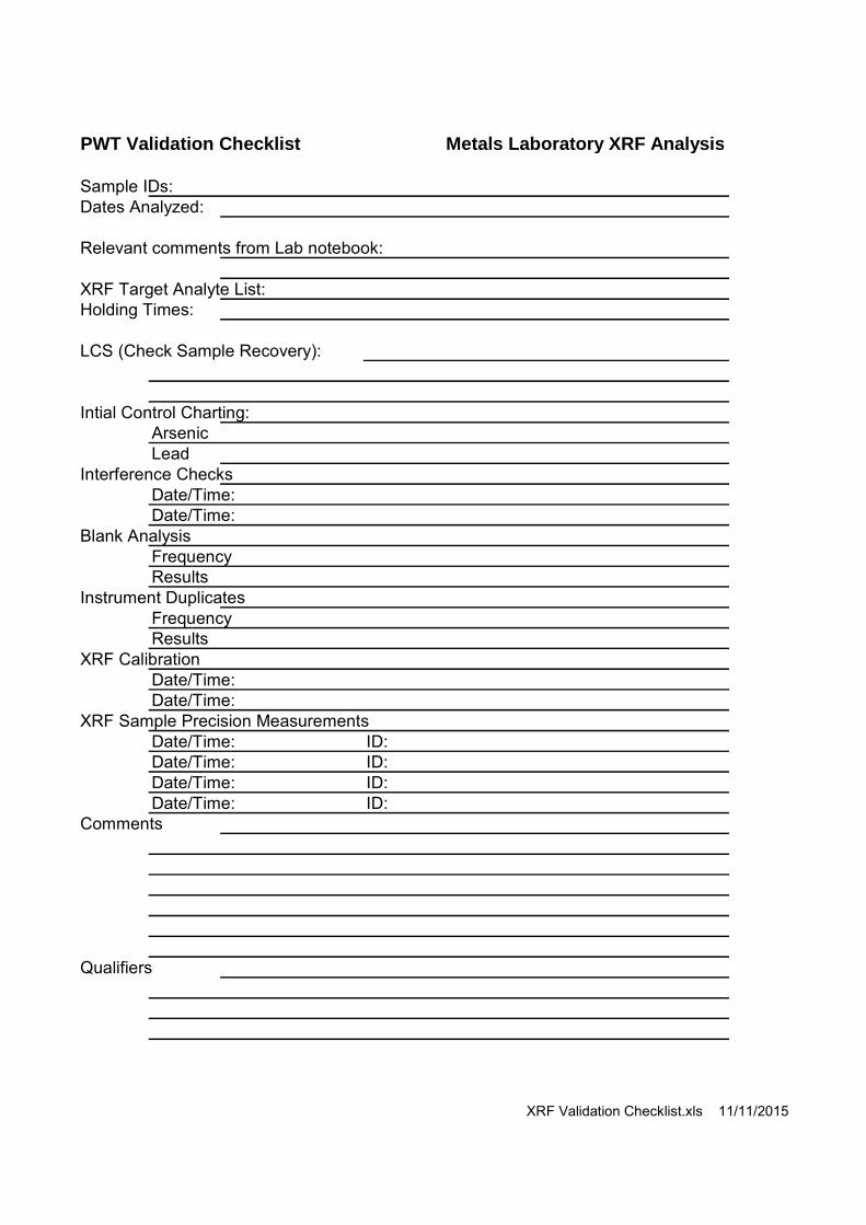
PWT Validation Checklist Metals Laboratory XRF Analysis
Sample IDs:Dates Analyzed:
Relevant comments from Lab notebook:
XRF Target Analyte List:Holding Times:
LCS (Check Sample Recovery):
Intial Control Charting:ArsenicLead
Interference ChecksDate/Time:Date/Time:
Blank AnalysisFrequencyResults
Instrument DuplicatesFrequencyResults
XRF CalibrationDate/Time:Date/Time:
XRF Sample Precision MeasurementsDate/Time: ID:Date/Time: ID:Date/Time: ID:Date/Time: ID:
Comments
Qualifiers
XRF Validation Checklist.xls 11/11/2015
ATTACHMENT 2
LABORATORY SOPS
ALSStandardOperatingProcedure
DOCUMENT TITLE: SOIL FRACTIONATION FOR LEAD ANALYSIS
REFERENCED METHOD: MDEQ PROCEDURE 213 SOP ID: HN-MET-007
REV. NUMBER: R04 EFFECTIVE DATE: 01/31/2016
Soil Fractionation for Pb HN-MET-007-R04 Effective: 01/31/2016 Page i of i
ALS GROUP USA, CORP. Part of the ALS Group An ALS Limited Company
STANDARD OPERATING PROCEDURE
TABLE OF CONTENTS 1) Scope and Applicability ................................................................................................................................................... 1 2) Summary of Procedure .................................................................................................................................................... 1 3) Definitions ....................................................................................................................................................................... 1 4) Health and Safety Warnings ............................................................................................................................................ 1 5) Cautions ........................................................................................................................................................................... 2 6) Interferences .................................................................................................................................................................... 2 7) Personnel Qualifications and Responsibilities ................................................................................................................. 2 8) Sample Collection, Handling, and Preservation .............................................................................................................. 2 9) Equipment and Supplies .................................................................................................................................................. 3 10) Standards and Reagents ................................................................................................................................................... 3 11) Method Calibration .......................................................................................................................................................... 3 12) Sample Preparation/Analysis ........................................................................................................................................... 3 13) Troubleshooting ............................................................................................................................................................... 4 14) Data Acquisition .............................................................................................................................................................. 4 15) Calculation, and Data Reduction Requirements .............................................................................................................. 4 16) Quality Control, Data Assessment and Corrective Action .............................................................................................. 4 17) Data Records Management .............................................................................................................................................. 5 18) Quality Assurance and Quality Control ........................................................................................................................... 5 19) Contingencies for Handling Out of Control Data ............................................................................................................ 5 20) Method Performance ....................................................................................................................................................... 5 21) Summary of Changes ....................................................................................................................................................... 5 22) References and Related Documents ................................................................................................................................ 5
Soil Fractionation for Pb HN-MET-007-R04 Effective: 01/31/2016 Page 1 of 5
ALS GROUP USA, CORP. Part of the ALS Group An ALS Limited Company
STANDARD OPERATING PROCEDURE
SOIL FRACTIONATION FOR LEAD ANALYSIS
1) Scope and Applicability
1.1 This procedure applies to soils collected by applicable Michigan Department of Environmental Quality (MDEQ) regulatory programs for the evaluation of lead exposure.
2) Summary of Procedure
2.1 Prior to sample digestion, the designated soil sample is mixed, agitated, dried, and sub-divided (via sieving) into coarse and fine fractions.
2.2 Each sample fraction is digested according to US EPA SW846-3050 (SOP HN-MET-009) and analyzed according to the project specified analytical procedure.
3) Definitions
3.1 Total Soil Fraction: A dried sample that will pass through a 10-mesh (2 mm) sieve.
3.2 Coarse Soil Fraction: The portion of the total soil fraction that will not pass through a 60-mesh (250 ) sieve.
3.3 Fine Soil Fraction: The portion of the total soil fraction that will pass through a 60-mesh (250 ) sieve.
3.4 Matrix: The component or substrate (i.e. soil) containing the analyte of interest.
3.5 SOP: Standard Operating Procedure
3.6 NCR: Nonconformance Report (refer to SOP HN-QS-003).
3.7 Material Safety Data Sheet (MSDS): Written information provided by vendors concerning a chemical's toxicity, health hazards, physical properties, fire, and reactivity data including storage, spill, and handling precautions.
4) Health and Safety Warnings
4.1 Lab Safety
4.1.1 Due to various hazards in the laboratory, safety glasses, disposable gloves, and laboratory coats or aprons must be worn when working with unknown samples. In addition, heavy-duty gloves and a face shield are recommended when dealing with toxic, caustic, and/or flammable chemicals.
4.1.2 The toxicity or carcinogenicity of each reagent used has not been precisely defined. However, each chemical used must be treated as a potential health hazard and exposure reduced to the lowest possible level. The laboratory maintains a current awareness file of OSHA regulations regarding the safe handling of the chemicals specified in this method. A reference file of data handling sheets (MSDS) is available to all personnel involved in these analyses.
4.2 Waste Disposal
4.2.1 Procedures for sample disposal are documented in SOP HN-SAF-001, Waste
Soil Fractionation for Pb HN-MET-007-R04 Effective: 01/31/2016 Page 2 of 5
ALS GROUP USA, CORP. Part of the ALS Group An ALS Limited Company
STANDARD OPERATING PROCEDURE
Disposal Procedures. 4.2.2 Samples must be disposed according to Federal, State, and local regulations.
4.3 Pollution Prevention
4.3.1 The quantities of chemicals purchased, when possible, must be based on the expected usage during its shelf life.
4.3.2 Standards and reagents must be prepared in volumes consistent with laboratory use to minimize the volume of expired standards or reagents to be disposed.
5) Cautions
5.1 Avoid inhalation of fine dust produced in this procedure, as it could contain harmful concentrations of lead.
6) Interferences
6.1 Sieves must be cleaned between each sample fractionation in order to avoid cross-contamination.
6.2 The work area should be periodically cleaned in order to eliminate potential environmental contamination.
7) Personnel Qualifications and Responsibilities
7.1 General Responsibilities - This method is restricted to use by or under the supervision of analysts experienced in the method.
7.2 Analyst - It is the responsibility of the analyst(s) to: 7.2.1 Read and understand this SOP and follow it as written. 7.2.2 Produce client compliant data that meets all quality requirements using this
procedure and the Data Reduction, Review and Validation SOP (HN-QS-009). 7.2.3 Complete the required demonstration of proficiency before performing this
procedure without supervision. 7.2.4 To create a data entry batch in LIMS for review and approval by the
Supervisor.
7.3 Section Supervisor - It is the responsibility of the section supervisor to: 7.3.1 Ensure that all analysts have the technical ability and have received adequate
training required to perform this procedure. 7.3.2 Ensure analysts have completed the required demonstration of proficiency
before performing this procedure without supervision. 7.3.3 Produce client compliant data that meets all quality requirements using this
procedure and the Data Reduction, Review and Validation SOP.
8) Sample Collection, Handling, and Preservation
8.1 Soil samples should be collected in 4 oz or 8 oz glass containers with Teflon lined lids.
Soil Fractionation for Pb HN-MET-007-R04 Effective: 01/31/2016 Page 3 of 5
ALS GROUP USA, CORP. Part of the ALS Group An ALS Limited Company
STANDARD OPERATING PROCEDURE
8.2 Samples should be stored at 4oC. No chemical preservation is required.
8.3 The holding time is 180 days.
9) Equipment and Supplies
9.1 Analytical balance – capable of weighing to 0.001 g
9.2 50ml Borosilicate glass beakers
9.3 Laboratory oven – capable of maintaining 1050 C + 20 C
9.4 Desiccator
9.5 10-mesh sieve – plastic or stainless steel
9.6 60-mesh sieve – plastic or stainless steel
9.7 Mechanical shaking device
9.8 Plastic vials w/caps
9.9 Mortar & pestle – ceramic w/ rubber tipped pestle
10) Standards and Reagents
10.1 Refer to the appropriate digestion and/or analytical method for reagents and standards.
11) Method Calibration
11.1 Analytical balance calibration must be verified and recorded prior to use as specified in SOP HN-EQ-001.
12) Sample Preparation/Analysis
12.1 Remove all rocks and/or vegetation from the soil sample.
12.2 Mix the sample thoroughly to achieve homogeneity and sieve through a 10-mesh sieve. If needed, manually agitate the sample contents (i.e., breakup large clumps) using a clean, ceramic/plastic spatula.
12.3 Transfer approximately 30g of sample from Section 12.2 into an appropriately labeled 50 ml glass beaker. (Use Black Sharpie®, as colored writing cooks off!)
12.4 Dry the sample at 1050 C + 20 C for 24 hours.
12.5 Remove the sample from the oven, immediately place in a desiccator, and cool for a minimum of one hour.
12.6 Pre-weigh a vials for each fraction to be determined; (1) Coarse and (1) Fine. Label as such, along with the appropriate sample ID. Record these weights in the Soil Fractionation Logbook.
12.7 If sample dried into large aggregates, use rubber tipped pestle to break up clumps. Take care not to grind aggregates, but to simply break up the clumps.
Soil Fractionation for Pb HN-MET-007-R04 Effective: 01/31/2016 Page 4 of 5
ALS GROUP USA, CORP. Part of the ALS Group An ALS Limited Company
STANDARD OPERATING PROCEDURE
12.8 Sieve the dried sample through a 60-mesh sieve for 10 minutes using a mechanical shaking device.
12.9 Transfer the soil passing through the 60-mesh sieve to the pre-weighed plastic vial labeled Fine. Weigh the combined (vial + sample) and record in the Soil Fractionation logbook.
12.10 Transfer the soil that did not pass through the 60-mesh sieve to the pre-weighed vial labeled Coarse. Weigh the combined (vial + sample) and record in the Soil Fractionation logbook.
12.11 Digest soil fractions per US EPA SW846-3050 (SOP HN-MET-009).
12.12 LCS1 – Digest 1.0g of NIST 8704. True concentration = 150 mg/Kg
12.13 LCS2 – Digest 1.0g of NIST 2586. True concentration = 432 mg/Kg
12.14 MS/MSD – Spike 1.0g sample with 5mL of Metals Custom Standard 901. True concentration = 50 mg/Kg.
13) Troubleshooting
13.1 Refer to the appropriate digestion and/or analytical method for troubleshooting.
14) Data Acquisition
14.1 Record all necessary data in the applicable preparation logbook/excel spreadsheet.
14.2 Refer to the appropriate digestion and/or analytical method for data acquisition.
15) Calculation, and Data Reduction Requirements
15.1 Refer to the appropriate digestion and/or analytical method for data reduction procedures.
15.2 Calculate the percent total solids in the soil % Total Solids = (DW/WW) X 100 where: DW = Sample weight dried WW = Sample weight as received
15.3 Analytical results for lead shall be based on dry weight.
15.4 Report analytical concentrations of lead in the fine and coarse fractions, separately.
15.5 Report total lead concentrations based upon the fine and coarse fractions adjusted for weight.
Total Lead = [(Conc
f X W
f) + (Conc
c X W
c)] / (W
f + W
c)
Where: Conc
f =
Lead Concentration in fine fraction
Conc
c = Lead Concentration in coarse fraction
W
f = Total Weight of the fine fraction
W
c = Total Weight of the coarse fraction
16) Quality Control, Data Assessment and Corrective Action
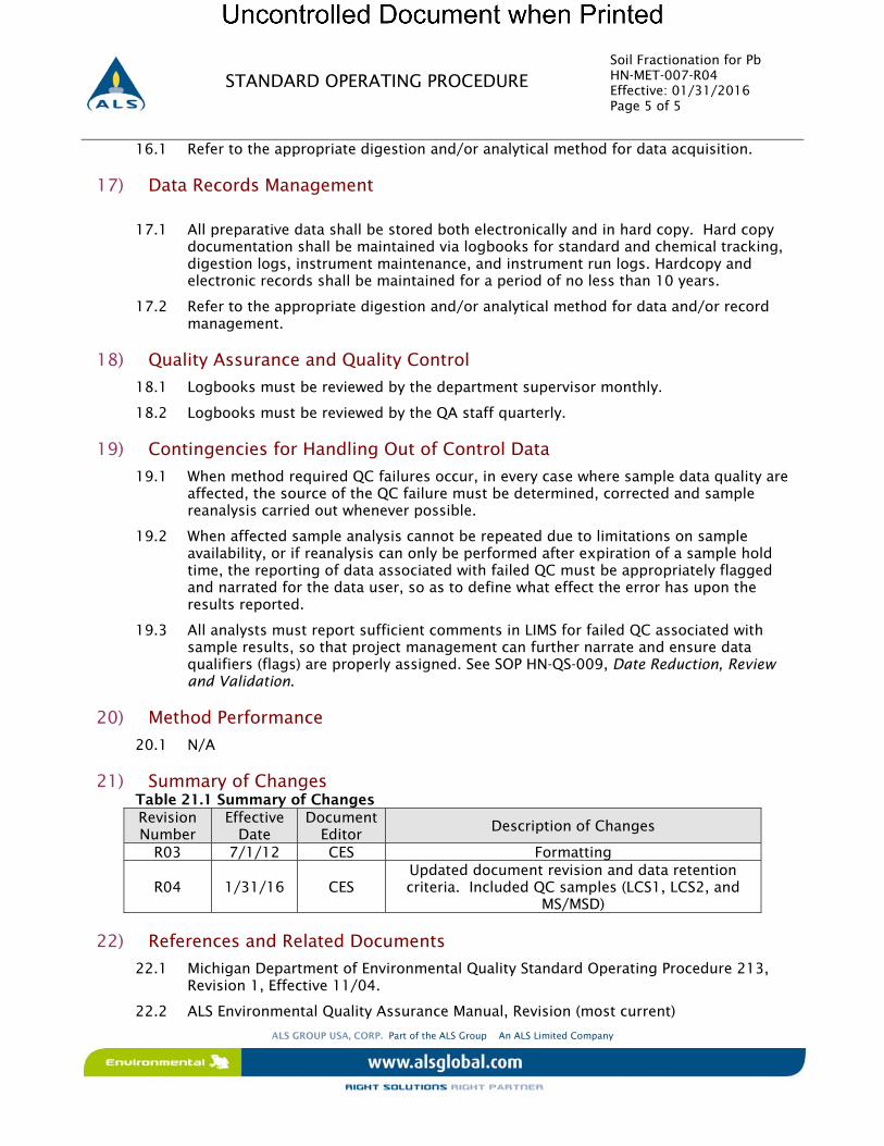
Soil Fractionation for Pb HN-MET-007-R04 Effective: 01/31/2016 Page 5 of 5
ALS GROUP USA, CORP. Part of the ALS Group An ALS Limited Company
STANDARD OPERATING PROCEDURE
16.1 Refer to the appropriate digestion and/or analytical method for data acquisition.
17) Data Records Management
17.1 All preparative data shall be stored both electronically and in hard copy. Hard copy documentation shall be maintained via logbooks for standard and chemical tracking, digestion logs, instrument maintenance, and instrument run logs. Hardcopy and electronic records shall be maintained for a period of no less than 10 years.
17.2 Refer to the appropriate digestion and/or analytical method for data and/or record management.
18) Quality Assurance and Quality Control
18.1 Logbooks must be reviewed by the department supervisor monthly.
18.2 Logbooks must be reviewed by the QA staff quarterly.
19) Contingencies for Handling Out of Control Data
19.1 When method required QC failures occur, in every case where sample data quality are affected, the source of the QC failure must be determined, corrected and sample reanalysis carried out whenever possible.
19.2 When affected sample analysis cannot be repeated due to limitations on sample availability, or if reanalysis can only be performed after expiration of a sample hold time, the reporting of data associated with failed QC must be appropriately flagged and narrated for the data user, so as to define what effect the error has upon the results reported.
19.3 All analysts must report sufficient comments in LIMS for failed QC associated with sample results, so that project management can further narrate and ensure data qualifiers (flags) are properly assigned. See SOP HN-QS-009, Date Reduction, Review and Validation.
20) Method Performance
20.1 N/A
21) Summary of Changes Table 21.1 Summary of Changes Revision Number
Effective Date
Document Editor Description of Changes
R03 7/1/12 CES Formatting
R04 1/31/16 CES Updated document revision and data retention criteria. Included QC samples (LCS1, LCS2, and
MS/MSD)
22) References and Related Documents
22.1 Michigan Department of Environmental Quality Standard Operating Procedure 213, Revision 1, Effective 11/04.
22.2 ALS Environmental Quality Assurance Manual, Revision (most current)
ALSStandardOperatingProcedure
DOCUMENT TITLE: METALS BY ICP-MS
REFERENCED METHOD: EPA 200.8 / SW846 6020A SOP ID: HN-MET-008
REV. NUMBER: R08 EFFECTIVE DATE: 01/15/2016

Metals by ICP-MS HN-MET-008-R08 Effective: 01/15/2016 Page i of i
R I G H T S O L U T I O N S | R I G H T P A R T N E R
STANDARD OPERATING PROCEDURE
TABLE OF CONTENTS 1) Scope and Applicability .............................................................................................................. 1 2) Summary of Procedure ............................................................................................................... 1 3) Definitions ................................................................................................................................. 1 4) Health and Safety Warnings ........................................................................................................ 2 5) Cautions .................................................................................................................................... 3 6) Interferences .............................................................................................................................. 3 7) Personnel Qualifications and Responsibilities ............................................................................. 4 8) Sample Collection, Handling, and Preservation ........................................................................... 5 9) Equipment and Supplies ............................................................................................................. 5 10) Standards and Reagents ............................................................................................................. 5 11) Method Calibration .................................................................................................................. 10 12) Sample Preparation/Analysis .................................................................................................... 12 13) Troubleshooting ...................................................................................................................... 14 14) Data Acquisition ...................................................................................................................... 14 15) Calculation, and Data Reduction Requirements ......................................................................... 14 16) Quality Control, Acceptance Criteria and Corrective Action ....................................................... 16 17) Data Records Management ....................................................................................................... 22 18) Contingencies for Handling Out of Control Data ....................................................................... 23 19) Method Performance ................................................................................................................ 23 20) Summary of Changes ............................................................................................................... 24 21) References and Related Documents .......................................................................................... 24
Metals by ICP-MS HN-MET-008-R08 Effective: 01/15/2016 Page 1 of 32
R I G H T S O L U T I O N S | R I G H T P A R T N E R
STANDARD OPERATING PROCEDURE
METALS BY ICP-MS
1) Scope and Applicability
1.1 Inductively coupled plasma-mass spectrometry (ICP-MS) is applicable to the determination of a large number of elements as either dissolved (aqueous only) or total metals.
1.2 This method is applicable to a variety of matrices including: drinking water, non-potable water, solid/chemical materials, and biological tissue.
1.3 ICP-MS has been applied to the determination of over 60 elements in various matrices. The method is applicable to analytical ranges of approximately 0.005 mg/L to 900 mg/L for aqueous matrices and 0.5 mg/kg to 900 mg/kg for solid matrices.
1.4 Method detection limits, quantitation limits, and linear ranges will vary with matrices, instrumentation, and operating conditions.
1.5 SW-846 Method 6020A is used to determine the analytes listed in Tables 20.1-A. This table lists more elements than the current version of Method 6020A. The additional elements are included based upon results of demonstrations of precision and accuracy and completion of method detection limit studies for aqueous and solid matrix.
1.6 Method 200.8 is used to determine the analytes listed in Table 20.1-B. This table lists more elements than the current version of Method 200.8. The additional elements are included based upon results of demonstrations of precision and accuracy and completion of method detection limit studies for aqueous matrix.
1.7 Internal standards are used for each analyte determined by ICP-MS. The internal standard mix used consists of 6Li, 45Sc, 89Y, 115In, 159Tb, 165Ho, and 209Bi. 89Y is used for analysis in helium gas mode.
2) Summary of Procedure
2.1 Prior to analysis, samples that require total ("acid-leachable") values must be digested using appropriate sample preparation methods as specified in SOP HN-MET-009 and HN-MET-010, Metal Digestion in Solid and Aqueous Matrices for ICPMS.
2.2 Analyte species originating in a liquid are nebulized and the resulting aerosol transported by argon gas into the plasma torch. Ions are produced by radio frequency inductively coupled plasma, entrained in the plasma gas, and introduced into a mass spectrometer. The ions are sorted according to their mass-to-charge ratios and quantified with a channel electron multiplier. Interferences must be assessed and valid corrections applied. Interference correction must include compensation for background ions contributed by the plasma gas, reagents, and constituents of the sample matrix.
3) Definitions
3.1 Laboratory Control Sample (LCS): An analyte-free matrix spiked with known concentrations of all target analytes. This is used to evaluate and document laboratory method performance.
3.2 Matrix: The component or substrate (e.g., surface water, groundwater, soil) which contains the analyte of interest.
3.3 Matrix Spike (MS): An aliquot of background sample spiked with a known concentrations of all target analytes. The spiking occurs prior to sample preparation
Metals by ICP-MS HN-MET-008-R08 Effective: 01/15/2016 Page 2 of 32
R I G H T S O L U T I O N S | R I G H T P A R T N E R
STANDARD OPERATING PROCEDURE
and analysis. A matrix spike is used to assess the bias of a method in a given sample matrix.
3.4 Matrix Spike Duplicate (MSD): A duplicate aliquot of the background sample spiked with a known concentrations of all target analytes. Spiking occurs prior to sample preparation and analysis. The MS/MSD pair are used to assess precision and bias of a method in a given sample matrix.
3.5 Method Blank: An analyte-free matrix to which all reagents are added in the same volumes or proportions as used in sample processing. The method blank is carried through the complete sample preparation and analytical procedure. The method blank is used to document contamination resulting from the analytical process.
3.6 Limit of Quantitation (LOQ): The minimum levels, concentrations, or quantities of a target variable (e.g., target analyte) that can be reported with a specified degree of confidence. The LOQ is also referred to as the method quantitation limit (MQL) or the reporting limit (RL).
3.7 Limit of Detection (LOD): an estimate of the minimum amount of a substance that an analytical process can reliably detect. An LOD is analyte- and matrix-specific and may be laboratory-dependent.
3.8 Method Detection Limit (MDL) study: the procedure, as described in 40CFR part 136, for determining the LOD based on statistical analysis of 7 low-level replicate spikes. The minimum concentration of an analyte that can be identified, measured, and reported with 99% confidence that the analyte concentration is greater than zero.
3.9 Standard Curve: A plot of concentrations of known analyte standards versus the instrument response to the analyte.
3.10 Internal Standard: A known amount of standard added to a test portion of a sample and carried through the entire measurement process as a reference for evaluating and controlling the precision and bias of the analytical test method.
3.11 Linear Dynamic Range (LDR): The concentration range through which the instrument response is linear.
3.12 Low-Level Quality Control sample (LLQC): A clean matrix sample spiked at the MQL and carried through the entire preparation and analysis process.
3.13 Low-Level Initial Calibration Verification (LLICV): A sample spiked at the MQL, used to validate the lower end of the initial calibration.
3.14 Low-Level Continuing Calibration Verification (LLCCV): A sample spiked at the MQL and analyzed periodically throughout an analytical sequence, monitoring continued performance of the lower end of a calibration.
4) Health and Safety Warnings
4.1 Lab Safety: Due to various hazards in the laboratory, safety glasses and laboratory coats or aprons must be worn at all times while in the laboratory. In addition, gloves and a face shield should be worn when dealing with toxic, caustic, and/or flammable chemicals.
4.2 Chemical Hygiene: The toxicity or carcinogenicity of each reagent used has not been precisely defined; however, each chemical used should be treated as a potential health hazard. Exposure to laboratory reagents should be reduced to the lowest possible level. The laboratory maintains a current awareness file of OSHA regulations regarding the safe handling of the chemicals specified in this method. A reference file of data
Metals by ICP-MS HN-MET-008-R08 Effective: 01/15/2016 Page 3 of 32
R I G H T S O L U T I O N S | R I G H T P A R T N E R
STANDARD OPERATING PROCEDURE
handling sheets (MSDS) is available to all personnel involved in these analyses.
4.3 Waste Management: The principal wastes generated by this procedure are the method-required chemicals and standards. It is the laboratory's responsibility to comply with all federal, state, and local regulations governing waste management by minimizing and controlling all releases from fume hoods and bench operations. Compliance with all sewage discharge permits and regulations is required. Laboratory procedures in SOP HN-SAF-001, Waste Disposal Procedures, must be followed.
4.4 Pollution Prevention: The materials used in this method pose little threat to the environment when recycled and managed properly. The quantities of chemicals purchased should be based on the expected usage during its shelf life. Standards and reagents should be prepared in volumes consistent with laboratory use to minimize the volume of expired standards or reagents to be disposed.
5) Cautions
5.1 Routine preventative maintenance must be performed as scheduled and documented to assure optimum instrument performance. Typical routine maintenance includes inspection and replacement of sample delivery tubing. Maintenance performed shall be recorded in a dedicated instrument maintenance logbook. Refer to HN-EQ-004 for additional information.
6) Interferences
6.1 Isobaric elemental interferences in ICP-MS are caused by isotopes of different elements forming ions with the same nominal mass-to-charge ratio (m/z) as those being monitored. A data system must be used to correct for these interferences. This involves determining the signal for another isotope of the interfering element and subtracting the appropriate signal from the analyte isotope signal. Such corrections will only be as accurate as the accuracy of the isotope ratio used in the elemental equation for data calculations. Isotope ratios should be established prior to the application of any corrections.
6.2 Isobaric molecular and double-charged ion interferences in ICP-MS are caused by ions consisting of more than one atom or charge, respectively. Most isobaric interferences that could affect ICP-MS determinations have been identified in the literature [3,4]. Examples include ArCl+ ions on the 75As signal and MoO+ ions on the cadmium isotopes. While the approach used to correct for molecular isobaric interferences is demonstrated below using the natural isotope abundances from the literature [5], the most precise coefficients for an instrument can be determined from the ratio of the net isotope signals observed for a standard solution at a concentration providing suitable (<1 percent) counting statistics. Because the 35Cl natural abundance of 75.77 percent is 3.13 times the 37Cl abundance of 24.23 percent, the chloride correction for arsenic can be calculated (approximately) as follows (where the 38Ar37Cl+ contribution at m/z 75 is a negligible 0.06 percent of the 40Ar35Cl+ signal): corrected arsenic signal (using natural isotopes abundances for coefficient approximations) = (m/z 75 signal) - (3.13) (m/z 77 signal) + (2.73) (m/z 82 signal), (where the final term adjusts for any selenium contribution at 77 m/z).
NOTE: Arsenic values can be biased high by this type of equation when the net signal at m/z 82 is caused by ions other than 82Se+, (e.g., 81BrH+ from bromine wastes [6]).
6.3 The accuracy of these types of equations is based upon the constancy of the OBSERVED isotopic ratios for the interfering species. Corrections that presume a constant
Metals by ICP-MS HN-MET-008-R08 Effective: 01/15/2016 Page 4 of 32
R I G H T S O L U T I O N S | R I G H T P A R T N E R
STANDARD OPERATING PROCEDURE
fraction of a molecular ion relative to the "parent" ion have not been found to be reliable, e.g., oxide levels can vary. If a correction for an oxide ion is based upon the ratio of parent-to-oxide ion intensities, the correction must be adjusted for the degree of oxide formation by the use of an appropriate oxide internal standard previously demonstrated to form a similar level of oxide as the interferent. This type of correction has been reported for oxide-ion corrections using ThO+/Th+ for the determination of rare earth elements. The use of aerosol de-solvation and/or mixed plasma has been shown to greatly reduce molecular interferences. These techniques can be used provided that method detection limits, accuracy, and precision requirements for analysis of the samples can be met.
6.4 Physical interferences can be associated with sample nebulization and transport processes as well as with ion-transmission efficiencies. Nebulization and transport processes can be affected if a matrix component causes a change in surface tension viscosity. Changes in matrix composition can cause significant signal suppression or enhancement. Dissolved solids can deposit on the nebulizer tip of a pneumatic nebulizer and on the interface skimmers (reducing the orifice size and the instrument performance). Total solid levels below 0.04% (400 mg/L) are recommended to minimize solid deposition. An internal standard can be used to correct for physical interferences, if it is carefully matched to the analyte so that the two elements are similarly affected by matrix changes. When completing analysis by Method 6020A, if the intensity level of an internal standard falls below 70 percent of the intensity of the calibration standard used for reference, the sample must be reanalyzed after a fivefold (1+4) or greater dilution has been performed. When completing analysis by Method 200.8 and the intensity of the internal standard is less than 60 percent or greater than 125 percent of the intensity of the calibration standard used for reference, the sample must be reanalyzed after a fivefold (1+4) or greater dilution has been performed.
6.5 Memory interferences can occur when there are large concentration differences between samples or standards that are analyzed sequentially. Sample deposition on the sampler or skimmer cone, spray chamber design, and the type of nebulizer affects the extent of the memory interferences that are observed. The rinse period between samples must be long enough to eliminate significant memory interference.
7) Personnel Qualifications and Responsibilities
7.1 General Responsibilities - This method is restricted to use by or under the supervision of analysts experienced in the method.
7.2 Analyst - It is the responsibility of the analyst(s) to:
7.2.1 Each must read and understand this SOP and follow it as written. Any
deviations or non-conformances must be documented and submitted to the QA Manager for approval.
7.2.2 Produce method compliant data that meets all quality requirements using this procedure and the Data Reduction, Review and Validation SOP (HN-QS-009).
7.2.3 Complete the required initial demonstration of proficiency before performing this procedure without supervision.
7.2.4 Complete an ongoing demonstration of proficiency annually when continuing to perform the procedure.
7.2.5 The analysts must submit data for peer or supervisor review.
7.3 Section Supervisor - It is the responsibility of the section supervisor to:
Metals by ICP-MS HN-MET-008-R08 Effective: 01/15/2016 Page 5 of 32
R I G H T S O L U T I O N S | R I G H T P A R T N E R
STANDARD OPERATING PROCEDURE
7.3.1 Ensure that all analysts have the technical ability and have received adequate training required to perform this procedure.
7.3.2 Ensure analysts have completed the required initial demonstration of proficiency before performing this procedure without supervision.
7.3.3 Ensure analysts complete an ongoing demonstration of proficiency annually when continuing to perform the procedure.
7.3.4 Ensure analysts produce method compliant data that meet all quality requirements using this procedure and the Data Reduction, Review and Validation SOP.
7.4 Project Manager - It is the responsibility of the Project Manager to ensure that all method requirements for a client requesting this procedure are understood by the laboratory prior to initiating this procedure for a given set of samples.
7.5 QA Manager: The QA Manager is responsible for
7.5.1 Approving deviations and non-conformances 7.5.2 Ensuring that this procedure is compliant with method and regulatory
requirements, 7.5.3 Ensuring that the analytical method and SOP are followed as written through
internal method and system audits.
8) Sample Collection, Handling, and Preservation
8.1 Aqueous samples shall be collected in 500 ml plastic containers and preserved to a pH of <2 with HNO
3.
8.2 Dissolved metal analyses shall be field filtered through a 0.45μ filter and preserved to a pH of <2 with HNO
3. Filtering should be completed in the field at time of sampling.
8.3 Sample pH should be verified at time of sample receipt and adjusted if necessary.
8.3.1 If adjusted at time of receipt, the sample shall be stored for a period of 24 hours after which the pH adjustment will be verified.
8.4 Soil samples should be collected in 4 oz wide mouth plastic containers.
8.5 Samples may be stored at room temperature. The holding time is six months for aqueous and solid matrices.
9) Equipment and Supplies
9.1 Inductively coupled plasma-mass spectrometer (Agilent 7500ce): Capable of providing resolution, better than or equal to 1.0 amu at 5% peak height. The system must have a mass range from at least 5 to 250 amu and a data system that allows for corrections of isobaric interferences and the application of the internal standard technique. Use of a mass-flow controller for the nebulizer argon/helium and a peristaltic pump for the sample solution is required.
9.2 Various Class A volumetric flasks: 10.0, 25, 50, 100, 250, etc.
9.3 Variable volume pipettes: 1.0 and 5.0 ml.
10) Standards and Reagents
Metals by ICP-MS HN-MET-008-R08 Effective: 01/15/2016 Page 6 of 32
R I G H T S O L U T I O N S | R I G H T P A R T N E R
STANDARD OPERATING PROCEDURE
10.1 Argon gas supply: High-purity grade (99.99%).
10.2 Helium gas supply: High-purity grade (99.99%).
10.3 Nitric acid, concentrated (trace metal grade)
10.4 Hydrochloric acid, concentrated (trace metal grade)
Note: Acids used in the preparation of standards and samples for ICP-MS must be of high purity. Re-distilled acids are recommended due to the high sensitivity of the instrumentation.
10.5 Diluent Solution
10.5.1 Prepare as a solution containing 5% HNO3 – 1% HCl. 10.5.2 Prepare fresh daily.
10.6 Stock Spike Standards:
10.6.1 Metals Mix standard w/ Ag, Al, As, Ba, Be, Cd, Co, Cr, Cu, Li, Mn, Mo, Ni, Pb, Sb, Se, Sr, Sn, Tl, V, and Zn @ 10 mg/L and Fe, K, Ca, Na, and Mg @ 1000 mg/L and B at 50 mg/L. (available from VHG ZALSLAB901-500 or equivalent)
10.6.2 Ti and Si Spike Stock @ 1000 ppm (available from Environmetal Express)
10.6.2.1 Single Element Working Spike Ti @ 10 mg/L and Si @ 50 mg/L.
10.6.2.1.1 Add 5 ml Ti and 25 ml Si Stock to 300 ml DI water in a 500 ml volumetric flask.
10.6.2.1.2 Acidify with 10 ml Nitric and 5 ml Hydrochloric acid. 10.6.2.1.3 Bring to final volume with DI water.
10.6.3 Low-level Metals Mix Standard I w/ As, Ba, Cr, Co, Cu, Pb, Mn, Ni, Se, Ag, Sr,
Tl, and V @ 0.5 mg/L and Be and Cd @ 0.2 mg/L and Al, Li, and Zn @ 1.0 mg/L and B @ 2.0 mg/L and Fe @ 8.0 mg/L and Mg, K, and Na @ 20 mg/L and Ca @ 50 mg/L. (available from VHG ZALSLAB1103-100 or equivalent)
10.6.4 Low-level Metals Mix Standard II w/ Sn @ 0.2 mg/L and Sb, Mo, and Ti @ 0.5 mg/L. (available from VHG ZALSLAB1104-100 or equivalent)
10.7 Initial Calibration Stock Standards (available from SPEX or equivalent):
10.7.1 Stock 1: 20 mg/L – Ag, Al, As, Ba, Be, Cd, Co, Cu, Cr, Mn, Mo, Ni, Pb, Sb, Se, Tl, V, Zn,
10.7.2 Stock 2: 1,000 mg/L – B 10.7.3 Stock 3: 1,000 mg/L – Fe, K, Ca, Na, Mg 10.7.4 Stock 4: 1,000 mg/L _ Sr 10.7.5 Stock 5: 1,000 mg/L – Ti 10.7.6 Stock 6: 1,000 mg/L - Sn 10.7.7 Stock 7: 1,000 mg/L – Li 10.7.8 Stock 8: 1,000 mg/L - Si 10.7.9 Stability of stock standards shall be consistent with the manufacturer’s
expiration date.
10.8 Intermediate Stock Standard for B and Si @ 100 mg/L and Sr, Ti, Sn @ 10 mg/L and Li @ 50 mg/L:
10.8.1 Add approximately 40 mL of DI water to (3) 50 mL volumetric flasks. Acidify
each using 2 mL Nitric acid and 0.5 mL Hydrochloric acid. 10.8.2 Quantitatively add 0.5 mL each of Stock 4, 5, and 6 (from Section 10.7) to first
Metals by ICP-MS HN-MET-008-R08 Effective: 01/15/2016 Page 7 of 32
R I G H T S O L U T I O N S | R I G H T P A R T N E R
STANDARD OPERATING PROCEDURE
flask. 10.8.3 Quantitatively add 5.0 mL of Stock 2 and 8 (from Section 10.7) to the second
flask. 10.8.4 Quantitatively add 2.5 mL of Stock 7 (from Section 10.7) to the third flask. 10.8.5 Bring each to a final volume of 50 ml with DI water. 10.8.6 The intermediate stock standard is stable for a period of 6 months. The
expiration date may not exceed that of any parent solution.
10.9 Working Initial Calibration Standards:
10.9.1 Working Calibration Stock Standard
10.9.1.1 Add approximately 125 ml of DI water to a 200 ml Class A volumetric flask. Acidify with 8 ml Nitric acid and 2 ml Hydrochloric acid.
10.9.1.2 Add 10 ml of Stock 3 (Section 10.7.3), 10 ml of Sr, Ti, Sn, intermediate stock (Section 10.8.2), 5 ml of B, Si intermediate stock (Section 10.8.3), 2 ml of Li intermediate stock (section 10.8.4), and 5 ml of Stock 1 (Section 10.7.1).
10.9.1.3 Bring to a final volume of 200 ml with DI water. 10.9.1.4 The working standard must be replaced weekly and the expiration
date may not exceed that of any parent solution.
10.9.2 Calibration Standards
10.9.2.1 Prepare, at a minimum, five (5) initial calibration standards from the Working Calibration Stock Standard (Section 10.9.1) as detailed in Table 10.9.2.
10.9.2.2 Calibration Standards are to be prepared on a daily basis. Table 10.9.2
Standard
(Note 1)
Amount of Working Calibration Stock
Final Volume
(Note 2)
Final Concentration
Level I 0 ml 50 ml 0 g/L Level II 1.0 mL of Level V 50 ml 0.2 g/L Level III 1.0 ml of Level VII 50 ml 2 g/L Level IV 2.5 ml of Level VII 50 ml 5 g/L Level V 5.0 ml of Level VII 50 ml 10 g/L Level VI 5 ml 50 ml 50 g/L Level VII 10 ml 50 ml 100 g/L Level VIII 20 ml 50 ml 200 g/L
Note (1): Additional standards may be added to extend the calibration range. Note (2): All standards must be adjusted to a final acid concentration of 4% HNO3 and 1%
HCl solution.
10.10 Stock Calibration Check Solutions (ICS):
10.10.1 ICS1: Ag, Al, As, Ba, Be, Cd, Co, Cr, Cu, Mn, Ni, Pb, Sb, Se, Tl, V, Zn @ 10 mg/L. (available from SPEX)
10.10.2 ICS3: Ca, Fe, K, Mg, Na @ 200 mg/L. (available from SPEX) 10.10.3 ICS5: Mo, Sn, Sr, Ti @ 10 mg/L. (available from SPEX) 10.10.4 Boron and Si @ 1,000 mg/L. (available from Environmental Express or
equivalent)
Metals by ICP-MS HN-MET-008-R08 Effective: 01/15/2016 Page 8 of 32
R I G H T S O L U T I O N S | R I G H T P A R T N E R
STANDARD OPERATING PROCEDURE
10.10.4.1 Boron and Si Working Solution @ 50 mg/L
10.10.4.1.1 Add approximately 40 ml of DI water to a 50 ml Class A
volumetric flask. Acidify with 2 ml Nitric acid and 0.5 ml Hydrochloric acid.
10.10.4.1.2 Add 2.5 ml of the 1,000 mg/L Boron standard and 2.5 ml of the 1,000 mg/L Si standard (Section 10.10.4).
10.10.4.1.3 Bring to a final volume of 50 ml with DI water. 10.10.4.1.4 Solution is stable for a period of 6 months
10.10.5 Lithium @ 1,000 mg/L. (available from Environmental Express or equivalent)
10.10.5.1 Lithium Working Solution @ 10mg/L
10.10.5.1.1 Add approximately 40 ml of DI water to a 50 ml Class A
volumetric flask. Acidify with 2 ml Nitric acid and 0.5 ml Hydrochloric acid.
10.10.5.1.2 Add 0.5 ml of the 1,000 mg/L Lithium standard (section 10.10.5).
10.10.5.1.3 Bring to a final volume of 50 mL with DI water. 10.10.5.1.4 Solution is stable for a period of 6 months.
10.11 Initial Calibration Verification (ICV/CCV) Solution:
10.11.1 Working ICV/CCV Solution @ 80/8000/80/400 for CLP Method ICV only.
10.11.1.1 Add 500 l ICS1 (Section10.10.1), 2 ml ICS3 (Section 10.10.2), 400 l ICS5 (Section 10.10.3), 400 l of boron/silica working solution (Section 10.10.4.1), and 400 l Lithium working solution (Section 10.10.5.1) to a 50 ml Class A volumetric flask.
10.11.1.2 Bring to volume with diluent solution (Section 10.5) 10.11.1.3 Prepare fresh daily.
10.11.2 The stock standard(s) for the ICV solution must be obtained from a second
source supplier or, if purchased from the same supplier, be a different solution warrantied to be prepared from a different lot of parent constituents.
10.12 Low-Level Initial Calibration Verification solution (LLICV/CCV) spike @ MQL:
10.12.1 Add approximately 40 mL DI water to a 50 mL volumetric flask and acidify with 2 mL Nitric acid and 0.5 mL Hydrochloric acid.
10.12.2 Pipet 0.5 mL Low-Level Metals mix standard I (section 10.6.3) and 0.5 mL Low-Level Metals mix standard II (section 10.6.4)
10.12.3 Bring to volume with DI water. 10.12.4 Prepare fresh daily
10.13 Initial Calibration Blank (ICB):
10.13.1 Prepare reagent water with a 4% HNO3 & 1% HCl content.
10.14 Interference Check Sample A (ICSA) Stock Standard – Available from SPEX: Cl @ 10,000 mg/L; C @ 2,000 mg/L; Al, Ca, Fe, K, Mg, NA, S @ 1,000 mg/L; Mo, Ti @ 20 mg/L.
10.15 Interference Check Sample A (ICSA) Working Standard
Metals by ICP-MS HN-MET-008-R08 Effective: 01/15/2016 Page 9 of 32
R I G H T S O L U T I O N S | R I G H T P A R T N E R
STANDARD OPERATING PROCEDURE
10.15.1 Add 2.5 ml of ICSA (Section 10.14) to a 50 ml Class A volumetric flask. 10.15.2 Dilute to 50 ml with diluent solution (Section 10.5). 10.15.3 Prepare weekly.
10.16 Interference Check Sample AB (ICSAB) Working Standard
10.16.1 Prepare same as CCV (Section 10.11.1) not bringing to final volume. 10.16.2 Add 2.5 ml ICSA (Section 10.14) 10.16.3 Dilute to 50 ml with diluent solution (Section 10.5). 10.16.4 Prepare weekly.
10.17 Linear Dynamic Range (LDR) Check Solution
10.17.1 Add 10 ml Stock Spike (Section 10.6.1 and 10.6.2) to a 50 ml Class A volumetric flask.
10.17.2 Bring to volume with diluent (Section 10.5). 10.17.3 This solution should be replaced weekly or if degradation is noted. The
expiration date may not exceed that of any parent solution.
10.18 Continuing Calibration Blank:
10.18.1 Same as Section 10.13.
10.19 Continuing Calibration Verification:
10.19.1 Same as Section 10.11.
10.20 Low-Level Continuing Calibration Verification:
10.20.1 Same as Section 10.12.
10.21 Internal Standard Stock Standard:
10.21.1 Yttrium @ 1000 mg/L. Available from Environmental Express. 10.21.2 Multi-Element Mix containing Li, Sc, Y, In, Tb, Ho, and Bi @ 10 mg/L. Available
from VHG Labs.
10.22 Internal Standard – Working Solution:
10.22.1 Add 5 ml of Multi-Element Mix (Section 10.21.2) and 500 l of Y standard (Section 10.21.1) to a 50 ml Class A volumetric flask.
10.22.2 Bring to volume with diluent (Section 10.5). 10.22.3 This solution should be replaced if degradation is noted. The expiration date
may not exceed that of any parent solution.
10.23 ICP-MS Tune Stock Solution:
10.23.1 Tuning solution containing 10 mg/L of Be, Mg, Co, In, Ba, Ce, Li, Rh, Tl, U, Y, and Pb.
10.24 ICP-MS Working Tune Solution @ 10 ppb:
10.24.1 Dilute 1 ml of the ICP-MS tune stock solution (Section 10.23.1) to 1 L. 10.24.2 Working tune solution must be replaced every 6 months or if degradation is
noted. The expiration date of this solution may not exceed that of its parent.
10.25 Stock Spiking Solution:
Metals by ICP-MS HN-MET-008-R08 Effective: 01/15/2016 Page 10 of 32
R I G H T S O L U T I O N S | R I G H T P A R T N E R
STANDARD OPERATING PROCEDURE
Multi-element standards documented in Sections 10.6.1 and 10.6.2 shall be used for spiking.
10.25.1 Soil Spike:
10.25.1.1 A 500 l volume of each spike solution is added to 0.5 gram of
solid after transfer to the digestion vessel. Following digestion (HN-MET-009), the digestate is brought to a final volume of 50 ml. Theoretical spike value is the 100 mg/kg for the trace metals, 1000 mg/kg for Ca/Fe/Mg/Na/K, and 25 mg/kg for B and Si.
10.25.2 Water Spike:
10.25.2.1 A 500l volume of spike solutions 10.6.1 and 10.6.2 is added to the 50.0 ml volume of aqueous sample after transfer to the digestion vessel. Following digestion (HN-MET-010), the digestate is brought to a final volume of 50.0 ml. Theoretical spike value is 0.1 mg/L for the trace metals, 10 mg/L for Ca/Fe/Mg/Na/K, and 0.5 mg/L for B and Si.
11) Method Calibration
11.1 Start-up Procedure
11.1.1 Visual check of instrument:
11.1.1.1 Inspect auto-sampler tubing; peristaltic pump tubing should be replaced daily.
11.1.1.2 Inspect sampling cone and skimmer cone for deposit build up; if build up is noticed, either clean or replace cone.
11.1.1.3 Verify argon gas flow; ensure there is 100 PSI coming into the instrument.
11.1.1.4 Check vacuum pressure and oil levels. 11.1.1.5 Check that the heat exchanger unit is turned on. 11.1.1.6 Record maintenance in routine maintenance logbook.
11.1.2 Turn plasma on and let the instrument stabilize for approximately 30-45 minutes.
11.1.3 During stabilization, verify basic instrument operating parameters. These parameters should be set at approximately:
11.1.3.1 RF power = 1500V 11.1.3.2 RF matching = 1.8V 11.1.3.3 Peristaltic Pump = 0.1 rps 11.1.3.4 S/C Temp = 20 C. 11.1.3.5 Small adjustments to the EM voltage and/or maintenance may be
required to meet subsequent tuning specification. This may be done using the Autotune function in the software.
11.1.4 After instrument stabilization, perform an instrument tune using the ICP-MS
Tune solution (Section 10.24). This is a preliminary tune to evaluate performance across the operating mass range of the instrument.

Metals by ICP-MS HN-MET-008-R08 Effective: 01/15/2016 Page 11 of 32
R I G H T S O L U T I O N S | R I G H T P A R T N E R
STANDARD OPERATING PROCEDURE
11.1.4.1 Analyze the ICP-MS tune solution in 5 replicates prior to the initial
calibration. 11.1.4.2 Adjust mass calibration such that the unit mass falls within + 0.1
amu of the expected value. 11.1.4.3 Acceptance Criteria:
11.1.4.3.1 Resolution should be ~ 0.75 amu at 5% peak height, and must be <0.90 amu.
11.1.4.3.2 Mass calibration must be +/- 0.1 amu from the true value. 11.1.4.3.3 Relative standard deviations (RSD) of absolute signals from
the five replicates must be < 5% for all analytes. 11.1.4.3.4 Internal standard criteria are not applicable to the ICP-MS
tune solution.
11.1.5 A P/A factor update shall be performed utilizing the 10ug/L standard incorporated in the initial calibration curve. This should be updated on a regular basis when a calibration curve begins to fail, a new calibration curve is used, and after instrument maintenance.
11.1.6 A five-point calibration (minimally) must be conducted daily utilizing a calibration blank and four calibration standards (Section 10.9.2).
11.1.6.1 All measurements must be based upon at least three integrations. 11.1.6.2 Reported values must use the average of the multiple integrations. 11.1.6.3 Results of the calibration blank must be < 3 times the current IDL
for each element. 11.1.6.4 Internal standard criteria must be achieved for all analyses.
11.2 Initial Calibration Curve:
11.2.1 A linear regression (first order fit) of the instrument response versus the concentration of the standards is employed for subsequent quantitation. The instrument response is treated as the dependent variable (y) and the concentration as the independent variable (x). The regression will produce the slope and intercept terms for a linear equation in the form:
y = ax + b
Where: y = instrument response (peak area) a = slope of the line (coefficient of x) x = concentration of the calibration standard b = blank intercept
11.2.2 The analyst should not force the line through the origin, but have the intercept calculated from the five data points.
11.2.3 The regression calculation correlation coefficient (r) must be > 0.998.
11.3 Initial Calibration Verification (ICV):
11.3.1 The initial calibration must be verified utilizing a second source calibration verification standard at a concentration below the mid-point of the calibration curve (Section 10.11).
11.3.2 The ICV must be run after each new initial calibration curve.
Metals by ICP-MS HN-MET-008-R08 Effective: 01/15/2016 Page 12 of 32
R I G H T S O L U T I O N S | R I G H T P A R T N E R
STANDARD OPERATING PROCEDURE
11.3.3 Must meet accuracy performance criteria of 90-110% as outlined in the applicable LIMS test code.
11.3.4 Internal standard criteria must be achieved for the ICV analysis.
11.4 Low-Level Initial Calibration Verification (LLICV):
11.4.1 The LLICV is analyzed at the laboratory MQL to verify the lower end of the initial calibration. (Section 10.12)
11.4.2 The LLICV must be run after each new initial calibration 11.4.3 Must meet accuracy performance criteria of 70-130% as outlined in the
applicable LIMS test code. 11.4.4 Internal standard criteria must be achieved for the LLICV analysis.
11.5 Interference Check Solutions (ICS):
11.5.1 The ICS (Section 10.15 & 10.16) must be analyzed at the beginning of an analytical sequence and every 8 hours during the analytical run.
11.5.2 Must meet accuracy performance criteria of 80-120% as outlined in the applicable LIMS test code.
11.5.3 Internal standard criteria must be achieved for each ICS analysis.
11.6 Continuing Calibration Verification (CCV):
11.6.1 A same source standard must be analyzed at the beginning of each daily batch, after a maximum of 10 samples run (including the Method Blank, LCS, and MS/MSD), and at the end of the analytical run.
11.6.2 Must meet accuracy performance criteria of 90-110% as outlined in the applicable LIMS test code.
11.6.3 Internal standard criteria must be achieved for each CCV analysis.
11.7 Low-Level Continuing Calibration Verification (LLCCV):
11.7.1 A low-level sample (section 10.20) must be analyzed at the beginning of each daily sequence, after a maximum of 10 samples run (including QC), and at the end of the analytical sequence.
11.7.2 Must meet accuracy performance criteria of 70-130%, for samples of a similar concentration, as outlined in the applicable LIMS test code.
11.7.3 Internal standard criteria must be achieved for each LLCCV analysis.
12) Sample Preparation/Analysis
12.1 Digestion procedures are presented in the applicable sample preparation SOP (HN-MET-009 and HN-MET-010).
12.2 When internal standard response falls outside acceptance criteria (<70% for 6020A and <60% or >125% for 200.8), dilute the sample and reanalyze.
12.3 Typical Analytical Sequence:
12.3.1 Initial Calibration curve, minimum four standards and a blank 12.3.2 Initial Calibration Verification standards (once daily) 12.3.3 Initial Calibration Verification Blank (once daily) 12.3.4 Low-Level Initial Calibration Verification Standard (once daily) 12.3.5 Interference Check Sample A (ICSA) 12.3.6 Interference Check Sample AB (ICSAB) 12.3.7 Continuing Calibration Verification (CCV)
Metals by ICP-MS HN-MET-008-R08 Effective: 01/15/2016 Page 13 of 32
R I G H T S O L U T I O N S | R I G H T P A R T N E R
STANDARD OPERATING PROCEDURE
12.3.8 Low-Level Continuing Calibration Verification Standard (LLCCV) 12.3.9 Continuing Calibration Blank (CCB) 12.3.10 Method blank (one MB per preparation batch of 20 or less) 12.3.11 Laboratory Control Sample (one per preparation batch of 20 or less) 12.3.12 Client sample(s) 12.3.13 Matrix spike
12.3.13.1 For Method 200.8, prepare at a 10% frequency (one per every 10 samples)
12.3.13.2 For Method 6020A, prepare at a 5% frequency (one per preparation batch of 20 or less)
12.3.14 Matrix spike duplicate
12.3.14.1 For Method 200.8, prepare at a 10% frequency (one per every 10 samples)
12.3.14.2 For Method 6020A, prepare at a 5% frequency (one per preparation batch of 20 or less)
12.3.15 Continuing Calibration Verification Standard (CCV after every 10 samples) 12.3.16 Continuing Calibration Blank (CCB after every ten samples) 12.3.17 Low-Level Continuing Calibration Verification Standard (LLCCV after every 10
samples) 12.3.18 Client samples and batch QC samples (dilution test sample, PDS, MB, LCS and
MS) – total of ten or less samples 12.3.19 Continuing Calibration Verification Standard (CCV at end of analytical
sequence) 12.3.20 Continuing Calibration Blank (CCB at end of analytical sequence) 12.3.21 Low-Level Continuing Calibration Verification Standard (LLCCV at end of
analytical sequence)
12.4 Dilution test:
12.4.1 If the analyte concentration is within the linear dynamic range of the instrument and sufficiently high (minimally, a factor of at least 100 times greater than the concentration in the reagent blank), an analysis of a fivefold dilution must agree within ± 10% of the original determination. If not, an interference effect must be suspected.
12.5 Post-Digestion Spike (PDS) Addition:
12.5.1 An analyte spike added to a portion of a prepared sample should fall within the laboratory derived acceptance criteria.
12.5.2 The spike addition should be based on the indigenous concentration of each element of interest in the sample.
12.5.3 If the spike is not recovered within the specified limits, the sample should be diluted and reanalyzed to compensate for the matrix effect.
12.5.4 Results must agree to within 10% of the original determination. 12.5.5 The use of a standard-addition analysis procedure may also be used if the
dilution technique proves inconclusive. 12.5.6 Post Digestion Preparation:
Metals by ICP-MS HN-MET-008-R08 Effective: 01/15/2016 Page 14 of 32
R I G H T S O L U T I O N S | R I G H T P A R T N E R
STANDARD OPERATING PROCEDURE
12.5.6.1 To a 10 ml portion of digestion sample, add 100 l of Metals mix standard I. (Section 10.6.1)
12.5.6.2 The theoretical spike is 100 ug/L for the trace metals, 10,000 ug/L for minerals, and 500 ug/L for Boron.
12.6 Method of Standard Additions (MSA):
12.6.1 When MS/MSD and PDS criteria are not met, the method of standard additions may be used to determine an accurate analyte level.
12.6.2 The MSA is an extension of the PDS where three PDS are performed on the same sample.
12.6.2.1 Ideally, the first PDS is spiked at approximately 50% of the
estimated analyte concentration. The second PDS is spiked at ~100% and the third at ~150%.
12.6.3 The MSA analyte concentration is determined using linear regression using
the four data points. An MS Excel spreadsheet calculation is employed to calculate results from MSA.
13) Troubleshooting
13.1 Refer to Agilent 7500ce hardware manual for specific technical troubleshooting guidance.
14) Data Acquisition
14.1 Create a prep batch (as applicable) in LIMS.
14.2 The data acquired is transferred via Chemstation™ to LIMS electronically. Calculations are performed by Chemstation™ software and LIMS.
14.3 Analyst review of data is performed on the raw data and in LIMS prior to being validated. If results are above the analytes detectable range, it will be reported as “-----------“. Appropriate dilutions must be performed to generate reportable data.
15) Calculation, and Data Reduction Requirements
15.1 Calculation of Linear Regression Correlation Coefficient, r
Where:
X = individual values for independent variable Y = individual values for dependent variable n = number of pairs of data. df = n-2
)n
)Y(-Y()nX)(-X(
nYX-XY
=r2
22
2
Metals by ICP-MS HN-MET-008-R08 Effective: 01/15/2016 Page 15 of 32
R I G H T S O L U T I O N S | R I G H T P A R T N E R
STANDARD OPERATING PROCEDURE
15.2 Calculation of the CCV % drift: 15.2.1 % Drift= [(Calculated conc - Theoretical conc) x 100 ] / Theoretical conc
15.3 The calibration curve versus sample response data produces the metal concentration in solution.
15.3.1 Equation for water samples:
)Applicable (If Factor Dilution xLugsponse Sample= LugionConcentrat )/(Re)/( 15.3.2 Equation for soil samples (external calibration):
)Applicable (If Factor Dil. x (g) Sampleof Weight
xFVLugResponse Sample = kgugionConcentrat )/()/(
Where:
FV = final volume of digestion, ml
15.3.3 If additional dilutions are used, the result must be multiplied by the total dilution factor.
15.4 QC Calculations: Calculate the percent recovery for various QC samples (MS, MSD,
LCS) according to the following equations:
15.4.1 % Recovery, %R (for MS/MSD and LCS)
Where:
SSR = Spiked Sample Result (mg/L or mg/kg). SR = Sample Result (unspiked) SA = Spike Amount Added (mg/L or mg/kg).
15.4.2 % Recovery, %R (for standards and CCV)
Where:
SSR = Spiked Sample Result (mg/L or mg/kg). SA = Spike Amount Added (mg/L or mg/kg).
15.4.3 % RPD (for precision or replication evaluation)
100SA
SRSSRR%
100%
SA
SSRR
Metals by ICP-MS HN-MET-008-R08 Effective: 01/15/2016 Page 16 of 32
R I G H T S O L U T I O N S | R I G H T P A R T N E R
STANDARD OPERATING PROCEDURE
Where:
SR1 = Sample result for replicate 1.
SR2 = Sample result for replicate 2.
16) Quality Control, Acceptance Criteria and Corrective Action
16.1 Instrument Detection Limit (IDL)
16.1.1 IDL determinations should be determined every three months and maintained with the instrument logbook.
16.1.2 IDL determinations are to be completed by averaging the standard deviations of seven measurements of a reagent blank, over a minimum of three non-sequential analytical runs.
16.2 Initial Calibration:
16.2.1 A calibration curve must be generated daily or whenever ICV/CCV fail to achieve acceptance criteria.
16.2.2 Acceptance Criteria:
16.2.2.1 Curve must be determined from a minimum of four standards and a calibration blank.
16.2.2.2 The regression coefficient “r” must be >0.998 16.2.2.3 All responses must be based upon the average of three integrations
at a minimum
16.2.3 Curve Failure Corrective Action:
16.2.3.1 Check standards and/or perform maintenance as necessary to correct problem.
16.2.3.2 Process a new initial calibration curve
16.3 Initial Calibration Verification (ICV):
16.3.1 Perform daily after generation of the initial calibration curve. 16.3.2 Acceptance criteria:
16.3.2.1 Must meet accuracy performance criteria of 90-110% as outlined in the applicable LIMS test code.
16.3.3 ICV Failure Corrective Action:
16.3.3.1 Evaluate condition and age of standards being used and/or perform any needed system maintenance.
16.3.3.2 Reanalyze the ICV and /or generate a new calibration curve as necessary to achieve acceptable calibration criteria.
16.4 Low-Level Initial Calibration Verification (LLICV):
16.4.1 Perform daily after generation of the initial calibration curve.
100SRSR½
SRSRRPD%
21
21
Metals by ICP-MS HN-MET-008-R08 Effective: 01/15/2016 Page 17 of 32
R I G H T S O L U T I O N S | R I G H T P A R T N E R
STANDARD OPERATING PROCEDURE
16.4.2 Acceptance criteria:
16.4.2.1 Must meet accuracy performance criteria of 70-130% as outlined in the applicable LIMS test code.
16.4.3 LLICV Failure Corrective Action:
16.4.3.1 Evaluate condition and age of standards being used and/or perform
any needed system maintenance. 16.4.3.2 Reprocess the LLICV and /or generate a new calibration curve as
necessary to achieve acceptable calibration criteria.
16.5 Continuing Calibration Verification (CCV):
16.5.1 The CCV must be run prior to sample analysis, after every 10 samples (including QC samples), and at the end of the analytical sequence.
16.5.2 Acceptance Criteria:
16.5.2.1 Must meet accuracy performance criteria of 90-110% as outlined in the applicable LIMS test code.
16.5.3 CCV failure Corrective Action:
16.5.3.1 If the calibration does not meet the criteria, re-analyze the
standard. 16.5.3.2 If subsequent analysis is outside of criteria, perform a new
calibration curve. 16.5.3.3 All samples processed following the last acceptable CCV must be
re-analyzed.
16.6 Low-Level Continuing Calibration Verification (LLCCV):
16.6.1 The LLCCV must be run prior to sample analysis, after every 10 samples (including QC samples), and at the end of the analytical sequence.
16.6.2 Acceptance Criteria:
16.6.2.1 Must meet accuracy performance criteria of 70-130% for analytes of a similar concentration, as outlined in the applicable LIMS test code.
16.6.3 LLCCV failure Corrective Action:
16.6.3.1 If the calibration does not meet the criteria, re-analyze the
standard. 16.6.3.2 If subsequent analysis remains outside of criteria, perform a new
calibration curve. 16.6.3.3 All samples of similar concentration (<CCV), processed following
the last acceptable LLCCV must be re-analyzed.
16.7 Continuing Calibration Blank (CCB):
16.7.1 The calibration blank must be run prior to sample analysis, after every 10 samples (including QC samples), and at the end of the analytical sequence.
16.7.2 Acceptance Criteria:
Metals by ICP-MS HN-MET-008-R08 Effective: 01/15/2016 Page 18 of 32
R I G H T S O L U T I O N S | R I G H T P A R T N E R
STANDARD OPERATING PROCEDURE
16.7.2.1 All analytes are must be less than three times the IDL.
16.7.3 CCB failure Corrective Action:
16.7.3.1 If the calibration blank does not meet the criteria, re-analyze the blank.
16.7.3.2 If subsequent analysis falls outside of criteria, perform any necessary maintenance and perform a new calibration curve.
16.7.3.3 All samples processed following the last acceptable CCB must be re-analyzed.
16.8 Linear Dynamic Range (LDR) Assessment
16.8.1 A LDR sample must be processed to assess linearity above the highest calibration standard.
16.8.2 Acceptance Criteria:
16.8.2.1 All analytes are must be within 10% of the true value of the LDR standard.
16.8.2.2 Sample concentrations greater than 90% of the LDR must be diluted and re-analyzed.
16.8.2.3 The LDR should be verified every 6 months (minimally) or whenever a modification in instrument hardware or operating conditions presents the potential for a change in the LDR.
16.8.3 LDR assessment failure Corrective Action:
16.8.3.1 If the LDR does not meet criteria for an analyte, no data for that analyte falling between the highest calibration standard and the LDR standard can be reported.
16.9 Blanks:
16.9.1 Rinse Blank(s)
16.9.1.1 Rinse blanks should be used to flush system components between blanks, standards, and samples.
16.9.1.2 Allow sufficient time to remove traces of the previous sample prior to new sample introduction.
16.9.1.3 Rinse blanks are not to be routinely run before QC samples. If carryover is an issue, rinse-out times may need to be addressed.
16.9.2 Calibration Blank(s)
16.9.2.1 See Section 16.7.
16.9.3 Method Blank(s)
16.9.3.1 A method blank must be processed with each batch of 20 or less samples of the same matrix and prepared on the same working shift.
16.9.3.2 Acceptance Criteria:
16.9.3.2.1 All analytes of interest should be less than one half the PQL and must be less than the PQL.
Metals by ICP-MS HN-MET-008-R08 Effective: 01/15/2016 Page 19 of 32
R I G H T S O L U T I O N S | R I G H T P A R T N E R
STANDARD OPERATING PROCEDURE
16.9.3.2.2 Method blank values exceeding the PQL indicate laboratory/reagent contamination and should be considered suspect.
16.9.3.2.3 Method blank values exceeding the PQL may be considered useable if:
16.9.3.2.3.1 The blank analyte concentration is < 5% of the
sample analyte concentration, 16.9.3.2.3.2 less than 5% of the regulatory limit, 16.9.3.2.3.3 or less than 3 times the MDL (whichever is greater), 16.9.3.2.3.4 All associated samples are appropriately qualified,
and Project Management notification/approval is completed.
16.9.3.2.4 Other approved QA program requirements must be followed when the acceptable blank contamination specified in the approved QA project plan differs from the above.
16.9.3.3 Corrective Action:
16.9.3.3.1 If the method blank results do not meet the acceptance
criteria above, then the laboratory must take corrective action to locate and reduce the source of the contamination.
16.9.3.3.2 All samples associated with the contaminated method blank must be reprocessed.
16.9.3.3.3 If samples cannot be reprocessed due to insufficient sample volume or other similar circumstances, a non-conformance must be documented in the data checklist for the analytical run. This must provide sufficient detail for project narration and to ensure all appropriate data flags are entered into LIMS.
16.9.3.3.4 Data reported with an associated contaminated method blank must be flagged with a “B”.
16.10 Laboratory Control Sample (LCS):
16.10.1 The LCS must be processed with each batch of 20 or less samples of the same matrix and processed on the same shift.
16.10.2 Acceptance Criteria:
16.10.2.1 Must meet accuracy performance criteria as outlined in the applicable LIMS test code.
16.10.3 LCS Corrective Action:
16.10.3.1 If the LCS recovery does not meet acceptance criteria, the sample batch must be reprocessed.
16.10.3.2 If samples cannot be reprocessed due to insufficient sample volume or other similar circumstances, a non-conformance must be documented in the data checklist for the analytical run. This must provide sufficient detail for project narration and to ensure all appropriate data flags are entered into LIMS.
Metals by ICP-MS HN-MET-008-R08 Effective: 01/15/2016 Page 20 of 32
R I G H T S O L U T I O N S | R I G H T P A R T N E R
STANDARD OPERATING PROCEDURE
16.10.3.3 Data reported with a failed LCS must be flagged and narrated as to potential bias characteristics.
16.11 Low-level Quality Control Sample (LLQC):
16.11.1 The LLQC must be processed quarterly. 16.11.2 Acceptance Criteria:
16.11.2.1 Must meet accuracy performance criteria of 70-130% as outlined in the applicable LIMS test code.
16.11.3 LLQC Corrective Action:
16.11.3.1 If the LLQC recovery does not meet acceptance criteria, investigate the cause of the failure.
16.11.3.2 Reprocess the LLQC once the cause of the failure has been identified and corrected.
16.11.3.3 If a cause cannot be identified and corrected, spike LLQC at a higher concentration, process, and adjust PQLs accordingly.
16.12 Matrix Spike and Matrix Spike Duplicate (MS/MSD)
16.12.1 A MS/MSD pair must be processed at a 10% frequency for Method 200.8 and at a 5% frequency for Method 6020A. MS/MSD samples must be of the same matrix and processed during the same working shift.
16.12.2 Acceptance Criteria:
16.12.2.1 Must meet accuracy and precision performance criteria as outlined in the applicable LIMS test code.
16.12.2.2 Recovery values should not be evaluated if the spike concentration is less than 25% of the parent concentration.
16.12.3 MS/MSD Corrective Action:
16.12.3.1 If the MS/MSD pair generates recovery values outside acceptance criteria, the deviation may be due to matrix effects. The LCS, internal standard recoveries, and calibration results must all be evaluated in order to determine if matrix interference is present. (Note that the MS/MSD are used to evaluate the matrix effect, not to control the analytical process.) If both the MS/MSD fall outside accuracy criteria for the same analyte, a matrix effect is suspected, assuming the LCS achieves accuracy criteria, and all internal standard recoveries are consistent.
As an example, if the matrix spikes exhibit low recovery but good precision,
laboratory control samples exhibit acceptable accuracy, and internal standard recovery is consistent, the presence of matrix interference is probable.
16.12.3.2 If the MS/MSD pair generates inconsistent recovery values and/or
suspect LCS values are present, laboratory error (and not matrix inference) is suspected.
As an example, if precision between the MS/MSD pair is poor and the LCS
presents divergent results, the presence of laboratory error is probable.
Metals by ICP-MS HN-MET-008-R08 Effective: 01/15/2016 Page 21 of 32
R I G H T S O L U T I O N S | R I G H T P A R T N E R
STANDARD OPERATING PROCEDURE
16.12.3.3 If the MS/MSD fails acceptance criteria, the data must be evaluated for error or possible matrix effect.
16.12.3.4 If laboratory error is indicated, all associated samples must be reprocessed. If samples cannot be reprocessed due to limited sample volume or other similar circumstances, all reported values must be qualified and narrated as to potential bias or usability.
16.12.3.5 If matrix interference is indicated, associated samples may be reported with appropriate qualification and narration.
16.12.3.6 A non-conformance must be documented in the data checklist for either scenario and must contain sufficient detail for project narration and to ensure all appropriate data qualifiers have been entered into LIMS.
16.13 Internal Standards (IS):
16.13.1 Internal standards must be added to all samples with the exception of the ICPMS tuning solution. We utilize an automatic internal standard introduction system via a peristaltic pump.
16.13.2 Acceptance Criteria:
16.13.2.1 For samples processed according to USEPA 6020A, the IS results must be >70% of the original response in the initial calibration.
16.13.2.2 For samples processed according to USEPA 200.8, the IS results must fall between 60%-125% of the original response in the initial calibration.
16.13.2.3 Analytical results associated with IS failures may not be reported.
16.13.3 IS failure corrective action:
16.13.3.1 If criteria are not met, the cause of the problem must be determined, corrected, and the samples re-analyzed.
16.13.3.2 The sample must undergo a five-fold (1+4) dilution to alleviate potential matrix interference. Note: Greater dilutions may be necessary for samples contributing significant matrix interference.
16.13.3.3 Samples undergoing a necessary dilution due to IS failure must be notated as such if the target analyte concentration falls below the reporting limit.
16.13.3.4 If samples cannot be re-analyzed, all associated results must be qualified as “Unusable”.
16.14 Reported Analyte Concentration
16.14.1 Reported concentrations for applicable analytes must be reported from the least dilute analysis that achieves all required quality control parameters.
16.15 Interference Check Solution:
16.15.1 The interference check solutions must be processed at the beginning of each analytical sequence and every 8 hours during an analytical run.
16.15.2 Acceptance Criteria:
16.15.2.1 Must meet accuracy performance criteria as outlined in the applicable LIMS test code.
Metals by ICP-MS HN-MET-008-R08 Effective: 01/15/2016 Page 22 of 32
R I G H T S O L U T I O N S | R I G H T P A R T N E R
STANDARD OPERATING PROCEDURE
16.15.2.2 All internal standard criteria must be achieved for the interference check solution analysis.
16.15.3 Interference Check Solution Failure
16.15.3.1 All samples associated with a failure of the ICS must be reprocessed.
16.15.3.2 If samples cannot be re-analyzed, all sample results must be qualified as unusable.
16.16 Dilution Test Check
16.16.1 If the sample analyte concentration is within the linear dynamic range and sufficiently high (>100 times the reagent blank), a sample dilution test should be completed at a five-fold dilution.
16.16.2 Acceptance Criteria
16.16.2.1 Must meet precision performance criteria as outlined in the applicable LIMS test code.
16.16.3 Dilution Test Failure
16.16.3.1 In the event of a dilution test failure, the sample must be closely inspected for indications of matrix interference.
16.16.3.2 A post digestion spike or standard addition should be completed on the failed sample to verify matrix interference.
16.17 Post Digestion spike requirements
16.17.1 One post digestion spike (PDS) must be completed for each batch of < 20 samples.
16.17.2 The PDS should be spiked at the same level as the MS/MSD. 16.17.3 Acceptance Criteria
16.17.3.1 Must meet accuracy performance criteria as outlined in the applicable LIMS test code.
16.17.4 PDS Failure
16.17.4.1 If the spike is not recovered within the recommended limits, the sample must be diluted and reanalyzed.
16.17.4.2 The results of the diluted re-analysis must agree within + 10% of the original determination.
16.17.4.3 If the PDS fails the various acceptance criteria, the sample should be processed using standard additions as detailed in Section 12.6.
16.18 Deviations and non-conforming events must be documented using a Nonconformance Corrective Action Report (NCAR) or as an Exception Report item on the laboratory review checklist. For mandatory QC failures (e.g. LCS), the NCAR must be submitted to the QA Manager via the NCAR database.
17) Data Records Management
17.1 All data is stored both electronically and hard copy for 10 years.
17.2 All analytical sequence IDs and standard preparation information must be recorded in
Metals by ICP-MS HN-MET-008-R08 Effective: 01/15/2016 Page 23 of 32
R I G H T S O L U T I O N S | R I G H T P A R T N E R
STANDARD OPERATING PROCEDURE
the Run logbook. Hardcopy computer printouts of analytical sequences and raw data must be retained and initialed by the analyst (electronic initials are acceptable). To simplify standard tracking, analyst must attempt to use one lot of reagents and standards with each batch.
17.3 Complete all pertinent sections in the respective logbooks. If not-applicable then line out the section. “Z” out or “X” out all large sections of the worksheet that are not used. Make all corrections with single line through, date and initial. Make NO obliterations when manually recording data.
17.4 Logbooks are controlled. Never remove a page from a logbook. Completed logbooks are returned to the QA department when filled and no longer needed in the work area.
17.5 The effective date of this SOP is the date in the header or last signature date, whichever is most recent.
17.6 Logbooks must be reviewed monthly by the department supervisor.
17.7 Logbooks must be reviewed quarterly by the QA Staff.
18) Contingencies for Handling Out of Control Data
18.1 When method required QC exceedances occur, in every case where sample data quality are affected, the source of the QC exceedance must be determined, corrected and sample reanalysis carried out when possible.
18.2 When affected sample analysis can not be repeated due to limitations (i.e. sample availability, or if reanalysis can only be performed after expiration of a sample hold time), the reporting of data associated with exceeded QC data must be appropriately flagged and narrated. This documentation is necessary to define for the data user the effect of the error has upon the data quality of the results reported (e.g. E flag data indicate the result to be only an estimate).
18.3 All analysts must report sufficient comments in laboratory data review checklist for exceeded QC associated with sample results so that project management can further narrate and ensure data qualifiers (flags) are properly assigned to the reported data.
18.4 NCARs must be issued for QC system exceedances. Matrix interferences are reported using the analyte reporting comment section in LIMS or using the Laboratory Data review checklist.
19) Method Performance
19.1 Demonstration of Proficiency:
19.1.1 Initial Demonstration of Proficiency
19.1.1.1 The laboratory must determine linear dynamic range, method detection limits, and evaluation of quality control samples prior to sample analysis by this procedure.
19.1.2 Routine Demonstration of Proficiency
19.1.2.1 Each analyst must demonstrate initial proficiency with sample preparation and/or analytical determination by generating 4 sets of data of acceptable accuracy and precision for target analytes in a clean matrix.
Metals by ICP-MS HN-MET-008-R08 Effective: 01/15/2016 Page 24 of 32
R I G H T S O L U T I O N S | R I G H T P A R T N E R
STANDARD OPERATING PROCEDURE
19.1.2.2 Each analyst must demonstrate ongoing proficiency annually with each sample preparation and/or analytical determination method by generating 4 sets of data of acceptable accuracy and precision for target analytes in a clean matrix or by passing performance in approved PT evaluations.
19.2 Method Detection Limits (MDLs) must be determined on an annual basis (at minimum) or whenever major modifications are performed on instrumentation (ex: change detector, auto-sampler, etc.).
19.3 On-going laboratory performance must be documented via performance evaluation studies and must be completed approximately every 6 months.
20) Summary of Changes Table 20.1 Summary of Changes
Revision Number
Effective Date
Document Editor
Description of Changes
R05 7/1/12 CES Formatting / Compliance R06 9/1/12 CES Sec. 12.3.11 removed; Sec. 16.6.3.3 (<CCV) added;
Sec. 16.11.3.1,2,3 amended; removed Sec. Heading 16.12.4
R07 10/1/13 CES Formatting; Change hold time of lab-filtered samples from 16 hours to 24 hours.
R08 1/15/16 CES Review Frequency and Data Storage requirement. Update Internal Standard Criteria for 21.7 - 21.8. Removal of ORS Method.
21) References and Related Documents
21.1 Environmental Protection Agency, “Method 6020A Inductively Coupled Plasma Mass Spectrometry”, Test Methods for Evaluating Solid Waste Physical/Chemical Methods, Revision 1, February 2007.
21.2 U.S. Environmental Protection Agency, “Method 200.8, Inductively Coupled Plasma – Mass Spectrometry,” Methods for Chemical Analysis of Water and Wastes, Revision 5.4, 1994.
21.3 ALS Environmental Quality Assurance Manual, Revision (most current)
21.4 Table 20.1-A - ICP-MS Analyte Listing for SW 846-6020A
21.5 Table 20.1-B - ICP-MS Analyte Listing for Method 200.8
21.6 Table 20.2 - LCS Acceptance Criteria
21.7 Table 20.3-A - Internal Standard Criteria for CLP SW 846-6020A
21.8 Table 20.3-B - Internal Standard Criteria for CLP Method 200.8
21.9 Table 20.4 - Calibration and QC Summary
Metals by ICP-MS HN-MET-008-R08 Effective: 01/15/2016 Page 25 of 32
R I G H T S O L U T I O N S | R I G H T P A R T N E R
STANDARD OPERATING PROCEDURE
Table 20.1-A
Analyte List: SW 846-6020A
Aluminum (Al) 7429-90-5 Antimony (Sb) 7440-36-0 Arsenic (As) 7440-38-2 Barium (Ba) 7440-39-3 Beryllium (Be) 7440-41-7 Boron (B) 7440-42-8 Cadmium (Cd) 7440-43-9 Calcium (Ca) 7440-70-2 Chromium (Cr) 7440-47-3 Cobalt (Co) 7440-48-4 Copper (Cu) 7440-50-8 Iron (Fe) 7439-89-6 Lithium (Li) 7439-93-2 Lead (Pb) 7439-92-1 Magnesium (Mg) 7439-95-4 Manganese (Mn) 7439-96-5 Molybdenum (Mo) 7439-98-7 Nickel (Ni) 7440-02-0 Potassium (K) 7440-09-7 Selenium (Se) 7782-49-2 Silicon (Si) 7440-21-3 Silver (Ag) 7440-22-4 Sodium (Na) 7440-23-5 Thallium (Tl) 7440-28-0 Vanadium (V) 7440-62-2 Zinc (Zn) 7440-66-6
(Additional analytes may be added based upon appropriate performance data.)
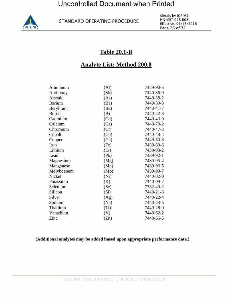
Metals by ICP-MS HN-MET-008-R08 Effective: 01/15/2016 Page 26 of 32
R I G H T S O L U T I O N S | R I G H T P A R T N E R
STANDARD OPERATING PROCEDURE
Table 20.1-B
Analyte List: Method 200.8
Aluminum (Al) 7429-90-5 Antimony (Sb) 7440-36-0 Arsenic (As) 7440-38-2 Barium (Ba) 7440-39-3 Beryllium (Be) 7440-41-7 Boron (B) 7440-42-8 Cadmium (Cd) 7440-43-9 Calcium (Ca) 7440-70-2 Chromium (Cr) 7440-47-3 Cobalt (Co) 7440-48-4 Copper (Cu) 7440-50-8 Iron (Fe) 7439-89-6 Lithium (Li) 7439-93-2 Lead (Pb) 7439-92-1 Magnesium (Mg) 7439-95-4 Manganese (Mn) 7439-96-5 Molybdenum (Mo) 7439-98-7 Nickel (Ni) 7440-02-0 Potassium (K) 7440-09-7 Selenium (Se) 7782-49-2 Silicon (Si) 7440-21-3 Silver (Ag) 7440-22-4 Sodium (Na) 7440-23-5 Thallium (Tl) 7440-28-0 Vanadium (V) 7440-62-2 Zinc (Zn) 7440-66-6
(Additional analytes may be added based upon appropriate performance data.)
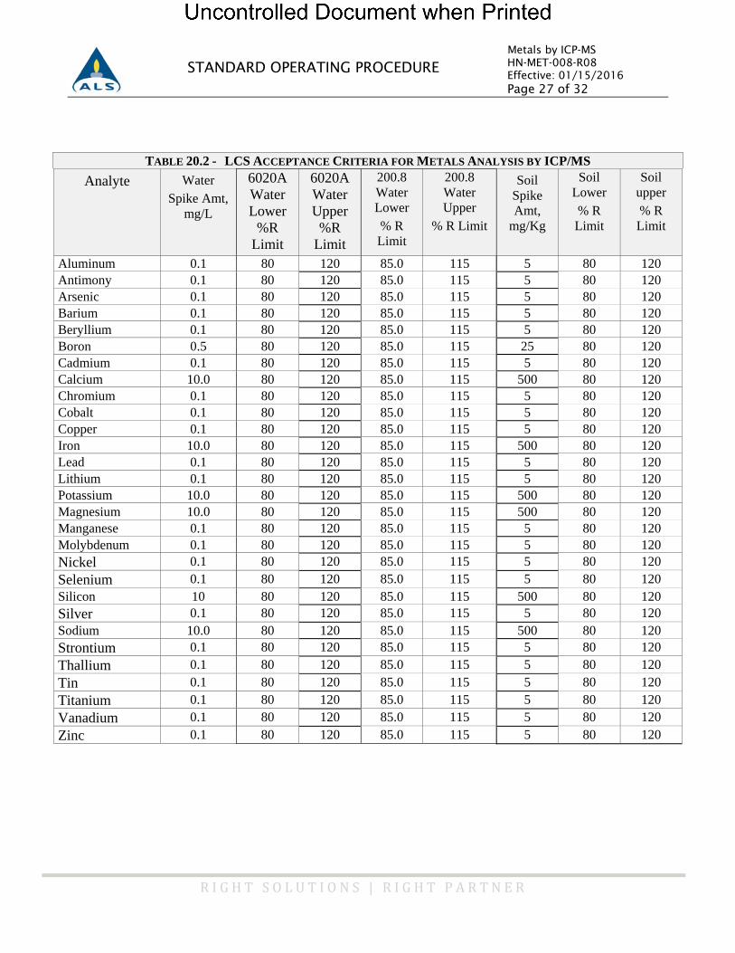
Metals by ICP-MS HN-MET-008-R08 Effective: 01/15/2016 Page 27 of 32
R I G H T S O L U T I O N S | R I G H T P A R T N E R
STANDARD OPERATING PROCEDURE
TABLE 20.2 - LCS ACCEPTANCE CRITERIA FOR METALS ANALYSIS BY ICP/MS Analyte
Water
Spike Amt, mg/L
6020A Water Lower
%R Limit
6020A Water Upper %R
Limit
200.8 Water Lower % R Limit
200.8 Water Upper
% R Limit
Soil
Spike Amt,
mg/Kg
Soil Lower % R Limit
Soil upper % R Limit
Aluminum 0.1 80 120 85.0 115 5 80 120 Antimony 0.1 80 120 85.0 115 5 80 120 Arsenic 0.1 80 120 85.0 115 5 80 120 Barium 0.1 80 120 85.0 115 5 80 120 Beryllium 0.1 80 120 85.0 115 5 80 120 Boron 0.5 80 120 85.0 115 25 80 120 Cadmium 0.1 80 120 85.0 115 5 80 120 Calcium 10.0 80 120 85.0 115 500 80 120 Chromium 0.1 80 120 85.0 115 5 80 120 Cobalt 0.1 80 120 85.0 115 5 80 120 Copper 0.1 80 120 85.0 115 5 80 120 Iron 10.0 80 120 85.0 115 500 80 120 Lead 0.1 80 120 85.0 115 5 80 120 Lithium 0.1 80 120 85.0 115 5 80 120 Potassium 10.0 80 120 85.0 115 500 80 120 Magnesium 10.0 80 120 85.0 115 500 80 120 Manganese 0.1 80 120 85.0 115 5 80 120 Molybdenum 0.1 80 120 85.0 115 5 80 120 Nickel 0.1 80 120 85.0 115 5 80 120 Selenium 0.1 80 120 85.0 115 5 80 120 Silicon 10 80 120 85.0 115 500 80 120 Silver 0.1 80 120 85.0 115 5 80 120 Sodium 10.0 80 120 85.0 115 500 80 120 Strontium 0.1 80 120 85.0 115 5 80 120 Thallium 0.1 80 120 85.0 115 5 80 120 Tin 0.1 80 120 85.0 115 5 80 120 Titanium 0.1 80 120 85.0 115 5 80 120 Vanadium 0.1 80 120 85.0 115 5 80 120 Zinc 0.1 80 120 85.0 115 5 80 120
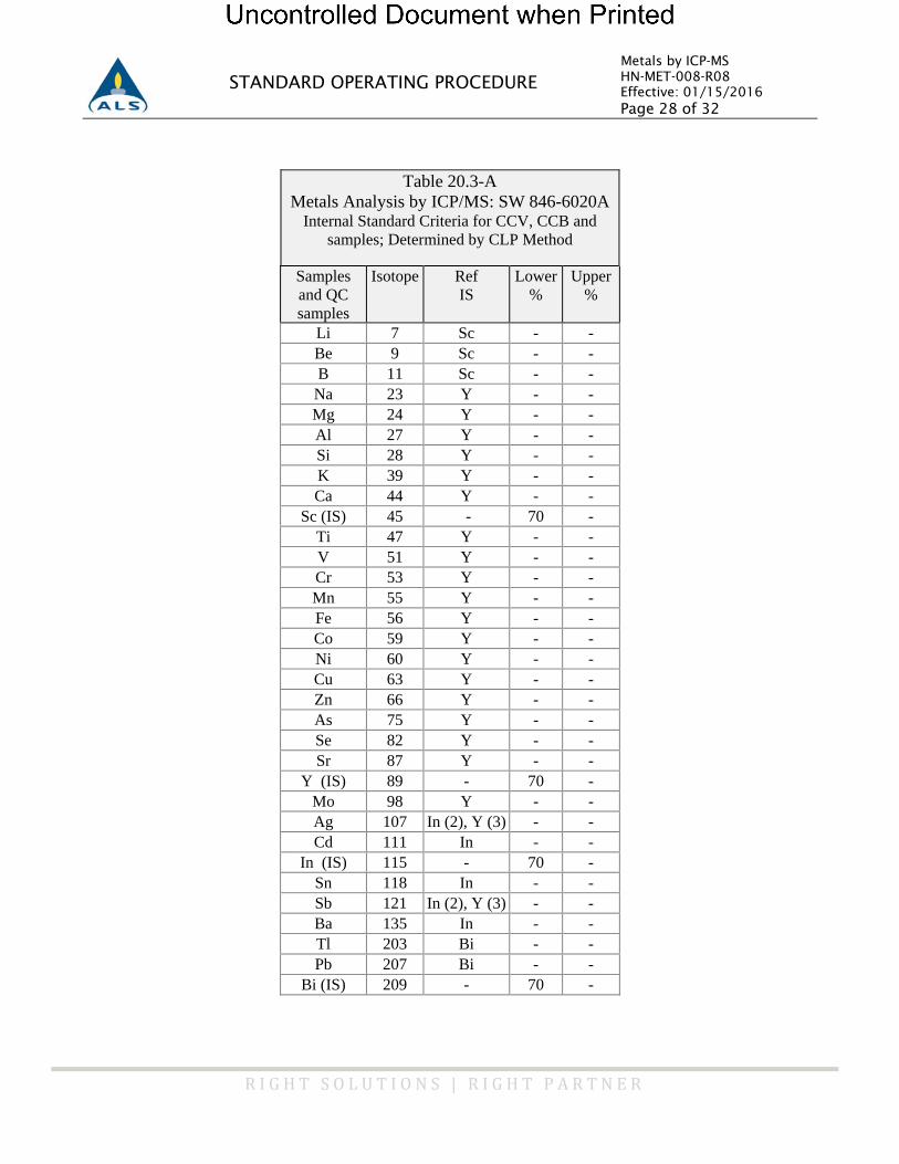
Metals by ICP-MS HN-MET-008-R08 Effective: 01/15/2016 Page 28 of 32
R I G H T S O L U T I O N S | R I G H T P A R T N E R
STANDARD OPERATING PROCEDURE
Table 20.3-A Metals Analysis by ICP/MS: SW 846-6020A
Internal Standard Criteria for CCV, CCB and samples; Determined by CLP Method
Samples and QC samples
Isotope Ref IS
Lower %
Upper %
Li 7 Sc - - Be 9 Sc - - B 11 Sc - -
Na 23 Y - - Mg 24 Y - - Al 27 Y - - Si 28 Y - - K 39 Y - - Ca 44 Y - -
Sc (IS) 45 - 70 - Ti 47 Y - - V 51 Y - - Cr 53 Y - - Mn 55 Y - - Fe 56 Y - - Co 59 Y - - Ni 60 Y - - Cu 63 Y - - Zn 66 Y - - As 75 Y - - Se 82 Y - - Sr 87 Y - -
Y (IS) 89 - 70 - Mo 98 Y - - Ag 107 In (2), Y (3) - - Cd 111 In - -
In (IS) 115 - 70 - Sn 118 In - - Sb 121 In (2), Y (3) - - Ba 135 In - - Tl 203 Bi - - Pb 207 Bi - -
Bi (IS) 209 - 70 -
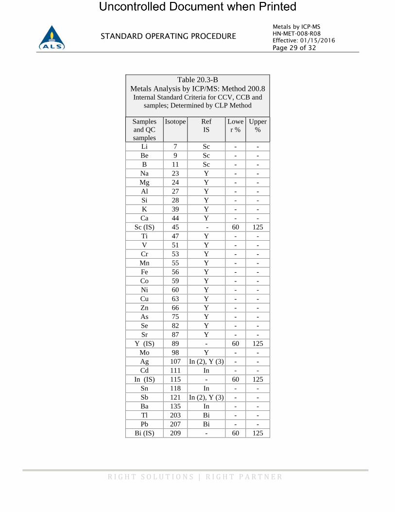
Metals by ICP-MS HN-MET-008-R08 Effective: 01/15/2016 Page 29 of 32
R I G H T S O L U T I O N S | R I G H T P A R T N E R
STANDARD OPERATING PROCEDURE
Table 20.3-B Metals Analysis by ICP/MS: Method 200.8 Internal Standard Criteria for CCV, CCB and
samples; Determined by CLP Method
Samples and QC samples
Isotope Ref IS
Lower %
Upper %
Li 7 Sc - - Be 9 Sc - - B 11 Sc - -
Na 23 Y - - Mg 24 Y - - Al 27 Y - - Si 28 Y - - K 39 Y - - Ca 44 Y - -
Sc (IS) 45 - 60 125 Ti 47 Y - - V 51 Y - - Cr 53 Y - - Mn 55 Y - - Fe 56 Y - - Co 59 Y - - Ni 60 Y - - Cu 63 Y - - Zn 66 Y - - As 75 Y - - Se 82 Y - - Sr 87 Y - -
Y (IS) 89 - 60 125 Mo 98 Y - - Ag 107 In (2), Y (3) - - Cd 111 In - -
In (IS) 115 - 60 125 Sn 118 In - - Sb 121 In (2), Y (3) - - Ba 135 In - - Tl 203 Bi - - Pb 207 Bi - -
Bi (IS) 209 - 60 125
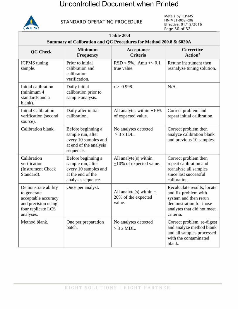
Metals by ICP-MS HN-MET-008-R08 Effective: 01/15/2016 Page 30 of 32
R I G H T S O L U T I O N S | R I G H T P A R T N E R
STANDARD OPERATING PROCEDURE
Table 20.4
Summary of Calibration and QC Procedures for Method 200.8 & 6020A
QC Check
Minimum Frequency
Acceptance Criteria
Corrective
Actiona ICPMS tuning sample.
Prior to initial calibration and calibration verification.
RSD < 5%. Amu +/- 0.1 true value.
Retune instrument then reanalyze tuning solution.
Initial calibration (minimum 4 standards and a blank).
Daily initial calibration prior to sample analysis.
r > 0.998. N/A.
Initial Calibration verification (second source).
Daily after initial calibration,
All analytes within ±10% of expected value.
Correct problem and repeat initial calibration.
Calibration blank.
Before beginning a sample run, after every 10 samples and at end of the analysis sequence.
No analytes detected > 3 x IDL.
Correct problem then analyze calibration blank and previous 10 samples.
Calibration verification (Instrument Check Standard).
Before beginning a sample run, after every 10 samples and at the end of the analysis sequence.
All analyte(s) within +10% of expected value.
Correct problem then repeat calibration and reanalyze all samples since last successful calibration.
Demonstrate ability to generate acceptable accuracy and precision using four replicate LCS analyses.
Once per analyst.
All analyte(s) within + 20% of the expected value.
Recalculate results; locate and fix problem with system and then rerun demonstration for those analytes that did not meet criteria.
Method blank.
One per preparation batch.
No analytes detected > 3 x MDL.
Correct problem, re-digest and analyze method blank and all samples processed with the contaminated blank.
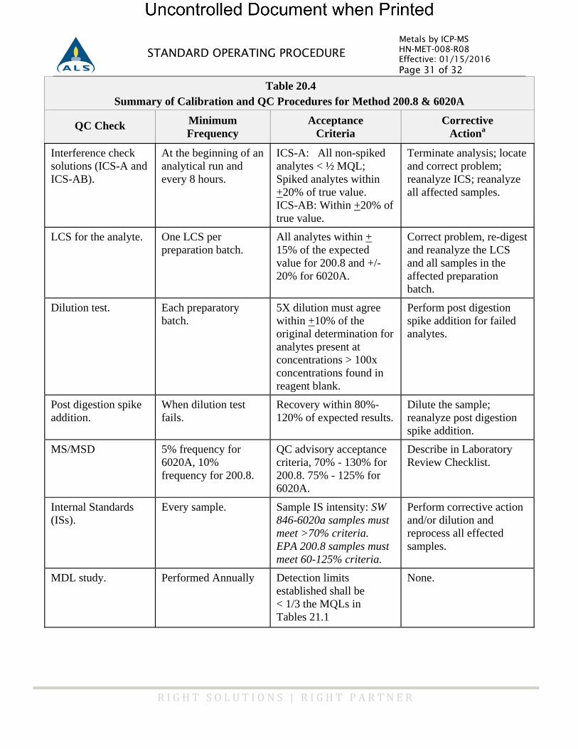
Metals by ICP-MS HN-MET-008-R08 Effective: 01/15/2016 Page 31 of 32
R I G H T S O L U T I O N S | R I G H T P A R T N E R
STANDARD OPERATING PROCEDURE
Table 20.4
Summary of Calibration and QC Procedures for Method 200.8 & 6020A
QC Check
Minimum Frequency
Acceptance Criteria
Corrective
Actiona Interference check solutions (ICS-A and ICS-AB).
At the beginning of an analytical run and every 8 hours.
ICS-A: All non-spiked analytes < ½ MQL; Spiked analytes within +20% of true value. ICS-AB: Within +20% of true value.
Terminate analysis; locate and correct problem; reanalyze ICS; reanalyze all affected samples.
LCS for the analyte.
One LCS per preparation batch.
All analytes within + 15% of the expected value for 200.8 and +/- 20% for 6020A.
Correct problem, re-digest and reanalyze the LCS and all samples in the affected preparation batch.
Dilution test.
Each preparatory batch.
5X dilution must agree within +10% of the original determination for analytes present at concentrations > 100x concentrations found in reagent blank.
Perform post digestion spike addition for failed analytes.
Post digestion spike addition.
When dilution test fails.
Recovery within 80%-120% of expected results.
Dilute the sample; reanalyze post digestion spike addition.
MS/MSD
5% frequency for 6020A, 10% frequency for 200.8.
QC advisory acceptance criteria, 70% - 130% for 200.8. 75% - 125% for 6020A.
Describe in Laboratory Review Checklist.
Internal Standards (ISs).
Every sample. Sample IS intensity: SW
846-6020a samples must meet >70% criteria. EPA 200.8 samples must meet 60-125% criteria.
Perform corrective action and/or dilution and reprocess all effected samples.
MDL study.
Performed Annually Detection limits
established shall be < 1/3 the MQLs in Tables 21.1
None.
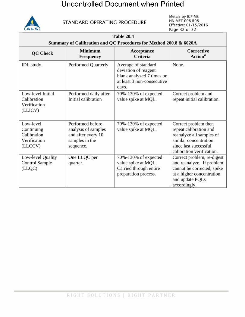
Metals by ICP-MS HN-MET-008-R08 Effective: 01/15/2016 Page 32 of 32
R I G H T S O L U T I O N S | R I G H T P A R T N E R
STANDARD OPERATING PROCEDURE
Table 20.4
Summary of Calibration and QC Procedures for Method 200.8 & 6020A
QC Check
Minimum Frequency
Acceptance Criteria
Corrective
Actiona IDL study.
Performed Quarterly Average of standard
deviation of reagent blank analyzed 7 times on at least 3 non-consecutive days.
None.
Low-level Initial Calibration Verification (LLICV)
Performed daily after Initial calibration
70%-130% of expected value spike at MQL.
Correct problem and repeat initial calibration.
Low-level Continuing Calibration Verification (LLCCV)
Performed before analysis of samples and after every 10 samples in the sequence.
70%-130% of expected value spike at MQL.
Correct problem then repeat calibration and reanalyze all samples of similar concentration since last successful calibration verification.
Low-level Quality Control Sample (LLQC)
One LLQC per quarter.
70%-130% of expected value spike at MQL. Carried through entire preparation process.
Correct problem, re-digest and reanalyze. If problem cannot be corrected, spike at a higher concentration and update PQLs accordingly.

ALSStandardOperatingProcedure
DOCUMENT TITLE: ICP-MS SOLIDS DIGESTION
REFERENCED METHOD: SW846 3050B SOP ID: HN-MET-009
REV. NUMBER: R06 EFFECTIVE DATE: 01/31/2016
ICP-MS Solids Digestion HN-MET-009-R06 Effective: 01/31/2016 Page i of i
R I G H T S O L U T I O N S | R I G H T P A R T N E R
STANDARD OPERATING PROCEDURE
TABLE OF CONTENTS 1) Scope and Applicability .............................................................................................................. 1 2) Summary of Procedure ............................................................................................................... 1 3) Definitions ................................................................................................................................. 1 4) Health and Safety Warnings ........................................................................................................ 2 5) Cautions .................................................................................................................................... 2 6) Interferences .............................................................................................................................. 2 7) Personnel Qualifications and Responsibilities ............................................................................. 2 8) Sample Collection, Handling, and Preservation ........................................................................... 3 9) Equipment and Supplies ............................................................................................................. 3 10) Standards and Reagents ............................................................................................................. 4 11) Method Calibration .................................................................................................................... 5 12) Sample Preparation/Analysis ...................................................................................................... 5 13) Troubleshooting ........................................................................................................................ 6 14) Data Acquisition ........................................................................................................................ 6 15) Calculation, and Data Reduction Requirements ........................................................................... 6 16) Quality Control, Acceptance Criteria and Corrective Action ......................................................... 6 17) Data Records Management ......................................................................................................... 7 18) Contingencies for Handling Out of Control Data ......................................................................... 7 19) Method Performance .................................................................................................................. 8 20) Summary of Changes ................................................................................................................. 8 21) References and Related Documents ............................................................................................ 8
ICP-MS Solids Digestion HN-MET-009-R06 Effective: 01/31/2016 Page 1 of 8
R I G H T S O L U T I O N S | R I G H T P A R T N E R
STANDARD OPERATING PROCEDURE
ICP-MS SOLIDS DIGESTION
1) Scope and Applicability
1.1 The objective of this method is to provide a general procedure for the preparation of soil or solid waste samples for determination of metals by ICP-MS or ICP-AES. The method is applicable to total leachable metals with the exception of mercury.
2) Summary of Procedure
2.1 A known amount of sample is digested with acid and peroxide by refluxing the sample in a hot block digester. The digestate is filtered (or allowed to settle), diluted to a specific volume, and analyzed by ICP-MS or ICP-AES. The procedure is based upon SW-846 Method 3050B.
3) Definitions
3.1 Preparation Batch: A grouping of 20 or less client samples processed under the same conditions, within an 8 hour working shift.
3.2 Laboratory Control Sample (LCS): An analyte-free matrix spiked with known concentrations of all target analytes. This is used to evaluate and document laboratory method performance.
3.3 Matrix: The component or substrate (e.g., surface water, groundwater, soil) which contains the analyte of interest.
3.4 Matrix Spike (MS): An aliquot of background sample spiked with a known concentrations of all target analytes. The spiking occurs prior to sample preparation and analysis. A matrix spike is used to assess the bias of a method in a given sample matrix.
3.5 Matrix Spike Duplicate (MSD): A duplicate aliquot of the background sample spiked with a known concentrations of all target analytes. Spiking occurs prior to sample preparation and analysis. The MS/MSD pair are used to assess precision and bias of a method in a given sample matrix.
3.6 Method Blank: An analyte-free matrix to which all reagents are added in the same volumes or proportions as used in sample processing. The method blank is carried through the complete sample preparation and analytical procedure. The method blank is used to document contamination resulting from the analytical process.
3.7 HCl = Hydrochloric acid
3.8 H2O
2 = Hydrogen peroxide
3.9 HNO3 = Nitric acid
3.10 Limit of Quantitation (LOQ): The minimum levels, concentrations, or quantities of a target variable (e.g., target analyte) that can be reported with a specified degree of confidence. The LOQ is also referred to as the method quantitation limit (MQL) or the reporting limit (RL).
3.11 Limit of Detection (LOD): an estimate of the minimum amount of a substance that an analytical process can reliably detect. An LOD is analyte- and matrix-specific and may be laboratory-dependent.
3.12 Method Detection Limit (MDL) study: the procedure, as described in 40CFR part 136, for determining the LOD based on statistical analysis of 7 low-level replicate spikes.
ICP-MS Solids Digestion HN-MET-009-R06 Effective: 01/31/2016 Page 2 of 8
R I G H T S O L U T I O N S | R I G H T P A R T N E R
STANDARD OPERATING PROCEDURE
4) Health and Safety Warnings
4.1 Lab Safety: Due to various hazards in the laboratory, safety glasses and laboratory coats or aprons must be worn at all times while in the laboratory. In addition, gloves and a face shield should be worn when dealing with toxic, caustic, and/or flammable chemicals.
4.2 Chemical Hygiene: The toxicity or carcinogenicity of each reagent used has not been precisely defined; however, each chemical used should be treated as a potential health hazard. Exposure to laboratory reagents should be reduced to the lowest possible level. The laboratory maintains a current awareness file of OSHA regulations regarding the safe handling of the chemicals specified in this method. A reference file of data handling sheets (MSDS) is available to all personnel involved in these analyses.
4.3 Waste Management: The principal wastes generated by this procedure are the method-required chemicals and standards. It is the laboratory's responsibility to comply with all federal, state, and local regulations governing waste management by minimizing and controlling all releases from fume hoods and bench operations. Compliance with all sewage discharge permits and regulations is required. Laboratory procedures in SOP HN-SAF-001, Waste Disposal Procedures, must be followed.
4.4 Pollution Prevention: The materials used in this method pose little threat to the environment when recycled and managed properly. The quantities of chemicals purchased should be based on the expected usage during its shelf life. Standards and reagents should be prepared in volumes consistent with laboratory use to minimize the volume of expired standards or reagents to be disposed.
5) Cautions
5.1 To prevent contamination of the analytical system, all supplies and materials coming in contact with the samples and instrument must be pre-cleaned in 1:4 HNO
3. This step
may be omitted for purchased materials of known cleanliness.
5.2 Proper use and maintenance of pipettes is important to achieve good technique and obtain good LCS, MS, and MSD recoveries. Slow addition of H
2O
2 is critical.
5.3 Use all appropriate personal protective equipment when handling concentrated acids. This includes gloves, lab-coat, and a face shield at a minimum.
5.4 Samples will emit hazardous/noxious fumes upon addition of acid. Perform acid addition and sample digestion in a hood with adequate ventilation.
6) Interferences
6.1 Sludge samples can contain diverse matrix types, each of which may present its own analytical challenge. Spiked samples and any relevant standard reference material should be processed in accordance with the quality control requirements given in the Quality Control section to aid in determining whether this method is applicable to a certain waste.
7) Personnel Qualifications and Responsibilities
7.1 General Responsibilities - This method is restricted to use by or under the supervision of analysts experienced in the method.
7.2 Analyst - It is the responsibility of the analyst(s) to:
ICP-MS Solids Digestion HN-MET-009-R06 Effective: 01/31/2016 Page 3 of 8
R I G H T S O L U T I O N S | R I G H T P A R T N E R
STANDARD OPERATING PROCEDURE
7.2.1 Each must read and understand this SOP and follow it as written. Any deviations or non-conformances must be documented and submitted to the QA Manager for approval.
7.2.2 Produce method compliant data that meets all quality requirements using this procedure and the Data Reduction, Review and Validation SOP (HN-QS-009).
7.2.3 Complete the required initial demonstration of proficiency before performing this procedure without supervision.
7.2.4 Complete an ongoing demonstration of proficiency annually when continuing to perform the procedure.
7.2.5 The analysts must submit data for peer or supervisor review.
7.3 Section Supervisor - It is the responsibility of the section supervisor to:
7.3.1 Ensure that all analysts have the technical ability and have received adequate
training required to perform this procedure. 7.3.2 Ensure analysts have completed the required initial demonstration of
proficiency before performing this procedure without supervision. 7.3.3 Ensure analysts complete an ongoing demonstration of proficiency annually
when continuing to perform the procedure. 7.3.4 Ensure analysts produce method compliant data that meet all quality
requirements using this procedure and the Data Reduction, Review and Validation SOP.
7.4 Project Manager - It is the responsibility of the Project Manager to ensure that all method requirements for a client requesting this procedure are understood by the laboratory prior to initiating this procedure for a given set of samples.
7.5 QA Manager: The QA Manager is responsible for
7.5.1 Approving deviations and non-conformances 7.5.2 Ensuring that this procedure is compliant with method and regulatory
requirements, 7.5.3 Ensuring that the analytical method and SOP are followed as written through
internal method and system audits.
8) Sample Collection, Handling, and Preservation
8.1 Soil samples are collected in 4 oz wide mouth glass containers. Refrigerated storage is not required. Should mercury analysis be required, soil samples must be refrigerated at 4°C prior to sample preparation.
8.2 Digestates do not require refrigeration.
8.3 The holding time is 180 days for soils. Should mercury analysis be required by this digestion method, the holding time is reduced to 28 days for the mercury only.
9) Equipment and Supplies
9.1 Analytical Balance (capable of weighing to nearest 0.001 gram).
9.2 Hot Block digester capable of maintaining a temperature of 95oC.
9.3 50 mL digestion vessels, certified clean
ICP-MS Solids Digestion HN-MET-009-R06 Effective: 01/31/2016 Page 4 of 8
R I G H T S O L U T I O N S | R I G H T P A R T N E R
STANDARD OPERATING PROCEDURE
9.4 Disposable watchglasses
9.5 Appropriately sized Class A volumetric flasks
9.6 Auto-pipettes, various delivery volumes
9.7 Filter mate®- 0.45μm push filter
9.8 Teflon® Chips, used as simulated solid matrix
10) Standards and Reagents
10.1 Acids used in the preparation of standards and for sample processing must be of high purity. Trace metal grade is recommended.
10.2 Concentrated HNO3 (Trace metal grade)
10.3 Concentrated HCl (Trace metal grade)
10.4 H2O
2 (30 %) – (Un-stabilized Trace metal grade, if available)
10.5 LCS and MS/MSD spiking solution (NIST traceable): 10.5.1 A 27 element standard is used each at 10 ppm, with the exception of the
minerals (Fe, Ca, Mg, Na, and K at 1000 ppm) and Boron at 50 ppm. (Available from VHG, Custom Standard 901)
10.5.2 Ti Standard @ 10 ppm and Si Standard @ 50 ppm:
10.5.2.1 Prepare using NIST traceable 1000 ppm Ti and Si stock standards. 10.5.2.2 In a 500 ml volumetric flask, add 5 ml Ti stock standard, 25 ml Si
stock standard, 10 ml HNO3, and 5 ml HCl to 300 ml DI water.
10.5.2.3 Bring to final volume of 500 ml with DI.
10.5.3 LCS/MS/MSD Soil Spiking:
10.5.3.1 A 500 μl volume of each spike solution (10.5.1 and 10.5.2) is added to 1.00 gram of solid matrix that has been transferred to the digestion vessel.
10.5.3.2 Spiking of the sample shall be performed prior to the addition of any reagents.
10.5.3.3 Following digestion, the digestate is brought to a final volume of 50 ml and filtered or allowed to settle.
10.6 LLQC Spiking solution (NIST traceable): 10.6.1 Low-level Metals Mix Standard I w/ As, Ba, Cr, Co, Cu, Pb, Mn, Ni, Se, Ag, Sr,
Tl, and V @ 0.5 mg/L and Be and Cd @ 0.2 mg/L and Al, Li, and Zn @ 1.0 mg/L and B @ 2.0 mg/L and Fe @ 8.0 mg/L and Mg, K, and Na @ 20 mg/L and Ca @ 50 mg/L. (available from VHG ZALSLAB1103-100 or equivalent)
10.6.2 Low-level Metals Mix Standard II w/ Sn @ 0.2 mg/L and Sb, Mo, and Ti @ 0.5
mg/L. (available from VHG ZALSLAB1104-100 or equivalent)
10.6.3 LLQC Soil Spike
ICP-MS Solids Digestion HN-MET-009-R06 Effective: 01/31/2016 Page 5 of 8
R I G H T S O L U T I O N S | R I G H T P A R T N E R
STANDARD OPERATING PROCEDURE
10.6.3.1 Add 500 μl of each solution (10.6.1 and 10.6.2) to 1.00 gram of solid matrix that has been transferred to the digestion vessel.
10.6.3.2 Spiking of the sample shall be performed prior to the addition of any reagents.
10.6.3.3 Following digestion, the digestate is brought to a final volume of 50ml then filtered or allowed to settle.
11) Method Calibration
11.1 Perform support equipment (balances, etc.) calibration checks as required for daily use.
12) Sample Preparation/Analysis
12.1 Assure sample has been thoroughly homogenized utilizing appropriate techniques. Weigh (to the nearest 0.001 g) a 0.500g - 1.000g portion of sample into a labeled 50 ml digestion vessel.
12.1.1 For MBLK, LCS, and LLQC weigh out ~ 1.000g Teflon® chips. 12.1.2 For MS/MSD, parent samples, and duplicates, weigh out, as close as possible,
equivalent masses in order to provide consistent calculations by LIMS.
12.2 Spike all QC samples prior to the addition of reagents.
12.3 Add 5 ml DI water, 5 ml concentrated HNO3, and 1 ml concentrated HCl to the
digestion vessel, mix the slurry, and cover with a ribbed watch glass. (Note: HCl is added prior to digestion to keep Ag in solution and preserve acceptable recovery.)
12.4 Reflux samples in the hot block at 900 – 950 C. Record digestion temperature in the associated logbook. Do not allow samples to boil. 12.4.1 Note: If brown fumes are observed during digestion, add an additional 5 ml
of concentrated HNO3 to the vessel and cover with a ribbed watch glass; heat
until volume is reduced to 5 - 10 ml.
12.5 Allow samples to digest for 45 minutes, then remove samples and cool. (Maintain a volume of at least 5 ml using DI).
12.6 Add 1.5 ml of 30% hydrogen peroxide (H2O
2). Cover with the ribbed watch glass and
return the vessels to the hot block for warming, to start the peroxide reaction. Care must be taken to ensure that losses do not occur due to excessively vigorous effervescence.
12.7 Continue to add H2O
2 in 1 ml aliquots with warming until the effervescence is minimal
or until the general sample appearance is unchanged. (NOTE: do not add more than a total of 5 ml of H
2O
2.)
12.8 Cover the digestion vessel and return to Hotblock under partial heat for 15 minutes, or until peroxide reaction has completed.
12.9 Remove samples from the block and cool.
12.10 Upon completion of the digestion, bring to a final volume of 50 ml using DI water and cap. Shake the capped digestates to homogenize acid and water layers.
ICP-MS Solids Digestion HN-MET-009-R06 Effective: 01/31/2016 Page 6 of 8
R I G H T S O L U T I O N S | R I G H T P A R T N E R
STANDARD OPERATING PROCEDURE
12.11 Filter the digestate using a Filtermate® filter, or allow particulates to settle prior to analysis.
12.12 Appropriately label all storage containers. The label must include the sample ID and Prep Batch ID.
12.13 A sample batch is all samples of the same matrix, digested by the same method on a unit basis. A sample batch cannot exceed 20 samples. If more than 20 samples require analysis, the first 20 shall be the first batch, the next 20 shall be the second batch, and so forth.
13) Troubleshooting
13.1 Refer to determinative method for guidance.
14) Data Acquisition
14.1 Sample preparation data recorded in preparation logbooks is entered into LIMS for later use in analytical and QC calculations. LIMS assigns a prep batch number for the data entered. Record the LIMS prep batch number in the prep log.
15) Calculation, and Data Reduction Requirements
15.1 LIMS uses prep batch information including initial sample weight and final volume to perform calculations after analysis has been completed.
16) Quality Control, Acceptance Criteria and Corrective Action
16.1 Method Blank (MBLK): The method blank is a clean solid matrix (Teflon® chips) containing the same reagent percentages and processed as a sample. The method blank is used to verify the absence of bias in analytical results due to the laboratory reagents.
16.1.1 Frequency: One per batch (< 20 samples) of sample digestions. 16.1.2 Criteria: Refer to relevant section in the determinative method SOP (HN-MET-
008 or HN-MET-015).
16.2 Laboratory Control Sample:
16.2.1 The LCS is prepared by adding 500 μL of the NIST traceable standard (section 10.5.3) to ~1.000g Teflon chips and processing as a sample.
16.2.2 Frequency: One LCS per batch of sample extractions. The results of the LCS are used for determining acceptability of results.
16.2.3 Criteria: Refer to the relevant section of the determinative method SOP (HN-MET-008 or HN-MET-015).
16.3 Matrix Spike/Matrix Spike Duplicate: 16.3.1 The matrix spike is prepared by adding 500 μL of NIST traceable standard
(section 10.5.3) to the sample labeled as the matrix spike and matrix spike duplicate. The sample is then processed.
16.3.2 Frequency: Matrix spikes will be analyzed on a frequency of one spike set for each 20 samples analyzed. If fewer than 20 samples are in a batch, at least one spike set will be included.
16.3.3 Criteria: Refer to the relevant section of the determinative method SOP (HN-MET-008 or HN-MET-015).
ICP-MS Solids Digestion HN-MET-009-R06 Effective: 01/31/2016 Page 7 of 8
R I G H T S O L U T I O N S | R I G H T P A R T N E R
STANDARD OPERATING PROCEDURE
16.4 Sample Duplicate
16.4.1 Frequency: Sample duplicates will be analyzed on a frequency of one for each 20 samples analyzed on a matrix specific basis. If fewer than 20 samples are in a batch, at least one duplicate will be included.
16.4.2 A matrix spike duplicate may be substituted for the duplicate analysis. 16.4.3 Criteria: Refer to the relevant section of the determinative method SOP (HN-
MET-008 or HN-MET-015).
16.5 Low-Level Quality Control sample (LLQC):
16.5.1 The LLQC is prepared by adding 500 μL of NIST traceable standard (section 10.6.3) to ~1.000g Teflon chips and processing as a sample.
16.5.2 Frequency: One LLQC sample extracted per quarter. The results of the LLQC are used for determining ongoing performance of the method at low concentrations.
16.5.3 Criteria: Refer to the relevant section of the determinative method SOP (HN-MET-008 or HN-MET-015).
16.6 Deviations and non-conforming events must be documented using a Nonconformance Corrective Action Report (NCAR) or as an Exception Report item on the laboratory review checklist. For mandatory QC failures (e.g. LCS), the NCAR must be submitted to the QA Manager via the NCAR database.
17) Data Records Management
17.1 All data is stored both electronically and hard copy for 10 years.
17.2 All analytical sequence IDs and standard preparation information must be recorded in the Run logbook. Hardcopy computer printouts of analytical sequences and raw data must be retained and initialed by the analyst (electronic initials are acceptable). To simplify standard tracking, analyst must attempt to use one lot of reagents and standards with each batch.
17.3 Complete all pertinent sections in the respective logbooks. If not-applicable then line out the section. “Z” out or “X” out all large sections of the worksheet that are not used. Make all corrections with single line through, date and initial. Make NO obliterations when manually recording data.
17.4 Logbooks are controlled. Never remove a page from a logbook. Completed logbooks are returned to the QA department when filled and no longer needed in the work area.
17.5 The effective date of this SOP is the date in the header or last signature date, whichever is most recent.
17.6 Logbooks must be reviewed monthly by the department supervisor.
17.7 Logbooks must be reviewed quarterly by the QA Staff.
18) Contingencies for Handling Out of Control Data
18.1 When method required QC exceedances occur, in every case where sample data quality are affected, the source of the QC exceedance must be determined, corrected and sample reanalysis carried out when possible.
18.2 When affected sample analysis can not be repeated due to limitations (i.e. sample availability, or if reanalysis can only be performed after expiration of a sample hold
ICP-MS Solids Digestion HN-MET-009-R06 Effective: 01/31/2016 Page 8 of 8
R I G H T S O L U T I O N S | R I G H T P A R T N E R
STANDARD OPERATING PROCEDURE
time), the reporting of data associated with exceeded QC data must be appropriately flagged and narrated. This documentation is necessary to define for the data user the effect of the error has upon the data quality of the results reported (e.g. E flag data indicate the result to be only an estimate).
18.3 All analysts must report sufficient comments in laboratory data review checklist for exceeded QC associated with sample results so that project management can further narrate and ensure data qualifiers (flags) are properly assigned to the reported data.
18.4 NCARs must be issued for QC system exceedances. Matrix interferences are reported using the analyte reporting comment section in LIMS or using the Laboratory Data review checklist.
19) Method Performance
19.1 Initial Demonstration of Proficiency- Each analyst must perform an initial demonstration of proficiency on a method and matrix basis with a successful analysis of four LCS where acceptable precision and accuracy are generated. The accuracy component must fall within LCS criteria. The precision component must be less than 20% for duplicate RPD data.
19.2 Method Detection Limits (MDLs) must be determined on an annual basis (at minimum) or whenever major modifications are performed.
20) Summary of Changes Table 20.1 Summary of Changes
Revision Number
Effective Date
Document Editor
Description of Changes
R04 7/1/12 CES Formatting/Compliance R05 10/1/2013 CES Formatting; Addition of dry-spiking requirement R06 1/31/16 CES Included ICP-AES analysis. Updated document
revision and data retention requirements.
21) References and Related Documents
21.1 U.S. Environmental Protection Agency, “Method 3050B Acid Digestion of Sediments, Sludges and Soils”, Test Methods for Evaluating Solid Waste Physical/Chemical Methods, Update III, June 13, 1997.
21.2 ALS Environmental Quality Assurance Manual, Revision (most current)
for fields of accreditation listed on the laboratory's accompanying Scope of Certification
in accordance with the provisions in Minnesota Laws and Rules.
Continued accreditation is contingent upon successful on-going compliance with Minnesota Statutes 144.97 to 144.98, 2009 TNI
Standard and applicable Minnesota Rules 4740.2010 to 4740.2120. The laboratory's Scope of Certification cites the specific
programs, methods, analytes and matrices for which MDH issues this accreditation.
This certificate is valid proof of accreditation only when associated with its accompanying Scope of Certification.
The Scope of Certification and reports of on-site assessments are on file at the Minnesota Department of Health,
601 Robert Street North, Saint Paul, Minnesota. Customers may verify the laboratory's accreditation status in
Minnesota by contacting MNELAP at (651) 201-5324.
Minnesota Department of Health
Environmental Laboratory Accreditation Program
Issues accreditation to
State Laboratory ID: 026-999-449
EPA Lab Code: MI00028
ALS Environmental
3352 128th Avenue
Holland, MI 49424-9263
Effective Date: 12/19/2016
Expires: 12/31/2017
Certificate Number: 1175716
Issued under the authoritydelegated by theCommissioner of Health,State of Minnesota
Related Documents


