Tests on a DIGITAL TV LNB for 10GHz narrowband Andy Talbot G4JNT Paul M0EYT mentioned that he was playing with a new low cost Satellite TV Low Noise Block that used a PLL synthesised Local Oscillator. He said that it appeared to receive GB3SCX very well, and the JT4G decoded perfectly. As soon as the Ebay link http://www.ebay.co.uk/itm/170940689242 appeared on the Email chat page, I ordered one which arrived two days later. The LNB is described as “Octagon Optima Narrow Feed Twin 0.1dB HD 3D Ready LNB With 3 Year Warranty Model OTLSO” It cost £19. See Figure 1. Paul had already looked at its innards and produced the photograph in Figure 2. The PLL/Mixer chip is RDA3560m; a short data sheet can be obtained from http://www.uhf-satcom.com/misc/datasheet/RDA3560m.pdf The photo shows the RF inputs (right hand side) and the RF path going leftwards through to the chip with a 27MHz reference crystal – its interesting to note that there is not the usual PCB band pass filter as found in other LNB’s. What is not visible on the photo is that there is a duplicate crystal and mixer /PLL / IF amplifier chip on the other side of the PCB, giving a dual channel IF output. The RF input is via a ‘standard’ satellite TV feedhorn, with circular waveguide probes for vertical / horizontal polarity, selectable via the usual +12V/+18V voltage switching. The unit is marked as being dual LO 9.75 and 10.6GHz. For normal operation, a 22kHz tone superimposed on the feed up to the LNB selects the higher LO frequency. A plain 12V DC supply selects 9.75GHz.

Welcome message from author
This document is posted to help you gain knowledge. Please leave a comment to let me know what you think about it! Share it to your friends and learn new things together.
Transcript
Tests on a DIGITAL TV LNB for 10GHz narrowband
Andy Talbot G4JNT
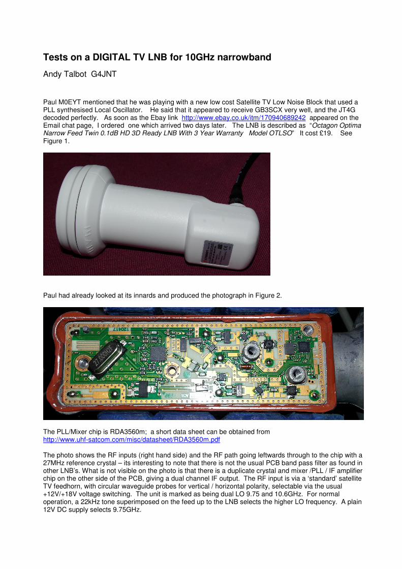
Paul M0EYT mentioned that he was playing with a new low cost Satellite TV Low Noise Block that used a PLL synthesised Local Oscillator. He said that it appeared to receive GB3SCX very well, and the JT4G decoded perfectly. As soon as the Ebay link http://www.ebay.co.uk/itm/170940689242 appeared on the Email chat page, I ordered one which arrived two days later. The LNB is described as “Octagon Optima Narrow Feed Twin 0.1dB HD 3D Ready LNB With 3 Year Warranty Model OTLSO” It cost £19. See Figure 1.
Paul had already looked at its innards and produced the photograph in Figure 2.
The PLL/Mixer chip is RDA3560m; a short data sheet can be obtained from http://www.uhf-satcom.com/misc/datasheet/RDA3560m.pdf The photo shows the RF inputs (right hand side) and the RF path going leftwards through to the chip with a 27MHz reference crystal – its interesting to note that there is not the usual PCB band pass filter as found in other LNB’s. What is not visible on the photo is that there is a duplicate crystal and mixer /PLL / IF amplifier chip on the other side of the PCB, giving a dual channel IF output. The RF input is via a ‘standard’ satellite TV feedhorn, with circular waveguide probes for vertical / horizontal polarity, selectable via the usual +12V/+18V voltage switching. The unit is marked as being dual LO 9.75 and 10.6GHz. For normal operation, a 22kHz tone superimposed on the feed up to the LNB selects the higher LO frequency. A plain 12V DC supply selects 9.75GHz.
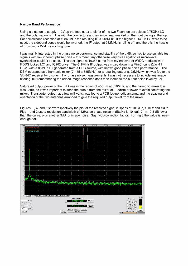
Narrow Band Performance Using a bias tee to supply +12V up the feed coax to either of the two F connectors selects 9.75GHz LO and the polarisation is in line with the connectors and an arrowhead marked on the front casing at the top. For narrowband reception at 10368MHz the resulting IF is 618MHz. If the higher 10.6GHz LO were to be used, the sideband sense would be inverted, the IF output at 232MHz is rolling off, and there is the hassle of providing a 22kHz switching tone. I was mainly interested in the phase noise performance and stability of the LNB, so had to use suitable test signals with low inherent phase noise – this meant my otherwise very nice Gigatronics microwave synthesizer couldn’t be used. The test signal at 10368 came from my transverter (WDG modules with RDDS locked LO) and IC202 drive. The 618MHz IF output was mixed down in a MiniCircuits ZLW-11 DBM. with a 85MHz LO generated from a DDS source, with known good phase noise performance. The DBM operated as a harmonic mixer (7 * 85 = 585MHz) for a resulting output at 23MHz which was fed to the SDR-IQ receiver for display. For phase noise measurements it was not necessary to include any image filtering, but remembering the added image response does then increase the output noise level by 3dB Saturated output power of the LNB was in the region of +5dBm at 618MHz, and the harmonic mixer loss was 33dB, so it was important to keep the output from the mixer at -35dBm or lower to avoid saturating the mixer. Transverter output, at a few milliwatts, was fed to a PCB log-periodic antenna and the spacing and orientation of the two antennas arranged to give the required output level from the mixer. Figures 3 , 4 and 5 show respectively the plot of the received signal in spans of 100kHz, 10kHz and 1kHz. Figs 1 and 2 use a resolution bandwidth of 12Hz, so phase noise in dBc/Hz is 10.log(12) = 10.8 dB lower than the curve, plus another 3dB for image noise. Say 14dB correction factor. For Fig 3 the value is near-enough 5dB
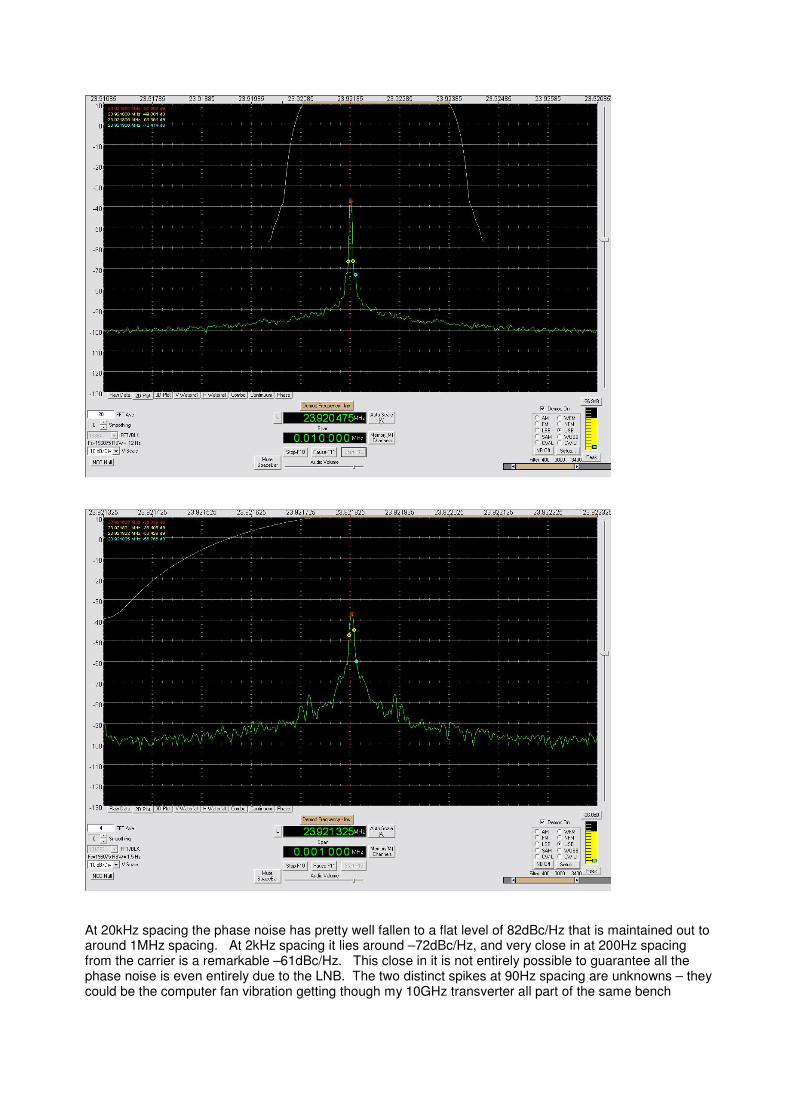
At 20kHz spacing the phase noise has pretty well fallen to a flat level of 82dBc/Hz that is maintained out to around 1MHz spacing. At 2kHz spacing it lies around –72dBc/Hz, and very close in at 200Hz spacing from the carrier is a remarkable –61dBc/Hz. This close in it is not entirely possible to guarantee all the phase noise is even entirely due to the LNB. The two distinct spikes at 90Hz spacing are unknowns – they could be the computer fan vibration getting though my 10GHz transverter all part of the same bench
assembly, or the central heating pump the other side of the partition wall, or anything. The ones at 100Hz spacing are self explanatory. To put the figures into perspective, take the far out 20kHz spacing value of –82dBc/Hz. In a 2.5kHz SSB filter, the resulting noise from a pure carrier will be –82 + 10.log(2500) = -48dBc. So any 59++ carrier anywhere in the passband, or a combination of many signals adding to this sort of level will make itself heard as a rise in background noise, 48dB down. But the close in performance is very impressive; it “sounds perfect”. Although that phrase is meaningless in the face of absolute measurements. That the phase noise is more-or less flat out to 1MHz suggests a high loop bandwidth is used, so the stability is just that of the crystal, multiplied up. Stability is also pretty good considering it comes from an unovenned fundamental mode 27MHz crystal. From turn on at room temperature it drifted a couple of kHz at the most (I didn’t measure it thoroughly) and after being on for a hour or more, no more than a few tens of Hz were detected over several minutes. Certainly it appears stable enough in a domestic environment for JTxx decoding. How much worse this would be outside with sun and wind is still to be determined. Changing the LO, and using an External Reference The internal 27MHz crystal (there are two of them, for two independent conversions via the two output connectors) is effectively multiplied by 361.111 inside the RD3560 chip. Paul removed one of his crystals and supplied 27MHz from a GPS locked signal generator – it worked perfectly, as before, and now with a rock steady output. In fact Paul, who can receive GB3SCX very strongly, could see the Simple-GPSDO induced wobble of a few Hz on the beacon using this LO in locked mode, something he hadn’t observed before. He then tried changing the injection frequency to 27.515076Mhz, which after multiplication yields an LO of 9936MHz and means 10368 is converted to 432MHz. He reported GB3SCX reception as being just the same as it was at 618MHz – so that works. (It would not really be fair to ask it to generate a 10224MHz LO as the IF circuitry has rolled off considerably at 144MHz, so that wasn’t tried). Special high resolution frequencies can easily be generated from a DDS, but be careful not to add in unwanted close in spurious signals as these will get passed straight through the PLL and be effectively multiplied in amplitude by 361
2 = 51dB. The reference must be very clean!
Paul added a separate miniature coax cable for the reference input. The reference input should be fed to one of the RDA3560m XTAL input pins via a 150R SMT resistor and a 1nF SMT capacitor in series. Using this method, it is possible to leave one complete converter running from its IF output connector and internal 27MHz XTAL whilst having an externally referenced converter from the other IF output connector. [So far] I’ve left mine well alone. Ideas for a Bottom End Box 618MHz is quite a benign IF to work with. A scanner (with SSB facility) is useable directly, but my AR8200 has a vastly worse phase noise than this LNB and ruins its performance as a narrowband monitor receiver. Amongst all the synthesizer modules I’ve made over the last year, one using an LMX2326 and MiniCircuits JTOS-535 will run at 474MHz (but only just, with this VCO) thus allowing a 144MHz IF from 618MHz. An alternative would be a 94.8MHz crystal oscillator and 5
th harmonic mixer. Or perhaps an old surplus
96MHz crystal giving a 138MHz 2nd
IF – within the tuning range of many modern 2m receivers With the huge gain available in the LNB, the losses of harmonic mixing are perfectly acceptable. The image response at 330MHz will be a straightforward task to filter out using high pass or bandpass LC elements. It is only necessary to reduce it by 20dB or so to kill the added noise – its not as if there are likely to be many image-frequency signals present. For direct feed to an SDR, an I/Q conversion using one of the chips described in RadCom Design Notes last year would do
The bottom end box will also have a DC injection bias-tee, and input attenuation to overcome the huge gain in the LNB. Conclusions This LNB offers an extraordinarily good performance as a low cost, low noise narrowband 10GHz monitoring receiver. If placed at the focus of a suitable dish, it will make for a very potent 10GHz receiving system. The Noise Figure is quoted as being 0.1dB, but in light of the Noise Figure measurement presentations at recent Microwave Roundtables, we’ll take that with a pinch of salt! But, it is still very good. With snow on the ground as I write, I don’t feel inclined to set up outside and do cold sky/[not very] hot ground tests. Time will tell just how stable the internal crystal really is, but use with an externally generated reference, a high stability converter can result.
UPDATE Some Tests Using an External Reference http://g4jnt.com/OctagonExtLo.pdf
Related Documents