2969 Proceedings of the XVI ECSMGE Geotechnical Engineering for Infrastructure and Development ISBN 978-0-7277-6067-8 © The authors and ICE Publishing: All rights reserved, 2015 doi:10.1680/ecsmge.60678 Testing of self-drilled hollow bar soil nails Tests de clous self percés hollow bar F.M. Lindsay *1 , S.B. Mickovski 2 and M.J. Smith 1 1 Jacobs UK Limited, Glasgow, United Kingdom 2 Glasgow Caledonian University, Glasgow, United Kingdom * Corresponding Author ABSTRACT Current standards and best practice guidance recognise that testing of self-drilled soil nails can be problematic as convention- al packers and debonded lengths cannot be constructed. As a result, this provides difficulty in testing and confirmi ng the ultimate bond re- sistance within the passive zone of a soil nailed slope, and thus the soil nail lengths determined within the design. This paper provides a summary and review of the various testing procedures adopted for a recent soil nail construction project in Scotland. Approximately 1,500 self-drilled hollow bar soil nails were installed to depths between 7 m and 24 m to stabilise a 40 m high coastal slope with a history of i n- stability. Fifty six sacrificial test nails were installed and tested at the site by various methods to validate the soil nail lengths determined within the design. These methods, the associated construction issues and design assumptions, and the subsequent test results have been discussed in this paper. RÉSUMÉ Normes en vigueur et les meilleures pratiques recommandées par reconnaissent qu'essais de sol automatique percé de clous peut être problématique, car les abattoirs conventionnels et longueurs libre ne peut pas être construites. Ainsi, cela fournit des difficultés dans les essais et confirmant la résistance ultime de liaison au sein de la zone passive de pente cloué au sol, et donc les longueurs de clou du sol déterminée dans la conception. Ce document fournit un résumé et l'examen des divers procédés tests adopté pour un projet de construction d'ongle de sol récente en Écosse. Environ 1 500 bar creux percé des clous ont été installés à des profondeurs variant entre 7 m et 24 m pour stabiliser une pente de 40 m de hauteur côtières ayant des antécédents d'instabilité. Cinquante six test sacrificiel clous ont été installés et testés sur le site par diverses méthodes pour valider les longueurs de clou sol déterminés au sein de la conception. Ces mét hodes, les ques- tions de construction connexes et des hypothèses de conception et les résultats des tests ultérieurs ont été discutées dans le présent doc u- ment. 1 INTRODUCTION 1.1 Soil Nailing Soil nailing is a form of slope stabilisation in which steel or polymetric reinforcement bars are installed into the slope face of in situ ground, whether natural soil or existing fill, anchoring a potentially unstable mass of soil to a more competent stratum below via mobilisation of the tensile strength of the reinforce- ment bars. An appropriate facing system is then con- structed to stabilise the surface soil thus completing the construction of the soil nailed slope. The use of soil nailing in slope stabilisation has grown rapidly in the UK since the mid-1990s (Phear et al. 2005). Traditionally, soil nails comprised of a solid steel tendon installed into a pre-drilled hole and then grouted. A hard, flexible or soft facing would then be constructed at the surface of the slope de- pending on the characteristics of the slope and asso- ciated instability. 1.2 Self-Drilled Soil Nails Latterly, self-drilled hollow bar soil nails have been developed and offer three significant advantages over the use of the traditional solid bar system. Firstly, the self-drilled soil nails can be installed into loose or collapsing soils without the need for casing to sup- port the drill hole (Dywidag 2008). This allows rela- tively small lightweight rigs to be able to install the soil nails within most ground conditions thus reduc- ing the health and safety implications of mobilising heavy plant to an already failed or unstable slope.

Welcome message from author
This document is posted to help you gain knowledge. Please leave a comment to let me know what you think about it! Share it to your friends and learn new things together.
Transcript

2969
Proceedings of the XVI ECSMGEGeotechnical Engineering for Infrastructure and DevelopmentISBN 978-0-7277-6067-8
© The authors and ICE Publishing: All rights reserved, 2015doi:10.1680/ecsmge.60678
4 CONCLUDING REMARKS
The use of in situ and laboratory tests confirms the complementarity of the different techniques in order to to allow to the designers to define a detailed ge-otechnical model.
The upper silty deposits shows low mechanical properties in terms of strenght and stiffness. Thus, the soil improvement of this soil layer (e.g. preload-ing or pile stones method) should be recommended before building construction.
Finally, these data could enforce the creation of an inventory useful for an information database of the geotechnical properties of Albanian soils and for the safe design of buildings.
ACKNOWLEDGEMENT
A special thanks to Prof. Silvano Marchetti for the collaboration and contribution to this study, and to the geotechnical and geological laboratory A.L.T.E.A & Geostudio 2000 for the support to realize the site and laboratory campaign.
REFERENCES
Allkja, S. 2011. The geological and engineering survey made by the “A.L.T.E.A & Geostudio 2000” for the Rinas airport and, A.L.T.E.A & Geostudio 2000, Tirane. Marchetti, S. 1980. In Situ Tests by Flat Dilatometer, J. Geotech. Engrg. Div., ASCE, 106, No.GT3, 299-321. Marchetti, S. 2013. Personal communication. Marchetti, S., Monaco, P., Totani, G., Calabrese, M. 2001. The Flat Dilatometer Test (DMT) in Soil Investigations – A Report by the ISSMGE Committee TC16, Proc. Int. Conf. on Insitu Meas-urement of Soil Properties and Case Histories, Bali, 2001, official version reprinted in Flat Dilatometer Testing, Proc. 2nd Int. Conf. on the Flat Dilatometer, Washington D.C., April 2-5, 2006, 7-48, R.A.Failmezger, J.B.Anderson (eds). Marchetti, S., Monaco, P., Totani, G., Marchetti, D. 2008. In Situ Tests by Seismic Dilatometer (SDMT), From Research to Practice in Geotechnical Engineering, ASCE, Geotechnical Special Publi-cation, 180, 292-311, J.E.Laier, D.K.Crapps, M.H.Hussein (eds). Shallo M., Vranaj A., Melo V. 2002. The geology of Albania.
Testing of self-drilled hollow bar soil nails Tests de clous self percés hollow bar
F.M. Lindsay*1, S.B. Mickovski2 and M.J. Smith1 1 Jacobs UK Limited, Glasgow, United Kingdom
2 Glasgow Caledonian University, Glasgow, United Kingdom * Corresponding Author
ABSTRACT Current standards and best practice guidance recognise that testing of self-drilled soil nails can be problematic as convention-al packers and debonded lengths cannot be constructed. As a result, this provides difficulty in testing and confirming the ultimate bond re-sistance within the passive zone of a soil nailed slope, and thus the soil nail lengths determined within the design. This paper provides a summary and review of the various testing procedures adopted for a recent soil nail construction project in Scotland. Approximately 1,500 self-drilled hollow bar soil nails were installed to depths between 7 m and 24 m to stabilise a 40 m high coastal slope with a history of in-stability. Fifty six sacrificial test nails were installed and tested at the site by various methods to validate the soil nail lengths determined within the design. These methods, the associated construction issues and design assumptions, and the subsequent test results have been discussed in this paper.
RÉSUMÉ Normes en vigueur et les meilleures pratiques recommandées par reconnaissent qu'essais de sol automatique percé de clous peut être problématique, car les abattoirs conventionnels et longueurs libre ne peut pas être construites. Ainsi, cela fournit des difficultés dans les essais et confirmant la résistance ultime de liaison au sein de la zone passive de pente cloué au sol, et donc les longueurs de clou du sol déterminée dans la conception. Ce document fournit un résumé et l'examen des divers procédés tests adopté pour un projet de construction d'ongle de sol récente en Écosse. Environ 1 500 bar creux percé des clous ont été installés à des profondeurs variant entre 7 m et 24 m pour stabiliser une pente de 40 m de hauteur côtières ayant des antécédents d'instabilité. Cinquante six test sacrificiel clous ont été installés et testés sur le site par diverses méthodes pour valider les longueurs de clou sol déterminés au sein de la conception. Ces méthodes, les ques-tions de construction connexes et des hypothèses de conception et les résultats des tests ultérieurs ont été discutées dans le présent docu-ment.
1 INTRODUCTION
1.1 Soil Nailing
Soil nailing is a form of slope stabilisation in which steel or polymetric reinforcement bars are installed into the slope face of in situ ground, whether natural soil or existing fill, anchoring a potentially unstable mass of soil to a more competent stratum below via mobilisation of the tensile strength of the reinforce-ment bars. An appropriate facing system is then con-structed to stabilise the surface soil thus completing the construction of the soil nailed slope.
The use of soil nailing in slope stabilisation has grown rapidly in the UK since the mid-1990s (Phear et al. 2005). Traditionally, soil nails comprised of a solid steel tendon installed into a pre-drilled hole and
then grouted. A hard, flexible or soft facing would then be constructed at the surface of the slope de-pending on the characteristics of the slope and asso-ciated instability.
1.2 Self-Drilled Soil Nails
Latterly, self-drilled hollow bar soil nails have been developed and offer three significant advantages over the use of the traditional solid bar system. Firstly, the self-drilled soil nails can be installed into loose or collapsing soils without the need for casing to sup-port the drill hole (Dywidag 2008). This allows rela-tively small lightweight rigs to be able to install the soil nails within most ground conditions thus reduc-ing the health and safety implications of mobilising heavy plant to an already failed or unstable slope.

Geotechnical Engineering for Infrastructure and Development
2970
Secondly, the drill hole is grouted as the steel ten-don is installed allowing the grout to permeate into the surrounding strata. This will result in a bulbing effect in more permeable or softer strata thus increas-ing the bond diameter and hence the capacity of the soil nail.
Lastly, by eliminating the need for casing the drill hole and grouting the hole whilst the soil nail is being installed, the production rates for soil nails can be greatly increased. This reduces the construction time for soil nail systems and thus the overall cost of the system. Additionally, a reduced construction time can also be of benefit where an already failed or un-stable slope is to be stabilised in an area of high risk.
2 SOIL NAIL TESTING
Various forms of soil nail testing are available to de-signers depending on the objectives of the testing (Phear et al. 2005).
2.1 Design Investigation Testing
‘Design investigation testing’ is undertaken prior to the soil nail design to confirm the ultimate bond re-sistance of each stratum, the variability with depth and the influence of groundwater on the bond re-sistance. The results from the design investigation testing can be used in the design to determine the re-quired soil nail lengths. This method of testing is likely to offer the most cost effective design, particu-larly for large sites or sites with limited ground inves-tigation information, given the site specific infor-mation obtained (Phear et al. 2005).
In this type of test, a sacrificial test nail is con-structed with a specified bonded length and is subse-quently tested to failure. This length should be based on the anticipated ultimate bond resistance, perhaps from empirical information, and the anticipated test loads to achieve pull-out. Larger bond lengths re-quire larger pull-out loads and hence larger and more expensive equipment and set-up. Conversely, shorter bonded lengths may not be adequately representative of the entire design bond length and thus lead to er-rors in the design if these results are extrapolated for the entire bond length.
Typically the specified bonded length is achieved by partial grouting of the drill hole. The drill hole is formed using open hole techniques and progressed to
the base of the bonded length. A packer is then in-stalled at the top of the bonded length to seal off the grouted section thus forming the bonded and debond-ed sections of the test nail.
2.2 Pull-Out (Suitability) Testing
‘Pull-out testing’ is undertaken immediately prior to or during the soil nail construction to verify the pull-out resistance within the passive zone and thus the soil nail lengths determined within the design.
Similar to the design investigation test, this test requires construction of a sacrificial test nail with a specified bonded length. Typically, the specified bonded length is achieved by partial grouting of the drill hole as with the design investigation test. This bonded length should equal the bond length within the passive zone of the slope determined within the design (BS EN 14490). The pull-out load applied to the test nail should equal the working load deter-mined within the design multiplied by a partial factor typically in the range of 1.5-2.0 (BS 8006-2).
An acceptable test, thus verifying the soil nail lengths determined within the design, is where the creep rate at the pull-out load is less than 2 mm per log cycle of time (BS 8006-2).
2.3 Acceptance Testing
‘Acceptance testing’ is undertaken on working nails to demonstrate satisfactory soil nail performance at the design load. This test is undertaken on fully grouted soil nails and is therefore not suitable to veri-fy the lengths determined within the design or con-firm the ultimate bond resistance of any strata. This type of test is primarily to confirm that the installa-tion methods give satisfactory displacement results at the working load (Phear et al. 2005).
The test load applied to the working nail should equal the working load determined within the design multiplied by a partial factor typically in the range of 1.1-1.5 (BS 8006-2). An acceptable test, thus verify-ing the soil nail installation methods, is where the creep rate at the proof load is less than 2 mm per log cycle of time (BS 8006-2).
2.4 Testing of Self-Drilled Soil Nails
Phear et al. (2005) recognise that testing of self-drilled soil nails can be problematical as, by their
very nature, their installation does not allow packers and debonded lengths to be constructed. They sug-gest a solution whereby the entire active zone is test-ed with the pull-out load deducted from a full-length test thus giving the bond resistance from the passive zone alone.
The introduction of BS EN 14490 in 2010 and the revised code of practice for soil nail design (BS 8006-2) in 2011 do not provide any clarity on how testing of self-drilled soil nails should be undertaken, ultimately leaving it up to the designer to confirm the test procedure to satisfy the design assumptions. This therefore relies heavily on the designer’s knowledge and experience of the ground conditions at the site and the impact on the construction and testing of self-drilled soil nails.
Suppliers and testing sub-contractors have at-tempted to address this issue and commonly recom-mend the test method suggested by Phear et al. (2005). Dywidag (2008) indicate that this method, named the ‘long nail / short nail’ testing method, is the most effective solution for testing hollow bar soil nails.
3 CASE STUDY – BERVIE BRAES, STONEHAVEN
3.1 Site Description
Self-drilled hollow bar soil nails were used in a re-cent slope stabilisation project Scotland. The 40 m high coastal slope in Stonehaven, known as the Bervie Braes, has a history of instability which has resulted in the closure of the trunk road into Stonehaven. The slope stabilisation works was lim-ited to the slope below the trunk road which runs sidelong and generally northwest-southeast across the slope.
3.2 Ground Conditions
The slope angle is generally between 25° and 30° be-low the road and 30° and 35° above the road. Typi-cally the area consists of topsoil, overlying Raised Beach Deposits comprising weak silts and silty sand with discrete soft cohesive layers, underlain by me-dium dense glacial sands and stiff cohesive glacial till, above bedrock.
The groundwater regime within the Braes consists of a shallow perched groundwater table, which exists due to the presence of the cohesive layers within the Raised Beach Deposits, and a deeper groundwater table perched upon the stiff cohesive glacial till.
The typical ground conditions at the site are shown in Figure 1.
Figure 1. Typical ground conditions.
3.3 Soil Nail Design
Soil nailing was the preferred method of stabilisation selected by the Local Authority in conjunction with the local residents following an options assessment. Self-drilled hollow bar soil nails were preferred to solid bar soil nails given the associated lower con-struction costs and the limited budget available for the works.
The soil nails were designed using the effective stress method (Method 4) detailed within Phear et al. (2005). Soil nail lengths of between 7 m and 24 m were determined with an active zone of up to 10 m in thickness.
A ‘soft facing’, consisting of a buried reinforced concrete soil nail head, a degradable jute mat and a light metallic mesh, was selected given the site con-ditions and the project aesthetic requirements. The concrete nail head, designed to HA 68/94, provides long term stability of the face by transfer of the soil load to the soil nails. The degradable jute mat and light metallic mesh formed part of the facing to pre-vent erosion and support establishment of vegetation which provides additional strength to the near-surface soil in the long term (Mickovski 2014).

2971
Secondly, the drill hole is grouted as the steel ten-don is installed allowing the grout to permeate into the surrounding strata. This will result in a bulbing effect in more permeable or softer strata thus increas-ing the bond diameter and hence the capacity of the soil nail.
Lastly, by eliminating the need for casing the drill hole and grouting the hole whilst the soil nail is being installed, the production rates for soil nails can be greatly increased. This reduces the construction time for soil nail systems and thus the overall cost of the system. Additionally, a reduced construction time can also be of benefit where an already failed or un-stable slope is to be stabilised in an area of high risk.
2 SOIL NAIL TESTING
Various forms of soil nail testing are available to de-signers depending on the objectives of the testing (Phear et al. 2005).
2.1 Design Investigation Testing
‘Design investigation testing’ is undertaken prior to the soil nail design to confirm the ultimate bond re-sistance of each stratum, the variability with depth and the influence of groundwater on the bond re-sistance. The results from the design investigation testing can be used in the design to determine the re-quired soil nail lengths. This method of testing is likely to offer the most cost effective design, particu-larly for large sites or sites with limited ground inves-tigation information, given the site specific infor-mation obtained (Phear et al. 2005).
In this type of test, a sacrificial test nail is con-structed with a specified bonded length and is subse-quently tested to failure. This length should be based on the anticipated ultimate bond resistance, perhaps from empirical information, and the anticipated test loads to achieve pull-out. Larger bond lengths re-quire larger pull-out loads and hence larger and more expensive equipment and set-up. Conversely, shorter bonded lengths may not be adequately representative of the entire design bond length and thus lead to er-rors in the design if these results are extrapolated for the entire bond length.
Typically the specified bonded length is achieved by partial grouting of the drill hole. The drill hole is formed using open hole techniques and progressed to
the base of the bonded length. A packer is then in-stalled at the top of the bonded length to seal off the grouted section thus forming the bonded and debond-ed sections of the test nail.
2.2 Pull-Out (Suitability) Testing
‘Pull-out testing’ is undertaken immediately prior to or during the soil nail construction to verify the pull-out resistance within the passive zone and thus the soil nail lengths determined within the design.
Similar to the design investigation test, this test requires construction of a sacrificial test nail with a specified bonded length. Typically, the specified bonded length is achieved by partial grouting of the drill hole as with the design investigation test. This bonded length should equal the bond length within the passive zone of the slope determined within the design (BS EN 14490). The pull-out load applied to the test nail should equal the working load deter-mined within the design multiplied by a partial factor typically in the range of 1.5-2.0 (BS 8006-2).
An acceptable test, thus verifying the soil nail lengths determined within the design, is where the creep rate at the pull-out load is less than 2 mm per log cycle of time (BS 8006-2).
2.3 Acceptance Testing
‘Acceptance testing’ is undertaken on working nails to demonstrate satisfactory soil nail performance at the design load. This test is undertaken on fully grouted soil nails and is therefore not suitable to veri-fy the lengths determined within the design or con-firm the ultimate bond resistance of any strata. This type of test is primarily to confirm that the installa-tion methods give satisfactory displacement results at the working load (Phear et al. 2005).
The test load applied to the working nail should equal the working load determined within the design multiplied by a partial factor typically in the range of 1.1-1.5 (BS 8006-2). An acceptable test, thus verify-ing the soil nail installation methods, is where the creep rate at the proof load is less than 2 mm per log cycle of time (BS 8006-2).
2.4 Testing of Self-Drilled Soil Nails
Phear et al. (2005) recognise that testing of self-drilled soil nails can be problematical as, by their
very nature, their installation does not allow packers and debonded lengths to be constructed. They sug-gest a solution whereby the entire active zone is test-ed with the pull-out load deducted from a full-length test thus giving the bond resistance from the passive zone alone.
The introduction of BS EN 14490 in 2010 and the revised code of practice for soil nail design (BS 8006-2) in 2011 do not provide any clarity on how testing of self-drilled soil nails should be undertaken, ultimately leaving it up to the designer to confirm the test procedure to satisfy the design assumptions. This therefore relies heavily on the designer’s knowledge and experience of the ground conditions at the site and the impact on the construction and testing of self-drilled soil nails.
Suppliers and testing sub-contractors have at-tempted to address this issue and commonly recom-mend the test method suggested by Phear et al. (2005). Dywidag (2008) indicate that this method, named the ‘long nail / short nail’ testing method, is the most effective solution for testing hollow bar soil nails.
3 CASE STUDY – BERVIE BRAES, STONEHAVEN
3.1 Site Description
Self-drilled hollow bar soil nails were used in a re-cent slope stabilisation project Scotland. The 40 m high coastal slope in Stonehaven, known as the Bervie Braes, has a history of instability which has resulted in the closure of the trunk road into Stonehaven. The slope stabilisation works was lim-ited to the slope below the trunk road which runs sidelong and generally northwest-southeast across the slope.
3.2 Ground Conditions
The slope angle is generally between 25° and 30° be-low the road and 30° and 35° above the road. Typi-cally the area consists of topsoil, overlying Raised Beach Deposits comprising weak silts and silty sand with discrete soft cohesive layers, underlain by me-dium dense glacial sands and stiff cohesive glacial till, above bedrock.
The groundwater regime within the Braes consists of a shallow perched groundwater table, which exists due to the presence of the cohesive layers within the Raised Beach Deposits, and a deeper groundwater table perched upon the stiff cohesive glacial till.
The typical ground conditions at the site are shown in Figure 1.
Figure 1. Typical ground conditions.
3.3 Soil Nail Design
Soil nailing was the preferred method of stabilisation selected by the Local Authority in conjunction with the local residents following an options assessment. Self-drilled hollow bar soil nails were preferred to solid bar soil nails given the associated lower con-struction costs and the limited budget available for the works.
The soil nails were designed using the effective stress method (Method 4) detailed within Phear et al. (2005). Soil nail lengths of between 7 m and 24 m were determined with an active zone of up to 10 m in thickness.
A ‘soft facing’, consisting of a buried reinforced concrete soil nail head, a degradable jute mat and a light metallic mesh, was selected given the site con-ditions and the project aesthetic requirements. The concrete nail head, designed to HA 68/94, provides long term stability of the face by transfer of the soil load to the soil nails. The degradable jute mat and light metallic mesh formed part of the facing to pre-vent erosion and support establishment of vegetation which provides additional strength to the near-surface soil in the long term (Mickovski 2014).
Lindsay, Mickovski and Smith

Geotechnical Engineering for Infrastructure and Development
2972
3.4 Soil Nail Testing
Fifty six sacrificial test nails were installed across the slope and tested to verify the nail lengths determined within the design. The ‘long nail / short nail’ test method, shown schematically in Figure 2, was initial-ly adopted given the recommendations within Phear et al. (2005) and from the specialist testing sub-contractor for the project.
Figure 2. Schematic layout of ‘long nail / short nail’ test method.
The short nail was installed to the boundary be-
tween the active and passive zones determined within the design, and the long nail was installed to full depth thus allowing the bond resistance from the pas-sive zone alone to be determined by simple deduc-tion. The test setup for the sacrificial nails installed for the long nail / short nail method is shown in Fig-ure 3.
Figure 3. Test setup for the sacrificial nails.
Given the inconclusive results obtained from some of the long nail / short nail tests (discussed in Section 4), further forms of testing were specified for the site.
Firstly, additional sacrificial test nails were in-stalled to full depth with a calculated volume of grout pumped into the hole after drilling with air flush to bond the nail entirely within the passive zone. This method assumed that the drill hole produced a perfect cylinder thus the volume of grout to bond the entire passive zone could be calculated. This test method was similar to a standard pull-out test, the only dif-ference being the volume of grout was determined by theoretical calculation rather than being limited by the inclusion of packer within the drill hole. This method allowed direct comparison with the test loads and allowed the soil nail lengths to be verified.
Secondly, additional test nails were installed using a modified method of the long nail / short nail test whereby the short test nail was installed beyond the active zone. Following deduction of the short nail pull-out load from the long nail, an ultimate bond re-sistance relating to the remaining length of the long nail was obtained. This method of testing was under-taken to verify the ultimate bond resistance of the material within the passive zone; in this case the gla-cial till. The results were then extrapolated for the entire bond length to determine the ultimate pull-out resistance for the nail and thus verify the soil nail lengths. It was recognised that extrapolating the re-sults to determine the ultimate pull-out resistance of the nail could lead to errors in design as this assumes uniformity of load distribution. As a result, the length of the short and long nails were varied to test and obtain an ultimate bond resistance for various depths and bonded lengths within the passive zone.
Thirdly, additional test nails were installed to var-ious depths within the passive zone with a calculated volume of grout pumped into the hole after drilling with air flush to bond only a short length within the passive zone; typically between 2 m and 5 m. This method, similar to the additional method to grout the entire bond length, assumes that the drill hole pro-duced a perfect cylinder thus the volume of grout to bond a specified short length could be calculated. This method was undertaken to verify the ultimate bond resistance of the material within the passive zone, and by extrapolation, the soil nail lengths de-termined within the design. A further benefit of this
Long Nail
Short Nail
Reaction Frame
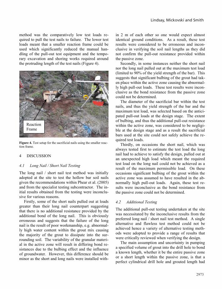
method was the comparatively low test loads re-quired to pull the test nails to failure. The lower test loads meant that a smaller reaction frame could be used which significantly reduced the manual han-dling of the pull-out test equipment and the tempo-rary excavation and shoring works required around the protruding length of the test nails (Figure 4).
Figure 4. Test setup for the sacrificial nails using the smaller reac-tion frame.
4 DISCUSSION
4.1 Long Nail / Short Nail Testing
The long nail / short nail test method was initially adopted at the site to test the hollow bar soil nails given the recommendations within Phear et al. (2005) and from the specialist testing subcontractor. The in-itial results obtained from the testing were inconclu-sive for various reasons.
Firstly, some of the short nails pulled out at loads greater than their long nail counterpart suggesting that there is no additional resistance provided by the additional bond of the long nail. This is obviously erroneous and suggests that the failure of the long nail is the result of poor workmanship, e.g. abnormal-ly high water content within the grout mix causing the majority of the grout to dissipate into the sur-rounding soil. The variability of the granular materi-al in the active zone will result in differing bond re-sistances due to the bulbing effect and the influence of groundwater. However, this difference should be minor as the short and long nails were installed with-
in 2 m of each other so one would expect almost identical ground conditions. As a result, these test results were considered to be erroneous and incon-clusive in verifying the soil nail lengths as they did not confirm the pull-out resistance provided within the passive zone.
Secondly, in some instances neither the short nail nor the long nail pulled out at the maximum test load (limited to 90% of the yield strength of the bar). This suggests that significant bulbing of the grout had tak-en place within the active zone causing the abnormal-ly high pull-out loads. These test results were incon-clusive as the bond resistance from the passive zone could not be determined.
The diameter of the sacrificial bar within the test nails, and thus the yield strength of the bar and the maximum test load, was selected based on the antici-pated pull-out loads at the design stage. The extent of bulbing, and thus the additional pull-out resistance within the active zone, was considered to be negligi-ble at the design stage and as a result the sacrificial bars used at the site could not safely achieve the re-quired test loads.
Thirdly, on occasions the short nail, which was always tested first to estimate the test load the long nail had to achieve to satisfy the design, pulled out at an unexpected high load which meant the required test load on the long nail could not be achieved as a result of the maximum permissible load. On these occasions significant bulbing of the grout within the active zone was assumed to have resulted in the ab-normally high pull-out loads. Again, these test re-sults were inconclusive as the bond resistance from the passive zone could not be determined.
4.2 Additional Testing
The additional pull-out testing undertaken at the site was necessitated by the inconclusive results from the preferred long nail / short nail test method. A single alternative and flawless test method could not be achieved hence a variety of alternative testing meth-ods were adopted to provide a range of results that were critically reviewed when verifying the design. The main assumption and uncertainty in pumping a specified volume of grout into the drill hole to bond a known length, whether it be the entire passive zone or a short length within the passive zone, is that a perfect cylindrical drill hole and grouted length had
Reaction Frame
2973
3.4 Soil Nail Testing
Fifty six sacrificial test nails were installed across the slope and tested to verify the nail lengths determined within the design. The ‘long nail / short nail’ test method, shown schematically in Figure 2, was initial-ly adopted given the recommendations within Phear et al. (2005) and from the specialist testing sub-contractor for the project.
Figure 2. Schematic layout of ‘long nail / short nail’ test method.
The short nail was installed to the boundary be-
tween the active and passive zones determined within the design, and the long nail was installed to full depth thus allowing the bond resistance from the pas-sive zone alone to be determined by simple deduc-tion. The test setup for the sacrificial nails installed for the long nail / short nail method is shown in Fig-ure 3.
Figure 3. Test setup for the sacrificial nails.
Given the inconclusive results obtained from some of the long nail / short nail tests (discussed in Section 4), further forms of testing were specified for the site.
Firstly, additional sacrificial test nails were in-stalled to full depth with a calculated volume of grout pumped into the hole after drilling with air flush to bond the nail entirely within the passive zone. This method assumed that the drill hole produced a perfect cylinder thus the volume of grout to bond the entire passive zone could be calculated. This test method was similar to a standard pull-out test, the only dif-ference being the volume of grout was determined by theoretical calculation rather than being limited by the inclusion of packer within the drill hole. This method allowed direct comparison with the test loads and allowed the soil nail lengths to be verified.
Secondly, additional test nails were installed using a modified method of the long nail / short nail test whereby the short test nail was installed beyond the active zone. Following deduction of the short nail pull-out load from the long nail, an ultimate bond re-sistance relating to the remaining length of the long nail was obtained. This method of testing was under-taken to verify the ultimate bond resistance of the material within the passive zone; in this case the gla-cial till. The results were then extrapolated for the entire bond length to determine the ultimate pull-out resistance for the nail and thus verify the soil nail lengths. It was recognised that extrapolating the re-sults to determine the ultimate pull-out resistance of the nail could lead to errors in design as this assumes uniformity of load distribution. As a result, the length of the short and long nails were varied to test and obtain an ultimate bond resistance for various depths and bonded lengths within the passive zone.
Thirdly, additional test nails were installed to var-ious depths within the passive zone with a calculated volume of grout pumped into the hole after drilling with air flush to bond only a short length within the passive zone; typically between 2 m and 5 m. This method, similar to the additional method to grout the entire bond length, assumes that the drill hole pro-duced a perfect cylinder thus the volume of grout to bond a specified short length could be calculated. This method was undertaken to verify the ultimate bond resistance of the material within the passive zone, and by extrapolation, the soil nail lengths de-termined within the design. A further benefit of this
Long Nail
Short Nail
Reaction Frame
method was the comparatively low test loads re-quired to pull the test nails to failure. The lower test loads meant that a smaller reaction frame could be used which significantly reduced the manual han-dling of the pull-out test equipment and the tempo-rary excavation and shoring works required around the protruding length of the test nails (Figure 4).
Figure 4. Test setup for the sacrificial nails using the smaller reac-tion frame.
4 DISCUSSION
4.1 Long Nail / Short Nail Testing
The long nail / short nail test method was initially adopted at the site to test the hollow bar soil nails given the recommendations within Phear et al. (2005) and from the specialist testing subcontractor. The in-itial results obtained from the testing were inconclu-sive for various reasons.
Firstly, some of the short nails pulled out at loads greater than their long nail counterpart suggesting that there is no additional resistance provided by the additional bond of the long nail. This is obviously erroneous and suggests that the failure of the long nail is the result of poor workmanship, e.g. abnormal-ly high water content within the grout mix causing the majority of the grout to dissipate into the sur-rounding soil. The variability of the granular materi-al in the active zone will result in differing bond re-sistances due to the bulbing effect and the influence of groundwater. However, this difference should be minor as the short and long nails were installed with-
in 2 m of each other so one would expect almost identical ground conditions. As a result, these test results were considered to be erroneous and incon-clusive in verifying the soil nail lengths as they did not confirm the pull-out resistance provided within the passive zone.
Secondly, in some instances neither the short nail nor the long nail pulled out at the maximum test load (limited to 90% of the yield strength of the bar). This suggests that significant bulbing of the grout had tak-en place within the active zone causing the abnormal-ly high pull-out loads. These test results were incon-clusive as the bond resistance from the passive zone could not be determined.
The diameter of the sacrificial bar within the test nails, and thus the yield strength of the bar and the maximum test load, was selected based on the antici-pated pull-out loads at the design stage. The extent of bulbing, and thus the additional pull-out resistance within the active zone, was considered to be negligi-ble at the design stage and as a result the sacrificial bars used at the site could not safely achieve the re-quired test loads.
Thirdly, on occasions the short nail, which was always tested first to estimate the test load the long nail had to achieve to satisfy the design, pulled out at an unexpected high load which meant the required test load on the long nail could not be achieved as a result of the maximum permissible load. On these occasions significant bulbing of the grout within the active zone was assumed to have resulted in the ab-normally high pull-out loads. Again, these test re-sults were inconclusive as the bond resistance from the passive zone could not be determined.
4.2 Additional Testing
The additional pull-out testing undertaken at the site was necessitated by the inconclusive results from the preferred long nail / short nail test method. A single alternative and flawless test method could not be achieved hence a variety of alternative testing meth-ods were adopted to provide a range of results that were critically reviewed when verifying the design. The main assumption and uncertainty in pumping a specified volume of grout into the drill hole to bond a known length, whether it be the entire passive zone or a short length within the passive zone, is that a perfect cylindrical drill hole and grouted length had
Reaction Frame
Lindsay, Mickovski and Smith

Geotechnical Engineering for Infrastructure and Development
2974
been created within the passive zone. This is unlike-ly to be the case as a result of bulbing of the grout within the drill hole, dissipation of grout into granu-lar bands within the passive zone and grout loss as the drill hole is being grouted. Ordinarily this grout-ed length is controlled by the use of a packer but this could not be incorporated into the self-drilled drill hole.
By assuming a perfect cylinder of grout however, the maximum possible bonded length was considered in the design verification and thus the most conserva-tive bond resistance per metre length was determined given the pull-out load obtained from the test. Where it was assumed that the entire passive zone had been bonded, then the test only had to satisfy the test load (design load x BS 8006-2 partial factor) hence whether the entire passive zone or only a proportion of the passive zone had been bonded was irrelevant provided that the test satisfied the test load. Where this test failed, an associated bond resistance was de-termined considering the bond within the entire pas-sive zone. Adopting the modified long nail / short nail test method removed this uncertainty and provided a bond resistance at various depths within the passive zone. The problem with this modified method how-ever was that the short nail had to be installed beyond the active zone and, given the problems experienced with the original long nail / short nail test method, the short nails were unlikely to pull out on occasions. As a result this alternative method was only adopted where the design lengths for the nails was relatively short to ensure that both the short and long nails could be pulled out and thus provide conclusive re-sults.
Considering all of the testing results and the asso-ciated limitations and assumptions with each of the testing methods, the nail lengths determined within the design were verified or modified where required.
4.3 Conclusions
The problems encountered with the soil nail pull-out testing at the Bervie Braes site are expected to be common in all projects comprising self-drilled hol-low bar soil nails. Further investigation and research, similar to that presented in this paper, is recommend-ed to inform the industry of the best practices in test-ing hollow bar soil nails. The industry should not be
dissuaded by the uncertainty and lack of published guidance regarding the testing and the subsequent verification of the design, as self-drilled hollow bar soil nails do offer considerable benefits, both in terms of reduced construction costs and in health and safe-ty, whilst allowing the designer to meet his duties under normative regulations.
When specifying pull-out testing for verification of the design nail lengths, the designer should take due regard of the ground conditions expected at the site, the associated bond resistances of each stratum from empirical information, the predicted test loads, the possibility of bulbing or dissipation of the grout and the effect on the test, and the manual handling and temporary works required in order to satisfy the specification. Where the ground conditions are particularly complex, or where the project comprises a significant number of soil nails, it is recommended that the hol-low bar test results are verified and supplemented with site testing using solid bars in the traditional manner until such time that a widely accepted meth-od of testing hollow bar soil nails is developed.
ACKNOWLEDGEMENT
The authors would like to thank Aberdeenshire Council for permitting the use of project information.
REFERENCES
BS 8006-2:2011. Code of practice for strengthened/reinforced soils. Part 2: Soil nail design. British Standards Institution, Lon-don. BS EN 14490:2010. Execution of special geotechnical works – Soil nailing. British Standards Institution, London. Dywidag Systems International 2008. DYWI Drill Hollow Bar brochure. HA 68/94 1994. Design Manual for Roads and Bridges. Design Methods for the Reinforcement of Highway Slopes by Reinforced Soil and Soil Nailing Techniques. The Scottish Office Industry Department. Mickovski, S.B. 2014. Stabilisation of former trunk road em-bankment using combined structural and eco-engineering strate-gies. In: Lakušić, S (ed.) Proc. 3rd Int’l Conf. on Road and Rail In-frastructure, 559-565. CETRA 2014, Split, Croatia. Phear, A. Dew, C. Ozsoy, B. Wharmby, N.J. Judge, J. Barley, A.D. 2005. Soil nailing – best practice guidance. CIRIA C637, London.
Very small strain stiffness of Lisbon Miocene clayey formation from in situ tests
Rigidité pour très petite déformation de la formation argileuse du Miocène de Lisbonne obtenue par essais in situ
M.L. Laranjo*1, J. Carvalho2, M.M. Fernandes2 and A.V. Fonseca2 1 Polytechnic Institute of Viana do Castelo, Viana do Castelo, Portugal
2 Faculty of Engineering, University of Porto, Porto, Portugal * Corresponding Author
ABSTRACT Lisbon Miocene clays are part of the Miocene Series, formed in the Lower Tagus Basin, in the western margin of the Iberian Plate. The Miocene Series is around 300 m thick and comprises several geological formations that include hard soils and soft rocks from both continental and marine origins. One of the main clayey formations is Prazeres clay, a highly consolidated clayey formation that en-compasses an important part of Lisbon subsoil, including areas of historical interest. Included in an ongoing investigation on the physical and mechanical characterization of Lisbon Miocene clays, in situ tests were performed, namely cross-hole seismic tests (CHT) and self-boring pressuremeter tests (SBPT). Although SBPT minimizes disturbance, there are differences in measurements of stiffness parameters from SBPT and CHT, with implications on small strain stiffness G0. This paper presents a discussion on the anisotropy of these properties, obtained from shear wave velocity in CHT tests under distinct travel paths, frequency bands and polarization directions. The paper also dis-cusses some correlations that can be established between the small strain stiffness (G0) obtained from CHT and from expansion-contraction cycles from SBPT taking into account the actual test stress-strain conditions
RÉSUMÉ Les argiles du Miocène de Lisbonne font partie de la série miocène, formé dans le bassin inférieur du Tage, sur la rive ouest de la Plaque Ibérique. La série miocène a une épaisseur de 300 m, comprenant plusieurs formations géologiques qui incluent des sols durs et des roches tendres, formées d'origines marines et continentales. Une des principales formations argileuses est l'argile de Prazeres, une for-mation très consolidée qui occupe une partie importante du sous-sol de Lisbonne, comprenant plusieurs zones d'intérêt historique. Des es-sais systématiques ont été effectués dans un champ expérimental, comme des essais sismiques cross-hole (CHT) et des essais pressio-mètriques (SBPT), qui font partie dans une enquête en cours sur la caractérisation physique et mécanique de ces argiles. Bien que le SBPT minimise la perturbation du sol lors de l'excavation, il y a des différences dans les mesures des paramètres de rigidité obtenus par SBPT et CHT, dans des implications sur le module de cisaillement pour très petites déformations (G0). Cet article présente une discussion sur l'ani-sotropie de ces propriétés, obtenues par des vitesses de propagation des ondes sismiques dans les tests CHT sur différents directions de pro-pagation, bandes de fréquences et directions de polarisation. Le document présente aussi certaines corrélations qui peuvent être établies entre différents G0, obtenus dans les essais CHT et dans les cycles d'expansion-contraction des tests SBPT, considérant les conditions de contrainte et déformation.
1 INTRODUCTION
Miocene clays form an important part of Lisbon sub-soil, where numerous constructions have been built in the last decades, namely metro and motorway tun-nels, deep excavations for underground parking facil-ities and for basements of new buildings, and spread and deep foundations for new buildings.
Included in a recent study undertaken at the Uni-versity of Porto, the characteristics of Prazeres Mio-
cene clays were studied both from the collection and treatment of existing data and from the results of in situ tests and laboratory tests on the soil of an exper-imental site (Lopes Laranjo 2013).
A brief geological background of Miocene clays is presented and both the experimental site and testing programme are described. The results from in situ cross-hole seismic tests (CHT) and self-boring pres-suremeter tests (SBPT) are interpreted and a discus-sion on the differences between parameters obtained
Related Documents


