Infrastructure Access Report Infrastructure: UEDIN FloWave All-Waters Current and Wave Test FacilityUEDIN Curved Wave Tank User-Project: Polymoor tidal Testing of polymer spring mooring components on a tidal current renewable energy device Technology from Ideas, ScotRenewables Tidal Power Marine Renewables Infrastructure Network Status: Draft Version: Date: 13-Jul-2015 EC FP7 “Capacities” Specific Programme Research Infrastructure Action

Welcome message from author
This document is posted to help you gain knowledge. Please leave a comment to let me know what you think about it! Share it to your friends and learn new things together.
Transcript

Infrastructure Access Report
Infrastructure: UEDIN FloWave All-Waters Current and Wave Test FacilityUEDIN Curved Wave Tank
User-Project: Polymoor tidal
Testing of polymer spring mooring components on a tidal current renewable energy device
Technology from Ideas, ScotRenewables Tidal Power
Marine Renewables Infrastructure Network
Status: Draft Version: Date: 13-Jul-2015
EC FP7 “Capacities” Specific Programme Research Infrastructure Action
Infrastructure Access Report: Polymoor tidal
Rev. , 13-Jul-2015 Page 2 of 12
ABOUT MARINET MARINET (Marine Renewables Infrastructure Network for emerging Energy Technologies) is an EC-funded network of research centres and organisations that are working together to accelerate the development of marine renewable energy - wave, tidal & offshore-wind. The initiative is funded through the EC's Seventh Framework Programme (FP7) and runs for four years until 2015. The network of 29 partners with 42 specialist marine research facilities is spread across 11 EU countries and 1 International Cooperation Partner Country (Brazil). MARINET offers periods of free-of-charge access to test facilities at a range of world-class research centres. Companies and research groups can avail of this Transnational Access (TA) to test devices at any scale in areas such as wave energy, tidal energy, offshore-wind energy and environmental data or to conduct tests on cross-cutting areas such as power take-off systems, grid integration, materials or moorings. In total, over 700 weeks of access is available to an estimated 300 projects and 800 external users, with at least four calls for access applications over the 4-year initiative. MARINET partners are also working to implement common standards for testing in order to streamline the development process, conducting research to improve testing capabilities across the network, providing training at various facilities in the network in order to enhance personnel expertise and organising industry networking events in order to facilitate partnerships and knowledge exchange. The aim of the initiative is to streamline the capabilities of test infrastructures in order to enhance their impact and accelerate the commercialisation of marine renewable energy. See www.fp7-marinet.eu for more details.
Partners
Ireland University College Cork, HMRC (UCC_HMRC)
Coordinator
Sustainable Energy Authority of Ireland (SEAI_OEDU)
Denmark Aalborg Universitet (AAU)
Danmarks Tekniske Universitet (RISOE)
France Ecole Centrale de Nantes (ECN)
Institut Français de Recherche Pour l'Exploitation de la Mer (IFREMER)
United Kingdom National Renewable Energy Centre Ltd. (NAREC)
The University of Exeter (UNEXE)
European Marine Energy Centre Ltd. (EMEC)
University of Strathclyde (UNI_STRATH)
The University of Edinburgh (UEDIN)
Queen’s University Belfast (QUB)
Plymouth University(PU)
Spain Ente Vasco de la Energía (EVE)
Tecnalia Research & Innovation Foundation (TECNALIA)
Belgium 1-Tech (1_TECH)
Netherlands Stichting Tidal Testing Centre (TTC)
Stichting Energieonderzoek Centrum Nederland (ECNeth)
Germany Fraunhofer-Gesellschaft Zur Foerderung Der Angewandten Forschung E.V (Fh_IWES)
Gottfried Wilhelm Leibniz Universität Hannover (LUH)
Universitaet Stuttgart (USTUTT)
Portugal Wave Energy Centre – Centro de Energia das Ondas (WavEC)
Italy Università degli Studi di Firenze (UNIFI-CRIACIV)
Università degli Studi di Firenze (UNIFI-PIN)
Università degli Studi della Tuscia (UNI_TUS)
Consiglio Nazionale delle Ricerche (CNR-INSEAN)
Brazil Instituto de Pesquisas Tecnológicas do Estado de São Paulo S.A. (IPT)
Norway Sintef Energi AS (SINTEF)
Norges Teknisk-Naturvitenskapelige Universitet (NTNU)
Infrastructure Access Report: Polymoor tidal
Rev. [Revision Number, e.g. 01], 13-Jul-2015 Page 3 of 12
DOCUMENT INFORMATION Title Testing of polymer spring mooring components on a tidal current renewable energy
device
Distribution Public
Document Reference MARINET-TA1-Polymoor tidal
User-Group Leader, Lead Author
Dr. Paul McEvoy Technology from Ideas Ltd. (TfI) 6 Charlemont Terrace, Crofton Road, Dun Laoghaire, A96 F8W5, Ireland.
User-Group Members, Contributing Authors
[Insert name or delete row] Technology from Ideas Ltd. Mr. Calum Miller ScotRenewables Tidal Power Ltd. Mr. Nicol Miller ScotRenewables Tidal Power Ltd. Mr. Alexander Sinclair ScotRenewables Tidal Power Ltd.
Infrastructure Accessed: UEDIN FloWave All-Waters Current and Wave Test Facility
Infrastructure Manager (or Main Contact)
Mr. Jeffrey Steynor
REVISION HISTORY Rev. Date Description Prepared by
(Name) Approved By Infrastructure
Manager
Status (Draft/Final)
01 13/7/15 Initial Completion A Sinclair Draft
02 19/8/15 First full draft P McEvoy Draft
Infrastructure Access Report: Polymoor tidal
Rev. [Revision Number, e.g. 01], 13-Jul-2015 Page 4 of 12
ABOUT THIS REPORT One of the requirements of the EC in enabling a user group to benefit from free-of-charge access to an infrastructure is that the user group must be entitled to disseminate the foreground (information and results) that they have generated under the project in order to progress the state-of-the-art of the sector. Notwithstanding this, the EC also state that dissemination activities shall be compatible with the protection of intellectual property rights, confidentiality obligations and the legitimate interests of the owner(s) of the foreground. The aim of this report is therefore to meet the first requirement of publicly disseminating the knowledge generated through this MARINET infrastructure access project in an accessible format in order to:
progress the state-of-the-art
publicise resulting progress made for the technology/industry
provide evidence of progress made along the Structured Development Plan
provide due diligence material for potential future investment and financing
share lessons learned
avoid potential future replication by others
provide opportunities for future collaboration
etc. In some cases, the user group may wish to protect some of this information which they deem commercially sensitive, and so may choose to present results in a normalised (non-dimensional) format or withhold certain design data – this is acceptable and allowed for in the second requirement outlined above.
ACKNOWLEDGEMENT The work described in this publication has received support from MARINET, a European Community - Research Infrastructure Action under the FP7 “Capacities” Specific Programme.
LEGAL DISCLAIMER The views expressed, and responsibility for the content of this publication, lie solely with the authors. The European Commission is not liable for any use that may be made of the information contained herein. This work may rely on data from sources external to the MARINET project Consortium. Members of the Consortium do not accept liability for loss or damage suffered by any third party as a result of errors or inaccuracies in such data. The information in this document is provided “as is” and no guarantee or warranty is given that the information is fit for any particular purpose. The user thereof uses the information at its sole risk and neither the European Commission nor any member of the MARINET Consortium is liable for any use that may be made of the information.
Infrastructure Access Report: Polymoor tidal
Rev. [Revision Number, e.g. 01], 13-Jul-2015 Page 5 of 12
EXECUTIVE SUMMARY Technology from Ideas (TfI) tested their Polymer Based Mooring (PolyMoor) system at the University of Edinburgh’s FloWave Ocean Energy Research Facility. These test were completed using a 1/40th scale model of ScotRenewables Tidal Power’s SR2000. The SR200 is a floating tidal turbine with a ‘turret’ style single point mooring system. The circular layout of the test tank allowed testing of the mooring system with wave loading from numerous directions in relation to the current. Load cells at the base of the mooring lines showed, and measured, the load on each line. A Qualisys system allowed the motion of the model to be accurately captured in the six degrees of freedom. Baseline testing was initially completed using the existing mooring system with the model. The PolyMoor system was then incorporated into the moorings and the same tests were undertaken. This allowed a direct comparison between the two to be made. The collected data will be used to prove the benefits of installing the PolyMoor system and deliver confidence that it can be used to good effect in the renewables sector.

Infrastructure Access Report: Polymoor tidal
Rev. [Revision Number, e.g. 01], 13-Jul-2015 Page 6 of 12
CONTENTS
1 INTRODUCTION & BACKGROUND ...................................................................................................................7
1.1 INTRODUCTION .................................................................................................................................................... 7 1.2 DEVELOPMENT SO FAR .......................................................................................................................................... 7 1.2.1 Stage Gate Progress ...................................................................................... Error! Bookmark not defined. 1.2.2 Plan For This Access ....................................................................................... Error! Bookmark not defined.
2 OUTLINE OF WORK CARRIED OUT ...................................................................................................................8
2.1 SETUP ................................................................................................................................................................. 8 2.2 TESTS ................................................................................................................................................................. 9 2.2.1 Test Plan ........................................................................................................ Error! Bookmark not defined.
2.3 RESULTS .............................................................................................................................................................. 9 2.4 ANALYSIS & CONCLUSIONS...................................................................................... ERROR! BOOKMARK NOT DEFINED.
3 MAIN LEARNING OUTCOMES ....................................................................................................................... 11
3.1 PROGRESS MADE ............................................................................................................................................... 11 3.1.1 Progress Made: For This User-Group or Technology ................................................................................. 11 3.1.2 Progress Made: For Marine Renewable Energy Industry .......................................................................... 11
3.2 KEY LESSONS LEARNED ........................................................................................... ERROR! BOOKMARK NOT DEFINED.
4 FURTHER INFORMATION .............................................................................................................................. 12
4.1 SCIENTIFIC PUBLICATIONS .................................................................................................................................... 12 4.2 WEBSITE & SOCIAL MEDIA ................................................................................................................................... 12
5 REFERENCES ............................................................................................... ERROR! BOOKMARK NOT DEFINED.
6 APPENDICES ............................................................................................... ERROR! BOOKMARK NOT DEFINED.
6.1 STAGE DEVELOPMENT SUMMARY TABLE ................................................................... ERROR! BOOKMARK NOT DEFINED. 6.2 ANY OTHER APPENDICES ........................................................................................ ERROR! BOOKMARK NOT DEFINED.
Infrastructure Access Report: Polymoor tidal
Rev. [Revision Number, e.g. 01], 13-Jul-2015 Page 7 of 12
1 INTRODUCTION & BACKGROUND
1.1 INTRODUCTION The tests were carried out at the University of Edinburgh’s FloWave Ocean Energy Research Facility. This facility allows the generation of numerous waves and a range of current speeds, both from any direction. It also contains Qualisys motion tracking technology which uses radar reflectors installed on the model to track its motion response. The aim of these tests is to compare an original mooring system with one incorporating the PolyMoor technology. The tests were held over one week starting 8th July and involved the turbine being tested in two configurations; rotors locked and rotors spinning.
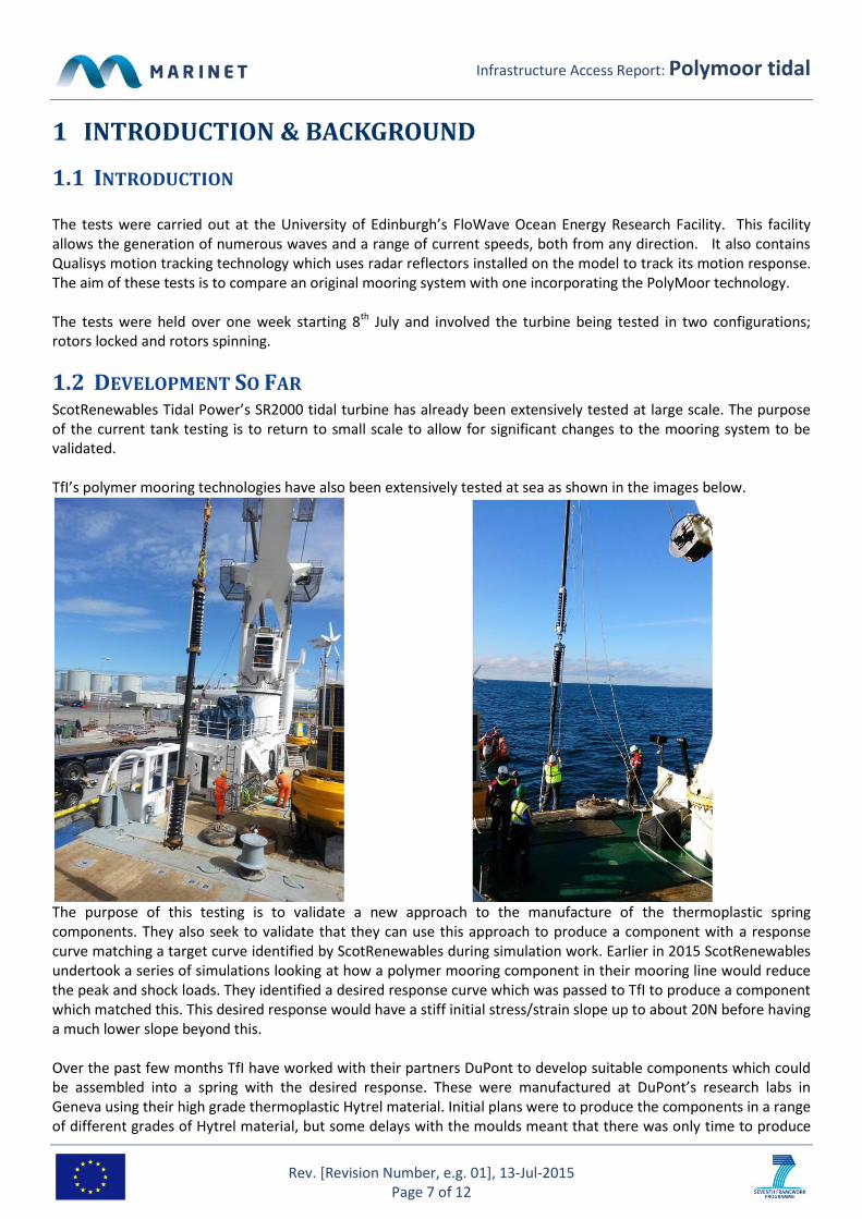
1.2 DEVELOPMENT SO FAR ScotRenewables Tidal Power’s SR2000 tidal turbine has already been extensively tested at large scale. The purpose of the current tank testing is to return to small scale to allow for significant changes to the mooring system to be validated. TfI’s polymer mooring technologies have also been extensively tested at sea as shown in the images below.
The purpose of this testing is to validate a new approach to the manufacture of the thermoplastic spring components. They also seek to validate that they can use this approach to produce a component with a response curve matching a target curve identified by ScotRenewables during simulation work. Earlier in 2015 ScotRenewables undertook a series of simulations looking at how a polymer mooring component in their mooring line would reduce the peak and shock loads. They identified a desired response curve which was passed to TfI to produce a component which matched this. This desired response would have a stiff initial stress/strain slope up to about 20N before having a much lower slope beyond this. Over the past few months TfI have worked with their partners DuPont to develop suitable components which could be assembled into a spring with the desired response. These were manufactured at DuPont’s research labs in Geneva using their high grade thermoplastic Hytrel material. Initial plans were to produce the components in a range of different grades of Hytrel material, but some delays with the moulds meant that there was only time to produce
Infrastructure Access Report: Polymoor tidal
Rev. [Revision Number, e.g. 01], 13-Jul-2015 Page 8 of 12
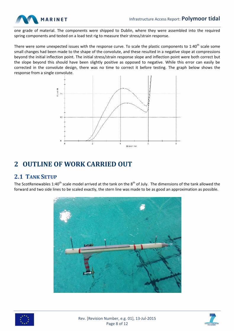
one grade of material. The components were shipped to Dublin, where they were assembled into the required spring components and tested on a load test rig to measure their stress/strain response. There were some unexpected issues with the response curve. To scale the plastic components to 1:40th scale some small changes had been made to the shape of the convolute, and these resulted in a negative slope at compressions beyond the initial inflection point. The initial stress/strain response slope and inflection point were both correct but the slope beyond this should have been slightly positive as opposed to negative. While this error can easily be corrected in the convolute design, there was no time to correct it before testing. The graph below shows the response from a single convolute.
2 OUTLINE OF WORK CARRIED OUT
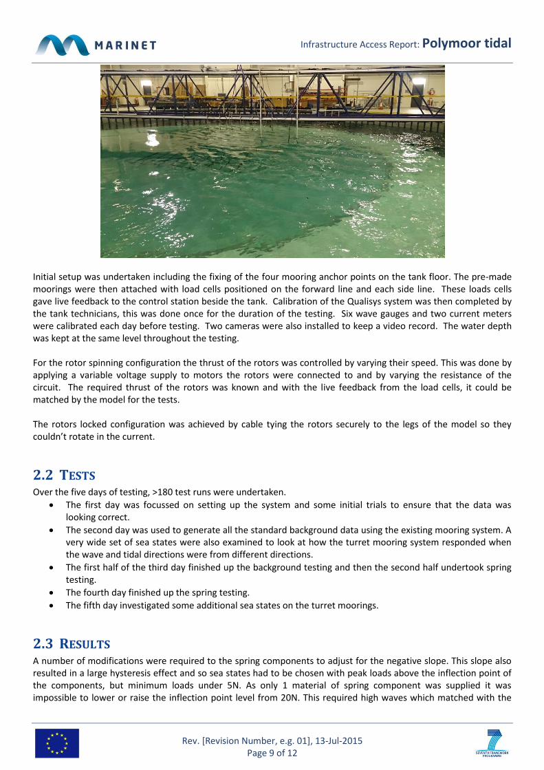
2.1 TANK SETUP The ScotRenewables 1:40th scale model arrived at the tank on the 8th of July. The dimensions of the tank allowed the forward and two side lines to be scaled exactly, the stern line was made to be as good an approximation as possible.
Infrastructure Access Report: Polymoor tidal
Rev. [Revision Number, e.g. 01], 13-Jul-2015 Page 9 of 12
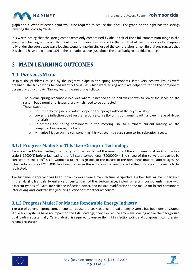
Initial setup was undertaken including the fixing of the four mooring anchor points on the tank floor. The pre-made moorings were then attached with load cells positioned on the forward line and each side line. These loads cells gave live feedback to the control station beside the tank. Calibration of the Qualisys system was then completed by the tank technicians, this was done once for the duration of the testing. Six wave gauges and two current meters were calibrated each day before testing. Two cameras were also installed to keep a video record. The water depth was kept at the same level throughout the testing. For the rotor spinning configuration the thrust of the rotors was controlled by varying their speed. This was done by applying a variable voltage supply to motors the rotors were connected to and by varying the resistance of the circuit. The required thrust of the rotors was known and with the live feedback from the load cells, it could be matched by the model for the tests. The rotors locked configuration was achieved by cable tying the rotors securely to the legs of the model so they couldn’t rotate in the current.
2.2 TESTS Over the five days of testing, >180 test runs were undertaken.
The first day was focussed on setting up the system and some initial trials to ensure that the data was looking correct.
The second day was used to generate all the standard background data using the existing mooring system. A very wide set of sea states were also examined to look at how the turret mooring system responded when the wave and tidal directions were from different directions.
The first half of the third day finished up the background testing and then the second half undertook spring testing.
The fourth day finished up the spring testing.
The fifth day investigated some additional sea states on the turret moorings.
2.3 RESULTS A number of modifications were required to the spring components to adjust for the negative slope. This slope also resulted in a large hysteresis effect and so sea states had to be chosen with peak loads above the inflection point of the components, but minimum loads under 5N. As only 1 material of spring component was supplied it was impossible to lower or raise the inflection point level from 20N. This required high waves which matched with the

Infrastructure Access Report: Polymoor tidal
Rev. [Revision Number, e.g. 01], 13-Jul-2015 Page 10 of 12
expected scenarios when the rotors were locked on the device. The graph below shows a typical response seen from testing.
The first noticeable feature was that the spring loads were higher than the original case by about 30%. This was surprising, but was eventually traced to the current loading on the spring component itself being very high. The springs were positioned floating at about half the sea depth and additional simulations undertaken showed that this position would increase the loads by about 15%. In addition the springs were also twice the diameter at the 1:40th scale than they would be at full scale, explaining the additional 15%. Re-positioning the springs on the seabed out of the tidal flow would eliminate most of this load. The second noticeable feature is the spikes on the load. These are caused by the negative slope on the component and would not be the case once this is corrected. Once the inflection point is reached as the component compresses it suddenly becomes easier to compress further than to relax and so the load drops substantially in a negative spike. As the component relaxes we see the opposite spike between the waves. The third feature is the change in slope seen around 20N. There is a very clear shift from a steep slope to a lower slope at this point as the slope of the spring component changes. The final feature is the broadening of the load curve, causing the load to rise earlier and fall later. The energy under this curve should be the same as the energy in the original curve (though this is not the case due to the increased loading from the spring component itself). And hence the peaks should be noticeably lower. The graphs below show responses compensated for the loads on the spring component itself.
There is a clear differentiation between the spring response in the two graphs. As the loads increase beyond ~25N the springs absorb nearly all the load which the original mooring system does not. Where the loads are below ~25N the springs have very little effect. This suggests that the inflection point is too high for the loads in the left hand
Infrastructure Access Report: Polymoor tidal
Rev. [Revision Number, e.g. 01], 13-Jul-2015 Page 11 of 12
graph and a lower inflection point would be required to reduce the loads. The graph on the right has the springs lowering the loads by ~40%. It is worth noting that the spring components only compressed by about half of their full compression range in the worst case loading scenarios. The ideal inflection point load would be the one that allows the springs to compress fully under the worst case wave loading scenario, maximising use of the compression range. Simulations suggest that this should have been about 16N in the scenarios above, just above the peak background tidal loading.
3 MAIN LEARNING OUTCOMES
3.1 PROGRESS MADE Despite the problems caused by the negative slope in the spring components some very positive results were obtained. The tank testing helped identify the issues which were arising and have helped to refine the component design and adjustments. The key lessons learnt are as follows;
- The overall spring response curve was where it needed to be and was shown to lower the loads on the system but a number of issues arose which need to be corrected
- These issues are o Return to the original convolute shape on the springs without the negative slope o Lower the inflection point on the response curve (by using components with a lower grade of Hytrel
material) o Re-position the spring component in the mooring line to eliminate current loading on the
component increasing the loads. o Minimise friction on the component as this was seen to cause some spring relaxation issues.
3.1.1 Progress Made: For This User-Group or Technology Based on the Marinet testing, the user group has reaffirmed the need to test the components at an intermediate scale (~10000N) before fabricating the full scale components (3000000N). The shape of the convolutes cannot be corrected at the 1:40th scale without a full redesign due to the nature of the non-linear material and designs. An intermediate scale of ~10000N has been chosen as this will allow the final shape for the full scale components to be replicated. The fundament approach has been shown to work from a manufacture perspective. Further test will be undertaken in the lab at t his scale to enhance understanding of the performance, including testing components made with different grades of Hytrel (to shift the inflection point), and making modification to the mould for better component interlocking and load transfer (reducing friction for smoother responses).
3.1.2 Progress Made: For Marine Renewable Energy Industry The use of polymer spring components to reduce the peak loading in tidal energy systems has been demonstrated. While such systems have no impact on the tidal loadings, they can reduce any wave loading above the background tidal loading substantially. Careful design is required to ensure the right inflection point and component compression ranges are chosen.

Infrastructure Access Report: Polymoor tidal
Rev. [Revision Number, e.g. 01], 13-Jul-2015 Page 12 of 12
4 FURTHER INFORMATION
4.1 SCIENTIFIC PUBLICATIONS TfI will present the results of the Marinet testing at the next User Group meeting. They will also incorporate some of the results for presentation to lead customers at trade shows.
4.2 WEBSITE & SOCIAL MEDIA Website: www.tfimarine.com; www.scotrenewables.com
Related Documents