Testing and Verification of Thermite Barrier Technology in a UKCS Well Abandonment Scenario - A Case Study Willem Boon von Ochssee Principal Well Engineer, Spirit Energy

Welcome message from author
This document is posted to help you gain knowledge. Please leave a comment to let me know what you think about it! Share it to your friends and learn new things together.
Transcript
Testing and Verification of Thermite Barrier Technology in a UKCS Well Abandonment Scenario - A Case Study
Willem Boon von OchsseePrincipal Well Engineer, Spirit Energy
The P&A Challenge & ThermiteWell abandonments - the future is now
Population of older wells increasing worldwide
Increasing costs compared to previous estimates
ABEX is a concern for operators and governments
Low commodity price environment
Why & How did Spirit Energy got involved with Thermite
• Thermite was a JIP by Interwell P&A, AkerBP and Equinor
• Field trials required but no wells were available.
• Spirit Energy offered to find suitable wells in Canada
The Challenge
• Introduction of Technology needs a new approach
• Innovative application of “old” technology with “revolutionary” approach
• Engaged with OGA and OGTC to develop the opportunity
Introduction.2

Thermite ReactionHistory
Hans Goldschmidt inventor of the Goldschmidt reaction in 1893
Aluminothermic Process patent no. 96317 in 1895 and
THERMIT® Registrated Trademark in 1900
Chemical reaction
Aluminium (Al) reduces the oxide from iron oxide (Fe2O3), to
form Aluminium Oxide (Al2O3) and pure iron (Fe)
Reaction energy ~4000 kJ/kg
Reaction temperature ~2500 ºC
Original thermite reaction
Fe2O3 + 2 Al → 2 Fe + Al2O3 + ΔH
Hematite, rust, red color
3 Introduction.
What is an Exothermic Reaction;
Any mixture of two or more chemicals that
produces heat when activated.
Why thermite is preferable;
Self sustained oxygen source (Iron Oxide)
High energy potential in both materials
Self sustained reaction after activation
Thermite Plug Deployment
Enter footer detail in 'Header & Footer' in 'Text' tools on the 'Insert' tab4 Introduction.4
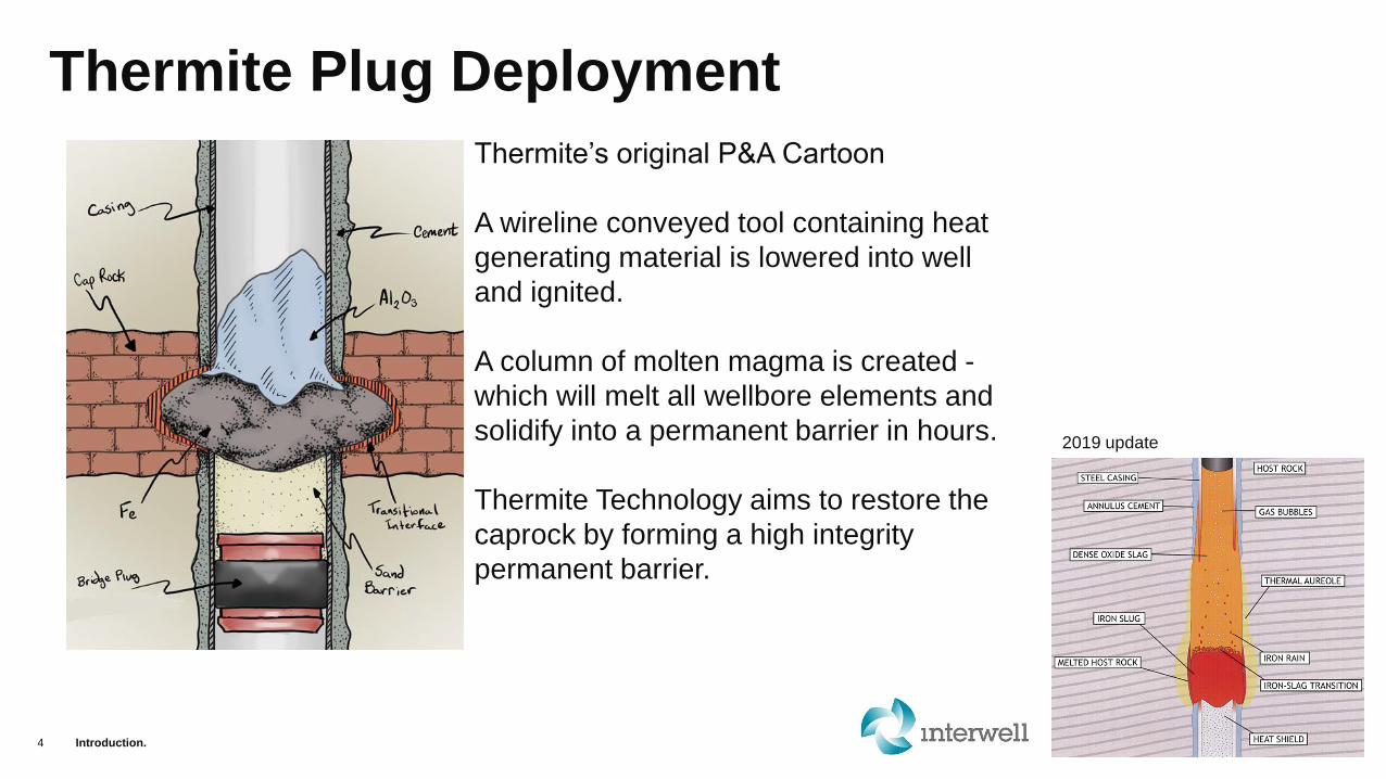
Thermite’s original P&A Cartoon
A wireline conveyed tool containing heat
generating material is lowered into well
and ignited.
A column of molten magma is created -
which will melt all wellbore elements and
solidify into a permanent barrier in hours.
Thermite Technology aims to restore the
caprock by forming a high integrity
permanent barrier.
2019 update
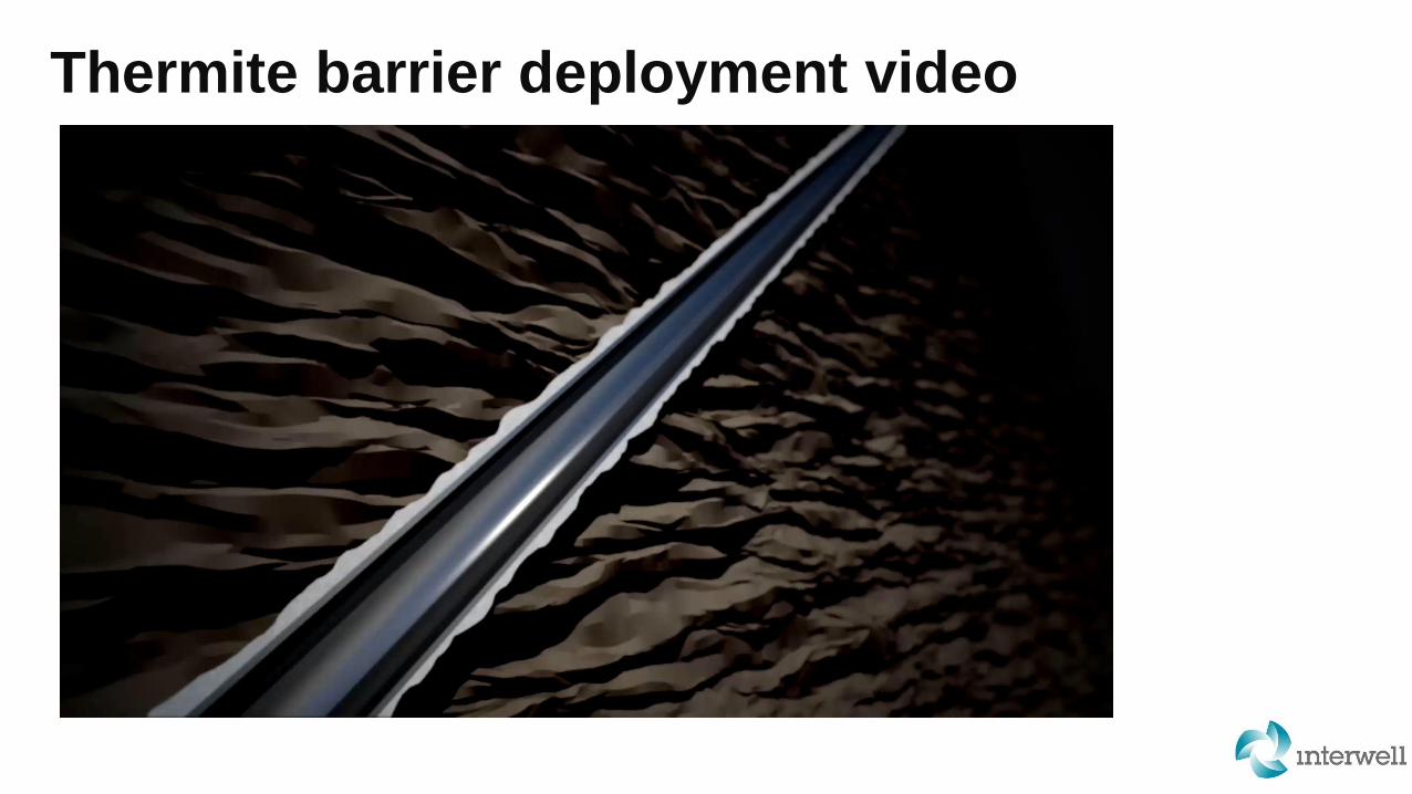
Thermite barrier deployment video
Testing and Verification of Thermite Barrier Technology in a UKNS Well Abandonment Scenario - A Case Study.5

Thermite Deployment Experience
Introduction6
• World’s first field trial in 2016 in Whitehorse in Alberta Canada,
followed by another in Benjamin.
• First European trial in England (Caythorpe) in May 2018.
• All three wells onshore with thermite set in 7 inch casing without
tubing in the hole.
• Imperial, Shell, Eni, West Lake, Canlin, CNR have also carried out
onshore trials
• First Offshore Deployment on Spirit Energy’s Audrey platform in the
North Sea
• Extensive deployment experience (18 trials in total). Focus now on
‘verification like cement’……

Challenging process ahead
• Resistance to new technology
• Qualify ‘new’ material
• No access to wells for field trials
• Lack of funding for technology development
• Competing with cement
• Establish Common Industry Approach
• A new education process
Enter footer detail in 'Header & Footer' in 'Text' tools on the 'Insert' tab7 Introduction7
*
Material Qualification
Technology Application
Barrier Verification

Thermite Pre/Post Deployment
Barrier Verification
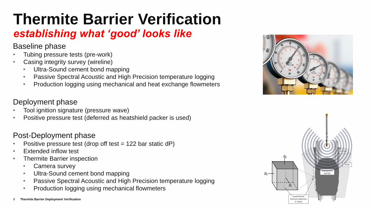
Thermite Barrier Verificationestablishing what ‘good’ looks like
Thermite Barrier Deployment Verification9
Baseline phase• Tubing pressure tests (pre-work)
• Casing integrity survey (wireline)
• Ultra-Sound cement bond mapping
• Passive Spectral Acoustic and High Precision temperature logging
• Production logging using mechanical and heat exchange flowmeters
Deployment phase• Tool ignition signature (pressure wave)
• Positive pressure test (deferred as heatshield packer is used)
Post-Deployment phase• Positive pressure test (drop off test = 122 bar static dP)
• Extended inflow test
• Thermite Barrier inspection
• Camera survey
• Ultra-Sound cement bond mapping
• Passive Spectral Acoustic and High Precision temperature logging
• Production logging using mechanical flowmeters
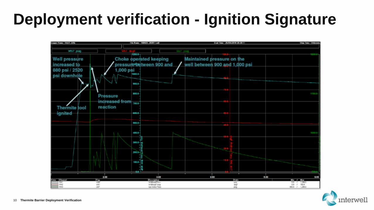
Deployment verification - Ignition Signature
Thermite Barrier Deployment Verification10

Deployment verification - Cement Bond
Thermite Barrier Deployment Verification11
PRE-LOG
Cement bond & Ultra sound survey:
• Well bounded, heterogeneous,
cement around the entire annulus
with non-connected liquid pockets
• Well immediately above the plug
un-affected by Thermite reaction
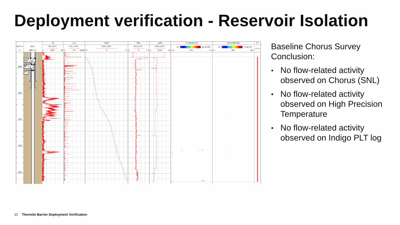
Deployment verification - Reservoir Isolation
Thermite Barrier Deployment Verification12
Baseline Chorus Survey
Conclusion:
• No flow-related activity
observed on Chorus (SNL)
• No flow-related activity
observed on High Precision
Temperature
• No flow-related activity
observed on Indigo PLT log

Deployment verification - Thermal modelling
Thermite Barrier Deployment Verification13
SLA
GIR
ON

Failure models comparison
Thermite Barrier Post Deployment Verification14
▪ Cement model ▪ Thermite model
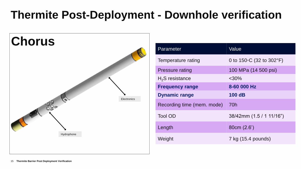
Thermite Post-Deployment - Downhole verification
15
Chorus
Electronics
Hydrophone
Parameter Value
Temperature rating 0 to 150◦C (32 to 302°F)
Pressure rating 100 MPa (14 500 psi)
H2S resistance <30%
Frequency range 8-60 000 Hz
Dynamic range 100 dB
Recording time (mem. mode) 70h
Tool OD 38/42mm (1.5 / 1 11/16”)
Length 80cm (2.6’)
Weight 7 kg (15.4 pounds)
Thermite Barrier Post Deployment Verification
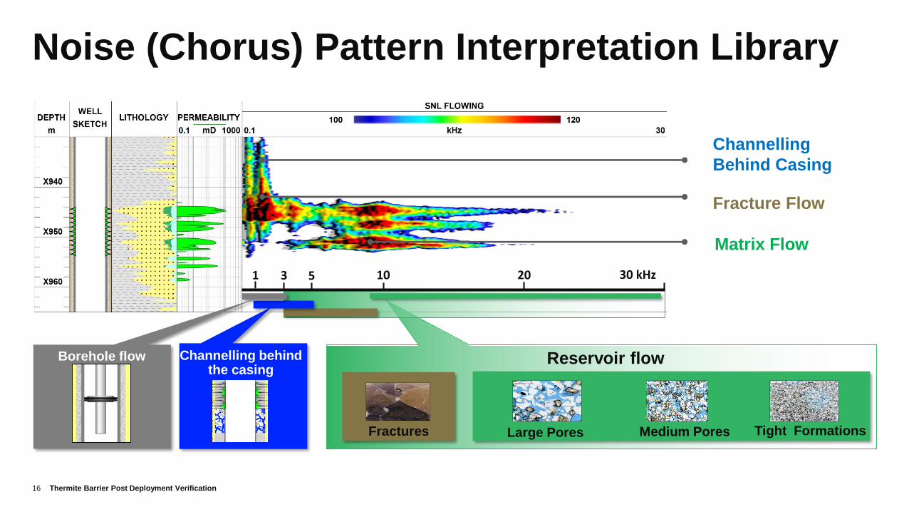
Noise (Chorus) Pattern Interpretation Library
Thermite Barrier Post Deployment Verification16
16
Reservoir flow
Tight FormationsLarge PoresFractures
Borehole flow Channelling behind the casing
1 3 30 kHz5 10 20
Medium Pores
Matrix Flow
Fracture Flow
Channelling
Behind Casing
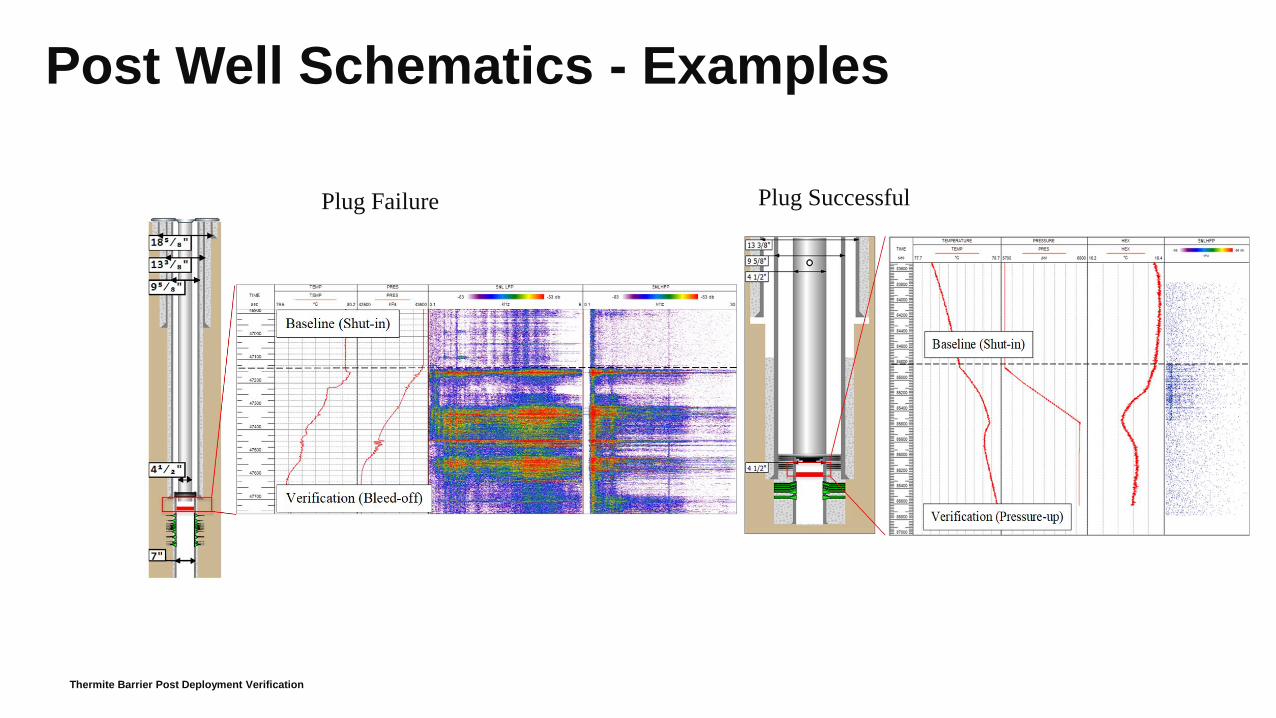
Post Well Schematics - Examples
Plug Failure Plug Successful
Thermite Barrier Post Deployment Verification

Caythorpe CA02 Thermite Trial
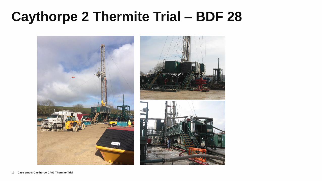
Caythorpe 2 Thermite Trial – BDF 28
Case study: Caythorpe CA02 Thermite Trial19
Key Objectives of Onshore Thermite Trial
20
• First UK / European deployment of the Thermite plug, as part of the phased
technology development programme (following the 2017 trials in Canada).
• Engage with EA, OGA and HSE to obtain regulatory consent to use the equipment
onshore
• 1st trial for setting Thermite plug in Halite formation, common cap rock in UKCS SNS
• Establish common application method and verification programme for Thermite P&A
technology
• Share the results with the Thermite Collaboration Forum to accelerate adoption of
new P&A technology in the UKCS
Case study: Caythorpe CA02 Thermite Trial
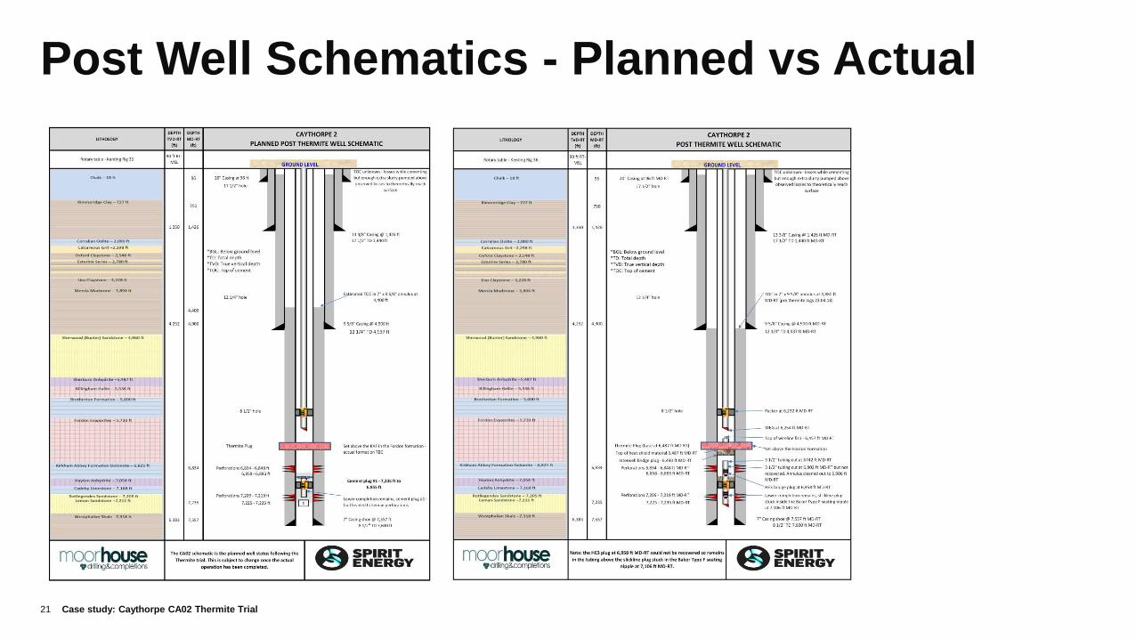
Post Well Schematics - Planned vs Actual
21 Case study: Caythorpe CA02 Thermite Trial

Well Re-entry & Preliminary results
22 Case study: Caythorpe CA02 Thermite Trial
CA02 Thermite Trial - Verification Pressure Test
Pressure to 550 psi
60 Minutes Pressure Test
START FINISH
• Positive pressure test
• Displaced Well to Nitrogen
• Extended inflow test
• 14 psi / hr PBU rate
• (equivalent of 5 SCF/min leak)

Audrey B1z Thermite Trial

Audrey B1z Thermite Trial
Case study: Audrey B1z Thermite Trial 24

Key Objectives of Offshore Trial (Top 5)
25
• First (global) offshore deployment of the Thermite plug, as part of the
phased technology development programme.
• Engage with OGA, OPRED/BEIS and HSE to obtain regulatory consent
to use the equipment offshore
• 2nd trial for setting Thermite plug in Halite formation, at lower angle
compared with CA-02 (common SNS Caprock)
• Share the results with the Thermite Collaboration Forum to accelerate
adoption of new P&A technology in the UKCS
• Progress Industry Common Verification road map for new P&A
technology and barrier material.
Case study: Audrey B1z Thermite Trial
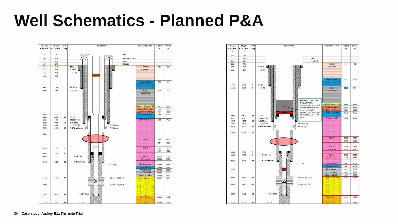
Well Schematics - Planned P&A
26 Case study: Audrey B1z Thermite Trial

Interim Well Status
27
Suspension
• (100bbl/hr losses observed prior to setting
Heatshield packer assembly)
• BVS w/ gauges & micro-smart valves set
below Thermite plug
• Suspend B1z with deepset Interwell plug
above Thermite, and shallow set Archer
plug as 2nd barrier.
Next
• Verify integrity of Thermite plug with BVS
receiver and repeat TGT SNL log.
• Continue with ‘Standard’ abandonment
programme
Case study: Audrey B1z Thermite Trial
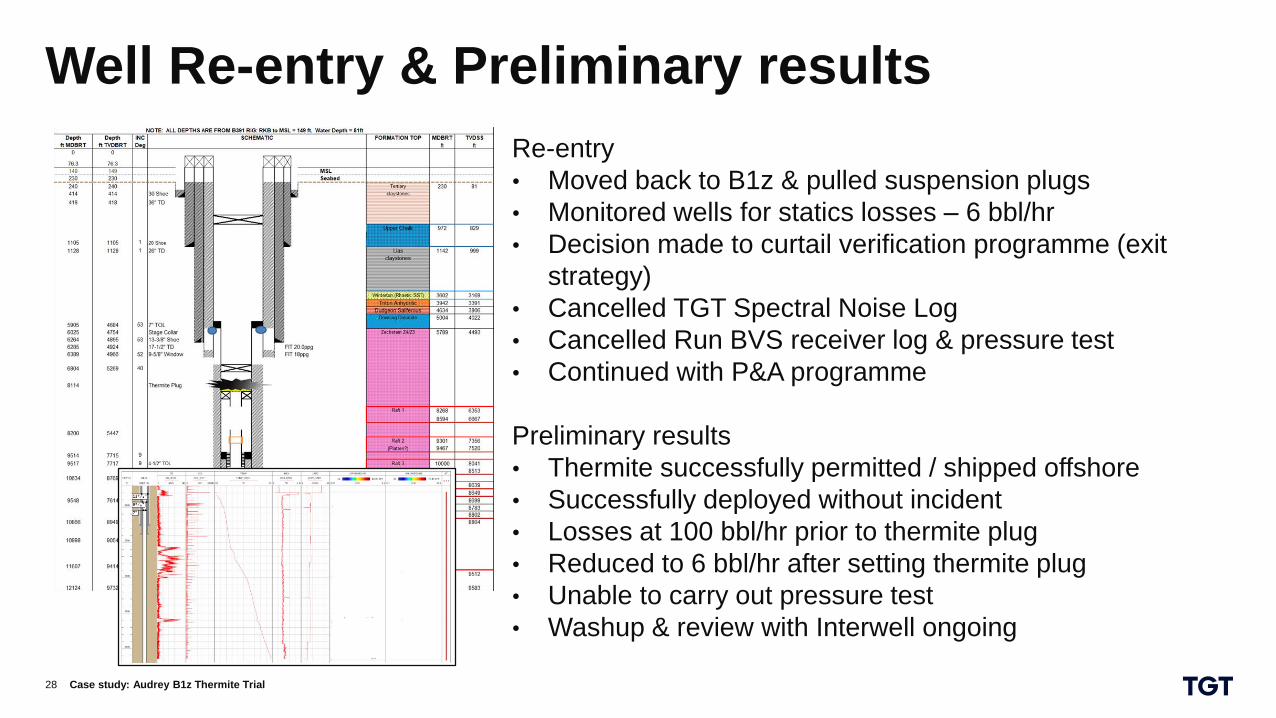
Well Re-entry & Preliminary results
28
Re-entry
• Moved back to B1z & pulled suspension plugs
• Monitored wells for statics losses – 6 bbl/hr
• Decision made to curtail verification programme (exit
strategy)
• Cancelled TGT Spectral Noise Log
• Cancelled Run BVS receiver log & pressure test
• Continued with P&A programme
Preliminary results
• Thermite successfully permitted / shipped offshore
• Successfully deployed without incident
• Losses at 100 bbl/hr prior to thermite plug
• Reduced to 6 bbl/hr after setting thermite plug
• Unable to carry out pressure test
• Washup & review with Interwell ongoing
Case study: Audrey B1z Thermite Trial

Two-Column Format Two-Column Format
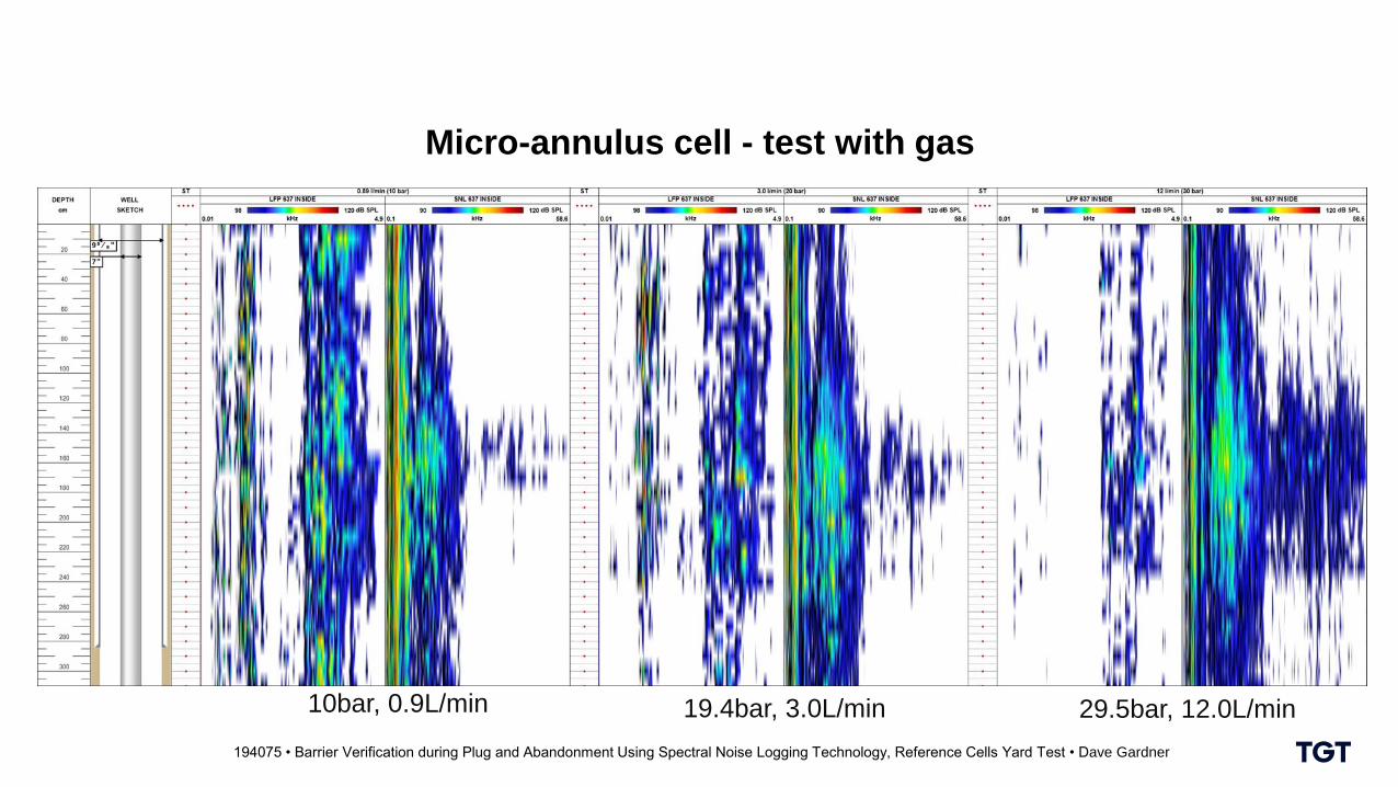
194075 • Barrier Verification during Plug and Abandonment Using Spectral Noise Logging Technology, Reference Cells Yard Test • Dave Gardner
Micro-annulus cell - test with gas
10bar, 0.9L/min 19.4bar, 3.0L/min 29.5bar, 12.0L/min
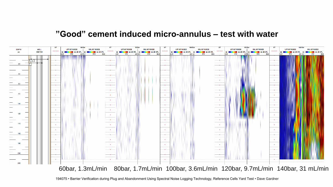
”Good” cement induced micro-annulus – test with water
Two-Column Format Two-Column Format
194075 • Barrier Verification during Plug and Abandonment Using Spectral Noise Logging Technology, Reference Cells Yard Test • Dave Gardner
60bar, 1.3mL/min 80bar, 1.7mL/min 100bar, 3.6mL/min 120bar, 9.7mL/min 140bar, 31 mL/min
Related Documents