Testbeds and Rapid Prototyping in Wireless System Design Markus Rupp, Christian Mehlf¨ uhrer, Sebastian Caban, Robert Langwieser, Lukas W. Mayer, and Arpad L. Scholtz * Institute of Communications and Radio-Frequency Engineering, Vienna University of Technology Gusshausstrasse 25/389, A-1040 Wien, Austria Phone: +43 1 58801 38967, Fax: +43 1 58801 38999 Email: [email protected] Web: http://www.nt.tuwien.ac.at/rapid-prototyping July 19, 2006 Abstract This tutorial paper gives an overview of requirements on testbeds and rapid prototyping suitable for MIMO transmissions. Testbeds support real-time transmissions over the air and thus allow for experimenting with true physical channels, including also an analog frontend. This makes the transmission process very realistic. On the other hand, rapid prototyping allows for sketching transmitter and receiver hardware architectures of future products. Thus, rapid prototyping is very close to the design of a final product, de-risking its financial invest- ment. Several experiment examples demonstrate how testbeds and prototypes can support system design significantly. * This work has been funded by the Christian Doppler Laboratory for Design Methodology of Signal Processing Algorithms, http://www.nt.tuwien.ac.at/cdlab. 1

Welcome message from author
This document is posted to help you gain knowledge. Please leave a comment to let me know what you think about it! Share it to your friends and learn new things together.
Transcript

Testbeds and Rapid Prototyping in Wireless System Design
Markus Rupp, Christian Mehlfuhrer, Sebastian Caban,Robert Langwieser, Lukas W. Mayer, and Arpad L. Scholtz∗
Institute of Communications and Radio-Frequency Engineering,Vienna University of Technology
Gusshausstrasse 25/389, A-1040 Wien, AustriaPhone: +43 1 58801 38967, Fax: +43 1 58801 38999
Email: [email protected]
Web: http://www.nt.tuwien.ac.at/rapid-prototyping
July 19, 2006
Abstract
This tutorial paper gives an overview of requirements on testbeds and rapid prototyping
suitable for MIMO transmissions. Testbeds support real-time transmissions over the air and
thus allow for experimenting with true physical channels, including also an analog frontend.
This makes the transmission process very realistic. On the other hand, rapid prototyping
allows for sketching transmitter and receiver hardware architectures of future products. Thus,
rapid prototyping is very close to the design of a final product, de-risking its financial invest-
ment. Several experiment examples demonstrate how testbeds and prototypes can support
system design significantly.
∗This work has been funded by the Christian Doppler Laboratory for Design Methodology of Signal ProcessingAlgorithms, http://www.nt.tuwien.ac.at/cdlab.
1
chmehl
Text Box
Copyright 2006 EURASIP, published in EURASIP Newsletter, vol. 17, no. 3, pp. 32-50, Sept. 2006

1 Introduction
Wireless products have become very popular due to low cost devices and services. Communicatingin a wireless fashion is by far not simple, in particular when many users desire to communicate atthe same time. The available spectrum is rather limited, making the design of a wireless multi-access scheme very challenging. Note that in most countries the majority of the spectrum below1 GHz is occupied by public TV broadcasting while only little is left for cellular and WLAN services.Although recently new bands at 3.5 GHz, 5.2 GHz and 11 GHz (in some countries also 1.5 GHz,2.6 GHz and 5.8 GHz) became available, moving to higher frequencies is not a good solution formost wireless connections because more transmit power is required to compensate for the muchhigher channel attenuation. Due to multipath propagation, the receivers become very complex, inparticular when data is to be transmitted at high rates. Because of this high complexity in signalprocessing, the mobile communication devices suffer of low battery life, making it a necessity torecharge the battery quite often.
On top of all these problems, newer communication standards still require increased signalprocessing complexity, draining the battery power even more. Several studies [1–3] show thatalthough Moore’s law [4] predicted in 1965 is still correct after 40 years, i.e. the available complexitydoubles every 16–18 months, the desired complexity follows Shannon’s law and is doubling evenfaster. While this was not so much of a problem in the past years since the available complexity wassufficient, it becomes a permanent problem nowadays, in particular when time-to-market aspectsbecome crucial [5]. This so-called complexity gap is accompanied by another one called design gapor productivity gap. The studies in [1, 2] show that current improvements in productivity, i.e. thedesigner’s capability to convert algorithms into silicon, is growing much slower than the availablesilicon complexity predicted by Moore’s law.
The reason for such a lack in productivity lies in the poor tool support. After the definitionof VHDL in the mid-eighties, industry took on tool support for design engineers and came upwith many useful products. At these times, only very few universities were involved. Until themid-nineties, the quality of the products improved only very little. While many tasks could bemade automatically, the remaining tasks are rather difficult to solve and many research teams atuniversities are currently working on solutions. In particular, there are very few tools to supportfloat-to-fixed conversion, i.e. the conversion from floating point descriptions of high level languageslike Matlab or ANSI-C to a corresponding fixed-point representation. While graphical tools fromSynopsys, CoWare, and Mathworks increase visibility, they support only manual partitioning inHW (Hardware) and SW (Software) modules. However, for complex algorithms, it may be muchbetter to have an automatic tool support, taking possible hardware platforms and communicationbetween the modules into account when deciding for partitioning. Often, specific HW platformsare already predefined and the task is to map an algorithm onto such a platform consisting of anembedded DSP with many HW-accelerators, RAMs, ROMs, and busses. Also recently, embeddedcores with power awareness were introduced [6], allowing idle algorithms to be switched off or torun on lower clock rates to preserve energy. Tools for all of these important tasks are currentlymissing and manual solutions are time consuming, erroneous and certainly sub-optimal.
This paper is organized as follows. In Section 2 the terminology in prototyping is defineddistinguishing strictly between testbeds and prototypes. While Section 3 further explains testbedsand provides many design examples utilizing a testbed, Section 4 provides the same details forprototypes. Here, in particular, the methods for rapid prototyping are focussed on. Exampleson MIMO-WLAN and adaptive predistortion techniques are provided. Section 5 discusses furtherchallenges in rapid prototyping, and Section 6 closes the paper with conclusions.
2 Prototyping
Many years ago, prototyping was used to build a first (set of) working demonstrator(s) to provethat a new theory could really be applied and to learn how cumbersome and expensive it couldonce become turning it into a product. Real-time experiments with working product demonstratorswere essential to understand all implications of a new technology and de-risk future decisions beforemarketing.
2

Due to tight time-to-market constraints and the permanently increasing complexity, prototypingwas more and more abandoned in wireless industry. Prototyping would have required a larger andlarger group of engineers, and the time to build a single prototype would have taken as long asdesigning the entire product. However, abandoning prototyping entirely and basing a design purelyon simulations is very risky as some cases have proven(see for example [7] for details).
In order to bring prototyping back into the design chain, specific tools for prototyping must beavailable [7, 8], allowing for a rapid prototyping design that can be implemented much faster thanthe entire product with a small design team but certainly allowing for real-time experiments on ahardware very similar to the final product.
Note that the terminology in this field is often used rather loosely. In [9] it has been dis-tinguished between demonstrators, testbeds, and prototyping. We like to repeat this distinctionfor convenience of easier reading (see also Merriam-Webster [10] and Funk & Wagnalls StandardDictionary of the English language [11]):
• A Demonstrator mainly serves as a sales vehicle and to show technology to customers. In gen-eral it will implement a new idea, concept or standard that has already been established andhas been finalized to some degree. Requirements on scalability are therefore less importantthan its functionality and often the required design time.
• A Testbed on the other hand is generally used for research. It is a vehicle for further devel-opments or for verification of algorithms or ideas under real-world or real-time conditions.This results in the requirement for scalability, modularity and extendibility.
• A Prototype is the initial realization of a research idea or a standard, either as a reference, aproof of concept or as a vehicle for future developments and improvements. As opposed to a“simulation” it is not an “imitative representation” of the device. Instead it has significantsimilarities. In industry, a migration into a product is often intended.
While demonstrators are most important for companies showing them to their potential cus-tomers, testbeds and prototypes are dominating the development process and are thus more of aresearch object. Both, testbeds and prototypes, allow for real-time experiments. However, testbedsallow only for a wireless transmission in real-time. The further processing of the received signalsmay be performed offline. While testbeds typically include the wireless channel, prototypes moreoften use channel emulators in order to provide an environment that allows for repeatable experi-ments. If testbeds are built properly, they may also allow for replacing the offline processing by aprototype or even the final product. While the processing of the algorithms is typically performedin a high-level language (i.e. in floating-point) when building a prototype it is important to usea hardware platform close to the final product, (i.e. processing is performed in fixed-point). Themain properties and differences of testbeds and prototypes are summarized in Table 1.
Testbeds PrototypesFast to program due to high level language Considerable time required to buildData storage and offline processing possible Methods to speed up design are requiredIncludes the wireless channel May include the wireless channelOnly wireless transmissions in real-time Functionality in real-timeDSP functions may be replaced by prototype Allows for design space explorationFixed and/or floating point algorithms True fixed-point design
Table 1: Properties of testbeds and prototypes.
3 Wireless Testbeds
The questions that can be solved with a testbed are essentially whether the channel model as-sumptions are viable and what impact the analog frontend may have. Although many MIMOchannel models exist, most publications assume i.i.d. (independent identically distributed) flat
3

Rayleigh fading channels. Measurements have proven that this is by far not true and more or lesscomplicated models have been proposed [12, 13]. Even the most complicated models still haveimperfections and do not necessarily address all points of interest. Typically, models are optimizedwith respect to channel capacity. However, they may fit capacity and still give incorrect behaviorfor BER performance [14, 15].
Typically the analog frontend of a testbed is of very high quality, satisfying linearity for a verylarge dynamic range of the signal. AD and DA converters provide high resolution of 14–16 bits.By introducing imperfections (cutting off bits or misadjusting the oscillator for example) one cananalyze how sensitive the algorithms are on the analog part of the transmission chain. Also derivingan idea of the final product costs, based on linearity requirements for example, is possible. If itturns out that the high precision analog frontend of the wireless testbed is not sufficient for therequired performance, one knows for sure that the idea is not technically sound for a final product.Alternatively, if the required analog frontend is already available (reuse of a previous product, forexample), it can be used in a testbed to clarify whether it is sufficient for the new algorithms.
3.1 Commercial Tools
Since companies do not use a consistent terminology and try to offer as many features as possible,it is not easy to categorize available products into testbeds and prototypes. Most can be used forboth purposes, however some are suited better for one purpose than for the other. The selectionhere is thus somewhat subjective. Complete out-of-the box testbeds are available from Lyrtech(www.lyrtech.com) and Signalion (www.signalion.com). Components to build testbeds and proto-types are available from Sundance (www.sundance.com), Hunt-Engineering (www.hunteng.co.uk),and Pentek (www.pentek.com)1. Most products lack RF-frontends making it very hard to includethe true physical channel. The development of RF frontends is costly and cumbersome. In par-ticular, available frontends are missing flexibility in terms of supported carrier frequencies andbandwidths.
Since specific design tools are typically missing in commercial testbeds and prototyping equip-ment, EDA (Electronic Design Automation) tools used in the chip design process are also usedfor prototyping. For example, EDA tools are available from Synopsys and CoWare (and manysmaller companies) but the licence costs are typically too high for prototyping. In particular,when heterogeneous systems including DSPs and FPGAs are required, no supporting design toolsare available. More details about tools are provided further ahead in Section 5.1.
3.2 Vienna MIMO Testbed
Due to a lack of commercially available products, we decided to develop our own testbed. This test-bed was designed by a team of researchers at the Institute of Communications and Radio FrequencyEngineering of the Vienna University of Technology during the last three years. Throughout thedevelopment process, emphasis was placed on scalability, modularity, and extendibility, allowingfor a multitude of very different experiments. The Vienna MIMO testbed [16, 17] primarily consistsof (see Fig. 1):
• a transmit PC that automatically preprocesses and up-converts complex baseband data sam-ples to a low IF (Intermediate Frequency) of 70 MHz.
• an analog transmitter-frontend, performing linear frequency conversion of up to four low IFsignal to the radio frequency of 2.5 GHz, filtering, and amplification to the transmit powerlevel of 30 dBm.
• a channel realized with channel emulators or a physical radio channel. Two positioningtables are used to move the antennas in order to achieve the channel realizations needed foraveraging the mean performance of a specific scenario.
• an analog receiver-frontend that prefilters, amplifies, and down-converts the received signalsof up to four antennas to a low IF of 70 MHz.
1Note that we only mention the most prominent ones. There is a multitude of smaller companies providingtestbed and prototyping equipment.
4

Figure 1: Block diagram of the Vienna MIMO Testbed.
• a receive PC that performs conversion to the digital baseband.
• user PC s from where algorithm designers carry out various radio transmission experiments.Using a flexible Matlab Interface, complex baseband data samples of a 4×4 MIMO systemcan be easily transmitted and received.
The concept of the Vienna MIMO testbed allows the algorithm designer to focus on digitalbaseband data processing on his own PC. Next to being platform independent, also multiple userscan access the testbed directly out of Matlab from anywhere in the LAN. This not only makes itvery convenient to integrate real-time air transmissions into existing Matlab simulations but alsosaves a lot of costs since very expensive2 hardware can be shared efficiently by several researchers.In the following, many examples are shown in which the testbed turned out to be useful.
3.3 Space-Time Codes
In the last years, space-time codes were thoroughly investigated and optimized [18–23]. However,hardly any results exist on how these space-time codes perform in a real system. Therefore,a MIMO testbed was used to measure the performance of an Extended Alamouti (4×1 MISO)code [17, 24]. By using code selection with just two bits feedback (i.e. selection of one out offour codes) from the receiver to the transmitter, an Extended Alamouti code transmission schemeachieves the full diversity order of four—at least in simulation. Surprisingly, the measurements withthe testbed and channel emulators (which were configured to produce uncorrelated flat Rayleighfading channels) showed an SNR loss of about 0.8 dB (see Fig. 2) when using two bits feedback. Itwas found that this effect is caused by slightly asynchronous transmitter outputs. A mean delay ofjust 20 ns (approx. 10 % of the symbol time) between the output samples of the transmitter chainscaused the measured loss of 0.8 dB. For the implementation of a final product, exactly synchronoustransmitter outputs are thus of utmost importance.
3.4 UMTS HSDPA Equalizers
The HSDPA (High Speed Downlink Packet Access) channels of UMTS provide high data ratesto the user. These channels use a small spreading factor of 16 and are thus very sensitive toMAI (Multiple Access Interference). MAI is caused by the multipath propagation channel whichdestroys the orthogonality of the spreading codes and therefore degrades the performance.
The Vienna MIMO testbed, in conjunction with the channel emulators, was used to investigatethe performance of different equalizer structures for HSDPA [25]. Here, the channel emulatorshave a major advantage over Matlab channel models: The channel emulators allow for emulatingpaths with nearly arbitrary delays (0.5 ns stepsize). A Matlab channel model would need very highinterpolation factors to offer resolutions in the same dimension. Our measurement results showed
2The required equipment, including channel emulators and noise sources, costs approximately 500,000¤.
5

-2 0 2 4 6 8 10 12 14 1610
-6
10-5
10-4
10-3
10-2
10-1
100
BE
R
Simulation (0/2 bit Feedback)
Measurement (0/2 bit Feedback)
Eb/N0 [dB]
No Diversity
4x Diversity
2x Diversity
No Feedback
2 bit Feedback
Figure 2: BER performance of the Extended Alamouti code (4.17 MSymbols/s)) [17].
that adaptive equalizer structures for HSDPA achieve the performance of the MMSE equalizer andclearly outperform the conventional RAKE receiver (Fig. 3).
-2 0 2 4 6 8 10 12 1410
-4
10-3
10-2
10-1
100
Eb/N 0 [dB]
BE
R
1 code: RAKE receiver1 code: chip-rate adaptive eq.1 code: MMSE equalizer8 codes: RAKE receiver8 codes: chip-rate adaptive eq.8 codes: MMSE equalizer
Figure 3: Comparison of different receiver structures for HSDPA [17].
3.5 MIMO Antenna Design
A general belief is that antennas for MIMO transmissions need to be at least λ/4 spaced apart,resulting in large and visible antenna constructs. A wireless testbed can also be used to determinethe performance of compact and realistic MIMO antennas. One example for such an antennadesign is given in the following.
A compact antenna with low constraints on its feasibility, designed for mobile communicationequipment, is the so-called inverted-F antenna [26, 27]. It consists of a metal plate that is aligned
6
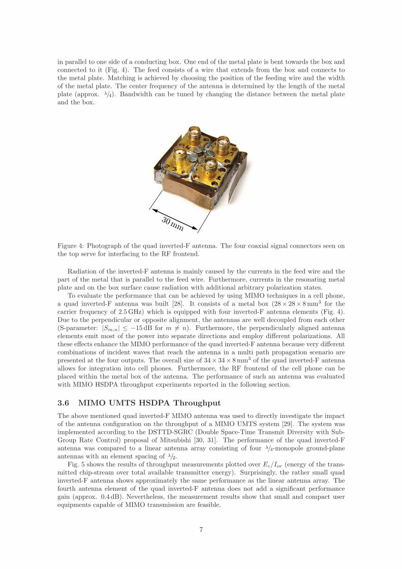
in parallel to one side of a conducting box. One end of the metal plate is bent towards the box andconnected to it (Fig. 4). The feed consists of a wire that extends from the box and connects tothe metal plate. Matching is achieved by choosing the position of the feeding wire and the widthof the metal plate. The center frequency of the antenna is determined by the length of the metalplate (approx. λ/4). Bandwidth can be tuned by changing the distance between the metal plateand the box.
30 mm
Figure 4: Photograph of the quad inverted-F antenna. The four coaxial signal connectors seen onthe top serve for interfacing to the RF frontend.
Radiation of the inverted-F antenna is mainly caused by the currents in the feed wire and thepart of the metal that is parallel to the feed wire. Furthermore, currents in the resonating metalplate and on the box surface cause radiation with additional arbitrary polarization states.
To evaluate the performance that can be achieved by using MIMO techniques in a cell phone,a quad inverted-F antenna was built [28]. It consists of a metal box (28× 28× 8 mm3 for thecarrier frequency of 2.5 GHz) which is equipped with four inverted-F antenna elements (Fig. 4).Due to the perpendicular or opposite alignment, the antennas are well decoupled from each other(S-parameter: |Sm,n| ≤ −15 dB for m 6= n). Furthermore, the perpendicularly aligned antennaelements emit most of the power into separate directions and employ different polarizations. Allthese effects enhance the MIMO performance of the quad inverted-F antenna because very differentcombinations of incident waves that reach the antenna in a multi path propagation scenario arepresented at the four outputs. The overall size of 34× 34× 8 mm3 of the quad inverted-F antennaallows for integration into cell phones. Furthermore, the RF frontend of the cell phone can beplaced within the metal box of the antenna. The performance of such an antenna was evaluatedwith MIMO HSDPA throughput experiments reported in the following section.
3.6 MIMO UMTS HSDPA Throughput
The above mentioned quad inverted-F MIMO antenna was used to directly investigate the impactof the antenna configuration on the throughput of a MIMO UMTS system [29]. The system wasimplemented according to the DSTTD-SGRC (Double Space-Time Transmit Diversity with Sub-Group Rate Control) proposal of Mitsubishi [30, 31]. The performance of the quad inverted-Fantenna was compared to a linear antenna array consisting of four λ/4-monopole ground-planeantennas with an element spacing of λ/2.
Fig. 5 shows the results of throughput measurements plotted over Ec/Ior (energy of the trans-mitted chip-stream over total available transmitter energy). Surprisingly, the rather small quadinverted-F antenna shows approximately the same performance as the linear antenna array. Thefourth antenna element of the quad inverted-F antenna does not add a significant performancegain (approx. 0.4 dB). Nevertheless, the measurement results show that small and compact userequipments capable of MIMO transmission are feasible.
7

-26 -24 -22 -20 -18 -16 -14 -12 -10 -8 -6
0
0.5
1
1.5
2
2.5
3x 10
6
EcIor [dB]
Thro
ughput
[bits/
s]
N R=2
Linear Array
N R=3
N R=4
Quad inverted F
/
Figure 5: Throughput measurement for varying number of receive antenna elements NR [28].
4 Rapid Prototyping
As mentioned in Section 2, conventional prototyping becomes more and more abandoned becauseof tight time-to-market constraints. Nevertheless, prototyping is an important means to de-risk anew technology and should be applied somehow. A possibility is to overcome the slow prototypingdevelopment by including a particular rapid prototyping design methodology and thus speedingup the development considerably. Since very likely a future product will not only consist of asingle DSP, it is of utmost importance to support DSPs as well as FPGAs, thus offering HW/SWpartitioning. Communication between connected blocks needs to be taken into account since itmay be rather complicated to move functions from DSPs to FPGAs while it is usually relativelysimple to stay on an FPGA or on a DSP when moving from block to block (as long as resourcesare available). An important feature to speed up development time is to use high level languageswherever possible. For example, many DSPs from Texas Instruments (C6x) and Analog Devices(SHARK) can be programmed fully in C including driver functions and DMA transfer. Also manytools exists that convert C into VHDL [32] or SystemC, both allowing to generate hardware. Mostimportantly, these tools allow to satisfy the one-code paradigm [7], claiming that most errors can beavoided when sticking to a single code for description in high level design and converting such codeto lower design levels by automatic tools only. In this section, we begin by summarizing availablecommercial design tools and discussing their properties. Then we introduce the Vienna PrototypingEnvironment (VPE) and finally show two examples where it has been applied successfully.
4.1 Commercial Tools
Commercial tools are typically based entirely on DSPs or entirely on FPGAs. Texas InstrumentsC6x processors (and some others like Analog Devices’ SHARK) can fully and efficiently be pro-grammed in ANSI-C. Matlab’s Simulink supports several platforms with C6x DSPs. Thus, ifit would simply be a task of mapping to a multi-DSP board, this could efficiently be achieved bysuch tools.
On the other hand, tools that map Simulink-code onto Xilinx or Altera FPGAs also exist,including a fixed-point library. Here the algorithm needs to be described with elements of thisfixed-point library (can also be utilized in floating point). Once the algorithm runs sufficiently insimulation, it can be mapped on to the desired FPGA. However, typically such algorithms need tobe of feed-forward structure. Once feedback elements are included, the simulation times becomerather long due to inefficient scheduling. Also, the algorithms should be data-flow driven and not
8

control-flow oriented. For control-flow oriented algorithms such programming is very tedious andeven small algorithmic changes can require a long time.
Lyrtech supports both conversion tools for DSPs and FPGAs on their boards including combi-nations of DSPs and FPGAs. The communication between a DSP and an FPGA is described bya special block under Simulink. While this is not extremely efficient, it provides a means to mapalgorithms directly onto FPGAs and DSPs provided one has sufficient resources available.
Other companies like Sundance, Hunt Engineering, Signalion, or Pentek offer various moduleswith FPGAs and DSPs and driver software supporting the communication links between the variousmodules. However, complete prototyping tools that would allow to map from high level design tothe hardware platform are typically not provided. Note that of the many providers, only Pentekand Signalion offer RF front ends (as of today), although most other companies have at leastconcepts for hardware they are planning to offer in the near future.
4.2 Vienna Prototyping Environment
The origin of the current Vienna Prototyping Environment (VPE) goes back to a developmentat Bell-labs that supported prototyping of local wireless loops [33] and early UMTS MIMO-receivers [34]. The VPE follows the one-code paradigm [7], i.e. only the high level descriptionis refined in every design step, but no manual recoding is required. The design flow starts withCOSSAP-C module descriptions, i.e. ANSI C code that is enriched with port information definingthe input and output ports as well as the rates of the data streams and corresponding data types.This information can be used to convert the module to a Simulink S-function and run simulations.Once it has been decided which blocks are mapped onto DSPs and which on FPGAs, the refinementof the C-code follows different rules. For the DSP code, the variables are converted to 16 bit shorttypes and intrinsic commands are included. With corresponding mapping algorithms the code canstill run under Simulink and be tested. For FPGAs, a similar technique is used to refine the C-codeso that it can be mapped automatically to an FPGA using Adelantetech’s Builder-tool. Currently,many tools like this exist [32], often of academic origin and freely available. An important fact isthat the algorithm in its refined form, although now suitable for a transformation to a hardwaredescription language, can still be run under Simulink. Very significant is the possibility to co-verifythe algorithms once they are converted to hardware. Many people validate their algorithms withModelsim [35] that can be used for cosimulation with Simulink. However, Modelsim models on afine granular level and is thus very time consuming. We developed a method that allows not onlyto map the high level description automatically onto DSPs and FPGAs but also to run the algo-rithm on the HW platform while the remaining parts are still running under Simulink. Originallydeveloped at Rice University [36] and adopted at Bell-Labs [7], the method was made more flexibleto convert it easily onto other hardware platforms and it was extended to FPGAs as well [37].Many details of the technique can be found in [7].
4.3 WLAN Prototyping
The VPE was used to set up an 802.11n MIMO wireless LAN system utilizing the prototypingplatform Smartsim by Seibersdorf Research [38, 39]. Since during the standardization of 802.11nseveral transmission schemes were discussed, the undefined parts of the system had to be imple-mented in a high level language to quickly adopt for changes after the release of the final standard.
The WLAN receiver is split into two parts. The first one consists of a receive filter, cyclic prefixremoval, and a 64-point FFT. This part of the receiver was already used in the 802.11a standardand was not subject to changes to ensure downward compatibility of the MIMO extension toexisting WLAN systems. Therefore, this part was implemented on a Xilinx Virtex 2 FPGA usingXilinx Core Generator which comprises highly optimized filters and FFT blocks. The functionalchain, including receive filters and FFT is implemented for every receive antenna. The second partof the receiver is the channel estimation and the space-time receiver. This part of the receiver wasimplemented in Generic C. Using a Generic C code, an automatic code conversion tool was usedto generate a Simulink model and assembler code for a TI 6416 DSP. This method allows for co-verification of the implemented Generic C receiver with a Simulink implementation. Furthermore,
9

the method also allows to verify the code after refinement steps for improving the performance ofthe real-time implementation.
4.4 Adaptive Predistortion
Power amplifiers in wireless systems introduce nonlinear distortions and thus undesired spuriousemissions in neighboring bands. In order to reduce such emissions, adaptive predistortion tech-niques are useful. The nonlinear behavior of the power amplifier is described by a parametricmodel. In a first step, its parameters have to be estimated. In the following, the inverse system iscomputed and the input of the power amplifier is predistorted by such an inverse system causingthe output of the amplifier to be linear again. Narrow band systems (e.g. up to 1 MHz at 2 GHz)can be sufficiently described by memoryless mappings, and inverse systems can be implementedby look-up tables [40]. For systems with higher bandwidth, memory plays a crucial role. Classicalapproaches use nonlinear models like Hammerstein or Wiener models. However, such models typi-cally lead to a minimization problem that is nonlinear with respect to its parameters. Thus, simplegradient type algorithms tend to run into local minima, not providing better results than memo-ryless approaches. A recently developed new method [41, 42] computes the predistorted signal ofthe amplifier directly, rather than computing the inverse explicitly. The corresponding method isan iterative method that approaches the desired quality in typically three steps. In order to checkthe method, a prototype based on Sundance modules was built applying the VPE. Fig. 6 depictsthe results showing strong improvement and at the same time a very good agreement of simulationand real-time measurement results.
2.44 2.445 2.45 2.455 2.46-95
-90
-85
-80
-75
-70
-65
-60
-55
-50
-45
-40
-35
-30 RBW = 100 kHz VBW = 100 kHz ATT = 10 dB
f [GHz]
P [dB
m/1
00kH
z]
no DPD, IBO 1dB
DPD, non real-time (Matlab)
DPD, real-time
Figure 6: Improvement by predistortion of a power amplifier (DPD = Digital Predistortion, IBO= Input Back-Off).
5 Future Challenges
Modern wireless systems, with their fast exponential increase in complexity, are very challengingwhen it comes to converting algorithms to run on real-time hardware.
5.1 Methods
Despite many efforts, several problems remain unsolved. Including Hardware-in-the-loop (HIL)techniques for DSPs [36] and FPGAs [7, 37] certainly eases verification a lot. Some companiesnow offer such techniques [43] and aim in offering techniques that allow to map from Simulink toheterogeneous DSP/FPGA boards. The main problems noted in the introduction, however, float-to-fix conversion, automatic partitioning, and platform based design, remain open. Recently, some
10
work on these topics has started [44, 45] but it will take some time until all of these aspects areincluded into a smooth design flow. One major problem is the conversion of block based processing,as it is given in Simulink and many other graphical tools, to HW platforms not supporting suchprocessing with relatively large storage buffers between the blocks. While large buffers are neededfor high speed simulation (we already mentioned the scheduling slow down in feedback systems inSection 4.1), small buffers are easier to implement. A solution could be utilizing variable buffer sizeswhen specifying the design, independent of the algorithm. The buffer size can then be set to a largevalue supporting fast simulation as well as to a small value supporting efficient implementation.
5.2 RF-Frontends
In modern communication systems with powerful digital signal processing, tasks like modulationand pulse shaping are more and more shifted from the analog to the digital domain. ADCs andDACs are the interfacing components of these two domains. Such converters exchange either analogbaseband signals or low intermediate frequency signals with the analog frontend. The task of theRF frontend is to perform a linear frequency conversion to a carrier frequency suitable for wirelesstransmission. The carrier frequency conversion can be carried out in one single step (zero IF) ormultiple steps (heterodyne). While highly integrated consumer products use the zero IF principle,in research often the heterodyne conversion is preferred. Due to market pressure, highly integratedconsumer RF frontend chips are designed to just meet the minimum requirements of a specific finalproduct. This makes single chip RF frontend solutions useless for wireless testbeds that shouldsupport a multitude of different present and future standards. Usually, high design flexibility andfast availability of an RF frontend can only be achieved by a heterodyne design which is inherentlymuch more complex. Thus, the RF frontend of a wireless testbed has to be built employing theheterodyne principle from available state-of-the-art components with lower integration level (e.g.mixers, amplifiers, filters) but much better performance. The main challenge when designing awireless testbed is therefore to build a high performance RF frontend supporting future standardswith today’s technology. Note that the availability of components is crucial in the design processof a testbed or prototype since these are often built years before a standard is defined or firstproducts are launched [46].
6 Conclusions
No doubt, rapid prototyping has gained importance. In 2003 the proposal for the NoE NESATwas rejected by the European commission due to its lack of testbeds3. Decisions on future wirelesssystems require a lot of financial investment, making them crucially dependent on the utilizedtechnology. Rapid prototyping can de-risk such decisions long before the investment is made. Inthis tutorial, we presented means of prototyping. In particular, we distinguished strictly betweenwireless testbeds and prototypes. We showed, by many examples, how testbeds and prototypeshelp to overcome technological hurdles without requiring a too high initial investment of time andmoney. Current challenges are in flexible RF frontends, as well as in the development of automaticdesign tools.
Acknowledgements
We like to thank many students that have taken part in the development and utilization of ourVienna MIMO Testbed and the Vienna Prototyping Environment. In particular, we like to mentionErnst Aschbacher, Werner Keim, Biljana Badic, Stefan Geirhofer, Georg Brandmayr, and PeterBrunmayr.
3Comment of the reviewers: “A real-time testbed is a critical tool, allowing more impact on standardizationbodies, however partnership is weak in this area.”
11

References
[1] P. Fisher and D. Cottrell, “Emerging Standards in the Electronic Design Automation (EDA) Industry,” inElectronic Systems Design Seminar, UC Berkeley, CA, USA, Oct. 1999.
[2] R. Subramanian, “Shannon vs. Moore: the digital signal processing in the broadband age,” in IEEE Commu-nication Workshop, Aptos, CA, USA, May 1999.
[3] ——, “Shannon vs. Moore: Driving the Evolution of Signal Processing Platforms in Wireless Communications,”in IEEE Workshop on Signal Processing Systems SIPS02, Oct. 2002.
[4] G. Moore, “Cramming more components onto integrated circuits,” Electronics Magazine, vol. 38, no. 8, pp.114–117, Apr. 1965.
[5] P. Belanovic, B. Knerr, M. Holzer, G. Sauzon, and M. Rupp, “A Consistent Design Methodology for WirelessEmbedded Systems,” EURASIP Journal on Applied Signal Processing, vol. 16, pp. 2598–2612, Oct 2005.
[6] M. Pedram and J. M. Rabaey, Power Aware Design Methodologies, 1st ed. Springer, 2002.
[7] M. Rupp, A. Burg, and E. Beck, “Rapid prototyping for wireless designs: the five-ones approach,” SignalProcessing, vol. 83, no. 7, pp. 1427–1444, July 2003.
[8] T. Kaiser, A. Wilzeck, M. Berentsen, and M. Rupp, “Prototyping for MIMO Systems - an Overview,” in Proc.of the 12th European Signal Processing Conference (EUSIPCO), pp. 681–688, Vienna, Austria, Sept. 2004.
[9] A. Burg and M. Rupp, EURASIP Book on SMART Antennas, Chapter: Demonstrators and Testbeds.EURASIP, April 2006.
[10] “Merriam-Webster OnLine Dictionary.” [Online]. Available: http://www.m-w.com/
[11] Funk & Wagnalls Standard Dictionary of the English language. J.G. Ferguson Pub. Co, 1982.
[12] “Homepage of the I-Metra project.” [Online]. Available: http://www.ist-imetra.org/
[13] W. Weichselberger, H. Ozcelik, M. Herdin, and E. Bonek, “A Novel Stochastic MIMO Channel Model and ItsPhysical Interpretation,” in Proc. 6th International Symposium on Wireless Personal Multimedia Communi-cations (WPMC’03), Yokosuka, Kanagawa, Japan, Oct. 2003.
[14] B. Badic, M. Herdin, M. Rupp, and H. Weinrichter, “Quasi Orthogonal Space-Time Block Codes on MeasuredMIMO Channels,” in Proc. of the SympoTIC 04, pp. 17–20, Bratislava, Slovakia, Oct. 2004.
[15] B. Badic, H. Weinrichter, and M. Rupp, “Comparison of Non-Orthogonal Space-Time Block Codes in CorrelatedChannels,” in Proc. SPAWC 04, Lisboa, Portugal, July 2004.
[16] S. Caban, C. Mehlfuhrer, R. Langwieser, A. L. Scholtz, and M. Rupp, “Vienna MIMO Testbed,” EURASIPJournal on Applied Signal Processing, vol. 2006, Article ID 54868, 2006.
[17] C. Mehlfuhrer, S. Geirhofer, S. Caban, and M. Rupp, “A Flexible MIMO Testbed with Remote Access,” inProc. of the 13th European Signal Processing Conference (EUSIPCO 2005), Antalya, Turkey, Sept. 2005.
[18] V. Tarokh, N. Seshadri, and A. R. Calderbank, “Space-time codes for high data rate wireless communication:performance criterion and code construction,” IEEE Transactions on Information Theory, vol. 44, no. 2, pp.744–765, Mar. 1998.
[19] H. Jafarkhani, “A Quasi Orthogonal Space-Time Block Code,” IEEE Transactions on Communications, vol. 49,no. 1, pp. 1–4, Jan. 2001.
[20] S. M. Alamouti, “A Simple Transmit Diversity Technique for Wireless Communications,” IEEE Journal onSelected Areas in Communications, vol. 16, no. 8, pp. 1451–1458, Oct. 1998.
[21] C. F. Mecklenbrauker and M. Rupp, “Flexible space-time block codes for trading quality of service againstdata rate in MIMO UMTS,” EURASIP Journal on Applied Signal Processing, no. 5, pp. 662–675, May 2004.
[22] B. Badic, M. Rupp, and H. Weinrichter, “Adaptive Channel-Matched Extended Alamouti Space-Time CodeExploiting Partial Feedback,” ETRI, vol. 26, no. 5, pp. 443–451, Oct. 2004.
[23] B. Badic, H. Weinrichter, and M. Rupp, “Quasi-Orthogonal Space Time Block Codes: Approaching Optimal-ity,” in Proc. of the 13th European Signal Processing Conference (EUSIPCO), tutorial paper, Antalya, Turkey,Sept. 2005.
[24] S. Caban, C. Mehlfuhrer, A. L. Scholtz, and M. Rupp, “Indoor MIMO Transmissions with Alamouti Space-Time Block Codes,” in Proc. 8th International Symposium on DSP and Communication Systems, DSPCS2005, Noosa Heads, Australia, Dec. 2005.
12

[25] S. Geirhofer, C. Mehlfuhrer, and M. Rupp, “Design and Real-Time Measurement of HSDPA Equalizers,” inProc. of the 6th IEEE Workshop on Signal Processing Advances in Wireless Communications (SPAWC 2005),pp. 166–170, New York City, USA, June 2005.
[26] J. Rasinger, A. L. Scholtz, W. Pichler, and E. Bonek, “A new enhanced-bandwidth internal antenna for portablecommunication systems,” in Proc. of the 40th IEEE Vehicular Technology Conference 1990, May 1990.
[27] K. Hirasawa and M. Haneishi, Analysis, Design, and Measurement of Small and Low-Profile Antennas, 1st ed.Artech House, Inc., 1992.
[28] C. Mehlfuhrer, S. Caban, M. Rupp, and A. L. Scholtz, “Effect of Transmit and Receive Antenna Configu-ration on the Throughput of MIMO UMTS Downlink,” in Proc. 8th International Symposium on DSP andCommunication Systems, DSPCS 2005, Noosa Heads, Australia, Dec. 2005.
[29] C. Mehlfuhrer, L. Mayer, R. Langwieser, A. L. Scholtz, and M. Rupp, “Free Space Experiments with MIMOUMTS High Speed Downlink Packet Access,” in Proc. of the 2nd IEE/EURASIP Conference on DSP enabledRadio, Southampton, UK, Sept. 2005.
[30] 3GPP, “Technical Specification Group Radio Access Network; Multiple-Input Multiple Output in UTRA,”3GPP, Tech. Rep. 25.876 V1.7.0, Aug. 2004.
[31] C. Mehlfuhrer, C. F. Mecklenbrauker, and M. Rupp, “Double Space-Time Transmit Diversity with SubgroupRate Control for UMTS: Throughput Analysis,” in Conference Record of the Thirty-Ninth Asilomar Conferenceon Signals, Systems and Computers, 2005, Pacific Grove, CA, USA, Nov. 2005.
[32] E. Casseau, B. L. Gal, P. Bomel, C. Jego, S. Huet, and E. Martin, “C-based rapid prototyping for digital signalprocessing,” in Proc. of the 13th European Signal Processing Conference (EUSIPCO), Antalya, Turkey, Sept.2005.
[33] M. Rupp, E. Beck, and R. Krishnamoorthy, “Rapid Prototyping for a High Data Rate Wireless Local Loop,”in Conference Record of the Thirty-Third Asilomar Conference on Signals, Systems and Computers, 1999, pp.993–997, Monterey, CA, USA, Oct. 1999.
[34] A. Adjoudani, E. Beck, A. Burg, G. M. Djuknic, T. Gvoth, D. Haessig, S. Manji, M. Milbrodt, M. Rupp,D. Samardzija, A. Siegel, T. S. II, C. Tran, S. Walker, S. A. Wilkus, and P. Wolniansky, “Prototype Experiencefor MIMO BLAST over Third-Generation Wireless System,” Special Issue JSAC on MIMO Systems, vol. 21,pp. 440–451, Apr. 2003.
[35] M. Huemer, M. Lunglmayr, and M. Pfaff, “A lecture course series: from concept engineering to implementationof signal processing algorithms with FPGAs,” in Proc. of the 13th European Signal Processing Conference(EUSIPCO), Antalya, Turkey, Sept. 2005.
[36] B. Jones, S. Rajagopal, and J. Cavallaro, “Real-time DSP multiprocessor implementation for future wirelessbase-station receivers,” in TI DSPS Fest, Wireless Applications, Aug. 2000.
[37] G. Brandmayr, G. Humer, and M. Rupp, “Automatic Co-verification of FPGA Designs in SIMULINK,” inProc. MBD Conference 2005, Munich, Germany, June 2005.
[38] G. Meindl-Pfeiffer, R. Kloibhofer, F. Kaltenberger, and G. Humer, “Multistandard Development platform forMIMO Software Defined Radio,” in Proc. of the 13th European Signal Processing Conference (EUSIPCO),Antalya, Turkey, Sept. 2005.
[39] C. Mehlfuhrer, F. Kaltenberger, M. Rupp, and G. Humer, “A Scalable Rapid Prototyping System for Real-Time MIMO OFDM Transmissions,” in Proc. of the 2nd IEE/EURASIP Conference on DSP enabled Radio,Southampton, UK, Sept. 2005.
[40] K. J. Muhonen and M. K. R. Krishnamoorthy, “Look-Up Table Techniques for Adaptive Digital Predistortion:A Development and Comparison,” IEEE Transactions on Vehicular Technology, vol. 49, no. 5, pp. 1995–2002,Sept. 2000.
[41] E. Aschbacher, H. Arthaber, and M. Rupp, “A Fast Algorithm for Digital Pre-distortion of Nonlinear PowerAmplifiers,” in Proc. of the 13th European Signal Processing Conference (EUSIPCO), Antalya, Turkey, Sept.2005.
[42] M. Y. Cheong, E. Aschbacher, P. Brunmayr, M. Rupp, and T. Laakso, “Comparison and Experimental Verifi-cation of Two Low-complex Digital Predistortion Methods,” in Proc. of Asilomar Conference, Monterey, CA,USA, Oct. 2005.
[43] M. Ahmadian, Z. Nazari, N. Nakhaee, and Z. Kostic, “Model based design and SDR,” in Proc. of the 2ndIEE/EURASIP Conference on DSP enabled Radio, Southampton, UK, Sept. 2005.
[44] P. Belanovic and M. Rupp, “Automated Floating-point to Fixed-point Conversion with the fixify Environment,”in Proc. of RSP 05, Montreal, Canada, June 2005.
13

[45] B. Knerr, M. Holzer, and M. Rupp, “Fast Rescheduling of Multi-Rate Systems for HW/SW Partitioning Algo-rithms,” in Conference Record of the Thirty-Ninth Asilomar Conference on Signals, Systems and Computers,2005, Monterey, CA, USA, Oct. 2005.
[46] R. Langwieser, M. Fischer, A. L. Scholtz, M. Rupp, and G. Humer, “Rapid Prototyping for RF-Transmittersand Receivers,” in Proc. 5th IASTED International Conference on Communication Systems and Networks(CSN’06), Palma de Mallorca, Spain, Aug. 2006.
7 Authors
Markus Rupp was born 1963 in Volklingen, Germany. He received his Dipl.-Ing. degree in 1988from the University of Saarbrucken, Germany, and his Dr.-Ing. degree in 1993 from the Technis-che Universitat Darmstadt, Germany, where he worked with Eberhardt Hansler on designing newalgorithms for acoustical and electrical echo compensation. From November 1993 until July 1995,he had a postdoctoral position at the University of Santa Barbara, California, with Sanjit Mitrawhere he worked with Ali H. Sayed on a robustness description of adaptive filters with impacts onneural networks and active noise control. From October 1995 until August 2001, he was a memberof the technical staff in the Wireless Technology Research Department, Bell-Labs, where he wasworking on various topics related to adaptive equalization and rapid implementation for IS-136,802.11, and UMTS. Since Oktober 2001 he is a Full Professor of digital signal processing in mobilecommunications at the Vienna University of Technology and since Juli 2002 he is founder anddirector of the Christian Doppler Laboratory for Design Methodology of Signal Processing Algo-rithms. He served as Associate Editor of IEEE Transactions on Signal Processing from 2002-2005,and is currently associated editor of EURASIP Journal on Applied Signal Processing, of EURASIPJournal on Embedded Systems and is an elected AdCom Member of EURASIP. He authored andcoauthored more than 200 papers and patents on adaptive filtering, wireless communications, andrapid prototyping.
Christian Mehlfuhrer was born 1979 in Vienna, Austria. In 2004 he received his Dipl.-Ing.degree in electrical engineering from the Vienna University of Technology. Besides his diplomastudies he worked part time at Siemens AG where he performed integration tests of GSM carrierunits. After finishing his diploma thesis on implementation and real-time testing of space-timeblock codes at the Institute of Communications and Radio-Frequency Engineering, Vienna Univer-sity of Technology, for which he received the Vodafone “Forderpreis 2006” (together with SebastianCaban), he now is member of the Christian Doppler Laboratory for Design Methodology of SignalProcessing Algorithms and works towards his doctoral thesis at the same institute. His researchinterests include rapid prototyping, experimental investigation of MIMO systems, the upcomingUMTS MIMO HSDPA mode, the MIMO extension for WLAN (802.11n), and WiMAX (802.16).
Sebastian Caban was born 1980 in Vienna, Austria. Studying electrical engineering at the ViennaUniversity of Technology, he received several scholarships as the best student of the college. Aftera year at the University of Illinois at Urbana-Champaign, USA, he is currently working as ateaching assistant on his Ph.D. thesis at the university’s Institute of Communications and Radio-Frequency Engineering. On June 23, 2006, he was awarded the “Forderpreis 2006” of the GermanVodafone Stiftung fur Forschung for his research which focuses on rapid prototyping in wirelesscommunications and multiple antenna systems.
Robert Langwieser was born 1972 in Linz, Austria. He studied telecommunications at theVienna University of Technology and earned his master degree in April 2004 with distinction. Atpresent Mr. Langwieser is employed as a research assistant and is member of the Christian DopplerLaboratory for Design Methodology of Signal Processing Algorithms. He currently works on thedevelopment of a modular radio-front-end for MIMO measurements.
Lukas W. Mayer was born 1980 in Vienna, Austria. He finished his studies at the ViennaUniversity of Technology in 2005. In his diploma thesis he worked on the radio frequency frontendof the institutes “Vienna MIMO Testbed”. His research interests focus on rapid prototyping in
14

wireless communications, antennas, and MIMO antenna systems. The task of his PhD thesis is todevelop small antennas that will be used for a novel RFID system.
Arpad L. Scholtz was born 1947 in Kecskemet, Hungary. In 1956 he moved to Austria andreceived the Austrian citizenship in 1960. He studied telecommunications at the Vienna Universityof Technology, where he earned his Masters degree in 1972 and the Ph.D. degree in 1976, both withdistinction. From 1972 to 1982, Mr. Scholtz worked as an Assistant Professor for radio-frequencyengineering at the Institute of Communications and Radio-Frequency Engineering. Since 1982, headditionally has been serving at the same Institute as a Lecturer, and in 1992 he was given the titleof Associate Professor. Arpad L. Scholtz is author or coauthor of more than a hundred scientificpublications. He teaches radio-frequency engineering with emphasis on electronic circuit design,antennas, and point-to-point communications.
15
Related Documents