TEST REPORT Rendered to: SCREEN TIGHT For: PRODUCT: 72 in by 36 in Guardrail System TYPE: Preservative-Treated Wood Rail with Mesh Screen Infill Report No.: E8681.01-119-19 Report Date: 12/01/15 Test Record Retention Date: 08/24/19 Revision 1: 01/27/16 130 Derry Court York, PA 17406 p. 717.764.7700 f. 717.764.4129 www.archtest.com www.intertek.com/building

Welcome message from author
This document is posted to help you gain knowledge. Please leave a comment to let me know what you think about it! Share it to your friends and learn new things together.
Transcript

TEST REPORT
Rendered to:
SCREEN TIGHT
For:
PRODUCT: 72 in by 36 in Guardrail System TYPE: Preservative-Treated Wood Rail with Mesh Screen Infill
Report No.: E8681.01-119-19 Report Date: 12/01/15 Test Record Retention Date: 08/24/19 Revision 1: 01/27/16
130 Derry CourtYork, PA 17406
p. 717.764.7700f. 717.764.4129
www.archtest.com www.intertek.com/building

TEST REPORT
E8681.01-119-19 December 1, 2015
Revision 1: January 27, 2016
TABLE OF CONTENTS
1.0 General Information ................................................................................................................. 1
1.1 Product ............................................................................................................................... 1
1.2 Project Description ............................................................................................................ 1
1.3 Limitations ......................................................................................................................... 1
1.4 Qualifications ..................................................................................................................... 2
1.5 Witnessing ......................................................................................................................... 2
1.6 Product Description ........................................................................................................... 2
2.0 Structural Performance Testing of Assembled Railing Systems ............................................... 3
2.1 Test Equipment .................................................................................................................. 3
2.2 Test Setup .......................................................................................................................... 3
2.3 Test Procedure ................................................................................................................... 4
2.4 Test Results ........................................................................................................................ 4
2.5 Summary and Conclusions ................................................................................................. 7
3.0 Closing Statement ..................................................................................................................... 8
Revision Log .................................................................................................................................... 9
Appendix A - Drawings
Appendix B - Photographs
130 Derry CourtYork, PA 17406
p. 717.764.7700f. 717.764.4129
www.archtest.com www.intertek.com/building

TEST REPORT
Rendered to:
SCREEN TIGHT One Better Way
Georgetown, South Carolina 29440
Report No.: E8681.01-119-19 Test Dates: 08/20/15 Through: 08/24/15 Report Date: 12/01/15 Test Record Retention Date: 08/24/19 Revision 1: 01/27/16
1.0 General Information 1.1 Product 72 in by 36 in Preservative-Treated Wood Rail with Mesh Screen Infill 1.2 Project Description Architectural Testing, Inc., an Intertek company (“Intertek-ATI”), was contracted by Screen Tight to conduct structural performance tests on their 72" wide by 36" high preservative-treated rail with mesh screen infill guardrail system. The system was evaluated for the design load requirements of the following building codes:
2015 International Building Code®, International Code Council
2015 International Residential Code®, International Code Council
Structural tests were performed according to Chapter 17 (Structural Tests and Special Inspections) of IBC 2015. 1.3 Limitations All tests performed were to evaluate structural performance of the guardrail assembly to carry and transfer imposed loads to the supports (posts). The test specimens evaluated included the infill, rails, rail brackets, and attachment to the supporting structure. The support posts were conventional construction and not within the scope of the evaluation. Posts were therefore not a tested component and were included in the test specimen only to facilitate anchorage of the rail brackets. Anchorage of support posts to the supporting structure is not included in the scope of this testing and would need to be evaluated separately. Testing is limited to satisfying the load requirements of IRC - One- and Two-Family Dwellings requirements.

E8681.01-119-19 Page 2 of 9
Revision 1: 01/27/16
1.4 Qualifications Intertek-ATI in York, Pennsylvania has demonstrated compliance with ISO/IEC International Standard 17025 and is consequently accredited as a Testing Laboratory (TL-144) by International Accreditation Service, Inc. (IAS). 1.5 Witnessing
Mr. Noel King of Screen Tight was present on 08/20/15 to witness the following tests and/or test setups and assist in test specimen fabrication:
Structural performance testing of assembled railing systems 1.6 Product Description Screen Tight provided the Mesh Guard Track and mesh screen infill components for testing. Wood components were supplied by Intertek-ATI and assembled by and Intertek-ATI technician. The assembled guardrail consisted of the following components:
Top Rail: Two-piece member consisting of one MCA preservative-treated wood (SYP) 2" by 4" (nominal) oriented with the 4" dimension vertical and one MCA preservative-treated wood (SYP) 2" by 4" (nominal) oriented with the 4" dimension horizontal
Bottom Rail: MCA preservative-treated wood (SYP) 2" by 4" (nominal) oriented with the 4" dimension horizontal
Infill: - Mesh Guard Screen
Post: MCA preservative-treated wood (SYP) 4" by 4" (nominal) with an MCA preservative-treated wood (SYP) 2" by 4" (nominal) side rail
Support Foot: MCA preservative-treated wood (SYP) 4" by 4" (nominal) cut to fit and located at mid-span of bottom rail
Mesh Guard Track: 1-7/16" wide by 1/4" high PVC section with 1/2" wide by 0.07" thick steel bar and 1-1/2" wide by 1/4" high PVC closure piece

E8681.01-119-19 Page 3 of 9
Revision 1: 01/27/16
1.6 Product Description (Continued)
Fasteners: - Top Rail to Post: (3) #10-9 x 3" (0.130 in minor diameter) star-drive, trim head,
coated exterior deck screws, toe-nailed through rail into post
- Top Rail Vertical Component to Top Rail Horizontal Component: #10-9 x 3" (0.130 in minor diameter) star-drive, trim head, coated exterior deck screws, 6" from each end and 12" on-center
- Bottom Rail to Post: (2) #10-9 x 3" (0.130 in minor diameter) star-drive, trim head, coated exterior deck screws, toe-nailed through rail into post
- Foot Block to Bottom Rail: (2) #10-9 x 3" (0.130 in minor diameter) star-drive, trim head, coated exterior deck screws, toe-nailed through rail into post
- Mesh Guard Track to Top/Bottom/Side Rail: #6-18 x 1-1/4" (0.097 in minor diameter) philips-drive, pan head, stainless steel screw 4" from each end (top/bottom rail), 2" from each end (side rail) and 8" on-center
See drawings in Appendix A and photographs in Appendix B for additional details. 2.0 Structural Performance Testing of Assembled Railing Systems 2.1 Test Equipment The guardrail was tested in a self-contained structural frame designed to accommodate anchorage of the guardrail assembly and application of the required test loads. The specimens were loaded using an electric winch mounted to a rigid steel test frame. High strength steel cables, nylon straps, and load distribution beams were used to impose test loads on the specimens. Applied load was measured using an electronic load cell located in-line with the loading system. Electronic linear motion transducers were used to measure deflections. 2.2 Test Setup The 72" wide by 36" high guardrail assembly was installed and tested as a single railing section by directly securing the posts into a rigid steel test fixture, which rigidly restrained the posts from deflecting. Transducers mounted to an independent reference frame were located to record movement of reference points on the guardrail system components (ends and mid-point) to determine net component deflections. See photographs in Appendix B for individual test setups.

E8681.01-119-19 Page 4 of 9
Revision 1: 01/27/16
2.3 Test Procedure Each test specimen was inspected prior to testing to verify size and general condition of the materials, assembly, and installation. No potentially compromising defects were observed prior to testing. An initial load, not exceeding 50% of design load, was applied and transducers were zeroed. Load was then applied at a steady uniform rate until reaching 2.0 times design load in no less than 10 seconds. After reaching 2.0 times design load, the load was released. After allowing a minimum period of one minute for stabilization, load was reapplied to the initial load level used at the start of the loading procedure, and deflections were recorded and used to analyze recovery. Load was then increased at a steady uniform rate until reaching 2.5 times design load or until failure occurred. The testing time was continually recorded from the application of initial test load until the ultimate test load was reached. 2.4 Test Results The following tests were performed on the guardrail assemblies for the design load requirements of the codes referenced. Deflection and permanent set were component deflections relative to their end-points; they were not overall system displacements. All loads and displacement measurements were horizontal, unless noted otherwise.
Key to Test Results Tables:
Load Level: Target test load
Test Load: Actual applied load at the designated load level (target).
Elapsed Time (E.T.): The amount of time into the test with zero established at the beginning of the loading procedure.
Test Series No. 1
Level Guardrail (In-Line Application) with Mesh Guard Screen - Heavy Duty
IRC - One- and Two-Family Dwellings
Test No. 1 - 08/20/15 Design Load: 50 lb / 1 Square Ft at Center of In-Fill
Load Level Test Load (lb) E.T.
(min:sec)
Displacement (in)
End Mid End Net 1
Initial Load 26 00:00 0.00 0.00 0.00 0.00
2.0x Design Load 102 00:24 0.26 1.15 0.26 0.89
Initial Load 27 02:45 0.00 0.02 0.00 0.02
98% Recovery from 2.0 x Design Load
2.5x Design Load 126 03:12 Achieved Load without Failure
1 Net displacement was the infill displacement relative to its top and bottom.

E8681.01-119-19 Page 5 of 9
Revision 1: 01/27/16
2.4 Test Results (Continued)
Test Series No. 1 (Continued)
Test No. 2 - 08/20/15 Design Load: 50 lb / 1 Square Ft at Bottom of In-Fill
Load Level Test Load (lb) E.T.
(min:sec)
Displacement (in)
End Mid End Net 1
Initial Load 25 00:00 0.00 0.00 0.00 0.00
2.0x Design Load 103 00:18 0.01 0.02 0.01 0.01
Initial Load 25 01:40 0.00 0.00 0.00 0.00
100% Recovery from 2.0 x Design Load
2.5x Design Load 127 01:55 Achieved Load without Failure
1 Net displacement was the bottom rail displacement relative to its ends.
Test No. 3 - 08/20/15 Design Load: 200 lb Concentrated Load at Midspan of Top Rail
Load Level Test Load (lb) E.T.
(min:sec)
Rail Displacement (in)
End Mid End Net 1
Initial Load 59 00:00 0.00 0.00 0.00 0.00
2.0x Design Load 408 00:16 0.03 0.46 0.02 0.44
Initial Load 59 01:30 0.00 0.00 0.00 0.00
100% Recovery from 2.0 x Design Load
2.5x Design Load 586 01:45 Achieved Load without Failure
1 Net displacement was mid-rail displacement relative to the rail at the support posts.
Test No. 4 - 08/20/15 Design Load: 200 lb Concentrated Load at Ends of Top Rail (Brackets)
Load Level 1 Test Load (lb) E.T.
(min:sec)
Rail Displacement (in)
Rail End #1 Rail End #2
Initial Load 100 00:00 0.00 0.00
2.0x Design Load 809 00:37 0.07 0.05
Initial Load 101 02:09 0.00 0.00
100% Recovery from 2.0 x Design Load
2.5x Design Load 1024 02:32 Achieved Load without Failure
1 A spreader beam was used to impose loads on both ends of the railing system; therefore, loads were doubled.

E8681.01-119-19 Page 6 of 9
Revision 1: 01/27/16
2.4 Test Results (Continued)
Test Series No. 2 Level Guardrail (In-Line Application) with
Mesh Guard Screen - Regular Duty IRC - One- and Two-Family Dwellings
Test No. 1 - 08/24/15 Design Load: 50 lb / 1 Square Ft at Center of In-Fill
Load Level Test Load (lb) E.T.
(min:sec)
Displacement (in)
End Mid End Net 1
Initial Load 25 00:00 0.00 0.00 0.00 0.00
2.0x Design Load 101 00:23 0.25 1.14 0.31 0.86
Initial Load 25 02:58 0.00 0.10 0.02 0.09
90% Recovery from 2.0 x Design Load
2.5x Design Load 126 03:15 Achieved Load without Failure
1 Net displacement was the infill displacement relative to its top and bottom.
Test No. 2 - 08/24/15 Design Load: 50 lb / 1 Square Ft at Bottom of In-Fill
Load Level Test Load (lb) E.T.
(min:sec)
Displacement (in)
End Mid End Net 1
Initial Load 25 00:00 0.00 0.00 0.00 0.00
2.0x Design Load 105 00:18 0.01 0.05 0.00 0.05
Initial Load 25 02:12 0.00 0.00 0.00 0.00
100% Recovery from 2.0 x Design Load
2.5x Design Load 128 02:32 Achieved Load without Failure
1 Net displacement was the bottom rail displacement relative to its ends.

E8681.01-119-19 Page 7 of 9
Revision 1: 01/27/16
2.4 Test Results (Continued)
Test Series No. 2 (Continued)
Test No. 3 - 08/24/15 Design Load: 200 lb Concentrated Load at Midspan of Top Rail
Load Level Test Load (lb) E.T.
(min:sec)
Rail Displacement (in)
End Mid End Net 1
Initial Load 61 00:00 0.00 0.00 0.00 0.00
2.0x Design Load 403 00:29 0.03 0.59 0.02 0.57
Initial Load 61 02:20 0.00 0.06 0.00 0.06
89% Recovery from 2.0 x Design Load
2.5x Design Load 508 02:46 Achieved Load without Failure
1 Net displacement was mid-rail displacement relative to the rail at the support posts.
Test No. 4 - 08/24/15 Design Load: 200 lb Concentrated Load at Ends of Top Rail (Brackets)
Load Level 1 Test Load (lb) E.T.
(min:sec)
Rail Displacement (in)
Rail End #1 Rail End #2
Initial Load 100 00:00 0.00 0.00
2.0x Design Load 799 00:40 0.27 0.14
Initial Load 103 02:08 0.03 0.02
Percent Recovery from 2.0 x Design Load 89% 86%
2.5x Design Load 1006 02:33 Achieved Load without Failure
1 A spreader beam was used to impose loads on both ends of the railing system; therefore, loads were doubled.
2.5 Summary and Conclusions Using performance criteria of 75% deflection recovery from 2.0 times design load and withstanding an ultimate load of 2.5 times design load, the test results substantiate compliance with the design load requirements of the referenced building codes for the 72" wide by 36" high railing assembly reported herein. Anchorage of support posts to the supporting structure is not included in the scope of this testing and would need to be evaluated separately.

E8681.01-119-19 Page 8 of 9
Revision 1: 01/27/16
3.0 Closing Statement Intertek-ATI will service this report for the entire test record retention period. Test records that are retained such as detailed drawings, datasheets, representative samples of test specimens, or other pertinent project documentation will be retained by Intertek-ATI for the entire test record retention period. Results obtained are tested values and were secured using the designated test methods. This report does not constitute certification of this product nor an opinion or endorsement by this laboratory. It is the exclusive property of the client so named herein and relates only to the specimens tested. This report may not be reproduced, except in full, without the written approval of Intertek-ATI. For INTERTEK-ATI: __________________________________ ________________________________ Adam J. Schrum V. Thomas Mickley, Jr., P.E. Technician I Senior Project Engineer Structural Systems Testing Structural Systems Testing AJS:vtm/jas Attachments (pages): This report is complete only when all attachments listed are included.
Appendix A - Drawings (3) Appendix B - Photographs (2)

E8681.01-119-19 Page 9 of 9
Revision 1: 01/27/16
Revision Log
Rev. # Date Page(s) Revision(s)
0 12/01/15 N/A Original report issue
1 01/27/16 2, 4, 6 Changed “1814 Regular Screen” and “Pet Screen” to “Mesh Guard Screen”
This report produced from controlled document template ATI 00642, revised 04/07/15.

E8681.01-119-19-R1
APPENDIX A
Drawings


E8681.01-119-19-R1
APPENDIX B
Photographs
E8681.01-119-19-R1
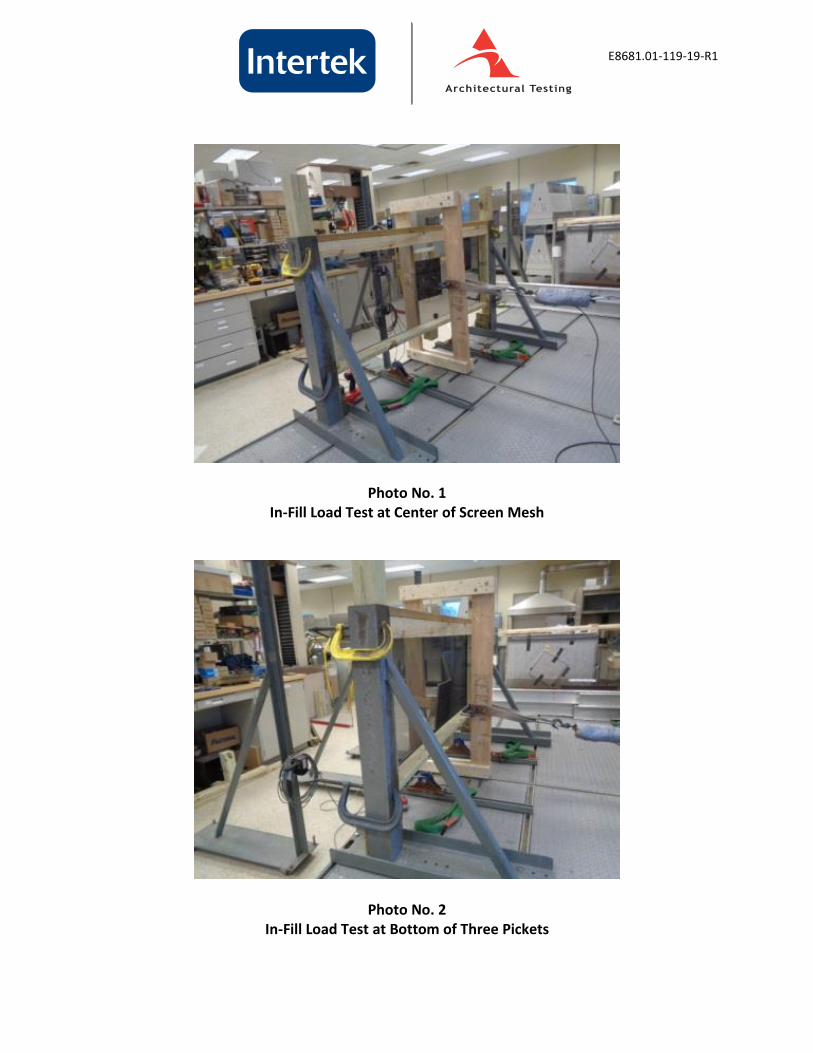
Photo No. 1 In-Fill Load Test at Center of Screen Mesh
Photo No. 2 In-Fill Load Test at Bottom of Three Pickets

E8681.01-119-19-R1
Photo No. 3 Concentrated Load Test at Ends of Top Rail (Brackets)
Photo No. 4 Railing Assembly Prior to Installation of Screen
Related Documents


