This report is for the exclusive use of Intertek's Client and is provided pursuant to the agreement between Intertek and its Client. Intertek's responsibility and liability are limited to the terms and conditions of the agreement. Intertek assumes no liability to any party, other than to the Client in accordance with the agreement, for any loss, expense or damage occasioned by the use of this report. Only the Client is authorized to permit copying or distribution of this report and then only in its entirety. Any use of the Intertek name or one of its marks for the sale or advertisement of the tested material, product or service must first be approved in writing by Intertek. The observations and test results in this report are relevant only to the sample tested. This report by itself does not imply that the material, product, or service is or has ever been under an Intertek certification program. Test Report issued under the responsibility of: TEST REPORT IEC 60950-1 Information technology equipment – Safety – Part 1: General requirements Report Number. ..............................: 140200043SHA-002 Date of issue..................................... : 2014-03-18 Total number of pages....................... 140 CB Testing Laboratory ...................: Intertek Testing Services Shanghai Address ............................................ : Building No.86, 1198 Qinzhou Road (North), 200233 Shanghai, China Applicant’s name ............................: GlobTek, Inc. Address ............................................ : 186 Veterans Dr. Northvale, NJ 07647 USA Manufacturer’s name……………….: GlobTek, Inc. Address ............................................ : 186 Veterans Dr. Northvale, NJ 07647 USA Test specification: Standard ........................................... : IEC 60950-1:2005 (Second Edition) + A1:2009 EN 60950-1:2006 + A11:2009 + A1:2010 + A12:2011 and Group differences for CENELEC countries, national difference for AU, CA, CN, JP, KR, SG and US. Test procedure ................................. : CB Scheme Non-standard test method…………..: N/A Test Report Form No......................: IEC60950_1C Test Report Form(s) Originator ........ : SGS Fimko Ltd Master TRF....................................... : Dated 2012-08 Copyright © 2012 Worldwide System for Conformity Testing and Certification of Electrotechnical Equipment and Components (IECEE), Geneva, Switzerland. All rights reserved. This publication may be reproduced in whole or in part for non-commercial purposes as long as the IECEE is acknowledged as copyright owner and source of the material. IECEE takes no responsibility for and will not assume liability for damages resulting from the reader's interpretation of the reproduced material due to its placement and context. If this Test Report Form is used by non-IECEE members, the IECEE/IEC logo and the reference to the CB Scheme procedure shall be removed. This report is not valid as a CB Test Report unless signed by an approved CB Testing Laboratory and appended to a CB Test Certificate issued by an NCB in accordance with IECEE 02. Test item description .....................: ITE Power Supply Trade Mark ....................................... : GlobTek Manufacturer .................................... : GlobTek, Inc. Model/Type reference....................... : GT*41080-**** (Refer to page 7 for details.) Ratings.............................................. : Input: 100-240V~, 50-60Hz, 0.6A; Output: Refer to page 7 for details.

Welcome message from author
This document is posted to help you gain knowledge. Please leave a comment to let me know what you think about it! Share it to your friends and learn new things together.
Transcript
This report is for the exclusive use of Intertek's Client and is provided pursuant to the agreement between Intertek and its Client. Intertek's responsibility and liability are limited to the terms and conditions of the agreement. Intertek assumes no liability to any party, other than to the Client in accordance with the agreement, for any loss, expense or damage occasioned by the use of this report. Only the Client is authorized to permit copying or distribution of this report and then only in its entirety. Any use of the Intertek name or one of its marks for the sale or advertisement of the tested material, product or service must first be approved in writing by Intertek. The observations and test results in this report are relevant only to the sample tested. This report by itself does not imply that the material, product, or service is or has ever been under an Intertek certification program.
Test Report issued under the responsibility of:
TEST REPORT
IEC 60950-1
Information technology equipment – Safety – Part 1: General requirements
Report Number. ..............................: 140200043SHA-002
Date of issue.....................................: 2014-03-18
Total number of pages....................... 140
CB Testing Laboratory...................: Intertek Testing Services Shanghai
Address ............................................: Building No.86, 1198 Qinzhou Road (North), 200233 Shanghai, China
Applicant’s name............................: GlobTek, Inc.
Address ............................................: 186 Veterans Dr. Northvale, NJ 07647 USA
Manufacturer’s name……………….: GlobTek, Inc.
Address ............................................: 186 Veterans Dr. Northvale, NJ 07647 USA
Test specification:
Standard ...........................................: IEC 60950-1:2005 (Second Edition) + A1:2009 EN 60950-1:2006 + A11:2009 + A1:2010 + A12:2011 and
Group differences for CENELEC countries, national difference for AU, CA, CN, JP, KR, SG and US.
Test procedure .................................: CB Scheme
Non-standard test method…………..: N/A
Test Report Form No......................: IEC60950_1C
Test Report Form(s) Originator ........: SGS Fimko Ltd
Master TRF.......................................: Dated 2012-08
Copyright © 2012 Worldwide System for Conformity Testing and Certification of Electrotechnical Equipment and Components (IECEE), Geneva, Switzerland. All rights reserved. This publication may be reproduced in whole or in part for non-commercial purposes as long as the IECEE is acknowledged as copyright owner and source of the material. IECEE takes no responsibility for and will not assume liability for damages resulting from the reader's interpretation of the reproduced material due to its placement and context. If this Test Report Form is used by non-IECEE members, the IECEE/IEC logo and the reference to the CB Scheme procedure shall be removed. This report is not valid as a CB Test Report unless signed by an approved CB Testing Laboratory and appended to a CB Test Certificate issued by an NCB in accordance with IECEE 02.
Test item description .....................: ITE Power Supply
Trade Mark .......................................: GlobTek
Manufacturer ....................................: GlobTek, Inc.
Model/Type reference.......................: GT*41080-**** (Refer to page 7 for details.)
Ratings..............................................: Input: 100-240V~, 50-60Hz, 0.6A; Output: Refer to page 7 for details.
Page 3 of 140 Report No.: 140200043SHA-002
TRF No. IEC60950_1C
List of Attachments (including a total number of pag es in each attachment):
Page 56-63: Photograph
Page 64-66: Circuit diagram & PCB Layout
Page 67-79: European group differences and national differences
Page 80-81: National differences for Singapore
Page 82-90: National differences for Japan
Page 91-96: National differences for China
Page 97-104: National differences for Australia and New Zealand
Page 105-109: National differences for USA
Page 110-114: National differences for Canada
Page 115: National differences for Korea
Page 116-140: Plug portion evaluation sheet according to EN 50075/AS/NZS 3112/NEMA 1-15/BS1363/ NBR 14136.
Summary of testing:
Tests performed (name of test and test clause): 1.6.2 Input test 1.7.11 Marking test 2.1.1.1 b) Finger test 2.1.1.1 c) Pin test 2.1.1.5 Energy hazards test 2.1.1.7 Stored Discharge on Capacitors Test 2.2.2 Voltage under normal conditions test 2.2.3 Voltage under fault conditions test 2.4 Limited current circuits 2.5 Limited power source test 2.9.2 Humidity test 2.10.2 Working voltage measurement 2.10.3/2.10.4 Clearances and creepage distances 2.10.5 Distance through insulation measurements 4.2.2 Mechanical strength - steady force test, 10 N 4.2.4 Mechanical strength - steady force test, 250 N 4.2.6 Mechanical strength - drop test 4.2.7 Mechanical strength - stress relief test 4.3.6 Strain on socket-outlet test 4.5.1 Temperature rise test 4.5.5 Ball pressure test of thermoplastic parts 5.1 Touch current & protective conductor current test 5.2 Electric strength test 5.3 Abnormal test
From the result of our examination and tests in the submitted samples, conclude they comply with the requirements of the standard IEC 60950-1:2005 (Second Edition) + A1: 2009 and EN 60950-1:2006 + A11:2009 + A1:2010+A12:2011.
Testing location:
Intertek Testing Services Shanghai
Building No.86, 1198 Qinzhou Road (North), 200233 Shanghai, China
Page 4 of 140 Report No.: 140200043SHA-002
TRF No. IEC60950_1C
Summary of compliance with National Differences
List of countries addressed:
The test report covers group- and national differences for the CENELEC countries.
The national differences for Singapore and Japan have been checked according to IEC 60950-1 1st ed.
The national differences for China and Australia/New Zealand have been checked according to IEC 60950-1 2nd ed.
The national differences for Korea, Canada and USA have been checked according to IEC 60950-1 2nd ed. + am.1.
The product fulfils the requirements of IEC 60950-1:2005+A1:2009 and EN 60950-1:2006+A11:2009 +A1:2010+A12:2011.
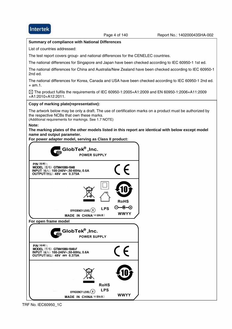
Copy of marking plate(representative):
The artwork below may be only a draft. The use of certification marks on a product must be authorized by the respective NCBs that own these marks. (Additional requirements for markings. See 1.7 NOTE)
Note: The marking plates of the other models listed in this report are identical with below except model name and output parameter. For power adapter model, serving as Class II product:
For open frame model
Page 5 of 140 Report No.: 140200043SHA-002
TRF No. IEC60950_1C
Test item particulars ...................................................:
Equipment mobility .................................................... : [] movable [] hand-held [] transportable [] stationary [] for building-in [x] direct plug-in Final determination in end product evaluation for open frame model.
Connection to the mains............................................ : [x] pluggable equipment [x] type A [] type B [] permanent connection [] detachable power supply cord [] non-detachable power supply cord [] not directly connected to the mains
Operating condition.................................................... : [x] continuous [] rated operating / resting time:
Access location ......................................................... : [x] operator accessible [] restricted access location
Over voltage category (OVC) ................................... : [] OVC I [x] OVC II [] OVC III [] OVC IV [] other:
Mains supply tolerance (%) or absolute mains supply values ....................................................................... :
+10%, -10%
Tested for IT power systems .................................... : [x] Yes [] No
IT testing, phase-phase voltage (V) .......................... : 230V
Class of equipment ................................................... : [] Class I or [x] Class II [] Class III [] Not classified Final determination in end product evaluation for open frame model.
Considered current rating of protective device as part of the building installation (A) .................................... :
16A or 20A
Pollution degree (PD) ............................................... : [] PD 1 [x] PD 2 [] PD 3
IP protection class .................................................... : IP20
Altitude during operation (m) .................................... : Max. 3000m
Altitude of test laboratory (m) ................................... : Max. 50m
Mass of equipment (kg) ............................................ : Approx. 0.24kg
Possible test case verdicts:
- test case does not apply to the test object ................. : N/A (or N)
- test object does meet the requirement....................... : P (Pass)
- test object does not meet the requirement ................ : F (Fail)
Testing ......................................................................... :
Date of receipt of test item............................................ : 2014-02-25
Date(s) of performance of tests.................................... : 2014-02-25~2014-03-18
Page 6 of 140 Report No.: 140200043SHA-002
TRF No. IEC60950_1C
General remarks:
The test results presented in this report relate only to the object tested. This report shall not be reproduced, except in full, without the written approval of the Issuing testing laboratory. "(See Enclosure #)" refers to additional information appended to the report. "(See appended table)" refers to a table appended to the report. Throughout this report a comma / point is used as the decimal separator.
Determination of the test result includes consideration of measurement uncertainty from the test equipment and methods.
Manufacturer’s Declaration per sub-clause 6.2.5 of IECEE 02:
The application for obtaining a CB Test Certificate includes more than one factory location and a declaration from the Manufacturer stating that the sample(s) submitted for evaluation is (are) representative of the products from each factory has been provided ................................................................:
Yes
Not applicable
When differences exist; they shall be identified in the General product information section.
Name and address of factory (ies) .......................... : Factory 1
GlobTek, Inc. 186 Veterans Dr. Northvale, NJ 07647 USA
Factory 2
GlobTek (Suzhou) Co., Ltd Building 4, No. 76, Jin Ling East Rd., Suzhou Industrial Park, Suzhou, JiangSu 215021, China
Page 7 of 140 Report No.: 140200043SHA-002
TRF No. IEC60950_1C
General product information:
Product covered by this report is ITE power supply module for indoor use only. The different models are corresponding to two structure types respectively.
One is direct plug-in power adapter with interchangeable plug portion, which is Class II apparatus. It can be used with different plug types. The evaluation reports of the different plug types are also attached with this report. Two pieces of outer enclosure are enclosed with ultrasonic welding without screw.
The other one is open frame power supply board which also provides a protective earth bonding terminal on the PCB board. The installation and use for the insulation construction shall be finally determined in the end product.
Two transformer types are alternative, which are identical in same construction except different routing of secondary lead wires. The equipment was submitted and evaluated for maximum manufacturer’s recommended ambient of 40 °C.
The enclosures fixed together by ultrasonic welding. All the types are designed for continuous operation.
Model Similarity:
GT*41080-****
The 1st “*” part can be ‘M’ or ‘-’ or ‘H’ for market identification and not related to safety.
The 2nd “*” part denotes the rated output wattage designation, which can be “01” to “18”, with interval of 1.
The 3rd “*” part denotes the standard rated output voltage designation, which can be “07”, “11” “17.9”, “30”, “38” and “48”. Each standard rated output voltage designation corresponds to a transformer model. Each transformer model is identical in insulation construction including clearance and creepage except number of turns per coil.
The 4th “*” part is optional, which can be “-0.1” to “-12” with interval of 0.1 to denote voltage deviation or blank to indicate no voltage different. The result by subtracting the deviation value from the standard rated output voltage denotes the rated output voltage, with a range of 5 - 48 volts.
The 5th “*” part is also optional, which can be “-F” to denote open frame power supply model series or blank to denote direct plug-in power adapter model series.
Tests were performed on 5Vdc/3A output adapter model and 48Vdc/0.375A output adapter model as worst condition, and also performed on other output models for reference. For open frame model, temperature testing, leakage current test and mechanical strength test shall be performed on this component when installed in the end product.
Model list
Model Rated output voltage range
Max. rated output current
Max. rated output power
Transformer model
GT*41080-*07** 5-7Vdc 3.6A 18W XF00514
GT*41080-*11** 7.1-11Vdc 2.53A 18W XF00550
GT*41080-*17.9** 11.1-17.9Vdc 1.62A 18W XF00579
GT*41080-*30** 18-30Vdc 1.0A 18W XF00590
GT*41080-*38** 30.1-38Vdc 0.60A 18W XF00682A
GT*41080-*48** 38.1-48Vdc 0.47A 18W XF00682
Page 8 of 140 Report No.: 140200043SHA-002
IEC 60950-1
Clause Requirement + Test Result - Remark Verdict
TRF No. IEC60950_1C
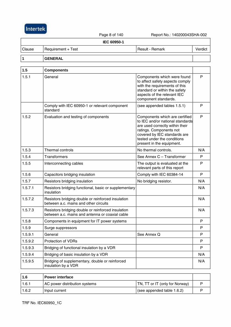
1 GENERAL
1.5 Components
1.5.1 General Components which were found to affect safety aspects comply with the requirements of this standard or within the safety aspects of the relevant IEC component standards.
P
Comply with IEC 60950-1 or relevant component standard
(see appended tables 1.5.1) P
1.5.2 Evaluation and testing of components Components which are certified to IEC and/or national standards are used correctly within their ratings. Components not covered by IEC standards are tested under the conditions present in the equipment.
P
1.5.3 Thermal controls No thermal controls. N/A
1.5.4 Transformers See Annex C – Transformer P
1.5.5 Interconnecting cables The output is evaluated at the relevant parts of this report
P
1.5.6 Capacitors bridging insulation Comply with IEC 60384-14 P
1.5.7 Resistors bridging insulation No bridging resistor. N/A
1.5.7.1 Resistors bridging functional, basic or supplementary insulation
N/A
1.5.7.2 Resistors bridging double or reinforced insulation between a.c. mains and other circuits
N/A
1.5.7.3 Resistors bridging double or reinforced insulation between a.c. mains and antenna or coaxial cable
N/A
1.5.8 Components in equipment for IT power systems P
1.5.9 Surge suppressors P
1.5.9.1 General See Annex Q P
1.5.9.2 Protection of VDRs P
1.5.9.3 Bridging of functional insulation by a VDR P
1.5.9.4 Bridging of basic insulation by a VDR N/A
1.5.9.5 Bridging of supplementary, double or reinforced insulation by a VDR
N/A
1.6 Power interface
1.6.1 AC power distribution systems TN, TT or IT (only for Norway) P
1.6.2 Input current (see appended table 1.6.2) P
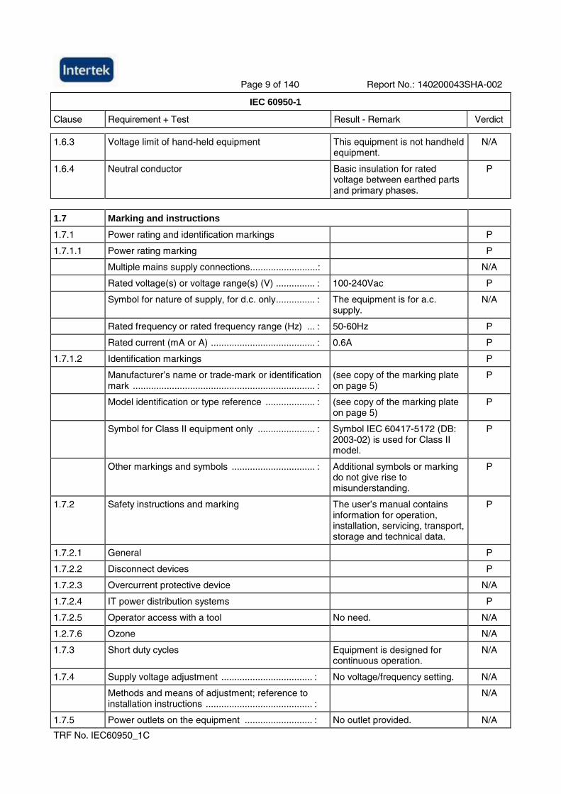
Page 9 of 140 Report No.: 140200043SHA-002
IEC 60950-1
Clause Requirement + Test Result - Remark Verdict
TRF No. IEC60950_1C
1.6.3 Voltage limit of hand-held equipment This equipment is not handheld equipment.
N/A
1.6.4 Neutral conductor Basic insulation for rated voltage between earthed parts and primary phases.
P
1.7 Marking and instructions
1.7.1 Power rating and identification markings P
1.7.1.1 Power rating marking P
Multiple mains supply connections..........................: N/A
Rated voltage(s) or voltage range(s) (V) ............... : 100-240Vac P
Symbol for nature of supply, for d.c. only............... : The equipment is for a.c. supply.
N/A
Rated frequency or rated frequency range (Hz) ... : 50-60Hz P
Rated current (mA or A) ........................................ : 0.6A P
1.7.1.2 Identification markings P
Manufacturer’s name or trade-mark or identification mark ...................................................................... :
(see copy of the marking plate on page 5)
P
Model identification or type reference ................... : (see copy of the marking plate on page 5)
P
Symbol for Class II equipment only ...................... : Symbol IEC 60417-5172 (DB: 2003-02) is used for Class II model.
P
Other markings and symbols ................................ : Additional symbols or marking do not give rise to misunderstanding.
P
1.7.2 Safety instructions and marking The user’s manual contains information for operation, installation, servicing, transport, storage and technical data.
P
1.7.2.1 General P
1.7.2.2 Disconnect devices P
1.7.2.3 Overcurrent protective device N/A
1.7.2.4 IT power distribution systems P
1.7.2.5 Operator access with a tool No need. N/A
1.2.7.6 Ozone N/A
1.7.3 Short duty cycles Equipment is designed for continuous operation.
N/A
1.7.4 Supply voltage adjustment ................................... : No voltage/frequency setting. N/A
Methods and means of adjustment; reference to installation instructions ......................................... :
N/A
1.7.5 Power outlets on the equipment .......................... : No outlet provided. N/A
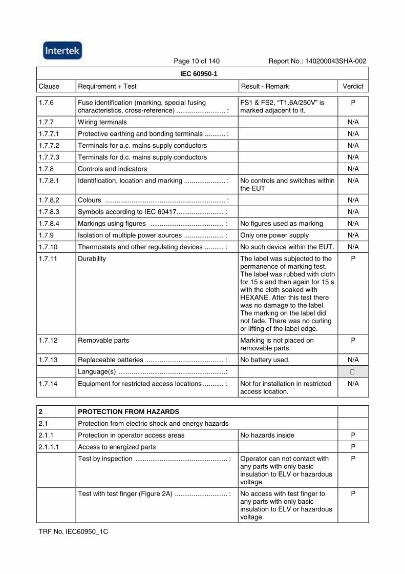
Page 10 of 140 Report No.: 140200043SHA-002
IEC 60950-1
Clause Requirement + Test Result - Remark Verdict
TRF No. IEC60950_1C
1.7.6 Fuse identification (marking, special fusing characteristics, cross-reference) .......................... :
FS1 & FS2, “T1.6A/250V” is marked adjacent to it.
P
1.7.7 Wiring terminals N/A
1.7.7.1 Protective earthing and bonding terminals ........... : N/A
1.7.7.2 Terminals for a.c. mains supply conductors N/A
1.7.7.3 Terminals for d.c. mains supply conductors N/A
1.7.8 Controls and indicators N/A
1.7.8.1 Identification, location and marking ...................... : No controls and switches within the EUT
N/A
1.7.8.2 Colours ................................................................ : N/A
1.7.8.3 Symbols according to IEC 60417......................... : N/A
1.7.8.4 Markings using figures ....................................... : No figures used as marking N/A
1.7.9 Isolation of multiple power sources ..................... : Only one power supply N/A
1.7.10 Thermostats and other regulating devices .......... : No such device within the EUT. N/A
1.7.11 Durability The label was subjected to the permanence of marking test. The label was rubbed with cloth for 15 s and then again for 15 s with the cloth soaked with HEXANE. After this test there was no damage to the label. The marking on the label did not fade. There was no curling or lifting of the label edge.
P
1.7.12 Removable parts Marking is not placed on removable parts.
P
1.7.13 Replaceable batteries ......................................... : No battery used. N/A
Language(s) .........................................................:
1.7.14 Equipment for restricted access locations ........... : Not for installation in restricted access location.
N/A
2 PROTECTION FROM HAZARDS
2.1 Protection from electric shock and energy hazards
2.1.1 Protection in operator access areas No hazards inside P
2.1.1.1 Access to energized parts P
Test by inspection ................................................. : Operator can not contact with any parts with only basic insulation to ELV or hazardous voltage.
P
Test with test finger (Figure 2A) ............................ : No access with test finger to any parts with only basic insulation to ELV or hazardous voltage.
P
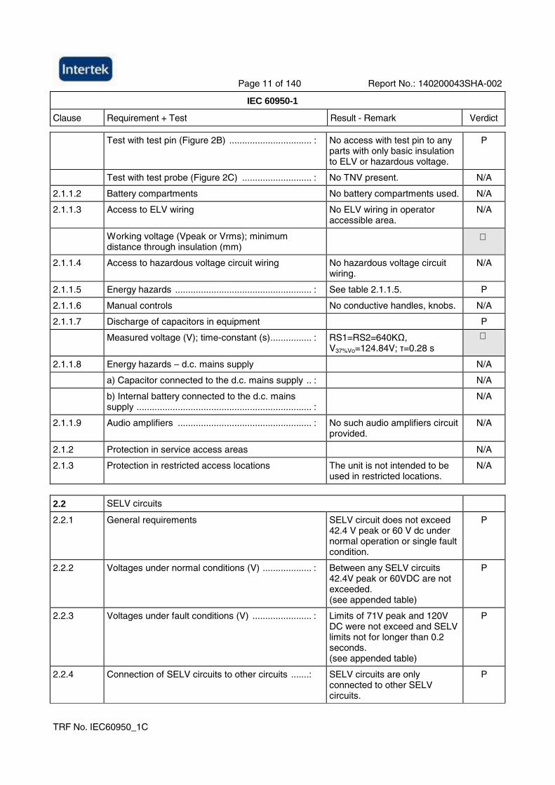
Page 11 of 140 Report No.: 140200043SHA-002
IEC 60950-1
Clause Requirement + Test Result - Remark Verdict
TRF No. IEC60950_1C
Test with test pin (Figure 2B) ................................ : No access with test pin to any parts with only basic insulation to ELV or hazardous voltage.
P
Test with test probe (Figure 2C) ........................... : No TNV present. N/A
2.1.1.2 Battery compartments No battery compartments used. N/A
2.1.1.3 Access to ELV wiring No ELV wiring in operator accessible area.
N/A
Working voltage (Vpeak or Vrms); minimum distance through insulation (mm)
2.1.1.4 Access to hazardous voltage circuit wiring No hazardous voltage circuit wiring.
N/A
2.1.1.5 Energy hazards ..................................................... : See table 2.1.1.5. P
2.1.1.6 Manual controls No conductive handles, knobs. N/A
2.1.1.7 Discharge of capacitors in equipment P
Measured voltage (V); time-constant (s)................ : RS1=RS2=640KΩ, V37%Vo=124.84V; τ=0.28 s
2.1.1.8 Energy hazards – d.c. mains supply N/A
a) Capacitor connected to the d.c. mains supply .. : N/A
b) Internal battery connected to the d.c. mains supply .................................................................... :
N/A
2.1.1.9 Audio amplifiers .................................................... : No such audio amplifiers circuit provided.
N/A
2.1.2 Protection in service access areas N/A
2.1.3 Protection in restricted access locations The unit is not intended to be used in restricted locations.
N/A
2.2 SELV circuits
2.2.1 General requirements SELV circuit does not exceed 42.4 V peak or 60 V dc under normal operation or single fault condition.
P
2.2.2 Voltages under normal conditions (V) ................... : Between any SELV circuits 42.4V peak or 60VDC are not exceeded. (see appended table)
P
2.2.3 Voltages under fault conditions (V) ....................... : Limits of 71V peak and 120V DC were not exceed and SELV limits not for longer than 0.2 seconds. (see appended table)
P
2.2.4 Connection of SELV circuits to other circuits .......: SELV circuits are only connected to other SELV circuits.
P
Page 12 of 140 Report No.: 140200043SHA-002
IEC 60950-1
Clause Requirement + Test Result - Remark Verdict
TRF No. IEC60950_1C
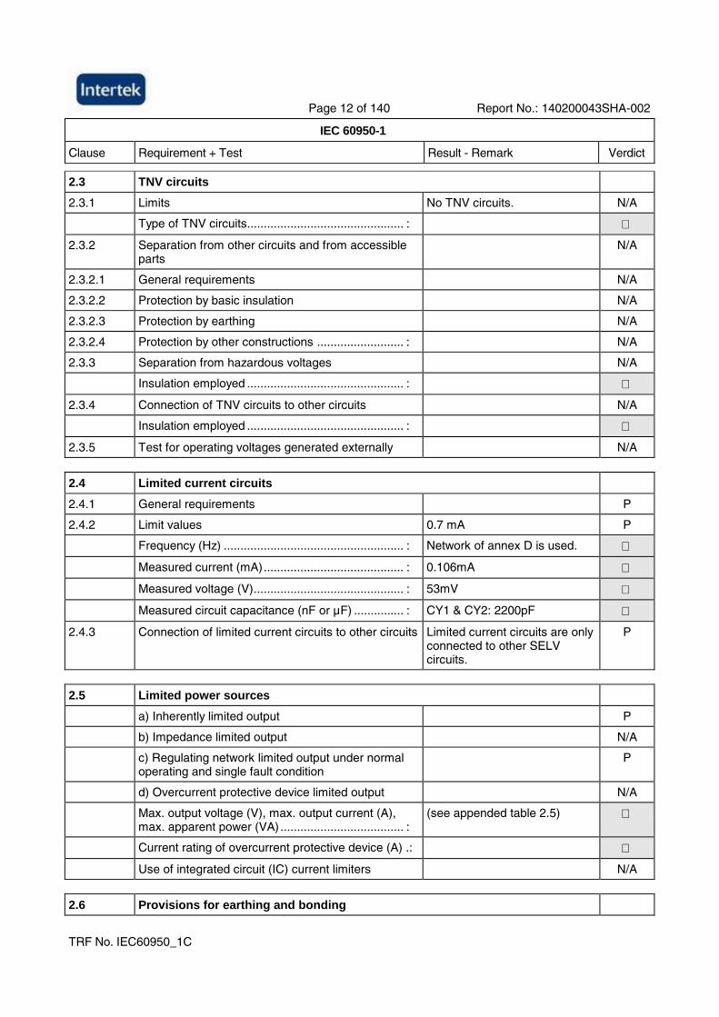
2.3 TNV circuits
2.3.1 Limits No TNV circuits. N/A
Type of TNV circuits............................................... :
2.3.2 Separation from other circuits and from accessible parts
N/A
2.3.2.1 General requirements N/A
2.3.2.2 Protection by basic insulation N/A
2.3.2.3 Protection by earthing N/A
2.3.2.4 Protection by other constructions .......................... : N/A
2.3.3 Separation from hazardous voltages N/A
Insulation employed ............................................... :
2.3.4 Connection of TNV circuits to other circuits N/A
Insulation employed ............................................... :
2.3.5 Test for operating voltages generated externally N/A
2.4 Limited current circuits
2.4.1 General requirements P
2.4.2 Limit values 0.7 mA P
Frequency (Hz) ...................................................... : Network of annex D is used.
Measured current (mA).......................................... : 0.106mA
Measured voltage (V)............................................. : 53mV
Measured circuit capacitance (nF or µF) ............... : CY1 & CY2: 2200pF
2.4.3 Connection of limited current circuits to other circuits Limited current circuits are only connected to other SELV circuits.
P
2.5 Limited power sources
a) Inherently limited output P
b) Impedance limited output N/A
c) Regulating network limited output under normal operating and single fault condition
P
d) Overcurrent protective device limited output N/A
Max. output voltage (V), max. output current (A), max. apparent power (VA) ..................................... :
(see appended table 2.5)
Current rating of overcurrent protective device (A) .:
Use of integrated circuit (IC) current limiters N/A
2.6 Provisions for earthing and bonding
Page 13 of 140 Report No.: 140200043SHA-002
IEC 60950-1
Clause Requirement + Test Result - Remark Verdict
TRF No. IEC60950_1C
2.6.1 Protective earthing Final determination in end product evaluation for open frame model.
N/A
2.6.2 Functional earthing N/A
2.6.3 Protective earthing and protective bonding conductors
N/A
2.6.3.1 General N/A
2.6.3.2 Size of protective earthing conductors N/A
Rated current (A), cross-sectional area (mm2), AWG............................................................................... :
2.6.3.3 Size of protective bonding conductors N/A
Rated current (A), cross-sectional area (mm2), AWG............................................................................... :
Protective current rating (A), cross-sectional area (mm2), AWG .......................................................... :
2.6.3.4 Resistance of earthing conductors and their terminations; resistance (Ω), voltage drop (V), test current (A), duration (min)...................................... :
N/A
2.6.3.5 Colour of insulation ................................................ : N/A
2.6.4 Terminals N/A
2.6.4.1 General N/A
2.6.4.2 Protective earthing and bonding terminals N/A
Rated current (A), type, nominal thread diameter (mm) ...................................................................... :
2.6.4.3 Separation of the protective earthing conductor from protective bonding conductors
N/A
2.6.5 Integrity of protective earthing N/A
2.6.5.1 Interconnection of equipment N/A
2.6.5.2 Components in protective earthing conductors and protective bonding conductors
N/A
2.6.5.3 Disconnection of protective earth N/A
2.6.5.4 Parts that can be removed by an operator N/A
2.6.5.5 Parts removed during servicing N/A
2.6.5.6 Corrosion resistance N/A
2.6.5.7 Screws for protective bonding N/A
2.6.5.8 Reliance on telecommunication network or cable distribution system
N/A
2.7 Overcurrent and earth fault protection in primary circuits
2.7.1 Basic requirements Integral part of equipment P
Instructions when protection relies on building N/A
Page 14 of 140 Report No.: 140200043SHA-002
IEC 60950-1
Clause Requirement + Test Result - Remark Verdict
TRF No. IEC60950_1C
installation
2.7.2 Faults not simulated in 5.3.7 N/A
2.7.3 Short-circuit backup protection Building installation is considered as the short-circuit backup protection.
P
2.7.4 Number and location of protective devices ........... : One current fuse (FS1) is located in the Line pole of primary circuit.
P
2.7.5 Protection by several devices Only one protection device N/A
2.7.6 Warning to service personnel ................................ : No service access area. N/A
2.8 Safety interlocks
2.8.1 General principles No safety interlock. N/A
2.8.2 Protection requirements N/A
2.8.3 Inadvertent reactivation N/A
2.8.4 Fail-safe operation N/A
Protection against extreme hazard N/A
2.8.5 Moving parts N/A
2.8.6 Overriding N/A
2.8.7 Switches, relays and their related circuits N/A
2.8.7.1 Separation distances for contact gaps and their related circuits (mm) ............................................. :
N/A
2.8.7.2 Overload test N/A
2.8.7.3 Endurance test N/A
2.8.7.4 Electric strength test N/A
2.8.8 Mechanical actuators N/A
2.9 Electrical insulation
2.9.1 Properties of insulating materials Natural rubber, asbestos or hygroscopic materials are not used.
N/A
2.9.2 Humidity conditioning Humidity treatment performed for 120 h per client’s request.
P
Relative humidity (%), temperature (°C) .......... ..... : 93%, 40°C
2.9.3 Grade of insulation The adequate level of safety insulation is provided and maintained to comply with the requirements of this standard.
P
2.9.4 Separation from hazardous voltages P
Method(s) used ..................................................... : Method 1.
Page 15 of 140 Report No.: 140200043SHA-002
IEC 60950-1
Clause Requirement + Test Result - Remark Verdict
TRF No. IEC60950_1C
2.10 Clearances, creepage distances and distances th rough insulation
2.10.1 General P
2.10.1.1 Frequency ............................................................. : more than 30kHz P
2.10.1.2 Pollution degrees .................................................. : Pollution degree 2 P
2.10.1.3 Reduced values for functional insulation P
2.10.1.4 Intervening unconnected conductive parts P
2.10.1.5 Insulation with varying dimensions No such transformer. N/A
2.10.1.6 Special separation requirements N/A
2.10.1.7 Insulation in circuits generating starting pulses N/A
2.10.2 Determination of working voltage P
2.10.2.1 General P
2.10.2.2 RMS working voltage P
2.10.2.3 Peak working voltage P
2.10.3 Clearances P
2.10.3.1 General P
2.10.3.2 Mains transient voltages P
a) AC mains supply : 100-240Vrms. Overvoltage Category II
P
b) Earthed d.c. mains supplies .............................. : N/A
c) Unearthed d.c. mains supplies ......................... : N/A
d) Battery operation ............................................... : N/A
2.10.3.3 Clearances in primary circuits (see appended table 2.10.3 and 2.10.4)
P
2.10.3.4 Clearances in secondary circuits Comply with clause 5.3.4 a) P
2.10.3.5 Clearances in circuits having starting pulses N/A
2.10.3.6 Transients from a.c. mains supply ........................ : N/A
2.10.3.7 Transients from d.c. mains supply ........................ : N/A
2.10.3.8 Transients from telecommunication networks and cable distribution systems ..................................... :
N/A
2.10.3.9 Measurement of transient voltage levels N/A
a) Transients from a mains supply N/A
For an a.c. mains supply ....................................... : N/A
For a d.c. mains supply ......................................... : N/A
b) Transients from a telecommunication network : N/A
2.10.4 Creepage distances P
2.10.4.1 General P
2.10.4.2 Material group and comparative tracking index P
Page 16 of 140 Report No.: 140200043SHA-002
IEC 60950-1
Clause Requirement + Test Result - Remark Verdict
TRF No. IEC60950_1C
CTI tests................................................................. : Material group IIIb is used
2.10.4.3 Minimum creepage distances (see appended table 2.10.3 and 2.10.4)
P
2.10.5 Solid insulation P
2.10.5.1 General P
2.10.5.2 Distances through insulation (see appended table 2.10.5) P
2.10.5.3 Insulating compound as solid insulation N/A
2.10.5.4 Semiconductor devices Approved optocoupler. P
2.10.5.5. Cemented joints N/A
2.10.5.6 Thin sheet material – General The thin sheet materials of polyester tape used in transformers.
P
2.10.5.7 Separable thin sheet material P
Number of layers (pcs)........................................... : (see appended table 2.10.5)
2.10.5.8 Non-separable thin sheet material N/A
2.10.5.9 Thin sheet material – standard test procedure See sub-clause 2.10.5.10 N/A
Electric strength test
2.10.5.10 Thin sheet material – alternative test procedure P
Electric strength test (see appended table 2.10.5)
2.10.5.11 Insulation in wound components (see Annex U) P
2.10.5.12 Wire in wound components Approved triple insulation wire for T1 secondary winding
P
Working voltage .................................................... : N/A
a) Basic insulation not under stress ...................... : N/A
b) Basic, supplementary, reinforced insulation ..... : N/A
c) Compliance with Annex U ................................. : Approved triple insulated winding wire used.
P
Two wires in contact inside wound component; angle between 45° and 90° ............................................. :
Additional insulation tape is used.
P
2.10.5.13 Wire with solvent-based enamel in wound components
No such device within the EUT N/A
Electric strength test
Routine test N/A
2.10.5.14 Additional insulation in wound components Bobbin between the winding and core
P
Working voltage .................................................... : (see appended table) P
- Basic insulation not under stress ........................ : N/A
- Supplementary, reinforced insulation ................. : (see appended table) P
2.10.6 Construction of printed boards P
Page 17 of 140 Report No.: 140200043SHA-002
IEC 60950-1
Clause Requirement + Test Result - Remark Verdict
TRF No. IEC60950_1C
2.10.6.1 Uncoated printed boards (see appended table 2.10.3 and 2.10.4)
P
2.10.6.2 Coated printed boards No coated printed board is used.
N/A
2.10.6.3 Insulation between conductors on the same inner surface of a printed board
Not multi-layer printed board. N/A
2.10.6.4 Insulation between conductors on different layers of a printed board
No such printed board use. N/A
Distance through insulation N/A
Number of insulation layers (pcs) .......................... : N/A
2.10.7 Component external terminations N/A
2.10.8 Tests on coated printed boards and coated components
No coated printed boards and coated components.
N/A
2.10.8.1 Sample preparation and preliminary inspection N/A
2.10.8.2 Thermal conditioning N/A
2.10.8.3 Electric strength test N/A
2.10.8.4 Abrasion resistance test N/A
2.10.9 Thermal cycling N/A
2.10.10 Test for Pollution Degree 1 environment and insulating compound
N/A
2.10.11 Tests for semiconductor devices and cemented joints
Approved optocouplers (U1) (see also appended table 1.5.1)
P
2.10.12 Enclosed and sealed parts N/A
3 WIRING, CONNECTIONS AND SUPPLY
3.1 General
3.1.1 Current rating and overcurrent protection Adequate cross sectional areas on internal wiring.
P
3.1.2 Protection against mechanical damage Wireways are smooth and free from edges. Wires are adequately fixed to prevent excessive strain on wire and terminals and avoiding damage to the insulation of the conductors.
P
3.1.3 Securing of internal wiring Internal wiring is secured against excessive strain, loosening of terminals and damage to the conductor insulation.
P
3.1.4 Insulation of conductors Only SELV wiring. N/A
3.1.5 Beads and ceramic insulators Not used. N/A
Page 18 of 140 Report No.: 140200043SHA-002
IEC 60950-1
Clause Requirement + Test Result - Remark Verdict
TRF No. IEC60950_1C
3.1.6 Screws for electrical contact pressure No such screws. N/A
3.1.7 Insulating materials in electrical connections No such construction. N/A
3.1.8 Self-tapping and spaced thread screws No spaced threaded or self-tapping screws are used.
N/A
3.1.9 Termination of conductors All conductors are reliably secured by use of solder-pins or glue or other mechanical fixing means.
P
10 N pull test P
3.1.10 Sleeving on wiring No sleeving is used as the supplementary insulation on internal wiring.
N/A
3.2 Connection to a mains supply
3.2.1 Means of connection Integral plug forming as part of the equipment.
P
3.2.1.1 Connection to an a.c. mains supply A mains plug that is part of direct plug-in equipment.
P
3.2.1.2 Connection to a d.c. mains supply No connection to d.c. mains supply.
N/A
3.2.2 Multiple supply connections Only one supply connection. N/A
3.2.3 Permanently connected equipment The unit is not permanent connected equipment.
N/A
Number of conductors, diameter of cable and conduits (mm) ....................................................... :
3.2.4 Appliance inlets No appliance inlet. N/A
3.2.5 Power supply cords No power supply cord. N/A
3.2.5.1 AC power supply cords N/A
Type ...................................................................... :
Rated current (A), cross-sectional area (mm2), AWG ..................................................................... :
3.2.5.2 DC power supply cords N/A
3.2.6 Cord anchorages and strain relief No such construction. N/A
Mass of equipment (kg), pull (N) .......................... :
Longitudinal displacement (mm) ........................... :
3.2.7 Protection against mechanical damage N/A
3.2.8 Cord guards N/A
Diameter or minor dimension D (mm); test mass (g) ............................................................................... :
Radius of curvature of cord (mm) .......................... :
3.2.9 Supply wiring space N/A
Page 19 of 140 Report No.: 140200043SHA-002
IEC 60950-1
Clause Requirement + Test Result - Remark Verdict
TRF No. IEC60950_1C
3.3 Wiring terminals for connection of external conductors
3.3.1 Wiring terminals No wiring terminal N/A
3.3.2 Connection of non-detachable power supply cords N/A
3.3.3 Screw terminals N/A
3.3.4 Conductor sizes to be connected N/A
Rated current (A), cord/cable type, cross-sectional area (mm2) ............................................................. :
3.3.5 Wiring terminal sizes N/A
Rated current (A), type, nominal thread diameter (mm) ..................................................................... :
3.3.6 Wiring terminal design N/A
3.3.7 Grouping of wiring terminals N/A
3.3.8 Stranded wire N/A
3.4 Disconnection from the mains supply
3.4.1 General requirement P
3.4.2 Disconnect devices Integral plug of forming as part of the equipment is considered as the disconnect device
P
3.4.3 Permanently connected equipment The unit is not permanently connected equipment.
N/A
3.4.4 Parts which remain energized N/A
3.4.5 Switches in flexible cords N/A
3.4.6 Number of poles - single-phase and d.c. equipment The disconnect device disconnects both poles simultaneously.
P
3.4.7 Number of poles - three-phase equipment Single phrase N/A
3.4.8 Switches as disconnect devices No switch. N/A
3.4.9 Plugs as disconnect devices No power supply cord. N/A
3.4.10 Interconnected equipment N/A
3.4.11 Multiple power sources N/A
3.5 Interconnection of equipment
3.5.1 General requirements P
3.5.2 Types of interconnection circuits ........................... : Interconnection circuits of SELV through the output connectors. No ELV interconnection circuits.
P
3.5.3 ELV circuits as interconnection circuits No ELV interconnection circuits.
N/A
Page 20 of 140 Report No.: 140200043SHA-002
IEC 60950-1
Clause Requirement + Test Result - Remark Verdict
TRF No. IEC60950_1C
3.5.4 Data ports for additional equipment N/A
4 PHYSICAL REQUIREMENTS
4.1 Stability
Angle of 10° The mass of EUT is less than 7 kg.
N/A
Test force (N) ........................................................ : Not floor standing unit. N/A
4.2 Mechanical strength
4.2.1 General P
Rack-mounted equipment. N/A
4.2.2 Steady force test, 10 N 10N applied to components. No hazard.
P
4.2.3 Steady force test, 30 N No such part needs test. N/A
4.2.4 Steady force test, 250 N 250N applied to all sources of plastic enclosure. No hazard.
P
4.2.5 Impact test N/A
Fall test N/A
Swing test N/A
4.2.6 Drop test; height (mm) .......................................... : 1000 mm height. P
4.2.7 Stress relief test After 7h at 104 °C and cooling down to room temperature, no shrinkage, distortion or loosing of enclosure parts was noticeable on the equipment.
P
4.2.8 Cathode ray tubes No such component. N/A
Picture tube separately certified ............................ : N/A
4.2.9 High pressure lamps No such component. N/A
4.2.10 Wall or ceiling mounted equipment; force (N) ...... : No such construction. N/A
4.2.11 Rotating solid media No such construction. N/A
Test to cover on the door…………………………….: N/A
4.3 Design and construction
4.3.1 Edges and corners Edges and corners of the enclosure are rounded.
P
4.3.2 Handles and manual controls; force (N) ............. : No such construction. N/A
4.3.3 Adjustable controls No hazardous adjustments accessible to the operator.
N/A
4.3.4 Securing of parts The enclosures are fixed together by ultrasonic welding
P
Page 21 of 140 Report No.: 140200043SHA-002
IEC 60950-1
Clause Requirement + Test Result - Remark Verdict
TRF No. IEC60950_1C
4.3.5 Connection by plugs and sockets Only specific interchangeable plugs can be used. They are all tested with appliance.
P
4.3.6 Direct plug-in equipment P
Torque ................................................................ : Max. 0.08 Nm
Compliance with the relevant mains plug standard ............................................................................ :
See also appendix page. P
4.3.7 Heating elements in earthed equipment No heating elements. N/A
4.3.8 Batteries No lithium battery. N/A
- Overcharging of a rechargeable battery N/A
- Unintentional charging of a non-rechargeable battery
N/A
- Reverse charging of a rechargeable battery N/A
- Excessive discharging rate for any battery N/A
4.3.9 Oil and grease Insulation is not exposed to oil, grease etc.
N/A
4.3.10 Dust, powders, liquids and gases Equipment in intended use not considered to be exposed to dust, powders, liquids or gases.
N/A
4.3.11 Containers for liquids or gases The equipment does not contain liquid.
N/A
4.3.12 Flammable liquids .............................................. : No flammable liquids in this unit.
N/A
Quantity of liquid (l) ............................................ : N/A
Flash point (°C) .................................................. : N/A
4.3.13 Radiation N/A
4.3.13.1 General N/A
4.3.13.2 Ionizing radiation The EUT does not generate ionizing radiation.
N/A
Measured radiation (pA/kg) ................................ :
Measured high-voltage (kV) ............................... :
Measured focus voltage (kV) ............................. :
CRT markings .................................................... :
4.3.13.3 Effect of ultraviolet (UV) radiation on materials The EUT does not produce UV radiation.
N/A
Part, property, retention after test, flammability classification ....................................................... :
N/A
4.3.13.4 Human exposure to ultraviolet (UV) radiation .... : N/A
4.3.13.5 Laser (including LEDs) No such parts. N/A
4.3.13.5.1 Lasers (including laser diodes) N/A
Page 22 of 140 Report No.: 140200043SHA-002
IEC 60950-1
Clause Requirement + Test Result - Remark Verdict
TRF No. IEC60950_1C
Laser class ......................................................... :
4.3.13.5.2 Light emitting diodes (LEDs) N/A
4.3.13.6 Other types ......................................................... : N/A
4.4 Protection against hazardous moving parts
4.4.1 General No such parts used. N/A
4.4.2 Protection in operator access areas .................... : N/A
Household and home/office document/media shredders
N/A
4.4.3 Protection in restricted access locations .............. : N/A
4.4.4 Protection in service access areas N/A
4.4.5 Protection against moving fan blades N/A
4.4.5.1 General N/A
Not considered to cause pain or injury. a)………….: N/A
Is considered to cause pain, not injury. b) …………: N/A
Considered to cause injury. c) ………………………: N/A
4.4.5.2 Protection for users N/A
Use of symbol or warning ……………………………: N/A
4.4.5.3 Protection for service persons N/A
Use of symbol or warning ……………………………: N/A
4.5 Thermal requirements
4.5.1 General P
4.5.2 Temperature tests P
Normal load condition per Annex L ...................... : L7
4.5.3 Temperature limits for materials (see appended table 4.5) P
4.5.4 Touch temperature limits (see appended table 4.5) P
4.5.5 Resistance to abnormal heat ............................... : (see appended table 4.5.5) P
4.6 Openings in enclosures
4.6.1 Top and side openings P
Dimensions (mm) ................................................. : No top and side opening.
4.6.2 Bottoms of fire enclosures P
Construction of the bottomm, dimensions (mm) .. : No bottom opening.
4.6.3 Doors or covers in fire enclosures N/A
4.6.4 Openings in transportable equipment N/A
4.6.4.1 Constructional design measures N/A
Page 23 of 140 Report No.: 140200043SHA-002
IEC 60950-1
Clause Requirement + Test Result - Remark Verdict
TRF No. IEC60950_1C
Dimensions (mm) ................................................. :
4.6.4.2 Evaluation measures for larger openings N/A
4.6.4.3 Use of metallized parts N/A
4.6.5 Adhesives for constructional purposes No barrier or screen secured with adhesive.
N/A
Conditioning temperature (°C), time (weeks)........ :
4.7 Resistance to fire
4.7.1 Reducing the risk of ignition and spread of flame Method 1 used. P
Method 1, selection and application of components wiring and materials
(see appended table 4.7) P
Method 2, application of all of simulated fault condition tests
N/A
4.7.2 Conditions for a fire enclosure Required. P
4.7.2.1 Parts requiring a fire enclosure P
4.7.2.2 Parts not requiring a fire enclosure N/A
4.7.3 Materials P
4.7.3.1 General Integrated circuits and small electrical parts mounted on a printed wiring board min. rated V-1.
P
4.7.3.2 Materials for fire enclosures Min. V-1 material is used. P
4.7.3.3 Materials for components and other parts outside fire enclosures
N/A
4.7.3.4 Materials for components and other parts inside fire enclosures
Bobbin: V-0; PCB: V-1 min.
P
4.7.3.5 Materials for air filter assemblies No air filters assemblies. N/A
4.7.3.6 Materials used in high-voltage components No parts exceeding 4kV. N/A
5 ELECTRICAL REQUIREMENTS AND SIMULATED ABNORMAL CONDITIONS
5.1 Touch current and protective conductor current
5.1.1 General (see appended Table 5.1) P
5.1.2 Configuration of equipment under test (EUT) Equipment designed for connection to only one power surce.
P
5.1.2.1 Single connection to an a.c. mains supply P
5.1.2.2 Redundant multiple connections to an a.c. mains supply
Single connection to a.c. mains supply.
N/A
5.1.2.3 Simultaneous multiple connections to an a.c. mains supply
Single connection to a.c. mains supply.
N/A
Page 24 of 140 Report No.: 140200043SHA-002
IEC 60950-1
Clause Requirement + Test Result - Remark Verdict
TRF No. IEC60950_1C
5.1.3 Test circuit Test circuit as in figure 5A is used.
P
5.1.4 Application of measuring instrument Measuring instrument as in annex D.1 is used.
P
5.1.5 Test procedure P
5.1.6 Test measurements P
Supply voltage (V) ................................................ : See appended table 5.1
Measured touch current (mA) .............................. : See appended table 5.1
Max. allowed touch current (mA) ......................... : See appended table 5.1
Measured protective conductor current (mA) ...... : See appended table 5.1
Max. allowed protective conductor current (mA) .. : See appended table 5.1
5.1.7 Equipment with touch current exceeding 3,5 mA N/A
5.1.7.1 General ................................................................ : N/A
5.1.7.2 Simultaneous multiple connections to the supply N/A
5.1.8 Touch currents to telecommunication networks and cable distribution systems and from telecommunication networks
Not connected to a telecommunication network or a cable distribution system.
N/A
5.1.8.1 Limitation of the touch current to a telecommunication network or to a cable distribution system
N/A
Supply voltage (V) ................................................ :
Measured touch current (mA) .............................. :
Max. allowed touch current (mA) ......................... :
5.1.8.2 Summation of touch currents from telecommunication networks
N/A
a) EUT with earthed telecommunication ports ..... : N/A
b) EUT whose telecommunication ports have no reference to protective earth
N/A
5.2 Electric strength
5.2.1 General (see appended table 5.2) P
5.2.2 Test procedure (see appended table 5.2) P
5.3 Abnormal operating and fault conditions
5.3.1 Protection against overload and abnormal operation (see appended table 5.3) P
5.3.2 Motors No motor. N/A
5.3.3 Transformers (see appended Annex C) P
5.3.4 Functional insulation.............................................. : Method a) & c). Short Circuit tests, result see appended table 5.3.
P
Page 25 of 140 Report No.: 140200043SHA-002
IEC 60950-1
Clause Requirement + Test Result - Remark Verdict
TRF No. IEC60950_1C
5.3.5 Electromechanical components No electromechanical components.
N/A
5.3.6 Audio amplifiers in ITE ......................................... : No such component. N/A
5.3.7 Simulation of faults (see appended table 5.3) P
5.3.8 Unattended equipment Not such equipment. N/A
5.3.9 Compliance criteria for abnormal operating and fault conditions
P
5.3.9.1 During the tests P
5.3.9.2 After the tests P
6 CONNECTION TO TELECOMMUNICATION NETWORKS
6.1 Protection of telecommunication network service persons, and users of other equipment connected to the network, from hazards in the equipment
6.1.1 Protection from hazardous voltages N/A
6.1.2 Separation of the telecommunication network from earth N/A
6.1.2.1 Requirements No TNV circuits. N/A
Supply voltage (V) ................................................ :
Current in the test circuit (mA) ........................... :
6.1.2.2 Exclusions ............................................................ : N/A
6.2 Protection of equipment users from overvoltages on telecommunication networks
6.2.1 Separation requirements N/A
6.2.2 Electric strength test procedure N/A
6.2.2.1 Impulse test N/A
6.2.2.2 Steady-state test N/A
6.2.2.3 Compliance criteria N/A
6.3 Protection of the telecommunication wiring system from overheating
Max. output current (A) ........................................ :
Current limiting method ........................................ :
7 CONNECTION TO CABLE DISTRIBUTION SYSTEMS
7.1 General The equipment doesn’t intend to be connected to cable distribution system.
N/A
7.2 Protection of cable distribution system service persons, and users of other equipment connected to the system, from hazardous voltages in the equipment
N/A
Page 26 of 140 Report No.: 140200043SHA-002
IEC 60950-1
Clause Requirement + Test Result - Remark Verdict
TRF No. IEC60950_1C
7.3 Protection of equipment users from overvoltages on the cable distribution system
N/A
7.4 Insulation between primary circuits and cable distribution systems
N/A
7.4.1 General N/A
7.4.2 Voltage surge test N/A
7.4.3 Impulse test N/A
A ANNEX A, TESTS FOR RESISTANCE TO HEAT AND FIRE N/A
A.1 Flammability test for fire enclosures of movable equipment having a total mass exceeding 18 kg, and of stationary equipment (see 4.7.3.2)
N/A
A.1.1 Samples ................................................................ :
Wall thickness (mm) ............................................. :
A.1.2 Conditioning of samples; temperature (°C) .......... : N/A
A.1.3 Mounting of samples ............................................ : N/A
A.1.4 Test flame (see IEC 60695-11-3) N/A
Flame A, B, C or D ............................................... :
A.1.5 Test procedure N/A
A.1.6 Compliance criteria N/A
Sample 1 burning time (s)..................................... :
Sample 2 burning time (s)..................................... :
Sample 3 burning time (s)..................................... :
A.2 Flammability test for fire enclosures of movable equipment having a total mass not exceeding 18 kg, and for material and components located inside fire enclosures (see 4.7.3.2 and 4.7.3.4)
N/A
A.2.1 Samples, material ................................................. :
Wall thickness (mm) ............................................. :
A.2.2 Conditioning of samples; temperature (°C) ... ....... : N/A
A.2.3 Mounting of samples ............................................ : N/A
A.2.4 Test flame (see IEC 60695-11-4) N/A
Flame A, B or C ................................................... :
A.2.5 Test procedure N/A
A.2.6 Compliance criteria N/A
Sample 1 burning time (s)..................................... :
Sample 2 burning time (s)..................................... :
Sample 3 burning time (s)..................................... :
A.2.7 Alternative test acc. to IEC 60695-11-5, cl. 5 and 9 N/A
Page 27 of 140 Report No.: 140200043SHA-002
IEC 60950-1
Clause Requirement + Test Result - Remark Verdict
TRF No. IEC60950_1C
Sample 1 burning time (s)..................................... :
Sample 2 burning time (s)..................................... :
Sample 3 burning time (s)..................................... :
A.3 Hot flaming oil test (see 4.6.2) N/A
A.3.1 Mounting of samples N/A
A.3.2 Test procedure N/A
A.3.3 Compliance criterion N/A
B ANNEX B, MOTOR TESTS UNDER ABNORMAL CONDITIONS (see 4.7.2.2 and 5.3.2)
N/A
B.1 General requirements N/A
Position ................................................................ :
Manufacturer ........................................................ :
Type ..................................................................... :
Rated values ....................................................... :
B.2 Test conditions N/A
B.3 Maximum temperatures N/A
B.4 Running overload test N/A
B.5 Locked-rotor overload test N/A
Test duration (days) ............................................. :
Electric strength test: test voltage (V) .................. :
B.6 Running overload test for d.c. motors in secondary circuits
N/A
B.6.1 General N/A
B.6.2 Test procedure N/A
B.6.3 Alternative test procedure N/A
B.6.4 Electric strength test; test voltage (V) .................. : N/A
B.7 Locked-rotor overload test for d.c. motors in secondary circuits
N/A
B.7.1 General N/A
B.7.2 Test procedure N/A
B.7.3 Alternative test procedure N/A
B.7.4 Electric strength test; test voltage (V) ..................: N/A
B.8 Test for motors with capacitors N/A
B.9 Test for three-phase motors N/A
B.10 Test for series motors N/A
Operating voltage (V) ........................................... :
Page 28 of 140 Report No.: 140200043SHA-002
IEC 60950-1
Clause Requirement + Test Result - Remark Verdict
TRF No. IEC60950_1C
C ANNEX C, TRANSFORMERS (see 1.5.4 and 5.3.3) P
Position ................................................................ : Soldered on PCB
Manufacturer ........................................................ : See the table 1.5.1.
Type ..................................................................... : See the table 1.5.1.
Rated values ....................................................... : Switching mode transformer.
Method of protection ............................................. : Protective circuits.
C.1 Overload test (see appended table 5.3) P
C.2 Insulation (see appended table 5.3) P
Protection from displacement of windings ............ : The end turns are reliably fixed by tape, the whole transformer varnished (See appended table 1.5.1)
P
D ANNEX D, MEASURING INSTRUMENTS FOR TOUCH-CURRENT TESTS (see 5.1.4)
D.1 Measuring instrument P
D.2 Alternative measuring instrument N/A
E ANNEX E, TEMPERATURE RISE OF A WINDING (see 1.4.13) N/A
F ANNEX F, MEASUREMENT OF CLEARANCES AND CREEPAGE DISTANCES (see 2.10 and Annex G)
P
G ANNEX G, ALTERNATIVE METHOD FOR DETERMINING MINIMUM CLEARANCES
N/A
G.1 Clearances N/A
G.1.1 General N/A
G.1.2 Summary of the procedure for determining minimum clearances
N/A
G.2 Determination of mains transient voltage (V) N/A
G.2.1 AC mains supply .................................................. : N/A
G.2.2 Earthed d.c. mains supplies ................................. : N/A
G.2.3 Unearthed d.c. mains supplies ............................ : N/A
G.2.4 Battery operation .................................................. : N/A
G.3 Determination of telecommunication network transient voltage (V) ............................................. :
N/A
G.4 Determination of required withstand voltage (V) N/A
G.4.1 Mains transients and internal repetitive peaks ..... : N/A
G.4.2 Transients from telecommunication networks ..... : N/A
Page 29 of 140 Report No.: 140200043SHA-002
IEC 60950-1
Clause Requirement + Test Result - Remark Verdict
TRF No. IEC60950_1C
G.4.3 Combination of transients N/A
G.4.4 Transients from cable distribution systems N/A
G.5 Measurement of transient voltages (V) N/A
a) Transients from a mains supply N/A
For an a.c. mains supply N/A
For a d.c. mains supply N/A
b) Transients from a telecommunication network N/A
G.6 Determination of minimum clearances ................ : N/A
H ANNEX H, IONIZING RADIATION (see 4.3.13) N/A
J ANNEX J, TABLE OF ELECTROCHEMICAL POTENTIALS (see 2.6.5.6) N/A
Metal(s) used ....................................................... :
K ANNEX K, THERMAL CONTROLS (see 1.5.3 and 5.3.8) N/A
K.1 Making and breaking capacity N/A
K.2 Thermostat reliability; operating voltage (V) ........ : N/A
K.3 Thermostat endurance test; operating voltage (V) .............................................................................. :
N/A
K.4 Temperature limiter endurance; operating voltage (V) ........................................................................ :
N/A
K.5 Thermal cut-out reliability N/A
K.6 Stability of operation N/A
L ANNEX L, NORMAL LOAD CONDITIONS FOR SOME TYPES OF ELECTRICAL BUSINESS EQUIPMENT (see 1.2.2.1 and 4.5.2)
P
L.1 Typewriters N/A
L.2 Adding machines and cash registers N/A
L.3 Erasers N/A
L.4 Pencil sharpeners N/A
L.5 Duplicators and copy machines N/A
L.6 Motor-operated files N/A
L.7 Other business equipment P
M ANNEX M, CRITERIA FOR TELEPHONE RINGING SIGNALS (see 2.3.1) N/A
M.1 Introduction N/A
M.2 Method A N/A
M.3 Method B N/A
M.3.1 Ringing signal N/A
Page 30 of 140 Report No.: 140200043SHA-002
IEC 60950-1
Clause Requirement + Test Result - Remark Verdict
TRF No. IEC60950_1C
M.3.1.1 Frequency (Hz) .................................................... :
M.3.1.2 Voltage (V) ........................................................... :
M.3.1.3 Cadence; time (s), voltage (V) ............................. :
M.3.1.4 Single fault current (mA) ...................................... :
M.3.2 Tripping device and monitoring voltage ............... : N/A
M.3.2.1 Conditions for use of a tripping device or a monitoring voltage
N/A
M.3.2.2 Tripping device N/A
M.3.2.3 Monitoring voltage (V) .......................................... : N/A
N ANNEX N, IMPULSE TEST GENERATORS (see 1.5.7.2, 1.5.7.3, 2.10.3.9, 6.2.2.1, 7.3.2, 7.4.3 and Clause G.5)
N/A
N.1 ITU-T impulse test generators N/A
N.2 IEC 60065 impulse test generator N/A
P ANNEX P, NORMATIVE REFERENCES
Q ANNEX Q, Voltage dependent resistors (VDRs) (see 1.5.9.1) P
a) Preferred climatic categories ........................... : See table 1.5.1 P
b) Maximum continuous voltage .......................... : See table 1.5.1 P
c) Pulse current .................................................... : See table 1.5.1 P
R ANNEX R, EXAMPLES OF REQUIREMENTS FOR QUALITY CONTROL PROGRAMMES
N/A
R.1 Minimum separation distances for unpopulated coated printed boards (see 2.10.6.2)
N/A
R.2 Reduced clearances (see 2.10.3) N/A
S ANNEX S, PROCEDURE FOR IMPULSE TESTING (see 6.2.2.3) N/A
S.1 Test equipment N/A
S.2 Test procedure N/A
S.3 Examples of waveforms during impulse testing N/A
T ANNEX T, GUIDANCE ON PROTECTION AGAINST INGRESS OF WATER (see 1.1.2)
N/A
U ANNEX U, INSULATED WINDING WIRES FOR USE WITHOUT INTERLEAVED INSULATION (see 2.10.5.4)
P
Page 31 of 140 Report No.: 140200043SHA-002
IEC 60950-1
Clause Requirement + Test Result - Remark Verdict
TRF No. IEC60950_1C
Approved triple insulated winding wire used.
V ANNEX V, AC POWER DISTRIBUTION SYSTEMS (see 1.6.1) P
V.1 Introduction P
V.2 TN power distribution systems P
W ANNEX W, SUMMATION OF TOUCH CURRENTS N/A
W.1 Touch current from electronic circuits N/A
W.1.1 Floating circuits N/A
W.1.2 Earthed circuits N/A
W.2 Interconnection of several equipments N/A
W.2.1 Isolation N/A
W.2.2 Common return, isolated from earth N/A
W.2.3 Common return, connected to protective earth N/A
X ANNEX X, MAXIMUM HEATING EFFECT IN TRANSFORMER TESTS (see clause C.1)
P
X.1 Determination of maximum input current P
X.2 Overload test procedure P
Y ANNEX Y, ULTRAVIOLET LIGHT CONDITIONING TEST (see 4.3.13.3) N/A
Y.1 Test apparatus ..................................................... : N/A
Y.2 Mounting of test samples ..................................... : N/A
Y.3 Carbon-arc light-exposure apparatus .................. : N/A
Y.4 Xenon-arc light exposure apparatus .................... : N/A
Z ANNEX Z, OVERVOLTAGE CATEGORIES (see 2.10.3.2 and Clause G.2) P
AA ANNEX AA, MANDREL TEST (see 2.10.5.8) N/A
BB ANNEX BB, CHANGES IN THE SECOND EDITION
CC ANNEX CC, Evaluation of integrated circuit (IC) current limiters N/A
CC.1 General N/A
CC.2 Test program 1……………………………………….: N/A
CC.3 Test program 2……………………………………….: N/A
DD ANNEX DD, Requirements for the mounting means of rack-mounted equipment N/A
Page 32 of 140 Report No.: 140200043SHA-002
IEC 60950-1
Clause Requirement + Test Result - Remark Verdict
TRF No. IEC60950_1C
DD.1 General N/A
DD.2 Mechanical strength test, variable N………………..: N/A
DD.3 Mechanical strength test, 250N, including end stops……………………………………………………:
N/A
DD.4 Compliance……………………………………………: N/A
EE ANNEX EE, Household and home/office document/media shredders N/A
EE.1 General N/A
EE.2 Markings and instructions N/A
Use of markings or symbols…………………………: N/A
Information of user instructions, maintenance and/or servicing instructions…………………………:
N/A
EE.3 Inadvertent reactivation test…………………………: N/A
EE.4 Disconnection of power to hazardous moving parts: N/A
Use of markings or symbols…………………………: N/A
EE.5 Protection against hazardous moving parts N/A
Test with test finger (Figure 2A) ……………………: N/A
Test with wedge probe (Figure EE1 and EE2) ……: N/A
Page 33 of 140 Report No.: 140200043SHA-002
IEC 60950-1
Clause Requirement + Test Result - Remark Verdict
TRF No. IEC60950_1C
1.5.1 TABLE: List of critical components P
Object/part No.
Manufacturer/ Trademark
Type No./ model No./
Technical data Standard No./, Edition
Mark(s) & Certificates of conformity 1
PCB TECHNI TECHNOLOGY LTD
T2A T2B T4
Min. V-0, min 1.6 mm thickness, 130°C
IEC/EN 60950-1 UL 796
Tested with appliance UL E154355
Alt. DONGGUAN HE TONG ELECTRONICS CO LTD
CEM1 Min. V-0, min 1.6 mm thickness, 130°C
IEC/EN 60950-1 UL 796
Tested with appliance UL E243157
Alt. CHEERFUL ELECTRONIC
03 03A
Min. V-0, min 1.6 mm thickness, 130°C
IEC/EN 60950-1 UL 796
Tested with appliance UL E199724
Alt. DONGGUAN DAYSUN ELECTRONIC CO LTD
DS2 Min. V-0, min 1.6 mm thickness, 130°C
IEC/EN 60950-1 UL 796
Tested with appliance UL E251754
Alt. SUZHOU CITY YILIHUA ELECTRONICS CO LTD
YLH-1 Min. V-0, min 1.6 mm thickness, 130°C
IEC/EN 60950-1 UL 796
Tested with appliance UL E251781
Alt. SHANGHAI AREX PRECISION ELECTRONIC CO LTD
02V0 04V0
Min. V-0, min 1.6 mm thickness, 130°C
IEC/EN 60950-1 UL 796
Tested with appliance UL E186016
Alt. BRITE PLUS ELECTRONICS (SUZHOU) CO LTD
DKV0-3A DGV0-3A
Min. V-0, min 1.6 mm thickness, 130°C
IEC/EN 60950-1 UL 796
Tested with appliance UL E177671
Alt. SHENZHEN TONGCHUANGXIN ELECTRONICS CO LTD
TCX Min 1.6 mm thickness, min.V-0, 130°C
IEC/EN 60950-1 UL 796
Tested with appliance UL E250336
Alt. Interchangeable Interchangeable Min. V-0, min 1.6 mm thickness, 130°C
IEC/EN 60950-1 UL 796
Tested with appliance UL Approved.
Insulating tape wrapping around the heatsink
3M COMPANY ELECTRICAL MARKETS DIV (EMD)
1350F-1 1350T-1
Min.130°C IEC/EN 60950-1 UL 510
Tested with appliance UL E17385
Alt. BONDTEC PACIFIC CO LTD
370S Min.130°C IEC/EN 60950-1 UL 510
Tested with appliance UL E175868
Page 34 of 140 Report No.: 140200043SHA-002
IEC 60950-1
Clause Requirement + Test Result - Remark Verdict
TRF No. IEC60950_1C
Object/part No.
Manufacturer/ Trademark
Type No./ model No./
Technical data Standard No./, Edition
Mark(s) & Certificates of conformity 1
Alt. JINGJIANG YAHUA PRESSURE SENSITIVE GLUE CO LTD
PZ CT
Min.130°C IEC/EN 60950-1 UL 510
Tested with appliance UL E165111
Alt. JINGJIANG JINGYI ADHESIVE PRODUCT CO LTD
JY25-A Min.130°C IEC/EN 60950-1 UL 510
Tested with appliance UL E246950
Alt. CHANG SHU LIANG YI TAPE INDUSTRY CO LTD
LY-XX Min.130°C IEC/EN 60950-1 UL 510
Tested with appliance UL E246820
Insulating tube used on heatsink (alternative to insulating tape)
SHENZHEN WOER HEAT-SHRINKABLE MATERIAL CO LTD
RSFR RSFR-H RSFR-HPF
600V, 125°C IEC/EN 60950-1 UL 224
Tested within appliance UL E203950
Alt. QIFURUI ELECTRONICS CO
QFR-h 600V, 125°C IEC/EN 60950-1 UL 224
Tested within appliance UL E225897
Alt. DONGGUAN SALIPT CO LTD
SALIPT S-901-300 SALIPT S-901-600
Min. 300V, 125°C IEC/EN 60950-1 UL 224
Tested within appliance UL E209436
Alt. GUANGZHOU KAIHENG ENTERPRISE GROUP
K-2 (+) K-2 (CB)
Min. 300V, 125°C IEC/EN 60950-1 UL 224
Tested within appliance UL E214175
Alt. CHANGYUAN ELECTRONICS (SHENZHEN) CO LTD
CB-HFT Min. 300V, 125°C IEC/EN 60950-1 UL 224
Tested within appliance UL E180908
Fuse (FS1, FS2) (FS2 is optional.)
Conquer Electronics Co., Ltd.
MST T1.6A, 250V, Rated breaking capacity 100A
IEC/EN 60127-2 UL 248-1 UL 248-14
VDE 40017118 UL E82636
Alt. Ever Island Electric Co., Ltd. and Walter Electric
2010 T1.6A, 250V, Rated breaking capacity 130A
IEC/EN 60127-2 UL 248-1 UL 248-14
VDE 40018781 UL E220181
Alt. Bel Fuse Ltd. RST T1.6A, 250V, Rated breaking capacity 100A
IEC/EN 60127-2 UL 248-1 UL 248-14
VDE 40011144 UL E20624
Page 35 of 140 Report No.: 140200043SHA-002
IEC 60950-1
Clause Requirement + Test Result - Remark Verdict
TRF No. IEC60950_1C
Object/part No.
Manufacturer/ Trademark
Type No./ model No./
Technical data Standard No./, Edition
Mark(s) & Certificates of conformity 1
Alt. Cooper Bussmann LLC
SS-5 T1.6A, 250V, Rated breaking capacity 35A
IEC/EN 60127-2 UL 248-1 UL 248-14
VDE 40015513 UL E19180
Alt. Das & Sons International Ltd.
385T series T1.6A, 250V, Rated breaking capacity 35A
IEC/EN 60127-2 UL 248-1 UL 248-14
VDE 40008524 UL E205718
Alt. Shenzhen Lanson Electronics Co. Ltd.
SMT T1.6A, 250V, Rated breaking capacity 35A
IEC/EN 60127-2 UL 248-1 UL 248-14
VDE 40012592 UL E221465
Alt. Walter Electronic Co. Ltd.
ICP series T1.6A, 250V, Rated breaking capacity 50A.
IEC/EN 60127-2 UL 248-1 UL 248-14
VDE 40012824 UL E56092
Alt. Zhongshan Lanbao Electrical Appliances Co., Ltd.
RTI-10 series T1.6A, 250V, Rated breaking capacity 50A
IEC/EN 60127-2 UL 248-1 UL 248-14
VDE 40017009 UL E213695
Alt. Sun Electric Co. 5T T1.6A, 250V, Rated breaking capacity 100A
IEC/EN 60127-2 UL 248-1 UL 248-14
VDE 40027241 UL E166522
Alt. Bel Fuse Ltd. 5ST T1.6A, 250V, Rated breaking capacity 35A
IEC/EN 60127-2 UL 248-1 UL 248-14
VDE 40000507 UL E20624
Varistor (MOV1) (optional)
JOYIN CO LTD 10N471K 14N471K
Max continuous voltage: 300VAC, 6kV/3kA, 40/85/56
IEC 61051-2 UL 1449
VDE 005937 UL E325508
Alt. CENTRA SCIENCE CORP
10D471K 14D471K
Max continuous voltage: 300VAC, 6kV/3kA, 40/85/56
IEC 61051-2 UL 1449
VDE 40008220 UL E316325
Alt. THINKING ELECTRONIC INDUSTRIAL CO LTD
TVR10471K TVR14471K
Max continuous voltage: 300VAC, 6kV/3kA, 40/85/56
IEC 61051-2 UL 1449
VDE 005944 UL E314979
Alt. SUCCESS ELECTRONICS CO LTD
SVR10D471K SVR14D471K
Max continuous voltage: 300VAC, 6kV/3kA, 40/85/56
IEC 61051-2 UL 1449
VDE 40030401 UL E330256
Alt. CERAMATE TECHNICAL CO LTD
GNR10D471K GND14D471K
Max continuous voltage: 300VAC, 6kV/3kA, 40/85/56
IEC 61051-2 UL 1449
VDE 40031745 UL E315429
Alt. BRIGHTKING (SHENZHEN) CO LTD
10D471K 14D471K
Max continuous voltage: 300VAC, 6kV/3kA, 40/85/56
IEC 61051-2 UL 1449
VDE 40027827 UL E327997
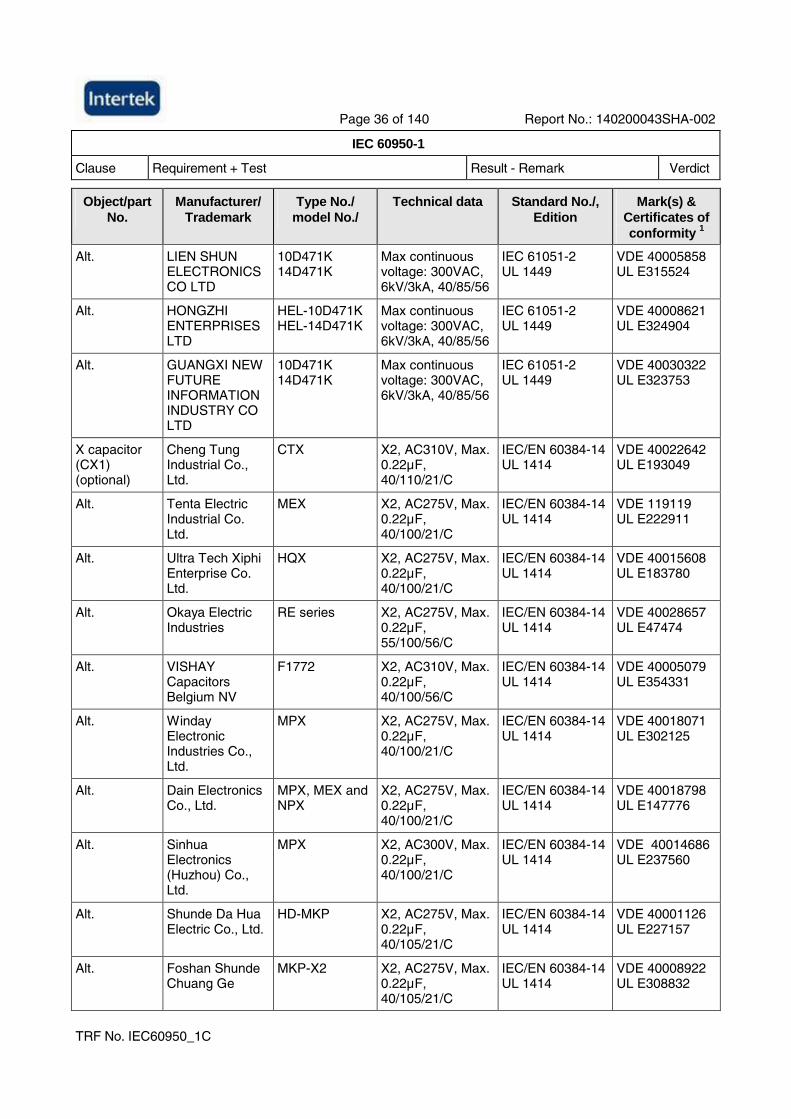
Page 36 of 140 Report No.: 140200043SHA-002
IEC 60950-1
Clause Requirement + Test Result - Remark Verdict
TRF No. IEC60950_1C
Object/part No.
Manufacturer/ Trademark
Type No./ model No./
Technical data Standard No./, Edition
Mark(s) & Certificates of conformity 1
Alt. LIEN SHUN ELECTRONICS CO LTD
10D471K 14D471K
Max continuous voltage: 300VAC, 6kV/3kA, 40/85/56
IEC 61051-2 UL 1449
VDE 40005858 UL E315524
Alt. HONGZHI ENTERPRISES LTD
HEL-10D471K HEL-14D471K
Max continuous voltage: 300VAC, 6kV/3kA, 40/85/56
IEC 61051-2 UL 1449
VDE 40008621 UL E324904
Alt. GUANGXI NEW FUTURE INFORMATION INDUSTRY CO LTD
10D471K 14D471K
Max continuous voltage: 300VAC, 6kV/3kA, 40/85/56
IEC 61051-2 UL 1449
VDE 40030322 UL E323753
X capacitor (CX1) (optional)
Cheng Tung Industrial Co., Ltd.
CTX X2, AC310V, Max. 0.22µF, 40/110/21/C
IEC/EN 60384-14 UL 1414
VDE 40022642 UL E193049
Alt. Tenta Electric Industrial Co. Ltd.
MEX X2, AC275V, Max. 0.22µF, 40/100/21/C
IEC/EN 60384-14 UL 1414
VDE 119119 UL E222911
Alt. Ultra Tech Xiphi Enterprise Co. Ltd.
HQX X2, AC275V, Max. 0.22µF, 40/100/21/C
IEC/EN 60384-14 UL 1414
VDE 40015608 UL E183780
Alt. Okaya Electric Industries
RE series X2, AC275V, Max. 0.22µF, 55/100/56/C
IEC/EN 60384-14 UL 1414
VDE 40028657 UL E47474
Alt. VISHAY Capacitors Belgium NV
F1772 X2, AC310V, Max. 0.22µF, 40/100/56/C
IEC/EN 60384-14 UL 1414
VDE 40005079 UL E354331
Alt. Winday Electronic Industries Co., Ltd.
MPX X2, AC275V, Max. 0.22µF, 40/100/21/C
IEC/EN 60384-14 UL 1414
VDE 40018071 UL E302125
Alt. Dain Electronics Co., Ltd.
MPX, MEX and NPX
X2, AC275V, Max. 0.22µF, 40/100/21/C
IEC/EN 60384-14 UL 1414
VDE 40018798 UL E147776
Alt. Sinhua Electronics (Huzhou) Co., Ltd.
MPX X2, AC300V, Max. 0.22µF, 40/100/21/C
IEC/EN 60384-14 UL 1414
VDE 40014686 UL E237560
Alt. Shunde Da Hua Electric Co., Ltd.
HD-MKP X2, AC275V, Max. 0.22µF, 40/105/21/C
IEC/EN 60384-14 UL 1414
VDE 40001126 UL E227157
Alt. Foshan Shunde Chuang Ge
MKP-X2 X2, AC275V, Max. 0.22µF, 40/105/21/C
IEC/EN 60384-14 UL 1414
VDE 40008922 UL E308832
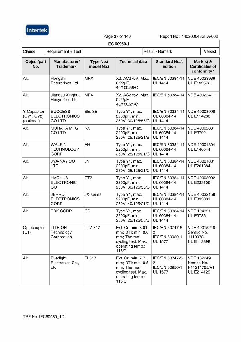
Page 37 of 140 Report No.: 140200043SHA-002
IEC 60950-1
Clause Requirement + Test Result - Remark Verdict
TRF No. IEC60950_1C
Object/part No.
Manufacturer/ Trademark
Type No./ model No./
Technical data Standard No./, Edition
Mark(s) & Certificates of conformity 1
Alt. Hongzhi Enterprises Ltd.
MPX X2, AC275V, Max. 0.22µF, 40/100/56/C
IEC/EN 60384-14 UL 1414
VDE 40023936 UL E192572
Alt. Jiangsu Xinghua Huayu Co., Ltd.
MPX X2, AC275V, Max. 0.22µF, 40/100/21/C
IEC/EN 60384-14 VDE 40022417
Y-Capacitor (CY1, CY2) (optional)
SUCCESS ELECTRONICS CO LTD
SE, SB Type Y1, max. 2200pF, min. 250V, 30/125/56/C
IEC/EN 60384-14 UL 60384-14 UL 1414
VDE 40008996 UL E114280
Alt. MURATA MFG CO LTD
KX Type Y1, max. 2200pF, min. 250V, 25/125/21/B
IEC/EN 60384-14 UL 60384-14 UL 1414
VDE 40002831 UL E37921
Alt. WALSIN TECHNOLOGY CORP
AH Type Y1, max. 2200pF, min. 250V, 25/125/21/C
IEC/EN 60384-14 UL 60384-14 UL 1414
VDE 40001804 UL E146544
Alt. JYA-NAY CO LTD
JN Type Y1, max. 2200pF, min. 250V, 25/125/21/C
IEC/EN 60384-14 UL 60384-14 UL 1414
VDE 40001831 UL E201384
Alt. HAOHUA ELECTRONIC CO
CT7 Type Y1, max. 2200pF, min. 250V, 30/125/56/C
IEC/EN 60384-14 UL 60384-14 UL 1414
VDE 40003902 UL E233106
Alt. JERRO ELECTRONICS CORP
JX-series Type Y1, max. 2200pF, min. 250V, 40/125/21/C
IEC/EN 60384-14 UL 60384-14 UL 1414
VDE 40032158 UL E333001
Alt. TDK CORP CD Type Y1, max. 2200pF, min. 250V, 25/125/56/B
IEC/EN 60384-14 UL 60384-14 UL 1414
VDE 124321 UL E37861
Optocoupler (U1)
LITE-ON Technology Corporation
LTV-817 Ext. Cr: min. 8.01 mm; DTI: min. 0.6 mm; Thermal cycling test. Max. operating temp.: 115°C
IEC/EN 60747-5-2 IEC/EN 60950-1 UL 1577
VDE 40015248 Semko No. 1119078 UL E113898
Alt. Everlight Electronics Co., Ltd.
EL817 Ext. Cr: min. 7.7 mm; DTI: min. 0.5 mm; Thermal cycling test. Max. operating temp.: 110°C
IEC/EN 60747-5-2 IEC/EN 60950-1 UL 1577
VDE 132249 Nemko No. P11214765/A1 UL E214129
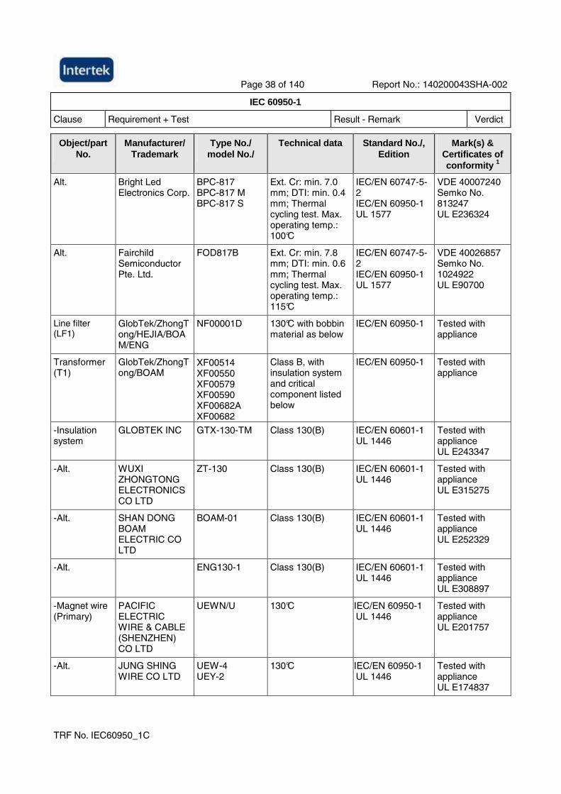
Page 38 of 140 Report No.: 140200043SHA-002
IEC 60950-1
Clause Requirement + Test Result - Remark Verdict
TRF No. IEC60950_1C
Object/part No.
Manufacturer/ Trademark
Type No./ model No./
Technical data Standard No./, Edition
Mark(s) & Certificates of conformity 1
Alt. Bright Led Electronics Corp.
BPC-817 BPC-817 M BPC-817 S
Ext. Cr: min. 7.0 mm; DTI: min. 0.4 mm; Thermal cycling test. Max. operating temp.: 100°C
IEC/EN 60747-5-2 IEC/EN 60950-1 UL 1577
VDE 40007240 Semko No. 813247 UL E236324
Alt. Fairchild Semiconductor Pte. Ltd.
FOD817B Ext. Cr: min. 7.8 mm; DTI: min. 0.6 mm; Thermal cycling test. Max. operating temp.: 115°C
IEC/EN 60747-5-2 IEC/EN 60950-1 UL 1577
VDE 40026857 Semko No. 1024922 UL E90700
Line filter (LF1)
GlobTek/ZhongTong/HEJIA/BOAM/ENG
NF00001D 130°C with bobbin material as below
IEC/EN 60950-1 Tested with appliance
Transformer (T1)
GlobTek/ZhongTong/BOAM
XF00514 XF00550 XF00579 XF00590 XF00682A XF00682
Class B, with insulation system and critical component listed below
IEC/EN 60950-1 Tested with appliance
-Insulation system
GLOBTEK INC GTX-130-TM Class 130(B) IEC/EN 60601-1 UL 1446
Tested with appliance UL E243347
-Alt. WUXI ZHONGTONG ELECTRONICS CO LTD
ZT-130 Class 130(B) IEC/EN 60601-1 UL 1446
Tested with appliance UL E315275
-Alt. SHAN DONG BOAM ELECTRIC CO LTD
BOAM-01 Class 130(B) IEC/EN 60601-1 UL 1446
Tested with appliance UL E252329
-Alt.
ENG130-1 Class 130(B) IEC/EN 60601-1 UL 1446
Tested with appliance UL E308897
-Magnet wire (Primary)
PACIFIC ELECTRIC WIRE & CABLE (SHENZHEN) CO LTD
UEWN/U 130°C IEC/EN 60950-1 UL 1446
Tested with appliance UL E201757
-Alt. JUNG SHING WIRE CO LTD
UEW-4 UEY-2
130°C IEC/EN 60950-1 UL 1446
Tested with appliance UL E174837
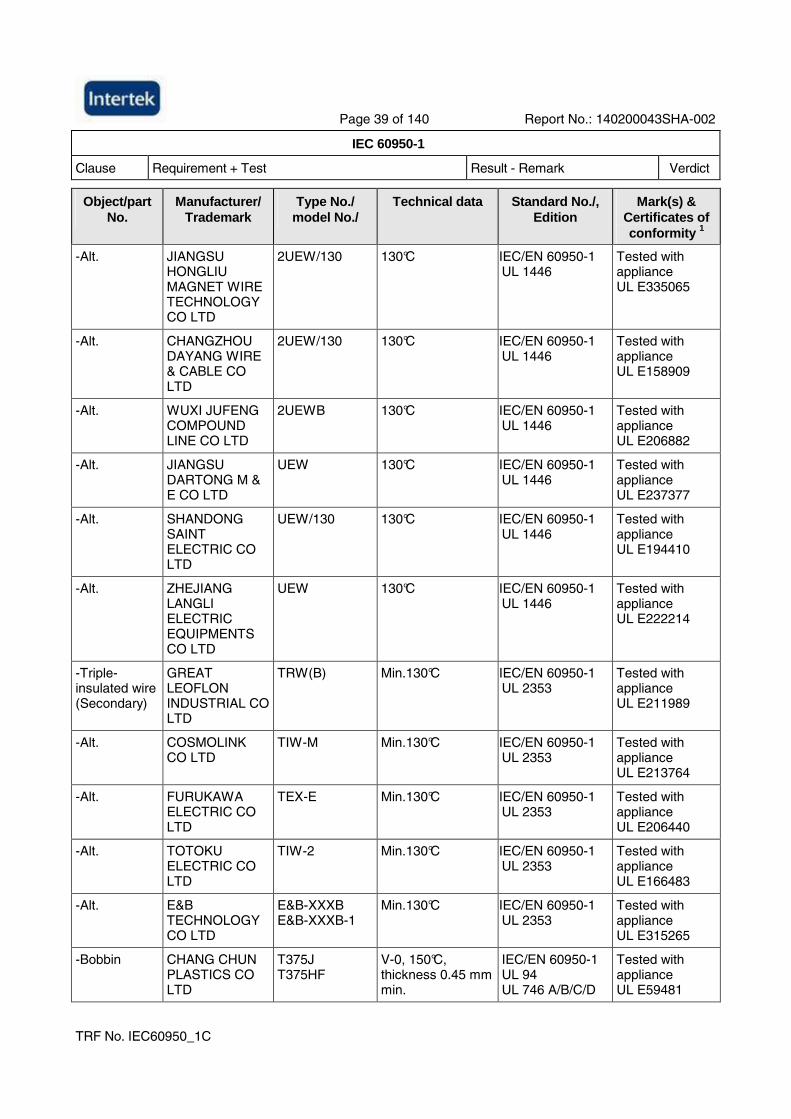
Page 39 of 140 Report No.: 140200043SHA-002
IEC 60950-1
Clause Requirement + Test Result - Remark Verdict
TRF No. IEC60950_1C
Object/part No.
Manufacturer/ Trademark
Type No./ model No./
Technical data Standard No./, Edition
Mark(s) & Certificates of conformity 1
-Alt. JIANGSU HONGLIU MAGNET WIRE TECHNOLOGY CO LTD
2UEW/130 130°C IEC/EN 60950-1 UL 1446
Tested with appliance UL E335065
-Alt. CHANGZHOU DAYANG WIRE & CABLE CO LTD
2UEW/130 130°C IEC/EN 60950-1 UL 1446
Tested with appliance UL E158909
-Alt. WUXI JUFENG COMPOUND LINE CO LTD
2UEWB 130°C IEC/EN 60950-1 UL 1446
Tested with appliance UL E206882
-Alt. JIANGSU DARTONG M & E CO LTD
UEW 130°C IEC/EN 60950-1 UL 1446
Tested with appliance UL E237377
-Alt. SHANDONG SAINT ELECTRIC CO LTD
UEW/130 130°C IEC/EN 60950-1 UL 1446
Tested with appliance UL E194410
-Alt. ZHEJIANG LANGLI ELECTRIC EQUIPMENTS CO LTD
UEW 130°C IEC/EN 60950-1 UL 1446
Tested with appliance UL E222214
-Triple-insulated wire (Secondary)
GREAT LEOFLON INDUSTRIAL CO LTD
TRW(B) Min.130°C IEC/EN 60950-1 UL 2353
Tested with appliance UL E211989
-Alt. COSMOLINK CO LTD
TIW-M Min.130°C IEC/EN 60950-1 UL 2353
Tested with appliance UL E213764
-Alt. FURUKAWA ELECTRIC CO LTD
TEX-E Min.130°C IEC/EN 60950-1 UL 2353
Tested with appliance UL E206440
-Alt. TOTOKU ELECTRIC CO LTD
TIW-2 Min.130°C IEC/EN 60950-1 UL 2353
Tested with appliance UL E166483
-Alt. E&B TECHNOLOGY CO LTD
E&B-XXXB E&B-XXXB-1
Min.130°C IEC/EN 60950-1 UL 2353
Tested with appliance UL E315265
-Bobbin CHANG CHUN PLASTICS CO LTD
T375J T375HF
V-0, 150°C, thickness 0.45 mm min.
IEC/EN 60950-1 UL 94 UL 746 A/B/C/D
Tested with appliance UL E59481
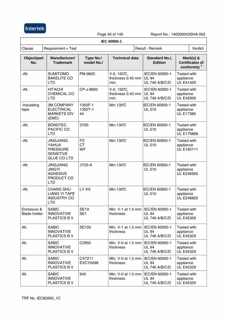
Page 40 of 140 Report No.: 140200043SHA-002
IEC 60950-1
Clause Requirement + Test Result - Remark Verdict
TRF No. IEC60950_1C
Object/part No.
Manufacturer/ Trademark
Type No./ model No./
Technical data Standard No./, Edition
Mark(s) & Certificates of conformity 1
-Alt. SUMITOMO BAKELITE CO LTD
PM-9820 V-0, 150°C, thickness 0.45 mm min.
IEC/EN 60950-1 UL 94 UL 746 A/B/C/D
Tested with appliance UL E41429
-Alt. HITACHI CHEMICAL CO LTD
CP-J-8800 V-0, 150°C, thickness 0.45 mm min.
IEC/EN 60950-1 UL 94 UL 746 A/B/C/D
Tested with appliance UL E42956
-Insulating tape
3M COMPANY ELECTRICAL MARKETS DIV (EMD)
1350F-1 1350T-1 44
Min.130°C IEC/EN 60950-1 UL 510
Tested with appliance UL E17385
-Alt. BONDTEC PACIFIC CO LTD
370S Min.130°C IEC/EN 60950-1 UL 510
Tested with appliance UL E175868
-Alt. JINGJIANG YAHUA PRESSURE SENSITIVE GLUE CO LTD
PZ CT WF
Min.130°C IEC/EN 60950-1 UL 510
Tested with appliance UL E165111
-Alt. JINGJIANG JINGYI ADHESIVE PRODUCT CO LTD
JY25-A Min.130°C IEC/EN 60950-1 UL 510
Tested with appliance UL E246950
-Alt. CHANG SHU LIANG YI TAPE INDUSTRY CO LTD
LY-XX Min.130°C IEC/EN 60950-1 UL 510
Tested with appliance UL E246820
Enclosure & Blade holder
SABIC INNOVATIVE PLASTICS B V
SE1X SE1
Min. V-1 at 1.5 mm thickness
IEC/EN 60950-1 UL 94 UL 746 A/B/C/D
Tested with appliance UL E45329
Alt. SABIC INNOVATIVE PLASTICS B V
SE100 Min. V-1 at 1.5 mm thickness
IEC/EN 60950-1 UL 94 UL 746 A/B/C/D
Tested with appliance UL E45329
Alt. SABIC INNOVATIVE PLASTICS B V
C2950 Min. V-0 at 1.5 mm thickness
IEC/EN 60950-1 UL 94 UL 746 A/B/C/D
Tested with appliance UL E45329
Alt. SABIC INNOVATIVE PLASTICS B V
CX7211 EXCY0098
Min. V-0 at 1.5 mm thickness
IEC/EN 60950-1 UL 94 UL 746 A/B/C/D
Tested with appliance UL E45329
Alt. SABIC INNOVATIVE PLASTICS B V
940 Min. V-0 at 1.5 mm thickness
IEC/EN 60950-1 UL 94 UL 746 A/B/C/D
Tested with appliance UL E45329
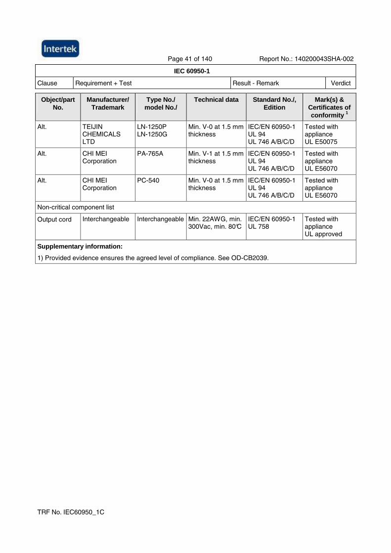
Page 41 of 140 Report No.: 140200043SHA-002
IEC 60950-1
Clause Requirement + Test Result - Remark Verdict
TRF No. IEC60950_1C
Object/part No.
Manufacturer/ Trademark
Type No./ model No./
Technical data Standard No./, Edition
Mark(s) & Certificates of conformity 1
Alt. TEIJIN CHEMICALS LTD
LN-1250P LN-1250G
Min. V-0 at 1.5 mm thickness
IEC/EN 60950-1 UL 94 UL 746 A/B/C/D
Tested with appliance UL E50075
Alt. CHI MEI Corporation
PA-765A Min. V-1 at 1.5 mm thickness
IEC/EN 60950-1 UL 94 UL 746 A/B/C/D
Tested with appliance UL E56070
Alt. CHI MEI Corporation
PC-540 Min. V-0 at 1.5 mm thickness
IEC/EN 60950-1 UL 94 UL 746 A/B/C/D
Tested with appliance UL E56070
Non-critical component list
Output cord Interchangeable Interchangeable Min. 22AWG, min. 300Vac, min. 80°C
IEC/EN 60950-1 UL 758
Tested with appliance UL approved
Supplementary information:
1) Provided evidence ensures the agreed level of compliance. See OD-CB2039.
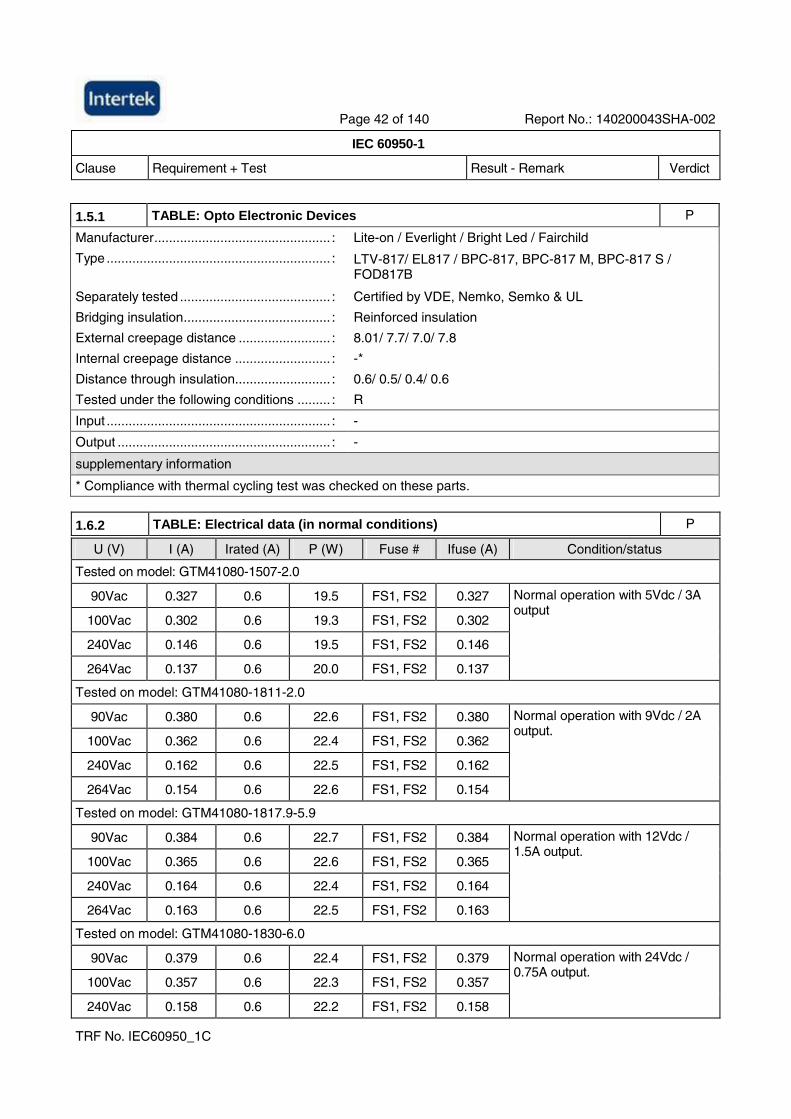
Page 42 of 140 Report No.: 140200043SHA-002
IEC 60950-1
Clause Requirement + Test Result - Remark Verdict
TRF No. IEC60950_1C
1.5.1 TABLE: Opto Electronic Devices P
Manufacturer................................................ : Lite-on / Everlight / Bright Led / Fairchild
Type ............................................................. : LTV-817/ EL817 / BPC-817, BPC-817 M, BPC-817 S / FOD817B
Separately tested ......................................... : Certified by VDE, Nemko, Semko & UL
Bridging insulation........................................ : Reinforced insulation
External creepage distance ......................... : 8.01/ 7.7/ 7.0/ 7.8
Internal creepage distance .......................... : -*
Distance through insulation.......................... : 0.6/ 0.5/ 0.4/ 0.6
Tested under the following conditions ......... : R
Input ............................................................. : -
Output .......................................................... : -
supplementary information
* Compliance with thermal cycling test was checked on these parts.
1.6.2 TABLE: Electrical data (in normal conditions) P
U (V) I (A) Irated (A) P (W) Fuse # Ifuse (A) Condition/status
Tested on model: GTM41080-1507-2.0
90Vac 0.327 0.6 19.5 FS1, FS2 0.327
100Vac 0.302 0.6 19.3 FS1, FS2 0.302
240Vac 0.146 0.6 19.5 FS1, FS2 0.146
264Vac 0.137 0.6 20.0 FS1, FS2 0.137
Normal operation with 5Vdc / 3A output
Tested on model: GTM41080-1811-2.0
90Vac 0.380 0.6 22.6 FS1, FS2 0.380
100Vac 0.362 0.6 22.4 FS1, FS2 0.362
240Vac 0.162 0.6 22.5 FS1, FS2 0.162
264Vac 0.154 0.6 22.6 FS1, FS2 0.154
Normal operation with 9Vdc / 2A output.
Tested on model: GTM41080-1817.9-5.9
90Vac 0.384 0.6 22.7 FS1, FS2 0.384
100Vac 0.365 0.6 22.6 FS1, FS2 0.365
240Vac 0.164 0.6 22.4 FS1, FS2 0.164
264Vac 0.163 0.6 22.5 FS1, FS2 0.163
Normal operation with 12Vdc / 1.5A output.
Tested on model: GTM41080-1830-6.0
90Vac 0.379 0.6 22.4 FS1, FS2 0.379
100Vac 0.357 0.6 22.3 FS1, FS2 0.357
240Vac 0.158 0.6 22.2 FS1, FS2 0.158
Normal operation with 24Vdc / 0.75A output.
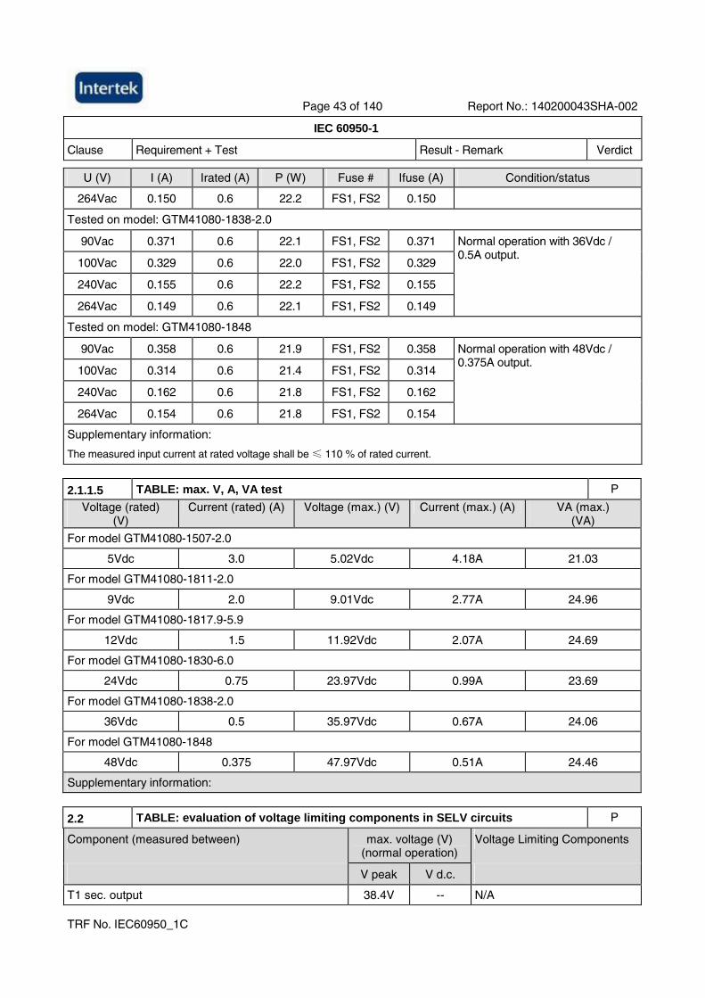
Page 43 of 140 Report No.: 140200043SHA-002
IEC 60950-1
Clause Requirement + Test Result - Remark Verdict
TRF No. IEC60950_1C
U (V) I (A) Irated (A) P (W) Fuse # Ifuse (A) Condition/status
264Vac 0.150 0.6 22.2 FS1, FS2 0.150
Tested on model: GTM41080-1838-2.0
90Vac 0.371 0.6 22.1 FS1, FS2 0.371
100Vac 0.329 0.6 22.0 FS1, FS2 0.329
240Vac 0.155 0.6 22.2 FS1, FS2 0.155
264Vac 0.149 0.6 22.1 FS1, FS2 0.149
Normal operation with 36Vdc / 0.5A output.
Tested on model: GTM41080-1848
90Vac 0.358 0.6 21.9 FS1, FS2 0.358
100Vac 0.314 0.6 21.4 FS1, FS2 0.314
240Vac 0.162 0.6 21.8 FS1, FS2 0.162
264Vac 0.154 0.6 21.8 FS1, FS2 0.154
Normal operation with 48Vdc / 0.375A output.
Supplementary information:
The measured input current at rated voltage shall be ≤ 110 % of rated current.
2.1.1.5 TABLE: max. V, A, VA test P
Voltage (rated) (V)
Current (rated) (A) Voltage (max.) (V) Current (max.) (A) VA (max.) (VA)
For model GTM41080-1507-2.0
5Vdc 3.0 5.02Vdc 4.18A 21.03
For model GTM41080-1811-2.0
9Vdc 2.0 9.01Vdc 2.77A 24.96
For model GTM41080-1817.9-5.9
12Vdc 1.5 11.92Vdc 2.07A 24.69
For model GTM41080-1830-6.0
24Vdc 0.75 23.97Vdc 0.99A 23.69
For model GTM41080-1838-2.0
36Vdc 0.5 35.97Vdc 0.67A 24.06
For model GTM41080-1848
48Vdc 0.375 47.97Vdc 0.51A 24.46
Supplementary information:
2.2 TABLE: evaluation of voltage limiting components in SELV circuits P
Component (measured between) max. voltage (V) (normal operation)
Voltage Limiting Components
V peak V d.c.
T1 sec. output 38.4V -- N/A
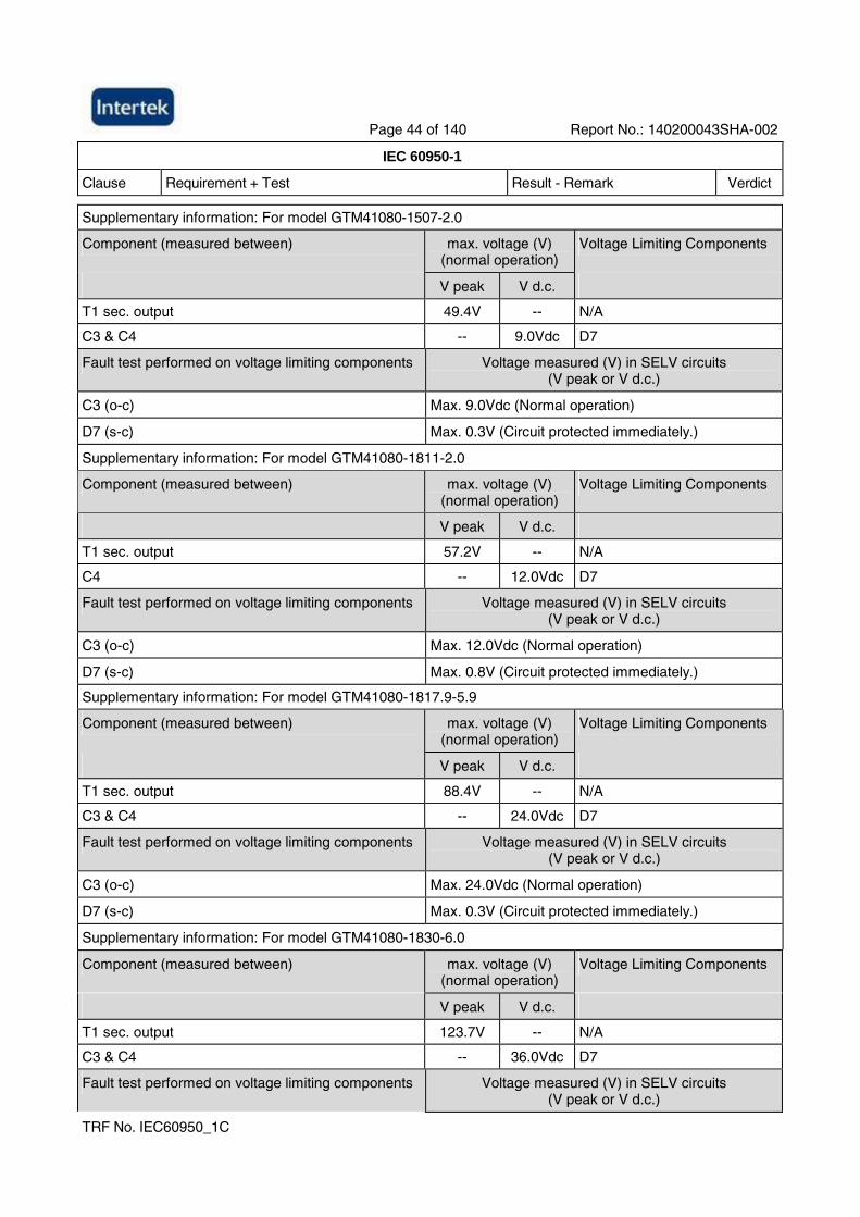
Page 44 of 140 Report No.: 140200043SHA-002
IEC 60950-1
Clause Requirement + Test Result - Remark Verdict
TRF No. IEC60950_1C
Supplementary information: For model GTM41080-1507-2.0
Component (measured between) max. voltage (V) (normal operation)
Voltage Limiting Components
V peak V d.c.
T1 sec. output 49.4V -- N/A
C3 & C4 -- 9.0Vdc D7
Fault test performed on voltage limiting components Voltage measured (V) in SELV circuits (V peak or V d.c.)
C3 (o-c) Max. 9.0Vdc (Normal operation)
D7 (s-c) Max. 0.3V (Circuit protected immediately.)
Supplementary information: For model GTM41080-1811-2.0
Component (measured between) max. voltage (V) (normal operation)
Voltage Limiting Components
V peak V d.c.
T1 sec. output 57.2V -- N/A
C4 -- 12.0Vdc D7
Fault test performed on voltage limiting components Voltage measured (V) in SELV circuits (V peak or V d.c.)
C3 (o-c) Max. 12.0Vdc (Normal operation)
D7 (s-c) Max. 0.8V (Circuit protected immediately.)
Supplementary information: For model GTM41080-1817.9-5.9
Component (measured between) max. voltage (V) (normal operation)
Voltage Limiting Components
V peak V d.c.
T1 sec. output 88.4V -- N/A
C3 & C4 -- 24.0Vdc D7
Fault test performed on voltage limiting components Voltage measured (V) in SELV circuits (V peak or V d.c.)
C3 (o-c) Max. 24.0Vdc (Normal operation)
D7 (s-c) Max. 0.3V (Circuit protected immediately.)
Supplementary information: For model GTM41080-1830-6.0
Component (measured between) max. voltage (V) (normal operation)
Voltage Limiting Components
V peak V d.c.
T1 sec. output 123.7V -- N/A
C3 & C4 -- 36.0Vdc D7
Fault test performed on voltage limiting components Voltage measured (V) in SELV circuits (V peak or V d.c.)
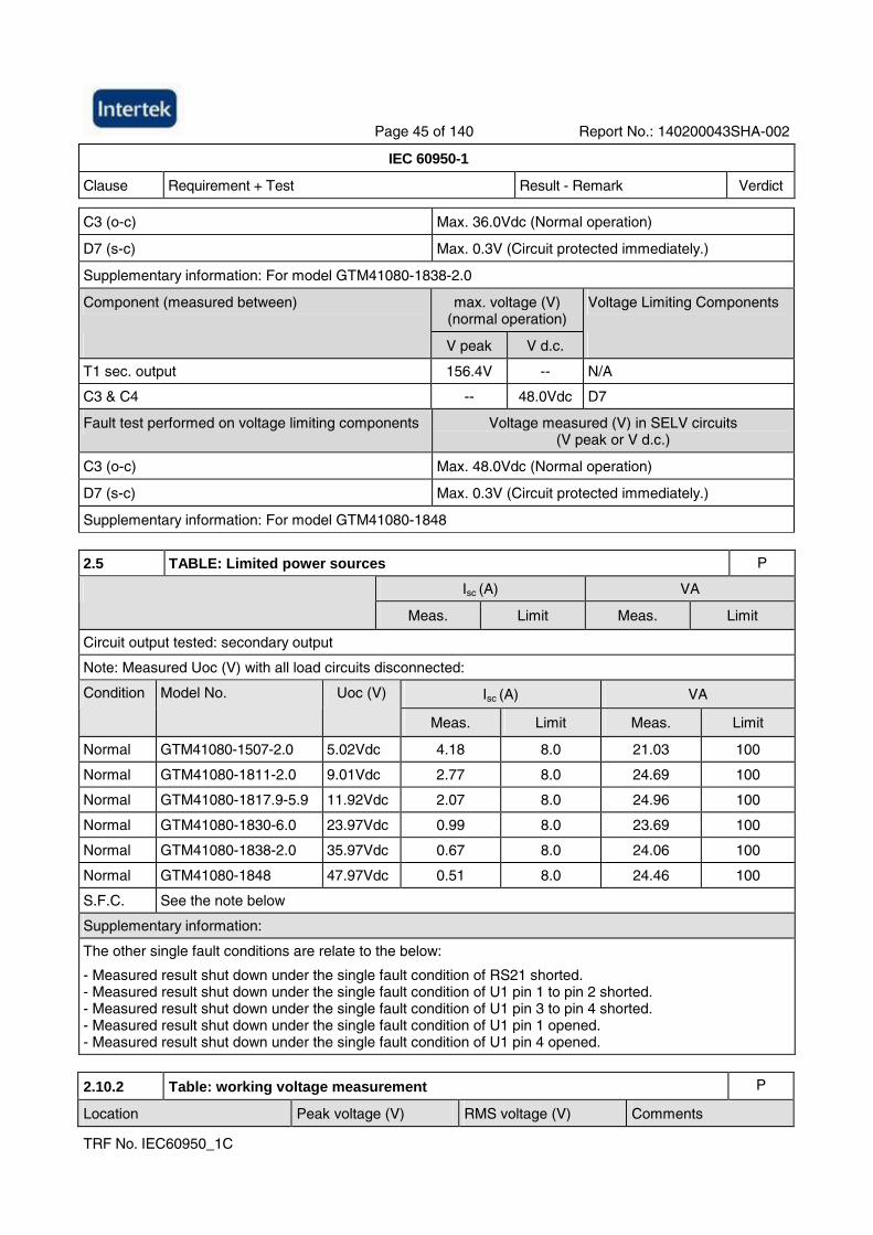
Page 45 of 140 Report No.: 140200043SHA-002
IEC 60950-1
Clause Requirement + Test Result - Remark Verdict
TRF No. IEC60950_1C
C3 (o-c) Max. 36.0Vdc (Normal operation)
D7 (s-c) Max. 0.3V (Circuit protected immediately.)
Supplementary information: For model GTM41080-1838-2.0
Component (measured between) max. voltage (V) (normal operation)
Voltage Limiting Components
V peak V d.c.
T1 sec. output 156.4V -- N/A
C3 & C4 -- 48.0Vdc D7
Fault test performed on voltage limiting components Voltage measured (V) in SELV circuits (V peak or V d.c.)
C3 (o-c) Max. 48.0Vdc (Normal operation)
D7 (s-c) Max. 0.3V (Circuit protected immediately.)
Supplementary information: For model GTM41080-1848
2.5 TABLE: Limited power sources P
Isc (A) VA
Meas. Limit Meas. Limit
Circuit output tested: secondary output
Note: Measured Uoc (V) with all load circuits disconnected:
Isc (A) VA Condition Model No. Uoc (V)
Meas. Limit Meas. Limit
Normal GTM41080-1507-2.0 5.02Vdc 4.18 8.0 21.03 100
Normal GTM41080-1811-2.0 9.01Vdc 2.77 8.0 24.69 100
Normal GTM41080-1817.9-5.9 11.92Vdc 2.07 8.0 24.96 100
Normal GTM41080-1830-6.0 23.97Vdc 0.99 8.0 23.69 100
Normal GTM41080-1838-2.0 35.97Vdc 0.67 8.0 24.06 100
Normal GTM41080-1848 47.97Vdc 0.51 8.0 24.46 100
S.F.C. See the note below
Supplementary information:
The other single fault conditions are relate to the below:
- Measured result shut down under the single fault condition of RS21 shorted. - Measured result shut down under the single fault condition of U1 pin 1 to pin 2 shorted. - Measured result shut down under the single fault condition of U1 pin 3 to pin 4 shorted. - Measured result shut down under the single fault condition of U1 pin 1 opened. - Measured result shut down under the single fault condition of U1 pin 4 opened.
2.10.2 Table: working voltage measurement P
Location Peak voltage (V) RMS voltage (V) Comments
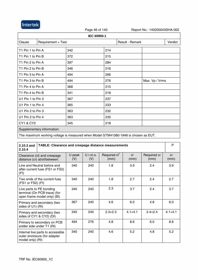
Page 46 of 140 Report No.: 140200043SHA-002
IEC 60950-1
Clause Requirement + Test Result - Remark Verdict
TRF No. IEC60950_1C
T1 Pin 1 to Pin A 342 214
T1 Pin 1 to Pin B 372 215
T1 Pin 2 to Pin A 397 284
T1 Pin 2 to Pin B 346 216
T1 Pin 3 to Pin A 494 266
T1 Pin 3 to Pin B 494 276 Max. Vp / Vrms
T1 Pin 4 to Pin A 368 215
T1 Pin 4 to Pin B 341 218
U1 Pin 1 to Pin 3 367 237
U1 Pin 1 to Pin 4 365 233
U1 Pin 2 to Pin 3 363 232
U1 Pin 2 to Pin 4 363 235
CY1 & CY2 345 218
Supplementary information:
The maximum working voltage is measured when Model GTM41080-1848 is chosen as EUT.
2.10.3 and 2.10.4
TABLE: Clearance and creepage distance measurements P
Clearance (cl) and creepage distance (cr) at/of/between:
U peak (V)
U r.m.s. (V)
Required cl1 (mm)
cl (mm)
Required cr (mm)
cr (mm)
Line and Neutral before and after current fuse (FS1 or FS2) (FI)
340 240 1.8 3.9 2.4 3.9
Two ends of the current fuse (FS1 or FS2) (FI)
340 240 1.8 2.7 2.4 2.7
Live parts to PE bonding terminal (On PCB trace) (for open frame model only) (BI)
340 240 2.3 3.7 2.4 3.7
Primary and secondary (two sides of U1) (RI)
367 240 4.6 6.0 4.8 6.0
Primary and secondary (two sides of CY1 & CY2) (DI)
345 240 2.3+2.3 4.1+4.1 2.4+2.4 4.1+4.1
Primary to secondary on PCB solder side under T1 (RI)
494 276 4.8 8.6 6.0 8.6
Internal live parts to accessible outer enclosure (for adapter model only) (RI)
340 240 4.6 5.2 4.8 5.2
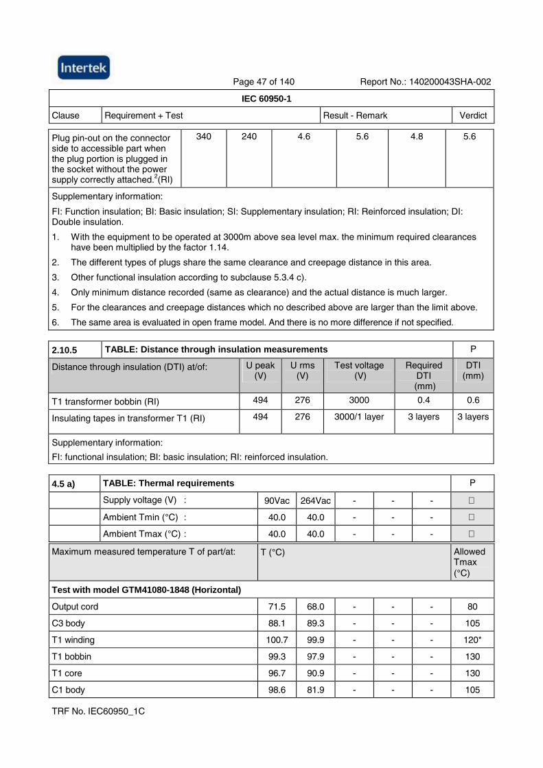
Page 47 of 140 Report No.: 140200043SHA-002
IEC 60950-1
Clause Requirement + Test Result - Remark Verdict
TRF No. IEC60950_1C
Plug pin-out on the connector side to accessible part when the plug portion is plugged in the socket without the power supply correctly attached.2(RI)
340 240 4.6 5.6 4.8 5.6
Supplementary information:
FI: Function insulation; BI: Basic insulation; SI: Supplementary insulation; RI: Reinforced insulation; DI: Double insulation.
1. With the equipment to be operated at 3000m above sea level max. the minimum required clearances have been multiplied by the factor 1.14.
2. The different types of plugs share the same clearance and creepage distance in this area.
3. Other functional insulation according to subclause 5.3.4 c).
4. Only minimum distance recorded (same as clearance) and the actual distance is much larger.
5. For the clearances and creepage distances which no described above are larger than the limit above.
6. The same area is evaluated in open frame model. And there is no more difference if not specified.
2.10.5 TABLE: Distance through insulation measurements P
Distance through insulation (DTI) at/of: U peak (V)
U rms (V)
Test voltage (V)
Required DTI
(mm)
DTI (mm)
T1 transformer bobbin (RI) 494 276 3000 0.4 0.6
Insulating tapes in transformer T1 (RI) 494 276 3000/1 layer 3 layers 3 layers
Supplementary information:
FI: functional insulation; BI: basic insulation; RI: reinforced insulation.
4.5 a) TABLE: Thermal requirements P
Supply voltage (V) : 90Vac 264Vac - - -
Ambient Tmin (°C) : 40.0 40.0 - - -
Ambient Tmax (°C) : 40.0 40.0 - - -
Maximum measured temperature T of part/at: T (°C) Allowed Tmax (°C)
Test with model GTM41080-1848 (Horizontal)
Output cord 71.5 68.0 - - - 80
C3 body 88.1 89.3 - - - 105
T1 winding 100.7 99.9 - - - 120*
T1 bobbin 99.3 97.9 - - - 130
T1 core 96.7 90.9 - - - 130
C1 body 98.6 81.9 - - - 105
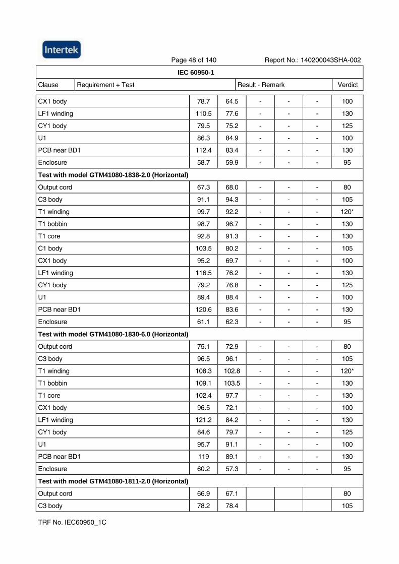
Page 48 of 140 Report No.: 140200043SHA-002
IEC 60950-1
Clause Requirement + Test Result - Remark Verdict
TRF No. IEC60950_1C
CX1 body 78.7 64.5 - - - 100
LF1 winding 110.5 77.6 - - - 130
CY1 body 79.5 75.2 - - - 125
U1 86.3 84.9 - - - 100
PCB near BD1 112.4 83.4 - - - 130
Enclosure 58.7 59.9 - - - 95
Test with model GTM41080-1838-2.0 (Horizontal)
Output cord 67.3 68.0 - - - 80
C3 body 91.1 94.3 - - - 105
T1 winding 99.7 92.2 - - - 120*
T1 bobbin 98.7 96.7 - - - 130
T1 core 92.8 91.3 - - - 130
C1 body 103.5 80.2 - - - 105
CX1 body 95.2 69.7 - - - 100
LF1 winding 116.5 76.2 - - - 130
CY1 body 79.2 76.8 - - - 125
U1 89.4 88.4 - - - 100
PCB near BD1 120.6 83.6 - - - 130
Enclosure 61.1 62.3 - - - 95
Test with model GTM41080-1830-6.0 (Horizontal)
Output cord 75.1 72.9 - - - 80
C3 body 96.5 96.1 - - - 105
T1 winding 108.3 102.8 - - - 120*
T1 bobbin 109.1 103.5 - - - 130
T1 core 102.4 97.7 - - - 130
CX1 body 96.5 72.1 - - - 100
LF1 winding 121.2 84.2 - - - 130
CY1 body 84.6 79.7 - - - 125
U1 95.7 91.1 - - - 100
PCB near BD1 119 89.1 - - - 130
Enclosure 60.2 57.3 - - - 95
Test with model GTM41080-1811-2.0 (Horizontal)
Output cord 66.9 67.1 80
C3 body 78.2 78.4 105
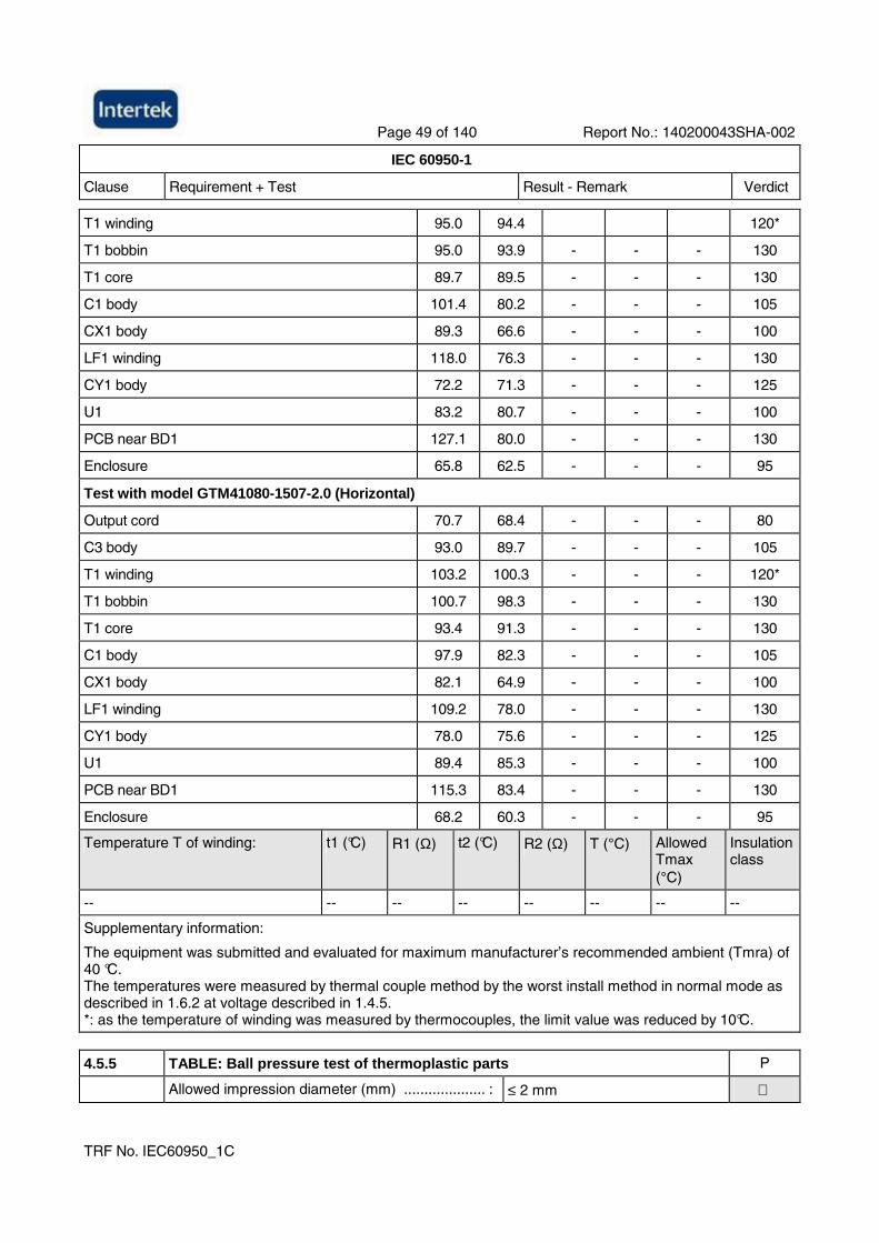
Page 49 of 140 Report No.: 140200043SHA-002
IEC 60950-1
Clause Requirement + Test Result - Remark Verdict
TRF No. IEC60950_1C
T1 winding 95.0 94.4 120*
T1 bobbin 95.0 93.9 - - - 130
T1 core 89.7 89.5 - - - 130
C1 body 101.4 80.2 - - - 105
CX1 body 89.3 66.6 - - - 100
LF1 winding 118.0 76.3 - - - 130
CY1 body 72.2 71.3 - - - 125
U1 83.2 80.7 - - - 100
PCB near BD1 127.1 80.0 - - - 130
Enclosure 65.8 62.5 - - - 95
Test with model GTM41080-1507-2.0 (Horizontal)
Output cord 70.7 68.4 - - - 80
C3 body 93.0 89.7 - - - 105
T1 winding 103.2 100.3 - - - 120*
T1 bobbin 100.7 98.3 - - - 130
T1 core 93.4 91.3 - - - 130
C1 body 97.9 82.3 - - - 105
CX1 body 82.1 64.9 - - - 100
LF1 winding 109.2 78.0 - - - 130
CY1 body 78.0 75.6 - - - 125
U1 89.4 85.3 - - - 100
PCB near BD1 115.3 83.4 - - - 130
Enclosure 68.2 60.3 - - - 95
Temperature T of winding: t1 (°C) R1 (Ω) t2 (°C) R2 (Ω) T (°C) Allowed Tmax (°C)
Insulation class
-- -- -- -- -- -- -- --
Supplementary information:
The equipment was submitted and evaluated for maximum manufacturer’s recommended ambient (Tmra) of 40 °C. The temperatures were measured by thermal couple method by the worst install method in normal mode as described in 1.6.2 at voltage described in 1.4.5. *: as the temperature of winding was measured by thermocouples, the limit value was reduced by 10°C.
4.5.5 TABLE: Ball pressure test of thermoplastic parts P
Allowed impression diameter (mm) .................... : ≤ 2 mm
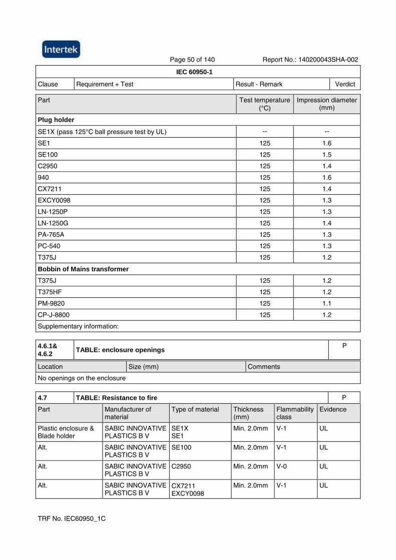
Page 50 of 140 Report No.: 140200043SHA-002
IEC 60950-1
Clause Requirement + Test Result - Remark Verdict
TRF No. IEC60950_1C
Part Test temperature (°C)
Impression diameter (mm)
Plug holder
SE1X (pass 125°C ball pressure test by UL) -- --
SE1 125 1.6
SE100 125 1.5
C2950 125 1.4
940 125 1.6
CX7211 125 1.4
EXCY0098 125 1.3
LN-1250P 125 1.3
LN-1250G 125 1.4
PA-765A 125 1.3
PC-540 125 1.3
T375J 125 1.2
Bobbin of Mains transformer
T375J 125 1.2
T375HF 125 1.2
PM-9820 125 1.1
CP-J-8800 125 1.2
Supplementary information:
4.6.1& 4.6.2
TABLE: enclosure openings P
Location Size (mm) Comments
No openings on the enclosure
4.7 TABLE: Resistance to fire P
Part Manufacturer of material
Type of material Thickness (mm)
Flammability class
Evidence
Plastic enclosure & Blade holder
SABIC INNOVATIVE PLASTICS B V
SE1X SE1
Min. 2.0mm V-1 UL
Alt. SABIC INNOVATIVE PLASTICS B V
SE100 Min. 2.0mm V-1 UL
Alt. SABIC INNOVATIVE PLASTICS B V
C2950 Min. 2.0mm V-0 UL
Alt. SABIC INNOVATIVE PLASTICS B V
CX7211 EXCY0098
Min. 2.0mm V-1 UL
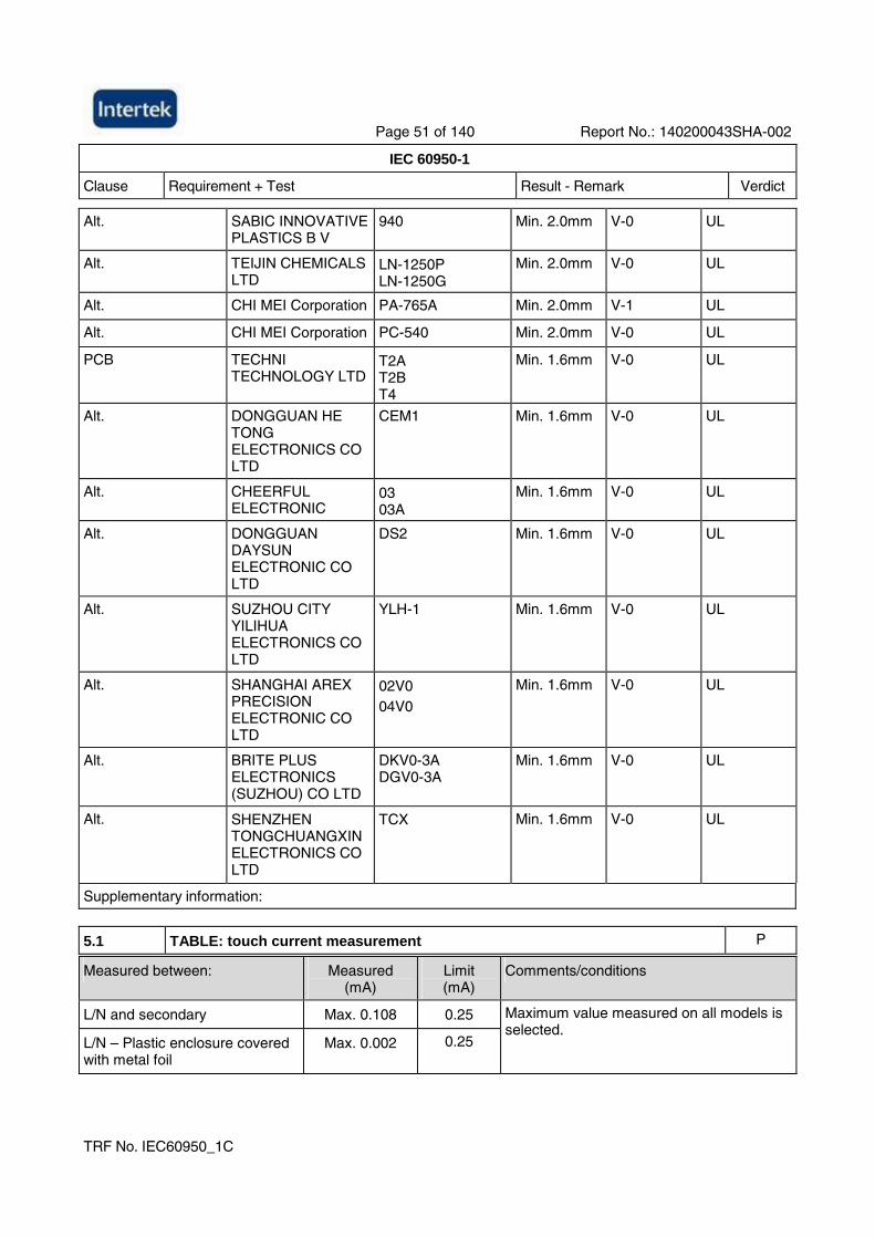
Page 51 of 140 Report No.: 140200043SHA-002
IEC 60950-1
Clause Requirement + Test Result - Remark Verdict
TRF No. IEC60950_1C
Alt. SABIC INNOVATIVE PLASTICS B V
940 Min. 2.0mm V-0 UL
Alt. TEIJIN CHEMICALS LTD
LN-1250P LN-1250G
Min. 2.0mm V-0 UL
Alt. CHI MEI Corporation PA-765A Min. 2.0mm V-1 UL
Alt. CHI MEI Corporation PC-540 Min. 2.0mm V-0 UL
PCB TECHNI TECHNOLOGY LTD
T2A T2B T4
Min. 1.6mm V-0 UL
Alt. DONGGUAN HE TONG ELECTRONICS CO LTD
CEM1 Min. 1.6mm V-0 UL
Alt. CHEERFUL ELECTRONIC
03 03A
Min. 1.6mm V-0 UL
Alt. DONGGUAN DAYSUN ELECTRONIC CO LTD
DS2 Min. 1.6mm V-0 UL
Alt. SUZHOU CITY YILIHUA ELECTRONICS CO LTD
YLH-1 Min. 1.6mm V-0 UL
Alt. SHANGHAI AREX PRECISION ELECTRONIC CO LTD
02V0 04V0
Min. 1.6mm V-0 UL
Alt. BRITE PLUS ELECTRONICS (SUZHOU) CO LTD
DKV0-3A DGV0-3A
Min. 1.6mm V-0 UL
Alt. SHENZHEN TONGCHUANGXIN ELECTRONICS CO LTD
TCX Min. 1.6mm V-0 UL
Supplementary information:
5.1 TABLE: touch current measurement P Measured between: Measured
(mA) Limit (mA)
Comments/conditions
L/N and secondary Max. 0.108 0.25
L/N – Plastic enclosure covered with metal foil
Max. 0.002 0.25
Maximum value measured on all models is selected.
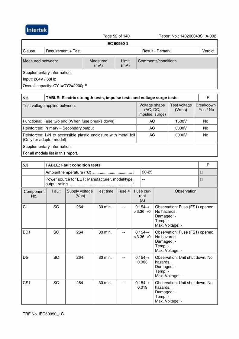
Page 52 of 140 Report No.: 140200043SHA-002
IEC 60950-1
Clause Requirement + Test Result - Remark Verdict
TRF No. IEC60950_1C
Measured between: Measured (mA)
Limit (mA)
Comments/conditions
Supplementary information:
Input: 264V / 60Hz
Overall capacity: CY1=CY2=2200pF
5.2 TABLE: Electric strength tests, impulse tests and voltage surge tests P
Test voltage applied between: Voltage shape (AC, DC,
impulse, surge)
Test voltage (Vrms)
Breakdown Yes / No
Functional: Fuse two end (When fuse breaks down) AC 1500V No
Reinforced: Primary – Secondary output AC 3000V No
Reinforced: L/N to accessible plastic enclosure with metal foil (Only for adapter model)
AC 3000V No
Supplementary information:
For all models list in this report.
5.3 TABLE: Fault condition tests P
Ambient temperature (°C) ................................... : 20-25
Power source for EUT: Manufacturer, model/type, output rating ........................................................ :
--
Component No.
Fault Supply voltage (Vac)
Test time Fuse # Fuse cur-rent (A)
Observation
C1 SC 264 30 min. -- 0.154→ >3.36→0
Observation: Fuse (FS1) opened. No hazards. Damaged: - Temp: - Max. Voltage: -
BD1 SC 264 30 min. -- 0.154→ >3.36→0
Observation: Fuse (FS1) opened. No hazards. Damaged: - Temp: - Max. Voltage: -
D5 SC 264 30 min. -- 0.154→ 0.003
Observation: Unit shut down. No hazards. Damaged: - Temp: - Max. Voltage: -
CS1 SC 264 30 min. -- 0.154→ 0.019
Observation: Unit shut down. No hazards. Damaged: - Temp: - Max. Voltage: -
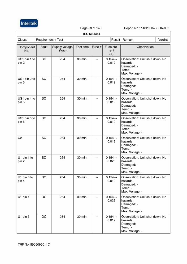
Page 53 of 140 Report No.: 140200043SHA-002
IEC 60950-1
Clause Requirement + Test Result - Remark Verdict
TRF No. IEC60950_1C
Component No.
Fault Supply voltage (Vac)
Test time Fuse # Fuse cur-rent (A)
Observation
US1 pin 1 to pin 2
SC 264 30 min. -- 0.154→ 0.019
Observation: Unit shut down. No hazards. Damaged: - Temp: - Max. Voltage: -
US1 pin 2 to pin 3
SC 264 30 min. -- 0.154→ 0.019
Observation: Unit shut down. No hazards. Damaged: - Temp: - Max. Voltage: -
US1 pin 4 to pin 5
SC 264 30 min. -- 0.154→ 0.019
Observation: Unit shut down. No hazards. Damaged: - Temp: - Max. Voltage: -
US1 pin 5 to pin 6
SC 264 30 min. -- 0.154→ 0.019
Observation: Unit shut down. No hazards. Damaged: - Temp: - Max. Voltage: -
C2 SC 264 30 min. -- 0.154→ 0.019
Observation: Unit shut down. No hazards. Damaged: - Temp: - Max. Voltage: -
U1 pin 1 to pin 2
SC 264 30 min. -- 0.154→ 0.028
Observation: Unit shut down. No hazards. Damaged: - Temp: - Max. Voltage: -
U1 pin 3 to pin 4
SC 264 30 min. -- 0.154→ 0.019
Observation: Unit shut down. No hazards. Damaged: - Temp: - Max. Voltage: -
U1 pin 1 OC 264 30 min. -- 0.154→ 0.026
Observation: Unit shut down. No hazards. Damaged: - Temp: - Max. Voltage: -
U1 pin 3 OC 264 30 min. -- 0.154→ 0.019
Observation: Unit shut down. No hazards. Damaged: - Temp: - Max. Voltage: -
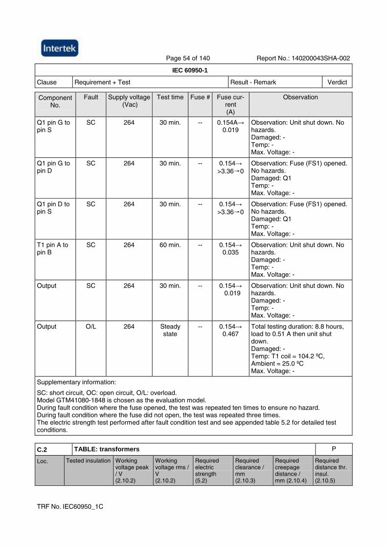
Page 54 of 140 Report No.: 140200043SHA-002
IEC 60950-1
Clause Requirement + Test Result - Remark Verdict
TRF No. IEC60950_1C
Component No.
Fault Supply voltage (Vac)
Test time Fuse # Fuse cur-rent (A)
Observation
Q1 pin G to pin S
SC 264 30 min. -- 0.154A→ 0.019
Observation: Unit shut down. No hazards. Damaged: - Temp: - Max. Voltage: -
Q1 pin G to pin D
SC 264 30 min. -- 0.154→ >3.36→0
Observation: Fuse (FS1) opened. No hazards. Damaged: Q1 Temp: - Max. Voltage: -
Q1 pin D to pin S
SC 264 30 min. -- 0.154→ >3.36→0
Observation: Fuse (FS1) opened. No hazards. Damaged: Q1 Temp: - Max. Voltage: -
T1 pin A to pin B
SC 264 60 min. -- 0.154→ 0.035
Observation: Unit shut down. No hazards. Damaged: - Temp: - Max. Voltage: -
Output SC 264 30 min. -- 0.154→ 0.019
Observation: Unit shut down. No hazards. Damaged: - Temp: - Max. Voltage: -
Output O/L 264 Steady state
-- 0.154→ 0.467
Total testing duration: 8.8 hours, load to 0.51 A then unit shut down. Damaged: - Temp: T1 coil = 104.2 ºC, Ambient = 25.0 ºC Max. Voltage: -
Supplementary information:
SC: short circuit, OC: open circuit, O/L: overload. Model GTM41080-1848 is chosen as the evaluation model. During fault condition where the fuse opened, the test was repeated ten times to ensure no hazard. During fault condition where the fuse did not open, the test was repeated three times. The electric strength test performed after fault condition test and see appended table 5.2 for detailed test conditions.
C.2 TABLE: transformers P
Loc. Tested insulation Working voltage peak / V (2.10.2)
Working voltage rms / V (2.10.2)
Required electric strength (5.2)
Required clearance / mm (2.10.3)
Required creepage distance / mm (2.10.4)
Required distance thr. insul. (2.10.5)
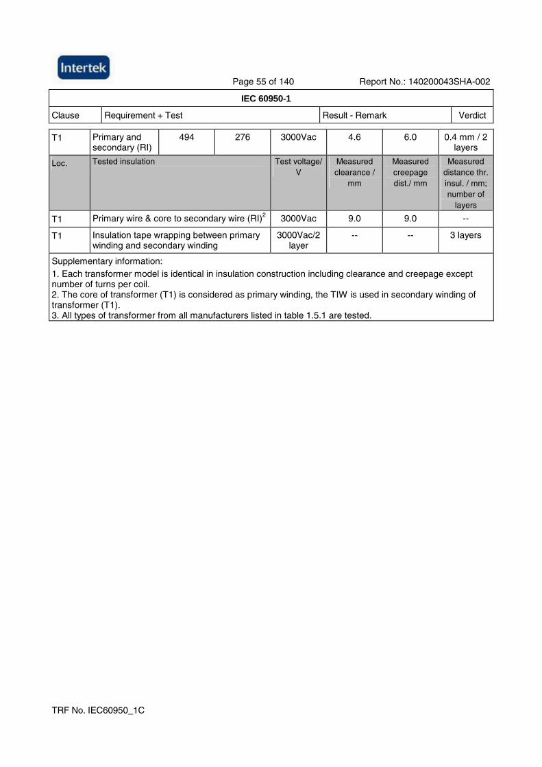
Page 55 of 140 Report No.: 140200043SHA-002
IEC 60950-1
Clause Requirement + Test Result - Remark Verdict
TRF No. IEC60950_1C
T1 Primary and secondary (RI)
494 276 3000Vac 4.6 6.0 0.4 mm / 2 layers
Loc. Tested insulation
Test voltage/ V
Measured clearance /
mm
Measured creepage dist./ mm
Measured distance thr. insul. / mm; number of
layers
T1 Primary wire & core to secondary wire (RI)2 3000Vac 9.0 9.0 --
T1 Insulation tape wrapping between primary winding and secondary winding
3000Vac/2 layer
-- -- 3 layers
Supplementary information: 1. Each transformer model is identical in insulation construction including clearance and creepage except number of turns per coil. 2. The core of transformer (T1) is considered as primary winding, the TIW is used in secondary winding of transformer (T1). 3. All types of transformer from all manufacturers listed in table 1.5.1 are tested.
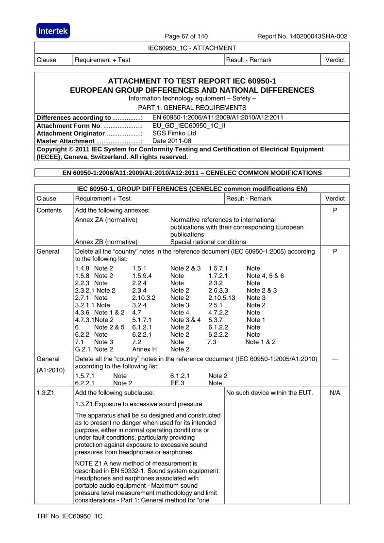
Page 67 of 140 Report No. 140200043SHA-002
IEC60950_1C - ATTACHMENT
Clause Requirement + Test Result - Remark Verdict
TRF No. IEC60950_1C
ATTACHMENT TO TEST REPORT IEC 60950-1 EUROPEAN GROUP DIFFERENCES AND NATIONAL DIFFERENCES
Information technology equipment – Safety – PART 1: GENERAL REQUIREMENTS
Differences according to ................: EN 60950-1:2006/A11:2009/A1:2010/A12:2011 Attachment Form No . .....................: EU_GD_IEC60950_1C_II Attachment Originator ....................: SGS Fimko Ltd Master Attachment .........................: Date 2011-08 Copyright © 2011 IEC System for Conformity Testing and Certification of Electrical Equipment (IECEE), Geneva, Switzerland. All rights reserved.
EN 60950-1:2006/A11:2009/A1:2010/A12:2011 – CENELEC COMMON MODIFICATIONS
IEC 60950-1, GROUP DIFFERENCES (CENELEC common modifications EN)
Clause Requirement + Test Result - Remark Verdict
Contents Add the following annexes:
Annex ZA (normative) Normative references to international publications with their corresponding European publications Annex ZB (normative) Special national conditions
P
General Delete all the “country” notes in the reference document (IEC 60950-1:2005) according to the following list:
1.4.8 Note 2 1.5.1 Note 2 & 3 1.5.7.1 Note 1.5.8 Note 2 1.5.9.4 Note 1.7.2.1 Note 4, 5 & 6 2.2.3 Note 2.2.4 Note 2.3.2 Note 2.3.2.1 Note 2 2.3.4 Note 2 2.6.3.3 Note 2 & 3 2.7.1 Note 2.10.3.2 Note 2 2.10.5.13 Note 3 3.2.1.1 Note 3.2.4 Note 3. 2.5.1 Note 2 4.3.6 Note 1 & 2 4.7 Note 4 4.7.2.2 Note 4.7.3.1Note 2 5.1.7.1 Note 3 & 4 5.3.7 Note 1 6 Note 2 & 5 6.1.2.1 Note 2 6.1.2.2 Note 6.2.2 Note 6.2.2.1 Note 2 6.2.2.2 Note 7.1 Note 3 7.2 Note 7.3 Note 1 & 2 G.2.1 Note 2 Annex H Note 2
P
General
(A1:2010)
Delete all the “country” notes in the reference document (IEC 60950-1:2005/A1:2010) according to the following list:
1.5.7.1 Note 6.1.2.1 Note 2 6.2.2.1 Note 2 EE.3 Note
—
1.3.Z1 Add the following subclause:
1.3.Z1 Exposure to excessive sound pressure
The apparatus shall be so designed and constructed as to present no danger when used for its intended purpose, either in normal operating conditions or under fault conditions, particularly providing protection against exposure to excessive sound pressures from headphones or earphones.
NOTE Z1 A new method of measurement is described in EN 50332-1, Sound system equipment: Headphones and earphones associated with portable audio equipment - Maximum sound pressure level measurement methodology and limit considerations - Part 1: General method for “one
No such device within the EUT. N/A
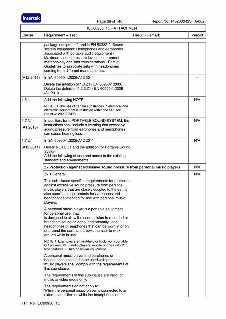
Page 68 of 140 Report No. 140200043SHA-002
IEC60950_1C - ATTACHMENT
Clause Requirement + Test Result - Remark Verdict
TRF No. IEC60950_1C
package equipment”, and in EN 50332-2, Sound system equipment: Headphones and earphones associated with portable audio equipment - Maximum sound pressure level measurement methodology and limit considerations - Part 2: Guidelines to associate sets with headphones coming from different manufacturers.
(A12:2011) In EN 60950-1:2006/A12:2011
Delete the addition of 1.3.Z1 / EN 60950-1:2006 Delete the definition 1.2.3.Z1 / EN 60950-1:2006 /A1:2010
—
1.5.1 Add the following NOTE:
NOTE Z1 The use of certain substances in electrical and electronic equipment is restricted within the EU: see Directive 2002/95/EC
N/A
1.7.2.1
(A1:2010)
In addition, for a PORTABLE SOUND SYSTEM, the instructions shall include a warning that excessive sound pressure from earphones and headphones can cause hearing loss.
N/A
In EN 60950-1:2006/A12:2011
Delete NOTE Z1 and the addition for Portable Sound System. Add the following clause and annex to the existing standard and amendments.
N/A
Zx Protection against excessive sound pressure from personal music players N/A
1.7.2.1
(A12.2011)
Zx.1 General
This sub-clause specifies requirements for protection against excessive sound pressure from personal music players that are closely coupled to the ear. It also specifies requirements for earphones and headphones intended for use with personal music players.
A personal music player is a portable equipment for personal use, that: is designed to allow the user to listen to recorded or broadcast sound or video; and primarily uses headphones or earphones that can be worn in or on or around the ears; and allows the user to walk around while in use.
NOTE 1: Examples are hand-held or body-worn portable CD players, MP3 audio players, mobile phones with MP3 type features, PDA’s or similar equipment.
A personal music player and earphones or headphones intended to be used with personal music players shall comply with the requirements of this sub-clause.
The requirements in this sub-clause are valid for music or video mode only.
The requirements do not apply to While the personal music player is connected to an external amplifier; or while the headphones or
N/A
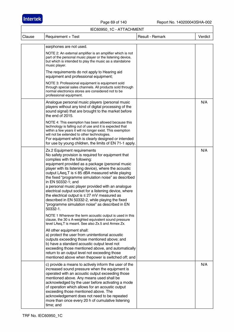
Page 69 of 140 Report No. 140200043SHA-002
IEC60950_1C - ATTACHMENT
Clause Requirement + Test Result - Remark Verdict
TRF No. IEC60950_1C
earphones are not used.
NOTE 2: An external amplifier is an amplifier which is not part of the personal music player or the listening device, but which is intended to play the music as a standalone music player.
The requirements do not apply to Hearing aid equipment and professional equipment;
NOTE 3: Professional equipment is equipment sold through special sales channels. All products sold through normal electronics stores are considered not to be professional equipment.
Analogue personal music players (personal music players without any kind of digital processing of the sound signal) that are brought to the market before the end of 2015.
NOTE 4: This exemption has been allowed because this technology is falling out of use and it is expected that within a few years it will no longer exist. This exemption will not be extended to other technologies. For equipment which is clearly designed or intended for use by young children, the limits of EN 71-1 apply.
N/A
Zx.2 Equipment requirements No safety provision is required for equipment that complies with the following: equipment provided as a package (personal music player with its listening device), where the acoustic output LAeq,T is ≤ 85 dBA measured while playing the fixed “programme simulation noise” as described in EN 50332-1; and a personal music player provided with an analogue electrical output socket for a listening device, where the electrical output is ≤ 27 mV measured as described in EN 50332-2, while playing the fixed “programme simulation noise” as described in EN 50332-1.
NOTE 1 Wherever the term acoustic output is used in this clause, the 30 s A-weighted equivalent sound pressure level LAeq,T is meant. See also Zx.5 and Annex Zx.
All other equipment shall: a) protect the user from unintentional acoustic outputs exceeding those mentioned above; and b) have a standard acoustic output level not exceeding those mentioned above, and automatically return to an output level not exceeding those mentioned above when thepower is switched off; and
N/A
c) provide a means to actively inform the user of the increased sound pressure when the equipment is operated with an acoustic output exceeding those mentioned above. Any means used shall be acknowledged by the user before activating a mode of operation which allows for an acoustic output exceeding those mentioned above. The acknowledgement does not need to be repeated more than once every 20 h of cumulative listening time; and
N/A
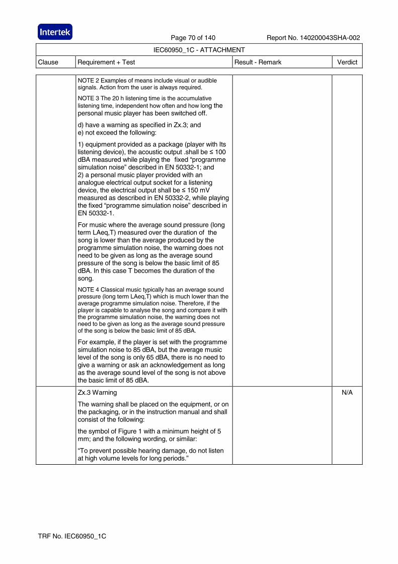
Page 70 of 140 Report No. 140200043SHA-002
IEC60950_1C - ATTACHMENT
Clause Requirement + Test Result - Remark Verdict
TRF No. IEC60950_1C
NOTE 2 Examples of means include visual or audible signals. Action from the user is always required.
NOTE 3 The 20 h listening time is the accumulative listening time, independent how often and how long the personal music player has been switched off.
d) have a warning as specified in Zx.3; and e) not exceed the following:
1) equipment provided as a package (player with Its listening device), the acoustic output .shall be ≤ 100 dBA measured while playing the fixed “programme simulation noise” described in EN 50332-1; and 2) a personal music player provided with an analogue electrical output socket for a listening device, the electrical output shall be ≤ 150 mV measured as described in EN 50332-2, while playing the fixed “programme simulation noise” described in EN 50332-1.
For music where the average sound pressure (long term LAeq,T) measured over the duration of the song is lower than the average produced by the programme simulation noise, the warning does not need to be given as long as the average sound pressure of the song is below the basic limit of 85 dBA. In this case T becomes the duration of the song.
NOTE 4 Classical music typically has an average sound pressure (long term LAeq,T) which is much lower than the average programme simulation noise. Therefore, if the player is capable to analyse the song and compare it with the programme simulation noise, the warning does not need to be given as long as the average sound pressure of the song is below the basic limit of 85 dBA.
For example, if the player is set with the programme simulation noise to 85 dBA, but the average music level of the song is only 65 dBA, there is no need to give a warning or ask an acknowledgement as long as the average sound level of the song is not above the basic limit of 85 dBA.
Zx.3 Warning
The warning shall be placed on the equipment, or on the packaging, or in the instruction manual and shall consist of the following:
the symbol of Figure 1 with a minimum height of 5 mm; and the following wording, or similar:
“To prevent possible hearing damage, do not listen at high volume levels for long periods.”
N/A
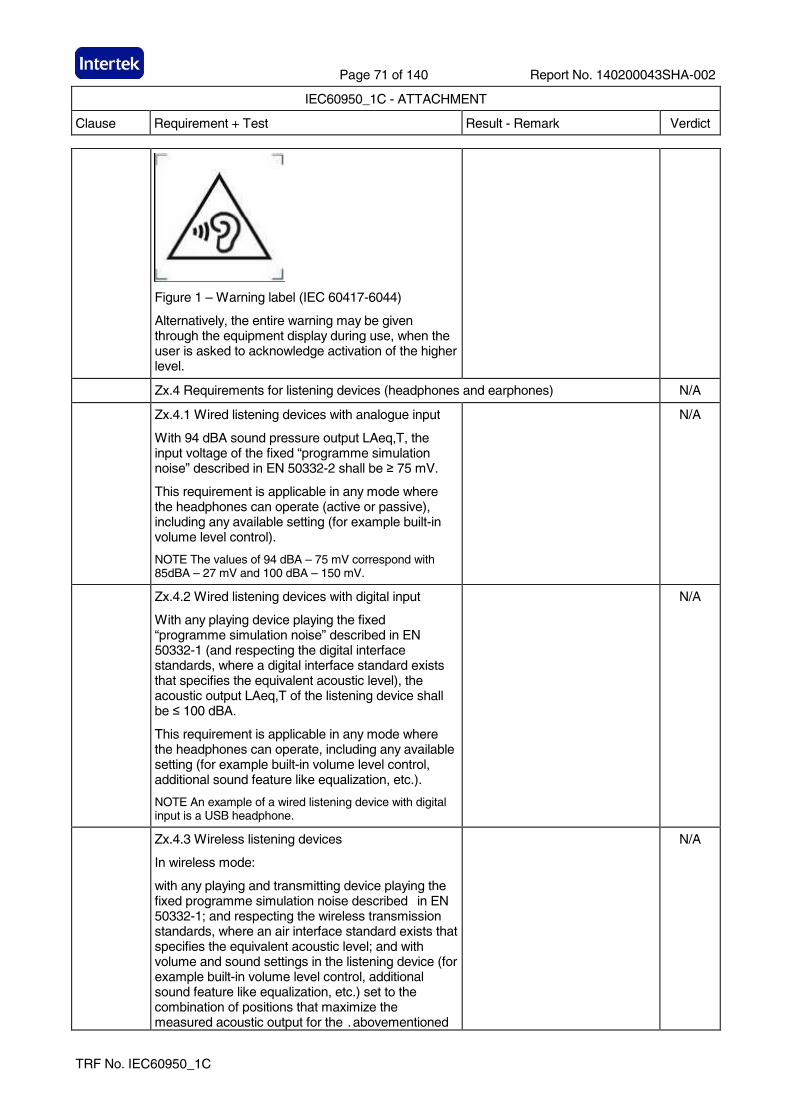
Page 71 of 140 Report No. 140200043SHA-002
IEC60950_1C - ATTACHMENT
Clause Requirement + Test Result - Remark Verdict
TRF No. IEC60950_1C
Figure 1 – Warning label (IEC 60417-6044)
Alternatively, the entire warning may be given through the equipment display during use, when the user is asked to acknowledge activation of the higher level.
Zx.4 Requirements for listening devices (headphones and earphones) N/A
Zx.4.1 Wired listening devices with analogue input
With 94 dBA sound pressure output LAeq,T, the input voltage of the fixed “programme simulation noise” described in EN 50332-2 shall be ≥ 75 mV.
This requirement is applicable in any mode where the headphones can operate (active or passive), including any available setting (for example built-in volume level control).
NOTE The values of 94 dBA – 75 mV correspond with 85dBA – 27 mV and 100 dBA – 150 mV.
N/A
Zx.4.2 Wired listening devices with digital input
With any playing device playing the fixed “programme simulation noise” described in EN 50332-1 (and respecting the digital interface standards, where a digital interface standard exists that specifies the equivalent acoustic level), the acoustic output LAeq,T of the listening device shall be ≤ 100 dBA.
This requirement is applicable in any mode where the headphones can operate, including any available setting (for example built-in volume level control, additional sound feature like equalization, etc.).
NOTE An example of a wired listening device with digital input is a USB headphone.
N/A
Zx.4.3 Wireless listening devices
In wireless mode:
with any playing and transmitting device playing the fixed programme simulation noise described in EN 50332-1; and respecting the wireless transmission standards, where an air interface standard exists that specifies the equivalent acoustic level; and with volume and sound settings in the listening device (for example built-in volume level control, additional sound feature like equalization, etc.) set to the combination of positions that maximize the measured acoustic output for the .abovementioned
N/A
Page 72 of 140 Report No. 140200043SHA-002
IEC60950_1C - ATTACHMENT
Clause Requirement + Test Result - Remark Verdict
TRF No. IEC60950_1C
programme simulation noise, ....the acoustic output LAeq,T of the listening device shall be ≤ 100 dBA.
NOTE An example of a wireless listening device is a Bluetooth headphone.
Zx.5 Measurement methods
Measurements shall be made in accordance with EN 50332-1 or EN 50332-2 as applicable. Unless stated otherwise, the time interval T shall be 30 s.
NOTE Test method for wireless equipment provided without listening device should be defined.
N/A
2.7.1 Replace the subclause as follows:
Basic requirements
To protect against excessive current, short-circuits and earth faults in PRIMARY CIRCUITS, protective devices shall be included either as integral parts of the equipment or as parts of the building installation, subject to the following, a), b) and c):
a) except as detailed in b) and c), protective devices necessary to comply with the requirements of 5.3 shall be included as parts of the equipment; b) for components in series with the mains input to the equipment such as the supply cord, appliance coupler, r.f.i. filter and switch, short-circuit and earth fault protection may be provided by protective devices in the building installation;
P
c) it is permitted for PLUGGABLE EQUIPMENT TYPE B or PERMANENTLY CONNECTED EQUIPMENT, to rely on dedicated overcurrent and short-circuit protection in the building installation, provided that the means of protection, e.g. fuses or circuit breakers, is fully specified in the installation instructions. If reliance is placed on protection in the building installation, the installation instructions shall so state, except that for PLUGGABLE EQUIPMENT TYPE A the building installation shall be regarded as providing protection in accordance with the rating of the wall socket outlet.
N/A
2.7.2 This subclause has been declared ‘void’. —
3.2.3 Delete the NOTE in Table 3A, and delete also in this table the conduit sizes in parentheses.
—
3.2.5.1 Replace “60245 IEC 53” by “H05 RR-F”; “60227 IEC 52” by “H03 VV-F or H03 VVH2-F”; “60227 IEC 53” by “H05 VV-F or H05 VVH2-F2”. In Table 3B, replace the first four lines by the following:
Up to and including 6 | 0,75 a) | Over 6 up to and including 10| (0,75) b) 1,0 | Over 10 up to and including 16| (1,0) c) 1,5 |
In the conditions applicable to Table 3B delete the words “in some countries” in condition a).
The EUT is direct plug-in equipment.
N/A
Page 73 of 140 Report No. 140200043SHA-002
IEC60950_1C - ATTACHMENT
Clause Requirement + Test Result - Remark Verdict
TRF No. IEC60950_1C
In NOTE 1, applicable to Table 3B, delete the second sentence.
3.3.4 In Table 3D, delete the fourth line: conductor sizes for 10 to 13 A, and replace with the following:
Over 10 up to and including 16 | 1,5 to 2,5 | 1,5 to 4 |
Delete the fifth line: conductor sizes for 13 to 16 A
No wiring terminal. N/A
4.3.13.6
(A1:2010)
Replace the existing NOTE by the following:
NOTE Z1 Attention is drawn to:
1999/519/EC: Council Recommendation on the limitation of exposure of the general public to electromagnetic fields 0 Hz to 300 GHz, and
2006/25/EC: Directive on the minimum health and safety requirements regarding the exposure of workers to risks arising from physical agents (artificial optical radiation).
N/A
Standards taking into account mentioned Recommendation and Directive which demonstrate compliance with the applicable EU Directive are indicated in the OJEC.
N/A
Annex H Replace the last paragraph of this annex by:
At any point 10 cm from the surface of the OPERATOR ACCESS AREA, the dose rate shall not exceed 1 µSv/h (0.1 mR/h) (see NOTE). Account is taken of the background level.
Replace the notes as follows:
NOTE These values appear in Directive 96/29/Euratom.
Delete NOTE 2.
N/A
Bibliography Additional EN standards.
ZA NORMATIVE REFERENCES TO INTERNATIONAL PUBLICATIONS WITH THEIR CORRESPONDING EUROPEAN PUBLICATIONS
ZB ANNEX (NORMATIVE)
SPECIAL NATIONAL CONDITIONS (EN)
Clause Requirement + Test Result - Remark Verdict
1.2.4.1 In Denmark, certain types of Class I appliances (see 3.2.1.1) may be provided with a plug not establishing earthing conditions when inserted into Danish socket-outlets.
It shall be checked for proper certificate of these countries’ certification before products are sold in the market.
N/A
1.2.13.14 In Norway and Sweden, for requirements see 1.7.2.1 and 7.3 of this annex.
N/A
Page 74 of 140 Report No. 140200043SHA-002
IEC60950_1C - ATTACHMENT
Clause Requirement + Test Result - Remark Verdict
TRF No. IEC60950_1C
1.5.7.1 In Finland, Norway and Sweden, resistors bridging BASIC INSULATION in CLASS I PLUGGABLE EQUIPMENT TYPE A must comply with the requirements in 1.5.7.1. In addition when a single resistor is used, the resistor must withstand the resistor test in 1.5.7.2.
No such device within the EUT. N/A
1.5.8 In Norway, due to the IT power system used (see annex V, Figure V.7), capacitors are required to be rated for the applicable line-to-line voltage (230 V).
N/A
1.5.9.4 In Finland, Norway and Sweden, the third dashed sentence is applicable only to equipment as defined in 6.1.2.2 of this annex.
N/A
1.7.2.1 In Finland, Norway and Sweden, CLASS I PLUGGABLE EQUIPMENT TYPE A intended for connection to other equipment or a network shall, if safety relies on connection to protective earth or if surge suppressors are connected between the network terminals and accessible parts, have a marking stating that the equipment must be connected to an earthed mains socket-outlet.
The marking text in the applicable countries shall be as follows:
In Finland: "Laite on liitettävä suojakoskettimilla varustettuun pistorasiaan"
In Norway: “Apparatet må tilkoples jordet stikkontakt”
In Sweden: “Apparaten skall anslutas till jordat uttag”
In Norway and Sweden, the screen of the cable distribution system is normally not earthed at the entrance of the building and there is normally no equipotential bonding system within the building. Therefore the protective earthing of the building installation need to be isolated from the screen of a cable distribution system.
It is however accepted to provide the insulation external to the equipment by an adapter or an interconnection cable with galvanic isolator, which may be provided by e.g. a retailer.
The user manual shall then have the following or similar information in Norwegian and Swedish language respectively, depending on in what country the equipment is intended to be used in:
“Equipment connected to the protective earthing of the building installation through the mains connection or through other equipment with a connection to protective earthing – and to a cable distribution system using coaxial cable, may in some circumstances create a fire hazard. Connection to a cable distribution system has therefore to be provided through a device providing electrical isolation below a certain frequency range (galvanic isolator, see EN 60728-11).”
It shall be checked for proper certificate of these countries’ certification before products are sold in the market.
N/A
Page 75 of 140 Report No. 140200043SHA-002
IEC60950_1C - ATTACHMENT
Clause Requirement + Test Result - Remark Verdict
TRF No. IEC60950_1C
NOTE In Norway, due to regulation for installations of cable distribution systems, and in Sweden, a galvanic isolator shall provide electrical insulation below 5 MHz. The insulation shall withstand a dielectric strength of 1,5 kV r.m.s., 50 Hz or 60 Hz, for 1 min.
Translation to Norwegian (the Swedish text will also be accepted in Norway):
“Utstyr som er koplet til beskyttelsesjord via nettplugg og/eller via annet jordtilkoplet utstyr – og er tilkoplet et kabel-TV nett, kan forårsake brannfare. For å unngå dette skal det ved tilkopling av utstyret til kabel-TV nettet installeres en galvanisk isolator mellom utstyret og kabel- TV nettet.” Translation to Swedish:
”Utrustning som är kopplad till skyddsjord via jordat vägguttag och/eller via annan utrustning och samtidigt är kopplad till kabel-TV nät kan i vissa fall medfőra risk főr brand. Főr att undvika detta skall vid anslutning av utrustningen till kabel-TV nät galvanisk isolator finnas mellan utrustningen och kabel-TV nätet.”
N/A
1.7.5 In Denmark, socket-outlets for providing power to other equipment shall be in accordance with the Heavy Current Regulations, Section 107-2-D1, Standard Sheet DK 1-3a, DK 1-5a or DK 1-7a, when used on Class I equipment. For STATIONARY EQUIPMENT the socket-outlet shall be in accordance with Standard Sheet DK 1-1b or DK 1-5a.
For CLASS II EQUIPMENT the socket outlet shall be in accordance with Standard Sheet DKA 1-4a.
N/A
2.2.4 In Norway, for requirements see 1.7.2.1, 6.1.2.1 and 6.1.2.2 of this annex.
N/A
2.3.2 In Finland, Norway and Sweden there are additional requirements for the insulation. See 6.1.2.1 and 6.1.2.2 of this annex.
N/A
2.3.4 In Norway, for requirements see 1.7.2.1, 6.1.2.1 and 6.1.2.2 of this annex.
N/A
2.6.3.3 In the United Kingdom, the current rating of the circuit shall be taken as 13 A, not 16 A.
N/A
2.7.1 In the United Kingdom, to protect against excessive currents and short-circuits in the PRIMARY CIRCUIT of DIRECT PLUG-IN EQUIPMENT, tests according to 5.3 shall be conducted, using an external protective device rated 30 A or 32 A. If these tests fail, suitable protective devices shall be included as integral parts of the DIRECT PLUG-IN EQUIPMENT, so that the requirements of 5.3 are met.
P
Page 76 of 140 Report No. 140200043SHA-002
IEC60950_1C - ATTACHMENT
Clause Requirement + Test Result - Remark Verdict
TRF No. IEC60950_1C
2.10.5.13 In Finland, Norway and Sweden, there are additional requirements for the insulation; see 6.1.2.1 and 6.1.2.2 of this annex.
N/A
3.2.1.1 In Switzerland, supply cords of equipment having a RATED CURRENT not exceeding 10 A shall be provided with a plug complying with SEV 1011 or IEC 60884-1 and one of the following dimension sheets:
SEV 6532-2.1991 Plug Type 15 3P+N+PE 250/400V 10A
The EUT is direct plug-in equipment.
N/A
SEV 6533-2.1991 Plug Type 11 L+N 250V, 10A SEV 6534-2.1991 Plug Type 12 L+N+PE 250V 10A
In general, EN 60309 applies for plugs for currents exceeding 10 A. However, a 16 A plug and socket-outlet system is being introduced in Switzerland, the plugs of which are according to the following dimension sheets, published in February 1998:
SEV 5932-2.1998 Plug Type 25 3L+N+PE 230/400V 16A SEV 5933-2.1998 Plug Type 21 L+N 250V 16A SEV 5934-2.1998 Plug Type 23 L+N+PE 250V 16A
3.2.1.1 In Denmark, supply cords of single-phase equipment having a rated current not exceeding13 A shall be provided with a plug according to the Heavy Current Regulations, Section 107-2-D1.
CLASS I EQUIPMENT provided with socket-outlets with earth contacts or which are intended to be used in locations where protection against indirect contact is required according to the wiring rules shall be provided with a plug in accordance with standard sheet DK 2-1a or DK 2-5a.
If poly-phase equipment and single-phase equipment having a RATED CURRENT exceeding 13 A is provided with a supply cord with a plug, this plug shall be in accordance with the Heavy Current Regulations, Section 107-2-D1 or EN 60309-2.
N/A
3.2.1.1 In Spain, supply cords of single-phase equipment having a rated current not exceeding 10 A shall be provided with a plug according to UNE 20315:1994.
Supply cords of single-phase equipment having a rated current not exceeding 2.5 A shall be provided with a plug according to UNE-EN 50075:1993.
CLASS I EQUIPMENT provided with socket-outlets with earth contacts or which are intended to be used in locations where protection against indirect contact is required according to the wiring rules, shall be provided with a plug in accordance with standard UNE 20315:1994.
If poly-phase equipment is provided with a supply cord with a plug, this plug shall be in accordance with UNE-EN 60309-2.
N/A
Page 77 of 140 Report No. 140200043SHA-002
IEC60950_1C - ATTACHMENT
Clause Requirement + Test Result - Remark Verdict
TRF No. IEC60950_1C
3.2.1.1 In the United Kingdom, apparatus which is fitted with a flexible cable or cord and is designed to be connected to a mains socket conforming to BS 1363 by means of that flexible cable or cord and plug, shall be fitted with a ‘standard plug’ in accordance with Statutory Instrument 1768:1994 - The Plugs and Sockets etc. (Safety) Regulations 1994, unless exempted by those regulations.
NOTE ‘Standard plug’ is defined in SI 1768:1994 and essentially means an approved plug conforming to BS 1363 or an approved conversion plug.
N/A
3.2.1.1 In Ireland, apparatus which is fitted with a flexible cable or cord and is designed to be connected to a mains socket conforming to I.S. 411 by means of that flexible cable or cord and plug, shall be fitted with a 13 A plug in accordance with Statutory Instrument 525:1997 - National Standards Authority of Ireland (section 28) (13 A Plugs and Conversion Adaptors for Domestic Use) Regulations 1997.
N/A
3.2.4 In Switzerland, for requirements see 3.2.1.1 of this annex.
N/A
3.2.5.1 In the United Kingdom, a power supply cord with conductor of 1,25 mm2 is allowed for equipment with a rated current over 10 A and up to and including 13 A.
N/A
3.3.4 In the United Kingdom, the range of conductor sizes of flexible cords to be accepted by terminals for equipment with a RATED CURRENT of over 10 A up to and including 13 A is:
• 1.25 mm2 to 1.5 mm2 nominal cross-sectional area.
N/A
4.3.6 In the United Kingdom, the torque test is performed using a socket outlet complying with BS 1363 part 1:1995, including Amendment 1:1997 and Amendment 2:2003 and the plug part of DIRECT PLUG-IN EQUIPMENT shall be assessed to BS 1363: Part 1, 12.1, 12.2, 12.3, 12.9, 12.11, 12.12, 12.13, 12.16 and 12.17, except that the test of 12.17 is performed at not less than 125 °C. Where the metal earth pin is replaced by an Insulated Shutter Opening Device (ISOD), the requirements of clauses 22.2 and 23 also apply.
P
4.3.6 In Ireland, DIRECT PLUG-IN EQUIPMENT is known as plug similar devices. Such devices shall comply with Statutory Instrument 526:1997 - National Standards Authority of Ireland (Section 28) (Electrical plugs, plug similar devices and sockets for domestic use) Regulations, 1997.
P
Page 78 of 140 Report No. 140200043SHA-002
IEC60950_1C - ATTACHMENT
Clause Requirement + Test Result - Remark Verdict
TRF No. IEC60950_1C
5.1.7.1 In Finland, Norway and Sweden TOUCH CURRENT measurement results exceeding 3,5 mA r.m.s. are permitted only for the following equipment:
• STATIONARY PLUGGABLE EQUIPMENT TYPE A that is intended to be used in a RESTRICTED ACCESS LOCATION where equipotential bonding has been applied, for example, in a telecommunication centre; and has provision for a permanently connected PROTECTIVE EARTHING CONDUCTOR; and is provided with instructions for the installation of that conductor by a SERVICE PERSON;
• STATIONARY PLUGGABLE EQUIPMENT TYPE B;
• STATIONARY PERMANENTLY CONNECTED EQUIPMENT.
N/A
6.1.2.1
(A1:2010)
In Finland, Norway and Sweden, add the following text between the first and second paragraph of the compliance clause:
If this insulation is solid, including insulation forming part of a component, it shall at least consist of either
-Two layers of thin sheet material, each of which shall pass the electric strength test below, or
-One layer having a distance through insulation of at least 0.4 mm, which shall pass the electric strength test below.
Alternatively for components, there is no distance through insulation requirements for the insulation consisting of an insulating compound completely filling the casing, so that CLEARANCES and CREEPAGE DISTANCES do not exist, if the component passes the electric strength test in accordance with the compliance clause below and in addition
- passes the tests and inspection criteria of 2.10.11 with an electric strength test of 1,5 kV multiplied by 1.6 (the electric strength test of 2.10.10 shall be performed using 1,5 kV), and
- is subject to ROUTINE TESTING for electric strength during manufacturing, using a test voltage of 1.5 kV.
N/A
Page 79 of 140 Report No. 140200043SHA-002
IEC60950_1C - ATTACHMENT
Clause Requirement + Test Result - Remark Verdict
TRF No. IEC60950_1C
It is permitted to bridge this insulation with an optocoupler complying with 2.10.5.4 b).
It is permitted to bridge this insulation with a capacitor complying with EN 60384-14:2005, subclass Y2.
A capacitor classified Y3 according to EN 60384-14:2005, may bridge this insulation under the following conditions:
-the insulation requirements are satisfied by having a capacitor classified Y3 as defined by EN 60384-14, which in addition to the Y3 testing, is tested with an impulse test of 2,5 kV defined in EN 60950-1:2006, 6.2.2.1;
- .the additional testing shall be performed on all the test specimens as described in EN 60384-14:
-the impulse test of 2,5 kV is to be performed before the endurance test in EN 60384-14, in the sequence of tests as described in EN 60384-14.
N/A
6.1.2.2 In Finland, Norway and Sweden, the exclusions are applicable for PERMANENTLY CONNECTED EQUIPMENT, PLUGGABLE EQUIPMENT TYPE B and equipment intended to be used in a RESTRICTED ACCESS LOCATION where equipotential bonding has been applied, e.g. in a telecommunication centre, and which has provision for a permanently connected PROTECTIVE EARTHING CONDUCTOR and is provided with instructions for the installation of that conductor by a SERVICE PERSON.
N/A
7.2 In Finland, Norway and Sweden, for requirements see 6.1.2.1 and 6.1.2.2 of this annex.
The term TELECOMMUNICATION NETWORK in 6.1.2 being replaced by the term CABLE DISTRIBUTION SYSTEM.
N/A
7.3 In Norway and Sweden, for requirements see 1.2.13.14 and 1.7.2.1 of this annex.
N/A
7.3 In Norway, for installation conditions see EN 60728-11:2005.
N/A
Page 80 of 140 Report No. 140200043SHA-002
IEC60950_1C - ATTACHMENT
Clause Requirement + Test Result - Remark Verdict
TRF No. IEC60950_1C
APPENDIX National differences for Singapore
IEC 60950-1, 1st edition
The following is the national differences in accordance with safety authority website www.safety.org.sg/ , ref. Singapore Consumer Protection (Safety Requirements) - Information booklet - chapter 7 (page 23 - 26). Based on information by Singapore NCB – PSB Corp.
7 SAFETY AUTHORITY’S REQUIREMENTS
The Safety Authority monitors the safety of the controlled goods sold in Singapore by investigating all complaints, incidents and accidents reported to the authority. Experiences gained are translated into the Safety Authority’s Requirements. These requirements are to be fulfilled in addition to the applicable safety standards.
Applicable to all electrical products
No Item Requirement Result - Remark Verdict
2 Controlled Goods incorporated with additional function
The additional function must be tested to its applicable safety standard.
P
3 All appliances All appliances must be tested to 230 VAC. The voltage range includes 230Vac.
P
4 Voltage selector (voltage mis-match test)
Appliance fitted with voltage selector shall be tested as follows:
Connect appliance to 230 VAC mains with voltage selector switch to settings not suitable for operation at 230 VAC.
No voltage selector. N/A
5 Tropical condition test
All appliances (with tropical test requirements in applicable Standards) shall comply with the tropical condition test as stated in the relevant IEC Standards.
P
6 Class I appliances (3-pin mains plug)
All Class I appliances must be fitted with 3-pin mains plugs complied with SS 145/SS 472 that are registered with the Safety Authority.
N/A
7 Class II appliances (mains plug)
a) All Class II appliances must be fitted with 2-pin mains plug (Appendix T) complied with EN 50075.
b) Class II appliances that are fitted with 3-pin mains plugs must use plugs that are complied with SS 145 and registered with the Safety Authority.
P
8 Appliances rated ≥ 3 kW or connected to fixed wiring
Electric appliance ≥ 3kW must be connected to fixed wiring. All connection to fixed wiring must be in accordance with Code of Practice CP5.
Not exceed 3kW. N/A
9 Detachable power cord set (consists of mains plug, mains cord and appliance
Detachable power cord set must be listed in the test report critical component list.
Direct plug-in device. N/A
Page 81 of 140 Report No. 140200043SHA-002
IEC60950_1C - ATTACHMENT
Clause Requirement + Test Result - Remark Verdict
TRF No. IEC60950_1C
connector)
10 Circuit diagrams Circuit diagrams must be indicated with component’s values for products tested to IEC 60065 and IEC 60950-1.
P
11 Circuit diagrams of electronic modules in electrical appliances
Circuit diagrams of the electronic modules in the electrical appliances must be provided.
P
12 Controlled goods likely to be treated as toy by children
Controlled goods, having an enclosure, which is shaped and decorated so that it is likely to be treated as a toy by children, shall not be accepted for certification and registration.
The shape and function are not considered for toy.
N/A
Applicable to AC adaptor
14 3-pin AC adaptor (Appendix V)
Test report showing that the 3-pin complied with sub-clauses 12.1 & 12.3 of SS 246 must be submitted.
N/A
15 2-pin AC adaptor (Appendix V)
The 2-pin (Appendix T) shall comply with EN 50075
See the appendix page. P
16 Detachable power supply cord set not supplied by Registered Supplier
Registered Supplier who is not supplying the detachable power supply cord set together with the AC Adaptor must provide written instruction to its customer on the type of approved detachable power cord set to use.
N/A
Applicable to computer products
17 CD/DVD ROM (used in personal computer)
Test certificate showing that CD/DVD ROM has complied with IEC 825 must be provided.
No CD/DVD ROM provided.
N/A
18 Modem Card (used in personal computer)
Modem card incorporated in the personal computer must be tested at set level (sub-clauses 5.1& 6 of IEC 60950-1) or at component level.
No modem card provided.
N/A
Applicable to plasma/LCD display monitor
37 Plasma/LCD display monitor with TV tuner
Plasma/LCD display monitor tested to IEC 60950-1 would require additional test to clauses 9 (related to antenna only), 10.1, 10.2, 10.3 and 12.5 of IEC 60065.
No TV tuner. N/A
Page 82 of 140 Report No. 140200043SHA-002
IEC60950_1C - ATTACHMENT
Clause Requirement + Test Result - Remark Verdict
TRF No. IEC60950_1C
APPENDIX National differences for Japan
IEC 60950-1, 1st edition
1.2.4.1 Add the following new notes.
Note: Even if the equipment is designed as Class I, the equipment is regarded as Class 0I equipment when 2-pin adaptor with earthing lead wire or cord set having 2-pin plug with earthing lead wire is provided or recommended.
N/A
1.2.4.3A Add the following new clause.
1.2.4.3A CLASS 0I EQUIPMENT
Equipment having attachment plug without earthing blade, where protection against electric shock is achieved by:
- using BASIC INSULATION, and - providing externally an earth terminal or a lead
wire for earthing in order to connect those conductive parts that might assume a HAZARDOUS VOLTAGES in the event of BASIC INSULATION fault to the PROTECTIVE EARTHING CONDUCTOR in the building wiring.
NOTE – Class 0I equipment may have a part constructed with Double Insulation or Reinforced Insulation circuit.
N/A
1.3.2 Add the following notes after first paragraph:
Note 1 Transportable or similar equipment that are relocated frequently for intended usage should not be designed as Class I or Class 0I equipment unless it is intended to be installed by service personnel.
Note 2 Considering wiring circumstance in Japan, equipment intended to be installed where the provision for earthing connection is unlikely should not be designed as Class I or Class 0I equipment unless it is intended to be installed by service personnel.
N/A
Page 83 of 140 Report No. 140200043SHA-002
IEC60950_1C - ATTACHMENT
Clause Requirement + Test Result - Remark Verdict
TRF No. IEC60950_1C
1.5.1 Replace the first paragraph with the follows:
Where safety is involved, components shall comply either with the requirements of this standard, with the safety aspects of the relevant JIS component standard, or IEC component standards in case there is no applicable JIS component standard is available. However, a component that falls within the scope of METI Ministerial ordinance No. 85 is properly used in accordance with its marked ratings, requirements of 1.5.4, 2.8.7 and 3.2.5 apply, and in addition, a cord connector of power supply cord set mating with appliance inlet complying with the standard sheet of IEC 60320-1, shall comply with relevant standard sheet of IEC 60320-1. Replace Note 1 with the following:
Note 1 A JIS or an IEC component standard is considered relevant only if the component in question clearly falls within its scope.
N/A
1.5.2 Replace first sentence in the first dashed paragraph with the following:
- A component that has been demonstrated to comply with a JIS component standard harmonized with the relevant IEC component standard, or where such JIS component standard is not available, a component that has been demonstrated to comply with the relevant IEC component standard shall be checked for correct application and use in accordance with its rating.
Add a note after the first dashed paragraph as follows:
Note 1 See 1.7.5A when Type C.14 appliance coupler rated 10 A per IEC 60320-1 is used with an equipment rated not more than 125 V and rated more than 10 A.
Replace first sentence in the third dashed paragraph as follows:
- Where no relevant IEC component standard or JIS component standard harmonized with the relevant IEC component standard exists, or where components are used in circuits not in accordance with their specified rating, the components shall be tested under the conditions occurring in the equipment.
N/A
1.7.1 Replace fifth dashed paragraph with the following:
- manufacturer’s or responsible company’s name or trade-mark or identification mark;
P
Page 84 of 140 Report No. 140200043SHA-002
IEC60950_1C - ATTACHMENT
Clause Requirement + Test Result - Remark Verdict
TRF No. IEC60950_1C
1.7.5A Add the following new clause. after 1.7.5
1.7.5A Appliance Coupler
If appliance coupler according to IEC60320-1, C.14(rated current: 10A)is used in equipment whose rated voltage is less than 125V and rated current is over 10A, the following instruction or equivalent shall be described in the user instruction.
“Use only designated cord set attached in this equipment”
N/A
1.7.12 Replace first sentence with the following:
Instructions and equipment marking related to safety shall be in Japanese.
It shall be checked for proper certificate of these countries’ certification before products are sold in the market.
N/A
1.7.17A Add the following new clause. after 1.7.17
1.7.17A Marking for CLASS 0I EQUIPMENT
For CLASS 0I EQUIPMENT, the following instruction shall be marked on the visible place of the mains plug or the main body: “Provide an earthing connection”
Moreover, for CLASS 0I EQUIPMENT, the following or equivalent instruction shall be indicated on the visible place of the main body or written in the operating instructions:
“Provide an earthing connection before the mains plug is connected to the mains. And, when disconnecting the earthing connection, be sure to disconnect after pulling out the mains plug from the mains.”
N/A
2.6.3.2 Add the following after 1st paragraph.
This also applies to the conductor of lead wire for protective earthing of CLASS 0I EQUIPMENT.
N/A
2.6.4.2 Replace 1st paragraph with the following.
Equipment required to have protective earthing shall have a main protective earthing terminal.
For equipment with a DETACHABLE POWER SUPPLY CORD, the earthing terminal in the appliance inlet is regarded as the main protective earthing terminal except for CLASS 0I EQUIPMENT providing separate main protective earthing terminal other than appliance inlet.
N/A
2.6.5.4 Replace 1st sentence with the following.
Protective earthing connections of CLASS I EQUIPMENT shall make earlier and break later than the supply connections in each of the following:
N/A
Page 85 of 140 Report No. 140200043SHA-002
IEC60950_1C - ATTACHMENT
Clause Requirement + Test Result - Remark Verdict
TRF No. IEC60950_1C
2.6.5.8A Add the following new clause. after 2.6.5.8A
2.6.5.8A Earthing of CLASS 0I EQUIPMENT Plugs with a lead wire for earthing shall not be used for equipment having a rated voltage exceeding 150V. For plugs with a lead wire for earthing, the lead wire shall not be earthed by a clip.
CLASS 0I EQUIPMENT shall be provided with an earthing terminal or lead wire for earthing in the external location where easily visible.
N/A
3.2.3 Add the following after Table 3A:
Table 3A applies when cables complying JIS C 3662 or JIS C 3663 are used. In case of other cables, cable entries shall be so designed that a conduit suitable for the cable used can be fitted.
N/A
3.2.5.1 Add the following to the last of first dashed paragraph.
Or mains cords shall be of the sheathed type complying with Appendix 1 of Article 1 of the Ministerial Ordinance on stipulating technical requirements for the Electrical Appliance.
Add the following to the last of second dashed paragraph.
Or mains cords shall be of the sheathed type complying with Appendix 1 of Article 1 of the Ministerial Ordinance on stipulating technical requirements for the Electrical Appliance..
Delete 1) in Table 3B.
N/A
3.3.4 Add the following note to Table 3D:
Note For cables other than those complying with JIS C 3662 or JIS C 3663; terminals shall be suitable for the size of the intended cables.
N/A
3.3.7 Add the following after the first sentence:
This requirement is not applicable to the external earthing terminal of Class 0I equipment.
N/A
4.3.4 Add the following after the first sentence:
This requirement also applies to those connections in Class 0I equipment, where CLEARANCE or CREEPAGE DISTANCES over BASIC INSULATION would be reduced to less than the values specified in 2.10.
N/A
5.1.3 Add a note after the first paragraph as follows:
Note – Attention should be drawn to that majority of three-phase power system in Japan is of delta connection, and therefore, in that case, test is conducted using the test circuit from IEC 60990, figure 13.
N/A
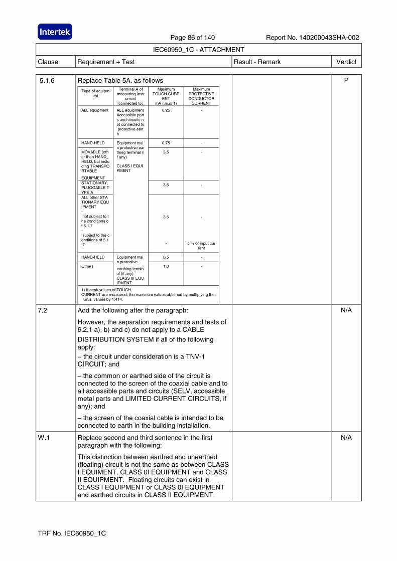
Page 86 of 140 Report No. 140200043SHA-002
IEC60950_1C - ATTACHMENT
Clause Requirement + Test Result - Remark Verdict
TRF No. IEC60950_1C
5.1.6 Replace Table 5A. as follows
Type of equipment
Terminal A of measuring instr
ument connected to:
Maximum TOUCH CURR
ENT mA r.m.s. 1)
Maximum PROTECTIVE CONDUCTOR
CURRENT
ALL equipment ALL equipment Accessible parts and circuits not connected to protective earth
0,25 -
HAND-HELD 0,75 -
MOVABLE (other than HAND_HELD, but including TRANSPORTABLE
EQUIPMENT
3,5 -
STATIONARY, PLUGGABLE TYPE A
3,5 -
ALL other STATIONARY EQUIPMENT - not subject to the conditions of 5.1.7 - subject to the conditions of 5.1.7
Equipment main protective earthing terminal (if any)
CLASS I EQUIPMENT
3.5
-
-
5 % of input current
HAND-HELD 0,5 -
Others
Equipment main protective
earthing terminal (if any) CLASS 0I EQUIPMENT
1.0 -
1) If peak values of TOUCH-CURRENT are measured, the maximum values obtained by multiplying the r.m.s. values by 1,414.
P
7.2 Add the following after the paragraph:
However, the separation requirements and tests of 6.2.1 a), b) and c) do not apply to a CABLE
DISTRIBUTION SYSTEM if all of the following apply: − the circuit under consideration is a TNV-1 CIRCUIT; and
– the common or earthed side of the circuit is connected to the screen of the coaxial cable and to all accessible parts and circuits (SELV, accessible metal parts and LIMITED CURRENT CIRCUITS, if any); and
– the screen of the coaxial cable is intended to be connected to earth in the building installation.
N/A
W.1 Replace second and third sentence in the first paragraph with the following:
This distinction between earthed and unearthed (floating) circuit is not the same as between CLASS I EQUIMENT, CLASS 0I EQUIPMENT and CLASS II EQUIPMENT. Floating circuits can exist in CLASS I EQUIPMENT or CLASS 0I EQUIPMENT and earthed circuits in CLASS II EQUIPMENT.
N/A
Page 87 of 140 Report No. 140200043SHA-002
IEC60950_1C - ATTACHMENT
Clause Requirement + Test Result - Remark Verdict
TRF No. IEC60950_1C
Annex JA Add a new annex JA with the following contents.
Annex JA
(normative) Document shredding machines
Document shredding machines shall also comply with the requirements of this annex except those of STATIONARY EQUIPMENT used by connecting directly to an AC MAINS SUPPLY of three-phase 200V or more.
JA.1 Markings and instructions
The symbol (JIS S 0101:2000, 6.2.4) and the following precautions for use shall be marked on readily visible part adjacent to document feed opening. The marking shall be clearly legible, permanent, and easily discernible;
- that use by an infants/children may cause a hazard of injury etc.;
- that a hand can be drawn into the mechanical section for shredding when touching the document-slot;
- that clothing can be drawn into the mechanical section for shredding when touching the document-slot;
- that hairs can be drawn into the mechanical section for shredding when touching the document-slot;
- in case of equipment incorporating a commutator motor, that equipment may catch fire or explode by spraying of flammable gas.
JA.2 Inadvertent reactivation
Any safety interlock that can be operated by means of the test finger, Figure JA.1, is considered to be likely to cause inadvertent reactivation of the hazard. Compliance is checked by inspection and, where necessary, by a test with the test finger, Figure JA.1
N/A
Page 88 of 140 Report No. 140200043SHA-002
IEC60950_1C - ATTACHMENT
Clause Requirement + Test Result - Remark Verdict
TRF No. IEC60950_1C
JA.3 Disconnection from the mains supply
Document shredding machines shall incorporate an isolating switch complying with sub-clause 3.4.2 as the device disconnecting the power of hazardous moving parts. For this switch, two-position (single-use) switch or multi-position (multifunction) switch (e.g., slide switch) may be used.
If two-position switch, the positions for “ON” and “OFF” shall be indicated in accordance with sub-clause 1.7.8. If multi-position switch, the position for “OFF” shall be indicated in accordance with sub-clause 1.7.8 and other positions shall be indicated with proper terms or symbols.
Compliance is checked by inspection
JA.4 Protection against hazardous moving parts
Any warning shall not be used instead of the structure for preventing access to hazardous moving parts.
Document shredding machines shall comply with the following requirements.
Insert the test finger, Figure JA.1, into all openings in MECHANICAL ENCLOSURES without applying appreciable force. It shall not be possible to touch hazardous moving parts with the test finger. This consideration applies to all sides of MECHANICAL ENCLOSURES when the equipment is mounted as intended. Before testing with the test finger, remove the parts detachable without a tool.
Insert the wedge-probe, Figure JA.2, into the document-slot. And, against all directions of openings, if straight-cutting type, a force of 45 N shall apply to the probe, and 90 N if cross-cutting type. In this case, the weight of the probe is to be factored into the overall applied force. Before testing with the wedge-probe, remove the parts detachable without a tool. It shall not be possible to touch any hazardous moving parts, including the shredding roller or the mechanical section for shedding, with the probe.
N/A
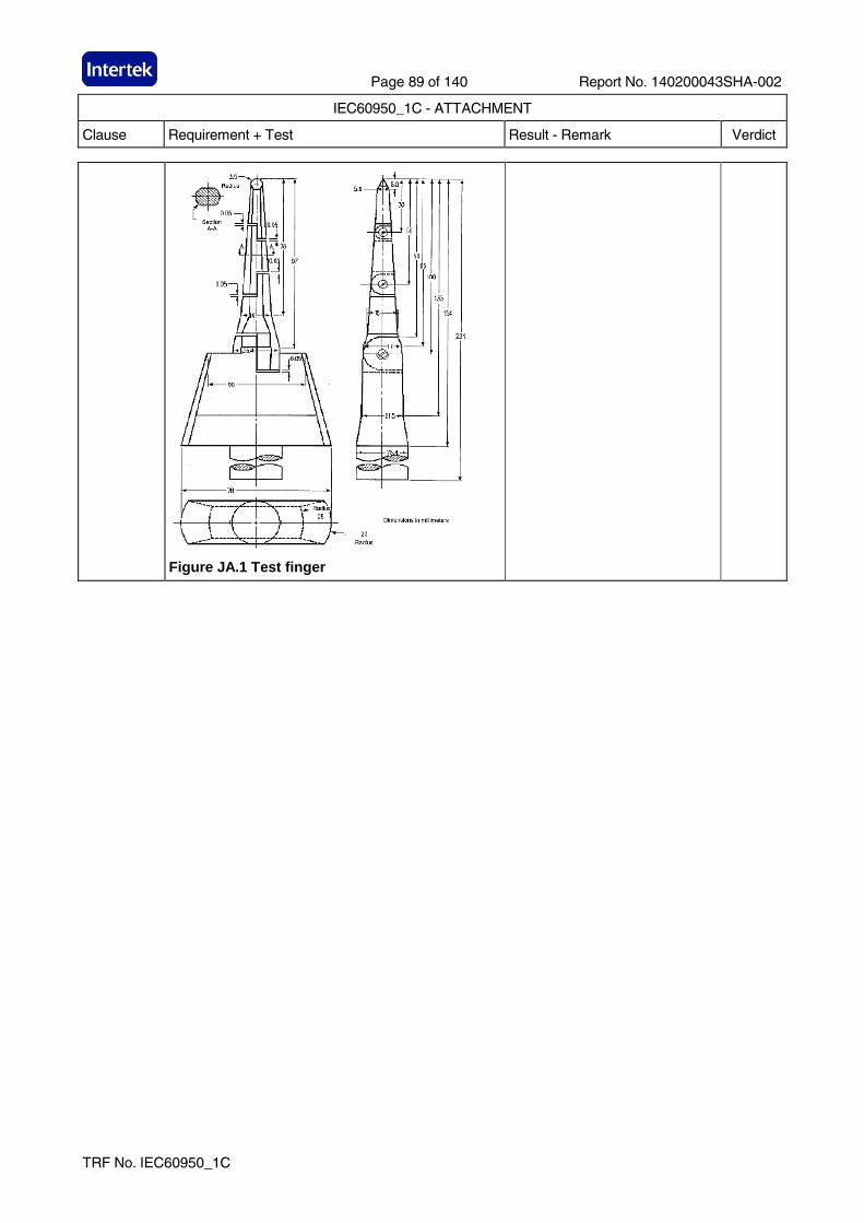
Page 89 of 140 Report No. 140200043SHA-002
IEC60950_1C - ATTACHMENT
Clause Requirement + Test Result - Remark Verdict
TRF No. IEC60950_1C
Figure JA.1 Test finger
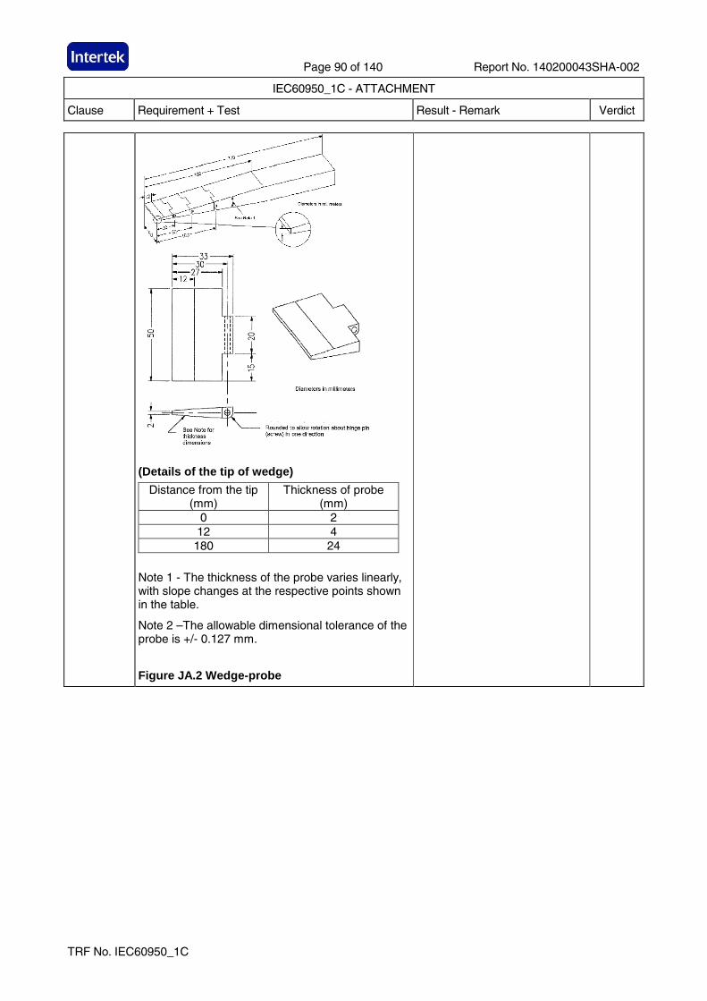
Page 90 of 140 Report No. 140200043SHA-002
IEC60950_1C - ATTACHMENT
Clause Requirement + Test Result - Remark Verdict
TRF No. IEC60950_1C
(Details of the tip of wedge)
Distance from the tip (mm)
Thickness of probe (mm)
0 2 12 4 180 24
Note 1 - The thickness of the probe varies linearly, with slope changes at the respective points shown in the table.
Note 2 –The allowable dimensional tolerance of the probe is +/- 0.127 mm.
Figure JA.2 Wedge-probe
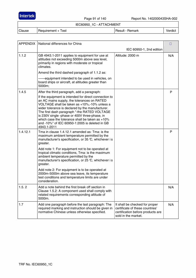
Page 91 of 140 Report No. 140200043SHA-002
IEC60950_1C - ATTACHMENT
Clause Requirement + Test Result - Remark Verdict
TRF No. IEC60950_1C
APPENDIX National differences for China
IEC 60950-1, 2nd edition
1.1.2 GB 4943.1-2011 applies to equipment for use at altitudes not exceeding 5000m above sea level, primarily in regions with moderate or tropical climates.
Amend the third dashed paragraph of 1.1.2 as:
——equipment intended to be used in vehicles, on board ships or aircraft, at altitudes greater than 5000m;
Altitude: 2000 m N/A
1.4.5 After the third paragraph, add a paragraph:
If the equipment is intended for direct connection to an AC mains supply, the tolerances on RATED VOLTAGE shall be taken as +10%,-10% unless a wider tolerance is declared by the manufacturer. The first dash paragraph "-the RATED VOLTAGE is 230V single -phase or 400V three-phase, in which case the tolerance shall be taken as +10% and -10%" of IEC 60950-1:2005 is deleted in GB 4943.1-2011
P
1.4.12.1 Tma in clause 1.4.12.1 amended as: Tma: is the maximum ambient temperature permitted by the manufacturer's specification, or 35 °C, whichever i s greater.
Add note 1: For equipment not to be operated at tropical climatic conditions, Tma: is the maximum ambient temperature permitted by the manufacturer's specification, or 25 °C, whichever i s greater.
Add note 2: For equipment is to be operated at 2000m-5000m above sea leave, its temperature test conditions and temperature limits are under consideration.
P
1.5. 2 Add a note behind the first break off section in Clause 1.5.2: A component used shall comply with related requirements corresponding altitude of 5000m.
N/A
1.7 Add one paragraph before the last paragraph: The required marking and instruction should be given in normative Chinese unless otherwise specified.
It shall be checked for proper certificate of these countries’ certification before products are sold in the market.
N/A
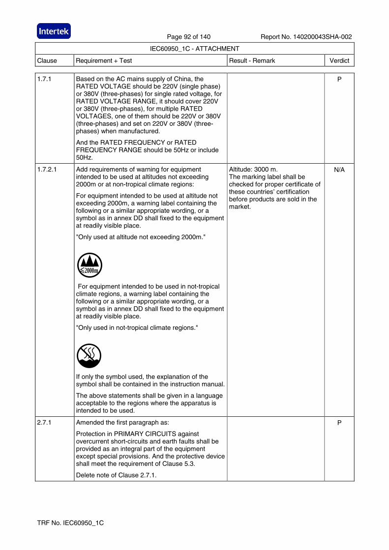
Page 92 of 140 Report No. 140200043SHA-002
IEC60950_1C - ATTACHMENT
Clause Requirement + Test Result - Remark Verdict
TRF No. IEC60950_1C
1.7.1 Based on the AC mains supply of China, the RATED VOLTAGE should be 220V (single phase) or 380V (three-phases) for single rated voltage, for RATED VOLTAGE RANGE, it should cover 220V or 380V (three-phases), for multiple RATED VOLTAGES, one of them should be 220V or 380V (three-phases) and set on 220V or 380V (three-phases) when manufactured.
And the RATED FREQUENCY or RATED FREQUENCY RANGE should be 50Hz or include 50Hz.
P
1.7.2.1 Add requirements of warning for equipment intended to be used at altitudes not exceeding 2000m or at non-tropical climate regions:
For equipment intended to be used at altitude not exceeding 2000m, a warning label containing the following or a similar appropriate wording, or a symbol as in annex DD shall fixed to the equipment at readily visible place.
"Only used at altitude not exceeding 2000m."
≤≤≤≤2000m
For equipment intended to be used in not-tropical climate regions, a warning label containing the following or a similar appropriate wording, or a symbol as in annex DD shall fixed to the equipment at readily visible place.
"Only used in not-tropical climate regions."
If only the symbol used, the explanation of the symbol shall be contained in the instruction manual.
The above statements shall be given in a language acceptable to the regions where the apparatus is intended to be used.
Altitude: 3000 m. The marking label shall be checked for proper certificate of these countries’ certification before products are sold in the market.
N/A
2.7.1 Amended the first paragraph as:
Protection in PRIMARY CIRCUITS against overcurrent short-circuits and earth faults shall be provided as an integral part of the equipment except special provisions. And the protective device shall meet the requirement of Clause 5.3.
Delete note of Clause 2.7.1.
P
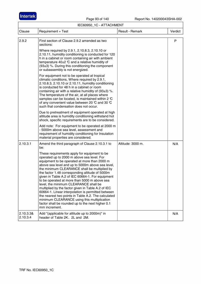
Page 93 of 140 Report No. 140200043SHA-002
IEC60950_1C - ATTACHMENT
Clause Requirement + Test Result - Remark Verdict
TRF No. IEC60950_1C
2.9.2 First section of Clause 2.9.2 amended as two sections:
Where required by 2.9.1, 2.10.8.3, 2.10.10 or 2.10.11, humidity conditioning is conducted for 120 h in a cabinet or room containing air with ambient temperature 40±2 °C and a relative humidity of (93±3) %. During this conditioning the component or subassembly is not energized.
For equipment not to be operated at tropical climatic conditions, Where required by 2.9.1, 2.10.8.3, 2.10.10 or 2.10.11, humidity conditioning is conducted for 48 h in a cabinet or room containing air with a relative humidity of (93±3) %. The temperature of the air, at all places where samples can be located, is maintained within 2 °C of any convenient value between 20 °C and 30 °C such that condensation does not occur.
Due to pretreatment of equipment operated at high altitude area is humidity conditioning withstand hot shock, specific requirements are to be considered.
Add note: For equipment to be operated at 2000 m - 5000m above sea level, assessment and requirement of humidity conditioning for Insulation material properties are considered.
P
2.10.3.1 Amend the third paragraph of Clause 2.10.3.1 to be:
These requirements apply for equipment to be operated up to 2000 m above sea level. For equipment to be operated at more than 2000 m above sea level and up to 5000m above sea level, the minimum CLEARANCE shall be multiplied by the factor 1.48 corresponding altitude of 5000m given in Table A.2 of IEC 60664-1. For equipment to be operated at more than 5000 m above sea level, the minimum CLEARANCE shall be multiplied by the factor given in Table A.2 of IEC 60664-1. Linear interpolation is permitted between the nearest two points in Table A.2. The calculated minimum CLEARANCE using this multiplication factor shall be rounded up to the next higher 0.1 mm increment.
Altitude: 3000 m. N/A
2.10.3.3& 2.10.3.4
Add "(applicable for altitude up to 2000m)" in header of Table 2K、2L and 2M.
N/A
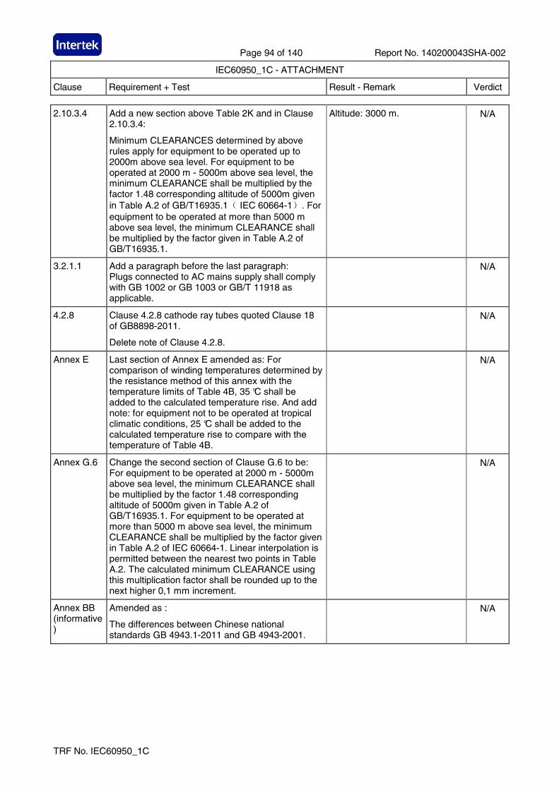
Page 94 of 140 Report No. 140200043SHA-002
IEC60950_1C - ATTACHMENT
Clause Requirement + Test Result - Remark Verdict
TRF No. IEC60950_1C
2.10.3.4
Add a new section above Table 2K and in Clause 2.10.3.4:
Minimum CLEARANCES determined by above rules apply for equipment to be operated up to 2000m above sea level. For equipment to be operated at 2000 m - 5000m above sea level, the minimum CLEARANCE shall be multiplied by the factor 1.48 corresponding altitude of 5000m given in Table A.2 of GB/T16935.1( IEC 60664-1). For equipment to be operated at more than 5000 m above sea level, the minimum CLEARANCE shall be multiplied by the factor given in Table A.2 of GB/T16935.1.
Altitude: 3000 m. N/A
3.2.1.1 Add a paragraph before the last paragraph: Plugs connected to AC mains supply shall comply with GB 1002 or GB 1003 or GB/T 11918 as applicable.
N/A
4.2.8
Clause 4.2.8 cathode ray tubes quoted Clause 18 of GB8898-2011.
Delete note of Clause 4.2.8.
N/A
Annex E
Last section of Annex E amended as: For comparison of winding temperatures determined by the resistance method of this annex with the temperature limits of Table 4B, 35 °C shall be added to the calculated temperature rise. And add note: for equipment not to be operated at tropical climatic conditions, 25 °C shall be added to the calculated temperature rise to compare with the temperature of Table 4B.
N/A
Annex G.6 Change the second section of Clause G.6 to be: For equipment to be operated at 2000 m - 5000m above sea level, the minimum CLEARANCE shall be multiplied by the factor 1.48 corresponding altitude of 5000m given in Table A.2 of GB/T16935.1. For equipment to be operated at more than 5000 m above sea level, the minimum CLEARANCE shall be multiplied by the factor given in Table A.2 of IEC 60664-1. Linear interpolation is permitted between the nearest two points in Table A.2. The calculated minimum CLEARANCE using this multiplication factor shall be rounded up to the next higher 0,1 mm increment.
N/A
Annex BB (informative)
Amended as :
The differences between Chinese national standards GB 4943.1-2011 and GB 4943-2001.
N/A
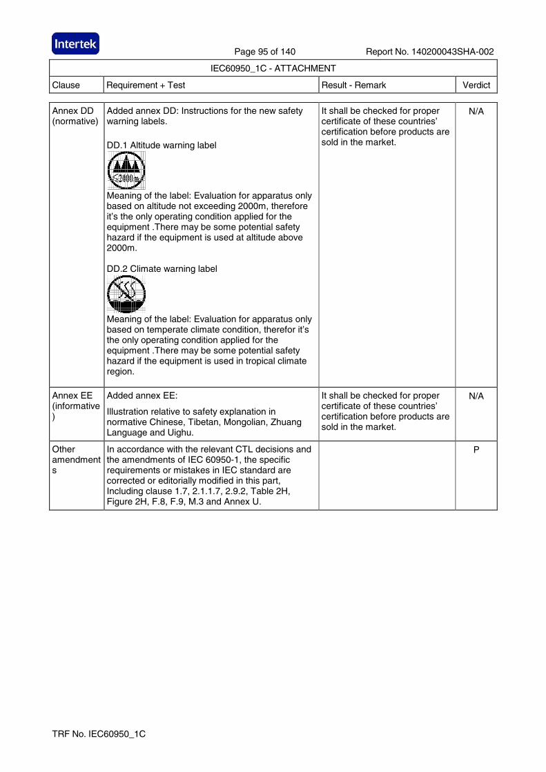
Page 95 of 140 Report No. 140200043SHA-002
IEC60950_1C - ATTACHMENT
Clause Requirement + Test Result - Remark Verdict
TRF No. IEC60950_1C
Annex DD (normative)
Added annex DD: Instructions for the new safety warning labels.
DD.1 Altitude warning label
Meaning of the label: Evaluation for apparatus only based on altitude not exceeding 2000m, therefore it’s the only operating condition applied for the equipment .There may be some potential safety hazard if the equipment is used at altitude above 2000m. DD.2 Climate warning label
Meaning of the label: Evaluation for apparatus only based on temperate climate condition, therefor it’s the only operating condition applied for the equipment .There may be some potential safety hazard if the equipment is used in tropical climate region.
It shall be checked for proper certificate of these countries’ certification before products are sold in the market.
N/A
Annex EE (informative)
Added annex EE:
Illustration relative to safety explanation in normative Chinese, Tibetan, Mongolian, Zhuang Language and Uighu.
It shall be checked for proper certificate of these countries’ certification before products are sold in the market.
N/A
Other amendments
In accordance with the relevant CTL decisions and the amendments of IEC 60950-1, the specific requirements or mistakes in IEC standard are corrected or editorially modified in this part, Including clause 1.7, 2.1.1.7, 2.9.2, Table 2H, Figure 2H, F.8, F.9, M.3 and Annex U.
P
Page 96 of 140 Report No. 140200043SHA-002
IEC60950_1C - ATTACHMENT
Clause Requirement + Test Result - Remark Verdict
TRF No. IEC60950_1C
Quoting standards and reference documents
The principles of quoting and referring to other standards in Annex P and reference documents of IEC 60950-1 are as follows:
If the date of the reference document is given, only that edition applies, excluding any subsequent corrigenda and amendments. However, parties to agreements based on this part are encouraged to investigate the possibility of applying the most recent editions of the reference documents. For undated references, the latest edition of the referenced document applies, including any corrigenda and amendments.
For the usage of international standards in Chinese national standards and industry standards is various, in the aim of achieving easy operation and based on the requirements of GB/T 1.1 and GB/T 20000.2, when quoting an entire international standard in the normative quoting files and reference documents of Annex P of this part, the principles of quotation are as follows:
- If there is no national standard or industry standard corresponding to the international standard, then the international standard is quoted;
- If there is national standard or industry standard corresponding to the international standard, then either the national or industry standard is quoted;
- If the date of the national standard or industry standard is not given, the latest edition of the standard applies;
- The national standard or industry standard number, corresponding international standard number and the consistency level code should be identified in parentheses behind the listed national standard or industry standard.
When quoting several chapters or clauses of the international standard, the principles of quotation are as follows:
- If there is no national standard or industry standard corresponding to the international standard, then the international standard is quoted;
- If there is national standard or industry standard corresponding to the international standard, then either the national or industry standard is quoted.
P
Meanwhile, in order to retain the relevant information on international standards, informative annex CC is increased, which gives the table about the comparison of the normative quoting files and reference documents in IEC 60950-1: 2005 and GB 4943.1-2011.
P
Page 97 of 140 Report No. 140200043SHA-002
IEC60950_1C - ATTACHMENT
Clause Requirement + Test Result - Remark Verdict
TRF No. IEC60950_1C
APPENDIX National differences for Australia and New Zealand
IEC 60950-1, 2nd edition
ANNEX ZZ (normative)
Variations to IEC 60950-1, ED.2.0 (2005) for application in Australia and New Zealand
ZZ1 Introduction
This Annex sets out variations and additional requirements to cover issues which have not been addressed by the International Standard. These variations indicate national variations for purposes of the IECEE CB Scheme and will be published in the IECEE CB Bulletin.
-
ZZ2 Variations
The following variations apply to the source text:
-
1.2 Between the definitions for ‘Person, service’ and ‘Range, rated frequency’
insert the following:
POTENTIAL IGNITION SOURCE 1.2.12
P
1.2.12.201 Insert a new Clause 1.2.12.201 after Clause 1.2.12.15 as follows:
1.2.12.201 POTENTIAL IGNITION SOURCE: Possible fault which can start a fire if the open-circuit voltage measured across an interruption or faulty contact exceeds a value of 50 V (peak) a.c. or d.c. and the product of the peak value of this voltage and the measured r.m.s current under normal operating conditions exceeds 15 VA.
Such a faulty contact or interruption in an electrical connection includes those which may occur in CONDUCTIVE PATTERNS on PRINTED BOARDS.
NOTE 201 An electronic protection circuit may be used to prevent such a fault from becoming a POTENTIAL IGNITION SOURCE.
NOTE 202 This definition is from AS/NZS 60065:2003.
P
1.5.1 Add the following to the end of first paragraph: “or the relevant Australian/New Zealand Standard”. In NOTE 1, add the following after the word “standard: “or an Australian/New Zealand Standard”.
P
1.5.2. Add the following to the end of first and third dash items: “or the relevant Australian/New Zealand Standard”.
P
Page 98 of 140 Report No. 140200043SHA-002
IEC60950_1C - ATTACHMENT
Clause Requirement + Test Result - Remark Verdict
TRF No. IEC60950_1C
3.2.5.1 Modify Table 3B as follows:
Delete the first four rows and replace with the following:
Minimum conductor sizes
RATED CURRENT of equipment
A
Nominal cross-sectional area
mm 2
AWG or kcmil [cross-sectional area in mm 2] see Note 2
Over 0.2 up to and including 3 Over 3 up to and including 7.5 Over 7.5 up to and including 10 Over 10 up to and including 16
0,5 a) 0,75 (0,75)b) 1,00 (1,0 )c) 1,5
18 [0,8] 16 [1,3] 16 [1,3] 14 [2]
Delete NOTE 1.
Replace footnote a) with the following: 1) This nominal cross-sectional area is only allowed for Class II appliances if the length of the power supply cord, measured between the point where the cord, or cord guard, enters the appliance, and the entry to the plug does not exceed 2 m (0.5 mm2 three-core supply flexible cords are not permitted; see AS/NZS 3191).
N/A
4.1.201 Insert a new Clause 4.1.201 after Clause 4.1 as follows:
4.1.201 Display devices used for television purposes
Display devices which may be used for television purposes, with a mass of 7 kg or more, shall comply with the requirements for stability and mechanical hazards, including the additional stability requirements for television receivers, specified in AS/NZS 60065.
N/A
4.3.6 Delete the third paragraph and replace with the following:
Equipment with a plug portion, suitable for insertion into a 10 A 3-pin flat-pin socket-outlet complying with AS/NZS 3112 shall comply with the requirements in AS/NZS 3112 for equipment with integral pins for insertion into socket-outlets.
P
4.3.13.5 Add the following to the end of the first paragraph:
“, or AS/NZS 2211.1”.
N/A
4.7 Add the following new paragraph to the end of the clause:
“For alternate tests refer to Clause 4.7.201.”
N/A
Page 99 of 140 Report No. 140200043SHA-002
IEC60950_1C - ATTACHMENT
Clause Requirement + Test Result - Remark Verdict
TRF No. IEC60950_1C
4.7.201 Insert a new Clause 4.7.201 after Clause 4.7.3.6 as follows:
4.7.201 Resistance to fire – Alternative tests
4.7.201.1 General
Parts of non-metallic material shall be resistant to ignition and spread of fire.
This requirement does not apply to decorative trims, knobs and other parts unlikely to be ignited or to propagate flames from inside the apparatus, or the following:
(a) Components that are contained in an enclosure having a flammability category of V-0 according to AS/NZS 60695.11.10 and having openings only for the connecting wires filling the openings completely, and for ventilation not exceeding 1 mm in width regardless of length.
(b) The following parts which would contribute negligible fuel to a fire:
- small mechanical parts, the mass of which does not exceed 4 g, such as mounting parts, gears, cams, belts and bearings;
- small electrical components, such as capacitors with a volume not exceeding 1,750 mm3, integrated circuits, transistors and optocoupler packages, if these components are mounted on material of flammability category V-1, or better, according to AS/NZS 60695.11.10.
NOTE In considering how to minimize propagation of fire and what “small parts” are, account should be taken of the cumulative effect of small parts adjacent to each other for the possible effect of propagating fire from one part to another.
Compliance shall be checked by the tests of 4.7.201.2, 4.7.201.3, 4.7.201.4 and 4.7.201.5.
For the base material of printed boards, compliance shall be checked by the test of 4.7.201.5.
The tests shall be carried out on parts of non-metallic material which have been removed from the apparatus. When the glow-wire test is carried out, the parts shall be placed in the same orientation as they would be in normal use.
These tests are not carried out on internal wiring.
The equipment complies with the requirements of IEC 60950-1. Alternative test methods are not considered.
N/A
Page 100 of 140 Report No. 140200043SHA-002
IEC60950_1C - ATTACHMENT
Clause Requirement + Test Result - Remark Verdict
TRF No. IEC60950_1C
Cont. 4.7.201.2 Testing of non-metallic materials
Parts of non-metallic material shall be subject to the glow-wire test of AS/NZS 60695.2.11 which shall be carried out at 550°C.
Parts for which the glow-wire test cannot be carried out, such as those made of soft or foamy material, shall meet the requirements specified in ISO 9772 for category FH-3 material. The glow-wire test shall be not carried out on parts of material classified at least FH-3 according to ISO 9772 provided that the sample tested was not thicker than the relevant part.
4.7.201.3 Testing of insulating materials
Parts of insulating material supporting POTENTIAL IGNITION SOURCES shall be subject to the glow-wire test of AS/NZS 60695.2.11 which shall be carried out at 750°C.
The test shall be also carried out on other parts of insulating material which are within a distance of 3 mm of the connection.
NOTE Contacts in components such as switch contacts are considered to be connections.
For parts which withstand the glow-wire test but produce a flame, other parts above the connection within the envelope of a vertical cylinder having a diameter of 20 mm and a height of 50 mm shall be subjected to the needle-flame test. However, parts shielded by a barrier which meets the needle-flame test shall not be tested.
The needle-flame test shall be made in accordance with AS/NZS 60695.11.5 with the following modifications:
N/A
Page 101 of 140 Report No. 140200043SHA-002
IEC60950_1C - ATTACHMENT
Clause Requirement + Test Result - Remark Verdict
TRF No. IEC60950_1C
Cont. Clause of AS/NZS 60695.11.5
Change
9 Test procedure 9.2 Application of needle-flame
Replace the first paragraph with: The specimen shall be arranged so that the flame can be applied to a vertical or horizontal edge as shown in the examples of figure 1. If possible the flame shall be applied at least 10 mm from a corner Replace the first paragraph with: The duration of application of the test flame shall be 30 s ±1 s.
9.3 Number of test specimens
Replace with: The test shall be made on one specimen. If the specimen does not withstand the test, the test may be repeated on two further specimens, both of which shall withstand the test.
11 Evaluation of test results
Replace with: The duration of burning (tb) shall not exceed 30 s. However, for printed circuit boards, it shall not exceed 15 s.
The needle-flame test shall not be carried out on parts of material classified as V-0 or V-1 according to AS/NZS 60695.11.10, provided that the sample tested was not thicker than the relevant part.
4.7.201.4 Testing in the event of non-extinguishing material
If parts, other than enclosures, do not withstand the glow wire tests of 4.7.201.3, by failure to extinguish within 30 s after the removal of the glow-wire tip, the needle-flame test detailed in 4.7.201.3 shall be made on all parts of non-metallic material which are within a distance of 50 mm or which are likely to be impinged upon by flame during the tests of 4.7.201.3. Parts shielded by a separate barrier which meets the needle-flame test need not be tested.
N/A
Page 102 of 140 Report No. 140200043SHA-002
IEC60950_1C - ATTACHMENT
Clause Requirement + Test Result - Remark Verdict
TRF No. IEC60950_1C
Cont. NOTE 1 - If the enclosure does not withstand the glow-wire test the equipment is considered to have failed to meet the requirements of Clause 4.7.201 without the need for consequential testing.
NOTE 2 - If other parts do not withstand the glow-wire test due to ignition of the tissue paper and if this indicates that burning or glowing particles can fall onto an external surface underneath the equipment, the equipment is considered to have failed to meet the requirements of Clause 4.7.201 without the need for consequential testing.
NOTE 3 - Parts likely to be impinged upon by the flame are considered to be those within the envelope of a vertical cylinder having a radius of 10 mm and a height equal to the height of the flame, positioned above the point of the material supporting, in contact with, or in close proximity to, connections.
4.7.201.5 Testing of printed boards
The base material of printed boards shall be subjected to the needle-flame test of Clause 4.7.201.3. The flame shall be applied to the edge of the board where the heat sink effect is lowest when the board is positioned as in normal use. The flame shall not be applied to an edge, consisting of broken perforations, unless the edge is less than 3 mm from a POTENTIAL IGNITION SOURCE.
The test is not carried out if the —
- Printed board does not carry any POTENTIAL IGNITION SOURCE;
- Base material of printed boards, on which the available apparent power at a connection exceeds 15 VA operating at a voltage exceeding 50 V and equal or less than 400 V (peak) a.c. or d.c. under normal operating conditions, is of flammability category V-1 or better according to AS/NZS 60695.11.10, or the printed boards are protected by an enclosure meeting the flammability category V-0 according to AS/NZS 60695.11.10, or made of metal, having openings only for connecting wires which fill the openings completely; or
- Base material of printed boards, on which the available apparatus power at a connection exceeds 15 VA operating at a voltage exceeding 400 V (peak) a.c. or d.c. under normal operating conditions, and base material of printed boards supporting spark gaps which provides protection against overvoltages, is of flammability category V-0 according to AS/NZS 60695.11.10 or the printed boards are contained in a metal enclosure, having openings only for connecting wires which fill the openings completely.
N/A
Compliance shall be determined using the smallest thickness of the material.
NOTE – Available apparent power is the maximum apparent power which can be drawn from the supplying circuit through a resistive load whose value is chosen to maximise the apparent power for more than 2 min when the circuit supplied is disconnected.
N/A
Page 103 of 140 Report No. 140200043SHA-002
IEC60950_1C - ATTACHMENT
Clause Requirement + Test Result - Remark Verdict
TRF No. IEC60950_1C
6.2.2 For Australia only, delete the first paragraph and Note, and replace with the following:
In Australia only, compliance with 6.2.2 shall be checked by the tests of both 6.2.2.1 and 6.2.2.2.
N/A
6.2.2.1 For Australia only, delete the first paragraph including the Notes, and replace with the following:
In Australia only, the electrical separation is subjected to 10 impulses of alternating polarity, using the impulse test generator reference 1 of Table N.1. The interval between successive impulses is 60 s and the initial voltage, Uc, is:
(i) for 6.2.1 a): 7.0 kV for hand-held telephones and for headsets and 2.5 kV for other equipment; and
(ii) for 6.2.1 b) and 6.2.1 c): 1.5 kV.
NOTE 201 – The 7 kV impulse simulates lightning surges on typical rural and semi-rural network lines.
NOTE 202 – The value of 2.5 kV for 6.2.1 a) was chosen to ensure the adequacy of the insulation concerned and does not necessarily simulate likely overvoltages.
N/A
6.2.2.2 For Australia only, delete the second paragraph including the Note, and replace with the following.
In Australia only, the a.c. test voltage is:
(i) for 6.2.1 a): 3 kV; and
(ii) for 6.2.1 b) and 6.2.1 c): 1.5 kV.
NOTE 201 – Where there are capacitors across the insulation under test, it is recommended that d.c. test voltages are used.
NOTE 202 – The 3 kV and 1.5 kV values have been determined considering the low frequency induced voltages from the power supply distribution system.
N/A
7.3 Add the following before the first paragraph:
Equipment providing functions that fall only within the scope of AS/NZS 60065 and that incorporate a PSTN interface, are not required to comply with this Clause where the only ports provided on the equipment, in addition to a coaxial cable connection and a PSTN interface, are audio or video ports and analogue or data ports not intended to be used for telecommunications purposes.
N/A
Annex P Add the following Normative References:
AS/NZS 3191, Electric flexible cords AS/NZS 3112, Approval and test specification—Plugs and socket-outlets
P
Page 104 of 140 Report No. 140200043SHA-002
IEC60950_1C - ATTACHMENT
Clause Requirement + Test Result - Remark Verdict
TRF No. IEC60950_1C
Index Insert the following between “asbestos, not be used as insulation” and “attitude see orientation”:
AS/NZS 2211.1 4.3.13.5 AS/NZS 3112 4.3.6 AS/NZS 3191 3.2.5.1 (Table 3B) AS/NZS 60064 4.1.201 AS/NZS 60695.2.11 4.7.201.2, 4.7.201.3 AS/NZS 60695.11.10 4.7.201.1, 4.7.201.5 AS/NZS 60695.11.5 4.7.201.3
Insert the following between “positive temperature coefficient (PTC) device” and ‘powder’:
potential ignition source 1.2.201, 4.7.201.3, 4.7.201.5
P
Page 105 of 140 Report No. 140200043SHA-002
IEC60950_1C - ATTACHMENT
Clause Requirement + Test Result - Remark Verdict
TRF No. IEC60950_1C
ATTACHMENT TO TEST REPORT IEC 60950-1 U.S.A. NATIONAL DIFFERENCES Information technology equipment – Safety –
Part 1: General requirements
Differences according to................. : UL 60950-1-07
Attachment Form No........................ : US_ND_IEC60950_1C
Attachment Originator ..................... : TÜV SÜD Product Service GmbH
Master Attachment........................... : Date (2012-08)
Copyright © 2012 IEC System for Conformity Testing and Certification of Electrical Equipment (IECEE), Geneva, Switzerland. All rights reserved.
Special national conditions
1.1.1 All equipment is to be designed to allow installation in accordance with the National Electrical Code (NEC), ANSI/NFPA 70, the Canadian Electrical Code (CEC), Part I, CAN/CSA C22.1, and when applicable, the National Electrical Safety Code, IEEE C2.
P
Also, unless marked or otherwise identified, installation is allowed per the Standard for the Protection of Electronic Computer/Data-Processing Equipment, ANSI/NFPA 75.
P
1.4.14 For Pluggable Equipment Type A, the protection in the installation is assumed to be 20A.
P
1.5.5 For lengths exceeding 3.05 m, external interconnecting flexible cord and cable assemblies are required to be a suitable cable type (e.g., DP, CL2) specified in the CEC/NEC.
N/A
For lengths 3.05 m or less, external interconnecting flexible cord and cable assemblies that are not types specified in the CEC are required to have special construction features and identification markings.
N/A
1.7.1 Equipment for use on a.c. mains supply systems with a neutral and more than one phase conductor (e.g. 120/240 V, 3-wire) require a special marking format for electrical ratings.
N/A
A voltage rating that exceeds an attachment plug cap rating is only permitted if it does not exceed the extreme operating conditions in Table 2 of CAN/CSA C22.2 No. 235, and
P
- If it is part of a range that extends into the Table 2 "Normal Operating Conditions."
P
A voltage rating is not to be lower than the specified "Normal Operating Conditions," unless it is part of a range that extends into the "Normal Operating Conditions."
P
Page 106 of 140 Report No. 140200043SHA-002
IEC60950_1C - ATTACHMENT
Clause Requirement + Test Result - Remark Verdict
TRF No. IEC60950_1C
1.7.7 Wiring terminals intended to supply Class 2 outputs in accordance with CEC Part 1 or NEC are marked with the voltage rating and “Class 2” or equivalent.
N/A
- Marking is located adjacent to the terminals N/A
- Marking is visible during wiring N/A
2.5 Fuse providing Class 2, Limited Power Source, or TNV current limiting is not operator-accessible unless it is not interchangeable.
N/A
2.6.3.3 Modify first column on Table 2D to “Smaller of the RATED CURRENT of the equipment or the PROTECTIVE CURRENT RATING of the circuit under consideration.”
N/A
2.7.1 Suitable NEC/CEC branch circuit protection rated at the maximum circuit rating is provided for all standard supply outlets and receptacles (such as supplied in power distribution units) if the supply branch circuit protection is not suitable. Power distribution transformers distributing power at 100 volts or more, and rated 10 kVA or more, provided with special transformer overcurrent protection.
Considered. P
3.2 Wiring methods (terminals, leads, etc.) used for the connection of the equipment to the mains is in accordance with the NEC/CEC.
N/A
3.2.1 Attachment plugs of power supply cords are rated not less than 125 per cent of the rated current of the equipment.
N/A
3.2.1.2 Equipment connected to a centralized d.c. power system, and having one pole of the DC mains input terminal connected to the main protective earthing terminal in the equipment comply with special earthing, wiring, marking and installation instruction requirements.
N/A
3.2.3 Permanent connection of equipment to the mains supply by a power supply cord is not permitted, except for certain equipment, such as ATMs.
N/A
3.2.5 Power supply cords are no longer than 4.5 m in length.
N/A
Minimum cord length is 1.5 m, with certain constructions such as external power supplies allowed to consider both input and output cord lengths into the requirement.
N/A
Flexible power supply cords are compatible with Article 400 of the NEC, and Tables 11 and 12 of the CEC.
N/A
3.2.9 Permanently connected equipment has a suitable wiring compartment and wire bending space.
N/A
3.3 Wiring terminals and associated spacing for field wiring connections comply with CSA C22.2 No. 0.
N/A
Page 107 of 140 Report No. 140200043SHA-002
IEC60950_1C - ATTACHMENT
Clause Requirement + Test Result - Remark Verdict
TRF No. IEC60950_1C
3.3.3 Wire binding screws are not permitted to attach conductors larger than 10 AWG (5.3 mm2).
N/A
3.3.4 Terminals for permanent wiring, including protective earthing terminals, are suitable for Canadian/US wire gauge sizes, are
N/A
- rated 125 per cent of the equipment rating, and N/A
- are specially marked when specified (1.7.7). N/A
3.3.5 Revise first column of Table 3E to “Smaller of the RATED CURRENT of the equipment or the PROTECTIVE CURRENT RATING of the circuit under consideration.”
N/A
3.4.2 Motor control devices are provided for cord-connected equipment with a motor if the equipment is rated more than 12 A,
N/A
- or if the motor has a nominal voltage rating greater than 120 V
N/A
- or is rated more than 1/3 hp (locked rotor current over 43 A)
N/A
3.4.8 Vertically-mounted disconnect switches and circuit breakers have the "on" position indicated by the handle in the up position.
N/A
3.4.11 For computer room applications, equipment with battery systems capable of supplying 750 VA for five minutes have a battery disconnect means that may be connected to the computer room remote power-off circuit.
N/A
4.3.12 The maximum quantity of flammable liquid stored in equipment complies with NFPA 30.
N/A
4.3.13.5 Equipment with lasers meets the Canadian Radiation Emitting Devices Act, REDR C1370 and/or Code of Federal Regulations 21 CFR 1040, as applicable.
N/A
4.7 For computer room applications, automated information storage systems with combustible media greater than 0.76 m3 (27 cu ft) have a provision for connection of either automatic sprinklers or a gaseous agent extinguishing system with an extended discharge.
N/A
4.7.3.1 For computer room applications, enclosures with combustible material measuring greater than 0.9 m2 (10 sq ft) or a single dimension greater than 1.8 m (6 ft) have a flame spread rating of 50 or less.
N/A
For other applications, enclosures with the same dimensions require a flame spread rating of 200 or less.
N/A
Annex H Equipment that produces ionizing radiation complies with U.S. Code of Federal Regulations, 21 CFR 1020 (and the Canadian Radiation Emitting Devices Act, REDR C1370).
N/A
Page 108 of 140 Report No. 140200043SHA-002
IEC60950_1C - ATTACHMENT
Clause Requirement + Test Result - Remark Verdict
TRF No. IEC60950_1C
Other National Differences
1.5.1 Some components and materials associated with the risk of fire, electric shock, or personal injury have component or material ratings in accordance with the applicable national (Canadian and/or U.S.) component or material standard requirements.
P
1.6.1.2 A circuit for connection to the DC Mains Supply is classified as a SELV Circuit, TNV-2 Circuit or Hazardous Voltage Circuit depending on the maximum operating voltage of the supply.
N/A
This maximum operating voltage includes consideration of the battery charging “float voltage” associated with the intended supply system, regardless of the marked power rating of the equipment.
N/A
2.3.1 For TNV-2 and TNV-3 circuits with other than ringing signals and with voltages exceeding 42.4 Vpeak or 60 Vd.c., the maximum acceptable current through a 2000 ohm resistor (or greater) connected across the voltage source with other loads disconnected is 7.1 mA peak or 30 mA d.c. under normal operating conditions.
N/A
2.3.2.1 In the event of a single fault between TNV and SELV circuits, the limits of 2.2.3 apply to SELV Circuits and accessible conductive parts.
N/A
2.6.3.4 Protective bonding conductors of non-standard protective bonding constructions (e.g., printed circuit traces) may be subjected to the additional limited short circuit test conditions specified.
N/A
4.2.8.1 Enclosures around CRTs with a face diameter of 160 mm or more reduce the risk of injury due to the implosion of the CRT.
N/A
4.3.2 Equipment with handles complies with special loading tests.
N/A
5.1.8.3 Equipment intended to receive telecommunication ringing signals comply with a special touch current measurement tests.
N/A
5.3.7 Internal (e.g., card cage) SELV circuit connectors and printed wiring board connectors that are accessible to the operator and that deliver power are overloaded.
P
During abnormal operating testing, if a circuit is interrupted by the opening of a component, the test shall be repeated twice (three tests total) using new components as necessary
P
6.4 Equipment intended for connection to telecommunication network outside plant cable is protected against overvoltage from power line crosses in accordance with 6.4 and Annex NAC.
N/A
Page 109 of 140 Report No. 140200043SHA-002
IEC60950_1C - ATTACHMENT
Clause Requirement + Test Result - Remark Verdict
TRF No. IEC60950_1C
Annex EE Articulated accessibility probe (Fig EE.3) is used for assessing accessibility to document/media shredders instead of the Figure 2A test finger.
N/A
Annex M.2 Continuous ringing signals up to 16 mA only are permitted if the equipment is subjected to special installation and performance restrictions.
N/A
Annex NAD Equipment connected to a telecommunication and cable distribution networks and supplied with an earphone intended to be held against, or in the ear comply with special acoustic pressure requirements.
N/A
Page 110 of 140 Report No. 140200043SHA-002
IEC60950_1C - ATTACHMENT
Clause Requirement + Test Result - Remark Verdict
TRF No. IEC60950_1C
APPENDIX National differences for Canada
IEC 60950-1, 2nd edition; Am 1:2009
SPECIAL NATIONAL CONDITIONS
The following is a summary of the key national differences based on national regulatory requirements, such as the Canadian Electrical Code (CEC) Part and the Canadian Building Code, which are referenced in legislation and which form the basis for the rules and practices followed in electrical and building installations
1.1.1 All equipment is to be designed to allow installation in accordance with the National Electrical Code (NEC), ANSI/NFPA 70, the Canadian Electrical Code (CEC), Part I, CAN/CSA C22.1, and when applicable, the National Electrical Safety Code, IEEE C2. Also, unless marked or otherwise identified, installation is allowed per the Standard for the Protection of Electronic Computer/Data-Processing Equipment, ANSI/NFPA 75.
Unit was evaluated according to IEC 60950-1.
The requirements have to be checked during national approval.
P
1.4.14 For Pluggable Equipment Type A, the protection in the installation is assumed to be 20A.
P
1.5.5 For lengths exceeding 3.05 m, external interconnecting flexible cord and cable assemblies are required to be a suitable cable type (e.g., DP, CL2) specified in the CEC/NEC.
For lengths 3.05 m or less, external interconnecting flexible cord and cable assemblies that are not types specified in the CEC are required to have special construction features and identification markings.
N/A
1.7.1 Equipment for use on a.c. mains supply systems with a neutral and more than one phase conductor (e.g. 120/240 V, 3-wire) require a special marking format for electrical ratings.
A voltage rating that exceeds an attachment plug cap rating is only permitted if it does not exceed the extreme operating conditions in Table 2 of CAN/CSA C22.2 No. 235, and if it is part of a range that extends into the Table 2 "Normal Operating Conditions." Likewise, a voltage rating shall not be lower than the specified "Normal Operating Conditions," unless it is part of a range that extends into the "Normal Operating Conditions."
P
1.7.7 Wiring terminals intended to supply Class 2 outputs in accordance with CEC Part 1 or NEC shall be marked with the voltage rating and “Class 2” or equivalent. Marking shall be located adjacent to the terminals and shall be visible during wiring.
N/A
2.5 Where a fuse is used to provide Class 2, Limited Power Source, or TNV current limiting, it shall not be operator-accessible unless it is not interchangeable.
N/A
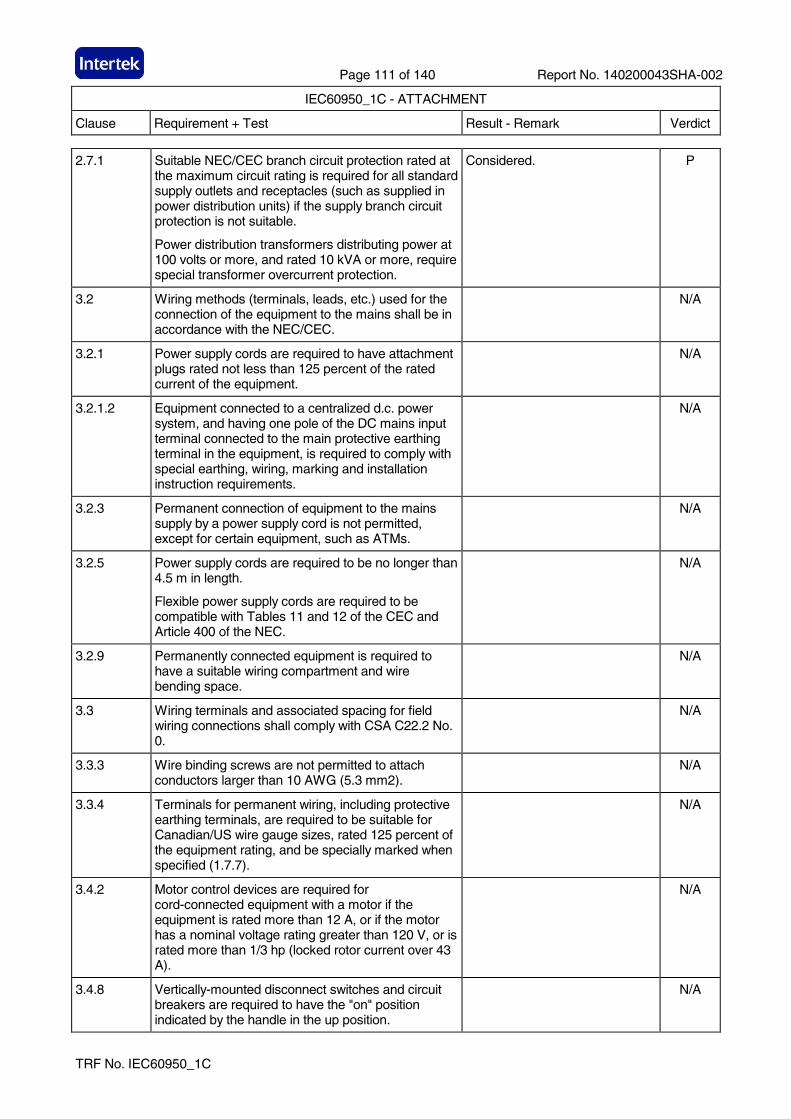
Page 111 of 140 Report No. 140200043SHA-002
IEC60950_1C - ATTACHMENT
Clause Requirement + Test Result - Remark Verdict
TRF No. IEC60950_1C
2.7.1 Suitable NEC/CEC branch circuit protection rated at the maximum circuit rating is required for all standard supply outlets and receptacles (such as supplied in power distribution units) if the supply branch circuit protection is not suitable.
Power distribution transformers distributing power at 100 volts or more, and rated 10 kVA or more, require special transformer overcurrent protection.
Considered. P
3.2 Wiring methods (terminals, leads, etc.) used for the connection of the equipment to the mains shall be in accordance with the NEC/CEC.
N/A
3.2.1 Power supply cords are required to have attachment plugs rated not less than 125 percent of the rated current of the equipment.
N/A
3.2.1.2 Equipment connected to a centralized d.c. power system, and having one pole of the DC mains input terminal connected to the main protective earthing terminal in the equipment, is required to comply with special earthing, wiring, marking and installation instruction requirements.
N/A
3.2.3 Permanent connection of equipment to the mains supply by a power supply cord is not permitted, except for certain equipment, such as ATMs.
N/A
3.2.5 Power supply cords are required to be no longer than 4.5 m in length.
Flexible power supply cords are required to be compatible with Tables 11 and 12 of the CEC and Article 400 of the NEC.
N/A
3.2.9 Permanently connected equipment is required to have a suitable wiring compartment and wire bending space.
N/A
3.3 Wiring terminals and associated spacing for field wiring connections shall comply with CSA C22.2 No. 0.
N/A
3.3.3 Wire binding screws are not permitted to attach conductors larger than 10 AWG (5.3 mm2).
N/A
3.3.4 Terminals for permanent wiring, including protective earthing terminals, are required to be suitable for Canadian/US wire gauge sizes, rated 125 percent of the equipment rating, and be specially marked when specified (1.7.7).
N/A
3.4.2 Motor control devices are required for cord-connected equipment with a motor if the equipment is rated more than 12 A, or if the motor has a nominal voltage rating greater than 120 V, or is rated more than 1/3 hp (locked rotor current over 43 A).
N/A
3.4.8 Vertically-mounted disconnect switches and circuit breakers are required to have the "on" position indicated by the handle in the up position.
N/A
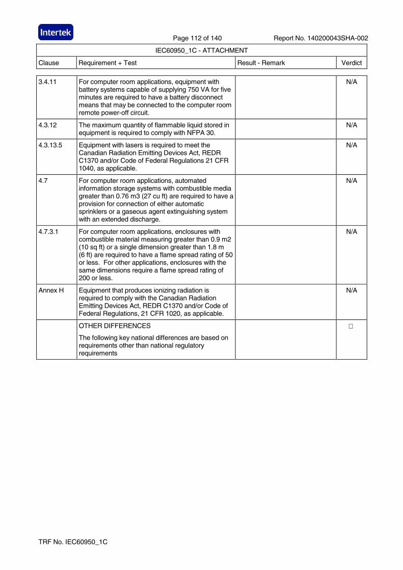
Page 112 of 140 Report No. 140200043SHA-002
IEC60950_1C - ATTACHMENT
Clause Requirement + Test Result - Remark Verdict
TRF No. IEC60950_1C
3.4.11 For computer room applications, equipment with battery systems capable of supplying 750 VA for five minutes are required to have a battery disconnect means that may be connected to the computer room remote power-off circuit.
N/A
4.3.12 The maximum quantity of flammable liquid stored in equipment is required to comply with NFPA 30.
N/A
4.3.13.5 Equipment with lasers is required to meet the Canadian Radiation Emitting Devices Act, REDR C1370 and/or Code of Federal Regulations 21 CFR 1040, as applicable.
N/A
4.7 For computer room applications, automated information storage systems with combustible media greater than 0.76 m3 (27 cu ft) are required to have a provision for connection of either automatic sprinklers or a gaseous agent extinguishing system with an extended discharge.
N/A
4.7.3.1 For computer room applications, enclosures with combustible material measuring greater than 0.9 m2 (10 sq ft) or a single dimension greater than 1.8 m (6 ft) are required to have a flame spread rating of 50 or less. For other applications, enclosures with the same dimensions require a flame spread rating of 200 or less.
N/A
Annex H Equipment that produces ionizing radiation is required to comply with the Canadian Radiation Emitting Devices Act, REDR C1370 and/or Code of Federal Regulations, 21 CFR 1020, as applicable.
N/A
OTHER DIFFERENCES
The following key national differences are based on requirements other than national regulatory requirements
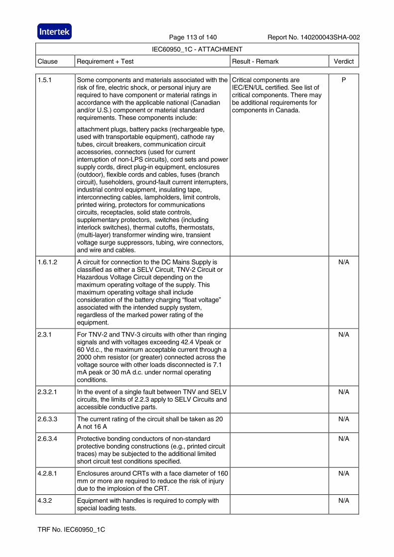
Page 113 of 140 Report No. 140200043SHA-002
IEC60950_1C - ATTACHMENT
Clause Requirement + Test Result - Remark Verdict
TRF No. IEC60950_1C
1.5.1 Some components and materials associated with the risk of fire, electric shock, or personal injury are required to have component or material ratings in accordance with the applicable national (Canadian and/or U.S.) component or material standard requirements. These components include:
attachment plugs, battery packs (rechargeable type, used with transportable equipment), cathode ray tubes, circuit breakers, communication circuit accessories, connectors (used for current interruption of non-LPS circuits), cord sets and power supply cords, direct plug-in equipment, enclosures (outdoor), flexible cords and cables, fuses (branch circuit), fuseholders, ground-fault current interrupters, industrial control equipment, insulating tape, interconnecting cables, lampholders, limit controls, printed wiring, protectors for communications circuits, receptacles, solid state controls, supplementary protectors, switches (including interlock switches), thermal cutoffs, thermostats, (multi-layer) transformer winding wire, transient voltage surge suppressors, tubing, wire connectors, and wire and cables.
Critical components are IEC/EN/UL certified. See list of critical components. There may be additional requirements for components in Canada.
P
1.6.1.2 A circuit for connection to the DC Mains Supply is classified as either a SELV Circuit, TNV-2 Circuit or Hazardous Voltage Circuit depending on the maximum operating voltage of the supply. This maximum operating voltage shall include consideration of the battery charging “float voltage” associated with the intended supply system, regardless of the marked power rating of the equipment.
N/A
2.3.1 For TNV-2 and TNV-3 circuits with other than ringing signals and with voltages exceeding 42.4 Vpeak or 60 Vd.c., the maximum acceptable current through a 2000 ohm resistor (or greater) connected across the voltage source with other loads disconnected is 7.1 mA peak or 30 mA d.c. under normal operating conditions.
N/A
2.3.2.1 In the event of a single fault between TNV and SELV circuits, the limits of 2.2.3 apply to SELV Circuits and accessible conductive parts.
N/A
2.6.3.3 The current rating of the circuit shall be taken as 20 A not 16 A
N/A
2.6.3.4 Protective bonding conductors of non-standard protective bonding constructions (e.g., printed circuit traces) may be subjected to the additional limited short circuit test conditions specified.
N/A
4.2.8.1 Enclosures around CRTs with a face diameter of 160 mm or more are required to reduce the risk of injury due to the implosion of the CRT.
N/A
4.3.2 Equipment with handles is required to comply with special loading tests.
N/A
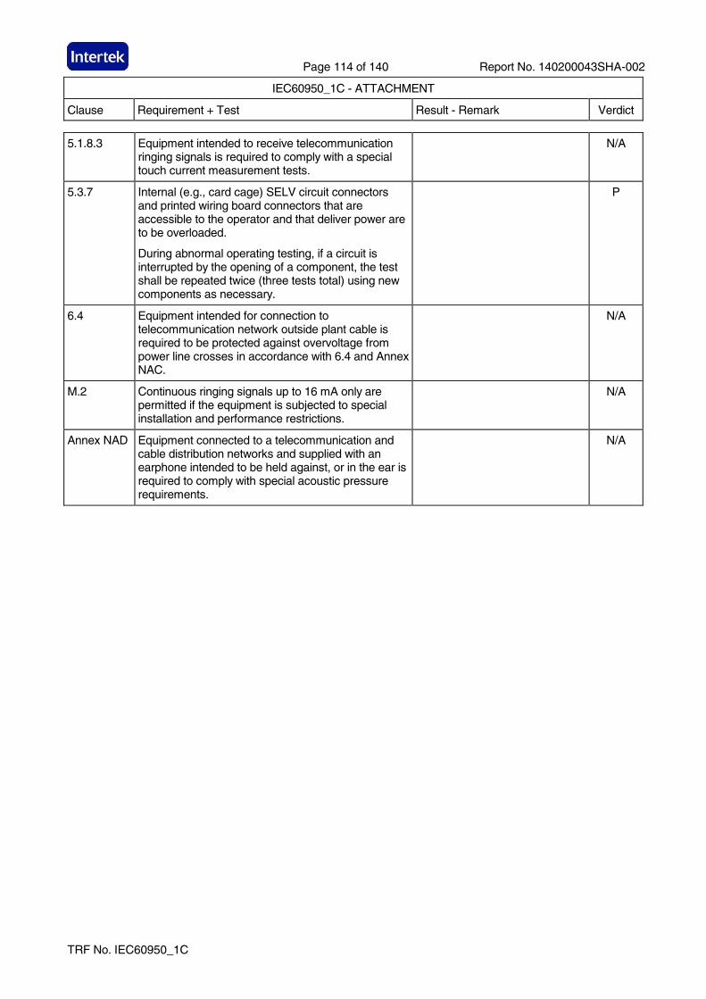
Page 114 of 140 Report No. 140200043SHA-002
IEC60950_1C - ATTACHMENT
Clause Requirement + Test Result - Remark Verdict
TRF No. IEC60950_1C
5.1.8.3 Equipment intended to receive telecommunication ringing signals is required to comply with a special touch current measurement tests.
N/A
5.3.7 Internal (e.g., card cage) SELV circuit connectors and printed wiring board connectors that are accessible to the operator and that deliver power are to be overloaded.
During abnormal operating testing, if a circuit is interrupted by the opening of a component, the test shall be repeated twice (three tests total) using new components as necessary.
P
6.4 Equipment intended for connection to telecommunication network outside plant cable is required to be protected against overvoltage from power line crosses in accordance with 6.4 and Annex NAC.
N/A
M.2 Continuous ringing signals up to 16 mA only are permitted if the equipment is subjected to special installation and performance restrictions.
N/A
Annex NAD Equipment connected to a telecommunication and cable distribution networks and supplied with an earphone intended to be held against, or in the ear is required to comply with special acoustic pressure requirements.
N/A
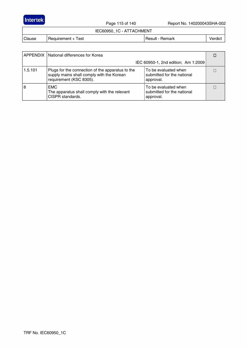
Page 115 of 140 Report No. 140200043SHA-002
IEC60950_1C - ATTACHMENT
Clause Requirement + Test Result - Remark Verdict
TRF No. IEC60950_1C
APPENDIX National differences for Korea
IEC 60950-1, 2nd edition; Am 1:2009
1.5.101
Plugs for the connection of the apparatus to the supply mains shall comply with the Korean requirement (KSC 8305).
To be evaluated when submitted for the national approval.
8
EMC The apparatus shall comply with the relevant CISPR standards.
To be evaluated when submitted for the national approval.
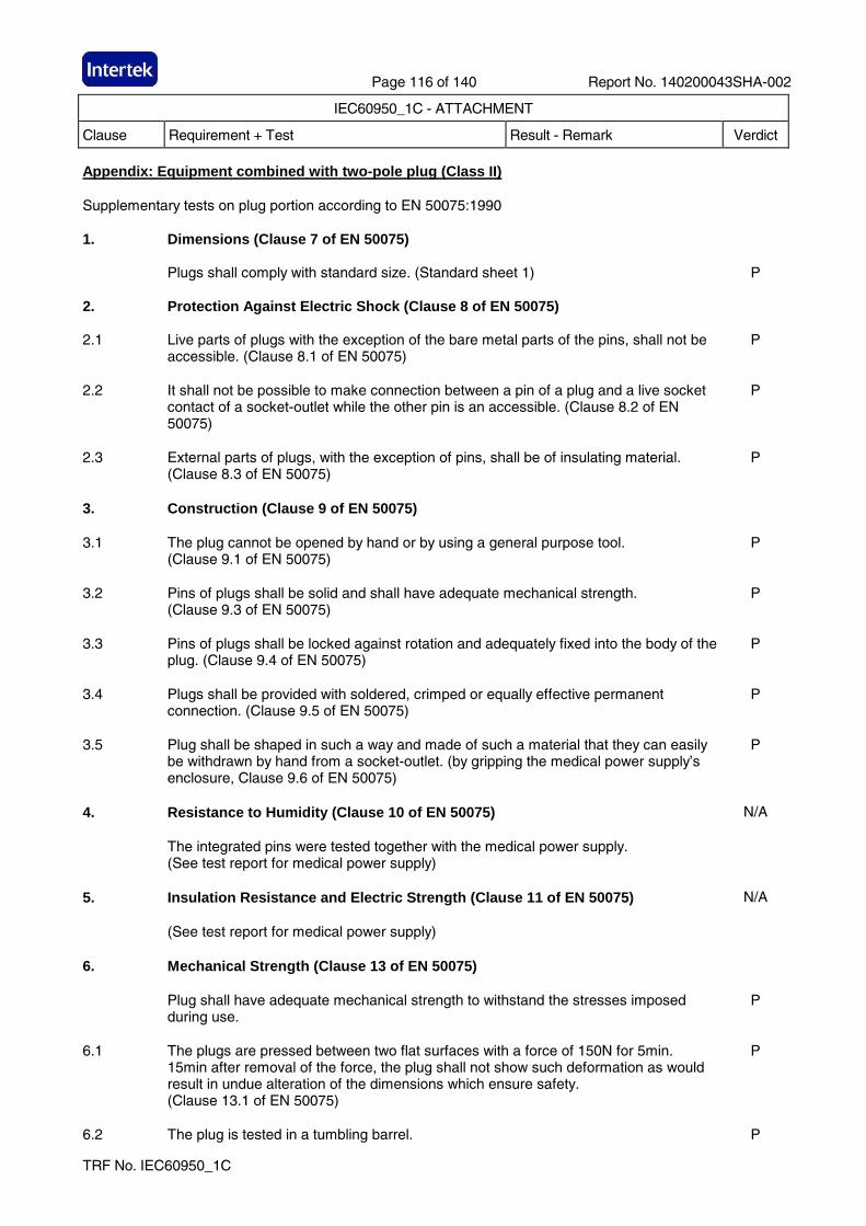
Page 116 of 140 Report No. 140200043SHA-002
IEC60950_1C - ATTACHMENT
Clause Requirement + Test Result - Remark Verdict
TRF No. IEC60950_1C
Appendix: Equipment combined with two-pole plug (Cla ss II) Supplementary tests on plug portion according to EN 50075:1990 1. Dimensions (Clause 7 of EN 50075) Plugs shall comply with standard size. (Standard sheet 1) P 2. Protection Against Electric Shock (Clause 8 of EN 50075) 2.1 Live parts of plugs with the exception of the bare metal parts of the pins, shall not be
accessible. (Clause 8.1 of EN 50075) P
2.2 It shall not be possible to make connection between a pin of a plug and a live socket
contact of a socket-outlet while the other pin is an accessible. (Clause 8.2 of EN 50075)
P
2.3 External parts of plugs, with the exception of pins, shall be of insulating material.
(Clause 8.3 of EN 50075) P
3. Construction (Clause 9 of EN 50075) 3.1 The plug cannot be opened by hand or by using a general purpose tool.
(Clause 9.1 of EN 50075) P
3.2 Pins of plugs shall be solid and shall have adequate mechanical strength.
(Clause 9.3 of EN 50075) P
3.3 Pins of plugs shall be locked against rotation and adequately fixed into the body of the
plug. (Clause 9.4 of EN 50075) P
3.4 Plugs shall be provided with soldered, crimped or equally effective permanent
connection. (Clause 9.5 of EN 50075) P
3.5 Plug shall be shaped in such a way and made of such a material that they can easily
be withdrawn by hand from a socket-outlet. (by gripping the medical power supply’s enclosure, Clause 9.6 of EN 50075)
P
4. Resistance to Humidity (Clause 10 of EN 50075) N/A The integrated pins were tested together with the medical power supply.
(See test report for medical power supply)
5. Insulation Resistance and Electric Strength (Clause 11 of EN 50075) N/A (See test report for medical power supply) 6. Mechanical Strength (Clause 13 of EN 50075) Plug shall have adequate mechanical strength to withstand the stresses imposed
during use. P
6.1 The plugs are pressed between two flat surfaces with a force of 150N for 5min.
15min after removal of the force, the plug shall not show such deformation as would result in undue alteration of the dimensions which ensure safety. (Clause 13.1 of EN 50075)
P
6.2 The plug is tested in a tumbling barrel. P
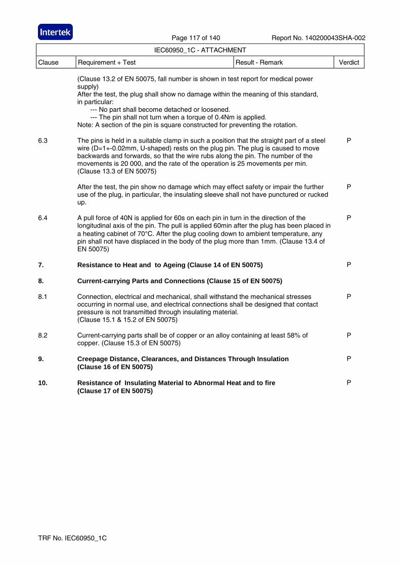
Page 117 of 140 Report No. 140200043SHA-002
IEC60950_1C - ATTACHMENT
Clause Requirement + Test Result - Remark Verdict
TRF No. IEC60950_1C
(Clause 13.2 of EN 50075, fall number is shown in test report for medical power supply) After the test, the plug shall show no damage within the meaning of this standard, in particular: --- No part shall become detached or loosened. --- The pin shall not turn when a torque of 0.4Nm is applied. Note: A section of the pin is square constructed for preventing the rotation.
6.3 The pins is held in a suitable clamp in such a position that the straight part of a steel
wire (D=1+-0.02mm, U-shaped) rests on the plug pin. The plug is caused to move backwards and forwards, so that the wire rubs along the pin. The number of the movements is 20 000, and the rate of the operation is 25 movements per min. (Clause 13.3 of EN 50075)
P
After the test, the pin show no damage which may effect safety or impair the further
use of the plug, in particular, the insulating sleeve shall not have punctured or rucked up.
P
6.4 A pull force of 40N is applied for 60s on each pin in turn in the direction of the
longitudinal axis of the pin. The pull is applied 60min after the plug has been placed in a heating cabinet of 70°C. After the plug cooling down to ambient temperature, any pin shall not have displaced in the body of the plug more than 1mm. (Clause 13.4 of EN 50075)
P
7. Resistance to Heat and to Ageing (Clause 14 of EN 50075) P 8. Current-carrying Parts and Connections (Clause 15 of EN 50075) 8.1 Connection, electrical and mechanical, shall withstand the mechanical stresses
occurring in normal use, and electrical connections shall be designed that contact pressure is not transmitted through insulating material. (Clause 15.1 & 15.2 of EN 50075)
P
8.2 Current-carrying parts shall be of copper or an alloy containing at least 58% of
copper. (Clause 15.3 of EN 50075) P
9. Creepage Distance, Clearances, and Distances Through Insulation
(Clause 16 of EN 50075) P
10. Resistance of Insulating Material to Abnormal Heat and to fire
(Clause 17 of EN 50075) P
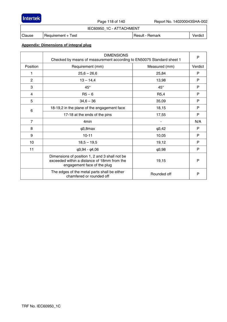
Page 118 of 140 Report No. 140200043SHA-002
IEC60950_1C - ATTACHMENT
Clause Requirement + Test Result - Remark Verdict
TRF No. IEC60950_1C
Appendix: Dimensions of integral plug
DIMENSIONS Checked by means of measurement according to EN50075 Standard sheet 1
P
Position Requirement (mm) Measured (mm) Verdict
1 25,6 – 26,6 25,84 P
2 13 – 14,4 13,98 P
3 45° 45° P
4 R5 – 6 R5,4 P
5 34,6 – 36 35,09 P
18-19,2 in the plane of the engagement face 18,15 P 6
17-18 at the ends of the pins 17,55 P
7 4min - N/A
8 φ3,8max φ3,42 P
9 10-11 10,05 P
10 18,5 – 19,5 19,12 P
11 φ3,94 - φ4,06 φ3,98 P
Dimensions of position 1, 2 and 3 shall not be exceeded within a distance of 18mm from the
engagement face of the plug 19,15 P
The edges of the metal parts shall be either chamfered or rounded off
Rounded off P
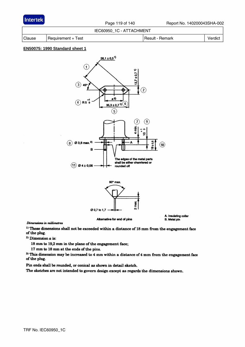
Page 119 of 140 Report No. 140200043SHA-002
IEC60950_1C - ATTACHMENT
Clause Requirement + Test Result - Remark Verdict
TRF No. IEC60950_1C
EN50075: 1990 Standard sheet 1
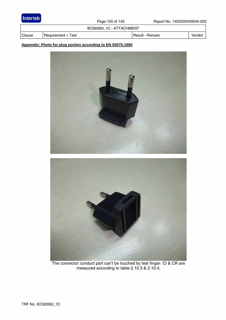
Page 120 of 140 Report No. 140200043SHA-002
IEC60950_1C - ATTACHMENT
Clause Requirement + Test Result - Remark Verdict
TRF No. IEC60950_1C
Appendix: Photo for plug portion according to EN 500 75:1990
The connector conduct part can’t be touched by test finger. Cl & CR are
measured according to table 2.10.3 & 2.10.4,
Page 121 of 140 Report No. 140200043SHA-002
IEC60950_1C - ATTACHMENT
Clause Requirement + Test Result - Remark Verdict
TRF No. IEC60950_1C
Appendix: Equipment’s combined with Australian plug. The Australian plug was tested according to Annex J of AS/NZS 3112:2011+A1:2012:
Clause Requirement − Test Remark Verdict
2.2 PLUG PINS P
2.2.1 MATERIAL FOR PINS: - Copper alloy containing at least 58% copper for parts made from cold rolled sheet
P
2.2.2 ASSEMBLY OF PINS - Assembled in factory and non-rewirable
P
2.2.3 FORM OF PIN P
2.2.4* INSULATION OF PLUG PINS - Live parts of insulated pins plug are not exposed when plug is partially or fully engaged with the associated socket.
P
2.3 INSULATING MATERIALS P
2.3.1 GENERAL P
2.3.2 PLUG BODY - Consisting of PBT which has properties not inferior to those specified in AS 3121 for insulating mouldings having a temperature class of 80°C
P
2.3.3 PLUG COVER - Consisting of PVC which has properties not inferior to those specified in AS 3121 for insulating mouldings having a temperature class of 60°C
P
2.8 RATINGS AND DIMENSIONS OF LOW VOLTAGE PLUGS - Comply with Figure 2.1 (c), rated 10A 250V~. - Distance between live pin and edge of plug moulding more than 9 mm
P
2.9 INTERNAL CONNECTIONS -No earthing connection
N/A
2.10 ARRANGEMENT OF EARTHING CONNECTIONS -No earthing connection
N/A
2.12 MARKING (No marking is applicable for the integral plug portion. See markings for transformer)
N/A
2.12.6 CONFIGURATION OF PLUGS - Figure 2.1 (c), the pin configuration is neutral and active in a clockwise direction
P
2.13 TESTS ON PLUGS P
2.13.3 HIGH VOLTAGE TEST P
2.13.7 TUMBLING BARREL TEST P
2.13.8 TEMPERATURE RISE TEST P
2.13.9 SECUREMENT OF PLUG P
Page 122 of 140 Report No. 140200043SHA-002
IEC60950_1C - ATTACHMENT
Clause Requirement + Test Result - Remark Verdict
TRF No. IEC60950_1C
Clause Requirement − Test Remark Verdict
2.13.9.1 MOVEMENT OF PINS P
2.13.9.2 FIXING OF PINS P
2.13.13 ADDITIONAL TESTS ON THE INSULATION MATERIAL OF INSULATED PIN PLUGS
P
INSULATING MATERIALS TEST IN ACCORDANCE WITH AS/NZS 3121: 2002
7.1 General P
7.2
Resistance to heat test The moulding shall be placed in an oven and maintained for 6 h at the temperature appropriate to its class (see Clause 5) plus 10°C. The temperature of the oven during this period shall not vary by more than ± 5°C. The moulding shall show no physical or chemical change likely to impair the safety of the equipment of which it forms a part.
P
7.3
Water absorption test The complete moulding shall be immersed in water at 20 °C ± 5°C for 48 h. The moulding shall not swell, delaminate, warp or show any physical change to a degree that would be liable to impair the safety of the equipment of which it forms a part.
P
7.4
Resistance to white spirit test Sample shall be immersed in white spirit at room temperature for 2 min. The moulding shall not blister, warp or show any physical or chemical change to a degree that would be liable to impair the safety of the equipment of which it forms a part.
P
Page 123 of 140 Report No. 140200043SHA-002
IEC60950_1C - ATTACHMENT
Clause Requirement + Test Result - Remark Verdict
TRF No. IEC60950_1C
Appendix: Photos of Australian plug portion
The connector conduct part can’t be touched by test finger. Cl & CR are measured
according to table 2.10.3 & 2.10.4,
Page 124 of 140 Report No. 140200043SHA-002
IEC60950_1C - ATTACHMENT
Clause Requirement + Test Result - Remark Verdict
TRF No. IEC60950_1C
Appendix: Equipment’s combined with NEMA 1-15 plug p ortion.
KEY:
√√√√ = Complies. G = General comment
E = Further evaluation required N/A = Not applicable
E√√√√ = Once “E” is found acceptable T = Testing required
F = Non-compliance TF = Test failed Section Key Comment
FORWARD Introduction 1 Scope
1.1-1.4 G The device under evaluation is an integral plug for medical power supply GT*41080-**** whose input rated 100-240V~, 50-60Hz, 0.6A. The plug is evaluated according to rated input.
2 Glossary 2.1-2.38 G Noted.
3 Components 3.1-3.4 G Noted
4 Units of Measurement 4.1 G Noted
5 Reference 5.1 G Noted
CONSTRUCTION ALL DEVICES
6 General
6.1 √ According to declared reasonable condition, 100-240VAC, 50-60Hz, has been considered in all following test.
6.2 √ Plug for AC use only
7 Configurations 7.1 √ 1-15P plug applied.
8 Insulating Materials 8.1 General
8.1.1 √ All parts that act as the electrical insulation or enclosure are made of plastic material. See 8.2.1
8.1.2 N/A Vulcanized fiber is not provided
8.2 Flammability
8.2.1 √ The insulating material required HB or more. For detailed parts, see report of end product)
8.3 Electrical properties
8.3.1 √ Exception No. 1: No information according to above table info. The insulating material has a CTI 3 (Required 3), so it need NOT comply with Comparative Tracking Index Test, Section 55.
8.3.2 √
Exception No. 2: The insulating material has a HWI 3, (required HWI value is 4 when material class is V-0). According to 8.1.2 (UL746D) and reasonable usage, reasonable arcing occurs in normal use. We are of the opinion that it need NOT comply with Glow Wire Test, see Section 56. Exception No. 3: The insulating material has a HAI 2. (required HWI value is 4 when
Page 125 of 140 Report No. 140200043SHA-002
IEC60950_1C - ATTACHMENT
Clause Requirement + Test Result - Remark Verdict
TRF No. IEC60950_1C
Section Key Comment material class is V-0. or check if the thickness), since no arcing in normal use, so it need not comply with High-Current Arc Resistance to Ignition Test, Section 57.
8.4 Thermal properties
8.4.1 √ All the RTI rating of the insulating materials are higher than 80 degree (C)
8.5 Vulcanized fiber
8.5.1 N/A No Vulcanized fiber is provided
8.5.2 N/A No Vulcanized fiber is provided
8.6 Sealing compounds
8.6.1-8.6.2 N/A Sealing compound is not provided, no need to comply with relevant requirement involved in ASTM 28.
8.7 Fuse enclosures
8.7.1-8.7.2 N/A Fuse is not provided
9 Enclosure 9.1 General
9.1.1 √ Live parts of plug parts are protected against exposure to contact by persons when fully assembled using all essential parts. Exception no. 2: for fixed wiring.
9.1.2-9.1.3 N/A No accessible dead-metal parts
9.1.4 √ The probe shown in Figure 9.1 is used to judge the accessibility of a live or dead-metal part. The applied force is not more than 13.3N.
9.1.5-9.1.7 N/A No such separable part
9.2 Male faces and wire terminations
9.2.1 N/A Not a 15 or 20A attachment plug or current tap
9.2.2 N/A There is no exposed live part.
9.2.3 N/A No such parts
9.2.4-9.2.5 √ Probe not access to live parts. The cover is securely fixed for all acceptable wiring.
9.2.6 √ The face plate is secure with the back part.
10 Current-carrying Parts 10.1 General
10.1.1 √ Iron or steel is not used for current-carrying parts.
10.1.2 √ The current-carrying parts are not able to be turned by means of general tools due to the appliance shroud mounted on Evaluated appliance.
10.1.3 N/A No such uninsulated live parts except for female contact of connector
10.2 Contacts (applying to the connector)
10.2.1 N/A Female contacts of the connector cannot be touched by the probe. Others parts are covered by exception no. 3
11 Grounding and Dead Metal Parts 11.1-11.10 N/A No grounding parts
12 Terminals 12.1-12.4 No terminals for end user
13 Cord Entry and Strain Relief 13.1-13.5 N/A Flexible cord part are considered in the end appliances.
14 Spacings
14.1 √ The spacing through air between uninsulated live parts of opposite polarity and between uninsulated live parts and exposed external surface is measured more than 2mm (required 3/36 inch, 1,2mm) for a device rated 250V or less.
14.2 N/A No such isolated dead-metal part
Page 126 of 140 Report No. 140200043SHA-002
IEC60950_1C - ATTACHMENT
Clause Requirement + Test Result - Remark Verdict
TRF No. IEC60950_1C
Section Key Comment
15 Assembly 15.1 General
15.1.1 √ Pre-wired in factory
15.1.2 √ Electrical contact is reliably maintained at any point
15.1.3 √ Live parts is protected against exposure to persons
15.1.4 N/A Not multiple outlet device
15.1.5 N/A Female contacts of the connector can be mated with the inlet in right way without exposure of the blades
15.2 Grounding and polarization 15.2.1-15.2.4
N/A No grounding
15.3 Mating and interchangeability
15.3.1 √ The electrical continuity is automatically established. 15.3.2-15.3.6 √ 1-15P receptacles ensuring.
15.4 Fuseholders 15.4.1-15.4.8
N/A Fuseholder is not provided
15.5 Switches
15.5.1 N/A The switch is provided between coupler 1 and coupler 2. but it is a information
ATTACHMENT PLUGS AND INLETS (for plug only) 16 Insulating material 16.1 √ The enclosure is measured min. 2.1 mm.
17 Enclosure 17.1 General
17.1.1 N/A Not a general use plug.
17.1.2 √ Measured 44 mm.
17.1.3 N/A Not a 50A plug
17.2 Grip
17.2.1 N/A See section 69
17.3 Face size
17.3.1 √ Larger than figure 17.1
18 Current carrying parts 18.1 N/A Not a folded-over plug.
18.2 √ Dimensional requirements fulfilled.
19 Grounding and dead metal parts 19.1-19.4 N/A No grounding or dead metal parts.
20 Terminals and leads 20.1-20.5 N/A All the assembly are pre-wired in factory
21 Assembly 21.1 √ The blades are held securely in place
21.2 N/A Not a inlet
21.3-21.4 N/A The device under evaluate is a plug part not inlet or surface mounting.
21.5 N/A Not for radio antenna or ground.
22 Weatherproof type
Page 127 of 140 Report No. 140200043SHA-002
IEC60950_1C - ATTACHMENT
Clause Requirement + Test Result - Remark Verdict
TRF No. IEC60950_1C
Section Key Comment 22.1-22.2 N/A Not weatherproof type
23-26 N/A CONNECTORS
27-37 N/A RECEPTACLES
SELF-CONTAINED RECEPTACLES FOR USE WITHOUT A SEPARATE OUTLET BOX
38-44 N/A These sections are applicable for self-contained receptacles. CURRENT TAPS
45 N/A The section is applicable for current taps only FLATIRON AND APPLIANCE PLUGS
46-53 N/A These sections are applicable for flatiron and appliance plugs.
PERFORMANCE GENERAL
54 Representative Devices 54.1-54.7 G Noted.
ALL DEVICES
55 Comparative Tracking Index Test 55.1 N/A Refer to Exception No. 2 of 8.3.2. Not main tests but the test is considered
56 Glow Wire Test 56.1-56.2 N/A Refer to Exception No. 2 of 8.3.2, Not main tests but the test is considered
57 High-Current Arc Resistance to Ignition Test 57.1-57.6 G Refer to Exception No. 3 of 8.3.2
58 Mold Stress Relief
58.1-58.2 T All devices are placed in air oven maintained at a 80oC for 7 hours. After 58.2, there is not any warpage, shrinkage or other distortion.
58.3 T Refer to data sheet. Repeat dielectric voltage-withstand test as described in section 60. Not required to be subjected to the humidity conditioning described in 60.1.2.
59 Moisture Absorption Resistance 59.1-59.2 T Refer to data sheet
60 Dielectric Withstand Test 60.1-60.2 T Refer to data sheet
61 Accelerated Aging Tests 61.1 General
61.1.1 G Exception to 8.4.1 for other material is not applicable for the devices under evaluation
61.2 Rubber, EPDM, and TEE compounds 61.2.1-61.2.4
N/A Not a rubber , EPDM, and TEE compounds
61.3 PVC compounds and copolymers 61.3.1-61.3.2
G See 61.1.1 shown as above
62 Insulation Resistance Test 62.1-62.6 T Refer to data sheet
63 Conductor Secureness Test 63.1-63.2 N/A No wire leads provided.
64 Tightening Torque Test 64.1-64.2 N/A Not provide any wire-binding screw
N/A ATTACHMENT PLUGS
Page 128 of 140 Report No. 140200043SHA-002
IEC60950_1C - ATTACHMENT
Clause Requirement + Test Result - Remark Verdict
TRF No. IEC60950_1C
Section Key Comment
65 General 65.1 G Noted.
66 Security of blades test 66.1-66.2 T Refer to data sheet
67 Secureness of cover test 67.1-67.2 T Refer to data sheet
68 Crushing test 68.1-68.2 T Refer to data sheet
69 Attachment plug grip test 69.1-69.9 T Refer to data sheet
70 Integrity of assembly test 70.1-70.2 N/A Cord part shall be considered in the end appliance.
71 Self-hinge Flexing test 71.1-71.3 N/A Not self-hinge type
72 Terminal temperature test 72.1-72.4 N/A No terminal for end user.
73 Fuse-holder temperature test 73.1-73.8 N/A No fuse-holder applied.
74-79 N/A Pin type terminal
80-85 N/A INLET (applying for inlet)
86-103 N/A CONNECTORS
104-150 N/A RECEPTACLES CURRENT-TAPS All devices
151-152 N/A These sections are for current-taps Flatiron and appliance plugs.
153-161 N/A These sections are applicable for flatiron and appliance plugs.
RATINGS 162 Details
162.1 G According to exception no. 2, rating is not required. The special-use device is not intended to ship out solely. (Note: plug is mounted in evaluated appliance).
162.2 √ Rating of 1A 120V~ is evaluated
162.3 √ 0.5HP rated.
162.4-162.7 N/A Not have the specified devices
MARKINGS AND INSTRUCTIONS 163 General
163.1-163.2 G The location of the catalog number is not prohibited from appearing according to exceptions of table 163.1 and 163.2
164 Identification and marking of terminals 164 G No any grounding parts and terminals SUPPLEMENT SA
(reserved for future use)
SUPPLEMENT SB
ENCLOSURE TYPES FOR ENVIRONMENTAL PROTECTION
SB1-SB7 N/A The requirements of SB don’t apply to the device under evaluation for it’s intended for indoor use only (refer to SB1.1)
Page 129 of 140 Report No. 140200043SHA-002
IEC60950_1C - ATTACHMENT
Clause Requirement + Test Result - Remark Verdict
TRF No. IEC60950_1C
Section Key Comment SUPPLEMENT SC
MARINE SHORE POWER INLETS
SC1-SC12 N/A These sections are for marine shore power inlets SUPPLEMENT SD
HOSPITAL GRADE DEVICES
SD1-SD30 N/A These sections are for hospital grade devices
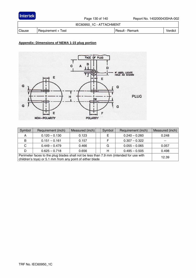
Page 130 of 140 Report No. 140200043SHA-002
IEC60950_1C - ATTACHMENT
Clause Requirement + Test Result - Remark Verdict
TRF No. IEC60950_1C
Appendix: Dimensions of NEMA 1-15 plug portion
Symbol Requirement (inch) Measured (inch) Symbol Requirement (inch) Measured (inch)
A 0.120 – 0.130 0.123 E 0.240 – 0.260 0.248
B 0.151 – 0.161 0.157 F 0.307 – 0.322 --
C 0.449 – 0.479 0.466 G 0.055 – 0.065 0.057
D 0.625 – 0.718 0.656 H 0.495 – 0.505 0.498 Perimeter faces to the plug blades shall not be less than 7.9 mm (intended for use with children’s toys) or 5.1 mm from any point of either blade
12.39
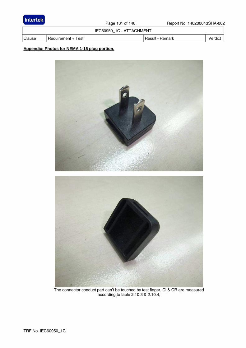
Page 131 of 140 Report No. 140200043SHA-002
IEC60950_1C - ATTACHMENT
Clause Requirement + Test Result - Remark Verdict
TRF No. IEC60950_1C
Appendix: Photos for NEMA 1-15 plug portion.
The connector conduct part can’t be touched by test finger. Cl & CR are measured
according to table 2.10.3 & 2.10.4,
Page 132 of 140 Report No. 140200043SHA-002
IEC60950_1C - ATTACHMENT
Clause Requirement + Test Result - Remark Verdict
TRF No. IEC60950_1C
Appendix: Equipment combined with BS-plug portion Supplementary tests on plug portion according to BS1363: Part 3 + Amd 9543 + Amd 14225 + Amd 14540 + Amd 17437 + Amd A4
Clause Requirement - Test Result-Remark Verdict
12.1 Dimensions
(Checked according to figure 4)
See appendix no. 1 & 2 P
12.2 Outline of plug shall not exceed the dimension shown in Figure 4 for a distance of not less than 6.35 mm from the engagement surface
8.90 mm P
Pin disposition, length and body outline shall be checked by use of the gauge shown in Figure 5
P
12.3 L/N pin was more than 9.5 mm from the periphery of the plug measured along the engagement surface
9.60 mm P
12.7 The base and cover of rewirable plugs shall be adaptor plugs having the cover fixed by screws shall be firmly secured to each other. It shall not be possible to remove the cover unless the adaptor is completely withdrawn from the socket-outlet. Fixing screws shall be captive. The test is carried out using apparatus similar to that shown in Figure 6
N/A
12.9 After the temperature rise test (clause 16). Use test probe 11 of BS EN 61032:1998 is applied a force 30 -5/0 N.
During and after the test, it was not possible to touch the live parts.
P
12.11 Adaptor plug pins shall be constructed of brass, except for sleeves of pins as specified in 12.18
P
All exposed surfaces of the adaptor plug pins shall be smooth and free from burrs or sharp edges and other irregularities which could cause damage or excessive wear to corresponding socket contacts or shutters.
P
Those surfaces of the non-solid adaptor plug pins which are visible when the adaptor is correctly assembled shall be free of apertures.
P
All seams and joints of non-solid adaptor plug pins shall be closed over their entire length.
P
For solid pins, conformity shall be checked by 12.11.4.1.
P
For non-solid pins, compliance shall be checked by 12.11.4.2.
N/A
Page 133 of 140 Report No. 140200043SHA-002
IEC60950_1C - ATTACHMENT
Clause Requirement + Test Result - Remark Verdict
TRF No. IEC60950_1C
Clause Requirement - Test Result-Remark Verdict
Adaptors with non-solid pins shall not cause excessive wear to socket contacts or shutters of socket-outlets in accordance with BS 1363-2:1995.
N/A
Adaptor plug pins shall have adequate mechanical strength to ensure that they cannot be distorted by twisting. Apply a torque 1N.m ± 10% for 60 +5/0 S.
After each pin has been separately twisted, the plug was fit the gauge in fig. 5. Repeated with opposite direction.
P
12.13 Adaptors shall be so designed that when fully assembled the pins are adequately retained in position such that there is no likelihood of them becoming detached from the adaptor during normal use.
P
Each pin is subjected for 60 +5/0 S to a pull of 100 -2/0 N without jerks in the direction of the major axis.
The plug is mounted using the steel plate shown in fig.7. The apparatus is placed within an oven and the pull is applied at least 1 h after the plug body has attained the test temperature of 70°C ± 5°C while maintained at this temperature.
After the test, the plug pin shall fit into the gauge and comply with 12.2.1.
P
12.14 The degree of flexibility of mounting of the plug pins or the angular movement of the pins in the base shall be not greater than 3° 30’. See fig. 8.
P
Test procedure refers to standard.
During each test, the declination from the horizontal measured on the scale shall not exceed 3° 30’ and comply with 12.2.1.
P
12.18 Live and neutral adaptor plug pins shall be fitted with insulating sleeves. See fig.4.
Sleeves shall not be fitted to any earthing adaptor plug pin.
P
12.19.3 Abrasion test – 10 000 times in each direction (20 000 movements) at a rate of 25 movements to 30 movements per min. (fig. 9).
After the test, the sleeve shall show no damage and also shall not have been penetrated or creased, satisfy the tests in 12.19.2.
P
13.10 The total mass of the equipment with all specified connectors shall not exceed 800 g. The torque exerted on a socket shall not exceed 0.7 N·m.
The test apparatus as Figure 37
Compliance with the main standard
N/A
Page 134 of 140 Report No. 140200043SHA-002
IEC60950_1C - ATTACHMENT
Clause Requirement + Test Result - Remark Verdict
TRF No. IEC60950_1C
Clause Requirement - Test Result-Remark Verdict
Additional: Products with torque exceeding 0.25Nm do not comply with the main standard hence full compliance with the main standard cannot be claimed
N/A
Additional test for ISODs according to BS1363: Part 1 + Amd 9541 + Amd 14539 + Amd 17435 + Amd A4
12.9.1 All exposed surfaces of plug pins shall be smooth and free from burrs or sharp edges and other irregularities which could cause damage or excessive wear to corresponding socket contacts or shutters.
P
12.9.4 Apply a force of 1100 -10/0N at a rate not exceeding 10 mm/min.
After this test the plug should fit the gauge to fig. 5.
P
Apply a force of 400 +10/0N at a rate 10 ± 2 mm/min.
Deflection shall not exceed 1.5 mm.
After this test the plug should fit the gauge to fig. 5.
P
12.9.6 ISODs shall have adequate mechanical strength to ensure that they cannot be distorted by twisting.
Apply a torque 1N.m ± 10% for 60 +5/0 S.
After each pin has been separately twisted, the plug shall fit the gauge in fig. 5.
Repeated with opposite direction.
P
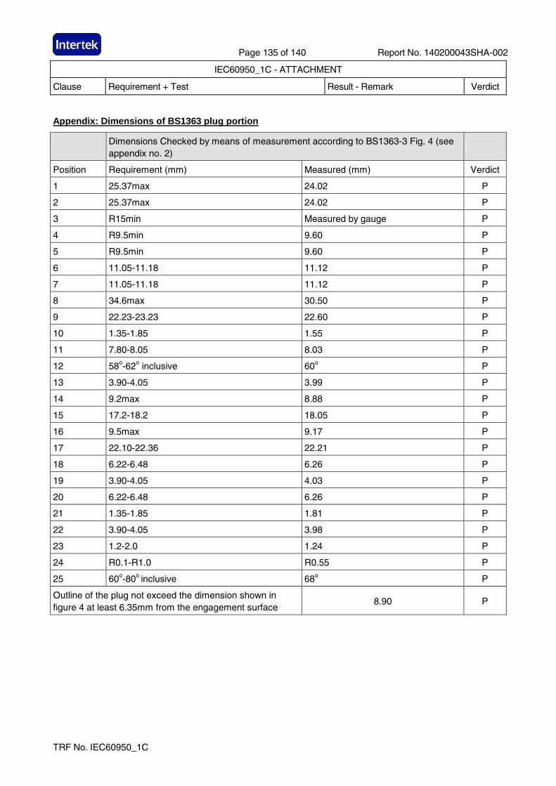
Page 135 of 140 Report No. 140200043SHA-002
IEC60950_1C - ATTACHMENT
Clause Requirement + Test Result - Remark Verdict
TRF No. IEC60950_1C
Appendix: Dimensions of BS1363 plug portion
Dimensions Checked by means of measurement according to BS1363-3 Fig. 4 (see appendix no. 2)
Position Requirement (mm) Measured (mm) Verdict
1 25.37max 24.02 P
2 25.37max 24.02 P
3 R15min Measured by gauge P
4 R9.5min 9.60 P
5 R9.5min 9.60 P
6 11.05-11.18 11.12 P
7 11.05-11.18 11.12 P
8 34.6max 30.50 P
9 22.23-23.23 22.60 P
10 1.35-1.85 1.55 P
11 7.80-8.05 8.03 P
12 58o-62o inclusive 60o P
13 3.90-4.05 3.99 P
14 9.2max 8.88 P
15 17.2-18.2 18.05 P
16 9.5max 9.17 P
17 22.10-22.36 22.21 P
18 6.22-6.48 6.26 P
19 3.90-4.05 4.03 P
20 6.22-6.48 6.26 P
21 1.35-1.85 1.81 P
22 3.90-4.05 3.98 P
23 1.2-2.0 1.24 P
24 R0.1-R1.0 R0.55 P
25 60o-80o inclusive 68o P
Outline of the plug not exceed the dimension shown in figure 4 at least 6.35mm from the engagement surface
8.90 P
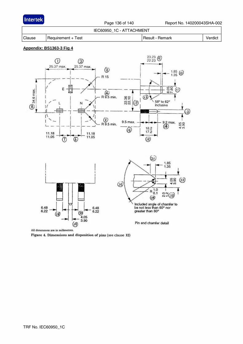
Page 136 of 140 Report No. 140200043SHA-002
IEC60950_1C - ATTACHMENT
Clause Requirement + Test Result - Remark Verdict
TRF No. IEC60950_1C
Appendix: BS1363-3 Fig 4
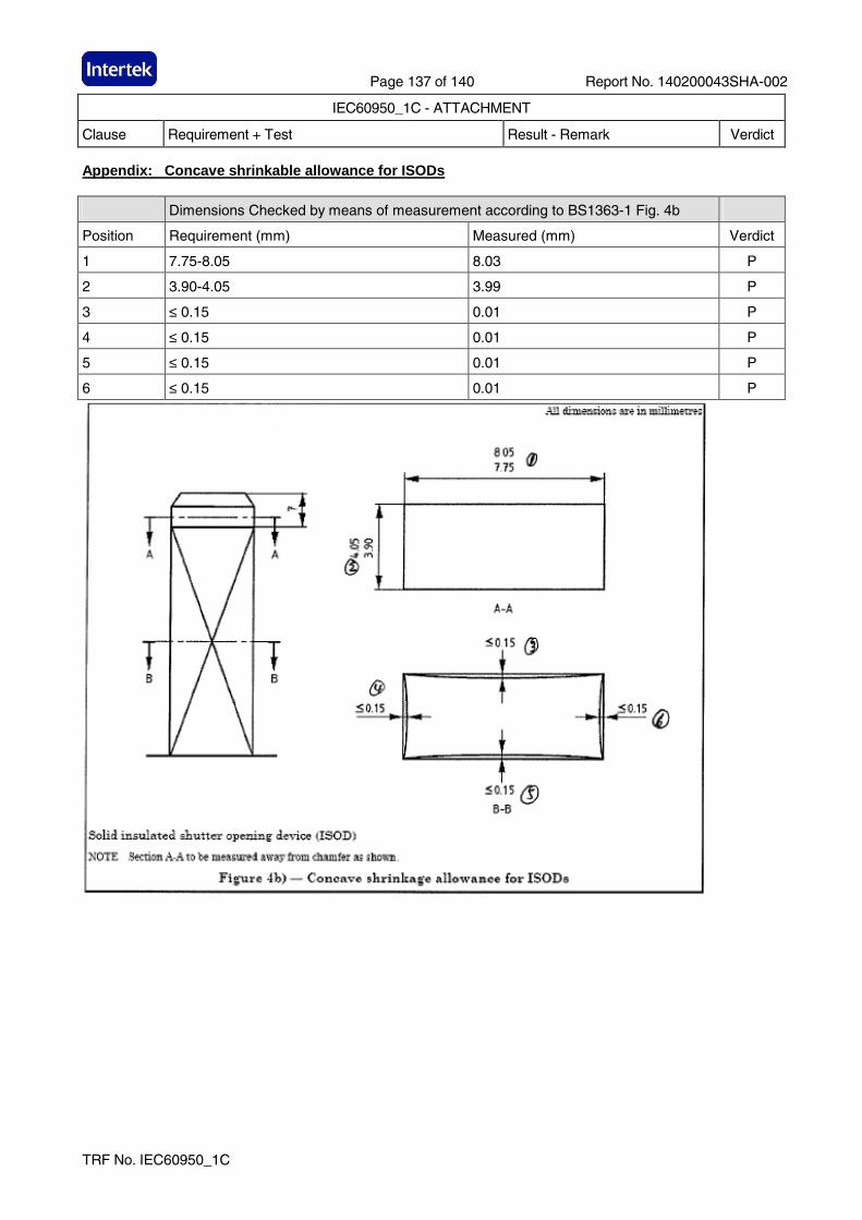
Page 137 of 140 Report No. 140200043SHA-002
IEC60950_1C - ATTACHMENT
Clause Requirement + Test Result - Remark Verdict
TRF No. IEC60950_1C
Appendix: Concave shrinkable allowance for ISODs
Dimensions Checked by means of measurement according to BS1363-1 Fig. 4b
Position Requirement (mm) Measured (mm) Verdict
1 7.75-8.05 8.03 P
2 3.90-4.05 3.99 P
3 ≤ 0.15 0.01 P
4 ≤ 0.15 0.01 P
5 ≤ 0.15 0.01 P
6 ≤ 0.15 0.01 P
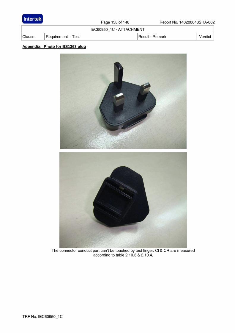
Page 138 of 140 Report No. 140200043SHA-002
IEC60950_1C - ATTACHMENT
Clause Requirement + Test Result - Remark Verdict
TRF No. IEC60950_1C
Appendix: Photo for BS1363 plug
The connector conduct part can’t be touched by test finger. Cl & CR are measured
according to table 2.10.3 & 2.10.4,
Page 139 of 140 Report No. 140200043SHA-002
IEC60950_1C - ATTACHMENT
Clause Requirement + Test Result - Remark Verdict
TRF No. IEC60950_1C
Appendix: Specification of NBR 14136 plug
Page 140 of 140 Report No. 140200043SHA-002
IEC60950_1C - ATTACHMENT
Clause Requirement + Test Result - Remark Verdict
TRF No. IEC60950_1C
Appendix: Evaluation sheet of NBR 14136 Figure 13 p lug
Related Documents