TESTING APPLICATION STANDARD (TAS) No. 100–95 TEST PROCEDURE FOR WIND AND WIND DRIVEN RAIN RESISTANCE OF DISCONTINUOUS ROOF SYSTEMS 1. Scope 1. 1 This Protocol covers the determination of the water infiltration resistance of all discontinu- ous roof systems, consisting of a prepared roof covering and underlayment, when applied at slopes of 2 in:12 in. or greater over a nailable deck. 1.2 The test procedures outlined in this Protocol determine whether a discontinuous roof sys- tem, consisting of an underlayment and a pre- pared roof covering, provides sufficient wind driven rain resistance to allow no water infil- tration through the deck sheathing during a predetermined test period. 1.3 All testing and calculations shall be conduct- ed by an approved testing agency and all test reports, including calculations, shall be signed by a Professional Engineer or Registered Roof Consultant. 2. Referenced Documents 2.1 ASTM Standards: D1079 Standard Definitions and Terms Relating to Roofing, Waterproofing and Bituminous Materials E 380 Excerpts from the Standard Practice for Use of the International System of Units (SI) (the Modernized Metric System) 2.2 International Conference of building officials Acceptance Criteria for Special Roofing Systems 2.3 The Florida Building Code, Building. 2.4 The American Plywood Association Performance Standards and Polices for Structural-Use Panels 2.5 Roof Consultants Institute Glossary of Terms 3. Terminology & Units 3.1 Definitions - For definitions of terms used in this specification, refer to ASTM D 1079, Chapters 2 and 15 (High Velocity Hurricane Zones) Florida Building Code, Building; and/or the RCI Glossary of Terms. The defi- nitions from the Florida Building Code, Building shall take precedence. 3.2 Units - For conversion of U.S. customary units to SI units, refer to ASTM E 380. 4. Significance and Use 4.1 The test procedure provides a means for establishing the resistance to wind driven rain of the discontinuous roof system, consisting of underlayment and a prepared roof cover- ing. This test procedure has not been contem- plated to measure the performance of the pre- pared roof covering and underlayment to maximum winds and/or uplift forces antici- pated in the High Velocity Hurricane Zone of the Florida Building Code, Building. 5. Apparatus 5.1 The Test Frame 5.1.1 The test frame shall consist of a 10' long x 8' wide base structure, con- structed from wood or steel framing, and a wood deck, constructed from plywood sheathing. Deck support joists shall be placed at 24 in. centers (See Figure 1, attached). The deck slope shall be adjustable or multiple interchangeable decks shall be avail- able to test specimens at slopes of 2 in., 3 in., 3 1 / 2 in., 4 in., 5 in. and 6 in. in 12 in.. The deck support assembly shall be capable of supporting not less than 55 lb per square foot of dead load. 5.1.2 The test frame shall not be constructed against the side of a wall or other structure which is taller than the frame. FLORIDA BUILDING CODE — TEST PROTOCOL HVHZ (TAS) 100–95.1

Welcome message from author
This document is posted to help you gain knowledge. Please leave a comment to let me know what you think about it! Share it to your friends and learn new things together.
Transcript

TESTING APPLICATION STANDARD (TAS) No. 100–95
TEST PROCEDURE FOR WIND AND WIND DRIVEN RAIN RESISTANCE OF DISCONTINUOUS ROOF SYSTEMS
1. Scope
1.1 This Protocol covers the determination of the water infiltration resistance of all discontinuous roof systems, consisting of a prepared roof covering and underlayment, when applied at slopes of 2 in:12 in. or greater over a nailable deck.
1.2 The test procedures outlined in this Protocol determine whether a discontinuous roof system, consisting of an underlayment and a prepared roof covering, provides sufficient wind driven rain resistance to allow no water infiltration through the deck sheathing during a predetermined test period.
1.3 All testing and calculations shall be conducted by an approved testing agency and all test reports, including calculations, shall be signed by a Professional Engineer or Registered Roof Consultant.
2. Referenced Documents
2.1 ASTM Standards:
D1079 Standard Definitions and Terms Relating to Roofing, Waterproofing and Bituminous Materials
E 380 Excerpts from the Standard Practice for Use of the International System of Units (SI) (the Modernized Metric System)
2.2 International Conference of building officials Acceptance Criteria for Special Roofing Systems
2.3 The Florida Building Code, Building.
2.4 The American Plywood Association Performance Standards and Polices for Structural-Use Panels
2.5 Roof Consultants Institute Glossary of Terms
3. Terminology & Units
3.1 Definitions - For definitions of terms used in this specification, refer to ASTM D 1079, Chapters 2 and 15 (High Velocity Hurricane Zones) Florida Building Code, Building; and/or the RCI Glossary of Terms. The definitions from the Florida Building Code, Building shall take precedence.
3.2 Units - For conversion of U.S. customary units to SI units, refer to ASTM E 380.
4. Significance and Use
4.1 The test procedure provides a means for establishing the resistance to wind driven rain of the discontinuous roof system, consisting of underlayment and a prepared roof covering. This test procedure has not been contemplated to measure the performance of the prepared roof covering and underlayment to maximum winds and/or uplift forces anticipated in the High Velocity Hurricane Zone of the Florida Building Code, Building.
5. Apparatus
5.1 The Test Frame
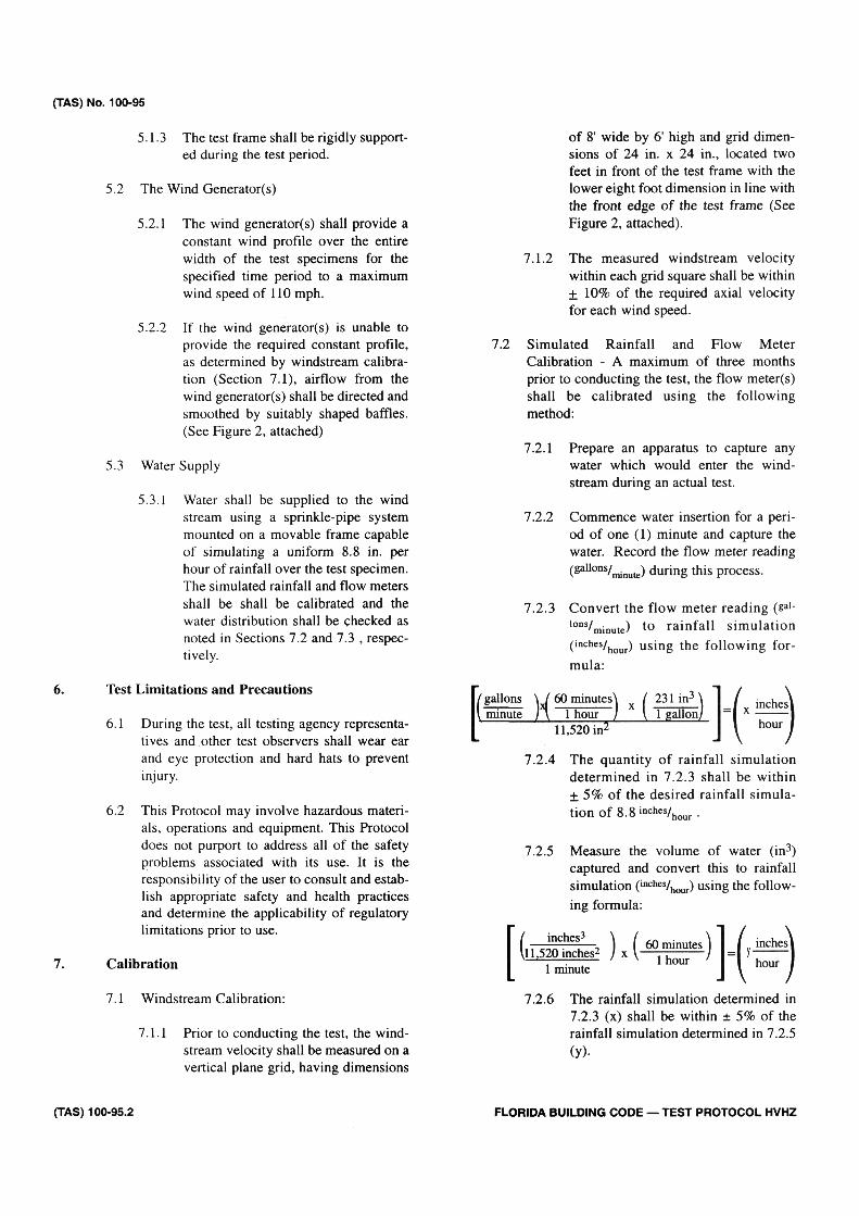
5.1.1 The test frame shall consist of a 10' long x 8' wide base structure, constructed from wood or steel framing, and a wood deck, constructed from plywood sheathing. Deck support joists shall be placed at 24 in. centers (See Figure 1, attached). The deck slope shall be adjustable or multiple interchangeable decks shall be available to test specimens at slopes of 2 in., 3 in., 31/2 in., 4 in., 5 in. and 6 in. in 12 in.. The deck support assembly shall be capable of supporting not less than 55 lb per square foot of dead load.
5.1.2 The test frame shall not be constructed against the side of a wall or other structure which is taller than the frame.
FLORIDA BUILDING CODE — TEST PROTOCOL HVHZ (TAS) 100–95.1
(TAS) No. 100–95
5.1.3 The test frame shall be rigidly supported during the test period.
5.2 The Wind Generator(s)
5.2.1 The wind generator(s) shall provide a constant wind profile over the entire width of the test specimens for the specified time period to a maximum wind speed of 110 mph.
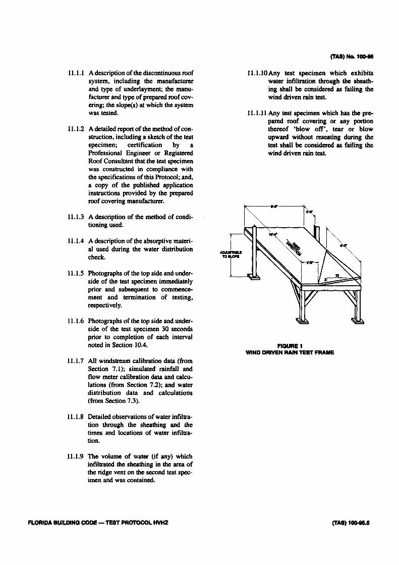
5.2.2 If the wind generator(s) is unable to provide the required constant profile, as determined by windstream calibration (Section 7.1), airflow from the wind generator(s) shall be directed and smoothed by suitably shaped baffles. (See Figure 2, attached)
5.3 Water Supply
5.3.1 Water shall be supplied to the wind stream using a sprinkle-pipe system mounted on a movable frame capable of simulating a uniform 8.8 in. per hour of rainfall over the test specimen. The simulated rainfall and flow meters shall be shall be calibrated and the water distribution shall be checked as noted in Sections 7.2 and 7.3 , respectively.
6. Test Limitations and Precautions
6.1 During the test, all testing agency representatives and other test observers shall wear ear and eye protection and hard hats to prevent injury.
6.2 This Protocol may involve hazardous materials, operations and equipment. This Protocol does not purport to address all of the safety problems associated with its use. It is the responsibility of the user to consult and establish appropriate safety and health practices and determine the applicability of regulatory limitations prior to use.
7. Calibration
7.1 Windstream Calibration:
7.1.1 Prior to conducting the test, the wind-stream velocity shall be measured on a vertical plane grid, having dimensions
of 8' wide by 6' high and grid dimensions of 24 in. x 24 in., located two feet in front of the test frame with the lower eight foot dimension in line with the front edge of the test frame (See Figure 2, attached).
7.1.2 The measured windstream velocity within each grid square shall be within ± 10% of the required axial velocity for each wind speed.
7.2 Simulated Rainfall and Flow Meter Calibration - A maximum of three months prior to conducting the test, the flow meter(s) shall be calibrated using the following method:
7.2.1 Prepare an apparatus to capture any water which would enter the wind-stream during an actual test.
7.2.2 Commence water insertion for a period of one (1) minute and capture the water. Record the flow meter reading (gallons/minute) during this process.
7.2.3 Convert the flow meter reading (gal-lons/minute) to rainfall simulation (inches/hour) using the following formula:
7.2.4 The quantity of rainfall simulation determined in 7.2.3 shall be within + 5% of the desired rainfall simulation of 8.8 i nches/hour.
7.2.5 Measure the volume of water (in3) captured and convert this to rainfall simulation (inches/hour) using the following formula:
7.2.6 The rainfall simulation determined in 7.2.3 (x) shall be within ± 5% of the rainfall simulation determined in 7.2.5 (y).
(TAS) 100–95.2 FLORIDA BUILDING CODE — TEST PROTOCOL HVHZ

7.3 Water Distribution Check - Prior to conducting the test, the water distribution over the test frame shall be checked and calibrated using the method outlined herein.
7.3.1 Prepare ten (10) 24 in. squares of thick absorptive material and weigh each sample. From this data, determine the average weight of the samples.
7.3.2 Prepare a 9' x 11' sheet of the absorptive material and mark the sheet with 20 24 in. squares centered on the sheet, leaving a 6 in. perimeter area unmarked.
7.3.3 Set the test frame to the desired slope and attach a sheathing panel, of the type specified in Section 8.1, to the test frame with the absorptive material centered on the sheathing. Fold the 6 in. paper perimeter down over the test fame perimeter and clamp into place using 2 in. x 4 in. blocking and C-clamps.
7.3.4 Set the wind speed to 35 mph and add water to the windstream at a constant rate, as indicated on the flow meter, until the absorptive material is wet but not saturated, at which time the wind and water flow shall be terminated. Record the duration of time required to 'wet' the material.
7.3.5 Remove the C-clamps and blocking and cut the material into 24 in. squares. Using the average dry weight of the material squares (determined in 6.3.1) and the weight after exposure, determine the volume of water (in3) striking each square sample at the particular wind speed and flow meter setting.
7.3.5.1 Determine the rain simulation (inches/hour) absorbed into each square sample using the following formula:
7.3.6 No one particular square sample shall exhibit a rainfall simulation (determined in 7.3.5) greater than or less than 15% of any other square sample.
7.3.7 Repeat steps 7.3.2 through 7.3.5 at a wind speed of 70 mph. 7.3.7.1 No one particular square sam
ple shall exhibit a rainfall simulation (determined in 7.3.5) greater than or less than 10% of any other square sample.
8. Test Specimens
8.1 Deck
8.1.1 The wood test deck shall consist of APA 32/16 span rated sheathing of 15/32 in. thickness installed over 2 in. x 6 in. perimeter supports and 2 in. x 6 in. intermediate supports spaced 24 in. apart. The sheathing shall be attached with 8d common nails at 6 in. o.c. at panel edges and 12 in. o.c. at intermediate supports. One valley shall be constructed into the test deck, located at the deck's front edge, as noted on Figure 1, attached.
8.1.2 The wood test deck shall be positioned at the minimum slope, as applicable in the High Velocity Hurricane Zone jurisdiction, for the type of discontinuous roof system being tested, but not less than 2 in:12 in..
8.2 Underlayment and Prepared Roof Covering
8.2.1 Underlayment and prepared roof covering shall be installed in strict compliance with the manufacturer's published installation instructions and the minimum installation requirements set forth in Section 1518 of the Florida Building Code, Building. The requirements of the Florida Building Code, Building shall take precedence.
8.3 The areas subject to the test criteria shall consist of the field area of the test deck, the eave, the valley, one rake section.
(TAS) No. 100–95
FLORIDA BUILDING CODE — TEST PROTOCOL HVHZ (TAS) 100–95.3

(TAS) No. 100–95
8.4 The test specimen shall be inspected by a Professional Engineer or Registered Roof Consultant who shall confirm in the final report that the method of construction is in compliance with the specifications of this Protocol.
9. Conditioning - conditioning need not be performed on mechanically attached, rigid, discontinuous roof systems.
9.1 Conditioning shall consist of three days of exposure to outside environmental conditions during which time the surface temperature of the prepared roof covering shall reach not less than 135°F for a period of six hours in each day. The surface temperature shall be measured with a surface mounted thermocouple and recorded to confirm that the specified surface temperature is attained for the specified period of time on each day.
9.2 Should the surface temperature fail to reach the specified temperature for the specified time period on each of three days, the test deck shall be conditioned for one additional day or until the surface temperature has been at 135°F for a total of 18 hours.
9.3 As an alternative, conditioning may consist of 16 continuous hours of deck exposure to minimum relative humidity of 80% + 5% and a minimum temperature of 135°F to 140°F in a closed cell or room.
9.4 Care must be taken not to damage, twist or distort the test specimen during handling as this may affect the test specimen's performance.
9.5 After the conditioning procedure is complete, the test deck shall be allowed to come to ambient temperature prior to testing.
10. Test Procedure
10.1 The test specimen shall be positioned on the test frame at the minimum slope proposed for installation but not less than 2 in: 12 in.
10.2 The test specimen shall be positioned so that the exposed edge of the 8 foot eave is facing the wind generators) and to accommodate an observer under the deck for the duration of the test period.
10.3 The topside and underside of the test speci men shall be photographed immediately prio to starting the test.
10.4 The wind speed intervals shall be conducts as noted below.
Interval # Wind speed (mph) Time (mjnr) 1 35 15 2 0 10 3 70 15 4 0 10 5 90 15 6 0 10 7 110 5 8 0 10
The test shall terminate at the end of the fina ten (10) minute 0 mph interval.
10.5 Water shall be added to the windstream upoi commencement of the initial wind speed upwind from the test deck, in an even spray, a a rate to simulate 8.8 in. per hour of rainfal over the test specimen. The flow of wate shall be measured with a calibrated flov meter during the test procedure to confirn water flow. Water flow shall be stopped and started in conjunction with the air flow inter vals noted in 10.4. Photographs shall be taker of the top side and underside of the test spec imen 30 seconds prior to the completion ol each interval noted in Section 10.4.
10.6 The observer shall monitor any water infiltration from the underside of the test specimen recording approximate quantities penetrating the deck structure during the test period Should the volume of water increase to steady dripping in three or more places during the test period, the test shall be terminatec prior to maximum wind speed. Water penetrating the test shall be contained and measured. The observer shall also monitor an) damage to the test specimen or any component thereof.
10.7 The top side and underside of the test specimen shall be photographed immediately subsequent to test termination.
11. Report
11.1 The final test report shall include the following:
(TAS) 100–95.4 FLORIDA BUILDING CODE — TEST PROTOCOL HVHZ
Interval # Wind speed (mph) Time (millr) 1 35 15 2 0 10 3 70 15 4 0 10 5 90 15 6 0 10 7 110 5 8 0 10
11.1.1 A description of the discontinuous roof system, including the manufacturer and type of underlayment; the manufacturer and type of prepared roof covering; the slope(s) at which the system was tested.
11.1.2 A detailed report of the method of construction, including a sketch of the test specimen; certification by a Professional Engineer or Registered Roof Consultant that the test specimen was constructed in compliance with the specifications of this Protocol; and, a copy of the published application instructions provided by the prepared roof covering manufacturer.
11.1.3 A description of the method of conditioning used.
11.1.4 A description of the absorptive material used during the water distribution check.
11.1.5 Photographs of the top side and underside of the test specimen immediately prior and subsequent to commencement and termination of testing, respectively.
11.1.6 Photographs of the top side and underside of the test specimen 30 seconds prior to completion of each interval noted in Section 10.4.
11.1.7 All windstream calibration data (from Section 7.1); simulated rainfall and flow meter calibration data and calculations (from Section 7.2); and water distribution data and calculations (from Section 7.3).
11.1.8 Detailed observations of water infiltration through the sheathing and the times and locations of water infiltration.
11.1.9 The volume of water (if any) which infiltrated the sheathing in the area of the ridge vent on the second test specimen and was contained.
11.1.10 Any test specimen which exhibits water infiltration through the sheathing shall be considered as failing the wind driven rain test.
11.1.11 Any test specimen which has the prepared roof covering or any portion thereof 'blow off', tear or blow upward without reseating during the test shall be considered as failing the wind driven rain test.
(TAS) No. 100–95
FIGURE 1 WIND DRIVEN RAIN TEST FRAME
FLORIDA BUILDING CODE —TEST PROTOCOL HVHZ (TAS) 100–064
(TAS) No. 100–95
FIGURE 2 WIND DRIVEN RAIN WIND TUNNEL
(TAS) 100–95.6 FLORIDA BUILDING CODE — TEST PROTOCOL HVHZ
Related Documents