©NJATC–07 Appendix Getting Down to Earth AVO, International I B E W — N E C A A P P R E N T I C E S H I P & T R A I N I N G A T T I T U D E ★ S K I L L ★ K N O W L E D G E ★ ★ F O R T H E E L E C T R I C A L I N D U S T R Y ★ ★ ® Appendix Appendix

Welcome message from author
This document is posted to help you gain knowledge. Please leave a comment to let me know what you think about it! Share it to your friends and learn new things together.
Transcript

©NJATC–07
Appendix
Getting Down to Earth
AVO, International
IBEW — NECA
APPRENTICESHIP & TRAIN
ING
ATTIT
U
DE★ SKILL ★KNOW
LED
GE
★★
FO
RTH
EELECTRICAL IN
D
US
TR
Y★
★
®
AppendixAppendix
41027_p067_122.indd 6741027_p067_122.indd 67 8/10/07 1:55:51 PM8/10/07 1:55:51 PM

©NJATC–07
Appendix
IBEW — NECA
APPRENTICESHIP & TRAIN
ING
ATTIT
U
DE★ SKILL ★KNOW
LED
GE
★★
FO
RTH
EELECTRICAL IN
D
US
TR
Y★
★
®
41027_p067_122.indd 6841027_p067_122.indd 68 8/10/07 1:55:52 PM8/10/07 1:55:52 PM

Appendix
©NJATC–07
R
R
AVTM25Ta
41027_p067_122.indd 6941027_p067_122.indd 69 8/10/07 1:55:53 PM8/10/07 1:55:53 PM

Appendix
©NJATC–07
41027_p067_122.indd 7041027_p067_122.indd 70 8/10/07 1:55:53 PM8/10/07 1:55:53 PM
Appendix
©NJATC–07
“ G e t t i n g D o w n To E a r t h . . . “
A Manual on
Earth Resistance Testing
for the practical man
Electrical ground systems
Earth resistivity
Fifth EditionFebruary, 1998
Copyright 1998
AVO International510 Township Line RoadBlue Bell, PA 19422 USAPhone: (800) 723-2861Fax: (215) 643-2670
“Getting Down to Earth…”
41027_p067_122.indd 7141027_p067_122.indd 71 8/10/07 1:55:53 PM8/10/07 1:55:53 PM

Appendix
©NJATC–07
Introduction
Nothing is quite so common or abundantly available throughout the worldas the earth’s soil. We are more apt to think of earth as something to betilled for planting or to be excavated for a building foundation. Yet, it alsohas an electrical property -- conductivity (or low resistance) -- that is put topractical use every day in industrial plants and utilities.
Broadly speaking, “earth resistance” is the resistance of soil to the passageof electric current. Actually, the earth is a relatively poor conductor ofelectricity compared to normal conductors like copper wire. But, if the areaof a path for current is large enough, resistance can be quite low and theearth can be a good conductor.
Earth resistance is measured in two ways for two important fields of use:
1. Determining effectiveness of “ground” grids and connections that areused with electrical systems to protect personnel and equipment.
2. Protecting for good (low resistance) “ground” locations, or obtainingmeasured resistance values that can give specific information aboutwhat lies some distance below the earth’s surface (such as depth to bedrock).
It is not the intent of this manual to go too deeply into the theory andmathematics of the subject. As covered in the references at the end, thereare many excellent books and papers that cover these. Rather, the coverageherein is in simple language for easy understanding by the user in industry.
From years of experience in supplying instruments for the tests involved,AVO International can provide advice to help you make specific tests, wewould be pleased to have a representative call on you to discuss yourproblem.
AVO InternationalBlue Bell, PA 19422
2
41027_p067_122.indd 7241027_p067_122.indd 72 8/10/07 1:55:53 PM8/10/07 1:55:53 PM
Appendix
©NJATC–07
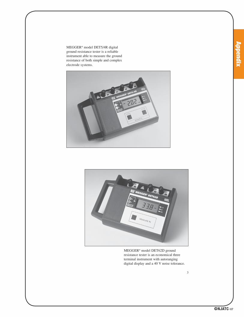
MEGGER® model DET5/4R digitalground resistance tester is a reliableinstrument able to measure the groundresistance of both simple and complexelectrode systems.
MEGGER® model DET62D groundresistance tester is an economical threeterminal instrument with autorangingdigital display and a 40 V noise tolerance.
3
41027_p067_122.indd 7341027_p067_122.indd 73 8/10/07 1:55:53 PM8/10/07 1:55:53 PM

Appendix
©NJATC–07
TABLE OF CONTENTS
Section Page
INTRODUCTION ................................................................................2SAFETY..............................................................................................6SECTION I - MEASURING EARTH RESISTANCE
FOR ELECTRICAL GROUNDING SYSTEMS.................................7Factors That Can Change Your Minimum Earth Resistance.........8Some Basic Definitions...................................................................8Factors Influencing Requirements for a Good Grounding System ............................................................................................9National Electrical Code Maximum Values ...................................11Nature of an Earth Electrode ........................................................12Principles Involved in Earth Resistance Testing ...........................13Basic Test Methods for Earth Resistance.....................................17Effects of Different Reference Probe Locations ...........................19Supplementary Tests ....................................................................24How to Improve Earth Resistance ................................................24
SECTION II - EARTH RESISTIVITY................................................29How Earth Resistivity is Measured ...............................................29Practical Example of Test Method ................................................30Type of Soil Affects Resistivity ......................................................31Resistivity Decreases with Moisture and Dissolved Salts ............32Effect of Temperature on Earth Resistivity ...................................33Seasonal Variations in Earth Resistivity .......................................34Determining a Good Electrode Location.......................................35
SECTION III - ACCURATELY MEASURING EARTH RESISTANCEFOR LARGE GROUND SYSTEMS ...............................................37Testing Challenges in Large Ground Systems .............................38Addressing the Testing Challenges in Large Ground Systems ........................................................................................38
Appendix I Nomograph Guide to Getting Acceptable Earth Resistance ....................................................................................41
Appendix II Measurement of the Resistance of Large Earth-Electrode Systems: Intersecting Curves Method..........................42
Appendix III Measurement of The Resistance of Large Earth Electrode Systems: Slope Method................................................45
Appendix IV Determining Touch and Step Potential ........................48References .......................................................................................50
4
41027_p067_122.indd 7441027_p067_122.indd 74 8/10/07 1:55:54 PM8/10/07 1:55:54 PM

Appendix
©NJATC–07
LIST OF ILLUSTRATIONS
Figure Page
1 A simplified grounding system in an industrial plant. ...............72 Example of an electrical circuit with too high an earth
resistance.................................................................................93 Typical conditions to be considered in a plant grounding
system. ..................................................................................104 Components of earth resistance in an earth electrode. ........125 Principle of an earth resistance test ......................................166 Fall-of-potential or three-terminal earth resistance test. ........177 Direct method or two-terminal earth resistance test. ............188 Effect of C location on the earth resistance curve.................209 Example of how C location affects the earth resistance curve. 2210 Earth resistance decreases with depth of electrode in earth. ..2511 Diameter of a rod has little effect on its earth resistance. ....2512 Average results obtained from multiple-rod earth electrodes. ..2613 Comparative resistance of multiple-rod earth electrodes. ....2714 Trench method of soil treatment. ..........................................2815 Chemical treatment of soil lessens seasonal variation of
electrode’s earth resistance. ..................................................2816 Four-terminal method of measuring earth resistivity. ............3017 Earth resistivity survey of pipeline shows where corrosion is
most likely to occur.................................................................3118 Deeper earth electrodes lower the resistance. ......................3219 Seasonal variation of earth resistance with an electrode of 3/4-
inch pipe in stony clay soil. ....................................................3520 Method of prospecting for best earth electrode location to a
depth a. ................................................................................3621 Nomograph relating the basic factors affecting earth
resistance ..............................................................................4022 Earth resistance curve applicable to systems of a large area...4323 Earth resistance curves for a substation. ..............................4324 Intersection curves for Fig. 23. ..............................................4425 Potential probe locations for using the Slope Method. ..........4526 Method of use for determining touch and step potential ......48
LIST OF TABLES
Table Page
I Guide to Approximate Location of Reference Probes ..........22II Resistivities of Different Soils ................................................31III Resistivities of Different Soils ................................................32IV Effect of Moisture Content on Earth Resistivity ....................33V Effect of Salt Content on Earth Resistivity ............................33VI Effect of Temperature on Earth Resistivity ............................34VII Values of P
t/C for Various Values of μ ..................................47
5
41027_p067_122.indd 7541027_p067_122.indd 75 8/10/07 1:55:54 PM8/10/07 1:55:54 PM

Appendix
S a f e t y
There is an inherent safety problem in earth resistance testing that requirescare and planning by the user of the test set.
The possibility exists that a fault in the power system will cause a highcurrent to flow into the ground system while the test is in progress. Thismay cause unexpected high voltages to appear at the current and voltageprobes, also at the terminals of the test set.
This risk must be evaluated by the person responsible for the tests, takinginto account the fault current available and expected step-and-touchpotentials. IEEE Standard 80 entitled “IEEE Guide for Safety in ACSubstation Grounding” fully covers this subject.
We recommend that the operator wear rubber protective gloves(ANSI/ASTM D120 or equal) while handling connections and use a rubbersafety mat (ANSI/ASTM D178 or equal) while operating the test set.
Checking the earth resistance of a ground system at a substation using a Biddle® Ground Resistance Tester, Cat. No. 250260.
6
©NJATC–07
41027_p067_122.indd 7641027_p067_122.indd 76 8/10/07 1:55:54 PM8/10/07 1:55:54 PM
Appendix
©NJATC–07
S e c t i o n I
M e a s u r i n g E a r t h R e s i s t a n c e f o r E l e c t r i c a l
G r o u n d i n g S y s t e m s
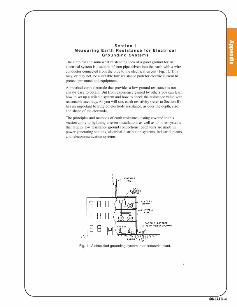
The simplest and somewhat misleading idea of a good ground for anelectrical system is a section of iron pipe driven into the earth with a wireconductor connected from the pipe to the electrical circuit (Fig. 1). Thismay, or may not, be a suitable low resistance path for electric current toprotect personnel and equipment.
A practical earth electrode that provides a low ground resistance is notalways easy to obtain. But from experience gained by others you can learnhow to set up a reliable system and how to check the resistance value withreasonable accuracy. As you will see, earth resistivity (refer to Section II)has an important bearing on electrode resistance, as does the depth, sizeand shape of the electrode.
The principles and methods of earth resistance testing covered in thissection apply to lightning arrester installations as well as to other systemsthat require low resistance ground connections. Such tests are made inpower-generating stations, electrical-distribution systems, industrial plants,and telecommunication systems.
Fig. 1 - A simplified grounding system in an industrial plant.
7
41027_p067_122.indd 7741027_p067_122.indd 77 8/10/07 1:55:54 PM8/10/07 1:55:54 PM
Appendix
©NJATC–07
Factors That Can Change Your
Minimum Earth Resistance
We will discuss later what value of earth resistance is considered lowenough. You’ll see that there is no general rule usable for all cases. First,however, consider three factors that can change the earth electroderequirements from year to year:
1. A plant or other electrical facility can expand in size. Also, new plantscontinue to be built larger and larger. Such changes create differentneeds in the earth electrode. What was formerly a suitably low earthresistance can become an obsolete “standard.”
2. As more nonmetallic pipes and conduits are installed underground,such installations become less and less dependable as effective, low-resistance ground connections.
3. In many locations, the water table is gradually falling. In a year or so,earth electrode systems that formerly were effective may end up in dryearth of high resistance.
These factors emphasize the importance of a continuous, periodic programof earth-resistance testing. It is not enough to check the earth resistanceonly at the time of installation.
Some Basic Definitions
First, let’s define our terms. As early as 19181, the terms ground, permanentground, and ground connections were defined to mean “electricalconnections intentionally made between electrical bodies (or conductingbodies in close proximity to electrical circuits) and metallic bodies in theearth - such as rods, water pipes, plates, or driven pipes.”
The metallic body in the earth is often referred to as an electrode eventhough it may be a water-pipe system, buried strips or plates, or wires.Such combinations of metallic bodies are called a grid. The earth resistancewe’re concerned with is the resistance to current from the electrode intothe surrounding earth.
To appreciate why earth resistance must be low, you need only use Ohm’sLaw: E = R x I where E is volts; R, the resistance in ohms; and I, thecurrent in amperes. Assume that you have a 4000-V supply (2300 V toground) with a resistance of 13 Ω (see Fig. 2). Now, assume that anexposed wire in this system touches a motor frame that is connected to agrounding system which has a 10-ohm resistance to earth.
8
1 Reference 19
41027_p067_122.indd 7841027_p067_122.indd 78 8/10/07 1:55:54 PM8/10/07 1:55:54 PM

Appendix
©NJATC–07
By Ohm’s Law, there will be a current of 100 Α2 through the fault (fromthe motor frame to the earth). If you happen to touch the motor frame andare grounded solidly to earth, (by standing in a puddle) you could besubjected to 1000 V (10 Ω x 100 Α).
Fig. 2 - Example of an electrical circuit with too high an earth resistance.
As you’ll note from point 2 in the following, this may be more than enoughto kill you instantly. If, however, the earth resistance is less than 1 Ω, the shock you’d get would be under 100 V (1 x 100) and you’dprobably live to correct the fault.
Equipment can also be damaged similarly by overvoltages caused by high-resistance ground systems.
Factors Influencing Requirements
for a Good Grounding System
In an industrial plant or other facility that requires a grounding system, oneor more of the following must be carefully considered (see Fig. 3):
1. Limiting to definite values the voltage to earth of the entire electricalsystem. Use of a suitable grounding system can do this by maintainingsome point in the circuit at earth potential. Such a grounding systemprovides these advantages:
• Limits voltage to which the system-to-ground insulation issubjected, thereby more definitely fixing the insulation rating.
• Limits the system-to-ground or system-to-frame voltage to valuessafe for personnel.
• Provides a relatively stable system with a minimum of transientovervoltages.
• Permits any system fault to ground to be quickly isolated.
9
2 I = E/R = 2,300/10 + 13 = 100 Amperes
41027_p067_122.indd 7941027_p067_122.indd 79 8/10/07 1:55:54 PM8/10/07 1:55:54 PM

Appendix
©NJATC–07
2. Proper grounding of metallic enclosures and support structures thatare part of the electrical system and may be contacted by personnel.Also, to be included are portable electrically operated devices.Consider that only a small amount of electric current - as little as 0.1 Afor one second - can be fatal! An even smaller amount can cause youto lose muscular control. These low currents can occur in your body atvoltages as low as 100 V, if your skin is moist.
Fig. 3 - Typical conditions to be considered in a plant grounding system.
3. Protection against static electricity from friction. Along with this arethe attendant hazards of shock, fire and explosion. Moving objects thatmay be inherent insulators - such as paper, textiles, conveyor belts orpower belts and rubberized fabrics - can develop surprisingly highcharges unless properly grounded.
4. Protection against direct lightning strokes. Elevated structures, such asstacks, the building proper, and water tanks may require lightning rodsconnected into the grounding system.
5. Protection against induced lightning voltages. This is particularly afactor if aerial power distribution and communications circuits areinvolved. Lightning arresters may be required in strategic locationsthroughout the plant.
6. Providing good grounds for electric process control andcommunication circuits. With the increased use of industrial controlinstruments, computers, and communications equipment, accessibilityof low-resistance ground connections in many plant locations - inoffice and production areas - must be considered.
10
41027_p067_122.indd 8041027_p067_122.indd 80 8/10/07 1:55:56 PM8/10/07 1:55:56 PM

Appendix
©NJATC–07
National Electrical Code Maximum Values
The National Electrical Code, Section 250-84 states that a single electrodewith a resistance to ground greater than 25 Ω shall be augmented by oneadditional electrode.
We recommend that single-electrode grounds be tested when installed
and periodically afterward.
Resistance to earth can vary with changes in climate and temperature. Suchchanges can be considerable. An earth electrode that was good (low-resistance) when installed may not stay that way; to be sure, you mustcheck it periodically.
We cannot tell you what your maximum earth resistance should be. Forspecific systems in definite locations, specifications are often set. Some callfor 5 Ω maximum; others accept no more than 3 Ω. In certain cases,resistances as low as a small fraction of an ohm are required.
Megger® DET2/2 Ground Resistance Tester offers additional features for testing in a high-noise environment.
11
41027_p067_122.indd 8141027_p067_122.indd 81 8/10/07 1:55:56 PM8/10/07 1:55:56 PM

Appendix
©NJATC–07
Nature of an Earth Electrode
Resistance to current through an earth electrode actually has threecomponents (Fig. 4):
1. Resistance of the electrode itself and connections to it.
2. Contact resistance between the electrode and the soil adjacent to it.
3. Resistance of the surrounding earth.
Electrode Resistance: Rods, pipes, masses of metal, structures, and otherdevices are commonly used for earth connections. These are usually ofsufficient size or cross-section that their resistance is a negligible part ofthe total resistance.
Electrode-Earth Contact Resistance: This is much less than you mightthink. If the electrode is free from paint or grease, and the earth is packedfirmly, contact resistance is negligible. Rust on an iron electrode has littleor no effect; the iron oxide is readily soaked with water and has lessresistance than most soils. But if an iron pipe has rusted through, the partbelow the break is not effective as a part of the earth electrode.
Resistance of Surrounding Earth: An electrode driven into earth ofuniform resistivity radiates current in all directions. Think of the electrodeas being surrounded by shells of earth, all of equal thickness (see Fig. 4).
Fig. 4 - Components of earth resistance in an earth electrode.
12
41027_p067_122.indd 8241027_p067_122.indd 82 8/10/07 1:55:56 PM8/10/07 1:55:56 PM

Appendix
©NJATC–07
The earth shell nearest the electrode naturally has the smallest surface areaand so offers the greatest resistance. The next earth shell is somewhatlarger in area and offers less resistance. Finally, a distance from theelectrode will be reached where inclusion of additional earth shells doesnot add significantly to the resistance of the earth surrounding theelectrode. It is this critical volume of soil that determines the effectivenessof the ground electrode and which therefore must be effectively measuredin order to make this determination. Ground testing is distinct whencompared to more familiar forms of electrical measurement, in that it is avolumetric measurement and cannot be treated as a “point” property.
Generally, the resistance of the surrounding earth will be the largest of thethree components making up the resistance of a ground connection. Theseveral factors that can affect this value are discussed in Section II on EarthResistivity. From Section II, you’ll see that earth resistivity depends on thesoil material, the moisture content, and the temperature. It is far from aconstant, predictable value ranging generally from 500 to 50,000 ohm-cm3.
Principles Involved in Earth Resistance Testing
The resistance to earth of any system of electrodes theoretically can becalculated from formulas based upon the general resistance formula:
R = ρ LA
where ρ is the resistivity of the earth in ohm-cm, L is the length of theconducting path, and A is the cross-sectional area of the path. Prof. H. B.Dwight of Massachusetts Institute of Technology developed rather complexformulas for the calculation of the resistance to earth for any distance fromvarious systems of electrodes (Reference 11). All such formulas can besimplified a little by basing them on the assumption that the earth’sresistivity is uniform throughout the entire soil volume under consideration.
Because the formulas are complicated, and earth resistivity is neitheruniform or constant, a simple and direct method of measuring earthresistance is needed. This is where we come in with our Megger® GroundResistance Tester, a self-contained portable instrument that is reliable andeasy to use. With it, you can check the resistance of your earth electrodewhile it is being installed; and, by periodic tests, observe any changes withtime.
13
3 An ohm-centimeter (abbreviated ohm-cm) is defined as the resistance of a cube ofmaterial (in this case, earth) with the cube sides being measured in centimeters.
41027_p067_122.indd 8341027_p067_122.indd 83 8/10/07 1:55:57 PM8/10/07 1:55:57 PM
Appendix
©NJATC–07
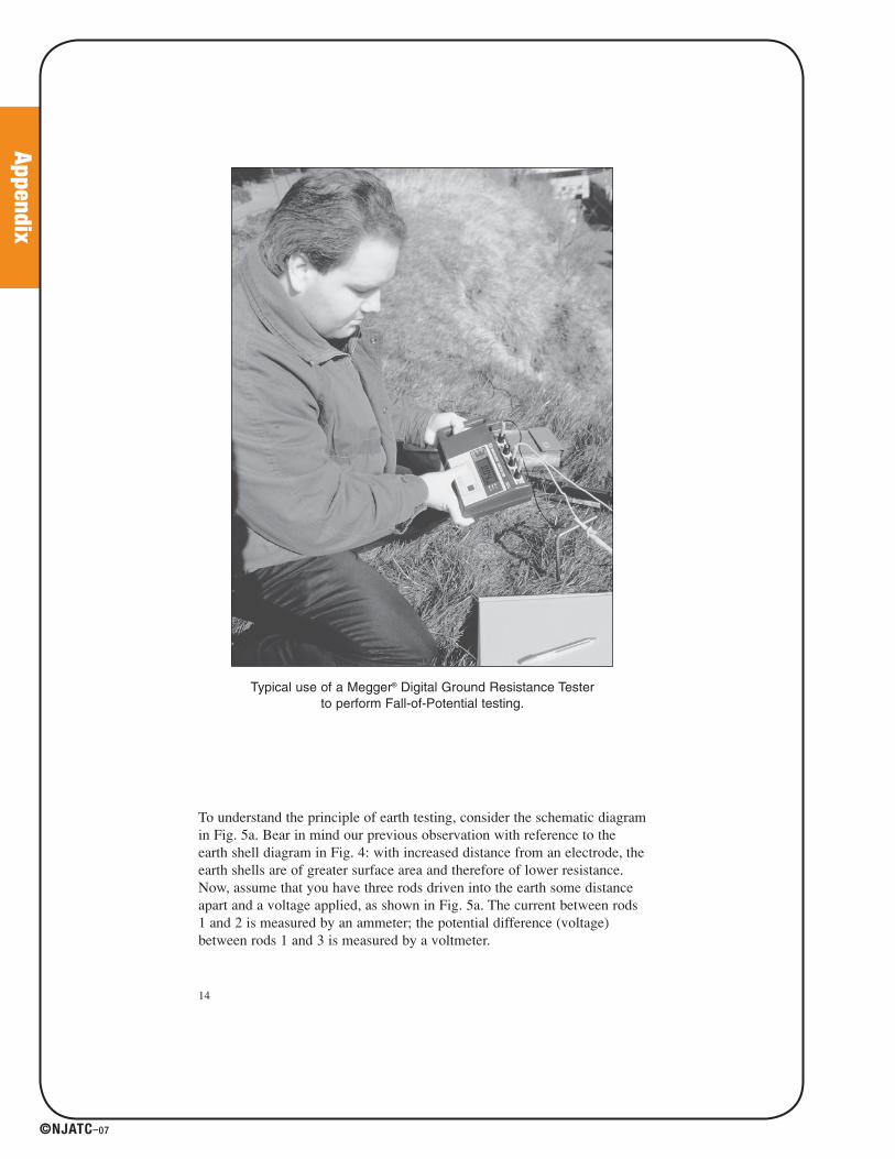
Typical use of a Megger® Digital Ground Resistance Tester to perform Fall-of-Potential testing.
To understand the principle of earth testing, consider the schematic diagramin Fig. 5a. Bear in mind our previous observation with reference to theearth shell diagram in Fig. 4: with increased distance from an electrode, theearth shells are of greater surface area and therefore of lower resistance.Now, assume that you have three rods driven into the earth some distanceapart and a voltage applied, as shown in Fig. 5a. The current between rods1 and 2 is measured by an ammeter; the potential difference (voltage)between rods 1 and 3 is measured by a voltmeter.
14
41027_p067_122.indd 8441027_p067_122.indd 84 8/10/07 1:55:57 PM8/10/07 1:55:57 PM
Appendix
©NJATC–07
If rod 3 is located at various points between rods 1 and 2, preferably in astraight line4, you can get a series of voltage readings. By Ohm’s Law (R = E/I) you can determine the earth resistance at any point measured. Forexample, if the measured voltage E between rods 1 and 3 is 30 V and themeasured current I is 2 Α, the resistance of the earth R at that point wouldbe 15 Ω.
The series of resistance values can be plotted against distance to obtain acurve (Fig. 5b). Note that as rod 3 is moved away from rod 1, the resistancevalues increase, but the amount of increase gets less and less until a point isreached where the rate of increase becomes so small that I can almost beconsidered constant (20 Ω in Fig. 5b). The earth shells between the two rods(1 and 3) have so great a surface area that they add little to the totalresistance. Beyond this point, as rod 3 approaches the earth shells of rod 2,resistance gradually picks up. Near rod 2, the values rise sharply.
Now, let’s say that rod 1 is our earth electrode under test. From a typicalearth-resistance curve, such as Fig. 5b, what is the resistance to earth ofthis rod? We call rod 2 current-reference probe C and rod 3, potential-reference probe P (simply for convenience in identification). The correctresistance is usually obtained if P (rod 3) is placed at a distance from thecenter of the earth electrode (rod 1) about 62 percent of the distancebetween the earth electrode and C (rod 2).
For example, in Fig. 5b, the distance D from the earth electrode to C is 100 ft. Taking 62 percent of this distance, we get 62 ft. From Fig. 5b, theresistance for this distance is 20 Ω. This is the measured resistance of theearth electrode.
This rule works well for simple electrodes, such as a driven rod. It alsoworks for a small group of rods. But you must know the true electricalcenter of the electrode system fairly accurately. Also, accuracy of readingsis better if the earth resistivity between the three electrodes is reasonablyconstant. Finally, C should be far enough away from the earth electrodesystem so that the 62 percent distance is out of the “sphere of influence” ofthe earth electrode. (See discussion with reference to Figs. 8 and 9). For thetest, the electrode should be isolated from the electrical system that it isprotecting; otherwise, the whole system is tested which (depending on localpractices) may include the pole ground, system neutral, and transformerground. This obscures the specific effect of the local ground.
Basically, you now have the principle of earth resistance testing. The rest isrefinement -- in test methods, use of electrodes or electrode systems, andinformation about earth resistivity, as covered in later portions of thismanual.
15
4 Actually, current can exist in other paths between the two fixed electrodes, so thatrod 3 could be (and might have to be) located at other than along a straight line.
41027_p067_122.indd 8541027_p067_122.indd 85 8/10/07 1:55:57 PM8/10/07 1:55:57 PM

Appendix
©NJATC–07
Figure 5 - Principle of an earth resistance test
16
41027_p067_122.indd 8641027_p067_122.indd 86 8/10/07 1:55:57 PM8/10/07 1:55:57 PM
Appendix
©NJATC–07
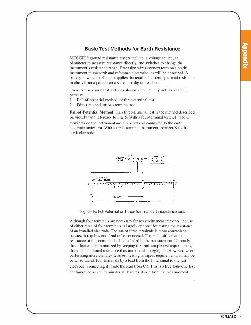
Basic Test Methods for Earth Resistance
MEGGER® ground resistance testers include: a voltage source, anohmmeter to measure resistance directly, and switches to change theinstrument’s resistance range. Extension wires connect terminals on theinstrument to the earth and reference electrodes, as will be described. Abattery-powered oscillator supplies the required current; you read resistancein ohms from a pointer on a scale or a digital readout.
There are two basic test methods shown schematically in Figs. 6 and 7,namely:1. Fall-of-potential method, or three-terminal test.2. Direct method, or two-terminal test.
Fall-of-Potential Method: This three-terminal test is the method describedpreviously with reference to Fig. 5. With a four-terminal tester, P
1and C
1
terminals on the instrument are jumpered and connected to the earthelectrode under test. With a three-terminal instrument, connect X to theearth electrode.
Fig. 6 - Fall-of-Potential or Three-Terminal earth resistance test.
Although four terminals are necessary for resistivity measurements, the useof either three of four terminals is largely optional for testing the resistanceof an installed electrode. The use of three terminals is more convenientbecause it requires one lead to be connected. The trade-off is that theresistance of this common lead is included in the measurement. Normally,this effect can be minimized by keeping the lead simple test requirements,the small additional resistance thus introduced is negligible. However, whenperforming more complex tests or meeting stringent requirements, it may bebetter to use all four terminals by a lead from the P
1terminal to the test
electrode (connecting it inside the lead from C1). This is a true four-wire test
configuration which eliminates all lead resistance from the measurement.
17
41027_p067_122.indd 8741027_p067_122.indd 87 8/10/07 1:55:57 PM8/10/07 1:55:57 PM

Appendix
©NJATC–07
The added accuracy may prove significant when meeting very lowresistance specifications or using test methods that necessitate an extra digitof measurement in order to meet the mathematical requirements. Thedecision is optional, based on the operator’s testing goals and the methodused. The driven reference rod C should be placed as far from the earthelectrode as practical; this distance may be limited by the length ofextension wire available, or the geography of the surroundings (see Fig. 6).Leads should be separated and “snaked,” not run close and parallel to eachother, to eliminate mutual inductance.
Potential-reference rod P is then driven in at a number of points roughly ona straight line between the earth electrode and C. Resistance readings arelogged for each of the points. A curve of resistance vs. distance, like Fig.5b, is then drawn. Correct earth resistance is read from the curve for thedistance that is about 62 percent of the total distance from the earthelectrode to C. In other words, if the total distance is D, the 62 percentdistance is 0.62D; for example, if D is 120 ft, the distance value for earthresistance is 0.62 x 120 or 74 ft.
Direct Method: When using a four-terminal instrument, P1
and C1
terminals connect to the earth electrode under test; P2
and C2
terminals
connect to an all-metallic water-pipe system. With a three-terminalinstrument, connect X to the earth electrode, P and C to the pipe system(Fig. 7). If the water system is extensive (covering a large area), itsresistance should only be a fraction of an ohm. You can then take theinstrument reading as being the resistance of the electrode under test.
Fig. 7 - Direct Method or Two-Terminal earth resistance test.
18
41027_p067_122.indd 8841027_p067_122.indd 88 8/10/07 1:55:57 PM8/10/07 1:55:57 PM

Appendix
©NJATC–07
The direct method is the simplest way to make an earth resistance test.With this method, resistance of two electrodes in series is measured - thedriven rod and the water system. But there are three important limitations:
1. The waterpipe system must be extensive enough to have a negligibleresistance.
2. The waterpipe system must be metallic throughout, without anyinsulating couplings or flanges.
3. The earth electrode under test must be far enough away from thewater-pipe system to be outside its sphere of influence.
In some locations, your earth electrode may be so close to the water-pipesystem that you cannot separate the two by the required distance formeasurement by the two-terminal method. Under these circumstances, ifconditions 1 and 2 above are met, you can connect to the water-pipe systemand obtain a suitable earth electrode. As a precaution against any possiblefuture changes in the resistance of the water-pipe system, however, youshould also install an earth electrode.
Effects of Different Reference Probe Locations
Now, you may ask: if the right location for probe P is always 62 percent ofthe distance between the earth electrode and C, why bother with all thetests at other locations for P? Why not just drive P in at the 62 percentdistance and assume that the measured resistance the correct earthresistance? The following should help answer these questions.
Minimum Distance for C: Consider Fig. 8 which shows earth shellsaround the earth electrode and reference probe C. In Fig. 8a, C is so closeto the earth electrode that the earth shells seriously overlap. Then you don’tget the leveling off of measured resistance as P is moved away from theearth electrode; the shells of C add to the shells of the earth electrode sothe resistance keeps increasing.
In Fig. 8b, C is placed farther away. Then the measured resistance levelsoff enough and at the 62 percent distance it is very close to the actual earthresistance. The reason for having C farther away is to get assurance that the62 percent value is “in line” with other values on the curve. The valuecould only be wrong (assuming there are no measuring mistakes) if the soilconditions at the 62 percent point vary from conditions at other points,causing changes in earth resistivity. Graded soil around construction sitesor buried objects such as pipes can cause such localized deviations.Therefore, you want to get some degree of flatness or leveling off of yourcurve to make such a variation easily noticeable. At the same time,remember that the resistance will rise again in the electrical field of thecurrent probe, so measurements in this area are to be avoided.
19
41027_p067_122.indd 8941027_p067_122.indd 89 8/10/07 1:55:58 PM8/10/07 1:55:58 PM

Appendix
©NJATC–07
Fig. 8 - Effect of C location on the earth resistance curve.
Measuring the resistance of a ground system on a pad-mounted transformer at a manufacturing plant.
20
41027_p067_122.indd 9041027_p067_122.indd 90 8/10/07 1:55:58 PM8/10/07 1:55:58 PM
Appendix
©NJATC–07
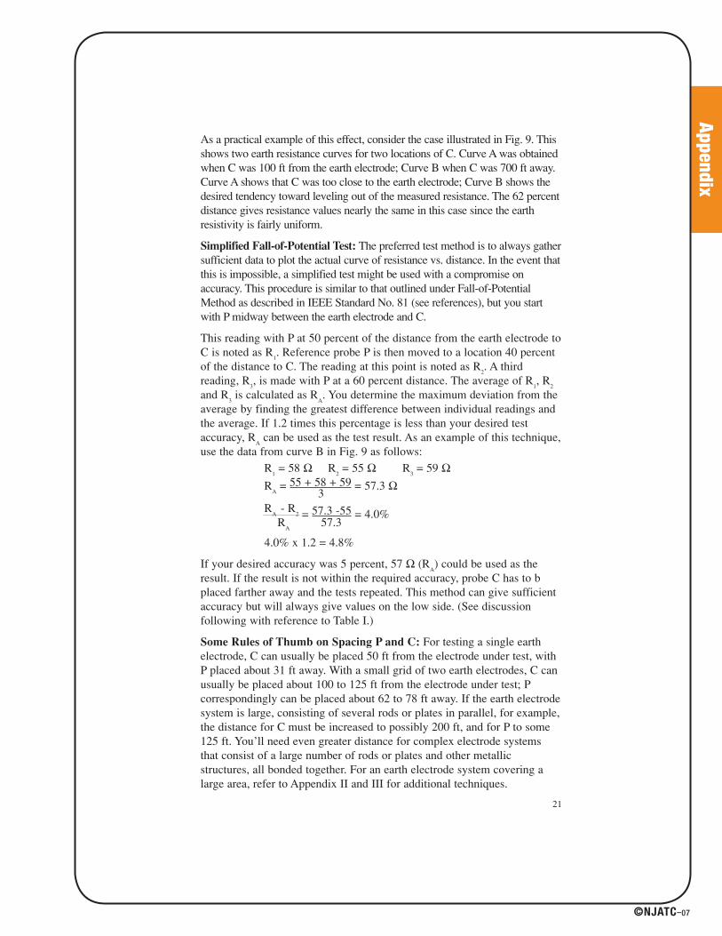
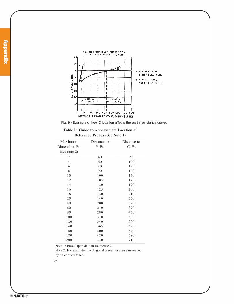
As a practical example of this effect, consider the case illustrated in Fig. 9. Thisshows two earth resistance curves for two locations of C. Curve A was obtainedwhen C was 100 ft from the earth electrode; Curve B when C was 700 ft away.Curve A shows that C was too close to the earth electrode; Curve B shows thedesired tendency toward leveling out of the measured resistance. The 62 percentdistance gives resistance values nearly the same in this case since the earthresistivity is fairly uniform.
Simplified Fall-of-Potential Test: The preferred test method is to always gathersufficient data to plot the actual curve of resistance vs. distance. In the event thatthis is impossible, a simplified test might be used with a compromise onaccuracy. This procedure is similar to that outlined under Fall-of-PotentialMethod as described in IEEE Standard No. 81 (see references), but you startwith P midway between the earth electrode and C.
This reading with P at 50 percent of the distance from the earth electrode toC is noted as R
1. Reference probe P is then moved to a location 40 percent
of the distance to C. The reading at this point is noted as R2. A third
reading, R3, is made with P at a 60 percent distance. The average of R
1, R
2
and R3
is calculated as RA. You determine the maximum deviation from the
average by finding the greatest difference between individual readings andthe average. If 1.2 times this percentage is less than your desired testaccuracy, R
Acan be used as the test result. As an example of this technique,
use the data from curve B in Fig. 9 as follows:
R1
= 58 Ω R2
= 55 Ω R3
= 59 ΩR
A= 55 + 58 + 59 = 57.3 Ω
3R
A- R
2 = 57.3 -55 = 4.0%R
A57.3
4.0% x 1.2 = 4.8%
If your desired accuracy was 5 percent, 57 Ω (RA) could be used as the
result. If the result is not within the required accuracy, probe C has to bplaced farther away and the tests repeated. This method can give sufficientaccuracy but will always give values on the low side. (See discussionfollowing with reference to Table I.)
Some Rules of Thumb on Spacing P and C: For testing a single earthelectrode, C can usually be placed 50 ft from the electrode under test, withP placed about 31 ft away. With a small grid of two earth electrodes, C canusually be placed about 100 to 125 ft from the electrode under test; Pcorrespondingly can be placed about 62 to 78 ft away. If the earth electrodesystem is large, consisting of several rods or plates in parallel, for example,the distance for C must be increased to possibly 200 ft, and for P to some125 ft. You’ll need even greater distance for complex electrode systemsthat consist of a large number of rods or plates and other metallicstructures, all bonded together. For an earth electrode system covering alarge area, refer to Appendix II and III for additional techniques.
21
41027_p067_122.indd 9141027_p067_122.indd 91 8/10/07 1:55:58 PM8/10/07 1:55:58 PM
Appendix
©NJATC–07
22
Fig. 9 - Example of how C location affects the earth resistance curve.
Table I: Guide to Approximate Location of
Reference Probes (See Note 1)__________________________________________________________________________________________________________________________________________________________________________________________________________________________________________
MaximumDimension, Ft.
(see note 2)
Distance toP, Ft.
Distance toC, Ft.
__________________________________________________________________________________________________________________________________________________________________________________________________________________________________________
2 40 704 60 1006 80 1258 90 140
10 100 16012 105 17014 120 19016 125 20018 130 21020 140 22040 200 32060 240 39080 280 450100 310 500120 340 550140 365 590160 400 640180 420 680200 440 710
__________________________________________________________________________________________________________________________________________________________________________________________________________________________________________
Note 1: Based upon data in Reference 2.Note 2: For example, the diagonal across an area surroundedby an earthed fence.
41027_p067_122.indd 9241027_p067_122.indd 92 8/10/07 1:55:58 PM8/10/07 1:55:58 PM

Appendix
©NJATC–07
Table I is a useful guide to reference probe location. You find the “MaximumDimension” figure by taking the diagonal distance across your electrodesystem area. For example, if the area measures 100 by 100 ft, the diagonalequals about 140 ft from the table, you run down the first column to 140 andread across that P should be 365 ft from the electrode and C, 590 ft.
Lazy Spikes
The latest designs of digital earth testers can operate with very hightemporary spike resistances and still give reliable and accurate results.Because the current and voltage are measured separately, it enables electrodemeasurements can be carried out with test spike resistances up to 400 kΩ.
The advantage of these instruments tolerating such high spike resistance isgenerally that tests can be performed quickly on a green field site becauseelectrodes do not have to be inserted too far into the ground. However, inurban situations, tests can be carried out using street furniture such as signposts, metal fences and bollards. Where this is not possible, results have beenobtained by laying the temporary electrodes on a wet patch of concrete. Thistechnique has led to measured values of “spike” of less than 10 kΩ, wellinside the maximum value that will cause an error to the reading.
With modern instruments, any problem with the temporary spikes will beindicated on the display to show that a reading may not be valid. A moresuitable position for the spike may have to be used such as along the gapbetween paving stones, a crack in concrete, or in a nearby puddle.
With Megger® Ground Resistance Testers’ high resistance test circuits,testing can be performed on a paved surface.
23
41027_p067_122.indd 9341027_p067_122.indd 93 8/10/07 1:55:58 PM8/10/07 1:55:58 PM
Appendix
©NJATC–07
Supplementary Tests
There are related tests which can be performed to supplement theinformation gained from the ground test and to augment the protectionprovided by the ground electrode. One of these is a continuity test to assurethat is complete and adequate throughout the grounding conductors anddown to the point of contact with the electrode. Either a three-terminal orfour-terminal tester can be used in a two-terminal configuration by shuntingtogether the appropriate pairs. The two leads can thus be connected across abond, weld, joint, or length of conductor, and the resistance is measured. Anearth tester, however, provides only a convenient backup check, not a fullyrigorous continuity test. The reason for this is that, for safety’s sake, the testcurrent is limited to values below a level harmful to the human body. A fullyrigorous proof of a bond, however, must stress the connection at currentlevels capable of revealing corrosion, cracks, loose connections, and thelike. For this reason, a dedicated low resistance ohmmeter capable of 10 Aor more of test current is preferred.
To protect personnel about to perform a ground test, as well as to identifythe presence of electrical problems in the system, the ground electrode canfirst be checked for the presence of fault current. It is not uncommon, in anunbalanced or faulted electrical system, for the electrode to be carrying afault current, more or less constantly, to ground. This may be only a fewmilliamps or several amps, and occurring undetected. A sufficientlysensitive clamp-on milliammeter can reveal the problem, and protect thetesting crew from possible shock, in just a few seconds.
The total impedance of the system can be measured at once by using a looptester. This instrument simulates a fault between a phase conductor andground, and thereby measures the total impedance of the entire groundloop, including conductors and the earth return path back to the transformerand its winding. If any of these elements have too high a resistance,protective devices may be inhibited from operating properly, even thoughthe ground electrode itself is maintained at a sufficiently low resistance.
How to Improve Earth Resistance
When you find that your earth electrode resistance is not low enough, thereare several ways you can improve it:
1. Lengthen the earth electrode in the earth.
2. Use multiple rods.
3. Treat the soil.
Effect of Rod Size: As you might suspect, driving a longer rod deeper intothe earth, materially decreases its resistance. In general, doubling the rodlength reduces resistance by about 40 percent. The curve of Fig. 10 showsthis effect. For example, note that a rod driven 2 ft down has a resistance of88 Ω; the same rod driven 4 ft down has a resistance of about 50 Ω. Using
24
41027_p067_122.indd 9441027_p067_122.indd 94 8/10/07 1:55:58 PM8/10/07 1:55:58 PM

Appendix
©NJATC–07
the 40 percent reduction rule, 88 x 0.4 = 35 Ω reduction. By thiscalculation, a 4-ft deep rod would have a resistance of 88 - 35 or 53 Ω -comparing closely with the curve values.
Fig. 10 - Earth resistance decreases with depth of electrode in earth. (Source: Reference 19)
You might also think that increasing the electrode diameter would lowerthe resistance. It does, but only a little. For the same depth, doubling therod’s diameter reduces the resistance only about 10 percent. Fig. 11 showsthis relationship. For example, a 10-ft deep rod, 5/8 in. in diameter, has aresistance of 6.33 Ω; increasing its diameter to 1-1/4 in. lowers theresistance o to 5.6 Ω. For this reason, you normally only considerincreasing the rod diameter if you have to drive it into hard terrain.
Fig. 11 - Diameter of a rod has little effect on its earth resistance.Curve A, from Reference 19.Curve B, average of Underwriters Laboratories tests at Chicago.Curve C, average of Underwriters Laboratories tests at Pittsburgh
25
41027_p067_122.indd 9541027_p067_122.indd 95 8/10/07 1:55:59 PM8/10/07 1:55:59 PM

Appendix
©NJATC–07
Use of Multiple Rods: Two well-spaced rods driven into the earth provideparallel paths. They are, in effect, two resistances in parallel. The rule fortwo resistances in parallel does not apply exactly; that is, the resultantresistance is not one-half the individual rod resistances (assuming they areof the same size and depth). Actually, the reduction for two equal resistancerods is about 40 percent. If three rods are used, the reduction is 60 percent;if four, 66 percent (see Fig. 12).
Fig. 12 - Average results obtained from multiple-rod earth electrodes5.
When you use multiple rods, they must be spaced apart further than thelength of their immersion. There are theoretical reasons for this, but youneed only refer to curves such as Fig. 13. For example, if you have tworods in parallel and 10-ft spacing, resistance is lowered about 40 percent. Ifthe spacing is increased to 20 percent, reduction is about 50 percent.
26
5 Source: Reference 20
41027_p067_122.indd 9641027_p067_122.indd 96 8/10/07 1:55:59 PM8/10/07 1:55:59 PM
Appendix
©NJATC–07
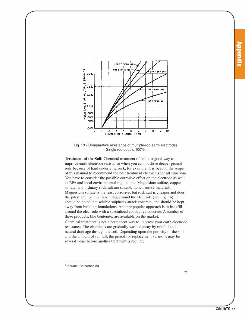
Fig. 13 - Comparative resistance of multiple-rod earth electrodes. Single rod equals 100%6.
Treatment of the Soil: Chemical treatment of soil is a good way toimprove earth electrode resistance when you cannot drive deeper groundrods because of hard underlying rock, for example. It is beyond the scopeof this manual to recommend the best treatment chemicals for all situations.You have to consider the possible corrosive effect on the electrode as wellas EPA and local environmental regulations. Magnesium sulfate, coppersulfate, and ordinary rock salt are suitable noncorrosive materials.Magnesium sulfate is the least corrosive, but rock salt is cheaper and doesthe job if applied in a trench dug around the electrode (see Fig. 14). Itshould be noted that soluble sulphates attack concrete, and should be keptaway from building foundations. Another popular approach is to backfillaround the electrode with a specialized conductive concrete. A number ofthese products, like bentonite, are available on the market.
Chemical treatment is not a permanent way to improve your earth electroderesistance. The chemicals are gradually washed away by rainfall andnatural drainage through the soil. Depending upon the porosity of the soiland the amount of rainfall, the period for replacement varies. It may beseveral years before another treatment is required.
27
6 Source: Reference 20
41027_p067_122.indd 9741027_p067_122.indd 97 8/10/07 1:55:59 PM8/10/07 1:55:59 PM
Appendix
©NJATC–07
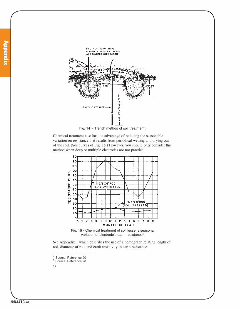
Fig. 14 - Trench method of soil treatment7.
Chemical treatment also has the advantage of reducing the seasonablevariation on resistance that results from periodical wetting and drying outof the soil. (See curves of Fig. 15.) However, you should only consider thismethod when deep or multiple electrodes are not practical.
Fig. 15 - Chemical treatment of soil lessens seasonal variation of electrode’s earth resistance8.
See Appendix 1 which describes the use of a nomograph relating length ofrod, diameter of rod, and earth resistivity to earth resistance.
28
7 Source: Reference 208 Source: Reference 20
41027_p067_122.indd 9841027_p067_122.indd 98 8/10/07 1:55:59 PM8/10/07 1:55:59 PM

Appendix
©NJATC–07
S E C T I O N I I - E a r t h R e s i s t i v i t y
As we’ve seen in Section I, the term, “earth resistivity,” expressed in ohm-centimeters (abbreviated ohm-cm), is one basic variable affecting resistanceto earth of an electrode system. But you found that the actual value of earthresistivity need not be measured to check the electrode earth resistance.Now we’ll consider other fields where the value of resistivity is measuredalso some of the factors affecting it that are of interest in earth testing.
Earth resistivity measurements can be used conveniently for geophysicalprospecting -- to locate ore bodies, clays, and water bearing gravel beneaththe earth’s surface. The measurement can also be used to determine depthto bed rock and thickness of glacial drift.
Measurements of earth resistivity are useful also for finding the bestlocation and depth for low resistance electrodes. Such studies are made, forexample, when a new electrical unit is being constructed; a generatingstation, substation, transmission tower, or telephone central office.
Finally, earth resistivity may be used to indicate the degree of corrosion tobe expected in underground pipelines for water, oil, gas, gasoline, etc. Ingeneral, spots where the resistivity values are low tend to increasecorrosion. This same kind of information is a good guide for installingcathodic protection.
How Earth Resistivity is Measured
A four-terminal instrument is used to measure earth resistivity. Now,however, you use four small-sized electrodes driven down to the samedepth and equal distances apart in a straight line (Fig. 16). Four separatelead wires connect the electrodes to the four terminals on the instrument, asshown. Hence, the name of this test: the four-terminal method.
Dr. Frank Wenner of the U.S. Bureau of Standards (now NIST) developedthe theory behind this test in 1915 (see reference 10). He showed that, ifthe electrode depth (B) is kept small compared to the distance between theelectrodes (A)9, the following formula applies:
ρ = 2π AR
where ρ is the average soil resistivity to depth A in ohm-cm, π is theconstant 3.1416, A is the distance between the electrodes in cm, and R isthe Megger earth tester reading in ohms.
In other words, if the distance A between the electrodes is 4 ft, you obtainthe average earth resistivity to a depth of 4 ft as follows:
29
9 B = 1⁄20 A is generally recommended.
41027_p067_122.indd 9941027_p067_122.indd 99 8/10/07 1:55:59 PM8/10/07 1:55:59 PM
Appendix
©NJATC–07
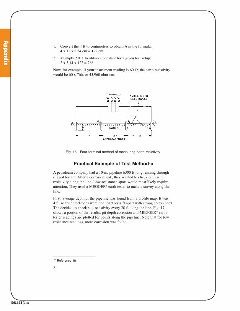
1. Convert the 4 ft to centimeters to obtain A in the formula:4 x 12 x 2.54 cm = 122 cm
2. Multiply 2 π A to obtain a constant for a given test setup:2 x 3.14 x 122 = 766
Now, for example, if your instrument reading is 60 Ω, the earth resistivitywould be 60 x 766, or 45,960 ohm-cm.
Fig. 16 - Four-terminal method of measuring earth resistivity.
Practical Example of Test Method10
A petroleum company had a 10-in. pipeline 6300 ft long running throughrugged terrain. After a corrosion leak, they wanted to check out earthresistivity along the line. Low-resistance spots would most likely requireattention. They used a MEGGER® earth tester to make a survey along theline.
First, average depth of the pipeline was found from a profile map. It was 4 ft, so four electrodes were tied together 4 ft apart with strong cotton cord.The decided to check soil resistivity every 20 ft along the line. Fig. 17shows a portion of the results; pit depth corrosion and MEGGER® earthtester readings are plotted for points along the pipeline. Note that for lowresistance readings, more corrosion was found.
30
10 Reference 18
41027_p067_122.indd 10041027_p067_122.indd 100 8/10/07 1:55:59 PM8/10/07 1:55:59 PM

Appendix
©NJATC–07
Fig. 17 - Earth resistivity survey of pipeline shows where corrosion is most likely to occur.
(Source: Reference 18)
31
Type of Soil Affects Resistivity
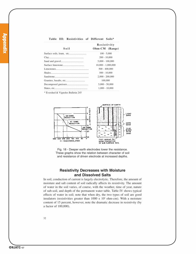
Whether a soil is largely clay or very sandy, for example, can change theearth resistivity a great deal. It isn’t easy to define exactly a given soil;“clay” can cover a wide variety of soils. Therefore, we cannot say that anygiven soil has a resistivity of so many ohm-cm. Tables II and III are takenfrom two different reference books and show the wide range in values.Note also the spread of values for the same general types of soil. See Fig. 18also.
Table II: Resistivities of Different Soils*__________________________________________________________________________________________________________________________________________________________________________________________________________________________________________
S o i l
R e s i s t i v i t y
Ohm-cm_____________________________________________________________________________________
A v g M i n M a x__________________________________________________________________________________________________________________________________________________________________________________________________________________________________________
Fills: ashes, cinders, brine wastes.................. 2,370 590 7,000
Clay, shale, gumbo, loam............................... 4,060 340 16,300
Same: varying proportions of sand/gravel.... 15,800 1,020 135,000
Gravel, sand, stones, with little clay/loam.... 94,000 59,000 458,000__________________________________________________________________________________________________________________________________________________________________________________________________________________________________________
* U.S. Bureau of Standards Report 108
41027_p067_122.indd 10141027_p067_122.indd 101 8/10/07 1:55:59 PM8/10/07 1:55:59 PM
Appendix
©NJATC–07
Resistivity Decreases with Moisture
and Dissolved SaltsIn soil, conduction of current is largely electrolytic. Therefore, the amount ofmoisture and salt content of soil radically affects its resistivity. The amountof water in the soil varies, of course, with the weather, time of year, natureof sub-soil, and depth of the permanent water table. Table IV shows typicaleffects of water in soil; note that when dry, the two types of soil are goodinsulators (resistivities greater than 1000 x 106 ohm-cm). With a moisturecontent of 15 percent, however, note the dramatic decrease in resistivity (bya factor of 100,000).
32
Table III: Resistivities of Different Soils*__________________________________________________________________________________________________________________________________________________________________________________________________________________________________________
S o i l
R e s i s t i v i t y
Ohm-CM (Range)__________________________________________________________________________________________________________________________________________________________________________________________________________________________________________
Surface soils, loam, etc........................... 100 - 5,000
Clay...................................................... 200 - 10,000
Sand and gravel................................... 5,000 - 100,000
Surface limestone................................. 10,000 - 1,000,000
Limestones................................................... 500 - 400,000
Shales........................................................... 500 - 10,000
Sandstone..................................................... 2,000 - 200,000
Granites, basalts, etc.............................. 100,000
Decomposed gneisses................................. 5,000 - 50,000
Slates, etc................................................... 1,000 - 10,000__________________________________________________________________________________________________________________________________________________________________________________________________________________________________________
* Evershed & Vignoles Bulletin 245
Fig. 18 - Deeper earth electrodes lower the resistance.These graphs show the relation between character of soiland resistance of driven electrode at increased depths.
41027_p067_122.indd 10241027_p067_122.indd 102 8/10/07 1:56:00 PM8/10/07 1:56:00 PM
Appendix
©NJATC–07
33
11 By “salt” we mean not just the kind you use to season food ( sodium chloride),though this kind can occur in the soil. Other kinds include copper sulphate, sodiumcarbonate, and others (see “Treatment of Soil”, Section I).
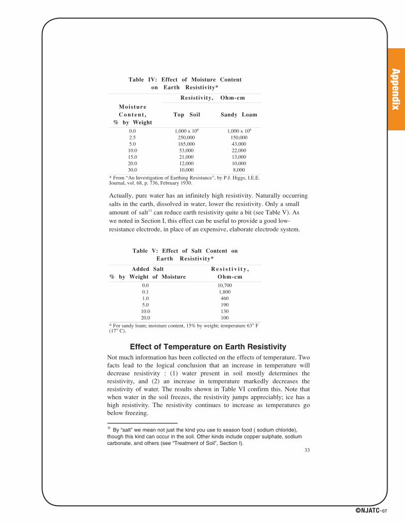
Table IV: Effect of Moisture Content
on Earth Resistivity*__________________________________________________________________________________________________________________________________________________________________________________________________________________________________________
Resistivity, Ohm-cm_________________________________________________________________________________________________________________________________________________________
Moisture
C o n t e n t ,
% by Weight
Top Soil Sandy Loam
__________________________________________________________________________________________________________________________________________________________________________________________________________________________________________
0.0 1,000 x 106 1,000 x 106
2.5 250,000 150,0005.0 165,000 43,000
10.0 53,000 22,00015.0 21,000 13,00020.0 12,000 10,00030.0 10,000 8,000
__________________________________________________________________________________________________________________________________________________________________________________________________________________________________________
* From “An Investigation of Earthing Resistance”, by P.J. Higgs, I.E.E.Journal, vol. 68, p. 736, February 1930.
Actually, pure water has an infinitely high resistivity. Naturally occurringsalts in the earth, dissolved in water, lower the resistivity. Only a smallamount of salt11 can reduce earth resistivity quite a bit (see Table V). Aswe noted in Section I, this effect can be useful to provide a good low-resistance electrode, in place of an expensive, elaborate electrode system.
Table V: Effect of Salt Content on
Earth Resistivity*__________________________________________________________________________________________________________________________________________________________________________________________________________________________________________
Added Salt
% by Weight of Moisture
R e s i s t i v i t y ,
Ohm-cm__________________________________________________________________________________________________________________________________________________________________________________________________________________________________________
0.0 10,7000.1 1,8001.0 4605.0 190
10.0 13020.0 100
__________________________________________________________________________________________________________________________________________________________________________________________________________________________________________
* For sandy loam; moisture content, 15% by weight; temperature 63° F(17° C).
Effect of Temperature on Earth Resistivity
Not much information has been collected on the effects of temperature. Twofacts lead to the logical conclusion that an increase in temperature willdecrease resistivity : (1) water present in soil mostly determines theresistivity, and (2) an increase in temperature markedly decreases theresistivity of water. The results shown in Table VI confirm this. Note thatwhen water in the soil freezes, the resistivity jumps appreciably; ice has ahigh resistivity. The resistivity continues to increase as temperatures gobelow freezing.
41027_p067_122.indd 10341027_p067_122.indd 103 8/10/07 1:56:00 PM8/10/07 1:56:00 PM

Appendix
©NJATC–07
Seasonal Variations in Earth Resistivity
We have seen the effects of temperature, moisture, and salt content uponearth resistivity. It makes sense, therefore, that the resistivity of soil willvary considerably at different times of year. This is particularly true inlocations where there are more extremes of temperature, rainfall, dry spells,and other seasonal variations.
From the preceding discussion, you can see that earth resistivity is a veryvariable quantity. If you want to know what the value is at a given location,at a given time of year, the only safe way is to measure it. When you usethis value for survey work, the change in the value, caused by changes inthe nature of the sub-soil, is the important thing; from the variations inresistivity you can obtain useful survey results.
As covered in Section I, the other main reason for measuring earthresistivity is to design earth-electrode systems for electrical power systems,lightning arresters, and so on. The measured resistivity values are used instandard engineering formulas that calculate factors like number and depthof rods necessary to achieve a required ground resistance, thus reducing theamount of trial and error in the installation of an effective ground. Earthresistance varies directly with earth resistivity and it is helpful to knowwhat factors affect resistivity.
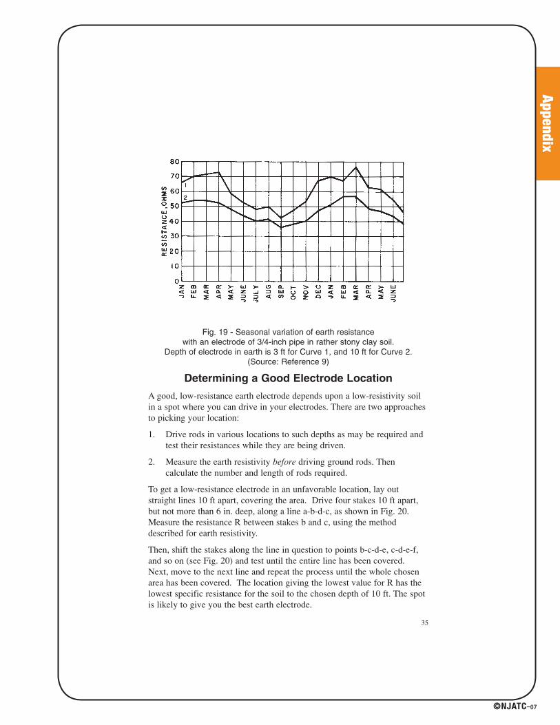
The curves of Fig. 19 illustrate several worthwhile points. They show theexpected change in earth resistance (due to resistivity changes) over a 1-1/2year period; they also show that the deeper electrode gives a more stableand lower value. We conclude that the moisture content and temperature ofthe soil become more stable at greater distances below the earth’s surface.Therefore, the earth electrode should reach deep enough level to provide:
1. Permanent moisture content (relatively speaking).
2. Constant temperature (below frost line; again, relatively speaking).
34
g
Table VI: Effect of Temperature
on Earth Resistivity*__________________________________________________________________________________________________________________________________________________________________________________________________________________________________________
Temperature______________________________________________________________________________________________________________________________________________________________
C F
R e s i s t i v i t y ,
Ohm-cm__________________________________________________________________________________________________________________________________________________________________________________________________________________________________________
20 68 7,20010 50 9,9000 32 (water) 13,8000 32 (ice) 30,000-5 23 79,000-15 14 330,000
__________________________________________________________________________________________________________________________________________________________________________________________________________________________________________
* For sandy loam; 15.2% moisture.
41027_p067_122.indd 10441027_p067_122.indd 104 8/10/07 1:56:00 PM8/10/07 1:56:00 PM
Appendix
©NJATC–07
Fig. 19 - Seasonal variation of earth resistance with an electrode of 3/4-inch pipe in rather stony clay soil.
Depth of electrode in earth is 3 ft for Curve 1, and 10 ft for Curve 2.(Source: Reference 9)
Determining a Good Electrode Location
A good, low-resistance earth electrode depends upon a low-resistivity soilin a spot where you can drive in your electrodes. There are two approachesto picking your location:
1. Drive rods in various locations to such depths as may be required andtest their resistances while they are being driven.
2. Measure the earth resistivity before driving ground rods. Thencalculate the number and length of rods required.
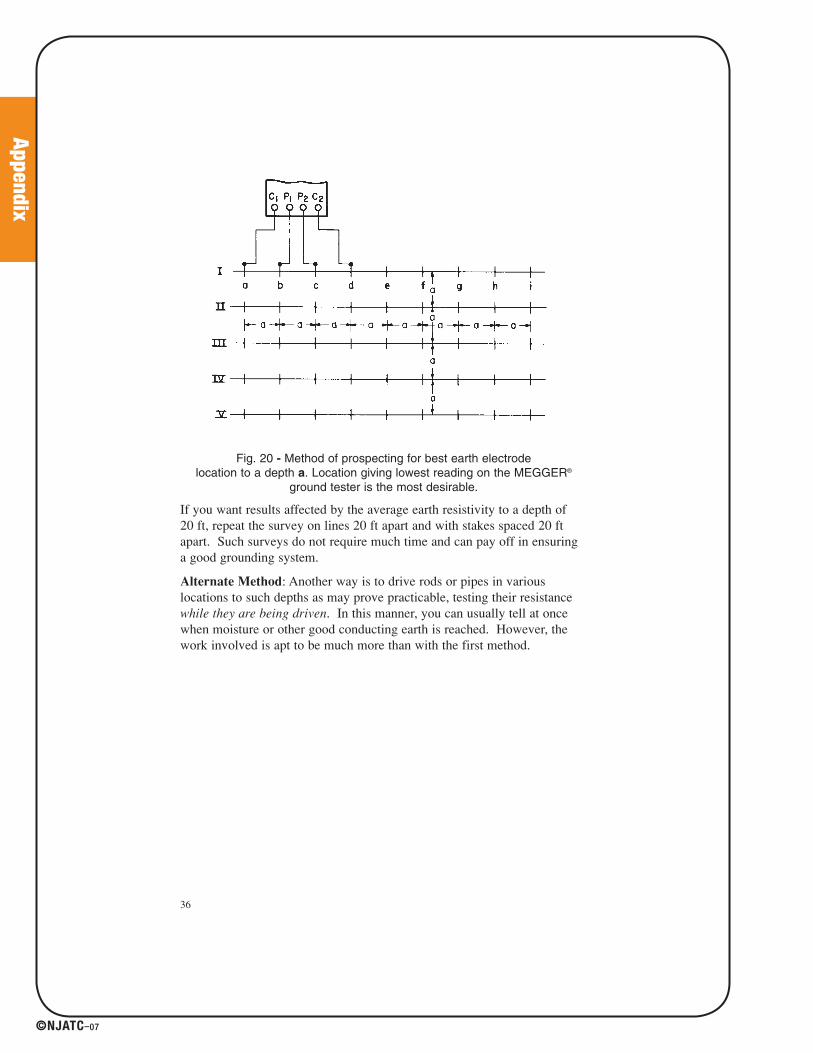
To get a low-resistance electrode in an unfavorable location, lay outstraight lines 10 ft apart, covering the area. Drive four stakes 10 ft apart,but not more than 6 in. deep, along a line a-b-d-c, as shown in Fig. 20.Measure the resistance R between stakes b and c, using the methoddescribed for earth resistivity.
Then, shift the stakes along the line in question to points b-c-d-e, c-d-e-f,and so on (see Fig. 20) and test until the entire line has been covered.Next, move to the next line and repeat the process until the whole chosenarea has been covered. The location giving the lowest value for R has thelowest specific resistance for the soil to the chosen depth of 10 ft. The spotis likely to give you the best earth electrode.
35
41027_p067_122.indd 10541027_p067_122.indd 105 8/10/07 1:56:00 PM8/10/07 1:56:00 PM
Appendix
©NJATC–07
Fig. 20 - Method of prospecting for best earth electrode location to a depth a. Location giving lowest reading on the MEGGER®
ground tester is the most desirable.
If you want results affected by the average earth resistivity to a depth of 20 ft, repeat the survey on lines 20 ft apart and with stakes spaced 20 ftapart. Such surveys do not require much time and can pay off in ensuringa good grounding system.
Alternate Method: Another way is to drive rods or pipes in variouslocations to such depths as may prove practicable, testing their resistancewhile they are being driven. In this manner, you can usually tell at oncewhen moisture or other good conducting earth is reached. However, thework involved is apt to be much more than with the first method.
36
41027_p067_122.indd 10641027_p067_122.indd 106 8/10/07 1:56:00 PM8/10/07 1:56:00 PM
Appendix
©NJATC–07
SECTION III
ACCURATELY MEASURING EARTH RESISTANCE
FOR LARGE GROUND SYSTEMS
Large ground systems, such as those found in substations and powerstations, are an important part of the protection of the electricity supplynetwork. They ensure that fault current will enable protective devices tooperate correctly. A substation must have a low ground resistance to reduceexcessive voltages developing during a fault which could endanger safetyof nearby people or damage equipment.
When installing a ground system the resistivity of the surrounding soilshould be measured. Inaccurate resistivity tests can lead to unnecessarycosts in the design of the system.
After installation it is vital to check that the electrical grounding systemmeets the design criteria and should be measured periodically to ensurecorrosion or changes in the soil's resistivity do not have an adverse effect.Ground networks may not appear faulty until a fault occurs and adangerous situation arises.
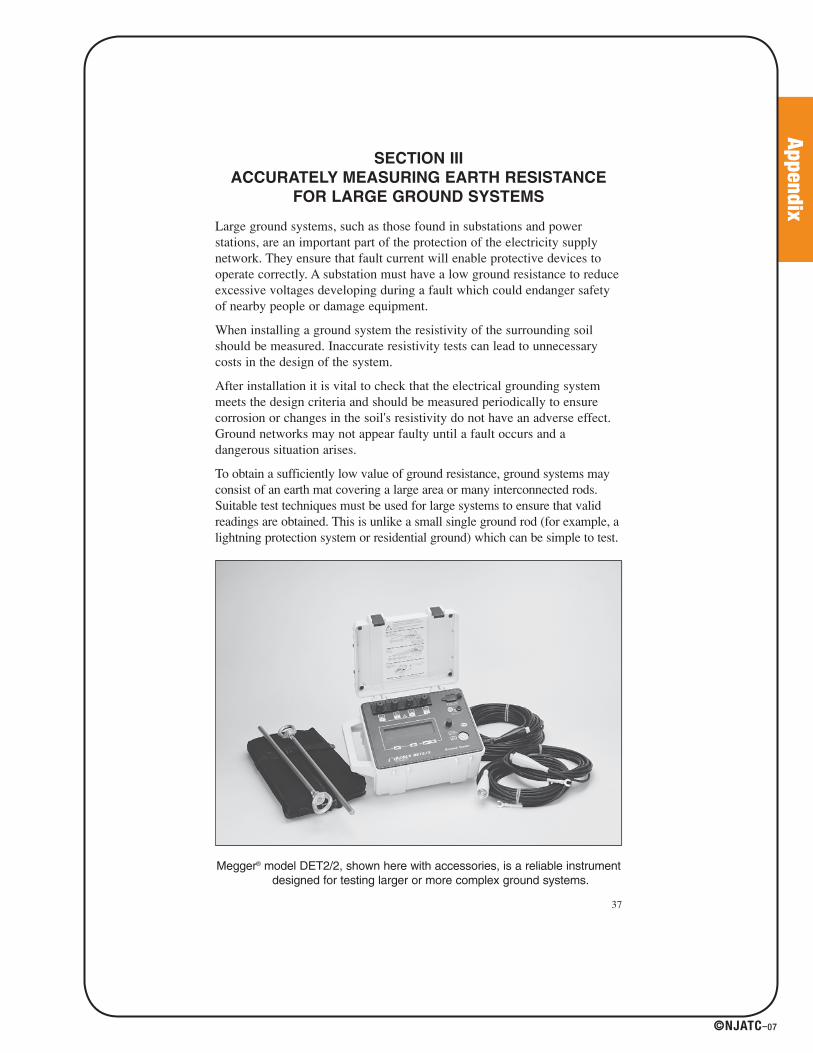
To obtain a sufficiently low value of ground resistance, ground systems mayconsist of an earth mat covering a large area or many interconnected rods.Suitable test techniques must be used for large systems to ensure that validreadings are obtained. This is unlike a small single ground rod (for example, alightning protection system or residential ground) which can be simple to test.
Megger® model DET2/2, shown here with accessories, is a reliable instrumentdesigned for testing larger or more complex ground systems.
37
41027_p067_122.indd 10741027_p067_122.indd 107 8/10/07 1:56:00 PM8/10/07 1:56:00 PM

Appendix
©NJATC–07
Testing Challenges in Large Ground Systems
Securing valid measurements when testing large ground systems requiresthat proper techniques and instrumentation be used. The nature ofsubstation and power station grounding systems and related conditionsmake testing far more complex than on a simple ground rod. Following arethe three key challenges in testing substation ground systems:
1. The physically large area of a substation/power station ground systemresults in a large “resistance area” and, consequently, long distances tothe test probes; ideally, the current test probe should be placed 10 timesthe maximum distance on the ground system (e.g, 3000 ft for a 300 ft2
ground grid) to find the “flat” portion of the characteristic resistancecurve.
2. The large “resistance area” typically gives ground resistance values ofless than 0.5 Ω; test instrument resolution is critical if small variancesin readings are to be observed; if the test instrument does not havesuitable resolution, instrument errors can overwhelm the results.
3. Large electrical networks contain noise consisting of the frequency ofthe power utility and its harmonics, plus high frequency noise fromswitching, etc., and induced signals from other sources; the groundtester must retrieve and analyze a small test signal in a much larger testenvironment; most ground testers only reject noise of a singlefrequency (usually 128 Hz) which is adequate in most situationsbecause it avoids harmonics of standard line frequencies; unfortunately,it is often not adequate in substations; this type of interference cancause significant measurement errors.
Addressing the Testing Challenges
in Large Ground Systems
In the ideal world, testing a large ground system would be conducted incomplete accordance with the Fall-of Potential Method. Unfortunately, thelarge “resistance areas” found in large ground systems may make itunfeasible or even impossible to carry out this test. As noted above, settingthe current test probe 10 times the maximum distance of the ground systemcan require leads to be many thousands of feet. In these situations, theSlope Method can be used effectively because it does not require the userto find the “flat” portion of the curve or to know the electrical center as apoint from which to measure. Readings are taken at 20 percent, 40 percentand 60 percent of the current probe distance and fit into a mathematicalmodel of the resistance characteristic. Appendix III provides a detailedexplanation of the Slope Method, including relevant tables.
38
41027_p067_122.indd 10841027_p067_122.indd 108 8/10/07 1:56:01 PM8/10/07 1:56:01 PM
Appendix
©NJATC–07
The other challenges faced in testing large ground systems relate to thecapabilities of the test instrument. Improved technology has made itpossible for instruments to be designed that address problems created bythe characteristics and conditions found in and around large groundsystems.
For the Slope Method to provide meaningful results, accurate measurementof the variations at different points is critical. Since large ground systemstypically have resistance values of less than 0.5 Ω, the differences can bequite small. An instrument with 1 mW measurement resolution can indicatethe small differences between low readings.
Noise is a major problem in testing large ground systems, and must beaddressed to ensure accurate results. To be effective, the test instrumentmust be designed to overcome the effects of significant noise in the testenvironment. Among the technical capabilities that can help offset the noiseproblem are:
• A variable test frequency (rather than a single, fixed test frequency)which can help remove any stray noise that could affect the reading.
• A high peak-to-peak interference suppression level.
• A sophisticated filter system to reject more noise.
• Various current settings to improve the signal-to-noise ratio whennecessary.
39
41027_p067_122.indd 10941027_p067_122.indd 109 8/10/07 1:56:01 PM8/10/07 1:56:01 PM
Appendix
©NJATC–07
40
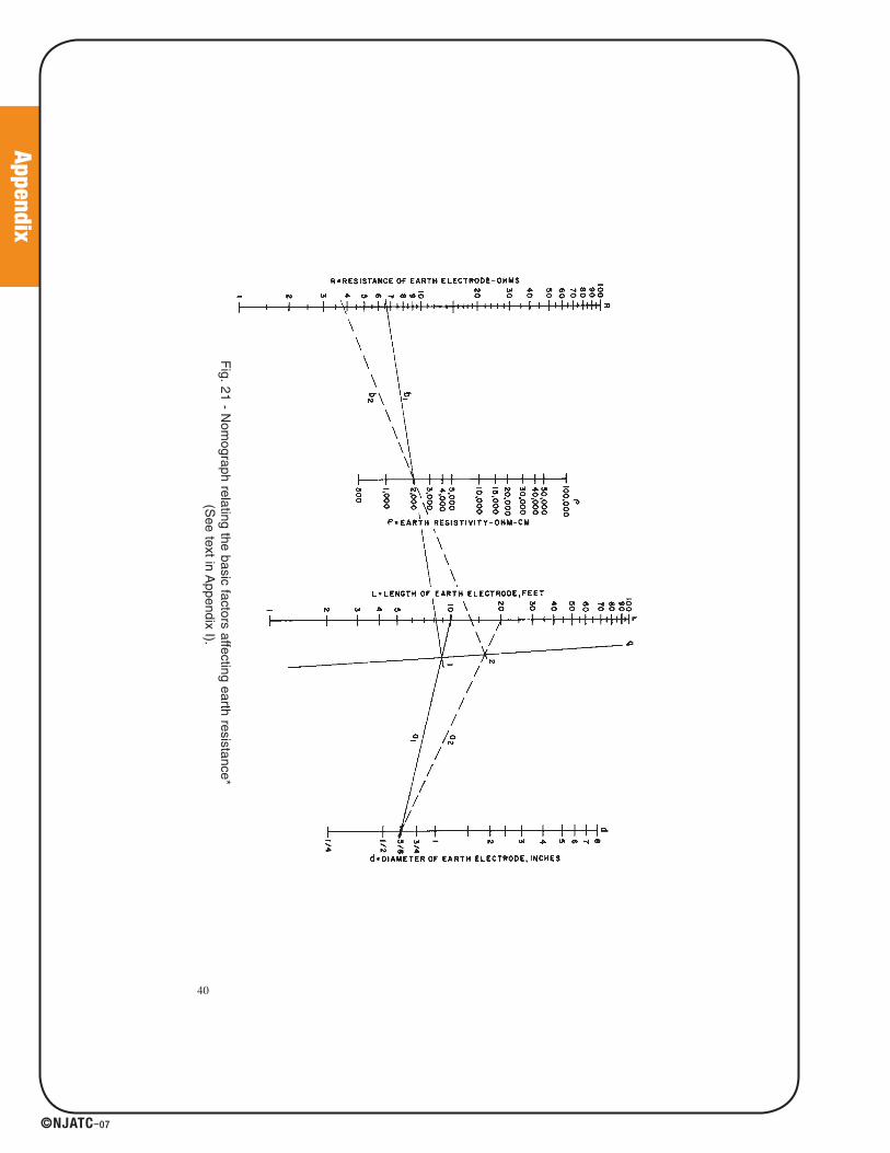
Fig. 21 -
Nom
ograph relating the basic factors affecting earth resistance*(S
ee text in Appendix I).
41027_p067_122.indd 11041027_p067_122.indd 110 8/10/07 1:56:01 PM8/10/07 1:56:01 PM

Appendix
©NJATC–07
Appendix I Nomograph Guide to Getting Acceptable
Earth Resistance12
Dr. L.E. Whitehead of the DuPage Laboratories developed a nomograph(Fig. 21) which can be a helpful guide in meeting the established standardfor a minimum earth resistance. If you have a given earth-electrode systemand find that your Megger instrument reading is too high, the graph can beused to show what you must do to lower the value. Note that it coversthree variable conditions that affect earth resistance of the electrode: earthresistivity, length of rod, and diameter of rod.
To illustrate use of the nomograph, let’s take an example. Assume youhave a 5/8-in. rod driven 10 ft into the soil. Your Megger® instrumentindicates an earth resistance of 6.6 Ω. But let’s say your specification forthis resistance is “no more than 4 Ω.” To get this, you can change one ormore of the three variables -- the simplest and most effective being depthof the driven rod. To find the required depth to give you a 4-Ω earthresistance, proceed as follows: With a ruler, draw a line from the 10-ftpoint in the L line to the 5/8-in. point in the d line; this gives a referencepoint where the line crosses the q line. Connect this reference point with6.6 Ω-the measured resistance on the R line, as shown in Fig. 21, read thevalue of earth resistivity when this line crosses the p line. The value is 2000 ohm-cm.
To determine the required rod depth for a 4-Ω earth resistance, draw a linefrom this point on the R line through the 2000 point on the line until youcross the q line. The dashed line on Fig. 21 shows this step. Now, assumingyou keep rod diameter unchanged, connect the 5/8 point on d line throughyour new reference point on q and extend the line to L. This gives you therequired rod depth for the 4-Ω resistance value. Finally, take a newinstrument reading to check the value, because earth resistivity may not beconstant (as the nomograph assumes).
Another way to reduce the earth resistance would be to lower the earthresistivity. Note in Fig. 21 that if you draw a line from a reference point 1(leaving rod depth and diameter unchanged), you would need to reduceearth resistivity to about 1000 ohm-cm to give the required 4-Ω earthresistance. You could do this by chemical treatment, as described earlier,but normally the deeper rod is the easier way.
41
12 Source: Reference 21
41027_p067_122.indd 11141027_p067_122.indd 111 8/10/07 1:56:01 PM8/10/07 1:56:01 PM

Appendix
©NJATC–07
Appendix II Measurement of the Resistance of
Large Earth-Electrode Systems: Intersecting
Curves Method13
The difficulties of measuring the resistance of large electrode systemsinvolve the use of very long leads to connect the potential and currentprobes. An alternative method, in which such long leads are not necessary,has been devised. The basic principle is to obtain earth-resistance curvesfor several current-electrode spacings and, by assuming a number ofsuccessive positions for the electrical center of the system, to produceintersection curves which will give the earth resistance and the position ofthe electrical center.
Some rather difficult problems are encountered when the resistance of anearth-electrode system, consisting of a number of rods, tapes, etc., allconnected in parallel and spread over a large area, is to be measured. Theusual method of measurement that worked very well has one disadvantage;namely, that it is generally necessary to place the auxiliary current probe ata considerable distance from the earth-electrode system. In some cases, thisdistance can be as much as 3000 ft, and this is not always convenient orpossible.
A method which does not require such long lengths of cable wouldobviously be better, therefore the following is suggested.
Suppose that all measurements are made from an arbitrary starting point O,the distance C to the current probe and the variable distance P to thepotential probe being measured from this point. then a curve such as abc(Fig. 22), giving the measured resistance against the value of P, can beobtained. Now suppose the electrical center of the earth-electrode system isactually at D, distance X from O. Then the true distance from the center tothe current probe is C + X, and the true resistance is obtained when thepotential probe is at a distance 0.618 (C + X) from D. This means that thevalue of P, measured from O, is 0.618 (C + X) - X. If X is now given anumber of values, the corresponding values of P can be calculated and theresistance read off the curve. These resistances can be plotted against thevalues of X in another curve. When this process is repeated for a differentvalue of C, and another curve of resistance against X obtained, the twocurves should cross at the required resistance. The process can be repeatedfor a third value of C as a check. These curves are called intersectioncurves. It has been assumed that D, O and C are in the same straight line.
42
13 Source: Reference 22
41027_p067_122.indd 11241027_p067_122.indd 112 8/10/07 1:56:01 PM8/10/07 1:56:01 PM

Appendix
©NJATC–07
Fig. 22 - Earth resistance curve applicable to systems of a large area.
Test at a Large Substation
Tests were made at a station which covers an area approximately 300 ft x 250 ft. The earthing system consists of a number of earth platesand rods joined together by copper cables. The testing line was run outfrom a point on the face approximately halfway along one side and thecurrent electrode was placed at distances of 400, 600, 800, and 1000 ftfrom the starting point. The resulting earth-resistance curves are given inFig. 23. The intersection curves are plotted and the final value of resistanceis found in Fig. 24.
It is reasonable to expect that this value is correct to within a few percent.
Fig. 23 - Earth resistance curves for a substation.
43
41027_p067_122.indd 11341027_p067_122.indd 113 8/10/07 1:56:01 PM8/10/07 1:56:01 PM
Appendix
©NJATC–07
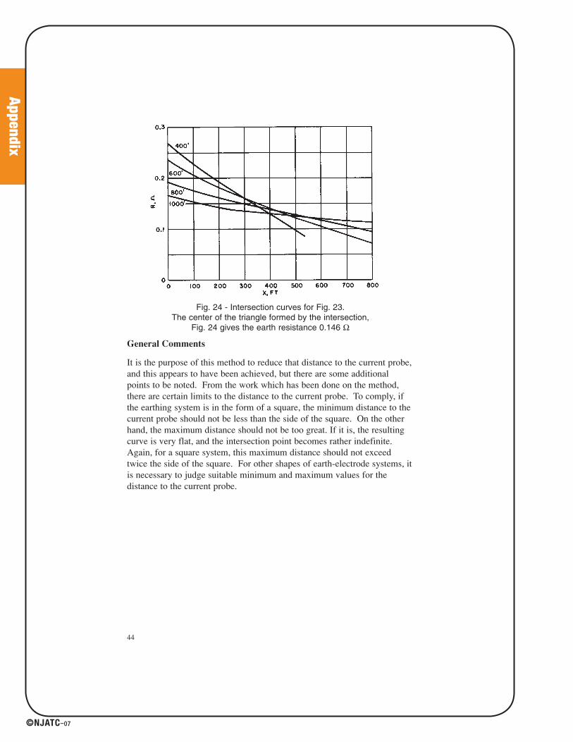
Fig. 24 - Intersection curves for Fig. 23. The center of the triangle formed by the intersection,
Fig. 24 gives the earth resistance 0.146 Ω
General Comments
It is the purpose of this method to reduce that distance to the current probe,and this appears to have been achieved, but there are some additionalpoints to be noted. From the work which has been done on the method,there are certain limits to the distance to the current probe. To comply, ifthe earthing system is in the form of a square, the minimum distance to thecurrent probe should not be less than the side of the square. On the otherhand, the maximum distance should not be too great. If it is, the resultingcurve is very flat, and the intersection point becomes rather indefinite.Again, for a square system, this maximum distance should not exceedtwice the side of the square. For other shapes of earth-electrode systems, itis necessary to judge suitable minimum and maximum values for thedistance to the current probe.
44
41027_p067_122.indd 11441027_p067_122.indd 114 8/10/07 1:56:02 PM8/10/07 1:56:02 PM
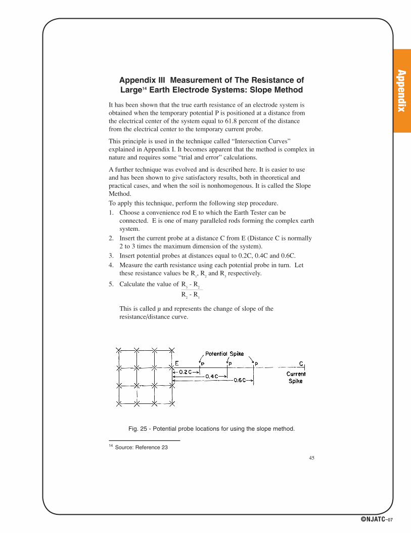
Appendix
©NJATC–07
Appendix III Measurement of The Resistance of
Large14 Earth Electrode Systems: Slope Method
It has been shown that the true earth resistance of an electrode system isobtained when the temporary potential P is positioned at a distance fromthe electrical center of the system equal to 61.8 percent of the distancefrom the electrical center to the temporary current probe.
This principle is used in the technique called “Intersection Curves”explained in Appendix I. It becomes apparent that the method is complex innature and requires some “trial and error” calculations.
A further technique was evolved and is described here. It is easier to useand has been shown to give satisfactory results, both in theoretical andpractical cases, and when the soil is nonhomogenous. It is called the SlopeMethod.
To apply this technique, perform the following step procedure.
1. Choose a convenience rod E to which the Earth Tester can beconnected. E is one of many paralleled rods forming the complex earthsystem.
2. Insert the current probe at a distance C from E (Distance C is normally2 to 3 times the maximum dimension of the system).
3. Insert potential probes at distances equal to 0.2C, 0.4C and 0.6C.
4. Measure the earth resistance using each potential probe in turn. Letthese resistance values be R
1, R
2and R
3respectively.
5. Calculate the value of R3
- R2
R2
- R1
This is called μ and represents the change of slope of theresistance/distance curve.
45
14 Source: Reference 23
Fig. 25 - Potential probe locations for using the slope method.
41027_p067_122.indd 11541027_p067_122.indd 115 8/10/07 1:56:02 PM8/10/07 1:56:02 PM
Appendix
©NJATC–07
46
52
6. Refer to Table VII to find the corresponding value pf PT/C for μ.
7. Since C is already know, calculate PT and insert a potential probe atthis distance from E.Measure the earth resistance which should be thetrue resistance.
8. Repeat the whole process for a larger value of C. If the “true”resistance decreases appreciably as C is increased, it is necessary toincrease C still further.
NOTE: As with other earth testing techniques, some experimentation maybe necessary to ascertain if the practical result is as accurate as the theoryappears to indicate.
The Slope Method has been designed to eliminate the need forimpractically long leads by the ability to interpolate the correct distancealong the combined resistance curve, i.e. the curve of the current probe’sresistance superimposed upon that of the tested grid, without sufficientspacing to produce the characteristic “flat portion” between.
One particular observation on the Slope Method is that if the calculationof μ is greater than that given in the table, the distance C must be increased.
Secondly, before the measured values for R1, R2 and R3 can be accepted witha degree of confidence, it is recommended that a curve be plotted whichwill identify any localized effects and eliminate uncharacteristic readingsfrom the calculations. Thirdly, it is also suggested that the test be repeatedin different directions and with different spacings. The various resultsshould exhibit a reasonable degree of agreement.
41027_p067_122.indd 11641027_p067_122.indd 116 8/10/07 1:56:02 PM8/10/07 1:56:02 PM

Appendix
©NJATC–07
47
Table VII: Values of Pt/C for Various Values of μ__________________________________________________________________________________________________________________________________________________________________________________________________________________________________________
μ PT/C μ PT/C μ PT/C__________________________________________________________________________________________________________________________________________________________________________________________________________________________________________
0.40 0.643 0.80 0.580 1.20 0.4940.41 0.642 0.81 0.579 1.21 0.4910.42 0.640 0.82 0.577 1.22 0.4880.43 0.639 0.83 0.575 1.23 0.4860.44 0.637 0.84 0.573 1.24 0.4830.45 0.636 0.85 0.571 1.25 0.4800.46 0.635 0.86 0.569 1.26 0.4770.47 0.633 0.87 0.567 1.27 0.4740.48 0.632 0.88 0.566 1.28 0.4710.49 0.630 0.89 0.564 1.29 0.468
0.50 0.629 0.90 0.562 1.30 0.4650.51 0.627 0.91 0.560 1.31 0.4620.52 0.626 0.92 0.558 1.32 0.4580.53 0.624 0.93 0.556 1.33 0.4550.54 0.623 0.94 0.554 1.34 0.4520.55 0.621 0.95 0.552 1.35 0.4480.56 0.620 0.96 0.550 1.36 0.4450.57 0.618 0.97 0.548 1.37 0.4410.58 0.617 0.98 0.546 1.38 0.4380.59 0.615 0.99 0.544 1.39 0.434
0.60 0.614 1.00 0.542 1.40 0.4310.61 0.612 1.01 0.539 1.41 0.4270.62 0.610 1.02 0.537 1.42 0.4230.63 0.609 1.03 0.535 1.43 0.4180.64 0.607 1.04 0.533 1.44 0.4140.65 0.606 1.05 0.531 1.45 0.4100.66 0.604 1.06 0.528 1.46 0.4060.67 0.602 1.07 0.526 1.47 0.4010.68 0.601 1.08 0.524 1.48 0.3970.69 0.599 1.09 0.522 1.49 0.393
0.70 0.597 1.10 0.519 1.50 0.3890.71 0.596 1.11 0.517 1.51 0.3840.72 0.594 1.12 0.514 1.52 0.3790.73 0.592 1.13 0.512 1.53 0.3740.74 0.591 1.14 0.509 1.54 0.3690.75 0.589 1.15 0.507 1.55 0.3640.76 0.587 1.16 0.504 1.56 0.3580.77 0.585 1.17 0.502 1.57 0.3520.78 0.584 1.18 0.499 1.58 0.3470.79 0.582 1.19 0.497 1.59 0.341
__________________________________________________________________________________________________________________________________________________________________________________________________________________________________________
41027_p067_122.indd 11741027_p067_122.indd 117 8/10/07 1:56:02 PM8/10/07 1:56:02 PM

Appendix
©NJATC–07
Appendix IV
Determining Touch and Step Potential
Touch potential is the term given to the potential difference a person mightexperience across their body if they were, for example, standing on theground outside the earthed perimeter fence of a substation and touching thefence at the time a fault to earth occurred.
To determine this value, an earth tester may first be used to find the earthresistance. It is connected as shown in Fig. 26.
Fig. 26 - Method of use for determining touch and step potential
Terminal “C1” of the earth tester is connected to the grounding system ofthe substation (e.g. at “E”) and terminal “C2” is connected to a current spike“C” (set up for testing purposes some distance away). Terminal “P1” isconnected to the structure being tested (e.g. the perimeter fence which theperson might touch) and terminal “P2” is connected to a potential spike “P”which is inserted into the ground about 3 ft away from the perimeter fenceadjacent to the point of test on the fence (i.e. where the person might stand).
48
B A
PE
Substation Ground System
Substation GroundedPerimeter
Fence
41027_p067_122.indd 11841027_p067_122.indd 118 8/10/07 1:56:02 PM8/10/07 1:56:02 PM
Appendix
©NJATC–07
The earth tester is operated in the normal way and a resistancemeasurement made. This is the effective resistance between the point oftest on the fence and the potential spike as seen by the test current. Themaximum value of the current that would flow in the earth when a faultoccurred at the substation must be known. The maximum fault current hasto be calculated from parameters associated with the substation ratingsinvolved; it is not necessarily straight forward.
The effective maximum touch potential can be calculated within areasonable margin of accuracy (about 20 percent, depending how true theearth resistance measurement is), by multiplying the fault current by theearth resistance.
Step potential is obtained in a similar way. This is the potential difference aperson would experience between their feet if they walked over the groundin which a fault current existed.
Terminals “C1” and “C2” on the earth tester are connected as described fordetermining touch potential. Terminals “P1” and “P2” are connected to twopotential spikes set up for test purposes. The spikes are hammered into theground at positions “A” and “B” as shown in Fig. 26, about 3 ft apart (i.e.,the approximate length of an average person’s step). (Note: “A” is nearestto “E” and is connected to terminal “P1.”)
The earth tester is operated in the normal way and a resistancemeasurement is made. This is the effective resistance between “A” and “B”as seen by the test current. Again, the maximum value of the current thatwould flow in the earth under fault conditions at the substation must beknown.
The effective step potential can be calculated by multiplying the faultcurrent by the earth resistance, again within a reasonable accuracy.
49
41027_p067_122.indd 11941027_p067_122.indd 119 8/10/07 1:56:02 PM8/10/07 1:56:02 PM
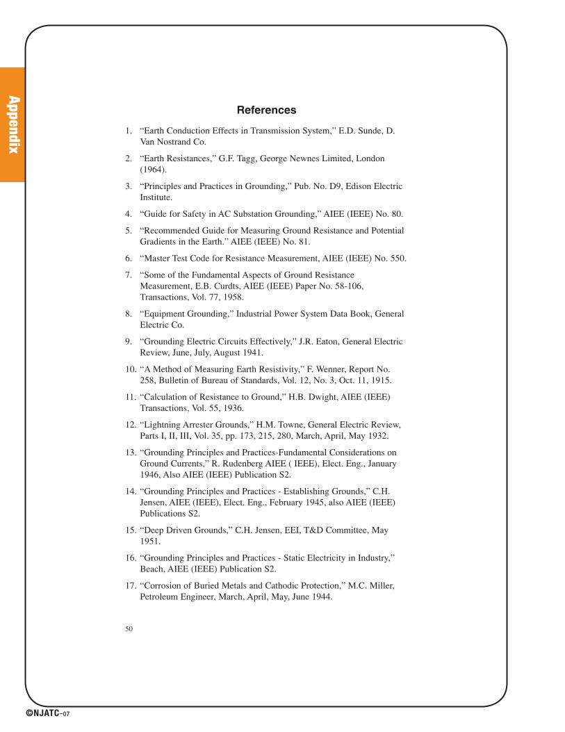
Appendix
©NJATC–07
References
1. “Earth Conduction Effects in Transmission System,” E.D. Sunde, D.Van Nostrand Co.
2. “Earth Resistances,” G.F. Tagg, George Newnes Limited, London(1964).
3. “Principles and Practices in Grounding,” Pub. No. D9, Edison ElectricInstitute.
4. “Guide for Safety in AC Substation Grounding,” AIEE (IEEE) No. 80.
5. “Recommended Guide for Measuring Ground Resistance and PotentialGradients in the Earth.” AIEE (IEEE) No. 81.
6. “Master Test Code for Resistance Measurement, AIEE (IEEE) No. 550.
7. “Some of the Fundamental Aspects of Ground ResistanceMeasurement, E.B. Curdts, AIEE (IEEE) Paper No. 58-106,Transactions, Vol. 77, 1958.
8. “Equipment Grounding,” Industrial Power System Data Book, GeneralElectric Co.
9. “Grounding Electric Circuits Effectively,” J.R. Eaton, General ElectricReview, June, July, August 1941.
10. “A Method of Measuring Earth Resistivity,” F. Wenner, Report No.258, Bulletin of Bureau of Standards, Vol. 12, No. 3, Oct. 11, 1915.
11. “Calculation of Resistance to Ground,” H.B. Dwight, AIEE (IEEE)Transactions, Vol. 55, 1936.
12. “Lightning Arrester Grounds,” H.M. Towne, General Electric Review,Parts I, II, III, Vol. 35, pp. 173, 215, 280, March, April, May 1932.
13. “Grounding Principles and Practices-Fundamental Considerations onGround Currents,” R. Rudenberg AIEE ( IEEE), Elect. Eng., January1946, Also AIEE (IEEE) Publication S2.
14. “Grounding Principles and Practices - Establishing Grounds,” C.H.Jensen, AIEE (IEEE), Elect. Eng., February 1945, also AIEE (IEEE)Publications S2.
15. “Deep Driven Grounds,” C.H. Jensen, EEI, T&D Committee, May1951.
16. “Grounding Principles and Practices - Static Electricity in Industry,”Beach, AIEE (IEEE) Publication S2.
17. “Corrosion of Buried Metals and Cathodic Protection,” M.C. Miller,Petroleum Engineer, March, April, May, June 1944.
50
41027_p067_122.indd 12041027_p067_122.indd 120 8/10/07 1:56:02 PM8/10/07 1:56:02 PM
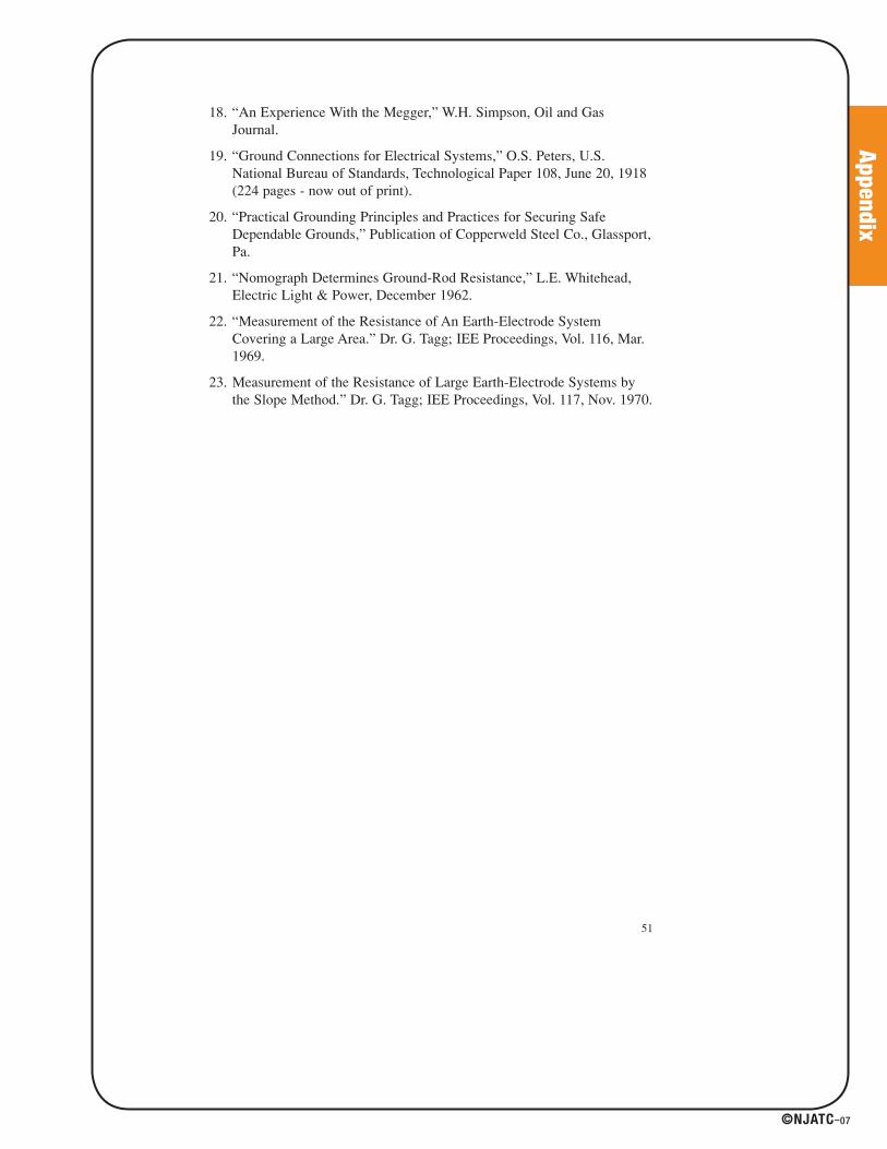
Appendix
©NJATC–07
18. “An Experience With the Megger,” W.H. Simpson, Oil and GasJournal.
19. “Ground Connections for Electrical Systems,” O.S. Peters, U.S.National Bureau of Standards, Technological Paper 108, June 20, 1918(224 pages - now out of print).
20. “Practical Grounding Principles and Practices for Securing SafeDependable Grounds,” Publication of Copperweld Steel Co., Glassport,Pa.
21. “Nomograph Determines Ground-Rod Resistance,” L.E. Whitehead,Electric Light & Power, December 1962.
22. “Measurement of the Resistance of An Earth-Electrode SystemCovering a Large Area.” Dr. G. Tagg; IEE Proceedings, Vol. 116, Mar.1969.
23. Measurement of the Resistance of Large Earth-Electrode Systems bythe Slope Method.” Dr. G. Tagg; IEE Proceedings, Vol. 117, Nov. 1970.
51
41027_p067_122.indd 12141027_p067_122.indd 121 8/10/07 1:56:02 PM8/10/07 1:56:02 PM
Related Documents


![Measuring earth resistance · tween the main earthing busbar and the earth electrode. The dissipation resistance R ... ring resistance to earth [5] • IEC 61557-6:2007 Equipment](https://static.cupdf.com/doc/110x72/5e7953ac372df33d9d51c0eb/measuring-earth-resistance-tween-the-main-earthing-busbar-and-the-earth-electrode.jpg)